Embed Size (px)
Citation preview
National Aeronautics and Space Administration
IEEE Aerospace 2016Big Sky, Montana
5 March – 11 March, 2016
Mars Surface Systems Common Capabilities and Challenges
for Human MissionsLarry Toups, NASA Johnson Space Center
Stephen J. Hoffman, Ph.D., Science Applications International Corporation
Kevin Watts, NASA Johnson Space Center
https://ntrs.nasa.gov/search.jsp?R=20160002369 2018-02-01T04:30:04+00:00Z
Agenda
• How do we pioneer an extended human presence on
Mars that is Earth independent?
• The Exploration Zone, Regions of Interest, and Mars
Surface Field Station concepts
• Impacts of Mars Surface Field Station location on
surface system commonality
– Traverse range and route impact on rover
– Landing site topographic impact on Field Station
layout
2
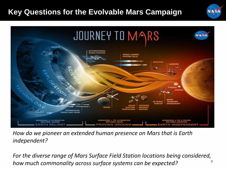
How do we pioneer an extended human presence on Mars that is Earth independent?
For the diverse range of Mars Surface Field Station locations being considered, how much commonality across surface systems can be expected?
Key Questions for the Evolvable Mars Campaign
3
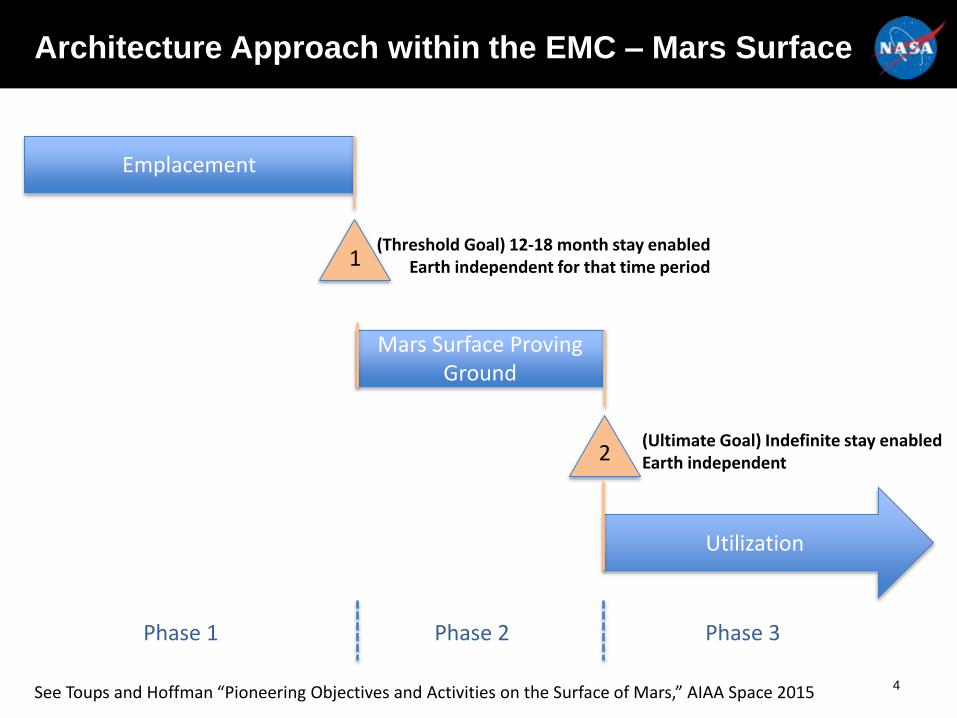
Architecture Approach within the EMC – Mars Surface
4
Mars Surface Proving Ground
Utilization
1
2
Phase 1 Phase 2 Phase 3
Emplacement
(Threshold Goal) 12-18 month stay enabledEarth independent for that time period
(Ultimate Goal) Indefinite stay enabledEarth independent
See Toups and Hoffman “Pioneering Objectives and Activities on the Surface of Mars,” AIAA Space 2015
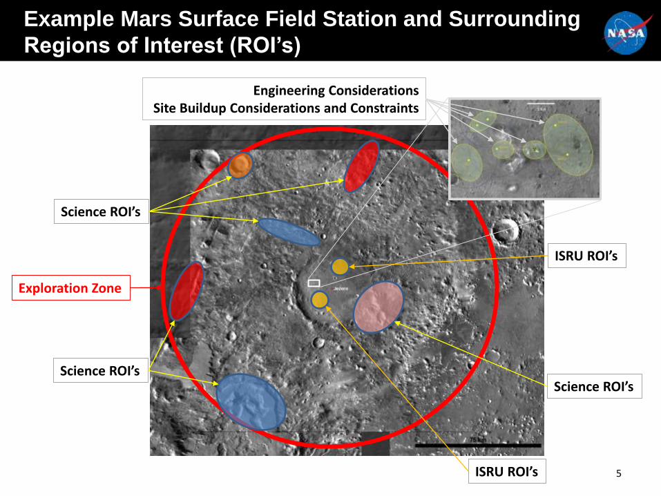
Example Mars Surface Field Station and Surrounding
Regions of Interest (ROI’s)
5
Exploration Zone
Science ROI’s
ISRU ROI’s
Science ROI’s
ISRU ROI’s
Science ROI’s
Engineering ConsiderationsSite Buildup Considerations and Constraints
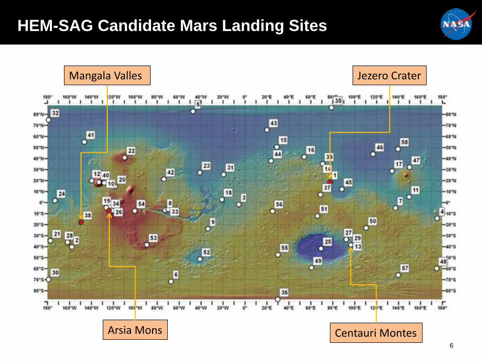
HEM-SAG Candidate Mars Landing Sites
Jezero Crater
Centauri MontesArsia Mons
Mangala Valles
6
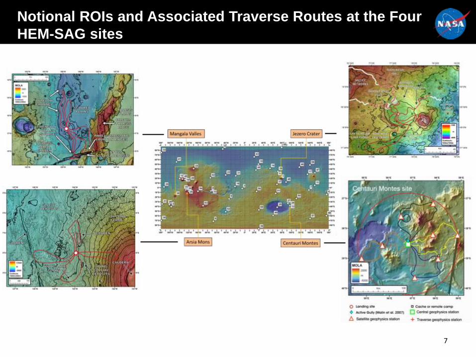
Notional ROIs and Associated Traverse Routes at the Four
HEM-SAG sites
7
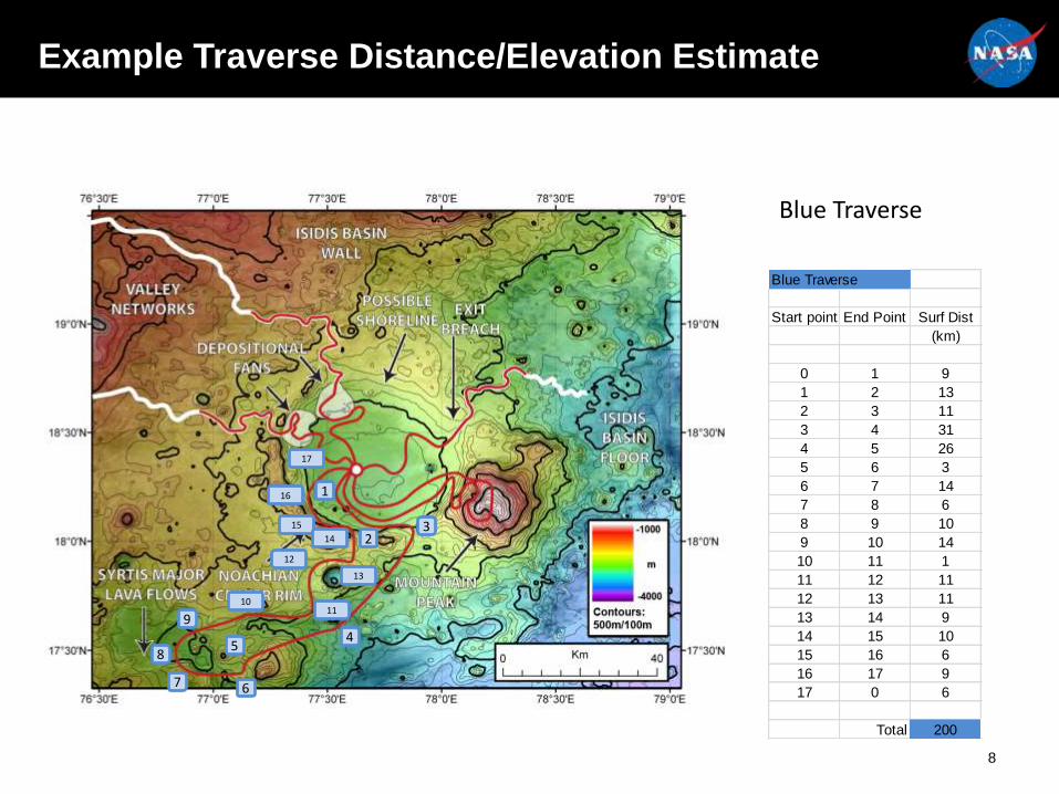
Blue Traverse
1
23
45
6
8
7
17
911
10
13
12
15
14
16
Blue Traverse
Start point End Point Surf Dist
(km)
0 1 9
1 2 13
2 3 11
3 4 31
4 5 26
5 6 3
6 7 14
7 8 6
8 9 10
9 10 14
10 11 1
11 12 11
12 13 11
13 14 9
14 15 10
15 16 6
16 17 9
17 0 6
Total 200
Example Traverse Distance/Elevation Estimate
8
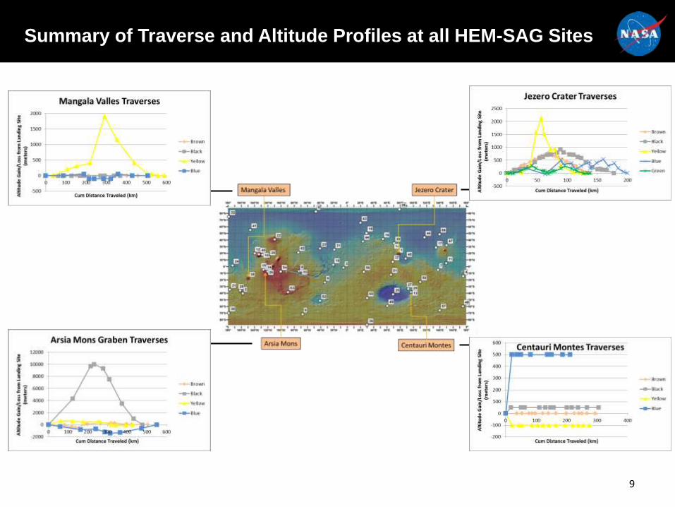
Summary of Traverse and Altitude Profiles at all HEM-SAG Sites
9
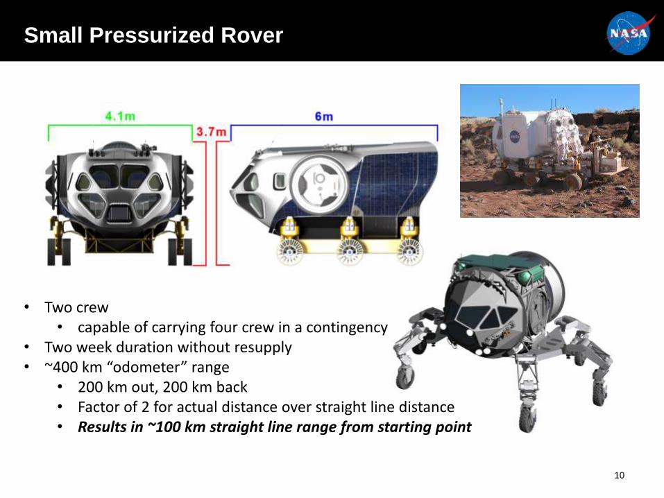
Small Pressurized Rover
• Two crew• capable of carrying four crew in a contingency
• Two week duration without resupply• ~400 km “odometer” range
• 200 km out, 200 km back• Factor of 2 for actual distance over straight line distance• Results in ~100 km straight line range from starting point
10
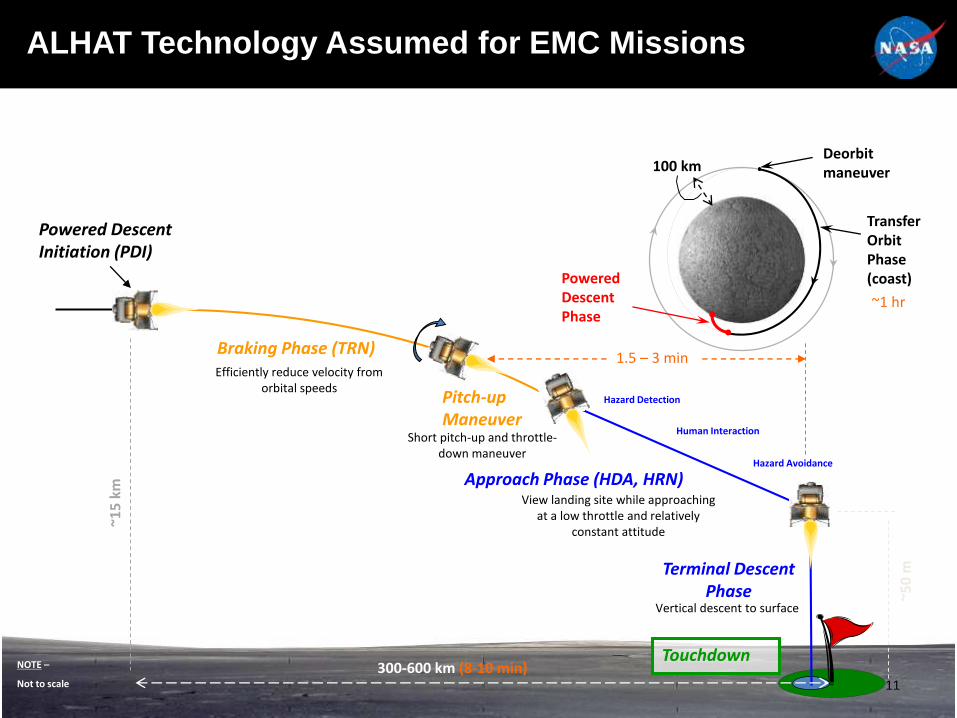
ALHAT Technology Assumed for EMC Missions
Deorbit maneuver
Powered Descent Phase
Transfer Orbit Phase (coast)
100 km
Touchdown
Approach Phase (HDA, HRN)
Braking Phase (TRN)
Terminal Descent Phase
Pitch-up Maneuver
Powered Descent Initiation (PDI)
~15
km
~50
m
300-600 km (8-10 min)
View landing site while approaching at a low throttle and relatively
constant attitude
Short pitch-up and throttle-down maneuver
Efficiently reduce velocity from orbital speeds
NOTE –
Not to scale
Vertical descent to surface
Hazard Detection
Human Interaction
Hazard Avoidance
1.5 – 3 min
~1 hr
11
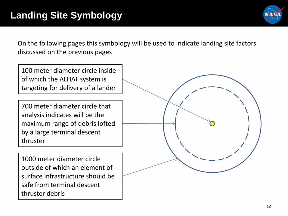
Landing Site Symbology
On the following pages this symbology will be used to indicate landing site factors discussed on the previous pages
100 meter diameter circle inside of which the ALHAT system is targeting for delivery of a lander
700 meter diameter circle that analysis indicates will be the maximum range of debris lofted by a large terminal descent thruster
1000 meter diameter circle outside of which an element of surface infrastructure should be safe from terminal descent thruster debris
12
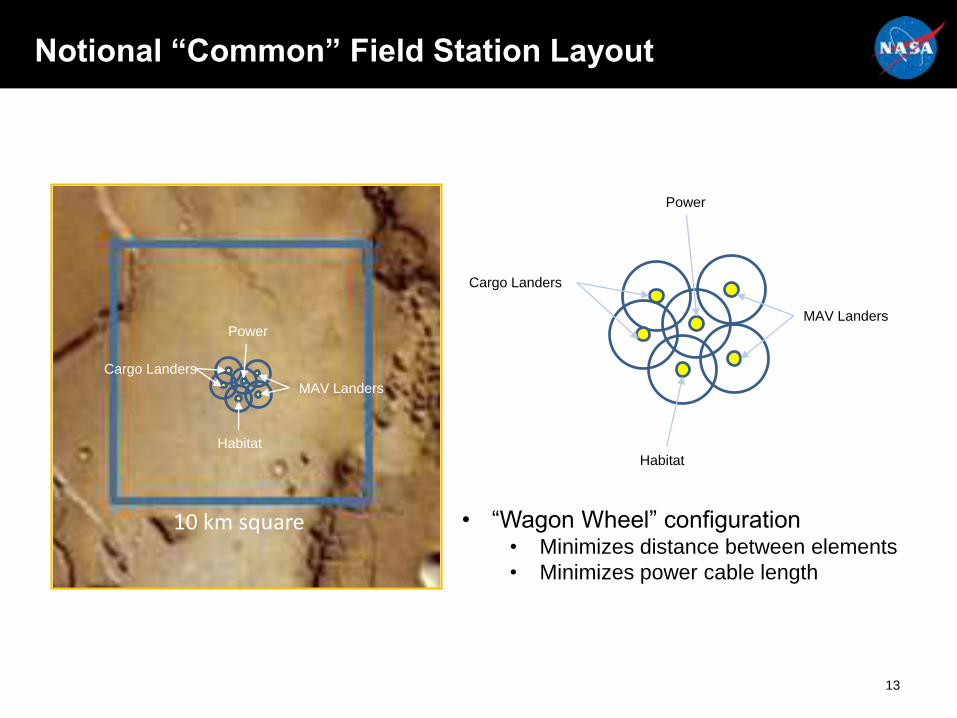
Cargo Landers
MAV Landers
Power
Habitat
10 km square
Cargo Landers
MAV Landers
Power
Habitat
Notional “Common” Field Station Layout
• “Wagon Wheel” configuration• Minimizes distance between elements
• Minimizes power cable length
13
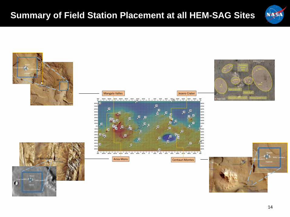
Summary of Field Station Placement at all HEM-SAG Sites
14
10 km square
Cargo LandersMAV Landers
Power
Habitat
10 km square
Cargo LandersMAV Landers
Power
Habitat
Cargo LandersMAV Landers
Power
Habitat
10 km square
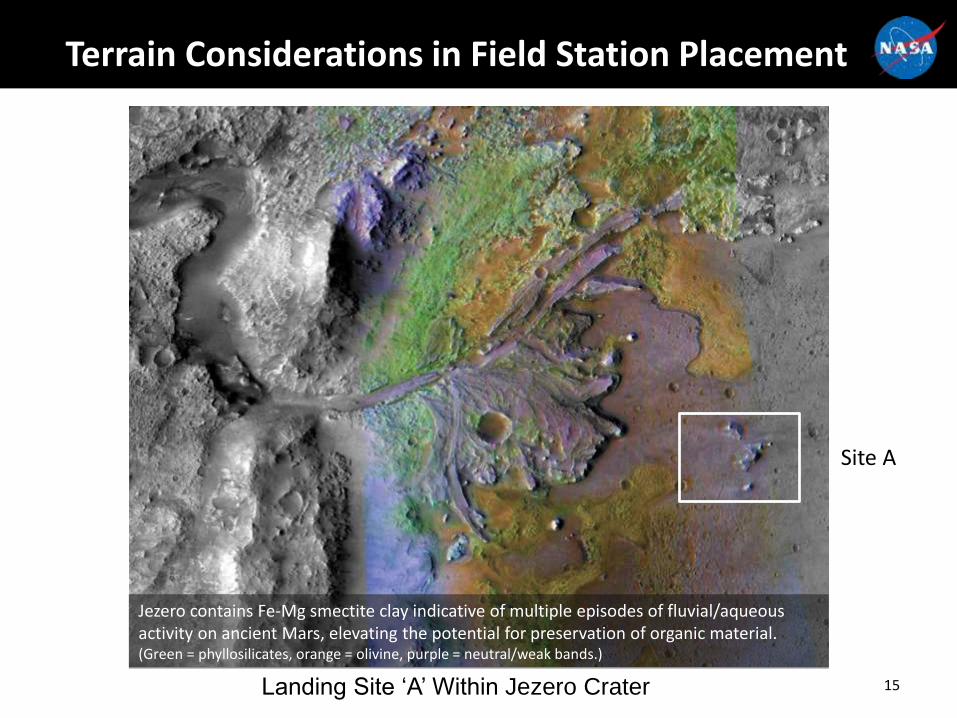
Site A
Jezero contains Fe-Mg smectite clay indicative of multiple episodes of fluvial/aqueous activity on ancient Mars, elevating the potential for preservation of organic material.(Green = phyllosilicates, orange = olivine, purple = neutral/weak bands.)
Terrain Considerations in Field Station Placement
15Landing Site ‘A’ Within Jezero Crater
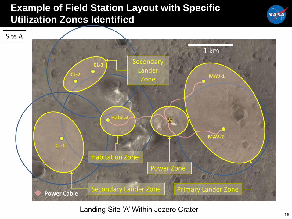
Site A
1 km
CL-2 MAV-1
CL-1
Habitat
MAV-2
CL-3
Power Cable
Power Zone
Primary Lander ZoneSecondary Lander Zone
Secondary Lander Zone
Habitation Zone
Example of Field Station Layout with Specific
Utilization Zones Identified
16Landing Site ‘A’ Within Jezero Crater
Summary
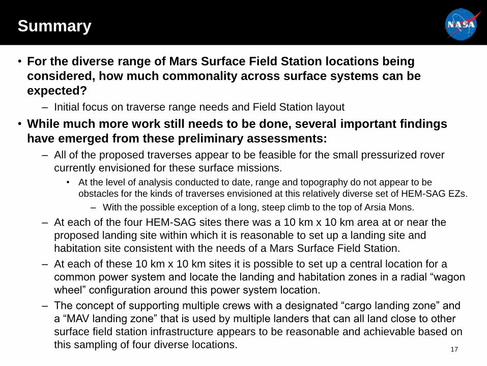
• For the diverse range of Mars Surface Field Station locations being
considered, how much commonality across surface systems can be
expected?
– Initial focus on traverse range needs and Field Station layout
• While much more work still needs to be done, several important findings
have emerged from these preliminary assessments:
– All of the proposed traverses appear to be feasible for the small pressurized rover
currently envisioned for these surface missions.
• At the level of analysis conducted to date, range and topography do not appear to be
obstacles for the kinds of traverses envisioned at this relatively diverse set of HEM-SAG EZs.
– With the possible exception of a long, steep climb to the top of Arsia Mons.
– At each of the four HEM-SAG sites there was a 10 km x 10 km area at or near the
proposed landing site within which it is reasonable to set up a landing site and
habitation site consistent with the needs of a Mars Surface Field Station.
– At each of these 10 km x 10 km sites it is possible to set up a central location for a
common power system and locate the landing and habitation zones in a radial “wagon
wheel” configuration around this power system location.
– The concept of supporting multiple crews with a designated “cargo landing zone” and
a “MAV landing zone” that is used by multiple landers that can all land close to other
surface field station infrastructure appears to be reasonable and achievable based on
this sampling of four diverse locations.17

Backup
18
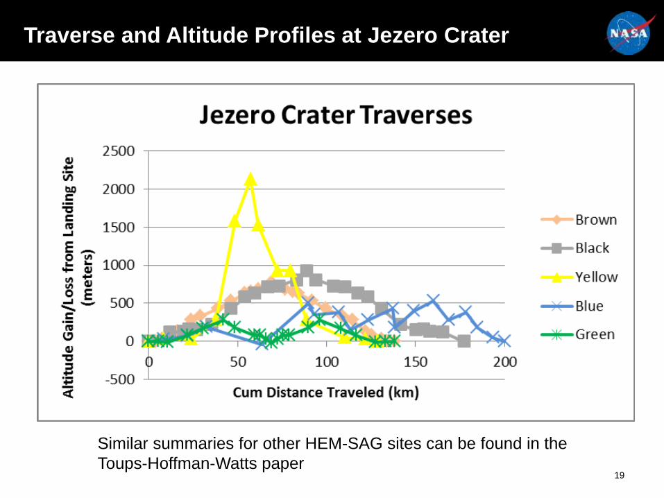
Traverse and Altitude Profiles at Jezero Crater
Similar summaries for other HEM-SAG sites can be found in the
Toups-Hoffman-Watts paper19
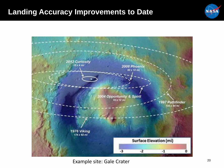
Landing Accuracy Improvements to Date
Example site: Gale Crater 20

1 km
Site A
Site B
Site C
MSL FinalLanding Ellipse
Comparison of MSL landing accuracy capability with ALHAT target capability
Example site: Jezero Crater21
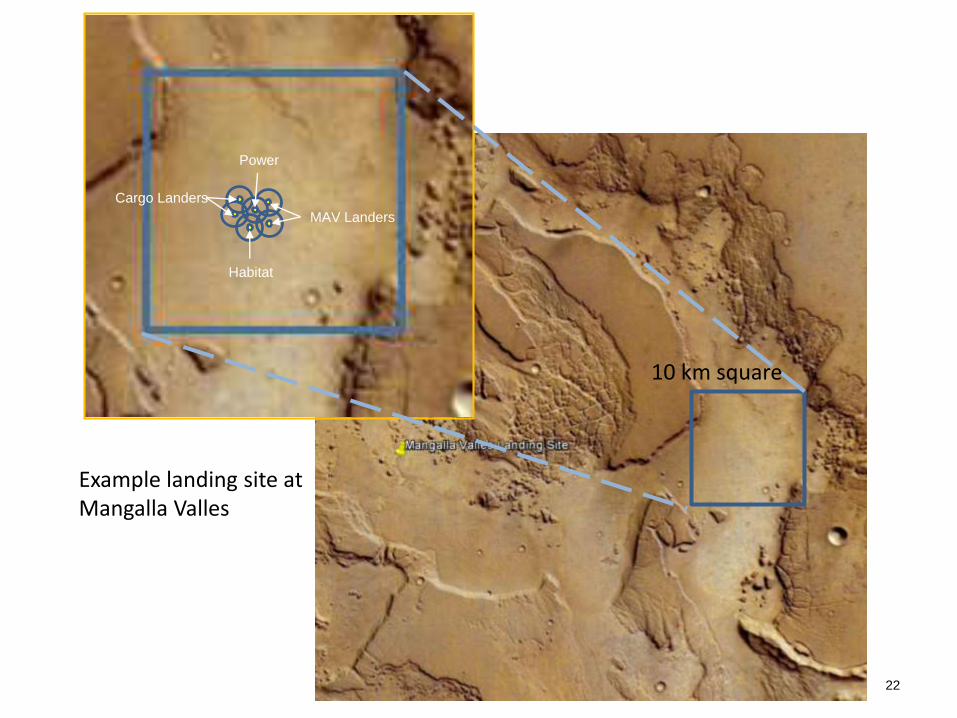
10 km square
Cargo Landers
MAV Landers
Power
Habitat
Example landing site atMangalla Valles
22
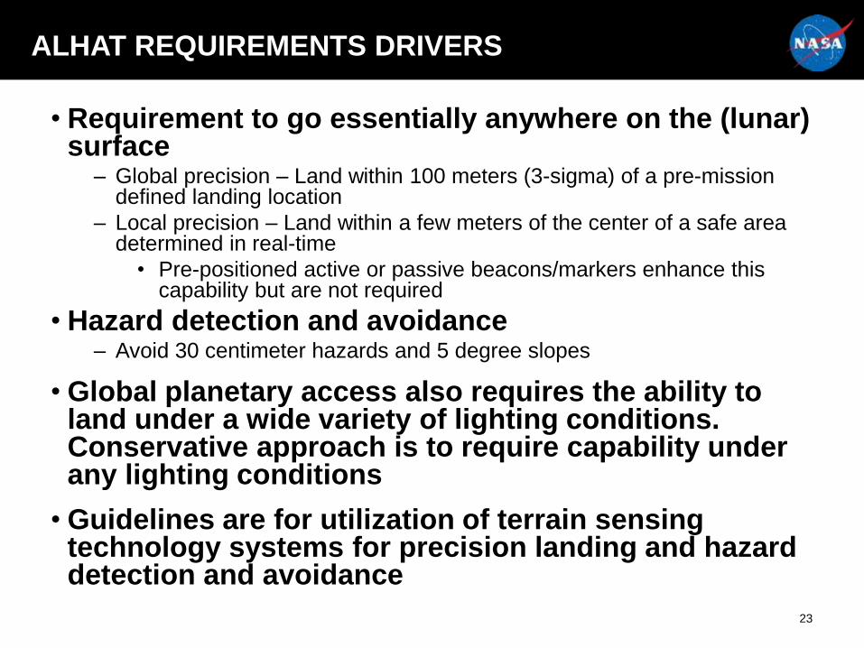
ALHAT REQUIREMENTS DRIVERS
• Requirement to go essentially anywhere on the (lunar) surface
– Global precision – Land within 100 meters (3-sigma) of a pre-mission defined landing location
– Local precision – Land within a few meters of the center of a safe area determined in real-time
• Pre-positioned active or passive beacons/markers enhance this capability but are not required
• Hazard detection and avoidance– Avoid 30 centimeter hazards and 5 degree slopes
• Global planetary access also requires the ability to land under a wide variety of lighting conditions. Conservative approach is to require capability under any lighting conditions
• Guidelines are for utilization of terrain sensing technology systems for precision landing and hazard detection and avoidance
23
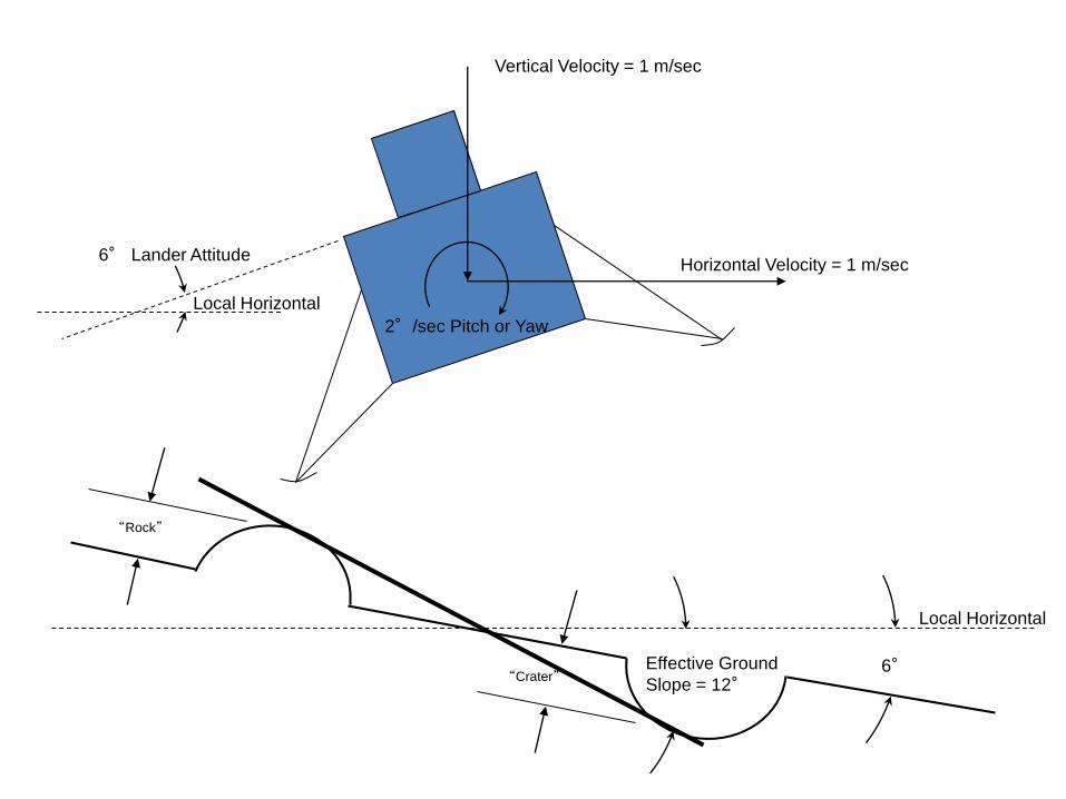
“Rock”
Local Horizontal
6°
Local Horizontal
6° Lander Attitude
Vertical Velocity = 1 m/sec
Horizontal Velocity = 1 m/sec
“Crater”
2°/sec Pitch or Yaw
Effective Ground
Slope = 12°
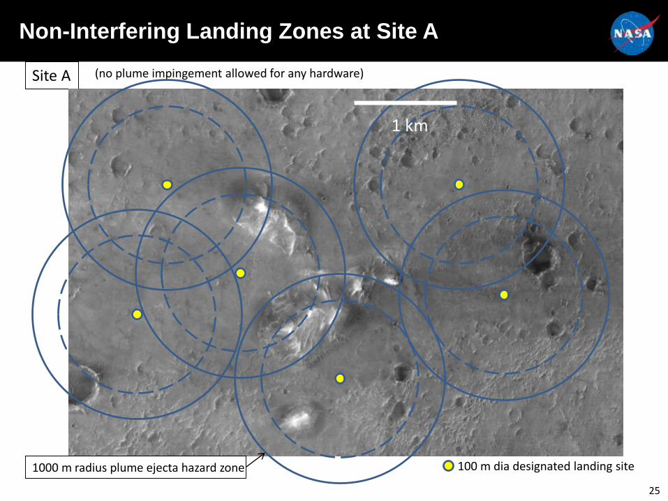
Site A (no plume impingement allowed for any hardware)
100 m dia designated landing site1000 m radius plume ejecta hazard zone
1 km
Non-Interfering Landing Zones at Site A
25
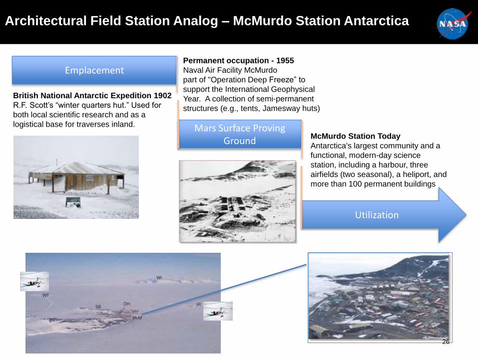
Architectural Field Station Analog – McMurdo Station Antarctica
Mars Surface Proving Ground
Utilization
Emplacement
British National Antarctic Expedition 1902
R.F. Scott’s “winter quarters hut.” Used for
both local scientific research and as a
logistical base for traverses inland.
Permanent occupation - 1955
Naval Air Facility McMurdo
part of "Operation Deep Freeze” to
support the International Geophysical
Year. A collection of semi-permanent
structures (e.g., tents, Jamesway huts)
McMurdo Station Today
Antarctica's largest community and a
functional, modern-day science
station, including a harbour, three
airfields (two seasonal), a heliport, and
more than 100 permanent buildings
26
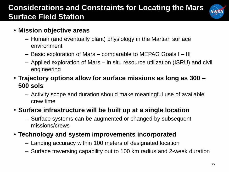
Considerations and Constraints for Locating the Mars
Surface Field Station
• Mission objective areas
– Human (and eventually plant) physiology in the Martian surface
environment
– Basic exploration of Mars – comparable to MEPAG Goals I – III
– Applied exploration of Mars – in situ resource utilization (ISRU) and civil
engineering
• Trajectory options allow for surface missions as long as 300 –
500 sols
– Activity scope and duration should make meaningful use of available
crew time
• Surface infrastructure will be built up at a single location
– Surface systems can be augmented or changed by subsequent
missions/crews
• Technology and system improvements incorporated
– Landing accuracy within 100 meters of designated location
– Surface traversing capability out to 100 km radius and 2-week duration
27
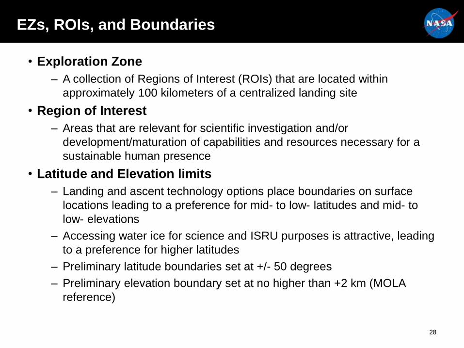
EZs, ROIs, and Boundaries
• Exploration Zone
– A collection of Regions of Interest (ROIs) that are located within
approximately 100 kilometers of a centralized landing site
• Region of Interest
– Areas that are relevant for scientific investigation and/or
development/maturation of capabilities and resources necessary for a
sustainable human presence
• Latitude and Elevation limits
– Landing and ascent technology options place boundaries on surface
locations leading to a preference for mid- to low- latitudes and mid- to
low- elevations
– Accessing water ice for science and ISRU purposes is attractive, leading
to a preference for higher latitudes
– Preliminary latitude boundaries set at +/- 50 degrees
– Preliminary elevation boundary set at no higher than +2 km (MOLA
reference)
28
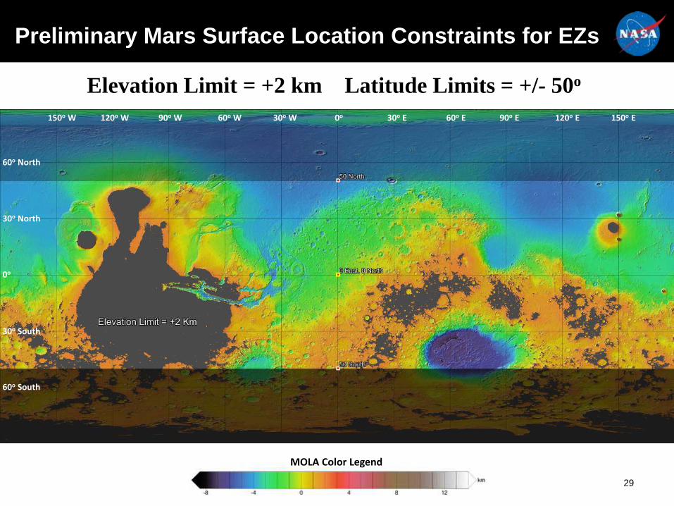
Elevation Limit = +2 km Latitude Limits = +/- 50o
150o W 120o W 90o W 60o W 30o W 0o 30o E 60o E 90o E 120o E 150o E
MOLA Color Legend
30o North
60o North
0o
60o South
30o South
Preliminary Mars Surface Location Constraints for EZs
29

Proposed Exploration Zones
30
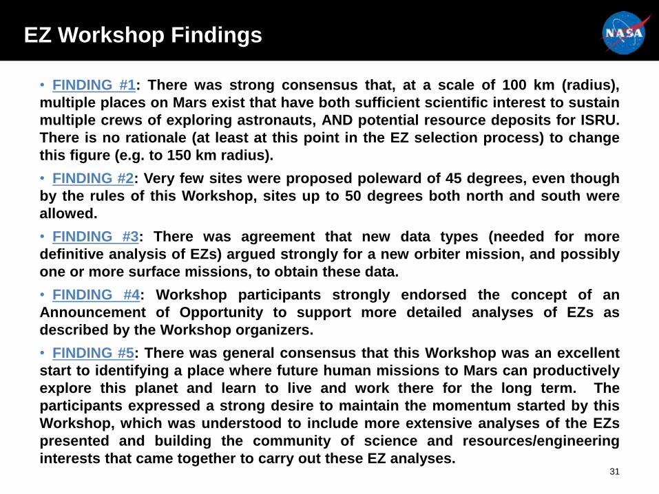
EZ Workshop Findings
• FINDING #1: There was strong consensus that, at a scale of 100 km (radius),
multiple places on Mars exist that have both sufficient scientific interest to sustain
multiple crews of exploring astronauts, AND potential resource deposits for ISRU.
There is no rationale (at least at this point in the EZ selection process) to change
this figure (e.g. to 150 km radius).
• FINDING #2: Very few sites were proposed poleward of 45 degrees, even though
by the rules of this Workshop, sites up to 50 degrees both north and south were
allowed.
• FINDING #3: There was agreement that new data types (needed for more
definitive analysis of EZs) argued strongly for a new orbiter mission, and possibly
one or more surface missions, to obtain these data.
• FINDING #4: Workshop participants strongly endorsed the concept of an
Announcement of Opportunity to support more detailed analyses of EZs as
described by the Workshop organizers.
• FINDING #5: There was general consensus that this Workshop was an excellent
start to identifying a place where future human missions to Mars can productively
explore this planet and learn to live and work there for the long term. The
participants expressed a strong desire to maintain the momentum started by this
Workshop, which was understood to include more extensive analyses of the EZs
presented and building the community of science and resources/engineering
interests that came together to carry out these EZ analyses.31