Embed Size (px)
Citation preview
1
omniran-16-0025-03-CF00
NRM for NMS and Network VirtualizationDate: 2016-05-25
Authors: Name Affiliation Phone Email
Max Riegel Nokia +491732938240 [email protected]
Notice:This document does not represent the agreed view of the OmniRAN TG It represents only the views of the participants listed in the ‘Authors:’ field above. It is offered as a basis for discussion. It is not binding on the contributor, who reserve the right to add, amend or withdraw material contained herein.
Copyright policy:The contributor is familiar with the IEEE-SA Copyright Policy <http://standards.ieee.org/IPR/copyrightpolicy.html>.
Patent policy: The contributor is familiar with the IEEE-SA Patent Policy and Procedures:<http://standards.ieee.org/guides/bylaws/sect6-7.html#6> and <http://standards.ieee.org/guides/opman/sect6.html#6.3>.
AbstractThis document proposes revised text and figures for the chapter 6.2ff to cover agreed extensions for Network Management and Network Slicing.
The revision 2 adds further content on operational roles and on operational and functional entities involved in the instantiation of virtualized access networks.
Revision 3 amends fig 6-5 for NMS and adds placeholder for upcoming NFV amendment.
2
omniran-16-0025-03-CF00
6 Network Reference Model ......................................................................................................36.1 Basic architectural concepts and terms (informative) ...............................................................36.2 Overview of IEEE 802 Network Reference Model .....................................................................3
6.2.1 Schematic Overview ................................................................................................................36.2.2 Reference Point Types .............................................................................................................4
6.3 Basic Network Reference Model ..................................................................................................56.3.1 Functional entities ....................................................................................................................6
6.3.1.1 Terminal ..............................................................................................................................................66.3.1.2 Access Network ..................................................................................................................................66.3.1.3 Access Router .....................................................................................................................................66.3.1.4 Subscription Service ...........................................................................................................................66.3.1.5 Network Management Service ............................................................................................................6
6.3.2 Reference Points ......................................................................................................................76.4 NRM with Coordination and Information Service ....................................................................8
6.4.1 Additional functional entities ...................................................................................................86.4.1.1 Coordination and Information Service ................................................................................................8
6.4.2 Additional reference points ......................................................................................................86.5 Comprehensive Network Reference Model ................................................................................8
6.5.1 Additional functional entities ...................................................................................................96.5.1.1 Node of Attachment ............................................................................................................................96.5.1.2 Backhaul .............................................................................................................................................9
6.5.2 Additional reference points ......................................................................................................96.5.3 Representation with abbreviations .........................................................................................10
6.6 Operational roles .........................................................................................................................106.7 Network Virtualization ...............................................................................................................11
6.7.1 Basic assumptions ..................................................................................................................116.7.2 Instantiation and lifecycle of virtualized access network ......................................................136.7.3 Multi-instance Design and Issues ..........................................................................................13
6.8 Network Function Virtualization ...............................................................................................146.8.1 Basic concepts of NFV ..........................................................................................................146.8.2 VNFs of the IEEE 802 access network ..................................................................................156.8.3 NFV deployment considerations for IEEE 802 access network ............................................15
6.9 Identifiers of functional entities .................................................................................................156.10 Deployment Scenarios .............................................................................................................15
6.10.1 Residential network (Wi-Fi router) ........................................................................................156.10.2 Integrated service provider .....................................................................................................156.10.3 Wholesale access network .....................................................................................................15
6 Network Reference Model ......................................................................................................36.1 Basic architectural concepts and terms (informative) ...............................................................36.2 Overview of IEEE 802 Network Reference Model .....................................................................3
6.2.1 Schematic Overview ................................................................................................................36.2.2 Reference Point Types .............................................................................................................4
6.3 Basic Network Reference Model ..................................................................................................56.3.1 Functional entities ....................................................................................................................6
6.3.1.1 Terminal ..............................................................................................................................................66.3.1.2 Access Network ..................................................................................................................................66.3.1.3 Access Router .....................................................................................................................................66.3.1.4 Subscription Service ...........................................................................................................................66.3.1.5 Network Management Service ............................................................................................................6
6.3.2 Reference Points ......................................................................................................................76.4 NRM with Coordination and Information Service ....................................................................8
3
omniran-16-0025-03-CF00
6.4.1 Additional functional entities ...................................................................................................86.4.1.1 Coordination and Information Service ................................................................................................8
6.4.2 Additional reference points ......................................................................................................86.5 Comprehensive Network Reference Model ................................................................................8
6.5.1 Additional functional entities ...................................................................................................96.5.1.1 Node of Attachment ............................................................................................................................96.5.1.2 Backhaul .............................................................................................................................................9
6.5.2 Additional reference points ......................................................................................................96.5.3 Representation with abbreviations .........................................................................................10
6.6 Network Virtualization ...............................................................................................................106.6.1 Basic assumptions ..................................................................................................................106.6.2 Multi-instance Design and Issues ..........................................................................................12
6.7 Identifiers of functional entities .................................................................................................136.8 Deployment Scenarios .................................................................................................................13
6.8.1 Residential network (Wi-Fi router) ........................................................................................136.8.2 Integrated service provider .....................................................................................................136.8.3 Wholesale access network .....................................................................................................13
4
omniran-16-0025-03-CF00
6 Network Reference Model
6.1 Basic architectural concepts and terms (informative)>>> No modification to this section <<<
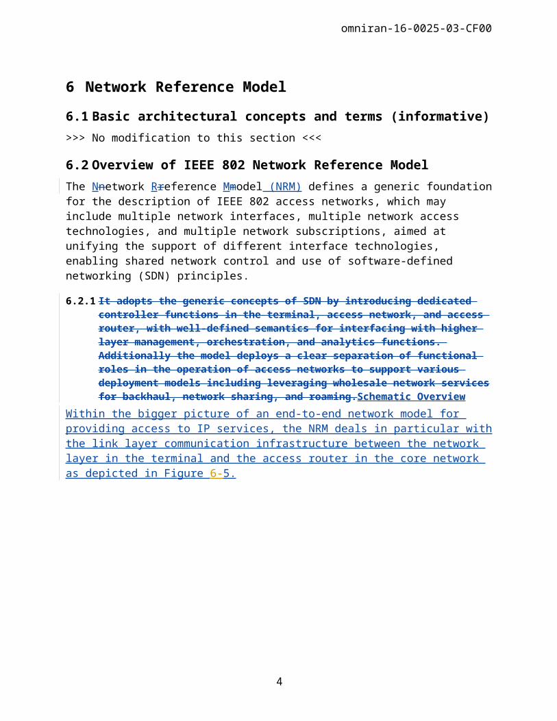
6.2 Overview of IEEE 802 Network Reference ModelThe Nnetwork Rreference Mmodel (NRM) defines a generic foundation for the description of IEEE 802 access networks, which may include multiple network interfaces, multiple network access technologies, and multiple network subscriptions, aimed at unifying the support of different interface technologies, enabling shared network control and use of software-defined networking (SDN) principles.
[6.2.1] It adopts the generic concepts of SDN by introducing dedicated controller functions in the terminal, access network, and access router, with well-defined semantics for interfacing with higher layer management, orchestration, and analytics functions. Additionally the model deploys a clear separation of functional roles in the operation of access networks to support various deployment models including leveraging wholesale network services for backhaul, network sharing, and roaming.Schematic Overview
Within the bigger picture of an end-to-end network model for providing access to IP services, the NRM deals in particular with the link layer communication infrastructure between the network layer in the terminal and the access router in the core network as depicted in Figure 6-5.
5
omniran-16-0025-03-CF00
6
omniran-16-0025-03-CF00
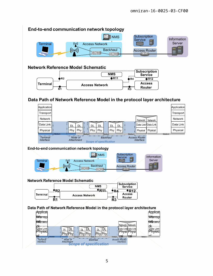
Figure 6.5—NRM overview
Within the bigger picture of an end-to-end network model for providing access to IP services, the NRM deals in particular with the link layer communication infrastructure between the network layer in the terminal and the access router in the core network as depicted in Figure 5.
At the top of the figure the end-to-end communication network topology shows the main elements of providing network services to terminals. The terminal is connected by wired or wireless links to an node of attachment access point or basestation of the access network. Node of attachment is used as a generic term for either access point or basestation. To serve a wider coverage area, a number of nodes of attachmentaccess points or basestations can be deployed within an access network, which are interconnected with each other. Traffic in the access network is aggregated and forwarded to the access router throughby the backhaul. The access router terminates the layer 2 link fromto the terminal and forwards user traffic towards information servers according to IP addresses carried in the payload of the layer 2 data frames. A subscription service provides is required authentication fore the terminals requesting access to the network and deliversto provide authorization to the access network to provideconfigure connectivity to services for particularthe terminals.
The figure in the middle shows at first glance, that the NRM for an IEEE 802 access network consists of the terminal, the access network, the network management service of the access network, the access router, and the subscription service. The subscription service provides authentication, authorization, and accounting, as well as policy functions specific for particular user accounts and terminals. Beyond the access router and out of scope of this specification is the infrastructure providing IP-based information services to the terminals.
As indicated by the figure at the bottom showing the data path scope of the NRM in the protocol layer architecture, In IEEE 802 access networks, the user data is forwarded the user data according to the destination MAC address in the Ethernet frames, which represent the endpoints of the link in the access network. Avoiding a functional separation of the user plane from the transport plane, the specification provides an integrated model for backhaul connectivity combined with subscriber-specific connectivity functions as facilitated by modern IEEE 802.1 bridging technologies.
The bottom of the figure shows aAt first glance, that the NRMnetwork model for an IEEE 802 access network consists of the terminal, the access network (which is made up of the node of attachment and the backhaul), the access router, and the subscription service. The subscription service provides authentication, authorization, and accounting, as well as policy functions specific for particular user accounts and terminals. Beyond the access router and out of scope of this specification is the infrastructure providing IP-based information services to the terminals.
[6.2.2] Reference Point TypesCommunication interfaces between the entities are denoted by R1 for the interface between the terminal and the node of attachment, by R2 for the authentication procedures between terminal and subscription service, by R3 for the interface between access network and the access router, and by R4 for the authentication, authorization, accounting, and policy functions between the access network and the subscription service.
There are two kinds of reference points used in the Network Reference Model.

7
omniran-16-0025-03-CF00
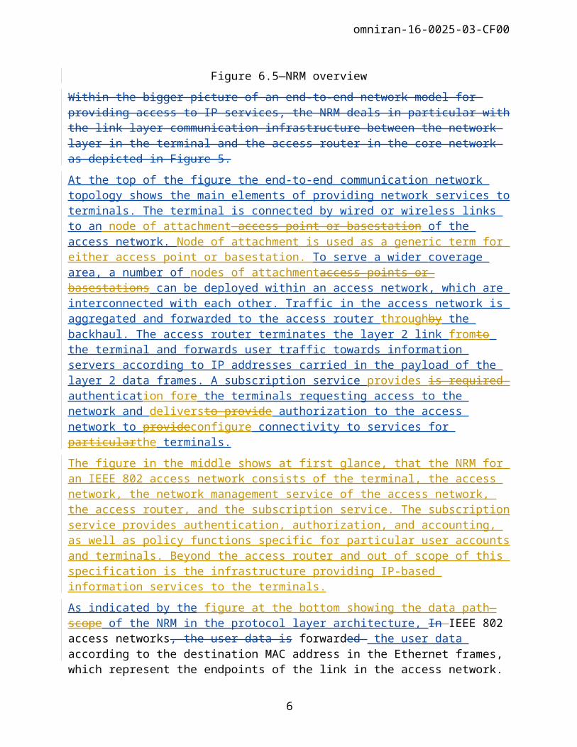
Figure 6.6: Reference Point types
According to the IEEE 802 basic architectural concepts and terms summarized in the previous section 6.1, information out of an IEEE 802 communication element is exchanged with another entity either over the port through the communication medium or as management information as payload over an unspecified kind of control protocol.
A control interface conveys IEEE 802 layer management information to another entity and is represented in the NRM by a dotted line. Usually IP based protocols like SNMP or RADIUS will be used for the transport of the layer management information.
A port carries the user data and can convey as well IEEE 802 control protocol information to the peer entity encoded in layer 2 frames. It is represented in the NRM by a solid line.
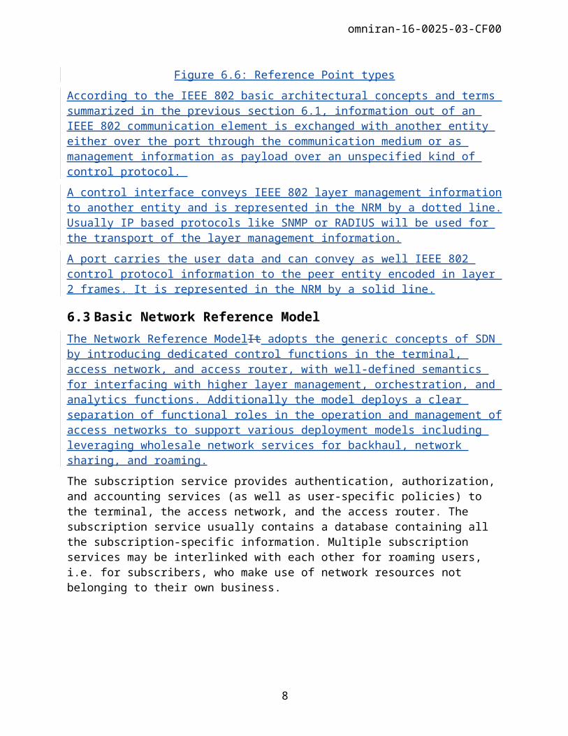
6.3 Basic Network Reference ModelThe Network Reference ModelIt adopts the generic concepts of SDN by introducing dedicated controller functions in the terminal, access network, and access router, with well-defined semantics for interfacing with higher layer management, orchestration, and analytics functions. Additionally the model deploys a clear separation of functional roles in the operation and management of access networks to support various deployment models including leveraging wholesale network services for backhaul, network sharing, and roaming.
The subscription service provides authentication, authorization, and accounting services (as well as user-specific policies) to the terminal, the access network, and the access router. The subscription service usually contains a database containing all the subscription-specific information. Multiple subscription services may be interlinked with each other for roaming users, i.e. for subscribers, who make use of network resources not belonging to their own business.
8
omniran-16-0025-03-CF00
Figure 6.67—Basic Network Reference Model
Figure 6 presents the Basic Network Reference Model. Solid lines represent the interfaces representing the data plane and connecting ports, while dotted lines show the flow of control and management information. This NRM is the foundation for further refinements and includes the basic differentiation between functional entities and the reference points for their communication. The Basic NRM is composed of four five main elements: i) the Terminal (TE), ii) the Access Network (AN), iii) the Access Router (AR), and iv) the Subscription Service (SS), and v) the Network Management Service (NMS).
The NMS comprises the services for operation, administration and maintenance of the access network. As depicted in Figure 67, the TE, AN, and AR each contain a control entity, which is denoted by Controller (Ctrl). Each of the three elements has its own specific controller.
Note - The access router is a logical functional unit with various options for implementation

9
omniran-16-0025-03-CF00
depending of the design and architecture of the access router controller.
Note - Please note that currently no assumptions are made regarding the ownership of the functional units. Access Network, Subscription Service, and Access Router may belong to the same operator, or may be distributed among three distinct operators.
[6.3.1] Functional entities
6.3.1.1 TerminalThe terminal is a mobile device that seeks connectivity to a communication infrastructure to get access to communication services. The terminal contains a terminal interface providing the physical port for network connectivity, and eventually deploys a terminal controller for dealing with particular parameters and configurations conveyed by the control and management interface.
[6.3.1.2] Access NnetworkThe access network consists of the nodes of attachment providing the physical ports toward the terminals and the backhaul for connecting the nodes of attachment toward the access router. The access network may deploy a dedicated access network controller for configuration and management of the elements inside the access network as well as exchange of control and management information with both the terminal and access router. As a central controller, ANC acts as an element manager providing management on network elements that connect to it, namely access network elements, terminal, and access router.
[6.3.1.3] Access RrouterThe access router terminates the layer 2 connectivity to the terminal by realizing the anchor for network layer communication toward the terminal side. The access router contains an access router interface that establishes the physical port of the connectivity toward the access network, and may eventually include a dedicated access router controller that handles and exchanges layer management information and configurations. With a dedicated access router controller, the access router becomes a logical functional unit with various implementation options for the controller and the packet forwarding engine attached to the access router interface.
[6.3.1.4] Subscription SserviceThe subscription service provides authentication, authorization, and accounting services as well as user-specific policies to the terminal, the access network, and the access router. The subscription service usually contains a database containing all the subscription-specific information. Multiple subscription services may be interlinked with each other for roaming users, i.e. for subscribers, who make use of resources of networks not belonging to their own business.
6.3.1.2 Network Management ServiceThe Network Management Service consists of the functions, which allows the operator of an access network to configure the access network infrastructure, manage functions related to the interaction between multiple network elements, monitor the usage and correct operation of the access network and to perform tests for detection, determination and correction of faults. Network Elements (NEs) are those entities in the NRM, which forward user data. A NMS exists in every access network, however the kind of implementation and sophistication widely varies and depends of the size of the network and particular operational requirements.

10
omniran-16-0025-03-CF00
6.3.2 Reference PointsR1 represents the reference point for the PHY and MAC layer functions establishing the physical port, as specified in numerous IEEE 802 standards, between terminal and access network.
R2 represents a logical control interface between terminal and the subscription service, e.g., for authentication. Information elements of the logical interface are tunneled over R1 and R4 between terminal and subscription service.
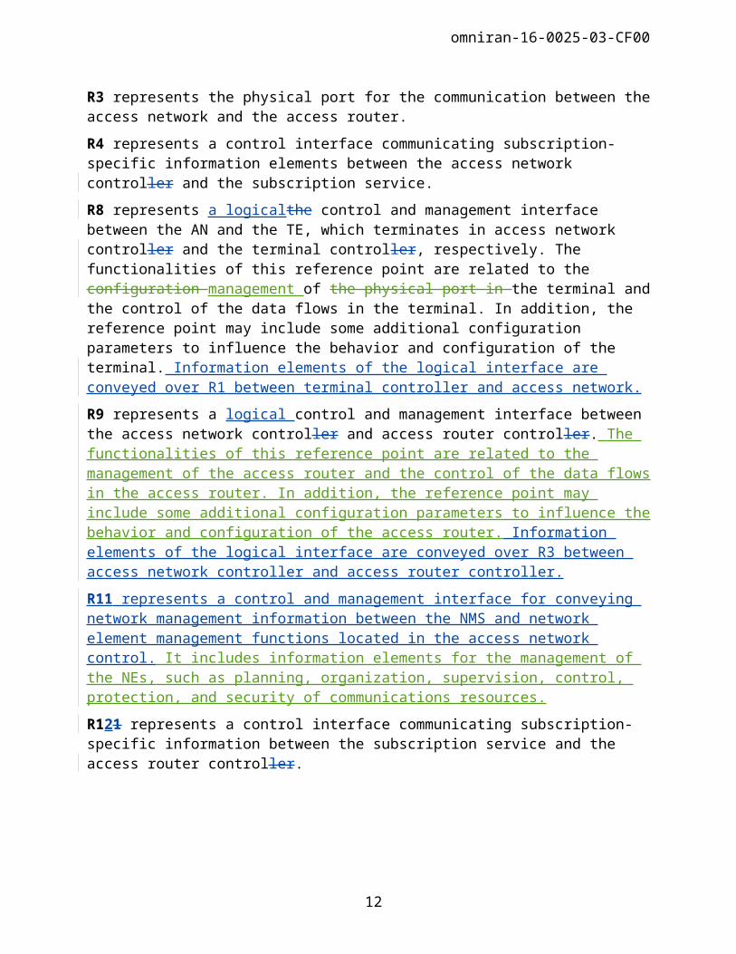
R3 represents the physical port for the communication between the access network and the access router.
R4 represents a control interface communicating subscription-specific information elements between the access network controller and the subscription service.
R8 represents a logicalthe control and management interface between the AN and the TE, which terminates in access network controller and the terminal controller, respectively. The functionalities of this reference point are related to the configuration management of the physical port in the terminal and the control of the data flows in the terminal. In addition, the reference point may include some additional configuration parameters to influence the behavior and configuration of the terminal. Information elements of the logical interface are conveyed over R1 between terminal controller and access network.
R9 represents a logical control and management interface between the access network controller and access router controller. The functionalities of this reference point are related to the management of the access router and the control of the data flows in the access router. In addition, the reference point may include some additional configuration parameters to influence the behavior and configuration of the access router. Information elements of the logical interface are conveyed over R3 between access network controller and access router controller.
R11 represents a control and management interface for conveying network management information between the NMS and network element management functions located in the access network control. It includes information elements for the management of the NEs, such as planning, organization, supervision, control, protection, and security of communications resources.
R121 represents a control interface communicating subscription-specific information between the subscription service and the access router controller.
11
omniran-16-0025-03-CF00
[6.4] NRMetwork Reference Model including with Coordination and Information Service
Figure 6.78—NRM with Coordination and Information Service
Some deployments include a Coordination and Information Service (CIS) to provide advanced services such as spectrum management, coexistence, and information services for mobility. The reference model includes the option for CIS by providing a reference point to communicate the information between CIS and the AN Ctrl, possibly propagated further by the AN Ctrl to the TE Ctrl and AR Ctrl over the R8 and R9 interfaces, respectively.
6.3.3[6.4.1] Additional functional entities
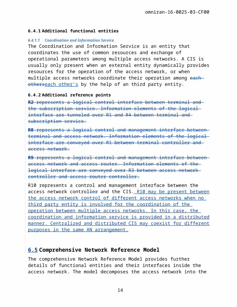
6.3.3.1[6.4.1.1] Coordination and Information ServiceThe Coordination and Information Service is an entity that coordinates the use of common
12
omniran-16-0025-03-CF00
resources and exchange of operational parameters among multiple access networks. A CIS is usually only present when an external entity dynamically provides resources for the operation of the access network, or when multiple access networks coordinate their operation among each otherseach other’s by the help of an third party entity.
6.3.4[6.4.2] Additional reference pointsR2 represents a logical control interface between terminal and the subscription service. Information elements of the logical interface are tunneled over R1 and R4 between terminal and subscription service.
R8 represents a logical control and management interface between terminal and access network. Information elements of the logical interface are conveyed over R1 between terminal controller and access network.
R9 represents a logical control and management interface between access network and access router. Information elements of the logical interface are conveyed over R3 between access network controller and access router controller.
R10 represents a control and management interface between the access network controller and the CIS. R10 may be present between the access network control of different access networks when no third party entity is involved for the coordination of the operation between multiple access networks. In this case, the coordination and information service is provided in a distributed manner. Centralized and distributed CIS may coexist for different purposes in the same AN arrangement.
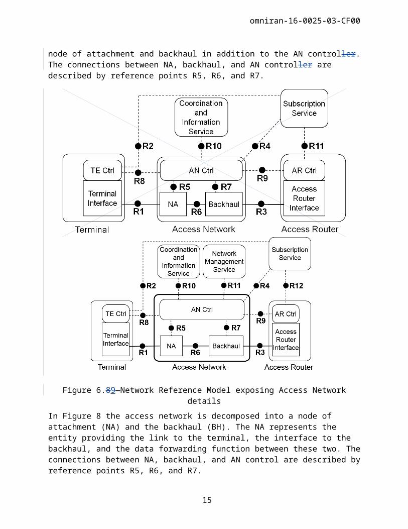
6.4 Comprehensive Network Reference ModelThe comprehensive Network Reference Model provides further details of functional entities and their interfaces inside the access network. The model decomposes the access network into the node of attachment and backhaul in addition to the AN controller. The connections between NA, backhaul, and AN controller are described by reference points R5, R6, and R7.

13
omniran-16-0025-03-CF00
Figure 6.89—Network Reference Model exposing Access Network details
In Figure 8 the access network is decomposed into a node of attachment (NA) and the backhaul (BH). The NA represents the entity providing the link to the terminal, the interface to the backhaul, and the data forwarding function between these two. The connections between NA, backhaul, and AN control are described by reference points R5, R6, and R7.
6.4.1[6.4.3] Additional functional entities
6.4.1.1[6.4.3.1] Node of AttachmentThe node of attachment represents the access network entity that provides the physical link to the terminal. It forwards user data to a network side port inside the access network and is connected with the AN controller for configuration and management.
6.4.1.2[6.4.3.2] BackhaulThe backhaul represents the aggregation and forwarding infrastructure inside the access network
14
omniran-16-0025-03-CF00
providing the link between the network side port of the NA and the AR interface.
6.4.2[6.4.4] Additional reference pointsR5 represents a control-only interface for the configuration and operation of the node of attachment. It includes information elements for the configuration of the R6 port toward the backhaul, the R1 port toward the terminal, and the data-forwarding functions inside the node of attachment.
R6 represents a reference point for the physical ports between the node of attachment and the backhaul.
R7 represents an interface used to control and configure the user plane within the backhaul. The backhaul interconnects the NAs with the access router.
R10 may be present between the access network controllers of different access networks when no third party entity is involved for the coordination of the operation between multiple access networks. In this case, the coordination and information service is provided in a distributed manner. Centralized and distributed CIS may coexist for different purposes in the same AN arrangement.
6.4.3 Representation with abbreviationsFor schematic use cases and when less space is available for reproducing the NRM with all terms spelled out, a representation of the NRM with abbreviations can be used.
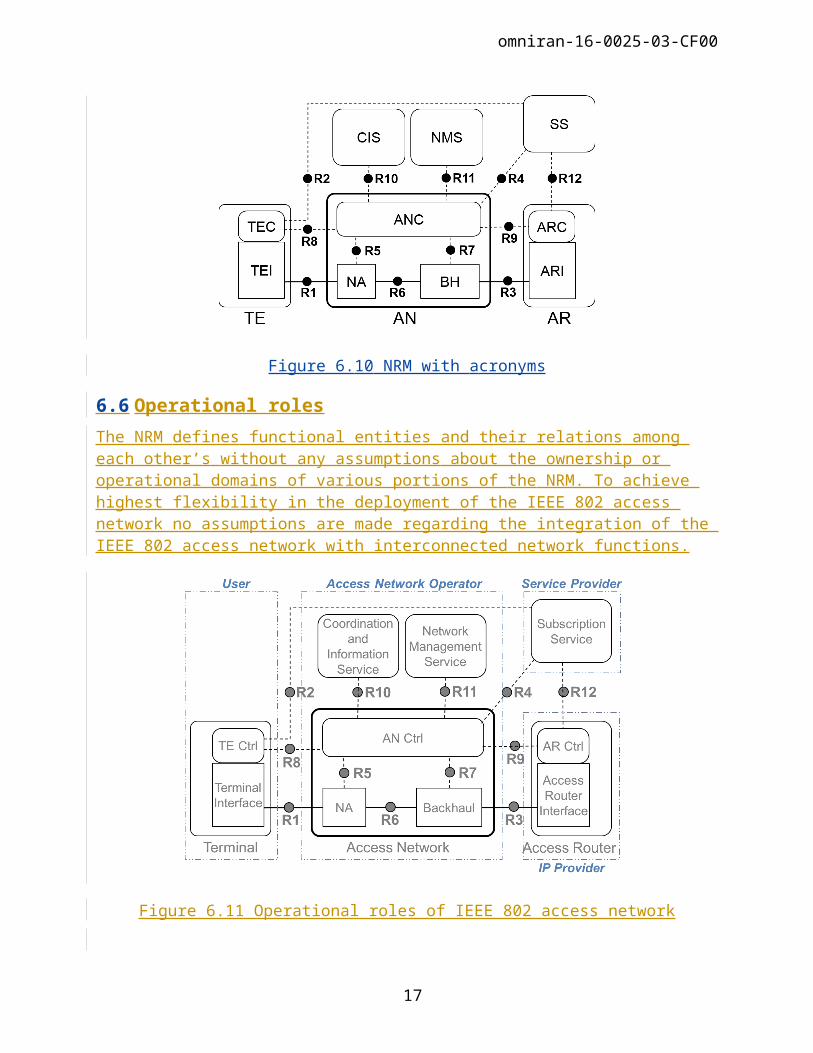
Figure 6.10 NRM with acronyms
6.5 Operational rolesThe NRM defines functional entities and their relations among each other’s without any assumptions about the ownership or operational domains of various portions of the NRM. To achieve highest flexibility in the deployment of the IEEE 802 access network no assumptions are made regarding the integration of the IEEE 802 access network with interconnected network functions.
15
omniran-16-0025-03-CF00
Figure 6.11 Operational roles of IEEE 802 access network
In its most generic realization the operation of the IEEE 802 access network involves the following operational roles or operational domains:
User represents the organization or individual being in charge of the terminal. Access Network Operator represents the organization operating the access network
together with the related network management service, the coordination and information service as well as further BSS/OSS functions dedicated to the access network.
Service Provider represents the organization owning and operating the subscription service and related OSS/BSS functions.
IP Provider represents the organization owning and operating the access router, related OSS/BSS functions and further networking functions for the realization of IP services.
Note - Some deployment scenarios may not expose such fine grain operational separation but may combine several operational roles into a single operation with partial or full integration of the BSS and OSS. Access Network, Subscription Service, and Access Router may belong to the same operator, or may be distributed among distinct operators. A frequent scenario is e.g. the integration of a Service Provider with an IP Provider, commonly called ISP. Such integration is considered as a particular implementation model of the NRM and is not further detailed in this specification.
6.6 Network VirtualizationNetwork virtualization, often also called network slicing, allows for cost-effective installations of multiple dedicated access networks for different applications, for particular security requirements, or for isolated operational domains at the same area. To enable virtualization, network elements are designed the way, that a common hardware can realize multiple logical instances of such network element. However, due to common usage of the same hardware resources, some limitations regarding the configuration of the hardware dependent parameters

16
omniran-16-0025-03-CF00
may exist, e.g. the operation channel of a radio interface has to be the same for all of the virtual interfaces operating on the same device, or the PHY speed of a wired Ethernet interface is the same for all virtual connections going over a common LAN cable.
IEEE 802 technologies support the capabilities to realize multiple virtual instances of network elements under the potential restrictions mentioned above, e.g. IEEE 802.1Q defines the methods to share a common Ethernet infrastructure for the establishment of multiple virtual LANs (VLANs), and IEEE 802.11 describes the implementation of multiple virtual APs each exposing its own SSID and defining its own security environment on a single radio interface.
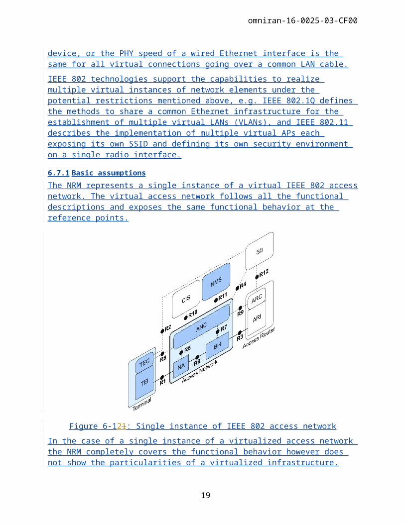
6.6.1 Basic assumptionsThe NRM represents a single instance of a virtual IEEE 802 access network. The virtual access network follows all the functional descriptions and exposes the same functional behavior at the reference points.
Figure 6-121: Single instance of IEEE 802 access network
In the case of a single instance of a virtualized access network the NRM completely covers the functional behavior however does not show the particularities of a virtualized infrastructure.
17
omniran-16-0025-03-CF00
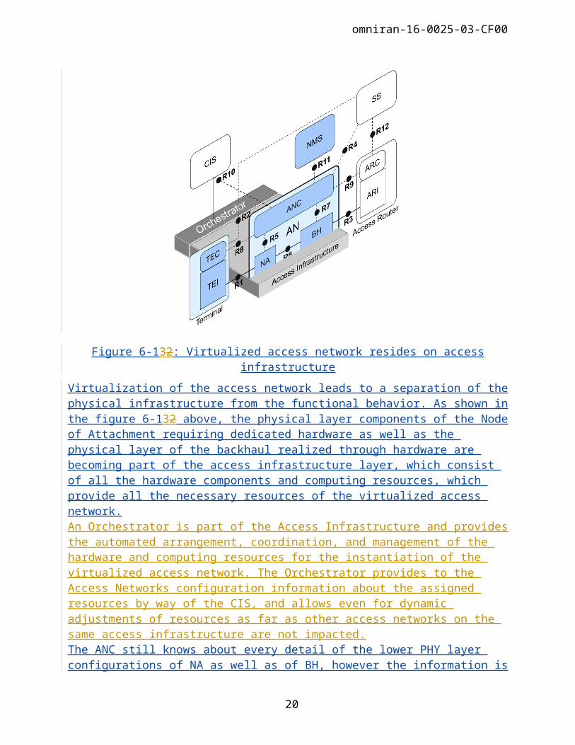
Figure 6-132: Virtualized access network resides on access infrastructure
Virtualization of the access network leads to a separation of the physical infrastructure from the functional behavior. As shown in the figure 6-132 above, the physical layer components of the Node of Attachment requiring dedicated hardware as well as the physical layer of the backhaul realized through hardware are becoming part of the access infrastructure layer, which consist of all the hardware components and computing resources, which provide all the necessary resources of the virtualized access network.An Orchestrator is part of the Access Infrastructure and provides the automated arrangement, coordination, and management of the hardware and computing resources for the instantiation of the virtualized access network. The Orchestrator provides to the Access Networks configuration information about the assigned resources by way of the CIS, and allows even for dynamic adjustments of resources as far as other access networks on the same access infrastructure are not impacted.The ANC still knows about every detail of the lower PHY layer configurations of NA as well as of BH, however the information is provided by the way of CIS and the parameters are mostly ‘read-only’, as the configuration of the access infrastructure predefines the configuration parameters of the lower PHY layer.
6.6.2 Instantiation and lifecycle of virtualized access networkA virtualized infrastructure allows for dynamic creation, modification and tear down of access networks. A new instance of access network is created by the Orchestrator through reservation and assignment of infrastructure resources to that instance. Part of the instantiation is the establishment of the connectivity towards subscription services and access routers.After instantiation the access network initializes its control connections towards subscription services and access routers and gets ready for serving terminals.

18
omniran-16-0025-03-CF00
During operation the access network is able to adjust its resources by sending requests to the Orchestrator. It should be kept in mind, that not all resource requests might be successfully fulfilled in the virtualized environment.Allocated resources can be released during the runtime of the access network, and it is possible to completely remove an access network by first terminating service to terminals, then tearing down the control connections to SSs and ARs, and finally releasing all resources through instructing the Orchestrator to dissolve the access network instance.
6.6.3 Multi-instance Design and IssuesThe full capabilities of network virtualization become visible in the following figure, which depicts 3 different AN instances on a common access infrastructure. All three ANs have an R10 reference point towards the common CIS, which allows for each of the virtualized access network to get access to the lower PHY layer parameters, which are common for all three networks, and to request to the Orchestrator modifications to the networking and computing resource parameters. As far as the requests do not collide with requests fromof the other virtualized ANs, the Orchestrator access infrastructure can dynamically adjust the assignment of resources parameters according to requests.For clarity of the visualization, the R2 reference point and signal flow is not shown in the figure below.
Figure 6-143: Multi-instance virtualization
Each of the three virtualized networks (network slices) fully realize the complete NRM including NMS and own relations with SSs as well as ARs. Each of the slices can have its completely own
19
omniran-16-0025-03-CF00
arrangements, and the virtualized networks are completely independent to each other’s, except the use of the access infrastructure resources, which are shared among the ANs and imply some limitations, as the sum of used resources can’t exceed the total available resources.R10 interfaces of all virtualized access networks to a common CIS, which is tight to the Orchestrator of the access infrastructure, provides access to the infrastructure parameters and allows for dynamic allocation of resources. As the access infrastructure is shared among multiple AN instances, an AN can request to the Orchestrator modifications to the lower PHY layer parameters through the CIS, and it becomes possible, that the resources are dynamically allocated by the ANC depending on load conditions and service requirements.
6.7 Network Function Virtualization>>> this section may be combined with the SDN chapter to a SDN and NFV chapter <<<
Network Function Virtualization addresses the realization of network functions with data path interfaces through common virtualization technologies widely deployed in data centers and in the cloud.
6.7.1 Basic concepts of NFV>>> content t.b.d. <<<
6.7.2 VNFs of the IEEE 802 access network>>> content t.b.d. <<<
6.7.3 NFV deployment considerations for IEEE 802 access network>>> content t.b.d. <<<
6.8[6.5] Identifiers of functional entities>>> content not modified <<<
6.9 Deployment ScenariosThe following section present a variety of deployment scenarios of the IEEE 802 NRM. The listing begins with simple scenarios with only one or a few operational domains involved, and ends with very versatile deployments, where operational responsibilities are widely distributed and a bigger number of operational domains are involved in network operation.
6.9.1 Residential network (Wi-Fi router)In the case of a residential network all the entities of the NRM including terminal belong to the same operational domain. Such deployment allows for a number of simplifications, mainly in the area of network security.
6.9.2 Integrated service providerThe integrated service provider operates all the network functional entities in a single operational domain. It owns the access network as well as the subscription service and the access router. Only customers of the integrated service provider are allowed to access the infrastructure.
20
omniran-16-0025-03-CF00
6.9.3 Wholesale access networkIn the wholesale access network case, the access network operator has contractual agreements with one or more subscription service providers, which either operate their own access routers, or have relationship with some access router operators for providing the access router.The wholesale access network is the most versatile deployment case, which requires that multiple different entities can be handled by each of the reference points.


![IEEE 802.11 and 802.16 Cooperation Within Multi … 802.11 and 802.16 Cooperation Within Multi-Radio Stations 527 upgrades to the MAC of the 802.16 base station in [15]. These updates](https://img.pdfslide.us/doc/110x75/5b0cb85a7f8b9a02508c9b9a/ieee-80211-and-80216-cooperation-within-multi-80211-and-80216-cooperation-within.jpg)