Embed Size (px)
Citation preview
IEEE 802.11 Wireless LANsIEEE 802.11 Wireless LANs
Giuseppe Bianchi, Ilenia Tinnirello
Introduction
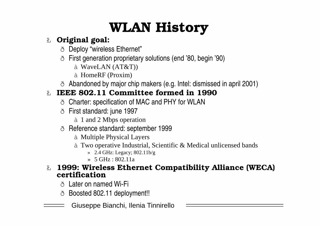
WLAN HistoryWLAN HistoryŁ Original goal:
ð Deploy “wireless Ethernet”ð First generation proprietary solutions (end ’80, begin ’90)
à WaveLAN (AT&T))à HomeRF (Proxim)
ð Abandoned by major chip makers (e.g. Intel: dismissed in april 2001)Ł IEEE 802.11 Committee formed in 1990
ð Charter: specification of MAC and PHY for WLANð First standard: june 1997
Giuseppe Bianchi, Ilenia Tinnirello
ð First standard: june 1997à 1 and 2 Mbps operation
ð Reference standard: september 1999à Multiple Physical Layersà Two operative Industrial, Scientific & Medical unlicensed bands
» 2.4 GHz: Legacy; 802.11b/g» 5 GHz : 802.11a
Ł 1999: Wireless Ethernet Compatibility Alliance (WECA) certificationð Later on named Wi-Fi ð Boosted 802.11 deployment!!
Why so much talking about of Why so much talking about of 802.11 today?802.11 today?
Ł 802.11: no more “just” a WLANŁ Hot-spots
ð Where the user goes, the network is available: home, school, office, hotel, university, airport, convention center…
ð Freedom to roam with seamless connectivity in every domain, with single client device
Ł May compete (complement) with 3G for
Giuseppe Bianchi, Ilenia Tinnirello
Ł May compete (complement) with 3G for Wireless Internet accessð Mesh networks, community networks, etc.
WLAN vs. PCSWLAN vs. PCS
Ł Public Cellular Systems:ð Global coverage: network level for addressing a node within the whole
national-wide networkð Circuit services: each user may receive a dedicated channel (time slot,
frequency, code..) radio resources are assigned ð Resource reuse thanks to complex planning and management operations
performed by network providers
Giuseppe Bianchi, Ilenia Tinnirello
Ł Wireless Local Area Networks:ð Local coverage: hotspots; no network level; addressing in guaranteed only
within the hotspot; à Other network levels (e.g. IP) can be used for going outside the hotspot
ð Data services: one shared channel among all users, in which each user acquired the right to transmit for a limited amount of time
ð No coordination: no central planning for coordinating different hot-spots and very limited management operation
One shared channel:One shared channel:On which bandwidths?On which bandwidths?
Ł Classical approach: narrow frequency band, much power as possible into the signalð Authority must impose rulse on how RF spectrum is used.ð Licenses restrict frequencies and transmission power
Ł However.. Several bands have been reserved for unlicensed useð To allow consumer market for home use, bands for
Giuseppe Bianchi, Ilenia Tinnirello
ð To allow consumer market for home use, bands for “industrial, scientific and medical” equipment (ISM bands): e.g. 2.4 Ghz, 5 Ghz
ð Limitations only on transmitted power
ð “unlicensed” does not mean “plays well with others�
WIFI WORKS ON UNLICENSED BANDWIDTHS!
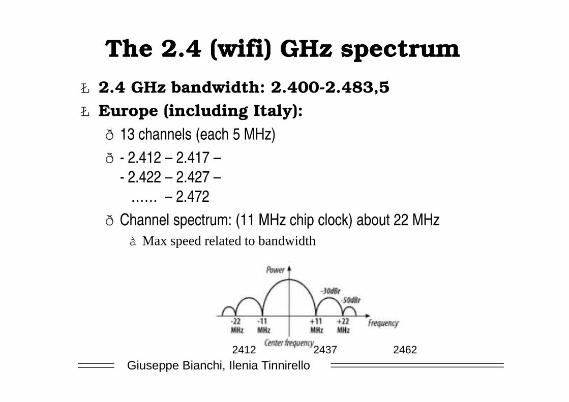
The 2.4 (wifi) GHz spectrumThe 2.4 (wifi) GHz spectrumŁ 2.4 GHz bandwidth: 2.400-2.483,5Ł Europe (including Italy):
ð 13 channels (each 5 MHz) ð - 2.412 – 2.417 –
- 2.422 – 2.427 –…… – 2.472
Giuseppe Bianchi, Ilenia Tinnirello
…… – 2.472ð Channel spectrum: (11 MHz chip clock) about 22 MHz
à Max speed related to bandwidth
2412 2437 2462
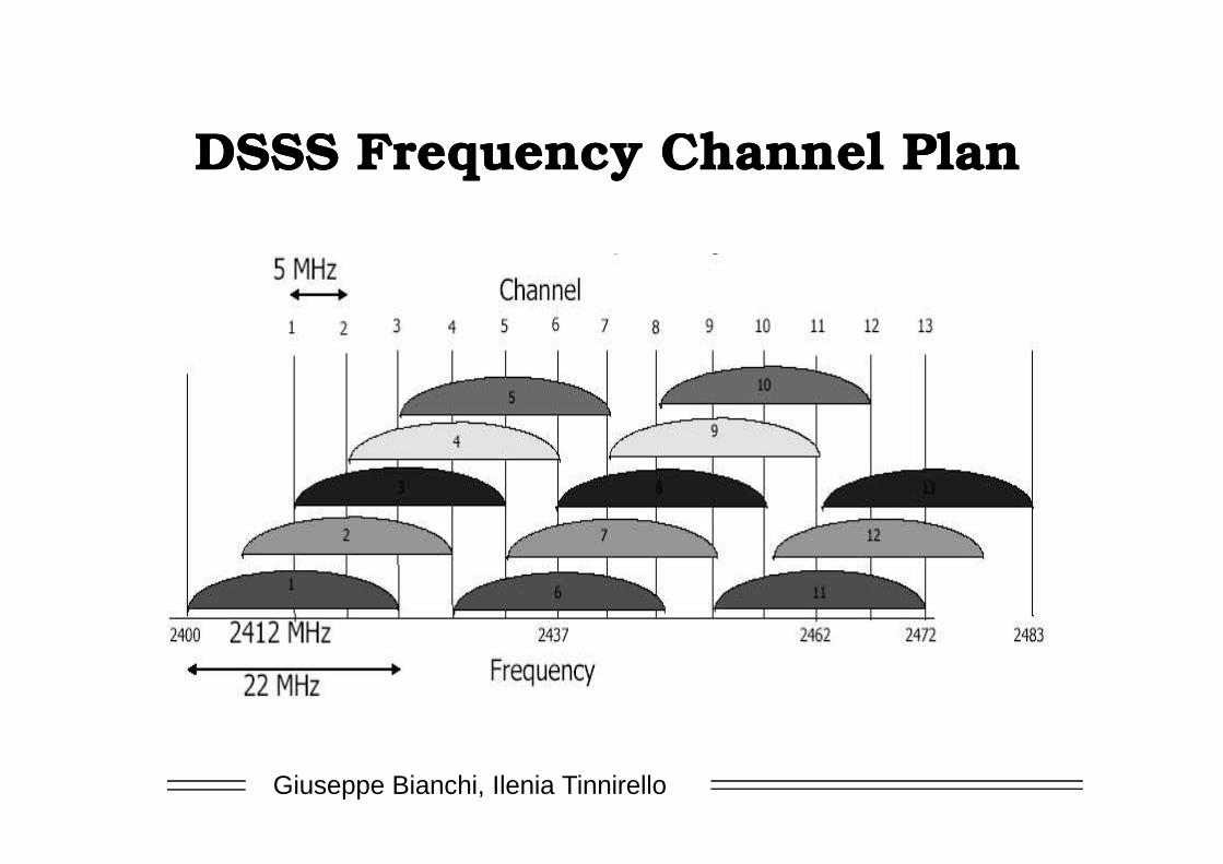
DSSS Frequency Channel PlanDSSS Frequency Channel Plan
Giuseppe Bianchi, Ilenia Tinnirello
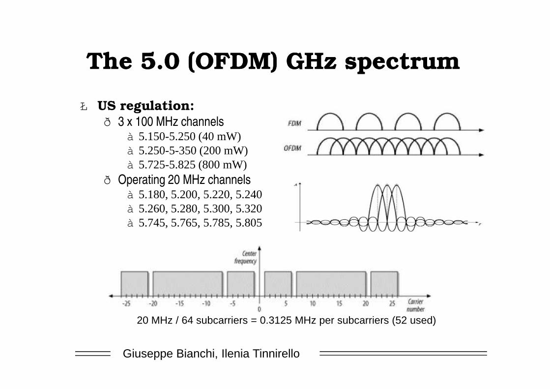
The 5.0 (OFDM) GHz spectrumThe 5.0 (OFDM) GHz spectrum
Ł US regulation:ð 3 x 100 MHz channels
à 5.150-5.250 (40 mW)à 5.250-5-350 (200 mW)à 5.725-5.825 (800 mW)
ð Operating 20 MHz channelsà 5.180, 5.200, 5.220, 5.240
Giuseppe Bianchi, Ilenia Tinnirello
à 5.180, 5.200, 5.220, 5.240à 5.260, 5.280, 5.300, 5.320à 5.745, 5.765, 5.785, 5.805
20 MHz / 64 subcarriers = 0.3125 MHz per subcarriers (52 used)
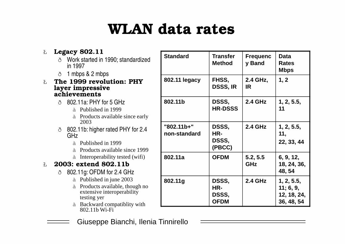
WLAN data ratesWLAN data rates
Standard Transfer Method
Frequency Band
Data Rates Mbps
802.11 legacy FHSS, DSSS, IR
2.4 GHz, IR
1, 2
802.11b DSSS, HR-DSSS
2.4 GHz 1, 2, 5.5, 11
Ł Legacy 802.11ð Work started in 1990; standardized
in 1997ð 1 mbps & 2 mbps
Ł The 1999 revolution: PHY layer impressive achievementsð 802.11a: PHY for 5 GHz
à Published in 1999à Products available since early
2003
Giuseppe Bianchi, Ilenia Tinnirello
"802.11b+" non-standard
DSSS, HR-DSSS, (PBCC)
2.4 GHz 1, 2, 5.5, 11,22, 33, 44
802.11a OFDM 5.2, 5.5 GHz
6, 9, 12, 18, 24, 36, 48, 54
802.11g DSSS, HR-DSSS, OFDM
2.4 GHz 1, 2, 5.5, 11; 6, 9, 12, 18, 24, 36, 48, 54
2003ð 802.11b: higher rated PHY for 2.4
GHzà Published in 1999à Products available since 1999à Interoperability tested (wifi)
Ł 2003: extend 802.11bð 802.11g: OFDM for 2.4 GHz
à Published in june 2003à Products available, though no
extensive interoperability testing yer
à Backward compatiblity with 802.11b Wi-Fi
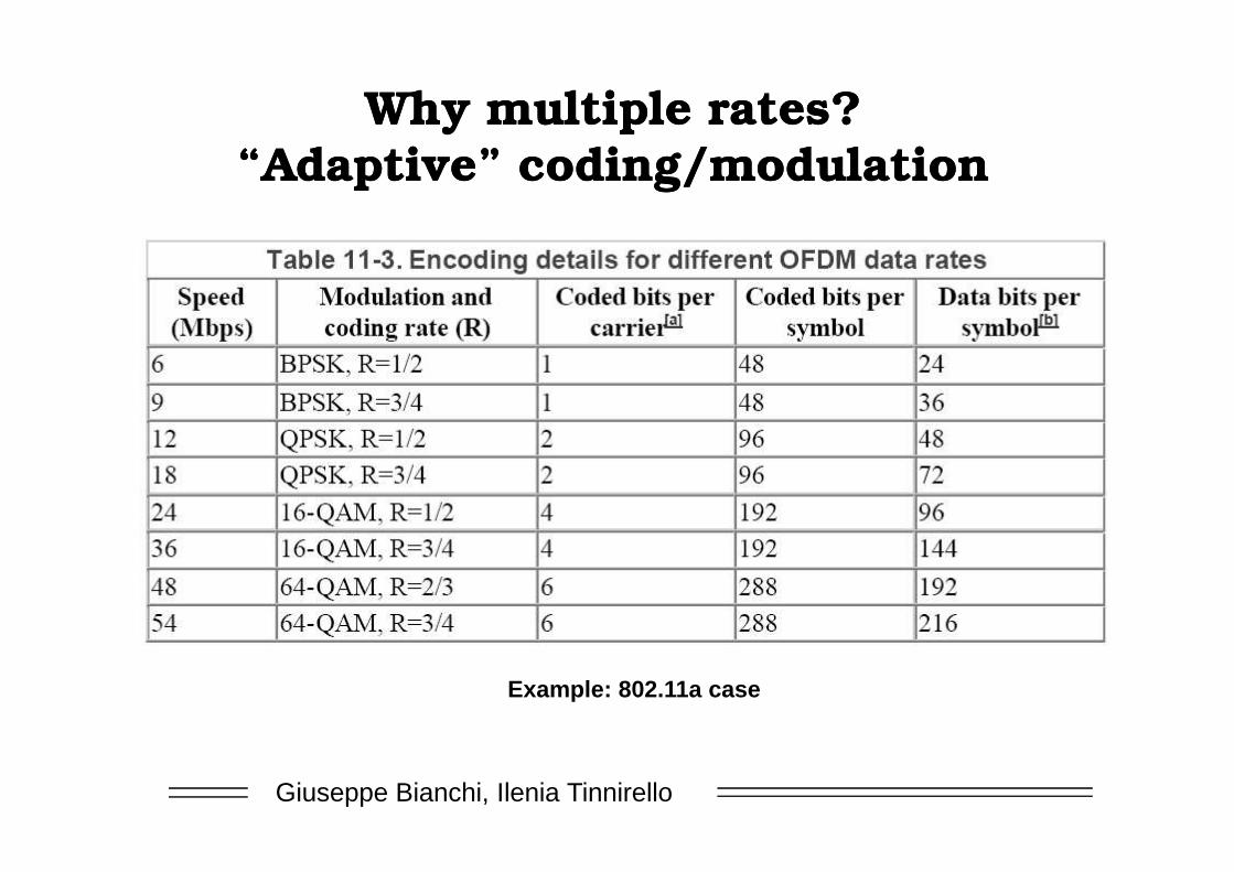
Why multiple rates?Why multiple rates?“Adaptive” coding/modulation“Adaptive” coding/modulation
Giuseppe Bianchi, Ilenia Tinnirello
Example: 802.11a case
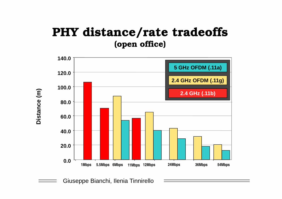
PHY distance/rate tradeoffsPHY distance/rate tradeoffs(open office)(open office)
80.0
100.0
120.0
140.0
Dis
tan
ce (
m)
2.4 GHz OFDM (.11g)
5 GHz OFDM (.11a)
2.4 GHz (.11b)
Giuseppe Bianchi, Ilenia Tinnirello
0.0
20.0
40.0
60.0
80.0
Dis
tan
ce (
m)
54Mbps36Mbps24Mbps12Mbps6Mbps 11Mbps5.5Mbps1Mbps
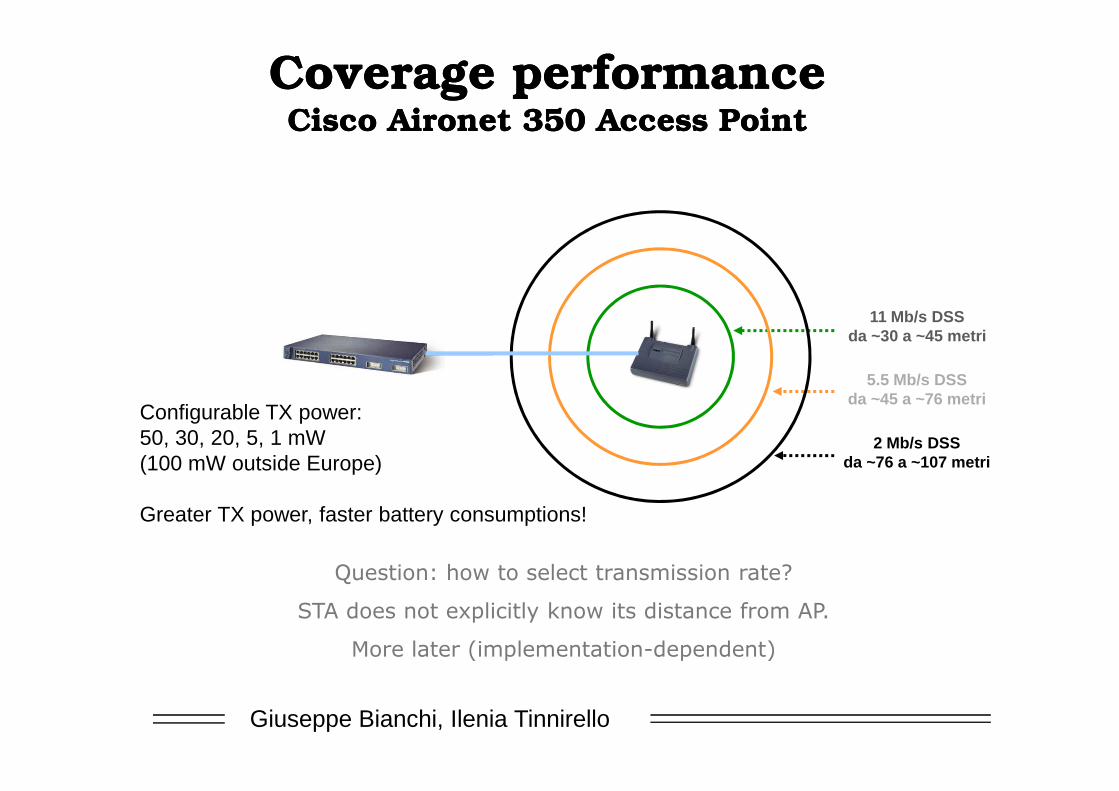
Coverage performance Coverage performance Cisco Aironet 350 Access PointCisco Aironet 350 Access Point
11 Mb/s DSSda ~30 a ~45 metri
5.5 Mb/s DSSda ~45 a ~76 metri
Giuseppe Bianchi, Ilenia Tinnirello
da ~45 a ~76 metri
2 Mb/s DSSda ~76 a ~107 metri
Configurable TX power:50, 30, 20, 5, 1 mW(100 mW outside Europe)
Greater TX power, faster battery consumptions!
��������������� ��������������������
������������� ���� �����������������������
���� �������� ���������� ���������!
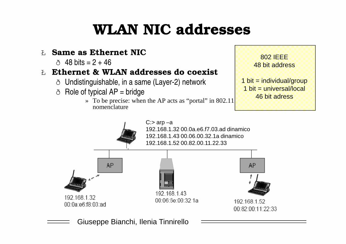
WLAN NIC addressesWLAN NIC addressesŁ Same as Ethernet NIC
ð 48 bits = 2 + 46Ł Ethernet & WLAN addresses do coexist
ð Undistinguishable, in a same (Layer-2) networkð Role of typical AP = bridge
» To be precise: when the AP acts as “portal” in 802.11 nomenclature
802 IEEE48 bit address
1 bit = individual/group1 bit = universal/local
46 bit adress
C:> arp –a
Giuseppe Bianchi, Ilenia Tinnirello
C:> arp –a192.168.1.32 00.0a.e6.f7.03.ad dinamico192.168.1.43 00.06.00.32.1a dinamico192.168.1.52 00.82.00.11.22.33
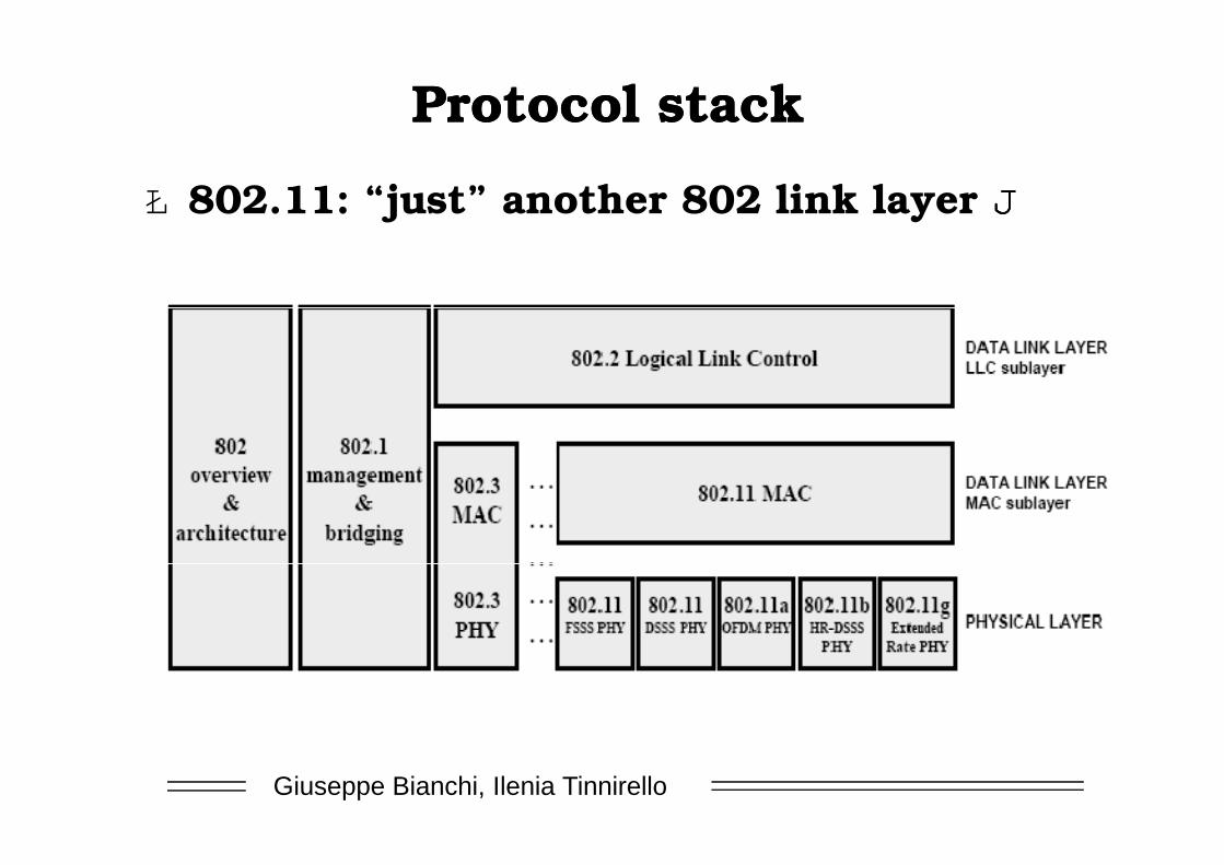
Protocol stackProtocol stack
Ł 802.11: “just” another 802 link layer JJJJ
Giuseppe Bianchi, Ilenia Tinnirello
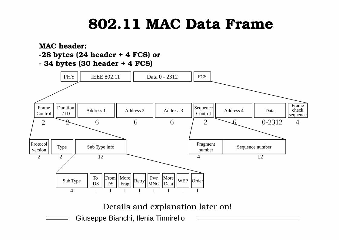
802.11 MAC Data Frame802.11 MAC Data Frame
PHY IEEE 802.11 Data 0 - 2312 FCS
FrameControl
Duration/ ID
Address 1 Address 2 Address 3SequenceControl
Address 4 DataFramecheck
sequence
2 2 2 40-23126666
MAC header:-28 bytes (24 header + 4 FCS) or- 34 bytes (30 header + 4 FCS)
Giuseppe Bianchi, Ilenia Tinnirello
Protocolversion
Type Sub Type info
2 2 12
Sub TypeTo DS
FromDS
MoreFrag
RetryPwr
MNGMoreData
WEP Order
4 1 1 1 1 1 1 1 1
2 2 2 40-23126666
Fragmentnumber
Sequence number
4 12
Details and explanation later on!
IEEE 802.11 WLANIEEE 802.11 WLAN
Giuseppe Bianchi, Ilenia Tinnirello
Wireless LAN Networks and related Addressing
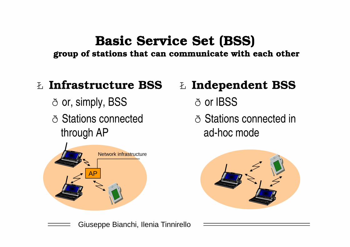
Basic Service Set (BSS)Basic Service Set (BSS)group of stations that can communicate with each othergroup of stations that can communicate with each other
Ł Infrastructure BSSð or, simply, BSSð Stations connected
Ł Independent BSSð or IBSSð Stations connected in
Giuseppe Bianchi, Ilenia Tinnirello
ð Stations connected through AP
ð Stations connected in ad-hoc mode
AP
Network infrastructure
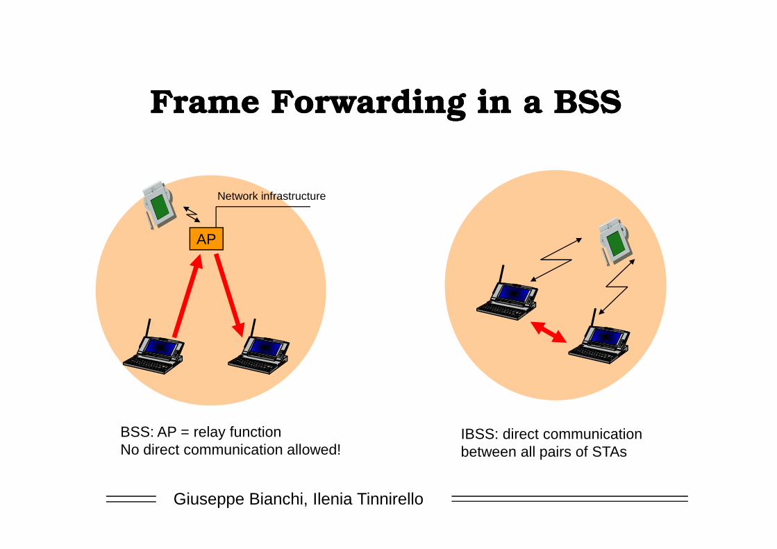
Frame Forwarding in a BSSFrame Forwarding in a BSS
AP
Network infrastructure
Giuseppe Bianchi, Ilenia Tinnirello
BSS: AP = relay functionNo direct communication allowed!
IBSS: direct communicationbetween all pairs of STAs
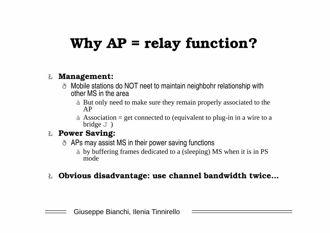
Why AP = relay function?Why AP = relay function?
Ł Management:ð Mobile stations do NOT neet to maintain neighbohr relationship with
other MS in the areaà But only need to make sure they remain properly associated to the
APà Association = get connected to (equivalent to plug-in in a wire to a
Giuseppe Bianchi, Ilenia Tinnirello
à Association = get connected to (equivalent to plug-in in a wire to a bridge J )
Ł Power Saving:ð APs may assist MS in their power saving functions
à by buffering frames dedicated to a (sleeping) MS when it is in PS mode
Ł Obvious disadvantage: use channel bandwidth twice…
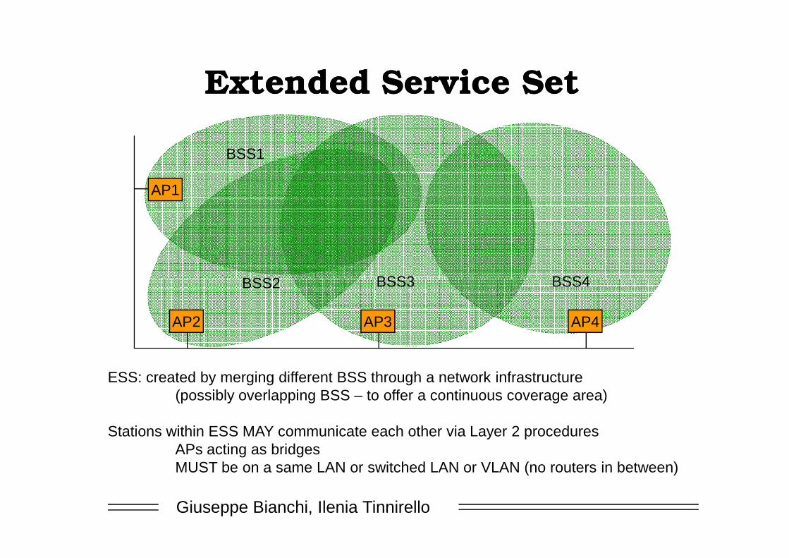
Extended Service SetExtended Service Set
AP1
BSS1
BSS2 BSS3 BSS4
Giuseppe Bianchi, Ilenia Tinnirello
AP2 AP3 AP4
BSS2 BSS3 BSS4
ESS: created by merging different BSS through a network infrastructure(possibly overlapping BSS – to offer a continuous coverage area)
Stations within ESS MAY communicate each other via Layer 2 proceduresAPs acting as bridgesMUST be on a same LAN or switched LAN or VLAN (no routers in between)

The concept of Distribution The concept of Distribution SystemSystem
AP1 AP2 AP3
MSs in a same ESS need to1) communicate each other
Distribution system (physical connectivity + logical service support)
Giuseppe Bianchi, Ilenia Tinnirello
1) communicate each other2) move through the ESS
No standard implementation, but set of services:Association, disassociation, reassociation, Integration, distribution
Basically. DS role: - track where an MS is registrered within an ESS area- deliver frame to MS

Association and DSAssociation and DS
AP1 AP2 AP3
Association
IAPP IAPP
Giuseppe Bianchi, Ilenia Tinnirello
DS implementation:- an AP must inform other APs of associated MSs MAC addresses- proprietary implementation
à no interoperability - standardized protocol IAPP (802.11f) in june 2003
Current trend:- Centralized solutions (Cisco, Aruba)- CAPWAP?
Ł Typical implementation (media)ð Switched ethernet backboneð But alternative “distribution medium” are
possibleà E.g. wireless distribution system (WDS)

Wireless Distribution SystemWireless Distribution System
AP1 AP2 AP3
Giuseppe Bianchi, Ilenia Tinnirello
DS medium:- not necessarily an ethernet backbone!- could be the 802.11 technology itself
Resulting AP = wireless bridge

AddressesAddresses
Ł At least three addressesð Receiving stationð Transmitting station
Giuseppe Bianchi, Ilenia Tinnirello
ð Transmitting stationð BSS address
à To make sure a frame is valid within the considered BSS
à For filtering purpose (filter frame within a BSS)

BSSIDBSSID
Ł Address of a BSSð Infrastructure mode:
à AP MAC address
802 IEEE 48 bit addresses
1 bit = individual/group
Giuseppe Bianchi, Ilenia Tinnirello
à AP MAC address
ð Ad-hoc mode:à Random value
» With universal/local bit set to 1
à Generated by STA initiating the IBSS
1 bit = individual/group1 bit = universal/local
46 bit address

Addressing in an IBSSAddressing in an IBSS
SA
Giuseppe Bianchi, Ilenia Tinnirello
FrameControl
Duration/ ID
Address 1DA
Address 2SA
Address 3BSSID
SequenceControl
Address 4---
Data FCS
SA = Source AddressDA = Destination Address
DA

Addressing in a BSS?Addressing in a BSS?
X
AP
Giuseppe Bianchi, Ilenia Tinnirello
XDA
SA

Addressing in a BSS!Addressing in a BSS!
AP
Distribution system
Giuseppe Bianchi, Ilenia Tinnirello
Frame must carry following info:1) Destined to DA2) But through the APWhat is the most general addressing structure?
DASA

Addressing in a BSS (to AP)Addressing in a BSS (to AP)
AP
Distribution system
BSSID
Address 2 = wireless TxAddress 1 = wireless RxAddress 3 = dest
Giuseppe Bianchi, Ilenia Tinnirello
FrameControl
Duration/ ID
Address 1BSSID
Address 2SA
Address 3DA
SequenceControl
Address 4---
Data FCS
DASA
Protocolversion
Type
2 2
Sub TypeTo DS
FromDS
MoreFrag
RetryPwr
MNGMoreData
WEP Order
4 1 1 1 1 1 1 1 1
1 0

Addressing in an ESSAddressing in an ESS
AP
Distribution System
DA
BSSID
AP
DA
Giuseppe Bianchi, Ilenia Tinnirello
SA
FrameControl
Duration/ ID
Address 1BSSID
Address 2SA
Address 3DA
SequenceControl
Address 4---
Data FCS
Protocolversion
Type
2 2
Sub TypeTo DS
FromDS
MoreFrag
RetryPwr
MNGMoreData
WEP Order
4 1 1 1 1 1 1 1 1
1 0
Idea: DS will be able to forward frame to dest(either if fixed or wireless MAC)

Addressing in a BSS (from AP)Addressing in a BSS (from AP)
AP
Distribution system
BSSID
Address 2 = wireless TxAddress 1 = wireless RxAddress 3 = src
Giuseppe Bianchi, Ilenia Tinnirello
FrameControl
Duration/ ID
Address 1DA
Address 2BSSID
Address 3SA
SequenceControl
Address 4---
Data FCS
DASA
Protocolversion
Type
2 2
Sub TypeTo DS
FromDS
MoreFrag
RetryPwr
MNGMoreData
WEP Order
4 1 1 1 1 1 1 1 1
0 1

From AP: do we really need 3 From AP: do we really need 3 addresses?addresses?
AP
Distribution system
BSSID
Giuseppe Bianchi, Ilenia Tinnirello
DASA
DA correctly receives frame, and send 802.11 ACK to … BSSID (wireless transmitted)
DA correctly receives frame, and send higher level ACK to … SA (actual transmitter)

Addressing within a WDSAddressing within a WDS
AP
Wireless Distribution System
TA
AP
RA
Address 4:
Giuseppe Bianchi, Ilenia Tinnirello
SADA
FrameControl
Duration/ ID
Address 1RA
Address 2TA
Address 3DA
SequenceControl
Address 4SA
Data FCS
Protocolversion
Type
2 2
Sub TypeTo DS
FromDS
MoreFrag
RetryPwr
MNGMoreData
WEP Order
4 1 1 1 1 1 1 1 1
1 1
Address 4: initially forgotten…

Addressing: summaryAddressing: summary
Function To DS From DS Address 1 Address 2 Address 3 Address 4
IBSS 0 0 RA = DA SA BSSID N/A
From AP 0 1 RA = DA BSSID SA N/A
To AP 1 0 RA = BSSID SA DA N/A
Wireless DS 1 1 RA TA DA SA
Receiver Transmitter
Ł BSS Identifier (BSSID)
Giuseppe Bianchi, Ilenia Tinnirello
Ł BSS Identifier (BSSID)ð unique identifier for a particular BSS. In an infrastructure BSSID it is the MAC address of the AP. In IBSS, it is
random and locally administered by the starting station. (uniqueness)Ł Transmitter Address (TA)
ð MAC address of the station that transmit the frame to the wireless medium. Always an individual address.Ł Receiver Address (RA)
ð to which the frame is sent over wireless medium. Individual or Group.Ł Source Address (SA)
ð MAC address of the station who originated the frame. Always individual address. ð May not match TA because of the indirection performed by DS of an IEEE 802.11 WLAN. SA field is considered
by higher layers.Ł Destination Address (DA)
ð Final destination . Individual or Group. ð May not match RA because of the indirection.

Service Set IDentifier (SSID)Service Set IDentifier (SSID)
Ł Name of the WLAN networkð Plain text (ascii), up to 32 char
Ł Assigned by the network administratorð All BSS in a same ESS have
same SSIDŁ Typically (but not
necessarily) is transmitted
Giuseppe Bianchi, Ilenia Tinnirello
Typically (but not necessarily) is transmitted in periodic management frames (beacon)ð Typical: 1 broadcast beacon
every 100 ms (configurable by sysadm)
ð Beacon may transmit a LOT of other info
Beacon example

IEEE 802.11 WLANIEEE 802.11 WLAN
Giuseppe Bianchi, Ilenia Tinnirello
Medium Access Control Protocols: DCF

Wireless EthernetWireless EthernetŁ 802.3 (Ethernet)
ð CSMA/CDà Carrier Sense Multiple Access à Collision Detect
A B C
Ł Both A and C sense the channel idle at the same time àààà they send at the same time.
Giuseppe Bianchi, Ilenia Tinnirello
Ł 802.11(wireless LAN)ð CSMA/CA ð (Distributed Coordination Function)
à Carrier Sense Multiple Access à Collision Avoidance
time.Ł Collision can be detected at sender in
Ethernet.Ł Why this is not possible in 802.11?
1. Either TX or RX (no simultaneous RX/TX)
2. Large amount of power difference in Tx and Rx (even if simultaneous tx-rx, no possibility in rx while tx-ing)
3. Wireless medium = additional problems vs broadcast cable!!

Ł Large difference in signal strength; physical channel impairments (shadowing)ð It may result that two stations in the same area cannot communicate
Ł Hidden terminalsð A and C cannot hear each otherð A transmits to Bð C wants to send to B; C cannot receive A;C senses “idle” medium
(Carrier Sense fails)ð Collision occurs at B.
Hidden Terminal ProblemHidden Terminal Problem
Giuseppe Bianchi, Ilenia Tinnirello
ð Collision occurs at B.ð A cannot detect the collision (Collision Detection fails).ð A is “hidden” to C.
BA C

802.11 MAC approach802.11 MAC approachŁ Still based on Carrier Sense:
à Listen before talkingŁ But collisions can only be inferred
afterwards, at the receiverà Receivers see corrupted data through a CRC errorà Transmitters fail to get a response
Ł Two-way handshaking mechanism to
Giuseppe Bianchi, Ilenia Tinnirello
Ł Two-way handshaking mechanism to infer collisionsð DATA-ACK packets
TX RX
packet
ACK

Channel Access detailsChannel Access detailsŁ A station can transmit only if it senses the
channel IDLE for a DIFS timeð DIFS = Distributed Inter Frame Space
DIFSDATA
SIFS
TX
Packet arrival
Giuseppe Bianchi, Ilenia Tinnirello
SIFS ACK
Ł ���������������� ��������������������������������������������
ð SIFS = Short Inter Frame Spaceð ���������������������������������������������������
RX
What about a station arriving in this frame time?

DIFS & SIFS in wiDIFS & SIFS in wi--fifi
Ł DIFS = 50 ����sŁ SIFS = 10 ����s
Giuseppe Bianchi, Ilenia Tinnirello

Why backoff?Why backoff?DIFS
DATA
SIFS ACKSTA1
STA2DIFS
Giuseppe Bianchi, Ilenia Tinnirello
STA2
STA3
Collision!
RULE: when the channel is initially sensed BUSY, station defers transmission;But when it is sensed IDLE for a DIFS, defer transmission of a further random time(BACKOFF TIME)

Slotted BackoffSlotted Backoff
STA2DIFS
Extract random number in range (0, W-1)Decrement every slot-time �
w=7
w=5
Giuseppe Bianchi, Ilenia Tinnirello
STA3
Note: slot times are not physically delimited on the channel!Rather, they are logically identified by every STA
Slot-time values: 20�s for DSSS (wi-fi)Accounts for: 1) RX_TX turnaround time
2) busy detect time3) propagation delay

Backoff freezingBackoff freezing
Ł When STA is in backoff stage:ð It freezes the backoff counter as long as the channel is
sensed BUSYð It restarts decrementing the backoff as the channel is sensed
IDLE for a DIFS period
Giuseppe Bianchi, Ilenia Tinnirello
IDLE for a DIFS period
DIFS DATA
SIFS ACK
STATION 1
DIFS
SIFS ACK 6 5
DIFS
Frozen slot-time 4BUSY medium
STATION 2
DIFS3 2 1

Backoff rulesBackoff rulesŁ First backoff value:
ð Extract a uniform random number in range (0,CWmin)Ł If unsuccessful TX:
ð Extract a uniform random number in range (0,2×(CWmin+1)-1)Ł If unsuccessful TX:
Giuseppe Bianchi, Ilenia Tinnirello
Ł If unsuccessful TX:ð Extract a uniform random number in range (0,22×(CWmin+1)-1)
Ł Etc up to 2m×(CWmin+1)-1
Exponential Backoff!CWmin = 31CWmax = 1023 (m=5)

RTS/CTSRTS/CTS
Ł Request-To-Send / Clear-To-SendŁ 4-way handshaking ð Versus 2-way handshaking of basic access
mechanism
Giuseppe Bianchi, Ilenia Tinnirello
mechanismŁ Introduced for two reasonsð Combat hidden terminalð Improve throughput performance with long
packets

DIFSDATA
SIFS ACK
TX
RX
Packet arrival
RTS
SIFS CTS SIFS
RTS/CTS and RTS/CTS and hiddenhidden terminalsterminals
others NAV (RTS)
Giuseppe Bianchi, Ilenia Tinnirello
TX
RX
hidden
others
RTS
NAV (RTS)
RTS/CTS: carry the amount of time the channelwill be BUSY. Other stations may update a Network Allocation Vector, and defer TX
even if they sense the channel idle (Virtual Carrier Sensing)
CTS CTS
NAV (CTS)
(Update NAV)

Frame formatsFrame formats
FrameControl
Duration/ ID
Address 1 Address 2 Address 3SequenceControl
Address 4 Data FCS
DATA FRAME (28 bytes excluded address 4)
RTS (20 bytes)
Giuseppe Bianchi, Ilenia Tinnirello
FrameControl
Duration RA TA FCS
FrameControl
Duration RA FCS
RTS (20 bytes)
CTS / ACK (14 bytes)

Ł Splits message (MSDU) into several frames (MPDU)ð Same fragment size
à except the last oneŁ Fragmentation burst
ð Fragments separated by SIFSà Channel cannot be captured by
someone elseð Each fragment individually ACKed
FragmentationFragmentationŁ Each fragment reserves channel
for next oneð NAV updated fragment by fragment
Ł Missing ACK for fragment xð Release channel (automatic)ð Backoffð Restart from transmission of fragment x
Giuseppe Bianchi, Ilenia Tinnirello
ð Each fragment individually ACKed

Ł High Bit Error Rate (BER)ð Increases with distanceð The longer the frame, the lower the successful TX probabilityð High BER = high rts overhead & increased rtx delay
à Backoff window increases: cannot distinguish collisions from tx error!
Why Fragmentation?Why Fragmentation?
Giuseppe Bianchi, Ilenia Tinnirello

Fragment and sequence numbersFragment and sequence numbers
Ł Fragment numberð Increasing integer value 0-15 (max 16 fragments since 4 bits available)
FrameControl
Duration/ ID
Address 1 Address 2 Address 3SequenceControl
Address 4 Data FCS
DATA FRAME (28 bytes excluded address 4)
More Frag
Retry
1 1
Fragmentnumber
Sequence number
4 12
Giuseppe Bianchi, Ilenia Tinnirello
ð Increasing integer value 0-15 (max 16 fragments since 4 bits available)ð Essential for reassembly
Ł More fragment bit (frame control field) set to:ð 1 for intermediate fragmentsð 0 for last fragment
Ł Sequence Numberð Used to filter out duplicates
à Unlike Ethernet, duplicates are quite frequent!à Retransmissions are a main feature of the MAC
Ł Retry bit: helps to distinguish retransmissionsð Set to 0 at transmission of a new frame

IEEE 802.11 WLANIEEE 802.11 WLAN
Giuseppe Bianchi, Ilenia Tinnirello
Lecture 3bisMedium Access Control
Protocols: PCF

PCF vs DCFPCF vs DCF
DCF
PCF
Giuseppe Bianchi, Ilenia Tinnirello
PHY
DCF
PCF deployed on TOP of DCFBackward compatibility

PCFPCF
Ł Token-based access mechanismð Polling
Ł Channel arbitration enforced by a “point Coordinator” (PC)ð Typically the AP, but not necessarily
Ł Contention-free access
Giuseppe Bianchi, Ilenia Tinnirello
Ł Contention-free accessð No collision on channel
Ł PCF deployment: minimal!!ð Optional part of the 802.11 specificationð As such, almost never deployedð But HCCA (PCF extension in 802.11e) is getting considerable attention…

PCF frame transferPCF frame transfer
Giuseppe Bianchi, Ilenia Tinnirello
SIFS
Polling strategy: very elementary!!- send polling command to stations with increasing Association ID value…- (regardless whether they might have or not data to transmit)

IEEE 802.11 WLANIEEE 802.11 WLAN
Giuseppe Bianchi, Ilenia Tinnirello
Network Management

Management OperationsManagement Operations
Ł Wireless is not always an advantageð Medium unreliable, lack of physical boundaries,
power consumptionŁ How to join, build, connect, move
Giuseppe Bianchi, Ilenia Tinnirello
Ł How to join, build, connect, move nodes, save energies, …ð All these issues are faced by the management
procedures, which can be customizedð Different vendor offers: very simple products vs.
feature-rich products

ScanningScanning
Ł Before joining a network, you have to find it!! The discovery operation is called scanning
Ł Several parameters can be specified by the userð BSSType (independent, infrastucture, both)ð BSSID (individual, Broadcast)ð SSID (network name)
Giuseppe Bianchi, Ilenia Tinnirello
ð SSID (network name)ð ScanType (active, passive)ð Channel Listð Probe Delay (to start the active scanning in each channel)ð MinChannelTime, MaxChannelTime

Passive ScanningPassive ScanningŁ Saves battery, since it requires listening
onlyŁ Scanning report based on beacon frames
heard while sweeping channel to channel
Giuseppe Bianchi, Ilenia Tinnirello
AP2
AP3AP1
Found AP1, AP3

Active ScanningActive ScanningŁ Probe Request Frames used to solicit responses from
a network, when the ProbeDelay time expiresð If the medium is detected busy during the MinChannelTime, wait until the
MaxChanneltime expiresð One station in each BSS is responsible to send Probe Responses
(station which transmitted the last beacon frame)
Giuseppe Bianchi, Ilenia Tinnirello

JoiningJoining
Ł A scan report is generated after each scan, reporting BSSID, SSID, BSSType,ð Beacon Intervalð DTIM period ð Timing Parameters (Timestamp)
Giuseppe Bianchi, Ilenia Tinnirello
ð Timing Parameters (Timestamp)ð PHY Parameters, BSSBasicRateSet
Ł Joing: before associating, select a network (often it requires user action)
Ł and after?ð autentication

AssociationAssociation
Ł After that we choose a network and we authenticate, we can finally send an “association” messageð The message is required for tracking the host
position in the ESS
Giuseppe Bianchi, Ilenia Tinnirello
position in the ESSð Not used for ad hoc networksð Re-association after hand-over

And to be found?And to be found?
Ł It is required to periodically transmit a beacon!ð In infrastructure: beacon transmissions managed by the APð In ad-hoc: each station contend for the beacon and leave the contention
after the first observed beaconŁ The beacon frames are periodically scheduled, but
contend as normal framesDeterministic
Giuseppe Bianchi, Ilenia Tinnirello
Deterministic scheduling
Random transmission delays

What information What information is carried by beacons?is carried by beacons?
Ł Timestamp (8 bytes): in Transmission Units TU (=1024 us) to synchronize stations
Ł Beacon Interval (2 bytes): beacon scheduling intervalŁ Capability Info (2 bytes): bit map to activate/deactivate some
network featuresŁ SSID (variable size): network name set by the operators
ð Element ID, Length, Information for every variable size field
Giuseppe Bianchi, Ilenia Tinnirello
OPTIONAL:Ł FH ParameterSet (7 bytes)Ł DS ParameterSet (2 bytes)Ł CF ParameterSet (8 bytes)Ł IBSS ParameterSet (4 bytes)Ł Traffic Indicator Map TIM (variable size): to indicate which
stations have buffered frames; some TIM are Delivery TIM for broadcast traffic

Why Timestamps for Why Timestamps for Synchronization?Synchronization?
Giuseppe Bianchi, Ilenia Tinnirello
��� ������� ��"��#�����$��������%������������������ ������&���������'