Embed Size (px)
Citation preview
University of PerugiaUniversity of Perugia
G. Reali – IEEE 802.11 Wireless LAN 1
IEEE 802.11 Wireless LAN
Gianluca Reali
University of PerugiaUniversity of Perugia
G. Reali – IEEE 802.11 Wireless LAN 2
What is IEEE 802.11?
• Local, high-speed wireless connectivity for fixed, portable and moving stations – stations can be moving at pedestrian and vehicular
speed• Standard promises interoperability
– vendors products on the same physical layer shouldinteroperate
• Target use– inside buildings, outdoor areas, anywhere!
University of PerugiaUniversity of Perugia
G. Reali – IEEE 802.11 Wireless LAN 3
Glossary of 802.11 Wireless Terms
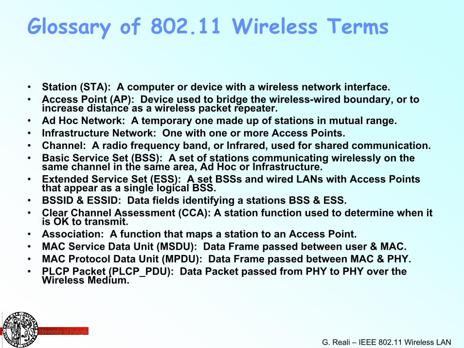
• Station (STA): A computer or device with a wireless network interface.• Access Point (AP): Device used to bridge the wireless-wired boundary, or to
increase distance as a wireless packet repeater.• Ad Hoc Network: A temporary one made up of stations in mutual range.• Infrastructure Network: One with one or more Access Points.• Channel: A radio frequency band, or Infrared, used for shared communication.• Basic Service Set (BSS): A set of stations communicating wirelessly on the
same channel in the same area, Ad Hoc or Infrastructure.• Extended Service Set (ESS): A set BSSs and wired LANs with Access Points
that appear as a single logical BSS.• BSSID & ESSID: Data fields identifying a stations BSS & ESS.• Clear Channel Assessment (CCA): A station function used to determine when it
is OK to transmit.• Association: A function that maps a station to an Access Point.• MAC Service Data Unit (MSDU): Data Frame passed between user & MAC.• MAC Protocol Data Unit (MPDU): Data Frame passed between MAC & PHY.• PLCP Packet (PLCP_PDU): Data Packet passed from PHY to PHY over the
Wireless Medium.
University of PerugiaUniversity of Perugia
G. Reali – IEEE 802.11 Wireless LAN 4
802.11 Task Groups
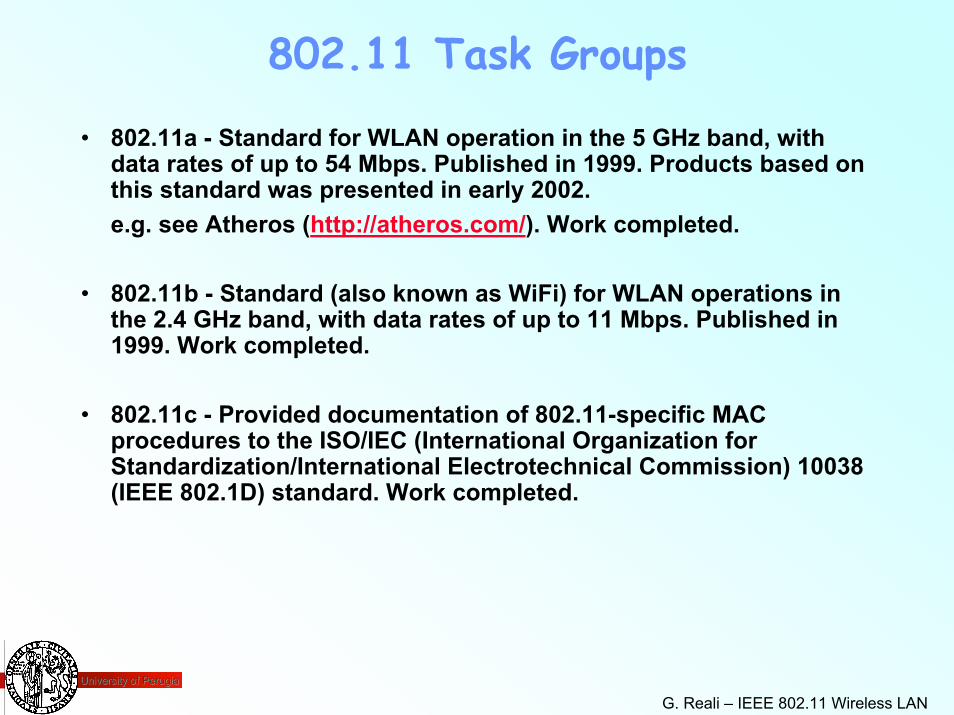
• 802.11a - Standard for WLAN operation in the 5 GHz band, withdata rates of up to 54 Mbps. Published in 1999. Products based on this standard was presented in early 2002. e.g. see Atheros (http://atheros.com/). Work completed.
• 802.11b - Standard (also known as WiFi) for WLAN operations in the 2.4 GHz band, with data rates of up to 11 Mbps. Published in 1999. Work completed.
• 802.11c - Provided documentation of 802.11-specific MAC procedures to the ISO/IEC (International Organization forStandardization/International Electrotechnical Commission) 10038 (IEEE 802.1D) standard. Work completed.
University of PerugiaUniversity of Perugia
G. Reali – IEEE 802.11 Wireless LAN 5
802.11 Task Groups
• 802.11d - Publishing definitions and requirements to allow the 802.11 standard to operate in countries not currently served by the standard. Ongoing.
• 802.11e - Attempting to enhance the 802.11 MAC to introduce quality of service. Improvement in capabilities and efficiency are planned to allow applications such as voice, video, or audio transport over 802.11 wireless networks. Ongoing.
• 802.11f - Developing recommended practices for implementing the 802.11 concepts of Access Points and Distribution Systems. The purpose is to increase compatibility between Access Pointdevices from different vendors. Ongoing.
University of PerugiaUniversity of Perugia
G. Reali – IEEE 802.11 Wireless LAN 6
802.11 Task Groups
• 802.11g - Developing a higher-speed PHY extension to the 802.11b standard, while maintaining backward compatibility with current802.11b devices. The target data rate for the project is at least 20 Mbps. Ongoing.
• 802.11h - Enhancing the 802.11 MAC and 802.11a PHY to providenetwork management and control extensions for spectrum and transmit power management in the 5 GHz band. This is will allowregulatory acceptance of the standard in some Europeancountries. Ongoing.
• 802.11i - Enhancing the security and authentication mechanismsof the 802.11 standard. Ongoing.
University of PerugiaUniversity of Perugia
G. Reali – IEEE 802.11 Wireless LAN 7
IEEE 802.11 basic
• Uses Direct Sequence spread spectrum (DSSS) technology– Frequency-Hopping spread spectrum (FHSS) can only be
used for 1 or 2 Mbps in US due to FCC regulations• Operates in unlicensed 2.4 GHz ISM band
– ISM: Industrial, Scientific and Medical– ISM regulatory range:
» 2.4 GHz to 2.4835 GHz for North America
University of PerugiaUniversity of Perugia
G. Reali – IEEE 802.11 Wireless LAN 8
IEEE 802.11 basic
• Supported Speeds and Distances– 1, 2, 5.5, 11 Mbps at distances of 150-2000 feet without
special antenna– Greater distances can be achieved by using special
antennas– Reachable Distance (or signal strength) greatly depends
on environment (buildings, walls, moving objects…)– Maximum obtainable speed depends on signal strength
University of PerugiaUniversity of Perugia
G. Reali – IEEE 802.11 Wireless LAN 9
IEEE 802.11b
• ‘b’ in IEEE 802.11b– September 1999, 802.11b “High Rate” amendment was
ratified by the IEEE– 802.11b amendment to 802.11 only affects the physical
layer, the basic artitecture is the same» Added two increased transmission speed
• 5.5 and 11 Mbps» More robust connectivity
• 802.11b also known as Wi-Fi (Wireless Fidelity)
University of PerugiaUniversity of Perugia
G. Reali – IEEE 802.11 Wireless LAN 10
IEEE 802.11a
• “Fast Ethernet” standard of wireless LANs
• Transmission speeds up to 54 Mbps
• 5 GHz (U-NII band) instead of 2.4 GHz – Unlicensed National Information Infrastructure
• OFDM instead of DSSS for encoding– Orthogonal Frequency Division Multiplexing
• 802.11a products are currently on the market
University of PerugiaUniversity of Perugia
G. Reali – IEEE 802.11 Wireless LAN 11
IEEE 802.11a
• Advantages– higher speed– less RF interference than 2.4 GHz in US
» 2.4 GHz used by Bluetooth, cordless/cellular phones, etc.– some interoperability, vendors currently have “dual-
standard” 802.11a/b equipment
• Disadvantages– shorter range, need to increase AP density or to increase
power to compensate
University of PerugiaUniversity of Perugia
G. Reali – IEEE 802.11 Wireless LAN 12
IEEE 802.11g
• Another high-speed standard• Viewed as a ‘step’ towards 802.11a• Speeds of up to 54 Mbps
– may be more like 20+ Mbps• Still works at 2.4 GHz
– not in the 5 GHz range like 802.11a• Advantages
– compatible with 802.11b– better range than 802.11a, by now
University of PerugiaUniversity of Perugia
G. Reali – IEEE 802.11 Wireless LAN 13
IEEE 802.11e
• Another upcoming standard for WLANs– adds quality-of-service features to MAC layer of 802.11b
compatible networks» error correction» better bandwidth management
• significantly improves multimedia performance» works around RF interference
• handles interference by moving away from it• i.e., moves to a new frequency when interference from a 2.4 GHz
cordless phone is detected
University of PerugiaUniversity of Perugia
G. Reali – IEEE 802.11 Wireless LAN 14
IEEE 802.11 Topologies
• Three basic topologies for WLANs– IBSS: Independent Basic Service Set– BSS: Basic Service Set– ESS: Extended Service Set
• Independent of type of PHY chosen
University of PerugiaUniversity of Perugia
G. Reali – IEEE 802.11 Wireless LAN 15
IEEE 802.11 IBSS
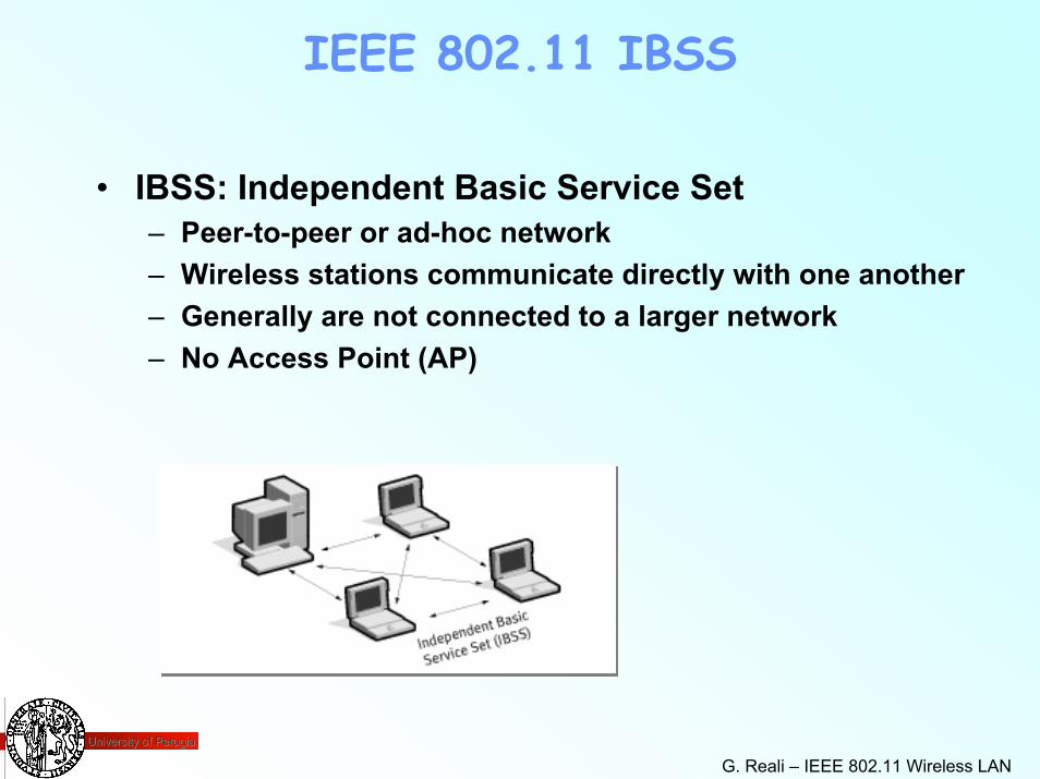
• IBSS: Independent Basic Service Set– Peer-to-peer or ad-hoc network– Wireless stations communicate directly with one another– Generally are not connected to a larger network– No Access Point (AP)
University of PerugiaUniversity of Perugia
G. Reali – IEEE 802.11 Wireless LAN 16
IEEE 802.11 BSS
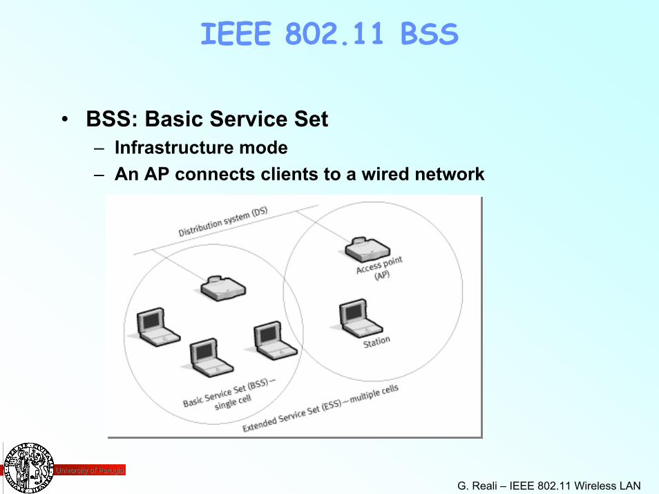
• BSS: Basic Service Set– Infrastructure mode– An AP connects clients to a wired network
University of PerugiaUniversity of Perugia
G. Reali – IEEE 802.11 Wireless LAN 17
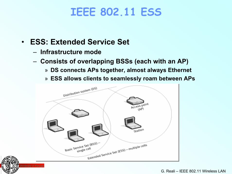
IEEE 802.11 ESS
• ESS: Extended Service Set– Infrastructure mode– Consists of overlapping BSSs (each with an AP)
» DS connects APs together, almost always Ethernet» ESS allows clients to seamlessly roam between APs
University of PerugiaUniversity of Perugia
G. Reali – IEEE 802.11 Wireless LAN 18
Access Points (APs)
• Broadcasts service– uses beacon management frames
• Number of clients supported– device dependent
» memory size, congestion,» SMC2652W - 128 clients» Cisco Aironet 340 - 2,048 clients
University of PerugiaUniversity of Perugia
G. Reali – IEEE 802.11 Wireless LAN 19
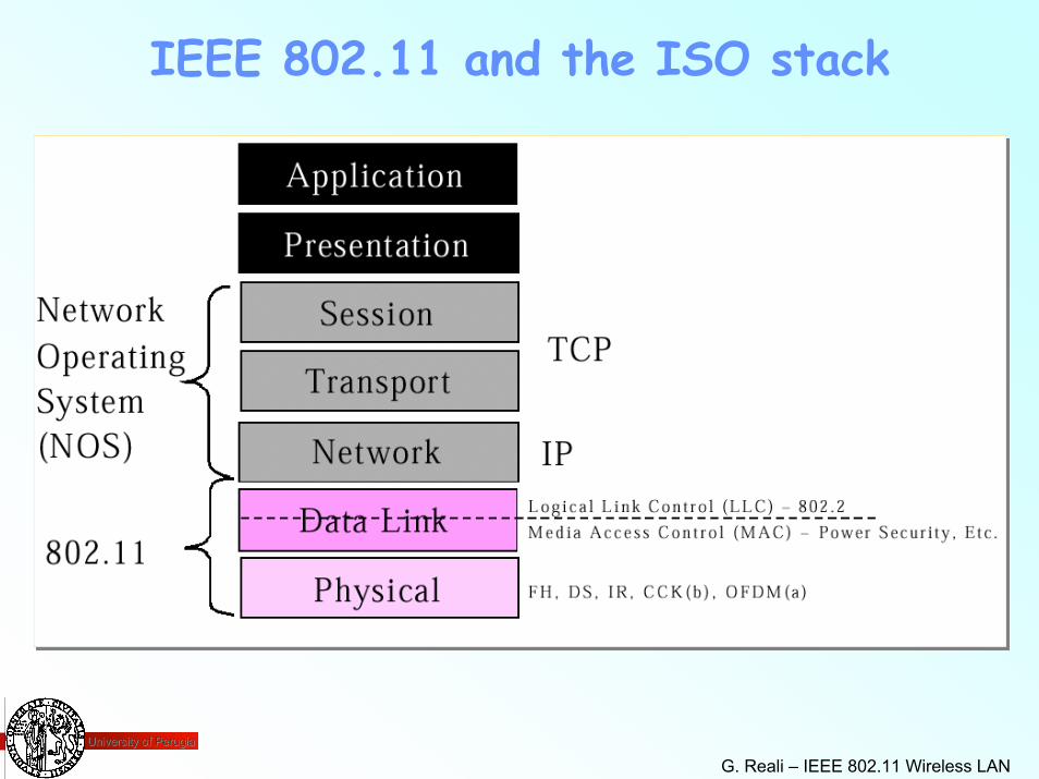
IEEE 802.11 and the ISO stack
University of PerugiaUniversity of Perugia
G. Reali – IEEE 802.11 Wireless LAN 20
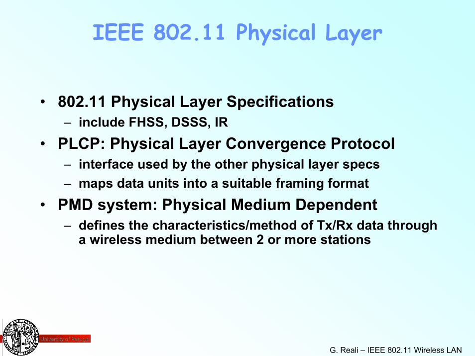
IEEE 802.11 Physical Layer
• 802.11 Physical Layer Specifications– include FHSS, DSSS, IR
• PLCP: Physical Layer Convergence Protocol– interface used by the other physical layer specs– maps data units into a suitable framing format
• PMD system: Physical Medium Dependent– defines the characteristics/method of Tx/Rx data through
a wireless medium between 2 or more stations
University of PerugiaUniversity of Perugia
G. Reali – IEEE 802.11 Wireless LAN 21
IEEE 802.11 Data Link Layer
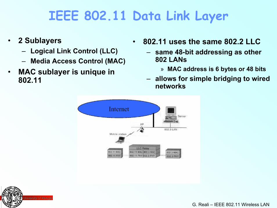
• 2 Sublayers– Logical Link Control (LLC)– Media Access Control (MAC)
• MAC sublayer is unique in 802.11
• 802.11 uses the same 802.2 LLC– same 48-bit addressing as other
802 LANs» MAC address is 6 bytes or 48 bits
– allows for simple bridging to wired networks
University of PerugiaUniversity of Perugia
G. Reali – IEEE 802.11 Wireless LAN 22
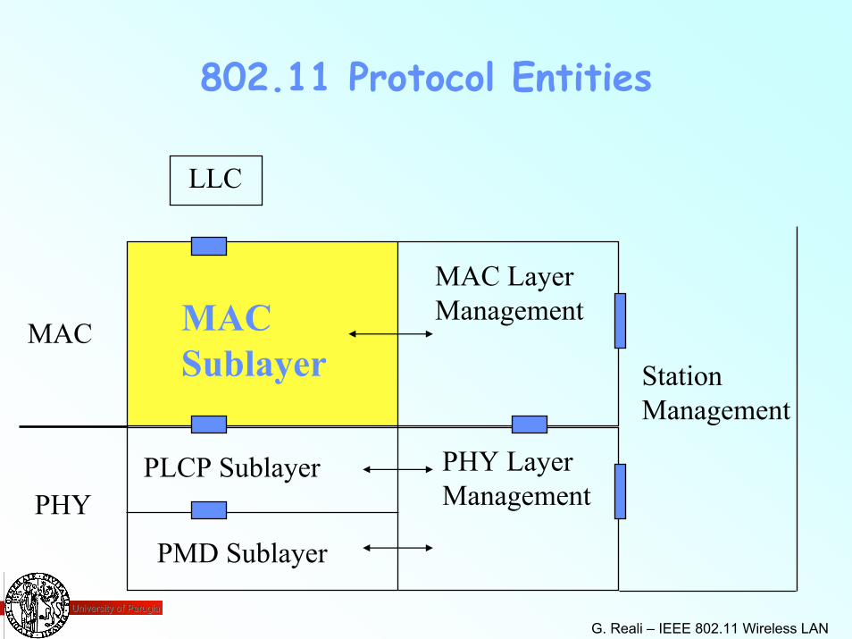
802.11 Protocol Entities
LLC
MAC Sublayer
PLCP Sublayer
PMD Sublayer
MAC LayerManagement
PHY LayerManagement
MACStationManagement
PHY
University of PerugiaUniversity of Perugia
G. Reali – IEEE 802.11 Wireless LAN 23
IEEE 802.11 MAC Sublayer
• MAC: Regulates access to the medium• Wired IEEE 802 LANs use CSMA/CD• 802.11 uses CSMA/CA• CSMA: carrier sense multiple access
– CD: with collision detection– CA: with collision avoidance
• Collision detection is not possible in 802.11– near/far problem: can’t transmit and “hear” a collision at
the same time
University of PerugiaUniversity of Perugia
G. Reali – IEEE 802.11 Wireless LAN 24
IEEE 802.11 MAC Sublayer
• CSMA/CA avoids collisions by explicit packet acknowledgment (ACK)– station wishing to transmit first senses the medium– if no activity detected, station waits an additional, random
amount of time then transmits if the medium is still free– ACK packet is sent by receiving station to confirm the data
packet arrived intact– collision assumed if sending station doesn’t get ACK, data is
retransmitted after a random time
University of PerugiaUniversity of Perugia
G. Reali – IEEE 802.11 Wireless LAN 25
IEEE 802.11 MAC Sublayer
• Other unique features in 802.11– IFS: Inter Frame Space
» time interval between frames– Handling hidden stations (hidden-node problem)
» virtual carrier sense– Power management functions– Data security (MAC address, WEP)
» WEP: Wired Equivalent Privacy– Multirate support– Fragmentation / Defragmentation
University of PerugiaUniversity of Perugia
G. Reali – IEEE 802.11 Wireless LAN 26
Main Requirements• Single MAC to support multiple PHYs.
– Support single and multiple channel PHYs.– and PHYs with different Medium Sense characteristics
• Should allow overlap of multiple networks in the same area and channel space.
– Need to be able to share the medium.– Allow re-use of the same medium.
• Need to be Robust for Interference.– Microwave interferers– Other un-licensed spectrum users– Co-channel interference
• Need mechanisms to deal with Hidden Nodes.• Need provisions for Time Bounded Services.• Need provisions for Privacy and Access Control.
University of PerugiaUniversity of Perugia
G. Reali – IEEE 802.11 Wireless LAN 27
Basic Access Protocol Features• Use Distributed Coordination Function (DCF) for efficient medium
sharing without overlap restrictions.– Use CSMA with Collision Avoidance derivation.– Based on Carrier Sense function in PHY called ClearClear ChannelChannel
AssessmentAssessment (CCA).• Robust for interference.
–– CSMA/CA + ACK CSMA/CA + ACK for unicast frames, with MAC level recovery.– CSMA/CA for Broadcast frames.
• Parameterized use of RTS / CTS to provide a VirtualVirtual CarrierCarrier SenseSensefunction to protect against Hidden Nodes.
–– DurationDuration information is distributed by both transmitter and receiver through separate RTS and CTS Control Frames.
• Includes fragmentation to cope with different PHY characteristics.• Frame formats to support the access scheme
– For Infrastructure and Ad-Hoc Network support– and Wireless Distribution System.
University of PerugiaUniversity of Perugia
G. Reali – IEEE 802.11 Wireless LAN 28
802.11 – Inter Frame Spacing
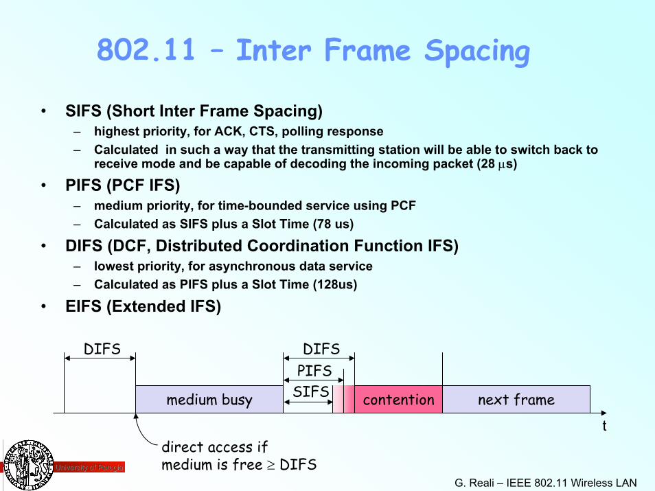
• SIFS (Short Inter Frame Spacing)– highest priority, for ACK, CTS, polling response– Calculated in such a way that the transmitting station will be able to switch back to
receive mode and be capable of decoding the incoming packet (28 µs)
• PIFS (PCF IFS) – medium priority, for time-bounded service using PCF– Calculated as SIFS plus a Slot Time (78 us)
• DIFS (DCF, Distributed Coordination Function IFS)– lowest priority, for asynchronous data service– Calculated as PIFS plus a Slot Time (128us)
• EIFS (Extended IFS)
direct access ifmedium is free ≥ DIFS
t
medium busy SIFSPIFSDIFSDIFS
next framecontention
University of PerugiaUniversity of Perugia
G. Reali – IEEE 802.11 Wireless LAN 29
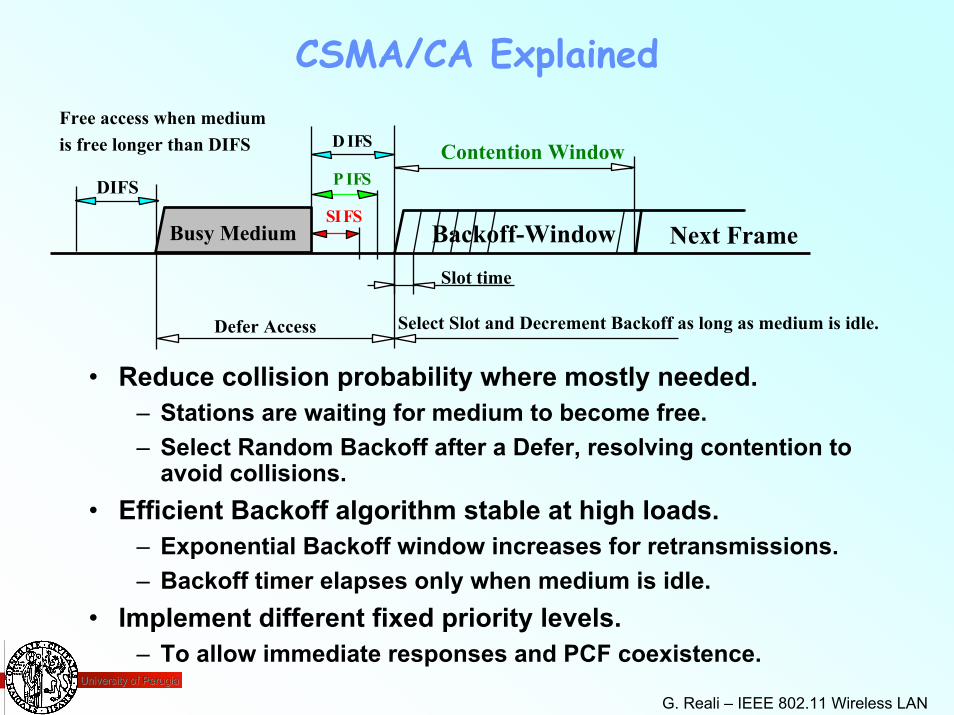
CSMA/CA ExplainedFree access when medium
Backoff-Window Next Frame
is free longer than DIFS D IFS Contention Window
Slot time
Defer Access Select Slot and Decrement Backoff as long as medium is idle.
P IFSDIFS
Busy MediumSIFS
• Reduce collision probability where mostly needed.– Stations are waiting for medium to become free.– Select Random Backoff after a Defer, resolving contention to
avoid collisions.• Efficient Backoff algorithm stable at high loads.
– Exponential Backoff window increases for retransmissions.– Backoff timer elapses only when medium is idle.
• Implement different fixed priority levels.– To allow immediate responses and PCF coexistence.
University of PerugiaUniversity of Perugia
G. Reali – IEEE 802.11 Wireless LAN 30
Backoff Interval
• When transmitting a packet, choose a backoff interval in the range [0,cw]– cw is contention window
• Count down the backoff interval when medium is idle– Count-down is suspended if medium becomes busy
• When backoff interval reaches 0, transmit RTS
University of PerugiaUniversity of Perugia
G. Reali – IEEE 802.11 Wireless LAN 31
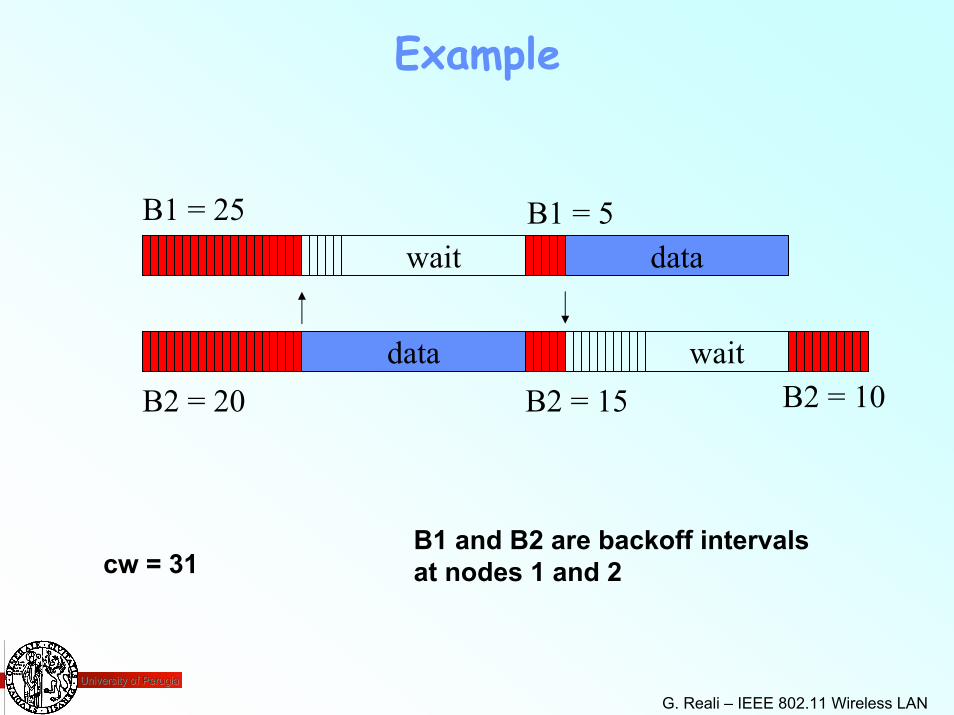
Example
data
waitB1 = 5
B2 = 15
B1 = 25
B2 = 20
data
waitB2 = 10
B1 and B2 are backoff intervalsat nodes 1 and 2cw = 31
University of PerugiaUniversity of Perugia
G. Reali – IEEE 802.11 Wireless LAN 32
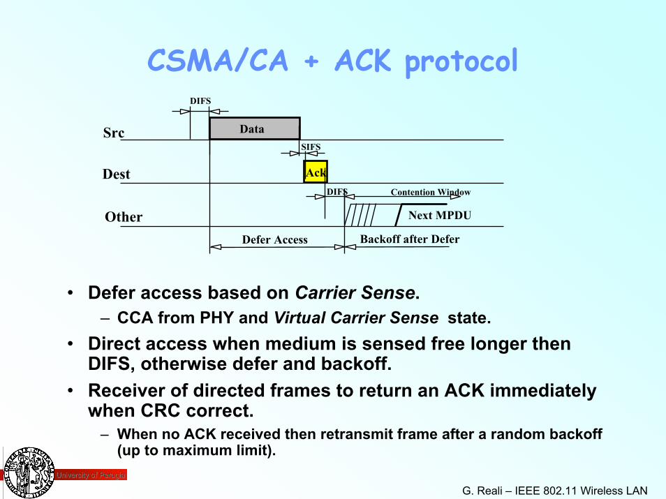
CSMA/CA + ACK protocol
Ack
Data
Next MPDU
Src
Dest
Other
Contention Window
Defer Access Backoff after Defer
DIFS
SIFS
DIFS
• Defer access based on Carrier Sense.– CCA from PHY and Virtual Carrier Sense state.
• Direct access when medium is sensed free longer then DIFS, otherwise defer and backoff.
• Receiver of directed frames to return an ACK immediately when CRC correct.
– When no ACK received then retransmit frame after a random backoff(up to maximum limit).
University of PerugiaUniversity of Perugia
G. Reali – IEEE 802.11 Wireless LAN 33
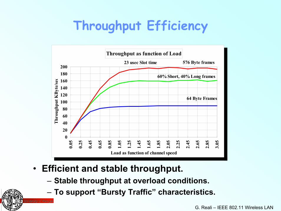
Throughput Efficiency
Throughput as function of Load
Load as function of channel speed
Thr
ough
put K
Byt
e/se
c
020406080
1001201401601802000.
05
0.25
0.45
0.65
0.85
1.05
1.25
1.45
1.65
1.85
2.05
2.25
2.45
2.65
2.85
3.05
576 Byte frames
60% Short, 40% Long frames
64 Byte Frames
23 usec Slot time
• Efficient and stable throughput.– Stable throughput at overload conditions.– To support “Bursty Traffic” characteristics.
University of PerugiaUniversity of Perugia
G. Reali – IEEE 802.11 Wireless LAN 34
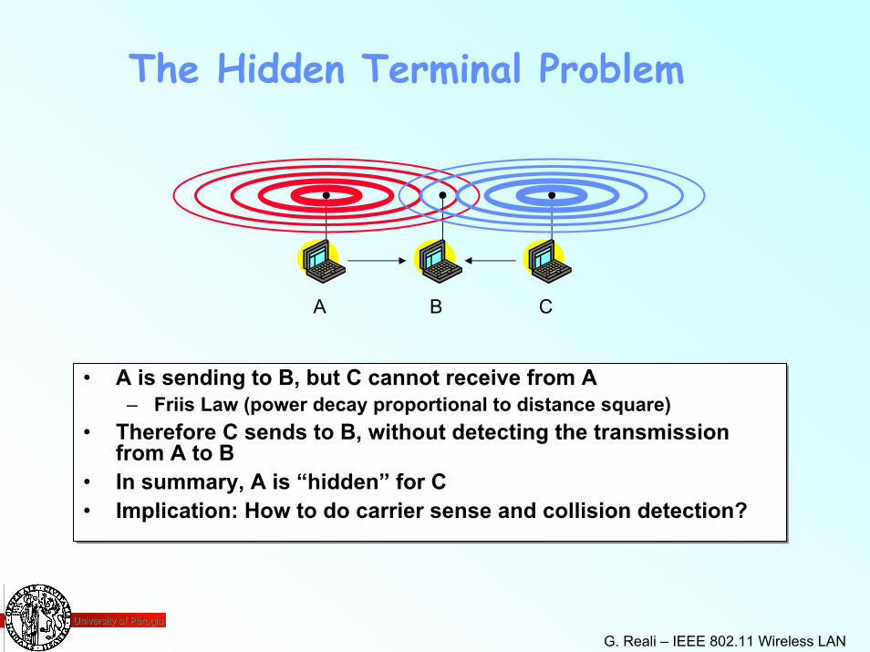
The Hidden Terminal Problem
BA C
• A is sending to B, but C cannot receive from A – Friis Law (power decay proportional to distance square)
• Therefore C sends to B, without detecting the transmission from A to B
• In summary, A is “hidden” for C• Implication: How to do carrier sense and collision detection?
• A is sending to B, but C cannot receive from A – Friis Law (power decay proportional to distance square)
• Therefore C sends to B, without detecting the transmission from A to B
• In summary, A is “hidden” for C• Implication: How to do carrier sense and collision detection?
University of PerugiaUniversity of Perugia
G. Reali – IEEE 802.11 Wireless LAN 35
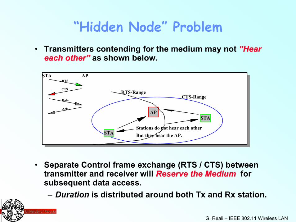
“Hidden Node” Problem
AP
STA
STA
CTS-RangeRTS-Range
STA APRTS
CTS
Data
Ack
Stations do not hear each otherBut they hear the AP.
• Transmitters contending for the medium may not “Hear “Hear each other” each other” as shown below.
• Separate Control frame exchange (RTS / CTS) between transmitter and receiver will Reserve the MediumReserve the Medium for subsequent data access.– Duration is distributed around both Tx and Rx station.
University of PerugiaUniversity of Perugia
G. Reali – IEEE 802.11 Wireless LAN 36
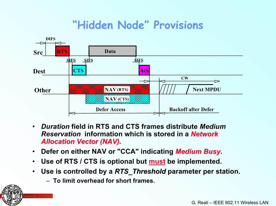
“Hidden Node” Provisions
RTS
CTS Ack
Data
NAV Next MPDU
Src
Dest
Other
CW
NAV
(RTS)
(CTS)
DIFS
SIFS SIFS SIFS
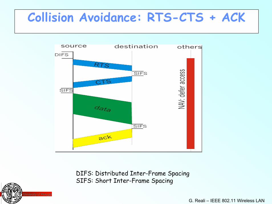
• Duration field in RTS and CTS frames distribute Medium Reservation information which is stored in a Network Network Allocation Vector (NAV)Allocation Vector (NAV).
• Defer on either NAV or "CCA" indicating Medium BusyMedium Busy.• Use of RTS / CTS is optional but must be implemented.• Use is controlled by a RTS_ThresholdRTS_Threshold parameter per station.
– To limit overhead for short frames.
Defer Access Backoff after Defer
University of PerugiaUniversity of Perugia
G. Reali – IEEE 802.11 Wireless LAN 37
Collision Avoidance: RTS-CTS + ACK
DIFS: Distributed Inter-Frame SpacingSIFS: Short Inter-Frame Spacing
University of PerugiaUniversity of Perugia
G. Reali – IEEE 802.11 Wireless LAN 38
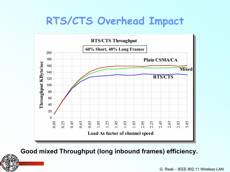
RTS/CTS Overhead Impact
RTS/CTS Throughput
0
20
40
60
80
100
120
140
160
180
2000.
05
0.25
0.45
0.65
0.85
1.05
1.25
1.45
1.65
1.85
2.05
2.25
2.45
2.65
2.85
3.05
Load As factor of channel speed
Thr
ough
put K
Byt
e/se
c Plain CSMA/CA
MixedRTS/CTS
RTS/CTS Throughput
0
20
40
60
80
100
120
140
160
180
2000.
05
0.25
0.45
0.65
0.85
1.05
1.25
1.45
1.65
1.85
2.05
2.25
2.45
2.65
2.85
3.05
Load As factor of channel speed
Thr
ough
put K
Byt
e/se
c Plain CSMA/CA
MixedRTS/CTS
60% Short, 40% Long Frames
Good mixed Throughput (long inbound frames) efficiency.
University of PerugiaUniversity of Perugia
G. Reali – IEEE 802.11 Wireless LAN 39
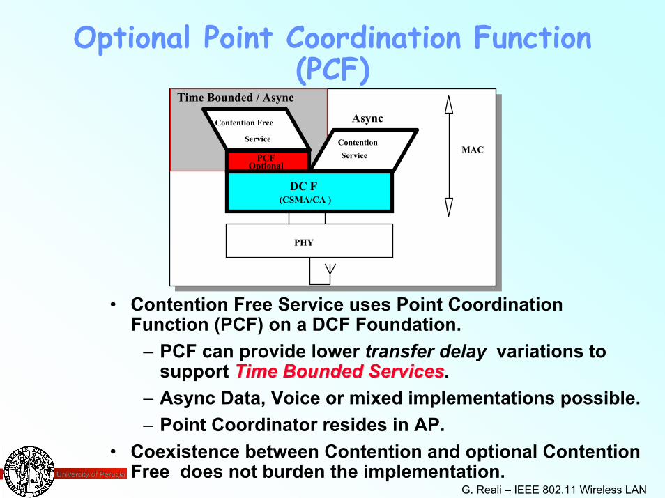
Optional Point Coordination Function (PCF)
(CSMA/CA )
ContentionService
Service
PHY
MACPCF
Optional
DC F
Contention Free Async
Time Bounded / Async
• Contention Free Service uses Point Coordination Function (PCF) on a DCF Foundation.
– PCF can provide lower transfer delay variations to support Time Bounded ServicesTime Bounded Services.
– Async Data, Voice or mixed implementations possible.– Point Coordinator resides in AP.
• Coexistence between Contention and optional Contention Free does not burden the implementation.
University of PerugiaUniversity of Perugia
G. Reali – IEEE 802.11 Wireless LAN 40
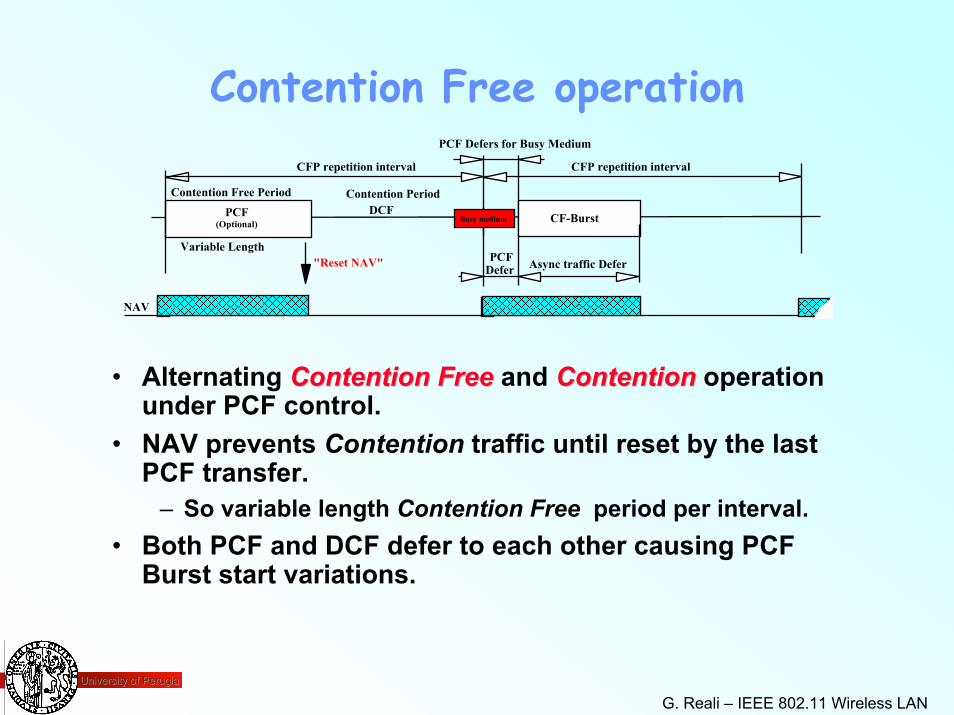
Contention Free operationPCF Defers for Busy Medium
CF-BurstBusy mediumPCF DCF
(Optional)
• Alternating Contention FreeContention Free and ContentionContention operation under PCF control.
• NAV prevents Contention traffic until reset by the last PCF transfer.
– So variable length Contention Free period per interval.• Both PCF and DCF defer to each other causing PCF
Burst start variations.
Contention Free Period Contention Period
CFP repetition interval CFP repetition interval
Defer Async traffic DeferPCFVariable Length
"Reset NAV"
NAV
University of PerugiaUniversity of Perugia
G. Reali – IEEE 802.11 Wireless LAN 41
PCF Burst
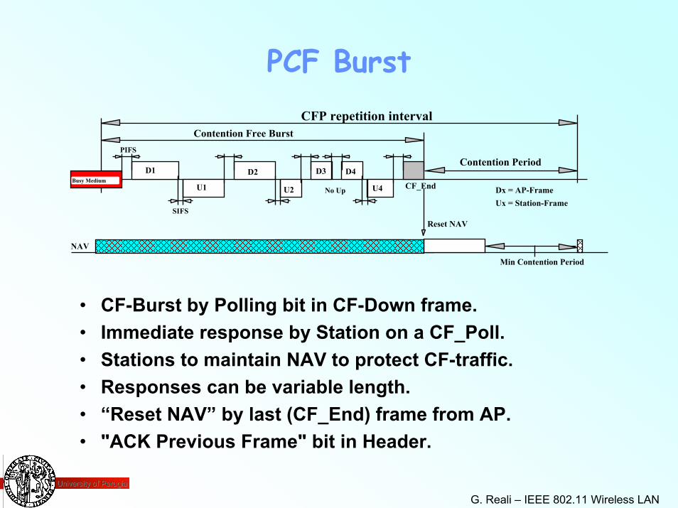
• CF-Burst by Polling bit in CF-Down frame.• Immediate response by Station on a CF_Poll.• Stations to maintain NAV to protect CF-traffic.• Responses can be variable length.• “Reset NAV” by last (CF_End) frame from AP.• "ACK Previous Frame" bit in Header.
CFP repetition interval
D1
U1 U2
D2 D3 D4
U4
NAV
Reset NAV
No Up
Contention Period
Contention Free Burst
Dx = AP-FrameUx = Station-Frame
CF_End
Min Contention Period
Busy Medium
PIFS
SIFS
University of PerugiaUniversity of Perugia
G. Reali – IEEE 802.11 Wireless LAN 42
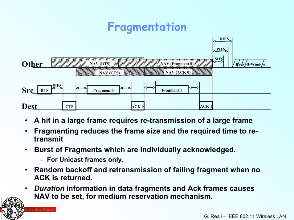
Fragmentation
• A hit in a large frame requires re-transmission of a large frame• Fragmenting reduces the frame size and the required time to re-
transmit• Burst of Fragments which are individually acknowledged.
– For Unicast frames only.• Random backoff and retransmission of failing fragment when no
ACK is returned.• Duration information in data fragments and Ack frames causes
NAV to be set, for medium reservation mechanism.
Fragment 0
ACK 0
Src
Dest CTS
SIFSRTS
NAV (RTS)
NAV (CTS)
Other Backoff-Window
ACK 1
Fragment 1
NAV (Fragment 0)
NAV (ACK 0)
SIFS
DIFS
PIFS
University of PerugiaUniversity of Perugia
G. Reali – IEEE 802.11 Wireless LAN 43
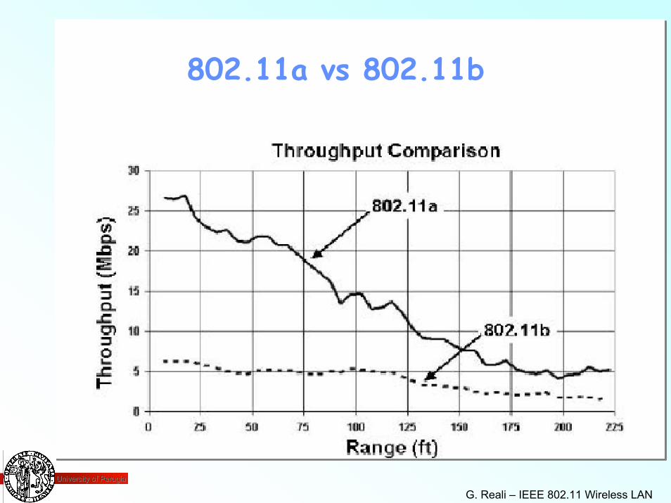
802.11a vs 802.11b
University of PerugiaUniversity of Perugia
G. Reali – IEEE 802.11 Wireless LAN 44
IEEE 802.11 Frame Types
• Three types of frames– Control
» RTS, CTS, ACK, Contention-Free (CF), PS-Poll– Management
» Probe request/response» Beacon
• supported rates, timestamp, traffic indication map» Authentication / deauthentication» Announcement traffic indication message (ATIM)
• sent after each frame
– Data
University of PerugiaUniversity of Perugia
G. Reali – IEEE 802.11 Wireless LAN 45
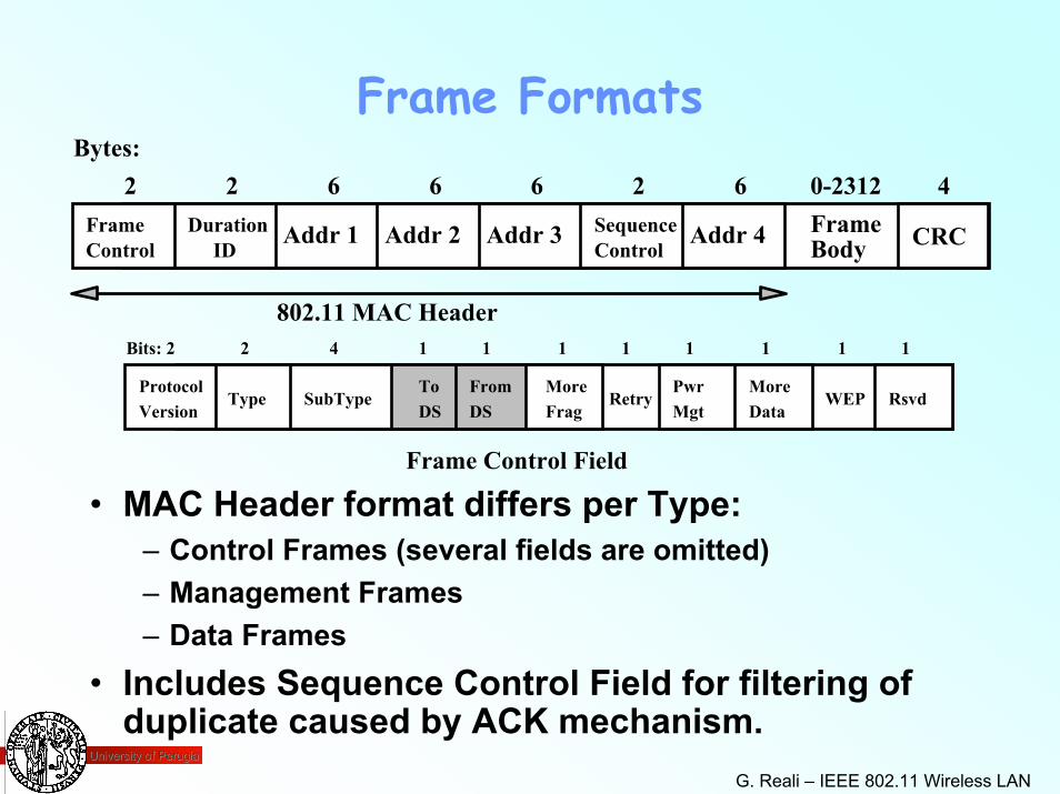
Frame FormatsBytes:
FrameControl
DurationID
Addr 1 Addr 2 Addr 3 Addr 4SequenceControl CRCFrame
Body
2 2 6 6 6 62 0-2312 4
802.11 MAC HeaderBits: 2 2 4 1 1 1 1 1 1 1 1
ProtocolVersion
Type SubTypeToDS
RetryPwrMgt
MoreData
WEP RsvdDSFrom More
Frag
Frame Control Field
• MAC Header format differs per Type:– Control Frames (several fields are omitted)– Management Frames– Data Frames
• Includes Sequence Control Field for filtering of duplicate caused by ACK mechanism.
University of PerugiaUniversity of Perugia
G. Reali – IEEE 802.11 Wireless LAN 46
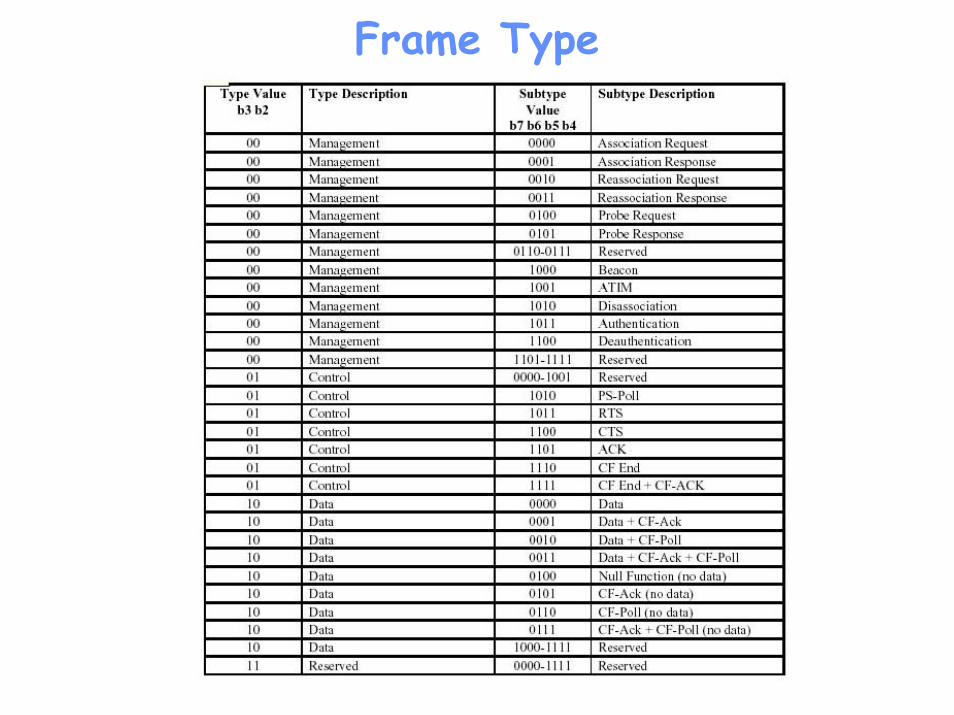
Frame Type
University of PerugiaUniversity of Perugia
G. Reali – IEEE 802.11 Wireless LAN 47
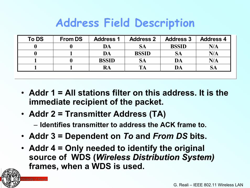
Address Field DescriptionTo DS From DS Address 1 Address 2 Address 3 Address 4
0 0 DA SA BSSID N/A0 1 DA BSSID SA N/A1 0 BSSID SA DA N/A1 1 RA TA DA SA
• Addr 1 = All stations filter on this address. It is the immediate recipient of the packet.
• Addr 2 = Transmitter Address (TA)– Identifies transmitter to address the ACK frame to.
• Addr 3 = Dependent on To and From DS bits.• Addr 4 = Only needed to identify the original
source of WDS ((Wireless Distribution System)Wireless Distribution System)frames, when a WDS is used.
University of PerugiaUniversity of Perugia
G. Reali – IEEE 802.11 Wireless LAN 48
Privacy and Access Control• Goal of 802.11 is to provide “Wired Equivalent Privacy” (WEP)
– Usable worldwide• 802.11 provides for an Authentication mechanism
– To aid in access control.– Has provisions for “OPEN”, “Shared Key” or proprietary
authentication extensions.• Optional (WEP) Privacy mechanism defined by 802.11.
– Limited for Station-to-Station traffic, so not “end to end”.» Embedded in the MAC entity.
– Only implements “Confidentiality” function.– Uses RC4 PRNG algorithm based on:
» a 40 bit secret key (No Key distribution standardized)» and a 24 bit IV that is send with the data.» includes an ICV to allow integrity check.
– Only payload of Data frames are encrypted.» Encryption on per MPDU basis.
University of PerugiaUniversity of Perugia
G. Reali – IEEE 802.11 Wireless LAN 49
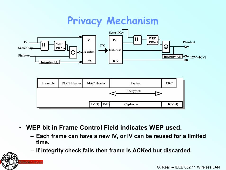
Privacy MechanismIV
Secret Key
Ciphertext
ICV
WEPPRNG
+WEPPRNG
IV
Secret Key
Integrity Alg
+ Ciphertext
ICV
Plaintext
PlaintextIV
• WEP bit in Frame Control Field indicates WEP used.– Each frame can have a new IV, or IV can be reused for a limited
time.– If integrity check fails then frame is ACKed but discarded.
TX
Integrity Alg ICV'=ICV?
Preamble PLCP Header MAC Header CRCPayload
Encrypted
IV (4) ICV (4)CyphertextK-ID
University of PerugiaUniversity of Perugia
G. Reali – IEEE 802.11 Wireless LAN 50
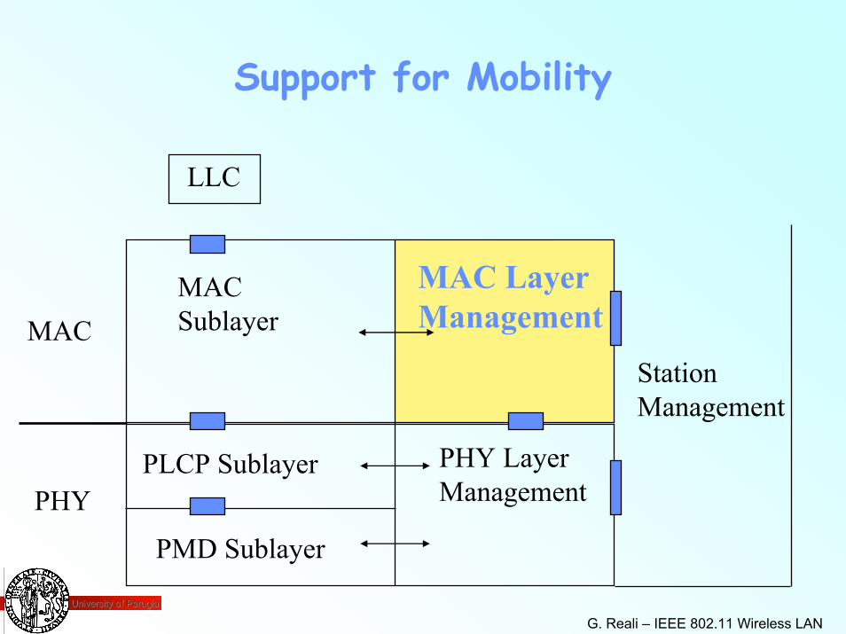
Support for Mobility
LLC
MAC Sublayer
PLCP Sublayer
PMD Sublayer
MAC LayerManagement
PHY LayerManagement
MACStationManagement
PHY
University of PerugiaUniversity of Perugia
G. Reali – IEEE 802.11 Wireless LAN 51
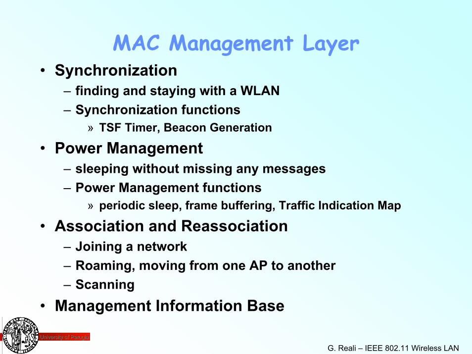
MAC Management Layer• Synchronization
– finding and staying with a WLAN– Synchronization functions
» TSF Timer, Beacon Generation
• Power Management– sleeping without missing any messages– Power Management functions
» periodic sleep, frame buffering, Traffic Indication Map
• Association and Reassociation– Joining a network– Roaming, moving from one AP to another– Scanning
• Management Information Base
University of PerugiaUniversity of Perugia
G. Reali – IEEE 802.11 Wireless LAN 52
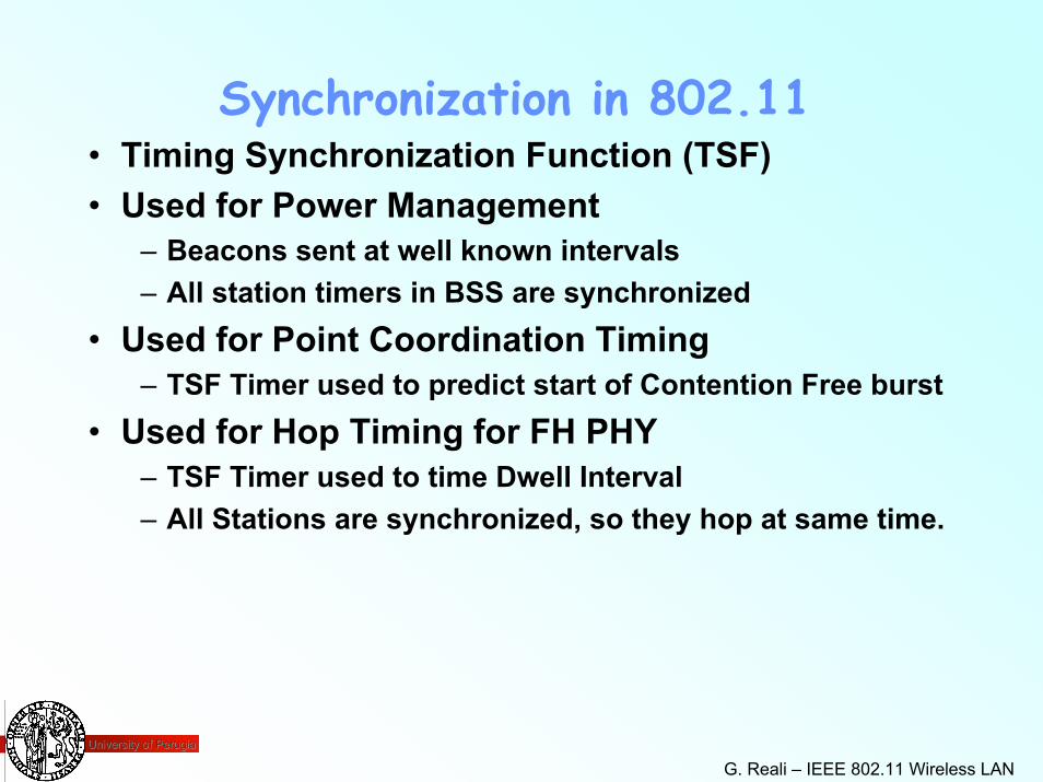
Synchronization in 802.11• Timing Synchronization Function (TSF)• Used for Power Management
– Beacons sent at well known intervals– All station timers in BSS are synchronized
• Used for Point Coordination Timing– TSF Timer used to predict start of Contention Free burst
• Used for Hop Timing for FH PHY– TSF Timer used to time Dwell Interval– All Stations are synchronized, so they hop at same time.
University of PerugiaUniversity of Perugia
G. Reali – IEEE 802.11 Wireless LAN 53
Synchronization Approach• All stations maintain a local timer.• Timing Synchronization Function
– keeps timers from all stations in synch– AP controls timing in infrastructure networks– distributed function for Independent BSS
• Timing conveyed by periodic Beacon transmissions– Beacons contain Timestamp for the entire BSS– Timestamp from Beacons used to calibrate local clocks– not required to hear every Beacon to stay in synch– Beacons contain other management information
» also used for Power Management, Roaming
University of PerugiaUniversity of Perugia
G. Reali – IEEE 802.11 Wireless LAN 54
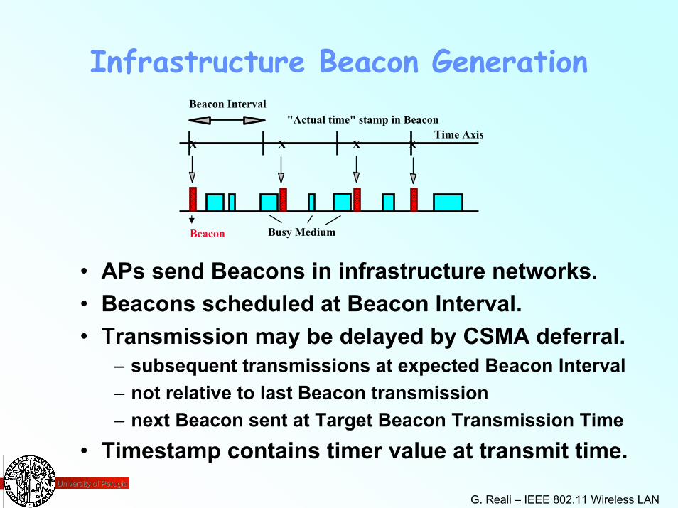
Infrastructure Beacon GenerationBeacon Interval
• APs send Beacons in infrastructure networks. • Beacons scheduled at Beacon Interval.• Transmission may be delayed by CSMA deferral.
– subsequent transmissions at expected Beacon Interval– not relative to last Beacon transmission– next Beacon sent at Target Beacon Transmission Time
• Timestamp contains timer value at transmit time.
Time Axis"Actual time" stamp in Beacon
X X X X
Busy MediumBeacon
University of PerugiaUniversity of Perugia
G. Reali – IEEE 802.11 Wireless LAN 55
Power Management• Mobile devices are battery powered.
– Power Management is important for mobility.• Current LAN protocols assume stations are
always ready to receive.– Idle receive state dominates LAN adapter power
consumption over time.• How can we power off during idle periods, yet
maintain an active session?• 802.11 Power Management Protocol:
– allows transceiver to be off as much as possible– is transparent to existing protocols– is flexible to support different applications
» possible to trade off throughput for battery life
University of PerugiaUniversity of Perugia
G. Reali – IEEE 802.11 Wireless LAN 56
Power Management Approach• Allow idle stations to go to sleep
– station’s power save mode stored in AP• APs buffer packets for sleeping stations.
– AP announces which stations have frames buffered– Traffic Indication Map (TIM) sent with every Beacon
• Power Saving stations wake up periodically– listen for Beacons
• TSF assures AP and Power Save stations are synchronized
– stations will wake up to hear a Beacon– TSF timer keeps running when stations are sleeping– synchronization allows extreme low power operation
• Independent BSS also have Power Management– similar in concept, distributed approach
University of PerugiaUniversity of Perugia
G. Reali – IEEE 802.11 Wireless LAN 57
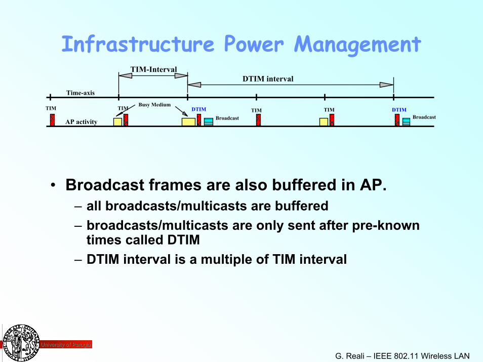
Infrastructure Power Management
• Broadcast frames are also buffered in AP.– all broadcasts/multicasts are buffered– broadcasts/multicasts are only sent after pre-known
times called DTIM– DTIM interval is a multiple of TIM interval
TIM-IntervalDTIM interval
Time-axis
AP activity
TIMBroadcastBroadcast
Busy MediumTIM DTIM TIM DTIMTIM
University of PerugiaUniversity of Perugia
G. Reali – IEEE 802.11 Wireless LAN 58
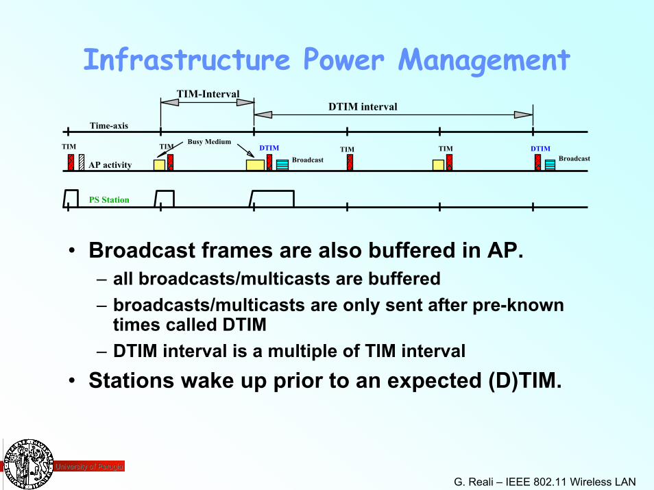
Infrastructure Power Management
• Broadcast frames are also buffered in AP.– all broadcasts/multicasts are buffered– broadcasts/multicasts are only sent after pre-known
times called DTIM– DTIM interval is a multiple of TIM interval
• Stations wake up prior to an expected (D)TIM.
TIM-IntervalDTIM interval
Time-axis
AP activity
TIMBroadcastBroadcast
Busy MediumTIM DTIM TIM DTIMTIM
PS Station
University of PerugiaUniversity of Perugia
G. Reali – IEEE 802.11 Wireless LAN 59
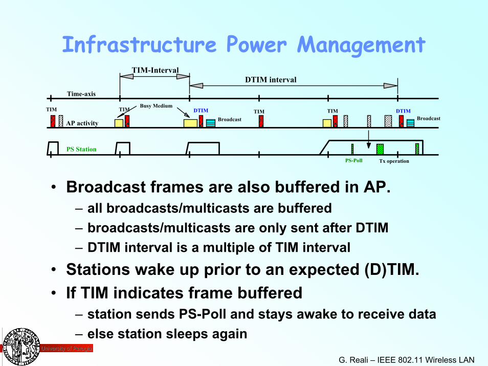
Infrastructure Power Management
• Broadcast frames are also buffered in AP.– all broadcasts/multicasts are buffered– broadcasts/multicasts are only sent after DTIM– DTIM interval is a multiple of TIM interval
• Stations wake up prior to an expected (D)TIM.• If TIM indicates frame buffered
– station sends PS-Poll and stays awake to receive data– else station sleeps again
TIM-IntervalDTIM interval
Time-axis
AP activity
TIMBroadcastBroadcast
Busy MediumTIM DTIM TIM DTIMTIM
Tx operation
PS StationPS-Poll
University of PerugiaUniversity of Perugia
G. Reali – IEEE 802.11 Wireless LAN 60
WLAN Infrastructure Network
Access Point A
Access Point B
Station 4
Access Point C
Station 1 Station 2
Station 3
Station 5Station 6
Station 7
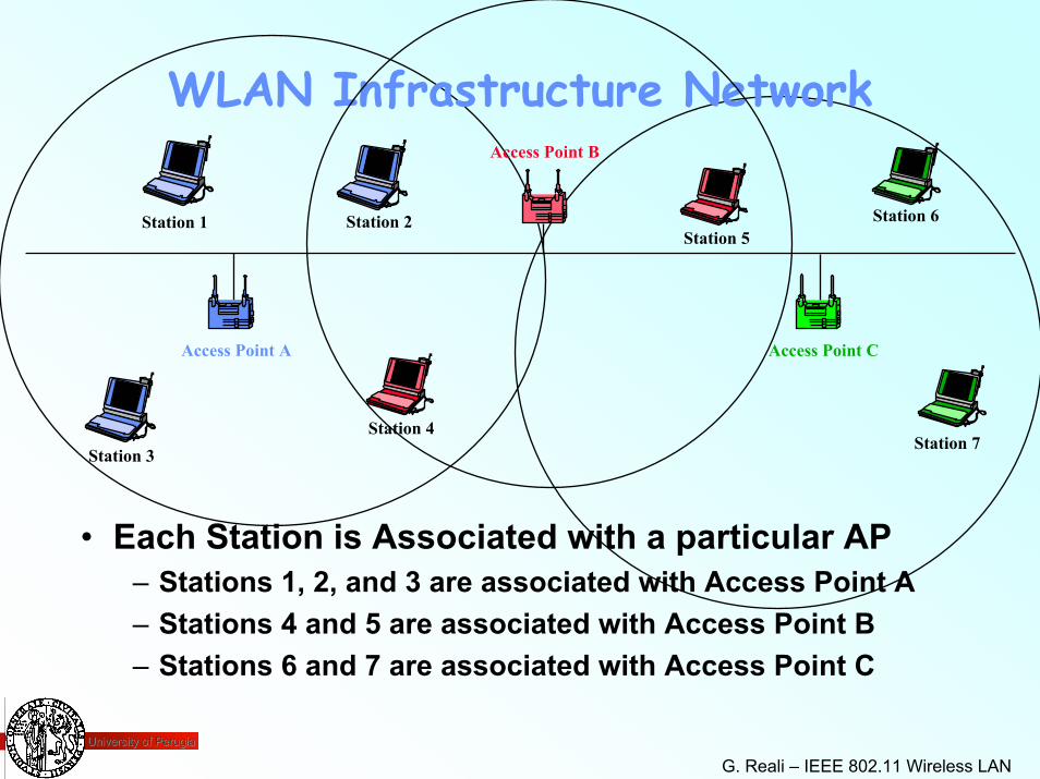
• Each Station is Associated with a particular AP– Stations 1, 2, and 3 are associated with Access Point A– Stations 4 and 5 are associated with Access Point B– Stations 6 and 7 are associated with Access Point C
University of PerugiaUniversity of Perugia
G. Reali – IEEE 802.11 Wireless LAN 61
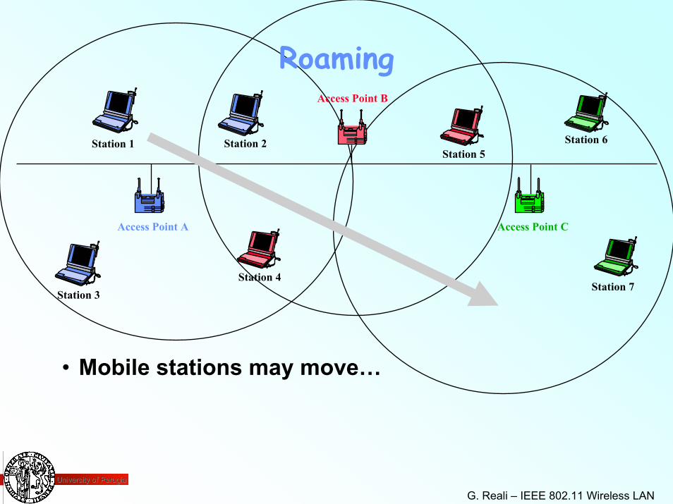
Roaming
Access Point A
Access Point B
Station 4
Access Point C
Station 1 Station 2
Station 3
Station 5Station 6
Station 7
• Mobile stations may move…
University of PerugiaUniversity of Perugia
G. Reali – IEEE 802.11 Wireless LAN 62
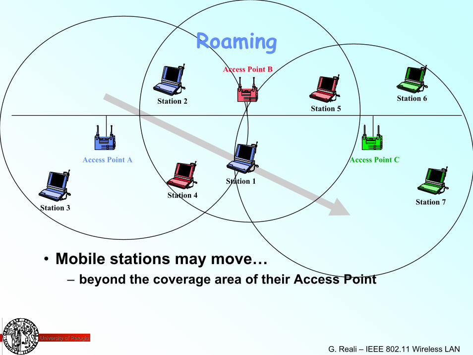
Roaming
Access Point A
Access Point B
Station 4
Access Point C
Station 1
Station 2
Station 3
Station 5Station 6
Station 7
• Mobile stations may move…– beyond the coverage area of their Access Point
University of PerugiaUniversity of Perugia
G. Reali – IEEE 802.11 Wireless LAN 63
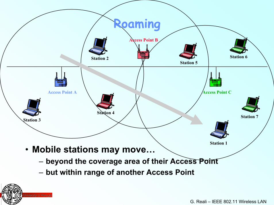
Roaming
Access Point A
Access Point B
Station 4
Access Point C
Station 1
Station 2
Station 3
Station 5Station 6
Station 7
• Mobile stations may move…– beyond the coverage area of their Access Point– but within range of another Access Point
University of PerugiaUniversity of Perugia
G. Reali – IEEE 802.11 Wireless LAN 64
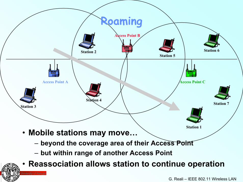
Roaming
Access Point A
Access Point B
Station 4
Access Point C
Station 1
Station 2
Station 3
Station 5Station 6
Station 7
• Mobile stations may move…– beyond the coverage area of their Access Point– but within range of another Access Point
• Reassociation allows station to continue operation
University of PerugiaUniversity of Perugia
G. Reali – IEEE 802.11 Wireless LAN 65
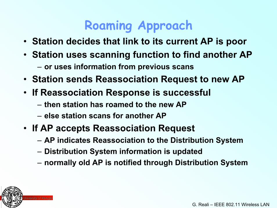
Roaming Approach• Station decides that link to its current AP is poor• Station uses scanning function to find another AP
– or uses information from previous scans• Station sends Reassociation Request to new AP• If Reassociation Response is successful
– then station has roamed to the new AP– else station scans for another AP
• If AP accepts Reassociation Request– AP indicates Reassociation to the Distribution System– Distribution System information is updated– normally old AP is notified through Distribution System
University of PerugiaUniversity of Perugia
G. Reali – IEEE 802.11 Wireless LAN 66
Scanning• Scanning required for many functions.
– finding and joining a network– finding a new AP while roaming– initializing an Independent BSS (ad hoc) network
• 802.11 MAC uses a common mechanism for all PHY.– single or multi channel– passive or active scanning
• Passive Scanning– Find networks simply by listening for Beacons
• Active Scanning– On each channel
» Send a Probe, Wait for a Probe Response
• Beacon or Probe Response contains information necessary to join new network.
University of PerugiaUniversity of Perugia
G. Reali – IEEE 802.11 Wireless LAN 67
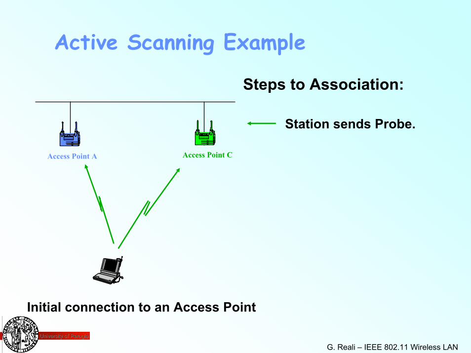
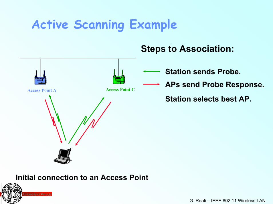
Active Scanning Example
Steps to Association:
Station sends Probe.
Initial connection to an Access Point
Access Point CAccess Point A
University of PerugiaUniversity of Perugia
G. Reali – IEEE 802.11 Wireless LAN 68
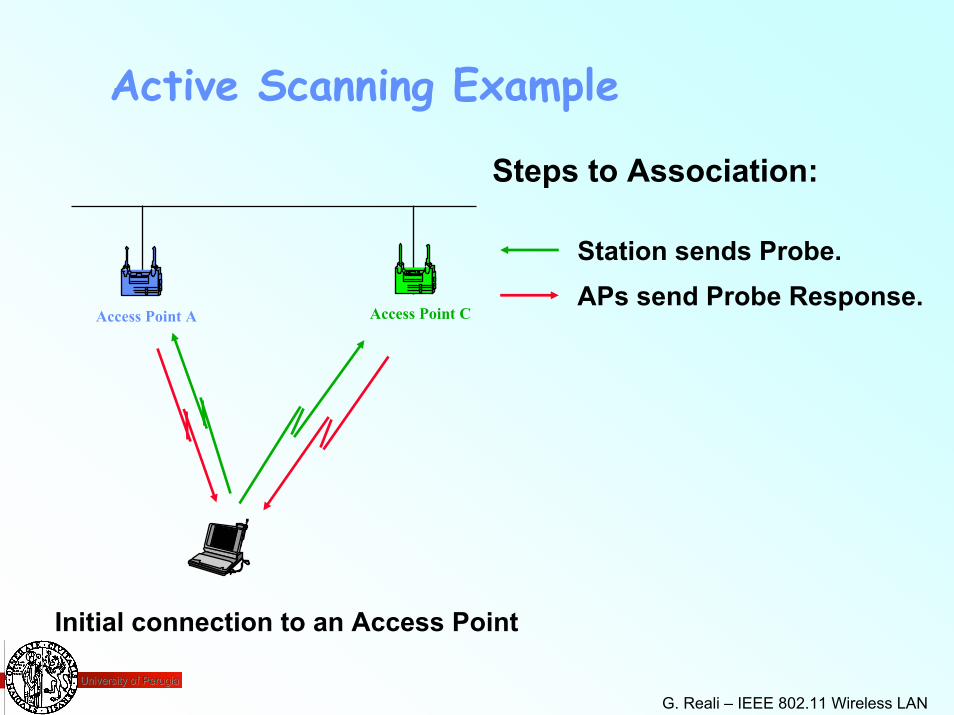
Active Scanning Example
Steps to Association:
Station sends Probe.APs send Probe Response.
Initial connection to an Access Point
Access Point CAccess Point A
University of PerugiaUniversity of Perugia
G. Reali – IEEE 802.11 Wireless LAN 69
Active Scanning Example
Steps to Association:
Station sends Probe.APs send Probe Response.
Station selects best AP.
Initial connection to an Access Point
Access Point CAccess Point A
University of PerugiaUniversity of Perugia
G. Reali – IEEE 802.11 Wireless LAN 70
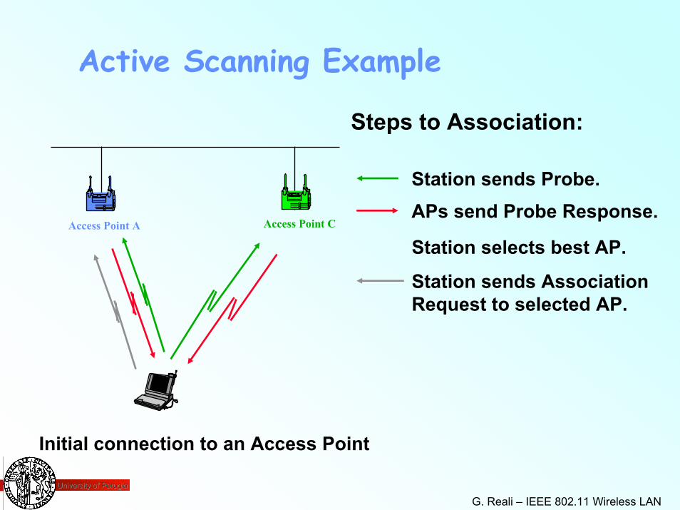
Active Scanning Example
Steps to Association:
Station sends Probe.APs send Probe Response.
Station selects best AP.
Station sends AssociationRequest to selected AP.
Initial connection to an Access Point
Access Point CAccess Point A
University of PerugiaUniversity of Perugia
G. Reali – IEEE 802.11 Wireless LAN 71
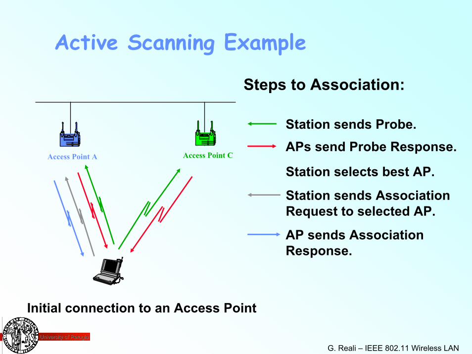
Active Scanning Example
Steps to Association:
Station sends Probe.APs send Probe Response.
Station selects best AP.
Station sends AssociationRequest to selected AP.
AP sends AssociationResponse.
Initial connection to an Access Point
Access Point CAccess Point A
University of PerugiaUniversity of Perugia
G. Reali – IEEE 802.11 Wireless LAN 72
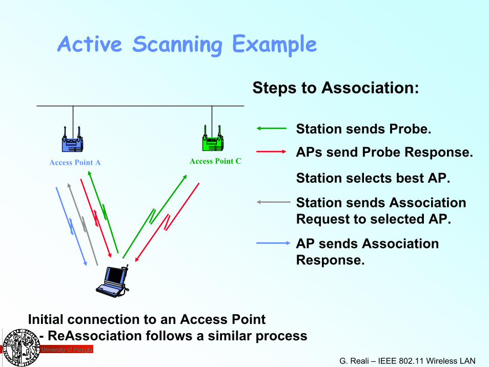
Active Scanning Example
Steps to Association:
Station sends Probe.APs send Probe Response.
Station selects best AP.
Station sends AssociationRequest to selected AP.
AP sends AssociationResponse.
Initial connection to an Access Point- ReAssociation follows a similar process
Access Point CAccess Point A
University of PerugiaUniversity of Perugia
G. Reali – IEEE 802.11 Wireless LAN 73
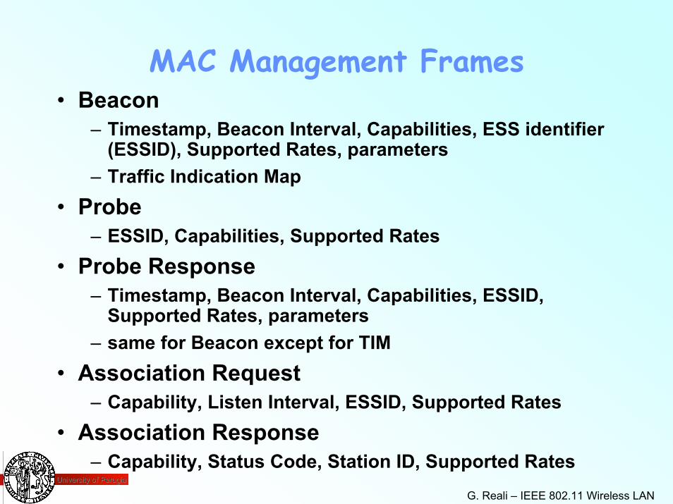
MAC Management Frames• Beacon
– Timestamp, Beacon Interval, Capabilities, ESS identifier (ESSID), Supported Rates, parameters
– Traffic Indication Map• Probe
– ESSID, Capabilities, Supported Rates• Probe Response
– Timestamp, Beacon Interval, Capabilities, ESSID, Supported Rates, parameters
– same for Beacon except for TIM• Association Request
– Capability, Listen Interval, ESSID, Supported Rates• Association Response
– Capability, Status Code, Station ID, Supported Rates
University of PerugiaUniversity of Perugia
G. Reali – IEEE 802.11 Wireless LAN 74
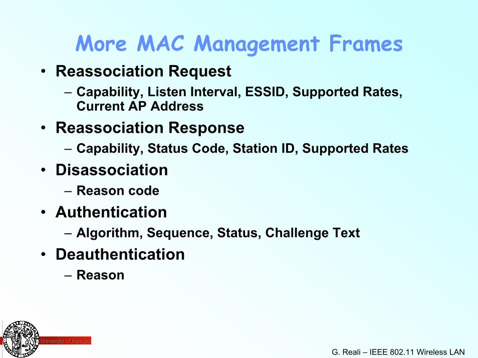
More MAC Management Frames• Reassociation Request
– Capability, Listen Interval, ESSID, Supported Rates, Current AP Address
• Reassociation Response– Capability, Status Code, Station ID, Supported Rates
• Disassociation– Reason code
• Authentication– Algorithm, Sequence, Status, Challenge Text
• Deauthentication– Reason

University of PerugiaUniversity of Perugia
G. Reali – IEEE 802.11 Wireless LAN 75
Questions and
answers