Embed Size (px)
Citation preview
IEEE 802.11 WLAN and HIPERLAN
Dmitri A. Moltchanov
E-mail: [email protected]
http://www.cs.tut.fi/kurssit/ELT-53306/
ELT-53306 D.Moltchanov, TUT
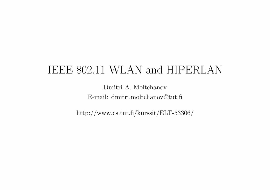
NGN BACKBONE
3G MOBILE SYSTEMS
AD HOC NETWORKS
WLAN
BAN/PAN
WMAN
Lecture: IEEE 802.11 WLAN and HIPERLAN 2
ELT-53306 D.Moltchanov, TUT
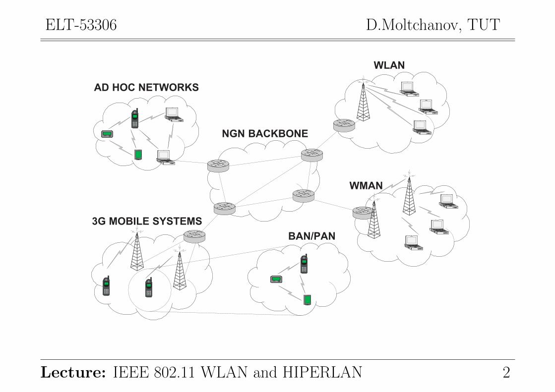
• WLAN technical challenges and design issues:
• Overview of IEEE 802.11;
– IEEE 802.11 task groups;
– Development and layered structure of IEEE 802.11.
• Physical layer;
• MAC layer mechanism;
• Comparison of IEEE 802.11a and 802.11b;
• Comparison of IEEE 802.11g and 802.11b;
• System design for networking in IEEE 802.11;
• The HIPERLAN set of standards:
– HIPERLAN/1;
– HIPERLAN/2.
Lecture: IEEE 802.11 WLAN and HIPERLAN 3
ELT-53306 D.Moltchanov, TUT
1. WLAN technical challenges and design issuesProblems making WLAN design a complicated task:
• Address is not a physical location:
The station is not always stationary. The address does not give any information about location.
• Dynamically changed topology:
The network connectivity is partial at times.
• Medium boundaries are soft:
The communication range cannot be determined precisely in wireless networks.
• Erroneous medium:
BER in wireless network is about 10E − 4 compared to 10E − 9 in fixed networks.
• Hidden and exposed terminal problems:
Some nodes should (not) be allowed to communicate at a certain time.
TASK: build a reliable network using unreliable channels.
Lecture: IEEE 802.11 WLAN and HIPERLAN 4
ELT-53306 D.Moltchanov, TUT
What criteria need to be met?
• Operational simplicity:
Mobile use MUST be able to quickly set up and access network services in a SIMPLE manner.
• Power efficient operation:
The main resource of MT is the power. Design of WLAN must use power saving features.
• Licence-free operation:
Lost cost installation is required for widespread usage of WLAN, e.g., ISM band.
• Tolerance to interference:
There are a lot of technologies operating in ISM band causing interference between them.
• Security:
The inherent broadcast nature make the WLAN vulnerable to different attacks.
• Compatibility:
Compatibility with other technologies and applications is required for a commercial success.
ON TOP OF THIS: global usability, safety, quality of service.
Lecture: IEEE 802.11 WLAN and HIPERLAN 5
ELT-53306 D.Moltchanov, TUT
2. Overview of IEEE 802.11What is important about IEEE WLAN standards:
• the IEEE 802.11 standards are de-factor standards for WLANs;
• set 802.11x specifies the physical and the medium access control (MAC) layers only!
• interfaces to higher layer is the same as those in IEEE 802.x standards;
• MAC layer should be able to work with multiple physical layers.
2.1. IEEE 802.11 task groups
A number of task groups have been defined to work on different networking aspects of WLANs:
• 802.11 WG:
– first WG in 802.11 set;
– aims: develop MAC layer and physical layer specifications;
– released in 1997.
Lecture: IEEE 802.11 WLAN and HIPERLAN 6
ELT-53306 D.Moltchanov, TUT
• 802.11a WG:
– aims: develop a standard for WLAN operations in the 5GHz frequency band;
– released in 1999 (rates up to 54Mbps).
• 802.11b WG:
– aims: develop a standard for operations in 2.4GHz (ISM) frequency band;
– released in 1999;
– rates up to 11Mbps;
– referred to as Wireless Fidelity (Wi-Fi).
• 802.11c WG:
– aims: develop a standard for bridging and access points operations;
– released in 1998.
• 802.11d WG:
– aims: definition and requirements for 802.11 operation in different countries;
– released in 2001.
Lecture: IEEE 802.11 WLAN and HIPERLAN 7
ELT-53306 D.Moltchanov, TUT
• 801.11e WG:
– aims: extend the 802.11 to QoS provision;
– work is in progress.
• 802.11f WG:
– aims: inter access point protocols for operation in ESS;
– released in 2003.
• 802.11g WG:
– aims: extensions to support up to 54Mbps, compatible with 802.11b;
– released in 2003.
• 802.11h WG:
– aims: MAC layer to be in compliance with European standards;
– released in 2003.
• 802.11i WG:
– aims: security extensions for 802.11.
Lecture: IEEE 802.11 WLAN and HIPERLAN 8
ELT-53306 D.Moltchanov, TUT
• 802.11j WG:
– aims: extensions for operation in 4.9GHz band in Japan.
• 802.11n WG:
– aims: extensions for MAC layer to achieve very high data rates (up to 600Mbps);
– work is in progress.
Additional notes about 802.11 WGs:
• Initially, IEEE 802.11 was released, IEEE 802.11b/a/g/n appeared later;
• IEEE 802.11b was the most successful among family (early entrance to the market);
• IEEE 802.11a first appeared on the marked (not compatible with IEEE 802.11b);
• IEEE 802.11g appeared on the marked (compatible with IEEE 802.11b);
• IEEE 802.11n is backward compatible with 802.11b/g
Why is 802.11 WLANs are so successful:
• simplicity of the basic access protocol;
• good start back in 90s.
Lecture: IEEE 802.11 WLAN and HIPERLAN 9
ELT-53306 D.Moltchanov, TUT
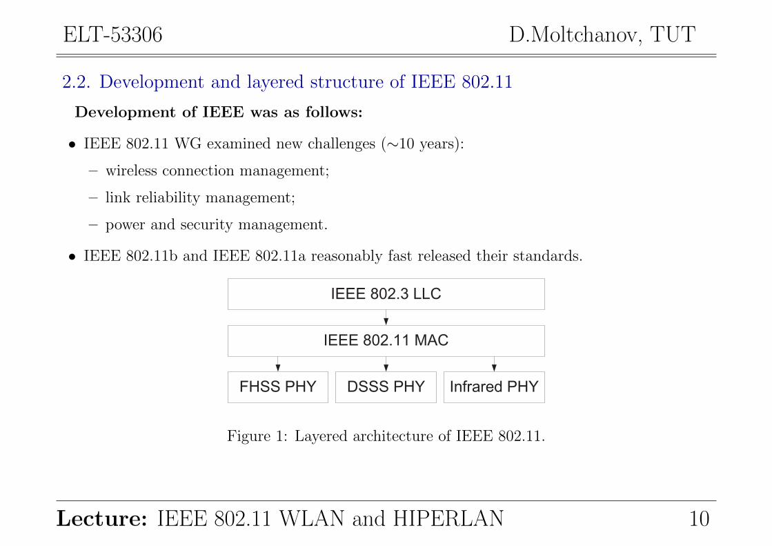
2.2. Development and layered structure of IEEE 802.11
Development of IEEE was as follows:
• IEEE 802.11 WG examined new challenges (∼10 years):
– wireless connection management;
– link reliability management;
– power and security management.
• IEEE 802.11b and IEEE 802.11a reasonably fast released their standards.
FHSS PHY DSSS PHY Infrared PHY
IEEE 802.11 MAC
IEEE 802.3 LLC
Figure 1: Layered architecture of IEEE 802.11.
Lecture: IEEE 802.11 WLAN and HIPERLAN 10
ELT-53306 D.Moltchanov, TUT
802.11
FHSS
IEEE 802.11 MAC
IEEE 802.3 LLC
802.11
DSSS
802.11b
DSSS
802.11a
OFDM
802.5
PHY
802.3
PHY
802.5
MAC
802.3
MAC
802.1
Managem
ent
TCP/IP
Applications
802.11g
OFDM
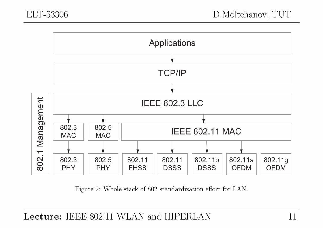
Figure 2: Whole stack of 802 standardization effort for LAN.
Lecture: IEEE 802.11 WLAN and HIPERLAN 11
ELT-53306 D.Moltchanov, TUT
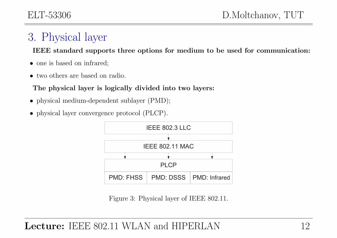
3. Physical layerIEEE standard supports three options for medium to be used for communication:
• one is based on infrared;
• two others are based on radio.
The physical layer is logically divided into two layers:
• physical medium-dependent sublayer (PMD);
• physical layer convergence protocol (PLCP).
PMD: FHSS PMD: DSSS PMD: Infrared
IEEE 802.11 MAC
IEEE 802.3 LLC
PLCP
Figure 3: Physical layer of IEEE 802.11.
Lecture: IEEE 802.11 WLAN and HIPERLAN 12
ELT-53306 D.Moltchanov, TUT
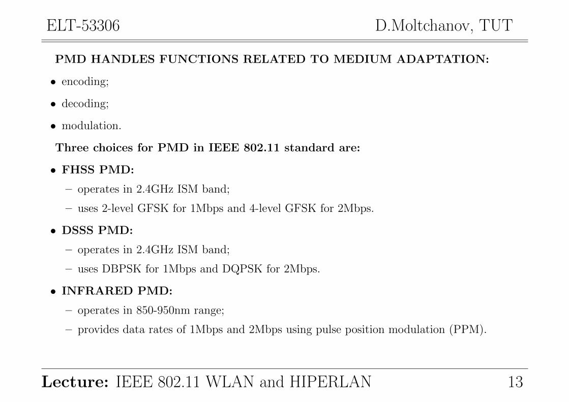
PMD HANDLES FUNCTIONS RELATED TO MEDIUM ADAPTATION:
• encoding;
• decoding;
• modulation.
Three choices for PMD in IEEE 802.11 standard are:
• FHSS PMD:
– operates in 2.4GHz ISM band;
– uses 2-level GFSK for 1Mbps and 4-level GFSK for 2Mbps.
• DSSS PMD:
– operates in 2.4GHz ISM band;
– uses DBPSK for 1Mbps and DQPSK for 2Mbps.
• INFRARED PMD:
– operates in 850-950nm range;
– provides data rates of 1Mbps and 2Mbps using pulse position modulation (PPM).
Lecture: IEEE 802.11 WLAN and HIPERLAN 13
ELT-53306 D.Moltchanov, TUT
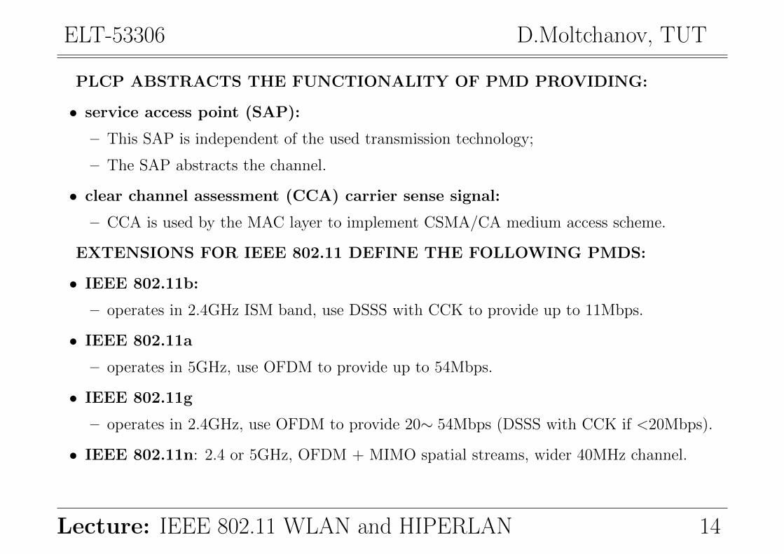
PLCP ABSTRACTS THE FUNCTIONALITY OF PMD PROVIDING:
• service access point (SAP):
– This SAP is independent of the used transmission technology;
– The SAP abstracts the channel.
• clear channel assessment (CCA) carrier sense signal:
– CCA is used by the MAC layer to implement CSMA/CA medium access scheme.
EXTENSIONS FOR IEEE 802.11 DEFINE THE FOLLOWING PMDS:
• IEEE 802.11b:
– operates in 2.4GHz ISM band, use DSSS with CCK to provide up to 11Mbps.
• IEEE 802.11a
– operates in 5GHz, use OFDM to provide up to 54Mbps.
• IEEE 802.11g
– operates in 2.4GHz, use OFDM to provide 20∼ 54Mbps (DSSS with CCK if <20Mbps).
• IEEE 802.11n: 2.4 or 5GHz, OFDM + MIMO spatial streams, wider 40MHz channel.
Lecture: IEEE 802.11 WLAN and HIPERLAN 14
ELT-53306 D.Moltchanov, TUT
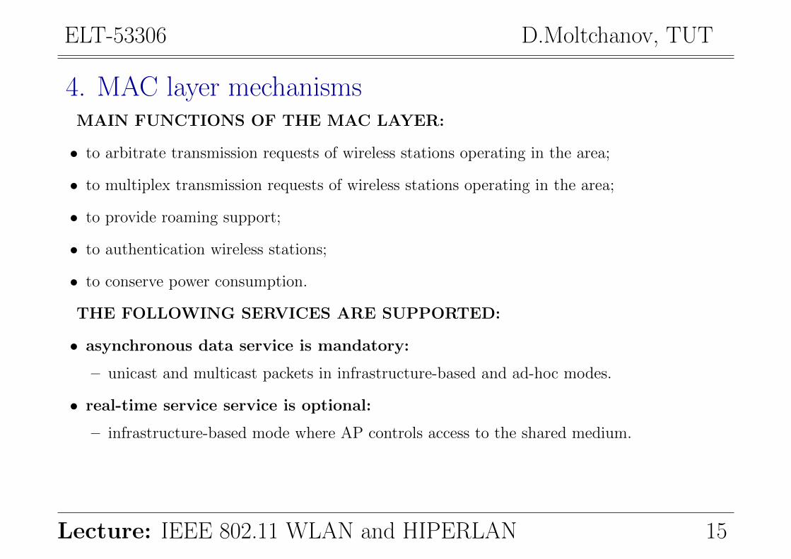
4. MAC layer mechanismsMAIN FUNCTIONS OF THE MAC LAYER:
• to arbitrate transmission requests of wireless stations operating in the area;
• to multiplex transmission requests of wireless stations operating in the area;
• to provide roaming support;
• to authentication wireless stations;
• to conserve power consumption.
THE FOLLOWING SERVICES ARE SUPPORTED:
• asynchronous data service is mandatory:
– unicast and multicast packets in infrastructure-based and ad-hoc modes.
• real-time service service is optional:
– infrastructure-based mode where AP controls access to the shared medium.
Lecture: IEEE 802.11 WLAN and HIPERLAN 15
ELT-53306 D.Moltchanov, TUT
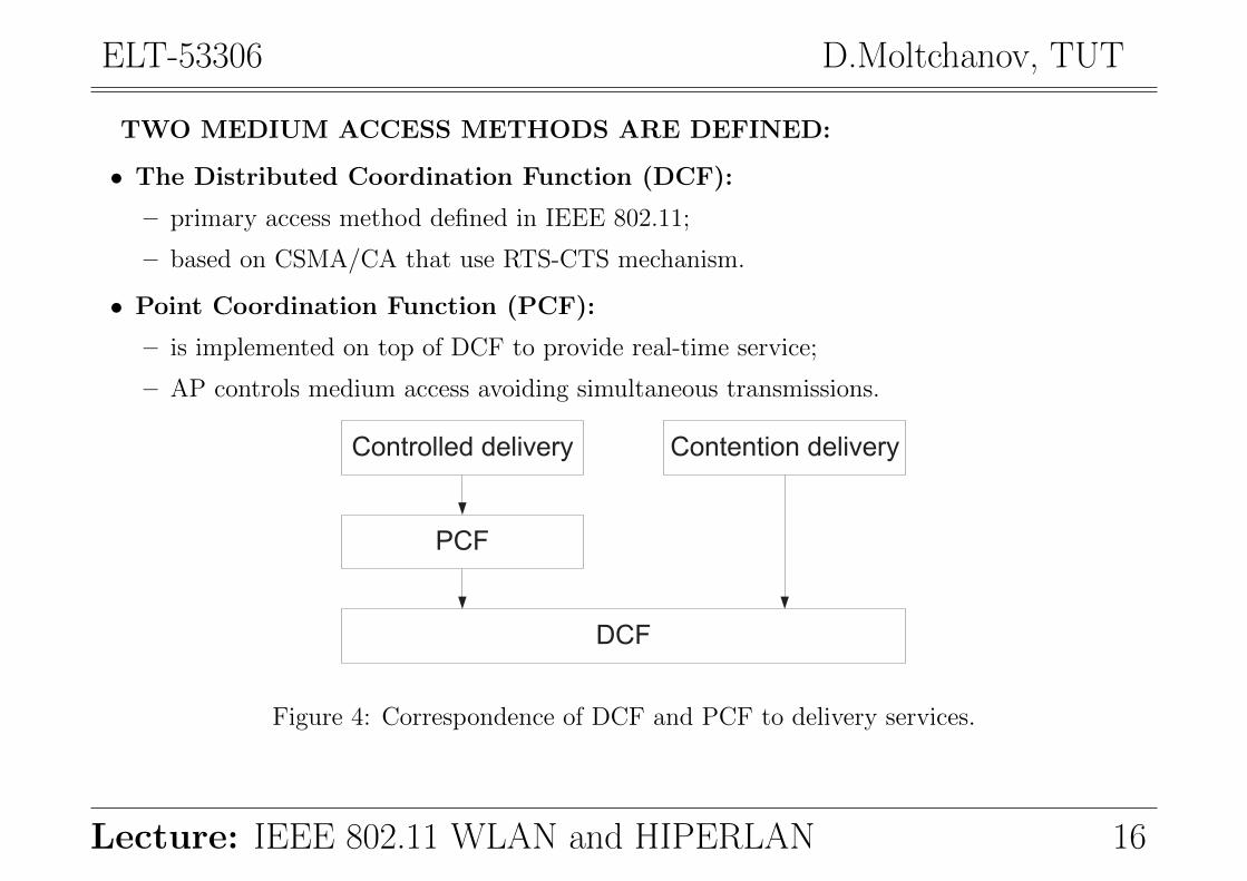
TWO MEDIUM ACCESS METHODS ARE DEFINED:
• The Distributed Coordination Function (DCF):
– primary access method defined in IEEE 802.11;
– based on CSMA/CA that use RTS-CTS mechanism.
• Point Coordination Function (PCF):
– is implemented on top of DCF to provide real-time service;
– AP controls medium access avoiding simultaneous transmissions.
Controlled delivery Contention delivery
PCF
DCF
Figure 4: Correspondence of DCF and PCF to delivery services.
Lecture: IEEE 802.11 WLAN and HIPERLAN 16
ELT-53306 D.Moltchanov, TUT
4.1. Interframe spacing: priorities in frame transmission
THERE ARE FOLLOWING IFSs DEFINED IN IEEE 802.11:
• Short inter-frame spacing (SIFS), shortest:
– the shortest ISF, highest priority;
– used for RTS/CTS frames and ACKs;
– these frames are allowed to transmit just after SIFS.
• PCF inter-frame spacing (PIFS): is the waiting time between SIFS and DIFS (real-time);
– used by PCF in contention-free operation;
– transmission of contention -based stations is just preempted.
• DCF inter-frame spacing (DIFS): used by stations in DSF mode (asynchronous data);
– minimum idle time for contention-based transmissions;
– station is allowed to transmit after DIFS if it has been idle more than this DIFS.
• Extended inter-frame spacing (EIFS): longest (least priority access).
– used when there is an error in frame transmission.
Lecture: IEEE 802.11 WLAN and HIPERLAN 17
ELT-53306 D.Moltchanov, TUT
4.2. Medium access mechanism for contention-based access
THERE WERE TWO CHOICES FOR SHARED MEDIUM ACCESS:
• CSMA/CD:
– +: successfully used in wired IEEE 802.3 networks;
– −: collisions in wireless channels are harder to detect;
– −: collisions leads to usage of bandwidth (this is a scarce resource).
• CSMA/CA was adopted.
HOW TO PROVIDE CARRIER SENSING:
• physical carrier sensing:
– direct sensing of the PHY;
– expensive, provided by the physical layer, complexity depends on the PHY.
• virtual carrier sensing:
– provided by the network allocation vector (NAV);
– NAV indicates how long the medium is reserved;
– NAV is set according to fields (durations) indicated in most frames.
Lecture: IEEE 802.11 WLAN and HIPERLAN 18
ELT-53306 D.Moltchanov, TUT
RTS
CTS
FRAME
ACK
NAV (RTS)
SIFS
SIFS
SIFS
DIFS
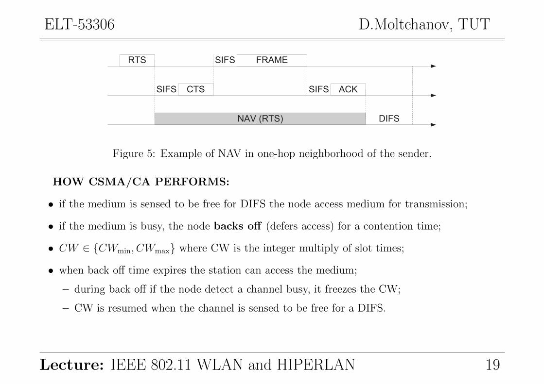
Figure 5: Example of NAV in one-hop neighborhood of the sender.
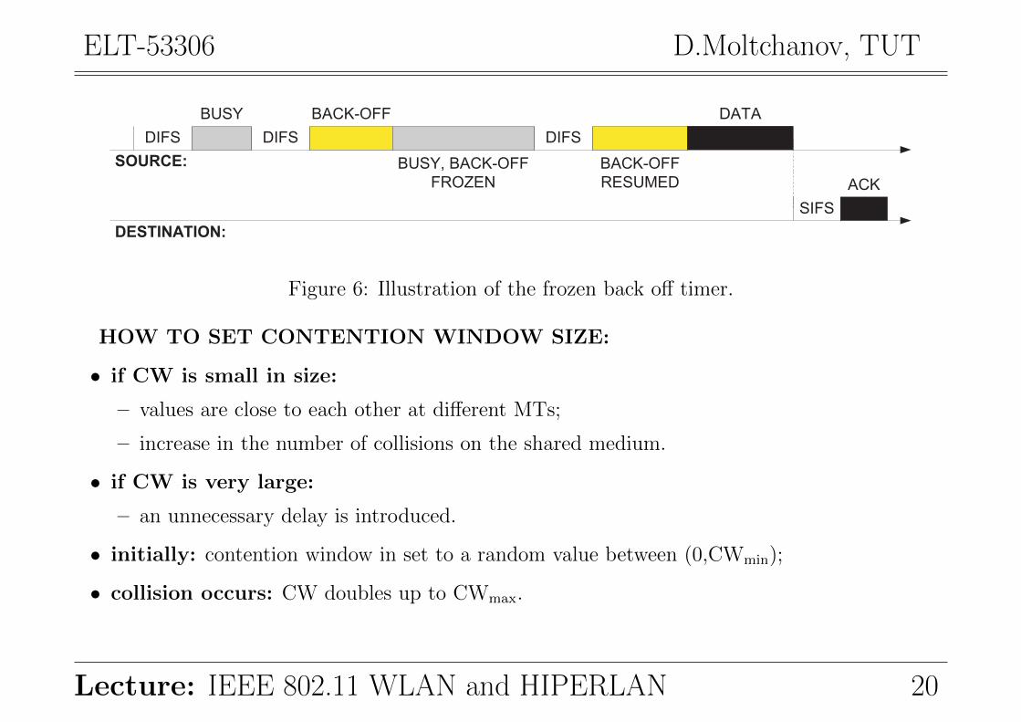
HOW CSMA/CA PERFORMS:
• if the medium is sensed to be free for DIFS the node access medium for transmission;
• if the medium is busy, the node backs off (defers access) for a contention time;
• CW ∈ {CWmin, CWmax} where CW is the integer multiply of slot times;
• when back off time expires the station can access the medium;
– during back off if the node detect a channel busy, it freezes the CW;
– CW is resumed when the channel is sensed to be free for a DIFS.
Lecture: IEEE 802.11 WLAN and HIPERLAN 19
ELT-53306 D.Moltchanov, TUT
DIFS DIFS
BACK-OFF
BUSY, BACK-OFF
FROZEN
DIFS
BACK-OFF
RESUMED
DATA
ACK
SIFS
BUSY
SOURCE:
DESTINATION:
Figure 6: Illustration of the frozen back off timer.
HOW TO SET CONTENTION WINDOW SIZE:
• if CW is small in size:
– values are close to each other at different MTs;
– increase in the number of collisions on the shared medium.
• if CW is very large:
– an unnecessary delay is introduced.
• initially: contention window in set to a random value between (0,CWmin);
• collision occurs: CW doubles up to CWmax.
Lecture: IEEE 802.11 WLAN and HIPERLAN 20
ELT-53306 D.Moltchanov, TUT
31DIFS
63DIFS
127DIFS
255DIFS
511DIFS
1023 slotsDIFS
1023 slotsDIFS
initial transmission
1st retransmission
2nd retransmission
5th
6th
3rd
4th
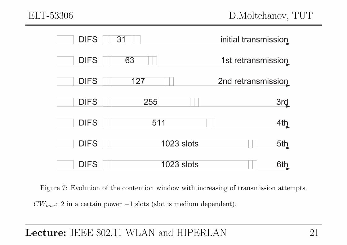
Figure 7: Evolution of the contention window with increasing of transmission attempts.
CWmax: 2 in a certain power −1 slots (slot is medium dependent).
Lecture: IEEE 802.11 WLAN and HIPERLAN 21
ELT-53306 D.Moltchanov, TUT
4.3. Acknowledgements
WHY WE HAVE TO USE ACKs:
• you may expect that frequently frames are incorrectly received.
ACKs ARE POSITIVE! HOW IT IS DONE:
• if a packet is correctly received then priority transmission is organized for ACK (SIFS);
• the receiver accesses the medium after waiting for a SIFS and sends ACK.
4.4. Error detection
WHAT IS IMPLEMENTED TO CONCEAL ERRORS:
• Error detection:
– to detect errors CRC code is used.
• Error correction:
– if no ACK is received by the sender, frame is retransmitted;
– the number of retransmissions is limited;
– if the limit is exceeded the error to higher layer is reported.
Lecture: IEEE 802.11 WLAN and HIPERLAN 22
ELT-53306 D.Moltchanov, TUT
4.5. RTS-CTS mechanism
receiver senderhidden terminal
collisionpackets packets
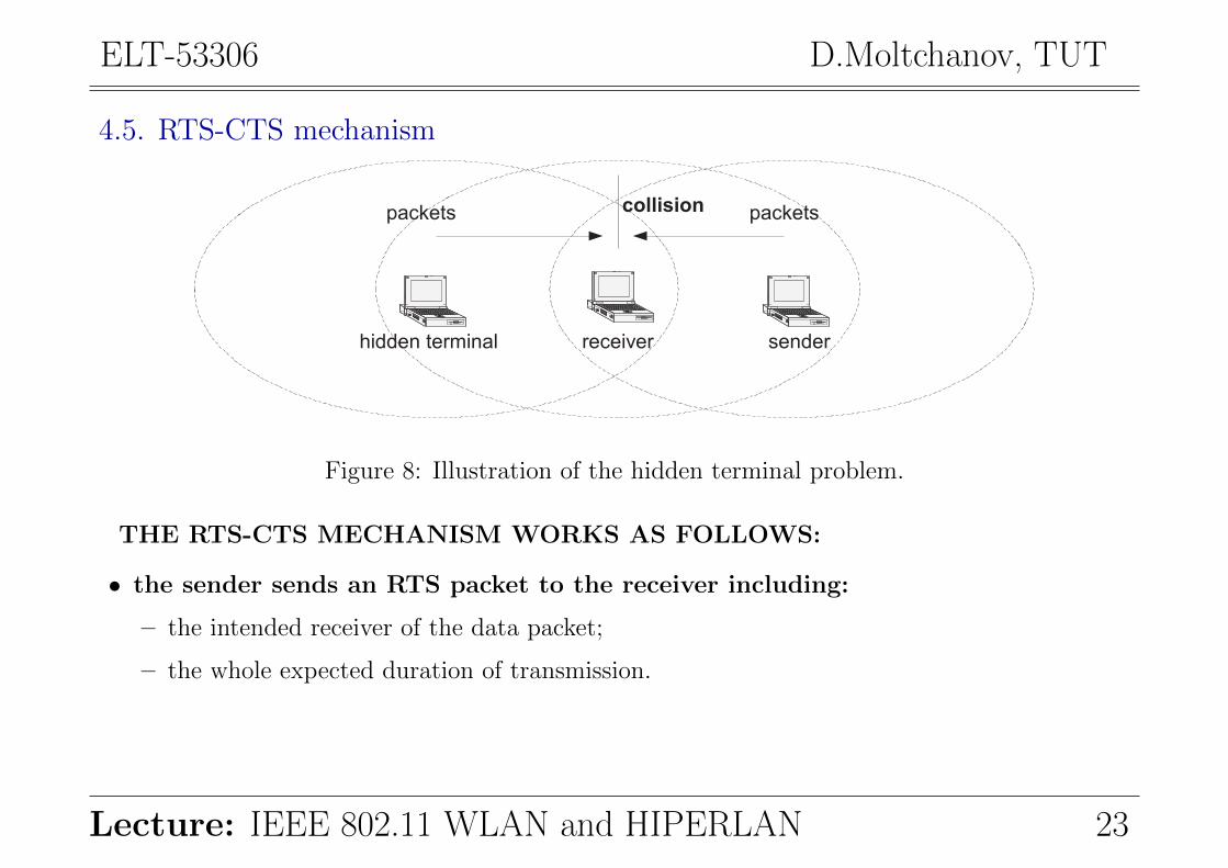
Figure 8: Illustration of the hidden terminal problem.
THE RTS-CTS MECHANISM WORKS AS FOLLOWS:
• the sender sends an RTS packet to the receiver including:
– the intended receiver of the data packet;
– the whole expected duration of transmission.
Lecture: IEEE 802.11 WLAN and HIPERLAN 23
ELT-53306 D.Moltchanov, TUT
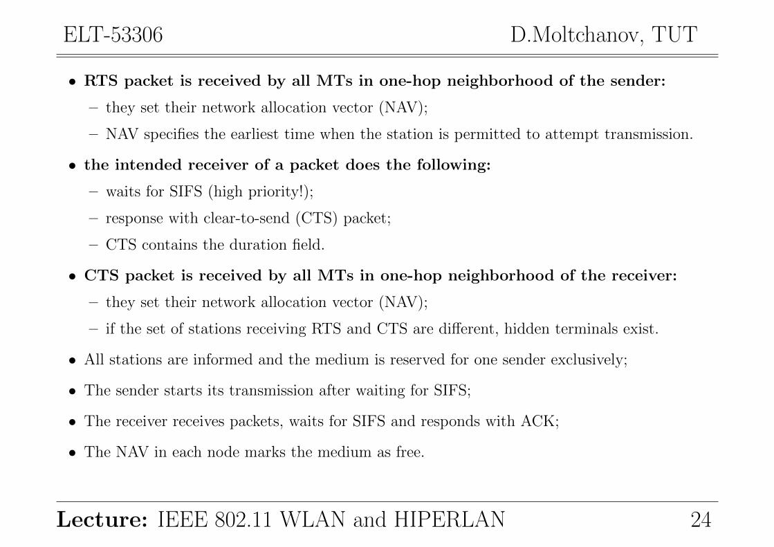
• RTS packet is received by all MTs in one-hop neighborhood of the sender:
– they set their network allocation vector (NAV);
– NAV specifies the earliest time when the station is permitted to attempt transmission.
• the intended receiver of a packet does the following:
– waits for SIFS (high priority!);
– response with clear-to-send (CTS) packet;
– CTS contains the duration field.
• CTS packet is received by all MTs in one-hop neighborhood of the receiver:
– they set their network allocation vector (NAV);
– if the set of stations receiving RTS and CTS are different, hidden terminals exist.
• All stations are informed and the medium is reserved for one sender exclusively;
• The sender starts its transmission after waiting for SIFS;
• The receiver receives packets, waits for SIFS and responds with ACK;
• The NAV in each node marks the medium as free.
Lecture: IEEE 802.11 WLAN and HIPERLAN 24

ELT-53306 D.Moltchanov, TUT
BACK-OFF RTS
SIFS CTS
SIFS DATA
SIFS ACK
DIFS BACK-OFF
NAV FROM RTS
NAV FROM CTS
NAV FROM DATAAccess to medium is differed:
SOURCE:
DESTINATION:
OTHER NODES:
Figure 9: Illustration of the RTS-CTS algorithm.
WHAT ARE SHORTCOMINGS AND ADVANTAGES:
• +: completely and reliably removes the hidden terminal problem;
• −: introduces significant overhead and sometimes is not performed;
• +: performs well in overloaded networks.
Lecture: IEEE 802.11 WLAN and HIPERLAN 25

ELT-53306 D.Moltchanov, TUT
SOMETIMES RTS-CTS IS NOT PERFORMED:
• execution of RTS-CTS depends on the packet size and RTS threshold:
– packet size is greater than RTS threshold: a four-way RTS-CTS-DATA-ACK is performed;
– packet size is less than RTS threshold: a two-way DATA-ACK is performed.
• −: performs bad in overloaded networks.
• +: performs well in moderately loaded networks.
BACK-OFF DATA
SIFS ACK
DIFS BACK-OFF
SOURCE:
DESTINATION:
OTHER NODES:
Figure 10: When RTS-CTS is not used.
Lecture: IEEE 802.11 WLAN and HIPERLAN 26
ELT-53306 D.Moltchanov, TUT
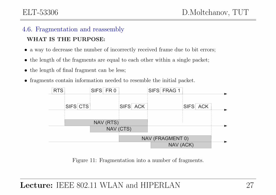
4.6. Fragmentation and reassembly
WHAT IS THE PURPOSE:
• a way to decrease the number of incorrectly received frame due to bit errors;
• the length of the fragments are equal to each other within a single packet;
• the length of final fragment can be less;
• fragments contain information needed to resemble the initial packet.
RTS
CTS
FR 0
NAV (RTS)
SIFS
SIFS
ACKSIFS
FRAG 1SIFS
ACKSIFS
NAV (FRAGMENT 0)
NAV (CTS)
NAV (ACK)
Figure 11: Fragmentation into a number of fragments.
Lecture: IEEE 802.11 WLAN and HIPERLAN 27
ELT-53306 D.Moltchanov, TUT
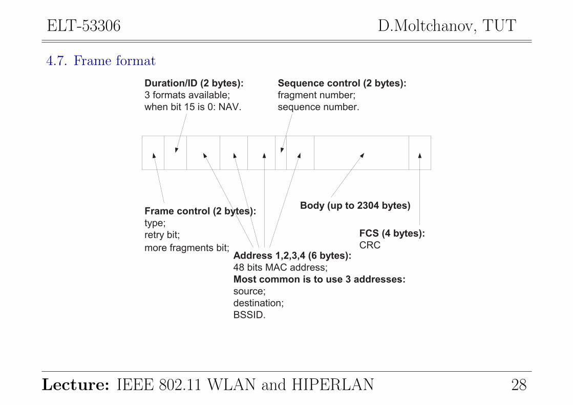
4.7. Frame format
Frame control (2 bytes):
type;
retry bit;
more fragments bit;Address 1,2,3,4 (6 bytes):
48 bits MAC address;
Most common is to use 3 addresses:
source;
destination;
BSSID.
Duration/ID (2 bytes):
3 formats available;
when bit 15 is 0: NAV.
Sequence control (2 bytes):
fragment number;
sequence number.
Body (up to 2304 bytes)
FCS (4 bytes):
CRC
Lecture: IEEE 802.11 WLAN and HIPERLAN 28
ELT-53306 D.Moltchanov, TUT
4.8. Other MAC functions
THERE ARE FOLLOWING ADDITIONAL FUNCTIONS OF THE MAC:
• Point Coordination Function (PCF):
– aim: provide QoS parameters: max access delay, minimum transmission bandwidth, etc.
– idea: AP acts as a centralized coordinator;
– how: AP determines and informs a node that has a right to transmit next.
• Synchronization:
– requirement: each station has a clock, all clocks have to be synchronized;
– aim: power management, PCF coordination, hopping synchronization when using FHSS;
– how: timing coordination function.
• Power management:
– usage of batteries requires power conservation/managment functions.
To switch off the transceiver when carrier sensing is not needed! Two state are defined:
– sleep: in this state MT cannot transmit and receive packets (invoked periodically);
– awake: in this state MT may perform all operations.
Lecture: IEEE 802.11 WLAN and HIPERLAN 29
ELT-53306 D.Moltchanov, TUT
• QoS in IEEE 802.11 environment:
– Hybrid coordination function (HCF):
∗ AP polls stations in a weighted manner.
– Extended DCF (EDCF):
∗ higher priority MTs are allowed to choose the back off from a smaller CW.
• Support for roaming:
– AP has a range of up to several hundreds meters;
– The roaming between AP is done using the following:
∗ when the stations begins to experience a poor single quality it scans for a new AP.
THERE ARE TWO SCANNING METHODS:
• Active scanning: sends a probe on each channel and waits for a response;
• Passive scanning: listening to the medium to find other networks.
THE INFORMATION ABOUT JOINING THE NETWORK IS OBTAINED:
• from beacon frames used for synchronization;
• probe frames used when PCF is employed.
Lecture: IEEE 802.11 WLAN and HIPERLAN 30
ELT-53306 D.Moltchanov, TUT
5. IEEE 802.11a and IEEE 802.11bWhat are differences:
• Power efficiency:
– 802.11b: DSSS;
– 802.11a: OFDM;
– Result: 802.11b is more power efficient than 802.11a.
• Frequency:
– 802.11b: 2.4GHz ISM bandwidth, highly overloaded;
– 802.11a: 5GHz, less overloaded but higher absorbtion rate;
– Result: each has its own advantages and drawbacks.
• Communication range:
– 802.11b: communication range is around ≈ 150m;
– 802.11a: shorter communication range compared to 802.11b (≈ 50m);
– Result: more transceivers are required for 802.11a.
Lecture: IEEE 802.11 WLAN and HIPERLAN 31

ELT-53306 D.Moltchanov, TUT
• Data-rate:
– 802.11b: up to 11Mbps;
– 802.11a: up to 54Mbps, (up to 72Mbps) (realistically, less, fastly decreases with distance);
– Result: 54Mbps looks promising if one can get it working.
• Cost efficiency:
– 802.11b: well-established manufacturing;
– 802.11a: components are more expensive, more transmitters are required;
– Result: 802.11b is cheaper.
• Compatibility:
– 802.11b: this was the first available WLAN;
– 802.11a: is not compatible with 802.11b;
– Result: not so good for 802.11a.
• Number of users:
– 802.11a: can accommodate more users due to increase in channels and bandwidth;
– Result: capacity of 802.11a is higher.
Lecture: IEEE 802.11 WLAN and HIPERLAN 32

ELT-53306 D.Moltchanov, TUT
6. IEEE 802.11g and IEEE 802.11bWhat are differences:
• Power efficiency:
– 802.11b: DSSS;
– 802.11g: OFDM;
– Result: 802.11b is more power efficient than 802.11a and IEEE 802.11g.
• Frequency:
– 802.11b: 2.4GHz ISM bandwidth, highly overloaded;
– 802.11g: 2.4GHz ISM bandwidth, highly overloaded;
– Result: poor performance in overloaded environment (802.11a is better: 5GHz).
• Communication range:
– 802.11b: communication range is around ≈ 150m;
– 802.11g: shorter communication range compared to 802.11b, higher than 802.11a;
– Result: only slightly more transceivers are required for 802.11g than for 802.11b.
Lecture: IEEE 802.11 WLAN and HIPERLAN 33

ELT-53306 D.Moltchanov, TUT
• Data-rate:
– 802.11b: up to 11Mbps;
– 802.11g: up to 54Mbps (realistically ≈ 10− 20);
– Result: less than 802.11a, more than 802.11b.
• Cost efficiency:
– 802.11b: well-established manufacturing;
– 802.11g: components are more expensive than 802.11b, less expensive than (802.11a);
– Result: 802.11b is cheaper.
• Compatibility:
– 802.11b: this was the first available WLAN;
– 802.11g: compatible with 802.11b;
– Result: from this point of view 802.11g is a nice choice.
• Number of users:
– 802.11g: the same number of channel as in 802.11b;
– Result: capacity of 802.11a is higher.
Lecture: IEEE 802.11 WLAN and HIPERLAN 34
ELT-53306 D.Moltchanov, TUT
7. System design for networking in IEEE 802.117.1. Types of networks based on IEEE 802.11
THERE ARE TWO BASIC CONCEPTS IN 802.11 SYSTEM:
• Basic Service Set (BSS): a set of stations communicating with each other;
• Basic Service Area (BSA): area in which stations communicate.
IEEE 802.11 NETWORK MAY OPERATE IN TWO MODES:
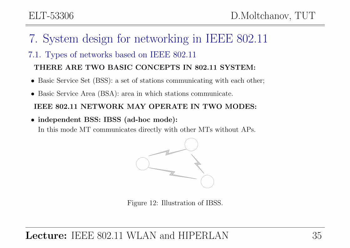
• independent BSS: IBSS (ad-hoc mode):
In this mode MT communicates directly with other MTs without APs.
Figure 12: Illustration of IBSS.
Lecture: IEEE 802.11 WLAN and HIPERLAN 35
ELT-53306 D.Moltchanov, TUT
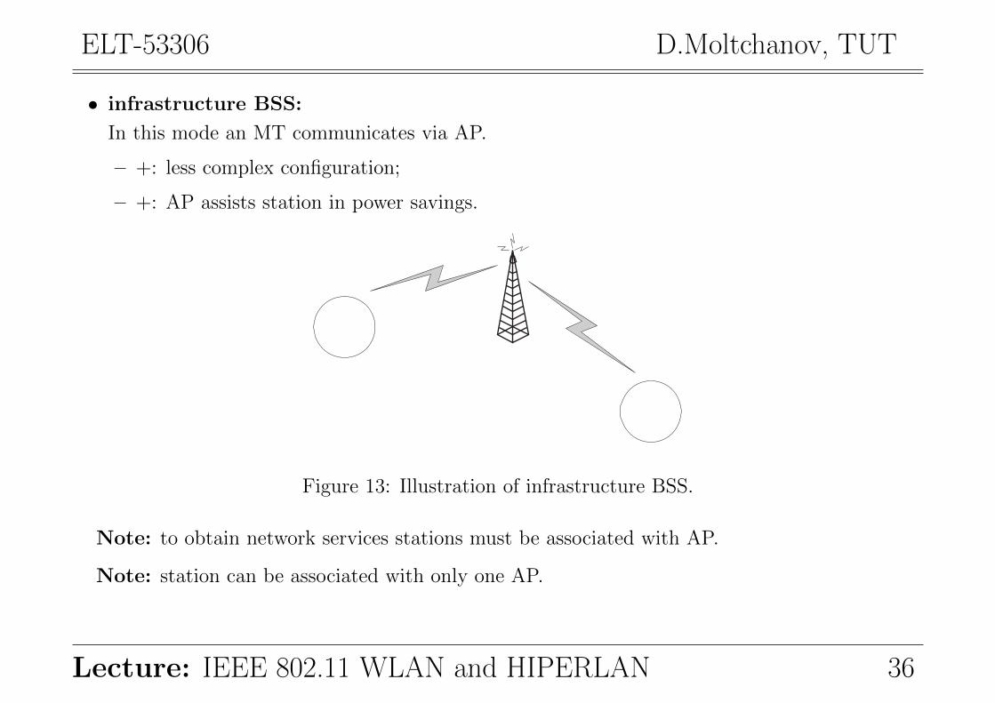
• infrastructure BSS:
In this mode an MT communicates via AP.
– +: less complex configuration;
– +: AP assists station in power savings.
Figure 13: Illustration of infrastructure BSS.
Note: to obtain network services stations must be associated with AP.
Note: station can be associated with only one AP.
Lecture: IEEE 802.11 WLAN and HIPERLAN 36
ELT-53306 D.Moltchanov, TUT
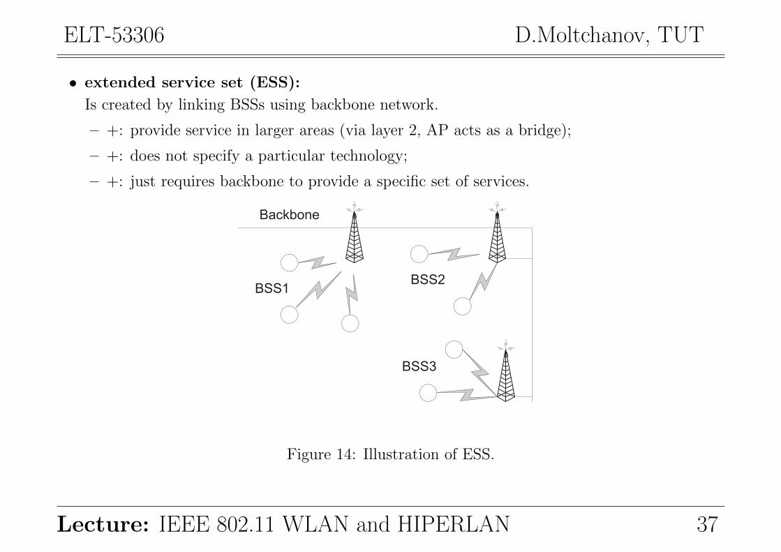
• extended service set (ESS):
Is created by linking BSSs using backbone network.
– +: provide service in larger areas (via layer 2, AP acts as a bridge);
– +: does not specify a particular technology;
– +: just requires backbone to provide a specific set of services.
Backbone
BSS1BSS2
BSS3
Figure 14: Illustration of ESS.
Lecture: IEEE 802.11 WLAN and HIPERLAN 37

ELT-53306 D.Moltchanov, TUT
7.2. Components of infrastructure BSS/ESS
IEEE 802.11 NETWORK CONSISTS OF THE FOLLOWING COMPONENTS:
• Distribution system: backbone network (e.g. IEEE 802.3);
• Access point: device performing wireless-to-wired mapping functions;
• Wireless medium: air interface;
• Station: end-user equipment using IEEE 802.11.
Distribution system
Access point
StationWireless
medium
Figure 15: Components of IEEE 802.11 WLAN.
Lecture: IEEE 802.11 WLAN and HIPERLAN 38

ELT-53306 D.Moltchanov, TUT
7.3. Distribution system
Include not only backbone network but bridging capabilities of APs.
IT PROVIDES:
• relay of frames within ESS;
• inter AP protocol (IAPP):
provides a way for AP to know where (to which AP) to forward a frame.
Bringing capabilities
Distribution system
Wireless medium
Figure 16: Illustration of distribution system.
Lecture: IEEE 802.11 WLAN and HIPERLAN 39
ELT-53306 D.Moltchanov, TUT
7.4. Network services
SERVICES OFFERED BY 802.11 ARE DIVIDED INTO:
• services offered by AP;
• services offered by MT.
THE FOLLOWING SERVICES ARE OFFERED BY AP:
• Association:
The address of MT must be known by AP before communication. This is done via association.
• Reassociation:
The established association is transferred from one MT to another using reassociation.
• Disassociation:
When node leaves AP or shuts down it enforces disassociation.
• Distribution:
This refers to the distribution of traffic within, in and out the network.
• Integration:
This service is evoked when transmission via non-IEEE 802.11 network is required.
Lecture: IEEE 802.11 WLAN and HIPERLAN 40
ELT-53306 D.Moltchanov, TUT
THE FOLLOWING SERVICES ARE OFFERED BY MT:
• Authentication:
This is used in order to establish the identity of stations to each other. Authentication imple-
mentation may range from insecure handshake procedures, to public key encryption schemes.
• Deauthentication:
This procedure is evoked to terminate existing authentication.
• Privacy:
The contents of messages os sometimes encrypted using a certain protocol to prevent unau-
thorized reading.
• Data delivery:
IEEE 802.11 networks provide a way to transmit and receive data. The transmission is not
guaranteed to be completely reliable.
Lecture: IEEE 802.11 WLAN and HIPERLAN 41
ELT-53306 D.Moltchanov, TUT
7.5. Mobility support
THREE TYPES OF TRANSITIONS BETWEEN APs ARE SUPPORTED:
• No transition:
– station is not moving or moving within a BSS.
• BSS transition:
– movement between BSS within ESS;
– station continuously monitors the signal level;
– use reassociation to be associated with another AP;
– requires cooperation between APs, should be standardized in IAPP.
• ESS transition:
– movement between two ESSs;
– does not support this type of transition (except for allowing to associate again);
– higher-layer connection will be interrupted;
– result: seamless transition is not supported.
Lecture: IEEE 802.11 WLAN and HIPERLAN 42
ELT-53306 D.Moltchanov, TUT
8. The HIPERLAN set of standardsThe HIgh PERformance Radio LAN (HIPERLAN)
BASIC INFORMATION:
• European counterpart to the IEEE 802.11;
• defined by European Telecommunications Standards Institute (ETSI).
FOUR SET OF STANDARDS HAVE BEEN DEFINED
• HIPERLAN/1:
– radio LAN, 5.15GHz and the 17.1GHz, max rate: 23.5Mbps.
• HIPERLAN/2:
– short-range wireless access to IP, 5GHz, rates: 6Mbps to 54Mbps.
• HIPERACCESS:
– to cover the so-called ’last mile’, rate: 25Mbps.
• HIPERLINK:
– point-to-point static interconnections, 17GHz, range: up to 150m.
Lecture: IEEE 802.11 WLAN and HIPERLAN 43
ELT-53306 D.Moltchanov, TUT
9. HIPERLAN/1WHAT HIPERLAN/1 PROVIDES:
• allows nodes to be deployed in a pre-arranged and ad-hoc manners;
• provides forwarding mechanism e.g., multi-hop routing;
• provides data rate of around 25Mbps;
• has the capability to support both multimedia and asynchronous data;
COMPARING WITH IEEE 802.11:
• IEEE 802.11 is seen as dumb but simple;
• HIPERLAN is clever but more sophisticated.
PROTOCOL STACK: TWO LAYERS OF OSI:
• physical layer;
• data-link layer:
– medium access control (MAC) sublayer;
– channel access control (CAC) sublayer.
Lecture: IEEE 802.11 WLAN and HIPERLAN 44

ELT-53306 D.Moltchanov, TUT
9.1. Physical layer
WHAT ARE FUNCTIONALITIES:
• modulation and demodulation;
• forward error corrections;
• signal strength measurement;
• synchronization between the sender and a receiver;
• channel sensing (idle/busy) using CCA scheme this is similar to IEEE 802.11.
9.2. MAC sublayer
WHAT ARE FUNCTIONALITIES:
• processing packets from the higher layer;
• scheduling packets according to the QoS requests;
• forwarding packets and power conservation features;
• communication confidentiality using encryption-decryption schemes.
Lecture: IEEE 802.11 WLAN and HIPERLAN 45
ELT-53306 D.Moltchanov, TUT
TWO SPECIFIC FUNCTIONS ARE PROVIDED:
• multi-hop forwarding:
– in ad hoc mode;
– topology-related information is exchanged between nodes.
• QoS priorities assignment (!!!):
– computes access priority for each PDU received from the higher layer;
– maps this priority to the channel access mechanism (CAM) priority.
9.3. The CAC sublayer
WHAT ARE FUNCTIONALITIES:
• CAC sublayer offers a connectionless data service to MAC sublayer;
• The MAC layer uses the service to specify the CAM priority;
• CAM priority is a single QoS parameter for the CAC layer;
• the packet selected for transmission is transmitted.
Lecture: IEEE 802.11 WLAN and HIPERLAN 46
ELT-53306 D.Moltchanov, TUT
9.4. Channel access scheme
ELIMINATION YIELD NON-PREEMPTIVE MULTIPLE ACCESS
• dynamic listen-then-talk channel access protocol;
• similar to CSMA/CA used in IEEE 802.11;
• exception: provides service differentiation!
CHANNEL ACCESS CONSISTS OF THE FOLLOWING CYCLES:
• . . .
• synchronization;
• prioritization;
• contention;
• transmission;
• synchronization;
• . . .
Lecture: IEEE 802.11 WLAN and HIPERLAN 47

ELT-53306 D.Moltchanov, TUT
• PRIORITIZATION:
Aim: to detect nodes having packets with the highest CAM priority. Two stages:
– priority detection:
A node listens channel for a number of slots proportional to the CAM priority of its packet.
– priority assertion:
A node asserts its priority sending a signal in the slot corresponding to the packet priority.
Nodes having packets with low CAM priority detects nodes with the higher priority packets.
• CONTENTION:
Aim: eliminate as many nodes as possible to minimize the collision:
– Elimination phase:
∗ a node transmits signal for geometrically distributed number of slots (0.5k,k is the CAM);
∗ the it senses the media for one slot;
∗ if transmissions in this slot are detected, a node stops contention process;
∗ if no, it goes to yield phase.
– Yield phase:
A node listens channel for a number of slots. If it is idle, the node is chosen for transmission.
Lecture: IEEE 802.11 WLAN and HIPERLAN 48
ELT-53306 D.Moltchanov, TUT
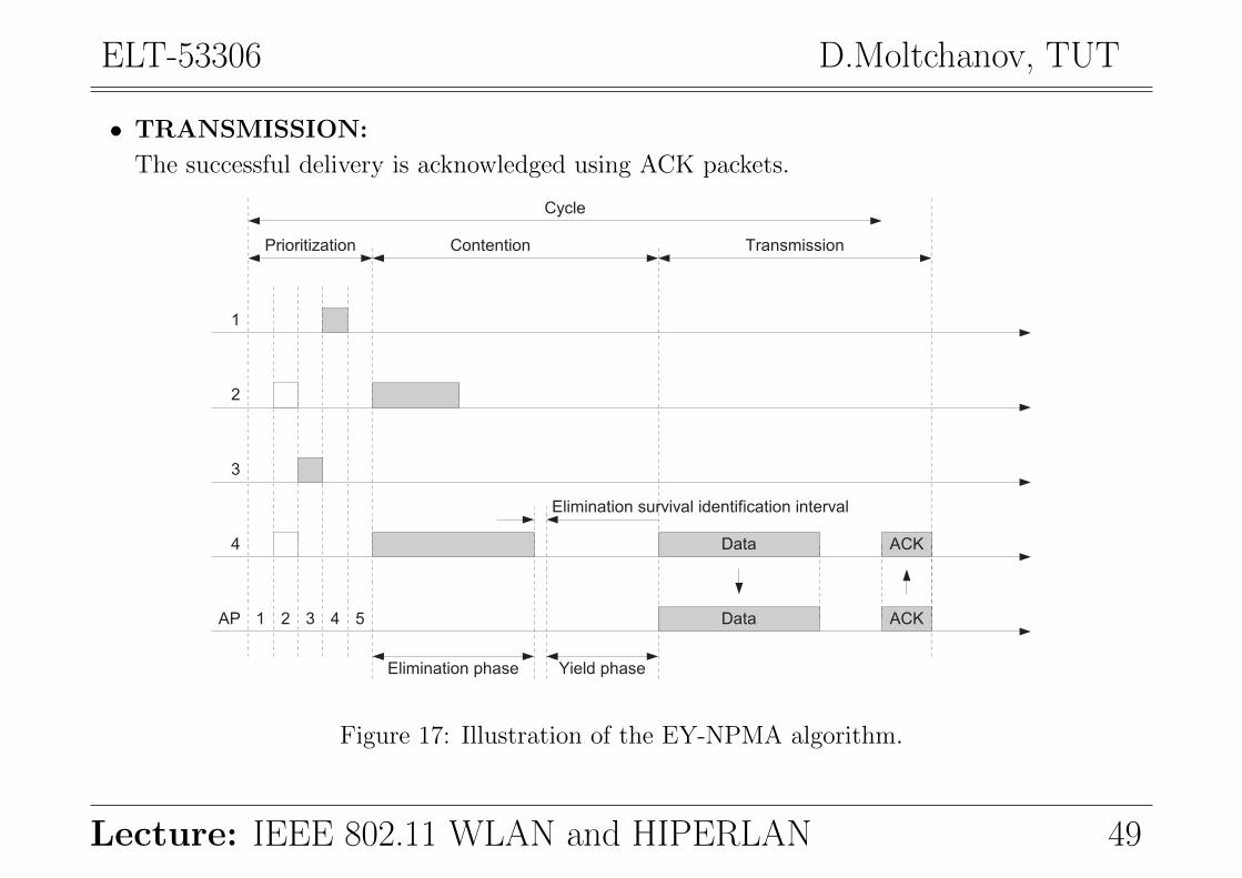
• TRANSMISSION:
The successful delivery is acknowledged using ACK packets.
1 2 3 4 5AP
1
2
3
4
Prioritization
Data
Data ACK
ACK
Contention Transmission
Cycle
Elimination phase Yield phase
Elimination survival identification interval
Figure 17: Illustration of the EY-NPMA algorithm.
Lecture: IEEE 802.11 WLAN and HIPERLAN 49

ELT-53306 D.Moltchanov, TUT
9.5. Power conservation
HIPERLAN/1 ALLOWS POWER TO BE CONSERVED AT:
• MAC layer:
At the MAC layer two modes are defined namely:
– sleep;
– awake.
To implement this function nodes are divided into:
– p-savers: those nodes that want to implement sleep function;
– p-supporters: neighbors to p-savers chosen to sleep later.
Note: p-savers must be active only on pre-determined slots.
• Physical layer:
A physical signal consists of:
– low bit rate (LBR) burst: uses FSK modulation (lower rate/less power);
– high bit rate (HBR) burst: uses GMSK modulation (higher rate/more power).
The LBR contains the dest. address and precedes HBR, node decides whether to receive HBR.
Lecture: IEEE 802.11 WLAN and HIPERLAN 50
ELT-53306 D.Moltchanov, TUT
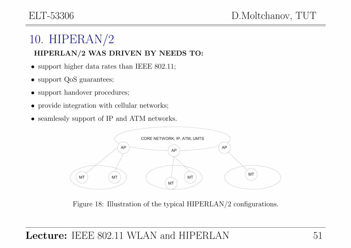
10. HIPERAN/2HIPERLAN/2 WAS DRIVEN BY NEEDS TO:
• support higher data rates than IEEE 802.11;
• support QoS guarantees;
• support handover procedures;
• provide integration with cellular networks;
• seamlessly support of IP and ATM networks.
CORE NETWORK: IP, ATM, UMTS
APAP
AP
MT MT
MT
MTMT
Figure 18: Illustration of the typical HIPERLAN/2 configurations.
Lecture: IEEE 802.11 WLAN and HIPERLAN 51

ELT-53306 D.Moltchanov, TUT
THE AP IN HIPERLAN/2 CONSISTS OF:
• one of many transceivers called access point transceivers (APT);
• access point controlled (APC) controlling APTs.
TWO MODES OF OPERATION ARE DEFINED FOR HIPERLAN/2:
• Business environment:
– the ad-hoc architecture of HIPERLAN/1 extended to support centralized communication.
• Home environment:
– ad-hoc mode of communications controlled by a central entity elected from nodes.
THE PROTOCOL STACK OF HIPERLAN/2 CONSISTS OF:
• physical layer;
• data-link control layer (DLC);
• convergence layer (CL).
Lecture: IEEE 802.11 WLAN and HIPERLAN 52
ELT-53306 D.Moltchanov, TUT
10.1. Physical layer
CLASSIC FUNCTIONALITIES AND(!!!):
• choice of suitable modulation using link adaptation scheme (6-54Mbps).
10.2. Data-link control layer
PROVIDES: the logical connection-oriented link between AP and MTs.
THE DLC IS DIVIDED TO:
• Radio link control (RLC) sublayer on the control plane;
• Error control sublayer on the user plane;
• MAC sublayer.
1. ERROR CONTROL SUBLAYER:
• error detection: CRC;
• error correction: Selective-Repeat ARQ (SR-ARQ).
Note: packet discard mechanism can be provided specifying the maximum delay.
Lecture: IEEE 802.11 WLAN and HIPERLAN 53
ELT-53306 D.Moltchanov, TUT
2. THE RLC SUBLAYER:
• Association control function (ACF):
– registration and authentication function.
• DLC user connection control (DCC):
– setup, modify, and terminate connections.
• Radio resource control:
The RRC is responsible for efficient utilization of available frequency resources:
– Dynamic frequency selection:
∗ allows to choose the best suitable frequency (channel) for communications;
∗ unique to HIPERLAN/2.
– Handover:
∗ sector handover (moving to another sector of the same antenna of an APT);
∗ radio handover (handover between two APTs under the same APC);
∗ network handover (handover between two APs in the same network).
– Power saving: these features are similar to those used in HIPERLAN/1.
Lecture: IEEE 802.11 WLAN and HIPERLAN 54
ELT-53306 D.Moltchanov, TUT
3. THE MAC SUBLAYER
Based on: TDMA/TDD with centralized AP scheduling providing:
• collision free transmission;
• QoS support.
This protocol simultaneously supports connection-oriented:
• AP-MT multicast and unicast transmission;
• MT-MT peer communication.
10.3. Convergence layer
WHAT ARE FUNCTIONALITIES:
• to adapt requirements of higher layer protocols to services provided by the lower layers;
• to convert the higher layer packets into fixed size ones used by HIPERLAN/2.
CL IS UNIQUE FOR EVERY SUPPORTED CORE NETWORK:
• packet-based CL: for variable length packets such as IP;
• cell-based CL: for fixed size ATM cells.
Lecture: IEEE 802.11 WLAN and HIPERLAN 55