Embed Size (px)
Citation preview
AU-A127 937 PATOKA LAKE FOUNDATION REPORT BOOK 5 APPENDIX E SPECIAL 1/2GROUTING ANALYSIS REPORT(U) ARMY ENGINEER DISTRICTLOUISVILLE KY S BARTLET T AL. APR 83
UNCLASSIFIED F/G 13/13 NL
U I IEEU001900 I00IIEE-EIhEIIIImIIhEEEEIIEEEEIIIIIIIIIIIIIuIIIIIIIIIIIIIIfllfllfl
EIEIIIIIEIIEEEEIIIIIIIIIIIIl
1W3
MICROCOPY RESOLUTION TEST CHART
NATIONAL BUREAU OF STANDARDS- 1963-A
BOOK 5 of 5
PATOKA LAKE FOUNDATION REPORT
APPENDIX E
SPECIAL GROUTING ANALYSIS REPORT
CMy cv-- 1 -fn DTIC don 9
COPA of 9
DISCLAIMER NOTICE
THIS DOCUMENT IS BEST QUALITYPRACTICABLE. THE COPY FURNISHEDTO DTIC CONTAINED A SIGNIFICANTNUMBER OF PAGES WHICH DO NOTREPRODUCE LEGIBLY.
- - - -. -
UNCLAS'TF F7F)SECURIY CLASSIFICATION OF THIS PAGE i otel FnleFeE)
READ INSTRUCTIONSREPORT DOCUMENTATION PAGE BEFORE COMPLETING FORM
I. *(POR NUMBER 2 OVT ACCESSION NO. 3 RECIPIENT'S CATA.OG NUMBER
7 - S IIIh L) 141' 723' F--inaj-4. TITLE (mod Subltle) / S TyPE OF REPORT A PERIOD COVERED
Patoka LakeFoundation Report
6 PERFORMING ORG. REPORT NUMBER
. AUTHO RI() SI CON fT A T oR GRANT N UMUErR(eJ
Sam Bartlett - GeologistGary Fitzgerald - Resident Engineer
9. PERFMIrNG ORGANIZATION NAME AND ADDRESS 10 PROGRAM ELEMENT PROJECT. TASK(S.PROMN RAIAINNM N AREA A WORIC UNIT NUlbERS
Louisville Resident Office
10450 Lower River Road
It. CONTROLLING OFFICE NAME AND ADDRESS 12. REPORT DATE
U.S. Army Corps of Engineers April 1983Louisville District, P.O. Box 59 13. NUMBEROFPAGES
Louisville, Kentucky 40201 5 Volumes14. MONITORING AGENCY NAME A ADDRESS(If diflerent from Controlnn Office) IS. SECURITY CLASS. (o til. repot)
UNCLASSIFIEDIS.. DECL ASSIFICATION 'DOWNGRADING
SCHEDULE
16. DISTRIBUTION STATEMENT (*I ULs Report)
Approved for public release; distribution is unlimited.
17. DISTRIBUTION STATEMENT (of th. ebstract entered In Block 20, If diff.rent from Report)
I&. SUPPLEMENTARY NOTES ,O21)i . ,n: oo-.,4 ej 44O
IS. KEY WORDS (Continue on revese @Ids If nece.ewy ad Identity by block number)
Patoka RiverIndiana
S. A STRACT (Vdiritw m rovs, atdP I mec..7somad iemflgy by block num&w)
This report covers the construction of the Patoka Dam, Spillway and Dike.Patoka is a flood control structure on the Patoks River, a tributary of theWabash River in Southwestern Indiana. It is in the flood control structuresfor the Ohio River Basin. The report contains narratives, charts, photos andconstruction logs.
APPENDIX E
SPECIAL GROUTING ANALYSIS REPORTTO PATOKA LAKE FOUNDATION REPORT
%001
Ito-it
plat 'I C reproduet l
--r'
. € :-'. ..
lo 1xk n
........... 140
:iv
ilk
Ile
U3. S. ARMY ENGINEER DISTRICT
LOUISVILLE
PATOICA LAKE, INDIANA
ANALYSIS OF GROUTING EFFECTIVENESS ANDDISTRIBUTION AS OBSERVED DURING EXCAVATION
PATOKA RESIDENT OFFICE
-4920M.
PATOKA LAKE
GROUJTING ANALYSIS
TABLE OF CONTENTS
PART TITLE PACE
I INTRODUCTION . . . . . .. . . . . . . . . . 1II GEOLOGY . a * * * & @ * * * a * @ e @ * * 3
III DESIGN PHASE ............... . 10IV GROUTING PHASE . .... . ........ . 16V EXCAVATION .. . . . . . . . . . o o o . , . 41
VI GROUT DISTRIBUTION .T ........... 52VII REVIEW AM DISCUSSION . .......... 72VIII CONCLUSION . ....... , ........ 31
NO. FIGURES
I-1 Location Map . . . . . . .* . * * . 2II-1 Generalized Geologic Column .. . . . . . . 4
11-2 Overburden at Station 4+0 . . . . . . . * 6
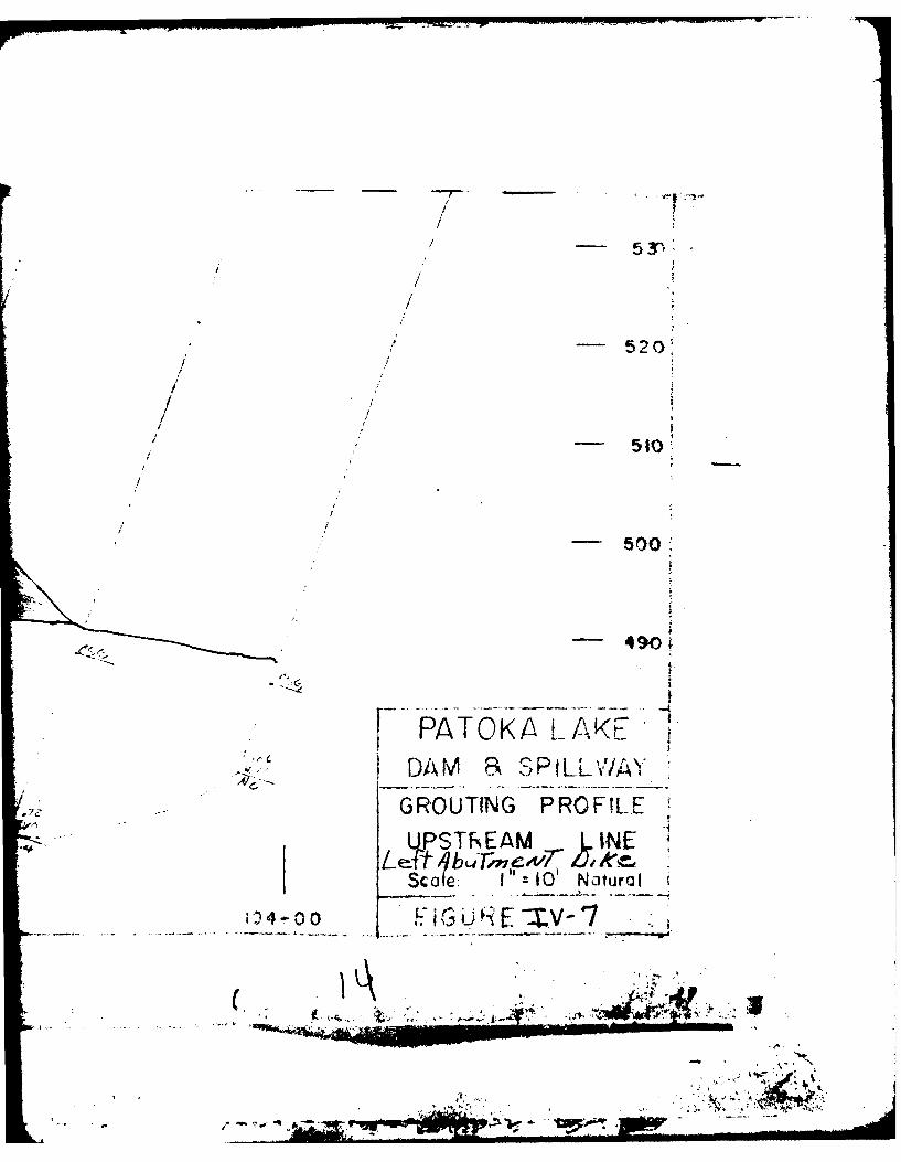
IIl-1 Design Profile of Dike Left Abutment . . . . 13IV-l Grouting Profile, Legend . .. . . . . . . . 18
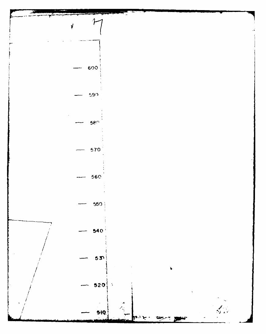
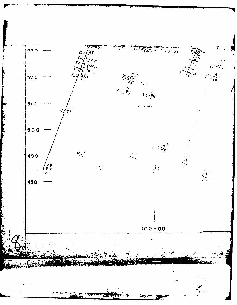
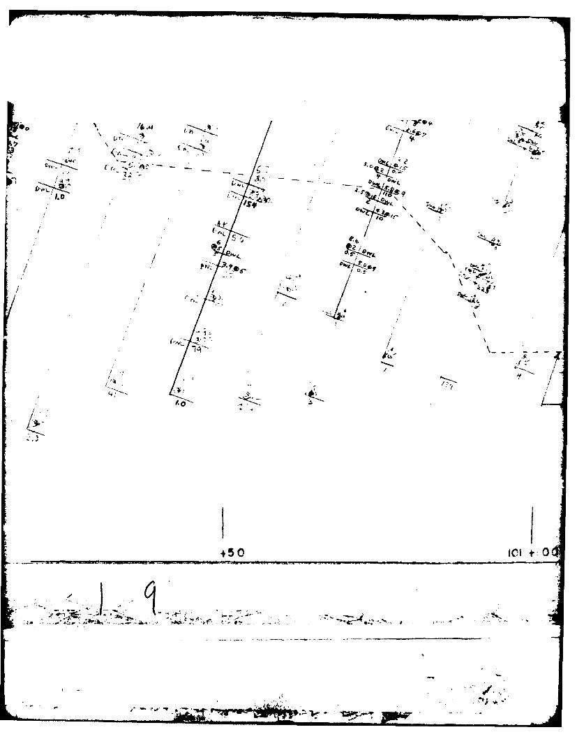
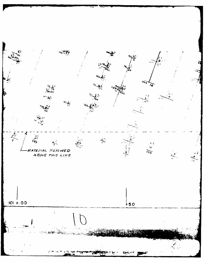
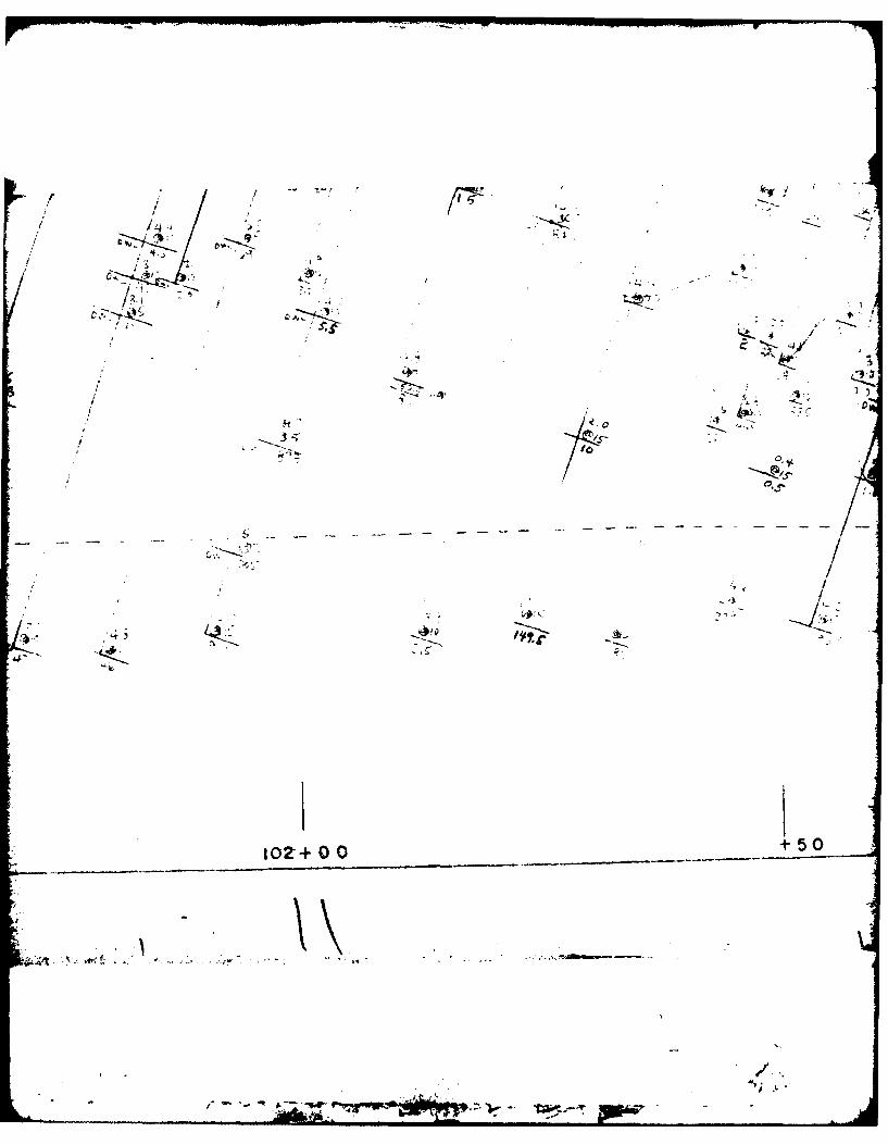
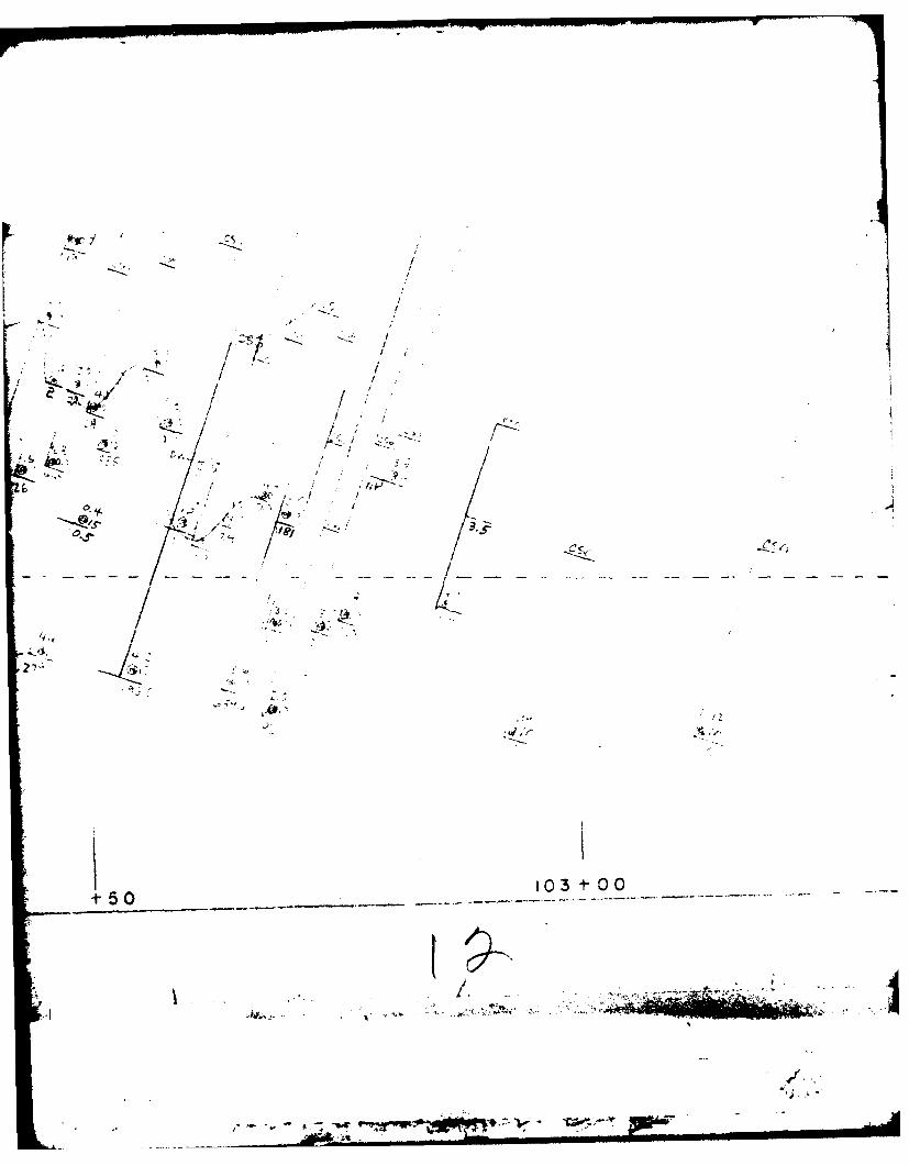
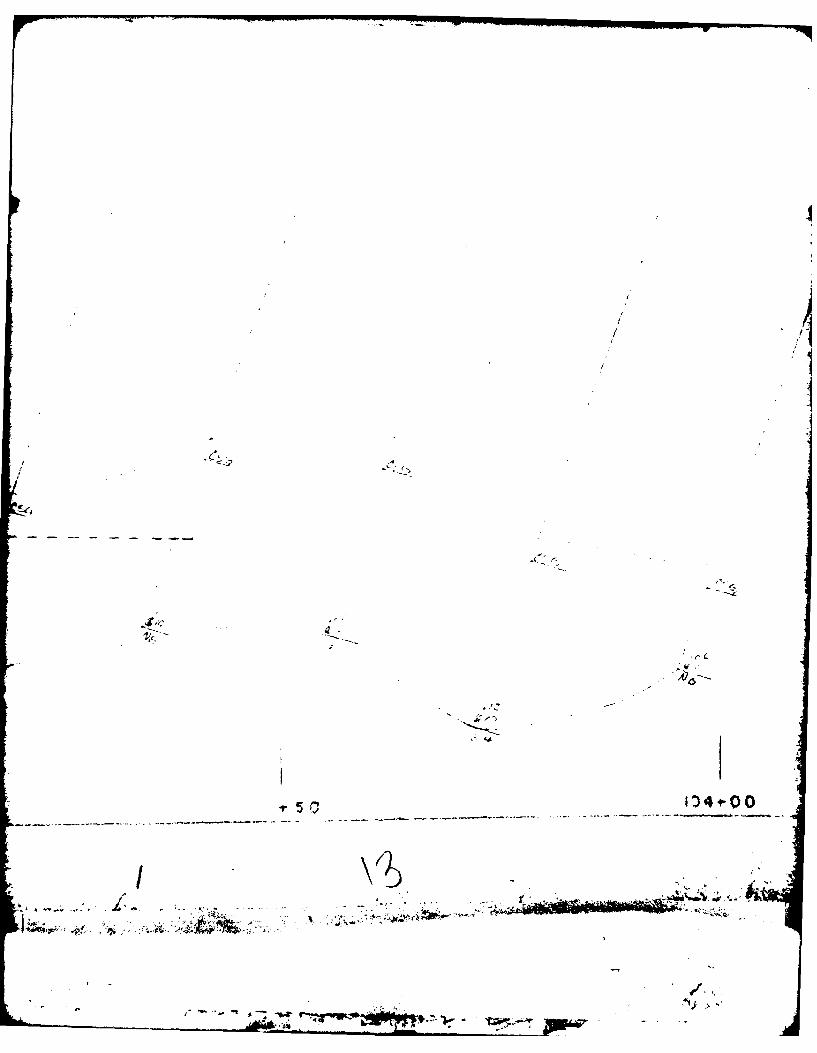
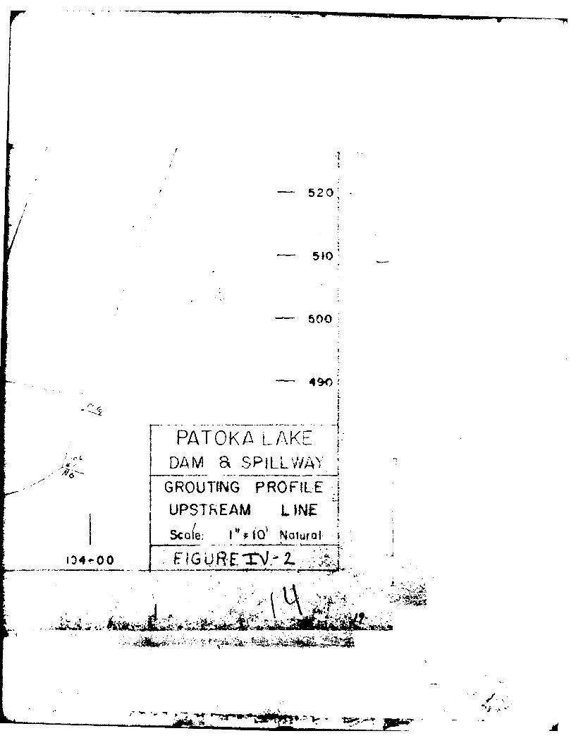
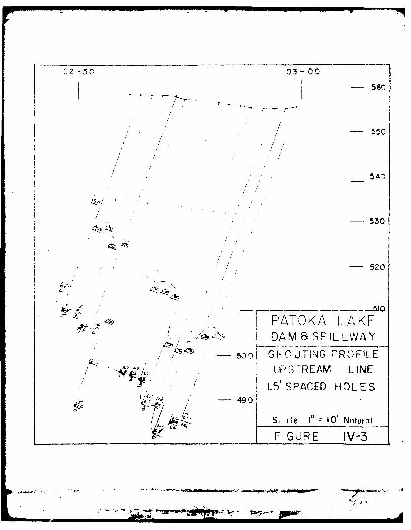
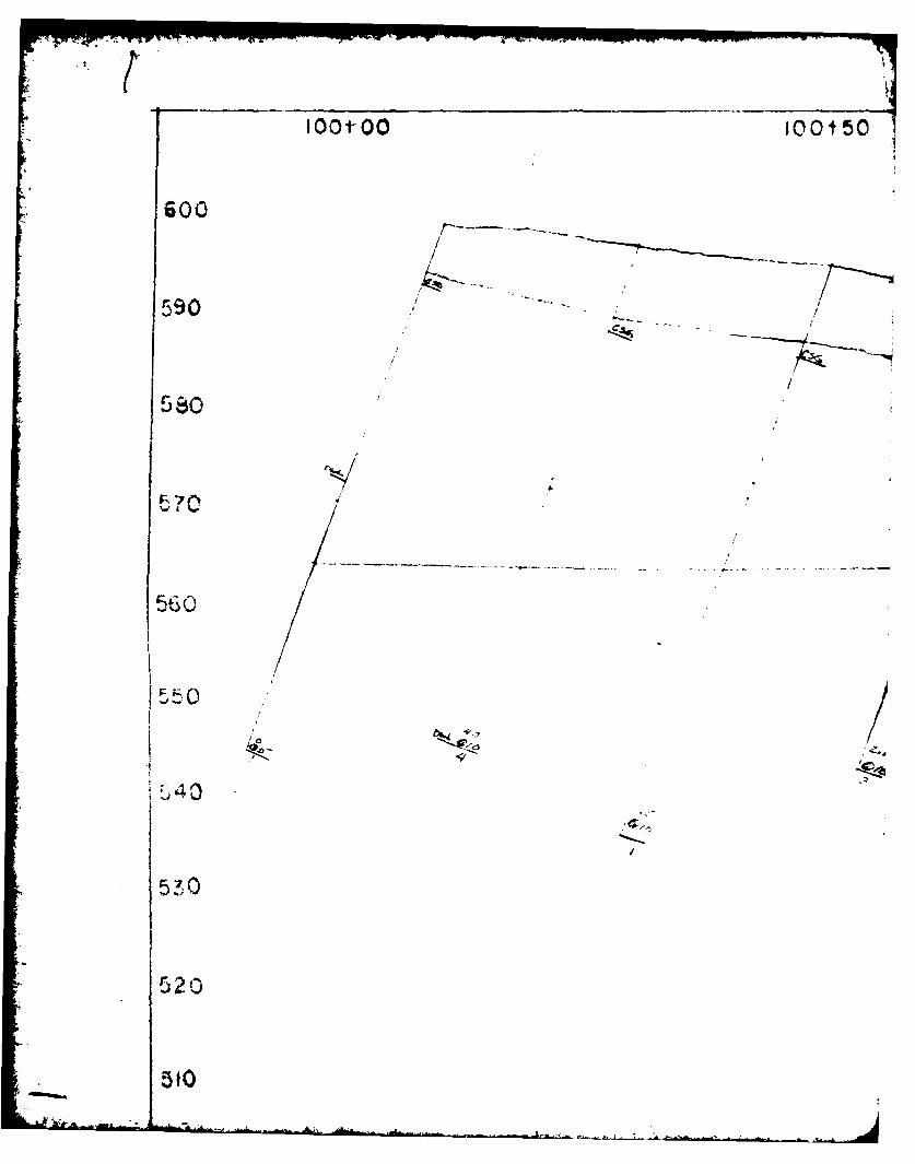
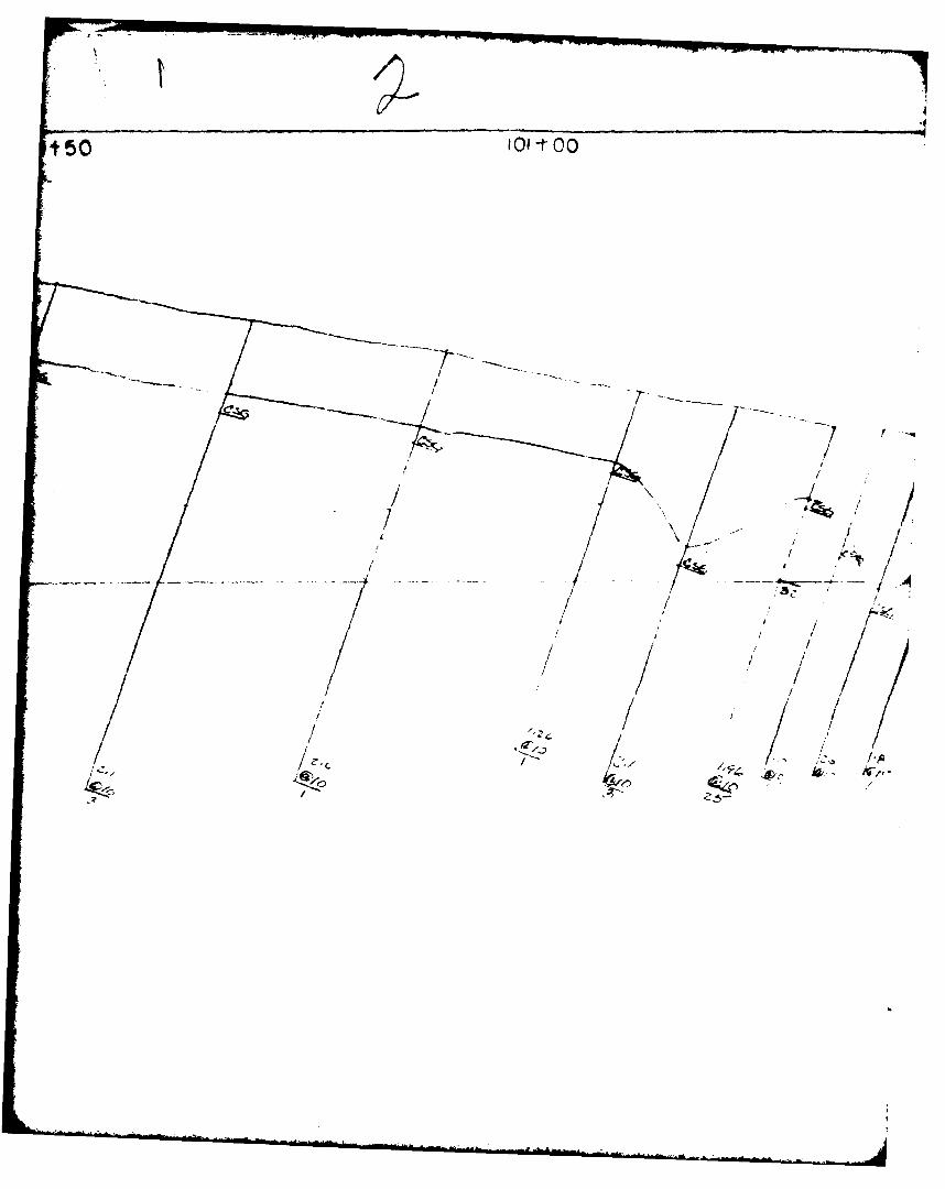
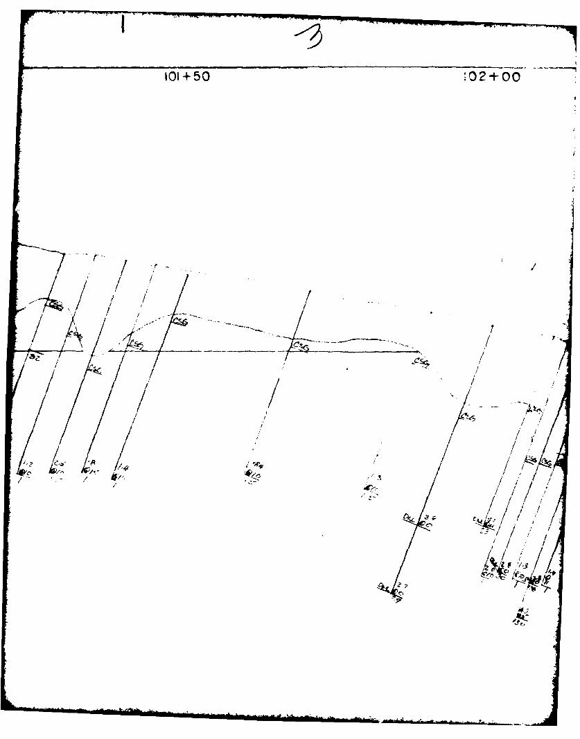
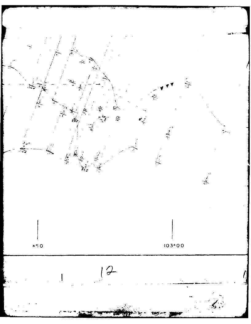
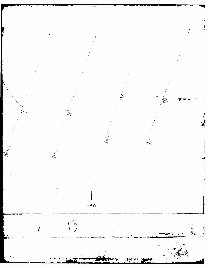
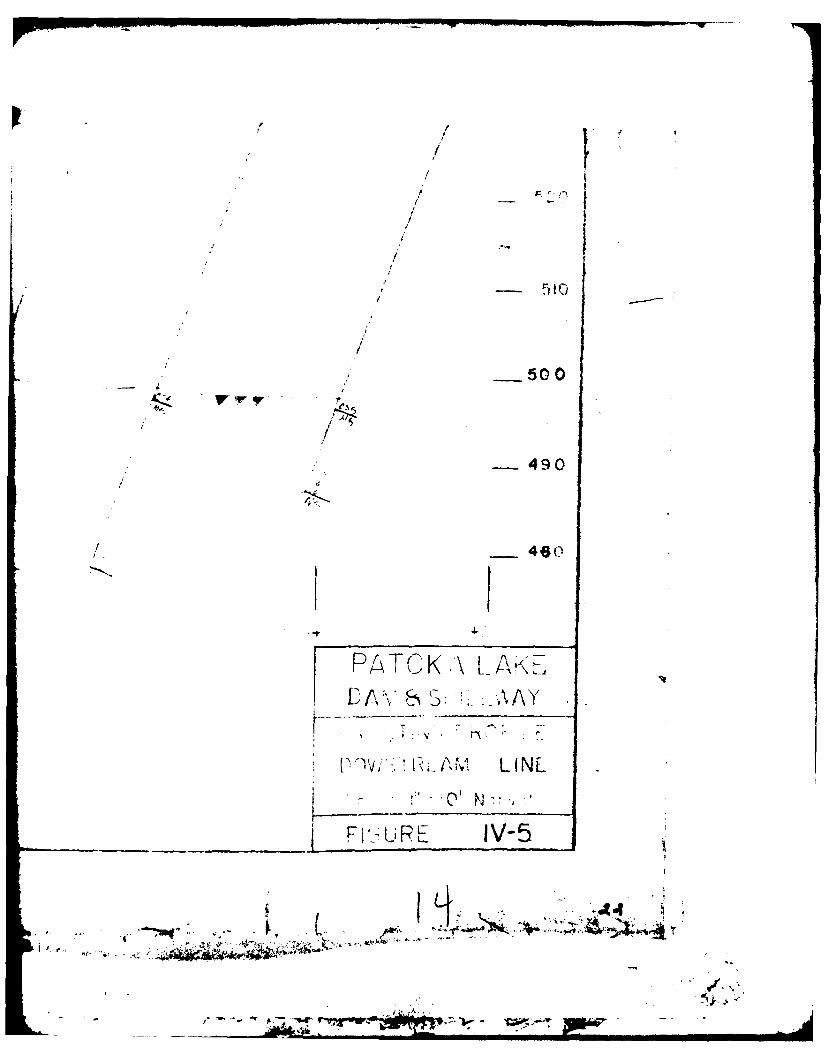
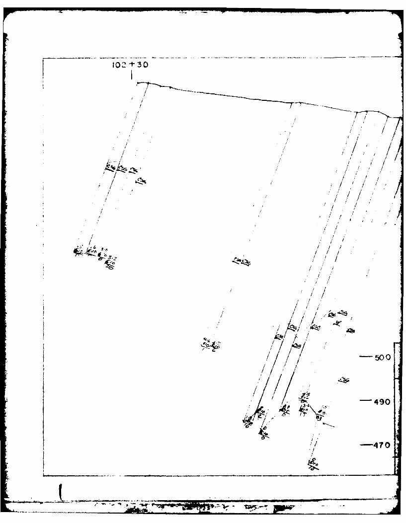
IV-2 Grouting Profile, U. S. Line .. . . . . . 19IV-3 Grouting Profile, U. S. Line, 1.5 Ft. Centers 20IV-4 Grouting Profile, Centerline . .* .. o o *. 21IV-5 Grouting Profile, D.S. Line . . a o . * . 22
IV-6 Grouting Profile, D.S. Line, 1.5 Ft. Centers 23IV-7 Special Grouting Profile . .. .. . .. .. 29V-1 Plan View of Dike Excavation ........ 43
V-2 Profile of Limestone Left in Place , .... 46
V-3 Foundation Map .......... . . . . 49
V-4 Foundation Map . . .. .. .. .. .. . . 51
TABLES
IV-l Sand Modifications . . .... . . a o 17
IV-2 U.S. Grout Line Tabulation .... . . . . . 31IV-3 Grouting Summary . . . ...... . . . . . 40
VOW
r -fi-r
F"m
TAKE OF CONTENTS (Cot)
NO PEs PAGE
2-1 Progress Photographs * a 0. . . . . . . . . 85-1 Progress Photographs . . . . . . . . . .. 425-1I Progress Photographs . . , 0 0 0 . 0. .. . 455-Inl Progress Photographs . . . . . o 0 0 . 0 . 486-I Progress Photographs , .S . . . . . . . 0 a 536-11 Progress Photographs . . . *. . .. .. .. 546-Il Progress Photographs . . . . . .0. . . . . . 566-IV Progress Photographs .. . . ... . 5§76-V Progress Photographs . . . . . . . . .0 . . 596-VI Progress Photographs , ...... ... 616-Vfl Progress Photographs ..... . .... . . 626-VIII Progress Photographs ..... .... . . 64
6-IX Progress Photographs . o o . . . .. . . . o 666-X Progress Photographs ... s.. . . .0. , o 676-XI Progress Photographs .. . . . . . . . . . . 696-XII Progress Photographs .... ... . .... 717-1 Progress Photographs . . . . . & .. . . . . 74
4f,
.7-
PART I -INTRODUCTION
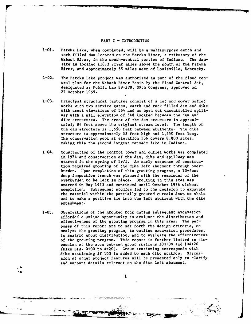
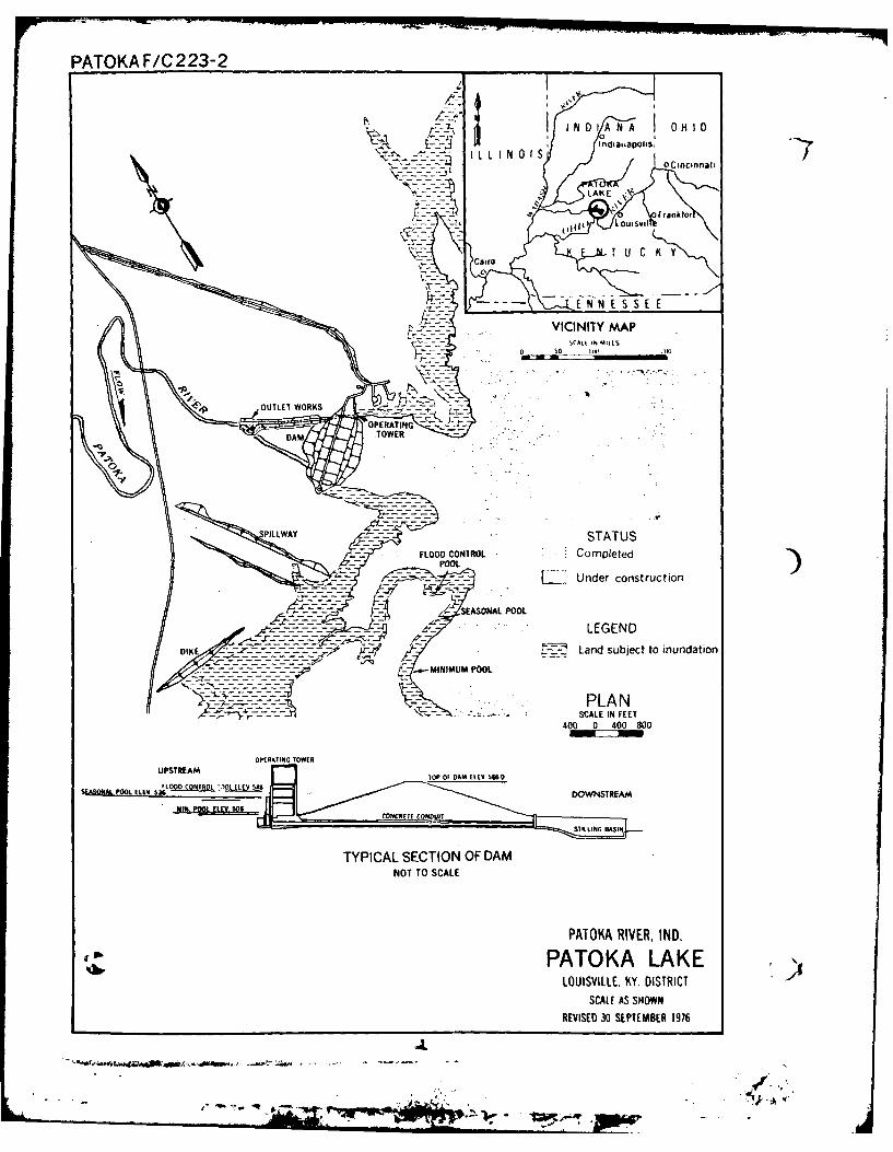
1-01. Patoka Lake, when completed, will be a multipurpose earth androck filled dam located on the Patoka River, a tributary of theWabash River, in the south-central portion of Indiana. The dam-site is located 118.3 river miles above the mouth of the PatokaRiver, and approximately 55 miles vest of Louisville, Kentucky.
1-02. The Patoka Lake project was authorized as part of the flood con-trol plan for the Wabash River Basin by the Flood Control Act,designated as Public Law 89-298, 89th Congress, approved on27 October 1965.
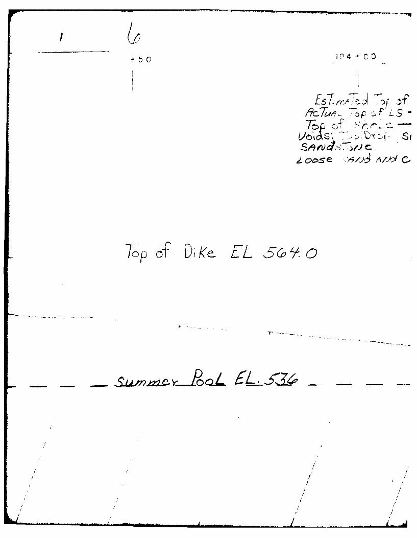
1-03. Principal structural features consist of a cut and cover outletworks with two service gates, earth and rock filled damn and dikewith crest elevations of 564 and an open cut uncontrolled spill-way with a sill elevation of 548 located between the dam anddike structures. The crest of the damn structure is approxi-mately 84 feet above the original stream level. The length ofthe darn structure is 1,550 feet between abutments. The dikestructure Is approximately 33 feet high and 1,550 feet long.The conservation pool at elevation 536 covers 8,800 acres,making this the second largest manmade lake in Indiana.
1-04. Construction of the control tower and outlet works was completedin 1974 and construction of the dam, dike and spillway wasstarted in the spring of 1975. An early sequence of construc-tion required grouting of the dike left abutment through over-burden. Upon completion of this grouting program, a 10-footdeep inspection trench was planned with the remainder of theoverburden to be left in place. Grouting in this area wasstarted in May 1975 and continued until October 1976 withoutcompletion. Subsequent studies led to the decision to excavatethe material within the partially grouted curtain down to shaleand to make a positive tie into the left abutment with the dikeembankment.
1-05. Observations of the grouted rock during subsequpnt excavationafforded a unique opportunity to evaluate the distribution andeffectiveness of the grouting program in this area. The pur-poses of this report are to set forth the design criteria, toanalyze the grouting program, to outline excavation procedures,to analyze grout distribution, and to evaluate the effectivenessof the grouting program. This report is further limited to dis-cussion of the area between grout stations 100+00 and 104+20(Dike Sta. 0+00 to 4+20). Grout stationing corresponds withdike stationing if 100 is added to each dike station. Discus-sion of other project features will be presented only to clarifyand support details relevant to the dike left abutment.
PATOKA F/C 223-2
VA K
I'. / I, NDIANA I orIUIVI
rIDOD~~~ UOTO Co Cee K yCairo)
OPERATINGOO
O EAM TOWrR
UPSTATUS
'~~~~ONAFOO COOOLO Com.p10leOTtLedL110
M~ POOL~LPOOL0
TYPICL SETIONOA DAML- ~ ~ ~ ~ O -O SCALE-- -- EG N
PATLALKSCALE AS SHOWN
REVSE 0 SETEBE 190 6
OPERATIG TOWEUPSTREA
................... 6FLO CONTROL OL E 549**)**
PART II - GEOLOGY
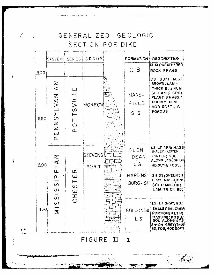
2-01. Geologically, the dike structure is founded on sedimentary rocksof the Mississippian and Pennsylvanian Systems. Regional dip iswesterly at approximately 25 feet per mile. Overlying bedrockare formations of glacial lacustrine, colluvium, and recentalluvial deposits. Figure IU-, geologic column, is includedfor reference.
2-02. The oldest rock formation of concern is the limestone portion ofthe Mississippian Golconda Formation. This portion of theformation consists of a massive, gray, hard, fossiliferous,slightly shaley, crystalline limestone. The limestone averages30 feet thick in the dike area. Though highly solutioned inother areas of the foundation, all available data indicates thatthis formation is unsolutioned below the dike. This limestonewas not included in the grouting program for the left abutmentof the dike.
2-03. Overlying the Golconda Limestone is the Hardensburg Shale forma-tion. This formation consists of lenticular beds of mottledshale, calcareous sandstone, and soft slickensided induratedclay. The thickness ranges from 25 to 30 feet in the damsitearea. This formation comprises the foundation for the majorportion of the revised dike embankment.
2-04. The next younger formation in sequence is the Glen Dean Lime-stone. Normal thickness in the dike area is 30 feet. Thethickness is less where the limestone has been subjected toextensive solutioning and erosion. The rock is a gray, hard,crystalline, fossiliferous, highly jointed, massive limestone.In the dike area, this limestone is highly solutioned alongjoints and bedding planes. In addition, this formation has been
extensively eroded during a long interval of exposure between
Mississippian and Pennsylvanian depositions. Normally there is
a 30-foot section of alternating shales and limestones above themassive portion of this formation. However, in the general
damsite area, this upper portion of the Glen Dean Formation isabsent due to the pre-Pennsylvanian interval of erosion.
2-05. The three formations described above comprise the bulk of theStephensport Group of the Chester Series. In the normalgeologic column, another unnamed group of the Chester Series ispresent above the Stephensport formations. This unnamed group
between the Stephensport Group and the Pennsylvanian System is
totally absent in the damsite area. In this general area, the
unnamed group of rocks was either not deposited or was removedduring the long period of erosion between two major systems ofdeposition.
3
ii ~ - - -
GENERALIZED GEOLOGIC
SECTION FOR DIKE
SSYSTEM RIES GROUP 'FORMATION DESCRIPTION
CLAYi WEATHERED
i )0 5 ROCK FRAGS
BROWNLAM-
I.,. THICK Bd.; NUM
z .. Ji BMANS- SH LAM BDS-,
IPLANT FRAGS"< I POORLY CEM.
>.>MORR0 : -L I MOD SOFT, V.S S POROUS
0zLui
<-i-- ;:: LEN LS-LT GRAY MASSL E N SHAt.EY inLOWERDEAN -O.TIN;,SOL.
LSTVSN ALONG JTS SH I'l5__0 -PORT LS HD,)(LYN; FOS
" L. 'HARDINS- SH SS;GREENISI_ S-LT GRAY- MASOOS!;
(J--- SOFT-MOD HD;
450'S1.:.i. , SHALEY IN LOWER
---, L-ORTION; SL NI .,, .... S-L ALNG JT6 d
L :1D:: L MODS"FTF IRY GUO I_________-_ -.. _______.___-
I _ _'"'",- -- _ _"
(1) D :. LS-LT GRAY, HD;--5'0' 'r"--- rnMrA: SHALEY IN LOWER
L MA5SIVE;FOS S'.:' A L S SOL ALONG .JTj
I sH-- D H--GRE Y;THI N]......... .. L .____ , _ ]BD;FOS;MODSOF j
~FIGURE 11-1
2-06. Consequently at the damsite, the Mansfield Formation, which isthe basal member of the Pennsylvanian System, lies disconform-ably upon the Glen Dean Limestone. The Mansfield Sandstone
consists of interbedded fine grained sandstones and shales. Inthe dike area, this formation Is poorly cemented, leached and
crossbedded in part. The beds are generally lenticular. TheMansfield Formation is the youngest rock unit found in the dike
area.
2-07. Subsequent to deposition and consolidation, the Mississippianrocks in this area have been raised and tilted slightly.Formations of this age generally dip S 650 W, with slight
variations. The rate of dip-is approximately 25 feet per mile,with lower Mississippian rocks dipping steeper than the higherbeds. The Pennsylvanian rocks dip nearly westward at a slightlylower angle than the L'ississippian rocks.
2-08. The Mississippian Limestones present well developed right anglepatterns of nearly vertical j6ints. The joint patterns betweenthe two limestones are nearly parallel and generally trendnorth-south and east-west. Variations are common that disrupt
the general pattern. As mentioned earlier, large numbers ofthese joints have been extensively solutioned and subsequentlyfilled with "Terra Rosa" clays.
2-09. The top of the natural water table in the left abutment of thedike generally conforms to the top of the presolutioned GlenDean Limestone (elev. 522). Interestingly, the water tableremains at elevation 522 in the areas where this limestone hasbeen solutioned and eroded away.
2-10. Several large clay and rubble-filled relief joints were found in
the Mansfield Sandstone at the dike left abutment during excava-tion. One of these joints contained a small 3-foot wide cavethat most likely connected with another small cave at the countyroad 500 feet upstream of the dike. Portions of this cave havecollapsed, but a small open section was uncovered during excava-tions at Sta. 0+60 above the top of the grout curtain. The clayand rubble-filled joints ranged from 0.2 to 3 ft. in width. Allof these joints become narrower with depth and all stopped at orabove the sandstone-limestone contact. From these characteris-
tics, the joints apparently resulted from lateral relief of the
sandstone during erosion of a deep river channel between Stas.
3+50 and 7+0. These joints have been plotted on Figure V-1.
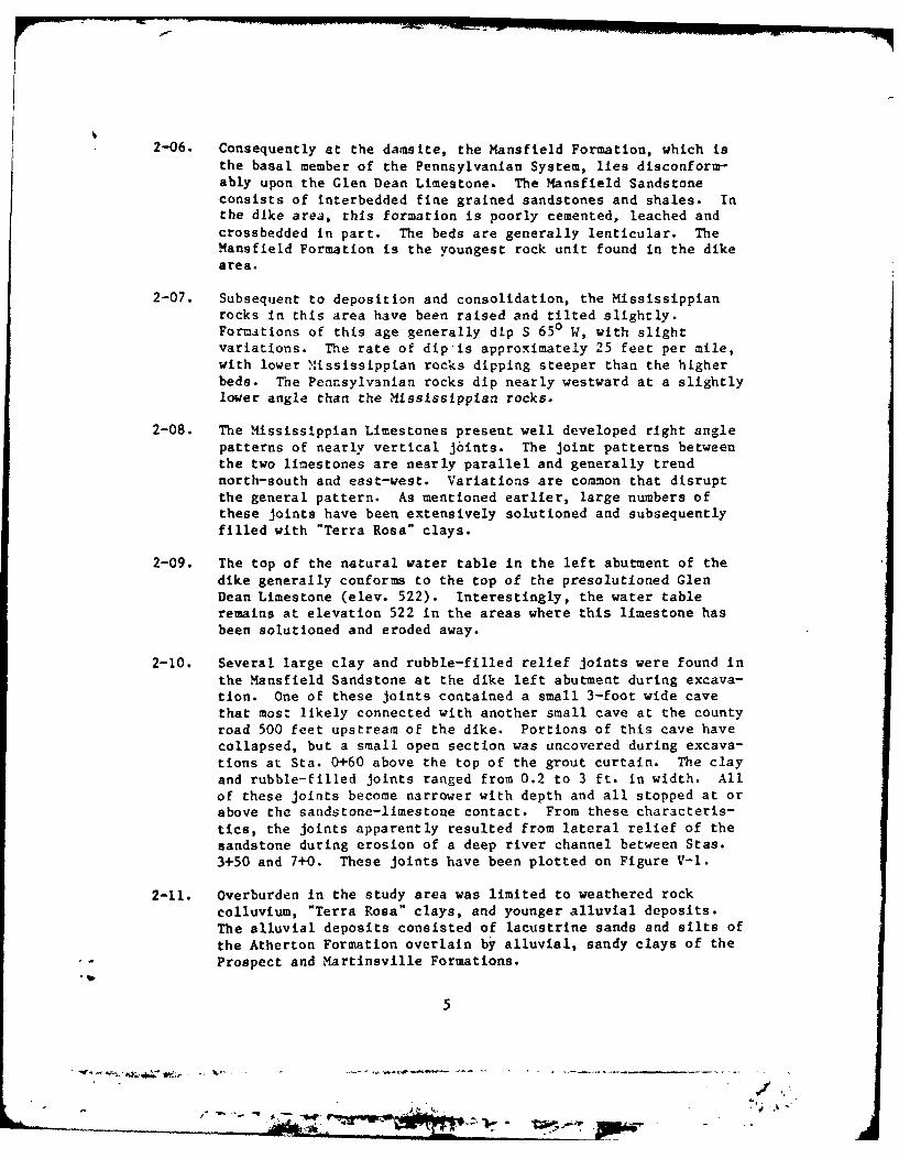
2-11. Overburden in the study area was limited to weathered rock
colluvium, "Terra Rosa" clays, and younger alluvial deposits.
The alluvial deposits consisted of lacustrine sands and silts of
the Atherton Formation overlain by alluvial, sandy clays of the
Prospect and Martinsville Formations.
5
. ' 4
55C M.ART;NSVILLE FM. CL MOTTLED GRAY TO BROWN,
V. SILTY, ALLUVIUM546,-0 _
PROSPECT FM. MOTTLED BROWN AND GPAYAND CL SILTY, NUMEROUS SR FRAGS.
COLLUVIUM (MORE AbUNDANT IN UPPER),
PAPTiAL COLLUVIUM
517.5
510 K. OTTLED GRAY R bROWNSILTY,PROSPECT C L CC FOOT FRAGS, CCC RUZT
F M ' S TA I N I NG
so c-
494.8
490H SM GRAY, SILTY, OCC PLANT FRAGStATHERTON SMFM WET. NO APPARENT BDI V. FINE
r M. 1GRAINED4 r?-C 480.4 C EMENTED GONG, GRY, SUB-
448 0,___ROUNDE SSGRAVEL47 "8.I LOOSE SANDI GRAYW/SS GRAVEL,
S H MAKING WATER
PPATOKA LAKEDIKE
_4_f.. OVERBURDEN SECTIONSTA. 4+00
Scole. FIGURE 11-2
jr
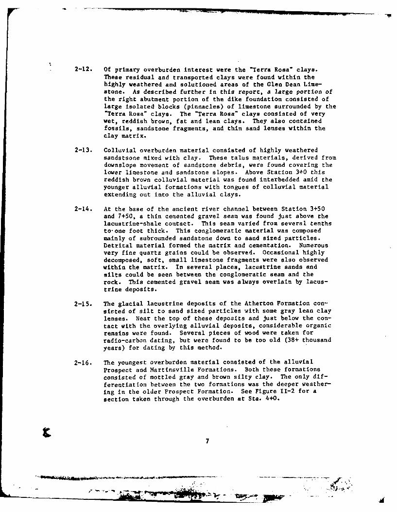
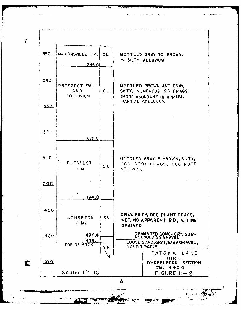
2-12. Of primary overburden interest were the "Terra Rosa" clays.These residual and transported clays were found within thehighly weathered and solutioned areas of the Glen Dean Lime-stone. As described further in this report, a large portion ofthe right abutment portion of the dike foundation consisted oflarge isolated blocks (pinnacles) of limestone surrounded by the"Terra Rosa" clays. The "Terra Rosa" clays consisted of verywet, reddish brown, fat and lean clays. They also containedfossils, sandstone fragments, and thin sand lenses within theclay matrix.
2-13. Colluvial overburden material consisted of highly weatheredsandstsone mixed with clay. These talus materials, derived fromdownslope movement of sandstone debris, were found covering thelower limestone and sandstone slopes. Above Station 3+0 thisreddish brown colluvial material was found interbedded amid theyounger alluvial formations with tongues of colluvial materialextending out into the alluvial clays.
2-14. At the base of the ancient river channel between Station 3+50and 7+50, a thin cemented gravel seam was found just above thelacustrine-shale contact. This seam varied from several tenthsto-one foot thick. This conglomeratic material was composedmainly of subrounded sandstone down to sand sized particles.Detrital material formed the matrix and cementation. Numerousvery fine quartz grains could be observed. Occasional highlydecomposed, soft, small limestone fragments were also observedwithin the matrix. In several places, lacustrine sands andsilts could be seen between the conglomeratic seam and therock. This cemented gravel seam was always overlain by lacus-trine deposits.
2-15. The glacial lacustrine deposits of the Atherton Formation con-sisted of silt to sand sized particles with some gray lean claylenses. Near the top of these deposits and just below the con-tact with the overlying alluvial deposits, considerable organicremains were found. Several pieces of wood were taken forradio-carbon dating, but were found to be too old (38+ thousandyears) for dating by this method.
2-16. The youngest overburden material consisted of the alluvialProspect and Martinsville Formations. Both these formationsconsisted of mottled gray and brown silty clay. The only dif-ferentiation between the two formations was the deeper weather-ing in the older Prospect Formation. See Figure 11-2 for asection taken through the overburden at Sta. 4+0.
7
I - -Ad
U.S. Wall. LS pinnacle overlain with SS,
Details of LS pinnacleat Sta. 2+20 on USwall
Plate 2-
2-17. Selsmically, the project lies in Algermission's risk area #2.Earthquakes with a surface wave of 6.25 magnitude at 0.46G canbe expected In the project area. Faulting, however, is notevident in the dike formation. Geophysical considerations didnot alter the dike foundation design.
i9
*E.~.... -~T
jjwI
PART III - DESIGN PHASE
3-01. Initial studies for Patoka Lake were undertaken by the IndianaGeological Survey in the late 1950's and early 1960's. Studiesincluded exploratory drilling, seismic profiles, aerial photog-raphy and previous geologic and soil reports. The results ofthese studies were published in 1963 as Special Report #2. Con-clusions reached in this report indicated that leakage throughthe two cavernous limestones was possible and would need furtherstudy. The damsite was selected as a result of these studies.
3-02. Foundations investigations by the Corps of Engineers werestarted in October 1962 and continued intermittently until thedam contract was awarded in January 1975. A total of eightexploratory holes, including state borings, were drilled in theleft abutment area of the dike. During the design phase, exten-sive exploratory work was done on the right abutment of the dikeincluding one 36-inch diameter auger hole drilled part-way intothe Glen Dean Limestone.
A. General Design
3-03. The General Design Memorandum (DX #2) was published in September1968. As set forth in this Design Memorandum, the dike was tobe founded on alluvial material of the Prospect Formation, whichhad a maximum thickness of 70 feet at Sta. 5+0. A 10-foot deepinspection trench starting at Sta. 2+30 was intended to removeall surface obstructions. The right end of the dike embankmentwas planned to tie into the Mansfield Sandstone, but no rocktie-in was intended for the left end of the embankment. Duringexploratory drilling, excessive core losses were recorded in theMansfield sandstone at the left abutment. Two exploratoryholes, including one on the left abutment, were examined with abore hole camera to check the reasons for excessive corelosses. The results of these examinations Indicated that theexcessive core losses were due to poor cementation and not dueto cavities. However, the exploratory hole in the left abutmentarea was not examined at the sandstone-limestone contact whereproblems with cavities ocurred during construction. The corehole in the right abutment area was indistinctly examined at thesandstone-limestone contact due to the very muddy sidewalls,indicating a clay-filled cavity.
3-04. Seepage below the dike was not considered a problem In DM #2 dueto the great thickness of overburden and due to the plannednormal pooi near the ground surface. Grouting of the sandstoneand upper limestone was considered adequate to prevent seepagebeneath the left abutment of the dike. Many drill water losses
10
a..-A4
were noted in core holes, but no pressure test data for the leftabutment was presented in this Design Memorandum. Exploratorydrilling also indicated a low water table in the left abutmentof the dike. Consequently, the conclusion was reached that apositive grout curtain tied into a high water table was notpossible. The grout curtain for the left abutment was thereforedesigned to insure the integrity of the embankment while allow-ing some end around seepage.
3-05. A triple line grout curtain was envisaged for the left abutmentof the dike with the outside lines being grouted prior to thecenterline. The top of the curtain was to coincide with the topof the dike (Elev. 564). The curtain was to be drilled from theground surface with the overburden being cased off. In thisGeneral Design Memorandum, grouting was carried across theentire length of the dike. The proposed curtain on the leftabutment terminated approximately 800 feet landward of dikeSta. 1+0. The lower (Golconda) limestone in the dike area wasnot mentioned in this D.M., but was inferred to be too deep toconstitute a seepage problem. Exploratory core holes did notpenetrate this deep limestone in the dike area.
3-06. Several review comments by ORD and OCE were published as addendato this Design Memorandum. Grouting comments revolved aroundrim leakage, positive cutoff for the highly solutioned limestoneon the right abutment of the dike and elimination of the groutcurtain in the area where the Glen Dean Limestone was absent.These comments were answered by ORL with indications that theproblems would be further studied for presentation in theFeature Design Memorandum.
B. Feature Design
3-07. Further groundwater studies and exploratory borings were madeafter publication of D.M. 2. The results of these studies andsubsequent refinements to the grouting design were presented inthe Feature Design Memorandum (D.M. 8). The Feature DesignMemorandum was published in June 1970 with one appendix.
3-08. The general design for the dike foundation remained the same aspresented in D.M. 2. The dike, again, was to be founded onalluvial material with a 10-foot deep inspection trench through-out its length. The embankment was again designed to tie intothe Mansfield Sandstone at the right abutment, but not at theleft abutment.
P 11
t 3-09. As in D.M. 2, seepage below the dike embankment was not consid-
ered a problem. Again, seepage at the disconformity would becontrolled by grouting the Mansfield Sandstone and Glen DeanLimestone. On the left abutment and rim, seepage was notconsidered to be a problem since both soluble limestcnes (GlenDean and Golconda) were deeply covered and were dipping into thehill. Seepage in the Mansfield Sandstone was not considered aserious problem and would be controlled by grouting. Seepagearound the left end of the curtain was presented as a possi-bility and contingencies to extend the curtain at a later datewere suggested.
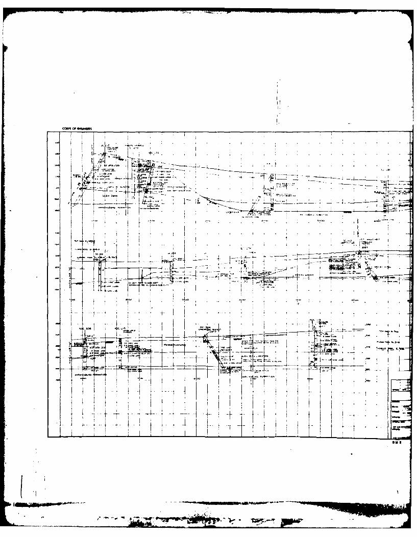
3-10. Details of the grout curtain remained essentially the sameexcept that grouting was eliminated where the Glen Dean Lime-stone was absent below the dike, Sta. 4+50 to 7+65. A moredetailed grouting profile was included showing the curtain onthe dike left abutment to be broken into two zones below ele-vation 564. The base of the curtain was defined as being 5 feetbelow the lower Glen Dean Limestone contact on the left abut-ment. The grout curtain was shortened 700 feet at the leftabutment of the dike. There was no discussion as to why thegrout curtain was shortened. Again, grouting through the over-burden was planned. The grouting profile shown in this D.M.remained essentially the same a presented in the contractdrawings.
3-11. The results of a groundwater study and better pressure test datawere included in this D.M. Low water tables were noted on bothreservoir rims. Seepage control for the left rim was notaltered. Only one core hole on the left abutment of the dike(Sta. 1+20) was pressure tested. This hole indicated a tightlimestone. However, water takes in the 15-foot interval at thecontact between limestone and sandstone averaged 6 cu. ft. per-minute. Water takes in the sandstone above this interval rangedfrom 1 to 5 cu. ft. per minute in 5-foot testing intervals.These takes were considerably less than takes observed duringcontract grouting. As in D.M. 2, drill water loss zones werepresented. Of the eight exploratory holes drilled on the leftabutment of the dike, four holes lost drill water in the sand-stone, one hole lost drill water in the limestone, one hole lostdrill water in both the sandstone and in the limestone, one holeencountered very little limestone, and one hole indicated nodrill water lose.
12
~~4SjUPI3t-w POWa.
camS OF 4#
j4Ak. -~-4- _
1-----t A
.. .. ...
-lif-~ 2O*'slow

U SAt
-- I z
. - L A
1.13
ILL-....
* ~ I ~NOW
3-1 2. After review, comments were made by ORD and OCE. These commentswere inserted in the front of the Feature Design Memorandum.Several comments concerning grouting were pertinent to the prob-lem encountered during construction. A lack of data to supportrim grouting conclusions were noted. The presumption that theMansfield Sandstone would not present a seepage problem wasquestioned. Further, the possibility of large cavities betweenthe sandstone and the solutioned limestone was noted. A posi-tive cutoff through the Glen Dean Limestone on the rightabutment of the dike was strongly recommended to eliminate thepiping potential in this area. The ineffectiveness of proposedgrouting in the right abutment area was also noted. No commentswere made about the left abutment. The left abutment seepagezone between sandstone and limestone was considered too farbelow the surface to be treated economically by an excavatedcutoff. Further exploratory work was suggested for the dikearea.
3-13. Further exploratory work including a 36-inch diameter auger holeon the right abutment was accomplished in the dike area. How-ever, no further exploratory work was accomplished on the leftabutment of the dike. The results of this additional explora-tory drilling were presented In Supplement 1 to Design Memo-randum 8.
3-14. In this supplement, the design was altered to excavate apositive cutoff trench through the Glen Dean Limestone on theright abutment of the dike. No changes were made to the leftabutment foundation treatment.
3-15. Further comments by ORD and OCE with replies by ORL were in-cluded in this supplement. The only comment concerning the dikeleft abutment suggested placing a large waste material bermdownstream of the dike. This berm would increase the length ofthe seepage path and prevent breaching of the dike in case ofsink hole development above the solutioned limestone. The finalcontract plans included this added berm downstream of the dike.
C. Contract Specifications
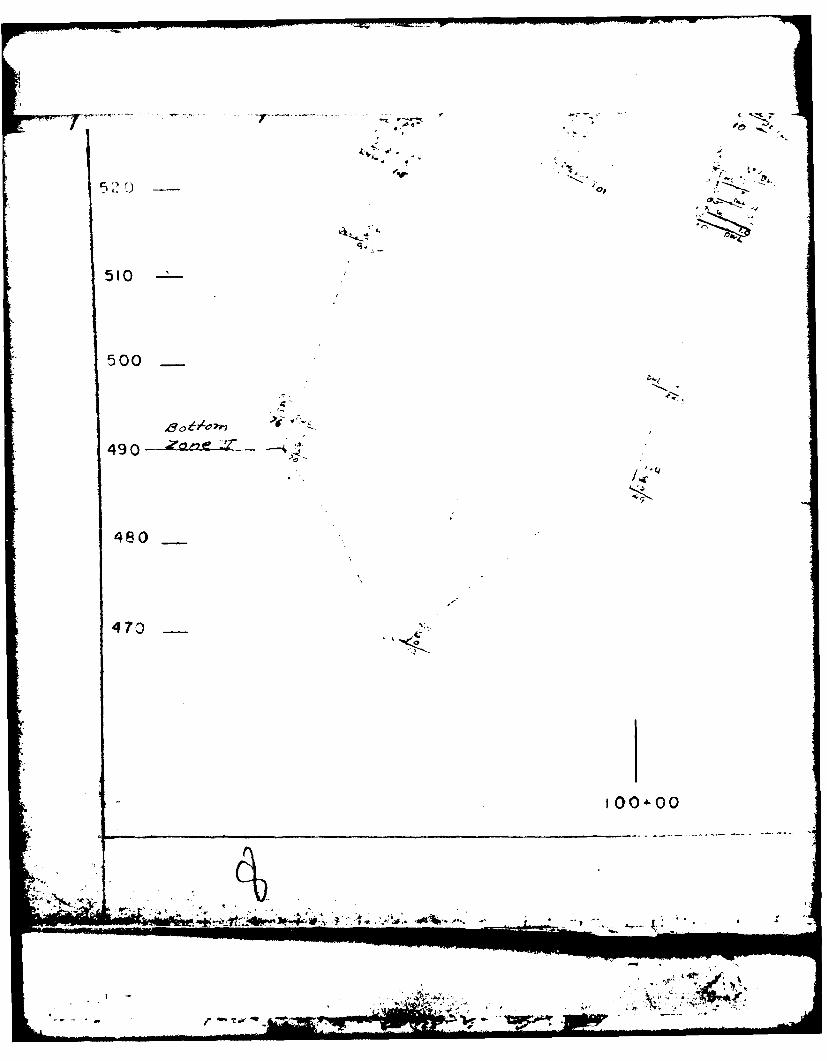
3-16. The final grout curtain design was set forth in the contractplans and specifications. On the left abutment of the dike, theplans called for a triple line stage grouted curtain betweenStations 1+0 and 4+20. The top of the curtain was set at Eleva-tion 564 or at the top of rock, whichever was deeper. The groutcurtain was divided into two zones. The bottom of the firstzone was defined as being 20 feet below the top of the cur-tain. The bottom of the second zone was defined as being 5 feetbelow the base of the Glen Dean Limestone. The two outside
14
lines were to be completed within a zone before completion ofthe centerline in the same zone. Original spacing was set at20-foot centers with provisions for split spacing as neces-sary. Stages were defined as drill water loss or bottom ofzone. The grouting operations were further reduced to 100-footsections in which drilling and grouting could not be carried onsimultaneously. Minimum diameter of holes was defined as 1-3/8inches. All holes were battered on 20 degree angles into theabutment. The maximum depth for any one hole was 122 feet.Plans required this area to be completely grouted before exca-vation of the 10-foot deep dike inspection trench.
3-17. Casings were required through the overburden and sealed at leastone foot into rock. Where rock overlaid the top of the groutcurtain (Elev. 564), the rock above the curtain was not to begrouted. In this situation, a packer was required at Elevation564 to prevent grout leakage. Upon completion of groutingoperations, all casings were to be removed and the resultingvoids backfilled.
3-18. After drilling any stage, the holes were to be washed andpressure tested Immediately prior to grouting. If joint fillingwas encountered, washing under pressure would continue until allfilling material was washed from the joints. Holes where nopressure could be built up were to be washed for a period offive minutes.
3-19. Specified water cement ratios for grouting varied from 3:1 to0.6:1. Provisions were included for mortar grout if neces-sary. Allowable grouting pressures, as specified, ranged from 1to 170 psi, static head. Specifications required air driveprogressive cavity (non surge) or equal grout pumps. The groutpump could not be placed further than 100 feet from the holebeing grouted. Grout supply lines of 1.5 inch diameter werespecified between the grout pump and the hole being grouted.
PART IV -GROUTING PHIASE
4-01. The contract for the Damn and Spillway was awarded in January1975 and work began the same month. Grouting was started onM1ay 22, 1975, at the dike left abutment. Work continued in thisarea almost continually until October 13, 1976, when groutingwas abandoned.
4-02. This short area was divided into four 100-foot long sections andworked by sections thereafter. The problems encountered latercoincided closely within the boundaries of these four sec-tions. All the primary casings were installed before drillingand grouting were started.
4-03. Drilling and grouting equipment used in this area of the groutcurtain was of standard design for the grouting industry. Cas-ings were drilled with a Chicago Pneumatic air-trac drillconverted to rotary operation using standard NW drill rods androck bits. Grout hole drilling was performed with air-operatedChicago Pneumatic 55 post mounted drills utilizing EX rods andbits. The grout plant consisted of 2 each 17 cu. ft. mixingtubs and an air-operated 1i1oyno progressive cavitating groutPUMP.
4-04. Mix designs and general grouting procedures were formulatedearly in the grouting process. Water cement ratios ranged from3:1 to 0.6:1 in neat mixes. The sand mix designed for groutingcontained 5 cu. ft. or mortar sand, 3 cu. ft. of water, 3 cu. ft.of cement, and I cu. ft. of flyash. The water content was lowered occasionally. However, inconsistent sand moisture con-tents and slightly inaccurate water meters resulted in varyingmix consistencies when the water content was altered. The3 cu. ft. of water was standardized to give a consistentlypumpable mix. Grouting pressures of 10 and 15 psi were usedfor the first and second zones, respectively.
4-05. Grouting was usually started with a 2:1 mix depending upon watertake. The mix was periodically thickened, usually in 30 cu. ft.increments, until a 0.6:1 mix was achieved. Where no pressurewas recorded, pumping was continued until approximately 150cu. ft. of solids were pumped into the hole. If no pressure wasreached at this point, grouting was discontinued for one shift.The following shift, sanded grout, was pumped until a total of500 cu. ft. of solids were pumped. Grouting was discontinuedfor another shift to allow a complete set. Pumping of sandedgrout was continued in this manner until the hole refused. Thegrouting procedures described here represented a very generalgrouting procedure and were varied according to circumstances.
16
4-06. The 150 cu. ft. initial neat cement grouting was justified fortwo primary reasons. First, a large number of holes, especiallyin the sandstone, refused between 100 and 150 cu. ft. Secondly,this procedure allowed some smaller cracks to be filled whilepumping into a larger void.
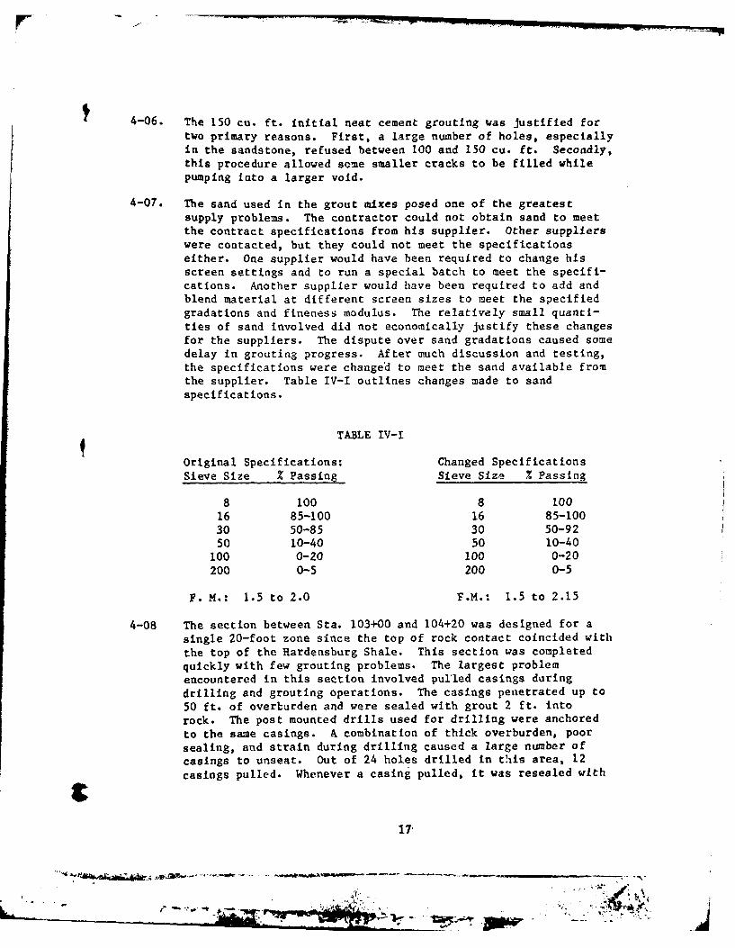
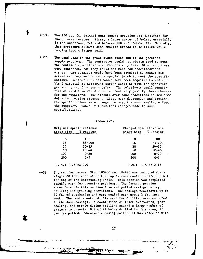
4-07. The sand used in the grout mixes posed one of the greatestsupply problems. The contractor could not obtain sand to meetthe contract specifications from his supplier. Other supplierswere contacted, but they could not meet the specificationseither. One supplier would have been required to change hisscreen settings and to run a special batch to meet the specifi-cations. Another supplier would have been required to add andblend material at different screen sizes to meet the specifiedgradations and fineness modulus. The relatively small quanti-ties of sand involved did not economically justify these changesfor the suppliers. The dispute over sand gradations caused somedelay in grouting progress. After much discussion and testing,the specifications were changed to meet the sand available fromthe supplier. Table tV-I outlines changes made to sandspecifications.
TABLE IV-I
Original Specifications: Changed SpecificationsSieve Size Z Passing Sieve Size % Passing
8 100 8 10016 85-100 16 85-10030 50-85 30 50-9250 10-40 50 10-40
100 0-20 100 0-20200 0-5 200 0-5
F. M.: 1.5 to 2.0 F.M.: 1.5 to 2.15
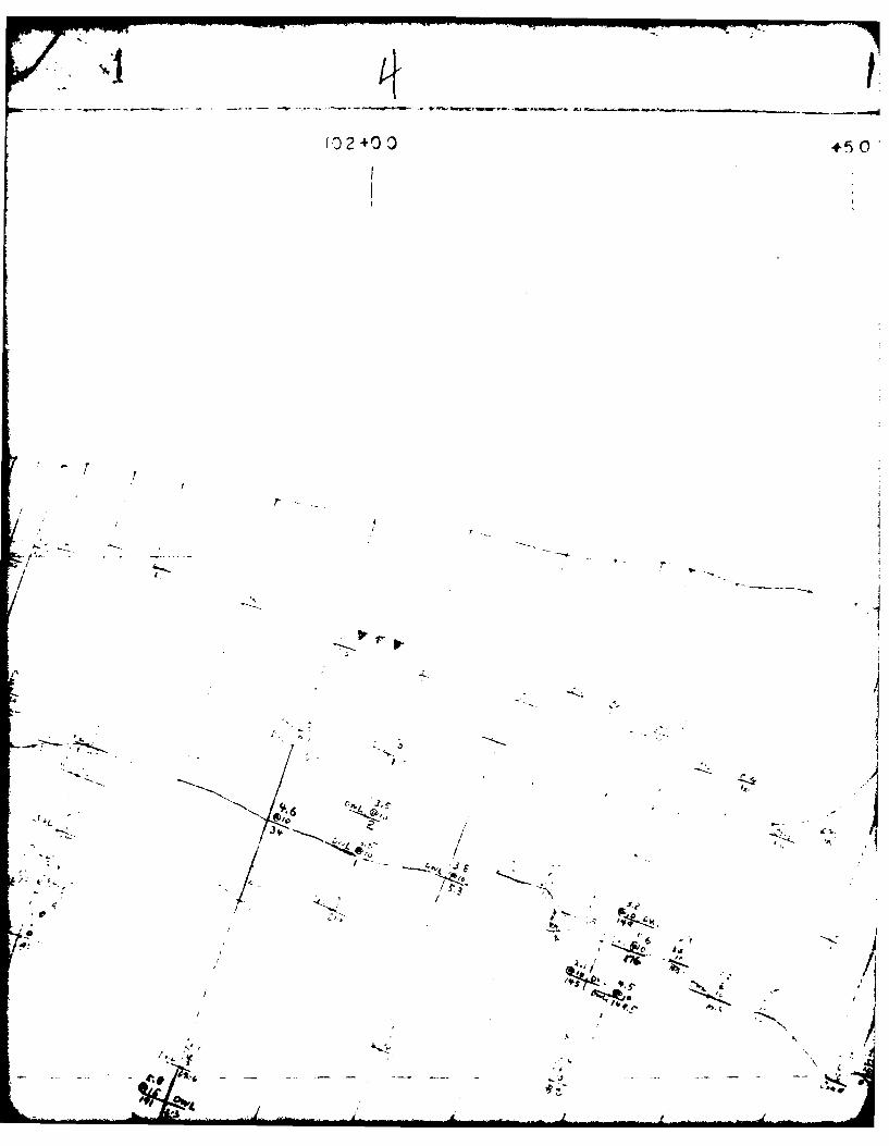
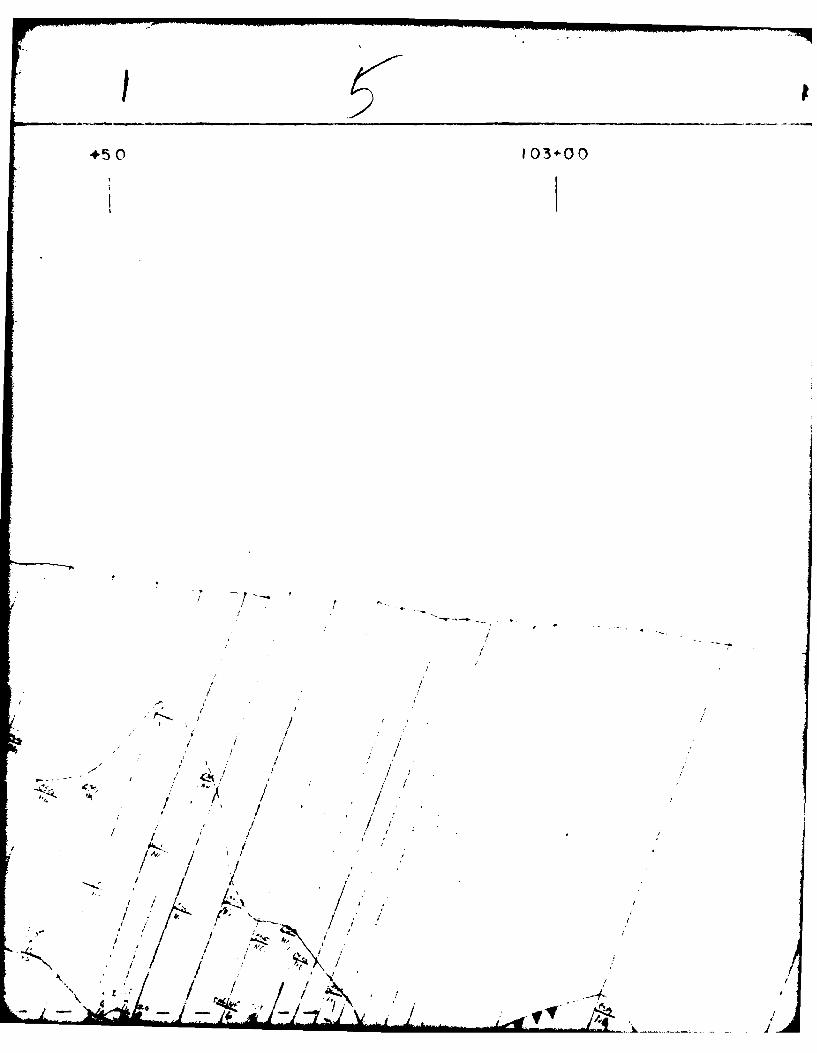
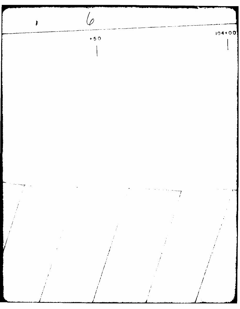
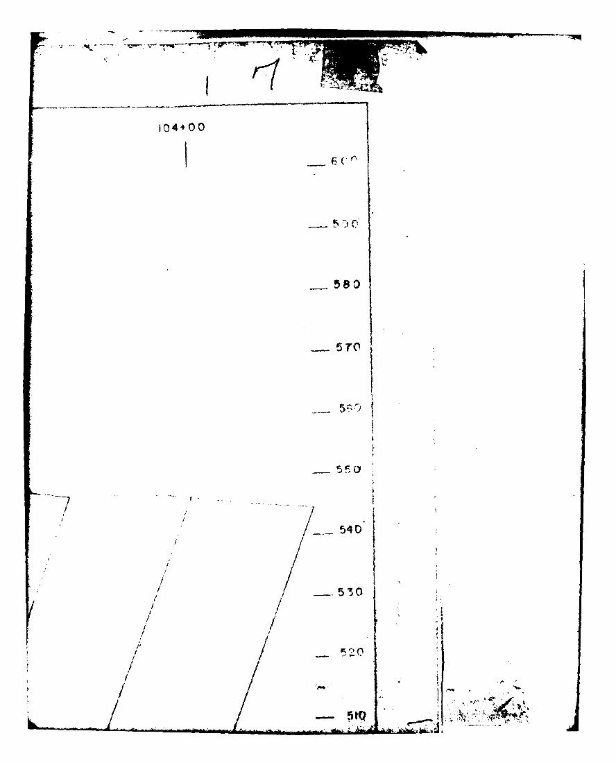
4-08 The section between Sta. 103+00 and 104+20 was designed for asingle 20-foot zone since the top of rock contact coincided withthe top of the Hardensburg Shale. This section was completedquickly with few grouting problems. The largest problemencountered in this section involved pul'led casings duringdrilling and grouting operations. The casings penetrated up to50 ft. of overburden and were sealed with grout 2 ft. intorock. The post mounted drills used for drilling were anchoredto the same casings. A combination of thick overburden, poorsealing, and strain during drilling caused a large number ofcasings to unseat. Out of 24 holes drilled in this area, 12casings pulled. Whenever a casing pulled, it was resealed with
17
-, ..... ...... .
4-06. The 150 cu. ft. initial neat cement grouting was justified fortwo primary reasons. First, a large number of holes, especiallyIn the sandstone, refused between 100 and 150 cu. ft. Secondly,this procedure allowed some smaller cracks to be filled whilepumping into a larger void.
4-07. The sand used in the grout mixes posed one of the greatestsupply problems. The contractor could not obtain sand to meetthe contract specifications from his supplier. Other supplierswere contacted, but they could not meet the specificationseither. One supplier would have been required to change hisscreen settings and to run a special batch to meet the specifi-cations. Another supplier would have been required to add andblend material at differkunt screen sizes to meet the specifiedgradations and finieness modulus. The relatively small quanti-ties of sand involved did not economically justify these changesfor the suppliers. The dispute over sand gradations caused somedelay in grouting progress. After mnuch discussion and testing,the specifications were changed to meet the sand available fromthe supplier. Table IV-I outlines changes made to sandspecif icat ions.
TABLE IV-I
Original Specifications: Changed SpecificationsSieve Size % Passing Sieve Size %Passing
8 100 8 10016 85-100 16 85-10030 50-85 30 50-9250 10-40 50 10-40
100 0-20 100 0-20200 0-5 200 0-5
F. M.: 1.5 to 2.0 F.M.: 1.5 to 2.15
4-08 The section between Sta. 103+00 and 104+20 was designed for asingle 20-foot zone since the top of rock contact coincided withthe top of the Hardensburg Shale. This section was comnpletedquickly with few grouting problems. The largest problemencountered in this section involved pulled casings duringdrilling and grouting operations. The casings penetrated up to50 ft. of overburden and were sealed with grout 2 ft. intorock. The post mounted drills used for drilling were anchoredto the same casings. A combination of thick overburden, poorsealing, and strain during drilling caused a large number ofcasings to unseat. Out of 24 holes drilled in this area, 12casings pulled. Whenever a casing pulled, it was resealed with
17
- ~it:- - -"'A
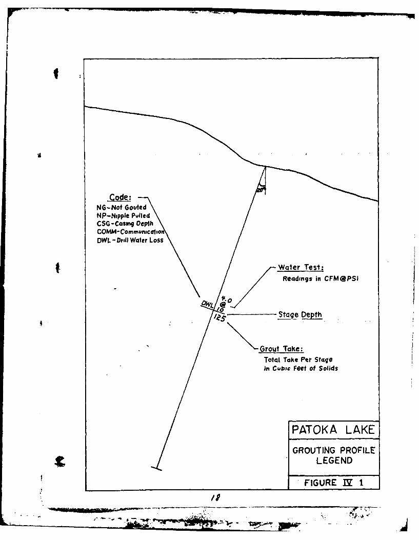
NG-Nof Gout edNP-Nipple PulledCSG-Casing DepthCOMM- CommunicationDWL - Drill Water Loss
t. Woter Test:Readings in CFM@PSI
Stage Depth
Grout Take:Total Take Per Stagein Cubic Feet of Solids
PATOKA LAKE
GROUTING PROFILELEGEND
FIGURE 1Y 1
/1j
#5 10 4L -'0
NJ
j59(ell
C' -6
SAO 0
~7K~ -
zz-. 4
Vo/
II
-1
39s7
- .-r
k- ; / /
Ko k
/ ,/
,-
/ ./11
6
*s7,
'DI
1 .- 'I
'A , / 1
"t' .,L-.- ," -' ___b d
. ! ./ .. I
,e . *1/.~~ / r I / / " ,3., - :, -) 71
/"/ - "
° y /.,. , I. ,.
It-iV~2~ ~O
I' 7. T t-
/ / I I
d I - . -
/
/
/
/
z.. -
/ I
IV
10
hj4 *-
* I.-' ~
/ ,b ~Y /I6~ *~> <9
/L4~ *j~-.~$; /
~ o~< -.1,1- I 4.
- 'I-
2)1 1;
/ ~~4/~; III~*/ 4*~ I
* -~ . -~ I.
I -.-- lJ- I
S ~
II; __
+;C 3 10 0
I
1~-~~~
!/'*- ~ ~r / / -~
1/ i/ ,
cc~
j / 9
7 *~'~-1 / *'
*~?-' I /
:s/<,j. "I /
I' / / I
''p
+50 104 -~ CO
*
-r
//
/
/
I /
/ /
/ *1~
// ,1/
/ /
-600
590)
-- 570
-560
-. 540/
! -I
/ ,,p
/ ' I",11 - 520i
1-t-
510 .- -
490-
48 -
.fS. ta .&N
IsmI
- _ *- IA
* IS9
+50 '
~ .~I, * 1~g ~ .. ~
t/ /-
10 /: 00
//
. . - ,/ . -..
-o r
,' /
," 4' . 7 : . .2 4,- /. '
I-I
' ' -"" q4 r 7g.W<.. -. -
"~r j,) '-
9.1.
- -.. . . - 7 " "/
/ 0L: ' / / :
i, ., -- / 7-. "
/I
t 50 03 -00
±5\ -- '_.... .
I/, ...- - '-;" .. " ..,~..I ... '- "' ... : 1
,/
.I. - -
!I
Ie C
/ 0
v6
A
~5C 34-.0
Ii
/t
.I , -
t • / , *
I - - - _-1 . ..4 ... - - .- ,,.*''
-520*
-510-
-490
-PATOKA -LA/-KE-
GROUTING PROFILE iUPSTREAM L )Nf
Sco(ae I it oI Natural .
1.4-0 IG T\ -2
' -' U.-
r ,2 +50 103 0
560rq
/
550
/1 /
//
54
-. 520
PATOKA LAKE" DAM 5 SPIL LWAY
-,s5ool G.OU-T;NG rRFILE/P STREAM LINE
Y, 1.5' SPACED HOL E S-490'//,
/ / '. S, lie I 10' NituralFIGURE IV-3
.. . .. w IIr "" I o
I OOt00 00t50"
600
590 , - /
F,/
0
4 0
570 /
520
/f~~5c)
II
t50
I
~---------- --
77I
4~ 7'I;
I
I 3-, 2~~1 // /
fr~;/
I /
I! 'I
/ // //I
/1 ' I
/ ~
/
S101+50 02-00
// - "/
7I ,- - -- - --. ,
// t / "
// / i
/ .:
'/o ! !
/ , , - / ,
/ 4>- / /1
102+00 25
I// /
Ii. /ll '
/ /
' /
/ '
0 /
"'9/'3 / ... -
I ~'-1
4?$-.. - -
/
103-t- 00 103±50
/
/
/
/
/ p
V
- - S ~
p3±50104+10
5901
58 0
57011
/ I 54O 1,
530
.1 520
I 1510
[ 500
490
480
470
100-00 I00+50
I..
I / / I / iiI . 'I,.
I I
________ I01+00
V. . -
AV
101-50 102±00
7 1L'I.
-'-4
4LW2;
-V At. -
, ,-A; :. zi-s
n- , ,
/ .".
A,0.1.
4A/At
10 f0 0 .1......
103-O0. 103i 50
-. - .... . t
516
500:
490
400
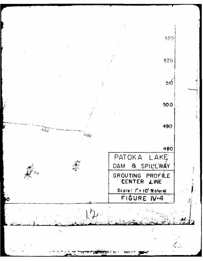
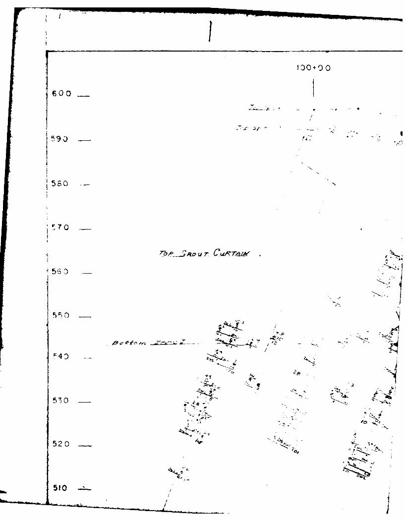
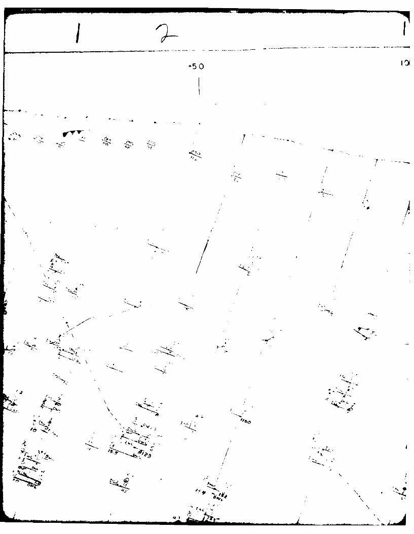
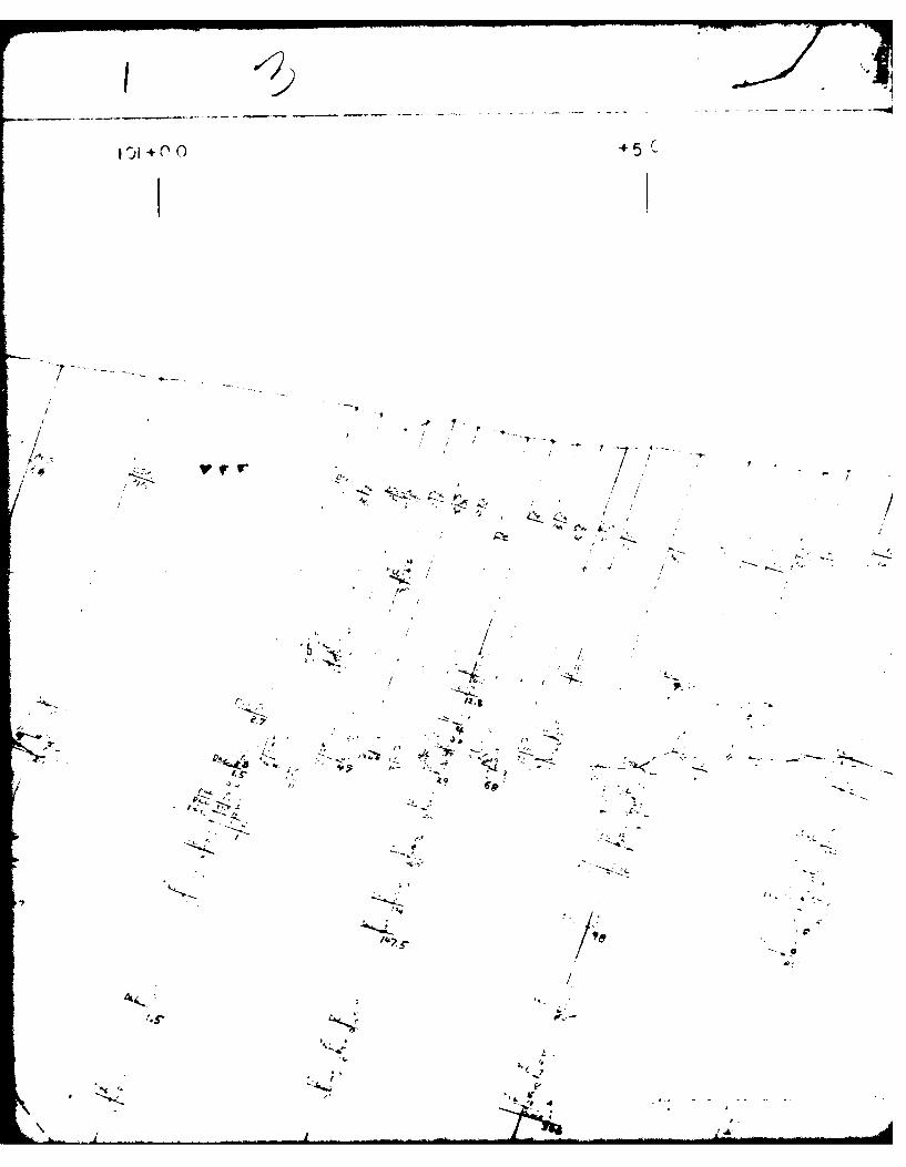
PATOKA LAK 'DAM 8~SPIL LWAX
GROUTING PROF~tLE'CENTER ILINE
Scated, f"z 0' naturuiFIGURE IV-4
I0 0
600 -
/
2/ a
t7 0
tI
560
AR9 -
570-
' .'
52 0 " ' . i
510
8"SI
II
*5
N / '6
N x;
- .n k. - \ L
. -S.,N.*. 1
... .. . . °--° - 4.'. 4
I -I
,7.,/ /
_- i ' - - -•- f- ---/
- ..- /
.1 .p'. "; . p ..
/*-.
sj /-I...
-* * > s j ' " # 4- " - --,.
. .
1~i
II-r~~~~~~~ ~~~~~~~~~~ - r -.-- . - - ----. - ~ r . r . . ~ . . n . n ~
* I+50 IO3'~QO
/
/-I
I //
/ 1' / ii/ *1
9'! .1' I ~ I' I'
-'Z~ Cl'4' A / /
'1, , /:
/ / I/ h.. 1 './' I
/ ,1 ,~
'I / /
/ * (21. ~.
* ! // / A.~ ~,
/ ~ '/I/ / / &~\ / -4
4 -, '' .1- VI ~.
4
4-50
I
t
/
/
'I / /1 1/I/
104400
5 TO
550
" l t +. -.....
/' 54 0
/ I
/I,/ / .530
i / "/ /"
I /' 0
/ " : ; :'',
510
500
49 0 -
480
4 70
5000+-
4-,
._DOi .A,.~
,p - - , i . '
K t~~( -ks -
- ~
4d<
XeS
- 7.~
c~ ~4
'A -.
/ -A~~.
4
'I
/
'V
4-0
t -. -'-I'; .-. ,
-~ - - - - ~ . S- .I~,- ~ - -
101+00
-- 445
.1'7'.- ~K.
~' .~
/
- - - .-- - ---- --. - -- , - - -- -.
K..1~'
I, .*.
I), g -
- ----. -
V
102. 00 4~Q
/ !
-< .-- -- ,"-- , "* ' :
., ,.. <:74 .
I "I E r, .
e -&q
z--/J
/ ,
// i,,-
-C0 103"0
• ' ' "J"" :" -C - '.r
I3 2,
344
/
//
/
t7
/
" , 500
- 490
400
PA TCK\ LA.KE<-_' ' "KE A", S -A . AY
l AM LiN L-
' O ' N ->.,
F ;.URLE- IV-5
,~ - . ., o .,,
~~~102±-30
I
/ ( I '
, f /
,I€ / /
/ / /
.. ,// / I •
I ,i / / / ,t / !
* I I i
* 6 ' /I
* / /* / /
* /
" ' / i. "
/ / /
I / /
//
-/, I,2/ 4'
- / 1
'1' -47'0
( _______._
103+00
56o
// I
! .*I
/, /-
J // /
:/,/
- 510
-500PATOKA LAKE-DAM & SPILLWAY
GROUTING PROFILE490 DOWNSTREAM LINET
I5'SPACED HOLES
Scile: 10' Natural
___ FIGuRE I V-6
.1.
V -/
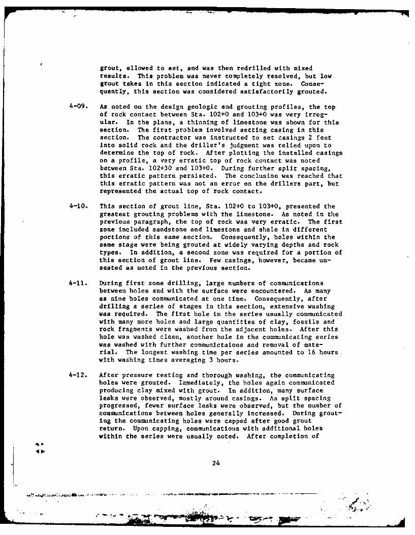
grout, allowed to set, and was then redrilled with mixedresults. This problem was never completely resolved, but lowgrout takes in this section indicated a tight zone. Conse-quently, this section was considered satisfactorily grouted.
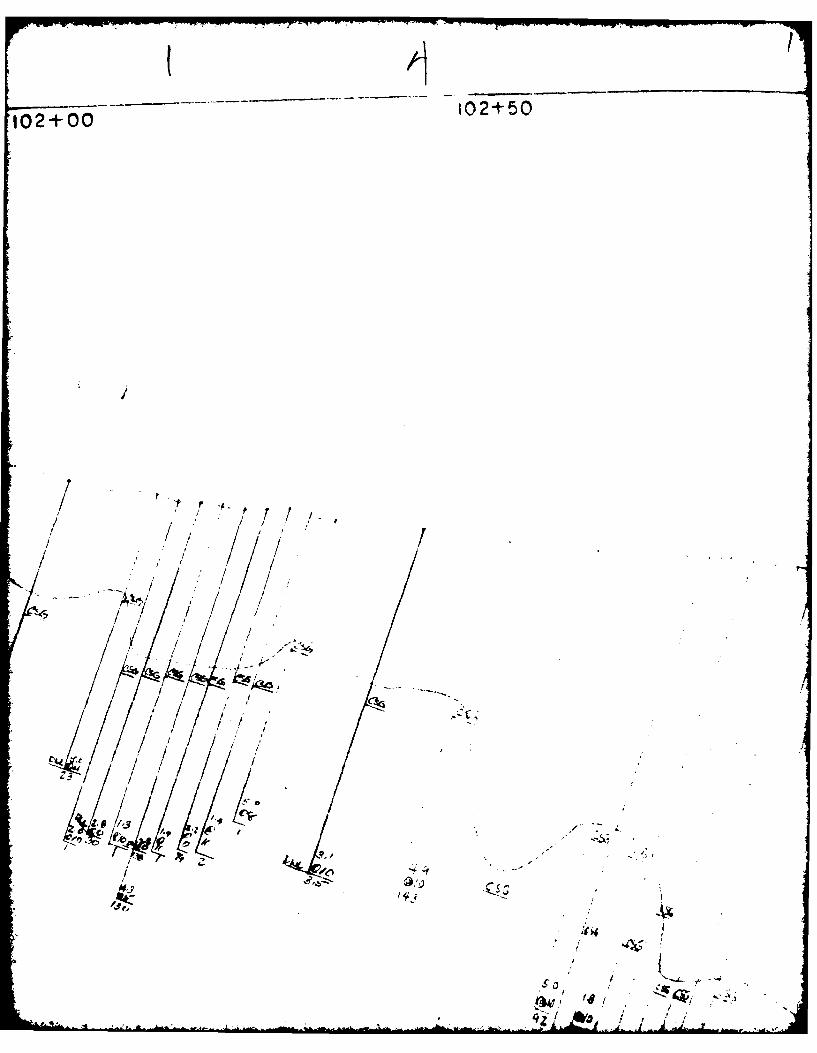
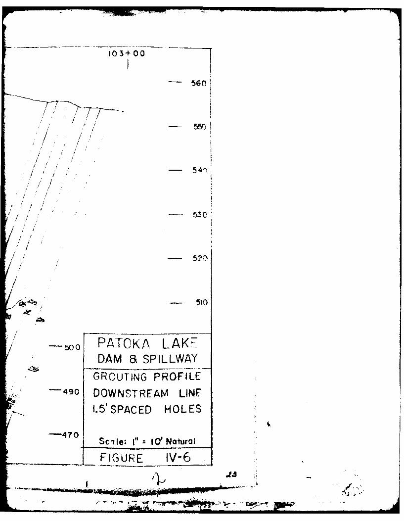
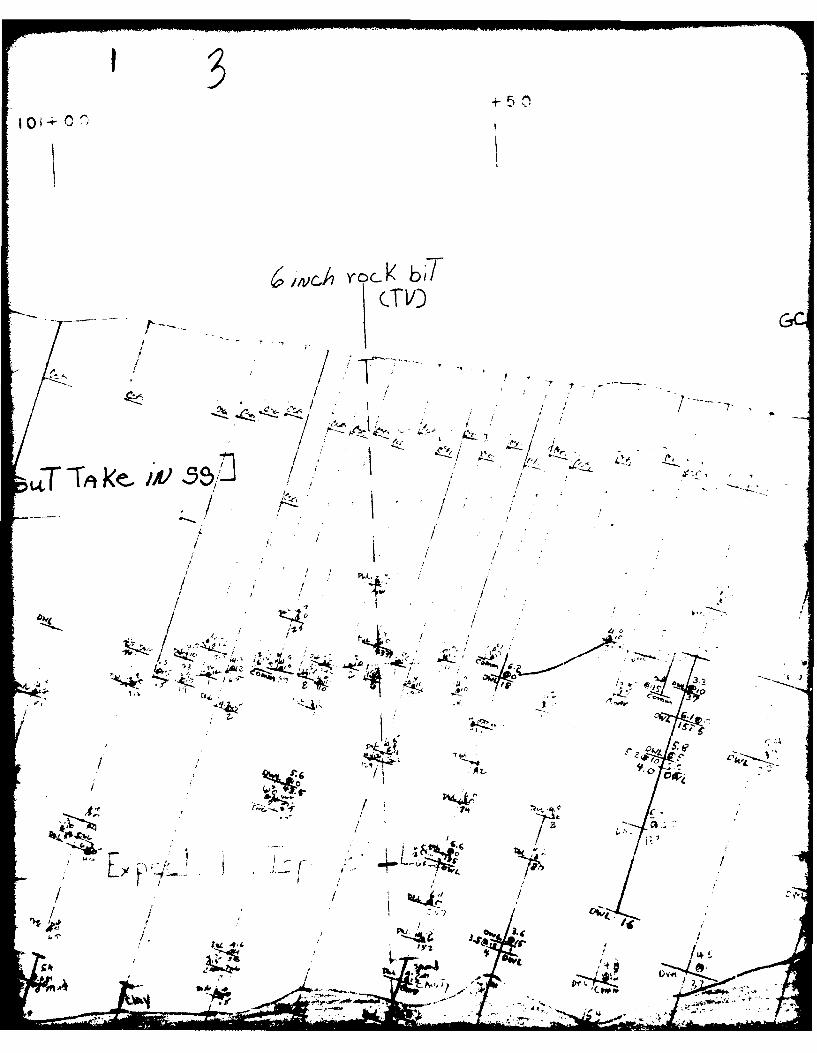
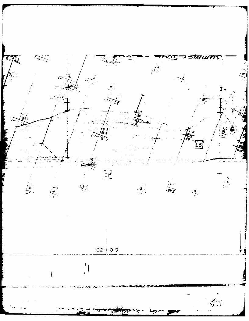
4-09. As noted on the design geologic and grouting profiles, the topof rock contact between Sta. 102+0 and 103+0 was very irreg-ular. In the plans, a thinning of limestone was shown for thissection. The first problem involved setting casing in thissection. The contractor was instructed to set casings 2 feetinto solid rock and the driller's judgment was relied upon todetermine the top of rock. After plotting the installed casingson a profile, a very erratic top of rock contact was notedbetween Sta. 102+30 and 103+0. During further split spacing,this erratic pattern persisted. The conclusion was reached thatthis erratic pattern was not an error on the drillers part, butrepresented the actual top of rock contact.
4-10. This section of grout line, Sta. 102+0 to 103+0, presented thegreatest grouting problems with the limestone. As noted in theprevious paragraph, the top of rock was very erratic. The firstzone included sandstone and limestone and shale in differentportions of this same section. Consequently, holes within thesame stage were being grouted at widely varying depths and rocktypes. In addition, a second zone was required for a portion ofthis section of grout line. Few casings, however, became un-seated as noted in the previous section.
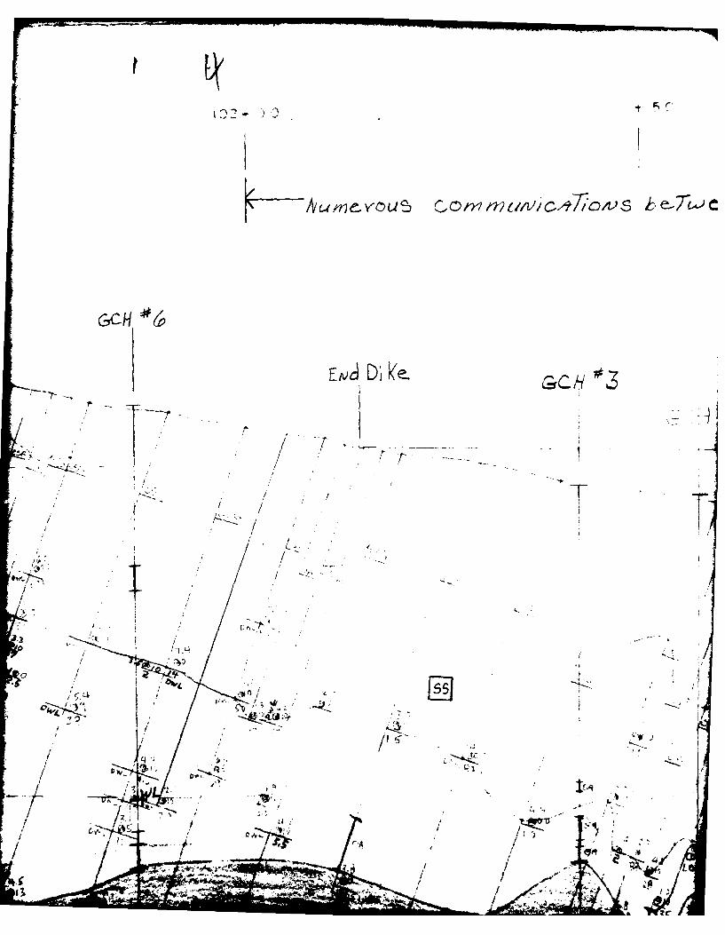
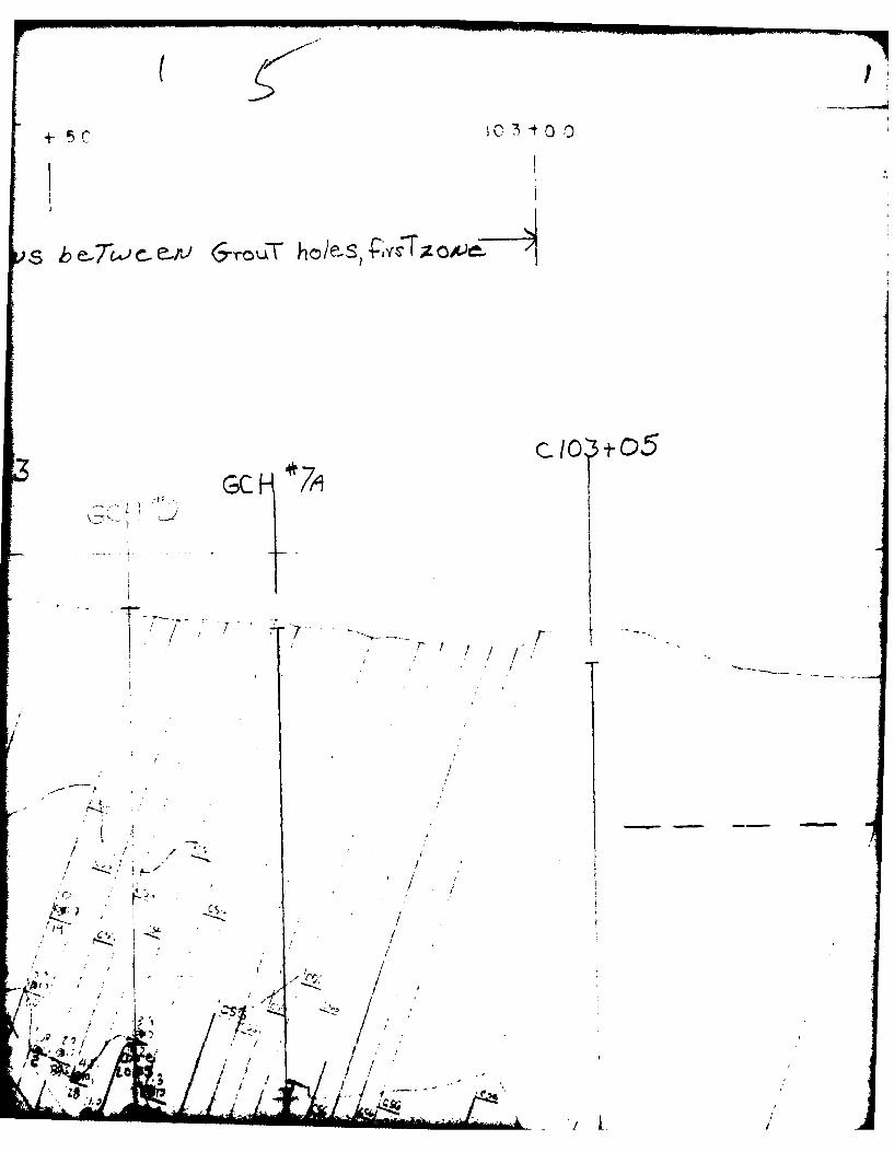
4-Il. During first zone drilling, large numbers of communicationsbetween holes and with the surface were encountered. As manyas nine holes communicated at one time. Consequently, afterdrilling a series of stages in this section, extensive washingwas required. The first hole in the series usually communicatedwith many more holes and large quantities of clay, fossils androck fragments were washed from the adjacent holes. After thishole was washed clean, another hole in the communicating serieswas washed with further comnunictaions and removal of mate-rial. The longest washing time per series amounted to 16 hourswith washing times averaging 3 hours.
4-12. After pressure testing and thorough washing, the communicatingholes were grouted. Immediately, the holes again communicatedproducing clay mixed with grout. In addition, many surfaceleaks were observed, mostly around casings. As split spacingprogressed, fewer surface leaks were observed, but the number ofcommsunications between holes generally increased. During grout-ing the communicating holes were capped after good groutreturn. Upon capping, communications with additional holeswithin the series were usually noted. After completion of
24
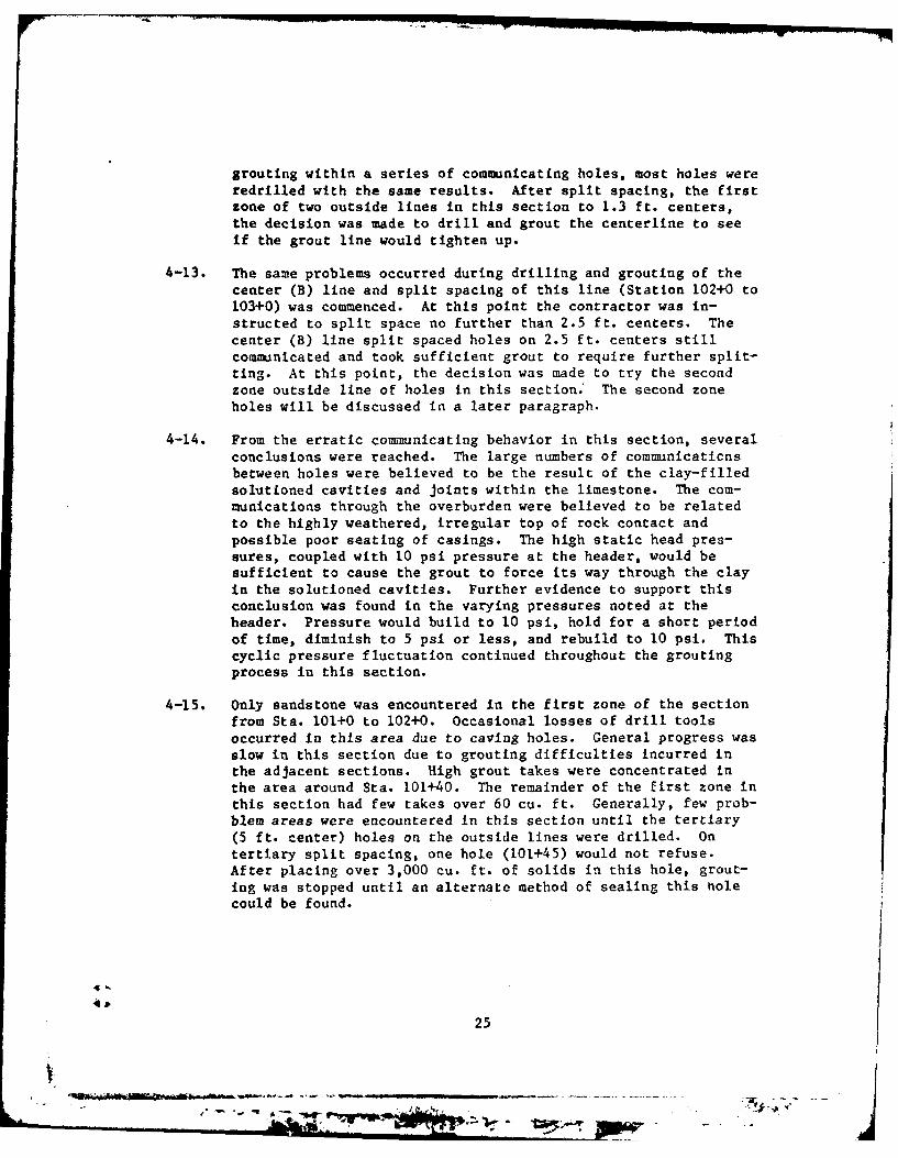
grouting within a series of communicating holes, most holes wereredrilled with the same results. After split spacing. the firstzone of two outside lines in this section to 1.3 ft. centers,the decision was made to drill and grout the centerline to seeif the grout line would tighten up.
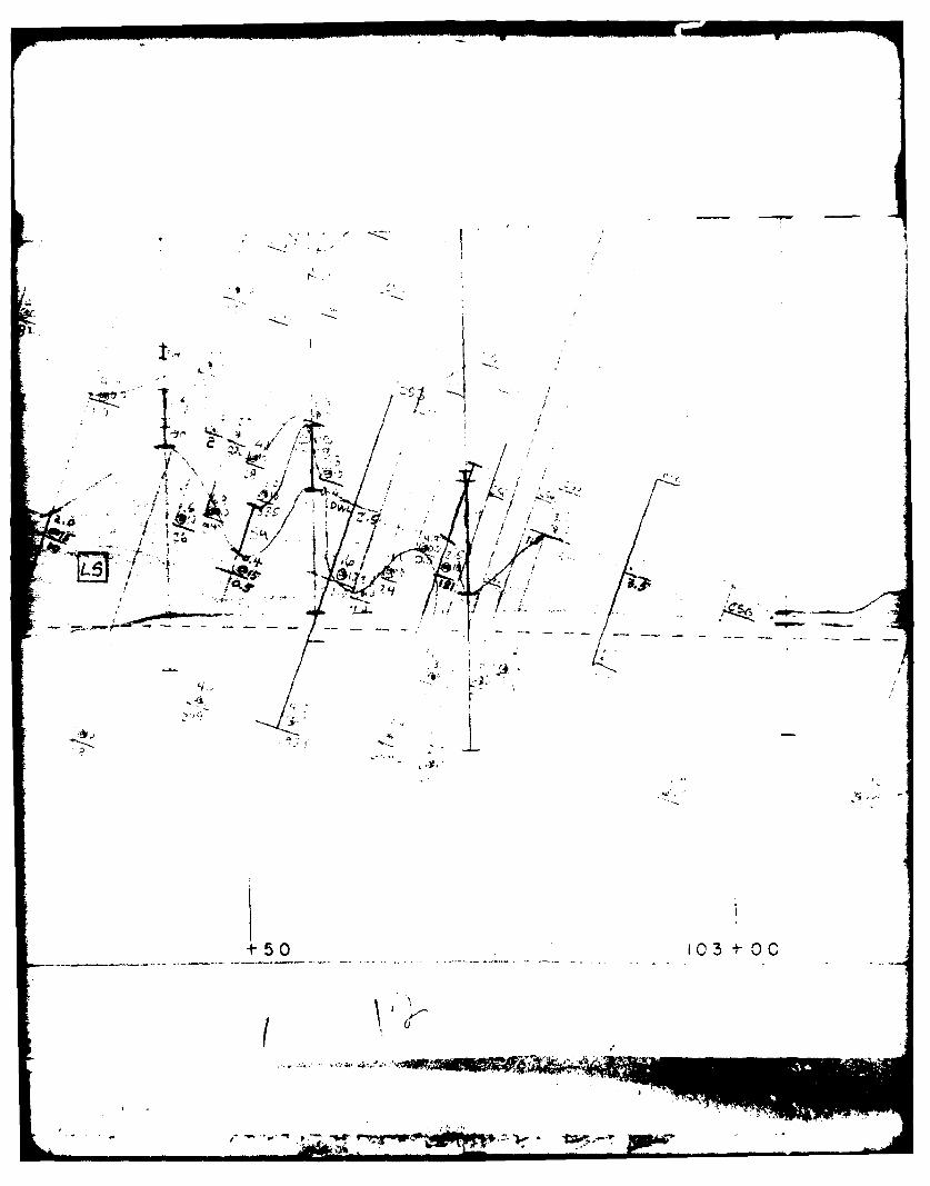
4-13. The same problems occurred during drilling and grouting of thecenter (B) line and split spacing of this line (Station 102+0 to103+0) was commenced. At this point the contractor was in-structed to split space no further than 2.5 ft. centers. Thecenter (B) line split spaced holes on 2.5 ft. centers stillcomiainicated and took sufficient grout to require further split-ting. At this point, the decision was made to try the secondzone outside line of holes in this section.' The second zoneholes will be discussed in a later paragraph.
4-14. From the erratic communicating behavior in this section, severalconclusions were reached. The large numbers of communicaticnsbetween holes were believed to be the result of the clay-filledsolutioned cavities and joints within the limestone. The com-munications through the overburden were believed to be relatedto the highly weathered, irregular top of rock contact andpossible poor seating of casings. The high static head pres-sures, coupled with 1.0 psi pressure at the header, would besufficient to cause the grout to force its way through the clayin the solutioned cavities. Further evidence to support thisconclusion was found in the varying pressures noted at theheader. Pressure would build to 10 psi, hold for a short periodof time, diminish to 5 psi or less, and rebuild to 10 psi. Thiscyclic pressure fluctuation continued throughout the groutingprocess in this section.
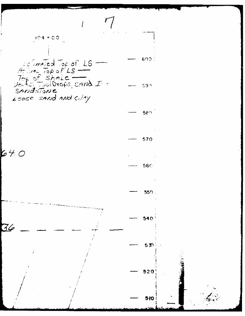
4-15. Only sandstone was encountered in the first zone of the sectionfrom Sta. 101+0 to 102+0. Occasional losses of drill toolsoccurred In this area due to caving holes. General progress wasslow in this section due to grouting difficulties incurred inthe adjacent sections. High grout takes were concentrated inthe area around Sta. 101+40. The remainder of the first zone inthis section had few takes over 60 cu. ft. Generally, few prob-blem areas were encountered in this section until the tertiary(5 ft. center) holes on the outside lines were drilled. Ontertiary split spacing, one hole (101+45) would not refuse.After placing over 3,000 cu. ft. of solids in this hole, grout-ing was stopped until an alternate method of sealing this tnolecould be found.
25
, ~ .WOW ,
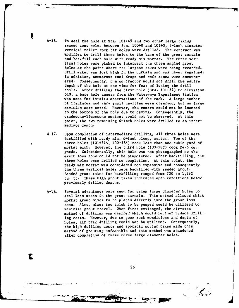
4-16. To seal the hole at Sta. 101+45 and two other large taking
second zone holes between Sta. 100+0 and 101+0, 6-inch diametervertical roller rock bit holes were drilled. The contract wasmodified to drill three holes to the base of the grout curtainand backfill each hole with ready mix mortar. The three ver-tical holes were picked to intersect the three angled groutholes at the point where the largest takes were being recorded.Drill water was lost high in the curtain and was never regained.In addition, nuumerous tool drops and soft zones were encount-ered. Consequently, the contractor would not drill the entiredepth of the hole at one time for fear of losing the drilltools. After drilling the first hole (Sta. 101+34) to elevation510, a bore hole camera from the Waterways Experiment Stationwas used for in-situ observations of the rock. A large numberof fractures and very small cavities were observed, but no largecavities were noted. However, the camera could not be loweredto the bottom of the hole due to caving. Consequently, thesandstone-limestone contact could not be observed. At thispoint, the two remaining 6-inch holes were drilled to an inter-mediate depth.
4-17. Upon completion of intermediate drilling, all three holes werebackfilled with ready mix, 6-inch slump, mortar. Two of thethree holes (101+34A, l00+55A) took less than one cubic yard ofmortar each. However, the third hole (100+58C) took 24.5 cu.yards. Coincidentally, this hole was not photographed so theexact loss zone could not be pinpointed. After backfilling, thethree holes were drilled to completion. At this point, theready mix mortar was considered too expensive and consequentlythe three vertical holes were backfiled with sanded grout.Sanded grout takes for backfilling ranged from 730 to 1,192cu. ft. These high grout takes indicated open conditions belowpreviously drilled depths.
4-18. Several advantages were seen for using large diameter holes toseal loss areas in the grout curtain. This method allowed thickmortar grout mixes to be placed directly into the grout losszone. Also, mixes too thick to be pumped could be utilized tominimize grout travel. When first envisaged, the air-tracmethod of drilling was desired which would further reduce drill-ing costs. However, due to poor rock conditions and depth ofholes, air-trac drilling could not be utilized. Consequently,the high drilling costs and sporadic mortar takes made thismethod of grouting unfeasible and this method was abandonedafter completion of these three large diameter holes.
26
Vim-I
t 4-19. Grouting was again continued in the hole at Sta. 101+45.Another 950 cu, ft. of grout was pumped before this hole finallyrefused. This hole (101+45A) was further split spaced andneither of the first zone split holes took over 2 cu. ft. ofgrout. The remainder of the first zone in this section wasgrouted without further problems. The other two grout holesintersected by large diameter vertical holes were furthergrouted also. Both of these holes sealed rapidly and werestaged further. Both holes took large quantities of groutduring subsequent staging.
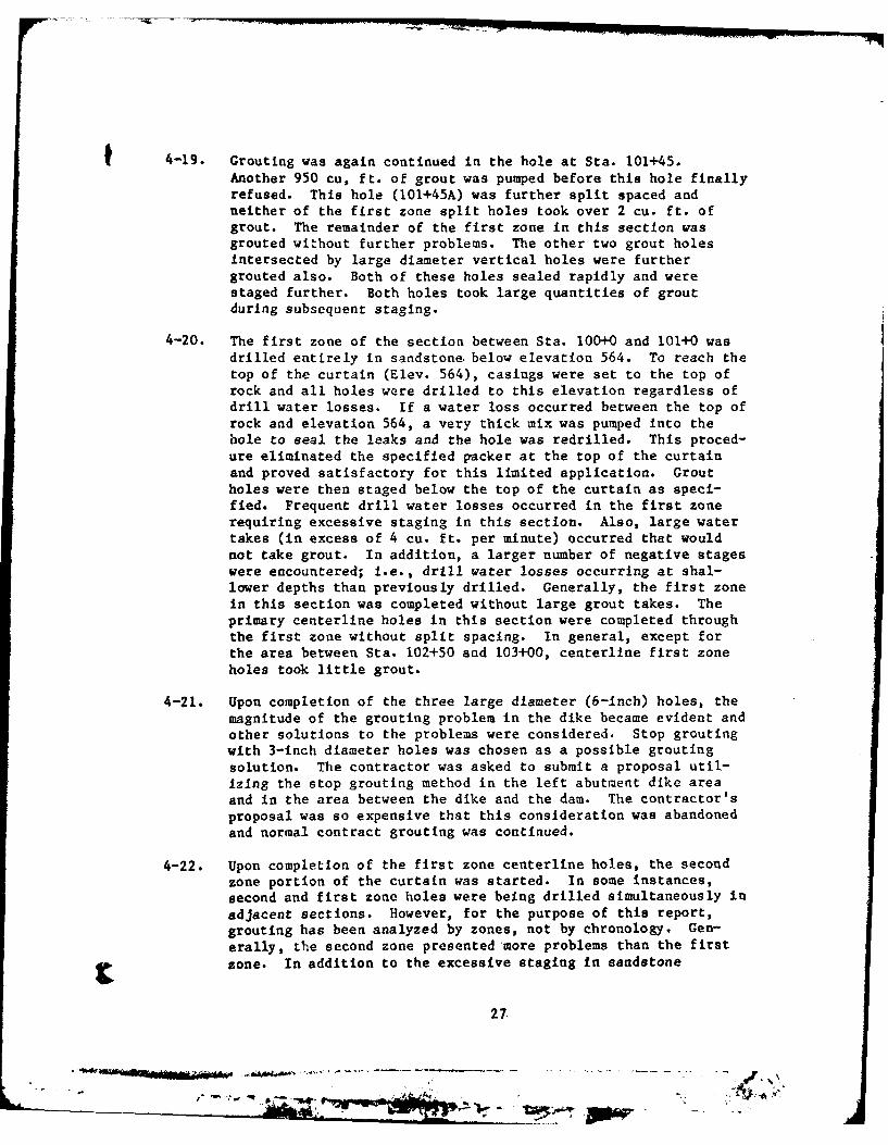
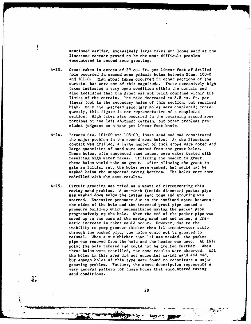
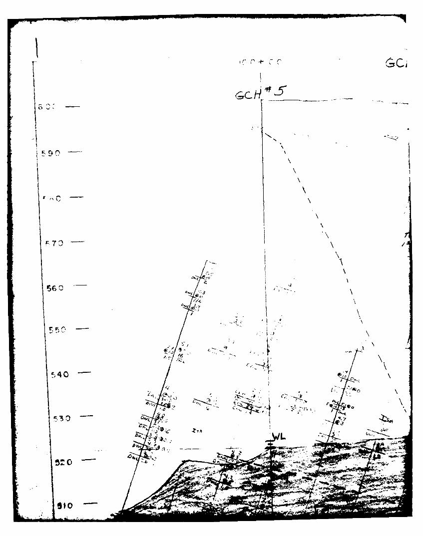
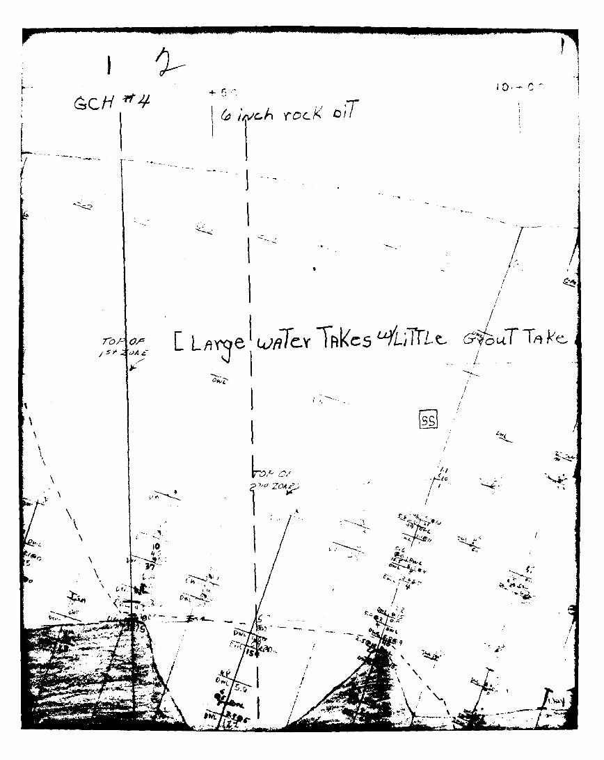
4-20. The first zone of the section between Sta. 100+0 and 101+0 wasdrilled entirely in sandstone. below elevation 564. To reach thetop of the curtain (Elev. 564), casings were set to the top ofrock and all holes were drilled to this elevation regardless ofdrill water losses. If a water loss occurred between the top ofrock and elevation 564, a very thick mix was pumped into thehole to seal the leaks and the hole was redrilled. This proced-ure eliminated the specified packer at the top of the curtainand proved satisfactory for this limited application. Groutholes were then staged below the top of the curtain as speci-fied. Frequent drill water losses occurred in the first zonerequiring excessive staging in this section. Also, large watertakes Cin excess of 4 cu. ft. per minute) occurred that wouldnot take grout. In addition, a larger number of negative stageswere encountered; I.e., drill water losses occurring at shal-lower depths than previously drilled. Generally, the first zoneIn this section was completed without large grout takes. Theprimary centerline holes in this section were completed throughthe first zone without split spacing. In general, except forthe area between Sta. 102+50 and 103+00, centerline first zoneholes took little grout.
4-21. Upon completion of the three large diameter (6-inch) holes, themagnitude of the grouting problem in the dike became evident andother solutions to the problems were considered. Stop groutingwith 3-inch diameter holes was chosen as a possible groutingsolution. The contractor was asked to submit a proposal util-izing the stop grouting method in the left abutment dike areaand in the area between the dike and the dam. The contractor'sproposal was so expensive that this consideration was abandonedand normal contract grouting was continued.
4-22. Upon completion of the first zone centerline holes, the secondzone portion of the curtain was started. In some instances,second and first zone holes were being drilled simultaneously inadjacent sections. However, for the purpose of this report,grouting has been analyzed by zones, not by chronology. Gen-erally, the second zone presented more problems than the firstzone. In addition to the excessive staging In sandstone
27
4,~ -_-. Slow - i>
mentioned earlier, excessively large takes and loose sand at thelimestone contact proved to be the most difficult problemencountered in second zone grouting.
4-23. Grout takes in excess of 29 cu. ft. per linear foot of drilledhole occurred in second zone primary holes between Stas. 100+0and 101+0. High grout takes occurred in other sections of thecurtain, but were not of this magnitude. These excessively hightakes indicated a very open condition within the curtain andalso indicated that the grout was not being confined within thelimits of the curtain. The take decreased to 8.8 cu. ft. perlinear foot in the secondary holes of this section, but remainedhigh. Only the upstream secondary holes were completed; conse-quently, this figure is not representative of a completedsection. High takes also occurred in the remaining second zoneportions of the left abutment curtain, but other problems pre-cluded judgment on a take per linear foot basis.
4-24. Between Sta. 101+00 and 103+00, loose sand and mud constitutedthe major problem in the second zone holes. As the limestonecontact was drilled, a large number of tool drops were noted andlarge quantities of sand were washed from the grout holes.These holes, with suspected sand zones, were water tested withresulting high water takes. Utilizing the header to grout,these holes would take no grout. After allowing the grout togain an initial set, the holes were washed, but could not bewashed below the suspected caving horizon. The holes were thenredrilled with the same results.
4-25. Circuit grouting was tried as a means of circumventing thiscaving sand problem. A one-inch (inside diameter) packer pipewas washed down below the caving sand zone and grouting wasstarted. Excessive pressure due to the confined space betweenthe sides of the hole and the inserted grout pipe caused apressure build-up which necessitated moving the packer pipeprogressively up the hole. When the end of the packer pipe wasmoved up to the base of the caving sand and mud zones, a dra-matic increase in takes would occur. However, due to theinability to pump grouter thicker than 1:1 cement-water ratiothrough the packer pipe, the holes could not be grouted torefusal. When a mix thicker than 1:1 was needed, the packerpipe was removed from the hole and the header was used. At thispoint the hole refused and could not be grouted further. Whenthese holes were redrilled, the same results were observed. Allthe holes in this area did not encounter caving sand and mud,but enough holes of this type were found to constitute a majorgrouting problem. Further, the above description represents avery general pattern for those holes that encountered cavingsand conditions.
P.
28
41 0
M'S00
V4
L V--
1
C- H
eI>,~ TR.5T
GCH p~4 4Li-cA ~
II- .~ - - - -.. I -
(.TVD
F -
/ 7t
a I sY§AN . *-
J~$~A~: ;A. //f L*"C hFP.jsc
~T~te'Pt I /
I.I
Yo a
1'
10310.0
s be-TL-.~-'c~e-,~-' &~T ho/e-S1 J~o~e~
CGO
7-I /
It
/
27 /
J4~wJ
.. /'1 /
I
I /, ('I-,
- . -~ /A> /
9 1/*, I
I, / * ,1 ..
/3 - -
___________
+50 104 C~ 0
7 4of D/< EL 5( ,.O
,r71 4 0
~ '~P cJ'LS-
iL
-'570
.,"56(l
-- 5401
5r0
520
I'//'/
/ -
4~ I3
480.
0 h-
/ * ,-*
*
Jew
4-,.-
~ /
/4.0 4.S. ~
/2
I i*"~
/
I /
, 7
.,,.~ I
--
-~j ~- ~- /.
p4,44 0~ -
/
1t~> I
/
I
/
I,
-U.
/
I -~
________
I.! * ~*0
__________________________
.4
______________
- - /
I
A.
I-
Id 1- CV)
+50
I
* <~1- 9 __
____
~~0~ -' - -
I.
0.,,
k44
A -3 5 1-
1 5 0 - " 4: i .' / """
-..--- -- , -t .- , - -- - , ,~ ,,
/-k1A.?/A. r ~'I' 4 . . '
+A-- ; 6 :W/ ,fA.- '.
. * /0 . ..
i ... ", -- " : " /
]---, ,r,+,--''., '.- n= <VE _ . ,..
L.
I It
--4 -I-
-- ,-
4-40
/ .-.*' --
IL
1 14- . -e -"-- 0. 0 0
i02 +00
. ... , . .-,, . , , - ... ..,r. ' ',,,, 1 L..' '' -' ' : ' ''' ' ' 'l ' l ' 'ti
--- *- - - I A .x;-,
,_. 4:. , U-.,
* - *-~--z:* -2 -
--.
1.*
I.
-eV ~. <~ -Ae
V.'4 A I C.
.1*''* ~, ~
* /
e -
~ 1*, 9
I'> ,' ,j ~~-----/-----.- -
(~I -9
.2
±50 1031-CO
a -
* .* - ~ ~ ~4* 9**~*~~~ ,~:,* ~,. ~
/
e - --
-~ ~-.
/I
I§J.1~'
r 5
<5
Ir
/ /
i/
S I 0 N 5tu
//
/0
- 9.
C.52
/ /iPATKA AKD/ ,PLLA
/~ / RUIG RF
-,. ." 510 ~ ~ .
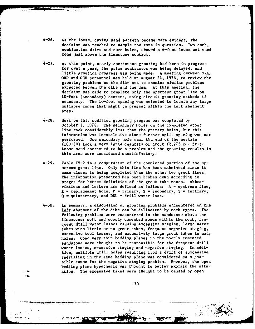
4-26. As the loose, caving sand pattern became more evident, thedecision was reached to sample the zone in question. Two each,combination drive and core holes, showed a 6-foot loose wet sandzone just above the limestone contact.
4-27. At this point, nearly continuous grouting had been in progressfor over a year, the prime contractor was being delayed, andlittle grouting progress was being made. A meeting between ORL,ORD~ and OCE personnel was held on August 24, 1976, to review thegrouting problems on the dike and to examine similar problemsexpected betwen the dike and the dam. At this meeting, thedecision was made to complete only the upstream grout line on10-foot (secondary) centers, using circuit grouting methods ifnecessary. The 10-foot spacing was selected to locate any largecollapse zones that might be present within the left abutmentarea.
4-28. Work on this modified grouting program was completed byOctober 1, 1976. The secondary holes on the completed groutline took considerably less than the primary holes, but thisinformation was inconclusive since further split spacing was notperformed. One secondary hole near the end of the curtain(100+30) took a very large qu 'antity of grout (2,273 cu. ft.).Loose sand continued to be a problem and the grouting results inthis area were considered unsatisfactory.
4-29. Table IV-2 is a computation of the completed portion of the up-stream grout line. Only this line has been tabulated since itcame closer to being completed than the other two grout lines.The information presented has been broken down according tostages for better definition of the grout take zones. Abbre-viations and letters are defined as follows: A -upstream line,R - replacement hole, P primary, S = secondary, T - tertiary,Q -quinternary, and DWL drill water loss.
4-30. In summary, a discussion of grouting problems encountered on theleft abutment of the dike can be delineated by rock types. Thefollowing problems were encountered in the sandstone above thelimestone: soft and poorly cemented zones within the rock, fre-quent drill water losses causing excessive staging, large watertakes with little or no grout, takes, frequent negative staging,excessive tool losses, and excessively large grout takes in manyholes. Open very thin bedding planes in the poorly cementedsandstone were thought to be responsible for tlhe frequent drillwater losses, excessive staging and negative staging. In addi-tion, multiple drill holes resulting from a drift of successiveredrilling in the same bedding plane was considered as a pos-sible cause for the negative staging problem. However, the openbedding plane hypothesis was thought to better explain the situ-ation. The excessive takes were thought to be caused by open
30
!1 !;:
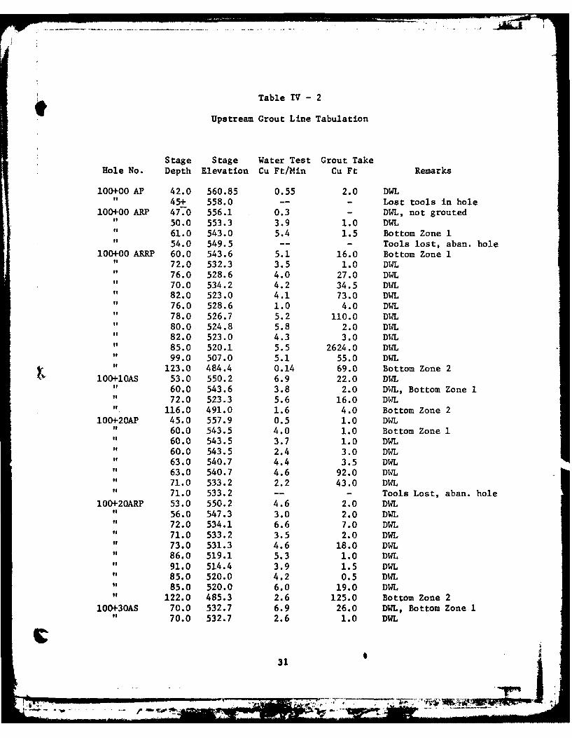
Table IV 2
Upstream Grout Line Tabulation
Stage Stage Water Test Grout TakeHole No. Depth Elevation Cu Ft/Min Cu Ft Remarks
100+00 AP 42.0 560.85 0.55 2.0 DWL" 45+ 558.0 -- - Lost tools in hole
100+00 ARP 47.0 556.1 0.3 - DWL, not grouted" 50.0 553.3 3.9 1.0 DWL
61.0 543.0 5.4 1.5 Bottom Zone 154.0 549.5 -- - Tools lost, aban. hole
100+00 ARRP 60.0 543.6 5.1 16.0 Bottom Zone 1i 72.0 532.3 3.5 1.0 DWL" 76.0 528.6 4.0 27.0 DWL
70.0 534.2 4.2 34.5 DWL82.0 523.0 4.1 73.0 DWL76.0 528.6 1.0 4.0 DWL78.0 526.7 5.2 110.0 DWL80.0 524.8 5.8 2.0 DWL82.0 523.0 4.3 3.0 DWL85.0 520.1 5.5 2624.0 DWL99.0 507.0 5.1 55.0 DWL
I 123.0 484.4 0.14 69.0 Bottom Zone 2100+10AS 53.0 550.2 6.9 22.0 DWL
" 60.0 543.6 3.8 2.0 DWL, Bottom Zone I" 72.0 523.3 5.6 16.0 DWL
116.0 491.0 1.6 4.0 Bottom Zone 2100+20AP 45.0 557.9 0.5 1.0 DW4L
" 60.0 543.5 4.0 1.0 Bottom Zone 1o 60.0 543.5 3.7 1.0 DWL" 60.0 543.5 2.4 3.0 DWLto 63.0 540.7 4.4 3.5 DWL" 63.0 540.7 4.6 92.0 DWL" 71.0 533.2 2.2 43.0 DWL" 71.0 533.2 -- - Tools Lost, aban. hole
100+20ARP 53.0 550.2 4.6 2,0 DWL" 56.0 547.3 3.0 2.0 DWL" 72.0 534.1 6.6 7.0 DW4L" 71.0 533.2 3.5 2.0 DWL" 73.0 531.3 4.6 18.0 DWL" 86.0 519.1 5.3 1.0 DWL" 91.0 514.4 3.9 1.5 DWL" 85.0 520.0 4.2 0.5 D14Lo 85.0 520.0 6.0 19.0 DWL" 122.0 485.3 2.6 125.0 Bottom Zone 2
100+30AS 70.0 532.7 6.9 26.0 DWL, Bottom Zone 170.0 532.7 2.6 1.0 DWL
31
~~~~1 M -~:"$
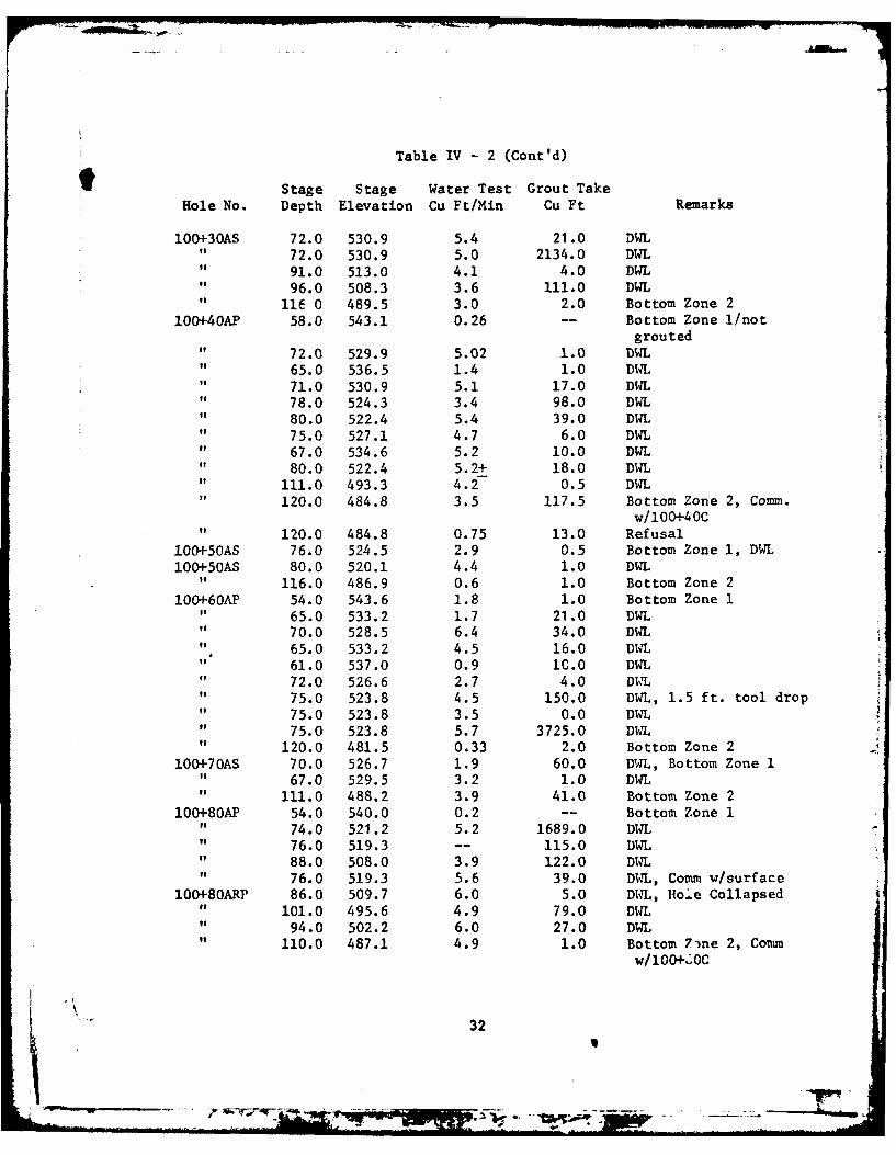
Table IV - 2 (Cont'd)
t Stage Stage Water Test Grout TakeHole No. Depth Elevation Cu Ft/Min Cu Ft Remarks
100+30AS 72.0 530.9 5.4 21.0 DWL" 72.0 530.9 5.0 2134.0 DWL
91.0 513.0 4.1 4.0 DWL96.0 508.3 3.6 111.0 DWL
116 0 489.5 3.0 2.0 Bottom Zone 2100+40AP 58.0 543.1 0.26 -- Bottom Zone 1/not
grouted" 72.0 529.9 5.02 1.0 DWL" 65.0 536.5 1.4 1.0 DWL" 71.0 530.9 5.1 17.0 DWL" 78.0 524.3 3.4 98.0 DWL
80.0 522.4 5.4 39.0 DWL75.0 527.1 4.7 6.0 DWL67.0 534.6 5.2 10.0 DWL80.0 522.4 5.2+ 18.0 DWL
111.0 493.3 4.2 0.5 DWL120.0 484.8 3.5 117.5 Bottom Zone 2, Comm.
w/l00+40C120.0 484.8 0.75 13.0 Refusal
100+50AS 76.0 524.5 2.9 0.5 Bottom Zone 1, DWL100+50AS 80.0 520.1 4.4 1.0 DAL
" 116.0 486.9 0.6 1.0 Bottom Zone 2100+60AP 54.0 543.6 1.8 1.0 Bottom Zone I
" 65.0 533.2 1.7 21.0 DWL70.0 528.5 6.4 34.0 DWL65.0 533.2 4.5 16.0 DWL61.0 537.0 0.9 1C.0 DWL72.0 526.6 2.7 4.0 DAL
75.0 523.8 4.5 150.0 DWL, 1.5 ft. tool drop75.0 523.8 3.5 0.0 DWL75.0 523.8 5.7 3725.0 DWL
120.0 481.5 0.33 2.0 Bottom Zone 2100+70AS 70.0 526.7 1.9 60.0 DWL, Bottom Zone 1
" 67.0 529.5 3.2 1.0 DWL" 111.0 488.2 3.9 41.0 Bottom Zone 2
100+80AP 54.0 540.0 0.2 -- Bottom Zone 1" 74.0 521.2 5.2 1689.0 DWL
76.0 519.3 -- 115.0 DWL88.0 508.0 3.9 122.0 DWL76.0 519.3 5.6 39.0 DIM, Comm w/surface
100+80ARP 86.0 509.7 6.0 5.0 DWL, Hole Collapsedo 101.0 495.6 4.9 79.0 D14L" 94.0 502.2 6.0 27.0 DWL
110.0 487.1 4.9 1.0 Bottom 7 ne 2, Comm
w/lOO2.OC
32
-L----- r---
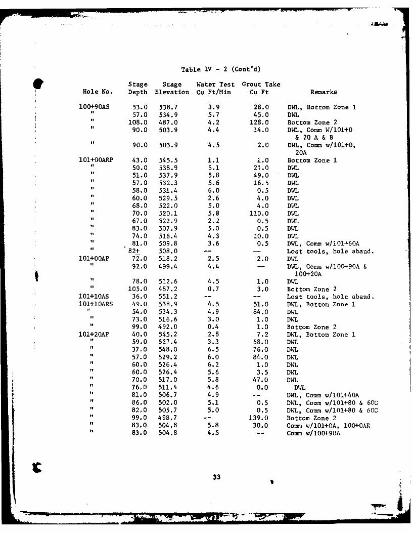
Table IV - 2 (Cont'd)
Stage Stage Water Test Grout TakeHole No. Depth Elevation Cu Ft/Min Cu Ft Remarks
100+90AS 53.0 538.7 3.9 28.0 DWL, Bottom Zone I57.0 534.9 5.7 45.0 DWL
108.0 487.0 4.2 128.0 Bottom Zone 290.0 503.9 4.4 14.0 DWL, Comm W/l0l+0
& 20 A & B" 90.0 503.9 4.5 2.0 DWL, Comm w/lOl+0,
20A101+OOARP 43.0 545.5 1.1 1.0 Bottom Zone 1
" 50.0 538.9 5.1 21.0 DWL51.0 537.9 5.8 49.0 DWL57.0 532.3 5.6 16.5 DWL58.0 531.4 6.0 0.5 DWL60.0 529.5 2.6 4.0 DWL68.0 522.0 5.0 4.0 DWL70.0 520.1 5.8 110.0 DWL67.0 522.9 2.2 0.5 DWL83.0 507.9 5.0 0.5 DWL74.0 516.4 4.3 10.0 DWL81.0 509.8 3.6 0.5 DWL, Comm w/101+60A
82+ 508.0 -- -- Lost tools, hole aband.101+OOAP 72.0 518.2 2.5 2.0 DWL
92.0 499.4 4.4 -- DWL, Comm w/100+90A &100+20A
78.0 512.6 4.5 1.0 DWL105.0 487.2 0.7 3.0 Bottom Zone 2
101+10AS 36.0 551.2 - -- Lost tools, hole aband.101+lOARS 49.0 538.9 4.5 51.0 DWL, Bottom Zone 1
54.0 534.3 4.9 84.0 DWL73.0 516.6 3.0 1.0 DWL99.0 492.0 0.4 1.0 Bottom Zone 2
101+20AP 40.0 545.2 2.8 7.2 DWL, Bottom Zone 1" 59.0 527.4 3.3 58.0 DWL" 37.0 548.0 6.5 76.0 D14L
57.0 529.2 6.0 84.0 DIL60.0 526.4 6.2 1.0 DWL60.0 526.4 5.6 3.5 DWL70.0 517.0 5.8 47.0 DW4L76.0 511.4 4.6 0.0 DWL81.0 506.7 4.9 -- DWL, Comm w/101+40A86.0 502.0 5.1 0.5 DWL, Comm w/l01+80 & 60C82.0 505.7 5.0 0.5 DWL, Comm w/lO1+80 & 60C99.0 498.7 -- 139.0 Bottom Zone 283.0 504.8 5.8 30.0 Comm w/101+OA, 100+0AR83.0 504.8 4.5 -- Comm w/l00+90A
33
rl
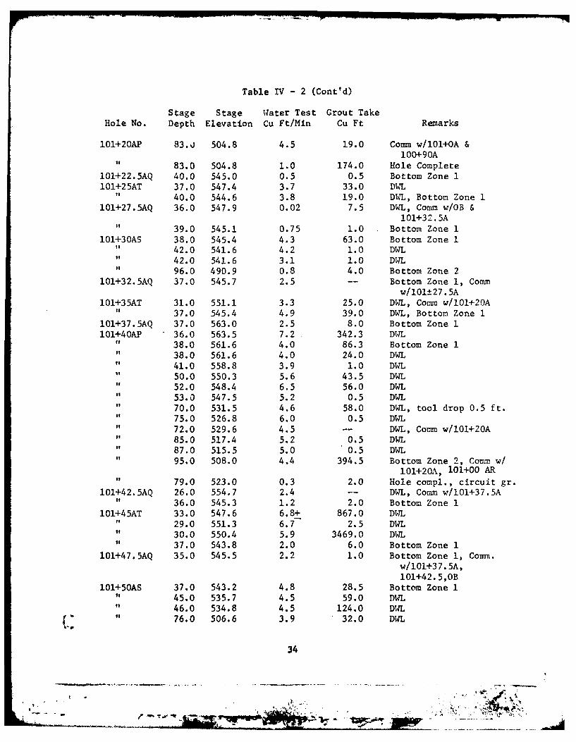
Table IV - 2 (Cont'd)
Stage Stage Water Test Grout TakeHole No. Depth Elevation Cu Ft/Min Cu Ft Remarks
101+20AP 83.%j 504.8 4.5 19.0 Comm w/101+OA &100+90A
it 83.0 504.8 1.0 174.0 Hole Complete101+22.5AQ 40.0 545.0 0.5 0.5 Bottom Zone 1101+25AT 37.0 547.4 3.7 33.0 DWL
" 40.0 544.6 3.8 19.0 DWL, Bottom Zone 1101+27.5AQ 36.0 547.9 0.02 7.5 DL, Comm w/OB &
101+32.5A39.0 545.1 0.75 1.0 Bottom Zone 1
101+30AS 38.0 545.4 4.3 63.0 Bottom Zone 1" 42.0 541.6 4.2 1.0 DWL" 42.0 541.6 3.1 1.0 DWL" 96.0 490.9 0.8 4.0 Bottom Zone 2
101+32.5AQ 37.0 545.7 2.5 -- Bottom Zone 1, Commw/1Ol±27.5A
101+35AT 31.0 551.1 3.3 25.0 DWL, Comm w/101+20A" 37.0 545.4 4.9 39.0 DWL, Bottom Zone 1
l01+37.5AQ 37.0 563.0 2.5 8.0 Bottom Zone I101+40AP 36.0 563.5 7.2 342.3 DWL
I 38.0 561.6 4.0 86.3 Bottom Zone 1" 38.0 561.6 4.0 24.0 DWL
41.0 558.8 3.9 1.0 DWL50.0 550.3 5.6 43.5 DWL52.0 548.4 6.5 56.0 DWL53.0 547.5 5.2 0.5 DWL70.0 531.5 4.6 58.0 DWL, tool drop 0.5 ft.75.0 526.8 6.0 0.5 DWL72.0 529.6 4.5 -- DWL, Comm w/101+20A85.0 517.4 5.2 0.5 DWL87.0 515.5 5.0 0.5 DWL
" 95.0 508.0 4.4 394.5 Bottom Zone 2, Comm w/101+20A, 101+00 AR
79.0 523.0 0.3 2.0 Hole compl., circuit gr.l01+42.5AQ 26.0 554.7 2.4 -- DWL, Comm w/101+37.5A
" 36.0 545.3 1.2 2.0 Bottom Zone I101+45AT 33.0 547.6 6.8+ 867.0 DWL
f 29.0 551.3 6.7 2.5 DWL30.0 550.4 5.9 3469.0 DWL37.0 543.8 2.0 6.0 Bottom Zone 1
101+47.5AQ 35.0 545.5 2.2 1.0 Bottom Zone 1, Comm.w/101+37.5A,
101+42.5,OB101+50AS 37.0 543.2 4.8 28.5 Bottom Zone 1
" 45.0 535.7 4.5 59.0 D14Lit 46.0 534.8 4.5 124.0 DWL
76.0 506.6 3.9 32.0 DWL
34
, . • . ' -.- -.
,
- . . .S. , . :" . " . .
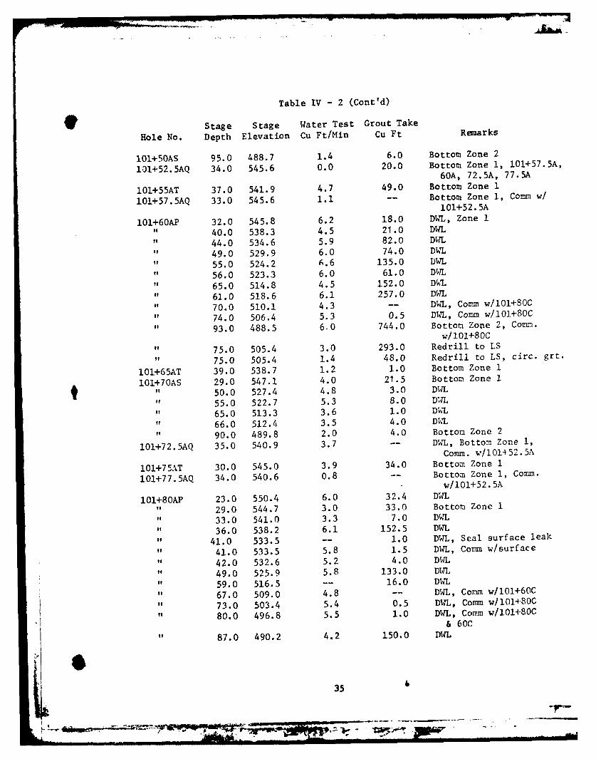
Table IV - 2 (Cont'd)
Stage Stage Water Test Grout Take
Hole No. Depth Elevation Cu Ft/Min Cu Ft Renarks
1O1+50AS 95.0 488.7 1.4 6.0 Bottom Zone 2
101+52.5AQ 34.0 545.6 0.0 20.0 Bottom Zone 1, 101+57.5A,
60A, 72.5A, 77.5A
101+55AT 37.0 541.9 4.7 49.0 Bottom Zone 1
101+57.5AQ 33.0 545.6 1.1 -- Bottom Zone 1, Comm w/
101+52.5A
01+60AP 32.0 545.8 6.2 18.0 DWL, Zone 1" 40.0 538.3 4.5 21.0 DWL
44.0 534.6 5.9 82.0 DWL
49.0 529.9 6.0 74.0 DWL
" 55.0 524.2 6.6 135.0 DWL
56.0 523.3 6.0 61.0 DWL
65.0 514.8 4.5 152.0 DWL
" 61.0 518.6 6.1 257.0 DWL
70.0 510.1 4.3 -- DWL, Comm w/101+80C
74.0 506.4 5.3 0.5 DWL, Comm w/101+80C
93.0 488.5 6-0 744.0 Bottom Zone 2, Comm.w/101+80C
75.0 505.4 3.0 293.0 Redrill to LS
75.0 505.4 1.4 48.0 Redrill to LS, circ. grt.
101+65AT 39.0 538.7 1.2 1.0 Bottom Zone 1
10+70AS 29.0 547.1 4.0 21.5 Bottom Zone I
" 50.0 527.4 4.8 3.0 DWL
55.0 522.7 5.3 8.0 DWL
65.0 513.3 3.6 1.0 DWL
" 66.0 512.4 3.5 4.0 DtUL
90.0 489.8 2.0 4.0 Bottom Zone 2
101+72.5AQ 35.0 540.9 3.7 -- DWL, Bottom Zone 1,Comm. w/101452.5A
101+75AT 30.0 545.0 3.9 34.0 Bottom Zone 1
l01+77.5AQ 34.0 540.6 0.8 -- Bottom Zone 1, Comm.w/i01+52.5A
101+80AP 23.0 550.4 6.0 32.4 DWL" 29.0 544.7 3.0 33.0 Bottom Zone I" 33.0 541.0 3.3 7.0 DWL" 36.0 538.2 6.1 152.5 DWL" 41.0 533.5 -- 1.0 DWL, Seal surface leak
" 41.0 533.5 5.8 1.5 DWL, Comm w/surface
" 42.0 532.6 5.2 4.0 DWL" 49.0 525.9 5.8 133.0 DWL" 59.0 516.5 -- 16.0 DWL
67.0 509.0 4.8 -- DWL, Comm w/101+60C
73.0 503.4 5.4 0.5 DWL, Comm w/101+80C
80.0 496.8 5.5 1.0 DWL, Comm w/101+80C& 60C
87.0 490.2 4.2 150.0 DWL
35
Pow
AD-A127 937 PATOKA LAKE FOUNDATION REPORT ROOK 5 'APPENDIX E SPECIALGROUTING ANALYSIS REPOR(U) ARMY ERGINEER DISTRICTA-LOUISVILLE KY S RARTLET ET AL APR R3
UNCLASSIFIED FG1/3 N
*iiimmmmmnuriui
Ji 132 W
... .. .. .-. , . .
II
111125 o 1.4
MICROCOPY RESOLUTION TEST CHART
NAIIONAL BUREU OF STANDARDS- IQE A
II
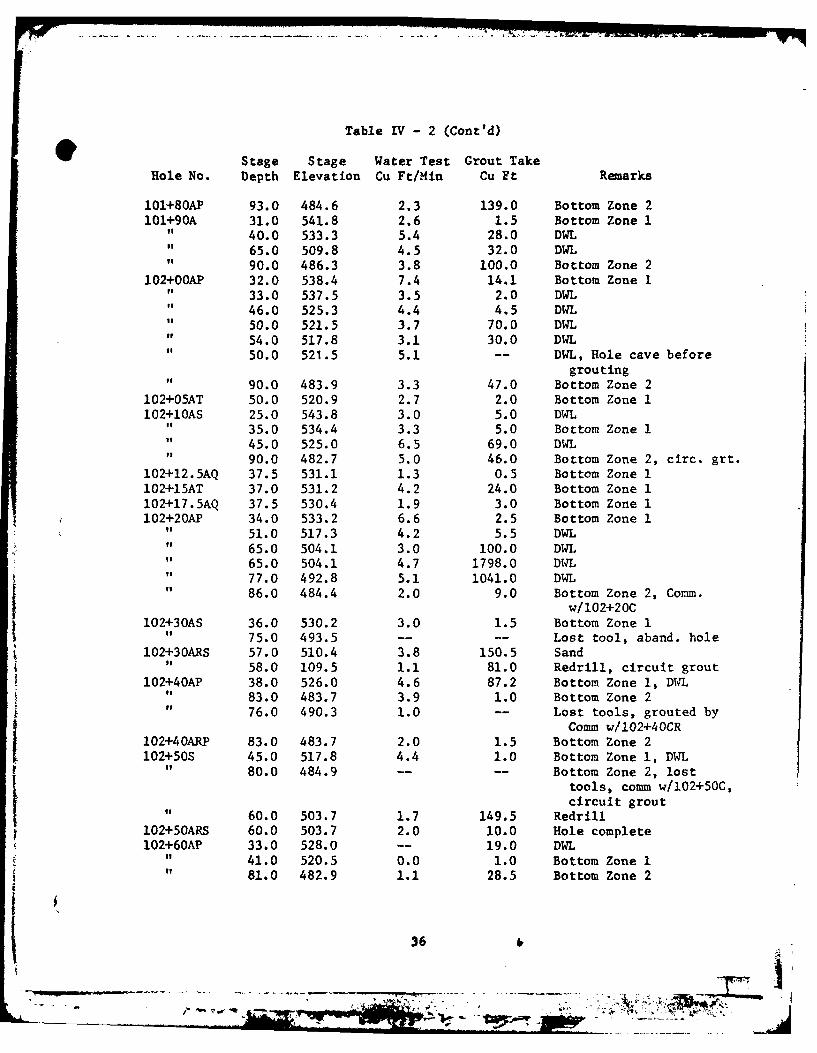
Table IV- 2 (Cont'd)
Stage Stage Water Test Grout TakeHole No. Depth Elevation Cu Ft/Min Cu Ft Remarks
l0+80AP 93.0 484.6 2.3 139.0 Bottom Zone 2101+90A 31.0 541.8 2.6 1.5 Bottom Zone 1
" 40.0 533.3 5.4 28.0 DWLo 65.0 509.8 4.5 32.0 DWL" 90.0 486.3 3.8 100.0 Bottom Zone 2
102+OOAP 32.0 538.4 7.4 14.1 Bottom Zone 133.0 537.5 3.5 2.0 DWL46.0 525.3 4.4 4.5 DWL50.0 521.5 3.7 70.0 DWL54.0 517.8 3.1 30.0 DWL50.0 521.5 5.1 -- DWL, Hole cave before
grouting90.0 483.9 3.3 47.0 Bottom Zone 2
102+05AT 50.0 520.9 2.7 2.0 Bottom Zone 1102+1OAS 25.0 543.8 3.0 5.0 DWL
" 35.0 534.4 3.3 5.0 Bottom Zone 1it 45.0 525.0 6.5 69.0 DWL
90.0 482.7 5.0 46.0 Bottom Zone 2, circ. grt.102+12.5AQ 37.5 531.1 1.3 0.5 Bottom Zone 1102+15AT 37.0 531.2 4.2 24.0 Bottom Zone 1102+17.5AQ 37.5 530.4 1.9 3.0 Bottom Zone 1102+20AP 34.0 533.2 6.6 2.5 Bottom Zone 1
51.0 517.3 4.2 5.5 DWL65.0 504.1 3.0 100.0 DWL65.0 504.1 4.7 1798.0 DUTL77.0 492.8 5.1 1041.0 DWL
" 86.0 484.4 2.0 9.0 Bottom Zone 2, Comm.w/102+20C
102+30AS 36.0 530.2 3.0 1.5 Bottom Zone 1" 75.0 493.5 -- -- Lost tool, aband. hole
102+30ARS 57.0 510.4 3.8 150.5 Sand58.0 109.5 1.1 81.0 Redrill, circuit grout
102+40AP 38.0 526.0 4.6 87.2 Bottom Zone 1, DWL" 83.0 483.7 3.9 1.0 Bottom Zone 2
76.0 490.3 1.0 -- Lost tools, grouted byComm w/l02+40CR
102+40ARP 83.0 483.7 2.0 1.5 Bottom Zone 2102+50S 45.0 517.8 4.4 1.0 Bottom Zone 1, DWL
F 80.0 484.9 -- -- Bottom Zone 2, lost
tools, comm w/102+50C,circuit grout
60.0 503.7 1.7 149.5 Redrill102+5OARS 60.0 503.7 2.0 10.0 Hole complete102+60AP 33.0 528.0 -- 19.0 DWL
41.0 520.5 0.0 1.0 Bottom Zone 181.0 482.9 1.1 28.5 Bottom Zone 2
36 4'
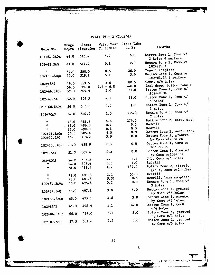
Table IV - 2 (Cont'd)
Stage Stage Water Test Grout Take
Role No. Depth Elevation Cu Ft/Min Cu Ft Remarks
102+61.3AQn 46.0 515.4 5.2 6.0 Bottom Zone i, Comm w/2 holes & surface
102+62.5AQ 47.0 514.4 0.1 2.0 Bottom Zone 1, Comm w/102+72.5A
57.0 505.0 0.5 26.0 Zone 1 complete
102+63.8AQn 42.0 519.1 5.1 5.0 Bottom Zone 1, Comm w/102+61.3A & surface
102+65AT 48.0 513.5 2.0 88.5 Comm. w/6 holes
" 56.0 506.0 2.4 - 6.8 940.0 Tool drop, bottom zone 1
102+66.3AQn 52.0 509.5 5.0 21.0 Bottom Zone 1, Comm w/102+68.3A
102+67.5AQ 52.0 509.3 4.1 28.0 Bottom Zone 1, Comm w/5 holes
102+68.8AQn 56.0 505.5 4.9 1.0 Bottom Zone 1, Comm w/3 holes
102+70AS 54.0 507.4 1.0 335.0 Bottom Zone 1, Comm w/2 holes
76.0 486.7 4.6 279.0 Bottom Zone 2, circ. grt.
" 62.0 499.8 0.4 0.5 Redrill
62.0 499.8 0.1 0.0 Redrill
102+71.3AQn 56.0 505.6 5.0 0.0 Bottom Zone 1, surf. leak
102+72.5AQ 46.0 515.2 3.9 0.0 Bottom Zone 1, grouted9 by Comm w/2 holes
102+73.8AQn 73.0 488.9 0.5 0.0 Bottom Zone 1, Comm w/102+71. 3A
102+75AT 51.0 509.6 0.3 0.0 Bottom Zone 1, Groutedby Comm w/102+65A
102+80AP 54.P 506.4 -- 2.5 DWL, Comm w/4 holes
" 54.0 506.4 0.6 1.0 Redrillit 78.0 483.8 4.2 142.0 Bottom Zone 2, circuit
grout, comm w/2 holes
" 78.0 483.8 2.2 53.0 Redrill" 78.0 483.8 0.02 0.5 Redrill, hole complete
102+81.3AQn 65.0 495.6 5.2 0.0 Bottom Zone 1, Comm w/3 holes
102+82.5AQ 63.0 497.1 3.8 4.0 Bottom Zone 1, groutedby Comm w/5 holes
102+83.8AQn 65.0 495.1 4.8 3.0 Bottom Zone 1, groutedby Comm w/2 holes
102+85AT 61.0 498.9 1.1 24.0 Bottom Zone 1, Commw/4 holes
102+86.3AQn 66.0 494.0 5.3 3.0 Bottom Zone I, groutedby Comm w/3 holes
102+87.5AQ 57.5 501.8 4.4 0.0 Bottom Zone I, groutedby Comm w/3 holes
37
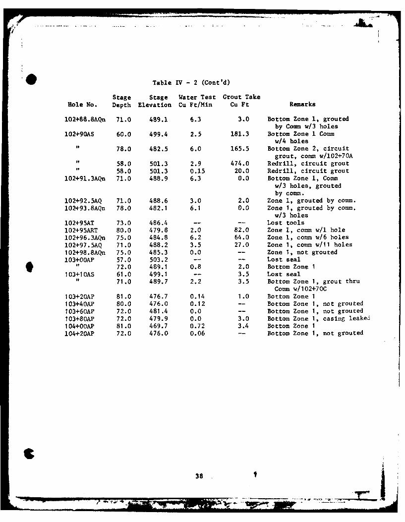
Table IV - 2 (Cont'd)
Stage Stage Water Test Grout TakeHole No. Depth Elevation Cu Ft/Min Cu Ft Remarks
102+88.8AQn 71.0 489.1 6.3 3.0 Bottom Zone 1, groutedby Comm w/3 holes
102+90AS 60.0 499.4 2.5 181.3 Bottom Zone 1 Commw/4 holes
" 78.0 482.5 6.0 165.5 Bottom Zone 2, circuitgrout, comm w/102+70A
58.0 501.3 2.9 474.0 Redrill, circuit grout58.0 501.3 0.15 20.0 Redrill, circuit grout
102+91.3AQn 71.0 488.9 6.3 0.0 Bottom Zone 1, Commw/3 holes, groutedby comm.
102+92.5AQ 71.0 488.6 3.0 2.0 Zone 1, grouted by comm.102+93.8AQn 78.0 482.1 6.1 0.0 Zone 1, grouted by comm.
w/3 holes
102+95AT 73.0 486.4 -- -- Lost tools102+95ART 80.0 479.8 2.0 82.0 Zone i, comm w/l hole102+96.3AQn 75.0 484.8 6.2 64.0 Zone 1, comm w/6 holes102+97.5AQ 71.0 488.2 3.5 27.0 Zone 1, comm w/11 holes102+98.8AQn 75.0 485.3 0.0 -- Zone 1, not grouted103+OOAP 57.0 503.2 -- -- Lost seal
" 72.0 489.1 0.8 2.0 Bottom Zone 1103+1OAS 61.0 499.1 -- 3.5 Lost seal
" 71.0 489.7 2.2 3.5 Bottom Zone 1, grout thruComm w/102+70C
103+20AP 81.0 476.7 0.14 1.0 Bottom Zone 1103+40AP 80.0 476.0 0.12 -- Bottom Zone 1, not grouted103+60AP 72.0 481.4 0.0 -- Bottom Zone 1, not grouted103+80AP 72.0 479.9 0.0 3.0 Bottom Zone 1, casing leaked104+OOAP 81.0 469.7 0.72 3.4 Bottom Zone I104+20AP 72.0 476.0 0.06 -- Bottom Zone 1, not grouted
38
joints leading away from the grout curtain, primarily in askewed downstream direction.
4-31. The following problems were encountered at the sandstone-limestone contact: loose sand and mud at the contact which couldnot be treated by circuit grouting, caving grout holes, incon-sistent top of limestone, and large grout takes in final splitspaced holes. The highly irregular erosional disconformitybetween the limestone and sandstone was believed to beresponsible for these problems.
4-32. The following problems were encountered within the limestoneportion of the grout curtain: frequent communications betweenholes, holes that could not be cleaned by washing, and cavingholes making grouting results in the lower limestone highlyquestionable. These problems, again, were thought to be theresult of extensive erosion between Mississippian and Pennsyl-vanian depositional sequences. The limestone was highly solu-tioned during this sequence and the resulting cavities were filledwith clay and sand. Washing could not remove the clay entirely,leaving clay and grout intermixed. This residual clay andsand was also saturated and subject to collapsing in smalldiameter battered holes. During the grouting program in theleft abutment ares, the dike right abutment excavation was inprogress and the highly solutioned state of the limestone becameevident.
4-33. As a result of the problems encountered during grouting on theleft abutment of the dike, certain conclusions were reached.First, the grout curtain could not be completed in the allottedcontract time. Secondly, the sandstone-limestone contact couldnot be grouted satisfactorily. Finally, the integrity of thecompleted curtain could not be assured.
4-34. Table IV-3 contains a summary of grouting for the dike portionof the grout curtain. All three lines have been includedalthough the B line was not grouted in the second zone and the Cline was not split spaced in the second zone. Caution should beused when analyzing this table since the second zone was notgrouted to completion. Consequently, the grouting ratios arenot truly representative of actual conditions.
'1 39
:.-~JS
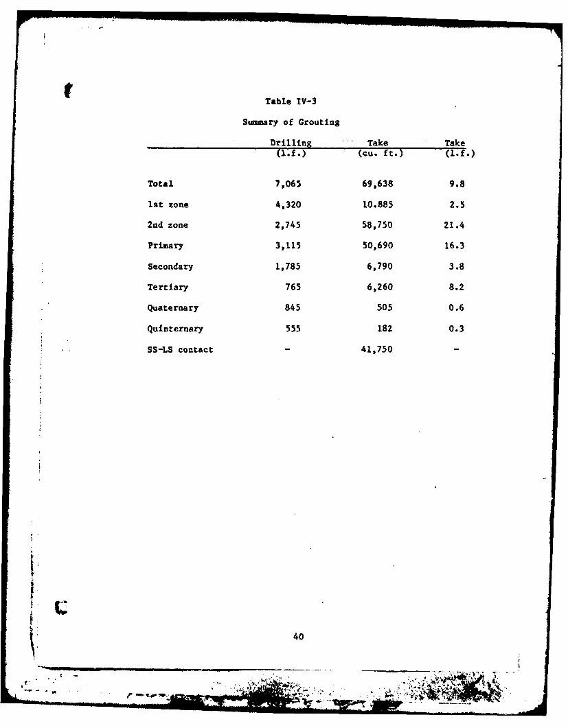
Table IV-3
Summary of Grouting
Drilling Take Take
(1f)(cu. ft.) (1. f.)
Total 7,065 69,638 9.8
1st zone 4,320 10.885 2.5
2nd zone 2,745 58,750 21.4
Primary 3,115 50,690 16.3
Secondary 1,785 6,790 3.8
Tertiary 765 6,260 8.2
Quaternary 845 505 0.6
Quinternary 555 182 0.3
SS-LS contact 41,750
40
t PART V - EXCAVATION
5-01. Upon completion of the modified grouting program on the leftabutment of the dike, serious questions remained unansweredconcerning the stability of the foundation in this area.Further studies in the form of four each 6-inch core holes wereinitiated. These holes were drilled between November 1976 andMarch 1977.
5-02. The locations for these core holes were selected from dataobtained during grouting of the upstream line. Drillingproblems were experienced when the first core hole at Sta.102+72.5 was started. The top of rock could not be determinedaccurately. Coring was started at the hardest material close towhere the top of rock was plotted on the grout profiles. Thefirst three 5-foot runs recovered clay, grout, limestone, andsandstone fragments which indicated that the core barrel wasfollowing down the sides of a solutioned Joint. On the fourthrun, the core barrel was lost in the hole and the hole had to bereplaced. The remaining three core holes were completed withfever difficulties and good samples were obtained. Some corelosses were experienced, especially at the sandstone-limestonecontact.
5-03. Upon completion of the drilling in these four holes, each holewas examined with a bore hole camera from the Waterways Experi-ment Station. The bore hole camera shoved relatively competentsandstone hwith very small cavities, thin, open bedding planesand small open fractures. The bore hole camera indicated smallcavities in all holes at the sandstone-limestone contact withvarying amounts of clay filling. Only one hole indicated solu-tioning within the limestone. The r ock bitted replacement holeat Sta. 102+72 encountered only one foot of limestone above thelower shale contact. After photographing each hole, the holeswere caliphered. Caliphering indicated the same results deter-mined by coring and photographing, but gave a better indicationof cavity sizes at the sandstone-limestone contact.
5-04. Between the cores, bore hole camera and caliphers, a good indi-cation of in-situ conditions were obtained. The cores suppliedthe greatest source of information, but the small core losszones could not be fully analyzed. The bore hole camera alloweddirect observations of these core loss zones, but encountereddifferent problems. The camera could not focus beyond a fewinches and consequently, the size of the cavities could beneither measured nor sufficiently observed. In addition, thecamera used vas a black and white model. The sandstone pre-sented many subtle color variations related to structure andweathering. These variations could not be properly analyzed due
41
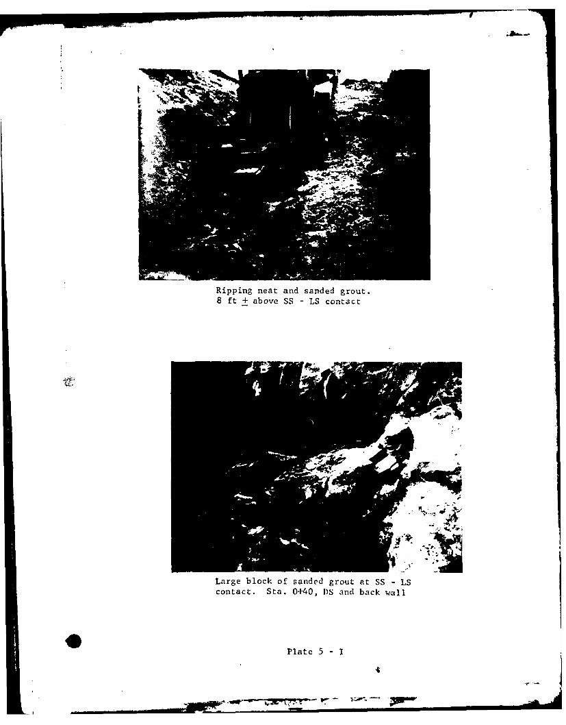
Ripping neat and sanded grout.8 ft + above SS - LS contact
Large block of sanded grout at SS - LScontact. Sta. 0+40, DS and back wall
Plate 5 - I
'I
- -r
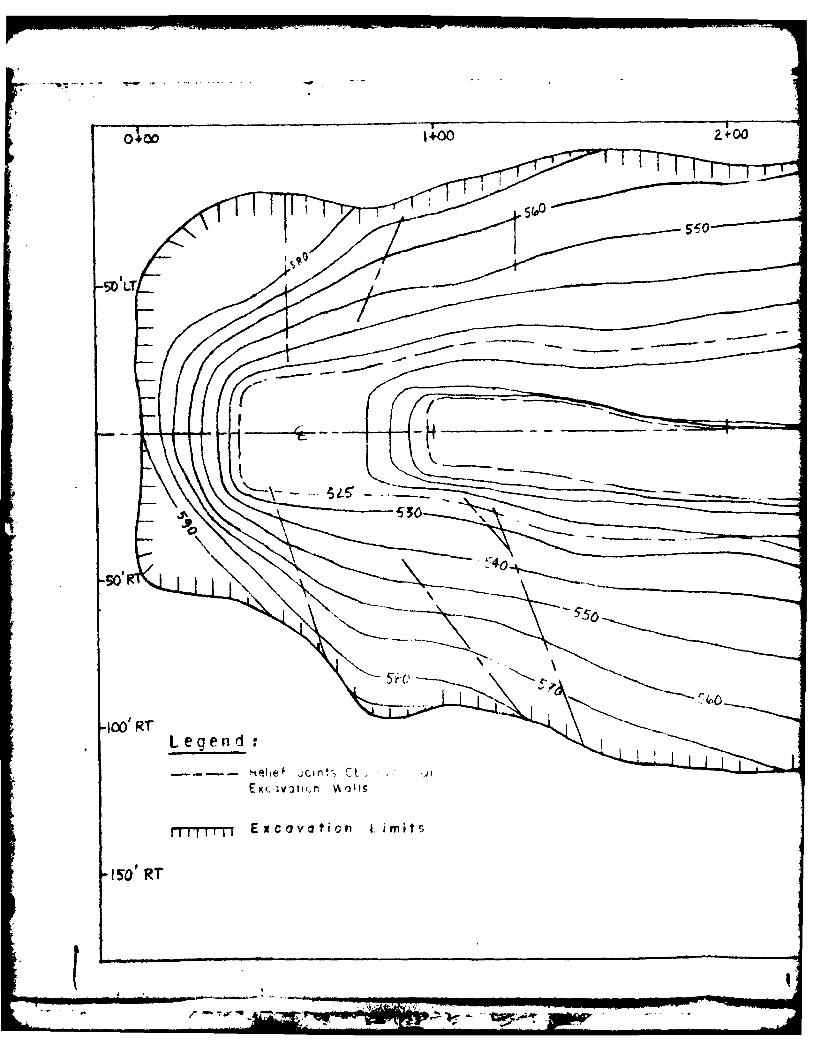
.- W 1+0 2.+-0
SISa
-50
Legend.:
f-r-rT11Excovaticir 1. imits
IS'RT
TWI
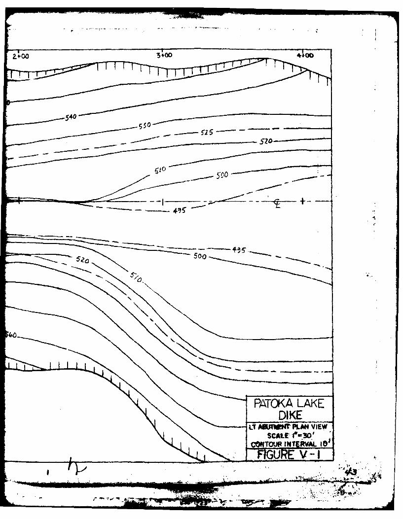
540
- 500
DIK
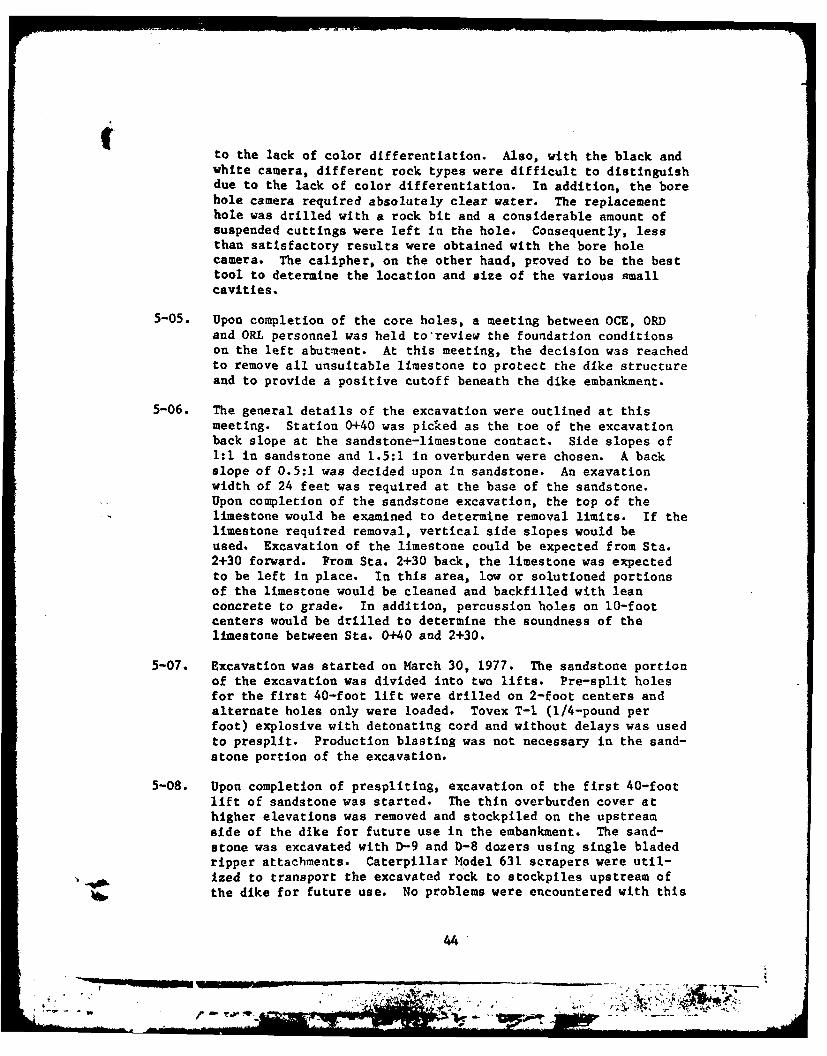
iIto the lack of color differentiation. Also, with the black andwhite camera, different rock types were difficult to distinguishdue to the lack of color differentiation. In addition, the borehole camera required absolutely clear water. The replacementhole was drilled with a rock bit and a considerable amount ofsuspended cuttings were left in the hole. Consequently, lessthan satisfactory results were obtained with the bore holecamera. The calipher, on the other hand, proved to be the besttool to determine the location and size of the various smallcavities.
5-05. Upon completion of the core holes, a meeting between OCE, ORDand ORL personnel was held to'review the foundation conditionson the left abutment. At this meeting, the decision was reachedto remove all unsuitable limestone to protect the dike structureand to provide a positive cutoff beneath the dike embankment.
5-06. The general details of the excavation were outlined at thismeeting. Station 0+40 was picked as the toe of the excavationback slope at the sandstone-limestone contact. Side slopes of1:1 in sandstone and 1.5:1 in overburden were chosen. A backslope of 0.5:1 was decided upon in sandstone. An exavationwidth of 24 feet was required at the base of the sandstone.Upon completion of the sandstone excavation, the top of thelimestone would be examined to determine removal limits. If thelimestone required removal, vertical side slopes would beused. Excavation of the limestone could be expected from Sta.2+30 forward. From Sta. 2+30 back, the limestone was expectedto be left in place. In this area, low or solutioned portionsof the limestone would be cleaned and backfilled with leanconcrete to grade. In addition, percussion holes on 10-footcenters would be drilled to determine the soundness of thelimestone between Sta. 0+40 and 2+30.
5-07. Excavation was started on March 30, 1977. The sandstone portionof the excavation was divided into two lifts. Pre-split holesfor the first 40-foot lift were drilled on 2-foot centers andalternate holes only were loaded. Tovex T-1 (1/4-pound perfoot) explosive with detonating cord and without delays was usedto presplit. Production blasting was not necessary in the sand-stone portion of the excavation.
5-08. Upon completion of prespliting, excavation of the first 40-footlift of sandstone was started. The thin overburden cover athigher elevations was removed and stockpiled on the upstreamside of the dike for future use in the embankment. The sand-stone was excavated with D-9 and D-8 dozers using single bladedripper attachments. Caterpillar Model 631 scrapers were util-ized to transport the excavated rock to stockpiles upstream ofthe dike for future use. No problems were encountered with this
44
- --
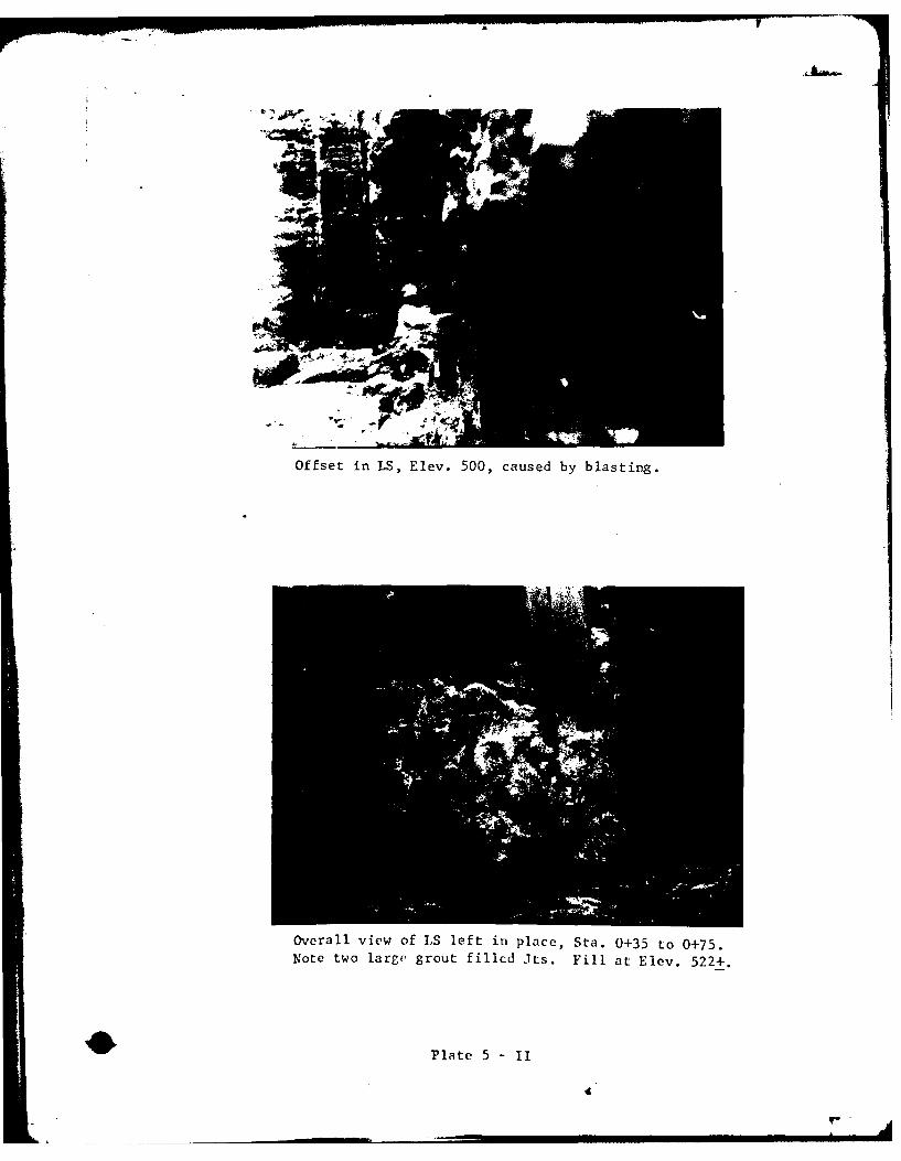
Offset in LS, Elev. 500, caused by blasting.
overall view of LS left in place, Sta. 0+35 to 0+75.Note two large grout filled its. Fill at Elev. 522+.
Plate 5 -IT
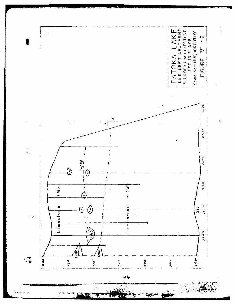
~ui - C~j
2LC
CC
W x
< -- C
CL S' j
41 -
0 IAz
method of excavation and side slope pre-split lines were notdisturbed. Transition between 1:1 and 1.5:1 side slopes wasmade between Sta. 1+0 and 1+50. The contact between sandstoneand overburden was very indistinct; consequently, slope changeswere arbitrarily chosen.
5-09. After excavating the first 40-foot lift, the pre-split line wasoffset four feet and the remaining sandstone was presplit to thelimestone contact on 2-foot centers. Again, only the alternateholes were loaded and shot. After presplitting, the remainingsandstone was excavated in the manner described above. Noproblems were encountered in the second sandstone lift. Diffi-culties in removing the large blocks of grout at the limestonecontact occurred, but did not impede progress.
5-10. Simultaneously with sandstone excavation (Sta. 0+0 to 2+50),deep overburden excavation was performed (Sta. 2+50 to 4+0).This material was also ripped and removed with scrapers. Thedeep clay overburden material was also stockpiled upstream ofthe dike for further embankment utilization.
5-11. Upon completion of sandstone excavation, the limestone wasexamined to determine removal limits. A series of percussionholes on 5 to 10 foot centers were drilled along the center-line. From the results of this drilling and further studies,the decision was reached to remove the entire limestone back toSta. 0+76. At the same time the centerline was moved slightlyupstream to preserve the current downstream slopes above whichspoil had been wasted. Figure V-2 shows the condition of thelimestone left in place between Sta. 0+32 and 0+92.
5-12. The limestone from Sta. 0+76 ahead was removed in either one ortwo lifts depending upon the limestone configuration. Where thelimestone was relatively competent, one lift was used. Theentire limestone was pre-split at one time. Side slopes inlimestone were vertical. The back slope in limestone wasdrilled on a 1 horizontal to 3 vertical slope, Sta. 0+76 to0+92. Pre-split holes were drilled on 2-foot centers. Again,alternate holes were loaded with "Tovex" T-1 (1/4-pound perfoot) and detonated with primacord. No delays were used.
5-13. Production blasting varied, but was usually accomplished in a Vpattern with delays between rows. Vertical 3-inch blast holeswere drilled in a 4 x 4 pattern. "Tovex" waterproof gel In2 x 16 inch cartridges was used as the blasting agent. Softseams were not stemmed. Detonating cord with MS-5 connectorswas used to activate the explosives. The powder factor variedfrom 1.02 to 1.14 pounds per cu. yd. The shot rock was removed
44
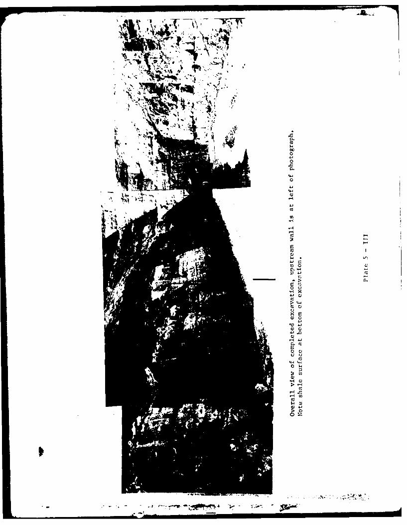
4 4F
U) 0
0 u
cc0
w0
>-4-4
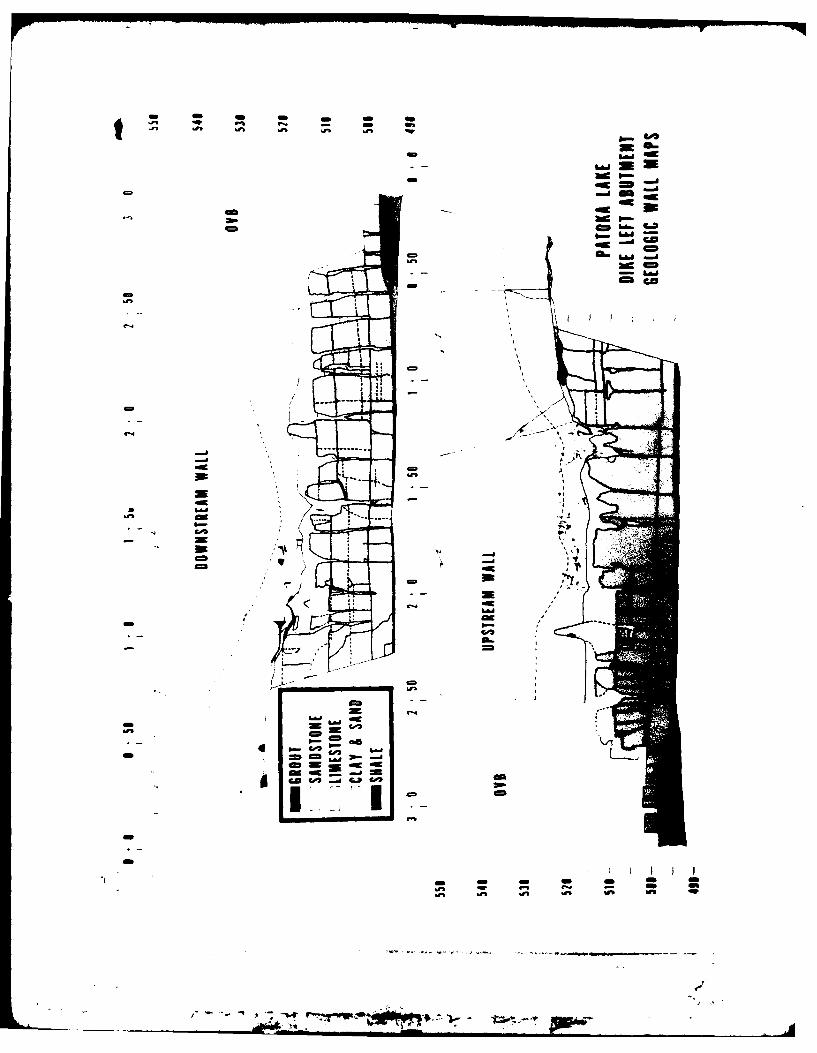
-a
--- ~~ -----
mc
m -m
-- CD
m ca
-7b
by dozers, high lifts, and dump trucks. The limestone was
further broken and used as riprap on the upstream slope of thedam.
5-14. Upon completion of limestone excavation, the lower shale wascleaned. All solutioned seams in the limestone side walls down-stream were cleaned to a depth of two times their width andfilled with lean concrete. The solutioned areas in limestoneupstream were left and filled with crushed stone filter materialas the impervious fill was placed. The end wall did not requireextensive treatment other than filling the solutioned joints andsmall overhangs with lean concrete. The impervious core wasprotected from piping by a 6-foot wide double zoned reversefilter against the downstream face of the limestone excava-tion. The filter consisted of Ind. #7 stone on the outside andInd. #14-1 sand on the inside against the impervious core.
50
_Nf " ''T
... ... , ,. /.S.. . .-
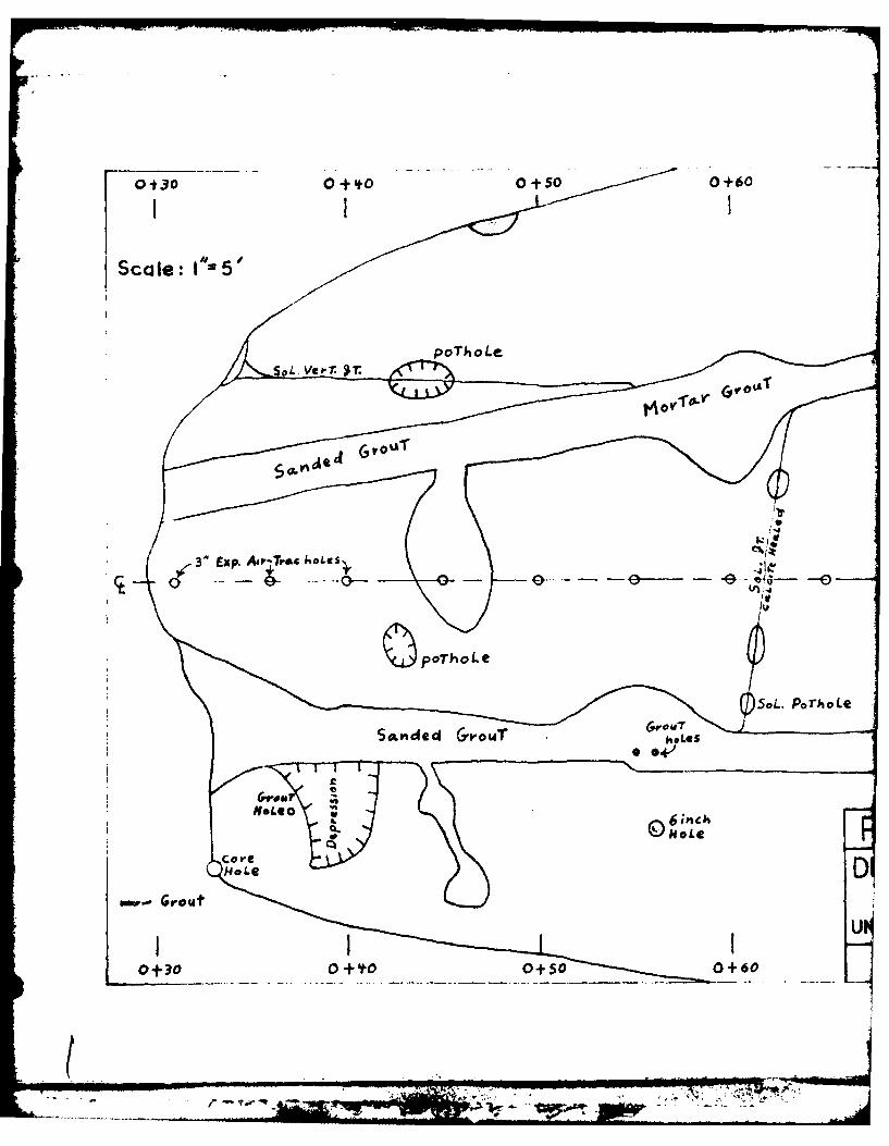
0130 000+00+60
Scale: 1'"5'5
poThoLe.L. Ve.7
N~ypoThoLe
5*L. PorhoLe
OUT
SaddGoTjv4
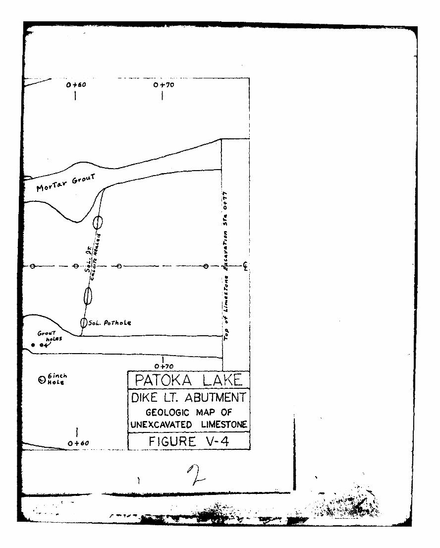
0+60 0+70
00
SaL. PorhoLe
0+70
PATOKA LAKE_DIKE LT. ABUTMENT
GEOLOGIC MAP OFUNEXCAVATED LIMESTONE
0+60 FIGURE V-4
PART V1 - GROUT DISTRIBUTION
6-01. During excavation grout distribution was carefully observed,mapped and photographed. The discussion of grout distributionhas been arranged by rock types In descending order.
A. Overburden
6-02. Generally, very little grout was found in the overburden. Near
the surface, a large chunk of grout was found close to Sta. 2+40where a large breakout occurred during grouting. The thinoverburden portion of the curtain between 0+0 and 2+30 displayedno grout. In spite of the many grout outbreaks near the casingsexperienced during grouting, very little grout was observed inthe thick overburden area between 2+30 and 3+0 during excava-tion. One major and two minor grout stringers were found on theside slopes of the excavation within the deepest portion of theoverburden. One of the two minor grout stringers was found onthe downstream slope and the other minor seam was found on theupstream slope.
6-03. The major grout seam on the downstream slope ranged from 0.6 to0.05 foot in thickness, with the grout thinning at higher eleva-tions until the seam stopped altogether. The seam stopped wellbelow the top of ground. The lower portion of the grout seamwas not observed due to overlying rubble, but probably startedat or near the limestone overburden contact near Sta. 2+70.Grout consisted of both sanded and neat grout with sanded groutforming the lower, thicker portion of the seam. Apparently,grouting pressure relief with decreasing depth caused the seamto thin and finally stop at Elev. 544. The difference betweensanded and neat grout was more difficult to explain. Apparentlythis seam was the result of two different grouting operations,sanded grout first and neat grout second.
6-04. The first of the two minor grout seams was observed on the down-stream wall near the limestone-overburden contact. This seamwas close to the major seam discussed in the preceding para-graph. These two seamis were probably related and could havebeen part of the same seam.
6-05. The second minor seam was found on the upstream slope near Sta.2+70 between Elevs. 533 and 535. This seam was approximately 4feet long, 0.1 to 0.4 foot thick, and was composed of neatgrout. However, the base of this seam was not observed. Theseam was within 10 feet of the sandstone-overburden contact, butwas not connected within view.. No other grout seams wereobserved in the lower portion of the overburden.
52
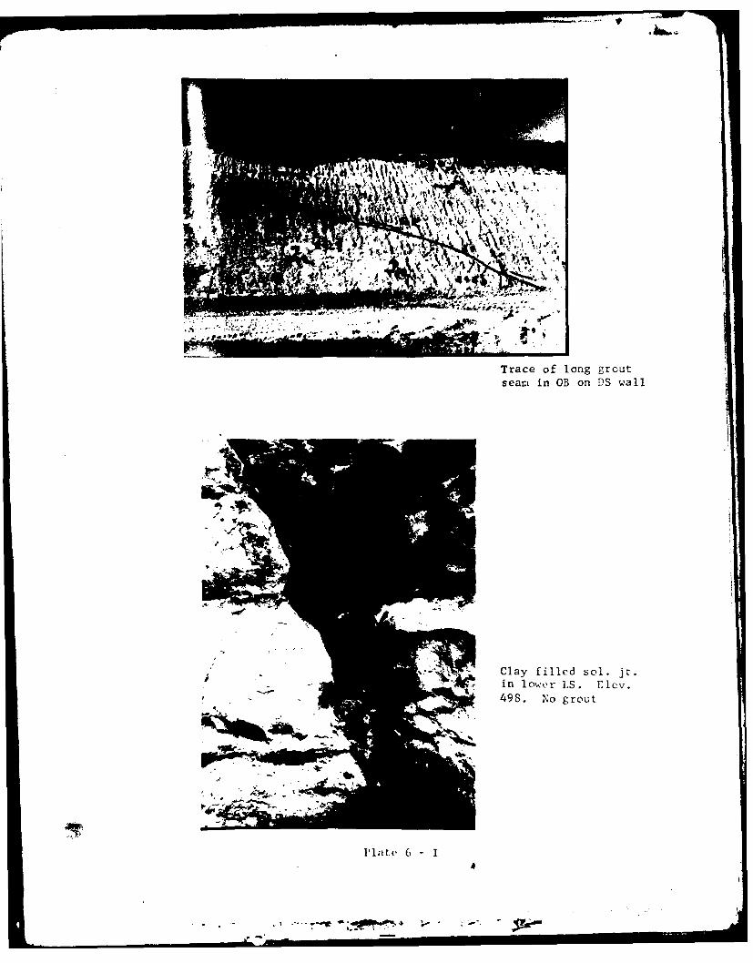
Trace of long groutseam in OB on DS wall
Clay filled sol. jr.
498. No grout
Plate 6-I
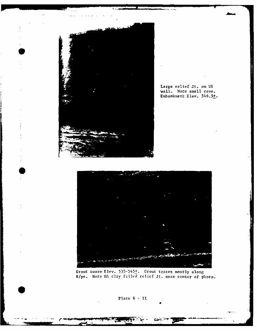
Large relief Jt. on USwall. Note small cave.Embankment Elev. 546.5+.
Grout swarm Elev. 535-545+. Grout traces mostly alongB/ps. Note IIA clay filled relief Jt. near center of photo.
0 ~Plate 6 -1
. ~"0 - -
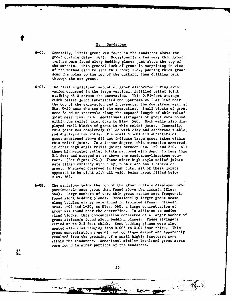
B. Sandstone
6-06. Generally. little grout was found in the sandstone above thegrout curtain (Elev. 564). Occasionally a few very thin groutlaminae were found along bedding planes just above the top ofthe curtain. This general lack of grout is surprising in viewof the method used to seal this zone; i.e., pouring thick groutdown the holes to the top of the curtain, then drilling backthrough the set grout.
6-07. The first significant amount of grout discovered during exca-vation occurred in the large vertical, infilled relief jointstriking NS W across the excavation. This 0.95-foot averagewidth relief joint intersected the upstream wall at 0+62 nearthe top of the excavation and intersected the downstream wall atSta. 0+-50 near the top of the excavation. Small blocks of groutwere found at intervals along the exposed length of this reliefjoint near Elev. 570. Additional stringers of grout were foundwithin the relief joint down to Elev. 560. Both walls also dis-played small blocks of grout in this relief joint. Generally,this joint was completely filled with clay and sandstone rubble,and displayed few voids. The small blocks and stringers ofgrout mentioned above did not indicate large grout takes withinthis relief joint. To a lesser degree, this situation occurred.in other high angle relief joints between Sta. 1+0 and 2+0. Allthese high-angled relief joints narrowed with depth to less than0.1 foot and stopped at or above the sandstone-limestone con-tact. (See Figure V-1.) These minor high angle relief jointswere filled entirely with clay, rubble and small blocks ofgrout. Whenever observed in fresh cuts, all of these jointsappeared to be tight with all voids being grout filled belowElev. 564.
6-08. The sandstone below the top of the grout curtain displayed pro-
portionately more grout than found above the curtain (Elev.564). Large numbers of very thin grout traces were frequentlyfound along bedding planes. Occasionally larger grout seamsalong bedding planes were found in isolated areas. BetweenStas. 1+05 and 1+20, at Elev. 560, a large concentration ofgrout was found near the centerline. In addition to mediumsized blocks, this concentratton consisted of a larger number ofgrout stringers found along bedding planes. These stringersvaried up to 0.5 foot thick. Some bedding planes were alsocoated with clay ranging from 0.005 to 0.01 foot thick. Thisgrout concentration zone did not continue deeper and apparentlyresulted from the grouting of a small highly fractured zonewithin the sandstone. Occasional similar localized grout areaswere found In other portions of the sandstone.
55
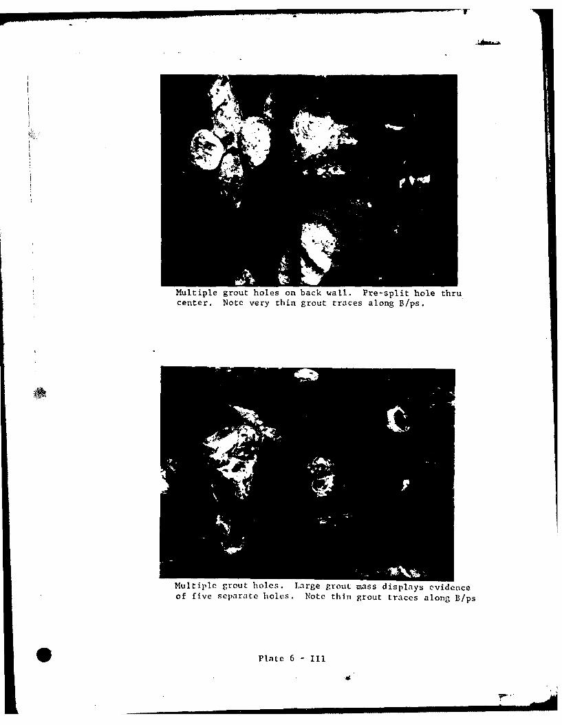
WV
Multiple grout holes on back wall. Pre-split hole thrucenter. Note very thin grout traces along B/ps.
Multiple grout holes. Large grout mass displays ovidenceof five separate holes. Note thin grout traces along B/ps
Plate 6 - III
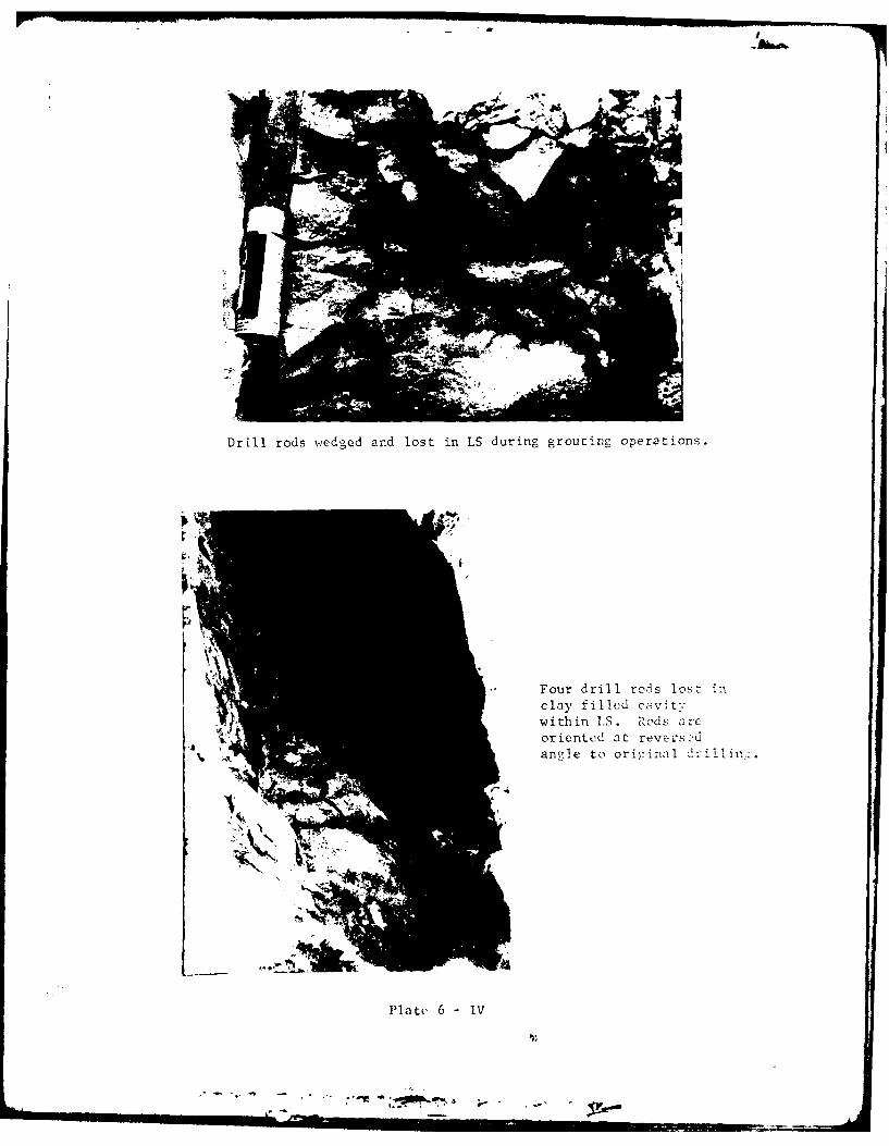
- 71 - -
Drill rods wedged and lost in LS during grouting operations.
Four drill rods lost in
cl1ay3 f il1le.d Cav t%within I'S. Rods arcoriented at revers:,uangle to oriycinal drillin,.
Platc 6 -IV
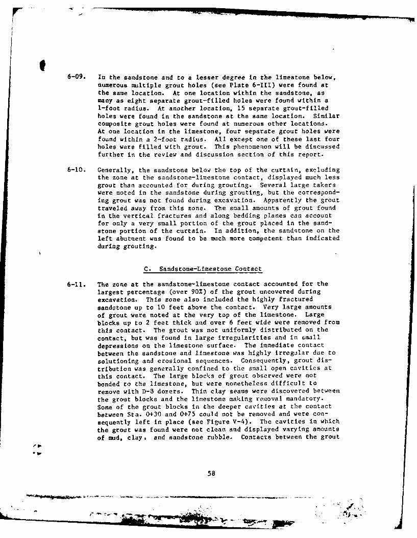
6-09. In the sandstone and to a lesser degree in the limestone below,numerous multiple grout holes (see Plate 6-111) were found atthe same location. At one location within the sandstone, asmany as eight separate grout-filled holes were found within a1-foot radius. At another location, 15 separate grout-filledholes were found in the sandstone at the same location. Similarcomposite grout holes were found at numerous other locations.At one location in the limestone, four separate grout holes werefound within a 2-foot radius. All except one of these last fourholes were filled with grout. This phenomenon will be discussedfurther in the review and discussion section of this report.
6-10. Generally, the sandstone below the top of the curtain, excludingthe zone at the sandstone-limestone contact, displayed much lessgrout than accounted for during grouting. Several large takerswere noted in the sandstone during grouting, but the correspond-ing grout was not found during excavation. Apparently the grouttraveled away from this zone. The small amounts of grout foundin the vertical fractures and along bedding planes can accountfor only a very small portion of the grout placed in the sand-stone portion of the curtain. In addition, the sandstone on theleft abutment was found to be much more competent than Indicatedduring grouting.
C. Sandstone-Limestone Contact
6-11. The zone at the sandstone-limestone contact accounted for thelargest percentage (over 90%) of the grout uncovered duringexcavation. This zone also included the highly fracturedsandotone up to 10 feet above the contact. Very large amountsof grout were noted at the very top of the limestone. Largeblocks up to 2 feet thick and over 6 feet wide were removed fromthis contact. The grout was not uniformly distributed on thecontact, but was found in large irregularities and in smalldepressions on the limestone surface. The immediate contactbetween the sandstone and limestone was highly irregalar due tosolutioning and erosional sequences. Consequently, grout dis-tribution was generally confined to the small open cavities atthis contact. The large blocks of grout observed were notbonded to the limestone, but were nonetheless difficult toremove with D-8 dozers. Thin clay seams were discovered betweenthe grout blocks and the limestone making removal mandatory.Some of the grout blocks in the deeper cavities at the contactbetween Sta. 0+30 and 0+75 could not be removed and were con-sequently left in place (see Figure V-4). The cavities in whichthe grout was found were not clean and displayed varying amountsof mud, clay, and sandstone rubble. Contacts between the grout
-ASW
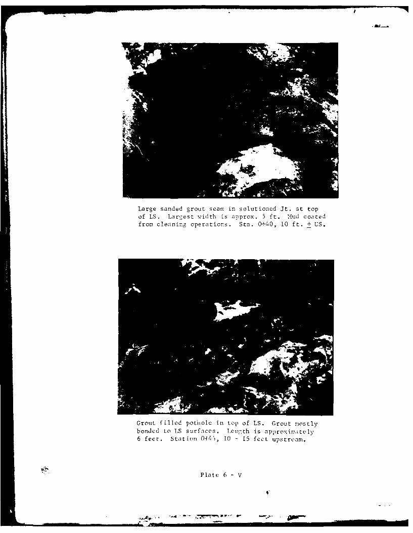
Large sanded grout seam in solution-d it. at topof LS. Largest w'idth is approx. 5 ft. Mud coatedfrom cleaning operations. Sta. 0--40, 10 ft. +US.
Grout f illed potiiole in top of LS. Grout mostlybonded to LS surfaces. Le nth is approximately6 feet. Station 0-45, 10 -15 feet upstrcam.
Plate 6 -V
.-.- .. N
and the surrounding materials appeared to be tight with allvoids being filled. In addition, excessive amounts of groutwere found outside the limits of the grout curtain.
6-12. The grout found at the limestone contact was not limited tolarge blocks. Numerous stringers and small blocks were alsofound at this contact. The sandstone-limestone contact zoneranged fromi less than 1 foot to more than 10 feet thick, withlarge amounts of grout occurring throughout the zone.
6-13. Physically, the grout observed was composed of neat and sandedgrout. In the large blocks, sanded grout formed the core withneat grout forming the contacts. Most grout found in the largeblocks also appeared banded with alternating shades and types ofgrout. This banding can clearly be seen in detailed photographsof large grout blocks (see plate 5-1). Solid neat grout ofvarying width usually formed the basal contacts. The next bandsIn order consisted of sanded grout. These sanded grout bandsusually comprised the bulk of the grout found in the largeblocks. Additional neat grout in thin alternately colored bandsusually formed the top contact between grout and rock. The topcontacts were consistently tight and completely filled. Thecolor variations in the top of the grout bands were mainly dueto the varying consistency of the grout. The dark gray zonesrepresented hard, solid, uniform, high strength grout. Thelight gray bands represented grout with varying amounts of en-trapped air. Rare instances of soft, spongy, unset grout werenoted. Occasionally, some frothy, very weak grout was fob_ atthe extreme top of the larger grout seams. Generally, thelighter gray grout was not weaker than ti. larker gzrout.Occasionally, inclusions of sandstone anl --'ay wert t~und withinthe larger grout blocks.
6-14. The banding described in the preceding paragraphs was represen-tative of the grouting method. The bottom bands of neat groutrepresented up to 150 cu. ft. of neat grout initially pumpedinto the hole. The sand grout bands represented successiveinjections of sanded grout. Upon refusal, the grout holes wereusually redrilled and the small voids above the sanded groutwere sealed with neat grout. Between successive sanded groutinjections, small amounts of neat cement were pumped. Thissequence was represented by small bands of neat grout sandwiched
between larger bands of sanded grout in the larger grout blocks.
6-15. Except for the occasional frothy grout noted in the precedingparagraphs, most of the grout, especially the sanded grout,appeared to be of uniform consistency. No segregation was notedIn any of the sanded grout observed. Sand and cement appearedto be thoroughly mixed with no lumps of unmixed materials.
60
~~rp- pig' .f. -
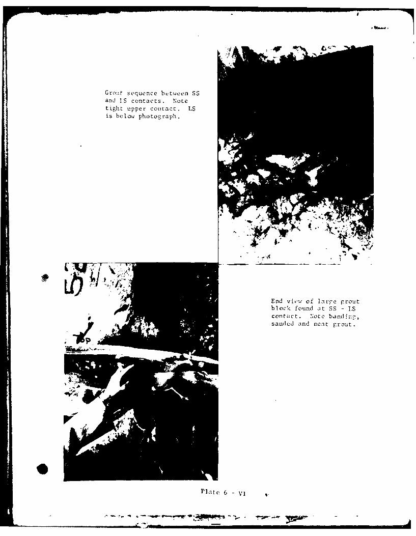
AI
Grout sequence between SSand I.S contacts. Notetight upper contact. LSis below photograph.
End view of lari-e groutblock found at SS - IScontact, Note banding,sanded and neat grout.
l'ld(' 6 V1
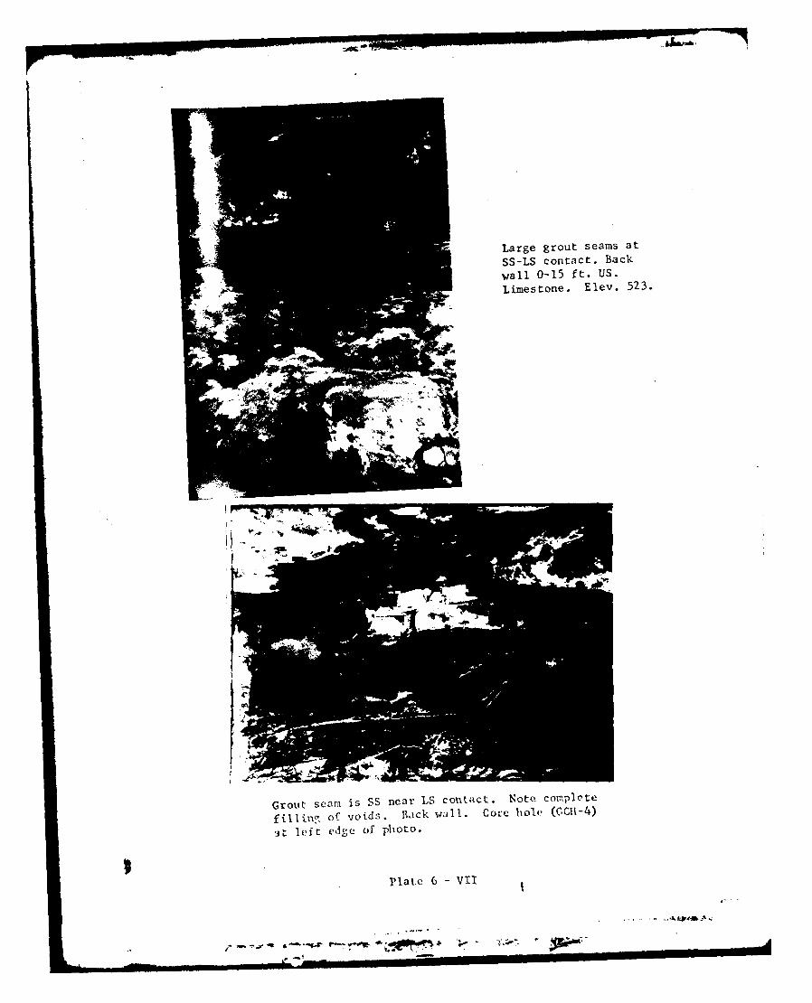
Large grout seams at
SS-LS contact. Backwall 0-15 ft. US-
Limestone. Elev. 523.
Grout scam is SS near LS contaict. Note complete
filling of voids. Wi~jck wa IlI. Core hiole (C1-4)~it left edse of photo.
Plate 6 -VII
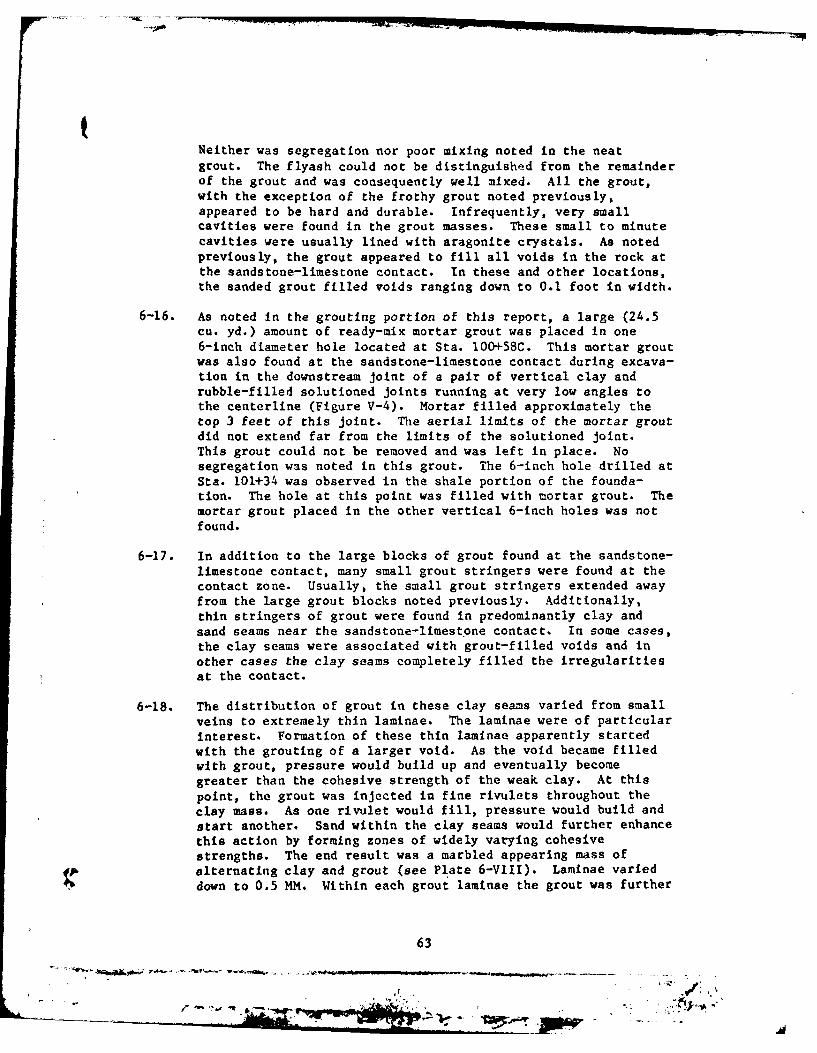
Neither was segregation nor poor mixing noted in the neatgrout. The flyash could not be distinguished from the remainderof the grout and was consequently well ixbed. All the grout,with the exception of the frothy grout noted previously,appeared to be hard and durable. Infrequently, very smallcavities were found In the grout masses. These small to minutecavities were usually lined with aragonite crystals. As notedpreviously, the grout appeared to fill all voids in the rock atthe sandstone-limestone contact. In these and other locations,the sanded grout filled voids ranging down to 0.1 foot in width.
6-16. As noted in the grouting portion of this report, a large (24.5cu. yd.) amount of ready-mix mortar grout was placed in one6-inch diameter hole located at Sta. 100+58C. This mortar groutwas also found at the sandstone-limestone contact during excava-tion in the downstream joint of a pair of vertical clay andrubble-filled solutioned joints running at very low angles tothe centerline (Figure V-4). Mortar filled approximately thetop 3 feet of this joint. The aerial limits of the mortar groutdid not extend far from the limits of the solutioned joint.This grout could not be removed and was left in place. Nosegregation was noted in this grout. The 6-inch hole drilled atSta. 101+34 was observed in the shale portion of the founda-tion. The hole at this point was filled with mortar grout. Themortar grout placed in the other vertical 6-inch holes was notfound.
6-17. In addition to the large blocks of grout found at the sandstone-limestone contact, many small grout stringers were found at thecontact zone. Usually, the small grout stringers extended awayfrom the large grout blocks noted previously. Additionally,thin stringers of grout were found in predominantly clay andsand seams near the sandstone-limest 'one contact. In some cases,the clay seams were associated with grout-filled voids and inother cases the clay seams completely filled the irregularitiesat the contact.
6-18. The distribution of grout in these clay seams varied from smallveins to extremely thin laminae. The laminae were of particularInterest. Formation of these thin laminae apparently startedwith the grouting of a larger void. As the void became filledwith grout, pressure would build up and eventually becomegreater than the cohesive strength of the weak clay. At thispoint, the grout was injected in fine rivulets throughout theclay mass. As one rivulet would fill, pressure would build andstart another. Sand within the clay seams would further enhancethis action by forming zones of widely varying cohesivestrengths. The end result was a marbled appearing mass ofalternating clay and grout (see P1l'ate 6-VIII). Lamiinae varieddown to 0.5 MM. Within each grout lamninae the grout was further
63
POW
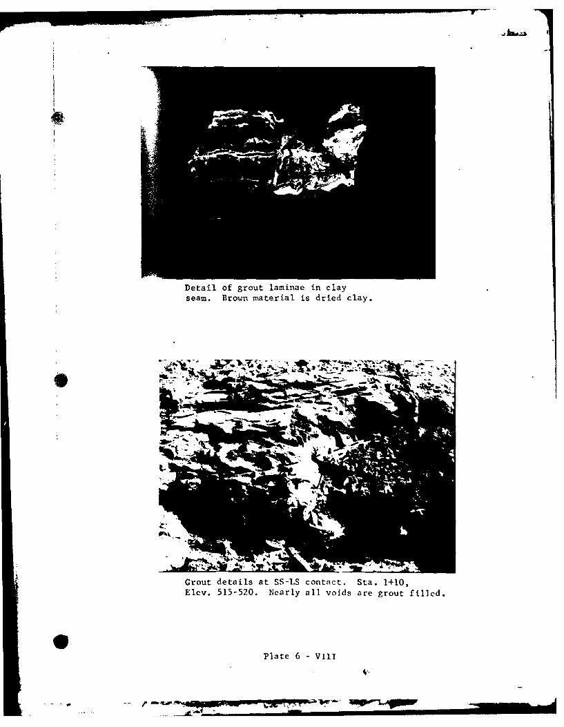
Detail of grout laminae in clayseam. Brown material is dried clay.
Grout details at SS-LS contact. Sta. 1+10,Elev. 515-520. Nearly all voids are grout filled.
Plate 6 -vinI
$--Ao
segregated into light and dark bands. As discussed previously,the light gray usually represented air entrained grout while thedarker gray represented purer hard grout. The majority of thegrout lamainae were light gray.
6-19. Occasionally, sanded grout would react in the same manner, form-ing laminae down to 0.02 foot in width. Due to the extremelylow cohesive strengths of the saturated clay and sand cavityfillings and the deep grout injection points, this type ofgrouting situation could not be avoided. As mentioned pre-
viously, all the cavities could not be washed clean. Generally,all cavities at the sandstone-limestone contact were filled. Inmost cases, clay and sand still comprised the majority of the
cavity fillings near this contact.
6-20. The grout distribution within the 10-foot section of sandstone
just above the sandstone-limestone contact was very closelyrelated to the grout distribution in the immediate contactarea. For this reason, the lower 10 feet of the Mansfieldsandstone has been included with the sandstone-limestone contactstudy area. This 10-foot section of sandstone was very highlyfractured, resulting from partial settlement into the underlyingeroded and solutioned limestone. Throughout this 10-foot zone,grout seams of varying width extended from the contact up to theindividual fracture closures. From close obervations, all frac-
tures within this 10-foot extensively fractured zone connecteddirectly with the large grout blocks at the immediate sandstone-limestone contact. In addition, great quantities of grout wereremoved during excavation from this 10 foot extensively frac-
tured sandstone zone. Grout varied from neat to sanded groutdepending upon the width of the fractures. Fractures down to
1 mm were sealed with grout. Judging from the extensive fillingof exposed fractures, this 10-foot zone of highly fractured
sandstone represented the area of greatest grouting success.
One fractured sandstone area occurring at Sta. 1+05 25 feet
downstream, Elev. 530, can be seen in Plate 6-IX. Grout in this
photo consisted of neat and sanded grout, approximately 0.5 foot
thick and parallel to normal bedding planes.
D. Limestone
6-21. The limestone below the sandstone-limestone contact displayed
less grout than expected from recorded grouting takes. This
rock was also more solutioned than previously expected. Two
large solutioned joints running at very low angles to the cen-terline were found that were not indicated during grouting.
Numerous extensively solutioned joints at oblique angles to thecenterline were also found. These numerous oblique solutioned
joints were known to exist, but the degree of solutioning was
65
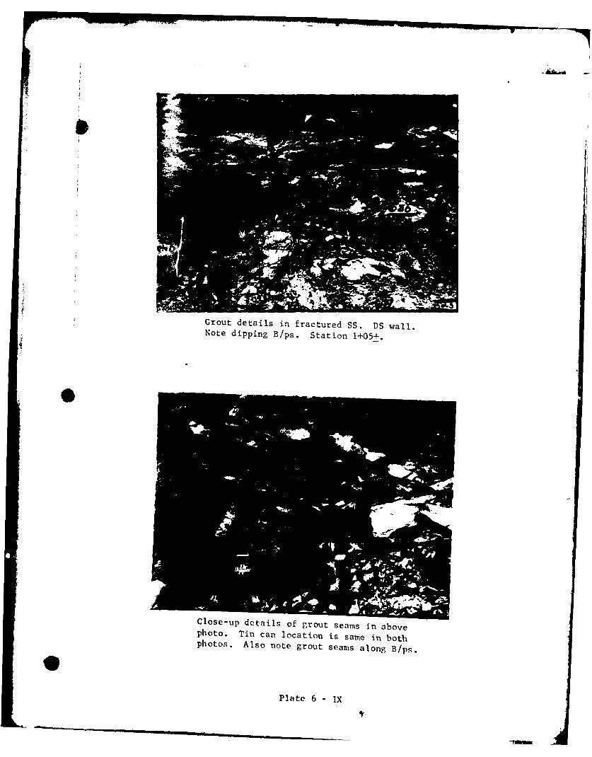
Grout details in fractured SS. DS wall.Note dipping B/ps. Station 1+05+.
Close-up details of grout seams in abovephoto. Tin can location is same in bothphotos. Also note grout seams along B/ps.
Plate 6 - IX
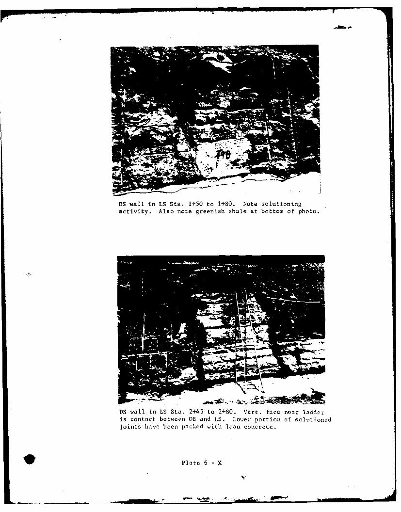
DS wall in LS Sta. 1+50 to 1+80. Note solutioningactivity. Also note greenish shale at bottom of photo.
M" 'A.-.
DS wall in LS Sta. 2+145 to 2+80. Vert. face near ladderis contact between OB and LS. Lower portion of solutionedjoints have been packed with Ican concrete.
Plate 6 -X
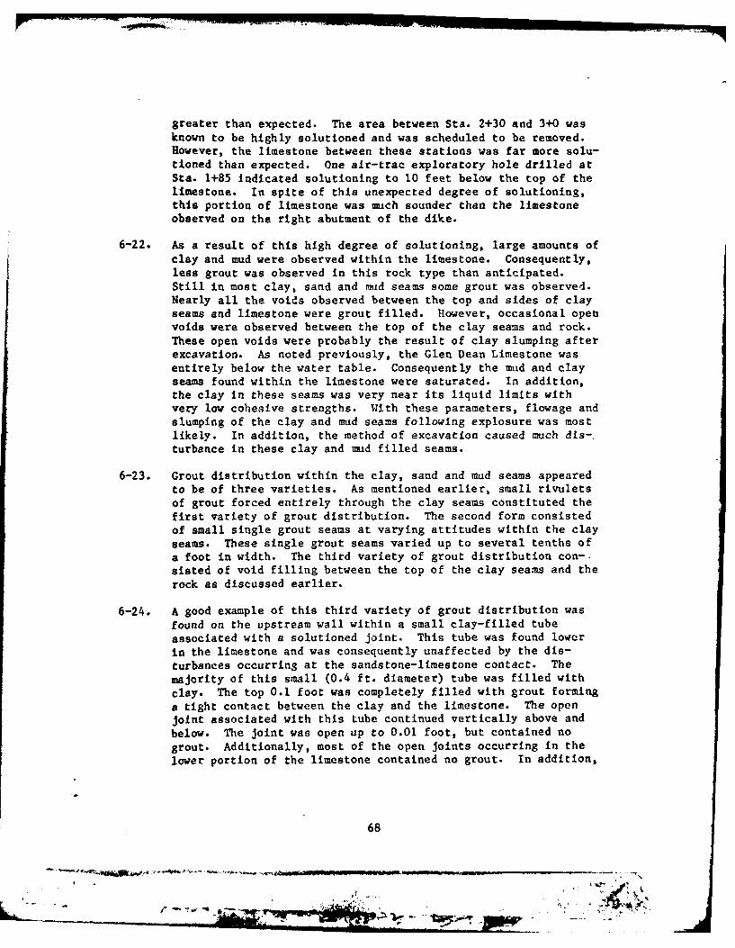
greater than expected. The area between Sta. 2+30 and 3+0 was
known to be highly solutioned and was scheduled to be removed.However, the limestone between these stations was far more solu-tioned than expected. One air-trac exploratory hole drilled atSta. 1+85 indicated solutioning to 10 feet below the top of thelimestone. In spite of this unexpected degree of solutioning,this portion of limestone was much sounder than the limestoneobserved on the right abutment of the dike.
6-22. As a result of this high degree of solutioning, large amounts ofclay and mud were observed within the limestone. Consequently,less grout was observed in this rock type than anticipated.Still in most clay, sand and mud seams some grout was observed.Nearly all the voids observed between the top and sides of clayseams and limestone were grout filled. However, occasional openvoids were observed between the top of the clay seams and rock.These open voids were probably the result of clay slumping afterexcavation. As noted previously, the Glen Dean Limestone wasentirely below the water table. Consequently the mud and clayseams found within the limestone were saturated. In addition,the clay in these seams was very near its liquid limits withvery low cohesive strengths. With these parameters, flowage andslumping of the clay and mud seams following explosure was mostlikely. In addition, the method of excavation caused much dis-.turbance in these clay and mud filled seams.
6-23. Grout distribution within the clay, sand and mud seams appearedto be of three varieties. As mentioned earlier, small rivuletsof grout forced entirely through the clay seams constituted thefirst variety of grout distribution. The second form consistedof small single grout seams at varying attitudes within the clayseams. These single grout seams varied up to several tenths ofa foot in width. The third variety of grout distribution con-sisted of void filling between the top of the clay seams and therock as discussed earlier.
6-24. A good example of this third variety of grout distribution wasfound on the upstream wall within a small clay-filled tubeassociated with a solutioned joint. This tube was found lowerin the limestone and was consequently unaffected by the dis-turbances occurring at the sandstone-limestone contact. Themajority of this small (0.4 ft. diameter) tube was filled withclay. The top 0.1 foot was completely filled with grout forminga tight contact between the clay and the limestone. The openjoint associated with this tube continued vertically above andbelow. The joint was open up to 0.01 foot, but contained nogrout. Additionally, most of the open joints occurring in thelower portion of the limestone contained no grout. In addition,
68
77.
Grouting details in clay filled solutionedjoint. LS at right and left sides of photo.
S Small solutioned tubealong jt. in LS. Clayfilled with grout seamP
- at top. Tight contacts.Approx. 0.4 ft. diam.Sta. 0+86, Elev. 516.
- Vert. jt. is open andslightly solutioned.
Plnte 6 -Xl
"WMN MWF0 D 10- M51T
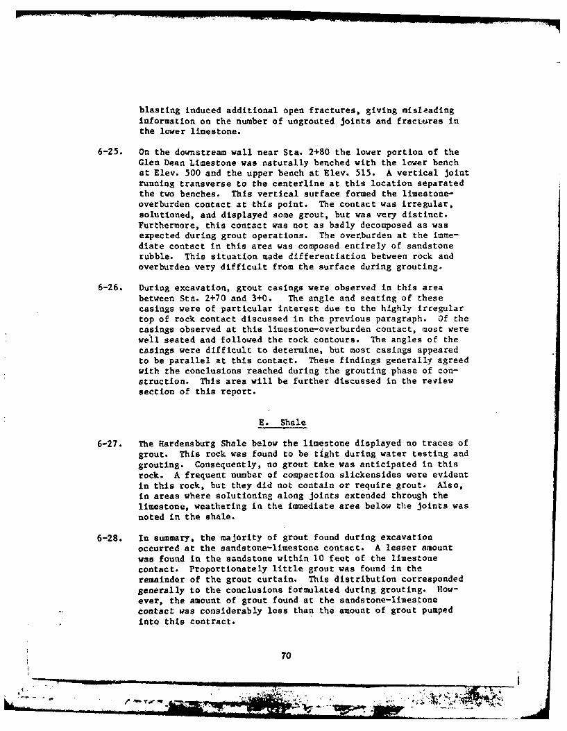
blasting induced additional open fractures, giving misleadinginformation on the number of ungrouted joints and fractures inthe lower limestone.
6-25. on the downstream vail near Sta. 2+80 the lower portion of theGlen Dean Limestone was naturally benched with the lower benchat Elev. 500 and the upper bench at Elev. 515. A vertical jointrunning transverse to the centerline at this location separatedthe two benches. This vertical surface formed the limestone-overburden contact at this point. The contact was irregular,solutioned, and displayed some grout, but was very distinct.Furthermore, this contact was not as badly decomposed as wasexpected during grout operations. The overburden at the imme-diate contact in this area was composed entirely of sandstonerubble. This situation made differentiation between rock andoverburden very difficult from the surface during grouting.
6-26. During excavation, grout casings were observed in this areabetween Sta. 2+70 and 3+0. The angle and seating of thesecasings were of particular interest due to the highly Irregulartop of rock contact discussed in the previous paragraph. Of thecasings observed at this limestone-overburden contact, most werewell seated and followed the rock contours. The angles of thecasings were difficult to determine, but most casings appearedto be parallel at this contact. These findings generally agreedwith the conclusions reached during the grouting phase of con-struction. This area will be further discussed in the reviewsection of this report.
E. Shale
6-27. The Rardensburg Shale below the limestone displayed no traces ofgrout. This rock was found to be tight during water testing andgrouting. Consequently, no grout take was anticipated in thisrock. A frequent number of compaction slickensides were evidentin this rock, but they did not contain or require grout. Also,in areas where solutioning along joints extended through thelimestone, weathering in the immediate area below the joints wasnoted in the shale.
6-28. In summary, the majority of grout found during excavationoccurred at the sandstone-limestone contact. A lesser amountwas found in the sandstone within 10 feet of the limestonecontact. Proportionately little grout was found in theremainder of the grout curtain. This distribution correspondedgenerally to the conclusions formulated during grouting. How-ever, the amount of grout found at the sandstone-limestonecontact was considerably less than the amount of grout pumpedinto this contract.
70
A--- 0 1 -
*r2v Vom
DS wall Sta. 2+80.Circled area indicates
grout casing at LS -OB contact. Disturbedbut original attitude
is evident.
r'-4
Weathering and discoloration in lower shale at baseof clay-filled solutioned joint. DS wall Sta. 2+60.
Plate 6 -XII
PART VII - REVIEW AND DISCUSSION
7-01. As discussed in the previous sections of this report, the bulkof the grout was found at the sandstone-limestone contact. Inaddition, large quantities of grout were found in the lower10 feet of the sandstone, particularly between Stas. 0+30 and1+30. Less grout than expected was fouind in the sandstone aboveElev. 535 and as suspected, very little grout was found in thelimestone below the sandstone contact. Also, as expected,little grout was found in the shale below the Glen Deanlimestone. The thick colluvial overburden at the limestonecontact also displayed very little grout.
A. Sandstone
7-02. Within the sandstone, fracturing had the greatest effect ongrout distribution. As noted, large quantities of grout (6,450cu. ft. in the upstream line alone) were pumped into the sand-stone above Elev. 535. Apparently, the grout pumped at thesehigher elevations migrated vertically through open joints andfractures to the sandstone-limestone contact. This mobility ofgrout was surprising in view of the thick mixes pumped and thelack of observed continuous fractures.
7-03. The observed physical condition of the sandstone above Elev. 535vas much sounder than anticipated during the grouting program.The sandstone was much harder and better cemented thanexpected. Numerous very thin open bedding planes were evident,but little grout was observed along these bedding planes. Thesteep excavation walls held up veil with little spalling duringone extreme winter season, thus indicating the competency of thesandstone portion of the foundation.'
7-04. The numerous high angle infilled fractures in the sandstonebetween Sta. 0+70 and 1+50 had little apparent effect upon thedistribution of grout. Several large joints or fractures run-ning upstream and downstream were suspected during grouting anda large amount of grout was believed to have been lost down-stream through these fractures. This apparently was not thecase. Of the several high angle fractures, none displayedappreciable amounts of grout. The large clay and rubble inf ill-ing within the fracture at Sta. 0+60 was generally tight andwell packed against the walls. Small voids and grout pocketsvere observed along its length, but no indications of largegrout takes were evident. The remaining smaller high anglefractures indicated the same type of compact infilling anddisplayed proportionately less grout. Consequently, littlegrout was lost through these high angle fractures.
72
* ~ - - .- ~-----
7-05. In general, grouting in the sandstone portion of the groutcurtain proved to be very effective. All fractures and jointsof any significance were filled with grout and appeared tight.The highly fractured sandstone near the limestone contact waseffectively grouted with nearly all fractures down to 1 mm beingfilled.
B. Sandstone-Limestone Contact
7-06. At the sandstone-limestone contact, grout distribution was con-trolled by large voids resulting from solution and collapseactivity. Although the bulk of the grout was found in thisarea, larger amounts must have escaped from'the curtain limitsin this zone because much more grout was pumped in this zonethan was observed during excavation.
7-07. During the grouting phase of construction, many discussions tookplace concerning grout escaping from the confines of the groutcurtain. During excavation, two possible routes of escape werediscovered. Both areas occurred at the sandstone-limestonecontact near the toe of the backslope. The two routes of escapewere oriented along solutioned joints in the limestone forminghollow tubes at the upper contact. These joints were not exca-vated through the limestone. Consequently, the conditionswithin the limestone were not observed. However, air-tracexploratory holes indicated a sound limestone at this location.
7-08. These two grout-filled solutioned joints have been plotted onFigure V-4. The upstream joint of this pair trends nearlyparallel to the dike centerline. The downstream joint of thispair trends away from the centerline at a low angle upstation.Both photos on Plate 6-VII clearlly show the upstream groutfilled joint. When excavated, both joints were completely groutfilled and the voids at the intersection with the back slopewere also completely filled with grout. This complete fillingindicated that the curtain was starting to seal off at theconclusion of grouting operations.
7-09. The contact zone betwen sandstone and limestone was found to beextremely irregular as a result of the complex depositional his-tory of the damsite area. The long interval of erosion betweendeposition of the two rock types sculptured the surface of thelimestone into multi-leveled and pinnacled forms. Consequently,elevation could not be relied upon as a key to rock types.Below the original top of limestone elevation, any type of mate-rial ranging from unconsolidated sand and clay to unweatheredsandstone and limestone could be encountered. Plate 2-1 clearlyshows the complex nature of this contact zone. The large pin-nacle of limestone at the original elevation is surrounded on
73
.r -- ~- ~ -. -.-.,..., - - ~ - ---- ~---
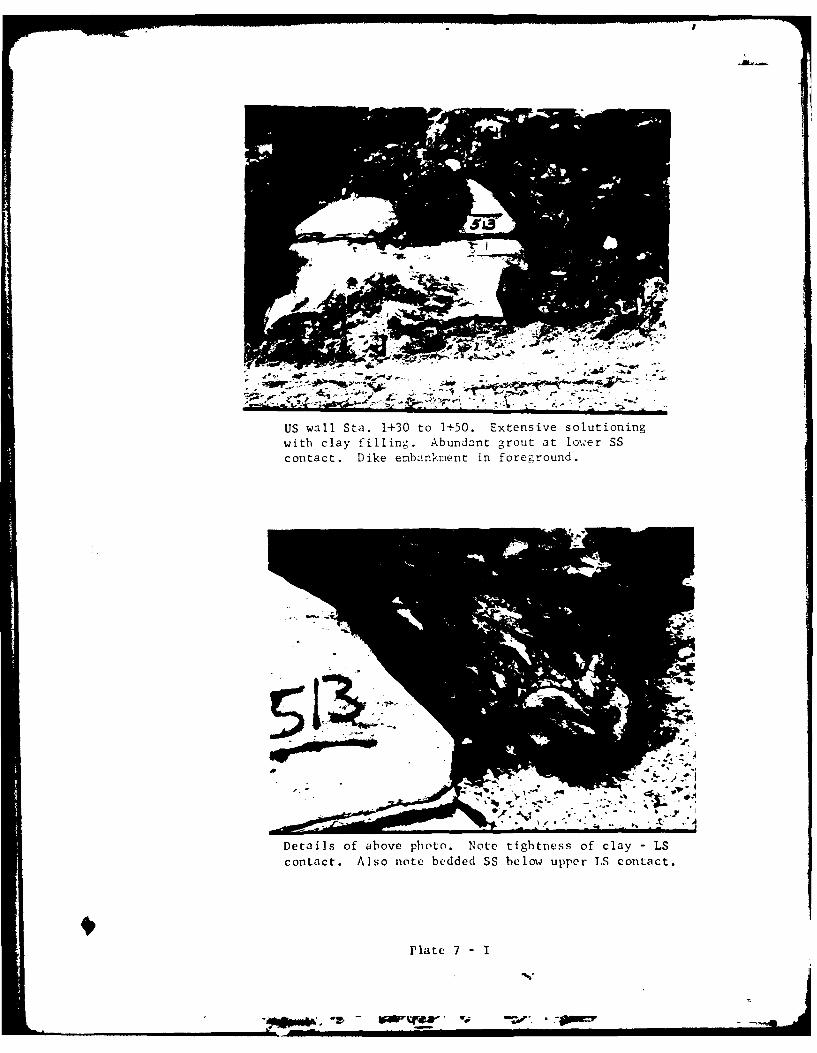
US wall Sta. 1+30 to 1-'50. Extensive solutioningwith clay fillin~g. Abundant grout at lower SS
contact. Dike ernlbankment in foreground.
Detii1s of above photo. Note tightness of clay LScontaict. Also note bedded SS below upper LS contact.
Mlate 7 - I
all sides by normally bedded sandstone. In addition, the entirelimestone pinnacle is sheathed In a thin coat of reddish brownclay.
C. Limestone
7-10. The poor grouting results and the subsequent decision toexcavate this portion of the dike foundation were mainly theconsequences of the clay and sand filled cavities found withinthe limestone. The clay and sand filling in these cavities,including the fillings at the sandstone-limestone contact,consisted of clay, mud, sand,-and sandstone fragments in varyingproportions. The clay and loose sand proved to be the mostdifficult materials to grout and consequently had the greatesteffect upon grout distribution and stability. Due to the im-possibility of thoroughly washing these clay and sand filledseams, as discussed in the grouting portion of this report, thepotential for piping remained in spite of the intensive groutingeffort.
7-11. As observed, nearly all voids above the clay seams were sealedwith grout and in may areas the clay was marbeled with rivuletsof grout. The phenomenon of "Ratholing" was probably respon-sible for most of the grout found within these clay seams. Inthis process, clay was removed during wdshing to the maximumcapacity of the pump. At this point a hole large enough toaccommodate the maximum flow of water was forced through theclay seam, and no further clay could be removed. During grout-ing, this hole was filled with grout leaving the larger mass ofclay intact. 'When the grout hole was redrilled, this processwas repeated.
7-12. The sand in the solutioned cavities represented an even greaterhindrance to grouting. As discussed earlier, the cavinga sandcreated an extremely difficult grouting problem that was neverfully resolved. Circuit grouting was used, but was generallyunsuccessful. When grouting operations were completed, cavingsand still persisted. During excavation, the full extent ofthis problem became evident. Large areas at the sandstone-limestone contact were filled with loose sand as a result ofweathering, transportation, and poor consolidation during andfollowing deposition. In addition, thin sand seams and looserubble in solutioned joints made thorough grouting of thesezones very unlikely.
7-13. As a consequence of the clay seams and loose sand near thesandstone-limestone contact, little grout was found in thelimestone below the highly solutioned zones. During grouting,this situation was suspected, but the magnitude was not realized
75
until excavation was complete. Numerous thin open joints were
evident below the clay and sand horizons which contained littleor no grout. These joints in themselves presented no grouting
problem and would have been sealed under normal grouting condi-tions. However, if left ungrouted, these open joints would havepresented a potential seepage problem.
D. Limestone-Sandstone-Overburden Contact
7-14. The highly irregular limestone-sandstone-overburden contact
betwen Sta. 2+60 and 3+0 presented another difficult groutingproblem. The limestone contact in this area, as discussed inparagraph 6-26, was irregularly stairstepped with nearlyvertical faces between steps. Covering and masking thesevertical features were varying thicknesses of sandstone
colluvial rubble. Some residual clay was present in this zone,but extensive patterns of openings and loose sand pockets
extended from one to ten feet away from the rock contacts.
7-15. Contract specifications stipulated that casings would be seateda minimum of 1 foot into rock. From the information gatheredduring casing installation and during excavation, most casings
were seated in the limestone with the resultant casing off ofthe rubbly zone. Some grout leakage into this rubbly zone wassuspected during grouting. However, few grout stringers wereobserved in this immediate rubble zone during excavation andsubsequent mapping.
7-16. From these observations, the contract method of grouting clearly
did not provide for adequate grouting of this rubbly contactzone. If left ungrouted, a very serious potential for seepage
and piping would occur. Further, this highly irregular contactzone was not discovered during exploration for the design
phase. From the alluvial history of the dike area, this type ofcontact could have been expected and separate grouting methodsfor this zone should have been specified.
7-17. In addition, the problems encountered between Sta. 3+0 and 4+20very likely stemmed from this rubbly overburden contact zone.As shown on the grouting profiles (Figures IV-2 to IV-7), thecasings in this area were set considerably higher than the top
of shale contact. Also at the time of drilling and grouting,the limestone was known to be absent from this area. However,the driller's judgment was relied upon to set the casings into
rock. The final profile presented at the March 8, 1977 meetingindicated that the zone between the casings and the shale waslimestone. This assumption was based strictly on the seatedcasing depths. Subsequent observations during excavation voided
this conclusion. Consequently, the high casing must have been
76
seated in the rubbly slope wash material overlying the shale.However, little or no grout was observed at this location. Thissituation would also account for the large number of pulledcasings In this area.
E. Shale
7-18. The grout distribution in the shale below the Glen Dean Lime-stone met expectations. The shale was tight and no grout wasobserved. Numerous compaction slickensides were noted, but noopen features requiring grout were observed. The 6-inchdiameter grout hole drilled at Sta. 1+34 was observed in theshale portion of the foundation. At this point, the hole wasfilled with sanded grout, the sides were tight, and no mud wasobserved. The complete filling of the hole indicated thatlittle or no caving occurred during the final drilling of thislarge diameter hole.
7-19. Grouting in the shale proved to be effective. Actually, grout-ing in the shale was intended as a check measure and groutingproved to be unnecessary. Problems with casing anchoringoccurred between Sta. 3+0 and 4+20, but did not involve groutingproblems within the rock.
F. Discussion
7-20. Contract specifications stipulated that grout holes would eitherbe washed out after grouting operations, after allowing enoughtime for initial grout set, or that the grout holes would beredrilled at the contractor's expense. The contractor electedto redrill the holes rather than waiting the required 3-hour settime to wash. Due to the softness of the sandstone, the setgrout within the grout holes became harder than the surroundingrock. When redrilled, the drill bit tended to drill a new holeIn the soft sandstone rather than drill through the hardergrout. This phenomenon accounted for the large number of groutholes found in the same relative location near the base of thesandstone (see Plate 6-111). In one instance, over 15 separategrout holes were found at the same location. In general, thecontractor's selection of redrilling rather than washing bene-fitted the grouting program greatly in that a greater area couldbe grouted with a single hole. In addition, a better curtainwas obtained in the sandstone due to the larger number of freshgrout holes.
7-21. These muiltiple grout holes also offered an explanation of theexcessive negative staging in the sandstone. In each groutingstage, the grout would travel only a very short distance from
72'i
the grout hole due to the very thin openings between beddingplanes. Each time a grout hole was redrilled, the bit wouldmiss the grout in the original hole and lose drill water alongthe same bedding plane.
7-22. In spite of the greater number of holes in the same generallocation, the angles of the individual grout holes did not varyin the sandstone as greatly as suspected during grouting opera-tions. Most redrill holes in sandstone were found within a 5-foot radius of the original holes. Given the length of drillhole, up to 82 feet in sandstone, the deviation of the redrilledholes would be less than 10 percent. Relatively few holes wereobserved and variations greater than this may have occurred inother holes.
7-23. Deviations in multiple grout hole angles were much more erraticin the limestone portion of the grout curtain. Generally, holesremained true In competent limestone, but several outstandingdeviations in weathered limestone were noted. Near Sta. 2+60),several broken drill rods were observed in a clay-filled solu-tion joint (see Plate 6-IV). These rods were found at widelyvarying angles and were found at reversed angles to the originalhole. In this and other Instances, the drill rods and bit wouldfollow the sides of the joint rather than punch through theirregular rock surface. This phenomenon was also noted duringdrilling of the core hole (OCH #7) at Sta. 2+72.5.
7-24. In the case of the grout holes, the type of bit may also haveinfluenced the deviations noted in limestone. Carborundumtipped, fishtail bits were used in lieu of diamond bits. Thesofter, irregular bits would have a greater tendency to followthe softer weathered rock on joint faces rather than continuethrough the hard side walls of these joints.
7-25. Holes drilled through the overburden were not observed closelyenough to determine general deviations in drilling angles. Onecluster of four grout casings was observed near Sta. 2+80 at thelimestone overburden contact (see Plate 6-XII). These foujrcasings were found within a 2-foot square area and seemed tovary from the intended drill angles. However, the close spacingof the grout holes in this area made it difficult to reach anyconclusions based on just these four holes. No other in placecasings were observed in this area.
7-26. Many grout-filled holes found during excavation displayed aconcentric circular and oval banding of the hardened grout.Banding consisted of alternating light and dark grout. Thelighter bands were probably the result of a higher air contentwhile the darker bands probably represented consistently denser
* grout.
78
* -.
7-27. Indirectly the grout banding could also be related to the method
of grouting. Very frequent premature plugging of holes wasnoted during grouting. This phenomenon was especially evidentwhile pumping the thicker mixes. As grouting progressed with nopressure build-up, progressively thicker mixes were introducedinto the hole. At some point during this process, often between100 and 150 sacks, the hole would suddenly refuse with pressuresrising from 0 to 15 psi instantly.
7-28. Many explanations can be hypothesized to explain this prematureplugging, but the grout banding noted above suggests one of themost plausible explanations. Grout holes in sandstone weregenerally drilled with a carborundum tipped fishtail bit. Thefishtail bit combined with whipping of the drill rods, due toexcessive drill speeds, left a much rougher edged hole thansimilar drilling with diamond bits. During grouting operationsthe rough edged holes would tend to impede the flow of groutwithin the hole. In addition, the velocity of grout would tendto slow at the outer edges of the fluid. Grout would also tendto to cake on the outside of the rough holes and furtherrestrict the flow of grout. Eventually, the flow of grout wouldbecome so constricted that the hole would plug completely.Other causes are possible, but the banded grout phenomenonsuggests one plausible explanation for grout hole plugging.
7-29. In practice, the contractor was required to redrill any hole Inwhich the Government representative suspected premature plug-ging. Larger diameter (NX) holes might have alleviated thepremature plugging problem, but would not have completely solvedthis problem.
7-30. The analysis of rock conditions made during grouting (FigureIV-7) and used as a basis for the final excavation design provedto be generally correct. However, details varied slightly.The limestone, for example, was in a worse condition than ex-pected. Grouting indicated the limestone to be tight below thesolutioned zone at the sandstone contact. However, when un-covered, solutioning within the limestone extended much furtherinto the abutment than anticipated. Consequently, more lime-stone had to be removed than planned. Specifically, the lime-stone had to be removed completely back to Sta. 0+76, whereasfinal plans called for complete removal only to Sta. 2+40. Thesandstone, on the other hand, proved to be sounder than assumedduring grouting.
7-31. At the time the decision was made to excavate a cutoff into theleft abutment, alternate methods of treatment were not consid-ered. However, two alternate methods were considered on
ru otherportions of the project where similar conditions were en-countered. A 5-foot wide cutoff trench excavated 30 feet
79
through the timestone was utilized between the dike and thespillway. At che dike left abutment, greater depths wouldprobably have precluded this method of treatment. A drilledwall consisting of 24-Inch overlapping holes was considered atthe right abutment of the dike, but was not utilized. Thismethod could have been utilized at the left abutment of the dikeas an alternative to complete excavation, depending upon costand other considerations.
7-32. Chemical grouting was considered during grouting operations, butwas not utilized due to contractual restraints. This type ofgrouting would greatly have improved the results in the loosesand encountered at the limestone-sandstone contact. Used inconjunction with cement grouting, chemical grouting might alsohave facilitated the grouting of the rubble overlying limestoneat station 3+00 if that condition was known to have existedduring the grouting phase of construction. However, the sta-bility of the clay in the solutioned zones of the limestonecould not be improved by utilizing chemical grout. In addition,the settlement of the foundation upon loading with embankmentcould not have been prevented by this grouting method. As aresult, the integrity of the foundation could not be insuredthroughout the life of the project.
7-33. The left abutment of the dike would have provided an ideal areafor a test grouting program. Similar rock conditions prevailedfor a large portion of the total grout curtain. Consequently,the dike section would have provided an isolated, short studyarea for the remaining curtain. Alternate methods of grouting,such as large diameter holes, stop grouting, and combinationchemical grouting and cement grout could have been used andevaluated without costly contract modification or holding up thedike excavation. Further, alternate solutions to grouting, suchas excavation or drilled cutoff wall, could have been analyzedbefore awarding the construction contract.
s
88
PART VIII - CONCLUSION
8-01. Stage grouting as envisioned during the design phase of thisproject proved to be inadequate to seal the complex rockstructure encountered at the left abutment of the dike. Theinability to treat the loose sand at the sandstone-limestonecontact, the clay-filled solutioned joints and the open voidswithin the colluvium-limestone contact finally caused abandon-ment of the grouting program. Additional methods of groutingcontemplated during construction, such as backfilling 6-inchdiameter holes with high slump mortar grout, circuit groutingand stop grouting in 3-inch holes either did not nor would nothave increased the effectiveness of the grouting program in thisarea. Chemical grouting could have improved the grouting re-sults in loose sand areas, but probably would not have improvedthe grouting effectiveness in the clay-filled zones.
8-02. Subsequent reevaluation of the structural integrity of the dikestructure, with regard to piping, led to complete excavation ofthe objectionable material to provide a positive tie-in to theunderlying impervious rock. During the final rock excavation ofthe dike left abutment, the magnitude of the grouting difficul-ties became readily apparent. Most open voids were filled with.grout, but the clay-filled solutioned joints remained and loosesand was observed within these joints. The unconsolidated col-luvium at the limestone contact remained ungrouted and posed areal threat to future structural integrity through extensiveseepage and resulting piping of finer materials. Excavationallowed removal of unsuitable material back to a point where thesafety of the structure was insured.
8-03. During design, too great a reliance was placed on cement grout-ing to cure the problems of a weak foundation. The state of theart, since the design of this project, has progressed to thepoint of less dependence upon grouting in complex solutionedlimestone areas. Grouting often has only short term effective-ness in solutioned limestone and quite often the area has to becontinually regrouted during the life of the structure tocontrol seepage.
8-04. In the future, greater care should be given to determininggroutable and nongroutable solutioned limestones. Less depend-ence should be placed on grouting in a badly solutioned lime-stone with extensive clay-filled joints or cavities. Theseclay-filled cavities and joints cannot be effectively washed orgrouted and present a very high potential for future seepage andpiping. Any limestone that has been subjected to surface ero-sional cycles should be highly suspect for groutingincompatibility.
M81
, . . . p - . '.-,, . ' - '- . .. .
08-05. Greater emphasis should be placed on foundation exploration and
in-situ observations of the limestone contacts. Grouting shouldnot be relied upon for any structural foundation where seepageand resultant piping could threaten the integrity of thatfoundation. Instead, positve cutoff methods such as drilled-inwalls, cutoff trenches, or complete removal should be utilizedto insure the structural integrity of the critical foundationsin highly solutioned limestones.
II
82
Ir~ i