Embed Size (px)
Citation preview

Contents
Range of Products
Applicable Standards
Standard Motors : Output Summary
Mechanical Features
Dimensions of Foot Maunted Motors (B-3 Mounting) as per IS : 1231
Dimensions of Face Mounted Motors (B-14 Mounting) as per IS: 2223
Dimensions of Flange Mounted Motors (B-5 Mounting) as per IS: 2223
Permissible radial load for Standard Motors
Electrical Features
Guidelines for Motors Protection fuse rating
Electrical Performance Figures
Energy Efficient Motors (EFF-1)
Cooling Tower Motors
Flame-proof Motors (Ex 'd' )
Roller Table Motors
Non-Sparking Motors (Ex 'nA')
Tolerance on Performance Values & Dimensions
Shipping Specifications
:
:
:
:
:
:
:
:
:
:
:
:
:
:
:
:
:
:
1
2
3
4-5
6
7
8
9
10
11
12-15
16-18
19
20-33
33
34-35
36-37
37
Note : Due to continual improvements, the data given in this catalogue, may get changed.
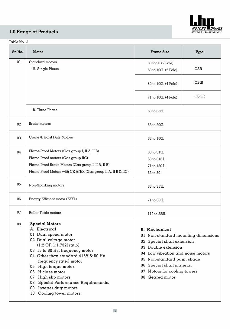
1.0 Range of Products
Table No. -1
Sr. No. Motor Frame Size
Standard motors
A. Single Phase
B. Three hase
Brake motors
Crane & Hoist Duty Motors
Flame-Proof Motors ( I, II A, II B
Flame roof motors (Gas group II )
Flame roof Brake Motors
Non-Sparking motors
Energy Efficient motor
Roller Table motors
P
Gas group )
-P C
-P (Gas group I, II A, II B)
Flame-Proof Motors with CE ATEX (Gas group II A, II B & IIC)
(EFF1)
63 to 90 (2 Pole)
63 to 100L (2 Pole)
80 to 100L (4 Pole)
71 to 100L (4 Pole)
63 to 355L
63 to 200L
63 to 160L
63 to 315L
63 to 315 L
71 to 180 L
63 to 80
63 to 355L
71 to 355L
112 to 355L
01
02
03
04
05
06
07
08 Special MotorsA. Electrical01 Dual speed motor02 Dual voltage motor
(1:2 OR 1:1.7321ratio)03 15 to 60 Hz. frequency motor04 Other than standard 415V & 50 Hz
frequency rated motor05 High torque motor06 H class motor07 High slip motors08 Special Performance Requirements.09 Inverter duty motors10 Cooling tower motors
B. Mechanical01 Non-standard mounting dimensions02 Special shaft extension03 Double extension04 Low vibration and noise motors05 Non-standard paint shade06 Special shaft material07 Motors for cooling towers08 Geared motor
1
Type
CSR
CSIR
CSCR
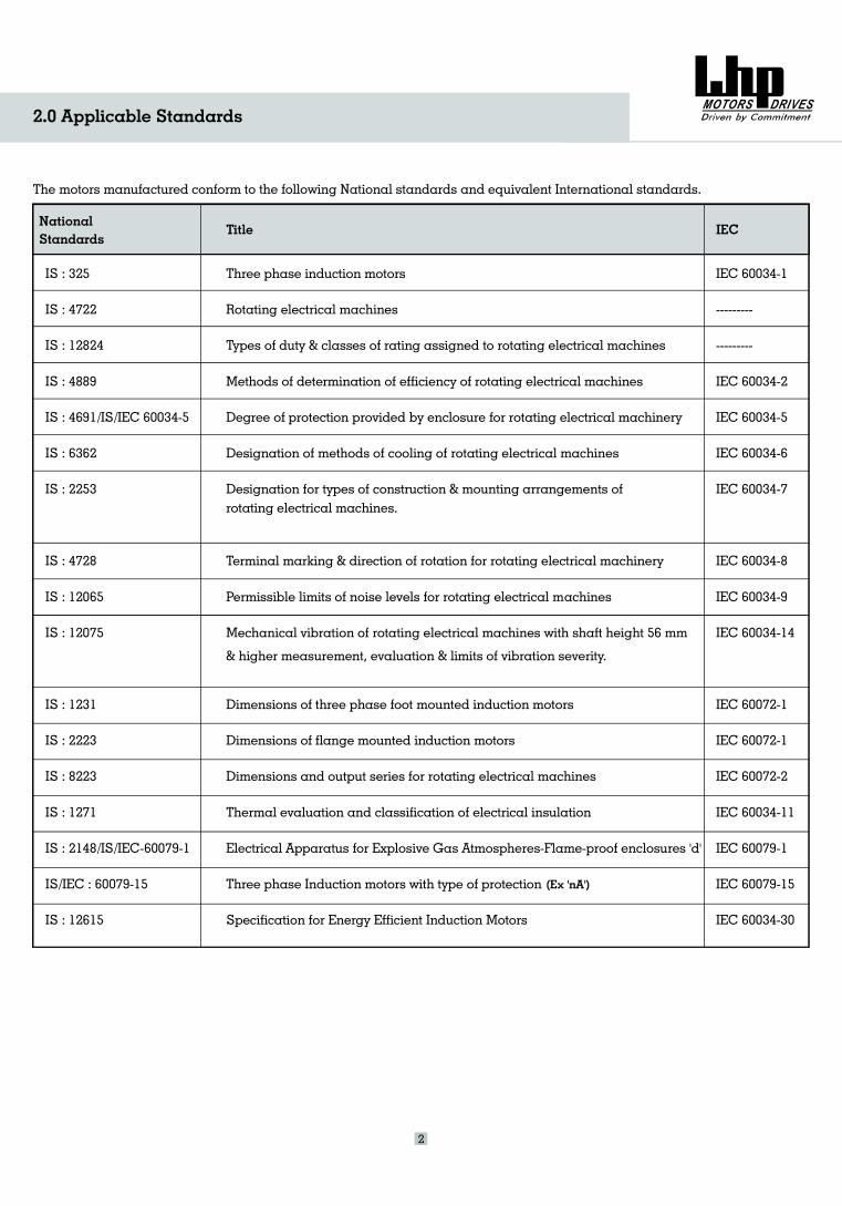
2.0 Applicable Standards
The motors manufactured conform to the following National standards and equivalent International standards.
NationalStandards
Title IEC
IS : 325
IS : 4722
IS : 12824
IS : 4889
IS : 4691
IS : 6362
IS : 2253
IS : 4728
IS : 12065
IS : 12075
IS : 1231
IS : 2223
IS : 8223
IS : 1271
IS : 2148
IS/IEC :
IS : 12615
/IS/IEC 60034-5
/IS/IEC-60079-1
60079-15
Three phase induction motors
Rotating electrical machines
Types of duty & classes of rating assigned to rotating electrical machines
Methods of determination of efficiency of rotating electrical machines
Degree of protection provided by enclosure for rotating electrical machinery
Designation of methods of cooling of rotating electrical machines
Designation for types of construction & mounting arrangements ofrotating electrical machines.
Terminal marking & direction of rotation for rotating electrical machinery
Permissible limits of noise levels for rotating electrical machines
Mechanical vibration of rotating electrical machines with shaft height 56 mm
& higher measurement, evaluation & limits of vibration severity.
Dimensions of three phase foot mounted induction motors
Dimensions of flange mounted induction motors
Dimensions and output series for rotating electrical machines
Thermal evaluation and classification of electrical insulation
Electrical Apparatus for Explosive Gas Atmospheres-Flame-proof enclosures 'd'
Three phase Induction motors with type of protection
Specification for Energy Efficient Induction Motors
IEC 60034-1
-
IEC 60034-2
IEC 60034-5
IEC 60034-6
IEC 60034-7
IEC 60034-8
IEC 60034-9
IEC 60034-14
IEC 60072-1
IEC 60072-2
IEC 60034
IEC 60079-1
IEC 6007 -15
--------
---------
IEC 60072-1
-11
9
IEC 60034-30
2
(Ex 'nA')
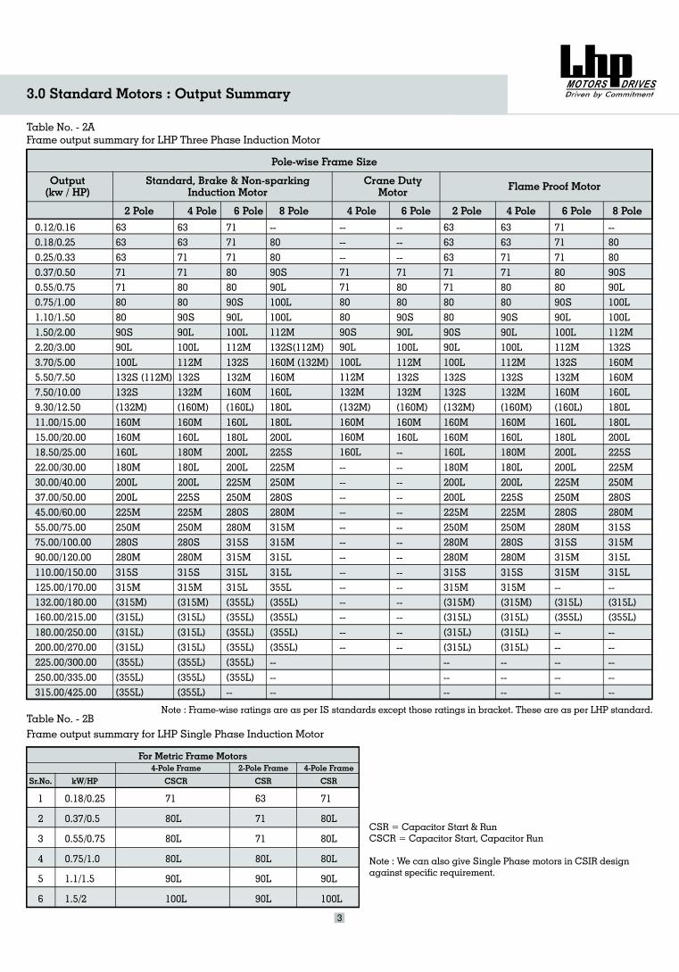
3.0 Standard Motors : Output Summary
Table No. - 2AFrame output summary for LHP Three Phase Induction Motor
Output(kw / HP)
Standard, Brake & Non-sparkingInduction Motor
Crane DutyMotor Flame Proof Motor
Pole-wise Frame Size
2 Pole 4 Pole 6 Pole 8 Pole 4 Pole 6 Pole 2 Pole 4 Pole 6 Pole 8 Pole
0.12/0.160.18/0.250.25/0.330.37/0.500.55/0.750.75/1.001.10/1.501.50/2.002.20/3.003.70/5.005.50/7.507.50/10.009.30/12.5011.00/15.0015.00/20.0018.50/25.0022.00/30.0030.00/40.0037.00/50.0045.00/60.0055.00/75.0075.00/100.0090.00/120.00110.00/150.00125.00/170.00132.00/180.00160.00/215.00180.00/250.00200.00/270.00225.00/300.00250.00/335.00315.00/425.00
6363637171808090S90L100L132S (112M)132S(132M)160M160M160L180M200L200L225M250M280S280M315S315M(315M)(315L)(315L)(315L)(355L)(355L)(355L)
63637171808090S90L100L112M132S132M(160M)160M160L180M180L200L225S225M250M280S280M315S315M(315M)(315L)(3 5L)(3 5L)(355L)(355L)
11
(355L)
717171808090S90L100L112M132S132M160M(160L)160L180L200L200L225M250M280S280M315S315M315
(355 )(355L)(355L)--
L315L(355L)(355L)(355L)
L
6363637171808090S90L100L132S132S(132M)160M160M160L180M200L200L225M250M280M280M315S315M(315M)(315L)(315L)(315L)------
6363
(315L)
7171808090S90L100L112M132S132M(160M)160M160L180M180L200L225S225M250M280S280M315S315M(315M)(315L)(315L)
------
717171808090S90L100L112M132S132M160M(160L)160L180L200L200L225M250M280S280M315S315M315M--(315L)(355L)----------
--808090S90L100L100L112M132S160M160M160L180L180L200L225S225M250M280S280M315S315M315L315L--(315L)(355L)----------
--808090S90L100L100L112M132S(112M)160M (132M)160M160L180L180L200L225S225M250M280S280M315315315315355(355L)(355L)
(355L)------
MMLLL
(355L)
------7171808090S90L100L112M132M(132M)160M160M
--------------------------
160L
------71808090S90L100L112M132S132M(160M)160M160L----------------------------
Table No. - 2BFrame output summary for LHP Single Phase Induction Motor
Note : Frame-wise ratings are as per IS standards except those ratings in bracket. These are as per LHP standard.
For Metric Frame Motors4-Pole Frame 2-Pole Frame 4-Pole Frame
Sr.No. kW/HP CSCR CSR CSR
1
2
3
4
5
6
0.18/0.25
0.37/0.5
0.55/0.75
0.75/1.0
1.1/1.5
1.5/2
71
80L
80L
80L
90L
100L
63
71
71
80L
90L
90L
71
80L
80L
80L
90L
100L
3
CSR = Capacitor Start & RunCSCR = Capacitor Start, Capacitor Run
Note : We can also give Single Phase motors in CSIR designagainst specific requirement.
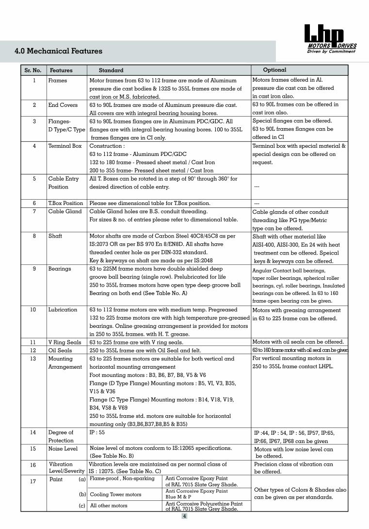
4.0 Mechanical Features
4
Sr. No. Features Optional
Motor frames from 63 to 112 frame are made of Aluminumpressure die cast bodies & 132S to 355L frames are made ofcast iron or M.S. fabricated.63 to 90L frames are made of Aluminum pressure die cast.All covers are with integral bearing housing bores.
flanges are . Allflanges are with integral bearing housing bores.
Construction :63 to 112 frame - Aluminum132 to 180 frame - Pressed sheet metal / Cast Iron200 to 355 frame-All T. Boxes can be rotated in a step of 90 through 360 fordesired direction of cable entry.
Please see dimensional table for T.Box position.Cable Gland holes are B.S. conduit threading.For sizes & no. of entries please refer to dimensional table.
Motor shafts are made of Carbon Steel as perIS: All shafts havethreaded center hole as per DIN-332 standard.Key & keyways on shaft are made as per IS:204863 to 225 frame motors have double shielded deepgroove ball bearing (single row).250 to 355L frames motors have open type deep groove ball
(See Table No. A)
to 225 frame motors are with high temperature pre-greasedbearings. Online greasing arrangement is provided for motorsin 250 to 355L frames.63 to frame are with V ring seals
to 355L frame are with Oil Seal63 to 225 frames motors are suitable for both vertical andhorizontal mounting arrangementFoot mounting motors : B3, B6, B7, B8, V5 & V6Flange (D Type Flange) Mounting motors : B5, VI, V3, B35,V15 & V36Flange (C Type Flange) Mounting motors : B14, V18, V19,B34, V58 & V69250 to 355L frame motors are suitable for horizontalmounting only (B3,B6,B37,B8,B5 & B35)IP : 55
63 to 90L frames in Aluminum PDC/GDC100 to 355L
frames flanges are in CI only.
PDC/GDC
Pressed sheet metal / Cast Iron° °
40C8/45C82073 OR as per BS 970 En 8/EN8D.
MPrelubricated for life
Bearing on both end
63 to 112 frame motors are with medium temp. Pregreased132
with H. T. grease.225 .
250 and felt.
std.
Standard
Frames
End Covers
Flanges-D Type/C Type
Terminal Box
Cable EntryPosition
T.Box PositionCable Gland
Shaft
Bearings
Lubrication
V Ring SealsOil SealsMountingArrangement
Degree ofProtectionNoise Level
1
2
3
4
5
67
8
9
10
111213
14
15
16
17
Motors frames offered in Al.pressure die cast can be offeredin cast iron also.63 to 90L frames can be offered incast iron also.Special flanges can be offered.63 to 90L frames flanges can beoffered in CI
Terminal box with special material &special design can be offered onrequest.
---
---
Cable glands of other conduitthreading like PG type/Metrictype can be offered.Shaft with other material likeAISI-400, AISI-300, En 24 with heattreatment can be offered. Speicalkeys & keyways can be offered.
Angular Contact ball bearings,taper roller bearings, spherical rollerbearings, cyl. roller bearings, Insulatedbearings can be offered. In 63 to 160frame open bearing can be given.
Motors with greasing arrangementin 63 to 225 frame can be offered.
Motors with oil seals can be offered.63to160framemotorwithoil seal canbegivenFor vertical mounting motors in250 to 355L frame contact LHPL.
IP :44, IP : 54, IP : 56, IP57, IP:65,IP:66, IP67, IP68 can be givenMotors with low noise level canbe offered.Precision class of vibration canbe offered.
Flame-proof , Non-sparking
(b)
All other motors
Anti Corrosive Epoxy Paintof RAL 7015 Slate Grey Shade.
Anti Corrosive Polyurethine Paintof RAL 7015 Slate Grey Shade.
Vibration levels are maintained as per normal class ofIS : 12075. (See Table No. C)
Noise level of motors conform to IS:12065 specifications.(See Table No. B)
VibrationLevel/Severity
Paint (a)
Other types of Colors & Shades alsocan be given as per standards.
(c)
Cooling Tower motorsAnti Corrosive Epoxy PaintBlue M & P
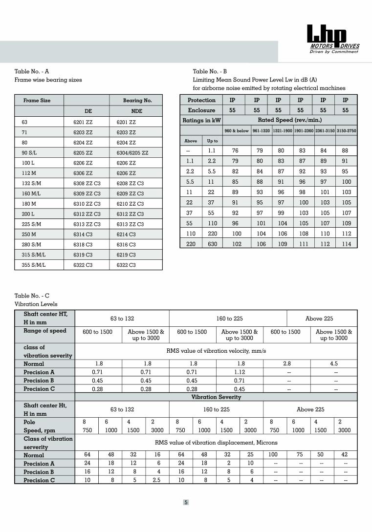
Table No. - AFrame wise bearing sizes
Table No. - BLimiting Mean Sound Power Level Lw in dB (A)for airborne noise emitted by rotating electrical machines
Frame Size
DE
Bearing No.
NDE
63
71
80
90 S/L
100 L
112 M
132 S/M
160 M/L
180 M
200 L
225 S/M
250 M
280 S/M
315 S/M/L
355 S/M/L
6201 ZZ
6203 ZZ
6204 ZZ
6205 ZZ
6206 ZZ
6306 ZZ
6308 ZZ C3
6309 ZZ C3
6310 ZZ C3
6312 ZZ C3
6313 ZZ C3
6314 C3
6318 C3
6319 C3
6322 C3
6201 ZZ
6203 ZZ
6204 ZZ
6304/6205 ZZ
6206 ZZ
6206 ZZ
6208 ZZ C3
6209 ZZ C3
6210 ZZ C3
6312 ZZ C3
6313 ZZ C3
6214 C3
6316 C3
6219 C3
6322 C3
Protection
Enclosure
Ratings in kW
IP
55
IP
55
IP
55
IP
55
IP
55
IP
55
Rated Speed (rev./min.)
960 & below 961-1320 1321-1900 1901-2360 2361-3150 3150-3750
Above Up to
--
1.1
2.2
5.5
11
22
37
55
110
220
1.1
2.2
5.5
11
22
37
55
110
220
630
76
79
82
85
89
91
92
96
100
102
79
80
84
88
93
95
97
101
104
106
80
83
87
91
96
97
99
104
106
109
83
87
92
96
98
100
103
105
108
111
84
89
93
97
101
103
105
107
110
112
88
91
95
100
103
105
107
109
112
114
Shaft center HT,H in mmRange of speed
class ofvibration severityNormalPrecision APrecision BPrecision C
Shaft center Ht,H in mmPoleSpeed, rpmClass of vibrationserverityNormalPrecision APrecision BPrecision C
63 to 132 160 to 225 Above 225
600 to 1500 Above 1500 &up to 3000
600 to 1500 Above 1500 &up to 3000
600 to 1500 Above 1500 &up to 3000
RMS value of vibration velocity, mm/s
1.80.710.450.28
1.80.710.450.28
1.80.710.450.28
1.81.120.710.45
2.8------
4.5------
Vibration Severity
63 to 132 160 to 225 Above 225
8750
61000
41500
23000
8750
61000
41500
23000
8750
61000
41500
23000
RMS value of vibration displacement, Microns
64241610
4818128
321285
1664
2.5
64241610
4818128
32285
251064
100------
75------
50------
42------
Table No. - CVibration Levels
5
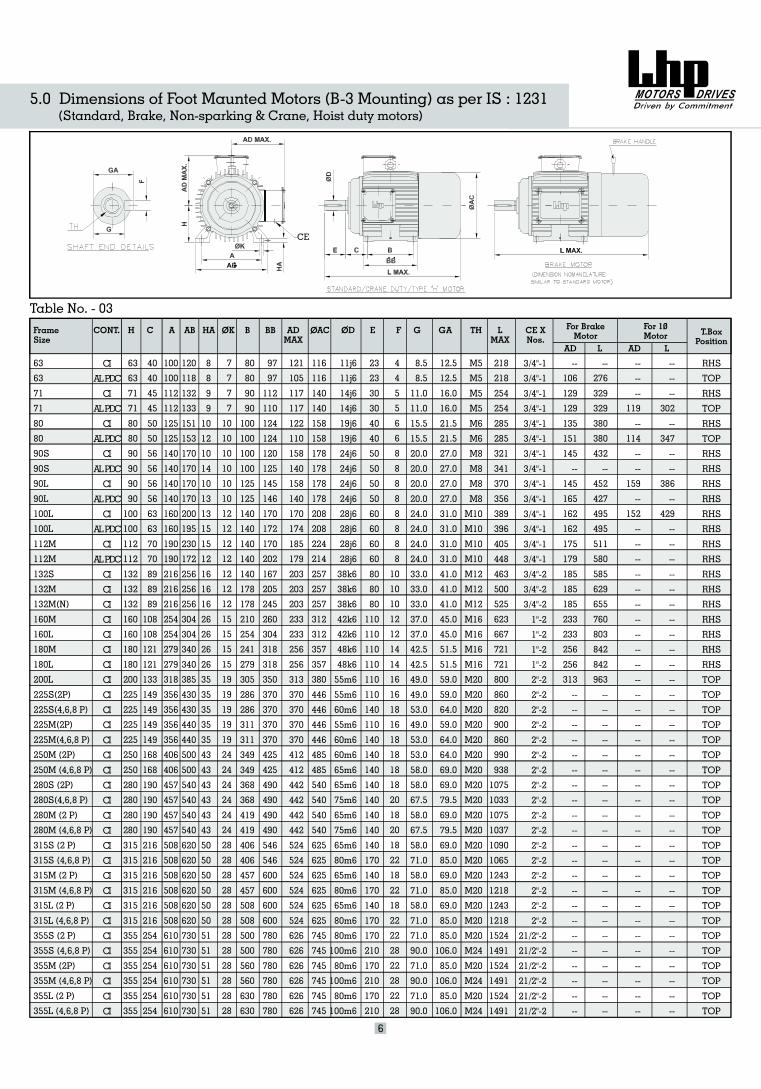
FrameSize
HCONT. C A AB HA OK B BB ADMAX
OAC OD E F G GA TH LMAX
CE XNos.
For BrakeMotor T.Box
Position
63
63
71
71
80
80
90
90
90
90
100
100
112
112
132
132
132
160
160
180
180
200
225
225
225
225
250
250
280
280
280
280
315
315
315
315
315
315
355
355
355
355
355
355
CI
ALPDC
CI
ALPDC
CI
ALPDC
CI
ALPDC
CI
ALPDC
CI
ALPDC
CI
ALPDC
CI
CI
CI
CI
CI
CI
CI
CI
CI
CI
CI
CI
CI
CI
CI
CI
CI
CI
CI
CI
CI
CI
CI
CI
CI
CI
CI
CI
CI
CI
40
40
45
45
50
50
56
56
56
56
63
63
70
70
89
89
89
108
108
121
121
133
149
149
149
149
168
168
190
190
190
190
216
216
216
216
216
216
254
254
254
254
254
254
100
100
112
112
125
125
140
140
140
140
160
160
190
190
216
216
216
254
254
279
279
318
356
356
356
356
406
406
457
457
457
457
508
508
508
508
508
508
610
610
610
610
610
610
120
118
132
133
151
153
170
170
170
170
200
195
230
172
256
256
256
304
304
340
340
385
430
430
440
440
500
500
540
540
540
540
620
620
620
620
620
620
730
730
730
730
730
730
8
8
9
9
10
12
10
14
10
13
13
15
15
12
16
16
16
26
26
26
26
35
35
35
35
35
43
43
43
43
43
43
50
50
50
50
50
50
51
51
51
51
51
51
7
7
7
7
10
10
10
10
10
10
12
12
12
12
12
12
12
15
15
15
15
19
19
19
19
19
24
24
24
24
24
24
28
28
28
28
28
28
28
28
28
28
28
28
80
80
90
90
100
100
100
100
125
125
140
140
140
140
140
178
178
210
254
241
279
305
286
286
311
311
349
349
368
368
419
419
406
406
457
457
508
508
500
500
560
560
630
630
97
97
112
110
124
124
120
125
145
146
170
172
170
202
167
205
245
260
304
318
318
350
370
370
370
370
425
425
490
490
490
490
546
546
600
600
600
600
780
780
780
780
780
780
121
105
117
117
122
110
158
140
158
140
170
174
185
179
203
203
203
233
233
256
256
313
370
370
370
370
412
412
442
442
442
442
524
524
524
524
524
524
626
626
626
626
626
626
116
116
140
140
158
158
178
178
178
178
208
208
224
214
257
257
257
312
312
357
357
380
446
446
446
446
485
485
540
540
540
540
625
625
625
625
625
625
745
745
745
745
745
745
11j6
14j6
19j6
24j6
28j6
38k6
42
48
55m6
60
65
80
65
80
80
0
11j6
14j6
19j6
24j6
24j6
24j6
28j6
28j6
28j6
38k6
38k6
k6
42k6
k6
48k6
55m6
m6
55m6
60m6
60m6
65m6
65m6
75m6
65m6
75m6
65m6
80m6
m6
m6
m6
m6
80m6
100m6
m6
10 m6
80m6
100m6
23
23
30
30
40
40
50
50
50
50
60
60
60
60
80
80
80
110
110
110
110
110
110
140
110
140
140
140
140
140
140
140
140
170
140
170
140
170
170
210
170
210
170
210
4
4
5
5
6
6
8
8
8
8
8
8
8
8
10
10
10
12
12
14
14
16
16
18
16
18
18
18
18
20
18
20
18
22
18
22
18
22
22
28
22
28
22
28
8.5
11.0
15.5
20.0
20.0
24.0
24.0
33.0
33.0
37.0
37.0
42.5
42.5
49.0
49.0
53.0
49.0
53.0
53.0
58.0
58.0
67.5
58.0
7.5
58.0
71.0
58.0
71.0
58.0
71.0
71.0
90.0
71.0
90.0
71.0
90.0
8.5
11.0
15.5
20.0
20.0
24.0
24.0
33.0
6
12.5
16.0
21.5
27.0
27.0
31.0
31.0
41.0
41.0
45.0
45.0
51.5
51.5
59.0
59.0
64.0
59.0
64.0
.0
79.5
69.0
85.0
69.0
85.0
106.0
85.0
106.0
85.0
106.0
12.5
16.0
21.5
27.0
27.0
31.0
31.0
41.0
64.0
69.0
69
79.5
69.0
69.0
85.0
85.0
M5
5
6
8
8
10
10
12
12
16
16
16
16
20
20
20
20
20
20
20
20
20
20
20
20
20
20
20
20
20
20
24
20
24
20
24
M
M5
M5
M
M6
M
M
M8
M8
M
M
M10
M10
M
M
M12
M
M
M
M
M
M
M
M
M
M
M
M
M
M
M
M
M
M
M
M
M
M
M
M
M
M
M
218
254
285
341
356
396
448
500
623
667
721
721
800
218
254
285
321
370
389
405
463
525
860
820
900
860
990
938
1075
1033
1075
1037
1090
1065
1243
1218
1243
1218
1524
1491
1524
1491
1524
1491
3/4"-1
3/4"-1
3/4"-1
3/4"-1
3/4"-1
3/4"-1
3/4"-1
3/4"-1
3/4"-1
3/4"-1
3/4"-1
3/4"-1
3/4"-1
3/4"-1
3/4"-2
3/4"-2
3/4"-2
1"-2
1"-2
1"-2
1"-2
2"-2
2"-2
2"-2
2"-2
2"-2
2"-2
2"-2
2"-2
2"-2
2"-2
2"-2
2"-2
2"-2
2"-2
2"-2
2"-2
2"-2
21/2"-2
21/2"-2
21/2"-2
21/2"-2
21/2"-2
21/2"-2
--
276
329
329
380
380
432
--
452
427
495
495
511
580
629
655
760
803
842
842
963
--
585
--
--
--
--
--
--
--
--
--
--
--
--
--
--
--
--
--
--
--
--
--
RHS
RHS
RHS
RHS
RHS
RHS
RHS
RHS
RHS
TOP
TOP
TOP
TOP
TOP
TOP
TOP
TOP
TOP
TOP
TOP
TOP
TOP
TOP
TOP
TOP
TOP
TOP
TOP
TOP
TOP
TOP
TOP
TOP
RHS
TOP
RHS
RHS
RHS
RHS
RHS
RHS
RHS
RHS
TOP
63
63
71
71
80
80
90S
90S
90L
90L
100L
100L
112M
112M
132S
132M
132M(N)
160M
160L
180M
180L
200L
225S(2P)
225S(4,6,8 P)
225M(2P)
225M(4,6,8 P)
250M (2P)
250M (4,6,8 P)
280S (2P)
280S(4,6,8 P)
280M (2 P)
280M (4,6,8 P)
315S (2 P)
315S (4,6,8 P)
315M (2 P)
315M (4,6,8 P)
315L (2 P)
315L (4,6,8 P)
355S (2 P)
355S (4,6,8 P)
355M (2P)
355M (4,6,8 P)
355L (2 P)
355L (4,6,8 P)
Table No. - 03For 10Motor
5.0 Dimensions of Foot Maunted Motors (B-3 Mounting) as per IS : 1231(Standard, Brake, Non-sparking & Crane, Hoist duty motors)
6
LAD
--
106
129
129
135
151
145
--
145
165
162
162
175
179
233
233
256
256
313
--
185
185
185
--
--
--
--
--
--
--
--
--
--
--
--
--
--
--
--
--
--
--
--
--
--
--
--
302
--
347
--
--
386
--
429
--
--
--
--
--
--
--
--
--
--
--
--
--
--
--
--
--
--
--
--
--
--
--
--
--
--
--
--
--
--
--
--
--
LAD
--
--
--
119
--
114
--
--
159
--
152
--
--
--
--
--
--
--
--
--
--
--
--
--
--
--
--
--
--
--
--
--
--
--
--
--
--
--
--
--
--
--
--
--
CE
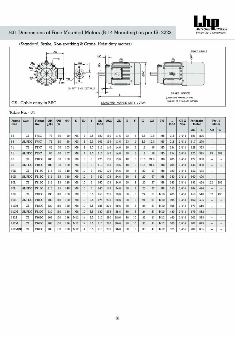
FrameSize
FlangeNo.
F
F
F
F1
75C
F75C
85C
F85C
100C
F100C
15C
F115C
F115C
F115C
F130C
F130C
F130C
F130C
F165C
F165C
F165C
75
75
85
85
100
100
115
115
115
115
130
130
130
130
165
165
165
60
60
70
70
80
80
95
95
95
95
110
110
110
110
130
130
130
90
90
105
107
120
120
140
140
140
140
160
160
160
160
196
196
196
M5
M6
M6
M8
M8
M8
M8
M12
M12
M5
M6
M6
M8
M8
M8
M8
M12
6
6
8
8
8
8
10
10
10
10
10
10
10
10
14
14
14
2.5
2.5
2.5
2.5
3
3
3
3
3
3
3.5
3.5
3.5
3.5
3.5
3.5
3.5
120
105
115
115
125
110
160
140
160
140
158
175
185
180
210
210
210
116
116
140
140
158
158
178
178
178
178
208
208
225
215
260
260
260
11j6
14j6
19j6
24j6
24j6
28j6
28j6
38k6
38k6
11j6
14j6
19j6
24j6
24j6
28j6
28j6
38k6
23
23
30
30
40
40
50
50
50
50
60
60
60
60
80
80
80
4
4
5
5
6
6
8
8
8
8
8
8
8
8
10
10
10
8.5
8.5
11
11
15.5
15.5
20
20
20
20
24
24
24
24
33
33
33
12.5
12.5
16
16
21.5
21.5
27
27
27
27
31
31
31
31
41
41
41
M5
M5
M6
M8
M8
M10
M10
M12
M12
M5
M5
M6
M8
M8
M10
M10
M12
218
218
254
254
285
285
320
340
345
355
405
395
405
430
460
500
525
3/4"-1
3/4"-1
3/4"-1
3/4"-1
3/4"-1
3/4"-1
3/4"-1
3/4"-1
3/4"-1
3/4"-1
3/4"-1
3/4"-1
3/4"-1
3/4"-1
3/4"-2
3/4"-2
3/4"-2
276
276
325
325
380
380
435
426
454
424
510
495
510
562
585
629
655
121
117
129
125
127
146
152
160
152
164
158
162
171
179
202
202
202
63
63
71
71
80
80
90S
90S
90L
90L
100L
100L
112M
112M
132S
132M
132M(N)
Table No. - 04
j6ON TD T AD
MAXOACOM
0.3OD E F G GA TH L
MAXCE XNos.
For BrakeMotor
L
--
--
--
119
--
--
--
--
152
--
152
--
--
--
--
--
--
OP
--
--
--
302
--
--
--
--
395
--
435
--
--
--
--
--
--
S
AD L
For 10Motor
6.0 Dimensions of Face Mounted Motors (B-14 Mounting) as per IS: 2223
(Standard, Brake, Non-sparking & Crane, Hoist duty motors)
AD
TH
GA
G
G
TD
ET
L
7
AD
Cont.
CI
AL.PDC
CI
AL.PDC
CI
AL.PDC
CI
AL.PDC
CI
AL.PDC
CI
AL.PDC
CI
AL.PDC
CI
CI
CI
CE - Cable entry in BSC
CE
S
1/2
1/2
Table No. - 05
FrameSize
FlangeNo.
F115B
F115B
F130B
F130B
F165B
F165B
F165B
F165B
F165B
F165B
F215B
F215B
F215B
F215B
F265B
F265B
F265B
F300B
F300B
F300B
F350B
F400B
F400B
F500B
F500B
F500B
F500B
F600B
F600B
F740B
F740B
115
115
130
130
165
165
165
165
165
165
215
215
215
215
265
265
265
300
300
300
350
400
400
500
500
500
500
600
600
740
740
95
95
110
110
130
130
130
130
130
130
180
180
180
180
230
230
230
250
250
250
300
350
350
450
450
450
450
550
550
680
680
140
140
160
160
200
200
200
200
200
200
250
250
250
250
300
300
300
350
350
350
400
450
450
550
550
550
550
660
660
800
800
10 X 4
10 X 4
10 X 4
10 X 4
12 X 4
12 X 4
12 X 4
12 X 4
12 X 4
12 X 4
15 X 4
15 X 4
15 X 4
15 X 4
15 X 4
15 X 4
15 X 4
19 X 4
19 X 4
19 X 4
19 X 8
19 X 8
19 X 8
19 X 8
19 X 8
19 X 8
19 X 8
24 X 8
24 X 8
24 X 8
24 X 8
3
3
3.5
3.5
3.5
3.5
3.5
3.5
3.5
3.5
4
4
4
4
4
4
4
5
5
5
5
5
5
5
5
5
5
6
6
6
6
10
10
10
10
11
11
11
11
11
11
12
12
12
12
13
13
13
14
14
14
16
16
16
19
19
22
22
22
22
25
25
10
10
10
20
16
16
22
22
22
22
20
22
23
18
47
47
47
54
54
72
71
71
71
65
65
50
50
50
50
45
45
120
105
115
115
125
110
160
160
160
160
158
175
185
180
210
210
210
230
230
255
340
375
375
410
410
430
430
520
520
625
625
116
116
140
140
158
158
178
178
178
178
208
208
225
215
260
260
260
312
312
360
382
445
445
485
485
540
540
625
625
745
745
11j6
11j6
14j6
14j6
19j6
19j6
24j6
24j6
24j6
24j6
28j6
28j6
28j6
28j6
38k6
38k6
38k6
42k6
42k6
48k6
55m6
55m6
60m6
60m6
65m6
65m6
75m6
65m6
80m6
80m6
100m6
23
23
30
30
40
40
50
50
50
50
60
60
60
60
80
80
80
110
110
110
110
110
140
140
140
140
140
140
170
170
210
4
4
5
5
6
6
8
8
8
8
8
8
8
8
10
10
10
12
12
14
16
16
18
18
18
18
20
18
22
22
28
8.5
8.5
11
11
15.5
15.5
20
20
20
20
24
24
24
24
33
33
33
37
37
42.5
49
49
53
53
58
58
67.5
58
71
71
90
12.5
12.5
16
16
21.5
21.5
27
27
27
27
31
31
31
31
41
41
41
45
45
51.5
59
59
64
64
69
69
79.5
69
85
85
106
M5
M5
M5
M5
M6
M6
M8
M8
M8
M8
M10
M10
M10
M10
M12
M12
M12
M16
M16
M16
M20
M20
M20
M20
M20
M20
M20
M20
M20
M20
M24
3/4"-1
3/4"-1
3/4"-1
3/4"-1
3/4"-1
3/4"-1
3/4"-1
3/4"-1
3/4"-1
3/4"-1
3/4"-1
3/4"-1
3/4"-1
3/4"-1
3/4"-2
3/4"-2
3/4"-2
1"-2
1"-2
1"-2
2"-2
2"-2
2"-2
2"-2
2"-2
2"-2
2"-2
2"-2
2"-2
2 -2
2 -2
---
---
---
119
----
---
---
152
---
152
---
---
---
---
---
114
---
---
---
---
---
---
---
---
---
---
---
---
---
---
---
276
276
325
325
380
380
435
426
456
424
497
497
510
553
629
760
803
725
--
585
655
--
--
--
--
--
--
--
--
--
--
63
71
80
90S
90L
100L
112M
132S
132M
132M (N)
63
71
80
90S
90L
100L
112M
160M
160L
180M/L
200L
225S/M (2P)
225S/M (4,6,8P)
250M (2P)
250M (4,6,8P)
280S/M (2P)
280S/M (4,6,8P)
315S/M/L (2P)
315S/M/L (4,6,8P)
355S/M/L (2P)
355S/M/L (4,6,8P)
j6 T LA LD ADMAX
OM OD E F G GA TH CEXNos.
For SinglePhaseMotor
ForBrakeMotor
ADL LAD
---
---
---
302
---
348
---
---
395
---
435
---
---
---
---
---
---
---
---
---
---
---
---
---
---
---
---
---
---
---
---
121
117
129
125
127
146
152
160
152
164
158
162
189
179
202
202
202
233
233
835
--
--
--
--
--
--
--
--
--
--
--
OP
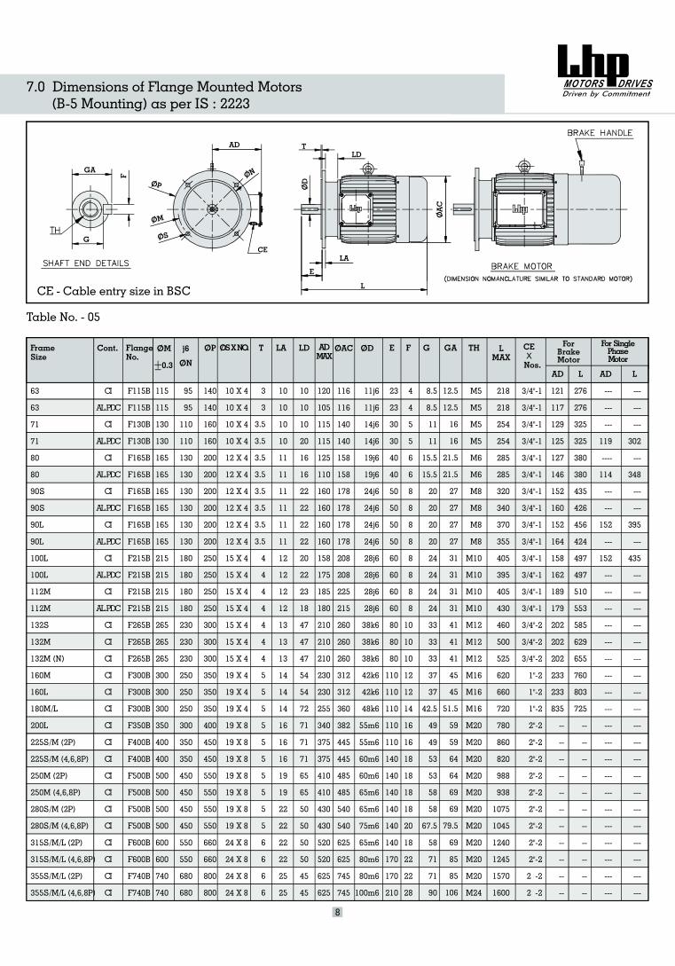
7.0 Dimensions of Flange Mounted Motors(B-5 Mounting) as per IS : 2223
GA
G
AD TLD
LA
L
E
8
Cont.
CI
AL.PDC
CI
AL.PDC
CI
AL.PDC
CI
AL.PDC
CI
AL.PDC
CI
AL.PDC
CI
AL.PDC
CI
CI
CI
CI
CI
CI
CI
CI
CI
CI
CI
CI
CI
CI
CI
CI
CI
OSXNO. OAC
218
218
254
254
285
285
320
340
370
355
405
395
405
430
460
500
525
620
660
720
780
860
820
988
938
1075
1045
1240
1245
1570
1600
LMAX
0.3 ON
CE - Cable entry size in BSC
CE
Frame Size
63
71
80
90
100
112
132
160
180
200
225
250
280
315
355
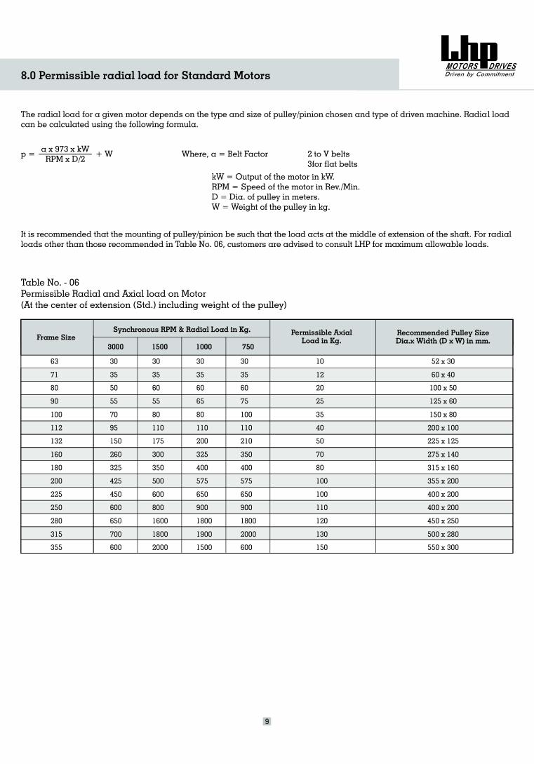
Table No. - 06Permissible Radial and Axial load on Motor(At the center of extension (Std.) including weight of the pulley)
The radial load for a given motor depends on the type and size of pulley/pinion chosen and type of driven machine. Radial loadcan be calculated using the following formula.
p = a x 973 x kWRPM x D/2
+ W Where, a = Belt Factor 2 to V belts3for flat belts
kW = Output of the motor in kW.RPM = Speed of the motor in Rev./Min.D = Dia. of pulley in meters.W = Weight of the pulley in kg.
It is recommended that the mounting of pulley/pinion be such that the load acts at the middle of extension of the shaft. For radialloads other than those recommended in Table No. 06, customers are advised to consult LHP for maximum allowable loads.
30
35
50
55
70
95
150
260
325
425
450
600
650
700
600
30
35
60
55
80
110
175
300
350
500
600
800
1600
1800
2000
30
35
60
65
80
110
200
325
400
575
650
900
1800
1900
1500
30
35
60
75
100
110
210
350
400
575
650
900
1800
2000
600
10
12
20
25
35
40
50
70
80
100
100
110
120
130
150
52 x 30
60 x 40
100 x 50
125 x 60
150 x 80
200 x 100
225 x 125
275 x 140
315 x 160
355 x 200
400 x 200
400 x 200
450 x 250
500 x 280
550 x 300
Synchronous RPM & Radial Load in Kg.
3000 1500 1000 750
Permissible AxialLoad in Kg.
Recommended Pulley SizeDia.x Width (D x W) in mm.
8.0 Permissible radial load for Standard Motors
9
Sr. No. Features
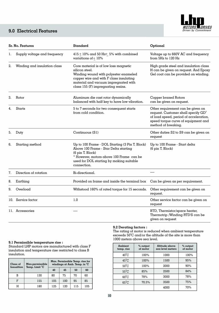
9.0 Electrical Features
Standard Optional
1. Supply voltage and frequency 415 _ 10% and 50 Hz _ 5% with combinedvariations of _ 10%
+ ++
Voltage up to 660V AC and frequencyfrom 5Hz to 120 Hz
2. Winding and insulation class Core material is of low loss magneticsilicon steel.Winding wound with polyester enameledcopper wire and with F class insulatingmaterial and vacuum impregnated withclass 155 (F) impregnating resins.
High grade steel and insulation classH can be given on request. And EpoxyGel coat can be provided on winding.
3. Rotor Aluminum die cast rotor dynamicallybalanced with half key to have low vibration.
Copper brazed Rotorscan be given on request.
4. Starts 5 to 7 seconds for two consequent startsfrom cold condition.
Other requirement can be given onrequest. Customer shall specify GD
speed, period of acceleration,speed torque curve of equipment andmethod of breaking.
2
of load
5. Duty Continuous (S1) Other duties S2 to S9 can be given onrequest
6. Starting method Up to 100 Frame - DOL Starting (3 Pin T. Block)Above 100 Frame - Star Delta starting(6 pin T. Block)* However, motors above 100 Frame can beused for DOL starting by making suitableconnection.
Up to 100 Frame - Start delta(6 pin T. Block)
7. Direction of rotation Bi-directional. ----
8. Earthing Provided on frame and inside the terminal box Can be given as per requirement.
9. Overload Withstood 160% of rated torque for 15 seconds. Other requirement can be given onrequest.
10. Service factor 1.0 Other service factor can be given onrequest
11. Accessories ---- BTD, Thermistor/space heater,Thermotrip /Winding RTD'S can begiven on request
9.1 Permissible temperature rise :Standard LHP motors are manufactured with class Finsulation and temperature rise restricted to class Binsulation.
9.2 Derating factors :The rating of motor is reduced when ambient temperatureexceeds 50 C and/or the altitude of the site is more than1000 meters above sea level.
0
Class ofInsualtion
B
F
H
130
155
180
80
105
125
75
100
120
70
95
115
60
85
105
40 45 50
Max.permissibleTemp. Limit C0
Max. Permissible Temp. rise forwindings at Amb. Temp. in C0
60
Ambienttemp. rise
% outputof motor
Altitude abovesea level meters
% outputof motor
10
40
45
50
0
0
0
0
0
0
C
C
C
55 C
60 C
65 C
100%
100%
100%
85%
78%
70.5%
1000
00
000
00
15
2
25
3000
3500
4000
100%
95%
90%
84%
78%
75%
70%
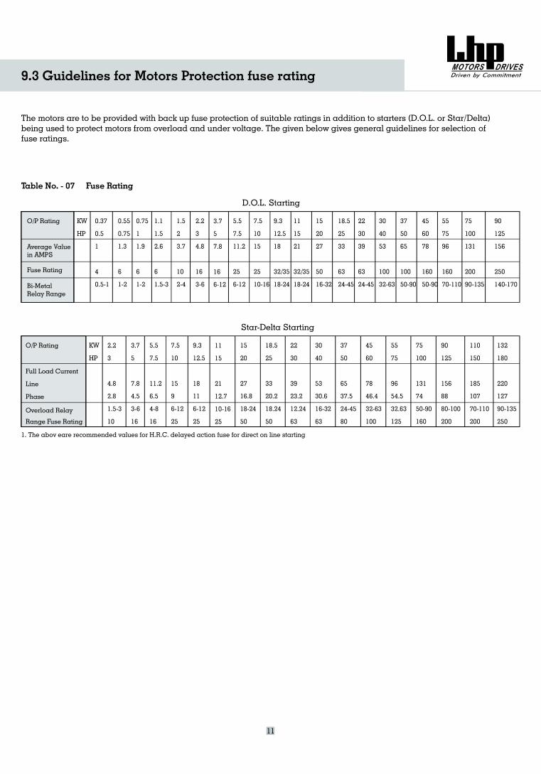
9.3 Guidelines for Motors Protection fuse rating
The motors are to be provided with back up fuse protection of suitable ratings in addition to starters (D.O.L. or Star/Delta)being used to protect motors from overload and under voltage. The given below gives general guidelines for selection offuse ratings.
Table No. - 07 Fuse Rating
D.O.L. Starting
O/P Rating
Average Valuein AMPS
Fuse Rating
Bi-MetalRelay Range
KW
HP
0.37
0.5
1
4
0.5-1
0.55
0.75
1.3
6
1-2
0.75
1
1.9
6
1-2
1.1
1.5
2.6
6
1.5-3
2.2
3
4.8
16
3-6
3.7
5
7.8
16
6-12
7.5
10
15
25
10-16
9.3
12.5
18
32/35
18-24
11
15
21
32/35
18-24
15
20
27
50
16-32
18.5
25
33
63
24-45
22
30
39
63
24-45
30
40
53
100
32-63
37
50
65
100
50-90
45
60
78
160
50-90
55
75
96
160
70-110
75
100
131
200
90-135
90
125
156
250
140-170
5.5
7.5
11.2
25
6-12
Star-Delta Starting
O/P Rating
Full Load Current
Line
Phase
Overload Relay
Range Fuse Rating
KW
HP
2.2
3
4.8
2.8
1.5-3
10
3.7
5
7.8
4.5
3-6
16
5.5
7.5
11.2
6.5
4-8
16
7.5
10
15
9
6-12
25
9.3
12.5
18
11
6-12
25
11
15
21
12.7
10-16
25
18.5
25
33
20.2
18.24
50
22
30
39
23.2
12.24
63
30
40
53
30.6
16-32
63
37
50
65
37.5
24-45
80
45
60
78
46.4
32-63
100
55
75
96
54.5
32.63
125
75
100
131
74
50-90
160
90
125
156
88
80-100
200
110
150
185
107
70-110
200
132
180
220
127
90-135
250
15
20
27
16.8
18-24
50
1. The abov eare recommended values for H.R.C. delayed action fuse for direct on line starting
11
1.5
2
3.7
10
2-4
Rated Output FrameSize
0.25
0.33
0.33
0.5
0.75
1
1.5
2
3
5
7.5
7.5
10
12.5
15
20
25
30
40
50
60
75
100
120
150
170
180
215
240
270
335
425
63
71
71
80
90
90L
100L
112M
132S
132S
132M
1 M
160M
160
1 0
200L
25 M
2 0
280
315
315M
315L
315L
355L
355L
63
71
80
S
60
L
8 M
200L
225M
0
8 S
M
315S
M
315L
0.58
0.7
0.65
0.95
1.31
1.65
2.4
3.1
4.4
7.1
10.4
10.1
13.7
16.5
19.5
26
32
37
51
62.5
75
90
125
148
181
205
217
258
288
322
398
502
2730
2820
2820
2800
2820
2800
2860
2860
2830
2880
2900
2900
2900
2920
2920
2940
2930
2940
2930
2955
2950
2960
2970
2970
2980
2970
2970
2980
2980
2980
2982
2982
0.06
0.09
0.09
0.13
0.19
0.26
0.38
0.51
0.75
1.25
1.85
1.84
2.52
3.13
3.67
4.97
6.15
7.29
9.97
12.20
14.86
18.10
24.60
29.52
35.95
40.99
43.29
52.30
58.83
65.37
81.66
102.89
400
430
430
450
500
600
600
600
650
600
650
650
650
650
650
650
650
650
650
650
650
650
650
650
650
650
650
650
650
700
700
700
220
220
220
230
230
240
240
240
240
220
220
200
200
210
200
200
200
230
220
250
200
210
190
190
180
180
180
180
180
180
160
160
300
300
320
300
300
320
320
300
300
300
280
250
250
280
280
280
280
300
300
300
250
270
270
270
270
270
270
270
270
270
280
280
64
66
68
71
74
77
79
80
81.5
84.5
86
86
87
88
89
89.5
90
91
91.5
92.5
92.5
93.3
93.6
94
94
94.5
94.5
95
95
95.5
95.5
95.5
62
62
67
68
68
75
78
79
80
83
85
86
87
87
88
89
90
90
91.5
92
92
92.7
93.3
93.5
94
94.5
94.5
94.5
94.5
95.5
95
95.5
56
58
62
62
64
70
76
76
78
78
82
83
85
84
86
87.5
88
88
90
90
90
91
92
91.5
93
93.5
93
93
93
94
94
94
0.68
0.75
0.77
0.76
0.79
0.82
0.81
0.84
0.85
0.85
0.86
0.89
0.88
0.89
0.88
0.90
0.89
0.91
0.90
0.89
0.90
0.91
0.89
0.90
0.90
0.90
0.90
0.91
0.92
0.91
0.92
0.92
0.65
0.66
0.70
0.64
0.70
0.74
0.76
0.81
0.82
0.81
0.82
0.85
0.84
0.85
0.87
0.88
0.87
0.88
0.88
0.88
0.88
0.90
0.86
0.86
0.87
0.87
0.87
0.88
0.90
0.88
0.89
0.89
0.54
0.54
0.60
0.58
0.65
0.68
0.70
0.75
0.75
0.74
0.78
0.78
0.76
0.79
0.82
0.85
0.84
0.82
0.86
0.86
0.86
0.86
0.77
0.78
0.77
0.77
0.78
0.83
0.88
0.83
0.84
0.84
0.0009
0.0009
0.0015
0.0015
0.0021
0.0036
0.0036
0.0073
0.0089
0.022
0.028
0.052
0.068
0.08
0.17
0.22
0.28
0.42
0.64
0.75
0.91
1.80
6.63
8.18
11.55
12.70
13.89
14.30
15.96
18.87
23.40
29.70
4.5/7
4.5/7.5
5/10
6.2/10
6.2/10
7.2/11
10.5/16
13.5/22
17/25
27/38
35/47
63
70
77
119
137
143
174
254
280
378
525
703
741
1031
1070
1086
1150
1195
1255
2605
2685
0.18
0.25
0.25
0.37
0.55
0.75
1.1
1.5
2.2
3.7
5.5
5.5
7.5
9.3
11
15
18.5
22
*30
37
45
55
75
90
*110
125
*132
*160
180
200
250
315
kW HP
RatedCurrentAmps
RatedSpeedRPM
RatedTorquekgm
StartingCurrent% ofRatedCurrent
StartingTorque% ofRatedTorque
PeakTorque% ofRatedTorque
Approx.Net
Weightkg
Rotor
GDkg m sq
2
Efficiency %
100% 75% 50% 100% 75% 50%
Power Factor
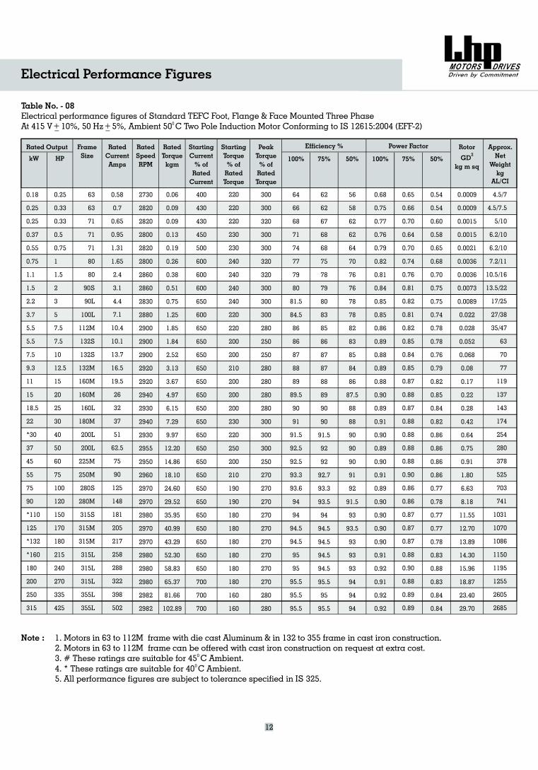
Table No. - 08Electrical performance figures of Standard TEFC Foot, Flange & Face Mounted Three PhaseAt 415 V _ 10%, 50 Hz _ 5%, Two Pole Induction MotorAmbient 50 C Conforming to IS 12615:2004 (EFF-2)0+ +
Electrical Performance Figures
12
AL/CI
Note : 1. Motors in 63 to 112M frame with die cast Aluminum & in 132 to 355 frame in cast iron construction.2. Motors in 63 to 112M can be offered with cast iron construction on request at extra cost.3. # These ratings are suitable for 45
frameC Ambient.
4. * These ratings are suitable for 40 C Ambient.5. All performance figures are subject to tolerance specified in IS 325.
0
0
Rated Output FrameSize
0.16
0.25
0.33
0.5
0.75
1
1.5
2
3
4
5
7.5
10
12.5
15
20
25
30
40
50
60
75
100
120
150
180
215
240
270
300
335
425
63
71
71
80
80
90S
90L
100L
112M
132S
132M
1 M
160M
160L
180M
200L
225M
250M
280S
280M
315S
315L
315L
355L
355L
63
100L
60
180L
225S
315M
315L
355L
0.09
0.13
0.17
0.26
0.38
0.52
0.76
1.04
1.50
2.06
2.52
3.69
5.04
6.25
7.39
9.97
12.30
14.63
19.95
24.60
29.82
36.32
49.36
59.23
72.15
86.58
104.59
117.66
130.74
147.08
163.42
205.91
300
310
450
450
430
450
550
550
590
550
580
600
600
600
500
600
600
600
600
600
600
600
600
600
600
600
600
600
600
650
650
650
200
210
200
200
200
200
200
200
200
200
200
200
200
200
200
220
250
250
250
230
200
200
200
190
190
200
200
200
200
180
160
170
280
280
260
260
250
240
260
250
250
250
250
260
250
250
250
270
270
270
270
280
250
250
250
240
240
250
250
250
250
230
230
230
58
64
68
71
74
77
78
79
82
82.5
85
86
87
88
89
90
91.1
91.8
92
92.5
93
93.5
94
94.5
94.5
94.8
95.3
95.3
95.5
95.5
95.6
96
45
52
60
65
70
72
73
75
79
80
83
83
84
87
86
88
90
90
90
91.3
91
92
92.5
92.6
92
94
94
94
94
94
94.5
94.4
0.72
0.69
0.73
0.69
0.74
0.78
0.79
0.79
0.78
0.82
0.82
0.85
0.83
0.84
0.82
0.84
0.85
0.83
0.87
0.86
0.88
0.87
0.89
0.88
0.86
0.88
0.87
0.87
0.86
0.87
0.88
0.88
0.65
0.63
0.65
0.61
0.63
0.72
0.71
0.73
0.72
0.78
0.80
0.80
0.77
0.79
0.80
0.82
0.82
0.82
0.85
0.84
0.85
0.85
0.88
0.83
0.83
0.84
0.82
0.83
0.82
0.84
0.86
0.86
0.50
0.50
0.55
0.50
0.52
0.58
0.58
0.60
0.60
0.70
0.65
0.67
0.65
0.70
0.74
0.76
0,72
0.78
0.78
0.78
0.80
0.80
0.83
0.81
0.78
0.78
0.76
0.75
0.74
0.79
0.80
0.80
0.0014
0.0014
0.0034
0.0034
0.0077
0.0086
0.014
0.015
0.029
0.038
0.057
0.093
0.12
0.17
0.20
0.26
0.66
0.84
1.19
1.46
1.71
3.20
7.21
8.25
11.62
13.98
27.88
29.30
30.74
34.10
38.10
48.30
5/7.5
4.5/7
8/11
7.3/10
10/15
11/16
13/22
17/25
21/32
28/38
34/44
70
73
105
112
137
173
193
264
235
335
523
696
749
1060
1137
1225
1290
1392
2615
2650
2695
0.12
0.18
0.25
0.37
0.55
0.75
1.1
1.5
2.2
3.0
3.7
#5.5
7.5
#9.3
11
15
18.5
22
30
37
#45
55
75
#90
110
#132
#160
180
200
225
250
315
kW HP
RatedCurrentAmps
RatedSpeedRPM
RatedTorquekgm
StartingCurrent% ofRatedCurrent
StartingTorque% ofRatedTorque
PeakTorque% ofRatedTorque
Approx.Net
Weightkg
AL/CI
Rotor
GDkg m sq
2
Efficiency %
100% 75% 50% 100% 75% 50%
Power Factor
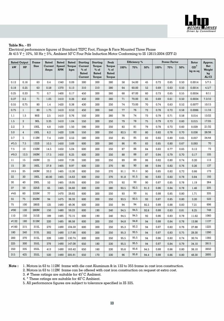
Table No. - 09Electrical performance figures of Standard TEFC Foot, Flange & Face Mounted Three PhaseAt 415 V _ 10%, 50 Hz _ 5%, Four Pole Induction MotorAmbient 50 C Conforming to IS 12615:2004 (EFF-2)0+ +
54.00
60.00
67.00
70.00
73.00
76
74
78
81
82
85
85
86
88
89
90
91.1
91.5
92
92.5
93
93.5
94
94.5
94.5
94.8
95.2
92.5
95.5
95.5
95.6
95.8
13
Note : 1. Motors in 63 to 112M frame with die cast Aluminum & in 132 to 355 frame in cast iron construction.2. Motors in 63 to 112M can be offered with cast iron construction on request at extra cost.3. # These ratings are suitable for 45
5.
frameC Ambient.
4. * These ratings are suitable for 40 C Ambient.All performance figures are subject to tolerance specified in IS 325.
0
0
0.4
0.58
0.7
1.05
1.4
1.75
2.5
3.35
4.8
6.2
7.4
10.5
14.5
17.5
21
27.8
33.2
40.00
52
65
77
94
125
150
189
220
270
302
339
378
413
520
1340
1370
1400
1410
1420
1410
1410
1410
1430
1420
1430
1450
1450
1450
1450
1465
1465
1465
1465
1465
1470
1475
1480
1480
1485
1485
1490
1490
1490
1490
1490
1490
Rated Output FrameSizekW HP
RatedCurrentAmps
RatedSpeedRPM
RatedTorquekgm
StartingCurrent% ofRatedCurrent
Starting
% ofRatedTorque
TorquePeakTorque% ofRatedTorque
Approx.Net
Weightkg
Al/CI
RotorGD
kg m sq
Efficiency %
100% 75% 50% 100% 75% 50%
Power Factor
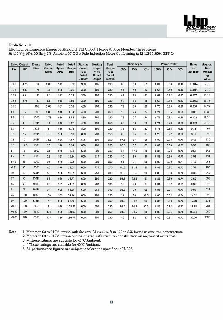
Table No. - 10Electrical performance figures of Standard TEFC Foot, Flange & Face Mounted Three PhaseAt 415 V _ 10%, 50 Hz _ 5%, Six Pole Induction MotorAmbient 50 C Conforming to IS 12615:2004 (EFF-2)0+ +
14
0.18
0.25
0.37
0.55
0.75
1.1
1.5
2.2
3.7
5.5
7.5
9.3
11
15
18.5
# 22
30
37
45
55
75
90
#110
#132
#200
0.25
0.33
0.5
0.75
1
1.5
2
3
5
7.5
10
12.5
15
20
25
30
40
50
60
75
100
120
150
180
270
230
240
240
250
260
260
250
250
250
250
250
250
250
260
260
270
280
240
300
300
250
250
250
250
230
71
71
80
80
90S
90L
100L
112M
132S
132M
160M
160L
160L
180L
200L
200L
225M
250M
280S
280M
315S
315M
315L
315L
355L
0.68
0.9
1.1
1.6
2.05
2.85
3.75
5.2
8
11.5
14.5
18
21
28
34
40
53
66
80
97
130
157
191
226
343
915
920
915
915
955
940
950
945
960
960
965
970
970
965
970
970
980
980
982
982
985
990
990
990
990
0.19
0.26
0.39
0.59
0.76
1.14
1.54
2.27
3.75
5.58
7.57
9.34
11.05
15.14
18.58
22.09
29.82
36.77
44.63
54.55
74.16
88.55
108.22
129.87
196.77
350
300
300
320
400
400
450
400
500
600
575
600
600
600
600
600
600
600
600
600
600
600
600
600
650
185
190
190
190
200
200
190
190
190
200
190
200
200
210
230
220
250
190
260
260
200
200
200
200
190
60
61
68
69
73
76
78
80
85
85
87.5
87.5
88
90
91
91.3
91.8
92.5
93
93.5
94
94.2
94.5
94.8
95
55
52
63
66
69
74
74
75
82
81
85
85
86
88
90
89
90
91
91
92
92.5
92
92.5
93
91
0.61
0.63
0.69
0.69
0.70
0.71
0.71
0.74
0.76
0.78
0.82
0.82
0.83
0.83
0.83
0.84
0.86
0.84
0.84
0.84
0.85
0.85
0.85
0.86
0.85
0.58
0.50
0.62
0.62
0.66
0.65
0.66
0.70
0.65
0.72
0.78
0.80
0.78
0.80
0.80
0.82
0.83
0.80
0.82
0.81
0.82
0.82
0.82
0.84
0.81
0.48
0.40
0.55
0.53
0.60
0.58
0.58
0.62
0.50
0.68
0.70
0.72
0.70
0.70
0.74
0.72
0.76
0.74
0.73
0.73
0.74
0.70
0.72
0.75
0.72
0.0044
0.0044
0.007
0.0093
0.016
0.02
0.032
0.072
0.13
0.17
0.43
0.58
0.66
1.03
1.43
1.57
2.30
3.60
8.01
9.89
14.12
17.00
18.98
29.94
37.50
7/10
7/10
10/14
11/16
14/22
19/26
19/34
35/49
67
73
110
133
143
191
251
263
247
503
675
736
1075
1138
1264
1082
2626
58
59
66
68
70
76
77
80
84
84
87
87
87.5
90
91
91.3
91.5
92.5
93
93
94
94.2
94.5
94.5
94
Note : 1. Motors in 63 to 112M frame with die cast Aluminum & in 132 to 355 frame in cast iron construction.2. Motors in 63 to 112M can be offered with cast iron construction on request at extra cost.3. # These ratings are suitable for 45
frameC Ambient.
4. * These ratings are suitable for 40 C Ambient.5. All performance figures are subject to tolerance specified in IS 325.
0
0
Rated Output FrameSizekW HP
RatedCurrentAmps
RatedSpeedRPM
RatedTorquekgm
StartingCurrent% ofRatedCurrent
StartingTorque% ofRatedTorque
PeakTorque% ofRatedTorque
Approx.Net
Weightkg
AL/CI
RotorGD
kg m sq
Efficiency %
100% 75% 50% 100% 75% 50%
Power Factor
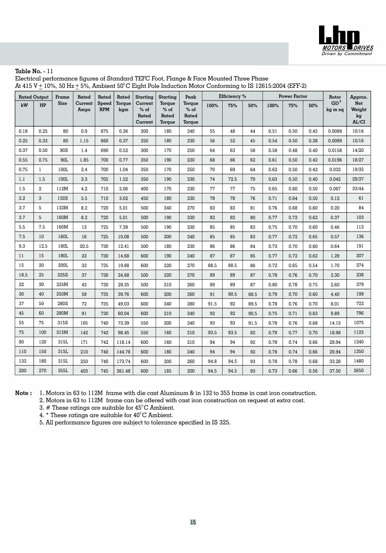
Table No. - 11Electrical performance figures of Standard TEFC Foot, Flange & Face Mounted Three PhaseAt 415 V _ 10%, 50 Hz _ 5%, Ambient 50 C Eight Pole Induction Motor0 Conforming to IS 12615:2004 (EFF-2)+ +
15
2
Note : 1. Motors in 63 to 112M frame with die cast Aluminum & in 132 to 355 frame in cast iron construction.2. Motors in 63 to 112M can be offered with cast iron construction on request at extra cost.3. # These ratings are suitable for 45
frameC Ambient.
4. * These ratings are suitable for 40 C Ambient.5. All performance figures are subject to tolerance specified in IS 325.
0
0
0.25
0.33
0.50
0.75
1
1.5
2
3
5
5
7.5
10
12.5
15
20
25
30
40
50
60
75
100
120
150
180
270
80
80
90S
90L
100L
100L
112M
132S
132M
160M
160M
160L
180L
180L
200L
225S
225M
250M
280S
280M
315S
315M
315L
315L
315L
355L
0.9
1.15
1.4
1.85
2.4
3.3
4.2
5.5
8.2
8.2
12
16
20.5
23
33
37
43
58
72
91
105
142
171
210
250
403
675
660
690
700
700
705
710
710
720
720
725
725
730
730
735
730
730
735
735
730
740
742
742
740
740
745
0.26
0.37
0.52
0.77
1.04
1.52
2.06
3.02
5.01
5.01
7.39
10.08
12.41
14.68
19.88
24.68
29.35
39.76
49.03
60.04
72.39
98.45
118.14
144.78
173.74
261.48
200
250
300
350
350
350
400
450
500
500
500
500
500
600
600
500
500
600
600
600
550
550
600
600
600
600
180
180
170
190
170
190
170
180
240
190
190
200
180
190
220
220
210
200
240
210
200
160
160
180
200
185
240
230
250
230
250
230
230
230
270
230
230
240
230
240
270
270
260
260
280
240
240
210
210
240
260
200
55
56
64
68
70
74
77
78
83
82
85
85
86
87
88.5
89
89
91
91.5
92
93
93.5
94
94
94.8
94.5
44
45
58
62
64
70
75
76
81
80
83
83
84
85
86
87
87
88.5
89.5
90.5
91.5
92
92
92
93
93
0.51
0.54
0.58
0.61
0.62
0.63
0.65
0.71
0.76
0.77
0.75
0.77
0.73
0.77
0.72
0.78
0.80
0.79
0.78
0.75
0.78
0.79
0.78
0.78
0.78
0.73
0.50
0.50
0.48
0.50
0.50
0.50
0.60
0.64
0.68
0.72
0.70
0.72
0.70
0.72
0.65
0.76
0.78
0.70
0.76
0.71
0.76
0.77
0.74
0.74
0.78
0.66
0.45
0.38
0.40
0.42
0.42
0.40
0.50
0.50
0.60
0.62
0.60
0.65
0.60
0.62
0.54
0.70
0.75
0.60
0.70
0.63
0.68
0.70
0.66
0.66
0.68
0.56
0.0089
0.0089
0.0158
0.0196
0.032
0.042
0.067
0.12
0.20
0.37
0.46
0.57
0.64
1.29
1.70
2.30
2.60
4.40
8.01
9.89
14.12
18.98
29.94
29.94
33.28
37.50
10/16
10/16
14/20
18/27
19/35
29/37
33/44
61
84
103
113
136
191
207
274
238
379
199
722
796
1075
1125
1240
1350
1480
2650
0.18
0.25
0.37
0.55
0.75
1.1
1.5
2.2
3.7
3.7
5.5
7.5
9.3
11
15
18.5
22
30
37
45
55
75
90
110
132
200
48
52
63
66
69
72.5
77
78
83
82
85
85
86
87
88.5
89
89
90.5
92
92
93
93.5
94
94
94.5
94.5
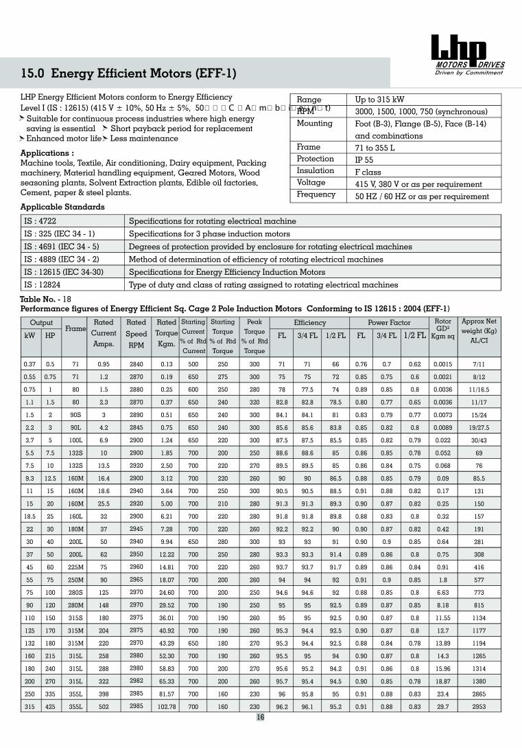
LHP Energy Efficient Motors conform to Energy EfficiencyLevel I (IS : 12615) (415 V ± 10%, 50 Hz ± 5%, 50⁰C Ambient)Suitable for continuous process industries where high energysaving is essential Short payback period for replacementEnhanced motor life Less maintenance
Applications :Machine tools, Textile, Air conditioning, Dairy equipment, Packingmachinery, Material handling equipment, Geared Motors, Woodseasoning plants, Solvent Extraction plants, Edible oil factories,Cement, paper & steel plants.
Applicable Standards
IS : 4722
IS : 325 (IEC 34 - 1)
IS : 4691 (IEC 34 - 5)
IS : 4889 (IEC 34 - 2)
IS : 12615 (IEC 34-30)
IS : 12824
RangeRPMMounting
FrameProtectionInsulationVoltageFrequency
Up to 315 kW3000, 1500, 1000, 750 (synchronous)Foot (B-3), Flange (B-5), Face (B-14)and combinations71 to 355 LIP 55F class415 V, 380 V or as per requirement50 HZ / 60 HZ or as per requirement
Specifications for rotating electrical machine
Specifications for 3 phase induction motors
Degrees of protection provided by enclosure for rotating electrical machines
Method of determination of efficiency of rotating electrical machines
Specifications for Energy Efficiency Induction Motors
Type of duty and class of rating assigned to rotating electrical machines
Performance figures of Energy Efficient Sq. Cage 2 Pole Induction Motors Conforming to IS 12615 : 2004 (EFF-1)
OutputFrame
kW HP
15.0 Energy Efficient Motors (EFF-1)
16
Table No. - 18
RatedCurrentAmps.
Rated
Speed
RPM
RatedTorqueKgm.
StartingCurrent% of RtdCurrent
FL
Efficiency
3/4 FL 1/2 FL FL
Power Factor
3/4 FL 1/2 FL
RotorGD²
Kgm sq
Approx Netweight (Kg)
AL/CI
StartingTorque% of RtdTorque
PeakTorque% of RtdTorque
0.37
0.55
0.75
1.1
1.5
2.2
3.7
5.5
7.5
9.3
11
15
18.5
22
30
37
45
55
75
90
110
125
132
160
180
200
250
315
0.5
0.75
1
1.5
2
3
5
7.5
10
12.5
15
20
25
30
40
50
60
75
100
120
150
170
180
215
240
270
335
425
71
71
80
80
90S
90L
100L
132S
132S
160M
160M
160M
160L
180M
200L
200L
225M
250M
280S
280M
315S
315M
315M
315L
315L
315L
355L
355L
0.95
1.2
1.5
2.3
3
4.2
6.9
10
13.5
16.4
18.6
25.5
32
37
50
62
75
90
125
148
180
204
220
258
288
322
398
502
2840
2870
2880
2870
2890
2845
2900
2900
2920
2900
2940
2920
2900
2945
2940
2950
2960
2965
2970
2970
2975
2975
2970
2980
2980
2982
2985
2985
0.13
0.19
0.25
0.37
0.51
0.75
1.24
1.85
2.50
3.12
3.64
5.00
6.21
7.28
9.94
12.22
14.81
18.07
24.60
29.52
36.01
40.92
43.29
52.30
58.83
65.33
81.57
102.78
500
650
600
650
650
650
650
700
700
700
700
700
700
700
650
700
700
700
700
700
700
700
650
700
700
700
700
700
250
275
250
240
240
240
220
200
220
220
250
210
220
220
280
250
220
200
200
190
190
190
180
190
200
200
160
160
300
300
280
320
300
300
300
250
270
260
300
280
280
260
300
280
260
260
250
250
260
260
270
260
270
260
230
230
71
75
78
82.8
84.1
85.6
87.5
88.6
89.5
90
90.5
91.3
91.8
92.2
93
93.3
93.7
94
94.6
95
95
95.3
95.3
95.5
95.6
95.7
96
96.2
71
75
77.5
82.8
84.1
85.6
87.5
88.6
89.5
90
90.5
91.3
91.8
92.2
93
93.3
93.7
94
94.6
95
95
94.4
94.4
95
95.2
95.4
95.8
96.1
66
72
74
78.5
81
83.8
85.5
85
85
86.5
88.5
89.3
89.8
90
91
91.4
91.7
92
92
92.5
92.5
92.5
92.5
94
94.2
94.5
95
95.2
0.76
0.85
0.89
0.80
0.83
0.85
0.85
0.86
0.86
0.88
0.91
0.90
0.88
0.90
0.90
0.89
0.89
0.91
0.88
0.89
0.90
0.90
0.88
0.90
0.91
0.90
0.91
0.91
0.7
0.75
0.85
0.77
0.79
0.82
0.82
0.85
0.84
0.85
0.88
0.87
0.83
0.87
0.9
0.86
0.86
0.9
0.85
0.87
0.87
0.87
0.84
0.87
0.86
0.85
0.88
0.88
0.62
0.6
0.8
0.65
0.77
0.8
0.79
0.78
0.75
0.79
0.82
0.82
0.8
0.82
0.85
0.8
0.84
0.85
0.8
0.85
0.8
0.8
0.78
0.8
0.8
0.78
0.83
0.83
0.0015
0.0021
0.0036
0.0036
0.0073
0.0089
0.022
0.052
0.068
0.09
0.17
0.25
0.32
0.42
0.64
0.75
0.91
1.8
6.63
8.18
11.55
12.7
13.89
14.3
15.96
18.87
23.4
29.7
7/11
8/12
11/16.5
11/17
15/24
19/27.5
30/43
69
76
85.5
131
150
157
191
281
308
416
577
773
815
1134
1177
1194
1265
1314
1380
2865
2953
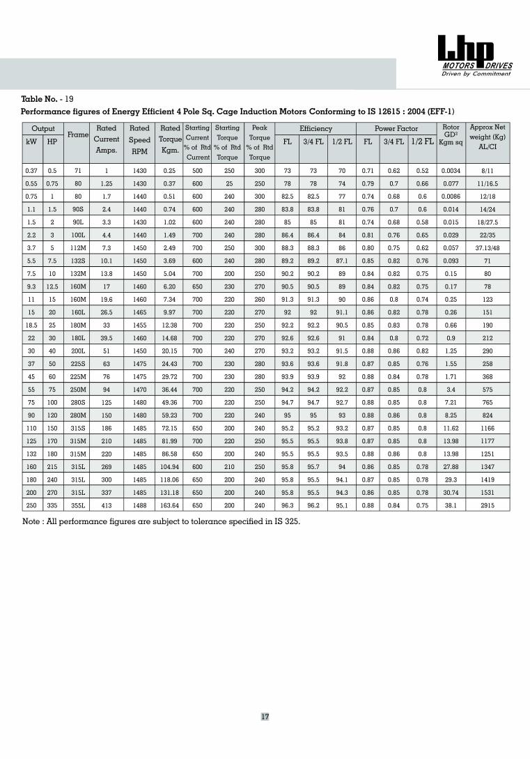
Performance figures of Energy Efficient 4 Pole Sq. Cage Induction Motors Conforming to IS 12615 : 2004 (EFF-1)
17
Table No. - 19
OutputFrame
kW HP
RatedCurrentAmps.
Rated
Speed
RPM
RatedTorqueKgm.
StartingCurrent% of RtdCurrent
FL
Efficiency
3/4 FL 1/2 FL FL
Power Factor
3/4 FL 1/2 FL
RotorGD²
Kgm sq
Approx Netweight (Kg)
AL/CI
StartingTorque% of RtdTorque
PeakTorque% of RtdTorque
0.37
0.55
0.75
1.1
1.5
2.2
3.7
5.5
7.5
9.3
11
15
18.5
22
30
37
45
55
75
90
110
125
132
160
180
200
250
0.5
0.75
1
1.5
2
3
5
7.5
10
12.5
15
20
25
30
40
50
60
75
100
120
150
170
180
215
240
270
335
71
80
80
90S
90L
100L
112M
132S
132M
160M
160M
160L
180M
180L
200L
225S
225M
250M
280S
280M
315S
315M
315M
315L
315L
315L
355L
1
1.25
1.7
2.4
3.3
4.4
7.3
10.1
13.8
17
19.6
26.5
33
39.5
51
63
76
94
125
150
186
210
220
269
300
337
413
1430
1430
1440
1440
1430
1440
1450
1450
1450
1460
1460
1465
1455
1460
1450
1475
1475
1470
1480
1480
1485
1485
1485
1485
1485
1485
1488
0.25
0.37
0.51
0.74
1.02
1.49
2.49
3.69
5.04
6.20
7.34
9.97
12.38
14.68
20.15
24.43
29.72
36.44
49.36
59.23
72.15
81.99
86.58
104.94
118.06
131.18
163.64
500
600
600
600
600
700
700
600
700
650
700
700
700
700
700
700
700
700
700
700
650
700
650
600
650
650
650
250
25
240
240
240
240
250
240
200
230
220
220
220
220
240
230
230
220
220
220
200
220
200
210
200
200
200
300
250
300
280
280
280
300
280
250
270
260
270
250
270
270
280
280
250
250
240
240
250
240
250
240
240
240
73
78
82.5
83.8
85
86.4
88.3
89.2
90.2
90.5
91.3
92
92.2
92.6
93.2
93.6
93.9
94.2
94.7
95
95.2
95.5
95.5
95.8
95.8
95.8
96.3
73
78
82.5
83.8
85
86.4
88.3
89.2
90.2
90.5
91.3
92
92.2
92.6
93.2
93.6
93.9
94.2
94.7
95
95.2
95.5
95.5
95.7
95.5
95.5
96.2
70
74
77
81
81
84
86
87.1
89
89
90
91.1
90.5
91
91.5
91.8
92
92.2
92.7
93
93.2
93.8
93.5
94
94.1
94.3
95.1
0.71
0.79
0.74
0.76
0.74
0.81
0.80
0.85
0.84
0.84
0.86
0.86
0.85
0.84
0.88
0.87
0.88
0.87
0.88
0.88
0.87
0.87
0.88
0.86
0.87
0.86
0.88
0.62
0.7
0.68
0.7
0.68
0.76
0.75
0.82
0.82
0.82
0.8
0.82
0.83
0.8
0.86
0.85
0.84
0.85
0.85
0.86
0.85
0.85
0.86
0.85
0.85
0.85
0.84
0.52
0.66
0.6
0.6
0.58
0.65
0.62
0.76
0.75
0.75
0.74
0.78
0.78
0.72
0.82
0.76
0.78
0.8
0.8
0.8
0.8
0.8
0.8
0.78
0.78
0.78
0.75
0.0034
0.077
0.0086
0.014
0.015
0.029
0.057
0.093
0.15
0.17
0.25
0.26
0.66
0.9
1.25
1.55
1.71
3.4
7.21
8.25
11.62
13.98
13.98
27.88
29.3
30.74
38.1
8/11
11/16.5
12/18
14/24
18/27.5
22/35
37.13/48
71
80
78
123
151
190
212
290
258
368
575
765
824
1166
1177
1251
1347
1419
1531
2915
Note : All performance figures are subject to tolerance specified in IS 325.
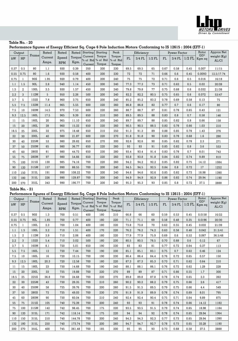
Performance figures of Energy Efficient Sq. Cage 6 Pole Induction Motors Conforming to IS 12615 : 2004 (EFF-1)Table No. - 20
kW
Output
HPFrame
RatedCurrentAmps.
Rated
Speed
RPM
RatedTorqueKgm.
StartingCurrent% of RtdCurrent
FL
Efficiency
3/4 FL 1/2 FL FL
Power Factor
3/4 FL 1/2 FL
RotorGD²
Kgm sq
Approx Netweight (Kg)
AL/CI
StartingTorque% of RtdTorque
PeakTorque% of RtdTorque
0.5
0.75
1
1.5
2
3
5
7.5
10
12.5
15
20
25
30
40
50
60
75
100
120
150
180
270
80
80
90S
90L
100L
112M
132S
132M
160M
160L
160L
180L
200L
200L
225M
250M
280S
280M
315S
315M
315L
315L
355L
1.1
1.6
1.95
2.8
3.5
5
7.8
11.4
14.5
17.5
20
28
32
40
53
65
81
97
130
157
191
226
343
930
930
920
940
930
950
960
965
970
965
965
960
975
980
980
980
980
980
985
990
990
990
990
0.39
0.58
0.79
1.14
1.57
2.26
3.75
5.55
7.53
9.39
11.10
15.22
18.48
21.87
29.82
36.77
44.72
54.66
74.16
88.55
108.22
129.87
196.77
350
400
400
450
450
500
650
600
600
650
650
650
650
600
650
650
650
650
700
700
700
700
700
200
200
200
200
200
200
200
220
220
210
200
220
210
220
270
220
230
220
220
200
200
200
200
230
230
240
240
240
240
240
260
260
260
240
260
250
270
300
260
280
260
260
240
240
240
240
69.5
72
75
77.3
79.8
82.2
85.2
86.8
88.7
89.5
89.7
90.5
91.3
91.8
92.6
93
93.4
93.8
94.2
94.5
94.6
94.9
95.3
69.5
72
75
77.3
79.8
82.2
85.2
86.8
88.7
89.5
89.7
90.5
91.3
91.8
92.6
93
93.4
93.8
94.2
94.5
94.6
94.9
95.3
65
71
72
73
77
80.5
83.2
82
87
88
88
88.5
89
90
90
91
91.4
91.8
92.2
92.5
92.6
92.9
93
0.67
0.66
0.71
0.71
0.75
0.75
0.78
0.77
0.81
0.83
0.85
0.82
0.88
0.83
0.85
0.85
0.83
0.84
0.85
0.84
0.85
0.86
0.85
0.58
0.6
0.6
0.62
0.68
0.65
0.69
0.7
0.78
0.8
0.82
0.78
0.85
0.78
0.82
0.82
0.78
0.82
0.82
0.8
0.82
0.82
0.8
0.45
0.45
0.5
0.5
0.6
0.6
0.58
0.6
0.65
0.7
0.8
0.66
0.78
0.68
0.78
0.8
0.7
0.74
0.75
0.72
0.73
0.74
0.72
0.007
0.0093
0.016
0.02
0.032
0.072
0.13
0.17
0.43
0.58
0.66
1.03
1.43
1.6
2.3
3.6
8.01
9.89
14.12
17
18.98
29.94
37.5
11/15
12.5/17.74
16/18
20/28
21/38
53/47
75
80
121
146
158
210
276
290
271
553
743
810
1084
1252
1390
1190
2888
0.37
0.55
0.75
1.1
1.5
2.2
3.7
5.5
7.5
9.3
11
15
18.5
22
30
37
45
55
75
90
110
132
200
Table No. - 21Performance figures of Energy Efficient Sq. Cage 8 Pole Induction Motors Conforming to IS 12615 : 2004 (EFF-1)
kW
Output
HPFrame
RatedCurrentAmps.
Rated
Speed
RPM
RatedTorqueKgm.
StartingCurrent% of RtdCurrent
FL
Efficiency
3/4 FL 1/2 FL FL
Power Factor
3/4 FL 1/2 FL
RotorGD²
Kgm sq
Approx Netweight (Kg)
AL/CI
StartingTorque% of RtdTorque
PeakTorque% of RtdTorque
0.5
0.75
1
1.5
2
3
5
7.5
10
12.5
15
20
25
30
40
50
60
75
100
120
150
180
270
90S
90L
100L
100L
112M
132S
160M
160L
160L
180L
180L
200L
225S
225M
250M
280S
280M
315S
315M
315L
315L
315L
355L
1.3
1.85
2.3
3.2
3.9
5.4
8.1
12
16
20.3
23
33
36.8
43
58
72
90
105
142
171
210
250
400
700
700
700
710
710
710
720
720
720
720
730
735
730
730
735
735
730
740
742
742
740
740
745
0.51
0.77
1.04
1.51
2.06
3.02
5.01
7.44
10.15
12.58
14.68
19.88
24.68
29.35
39.76
49.03
60.04
72.39
98.45
118.14
144.78
173.74
261.48
400
400
400
400
400
500
650
700
700
700
700
700
700
700
700
700
700
700
700
700
700
700
700
180
180
180
170
180
180
190
190
190
180
190
220
220
210
200
230
210
200
175
175
200
200
185
210
220
220
220
220
230
230
230
230
220
240
270
270
260
260
270
240
240
220
220
240
260
200
66.8
71.1
73.8
76.2
77.9
80.5
83
85.1
86.4
87.3
88.1
89
89.8
90.2
91.5
91.9
92.4
93
93.5
94
94.3
94.7
95
66
71.1
73.8
76.2
77.9
80.5
83
85.1
86.4
87.3
88.1
89
89.8
90.2
91.5
91.9
92.4
93
93.5
94
94.3
94.7
95
60
69
70
74.2
75.9
78.5
81
83.1
84.4
85.3
86.1
87
87.8
88.2
89.5
89.9
90.4
91
91.5
92
92.3
92.7
93
0.59
0.58
0.62
0.63
0.69
0.70
0.77
0.75
0.76
0.73
0.76
0.71
0.78
0.79
0.79
0.78
0.75
0.78
0.79
0.78
0.77
0.78
0.73
0.53
0.48
0.55
0.58
0.6
0.68
0.72
0.7
0.72
0.71
0.72
0.66
0.74
0.75
0.75
0.74
0.71
0.74
0.74
0.74
0.73
0.73
0.68
0.45
0.35
0.45
0.48
0.52
0.6
0.64
0.62
0.65
0.62
0.62
0.55
0.65
0.66
0.66
0.69
0.64
0.66
0.65
0.65
0.65
0.65
0.58
16/22
20/30
21/39
31.5/41
36.5/48
67
113
124
150
210
228
300
262
417
549
795
875
1182
1184
1364
1390
1190
2888
0.37
0.55
0.75
1.1
1.5
2.2
3.7
5.5
7.5
9.3
11
15
18.5
22
30
37
45
55
75
90
110
132
200
0.0158
0.0196
0.032
0.042
0.067
0.12
0.37
0.46
0.57
0.64
1.29
1.7
2.3
2.6
4.4
8.01
9.89
14.12
18.98
29.94
29.94
33.28
37.5
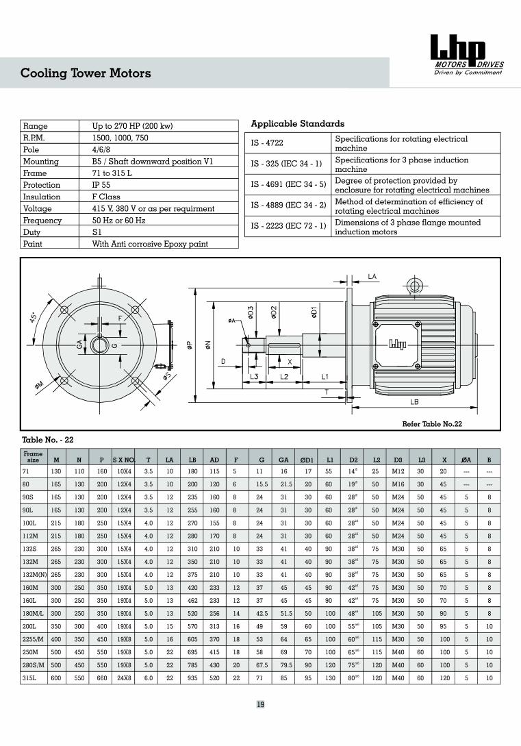
71
80
90S
90L
100L
112M
132S
132M
132M(N)
160M
160L
180M/L
200L
2255/M
250M
280S/M
315L
130
165
165
165
215
215
265
265
265
300
300
300
350
400
500
500
600
110
130
130
130
180
180
230
230
230
250
250
250
300
350
450
450
550
160
200
200
200
250
250
300
300
300
350
350
350
400
450
550
550
660
10X4
12X4
12X4
12X4
15X4
15X4
15X4
15X4
15X4
19X4
19X4
19X4
19X4
19X8
19X8
19X8
24X8
3.5
3.5
3.5
3.5
4.0
4.0
4.0
4.0
4.0
5.0
5.0
5.0
5.0
5.0
5.0
5.0
6.0
10
10
12
12
12
12
12
12
12
13
13
13
15
16
22
22
22
180
200
235
255
270
280
310
350
375
420
462
520
570
605
695
785
935
115
120
160
160
155
170
210
210
210
233
233
256
313
370
415
430
520
5
6
8
8
8
8
10
10
10
12
12
14
16
18
18
20
22
11
15.5
24
24
24
24
33
33
33
37
37
42.5
49
53
58
67.5
71
16
21.5
31
31
31
31
41
41
41
45
45
51.5
59
64
69
79.5
85
17
20
30
30
30
30
40
40
40
45
45
50
60
65
70
90
95
55
60
60
60
60
60
90
90
90
90
90
100
100
100
100
120
130
14
19
28
28
28
38
38
42
42
48
55
60
65
75
80
j6
j6
j6
j6
k6
k6
k6
k6
k6
k6
k6
k6
m6
m6
m6
m6
m
28
38
6
25
50
50
50
50
50
75
75
75
75
75
105
105
115
115
120
120
M12
16
24
24
24
24
30
30
30
30
30
30
30
40
40
40
M
M
M
M
M
M
M
M
M
M
M
M
M30
M
M
M
30
30
50
50
50
50
50
50
50
50
50
50
50
50
60
60
60
20
45
45
45
45
45
65
65
65
70
70
90
95
100
100
100
120
---
---
5
5
5
5
5
5
5
5
5
5
5
5
5
5
5
19
Cooling Tower Motors
RangeR.P.M.PoleMountingFrameProtectionInsulationVoltageFrequencyDutyPaint
Up to 270 HP (200 kw)1500, 1000, 7504/6/8B5 / Shaft downward position V171 to 315 LIP 55F Class415 V, 380 V or as per requirment50 Hz or 60 HzS1With Anti corrosive Epoxy paint
IS - 4722
IS - 325 (IEC 34 - 1)
IS - 4691 (IEC 34 - 5)
IS - 4889 (IEC 34 - 2)
IS - 2223 (IEC 72 - 1)
Applicable Standards
Specifications for rotating electricalmachineSpecifications for 3 phase inductionmachineDegree of protection provided byenclosure for rotating electrical machinesMethod of determination of efficiency ofrotating electrical machinesDimensions of 3 phase flange mountedinduction motors
Framesize M N P S X NO. T LA LB AD F G GA L1 D2 L2 D3 L3 X OAOD1
---
---
8
8
8
8
8
8
8
8
8
8
10
10
10
10
10
B
Table No. - 22
Refer Table No.22
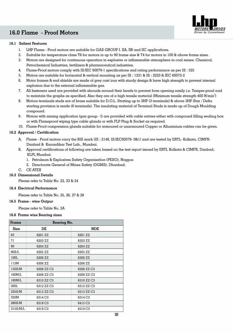
20
16.0 Flame - Proof Motors
16.1 Salient Features
1. LHP Flame - Proof motors are suitable for GAS GROUP I. IIA, IIB and IIC applications.2. Suitable for temperature class T6 for motors in up to 90 frame size & T4 for motors in 100 & above frame sizes.3. Motors are designed for continuous operation in explosive or inflammable atmosphere in coal mines. Chemical,
Petrochemical Industries, fertilizers & pharmaceutical industries.4. Flame-Proof motors comply with IS/IEC 60079-1 specifications and rating performance as per IS : 3255. Motors are suitable for horizontal & vertical mounting as per IS : 1231 & IS : 2223 & IEC 60072-26. Motor frames & end shields are made of grey cast iron with sturdy design & have high strength to prevent internal
explosion due to the external inflammable gas.7. All fasteners used are provided with shrouds around their heads to prevent from opening easily i.e. Tamper-proof and
to maintain the graphs as specified. Also they are of a high tensile material (Minimum tensile strength 400 N/min )8. Motors terminals studs are of brass suitable for D.O.L. Strating up to 3HP (3 terminals) & above 3HP Star / Delta
starting provision is made (6 terminals). The insulating material of Terminal Studs is made up of Dough Mouldingcompound.
9. Motors with mining application (gas group - I) are provided with cable entries either with compound filling sealing boxor with Flameproof wiping type cable glands or with FLP Plug & Socket as required.
10. Flame-Proof compression glands suitable for armoured or unarmoured Copper or Alluminium cables can be given.
2
16.2 Approval / Certification
16.3 Dimensional Details
A. Flame - Proof motors carry the BIS mark (IS : 2148, IS/IEC60079- 0&1) and are tested by ERTL- Kolkata, CIMFR-Danbad & Karandikar Test Lab., Mumbai.
B. Approval certifications of following are taken based on the test report issued by ERTL
1. Petroleum & Explosives Safety Organisation (PESO), Nagpur.2. Directorate General of Mines Safety (DGMS), Dhanbad.
Kolkata & CIMFR, Danbad,KLPL Mumbai.
C. CE ATEX
Please refer to Table No. 22, 23 & 24
16.4 Electrical Performance
Please refer to Table No. 25, 26, 27 & 28
16.5 Frame - wise Outpur
Please refer to Table No. 2A
16.6 Frame wise Bearing sizes
Bearing No.
DE NDE
6201 ZZ
ZZ
6205 ZZ
6206 ZZ
6306 ZZ
6308 ZZ C3
6309 ZZ C3
6310 ZZ C3
6312 ZZ C3
6313 ZZ C3
6314 C3
6318 C3
6319 C3
6203 ZZ
6204
6201 ZZ
ZZ
6205 ZZ
6206 ZZ
6206 ZZ
6208 ZZ C3
6309 ZZ C3
6310 ZZ C3
6312 ZZ C3
6313 ZZ C3
6314 C3
6415 C3
6319 C3
6203 ZZ
6204
63
L
M
1 S/M
M/L
M/L
L
S/M
M
S/M
S/M/L
71
80
90S/L
100
112
32
160
180
200
225
250
280
315
Frame
Size
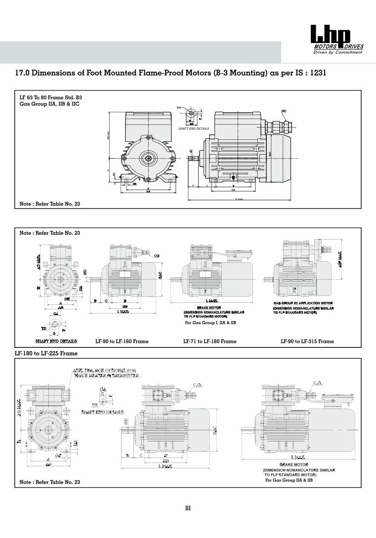
17.0 Dimensions of Foot Mounted Flame-Proof Motors (B-3 Mounting) as per IS : 1231
LF-180 to LF-225 Frame
21
LF-90 to LF-160 Frame LF-71 to LF-160 Frame LF-90 to LF-315 Frame
LF 63 To 80 Frame Std. B3Gas Group IIA, IIB & IIC
Note : Refer Table No. 23
Note : Refer Table No. 23
For Gas Group IIA & IIBNote : Refer Table No. 23
For Gas Group I, IIA & IIB
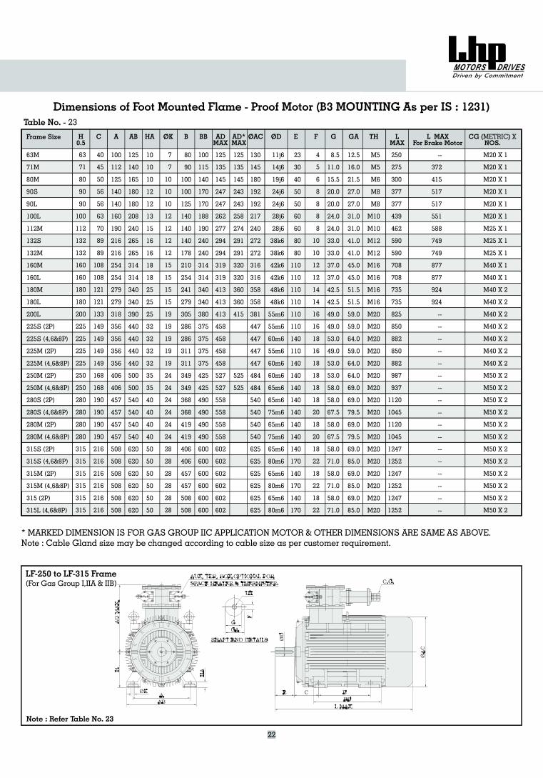
Dimensions of Foot Mounted Flame - Proof Motor (B3 MOUNTING As per IS : 1231)
63M
M
M
(4,6&8P)
280S (2P)
280S (4,6&8P)
280M (2P)
280M (4,6&8P)
315S (2P)
315S (4,6&8P)
315M (2P)
315M (4,6&8P)
315 (2P)
315L (4,6&8P)
71
80
90S
90L
100L
112M
132S
132M
160M
160L
180M
180L
200L
225S (2P)
225S (4,6&8P)
225M (2P)
225M (4,6&8P)
250M (2P)
250M
63
71
80
90
90
100
112
132
132
160
160
180
180
200
225
225
225
225
250
250
280
280
280
280
315
315
315
315
315
315
40
45
50
56
56
63
70
89
89
108
108
121
121
133
149
149
149
149
168
168
190
190
190
190
216
216
216
216
216
216
100
112
125
140
140
160
190
216
216
254
254
279
279
318
356
356
356
356
406
406
457
457
457
457
508
508
508
508
508
508
125
140
165
180
180
208
240
265
265
314
314
340
340
390
440
440
440
440
500
500
540
540
540
540
620
620
620
620
620
620
10
10
10
12
12
13
15
16
16
18
18
25
25
25
32
32
32
32
35
35
40
40
40
40
50
50
50
50
50
50
7
7
10
10
10
12
12
12
12
15
15
15
15
19
19
19
19
19
24
24
24
24
24
24
28
28
28
28
28
28
80
90
100
100
125
140
140
140
178
210
254
241
279
305
286
286
311
311
349
349
368
368
419
419
406
406
457
457
508
508
100
115
140
170
170
188
190
240
240
314
314
340
340
380
375
375
375
375
425
425
490
490
490
490
600
600
600
600
600
600
130
145
180
192
192
217
240
272
272
316
316
358
358
381
447
447
447
447
484
484
540
540
540
540
625
625
625
625
625
625
11j6
14j6
19j6
24j6
24j6
28j6
28j6
38k6
38k6
42k6
42k6
48k6
48k6
55m6
55m6
60m6
55m6
60m6
60m6
65m6
65m6
75m6
65m6
75m6
65m6
80m6
65m6
80m6
65m6
80m6
23
30
40
50
50
60
60
80
80
110
110
110
110
110
110
140
110
140
140
140
140
140
140
140
140
170
140
170
140
170
4
5
6
8
8
8
8
10
10
12
12
14
14
16
16
18
16
18
18
18
18
20
18
20
18
22
18
22
18
22
8.5
11.0
15.5
20.0
20.0
24.0
24.0
33.0
33.0
37.0
37.0
42.5
42.5
49.0
49.0
53.0
49.0
53.0
53.0
58.0
58.0
67.5
58.0
67.5
58.0
71.0
58.0
71.0
58.0
71.0
12.5
16.0
21.5
27.0
27.0
31.0
31.0
41.0
41.0
45.0
45.0
51.5
51.5
59.0
59.0
64.0
59.0
64.0
64.0
69.0
69.0
79.5
69.0
79.5
69.0
85.0
69.0
85.0
69.0
85.0
M5
M5
M6
M8
M8
M10
M10
M12
M12
M16
M16
M16
M16
M20
M20
M20
M20
M20
M20
M20
M20
M20
M20
M20
M20
M20
M20
M20
M20
M20
Frame Size H0.5
C A AB HA B BB ADMAX
E F G GA TH CG ( )NOS.METRIC XOK OAC ODAD*
MAXL
MAXL MAX
For Brake Motor
--
--
--
--
--
--
--
--
--
--
--
--
--
--
--
--
--
372
415
517
517
551
588
749
749
877
877
924
924
--
* MARKED DIMENSION IS FOR GAS GROUP IIC APPLICATION MOTOR & OTHER DIMENSIONS ARE SAME AS ABOVE.Note : Cable Gland size may be changed according to cable size as per customer requirement.
Table No. - 23
125
135
145
247
247
262
277
294
294
319
319
413
413
413
458
458
458
458
527
527
558
558
558
558
602
602
602
602
602
602
125
135
145
243
243
258
274
291
291
320
320
360
360
415
525
525
250
275
300
377
377
439
462
590
590
708
708
735
735
825
850
882
850
882
987
937
1120
1045
1120
1045
1247
1252
1247
1252
1247
1252
M20 X 1
M20 X 1
M20 X 1
M20 X 1
M20 X 1
M20 X 1
M25 X 1
M25 X 1
M25 X 1
M40 X 1
M40 X 1
M40 X 2
M40 X 2
M40 X 2
M40 X 2
M40 X 2
M40 X 2
M40 X 2
M50 X 2
M50 X 2
M50 X 2
M50 X 2
M50 X 2
M50 X 2
M50 X 2
M50 X 2
M50 X 2
M50 X 2
M50 X 2
M50 X 2
22
LF-250 to LF-315 Frame(For Gas Group I,IIA & IIB)
Note : Refer Table No. 23
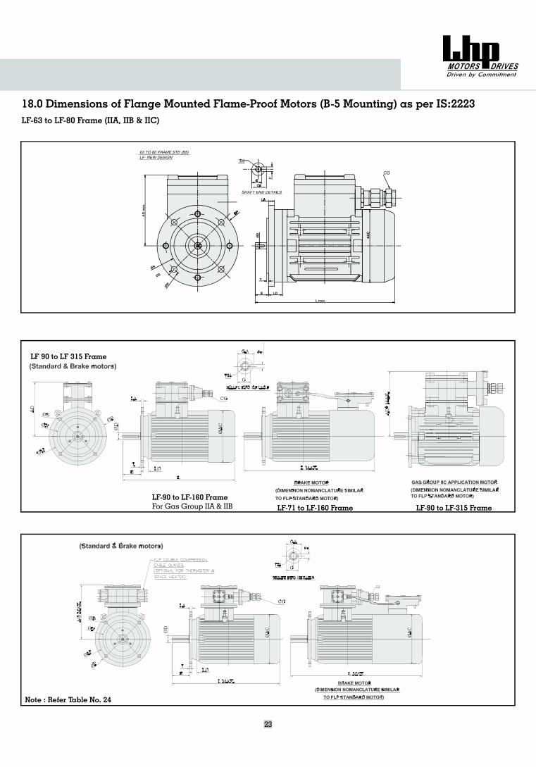
18.0 Dimensions of Flange Mounted Flame-Proof Motors (B-5 Mounting) as per IS:2223
23
LF-90 to LF-160 FrameFor Gas Group IIA & IIB LF-71 to LF-160 Frame LF-90 to LF-315 Frame
LF-63 to LF-80 Frame (IIA, IIB & IIC)
LF 90 to LF 315 Frame
Note : Refer Table No. 24
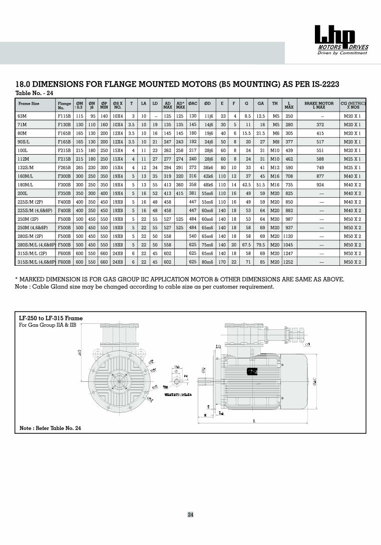
18.0 DIMENSIONS FOR FLANGE MOUNTED MOTORS (B5 MOUNTING) AS PER IS-2223
Frame Size OM0.3
ONj6
OPMIN
OS XNO.
T LA LD AD*MAX
OAC OD E F GA TH LMAX
CG ( )NOSMETRICX
FlangeNo.
G
24
ADMAX
BRAKE MOTORL MAX
* MARKED DIMENSION IS FOR GAS GROUP IIC APPLICATION MOTOR & OTHER DIMENSIONS ARE SAME AS ABOVE.Note : Cable Gland size may be changed according to cable size as per customer requirement.
Table No. - 24
63M
M
M
/L
/M
/L
/L
/M
/M
250M (2P)
250M (4,6&8P)
280S/M (2P)
280S/M/L (4,6&8P)
315S/M/L (2P)
315S/M/L (4,6&8P)
71
80
90S
100L
112M
132S
160M
180M
200L
225S (2P)
225S (4,6&8P)
F115B
F600B
F130B
F165B
F165B
F215B
F215B
F265B
F300B
F300B
F350B
F400B
F400B
F500B
F500B
F500B
F500B
F600B
115
130
165
165
215
215
265
300
300
350
400
400
500
500
500
500
600
600
95
110
130
130
180
180
230
250
250
300
350
350
450
450
450
450
550
550
140
160
200
200
250
250
300
350
350
400
450
450
550
550
550
550
660
660
10X4
19X8
19X8
19X8
19X8
24X8
24X8
10X4
12X4
12X4
15X4
15X4
15X4
19X4
19X4
19X4
19X8
19X8
3
3.5
3.5
3.5
4
4
4
5
5
5
5
5
5
5
5
5
6
6
10
10
10
10
11
11
12
13
13
16
16
16
22
22
22
22
22
22
--
19
16
21
23
27
34
35
55
52
48
48
55
55
50
50
45
45
130
145
180
192
217
240
272
316
358
381
447
447
484
484
540
625
625
625
11j6
14j6
19j6
24j6
28j6
28j6
38k6
42k6
48k6
55m6
55m6
60m6
60m6
65m6
65m6
75m6
65m6
80m6
23
30
40
50
60
60
80
110
110
110
110
140
140
140
140
140
140
170
4
5
6
8
8
8
10
12
14
16
16
18
18
18
18
20
18
22
8.5
11
15.5
20
24
24
33
37
42.5
49
49
53
53
58
58
67.5
58
71
12.5
16
21.5
27
31
31
41
45
51.5
59
59
64
64
69
69
79.5
69
85
M5
M20
M20
M20
M20
M20
M20
M5
M6
M8
M10
M10
M12
M16
M16
M20
M20
M20
--
---
---
---
---
---
---
---
---
372
415
517
551
588
749
877
924
---
125
135
145
247
262
277
294
319
413
413
458
458
527
527
558
558
602
602
125
135
145
243
258
274
291
320
360
415
525
525
250
280
305
377
439
462
590
708
735
825
850
882
987
937
1120
1045
1247
1252
M20 X 1
M20 X 1
M20 X 1
M20 X 1
M20 X 1
M25 X 1
M25 X 1
M40 X 1
M40 X 2
M40 X 2
M40 X 2
M40 X 2
M50 X 2
M50 X 2
M50 X 2
M50 X 2
M50 X 2
M50 X 2
LF-250 to LF-315 FrameFor Gas Group IIA & IIB
Note : Refer Table No. 24
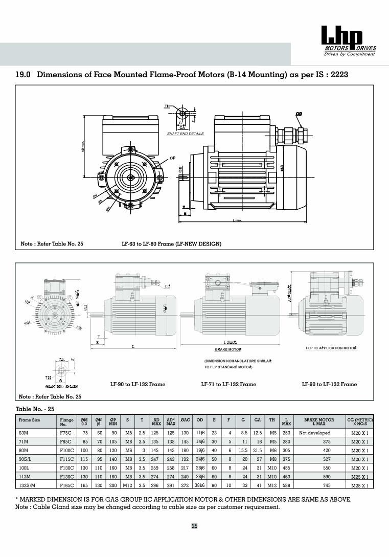
19.0 Dimensions of Face Mounted Flame-Proof Motors (B-14 Mounting) as per IS : 2223
25
* MARKED DIMENSION IS FOR GAS GROUP IIC APPLICATION MOTOR & OTHER DIMENSIONS ARE SAME AS ABOVE.Note : Cable Gland size may be changed according to cable size as per customer requirement.
Table No. - 25
Frame Size ONj6
OPMIN
S T ADMAX
AD*MAX
OAC OD E F G GA LMAX
CG ( )NO.SMETRICX
FlangeNo.
THOM0.3
BRAKE MOTORL MAX
63M
M
M
/L
/M
71
80
90S
100L
112M
132S
F75C
F85C
F100C
F115C
F130C
F130C
F165C
75
85
100
115
130
130
165
60
70
80
95
110
110
130
90
105
120
140
160
160
200
M5
M6
M6
M8
M8
M8
M12
2.5
2.5
3
3.5
3.5
3.5
3.5
11j6
14j6
19j6
24j6
28j6
28j6
38k6
23
30
40
50
60
60
80
4
5
6
8
8
8
10
8.5
11
15.5
20
24
24
33
12.5
16
21.5
27
31
31
41
M5
M5
M6
M8
M10
M10
M12
250
280
305
375
435
460
588
Not developed
375
420
527
550
590
745
125
135
145
247
259
274
296
130
145
180
192
217
240
272
125
135
145
243
258
274
291
M20 X 1
M20 X 1
M20 X 1
M20 X 1
M20 X 1
M25 X 1
M25 X 1
LF-90 to LF-132 Frame LF-71 to LF-132 Frame LF-90 to LF-132 Frame
LF-63 to LF-80 Frame (LF-NEW DESIGN)
ØP
CAG
Note : Refer Table No. 25
Note : Refer Table No. 25
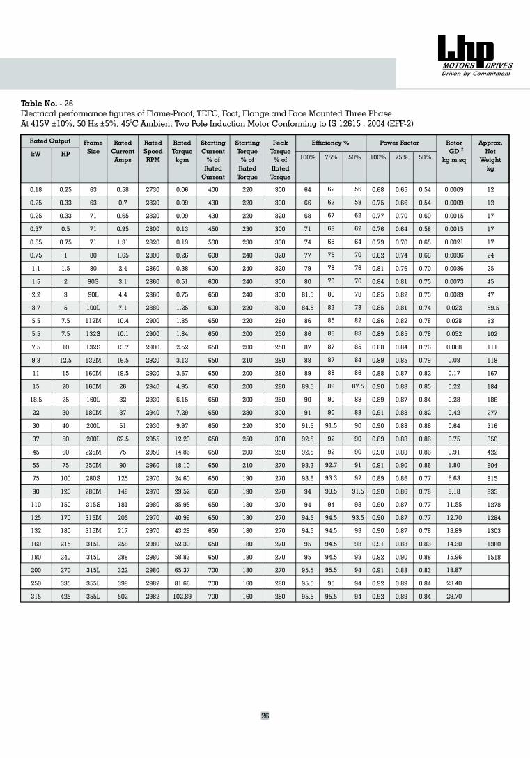
Rated Output FrameSizekW HP
RatedCurrentAmps
RatedSpeedRPM
RatedTorquekgm
StartingCurrent% ofRatedCurrent
StartingTorque% ofRatedTorque
PeakTorque% ofRatedTorque
Approx.Net
Weightkg
RotorGD
kg m sq
Efficiency % Power Factor
Table No. - 26Electrical performance figures of Flame-Proof, TEFC, Foot, Flange and Face Mounted Three Phase
45 C Ambient Two Pole Induction MotorAt 415V 10%, 50 Hz 5%, Conforming to IS 12615 : 2004 (EFF-2)± ± 0
100% 75% 50% 100% 75% 50%
26
2
0.18
0.25
0.25
0.37
0.55
0.75
1.1
1.5
2.2
3.7
5.5
5.5
7.5
9.3
11
15
18.5
22
30
37
45
55
75
90
110
125
132
160
180
200
250
315
0.25
0.33
0.33
0.5
0.75
1
1.5
2
3
5
7.5
7.5
10
12.5
15
20
25
30
40
50
60
75
100
120
150
170
180
215
240
270
335
425
0.58
0.7
0.65
0.95
1.31
1.65
2.4
3.1
4.4
7.1
10.4
10.1
13.7
16.5
19.5
26
32
37
51
62.5
75
90
125
148
181
205
217
258
288
322
398
502
63
63
71
71
71
80
80
90S
90L
100L
112M
132S
132S
132M
160M
160M
160L
180M
200L
200L
225M
250M
280S
280M
315S
315M
315M
315L
315L
315L
355L
355L
2730
2820
2820
2800
2820
2800
2860
2860
2860
2880
2900
2900
2900
2920
2920
2940
2930
2940
2930
2955
2950
2960
2970
2970
2980
2970
2970
2980
2980
2980
2982
2982
0.06
0.09
0.09
0.13
0.19
0.26
0.38
0.51
0.75
1.25
1.85
1.84
2.52
3.13
3.67
4.95
6.15
7.29
9.97
12.20
14.86
18.10
24.60
29.52
35.95
40.99
43.29
52.30
58.83
65.37
81.66
102.89
400
430
430
450
500
600
600
600
650
600
650
650
650
650
650
650
650
650
650
650
650
650
650
650
650
650
650
650
650
700
700
700
220
220
220
230
230
240
240
240
240
220
220
200
200
210
200
200
200
230
220
250
200
210
190
190
180
180
180
180
180
180
160
160
300
300
320
300
300
320
320
300
300
300
280
250
250
280
280
280
280
300
300
300
250
270
270
270
270
270
270
270
270
270
280
280
64
66
68
71
74
77
79
80
81.5
84.5
86
86
87
88
89
89.5
90
91
91.5
92.5
92.5
93.3
93.6
94
94
94.5
94.5
95
95
95.5
95.5
95.5
62
62
67
68
68
75
78
79
80
83
85
86
87
87
88
89
90
90
91.5
92
92
92.7
93.3
93.5
94
94.5
94.5
94.5
94.5
95.5
95
95.5
56
58
62
62
64
70
76
76
78
78
82
83
85
84
86
87.5
88
88
90
90
90
91
92
91.5
93
93.5
93
93
93
94
94
94
0.68
0.75
0.77
0.76
0.79
0.82
0.81
0.84
0.85
0.85
0.86
0.89
0.88
0.89
0.88
0.90
0.89
0.91
0.90
0.89
0.90
0.91
0.89
0.90
0.90
0.90
0.90
0.91
0.92
0.91
0.92
0.92
0.65
0.66
0.70
0.64
0.70
0.74
0.76
0.81
0.82
0.81
0.82
0.85
0.84
0.85
0.87
0.88
0.87
0.88
0.88
0.88
0.88
0.90
0.86
0.86
0.87
0.87
0.87
0.88
0.90
0.88
0.89
0.89
0.0009
0.0009
0.0015
0.0015
0.0021
0.0036
0.0036
0.0073
0.0089
0.022
0.028
0.052
0.068
0.08
0.17
0.22
0.28
0.42
0.64
0.75
0.91
1.80
6.63
8.18
11.55
12.70
13.89
14.30
15.96
18.87
23.40
29.70
0.54
0.54
0.60
0.58
0.65
0.68
0.70
0.75
0.75
0.74
0.78
0.78
0.76
0.79
0.82
0.85
0.84
0.82
0.86
0.86
0.86
0.86
0.77
0.78
0.77
0.77
0.78
0.83
0.88
0.83
0.84
0.84
12
12
17
17
17
24
25
45
47
59.5
83
102
111
118
167
184
186
277
316
350
422
604
815
835
1278
1284
1303
1380
1518
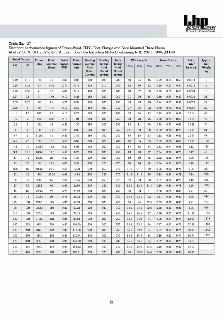
Rated Output FrameSize
15
14
16
21
22
20
45
47
55
61
81
100
115
49
158
177
261
279
326
390
381
594
794
838
1093
1313
1463
1540
1475
kW HP
RatedCurrentAmps
RatedTorquekgm
Starting
% ofRatedTorque
TorqueApprox.Net
Weightkg
RotorGD
kg m sq
Efficiency % Power Factor
Table No. - 27Electrical performance figures of Flame-Proof, TEFC, Foot, Flange and Face Mounted Three Phase
Four Pole Induction MotorAt 415V 10%, 50 Hz 5%, 45 C Ambient Conforming to IS 12615 : 2004 (EFF-2)± ± 0
100% 75% 50% 100% 75% 50%
27
2
0.12
0.18
0.25
0.37
0.55
0.75
1.1
1.5
2.2
3
3.7
5.5
7.5
9.3
11
15
18.5
22
30
37
45
55
75
90
110
132
160
180
200
225
250
315
0.16
0.25
0.33
0.5
0.75
1
1.5
2
3
4
5
7.5
10
12.5
15
20
25
30
40
50
60
75
100
120
150
180
215
240
270
300
335
425
63
63
71
71
80
80
90S
90L
100L
100L
112M
132S
132M
160M
160M
160L
180M
180L
200L
225S
225M
250M
280S
280M
315S
315M
315L
315L
315L
355L
355L
355L
0.4
0.58
0.7
1.05
1.4
1.75
2.5
3.35
4.8
6.2
7.4
10.5
14.5
17.5
21
27.8
33.2
40.00
52
65
77
94
125
150
189
220
270
302
339
378
413
520
1340
1370
1400
1410
1420
1410
1410
1410
1430
1420
1430
1450
1450
1450
1450
1465
1465
1465
1465
1465
1470
1475
1480
1480
1485
1485
1490
1490
1490
1490
1490
1490
RatedSpeedRPM
0.09
0.13
0.17
0.26
0.38
0.52
0.76
1.04
1.50
2.06
2.52
3.69
5.04
6.25
7.39
9.97
12.30
14.63
19.95
24.60
29.82
36.32
49.36
59.23
72.15
86.58
104.59
117.66
130.74
147.08
163.42
205.91
300
310
450
450
430
450
550
550
590
550
580
600
600
600
500
600
600
600
600
600
600
600
600
600
600
600
600
600
600
650
650
650
StartingCurrent% ofRatedCurrent
200
210
200
200
200
200
200
200
200
200
200
200
200
200
200
220
250
250
250
230
200
200
200
190
190
200
200
200
200
180
160
170
280
280
260
260
250
240
260
250
250
250
250
260
250
250
250
270
270
270
270
280
250
250
250
240
240
250
250
250
250
230
230
230
PeakTorque% ofRatedTorque
58
64
68
71
74
77
78
79
82
82.5
85
86
87
88
89
90
91.1
91.8
92
92.5
93
93.5
94
94.5
94.5
94.8
95.3
95.3
95.5
95.5
95.6
96
54
60
67
70
73
76
74
78
81
82
85
85
86
88
89
90
91.1
91.5
92
92.5
93
93.5
94
94.5
94.5
94.8
95.2
92.2
95.5
95.5
95.6
95.8
45
52
60
65
70
72
73
75
79
80
83
83
84
87
86
88
90
90
90
91.3
91
92
92.5
92.6
92
94
94
94
94
94
94.5
94.4
0.72
0.69
0.73
0.69
0.74
0.78
0.79
0.79
0.78
0.82
0.82
0.85
0.83
0.84
0.82
0.84
0.85
0.83
0.87
0.86
0.88
0.87
0.89
0.88
0.86
0.88
0.87
0.87
0.86
0.87
0.88
0.88
0.65
0.63
0.65
0.61
0.63
0.72
0.71
0.73
0.72
0.78
0.80
0.80
0.77
0.79
0.80
0.82
0.82
0.82
0.85
0.84
0.85
0.85
0.88
0.83
0.83
0.84
0.82
0.83
0.82
0.84
0.86
0.86
0.50
0.50
0.55
0.50
0.52
0.58
0.58
0.60
0.60
0.70
0.65
0.67
0.65
0.70
0.74
0.76
0,72
0.78
0.78
0.78
0.80
0.80
0.83
0.81
0.78
0.78
0.76
0.75
0.74
0.79
0.80
0.80
0.0014
0.0014
0.0034
0.0034
0.0077
0.0086
0.014
0.015
0.029
0.038
0.057
0.093
0.12
0.17
0.20
0.26
0.66
0.84
1.19
1.46
1.71
3.20
7.21
8.25
11.62
13.98
27.88
29.30
30.74
34.10
38.10
48.30
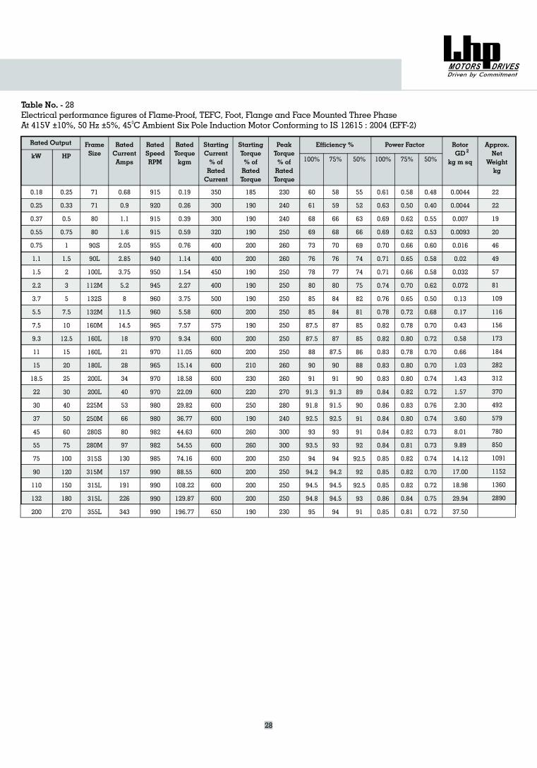
Rated Output FrameSize
22
22
19
20
46
49
57
81
109
116
156
173
184
282
312
370
492
579
780
850
1091
1152
1360
2890
HP
RatedSpeedRPM
RatedTorquekgm
Approx.Net
Weightkg
Efficiency % Power Factor
Table No. - 28Electrical performance figures of Flame-Proof, TEFC, Foot, Flange and Face Mounted Three Phase
Six Pole Induction MotorAt 415V 10%, 50 Hz 5%, 45 C Ambient Conforming to IS 12615 : 2004 (EFF-2)± ± 0
100% 75%
28
2
0.18
0.25
0.37
0.55
0.75
1.1
1.5
2.2
3.7
5.5
7.5
9.3
11
15
18.5
22
30
37
45
55
75
90
110
132
200
kW
0.25
0.33
0.5
0.75
1
1.5
2
3
5
7.5
10
12.5
15
20
25
30
40
50
60
75
100
120
150
180
270
0.68
0.9
1.1
1.6
2.05
2.85
3.75
5.2
8
11.5
14.5
18
21
28
34
40
53
66
80
97
130
157
191
226
343
RatedCurrentAmps
71
71
80
80
90S
90L
100L
112M
132S
132M
160M
160L
160L
180L
200L
200L
225M
250M
280S
280M
315S
315M
315L
315L
355L
915
920
915
915
955
940
950
945
960
960
965
970
970
965
970
970
980
980
982
982
985
990
990
990
990
0.19
0.26
0.39
0.59
0.76
1.14
1.54
2.27
3.75
5.58
7.57
9.34
11.05
15.14
18.58
22.09
29.82
36.77
44.63
54.55
74.16
88.55
108.22
129.87
196.77
350
300
300
320
400
400
450
400
500
600
575
600
600
600
600
600
600
600
600
600
600
600
600
600
650
StartingCurrent% ofRatedCurrent
185
190
190
190
200
200
190
190
190
200
190
200
200
210
230
220
250
190
260
260
200
200
200
200
190
Starting
% ofRatedTorque
Torque
230
240
240
250
260
260
250
250
250
250
250
250
250
260
260
270
280
240
300
300
250
250
250
250
230
PeakTorque% ofRatedTorque
60
61
68
69
73
76
78
80
85
85
87.5
87.5
88
90
91
91.3
91.8
92.5
93
93.5
94
94.2
94.5
94.8
95
75%
58
59
66
68
70
76
77
80
84
84
87
87
87.5
90
91
91.3
91.5
92.5
93
93
94
94.2
94.5
94.5
94
50%
55
52
63
66
69
74
74
75
82
81
85
85
86
88
90
89
90
91
91
92
92.5
92
92.5
93
91
100%
0.61
0.63
0.69
0.69
0.70
0.71
0.71
0.74
0.76
0.78
0.82
0.82
0.83
0.83
0.83
0.84
0.86
0.84
0.84
0.84
0.85
0.85
0.85
0.86
0.85
0.58
0.50
0.62
0.62
0.66
0.65
0.66
0.70
0.65
0.72
0.78
0.80
0.78
0.80
0.80
0.82
0.83
0.80
0.82
0.81
0.82
0.82
0.82
0.84
0.81
50%
0.48
0.40
0.55
0.53
0.60
0.58
0.58
0.62
0.50
0.68
0.70
0.72
0.70
0.70
0.74
0.72
0.76
0.74
0.73
0.73
0.74
0.70
0.72
0.75
0.72
0.0044
0.0044
0.007
0.0093
0.016
0.02
0.032
0.072
0.13
0.17
0.43
0.58
0.66
1.03
1.43
1.57
2.30
3.60
8.01
9.89
14.12
17.00
18.98
29.94
37.50
RotorGD
kg m sq
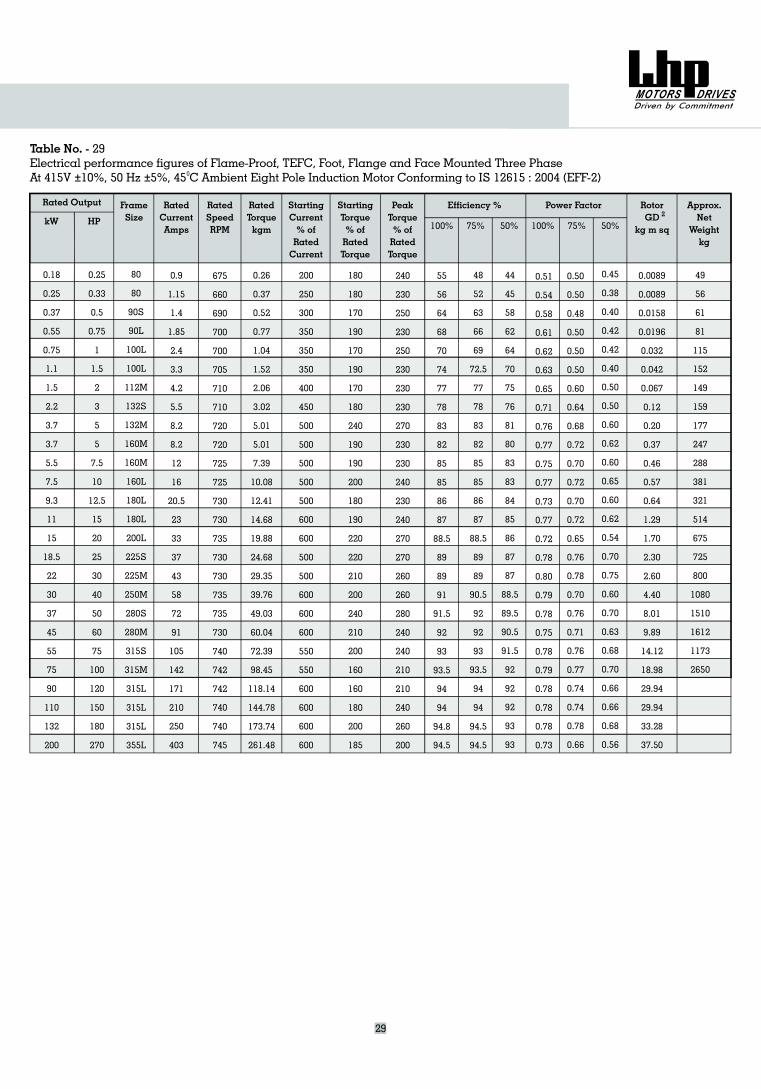
Rated Output FrameSizekW HP
RatedCurrentAmps
RatedTorquekgm
StartingCurrent% ofRatedCurrent
Starting
% ofRatedTorque
TorquePeakTorque% ofRatedTorque
Approx.Net
Weightkg
RotorGD
kg m sq
Efficiency % Power Factor
Table No. - 29Electrical performance figures of Flame-Proof, TEFC, Foot, Flange and Face Mounted Three Phase
Eight Pole Induction MotorAt 415V 10%, 50 Hz 5%, 45 C Ambient Conforming to IS 12615 : 2004 (EFF-2)± ± 0
100% 75% 50% 100% 75% 50%
29
2
49
56
61
81
115
152
149
159
177
247
288
381
321
514
675
725
800
1080
1510
1612
1173
2650
0.18
0.25
0.37
0.55
0.75
1.1
1.5
2.2
3.7
3.7
5.5
7.5
9.3
11
15
18.5
22
30
37
45
55
75
90
110
132
200
0.25
0.33
0.5
0.75
1
1.5
2
3
5
5
7.5
10
12.5
15
20
25
30
40
50
60
75
100
120
150
180
270
80
80
90S
90L
100L
100L
112M
132S
132M
160M
160M
160L
180L
180L
200L
225S
225M
250M
280S
280M
315S
315M
315L
315L
315L
355L
0.9
1.15
1.4
1.85
2.4
3.3
4.2
5.5
8.2
8.2
12
16
20.5
23
33
37
43
58
72
91
105
142
171
210
250
403
RatedSpeedRPM
675
660
690
700
700
705
710
710
720
720
725
725
730
730
735
730
730
735
735
730
740
742
742
740
740
745
0.26
0.37
0.52
0.77
1.04
1.52
2.06
3.02
5.01
5.01
7.39
10.08
12.41
14.68
19.88
24.68
29.35
39.76
49.03
60.04
72.39
98.45
118.14
144.78
173.74
261.48
200
250
300
350
350
350
400
450
500
500
500
500
500
600
600
500
500
600
600
600
550
550
600
600
600
600
180
180
170
190
170
190
170
180
240
190
190
200
180
190
220
220
210
200
240
210
200
160
160
180
200
185
240
230
250
230
250
230
230
230
270
230
230
240
230
240
270
270
260
260
280
240
240
210
210
240
260
200
55
56
64
68
70
74
77
78
83
82
85
85
86
87
88.5
89
89
91
91.5
92
93
93.5
94
94
94.8
94.5
48
52
63
66
69
72.5
77
78
83
82
85
85
86
87
88.5
89
89
90.5
92
92
93
93.5
94
94
94.5
94.5
44
45
58
62
64
70
75
76
81
80
83
83
84
85
86
87
87
88.5
89.5
90.5
91.5
92
92
92
93
93
0.51
0.54
0.58
0.61
0.62
0.63
0.65
0.71
0.76
0.77
0.75
0.77
0.73
0.77
0.72
0.78
0.80
0.79
0.78
0.75
0.78
0.79
0.78
0.78
0.78
0.73
0.50
0.50
0.48
0.50
0.50
0.50
0.60
0.64
0.68
0.72
0.70
0.72
0.70
0.72
0.65
0.76
0.78
0.70
0.76
0.71
0.76
0.77
0.74
0.74
0.78
0.66
0.45
0.38
0.40
0.42
0.42
0.40
0.50
0.50
0.60
0.62
0.60
0.65
0.60
0.62
0.54
0.70
0.75
0.60
0.70
0.63
0.68
0.70
0.66
0.66
0.68
0.56
0.0089
0.0089
0.0158
0.0196
0.032
0.042
0.067
0.12
0.20
0.37
0.46
0.57
0.64
1.29
1.70
2.30
2.60
4.40
8.01
9.89
14.12
18.98
29.94
29.94
33.28
37.50
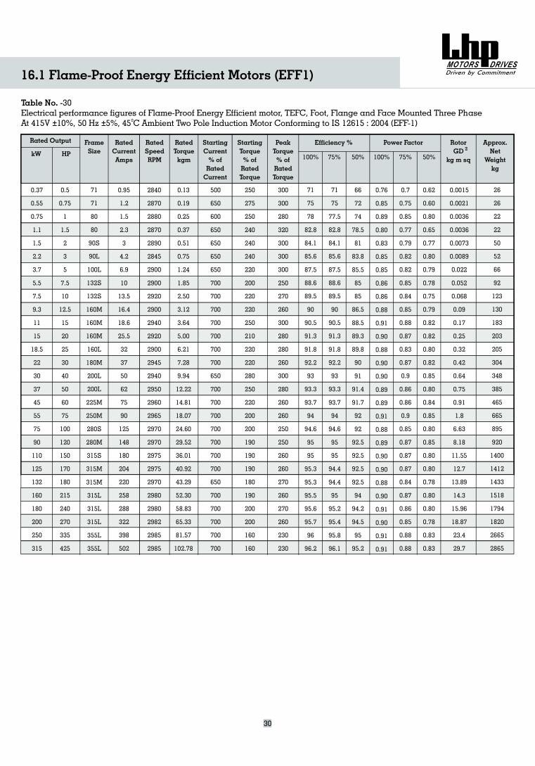
Rated Output FrameSizekW HP
RatedCurrentAmps
RatedSpeedRPM
RatedTorquekgm
StartingCurrent% ofRatedCurrent
Starting
% ofRatedTorque
TorquePeakTorque% ofRatedTorque
Approx.Net
Weightkg
RotorGD
kg m sq
Efficiency % Power Factor
Table No. -30Electrical performance figures of Flame-Proof Energy Efficient motor, TEFC, Foot, Flange and Face Mounted Three Phase
Pole Induction MotorAt 415V 10%, 50 Hz 5%, 45 C Ambient Two Conforming to IS 12615 : 2004 (EFF-1)± ± 0
100% 75% 50% 100% 75% 50%2
0.37
0.55
0.75
1.1
1.5
2.2
3.7
5.5
7.5
9.3
11
15
18.5
22
30
37
45
55
75
90
110
125
132
160
180
200
250
315
0.5
0.75
1
1.5
2
3
5
7.5
10
12.5
15
20
25
30
40
50
60
75
100
120
150
170
180
215
240
270
335
425
71
71
80
80
90S
90L
100L
132S
132S
160M
160M
160M
160L
180M
200L
200L
225M
250M
280S
280M
315S
315M
315M
315L
315L
315L
355L
355L
0.95
1.2
1.5
2.3
3
4.2
6.9
10
13.5
16.4
18.6
25.5
32
37
50
62
75
90
125
148
180
204
220
258
288
322
398
502
2840
2870
2880
2870
2890
2845
2900
2900
2920
2900
2940
2920
2900
2945
2940
2950
2960
2965
2970
2970
2975
2975
2970
2980
2980
2982
2985
2985
0.13
0.19
0.25
0.37
0.51
0.75
1.24
1.85
2.50
3.12
3.64
5.00
6.21
7.28
9.94
12.22
14.81
18.07
24.60
29.52
36.01
40.92
43.29
52.30
58.83
65.33
81.57
102.78
500
650
600
650
650
650
650
700
700
700
700
700
700
700
650
700
700
700
700
700
700
700
650
700
700
700
700
700
250
275
250
240
240
240
220
200
220
220
250
210
220
220
280
250
220
200
200
190
190
190
180
190
200
200
160
160
300
300
280
320
300
300
300
250
270
260
300
280
280
260
300
280
260
260
250
250
260
260
270
260
270
260
230
230
71
75
78
82.8
84.1
85.6
87.5
88.6
89.5
90
90.5
91.3
91.8
92.2
93
93.3
93.7
94
94.6
95
95
95.3
95.3
95.5
95.6
95.7
96
96.2
71
75
77.5
82.8
84.1
85.6
87.5
88.6
89.5
90
90.5
91.3
91.8
92.2
93
93.3
93.7
94
94.6
95
95
94.4
94.4
95
95.2
95.4
95.8
96.1
66
72
74
78.5
81
83.8
85.5
85
85
86.5
88.5
89.3
89.8
90
91
91.4
91.7
92
92
92.5
92.5
92.5
92.5
94
94.2
94.5
95
95.2
0.76
0.85
0.89
0.80
0.83
0.85
0.85
0.86
0.86
0.88
0.91
0.90
0.88
0.90
0.90
0.89
0.89
0.91
0.88
0.89
0.90
0.90
0.88
0.90
0.91
0.90
0.91
0.91
0.7
0.75
0.85
0.77
0.79
0.82
0.82
0.85
0.84
0.85
0.88
0.87
0.83
0.87
0.9
0.86
0.86
0.9
0.85
0.87
0.87
0.87
0.84
0.87
0.86
0.85
0.88
0.88
0.62
0.60
0.80
0.65
0.77
0.80
0.79
0.78
0.75
0.79
0.82
0.82
0.80
0.82
0.85
0.80
0.84
0.85
0.80
0.85
0.80
0.80
0.78
0.80
0.80
0.78
0.83
0.83
0.0015
0.0021
0.0036
0.0036
0.0073
0.0089
0.022
0.052
0.068
0.09
0.17
0.25
0.32
0.42
0.64
0.75
0.91
1.8
6.63
8.18
11.55
12.7
13.89
14.3
15.96
18.87
23.4
29.7
26
26
22
22
50
52
66
92
123
130
183
203
205
304
348
385
465
665
895
920
1400
1412
1433
1518
1794
1820
2665
2865
30
16.1 Flame-Proof Energy Efficient Motors (EFF1)
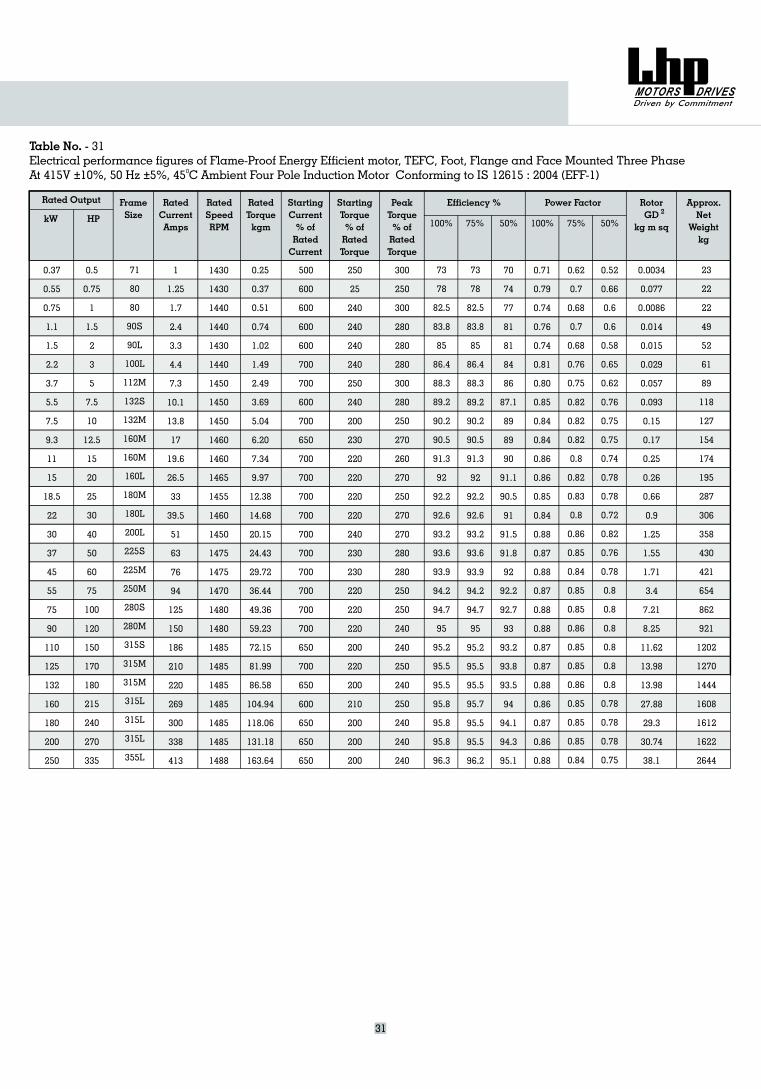
Table No. - 31Electrical performance figures of Flame-Proof Energy Efficient motor, TEFC, Foot, Flange and Face Mounted Three Phase
Pole Induction MotorAt 415V 10%, 50 Hz 5%, 45 C Ambient Four Conforming to IS 12615 : 2004 (EFF-1)± ± 0
Rated Output
kW
0.37
0.55
0.75
1.1
1.5
2.2
3.7
5.5
7.5
9.3
11
15
18.5
22
30
37
45
55
75
90
110
125
132
160
180
200
250
FrameSizeHP
RatedCurrentAmps
RatedSpeedRPM
RatedTorquekgm
StartingCurrent% ofRatedCurrent
Starting
% ofRatedTorque
TorquePeakTorque% ofRatedTorque
Approx.Net
Weightkg
RotorGD
kg m sq
Efficiency % Power Factor
100% 75% 50% 100% 75% 50%2
0.5
0.75
1
1.5
2
3
5
7.5
10
12.5
15
20
25
30
40
50
60
75
100
120
150
170
180
215
240
270
335
1
1.25
1.7
2.4
3.3
4.4
7.3
10.1
13.8
17
19.6
26.5
33
39.5
51
63
76
94
125
150
186
210
220
269
300
338
413
1430
1430
1440
1440
1430
1440
1450
1450
1450
1460
1460
1465
1455
1460
1450
1475
1475
1470
1480
1480
1485
1485
1485
1485
1485
1485
1488
0.25
0.37
0.51
0.74
1.02
1.49
2.49
3.69
5.04
6.20
7.34
9.97
12.38
14.68
20.15
24.43
29.72
36.44
49.36
59.23
72.15
81.99
86.58
104.94
118.06
131.18
163.64
500
600
600
600
600
700
700
600
700
650
700
700
700
700
700
700
700
700
700
700
650
700
650
600
650
650
650
250
25
240
240
240
240
250
240
200
230
220
220
220
220
240
230
230
220
220
220
200
220
200
210
200
200
200
300
250
300
280
280
280
300
280
250
270
260
270
250
270
270
280
280
250
250
240
240
250
240
250
240
240
240
73
78
82.5
83.8
85
86.4
88.3
89.2
90.2
90.5
91.3
92
92.2
92.6
93.2
93.6
93.9
94.2
94.7
95
95.2
95.5
95.5
95.8
95.8
95.8
96.3
73
78
82.5
83.8
85
86.4
88.3
89.2
90.2
90.5
91.3
92
92.2
92.6
93.2
93.6
93.9
94.2
94.7
95
95.2
95.5
95.5
95.7
95.5
95.5
96.2
70
74
77
81
81
84
86
87.1
89
89
90
91.1
90.5
91
91.5
91.8
92
92.2
92.7
93
93.2
93.8
93.5
94
94.1
94.3
95.1
0.71
0.79
0.74
0.76
0.74
0.81
0.80
0.85
0.84
0.84
0.86
0.86
0.85
0.84
0.88
0.87
0.88
0.87
0.88
0.88
0.87
0.87
0.88
0.86
0.87
0.86
0.88
0.62
0.7
0.68
0.7
0.68
0.76
0.75
0.82
0.82
0.82
0.8
0.82
0.83
0.8
0.86
0.85
0.84
0.85
0.85
0.86
0.85
0.85
0.86
0.85
0.85
0.85
0.84
0.52
0.66
0.6
0.6
0.58
0.65
0.62
0.76
0.75
0.75
0.74
0.78
0.78
0.72
0.82
0.76
0.78
0.8
0.8
0.8
0.8
0.8
0.8
0.78
0.78
0.78
0.75
0.0034
0.077
0.0086
0.014
0.015
0.029
0.057
0.093
0.15
0.17
0.25
0.26
0.66
0.9
1.25
1.55
1.71
3.4
7.21
8.25
11.62
13.98
13.98
27.88
29.3
30.74
38.1
23
22
22
49
52
61
89
118
127
154
174
195
287
306
358
430
421
654
862
921
1202
1270
1444
1608
1612
1622
2644
71
80
80
90S
90L
100L
112M
132S
132M
160M
160M
160L
180M
180L
200L
225S
225M
250M
280S
280M
315S
315M
315M
315L
315L
315L
355L
31
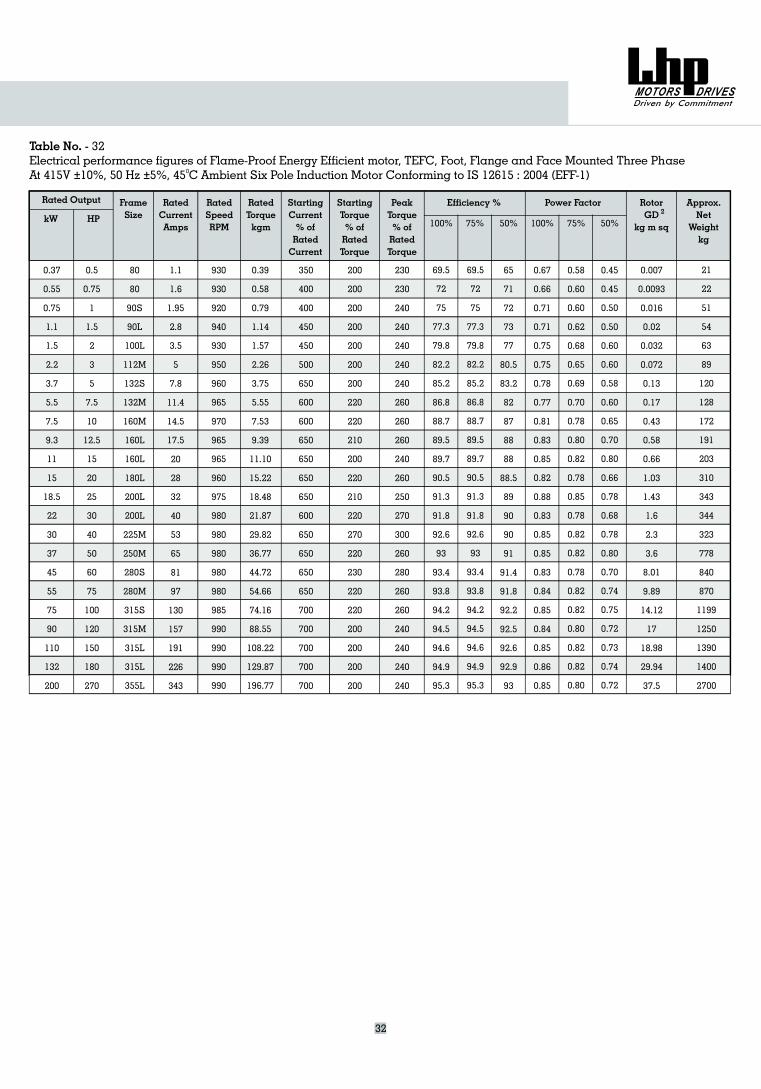
Table No. - 32Electrical performance figures of Flame-Proof Energy Efficient motor, TEFC, Foot, Flange and Face Mounted Three Phase
Pole Induction MotorAt 415V 10%, 50 Hz 5%, 45 C Ambient Six Conforming to IS 12615 : 2004 (EFF-1)± ± 0
Rated Output
kW
0.37
0.55
0.75
1.1
1.5
2.2
3.7
5.5
7.5
9.3
11
15
18.5
22
30
37
45
55
75
90
110
132
200
FrameSizeHP
RatedCurrentAmps
RatedSpeedRPM
RatedTorquekgm
StartingCurrent% ofRatedCurrent
Starting
% ofRatedTorque
TorquePeakTorque% ofRatedTorque
Approx.Net
Weightkg
RotorGD
kg m sq
Efficiency % Power Factor
100% 75% 50% 100% 75% 50%2
0.5
0.75
1
1.5
2
3
5
7.5
10
12.5
15
20
25
30
40
50
60
75
100
120
150
180
270
1.1
1.6
1.95
2.8
3.5
5
7.8
11.4
14.5
17.5
20
28
32
40
53
65
81
97
130
157
191
226
343
930
930
920
940
930
950
960
965
970
965
965
960
975
980
980
980
980
980
985
990
990
990
990
0.39
0.58
0.79
1.14
1.57
2.26
3.75
5.55
7.53
9.39
11.10
15.22
18.48
21.87
29.82
36.77
44.72
54.66
74.16
88.55
108.22
129.87
196.77
350
400
400
450
450
500
650
600
600
650
650
650
650
600
650
650
650
650
700
700
700
700
700
200
200
200
200
200
200
200
220
220
210
200
220
210
220
270
220
230
220
220
200
200
200
200
230
230
240
240
240
240
240
260
260
260
240
260
250
270
300
260
280
260
260
240
240
240
240
69.5
72
75
77.3
79.8
82.2
85.2
86.8
88.7
89.5
89.7
90.5
91.3
91.8
92.6
93
93.4
93.8
94.2
94.5
94.6
94.9
95.3
69.5
72
75
77.3
79.8
82.2
85.2
86.8
88.7
89.5
89.7
90.5
91.3
91.8
92.6
93
93.4
93.8
94.2
94.5
94.6
94.9
95.3
65
71
72
73
77
80.5
83.2
82
87
88
88
88.5
89
90
90
91
91.4
91.8
92.2
92.5
92.6
92.9
93
0.67
0.66
0.71
0.71
0.75
0.75
0.78
0.77
0.81
0.83
0.85
0.82
0.88
0.83
0.85
0.85
0.83
0.84
0.85
0.84
0.85
0.86
0.85
0.58
0.60
0.60
0.62
0.68
0.65
0.69
0.70
0.78
0.80
0.82
0.78
0.85
0.78
0.82
0.82
0.78
0.82
0.82
0.80
0.82
0.82
0.80
0.45
0.45
0.50
0.50
0.60
0.60
0.58
0.60
0.65
0.70
0.80
0.66
0.78
0.68
0.78
0.80
0.70
0.74
0.75
0.72
0.73
0.74
0.72
0.007
0.0093
0.016
0.02
0.032
0.072
0.13
0.17
0.43
0.58
0.66
1.03
1.43
1.6
2.3
3.6
8.01
9.89
14.12
17
18.98
29.94
37.5
21
22
51
54
63
89
120
128
172
191
203
310
343
344
323
778
840
870
1199
1250
1390
1400
2700
80
80
90S
90L
100L
112M
132S
132M
160M
160L
160L
180L
200L
200L
225M
250M
280S
280M
315S
315M
315L
315L
355L
32
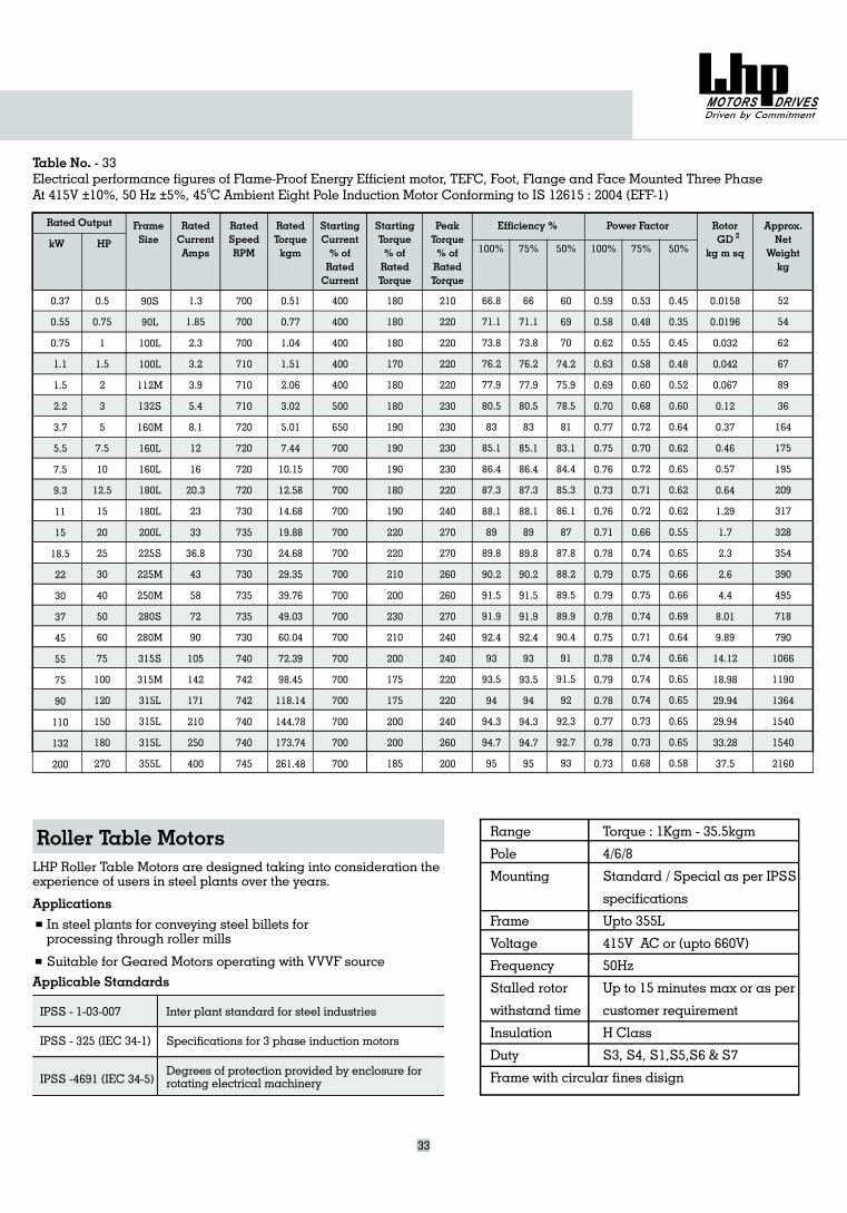
LHP Roller Table Motors are designed taking into consideration theexperience of users in steel plants over the years.
Applications
In steel plants for conveying steel billets forprocessing through roller mills
Suitable for Geared Motors operating with VVVF source
Applicable Standards
Roller Table Motors
IPSS - 1-03-007 Inter plant standard for steel industries
IPSS - 325 (IEC 34-1) Specifications for 3 phase induction motors
IPSS -4691 (IEC 34-5)Degrees of protection provided by enclosure forrotating electrical machinery
Range
Pole
Mounting
Frame
Voltage
Frequency
Stalled rotor
withstand time
Insulation
Duty
Frame with circular fines disign
Torque : 1Kgm - 35.5kgm
4/6/8
Standard / Special as per IPSS
specifications
Upto 355L
415V AC or (upto 660V)
50Hz
Up to 15 minutes max or as per
customer requirement
H Class
S3, S4, S1,S5,S6 & S7
Table No. - 33Electrical performance figures of Flame-Proof Energy Efficient motor, TEFC, Foot, Flange and Face Mounted Three Phase
45 Pole Induction MotorAt 415V 10%, 50 Hz 5%, C Ambient Eight Conforming to IS 12615 : 2004 (EFF-1)± ± 0
Rated Output
kW
FrameSizeHP
RatedCurrentAmps
RatedSpeedRPM
RatedTorquekgm
StartingCurrent% ofRatedCurrent
Starting
% ofRatedTorque
TorquePeakTorque% ofRatedTorque
Approx.Net
Weightkg
RotorGD
kg m sq
Efficiency % Power Factor
100% 75% 50% 100% 75% 50%2
0.5
0.75
1
1.5
2
3
5
7.5
10
12.5
15
20
25
30
40
50
60
75
100
120
150
180
270
1.3
1.85
2.3
3.2
3.9
5.4
8.1
12
16
20.3
23
33
36.8
43
58
72
90
105
142
171
210
250
400
700
700
700
710
710
710
720
720
720
720
730
735
730
730
735
735
730
740
742
742
740
740
745
0.51
0.77
1.04
1.51
2.06
3.02
5.01
7.44
10.15
12.58
14.68
19.88
24.68
29.35
39.76
49.03
60.04
72.39
98.45
118.14
144.78
173.74
261.48
400
400
400
400
400
500
650
700
700
700
700
700
700
700
700
700
700
700
700
700
700
700
700
180
180
180
170
180
180
190
190
190
180
190
220
220
210
200
230
210
200
175
175
200
200
185
210
220
220
220
220
230
230
230
230
220
240
270
270
260
260
270
240
240
220
220
240
260
200
66.8
71.1
73.8
76.2
77.9
80.5
83
85.1
86.4
87.3
88.1
89
89.8
90.2
91.5
91.9
92.4
93
93.5
94
94.3
94.7
95
66
71.1
73.8
76.2
77.9
80.5
83
85.1
86.4
87.3
88.1
89
89.8
90.2
91.5
91.9
92.4
93
93.5
94
94.3
94.7
95
60
69
70
74.2
75.9
78.5
81
83.1
84.4
85.3
86.1
87
87.8
88.2
89.5
89.9
90.4
91
91.5
92
92.3
92.7
93
0.59
0.58
0.62
0.63
0.69
0.70
0.77
0.75
0.76
0.73
0.76
0.71
0.78
0.79
0.79
0.78
0.75
0.78
0.79
0.78
0.77
0.78
0.73
0.53
0.48
0.55
0.58
0.60
0.68
0.72
0.70
0.72
0.71
0.72
0.66
0.74
0.75
0.75
0.74
0.71
0.74
0.74
0.74
0.73
0.73
0.68
0.45
0.35
0.45
0.48
0.52
0.60
0.64
0.62
0.65
0.62
0.62
0.55
0.65
0.66
0.66
0.69
0.64
0.66
0.65
0.65
0.65
0.65
0.58
0.0158
0.0196
0.032
0.042
0.067
0.12
0.37
0.46
0.57
0.64
1.29
1.7
2.3
2.6
4.4
8.01
9.89
14.12
18.98
29.94
29.94
33.28
37.5
52
54
62
67
89
36
164
175
195
209
317
328
354
390
495
718
790
1066
1190
1364
1540
1540
2160
90S
90L
100L
100L
112M
132S
160M
160L
160L
180L
180L
200L
225S
225M
250M
280S
280M
315S
315M
315L
315L
315L
355L
0.37
0.55
0.75
1.1
1.5
2.2
3.7
5.5
7.5
9.3
11
15
18.5
22
30
37
45
55
75
90
110
132
200
33
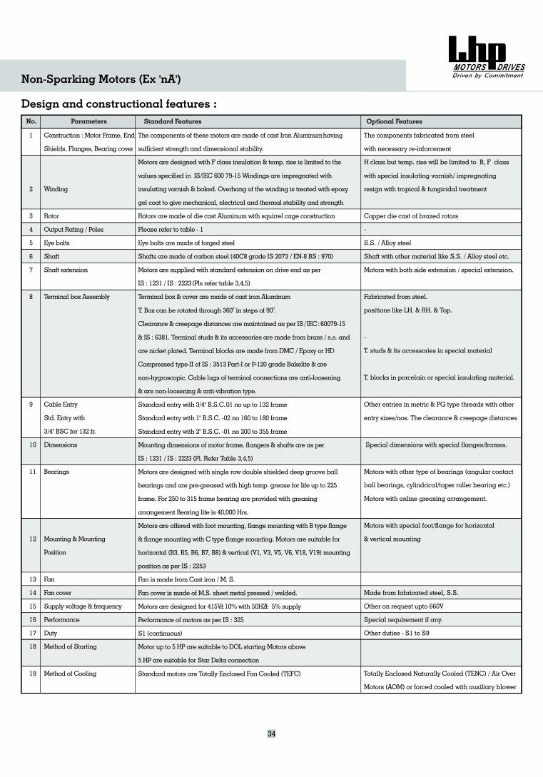
No.
1
2
3
4
5
6
7
8
9
10
11
12
13
14
15
16
17
18
19
Construction : Motor Frame, End
Shields, Flanges, Bearing cover
Winding
Rotor
Output Rating / Poles
Eye bolts
Shaft
Shaft extension
Terminal box Assembly
Cable Entry
Std. Entry with
3/4" BSC for 132 fr.
Dimensions
Bearings
Mounting &Mounting
Position
Fan
Fan cover
Supply voltage & frequency
Performance
Duty
Method of Starting
Method of Cooling
Design and constructional features :Parameters Standard Features Optional Features
The components fabricated from steel
with necessary re-inforcement
H class but temp. rise will be limited to B, F class
with special insulating varnish/ impregnating
resign with tropical & fungicidal treatment
Copper die cast of brazed rotors
-
S.S. / Alloy steel
Shaft with other material like S.S. / Alloy steel etc.
Motors with both side extension / special extension.
Fabricated from steel.
positions like LH. & RH. & Top.
-
T. studs & its accessories in special material
T. blocks in porcelain or special insulating material.
Other entries in metric & PG type threads with other
entry sizes/nos. The clearance & creepage distances
Special dimensions with special flanges/frames.
Motors with other type of bearings (angular contact
ball bearings, cylindrical/taper roller bearing etc.)
Motors with online greasing arrangement.
Motors with special foot/flange for horizontal
& vertical mounting
Made from fabricated steel, S.S.
Other on request upto 660V
Special requirement if any.
Other duties - S1 to S9
Totally Enclosed Naturally Cooled (TENC) / Air Over
Motors (AOM) or forced cooled with auxiliary blower
Non-Sparking Motors (Ex 'nA')
34
The components of these motors are made of cast Iron Aluminumhaving
sufficient strength and dimensional stability.
Motors are designed with F class insulation & temp. rise is limited to the
values specified in IS/IEC 600 79-15Windings are impregnated with
insulating varnish & baked. Overhang of the winding is treated with epoxy
gel coat to give mechanical, electrical and thermal stability and strength
Rotors are made of die cast Aluminumwith squirrel cage construction
Please refer to table - 1
Eye bolts are made of forged steel
Shafts are made of carbon steel (40C8 grade IS 2073 / EN-8 BS : 970)
Motors are supplied with standard extension on drive end as per
IS : 1231 / IS : 2223(Pls refer table 3,4,5)
Terminal box & cover are made of cast iron Aluminum
T. Box can be rotated through 360 in steps of 90 .
Clearance & creepage distances are maintained as per IS/IEC:60079-15
& IS : 6381. Terminal studs & its accessories are made from brass / s.s. and
are nicket plated. Terminal blocks are made from DMC / Epoxy or HD
Compressed type-II of IS : 3513 Part-I or P-120 grade Bakelite & are
non-hygroscopic. Cable lugs of terminal connections are anti-loosening
& are non-loosening & anti-vibration type.
Standard entry with 3/4" B.S.C.01 no up to 1 frame
Standard entry with 1" B.S.C. -02 no 160 to 180 frame
Mounting dimensions of motor frame, flangers & shafts are as per
IS : 1231 / IS : 2223
Motors are designed with single row double shielded deep groove ball
bearings and are pre-greased with high temp. grease for life up to 225
frame. For 250 to 315 frame bearing are provided with greasing
arrangement Bearing life is 40,000 Hrs.
Motors are offered with foot mounting, flange mounting with B type flange
& flange mounting with C type flange mounting. Motors are suitable for
horizontal (B3, B5, B6, B7, B8) & vertical (V1, V3, V5, V6, V18, V19) mounting
position as per IS : 2253
Fan is made from
Fan cover is made of .S. sheet metal pressed / welded.
Motors are designed for 415V 10%with 50HZ 5% supply
Performance of motors as per I : 325
S1 (continuous)
Motor up to 5 HP are suitable to DOL starting Motors above
5 HP are suitable for Star Delta connection
Standard motors are Totally Enclosed Fan Cooled (TEFC)
0 0
32
Standard entry with 2" B.S.C. -01 no 200 to 355 frame
(Pl. Refer Table 3,4,5)
Cast iron / M. S.
M
S
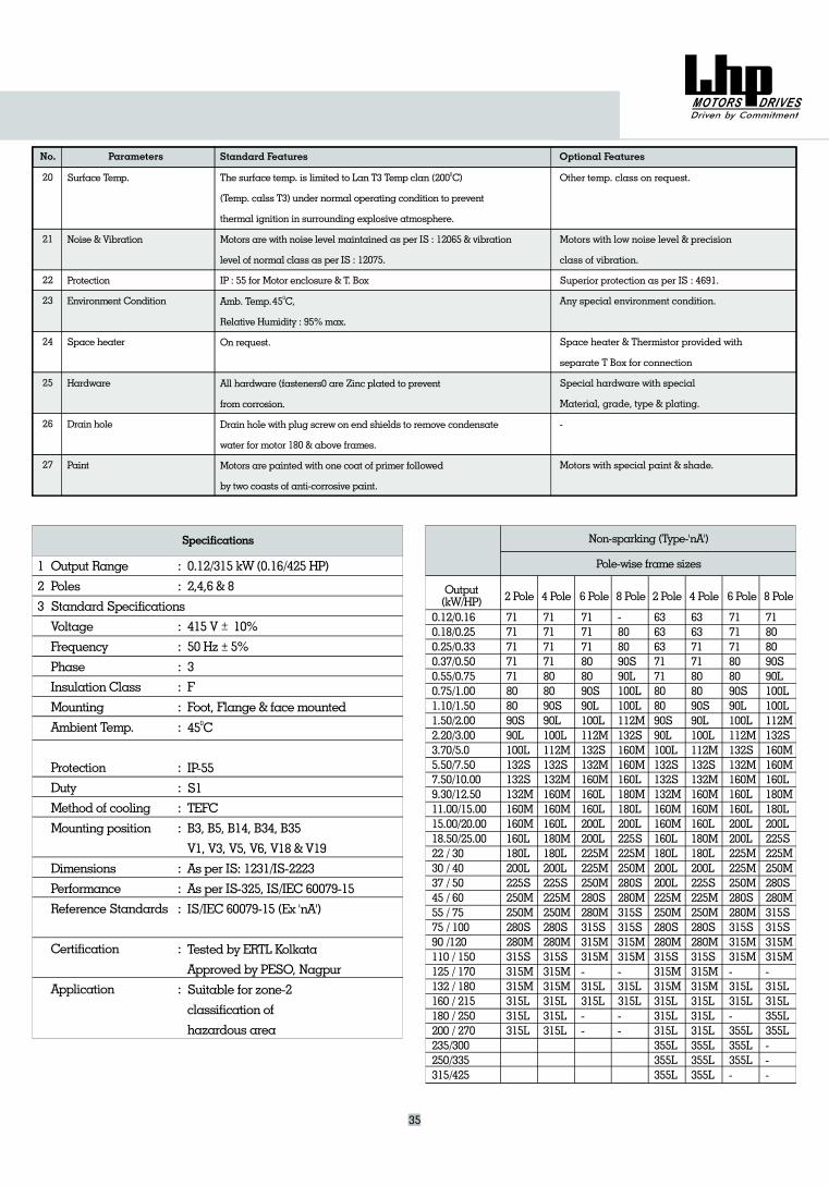
No.
20
21
22
23
24
25
26
27
Surface Temp.
Noise & Vibration
Protection
Environment Condition
Space heater
Hardware
Drain hole
Paint
Parameters Standard Features Optional Features
The surface temp. is limited to Lan T3 Temp clan (200 C)
(Temp. calss T3) under normal operating condition to prevent
thermal ignition in surrounding explosive atmosphere.
Motors are with noise level maintained as per IS : 12065 & vibration
level of normal class as per IS : 12075.
IP : 55 for Motor enclosure & T. Box
Amb. Temp. C,
Relative Humidity : 95%max.
On request.
All hardware (fasteners0 are Zinc plated to prevent
from corrosion.
Drain hole with plug screw on end shields to remove condensate
water for motor 180 & above frames.
Motors are painted with one coat of primer followed
by two coasts of anti-corrosive paint.
0
0
Other temp. class on request.
Motors with low noise level & precision
class of vibration.
Superior protection as per IS : 4691.
Any special environment condition.
Space heater & Thermistor provided with
separate T Box for connection
Special hardware with special
Material, grade, type & plating.
-
Motors with special paint & shade.
Output Range
Poles
Standard Specifications
Voltage
Frequency
Phase
Insulation Class
Mounting
Ambient Temp.
Protection
Duty
Method of cooling
Mounting position
Dimensions
Performance
Reference Standards
Certification
Application
Specifications
0.12/315 kW (0.16/425 HP)
2,4,6 & 8
415 V 10%
50 Hz 5%
3
F
Foot, Flange & facemounted
45 C
IP-55
S1
TEFC
B3, B5, B14, B34, B35
V1, V3, V5, V6, V18 & V19
As per IS: 1231/IS-2223
As per IS-325, IS/IEC 60079-15
IS/IEC 60079-15
Tested by
Approved by , Nagpur
Suitable for zone-2
classification of
hazardous area
0
(Ex 'nA')
ERTL Kolkata
PESO
:
:
:
:
:
:
:
:
:
:
:
:
:
:
:
:
:
1
2
3
Non-sparking (Type-'nA')
Pole-wise frame sizes
Output(kW/HP) 2 Pole 4 Pole 6 Pole 8 Pole 2 Pole 4 Pole 6 Pole 8 Pole
0.12/0.160.18/0.250.25/0.330.37/0.500.55/0.750.75/1.001.10/1.501.50/2.002.20/3.003.70/5.05.50/7.507.50/10.009.30/12.5011.00/15.0015.00/20.0018.50/25.0022 / 3030 / 4037 / 5045 / 6055 / 7575 / 10090 /120110 / 150125 / 170132 / 180160 / 215180 / 250200 / 270235/300250/335315/425
7171717171808090S90L100L132S132S132M160M160M160L180L200L225S250M250M280S280M315S315M315M315L315L315L
71717171808090S90L100L112M132S132M160M160M160L180M180L200L225S225M250M280S280M315S315M315M315L315L315L
717171808090S90L100L112M132S132M160M160L160L200L200L225M225M250M280S280M315S315M315M-315L315L--
-808090S90L100L100L112M132S160M160M160L180M180L200L225S225M250M280S280M315S315S315M315M-315L315L--
636363
132S
160M
50
355L355L355L
7171808090S90L100L132S
132M160M
160L180L200L200L225M2 M280S280M315S315M315M315L315L315L
6363
132S
160M
355L355L355L
7171808090S90L100L112M
132M160M
160L180M180L200L225S225M250M280S280M315S315M315M315L315L315L
717171808090S90L100L112M
132M160M
L160L200L
225M225M250M280S280M315S315M315M-315L315L-
132S
160
200L
355L355L355L-
71
132S
355L355L
--
808090S90L100L100L112M
160M160M160L180M180L200L225S225M250M280S280M315S315S315M315M-315L315L
-
35
45
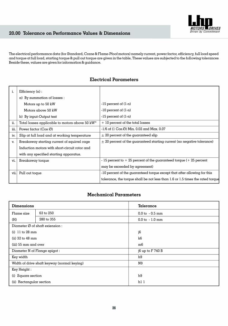
20.00 Tolerance on Performance Values & Dimensions
Theelectrical performancedata (for Standard,Crane&Flame-Pfoofmotors) namely current, power factor, efficiency, full load speedand torque at full load, starting torque& pull out torque are given in the table, These values are subjected to the following tolerancesBeside these, valuesaregiven for information&guidance.
Efficiency (n) :
a) By summation of losses :
Motors up to 50 kW
Motors above 50 kW
b) By input-Output test
Total losses applicable to motors above 50 kW*
Power factor (Cos O)
Slip at full load and at working temperature
Breakaway starting current of squirrel cage
Induction motors with short-circuit rotor and
with any specified starting apparatus.
Breakaway torque
Pull out toque
Flame size
(
Diameter O of shaft exiension :
(i) 11 to 28 mm
(ii) 32 to 48 mm
(iii) 55 mm and over
Diameter N of Flange spigot :
Key wi th
Width of drive shaft keyway (normal keying)
Key :
(i) Square section
(ii) Rectangular section
H)
d
Height
i.
ii.
iii.
iv.
v.
vi.
vii.
Electrical Parameters
Mechanical Parameters
-15 percent of (1-n)
-10 percent of (1-n)
-15 percent of (1-n)
+ 10 percent of the total losses
-1/6 of (1 Cos O) Min. 0.02 and Max. 0.07
+ 20 percent of the guaranteed slip
+ 20 percent of the guaranteed starting current (no negative tolerance)
- 15 percent to + 25 percent of the guaranteed torque (+ 25 percent
may be exceeded by agreement)
-10 percent of the guaranteed torque except that after allowing for this
tolerance, the torque shall be not less than 1.6 or 1.5 times the rated torque
0.0 to - 0.5 mm
0.0 to - 1.0 mm
j6
k6
m6
j6 up to F 740 B
h9
N9
h9
h1 1
Dimensions Talerance
36
63 to 250
280 to 355
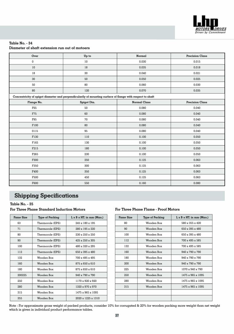
Fame Size Type of Packing L x B x HT. in mm (Max.)
0
10
18
30
50
80
F65
F75
F85
F100
0115
F130
F165
F215
F265
F300
F350
F400
F500
F600
10
18
30
50
80
120
50
60
70
80
95
110
130
180
230
250
300
350
450
550
0.030
0.035
0.040
0.050
0.060
0.070
0.080
0.080
0.080
0.080
0.080
0.100
0.100
0.100
0.100
0.125
0.125
0.125
0.125
0.160
0.015
0.018
0.021
0.025
0.030
0.035
0.040
0.040
0.040
0.040
0.040
0.050
0.050
0.050
0.050
0.063
0.063
0.063
0.063
0.080
Diameter of shaft extension run out of motoers
Over Up to Normal Precision Class
Flange No. Spigot Dia. Normal Class Precision Class
Concentricity of spigot diameter and perpendicularily of mounting surface of flange with respect to shaft
37
Table No. - 34
Wooden Box
Wooden Box
Wooden Box
Wooden Box
Wooden Box
Wooden Box
Wooden Box
Wooden Box
Wooden Box
Wooden Box
Wooden Box
Wooden Box
580 x 355 x 420
650 x 395 x 480
650 x 395 x 480
700 x 495 x 585
700 x 495 x 585
940 x 790 x 790
940 x 790 x 790
940 x 790 x 790
1070 x 940 x 790
1475 x 965 x 1095
1475 x 965 x 1095
1475 x 965 x 1095
80
90
100
112
132
160
180
200
225
250
280
315
63
71
80
90
100
112
132
160
180
200225
250
280
315
355
Thermocole (EPS)
Thermocole (EPS)
Thermocole (EPS)
Thermocole (EPS)
Thermocole (EPS)
Thermocole (EPS)
Wooden Box
Wooden Box
Wooden Box
Wooden Box
Wooden Box
Wooden Box
Wooden Box
Wooden Box
245 x 180 x 195
280 x 195 x 220
230 x 250 x 250
425 x 250 x 305
480 x 320 x 295
650 x 395 x 480
700 x 495 x 495
875 x 650 x 610
875 x 650 x 610
940 x 790 x 790
1170 x 920 x 920
1320 x 970 x 970
1475 x 965 x 1095
2020 x 1225 x 1310
For Three Phase Standard Induction Motors
Fame Size Type of Packing L x B x HT. in mm (Max.)
For Three Phase Flame - Proof MotorsTable No. - 35
Note : For approximate gross weight of packed products, consider 10% for corrugated & 20% for wooden packing more weight than net weightwhich is given in individual product performance tables.
Shipping Specifications


![Lenze Compact MCM Synchronous Servo Motors...Dialgaugeholderforflange z +/-1 [mm] 10.0 check Concentricity IEC60072 Normalclass Value y [mm] 0.080 0.10 Axialrun-out IEC60072 Normalclass](https://img.pdfslide.us/doc/110x75/60b6723cd6579810854ba303/lenze-compact-mcm-synchronous-servo-motors-dialgaugeholderforflange-z-1-mm.jpg)