Embed Size (px)
Citation preview
Page 1 of 26 Report No. BA-4786867568-A-1
TRF No. IEC62133B
F
Test Report issued under the responsibility of:
TEST REPORT IEC 62133, Second Edition
Secondary cells and batteries containing alkaline or other non-acid electrolytes – Safety requirements for portable sealed secondary cells,
and for batteries made from them, for use in portable applications
Report Number. .............................. : BA-4786867568-A-1
Date of issue ................................... : 2015-03-31
Total number of pages .................... 26
Applicant’s name ............................ : LG CHEM, LTD
Address ........................................... : 128 YEOUI-DAERO, YEONGDEUNGPO-GU
SEOUL 150-721 REPUBLIC OF KOREA
Test specification:
Standard .......................................... : IEC 62133: 2012 (Second Edition)
Test procedure ............................... : CB Scheme
Non-standard test method............. : N/A
Test Report Form No. ..................... : IEC62133B
Test Report Form(s) Originator .... : UL(Demko)
Master TRF ...................................... : Dated 2013-03
Copyright © 2013 Worldwide System for Conformity Testing and Certification of Electrotechnical Equipment and Components (IECEE), Geneva, Switzerland. All rights reserved. This publication may be reproduced in whole or in part for non-commercial purposes as long as the IECEE is acknowledged as copyright owner and source of the material. IECEE takes no responsibility for and will not assume liability for damages resulting from the reader's interpretation of the reproduced material due to its placement and context.
If this Test Report Form is used by non-IECEE members, the IECEE/IEC logo and the reference to the CB Scheme procedure shall be removed.
This report is not valid as a CB Test Report unless signed by an approved CB Testing Laboratory and appended to a CB Test Certificate issued by an NCB in accordance with IECEE 02.
Test item description ..................... : Rechargeable Li-ion Cell
Trade Mark ...................................... :
Manufacturer ................................... : LG CHEM, LTD/ RESEARCH PARK 188 MUNJIRO, YUSEONG-GU, DAEJEON, 305-738, REPUBLIC OF KOREA
Model/Type reference .................... : INR18650HG2 or HG2 / INR19/66
Ratings ............................................ : 3.6Vdc, 3000mAh
Page 2 of 26 Report No. BA-4786867568-A-1
TRF No. IEC62133B
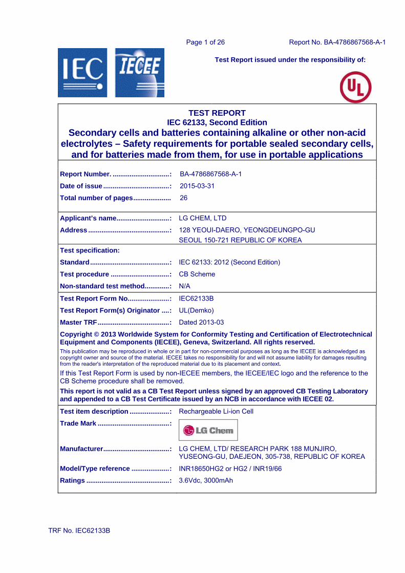
Testing procedure and testing location:
CB Testing Laboratory: Underwriters Laboratories Taiwan Co,. Ltd
Testing location/ address ....................... : 260 Da-Yeh Road 112 Peitou Taipei City, CHINESE TAIPEI
Associated CB Testing Laboratory:
Testing location/ address ....................... :
Tested by (name + signature) .......... :
Approved by (name + signature) ..... :
Testing procedure: TMP
Testing location/ address ....................... :
Tested by (name + signature) .......... :
Approved by (name + signature) ..... :
Testing procedure: WMT
Testing location/ address ....................... :
Tested by (name + signature) .......... :
Witnessed by (name + signature) .... :
Approved by (name + signature) ..... :
Testing procedure: SMT
Testing location/ address ....................... : LG CHEM, LTD/ RESEARCH PARK 188 MUNJIRO, YUSEONG-GU, DAEJEON, 305-738, REPUBLIC OF KOREA
Tested by (name + signature) .......... : IKHYUN NAM
Approved by (name + signature) ..... : Richard Jeon
Supervised by (name + signature) .. : YunSun Ju
Page 3 of 26 Report No. BA-4786867568-A-1
TRF No. IEC62133B
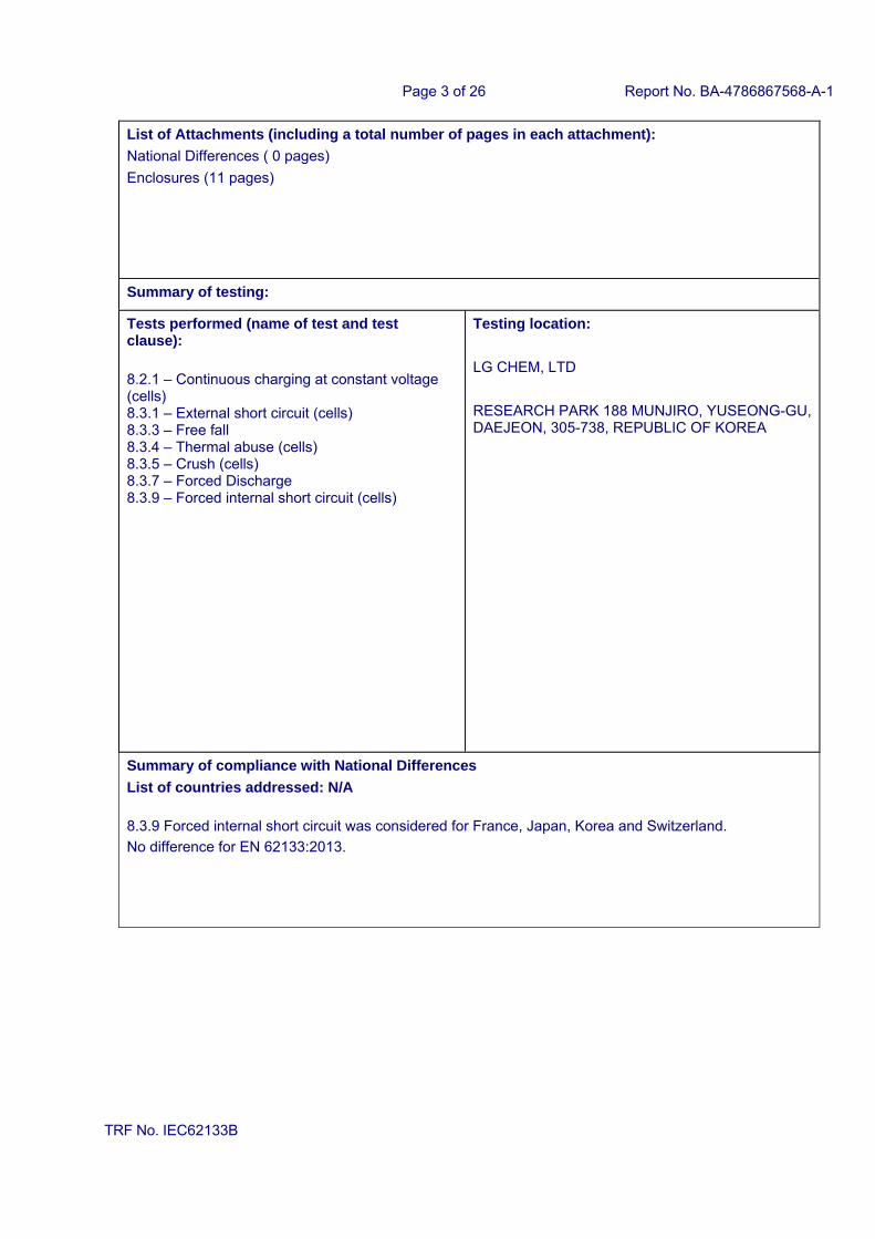
List of Attachments (including a total number of pages in each attachment):
National Differences ( 0 pages)
Enclosures (11 pages)
Summary of testing:
Tests performed (name of test and test clause):
8.2.1 – Continuous charging at constant voltage (cells) 8.3.1 – External short circuit (cells) 8.3.3 – Free fall 8.3.4 – Thermal abuse (cells) 8.3.5 – Crush (cells) 8.3.7 – Forced Discharge 8.3.9 – Forced internal short circuit (cells)
Testing location:
LG CHEM, LTD
RESEARCH PARK 188 MUNJIRO, YUSEONG-GU, DAEJEON, 305-738, REPUBLIC OF KOREA
Summary of compliance with National Differences
List of countries addressed: N/A
8.3.9 Forced internal short circuit was considered for France, Japan, Korea and Switzerland.
No difference for EN 62133:2013.
Page 4 of 26 Report No. BA-4786867568-A-1
TRF No. IEC62133B
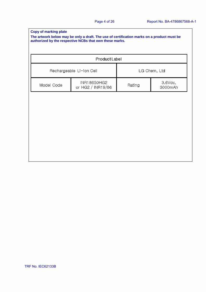
Copy of marking plate
The artwork below may be only a draft. The use of certification marks on a product must be authorized by the respective NCBs that own these marks.
Page 5 of 26 Report No. BA-4786867568-A-1
TRF No. IEC62133B
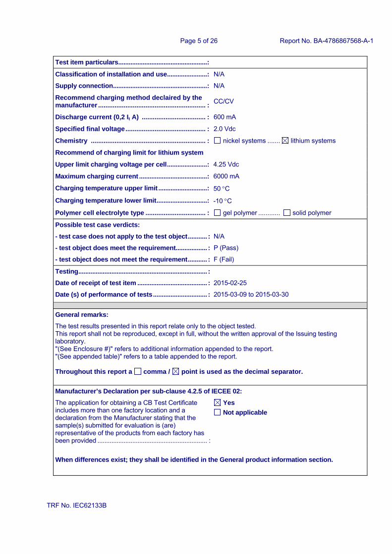
Test item particulars................................................... :
Classification of installation and use ....................... : N/A
Supply connection...................................................... : N/A
Recommend charging method declaired by the manufacturer ........................................................... :
CC/CV
Discharge current (0,2 It A) ................................... : 600 mA
Specified final voltage ............................................ : 2.0 Vdc
Chemistry ............................................................... : nickel systems ....... lithium systems
Recommend of charging limit for lithium system
Upper limit charging voltage per cell ....................... : 4.25 Vdc
Maximum charging current ....................................... : 6000 mA
Charging temperature upper limit ............................ : 50 C
Charging temperature lower limit ............................. : -10 C
Polymer cell electrolyte type ................................. : gel polymer ............ solid polymer
Possible test case verdicts:
- test case does not apply to the test object ........... : N/A
- test object does meet the requirement.................. : P (Pass)
- test object does not meet the requirement ........... : F (Fail)
Testing .......................................................................... :
Date of receipt of test item ........................................ : 2015-02-25
Date (s) of performance of tests ............................... : 2015-03-09 to 2015-03-30
General remarks:
The test results presented in this report relate only to the object tested. This report shall not be reproduced, except in full, without the written approval of the Issuing testing laboratory. "(See Enclosure #)" refers to additional information appended to the report. "(See appended table)" refers to a table appended to the report. Throughout this report a comma / point is used as the decimal separator.
Manufacturer’s Declaration per sub-clause 4.2.5 of IECEE 02:
The application for obtaining a CB Test Certificate includes more than one factory location and a declaration from the Manufacturer stating that the sample(s) submitted for evaluation is (are) representative of the products from each factory has been provided ............................................................... :
Yes
Not applicable
When differences exist; they shall be identified in the General product information section.
Page 6 of 26 Report No. BA-4786867568-A-1
TRF No. IEC62133B
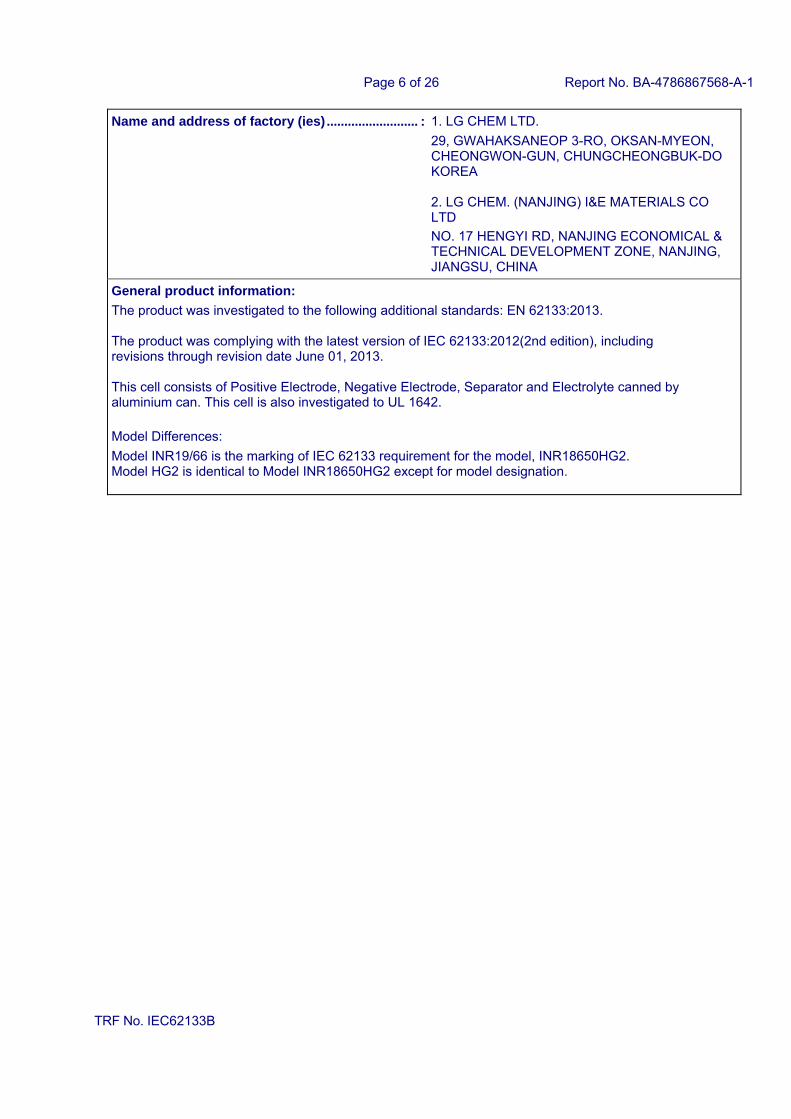
Name and address of factory (ies) .......................... : 1. LG CHEM LTD.
29, GWAHAKSANEOP 3-RO, OKSAN-MYEON, CHEONGWON-GUN, CHUNGCHEONGBUK-DO KOREA 2. LG CHEM. (NANJING) I&E MATERIALS CO LTD
NO. 17 HENGYI RD, NANJING ECONOMICAL & TECHNICAL DEVELOPMENT ZONE, NANJING, JIANGSU, CHINA
General product information:
The product was investigated to the following additional standards: EN 62133:2013. The product was complying with the latest version of IEC 62133:2012(2nd edition), including revisions through revision date June 01, 2013. This cell consists of Positive Electrode, Negative Electrode, Separator and Electrolyte canned by aluminium can. This cell is also investigated to UL 1642.
Model Differences:
Model INR19/66 is the marking of IEC 62133 requirement for the model, INR18650HG2. Model HG2 is identical to Model INR18650HG2 except for model designation.
Page 7 of 26 Report No. BA-4786867568-A-1
IEC 62133
Clause Requirement + Test Result - Remark Verdict
TRF No. IEC62133B
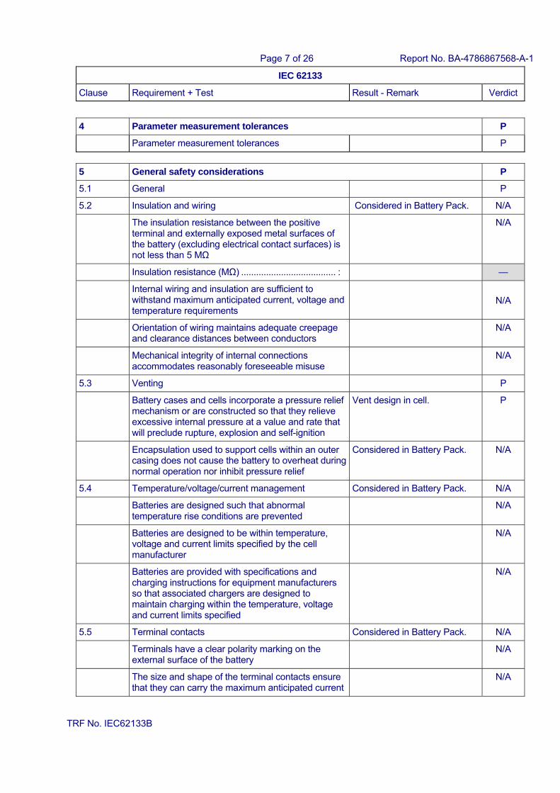
4 Parameter measurement tolerances P
Parameter measurement tolerances P
5 General safety considerations P
5.1 General P
5.2 Insulation and wiring Considered in Battery Pack. N/A
The insulation resistance between the positive terminal and externally exposed metal surfaces of the battery (excluding electrical contact surfaces) is not less than 5 MΩ
N/A
Insulation resistance (MΩ) ...................................... : —
Internal wiring and insulation are sufficient to withstand maximum anticipated current, voltage and temperature requirements
N/A
Orientation of wiring maintains adequate creepage and clearance distances between conductors
N/A
Mechanical integrity of internal connections accommodates reasonably foreseeable misuse
N/A
5.3 Venting P
Battery cases and cells incorporate a pressure relief mechanism or are constructed so that they relieve excessive internal pressure at a value and rate that will preclude rupture, explosion and self-ignition
Vent design in cell. P
Encapsulation used to support cells within an outer casing does not cause the battery to overheat during normal operation nor inhibit pressure relief
Considered in Battery Pack. N/A
5.4 Temperature/voltage/current management Considered in Battery Pack. N/A
Batteries are designed such that abnormal temperature rise conditions are prevented
N/A
Batteries are designed to be within temperature, voltage and current limits specified by the cell manufacturer
N/A
Batteries are provided with specifications and charging instructions for equipment manufacturers so that associated chargers are designed to maintain charging within the temperature, voltage and current limits specified
N/A
5.5 Terminal contacts Considered in Battery Pack. N/A
Terminals have a clear polarity marking on the external surface of the battery
N/A
The size and shape of the terminal contacts ensure that they can carry the maximum anticipated current
N/A
Page 8 of 26 Report No. BA-4786867568-A-1
IEC 62133
Clause Requirement + Test Result - Remark Verdict
TRF No. IEC62133B
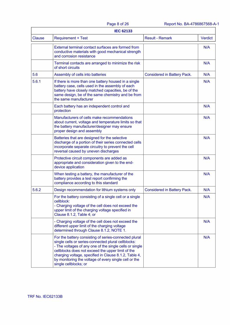
External terminal contact surfaces are formed from conductive materials with good mechanical strength and corrosion resistance
N/A
Terminal contacts are arranged to minimize the risk of short circuits
N/A
5.6 Assembly of cells into batteries Considered in Battery Pack. N/A
5.6.1 If there is more than one battery housed in a single battery case, cells used in the assembly of each battery have closely matched capacities, be of the same design, be of the same chemistry and be from the same manufacturer
N/A
Each battery has an independent control and protection
N/A
Manufacturers of cells make recommendations about current, voltage and temperature limits so that the battery manufacturer/designer may ensure proper design and assembly
N/A
Batteries that are designed for the selective discharge of a portion of their series connected cells incorporate separate circuitry to prevent the cell reversal caused by uneven discharges
N/A
Protective circuit components are added as appropriate and consideration given to the end-device application
N/A
When testing a battery, the manufacturer of the battery provides a test report confirming the compliance according to this standard
N/A
5.6.2 Design recommendation for lithium systems only Considered in Battery Pack. N/A
For the battery consisting of a single cell or a single cellblock: - Charging voltage of the cell does not exceed the upper limit of the charging voltage specified in Clause 8.1.2, Table 4; or
N/A
- Charging voltage of the cell does not exceed the different upper limit of the charging voltage determined through Clause 8.1.2, NOTE 1.
N/A
For the battery consisting of series-connected plural single cells or series-connected plural cellblocks: - The voltages of any one of the single cells or single cellblocks does not exceed the upper limit of the charging voltage, specified in Clause 8.1.2, Table 4, by monitoring the voltage of every single cell or the single cellblocks; or
N/A
Page 9 of 26 Report No. BA-4786867568-A-1
IEC 62133
Clause Requirement + Test Result - Remark Verdict
TRF No. IEC62133B
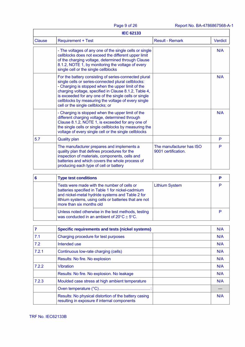
- The voltages of any one of the single cells or single cellblocks does not exceed the different upper limit of the charging voltage, determined through Clause 8.1.2, NOTE 1, by monitoring the voltage of every single cell or the single cellblocks
N/A
For the battery consisting of series-connected plural single cells or series-connected plural cellblocks: - Charging is stopped when the upper limit of the charging voltage, specified in Clause 8.1.2, Table 4, is exceeded for any one of the single cells or single cellblocks by measuring the voltage of every single cell or the single cellblocks; or
N/A
- Charging is stopped when the upper limit of the different charging voltage, determined through Clause 8.1.2, NOTE 1, is exceeded for any one of the single cells or single cellblocks by measuring the voltage of every single cell or the single cellblocks
N/A
5.7 Quality plan P
The manufacturer prepares and implements a quality plan that defines procedures for the inspection of materials, components, cells and batteries and which covers the whole process of producing each type of cell or battery
The manufacturer has ISO 9001 certification.
P
6 Type test conditions P
Tests were made with the number of cells or batteries specified in Table 1 for nickel-cadmium and nickel-metal hydride systems and Table 2 for lithium systems, using cells or batteries that are not more than six months old
Lithium System P
Unless noted otherwise in the test methods, testing was conducted in an ambient of 20C 5C.
P
7 Specific requirements and tests (nickel systems) N/A
7.1 Charging procedure for test purposes N/A
7.2 Intended use N/A
7.2.1 Continuous low-rate charging (cells) N/A
Results: No fire. No explosion N/A
7.2.2 Vibration N/A
Results: No fire. No explosion. No leakage N/A
7.2.3 Moulded case stress at high ambient temperature N/A
Oven temperature (°C) ............................................... : —
Results: No physical distortion of the battery casing resulting in exposure if internal components
N/A
Page 10 of 26 Report No. BA-4786867568-A-1
IEC 62133
Clause Requirement + Test Result - Remark Verdict
TRF No. IEC62133B
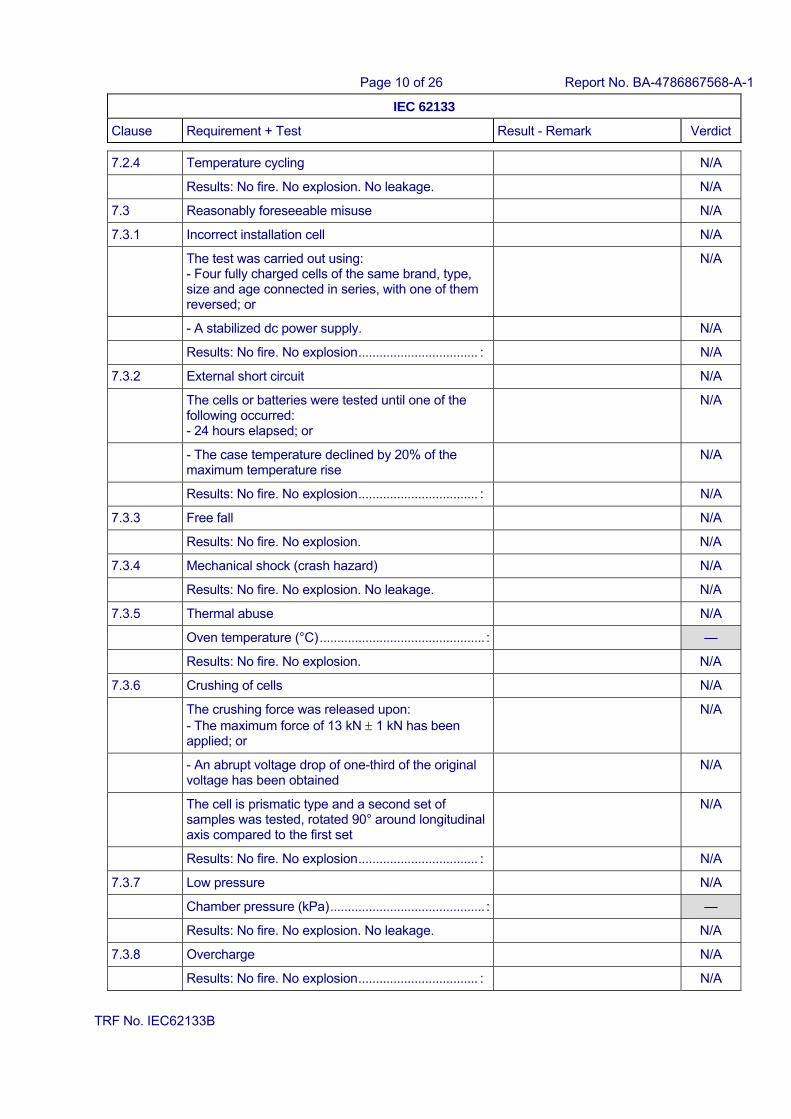
7.2.4 Temperature cycling N/A
Results: No fire. No explosion. No leakage. N/A
7.3 Reasonably foreseeable misuse N/A
7.3.1 Incorrect installation cell N/A
The test was carried out using: - Four fully charged cells of the same brand, type, size and age connected in series, with one of them reversed; or
N/A
- A stabilized dc power supply. N/A
Results: No fire. No explosion .................................. : N/A
7.3.2 External short circuit N/A
The cells or batteries were tested until one of the following occurred: - 24 hours elapsed; or
N/A
- The case temperature declined by 20% of the maximum temperature rise
N/A
Results: No fire. No explosion .................................. : N/A
7.3.3 Free fall N/A
Results: No fire. No explosion. N/A
7.3.4 Mechanical shock (crash hazard) N/A
Results: No fire. No explosion. No leakage. N/A
7.3.5 Thermal abuse N/A
Oven temperature (°C) ............................................... : —
Results: No fire. No explosion. N/A
7.3.6 Crushing of cells N/A
The crushing force was released upon: - The maximum force of 13 kN 1 kN has been applied; or
N/A
- An abrupt voltage drop of one-third of the original voltage has been obtained
N/A
The cell is prismatic type and a second set of samples was tested, rotated 90° around longitudinal axis compared to the first set
N/A
Results: No fire. No explosion .................................. : N/A
7.3.7 Low pressure N/A
Chamber pressure (kPa) ............................................ : —
Results: No fire. No explosion. No leakage. N/A
7.3.8 Overcharge N/A
Results: No fire. No explosion .................................. : N/A
Page 11 of 26 Report No. BA-4786867568-A-1
IEC 62133
Clause Requirement + Test Result - Remark Verdict
TRF No. IEC62133B
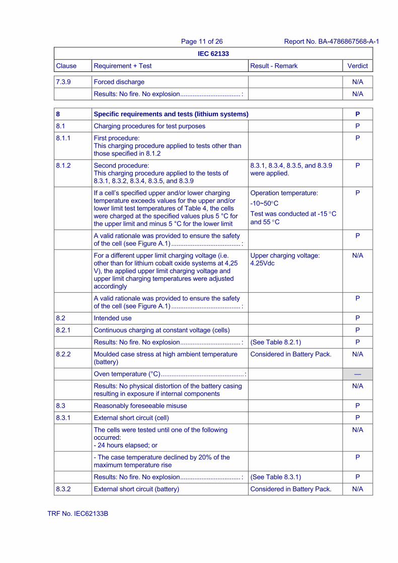
7.3.9 Forced discharge N/A
Results: No fire. No explosion .................................. : N/A
8 Specific requirements and tests (lithium systems) P
8.1 Charging procedures for test purposes P
8.1.1 First procedure: This charging procedure applied to tests other than those specified in 8.1.2
P
8.1.2 Second procedure: This charging procedure applied to the tests of 8.3.1, 8.3.2, 8.3.4, 8.3.5, and 8.3.9
8.3.1, 8.3.4, 8.3.5, and 8.3.9 were applied.
P
If a cell’s specified upper and/or lower charging temperature exceeds values for the upper and/or lower limit test temperatures of Table 4, the cells were charged at the specified values plus 5 °C for the upper limit and minus 5 °C for the lower limit
Operation temperature:
-10~50C
Test was conducted at -15 C and 55 C
P
A valid rationale was provided to ensure the safety of the cell (see Figure A.1) ....................................... :
P
For a different upper limit charging voltage (i.e. other than for lithium cobalt oxide systems at 4,25 V), the applied upper limit charging voltage and upper limit charging temperatures were adjusted accordingly
Upper charging voltage: 4.25Vdc
N/A
A valid rationale was provided to ensure the safety of the cell (see Figure A.1) ....................................... :
P
8.2 Intended use P
8.2.1 Continuous charging at constant voltage (cells) P
Results: No fire. No explosion .................................. : (See Table 8.2.1) P
8.2.2 Moulded case stress at high ambient temperature (battery)
Considered in Battery Pack. N/A
Oven temperature (°C) ............................................... : —
Results: No physical distortion of the battery casing resulting in exposure if internal components
N/A
8.3 Reasonably foreseeable misuse P
8.3.1 External short circuit (cell) P
The cells were tested until one of the following occurred: - 24 hours elapsed; or
N/A
- The case temperature declined by 20% of the maximum temperature rise
P
Results: No fire. No explosion .................................. : (See Table 8.3.1) P
8.3.2 External short circuit (battery) Considered in Battery Pack. N/A
Page 12 of 26 Report No. BA-4786867568-A-1
IEC 62133
Clause Requirement + Test Result - Remark Verdict
TRF No. IEC62133B
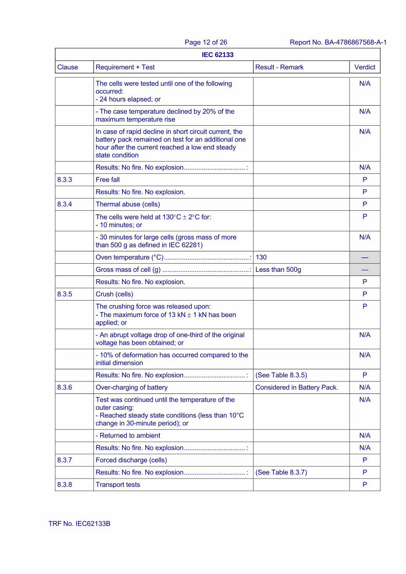
The cells were tested until one of the following occurred: - 24 hours elapsed; or
N/A
- The case temperature declined by 20% of the maximum temperature rise
N/A
In case of rapid decline in short circuit current, the battery pack remained on test for an additional one hour after the current reached a low end steady state condition
N/A
Results: No fire. No explosion .................................. : N/A
8.3.3 Free fall P
Results: No fire. No explosion. P
8.3.4 Thermal abuse (cells) P
The cells were held at 130C 2C for: - 10 minutes; or
P
- 30 minutes for large cells (gross mass of more than 500 g as defined in IEC 62281)
N/A
Oven temperature (°C) ............................................... : 130 —
Gross mass of cell (g) ................................................ : Less than 500g —
Results: No fire. No explosion. P
8.3.5 Crush (cells) P
The crushing force was released upon: - The maximum force of 13 kN 1 kN has been applied; or
P
- An abrupt voltage drop of one-third of the original voltage has been obtained; or
N/A
- 10% of deformation has occurred compared to the initial dimension
N/A
Results: No fire. No explosion .................................. : (See Table 8.3.5) P
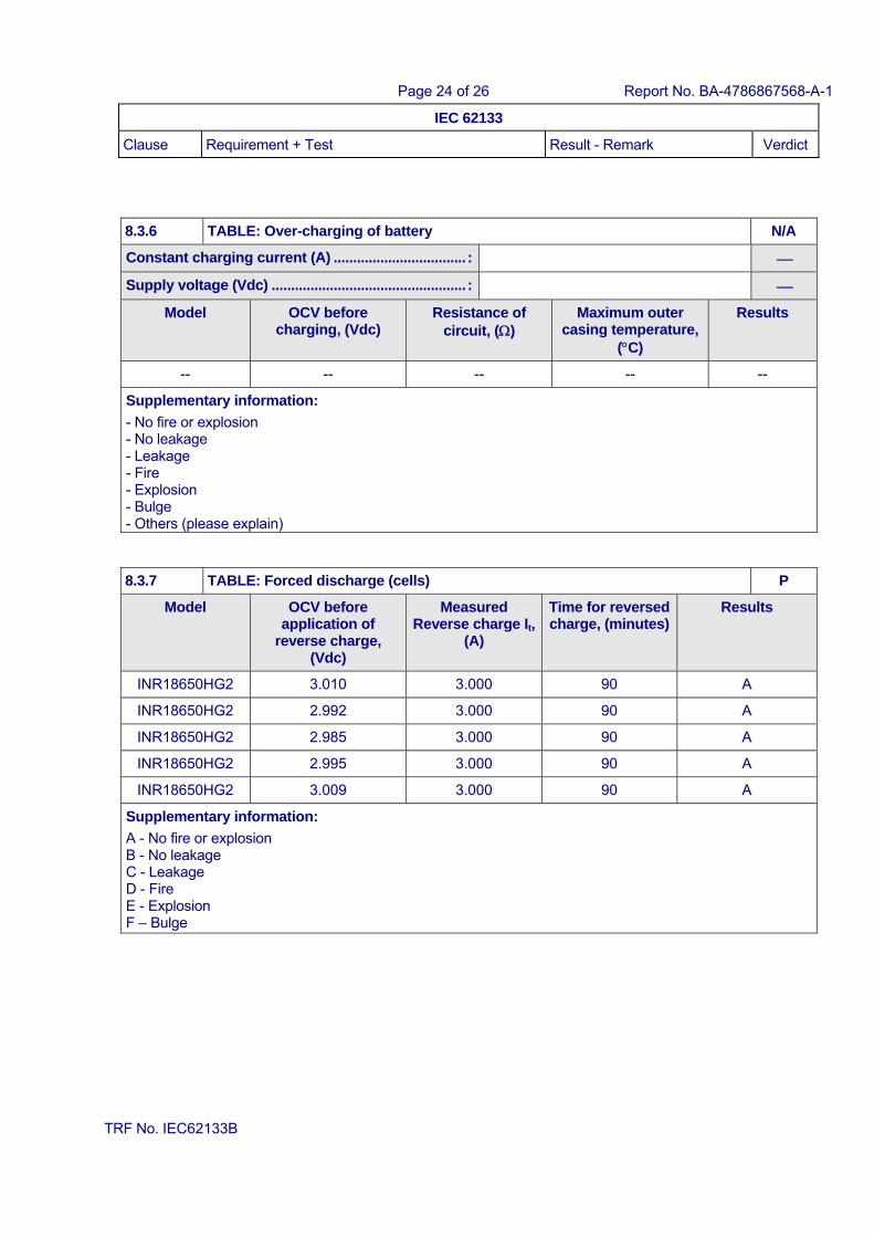
8.3.6 Over-charging of battery Considered in Battery Pack. N/A
Test was continued until the temperature of the outer casing: - Reached steady state conditions (less than 10°C change in 30-minute period); or
N/A
- Returned to ambient N/A
Results: No fire. No explosion .................................. : N/A
8.3.7 Forced discharge (cells) P
Results: No fire. No explosion .................................. : (See Table 8.3.7) P
8.3.8 Transport tests P
Page 13 of 26 Report No. BA-4786867568-A-1
IEC 62133
Clause Requirement + Test Result - Remark Verdict
TRF No. IEC62133B
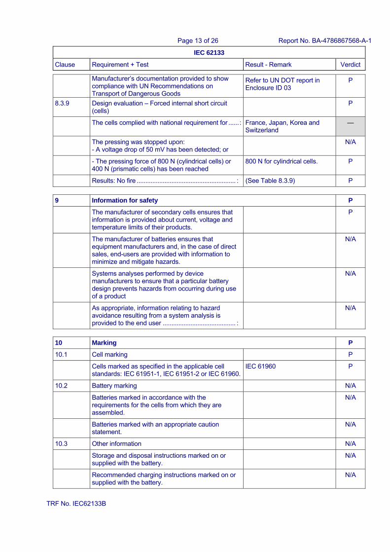
Manufacturer’s documentation provided to show compliance with UN Recommendations on Transport of Dangerous Goods
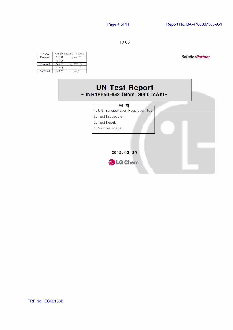
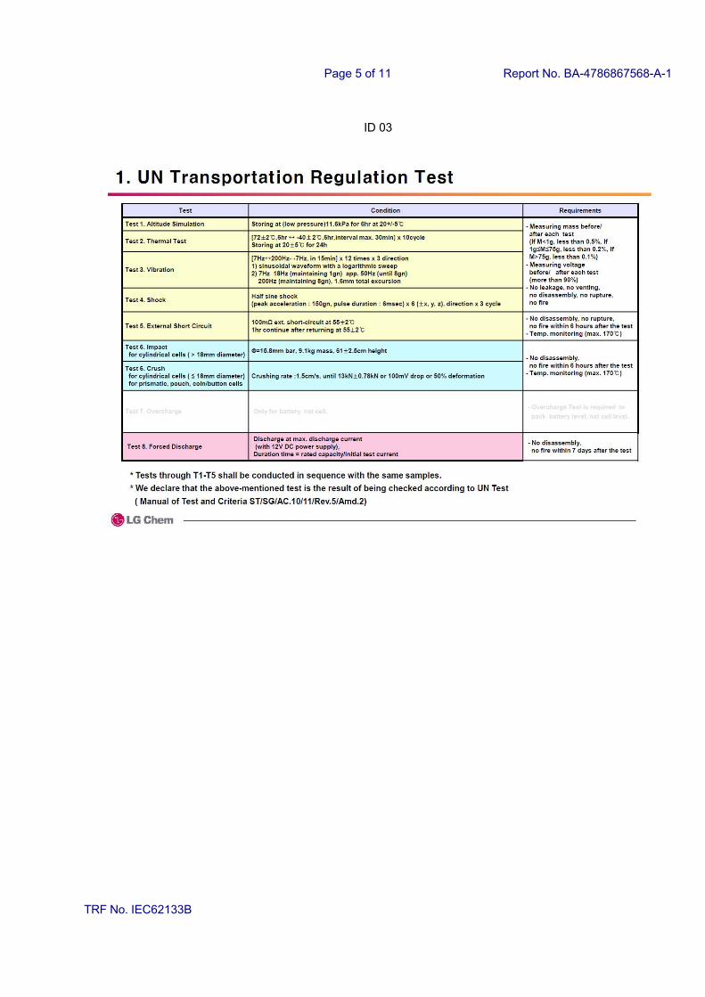
Refer to UN DOT report in Enclosure ID 03
P
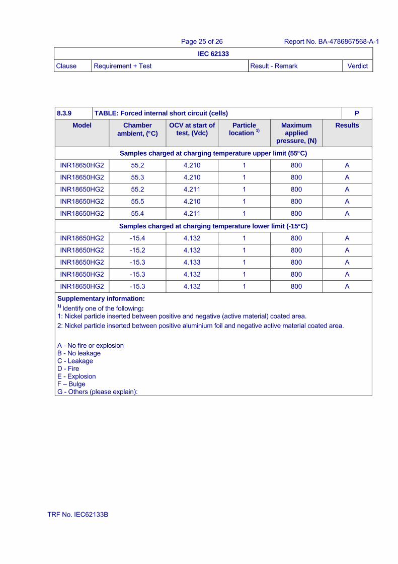
8.3.9 Design evaluation – Forced internal short circuit (cells)
P
The cells complied with national requirement for ...... : France, Japan, Korea and Switzerland
—
The pressing was stopped upon: - A voltage drop of 50 mV has been detected; or
N/A
- The pressing force of 800 N (cylindrical cells) or 400 N (prismatic cells) has been reached
800 N for cylindrical cells. P
Results: No fire ......................................................... : (See Table 8.3.9) P
9 Information for safety P
The manufacturer of secondary cells ensures that information is provided about current, voltage and temperature limits of their products.
P
The manufacturer of batteries ensures that equipment manufacturers and, in the case of direct sales, end-users are provided with information to minimize and mitigate hazards.
N/A
Systems analyses performed by device manufacturers to ensure that a particular battery design prevents hazards from occurring during use of a product
N/A
As appropriate, information relating to hazard avoidance resulting from a system analysis is provided to the end user .......................................... :
N/A
10 Marking P
10.1 Cell marking P
Cells marked as specified in the applicable cell standards: IEC 61951-1, IEC 61951-2 or IEC 61960.
IEC 61960 P
10.2 Battery marking N/A
Batteries marked in accordance with the requirements for the cells from which they are assembled.
N/A
Batteries marked with an appropriate caution statement.
N/A
10.3 Other information N/A
Storage and disposal instructions marked on or supplied with the battery.
N/A
Recommended charging instructions marked on or supplied with the battery.
N/A
Page 14 of 26 Report No. BA-4786867568-A-1
IEC 62133
Clause Requirement + Test Result - Remark Verdict
TRF No. IEC62133B
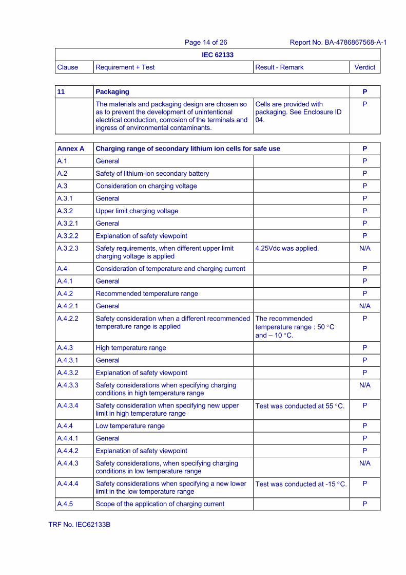
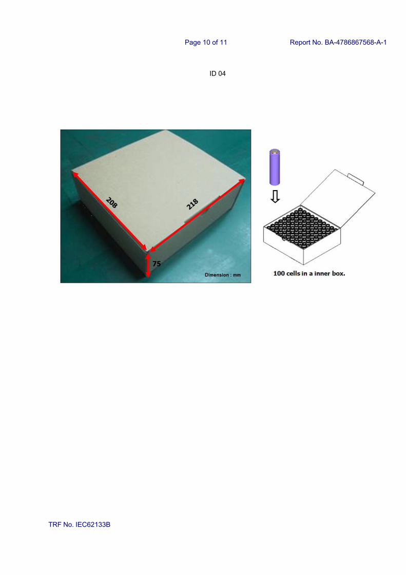
11 Packaging P
The materials and packaging design are chosen so as to prevent the development of unintentional electrical conduction, corrosion of the terminals and ingress of environmental contaminants.
Cells are provided with packaging. See Enclosure ID 04.
P
Annex A Charging range of secondary lithium ion cells for safe use P
A.1 General P
A.2 Safety of lithium-ion secondary battery P
A.3 Consideration on charging voltage P
A.3.1 General P
A.3.2 Upper limit charging voltage P
A.3.2.1 General P
A.3.2.2 Explanation of safety viewpoint P
A.3.2.3 Safety requirements, when different upper limit charging voltage is applied
4.25Vdc was applied. N/A
A.4 Consideration of temperature and charging current P
A.4.1 General P
A.4.2 Recommended temperature range P
A.4.2.1 General N/A
A.4.2.2 Safety consideration when a different recommended temperature range is applied
The recommended temperature range : 50 C and – 10 C.
P
A.4.3 High temperature range P
A.4.3.1 General P
A.4.3.2 Explanation of safety viewpoint P
A.4.3.3 Safety considerations when specifying charging conditions in high temperature range
N/A
A.4.3.4 Safety consideration when specifying new upper limit in high temperature range
Test was conducted at 55 C. P
A.4.4 Low temperature range P
A.4.4.1 General P
A.4.4.2 Explanation of safety viewpoint P
A.4.4.3 Safety considerations, when specifying charging conditions in low temperature range
N/A
A.4.4.4 Safety considerations when specifying a new lower limit in the low temperature range
Test was conducted at -15 C. P
A.4.5 Scope of the application of charging current P

Page 15 of 26 Report No. BA-4786867568-A-1
IEC 62133
Clause Requirement + Test Result - Remark Verdict
TRF No. IEC62133B
A.5 Sample preparation P
A.5.1 General P
A.5.2 Insertion procedure for nickel particle to generate internal short
P
The insertion procedure carried out at 20°C±5°C and under -25 °C of dew point
P
A.5.3 Disassembly of charged cell P
A.5.4 Shape of nickel particle P
A.5.5 Insertion of nickel particle to cylindrical cell P
A.5.5.1 Insertion of nickel particle to winding core P
A.5.5.2 Mark the position of nickel particle on the both end of winding core of the separator
P
A.5.6 Insertion of nickel particle to prismatic cell N/A
Page 16 of 26 Report No. BA-4786867568-A-1
IEC 62133
Clause Requirement + Test Result - Remark Verdict
TRF No. IEC62133B
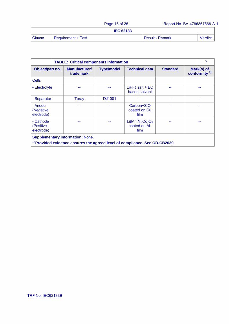
TABLE: Critical components information P
Object/part no. Manufacturer/ trademark
Type/model Technical data Standard Mark(s) of conformity 1)
Cells
- Electrolyte -- -- LiPF6 salt + EC based solvent
-- --
- Separator Toray DJ1001 -- -- --
- Anode (Negative electrode)
-- -- Carbon+SiO coated on Cu
film
-- --
- Cathode (Positive electrode)
-- -- Li(Mn,Ni,Co)O2
coated on AL film
-- --
Supplementary information: None. 1) Provided evidence ensures the agreed level of compliance. See OD-CB2039.
Page 17 of 26 Report No. BA-4786867568-A-1
IEC 62133
Clause Requirement + Test Result - Remark Verdict
TRF No. IEC62133B
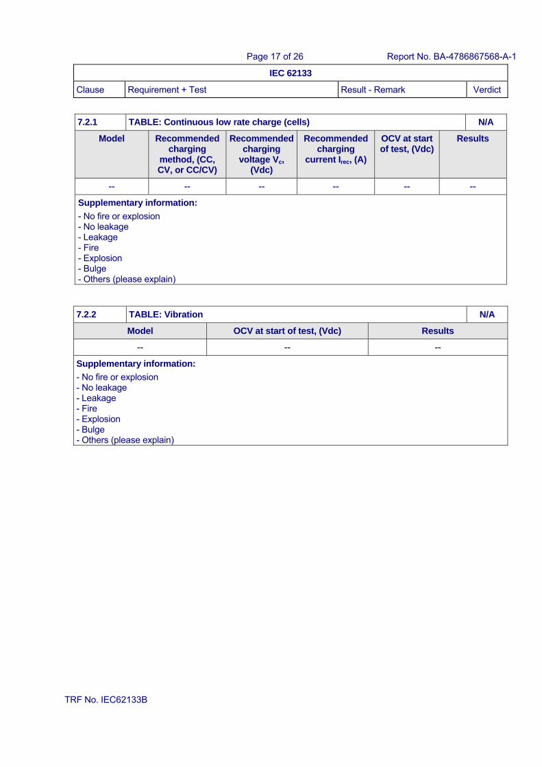
7.2.1 TABLE: Continuous low rate charge (cells) N/A
Model Recommended charging
method, (CC, CV, or CC/CV)
Recommended charging
voltage Vc, (Vdc)
Recommended charging
current Irec, (A)
OCV at start of test, (Vdc)
Results
-- -- -- -- -- --
Supplementary information:
- No fire or explosion - No leakage - Leakage - Fire - Explosion - Bulge - Others (please explain)
7.2.2 TABLE: Vibration N/A
Model OCV at start of test, (Vdc) Results
-- -- --
Supplementary information:
- No fire or explosion - No leakage - Leakage - Fire - Explosion - Bulge - Others (please explain)
Page 18 of 26 Report No. BA-4786867568-A-1
IEC 62133
Clause Requirement + Test Result - Remark Verdict
TRF No. IEC62133B
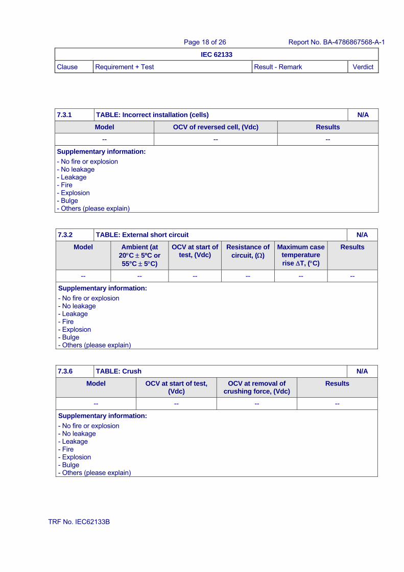
7.3.1 TABLE: Incorrect installation (cells) N/A
Model OCV of reversed cell, (Vdc) Results
-- -- --
Supplementary information:
- No fire or explosion - No leakage - Leakage - Fire - Explosion - Bulge - Others (please explain)
7.3.2 TABLE: External short circuit N/A
Model Ambient (at 20C 5ºC or 55°C 5C)
OCV at start of test, (Vdc)
Resistance of circuit, ()
Maximum case temperature rise T, (C)
Results
-- -- -- -- -- --
Supplementary information:
- No fire or explosion - No leakage - Leakage - Fire - Explosion - Bulge - Others (please explain)
7.3.6 TABLE: Crush N/A
Model OCV at start of test, (Vdc)
OCV at removal of crushing force, (Vdc)
Results
-- -- -- --
Supplementary information:
- No fire or explosion - No leakage - Leakage - Fire - Explosion - Bulge - Others (please explain)
Page 19 of 26 Report No. BA-4786867568-A-1
IEC 62133
Clause Requirement + Test Result - Remark Verdict
TRF No. IEC62133B
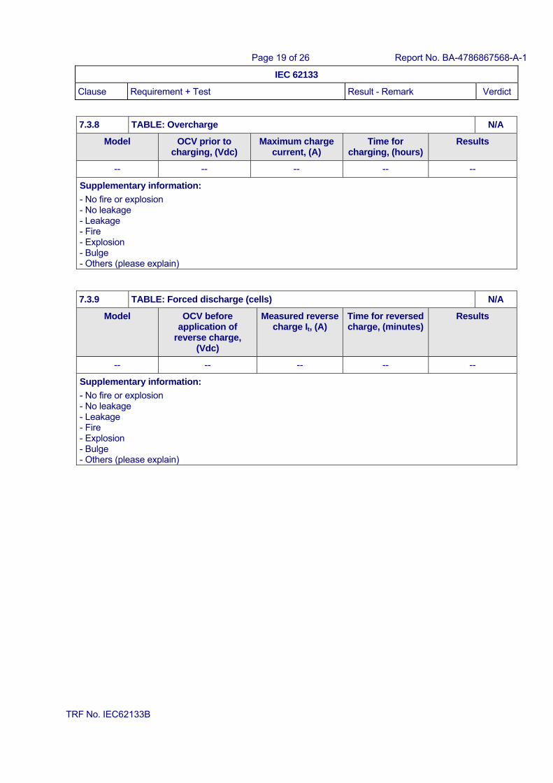
7.3.8 TABLE: Overcharge N/A
Model OCV prior to charging, (Vdc)
Maximum charge current, (A)
Time for charging, (hours)
Results
-- -- -- -- --
Supplementary information:
- No fire or explosion - No leakage - Leakage - Fire - Explosion - Bulge - Others (please explain)
7.3.9 TABLE: Forced discharge (cells) N/A
Model OCV before application of
reverse charge, (Vdc)
Measured reverse charge It, (A)
Time for reversed charge, (minutes)
Results
-- -- -- -- --
Supplementary information:
- No fire or explosion - No leakage - Leakage - Fire - Explosion - Bulge - Others (please explain)
Page 20 of 26 Report No. BA-4786867568-A-1
IEC 62133
Clause Requirement + Test Result - Remark Verdict
TRF No. IEC62133B
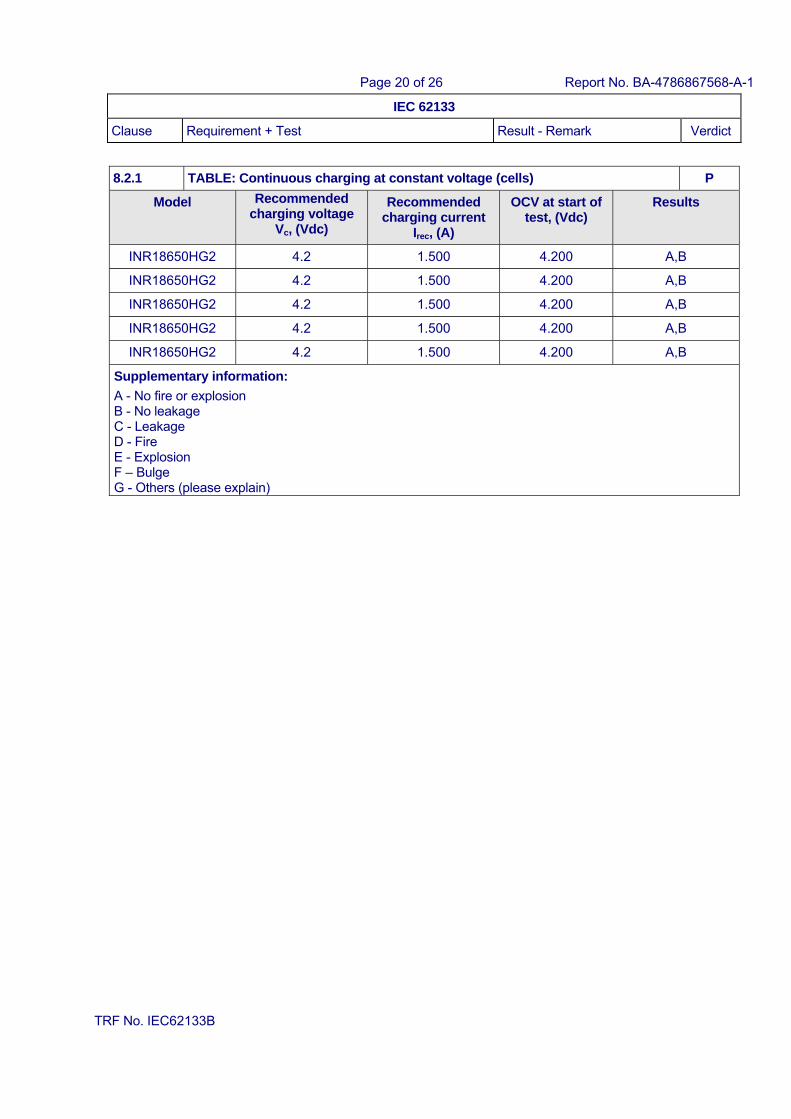
8.2.1 TABLE: Continuous charging at constant voltage (cells) P
Model Recommended charging voltage
Vc, (Vdc)
Recommended charging current
Irec, (A)
OCV at start of test, (Vdc)
Results
INR18650HG2 4.2 1.500 4.200 A,B
INR18650HG2 4.2 1.500 4.200 A,B
INR18650HG2 4.2 1.500 4.200 A,B
INR18650HG2 4.2 1.500 4.200 A,B
INR18650HG2 4.2 1.500 4.200 A,B
Supplementary information:
A - No fire or explosion B - No leakage C - Leakage D - Fire E - Explosion F – Bulge G - Others (please explain)
Page 21 of 26 Report No. BA-4786867568-A-1
IEC 62133
Clause Requirement + Test Result - Remark Verdict
TRF No. IEC62133B
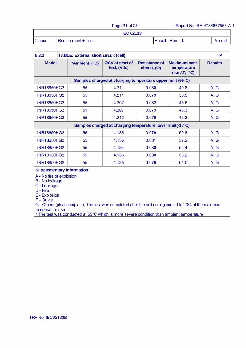
8.3.1 TABLE: External short circuit (cell) P
Model *Ambient, (C) OCV at start of test, (Vdc)
Resistance of circuit, ()
Maximum case temperature rise T, (C)
Results
Samples charged at charging temperature upper limit (55C)
INR18650HG2 55 4.211 0.080 49.8 A, G
INR18650HG2 55 4.211 0.079 56.5 A, G
INR18650HG2 55 4.207 0.082 45.6 A, G
INR18650HG2 55 4.207 0.079 48.3 A, G
INR18650HG2 55 4.212 0.079 43.3 A, G
Samples charged at charging temperature lower limit(-15C)
INR18650HG2 55 4.135 0.079 59.8 A, G
INR18650HG2 55 4.136 0.081 57.2 A, G
INR18650HG2 55 4.134 0.080 54.4 A, G
INR18650HG2 55 4.136 0.080 58.2 A, G
INR18650HG2 55 4.135 0.079 61.0 A, G
Supplementary information:
A - No fire or explosion B - No leakage C - Leakage D - Fire E - Explosion F – Bulge G - Others (please explain), The test was completed after the cell casing cooled to 20% of the maximum temperature rise * The test was conducted at 55°C which is more severe condition than ambient temperature
Page 22 of 26 Report No. BA-4786867568-A-1
IEC 62133
Clause Requirement + Test Result - Remark Verdict
TRF No. IEC62133B
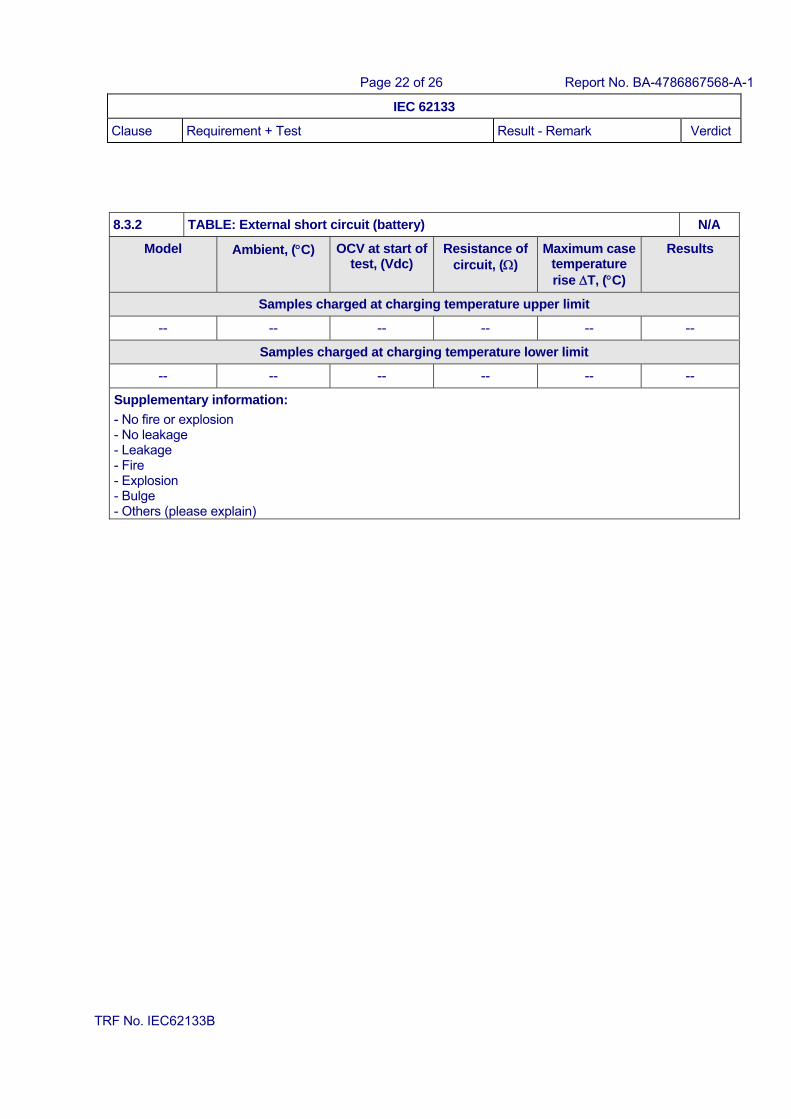
8.3.2 TABLE: External short circuit (battery) N/A
Model Ambient, (C) OCV at start of test, (Vdc)
Resistance of circuit, ()
Maximum case temperature rise T, (C)
Results
Samples charged at charging temperature upper limit
-- -- -- -- -- --
Samples charged at charging temperature lower limit
-- -- -- -- -- --
Supplementary information:
- No fire or explosion - No leakage - Leakage - Fire - Explosion - Bulge - Others (please explain)
Page 23 of 26 Report No. BA-4786867568-A-1
IEC 62133
Clause Requirement + Test Result - Remark Verdict
TRF No. IEC62133B
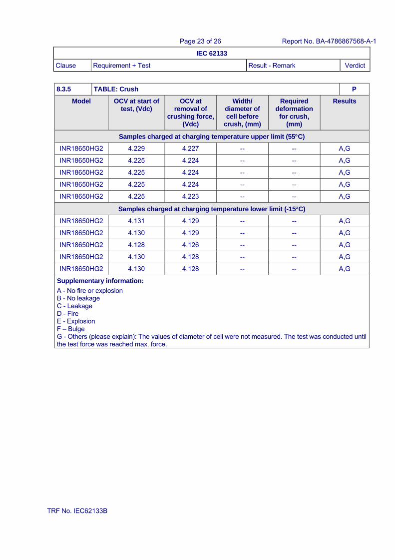
8.3.5 TABLE: Crush P
Model OCV at start of test, (Vdc)
OCV at removal of
crushing force, (Vdc)
Width/ diameter of cell before
crush, (mm)
Required deformation
for crush, (mm)
Results
Samples charged at charging temperature upper limit (55C)
INR18650HG2 4.229 4.227 -- -- A,G
INR18650HG2 4.225 4.224 -- -- A,G
INR18650HG2 4.225 4.224 -- -- A,G
INR18650HG2 4.225 4.224 -- -- A,G
INR18650HG2 4.225 4.223 -- -- A,G
Samples charged at charging temperature lower limit (-15C)
INR18650HG2 4.131 4.129 -- -- A,G
INR18650HG2 4.130 4.129 -- -- A,G
INR18650HG2 4.128 4.126 -- -- A,G
INR18650HG2 4.130 4.128 -- -- A,G
INR18650HG2 4.130 4.128 -- -- A,G
Supplementary information:
A - No fire or explosion B - No leakage C - Leakage D - Fire E - Explosion F – Bulge G - Others (please explain): The values of diameter of cell were not measured. The test was conducted until the test force was reached max. force.
Page 24 of 26 Report No. BA-4786867568-A-1
IEC 62133
Clause Requirement + Test Result - Remark Verdict
TRF No. IEC62133B
8.3.6 TABLE: Over-charging of battery N/A
Constant charging current (A) .................................. :
Supply voltage (Vdc) .................................................. :
Model OCV before charging, (Vdc)
Resistance of circuit, ()
Maximum outer casing temperature,
(C)
Results
-- -- -- -- --
Supplementary information:
- No fire or explosion - No leakage - Leakage - Fire - Explosion - Bulge - Others (please explain)
8.3.7 TABLE: Forced discharge (cells) P
Model OCV before application of
reverse charge, (Vdc)
Measured Reverse charge It,
(A)
Time for reversed charge, (minutes)
Results
INR18650HG2 3.010 3.000 90 A
INR18650HG2 2.992 3.000 90 A
INR18650HG2 2.985 3.000 90 A
INR18650HG2 2.995 3.000 90 A
INR18650HG2 3.009 3.000 90 A
Supplementary information:
A - No fire or explosion B - No leakage C - Leakage D - Fire E - Explosion F – Bulge
Page 25 of 26 Report No. BA-4786867568-A-1
IEC 62133
Clause Requirement + Test Result - Remark Verdict
TRF No. IEC62133B
8.3.9 TABLE: Forced internal short circuit (cells) P
Model Chamber ambient, (C)
OCV at start of test, (Vdc)
Particle location 1)
Maximum applied
pressure, (N)
Results
Samples charged at charging temperature upper limit (55C)
INR18650HG2 55.2 4.210 1 800 A
INR18650HG2 55.3 4.210 1 800 A
INR18650HG2 55.2 4.211 1 800 A
INR18650HG2 55.5 4.210 1 800 A
INR18650HG2 55.4 4.211 1 800 A
Samples charged at charging temperature lower limit (-15C)
INR18650HG2 -15.4 4.132 1 800 A
INR18650HG2 -15.2 4.132 1 800 A
INR18650HG2 -15.3 4.133 1 800 A
INR18650HG2 -15.3 4.132 1 800 A
INR18650HG2 -15.3 4.132 1 800 A
Supplementary information: 1) Identify one of the following: 1: Nickel particle inserted between positive and negative (active material) coated area.
2: Nickel particle inserted between positive aluminium foil and negative active material coated area.
A - No fire or explosion B - No leakage C - Leakage D - Fire E - Explosion F – Bulge G - Others (please explain):
Page 26 of 26 Report No. BA-4786867568-A-1
TRF No. IEC62133B
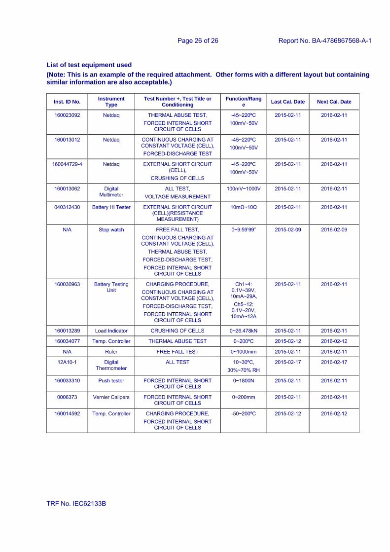
List of test equipment used
(Note: This is an example of the required attachment. Other forms with a different layout but containing similar information are also acceptable.)
Inst. ID No. Instrument
Type Test Number +, Test Title or
Conditioning Function/Rang
e Last Cal. Date Next Cal. Date
160023092 Netdaq THERMAL ABUSE TEST,
FORCED INTERNAL SHORT CIRCUIT OF CELLS
-45~220ºC
100mV~50V
2015-02-11 2016-02-11
160013012 Netdaq CONTINUOUS CHARGING AT CONSTANT VOLTAGE (CELL),
FORCED-DISCHARGE TEST
-45~220ºC
100mV~50V
2015-02-11 2016-02-11
160044729-4 Netdaq EXTERNAL SHORT CIRCUIT (CELL),
CRUSHING OF CELLS
-45~220ºC
100mV~50V
2015-02-11 2016-02-11
160013062 Digital Multimeter
ALL TEST,
VOLTAGE MEASUREMENT
100mV~1000V 2015-02-11 2016-02-11
040312430 Battery Hi Tester EXTERNAL SHORT CIRCUIT (CELL)(RESISTANCE
MEASUREMENT)
10mΩ~10Ω 2015-02-11 2016-02-11
N/A Stop watch FREE FALL TEST,
CONTINUOUS CHARGING AT CONSTANT VOLTAGE (CELL),
THERMAL ABUSE TEST,
FORCED-DISCHARGE TEST,
FORCED INTERNAL SHORT CIRCUIT OF CELLS
0~9:59’99” 2015-02-09 2016-02-09
160030963 Battery Testing Unit
CHARGING PROCEDURE,
CONTINUOUS CHARGING AT CONSTANT VOLTAGE (CELL),
FORCED-DISCHARGE TEST,
FORCED INTERNAL SHORT CIRCUIT OF CELLS
Ch1~4: 0.1V~39V,
10mA~29A,
Ch5~12: 0.1V~20V, 10mA~12A
2015-02-11 2016-02-11
160013289 Load Indicator CRUSHING OF CELLS 0~26.478kN 2015-02-11 2016-02-11
160034077 Temp. Controller THERMAL ABUSE TEST 0~200ºC 2015-02-12 2016-02-12
N/A Ruler FREE FALL TEST 0~1000mm 2015-02-11 2016-02-11
12A10-1 Digital Thermometer
ALL TEST 10~30ºC,
30%~70% RH
2015-02-17 2016-02-17
160033310 Push tester FORCED INTERNAL SHORT CIRCUIT OF CELLS
0~1800N 2015-02-11 2016-02-11
0006373 Vernier Calipers FORCED INTERNAL SHORT CIRCUIT OF CELLS
0~200mm 2015-02-11 2016-02-11
160014592 Temp. Controller CHARGING PROCEDURE,
FORCED INTERNAL SHORT CIRCUIT OF CELLS
-50~200ºC 2015-02-12 2016-02-12
Page 1 of 11 Report No. BA-4786867568-A-1
TRF No. IEC62133B
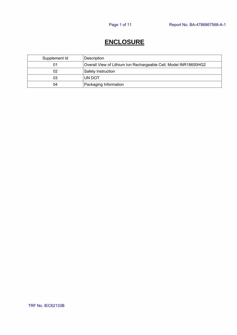
ENCLOSURE
Supplement Id Description
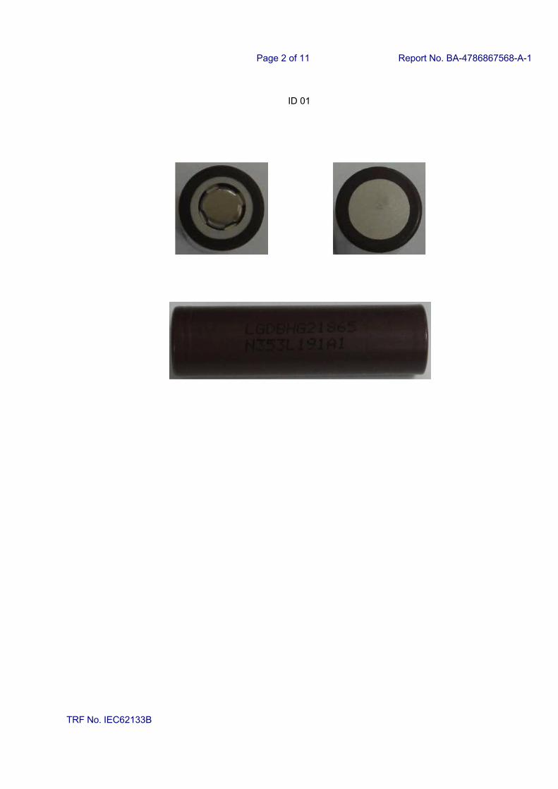
01 Overall View of Lithium Ion Rechargeable Cell, Model INR18650HG2
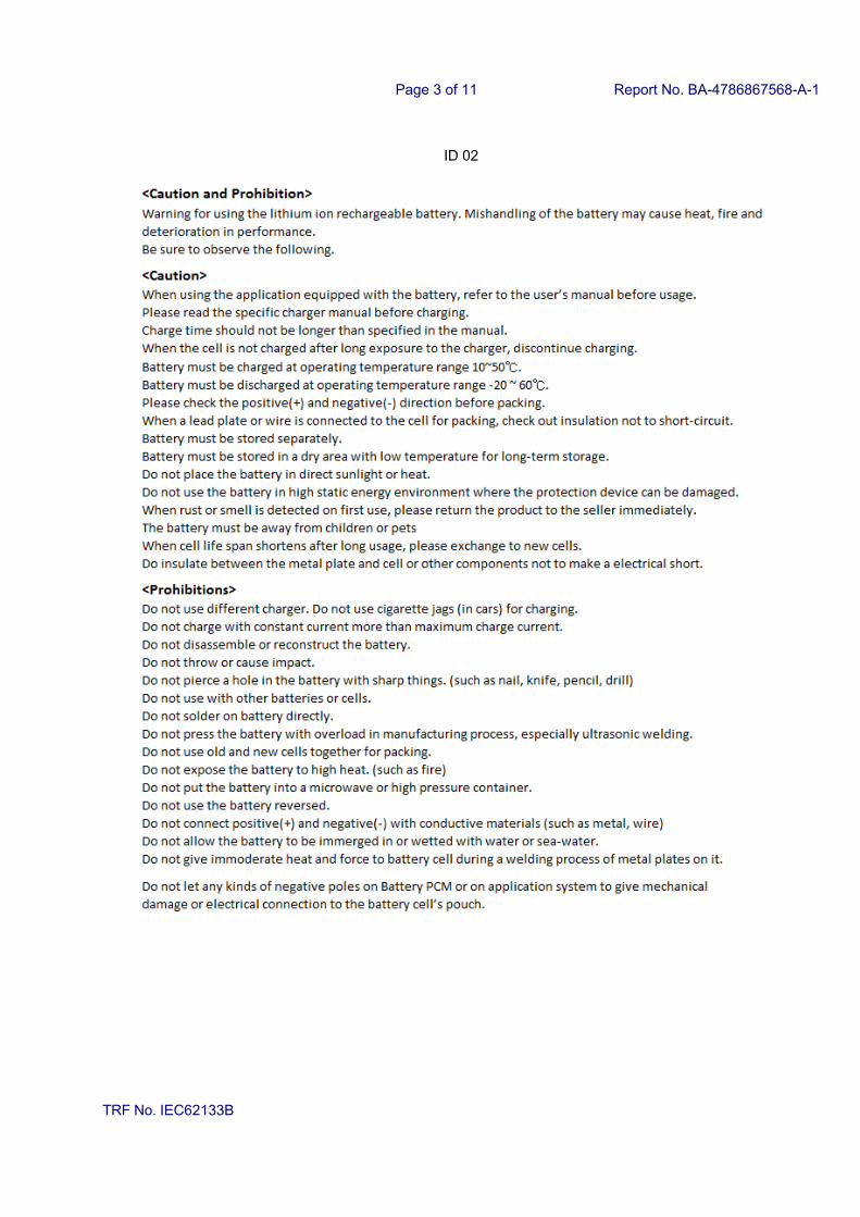
02 Safety Instruction
03 UN DOT
04 Packaging Information
Page 2 of 11 Report No. BA-4786867568-A-1
TRF No. IEC62133B
ID 01
Page 3 of 11 Report No. BA-4786867568-A-1
TRF No. IEC62133B
ID 02
Page 4 of 11 Report No. BA-4786867568-A-1
TRF No. IEC62133B
ID 03
Page 5 of 11 Report No. BA-4786867568-A-1
TRF No. IEC62133B
ID 03
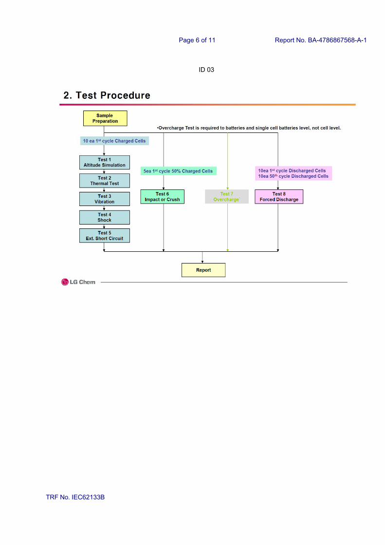
Page 6 of 11 Report No. BA-4786867568-A-1
TRF No. IEC62133B
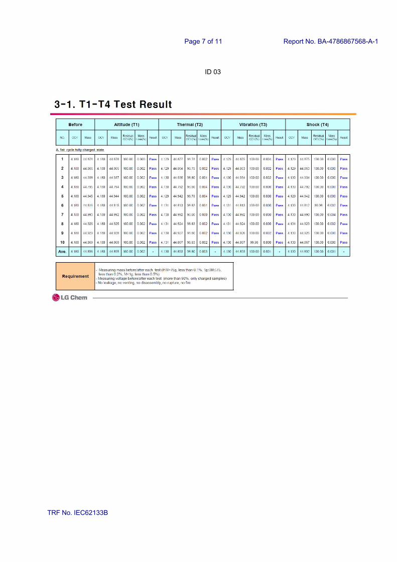
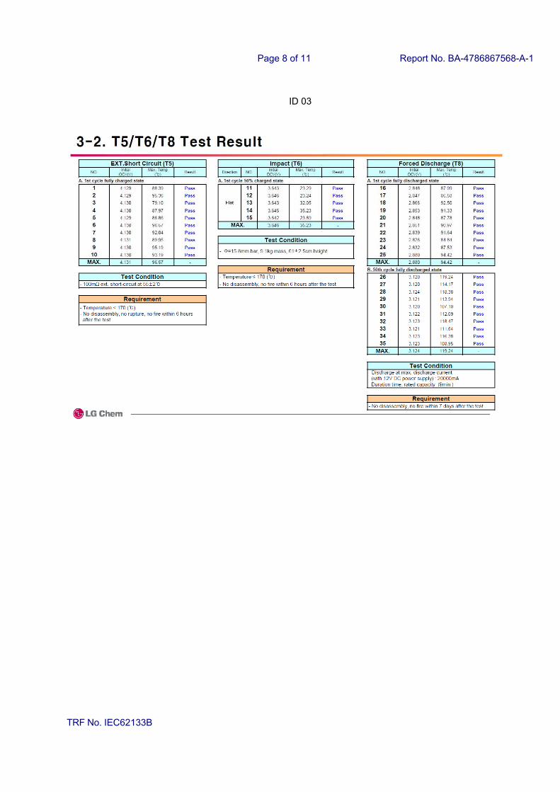
ID 03
Page 7 of 11 Report No. BA-4786867568-A-1
TRF No. IEC62133B
ID 03
Page 8 of 11 Report No. BA-4786867568-A-1
TRF No. IEC62133B
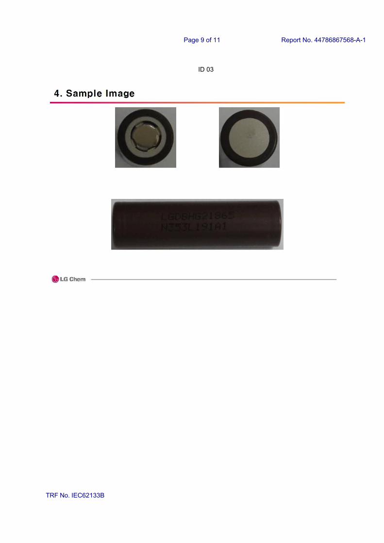
ID 03
Page 9 of 11 Report No. 44786867568-A-1
TRF No. IEC62133B
ID 03
Page 10 of 11 Report No. BA-4786867568-A-1
TRF No. IEC62133B
ID 04