Embed Size (px)
Citation preview

The document was prepared using best effort. The authors make no warranty of any kind and shall not be liable in any event for incidental or consequential damages in connection with the application of the document.
© All rights reserved.
IEC 61508 Functional Safety Assessment
Project:
3/2-Way & 5/2-Way Falcon Solenoid Valve
Customer:
Pentair UK Ltd.
Tunbridge Wells, Kent
UK
Contract Number: Q14/04-086r1
Report No.: WES 09/09-39 R002
Version V2, Revision R2, April 21, 2015
Gregory Sauk
© exida WES 09-09-39 R002 V2R2 UK Falcon Assessment.docx
T-023 V3R3 www.exida.com Page 2 of 21
Management Summary
This report summarizes the results of the functional safety assessment according to IEC 61508 carried out on the Pentair UK Ltd.
3/2-Way & 5/2-Way Falcon Solenoid Valve Series
The functional safety assessment performed by exida consisted of the following activities:
- exida assessed the development process used by Pentair UK Ltd. through an audit and
review of a detailed safety case against the exida certification scheme which includes the relevant requirements of IEC 61508. The investigation was executed using subsets of the
IEC 61508 requirements tailored to the work scope of the development team. exida reviewed and assessed a detailed Failure Modes, Effects, and Diagnostic Analysis (FMEDA) of the devices to document the hardware architecture and failure behavior.
- exida performed a detailed Failure Modes, Effects, and Diagnostic Analysis (FMEDA) of the devices to document the hardware architecture and failure behavior.
- exida reviewed field failure data to verify the accuracy of the FMEDA analysis.
- exida reviewed the manufacturing quality system in use at Pentair.
The functional safety assessment was performed to the requirements of IEC 61508: ed2, 2010, SIL
3 for mechanical components. A full IEC 61508 Safety Case was prepared using the exida Safety Case tool as the primary audit tool. Hardware process requirements and all associated documentation were reviewed. Environmental test reports were reviewed. Also the user documentation (safety manual) was reviewed.
The results of the Functional Safety Assessment can be summarized as:
The audited development process as tailored and implemented by the Pentair Falcon Series Valves development project, complies with the relevant safety management requirements of IEC 61508 SIL 3, SC 3 (SIL 3 Capable).
The assessment of the FMEDA, done to the requirements of IEC 61508, has shown that the Pentair Falcon Series Solenoid Valves can be used in a low demand safety related system in a manor where the PFDavg is within the allowed range for up to SIL 3 (HFT = 0) according to table 2 of IEC 61508-1.
This means that the Pentair Falcon Series Solenoid Valves are capable for use in SIL 3 applications in Low DEMAND mode, when properly designed into a Safety Instrumented Function per the requirements in the Safety Manual and when using the Falcon versions specified in section 3 of this document.
The manufacturer will be entitled to use the Functional Safety Logo.
© exida WES 09-09-39 R002 V2R2 UK Falcon Assessment.docx
T-023 V3R3 www.exida.com Page 3 of 21
© exida WES 09-09-39 R002 V2R2 UK Falcon Assessment.docx
T-023 V3R3 www.exida.com Page 4 of 21
Table of Contents
Management Summary ................................................................................................... 2
1 Purpose and Scope ................................................................................................... 5
1.1 Tools and Methods used for the assessment ............................................................... 5
2 Project Management .................................................................................................. 6
2.1 exida ............................................................................................................................ 6
2.2 Roles of the parties involved ........................................................................................ 6
2.3 Standards and literature used ...................................................................................... 6
2.4 Reference documents .................................................................................................. 6
2.4.1 Documentation provided by Pentair UK Ltd. ...................................................... 6
2.4.3 Documentation generated by exida ................................................................... 9
2.5 Assessment Approach ............................................................................................... 10
3 Product Descriptions ................................................................................................ 11
4 IEC 61508 Functional Safety Assessment Scheme................................................. 13
4.1 Methodology .............................................................................................................. 13
4.2 Assessment level ....................................................................................................... 13
5 Results of the IEC 61508 Functional Safety Assessment ........................................ 14
5.1 Lifecycle Activities and Fault Avoidance Measures .................................................... 14
5.1.1 Functional Safety Management ....................................................................... 14
5.1.2 Safety Requirements Specification and Architecture Design ............................ 15
5.1.3 Hardware Design ............................................................................................. 16
5.1.4 Validation ......................................................................................................... 16
5.1.5 Verification ....................................................................................................... 17
5.1.6 Proven In Use .................................................................................................. 17
5.1.7 Modifications ................................................................................................... 17
5.1.8 User documentation......................................................................................... 18
5.2 Hardware Assessment ............................................................................................... 18
6 Terms and Definitions .............................................................................................. 20
7 Status of the Document ........................................................................................... 21
7.1 Liability ....................................................................................................................... 21
7.2 Releases .................................................................................................................... 21
7.3 Future Enhancements ................................................................................................ 21
7.4 Release Signatures .................................................................................................... 21
© exida WES 09-09-39 R002 V2R2 UK Falcon Assessment.docx
T-023 V3R3 www.exida.com Page 5 of 21
1 Purpose and Scope
This document shall describe the results of the IEC 61508 functional safety assessment of the Pentair UK Ltd.:
3/2-Way & 5/2-Way Falcon Solenoid Valve Series
by exida according to accredited exida certification scheme which includes the requirements of IEC 61508: ed2, 2010.
The assessment has been carried out based on the quality procedures and scope definitions of
exida.
The results of this provides the safety instrumentation engineer with the required failure data as per IEC 61508 / IEC 61511 and confidence that sufficient attention has been given to systematic failures during the development process of the device.
1.1 Tools and Methods used for the assessment
This assessment was carried out by using the exida Safety Case tool. The Safety Case tool
contains the exida scheme which includes all the relevant requirements of IEC 61508.
For the fulfillment of the objectives, expectations are defined which builds the acceptance level for the assessment. The expectations are reviewed to verify that each single requirement is covered. Because of this methodology, comparable assessments in multiple projects with different assessors are achieved. The arguments for the positive judgment of the assessor are documented within this tool and summarized within this report.
The assessment was planned by exida and agreed upon with Pentair UK Ltd..
All assessment steps were continuously documented by exida (see [R1] to [R5]).
© exida WES 09-09-39 R002 V2R2 UK Falcon Assessment.docx
T-023 V3R3 www.exida.com Page 6 of 21
2 Project Management
2.1 exida
exida is one of the world’s leading accredited Certification Bodies and knowledge companies specializing in automation system safety and availability with over 300 years of cumulative experience in functional safety. Founded by several of the world’s top reliability and safety experts
from assessment organizations and manufacturers, exida is a global company with offices around
the world. exida offers training, coaching, project oriented system consulting services, safety lifecycle engineering tools, detailed product assurance, cyber-security and functional safety
certification, and a collection of on-line safety and reliability resources. exida maintains the largest process equipment database of failure rates and failure modes with over 100 billion unit operating hours.
2.2 Roles of the parties involved
Pentair UK Ltd. Manufacturer of the valve body of the Falcon Series Valves
RGS Electro-Pneumatics Ltd Designer of the Falcon Series Valves and OEM supplier of the coils, spools and sealing kits
exida Performed the hardware assessment
exida Performed the IEC 61508 Functional Safety Assessment
Pentair contracted exida in June 2014 for the IEC 61508 Functional Safety Re-assessment of the above mentioned devices.
2.3 Standards and literature used
The services delivered by exida were performed based on the following standards / literature.
[N1] IEC 61508 (Parts 1 - 7): 2010 Functional Safety of Electrical/Electronic/Programmable Electronic Safety-Related Systems
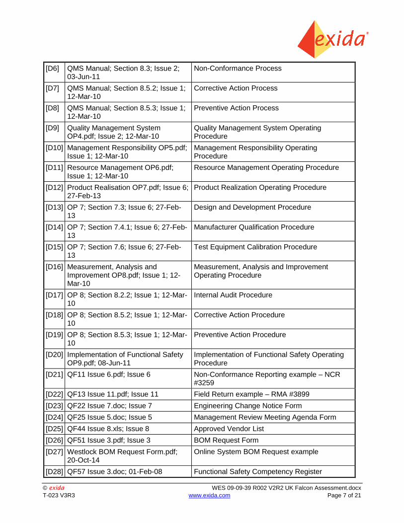
2.4 Reference documents
2.4.1 Documentation provided by Pentair UK Ltd.
[D1] QMS Manual ISO9001-2008 Master .pdf; (Issue varies by section)
Pentair UK Quality Assurance Manual
[D2] QMS Manual; Section 5.6; Issue 1; 12-Mar-10
Management Review Process
[D3] QMS Manual; Section 7.3; Issue 3; 08-Jun-11
Design and Development Process
[D4] QMS Manual; Section 7.4; Issue 2; 27-Feb-13
Purchasing Process
[D5] QMS Manual; Section 8.2; Issue 1; 12-Mar-10
Monitoring and Measurement Process
© exida WES 09-09-39 R002 V2R2 UK Falcon Assessment.docx
T-023 V3R3 www.exida.com Page 7 of 21
[D6] QMS Manual; Section 8.3; Issue 2; 03-Jun-11
Non-Conformance Process
[D7] QMS Manual; Section 8.5.2; Issue 1; 12-Mar-10
Corrective Action Process
[D8] QMS Manual; Section 8.5.3; Issue 1; 12-Mar-10
Preventive Action Process
[D9] Quality Management System OP4.pdf; Issue 2; 12-Mar-10
Quality Management System Operating Procedure
[D10] Management Responsibility OP5.pdf; Issue 1; 12-Mar-10
Management Responsibility Operating Procedure
[D11] Resource Management OP6.pdf; Issue 1; 12-Mar-10
Resource Management Operating Procedure
[D12] Product Realisation OP7.pdf; Issue 6; 27-Feb-13
Product Realization Operating Procedure
[D13] OP 7; Section 7.3; Issue 6; 27-Feb-13
Design and Development Procedure
[D14] OP 7; Section 7.4.1; Issue 6; 27-Feb-13
Manufacturer Qualification Procedure
[D15] OP 7; Section 7.6; Issue 6; 27-Feb-13
Test Equipment Calibration Procedure
[D16] Measurement, Analysis and Improvement OP8.pdf; Issue 1; 12-Mar-10
Measurement, Analysis and Improvement Operating Procedure
[D17] OP 8; Section 8.2.2; Issue 1; 12-Mar-10
Internal Audit Procedure
[D18] OP 8; Section 8.5.2; Issue 1; 12-Mar-10
Corrective Action Procedure
[D19] OP 8; Section 8.5.3; Issue 1; 12-Mar-10
Preventive Action Procedure
[D20] Implementation of Functional Safety OP9.pdf; 08-Jun-11
Implementation of Functional Safety Operating Procedure
[D21] QF11 Issue 6.pdf; Issue 6 Non-Conformance Reporting example – NCR #3259
[D22] QF13 Issue 11.pdf; Issue 11 Field Return example – RMA #3899
[D23] QF22 Issue 7.doc; Issue 7 Engineering Change Notice Form
[D24] QF25 Issue 5.doc; Issue 5 Management Review Meeting Agenda Form
[D25] QF44 Issue 8.xls; Issue 8 Approved Vendor List
[D26] QF51 Issue 3.pdf; Issue 3 BOM Request Form
[D27] Westlock BOM Request Form.pdf; 20-Oct-14
Online System BOM Request example
[D28] QF57 Issue 3.doc; 01-Feb-08 Functional Safety Competency Register
© exida WES 09-09-39 R002 V2R2 UK Falcon Assessment.docx
T-023 V3R3 www.exida.com Page 8 of 21
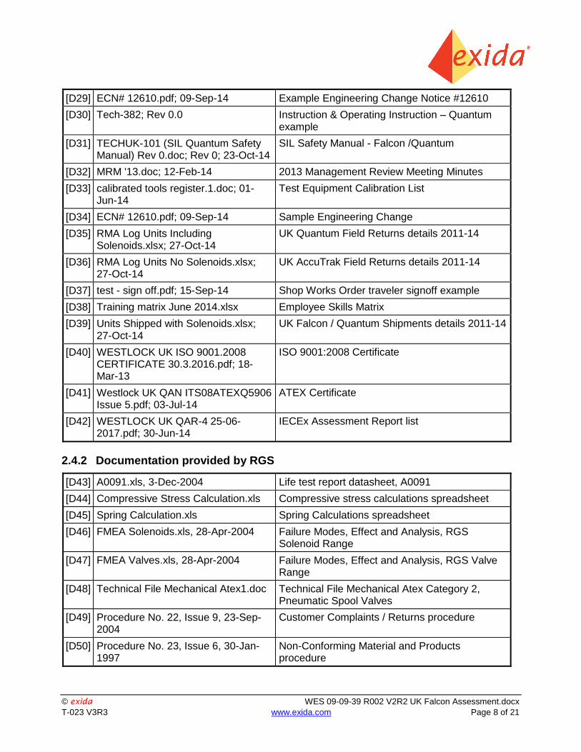
[D29] ECN# 12610.pdf; 09-Sep-14 Example Engineering Change Notice #12610
[D30] Tech-382; Rev 0.0 Instruction & Operating Instruction – Quantum example
[D31] TECHUK-101 (SIL Quantum Safety Manual) Rev 0.doc; Rev 0; 23-Oct-14
SIL Safety Manual - Falcon /Quantum
[D32] MRM '13.doc; 12-Feb-14 2013 Management Review Meeting Minutes
[D33] calibrated tools register.1.doc; 01-Jun-14
Test Equipment Calibration List
[D34] ECN# 12610.pdf; 09-Sep-14 Sample Engineering Change
[D35] RMA Log Units Including Solenoids.xlsx; 27-Oct-14
UK Quantum Field Returns details 2011-14
[D36] RMA Log Units No Solenoids.xlsx; 27-Oct-14
UK AccuTrak Field Returns details 2011-14
[D37] test - sign off.pdf; 15-Sep-14 Shop Works Order traveler signoff example
[D38] Training matrix June 2014.xlsx Employee Skills Matrix
[D39] Units Shipped with Solenoids.xlsx; 27-Oct-14
UK Falcon / Quantum Shipments details 2011-14
[D40] WESTLOCK UK ISO 9001.2008 CERTIFICATE 30.3.2016.pdf; 18-Mar-13
ISO 9001:2008 Certificate
[D41] Westlock UK QAN ITS08ATEXQ5906 Issue 5.pdf; 03-Jul-14
ATEX Certificate
[D42] WESTLOCK UK QAR-4 25-06-2017.pdf; 30-Jun-14
IECEx Assessment Report list
2.4.2 Documentation provided by RGS
[D43] A0091.xls, 3-Dec-2004 Life test report datasheet, A0091
[D44] Compressive Stress Calculation.xls Compressive stress calculations spreadsheet
[D45] Spring Calculation.xls Spring Calculations spreadsheet
[D46] FMEA Solenoids.xls, 28-Apr-2004 Failure Modes, Effect and Analysis, RGS Solenoid Range
[D47] FMEA Valves.xls, 28-Apr-2004 Failure Modes, Effect and Analysis, RGS Valve Range
[D48] Technical File Mechanical Atex1.doc Technical File Mechanical Atex Category 2, Pneumatic Spool Valves
[D49] Procedure No. 22, Issue 9, 23-Sep-2004
Customer Complaints / Returns procedure
[D50] Procedure No. 23, Issue 6, 30-Jan-1997
Non-Conforming Material and Products procedure
© exida WES 09-09-39 R002 V2R2 UK Falcon Assessment.docx
T-023 V3R3 www.exida.com Page 9 of 21
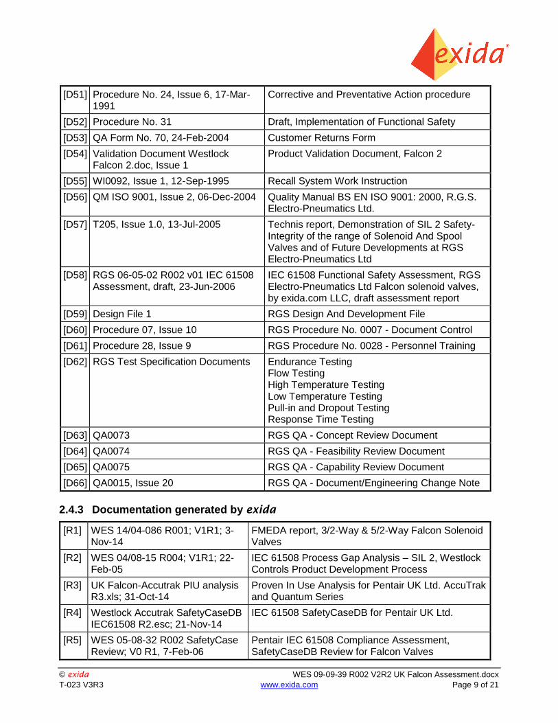
[D51] Procedure No. 24, Issue 6, 17-Mar-1991
Corrective and Preventative Action procedure
[D52] Procedure No. 31 Draft, Implementation of Functional Safety
[D53] QA Form No. 70, 24-Feb-2004 Customer Returns Form
[D54] Validation Document Westlock Falcon 2.doc, Issue 1
Product Validation Document, Falcon 2
[D55] WI0092, Issue 1, 12-Sep-1995 Recall System Work Instruction
[D56] QM ISO 9001, Issue 2, 06-Dec-2004 Quality Manual BS EN ISO 9001: 2000, R.G.S. Electro-Pneumatics Ltd.
[D57] T205, Issue 1.0, 13-Jul-2005 Technis report, Demonstration of SIL 2 Safety-Integrity of the range of Solenoid And Spool Valves and of Future Developments at RGS Electro-Pneumatics Ltd
[D58] RGS 06-05-02 R002 v01 IEC 61508 Assessment, draft, 23-Jun-2006
IEC 61508 Functional Safety Assessment, RGS Electro-Pneumatics Ltd Falcon solenoid valves, by exida.com LLC, draft assessment report
[D59] Design File 1 RGS Design And Development File
[D60] Procedure 07, Issue 10 RGS Procedure No. 0007 - Document Control
[D61] Procedure 28, Issue 9 RGS Procedure No. 0028 - Personnel Training
[D62] RGS Test Specification Documents Endurance Testing Flow Testing High Temperature Testing Low Temperature Testing Pull-in and Dropout Testing Response Time Testing
[D63] QA0073 RGS QA - Concept Review Document
[D64] QA0074 RGS QA - Feasibility Review Document
[D65] QA0075 RGS QA - Capability Review Document
[D66] QA0015, Issue 20 RGS QA - Document/Engineering Change Note
2.4.3 Documentation generated by exida
[R1] WES 14/04-086 R001; V1R1; 3-Nov-14
FMEDA report, 3/2-Way & 5/2-Way Falcon Solenoid Valves
[R2] WES 04/08-15 R004; V1R1; 22-Feb-05
IEC 61508 Process Gap Analysis – SIL 2, Westlock Controls Product Development Process
[R3] UK Falcon-Accutrak PIU analysis R3.xls; 31-Oct-14
Proven In Use Analysis for Pentair UK Ltd. AccuTrak and Quantum Series
[R4] Westlock Accutrak SafetyCaseDB IEC61508 R2.esc; 21-Nov-14
IEC 61508 SafetyCaseDB for Pentair UK Ltd.
[R5] WES 05-08-32 R002 SafetyCase Review; V0 R1, 7-Feb-06
Pentair IEC 61508 Compliance Assessment, SafetyCaseDB Review for Falcon Valves
© exida WES 09-09-39 R002 V2R2 UK Falcon Assessment.docx
T-023 V3R3 www.exida.com Page 10 of 21
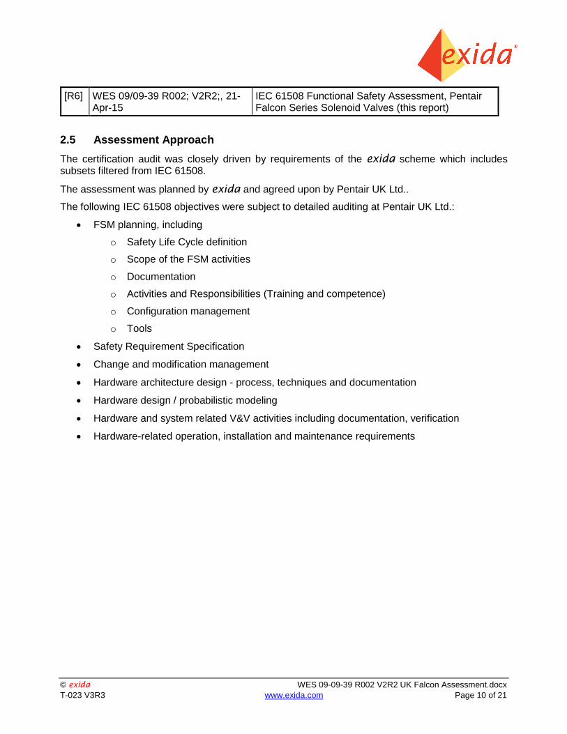
[R6] WES 09/09-39 R002; V2R2;, 21-Apr-15
IEC 61508 Functional Safety Assessment, Pentair Falcon Series Solenoid Valves (this report)
2.5 Assessment Approach
The certification audit was closely driven by requirements of the exida scheme which includes subsets filtered from IEC 61508.
The assessment was planned by exida and agreed upon by Pentair UK Ltd..
The following IEC 61508 objectives were subject to detailed auditing at Pentair UK Ltd.:
FSM planning, including
o Safety Life Cycle definition
o Scope of the FSM activities
o Documentation
o Activities and Responsibilities (Training and competence)
o Configuration management
o Tools
Safety Requirement Specification
Change and modification management
Hardware architecture design - process, techniques and documentation
Hardware design / probabilistic modeling
Hardware and system related V&V activities including documentation, verification
Hardware-related operation, installation and maintenance requirements
© exida WES 09-09-39 R002 V2R2 UK Falcon Assessment.docx
T-023 V3R3 www.exida.com Page 11 of 21
3 Product Descriptions
The Pentair Falcon Series Solenoid Valves are a series of sliding spool solenoid valves. A shaped spool moves between chambers isolated by elastomeric static seals. The seal space assembly forms individual annular chambers opposite each valve port and the grooved spool either closes or allows flow between adjacent chambers, hence the position of the spool determines which ports are open or closed. The spool is moved by way of a solenoid controlled pneumatic pressure, normally against a spring return. They are available in various body materials and different flow capacities. These can also be equipped with various Manual Overrides. These valves are primarily used as part of a Pentair Quantum Control Monitor.
The Falcon Solenoid Valve Series covered in this Assessment all have similar construction and options. Three different materials of construction for the body are available. Also included are various DC and AC coil options available that range between 0.48 and up to 4 watts. Models may also be equipped with or without Manual Override(s).
Note: the SIF designer is responsible for determining if the Override function is suitable for the application. The end user qualified personnel are responsible for determining if it is safe to manually Override the Valves position.
Table 1 gives an overview of the different versions that were considered in this Assessment of the AccuTrak and Quantum series.
Table 1 Version overview
3/2-Way, DTT (Spring Return)
Falcon Series : 3/2-Way, 2 position, Single Coil Solenoid, Spring Return, De-energize to Trip, with or w/o Manual Override
3/2-Way, ETT (Spring Return)
Falcon Series : 3/2-Way, 2 position, Single Coil Solenoid, Spring Return, Energize to Trip, with or w/o Manual Override
5/2-Way, DTT (Spring Return)
Falcon Series : 5/2-Way, 2 position, Single Coil Solenoid, Spring Return, De-energize to Trip, with or w/o Manual Override
5/2-Way, ETT (Spring Return)
Falcon Series : 5/2-Way, 2 position, Single Coil Solenoid, Spring Return, Energize to Trip, with or w/o Manual Override
Dual Coil Solenoid 5/2-Way
Falcon Series : 5/2-Way, 2 position, Dual Coil Solenoid, fail in place, with or w/o Manual Overrides
The Falcon Solenoid Valve Series are classified as a device that is part of a Type A1 element according to IEC 61508, having a hardware fault tolerance of 0.
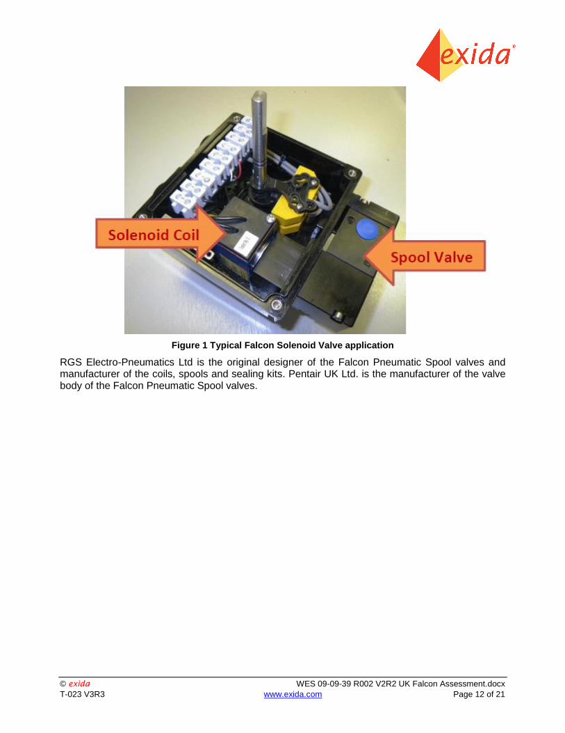
Figure 1 shows a typical Falcon Series Valve mounted to a Control Monitor enclosure.
Note: Only the Safety Function provided by the Solenoid Coil and Spool Valve are included in this Assessment. The Safety Function(s) provided by the Switches / Sensors are covered in separate FMEDA and Assessment reports.
1 Type A element: “Non-Complex” element (using discrete components); for details see 7.4.4.1.2 of IEC
61508-2, ed2, 2010.
© exida WES 09-09-39 R002 V2R2 UK Falcon Assessment.docx
T-023 V3R3 www.exida.com Page 12 of 21
Figure 1 Typical Falcon Solenoid Valve application
RGS Electro-Pneumatics Ltd is the original designer of the Falcon Pneumatic Spool valves and manufacturer of the coils, spools and sealing kits. Pentair UK Ltd. is the manufacturer of the valve body of the Falcon Pneumatic Spool valves.
© exida WES 09-09-39 R002 V2R2 UK Falcon Assessment.docx
T-023 V3R3 www.exida.com Page 13 of 21
4 IEC 61508 Functional Safety Assessment Scheme
exida assessed the development process used by Pentair UK Ltd. for this development project
against the objectives of the exida certification scheme which includes subsets of IEC 61508 -1 to 3. The results of the assessment are documented in [R4] and [R5].
4.1 Methodology
The full functional safety assessment includes an assessment of all fault avoidance and fault control measures during hardware development and demonstrates full compliance with IEC 61508 to the end-user. The assessment considers all requirements of IEC 61508. Any requirements that have been deemed not applicable have been marked as such in the full Safety Case report, e.g. software development requirements for a product with no software. The assessment also includes a review of existing manufacturing quality procedures to ensure compliance to the quality requirements of IEC 61508.
As part of the IEC 61508 functional safety assessment the following aspects have been reviewed:
Development process, including:
o Functional Safety Management, including training and competence recording, FSM planning, and configuration management
o Specification process, techniques and documentation
o Design process, techniques and documentation, including tools used
o Validation activities, including development test procedures, test plans and reports, production test procedures and documentation
o Verification activities and documentation
o Modification process and documentation
o Installation, operation, and maintenance requirements, including user documentation
o Manufacturing Quality System
Product design
o Hardware architecture and failure behavior, documented in a FMEDA
o Hardware Proven-in-use study, as documented in [D57] and [R3]
The review of the development procedures is described in section 5. The review of the product design is described in section 5.2.
4.2 Assessment level
The Falcon Series Valves have been assessed per IEC 61508 to the following levels:
Systematic Capability SC3 (SIL 3 capability) as the development procedures were assessed as suitable for use in applications with a maximum Safety Integrity Level of 3 (SIL 3) according to IEC 61508.
Architecture Constraint limitations of SIL 2 for a single device or SIL 3 with HFT=1 (using Route 2H) and SIL 2 for a single device where the SFF for the complete Type A final element is >60% (if using Route 1H).
© exida WES 09-09-39 R002 V2R2 UK Falcon Assessment.docx
T-023 V3R3 www.exida.com Page 14 of 21
5 Results of the IEC 61508 Functional Safety Assessment
exida assessed the development process used by Pentair UK Ltd. for these products against the objectives of IEC 61508 parts 1 - 7. The assessment was done on-site at the Tunbridge Wells, Kent facility on May 2, 2014 and documented in the SafetyCase [R4].
RGS Electro-Pneumatics Ltd is the OEM supplier of the coils, spools and sealing kits. As RGS Electro-Pneumatics Ltd is also the original designer of the Falcon Solenoid Valve Series and is involved in any modification activities, the development process used by RGS is a critical part of the assessment. The development process of RGS Electro-Pneumatics Ltd was assessed to IEC 61508 by exida. The RGS Electro-Pneumatics Ltd IEC 61508 assessment report (draft) [D58] and documentation provided as part of that assessment served as input to the Pentair UK Ltd. Falcon Solenoid Valve Series IEC 61508 assessment.
A SafetyCase was also completed, see [R4] and [R5]. For the SafetyCase, the emphasis for the assessment of Pentair UK Ltd. was on the modification process and installation, operation, and maintenance requirements, including user documentation and field return procedures.
5.1 Lifecycle Activities and Fault Avoidance Measures
Pentair UK Ltd. has a defined product lifecycle process in place. This is documented in the Quality Assurance Manual [D1] and various Operating Procedures [D9]-[D20]. A documented modification process is also covered in the Quality Assurance Manual. No software is part of the design and therefore any requirements specific from IEC 61508 to software and software development do not apply.
The assessment investigated the compliance with IEC 61508 of the processes, procedures and techniques as implemented for product design and development. The investigation was executed using subsets of the IEC 61508 requirements tailored to the SIL 3 work scope of the development and engineering teams. The defined product lifecycle process was modified as a result of the audit which showed some areas for improvement. However, given the simple nature of the safety function and the extensive proven field experience for existing products Pentair UK Ltd. was able to demonstrate that the objectives of the standard have been met. The result of the assessment can be summarized by the following observations:
The audited Pentair UK Ltd. solenoid modification process complies with the relevant managerial requirements of IEC 61508 SIL 3. The RGS Electro-Pneumatics Ltd development process complies with the relevant managerial requirements of IEC 61508 SIL 3.
5.1.1 Functional Safety Management
The Falcon Series Valves manufactured by Pentair are not built for inventory. These devices are built-to-order. The basic designs are standardized, but each order can have materials and coil variations or other specific customer requested options as detailed in the product brochures. Due to the specialized nature of each Solenoid, documentation that defines all of the requirements is generated for every order as part of the process.
FSM Planning As the Falcon Solenoid Valve Series are an existing product, the Pentair UK Ltd. product variation development process applies to any product variations. Specific deliverables, reviews, and approvals are documented in [D13]. This process and procedures referenced herein fulfill the requirements of IEC 61508 with respect to functional safety management. All Pentair design
© exida WES 09-09-39 R002 V2R2 UK Falcon Assessment.docx
T-023 V3R3 www.exida.com Page 15 of 21
documents, such as drawings, match RGS design documentation. RGS has a special check in its modification process to see if modifications impact Pentair. Pentair defines responsibilities in the Quality Assurance Manual [D1]. This is deemed sufficient for the Falcon Solenoid Valve Series given its simple complexity and well defined safety functionality.
RGS Electro-Pneumatics Ltd has a 3 stage development process (Concept, Feasibility, Capability) in place for product development with specific deliverables, reviews and approvals. This is documented in the Design and Development File [D59] used to specify each development project. The same process is used for modifications. This process and procedures referenced herein fulfill the requirements of IEC 61508 with respect to functional safety management.
Version Control
Section 7.3 of the Pentair QAM requires that all documents be under document control. Use of this to control revisions was evident during the audit.
At RGS all documents as called out for in Design and Development File are under version control per [D60]. Design drawings and documents are also under version control.
Training, Competency recording
Section 6.2 of the Pentair QAM requires the Human Resource department to maintain training records of education, experience, training and qualifications for all personnel. Department heads are responsible for identifying and providing the training needs for their department as well as proficiency evaluations. Section 9.3 of OP 9 [D20] covers the additional competencies required for Functional Safety items which are documented in the FS Competency Register [D28]. The procedures and records were examined and found up-to-date and sufficient.
RGS personnel training records are kept per [D61]. The procedure and records were examined and found up-to-date and sufficient.
Pentair hired exida to be the independent assessor per IEC 61508 and to provide specific IEC 61508 knowledge.
5.1.2 Safety Requirements Specification and Architecture Design
Since RGS is the original developer of the Falcon Solenoid Valve Series and involved in any modification activities, this lifecycle phase applies to RGS. The compliance to the requirements for this lifecycle phase are covered in the RGS IEC 61508 assessment report.
The first step for any new development is the creation of a Design Specification per the Design and Development File [D59]. The creation of the design specifciation is a combined effort by marketing and engineering. This ensures that the design requiremetns are understood correctly by engineering. The Design and Development file uses a template for design specification which ensures completeness of the requirements. The templace captures in detail all the requirements for the devices, such as critical functions, performance targets etc. exida reviewed the content of the specification for completeness per the requirements of IEC 61508.
As the valves are simple electro-mechanical devices, there is no need for a separate architecture design phase. The design concepts, which follow the design specification, will indicate if the design is new or based on an existing design.
Requirements as specified in the Design Specification are tracked through all development phases, simply by the fact that they are contained in the Design and Development file which guides a development project through all development lifecycle phases.
© exida WES 09-09-39 R002 V2R2 UK Falcon Assessment.docx
T-023 V3R3 www.exida.com Page 16 of 21
Items from IEC 61508-2, Table B.1 include project management, documentation, separation of safety requirements from non-safety requirements, structured specification, and inspection of the specification. As the function of the valve is simple and clearly defined there is no need for semi-formal methods such as functional block diagrams. The application is considered when specifying the requirements; the devices may be required to meet specific applications standards. This meets SIL 3.
5.1.3 Hardware Design
Since RGS is the original developer of the Falcon Solenoid Valve Series and involved in any modification activities, this lifecycle phase applies to RGS. The compliance to the requirements for this lifecycle phase are covered in the RGS IEC 61508 assessment report.
The hardware design process consists of two distinct phases: concept and feasibility. During the concept phase all possible solutions are reviewed and the most promising is detailed. At this time a Design and Development File will be created which contains requirements, test specifications, etc. The test specifications are considered equal to validation plan per IEC 61508.
In the feasibility phase, the design is further detailed and testing is performed on beta units. Design reviews are performed per the Design and Development File [D59]. RGS Electro-Pneumatics Ltd has standards for documentation with specified output documents.
RGS Electro-Pneumatics Ltd uses Autocad Lite and Design Manager as development tools. Version numbers are listed and re-qualification is done when the tool vendor makes revisions. Re-qualification is done annually at the management review to ensure continued suitability. This meets SIL 3.
5.1.4 Validation
Since RGS is the original developer of the Falcon Solenoid Valve Series and involved in any modification activities, this lifecycle phase applies to RGS. The compliance to the requirements for this lifecycle phase are covered in the RGS IEC 61508 assessment report. As the Falcon Solenoid Valve Series are purely electro-mechanical devices with a simple safety function, there is no separate integration testing necessary.
Validation Testing is done via a set of documented tests, the RGS Test Specification Documents [D62], as required by the Design and Development File [D59]. The tests are traceable to the requirements via the Design and Development File. In addition to standard Test Specification Documents third party testing may be included as part of agency approvals. As the Falcon Solenoid Valve Series are purely electro-mechanical devices with a simple safety function, there is no separate integration testing necessary. However, the solenoids do undergo several separate tests before the valve body and solenoid are integrated; this is part of the RGS Test Specification Documents. The Falcon Solenoid Valve Series perform only 1 Safety Function, which is extensively tested under various conditions during validation testing.
Procedures are in place for corrective actions to be taken when tests fail. Every run of the RGS Test Specification Documents is documented in a test report and reviewed. The test reports are included in the Design and Development File for the project.
Items from IEC 61508-2, Table B.3 include functional testing, project management, documentation, and black-box testing (for the considered devices this is similar to functional testing). Field experience and statistical testing via regression testing are not applicable. This meets SIL 3.
© exida WES 09-09-39 R002 V2R2 UK Falcon Assessment.docx
T-023 V3R3 www.exida.com Page 17 of 21
Items from IEC 61508-2, Table B.5 included functional testing and functional testing under environmental conditions, project management, documentation, failure analysis (analysis on products that failed), expanded functional testing, black-box testing, and fault insertion testing. This meets SIL 3.
5.1.5 Verification
Since RGS is the original developer of the Falcon Solenoid Valve Series and involved in any modification activities, this lifecycle phase applies to RGS. The compliance to the requirements for this lifecycle phase are covered in the RGS IEC 61508 assessment report.
The development and verification activities are defined in the Design and Development File [D59]. For each phase the objectives are stated, required input and output documents and review activities. QA forms are used to facility the verification activities at the concept, feasibility and capability stages, see [D63], [D64], and [D65] respectively. All verification activities are documented. Given the solenoids only perform a single safety function, this meets SIL 3.
5.1.6 Proven In Use
In addition to the Design Fault avoidance techniques listed above, a Proven in Use evaluation was carried out on the Pentair 3/2-Way & 5/2-Way Falcon Solenoid Valve. Shipment records were used to determine that the Falcon Solenoid Valve Series have >200 million hours in use and they have demonstrated a field failure rate less than the failure rates indicated in the FMEDA reports. This meets the requirements for Proven In Use for SIL 3.
5.1.7 Modifications
Pentair UK Ltd. design changes are controlled by revision numbers and dates, and are initiated by Engineering Change Notices on form QF22 [D23] per section 7.3.7 of OP 7. All Pentair design documents, such as drawings, match RGS design documentation. RGS has a special check in its modification process to see if modification impacts Pentair UK Ltd.. RGS is responsible for checking if design changes affect Functional Safety.
For RGS the compliance to the requirements for this lifecycle phase are covered in the RGS IEC 61508 assessment report. Modifications are done per the QA Document/Engineering Change Note Form [D66]. The D/ECN form subsequently becomes part of the Design and Development File. The D/ECN system allows the user to identify if the change affects Functional Safety. Affected documents and/or drawings are also listed. If design changes are identified as a result of a D/ECN, they are usually treated as a derived product and therefore the same general procedure is used for both new development and modifications. All design change requests are reviewed to determine if there is any negative impact on product safety. This review is done by both the assigned engineer and the appropriate engineering manager (others may be included in the review as necessary). This meets SIL 3.
Pentair UK Ltd. has a field return process in place as described in [D1]. Field returns are evaluated by Quality Assurance. Returns that require modification to the Falcon Solenoid Valve Series are communicated to RGS. If it is determined that a non-conformity affects Functional Safety, RGS will notify Pentair.
As the Pentair and RGS modification processes have been successfully assessed and audited, Pentair and RGS may make modifications to this product as needed.
© exida WES 09-09-39 R002 V2R2 UK Falcon Assessment.docx
T-023 V3R3 www.exida.com Page 18 of 21
As part of the exida scheme a surveillance audit is conducted every 3 years. The modification documentation listed below is submitted as part of the surveillance audit.
exida will review the decisions made by the competent person in respect to the modifications made.
o List of all anomalies reported
o List of all modifications completed
o Safety impact analysis which shall indicate with respect to the modification:
The initiating problem (e.g. results of root cause analysis)
The effect on the product / system
The elements/components that are subject to the modification
The extent of any re-testing
o List of modified documentation
This meets SIL 3.
5.1.8 User documentation
Pentair UK Ltd. creates the following user documentation: data sheets, operating manuals and a Safety Manual. The Safety Manual was found to contain all of the required information given the simplicity of the products. The Safety Manual references the data from the FMEDA report(s) which are available and contain the required failure rates, failure modes, useful life, and suggested proof test information.
Items from IEC 61508-2, Table B.4 include operation and maintenance instructions, user friendliness, maintenance friendliness, project management, documentation, limited operation possibilities (Falcon Series Valves perform well-defined actions) and operation only by skilled operators (operators familiar with Solenoid Valves, although this is partly the responsibility of the end-user). This meets SIL 3.
5.2 Hardware Assessment
To evaluate the hardware design of the 3/2-Way & 5/2-Way Falcon Solenoid Valve, a Failure
Modes, Effects, and Diagnostic Analysis was performed by exida. This is documented in [R1].
A Failure Modes and Effects Analysis (FMEA) is a systematic way to identify and evaluate the effects of different component failure modes, to determine what could eliminate or reduce the chance of failure, and to document the system in consideration. An FMEDA (Failure Mode Effect and Diagnostic Analysis) is an FMEA extension. It combines standard FMEA techniques with extension to identify online diagnostics techniques and the failure modes relevant to safety instrumented system design.
From the FMEDA, failure rates are derived for each important failure category. All failure rate analysis results and useful life limitations are listed in the FMEDA report [R1]. Tables in the FMEDA report list these failure rates for the 3/2-Way & 5/2-Way Falcon Solenoid Valve under a variety of applications. The failure rates listed are valid for the useful life of the devices.
© exida WES 09-09-39 R002 V2R2 UK Falcon Assessment.docx
T-023 V3R3 www.exida.com Page 19 of 21
According to IEC 61508 the architectural constraints of an element must be determined. This can be done by following the 1H approach according to 7.4.4.2 of IEC 61508 or the 2H approach according to 7.4.4.3 of IEC 61508.
The 1H approach involves calculating the Safe Failure Fraction for the entire element.
The 2H approach involves assessment of the reliability data for the entire element according to 7.4.4.3.3 of IEC 61508.
The failure rate data used for this analysis meets the exida criteria for Route 2H. Therefore the Falcon Series Valves can be classified as a 2H device. When 2H data is used for all of the devices in an element, the element meets the hardware architectural constraints up to SIL 2 at HFT=0 (or SIL 3 @ HFT=1) per Route 2H.
If Route 2H is not applicable for the entire final element, the architectural constraints will need to be evaluated per Route 1H.
Note, as the Pentair Falcon Series Solenoid Valves is only one part of a (sub)system, the SFF should be calculated for the entire final element combination.
These results must be considered in combination with PFDavg values of other devices of a Safety Instrumented Function (SIF) in order to determine suitability for a specific Safety Integrity Level (SIL). The architectural constraints requirements of IEC 61508-2, Table 2 also need to be evaluated for each final element application. It is the end users responsibility to confirm this for each particular application and to include all components of the final element in the calculations.
The analysis shows that the design of the Pentair Falcon Series Solenoid Valves can meet the hardware requirements of IEC 61508, SIL 3 depending on the complete final element design. The Hardware Fault Tolerance and PFDavg requirements of IEC 61508 must be verified for each specific design.
© exida WES 09-09-39 R002 V2R2 UK Falcon Assessment.docx
T-023 V3R3 www.exida.com Page 20 of 21
6 Terms and Definitions
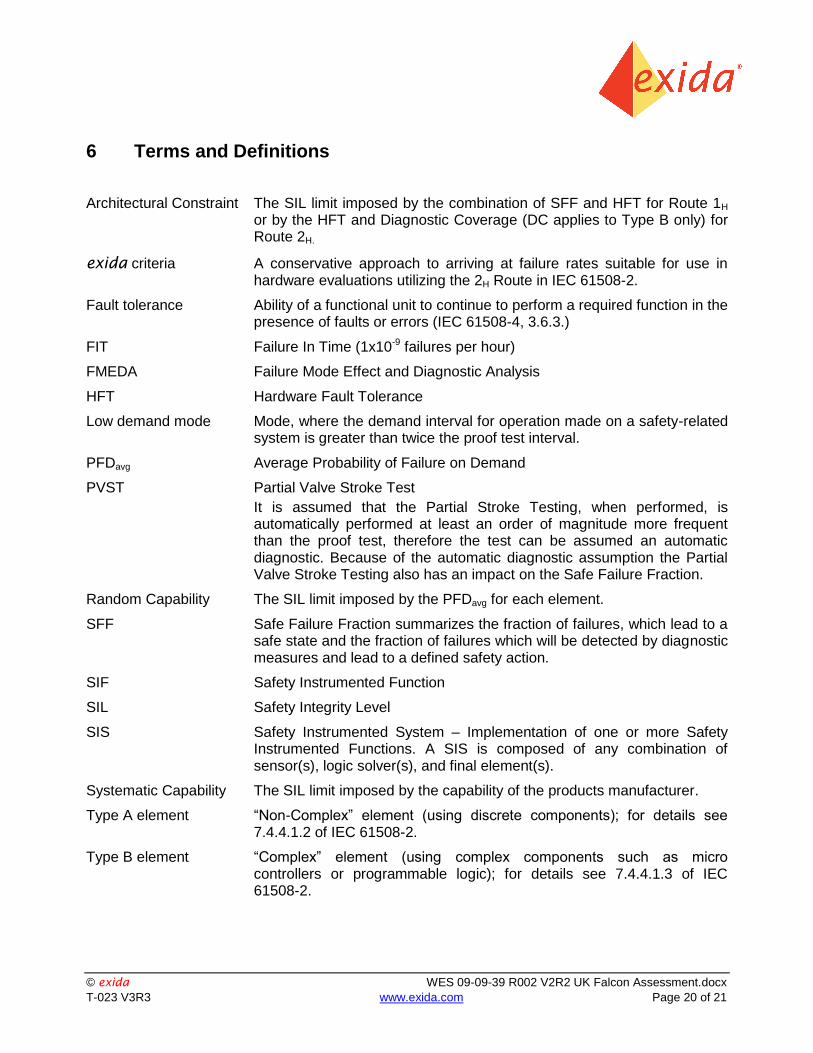
Architectural Constraint The SIL limit imposed by the combination of SFF and HFT for Route 1H or by the HFT and Diagnostic Coverage (DC applies to Type B only) for Route 2H.
exida criteria A conservative approach to arriving at failure rates suitable for use in hardware evaluations utilizing the 2H Route in IEC 61508-2.
Fault tolerance Ability of a functional unit to continue to perform a required function in the presence of faults or errors (IEC 61508-4, 3.6.3.)
FIT Failure In Time (1x10⁻⁹ failures per hour)
FMEDA Failure Mode Effect and Diagnostic Analysis
HFT Hardware Fault Tolerance
Low demand mode Mode, where the demand interval for operation made on a safety-related system is greater than twice the proof test interval.
PFDavg Average Probability of Failure on Demand
PVST Partial Valve Stroke Test
It is assumed that the Partial Stroke Testing, when performed, is automatically performed at least an order of magnitude more frequent than the proof test, therefore the test can be assumed an automatic diagnostic. Because of the automatic diagnostic assumption the Partial Valve Stroke Testing also has an impact on the Safe Failure Fraction.
Random Capability The SIL limit imposed by the PFDavg for each element.
SFF Safe Failure Fraction summarizes the fraction of failures, which lead to a safe state and the fraction of failures which will be detected by diagnostic measures and lead to a defined safety action.
SIF Safety Instrumented Function
SIL Safety Integrity Level
SIS Safety Instrumented System – Implementation of one or more Safety Instrumented Functions. A SIS is composed of any combination of sensor(s), logic solver(s), and final element(s).
Systematic Capability The SIL limit imposed by the capability of the products manufacturer.
Type A element “Non-Complex” element (using discrete components); for details see 7.4.4.1.2 of IEC 61508-2.
Type B element “Complex” element (using complex components such as micro controllers or programmable logic); for details see 7.4.4.1.3 of IEC 61508-2.
© exida WES 09-09-39 R002 V2R2 UK Falcon Assessment.docx
T-023 V3R3 www.exida.com Page 21 of 21
7 Status of the Document
7.1 Liability
exida prepares reports based on methods advocated in International standards. exida accepts no liability whatsoever for the use of this report or for the correctness of the standards on which the general calculation methods are based.
7.2 Releases
This report supersedes Report No. WES 05/08-32 R001 and all of its versions and revisions
Version: V2
Revision: R2
Version History: V2, R2 Revised company name to Pentair UK Ltd.; April 1, 2015
V2, R1 Combined report for RGS design based Falcon’s and added Route 2H info; April 1, 2015
V1, R1 Released to Pentair UK Ltd.
V1, R0: Draft; October 8, 2009
Authors: Gregory Sauk
Review: V2, R0: Steven Close; March 13, 2015
V1, R1: William Goble (exida); October 12, 2009
Release status: Released
7.3 Future Enhancements
At request of client.
7.4 Release Signatures
Gregory Sauk, CFSE, Senior Safety Engineer
Steven Close, Senior Safety Engineer


![IEC 61508 Assessment - exida€¦ · IEC 61508 Functional Safety Assessment ... [D38] QP 01; Rev 03; 4/29/2009 ... RP Approved Vendor; 7/6/2012 Approved Vendor List [D57]](https://img.pdfslide.us/doc/110x75/5b8675187f8b9a162d8d0076/iec-61508-assessment-iec-61508-functional-safety-assessment-d38-qp-01.jpg)