Embed Size (px)
Citation preview
Page 1 of 41
Jiangsu TÜV Product Service Ltd. Guangzhou Branch IEC60950_1B
Test Report issued under the responsibility of:
NCB TÜV SÜD PSB
1 Science Park Drive, 118221 Singapore
Singapore
TEST REPORT
IEC 60950-1 Information technology equipment – Safety –
Part 1: General requirements
Report Number. ............................... : 64.210.11.00477.01 Rev.00
Date of issue ..................................... : 2012-09-12
Total number of pages ....................... 41 pages
Testing Laboratory ......................... : Jiangsu TÜV Product Service Ltd. Guangzhou Branch
Address ............................................. : 5F, Communication Building, 163 Pingyun Rd, Huangpu Ave. West Guangzhou 510656 P. R. China
Applicant’s name ............................ : Gembird Electronics Ltd.
Address ............................................. : Floor 5th, Building B, Shifeng Science Technical Zone, Huaning Road,
Dalang Street, Bao An, 518129 Shenzhen, Guangdong, People’s Republic of China
Manufacturer’s name……………….: Same as applicant
Address ............................................. : Same as applicant
Test specification:
Standard ........................................... : EN 60950-1:2006+A11:2009 + A1:2010+ A12: 2011
Test procedure.................................. : --
Non-standard test method…………..: N/A
Test Report Form No. ..................... : IEC60950_1B
Test Report Form(s) Originator ........ : SGS Fimko Ltd
Master TRF ....................................... : Dated 2010-04
Copyright © 2010 Worldwide System for Conformity Testing and Certification of Electrotechnical Equipment and Components (IECEE), Geneva, Switzerland. All rights reserved.
This publication may be reproduced in whole or in part for non-commercial purposes as long as the IECEE is acknowledged as copyright owner and source of the material. IECEE takes no responsibility for and will not assume liability for damages resulting from the reader's interpretation of the reproduced material due to its placement and context.
If this Test Report Form is used by non-IECEE members, the IECEE/IEC logo and the reference to the CB Scheme procedure shall be removed.
This report is not valid as a CB Test Report unless signed by an approved CB Testing Laboratory and appended to a CB Test Certificate issued by an NCB in accordance with IECEE 02.
Test item description ..................... : USB Adaptor (Building-in portable socket-outlets)
Trade Mark ....................................... : --
Manufacturer ..................................... : Same as applicant
Model/Type reference ....................... : UC-1A, UC-2A
Ratings .............................................. : Input: 250 Vac, 50 Hz, 0,18 A
Output: 5,0Vd.c./ 1,0A for UC-1A; 5,0Vd.c./ 2,0A for UC-2A
Page 3 of 41 Report Ref. No.: 64.210.11.00477.01 Rev.00
Jiangsu TÜV Product Service Ltd. Guangzhou Branch IEC60950_1B
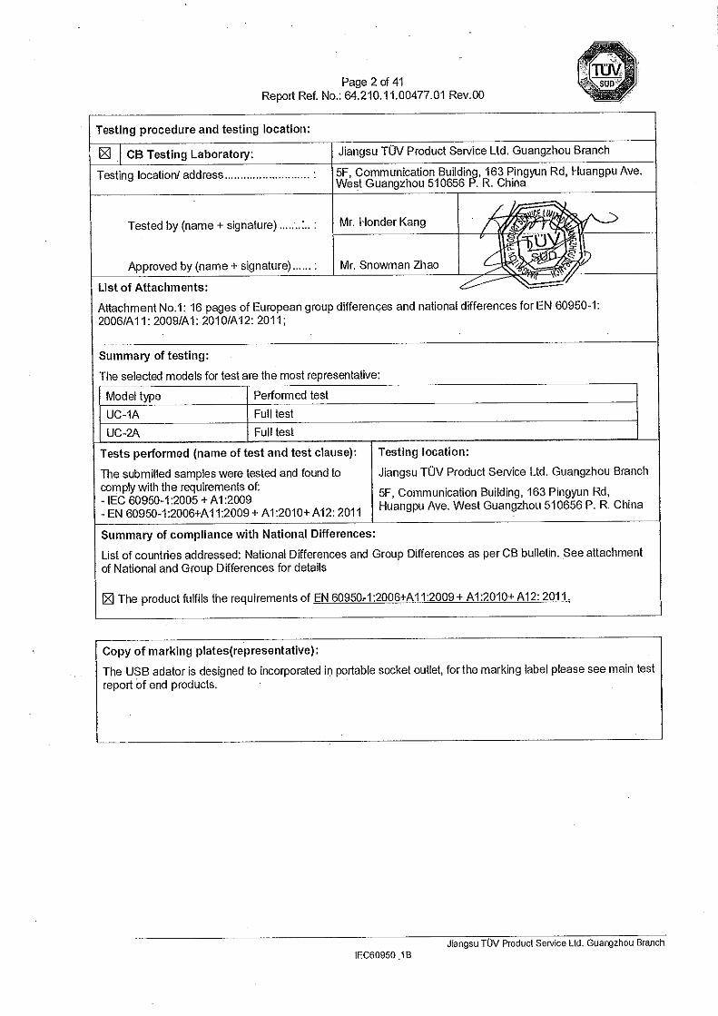
Test item particulars .................................................. :
Equipment mobility .................................................... : [] movable [ ] hand-held [ ] transportable
[ ] stationary [√] for building-in [] direct plug-in
Connection to the mains ............................................ : [√] pluggable equipment [√] type A [ ] type B
[ ] detachable power supply cord
[ ] non-detachable power supply cord
[ ] not directly connected to the mains
Operating condition .................................................... : [√ ] continuous
[ ] rated operating / resting time:
Access location ......................................................... : [√ ] operator accessible
[ ] restricted access location
Over voltage category (OVC) ................................... : [ ] OVC I [√ ] OVC II [ ] OVC III [ ] OVC IV
[ ] other:
Mains supply tolerance (%) or absolute mains supply values ....................................................................... :
+10%, -10% (required by the applicant)
Tested for IT power systems .................................... : [√] Yes [ ] No
IT testing, phase-phase voltage (V) .......................... : 230V (only for Norway)
Class of equipment ................................................... : [] Class I [√] Class II [ ] Class III [ ] Not classified
Considered current rating of protective device as part of the building installlation (A) ................................... :
16A
Pollution degree (PD) ............................................... : [] PD 1 [√] PD 2 [] PD 3
IP protection class .................................................... : IP00
Altitude during operation (m) .................................... : < 2000 m
Altitude of test laboratory (m) .................................... : < 500
Mass of equipment (kg) ............................................ : Approx. 0,25kg
Possible test case verdicts:
- test case does not apply to the test object ................. : N/A
- test object does meet the requirement ....................... : P (Pass)
- test object does not meet the requirement ................. : F (Fail)
Testing .......................................................................... :
Date of receipt of test item ............................................ : 2011-09-27
Date(s) of performance of tests .................................... : 2011-09-27 to 2011-12-26
General remarks:
The test results presented in this report relate only to the object tested. This report shall not be reproduced, except in full, without the written approval of the Issuing testing laboratory. "(see Enclosure #)" refers to additional information appended to the report. "(see appended table)" refers to a table appended to the report. Throughout this report a comma / point is used as the decimal separator.
Page 4 of 41 Report Ref. No.: 64.210.11.00477.01 Rev.00
Jiangsu TÜV Product Service Ltd. Guangzhou Branch IEC60950_1B
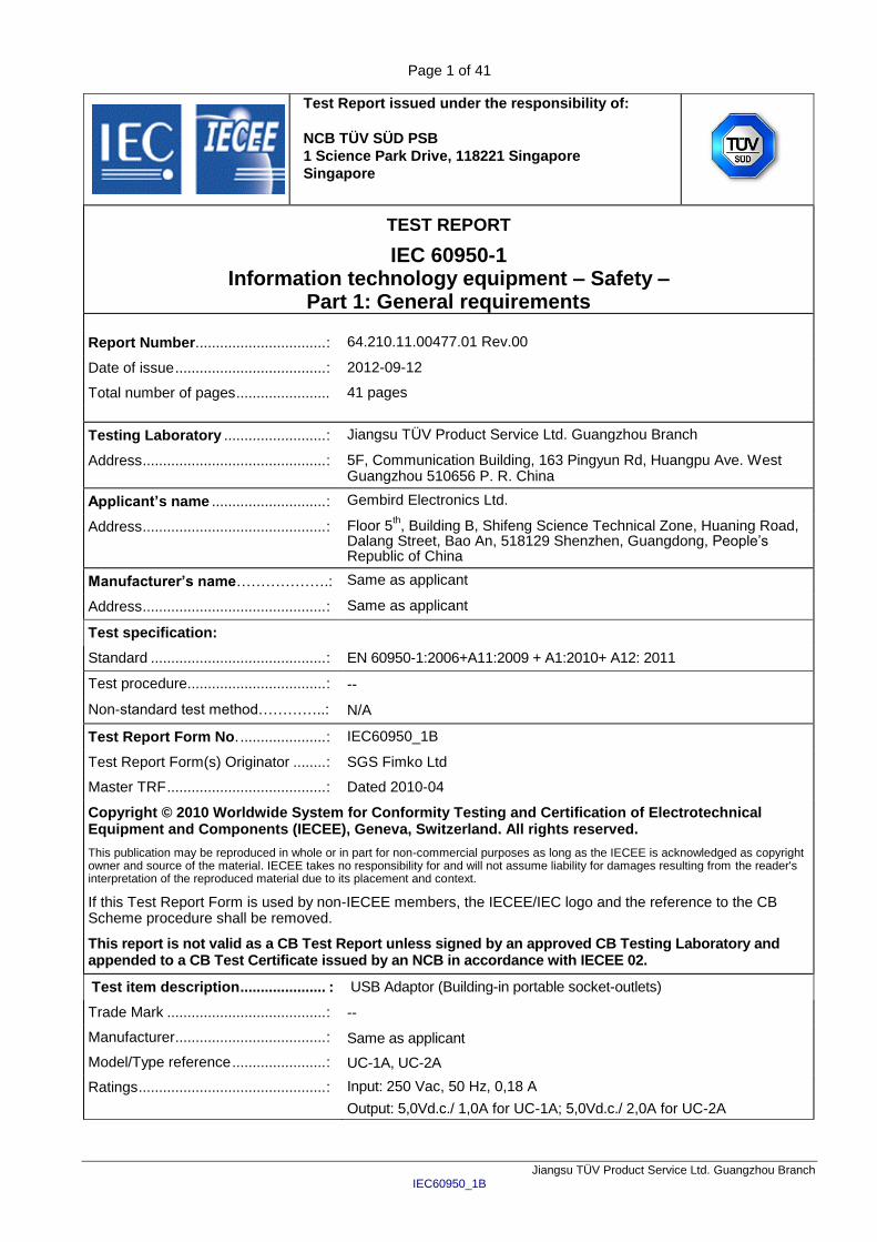
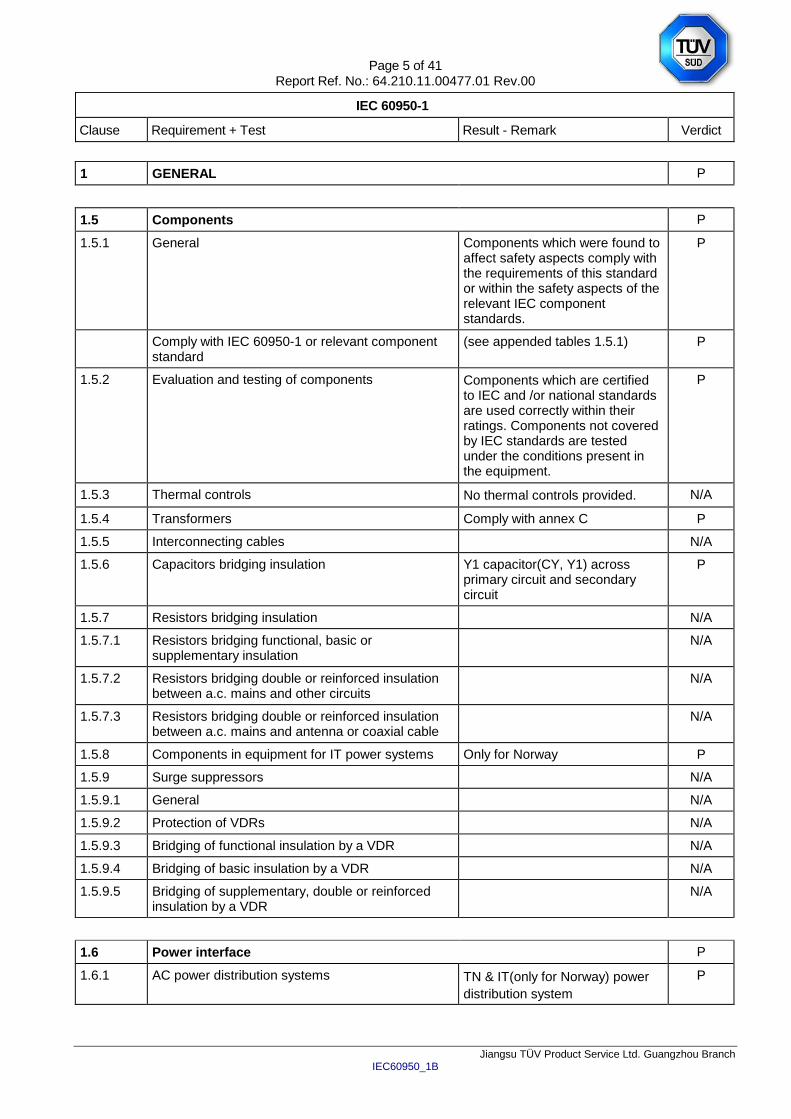
Manufacturer’s Declaration per sub-clause 6.2.5 of IECEE 02:
The application for obtaining a CB Test Certificate includes more than one factory location and a declaration from the Manufacturer stating that the sample(s) submitted for evaluation is (are) representative of the products from each factory has been provided ................................................................ :
Yes
Not applicable
When differences exist; they shall be identified in the General product information section.
Name and address of factory (ies) .......................... : Gembird Electronics Ltd.
Floor 5th, Building B, Shifeng Science Technical Zone,
Huaning Road, Dalang Street, Bao An, 518129 Shenzhen, Guangdong, People’s Republic of China
General product information:
1. The building-in USB charger is designed to incorporate in portable socket outlet, in this report the charger
was evaluated only and ambient temperature is 45C Max.
2. The equipment is in compliance with the requirements of sub-clause 2.5 (Limited power sources).
3. In normal heating test, the USB charger UC-1A was tested within the socket outlet model EG-SP5-
TNCU6B-RM; the USB charger UC-2A was tested within the socket outlet model EG-SP5-U6B-RM.
Difference between models: The models are identical except the circuit diagram, PCB layout and rated output current.
Abbreviations used in the report:
- normal conditions N.C. - single fault conditions S.F.C - functional insulation OP - basic insulation BI - double insulation DI - supplementary insulation SI - between parts of opposite polarity BOP - reinforced insulation RI Indicate used abbreviations (if any)
Page 5 of 41 Report Ref. No.: 64.210.11.00477.01 Rev.00
IEC 60950-1
Clause Requirement + Test Result - Remark Verdict
Jiangsu TÜV Product Service Ltd. Guangzhou Branch IEC60950_1B
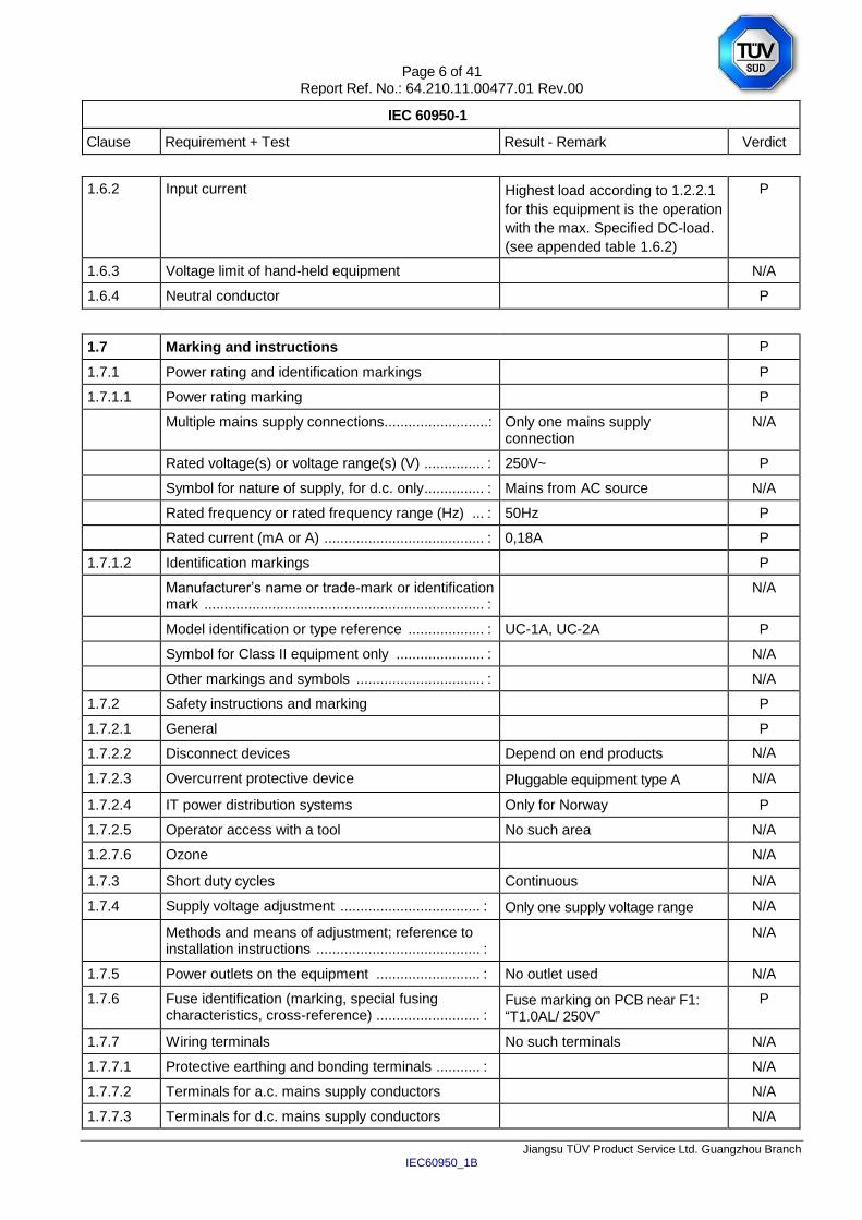
1 GENERAL P
1.5 Components P
1.5.1 General Components which were found to affect safety aspects comply with the requirements of this standard or within the safety aspects of the relevant IEC component standards.
P
Comply with IEC 60950-1 or relevant component standard
(see appended tables 1.5.1) P
1.5.2 Evaluation and testing of components Components which are certified to IEC and /or national standards are used correctly within their ratings. Components not covered by IEC standards are tested under the conditions present in the equipment.
P
1.5.3 Thermal controls No thermal controls provided. N/A
1.5.4 Transformers Comply with annex C P
1.5.5 Interconnecting cables N/A
1.5.6 Capacitors bridging insulation Y1 capacitor(CY, Y1) across primary circuit and secondary circuit
P
1.5.7 Resistors bridging insulation N/A
1.5.7.1 Resistors bridging functional, basic or supplementary insulation
N/A
1.5.7.2 Resistors bridging double or reinforced insulation between a.c. mains and other circuits
N/A
1.5.7.3 Resistors bridging double or reinforced insulation between a.c. mains and antenna or coaxial cable
N/A
1.5.8 Components in equipment for IT power systems Only for Norway P
1.5.9 Surge suppressors N/A
1.5.9.1 General N/A
1.5.9.2 Protection of VDRs N/A
1.5.9.3 Bridging of functional insulation by a VDR N/A
1.5.9.4 Bridging of basic insulation by a VDR N/A
1.5.9.5 Bridging of supplementary, double or reinforced insulation by a VDR
N/A
1.6 Power interface P
1.6.1 AC power distribution systems TN & IT(only for Norway) power
distribution system
P
Page 6 of 41 Report Ref. No.: 64.210.11.00477.01 Rev.00
IEC 60950-1
Clause Requirement + Test Result - Remark Verdict
Jiangsu TÜV Product Service Ltd. Guangzhou Branch IEC60950_1B
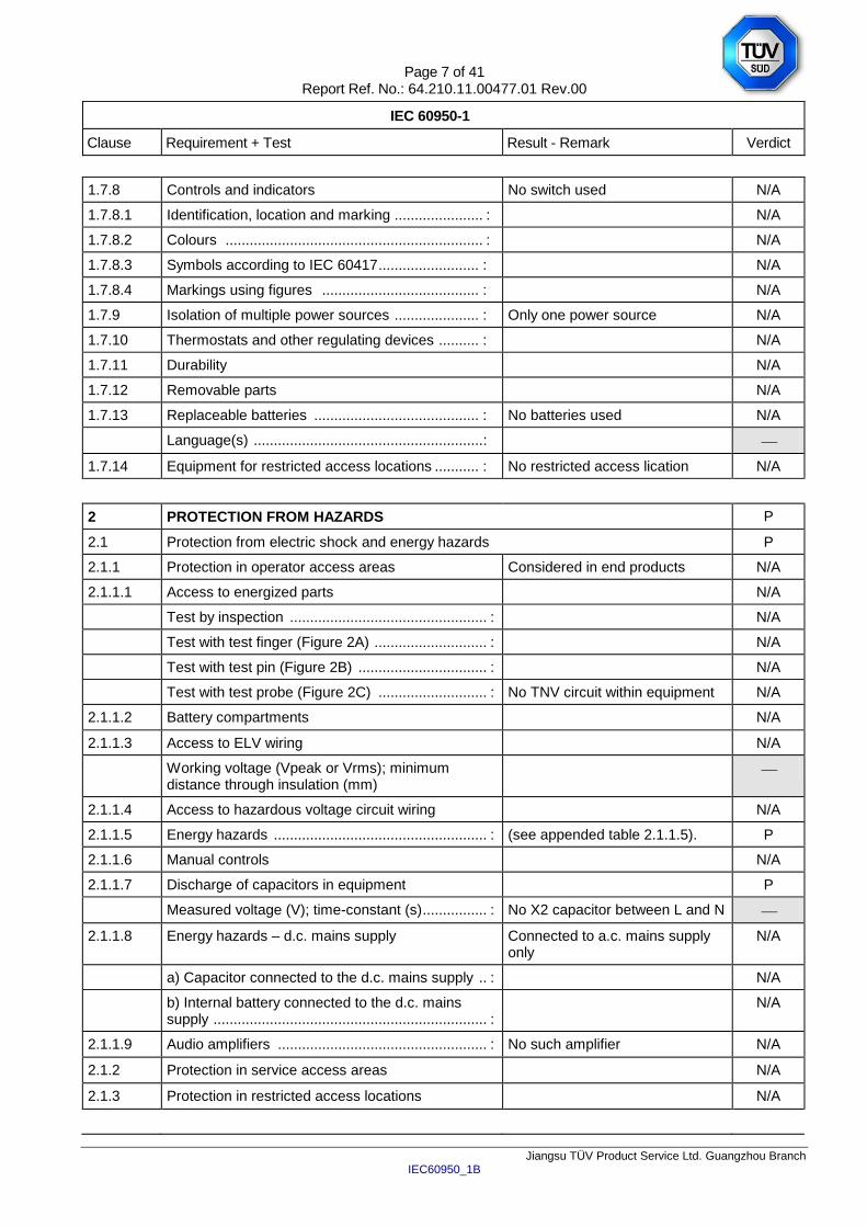
1.6.2 Input current Highest load according to 1.2.2.1
for this equipment is the operation
with the max. Specified DC-load.
(see appended table 1.6.2)
P
1.6.3 Voltage limit of hand-held equipment N/A
1.6.4 Neutral conductor P
1.7 Marking and instructions P
1.7.1 Power rating and identification markings P
1.7.1.1 Power rating marking P
Multiple mains supply connections..........................: Only one mains supply connection
N/A
Rated voltage(s) or voltage range(s) (V) ............... : 250V~ P
Symbol for nature of supply, for d.c. only ............... : Mains from AC source N/A
Rated frequency or rated frequency range (Hz) ... : 50Hz P
Rated current (mA or A) ........................................ : 0,18A P
1.7.1.2 Identification markings P
Manufacturer’s name or trade-mark or identification mark ...................................................................... :
N/A
Model identification or type reference ................... : UC-1A, UC-2A P
Symbol for Class II equipment only ...................... : N/A
Other markings and symbols ................................ : N/A
1.7.2 Safety instructions and marking P
1.7.2.1 General P
1.7.2.2 Disconnect devices Depend on end products N/A
1.7.2.3 Overcurrent protective device Pluggable equipment type A N/A
1.7.2.4 IT power distribution systems Only for Norway P
1.7.2.5 Operator access with a tool No such area N/A
1.2.7.6 Ozone N/A
1.7.3 Short duty cycles Continuous N/A
1.7.4 Supply voltage adjustment ................................... : Only one supply voltage range N/A
Methods and means of adjustment; reference to installation instructions ......................................... :
N/A
1.7.5 Power outlets on the equipment .......................... : No outlet used N/A
1.7.6 Fuse identification (marking, special fusing characteristics, cross-reference) .......................... :
Fuse marking on PCB near F1: “T1.0AL/ 250V”
P
1.7.7 Wiring terminals No such terminals N/A
1.7.7.1 Protective earthing and bonding terminals ........... : N/A
1.7.7.2 Terminals for a.c. mains supply conductors N/A
1.7.7.3 Terminals for d.c. mains supply conductors N/A
Page 7 of 41 Report Ref. No.: 64.210.11.00477.01 Rev.00
IEC 60950-1
Clause Requirement + Test Result - Remark Verdict
Jiangsu TÜV Product Service Ltd. Guangzhou Branch IEC60950_1B
1.7.8 Controls and indicators No switch used N/A
1.7.8.1 Identification, location and marking ...................... : N/A
1.7.8.2 Colours ................................................................ : N/A
1.7.8.3 Symbols according to IEC 60417 ......................... : N/A
1.7.8.4 Markings using figures ....................................... : N/A
1.7.9 Isolation of multiple power sources ..................... : Only one power source N/A
1.7.10 Thermostats and other regulating devices .......... : N/A
1.7.11 Durability N/A
1.7.12 Removable parts N/A
1.7.13 Replaceable batteries ......................................... : No batteries used N/A
Language(s) ......................................................... :
1.7.14 Equipment for restricted access locations ........... : No restricted access lication N/A
2 PROTECTION FROM HAZARDS P
2.1 Protection from electric shock and energy hazards P
2.1.1 Protection in operator access areas Considered in end products N/A
2.1.1.1 Access to energized parts N/A
Test by inspection ................................................. : N/A
Test with test finger (Figure 2A) ............................ : N/A
Test with test pin (Figure 2B) ................................ : N/A
Test with test probe (Figure 2C) ........................... : No TNV circuit within equipment N/A
2.1.1.2 Battery compartments N/A
2.1.1.3 Access to ELV wiring N/A
Working voltage (Vpeak or Vrms); minimum distance through insulation (mm)
2.1.1.4 Access to hazardous voltage circuit wiring N/A
2.1.1.5 Energy hazards ..................................................... : (see appended table 2.1.1.5). P
2.1.1.6 Manual controls N/A
2.1.1.7 Discharge of capacitors in equipment P
Measured voltage (V); time-constant (s) ................ : No X2 capacitor between L and N
2.1.1.8 Energy hazards – d.c. mains supply Connected to a.c. mains supply only
N/A
a) Capacitor connected to the d.c. mains supply .. : N/A
b) Internal battery connected to the d.c. mains supply .................................................................... :
N/A
2.1.1.9 Audio amplifiers .................................................... : No such amplifier N/A
2.1.2 Protection in service access areas N/A
2.1.3 Protection in restricted access locations N/A
Page 8 of 41 Report Ref. No.: 64.210.11.00477.01 Rev.00
IEC 60950-1
Clause Requirement + Test Result - Remark Verdict
Jiangsu TÜV Product Service Ltd. Guangzhou Branch IEC60950_1B
2.2 SELV circuits P
2.2.1 General requirements 42,4V peak or 60VDC are not
exceeded in outputs of power
supply under normal operation or
single fault condition.
P
2.2.2 Voltages under normal conditions (V) ................... : Output of power supply is not
exceeded 42,4V peak or 60VDC.
P
2.2.3 Voltages under fault conditions (V) ....................... : Single fault did not cause
excessive voltage in accessible
outputs. Limits of 71V peak and
120V DC were not exceed and
SELV limits not for longer than
0,2 seconds.
(see appended table 2.2.2 and
2.2.3).
P
2.2.4 Connection of SELV circuits to other circuits ...... : No direct connection between
SELV and any primary circuits.
P
2.3 TNV circuits N/A
2.3.1 Limits No TNV circuit within equipment N/A
Type of TNV circuits ............................................... :
2.3.2 Separation from other circuits and from accessible
parts
N/A
2.3.2.1 General requirements N/A
2.3.2.2 Protection by basic insulation N/A
2.3.2.3 Protection by earthing N/A
2.3.2.4 Protection by other constructions .......................... : N/A
2.3.3 Separation from hazardous voltages N/A
Insulation employed ............................................... :
2.3.4 Connection of TNV circuits to other circuits N/A
Insulation employed ............................................... :
2.3.5 Test for operating voltages generated externally N/A
2.4 Limited current circuits P
2.4.1 General requirements P
2.4.2 Limit values 0,7 mA x 15,75=11 mA P
Frequency (Hz) ...................................................... : 15,75 KHz
Measured current (mA) .......................................... : 3,5
Measured voltage (V) ............................................. : 7,0 Vp
Measured circuit capacitance (nF or µF) ............... : 2200 pF
Page 9 of 41 Report Ref. No.: 64.210.11.00477.01 Rev.00
IEC 60950-1
Clause Requirement + Test Result - Remark Verdict
Jiangsu TÜV Product Service Ltd. Guangzhou Branch IEC60950_1B
2.4.3 Connection of limited current circuits to other
circuits
N/A
2.5 Limited power sources P
a) Inherently limited output N/A
b) Impedance limited output N/A
c) Regulating network limited output under normal operating and single fault condition
(see appended table 2.5) P
d) Overcurrent protective device limited output N/A
Max. output voltage (V), max. output current (A), max. apparent power (VA) ..................................... :
(see appended table 2.5)
Current rating of overcurrent protective device (A) .:
Use of integrated circuit (IC) current limiters
2.6 Provisions for earthing and bonding N/A
2.6.1 Protective earthing N/A
2.6.2 Functional earthing N/A
2.6.3 Protective earthing and protective bonding conductors
N/A
2.6.3.1 General N/A
2.6.3.2 Size of protective earthing conductors N/A
Rated current (A), cross-sectional area (mm2),
AWG ...................................................................... :
2.6.3.3 Size of protective bonding conductors N/A
Rated current (A), cross-sectional area (mm2),
AWG ...................................................................... : Complies with clause 2.6.3.4
Protective current rating (A), cross-sectional area (mm
2), AWG .......................................................... :
Complies with clause 2.6.3.4 N/A
2.6.3.4 Resistance of earthing conductors and their
terminations; resistance (), voltage drop (V), test current (A), duration (min) ...................................... :
N/A
2.6.3.5 Colour of insulation ................................................ : N/A
2.6.4 Terminals N/A
2.6.4.1 General N/A
2.6.4.2 Protective earthing and bonding terminals N/A
Rated current (A), type, nominal thread diameter (mm) ...................................................................... :
2.6.4.3 Separation of the protective earthing conductor from protective bonding conductors
N/A
2.6.5 Integrity of protective earthing N/A
2.6.5.1 Interconnection of equipment N/A
Page 10 of 41 Report Ref. No.: 64.210.11.00477.01 Rev.00
IEC 60950-1
Clause Requirement + Test Result - Remark Verdict
Jiangsu TÜV Product Service Ltd. Guangzhou Branch IEC60950_1B
2.6.5.2 Components in protective earthing conductors and protective bonding conductors
N/A
2.6.5.3 Disconnection of protective earth N/A
2.6.5.4 Parts that can be removed by an operator N/A
2.6.5.5 Parts removed during servicing N/A
2.6.5.6 Corrosion resistance N/A
2.6.5.7 Screws for protective bonding N/A
2.6.5.8 Reliance on telecommunication network or cable distribution system
N/A
2.7 Overcurrent and earth fault protection in primary circuits P
2.7.1 Basic requirements Equipment relies on fuse or circuit breaker of the wall outlet installation protection of the building installation in regard to L to N short circuit. Over-current protection is provided by the fuse.
P
Instructions when protection relies on building installation
Not applicable for pluggable equipment type A.
N/A
2.7.2 Faults not simulated in 5.3.7 The protection device is well dimensioned and mounted.
P
2.7.3 Short-circuit backup protection Pluggable equipment type A. Building installation is considered as providing short-circuit backup protection.
P
2.7.4 Number and location of protective devices ........... : Over current protection by one built-in fuse.
P
2.7.5 Protection by several devices Only one fuse provided. N/A
2.7.6 Warning to service personnel ................................ : No service work necessary. N/A
2.8 Safety interlocks N/A
2.8.1 General principles No safety interlocks N/A
2.8.2 Protection requirements N/A
2.8.3 Inadvertent reactivation N/A
2.8.4 Fail-safe operation N/A
Protection against extreme hazard N/A
2.8.5 Moving parts N/A
2.8.6 Overriding N/A
2.8.7 Switches, relays and their related circuits N/A
2.8.7.1 Separation distances for contact gaps and their related circuits (mm) ............................................. :
N/A
Page 11 of 41 Report Ref. No.: 64.210.11.00477.01 Rev.00
IEC 60950-1
Clause Requirement + Test Result - Remark Verdict
Jiangsu TÜV Product Service Ltd. Guangzhou Branch IEC60950_1B
2.8.7.2 Overload test N/A
2.8.7.3 Endurance test N/A
2.8.7.4 Electric strength test N/A
2.8.8 Mechanical actuators N/A
2.9 Electrical insulation P
2.9.1 Properties of insulating materials No natural rubber, hygroscopic material and material containing asbestos used as insulation
P
2.9.2 Humidity conditioning P
Relative humidity (%), temperature (°C) ............... : 93%Rh, 30C, 48 hrs
2.9.3 Grade of insulation Insulation complies with sub-clauses 2.10, 4.5.1 and 5.2.
P
2.9.4 Separation from hazardous voltages The secondary circuit is seperated from hazardaous voltages by reinforce insulation or double insulation
P
Method(s) used ..................................................... : Method 1 used
2.10 Clearances, creepage distances and distances through insulation P
2.10.1 General See 2.10.3, 2.10.4 and 2.10.5. P
2.10.1.1 Frequency ............................................................. : Considered P
2.10.1.2 Pollution degrees .................................................. : 2 P
2.10.1.3 Reduced values for functional insualtion N/A
2.10.1.4 Intervening unconnected conductive parts N/A
2.10.1.5 Insulation with varying dimensions N/A
2.10.1.6 Special separation requirements N/A
2.10.1.7 Insulation in circuits generating starting pulses N/A
2.10.2 Determination of working voltage The rms and the peak voltage were measured on the adapter. The unit was connected to a 240V TN power system and secondary ground was maintained during measurement. Results see appended table 2.10.2.
P
2.10.2.1 General P
2.10.2.2 RMS working voltage (see appended table 2.10.2) P
2.10.2.3 Peak working voltage (see appended table 2.10.2) P
2.10.3 Clearances P
2.10.3.1 General P
2.10.3.2 Mains transient voltages P
a) AC mains supply ............................................... : 2500V P
Page 12 of 41 Report Ref. No.: 64.210.11.00477.01 Rev.00
IEC 60950-1
Clause Requirement + Test Result - Remark Verdict
Jiangsu TÜV Product Service Ltd. Guangzhou Branch IEC60950_1B
b) Earthed d.c. mains supplies .............................. : N/A
c) Unearthed d.c. mains supplies ......................... : N/A
d) Battery operation ............................................... : N/A
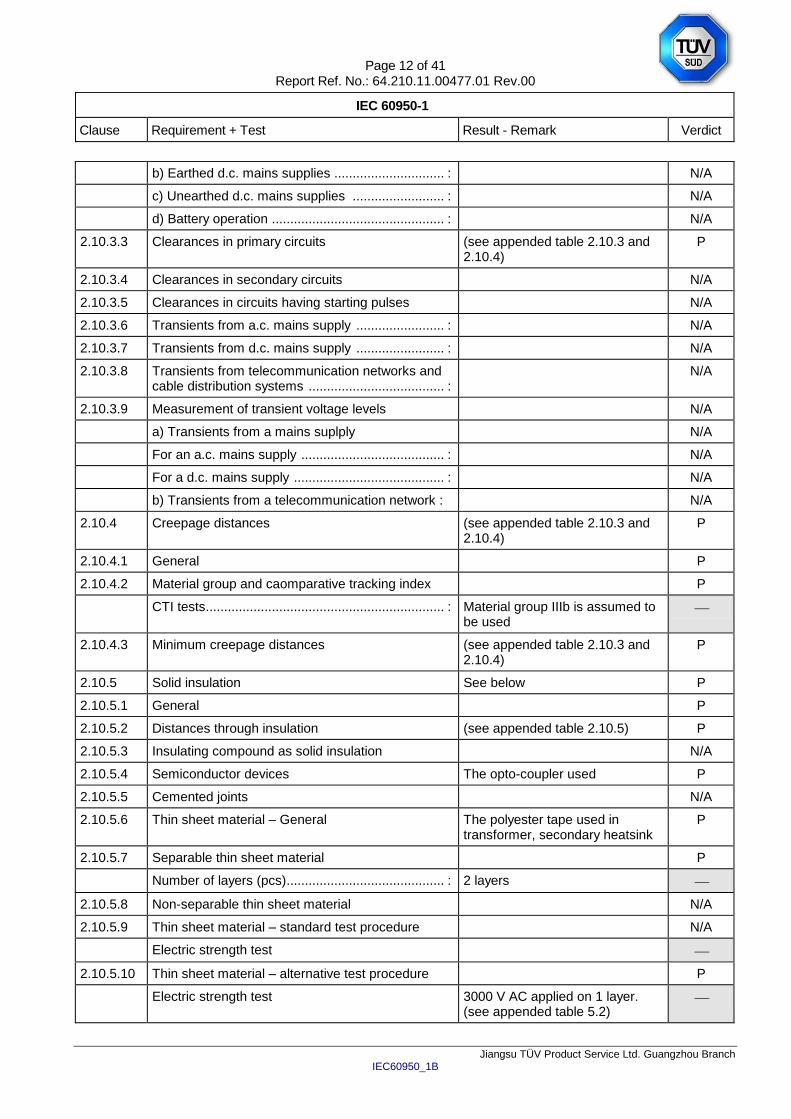
2.10.3.3 Clearances in primary circuits (see appended table 2.10.3 and 2.10.4)
P
2.10.3.4 Clearances in secondary circuits N/A
2.10.3.5 Clearances in circuits having starting pulses N/A
2.10.3.6 Transients from a.c. mains supply ........................ : N/A
2.10.3.7 Transients from d.c. mains supply ........................ : N/A
2.10.3.8 Transients from telecommunication networks and cable distribution systems ..................................... :
N/A
2.10.3.9 Measurement of transient voltage levels N/A
a) Transients from a mains suplply N/A
For an a.c. mains supply ....................................... : N/A
For a d.c. mains supply ......................................... : N/A
b) Transients from a telecommunication network : N/A
2.10.4 Creepage distances (see appended table 2.10.3 and 2.10.4)
P
2.10.4.1 General P
2.10.4.2 Material group and caomparative tracking index P
CTI tests ................................................................. : Material group IIIb is assumed to be used
2.10.4.3 Minimum creepage distances (see appended table 2.10.3 and 2.10.4)
P
2.10.5 Solid insulation See below P
2.10.5.1 General P
2.10.5.2 Distances through insulation (see appended table 2.10.5) P
2.10.5.3 Insulating compound as solid insulation N/A
2.10.5.4 Semiconductor devices The opto-coupler used P
2.10.5.5 Cemented joints N/A
2.10.5.6 Thin sheet material – General The polyester tape used in transformer, secondary heatsink
P
2.10.5.7 Separable thin sheet material P
Number of layers (pcs)........................................... : 2 layers
2.10.5.8 Non-separable thin sheet material N/A
2.10.5.9 Thin sheet material – standard test procedure N/A
Electric strength test
2.10.5.10 Thin sheet material – alternative test procedure P
Electric strength test 3000 V AC applied on 1 layer. (see appended table 5.2)
Page 13 of 41 Report Ref. No.: 64.210.11.00477.01 Rev.00
IEC 60950-1
Clause Requirement + Test Result - Remark Verdict
Jiangsu TÜV Product Service Ltd. Guangzhou Branch IEC60950_1B
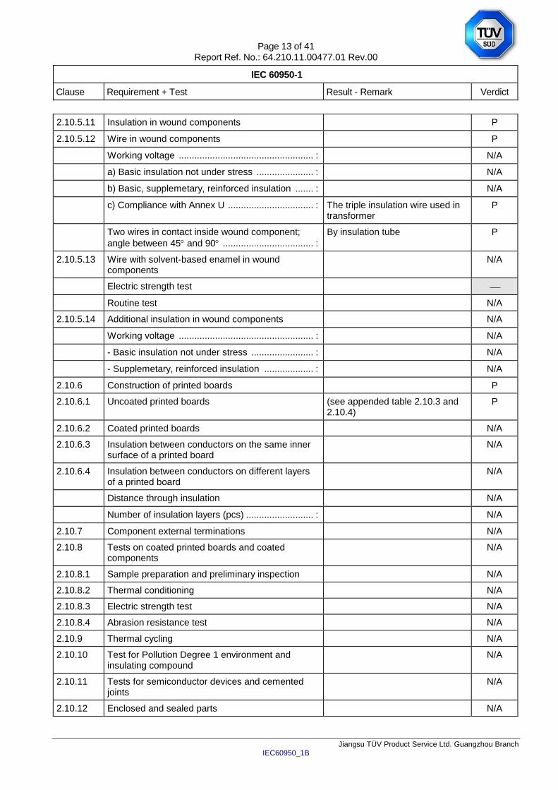
2.10.5.11 Insulation in wound components P
2.10.5.12 Wire in wound components P
Working voltage .................................................... : N/A
a) Basic insulation not under stress ...................... : N/A
b) Basic, supplemetary, reinforced insulation ....... : N/A
c) Compliance with Annex U ................................. : The triple insulation wire used in transformer
P
Two wires in contact inside wound component;
angle between 45 and 90 ................................... :
By insulation tube P
2.10.5.13 Wire with solvent-based enamel in wound components
N/A
Electric strength test
Routine test N/A
2.10.5.14 Additional insulation in wound components N/A
Working voltage .................................................... : N/A
- Basic insulation not under stress ........................ : N/A
- Supplemetary, reinforced insulation ................... : N/A
2.10.6 Construction of printed boards P
2.10.6.1 Uncoated printed boards (see appended table 2.10.3 and 2.10.4)
P
2.10.6.2 Coated printed boards N/A
2.10.6.3 Insulation between conductors on the same inner surface of a printed board
N/A
2.10.6.4 Insulation between conductors on different layers of a printed board
N/A
Distance through insulation N/A
Number of insulation layers (pcs) .......................... : N/A
2.10.7 Component external terminations N/A
2.10.8 Tests on coated printed boards and coated components
N/A
2.10.8.1 Sample preparation and preliminary inspection N/A
2.10.8.2 Thermal conditioning N/A
2.10.8.3 Electric strength test N/A
2.10.8.4 Abrasion resistance test N/A
2.10.9 Thermal cycling N/A
2.10.10 Test for Pollution Degree 1 environment and insulating compound
N/A
2.10.11 Tests for semiconductor devices and cemented joints
N/A
2.10.12 Enclosed and sealed parts N/A
Page 14 of 41 Report Ref. No.: 64.210.11.00477.01 Rev.00
IEC 60950-1
Clause Requirement + Test Result - Remark Verdict
Jiangsu TÜV Product Service Ltd. Guangzhou Branch IEC60950_1B
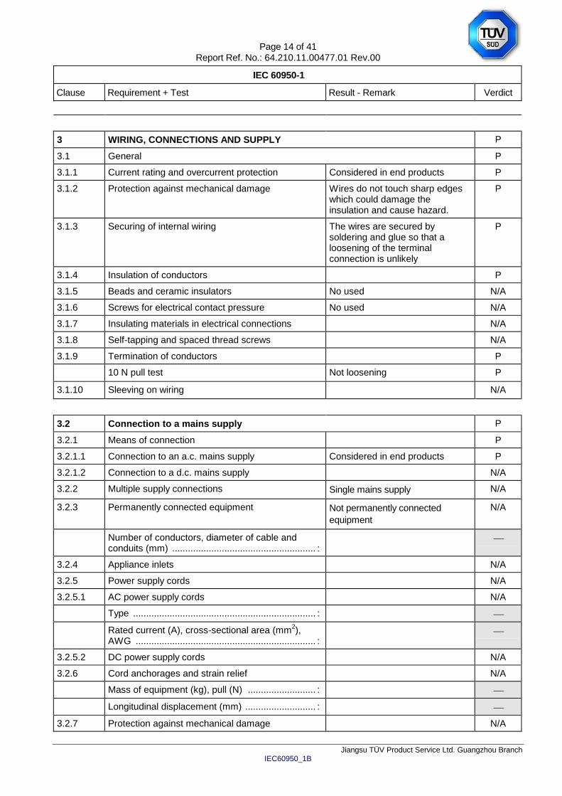
3 WIRING, CONNECTIONS AND SUPPLY P
3.1 General P
3.1.1 Current rating and overcurrent protection Considered in end products P
3.1.2 Protection against mechanical damage Wires do not touch sharp edges which could damage the insulation and cause hazard.
P
3.1.3 Securing of internal wiring The wires are secured by soldering and glue so that a loosening of the terminal connection is unlikely
P
3.1.4 Insulation of conductors P
3.1.5 Beads and ceramic insulators No used N/A
3.1.6 Screws for electrical contact pressure No used N/A
3.1.7 Insulating materials in electrical connections N/A
3.1.8 Self-tapping and spaced thread screws N/A
3.1.9 Termination of conductors P
10 N pull test Not loosening P
3.1.10 Sleeving on wiring N/A
3.2 Connection to a mains supply P
3.2.1 Means of connection P
3.2.1.1 Connection to an a.c. mains supply Considered in end products P
3.2.1.2 Connection to a d.c. mains supply N/A
3.2.2 Multiple supply connections Single mains supply N/A
3.2.3 Permanently connected equipment Not permanently connected
equipment
N/A
Number of conductors, diameter of cable and conduits (mm) ....................................................... :
3.2.4 Appliance inlets N/A
3.2.5 Power supply cords N/A
3.2.5.1 AC power supply cords N/A
Type ...................................................................... :
Rated current (A), cross-sectional area (mm2),
AWG ..................................................................... :
3.2.5.2 DC power supply cords N/A
3.2.6 Cord anchorages and strain relief N/A
Mass of equipment (kg), pull (N) .......................... :
Longitudinal displacement (mm) ........................... :
3.2.7 Protection against mechanical damage N/A
Page 15 of 41 Report Ref. No.: 64.210.11.00477.01 Rev.00
IEC 60950-1
Clause Requirement + Test Result - Remark Verdict
Jiangsu TÜV Product Service Ltd. Guangzhou Branch IEC60950_1B
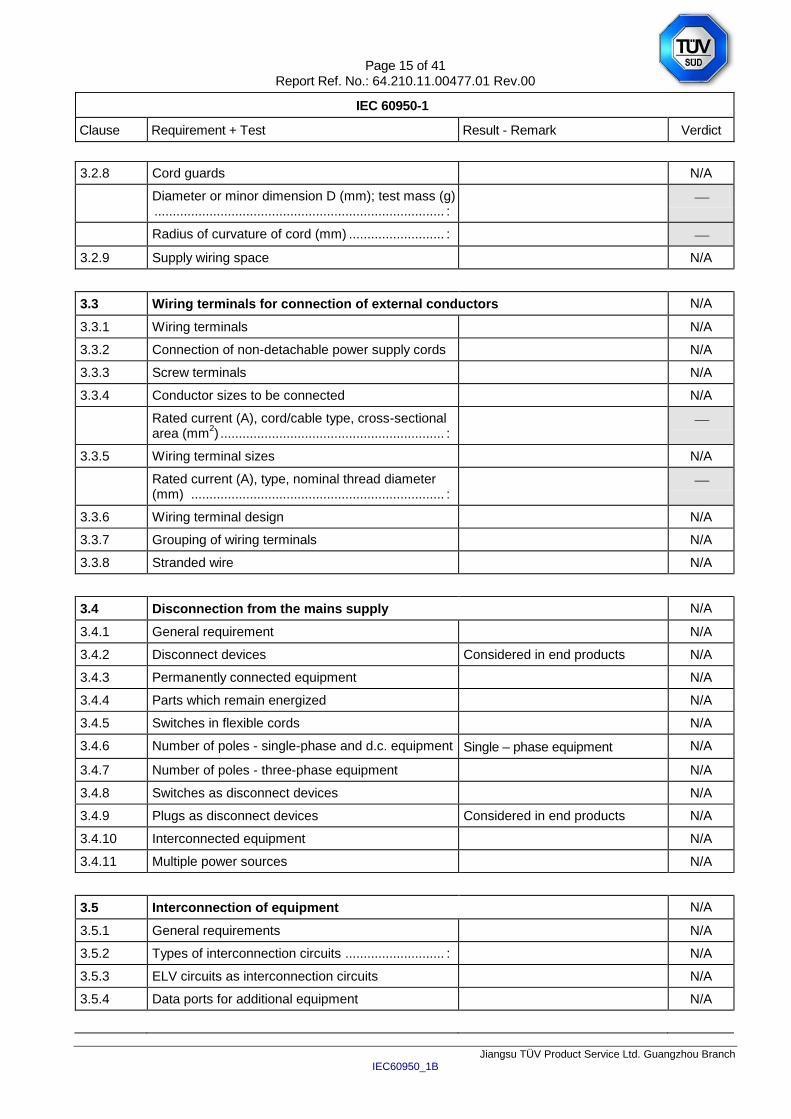
3.2.8 Cord guards N/A
Diameter or minor dimension D (mm); test mass (g) ............................................................................... :
Radius of curvature of cord (mm) .......................... :
3.2.9 Supply wiring space N/A
3.3 Wiring terminals for connection of external conductors N/A
3.3.1 Wiring terminals N/A
3.3.2 Connection of non-detachable power supply cords N/A
3.3.3 Screw terminals N/A
3.3.4 Conductor sizes to be connected N/A
Rated current (A), cord/cable type, cross-sectional area (mm
2) ............................................................. :
3.3.5 Wiring terminal sizes N/A
Rated current (A), type, nominal thread diameter (mm) ..................................................................... :
3.3.6 Wiring terminal design N/A
3.3.7 Grouping of wiring terminals N/A
3.3.8 Stranded wire N/A
3.4 Disconnection from the mains supply N/A
3.4.1 General requirement N/A
3.4.2 Disconnect devices Considered in end products N/A
3.4.3 Permanently connected equipment N/A
3.4.4 Parts which remain energized N/A
3.4.5 Switches in flexible cords N/A
3.4.6 Number of poles - single-phase and d.c. equipment Single – phase equipment N/A
3.4.7 Number of poles - three-phase equipment N/A
3.4.8 Switches as disconnect devices N/A
3.4.9 Plugs as disconnect devices Considered in end products N/A
3.4.10 Interconnected equipment N/A
3.4.11 Multiple power sources N/A
3.5 Interconnection of equipment N/A
3.5.1 General requirements N/A
3.5.2 Types of interconnection circuits ........................... : N/A
3.5.3 ELV circuits as interconnection circuits N/A
3.5.4 Data ports for additional equipment N/A
Page 16 of 41 Report Ref. No.: 64.210.11.00477.01 Rev.00
IEC 60950-1
Clause Requirement + Test Result - Remark Verdict
Jiangsu TÜV Product Service Ltd. Guangzhou Branch IEC60950_1B
4 PHYSICAL REQUIREMENTS N/A
4.1 Stability N/A
Angle of 10 N/A
Test force (N) ........................................................ : N/A
4.2 Mechanical strength P
4.2.1 General P
Rack-mounted equipment. N/A
4.2.2 Steady force test, 10 N Applied to component when measuring creepage distances and clearances
P
4.2.3 Steady force test, 30 N N/A
4.2.4 Steady force test, 250 N N/A
4.2.5 Impact test N/A
Fall test N/A
Swing test N/A
4.2.6 Drop test; height (mm) .......................................... : N/A
4.2.7 Stress relief test N/A
4.2.8 Cathode ray tubes No such device N/A
Picture tube separately certified ............................ : N/A
4.2.9 High pressure lamps No such device N/A
4.2.10 Wall or ceiling mounted equipment; force (N) ...... : N/A
4.2.11 Rotating solid media No such device N/A
Test to cover on the door…………………………….: N/A
4.3 Design and construction P
4.3.1 Edges and corners N/A
4.3.2 Handles and manual controls; force (N) ............. : No such component N/A
4.3.3 Adjustable controls N/A
4.3.4 Securing of parts N/A
4.3.5 Connection by plugs and sockets N/A
4.3.6 Direct plug-in equipment N/A
Torque .................................................................. :
Compliance with the relevant mains plug standard .............................................................................. :
N/A
4.3.7 Heating elements in earthed equipment No heating element N/A
4.3.8 Batteries No battery N/A
- Overcharging of a rechargeable battery N/A
Page 17 of 41 Report Ref. No.: 64.210.11.00477.01 Rev.00
IEC 60950-1
Clause Requirement + Test Result - Remark Verdict
Jiangsu TÜV Product Service Ltd. Guangzhou Branch IEC60950_1B
- Unintentional charging of a non-rechargeable battery
N/A
- Reverse charging of a rechargeable battery N/A
- Excessive discharging rate for any battery N/A
4.3.9 Oil and grease No insulation exposed to oil and grease
N/A
4.3.10 Dust, powders, liquids and gases Equipment do not produce dust, not use powder, liquid and gas
N/A
4.3.11 Containers for liquids or gases No containers for liquids or gases N/A
4.3.12 Flammable liquids ................................................ : N/A
Quantity of liquid (l) .............................................. : N/A
Flash point (C) .................................................... : N/A
4.3.13 Radiation N/A
4.3.13.1 General N/A
4.3.13.2 Ionizing radiation N/A
Measured radiation (pA/kg) .................................. :
Measured high-voltage (kV) ................................. :
Measured focus voltage (kV) ............................... :
CRT markings ...................................................... :
4.3.13.3 Effect of ultraviolet (UV) radiation on materials N/A
Part, property, retention after test, flammability classification ......................................................... :
N/A
4.3.13.4 Human exposure to ultraviolet (UV) radiation ...... : N/A
4.3.13.5 Lasers (including laser diodes) and LEDs N/A
4.3.13.5.1 Lasers (including laser laser diodes) N/A
Laser class ........................................................... :
4.3.13.5.2 Light emitting diodes (LEDs) N/A
4.3.13.6 Other types ........................................................... : N/A
4.4 Protection against hazardous moving parts N/A
4.4.1 General No moving part within equipment N/A
4.4.2 Protection in operator access areas .................... : N/A
Household and home/office document/media shredders
N/A
4.4.3 Protection in restricted access locations .............. : N/A
4.4.4 Protection in service access areas N/A
4.4.5 Protection against moving fan blades N/A
4.4.5.1 General N/A
Not considered to cause pain or injury. a)………….: N/A
Page 18 of 41 Report Ref. No.: 64.210.11.00477.01 Rev.00
IEC 60950-1
Clause Requirement + Test Result - Remark Verdict
Jiangsu TÜV Product Service Ltd. Guangzhou Branch IEC60950_1B
Is considered to cause pain, not injury. b) …………: N/A
Considered to cause injury. c) …………: N/A
4.4.5.2 Protection for users N/A
Use of symbol or warning ...…………………………: N/A
4.4.5.3 Protection for service persons N/A
Use of symbol or warning ...…………………………: N/A
4.5 Thermal requirements P
4.5.1 General P
4.5.2 Temperature tests (see appended table 4.5) P
Normal load condition per Annex L ...................... : Maximum normal load which specified by manufacturer
4.5.3 Temperature limits for materials (see appended table 4.5) P
4.5.4 Touch temperature limits (see appended table 4.5) P
4.5.5 Resistance to abnormal heat ............................... : N/A
4.6 Openings in enclosures N/A
4.6.1 Top and side openings Considered in end products N/A
Dimensions (mm) ................................................. :
4.6.2 Bottoms of fire enclosures Considered in end products N/A
Construction of the bottomm, dimensions (mm) .. :
4.6.3 Doors or covers in fire enclosures N/A
4.6.4 Openings in transportable equipment N/A
4.6.4.1 Constructional design measures N/A
Dimensions (mm) ................................................. :
4.6.4.2 Evaluation measures for larger openings N/A
4.6.4.3 Use of metallized parts N/A
4.6.5 Adhesives for constructional purposes N/A
Conditioning temperature (C), time (weeks) ........ :
4.7 Resistance to fire P
4.7.1 Reducing the risk of ignition and spread of flame Method 1 used P
Method 1, selection and application of components wiring and materials
(see appended table 4.7) P
Method 2, application of all of simulated fault condition tests
(see appended table 5.3) N/A
4.7.2 Conditions for a fire enclosure Considered in end products N/A
4.7.2.1 Parts requiring a fire enclosure Considered in end products N/A
4.7.2.2 Parts not requiring a fire enclosure N/A
Page 19 of 41 Report Ref. No.: 64.210.11.00477.01 Rev.00
IEC 60950-1
Clause Requirement + Test Result - Remark Verdict
Jiangsu TÜV Product Service Ltd. Guangzhou Branch IEC60950_1B
4.7.3 Materials P
4.7.3.1 General Parts mounted on PCB of flammability class V-0 or better.
P
4.7.3.2 Materials for fire enclosures Considered in end products N/A
4.7.3.3 Materials for components and other parts outside fire enclosures
N/A
4.7.3.4 Materials for components and other parts inside fire enclosures
PCB rated min. V-0, bobbin material rated V-0, approved by UL
P
4.7.3.5 Materials for air filter assemblies No such devices N/A
4.7.3.6 Materials used in high-voltage components No such components N/A
5 ELECTRICAL REQUIREMENTS AND SIMULATED ABNORMAL CONDITIONS P
5.1 Touch current and protective conductor current P
5.1.1 General See sub-clauses 5.1.2 to 5.1.6. P
5.1.2 Configuration of equipment under test (EUT) EUT has only one mains connection.
P
5.1.2.1 Single connection to an a.c. mains supply P
5.1.2.2 Redundant multiple connections to an a.c. mains supply
N/A
5.1.2.3 Simultaneous multiple connections to an a.c. mains supply
N/A
5.1.3 Test circuit Equipment of figure 5A used. P
5.1.4 Application of measuring instrument Figure 4 of IEC 60990 used P
5.1.5 Test procedure Measured between each pole of live parts and output terminal
P
5.1.6 Test measurements P
Supply voltage (V) ................................................ : (see appended table 5.1)
Measured touch current (mA) .............................. : (see appended table 5.1)
Max. allowed touch current (mA) ......................... : (see appended table 5.1)
Measured protective conductor current (mA) ...... :
Max. allowed protective conductor current (mA) .. :
5.1.7 Equipment with touch current exceeding 3,5 mA N/A
5.1.7.1 General ................................................................ : N/A
5.1.7.2 Simultaneous multiple connections to the supply N/A
5.1.8 Touch currents to telecommunication networks and cable distribution systems and from telecommunication networks
No telecommunication network connection ports on equipment
N/A
Page 20 of 41 Report Ref. No.: 64.210.11.00477.01 Rev.00
IEC 60950-1
Clause Requirement + Test Result - Remark Verdict
Jiangsu TÜV Product Service Ltd. Guangzhou Branch IEC60950_1B
5.1.8.1 Limitation of the touch current to a telecommunication network or to a cable distribution system
N/A
Supply voltage (V) ................................................ :
Measured touch current (mA) .............................. :
Max. allowed touch current (mA) ......................... :
5.1.8.2 Summation of touch currents from telecommunication networks
N/A
a) EUT with earthed telecommunication ports ..... : N/A
b) EUT whose telecommunication ports have no reference to protective earth
N/A
5.2 Electric strength P
5.2.1 General (see appended table 5.2) P
5.2.2 Test procedure P
5.3 Abnormal operating and fault conditions P
5.3.1 Protection against overload and abnormal operation
(see appended table 5.3) P
5.3.2 Motors No motors P
5.3.3 Transformers With the shorted output of the transformer, no high temperature of the transformer was recorded. Results of the short-circuit tests see appended table 5.3 and Annex C.
P
5.3.4 Functional insulation ............................................. : Method c). Test results see appended table 5.3.
P
5.3.5 Electromechanical components No electromechanical component provided.
N/A
5.3.6 Audio amplifiers in ITE ......................................... : No such component. N/A
5.3.7 Simulation of faults Results see appended table. P
5.3.8 Unattended equipment None of the listed components was provided.
N/A
5.3.9 Compliance criteria for abnormal operating and fault conditions
No fire propagated beyond the equipment. No molten metal was emitted. Electric strength test primary to SELV was passed.
P
5.3.9.1 During the tests During the test, no fire propagated beyond equipment; not emit molten metal and enclosure did not deform
P
Page 21 of 41 Report Ref. No.: 64.210.11.00477.01 Rev.00
IEC 60950-1
Clause Requirement + Test Result - Remark Verdict
Jiangsu TÜV Product Service Ltd. Guangzhou Branch IEC60950_1B
5.3.9.2 After the tests After the test, no any insulation damaged and withstand dielectric strength test AC3000V between live parts and secondary circuit
P
6 CONNECTION TO TELECOMMUNICATION NETWORKS N/A
6.1 Protection of telecommunication network service persons, and users of other equipment connected to the network, from hazards in the equipment
N/A
6.1.1 Protection from hazardous voltages N/A
6.1.2 Separation of the telecommunication network from earth N/A
6.1.2.1 Requirements No TNV. N/A
Supply voltage (V) ................................................ :
Current in the test circuit (mA) ........................... :
6.1.2.2 Exclusions ............................................................ : N/A
6.2 Protection of equipment users from overvoltages on telecommunication
networks
N/A
6.2.1 Separation requirements No TNV. N/A
6.2.2 Electric strength test procedure N/A
6.2.2.1 Impulse test N/A
6.2.2.2 Steady-state test N/A
6.2.2.3 Compliance criteria N/A
6.3 Protection of the telecommunication wiring system from overheating N/A
Max. output current (A) ........................................ : No TNV.
Current limiting method ........................................ :
7 CONNECTION TO CABLE DISTRIBUTION SYSTEMS N/A
7.1 General N/A
7.2 Protection of cable distribution system service persons, and users of other equipment connected to the system, from hazardous voltages in the equipment
N/A
7.3 Protection of equipment users from overvoltages on the cable distribution system
N/A
7.4 Insulation between primary circuits and cable distribution systems
N/A
7.4.1 General N/A
7.4.2 Voltage surge test N/A
7.4.3 Impulse test N/A
Page 22 of 41 Report Ref. No.: 64.210.11.00477.01 Rev.00
IEC 60950-1
Clause Requirement + Test Result - Remark Verdict
Jiangsu TÜV Product Service Ltd. Guangzhou Branch IEC60950_1B
A ANNEX A, TESTS FOR RESISTANCE TO HEAT AND FIRE N/A
A.1 Flammability test for fire enclosures of movable equipment having a total mass exceeding 18 kg, and of stationary equipment (see 4.7.3.2)
N/A
A.1.1 Samples ................................................................ :
Wall thickness (mm) ............................................. :
A.1.2 Conditioning of samples; temperature (C) .......... : N/A
A.1.3 Mounting of samples ............................................ : N/A
A.1.4 Test flame (see IEC 60695-11-3) N/A
Flame A, B, C or D ............................................... :
A.1.5 Test procedure N/A
A.1.6 Compliance criteria N/A
Sample 1 burning time (s) ..................................... :
Sample 2 burning time (s) ..................................... :
Sample 3 burning time (s) ..................................... :
A.2 Flammability test for fire enclosures of movable equipment having a total mass not exceeding 18 kg, and for material and components located inside fire enclosures (see 4.7.3.2 and 4.7.3.4)
N/A
A.2.1 Samples, material ................................................. :
Wall thickness (mm) ............................................. :
A.2.2 Conditioning of samples; temperature (°C) .......... : N/A
A.2.3 Mounting of samples ............................................ : N/A
A.2.4 Test flame (see IEC 60695-11-4) N/A
Flame A, B or C ................................................... :
A.2.5 Test procedure N/A
A.2.6 Compliance criteria N/A
Sample 1 burning time (s) ..................................... :
Sample 2 burning time (s) ..................................... :
Sample 3 burning time (s) ..................................... :
A.2.7 Alternative test acc. to IEC 60695-11-5, cl. 5 and 9 N/A
Sample 1 burning time (s) ..................................... :
Sample 2 burning time (s) ..................................... :
Sample 3 burning time (s) ..................................... :
A.3 Hot flaming oil test (see 4.6.2) N/A
A.3.1 Mounting of samples N/A
A.3.2 Test procedure N/A
A.3.3 Compliance criterion N/A
Page 23 of 41 Report Ref. No.: 64.210.11.00477.01 Rev.00
IEC 60950-1
Clause Requirement + Test Result - Remark Verdict
Jiangsu TÜV Product Service Ltd. Guangzhou Branch IEC60950_1B
B ANNEX B, MOTOR TESTS UNDER ABNORMAL CONDITIONS (see 4.7.2.2 and
5.3.2)
N/A
B.1 General requirements N/A
Position ................................................................ :
Manufacturer ........................................................ :
Type ..................................................................... :
Rated values ....................................................... :
B.2 Test conditions N/A
B.3 Maximum temperatures N/A
B.4 Running overload test N/A
B.5 Locked-rotor overload test N/A
Test duration (days) ............................................. :
Electric strength test: test voltage (V) .................. :
B.6 Running overload test for d.c. motors in secondary circuits
N/A
B.6.1 General N/A
B.6.2 Test procedure N/A
B.6.3 Alternative test procedure N/A
B.6.4 Electric strength test; test voltage (V) .................. : N/A
B.7 Locked-rotor overload test for d.c. motors in secondary circuits
N/A
B.7.1 General N/A
B.7.2 Test procedure N/A
B.7.3 Alternative test procedure N/A
B.7.4 Electric strength test; test voltage (V) ................. : N/A
B.8 Test for motors with capacitors N/A
B.9 Test for three-phase motors N/A
B.10 Test for series motors N/A
Operating voltage (V) ........................................... :
C ANNEX C, TRANSFORMERS (see 1.5.4 and 5.3.3) P
Position ................................................................ : (See appended tabel 1.5.1)
Manufacturer ........................................................ : (See appended tabel 1.5.1)
Type ..................................................................... : (See appended tabel 1.5.1)
Rated values ....................................................... : (See appended tabel 1.5.1)
Method of protection ............................................. : (See appended tabel 1.5.1)
C.1 Overload test (see appended table 5.3) P
C.2 Insulation (see appended tables 5.2 and C2) P
Page 24 of 41 Report Ref. No.: 64.210.11.00477.01 Rev.00
IEC 60950-1
Clause Requirement + Test Result - Remark Verdict
Jiangsu TÜV Product Service Ltd. Guangzhou Branch IEC60950_1B
Protection from displacement of windings ............ : By insulation tape P
D ANNEX D, MEASURING INSTRUMENTS FOR TOUCH-CURRENT TESTS
(see 5.1.4)
P
D.1 Measuring instrument P
D.2 Alternative measuring instrument N/A
E ANNEX E, TEMPERATURE RISE OF A WINDING (see 1.4.13) P
F ANNEX F, MEASUREMENT OF CLEARANCES AND CREEPAGE DISTANCES
(see 2.10 and Annex G)
P
G ANNEX G, ALTERNATIVE METHOD FOR DETERMINING MINIMUM CLEARANCES N/A
G.1 Clearances N/A
G.1.1 General N/A
G.1.2 Summary of the procedure for determining minimum clearances
N/A
G.2 Determination of mains transient voltage (V) N/A
G.2.1 AC mains supply .................................................. : N/A
G.2.2 Earthed d.c. mains supplies ................................. : N/A
G.2.3 Unearthed d.c. mains supplies ............................. : N/A
G.2.4 Battery operation .................................................. : N/A
G.3 Determination of telecommunication network transient voltage (V) ............................................. :
N/A
G.4 Determination of required withstand voltage (V) N/A
G.4.1 Mains transients and internal repetitive peaks ..... : N/A
G.4.2 Transients from telecommunication networks ..... : N/A
G.4.3 Combination of transients N/A
G.4.4 Transients from cable distribution systems N/A
G.5 Measurement of transient voltages (V) N/A
a) Transients from a mains supply N/A
For an a.c. mains supply N/A
For a d.c. mains supply N/A
b) Transients from a telecommunication network N/A
G.6 Determination of minimum clearances ................ : N/A
H ANNEX H, IONIZING RADIATION (see 4.3.13) N/A
J ANNEX J, TABLE OF ELECTROCHEMICAL POTENTIALS (see 2.6.5.6) N/A
Page 25 of 41 Report Ref. No.: 64.210.11.00477.01 Rev.00
IEC 60950-1
Clause Requirement + Test Result - Remark Verdict
Jiangsu TÜV Product Service Ltd. Guangzhou Branch IEC60950_1B
Metal(s) used ....................................................... :
K ANNEX K, THERMAL CONTROLS (see 1.5.3 and 5.3.8) N/A
K.1 Making and breaking capacity N/A
K.2 Thermostat reliability; operating voltage (V) ........ : N/A
K.3 Thermostat endurance test; operating voltage (V) .............................................................................. :
N/A
K.4 Temperature limiter endurance; operating voltage (V) ........................................................................ :
N/A
K.5 Thermal cut-out reliability N/A
K.6 Stability of operation N/A
L ANNEX L, NORMAL LOAD CONDITIONS FOR SOME TYPES OF ELECTRICAL
BUSINESS EQUIPMENT (see 1.2.2.1 and 4.5.2)
P
L.1 Typewriters N/A
L.2 Adding machines and cash registers N/A
L.3 Erasers N/A
L.4 Pencil sharpeners N/A
L.5 Duplicators and copy machines N/A
L.6 Motor-operated files N/A
L.7 Other business equipment P
M ANNEX M, CRITERIA FOR TELEPHONE RINGING SIGNALS (see 2.3.1) N/A
M.1 Introduction N/A
M.2 Method A N/A
M.3 Method B N/A
M.3.1 Ringing signal N/A
M.3.1.1 Frequency (Hz) .................................................... :
M.3.1.2 Voltage (V) ........................................................... :
M.3.1.3 Cadence; time (s), voltage (V) ............................. :
M.3.1.4 Single fault current (mA) ...................................... :
M.3.2 Tripping device and monitoring voltage ............... : N/A
M.3.2.1 Conditions for use of a tripping device or a monitoring voltage
N/A
M.3.2.2 Tripping device N/A
M.3.2.3 Monitoring voltage (V) .......................................... : N/A
N ANNEX N, IMPULSE TEST GENERATORS (see 1.5.7.2, 1.5.7.3, 2.10.3.9, 6.2.2.1,
7.3.2, 7.4.3 and Clause G.5)
N/A
Page 26 of 41 Report Ref. No.: 64.210.11.00477.01 Rev.00
IEC 60950-1
Clause Requirement + Test Result - Remark Verdict
Jiangsu TÜV Product Service Ltd. Guangzhou Branch IEC60950_1B
N.1 ITU-T impulse test generators N/A
N.2 IEC 60065 impulse test generator N/A
P ANNEX P, NORMATIVE REFERENCES
Q ANNEX Q, Voltage dependent resistors (VDRs) (see 1.5.9.1) N/A
a) Preferred climatic categories ........................... : N/A
b) Maximum continuous voltage .......................... : N/A
c) Pulse current .................................................... : N/A
R ANNEX R, EXAMPLES OF REQUIREMENTS FOR QUALITY CONTROL
PROGRAMMES
N/A
R.1 Minimum separation distances for unpopulated coated printed boards (see 2.10.6.2)
N/A
R.2 Reduced clearances (see 2.10.3) N/A
S ANNEX S, PROCEDURE FOR IMPULSE TESTING (see 6.2.2.3) N/A
S.1 Test equipment N/A
S.2 Test procedure N/A
S.3 Examples of waveforms during impulse testing N/A
T ANNEX T, GUIDANCE ON PROTECTION AGAINST INGRESS OF WATER
(see 1.1.2)
N/A
U ANNEX U, INSULATED WINDING WIRES FOR USE WITHOUT INTERLEAVED
INSULATION (see 2.10.5.4)
P
Approved TIW used
V ANNEX V, AC POWER DISTRIBUTION SYSTEMS (see 1.6.1) P
V.1 Introduction P
V.2 TN power distribution systems P
W ANNEX W, SUMMATION OF TOUCH CURRENTS N/A
W.1 Touch current from electronic circuits N/A
W.1.1 Floating circuits N/A
W.1.2 Earthed circuits N/A
W.2 Interconnection of several equipments N/A
W.2.1 Isolation N/A
W.2.2 Common return, isolated from earth N/A
Page 27 of 41 Report Ref. No.: 64.210.11.00477.01 Rev.00
IEC 60950-1
Clause Requirement + Test Result - Remark Verdict
Jiangsu TÜV Product Service Ltd. Guangzhou Branch IEC60950_1B
W.2.3 Common return, connected to protective earth N/A
X ANNEX X, MAXIMUM HEATING EFFECT IN TRANSFORMER TESTS (see clause
C.1)
N/A
X.1 Determination of maximum input current N/A
X.2 Overload test procedure N/A
Y ANNEX Y, ULTRAVIOLET LIGHT CONDITIONING TEST (see 4.3.13.3) N/A
Y.1 Test apparatus ..................................................... : N/A
Y.2 Mounting of test samples ..................................... : N/A
Y.3 Carbon-arc light-exposure apparatus .................. : N/A
Y.4 Xenon-arc light exposure apparatus .................... : N/A
Z ANNEX Z, OVERVOLTAGE CATEGORIES (see 2.10.3.2 and Clause G.2) P
AA ANNEX AA, MANDREL TEST (see 2.10.5.8) N/A
BB ANNEX BB, CHANGES IN THE SECOND EDITION
CC ANNEX CC, Evaluation of integrated circuit (IC) current limiters N/A
CC.1 General N/A
CC.2 Test program 1……………………………………….: N/A
CC.3 Test program 2……………………………………….: N/A
DD ANNEX DD, Requirements for the mounting means of rack-mounted equipment N/A
DD.1 General N/A
DD.2 Mechanical strength test, variable N………………..: N/A
DD.3 Mechanical strength test, 250N, including end stops……………………………………………………:
N/A
DD.4 Compliance……………………………………………: N/A
EE ANNEX EE, Household and home/office document/media shredders N/A
EE.1 General N/A
EE.2 Markings and instructions N/A
Use of markings or symbols…………………………: N/A
Information of user instructions, maintenance and/or servicing instructions…………………………:
N/A
EE.3 Inadvertent reactivation test…………………………: N/A
Page 28 of 41 Report Ref. No.: 64.210.11.00477.01 Rev.00
IEC 60950-1
Clause Requirement + Test Result - Remark Verdict
Jiangsu TÜV Product Service Ltd. Guangzhou Branch IEC60950_1B
EE.4 Disconnection of power to hazardous moving parts: N/A
Use of markings or symbols…………………………: N/A
EE.5 Protection against hazardous moving parts N/A
Test with test finger (Figure 2A) ……………………:
N/A
Test with wedge probe (Figure EE1 and EE2) ……: N/A
Page 29 of 41 Report Ref. No.: 64.210.11.00477.01 Rev.00
IEC 60950-1
Clause Requirement + Test Result - Remark Verdict
Jiangsu TÜV Product Service Ltd. Guangzhou Branch IEC60950_1B
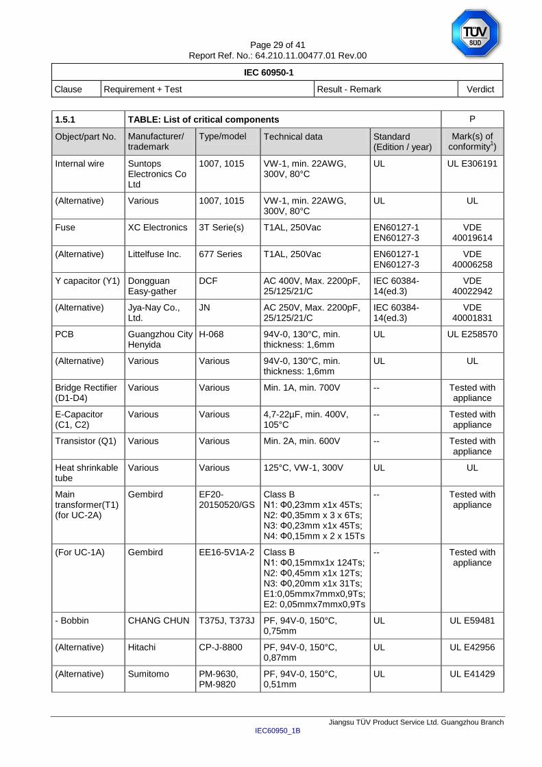
1.5.1 TABLE: List of critical components P
Object/part No. Manufacturer/ trademark
Type/model Technical data Standard (Edition / year)
Mark(s) of conformity
1)
Internal wire Suntops Electronics Co Ltd
1007, 1015 VW-1, min. 22AWG, 300V, 80°C
UL UL E306191
(Alternative) Various 1007, 1015 VW-1, min. 22AWG, 300V, 80°C
UL UL
Fuse XC Electronics 3T Serie(s) T1AL, 250Vac EN60127-1 EN60127-3
VDE 40019614
(Alternative) Littelfuse Inc. 677 Series T1AL, 250Vac EN60127-1 EN60127-3
VDE 40006258
Y capacitor (Y1) Dongguan Easy-gather
DCF AC 400V, Max. 2200pF, 25/125/21/C
IEC 60384-14(ed.3)
VDE 40022942
(Alternative) Jya-Nay Co., Ltd.
JN AC 250V, Max. 2200pF, 25/125/21/C
IEC 60384-14(ed.3)
VDE 40001831
PCB Guangzhou City Henyida
H-068 94V-0, 130°C, min. thickness: 1,6mm
UL UL E258570
(Alternative) Various Various 94V-0, 130°C, min. thickness: 1,6mm
UL UL
Bridge Rectifier (D1-D4)
Various Various Min. 1A, min. 700V -- Tested with appliance
E-Capacitor (C1, C2)
Various Various 4,7-22µF, min. 400V, 105°C
-- Tested with appliance
Transistor (Q1) Various
Various Min. 2A, min. 600V -- Tested with appliance
Heat shrinkable tube
Various
Various 125°C, VW-1, 300V UL UL
Main transformer(T1)(for UC-2A)
Gembird EF20-20150520/GS
Class B N1: Ф0,23mm x1x 45Ts; N2: Ф0,35mm x 3 x 6Ts; N3: Ф0,23mm x1x 45Ts; N4: Ф0,15mm x 2 x 15Ts
-- Tested with appliance
(For UC-1A) Gembird EE16-5V1A-2 Class B N1: Ф0,15mmx1x 124Ts; N2: Ф0,45mm x1x 12Ts; N3: Ф0,20mm x1x 31Ts; E1:0,05mmx7mmx0,9Ts; E2: 0,05mmx7mmx0,9Ts
-- Tested with appliance
- Bobbin CHANG CHUN T375J, T373J PF, 94V-0, 150°C, 0,75mm
UL UL E59481
(Alternative) Hitachi CP-J-8800 PF, 94V-0, 150°C, 0,87mm
UL UL E42956
(Alternative) Sumitomo PM-9630, PM-9820
PF, 94V-0, 150°C, 0,51mm
UL UL E41429
Page 30 of 41 Report Ref. No.: 64.210.11.00477.01 Rev.00
IEC 60950-1
Clause Requirement + Test Result - Remark Verdict
Jiangsu TÜV Product Service Ltd. Guangzhou Branch IEC60950_1B
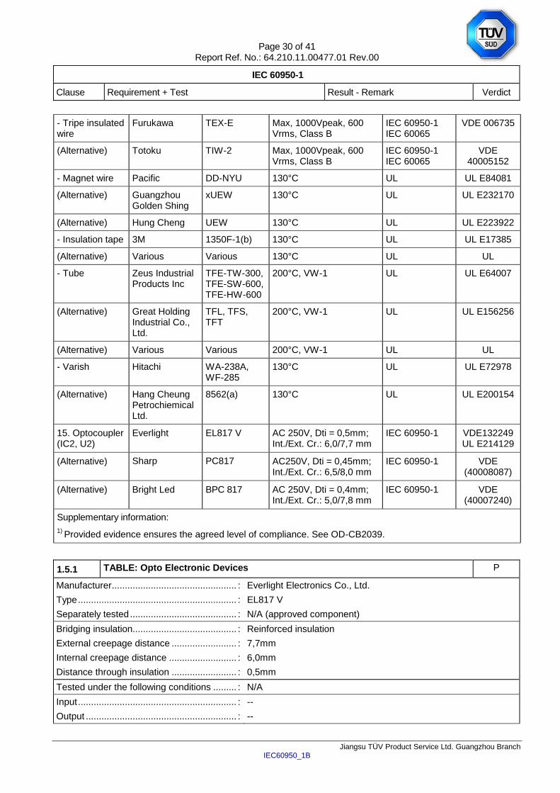
- Tripe insulated wire
Furukawa TEX-E Max, 1000Vpeak, 600 Vrms, Class B
IEC 60950-1 IEC 60065
VDE 006735
(Alternative) Totoku TIW-2 Max, 1000Vpeak, 600 Vrms, Class B
IEC 60950-1 IEC 60065
VDE 40005152
- Magnet wire Pacific DD-NYU 130°C UL UL E84081
(Alternative) Guangzhou Golden Shing
xUEW 130°C UL UL E232170
(Alternative) Hung Cheng UEW 130°C UL UL E223922
- Insulation tape 3M 1350F-1(b) 130°C UL UL E17385
(Alternative) Various Various 130°C UL UL
- Tube Zeus Industrial Products Inc
TFE-TW-300, TFE-SW-600, TFE-HW-600
200°C, VW-1 UL UL E64007
(Alternative) Great Holding Industrial Co., Ltd.
TFL, TFS, TFT
200°C, VW-1 UL UL E156256
(Alternative) Various Various 200°C, VW-1 UL UL
- Varish Hitachi WA-238A, WF-285
130°C UL UL E72978
(Alternative) Hang Cheung Petrochiemical Ltd.
8562(a) 130°C UL UL E200154
15. Optocoupler (IC2, U2)
Everlight EL817 V AC 250V, Dti = 0,5mm; Int./Ext. Cr.: 6,0/7,7 mm
IEC 60950-1 VDE132249 UL E214129
(Alternative) Sharp PC817 AC250V, Dti = 0,45mm; Int./Ext. Cr.: 6,5/8,0 mm
IEC 60950-1 VDE (40008087)
(Alternative) Bright Led BPC 817 AC 250V, Dti = 0,4mm; Int./Ext. Cr.: 5,0/7,8 mm
IEC 60950-1 VDE (40007240)
Supplementary information:
1) Provided evidence ensures the agreed level of compliance. See OD-CB2039.
1.5.1 TABLE: Opto Electronic Devices P
Manufacturer ................................................ : Everlight Electronics Co., Ltd.
Type ............................................................. : EL817 V
Separately tested ......................................... : N/A (approved component)
Bridging insulation........................................ : Reinforced insulation
External creepage distance ......................... : 7,7mm
Internal creepage distance .......................... : 6,0mm
Distance through insulation ......................... : 0,5mm
Tested under the following conditions ......... : N/A
Input ............................................................. : --
Output .......................................................... : --
Page 31 of 41 Report Ref. No.: 64.210.11.00477.01 Rev.00
IEC 60950-1
Clause Requirement + Test Result - Remark Verdict
Jiangsu TÜV Product Service Ltd. Guangzhou Branch IEC60950_1B
supplementary information
1.5.1 TABLE: Opto Electronic Devices P
Manufacturer ................................................ : Sharp Corp Electronic Components Group
Type ............................................................. : PC817
Separately tested ......................................... : N/A (approved component)
Bridging insulation........................................ : Reinforced insulation
External creepage distance ......................... : 8,2mm
Internal creepage distance .......................... : 4,0mm
Distance through insulation ......................... : 0,45mm
Tested under the following conditions ......... : N/A
Input ............................................................. : --
Output .......................................................... : --
supplementary information
1.5.1 TABLE: Opto Electronic Devices P
Manufacturer ................................................ : Bright Led
Type ............................................................. : BPC 817
Separately tested ......................................... : N/A (approved component)
Bridging insulation........................................ : Reinforced insulation
External creepage distance ......................... : 7,8mm
Internal creepage distance .......................... : 5,0mm
Distance through insulation ......................... : 0,4mm
Tested under the following conditions ......... : N/A
Input ............................................................. : --
Output .......................................................... : --
supplementary information
1.6.2 TABLE: Electrical data (in normal conditions) P
U (V) I (mA) Irated (mA) P (W) Fuse # Ifuse (mA) Condition/status
For model: UC-1A
225V/50Hz 72,2 -- 7,20 F1 72,2 At rated output load: 5Vd.c./1A
250V/50Hz 67,5 180 7,24 F1 67,5 At rated output load: 5Vd.c./1A
275V/50Hz 64,2 -- 7,26 F1 64,2 At rated output load: 5Vd.c./1A
For model: UC-2A
225V/50Hz 128 -- 13,03 F1 128 At rated output load: 5Vd.c./2A
Page 32 of 41 Report Ref. No.: 64.210.11.00477.01 Rev.00
IEC 60950-1
Clause Requirement + Test Result - Remark Verdict
Jiangsu TÜV Product Service Ltd. Guangzhou Branch IEC60950_1B
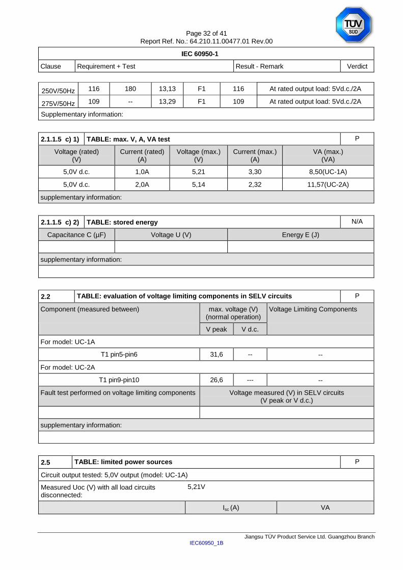
250V/50Hz 116 180 13,13 F1 116 At rated output load: 5Vd.c./2A
275V/50Hz 109 -- 13,29 F1 109 At rated output load: 5Vd.c./2A
Supplementary information:
2.1.1.5 c) 1) TABLE: max. V, A, VA test P
Voltage (rated) (V)
Current (rated) (A)
Voltage (max.) (V)
Current (max.) (A)
VA (max.) (VA)
5,0V d.c. 1,0A 5,21 3,30 8,50(UC-1A)
5,0V d.c. 2,0A 5,14 2,32 11,57(UC-2A)
supplementary information:
2.1.1.5 c) 2) TABLE: stored energy N/A
Capacitance C (µF) Voltage U (V) Energy E (J)
supplementary information:
2.2 TABLE: evaluation of voltage limiting components in SELV circuits P
Component (measured between) max. voltage (V) (normal operation)
Voltage Limiting Components
V peak V d.c.
For model: UC-1A
T1 pin5-pin6 31,6 -- --
For model: UC-2A
T1 pin9-pin10 26,6 --- --
Fault test performed on voltage limiting components Voltage measured (V) in SELV circuits (V peak or V d.c.)
supplementary information:
2.5 TABLE: limited power sources P
Circuit output tested: 5,0V output (model: UC-1A)
Measured Uoc (V) with all load circuits disconnected:
5,21V
Isc (A) VA
Page 33 of 41 Report Ref. No.: 64.210.11.00477.01 Rev.00
IEC 60950-1
Clause Requirement + Test Result - Remark Verdict
Jiangsu TÜV Product Service Ltd. Guangzhou Branch IEC60950_1B
Meas. Limit Meas. Limit
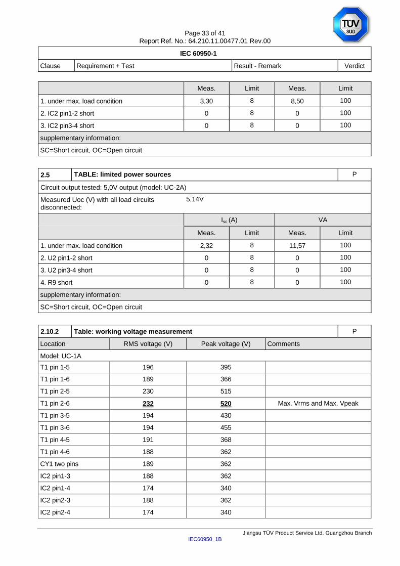
1. under max. load condition 3,30 8 8,50 100
2. IC2 pin1-2 short 0 8 0 100
3. IC2 pin3-4 short 0 8 0 100
supplementary information:
SC=Short circuit, OC=Open circuit
2.5 TABLE: limited power sources P
Circuit output tested: 5,0V output (model: UC-2A)
Measured Uoc (V) with all load circuits disconnected:
5,14V
Isc (A) VA
Meas. Limit Meas. Limit
1. under max. load condition 2,32 8 11,57 100
2. U2 pin1-2 short 0 8 0 100
3. U2 pin3-4 short 0 8 0 100
4. R9 short 0 8 0 100
supplementary information:
SC=Short circuit, OC=Open circuit
2.10.2 Table: working voltage measurement P
Location RMS voltage (V) Peak voltage (V) Comments
Model: UC-1A
T1 pin 1-5 196 395
T1 pin 1-6 189 366
T1 pin 2-5 230 515
T1 pin 2-6 232 520 Max. Vrms and Max. Vpeak
T1 pin 3-5 194 430
T1 pin 3-6 194 455
T1 pin 4-5 191 368
T1 pin 4-6 188 362
CY1 two pins 189 362
IC2 pin1-3 188 362
IC2 pin1-4 174 340
IC2 pin2-3 188 362
IC2 pin2-4 174 340
Page 34 of 41 Report Ref. No.: 64.210.11.00477.01 Rev.00
IEC 60950-1
Clause Requirement + Test Result - Remark Verdict
Jiangsu TÜV Product Service Ltd. Guangzhou Branch IEC60950_1B
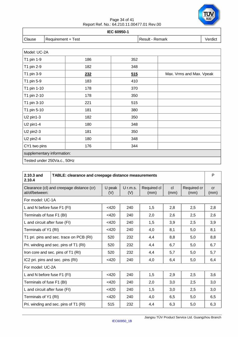
Model: UC-2A
T1 pin 1-9 186 352
T1 pin 2-9 182 348
T1 pin 3-9 232 515 Max. Vrms and Max. Vpeak
T1 pin 5-9 183 410
T1 pin 1-10 178 370
T1 pin 2-10 178 350
T1 pin 3-10 221 515
T1 pin 5-10 181 380
U2 pin1-3 182 350
U2 pin1-4 180 348
U2 pin2-3 181 350
U2 pin2-4 180 348
CY1 two pins 176 344
supplementary information:
Tested under 250Va.c., 50Hz
2.10.3 and
2.10.4
TABLE: clearance and creepage distance measurements P
Clearance (cl) and creepage distance (cr)
at/of/between:
U peak
(V)
U r.m.s.
(V)
Required cl
(mm)
cl
(mm)
Required cr
(mm)
cr
(mm)
For model: UC-1A
L and N before fuse F1 (FI) <420 240 1,5 2,8 2,5 2,8
Terminals of fuse F1 (BI) <420 240 2,0 2,6 2,5 2,6
L and circuit after fuse (FI) <420 240 1,5 3,9 2,5 3,9
Terminals of Y1 (RI) <420 240 4,0 8,1 5,0 8,1
T1 pri. pins and sec. trace on PCB (RI) 520 232 4,4 8,8 5,0 8,8
Pri. winding and sec. pins of T1 (RI) 520 232 4,4 6,7 5,0 6,7
Iron core and sec. pins of T1 (RI) 520 232 4,4 5,7 5,0 5,7
IC2 pri. pins and sec. pins (RI) <420 240 4,0 6,4 5,0 6,4
For model: UC-2A
L and N before fuse F1 (FI) <420 240 1,5 2,9 2,5 3,6
Terminals of fuse F1 (BI) <420 240 2,0 3,0 2,5 3,0
L and circuit after fuse (FI) <420 240 1,5 3,0 2,5 3,0
Terminals of Y1 (RI) <420 240 4,0 6,5 5,0 6,5
Pri. winding and sec. pins of T1 (RI) 515 232 4,4 6,3 5,0 6,3
Page 35 of 41 Report Ref. No.: 64.210.11.00477.01 Rev.00
IEC 60950-1
Clause Requirement + Test Result - Remark Verdict
Jiangsu TÜV Product Service Ltd. Guangzhou Branch IEC60950_1B
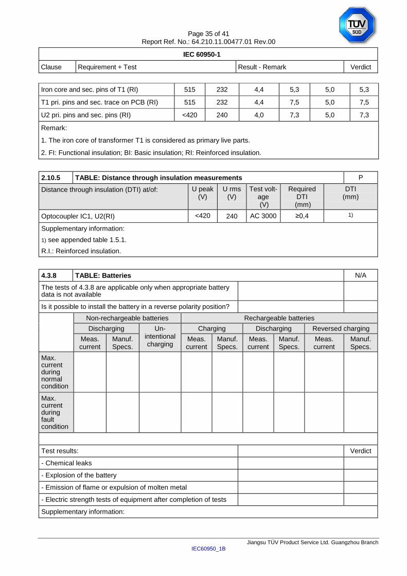
Iron core and sec. pins of T1 (RI) 515 232 4,4 5,3 5,0 5,3
T1 pri. pins and sec. trace on PCB (RI) 515 232 4,4 7,5 5,0 7,5
U2 pri. pins and sec. pins (RI) <420 240 4,0 7,3 5,0 7,3
Remark:
1. The iron core of transformer T1 is considered as primary live parts.
2. FI: Functional insulation; BI: Basic insulation; RI: Reinforced insulation.
2.10.5 TABLE: Distance through insulation measurements P
Distance through insulation (DTI) at/of: U peak (V)
U rms (V)
Test volt-age (V)
Required DTI
(mm)
DTI (mm)
Optocoupler IC1, U2(RI) <420 240 AC 3000 ≥0,4 1)
Supplementary information:
1) see appended table 1.5.1.
R.I.: Reinforced insulation.
4.3.8 TABLE: Batteries N/A
The tests of 4.3.8 are applicable only when appropriate battery data is not available
Is it possible to install the battery in a reverse polarity position?
Non-rechargeable batteries Rechargeable batteries
Discharging Un-intentional charging
Charging Discharging Reversed charging
Meas. current
Manuf. Specs.
Meas. current
Manuf. Specs.
Meas. current
Manuf. Specs.
Meas. current
Manuf. Specs.
Max. current during normal condition
Max. current during fault condition
Test results: Verdict
- Chemical leaks
- Explosion of the battery
- Emission of flame or expulsion of molten metal
- Electric strength tests of equipment after completion of tests
Supplementary information:
Page 36 of 41 Report Ref. No.: 64.210.11.00477.01 Rev.00
IEC 60950-1
Clause Requirement + Test Result - Remark Verdict
Jiangsu TÜV Product Service Ltd. Guangzhou Branch IEC60950_1B
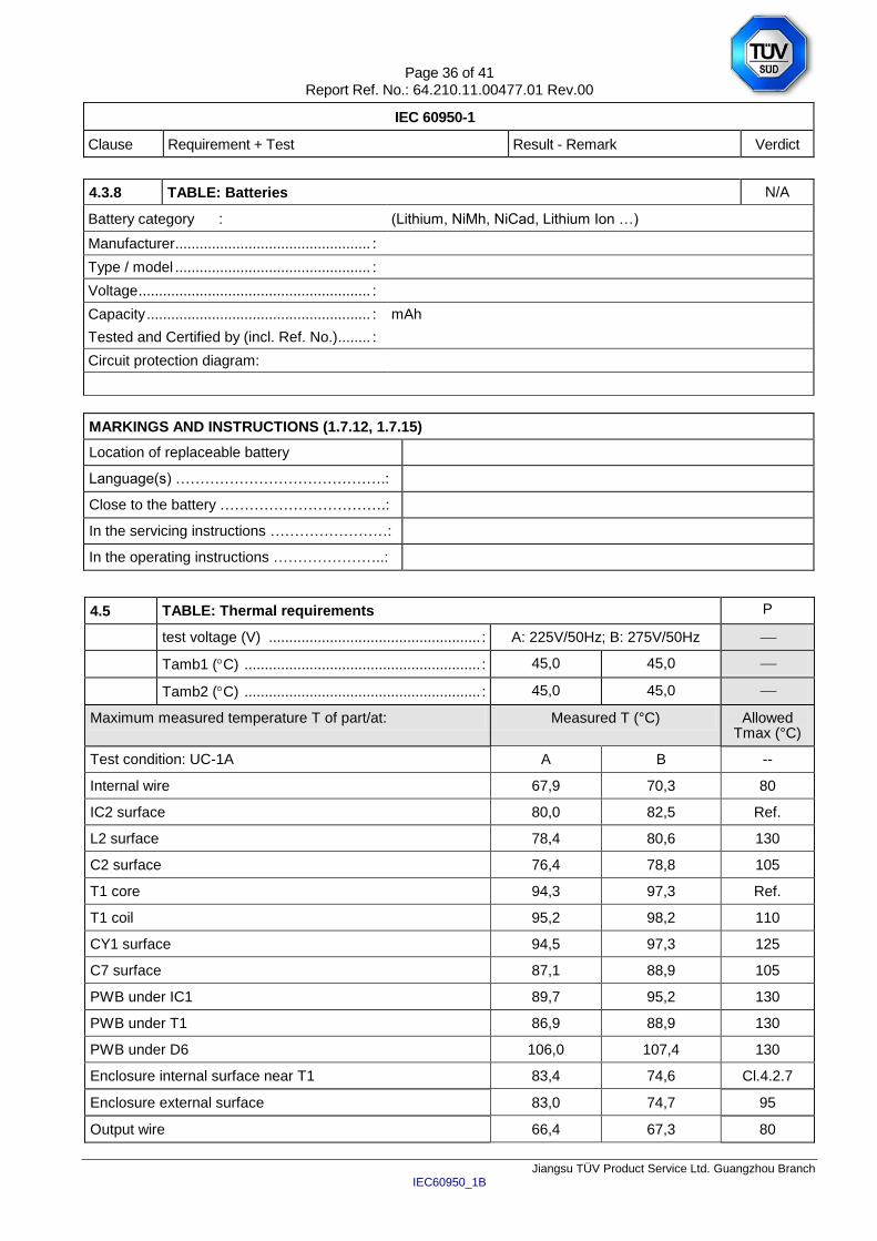
4.3.8 TABLE: Batteries N/A
Battery category : (Lithium, NiMh, NiCad, Lithium Ion …)
Manufacturer ................................................ :
Type / model ................................................ :
Voltage ......................................................... :
Capacity ....................................................... : mAh
Tested and Certified by (incl. Ref. No.) ........ :
Circuit protection diagram:
MARKINGS AND INSTRUCTIONS (1.7.12, 1.7.15)
Location of replaceable battery
Language(s) …………………………………….:
Close to the battery …………………………….:
In the servicing instructions ……………………:
In the operating instructions …………………..:
4.5 TABLE: Thermal requirements P
test voltage (V) .................................................... : A: 225V/50Hz; B: 275V/50Hz
Tamb1 (C) .......................................................... : 45,0 45,0
Tamb2 (C) .......................................................... : 45,0 45,0
Maximum measured temperature T of part/at: Measured T (°C) Allowed Tmax (°C)
Test condition: UC-1A A B --
Internal wire 67,9 70,3 80
IC2 surface 80,0 82,5 Ref.
L2 surface 78,4 80,6 130
C2 surface 76,4 78,8 105
T1 core 94,3 97,3 Ref.
T1 coil 95,2 98,2 110
CY1 surface 94,5 97,3 125
C7 surface 87,1 88,9 105
PWB under IC1 89,7 95,2 130
PWB under T1 86,9 88,9 130
PWB under D6 106,0 107,4 130
Enclosure internal surface near T1 83,4 74,6 Cl.4.2.7
Enclosure external surface 83,0 74,7 95
Output wire 66,4 67,3 80
Page 37 of 41 Report Ref. No.: 64.210.11.00477.01 Rev.00
IEC 60950-1
Clause Requirement + Test Result - Remark Verdict
Jiangsu TÜV Product Service Ltd. Guangzhou Branch IEC60950_1B
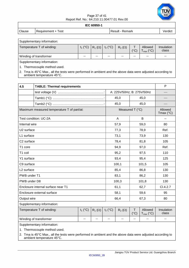
Supplementary information:
Temperature T of winding: t1 (°C) R1 () t2 (°C) R2 () T (C)
Allowed Tmax (C)
Insulation class
Winding of transformer -- -- -- -- -- -- --
Supplementary information:
1. Thermocouple method used.
2. Tma is 45°C Max., all the tests were performed in ambient and the above data were adjusted according to ambient temperature 45°C.
4.5 TABLE: Thermal requirements P
test voltage (V) .................................................... : A: 225V/50Hz; B: 275V/50Hz
Tamb1 (C) .......................................................... : 45,0 45,0
Tamb2 (C) .......................................................... : 45,0 45,0
Maximum measured temperature T of part/at: Measured T (°C) Allowed Tmax (°C)
Test condition: UC-2A A B --
Internal wire 57,9 59,0 80
U2 surface 77,3 78,9 Ref.
L1 surface 73,1 73,9 130
C2 surface 78,4 81,8 105
T1 core 94,9 97,0 Ref.
T1 coil 95,2 97,5 110
Y1 surface 93,4 95,4 125
C9 surface 100,1 101,5 105
L2 surface 85,4 86,8 130
PWB under T1 83,1 86,2 130
PWB under D8 100,3 101,8 130
Enclosure internal surface near T1 61,1 62,7 Cl.4.2.7
Enclosure external surface 58,1 59,6 95
Output wire 66,4 67,3 80
Supplementary information:
Temperature T of winding: t1 (°C) R1 () t2 (°C) R2 () T (C)
Allowed Tmax (C)
Insulation class
Winding of transformer -- -- -- -- -- -- --
Supplementary information:
1. Thermocouple method used.
2. Tma is 45°C Max., all the tests were performed in ambient and the above data were adjusted according to ambient temperature 45°C.
Page 38 of 41 Report Ref. No.: 64.210.11.00477.01 Rev.00
IEC 60950-1
Clause Requirement + Test Result - Remark Verdict
Jiangsu TÜV Product Service Ltd. Guangzhou Branch IEC60950_1B
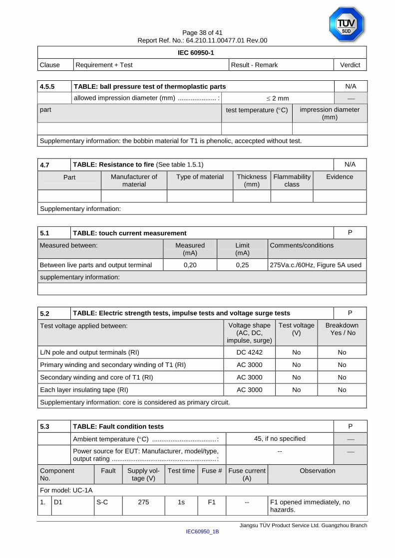
4.5.5 TABLE: ball pressure test of thermoplastic parts N/A
allowed impression diameter (mm) ..................... : 2 mm
part test temperature (C) impression diameter (mm)
Supplementary information: the bobbin material for T1 is phenolic, accecpted without test.
4.7 TABLE: Resistance to fire (See table 1.5.1) N/A
Part Manufacturer of material
Type of material Thickness (mm)
Flammability class
Evidence
Supplementary information:
5.1 TABLE: touch current measurement P
Measured between: Measured (mA)
Limit (mA)
Comments/conditions
Between live parts and output terminal 0,20 0,25 275Va.c./60Hz, Figure 5A used
supplementary information:
5.2 TABLE: Electric strength tests, impulse tests and voltage surge tests P
Test voltage applied between: Voltage shape (AC, DC,
impulse, surge)
Test voltage (V)
Breakdown Yes / No
L/N pole and output terminals (RI) DC 4242 No No
Primary winding and secondary winding of T1 (RI) AC 3000 No No
Secondary winding and core of T1 (RI) AC 3000 No No
Each layer insulating tape (RI) AC 3000 No No
Supplementary information: core is considered as primary circuit.
5.3 TABLE: Fault condition tests P
Ambient temperature (C) ................................... : 45, if no specified
Power source for EUT: Manufacturer, model/type, output rating ......................................................... :
--
Component No.
Fault Supply vol-tage (V)
Test time Fuse # Fuse current (A)
Observation
For model: UC-1A
1. D1 S-C 275 1s F1 -- F1 opened immediately, no hazards.
Page 39 of 41 Report Ref. No.: 64.210.11.00477.01 Rev.00
IEC 60950-1
Clause Requirement + Test Result - Remark Verdict
Jiangsu TÜV Product Service Ltd. Guangzhou Branch IEC60950_1B
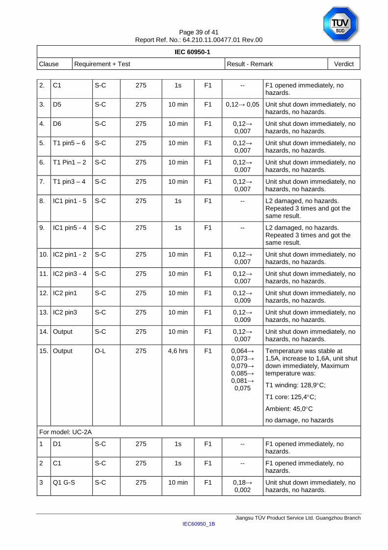
2. C1 S-C 275 1s F1 -- F1 opened immediately, no hazards.
3. D5 S-C 275 10 min F1 0,12→ 0,05 Unit shut down immediately, no hazards, no hazards.
4. D6 S-C 275 10 min F1 0,12→ 0,007
Unit shut down immediately, no hazards, no hazards.
5. T1 pin5 – 6 S-C 275 10 min F1 0,12→ 0,007
Unit shut down immediately, no hazards, no hazards.
6. T1 Pin1 – 2 S-C 275 10 min F1 0,12→ 0,007
Unit shut down immediately, no hazards, no hazards.
7. T1 pin3 – 4 S-C 275 10 min F1 0,12→ 0,007
Unit shut down immediately, no hazards, no hazards.
8. IC1 pin1 - 5 S-C 275 1s F1 -- L2 damaged, no hazards. Repeated 3 times and got the same result.
9. IC1 pin5 - 4 S-C 275 1s F1 -- L2 damaged, no hazards. Repeated 3 times and got the same result.
10. IC2 pin1 - 2 S-C 275 10 min F1 0,12→ 0,007
Unit shut down immediately, no hazards, no hazards.
11. IC2 pin3 - 4 S-C 275 10 min F1 0,12→ 0,007
Unit shut down immediately, no hazards, no hazards.
12. IC2 pin1 S-C 275 10 min F1 0,12→ 0,009
Unit shut down immediately, no hazards, no hazards.
13. IC2 pin3 S-C 275 10 min F1 0,12→ 0,009
Unit shut down immediately, no hazards, no hazards.
14. Output S-C 275 10 min F1 0,12→ 0,007
Unit shut down immediately, no hazards, no hazards.
15. Output O-L 275 4,6 hrs F1 0,064→ 0,073→ 0,079→ 0,085→ 0,081→ 0,075
Temperature was stable at 1,5A, increase to 1,6A, unit shut down immediately, Maximum temperature was:
T1 winding: 128,9C;
T1 core: 125,4C;
Ambient: 45,0C
no damage, no hazards
For model: UC-2A
1 D1 S-C 275 1s F1 -- F1 opened immediately, no hazards.
2 C1 S-C 275 1s F1 -- F1 opened immediately, no hazards.
3 Q1 G-S S-C 275 10 min F1 0,18→ 0,002
Unit shut down immediately, no hazards, no hazards.
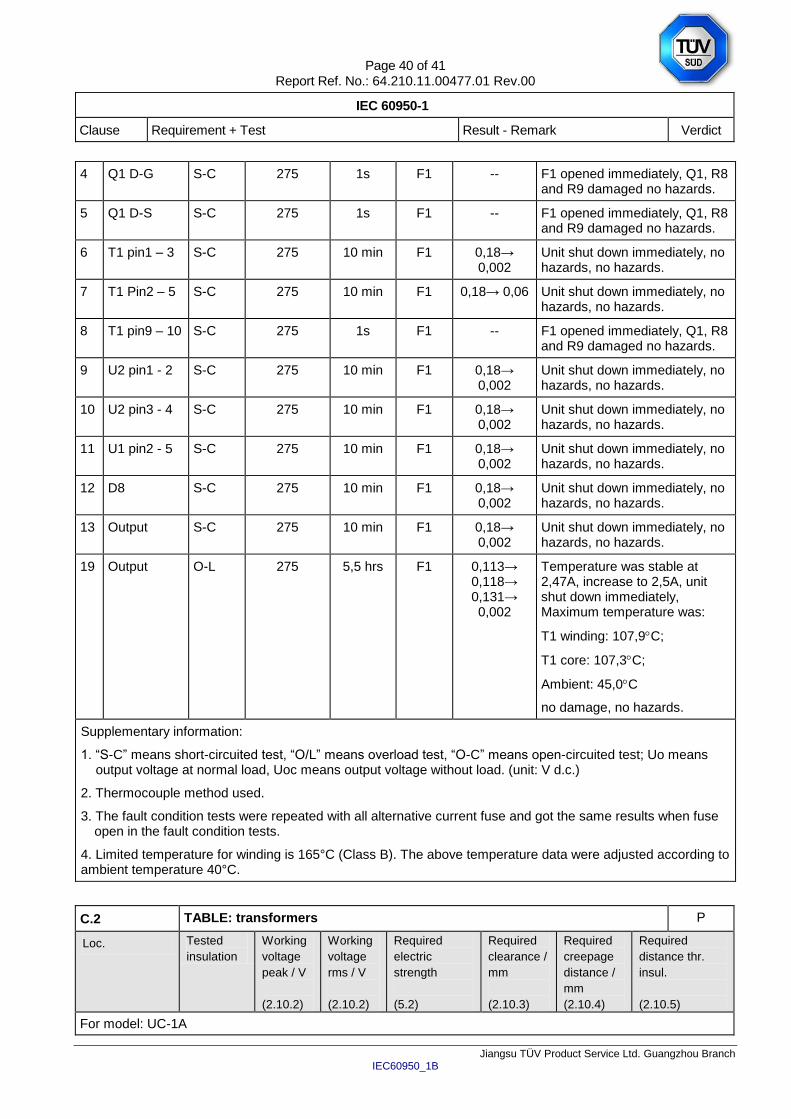
Page 40 of 41 Report Ref. No.: 64.210.11.00477.01 Rev.00
IEC 60950-1
Clause Requirement + Test Result - Remark Verdict
Jiangsu TÜV Product Service Ltd. Guangzhou Branch IEC60950_1B
4 Q1 D-G S-C 275 1s F1 -- F1 opened immediately, Q1, R8 and R9 damaged no hazards.
5 Q1 D-S S-C 275 1s F1 -- F1 opened immediately, Q1, R8 and R9 damaged no hazards.
6 T1 pin1 – 3 S-C 275 10 min F1 0,18→ 0,002
Unit shut down immediately, no hazards, no hazards.
7 T1 Pin2 – 5 S-C 275 10 min F1 0,18→ 0,06 Unit shut down immediately, no hazards, no hazards.
8 T1 pin9 – 10 S-C 275 1s F1 -- F1 opened immediately, Q1, R8 and R9 damaged no hazards.
9 U2 pin1 - 2 S-C 275 10 min F1 0,18→ 0,002
Unit shut down immediately, no hazards, no hazards.
10 U2 pin3 - 4 S-C 275 10 min F1 0,18→ 0,002
Unit shut down immediately, no hazards, no hazards.
11 U1 pin2 - 5 S-C 275 10 min F1 0,18→ 0,002
Unit shut down immediately, no hazards, no hazards.
12 D8 S-C 275 10 min F1 0,18→ 0,002
Unit shut down immediately, no hazards, no hazards.
13 Output S-C 275 10 min F1 0,18→ 0,002
Unit shut down immediately, no hazards, no hazards.
19 Output O-L 275 5,5 hrs F1 0,113→ 0,118→ 0,131→ 0,002
Temperature was stable at 2,47A, increase to 2,5A, unit shut down immediately, Maximum temperature was:
T1 winding: 107,9C;
T1 core: 107,3C;
Ambient: 45,0C
no damage, no hazards.
Supplementary information:
1. “S-C” means short-circuited test, “O/L” means overload test, “O-C” means open-circuited test; Uo means output voltage at normal load, Uoc means output voltage without load. (unit: V d.c.)
2. Thermocouple method used.
3. The fault condition tests were repeated with all alternative current fuse and got the same results when fuse open in the fault condition tests.
4. Limited temperature for winding is 165°C (Class B). The above temperature data were adjusted according to ambient temperature 40°C.
C.2 TABLE: transformers P
Loc. Tested
insulation
Working
voltage
peak / V
(2.10.2)
Working
voltage
rms / V
(2.10.2)
Required
electric
strength
(5.2)
Required
clearance /
mm
(2.10.3)
Required
creepage
distance /
mm
(2.10.4)
Required
distance thr.
insul.
(2.10.5)
For model: UC-1A
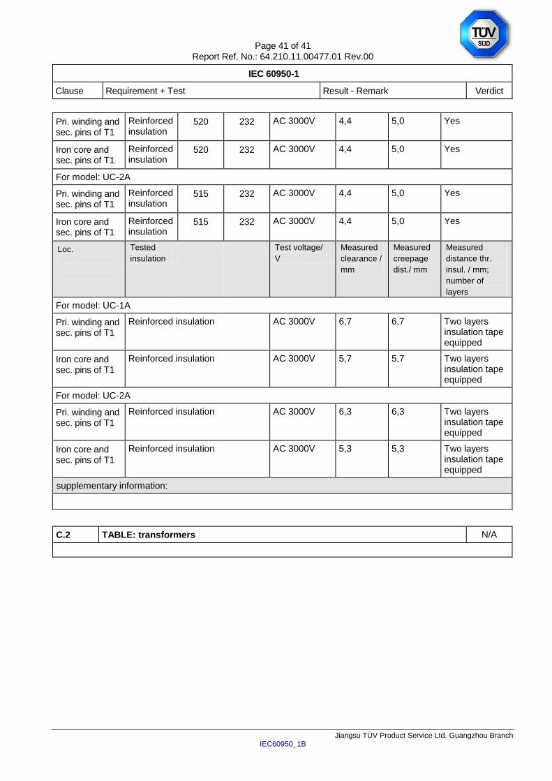
Page 41 of 41 Report Ref. No.: 64.210.11.00477.01 Rev.00
IEC 60950-1
Clause Requirement + Test Result - Remark Verdict
Jiangsu TÜV Product Service Ltd. Guangzhou Branch IEC60950_1B
Pri. winding and sec. pins of T1
Reinforced insulation
520 232 AC 3000V 4,4 5,0 Yes
Iron core and sec. pins of T1
Reinforced insulation
520 232 AC 3000V 4,4 5,0 Yes
For model: UC-2A
Pri. winding and sec. pins of T1
Reinforced insulation
515 232 AC 3000V 4,4 5,0 Yes
Iron core and sec. pins of T1
Reinforced insulation
515 232 AC 3000V 4,4 5,0 Yes
Loc.
Tested
insulation
Test voltage/
V
Measured
clearance /
mm
Measured
creepage
dist./ mm
Measured
distance thr.
insul. / mm;
number of
layers
For model: UC-1A
Pri. winding and sec. pins of T1
Reinforced insulation AC 3000V 6,7 6,7 Two layers insulation tape equipped
Iron core and sec. pins of T1
Reinforced insulation AC 3000V 5,7 5,7 Two layers insulation tape equipped
For model: UC-2A
Pri. winding and sec. pins of T1
Reinforced insulation AC 3000V 6,3 6,3 Two layers insulation tape equipped
Iron core and sec. pins of T1
Reinforced insulation AC 3000V 5,3 5,3 Two layers insulation tape equipped
supplementary information:
C.2 TABLE: transformers N/A
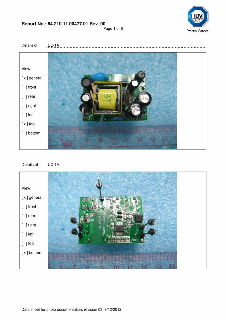
Report No.: 64.210.11.00477.01 Rev. 00
Page 1 of 6
Data sheet for photo documentation, revision 03, 9/12/2012
Details of:
UC-1A
View: [ x ] general [ ] front [ ] rear [ ] right [ ] left [ x ] top [ ] bottom
Details of: UC-1A
View: [ x ] general [ ] front [ ] rear [ ] right [ ] left [ ] top [ x ] bottom
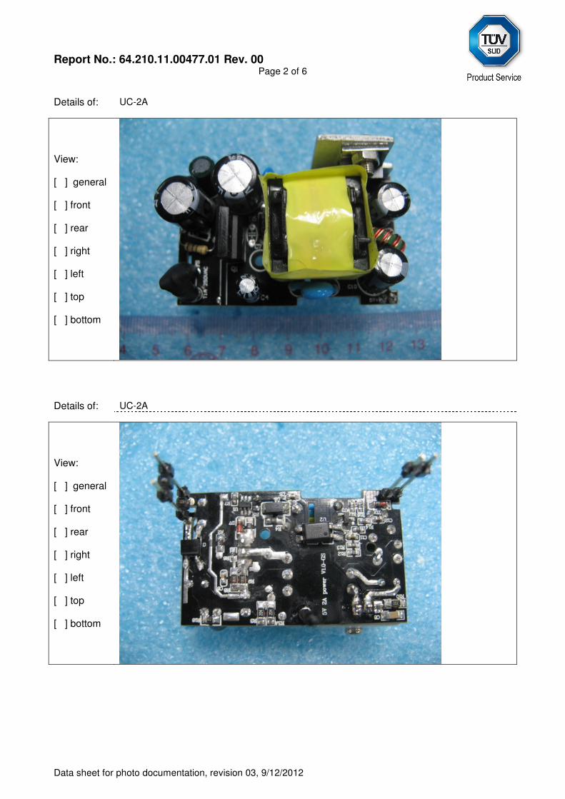
Report No.: 64.210.11.00477.01 Rev. 00
Page 2 of 6
Data sheet for photo documentation, revision 03, 9/12/2012
Details of: UC-2A
View: [ ] general [ ] front [ ] rear [ ] right [ ] left [ ] top [ ] bottom
Details of: UC-2A
View: [ ] general [ ] front [ ] rear [ ] right [ ] left [ ] top [ ] bottom
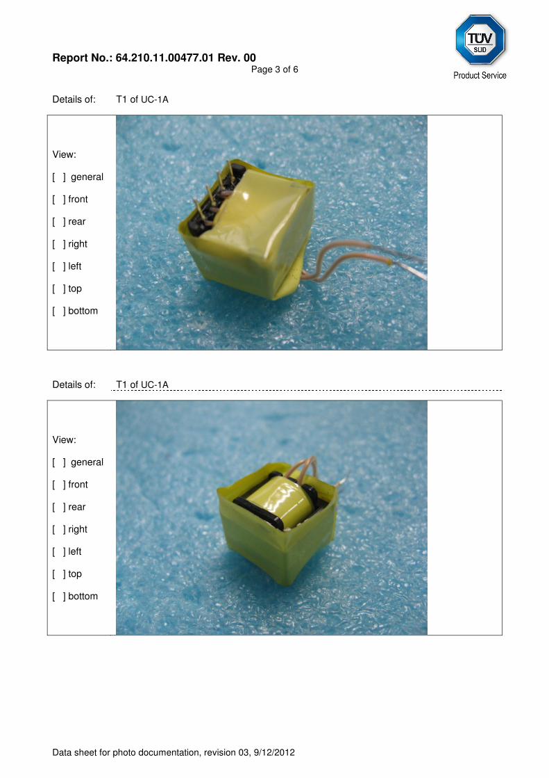
Report No.: 64.210.11.00477.01 Rev. 00
Page 3 of 6
Data sheet for photo documentation, revision 03, 9/12/2012
Details of: T1 of UC-1A
View: [ ] general [ ] front [ ] rear [ ] right [ ] left [ ] top [ ] bottom
Details of: T1 of UC-1A
View: [ ] general [ ] front [ ] rear [ ] right [ ] left [ ] top [ ] bottom
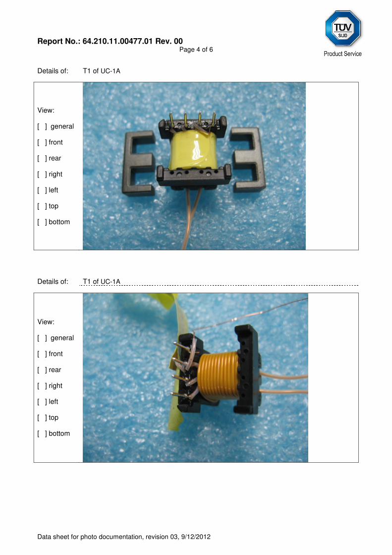
Report No.: 64.210.11.00477.01 Rev. 00
Page 4 of 6
Data sheet for photo documentation, revision 03, 9/12/2012
Details of: T1 of UC-1A
View: [ ] general [ ] front [ ] rear [ ] right [ ] left [ ] top [ ] bottom
Details of: T1 of UC-1A
View: [ ] general [ ] front [ ] rear [ ] right [ ] left [ ] top [ ] bottom
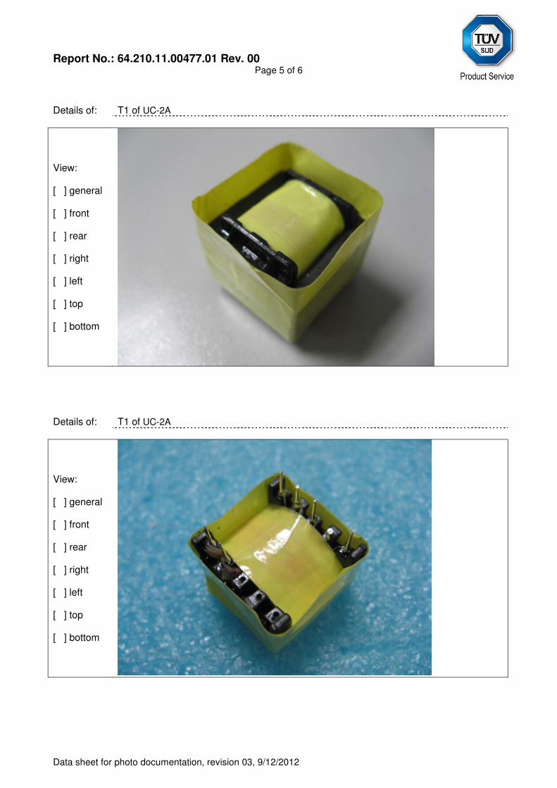
Report No.: 64.210.11.00477.01 Rev. 00
Page 5 of 6
Data sheet for photo documentation, revision 03, 9/12/2012
Details of: T1 of UC-2A
View: [ ] general [ ] front [ ] rear [ ] right [ ] left [ ] top [ ] bottom
Details of: T1 of UC-2A View: [ ] general [ ] front [ ] rear [ ] right [ ] left [ ] top [ ] bottom
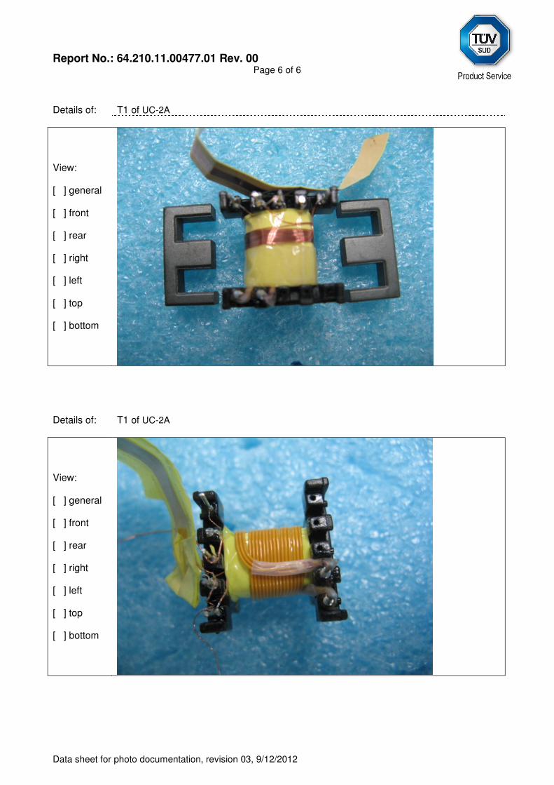
Report No.: 64.210.11.00477.01 Rev. 00
Page 6 of 6
Data sheet for photo documentation, revision 03, 9/12/2012
Details of: T1 of UC-2A
View: [ ] general [ ] front [ ] rear [ ] right [ ] left [ ] top [ ] bottom
Details of: T1 of UC-2A
View: [ ] general [ ] front [ ] rear [ ] right [ ] left [ ] top [ ] bottom


![IEC 60950 and IEC 62368 safety standard terminology€¦ · as for operator access areas, except as given in 1.7.14, 2.1.3, 4.5.4, 4.6.2 and 5.1.7. service access area [IEC 60950-1]:](https://img.pdfslide.us/doc/110x75/5fd918379509c8683f1fe745/iec-60950-and-iec-62368-safety-standard-as-for-operator-access-areas-except-as.jpg)