Embed Size (px)
Citation preview

IEC 60870-5-104Master Driver
© 2016 PTC Inc. All Rights Reserved.
IEC 60870-5-104 Master Driver
TableofContentsIEC 60870-5-104 Master Driver 1
Table of Contents 2
IEC 60870-5-104 Master Driver 4
Overview 4
Setup 5
Channel Properties - General 5
Channel Properties - Ethernet Communications 6
Channel Properties - Write Optimizations 6
Channel Properties - Advanced 7
Channel Properties - Communications 8
Channel Properties - 60870 Settings 8
Device Properties - General 9
Device Properties - Scan Mode 11
Device Properties - Auto-Demotion 12
Device Properties - Time Synchronization 12
Device Properties - Communications 13
Timing 15
Event Playback 15
Device Properties - Redundancy 16
Data Type Description 17
Address Descriptions 18
Error Descriptions 25
Device <device name> failed to complete clock synchronization. 25
Device <device name> failed to complete counter interrogation. 25
Device <device name> failed to complete general interrogation. 26
Device <device name> is not responding. 26
Error loading XML file for device <device name>. Common address is invalid. Valid range is<low limit> to <high limit>. 26
Error loading XML file for device <device name>. Common Address <common address> isalready used by device <device name>. 27
Read failed on tag <tag name>. 27
Read failed on tag <tag name> due to data typemismatch. 27
Toomany events received in <device name>; the buffer has overflowed. 28
Unable to write to address <address> on device <device>. 28
Write failed on tag <tag name>. 28
IEC 60870-5-104 Master Driver Interoperability Guide 29
www.kepware.com
2

IEC 60870-5-104 Master Driver
Index 44
www.kepware.com
3
IEC 60870-5-104 Master Driver
IEC 60870-5-104 Master DriverHelp version 1.026
CONTENTS
OverviewWhat is the IEC 60870-5-104 Master Driver?
Channel SetupHow do I configure a channel for use with this driver?
Device SetupHow do I configure devices for use with this driver?
Data Types DescriptionWhat data types does the IEC 60870-5-104 Master Driver support?
Address DescriptionsHow do I address a data location on a device?
Event Log MessagesWhat error messages are produced by the IEC 60870-5-104 Master Driver?
IEC 60870-5-104 Master Driver Interoperability GuideWhere can I find specific implementation information for the IEC 60870-5-104 Master Driver?
OverviewIEC 60870 is a commonly used substation communication protocol similar to DNP. The IEC 60870-5-104Master protocol uses specific terms to describe the communications pathway. Descriptions are as follows:
l Channel: This describes a communications path between two endpoints.
l Session: This describes a logical connection between a 104 master node (server channel) and a 104slave node (server device). It comprises one or more 104 Sectors.
l 104 Sector: This groups related data. It has its own Information Object Address (IOA) space. In theIEC 60870-5-104 Master Driver, a 104 session/sector pair is represented as server devices for eachchannel.
The server channel describes the communications pathway over which the master and slave willcommunicate. The other endpoint of the 104 channel may have one or more slave nodes and sectorsavailable. A server device must be created for each sector in the endpoint.
www.kepware.com
4
IEC 60870-5-104 Master Driver
SetupCommunication ProtocolIEC 60870-5-104 MasterFor more information, refer to IEC 60870-5-104 Interoperability Guide.
Supported DevicesAny IEC 60870-5-104 slave device or gateway.
Maximum Channels and DevicesThe maximum number of channels supported is 256 (with one socket allowed per channel). The maximumnumber of devices supported per channel is 1024.
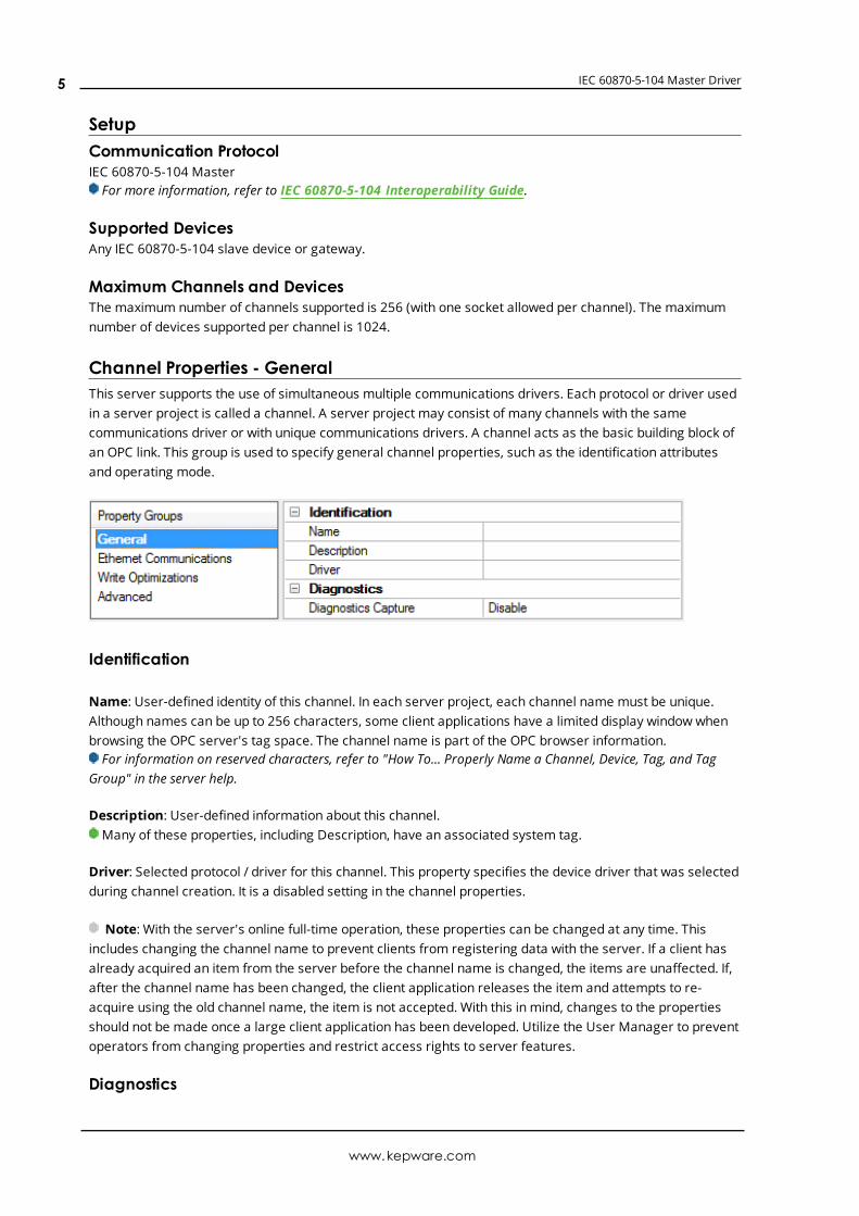
Channel Properties - GeneralThis server supports the use of simultaneous multiple communications drivers. Each protocol or driver usedin a server project is called a channel. A server project may consist of many channels with the samecommunications driver or with unique communications drivers. A channel acts as the basic building block ofan OPC link. This group is used to specify general channel properties, such as the identification attributesand operating mode.
Identification
Name: User-defined identity of this channel. In each server project, each channel name must be unique.Although names can be up to 256 characters, some client applications have a limited display window whenbrowsing the OPC server's tag space. The channel name is part of the OPC browser information.For information on reserved characters, refer to "How To... Properly Name a Channel, Device, Tag, and Tag
Group" in the server help.
Description: User-defined information about this channel. Many of these properties, including Description, have an associated system tag.
Driver: Selected protocol / driver for this channel. This property specifies the device driver that was selectedduring channel creation. It is a disabled setting in the channel properties.
Note: With the server's online full-time operation, these properties can be changed at any time. Thisincludes changing the channel name to prevent clients from registering data with the server. If a client hasalready acquired an item from the server before the channel name is changed, the items are unaffected. If,after the channel name has been changed, the client application releases the item and attempts to re-acquire using the old channel name, the item is not accepted. With this in mind, changes to the propertiesshould not be made once a large client application has been developed. Utilize the User Manager to preventoperators from changing properties and restrict access rights to server features.
Diagnostics
www.kepware.com
5
IEC 60870-5-104 Master Driver
Diagnostics Capture: When enabled, this optionmakes the channel's diagnostic information available toOPC applications. Because the server's diagnostic features require a minimal amount of overheadprocessing, it is recommended that they be utilized when needed and disabled when not. The default isdisabled.For more information, refer to "Communication Diagnostics" in the server help.
Not all drivers support diagnostics. To determine whether diagnostics are available for a particular driver, openthe driver information and locate the "Supports device level diagnostics" statement.
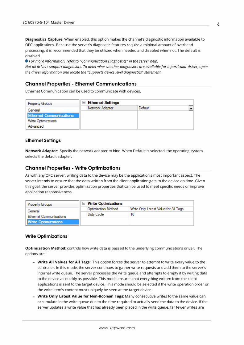
Channel Properties - Ethernet CommunicationsEthernet Communication can be used to communicate with devices.
Ethernet Settings
Network Adapter: Specify the network adapter to bind. When Default is selected, the operating systemselects the default adapter.
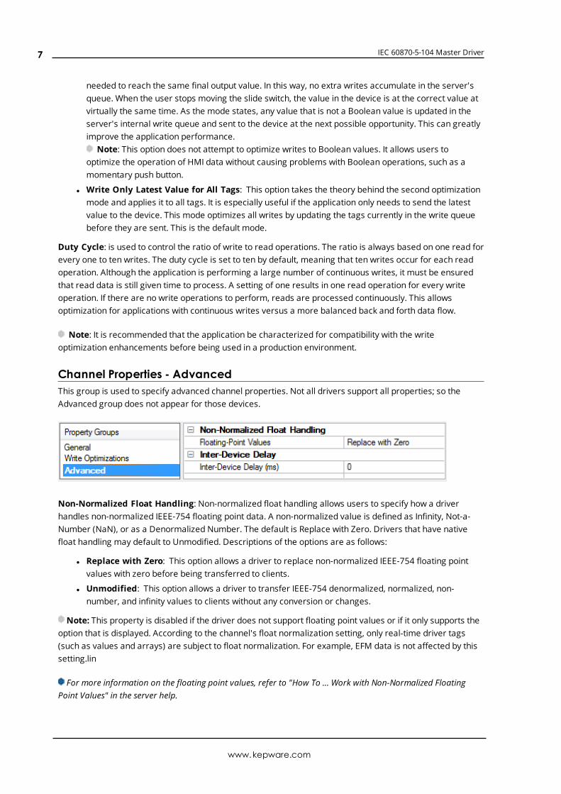
Channel Properties - Write OptimizationsAs with any OPC server, writing data to the device may be the application's most important aspect. Theserver intends to ensure that the data written from the client application gets to the device on time. Giventhis goal, the server provides optimization properties that can be used to meet specific needs or improveapplication responsiveness.
Write Optimizations
Optimization Method: controls how write data is passed to the underlying communications driver. Theoptions are:
l Write All Values for All Tags: This option forces the server to attempt to write every value to thecontroller. In this mode, the server continues to gather write requests and add them to the server'sinternal write queue. The server processes the write queue and attempts to empty it by writing datato the device as quickly as possible. This mode ensures that everything written from the clientapplications is sent to the target device. This mode should be selected if the write operation order orthe write item's content must uniquely be seen at the target device.
l Write Only Latest Value for Non-Boolean Tags: Many consecutive writes to the same value canaccumulate in the write queue due to the time required to actually send the data to the device. If theserver updates a write value that has already been placed in the write queue, far fewer writes are
www.kepware.com
6
IEC 60870-5-104 Master Driver
needed to reach the same final output value. In this way, no extra writes accumulate in the server'squeue. When the user stops moving the slide switch, the value in the device is at the correct value atvirtually the same time. As the mode states, any value that is not a Boolean value is updated in theserver's internal write queue and sent to the device at the next possible opportunity. This can greatlyimprove the application performance.
Note: This option does not attempt to optimize writes to Boolean values. It allows users tooptimize the operation of HMI data without causing problems with Boolean operations, such as amomentary push button.
l Write Only Latest Value for All Tags: This option takes the theory behind the second optimizationmode and applies it to all tags. It is especially useful if the application only needs to send the latestvalue to the device. This mode optimizes all writes by updating the tags currently in the write queuebefore they are sent. This is the default mode.
Duty Cycle: is used to control the ratio of write to read operations. The ratio is always based on one read forevery one to ten writes. The duty cycle is set to ten by default, meaning that ten writes occur for each readoperation. Although the application is performing a large number of continuous writes, it must be ensuredthat read data is still given time to process. A setting of one results in one read operation for every writeoperation. If there are no write operations to perform, reads are processed continuously. This allowsoptimization for applications with continuous writes versus a more balanced back and forth data flow.
Note: It is recommended that the application be characterized for compatibility with the writeoptimization enhancements before being used in a production environment.
Channel Properties - AdvancedThis group is used to specify advanced channel properties. Not all drivers support all properties; so theAdvanced group does not appear for those devices.
Non-Normalized Float Handling: Non-normalized float handling allows users to specify how a driverhandles non-normalized IEEE-754 floating point data. A non-normalized value is defined as Infinity, Not-a-Number (NaN), or as a Denormalized Number. The default is Replace with Zero. Drivers that have nativefloat handling may default to Unmodified. Descriptions of the options are as follows:
l Replace with Zero: This option allows a driver to replace non-normalized IEEE-754 floating pointvalues with zero before being transferred to clients.
l Unmodified: This option allows a driver to transfer IEEE-754 denormalized, normalized, non-number, and infinity values to clients without any conversion or changes.
Note: This property is disabled if the driver does not support floating point values or if it only supports theoption that is displayed. According to the channel's float normalization setting, only real-time driver tags(such as values and arrays) are subject to float normalization. For example, EFM data is not affected by thissetting.lin
For more information on the floating point values, refer to "How To ... Work with Non-Normalized FloatingPoint Values" in the server help.
www.kepware.com
7
IEC 60870-5-104 Master Driver
Inter-Device Delay: Specify the amount of time the communications channel waits to send new requests tothe next device after data is received from the current device on the same channel. Zero (0) disables thedelay.
Note: This property is not available for all drivers, models, and dependent settings.
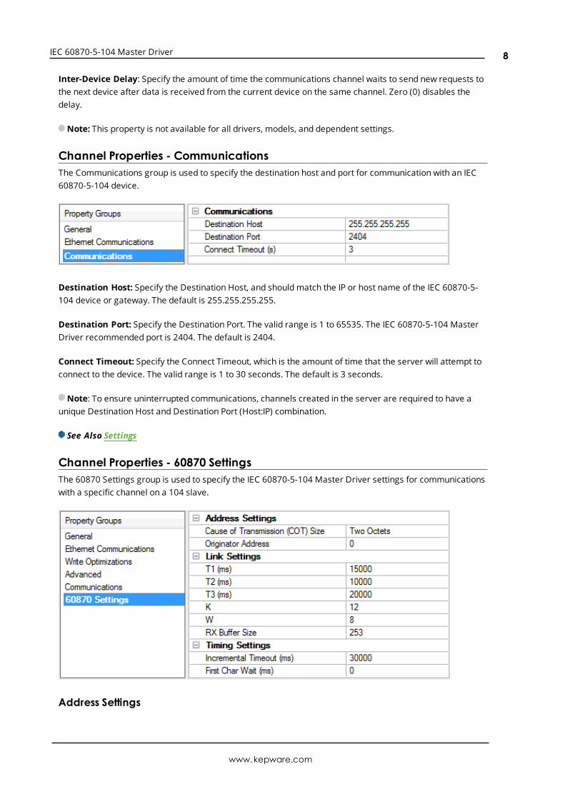
Channel Properties - CommunicationsThe Communications group is used to specify the destination host and port for communication with an IEC60870-5-104 device.
Destination Host: Specify the Destination Host, and should match the IP or host name of the IEC 60870-5-104 device or gateway. The default is 255.255.255.255.
Destination Port: Specify the Destination Port. The valid range is 1 to 65535. The IEC 60870-5-104 MasterDriver recommended port is 2404. The default is 2404.
Connect Timeout: Specify the Connect Timeout, which is the amount of time that the server will attempt toconnect to the device. The valid range is 1 to 30 seconds. The default is 3 seconds.
Note: To ensure uninterrupted communications, channels created in the server are required to have aunique Destination Host and Destination Port (Host:IP) combination.
See Also Settings
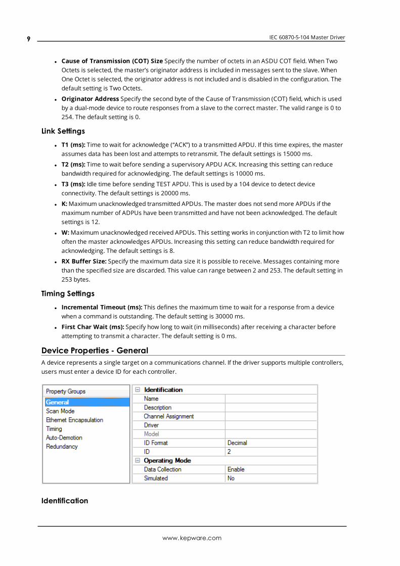
Channel Properties - 60870 SettingsThe 60870 Settings group is used to specify the IEC 60870-5-104 Master Driver settings for communicationswith a specific channel on a 104 slave.
Address Settings
www.kepware.com
8
IEC 60870-5-104 Master Driver
l Cause of Transmission (COT) Size Specify the number of octets in an ASDU COT field. When TwoOctets is selected, the master’s originator address is included in messages sent to the slave. WhenOne Octet is selected, the originator address is not included and is disabled in the configuration. Thedefault setting is Two Octets.
l Originator Address Specify the second byte of the Cause of Transmission (COT) field, which is usedby a dual-mode device to route responses from a slave to the correct master. The valid range is 0 to254. The default setting is 0.
Link Settings
l T1 (ms): Time to wait for acknowledge (“ACK”) to a transmitted APDU. If this time expires, the masterassumes data has been lost and attempts to retransmit. The default settings is 15000 ms.
l T2 (ms): Time to wait before sending a supervisory APDU ACK. Increasing this setting can reducebandwidth required for acknowledging. The default settings is 10000 ms.
l T3 (ms): Idle time before sending TEST APDU. This is used by a 104 device to detect deviceconnectivity. The default settings is 20000 ms.
l K:Maximum unacknowledged transmitted APDUs. The master does not sendmore APDUs if themaximum number of ADPUs have been transmitted and have not been acknowledged. The defaultsettings is 12.
l W:Maximum unacknowledged received APDUs. This setting works in conjunction with T2 to limit howoften the master acknowledges APDUs. Increasing this setting can reduce bandwidth required foracknowledging. The default settings is 8.
l RX Buffer Size: Specify the maximum data size it is possible to receive. Messages containing morethan the specified size are discarded. This value can range between 2 and 253. The default setting in253 bytes.
Timing Settings
l Incremental Timeout (ms): This defines the maximum time to wait for a response from a devicewhen a command is outstanding. The default setting is 30000 ms.
l First Char Wait (ms): Specify how long to wait (in milliseconds) after receiving a character beforeattempting to transmit a character. The default setting is 0 ms.
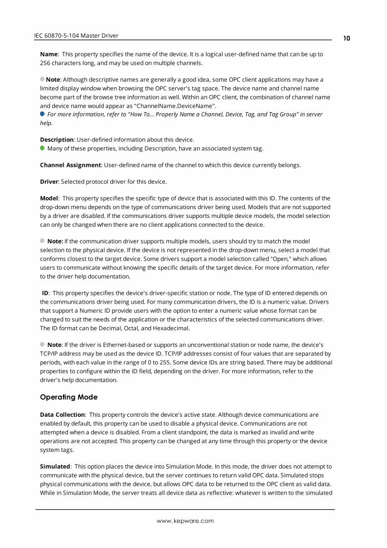
Device Properties - GeneralA device represents a single target on a communications channel. If the driver supports multiple controllers,users must enter a device ID for each controller.
Identification
www.kepware.com
9
IEC 60870-5-104 Master Driver
Name: This property specifies the name of the device. It is a logical user-defined name that can be up to256 characters long, andmay be used onmultiple channels.
Note: Although descriptive names are generally a good idea, some OPC client applications may have alimited display window when browsing the OPC server's tag space. The device name and channel namebecome part of the browse tree information as well. Within an OPC client, the combination of channel nameand device name would appear as "ChannelName.DeviceName".
For more information, refer to "How To... Properly Name a Channel, Device, Tag, and Tag Group" in serverhelp.
Description: User-defined information about this device.Many of these properties, including Description, have an associated system tag.
Channel Assignment: User-defined name of the channel to which this device currently belongs.
Driver: Selected protocol driver for this device.
Model: This property specifies the specific type of device that is associated with this ID. The contents of thedrop-downmenu depends on the type of communications driver being used. Models that are not supportedby a driver are disabled. If the communications driver supports multiple device models, the model selectioncan only be changed when there are no client applications connected to the device.
Note: If the communication driver supports multiple models, users should try to match the modelselection to the physical device. If the device is not represented in the drop-downmenu, select a model thatconforms closest to the target device. Some drivers support a model selection called "Open," which allowsusers to communicate without knowing the specific details of the target device. For more information, referto the driver help documentation.
ID: This property specifies the device's driver-specific station or node. The type of ID entered depends onthe communications driver being used. For many communication drivers, the ID is a numeric value. Driversthat support a Numeric ID provide users with the option to enter a numeric value whose format can bechanged to suit the needs of the application or the characteristics of the selected communications driver.The ID format can be Decimal, Octal, and Hexadecimal.
Note: If the driver is Ethernet-based or supports an unconventional station or node name, the device'sTCP/IP address may be used as the device ID. TCP/IP addresses consist of four values that are separated byperiods, with each value in the range of 0 to 255. Some device IDs are string based. There may be additionalproperties to configure within the ID field, depending on the driver. For more information, refer to thedriver's help documentation.
Operating Mode
Data Collection: This property controls the device's active state. Although device communications areenabled by default, this property can be used to disable a physical device. Communications are notattempted when a device is disabled. From a client standpoint, the data is marked as invalid and writeoperations are not accepted. This property can be changed at any time through this property or the devicesystem tags.
Simulated: This option places the device into Simulation Mode. In this mode, the driver does not attempt tocommunicate with the physical device, but the server continues to return valid OPC data. Simulated stopsphysical communications with the device, but allows OPC data to be returned to the OPC client as valid data.While in Simulation Mode, the server treats all device data as reflective: whatever is written to the simulated
www.kepware.com
10
IEC 60870-5-104 Master Driver
device is read back and each OPC item is treated individually. The item's memory map is based on the groupUpdate Rate. The data is not saved if the server removes the item (such as when the server is reinitialized).The default is No.
Notes:
1. This System tag (_Simulated) is read only and cannot be written to for runtime protection. The Systemtag allows this property to be monitored from the client.
2. In Simulationmode, the item's memory map is based on client update rate(s) (Group Update Rate forOPC clients or Scan Rate for native and DDE interfaces). This means that two clients that referencethe same item with different update rates return different data.
Simulation Mode is for test and simulation purposes only. It should never be used in a productionenvironment.
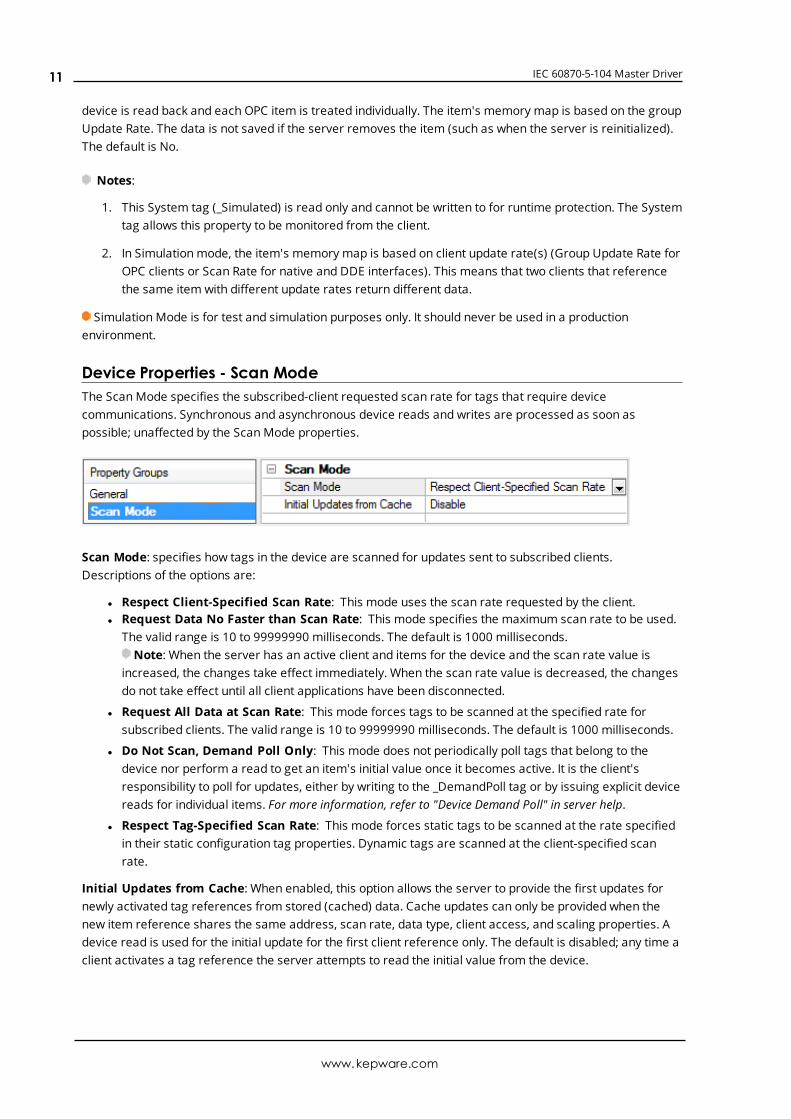
Device Properties - Scan ModeThe ScanMode specifies the subscribed-client requested scan rate for tags that require devicecommunications. Synchronous and asynchronous device reads and writes are processed as soon aspossible; unaffected by the ScanMode properties.
Scan Mode: specifies how tags in the device are scanned for updates sent to subscribed clients.Descriptions of the options are:
l Respect Client-Specified Scan Rate: This mode uses the scan rate requested by the client.l Request Data No Faster than Scan Rate: This mode specifies the maximum scan rate to be used.
The valid range is 10 to 99999990 milliseconds. The default is 1000 milliseconds.Note: When the server has an active client and items for the device and the scan rate value is
increased, the changes take effect immediately. When the scan rate value is decreased, the changesdo not take effect until all client applications have been disconnected.
l Request All Data at Scan Rate: This mode forces tags to be scanned at the specified rate forsubscribed clients. The valid range is 10 to 99999990 milliseconds. The default is 1000 milliseconds.
l Do Not Scan, Demand Poll Only: This mode does not periodically poll tags that belong to thedevice nor perform a read to get an item's initial value once it becomes active. It is the client'sresponsibility to poll for updates, either by writing to the _DemandPoll tag or by issuing explicit devicereads for individual items. For more information, refer to "Device Demand Poll" in server help.
l Respect Tag-Specified Scan Rate: This mode forces static tags to be scanned at the rate specifiedin their static configuration tag properties. Dynamic tags are scanned at the client-specified scanrate.
Initial Updates from Cache: When enabled, this option allows the server to provide the first updates fornewly activated tag references from stored (cached) data. Cache updates can only be provided when thenew item reference shares the same address, scan rate, data type, client access, and scaling properties. Adevice read is used for the initial update for the first client reference only. The default is disabled; any time aclient activates a tag reference the server attempts to read the initial value from the device.
www.kepware.com
11
IEC 60870-5-104 Master Driver
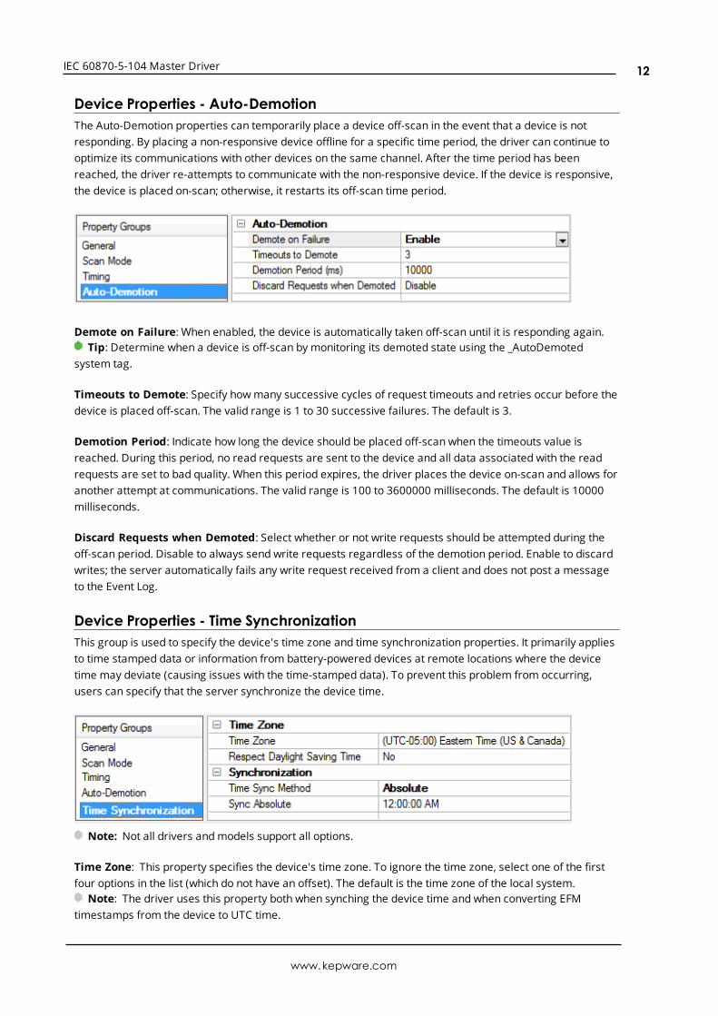
Device Properties - Auto-DemotionThe Auto-Demotion properties can temporarily place a device off-scan in the event that a device is notresponding. By placing a non-responsive device offline for a specific time period, the driver can continue tooptimize its communications with other devices on the same channel. After the time period has beenreached, the driver re-attempts to communicate with the non-responsive device. If the device is responsive,the device is placed on-scan; otherwise, it restarts its off-scan time period.
Demote on Failure: When enabled, the device is automatically taken off-scan until it is responding again.Tip: Determine when a device is off-scan by monitoring its demoted state using the _AutoDemoted
system tag.
Timeouts to Demote: Specify howmany successive cycles of request timeouts and retries occur before thedevice is placed off-scan. The valid range is 1 to 30 successive failures. The default is 3.
Demotion Period: Indicate how long the device should be placed off-scan when the timeouts value isreached. During this period, no read requests are sent to the device and all data associated with the readrequests are set to bad quality. When this period expires, the driver places the device on-scan and allows foranother attempt at communications. The valid range is 100 to 3600000 milliseconds. The default is 10000milliseconds.
Discard Requests when Demoted: Select whether or not write requests should be attempted during theoff-scan period. Disable to always send write requests regardless of the demotion period. Enable to discardwrites; the server automatically fails any write request received from a client and does not post a messageto the Event Log.
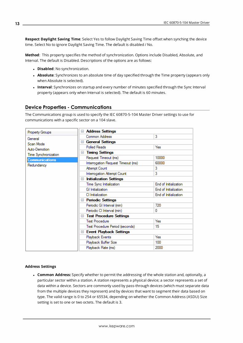
Device Properties - Time SynchronizationThis group is used to specify the device's time zone and time synchronization properties. It primarily appliesto time stamped data or information from battery-powered devices at remote locations where the devicetime may deviate (causing issues with the time-stamped data). To prevent this problem from occurring,users can specify that the server synchronize the device time.
Note: Not all drivers andmodels support all options.
Time Zone: This property specifies the device's time zone. To ignore the time zone, select one of the firstfour options in the list (which do not have an offset). The default is the time zone of the local system.
Note: The driver uses this property both when synching the device time and when converting EFMtimestamps from the device to UTC time.
www.kepware.com
12
IEC 60870-5-104 Master Driver
Respect Daylight Saving Time: Select Yes to follow Daylight Saving Time offset when synching the devicetime. Select No to ignore Daylight Saving Time. The default is disabled / No.
Method: This property specifies the method of synchronization. Options include Disabled, Absolute, andInterval. The default is Disabled. Descriptions of the options are as follows:
l Disabled: No synchronization.
l Absolute: Synchronizes to an absolute time of day specified through the Time property (appears onlywhen Absolute is selected).
l Interval: Synchronizes on startup and every number of minutes specified through the Sync Intervalproperty (appears only when Interval is selected). The default is 60 minutes.
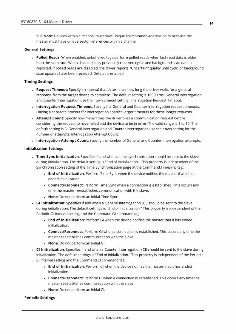
Device Properties - CommunicationsThe Communications group is used to specify the IEC 60870-5-104 Master Driver settings to use forcommunications with a specific sector on a 104 slave.
Address Settings
l Common Address: Specify whether to permit the addressing of the whole station and, optionally, aparticular sector within a station. A station represents a physical device; a sector represents a set ofdata within a device. Sectors are commonly used by pass-through devices (which must separate datafrom the multiple devices they represent) and by devices that want to segment their data based ontype. The valid range is 0 to 254 or 65534, depending on whether the Common Address (ASDU) Sizesetting is set to one or two octets. The default is 3.
www.kepware.com
13
IEC 60870-5-104 Master Driver
Note: Devices within a channel must have unique link/common address pairs because themaster must have unique sector references within a channel.
General Settings
l Polled Reads:When enabled, unbuffered tags perform polled reads when last-read data is olderthan the scan rate. When disabled, only previously received cyclic and background scan data isreported. If polled reads are disabled, the driver reports "Uncertain" quality until cyclic or backgroundscan updates have been received. Default is enabled.
Timing Settings
l Request Timeout: Specify an interval that determines how long the driver waits for a generalresponse from the target device to complete. The default setting is 10000 ms. General Interrogationand Counter Interrogation use their own timeout setting: Interrogation Request Timeout.
l Interrogation Request Timeout: Specify the General and Counter Interrogation request timeouts.Having a separate timeout for interrogation enables larger timeouts for these longer requests.
l Attempt Count: Specify howmany times the driver tries a communication request beforeconsidering the request to have failed and the device to be in error. The valid range is 1 to 10. Thedefault setting is 3. General Interrogation and Counter Interrogation use their own setting for thenumber of attempts: Interrogation Attempt Count.
l Interrogation Attempt Count: Specify the number of General and Counter Interrogation attempts.
Initialization Settings
l Time Sync Initialization: Specifies if and when a time synchronization should be sent to the slaveduring initialization. The default setting is "End of Initialization." This property is independent of theSynchronization setting of the Time Synchronization page at the Command.Timesync tag.
l End of Initialization: Perform Time Sync when the device notifies the master that it hasended initialization.
l Connect/Reconnect: Perform Time Sync when a connection is established. This occurs anytime the master reestablishes communication with the slave.
l None: Do not perform an initial Time Sync.
l GI Initialization: Specifies if and when a General Interrogation (GI) should be sent to the slaveduring initialization. The default settings is "End of Initialization." This property is independent of thePeriodic GI Interval setting and the Command.GI command tag.
l End of Initialization: Perform GI when the device notifies the master that it has endedinitialization.
l Connect/Reconnect: Perform GI when a connection is established. This occurs any time themaster reestablishes communication with the slave.
l None: Do not perform an initial GI.
l CI Initialization: Specifies if and when a Counter Interrogation (CI) should be sent to the slave duringinitialization. The default settings is "End of Initialization." This property is independent of the PeriodicCI Interval setting and the Command.CI command tag.
l End of Initialization: Perform CI when the device notifies the master that it has endedinitialization.
l Connect/Reconnect: Perform CI when a connection is established. This occurs any time themaster reestablishes communication with the slave.
l None: Do not perform an initial CI.
Periodic Settings
www.kepware.com
14
IEC 60870-5-104 Master Driver
l Periodic GI Interval: Configures the master to perform a General Interrogation based on a specifiedtime interval. The default setting is 720 minutes (12 hours). When clients are connected, GeneralInterrogations are sent every time the specified period elapses. Specifying an interval of 0 disablesperiodic GI.
l Periodic CI Interval: Configures the master to perform a Counter Interrogation based on a specifiedtime interval. When clients are connected, Counter Interrogations are sent every time the specifiedperiod elapses. The default is 0 minutes (disabled). Specifying an interval of 0 disables periodic CI.
Test Procedure Settings
l Test Procedure: Specifies whether or not test command is enabled. When enabled, the masterperiodically sends a test command ASDU. This command can be used to determine device errorstate. It is not recommended to enable this setting because the TCP/IP layer handles connectivitydetection. The default is disabled.
l Test Procedure Period: Test commands are sent at the specified rate. The default is 15 seconds.
Playback Settings
l Playback Events: Specifies whether or not event playback is enabled. When disabled, all tagsassociated with event playback report the most recent data and no data is buffered. When enabled,events are played back based on the buffer size and playback rate. The default is Enabled. See EventPlayback.
l Playback Buffer Size: The maximum number of events buffered for each Information ObjectAddress (IOA) buffer. The default is 100.
l Playback Rate: Rate at which events are played back. The default is 2000 ms.
TimingTiming settings come in two varieties: link-layer timing and application-layer timing. Link-layer timingsettings are used to control or time out the acquisition of application layer data. Application-layer datacontains the individual commands to read or write. For example, General Interrogation is performed as anapplication-layer command, but the acquisition of individual data is accomplished through the link layer.
Device-level application-layer timeouts are controlled through the request timeout device settings. Thesesettings are the only timing properties that can affect tag quality.
The channel-level timing settings affect the link layer. They do not directly affect the quality of a tag, but theycan be tuned to allow for delays or timeouts during the acquisition of individual data pieces. These settingscan introduce complex interactions in data acquisition and should not be changed without a compellingreason.
Event PlaybackA device may sendmany updates in one transaction. To address this, event playback handles spontaneouslytransmitted data. For example, if a device sends a set of packed events that represent some history of ananalog event (such as voltage values during a fault), the data is played back. The driver plays back each datapoint at a set interval to allow the client to read each update in the order it was received from the device.
Event playback also guarantees that each data point is read. If the interval expires before the data has beenaccessed, the data is maintained until the client references it.
To guarantee that no data is missed, it is recommended that client update rates be at least as fast as theevent playback interval. This is not required with a single client because data is held until at least one read
www.kepware.com
15
IEC 60870-5-104 Master Driver
has occurred; however, it is required in the case of multiple clients reading the same data point to ensurethat each client receives all the data.
The quality of buffered tags is “uncertain” until data associated with a tag(s) is received. If a DNR occursduring event playback, all buffered events are played back before reporting “bad” quality.
Notes:
1. Please see the OPC DA Compliance note for OPC DA Compliance settings that can affect eventplayback.
2. The OPC timestamp is based on the device time (if available) or the server time. When the OPCtimestamp is based on server time, it represents the time of the data arrival.
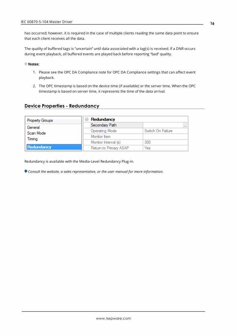
Device Properties - Redundancy
Redundancy is available with the Media-Level Redundancy Plug-in.
Consult the website, a sales representative, or the user manual for more information.
www.kepware.com
16
IEC 60870-5-104 Master Driver
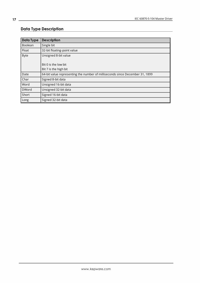
Data Type Description
Data Type DescriptionBoolean Single bit
Float 32-bit floating-point value
Byte Unsigned 8-bit value
Bit 0 is the low bitBit 7 is the high bit
Date 64-bit value representing the number of milliseconds since December 31, 1899
Char Signed 8-bit data
Word Unsigned 16-bit data
DWord Unsigned 32-bit data
Short Signed 16-bit data
Long Signed 32-bit data
www.kepware.com
17
IEC 60870-5-104 Master Driver
Address DescriptionsThere are two forms of tag addressing. The first is information object address (IOA) based tag addressing,which allows access to each individual data point on a device. IOA-based tag addressing includes monitorASDUs and control ASDUs. The second form is device-level command-based tag addressing, which allowscontrol of device-specific commands.
IOA-Based Tag AddressingMonitor ASDUsControl ASDUs
Command-Based Tag Addressing
IOA-Based Tag Addressing
Tag addressing takes the form TYPEID.IOA.SUB-TYPE.OPTIONAL.OPTIONAL, where:
l TYPEID is the ASDU type.
l IOA is the Information Object Address (IOA).
l SUB-TYPE is the point's driver-specific attribute.
l OPTIONAL is an attribute that is not required.
Note: The Information Object Address (IOA) represents a slave device's point address. It is an integerbetween 1 and 254, 65535, or 16777215; depending on whether the Information Object Address Sizeproperty is set to one, two, or three octets (respectively).
TYPEIDThe TYPEID represents the ASDU type as defined by the protocol. Types include monitor or control. Eachmonitor TYPEID supports multiple protocol-defined ASDU numbers. Monitor types represent data that isread only. Control types represent data that can be written.
Monitor ASDUsControl ASDUs
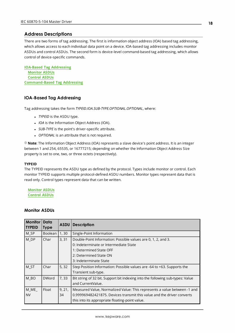
Monitor ASDUs
MonitorTYPEID
DataType ASDU Description
M_SP Boolean 1, 30 Single-Point Information
M_DP Char 3, 31 Double-Point Information: Possible values are 0, 1, 2, and 3.0: Indeterminate or Intermediate State1: Determined State OFF2: Determined State ON3: Indeterminate State
M_ST Char 5, 32 Step Position Information: Possible values are -64 to +63. Supports theTransient sub-type.
M_BO DWord 7, 33 Bit string of 32 bit. Support bit indexing into the following sub-types: Valueand CurrentValue.
M_ME_NV
Float 9, 21,34
Measured Value, Normalized Value: This represents a value between -1 and0.999969482421875. Devices transmit this value and the driver convertsthis into its appropriate floating-point value.
www.kepware.com
18
IEC 60870-5-104 Master Driver
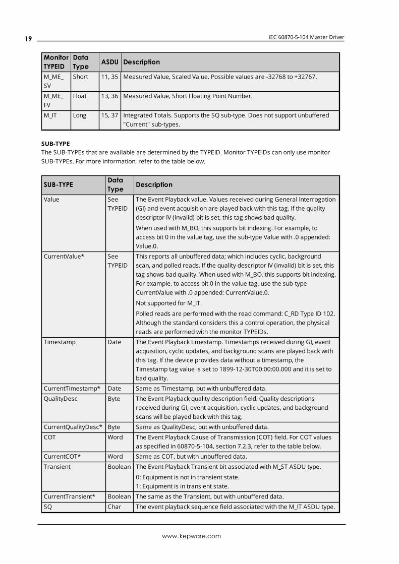
MonitorTYPEID
DataType ASDU Description
M_ME_SV
Short 11, 35 Measured Value, Scaled Value. Possible values are -32768 to +32767.
M_ME_FV
Float 13, 36 Measured Value, Short Floating Point Number.
M_IT Long 15, 37 Integrated Totals. Supports the SQ sub-type. Does not support unbuffered"Current" sub-types.
SUB-TYPEThe SUB-TYPEs that are available are determined by the TYPEID. Monitor TYPEIDs can only use monitorSUB-TYPEs. For more information, refer to the table below.
SUB-TYPE DataType Description
Value SeeTYPEID
The Event Playback value. Values received during General Interrogation(GI) and event acquisition are played back with this tag. If the qualitydescriptor IV (invalid) bit is set, this tag shows bad quality.
When used with M_BO, this supports bit indexing. For example, toaccess bit 0 in the value tag, use the sub-type Value with .0 appended:Value.0.
CurrentValue* SeeTYPEID
This reports all unbuffered data; which includes cyclic, backgroundscan, and polled reads. If the quality descriptor IV (invalid) bit is set, thistag shows bad quality. When used with M_BO, this supports bit indexing.For example, to access bit 0 in the value tag, use the sub-typeCurrentValue with .0 appended: CurrentValue.0.
Not supported for M_IT.
Polled reads are performed with the read command: C_RD Type ID 102.Although the standard considers this a control operation, the physicalreads are performed with the monitor TYPEIDs.
Timestamp Date The Event Playback timestamp. Timestamps received during GI, eventacquisition, cyclic updates, and background scans are played back withthis tag. If the device provides data without a timestamp, theTimestamp tag value is set to 1899-12-30T00:00:00.000 and it is set tobad quality.
CurrentTimestamp* Date Same as Timestamp, but with unbuffered data.
QualityDesc Byte The Event Playback quality description field. Quality descriptionsreceived during GI, event acquisition, cyclic updates, and backgroundscans will be played back with this tag.
CurrentQualityDesc* Byte Same as QualityDesc, but with unbuffered data.
COT Word The Event Playback Cause of Transmission (COT) field. For COT valuesas specified in 60870-5-104, section 7.2.3, refer to the table below.
CurrentCOT* Word Same as COT, but with unbuffered data.
Transient Boolean The Event Playback Transient bit associated with M_ST ASDU type.
0: Equipment is not in transient state.1: Equipment is in transient state.
CurrentTransient* Boolean The same as the Transient, but with unbuffered data.
SQ Char The event playback sequence field associated with the M_IT ASDU type.
www.kepware.com
19
IEC 60870-5-104 Master Driver
SUB-TYPE DataType Description
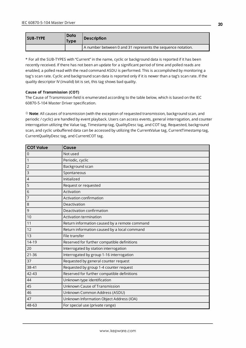
A number between 0 and 31 represents the sequence notation.
* For all the SUB-TYPES with “Current” in the name, cyclic or background data is reported if it has beenrecently received. If there has not been an update for a significant period of time and polled reads areenabled, a polled read with the read command ASDU is performed. This is accomplished by monitoring atag's scan rate. Cyclic and background scan data is reported only if it is newer than a tag’s scan rate. If thequality descriptor IV (invalid) bit is set, this tag shows bad quality.
Cause of Transmission (COT)The Cause of Transmission field is enumerated according to the table below, which is based on the IEC60870-5-104 Master Driver specification.
Note: All causes of transmission (with the exception of requested transmission, background scan, andperiodic / cyclic) are handled by event playback. Users can access events, general interrogation, and counterinterrogation utilizing the Value tag, Timestamp tag, QualityDesc tag, and COT tag. Requested, backgroundscan, and cyclic unbuffered data can be accessed by utilizing the CurrentValue tag, CurrentTimestamp tag,CurrentQualityDesc tag, and CurrentCOT tag.
COT Value Cause0 Not used
1 Periodic, cyclic
2 Background scan
3 Spontaneous
4 Initialized
5 Request or requested
6 Activation
7 Activation confirmation
8 Deactivation
9 Deactivation confirmation
10 Activation termination
11 Return information caused by a remote command
12 Return information caused by a local command
13 File transfer
14-19 Reserved for further compatible definitions
20 Interrogated by station interrogation
21-36 Interrogated by group 1-16 interrogation
37 Requested by general counter request
38-41 Requested by group 1-4 counter request
42-43 Reserved for further compatible definitions
44 Unknown type identification
45 Unknown Cause of Transmission
46 Unknown Common Address (ASDU)
47 Unknown Information Object Address (IOA)
48-63 For special use (private range)
www.kepware.com
20
IEC 60870-5-104 Master Driver
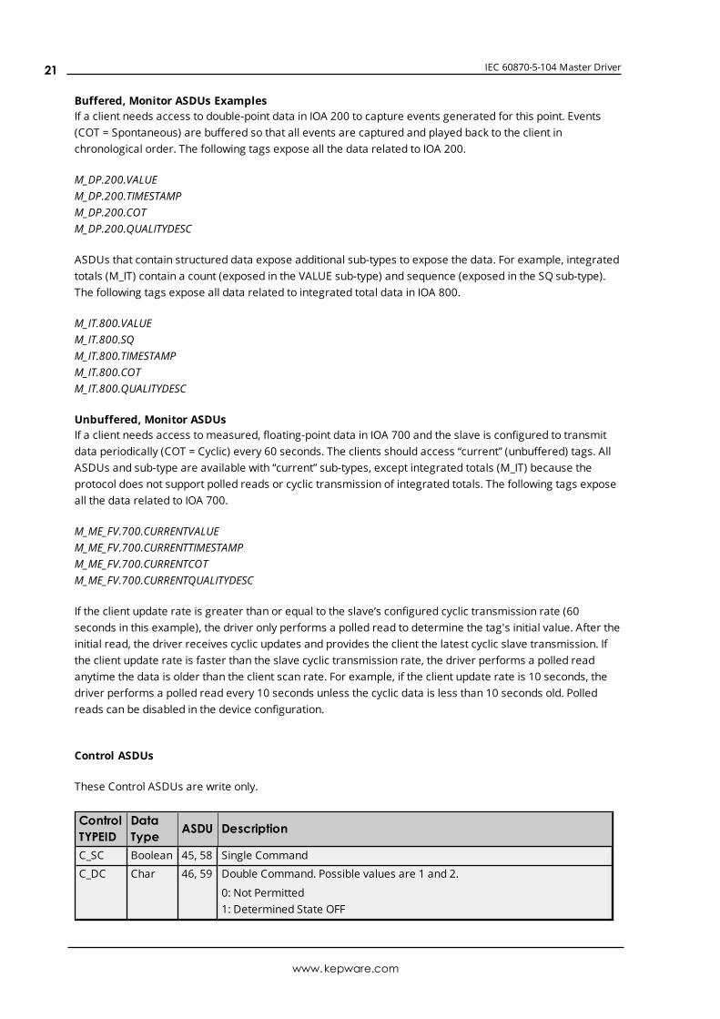
Buffered, Monitor ASDUs ExamplesIf a client needs access to double-point data in IOA 200 to capture events generated for this point. Events(COT = Spontaneous) are buffered so that all events are captured and played back to the client inchronological order. The following tags expose all the data related to IOA 200.
M_DP.200.VALUEM_DP.200.TIMESTAMPM_DP.200.COTM_DP.200.QUALITYDESC
ASDUs that contain structured data expose additional sub-types to expose the data. For example, integratedtotals (M_IT) contain a count (exposed in the VALUE sub-type) and sequence (exposed in the SQ sub-type).The following tags expose all data related to integrated total data in IOA 800.
M_IT.800.VALUEM_IT.800.SQM_IT.800.TIMESTAMPM_IT.800.COTM_IT.800.QUALITYDESC
Unbuffered, Monitor ASDUsIf a client needs access to measured, floating-point data in IOA 700 and the slave is configured to transmitdata periodically (COT = Cyclic) every 60 seconds. The clients should access “current” (unbuffered) tags. AllASDUs and sub-type are available with “current” sub-types, except integrated totals (M_IT) because theprotocol does not support polled reads or cyclic transmission of integrated totals. The following tags exposeall the data related to IOA 700.
M_ME_FV.700.CURRENTVALUEM_ME_FV.700.CURRENTTIMESTAMPM_ME_FV.700.CURRENTCOTM_ME_FV.700.CURRENTQUALITYDESC
If the client update rate is greater than or equal to the slave’s configured cyclic transmission rate (60seconds in this example), the driver only performs a polled read to determine the tag's initial value. After theinitial read, the driver receives cyclic updates and provides the client the latest cyclic slave transmission. Ifthe client update rate is faster than the slave cyclic transmission rate, the driver performs a polled readanytime the data is older than the client scan rate. For example, if the client update rate is 10 seconds, thedriver performs a polled read every 10 seconds unless the cyclic data is less than 10 seconds old. Polledreads can be disabled in the device configuration.
Control ASDUs
These Control ASDUs are write only.
ControlTYPEID
DataType ASDU Description
C_SC Boolean 45, 58 Single Command
C_DC Char 46, 59 Double Command. Possible values are 1 and 2.
0: Not Permitted1: Determined State OFF
www.kepware.com
21
IEC 60870-5-104 Master Driver
ControlTYPEID
DataType ASDU Description
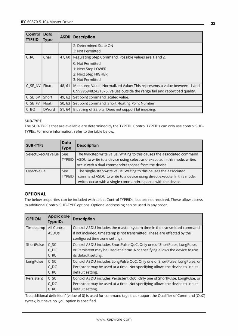
2: Determined State ON3: Not Permitted
C_RC Char 47, 60 Regulating Step Command. Possible values are 1 and 2.
0: Not Permitted1: Next Step LOWER2: Next Step HIGHER3: Not Permitted
C_SE_NV Float 48, 61 Measured Value, Normalized Value: This represents a value between -1 and0.999969482421875. Values outside the range fail and report bad quality.
C_SE_SV Short 49, 62 Set point command, scaled value.
C_SE_FV Float 50, 63 Set point command, Short Floating Point Number.
C_BO DWord 51, 64 Bit string of 32 bits. Does not support bit indexing.
SUB-TYPEThe SUB-TYPEs that are available are determined by the TYPEID. Control TYPEIDs can only use control SUB-TYPEs. For more information, refer to the table below.
SUB-TYPE DataType Description
SelectExecuteValue SeeTYPEID
The two-step write value. Writing to this causes the associated commandASDU to write to a device using select-and-execute. In this mode, writesoccur with a dual command/response from the device.
DirectValue SeeTYPEID
The single-step write value. Writing to this causes the associatedcommand ASDU to write to a device using direct execute. In this mode,writes occur with a single command/response with the device.
OPTIONALThe below properties can be included with select Control TYPEIDs, but are not required. These allow accessto additional Control SUB-TYPE options. Optional addressing can be used in any order.
OPTION ApplicableTypeIDs Description
Timestamp All ControlASDUs
Control ASDU includes the master system time in the transmitted command.If not included, timestamp is not transmitted. These are effected by theconfigured time zone settings.
ShortPulse C_SCC_DCC_RC
Control ASDU includes ShortPulse QoC. Only one of ShortPulse, LongPulse,or Persistent may be used at a time. Not specifying allows the device to useits default setting.
LongPulse C_SCC_DCC_RC
Control ASDU includes LongPulse QoC. Only one of ShortPulse, LongPulse, orPersistent may be used at a time. Not specifying allows the device to use itsdefault setting.
Persistent C_SCC_DCC_RC
Control ASDU includes Persistent QoC. Only one of ShortPulse, LongPulse, orPersistent may be used at a time. Not specifying allows the device to use itsdefault setting.
“No additional definition” (value of 0) is used for command tags that support the Qualifier of Command (QoC)syntax, but have no QoC option is specified.
www.kepware.com
22
IEC 60870-5-104 Master Driver
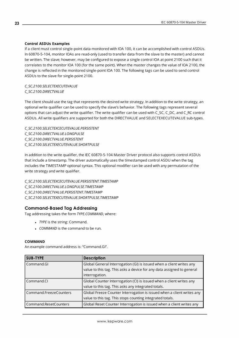
Control ASDUs ExamplesIf a client must control single-point data monitored with IOA 100, it can be accomplished with control ASDUs.In 60870-5-104, monitor IOAs are read-only (used to transfer data from the slave to the master) and cannotbe written. The slave; however, may be configured to expose a single control IOA at point 2100 such that itcorrelates to the monitor IOA 100 (for the same point). When the master changes the value of IOA 2100, thechange is reflected in the monitored single-point IOA 100. The following tags can be used to send controlASDUs to the slave for single-point 2100.
C_SC.2100.SELECTEXECUTEVALUEC_SC.2100.DIRECTVALUE
The client should use the tag that represents the desired write strategy. In addition to the write strategy, anoptional write qualifier can be used to specify the slave’s behavior. The following tags represent severaloptions that can adjust the write qualifier. The write qualifier can be used with C_SC, C_DC, and C_RC controlASDUs. All write qualifiers are supported for both the DIRECTVALUE and SELECTEXECUTEVALUE sub-types.
C_SC.2100.SELECTEXCECUTEVALUE.PERSISTENTC_SC.2100.DIRECTVALUE.LONGPULSEC_SC.2100.DIRECTVALUE.PERSISTENTC_SC.2100.SELECTEXECUTEVALUE.SHORTPULSE
In addition to the write qualifier, the IEC 60870-5-104 Master Driver protocol also supports control ASDUsthat include a timestamp. The driver automatically uses the timestamped control ASDU when the tagincludes the TIMESTAMP optional syntax. This optional modifier can be used with any permutation of thewrite strategy and write qualifier.
C_SC.2100.SELECTEXCECUTEVALUE.PERSISTENT.TIMESTAMPC_SC.2100.DIRECTVALUE.LONGPULSE.TIMESTAMPC_SC.2100.DIRECTVALUE.PERSISTENT.TIMESTAMPC_SC.2100.SELECTEXECUTEVALUE.SHORTPULSE.TIMESTAMP
Command-Based Tag AddressingTag addressing takes the form TYPE.COMMAND, where:
l TYPE is the string: Command.
l COMMAND is the command to be run.
COMMANDAn example command address is: “Command.GI”.
SUB-TYPE DescriptionCommand.GI Global General Interrogation (GI) is issued when a client writes any
value to this tag. This asks a device for any data assigned to generalinterrogation.
Command.CI Global Counter Interrogation (CI) is issued when a client writes anyvalue to this tag. This asks any integrated totals.
Command.FreezeCounters Global Freeze Counter Interrogation is issued when a client writes anyvalue to this tag. This stops counting integrated totals.
Command.ResetCounters Global Reset Counter Interrogation is issued when a client writes any
www.kepware.com
23

IEC 60870-5-104 Master Driver
SUB-TYPE Descriptionvalue to this tag. This returns all integrated totals to 0.
Command.FreezeResetCounters Global Freeze and Reset Counter Interrogation is issued when a clientwrites any value to this tag. This stops all integrated totals and returnsall integrated totals to 0.
Command.TimeSync Time Sync is issued when a client writes any value to this tag. Thissynchronizes the master clock with the slave clock.
Command.TestProcedure Test Procedure is issued when a client writes any value to this tag. Thischecks a device to see if it is connected.
www.kepware.com
24
IEC 60870-5-104 Master Driver
Error DescriptionsThe following messages may be generated. Click on the link for a description of the message.
Error MessagesDevice <device name> failed to complete clock synchronization.Device <device name> failed to complete counter interrogation.Device <device name> failed to complete general interrogation.Device <device name> is not responding.Error loading XML file for <device name>. Common address is invalid.Error loading XML file for <device name>. Common address already used by <devicename>.Read failed on tag <tag name>.Read failed on tag <tag name> due to data type mismatch.Too many events received in <device name>; the buffer has overflowed.Unable to write to address <address> on device <device>.Write failed on tag <tag name>.
Device <device name> failed to complete clock synchronization.Error Type:Warning
Possible Cause:
1. Communications were lost.
2. Communications timed out.
Solution:
1. Service the device connection.
2. Increase the value of the device's clock synchronization request timeout setting.
Device <device name> failed to complete counter interrogation.Error Type:Warning
Possible Cause:
1. Communications were lost.
2. Communications timed out. This can occur when the time to send all counter interrogation dataexceeds the Interrogation Request Timeout.
Solution:
1. Service the device connection.
2. Increase the value of the device interrogation request timeout setting.
www.kepware.com
25
IEC 60870-5-104 Master Driver
Device <device name> failed to complete general interrogation.Error Type:Warning
Possible Cause:
1. Communications were lost.
2. Communications timed out. This can occur when the time to send all general interrogation dataexceeds the request timeout.
Solution:
1. Service the device connection.
2. Increase the value of that device's interrogation request timeout setting.
Device <device name> is not responding.Error Type:Serious
Possible Cause:
1. The connection between the device and the host PC is broken.
2. The communications properties for the connection are incorrect.
3. The named device may have been assigned an incorrect network ID.
4. A device on the channel is unresponsive, due to improper timing settings or a brokencommunications link.
5. There are multiple channels using DNS host names that resolve to the same IP address.
6. The response from the device took longer to receive than the amount of time specified in theRequest Timeout device setting.
Solution:
1. Verify the cabling between the IEC 60870 master and the IEC 60870 slave device.
2. Verify that the specified communications properties match those of the device.
3. Verify that the network ID given to the named device matches that of the actual device.
4. Locate the unresponsive device and correct the timing settings or fix the broken communicationslink.
5. Ensure that all channels are using a unique Destination Host.
6. Increase the Request Timeout setting so that the entire response can be handled.
Error loading XML file for device <device name>. Common address is invalid.Valid range is <low limit> to <high limit>.Error Type:Error
www.kepware.com
26
IEC 60870-5-104 Master Driver
Possible Cause:The XML project being loaded specifies a common address that is not valid with the Common Address Sizesetting.
Solution:
l Increase the Common Address Size. Possible values are 1 Octet or 2 Octets.
l Update the Common Address so that it is within the allowed range.
Error loading XML file for device <device name>. Common Address <commonaddress> is already used by device <device name>.Error Type:Error
Possible Cause:More than one device in the channel has the same common address pair.
Solution:Verify every device in the channel has a unique address.
Read failed on tag <tag name>.Error Type:Warning
Possible Cause:A device is connected, but the tag is not appropriate for the device. For example, the ASDU type or IOA maynot be appropriate for the data on the device.
Solution:Correct the tag address to match the device's configuration.
See Also:Address Descriptions
Read failed on tag <tag name> due to data type mismatch.Error Type:Warning
Possible Cause:Tag ASDU type is incorrect. This error occurs when data is received from the device at this IOA, but itrepresents a different ASDU type.
Solution:Verify or correct the ASDU type. Correct the tag address to match the device configuration.
See Also:Address Descriptions
www.kepware.com
27
IEC 60870-5-104 Master Driver
Too many events received in <device name>; the buffer has overflowed.Error Type:Warning
Possible Cause:The slave is producing events faster than the client can consume them.
Solution:Increase the event playback buffer size. The per-item event buffer size should be large enough to handle thedata at the highest per-item event transmission speed. For example, if a slave may transmit 100 events in 5seconds and the event playback rate is set to 5 seconds, the event buffer will overflow if more than 100events are received in a 5-second period.
Unable to write to address <address> on device <device>.Error Type:Warning
Possible Cause:
1. Incorrect common address; the device is not responding.
2. The point does not exist in the slave.
3. The address has an incorrect data type.
Solution:
1. Correct the common address to match the slave.
2. Correct the Information Object Address(IOA).
3. Correct the data type for the address.
See Also:Address Descriptions
Write failed on tag <tag name>.Error Type:Warning
Possible Cause:Attempted to write to a tag outside the supported range.
Solution:Note the minimum andmaximum values and limit writes within the supported range.
See Also:Address Descriptions
www.kepware.com
28
IEC 60870-5-104 Master Driver
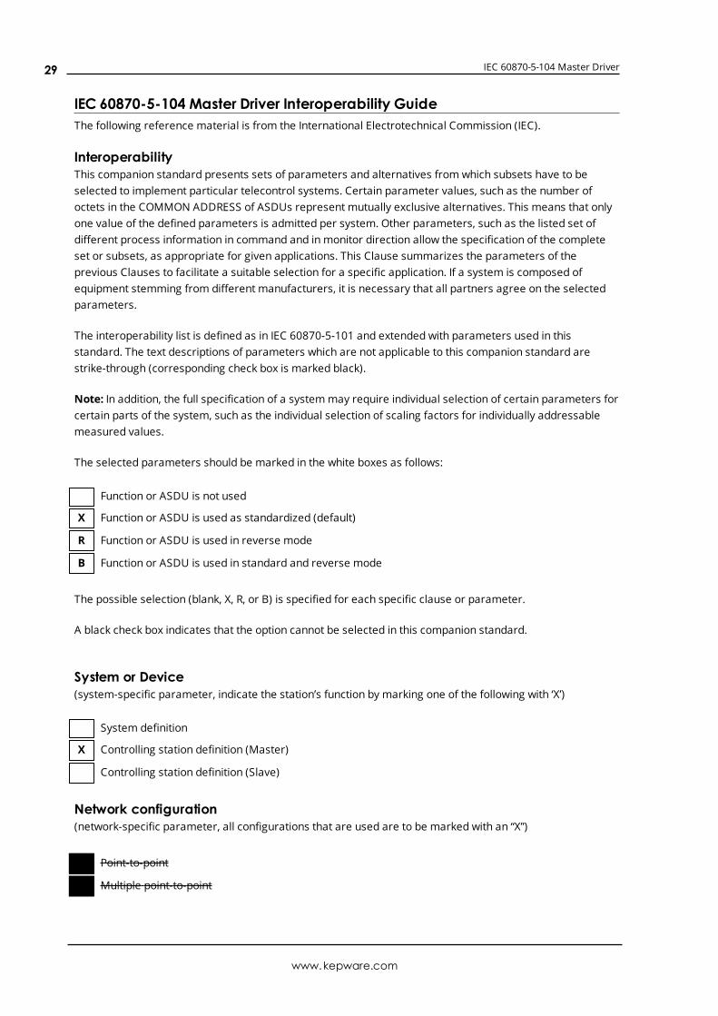
IEC 60870-5-104 Master Driver Interoperability GuideThe following reference material is from the International Electrotechnical Commission (IEC).
InteroperabilityThis companion standard presents sets of parameters and alternatives from which subsets have to beselected to implement particular telecontrol systems. Certain parameter values, such as the number ofoctets in the COMMON ADDRESS of ASDUs represent mutually exclusive alternatives. This means that onlyone value of the defined parameters is admitted per system. Other parameters, such as the listed set ofdifferent process information in command and in monitor direction allow the specification of the completeset or subsets, as appropriate for given applications. This Clause summarizes the parameters of theprevious Clauses to facilitate a suitable selection for a specific application. If a system is composed ofequipment stemming from different manufacturers, it is necessary that all partners agree on the selectedparameters.
The interoperability list is defined as in IEC 60870-5-101 and extended with parameters used in thisstandard. The text descriptions of parameters which are not applicable to this companion standard arestrike-through (corresponding check box is marked black).
Note: In addition, the full specification of a systemmay require individual selection of certain parameters forcertain parts of the system, such as the individual selection of scaling factors for individually addressablemeasured values.
The selected parameters should be marked in the white boxes as follows:
Function or ASDU is not used
X Function or ASDU is used as standardized (default)
R Function or ASDU is used in reverse mode
B Function or ASDU is used in standard and reverse mode
The possible selection (blank, X, R, or B) is specified for each specific clause or parameter.
A black check box indicates that the option cannot be selected in this companion standard.
System or Device(system-specific parameter, indicate the station’s function by marking one of the following with ‘X’)
System definition
X Controlling station definition (Master)
Controlling station definition (Slave)
Network configuration(network-specific parameter, all configurations that are used are to be marked with an “X”)
Point-to-point
Multiple point-to-point
www.kepware.com
29
IEC 60870-5-104 Master Driver
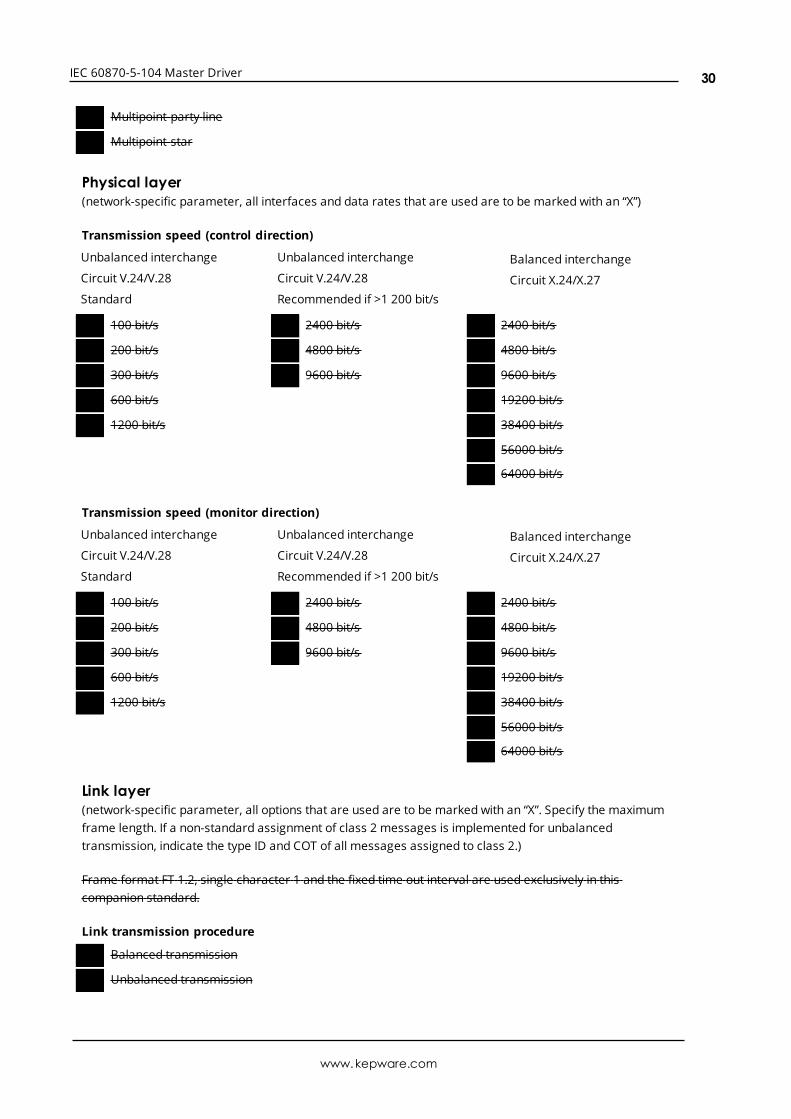
Multipoint-party line
Multipoint-star
Physical layer(network-specific parameter, all interfaces and data rates that are used are to be marked with an “X”)
Transmission speed (control direction)
Unbalanced interchange
Circuit V.24/V.28
Standard
Unbalanced interchange
Circuit V.24/V.28
Recommended if >1 200 bit/s
Balanced interchange
Circuit X.24/X.27
100 bit/s X 2400 bit/s X 2400 bit/s
200 bit/s X 4800 bit/s X 4800 bit/s
X 300 bit/s X 9600 bit/s X 9600 bit/s
X 600 bit/s X 19200 bit/s
X 1200 bit/s X 38400 bit/s
X 56000 bit/s
64000 bit/s
Transmission speed (monitor direction)
Unbalanced interchange
Circuit V.24/V.28
Standard
Unbalanced interchange
Circuit V.24/V.28
Recommended if >1 200 bit/s
Balanced interchange
Circuit X.24/X.27
100 bit/s X 2400 bit/s X 2400 bit/s
200 bit/s X 4800 bit/s X 4800 bit/s
X 300 bit/s X 9600 bit/s X 9600 bit/s
X 600 bit/s X 19200 bit/s
X 1200 bit/s X 38400 bit/s
X 56000 bit/s
64000 bit/s
Link layer(network-specific parameter, all options that are used are to be marked with an “X”. Specify the maximumframe length. If a non-standard assignment of class 2 messages is implemented for unbalancedtransmission, indicate the type ID and COT of all messages assigned to class 2.)
Frame format FT 1.2, single character 1 and the fixed time out interval are used exclusively in thiscompanion standard.
Link transmission procedure
X Balanced transmission
X Unbalanced transmission
www.kepware.com
30
IEC 60870-5-104 Master Driver
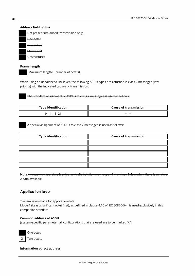
Address field of link
X Not present (balanced transmission only)
X One octet
X Two octets
Structured
Unstructured
Frame length
Maximum length L (number of octets)
When using an unbalanced link layer, the following ASDU types are returned in class 2 messages (lowpriority) with the indicated causes of transmission:
The standard assignment of ASDUs to class 2 messages is used as follows:
Type identification Cause of transmission
9, 11, 13, 21 <1>
A special assignment of ASDUs to class 2 messages is used as follows:
Type identification Cause of transmission
Note: In response to a class 2 poll, a controlled stationmay respond with class 1 data when there is no class2 data available.
Application layer
Transmissionmode for application dataMode 1 (Least significant octet first), as defined in clause 4.10 of IEC 60870-5-4, is used exclusively in thiscompanion standard.
Common address of ASDU(system-specific parameter, all configurations that are used are to be marked “X”)
One octet
X Two octets
Information object address
www.kepware.com
31
IEC 60870-5-104 Master Driver
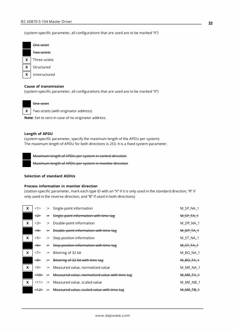
(system-specific parameter, all configurations that are used are to be marked “X”)
X One octet
X Two octets
X Three octets
X Structured
X Unstructured
Cause of transmission(system-specific parameter, all configurations that are used are to be marked “X”)
One octet
X Two octets (with originator address)
Note: Set to zero in case of no originator address.
Length of APDU(system-specific parameter, specify the maximum length of the APDU per system)The maximum length of APDU for both directions is 253. It is a fixed system parameter.
Maximum length of APDU per system in control direction
Maximum length of APDU per system inmonitor direction
Selection of standard ASDUs
Process information in monitor direction(station-specific parameter, mark each type ID with an “X” if it is only used in the standard direction, “R” ifonly used in the reverse direction, and “B” if used in both directions)
X <1> := Single-point information M_SP_NA_1
X <2> := Single-point information with time tag M_SP_TA_1
X <3> := Double-point information M_DP_NA_1
X <4> := Double-point information with time tag M_DP_TA_1
X <5> := Step position information M_ST_NA_1
X <6> := Step position information with time tag M_ST_TA_1
X <7> := Bitstring of 32 bit M_BO_NA_1
X <8> := Bitstring of 32 bit with time tag M_BO_TA_1
X <9> := Measured value, normalized value M_ME_NA_1
X <10> := Measured value, normalized value with time tag M_ME_TA_1
X <11> := Measured value, scaled value M_ME_NB_1
X <12> := Measured value, scaled value with time tag M_ME_TB_1
www.kepware.com
32
IEC 60870-5-104 Master Driver
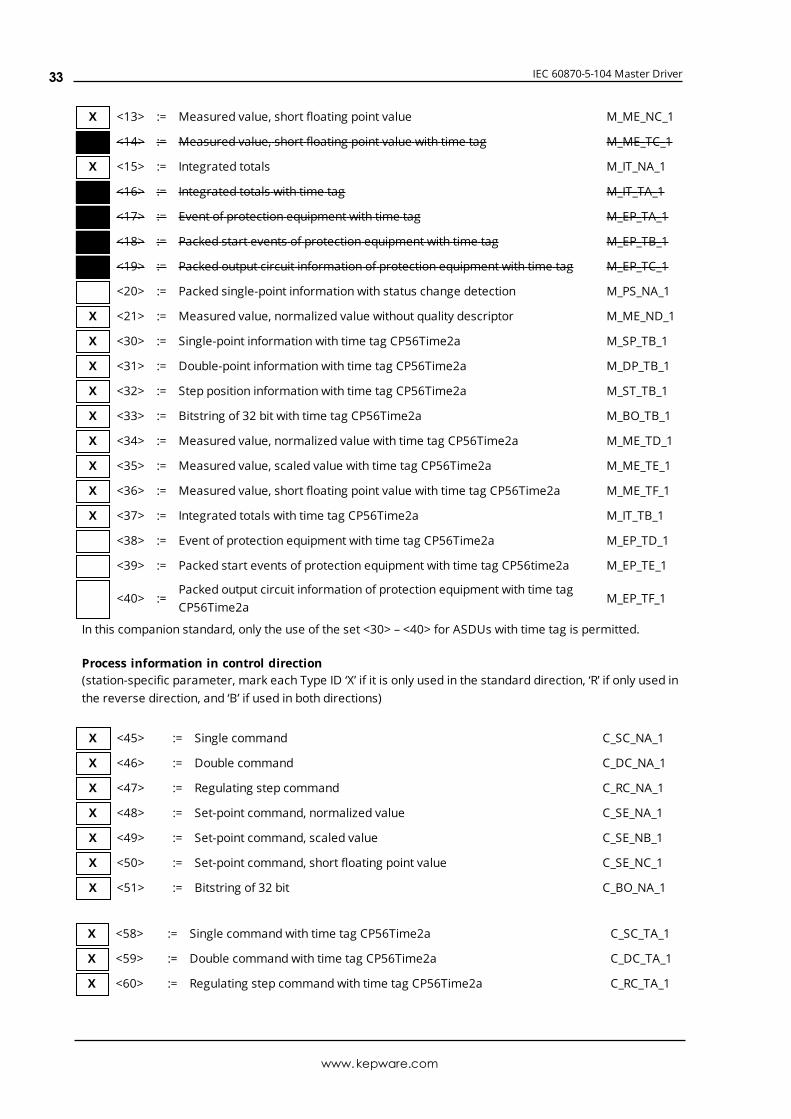
X <13> := Measured value, short floating point value M_ME_NC_1
X <14> := Measured value, short floating point value with time tag M_ME_TC_1
X <15> := Integrated totals M_IT_NA_1
X <16> := Integrated totals with time tag M_IT_TA_1
<17> := Event of protection equipment with time tag M_EP_TA_1
<18> := Packed start events of protection equipment with time tag M_EP_TB_1
<19> := Packed output circuit information of protection equipment with time tag M_EP_TC_1
<20> := Packed single-point information with status change detection M_PS_NA_1
X <21> := Measured value, normalized value without quality descriptor M_ME_ND_1
X <30> := Single-point information with time tag CP56Time2a M_SP_TB_1
X <31> := Double-point information with time tag CP56Time2a M_DP_TB_1
X <32> := Step position information with time tag CP56Time2a M_ST_TB_1
X <33> := Bitstring of 32 bit with time tag CP56Time2a M_BO_TB_1
X <34> := Measured value, normalized value with time tag CP56Time2a M_ME_TD_1
X <35> := Measured value, scaled value with time tag CP56Time2a M_ME_TE_1
X <36> := Measured value, short floating point value with time tag CP56Time2a M_ME_TF_1
X <37> := Integrated totals with time tag CP56Time2a M_IT_TB_1
<38> := Event of protection equipment with time tag CP56Time2a M_EP_TD_1
<39> := Packed start events of protection equipment with time tag CP56time2a M_EP_TE_1
<40> :=Packed output circuit information of protection equipment with time tagCP56Time2a
M_EP_TF_1
In this companion standard, only the use of the set <30> – <40> for ASDUs with time tag is permitted.
Process information in control direction(station-specific parameter, mark each Type ID ‘X’ if it is only used in the standard direction, ‘R’ if only used inthe reverse direction, and ‘B’ if used in both directions)
X <45> := Single command C_SC_NA_1
X <46> := Double command C_DC_NA_1
X <47> := Regulating step command C_RC_NA_1
X <48> := Set-point command, normalized value C_SE_NA_1
X <49> := Set-point command, scaled value C_SE_NB_1
X <50> := Set-point command, short floating point value C_SE_NC_1
X <51> := Bitstring of 32 bit C_BO_NA_1
X <58> := Single command with time tag CP56Time2a C_SC_TA_1
X <59> := Double command with time tag CP56Time2a C_DC_TA_1
X <60> := Regulating step command with time tag CP56Time2a C_RC_TA_1
www.kepware.com
33
IEC 60870-5-104 Master Driver
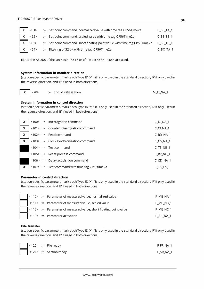
X <61> := Set-point command, normalized value with time tag CP56Time2a C_SE_TA_1
X <62> := Set-point command, scaled value with time tag CP56Time2a C_SE_TB_1
X <63> := Set-point command, short floating point value with time tag CP56Time2a C_SE_TC_1
X <64> := Bitstring of 32 bit with time tag CP56Time2a C_BO_TA_1
Either the ASDUs of the set <45> – <51> or of the set <58> – <64> are used.
System information in monitor direction(station-specific parameter, mark each Type ID ‘X’ if it is only used in the standard direction, ‘R’ if only used inthe reverse direction, and ‘B’ if used in both directions)
X <70> := End of initialization M_EI_NA_1
System information in control direction(station-specific parameter, mark each Type ID ‘X’ if it is only used in the standard direction, ‘R’ if only used inthe reverse direction, and ‘B’ if used in both directions)
X <100> := Interrogation command C_IC_NA_1
X <101> := Counter interrogation command C_CI_NA_1
X <102> := Read command C_RD_NA_1
X <103> := Clock synchronization command C_CS_NA_1
X <104> := Test command C_TS_NB_1
<105> := Reset process command C_RP_NC_1
X <106> := Delay acquisition command C_CD_NA_1
X <107> := Test command with time tag CP56time2a C_TS_TA_1
Parameter in control direction(station-specific parameter, mark each Type ID ‘X’ if it is only used in the standard direction, ‘R’ if only used inthe reverse direction, and ‘B’ if used in both directions)
<110> := Parameter of measured value, normalized value P_ME_NA_1
<111> := Parameter of measured value, scaled value P_ME_NB_1
<112> := Parameter of measured value, short floating point value P_ME_NC_1
<113> := Parameter activation P_AC_NA_1
File transfer(station-specific parameter, mark each Type ID ‘X’ if it is only used in the standard direction, ‘R’ if only used inthe reverse direction, and ‘B’ if used in both directions)
<120> := File ready F_FR_NA_1
<121> := Section ready F_SR_NA_1
www.kepware.com
34
IEC 60870-5-104 Master Driver
<122> := Call directory, select file, call file, call section F_SC_NA_1
<123> := Last section, last segment F_LS_NA_1
<124> := Ack file, ack section F_AF_NA_1
<125> := Segment F_SG_NA_1
<126> := Directory {blank or X, only available in monitor (standard) direction} F_DR_TA_1
<127> := Query Log – Request archive file F_SC_NB_1
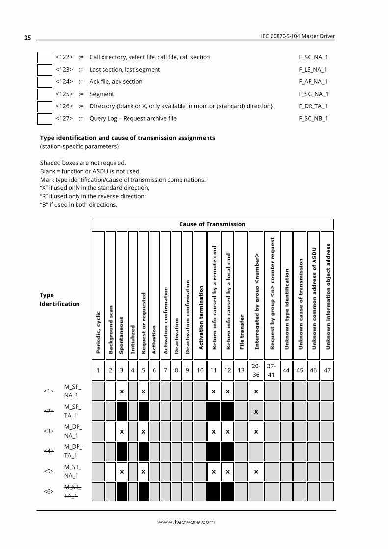
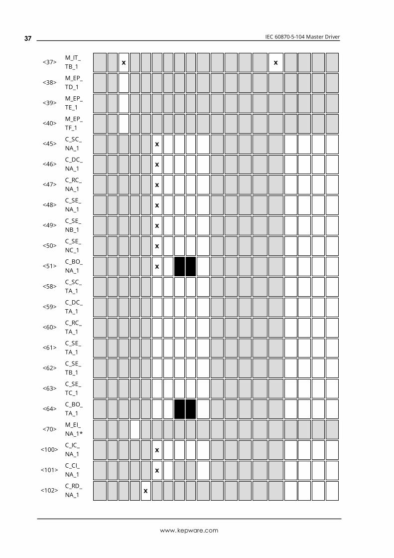
Type identification and cause of transmission assignments(station-specific parameters)
Shaded boxes are not required.Blank = function or ASDU is not used.Mark type identification/cause of transmission combinations:“X” if used only in the standard direction;“R” if used only in the reverse direction;“B” if used in both directions.
TypeIdentification
Cause of Transmission
1 2 3 4 5 6 7 8 9 10 11 12 1320-36
37-41
44 45 46 47
<1>M_SP_NA_1
X X X X X
<2>M_SP_TA_1
X X X X X
<3>M_DP_NA_1
X X X X X
<4>M_DP_TA_1
X X X X
<5>M_ST_NA_1
X X X X X
<6>M_ST_TA_1
X X X X
www.kepware.com
35
IEC 60870-5-104 Master Driver
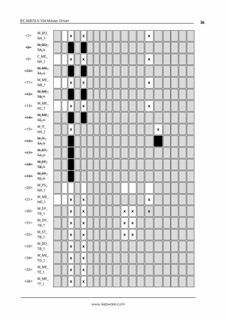
<7>M_BO_NA_1
X X X
<8>M_BO_TA_1
X X
<9>C_ME_NA_1
X X X
<10>M_ME_TA_1
X X
<11>M_ME_NB_1
X X X
<12>M_ME_TB_1
X X
<13>M_ME_NC_1
X X X
<14>M_ME_TC_1
X X
<15>M_IT_NA_1
X X
<16>M_IT_TA_1
X
<17>M_EP_TA_1
<18>M_EP_TB_1
<19>M_EP_TC_1
<20>M_PS_NA_1
<21>M_ME_ND_1
X X X
<30>M_SP_TB_1
X X X X X
<31>M_DP_TB_1
X X X X
<32>M_ST_TB_1
X X X X
<33>M_BO_TB_1
X X
<34>M_ME_TD_1
X X
<35>M_ME_TE_1
X X
<36>M_ME_TF_1
X X
www.kepware.com
36
IEC 60870-5-104 Master Driver
<37>M_IT_TB_1
X X
<38>M_EP_TD_1
<39>M_EP_TE_1
<40>M_EP_TF_1
<45>C_SC_NA_1
X
<46>C_DC_NA_1
X
<47>C_RC_NA_1
X
<48>C_SE_NA_1
X
<49>C_SE_NB_1
X
<50>C_SE_NC_1
X
<51>C_BO_NA_1
X
<58>C_SC_TA_1
<59>C_DC_TA_1
<60>C_RC_TA_1
<61>C_SE_TA_1
<62>C_SE_TB_1
<63>C_SE_TC_1
<64>C_BO_TA_1
<70>M_EI_NA_1*
<100>C_IC_NA_1
X
<101>C_CI_NA_1
X
<102>C_RD_NA_1
X
www.kepware.com
37
IEC 60870-5-104 Master Driver
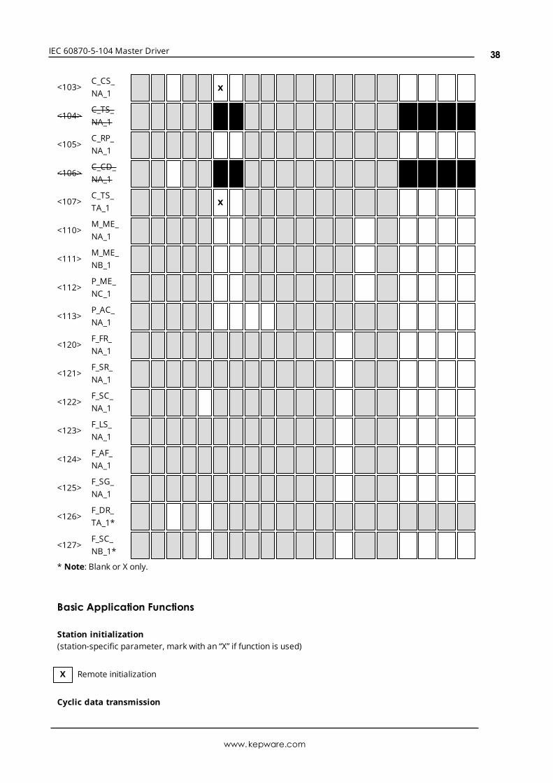
<103>C_CS_NA_1
X
<104>C_TS_NA_1
X
<105>C_RP_NA_1
<106>C_CD_NA_1
<107>C_TS_TA_1
X
<110>M_ME_NA_1
<111>M_ME_NB_1
<112>P_ME_NC_1
<113>P_AC_NA_1
<120>F_FR_NA_1
<121>F_SR_NA_1
<122>F_SC_NA_1
<123>F_LS_NA_1
<124>F_AF_NA_1
<125>F_SG_NA_1
<126>F_DR_TA_1*
<127>F_SC_NB_1*
* Note: Blank or X only.
Basic Application Functions
Station initialization(station-specific parameter, mark with an “X” if function is used)
X Remote initialization
Cyclic data transmission
www.kepware.com
38
IEC 60870-5-104 Master Driver
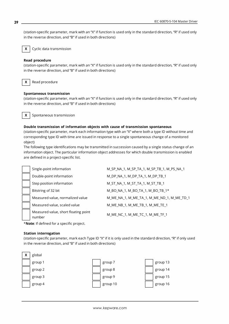
(station-specific parameter, mark with an “X” if function is used only in the standard direction, “R” if used onlyin the reverse direction, and “B” if used in both directions)
X Cyclic data transmission
Read procedure(station-specific parameter, mark with an “X” if function is used only in the standard direction, “R” if used onlyin the reverse direction, and “B” if used in both directions)
X Read procedure
Spontaneous transmission(station-specific parameter, mark with an “X” if function is used only in the standard direction, “R” if used onlyin the reverse direction, and “B” if used in both directions)
X Spontaneous transmission
Double transmission of information objects with cause of transmission spontaneous(station-specific parameter, mark each information type with an “X” where both a type ID without time andcorresponding type ID with time are issued in response to a single spontaneous change of a monitoredobject)The following type identifications may be transmitted in succession caused by a single status change of aninformation object. The particular information object addresses for which double transmission is enabledare defined in a project-specific list.
Single-point information M_SP_NA_1, M_SP_TA_1, M_SP_TB_1, M_PS_NA_1
Double-point information M_DP_NA_1, M_DP_TA_1, M_DP_TB_1
Step position information M_ST_NA_1, M_ST_TA_1, M_ST_TB_1
Bitstring of 32 bit M_BO_NA_1, M_BO_TA_1, M_BO_TB_1*
Measured value, normalized value M_ME_NA_1, M_ME_TA_1, M_ME_ND_1, M_ME_TD_1
Measured value, scaled value M_ME_NB_1, M_ME_TB_1, M_ME_TE_1
Measured value, short floating pointnumber
M_ME_NC_1, M_ME_TC_1, M_ME_TF_1
*Note: If defined for a specific project.
Station interrogation(station-specific parameter, mark each Type ID “X” if it is only used in the standard direction, “R” if only usedin the reverse direction, and “B” if used in both directions)
X global
group 1 group 7 group 13
group 2 group 8 group 14
group 3 group 9 group 15
group 4 group 10 group 16
www.kepware.com
39
IEC 60870-5-104 Master Driver
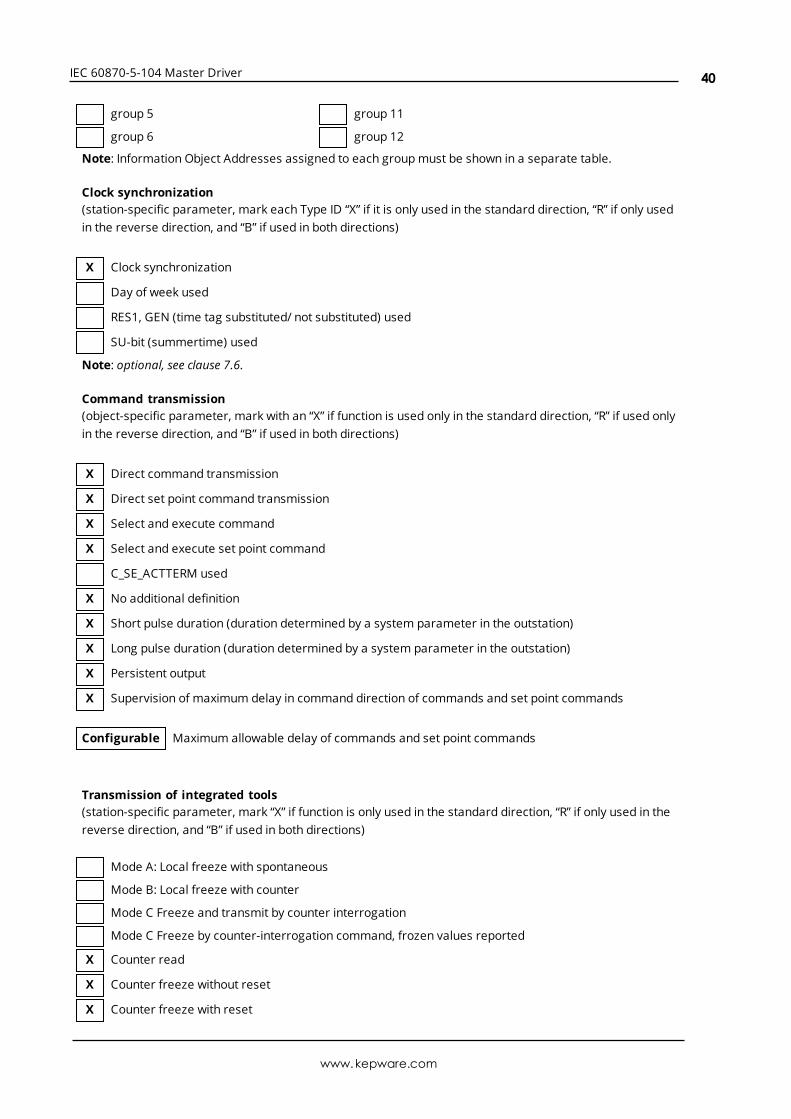
group 5 group 11
group 6 group 12
Note: Information Object Addresses assigned to each groupmust be shown in a separate table.
Clock synchronization(station-specific parameter, mark each Type ID “X” if it is only used in the standard direction, “R” if only usedin the reverse direction, and “B” if used in both directions)
X Clock synchronization
Day of week used
RES1, GEN (time tag substituted/ not substituted) used
SU-bit (summertime) used
Note: optional, see clause 7.6.
Command transmission(object-specific parameter, mark with an “X” if function is used only in the standard direction, “R” if used onlyin the reverse direction, and “B” if used in both directions)
X Direct command transmission
X Direct set point command transmission
X Select and execute command
X Select and execute set point command
C_SE_ACTTERM used
X No additional definition
X Short pulse duration (duration determined by a system parameter in the outstation)
X Long pulse duration (duration determined by a system parameter in the outstation)
X Persistent output
X Supervision of maximum delay in command direction of commands and set point commands
Configurable Maximum allowable delay of commands and set point commands
Transmission of integrated tools(station-specific parameter, mark “X” if function is only used in the standard direction, “R” if only used in thereverse direction, and “B” if used in both directions)
Mode A: Local freeze with spontaneous
Mode B: Local freeze with counter
Mode C Freeze and transmit by counter interrogation
Mode C Freeze by counter-interrogation command, frozen values reported
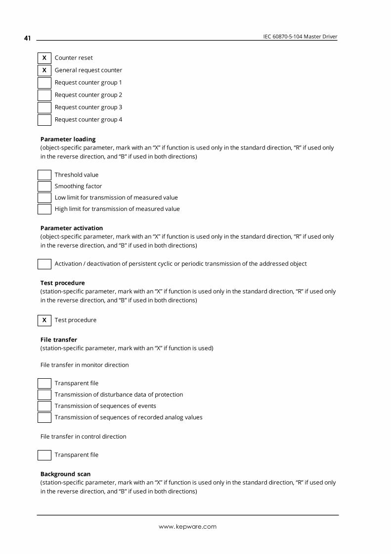
X Counter read
X Counter freeze without reset
X Counter freeze with reset
www.kepware.com
40
IEC 60870-5-104 Master Driver
X Counter reset
X General request counter
Request counter group 1
Request counter group 2
Request counter group 3
Request counter group 4
Parameter loading(object-specific parameter, mark with an “X” if function is used only in the standard direction, “R” if used onlyin the reverse direction, and “B” if used in both directions)
Threshold value
Smoothing factor
Low limit for transmission of measured value
High limit for transmission of measured value
Parameter activation(object-specific parameter, mark with an “X” if function is used only in the standard direction, “R” if used onlyin the reverse direction, and “B” if used in both directions)
Activation / deactivation of persistent cyclic or periodic transmission of the addressed object
Test procedure(station-specific parameter, mark with an “X” if function is used only in the standard direction, “R” if used onlyin the reverse direction, and “B” if used in both directions)
X Test procedure
File transfer(station-specific parameter, mark with an “X” if function is used)
File transfer in monitor direction
Transparent file
Transmission of disturbance data of protection
Transmission of sequences of events
Transmission of sequences of recorded analog values
File transfer in control direction
Transparent file
Background scan(station-specific parameter, mark with an “X” if function is used only in the standard direction, “R” if used onlyin the reverse direction, and “B” if used in both directions)
www.kepware.com
41
IEC 60870-5-104 Master Driver
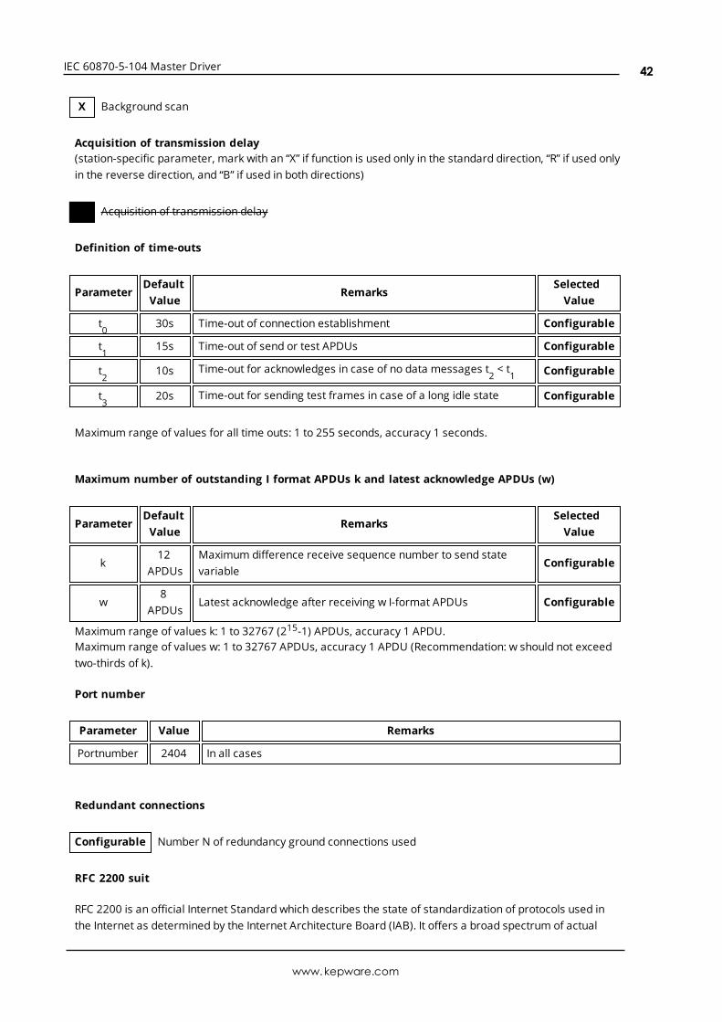
X Background scan
Acquisition of transmission delay(station-specific parameter, mark with an “X” if function is used only in the standard direction, “R” if used onlyin the reverse direction, and “B” if used in both directions)
X Acquisition of transmission delay
Definition of time-outs
ParameterDefaultValue
RemarksSelectedValue
t0
30s Time-out of connection establishment Configurable
t1
15s Time-out of send or test APDUs Configurable
t2
10s Time-out for acknowledges in case of no data messages t2< t
1 Configurable
t3
20s Time-out for sending test frames in case of a long idle state Configurable
Maximum range of values for all time outs: 1 to 255 seconds, accuracy 1 seconds.
Maximum number of outstanding I format APDUs k and latest acknowledge APDUs (w)
ParameterDefaultValue
RemarksSelectedValue
k12
APDUsMaximum difference receive sequence number to send statevariable
Configurable
w8
APDUsLatest acknowledge after receiving w I-format APDUs Configurable
Maximum range of values k: 1 to 32767 (215-1) APDUs, accuracy 1 APDU.Maximum range of values w: 1 to 32767 APDUs, accuracy 1 APDU (Recommendation: w should not exceedtwo-thirds of k).
Port number
Parameter Value Remarks
Portnumber 2404 In all cases
Redundant connections
Configurable Number N of redundancy ground connections used
RFC 2200 suit
RFC 2200 is an official Internet Standard which describes the state of standardization of protocols used inthe Internet as determined by the Internet Architecture Board (IAB). It offers a broad spectrum of actual
www.kepware.com
42
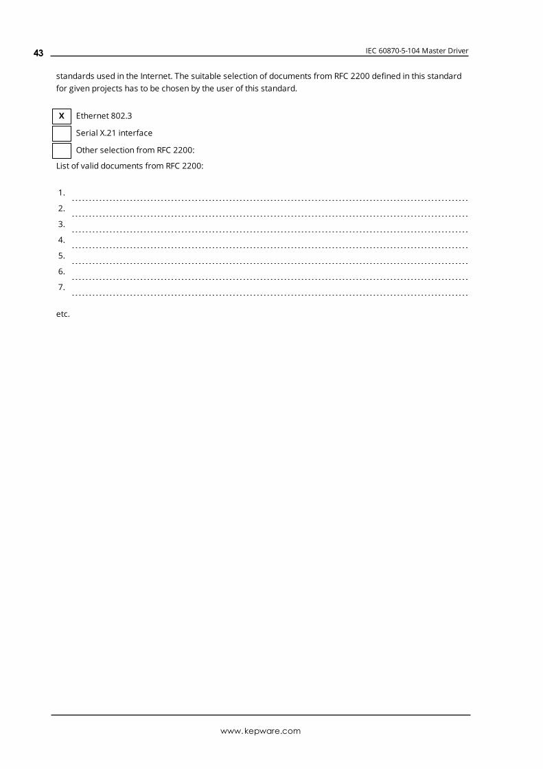
IEC 60870-5-104 Master Driver
standards used in the Internet. The suitable selection of documents from RFC 2200 defined in this standardfor given projects has to be chosen by the user of this standard.
X Ethernet 802.3
Serial X.21 interface
Other selection from RFC 2200:
List of valid documents from RFC 2200:
1.
2.
3.
4.
5.
6.
7.
etc.
www.kepware.com
43
IEC 60870-5-104 Master Driver
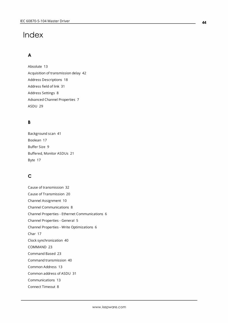
Index
A
Absolute 13
Acquisition of transmission delay 42
Address Descriptions 18
Address field of link 31
Address Settings 8
Advanced Channel Properties 7
ASDU 29
B
Background scan 41
Boolean 17
Buffer Size 9
Buffered, Monitor ASDUs 21
Byte 17
C
Cause of transmission 32
Cause of Transmission 20
Channel Assignment 10
Channel Communications 8
Channel Properties - Ethernet Communications 6
Channel Properties - General 5
Channel Properties - Write Optimizations 6
Char 17
Clock synchronization 40
COMMAND 23
Command Based 23
Command transmission 40
Common Address 13
Common address of ASDU 31
Communications 13
Connect Timeout 8
www.kepware.com
44
IEC 60870-5-104 Master Driver
Control ASDUs 23
COT 20
Counter Interrogation 14
Cyclic data transmission 38
D
Data Collection 10
Data Types Description 17
Date 17
Daylight Saving Time 13
Demote on Failure 12
Demotion Period 12
Description 10
Destination Host 8
Destination Port 8
Device <device name> failed to complete clock synchronization. 25
Device <device name> failed to complete counter interrogation. 25
Device <device name> failed to complete general interrogation. 26
Device <device name> is not responding. 26
Device Properties - Auto-Demotion 12
Device Properties - General 9
Diagnostics 6
Discard Requests when Demoted 12
Do Not Scan, Demand Poll Only 11
Double transmission 39
Driver 5, 10
Duty Cycle 7
DWord 17
E
Error Descriptions 25
Error loading XML file for device. Common Address is already used. 27
Error loading XML file for device. Common Address is invalid. Valid range is low limit to high limit. 26
Event Playback 15
www.kepware.com
45
IEC 60870-5-104 Master Driver
F
File transfer 34
Float 17
Frame length 31
G
General Interrogation 14
H
Help Contents 4
I
ID 10
IEC 60870-5-104 Interoperability Guide 29
IEEE-754 floating point 7
Incremental Timeout 9
Information object address 31
Information Object Address (IOA) 18
Initial Updates from Cache 11
Initialization Settings 14
Interrogation Attempt Count 14
Interrogation Request Timeout 14
Interval 13
L
Length of APDU 32
Link Settings 9
Link transmission procedure 30
Long 17
www.kepware.com
46
IEC 60870-5-104 Master Driver
M
Master 29
Messages 25
Method 13
Model 10
Monitor ASDUs 18
N
Name 10
Network Adapter 6
Non-Normalized Float Handling 7
O
Optimization Method 6
OPTIONAL 22
Originator Address 9
Overview 4
P
Parameter 34
Parameter activation 41
Parameter loading 41
Playback Buffer Size 15
Playback Rate 15
Polled Reads 14
Process information 32
Protocol 5
R
Read failed on tag due to data type mismatch. 27
Read failed on tag. 27
Read procedure 39
Redundancy 16
www.kepware.com
47
IEC 60870-5-104 Master Driver
Request All Data at Scan Rate 11
Request Data No Faster than Scan Rate 11
Respect Client-Specified Scan Rate 11
Respect Tag-Specified Scan Rate 11
S
ScanMode 11
Settings 8
Setup 5
Short 17
Simulated 10
Slave 29
Spontaneous transmission 39
Standard ASDUs 32
Station initialization 38
Station interrogation 39
SUBTYPE 19, 22
System information 34
T
Test procedure 41
Time Synchronization 12
Time Zone 12
Timeouts to Demote 12
Timing 15
Timing Settings 9
Too many events received in device name, the buffer has overflowed. 28
Transmission of integrated tools 40
Transmission speed 30
Type identification 31
TYPEID 18
U
Unable to write to address <address> on device <device>. 28
Unbuffered, Monitor ASDUs 21
www.kepware.com
48

IEC 60870-5-104 Master Driver
W
Word 17
Write All Values for All Tags 6
Write failed on <tag name>. 28
Write Only Latest Value for All Tags 7
Write Only Latest Value for Non-Boolean Tags 6
Write Optimizations 6
www.kepware.com
49