Embed Size (px)
Citation preview

MicroSCADA ProSYS 600 9.2IEC 60870-5-101 Master Protocol
Configuration Manual

MicroSCADA ProIEC 60870-5-101 Master ProtocolConfiguration Manual
SYS 600 9.21MRS756158
Issued: 15.11.2006Version: A/15.11.2006
ContentsCopyrights .....................................................................................51. Introduction ...............................................................................7
1.1. This manual ...................................................................................71.2. Use of symbols ..............................................................................81.3. Related Documents .......................................................................81.4. Document revisions .......................................................................8
2. Safety information .....................................................................92.1. Backup copies ...............................................................................92.2. Fatal errors ..................................................................................10
3. Instructions ..............................................................................113.1. Communication ...........................................................................113.2. Installation ...................................................................................113.3. Configuration ...............................................................................11
3.3.1. Base system configuration ...............................................113.3.2. Communication system configuration ..............................13
3.4. After configuration .......................................................................393.5. How to test the configuration .......................................................393.6. Serial cable wiring diagram .........................................................39
4. Technical description .............................................................414.1. General .......................................................................................41
4.1.1. IEC 60870-5-101 protocol ................................................414.1.2. Level of implementation ...................................................41
4.2. Communication ...........................................................................434.2.1. Communication modes ....................................................434.2.2. Protocol converter ............................................................434.2.3. Addressing .......................................................................434.2.4. Device communication attributes .....................................444.2.5. Data in monitoring direction .............................................474.2.6. Data in control direction ...................................................51
4.2.6.1. Command handling in IEC 60870-5-101 protocol ..............................................................51
4.2.6.2. Data commands .................................................524.2.6.3. Application commands .......................................544.2.6.4. System commands .............................................55
4.2.7. Transparent data commands ...........................................564.2.8. Parameter in control direction ..........................................57
4.3. Signal engineering ......................................................................584.4. Status codes ...............................................................................59
3

1MRS756158MicroSCADA ProIEC 60870-5-101 Master ProtocolConfiguration Manual
SYS 600 9.2
4.5. Interoperability list ....................................................................... 61
5. Index ........................................................................................ 77
4

The information in this document is subject to change without notice and should not be construed as a commitment by ABB Oy. ABB Oy assumes no responsibility for any errors that may appear in this document.
In no event shall ABB Oy be liable for direct, indirect, special, incidental or consequential damages of any nature or kind arising from the use of this document, nor shall ABB Oy be liable for incidental or consequential damages arising from use of any software or hardware described in this document.
This document and parts thereof must not be reproduced or copied without written permission from ABB Oy, and the contents thereof must not be imparted to a third party nor used for any unauthorized purpose.
The software or hardware described in this document is furnished under alicense and may be used, copied, or disclosed only in accordance with the terms of such license.
Copyright © 2006 ABB OyAll rights reserved.
TrademarksABB is a registered trademark of ABB Group. All other brand or product names mentioned in this document may be trademarks or registered trademarks of their respective holders.
GuaranteePlease inquire about the terms of guarantee from your nearest ABB representative.
1MRS756158 SYS 600 9.2
5
MicroSCADA ProIEC 60870-5-101 Master ProtocolConfiguration Manual
Copyrights

6
1MRS756158 SYS 600 9.2MicroSCADA ProIEC 60870-5-101 Master ProtocolConfiguration Manual
1. Introduction
1.1. This manualThis manual provides thorough information on the IEC 60870-5-101 master protocol and needed information related to it. It describes how to configure the base system and the communication system to establish communication to an IEC 60870-5-101 slave.
In addition to this configuration, the base system needs to be configured for other communication tasks, for example, process communication, if needed. For information about this subject, refer to other manuals, for example, Application Objects and System Objects. The IEC 60870-5-101 slave needs to be configured as well.
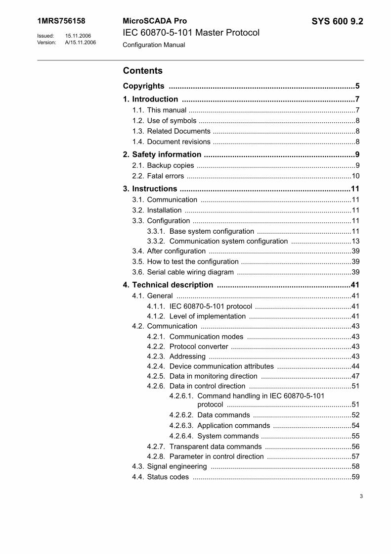
IEC 60870-5-101 master protocolThe IEC 60870-5-101 master protocol is mainly used for upper level communication between SYS 600 and a Substation Control System (SCS) as illustrated by Fig. 1.1.-1. This protocol can also be used for communication between SYS 600 and for example, a remote-controlled line disconnector.
IEC_protocoö
Fig. 1.1.-1 The IEC master sees the Substation Control System (SCS) as an IEC slave
7
1MRS756158MicroSCADA ProIEC 60870-5-101 Master ProtocolConfiguration Manual
SYS 600 9.2
1.2. Use of symbolsThis document includes caution and information icons that point out safety-related conditions or other important information. The corresponding icons should be interpreted as follows:
1.3. Related DocumentsThe following SYS 600 manuals should be available for reference during the use of this manual:
The following SYS 600 manuals should be available for reference during the use of this manual:
Other referenced manualsThe IEC 60870-5-101 protocol is based on the following documents by the IEC Technical Committee 57:
1.4. Document revisions
The caution icon indicates important information or warning related to the concept discussed in the text. It might indicate the presence of a hazard which could result in corruption of software or damage to equipment or property.
The information icon alerts the reader to relevant facts and conditions.
Name of the document MRS numberIEC 60870-5-101 Slave Protocol 1MRS756159
Name of the document MRS numberSystem Configuration 1MRS756112System Objects 1MRS756177Application Objects 1MRS756175
• IEC 60870-5-1 Transmission Frame Formats
• IEC 60870-5-2 Data Link Transmission Services
• IEC 60870-5-3 General Structure of Application Data
• IEC 60870-5-4 Definition and Coding of Information Elements
• IEC 60870-5-5 Basic Application Functions
• IEC 60870-5-101 Companion standard for the IEC 60870-5-101 Protocol
Version Revision number DateA 9.2 15.11.2006
8
1MRS756158 SYS 600 9.2MicroSCADA ProIEC 60870-5-101 Master ProtocolConfiguration Manual
2. Safety information
This chapter gives information about the prevention of hazards.
2.1. Backup copies
Taking backup copiesWe suggest that you take backup copies before making any changes, especially the ones that might have side effects. Software and data need to be copied to another place, usually to a CD or a backup tape. A writable CD and DAT tape are commonly used.
Backup copying makes it easier to restore the application software in case of disk crash or other severe failure when stored data is lost. It is therefore recommended that backup copies are taken regularly.
There should be at least two system backup copies and two application copies. A new backup is copied over the oldest backup. This way the latest version is always available, even if the backup procedure fails.
Detailed information on how to take backup copies should be delivered to the customer with the application.
System backupUsually a system back up is taken after the application is made. It should be taken again when changes are made to the SYS 600 system. This is needed, for example, when the driver configuration or the network setup is changed.
Application backupAn application backup is also taken at the same time with the system backup, after the application is made. It should be taken again when changes are made to the application, e.g. if pictures or databases are edited or new pictures are added.
9
1MRS756158MicroSCADA ProIEC 60870-5-101 Master ProtocolConfiguration Manual
SYS 600 9.2
2.2. Fatal errorsA fatal error is an error that causes a breakdown or a locked situation in the SYS 600 program execution.
HandlingIn case of a fatal error:1. Write down the possible SYS 600 error messages.2. Shut down the SYS 600 main program. If this cannot be done in the SYS 600
Control Panel, try to end the task in Windows Task Manager.
3. In Windows, the data kept in the main memory at the moment of a fatal error is placed into drwtsn32.log file. It is placed in a system folder, for example WINNT. Analyse and copy the data in this file.
4. Restart the system.5. Report the program break-down together with the possible SYS 600 error
messages and the information from the drwtsn32.log file to the SYS 600 supplier.
Status codesError messages in SCIL are called status codes. A list of status codes and short explanations can be found in the Status Codes manual.
Files may be damaged if you shut down the base system computers by switching the power off.
10
1MRS756158 SYS 600 9.2MicroSCADA ProIEC 60870-5-101 Master ProtocolConfiguration Manual
3. Instructions
3.1. CommunicationIn SYS 600 the IEC 60870-5-101 master protocol is implemented in the PC-NET software only. PC-NET communicates over an INTEGRATED link and via the serial ports of the base system computer. Setting the attributes of the SYS 600 system objects modifies the communication parameters.
The base system sees each IEC master device as a station (STA object) that has been created to a line of a NET unit. Each IEC station works as a protocol converter that converts data between the internal protocol of SYS 600 and the IEC 60870-5-101 protocol.
3.2. InstallationThe SYS 600 installation is required.
3.3. ConfigurationThe configuration can be divided into two parts: • Base system configuration• Communication system configuration
Configuration can be made either by using the System Configuration Tool or by using SCIL statements. The following sections show how to make the configuration by using SCIL. For details about the System Configuration Tool, refer to the System Configuration manual.
3.3.1. Base system configurationEach base system has a set of objects that specify the base system and its environment, hardware and software, as well as the physical and logical connections of the base system and its applications.
The base system objects are defined with SCIL commands in the SYS_BASCON.COM file, which is executed every time the base system is started. With a few limitations, you can also define and modify the base system objects any time when SYS 600 is running. During the operation, the base system objects are in the primary memory of the base system computer.
The IEC 60870-5-101 master protocol is implemented in the PC-NET software, which means that an INTEGRATED link must be used. The IEC 60870-5-101 master protocol uses the station type (STY object) 29.
Configuration stepsTo configure SYS_BASCON.COM:1. Define the base system.2. Define a link.3. Define a node.4. Define a monitor.
11
1MRS756158MicroSCADA ProIEC 60870-5-101 Master ProtocolConfiguration Manual
SYS 600 9.2
5. Define an application.6. Define the station type.7. Define the IEC stations.
The definitions are made in the example below by using the old SYS_BASCON.COM template. If the new (revision 8.4.2 or later) template is used, the INTEGRATED link and the node for the PC-NET will be created by the System Configuration Tool and need not to be included in SYS_BASCON.COM. For more information about the system objects, see the System Objects manual.
ExampleThe following is an example of the SYS_BASCON.COM file for communication with the IEC 60870-5-101 master protocol. An application IEC_TEST is defined. In this example two IEC 60870-5-101 master stations are configured.
;***********************************************************;; SYS_BASCON.COM; BASE SYSTEM CONFIGURATION TEMPLATE;;***********************************************************
#CREATE SYS:B = LIST(- SA = 209,- ;STATION ADDRESS OF BASE SYSTEM ND = 9,- ;NODE NUMBER OF BASE SYSTEM DN = 3,- ;DEFAULT NET NODE NUMBER DS = "RTU",- ;STA TYPES: E.G. STA,RTU,SPA,REX FS = "NEVER") ;FILE SYNCH CRITERIA: ;NEVER,MAINT,SET,CHECKPOINT,ALWAYS
;***********************************************************;; COMMUNICATION LINKS
#CREATE LIN:V = LIST(- ;REQUIRES THE PC-NET PROGRAM LT = "INTEGRATED",- SC = "\SC\PROG\PC_NET\PC_NETS.EXE") ;STARTUP COMMAND#CREATE LIN3:B = %LIN;***********************************************************;; COMMUNICATION NODES
#CREATE NOD:V = LIST(- LI = 3,- SA = 203)#CREATE NOD3:B = %NOD
;***********************************************************;; PRINTERS
;***********************************************************;; MONITORS
It is extremely important to map the spontaneous (3) cause of transmission value as shown in the following example, otherwise spontaneous data does not update the process objects.
12
1MRS756158 SYS 600 9.2MicroSCADA ProIEC 60870-5-101 Master ProtocolConfiguration Manual
#LOOP_WITH I = 1..5 #CREATE MON'I':B = LIST(- TT = "LOCAL",- ;TRANSLATION TYPE DT = "X") ;X MONITOR @MON_MAP(%I) = -1#LOOP_END
#LOOP_WITH I = 6..10 #CREATE MON'I':B = LIST(- TT = "LOCAL",- ;TRANSLATION TYPE DT = "VS") ;VISUAL SCIL MONITOR @MON_MAP(%I) = -1#LOOP_END
;***********************************************************;; APPLICATIONS
#CREATE APL:V = LIST(- TT = "LOCAL",- ;TRANSLATION TYPE NA = "IEC_TEST",- ;NAME OF APPLICATION DIRECTORY AS = "HOT",- ;APPLICATION STATE: COLD,WARM,HOT HB = 2000,- ;HISTORY BUFFER SIZE) RC = VECTOR("FILE_FUNCTIONS_CREATE_DIRECTORIES"),- AP = (1,2),- MO = %MON_MAP,- ;MONITOR MAPPING PR = (1,2,3)) ;PRINTER MAPPING#CREATE APL1:B = %APL
;***********************************************************
; STATION TYPES
#SET STY29:BCX = "IEC"#SET STY29:BCT(3) = "UNKNOWN" ; MAPPING OF SPONTANEOUS CAUSE #OF TRANSMISSION
;***********************************************************
; STATIONS
;*** NET 3 stations ***
#CREATE STA:V = LIST(- TT = "EXTERNAL",- ST = "IEC",- ND = 3,- TN = 1)#CREATE STA1:B = %STA
#CREATE STA:V = LIST(- TT = "EXTERNAL",- ST = "IEC",- ND = 3,- TN = 2)#CREATE STA2:B = %STA
;***********************************************************
3.3.2. Communication system configurationEach NET unit contains a set of system objects, which specify line properties, connected devices etc. These objects can be created, modified and deleted by SCIL, and setting the attributes of the objects can change the properties.
13
1MRS756158MicroSCADA ProIEC 60870-5-101 Master ProtocolConfiguration Manual
SYS 600 9.2
Access to the attributes can be one of the following:• Read-only: The attribute can only be read. There are still a few exceptions in
which the values can be reset.• Write-only: The attribute can only be written (set).• Read, conditional write: The attribute can be both read and written, but the
object must be set out of use (IU = 0) before writing.• No limitations: The attribute can be both read and written without limitations.
The implementation of the IEC 60870-5-101 master protocol in SYS 600 can be divided into two layers: link layer and application layer. Both of these layers have a specific functionality and a set of attributes of their own. The link layer corresponds to a line of a NET unit and the application layer corresponds to a station configured to the line.
The purpose of the communication system configuration is to:• Create all the system objects needed to establish communication between the
master and the slave.• Adjust the values of the system object attributes to match the physical
communication channel and the properties of the slave station.
Setting the attribute valuesAll the line and station attributes have sensible default values but the value of each attribute must be checked against the requirements of the actual communication system. The attribute values depend on:• The physical communication media (e.g. leased telephone line, radio link, and
power line carrier). This affects particularly the attributes of the line, such as baud rate and parity.
• The network topology used (point-to-point, multidrop). This affects, for example, the link type.
• The size (number of stations) of the system. This affects especially the timeout parameters; the slower the media and bigger the system, the longer timeouts are needed.
• The slave system. This affects both the line and station attributes, and also the message types used.
When making the IEC connection, an agreement about the communication parameters used should be made with the supplier or owner of the system acting as the IEC slave.
It is important to match the address length attributes (PL, SL, IL and CL) of the IEC 60870-5-101 station to the parameters of the slave. If this is not done, the communication may appear to be working properly although the messages are incorrectly interpreted.
14
1MRS756158 SYS 600 9.2MicroSCADA ProIEC 60870-5-101 Master ProtocolConfiguration Manual
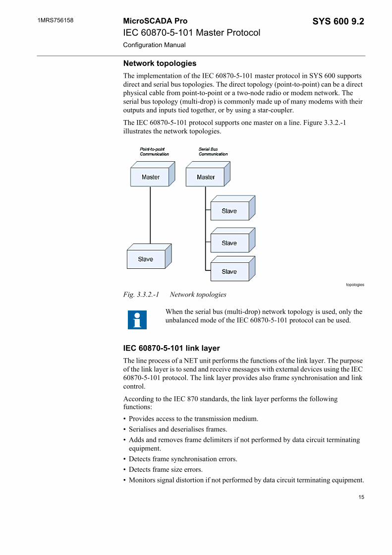
Network topologiesThe implementation of the IEC 60870-5-101 master protocol in SYS 600 supports direct and serial bus topologies. The direct topology (point-to-point) can be a direct physical cable from point-to-point or a two-node radio or modem network. The serial bus topology (multi-drop) is commonly made up of many modems with their outputs and inputs tied together, or by using a star-coupler.
The IEC 60870-5-101 protocol supports one master on a line. Figure 3.3.2.-1 illustrates the network topologies.
topologies
Fig. 3.3.2.-1 Network topologies
IEC 60870-5-101 link layerThe line process of a NET unit performs the functions of the link layer. The purpose of the link layer is to send and receive messages with external devices using the IEC 60870-5-101 protocol. The link layer provides also frame synchronisation and link control.
According to the IEC 870 standards, the link layer performs the following functions:• Provides access to the transmission medium.• Serialises and deserialises frames.• Adds and removes frame delimiters if not performed by data circuit terminating
equipment.• Detects frame synchronisation errors.• Detects frame size errors.• Monitors signal distortion if not performed by data circuit terminating equipment.
When the serial bus (multi-drop) network topology is used, only the unbalanced mode of the IEC 60870-5-101 protocol can be used.
15
1MRS756158MicroSCADA ProIEC 60870-5-101 Master ProtocolConfiguration Manual
SYS 600 9.2
• Recognises frames addressed to a designated station.• Prevents the station transmitting without pause.• Protects messages against loss and errors within predetermined limits.• Reports on persistent transmission errors.• Reports on the status of link configuration.• Supports initiation and maintenance functions.
Link layer attributesThe following attributes can be used for configuring the IEC 60870-5-101 master lines in SYS 600.
IU In UseIndicates whether the line is in use (value 1) or not in use (value 0).
Data type: IntegerValue: 0, 1Index range: 1...8 (NET line numbering)Default value: 0Access: No limitations
PO ProtocolThe data transfer protocol used on the line. The line is defined to the NET by setting this attribute. By setting the attribute to 0, the line definition including all the line attributes will be deleted.
Data type: IntegerValue: 0...35
Value with IEC 60870-5-101 master protocol: 31 (unbalanced mode) or 32 (balanced mode).
Index range: 1...8 (NET line numbering)Access: Read, conditional write
SD System Device Name Associates the NET line numbers of PC-NET with the device names of the physical channels of the serial ports.
By default, line number 1 is connected to COM1, line 2 to COM2 and so on. By using the SD attribute it is possible to override these default values. This may be necessary if COM ports will be used as NET lines or if, for example, a RocketPort card is used.
Data type: TextValue: See aboveIndex range: 1...8 (NET line numbering)Access: Read, conditional write
16
1MRS756158 SYS 600 9.2MicroSCADA ProIEC 60870-5-101 Master ProtocolConfiguration Manual
PS Buffer Pool SizeSpecifies the number of message buffers reserved for the line. Each buffer can contain one message. The maximum data content length of a message is 228 bytes.
Data type: IntegerValue: 1...250Index range: 1...8 (NET line numbering)Default value: 20Access: Read, conditional write
BR Baud RateTransmission rate used on the line.
Data type: IntegerValue: 1...19200Unit: Bits / sIndex range: 1...8 (NET line numbering)Default value: 2400Access: Read, conditional write
PY ParitySpecifies the parity check (if any) used for the characters transferred on the line.
Data type: IntegerValue: 0 = no parity check
1 = odd parity2 = even parity
Index range: 1...8 (NET line numbering)Default value: 2Access: Read, conditional write
OM Operating ModeThis attribute consists of a set of flags which control the behaviour and functionality of the IEC line. Each flag is one bit of this attribute. The bits are the following:
Bit 0: Balanced mode handshakeWhen this bit is 0, the sending of the handshaking messages (request, status of link, reset of remote link) are NOT restarted when a ‘request status of link’ message is received from the remote end. When the bit is 1, the sending of the handshaking messages are
The value of this attribute should be greater than the number of IEC stations configured on the line.
17
1MRS756158MicroSCADA ProIEC 60870-5-101 Master ProtocolConfiguration Manual
SYS 600 9.2
restarted when a ‘request status of link’ message is received. Notice, that if SYS 600 is used in both ends, only one of them should have this bit set. This bit is meaningful only in the balanced modes.
Bit 1: The polling method when a remote station sets the DFC bit on. When this bit is 0, the master sends the 'request status of link' until the remote station clears the DFC bit (this is the default operation). When this bit is 1, the master continues polling normally. The bit is meaningful only in unbalanced mode.
Bit 2: One link, one station poll. When this bit is 1, the master infinitely polls the first link that responds. Only the station from which the first data is received is set to OK status and in case of communication failure, only this station is set to suspended state. This configuration is especially useful in a multistation configuration with dial-up, in which the remote station makes the call and there is only station behind the link. This bit should be set only in unbalanced mode. When this bit is 0, all the links are polled normally (this is the default operation).
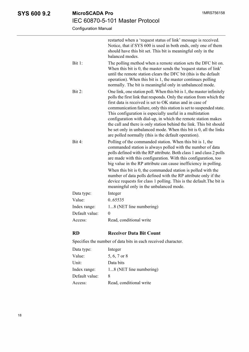
Bit 4: Polling of the commanded station. When this bit is 1, the commanded station is always polled with the number of data polls defined with the RP attribute. Both class 1 and class 2 polls are made with this configuration. With this configuration, too big value in the RP attribute can cause inefficiency in polling. When this bit is 0, the commanded station is polled with the number of data polls defined with the RP attribute only if the device requests for class 1 polling. This is the default.The bit is meaningful only in the unbalanced mode.
Data type: IntegerValue: 0..65535Index range: 1...8 (NET line numbering)Default value: 0Access: Read, conditional write
RD Receiver Data Bit CountSpecifies the number of data bits in each received character.
Data type: IntegerValue: 5, 6, 7 or 8Unit: Data bitsIndex range: 1...8 (NET line numbering)Default value: 8Access: Read, conditional write
18
1MRS756158 SYS 600 9.2MicroSCADA ProIEC 60870-5-101 Master ProtocolConfiguration Manual
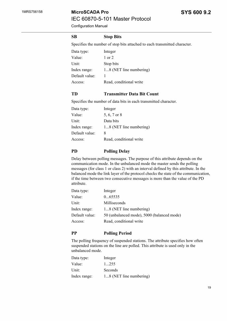
SB Stop BitsSpecifies the number of stop bits attached to each transmitted character.
Data type: IntegerValue: 1 or 2Unit: Stop bitsIndex range: 1...8 (NET line numbering)Default value: 1Access: Read, conditional write
TD Transmitter Data Bit CountSpecifies the number of data bits in each transmitted character.
Data type: IntegerValue: 5, 6, 7 or 8Unit: Data bitsIndex range: 1...8 (NET line numbering)Default value: 8Access: Read, conditional write
PD Polling DelayDelay between polling messages. The purpose of this attribute depends on the communication mode. In the unbalanced mode the master sends the polling messages (for class 1 or class 2) with an interval defined by this attribute. In the balanced mode the link layer of the protocol checks the state of the communication, if the time between two consecutive messages is more than the value of the PD attribute.
Data type: IntegerValue: 0...65535Unit: MillisecondsIndex range: 1...8 (NET line numbering)Default value: 50 (unbalanced mode), 5000 (balanced mode)Access: Read, conditional write
PP Polling PeriodThe polling frequency of suspended stations. The attribute specifies how often suspended stations on the line are polled. This attribute is used only in the unbalanced mode.
Data type: IntegerValue: 1...255Unit: SecondsIndex range: 1...8 (NET line numbering)
19
1MRS756158MicroSCADA ProIEC 60870-5-101 Master ProtocolConfiguration Manual
SYS 600 9.2
Default value: 10Access: Read, conditional write
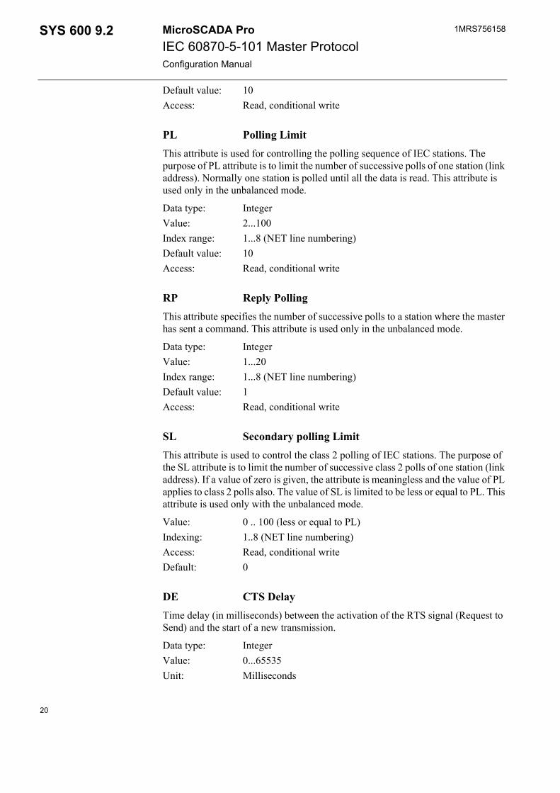
PL Polling LimitThis attribute is used for controlling the polling sequence of IEC stations. The purpose of PL attribute is to limit the number of successive polls of one station (link address). Normally one station is polled until all the data is read. This attribute is used only in the unbalanced mode.
Data type: IntegerValue: 2...100Index range: 1...8 (NET line numbering)Default value: 10Access: Read, conditional write
RP Reply PollingThis attribute specifies the number of successive polls to a station where the master has sent a command. This attribute is used only in the unbalanced mode.
Data type: IntegerValue: 1...20Index range: 1...8 (NET line numbering)Default value: 1Access: Read, conditional write
SL Secondary polling LimitThis attribute is used to control the class 2 polling of IEC stations. The purpose of the SL attribute is to limit the number of successive class 2 polls of one station (link address). If a value of zero is given, the attribute is meaningless and the value of PL applies to class 2 polls also. The value of SL is limited to be less or equal to PL. This attribute is used only with the unbalanced mode.
Value: 0 .. 100 (less or equal to PL)Indexing: 1..8 (NET line numbering)Access: Read, conditional writeDefault: 0
DE CTS DelayTime delay (in milliseconds) between the activation of the RTS signal (Request to Send) and the start of a new transmission.
Data type: IntegerValue: 0...65535Unit: Milliseconds
20
1MRS756158 SYS 600 9.2MicroSCADA ProIEC 60870-5-101 Master ProtocolConfiguration Manual
Index range: 1...8 (NET line numbering)Default value 50Access: Read, conditional write
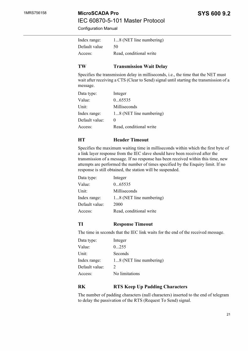
TW Transmission Wait DelaySpecifies the transmission delay in milliseconds, i.e., the time that the NET must wait after receiving a CTS (Clear to Send) signal until starting the transmission of a message.
Data type: IntegerValue: 0...65535Unit: MillisecondsIndex range: 1...8 (NET line numbering)Default value: 0Access: Read, conditional write
HT Header TimeoutSpecifies the maximum waiting time in milliseconds within which the first byte of a link layer response from the IEC slave should have been received after the transmission of a message. If no response has been received within this time, new attempts are performed the number of times specified by the Enquiry limit. If no response is still obtained, the station will be suspended.
Data type: IntegerValue: 0...65535Unit: MillisecondsIndex range: 1...8 (NET line numbering)Default value: 2000Access: Read, conditional write
TI Response TimeoutThe time in seconds that the IEC link waits for the end of the received message.
Data type: IntegerValue: 0...255Unit: SecondsIndex range: 1...8 (NET line numbering)Default value: 2Access: No limitations
RK RTS Keep Up Padding CharactersThe number of padding characters (null characters) inserted to the end of telegram to delay the passivation of the RTS (Request To Send) signal.
21
1MRS756158MicroSCADA ProIEC 60870-5-101 Master ProtocolConfiguration Manual
SYS 600 9.2
Data type: IntegerValue: 0...255Index range: 1...8 (NET line numbering)Default value: 0Access: Read, conditional write
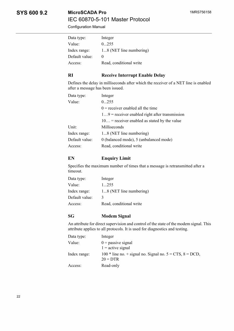
RI Receive Interrupt Enable DelayDefines the delay in milliseconds after which the receiver of a NET line is enabled after a message has been issued.
Data type: IntegerValue: 0...255
0 = receiver enabled all the time1…9 = receiver enabled right after transmission10… = receiver enabled as stated by the value
Unit: MillisecondsIndex range: 1...8 (NET line numbering)Default value: 0 (balanced mode), 5 (unbalanced mode)Access: Read, conditional write
EN Enquiry LimitSpecifies the maximum number of times that a message is retransmitted after a timeout.
Data type: IntegerValue: 1...255Index range: 1...8 (NET line numbering)Default value: 3Access: Read, conditional write
SG Modem SignalAn attribute for direct supervision and control of the state of the modem signal. This attribute applies to all protocols. It is used for diagnostics and testing.
Data type: IntegerValue: 0 = passive signal
1 = active signalIndex range: 100 * line no. + signal no. Signal no. 5 = CTS, 8 = DCD,
20 = DTRAccess: Read-only
22
1MRS756158 SYS 600 9.2MicroSCADA ProIEC 60870-5-101 Master ProtocolConfiguration Manual
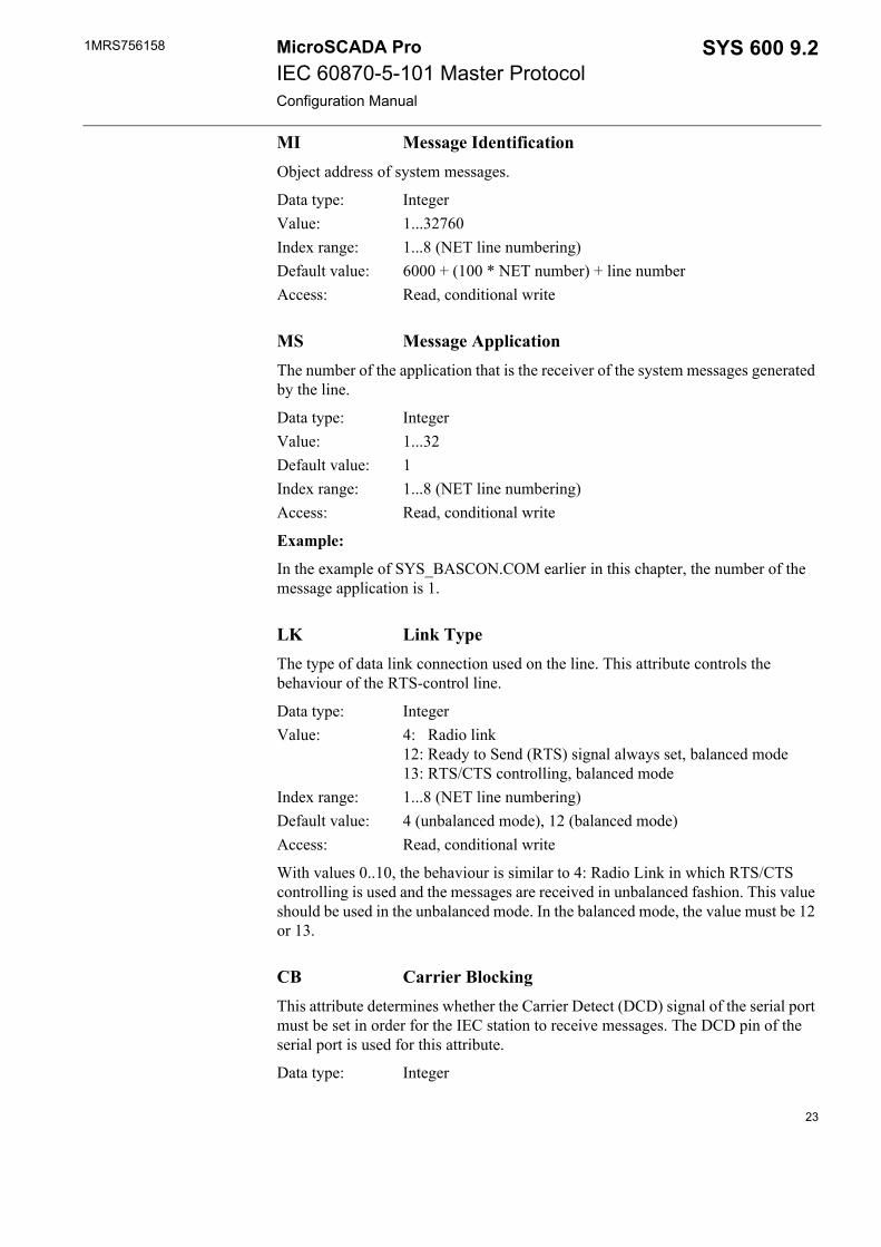
MI Message IdentificationObject address of system messages.
Data type: IntegerValue: 1...32760Index range: 1...8 (NET line numbering)Default value: 6000 + (100 * NET number) + line numberAccess: Read, conditional write
MS Message ApplicationThe number of the application that is the receiver of the system messages generated by the line.
Data type: IntegerValue: 1...32Default value: 1Index range: 1...8 (NET line numbering)Access: Read, conditional write
Example:
In the example of SYS_BASCON.COM earlier in this chapter, the number of the message application is 1.
LK Link TypeThe type of data link connection used on the line. This attribute controls the behaviour of the RTS-control line.
Data type: IntegerValue: 4: Radio link
12: Ready to Send (RTS) signal always set, balanced mode13: RTS/CTS controlling, balanced mode
Index range: 1...8 (NET line numbering)Default value: 4 (unbalanced mode), 12 (balanced mode)Access: Read, conditional write
With values 0..10, the behaviour is similar to 4: Radio Link in which RTS/CTS controlling is used and the messages are received in unbalanced fashion. This value should be used in the unbalanced mode. In the balanced mode, the value must be 12 or 13.
CB Carrier BlockingThis attribute determines whether the Carrier Detect (DCD) signal of the serial port must be set in order for the IEC station to receive messages. The DCD pin of the serial port is used for this attribute.
Data type: Integer
23

1MRS756158MicroSCADA ProIEC 60870-5-101 Master ProtocolConfiguration Manual
SYS 600 9.2
Value: 0 = Carrier blocking not used, Carrier Detect ignored1 = Carrier blocking not used, Carrier Detect must be set
Default value: 1Index range: 1...8 (NET line numbering)Access: Read, conditional write
DC Diagnostic CountersThe line protocols gather statistical information about the events on the lines by incrementing a number of diagnostic counters. All the major events and error situations of the communication have their own counters.
When accessing diagnostic counters, the attribute is indexed according to the formula:
100 * (line number) + (diagnostic counter number) The IEC 60870-5-101 master protocol supports the following counters:
1. Transmitted telegrams2. Failed transmissions4. Transmitted commands5. Transmitted replies10. Received too long message11. Link response timeouts12. Parity errors13. Overrun errors14. Check sum errors15. Framing errors16. Buffer overflow errors
Data type: IntegerValue: 0...30000Index range: See aboveAccess: Read-only, the values can be reset
SR Single Char ResponseEnables or disables single character responses. If single character responses are enabled, the IEC master station replies with a 0xE5 character as a link layer acknowledgement. This attribute is used only in the balanced mode.
Data type: IntegerValue: 0 or 1Default value: 0 (single char responses disabled)Access: Read, conditional write
24
1MRS756158 SYS 600 9.2MicroSCADA ProIEC 60870-5-101 Master ProtocolConfiguration Manual
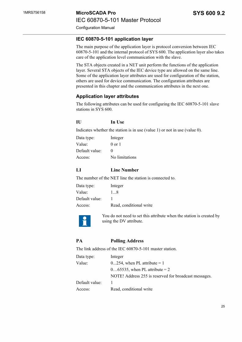
IEC 60870-5-101 application layerThe main purpose of the application layer is protocol conversion between IEC 60870-5-101 and the internal protocol of SYS 600. The application layer also takes care of the application level communication with the slave.
The STA objects created in a NET unit perform the functions of the application layer. Several STA objects of the IEC device type are allowed on the same line. Some of the application layer attributes are used for configuration of the station, others are used for device communication. The configuration attributes are presented in this chapter and the communication attributes in the next one.
Application layer attributesThe following attributes can be used for configuring the IEC 60870-5-101 slave stations in SYS 600.
IU In UseIndicates whether the station is in use (value 1) or not in use (value 0).
Data type: IntegerValue: 0 or 1Default value: 0Access: No limitations
LI Line NumberThe number of the NET line the station is connected to.
Data type: IntegerValue: 1...8Default value: 1Access: Read, conditional write
PA Polling AddressThe link address of the IEC 60870-5-101 master station.
Data type: IntegerValue: 0...254, when PL attribute = 1
0…65535, when PL attribute = 2NOTE! Address 255 is reserved for broadcast messages.
Default value: 1Access: Read, conditional write
You do not need to set this attribute when the station is created by using the DV attribute.
25

1MRS756158MicroSCADA ProIEC 60870-5-101 Master ProtocolConfiguration Manual
SYS 600 9.2
SA Station AddressThe station address of the IEC 60870-5-101 master station, the common address of ASDU in an IEC message.
Data type: IntegerValue: 0...255, when SL attribute = 1
0...65535, when SL attribute = 2Default value: 1Access: Read, conditional write
DR DirectionStates if the IEC master station acts as the station A (primary station) or station B (secondary station).
Data type: IntegerValue: 0 or 1Default value: 1 (primary station)Access: Read, conditional write
PL Polling Address LengthThe length of the link address in octets.
Data type: IntegerValue: 1 or 2Default value: 1Access: Read, conditional write (line IU must also be 0 when writing)
SL Station Address LengthThe length of the station address (common address of ASDU) in octets.
Data type: IntegerValue: 1 or 2Default value: 1Access: Read, conditional write
IL Information Address LengthThe length of the information object address in octets.
Data type: IntegerValue: 1…3Default value: 2Access: Read, conditional write
26
1MRS756158 SYS 600 9.2MicroSCADA ProIEC 60870-5-101 Master ProtocolConfiguration Manual
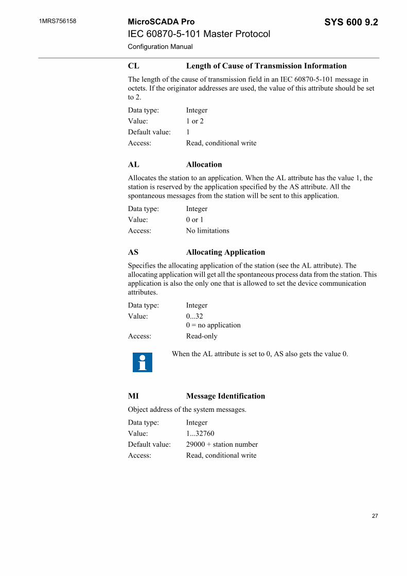
CL Length of Cause of Transmission InformationThe length of the cause of transmission field in an IEC 60870-5-101 message in octets. If the originator addresses are used, the value of this attribute should be set to 2.
Data type: IntegerValue: 1 or 2Default value: 1Access: Read, conditional write
AL AllocationAllocates the station to an application. When the AL attribute has the value 1, the station is reserved by the application specified by the AS attribute. All the spontaneous messages from the station will be sent to this application.
Data type: IntegerValue: 0 or 1Access: No limitations
AS Allocating ApplicationSpecifies the allocating application of the station (see the AL attribute). The allocating application will get all the spontaneous process data from the station. This application is also the only one that is allowed to set the device communication attributes.
Data type: IntegerValue: 0...32
0 = no applicationAccess: Read-only
MI Message IdentificationObject address of the system messages.
Data type: IntegerValue: 1...32760Default value: 29000 + station numberAccess: Read, conditional write
When the AL attribute is set to 0, AS also gets the value 0.
27
1MRS756158MicroSCADA ProIEC 60870-5-101 Master ProtocolConfiguration Manual
SYS 600 9.2
MS Message ApplicationThe number of the application that is the receiver of the system messages generated by the line.
Data type: IntegerValue: 1...32Default value: 1Access: Read, conditional write
Example:
In the example of SYS_BASCON.COM earlier in this chapter, the number of the message application is 1.
SE System Messages EnabledSpecifies whether the system messages generated by NET and related to the station are sent to applications (value 1) or not (value 0). By using this attribute, it is possible to disable the system messages related to the station.
Data type: IntegerValue: 0 or 1Default value: 1Access: No limitations
CA Command AddressThe object address of the bitstream process object in the SYS 600 process database, where private range ASDUs (32-255) and unrecognised messages are sent.
Data type: IntegerValue: 0 … 65534Default value: 32000Access: Read, conditional write
ML Maximum Message LengthThe maximum length of ASDU in a transmitted message. Because the total length of the message cannot be more than 255 octets, the maximum value of ML depends on the value of attributes CL, SL and PL. The formula is:
max ML = 255 - (CL+PL+SL) +1
PC-NET modifies the value of ML automatically if needed, when CL, PL or SL is modified.
The unit number (UN attribute) of the bit stream process object must be the same as the STA object number of the IEC master station.
28
1MRS756158 SYS 600 9.2MicroSCADA ProIEC 60870-5-101 Master ProtocolConfiguration Manual
Data type: IntegerValue: 0…253Default value: 230Access: Read, conditional write
CF ConFirmation ModeThe waiting of the activation termination message. With value 0, the timer defined with the CT attribute is not started. Value 0 is needed with some IEC60870-5-101 slave implementations, which do not send activation termination messages at all.
Data type: IntegerValue: 0 = Activation termination is not waited
1 = Activation termination is waitedDefault value: 1Access: No limitations
RM Running ModeConsists of a set of flags that control the behaviour and functionality of the IEC master station. Each flag is one bit of this attribute. The bits are as follows (bits 1...2 used by the IEC slave stations are left out):
Bit 0: The hour transmission method of the events to the master. When this bit is 0, the master gets the year, date and hour from the slave as hourly clock synchronisation (ASDU 103). When this bit is 1, the master adds the year, date and hour from its internal clock to the events. Minutes and seconds should be provided in time-tagged events by the slave.
Bit 3: Handling of the unrecognised commands. When this bit is 0, unrecognised command messages are ignored. When this bit is 1, unrecognised messages sent by the slave are forwarded to a bit stream process object with an address as defined by the CA attribute.
Bit 4: Sending of the general interrogation command when the master receives ASDU 70. When this bit is 0, a general interrogation command is always sent when the end of initialisation message (ASDU 70) is received from the IEC slave. When this bit is 1, general interrogation is not sent automatically when receiving ASDU 70.
Bit 5: Sending of the general interrogation command when the master gets the zero (OK) status. When this bit is 0, a general interrogation command is always sent when the object status of the IEC master station gets the value zero, e.g. when set in use or after a suspension. When this bit is 1, general interrogation is not sent automatically at zero status.
For compatibility reasons, it is recommended to keep the value of the attribute at least at 20.
29
1MRS756158MicroSCADA ProIEC 60870-5-101 Master ProtocolConfiguration Manual
SYS 600 9.2
Bit 6 Parallel commands. When this bit is 1, the sending of parallel commands is possible. The control is returned immediately back to SCIL and the return status of command must be checked from the command termination process object. When this bit is 0, sending another command is not possible before the previous command has been completed or the confirmation timeout has occurred. This is the default way of operation.
Bit 7 Private ASDU handling. When this bit is 1, the private range ASDUs 146, 148 and 160 are handled as unknown ASDUS. Thus, the contents of these ASDUs are sent to a bitstream process object if the bit 3 of RM is set. When bit 7 is 0, the ASDUs are interpreted in a following way:
ASDU 146 is similar to ASDU 30, single pointinformation with full time tagASDU 148 is similar to ASDU 31, double pointinformation with full time tagASDU 160 is similar to ASDU 37, integrated totals withfull time tag
The default value for this bit is 0.
Data type: IntegerValue: 1...65534, see aboveDefault value: 0Access: Read, conditional write
Example:
Enable general interrogation at zero status and disable other features, RM value = 0*8+1*16+0*32=16.
DC Diagnostic CountersThe values of the diagnostic counters which the NET unit keeps for the station. The counters have the following meaning:
1. Suspension information (0 = OK, 1 = suspended)2. Suspension counter3. Transmitted data messages4. Transmitted command messages5. Transmitted confirmation messages6. Received data messages7. Received command messages8. Received confirmation messages9. Received unknown messages10. Received too long messages15. Application response timeoutsData type: IntegerValue: 1...65535
30
1MRS756158 SYS 600 9.2MicroSCADA ProIEC 60870-5-101 Master ProtocolConfiguration Manual
Index range: 1...20Access: Read-only
LT Last Transaction numberThe NET unit has a buffer for storing the last data messages received from different units. By using the LT attribute, the last transmitted transaction number can be read, and a forced re-transmission to the application of the latest transactions can be started.
Data type: IntegerValue: When read: Integer. The last transaction number of the last data
message which the NET unit has forwarded to the application (the application from where the read command is issued).When written: Integer. A transaction number. All the stored transactions above this number (if any) are transmitted to the application.
Access: Not preconfigurable, otherwise no limitations
Example:
The transactions occurred after the last received transaction is transmitted to the application which issues the command:#SET NET1:SLT = NOD1:BLT
OS Object StatusThe current object status of the IEC slave station. When the value 1 is written to this attribute, the slave station retransmits its current status code to the system message process object.
Data type: IntegerValue: 0…65535Access: Read-only, the values can be reset
ST SYS Waiting TimeThe maximum time that the slave station waits for a reply from the base system.
Data type: IntegerValue: 0...60000Unit: MillisecondsDefault value: 5000Access: No limitations
RT Activation Reply TimeoutThe maximum time the IEC master station waits for an activation confirmation message from the IEC slave.
31
1MRS756158MicroSCADA ProIEC 60870-5-101 Master ProtocolConfiguration Manual
SYS 600 9.2
Data type: IntegerValue: 0...255Unit: SecondsDefault value: 10
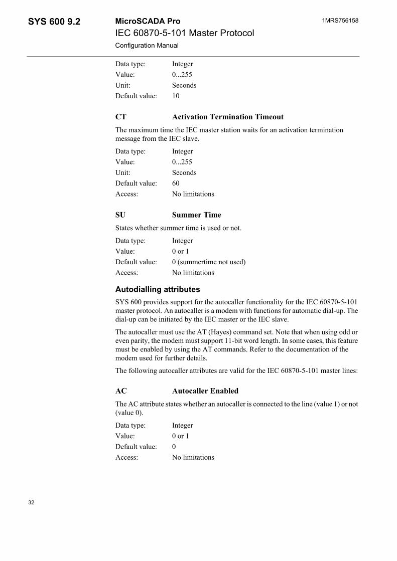
CT Activation Termination TimeoutThe maximum time the IEC master station waits for an activation termination message from the IEC slave.
Data type: IntegerValue: 0...255Unit: SecondsDefault value: 60Access: No limitations
SU Summer TimeStates whether summer time is used or not.
Data type: IntegerValue: 0 or 1Default value: 0 (summertime not used)Access: No limitations
Autodialling attributesSYS 600 provides support for the autocaller functionality for the IEC 60870-5-101 master protocol. An autocaller is a modem with functions for automatic dial-up. The dial-up can be initiated by the IEC master or the IEC slave.
The autocaller must use the AT (Hayes) command set. Note that when using odd or even parity, the modem must support 11-bit word length. In some cases, this feature must be enabled by using the AT commands. Refer to the documentation of the modem used for further details.
The following autocaller attributes are valid for the IEC 60870-5-101 master lines:
AC Autocaller EnabledThe AC attribute states whether an autocaller is connected to the line (value 1) or not (value 0).
Data type: IntegerValue: 0 or 1Default value: 0Access: No limitations
32
1MRS756158 SYS 600 9.2MicroSCADA ProIEC 60870-5-101 Master ProtocolConfiguration Manual
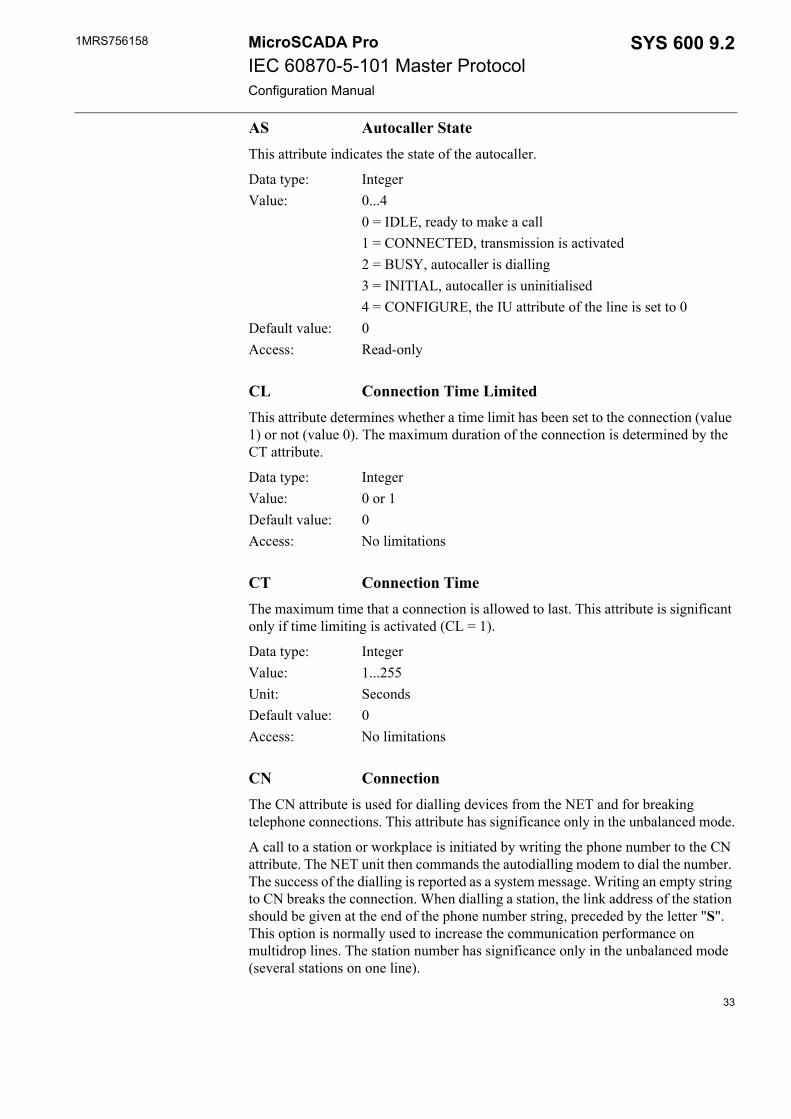
AS Autocaller StateThis attribute indicates the state of the autocaller.
Data type: IntegerValue: 0...4
0 = IDLE, ready to make a call1 = CONNECTED, transmission is activated2 = BUSY, autocaller is dialling3 = INITIAL, autocaller is uninitialised4 = CONFIGURE, the IU attribute of the line is set to 0
Default value: 0Access: Read-only
CL Connection Time LimitedThis attribute determines whether a time limit has been set to the connection (value 1) or not (value 0). The maximum duration of the connection is determined by the CT attribute.
Data type: IntegerValue: 0 or 1Default value: 0Access: No limitations
CT Connection Time The maximum time that a connection is allowed to last. This attribute is significant only if time limiting is activated (CL = 1).
Data type: IntegerValue: 1...255Unit: SecondsDefault value: 0Access: No limitations
CN ConnectionThe CN attribute is used for dialling devices from the NET and for breaking telephone connections. This attribute has significance only in the unbalanced mode.
A call to a station or workplace is initiated by writing the phone number to the CN attribute. The NET unit then commands the autodialling modem to dial the number. The success of the dialling is reported as a system message. Writing an empty string to CN breaks the connection. When dialling a station, the link address of the station should be given at the end of the phone number string, preceded by the letter "S". This option is normally used to increase the communication performance on multidrop lines. The station number has significance only in the unbalanced mode (several stations on one line).
33

1MRS756158MicroSCADA ProIEC 60870-5-101 Master ProtocolConfiguration Manual
SYS 600 9.2
Data type: TextValue: Text string of maximum 25 charactersDefault value: Empty text stringAccess: No limitations
Example:#SET NET1:SCN5 = "123456789S11"
CS Connected Station The link address of the station a NET unit is communicating with.
Data type: IntegerValue: 0...65535
0 = autocaller not defined or no communicationDefault value: 0Access: Read-only
DD Radio Disconnection Delay Delay between the last data transfer and line disconnection.
Data type: IntegerValue: 1...255Unit: SecondsDefault value: 0Access: No limitations
MC Modem CommandUsing this attribute, a modem can be controlled directly from SCIL with the AT/Hayes commands. When an AT command is written to the MC, attribute it is transmitted to the modem on the line. The response from the modem is read using the same attribute.
Data type: TextValue: Text string, an AT/Hayes commandDefault value: 0Access: No limitations
Example:#SET NET1:SMC3 = ("AS0?")'
PC Pulse Dialing This attribute determines the dialling principle used.
Data type: Integer
34
1MRS756158 SYS 600 9.2MicroSCADA ProIEC 60870-5-101 Master ProtocolConfiguration Manual
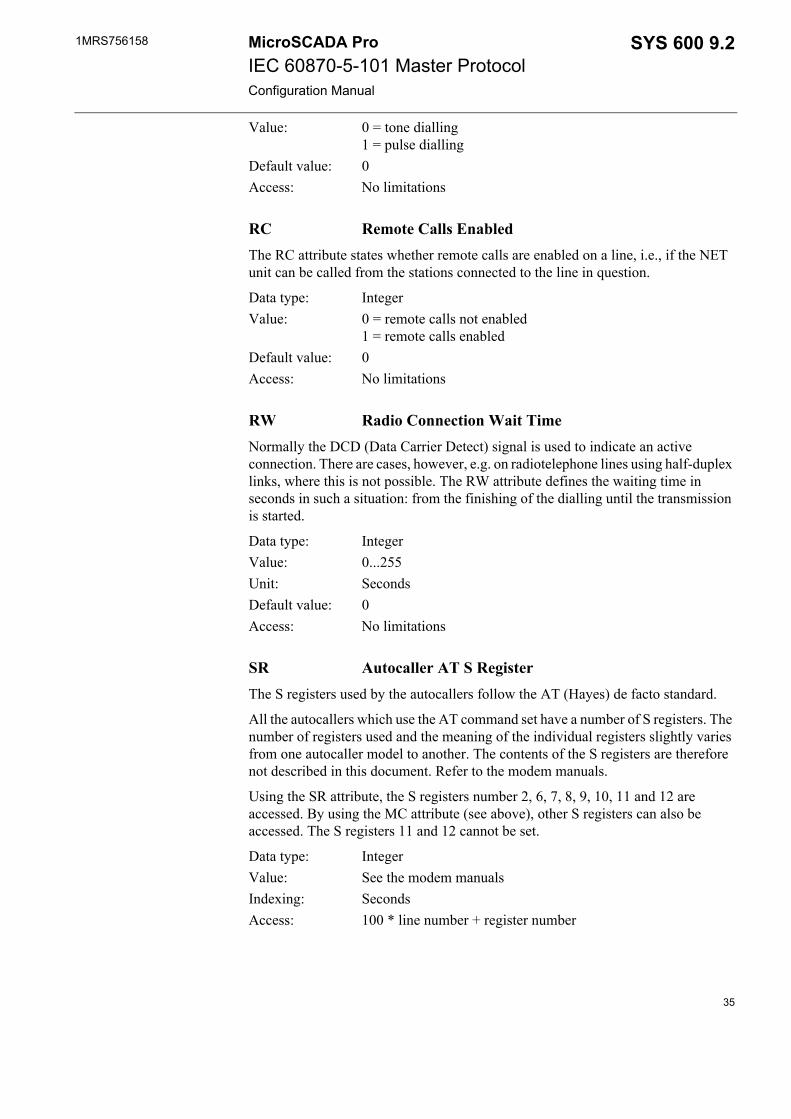
Value: 0 = tone dialling1 = pulse dialling
Default value: 0Access: No limitations
RC Remote Calls EnabledThe RC attribute states whether remote calls are enabled on a line, i.e., if the NET unit can be called from the stations connected to the line in question.
Data type: IntegerValue: 0 = remote calls not enabled
1 = remote calls enabledDefault value: 0Access: No limitations
RW Radio Connection Wait Time Normally the DCD (Data Carrier Detect) signal is used to indicate an active connection. There are cases, however, e.g. on radiotelephone lines using half-duplex links, where this is not possible. The RW attribute defines the waiting time in seconds in such a situation: from the finishing of the dialling until the transmission is started.
Data type: IntegerValue: 0...255Unit: SecondsDefault value: 0Access: No limitations
SR Autocaller AT S Register The S registers used by the autocallers follow the AT (Hayes) de facto standard.
All the autocallers which use the AT command set have a number of S registers. The number of registers used and the meaning of the individual registers slightly varies from one autocaller model to another. The contents of the S registers are therefore not described in this document. Refer to the modem manuals.
Using the SR attribute, the S registers number 2, 6, 7, 8, 9, 10, 11 and 12 are accessed. By using the MC attribute (see above), other S registers can also be accessed. The S registers 11 and 12 cannot be set.
Data type: IntegerValue: See the modem manualsIndexing: SecondsAccess: 100 * line number + register number
35
1MRS756158MicroSCADA ProIEC 60870-5-101 Master ProtocolConfiguration Manual
SYS 600 9.2
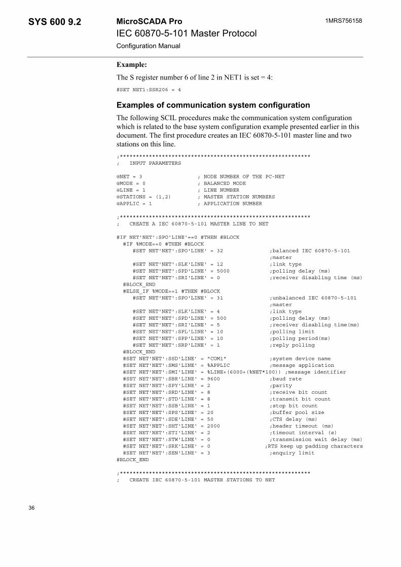
Example:
The S register number 6 of line 2 in NET1 is set = 4:#SET NET1:SSR206 = 4
Examples of communication system configurationThe following SCIL procedures make the communication system configuration which is related to the base system configuration example presented earlier in this document. The first procedure creates an IEC 60870-5-101 master line and two stations on this line.;***********************************************************; INPUT PARAMETERS
@NET = 3 ; NODE NUMBER OF THE PC-NET@MODE = 0 ; BALANCED MODE@LINE = 1 ; LINE NUMBER@STATIONS = (1,2) ; MASTER STATION NUMBERS@APPLIC = 1 ; APPLICATION NUMBER
;***********************************************************; CREATE A IEC 60870-5-101 MASTER LINE TO NET
#IF NET'NET':SPO'LINE'==0 #THEN #BLOCK #IF %MODE==0 #THEN #BLOCK #SET NET'NET':SPO'LINE' = 32 ;balanced IEC 60870-5-101 ;master #SET NET'NET':SLK'LINE' = 12 ;link type #SET NET'NET':SPD'LINE' = 5000 ;polling delay (ms) #SET NET'NET':SRI'LINE' = 0 ;receiver disabling time (ms) #BLOCK_END #ELSE_IF %MODE==1 #THEN #BLOCK #SET NET'NET':SPO'LINE' = 31 ;unbalanced IEC 60870-5-101 ;master #SET NET'NET':SLK'LINE' = 4 ;link type #SET NET'NET':SPD'LINE' = 500 ;polling delay (ms) #SET NET'NET':SRI'LINE' = 5 ;receiver disabling time(ms) #SET NET'NET':SPL'LINE' = 10 ;polling limit #SET NET'NET':SPP'LINE' = 10 ;polling period(ms) #SET NET'NET':SRP'LINE' = 1 ;reply polling #BLOCK_END #SET NET'NET':SSD'LINE’ = "COM1" ;system device name #SET NET'NET':SMS'LINE' = %APPLIC ;message application #SET NET'NET':SMI'LINE' = %LINE+(6000+(%NET*100)) ;message identifier #SET NET'NET':SBR'LINE' = 9600 ;baud rate #SET NET'NET':SPY'LINE' = 2 ;parity #SET NET'NET':SRD'LINE' = 8 ;receive bit count #SET NET'NET':STD'LINE' = 8 ;transmit bit count #SET NET'NET':SSB'LINE' = 1 ;stop bit count #SET NET'NET':SPS'LINE' = 20 ;buffer pool size #SET NET'NET':SDE'LINE' = 50 ;CTS delay (ms) #SET NET'NET':SHT'LINE' = 2000 ;header timeout (ms) #SET NET'NET':STI'LINE' = 2 ;timeout interval (s) #SET NET'NET':STW'LINE' = 0 ;transmission wait delay (ms) #SET NET'NET':SRK'LINE' = 0 ;RTS keep up padding characters #SET NET'NET':SEN'LINE' = 3 ;enquiry limit#BLOCK_END
;***********************************************************; CREATE IEC 60870-5-101 MASTER STATIONS TO NET
36
1MRS756158 SYS 600 9.2MicroSCADA ProIEC 60870-5-101 Master ProtocolConfiguration Manual
#LOOP_WITH I = 1..LENGTH(%STATIONS) @STA=%STATIONS(%I) #SET NET'NET':SDV(29) = (%STA,%LINE) ;create station to line #SET STA'STA':SAL = 1 ;allocated #SET STA'STA':SAS = %APPLIC ;allocating application #SET STA'STA':SMI = 1000+%STA ;message identification #SET STA'STA':SMS = %APPLIC ;message application #SET STA'STA':SSE = 1 ;system messages enabled #SET STA'STA':SSA = %STA ;station address #SET STA'STA':SSL = 2 ;station address length (bytes) #SET STA'STA':SPA = %STA ;polling address link (address) #SET STA'STA':SPL = 1 ;polling address length (bytes) #SET STA'STA':SIL = 3 ;info addr. length (bytes) #SET STA'STA':SCL = 1 ;COT length (bytes) #SET STA'STA':SCA = 32000 ;command address #SET STA'STA':SST = 5000 ;SYS waiting time (ms) #SET STA'STA':SRT = 10 ;application reply timeout (s) #SET STA'STA':SCT = 60 ;application termin. timeout(s) #SET STA'STA':SSU = 0 ;summer time (0=no, 1=yes) #SET STA'STA':SRW = 10 ;reply window size #SET STA'STA':SML = 230 ;max. message length #SET STA'STA':SDR = 0 ;direction #SET STA'STA':SSR = 0 ;single char response #SET STA'STA':SRM = 0 ;running mode #SET STA'STA':SIU = 1 ;set station in use#LOOP_END
; Set line in use#SET NET'NET':SIU'LINE' = 1
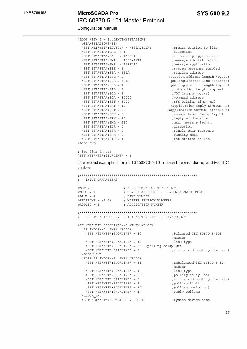
The second example is for an IEC 60870-5-101 master line with dial-up and two IEC stations.;***********************************************************; INPUT PARAMETERS
@NET = 3 ; NODE NUMBER OF THE PC-NET@MODE = 1 ; 0 = BALANCED MODE, 1 = UNBALANCED MODE@LINE = 2 ; LINE NUMBER@STATIONS = (1,2) ; MASTER STATION NUMBERS@APPLIC = 1 ; APPLICATION NUMBER
;***********************************************************; CREATE A IEC 60870-5-101 MASTER DIAL-UP LINE TO NET
#IF NET'NET':SPO'LINE'==0 #THEN #BLOCK #IF %MODE==0 #THEN #BLOCK #SET NET'NET':SPO'LINE' = 32 ;balanced IEC 60870-5-101
;master #SET NET'NET':SLK'LINE' = 12 ;link type #SET NET'NET':SPD'LINE' = 5000;polling delay (ms) #SET NET'NET':SRI'LINE' = 0 ;receiver disabling time (ms) #BLOCK_END #ELSE_IF %MODE==1 #THEN #BLOCK #SET NET'NET':SPO'LINE' = 31 ;unbalanced IEC 60870-5-10 ;master #SET NET'NET':SLK'LINE' = 1 ;link type #SET NET'NET':SPD'LINE' = 500 ;polling delay (ms) #SET NET'NET':SRI'LINE' = 5 ;receiver disabling time (ms) #SET NET'NET':SPL'LINE' = 1 ;polling limit #SET NET'NET':SPP'LINE' = 10 ;polling period(ms) #SET NET'NET':SRP'LINE' = 1 ;reply polling #BLOCK_END #SET NET'NET':SSD'LINE’ = "COM1" ;system device name
37
1MRS756158MicroSCADA ProIEC 60870-5-101 Master ProtocolConfiguration Manual
SYS 600 9.2
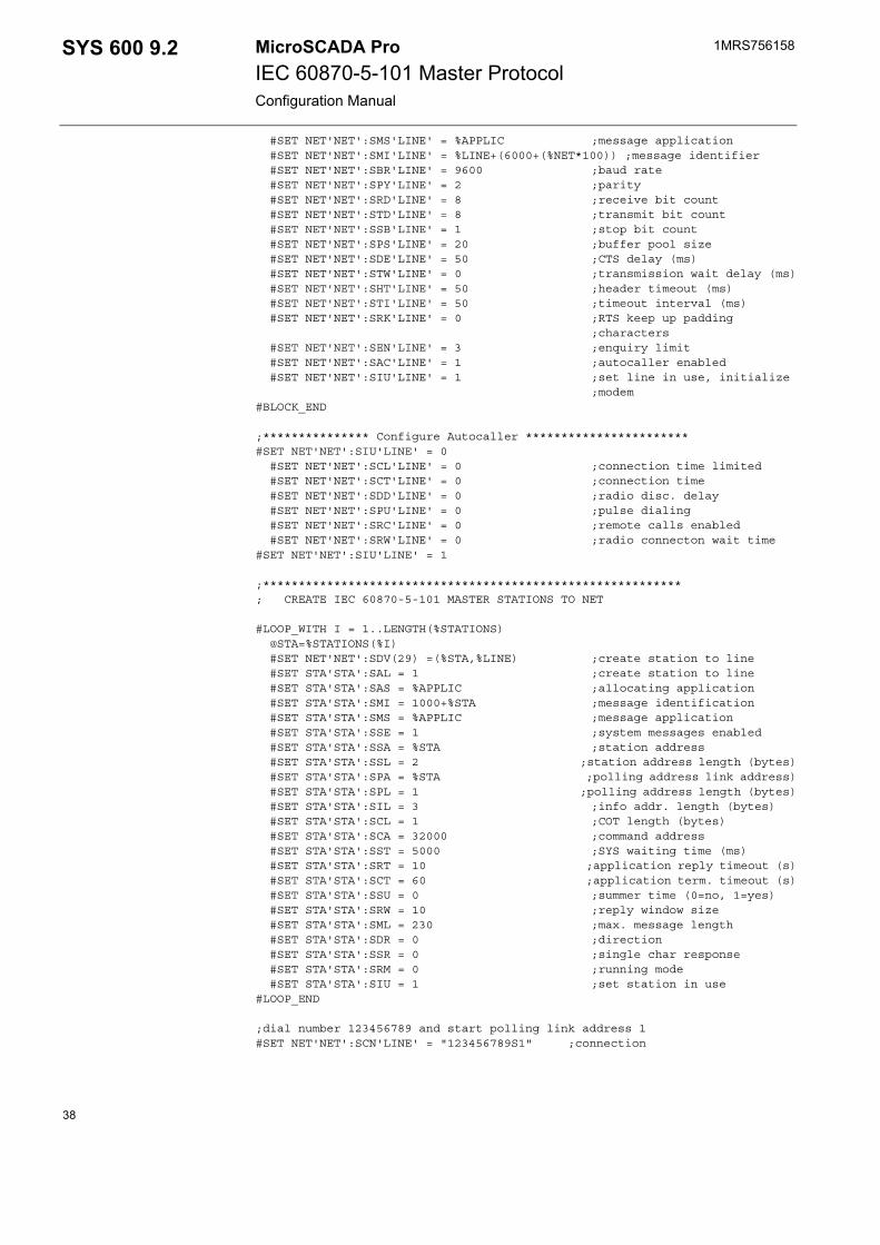
#SET NET'NET':SMS'LINE' = %APPLIC ;message application #SET NET'NET':SMI'LINE' = %LINE+(6000+(%NET*100)) ;message identifier #SET NET'NET':SBR'LINE' = 9600 ;baud rate #SET NET'NET':SPY'LINE' = 2 ;parity #SET NET'NET':SRD'LINE' = 8 ;receive bit count #SET NET'NET':STD'LINE' = 8 ;transmit bit count #SET NET'NET':SSB'LINE' = 1 ;stop bit count #SET NET'NET':SPS'LINE' = 20 ;buffer pool size #SET NET'NET':SDE'LINE' = 50 ;CTS delay (ms) #SET NET'NET':STW'LINE' = 0 ;transmission wait delay (ms) #SET NET'NET':SHT'LINE' = 50 ;header timeout (ms) #SET NET'NET':STI'LINE' = 50 ;timeout interval (ms) #SET NET'NET':SRK'LINE' = 0 ;RTS keep up padding ;characters #SET NET'NET':SEN'LINE' = 3 ;enquiry limit #SET NET'NET':SAC'LINE' = 1 ;autocaller enabled #SET NET'NET':SIU'LINE' = 1 ;set line in use, initialize
;modem#BLOCK_END
;*************** Configure Autocaller ***********************#SET NET'NET':SIU'LINE' = 0 #SET NET'NET':SCL'LINE' = 0 ;connection time limited #SET NET'NET':SCT'LINE' = 0 ;connection time #SET NET'NET':SDD'LINE' = 0 ;radio disc. delay #SET NET'NET':SPU'LINE' = 0 ;pulse dialing #SET NET'NET':SRC'LINE' = 0 ;remote calls enabled #SET NET'NET':SRW'LINE' = 0 ;radio connecton wait time#SET NET'NET':SIU'LINE' = 1
;***********************************************************; CREATE IEC 60870-5-101 MASTER STATIONS TO NET
#LOOP_WITH I = 1..LENGTH(%STATIONS) @STA=%STATIONS(%I) #SET NET'NET':SDV(29) =(%STA,%LINE) ;create station to line #SET STA'STA':SAL = 1 ;create station to line #SET STA'STA':SAS = %APPLIC ;allocating application #SET STA'STA':SMI = 1000+%STA ;message identification #SET STA'STA':SMS = %APPLIC ;message application #SET STA'STA':SSE = 1 ;system messages enabled #SET STA'STA':SSA = %STA ;station address #SET STA'STA':SSL = 2 ;station address length (bytes) #SET STA'STA':SPA = %STA ;polling address link address) #SET STA'STA':SPL = 1 ;polling address length (bytes) #SET STA'STA':SIL = 3 ;info addr. length (bytes) #SET STA'STA':SCL = 1 ;COT length (bytes) #SET STA'STA':SCA = 32000 ;command address #SET STA'STA':SST = 5000 ;SYS waiting time (ms) #SET STA'STA':SRT = 10 ;application reply timeout (s) #SET STA'STA':SCT = 60 ;application term. timeout (s) #SET STA'STA':SSU = 0 ;summer time (0=no, 1=yes) #SET STA'STA':SRW = 10 ;reply window size #SET STA'STA':SML = 230 ;max. message length #SET STA'STA':SDR = 0 ;direction #SET STA'STA':SSR = 0 ;single char response #SET STA'STA':SRM = 0 ;running mode #SET STA'STA':SIU = 1 ;set station in use#LOOP_END
;dial number 123456789 and start polling link address 1#SET NET'NET':SCN'LINE' = "123456789S1" ;connection
38
1MRS756158 SYS 600 9.2MicroSCADA ProIEC 60870-5-101 Master ProtocolConfiguration Manual
3.4. After configurationFor each input signal from the process devices the process database should contain a process object whose value changes after process data is received. For each command there should be an output process object. You should also create the bit stream process object that receives unrecognised IEC messages from the slave.
Besides the configuration of the base and communication system, you also need to configure the IEC slave.
3.5. How to test the configurationWhen the slave and master stations have been physically tested and the configuration has been completed, the connection and configuration can be tested based on the following methods:• Clear to Send (CTS) and Carrier Detect (DCD) signals. With the IEC master
protocols both the Clear to Send and Carrier Detect signals are always active.• Diagnostic counters. When the communication between the slave and the master
is running properly and data is moving on the line, the diagnostic counters indicating the number received and transmitted data messages should be incrementing.
• By connecting a serial line analyser to the IEC 60870-5-101 line.
One advisable way to test the configuration is to use SYS 600 also as the IEC slave. In this case you have to make the base system and communication system configuration for the IEC 60870-5-101 slave line and station(s). The IEC slave can be even in the same computer.
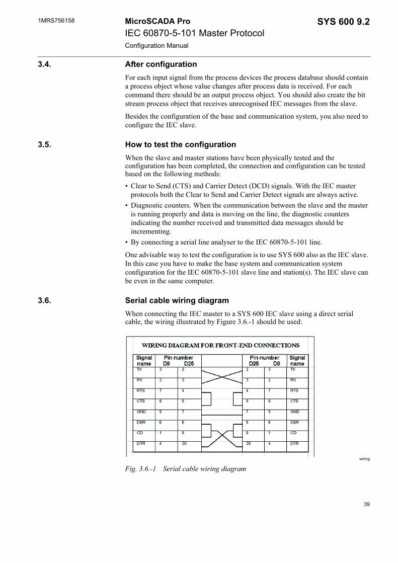
3.6. Serial cable wiring diagramWhen connecting the IEC master to a SYS 600 IEC slave using a direct serial cable, the wiring illustrated by Figure 3.6.-1 should be used:
wiring
Fig. 3.6.-1 Serial cable wiring diagram
39

40
1MRS756158 SYS 600 9.2MicroSCADA ProIEC 60870-5-101 Master ProtocolConfiguration Manual
4. Technical description
4.1. General
4.1.1. IEC 60870-5-101 protocolThe IEC Technical Committee 57 (Working Group 03) has developed a protocol standard for telecontrol, teleprotection and associated telecommunications for electric power systems. The result of this work is IEC 60870-5. The five first documents listed in Section 1.1 specify the base of IEC 60870-5.
The IEC Technical Committee 57 has also generated a companion standard IEC 60870-5-101 for telecontrol equipment and systems with coded bit serial data transmission for monitoring and controlling geographically widespread processes. This standard utilises the series of documents of IEC 60870-5.
IEC 60870-5-101 is designed according to the Enhanced Protocol Architecture (EPA) and specifies the following Open Systems Interconnection (OSI) layers:• Physical layer• Data link layer• Application layer
The physical layer can be any bit-serial physical layer, such as RS-232 C, RS-485 or fibre transceiver. In SYS 600 the communication takes place by using the serial port(s) of the base system computer. The interface used is RS-232 C.
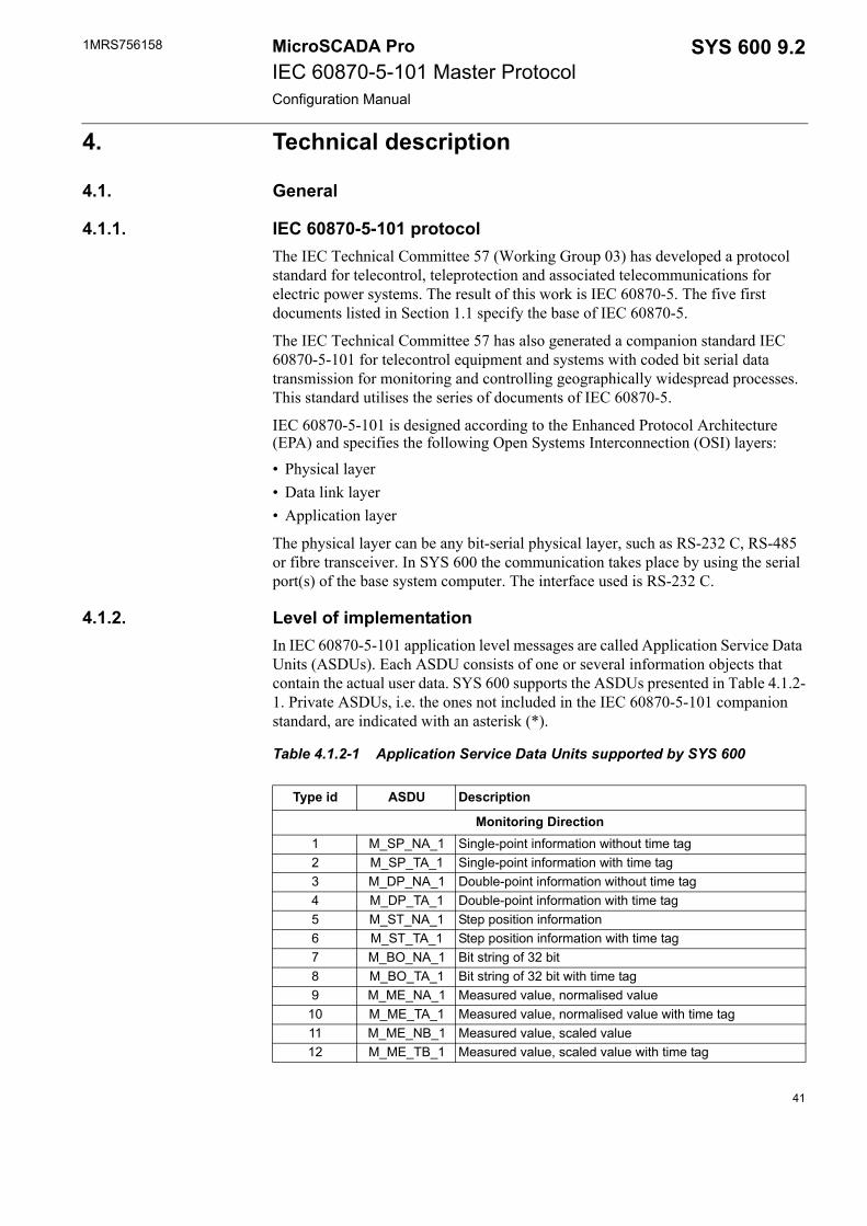
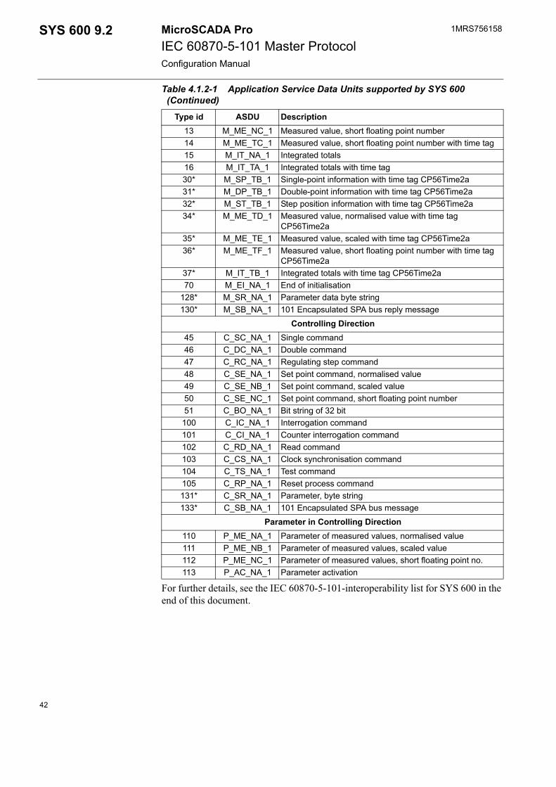
4.1.2. Level of implementationIn IEC 60870-5-101 application level messages are called Application Service Data Units (ASDUs). Each ASDU consists of one or several information objects that contain the actual user data. SYS 600 supports the ASDUs presented in Table 4.1.2-1. Private ASDUs, i.e. the ones not included in the IEC 60870-5-101 companion standard, are indicated with an asterisk (*).
Table 4.1.2-1 Application Service Data Units supported by SYS 600
Type id ASDU Description
Monitoring Direction1 M_SP_NA_1 Single-point information without time tag2 M_SP_TA_1 Single-point information with time tag3 M_DP_NA_1 Double-point information without time tag4 M_DP_TA_1 Double-point information with time tag5 M_ST_NA_1 Step position information6 M_ST_TA_1 Step position information with time tag7 M_BO_NA_1 Bit string of 32 bit8 M_BO_TA_1 Bit string of 32 bit with time tag9 M_ME_NA_1 Measured value, normalised value
10 M_ME_TA_1 Measured value, normalised value with time tag11 M_ME_NB_1 Measured value, scaled value12 M_ME_TB_1 Measured value, scaled value with time tag
41
1MRS756158MicroSCADA ProIEC 60870-5-101 Master ProtocolConfiguration Manual
SYS 600 9.2
For further details, see the IEC 60870-5-101-interoperability list for SYS 600 in the end of this document.
13 M_ME_NC_1 Measured value, short floating point number14 M_ME_TC_1 Measured value, short floating point number with time tag15 M_IT_NA_1 Integrated totals16 M_IT_TA_1 Integrated totals with time tag30* M_SP_TB_1 Single-point information with time tag CP56Time2a31* M_DP_TB_1 Double-point information with time tag CP56Time2a32* M_ST_TB_1 Step position information with time tag CP56Time2a34* M_ME_TD_1 Measured value, normalised value with time tag
CP56Time2a35* M_ME_TE_1 Measured value, scaled with time tag CP56Time2a36* M_ME_TF_1 Measured value, short floating point number with time tag
CP56Time2a37* M_IT_TB_1 Integrated totals with time tag CP56Time2a70 M_EI_NA_1 End of initialisation
128* M_SR_NA_1 Parameter data byte string130* M_SB_NA_1 101 Encapsulated SPA bus reply message
Controlling Direction45 C_SC_NA_1 Single command46 C_DC_NA_1 Double command47 C_RC_NA_1 Regulating step command48 C_SE_NA_1 Set point command, normalised value49 C_SE_NB_1 Set point command, scaled value50 C_SE_NC_1 Set point command, short floating point number51 C_BO_NA_1 Bit string of 32 bit100 C_IC_NA_1 Interrogation command101 C_CI_NA_1 Counter interrogation command102 C_RD_NA_1 Read command103 C_CS_NA_1 Clock synchronisation command104 C_TS_NA_1 Test command105 C_RP_NA_1 Reset process command131* C_SR_NA_1 Parameter, byte string133* C_SB_NA_1 101 Encapsulated SPA bus message
Parameter in Controlling Direction110 P_ME_NA_1 Parameter of measured values, normalised value111 P_ME_NB_1 Parameter of measured values, scaled value112 P_ME_NC_1 Parameter of measured values, short floating point no.113 P_AC_NA_1 Parameter activation
Table 4.1.2-1 Application Service Data Units supported by SYS 600 (Continued)
Type id ASDU Description
42
1MRS756158 SYS 600 9.2MicroSCADA ProIEC 60870-5-101 Master ProtocolConfiguration Manual
4.2. CommunicationThis chapter gives a more detailed description of the implementation of the IEC 60870-5-101 master protocol in SYS 600. The attributes that can be used for device communication are also described. Examples of how to exchange data between the master and the slave are given in this chapter along with information of the IEC 60870-5-101 status codes.
4.2.1. Communication modesThe IEC 60870-5-101 protocol has two modes or link layer transmission procedures: unbalanced mode and balanced mode.
In the unbalanced mode a master station controls the data traffic by polling the outstations sequentially. In this case the master is the primary station that initiates all the message transfer. The outstations are secondary stations (slaves) that may transmit only when they are polled.
In the balanced mode each station, master and slave, may initiate message transfers. The communication mode of a NET line can be selected by using the PO attribute when the line is created, and must of course be matched with the communication mode of the master station.
4.2.2. Protocol converterEach IEC 60870-5-101 master station configured on a line of a NET unit acts as a protocol converter between the IEC 60870-5-101 protocol and a base system. An internal protocol of SYS 600 is used in communication between the SYS 600 nodes, for example, between a base system and a NET unit.
In IEC 60870-5-101 the data sent from the slave to the master can be divided in two classes: class 1 or class 2. The data from the classes is sent to the master either by polling (unbalanced mode) or spontaneously (balanced mode).
4.2.3. AddressingIn IEC 60870-5-101 there are three kinds of addresses:• Link address: the address of the IEC link. This address is defined by the PA
(Polling Address) attribute of the IEC station. In most cases it is the same as the station address.
• Station address: a common address of an ASDU. There can be several common addresses of an ASDU with the same link address. This address is defined by the SA (Station Address) attribute of the IEC station.
• Signal address: an information object address. This address is unique for each signal with the same common address of an ASDU. The Information object address can be given in two ways:• As an unstructured address, which is basically just an integer within the range
of the information object address.
The serial bus topology (multi-drop) can be used only in the unbalanced mode.
43
1MRS756158MicroSCADA ProIEC 60870-5-101 Master ProtocolConfiguration Manual
SYS 600 9.2
• As a structured address which is given byte-wise so that each byte usually represents a level in a hierarchical structure. For example, upper byte = unit number and lower byte = signal address.
SYS 600 supports only unstructured addresses. However, this does not prevent communication with the IEC slaves using structured addresses, since the two types of addresses just demonstrate two different ways of presenting the same address. For example, a two-byte address can be represented as follows: unstructured = 256*upper byte + lower byte.
In SYS 600 both the input and output process objects share the same address range, which means that there cannot be two process objects with overlapping addresses. If the user wants this feature, e.g. a command and the corresponding indication having the same address, it can be achieved by using offsets that are outside the information address range limited by the IL attribute. The offset used must be large enough to set only the bits of the information object address that are more significant than the bits within the IL range.
Example:
(bits numbered from 0 to 31)STAn:SIL = 2, 16 bit addresses
Information object address 2000 (decimal) = 00000011111010000 (binary)
Offset = 131072 (decimal) = 100000000000000000 (binary), sets bit 16
Address for indication = 2000 (decimal) = 00000011111010000 (binary)
Address for command = 2000 + 131072 = 133072 (decimal) = 100000011111010000 (binary)
The NET unit interprets both addresses as 2000, since bits above the IL range are left out. The offset used must of course be larger if IL = 3.
4.2.4. Device communication attributes
CO Command OutThe CO attribute can be used for generating command messages to IEC stations. All kinds of commands can be generated: data commands, application commands and system commands. Parameters in the command direction are also sent by using the CO attribute.
The data content of the command, which in the IEC standards is called a set of information objects, is given as transparent data, octet by octet. It must be noted that the user is responsible for the validity of the data content. For more information, refer to the IEC standards listed in Section 1.1.
44
1MRS756158 SYS 600 9.2MicroSCADA ProIEC 60870-5-101 Master ProtocolConfiguration Manual
Data type: VectorValue Vector (TYPE, ADDR,COT,DATA)Value range: 0...255, when IL attribute = 1
0...65535, when IL attribute = 270...16777215,when IL attribute = 3
Access: Write-only
Description of the vector parameters:
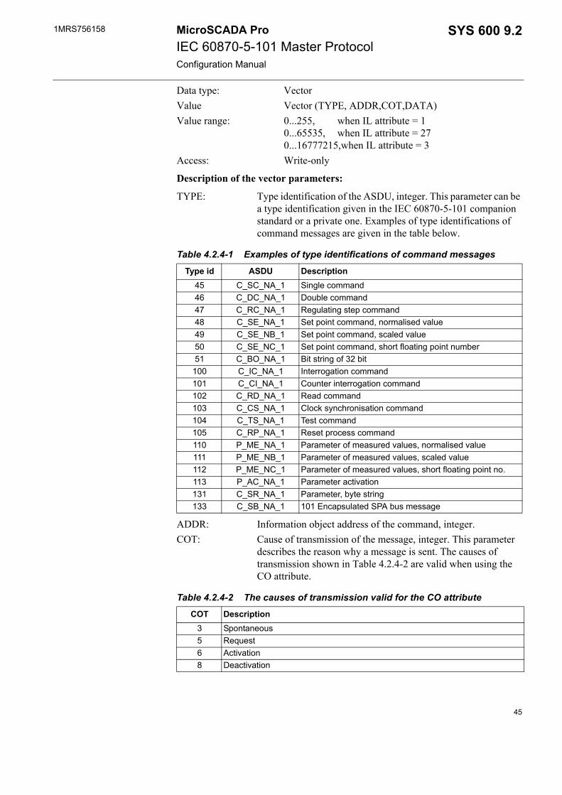
TYPE: Type identification of the ASDU, integer. This parameter can be a type identification given in the IEC 60870-5-101 companion standard or a private one. Examples of type identifications of command messages are given in the table below.
ADDR: Information object address of the command, integer.COT: Cause of transmission of the message, integer. This parameter
describes the reason why a message is sent. The causes of transmission shown in Table 4.2.4-2 are valid when using the CO attribute.
Table 4.2.4-1 Examples of type identifications of command messages
Type id ASDU Description45 C_SC_NA_1 Single command46 C_DC_NA_1 Double command47 C_RC_NA_1 Regulating step command48 C_SE_NA_1 Set point command, normalised value49 C_SE_NB_1 Set point command, scaled value50 C_SE_NC_1 Set point command, short floating point number51 C_BO_NA_1 Bit string of 32 bit
100 C_IC_NA_1 Interrogation command101 C_CI_NA_1 Counter interrogation command102 C_RD_NA_1 Read command103 C_CS_NA_1 Clock synchronisation command104 C_TS_NA_1 Test command105 C_RP_NA_1 Reset process command110 P_ME_NA_1 Parameter of measured values, normalised value111 P_ME_NB_1 Parameter of measured values, scaled value112 P_ME_NC_1 Parameter of measured values, short floating point no.113 P_AC_NA_1 Parameter activation131 C_SR_NA_1 Parameter, byte string133 C_SB_NA_1 101 Encapsulated SPA bus message
Table 4.2.4-2 The causes of transmission valid for the CO attribute
COT Description3 Spontaneous5 Request6 Activation8 Deactivation
45
1MRS756158MicroSCADA ProIEC 60870-5-101 Master ProtocolConfiguration Manual
SYS 600 9.2
DATA: The set of information objects of the command as integers. Each integer corresponds to one octet in the IEC message.
Some examples of the use of the CO attribute are presented below. See also the examples of the data, application and system commands later in this document.;general interrogation#SET STA'STA_NR':SCO = (100,0,6,20)
;close select command, double command, address 1000#SET STA'STA_NR':SCO = (46,1000,6,128+1)
;test command#SET STA'STA_NR':SCO = (104,0,6,170,85)
GI General InterrogationSetting this attribute sends a general/group interrogation command (ASDU 100) to the IEC slave station. In IEC 60870-5-101 analog and binary data can be divided into 16 groups which can be interrogated separately. General interrogation covers all groups.
By setting 1 to the GI attribute a general interrogation message is generated. By using the vector value, an interrogation command can be deactivated, i.e. cancelled, or a group interrogation command generated.
Data type: Vector or integerValue: Vector (ENA,[QOI]) or integer 1Access: No limitations
Description of the vector parameters:
ENA: Activate (value 1) or deactivate (value 0) interrogationQOI: Qualifier of interrogation
Value 20: General interrogationValues 21…36: Interrogation for groups 1…16
SY SynchroniseThe SY attribute is used to make an accurate time synchronisation of IEC stations. No time arguments are needed since the time sent in the synchronisation message is taken from the internal clock of SYS 600. Stations can be synchronised one by one or by using a broadcast synchronisation message, which synchronises all the stations configured on an IEC line.
Data type: Vector Value: Vector (COT, [BRO,[ADDR]])Access: Write-only
Description of the vector parameters:
COT: Cause of transmission of the synchronisation messages. Valid values: 6 = activate, 8 = deactivate.
46
1MRS756158 SYS 600 9.2MicroSCADA ProIEC 60870-5-101 Master ProtocolConfiguration Manual
BRO: Broadcast, determines whether the synchronisation message is a broadcast message (value 1) or not (value 0). If omitted, value 0 is assumed.
ADDR: Information object address of the synchronisation message. In most cases value 0 is correct. If omitted, value 0 is assumed.
TD Transparent DataThe TD attribute is used for sending transparent data (e.g. SPA messages) to the IEC slave.
Data type: VectorValue Vector (TYPE, ADDR, COT, TDT)Value range: 0...255, when IL attribute = 1
0...65535, when IL attribute = 20...16777215, when IL attribute = 3
Access: Write-only
Description of the vector parameters:
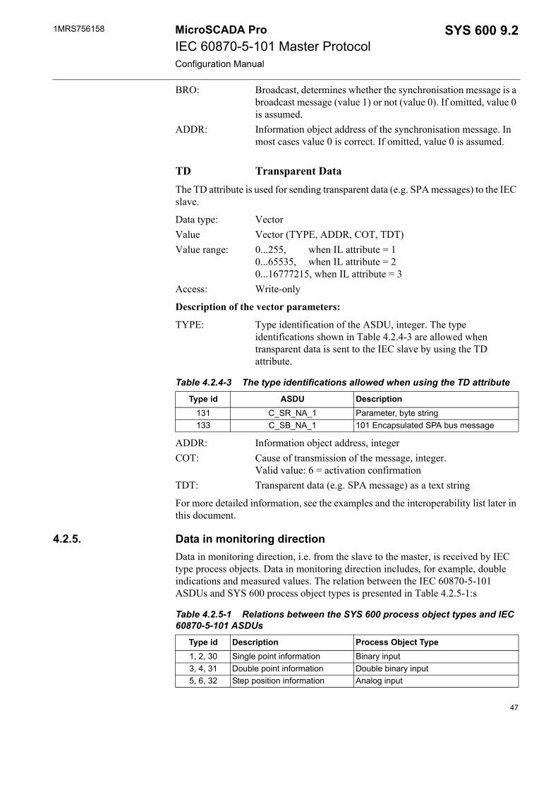
TYPE: Type identification of the ASDU, integer. The type identifications shown in Table 4.2.4-3 are allowed when transparent data is sent to the IEC slave by using the TD attribute.
ADDR: Information object address, integerCOT: Cause of transmission of the message, integer.
Valid value: 6 = activation confirmationTDT: Transparent data (e.g. SPA message) as a text string
For more detailed information, see the examples and the interoperability list later in this document.
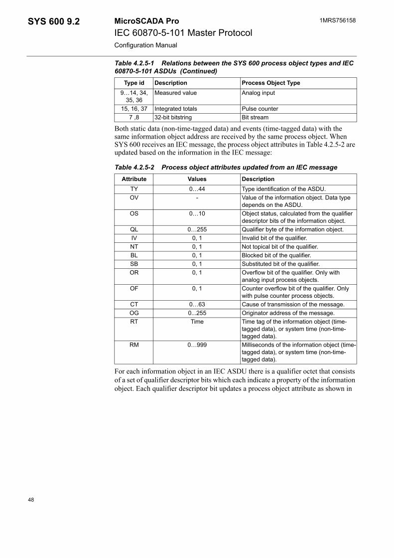
4.2.5. Data in monitoring directionData in monitoring direction, i.e. from the slave to the master, is received by IEC type process objects. Data in monitoring direction includes, for example, double indications and measured values. The relation between the IEC 60870-5-101 ASDUs and SYS 600 process object types is presented in Table 4.2.5-1:s
Table 4.2.4-3 The type identifications allowed when using the TD attribute
Type id ASDU Description131 C_SR_NA_1 Parameter, byte string133 C_SB_NA_1 101 Encapsulated SPA bus message
Table 4.2.5-1 Relations between the SYS 600 process object types and IEC 60870-5-101 ASDUs
Type id Description Process Object Type1, 2, 30 Single point information Binary input3, 4, 31 Double point information Double binary input5, 6, 32 Step position information Analog input
47
1MRS756158MicroSCADA ProIEC 60870-5-101 Master ProtocolConfiguration Manual
SYS 600 9.2
Both static data (non-time-tagged data) and events (time-tagged data) with the same information object address are received by the same process object. When SYS 600 receives an IEC message, the process object attributes in Table 4.2.5-2 are updated based on the information in the IEC message:
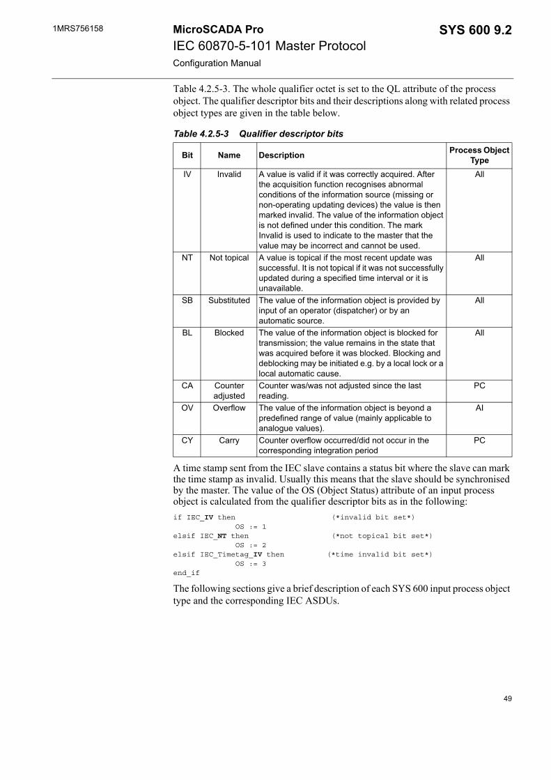
For each information object in an IEC ASDU there is a qualifier octet that consists of a set of qualifier descriptor bits which each indicate a property of the information object. Each qualifier descriptor bit updates a process object attribute as shown in
9…14, 34, 35, 36
Measured value Analog input
15, 16, 37 Integrated totals Pulse counter7 ,8 32-bit bitstring Bit stream
Table 4.2.5-2 Process object attributes updated from an IEC message
Attribute Values DescriptionTY 0…44 Type identification of the ASDU.OV - Value of the information object. Data type
depends on the ASDU.OS 0…10 Object status, calculated from the qualifier
descriptor bits of the information object.QL 0…255 Qualifier byte of the information object.IV 0, 1 Invalid bit of the qualifier.NT 0, 1 Not topical bit of the qualifier.BL 0, 1 Blocked bit of the qualifier.SB 0, 1 Substituted bit of the qualifier.OR 0, 1 Overflow bit of the qualifier. Only with
analog input process objects.OF 0, 1 Counter overflow bit of the qualifier. Only
with pulse counter process objects.CT 0…63 Cause of transmission of the message.OG 0...255 Originator address of the message.RT Time Time tag of the information object (time-
tagged data), or system time (non-time-tagged data).
RM 0…999 Milliseconds of the information object (time-tagged data), or system time (non-time-tagged data).
Table 4.2.5-1 Relations between the SYS 600 process object types and IEC 60870-5-101 ASDUs (Continued)
Type id Description Process Object Type
48
1MRS756158 SYS 600 9.2MicroSCADA ProIEC 60870-5-101 Master ProtocolConfiguration Manual
Table 4.2.5-3. The whole qualifier octet is set to the QL attribute of the process object. The qualifier descriptor bits and their descriptions along with related process object types are given in the table below.
A time stamp sent from the IEC slave contains a status bit where the slave can mark the time stamp as invalid. Usually this means that the slave should be synchronised by the master. The value of the OS (Object Status) attribute of an input process object is calculated from the qualifier descriptor bits as in the following:if IEC_IV then (*invalid bit set*) OS := 1elsif IEC_NT then (*not topical bit set*) OS := 2elsif IEC_Timetag_IV then (*time invalid bit set*) OS := 3end_if
The following sections give a brief description of each SYS 600 input process object type and the corresponding IEC ASDUs.
Table 4.2.5-3 Qualifier descriptor bits
Bit Name Description Process Object Type
IV Invalid A value is valid if it was correctly acquired. After the acquisition function recognises abnormal conditions of the information source (missing or non-operating updating devices) the value is then marked invalid. The value of the information object is not defined under this condition. The mark Invalid is used to indicate to the master that the value may be incorrect and cannot be used.
All
NT Not topical A value is topical if the most recent update was successful. It is not topical if it was not successfully updated during a specified time interval or it is unavailable.
All
SB Substituted The value of the information object is provided by input of an operator (dispatcher) or by an automatic source.
All
BL Blocked The value of the information object is blocked for transmission; the value remains in the state that was acquired before it was blocked. Blocking and deblocking may be initiated e.g. by a local lock or a local automatic cause.
All
CA Counter adjusted
Counter was/was not adjusted since the last reading.
PC
OV Overflow The value of the information object is beyond a predefined range of value (mainly applicable to analogue values).
AI
CY Carry Counter overflow occurred/did not occur in the corresponding integration period
PC
49
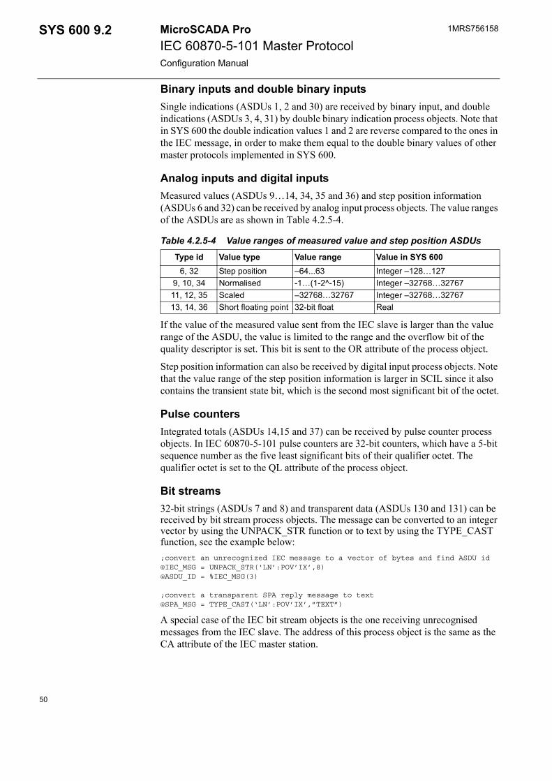
1MRS756158MicroSCADA ProIEC 60870-5-101 Master ProtocolConfiguration Manual
SYS 600 9.2
Binary inputs and double binary inputsSingle indications (ASDUs 1, 2 and 30) are received by binary input, and double indications (ASDUs 3, 4, 31) by double binary indication process objects. Note that in SYS 600 the double indication values 1 and 2 are reverse compared to the ones in the IEC message, in order to make them equal to the double binary values of other master protocols implemented in SYS 600.
Analog inputs and digital inputsMeasured values (ASDUs 9…14, 34, 35 and 36) and step position information (ASDUs 6 and 32) can be received by analog input process objects. The value ranges of the ASDUs are as shown in Table 4.2.5-4.
If the value of the measured value sent from the IEC slave is larger than the value range of the ASDU, the value is limited to the range and the overflow bit of the quality descriptor is set. This bit is sent to the OR attribute of the process object.
Step position information can also be received by digital input process objects. Note that the value range of the step position information is larger in SCIL since it also contains the transient state bit, which is the second most significant bit of the octet.
Pulse countersIntegrated totals (ASDUs 14,15 and 37) can be received by pulse counter process objects. In IEC 60870-5-101 pulse counters are 32-bit counters, which have a 5-bit sequence number as the five least significant bits of their qualifier octet. The qualifier octet is set to the QL attribute of the process object.
Bit streams32-bit strings (ASDUs 7 and 8) and transparent data (ASDUs 130 and 131) can be received by bit stream process objects. The message can be converted to an integer vector by using the UNPACK_STR function or to text by using the TYPE_CAST function, see the example below:;convert an unrecognized IEC message to a vector of bytes and find ASDU id@IEC_MSG = UNPACK_STR(‘LN’:POV’IX’,8)@ASDU_ID = %IEC_MSG(3)
;convert a transparent SPA reply message to text@SPA_MSG = TYPE_CAST(‘LN’:POV’IX’,”TEXT”)
A special case of the IEC bit stream objects is the one receiving unrecognised messages from the IEC slave. The address of this process object is the same as the CA attribute of the IEC master station.
Table 4.2.5-4 Value ranges of measured value and step position ASDUs
Type id Value type Value range Value in SYS 6006, 32 Step position –64...63 Integer –128…127
9, 10, 34 Normalised -1…(1-2^-15) Integer –32768…3276711, 12, 35 Scaled –32768…32767 Integer –32768…3276713, 14, 36 Short floating point 32-bit float Real
50
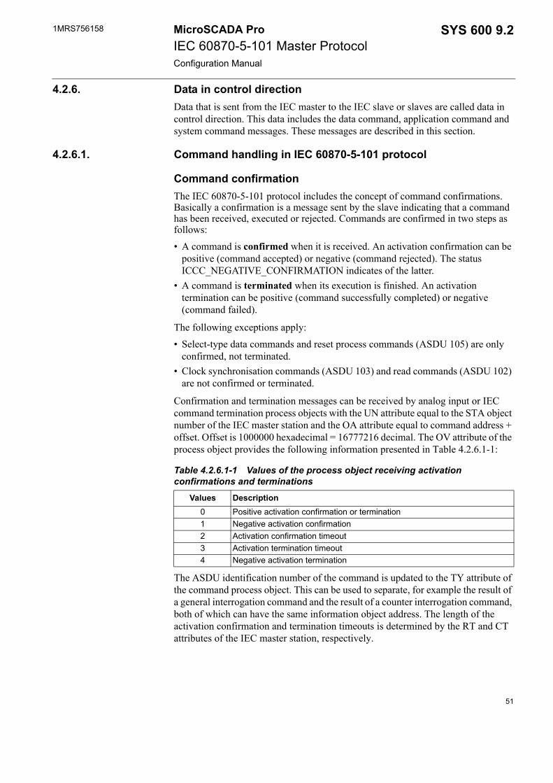
1MRS756158 SYS 600 9.2MicroSCADA ProIEC 60870-5-101 Master ProtocolConfiguration Manual
4.2.6. Data in control directionData that is sent from the IEC master to the IEC slave or slaves are called data in control direction. This data includes the data command, application command and system command messages. These messages are described in this section.
4.2.6.1. Command handling in IEC 60870-5-101 protocol
Command confirmationThe IEC 60870-5-101 protocol includes the concept of command confirmations. Basically a confirmation is a message sent by the slave indicating that a command has been received, executed or rejected. Commands are confirmed in two steps as follows:• A command is confirmed when it is received. An activation confirmation can be
positive (command accepted) or negative (command rejected). The status ICCC_NEGATIVE_CONFIRMATION indicates of the latter.
• A command is terminated when its execution is finished. An activation termination can be positive (command successfully completed) or negative (command failed).
The following exceptions apply:• Select-type data commands and reset process commands (ASDU 105) are only
confirmed, not terminated.• Clock synchronisation commands (ASDU 103) and read commands (ASDU 102)
are not confirmed or terminated.
Confirmation and termination messages can be received by analog input or IEC command termination process objects with the UN attribute equal to the STA object number of the IEC master station and the OA attribute equal to command address + offset. Offset is 1000000 hexadecimal = 16777216 decimal. The OV attribute of the process object provides the following information presented in Table 4.2.6.1-1:
The ASDU identification number of the command is updated to the TY attribute of the command process object. This can be used to separate, for example the result of a general interrogation command and the result of a counter interrogation command, both of which can have the same information object address. The length of the activation confirmation and termination timeouts is determined by the RT and CT attributes of the IEC master station, respectively.
Table 4.2.6.1-1 Values of the process object receiving activation confirmations and terminations
Values Description0 Positive activation confirmation or termination1 Negative activation confirmation2 Activation confirmation timeout3 Activation termination timeout4 Negative activation termination
51
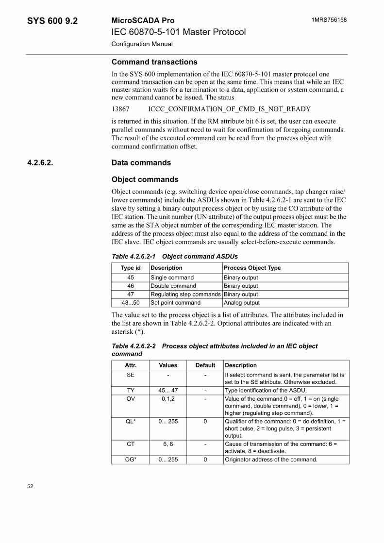
1MRS756158MicroSCADA ProIEC 60870-5-101 Master ProtocolConfiguration Manual
SYS 600 9.2
Command transactionsIn the SYS 600 implementation of the IEC 60870-5-101 master protocol one command transaction can be open at the same time. This means that while an IEC master station waits for a termination to a data, application or system command, a new command cannot be issued. The status 13867 ICCC_CONFIRMATION_OF_CMD_IS_NOT_READY
is returned in this situation. If the RM attribute bit 6 is set, the user can execute parallel commands without need to wait for confirmation of foregoing commands. The result of the executed command can be read from the process object with command confirmation offset.
4.2.6.2. Data commands
Object commandsObject commands (e.g. switching device open/close commands, tap changer raise/lower commands) include the ASDUs shown in Table 4.2.6.2-1 are sent to the IEC slave by setting a binary output process object or by using the CO attribute of the IEC station. The unit number (UN attribute) of the output process object must be the same as the STA object number of the corresponding IEC master station. The address of the process object must also equal to the address of the command in the IEC slave. IEC object commands are usually select-before-execute commands.
The value set to the process object is a list of attributes. The attributes included in the list are shown in Table 4.2.6.2-2. Optional attributes are indicated with an asterisk (*).
Table 4.2.6.2-1 Object command ASDUs
Type id Description Process Object Type45 Single command Binary output46 Double command Binary output47 Regulating step commands Binary output
48...50 Set point command Analog output
Table 4.2.6.2-2 Process object attributes included in an IEC object command
Attr. Values Default DescriptionSE - - If select command is sent, the parameter list is
set to the SE attribute. Otherwise excluded.TY 45... 47 - Type identification of the ASDU.OV 0,1,2 - Value of the command 0 = off, 1 = on (single
command, double command), 0 = lower, 1 = higher (regulating step command).
QL* 0... 255 0 Qualifier of the command: 0 = do definition, 1 = short pulse, 2 = long pulse, 3 = persistent output.
CT 6, 8 - Cause of transmission of the command: 6 = activate, 8 = deactivate.
OG* 0... 255 0 Originator address of the command.
52
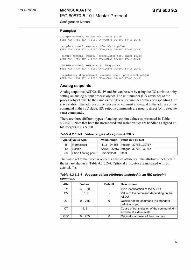
1MRS756158 SYS 600 9.2MicroSCADA ProIEC 60870-5-101 Master ProtocolConfiguration Manual
Examples:;single command, select off, short pulse #SET 'LN':PSE'IX' = LIST(OV=0,CT=6,OG=100,TY=45,QL=1)
;single command, execute offn, short pulse #SET 'LN':POV'IX' = LIST(OV=0,CT=6,OG=100,TY=45,QL=1)
;single command, cancel (deactivate) off, short pulse #SET 'LN':POV'IX' = LIST(OV=0,CT=8,OG=100,TY=45,QL=1)
;double command, execute on, long pulse #SET 'LN':POV'IX' = LIST(OV=1,CT=6,OG=100,TY=46,QL=2)
;regulating step command, execute lower, persistent output #SET 'LN':POV'IX' = LIST(OV=0,CT=6,OG=100,TY=47,QL=3)
Analog setpointsAnalog setpoints (ASDUs 48, 49 and 50) can be sent by using the CO attribute or by setting an analog output process object. The unit number (UN attribute) of the process object must be the same as the STA object number of the corresponding IEC slave station. The address of the process object must also equal to the address of the command in the IEC slave. IEC setpoint commands are usually direct (only execute sent) commands.
There are three different types of analog setpoint values as presented in Table 4.2.6.2-3. Note that both the normalised and scaled values are handled as signed 16-bit integers in SYS 600.
The value set to the process object is a list of attributes. The attributes included in the list are shown in Table 4.2.6.2-4. Optional attributes are indicated with an asterisk (*).
Table 4.2.6.2-3 Value ranges of setpoint ASDUs
Type id Value type Value range Value in SYS 60048 Normalised -1…(1-2^-15) Integer –32768…3276749 Scaled –32768…32767 Integer –32768…3276750 Short floating point 32-bit float Real
Table 4.2.6.2-4 Process object attributes included in an IEC setpoint command
Attr. Values Default DescriptionTY 48... 50 - Type identification of the ASDUOV 0,1,2 - Value of the command depending on the
ASDUQL* 0... 255 0 Qualifier of the command (no standard
definitions yet)CT 6, 8 - Cause of transmission of the command: 6 =
activate, 8 = deactivateOG* 0... 255 0 Originator address of the command
53
1MRS756158MicroSCADA ProIEC 60870-5-101 Master ProtocolConfiguration Manual
SYS 600 9.2
Examples:;normalised setpoint command, execute #SET 'LN':POV'IX' = LIST(OV=5000,CT=6,OG=100,TY=48,QL=0)
;scaled command, cancel (deactivate) #SET 'LN':POV'IX' = LIST(OV=100,CT=8,OG=100,TY=49,QL=0)
4.2.6.3. Application commandsApplication commands include the ASDUs shown in Table 4.2.6.3-1. All application commands are sent with address zero.
General interrogation commandWhen the IEC slave station receives a general interrogation command (ASDU 100) from the master, it must send all the input signals except pulse counters to the master without time tag. The cause of transmission is set to 20. IEC 60870-5-101 includes also a group interrogation function. When this function is used, the signals to be sent to the IEC master are divided into groups which can be interrogated one at the time. The cause of transmission is set to 20 + group number. Interrogation commands can be sent by using the GI or CO attributes of the IEC master station as shown in the examples below.;activate general interrogation#SET STA'STA_NR':SGI = 1
;activate group interrogation@GROUP = 1 ; 1..16#SET STA'STA_NR':SCO = (100,0,6,20+%GROUP)
Counter interrogation commandThe counter interrogation command is like a general interrogation but for only integrated totals (pulse counters). A counter interrogation can also be a group interrogation; in this case the number of the groups is four. The cause of transmission of the interrogated pulse counters is 37 in case of a counter interrogation or 37 + group number in case of a group counter interrogation. A counter interrogation command can be sent by using the CO attribute as shown below:;activate counter interrogation#SET STA'STA_NR':SCO = (101,0,6,0)
;activate group counter interrogation@GROUP = 1 ; 1..4#SET STA'STA_NR':SCO = (101,0,6,%GROUP)
Table 4.2.6.3-1 IEC 60870-5-101 application commands
Type id ASDU Description100 C_IC_NA_1 Interrogation command101 C_CI_NA_1 Counter interrogation command102 C_RD_NA_1 Read command105 C_RP_NA_1 Reset process command
54
1MRS756158 SYS 600 9.2MicroSCADA ProIEC 60870-5-101 Master ProtocolConfiguration Manual
Read commandBy using the read command (ASDU 102) the user can request the value of an individual signal from the IEC master. The requested signal is sent with the cause of transmission value 5. Note that pulse counters are not included in the read command. A read command can be sent by using the CO attribute as shown below:;read of user data command@ADDR = 255 ; information object address#SET STA'STA_NR':SCO = (102,%ADDR,5)
Reset process commandThe purpose of the reset process command (ASDU 105) is to re-initialise the application level of the IEC slave station. It can be sent by using the CO attribute as shown below:;activate reset process command#SET STA'STA_NR':SCO = (105,0,6,0)
4.2.6.4. System commandsSystem commands include the ASDUs presented in Table 4.2.6.4-1. All the application commands are sent with address zero by default. The address of the clock synchronisation command can be changed by using the ADDR parameter of the SY (Synchronise) attribute.
Clock synchronisation commandThe clock synchronisation commands (ASDU 103) are used for synchronising IEC slave stations. This command can be sent by using the SY attribute of the IEC master station as shown below:;activate broadcast synch#SET STA’STA_NR’:SSY = (6,1)
;deactivate synch to one station#SET STA’STA_NR’:SSY = (8,0)
Test commandBy sending a test command (ASDU 104) to the IEC slave the IEC master can check that the connection to the application level of the slave is working properly. A test command can be sent by using the CO attribute as shown below:;test command#SET STA'STA_NR':SCO = (104,0,6,170,85)
Table 4.2.6.4-1 IEC 60870-5-101 system command ASDUs
Type id ASDU Description103 C_CS_NA_1 Clock synchronisation command104 C_RP_NA_1 Test command
55
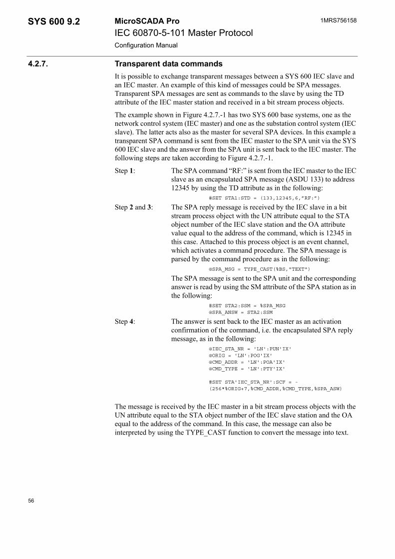
1MRS756158MicroSCADA ProIEC 60870-5-101 Master ProtocolConfiguration Manual
SYS 600 9.2
4.2.7. Transparent data commandsIt is possible to exchange transparent messages between a SYS 600 IEC slave and an IEC master. An example of this kind of messages could be SPA messages. Transparent SPA messages are sent as commands to the slave by using the TD attribute of the IEC master station and received in a bit stream process objects.
The example shown in Figure 4.2.7.-1 has two SYS 600 base systems, one as the network control system (IEC master) and one as the substation control system (IEC slave). The latter acts also as the master for several SPA devices. In this example a transparent SPA command is sent from the IEC master to the SPA unit via the SYS 600 IEC slave and the answer from the SPA unit is sent back to the IEC master. The following steps are taken according to Figure 4.2.7.-1.
Step 1: The SPA command “RF:” is sent from the IEC master to the IEC slave as an encapsulated SPA message (ASDU 133) to address 12345 by using the TD attribute as in the following:
#SET STA1:STD = (133,12345,6,”RF:”)
Step 2 and 3: The SPA reply message is received by the IEC slave in a bit stream process object with the UN attribute equal to the STA object number of the IEC slave station and the OA attribute value equal to the address of the command, which is 12345 in this case. Attached to this process object is an event channel, which activates a command procedure. The SPA message is parsed by the command procedure as in the following:
@SPA_MSG = TYPE_CAST(%BS,"TEXT")
The SPA message is sent to the SPA unit and the corresponding answer is read by using the SM attribute of the SPA station as in the following:
#SET STA2:SSM = %SPA_MSG@SPA_ANSW = STA2:SSM
Step 4: The answer is sent back to the IEC master as an activation confirmation of the command, i.e. the encapsulated SPA reply message, as in the following:
@IEC_STA_NR = 'LN':PUN'IX'@ORIG = 'LN':POG'IX'@CMD_ADDR = 'LN':POA'IX'@CMD_TYPE = 'LN':PTY'IX'
#SET STA'IEC_STA_NR':SCF = -(256*%ORIG+7,%CMD_ADDR,%CMD_TYPE,%SPA_ASW)
The message is received by the IEC master in a bit stream process objects with the UN attribute equal to the STA object number of the IEC slave station and the OA equal to the address of the command. In this case, the message can also be interpreted by using the TYPE_CAST function to convert the message into text.
56
1MRS756158 SYS 600 9.2MicroSCADA ProIEC 60870-5-101 Master ProtocolConfiguration Manual
trans_spa
Fig. 4.2.7.-1 Flow of the transparent SPA messages
By using a mechanism like the one described above, it is possible to read and write the parameters of SPA units over an IEC 60870-5-101 line. The same kind of mechanism can also be used for other purposes, for example, exchanging free-format text messages between the master and the slave.
4.2.8. Parameter in control directionIn the IEC 60870-5-101 protocol it is possible for the master to set and activate parameters of information objects of the IEC slave. This kind of action is, for example, setting the limits of a measured value. The following ASDUs presented in Table 4.2.8-1 are provided by the protocol:
All of these ASDUs can be sent by using the CO attribute of the IEC master station. See the description of the CO attribute in Section 4.2.4 for more details.
ASDUs 110…112 are for setting the parameters of measured values. The syntax is as in the following:#SET STAn:SCO = (TYPE, ADDR,COT,VALUE,QUAL)
Table 4.2.8-1 ASDUs for parameters in the control direction
Type id ASDU Description110 P_ME_NA_1 Parameter of measured values, normalised value.111 P_ME_NB_1 Parameter of measured values, scaled value.112 P_ME_NC_1 Parameter of measured values,
short floating point number.113 P_AC_NA_1 Parameter activation.
57
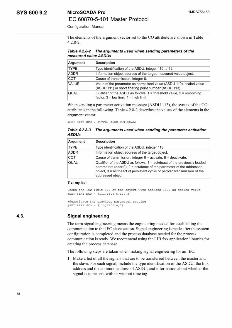
1MRS756158MicroSCADA ProIEC 60870-5-101 Master ProtocolConfiguration Manual
SYS 600 9.2
The elements of the argument vector set to the CO attribute are shown in Table 4.2.8-2.
When sending a parameter activation message (ASDU 113), the syntax of the CO attribute is in the following. Table 4.2.8-3 describes the values of the elements in the argument vector.#SET STAn:SCO = (TYPE, ADDR,COT,QUAL)
Examples:;send the low limit 100 of the object with address 1500 as scaled value#SET STA1:SCO = (111,1500,6,100,3)
;deactivate the previous parameter setting#SET STA1:SCO = (113,1500,8,2)
4.3. Signal engineeringThe term signal engineering means the engineering needed for establishing the communication to the IEC slave station. Signal engineering is made after the system configuration is completed and the process database needed for the process communication is ready. We recommend using the LIB 5xx application libraries for creating the process database.
The following steps are taken when making signal engineering for an IEC:1. Make a list of all the signals that are to be transferred between the master and
the slave. For each signal, include the type identification of the ASDU, the link address and the common address of ASDU, and information about whether the signal is to be sent with or without time tag.
Table 4.2.8-2 The arguments used when sending parameters of the measured value ASDUs
Argument DescriptionTYPE Type identification of the ASDU, integer 110…112.ADDR Information object address of the target measured value object.COT Cause of transmission, integer 6.VALUE Value of the parameter as normalised value (ASDU 110), scaled value
(ASDU 111) or short floating point number (ASDU 113).QUAL Qualifier of the ASDU as follows: 1 = threshold value, 2 = smoothing
factor, 3 = low limit, 4 = high limit.
Table 4.2.8-3 The arguments used when sending the parameter activation ASDUs
Argument DescriptionTYPE Type identification of the ASDU, integer 113.ADDR Information object address of the target object.COT Cause of transmission, integer 6 = activate, 8 = deactivate.QUAL Qualifier of the ASDU as follows: 1 = act/deact of the previously loaded
parameters (addr 0), 2 = act/deact of the parameter of the addressed object, 3 = act/deact of persistent cyclic or perodic transmission of the addressed object.
58
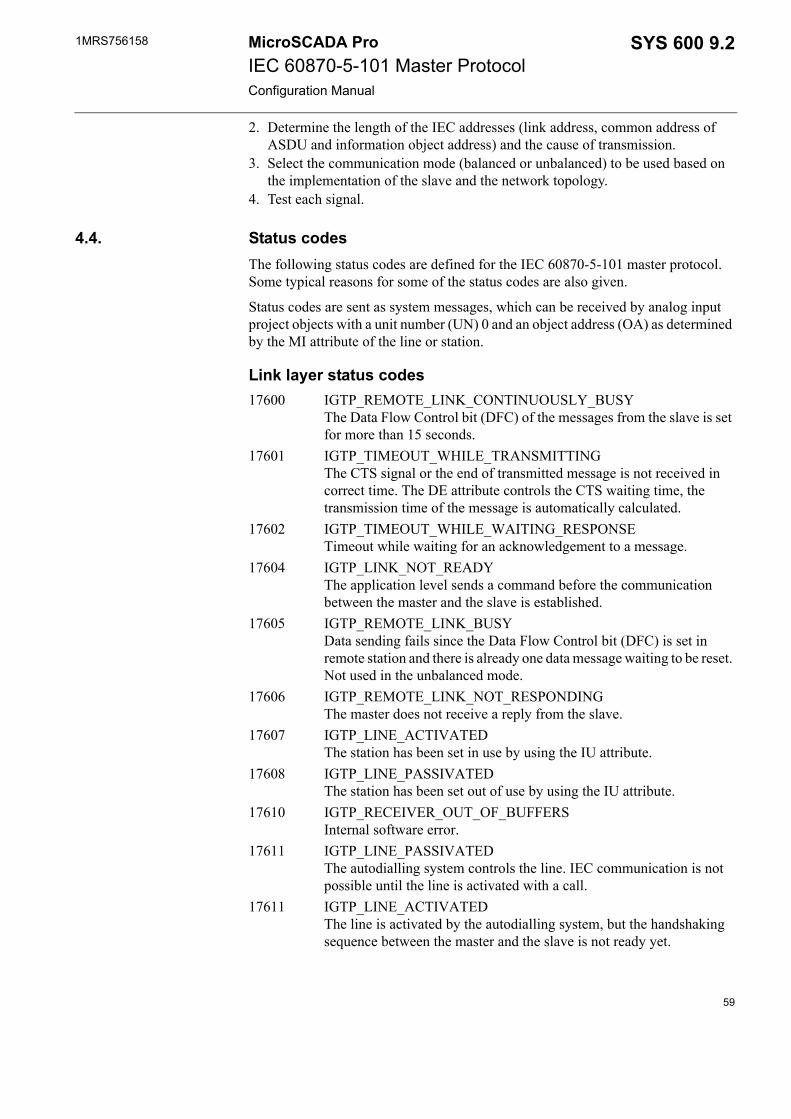
1MRS756158 SYS 600 9.2MicroSCADA ProIEC 60870-5-101 Master ProtocolConfiguration Manual
2. Determine the length of the IEC addresses (link address, common address of ASDU and information object address) and the cause of transmission.
3. Select the communication mode (balanced or unbalanced) to be used based on the implementation of the slave and the network topology.
4. Test each signal.
4.4. Status codesThe following status codes are defined for the IEC 60870-5-101 master protocol. Some typical reasons for some of the status codes are also given.
Status codes are sent as system messages, which can be received by analog input project objects with a unit number (UN) 0 and an object address (OA) as determined by the MI attribute of the line or station.
Link layer status codes17600 IGTP_REMOTE_LINK_CONTINUOUSLY_BUSY
The Data Flow Control bit (DFC) of the messages from the slave is set for more than 15 seconds.
17601 IGTP_TIMEOUT_WHILE_TRANSMITTING The CTS signal or the end of transmitted message is not received in correct time. The DE attribute controls the CTS waiting time, the transmission time of the message is automatically calculated.
17602 IGTP_TIMEOUT_WHILE_WAITING_RESPONSE Timeout while waiting for an acknowledgement to a message.
17604 IGTP_LINK_NOT_READYThe application level sends a command before the communication between the master and the slave is established.
17605 IGTP_REMOTE_LINK_BUSY Data sending fails since the Data Flow Control bit (DFC) is set in remote station and there is already one data message waiting to be reset. Not used in the unbalanced mode.
17606 IGTP_REMOTE_LINK_NOT_RESPONDINGThe master does not receive a reply from the slave.
17607 IGTP_LINE_ACTIVATEDThe station has been set in use by using the IU attribute.
17608 IGTP_LINE_PASSIVATEDThe station has been set out of use by using the IU attribute.
17610 IGTP_RECEIVER_OUT_OF_BUFFERS Internal software error.
17611 IGTP_LINE_PASSIVATED The autodialling system controls the line. IEC communication is not possible until the line is activated with a call.
17611 IGTP_LINE_ACTIVATED The line is activated by the autodialling system, but the handshaking sequence between the master and the slave is not ready yet.
59

1MRS756158MicroSCADA ProIEC 60870-5-101 Master ProtocolConfiguration Manual
SYS 600 9.2
17620 IGPC_ILLEGAL_ATTRIBUTE_VALUEThe value written to one of the line attributes is incorrect.
Application layer status codes13851 ICCC_INVALID_ATTRIBUTE_VALUE
The value set to an attribute of an IEC station is incorrect, e.g. one of the elements of the vector written to the SD attribute is out of range.
13852 ICCC_INVALID_INDEX_RANGEThe index range used when accessing an attribute of an IEC station is incorrect.
13853 ICCC_INVALID_ATTRIBUTEThe STA object attribute used is not valid for the IEC 60870-5-101 master protocol.
13854 ICCC_ASDU_TABLE_NOT_CREATEDInternal software error.
13855 ICCC_UNKNOWN_ASDU_NAME The name of the ASDU written to a STA object attribute is not supported.
13857 ICCC_MESSAGE_BUFFER_FULLInternal software error. The value of the ML attribute may be too small.
13858 ICCC_MESSAGE_FILLING_ERRORInternal software error. The value of the ML attribute may be too small.
13859 ICCC_UNKNOWN_ASDUThe number of the ASDU written to a STA object attribute is not supported.
13862 ICCC_SC_DATA_OVERFLOWInternal software error.
13863 ICCC_DEVICE_SUSPENDEDThe IEC station is in the suspended state. The reason for this could be that the link is not properly established (e.g. incorrect cable wiring) or the slave station does not respond.
13864 ICCC_MESSAGE_SENDING_ERRORInternal software error. This may be the result of a problem in wiring or hardware.
13865 ICCC_REMOTE_DEVICE_REPLIES_WITH_NACKThe slave did not accept the message but responded with a negative acknowledgement instead.
13866 ICCC_LINK_NOT_READYA message is sent to a line with a non-established communication.
13868 ICCC_OUT_OF_BUFFERSInternal software error. Operation could not be completed since the buffer pool has ran out of buffers.
13870 ICCC_CONFIRMATION_TIMEOUTAn activation confirmation to a command was not received from the IEC slave in the time defined by the RT attribute.
60
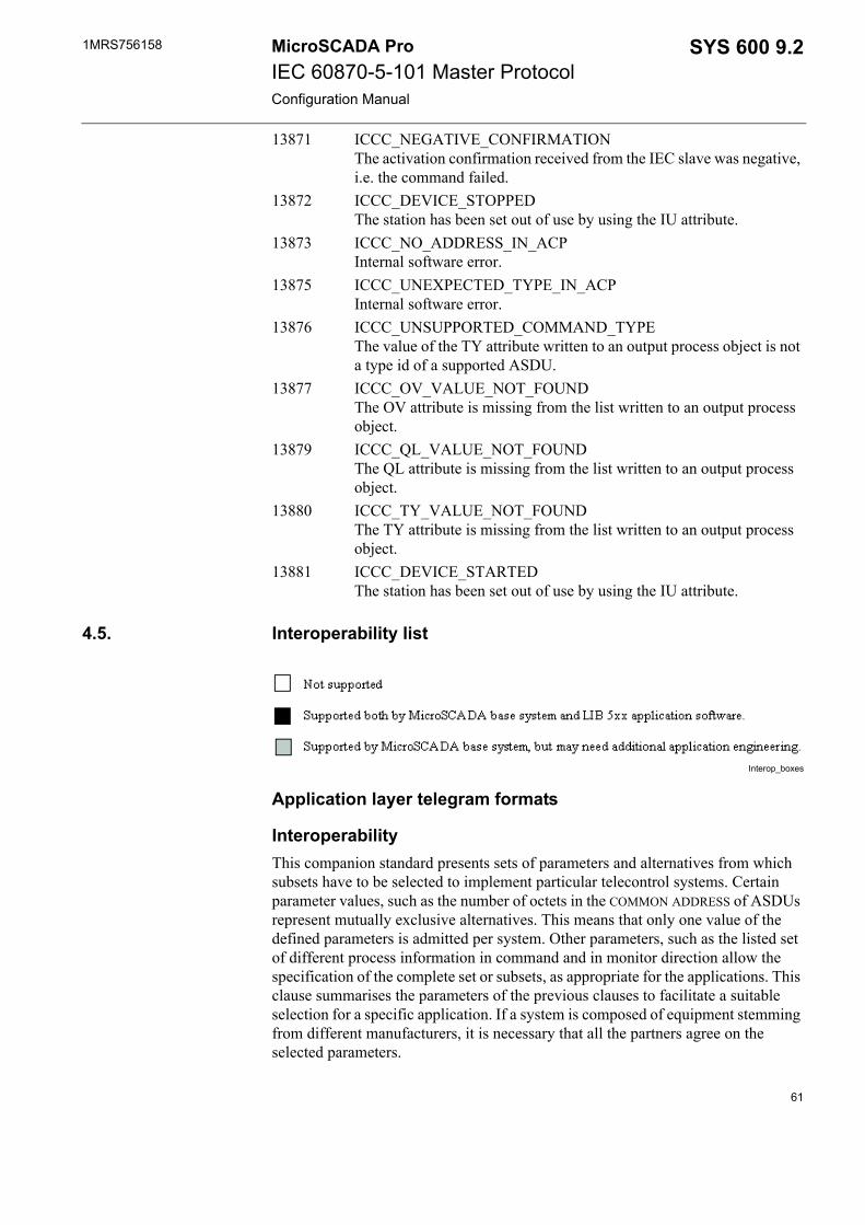
1MRS756158 SYS 600 9.2MicroSCADA ProIEC 60870-5-101 Master ProtocolConfiguration Manual
13871 ICCC_NEGATIVE_CONFIRMATIONThe activation confirmation received from the IEC slave was negative, i.e. the command failed.
13872 ICCC_DEVICE_STOPPEDThe station has been set out of use by using the IU attribute.
13873 ICCC_NO_ADDRESS_IN_ACPInternal software error.
13875 ICCC_UNEXPECTED_TYPE_IN_ACPInternal software error.
13876 ICCC_UNSUPPORTED_COMMAND_TYPEThe value of the TY attribute written to an output process object is not a type id of a supported ASDU.
13877 ICCC_OV_VALUE_NOT_FOUNDThe OV attribute is missing from the list written to an output process object.
13879 ICCC_QL_VALUE_NOT_FOUNDThe QL attribute is missing from the list written to an output process object.
13880 ICCC_TY_VALUE_NOT_FOUNDThe TY attribute is missing from the list written to an output process object.
13881 ICCC_DEVICE_STARTEDThe station has been set out of use by using the IU attribute.
4.5. Interoperability list
Interop_boxes
Application layer telegram formats
InteroperabilityThis companion standard presents sets of parameters and alternatives from which subsets have to be selected to implement particular telecontrol systems. Certain parameter values, such as the number of octets in the COMMON ADDRESS of ASDUs represent mutually exclusive alternatives. This means that only one value of the defined parameters is admitted per system. Other parameters, such as the listed set of different process information in command and in monitor direction allow the specification of the complete set or subsets, as appropriate for the applications. This clause summarises the parameters of the previous clauses to facilitate a suitable selection for a specific application. If a system is composed of equipment stemming from different manufacturers, it is necessary that all the partners agree on the selected parameters.
61

1MRS756158MicroSCADA ProIEC 60870-5-101 Master ProtocolConfiguration Manual
SYS 600 9.2
The selected parameters should be marked in the boxes.
Network configuration(network-specific parameter)
Network_config
Physical Layer(network-specific parameter)Transmission speed (control direction)
control_direction
Full specification of a system may require individual selection of certain parameters for certain parts of the system. For example individual selection of scaling factors for individually addressable measured values.
62

1MRS756158 SYS 600 9.2MicroSCADA ProIEC 60870-5-101 Master ProtocolConfiguration Manual
Transmission speed (monitor direction)
monitor_direction
Link layer(network-specific parameter)Frame format FT 1.2, single character 1 and the fixed time out interval are used exclusively in this companion standard.
link_layer
The maximum frame length per Controlled Station can be up to 255.
63

1MRS756158MicroSCADA ProIEC 60870-5-101 Master ProtocolConfiguration Manual
SYS 600 9.2
Application layerTransmission mode for application data
Mode 1 (The least significant octet first), as defined in clause 4.10 of IEC 870-5-4, is used exclusively in this companion standard.
Common address of ASDU
(system-specific parameter)
common_address
Information object address
(system-specific parameter)
inf_obj_address
Cause of transmission
(system-specific parameter)
Cause of_transm
64
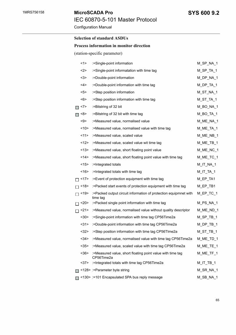
1MRS756158 SYS 600 9.2MicroSCADA ProIEC 60870-5-101 Master ProtocolConfiguration Manual
Selection of standard ASDUs
Process information in monitor direction
(station-specific parameter)
<1> :=Single-point information M_SP_NA_1
<2> :=Single-point informatation with time tag M_SP_TA_1
<3> :=Double-point information M_DP_NA_1
<4> :=Double-point information with time tag M_DP_TA_1
<5> :=Step position information M_ST_NA_1
<6> :=Step position information with time tag M_ST_TA_1
<7> :=Bitstring of 32 bit M_BO_NA_1
<8> :=Bitstring of 32 bit with time tag M_BO_TA_1
<9> :=Measured value, normalised value M_ME_NA_1
<10> :=Measured value, normalised value with time tag M_ME_TA_1
<11> :=Measured value, scaled value M_ME_NB_1
<12> :=Measured value, scaled value wit time tag M_ME_TB_1
<13> :=Measured value, short floating point value M_ME_NC_1
<14> :=Measured value, short floating point value with time tag M_ME_TC_1
<15> :=Integrated totals M_IT_NA_1
<16> :=Integrated totals with time tag M_IT_TA_1
<17> :=Event of protection equipment with time tag M_EP_TA1
<18> :=Packed start events of protection equipment with time tag M_EP_TB1
<19> :=Packed output circuit information of protection equipmnet with time tag
M_EP_TC_1
<20> :=Packed single point information with time tag M_PS_NA_1
<21> :=Measured value, normalised value without quality descriptor M_ME_ND_1
<30> :=Single-point information with time tag CP56Time2a M_SP_TB_1
<31> :=Double-point information with time tag CP56Time2a M_DP_TB_1
<32> :=Step position information with time tag CP56TIme2a M_ST_TB_1
<34> :=Measured value, normalised value with time tag CP56Time2a M_ME_TD_1
<35> :=Measured value, scaled value with time tag CP56Time2a M_ME_TE_1
<36> :=Measured value, short floating point value with time tag CP56Time2a
M_ME_TF_1
<37> :=Integrated totals with time tag CP56Time2a M_IT_TB_1
<128> :=Parameter byte string M_SR_NA_1
<130> :=101 Encapsulated SPA bus reply message M_SB_NA_1
65
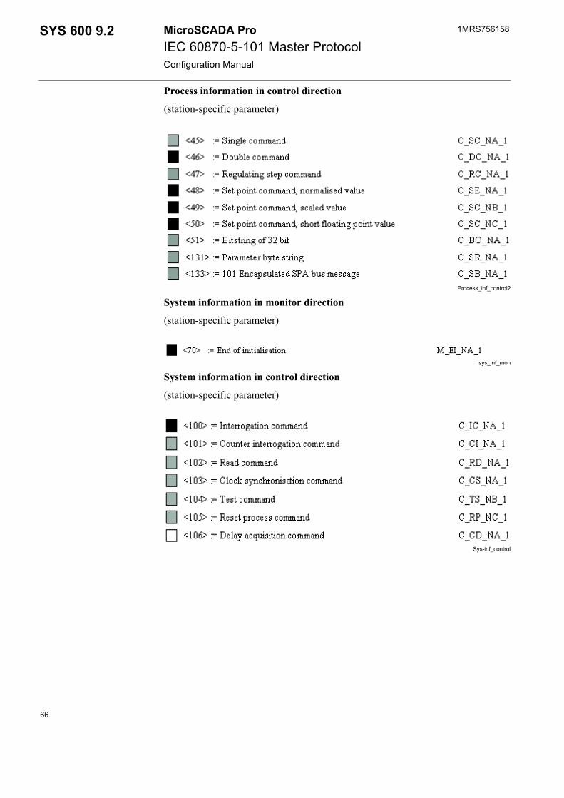
1MRS756158MicroSCADA ProIEC 60870-5-101 Master ProtocolConfiguration Manual
SYS 600 9.2
Process information in control direction
(station-specific parameter)
Process_inf_control2
System information in monitor direction
(station-specific parameter)
sys_inf_mon
System information in control direction
(station-specific parameter)
Sys-inf_control
66
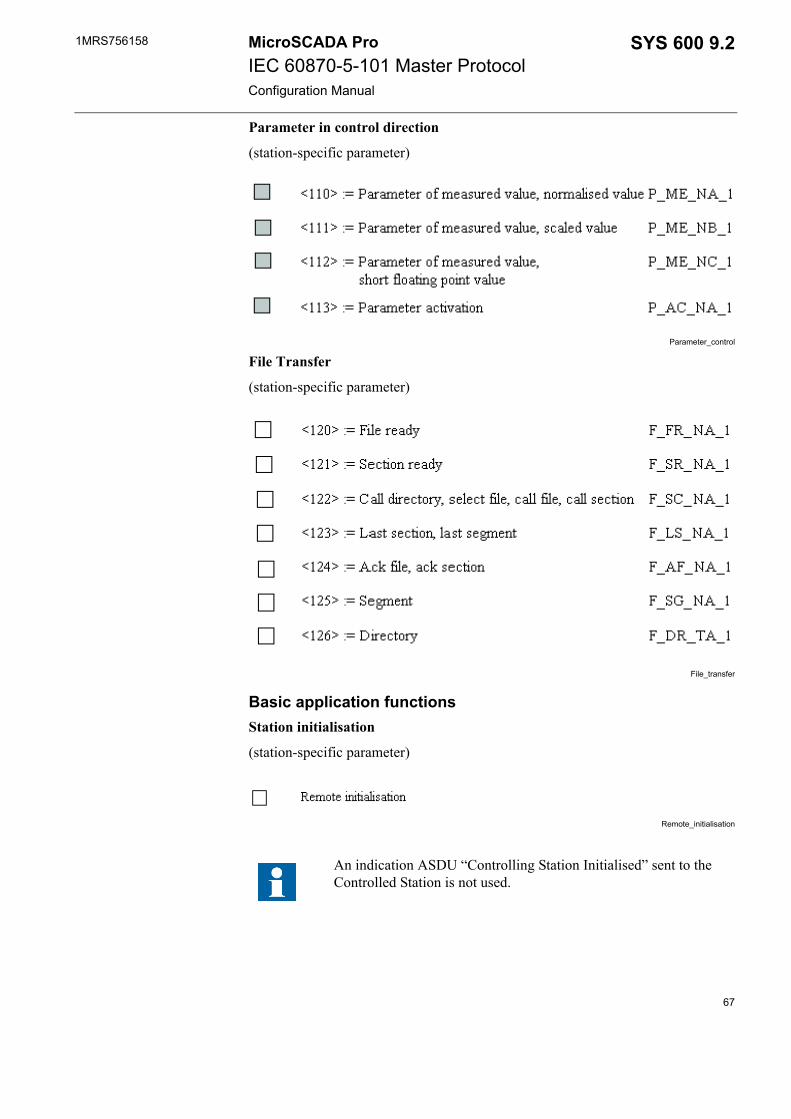
1MRS756158 SYS 600 9.2MicroSCADA ProIEC 60870-5-101 Master ProtocolConfiguration Manual
Parameter in control direction
(station-specific parameter)
Parameter_control
File Transfer
(station-specific parameter)
File_transfer
Basic application functionsStation initialisation
(station-specific parameter)
Remote_initialisation
An indication ASDU “Controlling Station Initialised” sent to the Controlled Station is not used.
67
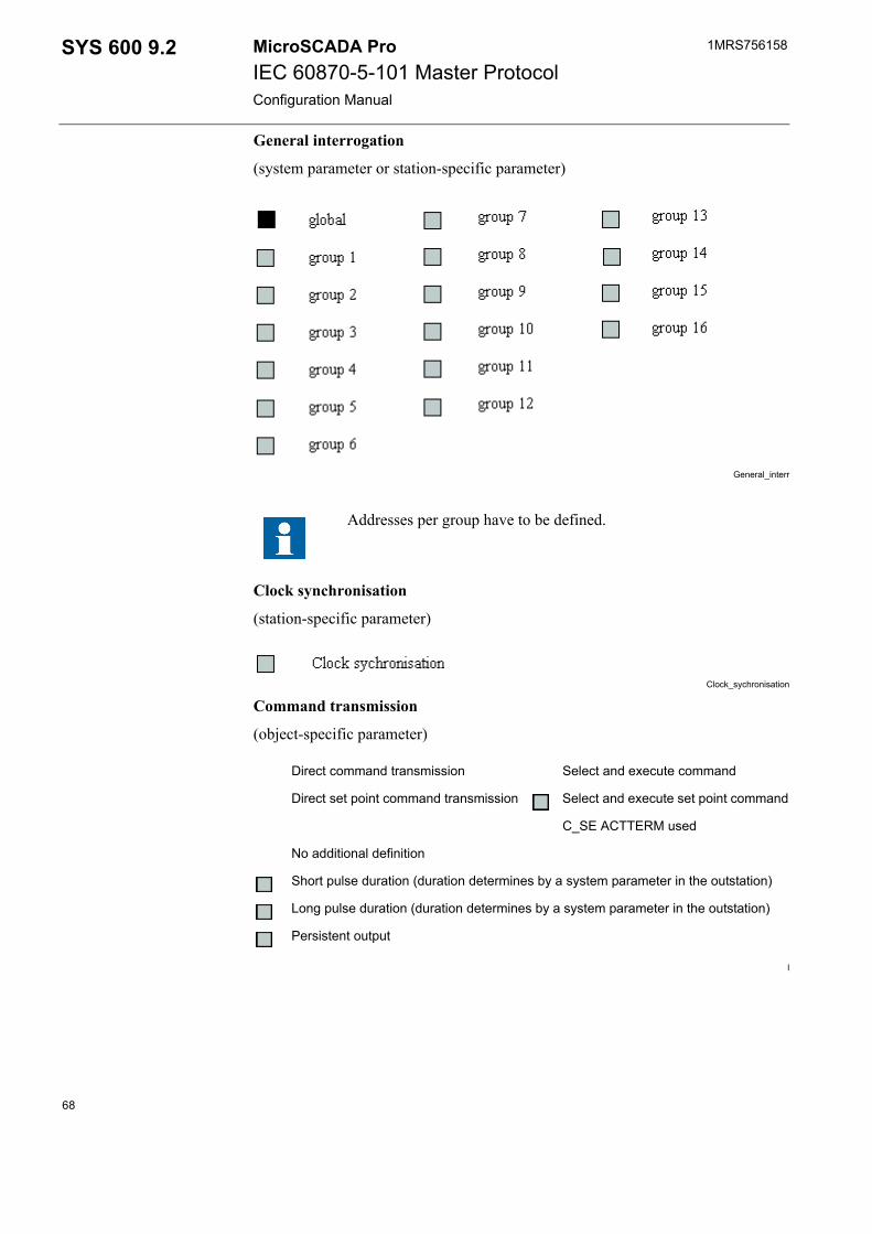
1MRS756158MicroSCADA ProIEC 60870-5-101 Master ProtocolConfiguration Manual
SYS 600 9.2
General interrogation
(system parameter or station-specific parameter)
General_interr
Clock synchronisation
(station-specific parameter)
Clock_sychronisation
Command transmission
(object-specific parameter)
l
Addresses per group have to be defined.
Direct command transmission Select and execute command
Direct set point command transmission Select and execute set point command
C_SE ACTTERM used
No additional definition
Short pulse duration (duration determines by a system parameter in the outstation)
Long pulse duration (duration determines by a system parameter in the outstation)
Persistent output
68

1MRS756158 SYS 600 9.2MicroSCADA ProIEC 60870-5-101 Master ProtocolConfiguration Manual
Transmission of integrated totals
(station parameter or object-specific parameter)
Transm_integr_totals
Parameter loading
(object-specific parameter)
Parameter_loading
Parameter activation
(object-specific parameter)
parameter_activation
Addresses per group have to be defined.
69
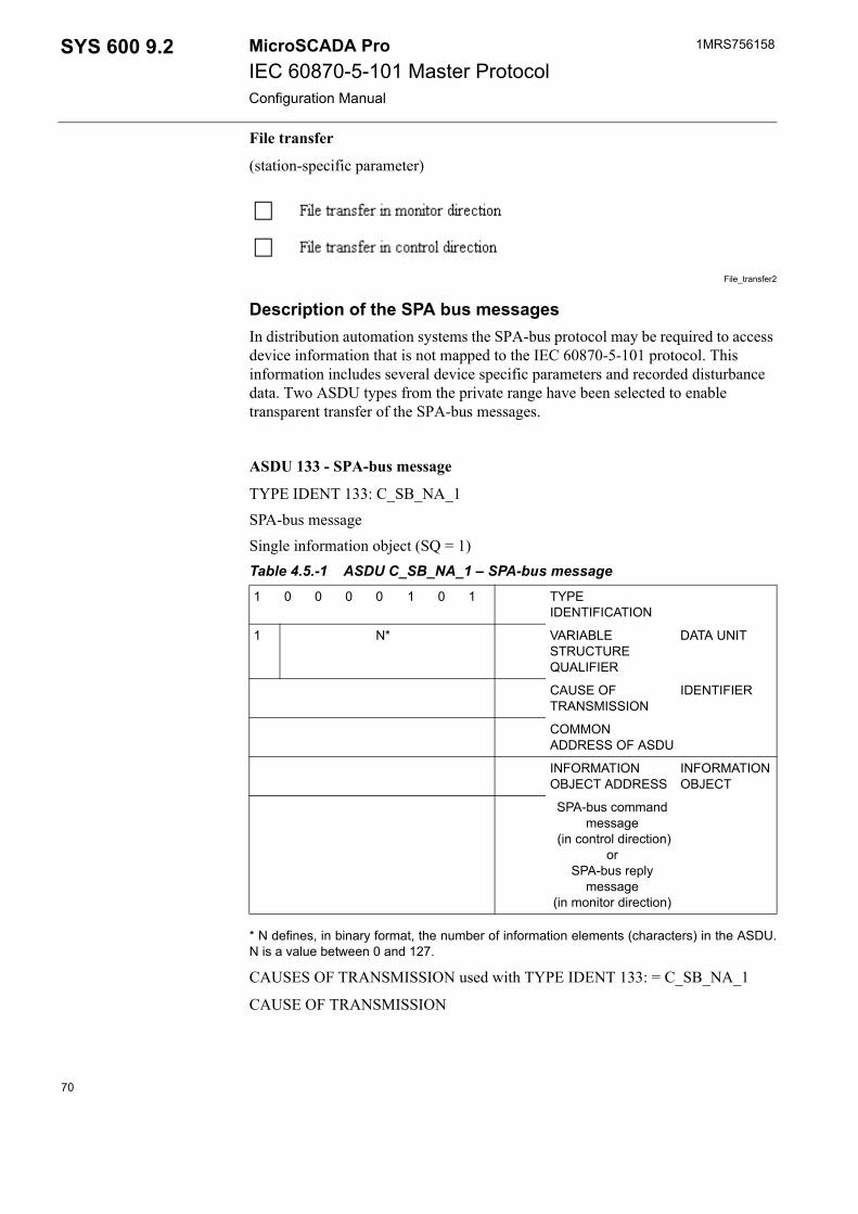
1MRS756158MicroSCADA ProIEC 60870-5-101 Master ProtocolConfiguration Manual
SYS 600 9.2
File transfer
(station-specific parameter)
File_transfer2
Description of the SPA bus messagesIn distribution automation systems the SPA-bus protocol may be required to access device information that is not mapped to the IEC 60870-5-101 protocol. This information includes several device specific parameters and recorded disturbance data. Two ASDU types from the private range have been selected to enable transparent transfer of the SPA-bus messages.
ASDU 133 - SPA-bus message
TYPE IDENT 133: C_SB_NA_1SPA-bus messageSingle information object (SQ = 1)Table 4.5.-1 ASDU C_SB_NA_1 – SPA-bus message
* N defines, in binary format, the number of information elements (characters) in the ASDU.N is a value between 0 and 127.
CAUSES OF TRANSMISSION used with TYPE IDENT 133: = C_SB_NA_1
CAUSE OF TRANSMISSION
1 0 0 0 0 1 0 1 TYPE IDENTIFICATION
1 N* VARIABLE STRUCTURE QUALIFIER
DATA UNIT
CAUSE OF TRANSMISSION
IDENTIFIER
COMMON ADDRESS OF ASDU
INFORMATION OBJECT ADDRESS
INFORMATION OBJECT
SPA-bus command message
(in control direction)or
SPA-bus reply message
(in monitor direction)
70
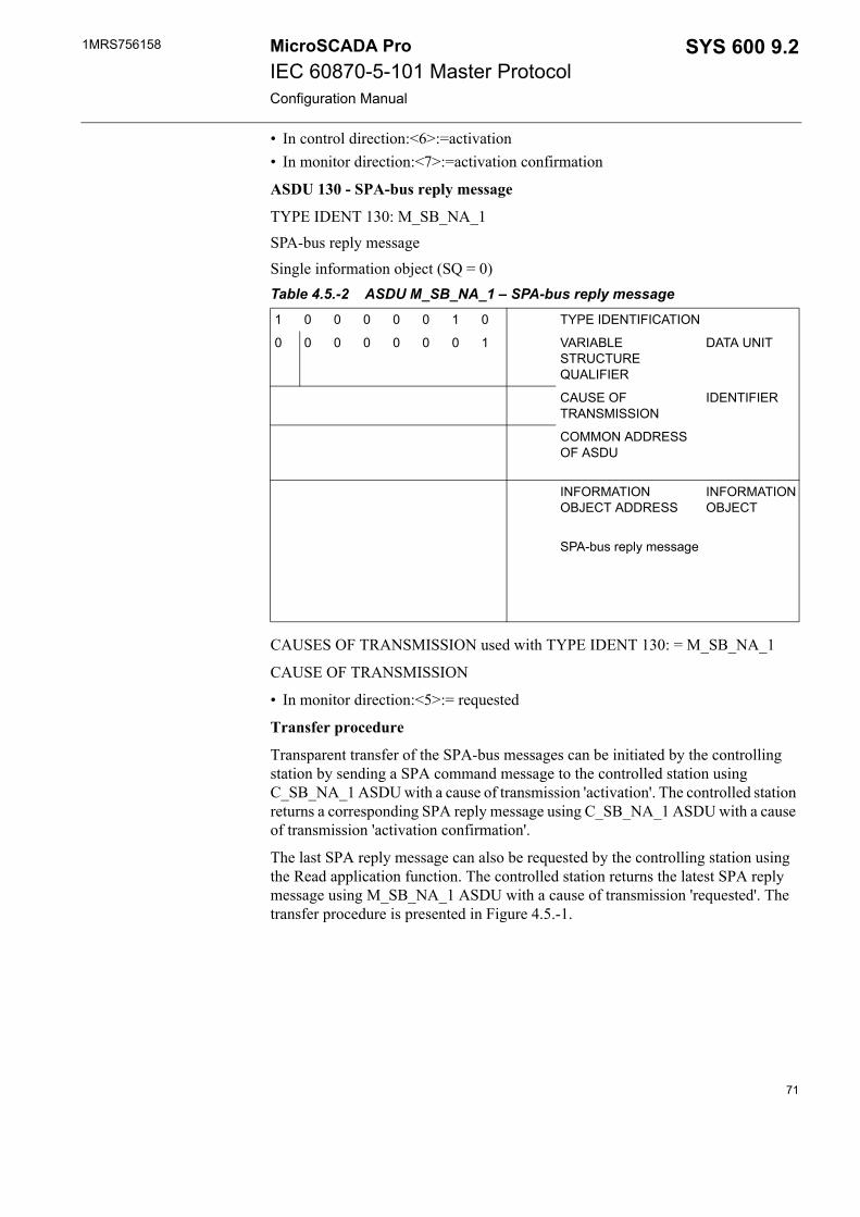
1MRS756158 SYS 600 9.2MicroSCADA ProIEC 60870-5-101 Master ProtocolConfiguration Manual
• In control direction:<6>:=activation• In monitor direction:<7>:=activation confirmation
ASDU 130 - SPA-bus reply message
TYPE IDENT 130: M_SB_NA_1SPA-bus reply messageSingle information object (SQ = 0)Table 4.5.-2 ASDU M_SB_NA_1 – SPA-bus reply message
CAUSES OF TRANSMISSION used with TYPE IDENT 130: = M_SB_NA_1
CAUSE OF TRANSMISSION
• In monitor direction:<5>:= requested
Transfer procedure
Transparent transfer of the SPA-bus messages can be initiated by the controlling station by sending a SPA command message to the controlled station using C_SB_NA_1 ASDU with a cause of transmission 'activation'. The controlled station returns a corresponding SPA reply message using C_SB_NA_1 ASDU with a cause of transmission 'activation confirmation'.
The last SPA reply message can also be requested by the controlling station using the Read application function. The controlled station returns the latest SPA reply message using M_SB_NA_1 ASDU with a cause of transmission 'requested'. The transfer procedure is presented in Figure 4.5.-1.
1 0 0 0 0 0 1 0 TYPE IDENTIFICATION
0 0 0 0 0 0 0 1 VARIABLE STRUCTURE QUALIFIER
DATA UNIT
CAUSE OF TRANSMISSION
IDENTIFIER
COMMON ADDRESS OF ASDU
INFORMATION OBJECT ADDRESS
INFORMATION OBJECT
SPA-bus reply message
71
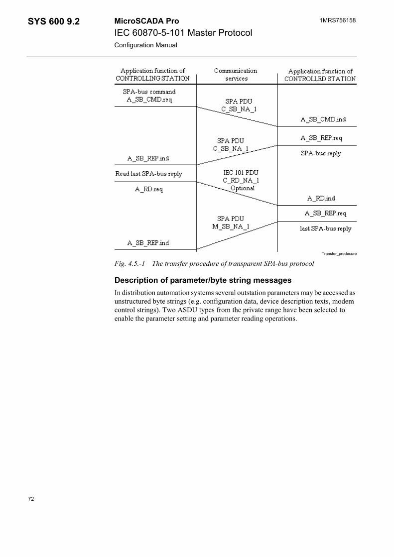
1MRS756158MicroSCADA ProIEC 60870-5-101 Master ProtocolConfiguration Manual
SYS 600 9.2
Transfer_prodecure
Fig. 4.5.-1 The transfer procedure of transparent SPA-bus protocol
Description of parameter/byte string messagesIn distribution automation systems several outstation parameters may be accessed as unstructured byte strings (e.g. configuration data, device description texts, modem control strings). Two ASDU types from the private range have been selected to enable the parameter setting and parameter reading operations.
72
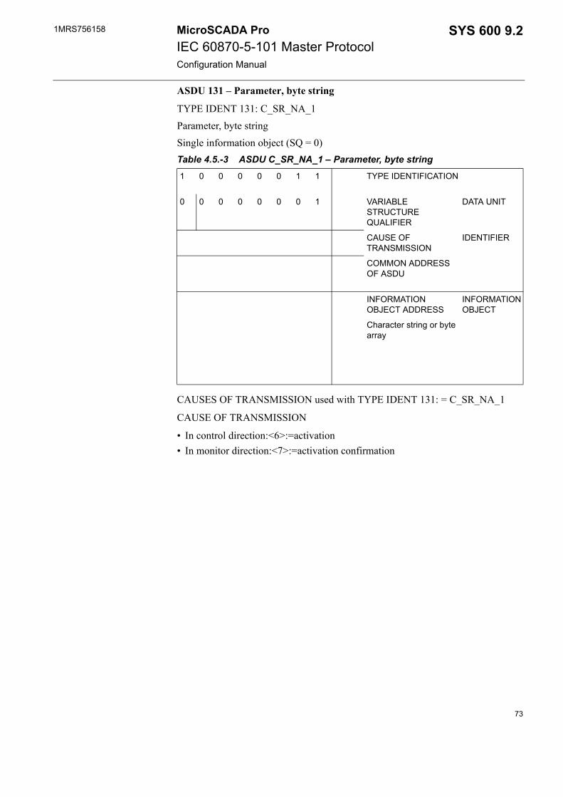
1MRS756158 SYS 600 9.2MicroSCADA ProIEC 60870-5-101 Master ProtocolConfiguration Manual
ASDU 131 – Parameter, byte string
TYPE IDENT 131: C_SR_NA_1Parameter, byte stringSingle information object (SQ = 0)Table 4.5.-3 ASDU C_SR_NA_1 – Parameter, byte string
CAUSES OF TRANSMISSION used with TYPE IDENT 131: = C_SR_NA_1
CAUSE OF TRANSMISSION
• In control direction:<6>:=activation• In monitor direction:<7>:=activation confirmation
1 0 0 0 0 0 1 1 TYPE IDENTIFICATION
0 0 0 0 0 0 0 1 VARIABLE STRUCTURE QUALIFIER
DATA UNIT
CAUSE OF TRANSMISSION
IDENTIFIER
COMMON ADDRESS OF ASDU
INFORMATION OBJECT ADDRESS
INFORMATION OBJECT
Character string or byte array
73
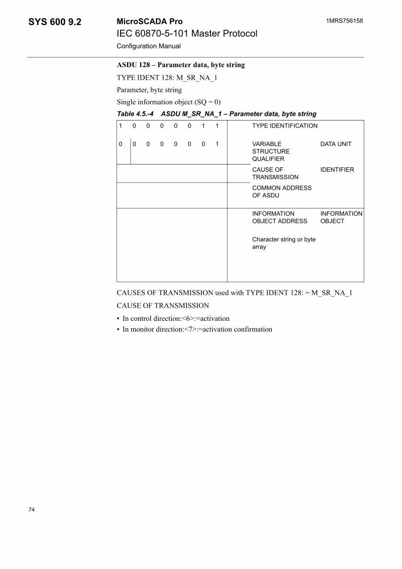
1MRS756158MicroSCADA ProIEC 60870-5-101 Master ProtocolConfiguration Manual
SYS 600 9.2
ASDU 128 – Parameter data, byte string
TYPE IDENT 128: M_SR_NA_1Parameter, byte stringSingle information object (SQ = 0)Table 4.5.-4 ASDU M_SR_NA_1 – Parameter data, byte string
CAUSES OF TRANSMISSION used with TYPE IDENT 128: = M_SR_NA_1
CAUSE OF TRANSMISSION
• In control direction:<6>:=activation• In monitor direction:<7>:=activation confirmation
1 0 0 0 0 0 1 1 TYPE IDENTIFICATION
0 0 0 0 0 0 0 1 VARIABLE STRUCTURE QUALIFIER
DATA UNIT
CAUSE OF TRANSMISSION
IDENTIFIER
COMMON ADDRESS OF ASDU
INFORMATION OBJECT ADDRESS
INFORMATION OBJECT
Character string or byte array
74
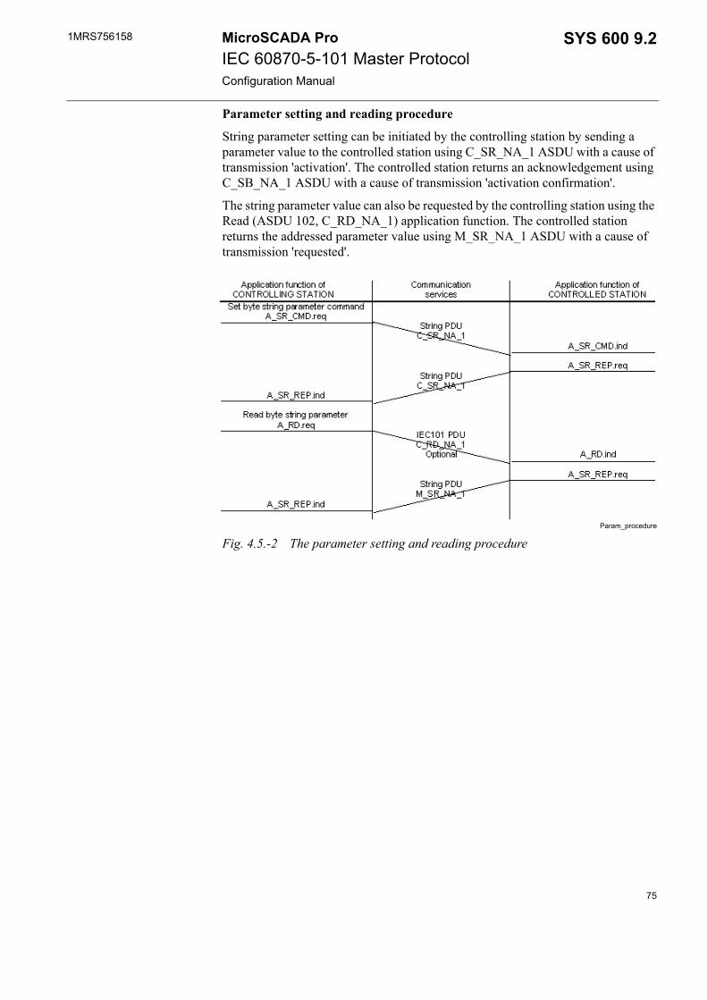
1MRS756158 SYS 600 9.2MicroSCADA ProIEC 60870-5-101 Master ProtocolConfiguration Manual
Parameter setting and reading procedure
String parameter setting can be initiated by the controlling station by sending a parameter value to the controlled station using C_SR_NA_1 ASDU with a cause of transmission 'activation'. The controlled station returns an acknowledgement using C_SB_NA_1 ASDU with a cause of transmission 'activation confirmation'.
The string parameter value can also be requested by the controlling station using the Read (ASDU 102, C_RD_NA_1) application function. The controlled station returns the addressed parameter value using M_SR_NA_1 ASDU with a cause of transmission 'requested'.
Param_procedure
Fig. 4.5.-2 The parameter setting and reading procedure
75

76
1MRS756158 SYS 600 9.2MicroSCADA ProIEC 60870-5-101 Master ProtocolConfiguration Manual
5. Index
AAC ............................................................................................................. 32Activation Reply Timeout ........................................................................ 31Activation Termination Timeout .............................................................. 32Addressing ................................................................................................ 43AL ............................................................................................................. 27Allocating Application ............................................................................. 27Allocation ................................................................................................. 27Analog inputs ...................................................................................... 48, 50Analog Setpoints ...................................................................................... 53Application commands ........................................................... 44, 51, 54, 55Application Layer Attributes .................................................................... 25Application Service Data Units (ASDUs) .......................................... 26, 41AS ....................................................................................................... 27, 33AT command ...................................................................................... 32, 34Autocaller AT S Register ......................................................................... 35Autocaller Enabled ................................................................................... 32Autocaller State ........................................................................................ 33
BBalanced mode ......................................................................................... 43Baud Rate ................................................................................................. 17Binary inputs ...................................................................................... 47, 50BL ....................................................................................................... 48, 49BR ............................................................................................................. 17Buffer Pool Size ....................................................................................... 17
CCA ........................................................................................... 28, 29, 49, 50Carrier Blocking ....................................................................................... 23Cause of Transmission (COT) .......................................... 12, 27, 46, 53, 54CB ............................................................................................................. 23CF ............................................................................................................. 29CL ........................................................................................... 14, 27, 28, 33CN ............................................................................................................. 33CO ................................................................................................. 44, 45, 52Command Address ................................................................................... 28Command Out .......................................................................................... 44Configuration ............................................................................................ 11Connected Station ..................................................................................... 34Connection ................................................................................................ 33Connection Time ...................................................................................... 33Connection Time Limited ......................................................................... 33Counter interrogation ................................................................................ 54
77
1MRS756158MicroSCADA ProIEC 60870-5-101 Master ProtocolConfiguration Manual
SYS 600 9.2
CS ............................................................................................................. 34CT ............................................................................... 32, 33, 48, 51, 52, 53CTS Delay ................................................................................................ 20CTS signal .................................................................................... 21, 39, 59CY ............................................................................................................ 49
DData commands ............................................................................ 44, 51, 52DC ...................................................................................................... 24, 30DCD signal ................................................................................... 23, 35, 39DD ............................................................................................................ 34DE ............................................................................................................ 20DFC .......................................................................................................... 59Diagnostic Counters ........................................................................... 24, 30Digital inputs ............................................................................................ 50Direction ................................................................................................... 26Double binary inputs .......................................................................... 47, 50DR ............................................................................................................ 26DV ............................................................................................................ 25
EEN ............................................................................................................ 22End of initialisation ............................................................................ 29, 42Enhanced Protocol Architecture (EPA) ................................................... 41Enquiry Limit ........................................................................................... 22
FFatal error ................................................................................................. 10
GGeneral Interrogation ......................................................................... 46, 54GI ........................................................................................................ 46, 54
HHeader Timeout ........................................................................................ 21HT ............................................................................................................ 21
IIEC 60870-5-101 master protocol .............................................................. 7IEC 60870-5-101 slave protocol .............................................................. 11IL .................................................................................................. 14, 26, 44In Use ................................................................................................. 16, 25Information Address Length .................................................................... 26Integrated link .......................................................................................... 11IU ............................................................................................ 16, 25, 33, 59IV ........................................................................................................ 48, 49
78
1MRS756158 SYS 600 9.2MicroSCADA ProIEC 60870-5-101 Master ProtocolConfiguration Manual
LLength of Cause of Transmission Information ......................................... 27Level of implementation ........................................................................... 41LI .............................................................................................................. 25Line Number ............................................................................................. 25Link Address ............................................................................................ 43Link Layer Attributes ............................................................................... 16Link Type ................................................................................................. 23LK ............................................................................................................. 23LT ............................................................................................................. 31
MMaximum Message Length ...................................................................... 28MC ...................................................................................................... 34, 35Message Application .......................................................................... 23, 28Message Identification ........................................................................ 23, 27MI ................................................................................................. 23, 27, 59ML ...................................................................................................... 28, 60Modem Command .................................................................................... 34Modem Signal .......................................................................................... 22MS ...................................................................................................... 23, 28Multi-drop network topology ............................................................. 15, 43
NNetwork Topologies ................................................................................. 15No limitations ........................................................................................... 14NT ....................................................................................................... 48, 49
OOA ............................................................................................................ 51Object commands ..................................................................................... 52Object Status ............................................................................................. 31OF ............................................................................................................. 48OG ................................................................................................ 48, 52, 53OM ............................................................................................................ 17Open Systems Interconnection (OSI) ....................................................... 41OR ....................................................................................................... 48, 50OS ................................................................................................. 31, 48, 49OV .............................................................................. 48, 49, 51, 52, 53, 61
PPA ....................................................................................................... 25, 43Parity ......................................................................................................... 17PC ............................................................................................................. 34PD ............................................................................................................. 19PL ........................................................................................... 14, 20, 26, 28PO ....................................................................................................... 16, 43
79
1MRS756158MicroSCADA ProIEC 60870-5-101 Master ProtocolConfiguration Manual
SYS 600 9.2
Point-to-point network topology .............................................................. 15Polling Address ........................................................................................ 25Polling Address Length ............................................................................ 26Polling Delay ............................................................................................ 19Polling Limit ............................................................................................ 20Polling Period ........................................................................................... 19PP ............................................................................................................. 19Private ASDUs ......................................................................................... 41Process object types ................................................................................. 47Protocol .................................................................................................... 16Protocol converter .............................................................................. 11, 43PS ............................................................................................................. 17Pulse counters ..................................................................................... 50, 54Pulse Dialing ............................................................................................ 34PY ............................................................................................................. 17
QQL .................................................................................... 48, 50, 52, 53, 61
RRadio Connection Wait Time ................................................................... 35Radio Disconnection Delay ...................................................................... 34RC ............................................................................................................ 35RD ............................................................................................................ 18Read command ......................................................................................... 55Read, conditional write ............................................................................ 14Read-only ................................................................................................. 14Receive Interrupt Enable Delay ............................................................... 22Receiver Data Bit Count .......................................................................... 18Remote Calls Enabled .............................................................................. 35Reply Polling ............................................................................................ 20Reset process command ............................................................... 42, 45, 51Response Timeout .................................................................................... 21RI .............................................................................................................. 22RK ............................................................................................................ 21RM ...................................................................................................... 29, 48RM attribute ............................................................................................. 52RP ............................................................................................................. 20RT ........................................................................................... 31, 48, 51, 60RTS Keep up Padding Characters ............................................................ 21RTS signal ................................................................................................ 20Running Mode .......................................................................................... 29RW ........................................................................................................... 35
SSA ....................................................................................................... 26, 43SB ................................................................................................. 19, 48, 49
80
1MRS756158 SYS 600 9.2MicroSCADA ProIEC 60870-5-101 Master ProtocolConfiguration Manual
SD ....................................................................................................... 16, 60SE ....................................................................................................... 28, 52Secondary polling Limit ........................................................................... 20SG ............................................................................................................. 22Signal address ........................................................................................... 43Single indications ..................................................................................... 50SL ................................................................................................. 14, 26, 28SM ............................................................................................................ 56Spontaneous data ...................................................................................... 12SR ............................................................................................................. 35ST ............................................................................................................. 31Station Address ................................................................................... 26, 43Station Address Length ............................................................................ 26Status codes .............................................................................................. 10
Application Layer ............................................................................... 59Link Layer .......................................................................................... 59
Stop Bits ................................................................................................... 19Structured address .................................................................................... 44SU ............................................................................................................. 32Substation Control System (SCS) .............................................................. 7Summer Time ........................................................................................... 32SY ....................................................................................................... 46, 55Synchronise .............................................................................................. 46SYS 600 ...................................................................................................... 7SYS Waiting Time ................................................................................... 31SYS_BASCON.COM .............................................................................. 11System commands .................................................................. 44, 51, 52, 55System Device Name ............................................................................... 16System Messages Enabled ........................................................................ 28
TTD ................................................................................................. 19, 47, 56TI .............................................................................................................. 21Transmission Wait Delay ......................................................................... 21Transmitter Data Bit Count ...................................................................... 19Transparent data ................................................................................. 47, 56Transparent SPA ................................................................................. 56, 57TW ............................................................................................................ 21TY ..................................................................................... 48, 51, 52, 53, 61
UUN ................................................................................................ 28, 51, 52Unbalanced mode ..................................................................................... 43Unstructured address ................................................................................ 44
WWiring ................................................................................................. 39, 60
81

1MRS756158MicroSCADA ProIEC 60870-5-101 Master ProtocolConfiguration Manual
SYS 600 9.2
Write-only ................................................................................................ 14
82


ABB OySubstation Automation ProductsP.O. Box 699FI-65101 VaasaFINLANDTel. +358 10 22 11Fax. +358 10 224 1094www.abb.com/substationautomation
1MR
S75
6158
EN
11.
2006