Embed Size (px)
Citation preview
iDog : An Assistive-Guide Robot for the Visually Impaired Georgios Galatas, Christopher McMurrough, Gian Luca Mariottini*, Fillia Makedon
Heracleia Laboratory, Dept. of CSE *ASTRA Robotics Lab
University of Texas at Arlington Arlington, TX 76015
{georgios.galatas}@mavs.uta.edu, {mcmurrough, gianluca, makedon}@uta.edu
ABSTRACT Visually impaired people can navigate unfamiliar areas by relying on the assistance of other people, canes, or specially trained guide dogs. Guide dogs provide the impaired person with the highest degree of mobility and independence, but require expensive training and selective breeding. In this paper we describe the design and development of a prototype assistive-guide robot (iDog) that provides the visually impaired person with autonomous vision-based navigation and laser-based obstacle avoidance capabilities. This kind of assistive-guide robot has several advantages, such as robust performance and reduced cost and maintenance. The main components of our system are the Create robotic platform (from iRobot), a net-book, an on-board USB webcam and a LIDAR unit. The camera is used as the primary exteroceptive sensor for the navigation task; the frames captured by the camera are processed in order to robustly estimate the position of the vanishing point associated to the road/corridor where the iDog needs to move. The controller will then steer the robot until the vanishing point and the image center coincide. This condition guarantees the robot to move parallel to the direction of the road/corridor. While moving, the robot uses the LIDAR for obstacle avoidance.
Categories and Subject Descriptors C.2.2 [Network Protocols]: Applications. G.1.2 [Approximation]: Least squares approximation. I.1.2 [Problem Solving, Control Methods and Search]: Control Theory. I.2.9 [Robotics]: Autonomous vehicles. I.2.10 [Vision and Scene Understanding]: Video Analysis. I.3.3 [Picture/Image Generation]: Line and curve generation. I.4.8 [Scene analysis]: Time varying imagery.
General Terms Algorithms, Performance, Design, Experimentation, Theory, Verification.
Keywords Autonomous assistive robot, vision-based navigation, Hough
transform, RANSAC.
1. INTRODUCTION Assistive devices have proven to be valuable tools in improving the quality of life for individuals suffering from a wide array of disabilities. The availability and effectiveness of these technologies have improved greatly in recent times, leading to a trend of increasing variety and practicality of assistive devices. The field of robotics in particular has shown great potential in addressing the challenges of some disabilities for which treatment options have remained relatively unchanged for some time. The development of effective mobility aids for the blind [1] is a demanding task that is complicated by many factors. The challenging nature of blindness requires that aids provide both location and situational awareness on many levels, while conveying this information to the user effectively and in real-time. These requirements make difficult the realization of devices with a level of utility comparable with that of traditional methods. Perhaps the most identifiable and useful aids for the blind are specially-trained guide dogs. Guide dogs are trained to lead their owner through the environment while recognizing and avoiding hazards such as stairs, doors, and moving objects. Guide dogs have proven to greatly increase the mobility and safety of blind people by allowing them to traverse great distances on foot in both indoor and outdoor environments. Guide dogs are able to effectively avoid obstacles while remaining on a given path. While the benefits of guide dogs are undeniable, many factors make them unsuitable or impractical in several situations. Guide dogs require extensive training before they can be matched with a user. Once a suitable dog has been identified and trained, the person must also be trained to operate as a single unit with the dog. This can make guide dogs less suitable for those who have difficulties adjusting to the special relationship needed for the team to be effective. Allergies can also be a limiting factor, though certain breeds can be used to mitigate this problem in some cases. Perhaps the greatest limiting factor in guide-dog use is their cost. The average cost of a guide dog in the United States, including the necessary training for both the dog and the user, is $42,000 [2]. The location and availability of effective training schools, together with the time required for training, make guide dogs impractical in many cases. The use of robotics is a promising alternative to guide dogs. A properly designed robot-navigation aid could be both performance and cost effective. Recent advances in sensing technology, particularly in computer vision, allow a robot to identify paths and objects, thus enabling effective location and hazard recognition in both indoor and outdoor environments. In addition
Permission to make digital or hard copies of all or part of this work for personal or classroom use is granted without fee provided that copies are not made or distributed for profit or commercial advantage and that copies bear this notice and the full citation on the first page. To copy otherwise, or republish, to post on servers or to redistribute to lists, requires prior specific permission and/or a fee. PETRA’11, May 25–27, 2011, Crete, Greece. Copyright 2011 ACM x-xxxxx-xxx-x/11/05…$10.00.
to possibly matching the abilities of a biological guide dog, this technology could enable the robotic aid to respond to more complex commands. A location-aware robot would remove the burden of high-level navigation from the user, resulting in more capable solution. We present here the design and development of an assistive guide robot that will provide vision-based navigation as well as laser-based obstacle and collision avoidance to a visually-impaired person. The novelty of our implementation is the use of RANSAC with adaptive thresholds to estimate the vanishing point of the visual scene as well as the fusion with the laser data in order to navigate the robot both indoors and outdoors. The feasibility and effectiveness of the approach is demonstrated by successfully guiding the user down the center of a path, such as a hallway or sidewalk, while navigating around obstacles and walls.
2. RELATED WORK The problem of guiding a robot along a certain outdoor path or corridor belongs to the broader range of lane-detection problems. These types of problems have been attacked using various approaches during the last years and even competitions like the DARPA Urban Challenge [3] or the Mini Grand Challenge [4]. There have been different approaches for lane detection, including particle filters [5] and homography [6]. One of the most popular approaches consist of using RANSAC for robust clustering of multiple lines in the image space in order to determine the vanishing point in an image [7,8,9,17]. Nevertheless most researchers have focused on car traffic and not assistive robots. To our knowledge there has been only one previous attempt of an assistive guide robot for the blind, which focused on indoor navigation. This was developed in the Utah State University by Vladimir Kulyukin et al. and utilized a Pioneer robotic platform, a SICK LIDAR for obstacle avoidance, a webcam, and RFID in order to locate a specific product in a store and then navigated to its position. The navigation was accomplished using a colored tape on the floor of the aisles and RFID tags on the intersections. This system requires a number of modifications in an existing store in order to be deployed, such as RFID tags on all product packages and placing colored tape on all aisles. In contrast, our approach includes outdoor navigation and uses Computer-Vision techniques to navigate a specific path [10,11,12].
3. SYSTEM ARCHITECTURE The main components for our iDog system are the iRobot platform, a notebook computer, a Logitech USB webcam and a Hokuyo LIDAR unit. The camera is the primary sensor for accomplishing the navigation task and is used to estimate the vanishing point from the captured video. This video sequence is processed using OpenCV 2.1 [20] which extracts prominent lines in the image. Then RANSAC is used to determine the most probable vanishing point. After the vanishing point has been determined, the deviation from the principal point of the camera is calculated and the robot steers accordingly in order to move parallel to the direction of the road. While moving, the robot uses the LIDAR scanning system for obstacle detection and avoidance. In addition to the navigation task, we provide a modular development platform to facilitate the evaluation of a variety of potential sensing and control approaches. This “plug and play” philosophy is loosely based around the Joint Architecture for
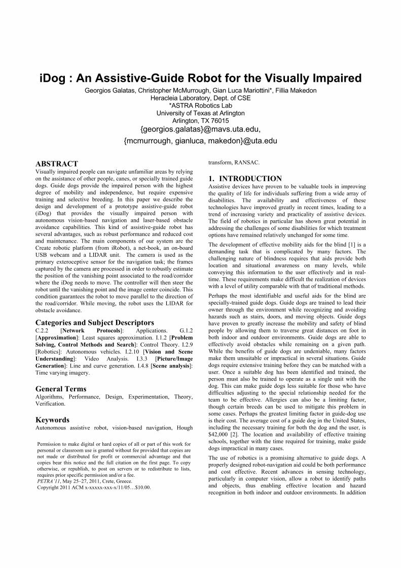
Unmanned Systems (JAUS) [13]. The JAUS architecture is a collection of standards, originally developed by the United States Department of Defense, for unmanned systems. JAUS is designed to govern the way that unmanned systems are designed at the networked component level, as well as the networked agent level. While a fully compliant JAUS implementation is out of the scope of this project, the software architecture utilized in the robotic guide dog follows many of the guidelines established by JAUS (distribution of software modules, UDP communication between modules, etc). This increases the level of interoperability at the component level, allowing a new software module to be quickly and easily integrated in the system without changes to other components. 3.1 Software architecture As previously mentioned, the architecture employed by the system is distributed at the component level. Individual software modules were created for specific tasks, such as polling a particular sensor or sending actuator commands to the iRobot platform. These background processes, or Daemons, communicate over a network protocol using UDP packets in a specific format. The modules are able to run on the same machine or on their own dedicated hardware simply by specifying the IP addresses and port numbers accordingly. This networked approach makes it possible to distribute computational load across several computers for increased performance and expandability. The software architecture employed by the iDog is shown in the diagram in Fig.1.
Figure 1: Software architecture of the iDog system
Each software module is assigned a unique IP address and port number pair, allowing them to be individually addressed across multiple hardware units. The vision and ranging daemons monitor the camera and the LIDAR, respectively, compute error signals, and send perceived
values to the system controller. The system controller runs the vehicle PID controller, provides error reference signals to the sensing daemons, and visualizes the incoming data streams. Every aspect of the vehicle control law (such as the period, PID gains, and filtering parameters) is configurable from the system controller. Filtering of the incoming data streams is performed independently, with both a moving-average and moving-median filter implemented. These filters, running in parallel, can be modified during execution to aid in testing and performance evaluation.
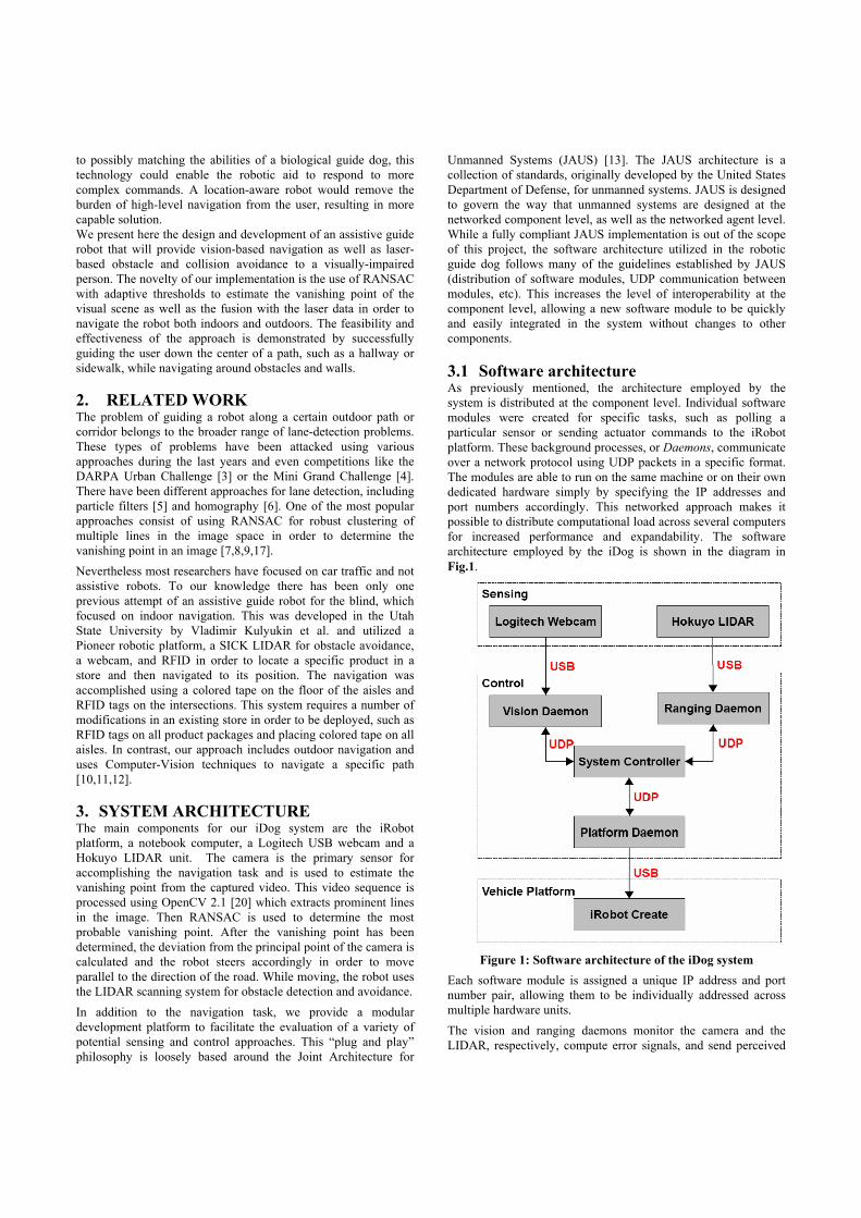
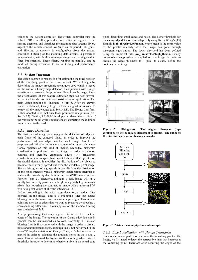
3.2 Vision Daemon The vision daemon is responsible for estimating the pixel position of the vanishing point at each time instant. We will begin by describing the image processing techniques used which is based on the use of a Canny edge-detector in conjunction with Hough transform that extracts the prominent lines in each image. Since the effectiveness of this feature extraction step has been proven, we decided to also use it in our assistive robot application. The main vision pipeline is illustrated in Fig. 3. After the current frame is obtained, Canny Edge Detection algorithm is used to extract all the image edges (c.f. Sect.3.2.1). The Hough transform is then adopted to extract only those prominent image lines (c.f., Sect.3.2.2). Finally, RANSAC is adopted to detect the position of the vanishing point while simultaneously extracting those image lines parallel to the road. 3.2.1 Edge Detection The first step of image processing is the detection of edges in each frame of the captured video. In order to improve the performance of our edge detector, each image has to be preprocessed. Initially the image is converted to grayscale, since Canny operates on this kind of images. Secondly, histogram equalization is performed on the image in order to increase contrast and therefore emphasize edges [14]. Histogram equalization is an image enhancement technique that operates on the spatial domain. It modifies the distribution of the pixels to become more evenly spread out over the available pixel range. Since a histogram of a grayscale image displays the distribution of the pixel intensity values, histogram equalization attempts to reshape the probability distribution function (PDF) into a uniform function (Fig. 2). Therefore, although a dark image will have mostly low intensity pixels and a bright image only high intensity pixels thus lowering the contrast, an image with a uniform PDF will have pixel values at all valid intensities [16]. Before proceeding to the actual edge detection, a median filter operates on the image. This is a smoothing filter that causes blurring but at the same time preserves larger edges. This aims at adjusting the size of edges that we want to preserve by choosing a corresponding filter size. In our application the median filtering uses a window of 5x5. After preprocessing, the Canny edge detector is used to extract the edges of the image. The operation of the Canny edge detector in general can be summarized as follows. Normally, a Gaussian blurring filter is first convolved with the image in order to discard noise and unimportant edges, although this is not performed in the OpenCV implementation of Canny. Then, a Sobel operator is applied in order to calculate the gradient norms in the x and y axes. This is followed by hysteresis thresholding which uses 2 thresholds in order to determine whether a pixel is an actual edge
pixel, discarding small edges and noise. The higher threshold for the canny edge detector is set adaptively using Kerry Wong’s [15] formula high_thresh=1.66*mean, where mean is the mean value of the pixels’ intensity after the image has gone through histogram equalization. The lower threshold has been defined using the empirical rule low_thresh=0.4*high_thresh. Finally non-maxima suppression is applied on the image in order to reduce the edges thickness to 1 pixel to clearly define the contours in the image.
Figure 2: Histograms. The original histogram (top) compared to the equalized histogram (bottom). The range of the pixel intensity values becomes broader.
Figure 3: Vision daemon pipeline and example. 3.2.2 Line Localization with Hough Transform Since our ultimate goal is to determine the vanishing point in the image, we first need to detect the perspective lines that intersect at the vanishing point. Therefore after acquiring the edges of the
Canny
Hough
RANSAC
Median Filtering and Hist.
Eq.
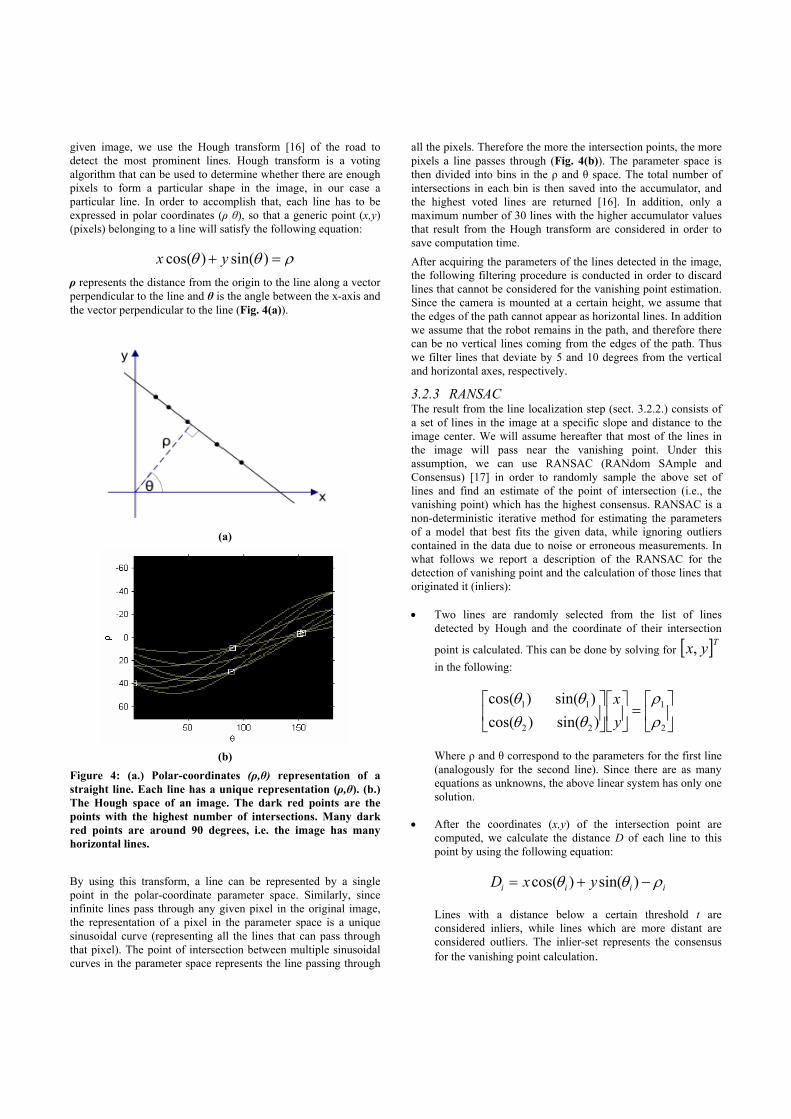
given image, we use the Hough transform [16] of the road to detect the most prominent lines. Hough transform is a voting algorithm that can be used to determine whether there are enough pixels to form a particular shape in the image, in our case a particular line. In order to accomplish that, each line has to be expressed in polar coordinates (ρ θ), so that a generic point (x,y) (pixels) belonging to a line will satisfy the following equation:
ρθθ =+ )sin()cos( yx
ρ represents the distance from the origin to the line along a vector perpendicular to the line and θ is the angle between the x-axis and the vector perpendicular to the line (Fig. 4(a)).
(a)
(b)
Figure 4: (a.) Polar-coordinates (ρ,θ) representation of a straight line. Each line has a unique representation (ρ,θ). (b.) The Hough space of an image. The dark red points are the points with the highest number of intersections. Many dark red points are around 90 degrees, i.e. the image has many horizontal lines. By using this transform, a line can be represented by a single point in the polar-coordinate parameter space. Similarly, since infinite lines pass through any given pixel in the original image, the representation of a pixel in the parameter space is a unique sinusoidal curve (representing all the lines that can pass through that pixel). The point of intersection between multiple sinusoidal curves in the parameter space represents the line passing through
all the pixels. Therefore the more the intersection points, the more pixels a line passes through (Fig. 4(b)). The parameter space is then divided into bins in the ρ and θ space. The total number of intersections in each bin is then saved into the accumulator, and the highest voted lines are returned [16]. In addition, only a maximum number of 30 lines with the higher accumulator values that result from the Hough transform are considered in order to save computation time. After acquiring the parameters of the lines detected in the image, the following filtering procedure is conducted in order to discard lines that cannot be considered for the vanishing point estimation. Since the camera is mounted at a certain height, we assume that the edges of the path cannot appear as horizontal lines. In addition we assume that the robot remains in the path, and therefore there can be no vertical lines coming from the edges of the path. Thus we filter lines that deviate by 5 and 10 degrees from the vertical and horizontal axes, respectively.
3.2.3 RANSAC The result from the line localization step (sect. 3.2.2.) consists of a set of lines in the image at a specific slope and distance to the image center. We will assume hereafter that most of the lines in the image will pass near the vanishing point. Under this assumption, we can use RANSAC (RANdom SAmple and Consensus) [17] in order to randomly sample the above set of lines and find an estimate of the point of intersection (i.e., the vanishing point) which has the highest consensus. RANSAC is a non-deterministic iterative method for estimating the parameters of a model that best fits the given data, while ignoring outliers contained in the data due to noise or erroneous measurements. In what follows we report a description of the RANSAC for the detection of vanishing point and the calculation of those lines that originated it (inliers): • Two lines are randomly selected from the list of lines
detected by Hough and the coordinate of their intersection
point is calculated. This can be done by solving for [ ]Tyx, in the following:
⎥⎦
⎤⎢⎣
⎡=⎥
⎦
⎤⎢⎣
⎡⎥⎦
⎤⎢⎣
⎡
2
1
22
11
)sin()cos()sin()cos(
ρρ
θθθθ
yx
Where ρ and θ correspond to the parameters for the first line (analogously for the second line). Since there are as many equations as unknowns, the above linear system has only one solution.
• After the coordinates (x,y) of the intersection point are computed, we calculate the distance D of each line to this point by using the following equation:
iiii yxD ρθθ −+= )sin()cos(
Lines with a distance below a certain threshold t are considered inliers, while lines which are more distant are considered outliers. The inlier-set represents the consensus for the vanishing point calculation.
• If the consensus set is larger than a certain threshold cT , then we consider that these inliers are a good estimate for the inliers of our data and the algorithm stops by returning the estimated intersection point coordinates as well as the inlier set. Otherwise we iterate the previous step either until we do find a large enough consensus or until a maximum number of iterations is reached. In every intermediate iteration with a higher consensus we keep the new estimate as a better one.
The three thresholds of the RANSAC algorithm are set adaptively. 1. The consensus threshold is set as a fraction of the filtered
lines considered by RANSAC and has been found to work effectively in the region of 50-80% of the total number of detected lines.
2. The maximum number of iterations is set in order to make the algorithm computationally efficient by avoiding the execution for every possible sample. If p is the probability that at least one of the samples is free from outliers, ε is the probability of a line being an outlier and s is the sample size, then it can be proven that: pw Ns −=− 1)1( , where
ε−= 1w [18]. Therefore the maximum number of
iterations can be expressed as ))1(1log(
)1log(s
pNε−−
−= ,where
p is usually set to 99%.
3. The distance threshold t is calculated as follows. According to [17], the measurement error can be described by a zero mean Gaussian with standard deviation σ. Then the square of the points’ distance to the lines can be expressed as a chi-squared distribution with co-dimension equal to 1. Thus, from the cumulative chi-squared distribution Fm with m degrees of freedom (co-dimension):
212 )( σ⋅= − aFt m
,where α is the probability of a point being an inlier. Then for m=1 and α=95% :
222 84.384.3 σσ ⋅=⇒⋅= tt
After the completion of the above procedure, we have a number n of inlier lines with the highest consensus which we will use to determine the vanishing point in the image. The resulting system will be in the form:
⎥⎥⎥⎥
⎦
⎤
⎢⎢⎢⎢
⎣
⎡
=⎥⎦
⎤⎢⎣
⎡
⎥⎥⎥⎥
⎦
⎤
⎢⎢⎢⎢
⎣
⎡
nnn
yx
ρ
ρρ
θθ
θθθθ
MMM
2
1
22
11
)sin()cos(
)sin()cos()sin()cos(
This over-determined problem can be expressed as ρϑχ = and solved in a least-squares sense using SVD.
In addition to obtaining the coordinates of the vanishing point for every frame, we store the coordinates of the last 5 frames and return the median of these coordinates. This acts as a buffering mechanism since it suppresses radical changes in the coordinates of the vanishing point due to incorrect estimation in specific frames. The x-coordinate of this filtered vanishing point is then used to calculate the deviation from the principal point of the camera. In our implementation we assume that the principal point is in the middle of the image and that the camera points parallel to the axis of motion of the robot. The deviation, which takes values from 0 to 255 from far left to far right, is then sent to the controller module using UDP datagrams.
(a.)
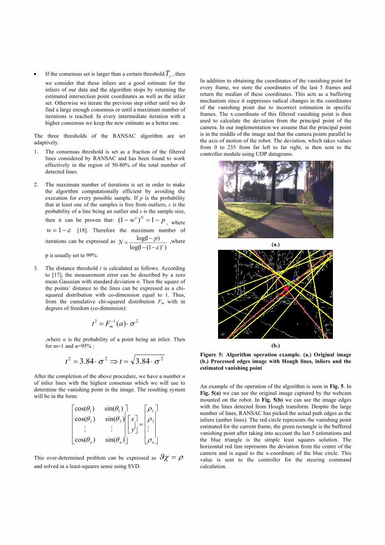
(b.)
Figure 5: Algorithm operation example. (a.) Original image (b.) Processed edges image with Hough lines, inliers and the estimated vanishing point An example of the operation of the algorithm is seen in Fig. 5. In Fig. 5(a) we can see the original image captured by the webcam mounted on the robot. In Fig. 5(b) we can see the image edges with the lines detected from Hough transform. Despite the large number of lines, RANSAC has picked the actual path edges as the inliers (amber lines). The red circle represents the vanishing point estimated for the current frame, the green rectangle is the buffered vanishing point after taking into account the last 5 estimations and the blue triangle is the simple least squares solution. The horizontal red line represents the deviation from the center of the camera and is equal to the x-coordinate of the blue circle. This value is sent to the controller for the steering command calculation.
3.3 Laser Daemon The laser daemon is designed to serve as the software interface to the LIDAR unit. Measurements from the Hokuyo URG-04-LX-01 ranging unit are acquired using the SKIP 2.0 USB protocol for Hokuyo ranging devices. The URG-04-LX-01 returns readings from an envelope of 240 degrees with 0.36 degree resolution. Each ranging measurement is achieved with a resolution of 1mm, and is assembled into a UDP packet for transmission to the system controller. Once received by the system controller (at a rate of 10 Hz), the UDP packet is used to populate an array of measurements. These measurements are then filtered using either a moving average or moving median filter, both with adjustable window sizes. After filtering, a “safety envelope” is scanned for potential obstacles. Laser measurements falling within this safety area are counted, and if this number exceeds a user defined threshold, the laser signal overrides the vision signal as the source of error for the PID controller.
3.4 System Controller As a central component of the iDog, our system controller is responsible for fusing real-time data streams from sensing components. This module performs the selection and filtering of sensor streams in order to generate the control law error signal. At each time step, filtered error signals are used as input to the controller.
The System Control GUI, in addition to conditioning data streams and providing user interface settings, performs discrete iterations of the PID controller. This common controller is used to calculate the turning radius command that is sent to the iRobot platform. The error e(t) is defined as the deviation of the vehicle from the desired path at time step t. The vehicle turning radius commanded at time t is then given by
∫−
++=T
Ttdip dt
tdekdektektU )()()()( ττ
The control gains kp, ki, and kd are configurable in the System Control GUI, along with an integration window of size T. This allows the user to tune and to evaluate every aspect of the radius controller.
In order to avoid collision with static and moving obstacles, the system controller switches the error signal source from the vision daemon to the laser daemon when obstacles are detected within the safety envelope. The centroid of all the scanning points lying within the safety envelope is then used as a new e(t) to its upper or lower bound value, such that the platform spins in place away from the obstacle centroid. This behavior is repeated until the safety envelope of the robot is determined to be clear.
The translational velocity command is switched in a manner similar to the turning radius, though a simple bang-bang controller is used in place of PID; its value is set by the user with the control GUI when no obstacles are present (zero otherwise).
3.5 Robot Daemon The iRobot daemon receives command packets from the system controller. These command packets are validated and transformed into iRobot Create OI commands, which are sent to the platform
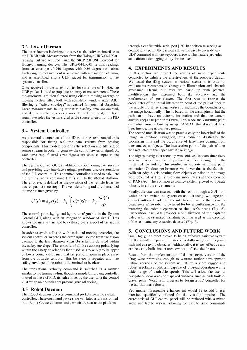
through a configurable serial port [19]. In addition to serving as control relay point, the daemon allows the user to override any UDP command with the keyboard arrows. This feature provides an additional debugging utility for the user. 4. EXPERIMENTS AND RESULTS In this section we present the results of some experiments conducted to validate the effectiveness of the proposed design. We tested the iDog system in various scenarios in order to evaluate its robustness to changes in illumination and obstacle avoidance. During our tests we came up with practical modifications that increased both the accuracy and the performance of our system. The first was to restrict the coordinates of the initial intersection point of the pair of lines to the middle 1/3 of the image vertically and inside the boundaries of the image horizontally. This is based on the assumptions that the path cannot have an extreme inclination and that the camera always keeps the path in its view. This made the vanishing point estimation more robust by using RANSAC that discarded false lines intersecting at arbitrary points. The second modification was to process only the lower half of the image in outdoor navigation, thus reducing drastically the processing time and the occurrence of false lines coming from trees and other objects. The intersection point of the pair of lines was restricted to the upper half of the image. The highest navigation accuracy was achieved indoors since there was an increased number of perspective lines coming from the walls and the ceiling. This resulted in accurate vanishing point estimation. Outdoor performance was lower due to the fact that collinear edge pixels coming from objects or noise in the image were detected as lines, introducing inaccuracies in the execution of RANSAC. The collision avoidance system proved to operate robustly in all the environments. Finally, the user can interacts with the robot through a GUI from which he can switch the system on and off using two large and distinct buttons. In addition the interface allows for the operating parameters of the robot to be tuned for better performance and for matching the robot’s operation to the user’s needs (Fig. 6). Furthermore, the GUI provides a visualization of the captured video with the estimated vanishing point as well as the direction of the robot and any obstacles detected (Fig. 7). 5. CONCLUSIONS AND FUTURE WORK Our iDog guide robot proved to be an effective assistive system for the visually impaired. It can successfully navigate on a given path and can avoid obstacles. Additionally, it is cost effective and can be easily built since it uses low cost, off-the-shelf parts. Results from the implementation of this prototype version of the iDog were promising enough to warrant further development. Future versions of the system will utilize a more rugged and robust mechanical platform capable of off-road operation with a wider range of attainable speeds. This will allow the user to navigate outdoor areas on unpaved surfaces, such as park trails or gravel paths. Work is in progress to design a PID controller for the translational velocity. Yet another foreseeable enhancement would be to add a user interface specifically tailored for the visually impaired. The current visual GUI control panel will be replaced with a mixed audio and tactile system, allowing the user to issue commands
verbally and receive system notifications through audio output or force feedback.
Figure 6: iDog GUI showing the multiple tabs of the iDog
System Controller Application
Figure 7: Vision and ranging data perceived by the iDog
system Finally, the vision daemon will be further optimized for speed and accuracy in a wider range of operating environments. A navigation paradigm that correlates visual features with LIDAR data could be used to eliminate obstacle edges from the set of edges considered by the RANSAC algorithm. This approach could greatly improve the performance of the system when operating in the presence of obstacles.
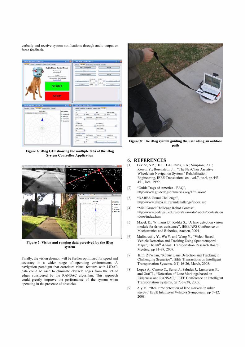
Figure 8: The iDog system guiding the user along an outdoor
path
6. REFERENCES [1] Levine, S.P.; Bell, D.A.; Jaros, L.A.; Simpson, R.C.;
Koren, Y.; Borenstein, J.; , "The NavChair Assistive Wheelchair Navigation System," Rehabilitation Engineering, IEEE Transactions on , vol.7, no.4, pp.443-451, Dec, 1999.
[2] “Guide Dogs of America - FAQ”, http://www.guidedogsofamerica.org/1/mission/
[3] “DARPA Grand Challenge”, http://www.darpa.mil/grandchallenge/index.asp
[4] “Mini Grand Challenge Robot Contest”, http://www.cede.psu.edu/users/avanzato/robots/contests/outdoor/index.htm
[5] Macek K., Williams B., Kolski S., “A lane detection vision module for driver assistance”, IEEE/APS Conference on Mechatronics and Robotics, Aachen, 2004.
[6] Malinovskiy Y., Wu Y. and Wang Y., “Video-Based Vehicle Detection and Tracking Using Spatiotemporal Maps”, The 88th Annual Transportation Research Board Meeting, pp 81-89, 2009.
[7] Kim, ZuWhan, “Robust Lane Detection and Tracking in Challenging Scenarios”, IEEE Transactions on Intelligent Transportation Systems, 9(1):16-26, March, 2008.
[8] Lopez A., Canero C., Serrat J., Saludes J., Lumbreras F., and Graf T., “Detection of Lane Markings based on Ridgeness and RANSAC,” IEEE Conference on Intelligent Transportation Systems, pp 733-738, 2005.
[9] Aly M., “Real time detection of lane markers in urban streets,” IEEE Intelligent Vehicles Symposium, pp 7–12, 2008.
[10] Kulyukin V., Gharpure C., and Nicholson J. “RoboCart: Toward Robot-Assisted Navigation of Grocery Stores by the Visually Impaired”. IEEE/RSJ International Conference on Intelligent Robots and Systems pp. 2845-2850, Alberta, Canada, 2005.
[11] Kulyukin V., Gharpure C., Nicholson J., Osborne G. “Robot-Assisted Wayfinding for the Visually Impaired in Structured Indoor Environments”. Autonomous Robots, 21(1): 29-41, June 2006.
[12] Kulyukin V., and Gharpure G. “A Robotic Shopping Assistant for the Blind” The 29-th Annual Conference of the Rehabilitation Engineering and Assistive Technology Society of North America (RESNA 2006), Atlanta, Georgia, 2006.
[13] Rowe S. and Wagner C. “An Introduction to the Joint Architecture for Unmanned Systems (JAUS)”, Technical Report from Cybernet Systems Corporation, http://www.cybernet.com
[14] Rezai-Rad G. Larijani H.H., "A New Investigation on Edge detection Filters Operation for Feature Extraction under Histogram Equalization Effect" Geometric Modeling and Imaging, pp 149-153, 2007.
[15] Wong K., “Canny Edge Detection Auto Thresholding”, http://www.kerrywong.com/2009/05/07/canny-edge-detection-auto-thresholding, May, 2009.
[16] Gonzalez RC and Woods RE. Digital Image Processing 3rd Edition. Prentice Hall, NJ. p. 2001.
[17] Fischler M.A. and Bolles R.C. Random sample consensus: A paradigm for model fitting with application to image analysis and automated cartography. Communications of the ACM, 24(6):381-395, 1981.
[18] Hartley R. and Zisserman A., “Multiple View Geometry in
Computer Vision”, Second Edition, Cambridge University Press, March, 2004.
[19] “Multiple iRobot Create Open Interface (OI) specification”, iRobot Corporation, http://www.irobot.com, 2006.
[20] “The OpenCV library” http://opencv.willowgarage.com/wiki/


![ENRICHME: Perception and Interaction of an Assistive Robot ...assistive robotics [25,48] investigates the usage of robots that assist humans through social interactions (e.g. speech](https://img.pdfslide.us/doc/110x75/5f084da37e708231d42157c4/enrichme-perception-and-interaction-of-an-assistive-robot-assistive-robotics.jpg)