Embed Size (px)
Citation preview

Section 6
Idle Air Control Systems
Engine Control Systems I - Course 852
Lesson Objectives 1. Determine the condition of the IACV system based on engine data2. Determine the root cause of a failure(s) in the IACV system using
appropriate diagnostic procedures
T852f259

The Idle Air Control (IAC) system regulates engine idle speed by adjust-ing the volume of air that is allowed to bypass the closed throttle valve.The ECM controls the Idle Air Control Valve (IACV) based on input sig-nals received from various sensors. The system is necessary to providestabilization of curb idle when loads are applied to the engine and toprovide cold fast idle on some applications.
The idle air control system regulates idle speed under at least one ormore of the following conditions, depending on application:
• Cold Fast Idle.
• Warm Curb Idle.
• Air Conditioner Load.
• Electrical Load.
• Automatic Transmission Load.
• Power Steering Idle Up.
The IAC system will also prevent engine stall on deceleration.
Section 6
Idle Air Control Systems
Engine Control Systems I - Course 852 6-1
Idle Air ControlSystem with Air Assist
Fig. 6-01
T852f258
Idle Air ControlSystems
Air Cleaner
ISC Valve
InjectorThrottle Valve
Intake Manifold
Air Gallery
Air Pipe

TOYOTA Technical Training6-2
Section 6
There are four different types of ECM controlled IAC systems. Thesesystems are referred to as:
• Stepper motor type.
• Rotary solenoid types.
• Duty control ACV type.
• On-off control VSV type.
IAC System
Stepper Motor IACV
As the valve steps increase, more air by-passes the throttle valve.
Fig. 6-02
T852f259
Fig. 6-03
T852f260/T852f261
ECM ModulatedIdle Air ControlSystems (IAC)
Rotor
Stator
From Air Flow Meter
Stopper Plate
Valve Shaft
Valve Seat
To Air IntakeChamber
Valve
0 125Valve Steps
By-
Pas
s A
ir Va
lve

Engine Control Systems I - Course 852 6-3
Idle Air Control Systems
The stepper motor IACV is located on the intake air chamber or throttlebody. It regulates engine speed by means of a stepper motor and a pintlevalve that controls the volume of air bypassing the closed throttle valve.The IACV throttle air bypass circuit routes intake air past the throttlevalve directly to the intake manifold through an opening between the pin-tle valve and its seat. The size of this opening is determined by how farthe pintle is from the seat.
The valve assembly consists of four electrical stator coils, a magneticrotor, a valve and valve shaft. The valve shaft is screwed into the rotor sothat as the rotor turns, the valve assembly will extend and retract.
The ECM controls movement of the pintle valve by sequentially groundingthe four electrical stator coils. Each time current is pulsed through one ofthe stator coils, the shaft moves one "step,” either into or out of the airpassage. The direction of valve movement depends on the sequence bywhich the ECM energizes the coils.
The ECM closes the air bypass by extending the valve through the follow-ing sequence:
ISC1 > ISC2 > ISC3 > ISC4
The ECM opens the air bypass by extending the valve through the follow-ing sequence:
ISC4 > ISC3 > ISC2 > ISC1
Stepper MotorIAC Valve
Stepper Motor IAC Operation
The ECM commands achange in IAC position
by sequentially turning onthe stepper motor coils.
Fig. 6-04
T852f262

TOYOTA Technical Training6-4
Section 6
The pintle valve has 125 possible positions, from fully retracted (maxi-mum air bypass) to fully extended (no air bypass). In the event that theIACV becomes disconnected or inoperative, its position will become fixedat the step count where it failed. Because the stepper idle air controlmotor is capable of controlling large volumes of air, it is used for coldfast idle control and is not used in combination with a mechanical airvalve.
Engines equipped with the stepper type IACV use an ECM controlledEFI main relay which delays system power down for about two secondsafter the ignition is turned off. During these two seconds, the ECM fullyopens the IACV to 125 steps from seat, improving engine stability whenit is started. This reset also allows the ECM to keep track of the IACVposition after each engine restart.
Once the engine has started and reached approximately 500 RPM, theECM drives the IACV to a precise number of steps from seat based onthe coolant temperature at time of start-up. This information is storedin a look up table in the ECM memory and is represented by point B onthe graph.
Fig. 6-05
T852f263
Primary ControlledParameters
Initial Set-Up
After-Start Control
Initial Set-Up AndAfter-Start Control
The IAC is opened to its125th step immediately
after the engine stopsrunning. After engine
start-up the ECMpositions the IAC valve
based on the currentcoolant temperature
A
20(68)
Coolant Temperature ºC (ºF)
B
A125
A→B After-Start Control
Low
← E
ngin
e R
PM
→ H
igh

Engine Control Systems I - Course 852 6-5
Idle Air Control Systems
As the engine coolant approaches normal operating temperature, the needfor cold fast idle is gradually eliminated. The ECM gradually steps theIACV toward its seat during warm-up. The warm curb idle position is rep-resented by point C on the graph. When the coolant temperature isapproximately 71°C (160°F), the cold fast idle program has ended.
The ECM has a preprogrammed target idle speed that is maintained bythe IACV based on feedback from the NE signal. Feedback idle air controloccurs any time the throttle is closed and the engine is at normal operat-ing temperature. The target idle speed is programmed in an ECM look up
Warm-up Control
The IAC valve positionadjusted to match the
actual idle speed tocalculated target speed.
Feedback Control
The IAC valve positionadjusted to match the
actual idle speed tocalculated target speed.
Fig. 6-06
T852f264
Fig. 6-07
T852f265
Engine Warm-upControl
Feedback(Closed Loop)
Idle Air Control
C
20 71(68) (160)
Coolant Temperature ºC (ºF)
A
B
C
125
B→C: Warm-Up Control
Low
← E
ngin
e R
PM
→ H
igh
Num
ber
of S
teps
20 71(68) (160)
Coolant Temperature ºC (ºF)
A
B
C
125
A → B:Warm-Up ControlB → C:Warm-Up Control
Low
← E
ngin
e R
PM
→ H
igh
Num
ber
of S
teps
Load FeedbackControl
No LoadFeedback Control
TOYOTA Technical Training6-6
Section 6
table and varies depending on inputs from the A/C and NSW signals.Any time actual speed varies by greater than 20 RPM from target idlespeed, the ECM will adjust the IAC valve position to bring idle speedback on target.
To prevent major loads from changing engine speed significantly, theECM monitors signals from the Neutral Start Switch (NSW), the AirConditioner switch (A/C), and models equipped with Power Steering OilPressure Switch (PS). By monitoring these inputs, the ECM reestablish-es target idle speeds accordingly and adjusts IACV position.
Before a change in engine speed can occur, the ECM has moved theIACV to compensate for the change in engine load. This feature helps tomaintain a stable idle speed under changing load conditions.
These speed specifications can be useful when troubleshooting suspect-ed operational problems in the step type idle air control system or relat-ed input sensor circuits.
Electrical Load Idle-up - Whenever a drop in voltage is sensed at theECM +B or IG terminals, the ECM responds by increasing engine idlespeed. This strategy ensures adequate alternator rpm to maintain sys-tem voltage at safe operational levels.
Other ControlledParameters
Target Idle Speed
Note the change in target speed as the A/Cor NSW are on or off.
Fig. 6-08
Air Conditioner Switch Neutral Start Switch Engine Speed
ON
OFF
ON
OFF
ON
OFF
900 RPM
750 RPM
650 RPM
580 RPM
Engine Load/SpeedChange Estimate
Control

Engine Control Systems I - Course 852 6-7
Idle Air Control Systems
Deceleration Control - Some ECMs use a deceleration function to allowthe engine to gradually return to idle. This strategy helps improve emis-sions control by allowing more air into the intake manifold on decelera-tion. This extra air is available to mix with any fuel that may have evapo-rated during the low manifold pressure conditions of deceleration.
Learned Idle Air Control - The idle air control program is based on anECM stored look up table, which lists pintle step positions in relation tospecific engine rpm values. Over time, engine wear and other variationstend to change these relationships. Because this system is capable offeedback control, it is also capable of memorizing changes in the relation-ship of step position and engine rpm. The ECM periodically updates itsmemory to provide more rapid and accurate response to changes inengine rpm.
If the battery is disconnected, the ECM must relearn target step positions.
The RS IACV is mounted on the throttle body and intake air bypassingthe throttle valve passes through it. According to the signals sent fromthe ECM, the IACV controls the flow rate of air bypassing the throttle
NOTE
Rotary Solenoid IAC System
Rotary Solenoid
Fig. 6-09
T852f266
Throttle Valve Air IntakeChamber
RS Valve
To Cylinder
ECMSensors
From AirCleaner

TOYOTA Technical Training6-8
Section 6
valve during idle. The air flow rate determines the idle speed. The IACVreceives its power from the EFI relay and ground through the ECM.
ECM
EFI main relay
* Some models only
Ignition switch
Battery BATT
E1
+B
+B1*
Mic
ropr
oces
sor
Sensors
ISC valueISC1(RSC)
ISC2(RSO)
Rotary Solenoid Circuit
Types of Rotary Solenoid IACV
Fig. 6-10
T852f267
Fig. 6-11
T852f268
RSO
ECMECM
Driver
IAC Valve
RSO
RSC
IACValve
Single Driver Circuit Dual Driver Circuits

Engine Control Systems I - Course 852 6-9
Idle Air Control Systems
There are two styles of rotary solenoid IACVs. The older style uses twodriver circuits, one driver for each coil. The newer style uses a single driv-er circuit, one coil is controlled by the ECM while the other coil is alwaysgrounded. They are not interchangeable. An easy way to tell which type ofrotary solenoid is to use the wiring schematic. The older style has twowires connected to the ECM while the newer type has one connected tothe ECM and the other wire connected to ground.
Rotary Solenoid IAC
Fig. 6-12
T852f269/T852f270
Bimetallic CoilA
A1
ValvesPermanent
Magnet
Coils
To CylinderFrom AirChamber
To Injector
A - A’ Cross Section

The valve assembly consists of two electrical coils, a permanent magnetmounted on the valve shaft, and a valve. A fail-safe bimetallic strip isfitted to the end of the shaft to operate the valve in the event of electri-cal failure in the IACV system.
Located at the end of the valve shaft, the cylindrical permanent magnetrotates when its two poles are repelled by the magnetism exerted bycoils T1 and T2.
Anchored to the midsection of the valve shaft, the valve controls theamount of air passing through the bypass port. The valve, valve shaft,and permanent magnet all rotate together.
As shown, each coil is connected to a transistor, T1 and T2 located inthe ECM. When transistor T1 turns on, current flows through that coil.The magnetic field of the coil and the magnetic field of the permanentmagnet cause the valve to rotate clockwise. When T2 is turned on, thevalve rotates counterclockwise.
The ECM varies the on time (duty ratio) for each coil. The difference instrength between the two magnetic fields determines the position of thevalve. The frequency is very high, 250Hz. This high frequency helps thevalve maintain the correct position for proper air flow.
IACV Components
TOYOTA Technical Training6-10
Section 6
Rotary IACVOperation
Fig. 6-13
T852f271
FixedPin Bimetallic Strip
Coil T2
Coil T1PermanentMagnet
BypassPort
RSO
+B
Sensors
Guard
Lever
Valve
Valve Shaft
ECM
T1T2
Engine Control Systems I - Course 852 6-11
Idle Air Control Systems
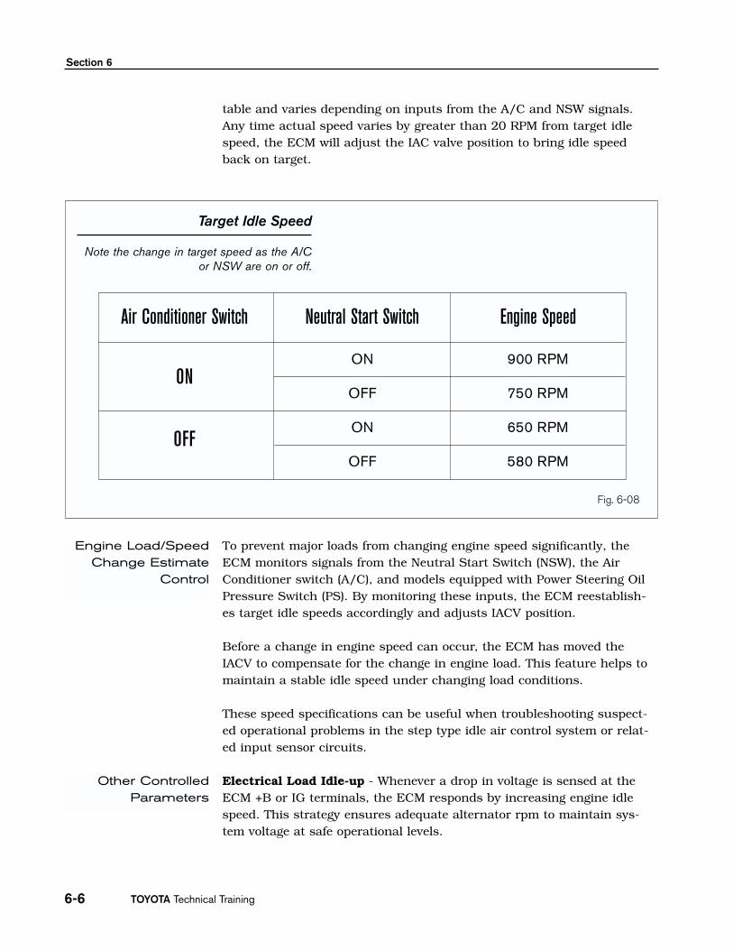
The difference with this type of IACV is that the ECM sends a duty cyclesignal to one coil inside the IACV; the other coil is always on. To changethe IACV position, ECM changes the duty ratio in the controlled coil.
If the electrical connector is disconnected or the valve fails electrically, theshaft will rotate to a position determined by the balancing of the perma-nent magnet with the iron core of the coils and the bi-metal strip.
The cold idle will not be as fast as normal and the warm idle will be high-er than normal.
Using a bimetallic strip allows the IACV to change airflow rate with thechange in temperature. The default rpm is approximately 1000 to 1200RPM once the engine has reached normal operating temperature.
As the engine is started, the ECM opens the IACV to a preprogrammedposition based on coolant temperature and sensed rpm.
Once the engine has started, the ECM controls the fast idle based oncoolant temperature. As the engine approaches normal operating temper-ature, engine speed is gradually reduced. At this time the ECM is com-paring actual idle rpm to the target rpm.
Rotary IACVControlledParameters
Engine Starting
Warm-up
Bimetallic SpringOperation
Single Driver RotaryIACV Operation
IACV Movement
Fig. 6-14
T852f272
To Cylinder
AirPassage
Valve
PermanentMagnet
Coils
To Injectors
From AirCleaner
BimetallicCoil
TOYOTA Technical Training6-12
Section 6
The ECM utilizes a feedback idle air control strategy (which functionsvery much like the stepper motor IAC system). That is, when the actualengine speed is lower than the target idling speed, the ECM signals theIACV to open. Conversely, when the actual idle speed is higher than thetarget idle speed, the ECM signal the IACV to close.
To prevent major loads from changing engine speed significantly, theECM monitors signals from the neutral start switch (NSW), the air con-ditioner switch (A/C), headlights or rear window defogger (ELS), and inmodels equipped with power steering, an oil pressure switch (PS). Bymonitoring these inputs, the ECM reestablishes target idle speedsaccordingly, and adjusts IACV position.
Before a change in engine speed can occur, the ECM has moved theIACV to compensate for the change in engine load. This feature helps tomaintain a stable idle speed under changing load conditions.
These speed specifications can be useful when troubleshooting suspect-ed operational problems in the IAC system or related input sensor cir-cuits.
The Rotary Solenoid IAC system utilizes a learned idle air control strate-gy. The ECM memorizes the relationship between engine rpm and dutycycle ratio and periodically updates its memory. Over time, engine wearand other variations tend to change these relationships. Because thissystem is capable of feedback control, it is also capable of memorizingchanges in the relationship of duty ratio and engine rpm. The ECM peri-odically updates its memory to provide more rapid and accurateresponse to changes in engine rpm.
If the battery is disconnected, the ECM must relearn target steppositions.
Engine Load/SpeedChange Estimate
Control
Feedback Control
NOTE

Engine Control Systems I - Course 852 6-13
Idle Air Control Systems
The air conditioning idle-up system is used in some models equipped withthe rotary solenoid to increase engine idle rpm any time the air condition-ing compressor is in operation. This system maintains engine idle stabili-ty during periods of A/C compressor operation. Additionally, it keepscompressor speed sufficiently high to ensure adequate cooling capacity atidle speed. The air control VSV is turned on or off by the air condi-tioning ECU.
Air ConditioningIdle-Up
Fig. 6-15
T852f273
A/C Idle-Up
Connector
Adjustment Screw
FromAir Cleaner
To Cylinder
ValveCoil

TOYOTA Technical Training6-14
Section 6
The power steering system draws a significant amount of horsepowerfrom the engine when the steering wheel is turned to either stop. Thiscan have an adverse effect on idle quality. To address this potentialproblem, many engines equipped with power steering use a power steer-ing idle-up system that activates whenever the steering wheel is turnedto a stop. There are two types:
• Non-ECM controlled.
• ECM controlled.
The Non-ECM controlled power steering idle-up system consists of ahydraulically operated air control valve and a vacuum circuit whichbypasses the throttle valve. Whenever power steering pressure exceedsthe calibration point of the control valve, the valve opens, allowing a cal-ibrated volume of air to bypass the closed throttle valve.
Fig. 6-16
T852f274
Power SteeringIdle-Up
Non-ECM Controlled
PowerSteering Idle-Up
Non-ECM ControlledSystem.
Air Intake Chamber
Steering Gear Housing
Air Control Valve
MAF

Engine Control Systems I - Course 852 6-15
Idle Air Control Systems
The system is only functional during very low speed maneuvering and atidle. The system can be tested by turning the steering wheel and listeningfor an RPM increase.
The ECM controlled power steering idle-up uses a pressure switch or sen-sor in place of the air control valve. Receiving a change in voltage signalfrom the sensor, the ECM will command the IACV to open,increasing engine RPMs.
ECM Controlled

TOYOTA Technical Training6-16
Section 6

Engine Control Systems I - Course 852 6-17
Technician Objectives
With this worksheet, you will learn to test rotary solenoid IACV circuits using the required toolsand equipment, retrieve and apply the needed service information, retrieve and interpret servicedata information.
Tools and Equipment
• Vehicle Repair Manual
• Vehicle EWD
• Diagnostic Tester
• DVOM
• Hand Tool Set
Section 1 1. Setup the Diagnostic Tester, go to Data List. Connect the DVOM to either IACV terminal.
2. Start the engine and note IACV percentage and voltage.
3. With the engine warmed up, increase engine RPM to 2500. What happened to IACV percentage andvoltage?
_________________________________________________________________________________________________________
4. With engine at idle, create an intake manifold leak that will cause the engine to run rough but not stall.
5. What happened to IACV percentage?
_________________________________________________________________________________________________________
Section 21. Using the RM, inspect IACV operation by connecting TE1 and E1 terminals in DLC1 (if applicable). What
happened to the idle?
_________________________________________________________________________________________________________
2. Go to Active Test for the IACV system. Increase the IACV percentage. What happened to engine RPM?
_________________________________________________________________________________________________________
3. Decrease IACV percentage. What happened to engine RPM?
_________________________________________________________________________________________________________
WORKSHEET 6—1Rotary Solenoid IACV System
Vehicle Year/Prod. Date Engine Transmission
(Instructor Copy)
TOYOTA Technical Training6-18
Worksheet 6—1
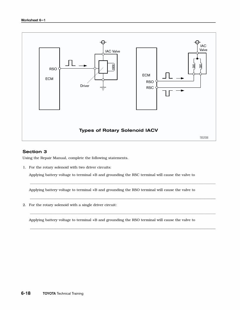
Section 3Using the Repair Manual, complete the following statements.
1. For the rotary solenoid with two driver circuits:
Applying battery voltage to terminal +B and grounding the RSC terminal will cause the valve to
_________________________________________________________________________________________________________
Applying battery voltage to terminal +B and grounding the RSO terminal will cause the valve to
_________________________________________________________________________________________________________
2. For the rotary solenoid with a single driver circuit:
_________________________________________________________________________________________________________
Applying battery voltage to terminal +B and grounding the RSO terminal will cause the valve to
_________________________________________________________________________________________________________
RSO
ECMECM
Driver
IAC Valve
RSO
RSC
IACValve
Types of Rotary Solenoid IACV
T852f268

Engine Control Systems I - Course 852 6-19
Rotary Solenoid IACV System
Name ____________________________________________________________ Date ________________________________Review this sheet as you are doing the worksheet. Check each category after completing the worksheet andinstructor presentation. Ask the instructor if you have questions. The comments section is for you to write whereto find the information, questions, etc.
I have questions I know I can
Topic Comment
Locate components in the IACV systemusing the EWD and RM
Find wire colors, pin numbers in the fueldelivery electrical circuits using the EWDand RM
Locate the IACV status in the Data Listand compare to specifications todetermine condition
Activate RS IACV with Active Test
Determine effect on IACV operation whenthere are engine problems
Test RS IACV operation
Check and retrieve relevant DTCs
Locate in the RM two sections related toIACV system concerns