Embed Size (px)
Citation preview

Identifying energy savings with thermal imaging

Contents
Summary 3
Thermal imaging – how it works 4
Detecting heat loss from pipes 5
Steam trap condition monitoring 6
Finding heat loss from buildings 7
Improving the efficiency of motors and drives 8
Tracing electrical faults 9
Next steps 10
Upgrading existing systems 11
�Identifying energy savings with thermal imaging
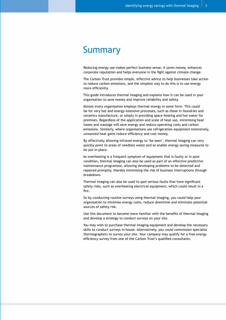
Summary
Reducing energy use makes perfect business sense; it saves money, enhances corporate reputation and helps everyone in the fight against climate change.
The Carbon Trust provides simple, effective advice to help businesses take action to reduce carbon emissions, and the simplest way to do this is to use energy more efficiently.
This guide introduces thermal imaging and explains how it can be used in your organisation to save money and improve reliability and safety.
Almost every organisation employs thermal energy in some form. This could be for very hot and energy-intensive processes, such as those in foundries and ceramics manufacture, or simply in providing space heating and hot water for premises. Regardless of the application and scale of heat use, minimising heat losses and wastage will save energy and reduce operating costs and carbon emissions. Similarly, where organisations use refrigeration equipment extensively, unwanted heat gains reduce efficiency and cost money.
By effectively allowing infrared energy to ‘be seen’, thermal imaging can very quickly point to areas of needless waste and so enable energy saving measures to be put in place.
As overheating is a frequent symptom of equipment that is faulty or in poor condition, thermal imaging can also be used as part of an effective predictive maintenance programme, allowing developing problems to be detected and repaired promptly, thereby minimising the risk of business interruptions through breakdown.
Thermal imaging can also be used to spot serious faults that have significant safety risks, such as overheating electrical equipment, which could result in a fire.
So by conducting routine surveys using thermal imaging, you could help your organisation to minimise energy costs, reduce downtime and eliminate potential sources of safety risk.
Use this document to become more familiar with the benefits of thermal imaging and develop a strategy to conduct surveys on your site.
You may wish to purchase thermal imaging equipment and develop the necessary skills to conduct surveys in-house. Alternatively, you could commission specialist thermographers to survey your site. Your company may qualify for a free energy efficiency survey from one of the Carbon Trust’s qualified consultants.

Thermal imaging – how it works
All objects, even very cold ones, emit heat as infrared radiation. Emission of infrared ceases only when the temperature falls to absolute zero (-273°C). Emission of infrared radiation increases, as the object’s temperature gets higher.
Infrared emissions are usually invisible, but thermal imaging enables us to see and interpret them.
Like visible light, infrared (thermal) energy is part of the electromagnetic spectrum; however, people cannot see it because its wavelength (shown in the diagram) is too long to be detected by the human eye.
Thermal imaging cameras work by detecting the infrared image emitted by an object, and then converting it to an image that can be seen by the human eye. The camera detects the different levels of emitted infrared in relation to the object’s temperature and represents them as different colours, usually ranging from black or blue for the coldest areas to yellow, orange and red for the hottest areas (although other combinations of colours are possible).
Most modern thermal imaging cameras determine the temperature of each part of the object according to the level of infrared emitted, and can store the images digitally. Software packages are also available to help users examine and interpret downloaded images.
Interpreting thermal images
Thermal imaging can be used for definitive temperature measurement which is helpful in quantifying heat losses and for condition monitoring. It can also be used effectively to identify changes in the condition of an object over time by spotting a trend of changing temperatures. Most frequently, thermal imaging is used to find abnormalities or unusual patterns of radiated heat which are indicative of a fault or excessive heat loss.
Interpreting a thermal image takes a degree of skill and understanding. Different materials and surfaces emit heat at different rates, so some allowance must be made for the construction of each different object inspected. Additionally, thermal imaging cameras cannot distinguish between emitted and reflected infrared energy so the user must be aware of any other sources of infrared energy that may cause reflection and must be able to recognise these in thermograms.
Whilst cameras are available for purchase or hire, it is often the case that using a specialist contractor to conduct a survey will pay dividends and avoid the risk of obtaining confusing or inconclusive results.
Benefits
When inspecting buildings, plant or equipment, visualisation of the heat emitted makes it easier to spot problems, understand their cause and so develop a suitable solution.
Thermal imaging makes it easy to identify where waterlogging of pipe insulation leads to wasteful heat losses. Waterlogging like this can also cause corrosion
which will lead to pipe failure.
A key commercial benefit of this technology is that potential faults can be identified quickly and without shutting down or isolating plant and processes.
As there is no need for contact with the object, or for invasive operations such as fitting probes, thermal imaging allows inspection to be conducted from a distance, which provides a number of advantages:
} The user can be located at a safe distance from potentially hazardous equipment, such as hot surfaces, live electrical circuits or vessels holding hazardous substances
} Temporary access, such as scaffolding or ladders, is not required to carry out the inspection
} There is no need to stop the process to fit invasive probes, thus business interruption is minimised.
Technology guide�
Ultraviolet Visible spectrum Infrared (invisible) (invisible)
100-�00nm �00-780nm 780-106nm
Identifying energy savings with thermal imaging
Detecting heat loss from pipes
Space heating systems and many industrial processes frequently use heat in the form of steam or hot water, which is supplied to the point of use by a piped distribution system. A well-insulated heat distribution system has relatively small losses of around 5-10%. However, in a poorly insulated distribution system the losses may reduce the overall efficiency at the point of use to 55% or even less.
Thermal imaging is an ideal tool to help you to quickly identify where pipe insulation must be installed, replaced or repaired to minimise energy losses.
It is often easy to spot with the human eye where pipe insulation is completely missing. However, as systems change or evolve over time to meet new requirements, it can be easy to lose track of the purpose of individual pipes. At this point, a visual survey to determine which pipes require insulation becomes more difficult. Where pipes for numerous services are run together in complex or congested arrangements then determining which pipes require insulation can be nearly impossible. By showing the heat emitted from individual pipes, thermal imaging allows you to quickly spot which pipes require insulation to be fitted.
The graph shows the approximate rate of heat loss for uninsulated pipes of various diameters, over a range of temperatures typical for hot water and steam.
Heat loss from external pipes increases still further when they are exposed to wind or rain and so insulation should have a suitable weatherproof exterior surface.
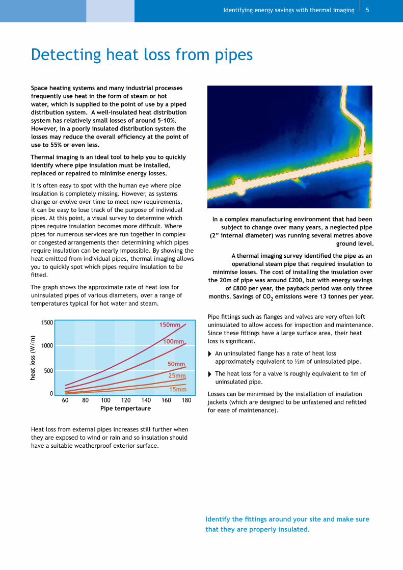
In a complex manufacturing environment that had been subject to change over many years, a neglected pipe
(2” internal diameter) was running several metres above ground level.
A thermal imaging survey identified the pipe as an operational steam pipe that required insulation to
minimise losses. The cost of installing the insulation over the 20m of pipe was around £200, but with energy savings
of £800 per year, the payback period was only three months. Savings of CO2 emissions were 13 tonnes per year.
Pipe fittings such as flanges and valves are very often left uninsulated to allow access for inspection and maintenance. Since these fittings have a large surface area, their heat loss is significant.
} An uninsulated flange has a rate of heat loss approximately equivalent to ½m of uninsulated pipe.
} The heat loss for a valve is roughly equivalent to 1m of uninsulated pipe.
Losses can be minimised by the installation of insulation jackets (which are designed to be unfastened and refitted for ease of maintenance).
�
Identify the fittings around your site and make sure that they are properly insulated.
0
500
1000
1500
heat
loss
(W/m
)
60 80 100 120 140 160 180Pipe tempertaure
15mm
25mm
50mm
100mm
150mm

in the steam system could cause problems such as water hammer, eventually resulting in business interruptions through breakdown.
Traps failed open
Particles of dirt or pipe debris can interfere with a trap and prevent it from closing properly. This results in the continuous and uncontrolled escape of steam into the condensate system, which wastes energy and is also potentially dangerous.
Using thermal imaging to survey steam traps
Analysis of steam traps is complex and surveys should be undertaken by experienced thermographers with an understanding of steam theory. Temperature levels on both side of the trap must be recorded and interpreted in relation to the trap design and the operation of the steam and condensate system.
Contact the Carbon Trust who can provide help and advice on surveying your steam traps.
Steam trap condition monitoring
Steam traps are important components in the efficient operation and control of virtually all steam systems. When working properly, traps act as selective valves, allowing liquid condensate (as well as air and other incondensable gases) to pass whilst still retaining steam. This allows the steam system to be drained properly and ensures maximum utilisation of the heat contained in the steam.
Trap failure can be hard to spot, but often leads to operational problems and significant energy wastage. A single failed steam trap can waste many hundreds or even thousands of pounds each year. You can use thermal imaging to determine the condition of steam traps, even in hard to reach places, and so develop an effective maintenance programme.
Traps failed closed
Traps that have failed in the closed position prevent condensate from being discharged and so it builds up on the steam side of the system.
For space and process heating applications, as the heat exchanger fills up with condensate, steam is prevented from entering and the desired heating rates cannot be achieved. For this reason, traps that have failed in the closed position are often detected very quickly because of the adverse effect on the process or heating system that they serve.
The effect of failure on traps used for system drainage can be less easy to detect, as excess condensate may simply be carried forward to the next drainage point. However, condensate is a barrier to effective heat exchange in a steam system. So, if several drain traps fail in the closed position then the build-up of condensate may again reduce performance of the heating systems, reducing heating rates and wasting energy. Additionally, a build-up of condensate
Technology guide6
A full thermal imaging survey of your steam traps will help you to understand and compare their condition, identify problems and target maintenance where required.
At 7bar(g), a 2�mm trap could waste between 11kg and 28kg of steam every hour. For a factory that operates continuously, the total steam wastage from one failed trap could be as much as 235 tonnes per year. Gas consumption will be around 1�7,000kWh annually, with CO2 emissions of around 30 tonnes.
The annual cost of this wasted steam would be £1,900 and there may be additional costs for fresh water and treatment chemicals.
Identifying energy savings with thermal imaging
Finding heat loss from buildings
In most organisations, the energy used for space heating represents a significant annual cost. Taking action to minimise the heat loss from buildings not only reduces energy wastage but also improves employee comfort.
Thermal imaging is the ideal tool to help you identify where heat is being lost from your buildings. Whilst this section focuses on unwanted heat escape from buildings, it should be borne in mind that thermal imaging can help to spot the ingress of unwanted heat into air conditioned or refrigerated spaces.
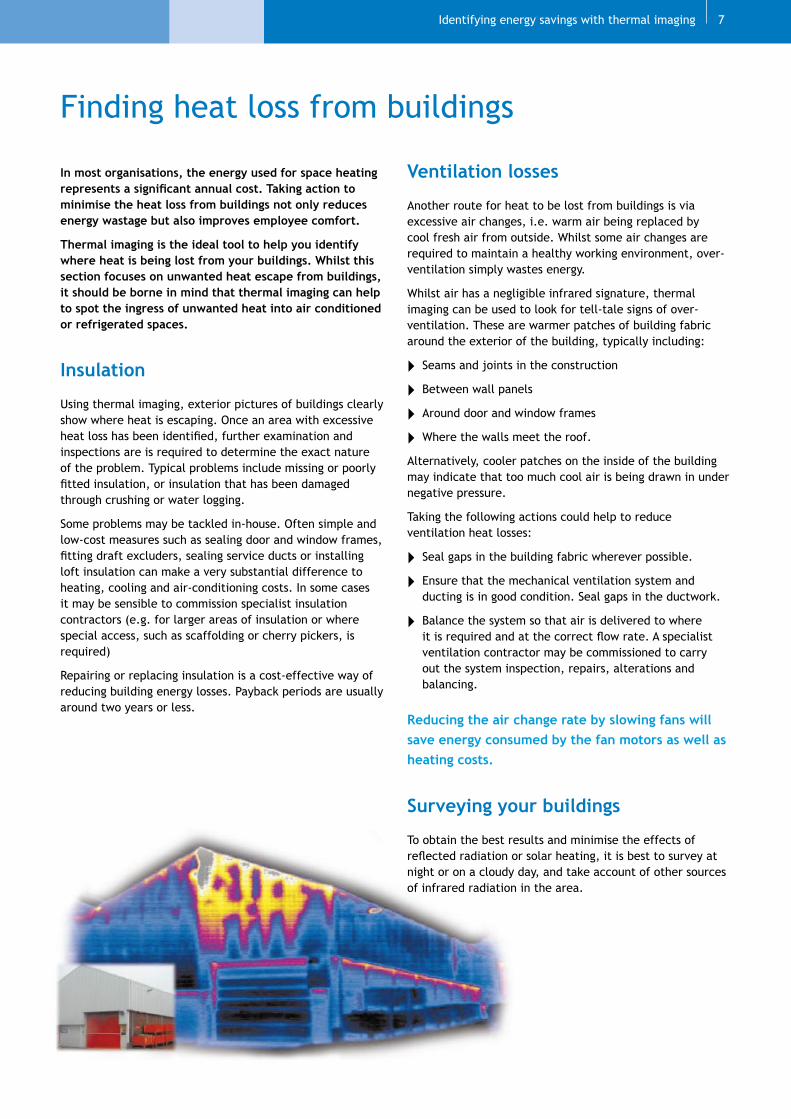
Insulation
Using thermal imaging, exterior pictures of buildings clearly show where heat is escaping. Once an area with excessive heat loss has been identified, further examination and inspections are is required to determine the exact nature of the problem. Typical problems include missing or poorly fitted insulation, or insulation that has been damaged through crushing or water logging.
Some problems may be tackled in-house. Often simple and low-cost measures such as sealing door and window frames, fitting draft excluders, sealing service ducts or installing loft insulation can make a very substantial difference to heating, cooling and air-conditioning costs. In some cases it may be sensible to commission specialist insulation contractors (e.g. for larger areas of insulation or where special access, such as scaffolding or cherry pickers, is required)
Repairing or replacing insulation is a cost-effective way of reducing building energy losses. Payback periods are usually around two years or less.
Ventilation losses
Another route for heat to be lost from buildings is via excessive air changes, i.e. warm air being replaced by cool fresh air from outside. Whilst some air changes are required to maintain a healthy working environment, over-ventilation simply wastes energy.
Whilst air has a negligible infrared signature, thermal imaging can be used to look for tell-tale signs of over-ventilation. These are warmer patches of building fabric around the exterior of the building, typically including:
} Seams and joints in the construction
} Between wall panels
} Around door and window frames
} Where the walls meet the roof.
Alternatively, cooler patches on the inside of the building may indicate that too much cool air is being drawn in under negative pressure.
Taking the following actions could help to reduce ventilation heat losses:
} Seal gaps in the building fabric wherever possible.
} Ensure that the mechanical ventilation system and ducting is in good condition. Seal gaps in the ductwork.
} Balance the system so that air is delivered to where it is required and at the correct flow rate. A specialist ventilation contractor may be commissioned to carry out the system inspection, repairs, alterations and balancing.
Reducing the air change rate by slowing fans will save energy consumed by the fan motors as well as heating costs.
Surveying your buildings
To obtain the best results and minimise the effects of reflected radiation or solar heating, it is best to survey at night or on a cloudy day, and take account of other sources of infrared radiation in the area.
7

Improving the efficiency of motors and drives
Through their numerous applications, electric motors consume around 60% of the electricity delivered to industry. Usually some of the power delivered by an electric motor is consumed by components of the drive system, such as the gearbox, pulleys, belts, chains or bearings. This load is usually a small proportion of the total power consumed by the motor. However, losses due to poor set-up or wear and tear may become a notable cost due to the large number of motor-driven systems, their long running hours and increasing energy prices.
As most drive system losses are manifested as heat, you can use thermal imaging to quickly identify which components require maintenance to restore optimum performance and energy efficiency.
Bearings
Abnormal temperatures in bearings and their housings are usually a good indication of excessive loading or friction, and result in increased drive losses. The causes of the problems may include lack of lubrication, shaft misalignment, badly fitted seals or wear to the bearing.
Where there are a number of bearings on a single system, or numerous similar drive systems on-site, traditional inspection and measurement methods can be time-consuming. You can use thermal imaging to compare the condition of each bearing and quickly spot the ones that are too hot.
When you find a bearing that is running hot, investigate the cause of the problem and correct it as soon as possible. In addition to wasting energy, the problem is likely to get worse and may eventually result in expensive equipment failure or unplanned breakdown.
Belts and pulleys
Belts and pulleys are a common means of transmitting mechanical power. They can have very high efficiencies if correctly installed and maintained. However, over time wear and tear inevitably reduces their efficiency resulting in additional energy consumption and cost.
Generally flat belts offer less mechanical resistance and therefore reduced power consumption, particularly over smaller pulley radii. However a well-designed, properly installed and maintained ’V’ belt will typically be 98% efficient. Without careful maintenance, the cumulative effects of incorrect tension, excessive pulley wear and misalignment could reduce mechanical efficiency down to 90% - adding significantly to energy costs.
Use thermal imaging to look for factors such as excessive temperature or uneven temperature profiles across the pulley and differences in temperatures between similar systems. Make a log of pulley temperatures and look for changes over time.
Technology guide8
Thermal inspection of a belt-driven system showed an uneven temperature profile across the face of the pulley. Subsequent mechanical inspection confirmed that the drive was misaligned, with some belts under greater tension than others.
The motor originally drew 16kW but correcting the problem improved efficiency by 4% with savings of 5,200kWh over a year of continuous operation. The annual costs savings were £260 and emissions of CO2 were reduced by 2.2tonnes per year.

Identifying energy savings with thermal imaging
Tracing electrical faults
Thermal imaging requires no physical contact with the equipment being examined, allowing electrical circuits to be surveyed quickly and safely.
Electrical faults can lead to costly breakdowns and have also been shown to be the cause of numerous fires. By using thermal imaging to conduct routine inspections of your electrical installations, you could spot components that are overheating and take corrective actions to reduce the risks to your business.
Electrical equipment generally deteriorates with age. As it does so, the heat that it generates increases, with the potential to reach dangerous levels. Other faults and causes of electrical overheating include:
} underrating or overloading of equipment
} imbalanced loading
} loose, corroded or improper connections
} insulation damage
} incorrect voltage
} blocked ventilation.
By comparing the temperature of the faulty equipment with that of a healthy equivalent it may be possible to determine the severity of the problems and schedule action accordingly.
To determine the full extent of overheating, comparisons should be made with circuits under full operating load. In general, where the faulty equipment is 20°C hotter than the equivalent, corrective action should be scheduled urgently. Where the temperature difference is 40°C or more, then action should be taken immediately.
Typically a survey of electrical equipment might include:
} overhead transmission lines
} cable runs
} substations
} transformers
} thyristor banks
} circuit operating devices
} switches, fuses and circuit breakers
} control equipment
} motors and motor control centres
Thermal imaging does not avoid the need for conventional inspecting and testing of electrical installations. This is needed at intervals of � years or less to check for electrical safety.
Motors windings are rated by the degree to which the insulation may withstand a rated temperature. Operating continuously at temperatures only slightly above this rating will very substantially reduce the design life. For example, exceeding the rated temperature of a motor’s windings by 10˚C could reduce its life by at least 50%.
9
Loose connection leads to resistive heating, failure and potentially fire
Next steps
Having read this guide, you should now understand the major benefits of thermal imaging. The following section provides some guidance on how to get the best results for your site.
Buy, hire or use a contractor?
The purchase cost of thermal imaging equipment has come down significantly over recent years. However prices for the most basic units still start from a few thousand pounds. In addition to the capital outlay, operatives should be properly trained in thermal imaging techniques to ensure that the equipment is used properly and images interpreted accurately. For these reasons, purchasing thermal imaging equipment to conduct regular in-house surveys is likely to be cost-effective for larger or more complex businesses, or those operating energy-intensive activities or continuous processes.
Equipment can be hired for a few hundred pounds. This could provide the opportunity to become familiar with thermal imaging equipment, techniques and benefits before committing to the full cost of purchasing a unit.
Commissioning thermal imaging contractors to conduct routine surveys could provide a suitable solution for many organisations. Contractors are well practised with thermal imaging techniques and conversant with the principles of operation for the systems under inspection. They are likely to bring a depth of experience that will enable them to interpret thermal images, quickly diagnose problems and propose suitable solutions. The cost of a survey could easily be recouped through identified energy savings or targeted maintenance on business critical equipment.
Contractors should be qualified with Personnel Certification in Non-Destructive Testing, preferably to level 2 in the relevant discipline (buildings, mechanical or electrical systems). Alternatively, a reputable thermographer should have membership of a recognised thermographic professional association, such as the UK Thermography Association, and a minimum of two years’ relevant demonstrable experience. Contact the UK Thermography Association to find the name of a suitable local contractor.
Conduct a survey
If you buy or hire equipment to conduct surveys in-house, following a few simple guidelines will help you to get meaningful results:
} The thermal imaging camera needs direct line of sight with the object being surveyed. Barriers such as glass will prevent transmission of the infrared signal to the camera.
} Try to conduct the survey when plant or equipment is at maximum operating load to determine the full extent of heat loss or overheating. Surveys conducted on partially loaded equipment may be inconclusive or misleading.
} Conduct thermal imaging surveys of space heating systems during the winter months and air-conditioning systems over the warmest summer months. Likewise building fabric losses need to be investigated with due regard to the climatic conditions and the duty of the building services plant.
} Be aware of any other factors that may disguise the real thermal signature of objects under inspection. Attention should be paid to factors such as the emissivity of the objects surface and the potential for reflected infrared energy from another heat source. For surveys of buildings, factors such as solar radiation, wind, fog rain and snow should also be considered.
} Providing operators with training will enable them to compensate appropriately for such factors.
Take action
Try to conduct surveys in advance of planned maintenance shutdowns, to allow highlighted problems to be repaired promptly.
Bear in mind that the results of a thermal imaging survey may only indicate the existence of a problem. Further investigation may be needed to determine the exact cause.
Once the repair is complete, obtain new thermal images to show the equipment in good condition. These will provide a reference for comparison when performing future surveys.
If you would like more information on thermal imaging or would like to conduct a survey on your site then contact the Carbon Trust using the details given on the following page.
Technology guide10
The Carbon Trust gratefully acknowledges the assistance of the UK Thermography Association in the production of this document. UKTA can be contacted on by phoning 01604 630 124 or by visiting their website at www.ukta.org.

Identifying energy savings with thermal imaging 11

The Carbon Trust works with business and the public sector to cut carbon emissions and capture the commercial potential of low carbon technologies.
An independent company set up by the Government to help the UK meet its climate change obligations through business-focused solutions to carbon emission reduction, the Carbon Trust is grant funded by the Department for Environment, Food and Rural Affairs, the Scottish Executive, the Welsh Assembly Government and Invest Northern Ireland.
Whilst reasonable steps have been taken to ensure that the information contained within this publication is correct, the Carbon Trust, its agents, contractors and sub-contractors, and the Government give no warranty and make no representation as to its accuracy and accept no liability for any errors or omissions. Nothing in this case study is intended to be, or should be interpreted as, an endorsement of, or recommendation for, any supplier, service or product
The Carbon Trust is a company limited by guarantee and registered in England and Wales under Company number 4190230 with its Registered Office at: 8th Floor, 3 Clement’s Inn, London WC2A 2AZ.
Published in the UK: March 2006.
© Queen’s Printer and Controller of HMSO Ref: CTG003
www.thecarbontrust.co.uk/energy0800 085 2005