Embed Size (px)
Citation preview
International Journal of Rotating Machinery,1996, Vol. 2, No. 3, pp. 187-199Reprints available directly from the publisherPhotocopying permitted by license only
(C) 1996 OPA (Overseas Publishers Association)Amsterdam B.V. Published in The Netherlands
by Harwood Academic Publishers GmbHPrinted in Singapore
Identification of the Quadrature Resonances UsingModal Nonsynchronous Perturbation "resting and
Dynamic Stiffness Approach for an Anisotropic RotorSystem with Fluid Interaction,
EUNGU JANGResearch Engineer, Bently Rotor Dynamics Research Corporation, P.O.BOX 2529, Minden, Nevada 89423, U.S.A
AGNES MUSZYNSKAPh.D., Research Manager, Bently Rotor Dynamics Research Corporation, P.O.BOX 2529, Minden, Nevada 89423, U.S.A
YOUNG-PIL PARKPh.D., Professor, Dept. of Mechanical Engineering, Yonsei University, 134 Shinchon-Dong, Suhdamoon-Ku, Seoul, Korea.
CHANG-HO KIMPh.D., Senior Researcher, Korea Institute of Science and Technology, P.O.BOX 131, 130-650 Cheong Ryang, Seoul, Korea.
The paper presents the dynamic analysis of an anisotropic rotor system with fluid interaction by using modalnonsynchronous perturbation testing and dynamic stiffness approaches. The anisotropic rotor system produces morecomplex rotor behavior than an isotropic system. In particular, the existence of the quadrature resonance phenomenon forbackward precession is demonstrated. A symmetric rotor supported anisotropically by one fluid lubricated bearing and onerolling element bearing simulates rotating machinery behavior. A dynamic stiffness anisotropy algorithm which includesfluid terms is used to process experimental data in order to identify lightly loaded journal fluid film force parameters. Theexistence of the quadrature resonance for backward precession obtained from the experiment is compared with the analyticalmodel. The results from modeling show strong agreement with experimental results.
Key Words: Anisotropy; fluid interaction; quadrature resonance phenomenon; dynamic stiffness anisotropy algorithm;modal nonsynchronous perturbation
INTRODUCTION
n spite of the interest and extensive research, it is noteasy to obtain adequate information on rotating sys-
tems, due to their complexity and diversity. For severaldecades, the models of rotating systems have beencontinuously improving based on rotating machine fielddata and experimental research results. Since the devel-opment of the simple, isotropic, Jeffcott rotor model in1919, various theoretical and experimental approaches,such as modal testing methods, multi-mode modeling,and consideration of fluid effects (Muszynska [1986,1994], Subbiah et al [1989] and Tam et al [1988]), havebeen implemented to produce meaningful insight into thesystem dynamics. Fluid involved in rotational motion,
mainly due to shaft rotation, has an interactive effect onthe system behavior. Due to fluid interaction, there existrotor self-excited vibrations which are known as fluidwhirl and whip (Muszynska [1986]). From the earlierwork, including an explanation of the fluid-related rotor
response, stability threshold (Poritsky [1953]), and rotat-ing character of fluid force (Black [1969]), to theintroduction of fluid circumferential average velocityratio and the experimental identification of the fluid forcemodel in lightly loaded bearings and seals (Muszynska[1986] and Bently [1988]), many researchers have con-tributed to improvements in dynamic models of rotorvibrations. There is still a room for further improvementsas most results were obtained for isotropic rotors. Theresearch on isotropic models have provided valuable
188 E. JANG, A. MUSZYNSKA Y.-R PARK AND C.-H. KIM
results; however, anisotropy must be considered in order’to analyze more complex behavior of rotating machinery.
There are many sources which contribute to therotating system anisotropy. The anisotropy natures ofrotor system which depends on operating conditionsproduces more complicated rotor behavior. Anisotropycan be produced by internal and external sources such asmisalignment, fluid interaction, nonsymmetry of supportcomponents, etc. Several diagnostic methods have beendeveloped to verify the presence of anisotropy based onrotor response. Graphic tools such as elliptical synchro-nous orbits, Bode and polar plots exhibiting "splitresonances," and transducer axis simulated rotationmethodology have been introduced by Hatch and Bently[1995]. Dynamic parameters, or characteristics of amachine or structure include natural frequencies, modeshapes, damping, and such modal properties as stiffnessand mass as a system parameters. To analyze the dy-namic behavior of a mechanical system, parameter iden-tification is an essential step. Extended modal testingtechniques (Nordmann [1983], Muszynska [1986], Rog-ers and Ewins [1989]), which were developed to over-come the limitations of classical passive structure modaltesting, are widely used to quantify parameters of rotat-ing machinery. Nordmann [1983] has used impact tech-nique to evaluate the stiffness, damping coefficients ofbearings, and considered some difference between non-rotating and rotating system. Roger and Ewins [1989]extended modal testing techniques to apply rotatingmachines by using a modified shaker. Muszynska 1986]has used synchronous perturbation testing, and nonsyn-chronous perturbation testing using swept frequencyforces for identification of rotating machines. One ofthem, the modal nonsynchronous perturbation testingmethodology by Muszynska [1986, 1990, 1995] hasproven to be a powerful tool, as it enables independentidentification of forward and backward modes of therotating machine rotors.
In this paper, a symmetric rotor supported anisotropi-cally by one relatively rigid and one fluid-lubricatedbearing is considered in a range of frequencies whichincludes the fluid-induced resonance (Muszynska[1995]). Modal nonsynchronous perturbation testing isapplied to the system in both forward and backwarddirections. A dynamic stiffness (Muszynska and Bently[1984, 1990]) data processing identification algorithm isdeveloped for the use with a two real degree of freedomanisotropic rotor model. The model includes fluid inertiaeffects. The existence of a previously undocumentedresonance phenomenon for the backward precession,which exists only under anisotropy, is demonstrated.
2. SYSTEM MODEL AND ANISOTROPYALGORITHM
The rotor is assumed to be symmetric, and supportedanisotropically by one rigid and one fluid lubricatedbearing. The system model, based on the discretizedmodal consideration of rotor displacement, can be rep-resented by two lateral modes. The model contains thefluid-induced force (including fluid inertia effect) thatwas developed for lightly loaded bearings and for sealsby Muszynska [1988, 1995]. The mathematical model interms of rotor two lateral orthogonal displacement modelat the bearing location is as follows"
M.# + D + Mfx(. -k- 2hx12S, hx2’2X) -[- Dx(YC + Xxly"1- (Ks -[- Kspx -[- KBx)X--LMy + Ds9 + Mfy(y 2Xy"- hay) + Dy(+ (K -{ gspy + Ky)y =fy (1)
j //," d/dt
where M, Ds, D, Mf, h, f are modal mass, shaft damping,fluid film radial damping, fluid inertia effect, fluidcircumferential average velocity ratio, and circular un-balance perturbation forces, respectively; Ks, Ksp, Ka arethe shaft stiffness, external supporting spring stiffness,and fluid film radial direct stiffness, respectively; x, y, oand 1 are rotor horizontal and vertical displacements,nonsynchronous perturbation frequency, and rotativespeed respectively. The subscripts x and y denote valuesof corresponding parameters in x and y direction. Due tothe realistic assumptions D >> Dsx, Dy >> Dsy, andintroduced notation Ks + Kspx + Kax Kx, Ks + Kspy +Kay Ky, the model (1) can be reduced to the followingform, where shaft damping is neglected:
M. + Mfx(. + 2hx23- h2122x) / Dx(Yc + hxay) + K=LMy + M- 2Xy- X2y) + Oy- XyX) + gyy
= (2)
The model (2) can be rewritten in the matrix form:
0 M + Mfy -2Mfy}kya Dy
DyXya Ky MfyXa)-
(3)When the perturbation circular forces fxf, fyf, f,, fy, are
applied to the system (f perturbation forward, b
QUADRATURE RESONANCES 189
backward), the rotor lateral displacements for forward,xf, yf and backward, x,, Yb, perturbation are:
xf Axfcos(tot + cxf), yf AyfcOs(tot + Cyf)xb Axb cos(tot axb), Yb Ayb cos(tot ayb) (4)
ff F cos(tot + ),fyf F sin(tot + )fib F cos(tot- ),fyb -F sin(tot- ) (5)
where A, a, F mrto2, 6 are response amplitudes andphases, unbalance perturbation force amplitudes andangular orientations, respectively. Substituting (4), (5)into Eq. (3) separately for forward and backward pertur-bation cases yields identification equations for eachdirection"
stiffnesses for each perturbation frequency, to. Frequencyswept perturbation and the combination with. forwardand backward results in the matrix of dynamic stiffnessesas functions of to which can be used for further parameteridentification. Where to is vary from zero to a specifiedspeed covering the range of natural frequency of thesystem.
3. TEST RIG
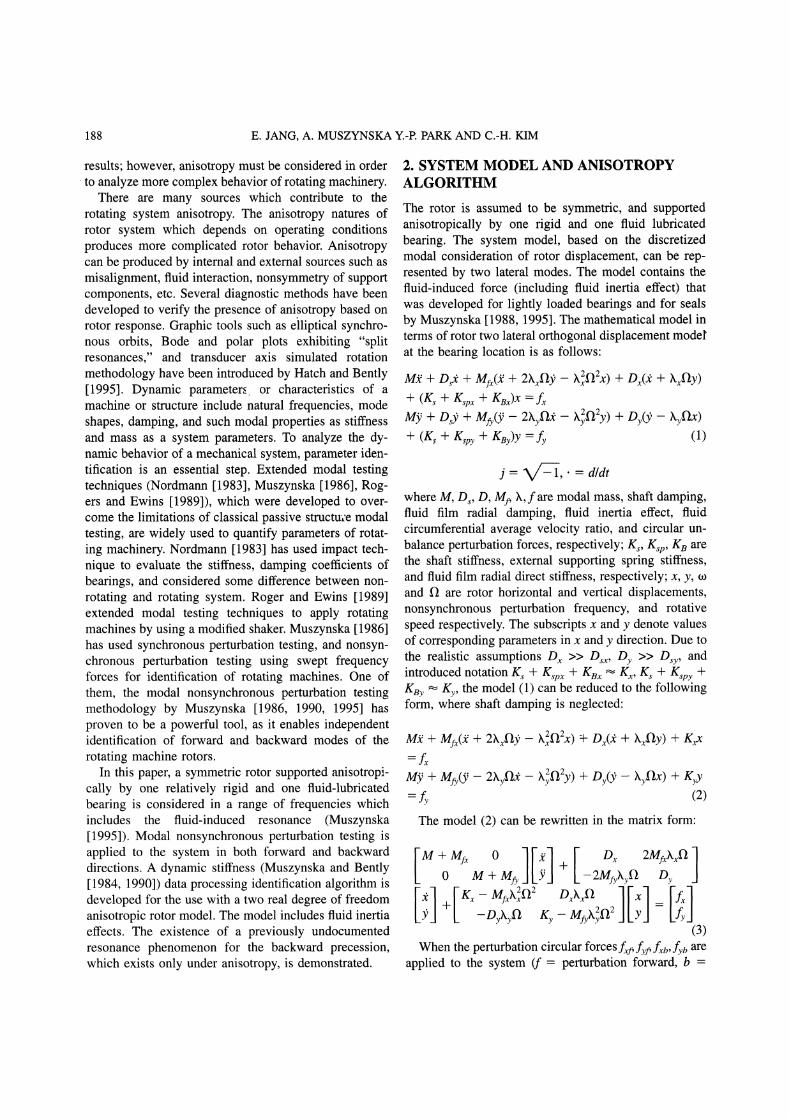
The test rig is shown in Figure 1. The rotor system iscomprised of a stainless steel shaft, 0.01m in diameterand 0.47m in length, with a journal of 0.025m diameterand 406tm diametral clearance inside the fluid-lubtivcated bearing, and a rigid coupling half component (usedin another experiment). The motor end of the shaft issupported on a radially-rigid pivoting rolling element
[][A] [f], [][A] bq
where R is the complex dynamic stiffness matrix and
(6) bearing, and the other end by a ’Chevron GST Oil 32’turbine-oil lubricated bearing. This fluid lubricated bear-ing has four equally spaced oil inputs and inlet/outlet oiltemperatures are monitored by two thermocouples thoseare located inlet/outlet oil supply tubes of the fluidlubricated bearing. To control the oil temperature, a
(7) water bath heat exchanger is used between the oil pumpand the bearing inlet. Oil temperature is controlled to21C +_ 1.5C. Four 3100N/m stiffness radial supportingsprings mounted in a flame near the fluid film bearingcontrol the joumal eccentricity. One pair of XY eddycurrent displacement probes is mounted 45 degrees leftand 45 degrees right from the vertical axis in thefluid-lubricated bearing to obtain rotor lateral vibrationdata. The main rotor is driven by a bi-directional 75W
(8) motor, installed at left end.The perturbation system consists of an aluminum disk
connected through a soft rubber drive belt to the main
[K] I Kll K12 1K21 K22
=_ [K (M + Mfx)to Mfxh2x’ nL jDxto
Dyhy j2MfyhytoDxhx + j2Mfxhato
Ky (M + Mfy)to2 Mfyh2y 0 + jDyto
Each complex dynamic stiffness component, Rij, splitsinto direct (real) and quadrature (imaginary) parts. Com-bining the results of the forward and backward cases (6)and inverting the response vector matrix, the followinganisotropic system complex dynamic stiffness matrixequation is obtained:
[K]-jFei jFe-& [Ay/% Aybe-J%
(9)
For a given 1 from Kll the following parameters can2 2be identified: K Mhhxl D and M + Mfx; from 12:
Mh and h can be identified; from 21" Mfy and h from2
Y
22" Ky Mfyhy-2, Dy and M + Mfy respectively can beidentified. Eq. (9) yields a matrix of system dynamic
L l
FIGURE Experimental Test Rig [a 0.28m, b 0.32m, c
0.36m, d 0.47m] A) 75 watt electric motor, B) Speed Control Probe,C) Keyphasor Tansducer (rotor), D) Flexible Motor Coupling, E)Rolling Element Bearing, F) Probe Mounting Block, G) Rotor, H)Supporting Spring Frame, I) Perturbation Disk, J) Probe Mounted at
Fluid-Lubricated Bearing, K) Fluid-Lubricated Bearing, L) RigidCoupling Half Component, M) V-shape Base.
190 E. JANG, A. MUSZYNSKA Y.-P. PARK AND C.-H. KIM
rotor system perturbator wheel carrying a known unbal-ance weight. It is driven by a motor similar to the mainrotor. The perturbation system is installed behind theperturbation disk. This type of system allows for non-synchronous shaft perturbation in forward and backwarddirections by using unbalance-induced circular rotatingforce, swept frequency perturbation which is entirelyindependent from the rotative speed of the main rotor.The rotor response excited by the perturbator is capturedby the data acquisition system and then filtered to theperturbation frequency. The response phase is measuredusing an optical Keyphasor(R) transducer that observes areflective spot on the side of the perturbation wheel. Tocompensate phase measurement change between forwardand backward precession, response phase of backwardprecession was adjusted by 3 This accounts for thewidth of the Keyphasor notch on the shaft. A digitalvector filter and data processing software were used inthe test.The tests were performed for the following conditions:
The fluid bearing is a four radial port bearing. The oilsupply pressure at the radial manifold was maintained atapproximately 18kPa. The constant rotative speed of therotor, 1, was 0, 1000, 2000, 3000 rpm. Nonsynchronousperturbation runs from 260 rpm to 2300 rpm wereperformed for each rotative speed. The results from the2000 rpm rotative speed case are presented here. Rotorresponses, to 3.1 gram unbalance weight for the forward,and 3.1 (Case 1) and 20.1 gram (Case 2) for backwardperturbation were selected through the several tests. Theunbalance weights were installed in line with verticalprobe location. The perturbation disk, with 0.035 mradius of unbalance, was used for these known unbalancemasses. In order to maximize the data’s signal-to-noiseratio, differential data technique (Franklin et al [1994])was used.
4. TESTS RESULTS
The rig was designed to have a conical rigid body modeof the rotor within the nonsynchronous perturbation
speed range. Through the basic tests, the quadrature(fluid-induced) resonance speeds were found at about500, 970, 1460 rpm for 1000, 2000, 3000 rpm rotativespeed respectively. These results show that the systemresonance is fluid-related, and the viscous damping of thefluid film is its dominant characteristic. The damping inthe fluid film has an over-critical value (Muszynska andBently [1995]) and high damping ratio (about 10).
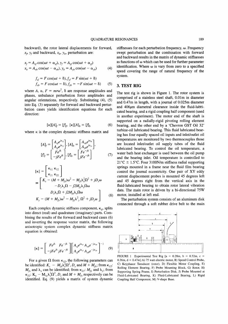
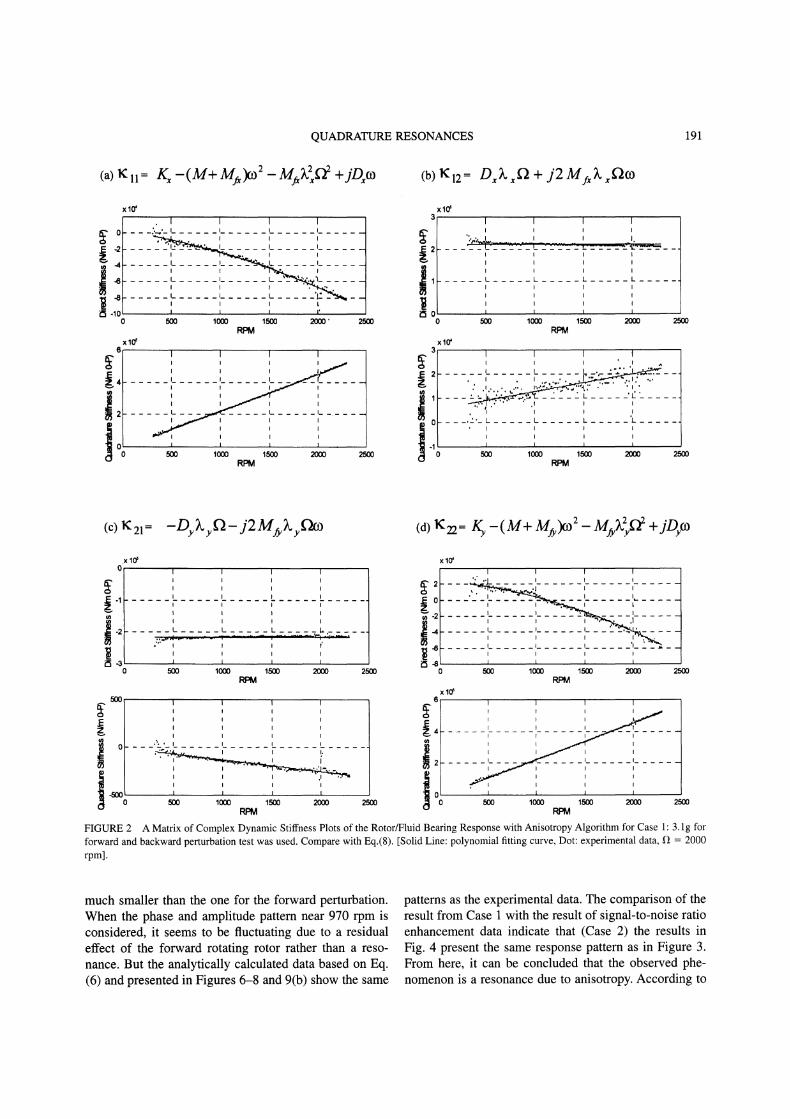
Table 1 summarizes the identified rotor/fluid bearingsystem parameters at 2000 rpm operating speed condi-tion. They were obtained based on the algorithm (8). Thedynamic stiffness plots are shown in Figure 2. A poly-nomial curve fitting was used to obtain rotor systemmodal parameters from the plots. Two different condi-tions, Case and Case 2, were tested. When using thesame unbalance weight for both forward and backwardperturbation, the magnitude of backward perturbationresponse amplitude is much smaller than that of forwardperturbation (Case 1). In the Case 2, the backwardperturbation force was 6.5 times higher. Two cases were,therefore, tested to verify and to compare the results frombackward precession (unbalance weights: 3.1 gram and20.1 gram). In Figure 2, the direct and quadraturestiffness plots present the expected results described bythe algorithm (8). They illustrate anisotropic compo-nents, which are mainly included in the direct stiffnessesof Kll and K22, and the quadrature stiffnesses of K12 and
K21 when the journal was positioned at low eccentricityratio, about 0.1, near the bearing center. Since it wasdifficult to separate M and Mf, M was calculated sepa-rately by considering rotor physical dimensions and steeldensity, 7.86 103 kg/m3.
Figures 3 to 5 and 9 (a) present the experimentalresponse data in the Bode and polar plot formats forseveral cases. There is some disturbance in the data whenthe perturbation and rotation frequency are equal, around2000 rpm, which is due to an interference in the filteringsystem. For the forward perturbation there is a high peakresonance (fluid-induced or quadrature resonance). Ineach case, there can also be seen the existence aresonance for backward perturbation, which has beenpreviously undocumented. This resonance amplitude is
TABLEIdentified Parameters of the Rotor/Fluid Lubricated Bearing System (1) 2,000 rpm).
O By )k )ky Mfx Mfy g Kv M
unit kg/s kg/s kg kg kN/m kN/m kgCase 2.16 103 2.17 10 0.477 0.474 0.22 0.49 5.25 29.40 0.52Case 2 2.14 )< 10 2.15 103 0.473 0.470 0.10 0.27 4.21 30.30 0.54Case 3 2.24 10 2.10 10 0.429 0.519 0.24 0.49 17.15 17.98 0.52
Case 1:3.1 gram for forward and backward perturbation test was used.Case 2:3.1 gram for forward, and 20.1 gram for backward perturbation test were used.Case 3:-45 coordinate rotation was applied to the Case results.
QUADRATURE RESONANCES 191
(b) El2 D,,.L + j2 My. fo3xlO
0 1 1 2000" 2R
xlO
RPM25oo
x10’
L L. L L
0 500 1000 1500 2000 2500RPM
xlO’
’.-. L _L_
"’_L L L L
500 1000 1500 2(XX) 2500RPM
(c) K21 -Dkf-j2M/kf (d) K22= F -(M+ M#) M#,vf’xlO
5001
I,
xlO
2500 500 1000 1500 2(X]O 2500
xlO6
25170
FIGURE 2 A Matrix of Complex Dynamic Stiffness Plots of the Rotor/Fluid Bearing Response with Anisotropy Algorithm for Case 1" 3. lg for
forward and backward perturbation test was used. Compare with Eq.(8). [Solid Line: polynomial fitting curve, Dot: experimental data, 12 2000
rpm].
much smaller than the one for the forward perturbation.When the phase and amplitude pattern near 970 rpm isconsidered, it seems to be fluctuating due to a residualeffect of the forward rotating rotor rather than a reso-nance. But the analytically calculated data based on Eq.(6) and presented in Figures 6-8 and 9(b) show the same
patterns as the experimental data. The comparison of theresult from Case with the result of signal-to-noise ratioenhancement data indicate that (Case 2) the results inFig. 4 present the same response pattern as in Figure 3.From here, it can be concluded that the observed phe-nomenon is a resonance due to anisotropy. According to
192 E. JANG, A. MUSZYNSKA Y.-P. PARK AND C.-H. KIM
-135
-180(R) -225
-270
-315<’r"
" -45
-90
-135-2500
E
uJ 15
:3 10
<0-2500
(a) Experimental backward response
I_ I,. L I_
I"
-2000 -1500 -1000 -500RPM
-2ooo -15oo -lOOO -5oo oRPM
(b) Experimental forward response
-135
-180(R) -225
-270
03 -315<-r" 0I:k -45
-90
-135
L
0 500 1000 25001500 2000RPM
E250
o
.9 200E
LU 150
IO0
5O
<0
2500
L L L
500 1000 1500 2000RPM
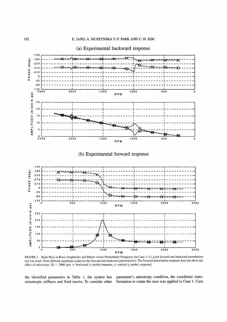
FIGURE 3 Bode Plots of Rotor Amplitudes and Phases versus Perturbation Frequency for Case 1" 3.1 g for forward and backward perturbationtest was used. (Note different amplitude scales for the forward and backward perturbations). The forward perturbation response does not show anyeffect of anisotropy. [f 2000 rpm, x: horizontal (x probe) response, o: vertical (y probe) response]
the identified parameters in Table 1, the system hasanisotropic stiffness and fluid inertia. To consider other
parameter’s anisotropy condition, the coordinate trans-formation to rotate the axes was applied to Case 1. Case
QUADRATURE RESONANCES
-135
-180=) -225
-270
(/) -315
-r 0
-45
-90
-135-2500
(a) Experimental backward response
L I.. l_ l_
-2000 -1500 -1000 -500RPM
120
100
80
60
40
20
0-2500 -2000 -1500 -1000 -500 0
RPM
193
(b) Experimental forward response
-135
-180) -225
-270
(/) -315
"r 0
-45
-90
-135500 1000 1500 2000 2500
RPM
E 250o
200E
l.U 150
:3 100- 50
0
I_ _I
-I---- -7- "0 500 1000 1500 2000 2500
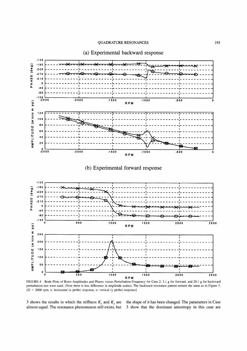
RPMFIGURE 4 Bode Plots of Rotor Amplitudes and Phases versus Perturbation Frequency for Case 2: 3. g for forward, and 20.1 g for backwardperturbation test were used. (Now there is less difference in amplitude scales). The backward resonance pattern remain the same as in Figure 3.[1) 2000 rpm, x: horizontal (x probe) response, o: vertical (y probe) response]
3 shows the results in which the stiffness Kx and Ky arealmost equal. The resonance phenomenon still exists, but
the shape of it has been changed. The parameters in Case3 show that the dominant anisotropy in this case are
194 E. JANG, A. MUSZYNSKA Y.-P. PARK AND C.-H. KIM
(a) Experimental backward response-135
o -225
o -315
UJ -45
’< -135
13. -225
-315
-45.-2500
f- A
E
Eu.I 15
I.. L L L.
,.2000 -1500 -t 000 -500RPM
rL L L
I,i--"
-2000 -1500 -1000 -500RPM
(b) Experimental forward response
-135
o) -225
o -315
I.u -45
<:: -135
0,. -225
-315
-450 2500
E250o
200EuJ 150
100
o. 50
00 500 1000 1500 2000 2500
RPM
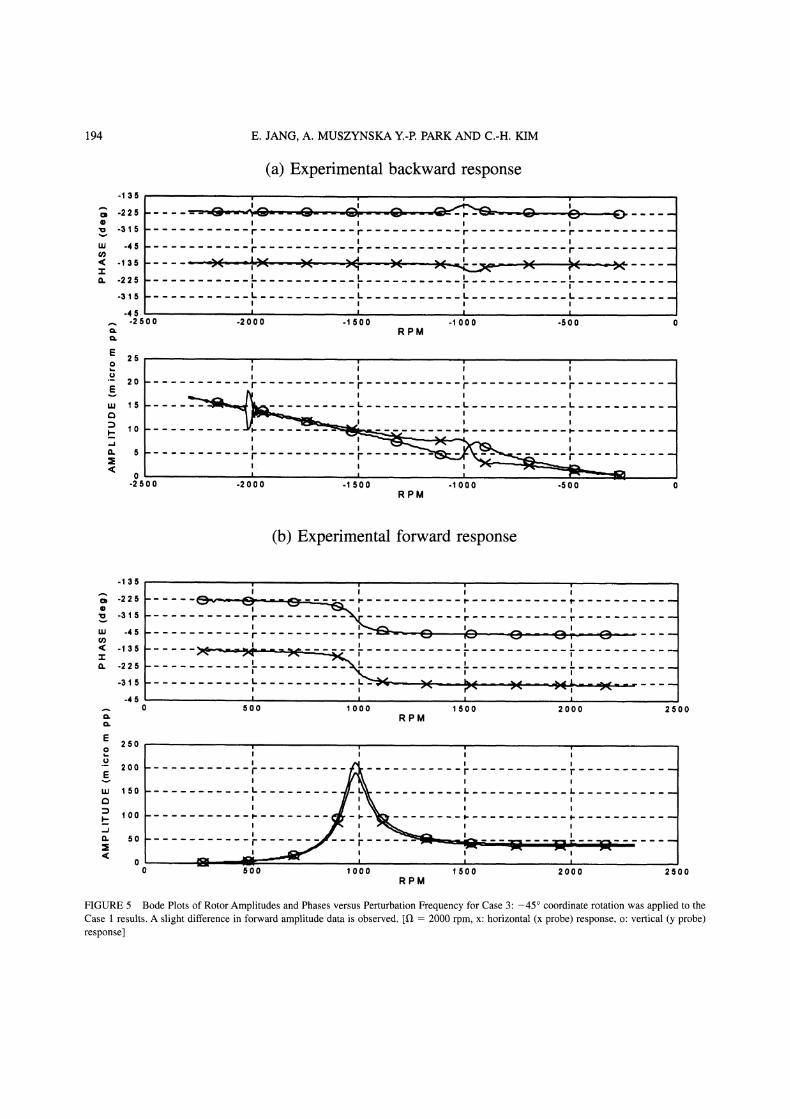
FIGURE 5 Bode Plots of Rotor Amplitudes and Phases versus Perturbation Frequency for Case 3:-45 coordinate rotation was applied to theCase results. A slight difference in forward amplitude data is observed. [1" 2000 rpm, x: horizontal (x probe) response, o: vertical (y probe)response]
QUADRATURE RESONANCES
-135
-180
-225
-270
oo -315<"r 0la. -45
-90
-135-2500
E
LU 15
:3 10- 5
<0-2500
(a) Analytical backward response
I. I_ I_ I_
-2000 -1500 -1000 -500RPM
1. L I_ l_
-lq_
I-
-2000 -1500 -1000 -500RPM
195
(b) Analytical forward response
-135
-180
-225
-270
-315
0
-45
-90
-135
E250
o
200E
ILl 150
I.-.. 100
. 50
0
r T T
O T--500 1000 1500 2000
RPM
/
L
/
1000 1500 2000RPM
2500
2500
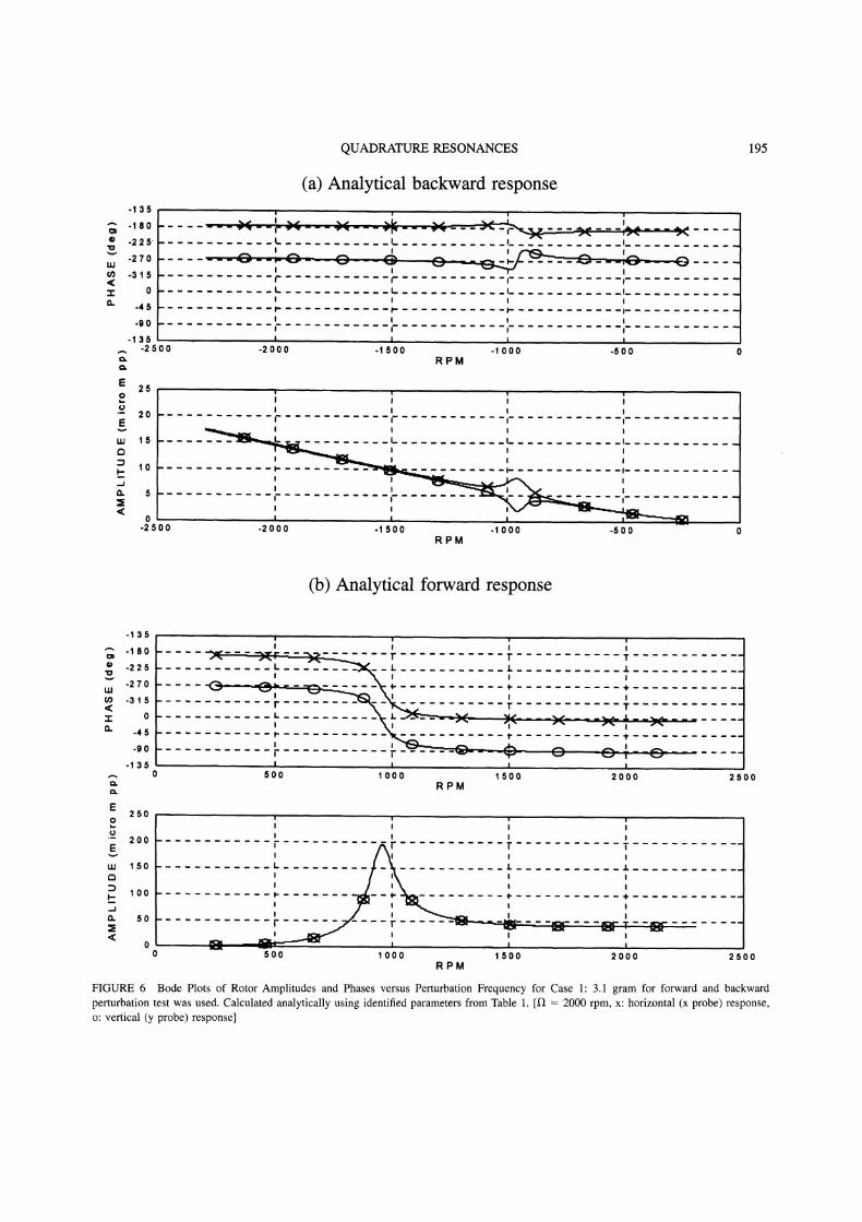
FIGURE 6 Bode Plots of Rotor Amplitudes and Phases versus Perturbation Frequency for Case 1" 3.1 gram for forward and backwardperturbation test was used. Calculated analytically using identified parameters from Table 1. [12 2000 rpm, x: horizontal (x probe) response,o: vertical (y probe) response]
196 E. JANG, A. MUSZYNSKA Y.-P. PARK AND C.-H. KIM
(a) Analytical backward response-135
-180
-225
-270
-315
0
-45
-90
-135-2500 -2000 -1500 -1000 -500
RPM
Eo 120
0100
E8O
C 60
40
: 20
0-2500 -2000 -1500 -1000 -500
RPM
(b) Analytical forward response
-135
-180) -225
-270
(/) -315<:"r" 0O.. -45
-9O
-1350
E250
O
200E
150
100
50
<00
500 1000 1500 2000RPM
2500
-3 "l- "-:- "1000 1500 2000
RPM---00 2500
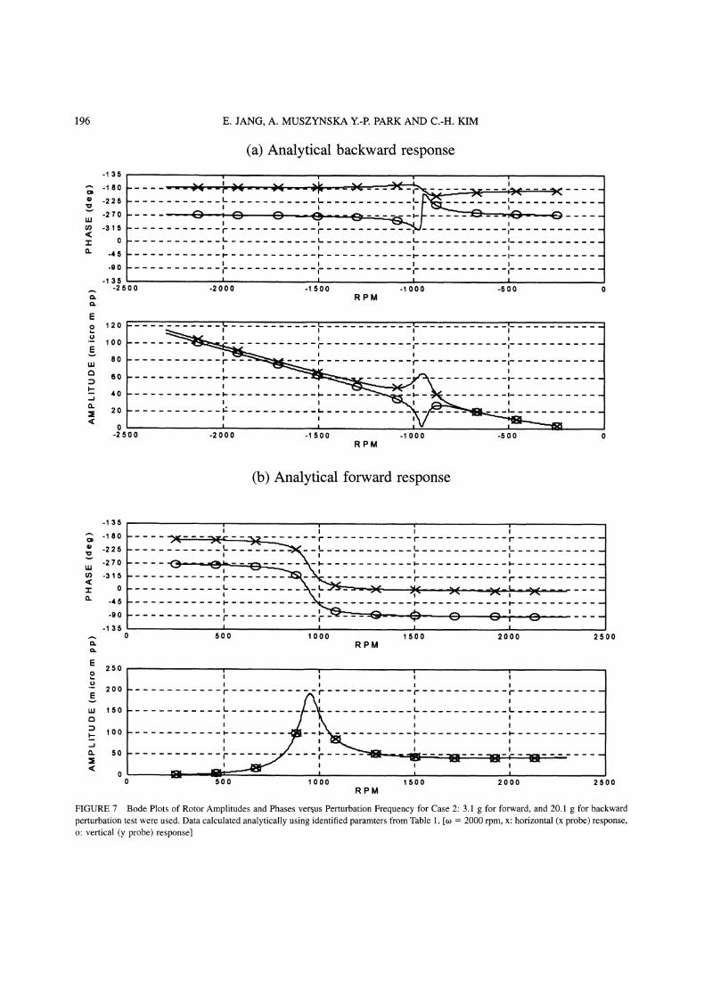
FIGURE 7 Bode Plots of Rotor Amplitudes and Phases versus Perturbation Frequency for Case 2:3.1 g for forward, and 20.1 g for backwardperturbation test were used. Data calculated analytically using identified paramters from Table 1. [o 2000 rpm, x: horizontal (x probe) response,o: vertical (y probe) response]
QUADRATURE RESONANCES
(a) Analytical backward response-135
o -225
o -315
UJ -45
<: -135. -225
-315
-45-2500
E
w 15
0-2 5’0 0
L L
I,,-2000 -1500 -1000 -500
RPM.r
-2000 -1500 -1000 -500 0RPM
197
(b) Analytical forward response
-1 35
o -225
o -315
w -45
<: -135
I:1. -225
-315
-45
250o
200E
l.u 150
::3 100
CL 50
<0
0 25O0
v L _v__
500 1000 1500 2000RPM
0 500 1000 1500 2000 2500RPM
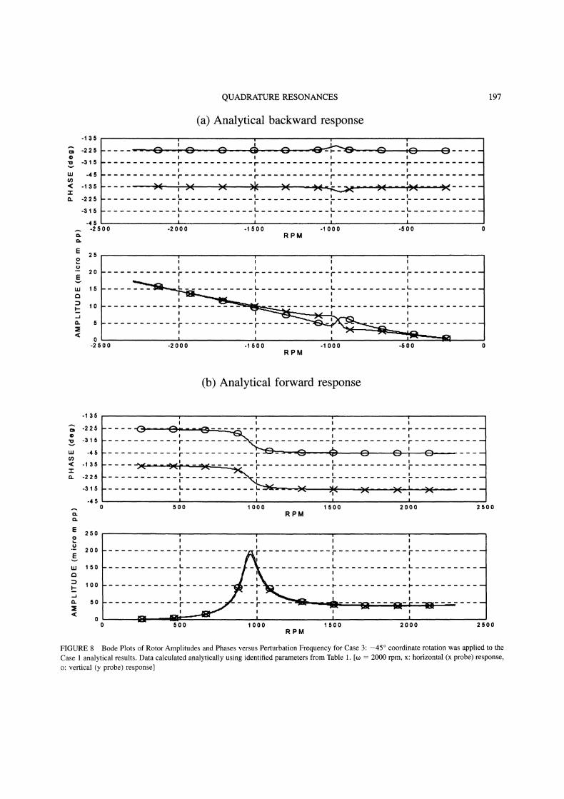
FIGURE 8 Bode Plots of Rotor Amplitudes and Phases versus Perturbation Frequency for Case 3’ -45 coordinate rotation was applied to the
Case analytical results. Data calculated analytically using identified parameters from Table 1. [to 2000 rpm, x: horizontal (x probe) response,o: vertical (y probe) response]
198 E. JANG, A. MUSZYNSKA Y.-P. PARK AND C.-H. KIM
(b)
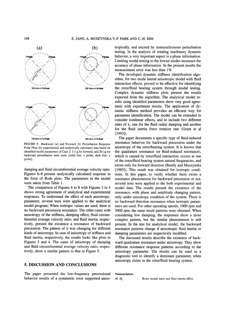
..",,,. ...../., ,q,, ,,i250 rricro Full Scalle
250 rcro Full Scale
FIGURE 9 Backward (a) and Forward (b) Perturbation ResponsePolar Plots for experimental and analytically calculated data based onidentified model parameters of Case 2:3.1 g for forward, and 20.1 g forbackward perturbation were used. [solid line: x probe, dash line: yprobe].
damping and fluid circumferential average velocity ratio.Figures 6-8 present analytically calculated response inthe form of Bode plots. The parameters in the modelwere taken from Table 1.The comparison of Figures 6 to 8 with Figures 3 to 5
shows strong agreement of analytical and experimentalresponses. To understand the effect of each anisotropy-parameter, several tests were applied to the analyticalmodel program; When isotropic values are used, there isno backward precession resonance. The other cases withanisotropy of the stiffness, damping effect, fluid circum-ferential average velocity ratio, and fluid inertia, respec-tively, present the existence a resonance of backwardprecession. The pattern of it was changing for differentkinds of anisotropy. In case of anisotropy of stiffness andfluid inertia, respectively, the results looks like plots inFigures 3 and 4. The cases of anisotropy of dampingand fluid circumferential average velocity ratio, respec-tively, show a similar pattern to that in Figure 5.
5. DISCUSSION AND CONCLUSIONS
tropically, and excited by nonsynchronous perturbationtesting. In the analysis of rotating machinery dynamicbehavior, a very important aspect is a phase information.Limiting modal testing to the lowest modes increases theaccuracy of phase information. In the present results themeasurement error was less than 1%.The developed dynamic stiffness identification algo-
rithm, for two mode lateral anisotropic model with fluidinteraction effects, proved to be effective for identifyingthe rotor/fluid bearing system through modal testing.Complex dynamic stiffness plots present the resultsexpected from the algorithm. The analytical model re-sults using identified parameters show very good agree-ment with experiment results. The application of dy-namic stiffness method provides an efficient way forparameter identification. The model can be extended toconsider nonlinear effects, and to include two differentrates of h, one for the fluid radial damping and anotherfor the fluid inertia force rotation rate (Grant et al[1993]).The paper documents a specific type of fluid-induced
resonance behavior for backward precession under theanisotropy of the rotor/bearing system. It is known thatthe quadrature resonance (or fluid-induced resonance),which is caused by rotor/fluid interaction, occurs at oneof the rotor/fluid bearing system natural frequencies, andexists only for forward direction (Bently and Muszynska[1985]). This result was obtained for isotropic condi-tions. In this paper, to verify whether there exists aresonance phenomenon for backward precession or not,several tests were applied to the both experimental andmodel data. The results present the existence of theresonance, with phase and amplitude changing pattern,only under anisotropy condition of the system. There isno backward direction resonance when isotropic param-eters are used. For other operating speeds, 1000 rpm and3000 rpm, the same result patterns were obtained. Whenconsidering low damping, the responses show a morecomplex pattern, but the similar phenomenon is stillpresent. In the test for analytical model, the backwardresonance patterns change if anisotropic fluid inertia ordamping parameters are respectively modified.The discussed results describe the existence of back-
ward quadrature resonance under anisotropy. They showdifferent resonance response patterns according to theanisotropy parameter. The results can be used as adiagnostic tool to identify a dominant parameter, whenanisotropy exists in the rotor/fluid beating system.
The paper presented the low-frequency precessionalbehavior results of a symmetric rotor supported aniso-
Nomenclature
M, Mf Rotor modal mass and fluid inertia effect.
QUADRATURE RESONANCES 199
D D
x,y
A, c, 8
m, r
J
Shaft damping and fluid film radial viscousdamping.Shaft stiffness, external spring frame stiffnessand fluid film radial stiffness.Fluid circumferential average velocity ratio.Perturbation exciting force and unbalancecircular force amplitude.Rotor rotative speed and perturbationfrequency.Rotor journal deflections in two lateraldirections.Rotor response amplitude, phase andperturbation force phase.Mass and radius of perturbator unbalance.Complex dynamic stiffness matrix.
Subscripts:
x, yPerturbation forward and backward direction.Two lateral directions.
References
Bently, D. E., Muszynska, A., 1985. Perturbation Study of a Rotor/
Bearing System: Identification of the Oil Whirl and Oil WhipResonances, Tenth Biennial ASME Design Engineering Division
Conference on Mechanical Vibration and Noise, 85-DET-142, Cin-cinnati, Ohio, Sept.
Bently, D. E., Muszynska, A., 1988. Role of Circumferential Flow inthe Stability of Fluid-Handling Machine Rotors, The Fifth Workshopon Rotordynamics Instability Problems in High Performance Turbo-machinery, Texas A&M University, College Station, Texas, NASACP 3026, 16-18 May, pp. 415-430.
Bently, D. E., Muszynska, A., 1984. The Dynamic Stiffness Character-istics of High Eccentricity Ratio Bearings and Seals by PerturbationTesting, Workshop on Rotordynamic Instability Problems in High
Performance Turbomachinery, Texas A&M University, NASA CP-2338, May.
Black, H. E, 1969. Effects of Hydraulic Forces in Annular PressureSeals on the Vibrations of Centrifugal Pump Rotors, Journal Me-chanical Engineering Science, vol. II, No. 2.
Franklin, W. D., Muszynska, A., and Bently, D. E., 1994. ParameterIdentification with Noncollocation of Force and Measurement Loca-tions Using Nonsynchronous Perturbation and Optimization Tech-
niques, ASME International Gas Turbine and Aeroengine Congressand Exposition, The Hague, Netherlands, 94-GT-127, 13-16, Jun.
Grant, J., Muszynska, A., Bently, D. E., 1993. Parameter Identificationof a Rotor Supported in a Pressurized Bearing Lubricated With Water,7th Workshop on Rotordynamic Instability Problems in High Perfor-mance Turbomachinery, Texas A&M, College Station, Texas, May.
Hatch, C. T., Bently, D. E., 1995. Anisotropic Rotor Response andProbe Data Transformation to Improve Machinery Diagnostic Capa-bility, Bently Rotor Dynamics Research Corporation Report, No. 1,Minden, Nevada, Jan.
Muszynska, A., 1994. Application of Multi-Mode Modal Models inRotor Dynamics, ISROMAC 5.
Muszynska, A., 1988. Improvements in Lightly Loaded Rotor/Bearingand Rotor/Seal Models, Transaction of the ASME Journal of Vibra-tion Acoustics, Stress and Reliability in Design, v. 110, No. 2, April.
Muszynska, A., 1986. Modal Testing of Rotor/Bearing Systems, TheInternational Journal ofAnalytical and Experimental Modal Analy-sis, v. 1, No. 3, pp. 15-34.
Muszynska, A., 1995. Modal Testing of Rotors with Fluid Interaction,Internation Journal of Rotating Machinery, v. 1, No. 2.
Muszynska, A., 1986. Whirl and Whip-Rotor/Bearing Stability Prob-lems, Journal of Sound and Vibration, U.K., vol. 110, No. 3, pp.443-462.
Muszynska, A., Bently, D. E., 1995. Fluid-Induced Instabilities ofRotors: Whirl and Whip, Bently Rotor Dynamics Research Corpora-tion Report, No. 3, Minden, Nevada.
Muszynska, A., Bently, D.,E., 1990. Frequency-Swept Rotating InputPerturbation Tdchniques and Identification of the Fluid Force Modelsin Rotor/Bearing/Seal Systems and Fluid Handling Machines, Jour-nal of Sound Vibration, Vol 143(1), pp. 103-124.
Nordmann, Rainer., 1983. Identification of Modal Parameters of anElastic Rotor with Oil Film Bearings, Journal of Vibration, Acoustics,Stress and Reliability in Design.
Poritsky, H., 1953. Contribution to the Theory of Oil Whip, Trans. ofthe ASME, No. 75.
Rogers, P. J., and Ewins, E. J., 1989. Modal Testing of an OperatingRotor System Using a Structural Dynamics Approach, Proceedings ofthe 7th IMAC.
Subbiah, R., Bhat, R. B., Sankar, T. S., 1989. Dynamic Response ofRotors Using Modal Reduction Technique, Journal of Vibration andAcoustics, vol. 111, October.
Tam, L. T., Przekwas, A., Muszynska, A., Hendricks, R., Braun, M. J.,Mullen R. L., 1988. Numerical and Analytical Study of FluidDynamic Forces in Seals and Bearings, Trans. ofASME Journal ofVibration, Acoustics, Stress, and Reliability in Design, vol. 110, No.3, July, pp. 315-325.

International Journal of
AerospaceEngineeringHindawi Publishing Corporationhttp://www.hindawi.com Volume 2010
RoboticsJournal of
Hindawi Publishing Corporationhttp://www.hindawi.com Volume 2014
Hindawi Publishing Corporationhttp://www.hindawi.com Volume 2014
Active and Passive Electronic Components
Control Scienceand Engineering
Journal of
Hindawi Publishing Corporationhttp://www.hindawi.com Volume 2014
International Journal of
RotatingMachinery
Hindawi Publishing Corporationhttp://www.hindawi.com Volume 2014
Hindawi Publishing Corporation http://www.hindawi.com
Journal ofEngineeringVolume 2014
Submit your manuscripts athttp://www.hindawi.com
VLSI Design
Hindawi Publishing Corporationhttp://www.hindawi.com Volume 2014
Hindawi Publishing Corporationhttp://www.hindawi.com Volume 2014
Shock and Vibration
Hindawi Publishing Corporationhttp://www.hindawi.com Volume 2014
Civil EngineeringAdvances in
Acoustics and VibrationAdvances in
Hindawi Publishing Corporationhttp://www.hindawi.com Volume 2014
Hindawi Publishing Corporationhttp://www.hindawi.com Volume 2014
Electrical and Computer Engineering
Journal of
Advances inOptoElectronics
Hindawi Publishing Corporation http://www.hindawi.com
Volume 2014
The Scientific World JournalHindawi Publishing Corporation http://www.hindawi.com Volume 2014
SensorsJournal of
Hindawi Publishing Corporationhttp://www.hindawi.com Volume 2014
Modelling & Simulation in EngineeringHindawi Publishing Corporation http://www.hindawi.com Volume 2014
Hindawi Publishing Corporationhttp://www.hindawi.com Volume 2014
Chemical EngineeringInternational Journal of Antennas and
Propagation
International Journal of
Hindawi Publishing Corporationhttp://www.hindawi.com Volume 2014
Hindawi Publishing Corporationhttp://www.hindawi.com Volume 2014
Navigation and Observation
International Journal of
Hindawi Publishing Corporationhttp://www.hindawi.com Volume 2014
DistributedSensor Networks
International Journal of


![ReciprocatingCompressor1DThermofluidDynamicSimulation ...downloads.hindawi.com/journals/ijrm/2012/564275.pdf · power domestic refrigeration [3]. Reported in this paper ... compressor](https://img.pdfslide.us/doc/110x75/5e8a576340cc2e2e527a81b2/reciprocatingcompressor1dthermoiuiddynamicsimulation-power-domestic-refrigeration.jpg)