Embed Size (px)
Citation preview
1
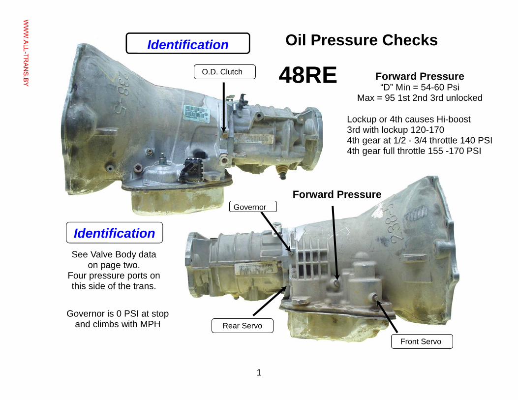
Oil Pressure Checks
Lockup or 4th causes Hi-boost 3rd with lockup 120-170 4th gear at 1/2 - 3/4 throttle 140 PSI 4th gear full throttle 155 -170 PSI
O.D. Clutch
Rear Servo
Front Servo
Forward Pressure Governor
Forward Pressure “D” Min = 54-60 Psi
Max = 95 1st 2nd 3rd unlocked
Governor is 0 PSI at stop and climbs with MPH
Identification
Identification See Valve Body data
on page two. Four pressure ports on this side of the trans.
48RE
WWW.ALL-TR
ANS.BY
2
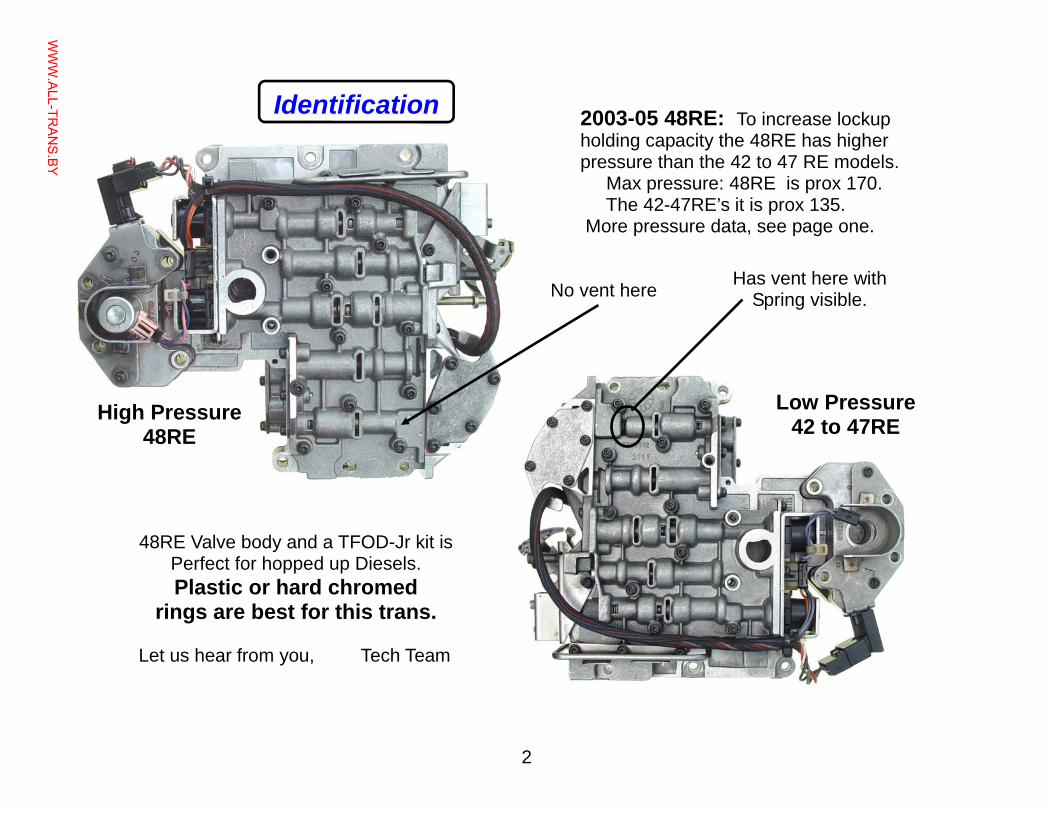
2003-05 48RE: To increase lockup holding capacity the 48RE has higher pressure than the 42 to 47 RE models. Max pressure: 48RE is prox 170. The 42-47RE’s it is prox 135. More pressure data, see page one.
Identification
High Pressure 48RE
No vent here
48RE Valve body and a TFOD-Jr kit is Perfect for hopped up Diesels. Plastic or hard chromed
rings are best for this trans. Let us hear from you, Tech Team
Low Pressure 42 to 47RE
Has vent here with Spring visible.
WWW.ALL-TR
ANS.BY
3
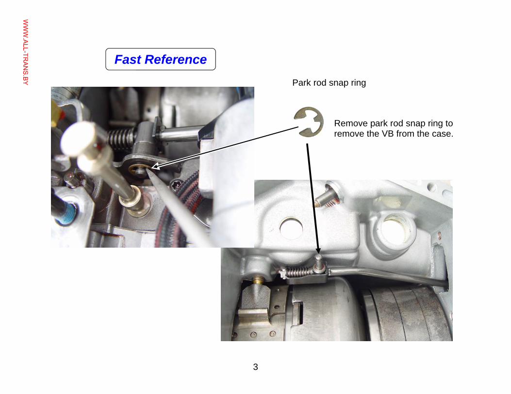
Remove park rod snap ring to remove the VB from the case.
Park rod snap ring
Fast Reference
WWW.ALL-TR
ANS.BY
4
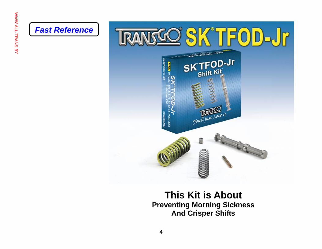
This Kit is About Preventing Morning Sickness
And Crisper Shifts
Fast Reference
WWW.ALL-TR
ANS.BY
5
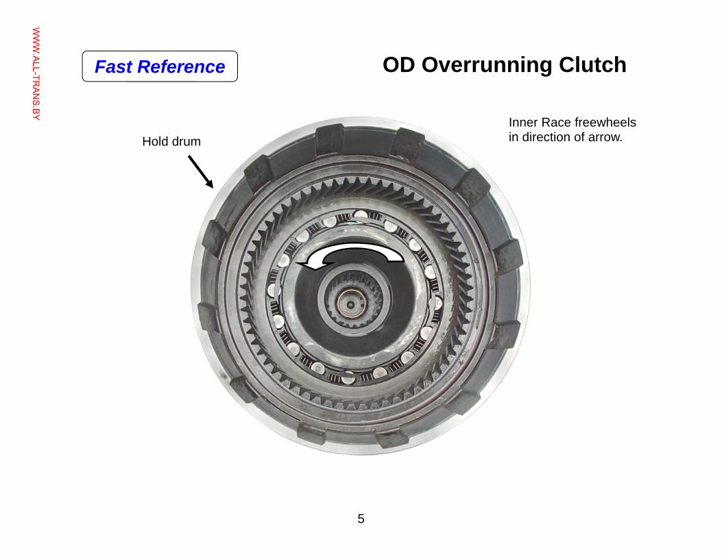
Inner Race freewheels in direction of arrow. Hold drum
OD Overrunning Clutch Fast Reference
WWW.ALL-TR
ANS.BY
6
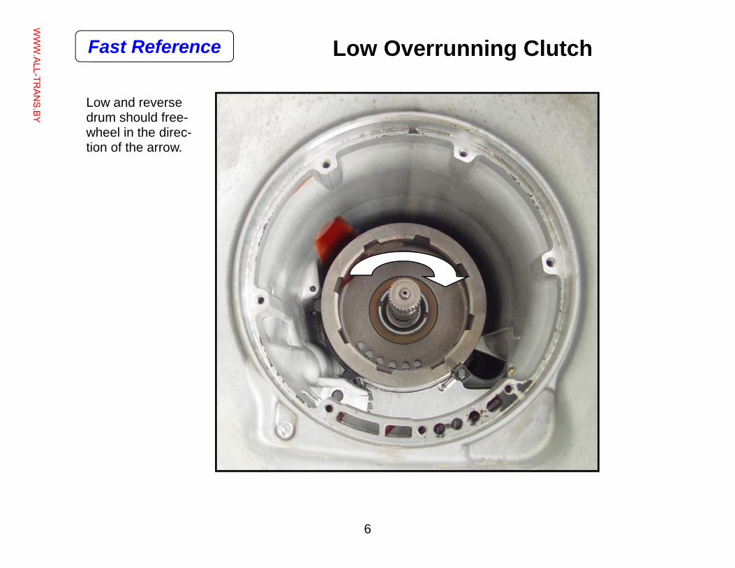
Low Overrunning Clutch
Low and reverse drum should free-wheel in the direc-tion of the arrow.
Fast Reference
WWW.ALL-TR
ANS.BY
7
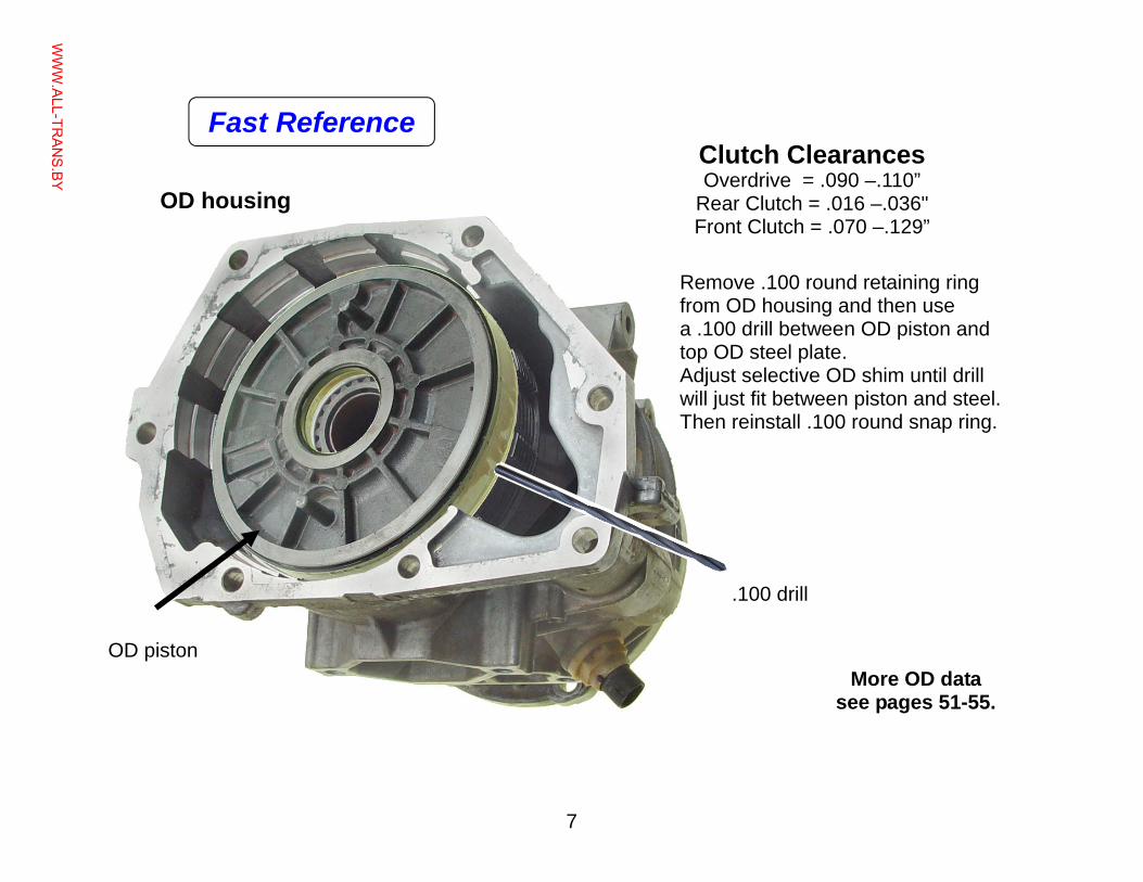
OD housing
OD piston
.100 drill
Remove .100 round retaining ring from OD housing and then use a .100 drill between OD piston and top OD steel plate. Adjust selective OD shim until drill will just fit between piston and steel. Then reinstall .100 round snap ring.
More OD data see pages 51-55.
Clutch Clearances Overdrive = .090 –.110”
Rear Clutch = .016 –.036" Front Clutch = .070 –.129”
Fast Reference
WWW.ALL-TR
ANS.BY
8
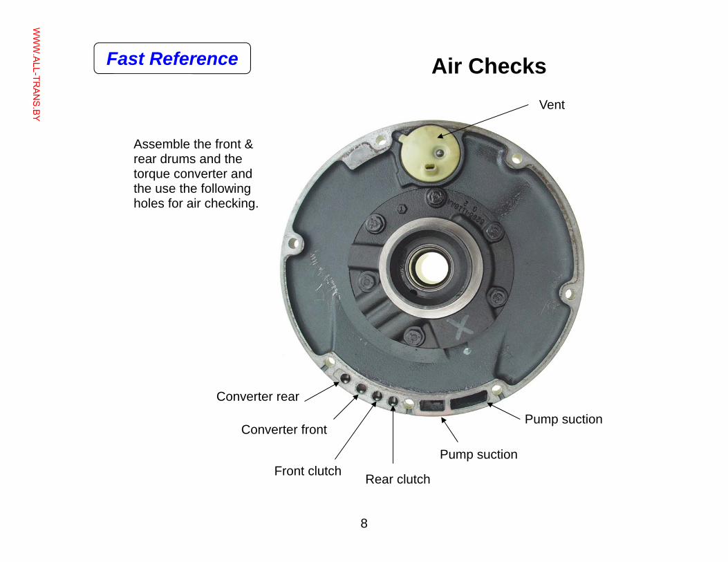
Pump suction
Pump suction
Converter rear
Converter front
Front clutch Rear clutch
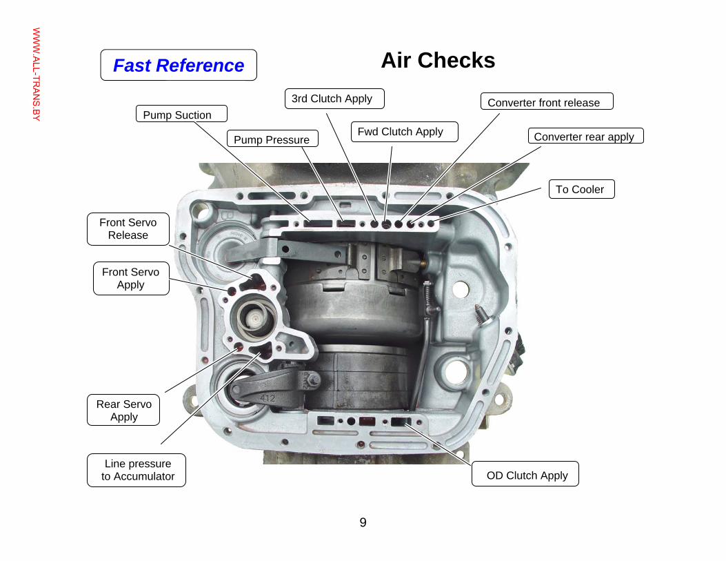
Assemble the front & rear drums and the torque converter and the use the following holes for air checking.
Vent
Air Checks Fast Reference
WWW.ALL-TR
ANS.BY
9
Air Checks
Pump Suction
Pump Pressure
3rd Clutch Apply
Fwd Clutch Apply
To Cooler
Front Servo Release
Front Servo Apply
Rear Servo Apply
Line pressure to Accumulator OD Clutch Apply
Converter rear apply
Converter front release
Fast Reference
WWW.ALL-TR
ANS.BY
10
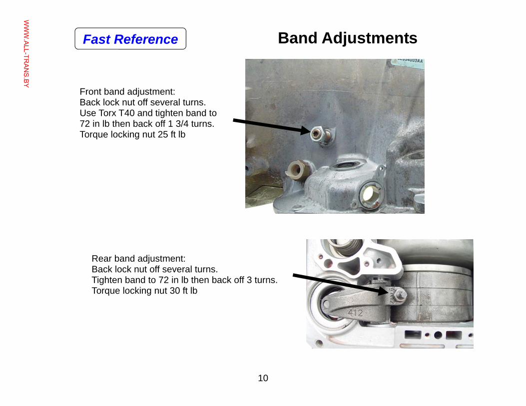
Band Adjustments
Front band adjustment: Back lock nut off several turns. Use Torx T40 and tighten band to 72 in lb then back off 1 3/4 turns. Torque locking nut 25 ft lb
Rear band adjustment: Back lock nut off several turns. Tighten band to 72 in lb then back off 3 turns. Torque locking nut 30 ft lb
Fast Reference
WWW.ALL-TR
ANS.BY
11
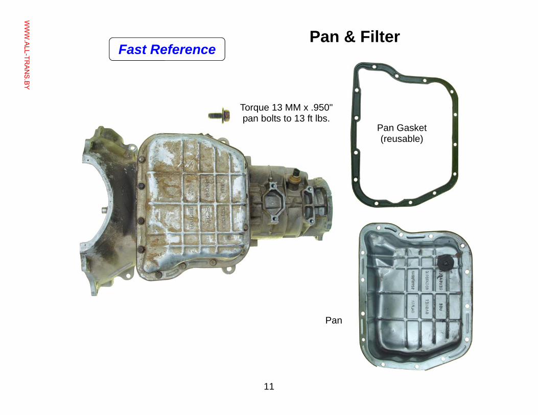
Pan & Filter
Pan
Pan Gasket (reusable)
Torque 13 MM x .950" pan bolts to 13 ft lbs.
Fast Reference
WWW.ALL-TR
ANS.BY
12
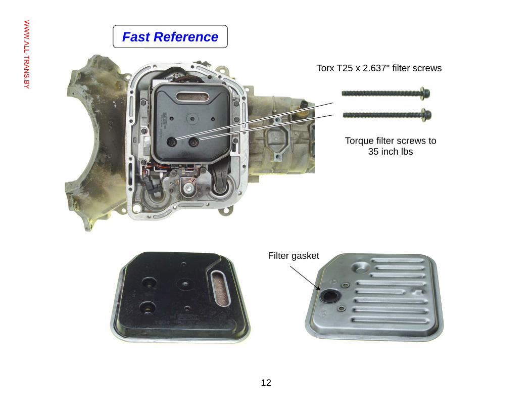
Filter gasket
Torque filter screws to 35 inch lbs
Torx T25 x 2.637" filter screws
Fast Reference
WWW.ALL-TR
ANS.BY
13
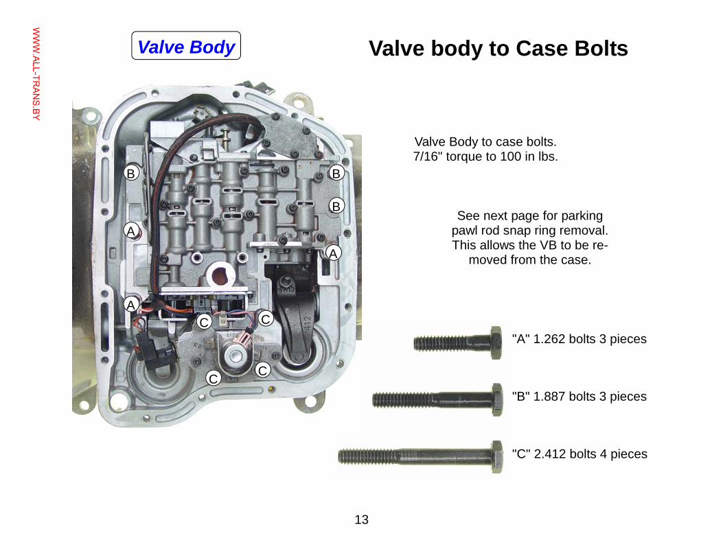
Valve body to Case Bolts
"A" 1.262 bolts 3 pieces
"B" 1.887 bolts 3 pieces
"C" 2.412 bolts 4 pieces
Valve Body to case bolts. 7/16" torque to 100 in lbs.
See next page for parking pawl rod snap ring removal. This allows the VB to be re-
moved from the case.
C C
C C
B
B B
A
A
A
Valve Body
WWW.ALL-TR
ANS.BY
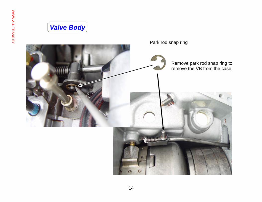
14
Remove park rod snap ring to remove the VB from the case.
Park rod snap ring
Valve Body
WWW.ALL-TR
ANS.BY
15
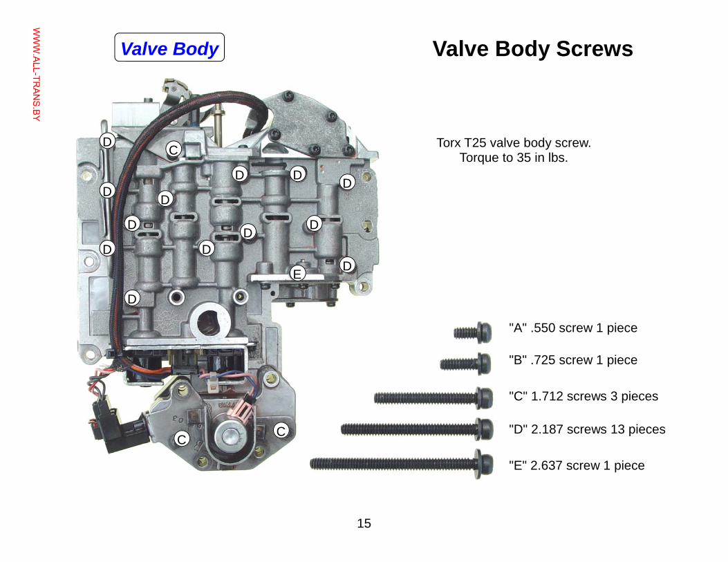
Torx T25 valve body screw. Torque to 35 in lbs.
"A" .550 screw 1 piece
"B" .725 screw 1 piece
"C" 1.712 screws 3 pieces
"D" 2.187 screws 13 pieces
"E" 2.637 screw 1 piece
D
C
E
C C
Valve Body Screws
D
D
D
D
D
D
D
D
D D
D
D
Valve Body
WWW.ALL-TR
ANS.BY
16
B
A
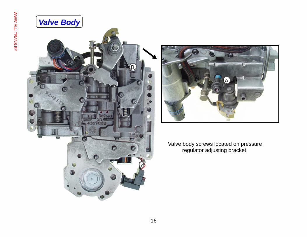
Valve body screws located on pressure regulator adjusting bracket.
Valve Body
WWW.ALL-TR
ANS.BY
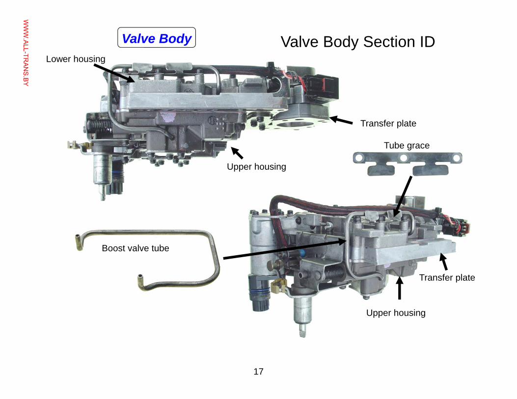
17
Valve Body Section ID
Upper housing
Lower housing
Upper housing
Transfer plate
Boost valve tube
Tube grace
Transfer plate
Valve Body
WWW.ALL-TR
ANS.BY
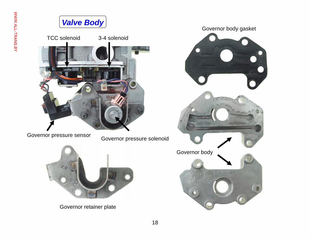
18
TCC solenoid 3-4 solenoid
Governor body
Governor body gasket
Governor retainer plate
Governor pressure solenoid Governor pressure sensor
Valve Body
WWW.ALL-TR
ANS.BY
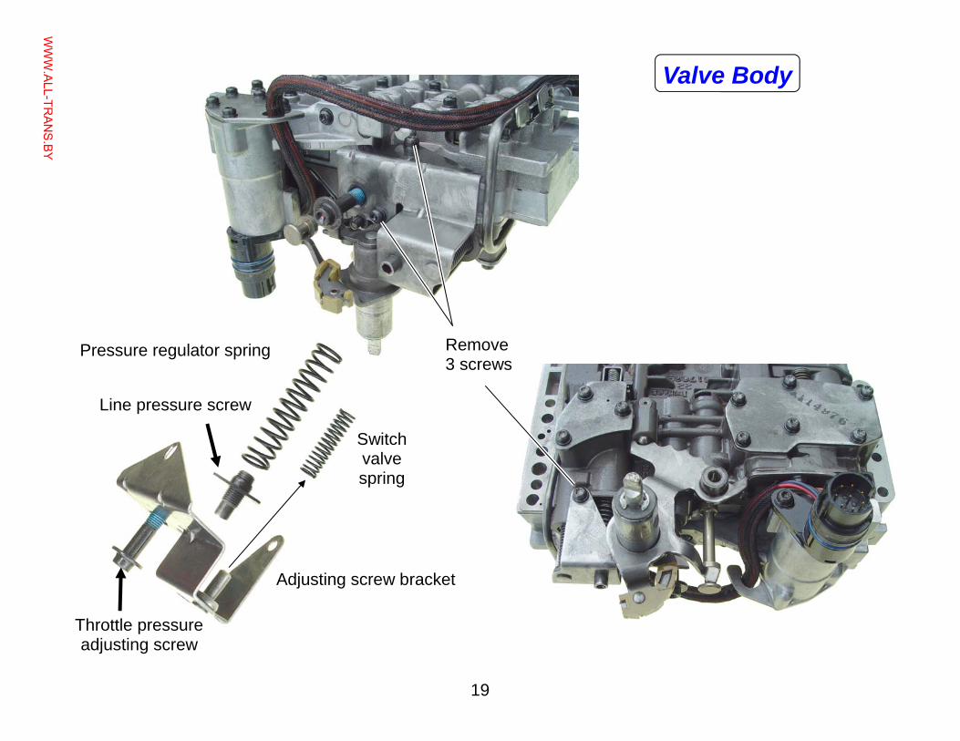
19
Remove 3 screws
Adjusting screw bracket
Pressure regulator spring
Line pressure screw
Throttle pressure adjusting screw
Switch valve spring
Valve Body
WWW.ALL-TR
ANS.BY
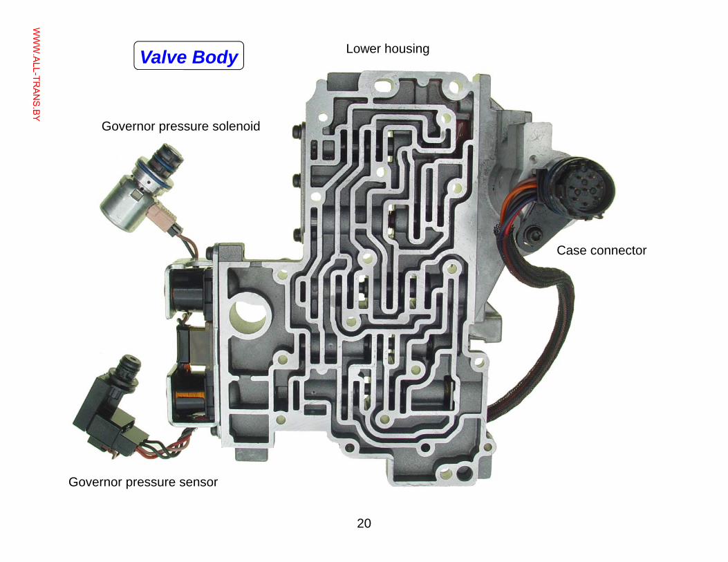
20
Governor pressure sensor
Governor pressure solenoid
Case connector
Lower housing Valve Body
WWW.ALL-TR
ANS.BY
21
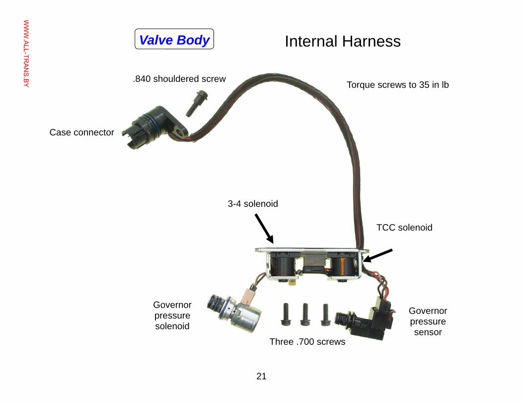
Internal Harness
Torque screws to 35 in lb
TCC solenoid
Governor pressure solenoid
Governor pressure sensor
3-4 solenoid
Case connector
.840 shouldered screw
Three .700 screws
Valve Body
WWW.ALL-TR
ANS.BY
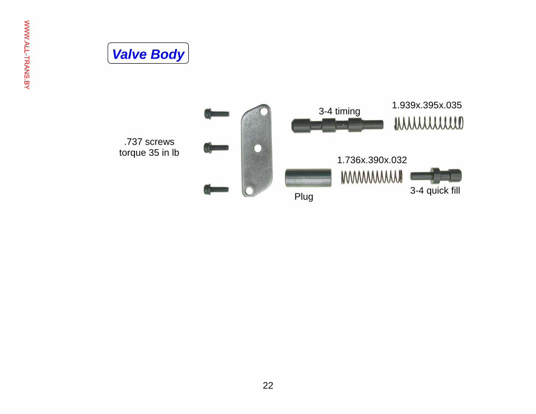
22
1.736x.390x.032
1.939x.395x.035
.737 screws torque 35 in lb
3-4 timing
3-4 quick fill Plug
Valve Body
WWW.ALL-TR
ANS.BY
23
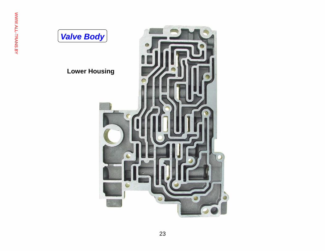
Lower Housing
Valve Body
WWW.ALL-TR
ANS.BY
24
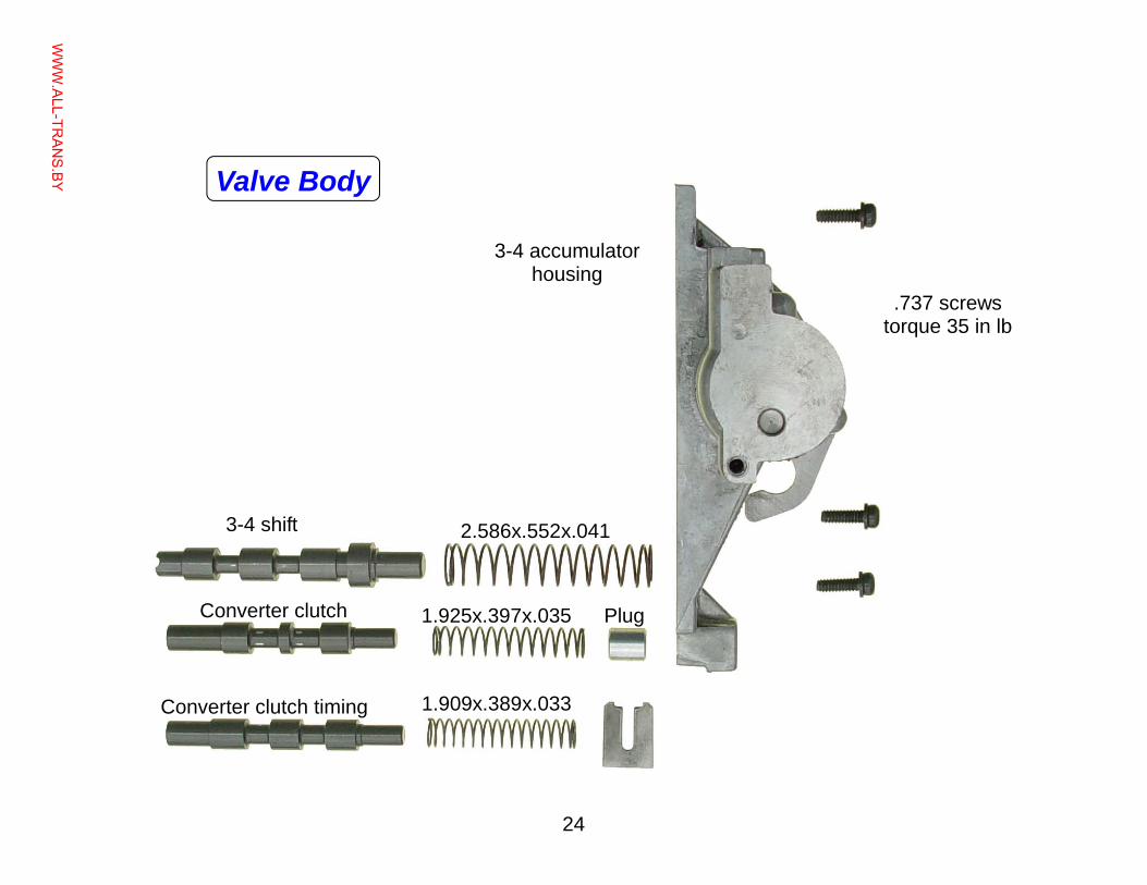
.737 screws torque 35 in lb
3-4 accumulator housing
1.909x.389x.033
1.925x.397x.035 Plug
2.586x.552x.041
Converter clutch timing
3-4 shift
Converter clutch
Valve Body
WWW.ALL-TR
ANS.BY
25
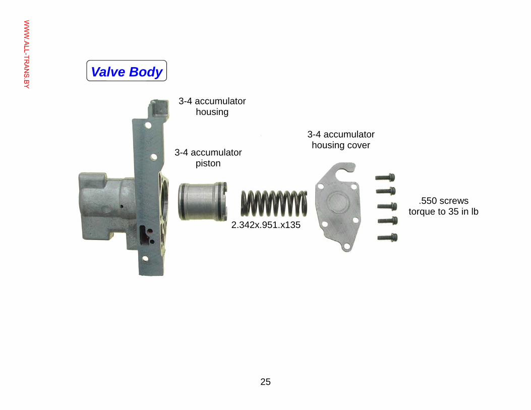
3-4 accumulator housing
3-4 accumulator piston
3-4 accumulator housing cover
.550 screws torque to 35 in lb
2.342x.951.x135
Valve Body
WWW.ALL-TR
ANS.BY
26
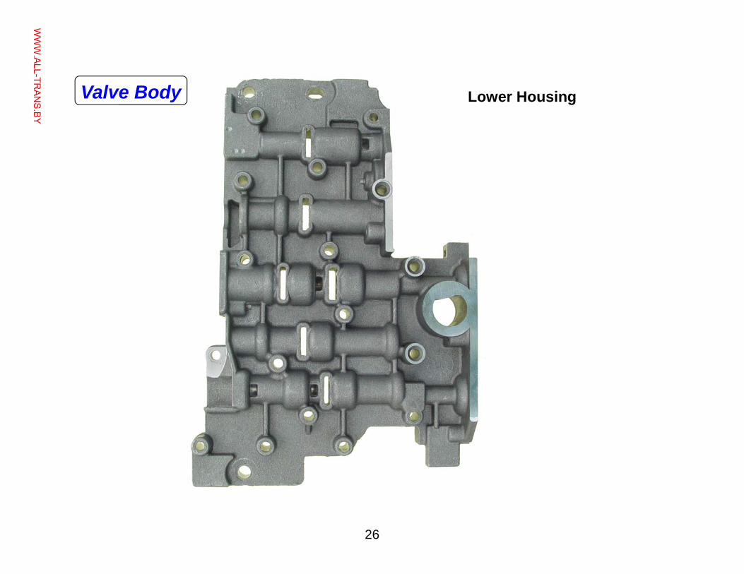
Lower Housing Valve Body
WWW.ALL-TR
ANS.BY
27
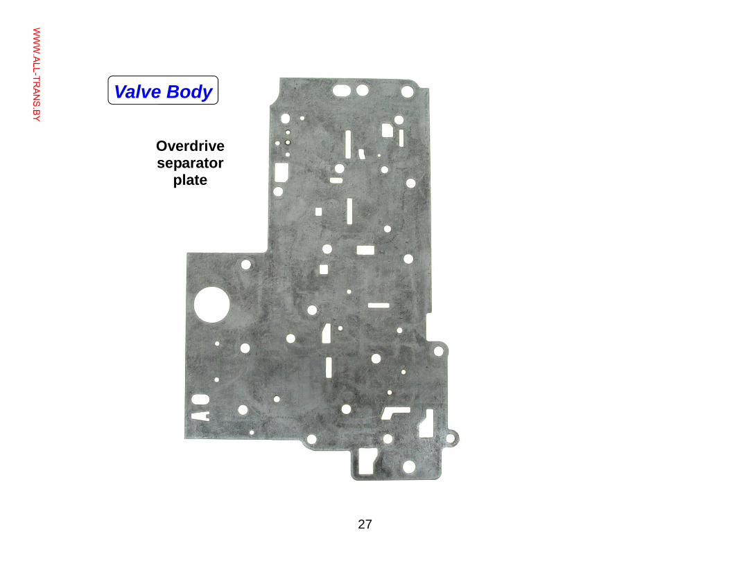
Overdrive separator
plate
Valve Body
WWW.ALL-TR
ANS.BY
28
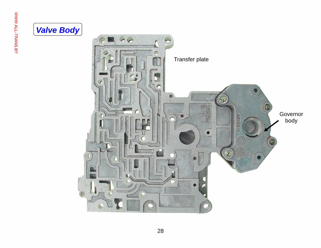
Transfer plate
Governor body
Valve Body
WWW.ALL-TR
ANS.BY
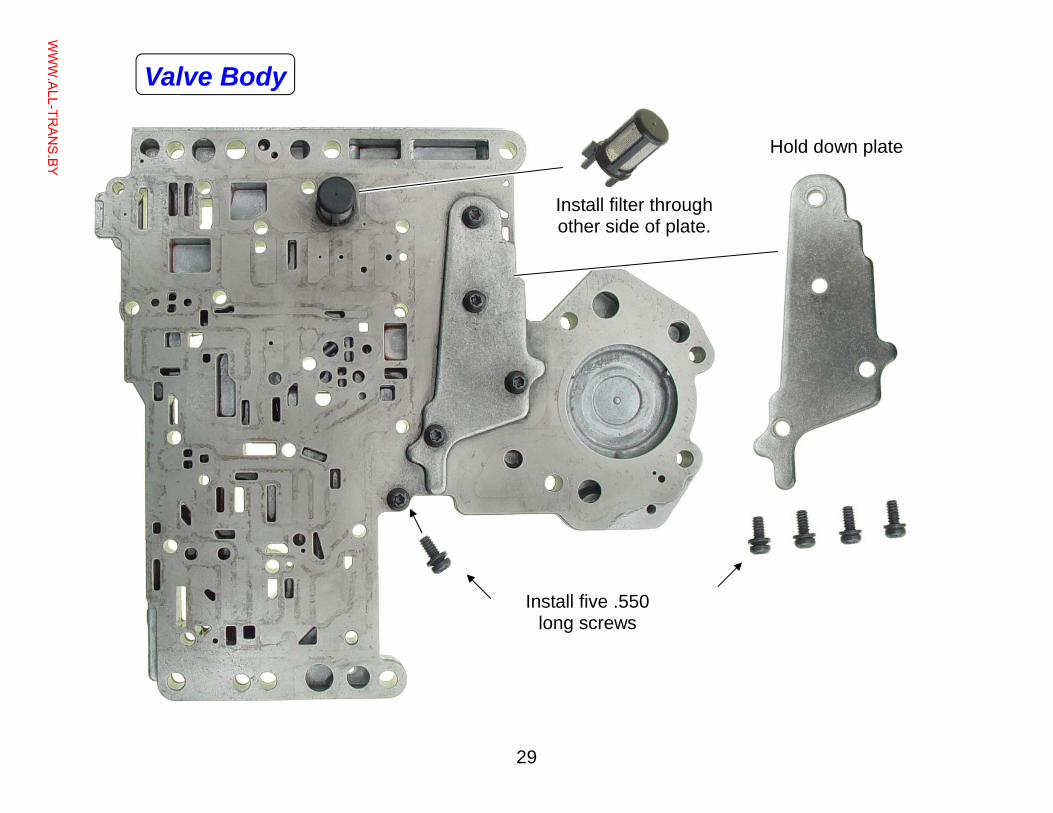
29
Install filter through other side of plate.
Install five .550 long screws
Hold down plate
Valve Body
WWW.ALL-TR
ANS.BY
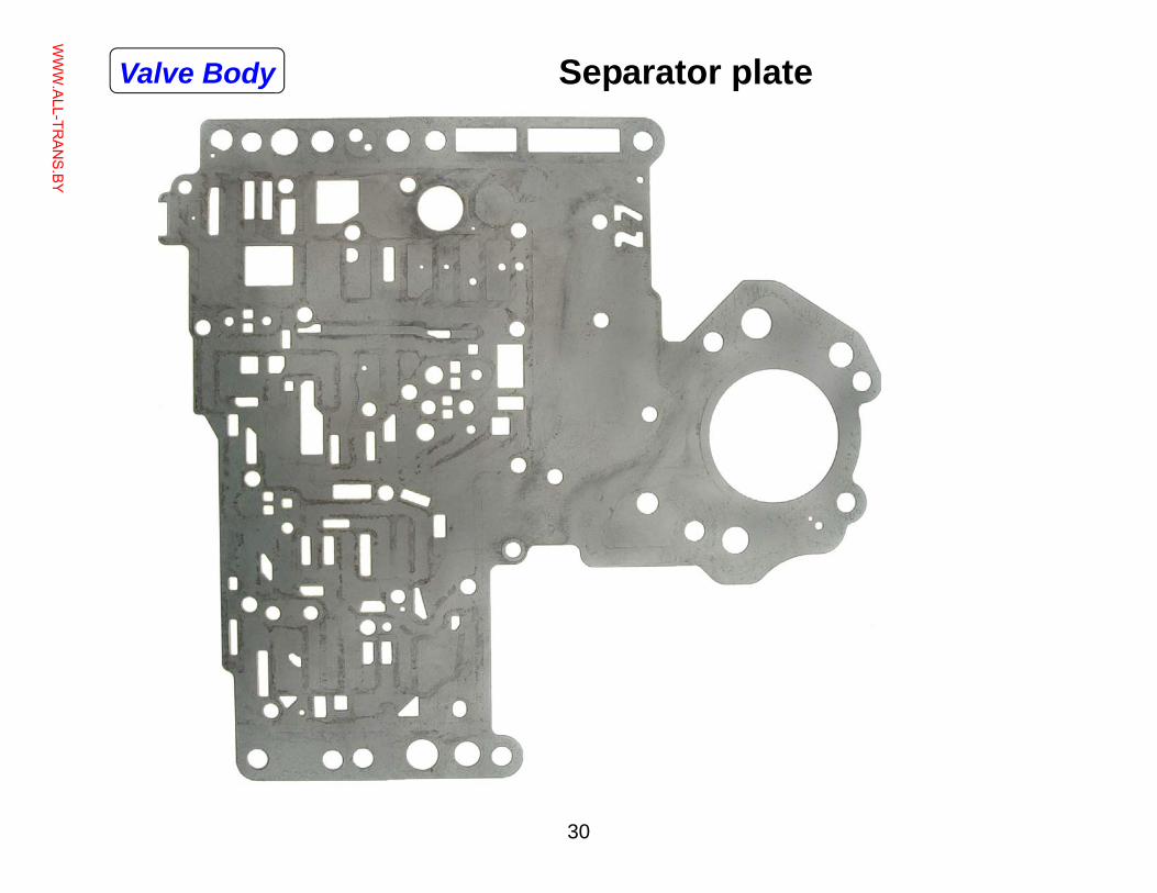
30
Separator plate Valve Body
WWW.ALL-TR
ANS.BY
31
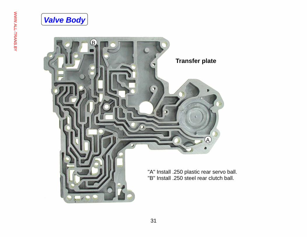
B
A
"A" Install .250 plastic rear servo ball. "B" Install .250 steel rear clutch ball.
Transfer plate
Valve Body
WWW.ALL-TR
ANS.BY
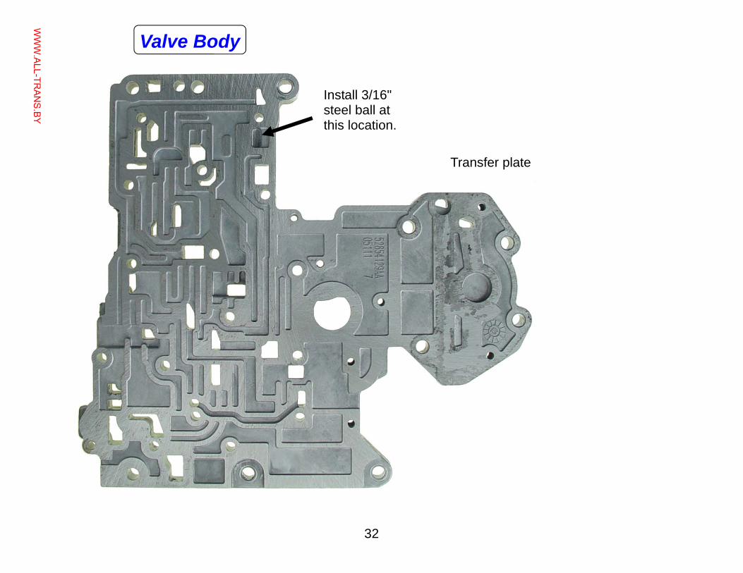
32
Transfer plate
Install 3/16" steel ball at this location.
Valve Body
WWW.ALL-TR
ANS.BY
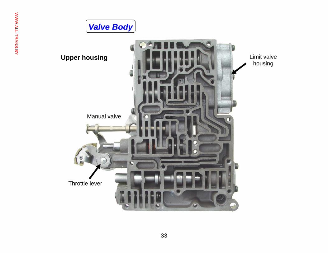
33
Upper housing Limit valve housing
Manual valve
Throttle lever
Valve Body
WWW.ALL-TR
ANS.BY
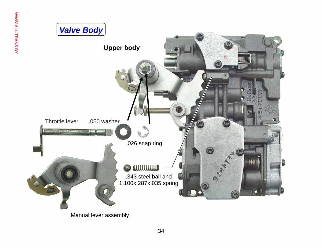
34
Throttle lever .050 washer
Manual lever assembly
.026 snap ring
.343 steel ball and 1.100x.287x.035 spring
Upper body
Valve Body
WWW.ALL-TR
ANS.BY
35
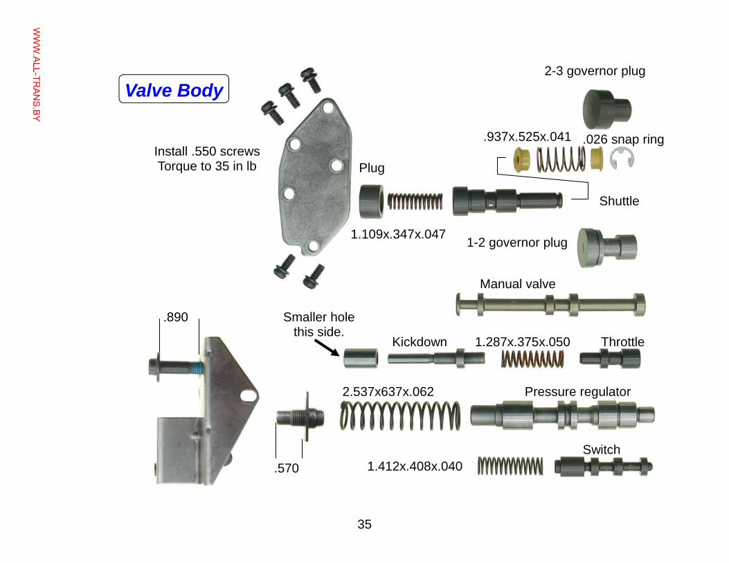
Install .550 screws Torque to 35 in lb
Manual valve
2-3 governor plug
1-2 governor plug
Shuttle
Plug
.026 snap ring .937x.525x.041
Throttle Kickdown
Smaller hole this side.
.570
.890
Pressure regulator
1.287x.375x.050
2.537x637x.062
1.412x.408x.040 Switch
1.109x.347x.047
Valve Body
WWW.ALL-TR
ANS.BY
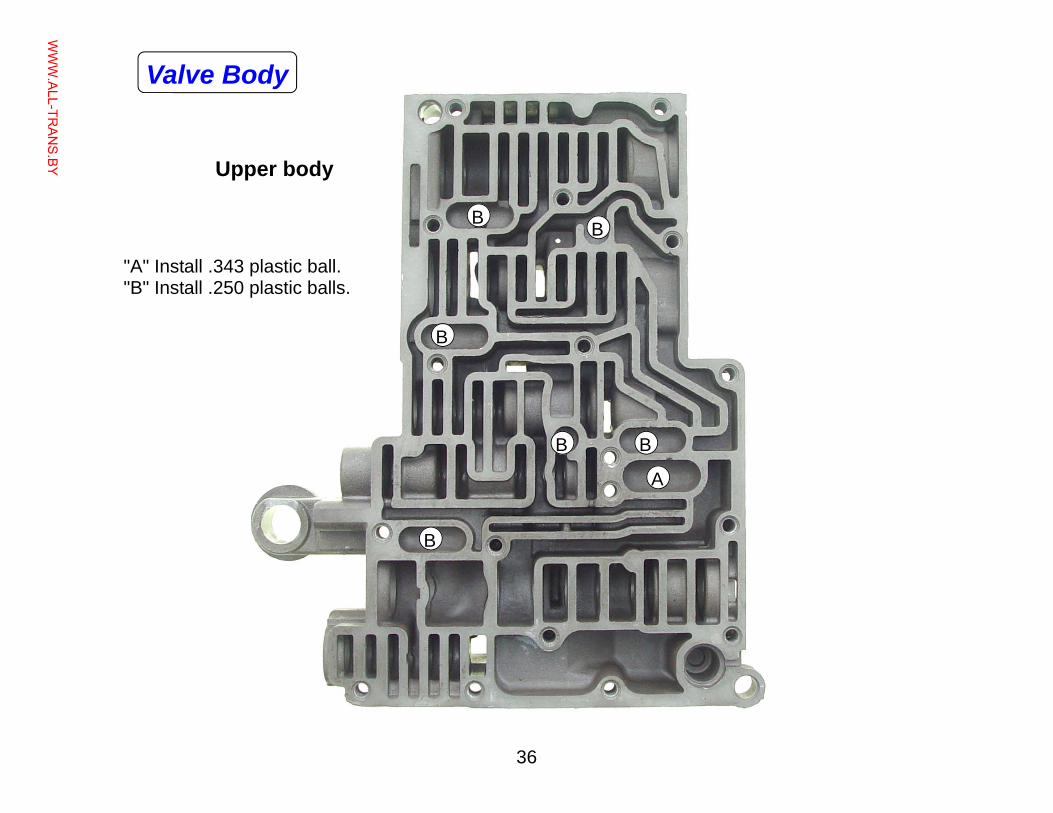
36
B
A
"A" Install .343 plastic ball. "B" Install .250 plastic balls.
Upper body
B
B
B
B B
Valve Body
WWW.ALL-TR
ANS.BY
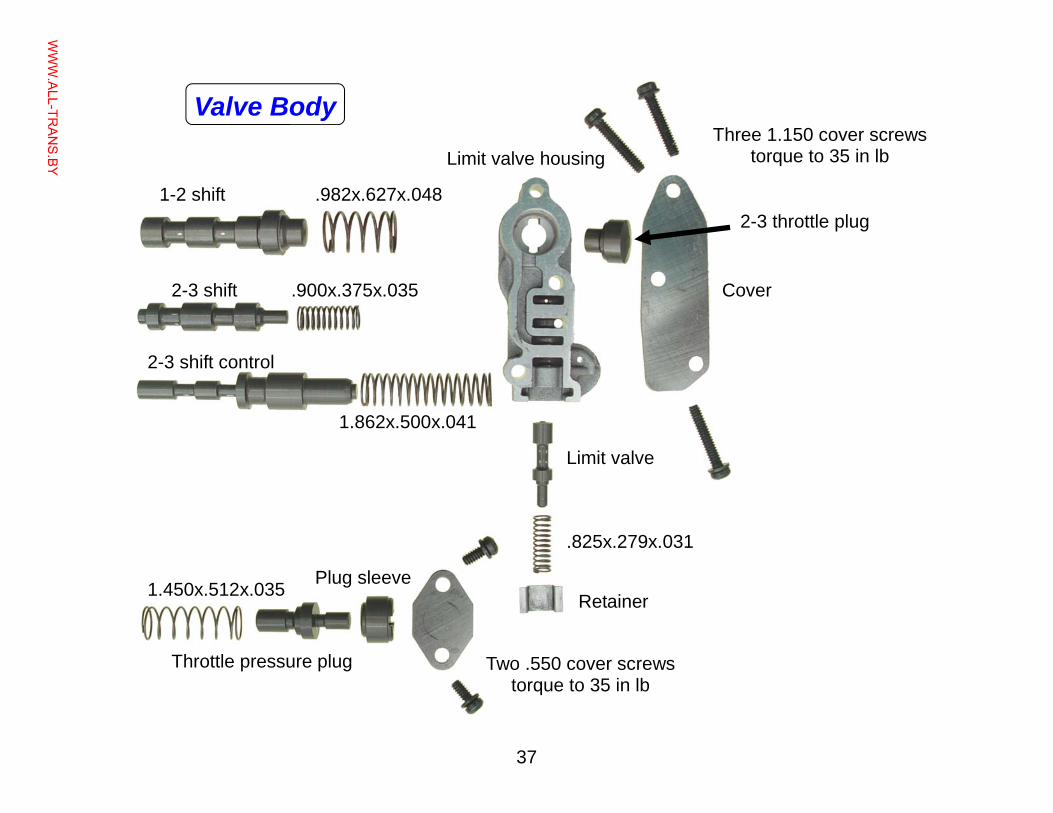
37
Limit valve housing
Cover
Three 1.150 cover screws torque to 35 in lb
Two .550 cover screws torque to 35 in lb
2-3 throttle plug
Limit valve
.825x.279x.031
Retainer
1-2 shift
2-3 shift
2-3 shift control
.982x.627x.048
.900x.375x.035
1.862x.500x.041
1.450x.512x.035
Throttle pressure plug
Plug sleeve
Valve Body
WWW.ALL-TR
ANS.BY
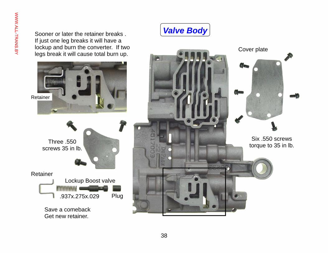
38
Cover plate
Six .550 screws torque to 35 in lb. Three .550
screws 35 in lb.
Lockup Boost valve
Plug .937x.275x.029
Valve Body Sooner or later the retainer breaks . If just one leg breaks it will have a lockup and burn the converter. If two legs break it will cause total burn up.
Save a comeback Get new retainer.
Retainer
Retainer
WWW.ALL-TR
ANS.BY
39
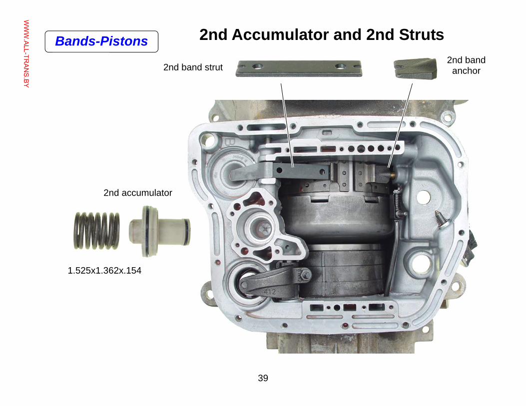
2nd Accumulator and 2nd Struts
2nd band strut 2nd band
anchor
2nd accumulator
1.525x1.362x.154
Bands-Pistons
WWW.ALL-TR
ANS.BY
40
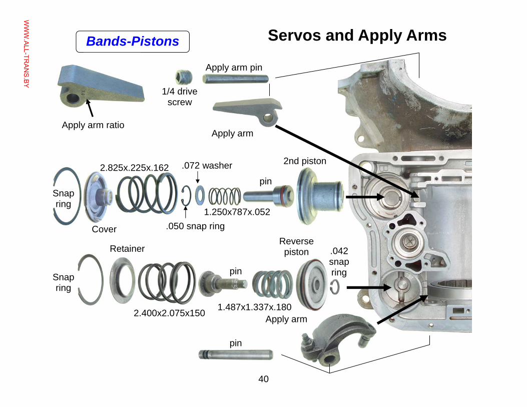
Servos and Apply Arms
Apply arm ratio Apply arm
Apply arm pin
1/4 drive screw
pin
2nd piston
1.250x787x.052
.072 washer
.050 snap ring
2.825x.225x.162
Cover
Snap ring
Snap ring
Retainer
pin
pin
Apply arm 2.400x2.075x150 1.487x1.337x.180
Reverse piston .042
snap ring
Bands-Pistons
WWW.ALL-TR
ANS.BY
41
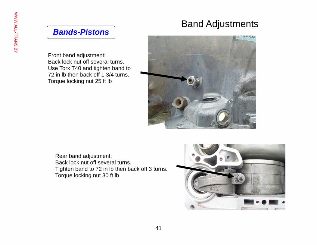
Band Adjustments
Front band adjustment: Back lock nut off several turns. Use Torx T40 and tighten band to 72 in lb then back off 1 3/4 turns. Torque locking nut 25 ft lb
Rear band adjustment: Back lock nut off several turns. Tighten band to 72 in lb then back off 3 turns. Torque locking nut 30 ft lb
Bands-Pistons
WWW.ALL-TR
ANS.BY
42
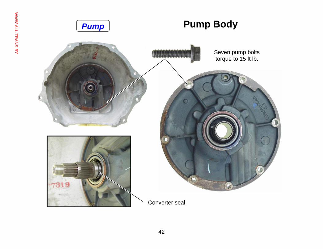
Pump Body
Converter seal
Seven pump bolts torque to 15 ft lb.
Pump
WWW.ALL-TR
ANS.BY
43
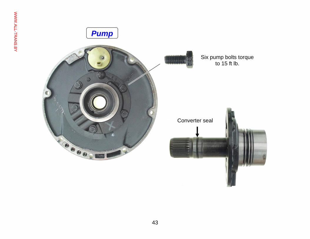
Converter seal
Six pump bolts torque to 15 ft lb.
Pump
WWW.ALL-TR
ANS.BY
44
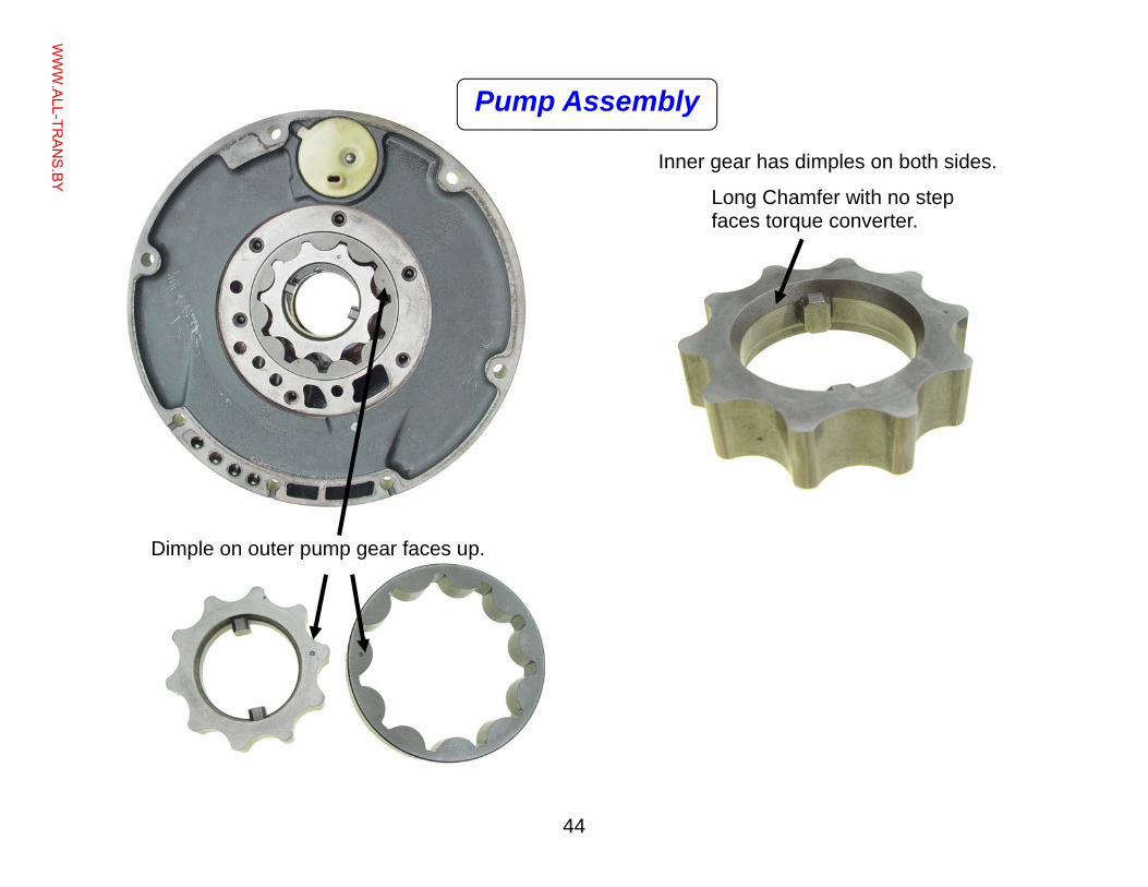
Long Chamfer with no step faces torque converter.
Dimple on outer pump gear faces up.
Inner gear has dimples on both sides.
Pump Assembly
WWW.ALL-TR
ANS.BY
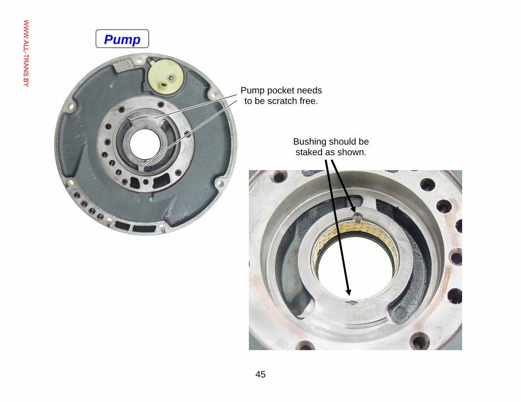
45
Bushing should be staked as shown.
Pump pocket needs to be scratch free.
Pump
WWW.ALL-TR
ANS.BY
46
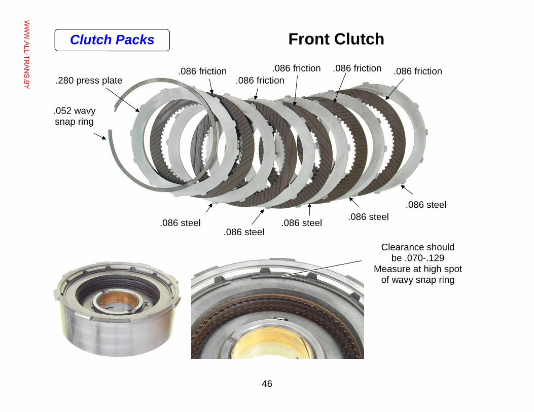
Front Clutch
.052 wavy snap ring
.086 friction .280 press plate
.086 friction .086 friction .086 friction
.086 friction
.086 steel .086 steel
.086 steel .086 steel .086 steel
Clearance should be .070-.129
Measure at high spot of wavy snap ring
Clutch Packs
WWW.ALL-TR
ANS.BY
47
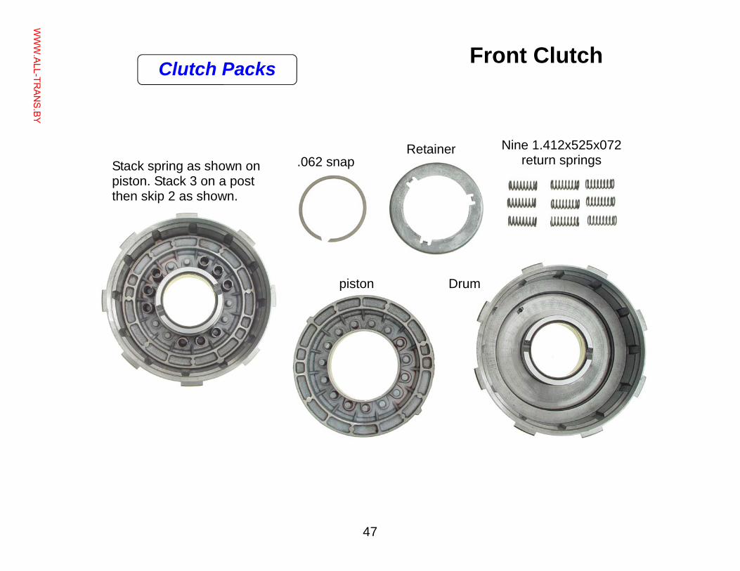
Front Clutch
.062 snap Retainer Nine 1.412x525x072
return springs Stack spring as shown on piston. Stack 3 on a post then skip 2 as shown.
piston Drum
Clutch Packs
WWW.ALL-TR
ANS.BY
48
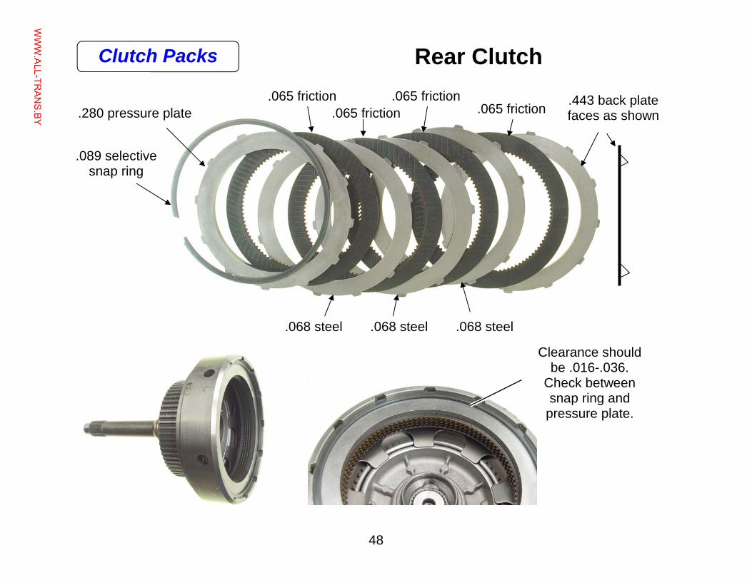
Rear Clutch
.280 pressure plate
.089 selective snap ring
.068 steel .068 steel .068 steel
Clearance should be .016-.036.
Check between snap ring and
pressure plate.
.443 back plate faces as shown .065 friction
.065 friction .065 friction
.065 friction
Clutch Packs
WWW.ALL-TR
ANS.BY
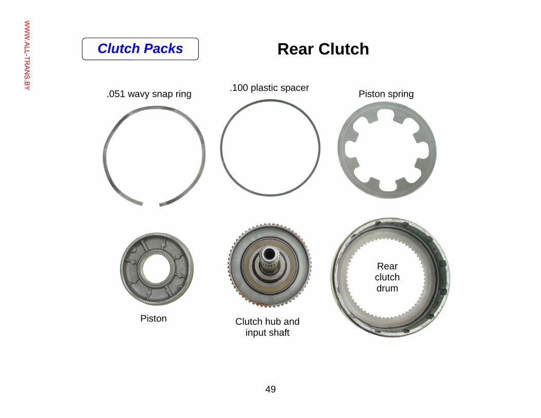
49
.051 wavy snap ring .100 plastic spacer Piston spring
Rear clutch drum
Clutch hub and input shaft
Piston
Rear Clutch Clutch Packs
WWW.ALL-TR
ANS.BY
50
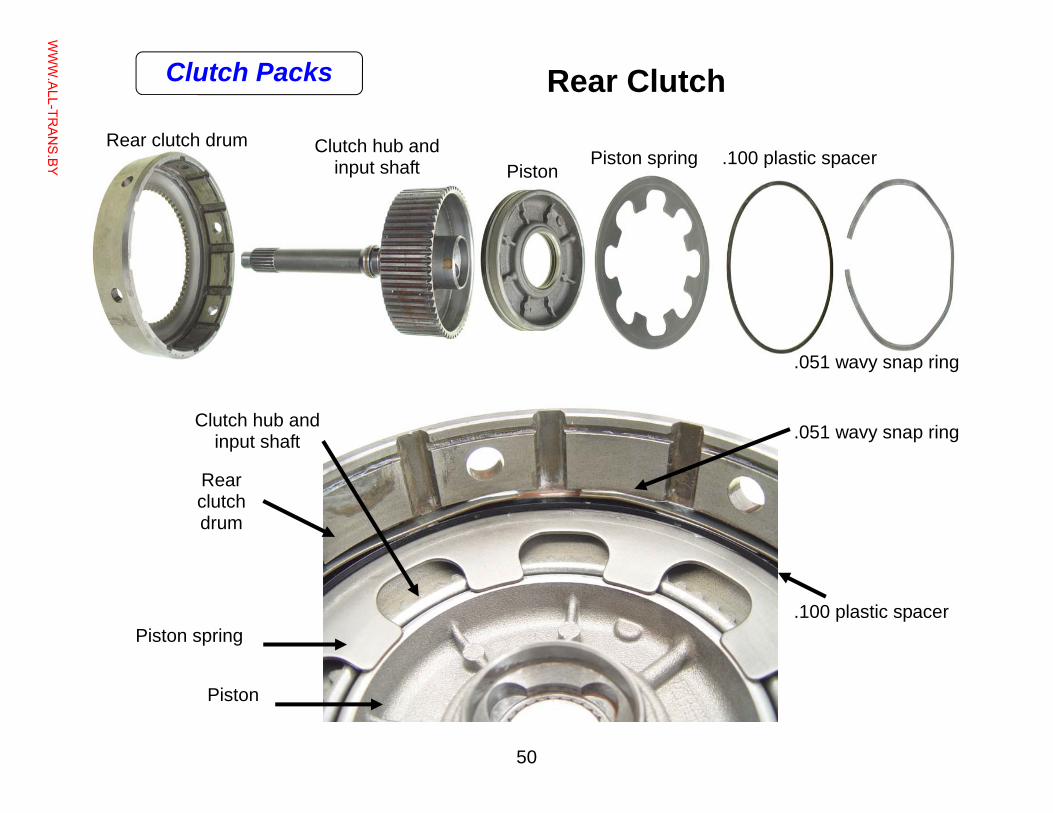
Rear Clutch
.051 wavy snap ring
.100 plastic spacer Piston spring Rear clutch drum Clutch hub and
input shaft Piston
Rear clutch drum
.051 wavy snap ring
.100 plastic spacer Piston spring
Piston
Clutch hub and input shaft
Clutch Packs
WWW.ALL-TR
ANS.BY
51
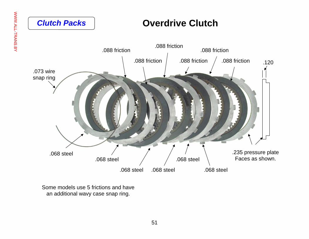
Overdrive Clutch
.235 pressure plate Faces as shown.
.088 friction
.068 steel
.073 wire snap ring
.068 steel
.068 steel .068 steel
.068 steel
.068 steel
.088 friction
.088 friction
.088 friction
.088 friction
.088 friction
Some models use 5 frictions and have an additional wavy case snap ring.
.120
Clutch Packs
WWW.ALL-TR
ANS.BY
52
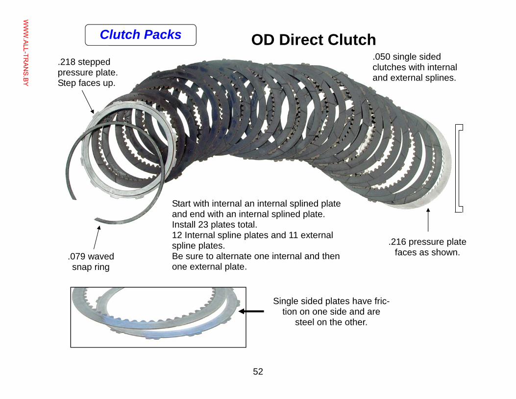
OD Direct Clutch
.079 waved snap ring
.050 single sided clutches with internal and external splines.
.218 stepped pressure plate. Step faces up.
Start with internal an internal splined plate and end with an internal splined plate. Install 23 plates total. 12 Internal spline plates and 11 external spline plates. Be sure to alternate one internal and then one external plate.
.216 pressure plate faces as shown.
Single sided plates have fric-tion on one side and are
steel on the other.
Clutch Packs
WWW.ALL-TR
ANS.BY
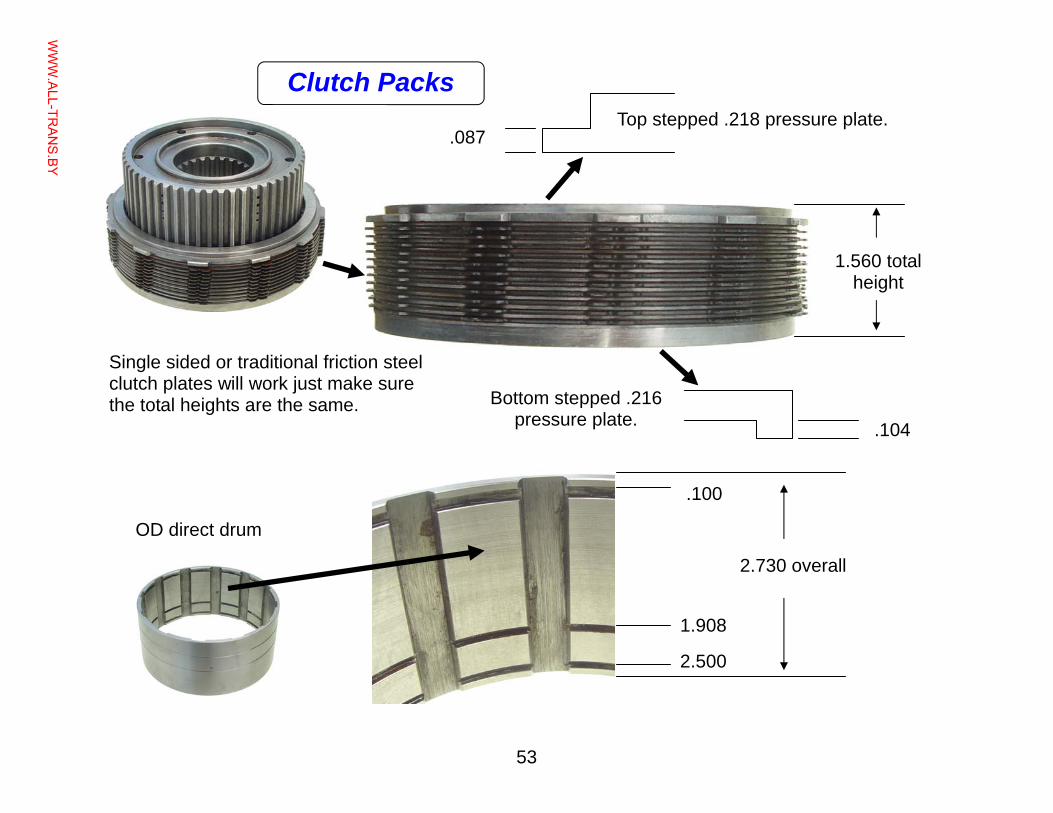
53
Top stepped .218 pressure plate. .087
Single sided or traditional friction steel clutch plates will work just make sure the total heights are the same. Bottom stepped .216
pressure plate. .104
1.560 total height
OD direct drum
.100
2.730 overall
1.908
2.500
Clutch Packs
WWW.ALL-TR
ANS.BY
54
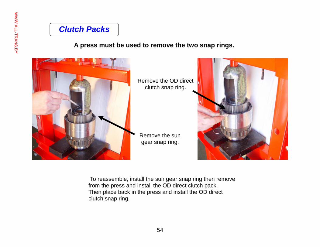
A press must be used to remove the two snap rings.
Remove the sun gear snap ring.
To reassemble, install the sun gear snap ring then remove from the press and install the OD direct clutch pack. Then place back in the press and install the OD direct clutch snap ring.
Remove the OD direct clutch snap ring.
Clutch Packs
WWW.ALL-TR
ANS.BY
55
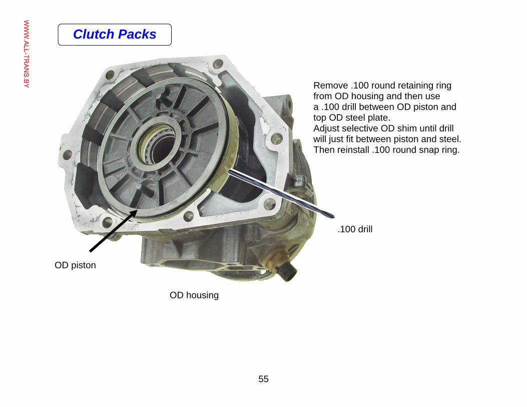
OD housing
OD piston
.100 drill
Remove .100 round retaining ring from OD housing and then use a .100 drill between OD piston and top OD steel plate. Adjust selective OD shim until drill will just fit between piston and steel. Then reinstall .100 round snap ring.
Clutch Packs
WWW.ALL-TR
ANS.BY
56
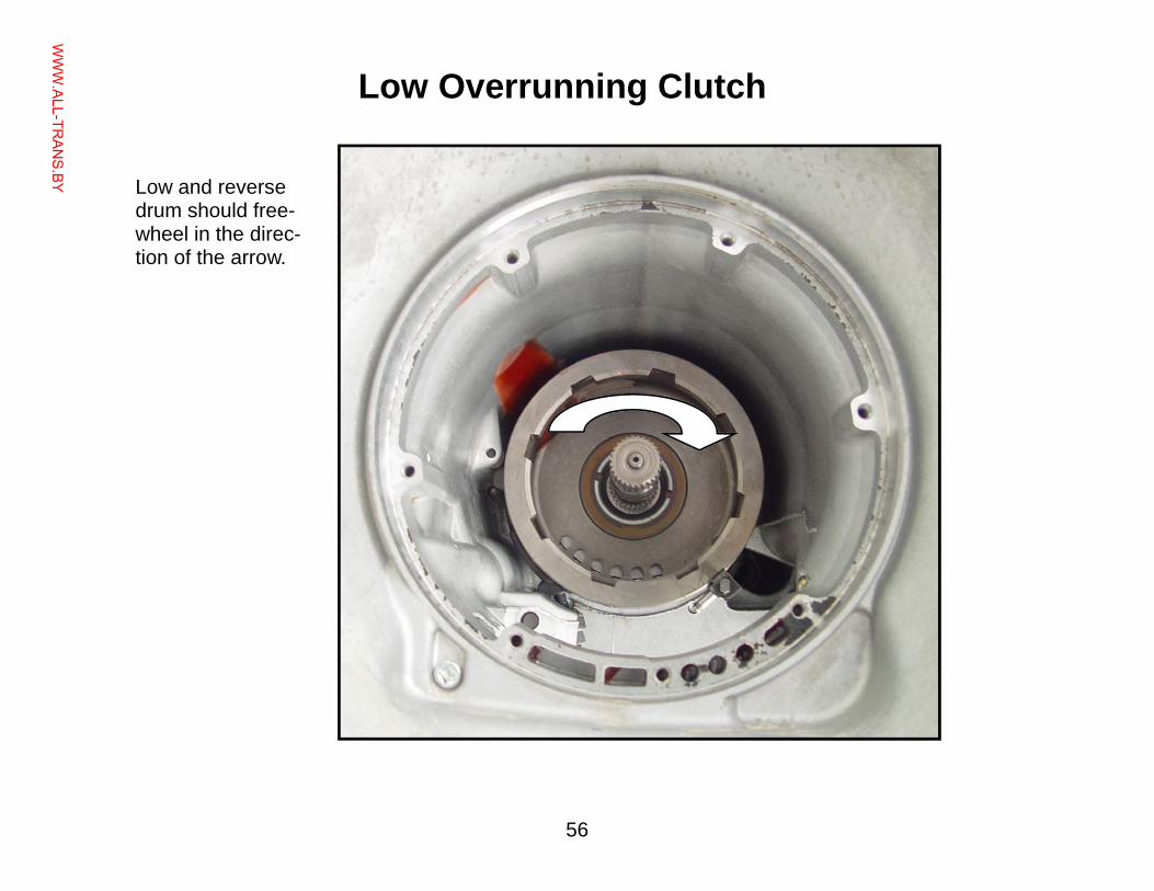
Low Overrunning Clutch
Low and reverse drum should free-wheel in the direc-tion of the arrow.
WWW.ALL-TR
ANS.BY
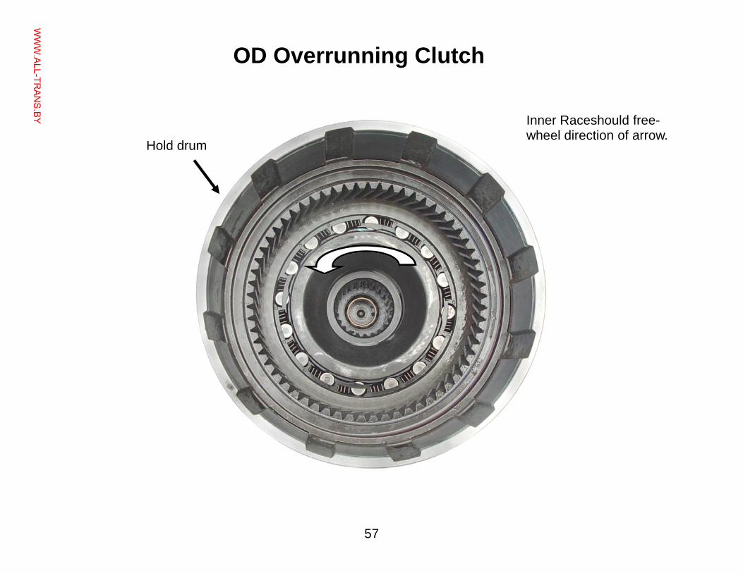
57
Inner Raceshould free-wheel direction of arrow.
Hold drum
OD Overrunning Clutch
WWW.ALL-TR
ANS.BY
58
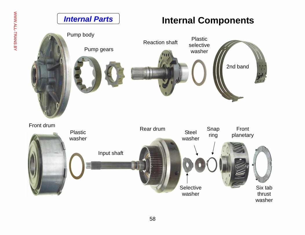
Internal Components
Steel washer
Input shaft
Pump body
Pump gears Reaction shaft Plastic
selective washer
2nd band
Front drum Plastic washer
Rear drum Snap ring
Selective washer
Front planetary
Six tab thrust
washer
Internal Parts
WWW.ALL-TR
ANS.BY
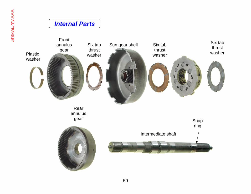
59
Sun gear shell
Plastic washer
Intermediate shaft
Front annulus
gear
Rear annulus
gear
Six tab thrust
washer
Six tab thrust
washer
Six tab thrust
washer
Snap ring
Internal Parts
WWW.ALL-TR
ANS.BY
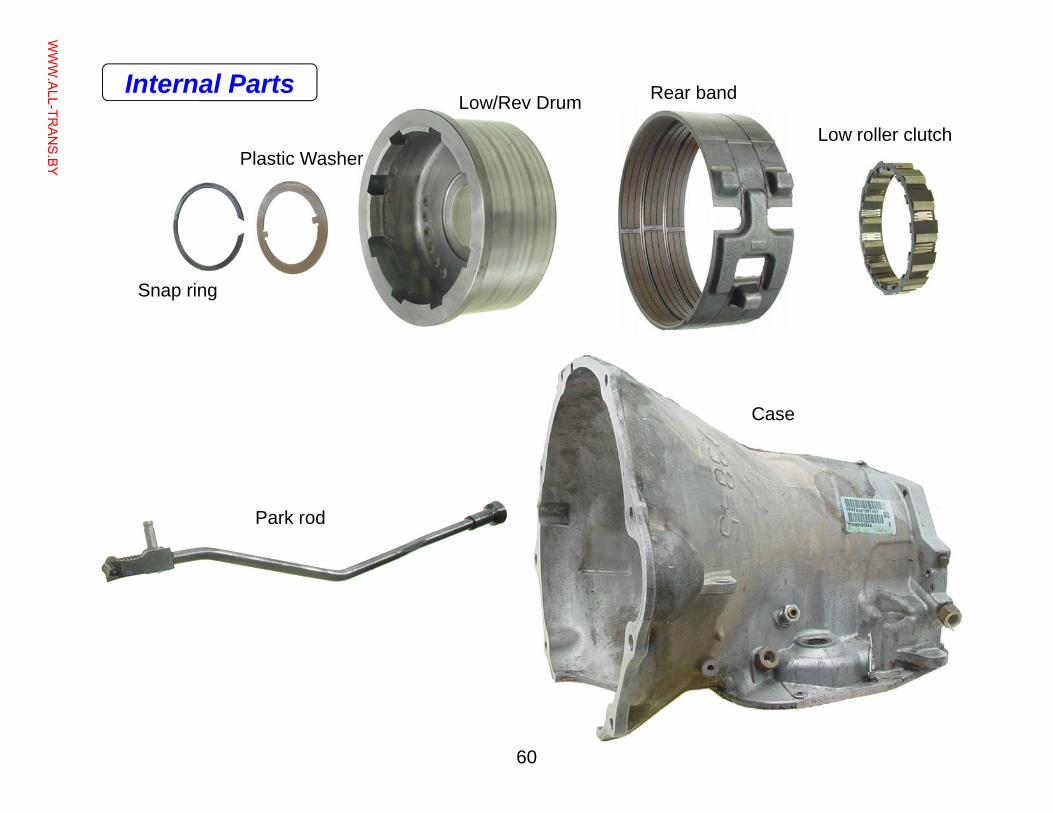
60
Low/Rev Drum Rear band
Low roller clutch
Case
Park rod
Snap ring
Plastic Washer
Internal Parts
WWW.ALL-TR
ANS.BY
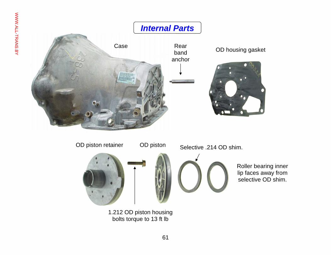
61
Roller bearing inner lip faces away from selective OD shim.
Selective .214 OD shim.
Case
OD piston retainer
OD housing gasket Rear band
anchor
1.212 OD piston housing bolts torque to 13 ft lb
OD piston
Internal Parts
WWW.ALL-TR
ANS.BY
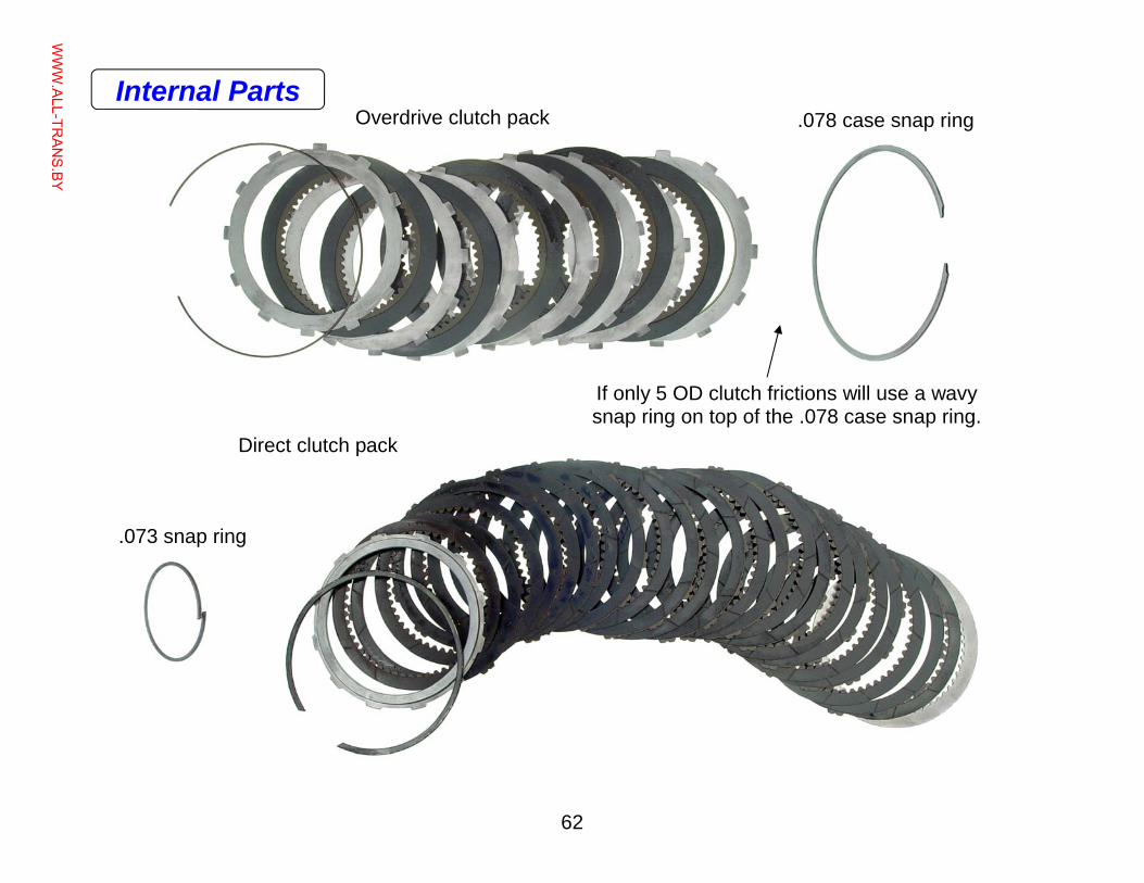
62
.073 snap ring
.078 case snap ring Overdrive clutch pack
Direct clutch pack
If only 5 OD clutch frictions will use a wavy snap ring on top of the .078 case snap ring.
Internal Parts
WWW.ALL-TR
ANS.BY
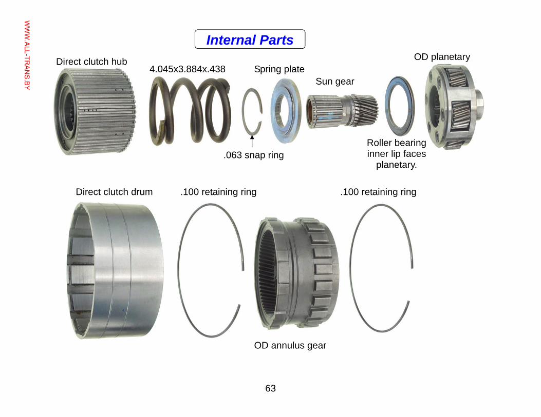
63
4.045x3.884x.438 Direct clutch hub
.100 retaining ring Direct clutch drum
OD planetary
Roller bearing inner lip faces
planetary.
Sun gear Spring plate
.063 snap ring
.100 retaining ring
OD annulus gear
Internal Parts
WWW.ALL-TR
ANS.BY
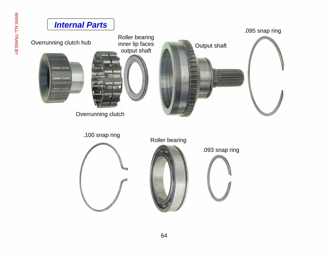
64
Roller bearing
.095 snap ring Roller bearing inner lip faces output shaft
Overrunning clutch hub
Overrunning clutch
.100 snap ring
.093 snap ring
Output shaft
Internal Parts
WWW.ALL-TR
ANS.BY
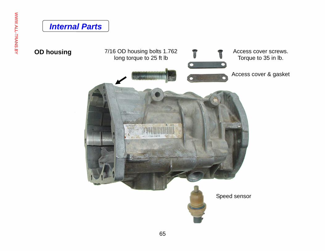
65
Access cover screws. Torque to 35 in lb.
7/16 OD housing bolts 1.762 long torque to 25 ft lb
OD housing
Access cover & gasket
Speed sensor
Internal Parts
WWW.ALL-TR
ANS.BY
66
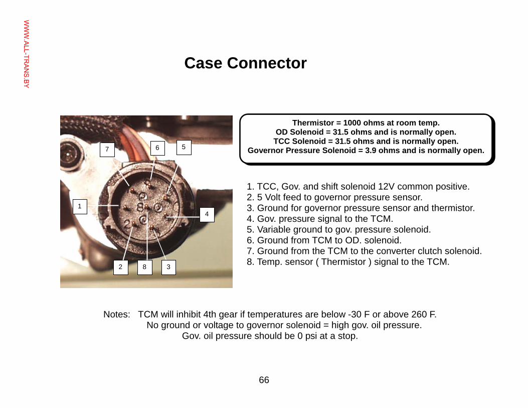
Notes: TCM will inhibit 4th gear if temperatures are below -30 F or above 260 F. No ground or voltage to governor solenoid = high gov. oil pressure.
Gov. oil pressure should be 0 psi at a stop.
1. TCC, Gov. and shift solenoid 12V common positive. 2. 5 Volt feed to governor pressure sensor. 3. Ground for governor pressure sensor and thermistor. 4. Gov. pressure signal to the TCM. 5. Variable ground to gov. pressure solenoid. 6. Ground from TCM to OD. solenoid. 7. Ground from the TCM to the converter clutch solenoid. 8. Temp. sensor ( Thermistor ) signal to the TCM.
Thermistor = 1000 ohms at room temp. OD Solenoid = 31.5 ohms and is normally open.
TCC Solenoid = 31.5 ohms and is normally open. Governor Pressure Solenoid = 3.9 ohms and is normally open.
2 8
5 6 7
3
4 1
Case Connector
WWW.ALL-TR
ANS.BY
67
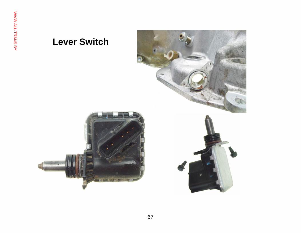
Lever Switch
WWW.ALL-TR
ANS.BY
68
Torque Specifications
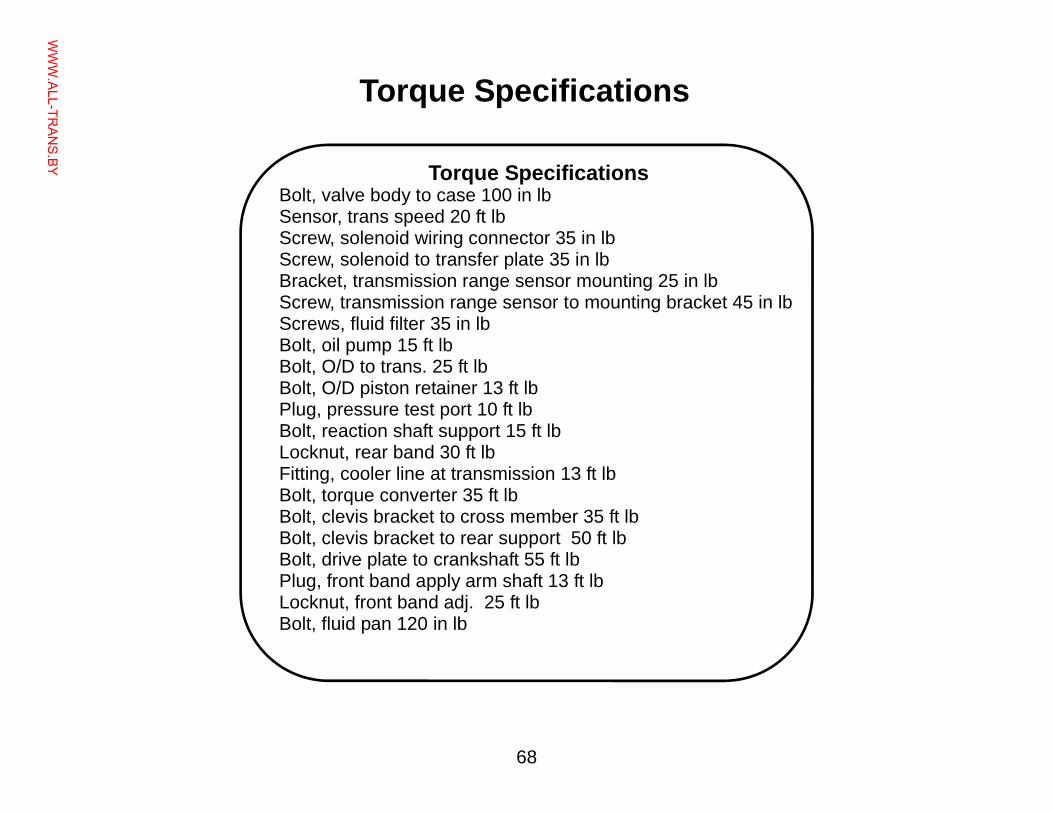
Torque Specifications Bolt, valve body to case 100 in lb Sensor, trans speed 20 ft lb Screw, solenoid wiring connector 35 in lb Screw, solenoid to transfer plate 35 in lb Bracket, transmission range sensor mounting 25 in lb Screw, transmission range sensor to mounting bracket 45 in lb Screws, fluid filter 35 in lb Bolt, oil pump 15 ft lb Bolt, O/D to trans. 25 ft lb Bolt, O/D piston retainer 13 ft lb Plug, pressure test port 10 ft lb Bolt, reaction shaft support 15 ft lb Locknut, rear band 30 ft lb Fitting, cooler line at transmission 13 ft lb Bolt, torque converter 35 ft lb Bolt, clevis bracket to cross member 35 ft lb Bolt, clevis bracket to rear support 50 ft lb Bolt, drive plate to crankshaft 55 ft lb Plug, front band apply arm shaft 13 ft lb Locknut, front band adj. 25 ft lb Bolt, fluid pan 120 in lb
WWW.ALL-TR
ANS.BY
69
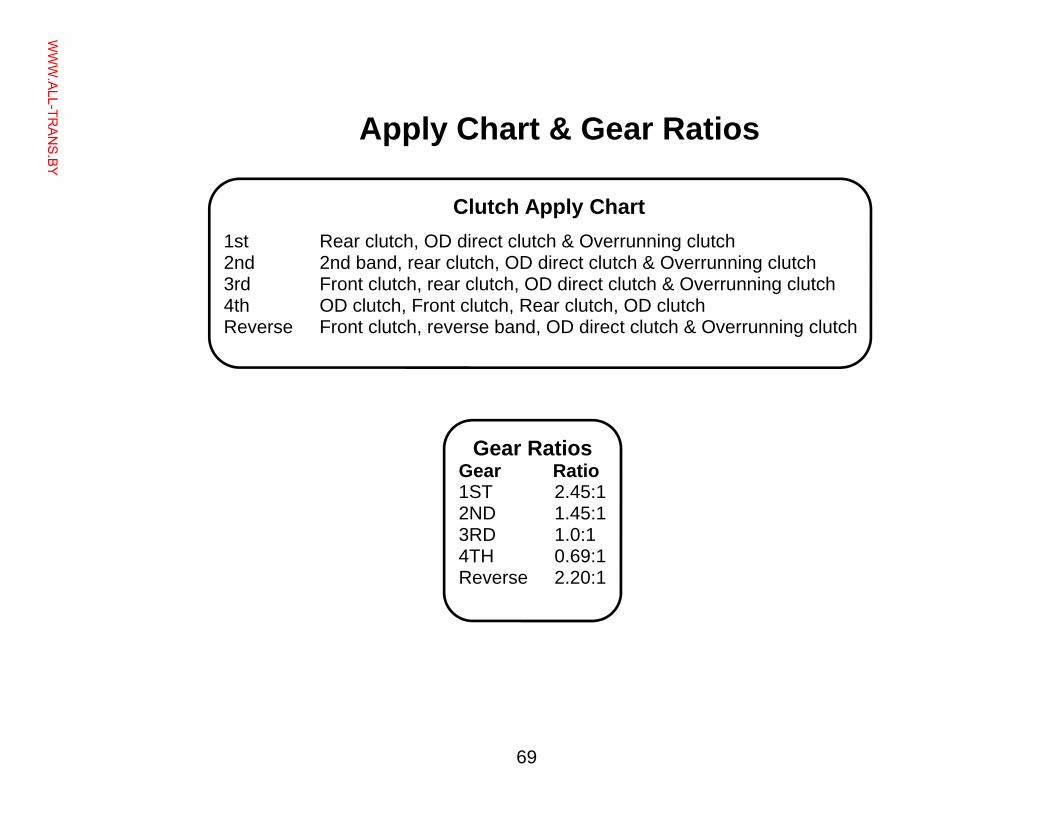
Clutch Apply Chart
1st Rear clutch, OD direct clutch & Overrunning clutch 2nd 2nd band, rear clutch, OD direct clutch & Overrunning clutch 3rd Front clutch, rear clutch, OD direct clutch & Overrunning clutch 4th OD clutch, Front clutch, Rear clutch, OD clutch Reverse Front clutch, reverse band, OD direct clutch & Overrunning clutch
Gear Ratios Gear Ratio 1ST 2.45:1 2ND 1.45:1 3RD 1.0:1 4TH 0.69:1 Reverse 2.20:1
Apply Chart & Gear Ratios
WWW.ALL-TR
ANS.BY
70
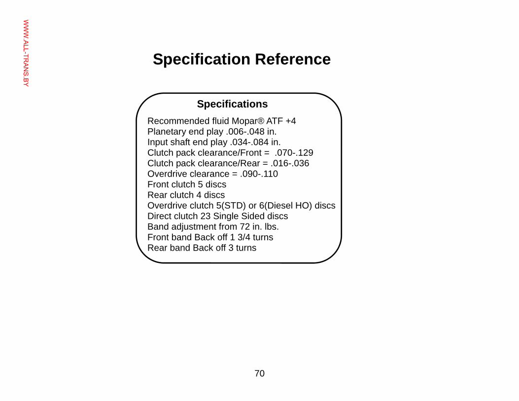
Specification Reference
Specifications
Recommended fluid Mopar® ATF +4 Planetary end play .006-.048 in. Input shaft end play .034-.084 in. Clutch pack clearance/Front = .070-.129 Clutch pack clearance/Rear = .016-.036 Overdrive clearance = .090-.110 Front clutch 5 discs Rear clutch 4 discs Overdrive clutch 5(STD) or 6(Diesel HO) discs Direct clutch 23 Single Sided discs Band adjustment from 72 in. lbs. Front band Back off 1 3/4 turns Rear band Back off 3 turns
WWW.ALL-TR
ANS.BY

71
Copyright TransGo 2005
The Technology IS the Ethic If the sign on the building or any advertising says, “Transmissions” that is declaration to the Universe that you know how to fix them.
When a product or service is offered, the offer it-self is a specific claim by the seller that he is ac-cepting the MORAL and TECHNICAL responsibility for correct function, for a reasonable length of time, in exchange for money.
Regardless what you may call your repair, the job is in your shop to have the complaints and failures corrected. It doesn’t matter how honest you are, as a person, if you do not fix the causes of the complaints and failures where is the ethic?
Each transmission develops 3 to 5 complaints and failures you see over and over again and again. A service is ethical and deserving to the exact ex-tent that your service corrects the causes of those complaints and failures; and does not include a whole bunch of parts that were not needed.
No more and no less, Gil
Technology and Ethics
WWW.ALL-TR
ANS.BY