Embed Size (px)
Citation preview

– 1 –
IDENTIFICATION BROCHUREFOR
“Central” COMMERCIALWET SPRINKLERS

– 2 –
INTRODUCTION TO THE “VOLUNTARY REPLACEMENT PROGRAM”This brochure provides information that will assist you in identifying whether the sprinklers in yoursprinkler system are the O-ring sprinklers involved in this Voluntary Replacement Program (“VRP”or “Program”). In addition, this brochure contains information that you will need to accuratelycomplete your Proof of Claim form and participate in the VRP. Please read this brochure care-fully and follow all instructions closely.
DO NOT ATTEMPT TO REMOVE OR DISTURB YOUR SPRINKLER HEADSWHILE TRYING TO IDENTIFY YOUR SPRINKLERS.
General Description of the O-Ring Fire Sprinklers Involved in this VRP
All the automatic fire sprinklers involved in this VRP utilize a heat-sensing element, for example,a liquid filled glass bulb (Fig. A), a solder link (Fig. D), or a solder strut (Fig. H), loaded within thesprinkler’s “frame” (Fig. A, C, D, or E). The frame is the piece of metal at the end of the sprinklerclosest to the wall, ceiling, or pipe that is connected to the sprinkler via pipe threads. The heat-sensing element holds the sprinkler “cap” (Fig. A, C, D, or E) in the “orifice,” blocking the flow ofwater through the orifice from the water supply. Should a fire occur, sufficient heat from the fireautomatically releases the heat sensing element permitting the water to push the “cap” out of thewaterway and strike against the “deflector.” The “deflector” is the rounded plate furthest from thewall, ceiling, or pipe that typically resembles a starburst, flower, or gear. The deflector distributeswater in a desirable spray pattern to provide fire control.
The heat sensing elements are provided in a variety of operating temperatures and the sprinklersincorporate a temperature identification system that combines a stamping on the sprinkler with acolor code. The stamping will typically appear on either the “cap” or the “deflector”. Color codingis as follows:
Typical Bulb Ratings Fluid Color Typical Solder Ratings Frame Color*
135F/57C Orange 135F/57C Plain155F/68C Red 165F/74C Plain175F/79C Yellow 212F/100C White200F/93C Green 286F/141C Blue
250F/121C Blue 360F/182C Red286F/141C Blue *Stripe on frame or dot on deflector
360F/182C Purple
The fire sprinklers involved in this Program use an “O-ring Seal Design” (Fig. F) to seal thesprinkler waterway. These O-ring sprinklers are being replaced withsprinklers that utilizea “Belleville Seal Design” (Fig. G).
The O-ring sprinklers involved in this Program are found in two categories of sprinkler systems:wet sprinkler systems or dry sprinkler systems. Wet sprinkler systems deliver water immediatelyupon sprinkler activation and can be used in areas not subject to freezing. In dry sprinkler systems(Fig. H, J, or K) the sprinklers are attached to a dry length of pipe. Sprinkler operation releasesthe seal and inner tube thus allowing the sprinkler to operate. Once the sprinkler has operated, acontrol type valve such as a dry pipe valve opens, filling the pipe with water and delivering waterto the open sprinklers. Dry type sprinklers are commonly used where a sprinkler must be locatedin an area subject to freezing yet water-filled supply piping is in an area not subject to freezing.For example, sprinkler drops into a freezer or sprinkler sprigs up into an attic where the watersupply pipes are located in the heated areas outside the freezer or attic. Dry sprinklers will havea small hole (a small “weep hole”) on the “cap” or seal.

– 3 –
O G G-RIN SEAL DESI N
O-RINGSEAL
WATERWAY
CAP
FRAME
BULB
BELLEVILLE SEAL DESIGN
BELLEVILLESEAL
WATERWAY
FRAME
CAP
BULB
A B C
D E F
G H J
K
NORMALLYCLOSED
INLET
TYPICAL DRYPENDENT
SHOWN WITHSOLDER STRUT HEATSENSING ELEMENT

– 4 –
The sprinklers in the VRP can be found in various installed positions to accommodate buildingconstruction and aesthetic considerations. Commonly, the sprinklers are either upright or pen-dent. Upright sprinklers (Fig. A) have the deflector on top and are usually located on top ofhorizontal piping. Pendent sprinklers (Fig. C) hang with the deflector facing the floor; they areoften installed with optional escutcheon plates to cover clearance holes in ceilings and some-times the sprinklers are “concealed” behind the removable cover plates (Fig. B). In addition toupright and pendent sprinklers, horizontal sidewall sprinklers (Fig. E), as the name implies, arelocated along a side-wall or side of a beam. Similar to pendent sprinklers, the horizontal sidewallsprinklers are often installed with optional escutcheon plates to cover clearance holes in the wall.
Precautionary Steps in Identifying Your SprinklersPrior to attempting the identification of a given sprinkler as being part of this Program,please review the following safety warnings:
Prior to attempting to view installed sprinklers, consult sprinkler system drawings, records ofinstallation and/or maintenance and spare heads located in the spare head box to attempt toidentify the sprinkler model(s) installed in your sprinkler system.
If you are unable to determine what type of sprinklers you have in this manner, you may try to getclose enough to the sprinklers to visually inspect them. Caution must always be exercised whenclimbing a ladder, using lifts, and scaffold to view installed sprinklers. Do not attempt to visuallyinspect your sprinklers if doing so places you in a precarious position.
Caution should be used at all times when attempting to identify and view sprinklers. The glassbulb or heat-sensitive element can be easily damaged, causing the sprinkler to activate. If youare required to remove a cover plate for a concealed sprinkler, use caution not to disturb thesprinkler or damage the operating element which may cause activation of the sprinkler. Do notapply sources of heat and do not strike, disturb, or apply pressure to the glass bulb or activationelement of the sprinkler. MORE IMPORTANTLY, DO NOT REMOVE YOUR SPRINKLERS INORDER TO IDENTIFY THEM. Sprinkler systems contain water under pressure or compressedair/gas that can cause severe damage or personal injury if sprinklers are removed while underpressure. Proper draining of a sprinkler system by a professional sprinkler installer prior to sprin-kler removal is required to protect the building from water damage. If a sprinkler is to be removedor installed after the system has been properly shut down and drained, only the approved sprin-kler wrench for the model sprinkler being removed or installed should be used to prevent damageto the sprinkler(s). Maintenance of sprinkler systems should be completed by a qualified, profes-sional fire sprinkler contractor in accordance with local and national guidelines. Sprinkler sys-tems should be regularly inspected and maintained by a professional fire protection installer. Allsprinkler heads in a sprinkler system should be tested, and replaced if necessary, no later thanten years after installation.

– 5 –
IF YOU CANNOT IDENTIFY THE TYPE OF SPRINKLERS INSTALLED INYOUR SPRINKLER SYSTEM, PLEASE CONSULT WITH A PROFESSIONALFIRE SPRINKLER CONTRACTOR.
Identification of Your Sprinklers
First. Visually inspect your sprinklers, noting the “frame” and the “deflector.” The sprinklermodel may appear on the frame or deflector (Figs. A-G).
Second. Make note of all of the inscriptions (including the year of manufacture) on the sprinkler“frame” and the sprinkler “deflector”. In the case of concealed sprinklers, remove(unscrew in most cases) the cover plate to observe the deflector inscriptions. Manysprinklers used in the fire protection industry contain similar components and looksimilar to each other. It is important to review the inscriptions on the sprinkler to properlyidentify certain Central, Gem, and Star models included in this Program.
. The presence of either a “CENTRAL” or “CSC” marking will at first verify the sprinkleras having been manufactured by Central Sprinkler Company.
. The presence of a “G in a Triangle” marking will at first verify the sprinkler as havingbeen manufactured by Gem Sprinkler Company.
. The presence of either a “STAR” or “Star shaped logo” marking will at first verify thesprinkler as having been manufactured by Star Sprinkler Company.
The VRP includes sprinklers having O-ring seals and that are listed in the followingtables:
. Central: Table A (Page 7), or Tables B, C, and D (not inlcuded in this document)
. Gem: Table E (not inlcuded in this document)
. Star: Table F (not inlcuded in this document)
Third. After verifying manufacture by Central, Gem, or Star, match the alpha and numericinscriptions to the model identifiers given in Tables A, B, C, D, E, and F as applicable.(Only those models identified in Tables A, B, C, D, E, and F having O-ring seals arepart of this Program.) By referring to the figure number referenced in the “Figure” column,a further identification of the sprinkler can be confirmed. It is important to properlyidentify the model(s) of sprinklers installed in a building as sprinklers have differentperformance characteristics. Replacement with sprinklers of different performancecharacteristics may impair the sprinkler system’s ability to control or extinguish a fire. Ifyour sprinklers are dry type sprinklers, you will also need to determine the length of thesupply pipe. Due to varying locations of the sprinkler supply pipe to the desired locationof a dry type sprinkler, dry type sprinklers are made to order with a desired length. Thelength is normally determined by measuring from the face of the sprinkler fitting (thepipe fitting into which the dry type sprinkler will be fitted) to the face of the ceiling or wallwhere the sprinkler is to be located. Because this pipe is often not exposed, you mayneed to contact a professional sprinkler installer to obtain these measurements.

– 6 –
Fourth. It is important to know that Central now manufactures sprinklers with Belleville seals,which are a different design than the sprinklers with O-ring seals that are subject of thisProgram. Where applicable, the Table indicates “Yes” in the “Sprinklers May ContainO-ring or Belleville Seal” column. Central did not manufacture sprinklers with Bellevilleseals until 1998, although Central also continued to manufacture sprinklers with O-ringseals after 1998. Note: The year of manufacture is typically stamped on thedeflector as four digits (e.g., 1984). If the four digits for the year of manufacturecannot be found on the deflector, the year of manufacture will appear on theframe. You can determine whether your sprinklers contain O-ring seals or Bellevilleseals in the following manner:
. If a Central sprinkler has been identified as being included in Tables A, B, or C andif the year stamped on the “frame” or “deflector” is 1997 or earlier, or “No” is indicatedin the “Sprinklers May Contain O-ring or Belleville Seal” column for any given yearof manufacture, the sprinkler has an O-ring seal and is part of the Program.
. If a Central sprinkler has been identified as being included in Tables A, B, or C andif the year stamped on the “frame” or deflector is 1998 or later, and “Yes” is indicatedin the “Sprinklers May Contain O-ring or Belleville Seal” column, a closer inspectionof the “cap” and its shape will be required to determine whether the sprinkler utilizesan O-ring seal and is part of the Program.
. After the “Yes” indication in the “Sprinklers May Contain O-ring or Belleville Seal”column, a reference to a “Style Letter” is given. In this case, refer to the “VisualizationGuide” located on page 8. An examination of the “cap” shape can be used todetermine if the identified sprinkler has an “O-Ring Seal Design” or the newer“Belleville Seal Design.” If the sprinkler is determined to have an O-ring seal, thenthe sprinkler is part of the Program.
Fifth. Call Central O-ring Sprinkler Replacement Customer Service Hotline at (866) 505-8553, if there is any doubt as to the type of sprinkler you have installed in your home orbuilding. Please be prepared to provide all of the noted inscriptions, as well as the useof the building (e.g., residential, hotel, manufacturing, storage, retail, etc.).

– 7 –
TABLE A — “CENTRAL” COMMERCIAL SPRINKLERSSprinkler May Contain
Heat Sensing O-ring Or Belleville SealModel K-Factor Type/Orientation Figure Element (See Guide - Page 9)
ELOC 11.2 Concealed Pendent 01 Solder Link Yes (Style F)ELO GB 11.2 Pendent and Upright 02 Glass Bulb NO*ELO GB QR 11.2 Pendent and Upright 03 Glass Bulb NO*ELO-LH 11.2 Pendent 04 Glass Bulb NO*ELO SW20 11.2 Horizontal Sidewall 05 Glass Bulb Yes (Style B)ELO SW24 11.2 Horizontal Sidewall 06 Glass Bulb Yes (Style B)ELO-16 GB 11.2 Pendent and Upright 07 Glass Bulb NO*ELO-16 GB FR 11.2 Pendent and Upright 08 Glass Bulb NO*ELO-231 GB 11.2 Pendent and Upright 09 Glass Bulb Yes (Style D & E)ELO-231 GB QR 11.2 Pendent and Upright 10 Glass Bulb Yes (Style D & E)ESLO 14.0 Pendent and Upright 11 Glass Bulb NO*ESLO-20 GB 14.0 Pendent and Upright 12 Glass Bulb NO*GB 5.6 Pendent and Upright 13 Glass Bulb Yes (Style A)GB 5.6 Horizontal Sidewall 14 Glass Bulb Yes (Style A)GB Multi Level 5.6 Upright 15 Glass Bulb Yes (Style A)GB-ALPHA 5.6 Pendent 16 Glass Bulb NO*GB-EC 5.6 Pendent 17 Glass Bulb Yes (Style A)GB-EC 5.6 Horizontal Sidewall 18 Glass Bulb Yes (Style A)GB-J 5.6 Pendent and Upright 19 Glass Bulb Yes (Style A)GB-LO 8.0 Horizontal Sidewall 20 Glass Bulb NO*GB-QR 4.2 Pendent and Upright 21 Glass Bulb Yes (Style A)GB-QR 5.6 Pendent and Upright 22 Glass Bulb Yes (Style A)GB-QR 5.6 Horizontal Sidewall 23 Glass Bulb Yes (Style A)GB-QR Multi Level 5.6 Upright 24 Glass Bulb Yes (Style A)GB-1 5.6 Pendent and Upright 25 Glass Bulb NO*GB4 5.6 Concealed Pendent 26 Glass Bulb Yes (Style C)GB4-EC 5.6 Concealed Pendent 27 Glass Bulb Yes (Style C)GB4-FR 5.6 Concealed Pendent 28 Glass Bulb Yes (Style C)GB4QREC 5.6 Concealed Pendent 29 Glass Bulb Yes (Style C)GB20 8.0 Pendent 30 Glass Bulb NO*GB20-QR 8.0 Pendent 31 Glass Bulb Yes (Style B)K17-231 16.8 Pendent and Upright 32 Glass Bulb Yes (Style C)LD 11.2 Upright 33 Glass Bulb Yes (Style B)ULTRA K17 16.8 Upright 34 Glass Bulb Yes (Style C)
* THERE WAS NO O-RING TO BELLEVILLE DESIGN CHANGE FOR THIS MODEL.

– 8 –
O-RING SEAL DESIGN
FRAME
STYLE
VISUALIZATION GUIDE
A
B
C
D
E
F
BELLEVILLE SEAL DESIGN
BULB FLATCAP CAP
CONICAL
(ESSENTIALLYFLAT CAP
FLUSH)
FRAME
BULB
FRAME
BULB
FRAME
BULB
FRAME
BULB
FRAME
FRAME
BULB
FRAME
BULB
FRAME
BULB
FRAME
BULB
FRAME
(ESSENTIALLYFLUSH)
FLAT CAP
CAPSTEPPED
STEPPEDCAP
EDGECAP
RAISED
FLATCAP
RAISED
FLATRAISED
CAP
SPRINGNOCOIL
SPRING
RAISED
CAPFLAT
BULB
FRAME

– 9 –
PENDENTDEFLECTOR
"CSC"
"ELOC"
Figure 01ELOC, K=11.2, Concealed Pendent
CENTRAL
DEFLECTORUPRIGHT
DEFLECTORPENDENT
"CSC"
Figure 02ELO GB, K=11.2, Pendent & Upright
CENTRAL
DEFLECTORUPRIGHT
DEFLECTORPENDENT
"ELO QR"
Figure 03ELO GB QR, K=11.2, Pendent & Upright
CENTRAL
COVER PLATE IS REMOVEDBY UNSCREWING
COUNTER-CLOCKWISE

– 10 –
DEFLECTORSIDEWALL
HORIZONTAL
"SW-20"
Figure 05ELO SW20, K=11.2, Horizontal Sidewall
CENTRAL
DEFLECTORSIDEWALL
HORIZONTAL
"SW-24"
Figure 06ELO SW24, K=11.2, Horizontal Sidewall
CENTRAL
DEFLECTORUPRIGHT
DEFLECTORPENDENT
"ELO-16 GB"
Figure 07ELO-16 GB, K=11.2, Pendent & Upright
CENTRAL
PENDENTDEFLECTOR
"ELO LH"
Figure 04ELO-LH, K=11.2, Pendent
CENTRAL

– 11 –
DEFLECTORUPRIGHT
DEFLECTORPENDENT
"ELO-231 QR"
Figure 10ELO-231 GB QR, K=11.2, Pendent & Upright
CENTRAL
DEFLECTORUPRIGHT
DEFLECTORPENDENT
"ESLO"
Figure 11ESLO, K=14.0, Pendent & Upright
CENTRAL
DEFLECTORUPRIGHT
DEFLECTORPENDENT
"ELO-16 GB FR"
Figure 08ELO-16 GB FR, K=11.2, Pendent & Upright
CENTRAL
DEFLECTORUPRIGHT
DEFLECTORPENDENT
"ELO-231"
Figure 09ELO-231 GB, K=11.2, Pendent & Upright
CENTRAL
– 12 –
HORIZONTALSIDEWALL
DEFLECTOR
Figure 14
GB, K=5.6, Horizontal SidewallCENTRAL
SHIELDUPRIGHT
Figure 15
GB, K=5.6, Multi Level, UprightCENTRAL
DEFLECTORUPRIGHT
"ESLO-20"
PENDENTDEFLECTOR
Figure 12
ESLO-20 GB, K=14.0, Pendent & UprightCENTRAL
DEFLECTORUPRIGHT
DEFLECTORPENDENT
Figure 13
GB, K=5.6, Pendent & UprightCENTRAL
5mm (3/16”) DIAMETER GLASS BULB

– 13 –
DEFLECTORSIDEWALL
HORIZONTAL"EC/QR-EC"
Figure 18GB-EC, K=5.6, Horizontal Sidewall
CENTRAL
DEFLECTORUPRIGHT
DEFLECTORPENDENT
"GB-J"
Figure 19GB-J, K=5.6, Pendent and Upright
CENTRAL
O-RING SEAL DESIGN
LABEL
ESCUTCHEON
SPRINKLERGB
NIPPLEADJUSTABLE
"CENTRAL""GB"
Figure 16GB-ALPHA, K=5.6, Pendent
CENTRAL
PENDENTDEFLECTOR
"EC/QR-EC"
Figure 17GB-EC, K=5.6, Pendent
CENTRAL
– 14 –
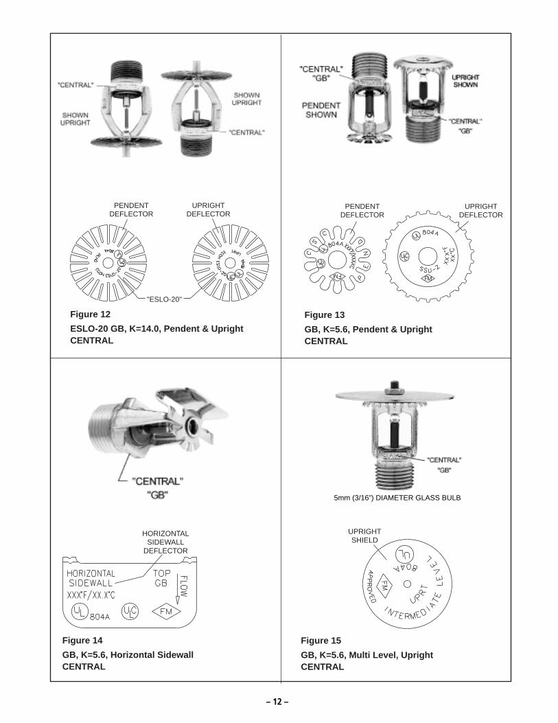
DEFLECTORUPRIGHT
DEFLECTORPENDENT
MARKING"QR"
Figure 22GB-QR, K=5.6, Pendent & Upright
CENTRAL
HORIZONTALSIDEWALL
DEFLECTOR MARKING"QR"
Figure 23GB-QR, K=5.6, Horizontal Sidewall
CENTRAL
DEFLECTORSIDEWALL
HORIZONTAL
Figure 20GB-LO, K=8.0, Horizontal Sidewall
CENTRAL
MARKING"QR"
PENDENTDEFLECTOR
UPRIGHTDEFLECTOR
Figure 21GB-QR, K=4.2, Pendent & Upright
CENTRAL
THE PINTLE INDICATES A SMALL ORIFICE (K=4.2) SPRINKLER

– 15 –
PENDENTDEFLECTOR
"GB4"
"CSC"
Figure 26
GB4, K=5.6, Concealed PendentCENTRAL
PENDENTDEFLECTOR
"GB4-EC"
"CSC"
Figure 27
GB4-EC, K=5.6, Concealed PendentCENTRAL
SHIELDUPRIGHT
Figure 24
GB-QR, K=5.6, Multi Level, UprightCENTRAL
DEFLECTORUPRIGHT
DEFLECTORPENDENT
Figure 25
GB-1, K=5.6, Pendent & UprightCENTRAL
COVER PLATE IS REMOVEDBY UNSCREWING
COUNTER-CLOCKWISE
COVER PLATE IS REMOVEDBY UNSCREWING
COUNTER-CLOCKWISE
3mm (1/8”) DIAMETER GLASS BULB

– 16 –
PENDENTDEFLECTOR
"GB-20"
Figure 30GB20, K=8.0, Pendent
CENTRAL
"QR"MARKING
PENDENTDEFLECTOR
"GB-20"
Figure 31GB20-QR, K=8.0, Pendent
CENTRAL
PENDENTDEFLECTOR
"GB4-FR"
"CSC"
Figure 28GB4-FR, K=5.6, Concealed Pendent
CENTRAL
PENDENTDEFLECTOR
"GB4 QR-EC"
"CSC"
Figure 29GB4QREC, K=5.6, Concealed Pendent
CENTRAL
COVER PLATE IS REMOVEDBY UNSCREWING
COUNTER-CLOCKWISE
COVER PLATE IS REMOVEDBY UNSCREWING
COUNTER-CLOCKWISE

– 17 –
DEFLECTORUPRIGHT
Figure 34ULTRA K17, K=16.8, Upright
CENTRAL
DEFLECTORUPRIGH
"K-17-231"
TDEFLECTOR
PENDENT
Figure 32K17-231, K=16.8, Pendent & Upright
CENTRAL
UPRIGHTDEFLECTOR
"LD"
Figure 33LD, K=11.2, Upright
CENTRAL
"ULTRA K-17"