Embed Size (px)
Citation preview
2/1/2017
1
1
Ideal Transformer
Properties
• High permeability of the core
• No Leakage Flux
• No winding resistances.
• Ideal core has no reluctance.
• No Core losses.
Copyright © The McGraw-Hill Companies, Inc. Permission required for reproduction or display.2
The negative sign is the statement of the Lenz’s law
stating that the polarity of the induced voltage should
be such that a current produced by it produces a flux in the opposite of the original flux. This is illustrated
below
Faraday’s Law
If a flux φ passes through N turns of a coil, the induced
voltage in the coil is given by
ind
de N
dt
ϕ= −
Copyright © The McGraw-Hill Companies, Inc. Permission required for reproduction or display.
3
Relationships
• From Faraday’s Law
• Since there is no magnetic potential drop in
the ideal core,
1
( ) ( )
( )
( )
s p s s
p s
s p
N I t N I t
I t N
I t N a
=
= =
Copyright © The McGraw-Hill Companies, Inc. Permission required for reproduction or display.
4
Relationships
• Since
• then
Power in equals power out.
No power loss in ideal transformer!
2/1/2017
2
5
Relationships
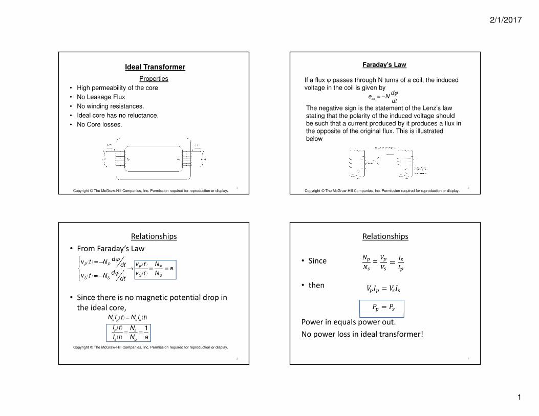
• Reflected Impedance
=
=
=
=
6
Dot Convention
• Help to determine the polarity of the voltage and direction of the current in the secondary winding.
• Voltages at the dots are in phase.
• When the primary current flows into the dotted end of the primary winding, the secondary current will flow out of the dotted end of the
secondary winding.
Compare the following distribution schemes
2/1/2017
3
same
11
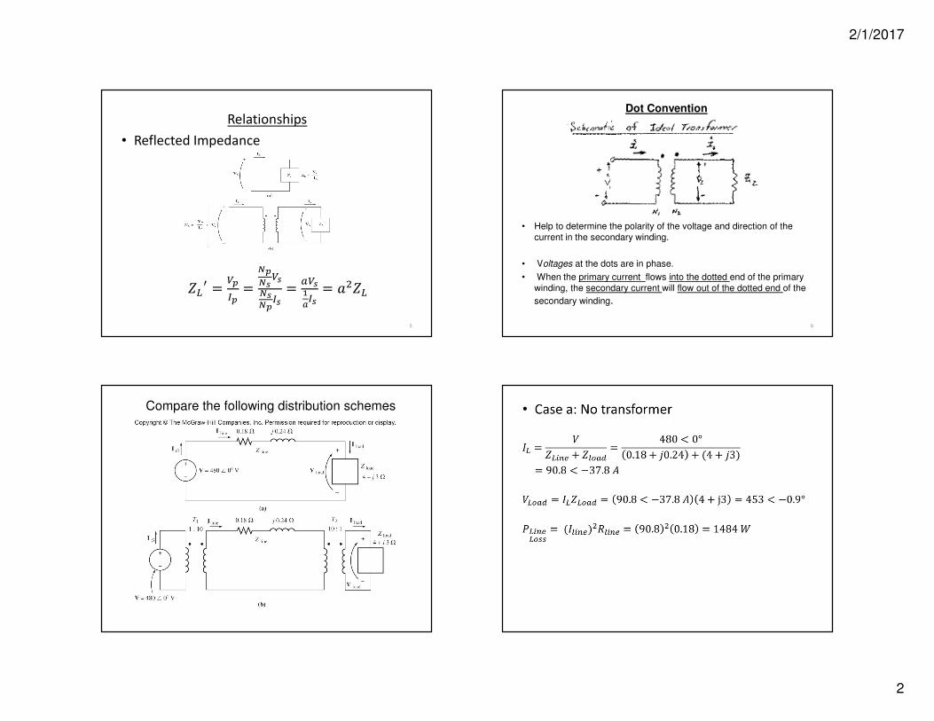
Non-Ideal Single-Phase Transformers
Non-ideal facts:
• Winding resistances modeled as series resistors Rp and Rs Also called Copper Losses.
• Leakage flux modeled as series inductances Xp and Xs
• Core Losses (Eddy Current and Hysteresis Losses) produce heating losses modeled as a shunt resistor RC in the primary winding.
•Magnetizing Current flows in the primary to establish the flux in the core. Modeled as a shunt inductance Xm in the primary winding.
Mutual (M) and Leakage (L) Flux
2/1/2017
4
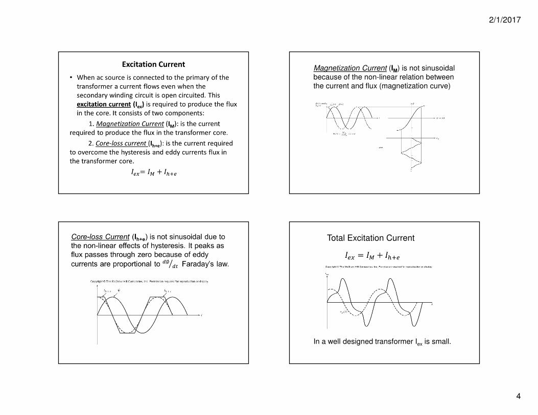
Excitation CurrentMagnetization Current (IM) is not sinusoidal
because of the non-linear relation between the current and flux (magnetization curve)
Total Excitation Current
In a well designed transformer Iex is small.
2/1/2017
5
17
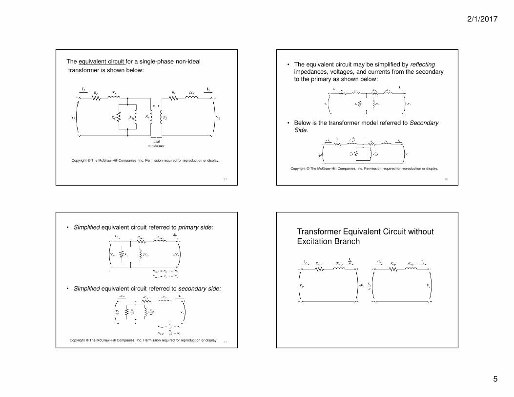
The equivalent circuit for a single-phase non-ideal
transformer is shown below:
Copyright © The McGraw-Hill Companies, Inc. Permission required for reproduction or display.
18
• The equivalent circuit may be simplified by reflectingimpedances, voltages, and currents from the secondary
to the primary as shown below:
• Below is the transformer model referred to Secondary Side.
Copyright © The McGraw-Hill Companies, Inc. Permission required for reproduction or display.
19
• Simplified equivalent circuit referred to primary side:
• Simplified equivalent circuit referred to secondary side:
Copyright © The McGraw-Hill Companies, Inc. Permission required for reproduction or display.
Transformer Equivalent Circuit without
Excitation Branch
2/1/2017
6
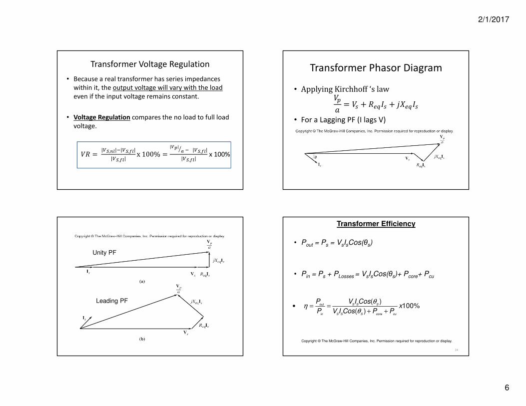
Transformer Voltage Regulation
• Because a real transformer has series impedances
within it, the output voltage will vary with the load
even if the input voltage remains constant.
• Voltage Regulation compares the no load to full load
voltage.
= |,||,|
|,|x100% =
|| |,|
|,|x 100%
Transformer Phasor Diagram
• ApplyingKirchhoff‘slaw0 = 1 + 3451 + 673451
• For a Lagging PF (I lags V)
Unity PF
Leading PF
24
Transformer Efficiency
• Pout = Ps = VsIsCos(θs)
• Pin = Ps + PLosses = VsIsCos(θs)+ Pcore+ Pcu
( ) 100%
( )out S S S
in S S S core cu
P V I Cosx
P V I Cos P P
θη
θ• = =
+ +
Copyright © The McGraw-Hill Companies, Inc. Permission required for reproduction or display.
2/1/2017
7
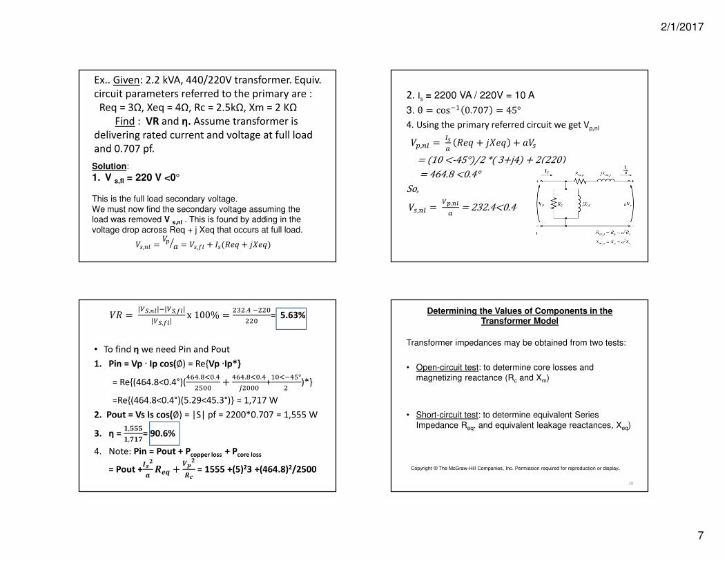
Ex.. Given: 2.2 kVA, 440/220V transformer. Equiv.
circuit parameters referred to the primary are :
Req = 3Ω, Xeq = 4Ω, Rc = 2.5kΩ, Xm = 2 KΩ
Find : VR and η. Assume transformer is
delivering rated current and voltage at full load
and 0.707 pf.
Solution:
1. V s,fl = 220 V <0°
This is the full load secondary voltage.
We must now find the secondary voltage assuming the load was removed V s,nl . This is found by adding in the
voltage drop across Req + j Xeq that occurs at full load.
1,9: =0
= 1,;: + 51(=> + 67=>)
2. Is = 2200 VA / 220V = 10 A
3. θ = cosA 0.707 = 45°4. Using the primary referred circuit we get Vp,nl
0,9: =
=> + 67=> + 1
=(10<-45°)/2*(3+j4)+2(220)=464.8<0.4°
So,
1,9: =,
=232.4<0.4
=|,||,|
|,|x100% =
P.QR
R= 5.63%
• To find η we need Pin and Pout
1. Pin = Vp ∙ Ip cos(∅) = ReVp ∙Ip*
= Re(464.8<0.4°)(QUQ.VWR.Q
XRR+
QUQ.VWR.Q
YRRR+ARWQX°
)*
=Re(464.8<0.4°)(5.29<45.3°) = 1,717 W
2. Pout = Vs Is cos(∅) = |S| pf = 2200*0.707 = 1,555 W
3. η = Z,[[[
Z,\Z\= 90.6%
4. Note: Pin = Pout + Pcopper loss + Pcore loss
= Pout +]^_
`abc +
de_
af= 1555 +(5)23 +(464.8)2/2500
28
Determining the Values of Components in the Transformer Model
Transformer impedances may be obtained from two tests:
• Open-circuit test: to determine core losses and
magnetizing reactance (Rc and Xm)
• Short-circuit test: to determine equivalent Series
Impedance Req. and equivalent leakage reactances, Xeq)
Copyright © The McGraw-Hill Companies, Inc. Permission required for reproduction or display.
2/1/2017
8
29
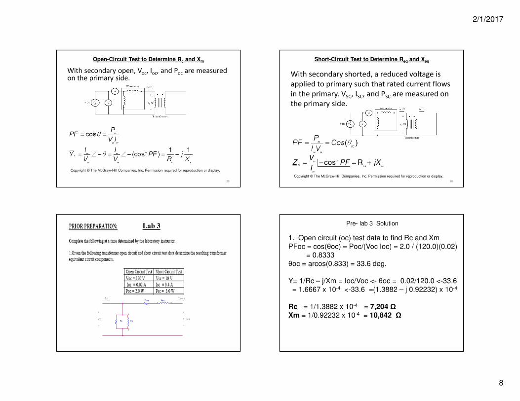
Open-Circuit Test to Determine Rc and Xm
With secondary open, Voc, Ioc, and Poc are measured on the primary side.
Copyright © The McGraw-Hill Companies, Inc. Permission required for reproduction or display.
30
Short-Circuit Test to Determine Req and Xeq
With secondary shorted, a reduced voltage is
applied to primary such that rated current flows
in the primary. VSC, ISC, and PSC are measured on
the primary side.
1
ecos Rsc
eqq eq
sc
VZ PF jX
I
−= − = +
Copyright © The McGraw-Hill Companies, Inc. Permission required for reproduction or display.
Req
Rc
Xeq1 2
Xm
1
2
Ip
Vp a Vs
Is/a
+
-
+
-
------>------>
Lab 3
1. Open circuit (oc) test data to find Rc and Xm
PFoc = cos(θoc) = Poc/(Voc Ioc) = 2.0 / (120.0)(0.02) = 0.8333
θoc = arcos(0.833) = 33.6 deg.
Y= 1/Rc – j/Xm = Ioc/Voc <- θoc = 0.02/120.0 <-33.6
= 1.6667 x 10⁻⁴ <-33.6 =(1.3882 – j 0.92232) x 10-4
Rc = 1/1.3882 x 10-4 = 7,204 ΩXm = 1/0.92232 x 10-4 = 10,842 Ω
Pre- lab 3 Solution
2/1/2017
9
2. Short circuit (sc) test data to find Req and Xeq
PFsc = cos(θsc)= Psc/(Vsc Isc) = 3.0 / (10.0)(0.4) = 0.75
θsc = arcos(0.75) = 41.4 deg.
Zeq = Req + j Xeq = Vsc/Isc < θsc
= 10.0/0.4 < 41.4 = 25.0 < 41.4 = 18.8 +j16.5 Ω
Req = 18.8 ΩXeq = 16.5 Ω
Pre- lab 3 Solution (continued) Pre- lab 3 Solution (continued)
VRc and ηc
1. Find secondary voltage using input voltage and voltage divider w/ ZL = 300 Ω
voltsj
VZZ
ZV
P
eqL
L
s8.1120.120
5.168.18300
300=
++=
+=
2. Find secondary current in load
AZ
VI
L
s
s 376.0300
8.112===
3. Find losses using eqv. circuit values
Pcopper = (Is)2 Req = (0.376)2 18.8 = 2.66 wPcore = (Vprimary/a)2/ Rc = (120.0)2/ 7204 = 2.0 W (note Pcor = Poc)
%38.6%1008.112
8.1120.120%100%100
,
,,=
−=
−=
−= xx
V
VVx
V
VVVR
s
sp
Loadfulls
LoadfullsLoadnos
c
%1.90%1000.266.24.42
4.42%100%100 =
++=
++== xx
PPP
Px
P
P
corecopout
out
in
out
cη
4. Find efficiency ηc and VRc using eqv. circuit values
Pout = Vs Is PF = (112.8)(0.376)(1) = 42.4 w since PF =1 for Z =300 Ω
36
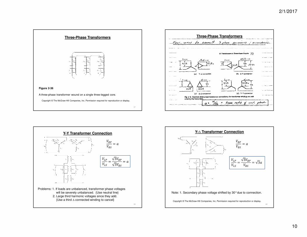
Three-Phase Transformers
Figure 2-35
A three-phase transformer bank composed of independent transformers
Copyright © The McGraw-Hill Companies, Inc. Permission required for reproduction or display.
2/1/2017
10
37
Figure 2-36
A three-phase transformer wound on a single three-legged core.
Copyright © The McGraw-Hill Companies, Inc. Permission required for reproduction or display.
Three-Phase Transformers Three-Phase Transformers
39
Y-Y Transformer Connection
gh
=3∅g3∅h
=
∅g
∅h=
Problems: 1. If loads are unbalanced, transformer phase voltageswill be severely unbalanced. Use neutral line
2. Large third harmonic voltages since they add.Use a third ∆ connected winding to cancel
40
Note: 1. Secondary phase voltage shifted by 30°due to connection.
Copyright © The McGraw-Hill Companies, Inc. Permission required for reproduction or display.
Y-∆ Transformer Connection
gh
=3∅g∅h
= 3
∅g
∅h=
2/1/2017
11
41
Note: 1. Secondary phase voltage shifted by 30°due to connection.
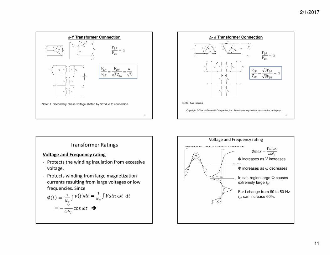
∆-Y Transformer Connection
∅g∅h
=
g
h=
∅g
3∅h
=
3
42
Note: No issues.
Copyright © The McGraw-Hill Companies, Inc. Permission required for reproduction or display.
∆- ∆ Transformer Connection
∅g∅h
=
g
h=
3∅g
3∅h
=
Transformer Ratings
Voltage and Frequency rating
- Protects the winding insulation from excessive
voltage.
- Protects winding from large magnetization
currents resulting from large voltages or low
frequencies. Since
∅ i = A
jkl i mi =
A
jknopωi mi
= −
sjcosti
Voltage and Frequency rating
∅u v =u vtw0
Φ increases as V increases
Φ increases as ω decreases
In sat. region large Φ causesextremely large ox
For f change from 60 to 50 Hz
ox can increase 60%.