Embed Size (px)
Citation preview
Version 1.1 2009.10
Hardware Replacement Guide
IdeaCentre K3 Series
31041387
31041387_K3_HRG_FM_EN_V1.1.indd 1 2009.10.23 10:34:44 AM
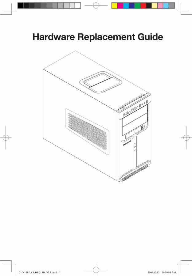
Hardware Replacement Guide
31041387_K3_HRG_EN_V1.1.indd 1 2009.10.23 10:29:53 AM

Contents
Overview ..................................................................................... 1
Chapter 1 Locations ................................................................ 4Locating components and connectors ...........................................4
Identifying parts on the system board ...........................................7
Chapter 2 Replacing hardware ............................................... 9General information ........................................................................9
Removing the computer cover ......................................................9
Removing the front bezel .............................................................11
Replacing a memory module ......................................................12
Replacing the hard disk drive .......................................................13
Replacing an optical drive ............................................................14
Replacing the system fan assembly .............................................15
Replacing the heat sink assembly ...............................................18
Replacing a PCI or AGP adapter .................................................20
Replacing the CPU ......................................................................26
Replacing the keyboard ..............................................................29
Replacing the mouse ..................................................................30
Replacing the External speaker ...................................................31
Completing the installation ..........................................................31
Appendix. .................................................................................. 33
31041387_K3_HRG_EN_V1.1.indd 2 2009.10.23 10:29:53 AM
�Hardware Replacement Guide
Overview
This guide is intended to be used by customers who are replacing Customer Replaceable Units (CRUs) as well as trained service personnel who are replacing Field Replaceable Units (FRUs). In this guide, CRUs and FRUs will often be referred to as parts.
Note: Trained service personnel should refer to the Hardware Maintenance Manual (HMM) for parts ordering information.
This guide does not include procedures for all parts. It is expected that cables, switches, and certain mechanical parts can be replaced by trained service personnel without the need for step-by-step procedures.
Note: Use only parts provided by Lenovo®.
The description of the TV-Tuner card in this manual applies only to those computer models that have the TV-Tuner card installed. It does not apply to those computer models that do not have the TV-Tuner card installed.
This guide contains procedures for replacing the following parts:
• Memory modules
• Hard disk drive
• Optical drive
• Heatsink, Fan
• CPU
• VGA card
• Keyboard, Mouse (wired)
• External speaker
Safety information for replacing CRUs
Do not open your computer or attempt any repair before reading the “Important safety information” in the Safety and Warranty Guide that was included with your computer. If you no longer have this copy of the Safety and Warranty Guide, you can obtain one online from the Support Web site at http://consumersupport.lenovo.com.
31041387_K3_HRG_EN_V1.1.indd 1 2009.10.23 10:29:53 AM
� Hardware Replacement Guide
Additional information resources
If you have Internet access, the most up-to-date information for your computer is available from the World Wide Web.
You can find the following information:
• CRU removal and installation information
• Publications
• Troubleshooting information
• Parts information
• Links to other useful sources of information
To access this information, go to http://consumersupport.lenovo.com.
Tools required
To disassemble the computer, you need the following tools:
• Wrist grounding strap and conductive mat for preventing electrostatic discharge
• Flat screwdriver
• Phillips screwdriver
• Hex screwdriver
• Plastic flat screwdriver
• Plastic tweezers
Note: The screws for the different components vary in size. During the disassembly procedure, group the screws with their corresponding components to avoid a mismatch when replacing the components.
Handling static-sensitive devices
Static electricity, although harmless to you, can seriously damage computer components.
When you are replacing a part, do not open the static-protective package containing the new part until the defective part has been removed from the computer and you are ready to install the new part.
When you handle parts and other computer components, take these precautions to avoid static-electricity damage:
31041387_K3_HRG_EN_V1.1.indd 2 2009.10.23 10:29:54 AM
�Hardware Replacement Guide
• Limit your movement. Movement can cause static-electricity to build up around you.
• Always handle parts and other computer components carefully. Handle adapters, memory modules, system boards, and microprocessors by the edges. Never touch any exposed circuitry.
• Prevent others from touching the parts and other computer components.
• Before you replace a new part, touch the static-protective package containing the part to a metal expansion-slot cover or other unpainted metal surface on the computer for at least two seconds. This reduces static electricity in the package and your body.
• When possible, remove the new part from the static-protective packaging, and install it directly in the computer without setting the part down. When this is not possible, place the static-protective package that the part came in on a smooth, level surface and place the part on it.
• Do not place the part on the computer cover or other metal surface.
31041387_K3_HRG_EN_V1.1.indd 3 2009.10.23 10:29:54 AM
� Hardware Replacement Guide
Locations Chapter
This chapter provides illustrations to help locate the various connectors, controls and components of the computer. To remove the computer cover, refer to “Removing the computer cover”.
Locating components and connectors
The following illustrations will help you to locate the various components and connectors in your computer.
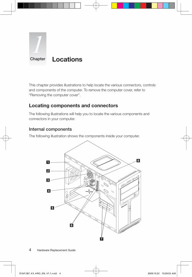
Internal componentsThe following illustration shows the components inside your computer.
1
3
2
4
5
6
7
8
31041387_K3_HRG_EN_V1.1.indd 4 2009.10.23 10:29:55 AM

�Hardware Replacement Guide
Power supply PCI Express adapter card
System fan Memory modules
Microprocessor fan and heat sink Hard disk drive
PCI Express adapter connector Optical drive
Front view The following illustrations show the location of connectors on the front of the computer.
9
8
3
1
2
4
56
7
Power button
Power Dial indicator ON/OFF
File backup button
USB connector
Microphone connector
Headphone connector
Memory card reader (selected models only)
31041387_K3_HRG_EN_V1.1.indd 5 2009.10.23 10:29:56 AM
� Hardware Replacement Guide
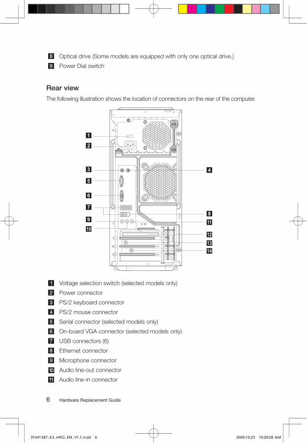
Optical drive (Some models are equipped with only one optical drive.)
Power Dial switch
Rear viewThe following illustration shows the location of connectors on the rear of the computer.
8
11
12
13
14
9
10
7
1
2
3 4
5
6
Voltage selection switch (selected models only)
Power connector
PS/2 keyboard connector
PS/2 mouse connector
Serial connector (selected models only)
On-board VGA connector (selected models only)
USB connectors (6)
Ethernet connector
Microphone connector
Audio line-out connector
Audio line-in connector
31041387_K3_HRG_EN_V1.1.indd 6 2009.10.23 10:29:58 AM

�Hardware Replacement Guide
PCI Express x16 graphics adapter connector (Some models are equipped with this connector. For more information about the graphics adapter, see the description below).
WiFi antenna connector (This connector only equipped on the model with WiFi card. For more information about this connector, see WM600-B-LO Wireless 802. 11b/g Wireless PCI-E Adapter Card User Manual.)
TV-Tuner(selected models only)
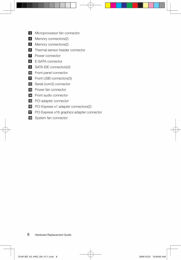
Identifying parts on the system board
The system board (sometimes called the planar or motherboard) is the main circuit board in your computer. It provides basic computer functions and supports a variety of devices that are factory-installed or that you can install later.
The following illustration shows the locations of parts on the system board.
12V power connector
Microprocessor and heat sink
31041387_K3_HRG_EN_V1.1.indd 7 2009.10.23 10:29:59 AM
� Hardware Replacement Guide
Microprocessor fan connector
Memory connectors(2)
Memory connectors(2)
Thermal sensor header connector
Power connector
E-SATA connector
SATA IDE connectors(3)
Front panel connector
Front USB connectors(3)
Serial (com2) connector
Power fan connector
Front audio connector
PCI adapter connector
PCI Express x1 adapter connectors(2)
PCI Express x16 graphics adapter connector
System fan connector
31041387_K3_HRG_EN_V1.1.indd 8 2009.10.23 10:30:00 AM
�Hardware Replacement Guide
Attention:
Do not remove the computer cover or attempt any repair before reading the “Important safety information” in the Safety and Warranty Guide that was included with your computer or in the Hardware Maintenance Manual (HMM) for the computer. To obtain copies of the Safety and Warranty Guide or HMM, go to the Support Web site at http://consumersupport.lenovo.com.
Note: Use only parts provided by Lenovo.
General information
Pre-disassembly instructions
Before proceeding with the disassembly procedure, make sure that you do the following:
1. Turn off the power to the system and all peripherals.
2. Unplug all power and signal cables from the computer.
3. Place the system on a flat, stable surface.
Removing the computer cover
Attention:
Turn off the computer and wait 3 to 5 minutes to let the computer cool before removing the computer cover.
To remove the computer cover:
1. Remove any media (diskettes, CDs, or memory cards) from the drives, shut down your operating system, turn off all attached devices, and the computer.
2. Unplug all power cords from electrical outlets.
Replacing hardware Chapter
31041387_K3_HRG_EN_V1.1.indd 9 2009.10.23 10:30:00 AM
�0 Hardware Replacement Guide
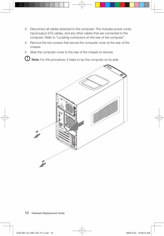
3. Disconnect all cables attached to the computer. This includes power cords, input/output (I/O) cables, and any other cables that are connected to the computer. Refer to “Locating connectors on the rear of the computer”.
4. Remove the two screws that secure the computer cover at the rear of the chassis.
5. Slide the computer cover to the rear of the chassis to remove.
Note: For this procedure, it helps to lay the computer on its side.
31041387_K3_HRG_EN_V1.1.indd 10 2009.10.23 10:30:10 AM

��Hardware Replacement Guide
Removing the front bezel
To remove the front bezel:
1. Remove the computer cover. Refer to “Removing the computer cover”.
Note: For this procedure, it helps to lay the computer on its side.
2. Remove the front bezel by releasing the three plastic tabs inside the chassis and push the bezel outward as shown.
3. To reinstall the bezel, align the plastic tabs on the bottom of the bezel with the corresponding holes in the chassis, and then snap it into position at the bottom and top of the chassis.
4. Refer to the “Completing the installation”.
31041387_K3_HRG_EN_V1.1.indd 11 2009.10.23 10:30:22 AM
�� Hardware Replacement Guide
Replacing a memory module
Attention: Do not remove the computer cover or attempt any repair before reading the
“Important safety information” in the Safety and Warranty Guide that was included with your computer or in the Hardware Maintenance Manual (HMM) for the computer. To obtain copies of the Safety and Warranty Guide or HMM, go to the Support Web site at http://consumersupport.lenovo.com.
To replace a memory module:
1. Remove the computer cover. Refer to “Removing the computer cover”.
Note: For this procedure, it helps to lay the computer on its side.
2. Locate the memory module connectors. Refer to “Locating components”.
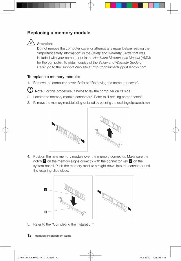
3. Remove the memory module being replaced by opening the retaining clips as shown.
4. Position the new memory module over the memory connector. Make sure the notch on the memory aligns correctly with the connector key on the system board. Push the memory module straight down into the connector until the retaining clips close.
5. Refer to the “Completing the installation”.
31041387_K3_HRG_EN_V1.1.indd 12 2009.10.23 10:30:23 AM

��Hardware Replacement Guide
Replacing the hard disk drive
Attention: Do not remove the computer cover or attempt any repair before reading the
“Important safety information” in the Safety and Warranty Guide that was included with your computer or in the Hardware Maintenance Manual (HMM) for the computer. To obtain copies of the Safety and Warranty Guide or HMM, go to the Support Web site at http://consumersupport.lenovo.com.
To replace the hard disk drive:
1. Remove the computer cover. Refer to “Removing the computer cover”.
Note: For this procedure, it helps to lay the computer on its side.
2. Disconnect the data and power cables from the hard disk drive.
3. Use the plastic handle to slide the hard disk drive out of the drive bay.
4. Slide the new hard disk drive into the drive bay.
5. Pivot in the drive bay in place.
6. Connect the power and signal cables to the hard disk drive. Refer to “Identifying parts on the system board”.
31041387_K3_HRG_EN_V1.1.indd 13 2009.10.23 10:30:33 AM
�� Hardware Replacement Guide
7. Refer to the “Completing the installation”.
Replacing an optical drive
Attention: Do not remove the computer cover or attempt any repair before reading the
“Important safety information” in the Safety and Warranty Guide that was included with your computer or in the Hardware Maintenance Manual (HMM) for the computer. To obtain copies of the Safety and Warranty Guide or HMM, go to the Support Web site at http://consumersupport.lenovo.com
To replace an optical drive
1. Remove the computer cover. Refer to “Removing the computer cover”.
2. Remove the front bezel. Refer to “Removing the front bezel”.
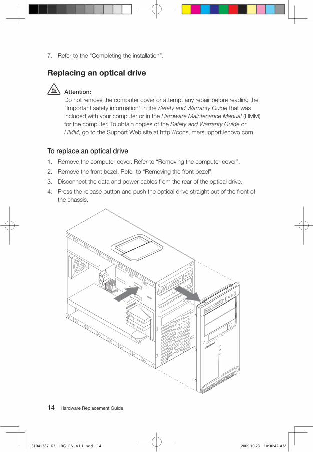
3. Disconnect the data and power cables from the rear of the optical drive.
4. Press the release button and push the optical drive straight out of the front of the chassis.
31041387_K3_HRG_EN_V1.1.indd 14 2009.10.23 10:30:42 AM
��Hardware Replacement Guide
5. Slide the new optical drive into the bay from the front until it snaps into position.
6. Connect the data and power cables to the drive.
7. Install the front bezel. Refer to the steps 3 of the “Removing the front bezel”.
8. Install the computer cover. Refer to “Completing the installation”.
Replacing the system fan assembly
Attention: Do not remove the computer cover or attempt any repair before reading the
“Important safety information” in the Safety and Warranty Guide that was included with your computer or in the Hardware Maintenance Manual (HMM) for the computer. To obtain copies of the Safety and Warranty Guide or HMM, go to the Support Web site at http://consumersupport.lenovo.com
To replace the system fan assembly:
1. Remove the computer cover. Refer to “Removing the computer cover”.
2. Locate the system fan assembly. Refer to “Identifying parts on the system board”.
3. Disconnect the system fan assembly cable from the system board. Refer to“Identifying parts on the system board”.
31041387_K3_HRG_EN_V1.1.indd 15 2009.10.23 10:30:43 AM

�� Hardware Replacement Guide
4. Pull the system fan assembly out of chassis.
31041387_K3_HRG_EN_V1.1.indd 16 2009.10.23 10:30:44 AM

��Hardware Replacement Guide
5. Install the new system fan assembly by aligning the rubber mounts of the system fan assembly with the holes on the chassis and push the rubber mounts through the holes.
6. Pull on the tips of the rubber mounts until the fan assembly is in place.
7. Connect the system fan assembly cable to the system fan connector on the system board.
8. Refer to the “Completing the installation”.
31041387_K3_HRG_EN_V1.1.indd 17 2009.10.23 10:30:53 AM
�� Hardware Replacement Guide
Replacing the heat sink assembly
Attention:
Do not remove the computer cover or attempt any repair before reading the “Important safety information” in the Safety and Warranty Guide that was included with your computer or in the Hardware Maintenance Manual (HMM) for the computer. To obtain copies of the Safety and Warranty Guide or HMM, go to the Support Web site at: http://consumersupport.lenovo.com
To replace the heat sink assembly:
1. Remove the computer cover. Refer to “Removing the computer cover”.
2. Lay the computer on its side.
3. Locate the heat sink. Refer to “Identifying parts on the system board”.
4. Disconnect the heat sink and the fan assembly cable from the system board.
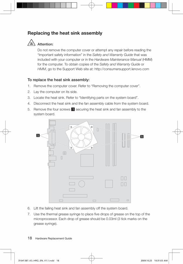
5. Remove the four screws securing the heat sink and fan assembly to the system board.
6. Lift the failing heat sink and fan assembly off the system board.
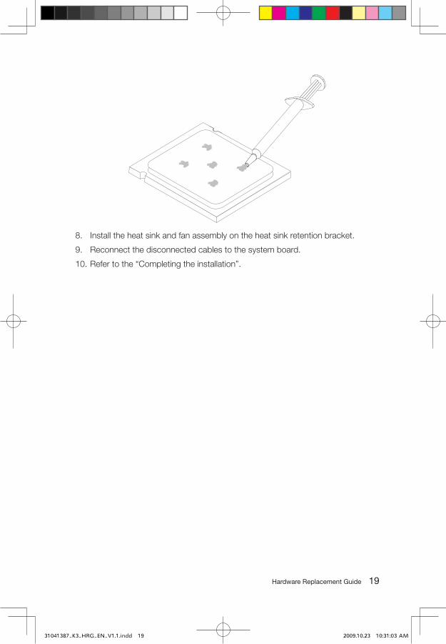
7. Use the thermal grease syringe to place five drops of grease on the top of the microprocessor. Each drop of grease should be 0.03ml (3 tick marks on the grease syringe).
31041387_K3_HRG_EN_V1.1.indd 18 2009.10.23 10:31:03 AM
��Hardware Replacement Guide
8. Install the heat sink and fan assembly on the heat sink retention bracket.
9. Reconnect the disconnected cables to the system board.
10. Refer to the “Completing the installation”.
31041387_K3_HRG_EN_V1.1.indd 19 2009.10.23 10:31:03 AM

�0 Hardware Replacement Guide
Replacing a PCI or AGP adapter
Attention:
Do not remove the computer cover or attempt any repair before reading the “Important safety information” in the Safety and Warranty Guide that was included with your computer or in the Hardware Maintenance Manual (HMM) for the computer. To obtain copies of the Safety and Warranty Guide or HMM, go to the Support Web site at: http://consumersupport.lenovo.com
To replace an adapter:
1. Remove the computer cover. Refer to “Removing the computer cover”.
2. At the rear of the computer, press the release button to open the adapter latch and remove the adapter by pulling it straight out of the adapter connector.
31041387_K3_HRG_EN_V1.1.indd 20 2009.10.23 10:31:05 AM
��Hardware Replacement Guide
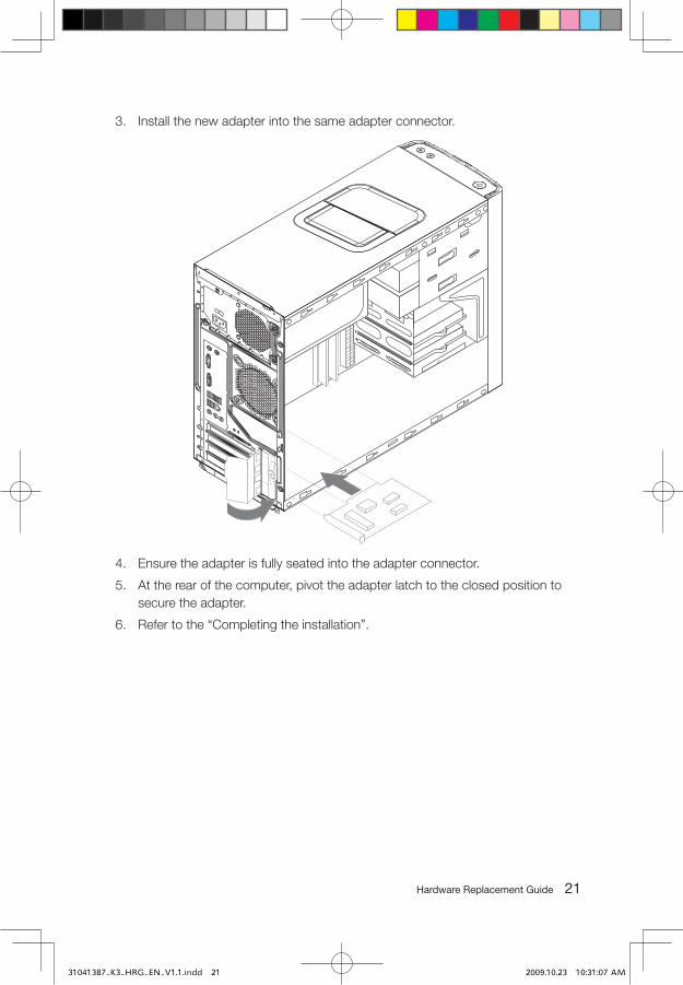
3. Install the new adapter into the same adapter connector.
4. Ensure the adapter is fully seated into the adapter connector.
5. At the rear of the computer, pivot the adapter latch to the closed position to secure the adapter.
6. Refer to the “Completing the installation”.
31041387_K3_HRG_EN_V1.1.indd 21 2009.10.23 10:31:07 AM
�� Hardware Replacement Guide
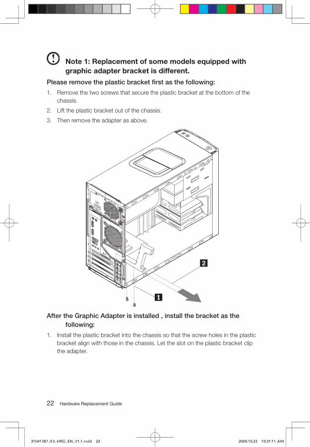
Note 1: Replacement of some models equipped with graphic adapter bracket is different.
Please remove the plastic bracket first as the following:
1. Remove the two screws that secure the plastic bracket at the bottom of the chassis.
2. Lift the plastic bracket out of the chassis.
3. Then remove the adapter as above.
After the Graphic Adapter is installed , install the bracket as the following:
1. Install the plastic bracket into the chassis so that the screw holes in the plastic bracket align with those in the chassis. Let the slot on the plastic bracket clip the adapter.
31041387_K3_HRG_EN_V1.1.indd 22 2009.10.23 10:31:11 AM
��Hardware Replacement Guide
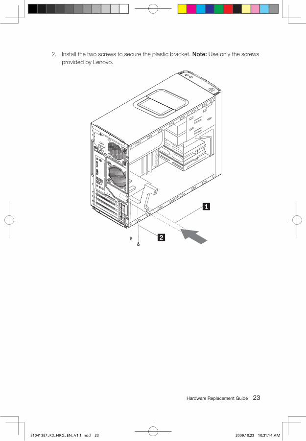
2. Install the two screws to secure the plastic bracket. Note: Use only the screws provided by Lenovo.
31041387_K3_HRG_EN_V1.1.indd 23 2009.10.23 10:31:14 AM
�� Hardware Replacement Guide
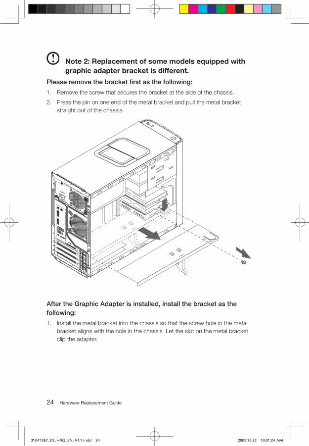
Note 2: Replacement of some models equipped with graphic adapter bracket is different.
Please remove the bracket first as the following:
1. Remove the screw that secures the bracket at the side of the chassis.
2. Press the pin on one end of the metal bracket and pull the metal bracket straight out of the chassis.
After the Graphic Adapter is installed, install the bracket as the following:
1. Install the metal bracket into the chassis so that the screw hole in the metal bracket aligns with the hole in the chassis. Let the slot on the metal bracket clip the adapter.
31041387_K3_HRG_EN_V1.1.indd 24 2009.10.23 10:31:24 AM
��Hardware Replacement Guide
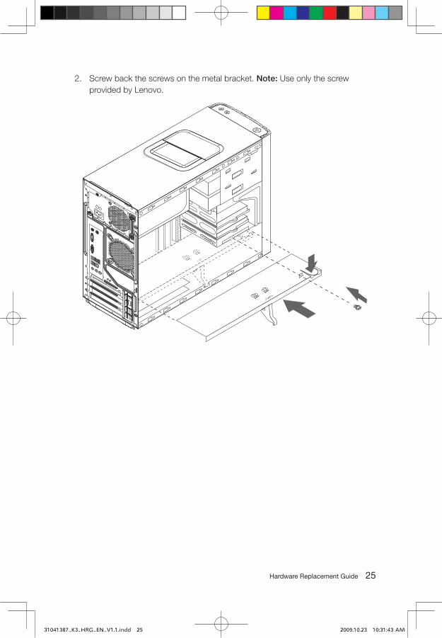
2. Screw back the screws on the metal bracket. Note: Use only the screw provided by Lenovo.
31041387_K3_HRG_EN_V1.1.indd 25 2009.10.23 10:31:43 AM

�� Hardware Replacement Guide
Replacing the CPU
Attention:
Do not remove the computer cover or attempt any repair before reading the “Important safety information” in the Safety and Warranty Guide that was included with your computer or in the Hardware Maintenance Manual (HMM) for the computer. To obtain copies of the Safety and Warranty Guide or HMM, go to the Support Web site at http://consumersupport.lenovo.com
To replace an CPU
1. Remove the computer cover. Refer to “Removing the computer cover”.
2. Remove the front bezel. Refer to “Removing the front bezel”.
3. Remove the system board. Refer to “Replacing the heat sink assembly”.
4. Remove the heat sink and fan assembly. Refer to “Replacing the heat sink assembly”.
5. To remove the microprocessor from the system board, lift the small handle and open the retainer .
Important: Do not touch the gold contacts on the bottom of the microprocessor. When
handling the microprocessor, touch only the sides.
31041387_K3_HRG_EN_V1.1.indd 26 2009.10.23 10:31:54 AM
��Hardware Replacement Guide
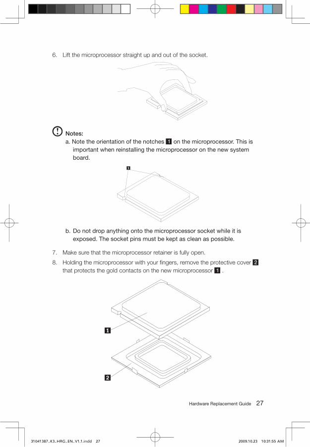
6. Lift the microprocessor straight up and out of the socket.
Notes:a. Note the orientation of the notches on the microprocessor. This is
important when reinstalling the microprocessor on the new system board.
b. Do not drop anything onto the microprocessor socket while it is exposed. The socket pins must be kept as clean as possible.
7. Make sure that the microprocessor retainer is fully open.
8. Holding the microprocessor with your fingers, remove the protective cover that protects the gold contacts on the new microprocessor .
31041387_K3_HRG_EN_V1.1.indd 27 2009.10.23 10:31:55 AM

�� Hardware Replacement Guide
9. Holding the microprocessor with your fingers, position the microprocessor so that the notches on the microprocessor are aligned with the tabs in the microprocessor socket.
Important: To avoid damaging the microprocessor contacts, do not tilt the microprocessor
when installing it into the socket.
10. Lower the microprocessor straight down into the system board socket of the system board.
11. To secure the microprocessor in the socket, close the microprocessor retainer and lock it into position with the small handle.
12. Use the thermal grease syringe to place five drops of grease on the top of the microprocessor. Each drop of grease should be 0.03ml (3 tick marks on the grease syringe).
13. Install the heat sink and fan assembly on the system board.
14. Connect the heat sink and fan assembly cable to the system board. Refer to the “Identifying parts on the system board”.
15. Install the system board into the chassis and allign the screw holes with those in the chassis.Insert and tighten the screws that secure the system board. Refer to the “Replacing the system board”.
16. Reconnect the disconnected cables to the system board.
17. Refer to the “Completing the installation”.
31041387_K3_HRG_EN_V1.1.indd 28 2009.10.23 10:31:55 AM
��Hardware Replacement Guide
Replacing the keyboard
To replace the keyboard:
1. Remove any media (diskettes, CDs, or memory cards) from the drives, shut down your operating system, and turn off all attached devices and the computer.
2. Unplug all power cords from electrical outlets.
3. Locate the connector for the keyboard. Refer to “Locating connectors on the rear of the computer” and “Locating connectors on the front of the computer”.
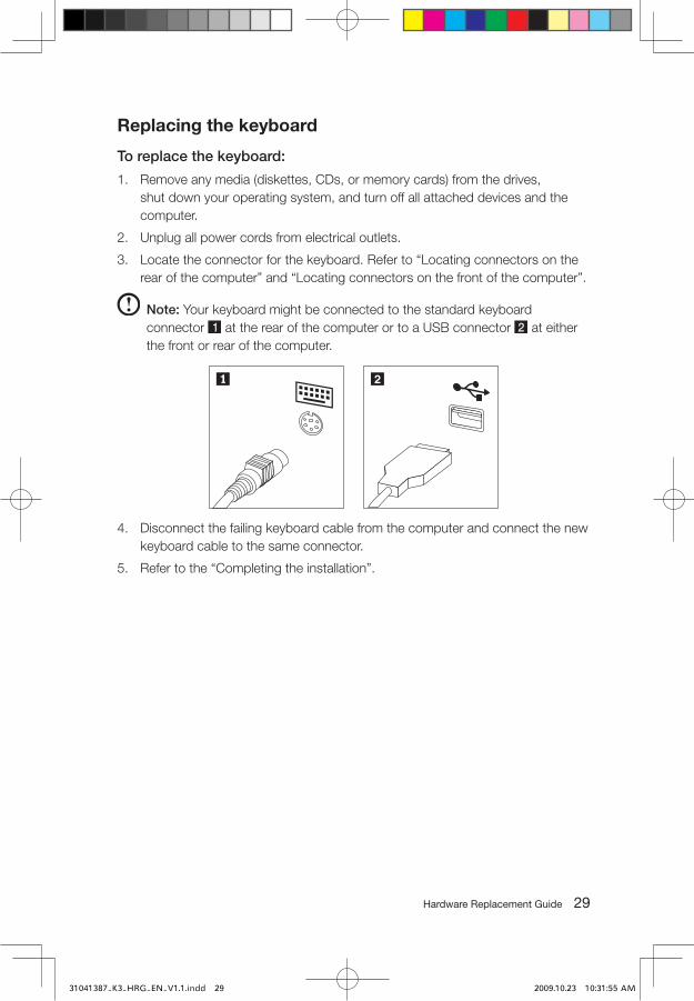
Note: Your keyboard might be connected to the standard keyboard connector at the rear of the computer or to a USB connector at either the front or rear of the computer.
4. Disconnect the failing keyboard cable from the computer and connect the new keyboard cable to the same connector.
5. Refer to the “Completing the installation”.
31041387_K3_HRG_EN_V1.1.indd 29 2009.10.23 10:31:55 AM
�0 Hardware Replacement Guide
Replacing the mouse
To replace the mouse:
1. Remove any media (diskettes, CDs, or memory cards) from the drives, shut down your operating system, and turn off all attached devices and the computer.
2. Unplug all power cords from electrical outlets.
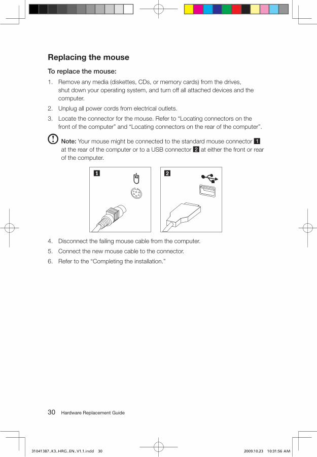
3. Locate the connector for the mouse. Refer to “Locating connectors on the front of the computer” and “Locating connectors on the rear of the computer”.
Note: Your mouse might be connected to the standard mouse connector
at the rear of the computer or to a USB connector at either the front or rear of the computer.
4. Disconnect the failing mouse cable from the computer.
5. Connect the new mouse cable to the connector.
6. Refer to the “Completing the installation.”
31041387_K3_HRG_EN_V1.1.indd 30 2009.10.23 10:31:56 AM
��Hardware Replacement Guide
Replacing the External speaker
1. Remove any media (diskettes, CDs, or memory cards) from the drives, shut down the computer, and turn off all attached devices.
2. Unplug all power cords from electrical outlets.
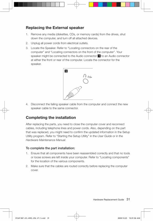
3. Locate the Speaker. Refer to “Locating connectors on the rear of the computer” and “Locating connectors on the front of the computer”. Your speaker might be connected to the Audio connector to an Audio connector at either the front or rear of the computer. Locate the connector for the speaker.
4. Disconnect the failing speaker cable from the computer and connect the new speaker cable to the same connector.
Completing the installation
After replacing the parts, you need to close the computer cover and reconnect cables, including telephone lines and power cords. Also, depending on the part that was replaced, you might need to confirm the updated information in the Setup Utility program. Refer to “Starting the Setup Utility” in the User Guide or in the Hardware Maintenance Manual.
To complete the part installation:
1. Ensure that all components have been reassembled correctly and that no tools or loose screws are left inside your computer. Refer to “Locating components” for the location of the various components.
2. Make sure that the cables are routed correctly before replacing the computer cover.
31041387_K3_HRG_EN_V1.1.indd 31 2009.10.23 10:31:56 AM
�� Hardware Replacement Guide
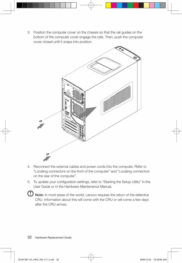
3. Position the computer cover on the chassis so that the rail guides on the bottom of the computer cover engage the rails. Then, push the computer cover closed until it snaps into position.
4. Reconnect the external cables and power cords into the computer. Refer to “Locating connectors on the front of the computer” and “Locating connectors on the rear of the computer”.
5. To update your configuration settings, refer to “Starting the Setup Utility” in the User Guide or in the Hardware Maintenance Manual.
Note: In most areas of the world, Lenovo requires the return of the defective CRU. Information about this will come with the CRU or will come a few days after the CRU arrives.
31041387_K3_HRG_EN_V1.1.indd 32 2009.10.23 10:32:06 AM
��Hardware Replacement Guide
Appendix.
Statement
Thanks for using Lenovo products.
Carefully read all of the documents shipped with your computer before you install and use the product for the first time. Lenovo will not assume responsibility for damage that results from failure to operate the product according to instructions and requirements described in the manuals included with your computer. Lenovo will not assume responsibility for any loss caused except that caused by the installation or operations carried out by Lenovo professional service staff.
Lenovo has made every attempt to ensure that the manuals included with your computer, are correct and accurate, but makes no guarantee that the publications are error free.
To provide better service, Lenovo reserves the right to improve and/or modify the products and software programs described in the manuals included with your computer and the content of the manual at any time without additional notice.
All of the manuals included with your computer are provided to help you use Lenovo products appropriately, but do not provide any description of the software/hardware configuration for the product. For the configuration of the product, refer to related contract (if any), product packing list for the product or retailer.
The content of the manuals included with your computer is protected by copyright laws and rules. None of the manuals included with your computer may be reproduced or transcribed by any means, or transmitted through wired or wireless network in any form, or translated into any language without prior written permission of Lenovo. All Lenovo publications included with your system are protected by Copyright © 2007, 2009 Lenovo.
The software and hardware configuration included with your computer depends on the actual configuration of the computer and may differ from other similar models.
Customers are welcome to contact us for any inconsistency between the product and the manuals included with your computer. For the latest information or any questions or comments, please visit consumer support website at: http://consumersupport.lenovo.com
31041387_K3_HRG_EN_V1.1.indd 33 2009.10.23 10:32:17 AM
�� Hardware Replacement Guide
Lenovo is a registered trademark of Lenovo.
Microsoft, Windows, and Windows Vista are trademarks of the Microsoft group of companies.
Intel Inside is the registered trademark of Intel.
AMD, the AMD Arrow logo, ATI, the ATI logo, AMD Athlon, AMD LIVE, AMD Opteron, AMD Phenom, AMD Sempron, Avivo, Catalyst, Cool 'n' Quiet, CrossFireX, Overdrive, Powerplay, Radeon, The Ultimate Visual Experience, and combinations thereof are trademarks of Advanced Micro Devices, Inc. in the United States and/or other jurisdictions.
The table above includes the logo and registered trademarks of Lenovo and its partners.
Other registered trademarks mentioned in all the manuals included with your computer belong to the specific company respectively.
The manual included with your computer is protected by copyright laws and rules. None of the manuals included with your computer may be reproduced or transcribed by any means, or transmitted through wired or wireless network in any form, or translated into any language without prior written permission of Lenovo.
Names or marks of certain companies mentioned in the manuals included with your computer or this document are only used to state trademark rights, and they will not necessarily indicate that related software or hardware is included. The concrete configuration of the product depends on the description of the specific model.
31041387_K3_HRG_EN_V1.1.indd 34 2009.10.23 10:32:18 AM