Embed Size (px)
Citation preview

IDE for MDABased on Executable Enterprise Modeling
with UML/CWM
Presented to:OMG’s Third Workshop on UML for
Enterprise Applications:Model Driven Solutions for the Enterprise
October 22, 2002By:
Michael LattaYngvar D. Tronstad

2002 Ceira Technologies Inc.™ Page 2
Agenda
OverviewEAI Market TrendThe ChallengesThe Next Generation EAI suites
Executable Model OverviewODM AIMAIM (Process)AIM (Process + Data)AIM (Execution)
Summary, Future Direction, Q&A

2002 Ceira Technologies Inc.™ Page 3
Cogility Product Suite
Mission Statement
To simplify the design and management of diverse artifacts of EAI by creating a singleextensible tool where the artifacts can all be modeled and then generated from the model and automatically deployed into ascalable execution environment, based on OMG’s MDA concept

2002 Ceira Technologies Inc.™ Page 4
Market Opportunity
3535
3226
252323
222121
0 5 10 15 20 25 30 35 40
Application Integration
Security Software
E-Commerce Initiatives
Windows 2000/XP Upgrade - Desktop
Web Site Enhancements
XML Based Applications
Windows 2000/XP Upgrade - Server
ERP Software / ERP Upgrade
Content management for Web Site
Network Equipment
Source: Morgan Stanley CIO Survey, 2002
Top 10 IT Spending Areas for 2002
2002 Ceira Technologies Inc.™ Page 5
Market Opportunity
Most integration projects are using hand-coded point-to-point approaches instead of using an integration frameworkHandcoded integration is deceptive, it seems easier and cheaper to implement then integration framework, but it ends up being far more expensive and aggravating to maintainCompanies that use integration frameworks spend less on maintenance and more on projects that add value
Integration Framework
Source: AMR Research, October 2001,Survey of 686 companies over 14 key
vertical markets
Integration FrameworkBottom Line• 11% less on
MaintenanceServicesHeadcounts
Integration FrameworkBottom Line• 11% less on
MaintenanceServicesHeadcounts

2002 Ceira Technologies Inc.™ Page 6
Problem Space and Challenges
Point-to-Point Integration

2002 Ceira Technologies Inc.™ Page 7
Large Scale Integration Problem
Required Transformations
0
50
100
150
200
250
300
350
1 2 3 4 5 6 7 8 9 10 11 12 13 14 15 16 17 18
Number of systems
Num
ber o
f Tra
nsfo
rmat
ions
Point-To-Point
Star Schema
n(n-1)
2n

2002 Ceira Technologies Inc.™ Page 8
Implementation Costs vs License Costs
8::1 Point to Point Integration
Message Based Middleware
Ceira’s Executable Models

2002 Ceira Technologies Inc.™ Page 9
Problem Space and Challenges
Configured piece by piece, organizations must carefully coordinate all of the implementation artifacts to build the final end-to-end solution.
State of the Art integration environment, using middleware solutions

2002 Ceira Technologies Inc.™ Page 10
Typical Conceptual walls separate the Life Cycle Steps
Problem Definition – Life Cycle Development

2002 Ceira Technologies Inc.™ Page 11
Implementation Costs vs License Costs
8::1 Point to Point Integration
Message Based Middleware
Ceira’s Executable Models
4::1

2002 Ceira Technologies Inc.™ Page 12
Value Added by MDA Tool
EAI complexity can be addressed by ingenious tools
– Holistic toolset for end-to-end visibility– Top-down abstraction and decomposition that through succesive
refinements maintains the business logic as an invariant from high level design to implementation
– Auto-deploy to multiple execution platforms

2002 Ceira Technologies Inc.™ Page 13
Ceira’s Two Part Architecture
Part 1: Authoring
Part 2: Execution
Third PartyMessaging andApplications {
{
{

2002 Ceira Technologies Inc.™ Page 14
Value Added by MDA
Divorce the details of the physical implementation from the logical view of the system, while ensuring completeness– Future Proof: Implementation mechanism can be modified
without affecting the logical model
Build-in layers of indirection (isolation layers) to reduce the impact of changes to any one detail
Create a mechanism for communicating the EAI strategy in the form of the EAI model that is executable, ensuring that the model and the implementation do not drift apart
2002 Ceira Technologies Inc.™ Page 15
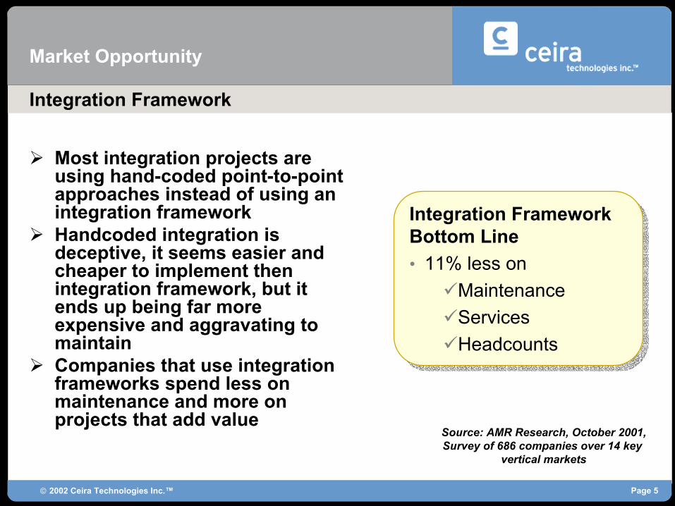
Implementation Costs vs License Costs
8::1
4::1
1::1
Point to Point Integration
Message Based Middleware
Executable Models
Solution that compress Design and Implementation Timeframes

2002 Ceira Technologies Inc.™ Page 16
Agenda
OverviewEAI Market TrendThe ChallengesThe Next Generation EAI suites
Executable Model OverviewExtensible FrameworkODM AIMAIM (Process)AIM (Process + Data)AIM (Execution)
Summary, Future Direction, Q&A

2002 Ceira Technologies Inc.™ Page 17
Modeling Environment
ODM
ODM DataApplication Models
Application
Application DataUser Models
Repository based multi-user model configuration management for Application Developers
Repository based multi-user model configuration management for Application Users
Executable Model Overview-ODM

2002 Ceira Technologies Inc.™ Page 18
Extensible Tool
Object Oriented UML based modeling environmentEach application is modeled
The application model defines the application boundaries and artifactsAn application can be extended by modifying the application model and specifying the new behavior
Executable Model Overview-Application Development
2002 Ceira Technologies Inc.™ Page 19
?
AIM (Process + Transforms)
AIM (Process)
PEAR
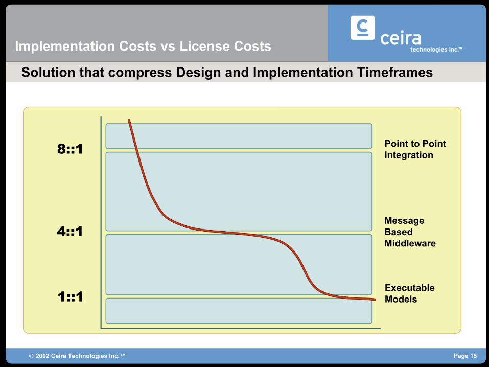
Extensible Application Authoring Environment
Object Design Manager
Object Design ManagerThis is an application that is used to createApplication Models for app development
PEARThis is used to model data structures which
get pushed into a repository as UML Schema
AIM (Process)This is the Application that allows the merging
of MIM data models with behavior models (SM)
AIM (Process + Transforms)This allows the modeling of DIMs with the MIM,
with CWM based data transformations
?Applications can be easily extended to tailor
them to new tasks
UML Core

2002 Ceira Technologies Inc.™ Page 20
Application Integration Modeler (AIM)
UML Model
UML Enactment
Application Integration Model
J2EE Application Server
Relational Database Persistence
OCL Based Execution Details
Modeling Environment
Execution Environment
Overview

2002 Ceira Technologies Inc.™ Page 21
Application Integration Modeler
The AIM tool is a multi-user, repository based, configuration managed EAI Integrated Development Environment
Fulfills the modeling aspect of OMG’s Model Driven Architecture (MDA)Star-schema modelingOMG UML (1.4) based object modeling (classes, associations)Process modeling using UML State MachinesOCL for low level logic and executionOMG’s Common Warehouse Metamodel (CWM 1.0 is based on MOF 1.3) based reusable transformation modelingMessage and Event modelingImplementation of OMG’s Object Constraint Language for specifying low level execution details as required by the MDA.

2002 Ceira Technologies Inc.™ Page 22
Application Integration Modeler With Process Modeling – AIM (Process)
UML Core
Master Information
Model
ProcessModel
Event Model
Message Model
M2E/E2M Transforms
Master Information ModelThis is an abstract model of the entities that
make up the enterprise
Process ModelThe behavior of the entities as they participate
in different business activities
Event ModelThe external events that will trigger state
transitions in the State Machine
Message ModelThe messages that the system must send to
other systems requesting actions
M2E/E2M TransformsTransformation model that interprets messages
received and events generated
Modeling Aspects

2002 Ceira Technologies Inc.™ Page 23
Application User Level Reuse: Data Transformation Models
The AIM (Process + Data) application allows the user to model the business processes that an enterprise entity participates in as well as the information models of the applications to be integrated and transformations between them
Eliminates point-to-point transformations by extending the star-schema concept to the EAI domain (the Master Information Model or MIM concept)
– Exponential reduction in transformation artifacts through reuse• 2n vs. n(n – 1)
Allows for an extensible and holistic environment in which to model the entire EAI scope in a single tool

2002 Ceira Technologies Inc.™ Page 24
Application Integration Modeler With Data Transformation Extensions
UML Core
AIM Process Model
Reusable Data Transformations
Transformation Chains
Distinct Information Models
Process ModelThis is an abstract model of the entities that
make up the enterprise and their behavior (MIM)
Reusable TransformationsModels transformation components that
convert between information models
Transformation ChainsModels reusable transformation units thatcan be connected to the message triggers
Distinct Information ModelModels of the relevant schema of the remote
systems that need to be integrated
M2D/D2M TransformsTransformation models that converts messages
to and from system specific definitions
Modeling Aspects

2002 Ceira Technologies Inc.™ Page 25
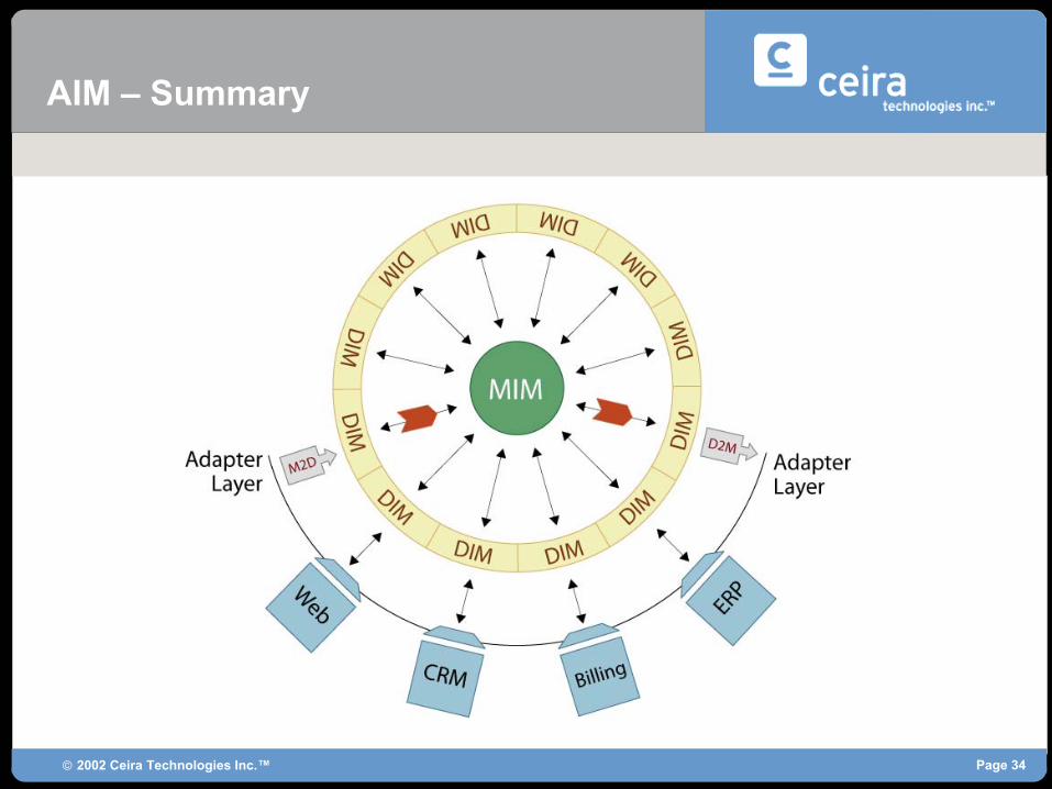
AIM uses the Star Schema pattern, extended for the EAI Domain
AIM (Process + Data): Star Schema
Master Information Model (MIM)
Distinct Information Model (DIM) representing Enterprise Applications

2002 Ceira Technologies Inc.™ Page 26
AIM: UML Information Models
Each Information Model is created using UML Modeling Techniques
Master Information Model (MIM)
Distinct Information Model (DIM) representing Enterprise Applications

2002 Ceira Technologies Inc.™ Page 27
AIM: Reusable CWM Based Transforms
The Model contains a reusable library of CWM based transformations
Master Information Model (MIM)
Distinct Information Model (DIM) representing Enterprise Applications
Reusable CWM Based Transforms

2002 Ceira Technologies Inc.™ Page 28
AIM: JMS Based Messaging Layer
The Model contains a JMS messaging layer that is active on deployment
Master Information Model (MIM)
Distinct Information Model (DIM) representing Enterprise Applications
Reusable CWM Based Transforms
JMS Based Messaging Layer for triggering transformations and state machines and sending notifications

2002 Ceira Technologies Inc.™ Page 29
AIM: Transformation Chains
The Model contains Transform Chains attached to the message layer or states for sequencing transformations
Transform Chains Attached to the Message Layer or states for transformation sequencing
Master Information Model (MIM)
Distinct Information Model (DIM) representing Enterprise Applications
Reusable CWM Based Transforms
JMS Based Messaging Layer for triggering transformations and state machines and sending notifications

2002 Ceira Technologies Inc.™ Page 30
Triggering Transformations: Direct Mode
JMSMSG
MD2
TD
- Data Object Set
JMSMSG
JMSMSG
D2M
D2M
8 8
2002 Ceira Technologies Inc.™ Page 31
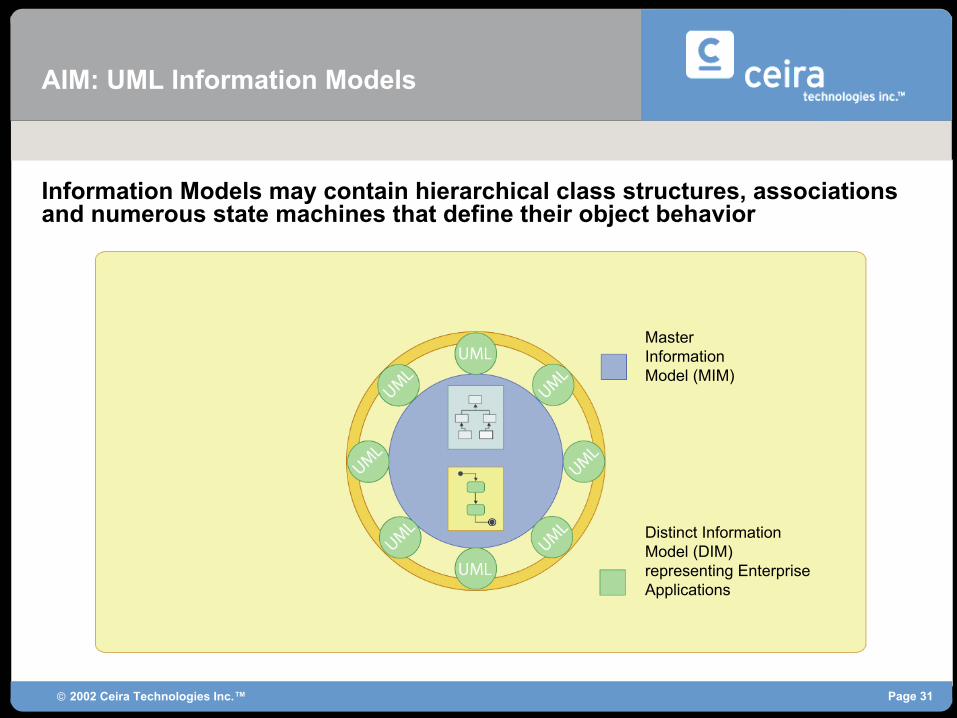
AIM: UML Information Models
Master Information Model (MIM)
Distinct Information Model (DIM) representing Enterprise Applications
Information Models may contain hierarchical class structures, associations and numerous state machines that define their object behavior

2002 Ceira Technologies Inc.™ Page 32
AIM: Embedded Transformations
Messages can also trigger behavior embedded in processes to allow finer control over transformation sequencing
Transform Chains Attached to the Message Layer or states for transformation sequencing
Master Information Model (MIM)
Distinct Information Model (DIM) representing Enterprise Applications
Reusable CWM Based Transforms
JMS Based Messaging Layer for triggering transformations and state machines and sending notifications

2002 Ceira Technologies Inc.™ Page 33
Triggering Transformations: Embedded Mode
JMSMSG
M2D
AIM Event
JMSMSG
D2M
Simple State
Simple State
Guard ConditionGuard Condition
AIMSimple State
2002 Ceira Technologies Inc.™ Page 34
AIM – Summary

2002 Ceira Technologies Inc.™ Page 35
Application User Level Reuse: Data Transformation Models
Data Transformations based on the OMG’s Common Warehouse Metamodel (CWM) standard
– Even the reduced number of transformation artifacts are built using a standard that promotes reuse
Allows for the modeling of reusable feature-level transformations (Feature Maps)
Allows for the modeling of Classifier Maps, which are transformations between DIM classes in the periphery and the MIM classes (hub), in terms of re-usable Feature Maps
Allows for the the modeling of Transformation Maps, which transform arbitrary sets of data types between a DIM and the MIM. Transformation Maps reuse Classifier maps as needed
Allows for the modeling of Transformation Chains , which are comprised of re-usable Transformation Maps (or other chains) in series or parallel (Decomposable re-use)

2002 Ceira Technologies Inc.™ Page 36
Application User Level Reuse: Data Transformation Models
Transformation Chains can be triggered by messages and can also publish messages destined for remote systems
– This allows the modeling of standard system responses to multiple stimuli using reusable components for quick assembly
– The Chain itself is reusable • Reusable as a component in another chain• Directly reusable because it can respond to similar messages from different
systems with the same behavior (due to the Transport Isolation Layer)
– Combines the modeling of data and behavior in the same environment with several layers of indirection providing separation of concern and ensuring that changes are localized to a limited area of influence
Never need to build logic more then once

2002 Ceira Technologies Inc.™ Page 37
Application Integration Modeler : Model Execution
OCL Execution
State Machine EnactmentExecutes the UML State Machine Diagram by evaluating
OCL specified state actions
Data TransformationsExecutes data Transformation Units by Decomposing
into constituents
Message TransformationThis component executes OCL instructions to map data
between messages and DIMs
OCL Execution EngineOCL Executor evaluates all OCL expressions that are used to
specify low-level details
JMS MDB LayerReceives messages from and sends messages to
Systems that are being integrated
PersistentObjectAccessLayer
CombinedData AndMessage
Transaction
StateMachine
Enactment
MessageTransformation
Execution
DataTransformation
Execution
Persistent Object Access LayerSeamlessly performs object persistence activities
(Create, Read, Update, Delete) for ERA
Transactional IntegrityUses J2EE semantics and transactional Persistence to
maintain transactional integrity
Product Overview
2002 Ceira Technologies Inc.™ Page 38
AIM: Model Execution
Model Execution is achieved by pushing the model into a scalableexecution environment
Fulfills the execution aspect of OMG’s Model Driven Architecture (MDA)Information Models are pushed into a relational database as database schemaAll Message Schemas are pushed into the database as execution metadataAll CWM based transformations described using OCL are compiled and stored in the databaseAll State Machines and associated actions are compiled and stored in the databaseAll Message transformations are stored in the databaseSpecified J2EE Application Server is configured with JMS topics and Message Driven BeansWeb Service based Admin Console is installed on the Application Server

2002 Ceira Technologies Inc.™ Page 39
Agenda
OverviewEAI Market TrendThe ChallengesThe Next Generation EAI suites
Executable Model OverviewODM AIMAIM (Process)AIM (Process + Data)AIM (Execution)
Summary, Future Direction, Q&A

2002 Ceira Technologies Inc.™ Page 40
Summary
A MDA approach that is UML based ALL the Way from high level abstraction to low level details
– UML Business Logic (Classes, Association and StateMachine)– CWM/UML Data modeling and transformation– UML/OCL Authoring-time definition and Run-Time execution– UML Run-time persistense for Classes, Associations and SM
Ensuring continuum from Analysis to Implementation
2002 Ceira Technologies Inc.™ Page 41
Future Direction
Introduce aspects of UML 2.0 (U2P) Enhancements that support Executable ModelsTop to bottom seamless semantics – no gaps as beforeIntroducing views that have meaning for execution
Sequence Diagrams containing valid executionUse Cases which have defined semantics to lower levels of decomposition
Uniform treatment of the system as classes and behaviorsCleaner layering, which should make it easier to present to users and at the same time provide better visibility and support for executable models
Overview

2002 Ceira Technologies Inc.™ Page 42
Future Direction
• Much better defined semantics.• Less use of English to convey semantics.• Cleaner decomposition to other model elements.
Use Cases

2002 Ceira Technologies Inc.™ Page 43
Future Direction
• Defined relationship to execution semantics.• Constrains set of valid executions.• Can contain control structures, and other aspects that make them
more than just “examples” of execution.• Each diagram defines 3 categories of sequences: valid, invalid,
and out of scope.• This allows a set of sequence diagrams to cover the space without
conflict
Sequence Diagrams

2002 Ceira Technologies Inc.™ Page 44
Future Direction
• Activities add new execution semantics.• Action Semantics integrated into common behavior framework.• State Machines still available with some enhancements.• Components are now explicitly modeled, which should enhance
reuse
Richer Execution Semantics

2002 Ceira Technologies Inc.™ Page 45
Future Direction
• Need the ability to model transaction boundaries and behavior.– A central part of most computing that is still missing.
• Need formalisms for failure handling, error recovery, and rework.• Need to deal with versioning of system models and the
relationship to executing systems.– Incremental deployment– Migration of active executions– Concurrent execution of different versions
Areas for Improvement


![A Conceptual Framework for Enterprise Architecture Design Public Website... · The framework is based on the prefabrics of the OMG’s Business Motivation Model [16], Simon’s science](https://img.pdfslide.us/doc/110x75/5c9568a409d3f2a67b8c9ddc/a-conceptual-framework-for-enterprise-architecture-design-public-website.jpg)