Embed Size (px)
Citation preview
- 1 - V. 2.0
"IDB SERIES" MEMBRANE PUMPS
You have decided to show your preference for the "BERTOLINI" brand and have bought a product which has been manufactured with the benefit of the most modern technology and the finest materials, designed through research to ensure its improved quality, duration and functionality. We thank you for the trust shown in our products. Please read this booklet with care and always keep it within easy reach. You will find it useful in resolving any problem you may have with regard to the characteristics and functionality of the product. Thank you for having chosen "IDB - Bertolini" This use and maintenance Manual is made up of the following chapters: 1. General Rules. 2. Product Description 3. Technical Characteristics 4. Choice of type of pump and the design of the plant 5. Installation 6. Use 7. Ordinary Maintenance instructions 8. Plant Construction Applications 9. Special Safety Instructions 10. Guarantee 11. Problems and their Solutions 12. Instructions for a correct use of the Loader Valve 13. Resistance Table 14. Dimensions, Exploded Diagrams and Names
We at Idromeccanica Bertolini recommend that you read this Use and Maintenance Manual carefully before installing and using the pump. You should keep it within easy reach for any further reference. The Manual should be considered as an integral part of the pump itself.
- 2 - V. 2.0
1. GENERAL RULES a) This Manual gives instructions on the use and maintenance of the pump; b) Any person using the pump is expected to be conversant with, and observe the
relevant legislative provisions currently in force in the country where the pump is to be used. They are also required to follow the instructions set out in this Manual with care;
c) This Manual is based on, and complies with, technical knowledge applicable as at the date of sale of the product and shall not be considered inadequate for the sole reason that it has been up-dated on the basis of new knowledge/experience. IDROMECCANICA BERTOLINI has the right to up-date its products and their related manuals without being thereby obliged to up-date previous products and manuals, save in cases deriving exclusively from safety considerations.
d) You may consult our "Technical Assistance Service" in relation to any query or need arising when using or maintaining the product and to obtain assistance in choosing accessories to use with it.
e) No part of this Manual may be reproduced without the written permission of IDROMECCANICA BERTOLINI S.p.A.
Take care to observe the warnings carrying the following symbols:
Safety Rules and Measures for the protection of the user or others against personal injury and/or for the protection of the pump against damage.
Instructions for facilitating the effecting of the related Operation. Technical Information
Warnings of an ecological nature. 2. Product Description "IDB" Series membrane-semi-hydraulic piston pumps have been manufactured with materials that make them particularly adapted for the application of disinfestations and pesticide treatments and the spraying of flowers and vegetable crops. Together with their accessories, they are easy to fit to tractors, spraying and weed-killing units and to both thermal and electric motors. The pumps in the "IDB" range are made on the basis of modern technology but without forgetting the lessons of the past. They include noble materials such as bronze and stainless steel, combining flexibility of use with easy and practical maintenance.
- 3 - V. 2.0
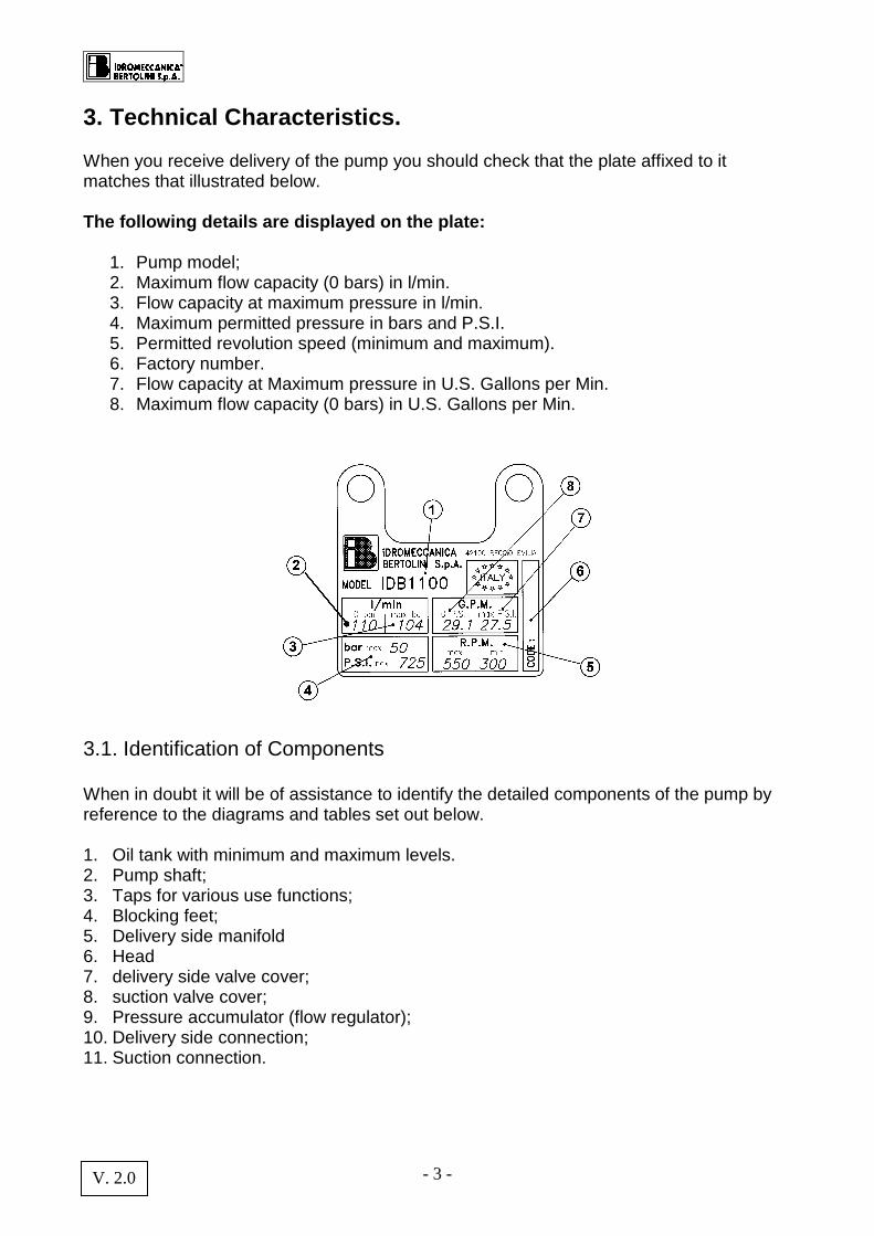
3. Technical Characteristics. When you receive delivery of the pump you should check that the plate affixed to it matches that illustrated below. The following details are displayed on the plate:
1. Pump model; 2. Maximum flow capacity (0 bars) in l/min. 3. Flow capacity at maximum pressure in l/min. 4. Maximum permitted pressure in bars and P.S.I. 5. Permitted revolution speed (minimum and maximum). 6. Factory number. 7. Flow capacity at Maximum pressure in U.S. Gallons per Min. 8. Maximum flow capacity (0 bars) in U.S. Gallons per Min.
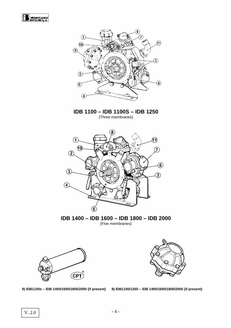
3.1. Identification of Components When in doubt it will be of assistance to identify the detailed components of the pump by reference to the diagrams and tables set out below. 1. Oil tank with minimum and maximum levels. 2. Pump shaft; 3. Taps for various use functions; 4. Blocking feet; 5. Delivery side manifold 6. Head 7. delivery side valve cover; 8. suction valve cover; 9. Pressure accumulator (flow regulator); 10. Delivery side connection; 11. Suction connection.
- 4 - V. 2.0
IDB 1100 – IDB 1100S – IDB 1250 (Three membranes)
IDB 1400 – IDB 1600 – IDB 1800 – IDB 2000 (Five membranes)
9) IDB1100s – IDB 1400/1600/1800/2000 (if present) 9) IDB1100/1250 – IDB 1400/1600/1800/2000 (if present)
- 5 - V. 2.0
4. Choice of type of Pump and Design of Plant With regard to safety, all pumps comply with the regulations UNI EN 809. The type of pump must be chosen by the manufacturer in relation to the nature of the liquid to be used and to the technical characteristics (flow capacity, pressure etc.)
to be achieved. The use of the pumps with incompatible materials may be hazardous, posing a danger to personal and environmental safety. When connections are made with electrical motors all related instructions should be followed as set out in the relevant regulations EN 6024.1, to avoid risks deriving from the use of electricity (cf. relevant part dealing with installation).
Bertolini "IDB" membrane pumps are designed from materials which are compatible for use with water and the majority of pesticide and weed-killing products currently on sale in the market in the concentrations advised by the
manufacturers(Cf. table at page 23). The technical data relating to the pumps performance characteristics (no. revs/l, flow capacity and maximum pressure) are set out on the plate affixed to the pump. For further information refer to the Bertolini Technical Assistance Service.
The plant manufacturer is responsible for ensuring the correct choice and size of the driving system, including in relation to the risk to personal safety that may be caused by the choice of system. The fitting of the pump with (electric or thermal) motors or transmission systems
with performance characteristics differing from those advised may cause situations posing danger to personal safety or the environment. Particular care must be taken by the manufacturer in the design and construction of the plant to avoid risks of personal injury deriving, not from the pump, but from the design, construction or improper use of the plant on which the pump is installed.
- 6 - V. 2.0
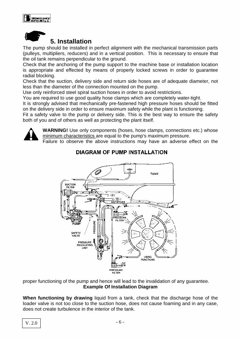
5. Installation The pump should be installed in perfect alignment with the mechanical transmission parts (pulleys, multipliers, reducers) and in a vertical position. This is necessary to ensure that the oil tank remains perpendicular to the ground. Check that the anchoring of the pump support to the machine base or installation location is appropriate and effected by means of properly locked screws in order to guarantee radial blocking. Check that the suction, delivery side and return side hoses are of adequate diameter, not less than the diameter of the connection mounted on the pump. Use only reinforced steel spiral suction hoses in order to avoid restrictions. You are required to use good quality hose clamps which are completely water-tight. It is strongly advised that mechanically pre-fastened high pressure hoses should be fitted on the delivery side in order to ensure maximum safety while the plant is functioning. Fit a safety valve to the pump or delivery side. This is the best way to ensure the safety both of you and of others as well as protecting the plant itself.
WARNING! Use only components (hoses, hose clamps, connections etc.) whose minimum characteristics are equal to the pump's maximum pressure. Failure to observe the above instructions may have an adverse effect on the
proper functioning of the pump and hence will lead to the invalidation of any guarantee. Example Of Installation Diagram
When functioning by drawing liquid from a tank, check that the discharge hose of the loader valve is not too close to the suction hose, does not cause foaming and in any case, does not create turbulence in the interior of the tank.
- 7 - V. 2.0
Particular attention should be given to the size of the Suction filter and/or of any diversion valve (three way valve). The flow capacity of the filter should be 1.5 times the flow capacity of the pump. An under-sized filter will reduce both the life of the membranes and the performance of the pump. EC Machine Directive 2006/42/CE Following the entry into force of the EC Machine Directive 2006/42/CE, you may find it useful to note that these regulations do not affect pumps as technically independent units. They only concern finished machines.
6. Use 1. Checks before use
– Check that the suction hose is not bent and is firmly fixed to the related connection and to the filter. Restrictions and suction of air pockets should be avoided in any case which may compromise the proper functioning of the pump.
– On each use: clean the suction and delivery side filters. This simple operation will help maintain the pump's efficiency and will ensure the spraying is carried out in the best way possible.
– Close all delivery side hoses connected to the use function machinery. An opening of the connection with the using apparatus can cause significant damage to persons, animals or property in the vicinity.
– Check the state of the hoses every time you use the pump. In addition, check that all connections are properly screwed down and safe.
– Inspect the pump and its components on a periodic basis. Ordinary maintenance of the pump will safe-guard your investment.
– Both in circumstances where the suction connection is made with a water mains or pressurised system and where there is a depressurised connection, when the pump is started up the lever of the loader valve should be maintained in the by-pass position.
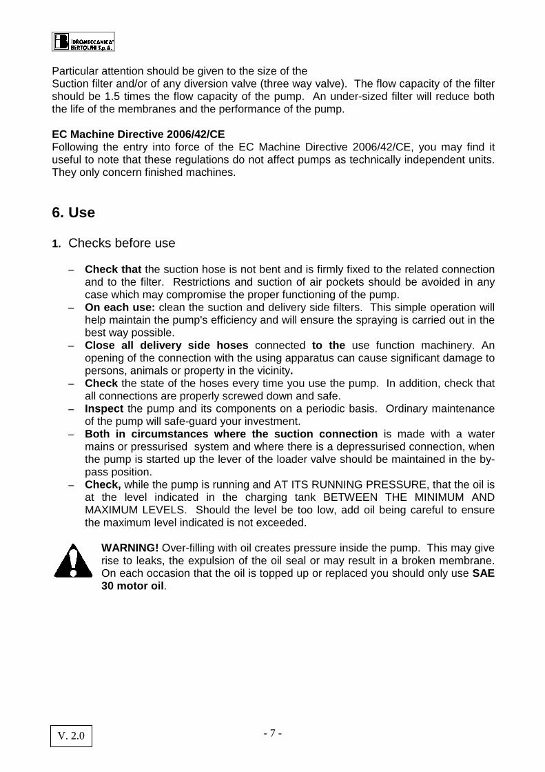
– Check, while the pump is running and AT ITS RUNNING PRESSURE, that the oil is at the level indicated in the charging tank BETWEEN THE MINIMUM AND MAXIMUM LEVELS. Should the level be too low, add oil being careful to ensure the maximum level indicated is not exceeded.
WARNING! Over-filling with oil creates pressure inside the pump. This may give rise to leaks, the expulsion of the oil seal or may result in a broken membrane. On each occasion that the oil is topped up or replaced you should only use SAE 30 motor oil .
- 8 - V. 2.0
IDB PUMP OIL LEVEL
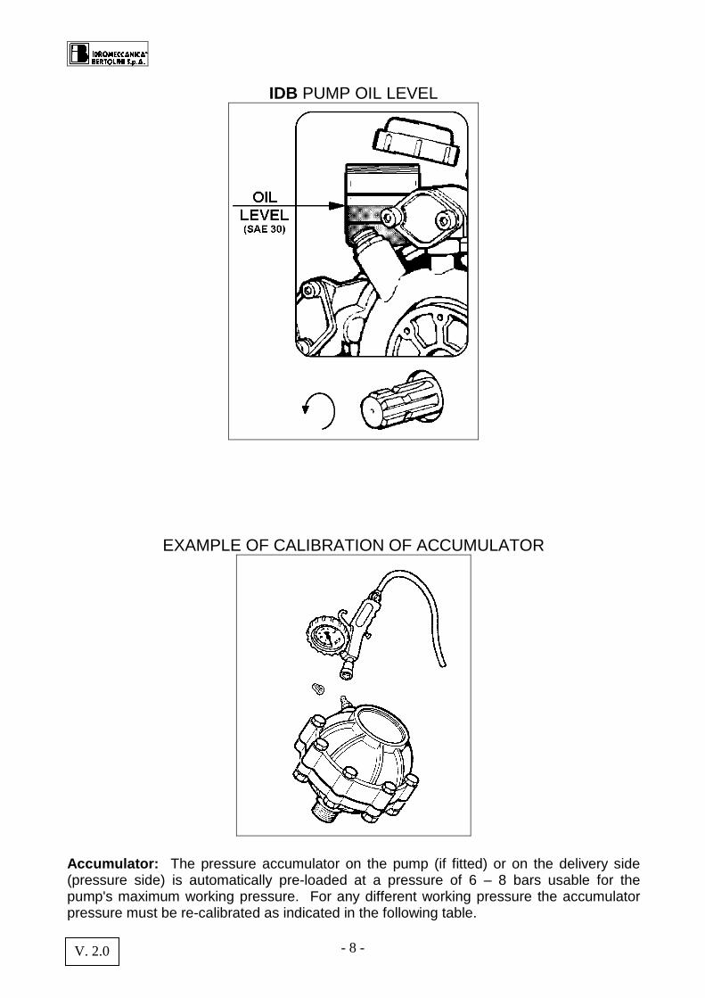
EXAMPLE OF CALIBRATION OF ACCUMULATOR
Accumulator: The pressure accumulator on the pump (if fitted) or on the delivery side (pressure side) is automatically pre-loaded at a pressure of 6 – 8 bars usable for the pump's maximum working pressure. For any different working pressure the accumulator pressure must be re-calibrated as indicated in the following table.
- 9 - V. 2.0
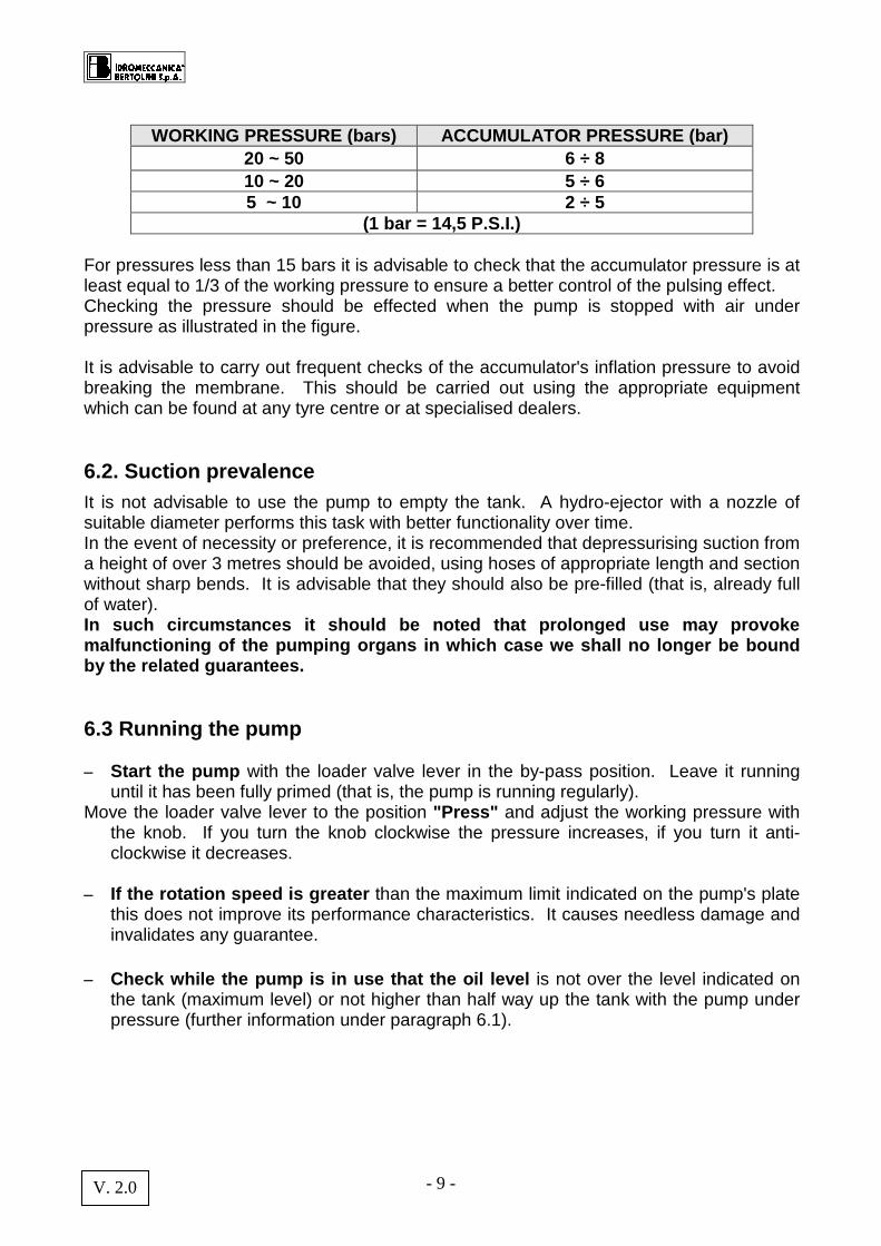
WORKING PRESSURE (bars) ACCUMULATOR PRESSURE (bar)
20 ~ 50 6 ÷ 8 10 ~ 20 5 ÷ 6 5 ~ 10 2 ÷ 5
(1 bar = 14,5 P.S.I.) For pressures less than 15 bars it is advisable to check that the accumulator pressure is at least equal to 1/3 of the working pressure to ensure a better control of the pulsing effect. Checking the pressure should be effected when the pump is stopped with air under pressure as illustrated in the figure. It is advisable to carry out frequent checks of the accumulator's inflation pressure to avoid breaking the membrane. This should be carried out using the appropriate equipment which can be found at any tyre centre or at specialised dealers. 6.2. Suction prevalence It is not advisable to use the pump to empty the tank. A hydro-ejector with a nozzle of suitable diameter performs this task with better functionality over time. In the event of necessity or preference, it is recommended that depressurising suction from a height of over 3 metres should be avoided, using hoses of appropriate length and section without sharp bends. It is advisable that they should also be pre-filled (that is, already full of water). In such circumstances it should be noted that prolo nged use may provoke malfunctioning of the pumping organs in which case we shall no longer be bound by the related guarantees. 6.3 Running the pump – Start the pump with the loader valve lever in the by-pass position. Leave it running
until it has been fully primed (that is, the pump is running regularly). Move the loader valve lever to the position "Press" and adjust the working pressure with
the knob. If you turn the knob clockwise the pressure increases, if you turn it anti-clockwise it decreases.
– If the rotation speed is greater than the maximum limit indicated on the pump's plate
this does not improve its performance characteristics. It causes needless damage and invalidates any guarantee.
– Check while the pump is in use that the oil level is not over the level indicated on
the tank (maximum level) or not higher than half way up the tank with the pump under pressure (further information under paragraph 6.1).
- 10 - V. 2.0
6.4. After use – It is essential , in order to avoid damage to the pump, to wash it after use. This should
be done by running the pump under pressure for a few minutes with clean water. You should then empty it by reducing the pressure to "0" and leaving it to run dry for a few minutes.
– Where there is a danger of freezing it is necessary to empty out all residual water. It is
a good precaution to mix an anti-freeze (of a type used with cars) with the cleaning water. This will protect the pump even in relation to any liquid residues left inside it.
– The pump and system components (hoses, clamps, connections etc.) should be periodically inspected (at the end of each operational season). Replace any component that shows signs of wear. If the membranes and all rubber parts are replaced at the end of each operational season (annually) this serves to preserve the pump and reduces costs resulting from unexpected breakages during the following season to a minimum, hence avoiding needless loss of time and money.
- 11 - V. 2.0
7. ORDINARY MAINTENANCE INSTRUCTIONS WARNING!
Before beginning any maintenance works or inspectio n of the pump, wash it with pure water, stop the power take off and dis connect it. Give particular attention to the stability and posi tioning of the machinery on which the pump is mounted to avoid inconvenience or nuisance to
yourself or others. Effect the maintenance away from areas to which chi ldren have access! Protect your hands, eyes and body with appropriate clothing. The pump could have been used with chemical products which are harmful to health. The pump is made with parts that are not for human ingestion. Do not bite, suck, chew or swallow any part of it for any reason.
Protect the environment from liquids contained in t he pump. Collect residues and dispose of them regularly. No residue must be introduced into the drainage system or soil
The replacement of materials such as membranes, oil, suction and delivery side valves and the sealing O rings is considered part of normal maintenance. These are parts subject to wear and tear.
Inspect the pump and its components on a periodic basis.
The ordinary maintenance of the pump will safeguard your investment! 7.1) Replacement of delivery side suction valve and O-rings.
a) Abnormal functioning resulting in excessive depressurising can damage the valve water-tight seals.
b) Impurities or residues can damage the valve blocking O-rings or stop the housing from closing properly.
Remedial steps should be as follows:
a) Remove the valve cover, take out the valve and check whether worn. It is a good rule to always replace the sealing O-rings;
b) Replace the necessary parts and re-assemble; c) Repeat the operation for all valves.
- 12 - V. 2.0
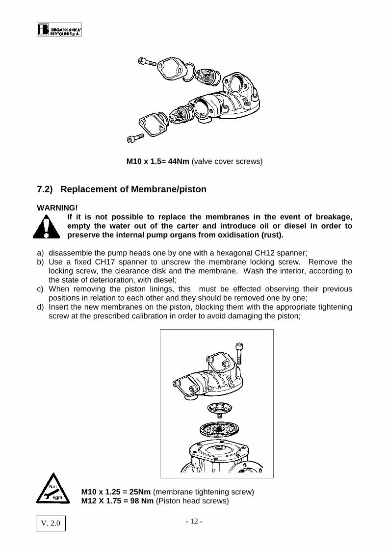
M10 x 1.5= 44Nm (valve cover screws)
7.2) Replacement of Membrane/piston WARNING!
If it is not possible to replace the membranes in t he event of breakage, empty the water out of the carter and introduce oil or diesel in order to preserve the internal pump organs from oxidisation (rust).
a) disassemble the pump heads one by one with a hexagonal CH12 spanner; b) Use a fixed CH17 spanner to unscrew the membrane locking screw. Remove the
locking screw, the clearance disk and the membrane. Wash the interior, according to the state of deterioration, with diesel;
c) When removing the piston linings, this must be effected observing their previous positions in relation to each other and they should be removed one by one;
d) Insert the new membranes on the piston, blocking them with the appropriate tightening screw at the prescribed calibration in order to avoid damaging the piston;
M10 x 1.25 = 25Nm (membrane tightening screw) M12 X 1.75 = 98 Nm (Piston head screws)
- 13 - V. 2.0
The membrane must be fitted with the piston at its lower rest position and with its edges perfectly inserted in the groove running round the circumference; e) Re-assemble the heads and lock the related screws; f) Fill the pump with oil (use only SAE 30 motor oil) through the tank while at the same
time turning the shaft manually. Once the manual operation has been completed, proceed with the Installation as before taking care to effect the related “checks before use” .
g) Check the oil level with the pump rotating at 0 pressure until all air bubbles have been evacuated.
h) Once the clearing operation has been completed close the tank with the appropriate plug.
After the first check of the oil level carry out a second check when the pump is under pressure. Check the level of the oil frequently during the first hours running to avoid damage to the pump. Always check, whenever replacing the membranes, that the suction and delivery side valves are not worn or blocked by residues. Valve malfunction is often the cause of the early breakage of the membranes.
7.3) OIL CHANGE ONLY USE SAE 30 MOTOR OIL. The first oil change should be made after 500 hours of use following the steps set out below:
a) Remove the filling and discharge plugs; b) Leave the oil to drain out rotating the pump shaft manually; c) It is advisable to clean the inside of the tank with diesel; d) Replace the discharge plug and pour the oil into the tank rotating the pump shaft; e) Start the pump for the first few minutes at "0" pressure to allow complete lubrication
of the internal parts and the evacuation of any air under the membrane; f) Check, still with the pump running, the level of oil within the tank. If this is not visible
it is necessary to add oil until the condition described above is achieved. A periodic oil change has to be effected for those models of pump without a discharge plug. This should be done at the same time as the check up carried out on those parts of the pump subject to wear and tear, recommended for the end of each season. The discharge of the oil is effected by disassembling the piston head and the related lining.
WARNING! Over-filling with oil may create pressure inside the pump leading to possible leakages, the expulsion of the oil seal or the breakage of the membranes. Use only SAE 30 MOTOR OIL for any top up or oil cha nge. WARNING! The used oil must be kept in a place well away from children and from heat sources until disposed of in the proper w ay.
- 14 - V. 2.0
WARNING! It is absolutely essential that the oil sh ould not be disposed of into the drainage or sewage system or into the soil .
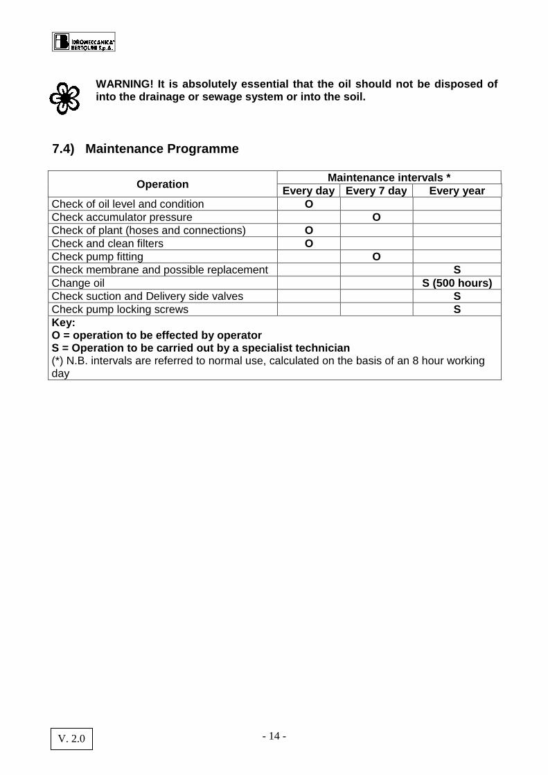
7.4) Maintenance Programme
Operation Maintenance intervals *
Every day Every 7 day Every year Check of oil level and condition O Check accumulator pressure O Check of plant (hoses and connections) O Check and clean filters O Check pump fitting O Check membrane and possible replacement S Change oil S (500 hours) Check suction and Delivery side valves S Check pump locking screws S Key: O = operation to be effected by operator S = Operation to be carried out by a specialist tec hnician (*) N.B. intervals are referred to normal use, calculated on the basis of an 8 hour working day

- 15 - V. 2.0
8. Plant Construction Applications
8.1 Application to farm machinery
a) Check that the machine's power take off does not exceed the permitted r.p.m. for the pump.
b) Where the power take off is synchronised with the gear, check the manufacture's manual to identify the gear ratio and the number of motor revolutions corresponding to the permitted r.p.m. for the pump.
c) Disconnect the power take off for stretches when the pump is not functioning. d) Disconnect the power take off at every change of direction entailing a slope greater
than that envisaged for the type of cardan shaft used. 8.2 Cardan Shaft protection
WARNING! Information relating to personal safety. READ THIS WITH CARE!
The choice of the motor cardan shaft protective safety cones on Bertolini pumps is dependant on two fundamental factors: A) In accordance with “CE” safety regulations the o verlapping between the pump
safety cone and that of the cardan shaft must be “ S” ≥ 50 mm; B) It is essential to know the characteristics of the type of cardan shaft used.
There are a wide number of different types of carda n shaft on the market with normal and wide angled yokes, torque limiters and freely rotating wheels. Since they are not standardised, the protruding ele ments of the related
protection are extremely variable. This makes the choice of safety cones to fit on the pump to comply with the required overlap for sa fety purposes a difficult process.
- 16 - V. 2.0
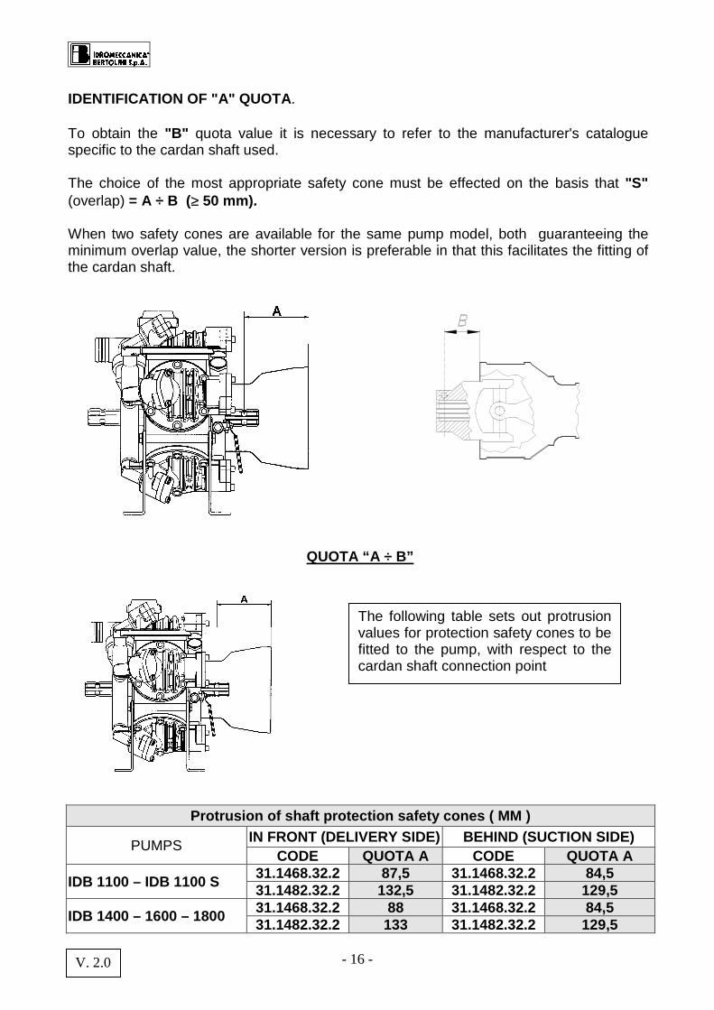
IDENTIFICATION OF "A" QUOTA . To obtain the "B" quota value it is necessary to refer to the manufacturer's catalogue specific to the cardan shaft used. The choice of the most appropriate safety cone must be effected on the basis that "S" (overlap) = A ÷ B ( ≥ 50 mm). When two safety cones are available for the same pump model, both guaranteeing the minimum overlap value, the shorter version is preferable in that this facilitates the fitting of the cardan shaft.
QUOTA “A ÷ B”
Protrusion of shaft protection safety cones ( MM )
PUMPS IN FRONT (DELIVERY SIDE) BEHIND (SUCTION SIDE)
CODE QUOTA A CODE QUOTA A
IDB 1100 – IDB 1100 S 31.1468.32.2 87,5 31.1468.32.2 84,5 31.1482.32.2 132,5 31.1482.32.2 129,5
IDB 1400 – 1600 – 1800 31.1468.32.2 88 31.1468.32.2 84,5 31.1482.32.2 133 31.1482.32.2 129,5
The following table sets out protrusion values for protection safety cones to be fitted to the pump, with respect to the cardan shaft connection point
- 17 - V. 2.0
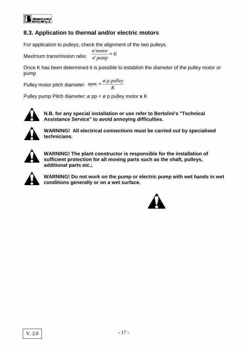
8.3. Application to thermal and/or electric motors For application to pulleys, check the alignment of the two pulleys. Maximum transmission ratio: Once K has been determined it is possible to establish the diameter of the pulley motor or pump Pulley motor pitch diameter: Pulley pump Pitch diameter: ø pp = ø p pulley motor x K
N.B. for any special installation or use refer to B ertolini's "Technical Assistance Service" to avoid annoying difficulties. WARNING! All electrical connections must be carrie d out by specialised technicians. WARNING! The plant constructor is responsible for t he installation of sufficient protection for all moving parts such as the shaft, pulleys, additional parts etc.; WARNING! Do not work on the pump or electric pump w ith wet hands in wet conditions generally or on a wet surface.
Kpumpn
motorn ='
'
K
pulleypøøpm
... =
- 18 - V. 2.0
9. SPECIAL SAFETY INSTRUCTIONS
– Do not work in the area where the pump is running without being protected by suitable
clothing and goggles; – Do not work on the pump without disconnecting the power take off (stop the pump); – Fit adequate protection on all moving parts such as the shaft, pulleys, joints etc.; – Do not remove protection fitted to moving parts; – Do not change the pump installation conditions, in particular to not modify the
hydraulic connection fittings; – Do not turn on any taps mounted on the pump if they are not connected with a use
function preventing the accidental discharge of the pumped liquid; – Make sure that there is a safety valve of appropriate capacity in the delivery side circuit
in addition to the loader valve; – Make sure that the hoses are properly fixed prior to use, checking all connections; – Carry out the checks set out under Section 5 prior to use; – Protect the pump from freezing over the winter; – Never leave the pump with the pumped liquid in it when not in use. The continuing
contact of the liquid with the internal parts of the pump when this is not required leads to a accelerated deterioration of the pump.
– Do not operate at a maximum speed greater than that indicated on the plate attached to the pump;
– Stop The pump and release the pressure in the circuit before carrying out any maintenance or checks;
– Keep children and animals away from the pump; – Do not use liquids at temperatures over 62° C or 145 ° F, or less than 5° C or 40° F; – Do not remove the pressure accumulator before releasing the pressurised air by
means of the appropriate valve; – Do not pump:
• Water solutions with density and viscosity greater than water; • Inflammable liquids or liquefied gases; • Solutions of chemical products where you are not sure of their compatibility with the
materials from which the pump is made; • Drinking water; • All kinds and types of paints; • Solvents and diluting liquids for paints of all kinds and types; • All kinds and types of fuels and lubricants; • Liquids containing granules or solid particles in suspension.
Protect the environment from the liquids contained in the pump. Collect residues and dispose of them properly. No residue should be released into the drainage or sewerage system or into the so il.
- 19 - V. 2.0
10. GUARANTEES In order for our guarantees to be operative it is a bsolutely necessary that: ♦♦♦ You keep the purchase invoice ;
♦♦♦ Fill out all parts of the validation schedule of the guarantee certificate;
♦♦♦ Send off the card enclosed correctly filled out in full within 15 days from the date of purchase to the following address, enclosing a copy of the purchase document:
IDROMECCANICA BERTOLINI S.p.A.
"Servizio Clienti" Via F.lli Cervi 35/1
42100 Reggio Emilia IT IS ONLY AT THIS POINT THAT OUR GUARANTEE WILL BECOME OPER ATIVE! Idromeccanica Bertolini S.p.A. undertakes, within the period of twelve months from the date on which the pump is delivered, to provide replacement parts for any part which proves to be of defective manufacture. You may also be able to take advantage of initiatives that we promote in the future. The guarantee is only valid where it has been possible for the defect to be verified by our "Customer Assistance Service" and where not deriving from improper use or failure to maintain the pump. Those parts subject to normal running wear (plastic or rubber parts) are not covered by the guarantee. IDROMECCANICA BERTOLINI will not be liable for damage caused in the following cases: ♦♦♦ use of the pump in a manner differing from that indicated in the Manual;
♦♦♦ Use in breach of specific regulations in force;
♦♦♦ Failure to maintain;
♦♦♦ Modifications or works not expressly authorised by IDROMECCANICA BERTOLINI ;
♦♦♦ Use of spare parts and accessories which are not original or specific for the product.
In cases where no safety valve has been fitted or w here the pump's pressure regulator valve has been tampered with, Id romeccanica Bertolini S.p.A. hereby declines any commitment under its gua rantee, as also in the case of the fitting of accessories not supplied by it.
For any check or verification the products must be sent as pre-paid freight.

- 20 - V. 2.0
11. Problems and Solutions
Problem Causes Solution
The pump does not achieve the desired pressure
– One or more valves have worn housings
– Suction hose with air pockets or irregular bends
– Worn nozzles or of incorrect diameter (See table)
– Filter blocked
– Check valves – Check hose – Check nozzles – Clean filter, replace
cartridge
Oscillating pressure gauge
– The pump is taking in air or presence of air in circuit, air not completely evacuated from pump;
– One or more valves blocked
– Make the pump turn with delivery open to evacuate air;
– Clean or replace the valves
The water pumped out is irregular, the pressure gauge oscillates
The air chamber is under-inflated Inflate the air chamber (see table)
Flow capacity decreasing, pump noisy.
Oil level is low Re-fill oil up to half way up tank with pump running
Oil coming out of discharge
1 or more membranes broken STOP THE PUMP IMMEDIATELY!
Empty the pump of oil, remove heads and replace the damaged membranes. Re-fill oil.
Oil changes colour, becomes white
1 or more membranes broken STOP THE PUMP IMMEDIATELY!
Empty the pump of oil, remove the heads and replace the damaged membranes. Re-fill with oil.
- 21 - V. 2.0
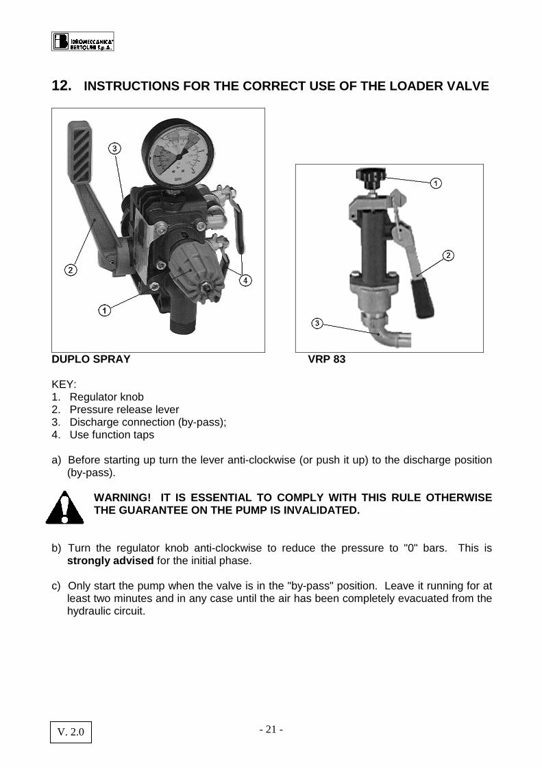
12. INSTRUCTIONS FOR THE CORRECT USE OF THE LOADER VALV E
DUPLO SPRAY VRP 83 KEY: 1. Regulator knob 2. Pressure release lever 3. Discharge connection (by-pass); 4. Use function taps a) Before starting up turn the lever anti-clockwise (or push it up) to the discharge position
(by-pass). WARNING! IT IS ESSENTIAL TO COMPLY WITH THIS RULE OTHERWISE THE GUARANTEE ON THE PUMP IS INVALIDATED.
b) Turn the regulator knob anti-clockwise to reduce the pressure to "0" bars. This is
strongly advised for the initial phase. c) Only start the pump when the valve is in the "by-pass" position. Leave it running for at
least two minutes and in any case until the air has been completely evacuated from the hydraulic circuit.
- 22 - V. 2.0
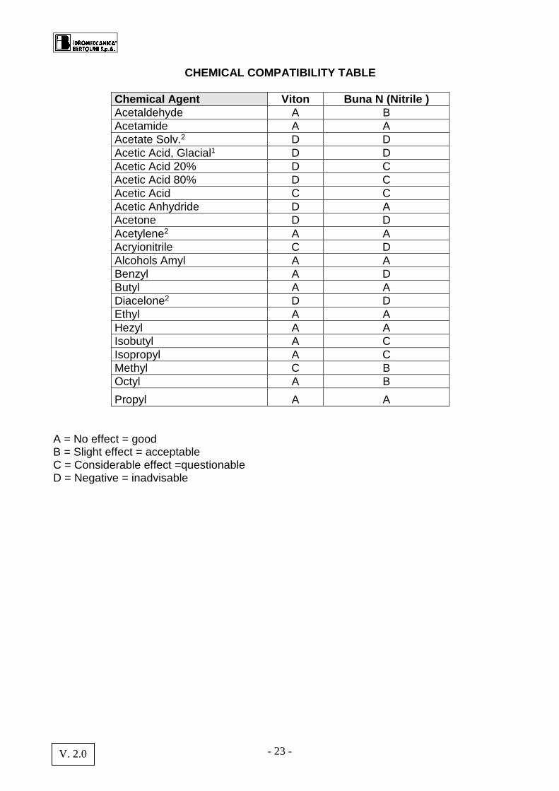
13. RESISTANCE TABLE Examples of resistance to chemical agents in basic groups This information has been supplied by producers of the chemicals and is derived from a careful examination of published data. We therefore consider it to be accurate. In any case though, since the resistance of the metals, plastics and elastomers may be influenced by factors such as concentration, temperature, the presence of other chemical agents and others, these data must be considered as providing a general guide and not an absolute guarantee. The information is not based on room temperature or performance, but only on resistance to the chemical agents. At the time of printing four different types of membranes are available, each with an elastomer of a different composition. Standard pump fittings are with membranes made of Buna-N which is the best compromise between chemical and mechanical compatibility. Membranes made from HPS®, Viton and Desmopan are available on request, offering better chemical characteristics.
N.B. FOR ANY SPECIAL INSTALLATION OR USE PLEASE CO NTACT BERTOLINI'S "TECHNICAL ASSISTANCE SERVICE" TO AVOID ANNOYING PROBLEMS.
- 23 - V. 2.0
CHEMICAL COMPATIBILITY TABLE
Chemical Agent Viton Buna N (Nitrile ) Acetaldehyde A B Acetamide A A Acetate Solv.2 D D Acetic Acid, Glacial1 D D Acetic Acid 20% D C Acetic Acid 80% D C Acetic Acid C C Acetic Anhydride D A Acetone D D Acetylene2 A A Acryionitrile C D Alcohols Amyl A A Benzyl A D Butyl A A Diacelone2 D D Ethyl A A Hezyl A A Isobutyl A C Isopropyl A C Methyl C B Octyl A B
Propyl A A A = No effect = good B = Slight effect = acceptable C = Considerable effect =questionable D = Negative = inadvisable
- 24 - V. 2.0
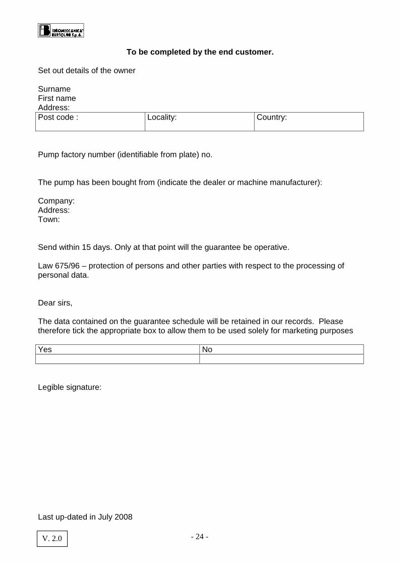
To be completed by the end customer. Set out details of the owner Surname First name Address: Post code :
Locality: Country:
Pump factory number (identifiable from plate) no. The pump has been bought from (indicate the dealer or machine manufacturer): Company: Address: Town: Send within 15 days. Only at that point will the guarantee be operative. Law 675/96 – protection of persons and other parties with respect to the processing of personal data. Dear sirs, The data contained on the guarantee schedule will be retained in our records. Please therefore tick the appropriate box to allow them to be used solely for marketing purposes Yes No Legible signature: Last up-dated in July 2008


![Presentation idb[1]](https://img.pdfslide.us/doc/110x75/5477df3db4af9f54028b48b8/presentation-idb1.jpg)