Embed Size (px)
Citation preview
Idaho National Engineering and Environmental Laboratory
Beryllium-Steam Reaction in Ceramic Blanket
Brad Merrill and Lee Cadwallader Fusion Safety Program
ARIES Project Meeting, ARIES Project Meeting, Wednesday, June 16th, 2004University of Wisconsin, Madison
Idaho National Engineering and Environmental Laboratory
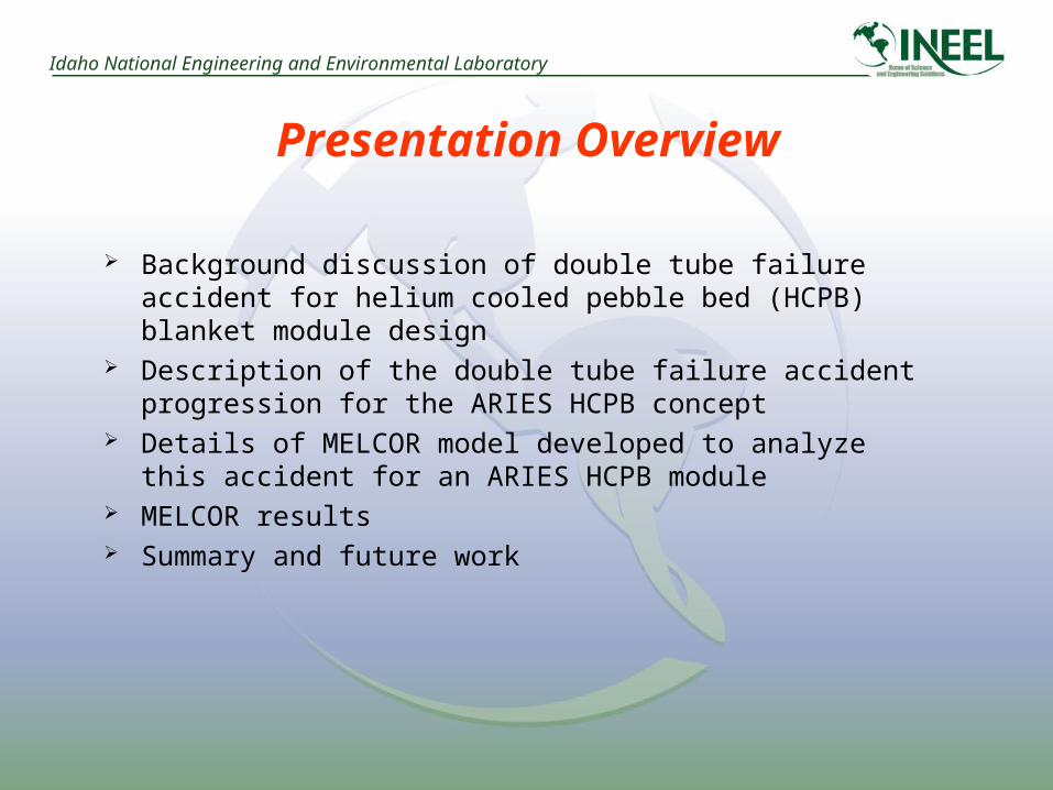
Presentation Overview
Background discussion of double tube failure accident for helium cooled pebble bed (HCPB) blanket module design
Description of the double tube failure accident progression for the ARIES HCPB concept
Details of MELCOR model developed to analyze this accident for an ARIES HCPB module
MELCOR results Summary and future work
Idaho National Engineering and Environmental Laboratory
Background of this Safety Issue The safety concern with this accident is the beryllium-steam reaction
producing chemical heat that propagates additional module failures, and producing hydrogen with the potential of hydrogen explosions failing confinement boundaries
A double tube failure accident scenario begins with the failure of a blanket helium cooling tube that results in the over-pressurization and failure of a blanket module; then a steam generator (SG) tube also fails, allowing steam to enter the failed module and react with the beryllium multiplier pebbles
Based on fission SG safety studies, this accident is most likely the result of independent tube failure events; that is, the failure of the first tube does not result in a condition for the second tube that is outside of the second tubes’ design envelope
Based on LWR and HTGR failure data, the probability of this event occurring was estimated at 5x10⁻¹⁰ /year
This probability value indicates that the double tube failure is a Beyond Design Basis Accident (BDBA), and would remain a BDBA even if the severe SG tube conditions produced by this accident where 1000 times more likely to fail the tube than fission data indicates

Idaho National Engineering and Environmental Laboratory
ARIES Pebble Bed Blanket Module
Assumed cooling tube break location(double-ended offset shear of 5 mm tube)
Module construction results in each beryllium pebble bed zone being separate, parallel flow paths for tritium purge system gas
As a consequence, a break into the zone indicated would not result in steam flowing into other regions of the module by way of the purge system

Idaho National Engineering and Environmental Laboratory
Double Tube Accident Progression
Module cooling tube breaks and helium leak pressurizes tritium extraction system, then this helium vents from tritium extraction system
Primary system depressurization to 70 atm occurs over several minutes, giving ample time to shutdown reactor prior to a complete cooling loss
A steam generator tube eventually breaks and re-pressurizes the cooling primary system
Inlet channel to broken tube bank will experience choked flow (sonic velocity) since it is the minimum area in the break flow path
Choked flow could also occur at the tube break since the pebble bed pressure will be less than the break pressure
Steam flow will continue until mass in the steam generator cools to 100ºC due to flashing (evaporative cooling); at 19,000 kg of H2O it should take hours for a single tube break vent this steam
Radioactive decay and steam-beryllium reactions will heat the module Steam flow will provide convective cooling to the module
Idaho National Engineering and Environmental Laboratory
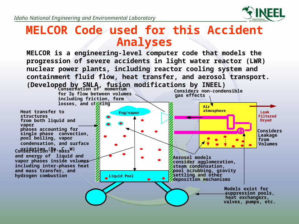
AiratmosphereFog/vapor
Liquid Pool
Conservation of massand energy of liquid andvapor phases inside volumesincluding inter-phases heatand mass transfer, andhydrogen combustion
Heat transfer to structuresfrom both liquid and vaporphases accounting forsingle phase convection,pool boiling, vaporcondensation, and surface oxidation (Be, C, W)
Considers non-condensiblegas effects
Conservation of momentum for 2 flow between volumes including friction, form losses, and choking
Aerosol modelsconsider agglomeration,steam condensation,pool scrubbing, gravitysettling and otherdeposition mechanisms
LeakFilteredDryed
ConsidersLeakagefromVolumes
Models exist forsuppression pools,heat exchangers,valves, pumps, etc.
MELCOR is a engineering-level computer code that models the progression of severe accidents in light water reactor (LWR) nuclear power plants, including reactor cooling system and containment fluid flow, heat transfer, and aerosol transport. (Developed by SNLA, fusion modifications by INEEL)
MELCOR Code used for this Accident Analyses
Idaho National Engineering and Environmental Laboratory
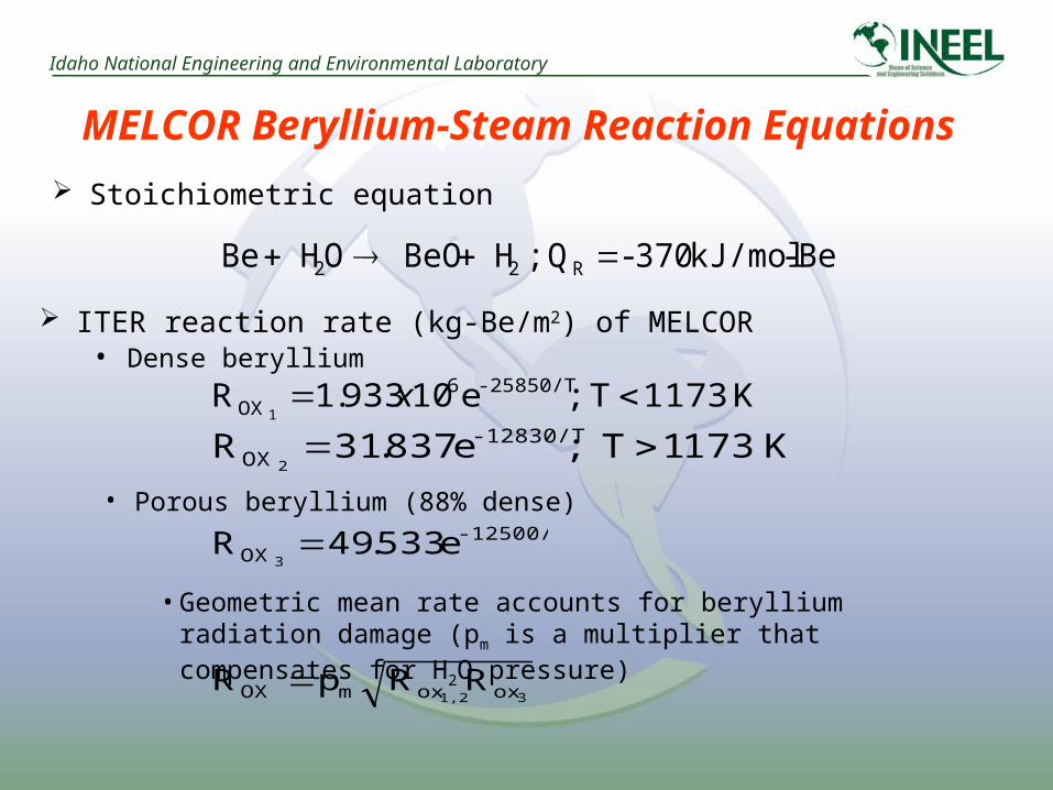
MELCOR Beryllium-Steam Reaction Equations
Be-kJ/mol 370- Q ; H BeO O H Be R22
Stoichiometric equation
K1173 T ; e10933.1R -25850/T6OX1
x
K1731 T ;e 837.31R -12830/TOX2
ITER reaction rate (kg-Be/m2) of MELCOR• Dense beryllium
• Porous beryllium (88% dense) -12500/T
OX e 533.49R3
• Geometric mean rate accounts for beryllium radiation damage (pm is a multiplier that compensates for H2O pressure)
RRpR31,2 oxoxmOX
Idaho National Engineering and Environmental Laboratory
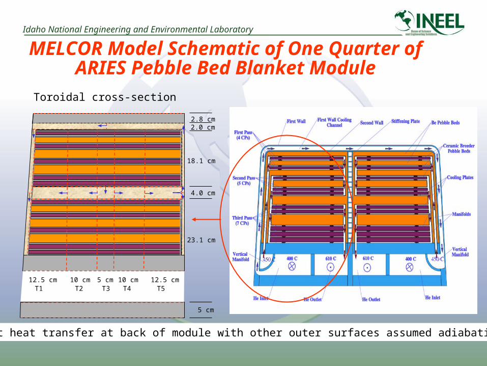
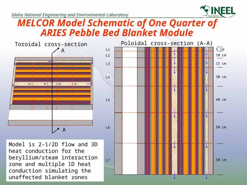
MELCOR Model Schematic of One Quarter of ARIES Pebble Bed Blanket Module
Toroidal cross-section
12.5 cm 10 cm 5 cm 10 cm 12.5 cm
2.8 cm
4.0 cm
2.0 cm
18.1 cm
23.1 cm
5 cm
T1 T2 T3 T4 T5
Radiant heat transfer at back of module with other outer surfaces assumed adiabatic
Idaho National Engineering and Environmental Laboratory
MELCOR Model Schematic of One Quarter of ARIES Pebble Bed Blanket Module
5 cm
10 cm
15 cm
30 cm
40 cm
50 cm
50 cm
L1
L2
L3
L4
L5
L6
L7
Poloidal cross-section (A-A)Toroidal cross-section
A
A
Model is 2-1/2D flow and 3D heat conduction for the beryllium/steam interaction zone and multiple 1D heat conduction simulating the unaffected blanket zones

Idaho National Engineering and Environmental Laboratory
Mid-zone Beryllium Temperature History(No Decay Heat)
0 50 100
Time (s)
600
650
700
750
800
Tem
pera
ture
(C
)Break
Module exit
Break
Module exit

Idaho National Engineering and Environmental Laboratory
Mid-zone Beryllium Surface Plot Locations
Toroidal location
Poloi
dal l
ocat
ion
200
cm50 cm

Idaho National Engineering and Environmental Laboratory
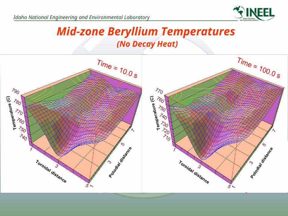
Mid-zone Beryllium Temperatures (No Decay Heat)
Idaho National Engineering and Environmental Laboratory
Mid-zone Beryllium Temperatures (No Decay Heat)

Idaho National Engineering and Environmental Laboratory
Why A Thermal Runaway Didn’t Occur(Back of the Envelope Check)
The quantity of beryllium in the interaction zone of the quarter module modeled is ~ 0.14 m3
For 4 mm pebbles, the number of pebbles is 32,550 with a total surface area of ~1.6 m2
If all of these pebbles were at the maximum beryllium temperature predicted by MELCOR, then the oxidation rate would be 9.2x10⁻⁵ kg-Be/s
At this reaction rate the heat produced would be 6.2 kW, and after 100 s only 2 gm of H2 would be generated
The break flow rate of steam is predicted to be ~100 g/s, and given the temperature rise through the module this steam removes ~33 kW of heat, therefore no thermal excursion
However, decay heat could change this result

Idaho National Engineering and Environmental Laboratory
Decay Heat Approximation
10-4
10-3
10-2
10-1
100
101
102
103
10-1 100 101 102 103 104 105 106 107 108 109 1010 1011
Flinabe including tritium bredNCF structureFlinabe excluding tritium bredNa-24 produced in Flinabe
Tot
al D
ecay
Hea
t in
Bla
nket
(MW
)
Time after Shutdown (s)
CLiFF Design
1 s 1 m 1 h 1 d 1 mo 1 y 10 y
Module decay heat was approximated for this module by adapting decay heating from an APEX molten salt blanket design
Decay heat was scaled by area (APEX at 555 m2 to 1 m2 for quarter module), giving 0.6 MW at shutdown and 36 kW after 60 s
Should be a conservative estimate because APEX neutron wall loading is 7 MW/m2 and the rapid decay of F-18 dominates heating during the first minute after shutdown
Idaho National Engineering and Environmental Laboratory
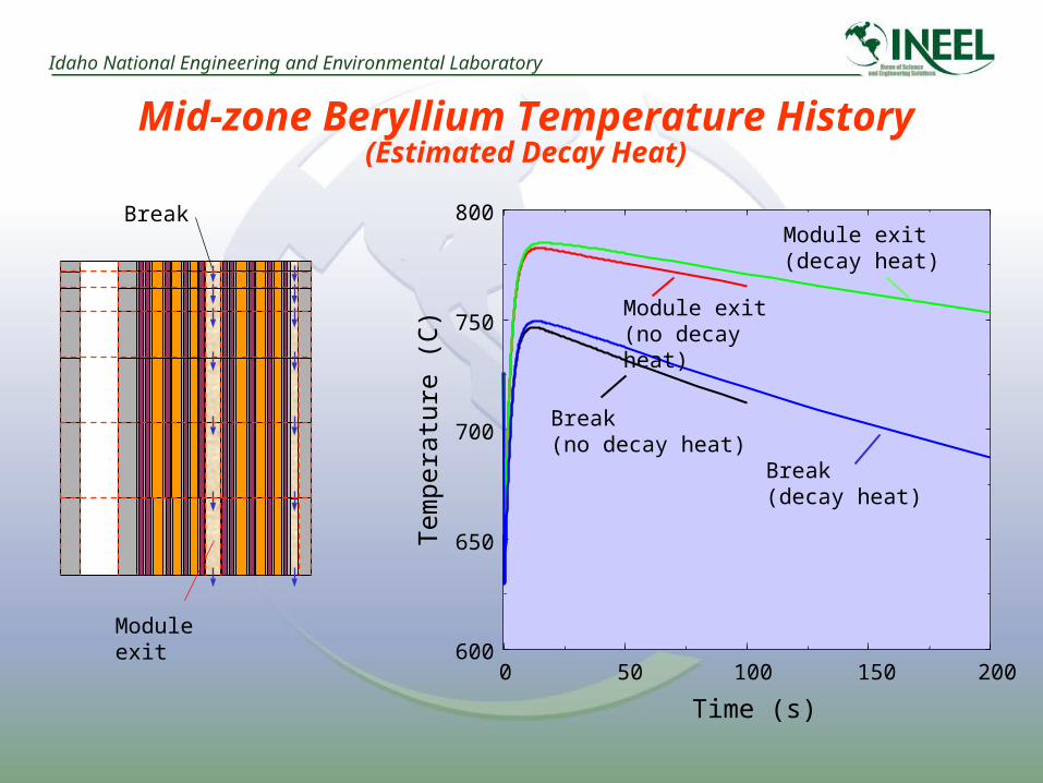
Mid-zone Beryllium Temperature History(Estimated Decay Heat)
Break
Module exit
0 50 100 150 200
Time (s)
600
650
700
750
800
Tem
pera
ture
(C
)Break(no decay heat)
Module exit(no decay heat)
Module exit(decay heat)
Break(decay heat)

Idaho National Engineering and Environmental Laboratory
Radial Cut Temperature History(Estimated Decay Heat)
535.0
638.5
742.0
845.5
949.0
64
07
20
80
08
80
Tem
per
atur
e (C
)
Radial distance (cm)
0
13
26
39
52
65 020
4060
80100
Time (s)
Idaho National Engineering and Environmental Laboratory
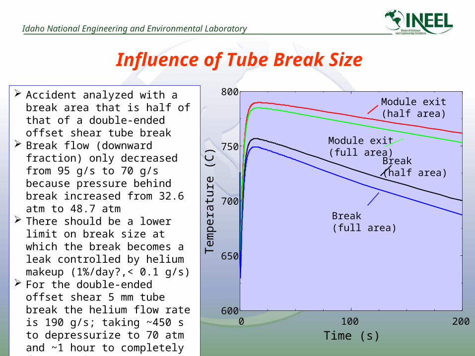
Influence of Tube Break Size
0 100 200
Time (s)
600
650
700
750
800
Tem
pera
ture
(C
) Break(half area)
Module exit(half area)
Module exit(full area)
Break(full area)
Accident analyzed with a break area that is half of that of a double-ended offset shear tube break
Break flow (downward fraction) only decreased from 95 g/s to 70 g/s because pressure behind break increased from 32.6 atm to 48.7 atm
There should be a lower limit on break size at which the break becomes a leak controlled by helium makeup (1%/day?,< 0.1 g/s)
For the double-ended offset shear 5 mm tube break the helium flow rate is 190 g/s; taking ~450 s to depressurize to 70 atm and ~1 hour to completely depressurize

Idaho National Engineering and Environmental Laboratory
Summary and Future Work
A multi-dimensional MELCOR fluid flow/heat conduction model was developed for one-quarter of an ARIES HCPB module to analyze a double tube failure event in this blanket design
Preliminary results suggest that the convective cooling of the steam entering the failed beryllium pebble bed zone will remove more heat than produced by the beryllium-steam reaction, and as a result propagation of this failure to other modules by chemical heating alone is not likely
The impact of decay heat on these results was investigated with scaled decay heating from a different blanket design and found not to change this conclusion
More accurate decay heat and pebble bed friction/heat transfer coefficients will be included in the existing MELCOR model for future analyses