Embed Size (px)
Citation preview
4P32 Section:
3ackground Chapter ieference:
Me:
~
12.5.1
3 28
Report of Emissions Test. Beta Steel Corp - Portage, Indiana Plant. Plant ID No. 127- 00036. Hot Strip Mill Slab Reheat Furnace Stack Selective Catalytic Reduction (SCR) Unit. November 4, 1999. Prepared for: Beta Steel Corp, Portage, IN. Prepared by: Industrial Environmental Management Consultants, Inc. Chesterton, IN and Ambient Air Services, Inc., Starke, FL. December 1999.
1 .
REPORT OF EMISSIONS TEST BETA STEEL CORP - PORTAGE, INDIANA PLANT
PLANT ID NO. 127-00036
HOT STRIP MILL SLAB REHEAT FURNACE STACK SELECTIVE CATALYTIC REDUCTION (SCR) UNIT
NOVEMBER 4, 1999
Prepared for:
BETA STEEL CORP 6 5 0 0 SOUTH BOUNDARY ROAD
PORTAGE, INDIANA 46368
Prepared by:
Industrial Environmental Management Consultants, Inc. 804 Wabash Avenue
Chesterton, Indiana 4 6 3 0 4
and
Ambient Air Services, Inc. 106 Ambient A i rway
Starke, Florida 32091
DECEMBER 1999
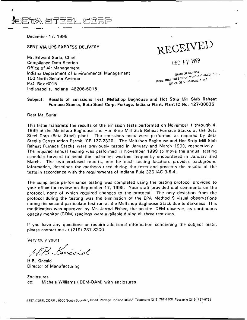
. December 17, 1999
SENT VIA UPS EXPRESS DELIVERY
Mr. Edward Surla, Chief
Office of Air Management
I . . t '1 i9j9 Compliance Data Section '_'I-'-.
Indiana Department of Environmental Management 100 North Senate Avenue P.O. Box 601 5 ~~ ~~ ~
Indianapolis, Indiana 46206-601 5
Subject: Results of Emissions Test, Meltshop Baghouse and Hot Strip Mill Slab Reheat Furnace Stacks, Beta Steel Corp, Portage, Indiana Plant, Plant ID No. 127-00036
Dear Mr. Surla:
This le t ter transmits the results of the emission tests performed on November 1 through 4, 1999 a t the Meltshop Baghouse and Hot Strip Mill Slab Reheat Furnace Stacks a t the Beta Steel Corp (Beta Steel) plant. The emissions tests were performed as required by Beta Steel's Construction Permit ICP 127-2326). The Meltshop Baghouse and Hot Strip Mill Slab Reheat Furnace Stacks were previously tested in January and March 1999, respectively. The required annual testing was performed in November 1999 to move the annual testing schedule forward to avoid the inclement weather frequently encountered in January and March. The two enclosed reports, one for each testing location, provides background information, describes the methods used during the tests and presents the results of the tests in accordance with the requirements of Indiana Rule 326 IAC 3-6-4.
The compliance performance testing was completed using the testing protocol provided to your office for review on September 17, 1999. Your staff provided oral comments on the protocol, none of which required changes to the protocol. The only deviation from the protocol during the testing was the elimination of the EPA Method 9 visual observations during the second particulate test run at the Meltshop Baghouse Stack due to darkness. This modification was approved by Mr. Jariod Fisher, the on-site IDEM observer, as continuous opacity monitor (COM) readings were available during all three t e s t runs.
If you have any questions or require additional information concerning the subject tests, please contact me a t (219) 787-8200.
Very truly yours,
H.B. Kincaid Director of Manufacturing
Enclosures cc: Michele Williams (IDEM-OAM) with enclosures
BETA STEEL CORP. : 6500 South Boundary Road. Ponage. Indiana 46368 Telephone (219) 787.8200 Facsimile (219) 787-8725 .
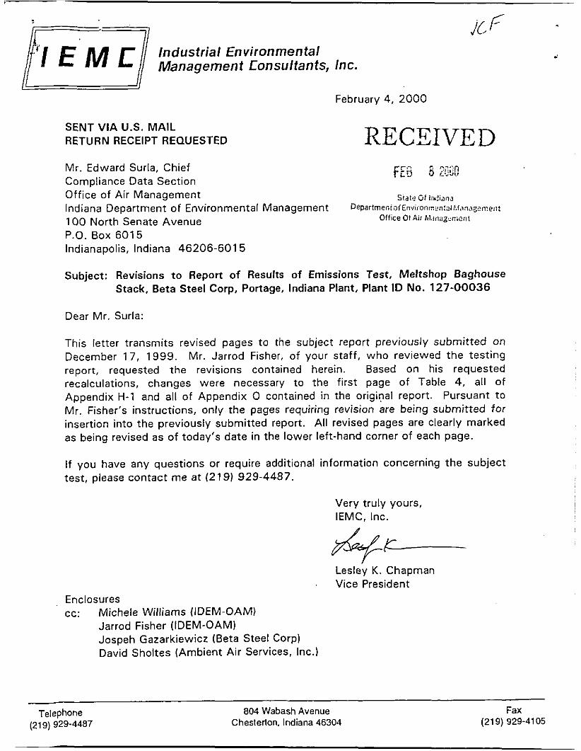
Industrial Environmental
February 4, 2000
SENT VIA U.S. MAIL RETURN RECEIPT REQUESTED RECEIVED
FEs 8 ?,;;:n i . J d V
Mr. Edward Surla, Chief Compliance Data Section
Indiana Department o f Environmental Management 1 0 0 North Senate Avenue P.O. Box 6015 Indianapolis, Indiana 46206-601 5
Subject: Revisions t o Report of Results of Emissions Test, Meltshop Baghouse Stack, Beta Steel Corp, Portage, Indiana Plant, Plant ID No. 127-00036
Office of Air Management Statu tf Injijna D e ~ a r l r n e n i ~ f E i i v i i . o i i , ~ ~ n : ~ l ~ . . i ~ , ~ ' 7 ~ ~ ~ ~ , , ~
Office Of Air M . 1 1 1 a 2- ..r;ient
Dear Mr. Surla:
This letter transmits revised pages to the subject report previously submitted on December 17, 1999. Mr. Jarrod Fisher, of your staff, who reviewed the testing report, requested the revisions contained herein. Based on his requested recalculations, changes were necessary to the first page of Table 4, all of Appendix H-1 and all of Appendix 0 contained in the original report. Pursuant t o Mr. Fisher's instructions, only the pages requiring revision are being submitted for insertion into the previously submitted report. All revised pages are clearly marked as being revised as of today's date in the lower left-hand corner of each page.
If you have any questions or require additional information concerning the subject test, please contact me at (21 9) 929-4487.
Very truly yours, IEMC, Inc.
&- Led& K. Chapman Vice President
En c I o s u r e s cc: Michele Williams (IDEM-OAM)
Jarrod Fisher (IDEM-OAM) Jospeh Gazarkiewicz (Beta Steel Corp) David Sholtes (Ambient Air Services, Inc.)
Telephone (219) 929-4487
804 Wabash Avenue Cheslerton, Indiana 46304
Fax (219) 929-4105
i
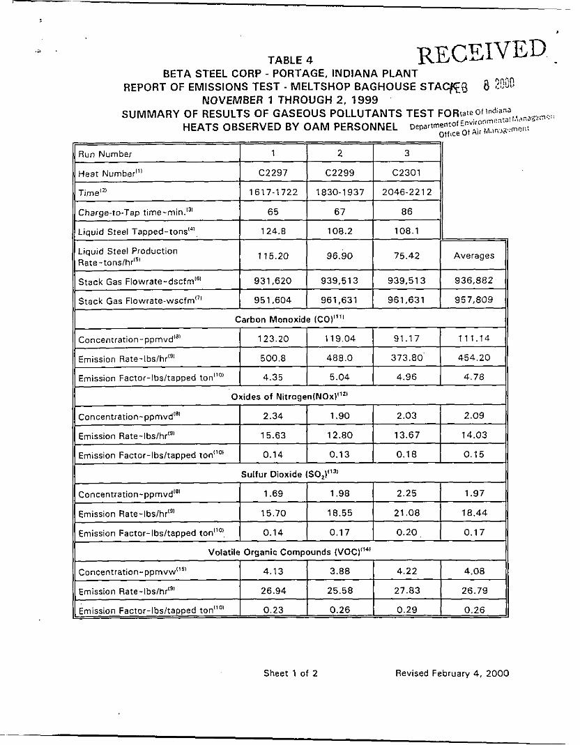
TABLE 4
~~ ~
Heat Number"'
Time"'
Run Number I 1 I 2 I 3 II C2297 C2299 C2301
1617-1722 1830-1937 2046-2212
~~
Liquid Steel Tapped-tons"'
Liquid Steel Production Rate-tonslhr"'
Stack Gas Flowrate-dscfrn"'
Charae-to-Tar, t ime-~nin. '~ ' I 65 I 67 I 86 11 ~ _ _ _ _ _ _ _ _ _ _
Averages
936,882
124.8 108.2 108.1
115.20 96.90 75.42
931,620 939,513 939.51 3 ~
Stack Gas Flowrate-wscfm"' 951,604 961,631 961,631 957,809
Emission Factor-lbsltapped ton""
Emission Rate- lb~ lh r '~ ' 1 500.8 1 488.0 1 373.80' I 454.20 1) 4.35 5.04 4.96 4.78
Concentration-ppmvd"' 2.34 1.90
Emission Rate-lbslhr"' 15.63 12.80
Emission Factor-IbsltaDDed ton"o' 0.14 0.13
2.03 2.09
13.67 14.03
0.18 0.15
Concentration-pprnvd'" 1.69 1.98
Emission Rare-lbslhr'" 15.70 18.55
2.25 1.97
21.08 18.44 ~
concentration-ppmvw'" 4.13
Emission Rate- lb~ /hr '~ ' 26.94
3.88 4.22 4.08
25.58 27.83 26.79 ~
Emission Factor-lbsltapped ton'1o' I 0.23 0.26 0.29 0.26
REPORT OF EMISSIONS TEST BETA STEEL CORP - PORTAGE, INDIANA PLANT
PLANT ID NO. 127-00036
HOT STRIP MILL SLAB REHEAT FURNACE STACK SELECTIVE CATALYTIC REDUCTION (SCRI UNIT
NOVEMBER 4, 1999
Prepared for:
BETA STEEL CORP 6500 SOUTH BOUNDARY ROAD
PORTAGE, INDIANA 46368
Prepared by:
Industrial Environmental Management Consultants, Inc. 804 Wabash Avenue
Chesterton, Indiana 46304
and
Ambient Air Services, Inc. 106 Ambient Airway
Starke, Florida 32091
DECEMBER 1999
>
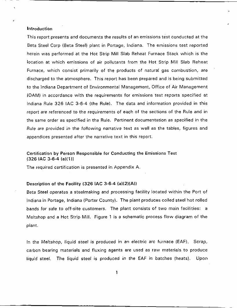
Introduction
This report presents and documents the results of an emissions test conducted a t the
Beta Steel Corp (Beta Steel) plant in Portage, Indiana. The emissions test reported
herein was performed at the Hot Strip Mill Slab Reheat Furnace Stack which is t he
location a t which emissions of air pollutants from the Hot Strip Mill Slab Reheat
Furnace, which consist primarily of the products of natural gas combustion, are
discharged to the atmosphere. This report has been prepared and is being submit ted
to the Indiana Department of Environmental Management, Office of Air Management
(OAM) in accordance w i th the requirements for emissions test reports specified at
Indiana Rule 326 IAC 3-6-4 (the Rule). The data and information provided in this
report are referenced to the requirements of each of the sections of the Rule and in
the same order as specified in the Rule. Pertinent documentation as specified in the
Rule are provided in the following narrative text as well as the tables, figures and
appendices presented after the narrative text in this report.
'
Certification by Person Responsible for Conducting the Emissions Test (326 IAC 3-6-4 ( a ) ( l ) )
The required certification is presented in Appendix A.
Description of the Facility (326 IAC 3-6-4 (a)(2)(A))
Beta Steel operates a steelmaking and processing facility located within the Port o f
Indiana in Portage, Indiana (Porter County). The plant produces coiled steel h o t rolled
bands for sale t o off-site customers. The plant consists of t w o main facilities: a
Meltshop and a Hot Strip Mill. Figure 1 is a schematic process f l ow diagram of t he
plant.
In the Meltshop, liquid steel is produced in an electric arc furnace (EAF). Scrap,
carbon bearing materials and fluxing agents are used as raw materials t o produce
liquid steel. Upon The liquid steel is produced in the EAF in batches (heats).
1
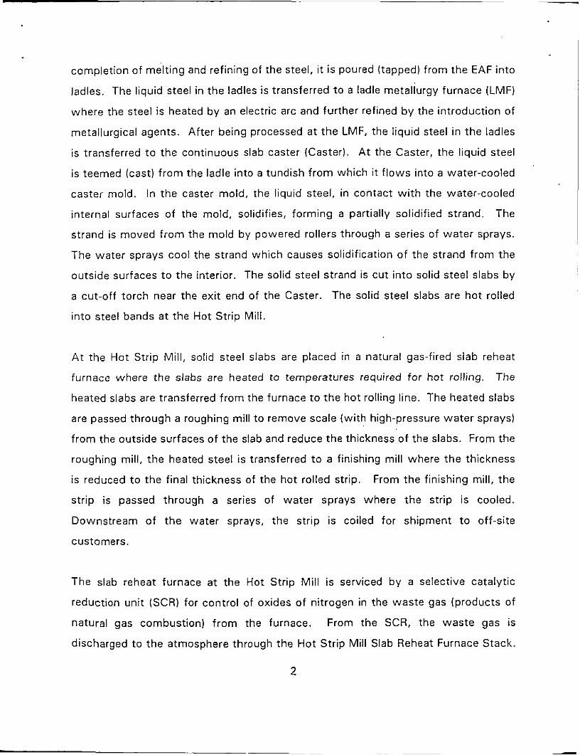
completion of melting and refining of the steel, i t is poured (tapped) from the EAF into
ladles. The liquid steel in the ladles is transferred to a ladle metallurgy furnace (LMF)
where the steel i s heated by an electric arc and further refined b y the introduction of
metallurgical agents. After being processed at the LMF, the liquid steel in the ladles
is transferred t o the continuous slab caster (Caster). A t the Caster, the liquid steel
i s teemed (cast) f rom the ladle into a tundish f rom which i t f lows into a water-cooled
caster mold. In the caster mold, the liquid steel, in contact with the water-cooled
internal surfaces of the mold, solidifies, forming a partially solidified strand. The
strand is moved f rom the mold by powered rollers through a series of water sprays.
The water sprays cool the strand which causes solidification of the strand from the
outside surfaces t o the interior. The solid steel strand is cut into solid steel slabs by
a cut-off torch near the exit end of the Caster. The solid steel slabs are hot rolled
into steel bands at the Hot Strip Mill.
A t the Hot Strip Mill, solid steel slabs are placed in a natural gas-fired slab reheat
furnace where the slabs are heated to temperatures required for ho t rolling. The
heated slabs are transferred f rom the furnace t o the hot rolling line. The heated slabs
are passed through a roughing mill t o remove scale (wi th high-pressure water sprays)
f rom the outside surfaces of the slab and reduce the thickness of the slabs. From the
roughing mill, the heated steel is transferred t o a finishing mill where the thickness
is reduced t o the final thickness of the ho t rolled strip. From the finishing mill, the
strip is passed through a series of water sprays where t h e strip is cooled.
Downstream of the water sprays, t h e strip is coiled for shipment t o off-site
customers.
The slab reheat furnace at the Hot Strip Mill is serviced by a selective catalytic
reduction unit (SCR) for control of oxides of nitrogen in the waste gas (products of
natural gas combustion) f rom the furnace. From the SCR, the waste gas is
discharged to the atmosphere through the Hot Strip Mill Slab Reheat Furnace Stack.
2
The Date or Dates on Which the Test was Performed (326 IAC 3-6-4 (aJ(2)(BJJ
Indiana Rule 326 IAC 6-5 (a)(3) requires a minimum of three t e s t runs during an
emission test. Testing for filterable and condensible particulate matter and for
gaseous pollutants (NOx, VOC and CO) was conducted over three test runs. All three
test runs occurred on November 4, 1999.
The Type of Tests Conducted (326 IAC 3-6-4 (a)(2)(CJ)
The emission test included the testing of stack gas at the Slab Reheat Furnace Stack
for particulate matter (filterable and condensible), oxides of nitrogen (NOx), carbon
monoxide (CO) and total hydrocarbons (VOC). The testing also included the
measurement of the stack gas velocities and other stack gas properties. The data
were used to calculate the stack gas flowrates. The stack gas f lowrates in
conjunction with the concentrations of pollutants in the stack gas were used t o
calculate mass emission rates of pollutants emitted through the stack t o the
atmosphere.
Beta Steel submitted a proposed test protocol to OAM on September 17, 1999. In
response to the proposed protocol, OAM provided oral comments, which did no t
require revision t o the submitted protocol. Table 1 presents a summary o f the test
methods specified i n the protocol and used during the emissions test.
The Type of Process and Control Equipment (326 I A C 3-6-4 (a)(2)(D))
The Slab Reheat Furnace Stack is the location at which emissions of air pollutants
from the Hot Strip Mil l Slab Reheat Furnace, which primarily consist of products of
natural gas combustion, are emitted t o the atmosphere. the Slab Reheat furnace is
used to heat steel slabs to temperatures required for ho t rolling into steel strip. The
reheat furnace at the Beta Steel plant is a natural gas-fired, pusher type furnace.
Cold slabs are placed in double rows on a charging table and progressively pushed
into and through the furnace a t a controlled push rate. Heated slabs are pushed ou t
3
of the exit end of the furnace onto a powered roller line which moves the ho t slabs
to the next step in the ho t rolling process: descaling and roughing mills.
The flue gas stream generated at the Slab Reheat Furnace is ducted through a waste
heat tunnel t o a selective catalytic reduction unit for the reduction of NOx
concentrations in the flue gas prior t o the discharge of the gas stream t o the
atmosphere through the Hot Strip Mil l Slab Reheat Furnace Stack. The SCR Unit is
equipped wi th a variable speed fan which is part of the Slab Reheat Furnace pressure
control system. The key operating parameters for achieving desired NOx removal
efficiencies are the rate of ammonia vapor injection upstream o f the catalyst bed, the
temperature of the catalyst in the catalyst bed (i.e., steady-state temperature of the
flue gas stream at the catalyst bed) and the activity of the catalyst surfaces in the
catalyst bed. Figure 2 presents a schematic f low diagram of the Slab Reheat Furnace
flue gas handling and treatment system.
~
The Source Name and Location (326 IAC 3-6-4 (a)(2)(E))
The emissions testing subject of this report was performed at:
Beta Steel Corp 6 5 0 0 South Boundary Road Portage, Indiana 46368 Plant ID No. 127-00036
The source is located in the south-western portion of property owned by the Port of
Indiana.
The Purpose of t he Test (326 IAC 3-6-4 (a)(2)(F))
The emissions test reported herein was conducted to comply with the annual stack
testing requirements that are specified at Operation Condition 14 o n Page 8 of 15 of
the PSD Construction Permit (CP-127-2326) issued to Beta Steel b y OAM on
February 24, 1 9 9 2 and amended on April 14, 1 9 9 7 (A-127-7055) , The PSD
4
Construction Pe'rmit is the current operation permit for t h e plant. Operation
Condition 1 4 requires annual stack testing of the Hot Strip Mill Slab Reheat Furnace
for particulate matter, CO, VOC and NOx.
The Test Participants and Their Titles (326 IAC 3-6-4 (a)(2)(G))
Appendix B presents a list of the individuals that participated in the emissions test,
the affiliations of the participants and their titles.
The Heat Input Rate (326 IAC 3-6-4 (a)(3)(A))
The heating of steel slabs in a reheat furnace is a generally continuous process except
for startup and shutdown periods. In general, the natural gas firing rate (i.e., heat
input rate in million BTU's per hour) is proportional to the steel slab throughput rate.
During periods o f delays, the natural gas firing rate (heat input rate) normally is
reduced t o c o n s e r h energy and prevent overheating of the slabs. During the
emissions test runs, the average heat input rates varied from 233.0 to 265.2
MMBTU/hr and averaged 251.7 MMBTU/hr. This is a range of 88.1 to 100 .2 and
an average of 95.1 percent of the heat input capacity of 264.6 MMBTU/hr specified
in the construction permit.
The Reference or Derived Conversion Factors (326 IAC 3-6-4 (a)(3)(B))
Appendix C presents a listing of all of the conversion factors used in the calculations
t o reduce the data obtained during the emissions test reported herein. .
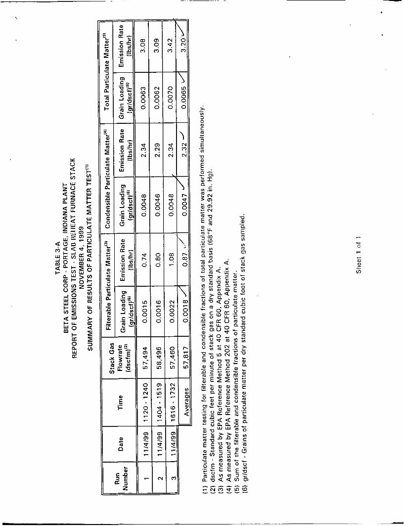
The Stack Gas Flowrate (326 3-6-4 (a)(3)(C))
Table 3-A, which provides the results of the particulate matter test runs, presents the
stack gas flowrate measured during each of the three test runs and the average stack
gas flowrate for the emissions test. Flowrates are also provided in Tables 4 and 7.
5
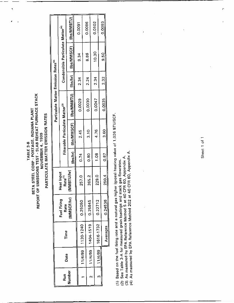
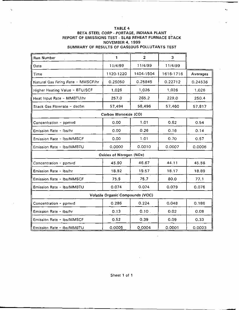
Measured Emissions Given in Units Consistent with Emissions Limitations (326 IAC 3-6-4 (a)(3)(D))
Tables 3 -A and 3-6 provide the measured emission rates of particulate matter given
in units consistent with the emission limitations. Table 4 presents the measured
emission rates for gaseous pollutants given in units consistent w i th the emissions
limitations.
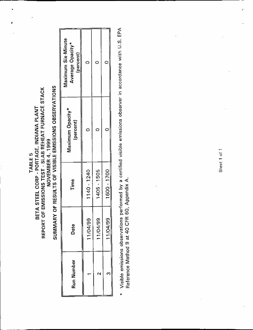
Visible Emissions Observations or Six-Minute Average Continuous Opacity Monitor Readings (326 IAC 3-6-4 (a)(3)(E))
Table 5 presents a summary of the results of visible emissions observations
performed during the test for periods corresponding to the three test runs for
particulate matter. As agreed t o by Mr. Jarrod Fisher, the on-site IDEM observer,
visible emissions were observed b y a certified visible emissions observer for a total
of three hours during the particulate matter test runs. Appendix D provides
photocopies of the visible emission observation forms.
Average Value of Emissions From Any Continuous Gaseous Pollutants Gaseous Emissions Monitoring System (326 IAC 3-6-4 (a)(3)(F))
During the emissions testing, the concentrations of gaseous pollutants (NOx, VOC
and CO) in the stack gas were continuously and simultaneously measured using
continuous sampling instruments. Continuous samples of the stack gas were
obtained from a location near the center of the stack.
A primary data logging apparatus was used for gaseous pollutant sampling. This
recorder obtained signals (measured concentrations) from the instruments used t o
analyze the stack gas sample for each of the gaseous pollutants once every one
second. The data logger accumulated 6 0 o f these one-second values for each
pollutant, calculated the average value of each group of 6 0 and stored the average
in the data bank. Therefore, the stored data for each pollutant consisted of a series
of 60-second (one minute) averages. This data logging and processing system
6
eliminates the need for continuous analog recorders (e.g., strip charts.) The analyzers
used to measure concentrations of each of the gaseous pollutants in the stack gas
are described below.
Oxides of Nitroaen - NOx concentrations were measured in accordance with EPA
Method 7E using a Thermo Environmental Instruments (TECO) Model 42H NOx
analyzer. The performance specifications of the TECO 42H meet or exceed the
performance specifications for EPA Method 7E.
Carbon Monoxide - CO concentrations were measured using an adaptation of EPA
Method 1 0 using 'a TECO Model 48 gas filter correlation type gas analyzer. The
required performance specifications for EPA Method 1 0 are met b y the TECO
Model 48. This instrument is a t least equivalent t o the NDlR instrumentation
described in EPA Method 10.
Volatile Oraanic ComDounds - VOC concentrations were measured in accordance with
an adaptation of EPA Method 2 5 A using a TECO Model 51 total hydrocarbon
analyzer. The TECO Model 51 measures total hydrocarbon concentrations through
a flame ionization detector and associated electronics. Calibration using propane and
calculation procedures specified in Method 25A results in calculated values for the
non-methane fraction of total hydrocarbons (i.e., VOC). The manufacturer's
specifications for the TECO Model 51 meet the performance specifications for EPA
Method 25A.
Stack gas flowrates were measured using procedures specified in 40 CFR 60,
Appendix A, Methods 1 through 3. 'The average emission rates of gaseous pollutants
were calculated for each test run using the averages of the continuously measured
concentrations and the measured stack gas flowrates for each test run.
7
The average emission rates for NOx, VOC and CO for each of the t e s t runs during the
emissions test are presented in Table 4.
The Process Flow Diagram (326 IAC 3-6-4 (a)(4)(8))
Figure 1 presents a schematic process f low diagram of the Bata Steel Plant. The
diagram shows the emission units that are located in the Hot Strip Mill including the
Slab Reheat Furnace, t he SCR Unit and the Slab Reheat Furnace Stack at which the
emissions test reported herein was performed. Figure 2 presents a schematic diagram
of the Slab Reheat Furnace flue gas handling and treatment system.
The Maximum Design Capacity (326 3-6-4 (a)(4)(B))
The rated heat input capacity of the Slab Reheat Furnace, as specified in the
construction permit is 264.6 MMBTU/hr. This is the current practical maximum
average sustainable heat input rate over a 24-hour period. The heat input rate over
individual hourly periods on occasion exceed 264.6 MMBTUlhr.
A Fuel Analysis and Heat Value for Heat Input Rate Determinations (326 IAC 3-6-4 (a)(4)(C))
Beta Steel obtains natural gas f rom the Northern Indiana Public Service Company
(NIPSCO). NIPSCO reports an average higher heating value of 1,026 BTUs per
standard cubic foo t (BTU/SCF) for natural gas supplied by NIPSCO.
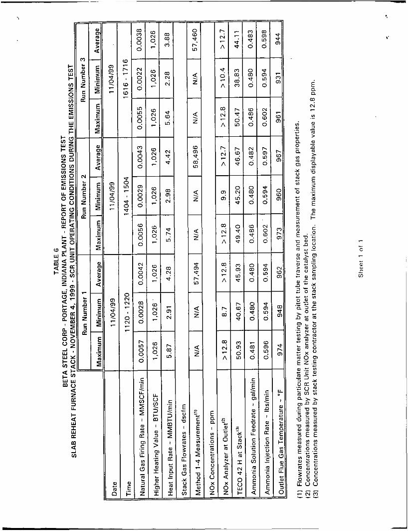
The Process and Control Equipment Operating Conditions (326 IAC 3-6-4 (a)(4)(D))
The key operating parameter at the Slab Reheat Furnace, w i th respect t o the
formation and emission of air pollutants, i s believed to be the natural gas fir ing rate.
The slab tons per hour reheated in t h e furnace generally is proportional to the natural
gas firing rate. During the emissions test reported herein, an effort was made t o
maintain the natural gas firing rate (heat input rate) a t the furnace a t or near the
practical heat input capacity of 264.6 MMBTUlhr. Normally encountered problems
8
and production delays a t the Hot Strip Mill limited the average heat input rate during
the three test runs t o a level of approximately 95.1 percent of the rated heat input
capacity. The average heat input rate and slab throughput rate during the emissions
test were higher than those for normal operations.
Two key operating parameters for the SCR Unit are the ammonia injection rate as
measured b y the ammonia solution f lowrate f rom the storage tank t o the ammonia
vaporizer and the temperature of the catalyst as measured by the flue gas
temperature a t the outlet of the catalyst bed. These t w o parameters were measured
during the emissions test using the SCR Unit's computerized monitoring system and
recorded on data sheets. The average values of the t w o key operating parameters
during the three test runs are presented in Table 6.
Discussion o f Variations From Normal Plant Operations (326 IAC 3-6-4 (a)(4)(E))
The Hot Strip Mill was operating normally during the emissions test. The only
variation w a s that t h e natural gas firing rates were higher than normal. As described
above, this was the result of efforts t o operate the furnace at or near the practical
rated heat input capacity o f 264.6 MMBTU/hr.
Beta Steel has been and continues to be engaged in a program directed at stabilizing
and optimizing control of NOx emissions f rom the Slab Reheat Furnace b y the SCR
Unit. The operating conditions except for the temperature of the catalyst bed of the
SCR Unit during the emissions test reported herein were similar t o those conditions
that have occurred in the past (during a compliance performance test in March 1999) .
The catalyst bed temperature was observed to be higher than that observed in the
March 1999 compliance test.
9
The Stack Height (326 IAC 3-6-4 (a)(4)(F))
The height of the Hot Strip Mil l Slab Reheat Furnace Stack is approximately 1 5 0 feet
f rom the local grade level to the location o f discharge to the atmosphere at the t o p
of the stack.
The Exit Diameter (326 IAC 3-6 -4 (a)(4)(G))
The inside diameter of the Hot Strip Mill Slab Reheat Furnace Stack a t the location of
discharge to the atmosphere at the top of the stack is approximately 12 feet. This
diameter is larger than the inside diameter o f the stack at the location of the sampling
ports (6.58 feet) because a diverging section is installed at the top of the stack (see
Figure 4).
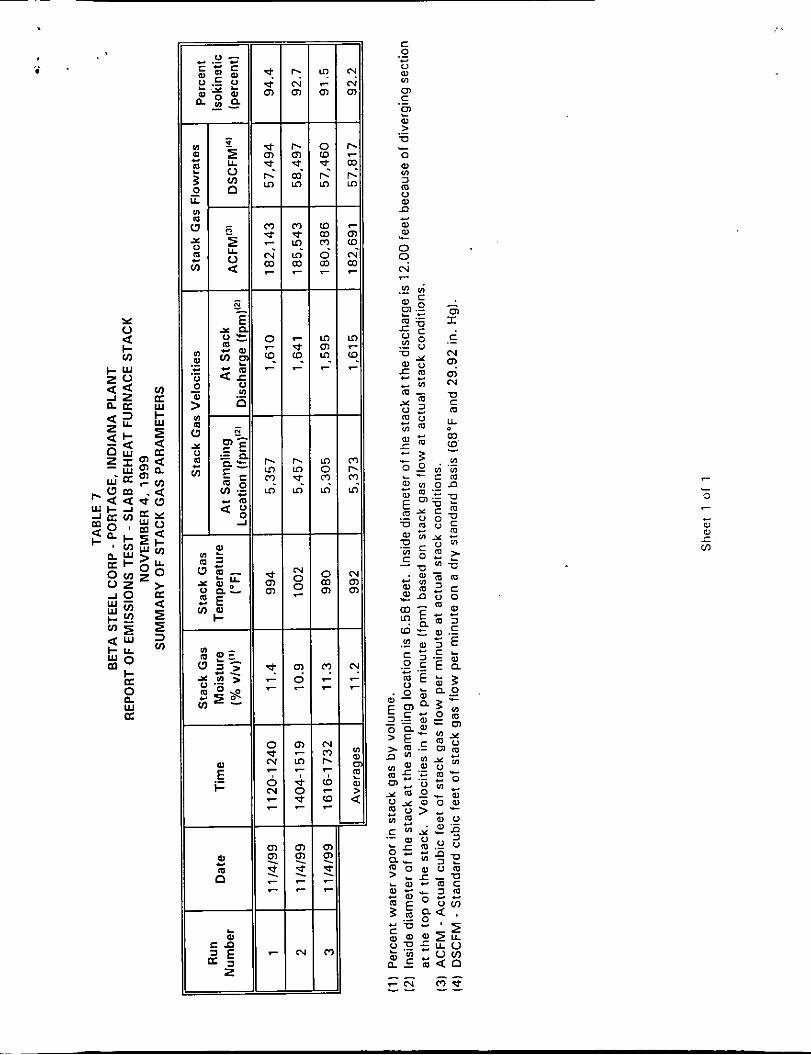
The Volumetric Flow Rate (326 IAC 3-6-4 (a)(4)(H))
Table 7 presents the volumetric flowrates of stack gas measured at the Slab Reheat
Furnace Stack during the emissions test at standard dry conditions (i.e., 29.92 inches
of mercury and 68°F) and a t the actual stack gas conditions tha t were measured
during the test.
The Exit Velocity (326 IAC 3-6-4 (a)(4)(J))
Table 7 presents the exit velocities that are calculated using the measured volumetric
flowrates under actual stack gas conditions and the inside exit diameter of the stack.
The Exit Temperature (326 IAC 3-6-4 (a)(4)(1))
Table 7 presents the average stack gas temperatures measured at the sampling por t
location during the test. The stack gas exit temperatures a t the discharge of the
stack are assumed t o be approximately equal t o these measured temperatures.
10
Brief Discussions o f the Analytical Procedures with Justification for Any Variance from Reference Method Procedures (326 IAC 3-6-4 (a)(5)(A))
The analytical procedures for the Method 5 and Method 202 particulate matter tests
are described in Appendix E. These include procedures for preparation of equipment,
sample recovery and laboratory analysis. No variances from the reference method
procedures were necessary.
.
The Number of Sampling Points, the Time Per Point and the Total Sampling Time Per Run (326 IAC 3-6-4 (a)(Ei)(B)(i), (ii) and (iii))
The number of sampling points utilized during the particulate matter tes ts was
2 4 (i.e., 2 sampling ports, 1 2 points per port). The target t ime per point was
2.5 minutes, wh ich would result in a total sampling time per run of (2.5 x 24)
60 minutes.
Cross Sectional Diagram of the Sampling Site Showing Sampling Points (326 IAC 3-6-4 (a)(5)(C))
Figure 3 is a cross sectional diagram o f the stack at the sampling port elevation
showing the locations of the sampling ports and the sampling points a t each sampling
port.
Diagram Showing the Stack Dimensions, the Sampling Location and the Distances from the Nearest F low Disturbance Upstream and Downstream from the Sampling Ports (326 IAC 3-6-4 (a)(5)(D)(i) and (ii))
Figure 4 is an elevation v iew diagram tha t shows the Hot Strip Mill Slab Reheat
Furnace Stack height above local grade elevation, the elevation of the stack sampling
ports and the distances f rom the stack sampling ports from the nearest upstream and
downstream f low disturbances. 2
11
Diagrams of the Sampling Trains (326 IAC 3-6-4 (a)(S)(D)(iv))
Figure 5 is a schematic diagram of the Method 5 sampling train used for sampling
filterable particulate matter. Figure 6 is a schematic diagram of the Method 202
sampling train used for sampling condensible particulate matter. Sampling for bo th
the filterable fraction and the condensible fraction of total particulate matter in the
stack gas was conducted simultaneously by combining the Method 5 and the Method
202 sampling trains into a single sampling train assembly.
Figure 7 presents a schematic diagram of the sampling train used for continuous,
simultaneous sampling and analyses of NOx and CO concentrations in the stack gas
by Methods 7E and 10, respectively. Figure 8 presents a schematic diagram of the
sampling train used for continuous sampling of total hydrocarbon (VOC)
concentrations in the stack gas using Method 25A.
One Complete Calculation Using Actual Data for Each Type of Test Performed Using Units Consistent Wi th the Applicable Emission Limitation (326 IAC 3-6-4 (a)(G)(A)(i) and (ii))
Appendix F presents example calculations for the particulate matter tests.
Appendix G presents example calculations for the gaseous pollutants tests.
Photocopies of All Actual Field Data (326 IAC 3-6-4 (a)(G)(A)(iv))
Appendix D provides photocopies of the Visible Emission Observation Forms used t o
record the results of all visible emissions observations performed by a certified visible
emissions observer during the tests. Appendix H presents photocopies of the field
data sheets for the particulate matter tests as well as the laboratory data sheets for
particulate weight determinations.
12
.
Laboratory Chain of Custody 1326 IAC 3-6-4 (a)(G)IB)(i))
The emissions testing was performed by Ambient Air Services, Inc. (AAS) of Starke,
Florida. The samples obtained during the particulate matter tests were obtained and
retained by A A S personnel while at the Beta Steel plant. The samples remained in
the custody of AAS personnel a t all times during travel from the Beta Steel plant t o
the AAS facility in Starke, Florida. The analyses of the samples were performed by
AAS personnel at the AAS facility. Therefore, the samples remained in the custody
of AAS personnel at all times from the collection of the samples through completion
of the analyses of the samples. That is, there was no chain of custody for the
samples.
Copies of All Calibration Data for Equipment Used in Sampling (326 IAC 3-6-4 (a)(6)(B)(ii))
Appendix I presents documentation of calibration of equipment used to perform the
measurements of stack gas flowrates and conduct the particulate matter tests.
Appendix J presents the certificates for the EPA protocol calibration gases used t o
perform instrument calibrations during the testing for gaseous pollutants. Appendix K presents the instrument calibration data for the gaseous pollutant testing. These data
include the calibration history and the instrument drift analysis.
Applicable Rules and Regulations Showing Emission Limitations (326 IAC 3-6-4 (a)(6)(C))
The emission limitations that are applicable t o the Hot Strip Mil l Slab Reheat Furnace
Stack are specified as conditions in Beta Steel's PSD construction permit, which is
the current operation permit for the plant. Table 8 presents a summary of the
applicable emission limitations. Appendix L presents a photocopy of an excerpted
page from the PSD Construction Permit which specifies the emission limitations.
13
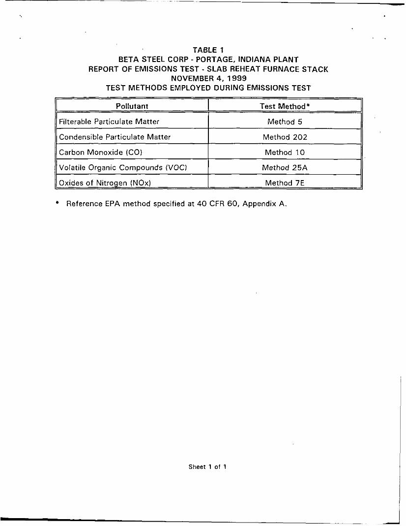
Pollutant
Filterable Particulate Matter
11 Condensible Particulate Matter I Method 202 II
Test Method*
Method 5
11 Carbon Monoxide (CO) I Method 10 II
Oxides of Nitrogen (NOx) ~ ~
Method 7E
Reference EPA method specified a t 40 CFR 60, Appendix A.
Sheet 1 of 1
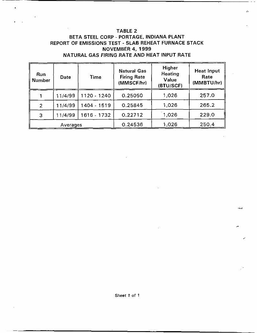
Heat Input Higher
Heating
Value (MMBTUlhr)
Natural Gas Firing Rate Rate
(MMSCFlhr) (BTUlSCF)
Date Time Run Number
1 11/4/99 1120 - 1240 0.25050 1,026 257.0
2 11/4/99 1404- 1519 0.25845 1,026 265.2
3 11/4/99 1616- 1732 0.22712 1,026 229.0
1 Avera es 1,026 250.4
Sheet 1 of 1
- -
m 9 m
- N (D 0
0 9
-
m p! N
-
W d 0
0 9
c
< ! L
I
r.
3 ? n
- N
N @?
- LD m 0
0 9
u - v e 3 + m
" ! : m 9
0
c e 0
... - 0 ...
m = - m
+ W W r m
Run Number 1 2 3
11 Time I 1120-1220 I 1404-1504 I 1616-1716 I Averages 11
~~
Higher Heating Value - BTUlSCF
Heat Input Rate - MMBTU/hr
11 Natural Gas Firina Rate - MMSCF/hr 1 0.25050 1 0.25845 1 0.22712 1 0.24536 11 ~~
1,026 1,026 1,026 1,026
257.0 265.2 229.0 250.4
Emission Rate - Ibs/MMBTU
11 Stack Gas Flowrate - dscfm I 57,494 1 58,496 I 57,460 I 57,817 11
0.0000 0.0010 0.0007 0.0006
Carbon Monoxide IC01 I
Concentration - ppmvd 45.90 46.67 44.1 1 45.56
(1 Emission Rate - Ibs/hr 1 0.00 I 0.26 1 0.16 1 0.14 11
Emission Rate - lbslMM8TU
/I Emission Rate - Ibs/MMSCF I 0.00 I 1.01 I 0.70 I 0.57 11
0.074 0.074 0.079 0.076
Emission Rate - Ibs/MMBTU
11 Emission Rate - lbslhr I 18.92 I 19.57 I 18.17 I 18.89 11
0.0005 0.0004 0.0001 1 0.0003
11 Emission Rate - IbslMMSCF 1 75.5 1 75.7 ' I 80.0 I 77.1 11
11 Concentration - ppmvd I 0.286 I 0.224 I 0.048 I 0.186 11 11 Emission Rate - Ibs/hr 1 0.13 1 0.10. 1 0.02 1 0.08 11
Sheet 1 of 1
i
*
,
c r
C C
- - m
9 m 0
0 - N N 0
0 9 - Lo Lo 0
0 9 - m d 0
0 9
- m N 0
0 9 -
!
!
I
C
v) a
W C
C VI m 01 Y U m v)
0
.- L L
2
+ c
E a a c9 PI
VI
a 3 m > a
c
.-
-
- n m > m - .- :: U
E ._ z x
a I- .c
? - 0 7
.. ,'
p1 ln
m ".
d m m
0 e N
0 N r 7
7
r
r
N n
. 4 0
u r
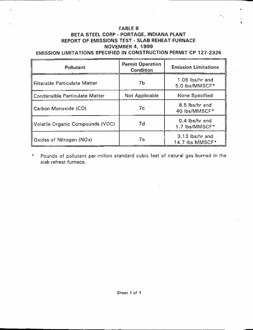
TABLE 8 BETA STEEL CORP - PORTAGE, INDIANA PLANT
REPORT OF EMISSIONS TEST - SLAB REHEAT FURNACE NOVEMBER 4, 1999
EMISSION LIMITATIONS SPECIFIED IN CONSTRUCTION PERMIT CP 127-2326
I/ Condensible Particulate Matter Not Applicable None Specified I
Permit Operation Condition Emission Limitations Pollutant
I Filterable Particulate Matter /I
Volatile Organic Compounds (VOC)
7b
0.4 lbslhr and 1.7 Ibs/MMSCF*
7d
1.06 Ibs/hr and 5.0 Ibs/MMSCF*
Oxides of Nitrogen (NOx) 3.1 3 Ibs/hr and
14.7 Ibs MMSCF' 7 e
11 Carbon Monoxide (CO) I 8.5 Ibs/hr and I 40 IbslMMSCF" 7c
I II II
* Pounds of pollutant per million standard cubic feet of natural gas burned in the slab reheat furnace.
Sheet 1 of 1