Embed Size (px)
Citation preview
1
Proceedings of the ICTWS 2014 7th International Conference on Thin-Walled Structures ICTWS2014
28 September – 2 October 2014, Busan, Korea
ICTWS2014-1403
SHIP COLLISION ON LOCK GATES – TECHNICAL SOLUTIONS AND SIMULATION APPROACHES
Sören Ehlers Norwegian University of Science and Technology,
Trondheim, Norway
Hervé Le Sourne ICAM, Mechanical Engineering Department,
Nantes, France
Loïc Buldgen University of Liege, ANAST,
Liege, Belgium
Juan Ollero INROS LACKNER AG,
Bremen, Germany
Colin Robertson Independent Consultant,
United Kingdom
Andreea Bela University of Liege, ANAST,
Liege, Belgium
Philippe Rigo University of Liege, ANAST,
Liege, Belgium
ABSTRACT
A ship colliding with a lock gate can result in severe structural damage and disrupt the lock operations. For heavily trafficked waterways containing locks such disruption of the lock operation can result in severe economic consequences if the gate has to be repaired, both for the lock operator and for the delayed ships. Consequently, the consequences of a ship colliding with a lock gate must be assessed. Therefore, this paper will present current regulatory requirements and recommendations including gate protection systems. Furthermore, simulation methods will be presented to allow for a direct assessment of the structural consequences. Thus, these methods will potentially lead to new structural design considerations as well as operational limitations in terms of specific ship approach velocities to remain below critical impact energies and thus allow for an undisrupted lock operation.
1. INTRODUCTION This paper presents and discusses an analysis approach for
the design of lock gates considering ship collisions. Various national guidelines and design standards exist, but none specifically require the consideration of ship collision as a design criterion whilst providing a detailed, yet general, methodology to assess the lock gate in question under ship collision. Furthermore, quantitative measures or guidance for parameters relevant to the collision accident are scarce.
The entry of a ship into a navigation lock is a difficult manoeuvre, which may lead to the ship colliding with the lock gate. Therefore, the eventual consequences of ship colliding with a lock gate must be analysed, ranging from the ship
sinking with potential loss of life to sudden downstream flooding if the gate fails. The causes of a ship colliding with a lock gate are manifold and Meinhold (2011) states that more than one half of such collisions is due to human error.
In Germany the design criteria are identified on a case-by-case basis and may include ship collision considerations. According to DIN 19704 and 19703 any collision against closure structures is to be prevented by installation of protection devices, where the kinetic energy to be absorbed is suggested to be in the range of 1 to 2 MN unless found to differ for the striking ship in question with a velocity around 1 m/s. Eurocode 1, EN 1991-1-7: 2010-12 provides indicative values for ship collision within inland waterways for different ship sizes according to the European Conference of Ministers of
2
Transport (ECMT), and in seaways for oceangoing ships. The values given there are for collisions against rigid structures, where the collision energy is being absorbed solely by the deformation of the striking ship.
In the United Kingdom navigation lock gates are not specifically designed against collision loadings, with the exception being gates at naval dockyards. In France there are no particular standards for designing lock gates against ship collisions. Nevertheless, some recommendations concerning ship collisions on lock gates are published by a technical division of the French Ministry of Equipment called the CETMEF, which are specifically addressed in the technical notice STC.VN n°97.01 (CETMEF 1997). According to the RfP (Request for Proposals) published by the Panama Canal Authority ACP (Autoridad del Canal de Panamá) “...Lock gates shall be designed and constructed to be able to resist, when closed, the impact of a 160,000-ton displacement ship traveling at a speed of 1 knot without compromising their watertightness or the capability of being moved into their recesses…”. The U.S. Army Corps of Engineers published several engineering manuals (EM), such as EM 1110-2-2105 and EM 1110-2-2703. Therein, depending on the lock gate type different collision loads and load cases are specified, including suggestions to, i.e., equip all mitre gates with a system of bumpers and fenders. In the Netherlands, ship collision is usually not considered as being a separate issue within gate design practice, but a part of the lock availability question.
Consequently, proper specifications and requirements concerning collision protection very much depend on the consequences that ship collision can have on the lock availability. Thus, there is no uniform national code or standard that considers ship collisions on lock gates. From a structural design perspective of the lock gate it is thus important to point out that the Eurocode 1 is not applicable here, because only rigid, i.e. non-energy absorbing, structures under ship collisions are considered, such as massive bridge piers.
Consequently, realistic analyses of lock gates under ship collision require computer-based numerical simulations. Therefore, this paper will identify the background needed to carry out a numerical ship collision simulation with a lock gate to allow for the analysis of the structural design of the lock gate. At first, common lock gate types are presented as well as possible gate protection systems followed by a design methodology section and available and recommended analysis approaches. Steel gates share many design aspects with ships, and the estimation of the collision resistance of ships is a fairly mature task using numerical methods, see for example Paik (2007) and Ehlers (2010). Obviously there are probabilistic issues within these problems, but these are beyond the scope of this paper.
Types of Gates
In general, functions of gate systems are diverse and they can range from closure structures of a navigation lock, harbour or shipyard dock to integral parts of water regulation and flood protection systems. For navigation locks it is useful to make a
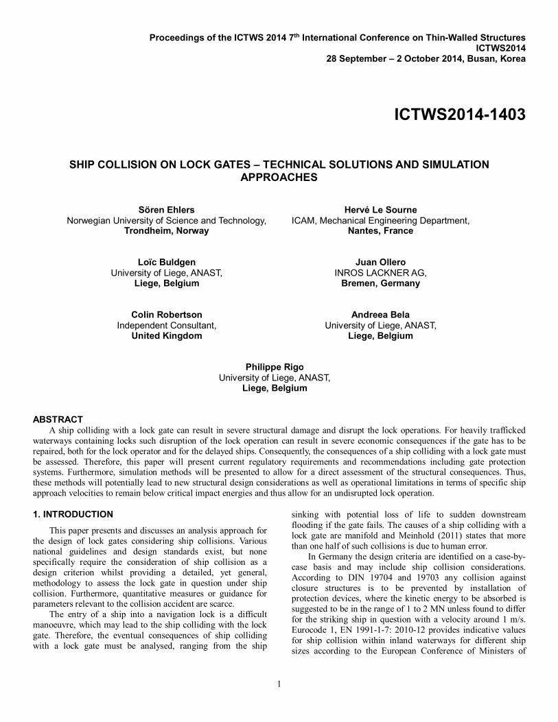
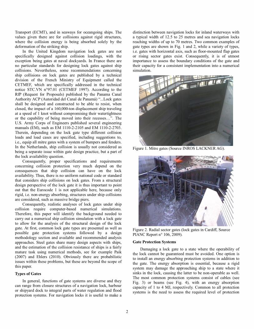
distinction between navigation locks for inland waterways with a typical width of 12.5 to 25 metres and sea navigation locks reaching widths of up to 70 metres. Two common examples of gate types are shown in Fig. 1 and 2, while a variety of types, i.e. gates with horizontal axis, such as floor-mounted flap gates or rising sector gates exist. Consequently, it is of utmost importance to assess the boundary conditions of the gate and their capacity for a consistent implementation into a numerical simulation.
Figure 1. Mitre gates (Source INROS LACKNER AG).
Figure 2. Radial sector gates (lock gates in Cardiff, Source PIANC Report n° 106, 2009).
Gate Protection Systems
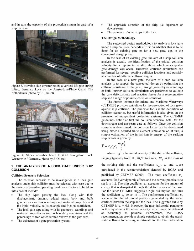
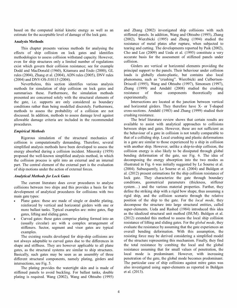
Damaging a lock gate to a state where the operability of the lock cannot be guaranteed must be avoided. One option is to install an energy absorbing protection systems in addition to the gate. The energy absorption is essential, because a rigid system may damage the approaching ship to a state where it sinks in the lock, causing the latter to be non-operable as well. The most common protection systems consist of cables (see Fig. 3) or beams (see Fig. 4), with an energy absorption capacity of 1 to 4 MJ, respectively. Common to all protection systems is the need to assess the required level of protection
3
and in turn the capacity of the protection system in case of a ship collision.
Figure 3. Movable ship arrestor net by a vertical lift gate during lifting, Bernhard Lock on the Amsterdam-Rhine Canal, The Netherlands (photo by R. Daniel)
Figure 4. Shock absorber beam II (Old Navigation Lock Wusterwitz / Germany, photo by J. Ollero).
2. THE ANALYSIS OF A LOCK GATE UNDER SHIP COLLISION
Collision Scenario Selection The collision scenario to be investigation in a lock gate
analysis under ship collision must be selected with care due to the variety of possible operating conditions. Factors to be taken into account include: The ship types passing the lock along with their
displacement, draught, added mass, bow and bulb geometry as well as scantlings and material properties and the initial velocity, collision angle and friction coefficient.
The lock gate type along with its geometry, scantlings and material properties as well as boundary conditions and the percentage of free water surface relative to the gate area.
The existence of a gate protection system.
The approach direction of the ship, i.e. upstream or downstream.
The presence of other ships in the lock.
The Design Methodology
The suggested design methodology to analyse a lock gate under a ship collision depends at first on whether this is to be done for an existing gate or for a new gate, e.g. in the conceptual design phase.
In the case of an existing gate, the aim of a ship collision analysis is usually the identification of the critical collision velocity for a representative ship above which unacceptable gate damage will occur. Therefore, collision simulations are performed for several possible collision locations and possibly at a number of different collision angles.
In the case of a new gate, the aim of a ship collision analysis is to support the conceptual design by optimising the collision resistance of the gate, through geometry or scantlings or both. Further collision simulations are performed to validate the gate deformations and reaction forces for a representative ship and a range of possible collision scenarios.
The French Institute for Inland and Maritime Waterways (CETMEF) provides guidelines for the protection of lock gates against ship collision. The principal focus is the definition of collision scenarios, but useful information is also given on the provision of independent protection systems. The CETMEF guidelines define at first the collision scenario, both, for the downstream and upstream gate as follows. Once the collision scenario is determined, the collision forces can be determined using either a detailed finite element simulation or, at first, a simple estimation of the initial kinetic energy of the striking ship, which is given by:
E = cmcccs
m0v02
2
where 푣 is the initial velocity of the ship at the collision, ranging typically from 0.5푚/푠 to 2 m/s; m0 is the mass of
the striking ship and the coefficients cm , 푐 and 푐 are introduced in the recommendations denoted by ROSA and published by CETMEF (2000). The mass coefficient cm accounts for hydrodynamic effects and the current practice is to set it to 1.2. The ship coefficientc accounts for the amount of energy that is dissipated through the deformations of the bow. For the latter CETMEF suggests a rigid assumption and thus the coefficient c be set to 1. The confinement coefficient c accounts for the additional pressure generated by the water confined between the ship and the lock. The suggested value by CETMEF is c = 0.8. However, the most influential parameter in this equation is the initial velocity, which must be obtained as accurately as possible. Furthermore, the ROSA recommendation provide a simple equation to obtain the quasi-static collision force using an estimate for the total indentation
4
based on the computed initial kinetic energy as well as an estimate for the acceptable level of damage of the lock gate.
Analysis Methods
This chapter presents various methods for analysing the effects of ship collision on lock gates and identifies methodologies to assess collision withstand capacity. However, even for ship structures only a limited number of regulations exist which govern their collision resistance; see for example Dodd and MacDonald (1960), Kitamura and Endo (2000), GL rules (2004), Zhang et al. (2004), ADN rules (2005), DNV rules (2004) and DNV-OS-J10115 (2004).
Nevertheless, this section identifies various analysis methods for simulation of ship collision on lock gates and summarises these. Furthermore, the simulation methods presented are concerned solely with the structural elements of the gate, i.e. supports are only considered as boundary conditions rather than being modelled discretely. Furthermore, methods to assess the probability of a collision are not discussed. In addition, methods to assess damage level against allowable damage criteria are included in the recommended procedures.
Empirical Methods
Rigorous simulation of the structural mechanics of collision is computationally demanding. Therefore, several simplified analysis methods have been developed to assess the energy absorbed during a collision incident. Minorsky (1959) proposed the well-known simplified analysis method, in which the collision process is split into an external and an internal part. The central element of the external part is the evaluation of ship motions under the action of external forces.
Analytical Methods for Lock Gates
The current literature does cover procedures to analyse collisions between two ships and this provides a basis for the development of analytical procedures for collisions with two main gate types: Plane gates: these are made of single or double plating,
reinforced by vertical and horizontal girders with one or more ballast tanks. Typical examples are: mitre gates, flap gates, lifting and sliding gates.
Curved gates: these gates comprise plating formed into an (usually circular) arc with a complex arrangement of stiffeners. Sector, segment and visor gates are typical examples. The existing results developed for ship-ship collisions are
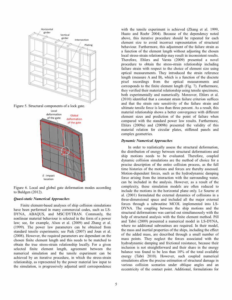
not always adaptable to curved gates due to the differences in shape and stiffness. They are however applicable to all plane gates, as the structural systems are similar to ship structures. Basically, such gates may be seen as an assembly of three different structural components, namely plating, girders and intersections, see Fig. 5.
The plating provides the watertight skin and is made of stiffened panels to avoid buckling. For ballast tanks, double plating is required. Wang (2002), Wang and Ohtsubo (1995)
and Zhang (2002) investigated ship collisions with such stiffened panels. In addition, Wang and Ohtsubo (1995), Zhang (2002), Wierzbicki (1995) and Zheng (1994) studied the resistance of metal plates after rupture, when subjected to tearing and cutting. The developments reported by Paik (2002), Cho and Lee (2009) and Ueda et al. (1995) constitute a very accurate basis for the assessment of stiffened panels under collision.
Girders are vertical or horizontal elements providing the principal support to the panels. Their behaviour under collision loads is globally elasto-plastic, but contains also local phenomena, such as “crushing”. Wierzbicki and Culbertson-Driscoll (1995), Wang and Ohtsubo (1997), Simonsen (1997), Zhang (1999) and Amdahl (2008) studied the crushing resistance of these components theoretically and experimentally.
Intersections are located at the junction between vertical and horizontal girders. They therefore have X- or T-shaped cross-sections. Amdahl (1983) and Zhang (1999) studied their crushing resistance.
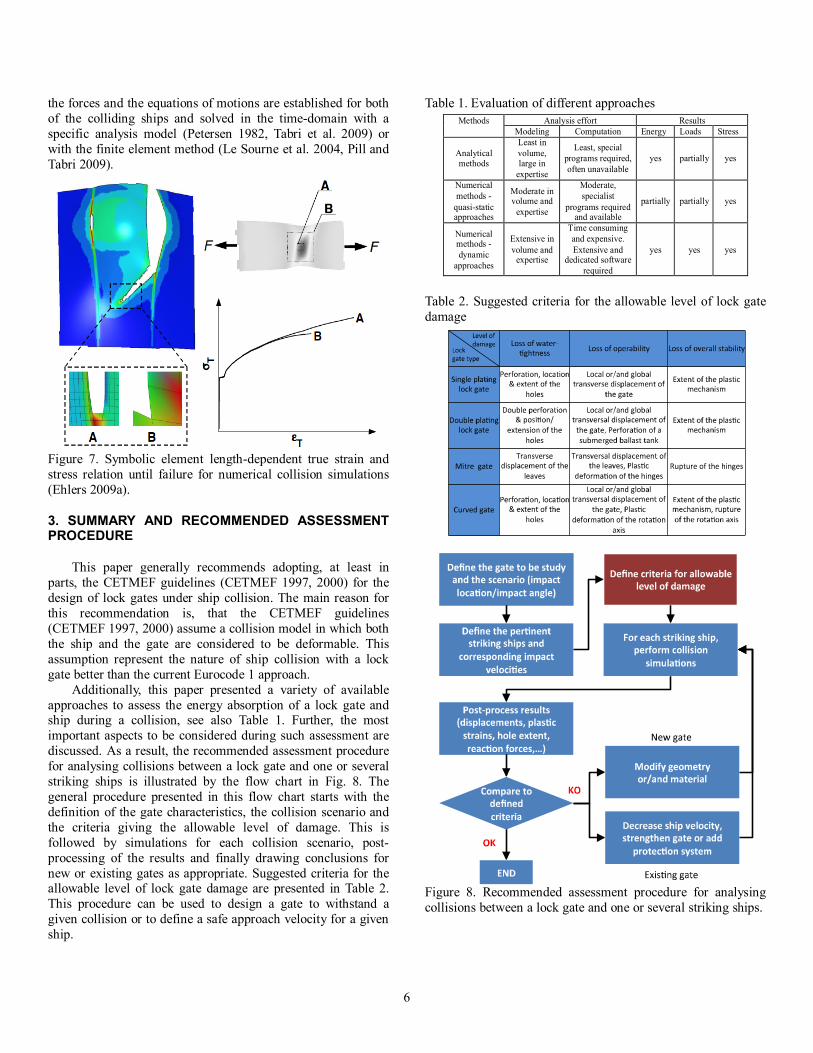
The brief literature review shows that certain results are available to assist with analytical approaches to collisions between ships and gates. However, these are not sufficient as the behaviour of a gate in collision is not totally comparable to that of a colliding ship. Local crushing and plastic deformations in a gate are similar to those experienced by a ship in collision with another ship. However, unlike a ship-to-ship collision, the collision energy is also likely to be dissipated through global bending deformation of the gate, see Fig. 6. The idea of decomposing the energy absorption into the two modes as illustrated in Fig. 6 was initially suggested by Le Sourne et al. (2004). Subsequently, Le Sourne et al. (2004) and Buldgen et al. (2012) present estimations for the ship collision resistance of lock gate. They characterize the gate through boundary conditions, geometrical parameters (thickness, stiffener system…) and the various material properties. Further, they define the striking ship with a rigid bow shape, thus assuming a rigid ship, and the collision scenario through the relative position of the ship to the gate. For the local mode, they decompose the structure into large structural entities, called super-elements. Ueda and Rashed (1984) introduced this idea as the idealized structural unit method (ISUM). Buldgen et al. (2012) extended this method to assess the local ship collision resistance of lifting and sliding gates. For the global mode, they evaluate the resistance by assuming that the gate experiences an overall bending deformation. With this assumption, the resisting force may be derived considering a simplified model of the structure representing this mechanism. Finally, they find the total resistance by combing the local and the global resistance assuming that for small values of penetration, the local mode is predominant. However, with increasing penetration of the gate, the global mode becomes predominant. The particular case of ship collisions against mitre gates was also investigated using super-elements as reported in Buldgen et al. (2013).
5
Figure 5. Structural components of a lock gate.
Figure 6. Local and global gate deformation modes according to Buldgen (2012).
Quasi-static Numerical Approaches
Finite element-based analyses of ship collision simulations have been performed in many commercial codes, such as LS-DYNA, ABAQUS, and MSC/DYTRAN. Commonly, the nonlinear material behaviour is selected in the form of a power law; see, for example, Alsos et al. (2009) and Zhang et al. (1999). The power law parameters can be obtained from standard tensile experiments; see Paik (2007) and Joun et al. (2008). However, the required parameters are dependant on the chosen finite element length and this needs to be matched to obtain the true stress-strain relationship locally. For a given selected finite element length, agreement between the numerical simulation and the tensile experiment can be achieved by an iterative procedure, in which the stress-strain relationship, as represented by the power material law input to the simulation, is progressively adjusted until correspondence
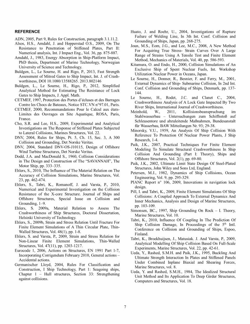
with the tensile experiment is achieved (Zhang et al. 1999, Huato and Roehr 2004). Because of the dependency noted above, this iterative procedure should be repeated for each element size to avoid incorrect representation of structural behaviour. Furthermore, this adjustment of the failure strain as a function of the element length without adjusting the chosen local stress-strain relationship may result in inconsistent results. Therefore, Ehlers and Varsta (2009) presented a novel procedure to obtain the stress-strain relationship including failure strain with respect to the choice of element size using optical measurements. They introduced the strain reference length (measure A and B), which is a function of the discrete pixel recordings from the optical measurements and corresponds to the finite element length (Fig. 7). Furthermore, they verified their material relationship using tensile specimens, both experimentally and numerically. Moreover, Ehlers et al. (2010) identified that a constant strain failure criterion suffices and that the strain rate sensitivity of the failure strain and ultimate tensile force is less than three percent. As a result, this material relationship shows a better convergence with different element sizes and prediction of the point of failure when compared with the standard power law results. Furthermore, Ehlers (2009a) and (2009b) presented the validity of this material relation for circular plates, stiffened panels and complex geometries.
Dynamic Numerical Approaches
In order to realistically assess the structural deformation, the distribution of energy between structural deformations and ship motions needs to be evaluated. Therefore, coupled dynamic collision simulations are the method of choice for a precise description of the entire collision process, as the full time histories of the motions and forces are thereby assessed. Motion-dependent forces, such as the hydrodynamic damping force arising from the interaction with the surrounding water, can be included in the analysis. However, as a result of the complexity, these simulation models are often reduced to include the motions in the horizontal plane only. Le Sourne et al. (2001) formulated the external dynamics of collisions in a three-dimensional space and included all the major external forces through a subroutine MCOL implemented into LS-DYNA. The coupling between the ship motions and the structural deformations was carried out simultaneously with the help of structural analysis with the finite element method. Pill and Tabri (2009) presented a numerical model in LS-DYNA, where no additional subroutines are required. In their model, the mass and inertial properties of the ships, including the effect of the added mass, are described through a small number of mass points. They neglect the forces associated with the hydrodynamic damping and frictional resistance, because their inclusion is not straightforward and their share in the energy balance was found to be less than 10% of the total available energy (Tabri 2010). However, such coupled numerical simulations allow the precise estimation of structural damage in various collision scenarios under oblique angles and an eccentricity of the contact point. Additional, formulations for
Horizontalgirder
Verticalgirder
Intersection
Plating
Global deformation of the gate
Local deformation of the gate
E
E : impact location
6
the forces and the equations of motions are established for both of the colliding ships and solved in the time-domain with a specific analysis model (Petersen 1982, Tabri et al. 2009) or with the finite element method (Le Sourne et al. 2004, Pill and Tabri 2009).
Figure 7. Symbolic element length-dependent true strain and stress relation until failure for numerical collision simulations (Ehlers 2009a).
3. SUMMARY AND RECOMMENDED ASSESSMENT PROCEDURE
This paper generally recommends adopting, at least in parts, the CETMEF guidelines (CETMEF 1997, 2000) for the design of lock gates under ship collision. The main reason for this recommendation is, that the CETMEF guidelines (CETMEF 1997, 2000) assume a collision model in which both the ship and the gate are considered to be deformable. This assumption represent the nature of ship collision with a lock gate better than the current Eurocode 1 approach.
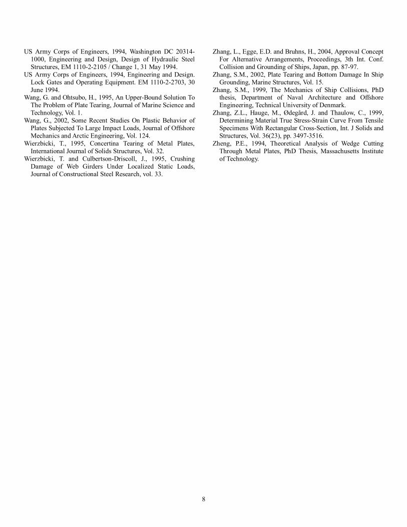
Additionally, this paper presented a variety of available approaches to assess the energy absorption of a lock gate and ship during a collision, see also Table 1. Further, the most important aspects to be considered during such assessment are discussed. As a result, the recommended assessment procedure for analysing collisions between a lock gate and one or several striking ships is illustrated by the flow chart in Fig. 8. The general procedure presented in this flow chart starts with the definition of the gate characteristics, the collision scenario and the criteria giving the allowable level of damage. This is followed by simulations for each collision scenario, post-processing of the results and finally drawing conclusions for new or existing gates as appropriate. Suggested criteria for the allowable level of lock gate damage are presented in Table 2. This procedure can be used to design a gate to withstand a given collision or to define a safe approach velocity for a given ship.
Table 1. Evaluation of different approaches
Table 2. Suggested criteria for the allowable level of lock gate damage
Figure 8. Recommended assessment procedure for analysing collisions between a lock gate and one or several striking ships.
Methods Analysis effort Results Modeling Computation Energy Loads Stress
Analytical methods
Least in volume, large in
expertise
Least, special programs required, often unavailable
yes partially yes
Numerical methods -
quasi-static approaches
Moderate in volume and
expertise
Moderate, specialist
programs required and available
partially partially yes
Numerical methods - dynamic
approaches
Extensive in volume and
expertise
Time consuming and expensive. Extensive and
dedicated software required
yes yes yes
7
REFERENCE
ADN, 2005, Part 9, Rules for Construction, paragraph 3.1.11.2. Alsos, H.S., Amdahl, J. and Hopperstad O.S., 2009, On The
Resistance to Penetration of Stiffened Plates, Part II: Numerical analysis, Int. J Impact Eng., Vol. 36, pp. 875-887.
Amdahl, J., 1983, Energy Absorption in Ship-Platform Impact, PhD thesis, Department of Marine Technology, Norwegian University of Science and Technology.
Buldgen, L., Le Sourne, H. and Rigo, P., 2013, Fast Strength Assessment of Mitred Gates to Ship Impact, Int. J. of Crash-worthiness, DOI 10.1080/13588265. 2013.802146
Buldgen, L., Le Sourne, H., Rigo, P., 2012, Simplified Analytical Method for Estimating The Resistance of Lock Gates to Ship Impacts, J. Appl. Math.
CETMEF, 1997, Protection des Portes d’écluses et des Barrages Contre les Chocs de Bateaux, Notice STC.VN n°97.01, Paris.
CETMEF, 2000, Recommandations Pour le Calcul aux états-Limites des Ouvrages en Site Aquatique, ROSA, Paris, France.
Cho, S.R. and Lee, H.S., 2009, Experimental and Analytical Investigations on The Response of Stiffened Plates Subjected to Lateral Collisions, Marines Structures, Vol. 22.
DNV, 2004, Rules for Ships, Pt. 5, Ch. 15, Sec. 3, A 300 Collision and Grounding, Det Norske Veritas.
DNV, 2004, Standard DNV-OS-J10115, Design of Offshore Wind Turbine Structures, Det Norske Veritas.
Dodd, J.A. and MacDonald S., 1960, Collision Considerations in The Design and Construction of The “SAVANNAH”, The Motor Ship, pp. 333–335.
Ehlers, S., 2010, The Influence of The Material Relation on The Accuracy of Collision Simulations, Marine Structures, Vol. 23, pp. 462-474.
Ehlers, S., Tabri, K., Romanoff, J. and Varsta, P., 2010, Numerical and Experimental Investigation on the Collision Resistance of the X-core Structure. Journal of Ships and Offshore Structures, Special Issue on Collision and Grounding, 1–9.
Ehlers, S. 2009a, Material Relation to Assess The Crashworthiness of Ship Structures, Doctoral Dissertation, Helsinki University of Technology.
Ehlers, S., 2009b, Strain and Stress Relation Until Fracture For Finite Element Simulations of A Thin Circular Plate, Thin-Walled Structures, Vol. 48(1), pp. 1-8.
Ehlers, S. and Varsta, P., 2009, Strain and Stress Relation for Non-Linear Finite Element Simulations, Thin-Walled Structures, Vol. 47(11), pp. 1203-1217.
Eurocode 1, 2006, Actions on Structures, EN 1991 Part 1-7, Incorporating Corrigendum February 2010, General actions – Accidental actions.
Germanischer Lloyd, 2004, Rules For Classification and Construction, I Ship Technology, Part 1: Seagoing ships, Chapter 1 – Hull structures, Section 33: Strengthening against collisions.
Huato, J. and Roehr, U., 2004, Investigations of Rupture Failure of Welding Line, In 3th Int. Conf. Collision and Grounding of Ships, Japan, pp. 268-275.
Joun, M.S., Eom, J.G., and Lee, M.C., 2008, A New Method For Acquiring True Stress- Strain Curves Over A Large Range of Strains Using A Tensile Test and Finite Element Method, Mechanics of Materials, Vol. 40, pp. 586-593.
Kitamura, O. and Endo, H., 2000, Collision Simulations of An Exclusive Ship of Spent Nuclear Fuels, Int. Workshop Utilization Nuclear Power in Oceans, Japan.
Le Sourne, H., Donner, R., Besnier, F. and Ferry, M., 2001, External Dynamics of Ship- Submarine Collision, In 2nd Int. Conf. Collision and Grounding of Ships, Denmark, pp. 137-144.
Le Sourne, H., Rodet, J.C. and Clanet C., 2004, Crashworthiness Analysis of A Lock Gate Impacted By Two River Ships, International Journal of Crashworthiness.
Meinhold, W., 2011, Kollisionsbeanspruchung im Stahlwasserbau – Untersuchungen zum Schiffsstoß auf Schleusentore und abzuleitende Maßnahmen, Bundesanstalt für Wasserbau, BAW Mitteilungen Nr. 93; 29-38.
Minorsky, V.U., 1959, An Analysis Of Ship Collision With Reference To Protection Of Nuclear Power Plants, J Ship Research, 1-4.
Paik, J.K., 2007, Practical Techniques For Finite Element Modeling To Simulate Structural Crashworthiness In Ship Collision And Grounding (Part I: Theory), Ships and Offshore Structures, Vol. 2(1), pp. 69-80.
Paik, J.K., 2002, Ultimate Limit State Design Of Steel-Plated Structures, John Wiley and Sons Ltd, England.
Petersen, M.J., 1982, Dynamics of Ship Collisions, Ocean Engineering, Vol. 9, pp. 295-329.
PIANC Report n° 106, 2009, Innovations in navigation lock design.
Pill, I. and Tabri, K., 2009, Finite Element Simulations Of Ship Collisions: A Coupled Approach To External Dynamics And Inner Mechanics, Analysis and Design of Marine Structures, pp. 103-109.
Simonsen, BC., 1997, Ship Grounding On Rock – I. Theory, Marine Structures, Vol. 10.
Tabri, K., 2010, Influence Of Coupling In The Prediction Of Ship Collision Damage, In Proceedings of the 5th Intl. Conference on Collision and Grounding of Ships, Espoo, Finland.
Tabri, K., Broekhuijsen, J., Matusiak. J. And Varsta, P., 2009, Analytical Modelling Of Ship Collision Based On Full-Scale Experiments, Marine Structures, Vol. 22, pp. 42-61.
Ueda, Y., Rashed, S.M.H. and Paik, J.K., 1995, Buckling And Ultimate Strength Interaction In Plates and Stiffened Panels Under Combined Inplane Biaxial and Shearing Forces, Marine Structures, vol. 8.
Ueda, Y. and Rashed, S.M.H., 1984, The Idealized Structural Unit Method and Its Application To Deep Girder Structures, Computers and Structures, Vol. 18.
8
US Army Corps of Engineers, 1994, Washington DC 20314-1000, Engineering and Design, Design of Hydraulic Steel Structures, EM 1110-2-2105 / Change 1, 31 May 1994.
US Army Corps of Engineers, 1994, Engineering and Design. Lock Gates and Operating Equipment. EM 1110-2-2703, 30 June 1994.
Wang, G. and Ohtsubo, H., 1995, An Upper-Bound Solution To The Problem of Plate Tearing, Journal of Marine Science and Technology, Vol. 1.
Wang, G., 2002, Some Recent Studies On Plastic Behavior of Plates Subjected To Large Impact Loads, Journal of Offshore Mechanics and Arctic Engineering, Vol. 124.
Wierzbicki, T., 1995, Concertina Tearing of Metal Plates, International Journal of Solids Structures, Vol. 32.
Wierzbicki, T. and Culbertson-Driscoll, J., 1995, Crushing Damage of Web Girders Under Localized Static Loads, Journal of Constructional Steel Research, vol. 33.
Zhang, L., Egge, E.D. and Bruhns, H., 2004, Approval Concept For Alternative Arrangements, Proceedings, 3th Int. Conf. Collision and Grounding of Ships, Japan, pp. 87-97.
Zhang, S.M., 2002, Plate Tearing and Bottom Damage In Ship Grounding, Marine Structures, Vol. 15.
Zhang, S.M., 1999, The Mechanics of Ship Collisions, PhD thesis, Department of Naval Architecture and Offshore Engineering, Technical University of Denmark.
Zhang, Z.L., Hauge, M., Ødegård, J. and Thaulow, C., 1999, Determining Material True Stress-Strain Curve From Tensile Specimens With Rectangular Cross-Section, Int. J Solids and Structures, Vol. 36(23), pp. 3497-3516.
Zheng, P.E., 1994, Theoretical Analysis of Wedge Cutting Through Metal Plates, PhD Thesis, Massachusetts Institute of Technology.


![[1403-1C1312] Air cooled chillers 50Hz 20131216](https://img.pdfslide.us/doc/110x75/55cf8dda550346703b8bf142/1403-1c1312-air-cooled-chillers-50hz-20131216.jpg)