Embed Size (px)
Citation preview

Institutional and Sector Modernisation Facility
ICT Standards
Project Funded by the European Union
ICT Business Function Analysis Document number: ISMF-ICT/3.04 Version: 3.0

1 Document control
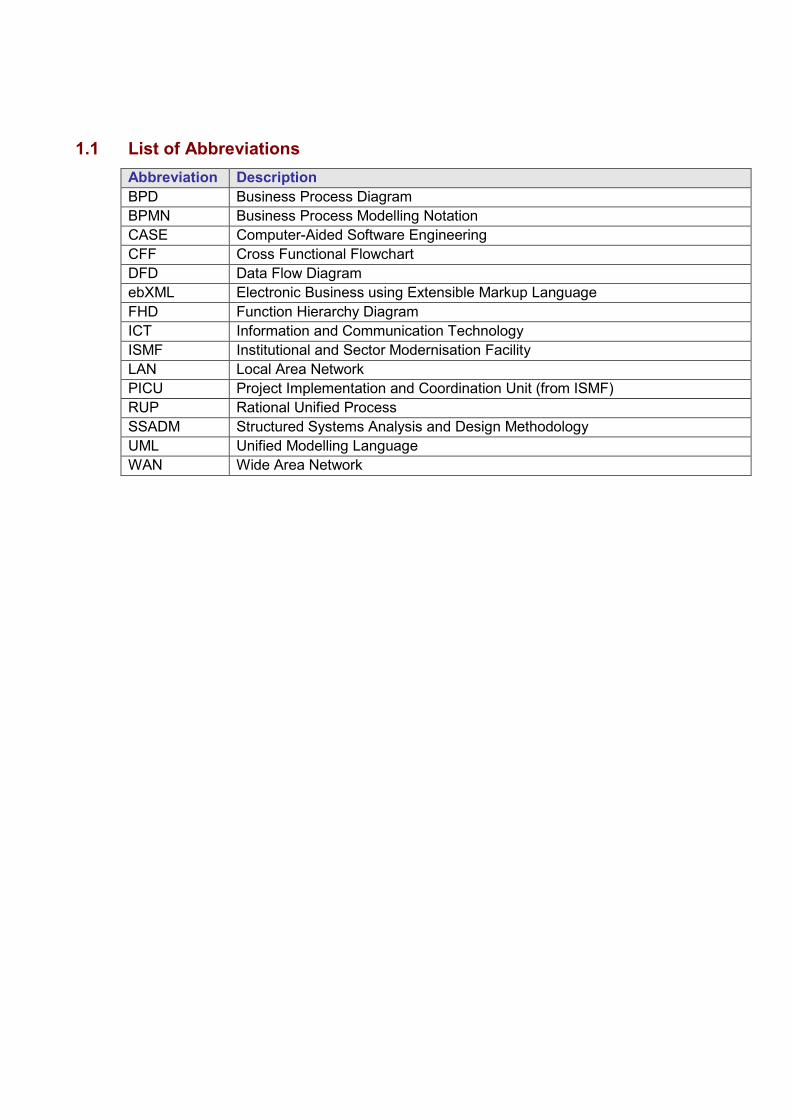
1.1 List of Abbreviations Abbreviation DescriptionBPD Business Process Diagram BPMN Business Process Modelling Notation CASE Computer-Aided Software Engineering CFF Cross Functional Flowchart DFD Data Flow Diagram ebXML Electronic Business using Extensible Markup Language FHD Function Hierarchy Diagram ICT Information and Communication Technology ISMF Institutional and Sector Modernisation Facility LAN Local Area Network PICU Project Implementation and Coordination Unit (from ISMF) RUP Rational Unified Process SSADM Structured Systems Analysis and Design Methodology UML Unified Modelling Language WAN Wide Area Network

1.2 Purpose of this Document This document constitutes Deliverable 3.04 “ICT Business Function Analysis” of Phase 1 – Development of Reference Documents, Sub-Phase 1.2 – Elaboration of Technical Standards (TS). This deliverable aims at providing sample methodology and models to carry out the Business Function Analysis required either for describing the “as is” (current model of organization and operation) or the “to be” (desired model).
1.3 When to carry out Business Function Analysis These models (at the appropriate level) will be included into the Project Life Cycle documentation as follows: Document Detail Level Model(Mandatory/Optional)
Master Plan High Level Organization chart (M) Context Diagram in describing both the “AS IS” and “TO BE” system (M)
Feasibility Study High Level Context Diagram (M) Data Flow Diagram (M)
Tender Document Medium Level Organization chart (O) Context diagram (M) Data Flow Diagram (O)
User Requirements Specs Context Diagram (M) Use Case (M)
Detail Analysis Documentation
Detailed level Context Diagram (M) Data Flow Diagram (M) Process Diagrams (M) Use Case (M) Other Diagrams, according to the modelling tool used (O).
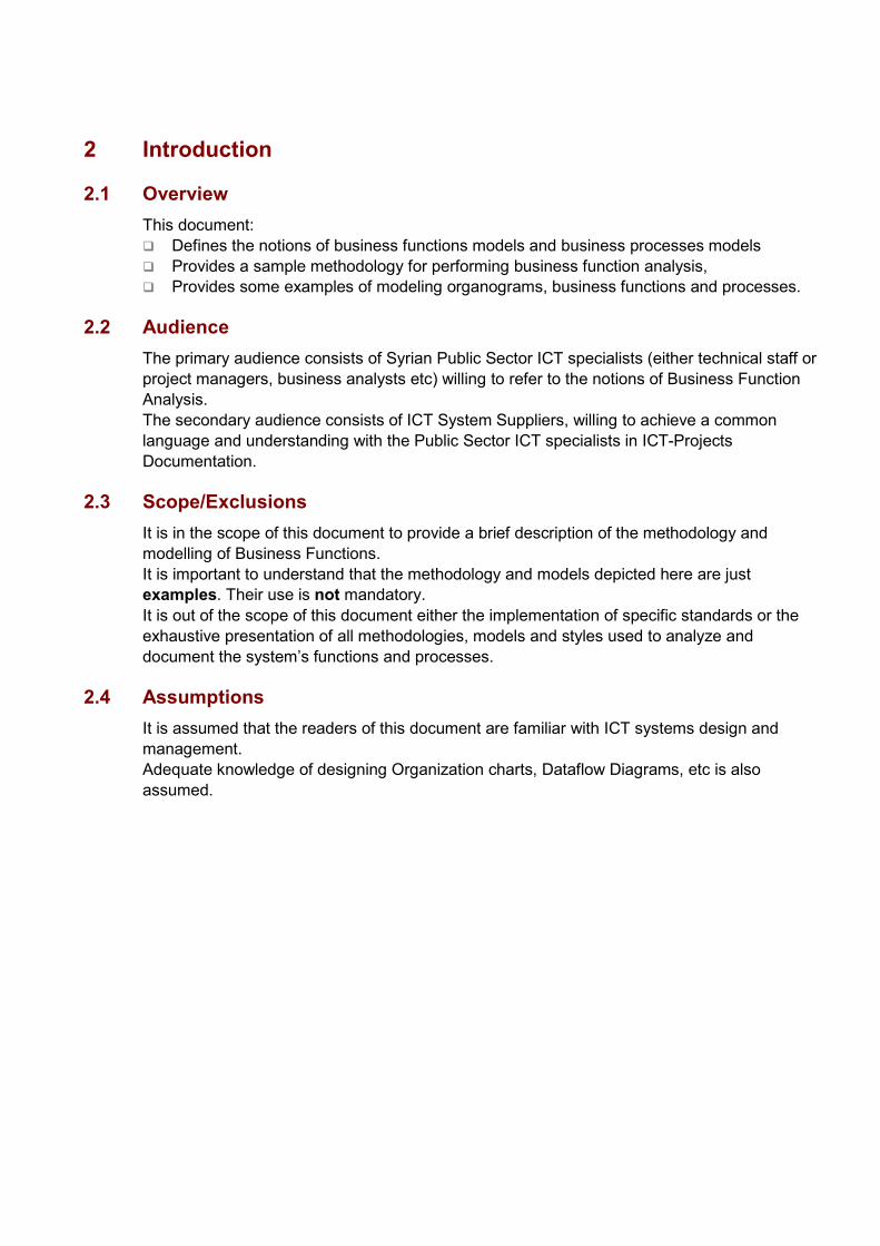
2 Introduction
2.1 Overview This document: � Defines the notions of business functions models and business processes models � Provides a sample methodology for performing business function analysis, � Provides some examples of modeling organograms, business functions and processes.
2.2 Audience The primary audience consists of Syrian Public Sector ICT specialists (either technical staff or project managers, business analysts etc) willing to refer to the notions of Business Function Analysis. The secondary audience consists of ICT System Suppliers, willing to achieve a common language and understanding with the Public Sector ICT specialists in ICT-Projects Documentation.
2.3 Scope/Exclusions It is in the scope of this document to provide a brief description of the methodology and modelling of Business Functions. It is important to understand that the methodology and models depicted here are just examples. Their use is not mandatory. It is out of the scope of this document either the implementation of specific standards or the exhaustive presentation of all methodologies, models and styles used to analyze and document the system’s functions and processes.
2.4 Assumptions It is assumed that the readers of this document are familiar with ICT systems design and management. Adequate knowledge of designing Organization charts, Dataflow Diagrams, etc is also assumed.

3 Definitions
3.1 Overview The notions of functions and processes are so interrelated that some times they are used as synonyms. This is not entirely correct, and some times confusing. The main difference resides in their nature; regardless of any definition, business function models are a static representation of the Organization’s activities, while Business process models are a dynamic one.
3.2 Business Function Model The business function model identifies and graphically displays, in a structured format, the activities that the Organization performs. It is important to distinguish between the function model and an organization model. An organization model depicts the structure (the hierarchy of units) of an Organization (e.g. a Syrian Public Sector entity). The business function model depicts what the Organization does. Nevertheless, generally Organizations are organized along function lines, in that each vertical organizational grouping performs the same or related set of activities and is responsible to a single control point.
3.2.1 Categories of Business Functions
The functions of any Organization, whether it is private or public Organization, can be segmented into two broad categories. Each of the various functions of the Organization can be assigned to one or the other of these categories, and in some cases, a function may be assigned in both categories.
Business category Functions in this category consist of those activities which are directly involved in producing the products, providing the services, generating the revenues and the profits of the Organization, or managing those areas. This category has been termed the operational area of the Organization. The functions in this category have also been termed line functions. From Application Software point of view, these functions are usually served by custom software, workflow software and Office Automation Suites.
Administrative, support or overhead category This category contains those functions which service the Organization as a legal entity and provide for its day-to-day well being. The administrative category usually contains functions such as personnel, buildings and maintenance, executive management, general accounting, etc. These functions have been termed “staff functions”. From Application Software point of view, these functions are usually served by off-the-shelf software (software packages), workflow software and Office Automation Suites.
3.3 Business Process Model A business process is a collection of activities designed to produce a specific output for a particular “customer” (e.g. a citizen or group of citizens). It implies a strong emphasis on how the work is done within an Organization, in contrast to a business function which focuses to what. A process is thus a specific ordering of work activities across time and place, with a beginning, an end, and clearly defined inputs and outputs: a structure for action.

On the other hand, a process can be defined as an organisation’s major business area of control or major activity. In this sense, a process is composed of and can be broken down to functions, activities and tasks, which are more elementary pieces of work carried out to achieve the business needs. Furthermore, In contrast with business functions which are generally performed inside an organizational unit, a business process usually consumes resources from several organizational units.
4 Methodological Approach This chapter presents the basic methodological steps for the execution of business function analysis as well as some constraints applying to it.
4.1 Organisation description The description of the organisational structure of a public entity or body is a mandatory step before proceeding with the actual Business Function Analysis. It provides adequate information and insight as to who are the main stakeholders of the potential information system to be implemented, their power and authority and, to some extent, the lines of communication. It also provides a general overview about the main business functions of the organisation, although at a higher level. When preparing the organisation description, one should: � First of all consult the official Organization chart and associated documents, laws and
regulations depicting the structure and the responsibilities of each element of it. � Draw the Organization chart using tools like MS Visio or MS PowerPoint. Describe in more
details the elements (Directorates, Departments, Agencies, etc.) that are directly involved in the functions under consideration.
� Ask about any “unofficial” structure and responsibilities. Make a separate notice about them.
4.2 Business Function Analysis The analyst should prepare a functional definition for each function addressed. The goal of this phase is to place the business sponsor in perspective within his or her specific business area and within the overall business functional framework. The definition of each business function should include as a minimum: � The positioning of the function in the business organisation hierarchy and its
interdependencies with other business functions. � The documents or other specific elements that are the input to the specific function and
their sources. � A narrative description of the activities and tasks executed in order for the business
function to meet its objectives. � The documents or other specific elements that are the output of the specific function and
their destinations. � The users of the specific business function and their positioning in the business
organisation hierarchy. � The IT infrastructure supporting the execution of the specific business functions, if any. It should be stressed that the language of the document should be in user, and thus in business, terms.
4.3 Methodology
The most important aspect of documenting functional requirements is the identification of elementary business functions. An elementary business function is what the organization does in complete response to a particular business event. A business event is any occurrence to which the organization responds in order to meet its business objectives. A common type of business event is a request by a customer for a product or service provided by the organization. The responsibility for an elementary business function typically falls within a particular functional area of the organization. Elementary business functions can be grouped into a hierarchy based on these functional area responsibilities. Grouping functions in this way serves primarily to facilitate group workshops and provide structure to requirements documents and reviews. Normally there should not be more than 1or 2 levels above the elementary function level, since more levels rarely clarify the model. While elementary business functions are focused on what the organization does in response to an event, one or more system processes will be identified in order to specify how the organization carries out each elementary business function. Each system process is typically conducted within a particular implementation environment. It is typically performed using a single mode (e.g. manual, online interactive, online real time, or batch) by a single person or group of people during a work session and, if automated, in a consistent computer environment. If more than one system process is planned to implement a single elementary business function, they will normally have to be conducted in a particular order. The business function model must clearly document business events, elementary business functions, and their outcomes. Each must be clearly described. Higher level functions in the model may include descriptions, if they serve a communication function. High level function descriptions should not just re-iterate what is already documented through lower level functions. Every entity used by an elementary business function will be identified along with the way in which it is used.
4.4 Constraints Typically, the business function analysis document alone does not provide a true picture of the scope of the business functions; at best, it provides a limited insight into the interactions of the user's function with the other functional areas of the Organization. Without this insight of the place of the user function within the overall framework of the organization and without an understanding of the relationship of the user function to the other functions of the Organization, it is difficult for analysts to assess the accuracy of their business knowledge. In reality, the various functions of the Organization interact in ways which transcend and cross the hierarchic boundaries which are implicit in the table of organization. In many organizations, the table of organization is either restricted to certain title or organizational levels, or is so fragmented as to be meaningless, or worse, hopelessly out of date.
5 Modelling This chapter presents some basic modelling techniques and tools that are common to business function analysis as a step of the implementation of information systems.
5.1 Organisation Charts The Organisation chart is a static representation of the organisation’s structure. Usually, it has a multi-level hierarchical tree shape depicting the levels of authority within the organisation and providing a clear view of reporting and communication hierarchies. The structure of an organisation chart has at its top level the senior management authority of the organisation. At the lower level are the executive organisational units (e.g. the Directorates) that have the responsibility to carry out the operations related to a specific business area and even below are the operational organisational units (e.g. the Departments) which, in general, have the responsibility for specific business functions. Generally, in public administration organisations, the organisation structure is not often modified and when this occurs, it has to be covered by issuing specific laws or regulations that define the authority and responsibilities of each organisational unit. The approach to carry out the elaboration of the organisation chart of a public body is presented in section 3.1 of the present document.
5.2 Function Hierarchy Diagrams Function Hierarchy is a simple grouping of functions in a strict hierarchy, representing all the functions in an area of a business. The Function Hierarchy Diagram (FHD) allows to create hierarchies of all the functions that are performed by a business, and to identify which parts of the business can be automated. The Function Hierarchy is used to: � decompose business functions � define elementary business functions � show how functions use data (used during detailed system analysis) When the function hierarchy is complete, it is composed of elementary business functions, the lowest level of functions. A FHD can show functions in various levels of decomposition, depending on the point of interest at the time. In the FHD, process flows are not shown. The concern in the FHD is on function relationships, not necessarily the flow. An FHD is an excellent tool to use to show how functions (processes) are related to one another. The business should be represented on as few diagrams as possible that will meet the objective of clear communication. If the entire function model can be shown on a single page without becoming either illegible or too complex, then only one page should be used.
5.3 Data Flow Diagrams Data Flow Diagrams (DFDs) are a viable alternative way to depict the business functions. DFDs, as the name suggests, illustrates the flow of information in a system. They are hardware
independent and they do not reflect decision points. Rather they demonstrate the information and how it flows between specific processes in a system. The general principles of Data Flow Diagrams are: � A system can be decomposed into subsystems, and subsystems can be decomposed into
lower level subsystems, and so on. � Each subsystem represents a process or activity in which data is processed. At the lowest
level, processes can no longer be decomposed. � Each 'process' (and from now on, by 'process' we mean subsystem and activity) in a DFD
has the characteristics of a system. � Just as a system must have input and output, so a process must have input and output. � Data enters the system from the environment; data flows between processes within the
system; and data is produced as output from the system.
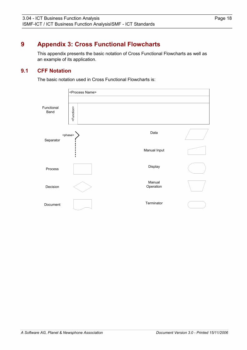
5.4 Cross Functional Flowcharts Cross Functional Flowcharts show, as their name indicates, the relationship between a business process and the organizational and functional units, such as departments, that are responsible for steps in that process. The flowcharts use standard symbols (elements) depicted from computer program flow diagrams to describe either an elementary function or a decision point or a document or a data store. These standard symbols include: � Bands, which represent the functional units. Shapes representing steps in the process are
placed in bands that correspond to the functional units responsible for those steps. � Separators, which indicate phases within a particular process. � Standard flowchart symbols, depicting processes, decisions, documents, data, manual
input, manual operations etc. Cross Functional Flowcharts focus on showing "who does which activity". A Cross Functional Flowchart shows the actual process flow and identifies the people or groups involved at each step. It is an excellent tool for clearly displaying process flows across organisational boundaries and identifying delays, repetitive steps, excessive control points, specialized tasks, and potential points of process failure.
5.5 Dynamic Models In recent years the concept of dynamic modelling has emerged, which covers, apart from the static attributes of a process, its dynamic attributes such as time and flow of control (e.g. transitions). Dynamic models used in business process modelling include Petri Nets and Business Process Modelling Notation (BPMN). A Petri net (also known as a place/transition net or P/T net) is one of several mathematical representations of discrete distributed systems. As a modeling language, it graphically depicts the structure of a distributed system as a directed bipartite graph with annotations. As such, a Petri net has place nodes, transition nodes, and directed arcs connecting places with transitions.

Business Process Modeling Notation (BPMN) is a standardized graphical notation for drawing business processes in a workflow. The primary goal of BPMN is to provide a notation that is readily understandable by all business users, from the business analysts who create the initial drafts of the processes, to the technical developers responsible for implementing the technology that will perform those processes, and finally, to the business people who will manage and monitor those processes. Thus, BPMN creates a standardized bridge for the gap between the business process design and process implementation. Currently, there are scores of process modeling tools and methodologies. BPMN will also advance the capabilities of traditional business process notations by inherently handling B2B (business-to-business) process concepts, such as public and private processes and choreographies, as well as advanced modeling concepts, such as exception handling and transaction compensation.
5.6 Use Cases In software engineering and system engineering, a use case is a technique for capturing functional requirements of systems and systems-of-systems. Each use case provides one or more scenarios that convey how the system should interact with the users called actors to achieve a specific business goal or function. Use case actors may be end users or other systems. Use cases typically avoid technical jargon, preferring instead the language of the end user or business champion. Use cases are often co-authored by business analysts and end users.

6 Conclusion Business Function Modelling is an essential tool to depict the organization’s activities and the way they are accomplished now (“AS IS” system) or they will be accomplished after the implementation of the new ICT System (“TO BE” system). There are several ways for modelling business functions and processes. The derived models should be included (at the appropriate level of detail) into the documents of the Project Life Cycle. The models presented in this document are just examples as follows: � Function Hierarchy diagrams and Data Flow Diagrams are examples of business function
models � Cross functional diagrams and Dynamic Models are examples of business process models � Use cases should be a business process modelling technique, in spite of its (usually) text
form CASE tools can provide alternative ways of modelling, which can also be used not just for the system documentation but as development tools too.
ICT Business Function Analysis Page 10 ISMF-ICT / ISMF - ICT Standards
7 Appendix – 1: Sample Checklists and Questionnaires for Business Function Analysis This appendix presents examples of checklists and questionnaires that are applicable during the execution of Business Function Analysis. The level of detail varies upon the purpose of the analysis’ task.
7.1 Questions to Be Asked during Functional Analysis The business function description document developed as a result of the functional analysis should, at a minimum, answer the following questions: � Who are the users? How many people are in the user functional area? � What is the average length of employment within the user area? � What is the average length of experience in the user area? � What do the users do? � Whom do the users work for and what do the users' superiors do? � What is the business function, or functions, that the user is supposed to perform? � What are the users' problems, and why are they problems? � Why do the users do what they do? � Whom do the users do what they do for? � When do the users do what they do? � Where do the users do what they do?
7.2 Business Function Analysis Documentation For each input document handled by the user, the analyst should describe the following in business terms: � Where do these documents come from? � What is their frequency of arrival? � What is the average document waiting time and average processing time? � What is the average backlog of documents waiting to be handled? � What is the document's level of accuracy or completeness? � Are there any document processing dependencies? � What other information is needed to process the document? Are there any other document
dependencies? � Are the documents received continuously, or is their arrival cyclic? Are there peaks and
valleys? � How long are the documents kept? � What criteria are used to determine when a document should be disposed of? � Are there any document priorities? Are there any significant variations within the general
document types? For each document generated by the user, the analyst should describe the following in business terms: � Where do these documents go? � What is their frequency of departure? � How long does it take to generate the document? � What is the average backlog of documents waiting to be generated? � What is the document's level of accuracy or completeness? � Are there any document dependencies?

ICT Business Function Analysis Page 11 ISMF-ICT / ISMF - ICT Standards
� What is the average length of the document? � Are there any significant variations within the general document type? If the user has a personal computer or workstation the analyst should describe the following in business terms: Workstation:� How would the user rate his knowledge of the personal computer (his level of computer
literacy)? � What portion of the normal day’s work is performed using the computer? � What packages or products does the user use?
� Word processor? � Spreadsheet? � Graphics or presentation preparation? � Database or file management product? � Project Management? � Personal time management?
� Does the user have any add-in or supplementary product such as conversion tools, dictionaries, add-in assistants?
� What does the user use each product for? � Does the user consider any of the products to be critical for his or her work?
� If so, which ones? � Why?
� How often is each product used? � What is the user’s evaluation of their level of proficiency with each product? Printers and plotters� Does the user have a personal printer? � Does the user share a printer with other users?
� Dot Matrix? � Inkjet? � Laser? � Colour?
� How much use is made of each? � Does the user have a personal plotter? � Does the user share a plotter with other users? � How often is the plotter used and for what purposes? Scanners:� Does the user have a scanner? � Does the user share a scanner with others? � How often is the scanner used and for what purposes? Fax machines:� Does the user have fax capability in his machine? � Does the user share a fax machine with others? � How often is the fax machine used and for what purposes? File storage and data access
ICT Business Function Analysis Page 12 ISMF-ICT / ISMF - ICT Standards
� Describe the kind and amount of data storage devices (floppy disk, hard disk, CD-ROM) associated with the user’s machine?
� What does the user store on each of the above? � Does the user back up the data files on the personal computer? � How often does the user back up the data files on the personal computer? � Are all data files backed up, or only selected ones? � And if selected ones:
� Which ones? � Why were they selected?
� What media is used for file back-up? � Where are the back-up copies stored? � Is there a log or record kept of when files were backed-up and when? If the user’s workstation is connected to a Local (LAN) or Wide Area Network (WAN) or the analyst should describe the following in business terms: � What products and files can be accessed form the LAN? � Does the user have access to E-mail? � How frequently does the user use the E-mail system? � Does the user also have access to the Internet? � What use does the user make of the Internet facilities? � Does the use transfer files to and from his machine? The documentation produced should also contain, at a minimum, � The user organizational chart � The placement of the user and his or her organization within the overall organization � The nature of the user's business � The user's function or job description � The user's specific function, or functions � The nature of the user's problems, if any � The impact of those problems on the user, the user's function, and, if necessary, on the
Organization � Any functional constraints which apply. These constraints should cover resources, time
frames, personnel, business exposure, loss of management control, cost impact, and the costs and benefits of resolving the problem, etc.
7.3 Additional Documentation to Include, If Available In addition the business functional analysis should contain detailed information about: � The user's charter or functional description and user comments as to how accurate that
charter or functional description is � Any user-perceived problems with the current functional responsibilities or relationships. � Any user perceived problems with any of the currently received documents � Any user dependencies on functions performed in any other user area � Any user management or financial controls.

ICT Business Function Analysis Page 13 ISMF-ICT / ISMF - ICT Standards
8 Appendix – 2: Data Flow Diagrams This appendix presents the concept of Data Flow Diagrams as one of the prevailing techniques used in Business Function Analysis and Modelling.
8.1 A simple DFD example
An example:The 'Context Diagram ' is an overall, simplified, view of the target system, which contains only one process box and the primary inputs and outputs.
Context diagram 1
Context diagram 2
Both the above diagrams say the same thing. The second makes use of the possibility in SSADM of including duplicate objects. (In context diagram 2 the duplication of the Customer object is shown by the line at the left hand side. Drawing the diagram in this way emphasizes the Input-Output properties of a system. The Context diagram above, and the decomposition which follows, are a first attempt at describing part of a 'Home Catalogue' sales system. In the modelling process it is likely that diagrams will be reworked and amended many times - until all parties are satisfied with the resulting model. A model can usefully be described as a co-ordinated set of diagrams.

ICT Business Function Analysis Page 14 ISMF-ICT / ISMF - ICT Standards
8.2 The Top (1st level) DFD
The Top or 1st level DFD, describes the whole of the target system. It 'bounds' the system under consideration.
Data Flow Diagrams show:• the processes within the system • the data stores (files) supporting the system's operation • the information flows within the system • the system boundary • interactions with external entities
DFD Notations DFDs are used in most system analysis methodologies.Processes, in other methodologies, may be called 'Activities', 'Actions', 'Procedures', 'Subsystems' etc. They may be shown as a circle, an oval, or (typically) a rectangular box. Data are generally shown as arrows coming to, or going from the edge of a process box. (Note that there is no 'Decision' symbol. A decision is a Process.
8.3 General Data Flow Rules � Entities are either 'sources of' or 'sinks' for data input and outputs - i.e. they are the
originators or terminators for data flows. � Data flows from Entities must flow into Processes

ICT Business Function Analysis Page 15 ISMF-ICT / ISMF - ICT Standards
� Data flows to Entities must come from Processes � Processes and Data Stores must have both inputs and outputs (What goes in must come
out!) � Inputs to Data Stores only come from Processes. � Outputs from Data Stores only go to Processes.
The Process Symbol
Processes transform or manipulate data. Each box has a unique number as identifier (top left) and a unique name (an imperative - e.g. 'do this' - statement in the main box area) The top line is used for the location of, or the people responsible for, the process. Processes are 'black boxes' - we don't know what is in them until they are decomposed Processes transform or manipulate input data to produce output data. Except in rare cases, you can't have one without the other.
Data Flows depict data/information flowing to or from a process. The arrows must either start and/or end at a process box. It is impossible for data to flow from data store to data store except via a process, and external entities are not allowed to access data stores directly. Arrows must be named. Double ended arrows may be used with care.
External Entities, also known as 'External sources/recipients, are things (eg: people, machines, organisations etc.) which contribute data or information to the system or which receive data/information from it. The name given to an external entity represents a Type not a specific instance of the type. When modelling complex systems, each external entity in a DFD will be given a unique identifier. It is common practice to have duplicates of external entities in order to avoid crossing lines, or just to make a diagram more readable.

ICT Business Function Analysis Page 16 ISMF-ICT / ISMF - ICT Standards
Data Stores are some location where data is held temporarily or permanently. In physical DFDs there can be 4 types.D = computerised Data M = Manual, e.g. filing cabinet. T = Transient data file, e.g. temporary program file T(M) = Transient Manual, e.g. in-tray, mail box. As with external entities, it is common practice to have duplicates of data stores to make a diagram less cluttered.
8.4 DFD Levels The Context and Top Level diagrams in the example start to describe 'Home Catalogue' type sales system. The two diagrams are just the first steps in creating a model of the system. (By model we mean a co-ordinated set of diagrams which describe the target system and provide answers to questions we need to ask about that system).As suggested the diagrams presented in the example will be reworked and amended many times - until all parties are satisfied. But the two diagrams by themselves are not enough; they only provide a high level description. On the other hand, the initial diagrams do start to break down, decompose, what might be quite a complex system into manageable parts. A revision of the example Top Level DFD
The next step - the Next Level(s) Each Process box in the Top Level diagram will itself be made up of a number of processes, and will need to be decomposed as a second level diagram.

ICT Business Function Analysis Page 17 ISMF-ICT / ISMF - ICT Standards
Each box in a diagram has an identification number derived from the parent - in the top left corner. (The Context level is seen as box 0) Any box in the second level decomposition may be decomposed to a third and then a fourth level. Very complex systems may possibly require decomposition of some boxes to further levels. Decomposition stops when a process box can be described with an Elementary Process Description using ordinary English, later on the process will be described more formally as a Function Description using, for example, pseudocode.
3.04 - ICT Business Function Analysis Page 18 ISMF-ICT / ICT Business Function AnalysisISMF - ICT Standards
A Software AG, Planet & Newsphone Association Document Version 3.0 - Printed 15/11/2006
9 Appendix 3: Cross Functional Flowcharts This appendix presents the basic notation of Cross Functional Flowcharts as well as an example of its application.
9.1 CFF Notation The basic notation used in Cross Functional Flowcharts is:
<phase>
<Process Name>
<Fun
ctio
n>
Separator
Process
Decision
Document
Data
Manual Input
Display
ManualOperation
Terminator
FunctionalBand

ICT Business Function Analysis Page 19ISMF-ICT / ISMF - ICT Standards
A Software AG, Planet & Newsphone Association Document Version 3.0 - Printed 15/11/2006
9.2 A Cross Functional Framework ExampleThe following drawing illustrates a functional diagram for the ICT procurement in the Syrian Public Sector.
ICT Business Function Analysis Page 20 ISMF-ICT ISMF - ICT Standards
A Software AG, Planet & Newsphone Association Document Version 3.0 - Printed 15/11/2006
10 Appendix 4: Business Process Modelling Notation This appendix presents in detail the Business Process Modelling Notation technique, as an example of the dynamic modelling tools for Business Function Analysis.
10.1 BPMN scope BPMN is constrained to support only the concepts of modeling that are applicable to business processes. This means that other types of modeling done by organizations for business purposes are out of scope for BPMN. For example, the modeling of the following will not be a part of BPMN: � Organizational structures � Functional breakdowns � Data models In addition, while BPMN will show the flow of data (messages), and the association of data artifacts to activities, it is not a Data Flow Diagram.
10.2 Uses of BPMN Business process modeling is used to communicate a wide variety of information to a wide variety of audiences. BPMN is designed to cover this wide range of usage and allows modeling of end-to-end business processes to allow the viewer of the Diagram to be able to easily differentiate between sections of a BPMN Diagram. There are three basic types of sub-models within an end-to-end BPMN model: � Private (internal) business processes � Abstract (public) processes � Collaboration (global) processes
10.2.1 Private (internal) business processes
Private business processes are those internal to a specific organization and are the types of processes that have been generally called workflow or BPM processes. If swim lanes are used then a private business process will be contained within a single Pool. The Sequence Flow of the Process is therefore contained within the Pool and cannot cross the boundaries of the Pool. Message Flow can cross the Pool boundary to show the interactions that exist between separate private business processes.
10.2.2 Abstract (public) processes
This represents the interactions between a private business process and another process or participant. Only those activities that are used to communicate outside the private business process are included in the abstract process. All other “internal” activities of the private business process are not shown in the abstract process. Thus, the abstract process shows to the outside world the sequence of messages that are required to interact with that business process. Abstract processes are contained within a Pool and can be modeled separately or within a larger BPMN Diagram to show the Message Flow between the abstract process activities and other entities. If the abstract process is in the same Diagram as its corresponding private business process, then the activities that are common to both processes can be associated.
ICT Business Function Analysis Page 21 ISMF-ICT ISMF - ICT Standards
A Software AG, Planet & Newsphone Association Document Version 3.0 - Printed 15/11/2006
10.2.3 Collaboration (global) processes
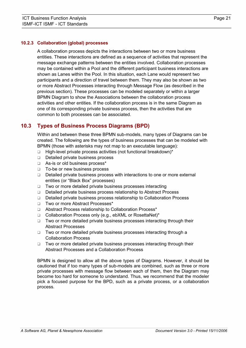
A collaboration process depicts the interactions between two or more business entities. These interactions are defined as a sequence of activities that represent the message exchange patterns between the entities involved. Collaboration processes may be contained within a Pool and the different participant business interactions are shown as Lanes within the Pool. In this situation, each Lane would represent two participants and a direction of travel between them. They may also be shown as two or more Abstract Processes interacting through Message Flow (as described in the previous section). These processes can be modeled separately or within a larger BPMN Diagram to show the Associations between the collaboration process activities and other entities. If the collaboration process is in the same Diagram as one of its corresponding private business process, then the activities that are common to both processes can be associated.
10.3 Types of Business Process Diagrams (BPD) Within and between these three BPMN sub-models, many types of Diagrams can be created. The following are the types of business processes that can be modeled with BPMN (those with asterisks may not map to an executable language): � High-level private process activities (not functional breakdown)* � Detailed private business process � As-is or old business process* � To-be or new business process � Detailed private business process with interactions to one or more external
entities (or “Black Box” processes) � Two or more detailed private business processes interacting � Detailed private business process relationship to Abstract Process � Detailed private business process relationship to Collaboration Process � Two or more Abstract Processes* � Abstract Process relationship to Collaboration Process* � Collaboration Process only (e.g., ebXML or RosettaNet)* � Two or more detailed private business processes interacting through their
Abstract Processes � Two or more detailed private business processes interacting through a
Collaboration Process � Two or more detailed private business processes interacting through their
Abstract Processes and a Collaboration Process BPMN is designed to allow all the above types of Diagrams. However, it should be cautioned that if too many types of sub-models are combined, such as three or more private processes with message flow between each of them, then the Diagram may become too hard for someone to understand. Thus, we recommend that the modeler pick a focused purpose for the BPD, such as a private process, or a collaboration process.

ICT Business Function Analysis Page 22 ISMF-ICT ISMF - ICT Standards
A Software AG, Planet & Newsphone Association Document Version 3.0 - Printed 15/11/2006
10.4 Elements The modeling in BPMN is made by simple diagrams with a small set of graphical elements. It should make it easy for business user as well as developers to understand the flow and the process. The four basic categories of elements are: � Flow Objects
� Events � Activities � Gateways
� Connecting Objects � sequence flow � Message Flow � Association
� Swimlanes � Pool � Lane
� Artifacts These four categories of elements give us the opportunity to make a simple diagram (BPD). It is also allowed in BPD to make your own type of a Flow Object or an Artifact to make the diagram more understandable.
10.4.1 Flow objects
Flow Objects consist of only three core elements. The three Flow Objects are: � Event: An Event is represented with a circle and is something that happens. It
could be Start, Intermediate or End. This element is a trigger or a result.
� Activity: An Activity is represented with a rounded-corner rectangle and shows us the kind of work which must be done. It could be a task or a sub-process. A sub-process also has a plus sign in the bottom line of the rectangle.
� Gateway: A Gateway is represented with a diamond shape and will determine different decisions. It will also determine forking, merging and joining of paths.
10.4.2 Connecting objects
The Flow Objects are connected to each other with Connecting Objects. There are three different Connecting Objects: � Sequence Flow: A Sequence Flow is represented with a solid line and arrowhead
and shows in which order the activities will be performed.
ICT Business Function Analysis Page 23 ISMF-ICT ISMF - ICT Standards
A Software AG, Planet & Newsphone Association Document Version 3.0 - Printed 15/11/2006
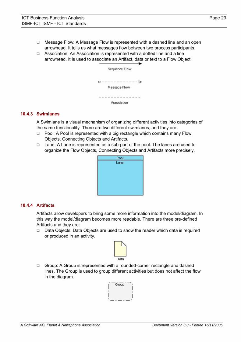
� Message Flow: A Message Flow is represented with a dashed line and an open arrowhead. It tells us what messages flow between two process participants.
� Association: An Association is represented with a dotted line and a line arrowhead. It is used to associate an Artifact, data or text to a Flow Object.
10.4.3 Swimlanes
A Swimlane is a visual mechanism of organizing different activities into categories of the same functionality. There are two different swimlanes, and they are: � Pool: A Pool is represented with a big rectangle which contains many Flow
Objects, Connecting Objects and Artifacts. � Lane: A Lane is represented as a sub-part of the pool. The lanes are used to
organize the Flow Objects, Connecting Objects and Artifacts more precisely.
10.4.4 Artifacts
Artifacts allow developers to bring some more information into the model/diagram. In this way the model/diagram becomes more readable. There are three pre-defined Artifacts and they are: � Data Objects: Data Objects are used to show the reader which data is required
or produced in an activity.
� Group: A Group is represented with a rounded-corner rectangle and dashed lines. The Group is used to group different activities but does not affect the flow in the diagram.

ICT Business Function Analysis Page 24 ISMF-ICT ISMF - ICT Standards
A Software AG, Planet & Newsphone Association Document Version 3.0 - Printed 15/11/2006
� Annotation: An Annotation is used to give the reader of the model/diagram an understandable impression.
10.5 Examples
10.5.1 A Process with Normal Flow

ICT Business Function Analysis Page 25ISMF-ICT / ISMF - ICT Standards
A Software AG, Planet & Newsphone Association Document Version 3.0 - Printed 15/11/2006
10.5.2 Discussion Cycle

ICT Business Function Analysis Page 26ISMF-ICT / ISMF - ICT Standards
A Software AG, Planet & Newsphone Association Document Version 3.0 - Printed 15/11/2006
10.5.3 E-Mail Voting Process
ICT Business Function Analysis Page 27ISMF-ICT / ISMF - ICT Standards
A Software AG, Planet & Newsphone Association Document Version 3.0 - Printed 15/11/2006
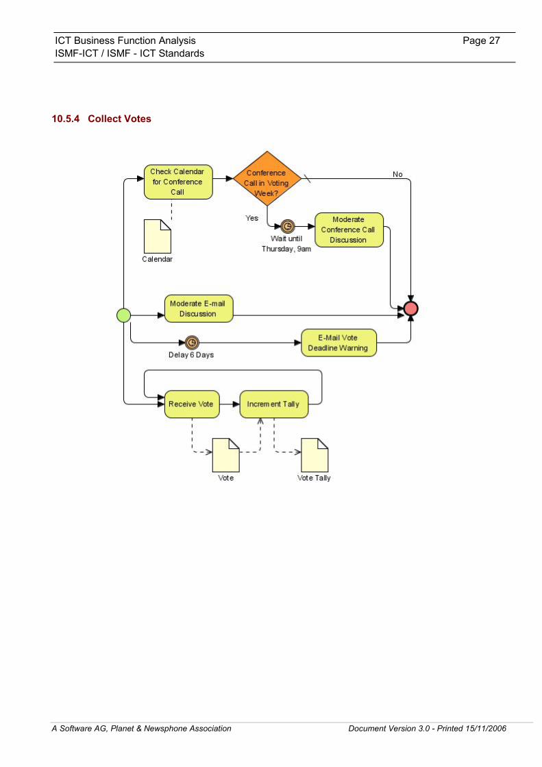
10.5.4 Collect Votes

ICT Business Function Analysis Page 28ISMF-ICT / ISMF - ICT Standards
A Software AG, Planet & Newsphone Association Document Version 3.0 - Printed 15/11/2006
11 Appendix 5: Use Cases This appendix presents in detail the concept of Use Cases, which are a technique used from the early stages of the implementation of an information system (such as the Business Function Analysis) and up to the very end of the cycle (e.g. the Acceptance Tests).
11.1 Scope and goals of a use case Each use case focuses on describing how to achieve a single business goal or task. From a traditional software engineering perspective a use case describes just one feature of the system. For most software projects this means that multiple, perhaps dozens, of use cases are needed to embrace the scope of the new system. The degree of formality of a particular software project and the stage of the project will influence the level of detail required in each use case. A use case defines the interactions between external actors and the system under consideration to accomplish a business goal. Actors are parties outside the system that interact with the system; an actor can be a class of users, roles users can play, or other systems. Use cases treat the system as a black box, and the interactions with the system, including system responses, are perceived as from outside the system. This is a deliberate policy, because it simplifies the description of requirements, and avoids the trap of making assumptions about how this functionality will be accomplished. A use case should: � describe a business task to serve a business goal. � have no implementation-specific language. � be at the appropriate level of detail. � be small enough to implement in a single release by the project's smallest team.
11.2 Writing a use case
11.2.1 Degree of detail
Brief A brief use case consists of a few sentences summarizing the use case. It is highly suitable to use a spreadsheet for planning software development. A brief use case can be easily inserted in a spreadsheet cell, and allows the other columns in the spreadsheet to record business priority, technical complexity, release number, etc.
Casual A casual use case consists of a few paragraphs of text, covering the items mentioned above, elaborating the use case in the form of a summary or story.
Detailed A detailed or complex use case is a formal document based on a long template with fields for various sections; and it is the most common understanding of the meaning of a use case. Detailed use cases are discussed in detail in the next section on use case templates

ICT Business Function Analysis Page 29ISMF-ICT / ISMF - ICT Standards
A Software AG, Planet & Newsphone Association Document Version 3.0 - Printed 15/11/2006
Appropriate detail Some software development processes do not require anything more than a simple use case to define requirements. However, some other development processes require detailed use cases to define requirements. The larger and more complex the project, the more likely it is that it will be necessary to use detailed use cases.
The level of detail in a use case often differs according to the progress of the project. The initial use cases may be brief, but as the development process unfolds the use cases become ever more detailed. This reflects the different requirements of the use case. Initially they need only be brief, because they are used to summarise the business requirement from the point of view of users. However, later in the process, software developers need far more specific and detailed guidance. Rational Unified Process (RUP) invites developers to write a brief use case description in the diagram, with a casual description as comments and a detailed description of the flow of events in a textual analysis. All those can usually be input into the UML Tool, or can be written separately in a text editor.
11.2.2 Use case templates
There is no standard template for documenting detailed use cases. There are a number of competing schemes, and individuals are encouraged to use templates that work for them or the project they are on. Standardization within each project is more important than the detail of a specific template. There is, however, considerable agreement about the core sections; beneath differing terminologies and orderings there is an underlying similarity between most use cases. Typical sections include: � Use Case Name � Iteration � Summary � Preconditions � Triggers � Basic course of events � Alternative paths � Postconditions � Business rules � Notes � Author and date Different templates often have additional sections, e.g. assumptions, exceptions, recommendations, technical requirements. There may also be industry specific sections.
Use case name The use case name provides a unique identifier for the use case. It should be written in verb-noun format (e.g., Borrow Books, Withdraw Cash), should describe a completable goal (e.g., Register User is better than Registering User) and should be sufficient for the end user to understand what the use case is about. Goal-driven use case analysis will name the use cases according to the Actor's goals thus ensuring use cases are strongly user centric. Two to three
ICT Business Function Analysis Page 30ISMF-ICT / ISMF - ICT Standards
A Software AG, Planet & Newsphone Association Document Version 3.0 - Printed 15/11/2006
words is the optimum length. If four or more words are proposed in the name there is usually a shorter better name that can be used.
Iteration Often an iteration section is needed to inform the reader the stage a use case has reached. The initial use case developed for business analysis and scoping may well be very different from the evolved version of that use case when the software is being developed. Older versions of the use case may still be current documents, because they may be valuable to different user groups.
Summary The summary section is used to capture the essence of the use case before the main body is complete. It provides a quick overview which is intended to save the reader from having to read the full contents of a use case to understand what the use case is about. Ideally a summary is just a few sentences or a paragraph in length and includes the goal and principal actor.
Preconditions A preconditions section is used to convey any conditions that must be true when a user initiates a use case. They are not however the triggers that initiate a use case. Where one or more preconditions are not met, the behavior of the use case should be considered indeterminate.
Triggers The Triggers section describes the starting condition(s) which cause a use case to be initiated. Triggers can be external, temporal or internal.
Basic course of events At a minimum, each use case should convey a primary scenario, or the typical course of events. The main basic course of events is often conveyed as a set of usually numbered steps, for example: � The system prompts the user to logon. � The user enters his name and password. � The system verifies the login information. � The system logs user on to system. ...and so on.
Alternative paths Use cases may contain secondary paths, or alternative scenarios which are variations on the main theme. Exceptions, or what happens when things go wrong, may also be described, either within the alternative paths section or in a section on their own. The alternative paths make use of the numbering of the basic course of events to show at which point they differ from the basic scenario, and if appropriate where they rejoin. The intention is to avoid repeating information unnecessarily. An example of an alternative path would be: � The system recognizes cookie on users machine. � Go to step 4 (Main path) An example of an exception path would be: � The system does not recognize user's logon information
ICT Business Function Analysis Page 31ISMF-ICT / ISMF - ICT Standards
A Software AG, Planet & Newsphone Association Document Version 3.0 - Printed 15/11/2006
� Go to step 1 (Main path) According to Anthony J H Simons and Ian Graham, alternate paths were not originally part of use cases. Instead, each use case represented a single user's interaction with the system. Or in other words, each use case represented one possible path through the system. Multiple use cases would be needed before designs based on them could be made. In this sense, use cases are for exploration, not documentation.
Postconditions The post-conditions section summarizes the state of affairs after the scenario is complete.
Business rules Business rules are written or unwritten rules that determine how an organization conducts its business with regard to a use case. Business rules are a special kind of assumption. Business rules may be specific to a use case or apply across all the use cases, and indeed all the business.
Notes Experience has shown that whatever template is used, analysts discover there is always important information that doesn't fit the structure of the template. Therefore each template usually includes a section for such seemingly inevitable information.
Author and date This section should list when this version of the use case was created and who documented it. It should also list and date any versions of the use case from an earlier stage in the development which are still current documents. The author is traditionally listed at the bottom, because it is not considered to be essential information; use cases are intended to be collaborative endeavors and they should be jointly owned.
11.3 Use Case Notation The relationship among the use cases and the actors are often diagrammed using a Unified Modeling Language (UML)-standardized notation.
11.4 Use Cases and the development process The specific way use cases are used within the development process will depend on which development methodology is being used. In certain development methodologies, a brief use case survey is all that is required. In other development methodologies, the use cases evolve in complexity and change in character as the development process proceeds. In some methodologies, they may begin as brief business use cases, evolve into more detailed system use cases, and then eventually develop into highly detailed and exhaustive test cases.
11.5 Benefits of Use Cases Use cases are a mature model to capture software requirements. They are often contrasted to large, monolithic documents that attempt but fail to completely convey all possible requirements before construction of a new system begins.
ICT Business Function Analysis Page 32ISMF-ICT / ISMF - ICT Standards
A Software AG, Planet & Newsphone Association Document Version 3.0 - Printed 15/11/2006
Use cases have a number of advantages: � Use case modeling (including the writing of use case specifications) is generally regarded
as an excellent technique for capturing the functional requirements of a system. � Use cases discourage premature design. � Use cases are traceable. � Use cases can serve as the basis for the estimating, scheduling, and validating effort. � Use cases are reusable within a project. The use case can evolve at each iteration from a
method of capturing requirements, to development guidelines to programmers, to a test case and finally into user documentation.
� Use case alternative paths capture additional behavior that can improve system robustness.
� Use cases are useful for scoping. Use cases make it easy to take a staged delivery approach to projects; they can be relatively easily added and removed from a software project as priorities change.
� Use cases have proved to be easily understandable by business users, and so have proven an excellent bridge between software developers and end users.
� Use case specifications don't use a special language. They can be written in a variety of styles to suit the particular needs of the project.
� Use cases allow us to tell stories. It is very easy to describe a use case in a concrete way by turning it into a story or scenario.
� Use cases are concerned with the interactions between the user and the system. They make it possible for user interface designers to become involved in the development process either before or in parallel with software developers.
� Use cases put requirements in context; they are clearly described in relationship to business tasks.
� Use case diagrams help stakeholders to understand the nature and scope of the business area or the system under development.
� Use case diagrams can be recorded using the UML and maintained within widely available CASE tools
� Use cases and use case diagrams can be fully integrated with other analysis and design deliverables created using a CASE tool to produce a complete requirements, design and implementation repository
� Test Cases(System, User Acceptance and Functional) can be directly derived from the use cases
� Use cases are critical for the effective execution of Performance Engineering