Embed Size (px)
Citation preview

Made in the USA
ICT 750 TransmitterOperation and Installation Manual
Thank you for choosing an Invisible Fence® Pet Containment System
Important Safeguards
We believe that you now own the highest qual-ity electronic pet containment system made any-where. We support this claim by backing InvisibleFence Brand products with a One-Year, Money-BackPerformance Guarantee*, and Warranties whichinclude lightning and surge damage. Refer to yourwarranty card or the back of your sales contract forcomplete details. All of this is backed up by our inter-
national network of local Invisible Fence profession-als who offer you professional installation, Safe Dog®
pet training, and prompt service.You are the most important judge of our pro d-
ucts and services. When you tell us that we have metor exceeded your expectations for Inv i s i ble Fe n c ep ro d u c t s , then we are ach i eving our go a l : to continu-o u s ly ke ep your pet safe at home™.
* Good only on pro fe s s i o n a l ly installed systems.
1. Read and Retain Manuals: Read all of theoperating and training instructions before installingand/or using your new Invisible Fence Brand pet con-tainment system.
2. Training: Train your pet according to thei n s t ructions in Inv i s i ble Fence training manu a l s .Complete all of the steps before allowing your pet torun free.
3. Obey all Cautions and Warnings: Adhere toall of the cautions and warnings contained in this man-ual and all other manuals pertaining to your InvisibleFence system, and all Invisible Fence system compo-nents.
4. Service and Repair: Other than repairing thesignal field wire, do not attempt to service anyInvisible Fence equipment yourself. Refer all serviceto an authorized Invisible Fence professional only.
5. For Animal Use Only:All Invisible Fence petcontainment systems are designed for animal use only.Never attempt to use this product for any purpose notspecifically described in this manual.
IMPORTANT: If, for any reason, your InvisibleFence system does not operate as described in thismanual, or if you encounter any difficulty trainingyour pet, call your Invisible Fence professional imme-diately.
Warning: The following precautionsshould always be taken.
1. Never attempt to install an Invisible Fence petcontainment system unless you have first consultedyour Invisible Fence professional and have InvisibleFence installation instructions.
2. Never install an Invisible Fence transmitter,LP3000, or any Invisible Fence system componentother than signal field wire outdoors or where theycould be exposed to the outdoor elements, doing sowill void the manufacturer’s warranties.
3. Check the transmitter periodically to makesure that it is operating properly and is producing asignal along the signal field wire.
4. Caution: Always take the Computer Collar®
off your pet before making any adjustment to yourInvisible Fence system.
5. If you have any questions about any aspect ofyour Invisible Fence system, please call your InvisibleFence professional immediately.
Warning: Never install, connect or service any Invisible Fence system
component or equipment when there is a thunder or lightning storm in the area.
Caution: Before starting any work,unplug the transmitter’s 12vAC
transformer from the 110v outlet and the transmitter. Turn off the electric service at the circuit breaker panel.
Warning: If you have any reason tobelieve that your pet may pose a
danger to others, or that it may harm itself if it is not kept from crossing the InvisibleBoundary® signal wire, you should not relysolely on this product to contain your pet.
1

2
Invisible Fence®pet containment will not workunless:
1. The 12vAC transformer is plugged into thetransmitter and is plugged into a 110vAC outlet.
2. The transmitter is on, connected to the signalfield wire, and producing a signal along the wire.
3. The signal field wire is intact, continuous, andthe transmitter’s green LED is blinking on and off.
4. The Computer Collar® is correctly fitted andworn by your pet.
The Computer Collar is adjusted so that thereceiver posts are touching your pet’s skin.
5. The Power Cap® battery in the receiver is goodand is correctly installed.
6. You train your pet as prescribed in InvisibleFence training manuals.
Do Not become overly confident that your pethas become conditioned to the Invisible Fence systemsooner than expected. Complete all of the trainingsteps before allowing your pet to run free.
If you have any questions about any aspect ofyour Invisible Fence system, please call your InvisibleFence professional immediately.
About Thunder or Electrical Storms
Even though your Invisible Fence system isequipped with lightning surge protection, it is stillpossible that it may be damaged during a thunderstorm, or when an electrical storm is in the areawhere you live. For added peace of mind, you maywant to take the Computer Collar off your petbefore an electrical storm.
· Check Your Pet’s Safe Areas
After a storm has ended, check all of your pet’ssafe areas before you put the Computer Collar backon him. Use the following procedure to make surethat your system is continuing to work properly.
Hold the Computer Collar collar so that thereceiver is at about the same height and on thesame angle that it is when your pet is wearing it,and move throughout his safe areas. This shouldinclude all of the safe areas where your pet isallowed to go, in your yard and in your home.
If the receiver sounds a warning when it is in asafe area, DO NOT put the Computer Collar backon your pet. Immediately call your local InvisibleFence professional for service.
Use a leash or other means to contain your petuntil after the service has been completed.
· At Least Once a Month, and After a ThunderStorm, Check the Width of Your Invisible FenceSystem’s Signal Field
Always keep a note of the width of your system’s signal field.
You only have to check the width of the signalfield from one place on the signal field loop wire.Always check the signal field from the same place.
Take the Computer Collar off your pet. Followthe instructions for checking the width of the signalfield on page 10.
If the receiver does not sound a warning wherethe edge of the signal is supposed to be, or if it onlysounds a warning when it is closer to the wire thanthe setting of the signal field, immediately call yourInvisible Fence professional for service.
Use a leash or other means to contain your petuntil all necessary service has been completed.
Important Safeguards continued
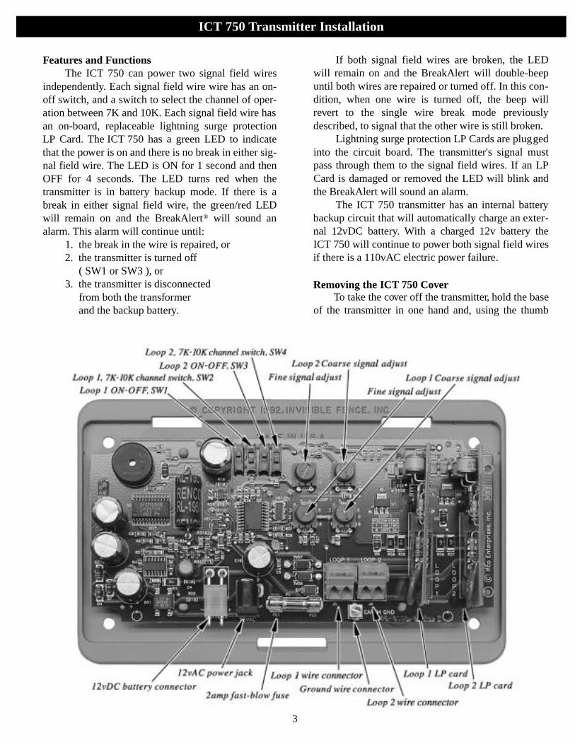
Features and FunctionsThe ICT 750 can power two signal field wires
independently. Each signal field wire wire has an on-off switch, and a switch to select the channel of oper-ation between 7K and 10K. Each signal field wire hasan on-board, replaceable lightning surge protectionLP Card. The ICT 750 has a green LED to indicatethat the power is on and there is no break in either sig-nal field wire. The LED is ON for 1 second and thenOFF for 4 seconds. The LED turns red when thetransmitter is in battery backup mode. If there is abreak in either signal field wire, the green/red LEDwill remain on and the BreakAlert® will sound analarm. This alarm will continue until:
1. the break in the wire is repaired, or2. the transmitter is turned off
( SW1 or SW3 ), or3. the transmitter is disconnected
from both the transformer and the backup battery.
If both signal field wires are broken, the LEDwill remain on and the BreakAlert will double-beepuntil both wires are repaired or turned off. In this con-dition, when one wire is turned off, the beep willrevert to the single wire break mode previouslydescribed, to signal that the other wire is still broken.
Lightning surge protection LP Cards are pluggedinto the circuit board. The transmitter's signal mustpass through them to the signal field wires. If an LPCard is damaged or removed the LED will blink andthe BreakAlert will sound an alarm.
The ICT 750 transmitter has an internal batterybackup circuit that will automatically charge an exter-nal 12vDC battery. With a charged 12v battery theICT 750 will continue to power both signal field wiresif there is a 110vAC electric power failure.
R e m oving the ICT 750 CoverTo take the cover off the transmitter, hold the base
of the transmitter in one hand and, using the thumb
3
ICT 750 Transmitter Installation
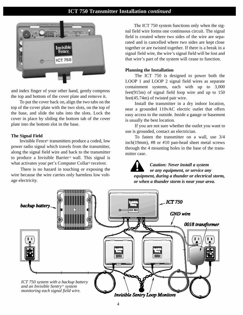
and index finger of your other hand, gently compressthe top and bottom of the cover plate and remove it.
To put the cover back on, align the two tabs on thetop of the cover plate with the two slots, on the top ofthe base, and slide the tabs into the slots. Lock thecover in place by sliding the bottom tab of the coverplate into the bottom slot in the base.
The Signal Fi e l dI nv i s i ble Fe n c e® t ra n s m i t t e rs produce a coded, low
power radio signal which travels from the transmitter,along the signal field wire and back to the transmitterto produce a Invisible Barrier ® wall. This signal iswhat activates your pet’s Computer Collar® receiver.
There is no hazard in touching or exposing thewire because the wire carries only harmless low volt-age electricity.
The ICT 750 system functions only when the sig-nal field wire forms one continuous circuit. The signalfield is created where two sides of the wire are sepa-rated and is cancelled where two sides are kept closetogether or are twisted together. If there is a break in asignal field wire, the wire’s signal field will be lost andthat wire’s part of the system will cease to function.
Planning the InstallationThe ICT 750 is designed to power both the
LOOP 1 and LOOP 2 signal field wires as separatecontainment systems, each with up to 3,000feet(915m) of signal field loop wire and up to 150feet(45.74m) of twisted pair wire.
Install the transmitter in a dry indoor location,near a grounded 110vAC electric outlet that offerseasy access to the outside. Inside a garage or basementis usually the best location.
If you are not sure whether the outlet you want touse is grounded, contact an electrician.
To fasten the transmitter on a wall, use 3/4inch(19mm), #8 or #10 pan-head sheet metal screwsthrough the 4 mounting holes in the base of the trans-mitter case.
Caution: Never install a system or any equipment, or service any
equipment, during a thunder or electrical storm,or when a thunder storm is near your area.
ICT 750 Transmitter Installation continued
4
ICT 750 system with a backup batteryand an Invisible Sentry™ system monitoring each signal field wire.
Caution: Before starting any work,you must unplug the 12vAC
transformer and turn off the electric service at the circuit panel.
All outdoor Invisible Fence® pet containmentsystems are equipped with lightning surge protectionthat is designed to prevent damage to the transmitterin the event of an electrical surge.
If the system is properly installed and grounded,and is equipped with an Invisible Fence lightning pro-tection device, Invisible Fence will repair or replace,at our option, any transmitter, transmitter circuitboard, transformer, or lightning protector damaged byan electrical surge for as long as the original ownerowns the system.
Before you connect the signal field wire, orbackup battery, or connect the transformer to thetransmitter, you must ground the system.
Connecting the Grounding Wire to the ICT 750 Circuit Board
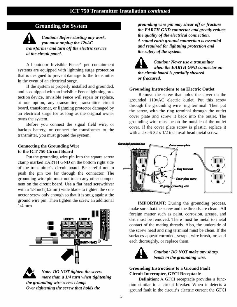
Put the grounding wire pin into the square screwclamp marked EARTH GND on the bottom right sideof the transmitter’s circuit board. Be careful not topush the pin too far through the connector. Thegrounding wire pin must not touch any other compo-nent on the circuit board. Use a flat head screwdriverwith a 1/8 inch(3.2mm) wide blade to tighten the con-nector screw only enough so that it is snug against theground wire pin. Then tighten the screw an additional1/4 turn.
Note: DO NOT tighten the screwmore than a 1/4 turn when tightening
the grounding wire screw clamp. Over tightening the screw that holds the
grounding wire pin may shear off or fracturethe EARTH GND connector and greatly reducethe quality of the electrical connection. A sound earth ground connection is essentialand required for lightning protection and the safety of the system.
Caution: Never use a transmitter when the EARTH GND connector on
the circuit board is partially sheared or fractured.
Grounding Instructions to an Electric OutletRemove the screw that holds the cover on the
grounded 110vAC electric outlet. Put this screwthrough the grounding wire ring terminal. Then putthe screw, with the ring terminal through the outletcover plate and screw it back into the outlet. Thegrounding wire must be on the outside of the outletcover. If the cover plate screw is plastic, replace itwith a size 6-32 x 1/2 inch oval-head metal screw.
IMPORTANT: During the grounding process,make sure that the screw and the threads are clean. Allforeign matter such as paint, corrosion, grease, anddirt must be removed. There must be metal to metalcontact of the mating threads. Also, the underside ofthe screw head and ring terminal must be clean. If thesurfaces appear corroded, scrape, wire brush, or sandeach thoroughly, or replace them.
Caution: DO NOT make any sharpbends in the grounding wire.
Grounding Instructions to a Ground Fault Circuit Interrupter, GFCI Receptacle
Definition: A GFCI receptacle provides a func-tion similar to a circuit breaker. When it detects aground fault in the circuit’s electric current the GFCI
ICT 750 Transmitter Installation continued
5
Grounding the System
trips and cuts the power. A ground fault is an abnor-mal electrical condition which is not desirable.
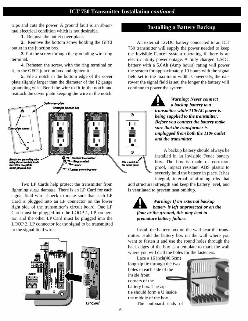
1. Remove the outlet cover plate.2. Remove the bottom screw holding the GFCI
outlet in the junction box.3. Put the screw through the grounding wire ring
terminal.4. Refasten the screw, with the ring terminal on
it, to the GFCI junction box and tighten it.5. File a notch in the bottom edge of the cover
plate slightly larger than the diameter of the 12 gaugegrounding wire. Bend the wire to fit in the notch andreattach the cover plate keeping the wire in the notch.
Two LP Cards help protect the transmitter fromlightning surge damage. There is an LP Card for eachsignal field wire. Check to make sure that each LPCard is plugged into an LP connector on the lowerright side of the transmitter’s circuit board. One LPCard must be plugged into the LOOP 1, LP connec-tor, and the other LP Card must be plugged into theLOOP 2, LP connector for the signal to be transmittedto the signal field wires.
An external 12vDC battery connected to an ICT750 transmitter will supply the power needed to keepthe Invisible Fence® system operating if there is anelectric utility power outage. A fully charged 12vDCbattery with a 5.0Ah (Amp hours) rating will powerthe system for approximately 10 hours with the signalfield set to the maximum width. Conversely, the nar-rower the signal field is set, the longer the battery willcontinue to power the system.
Warning: Never connect a backup battery to a
transmitter while 110vAC power isbeing supplied to the transmitter.Before you connect the battery makesure that the transformer isunplugged from both the 110v outletand the transmitter.
A backup battery should always beinstalled in an Invisible Fence batterybox. The box is made of corrosionproof, impact resistant ABS plastic tosecurely hold the battery in place. It hasintegral, internal reinforcing ribs that
add structural strength and keep the battery level, andis ventilated to prevent heat buildup.
Warning: If an external backup battery is left unprotected or on the
floor or the ground, this may lead to premature battery failure.
Install the battery box on the wall near the trans-mitter. Hold the battery box on the wall where youwant to fasten it and use the round holes through theback edges of the box as a template to mark the wallwhere you will drill the holes for the fasteners.
Lace a 16 inch(40.6cm)long zip tie through the twoholes in each side of theinside frontcorners of thebattery box. The ziptie should form a U insidethe middle of the box.
The outboard ends of6
ICT 750 Transmitter Installation continued
Installing a Battery Backup
the two battery leads, the ends that are connected tothe terminals on the battery, each have a spade quick-connect.
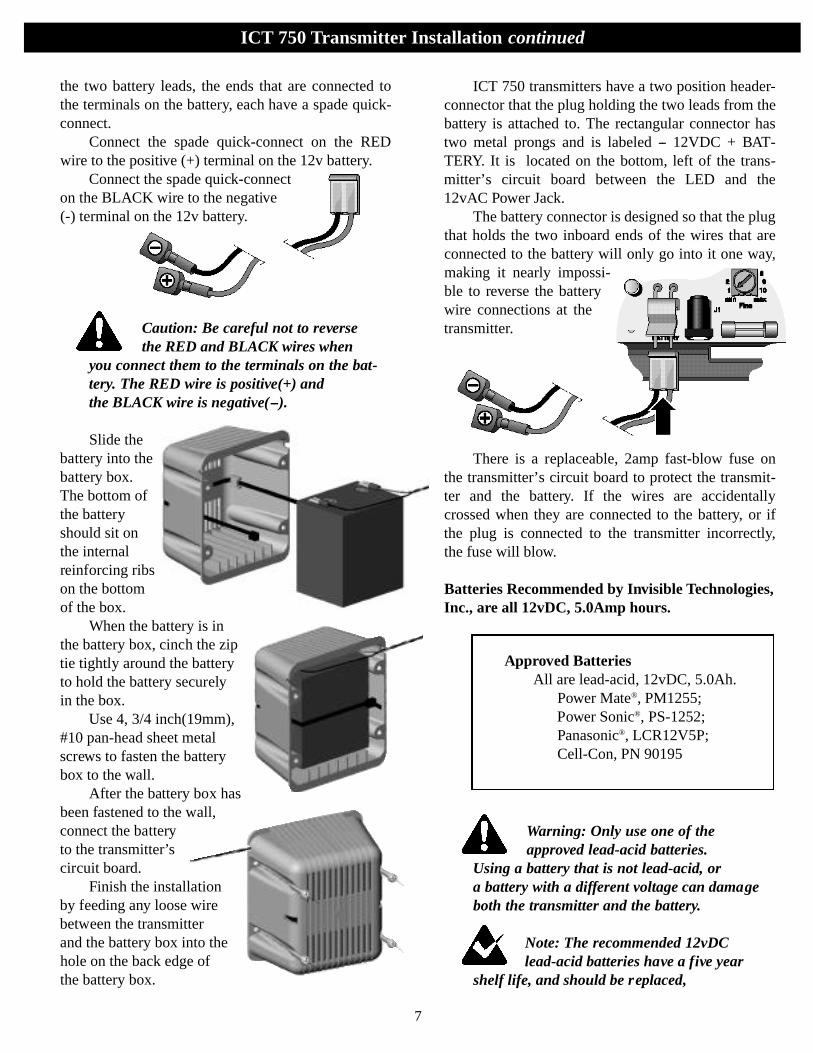
Connect the spade quick-connect on the REDwire to the positive (+) terminal on the 12v battery.
Connect the spade quick-connecton the BLACK wire to the negative(-) terminal on the 12v battery.
Caution: Be careful not to reverse the RED and BLACK wires when
you connect them to the terminals on the bat-tery. The RED wire is positive(+) and the BLACK wire is negative(--).
Slide thebattery into thebattery box.The bottom ofthe batteryshould sit onthe internalreinforcing ribson the bottomof the box.
When the battery is inthe battery box, cinch the ziptie tightly around the batteryto hold the battery securely in the box.
Use 4, 3/4 inch(19mm),#10 pan-head sheet metalscrews to fasten the batterybox to the wall.
After the battery box hasbeen fastened to the wall,connect the batteryto the transmitter’scircuit board.
Finish the installationby feeding any loose wirebetween the transmitterand the battery box into thehole on the back edge ofthe battery box.
ICT 750 transmitters have a two position header-connector that the plug holding the two leads from thebattery is attached to. The rectangular connector hastwo metal prongs and is labeled -- 12VDC + BAT-TERY. It is located on the bottom, left of the trans-mitter’s circuit board between the LED and the12vAC Power Jack.
The battery connector is designed so that the plugthat holds the two inboard ends of the wires that areconnected to the battery will only go into it one way,making it nearly impossi-ble to reverse the batterywire connections at thetransmitter.
There is a replaceable, 2amp fast-blow fuse onthe transmitter’s circuit board to protect the transmit-ter and the battery. If the wires are accidentallycrossed when they are connected to the battery, or ifthe plug is connected to the transmitter incorrectly,the fuse will blow.
Batteries Recommended by Invisible Technologies,Inc., are all 12vDC, 5.0Amp hours.
Warning: Only use one of theapproved lead-acid batteries.
Using a battery that is not lead-acid, or a battery with a different voltage can damageboth the transmitter and the battery.
Note: The recommended 12vDC lead-acid batteries have a five year
shelf life, and should be replaced,
7
ICT 750 Transmitter Installation continued
Approved BatteriesAll are lead-acid, 12vDC, 5.0Ah.
Power Mate®, PM1255;Power Sonic®, PS-1252; Panasonic®, LCR12V5P;Cell-Con, PN 90195
whether they have been engaged often or not,after that time.
Detecting Low Voltage in the Backup BatteryAfter a 12v battery is fully charged, a micro-
processor in the transmitter will automatically checkthe battery’s voltage. If the voltage of the batterydrops between 11vDC and 9vDC, the transmitter’sBreakAlert® alarm will sound. The low battery alarmwill continue until 110vAC power is restored and thebattery voltage is recharged to greater than 11vDC.The alarm is a single, one second beep that will soundonce a minute.
The LED on the transmitter that is green duringnormal operation, will turn red indicating that there isa 110vAC power failure and that the system is operat-ing on 12vDC battery backup power. The red LEDwill alternately blink ON for one second and OFF forfour seconds.
A fully discharged 5.0Ah battery will take fivetimes its projected operating time to completelyrecharge. The battery will take about 50 hours to fullycharge. The transmitter automatically charges thebackup battery while the system is operating normallyon 110vAC power.
Note: How long it will take the batteryto recharge to 11vDC will depend on
how low the battery’s voltage has dropped andhow wide the signal field is. The lower the voltage is and the wider the signal field is,the longer it will take to recharge the battery.
Note: A battery will take five times itsrated operating time to fully charge.
A 5.0Ah battery will take about 50 hoursto charge to full power.
If the voltage of the battery drops too low to pro-duce a signal field, the LED will not be lit.
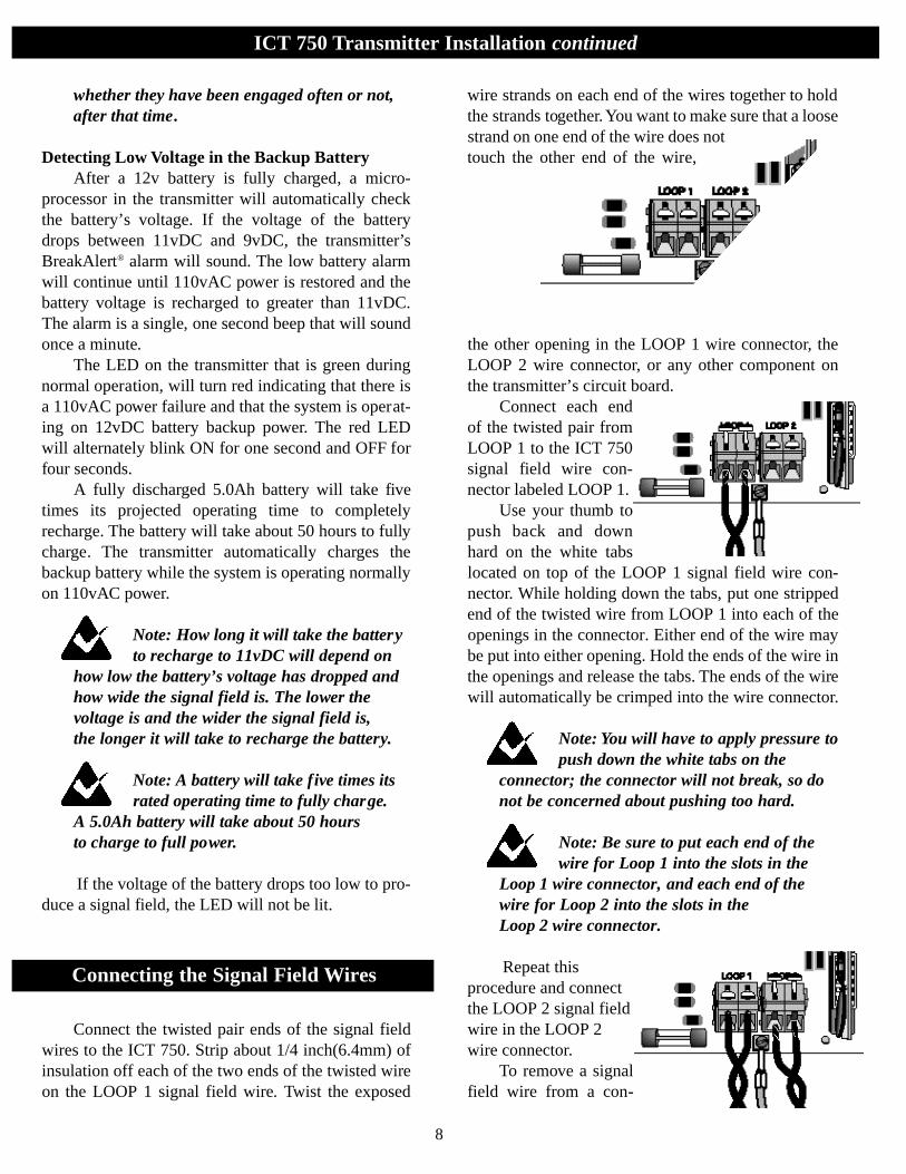
Connect the twisted pair ends of the signal fieldwires to the ICT 750. Strip about 1/4 inch(6.4mm) ofinsulation off each of the two ends of the twisted wireon the LOOP 1 signal field wire. Twist the exposed
wire strands on each end of the wires together to holdthe strands together. You want to make sure that a loosestrand on one end of the wire does nottouch the other end of the wire,
the other opening in the LOOP 1 wire connector, theLOOP 2 wire connector, or any other component onthe transmitter’s circuit board.
Connect each endof the twisted pair fromLOOP 1 to the ICT 750signal field wire con-nector labeled LOOP 1.
Use your thumb topush back and dow nhard on the white tabslocated on top of the LOOP 1 signal field wire con-nector. While holding down the tabs, put one strippedend of the twisted wire from LOOP 1 into each of theopenings in the connector. Either end of the wire maybe put into either opening. Hold the ends of the wire inthe openings and release the tabs. The ends of the wirewill automatically be crimped into the wire connector.
Note: You will have to apply pressure topush down the white tabs on the
connector; the connector will not break, so donot be concerned about pushing too hard.
Note: Be sure to put each end of thewire for Loop 1 into the slots in the
Loop 1 wire connector, and each end of thewire for Loop 2 into the slots in the Loop 2 wire connector.
Repeat thisprocedure and connectthe LOOP 2 signal fieldwire in the LOOP 2wire connector.
To remove a signalfield wire from a con-
8
ICT 750 Transmitter Installation continued
Connecting the Signal Field Wires
nector, push back and down on the tabs on the con-nector and pull the ends of the wire out.
ICT 750, 12vAC Transformer,Model 100-0018-01
To operate the ICT 750 system, plug thet ra n s fo rmer into the power jack , J 1 , on the tra n s-m i t t e r ’s circuit board. Then plug the t ra n s fo rm e rinto a 110vAC electric outlet. Any customer withanother electric power source should ask theirI nv i s i ble Fe n c e® p ro fessional for an ap p ro p ri at eadapter.
Only use the model 100-0018-0l, 12vAC trans-former provided with the ICT 750. This transformerwill supply the output necessary to power the ICT750. Specifications:
INPUT: 120vAC 60Hz 33.5WOUTPUT: 12vAC 1667mAUL/CSA CLASS 2 TransformerUL listed/CSA certified
Warning: The model 100-0018-01 is the
only transformer authorized by Invisible Technologies, Inc.to be used to supply the powerto an ICT 750. The use of any other transformer may result ina malfunction of the transmitter and the ICT 750 system.
Setting and Checking the Width of the Signal Field
Caution: Always be sure to take the Computer Collar® off your pet before
setting the signal field or making anyadjustment to your Invisible Fence® System.
A signal field that is broadcasted out from a sig-nal field wire is what activates your pet's ComputerCollar receiver. The signal field can be set to variousdistances from a signal field wire loop depending onthe layout and size of your property, and the tempera-ment of your dog. The average setting of the signalfield is 6 to 10 feet(1.8 to 3m) wide.
Check to be sure that the transmitter is turned onand that the channel of operation switches for both
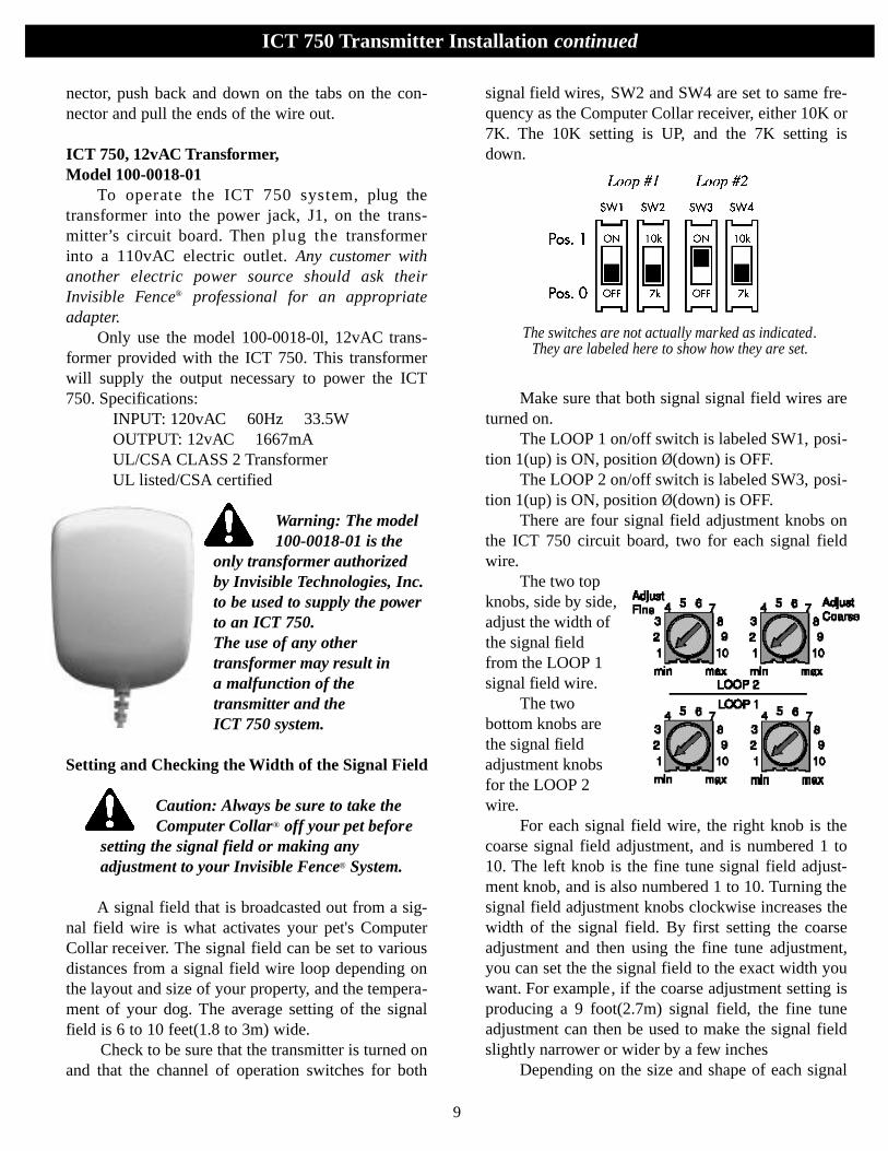
signal field wires, SW2 and SW4 are set to same fre-quency as the Computer Collar receiver, either 10K or7K. The 10K setting is UP, and the 7K setting isdown.
Make sure that both signal signal field wires areturned on.
The LOOP 1 on/off switch is labeled SW1, posi-tion 1(up) is ON, position Ø(down) is OFF.
The LOOP 2 on/off switch is labeled SW3, posi-tion 1(up) is ON, position Ø(down) is OFF.
There are four signal field adjustment knobs onthe ICT 750 circuit board, two for each signal fieldwire.
The two topknobs, side by side,adjust the width ofthe signal fieldfrom the LOOP 1signal field wire.
The twobottom knobs arethe signal fieldadjustment knobsfor the LOOP 2wire.
For each signal field wire, the right knob is thecoarse signal field adjustment, and is numbered 1 to10. The left knob is the fine tune signal field adjust-ment knob, and is also numbered 1 to 10. Turning thesignal field adjustment knobs clockwise increases thewidth of the signal field. By first setting the coarseadjustment and then using the fine tune adjustment,you can set the the signal field to the exact width youwant. For example, if the coarse adjustment setting isproducing a 9 foot(2.7m) signal field, the fine tuneadjustment can then be used to make the signal fieldslightly narrower or wider by a few inches
Depending on the size and shape of each signal
9
ICT 750 Transmitter Installation continued
The switches are not actually marked as indicated.They are labeled here to show how they are set.
field wire’s loop wire, the signal field adjustmentknobs for LOOP 1 and LOOP 2 may be set at differ-ent numbers to achieve the same signal field width oneach loop. Always set and check the width of the sig-nal field from each signal field wire separately.
These adjustments do not change the correctionlevel of the receiver, they only change thewidth of the signal field from the signal fieldloop wire.
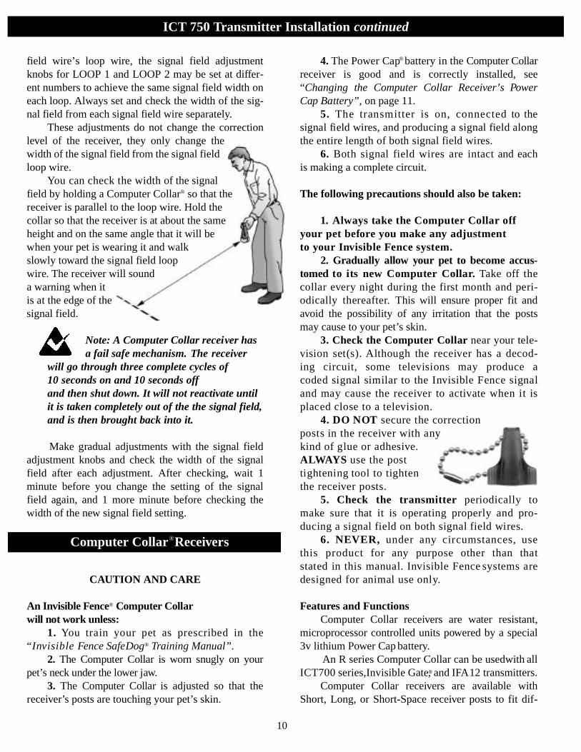
You can ch e ck the width of the signalfield by holding a Computer Collar® so that thereceiver is parallel to the loop wire. Hold thecollar so that the receiver is at about the sameheight and on the same angle that it will bewhen your pet is wearing it and walkslowly toward the signal field loopwire. The receiver will sounda warning when itis at the edge of thesignal field.
Note: A Computer Collar receiver hasa fail safe mechanism. The receiver
will go through three complete cycles of 10 seconds on and 10 seconds offand then shut down. It will not reactivate untilit is taken completely out of the the signal field,and is then brought back into it.
Make gradual adjustments with the signal fieldadjustment knobs and check the width of the signalfield after each adjustment. After checking, wait 1minute before you change the setting of the signalfield again, and 1 more minute before checking thewidth of the new signal field setting.
CAUTION AND CARE
An Inv i s i ble Fe n c e® Computer Collar will not wo rk unless:
1. You train your pet as pre s c ribed in the“I nv i s i ble Fence SafeDog® Training Manual”.
2 . The Computer Collar is wo rn snu g ly on yo u rp e t ’s neck under the lower jaw.
3. The Computer Collar is adjusted so that thereceiver’s posts are touching your pet’s skin.
4. The Power Cap® b at t e ry in the Computer Collarre c e iver is good and is corre c t ly installed, see“Changing the Computer Collar Receiver’s PowerCap Battery”, on page 11.
5. The transmitter is on, c o n n e c t e d to t h esignal field wire s , and producing a signal field alongthe entire length of both signal field wire s .
6 . Both signal field wires are intact and eachis making a complete circuit.
The following precautions should also be taken:
1. A lways take the Computer Collar offyour pet befo re you make any adjustment to your Inv i s i ble Fence system.
2. Gra d u a l ly allow your pet to become accus-tomed to its new Computer Collar. Ta ke off thecollar eve ry night during the fi rst month and peri-o d i c a l ly there a f t e r. This will ensure proper fit andavoid the possibility of any irritation that the postsmay cause to your pet’s skin.
3. Check the Computer Collar near your tele-v ision set(s). Although the re c e iver has a decod-ing circ u i t , some televisions may produce acoded signal similar to the Inv i s i ble Fence signaland may cause the re c e iver to activate when it isplaced close to a telev i s i o n .
4. DO NOT s e c u re the corre c t i o nposts in the re c e iver with anykind of glue or adhesive.A LWAY S use the posttightening tool to tighten the re c e iver posts.
5. Check the tra n s m i t t e r p e ri o d i c a l ly tom a ke sure that it is operating pro p e rly and pro-ducing a signal field on both signal field wires.
6. NEVER, under any circ u m s t a n c e s , u s ethis pro d u c t for any purpose other than thats t ated in this m a nual. Inv i s i ble Fe n c e systems aredesigned for animal use only.
Features and FunctionsComputer Collar receivers are water resistant,
microprocessor controlled units powered by a special3v lithium Power Cap battery.
An R series Computer Collar can be usedwith allICT700 series,Invisible Gate®, and IFA12 transmitters.
Computer Collar receivers are available withShort, Long, or Short-Space receiver posts to fit dif-
10
ICT 750 Transmitter Installation continued
Computer Collar®Receivers

ferent size dogs and work well with any type of coat Computer Collar receivers can be fitted w i t h
shunts to reduce the correction level of there c e iver fo r small pets who are shy or timid.
R21 v3 Series ReceiversThe R21 v3 Computer Collar receivers have an
added feature. The v3 will beep once when a PowerCap® battery is installed. The beep indicates that themicroprocessor in the receiver is working and that thePower Cap battery has enough voltage to power thereceiver.
The three smallcircular indentations,equidistantly spacedaround the outer edge ofthe base that supportsthe center batterycontact in the receiver,indicate that the receiveris an R21 v3 SeriesComputer Collar.
Fitting the Computer CollarTo wo rk pro p e rly, the correction posts on the
Computer Collar receiver must touch your pet’sskin. Posts are ava i l able in three diffe rent sizes toe n s u re a proper fit for eve ry pet: s h o rt , 1/2 inch
(12.7mm); long, 3/4 inch(19mm); and short - s p a c e dposts.
The re c e iver should be positioned undern e at hyour pet’s neck with the posts pointing up and thetop of the re c e iver pointing fo r wa rd, t owa rd yo u rp e t ’s nose. Adjust the collar so it’s snug enough toslide one fi n ger between a post and your pet’sn e ck. Pe riodic adjustment of the Computer Collarm ay be necessary as your pet’s coat , weight andage ch a n ge.
Changing the Computer Collar Receiver’sPower Cap Battery
The Power Cap battery is areplaceable 3v lithium battery with aunique plastic screw cap. It is veryimportant for proper operation that thereceiver always has a good Power Capbattery installed. On average, the bat-
tery should be changed every 3 to 4 months. But bat-tery life can be reduced by several variables, includinglower temperatures, the number of times a pet chal-lenges the system boundary, and the fit of the collaron the pet’s neck. In cold weather, for example, it maybe necessary to replace the battery more often. YourInvisible Fence® professional should recommend aschedule for regularly changing a receiver’s battery.We recommend that you ask your Dealer about a bat-tery replacement plan.
Note: Invisible Technologies, Inc.recommends that a customer subscribe
to a battery replacement plan where fresh
11
Computer Collar®Receivers continued
Make sure that the Computer Collar is snugenough for the posts to touch your pet’s skin.Be sure that you can still worka fingertipbetween the skinand the post.
Short, Long, and Short-Space Receiver Posts

12
Computer Collar®Receivers continued
Power Cap batteries are mailed directly to themon a regular schedule.Your Invisible Fence® professional can determine the best schedule for you.
Wa rn i n g : The use of any bat t e ry other than ab at t e ry authori zed by Inv i s i ble Te ch n o l ogi e s ,
I n c. can cause a re c e iver to operate errat i c a l ly. Fa i l u reof the re c e iver due to the use of an unauthori ze db at t e ry, m ay result in denial of a wa rranty cl a i m .
Invisible Fence receivers are water resistant, theyare not waterproof. In particularly humid climates orwhen a dog has access to creeks, pools, etc., watermay get trapped in the battery compartment. A smallrubber O-ring around the battery cap will minimizewater invasion, but if you think that the battery com-partment is getting wet, take the battery out of theComputer Collar receiver when your dog is not we a r-ing the collar. This will allow the battery and the com-partment to dry.
To re m ove anold Power Cap®
b at t e ry from aComputer Collarre c e ive r, use asmall, thin coin inthe slot on top of the batteryand turn it counter clockwise. The battery will rotateup and out of the battery chamber. Never use a screw-driver to remove or tighten the battery because youmay strip the plastic head on top of the battery.
Note: Remember, before you put in anew Power Cap battery, you must wait
for a full five minutes so that the ComputerCollar receiver’s microprocessor has enoughtime to recycle after the old battery has beenremoved.
To install anew battery, lineup the two lugson the bottom ofthe Power Capwith the two grooves inthe sides of the battery chamber. Gently put the PowerCap into the chamber while turning it clockwise withyour fingers. Finally, use a small, thin coin in the sloton the top of the battery to turn the battery clockwise
until the slot on the top of the battery is lined up withthe two small raised tabs on the bottom of the receiver.
When the new Power Cap is in, wait 10 secondsbefore taking the receiver into the signal field to givethe receiver time to recycle.
Failure to follow these directions exactly, mayresult in the Computer Collar receiver not activatingproperly. To maintain optimum performance, we rec-ommend that you periodically test the battery.
Warning: The Power Cap battery caseis made of soft, protective material. The use of unnecessary force may
damage the case and render the battery inoper-able.
Warning: NEVER open a Power Cap,dispose of it in fire, recharge it, heat it
above 212˚F(100˚C), or expose its contents towater. Doing so can cause leakage or explosionand may lead to personal injury.
Power Cap Battery TesterWe strongly recommend that each customer
obtain a Power Cap battery tester. At least once amonth, check the receiver battery with the Power Capbattery tester to be sure that your pet will stay out ofareas that it is supposed to, and remain safely withinyour Invisible Fence system.
The Power Cap battery tester measures the inter-nal resistance of a Power Cap battery and shows howmuch life is left in the battery.
To test a receiver battery with the Power Cap bat-tery tester, remove the battery from the receiver andput it into the Power Cap battery tester the same waythat you would put it into a receiver. If the battery isgood, the green and red LEDs on the tester will bothlight. If neither LEDon the tester lights,or just the red LEDlights dimly, the bat-tery needs to bereplaced.
13
Signal Field Wire Specifications
I f, for any re a s o n , your Inv i s i ble Fe n c e® system doesnot operate as described in this manu a l , or if yo uencounter any difficulty training your pet, please call yo u rI nv i s i ble Fence pro fessional immediat e ly.
Service Diagnostic Questions
ICT 750
Protected Area 0 to 8 acres 8 to 12 acres
Feet of Loop W i r e 400 to 2500 2500 to 3000
Feet of Twisted Pa i r up to 150 up to 150
Wire Size 14 AW G 12 AW G
Ja cket PE .045” (1.14mm )
Signal field wire is solid or stranded copper, insu-lated wire, which carries a harmless radio signal.There is no hazard in touching or exposing the wirebecause the wire carries only low voltage electricity.
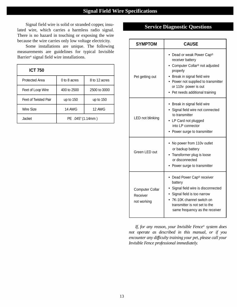
Some installations are unique. The followingmeasurements are guidelines for typical InvisibleBarrier® signal field wire installations. • Dead or weak Power Cap®
receiver battery
• Computer Collar® not adjustedproperly
• Break in signal field wire• Power not supplied to transmitter
or 110v power is out
• Pet needs additional training
• Break in signal field wire
• Signal field wire not connected to transmitter
• LP Card not plugged into LP connector
• Power surge to transmitter
• No power from 110v outlet
or backup battery
• Transformer plug is loose or disconnected
• Power surge to transmitter
• Dead Power Cap® receiverbattery
• Signal field wire is disconnected
• Signal field is too narrow
• 7K-10K channel switch ontransmitter is not set to the same frequency as the receiver
SYMPTOM CAUSE
Pet getting out
LED not blinking
Green LED out
Computer Collar
Receiver
not working
14
Important Warnings
1. WARNING: Occasionally an animal cannot be trained to avoid crossing the
Invisible Boundary ®. Sometimes even a properlytrained animal may cross the boundary.Therefore, Invisible Technologies, Inc, InvisibleFence Distributors and Dealers cannot guaranteethat the system will, in all cases, keep Customer'sanimal within the established boundary.Accordingly, if Customer has reason to believe thathis or her animal may pose a danger to others orharm itself if it is not kept from crossing the bound-aries, Customer should not rely solely upon the sys-tem to keep the animal from crossing the boundary.
2. WARNING: The control panel component of the system includes visual
and audio signals to warn of a system malfunction,and is therefore intended to be installed in a placewhere such signals may be easily seen and heard.If the control panel is installed in an enclosed boxor in a place not readily accessible to Customer,Customer will forfeit the benefits of the system'swarning functions for which Invisible Technologies,Inc., Invisible Fence Distributors and Dealersassume no responsibility.
3. WARNING: Some persons claim thatthe shock from an electronic receiver collar
can provoke an animal to become aggressive, andpossibly to attack or bite.Customer is hereby warned to be alert for growling,snarling, biting, or other aggressive behavior by anyanimal using the system, especially during training.If any such behavior is observed, particularly if itappears to be associated in any way with the system,Customer should immediately stop using the system,unplug the transmitter, and contact your localInvisible Fence professional or InvisibleTechnologies, Inc.Reported incidents have typically involved:
1) dogs with pre-existing aggressive tendencies; and
2) other provocation at the time of the incident. Reports to Invisible Technologies allegingsuch incidents are rare, less than one in10,000, or 0.01% of the time.

© 2003 Invisible Technologies, Inc., 1000 Fuller Drive, Garrett IN 46738. Made in USA. Printed in USA. Invisible, Invisible Fence, Invisible Fencing, Invisible Barrier, InvisibleBoundary, Invisible Power, Cloture Invisible, Inbounds, Softwear, Power Cap, Safe Dog, Invisible Mask, SuperDog, Computer Collar, Break Alert, Off Limits, Your Neighborhood PetContainment Professionals, Sharing the Responsibility For Your Pet’s Well-Being, The Fence that Make Sense, Always There . . . For The Life of Your Pet, Pet Central, Premium DogManagement, The Visible Difference, Pet Keeper, Room Keeper , In-Home, Project Pet Save, Invisible Fencing Celebrating 25 Years Protecting Pets & Design, The One and Only,Original, Pet Safety System,Invisible Fence Brand , Your Dog Safe @ Home and Invisible Gate are registered trademarks of Invisible Technologies, Inc. Pro Dog, Invisible FencingDogs’ Life, Invisible Sentry, Safe Cat, and Your dog is so much more than a pet. are trademarks of Invisible Technologies, Inc. Invisible Fence Brand products are covered by var-ious patents, both domestic and foreign. Trademark uses licensed. Trademark owner: Invisible Technologies, Inc., USA.
Questions or comments? Please call 1-800-538-DOGS or visit www.invisiblefence.com.
FCCID # KZ3ICT250 “ This device complies with Pa rt 15 of the FCCRules. Operation is subject to the fo l l owing two conditions: 1. Thisdevice may not cause harmful interference, and 2. This device must accept anyinterference received, including interference that may cause undesirable oper-ation. Changes or modifications not expressly approved by the party responsi-ble for compliance could void the user’s authority to operate the equipment.”
INDUSTRY CANADA CERTIFIED Canada 2430 101 802
1003 5 0 2 - 0 0 4 0 - 0 9