Embed Size (px)
Citation preview
CLEAR-COM ECLIPSE
ICS-2003 INTERCOM PANEL
INSTRUCTION MANUAL
ICS-2003 Intercom Panel Instruction Manual© 2007, 2009 Vitec Group Communications Ltd. All rights reserved.
Part Number 810303Z Rev. 4
Vitec Group Communications, LLC.850 Marina Village ParkwayAlameda, CA 94501U.S.A.
Vitec Group Communications7400 Beach DriveIQ CambridgeCambrideshireUnited KingdomCB25 9TP
The Vitec Group plcBeijing Representative OfficeRoom 706, Tower B Derun Building, YongAn Dongli A No.3 Jianwai Ave., Chaoyang DistrictBeijing, P.R.China 100022
® Clear-Com, CellCom/FreeSpeak and the Clear-Com Communication Systems logo are registered trademarks of The Vitec Group plc.
Website: www.clearcom.com
CONTENTSOPERATION . . . . . . . . . . . . . . . . . . . . . . . . . . . . . . 1-1Introduction . . . . . . . . . . . . . . . . . . . . . . . . . . . . . . . . . . . . . . . . . . . . 1-1Description . . . . . . . . . . . . . . . . . . . . . . . . . . . . . . . . . . . . . . . . . . . . 1-1
ICS-2003/ICS-2003T Display Panel . . . . . . . . . . . . . . . . . . . . . . . 1-1Panel Options . . . . . . . . . . . . . . . . . . . . . . . . . . . . . . . . . . . . . . . . 1-1Front-Panel Controls and Indicators . . . . . . . . . . . . . . . . . . . . . . . 1-2
Display Screen. . . . . . . . . . . . . . . . . . . . . . . . . . . . . . . . . . . . . . 1-2Talk Window . . . . . . . . . . . . . . . . . . . . . . . . . . . . . . . . . . . . . 1-2Listen Window . . . . . . . . . . . . . . . . . . . . . . . . . . . . . . . . . . . 1-3Answer-Back Window. . . . . . . . . . . . . . . . . . . . . . . . . . . . . . 1-3Message Window . . . . . . . . . . . . . . . . . . . . . . . . . . . . . . . . . 1-3Symbol Window . . . . . . . . . . . . . . . . . . . . . . . . . . . . . . . . . . 1-3Non-Displaying Characters. . . . . . . . . . . . . . . . . . . . . . . . . . 1-3
Communication-Error Indicator . . . . . . . . . . . . . . . . . . . . . . . . . 1-4Speaker/Headset Level Controls . . . . . . . . . . . . . . . . . . . . . . . . 1-4
Intercom Volume. . . . . . . . . . . . . . . . . . . . . . . . . . . . . . . . . . 1-4Program Volume. . . . . . . . . . . . . . . . . . . . . . . . . . . . . . . . . . 1-4Page Override. . . . . . . . . . . . . . . . . . . . . . . . . . . . . . . . . . . . 1-4Mute Level . . . . . . . . . . . . . . . . . . . . . . . . . . . . . . . . . . . . . . 1-4Listen Level Adjustment . . . . . . . . . . . . . . . . . . . . . . . . . . . . 1-4
Headset Connector . . . . . . . . . . . . . . . . . . . . . . . . . . . . . . . . . . 1-4Talk/Listen Selectors and Indicators . . . . . . . . . . . . . . . . . . . . . 1-5
Selector Operation . . . . . . . . . . . . . . . . . . . . . . . . . . . . . . . . 1-5Talk and Listen Indicators. . . . . . . . . . . . . . . . . . . . . . . . . . . 1-5Monitoring/Eavesdropping Indicators . . . . . . . . . . . . . . . . . . 1-5Call-Waiting Indicator . . . . . . . . . . . . . . . . . . . . . . . . . . . . . . 1-5In-Use Tally Indicator . . . . . . . . . . . . . . . . . . . . . . . . . . . . . . 1-5Telephone Off-Hook Tally Indicator . . . . . . . . . . . . . . . . . . . 1-5Radio Receiver Active Tally Indicator . . . . . . . . . . . . . . . . . . 1-6Panel Connected Tally Indicator. . . . . . . . . . . . . . . . . . . . . . 1-6Audio Presence Tally Indicator . . . . . . . . . . . . . . . . . . . . . . . 1-6
Answer-Back Facility . . . . . . . . . . . . . . . . . . . . . . . . . . . . . . . . . 1-6Answer-Back Window. . . . . . . . . . . . . . . . . . . . . . . . . . . . . . 1-6Answer-Back Selector . . . . . . . . . . . . . . . . . . . . . . . . . . . . . 1-6Answer-Back Label Selection . . . . . . . . . . . . . . . . . . . . . . . . 1-7Removing Labels from the Answer-Back Stack . . . . . . . . . . 1-7Calling an Unassigned Panel . . . . . . . . . . . . . . . . . . . . . . . . 1-7
Keypad: Single-Function Buttons . . . . . . . . . . . . . . . . . . . . . . . 1-7Mic On/Off Button . . . . . . . . . . . . . . . . . . . . . . . . . . . . . . . . . 1-7Speaker On/Off Button . . . . . . . . . . . . . . . . . . . . . . . . . . . . . 1-7Mic Select Button . . . . . . . . . . . . . . . . . . . . . . . . . . . . . . . . . 1-8Listen Level Button . . . . . . . . . . . . . . . . . . . . . . . . . . . . . . . . 1-8
Keypad: Administrative Buttons. . . . . . . . . . . . . . . . . . . . . . . . . 1-9
Clear-Com Communication SystemsICS-2003 Intercom Panel Instruction Manual
i
Menu Button (3) . . . . . . . . . . . . . . . . . . . . . . . . . . . . . . . . . . 1-9Panel Upgrade Facility. . . . . . . . . . . . . . . . . . . . . . . . . . . . . . . 1-13
Maintenance Menu . . . . . . . . . . . . . . . . . . . . . . . . . . . . . . . . . . . 1-14Listens Button (5). . . . . . . . . . . . . . . . . . . . . . . . . . . . . . . . . . . 1-14Swap Button (9) . . . . . . . . . . . . . . . . . . . . . . . . . . . . . . . . . . . . 1-14Dial Button (*) . . . . . . . . . . . . . . . . . . . . . . . . . . . . . . . . . . . . . 1-14SA (Studio/Stage Announce) Button (#) . . . . . . . . . . . . . . . . . 1-15
Rear-Panel Connectors. . . . . . . . . . . . . . . . . . . . . . . . . . . . . . . . 1-15Miscellaneous Connector . . . . . . . . . . . . . . . . . . . . . . . . . . . . 1-15
Logic Input #1 and #2 . . . . . . . . . . . . . . . . . . . . . . . . . . . . . 1-15Programmable Relay . . . . . . . . . . . . . . . . . . . . . . . . . . . . . 1-16Mute Relay . . . . . . . . . . . . . . . . . . . . . . . . . . . . . . . . . . . . . 1-16
OPT-100 Auxiliary Audio Option . . . . . . . . . . . . . . . . . . . . . . . 1-17Hot Mic Output . . . . . . . . . . . . . . . . . . . . . . . . . . . . . . . . . . 1-17Studio/Stage Announce Audio and Relay Outputs . . . . . . . 1-17Auxiliary Audio Line Level Output. . . . . . . . . . . . . . . . . . . . 1-17
Expansion Panel Operation . . . . . . . . . . . . . . . . . . . . . . . . . . . . . . 1-17
INSTALLATION . . . . . . . . . . . . . . . . . . . . . . . . . . . . 2-1Introduction . . . . . . . . . . . . . . . . . . . . . . . . . . . . . . . . . . . . . . . . . . . . 2-1Mounting Panels . . . . . . . . . . . . . . . . . . . . . . . . . . . . . . . . . . . . . . . . 2-1Wiring . . . . . . . . . . . . . . . . . . . . . . . . . . . . . . . . . . . . . . . . . . . . . . . . 2-1
Analog Matrix Frame to Panel Wiring . . . . . . . . . . . . . . . . . . . . . . 2-2Digital Matrix Frame to Panel Wiring. . . . . . . . . . . . . . . . . . . . . . . 2-3
Single-Pair Digital . . . . . . . . . . . . . . . . . . . . . . . . . . . . . . . . . . . 2-3Matrix Panel Miscellaneous Connector Wiring . . . . . . . . . . . . . . . 2-4
External Program Feed Input. . . . . . . . . . . . . . . . . . . . . . . . . . . 2-4Logic Input #1 and #2 . . . . . . . . . . . . . . . . . . . . . . . . . . . . . . . . 2-5Mute Relay Contacts . . . . . . . . . . . . . . . . . . . . . . . . . . . . . . . . . 2-6Programmable Relay Contacts . . . . . . . . . . . . . . . . . . . . . . . . . 2-6
OPT-100 Auxiliary Audio I/O Option . . . . . . . . . . . . . . . . . . . . . . . 2-8Hot Mic Output. . . . . . . . . . . . . . . . . . . . . . . . . . . . . . . . . . . . . . 2-8Studio/Stage Announce Audio and Relay Outputs . . . . . . . . . . 2-8Auxiliary Audio Line Level Output . . . . . . . . . . . . . . . . . . . . . . . 2-9
Binaural Headset Wiring . . . . . . . . . . . . . . . . . . . . . . . . . . . . . . . . 2-9Mains AC Power . . . . . . . . . . . . . . . . . . . . . . . . . . . . . . . . . . . . . . . 2-10Adjustments . . . . . . . . . . . . . . . . . . . . . . . . . . . . . . . . . . . . . . . . . . 2-10
Headset Sidetone . . . . . . . . . . . . . . . . . . . . . . . . . . . . . . . . . . . . 2-10Panel Microphone Gain. . . . . . . . . . . . . . . . . . . . . . . . . . . . . . . . 2-11Speaker Dim . . . . . . . . . . . . . . . . . . . . . . . . . . . . . . . . . . . . . . . . 2-11Page Volume Level . . . . . . . . . . . . . . . . . . . . . . . . . . . . . . . . . . . 2-11
Configuration . . . . . . . . . . . . . . . . . . . . . . . . . . . . . . . . . . . . . . . . . 2-11
Clear-Com Communication SystemsICS-2003 Intercom Panel Instruction Manual
ii
Accessory Panels . . . . . . . . . . . . . . . . . . . . . . . . . . . . . . . . . . . . . . 2-12XPL Type Expansion Panels . . . . . . . . . . . . . . . . . . . . . . . . . . . . 2-12Mounting . . . . . . . . . . . . . . . . . . . . . . . . . . . . . . . . . . . . . . . . . . . 2-12Power . . . . . . . . . . . . . . . . . . . . . . . . . . . . . . . . . . . . . . . . . . . . . 2-12Panel Connection . . . . . . . . . . . . . . . . . . . . . . . . . . . . . . . . . . . . 2-12Configuration. . . . . . . . . . . . . . . . . . . . . . . . . . . . . . . . . . . . . . . . 2-13
MAINTENANCE. . . . . . . . . . . . . . . . . . . . . . . . . . . . 3-1Introduction . . . . . . . . . . . . . . . . . . . . . . . . . . . . . . . . . . . . . . . . . . . . 3-1
Panel Reset. . . . . . . . . . . . . . . . . . . . . . . . . . . . . . . . . . . . . . . . . . 3-1Troubleshooting . . . . . . . . . . . . . . . . . . . . . . . . . . . . . . . . . . . . . . . . 3-1
Bill of Materials . . . . . . . . . . . . . . . . . . . . . . . . . . . . . . . . . . . . . . . 3-4Miscellaneous . . . . . . . . . . . . . . . . . . . . . . . . . . . . . . . . . . . . . . 3-4
Technical Reference . . . . . . . . . . . . . . . . . . . . . . . . . . . . . . . . . . . . . 3-5Bill of Materials for the ICS-2003/2003T Main PCB . . . . . . . . . . 3-14
Capacitors . . . . . . . . . . . . . . . . . . . . . . . . . . . . . . . . . . . . . . . . 3-14Resistors & Resistor Packs . . . . . . . . . . . . . . . . . . . . . . . . . . . 3-16Diodes and Transistors . . . . . . . . . . . . . . . . . . . . . . . . . . . . . . 3-18Integrated Circuits . . . . . . . . . . . . . . . . . . . . . . . . . . . . . . . . . . 3-18Miscellaneous . . . . . . . . . . . . . . . . . . . . . . . . . . . . . . . . . . . . . 3-20
Bill of Materials for the ICS-2003/2003T Front Panel PCB . . . . . 3-24Bill of Materials for the ICS-2003/ICS-2003T COM-10 PCB . . . . 3-28Bill of Materials for the OPT-100 PCB. . . . . . . . . . . . . . . . . . . . . 3-31Bill of Materials for COM-20 Communication PCB . . . . . . . . . . . 3-35
Capacitors . . . . . . . . . . . . . . . . . . . . . . . . . . . . . . . . . . . . . . . . 3-35Resistors . . . . . . . . . . . . . . . . . . . . . . . . . . . . . . . . . . . . . . . . . 3-36Diodes and Transistors . . . . . . . . . . . . . . . . . . . . . . . . . . . . . . 3-37Integrated Circuits . . . . . . . . . . . . . . . . . . . . . . . . . . . . . . . . . . 3-37Miscellaneous . . . . . . . . . . . . . . . . . . . . . . . . . . . . . . . . . . . . . 3-38
SPECIFICATIONS . . . . . . . . . . . . . . . . . . . . . . . . . . 4-1Front-Panel Controls and Connectors. . . . . . . . . . . . . . . . . . . . . . 4-1Rear-Panel Connectors. . . . . . . . . . . . . . . . . . . . . . . . . . . . . . . . . 4-1Panel Microphone Input . . . . . . . . . . . . . . . . . . . . . . . . . . . . . . . . 4-1Headset Microphone Input . . . . . . . . . . . . . . . . . . . . . . . . . . . . . . 4-1Local Program Input . . . . . . . . . . . . . . . . . . . . . . . . . . . . . . . . . . . 4-1Headphone Outputs . . . . . . . . . . . . . . . . . . . . . . . . . . . . . . . . . . . 4-2Speaker Amplifier Output . . . . . . . . . . . . . . . . . . . . . . . . . . . . . . . 4-2Line Input (2-pair Listen from Matrix) . . . . . . . . . . . . . . . . . . . . . . 4-2Line Output (2-pair Talk to Matrix) . . . . . . . . . . . . . . . . . . . . . . . . . 4-2Logic Input #1 . . . . . . . . . . . . . . . . . . . . . . . . . . . . . . . . . . . . . . . . 4-2
Clear-Com Communication SystemsICS-2003 Intercom Panel Instruction Manual
iii
Logic Input #2 . . . . . . . . . . . . . . . . . . . . . . . . . . . . . . . . . . . . . . . . 4-2Mute Relay . . . . . . . . . . . . . . . . . . . . . . . . . . . . . . . . . . . . . . . . . . 4-2Panel Relay. . . . . . . . . . . . . . . . . . . . . . . . . . . . . . . . . . . . . . . . . . 4-2AC Mains Power . . . . . . . . . . . . . . . . . . . . . . . . . . . . . . . . . . . . . . 4-2Temperature . . . . . . . . . . . . . . . . . . . . . . . . . . . . . . . . . . . . . . . . . 4-3Humidity . . . . . . . . . . . . . . . . . . . . . . . . . . . . . . . . . . . . . . . . . . . . 4-3Package Dimensions . . . . . . . . . . . . . . . . . . . . . . . . . . . . . . . . . . 4-3Audio . . . . . . . . . . . . . . . . . . . . . . . . . . . . . . . . . . . . . . . . . . . . . . . 4-3SA Relay . . . . . . . . . . . . . . . . . . . . . . . . . . . . . . . . . . . . . . . . . . . . 4-3
GLOSSARY . . . . . . . . . . . . . . . . . . . . . . . . . . . . . . . 5-1Eclipse Manuals . . . . . . . . . . . . . . . . . . . . . . . . . . . . . . . . . . . . . . . . 5-5
Software Manuals . . . . . . . . . . . . . . . . . . . . . . . . . . . . . . . . . . . . . 5-5Hardware Manuals . . . . . . . . . . . . . . . . . . . . . . . . . . . . . . . . . . . . 5-5
LIMITED WARRANTY . . . . . . . . . . . . . . . . . . . . . . . W-I
TECHNICAL SUPPORT & REPAIR POLICY. . . . . W-VTECHNICAL SUPPORT POLICY. . . . . . . . . . . . . . . . . . . . . . . . . . W-vRETURN MATERIAL AUTHORIZATION POLICY . . . . . . . . . . . . . W-viREPAIR POLICY . . . . . . . . . . . . . . . . . . . . . . . . . . . . . . . . . . . . . W-viii
Clear-Com Communication SystemsICS-2003 Intercom Panel Instruction Manual
iv
IMPORTANT SAFETY INSTRUCTIONSFor your safety, it is important to read and follow these instructions before operating an ICS-2003 intercom panel:
(1) WARNING: To reduce the risk of fire or electric shock, do not expose an ICS-2003 intercom panel to rain or moisture. Do not operate an ICS-2003 intercom panel near water, or place objects containing liquid on it. Do not expose an ICS-2003 intercom panel to splashing or dripping water.
(2) For proper ventilation, make sure ventilation openings are not blocked. Install the ICS-2003 according to the directions in the Installation Chapter of this manual.
(3) Do not install an ICS-2003 intercom panel near a heat source such as a radiator, heat register, stove, or other apparatus (including amplifiers) that produces heat. Do not place naked flame sources such as candles on or near an ICS-2003.
(4) Do not defeat the safety purpose of the polarized or grounding-type plug. A polarized plug has two blades, with one blade wider than the other. A grounding-type plug has two blades and a third grounding prong. The wide blade or the third prong is provided for your safety. If the provided plug does not fit into your outlet, consult an electrician for replacement of the obsolete outlet.
(5) Protect the power plug from being walked on or pinched particularly at plugs, convenience receptacles, and the point where they exit from the ICS-2003 chassis.
(6) Only use attachments/accessories specified by Clear-Com Communication Systems.
(7) Unplug the ICS-2003 panel during lightning storms or when unused for long periods of time.
(8) Refer all servicing to qualified service personnel. Servicing is required when:
• The ICS-2003 panel has been damaged in any way, such as when a power-supply cord or plug is damaged.
• Liquid has been spilled or objects have fallen into the ICS-2003 panel’s chassis.
• The ICS-2003 panel has been exposed to rain or moisture.
• The ICS-2003 panel does not operate normally.
• The ICS-2003 panel has been dropped.
Please familiarize yourself with the safety symbols in Figure 1. When you see these symbols on an ICS-2003 intercom panel, they warn you of the potential danger of electric shock if the panel is used improperly.
Please read and follow these instructions before operating an ICS-2003 intercom panel.
Clear-Com Communication SystemsICS-2003 Intercom Panel Instruction Manual
v
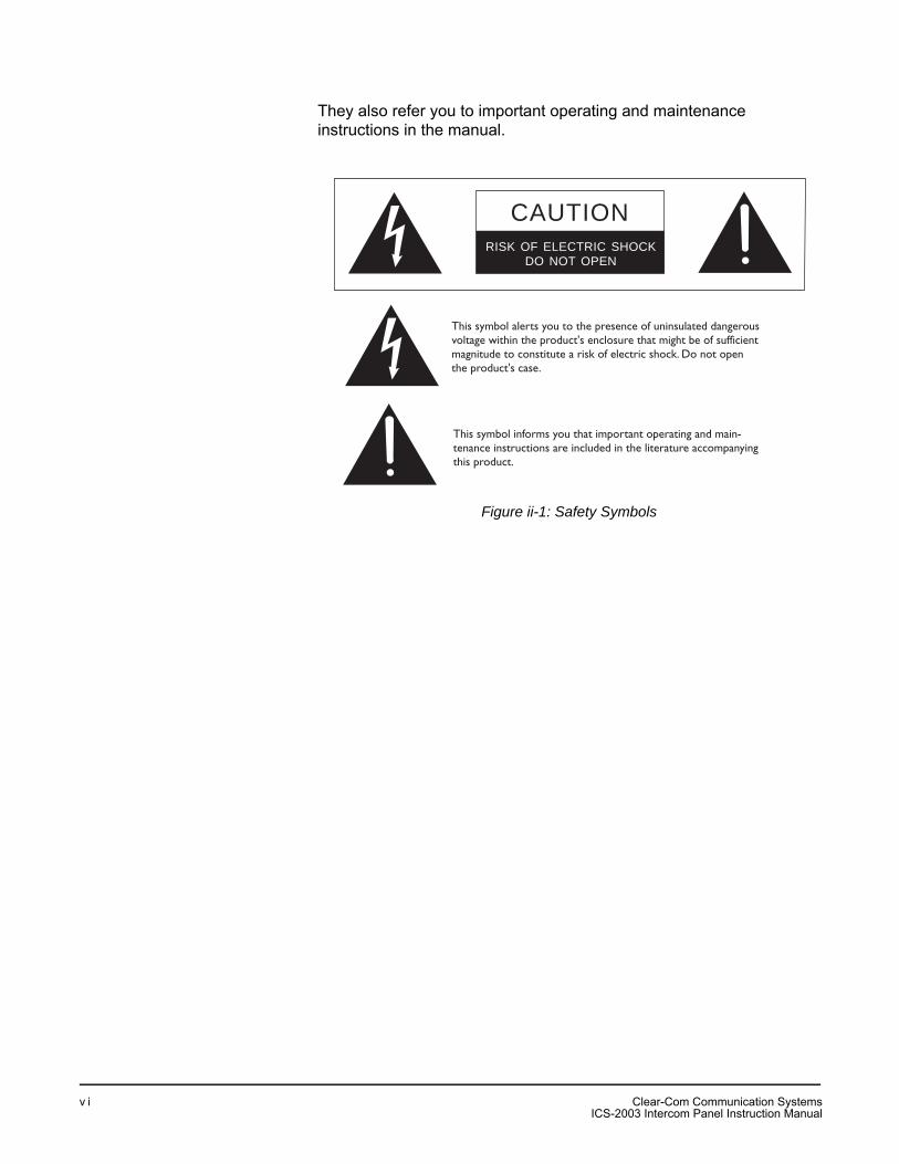
They also refer you to important operating and maintenance instructions in the manual.
Figure ii-1: Safety Symbols
CAUTIONRISK OF ELECTRIC SHOCK
DO NOT OPEN
This symbol alerts you to the presence of uninsulated dangerousvoltage within the product's enclosure that might be of sufficient magnitude to constitute a risk of electric shock. Do not open the product's case.
This symbol informs you that important operating and main-tenance instructions are included in the literature accompanyingthis product.
Clear-Com Communication SystemsICS-2003 Intercom Panel Instruction Manual
v i
OPERATIONINTRODUCTIONThis chapter describes how to operate an ICS-2003 display intercom panel and its digital equivalent, the ICS-2003T. Panel operators can use this manual after the Eclipse System has been correctly installed and configured.
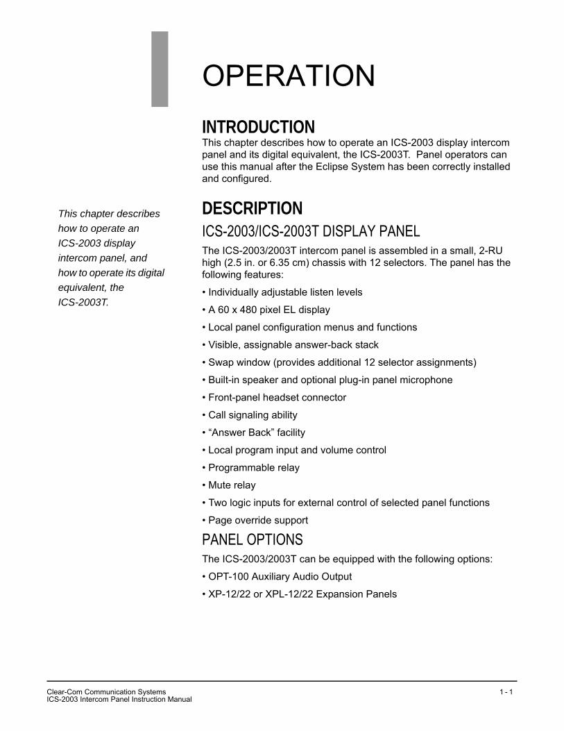
DESCRIPTIONICS-2003/ICS-2003T DISPLAY PANELThe ICS-2003/2003T intercom panel is assembled in a small, 2-RU high (2.5 in. or 6.35 cm) chassis with 12 selectors. The panel has the following features:
• Individually adjustable listen levels
• A 60 x 480 pixel EL display
• Local panel configuration menus and functions
• Visible, assignable answer-back stack
• Swap window (provides additional 12 selector assignments)
• Built-in speaker and optional plug-in panel microphone
• Front-panel headset connector
• Call signaling ability
• “Answer Back” facility
• Local program input and volume control
• Programmable relay
• Mute relay
• Two logic inputs for external control of selected panel functions
• Page override support
PANEL OPTIONS The ICS-2003/2003T can be equipped with the following options:
• OPT-100 Auxiliary Audio Output
• XP-12/22 or XPL-12/22 Expansion Panels
This chapter describes how to operate an ICS-2003 display intercom panel, and how to operate its digital equivalent, the ICS-2003T.
1
CIC
lear-Com Communication SystemsS-2003 Intercom Panel Instruction Manual
1 - 1
FRONT-PANEL CONTROLS AND INDICATORSThis section describes the front-panel controls and indicators. These include:
• The display screen
• Intercom and program controls
• Talk/listen selectors and indicators
• “Answer Back” facility
• Keypad buttons
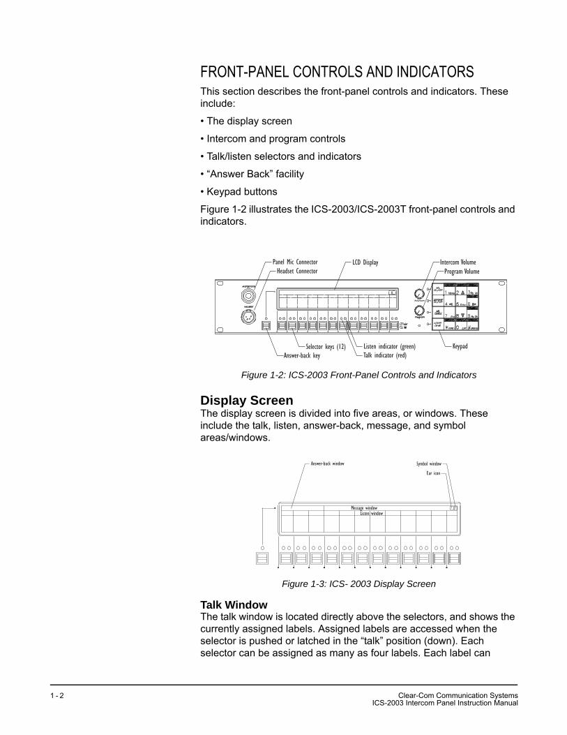
Figure 1-2 illustrates the ICS-2003/ICS-2003T front-panel controls and indicators.
Figure 1-2: ICS-2003 Front-Panel Controls and Indicators
Display ScreenThe display screen is divided into five areas, or windows. These include the talk, listen, answer-back, message, and symbol areas/windows.
Figure 1-3: ICS- 2003 Display Screen
Talk WindowThe talk window is located directly above the selectors, and shows the currently assigned labels. Assigned labels are accessed when the selector is pushed or latched in the “talk” position (down). Each selector can be assigned as many as four labels. Each label can
Panel Mic ConnectorHeadset Connector
LCD Display Intercom VolumeProgram Volume
Answer-back keySelector keys (12) Listen indicator (green)
Talk indicator (red)Keypad
Answer-back window Symbol window
Ear icon
Message windowListen window
Clear-Com Communication SystemsICS-2003 Intercom Panel Instruction Manual
1 - 2
represent a talk path to a panel, interface, fixed group, or party line, or can activate a programmable control function.
Listen WindowThe listen window is located directly above the talk window. It contains one listen label per selector. Labels refer to the listen paths that are established when the selector is pushed up.
Answer-Back WindowThe answer-back window is located above the “Answer Back” selector. It displays a list of as many as five incoming calls. The first caller’s label is closest to the “Answer Back” selector and is highlighted. Subsequent calls are placed to the right of the first in the window. This list is called the answer-back stack.
Message WindowThe message window displays panel status and error messages.
Symbol WindowThe symbol window displays two graphic symbols. The functions of the two symbols are as follows:
• Ear symbol—indicates when someone is listening to (monitoring) the panel.
• Window-indication symbol—displays a W (for window) and a Roman numeral I or II to indicate which talk/listen window is active, as toggled by the “Swap” button (See “Swap Button (9)” on page 14.).
Non-Displaying CharactersCertain Latin characters that may be present in a label will not be displayed on the ICS-2003 display screen and will be replaced by spaces. These characters are:
• ` (grave) is displayed as a space
• | (bar) is displayed as a space
• _ (underscore) is displayed as a space
• ~ (asciitilde) is displayed as a space
• (braceleft) is displayed as a space
• (braceright) is displayed as a space
• ¬ (logicalnot) is displayed as a space
Users should avoid the use of these characters in labels that may be configured on ICS-2003 panels as the replacement of the characters with spaces could cause operator errors.
CI
lear-Com Communication SystemsCS-2003 Intercom Panel Instruction Manual
1 - 3
Communication-Error IndicatorIf the panel should lose data communication with the matrix frame:
• It will display the message “WAITING FOR ECLIPSE CONNECTION.”
• All of the red LEDs will flash slowly.
When data communication is restored, the panel will automatically return to normal operation.
Speaker/Headset Level ControlsTo adjust the speaker or headset volume, use the “Intercom” and “Program” volume controls. The speaker volume can also be affected by three software-controlled functions: Page Override, Mute Level, and Listen Level Adjustment.
Intercom VolumeThe “Intercom” volume control sets the overall level of all signals coming from the matrix frame.
Program VolumeThe “Program” volume control adjusts the volume of the signal coming into the panel through the auxiliary input of the “Miscellaneous” rear-panel connector.
Page OverridePage override is a special function in the panel in which the intercom volume defaults to a preset to a value when commanded to by the central matrix. Any fixed group can be assigned the page-override function through the configuration program.The configuration program determines preset value for each panel. If the preset value is lower than the setting of the front-panel volume control, the volume will be controlled by the front-panel control.
Mute LevelThis turns down the speaker level when any talk is active at the panel. The amount of muting (measured in dB) is set by the configuration program for each panel. This function helps prevent possible feedback. The maximum amount of muting is 15 dB below full volume. If the front panel control is set below that level, then muting will have no effect.
Listen Level AdjustmentThe level of any active listen path can be adjusted individually. Refer to “Listen-Level Mode” on page 8.
Headset ConnectorThe headset connector provides a front-panel connection for a headset. Plugging in a headset will initially cause the panel to switch to headset-microphone operation and will turn the speaker off. Unplugging the headset will cause the panel to switch to panel-microphone operation and will turn the speaker on.
Clear-Com Communication SystemsICS-2003 Intercom Panel Instruction Manual
1 - 4
Talk/Listen Selectors and IndicatorsThe following section describes the operation of the talk/listen selectors and their associated indicators.
Selector OperationThe selectors operate as both talk and listen selectors; they also work as volume controls when the panel is in listen-level mode (see “Listen-Level Mode” on page 8). Pressing a selector down accesses a talk label; pushing it up accesses a listen label. Pushing the talk selector down and quickly releasing it will “latch” the selector and the talk path will stay active until it is pressed again. Pressing and holding a talk selector causes the talk path to stay active only for as long as it is held down. Listen selectors operate in the same manner.To prevent the selector on the panel from latching in the talk position (local latch disable), or to prevent any panel from latching a talk to the panel (global latch disable) use the configuration program.
Talk and Listen IndicatorsWhen a talk path is active, the selector’s red LED lights continuously. When a listen path is active, the selector’s green LED lights continuously.
Monitoring/Eavesdropping IndicatorsIf any other panel begins monitoring a panel a beep (the monitoring-alert tone) will sound at the panel.To inhibit the monitoring-alert tone, use the configuration program.
Call-Waiting IndicatorIf a panel calls another panel with a selector programmed with the caller’s label, the red LED will flash rapidly. This flashing is a call-waiting tally. To answer the incoming call, push the indicated talk selector. The call-waiting tally will be cleared when the call is answered or after the call is terminated and the answer-back, auto-clear time out lapses.Regardless of whether a selection is programmed with a caller’s label, the label will be placed in the answer-back stack (see “Removing Labels from the Answer-Back Stack” on page 7).
In-Use Tally IndicatorIf a selector is assigned to a label and another panel is currently using that label, the LED will double-flash once per second to indicate the label is in use. This tally must be enabled from the configuration software.
Telephone Off-Hook Tally IndicatorWhen a telephone interface is assigned to a talk selector, the talk LED will flash once per second if that telephone is off the hook. This tally must be enabled from the configuration program.
CI
lear-Com Communication SystemsCS-2003 Intercom Panel Instruction Manual
1 - 5
Radio Receiver Active Tally IndicatorWhen a two-way radio interface port is assigned to a talk selector, the LED will flash once per second when that radio’s receiver is active. This tally must be enabled from the configuration program.
Panel Connected Tally IndicatorThis tally is used when a panel is connected to the frame by a high-speed data line (such as an ISDN or T1 line) that might be inactive periodically. The red LED of any talk selector associated with that panel will flash once per second when the panel is on-line. This tally must be enabled from the configuration program.
Audio Presence Tally IndicatorWhen a label is assigned to a listen selector, the LED will flash once per second to indicate someone is talking on that channel. This tally must be enabled from the configuration program.
Answer-Back FacilityThe primary function of answer-back facility is to answer or call other panels or interfaces not assigned to a panel’s selectors. Panels and interfaces that are assigned to a panel’s selectors also can be answered or called with the answer-back facility.The following sections describe the use of the answer-back facility.
Answer-Back WindowThe answer-back window is located above the “Answer Back” selector. It displays a list of as many as five incoming calls. The first caller’s label is closest to the “Answer Back” selector and is highlighted. Subsequent calls are placed to the right of the first in the window. This list is called the answer-back stack.
Answer-Back SelectorThe “Answer Back” selector answers calls from panels and interfaces that are both assigned and unassigned to the panel.When a call arrives from a panel or interface:
• The calling panel’s label will be placed in the answer-back stack and be highlighted in the answer-back window.
• The red LED will flash.
These two conditions will continue until the call is answered, or until the answer-back time-out period lapses and the caller’s label is automatically removed. To answer the call, push the “Answer Back” selector. The LED will stay on steady, indicating an active talk path to the caller. The talk path is active for as long as the selector is held.
Note: The “Answer Back” selector cannot be latched; it is a momentary-only function.
Calls from panels or interfaces assigned to panel selectors will also be indicated by their associated LEDs.
Clear-Com Communication SystemsICS-2003 Intercom Panel Instruction Manual
1 - 6
Answer-Back Label SelectionIf another call or calls comes in while using the answer-back selector:
• The user will hear the caller’s voice
• The label will be placed in the answer-back stack.
To answer the next caller:1. Push up on the “Answer Back” selector to highlight the desired label
in the answer-back stack.2. Once the desired label is highlighted, press the selector down to
talk.
Removing Labels from the Answer-Back StackAny label will be automatically removed from the stack if it is not answered within a certain time interval, which is set by the answer-back auto-clear time in the configuration program.To manually remove the current caller’s label from the answer-back stack, push up on the “Answer Back” selector.
Calling an Unassigned PanelTo call a destination in the answer-back stack: 1. Push up on the “Answer Back” selector to highlight the desired label
in the answer-back stack.2. Once the desired label is highlighted, press the selector down to
talk.
Keypad: Single-Function ButtonsThe first column of buttons on the keypad consists of:
• “Mic On/Off”
• “Speaker On/Off”
• “Mic Select”
• “Listen Level”
Mic On/Off ButtonThis button activates the panel or headset microphone, whichever has been selected. The LED indicates when the microphone is on. If a talk is activated while the microphone is off, it will turn on for the duration of the call.
Speaker On/Off ButtonThis button functions only when a headset is plugged into the panel. To toggle the speaker on and off, push the “Speaker On/Off” button. The LED indicates when the speaker is on.
CI
lear-Com Communication SystemsCS-2003 Intercom Panel Instruction Manual
1 - 7
Mic Select ButtonThis button selects the panel or headset microphone. If a headset is plugged in, the panel will automatically switch to headset microphone operation. If the headset is unplugged, the panel will automatically switch back to panel microphone operation. The LED to will be on when the panel microphone is active.
Listen Level ButtonThe Listen Level button has four functions:
• Activating the listen-level mode
• Resetting the listen-level settings
• Sending call signals
• Releasing auto-answered telephone lines
Listen-Level ModeTo use the listen-level adjust mode:1. Push (for less than 1 second) and quickly release the “Listen Level”
button.2. “Listen Level Adjust Mode” will appear in the message window to
indicate the function is on and the LEDs of all active listen selectors will begin to flash.
Note: Only active selectors can be adjusted in listen-level mode.
3. Use the selector associated with the intended label to increase (up) or decrease (down) the volume.
4. To exit, push the “Listen Level” button or wait for the 3 second time-out.
Listen Level ResetTo reset the Listen Level to default settings:1. Press (for less than 1 second) and quickly release the “Listen Level”
button.2. Press and hold the “Listen Level” button for 3 seconds.3. Release the “Listen Level” button.
Call SignalsTo activate a call signal push and hold (for at least 1 second) the “Listen Level” button until the panel indicates it is in “Call Signal” mode.The call signal will be sent each time the selector with that label assignment is pushed down and will remain so until the call-signal mode times out (about 5 seconds).Call signals can be issued to any talk label assigned to a panel’s talk/listen selectors. If more than one label is assigned to a selector, all labels will receive the signal. If a label is a fixed group, the entire group will receive the call signal. If the label is a party line, then every panel listening on the party line will receive the call signal.
Clear-Com Communication SystemsICS-2003 Intercom Panel Instruction Manual
1 - 8
Remote Telephone Line ReleaseThis function is available only if specifically enabled in the configuration program. To hang up a TEL-14 telephone interface left off the hook:1. Push and hold the “Listen Level” button on the ICS-2003.2. The CALL SIGNAL: message should be displayed.3. Wait for approximately 2 seconds after the CALL SIGNAL: message
appears on the display.4. While holding the “Listen Level” button, press a talk selector for the
desired telephone interface.5. Release the “Listen Level” button.Note: In addition to hanging up the telephone interface, this will
deactivate any talk/listen selector set to the interface from anywhere in the system.
Keypad: Administrative ButtonsThe upper portions of 5 of the 12 buttons are labeled with the function active during normal panel operation; these functions are:
• (3) “Menu”
• (5) “Display Listen” Labels
• (9) “Swap” window
• (*) “Dial” phone
• (#) “SA” (studio/stage announce)
Menu Button (3) The “Menu” (3) button on the keypad accesses the Information, Local Configuration, System Configuration, and Maintenance menus. Pressing the “Menu”(3) button also displays the panel’s port number and label.
To access the menus: 1. Push the “Menu” (3) button. 2. Use the selectors and keypad as indicated to select the appropriate menu. If another panel calls while in a menu, that panel’s label will be added to the answer-back stack and the operator’s voice will be heard. To respond, push the “Answer Back” selector.
Information Menu The Information menu allows viewing, but not modifying, the following items:
• View Party Line Members
• View Fixed Group Members
• View Monitoring List
• View Forced Listens
CI
lear-Com Communication SystemsCS-2003 Intercom Panel Instruction Manual
1 - 9
• View Nearby Panels
View Party Line Members This function displays interfaces preset to a party line. Use the cursor buttons or selectors to select the desired party line.
View Fixed Group Members This function displays panels and interfaces in each fixed group. Use the cursor buttons or selectors to select the desired fixed group.
View Monitoring List This function displays all panels monitoring the panel. An ear symbol in the symbol window indicates monitoring of the panel.
View Forced Listens This function displays destinations or sources of forced listens. Use the selectors to select Destinations or Sources. Viewing Destinations displays all panels or interfaces always connected to the panel’s out-going audio. Viewing Sources displays all panels or interfaces always connected to the panel’s incoming audio.
View Nearby Panels This function displays all the labels set for nearby panels. This means that two panels are within hearing distance of each other and that an audio path between the panels can result in an audio feedback loop. Audio paths to panels designated as nearby panels cannot be established.
Local Configuration Menu Selecting the Local Configuration menu allows modifying the following items:
• Answer Back Time-Out
• Internal Level Adjust
• Display Brightness
Answerback Time-out This menu increases, decreases, or disables the time period a caller’s label will remain in the answer-back window. The time period is adjustable from 10 to 60 seconds in 10 second increments; the default period is 10 seconds. Use the selectors to change the time-out period.
Internal Level Adjust This menu changes the panel microphone, the headset microphone, and the headset sidetone gain. Use the selectors to raise or lower the gain.
Display Brightness This menu adjusts the brightness of the panel’s display. Use the cursor buttons or selectors to adjust the brightness.
Clear-Com Communication SystemsICS-2003 Intercom Panel Instruction Manual
1 - 1 0
Warning: All panel key reassignments take place immediately upon exiting this function. Active talk and listen paths will be disconnected when their labels are removed.
System Configuration Menu The System Configuration menu changes some of the Eclipse System configuration parameters typically only available through the configuration program. These are:
• Assign Party Line Members
• Assign Fixed Group Members
• Assign Panel Keys
• Assign Forced Listens
• Change Input Level Gains
Assign Party Line Members To add or remove an interface from a party line: 1. Choose the appropriate interface label category. 2. Choose an interface label. 3. A list of available party lines will be displayed. If the label is currently
part of any displayed party line, that party line(s) will be outlined. Add or delete the label from a displayed party line by selecting it and pressing Enter.
Assign Fixed Group Assignments To add or remove panels or interfaces from fixed groups: 1. Choose the appropriate interface label category. 2. Choose an interface label. 3. A list of available fixed groups will be displayed. If the label is
currently part of any displayed fixed group, that fixed group(s) will be outlined. Add or delete the label from a displayed fixed group by selecting it and pressing Enter.
Assign Panel Keys To change the talk and listen selector labels on any panel in the system, including the selectors on accessory panels: 1. Choose a panel. 2. Choose the selector to be assigned.
Note: It may be necessary to select a talk/listen window or expansion panel if the selector to be assigned isn’t visible. Use the Pg Up and Pg Dn buttons for this.
3. Press the Enter button to display all labels available for assignment. 4. Select the desired label.
To select between talk keys, listen keys, and combo keys:Some panels support keys which may be talk, or listen, or talk with listen, sometimes called combo keys. To change between these assignments on these panels use the keypad keys “2” or “up” and “8” or “down.” If the selected key is shown on the top line of the
CI
lear-Com Communication SystemsCS-2003 Intercom Panel Instruction Manual
1 - 1 1
display, pressing the “up” key will change the key assignment from talk to listen, from listen to talk with listen, and from talk with listen to talk. If the selected key is on the lower line pressing the “down” key does the same. The active assignment is shown in the center of the screen at the top of the display, a “T” is displayed for a talk assignment, an “L” for a listen assignment, and “T+L” for a talk-with-listen assignment.
5. Exit to save changes or abort to abandon the changes. Warning: All panel selector reassignments take place
immediately upon exiting this function. Active talk and listen paths will be disconnected when their labels are removed.
Assign Forced ListensTo add or remove forced listens:1. Select “select source -> assign destinations” to choose a single
source and assign it to multiple destinations. Select “select destination -> assign sources” to choose a single destination and assign multiple sources to it.
2. Choose a panel or interface label.3. A list of destination or source labels will be displayed depending
upon the assignment method selected. If the label(s) is already assigned to the selected label, that label will be outlined. To change a label’s assignment status, select the label and press Enter.
Change Input Level GainThis menu adjusts the level of the audio signal sent to the frame. Use the selectors to raise or lower the gain.
Clear-Com Communication SystemsICS-2003 Intercom Panel Instruction Manual
1 - 1 2
Panel Upgrade FacilityIf a panel firmware upgrade is downloaded to the matrix by ECS with the “Panel Prompt” option set the panel user will be asked whether the firmware upgrade should be applied. The panel will display the message “UPGRD TO VER nnnnn YES NO” on the display, with each word as a label (nnnnn is the version number). The panel keys will flash indicating an upgrade is available. This prompt will be displayed when the upgrade is available if the panel is online, or when the panel goes online if it is offline when the upgrade is downloaded to the matrix.
The panel operator can decline the upgrade by pressing the “NO” key after which the panel will return to the normal display. If the upgrade is declined it will not be offered again until a black reset is performed on the matrix.
If the panel user pressed the “YES” key a confirmation request is display on the panel. The confirmation display is “ARE YOU SURE nnnnn YES NO”. If the user selects the “NO” key the upgrade will be cancelled and will not be offered again until a black reset is performed on the matrix.
If the user selects the “YES” key the firmware upgrade will be applied to the panel. The message “UPDATE IN PROGRESS” will be dispayed while the panel is updating.
CI
lear-Com Communication SystemsCS-2003 Intercom Panel Instruction Manual
1 - 1 3
MAINTENANCE MENUThe Maintenance menu provides functions for technical personnel. For information on the use of these functions, see the Maintenance chapter.
Listens Button (5)Although not marked for the listen function, the center button (5) displays listen labels on any display expansion panel (XPL-12 or XPL-22) connected to the panel. Momentarily pressing and quickly releasing the (5) button will cause all XPL panels to display the listen labels assigned to the selectors. If the listen and talk labels are the same, then there will be no change. The function will time-out after 5 seconds.
Swap Button (9)The panel can support two sets of talk and listen label assignments for its selectors. The Swap window (9) button alternates between the two sets; the talk/listen windows display the labels for each. This effectively doubles the selectors.If talk/listen paths are latched on when windows are swapped, the paths will be disconnected temporarily. When the windows are swapped back, the previously latched paths will be re-established. Should the label appear in both windows (not necessarily in the same position) the path will remain latched through the swap.Additionally, the panel can be programmed to allow talks and listens to be active in both windows simultaneously.This function can be inhibited from the configuration program.
Dial Button (*)The “Dial” phone button turns the panel keypad into a touch-tone phone keypad, allowing DTMF tones (Touch Tones) to be generated for telephone dialing. To place a telephone call:1. Push a talk selector assigned to a telephone interface.2. After the dial tone is heard, push the “Dial” phone button on the
keypad.3. Enter the phone number using the keypad buttons. The panel will
automatically exit dial-tone mode after 5 seconds of keypad inactivity.
4. While the call is in progress, it is possible to enter dial-phone mode and send DTMF tones to the destination.
This function can be inhibited from the configuration program.
Clear-Com Communication SystemsICS-2003 Intercom Panel Instruction Manual
1 - 1 4
SA (Studio/Stage Announce) Button (#)This button functions only if the panel is equipped with the OPT-100 Auxiliary Audio Input/Output option. Pressing and holding the “SA” button sends the microphone output to the studio announce output on the Auxiliary Audio I/O connector. All other talk paths from the panel to the matrix frame are turned off.
REAR-PANEL CONNECTORSThis section describes only those rear-panel functions directly affecting normal panel operation. These include the functions available through the “Miscellaneous” connector and those added by the use of the “OPT-100 Auxiliary Audio” connector. The actual functions these inputs and outputs perform depend on the installation of the individual panel. This section only describes the general use of these functions.
Miscellaneous ConnectorThe Miscellaneous connector includes the following functions:
• Logic input #1
• Logic input #2
• Programmable relay
• Mute relay
Logic Input #1 and #2Each input can control one of several functions, determined through the configuration program. Typically, these inputs are connected to an external foot switch, a panel-mounted switch, or the logic output of another device.The following functions are available:
• Mic On/Off—toggles the panel’s microphone on and off.
• Mute Mic Output To Frame—turns off the audio from the panel to the frame. It does not turn off the Hot Mic output (described in “OPT-100 Auxiliary Audio Option” on page 17).
• Mic Off —momentarily turns off the panel’s microphone.
• Answer Back Talk/Clear—functions the same as the panel’s “Answer Back” selector. Holding down the switch activates a talk to a label in the answer-back stack. To clear the label, quickly press and release the switch.
• Studio Announce—sends the output of the panel’s selected microphone (panel or headset) to the panel’s Studio Announce (SA) audio output, and activates the SA relay. The microphone output is not sent to the frame. The SA output and relay are only present if the panel has the OPT-100 Auxiliary Audio I/O Option installed. (The SA options are described in “OPT-100 Auxiliary Audio Option” on page 17).
CI
lear-Com Communication SystemsCS-2003 Intercom Panel Instruction Manual
1 - 1 5
• Speaker OFF—turns off the panel speaker, disabling all audible output from the panel.
• PTT: Activate All Talk Keys—implements a push-to-talk function for all talk selectors. When the logic input is active, the panel operates normally. When the logic input is deactivated, all active talk selectors are disabled. Any controls (relays, etc.) assigned to the labels are activated or deactivated along with their assigned labels. The LED indicators associated with the active talk selectors operate normally regardless of the PTT status. This input only controls latched talks.
• Activate Talk Switch #1— equivalent to pressing the panel’s first (leftmost) talk selector; a momentary and latching activation.
• Activate Talk Switch #2—equivalent to pressing the panel’s second talk selector; a momentary and latching activation.
• Activate Listen Labels Button—equivalent to pressing the “Listen Labels” button to display listen labels on any display expansion panel (XPL-12 or XPL-22) connected to the panel.
• PTT: Activate Two-Way Radio Keys—implements a push-to-talk function for all two-way radio talk selectors. When the logic input is active, the panel operates normally. When the logic input is deactivated, all active two-way radio talk selectors are disabled. Any controls (relays, etc.) assigned to the labels are activated or deactivated along with their assigned labels. The LED indicators associated with the active two-way radio talk selectors operate normally regardless of the PTT status. This input only controls latched talks.
Programmable RelayEach ICS-2003 panel includes a relay controlled by the system program and independent of the local panel function. This relay can be assigned to any label(s) in the system, which will activate whenever a talk or listen is set to that label(s). If activating the relay is the only action desired, assign the relay to a Control label. See the Eclipse Configuration System Manual for more details.The relay can activate an external device, such as an applause light in a studio, a cue light, or a security door lock. Any programmable relay in the system can be activated from any panel in the system, including a direct-inward-access caller.
Mute RelayThe mute relay is activated whenever any talk selector is activated at the panel. The mute relay is commonly wired such that whenever it is activated, the volume of the monitor speaker in that room is decreased (muted).
Clear-Com Communication SystemsICS-2003 Intercom Panel Instruction Manual
1 - 1 6
OPT-100 Auxiliary Audio OptionThe OPT-100 Auxiliary Audio option provides the following features:
• Hot Mic output
• SA audio and relay outputs
• Auxiliary audio line level output
Hot Mic OutputThe Hot Mic output is a balanced, line-level, transformer-isolated feed of the signal from the currently selected microphone (panel or headset). The Hot Mic output is active regardless of whether the panel has talk paths set and regardless of the front-panel’s control settings.
Studio/Stage Announce Audio and Relay OutputsThe SA output is a balanced, line-level, transformer-isolated feed with the same signal sent to the Hot Mic output, except it is only active when the SA button on the panel’s front panel is pressed or when activated by Logic Input #1 or #2, which is configured for the Studio Announce Function.
Auxiliary Audio Line Level OutputThe Auxiliary Audio Line Level output is a balanced, line-level, transformer-isolated feed of the input to the panel’s internal speaker. For example, this output could be used to feed an external amplifier connected to loudspeakers.
EXPANSION PANEL OPERATIONOptional expansion panels provide additional selectors that operate the same as a panel’s selectors, including talk, listen, tally, and error indication. The XPL-12 expansion panel provides 10 additional keys, while the XPL-22 provides 20 additional keys. Each expansion panel offers illuminated 5-character labels for every key. Only one rack unit (1RU) of a standard Electronics Industry Association equipment rack is required for each expansion panel. The panels’ compact size makes them ideal for use in TV control rooms, edit suites, mobile OB vans, and any other location where many talk/listen keys are necessary but space it at a premium. Although the center button (5) on the panel’s keypad is not marked for a function, it has the function of displaying “listen” labels on any display expansion panel (XPL-12 or XPL-22) connected to the panel. Momentarily pressing and quickly releasing the “5” button will cause all XPL panels to display the listen label assigned to the key. If the listen and talk labels are the same, then there will be no change. The function will time-out after 5 seconds.
CI
lear-Com Communication SystemsCS-2003 Intercom Panel Instruction Manual
1 - 1 7

Clear-Com Communication SystemsICS-2003 Intercom Panel Instruction Manual
1 - 1 8
INSTALLATIONINTRODUCTIONThis chapter describes the installation of the ICS-2003/ICS-2003T display panel, including:
• Panel placement
• Wiring
• Mains AC power
• Adjustments
• Configuration
• Accessory panels
MOUNTING PANELSLocate all intercom panels at comfortable heights for operation and leave at least 2 inches (51 mm) of clearance behind the rear of the panel’s chassis to allow for cable connectors.Accessory panels, that are intended to expand or enhance panel operation are usually mounted next to or near the panel with which they are associated. Leave at least 2 inches (51 mm) of clearance behind the rear of the panel to allow for cable connectors. Accessory panels can be located as far as 25 ft. (7.6 m) away from the panel. A 6-ft. (1.8 m) cable is supplied to connect them.
WIRINGThis section provides detailed wiring diagrams for all panels’ wiring systems.Eclipse uses either a twisted, 4-pair transmission, a single-pair twisted, or a coax scheme between the panel and the frame using the industry standard RJ-45 connector. Refer to Installing an Eclipse Matrix System: An Overview for RJ-45 connector installation and use, and the type of cable needed for connection between panels and frames.Most panels have a DB-15M and an RJ-45 connector to connect them to the frame. Panels with only a DB-15M connector include a kit containing one DB-15F/RJ-45 adapter. The adapter allows the use of RJ-45 connectors on both ends of the connection between the frame and the panel.Connections to external devices via the Miscellaneous connector, use the included DB-15M connector to construct one or more cables to connect external devices to the panel.The following sections describe connecting the panel to the matrix frame, and all the connections between the panel and local devices.
Leave at least 2 inches (51mm) of clearance behind the panel for connecting cables.
2
CI
lear-Com Communication SystemsCS-2003 Intercom Panel Instruction Manual
2 - 1
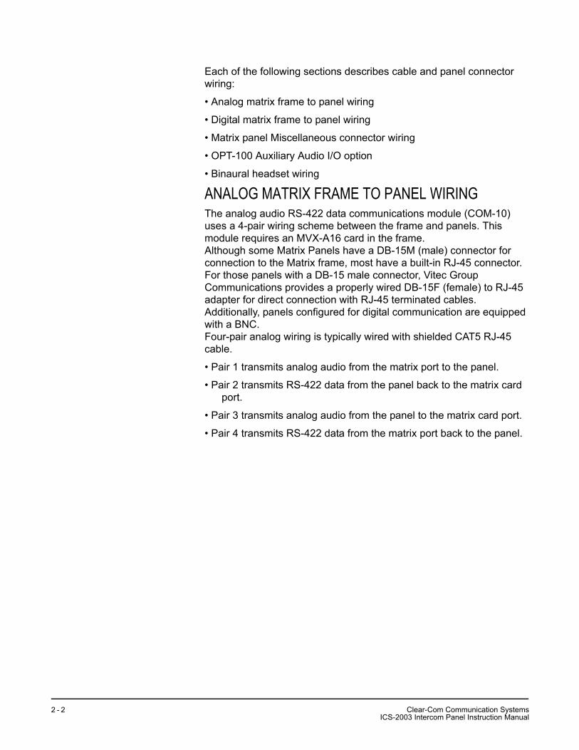
Each of the following sections describes cable and panel connector wiring:
• Analog matrix frame to panel wiring
• Digital matrix frame to panel wiring
• Matrix panel Miscellaneous connector wiring
• OPT-100 Auxiliary Audio I/O option
• Binaural headset wiring
ANALOG MATRIX FRAME TO PANEL WIRINGThe analog audio RS-422 data communications module (COM-10) uses a 4-pair wiring scheme between the frame and panels. This module requires an MVX-A16 card in the frame.Although some Matrix Panels have a DB-15M (male) connector for connection to the Matrix frame, most have a built-in RJ-45 connector. For those panels with a DB-15 male connector, Vitec Group Communications provides a properly wired DB-15F (female) to RJ-45 adapter for direct connection with RJ-45 terminated cables. Additionally, panels configured for digital communication are equipped with a BNC.Four-pair analog wiring is typically wired with shielded CAT5 RJ-45 cable.
• Pair 1 transmits analog audio from the matrix port to the panel.
• Pair 2 transmits RS-422 data from the panel back to the matrix card port.
• Pair 3 transmits analog audio from the panel to the matrix card port.
• Pair 4 transmits RS-422 data from the matrix port back to the panel.
Clear-Com Communication SystemsICS-2003 Intercom Panel Instruction Manual
2 - 2
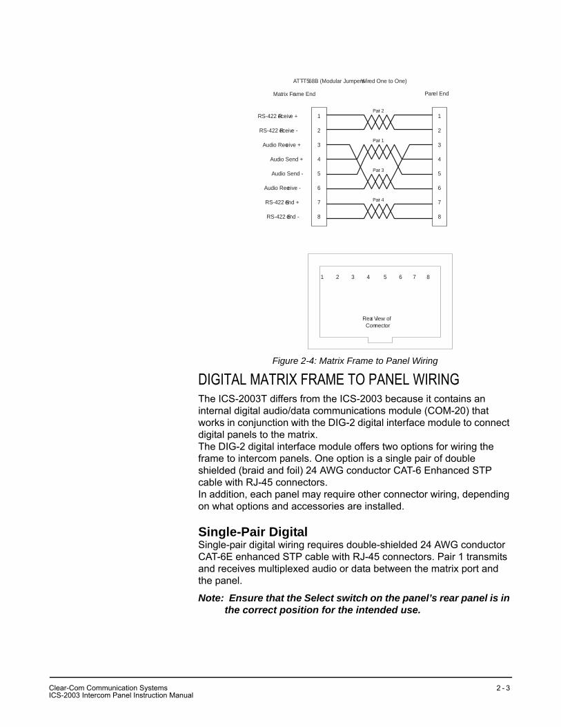
Figure 2-4: Matrix Frame to Panel Wiring
DIGITAL MATRIX FRAME TO PANEL WIRINGThe ICS-2003T differs from the ICS-2003 because it contains an internal digital audio/data communications module (COM-20) that works in conjunction with the DIG-2 digital interface module to connect digital panels to the matrix. The DIG-2 digital interface module offers two options for wiring the frame to intercom panels. One option is a single pair of double shielded (braid and foil) 24 AWG conductor CAT-6 Enhanced STP cable with RJ-45 connectors. In addition, each panel may require other connector wiring, depending on what options and accessories are installed.
Single-Pair DigitalSingle-pair digital wiring requires double-shielded 24 AWG conductor CAT-6E enhanced STP cable with RJ-45 connectors. Pair 1 transmits and receives multiplexed audio or data between the matrix port and the panel.
Note: Ensure that the Select switch on the panel’s rear panel is in the correct position for the intended use.
1
2
3
4
5
6
7
8
1
2
3
4
5
6
7
8
Matrix Frame End
Pair 2
Pair 1
Pair 3
Pair 4
ATT-T568B (Modular Jumpers Wired One to One)
1 2 3 4 5 6 7 8
Rear View ofConnector
RS-422 Receive +
RS-422 Receive -
Audio Receive +
Audio Send +
Audio Send -
Audio Receive -
RS-422 Send +
RS-422 Send -
Panel End
CI
lear-Com Communication SystemsCS-2003 Intercom Panel Instruction Manual
2 - 3
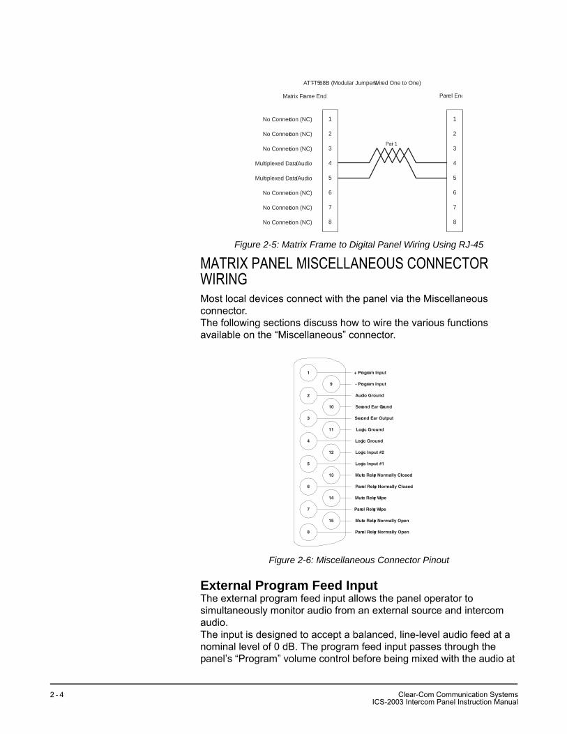
Figure 2-5: Matrix Frame to Digital Panel Wiring Using RJ-45
MATRIX PANEL MISCELLANEOUS CONNECTOR WIRINGMost local devices connect with the panel via the Miscellaneous connector.The following sections discuss how to wire the various functions available on the “Miscellaneous” connector.
Figure 2-6: Miscellaneous Connector Pinout
External Program Feed InputThe external program feed input allows the panel operator to simultaneously monitor audio from an external source and intercom audio.The input is designed to accept a balanced, line-level audio feed at a nominal level of 0 dB. The program feed input passes through the panel’s “Program” volume control before being mixed with the audio at
Pair 1
1
2
3
4
5
6
7
8
1
2
3
4
5
6
7
8
Matrix Frame End
ATT-T568B (Modular Jumpers Wired One to One)
Panel End
No Connection (NC)
No Connection (NC)
No Connection (NC)
Multiplexed Data/Audio
Multiplexed Data/Audio
No Connection (NC)
No Connection (NC)
No Connection (NC)
1
2
15
14
13
12
11
10
9
8
7
6
5
4
3
+ Program Input
- Program Input
Audio Ground
Second Ear Ground
Second Ear Output
Logic Ground
Logic Ground
Logic Input #1
Logic Input #2
Mute Relay Normally Closed
Panel Relay Normally Closed
Mute Relay Wipe
Panel Relay Wipe
Mute Relay Normally Open
Panel Relay Normally Open
Clear-Com Communication SystemsICS-2003 Intercom Panel Instruction Manual
2 - 4
the panel. The program feed (program audio) can be heard on the panel’s speaker and headset; it cannot be heard by other panels in the Matrix system.To connect an external program feed to the panel:1. Connect the balanced audio pair to pins 1 and 9.2. Connect a shield or ground connection if available to the connector’s
pin 2 (see Figure 2-6 on page 1-4).
Logic Input #1 and #2Each input can control one of several functions, determined through the configuration program. Typically, these inputs are connected to an external foot switch, a panel-mounted switch, or the logic output of another device.The following functions are available:
• Mic On/Off—toggles the panel’s microphone on and off.
• Mute Mic Output To Frame—turns off the audio from the panel to the frame. It does not turn off the Hot Mic output (described in “OPT-100 Auxiliary Audio I/O Option” on page 8). For an example of how to use this option, see “External Program Feed Input” on page 4.
• Mic Off —momentarily turns off the panel’s microphone.
• Answer Back Talk/Clear—the same functions as the panel’s “Answer Back” key. Holding down the switch activates a talk to a label in the answer-back stack. To clear the label, quickly press and release the switch.
• Studio Announce—sends the output of the panel’s selected microphone (panel or headset) to the panel’s Studio Announce (SA) audio output, and activates the SA relay. The microphone output is not sent to the frame. The SA output and relay are only present if the panel has the OPT-100 Auxiliary Audio I/O Option installed. (The SA options are described in “OPT-100 Auxiliary Audio I/O Option” on page 8).
• Speaker OFF—turns off the panel speaker, disabling all audible output from the panel.
• PTT: Activate All Talk Keys (Push To Talk)—when enabled from the configuration program and the logic input is active, the panel behaves normally. When this function (logic level) is deactivated, it disables activation of all talk labels, implementing a push-to-talk function for the panel. Any controls (relays, etc.) assigned to the labels are activated or deactivated along with their assigned labels. The LED indicators associated with the active labels behave normally regardless of this input’s activity. This input controls momentary and latched talks.
• Activate Talk Switch #1—equivalent to pressing the panel’s first (leftmost) talk selector; a momentary and latching activation.
CI
lear-Com Communication SystemsCS-2003 Intercom Panel Instruction Manual
2 - 5
• Activate Talk Switch #2—equivalent to pressing the panel’s second talk selector; a momentary and latching activation.
• Activate Listen Labels Button—equivalent to pressing the “Listens” button on the keypad; all modes of the “Listens” button are supported.
• PTT: Activate Two-Way Radio Keys—implements a push-to-talk function for all two-way radio talk selectors. When the logic input is active, the panel operates normally. When the logic input is deactivated, all active two-way radio talk selectors are disabled. Any controls (relays, etc.) assigned to the labels are activated or deactivated along with their assigned labels. The LED indicators associated with the active two-way radio talk selectors operate normally regardless of the PTT status. This input only controls latched talks.
Use normally open type switches to activate the logic inputs. Connect the switches as follows (Figure 2-6 on page 1-4):
• Logic input #1—pins 4 to 5 (pin 4 = ground)
• Logic input #2—Pins 11 to 12 (pin 11 = ground)
Note: Do not apply external voltage to the logic inputs.
Mute Relay ContactsThe mute relay is activated whenever any talk selector is activated at the panel. The mute relay is commonly wired such that whenever it is activated, the volume of the monitor speaker in that room is decreased (muted). See Figure 2-6 on page 1-4.Both normally open and normally closed contacts are provided. They are rated at 1 Amp at 24 VDC. This relay is not designed for switching mains AC line voltage. To switch an external device running on mains AC line voltage, use an external relay (or other switching mechanism) activated by this relay.
Programmable Relay ContactsEach panel includes a relay controlled by the system program and independent of the local panel function. This relay can be assigned to any label(s) in the system, which will activate whenever a talk or listen is set to that label(s). If activating the relay is the only action desired, assign the relay to a Control label. See the Eclipse Configuration System Manual for more details.The relay can activate an external device, such as an applause light in a studio, a cue light, or a security door lock. Any programmable relay in the system can be activated from any panel in the system, including a direct-inward-access caller. Figure 2-6 on page 1-4 shows the wiring of the relay contacts to the Miscellaneous connector.Both normally open and normally closed contacts are provided. They are rated at 1 Amp at 24 V DC. This relay is not designed for switching mains AC line voltage. To switch an external device running on mains
Clear-Com Communication SystemsICS-2003 Intercom Panel Instruction Manual
2 - 6
AC line voltage, use an external relay (or other switching mechanism) activated by this relay.
CI
lear-Com Communication SystemsCS-2003 Intercom Panel Instruction Manual
2 - 7
OPT-100 AUXILIARY AUDIO I/O OPTIONThe OPT-100 Auxiliary Audio option provides the following features:
• Hot Mic output
• SA audio and relay outputs
• Auxiliary audio line level output
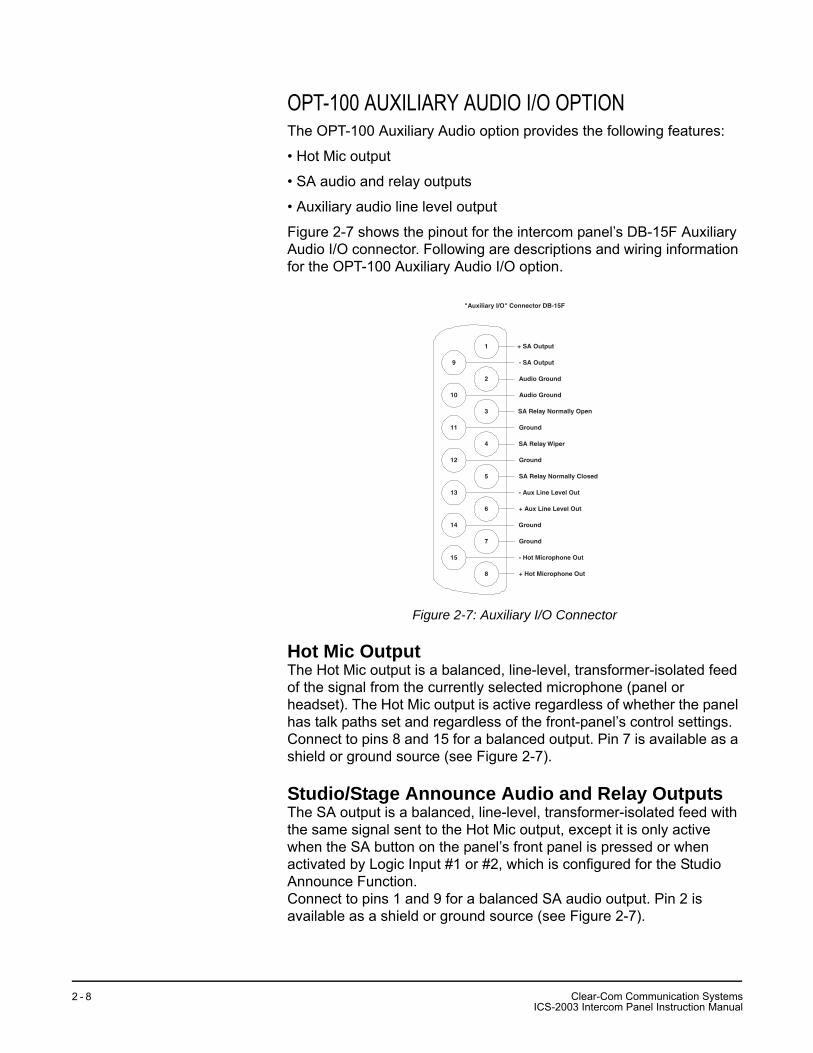
Figure 2-7 shows the pinout for the intercom panel’s DB-15F Auxiliary Audio I/O connector. Following are descriptions and wiring information for the OPT-100 Auxiliary Audio I/O option.
Figure 2-7: Auxiliary I/O Connector
Hot Mic OutputThe Hot Mic output is a balanced, line-level, transformer-isolated feed of the signal from the currently selected microphone (panel or headset). The Hot Mic output is active regardless of whether the panel has talk paths set and regardless of the front-panel’s control settings.Connect to pins 8 and 15 for a balanced output. Pin 7 is available as a shield or ground source (see Figure 2-7).
Studio/Stage Announce Audio and Relay OutputsThe SA output is a balanced, line-level, transformer-isolated feed with the same signal sent to the Hot Mic output, except it is only active when the SA button on the panel’s front panel is pressed or when activated by Logic Input #1 or #2, which is configured for the Studio Announce Function.Connect to pins 1 and 9 for a balanced SA audio output. Pin 2 is available as a shield or ground source (see Figure 2-7).
1
2
15
14
13
12
11
10
9
8
7
6
5
4
3
+ SA Output
- SA Output
Audio Ground
Audio Ground
SA Relay Normally Open
SA Relay Wiper
SA Relay Normally Closed
Ground
- Aux Line Level Out
+ Aux Line Level Out
Ground
- Hot Microphone Out
Ground
+ Hot Microphone Out
Ground
"Auxiliary I/O" Connector DB-15F
Clear-Com Communication SystemsICS-2003 Intercom Panel Instruction Manual
2 - 8
Both normally open and normally closed contacts are provided. They are rated at 1 Amp at 24 VDC. This relay is not designed for switching mains AC line voltage. To switch an external device running on mains AC line voltage, use an external relay (or other switching mechanism) activated by this relay (see Figure 2-7). The following table shows the pins available for the SA relay.
Auxiliary Audio Line Level OutputThe Auxiliary Audio Line Level output is a balanced, line-level, transformer-isolated feed of the input to the panel’s internal speaker. For example, this output could be used to feed an external amplifier connected to loudspeakers.Connect to pins 6 and 13 for a balanced output. Pin 14 is available as a shield or ground source (see Figure 2-7).
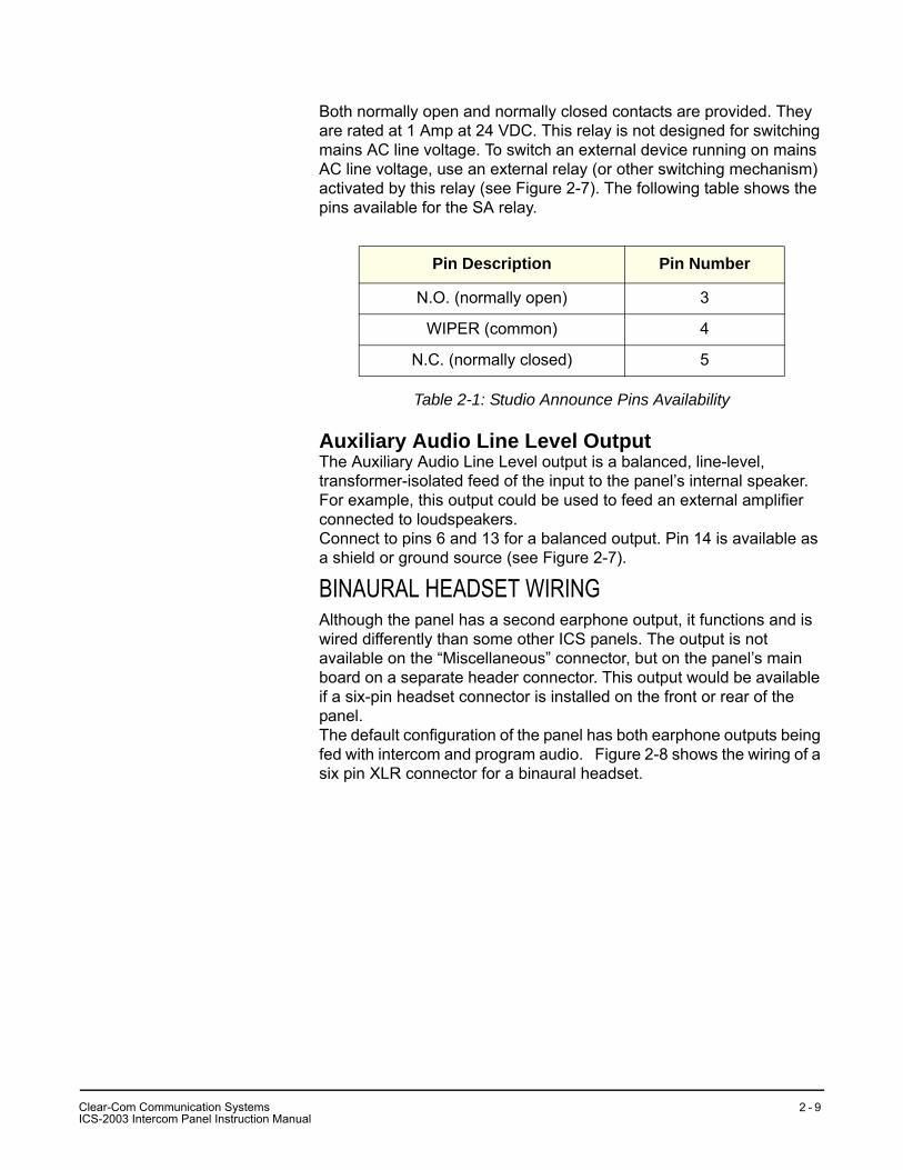
BINAURAL HEADSET WIRINGAlthough the panel has a second earphone output, it functions and is wired differently than some other ICS panels. The output is not available on the “Miscellaneous” connector, but on the panel’s main board on a separate header connector. This output would be available if a six-pin headset connector is installed on the front or rear of the panel.The default configuration of the panel has both earphone outputs being fed with intercom and program audio. Figure 2-8 shows the wiring of a six pin XLR connector for a binaural headset.
Pin Description Pin Number
N.O. (normally open) 3
WIPER (common) 4
N.C. (normally closed) 5
Table 2-1: Studio Announce Pins Availability
CI
lear-Com Communication SystemsCS-2003 Intercom Panel Instruction Manual
2 - 9
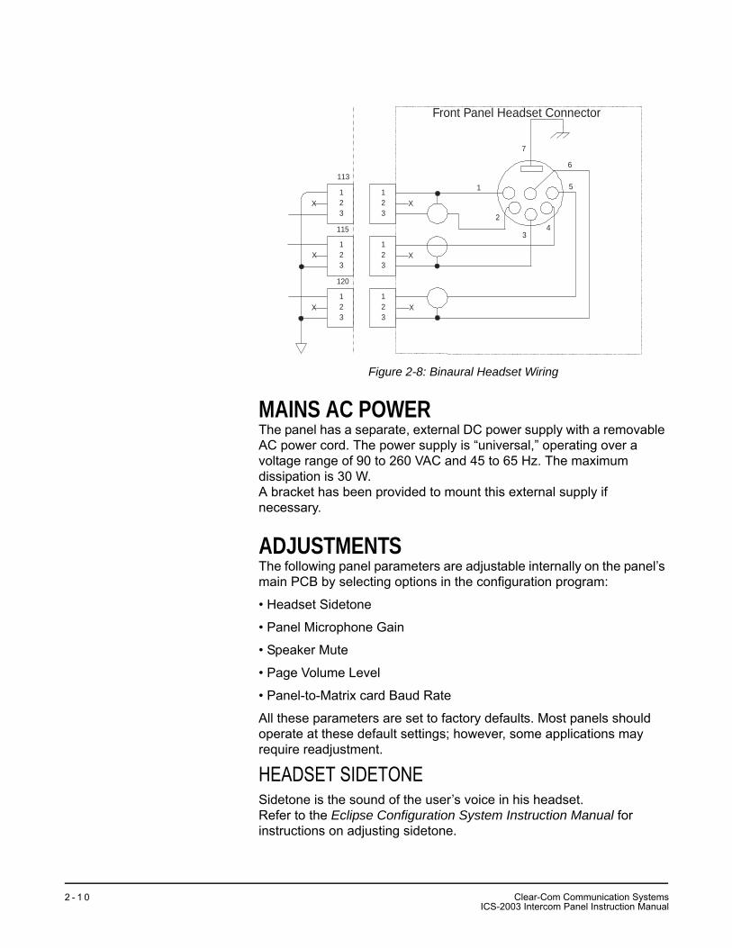
Figure 2-8: Binaural Headset Wiring
MAINS AC POWERThe panel has a separate, external DC power supply with a removable AC power cord. The power supply is “universal,” operating over a voltage range of 90 to 260 VAC and 45 to 65 Hz. The maximum dissipation is 30 W.A bracket has been provided to mount this external supply if necessary.
ADJUSTMENTSThe following panel parameters are adjustable internally on the panel’s main PCB by selecting options in the configuration program:
• Headset Sidetone
• Panel Microphone Gain
• Speaker Mute
• Page Volume Level
• Panel-to-Matrix card Baud Rate
All these parameters are set to factory defaults. Most panels should operate at these default settings; however, some applications may require readjustment.
HEADSET SIDETONESidetone is the sound of the user’s voice in his headset.Refer to the Eclipse Configuration System Instruction Manual for instructions on adjusting sidetone.
123
123
123
123
123
123
X
X
X
X
X
X
113
115
120
Front Panel Headset Connector
1
2
34
5
6
7
Clear-Com Communication SystemsICS-2003 Intercom Panel Instruction Manual
2 - 1 0
PANEL MICROPHONE GAINThe preamplifier gain of the panel microphone can be adjusted over a range of 0 to 10 dB; the maximum is the panel microphone gain’s default setting. However, if two panels are talking to each other at the same time with the panel microphone gain set to maximum, feedback may occur even if the speaker mute (see “Speaker Mute”) is set to maximum. In this case, it will be necessary to turn the panel microphone gain down. Similarly, in some noisy environments it may be necessary to turn the panel microphone gain down and have the operator talk more closely into the microphone. Refer to the Eclipse Configuration System Instruction Manual for instructions on adjusting panel microphone gain.
SPEAKER DIMWhen a panel microphone and a speaker are used together, feedback is possible. To reduce this possibility, the panel software will mute (turn down) the speaker level by some predetermined amount when both the microphone and speaker are enabled. The speaker mute can be adjusted from 0 to 15 dB; its default setting is 6 dB.Refer to the Eclipse Configuration System Instruction Manual for instructions on muting the speaker.
PAGE VOLUME LEVELWhen Page Override is assigned to a label, the audio level at the destination panel(s) is predetermined. This function allows talking to someone even if his panel’s volume control is off. Two things will happen when a panel activates such a label:
• If the destination speaker was off, it will turn on.
• The panel(s)’s speaker output will be at the predetermined level regardless of the “Intercom” volume control setting, unless this control is set higher than the predetermined level.
The page volume level can be adjusted within a range of 0 to 10, equivalent to the front-panel control settings of 0 equals off and 10 equals full pot. The page volume level’s default setting is 5.Refer to the Eclipse Configuration System Instruction Manual for instructions on using Page Override.
CONFIGURATIONAssign each panel’s name and other parameters by using the Eclipse Configuration System Program (see Eclipse Configuration System Manual for more information). Also refer to the Operation chapter for details regarding the configuration options available from the ICS-2003’s menus.
CI
lear-Com Communication SystemsCS-2003 Intercom Panel Instruction Manual
2 - 1 1
ACCESSORY PANELSThe following sections describes how to install the following optional, accessory key panels:
• The XPL-12 Display Expansion Panel adds 10 talk/listen selectors to a panel.
• The XPL-22 Display Expansion Panel adds 20 talk/listen selectors to a panel.
The installation procedure is identical for these two panels.
XPL TYPE EXPANSION PANELSThe XPL series provides selectors labeled with electronic displays that are automatically updated whenever changes are made.Only one rack unit (1RU) of a standard Electronics Industry Association equipment rack is required for each expansion panel. The panels’ compact size makes them ideal for use in TV control rooms, edit suites, mobile OB vans, and any other location where many talk/listen keys are necessary but space it at a premium. Model XPL-12 provides 10 additional selectors with displays and model XPL-22 provides 20 additional selectors with displays. Each panel can accept a maximum of 60 additional selectors.
MOUNTINGAll accessory panels are mounted in a standard 19-inch wide (48.3 cm) standard Electronics Industry Association rack, requiring one unit of rack space each. Leave at least 2 in. (51 mm) of clearance behind the rear of the chassis to allow for cable connectors.
POWEREach XPL panel is powered by an external AC transformer (included). Confirm that the transformer is correct for the line voltage being used. To connect the AC power transformer to an XPL panel, route the transformer’s secondary lead to the “AC Power Input” connector on the back of the panel. This is a 2.1 mm coax connector. When routing the lead, use the lead stress relief on the back of the panel. The panel can be powered by any 12- to 16-V RMS AC source rated for 750 mA.
PANEL CONNECTIONA cable is supplied with each panel to connect it to a panel or to additional panels. The cable is 6-ft. long (1.8 m) and has a DB-9F connector on one end and a DB-9M connector on the other end. If custom length cables are to be made, they should be made with 9 conductor control cable with 22 to 24 AWG wire. The pins should be wired one-to-one between the male and female connectors. The maximum distance between the panel and the last expansion panel should be 25 ft. (7.6 m). To connect an accessory panel to an intercom panel:
Clear-Com Communication SystemsICS-2003 Intercom Panel Instruction Manual
2 - 1 2
1. Plug the DB-9M end of the cable supplied into the “Accessory Panel” connector on the back of the panel.
2. Plug the DB-9F end into the “From Intercom Panel” connector on the rear panel of the accessory panel.
To connect an additional accessory panel:1. Plug the DB-9M end of the additional key panel’s cable into the “To
Next Expansion Panel” connector on the back of the preceding key panel.
2. Plug the DB-9F end of that cable into the “From Intercom Panel” connector on the back of the additional key panel.
More panels can be added by using this “daisy-chaining” method.The numbering of expansion selectors will be in the order of the daisy chaining. The first panel will be selectors 1 to 20, the second will be selectors 21 to 40, and so forth.
CONFIGURATIONAfter physically placing the key panels and connecting them to a panel, the number of accessory keys installed in the panel must be programmed into the configuration program. Refer to the Eclipse Configuration System Instruction Manual for more information.
CI
lear-Com Communication SystemsCS-2003 Intercom Panel Instruction Manual
2 - 1 3

Clear-Com Communication SystemsICS-2003 Intercom Panel Instruction Manual
2 - 1 4
MAINTENANCEINTRODUCTIONThis chapter provides panel microprocessor resetting instructions, maintenance menu use, troubleshooting guidelines, schematics, assembly drawings, and component lists.
PANEL RESETThe panel’s microprocessor has a reset button located in an unmarked hole just below the program volume knob on the right side of the unit’s front panel. If the panel is acting erratically, try resetting it by performing one of the following:
• Insert a small screwdriver or a stiff piece of wire (such as a bent paper clip) into the hole and pushing the reset button.
• Unplug the panel from AC power and reconnect.
TROUBLESHOOTINGWhen experiencing the symptoms listed below, attempt the following solutions in the order outlined. The solutions are listed in order of difficulty with the first being the most simple and easy.
• The panel’s display and all front-panel indicators fail to light.1. Check mains AC power into the panel.2. Ensure the external power supply is properly connected to the
panel.3. Replace the panel.• The display shows unexpected characters.1. Power the panel off and turn it back on.2. Reset the panel’s matrix card in the matrix frame.3. Replace the panel.• The LED indicator above a selector does not light when the
selector is pressed.1. Ensure the selector has a label assigned to it (the LED indicator will
not light without an assigned label).2. Reset the panel.3. Replace the panel.
• Keypad button functions do not operate, or the panel beeps when a button is pressed (affected buttons could include “Assign,” “Panel,” “Dial,” “Menu,” and “Swap”).
3
Clear-Com Communication SystemsICS-2003 Intercom Panel Instruction Manual
3 - 1
1. Ensure the function has not been inhibited from the configuration program of the panel’s local Configuration menu.
2. Reset the panel.3. Replace the panel.• The panel appears to activate talk paths, but other panels can’t
hear the panel operator.1. Check “Mic On/Off” and “Panel Mic” buttons to ensure the intended
microphone is selected and on.2. If the correct microphone is turned on, ensure the panel audio has
not been muted externally through the logic inputs.3. Make sure the panel has not been defined as a nearby panel.4. Activate the Matrix Loopback mode from the panel’s Maintenance
menu to check the audio paths to the matrix.5. Enable eavesdropping on the panel.6. Test the integrity of the panel’s audio path by temporarily setting a
forced listen to it.7. Reset the panel.8. Replace the panel.• The panel is inoperative and all red LEDs flash slowly.1. Wait 60 seconds. If the matrix frame has just been powered up, it is
possible it is still downloading the configuration to the Matrix cards.2. Ensure the cable connecting the panel to the matrix is plugged in at
both ends.3. Check the integrity of the data paths, especially the polarity for
panels using a COM-10 communication module.4. Check the configuration program to ensure the panel has been
assigned the correct port type.5. Confirm the matrix card type matches the panel. Panels with
COM-10 communication modules should have an MVX-A16. 6. Reset the panel’s matrix card in the Matrix frame.7. Replace the panel’s matrix card in the Matrix frame.8. Reset the panel.9. Replace the panel.• No audio from the panel’s speaker.1. Ensure the ‘Intercom” knob on the panel’s front panel is turned up.2. Ensure the “Speaker On/Off” button is on.3. Check whether audio can be heard in a headphone.4. Check the configuration program and the panel’s logic inputs to
ensure the speaker has not been software disabled.5. Test the integrity of the panel’s audio path by temporarily setting a
forced listen to it.6. Reset the panel’s Matrix card in the Matrix frame.7. Replace the panel’s Matrix card in the Matrix frame.8. Reset the panel.
Clear-Com Communication SystemsICS-2003 Intercom Panel Instruction Manual
3 - 2
9. Replace the panel.• The operator cannot hear another panel’s page or call signal
tones.1. Adjust the “Page Volume” control of the panel using the
configuration program (refer to the Eclipse Configuration System Manual).
2. Check the panel’s configuration to see if page override is enabled.• Announce tones (eavesdropping indication, change tones, etc.)
aren’t heard at the panel.Check the configuration program to see if the monitoring tones and change tones are enabled.
• No speaker audio from the external program feed.1. Check the “Program” knob on the panel’s front panel.2. Check the program source.3. Reset the panel.4. Replace the panel.• The headphone isn’t receiving audio from the external program
feed.1. If the external program feed is audible in the speaker, check the
panel’s configuration program to ensure the program was not disabled for the second earphone feed.
2. Replace the panel.• Accessory panels do not function.1. Check the accessory panel’s connection on the panel’s rear panel.2. Ensure the external AC power transformers are correctly connected
to the accessory panels.3. Check the configuration program to ensure the correct number of
selectors are configured.
‘
Clear-Com Communication SystemsICS-2003 Intercom Panel Instruction Manual
3 - 3
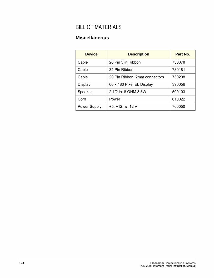
BILL OF MATERIALS
Miscellaneous
Device Description Part No.
Cable 26 Pin 3 in Ribbon 730078
Cable 34 Pin Ribbon 730181
Cable 20 Pin Ribbon, 2mm connectors 730208
Display 60 x 480 Pixel EL Display 390056
Speaker 2 1/2 in. 8 OHM 3.5W 500103
Cord Power 610022
Power Supply +5, +12, & -12 V 760050
Clear-Com Communication SystemsICS-2003 Intercom Panel Instruction Manual
3 - 4
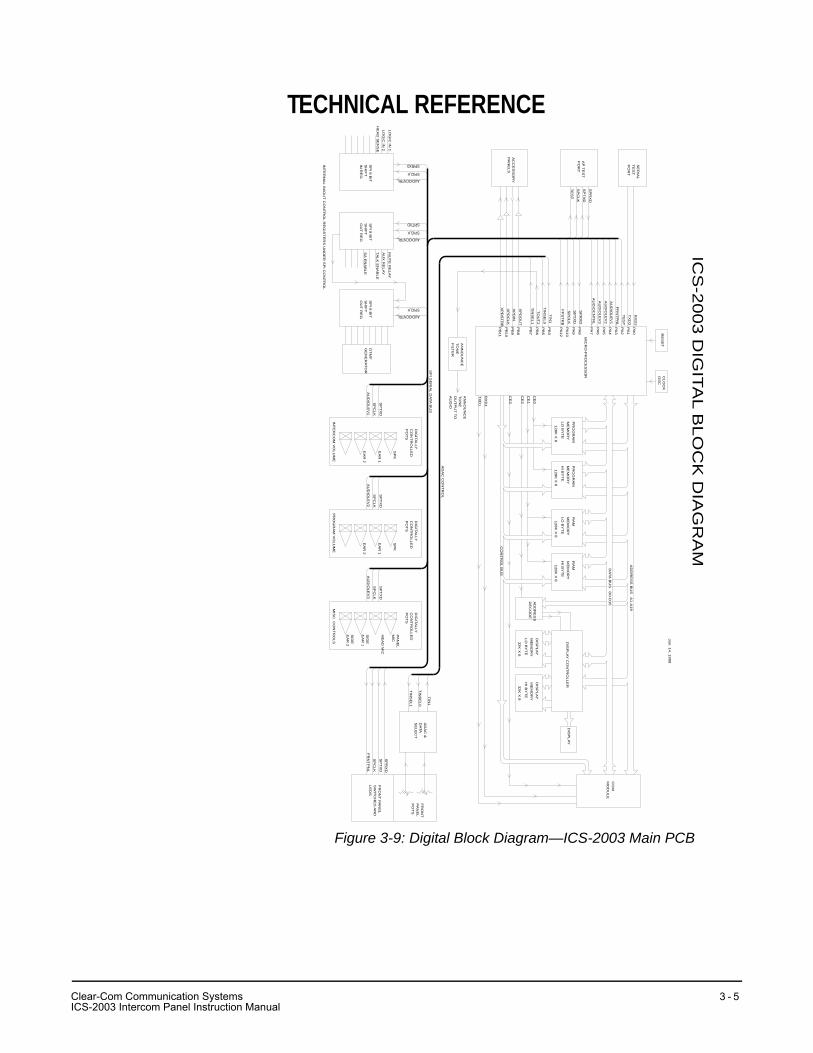
TECHNICAL REFERENCE
Figure 3-9: Digital Block Diagram—ICS-2003 Main PCB
ICS
-20
03
DIG
ITAL B
LO
CK
DIA
GR
AM
Jan
. 14
, 19
98
PR
OG
RA
MM
EM
OR
YL
O B
YT
E
PR
OG
RA
MM
EM
OR
Y
HI B
YT
E
RA
MM
EM
OR
Y
LO
BY
TE
RA
MM
EM
OR
Y
HI B
YT
ED
ISP
LA
Y C
ON
TR
OL
LE
R
DIS
PL
AY
ME
MO
RY
LO
BY
TE
DIS
PL
AY
ME
MO
RY
HI B
YT
E
AD
DR
ES
S B
US
A1
-A1
9
DA
TA B
US
D0
-D1
5
12
8K
X 8
12
8K
X 8
12
8K
X 8
12
8K
X 8
32
K X
83
2K
X 8
CE
0
CE
1
AD
DR
ES
SD
EC
OD
E
CE
2
DIS
PL
AY
CO
MM
OD
UL
E
CE
3
CO
NT
RO
L BU
S
RX
D1
TX
D1
CL
OC
KO
SC
RE
SE
T
MIC
RO
-PR
OC
ES
SO
R
AC
CE
SS
OR
YP
AN
EL
S
PB
8
PB
9
PB
10
PB
11
PA
0
PA
1
SE
RIA
LT
ES
TP
OR
T
RX
D2
TX
D2
XP
DO
UT
XP
DIN
XP
DC
LK
XP
DS
TR
B
PA
2
PA
3
PA
4
PA
5
PA
6
PA
7
PA
8
PA
9
PA
10
PA
12
SP
RX
D
SP
TX
D
SP
CL
K
PB
3
PB
5
PB
6
PB
7
TIN
1
TO
UT
2
TE
ST
FR
NT
PN
L
AU
DIO
LE
V1
AU
DIO
LE
V2
AU
DIO
CN
TR
L
TIN
SE
L0
TIN
SE
L1
AD
AC
&D
ATA
SE
LE
CT
FR
ON
TP
AN
EL
PO
TS
TIN
1
TIN
SE
L0
TIN
SE
L1
SP
RX
DS
PT
XD
SP
CL
K
FR
NT
PN
L
FR
ON
T P
AN
EL
SW
ITC
HE
S A
ND
LE
DS
DIG
ITAL
LYC
ON
TR
OL
LE
DP
OT
S
SP
TX
D
SP
CL
K
AU
DIO
LE
V2
DIG
ITAL
LYC
ON
TR
OL
LE
DP
OT
S
SP
CL
K
SP
TX
D
AU
DIO
LE
V1
AN
NO
UN
CE
TO
NE
FILT
ER
AN
NO
UN
CE
TO
NE
OU
TP
UT
TO
AU
DIO
AP
TE
ST
PO
RT
SP
RX
D
SP
TX
D
SP
CL
K
TE
ST
SP
I SE
RIA
L DA
TA B
US
AD
AC
CO
NT
RO
L
DT
MF
GE
NE
RA
TO
RS
PI 8
BIT
SH
IFT
OU
T R
EG
SP
I 8 B
ITS
HIF
T
IN R
EG
MU
TE
RE
LA
Y
AU
X R
EL
AY
TAL
K E
NA
BL
E
SA
EN
AB
LE
LO
GIC
IN 1
LO
GIC
IN 2
HE
AD
SE
NS
E
SP
I 8 B
ITS
HIF
TO
UT
RE
G
INT
ER
NA
L IN/O
UT
CO
NT
RO
L RE
GIS
TE
RS
UN
DE
R S
PI C
ON
TR
OL
SPITXD
SPICLK
AUDIOCNTRL
SPICLK
AUDIOCNTRL
SPICLK
AUDIOCNTRL
SPIRXD
AU
DIO
LE
V3
FP
ST
RB
DIG
ITAL
LYC
ON
TR
OL
LE
DP
OT
S
SP
TX
D
SP
CL
K
AU
DIO
LE
V3
SP
KS
PK
EA
R 1
EA
R 1
EA
R 2
EA
R 2
INT
ER
CO
M V
OL
UM
EP
RO
GR
AM
VO
LU
ME
MIS
C. C
ON
TR
OL
S
PA
NE
LM
IC
HE
AD
MIC
SID
EE
AR
1
SID
EE
AR
2
CI
lear-Com Communication SystemsCS-2003 Intercom Panel Instruction Manual
3 - 5

Clear-Com Communication SystemsICS-2003 Intercom Panel Instruction Manual
3 - 6
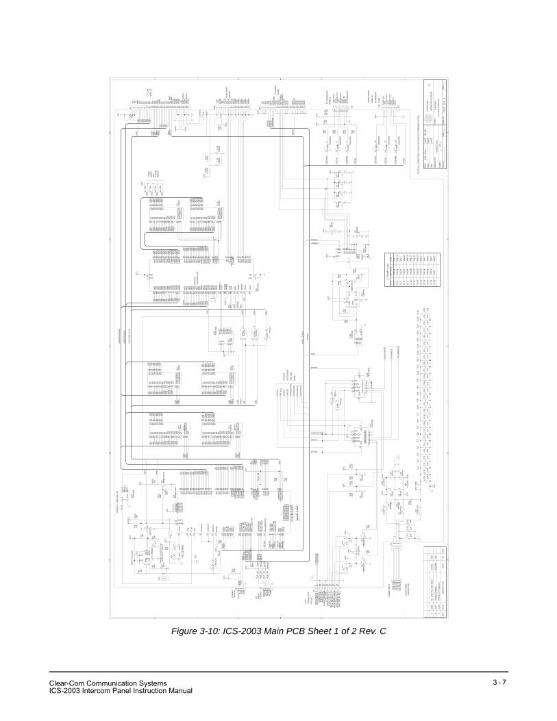
Figure 3-10: ICS-2003 Main PCB Sheet 1 of 2 Rev. C
AA
BB
CC
DD
EE
44
33
22
11
Sch
emat
ic
ICS
-200
3 M
AIN
PC
B
7104
32 -
SC
H -
D -
CD
12
7104
32S
C.D
SN
Cla
rk M
cCoy
06/1
6/98
----
----
----
----
----
---
ABC
2442
2487
2595
Rel
ease
to P
rodu
ctio
n
Vario
us C
hang
es
CE
, LIM
ITIN
G A
ND
MIS
C.
06/2
2/98
7/27
/99
CM
SD
O
CH
K
DW
N
AP
P
DAT
ED
ATE
DAT
E
OR
CA
D P
/N
SH
EE
T:O
F:
SC
ALE
SIZ
ED
WG
No.
RE
V
TITL
E:
CLE
AR
-CO
M
INTE
RC
OM
SY
STE
MS
R
RE
VE
CO
#D
ES
CR
IPTI
ON
DAT
EB
YC
HK
C60
.1uF
C14
.1uF
C10
4
.1uF
R13
100K
C10
5
.1uF
J3
IC7
6225
6
C28
.1uF
C10
6
.1uF
IC10
6225
6
C4
.002
2uF
R28
220
C29
.1uF
D15
5.6V
C30
.1uF
P2
C1 .1
uF
C11
0
.1uF
C24
.1uF
R36
10K
IC14
B74
AC
08
C25
.1uF
J5
R4
10K
R2
10K
C26
.1uF
J1
C20
.1uF
R7
10K
C27
.1uF
C21
.1uF
R8
10K
R13
72
1/2W
R18
1K
C16
.1uF
R17
1K
R41
8.2
1/4W
R9
10K
R16
220
C23
.1uF
R14
1K
R44
8.2
1/4W
IC4E
74H
C14
C15
.1uF
IC5
7104
30
R13
210
K
IC19
B 74H
C40
50
IC11
7104
31
C7
2200
uF
+
IC6
SE
D13
53
C9
2200
uF
+
R31
100K
IC19
C 74H
C40
50
IC16
LMC
555
R10
10K
R27
220
IC1A
74H
C39
3
K1
Q1
MM
BT2
907A
D1
BAV
70
TP3
IC19
D 74H
C40
50
IC13
74H
C13
8
C22
.1uF
R22
2.7K
R11
10K
D5
BAV
99
C17
.1uF
Q4
MM
BTA
14IC
1574
HC
4051
R23
27K
D6
BAV
99
C18
.1uF
C10
810
00uF
+
C3
.01u
F
J2
D7
BAV
99
C19
.1uF
C10
710
00uF
+
R26
10K
R6
10K
C12
.1uF
R12
815
1W
R19
10K
IC19
E 74H
C40
50
D8
BAV
99
R32
220
IC8
OS
C 1
6.38
MH
z
D2
BAV
99
C11
2
.1uF
F31.
35A
PO
LY
R30
220
D3
BAV
99
C11
3
.1uF
IC19
F 74H
C40
50
R35
2.7K
D4
BAV
70
C11
4.1
uF
C2
10uF
+
R15
210
K
Q9
MM
BT2
222A
R5
470
D13
1N40
03
IC4C 74
HC
14
R39
220
J19
D14
1N40
03
R29
220
R24
4.7K
IC3
6225
6
IC12
6225
6
F2 .65A
PO
LY
R1
1.5K
R42
220
C5
.002
2uF
F11.
35A
PO
LY
C11
1.1
uF
IC18
74H
C58
9A
R3
10K
IC17
74H
C59
5
K2
R12
10K
IC1B
74H
C39
3
IC2
TL77
05A
CD
J4
R20
10K
Q5
MM
BTA
14
C13
.1uF
R15
1.5K
R25
4.7K
R37
10K
IC9
MC
68LC
302
R13
310
K
R13
410
K
R13
510
K
J18
IC4B
74H
C14
IC4D
74H
C14
TP2
IC14
A74
AC
08
C10
220u
F
+C
11
220u
F
+
TP1
C8
220u
F+
R13
62
1/2W
C6
220u
F
+
IC19
A 74H
C40
50
P1
VC
C
VC
C
VC
C
VC
C
VC
CV
CC
VC
C
VC
C
VC
C
VC
C
VC
C
+12V
A
-12V
A
VC
C+1
2V
+12V
+12V
VC
CV
CC
VC
C
+12V
+12V
A
-12V
A-1
2V
+12V
VC
C
VC
C
VD
D
VS
SVC
C
+12V
VC
C
VC
CV
CC
VC
C
VC
C
VC
C
VC
C
VC
C
VC
C
LIS
TEN
AU
DIO
CN
TRL
HE
AD
SE
NS
E
SA
EN
AB
LE
TALK
EN
AB
LE
PR
OG
RA
M-
SP
TXD
2
SP
TXD
SP
CLK
AU
DIO
LEV
2
AU
DIO
LEV
1
BE
EP
TALK
PR
OG
RA
M+
AU
DIO
LEV
3
/SP
CLK
1 2 3 4 5 6 7 8 9 10 11 12 13 14 15 16 17 18 19 20 21 22 23 24 25 26
A0
10A
19
A2
8A
37
A4
6A
55
A6
4A
73
A8
25A
924
A10
21A
1123
A12
2A
1326
A14
1
%%
oCS
%%
o20
%%
oOE
%%
o22
%%
oWE
%%
o27
D0
11D
112
D2
13D
315
D4
16D
517
D6
18D
719
A0
10A
19
A2
8A
37
A4
6A
55
A6
4A
73
A8
25A
924
A10
21A
1123
A12
2A
1326
A14
1
%%
oCS
%%
o20
%%
oOE
%%
o22
%%
oWE
%%
o27
D0
11D
112
D2
13D
315
D4
16D
517
D6
18D
719
594837261
4 56
1 2 3 4 5
1 2 3 4 5 6 7 8 9 10 11 12 13 14 15 16 17 18 19 20 21 22 23 24 25 26 27 28 29 30 31 32 33 34
1110
A0
12A
111
A2
10A
39
A4
8A
57
A6
6A
75
A8
27A
926
A10
23A
1125
A12
4A
1328
A14
29
%%
oCE
%%
o22
%%
oOE
%%
o24
/WE
31
O0
13O
114
O2
15O
317
O4
18O
519
O6
20O
721
A15
3A
162
NC
30N
C1
54
A0
12A
111
A2
10A
39
A4
8A
57
A6
6A
75
A8
27A
926
A10
23A
1125
A12
4A
1328
A14
29
%%
oCE
%%
o22
%%
oOE
%%
o24
/WE
31
O0
13O
114
O2
15O
317
O4
18O
519
O6
20O
721
A15
3A
162
NC
30N
C1
AB
012
AB
113
AB
214
AB
315
AB
416
AB
517
AB
618
AB
719
AB
820
AB
921
AB
1022
AB
1123
AB
1224
AB
1325
AB
1426
AB
1527
AB
1628
AB
1729
AB
1830
AB
1931
DB
95
DB
106
DB
117
DB
128
DB
139
DB
1410
DB
1511
DB
094
DB
195
DB
296
DB
397
DB
599
DB
71
DB
498
DB
610
0
DB
84
VA0
33VA
134
VA2
35VA
336
VA4
37VA
538
VA6
39VA
740
VA8
41VA
942
VA10
43VA
1162
VA12
63VA
1364
VA14
65VA
1566
VD
044
VD
145
VD
246
VD
347
VD
448
VD
549
VD
650
VD
751
VD
854
VD
955
VD
1056
VD
1157
VD
1258
VD
1359
VD
1460
VD
1561
VW
E67
VC
S0
68V
CS
169
UD
370
UD
271
UD
172
UD
073
LD3
74LD
275
LD1
76LD
077
VDD3
VDD53VSS 2
VSS 52
YD
78LP
79X
SC
L81
WF/
XS
CL280
LCD
EN
B82
ME
MC
S87
IOC
S84
ME
MW
88M
EM
R89
IOW
85IO
R86
BH
E91
RE
AD
Y90
VO
E83
RE
SE
T32
OS
C1
92
OS
C2
93
76
TR2
CV
5Q
3
DIS
7
THR
6
R4VCC8
GND 1
A1
CLR
2
QA
3Q
B4
QC
5Q
D6
14 3
2 5
1 2
3
1
910
A1
B2
C3
G1
6G
2A4
G2B
5
Y0
15Y
114
Y2
13Y
312
Y4
11Y
510
Y6
9Y
77
12
3X
013
X1
14X
215
X3
12X
41
X5
5X
62
X7
4
INH 6
A11
B10
C9
X3
VDD16VSS 8VEE 7
12
3
1234
12
3
1112
12
3
OE
1
GN
D2
OU
T3
VC
C4
1 2
3
1 2
3
1415
12
3
56
1 2 3 4 5 6 7 8 9 10
A0
10A
19
A2
8A
37
A4
6A
55
A6
4A
73
A8
25A
924
A10
21A
1123
A12
2A
1326
A14
1
%%
oCS
%%
o20
%%
oOE
%%
o22
%%
oWE
%%
o27
D0
11D
112
D2
13D
315
D4
16D
517
D6
18D
719
A0
10A
19
A2
8A
37
A4
6A
55
A6
4A
73
A8
25A
924
A10
21A
1123
A12
2A
1326
A14
1
%%
oCS
%%
o20
%%
oOE
%%
o22
%%
oWE
%%
o27
D0
11D
112
D2
13D
315
D4
16D
517
D6
18D
719
SE
R14
A 15B 1C 2D 3E 4F 5G 6H 7
SRCLK11
SRLOAD13
RCLK12
OC10
QH
9D
IN14
SERCLK11
RESET10
LTCHCLK12
OE13
QA 15QB 1QC 2QD 3QE 4QF 5QG 6QH 7Q
H'
9
14 3
2 5
A13
CLR
12
QA
11Q
B10
QC
9Q
D8
RO
6/R
O5
RE
F1
SEN7
VCC8
RIN
2
CT
3
GND 4
12345
A1
93A
292
A3
91A
490
A5
89A
687
A7
86A
885
A9
84A
1082
A11
81A
1280
A13
79A
1478
A15
77A
1675
A17
74A
1873
A19
72
D0
51D
152
D2
53D
354
D4
56D
557
D6
58D
759
D8/
PN
863D
9/P
N964
D10
/PN
1065
D11
/PN
1166
D12
/PN
1268
D13
/PN
1369
D14
/PN
1470
D15
/PN
1571
/AS
11(R
/W)/O
E12(/U
DS
)/WE
H8(/L
DS
)/WE
L9/D
TAC
K28
/CS
094
/CS
195
/CS
296
/CS
397
PB
1198
PB
1099
PB
91
PB
82
/WD
OG
-PB
73
/TO
UT2
-PB
64
TIN
2-P
B5
5TI
N1-
PB
36
SP
CLK
-PA
1030
SP
TXD
-PA
946
SP
RX
D-P
A8
47
BR
G2-
SD
S2-
PA7
37/C
D2-
PA6
38/R
TS2-
PA5
39/C
TS2-
PA4
40TC
LK2-
PA3
41R
CLK
2-PA
243
TXD
2-PA
144
RX
D2-
PA0
45
/RTS
129
/CTS
149
/CD
150
TCLK
133
RC
LK1
32TX
D1
34R
XD
148
EX
TAL
18
XTA
L19
CLK
020
/RESET27
/HALT26
BU
SW
22D
ISC
PU
21
(/BR
)/IP
LO15
(/BG
AC
K)/I
PL116
VCCP17VCCQ113
VC
CS
YN
25
VCCS136VCCD160VCCQ262VCCA183 GNDP 100GNDA2 88GNDA1 76GNDD1 67GNDQ2 61GNDD2 55GNDS1 42GNDS2 31
GN
DS
YN
23
GNDQ1 14GNDP2 10
PA12
(MO
DC
LK)
35
XFC
24
(/BG
)/IP
L217
1 2 3 4 5
1 2 3 4 5 6 7 8 9 10 11 12 13 14 15 16 17 18 19 20
1 2 3 4 5
34
98
1 2 3
1 23
1
32
815714613512411310291
A1
A2
A3
A4
A8
A9
A10
A11
A12
TXD
2
D8
D12
D13
D15
D0
D3
D7
D4
D6
D2
D1
RX
D2
TES
T
TXD
1
SP
TXD
SP
TXD
RX
D1
A5
A7
A6
D11
D10
D9
A16
A17
A13
D14
A14
D5
D0
D1
D2
D3
D4
D5
D6
D7 D8
D9
D10
D11
D12
D13
D14
D15
/UD
SA
1A
2A
3 A7
A5
A4
A6 A10
A9
A11
A8
A14
A12
A13
/AS
R/W
/LD
S
/DTA
CK
RE
S
CL8
VA0
VA1
VA2
VA3
VA4
VA5
VA6
VA7
VA8
VA9
VA10
VA11
VA12
VA13
VA14
VA0
VA1
VA2
VA3
VA7
VA6
VA5
VA4
VA8
VA11
VA10
VA9
VA12
VA14
VA13
VA0
VA1
VA2
VA3
VA4
VA5
VA6
VA7
VA8
VA9
VA10
VA11
VA12
VA13
VA14
VD
0V
D1
VD
3V
D2
VD
6V
D7
VD
5V
D4
VD
8V
D9
VD
11V
D10
VD
14V
D15
VD
13V
D12
VD
0V
D1
VD
3V
D2
VD
6V
D7
VD
5V
D4
VD
8V
D9
VD
11V
D10
VD
14V
D15
VD
13V
D12
D13D
0D
1D
2D
3D
4D
5D
6D
7
D14
D15
A1
A2
A3
A4
A7
A8
A6
A5
A9
A10
A11
A12
A16
A14
A13
A17
D8
D9
D10
D11
D12
A3
A1
A6
A4
A5
A8
A7
A2
A10
A16
A14
A9
A13
A11
A12
A17
/CS
0
D0
D1
D2
D3
D6
D7
D5
D4
D14
D15
D8
D9
D10
D11
D12
D13
A3
A1
A6
A4
A5
A8
A7
A2
A10
A14
A9
A13
A11
A12
A3
A1
A6
A4
A5
A8
A7
A2
A10
A14
A9
A13
A11
A12
/OE
/CS
1
/WE
L
VD
0
VD
1
VD
2
VD
3
TES
T
XP
DO
UT
XP
DIN
XP
CLK
XP
STR
B
/AS
/DTA
CK
/UD
S
/LD
S
SP
TXD
/FR
NTP
NL
RE
SE
T
RE
SE
T
/IRQ
D0
D1
D2
D3
D4
D5
D6
D7
A2
A3
A4
A5
/CS
3/A
S/O
E
/IRQ
/OE
/WE
L
/OE
/OE
/CS
0
/CS
0
/WE
L
/CS
1/O
E/W
EH
/WE
H
/WE
H
/OE
/WE
L
/WE
H
/CS
1
/CS
3
A1
/WE
L
TXD
1R
XD
1
XP
DO
UT
XP
CLK
XP
STR
B
XP
DIN
TIN
SE
L0
BE
EP
/FR
NTP
NL
AU
DIO
LEV
1A
UD
IOLE
V2
TIN2
TIN
2
TIN
SE
L1
SP
RX
D
SP
CLK
SP
RX
D
AUDIOCNTRL
SPRXD
SP
CLK
AU
DIO
LEV
3
SP
CLK
SP
RX
D
SPTXD
/RE
S
FPS
TRB
TINSEL0
TINSEL1
CL1
6
XP
DO
UT
XP
CLK
FPS
TRB
XP
DIN
RE
S
/RE
S
R/W
A15
/CS
2
A15
A15
/CS
2
A15
A15
A15
AU
DIO
CN
TRL
SPCLK
RE
SE
T C
ontro
ller
(AD
DR
ES
S B
US
)
(DAT
A D
0-D
15)
AP
Dig
ital
Inte
rface
Pro
gram
Test
Por
t
Tim
e(S
) = 0
.013
Ct i
n uF
Tim
e(10
uF) =
130
mS
TO E
L PA
NE
LD
ISP
LAY
VID
EO
MO
DE
SE
TD
UR
ING
RE
SE
T
DIS
PLA
YC
ON
TRO
LLE
R
(CO
NTR
OL
BU
S)
DIV
IDE
X 2
FO
R D
ISP
LAY
/RE
SE
T
+5V
GN
D
PG
ND
TXD
RX
DC
LK/S
TRO
BE
PV
CC
PR
G W
IPE
RIN
T W
IPE
R
+5V
+5V
GN
DG
ND
GN
D
GN
DG
ND
GN
DG
ND
GN
DG
ND
GN
D
+5V
TO F
RO
NT
PAN
EL
+5V
+5V
/IRQ
+5V
D3
D2
D0
D1
D7
D4
D6
D5
/WE
L
/CE
/OE
/AS
A3
/RE
S
A2
A1
422
RE
C
A4
422
XM
ITA
5
AG
ND
DG
ND
AG
ND
DG
ND
AG
ND
+12A
TALK
AU
DIO
-12A
LIS
T A
UD
IOA
GN
D
DAT
A O
UT
+12V
CLO
CK
OU
T+1
2VR
ES
ET
OU
T
DAT
A IN
GN
D.
GN
D.
NO
CO
NN
EC
T
SP
I BU
S
MIS
C. I
/O B
US
PR
OG
RA
M IN
+P
RO
GR
AM
IN -
AU
DIO
GN
DA
UD
IO G
ND
LOG
IC V
OLT
AG
ELO
GIC
GN
DLO
GIC
INP
UT
#2LO
GIC
INP
UT
#1M
UTE
RE
LAY
N. C
.A
UX
. RE
LAY
N. C
.
AU
X. R
ELA
Y W
IPE
MU
TE R
ELA
Y W
IPE
MU
TE R
ELA
Y N
.O.
AU
X. R
ELA
Y N
.O.
MIS
C.
CO
NN
EC
TOR
DB
-15F
FRO
NT
PAN
EL
DIS
PLA
Y
EX
PAN
SIO
N
PO
RT
SP
I BU
S
EX
TEN
SIO
N
FOR
2N
D
PAG
E
'IC1'
'IC2'
'IC3'
'IC4'
'IC5'
'IC6'
'IC7'
'IC8'
'IC9'
'IC10
''IC
11'
'IC12
''IC
13'
'IC14
''IC
15'
'IC16
''IC
17'
'IC18
''IC
19'
IC-1
IC #
+5V
(VC
C)
GN
D.
IC P
OW
ER
& G
ND
.
PIN
14
PIN
7
IC-3
PIN
28
PIN
14
PIN
32
PIN
28
PIN
28
PIN
32
PIN
28
PIN
14
PIN
7
PIN
16
PIN
14
PIN
14
PIN
16
PIN
14
IC-4
IC-5
IC-7
IC-1
0
IC-1
1
IC-1
2
IC-1
3P
IN 1
6P
IN 8
IC-1
4
IC-1
7
PIN
14
PIN
7
PIN
16
PIN
8
IC-1
8P
IN 1
6P
IN 8
IC-1
9P
IN 1
PIN
8
PO
WE
R IN
PU
T
DAT
A O
UT
+5V
CLO
CK
OU
T+5
VR
ES
ET
OU
T
DAT
A IN
GN
D.
GN
D.
AU
DIO
GN
D
CO
M G
ND
-12
VO
LTS
+5 V
OLT
S
+12
VO
LTS
CO
M G
ND
RX
DTX
D
+5 V
OLT
S
GN
D
STR
OB
E
SP
TXD
SP
RX
D
SP
CLK
GN
D
TO E
XPA
NS
ION
PAN
ELS
+12A
+12A
+5V
DG
ND
DG
ND
DG
ND
DG
ND
DG
ND
DG
ND
DG
ND
DG
ND
DG
ND
VS
HS
XS
CL
VID
0
VID
1
VID
2
VID
3
DIM
'IC9'
'IC9'
'IC9'
'IC6'
RE
AR
PA
NE
LC
ON
NE
CTO
R
TO C
OM
MO
DU
LE
NO
TE: A
LL R
ES
ISTO
RS
1/1
0 W
SM
D U
NLE
SS
OTH
ER
WIS
E N
OTE
D
(OD
D)
(EV
EN
)
'IC6'
Clear-Com Communication SystemsICS-2003 Intercom Panel Instruction Manual
3 - 7

THIS PAGE INTENTIONALLY BLANK
Clear-Com Communication SystemsICS-2003 Intercom Panel Instruction Manual
3 - 8
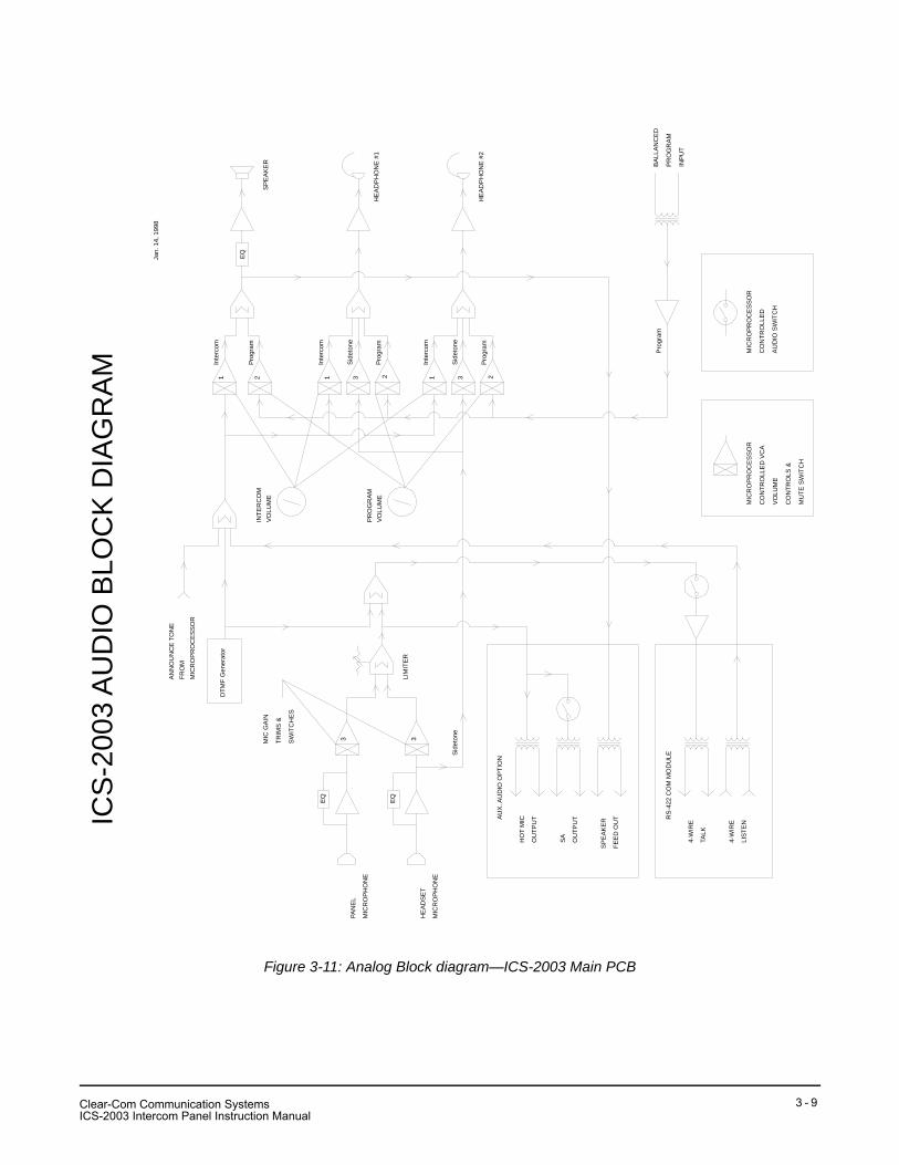
Figure 3-11: Analog Block diagram—ICS-2003 Main PCB
EQ
EQ
EQ
DTM
F G
ener
ator
AU
X. A
UD
IO O
PTI
ON
HO
T M
IC
OU
TPU
T
SA
OU
TPU
T
SP
EA
KE
R
FEE
D O
UT
AN
NO
UN
CE
TO
NE
FRO
MM
ICR
OP
RO
CE
SS
OR
RS
-422
CO
M M
OD
ULE
4-W
IRE
TALK
4-W
IRE
LIS
TEN
BA
LLA
NC
ED
PR
OG
RA
M
INP
UT
HE
AD
PH
ON
E #
1
HE
AD
PH
ON
E #
2
SP
EA
KE
R
PAN
EL
MIC
RO
PH
ON
E
HE
AD
SE
T
MIC
RO
PH
ON
E
MIC
GA
IN
TRIM
S &
SW
ITC
HE
S
LIM
ITE
R
MIC
RO
PR
OC
ES
SO
R
CO
NTR
OLL
ED
VC
A
VO
LUM
E
CO
NTR
OLS
&
MU
TE S
WIT
CH
MIC
RO
PR
OC
ES
SO
R
CO
NTR
OLL
ED
AU
DIO
SW
ITC
H
ICS
-200
3 A
UD
IO B
LOC
K D
IAG
RA
MJa
n. 1
4, 1
998
Inte
rcom
Inte
rcom
Inte
rcom
Pro
gram
Pro
gram
Pro
gram
Sid
eton
e
Sid
eton
e
Sid
eton
e
Pro
gram
1 1 12 2 23 3
33
PR
OG
RA
MV
OLU
ME
INTE
RC
OM
VO
LUM
E
Clear-Com Communication SystemsICS-2003 Intercom Panel Instruction Manual
3 - 9

THIS PAGE INTENTIONALLY BLANK
Clear-Com Communication SystemsICS-2003 Intercom Panel Instruction Manual
3 - 1 0
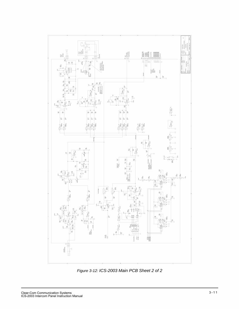
Figure 3-12: ICS-2003 Main PCB Sheet 2 of 2
AA
BB
CC
DD
EE
44
33
22
11
Sch
emat
ic
ICS
-200
3 M
AIN
PC
B
7104
32 -
SC
H -
D -
CD
22
7104
32S
C.D
SN
Cla
rk M
cCoy
06/1
6/98
----
----
----
----
----
---
CH
K
DW
N
AP
P
DAT
ED
ATE
DAT
E
OR
CA
D P
/N
SH
EE
T:O
F:
SC
ALE
SIZ
ED
WG
No.
RE
V
TITL
E:
CLE
AR
-CO
M
INTE
RC
OM
SY
STE
MS
R
C64
22uF
+
C88
10uF
+
C90
.1uF
IC28
BLM
833
+-
IC21
LM38
4
- +
R10
010
K
R93
15K
R11
715
0K
IC33
CD
G44
4
3
R97
22K
R82
4.02
K*
R50
220
R10
210
K
R55
10K
IC33
DD
G44
4 4
C66
4.7u
F+
R89
1K
C43 22uF
+
IC33
ED
G44
4
R11
04.
7K
IC31
DS
SM
2161
CH
4
C56
.002
2uF
C10
2.1
uF
IC31
BS
SM
2161
CH
2
R11
122
K
IC32
DS
SM
2161
CH
4
C34
22uF
+
R12
968
0 1/
2W
C10
310
uF
+
C53
.1uF
C75
.047
uF
IC23
BLM
833
+-
D9
BAV
99
Q6
MM
BFJ
175
C76
.004
7uF
C58
.006
8uF
R14
882
D10
BAV
99
R83
4.02
K*
R79
10K
IC27
74H
C59
5
R56
2.7K
R81
82
R52
4.02
K*
C40
.022
uF
C57 22uF
+
C82
.33u
F
C45
22uF
+
R61
4.3K
R87
100
R12
310
K
IC23
ALM
833
+-
R13
882
C33
10uF
+
J20
C61
.01u
F
R73
10K
D11
BAV
99
R58
47
C50
.047
uF
C70
.1uF
R75
10K
D12
BAV
99
IC30
ALM83
3+-
R96
22
Q7
MM
BT2
222A
IC28
ALM
833
+-
C92
.1uF
IC33
AD
G44
4
1R
99 10K
R85
3.3K
C95
.1uF
C81
.1uF
R13
982
R70
1.2K
IC30
BLM
833
+-
R49
33K
R11
510
K
D17
LED
C41
.015
uF
IC32
BS
SM
2161
CH
2
R90
33K
R10
710
K
C87
.1uF
R91
33K
C73
.001
5uF
C47 .1uF
R95
33K
C44
.004
7uF
IC31
ES
SM
2161
IC33
BD
G44
4
2
R65
220
R84
2.2M
J13
C59
.1uF
R13
047
0K
C52
.002
2uF
J15
C98
.01u
F
R78
10K
IC26
TP50
88
IC24
ALM
833
+-
Y1
3.57
9MH
z
C10
0.1
uF
R11
215
0K
IC32
ES
SM
2161
IC24
BLM
833
+-
R54
24K
C31
.1uF
IC14
C74
AC
08
C38
220p
F
C32
220p
F
C10
110
uF
+
R71
2.7K
IC14
D74
AC
08
IC22
BLM
833
+-
R48
10K
R64
2.2
C99
10uF
+
R51
4.02
K*
R62
4.3K
R74
47
C54
.1uF
R11
912
K
IC34
ES
SM
2161
IC31
CS
SM
2161
CH
3IC31
AS
SM
2161
CH
1
R67
10K
C46
220u
F
+
R14
182
C72
.1uF
R80 1M
IC20
ALM
833
+-
C63
47pF
C65
.1uF
C36
.002
2uF
R72
2.2K
R15
082
0
C49
.1uF
R68
4.02
K*
C39
.1uF
R15
147
0
C94
.1uF
R94
22
T1
R14
522
R92
150K
IC20
BLM
833
+-
R14
382
R13
110
0M
R12
410
K
R53
1.2K
C71
.1uF
C97
.1uF
J11
J7
C78
.004
7uF
R12
510
K
C79
.1uF
IC25
A
LM83
3+-
R11
89.
1K
C86
.1uF
C80
.004
7uF
R14
482
IC25
BLM
833
+-
R60
10K
C83
47pF
R10
622
R12
147
K
R14
082
C42
.01u
F
R10
515
0K
R12
01K
C35
1000
uF+
C48
.003
3uF
C77
.1uF
J17
R63
68K
IC32
AS
SM
2161
CH
1
C55
22uF
+
C89
10uF
+
IC4A
74H
C14
C67
100p
F
R14
682
C68
.1uF
C96
.1uF
C69
47pF
Q8
MM
BT2
222A
IC22
ALM
833
+-
C10
9.3
3uF
R10
922
R11
410
K
C51
22uF
+
R86
3.3K
C37
.1uF
R14
282
R10
333
K
IC32
CS
SM
2161
CH
3
R69
22K
IC4F
74H
C14
C62
.1uF
R14
782
R10
433
K
R76
2.2M
R47
47
R66
4.7K
D16 LE
D
IC34
AS
SM
2161
CH
1
R10
833
K
R77
56K
R57
8.2K
JP1
IC34
BS
SM
2161
CH
2
JP2
R11
610
K
IC34
CS
SM
2161
CH
3
C74
100p
F
IC34
DS
SM
2161
CH
4
+12V
A
-12V
A
VC
C
+12V
A
-12V
A
-12V
A
+12V
A
VC
C
-12V
A
+12V
A
-12V
A
+12V
A
VC
C
VC
C
+12V
A
+12V
A
-12V
A
+12V
-12V
+12V
-12V
A
+12V
AV
CC
-12V
A
+12V
A
+12V
A
-12V
A
-12V-1
2V-1
2V+1
2VA
+12V
A
HE
AD
SE
NS
E
PR
OG
RA
M-
PR
OG
RA
M+
LIS
TEN
SP
CLK
SP
TXD
2
SP
TXD
AU
DIO
LEV
1A
UD
IOLE
V2
AU
DIO
CN
TRL
BE
EP
SA
EN
AB
LE
TALK
EN
AB
LE
TALK
AU
DIO
LEV
3
/SP
CLK
567
6 2
8
73
1
144510111213
1110
9
67
8
VDD12
V+13 V- 4
VSS 5
1415
1617
1415
567
1 2
3
3
2 11 2
3
DIN
14S
ER
CLK
11R
ES
ET
10LT
CH
CLK
12O
E13
QA
15Q
B1
QC
2Q
D3
QE
4Q
F5
QG
6Q
H7
QH
'9
321
8 4
1 2 3
1 2
3
1 2
3
321
8 4
3
1
2
321
8 4
32
1
567
1617
AGND 2
V- 10
V+1
DAT
A13
DGND 11
CLK
12/W
RIT
E8
/LD
9
CH
SE
T20
MS
TR O
UT19
MS
TR S
ET18
VR
EF
3
1415
16
1
2
4
5
3
1 2 3 1 2 3
D0
9O
SC
IN6
OS
CO
UT7
TOU
T14
NC
13
MU
TE8
D1
10D
211
D3
12
TE2
%%
oSTE
%%
o3
GS
4
VSS 5VDD11 2 3
321
8 4
1 2 3
AGND 2
V- 10
V+1
DAT
A13
DGND 11
CLK
12/W
RIT
E8
/LD
9
CH
SE
T20
MS
TR O
UT19
MS
TR S
ET18
VR
EF
3
567
9 108
12 1311
567
AGND 2
V- 10
V+1
DAT
A13
DGND 11
CLK
12/W
RIT
E8
/LD
9
CH
SE
T20
MS
TR O
UT19
MS
TR S
ET18
VR
EF
3
76
54
321
8 4
13
24
567
1 2 3
1 2 3
1 2 3
321
8 4
567
1 2 3
1 2 3 4 5 6 7 8 9 10 11 12 13 14 15 16 17 18 19 20 21 22 23 24 25 26
54
12
3
1
2
321
8 4
76
1312
54
1617
76
1415
MIC
HO
T
LIN
EO
UT
TALK
BU
SMIC
GN
D
MIC
HO
T
MIC
GN
D
INTE
RC
OM
SID
ETO
NE
PR
OG
RA
M
FRO
NT
PAN
EL
HE
AD
SE
TC
ON
NE
CTO
R
TO H
EA
DS
ET
MIC
PR
EA
MP
FRO
MH
EA
DS
ET
CO
NN
EC
TOR
TO P
AN
EL
MIC
RO
PH
ON
E
AN
NO
UN
CE
TO
NE
FRO
MM
ICR
O-P
RO
CE
SS
OR
HE
AD
PH
ON
E S
EN
SE
INP
UT
OF
MIC
RO
-PR
OC
ES
SO
R
AN
ALO
G G
ND
.A
NA
LOG
GN
D.
AN
ALO
G G
ND
.A
NA
LOG
GN
D.
TALK
BU
S
-12
SU
PP
LY-1
2 S
UP
PLY
+12
SU
PP
LY+1
2 S
UP
PLY
SA
CO
NTR
OL
DIG
ITA
L G
ND
.D
IGIT
AL
GN
D.
DIG
ITA
L G
ND
.D
IGIT
AL
GN
D.
DIG
ITA
L G
ND
.D
IGIT
AL
GN
D.
DIG
ITA
L G
ND
.D
IGIT
AL
GN
D.
LIN
E O
UT
FRO
M C
OM
MO
DU
LE
BA
LLA
NC
ED
PR
OG
RA
M IN
PU
TFR
OM
MIS
C.
CO
NN
EC
TOR
AU
DIO
CO
NTR
OL
FRO
M 1
ST
PAG
E
TO C
OM
MO
DU
LE
2ND
EA
RP
HO
NE
FOR
STE
RE
OH
EA
DP
HO
NE
S
FRO
NT
PAN
EL
SP
EA
KE
R
CA
RB
ON
MIC
INP
UT R
129,
R13
0, R
131,
&C
98 N
OT
INS
TALL
ED
FOR
US
E W
ITH
CA
RB
ON
MIC
RO
PH
ON
ES
1ST
EA
RP
HO
NE
Clear-Com Communication SystemsICS-2003 Intercom Panel Instruction Manual
3 - 1 1

THIS PAGE INTENTIONALLY BLANK
Clear-Com Communication SystemsICS-2003 Intercom Panel Instruction Manual
3 - 1 2
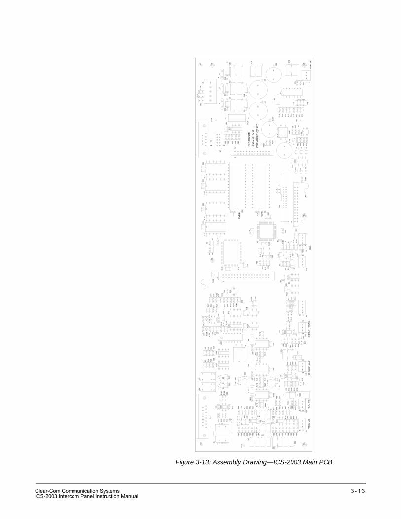
Figure 3-13: Assembly Drawing—ICS-2003 Main PCB
1ST
EA
R P
HO
NE
PAN
EL
MIC
S 1S 1
HE
AD
MIC
1
1
1
11
S
2ND
EA
R P
HO
NE
1S
S 11
S
1
IC6
CO
PY
RIG
HT(
C)1
997
AS
SY
#710
432
CLE
AR
-CO
M
GN
DS 1
1
(OD
D)
1
(EV
EN
)
1
11
1
SP
EA
KE
R
1
M2
R19
R15R20 R11
TP2C2
IC27
IC33
C95
IC26
J1
Y1
D10
D9
C59
Q7
Q8
R85
FID
1
R14
4
C89
J13
M1
J11
J15
R58
R73
R75
R76
R77
R79
C56 C61
R47 R
81
R82 R87
R89
C57
C96
R50
C55
C51
R69
R57
C47
R66
R65
R68
C97
IC22
R74
R52
C44
C52
C36
R51
C45
C43
C53
R67
R60
C34
C37
IC23
R80
R54
R53
C38
R78
C10
2C
92
D11
C63
R90
R92
D16
R95
R91
R13
1
R12
9
R13
0
C98
R83
C58
IC24
R94
C65
JP1
R93
R97
C62
D12
R96
R14
2
R14
7
C99
C10
3
C10
1
R14
0IC
34
R14
3
C10
0
R13
9IC
32
R14
8
C87
J20
J4
C15
R13
R18
IC4
C90
IC25
C64
C10
9
C66
R10
8 D17
JP2
R10
3
R10
4
C69
R10
5
R10
9
C77
R10
6
C68
R14
1
C88
R13
8IC
31
R14
6
C86
IC14
C25
C24
IC13
R16
R14
R17
IC1TP
1
C12
C1
R2 R5
C82
R12
3
C10
6
C28
C5
IC17
R25
R29
IC20
R84
P1
T1
R55
R86
Q6
R48
C32
R49
M6
K2
K1 D
4
R36
R12
4
C83
C49
R12
5
C31
R37
Q4
Q5
C74R10
7
R11
2
R11
6
C70
R11
4R
28
C71
IC18
C29
R24
R12
1C
79 R12
0
R11
8IC28
R119
C78
C80
C81
C4
R11
7
R11
5
C73
C94
C67
R10
0
R14
5
R10
2
R99
IC30
C72
C76
C75 R11
0
R11
1
C11
0
R13
2
C10
C6
C8
IC19
R12
8
IC11
J17
C46
C26
IC15
D7
R14
9M
4J2
M8
C16
IC5
J3
J18
IC9
R12
R1
IC2
R13
5
R13
4
Q9
R15
2
D1
R3R
6R
133
C13
TP3
C60
IC8
C19R
10
C10
5C
20
C10
4
C11
1
D6
D8
M5
C48
IC16
J7
R26
D5
C39
C40
R56
R61
R70
R41
C7
C41
R62
R72
C50
C10
7
R13
6 R13
7C
108
D2
D3
R31
R22
R23Q
1
C27R27
C3
FID
2
R15
0 R15
1
C35
C54
R64
IC21
R71
C42 R63
C33
R44
C9
C11
C21
C22
IC10
R8
IC7
R9
R4
C17
R7
C18
IC3
IC12
C23
C14
D13
P2
J19
R30
R32
R35
R39
R42
C30
FID
3M
3
J5
F2
D14
F1
D15
F3
C11
3
C11
2C
114
M7
1
Clear-Com Communication SystemsICS-2003 Intercom Panel Instruction Manual
3 - 1 3
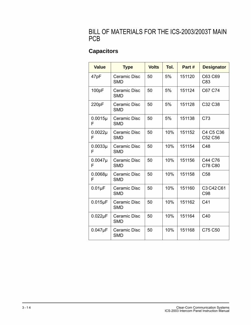
BILL OF MATERIALS FOR THE ICS-2003/2003T MAIN PCB
Capacitors
Value Type Volts Tol. Part # Designator
47pF Ceramic Disc SMD
50 5% 151120 C63 C69 C83
100pF Ceramic Disc SMD
50 5% 151124 C67 C74
220pF Ceramic Disc SMD
50 5% 151128 C32 C38
0.0015µF
Ceramic Disc SMD
50 5% 151138 C73
0.0022µF
Ceramic Disc SMD
50 10% 151152 C4 C5 C36 C52 C56
0.0033µF
Ceramic Disc SMD
50 10% 151154 C48
0.0047µF
Ceramic Disc SMD
50 10% 151156 C44 C76 C78 C80
0.0068µF
Ceramic Disc SMD
50 10% 151158 C58
0.01µF Ceramic Disc SMD
50 10% 151160 C3 C42 C61 C98
0.015µF Ceramic Disc SMD
50 10% 151162 C41
0.022µF Ceramic Disc SMD
50 10% 151164 C40
0.047µF Ceramic Disc SMD
50 10% 151168 C75 C50
Clear-Com Communication SystemsICS-2003 Intercom Panel Instruction Manual
3 - 1 4
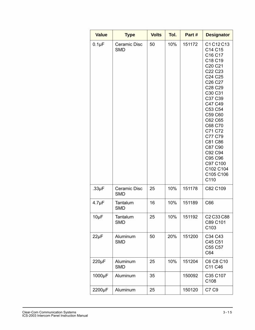
0.1µF Ceramic Disc SMD
50 10% 151172 C1 C12 C13 C14 C15 C16 C17 C18 C19 C20 C21 C22 C23 C24 C25 C26 C27 C28 C29 C30 C31 C37 C39 C47 C49 C53 C54 C59 C60 C62 C65 C68 C70 C71 C72 C77 C79 C81 C86 C87 C90 C92 C94 C95 C96 C97 C100 C102 C104 C105 C106 C110
.33µF Ceramic Disc SMD
25 10% 151178 C82 C109
4.7µF Tantalum SMD
16 10% 151189 C66
10µF Tantalum SMD
25 10% 151192 C2 C33 C88 C89 C101 C103
22µF Aluminum SMD
50 20% 151200 C34 C43 C45 C51 C55 C57 C64
220µF Aluminum SMD
25 10% 151204 C6 C8 C10 C11 C46
1000µF Aluminum 35 150092 C35 C107 C108
2200µF Aluminum 25 150120 C7 C9
Value Type Volts Tol. Part # Designator
Clear-Com Communication SystemsICS-2003 Intercom Panel Instruction Manual
3 - 1 5
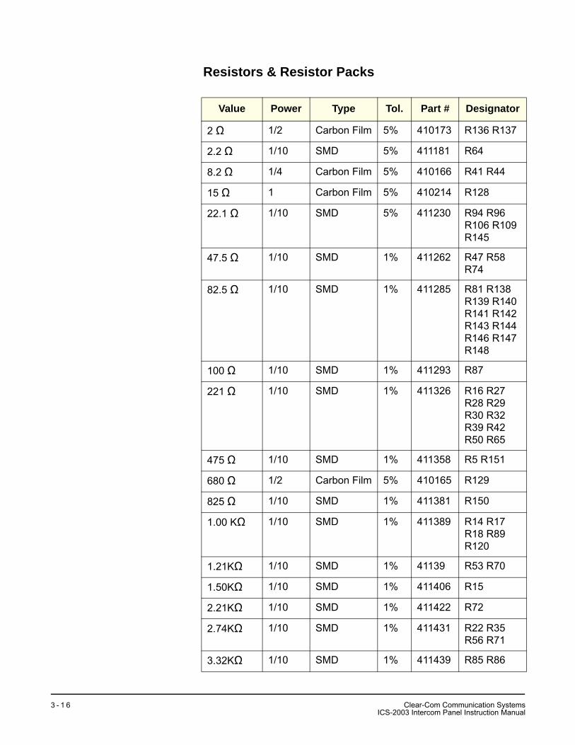
Resistors & Resistor Packs
Value Power Type Tol. Part # Designator
2 Ω 1/2 Carbon Film 5% 410173 R136 R137
2.2 Ω 1/10 SMD 5% 411181 R64
8.2 Ω 1/4 Carbon Film 5% 410166 R41 R44
15 Ω 1 Carbon Film 5% 410214 R128
22.1 Ω 1/10 SMD 5% 411230 R94 R96 R106 R109 R145
47.5 Ω 1/10 SMD 1% 411262 R47 R58 R74
82.5 Ω 1/10 SMD 1% 411285 R81 R138 R139 R140 R141 R142 R143 R144 R146 R147 R148
100 Ω 1/10 SMD 1% 411293 R87
221 Ω 1/10 SMD 1% 411326 R16 R27 R28 R29 R30 R32 R39 R42 R50 R65
475 Ω 1/10 SMD 1% 411358 R5 R151
680 Ω 1/2 Carbon Film 5% 410165 R129
825 Ω 1/10 SMD 1% 411381 R150
1.00 KΩ 1/10 SMD 1% 411389 R14 R17 R18 R89R120
1.21KΩ 1/10 SMD 1% 41139 R53 R70
1.50KΩ 1/10 SMD 1% 411406 R15
2.21KΩ 1/10 SMD 1% 411422 R72
2.74KΩ 1/10 SMD 1% 411431 R22 R35 R56 R71
3.32KΩ 1/10 SMD 1% 411439 R85 R86
Clear-Com Communication SystemsICS-2003 Intercom Panel Instruction Manual
3 - 1 6
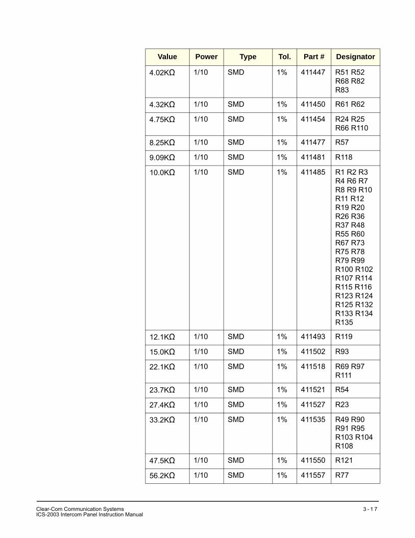
4.02KΩ 1/10 SMD 1% 411447 R51 R52 R68 R82R83
4.32KΩ 1/10 SMD 1% 411450 R61 R62
4.75KΩ 1/10 SMD 1% 411454 R24 R25 R66 R110
8.25KΩ 1/10 SMD 1% 411477 R57
9.09KΩ 1/10 SMD 1% 411481 R118
10.0KΩ 1/10 SMD 1% 411485 R1 R2 R3 R4 R6 R7 R8 R9 R10 R11 R12 R19 R20 R26 R36 R37 R48 R55 R60 R67 R73 R75 R78 R79 R99 R100 R102 R107 R114 R115 R116 R123 R124 R125 R132 R133 R134 R135
12.1KΩ 1/10 SMD 1% 411493 R119
15.0KΩ 1/10 SMD 1% 411502 R93
22.1KΩ 1/10 SMD 1% 411518 R69 R97 R111
23.7KΩ 1/10 SMD 1% 411521 R54
27.4KΩ 1/10 SMD 1% 411527 R23
33.2KΩ 1/10 SMD 1% 411535 R49 R90 R91 R95 R103 R104 R108
47.5KΩ 1/10 SMD 1% 411550 R121
56.2KΩ 1/10 SMD 1% 411557 R77
Value Power Type Tol. Part # Designator
Clear-Com Communication SystemsICS-2003 Intercom Panel Instruction Manual
3 - 1 7
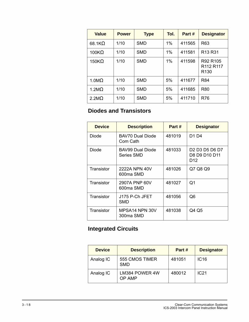
Diodes and Transistors
Integrated Circuits
68.1KΩ 1/10 SMD 1% 411565 R63
100KΩ 1/10 SMD 1% 411581 R13 R31
150KΩ 1/10 SMD 1% 411598 R92 R105 R112 R117 R130
1.0MΩ 1/10 SMD 5% 411677 R84
1.2MΩ 1/10 SMD 5% 411685 R80
2.2MΩ 1/10 SMD 5% 411710 R76
Device Description Part # Designator
Diode BAV70 Dual Diode Com Cath
481019 D1 D4
Diode BAV99 Dual Diode Series SMD
481033 D2 D3 D5 D6 D7 D8 D9 D10 D11 D12
Transistor 2222A NPN 40V 600ma SMD
481026 Q7 Q8 Q9
Transistor 2907A PNP 60V 600ma SMD
481027 Q1
Transistor J175 P-Ch JFET SMD
481056 Q6
Transistor MPSA14 NPN 30V 300ma SMD
481038 Q4 Q5
Device Description Part # Designator
Analog IC 555 CMOS TIMER SMD
481051 IC16
Analog IC LM384 POWER 4W OP AMP
480012 IC21
Value Power Type Tol. Part # Designator
Clear-Com Communication SystemsICS-2003 Intercom Panel Instruction Manual
3 - 1 8
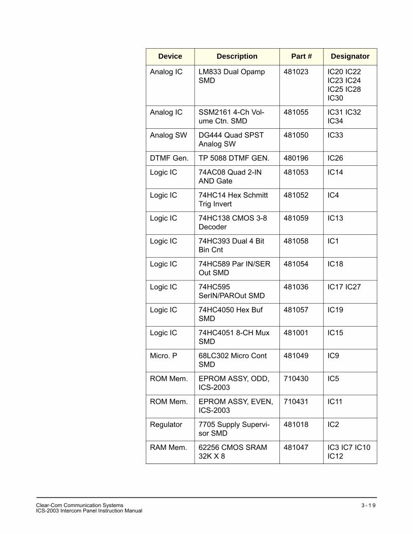
Analog IC LM833 Dual Opamp SMD
481023 IC20 IC22 IC23 IC24 IC25 IC28 IC30
Analog IC SSM2161 4-Ch Vol-ume Ctn. SMD
481055 IC31 IC32 IC34
Analog SW DG444 Quad SPST Analog SW
481050 IC33
DTMF Gen. TP 5088 DTMF GEN. 480196 IC26
Logic IC 74AC08 Quad 2-IN AND Gate
481053 IC14
Logic IC 74HC14 Hex Schmitt Trig Invert
481052 IC4
Logic IC 74HC138 CMOS 3-8 Decoder
481059 IC13
Logic IC 74HC393 Dual 4 Bit Bin Cnt
481058 IC1
Logic IC 74HC589 Par IN/SER Out SMD
481054 IC18
Logic IC 74HC595 SerIN/PAROut SMD
481036 IC17 IC27
Logic IC 74HC4050 Hex Buf SMD
481057 IC19
Logic IC 74HC4051 8-CH Mux SMD
481001 IC15
Micro. P 68LC302 Micro Cont SMD
481049 IC9
ROM Mem. EPROM ASSY, ODD, ICS-2003
710430 IC5
ROM Mem. EPROM ASSY, EVEN, ICS-2003
710431 IC11
Regulator 7705 Supply Supervi-sor SMD
481018 IC2
RAM Mem. 62256 CMOS SRAM 32K X 8
481047 IC3 IC7 IC10 IC12
Device Description Part # Designator
CI
lear-Com Communication SystemsCS-2003 Intercom Panel Instruction Manual
3 - 1 9
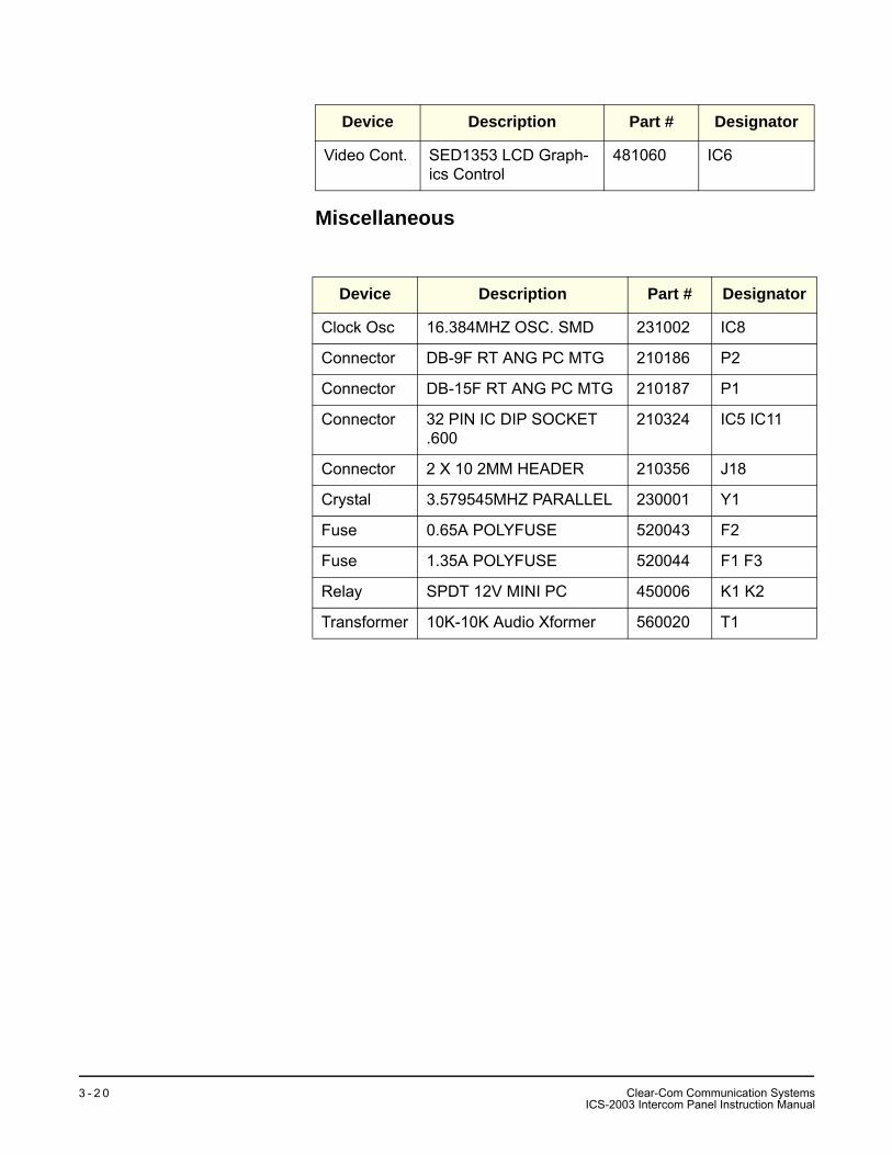
Miscellaneous
Video Cont. SED1353 LCD Graph-ics Control
481060 IC6
Device Description Part # Designator
Clock Osc 16.384MHZ OSC. SMD 231002 IC8
Connector DB-9F RT ANG PC MTG 210186 P2
Connector DB-15F RT ANG PC MTG 210187 P1
Connector 32 PIN IC DIP SOCKET .600
210324 IC5 IC11
Connector 2 X 10 2MM HEADER 210356 J18
Crystal 3.579545MHZ PARALLEL 230001 Y1
Fuse 0.65A POLYFUSE 520043 F2
Fuse 1.35A POLYFUSE 520044 F1 F3
Relay SPDT 12V MINI PC 450006 K1 K2
Transformer 10K-10K Audio Xformer 560020 T1
Device Description Part # Designator
Clear-Com Communication SystemsICS-2003 Intercom Panel Instruction Manual
3 - 2 0
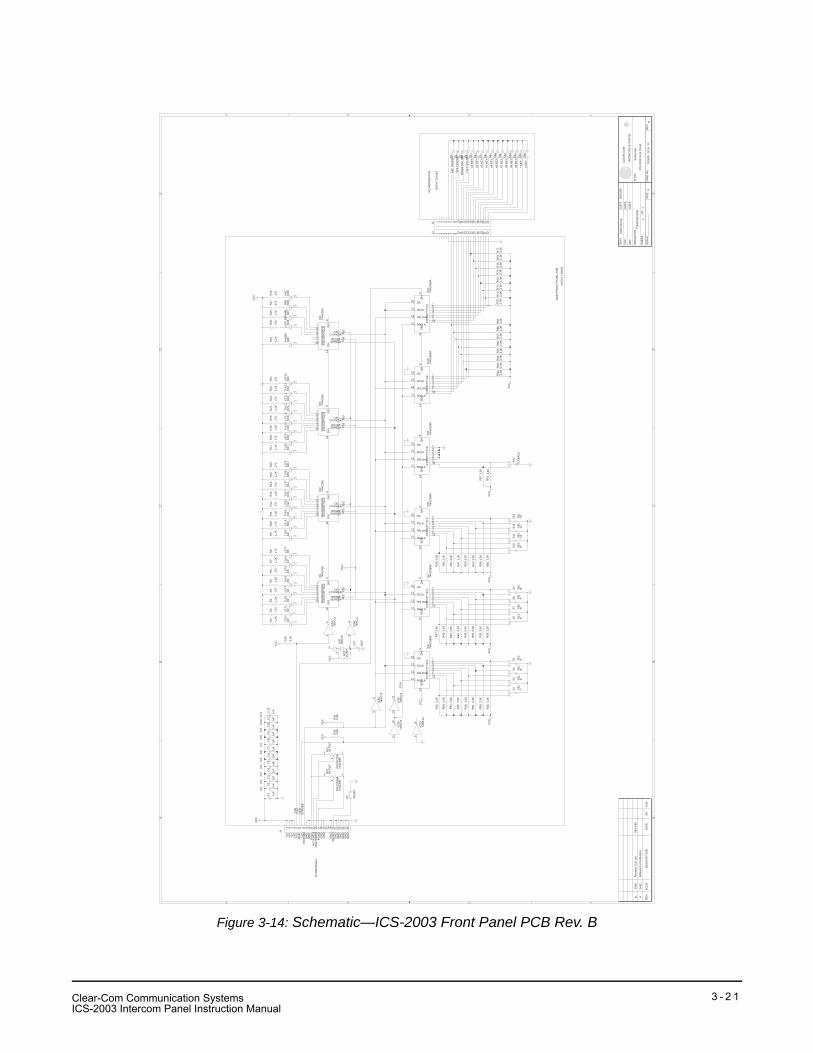
Figure 3-14: Schematic—ICS-2003 Front Panel PCB Rev. B
AA
BB
CC
DD
EE
44
33
22
11
Sch
emat
ic
ICS
-200
3 Fr
ont P
anel
7104
33 -
SC
H -
D -
BD
11
7104
33S
B.D
SN
Cla
rk M
cCoy
08/1
4/98
----
----
----
----
----
---
AB
2442
2505
Rel
ease
to P
rodu
ctio
n
Rem
ove
CLK
net
08/1
4/98
CH
K
DW
N
AP
P
DAT
ED
ATE
DAT
E
OR
CA
D P
/N
SH
EE
T:O
F:
SC
ALE
SIZ
ED
WG
No.
RE
V
TITL
E:
CLE
AR
-CO
M
INTE
RC
OM
SY
STE
MS
R
RE
VE
CO
#D
ES
CR
IPTI
ON
DAT
EB
YC
HK
S3
R67
3.3K
S2
C4
.1uF
C5
.1uF
IC8
74H
C58
9A
R37
3.3K
R43
3.3K
R40
3.3K
R46
3.3K
R52
3.3K
R59
3.3K
R49
3.3K
R55
3.3K
IC5C
74H
C14
R76
3.3K
S4
IC6
74H
C58
9A
D4
LST2
D3
TLK
2
S1
S5
D8
LST4
D7
TLK
4D
6LS
T3D
5TL
K3
J2
R9
1.2K
D10
LST5
D9
TLK
5
IC3
74H
C59
5
D12
LST6
R16
470
R15
1.2K
R14
470
R13
1.2K
R12
470
R11
1.2K
R10
470
R68
3.3K
S2
D16
LST8
D15
TLK
8D
13TL
K7
D14
LST7
D11
TLK
6
S6
S5
S4
S3
C1
1uF
+C
2
.1uF
S8
S7
R44
3.3K
R41
3.3K
R47
3.3K
R38
3.3K
IC5F
74H
C14
R60
3.3K
R50
3.3K
R56
3.3K
R53
3.3K
C8
.1uF
C6
.1uF
C7
.1uF
R77
3.3K
S13
S12
S11
S10
S9
S16
S15
S14
R28
470
R27
470
R26
470
R25
470
R69
3.3K
D29
MIC
D28
SP
KD
26LI
STL
EV
D27
PAN
EL
R62
3.3K
R19
1.2K
R18
470
R17
1.2K
D18
LST9
D17
TLK
9D
22LS
T11
D19
TLK
10D
20LS
T10
R24
470
R23
1.2K
R22
470
R21
1.2K
R20
470
D24
LST1
2D
23TL
K12
D21
TLK
11
IC4
74H
C59
5
R57
3.3K
R61
3.3K
S8
S7
S9
S6
R70
3.3K
D30
BAV
70
C11
.1uF
C12
.1uF
C10
.1uF
S1
C9
.1uF
S10
S12
S11
S13
IC7
74H
C58
9A
IC1
74H
C59
5
R71
3.3K
IC5E
74H
C14
R29
1.2K
R63
3.3K
S14
C13
10uF
+
D2
LST1
D1
TLK
1
R72
3.3K
R35
3.3K
R34
3.3K
R64
3.3K
IC5A
74H
C14
IC5B
74H
C14
R73
3.3K
R65
3.3K
R36
3.3K
IC11
74H
C58
9A
R42
3.3K
R39
3.3K
R33
31.6
K*
R45
3.3K
R48
3.3K
R51
3.3K
R58
3.3K
R54
3.3K
C3
.1uF
R30
3.3K
R1
1.2K
R4
470
R3
1.2K
R2
470
R74
3.3K
IC9
74H
C58
9A
R7
1.2K
R6
470
R5
1.2K
J1
R8
470
R66
3.3K
IC5D
74H
C14
R32
5K P
OT
IC10
74H
C58
9A
R31
5K P
OT
IC2
74H
C59
5
J1
R75
3.3K
D25
AN
SB
K
VC
C
VC
C
VC
C
VC
C
VC
C
VC
C
VC
C
VC
C
VC
CV
CC
VC
C
VC
CV
CC
SE
R14
A 15B 1C 2D 3E 4F 5G 6H 7
SRCLK11
SRLOAD13
RCLK12
OC10
QH
9
56
SE
R14
A 15B 1C 2D 3E 4F 5G 6H 7
SRCLK11
SRLOAD13
RCLK12
OC10
QH
9
1 2 3 4 5 6 7 8 9 10 11 12 13 14 15 16 17 18 19 20 21 22
DIN
14
SERCLK11RESET 10LTCHCLK12OE 13
QA15 QB1 QC2 QD3 QE4 QF5 QG6 QH7 QH
'9
1312
DIN
14
SERCLK11RESET 10LTCHCLK12OE 13
QA15 QB1 QC2 QD3 QE4 QF5 QG6 QH7 QH
'9
12
3
SE
R14
A 15B 1C 2D 3E 4F 5G 6H 7
SRCLK11
SRLOAD13
RCLK12
OC10
QH
9
DIN
14
SERCLK11RESET 10LTCHCLK12OE 13
QA15 QB1 QC2 QD3 QE4 QF5 QG6 QH7 QH
'9
1110
12
34
SE
R14
A 15B 1C 2D 3E 4F 5G 6H 7
SRCLK11
SRLOAD13
RCLK12
OC10
QH
9S
ER
14
A 15B 1C 2D 3E 4F 5G 6H 7
SRCLK11
SRLOAD13
RCLK12
OC10
QH
9
1 2 3 4 5 6 7 8 9 10 11 12 13 14 15 16 17 18 19 20 21 22
98
13
2
SE
R14
A 15B 1C 2D 3E 4F 5G 6H 7
SRCLK11
SRLOAD13
RCLK12
OC10
QH
9
13
2D
IN14
SERCLK11RESET 10LTCHCLK12OE 13
QA15 QB1 QC2 QD3 QE4 QF5 QG6 QH7 QH
'9
1 2 3 4 5 6 7 8 9 10 11 12 13 14 15 16 17 18 19 20 21 22 23 24 25 26
TXD
RX
DC
LKS
TRO
BE
/CLK
IC1
IC2
IC3
IC4
IC5
IC6
IC7
IC8
IC9
IC10
IC11
/RE
SE
T
+5V
GN
D
PG
ND
TXD
RX
DC
LK/S
TRO
BE
PR
G W
IPE
RIN
T W
IPE
R
RE
SE
T
+5V
+5V
GN
DG
ND
GN
D
GN
DG
ND
GN
DG
ND
GN
DG
ND
GN
D
+5V
To M
ain
Boa
rd
INTE
RC
OM
VO
LUM
EP
RO
GR
AM
VO
LUM
E
AS
SY
# 71
0433
MA
IN F
RO
NT
PAN
EL
PC
B
P+5
V
'6'
'2'
'9'
'5'
'1'
'12'
'8'
'4'
'11'
'TLK
BA
CK
''7
''S
EL'
'3'
'10'
MIC
ON
/OFF
SP
K O
N/O
FF
PAN
EL
MIC
SE
L
LIS
T LE
V A
DJ
#1 K
EY
#2 K
EY
#3 K
EY
#4 K
EY
#5 K
EY
#6 K
EY
#8 K
EY
#9 K
EY
#0 K
EY
#7 K
EY
* K
EY
# K
EY
AS
SY
# 71
0434
KE
YB
OA
RD
PC
B
'SE
L''S
EL'
'SE
L''S
EL'
'SE
L''S
EL'
'SE
L''S
EL'
'SE
L''S
EL'
'SE
L'
Clear-Com Communication SystemsICS-2003 Intercom Panel Instruction Manual
3 - 2 1

THIS PAGE INTENTIONALLY BLANK
Clear-Com Communication SystemsICS-2003 Intercom Panel Instruction Manual
3 - 2 2
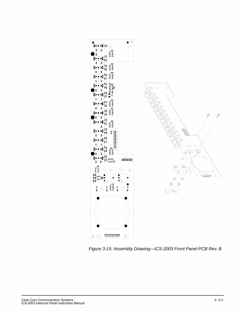
Figure 3-15: Assembly Drawing—ICS-2003 Front Panel PCB Rev. B
Clear-Com Communication SystemsICS-2003 Intercom Panel Instruction Manual
3 - 2 3
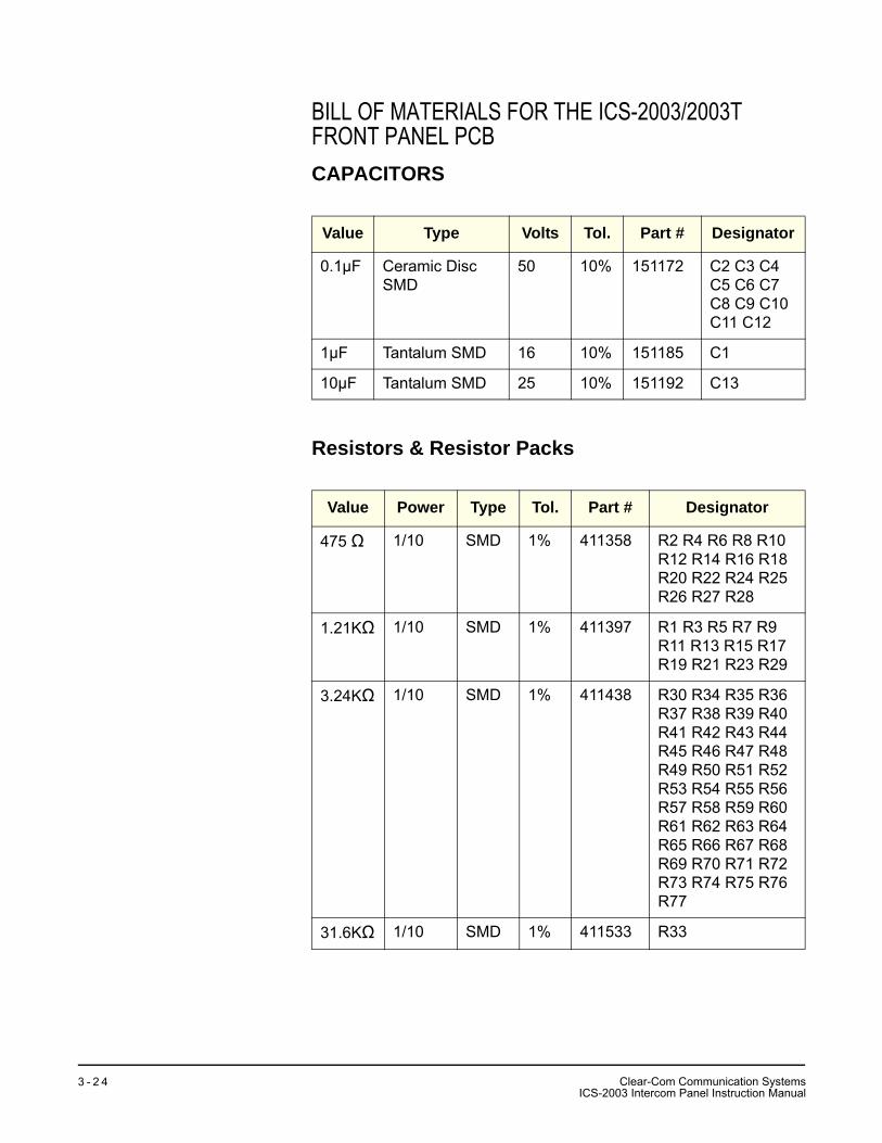
BILL OF MATERIALS FOR THE ICS-2003/2003T FRONT PANEL PCBCAPACITORS
Resistors & Resistor Packs
Value Type Volts Tol. Part # Designator
0.1µF Ceramic Disc SMD
50 10% 151172 C2 C3 C4 C5 C6 C7 C8 C9 C10 C11 C12
1µF Tantalum SMD 16 10% 151185 C1
10µF Tantalum SMD 25 10% 151192 C13
Value Power Type Tol. Part # Designator
475 Ω 1/10 SMD 1% 411358 R2 R4 R6 R8 R10 R12 R14 R16 R18 R20 R22 R24 R25 R26 R27 R28
1.21KΩ 1/10 SMD 1% 411397 R1 R3 R5 R7 R9 R11 R13 R15 R17 R19 R21 R23 R29
3.24KΩ 1/10 SMD 1% 411438 R30 R34 R35 R36 R37 R38 R39 R40 R41 R42 R43 R44 R45 R46 R47 R48 R49 R50 R51 R52 R53 R54 R55 R56 R57 R58 R59 R60 R61 R62 R63 R64 R65 R66 R67 R68 R69 R70 R71 R72 R73 R74 R75 R76 R77
31.6KΩ 1/10 SMD 1% 411533 R33
Clear-Com Communication SystemsICS-2003 Intercom Panel Instruction Manual
3 - 2 4
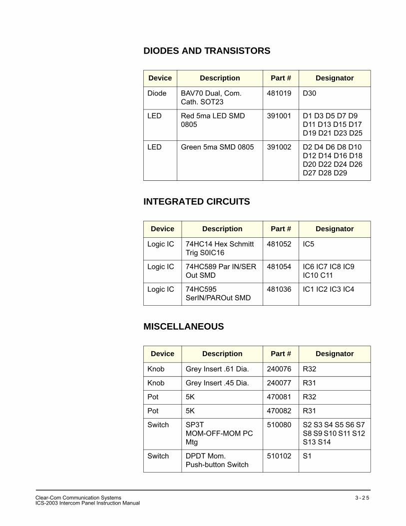
DIODES AND TRANSISTORS
INTEGRATED CIRCUITS
MISCELLANEOUS
Device Description Part # Designator
Diode BAV70 Dual, Com. Cath. SOT23
481019 D30
LED Red 5ma LED SMD 0805
391001 D1 D3 D5 D7 D9 D11 D13 D15 D17 D19 D21 D23 D25
LED Green 5ma SMD 0805 391002 D2 D4 D6 D8 D10 D12 D14 D16 D18 D20 D22 D24 D26 D27 D28 D29
Device Description Part # Designator
Logic IC 74HC14 Hex Schmitt Trig S0IC16
481052 IC5
Logic IC 74HC589 Par IN/SER Out SMD
481054 IC6 IC7 IC8 IC9 IC10 C11
Logic IC 74HC595 SerIN/PAROut SMD
481036 IC1 IC2 IC3 IC4
Device Description Part # Designator
Knob Grey Insert .61 Dia. 240076 R32
Knob Grey Insert .45 Dia. 240077 R31
Pot 5K 470081 R32
Pot 5K 470082 R31
Switch SP3T MOM-OFF-MOM PC Mtg
510080 S2 S3 S4 S5 S6 S7 S8 S9 S10 S11 S12 S13 S14
Switch DPDT Mom. Push-button Switch
510102 S1
Clear-Com Communication SystemsICS-2003 Intercom Panel Instruction Manual
3 - 2 5
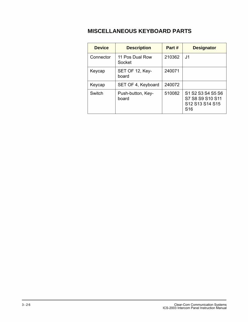
MISCELLANEOUS KEYBOARD PARTS
Device Description Part # Designator
Connector 11 Pos Dual Row Socket
210362 J1
Keycap SET OF 12, Key-board
240071
Keycap SET OF 4, Keyboard 240072
Switch Push-button, Key-board
510082 S1 S2 S3 S4 S5 S6 S7 S8 S9 S10 S11S12 S13 S14 S15 S16
Clear-Com Communication SystemsICS-2003 Intercom Panel Instruction Manual
3 - 2 6
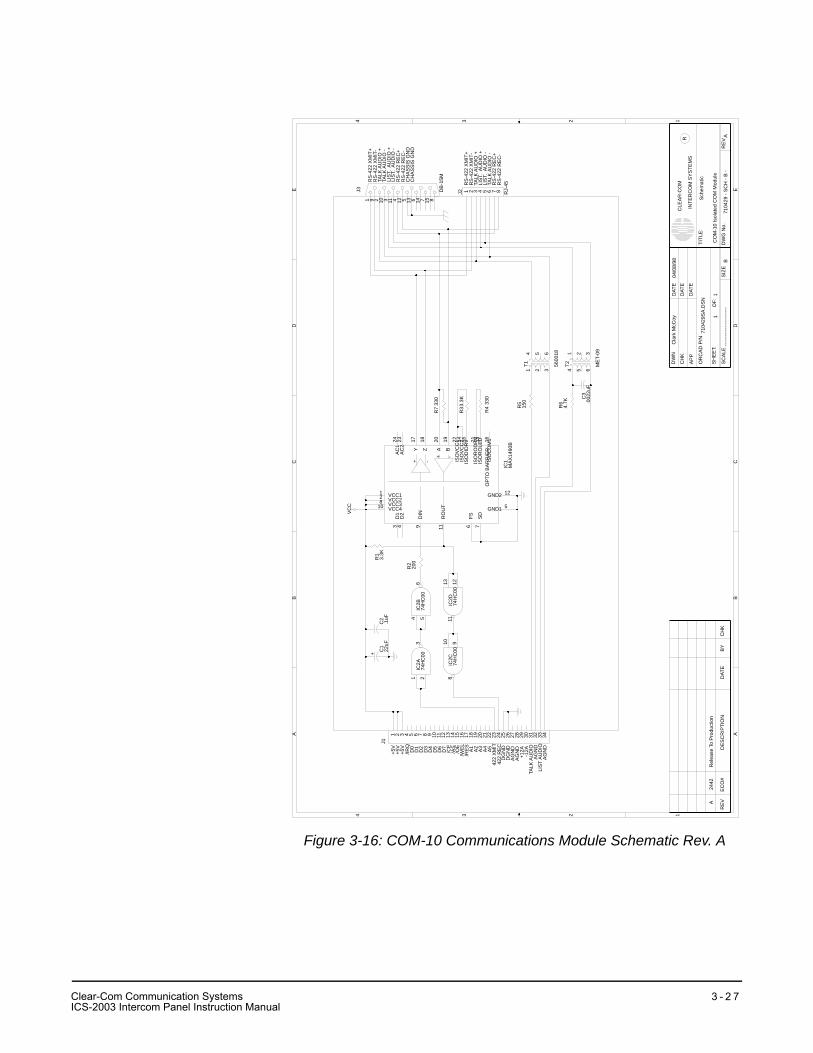
Figure 3-16: COM-10 Communications Module Schematic Rev. A
AA
BB
CC
DD
EE
44
33
22
11
Sch
emat
ic
CO
M-1
0 Is
olat
ed C
OM
Mod
ule
7104
29 -
SC
H -
B -
AB
11
7104
29S
A.D
SN
Cla
rk M
cCoy
04/0
8/98
----
----
----
----
----
---
A24
42R
elea
se T
o P
rodu
ctio
n
CH
K
DW
N
AP
P
DAT
ED
ATE
DAT
E
OR
CA
D P
/N
SH
EE
T:O
F:
SC
ALE
SIZ
ED
WG
No.
RE
V
TITL
E:
CLE
AR
-CO
M
INTE
RC
OM
SY
STE
MS
R
RE
VE
CO
#D
ES
CR
IPTI
ON
DAT
EB
YC
HK
J1
IC1
MA
X14
90B
+ -
-+
OP
TO B
AR
RIE
R
J2 RJ-
45
J3 DB
-15M
C1
22uF
+
C2
.1uF
R33
.3K
R4
330
IC2D
74H
C00
IC2B
74H
C00
IC2A
74H
C00
IC2C
74H
C00
R7
330
R2
200
R1
3.3K
T1 5600
18
T2 ME
T-09
R5
150
R6
4.7K
C3
.002
2uF
VC
C
1 2 3 4 5 6 7 8 9 10 11 12 13 14 15 16 17 18 19 20 21 22 23 24 25 26 27 28 29 30 31 32 33 34
VCC11VCC22VCC38VCC410 GND1 5
GND2 12
D1
3D
24
FS6
SD
7
DIN
9
RO
UT
11
AC
124
AC
223
A20
B19
Z18
Y17
ISO
VC
C122
ISO
VC
C214
ISO
DID
RV15
ISO
RO
DR
V21IS
OR
OLE
D13
ISO
CO
M116
1 2 3 4 5 6 7 8
815714613512411310291
1213114 5
61 2
3 9108
1
65
3
4
2
1
65
3
4
2
+5V
+5V
/IRQ
+5V
D3
D2
D0
D1
D7
D4
D6
D5
/WE
L
/CE
/OE
/AS
A3
/RE
S
A2
A1
422
RE
C
A4
422
XM
ITA
5
AG
ND
DG
ND
AG
ND
DG
ND
AG
ND
+12A
TALK
AU
DIO
-12A
LIS
T A
UD
IOA
GN
D
RS
-422
XM
IT+
RS
-422
XM
IT-
TALK
AU
DIO
+
TALK
AU
DIO
-
LIS
T. A
UD
IO +
LIS
T. A
UD
IO -
RS
-422
RE
C+
RS
-422
RE
C-
RS
-422
XM
IT+
RS
-422
XM
IT-
TALK
AU
DIO
+TA
LK A
UD
IO -
LIS
T. A
UD
IO +
LIS
T. A
UD
IO -
RS
-422
RE
C+
RS
-422
RE
C-
CH
AS
SIS
GN
DC
HA
SS
IS G
ND
Clear-Com Communication SystemsICS-2003 Intercom Panel Instruction Manual
3 - 2 7
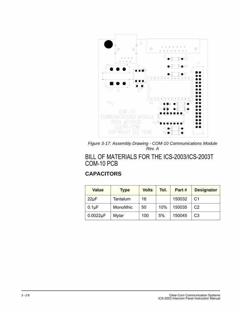
Figure 3-17: Assembly Drawing - COM-10 Communications Module Rev. A
BILL OF MATERIALS FOR THE ICS-2003/ICS-2003T COM-10 PCBCAPACITORS
Value Type Volts Tol. Part # Designator
22µF Tantalum 16 150032 C1
0.1µF Monolithic 50 10% 150035 C2
0.0022µF Mylar 100 5% 150045 C3
Clear-Com Communication SystemsICS-2003 Intercom Panel Instruction Manual
3 - 2 8
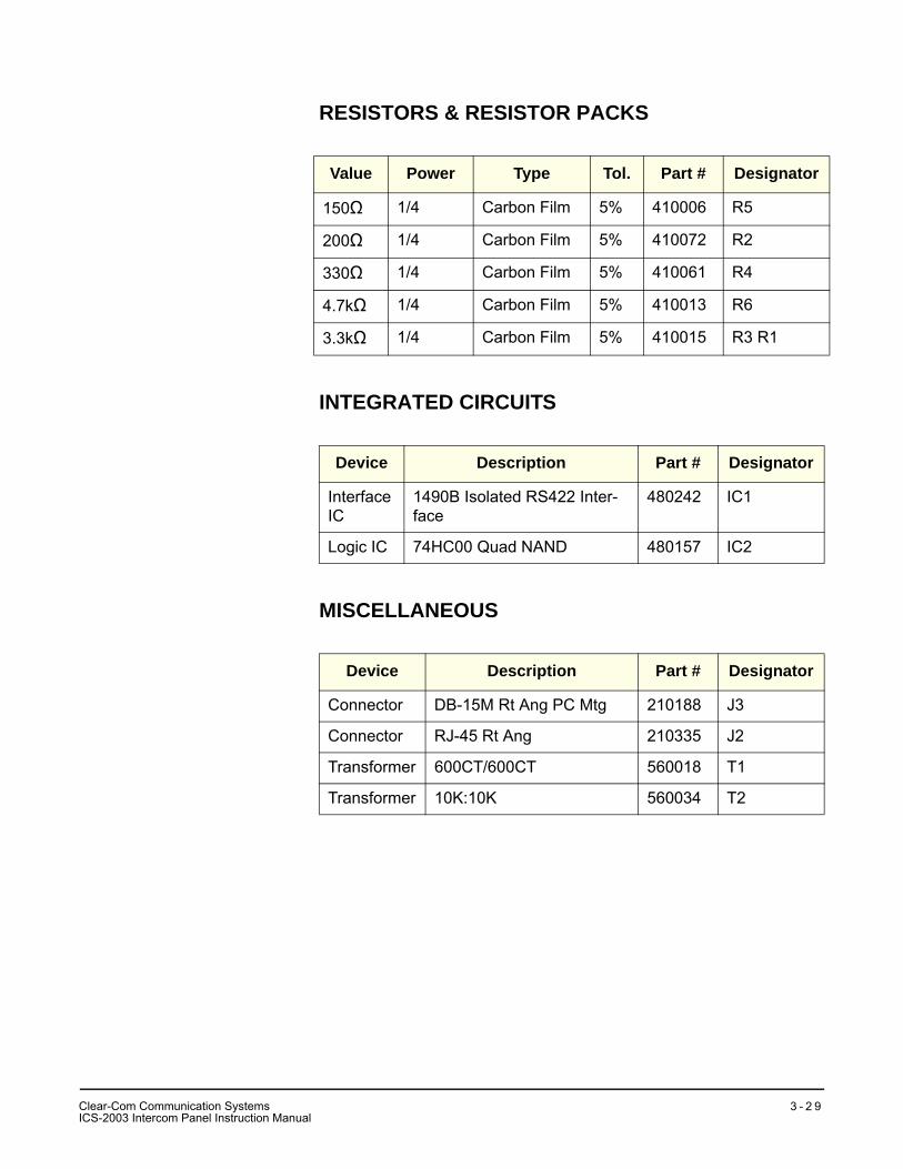
RESISTORS & RESISTOR PACKS
INTEGRATED CIRCUITS
MISCELLANEOUS
Value Power Type Tol. Part # Designator
150Ω 1/4 Carbon Film 5% 410006 R5
200Ω 1/4 Carbon Film 5% 410072 R2
330Ω 1/4 Carbon Film 5% 410061 R4
4.7kΩ 1/4 Carbon Film 5% 410013 R6
3.3kΩ 1/4 Carbon Film 5% 410015 R3 R1
Device Description Part # Designator
Interface IC
1490B Isolated RS422 Inter-face
480242 IC1
Logic IC 74HC00 Quad NAND 480157 IC2
Device Description Part # Designator
Connector DB-15M Rt Ang PC Mtg 210188 J3
Connector RJ-45 Rt Ang 210335 J2
Transformer 600CT/600CT 560018 T1
Transformer 10K:10K 560034 T2
Clear-Com Communication SystemsICS-2003 Intercom Panel Instruction Manual
3 - 2 9
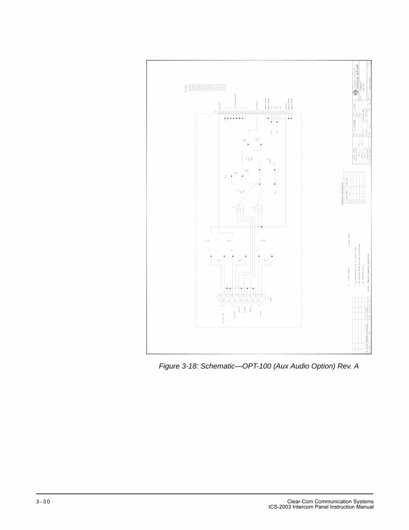
Figure 3-18: Schematic—OPT-100 (Aux Audio Option) Rev. A
ANALOG GROUND
ANALOG GROUND
TALK BUS
-15V
-15V
+15V
+15V
ANALOG GROUND
ANALOG GROUND
SA CONTROL
DIGITAL GROUND
-15V
+15V
25
26
24
23
22 21
20 19
18
17
16
15
14
13
12 11
10 9 8 7 6 5 4 3 2 1
1K
1K
OTHERWISE SPECIFIED
CHK.
BY
DATE
DESC.
ECO#
BEFORE PLATING
TOLERANCE: UNLESS
TITLE:
intercom systemsR R
EV
NO.
DWG
APP
CHK
DWN
DO NOT SCALE DRAWING
ANGLE +/-
REV
SCALE
DATE
DATE
DATE
.XXX +/-
ACAD P/N -
PLOT SIZE-
SIZE
SCHEMATIC
OPT-100
710327-SCH-C-
A
B. DOUGLAS
1/4/89
710327SA.DWG
C1=1
.015 1˚
A2074
RELEASE TO PRODUCTION
1/19/94
HCP
HOLES +/- .003
ACAD ARCHIVE
1=1
APR.
NOTES: (UNLESS OTHERWISE SPECIFIED)
1. ALL DIODES ARE 1N4148.
2. ALL CAPACITOR VALUES ARE LISTED IN MICROFARADS.
3. ALL RESISTORS ARE 1/4W, 5%, LISTED IN OHMS.
4. = ANALOG GROUND
= DIGITAL GROUND
8 7 6 5 1
15
14
13
12
34 2
91011
HOT MIC OUT
LINE OUT
SA OUT
DB15F
1K
23
25 21
19
17
15
13 11 9 7 5 3 1
246810
12
14
16
18
20
22
26
24
TOP VIEW
1K
1K
1K
MPS-
A55
+15V
15K 15K
MPS-
A05
1N4001
15K
4.7K
-15V
JQDR
NOT USED
LAST USED
REFERENCE DESIGNATORS
10 1 2 2
T K
3 2
SA N.C.
SA WIPE
SA N.Q.
J1
LINE OUT
R1
R2
R3
R4
R5
R6
T1
T2
T3
K1
K2
Q1
R7
R8
Q2
D1
R10 R9
J2
Clear-Com Communication SystemsICS-2003 Intercom Panel Instruction Manual
3 - 3 0
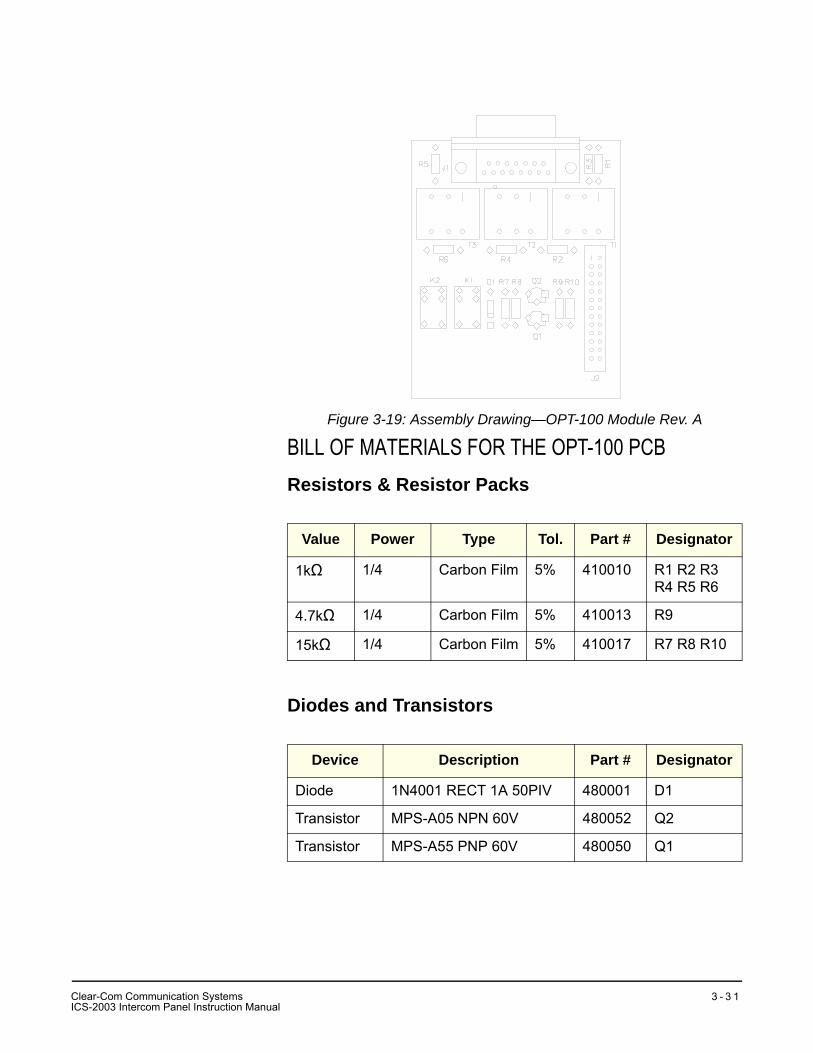
Figure 3-19: Assembly Drawing—OPT-100 Module Rev. A
BILL OF MATERIALS FOR THE OPT-100 PCBResistors & Resistor Packs
Diodes and Transistors
Value Power Type Tol. Part # Designator
1kΩ 1/4 Carbon Film 5% 410010 R1 R2 R3 R4 R5 R6
4.7kΩ 1/4 Carbon Film 5% 410013 R9
15kΩ 1/4 Carbon Film 5% 410017 R7 R8 R10
Device Description Part # Designator
Diode 1N4001 RECT 1A 50PIV 480001 D1
Transistor MPS-A05 NPN 60V 480052 Q2
Transistor MPS-A55 PNP 60V 480050 Q1
CI
lear-Com Communication SystemsCS-2003 Intercom Panel Instruction Manual
3 - 3 1
Miscellaneous
Device Description Part # Designator
Connector db-15fRT ANG PC MTG 210187 J1
Relay SPDT 24V MINI PC RELAY 450004 J1
Transformer AUDIO, 600CT/600CT 560018 K1 K2
Clear-Com Communication SystemsICS-2003 Intercom Panel Instruction Manual
3 - 3 2
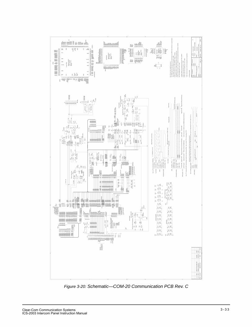
Figure 3-20: Schematic—COM-20 Communication PCB Rev. C
AA
BB
CC
DD
EE
44
33
22
11
BC
2573
2581
Rel
ease
to p
rodu
ctio
n
AD
JUS
T TA
LK G
AIN
; R27
04-0
7-99
4/22
/99
JEG
MA
SS
chem
atic
CO
M-2
0 D
igita
l Sub
scrib
er S
tatio
n
710
435
- SC
H -
D -
CD
11
7104
35S
C.D
SN
J.E
.Gal
brai
th04
-07-
99
----
----
----
----
----
---
RE
VE
CO
#D
ES
CR
IPTI
ON
DAT
EB
YC
HK
CH
K
DW
N
AP
P
DAT
E
DAT
E
DAT
E
OR
CA
D P
/N
SH
EE
T:O
F:
SC
ALE
SIZ
ED
WG
No.
RE
V
TITL
E:
CLE
AR
-CO
M
INTE
RC
OM
SY
STE
MS
®
TP23
CS
DO
R62
1.0K
*
IC8A
LMC
6482
R47
220*
R75
0
C43
.1uF (IC
6)
R52
220*
D1
BAV
99
C38 .1
uF(IC
2)
C39
.1uF
(IC6)
R63
1.0K
*
C47 .1
uF(IC
5)
C51
47pF
C18
.47u
F
+
L3
R53
220*
C10
.1uF
(IC6)
TP5
LO
UT
T1
R33
4.75
K*
R40
0
R56
1.0K
*
R34
0
C19
10uF
+
TP14
R54
220*
R64
1.0K
*
R37
2.74
K*
R35
0
J4
TP4
RO
UT
C8 .1uF
C48 .1uF (IC
7)
R65
1.0K
*
C7
100u
F
+
R12
4.75
K*
IC7
CS
4218
R36
0
R6
4.75
K*
R43
1.0K
IC2
6225
6
C42
.1uF
(IC6)
C20
.1uF
IC4
OS
C 1
0.24
MH
z
IC1
7104
51
CP
U In
terfa
ce
JTA
G P
ort
(CP
U S
el)
R67
1.0K
*
IC3
MT9
171B
P
R38
301*
R46
220*
R25
4.75
K*
R3
392*
R1
4.75
K*
R4
47.5
*C1 .0
015u
F
C4
.47u
F
+
C17
.47u
F
+
C5
.47u
F
+
TP18
R68
1.0K
*
C26 .1uF
(IC3)
C2
.022
uF
C6
.47u
F
+
C28
.1uF
(IC1)
C29
.1uF
(IC1)
R39
3.24
K*
C50 .1uF
(IC8)
R69
1.0K
*
C3
.1uF
(IC9)
C36
.1uF
(IC1)
C31
.1uF
(IC1)
R9
4.75
K*
C37
.1uF
(IC1)
J2 RJ-
45
C32
.1uF
(IC1)
L1
TP24
C33
.1uF
(IC1)
R70
1.0K
*
IC9
74H
CT4
046
C24
10uF
(IC7)
+
C34
.1uF
(IC1)
TP25
C35
.1uF
(IC1)
R71
1.0K
*
J5
BN
C
TP27
R32
4.75
K*
C27 .1
uF(IC
4)
R72
1.0K
*
C9
.003
3uF
R18
75.0
K*
R22 0
C46
.1uF
(IC6)
R17
7.50
K*
C11
47pF
R73
1.0K
*
R16 0
IC5
6225
6
R44
4.75
K*
TP46
S1
IC8B
LMC
6482
R55
604*
C52
.1uF
R24
4.75
K*
C41
.1uF
(IC6)
TP3
LIS
TEN
R41
4.75
K*
R11
4.75
K*
C12
.004
7uF
R74
1.0K
*
R48
220*
L2
C45
.1uF
(IC6)
R45
4.75
K*
R58
1.0K
*
C14
.001
uF*
R29
604*
C21
.33u
F
R26
75.0
K*
TP12
/F0
R19
604*
TP29
R49
220*
R13
4.75
K*
C15
47pF
C13
.004
7uF
R59
1.0K
*
TP30
C23
.004
7uF
IC6
DS
P56
004
Ser
ial H
ost I
nter
face
Gen
Pur
pose
I/O
OnC
E S
eria
l
Ser
ial A
udio
Ext
Mem
ory
TP1
C16
.33u
F
R50
220*
TP45
R30
2.2
C44
.1uF
(IC6)
R28
4.99
K*
R60
1.0K
*
C25
10uF
(IC7)
+
TP20
SC
LK
C22
.001
uF*
R10
4.75
K*
C40
.1uF
(IC6)
C49 .1uF (IC
7)
TP21
SS
YN
C
R51
220*
R42
4.75
K*
R27
4.75
K*
J1 DB
-15M
TP22
CS
DI
VC
CV
CC
VC
C
VC
C
VC
C
VC
C
+5D
0
VC
CV
CC
+5A
0
VC
C
VC
C
VC
C
VC
C
VC
C
VC
C
VC
C
VC
C
VC
C
VC
C
VC
C
VC
C
+5D
0
+5A
0
+5A
0
+5D
0
+5D
0
+5D
0
+5D
0
+5D
0
+5D
0
321
8 4
12
3
165
34
2
1 2 3 4 5 6 7 8 9 10 11 12 13 14 15 16 17 18 19 20 21 22 23 24 25 26 27 28 29 30 31 32 33 34
VA18
VD42
CLK
IN41
SS
YN
C39
SC
LK38
/PD
N7
LIN
121
RIN
119
LIN
222
RIN
220
CD
OU
T34
CD
IN33
/CC
S30
CC
LK29
/INT
32
/RE
SE
T40
MF6
28M
F725
MF8
24
AGND 17
DGND 43RE
FGN
D16
RE
FBY
P15R
EFB
UF14
SD
OU
T37
SD
IN36
SM
OD
E335
SM
OD
E226
SM
OD
E123
LOU
T10
RO
UT9
NC
44N
C1
NC
2N
C3
NC
4N
C5
NC
6
NC
8N
C11
NC
12
NC
13
DI1
27D
O1
31
A0
10A
19
A2
8A
37
A4
6A
55
A6
4A
73
A8
25A
924
A10
21A
1123
A12
2A
1326
A14
1
%%
oCS
%%
o20
%%
oOE
%%
o22
%%
oWE
%%
o27
D0
11D
112
D2
13D
315
D4
16D
517
D6
18D
719
OE
1
GN
D2
OU
T3
VC
C4
VCC7VCC19VCC22VCC42
GND 15GND 30GND 50GND 54
%%
oCP
UIR
Q%
%o
107
CP
UD
010
6C
PU
D1
105
CP
UD
210
4C
PU
D3
103
CP
UD
410
1C
PU
D5
100
CP
UD
699
CP
UD
798
/CE
097
/AS
--/C
E1
96/O
E--
R/W
95/W
EL-
-/RS
T93
/RE
S--
E92
A2-
-A0
86A
3--A
185
A4-
-A2
84A
5--A
383
%%
oRA
MW
E%
%o
113
%%
oRA
MO
E%
%o
125
%%
oRA
MC
S%
%o
131
RA
MA
013
6R
AM
A1
134
RA
MA
213
2R
AM
A3
124
RA
MA
412
1R
AM
A5
119
RA
MA
611
7R
AM
A7
115
RA
MA
811
8R
AM
A9
120
RA
MA
1012
8
RA
MD
013
9R
AM
D1
141
RA
MD
214
4R
AM
D3
142
RA
MD
414
0R
AM
D5
137
RA
MD
613
5R
AM
D7
133
CO
DE
CS
Clk74
CO
DE
CFS
ync
75
%%
oCO
DE
CR
eset
%%
o76
C16
In20
C8O
ut73
%%
oMC
S%
%o
59
%%
oMR
D%
%o
61%
%oM
WR
%%
o60
MD
062
MD
163
MD
264
MD
365
MD
467
MD
568
MD
669
MD
770
A1-
-AS
89
MA
443
MA
240
MA
341
TRS
TB71
TMS
72TD
I38
TCK
109
STM
110
TDO
143
MO
DE
108
MA
037
MA
139
CD
STi
5C
DS
To4
DS
Ti3
DS
To2
F06
GC
LK/I
21VCCIO58
VCC79VCC91VCC94VCC114
VCCIO130
GND 66GND 87GND 102GND 122GND 126GND 138
RA
MA
1411
1R
AM
A13
116
RA
MA
1211
2R
AM
A11
123
MA
544
MA
645
MA
746
MA
847
MA
948
MA
1049
MA
1151
MA
1252
%%
oDS
PR
ES
%%
o33
MO
DA
/IRQ
A34M
OD
B/IR
QB35
MO
DC
/NM
I36
SP
CLK
23S
PM
ISO24
SP
MO
SI25
%%
oHA
2%%
o26
HR
EQ
27
GP
IO231
GP
IO332
I17
AC
LK/I
18A
CLK
/I90
GP
IO028
GP
IO129
/C4O
ut56
%%
oBoo
tRam
CE
%%
o57
MA
1353
MA
1455
DS
I/OS
O8D
SC
K/O
S19
DS
O10
DR
11
Test
612
7Te
st7
129
Test
588
n/c
12n/
c13
n/c
14n/
c16
n/c
1
Test
077
Test
178
Test
280
Test
381
Test
482
CDSTO13
CDSTI12
VDD28 MS2 5
DS
TI16
DS
TO15
F0/C
LD10
C4/
TCK
19F0
O/R
CK
17R
EG
C9
PR
EC
AN
23O
SC
221
OS
C1
22
MSO 8
MS1 7
TEST26 VSS 14LOU
T2
LIN
27
LOU
T D
IS24
VR
EF
4V
BIA
S3
NC
1N
C6
NC
11N
C18
NC
20N
C25
1 2 3 4 5 6 7 8
CIN
3
VC
OU
T4
SIN
14
CX
6
CX
7IN
H5
R1
11R
212
PP
1P
12
P2
13
VC
OIN
9
DE
MO10
ZEN
15
A0
10A
19
A2
8A
37
A4
6A
55
A6
4A
73
A8
25A
924
A10
21A
1123
A12
2A
1326
A14
1
%%
oCS
%%
o20
%%
oOE
%%
o22
%%
oWE
%%
o27
D0
11D
112
D2
13D
315
D4
16D
517
D6
18D
719
123
456
567
MA
025
MA
124
MA
223
MA
322
MA
420
MA
519
MA
618
MA
716
MA
814
MA
913
MA
1012
MA
1111
MA
127
MA
135
MA
15/M
CS
33
MA
144
MD
071
MD
169
MD
268
MD
367
MD
465
MD
564
MD
663
MD
762
MA
16/M
CS
280
MA
17/M
CS
179
AGND 1AGND 8QGND 10AGND 15AGND 21QGND 29SGND 34
QGND 52SGND 44
SGND 54DGND 66
AVCC6QVCC9AVCC17QVCC28
PVCC33
SVCC40
QVCC53 SVCC48
DVCC70
DGND 72
PG
ND31
EX
TAL27
PC
AP
32
%%
oRE
SE
T%%
o36
MO
DA
/IRQ
A37M
OD
B/IR
QB38
MO
DC
/NM
I39
%%
oMR
D%
%o
77%
%oM
WR
%%
o78
%%
oMC
S0%
%o
2
SC
K/S
CL26
MIS
O/S
DA35
MO
SI/H
A041
SS
/HA
242%
%oH
RE
Q%
%o
43
GP
IO0
76G
PIO
175
GP
IO2
74G
PIO
373
PIN
IT30
DS
I/OS
059
DS
CK
/OS
160
DS
O58
%%
oDR
%%
o61
WS
R55
SC
KR
51S
DI0
57S
DI1
56W
ST
50S
CK
T49
SD
O047
SD
O146
SD
O245
815714613512411310291
C10
C10
AD
2
AD
4A
D5
AD
7
AD
0/IR
Q
AD
6
AD
1
AD
3
C4_
DN
IC
FR0A
11
/FR
0OE
FR0D
2
/MC
S/M
WR
MD
1
FR0A
13
MA
13
MA
4
MD
7M
A12
MD
5M
D4
/FR
0OE
FR0A
5
FR0A
12
MA
8M
A9
MO
DA
/IRQ
A
MO
DC
/NM
I
/BO
OTR
AM
CE
/DS
PR
ES
DS
OGP
IO1
MO
DA
/IRQ
A
FR0D
7
MD
0
MD
4
FR0A
9
MA
4
FR0A
8
MA
11
FR0A
0FR
0A1
MD
4
/RS
T
FR0A
2
FR0A
14
FR0A
11
MA
12
HR
EQ
/BO
OTR
AM
CE
MD
2
MO
DC
/NM
I
MA
10
DS
CK
/OS
1
FR0A
14
MA
5
MD
2
MA
0
FR0A
1
MD
6
MD
1
/MR
D
MA
6
FR0A
7
MA
14
FR0A
8
FR0D
0
FR0D
5
FR0A
3
MA
1
/MC
S
MA
7
MA
11
MA
12
FR0A
3
FR0D
4
/MR
D
MD
3
AS
MA
5
/MR
D
MA
5
MD
7
HR
EQ
MA
0
/FR
0WE
FR0A
0
MD
2
MD
7
MO
DB
/IRQ
B
DS
CK
/OS
1
MA
7
MO
DB
/IRQ
B
FR0A
5
MA
13
MD
5
FR0A
6
FR0D
3
DS
To
MA
1M
D1
MD
3
FR0A
4
MA
14
FR0A
9
FR0D
1
MD
5
/DS
PR
ES
/FR
0WE
MD
3M
A6
FR0A
10
MA
9
FR0A
4
MA
6
MA
11
/HA
2
FR0A
13
MD
0
MD
6
FR0A
6 /CE
0/C
E1
A1
MA
4
FRM
8KH
z
/FR
0CS
MA
9M
D6
/MW
R
R/W
FR0A
7
GP
IO1
DS
O
MD
0
MA
10
MA
10
FR0A
2 E A0
/FR
0CS
FR0A
10
FR0D
6
DS
Ti
MA
7
MA
13/M
WR
MA
8
MA
0
GP
IO3
MA
14
FR0A
12
MA
8
A2
A3
C16 MA
1
/C4
DS
I/OS
O
/DR
/DR
DS
I/OS
O
/TW
CD
STi
CD
STo
/HA
2
TW
MA
3M
A2
MA
2M
A3
MA
3M
A2
GP
IO3
FRM
8KH
z
/F0
SC
LK
CS
DI
SP
CLK
GP
IO0
C8
SP
MO
SI
SP
CLK
GP
IO0
SP
MO
SI
SP
MIS
O
VR
EF
C8
SS
YN
C
/CO
DE
CR
ES
CS
DO
GP
IO0
SC
LK
SS
YN
C
SS
YN
C
SP
MO
SI
SP
MIS
O
CS
DI
SC
LK
/CO
DE
CR
ES
VR
EF
SP
MIS
OS
PC
LK
CS
DO
PC
Boa
rd #
1702
64
Boo
t RA
M
Filte
red
CO
DE
C P
ower
DS
P56
004
CO
M3A
FR
AM
ER
OP
Am
p
LSBM
SB
LSBM
SB
Rig
ht W
ord
Bits
Left
Wor
d B
its
LSBM
SB
DS
P S
eria
l Aud
io In
terfa
ce to
CO
DE
C ti
min
g
CS
DI -
TP
22
CS
DO
- TP
23
PLL
MF=
5D
SP
Clo
ck=5
1.2
MH
z
18 19 20 21 22 23 24 25 26 27 28 29 30 31 32 33 34 35 36
54555657585960616263646566676869707172
132131130129128127126125124123122121120
5253
108
107
106
105
104
103
102
101
100
99 98 97 96 95 94 93 92 91 90 89 88 87 86
51
85 84
119118117
TQFP
Pac
kage
Sho
wn
4-tim
eslif
e si
ze
133134135136137138139140141142143144
116115114113112111110109
10 11 1 2 3 4 5 6 7 8 9 12 13 14 15 16 17
3738394041424344454647484950
7374757677787980818283
GND
GND
GND
GND
GND
GND
VC
C
VC
C
VC
C
VC
C
VC
C
VC
C
GN
D
GN
D
GN
D
GN
D
VCCIO
VCC
VCC
VCCIO
GC
LK/1
II
II
Pin
out f
or 1
44-P
in
7104
51 F
PG
A
RAMA8RAMA6
RAMA9RAMA5
RAMA11
RAMA4
/RAMOERAMA3
RAMA10
RAMA2/RAMCS
RAMA1RAMD7
RAMD6RAMA0RAMD5
RAMD0RAMD4RAMD1RAMD3
RAMD2
n/c
DS
ToD
STi
CD
STi
CD
STo F0
C16
In
TDIA
CLK
/IA
CLK
/I
GC
LK/1
TDO
TMSTRSTB
TCKSTM
MA0
MA1MA2MA3
MA4MA5MA6MA7MA8MA9MA10
MA11MA12
/MCS0/MWR/MRDMD0MD1MD2MD3
MD4MD5MD6MD7
C8
SC
LKFS
YN
C
CP
UA
3C
PU
A2
CP
UA
1C
PU
A0
CP
UA
4
CP
UE
Clk
/CP
UR
ES
CP
UR
/WC
PU
CE
1C
PU
CE
0C
PU
D7
CP
UD
6C
PU
D5
CP
UD
4
CP
UD
3C
PU
D2
CP
UD
1C
PU
D0
/CP
UIR
QM
OD
E
n/c
n/c
n/c
/CO
DE
CR
ES
MO
DA
/IRQ
AD
SP
RE
S
MO
DB
/IRQ
BM
OD
C/IR
QC
SP
CLK
SP
MIS
OS
PM
OS
IH
A2
HR
EQ
GP
IO2
RAMA7RAMA13
RAMA12/RAMWE
Test7
/C4Outn/
c
GP
IO3
RAMA14
n/c
Test6MA13
MA14
Test
3Te
st2
Test
1Te
st0
n/c
(CO
DE
C)
(DN
IC)
(RA
M)
(DS
P/E
PR
OM
)
(J4)
GP
IO1
GP
IO0
DS
I/OS
OD
SC
K/O
S1
DS
OD
R
Test
4
Test
5
(gnd
)
gnd
gnd
AG
ND
DGND
/HR
EQ
2
View1614 8 4 11
40
30
33
21
25
515559 4650
69
65
61
76
80
AVC
C
MA
15/M
CS
3
MA
6
MA2
EXTAL
SC
KT
MA16/MCAS
SV
CC
MODA/IRQA
SD
I1
DS
CK
/OS
1
Sho
wn
4-tim
es
PGND
MA
11
MD5
MD1
GPIO1
AG
ND
SVCC
/SS
/HA
2
MA17/MRAS
Top
3
2018 9 5 1
39
28
32
36
24
435458 4549
70
66
62
75
79
AVC
C
/MS
C0
MA
7
MA3
SCK/SCL
SD
O0
life
size
SG
ND
/RESET
WS
R
DS
I/OS
0
QGND
MA
12
MD6
MD2
GPIO2
QV
CC
SGND
MO
SI/H
A0
/MWR
SO
T-23
171512 6 2
38
27
31
35
23
425357 4448
71
67
63
74
78
QG
ND
DVCC
MA
8
MA
4
MA0
SD
O2
Pin
out f
or 8
0-P
in
QG
ND
MISO/SDA
SC
KR
QVCC
MA
13
DS
O
MD7
MD3
GPIO3
AG
ND
PCAP
MODC/NMI
/MRD
1
10 1913 7 3
37
26
29
34
22
41525660 47
72
68
64
73
77
DS
P56
0004
AGND
DGND
MA
9
MA
5
MA1
SD
O1
BAV
99
QV
CC
PINIT
WS
T
SG
ND
MA
14
MODB/IRQB
SD
I0
QFP
Pac
kage PVCC
MA
10
DR
MD4
MD0
GPIO0
EX
TAL=
10.2
4 M
Hz
VA
DO1
DI1
SMODE1
LIN
2
Dig
ital
1
5
9
1519
34 38 42
24
28
32
/RE
SE
T
Gro
und
SD
IN
n/c
n/c
n/c
AG
ND
/INT
MF6
LIN
1
MF8 LOUT11
4
8
141822
37 41
23
27
31
CLK
IN
Ana
log
SD
OU
T
Reg
ion
RE
FGN
D
CDIN
CCLKn/c
n/c
RIN
2
MF7 ROUT10
3
7
13172136 40 44
26
30
VD
Pla
ne
SC
LK
Reg
ion
RE
FBY
P
CD
OU
T
/CCSn/c
n/c
n/c
RIN
1
SMODE2/PDN
2
6
12162035 39 43
25
29
33
DG
ND
Gro
und
SS
YN
C
Pla
ne RE
FBU
F
SM
OD
E3
n/c
n/c
n/c
CS
4218
life
size
44-P
in T
QFP
Sho
wn
3-tim
es
Pac
kage
Pin
out f
or 23
13
28
9
Pac
kage
26
7
Sho
wn
2-tim
es
18
24 5
16
11
28-P
in P
LCC
14
MT8
971B
P
life
size
12
Pin
out f
or27
17
8
25
15
6
10
4321
2021
19
22
n/c
n/c
n/c
n/c
n/c
n/c
LOU
TV
Bia
sV
Ref
TES
TLI
NV
DD
/F0o
DS
Ti/D
iD
STo
/Do
VS
SC
DS
To/C
Do
CD
STi
/CD
i
MS2
MS1MS0RegC/F0/CLD
LOUT DISPrecanOSC1OSC2
/C4/TCK
"TA
LK_A
UD
IO" i
nput
leve
l is
limite
d in
the
pane
l to
+6dB
u.
Inpu
t Tal
k am
plifi
er g
ain
is s
et to
-36d
B.
CO
DE
C in
put c
lippi
ng le
vel i
s +2
dBu
(RE
FBU
F vo
ltage
+ 1
.0Vr
ms)
.
CO
DE
C o
utpu
t atte
nuat
ion
is s
et to
-13.
5dB
.
CO
DE
C o
utpu
t Lis
ten
ampl
ifier
gai
n is
set
to +
9dB
.
"LIS
TEN
_AU
DIO
" lev
el s
houl
d be
the
sam
e as
"TA
LK_A
UD
IO".
The
MAT
RIX
+III
sets
a +
10dB
u he
adro
om a
bove
max
imum
aud
io le
vel.
Not
e: T
alk
and
List
en a
mpl
ifier
gai
n is
sues
.
Pha
se L
ocke
d Lo
op
C16
- IC
9,P
in4
/C4
- IC
9,P
in3
C8/
CLK
IN -
IC7,
Pin
41
DN
IC/F
PG
A/P
LL c
lock
tim
ing
LSBM
SB
LSBM
SB
Ref
, SS
YN
C
- 2-W
ire D
ata
+ 2-
Wire
Dat
a
+ 2-
Wire
Dat
a
FOR
CO
AX
CG
ND
FOR
RJ-
45
- 2-W
ire D
ata
C16
Per
iod
= 61
nS
SC
LK P
erio
d =
977
nS
PLL
/FP
GA
C4_
DN
IC -
IC9,
Pin
14\\\
\\\\\\
\\\
/F0
(8K
Hz)
- TP
12
\\\D
NIC
Nex
t Fra
me
FPG
A/D
SP
/CO
DE
C
FRM
8KH
z/S
ync
- TP
27
SS
YN
C (3
2KH
z) -
TP21
SC
LK (1
MH
z) -
TP20
(Sec
ond
of fo
ur S
SY
NC
pul
ses)
(Jitt
er)
"0 d
Bu"
refe
renc
e le
vel i
s 0.
775
Vrm
s (im
pede
nce
not s
peci
fied)
.
CO
M-2
0O
PTI
ON
AL
PIN
AS
SIG
NE
MN
TS
/RE
S--
E
LIS
TEN
_AU
DIO
RA
M
VC
C
/AD
7
RE
C
A4-
-A2
DG
ND
/AD
1
VC
C
AG
ND
/AD
0
+12A
/AD
3
/AS
--/C
E1
/OE
--R
/W/W
EL-
-/RS
T
/AD
4
AG
ND
-12A
XM
IT
AG
ND
A5-
-A3
DG
ND
TALK
_AU
DIO
/CE
0
VC
C
A2-
-A0
/AD
2
AG
ND
/AD
6
/IRQ
A3-
-A1
/AD
5
A1-
-AS
/F0
(8K
Hz)
- TP
12
SC
LK (1
MH
z) -
TP20
SS
YN
C (3
2KH
z) -
TP21
Syn
c on
/F0
or ri
sing
edg
e of
FR
M8K
Hz.
FRM
8KH
z/S
ync
- TP
27
FPG
A/D
SP
/CO
DE
C
DN
IC
Left
Rcv
ISR
Left
Xm
it IS
RR
ight
Rcv
ISR
Rig
ht X
mit
ISR
(Syn
c an
d re
star
t IS
R s
tate
s)R
ight
Xm
it IS
R (n
ext I
SR
sta
te)
Rig
ht R
cv IS
R
Writ
e an
d R
ead
FRA
ME
R d
ata.
Upd
ate
ISR
buf
fers
DS
P pr
ogra
m -
TP1
Inte
rrup
t IS
Rs
DS
P P
rogr
amA
udio
Con
vers
ion
\\\ W
ait f
or n
ext F
RM
8KH
z/R
ight
Xm
it IS
R s
ync
Talk
Am
plifi
er
Gai
n A
djus
t, R
27
R26
,C22
=75u
S P
reem
phas
is
Boo
t CE
S/W
Syn
c
DS
P R
eset
Not
e: T
P1
indi
cate
s th
e D
SP
inte
rnal
pro
gram
act
ivity
(inc
ludi
ng in
terr
upt I
SR
s).
Syn
c on
eith
er T
P12
or r
isin
g ed
ge o
f TP
27.
Gai
n A
djus
t, R
17 +
600
Ohm
s
Sho
rt T
P23
loop
-bac
k
R18
,C14
=75u
S D
eem
phas
is
SM
4 M
ode
to T
P22
for
TS 1
List
en A
mpl
ifier
Sla
ve 3
2 B
PF
32 B
PF
CO
DE
C a
udio
as a
two
pin
jum
per j
ack
to
In fo
r: IS
C20
03IC
S21
10
Out
for:
ICS
52IC
S62
ICS
92IC
S10
2IC
S15
02
sele
ct p
roce
ssor
type
.
TP30
and
TP
45 a
re in
stal
led
CO
DE
C n
omin
al in
put g
ain
is s
et to
+12
dB a
nd c
an b
e ad
just
ed b
etw
een
0dB
and
+22
.5dB
.
The
CO
M20
inpu
t and
out
put g
ains
are
set
to m
atch
thos
e of
a C
OM
10 4
-wire
inte
rface
in a
typi
cal s
tatio
n.
GP
IO0
SP
CLK
SP
MO
SI
SP
MIS
O
DS
P S
eria
l Com
man
d In
terfa
ce to
CO
DE
C ti
min
g (T
ypic
al T
rans
actio
n)S
ync
on fa
lling
edg
e of
GP
IO0.
AD
VD
I1Ve
r1
AD
VD
I1M
SK
A3
A0
G3
Mut
eD
O1
DS
P/C
OD
EC
G2
G1
G0
A4
A2
A1
(Inte
rrup
t Mas
k=1,
Mut
e is
off,
Gai
n (G
(3..0
)) is
8 (+
12dB
), A
ttenu
atio
n (A
(4..0
)) is
9 (-
13.5
dB),
Mut
e=0,
DO
1=0,
AD
V=1
, DI1
=1.)
----
Clear-Com Communication SystemsICS-2003 Intercom Panel Instruction Manual
3 - 3 3

THIS PAGE INTENTIONALLY BLANK
Clear-Com Communication SystemsICS-2003 Intercom Panel Instruction Manual
3 - 3 4
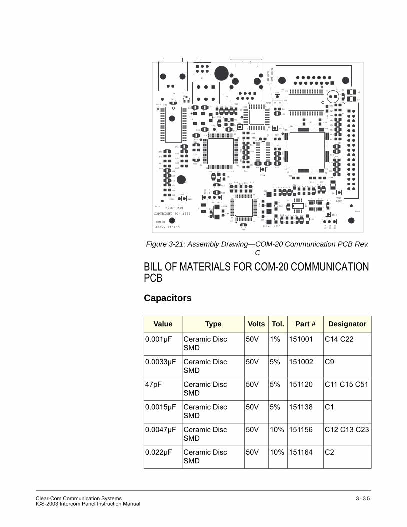
Figure 3-21: Assembly Drawing—COM-20 Communication PCB Rev. C
BILL OF MATERIALS FOR COM-20 COMMUNICATION PCB
Capacitors
Value Type Volts Tol. Part # Designator
0.001µF Ceramic Disc SMD
50V 1% 151001 C14 C22
0.0033µF Ceramic Disc SMD
50V 5% 151002 C9
47pF Ceramic Disc SMD
50V 5% 151120 C11 C15 C51
0.0015µF Ceramic Disc SMD
50V 5% 151138 C1
0.0047µF Ceramic Disc SMD
50V 10% 151156 C12 C13 C23
0.022µF Ceramic Disc SMD
50V 10% 151164 C2
+
19
ASSY# 710435
COPYRIGHT (C) 1999
CLEAR-COM
COM-20 11
GND
21
20
+
44
34
33
12
23
22
40
41
+
8061
60
+
+
54
26
25
+ +
+
37
36
AGND
73
72
12
11
144
18
GND
108
109
1
1
R24 R13R9R10
C49
JP1
J2
IN 2003
OUT 52/92
J5
IC5
M4
R67
R72
R65
M2
R59
R58
R60
R62
R63
R64
R74
FCL2
FCL1
C52
J4
IC1
R38
C44
R68
IC6
R37
TP14
TP29
IC7
R30
C10
TP20
R12
TP23TP21
TP24TP25
L1
X4
TP22
C24
C48
C9
R41
R43
C43
R32
TP3
TP4
TP5
R25 R26 R28C15 R27
C22
C17C19
C31
C11
IC8
R19R29C23 C13C14
C25
C18
C20
C50C16C21
R75
TP18
R35R16
C32
R22R18 R17
L4
C12
R34
R54
M3
FCL3
C8
R46
R47
C33
R49
R50
R51
R52
R53
R48
J1
R45
R44
IC3
IC9
R4C2R3C26
IC4
C1
TP27
C6
R56
R71
R69
R70
R73
C39
C45
C40
R55
C51
R33
C46
R11
C42
R42
C5
C4
C41
TP46
C27
T1
R6
D1
C47
S1
M1
C38
R1
IC2
C28
C3
R40
R39
C29
TP12
C34
C35
R36
C36C37
R2
TP1C7
L3
L2
Clear-Com Communication SystemsICS-2003 Intercom Panel Instruction Manual
3 - 3 5
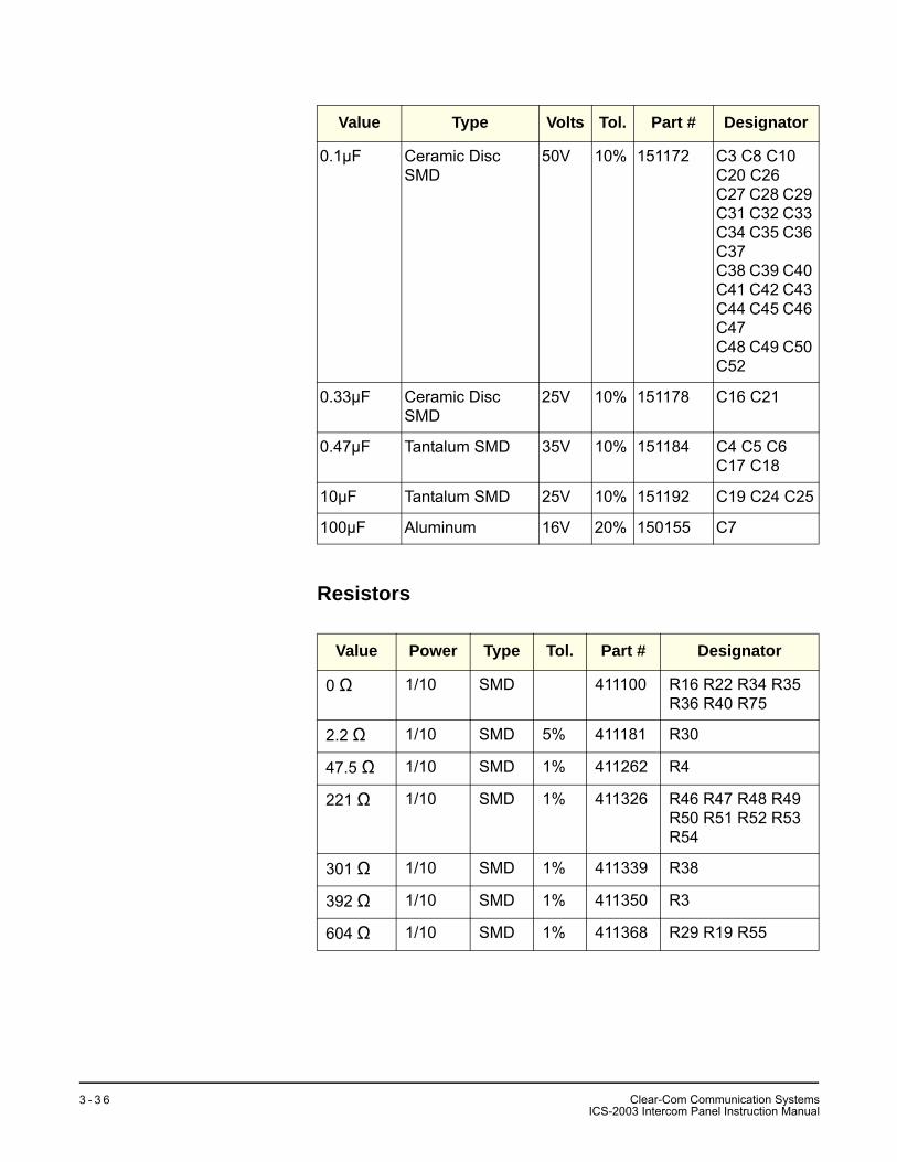
Resistors
0.1µF Ceramic Disc SMD
50V 10% 151172 C3 C8 C10 C20 C26C27 C28 C29 C31 C32 C33 C34 C35 C36 C37C38 C39 C40 C41 C42 C43 C44 C45 C46 C47C48 C49 C50 C52
0.33µF Ceramic Disc SMD
25V 10% 151178 C16 C21
0.47µF Tantalum SMD 35V 10% 151184 C4 C5 C6 C17 C18
10µF Tantalum SMD 25V 10% 151192 C19 C24 C25
100µF Aluminum 16V 20% 150155 C7
Value Power Type Tol. Part # Designator
0 Ω 1/10 SMD 411100 R16 R22 R34 R35 R36 R40 R75
2.2 Ω 1/10 SMD 5% 411181 R30
47.5 Ω 1/10 SMD 1% 411262 R4
221 Ω 1/10 SMD 1% 411326 R46 R47 R48 R49 R50 R51 R52 R53 R54
301 Ω 1/10 SMD 1% 411339 R38
392 Ω 1/10 SMD 1% 411350 R3
604 Ω 1/10 SMD 1% 411368 R29 R19 R55
Value Type Volts Tol. Part # Designator
Clear-Com Communication SystemsICS-2003 Intercom Panel Instruction Manual
3 - 3 6
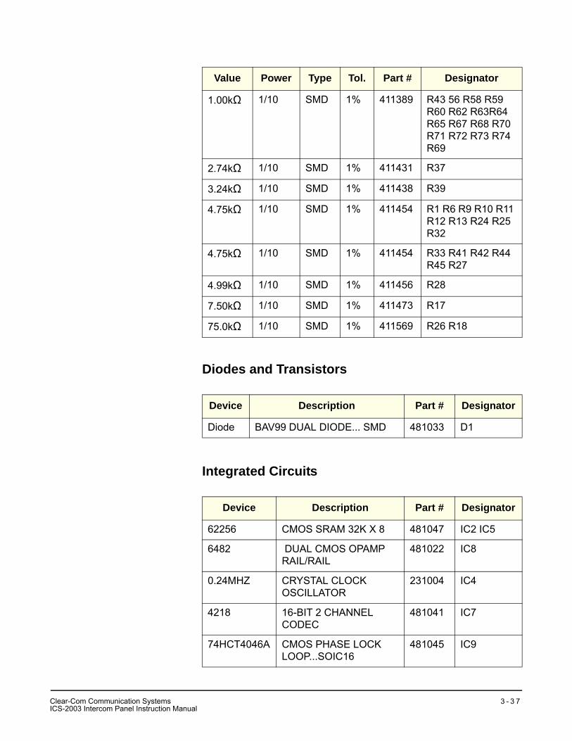
Diodes and Transistors
Integrated Circuits
1.00kΩ 1/10 SMD 1% 411389 R43 56 R58 R59 R60 R62 R63R64 R65 R67 R68 R70 R71 R72 R73 R74 R69
2.74kΩ 1/10 SMD 1% 411431 R37
3.24kΩ 1/10 SMD 1% 411438 R39
4.75kΩ 1/10 SMD 1% 411454 R1 R6 R9 R10 R11 R12 R13 R24 R25 R32
4.75kΩ 1/10 SMD 1% 411454 R33 R41 R42 R44 R45 R27
4.99kΩ 1/10 SMD 1% 411456 R28
7.50kΩ 1/10 SMD 1% 411473 R17
75.0kΩ 1/10 SMD 1% 411569 R26 R18
Device Description Part # Designator
Diode BAV99 DUAL DIODE... SMD 481033 D1
Device Description Part # Designator
62256 CMOS SRAM 32K X 8 481047 IC2 IC5
6482 DUAL CMOS OPAMP RAIL/RAIL
481022 IC8
0.24MHZ CRYSTAL CLOCK OSCILLATOR
231004 IC4
4218 16-BIT 2 CHANNEL CODEC
481041 IC7
74HCT4046A CMOS PHASE LOCK LOOP...SOIC16
481045 IC9
Value Power Type Tol. Part # Designator
CI
lear-Com Communication SystemsCS-2003 Intercom Panel Instruction Manual
3 - 3 7
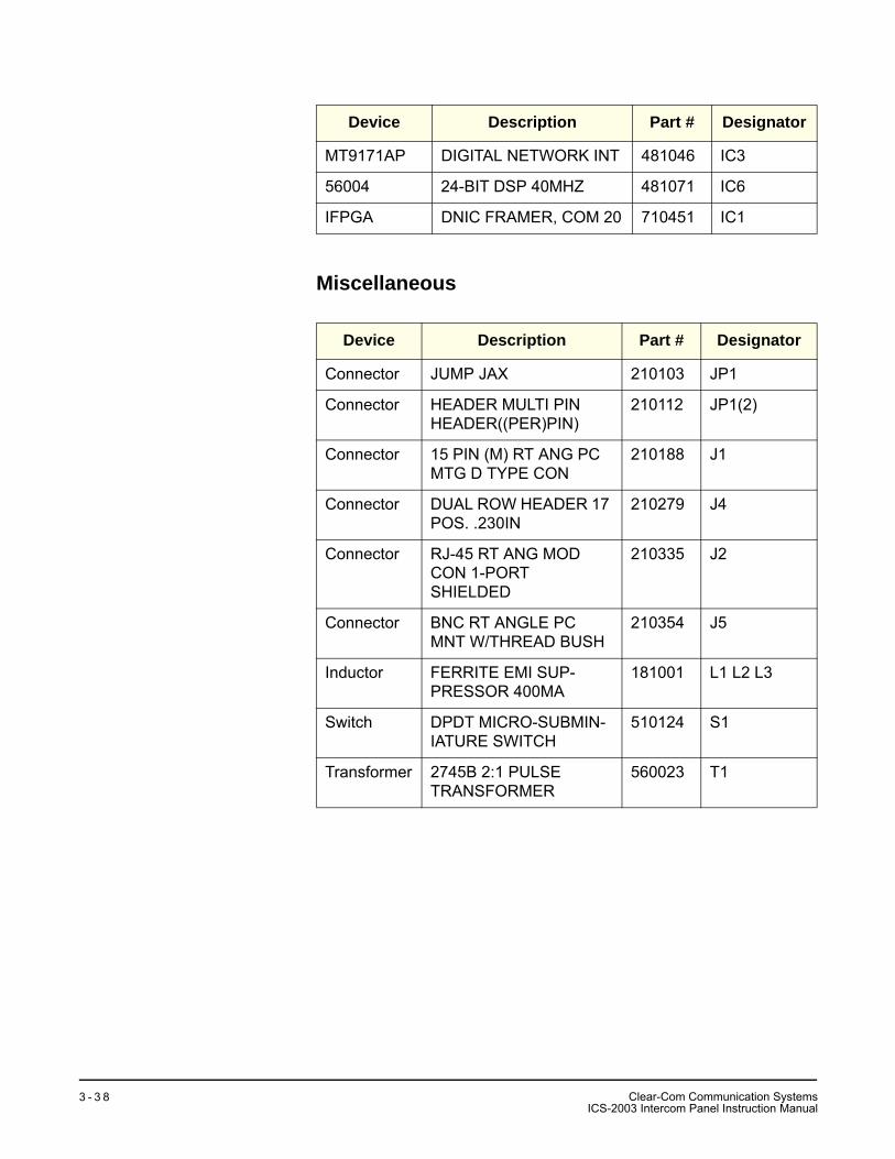
Miscellaneous
MT9171AP DIGITAL NETWORK INT 481046 IC3
56004 24-BIT DSP 40MHZ 481071 IC6
IFPGA DNIC FRAMER, COM 20 710451 IC1
Device Description Part # Designator
Connector JUMP JAX 210103 JP1
Connector HEADER MULTI PIN HEADER((PER)PIN)
210112 JP1(2)
Connector 15 PIN (M) RT ANG PC MTG D TYPE CON
210188 J1
Connector DUAL ROW HEADER 17 POS. .230IN
210279 J4
Connector RJ-45 RT ANG MOD CON 1-PORT SHIELDED
210335 J2
Connector BNC RT ANGLE PC MNT W/THREAD BUSH
210354 J5
Inductor FERRITE EMI SUP-PRESSOR 400MA
181001 L1 L2 L3
Switch DPDT MICRO-SUBMIN-IATURE SWITCH
510124 S1
Transformer 2745B 2:1 PULSE TRANSFORMER
560023 T1
Device Description Part # Designator
Clear-Com Communication SystemsICS-2003 Intercom Panel Instruction Manual
3 - 3 8
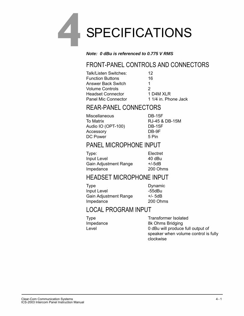
SPECIFICATIONSNote: 0 dBu is referenced to 0.775 V RMS
FRONT-PANEL CONTROLS AND CONNECTORSTalk/Listen Switches: 12Function Buttons 16Answer Back Switch 1Volume Controls 2Headset Connector 1 D4M XLRPanel Mic Connector 1 1/4 in. Phone Jack
REAR-PANEL CONNECTORSMiscellaneous DB-15FTo Matrix RJ-45 & DB-15MAudio IO (OPT-100) DB-15FAccessory DB-9FDC Power 5 Pin
PANEL MICROPHONE INPUTType: ElectretInput Level 40 dBuGain Adjustment Range +/-5dBImpedance 200 Ohms
HEADSET MICROPHONE INPUTType DynamicInput Level -55dBuGain Adjustment Range +/- 5dBImpedance 200 Ohms
LOCAL PROGRAM INPUTType Transformer IsolatedImpedance 8k Ohms BridgingLevel 0 dBu will produce full output of
speaker when volume control is fully clockwise
4
CI
lear-Com Communication SystemsCS-2003 Intercom Panel Instruction Manual
4 - 1
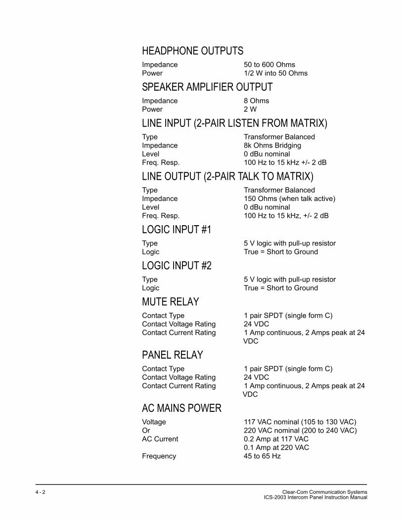
HEADPHONE OUTPUTSImpedance 50 to 600 OhmsPower 1/2 W into 50 Ohms
SPEAKER AMPLIFIER OUTPUTImpedance 8 OhmsPower 2 W
LINE INPUT (2-PAIR LISTEN FROM MATRIX)Type Transformer BalancedImpedance 8k Ohms BridgingLevel 0 dBu nominalFreq. Resp. 100 Hz to 15 kHz +/- 2 dB
LINE OUTPUT (2-PAIR TALK TO MATRIX)Type Transformer BalancedImpedance 150 Ohms (when talk active)Level 0 dBu nominalFreq. Resp. 100 Hz to 15 kHz, +/- 2 dB
LOGIC INPUT #1Type 5 V logic with pull-up resistorLogic True = Short to Ground
LOGIC INPUT #2Type 5 V logic with pull-up resistorLogic True = Short to Ground
MUTE RELAY Contact Type 1 pair SPDT (single form C)Contact Voltage Rating 24 VDCContact Current Rating 1 Amp continuous, 2 Amps peak at 24
VDC
PANEL RELAYContact Type 1 pair SPDT (single form C)Contact Voltage Rating 24 VDCContact Current Rating 1 Amp continuous, 2 Amps peak at 24
VDC
AC MAINS POWERVoltage 117 VAC nominal (105 to 130 VAC)Or 220 VAC nominal (200 to 240 VAC)AC Current 0.2 Amp at 117 VAC
0.1 Amp at 220 VACFrequency 45 to 65 Hz
Clear-Com Communication SystemsICS-2003 Intercom Panel Instruction Manual
4 - 2
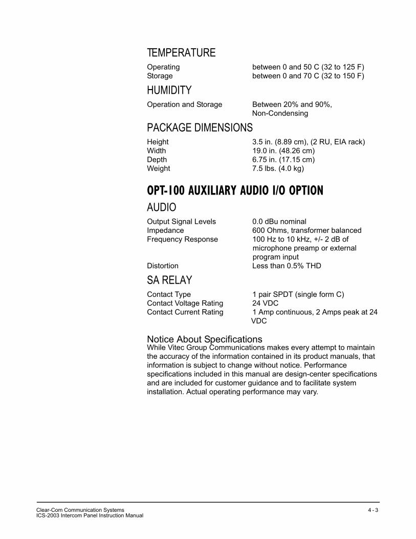
TEMPERATUREOperating between 0 and 50 C (32 to 125 F)Storage between 0 and 70 C (32 to 150 F)
HUMIDITYOperation and Storage Between 20% and 90%,
Non-Condensing
PACKAGE DIMENSIONSHeight 3.5 in. (8.89 cm), (2 RU, EIA rack)Width 19.0 in. (48.26 cm)Depth 6.75 in. (17.15 cm)Weight 7.5 lbs. (4.0 kg)
OPT-100 AUXILIARY AUDIO I/O OPTIONAUDIOOutput Signal Levels 0.0 dBu nominalImpedance 600 Ohms, transformer balancedFrequency Response 100 Hz to 10 kHz, +/- 2 dB of
microphone preamp or external program input
Distortion Less than 0.5% THD
SA RELAY Contact Type 1 pair SPDT (single form C)Contact Voltage Rating 24 VDCContact Current Rating 1 Amp continuous, 2 Amps peak at 24
VDC
Notice About SpecificationsWhile Vitec Group Communications makes every attempt to maintain the accuracy of the information contained in its product manuals, that information is subject to change without notice. Performance specifications included in this manual are design-center specifications and are included for customer guidance and to facilitate system installation. Actual operating performance may vary.
CI
lear-Com Communication SystemsCS-2003 Intercom Panel Instruction Manual
4 - 3

Clear-Com Communication SystemsICS-2003 Intercom Panel Instruction Manual
4 - 4
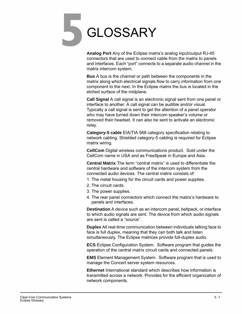
GLOSSARYAnalog Port Any of the Eclipse matrix’s analog input/output RJ-45 connectors that are used to connect cable from the matrix to panels and interfaces. Each “port” connects to a separate audio channel in the matrix intercom system.
Bus A bus is the channel or path between the components in the matrix along which electrical signals flow to carry information from one component to the next. In the Eclipse matrix the bus is located in the etched surface of the midplane.
Call Signal A call signal is an electronic signal sent from one panel or interface to another. A call signal can be audible and/or visual. Typically a call signal is sent to get the attention of a panel operator who may have turned down their intercom speaker’s volume or removed their headset. It can also be sent to activate an electronic relay.
Category-5 cable EIA/TIA 568 category specification relating to network cabling. Shielded category-5 cabling is required for Eclipse matrix wiring.
CellCom Digital wireless communications product. Sold under the CellCom name in USA and as FreeSpeak in Europe and Asia.
Central Matrix The term “central matrix” is used to differentiate the central hardware and software of the intercom system from the connected audio devices. The central matrix consists of:1. The metal housing for the circuit cards and power supplies.2. The circuit cards.3. The power supplies.4. The rear panel connectors which connect the matrix’s hardware to
panels and interfaces.Destination A device such as an intercom panel, beltpack, or interface to which audio signals are sent. The device from which audio signals are sent is called a “source”.
Duplex All real-time communication between individuals talking face to face is full duplex, meaning that they can both talk and listen simultaneously. The Eclipse matrices provide full-duplex audio.
ECS Eclipse Configuration System. Software program that guides the operation of the central matrix circuit cards and connected panels.
EMS Element Management System. Software program that is used to manage the Concert server system resources.
Ethernet International standard which describes how information is transmitted across a network. Provides for the efficient organization of network components.
5
CE
lear-Com Communication Systemsclipse Glossary
5 - 1
Fiber-optic Cable A fiber-optic cable consists of a glass core covered with a reflective material called “cladding” and several layers of buffer coating to protect the cable from the environment. A laser sends light pulses through the glass core to the other end of the cable.
FreeSpeak Digital wireless communications product. Sold under the FreeSpeak name in Europe and Asia and CellCom in USA.
Full Duplex Refers to transmission of signals in two directions simultaneously.
IFB “Interruptible Foldback”. The term “foldback” refers to sending “program” audio, or some other audio mix, back to announcers while they are on the air. Doing so allows announcers to monitor themselves, other announcers, videotapes of commercials, or some mix of sources, while they on the air. This is typically found in television news and live broadcast events.
Announcers typically wear a small ear piece so they can hear the selected foldback audio mix. When a director wants to give directions to an announcer on air, or to announce changes in the program, the director must “interrupt” the foldback. To do this, the director uses a channel specifically set up to interrupt the foldback audio.
Interface Module A piece of electronic hardware designed to convert the 4-wire signals of a central matrix port to some other form of communication, such as 2-wire party line, telephone, etc. The interface module is connected to a central matrix port. The external non-4-wire device is then connected to the interface module.
ISO The ISO function, short for “panel ISOlation”, allows a panel operator to call a destination and interrupt all of that destination’s other audio paths and establish a private conversation. When the call is completed the destination’s audio pathways are restored to their original state before the interruption.
IV-R Instant Voice Router. Software that routes digital audio data between Concert users and between Concert users and Eclipse systems.
Label A label is an alphanumeric name of up to five characters that identifies a source, destination, or control function accessed by an intercom panel. Labels appear in the displays of the intercom panel. Labels can identify panels, ports interfaced to other external equipment, fixed groups, party lines, and special control functions.
Mode A term used to describe a light path through a fiber as in multimode or single mode.
Multimode Fiber-optic Cable The glass core of a multimode fiber is larger than the core of a single mode fiber, which causes the transmitted light beam to disperse as it travels through the core. Single mode fiber, with its smaller core, concentrates the light beam so that it carries signals further. Multimode fiber was the first type of fiber offered
Clear-Com Communication SystemsEclipse Glossary
5 - 2
by manufacturers. Single-mode fiber evolved as production methods improved.
Multiplexing The process by which two or more signals are transmitted over a single communications channel. Examples include time division and wavelength division multiplexing.
Nanometer (nm) Common unit of measure for wavelength. One billionth of a meter.
Non-volatile Memory Data stored in the CPU’s firmware (ROM) that is not lost when the power is turned off.
Optical Signal A laser at one end of a fiber-optic cable pulses on or off to send a light signal through the glass core of the cable to the other end of the cable. Because the light signals are binary (on or off), the signal is digital.
Panel Also referred to as “station” in some cases (usually older manuals). Any intelligent intercom device connected to the rear-panel analog ports of the central matrix. This term does not refer to devices connected through interface modules.
Port Any of the input/output connections (RJ-45 connectors) on the back panel of the central matrix. These connectors and the attached cables connect the central matrix to remote intercom devices. The term “port” emphasizes that the connection is a “portal” between the central matrix and the remote intercom devices.
Program Any separate audio source that is fed into the intercom channels. In television applications, for example, “program” audio is the audio that is broadcast on air.
Rack Unit or RU Standardized unit of mounting space on a rack panel. Each rack unit is 1.75 inches (44.45 mm) of vertical mounting space. Therefore 1 RU is 1.75 inches (44.45 mm) of vertical mounting space, 2 RU is 3.5 inches (88.9 mm), 3 RU is 5.25 inches (133.35 mm), and so on.
Remote Panel Any intelligent intercom device connected to the back-panel ports of the central matrix. This term does not refer to devices connected through interfaces.
Sidetone The sound of the panel operator’s own voice heard in their own earphone as they speak.
Single-mode Fiber-optic Cable The glass core of a single-mode fiber is smaller in diameter than the core of a multimode fiber, so that the light signal transmitted over the core is more concentrated than with multimode fiber, which allows the signal to travel further. Single-mode fiber evolved from multimode fiber as production methods improved. Source In this manual, the term “source” refers to a device—such as an intercom panel, interface, or beltpack —that sends audio into the matrix. The device to which audio is sent is called a “destination”.
CE
lear-Com Communication Systemsclipse Glossary
5 - 3
VOX In the Eclipse system, when audio at a panel exceeds a threshold, a light switches on at the panel’s port card to visually cue the operator. The threshold level is set in the Eclipse Configuration Software.
V-Series Communications panels used with Eclipse systems providing advanced facilities. Available in rack mount and desktop formats.
Wavelength-division Multiplexing (WDM) A method of multiplexing optical signals developed for use on fiber-optic cable. Each signal is assigned a particular wavelength on the light spectrum and therefore many signals can be transmitted simultaneously without interfering with each other.
Clear-Com Communication SystemsEclipse Glossary
5 - 4
ECLIPSE MANUALSThe following manuals are available covering Eclipse products and accessories.
SOFTWARE MANUALSEclipse Configuration System (ECS) Instruction Manual - 810299Z
Eclipse Logic Maestro Instruction Manual - 810414Z
Eclipse Production Maestro Quick Start Guide - 810409Z
Eclipse Production Maestro Installation and User Guide - 810410Z
Eclipse DECTSync Manual - 810412Z
Eclipse Host Computer Interface (HCI) Manual - 810413Z
HARDWARE MANUALSEclipse Omega Matrix Instruction Manual - 810290Z
Eclipse Median Matrix Instruction Manual - 810347Z
Eclipse PiCo Matrix Instruction Manual - 810348Z
Eclipse-32 Matrix Instruction Manual - 810315Z
Eclipse Matrix Installation Manual - 810298Z
Eclipse Upgrade Reference Manual - 810377Z
Eclipse V-Series Panels User Manual - 810365Z
Eclipse FOR-22 4-Wire Interface Instruction Manual - 810306Z
Eclipse CCI-22 Party Line Interface Instruction Manual - 810307Z
Eclipse TEL-14 Telephone Interface Instruction Manual - 810308Z
Eclipse GPI-6 General Purpose Inputs Instruction Manual - 810309Z
Eclipse RLY-6 General Purpose Outputs Instruction Manual - 810310Z
DIG-2 Digital Interface Instruction Manual - 810311Z
IMF-3, IMF-102, DIF-102 Interface Module Frame Instruction Manual - 810313Z
Eclipse AES-6 Digital Interface Instruction Manual - 810383Z
Eclipse BAL-8 Isolation Interface Instruction Manual - 810403Z
Eclipse V-Series AES-3 Option Card Installation Instructions - 810388Z
Eclipse V-Series XLR-7M Upgrade Instructions - 810405Z
Eclipse V-Series T-Adapter Installation Instructions - 810406Z
Eclipse FIM-202D Fiber Interface Instruction Manual - 810385Z
CE
lear-Com Communication Systemsclipse Manuals
5 - 5
Eclipse FIM-102 Fiber Interface Instruction Manual - 810319Z
Eclipse FIM-108 Fiber Interface Instruction Manual - 810291Z
Eclipse IFB-104 Interface Instruction Manual - 810268Z
Eclipse 4000 Series II Panels Installation Guide - STA0530Z
Eclipse 4000 Series II Panels User Guide - STA0531Z
Eclipse ICS 1008E/1016E Panels Instruction Manual - 810404Z
Eclipse ICS 102/62 Panels Instruction Manual - 810302Z
Eclipse ICS 2003 Panel Instruction Manual 810303Z
Eclipse ICS 92/52 Panels Instruction Manual - 810301Z
Eclipse i-Station Instruction Manual - 810305Z
Eclipse ICS-21 Speaker Panel Instruction Manual - 810263Z
Eclipse ICS-22 Speaker Panel Instruction Manual - 810264Z
Eclipse ICS-24 Headset Panel Instruction Manual - 810265Z
Eclipse Digital Wireless Beltpack Instruction Manual - 810376Z
Clear-Com Communication SystemsEclipse Manuals
5 - 6
LIMITED WARRANTYThis document details the Clear-Com Standard Limited Warranty for all new products for sale within all regions with the exception of Military, Aerospace, and Government (MAG).
EXCEPT AS SET FORTH HEREIN ("LIMITED WARRANTY"), CLEAR-COM MAKES NO OTHER WARRANTIES, EXPRESS, IMPLIED OR STATUTORY, INCLUDING WITHOUT LIMITATION ANY WARRANTIES OF MERCHANTABILITY, NONINFRINGEMENT OF THIRD PARTY RIGHTS, OR FITNESS FOR A PARTICULAR PURPOSE, ALL OF WHICH ARE EXPRESSLY DISCLAIMED.
1. Standard Limited Warranty. Clear-Com Communication Systems ("Clear-Com") warrants its products, including supplied accessories, against defects in material or workmanship for the time periods as set forth below provided it was purchased from an authorized Clear-Com dealer or distributor.
a) Pursuant to this Limited Warranty, Clear-Com will, at its option:
i) repair the product using new or refurbished parts, or;
ii) replace the product with a new or refurbished product.
b) Remedies: In the event of a defect, the rights detailed in 1 (a) are your exclusive remedies. For purposes of this Limited Warranty, "refurbished" means a product or part that has been returned to its original specifications.
c) Standard Warranty Period (by Product):
i) All Clear-Com brand systems and products, including belt packs, have a Limited Warranty of two years, with the exception of;
(1) Cables, accessories, components & consumable items have a Limited Warranty of 90 days.
(2) Any Clear-Com product that has been classified as obsolete at the time of sale has a Limited Warranty of 90 days from sales and will be replaced with the same product or a sales credit will be issued, at the sole discretion of Clear-Com.
(3) Headsets, handsets, microphones, and associated spare parts, as well as UHF wireless IFB products, have a Limited Warranty of one year.
(4) UHF WBS Analog wireless intercom systems have a Limited Warranty of three years.
Clear-Com Communication SystemsStandard Limited Warranty
i
(5) All software products, including Concert (Client and Server), ECS, Production Maestro and Logic Maestro are warranted for one year and shall substantially conform to published specifications. The media on which the Software is furnished is warranted to be free of defects in material and workmanship (under normal use) for a period of one year.
(6) Any Clear-Com products that are listed within the last time buy period have the same Limited Warranty for their type 1.i 1 - 1.i.5 as above.
d) Any Clear-Com product that is repaired or supplied as a replacement under the terms of this Limited Warranty shall inherit the remaining warranty period from the original product.
e) Standard Warranty Period Start Date
i) Dealer / Distributor Sales: In view of Dealer or Distributor stocking practices, the Standard Warranty Period for products sold through Dealers or Distributors will commence from the Clear-Com invoice date and will include an automatic extension of three months. Any valid warranty claim within the Standard Warranty Period as determined by the Clear-Com invoice date will be covered without further supporting evidence. All warranty claims after this date must be supported by the Customer's proof of purchase that demonstrates the product is still within the Standard Warranty Period (as detailed in Section 1.c.i above, plus the automatic three month extension) from their purchase date.
ii) Direct Sales: The Standard Warranty Period will commence from the date the product was shipped from Clear-Com to the Customer. The Standard Warranty Period start date for contracts that include commissioning will be the date of the Site Acceptance Test (SAT) or one month from conclusion of the commissioning project, whichever is earlier.
f) Invalidation of Warranty
i) This Limited Warranty shall be invalidated if the product's outer case has been opened and internal modifications have been made or damage has occurred, or upon the occurrence of other damage or failure not attributable to normal wear and tear. Authorized modifications with Clear-Com's express written permission will not invalidate the warranty.
g) Software Updates
i) Software Updates are released periodically to correct discovered program bugs. During the Warranty Period, software updates are available to Customers free of charge.
Clear-Com Communication SystemsStandard Limited Warranty
i i
h) Software Upgrades
i) Software Upgrades include new Features and/or Functional Enhancements and are not included as part of the Standard Warranty but may be purchased at the published rates.
ii) Note: In the absence of a Software Update containing a program correction and no available workaround to mitigate the problem, at the discretion of Service, Sales, Engineering, or Product Management, the Customer may be provided a Software Upgrade under warranty.
2. Exclusions. Services do not cover damage or failure caused by any occurrence beyond Clear-Com's reasonable control, including without limitation acts of God, fire, flooding, earthquake, lightning, failure of electric power or air conditioning, neglect, misuse, improper operation, war, government regulations, supply shortages, riots, sabotage, terrorism, unauthorized modifications or repair, strikes, labor disputes or any product failure that Clear-Com determines is not a result of failure in the Services provided by Clear-Com. Further Services excluded from this Agreement include: services required due to errors or omissions in Customer purchase orders; installation or maintenance of wiring, circuits, electrical conduits or devices external to the products; replacement or reconditioning of products which, in Clear-Com's opinion cannot be reliably maintained or properly serviced due to excessive wear or deterioration; Customer's failure to maintain the installation site in accordance with the environmental specifications of the products; or service on products removed from the location originally specified by Customer and/or reinstalled without the prior written approval of Clear-Com. Customer will pay Clear-Com's then current published charges to restore such Covered Products to a condition eligible for further service under this Agreement. Clear-Com shall be excused from and shall not be liable for any failure or delay in performance under this Agreement due to the foregoing or any causes beyond its reasonable control.
3. Limitation of Liability. IN NO EVENT WILL CLEAR-COM BE LIABLE UNDER THIS AGREEMENT FOR ANY INDIRECT, SPECIAL, INCIDENTAL OR CONSEQUENTIAL DAMAGES (INCLUDING WITHOUT LIMITATION LOST PROFITS), REGARDLESS OF THE FORM OF ACTION, EVEN IF ADVISED IN ADVANCE OF THE POSSIBILITY OF SUCH DAMAGES.
4. Assignment. Neither party may assign this Agreement or any portion thereof without the prior written consent of the other, except in the event of a merger, sale of all or substantially all of the assets or other corporate reorganization.
5. Ownership of replaced parts or product. All replaced parts or products become the property of Clear-Com.
6. Entire Agreement. This Agreement constitutes the entire agreement between the parties with respect to the subject matter hereof, and supersedes all prior or contemporaneous proposals, oral or written, and all other communications between them relating to the subject matter of this Agreement.
Clear-Com Communication SystemsStandard Limited Warranty
i i i

Clear-Com Communication SystemsStandard Limited Warranty
i v

TECHNICAL SUPPORT & REPAIR POLICY
NOVEMBER 1, 2008In order to ensure that your experience with Clear-Com and our World Class products is as beneficial, effective and efficient as possible, we would like to define the policies and share some "best practices" that can accelerate any problem solving processes which we may find necessary and to enhance your customer service experience. Our Technical Support, Return Material Authorization, and Repair Policies are set forth below. These Policies are subject to revision and constantly evolve in order to address our Customers' and the Market's needs. Accordingly these are provided by way of guidance and for information only and may be changed at anytime with or without Notice.
TECHNICAL SUPPORT POLICY
a) Telephone, online, and e-mail technical support will be provided by the Customer Service Center free of charge during the Warranty Period.
b) Technical support will be provided free of charge for all software products under the following conditions:
i) The application, operating, and embedded software is installed on a product covered by Clear-Com's Limited Warranty, and:
(1) The software is at the current release level; or,
(2) The software is one (1) version removed from current.
ii) Older versions of software will receive "best-effort" support, but will not be updated to correct reported bugs or add requested functionality.
c) For Technical Support:
i) North and South America, (inc. Canada, Mexico, and the Caribbean) & US Military:Hours: 0800 - 1700 Pacific TimeDays: Monday - FridayTel: +1 510 337 6600Email: [email protected]
ii) Europe, the Middle East and Africa:Hours: 0800 - midnight Central European Time
Clear-Com Communication SystemsTechnical Support & Repair Policy
v
Days: Monday - FridayTel: +49 40 853 999 700Email: [email protected]
iii) Asia-Pacific:Hours: 0800 - 1700 Pacific TimeDays: Monday - FridayTel: +1 510 337 6600Email: [email protected]
d) Email Technical Support is available for all Clear-Com branded products free of charge for the life of the product, or two years after a product has been classified as obsolete, whichever comes first.
e) Support for Distributor and Dealer Sales
i) Distributors and Dealers may utilize the Customer Service Centers once a system has been installed and commissioned. Clear-Com Systems and Applications Engineers will provide support to the Distributor from the pre-sales stage through to satisfactory installation for new system purchases. Customers will be encouraged to contact their Dealer or Distributor with their installation and technical support enquires rather than using the Customer Service Centers directly.
f) Support for Direct Sales
i) Customers may utilize the Customer Service Centers once a system has been installed and commissioned by Clear-Com Systems and Applications Engineers, or in the case of project installations, once the Project Team has completed the hand-over to the Support Centers.
RETURN MATERIAL AUTHORIZATION POLICY
a) Authorizations: All products returned to Clear-Com or a Clear-Com Authorized Service Partner must be identified by a Return Material Authorization (RMA) number.
b) The Customer will be provided with an RMA number upon contacting Clear-Com Sales Support as instructed below.
c) The RMA number must be obtained from Clear-Com via phone or email prior to returning product
to the Service Center. Product received by the Service Center without a proper RMA number is subject to return to the Customer at the Customer's expense.
Clear-Com Communication SystemsTechnical Support & Repair Policy
v i
d) Damaged equipment will be repaired at the Customer's expense.
e) Returns are subject to a 15% restocking fee.
f) Advance Warranty Replacements (AWRs);
i) During the first 30 days of the Standard Warranty Period: Once the equipment fault has been verified by Clear-Com or its authorized representative, Clear-Com will ship a new replacement product. The Customer will be provided with an RMA number and be required to return the faulty equipment within 14 days of receipt of the replacement or will be invoiced for the list price of a new product.
ii) During days 31-90 of the Standard Warranty Period: Once the equipment fault has been verified by Clear-Com or its authorized representative, Clear-Com will ship a like-new, fully refurbished replacement product. The Customer will be provided with an RMA number and be required to return the faulty equipment within 14 days of receipt of the replacement or will be invoiced for the list price of a new product.
iii) To obtain an RMA number or request an AWR:
(1) North and South America, Asia-Pacific, and US Military:Hours: 0800 - 1700 Pacific TimeDays: Monday - FridayTel: +1 510 337 6600Email: [email protected]
(2) Europe, the Middle East and Africa:Hours: 0800 - 1700 GMT + 1Days: Monday - FridayTel: + 44 1223 815000Email: [email protected]
iv) Note: AWRs are not available for UHF WBS Analog wireless intercom systems. UHF WBS Analog wireless intercom systems out-of-box failures must be returned to Alameda for repair.
v) Note: Out-of-box failures returned after 90 days will be repaired and not replaced unless approved by Clear-Com Management.
vi) Note: AWRs are not available after 90 days of receipt of product unless an AWR Warranty Extension is purchased at the time of product purchase.
Clear-Com Communication SystemsTechnical Support & Repair Policy
v i i
vii) Note: Shipping charges, including duties, taxes, and insurance (optional), to Clear-Com's factory is the responsibility of the Customer. Shipping AWRs from Clear-Com is at Clear-Com's expense (normal ground or international economy delivery). Requests for expedited shipping (E.g. "Next-Day Air") and insurance are the responsibility of the Customer.
REPAIR POLICYa) Repair Authorizations: All products sent to Clear-Com or a Clear-Com Authorized Service Partner
for repair must be identified by a Repair Authorization (RA) number (see above).
b) The Customer will be provided with an RA number upon contacting Clear-Com Customer Services as instructed below.
c) The RA number must be obtained from Clear-Com via phone or email prior to returning product to the Service Center. Product received by the Service Center without a proper RA number is subject to return to the Customer at the Customer's expense.
d) Return for Repair
i) Customers are required to ship equipment at their own cost (including transportation, packing, transit, insurance, taxes and duties) to Clear-Com's designated location for repair.
(1) Clear-Com will pay for the equipment to be returned to the Customer when it is repaired under warranty.
(2) Shipping from Clear-Com is normal ground delivery or international economy. Requests for expedited shipping (E.g. "Next-Day Air") and insurance are the responsibility of the Customer.
ii) Clear-Com does not provide temporary replacement equipment ("loaner") during the period the product is at the factory for repair. Customers should consider a potential prolonged outage during the repair cycle, and if required for continuous operations purchase minimum spare equipment required or purchase an AWR Warranty Extension.
iii) No individual parts or subassemblies will be provided under warranty, and warranty repairs will be completed only by Clear-Com or its Authorized Service Partners.
iv) Customers requesting a non-warranty repair will be provided an estimate of the total repair cost prior to the return of the equipment. In the event that Clear-Com is unable to estimate
Clear-Com Communication SystemsTechnical Support & Repair Policy
v i i i
the cost of repair, the Customer may elect to return the product to the factory for an estimate. The Customer is responsible for shipping costs both to and from the factory in the event they choose not to accept the estimate.
v) The Customer must provide either a purchase order for the repair work, or will be required to make an advance payment (as a debit against the Dealer's line of credit, or credit card) prior to the repaired product being returned to the Customer.
vi) For requesting a Repair Authorization number:
(1) North and South America, Asia-Pacific, and US Military:Hours: 0800 - 1700 Pacific TimeDays: Monday - FridayTel: +1 510 337 6600Email: [email protected]
(2) Europe, the Middle East and Africa:Hours: 0800 - midnight Central European TimeDays: Monday - FridayTel: +49 40 853 999 700Email: [email protected]
vii) Note: Clear-Com's Limited Warranty does not cover normal wear and tear. The Customer will be charged the full cost of the repair if their equipment has been tampered with by non-approved personnel, or has been subject to damage through electrical failure, liquid damage or mishandling. The Customer Service Center will provide the Customer with a cost estimate for any such repairs prior to undertaking the work.
Clear-Com Communication SystemsTechnical Support & Repair Policy
i x