Embed Size (px)
Citation preview
Ersa GmbHLeonhard-Karl-Str. 2497877 Wertheim/Germanywww.ersa.com
Phone +49 9342/800-0Fax +49 9342/[email protected]
i‑CON VARIO 4Multi-channelSoldering & Desoldering Station
Operating Instructions
2 3BA00206 • 2016-08-11 • Rev. 2 Ersa i-CON VARIO 4
Table of Contents
Table of Contents
1. Introduction ............................................................................................................................... 51.1 Supply unit ................................................................................................................................. 5
2. Technical data............................................................................................................................. 6
3. Concerning your safety ............................................................................................................... 93.1 Explanations on pictograms and symbols .................................................................................. 93.2 Safety instructions ................................................................................................................... 103.3 Intended use ............................................................................................................................ 123.4 National and international regulations .................................................................................... 12
4. Transport, storage, waste disposal ........................................................................................... 134.1 Transport and storage ............................................................................................................. 134.2 Waste disposal ......................................................................................................................... 13
5. Commissioning ......................................................................................................................... 145.1 Before start-up ........................................................................................................................ 145.2 Description ............................................................................................................................... 145.3 Switching on the first time ....................................................................................................... 15
6. Functional description .............................................................................................................. 176.1 Operation ..................................................................................................................................176.2 The work mode .........................................................................................................................17
6.2.1 microSD-card ................................................................................................................ 186.2.1.1 Insert a microSD-card .................................................................................... 18
6.2.2 Software version .......................................................................................................... 186.2.3 Activating tools ............................................................................................................. 186.2.4 Working with the i-TOOL AIR S ..................................................................................... 196.2.5 Working with the CHIP TOOL VARIO ............................................................................. 216.2.6 Working with the X-TOOL ............................................................................................. 226.2.7 Working with the X-TOOL VARIO .................................................................................. 23
6.2.7.1 Before first commissioning ............................................................................ 236.2.7.2 Selection of the right desoldering temperature ............................................. 236.2.7.3 Desoldering with X-TOOL VARIO .................................................................... 246.2.7.4 Maintenance and servicing ............................................................................ 24
6.2.8 Working with the VAC PEN ........................................................................................... 266.2.9 Setting heating stage of heating plate .......................................................................... 266.2.10 Working with the heating plate .................................................................................... 27
6.2.10.1 Power values of the heating plate .................................................................. 276.3 Parameter mode ...................................................................................................................... 28
6.3.1 i-SET TOOL .................................................................................................................... 286.3.2 Nominal temperature ................................................................................................... 29
33BA00206 • 2016-08-11 • Rev. 2Ersa i-CON VARIO 4
Table of Contents
6.3.3 Calibration temperature ............................................................................................... 296.3.4 Setting the size of the hot air nozzle i-TOOL AIR S ........................................................ 306.3.5 Tip offset ...................................................................................................................... 306.3.6 Calibrating the i-CON VARIO 2 .......................................................................................316.3.7 Determining the calibration temperature .....................................................................316.3.8 Energy ........................................................................................................................... 326.3.9 Standby period ............................................................................................................. 326.3.10 Standby temperature ................................................................................................... 32
6.4 Configuration mode ................................................................................................................. 336.4.1 Temperature window ................................................................................................... 336.4.2 Process alarm ............................................................................................................... 346.4.3 Password protection..................................................................................................... 346.4.4 Setting the password .................................................................................................... 346.4.5 Changing the password ................................................................................................ 356.4.6 Password forgotten ...................................................................................................... 356.4.7 Temperature unit .......................................................................................................... 366.4.8 Language selection ....................................................................................................... 366.4.9 Adjustable shut-down function (idle state) .................................................................. 366.4.10 Heating plate ................................................................................................................ 37
6.4.10.1 Connecting heating plate to soldering station ............................................... 376.4.10.2 Activating the heating plate ........................................................................... 37
6.4.11 Activating the soldering fume extraction ..................................................................... 376.4.12 Activating VAC PEN Mode ............................................................................................. 37
6.5 Factory settings (“Default”) ..................................................................................................... 386.6 Contrast ................................................................................................................................... 396.7 Changing soldering tips ............................................................................................................ 40
6.7.1 i-TOOL ........................................................................................................................... 406.7.1.1 Changing the soldering tip on the i-TOOL ...................................................... 406.7.1.2 Replacing the soldering tip in the soldering tip fastening ...............................41
6.7.2 Changing the hot air nozzle i-TOOL AIR S .......................................................................416.7.3 Changing desoldering tips X-TOOL ................................................................................ 426.7.4 Changing desoldering tips of X-TOOL VARIO................................................................. 426.7.5 Replacing the CHIP TOOL VARIO heating element ........................................................ 436.7.6 Replacing the i-TOOL HP tip .......................................................................................... 43
6.8 Changing a heating element .................................................................................................... 446.8.1 Changing the i-TOOL heating element .......................................................................... 446.8.2 Changing the i-TOOL AIR S heating element ................................................................. 446.8.3 Changing the CHIP TOOL heating element ................................................................... 446.8.4 Changing the X-TOOL heating element ......................................................................... 456.8.5 Changing the CHIP TOOL VARIO heating element ........................................................ 456.8.6 Replacing the heating head .......................................................................................... 456.8.7 Changing the i-TOOL HP heating element .................................................................... 45
6.9 Replacing the filter of the X-TOOL ........................................................................................... 476.10 Changing the prefilter .............................................................................................................. 486.11 Sensitive components .............................................................................................................. 49
4 3BA00206 • 2016-08-11 • Rev. 2 Ersa i-CON VARIO 4
7. Error diagnosis and remedy ...................................................................................................... 507.1 General errors .......................................................................................................................... 507.2 Other faults .............................................................................................................................. 50
7.2.1 Continuity test for i-TOOL ............................................................................................. 507.2.1.1 Heating element ............................................................................................. 507.2.1.2 Thermocouple .................................................................................................51
7.2.2 Continuity test for CHIP TOOL VARIO ............................................................................517.2.3 Continuity test for i-TOOL AIR S .....................................................................................517.2.4 Continuity test for X-TOOL ............................................................................................ 52
7.2.4.1 Heating element ............................................................................................. 527.2.4.2 Thermocouple ................................................................................................ 52
7.2.5 Continuity test for X-TOOL VARIO ................................................................................. 537.2.5.1 Heating element ............................................................................................. 53
7.2.6 Continuity test for i-TOOL HP ....................................................................................... 537.2.6.1 Heating element ............................................................................................. 537.2.6.2 Thermal sensor ............................................................................................... 54
7.2.7 Parameter changes not possible .................................................................................. 547.3 Error Messages ........................................................................................................................ 55
8. Maintenance and cleaning ........................................................................................................ 568.1 Important service work ........................................................................................................... 568.2 Cleaning ................................................................................................................................... 568.3 Replacing the air filter .............................................................................................................. 56
9. Spare parts, accessories ............................................................................................................ 579.1 ERSADUR Permanent soldering tips ......................................................................................... 59
10. Warranty .................................................................................................................................. 60
53BA00206 • 2016-08-11 • Rev. 2Ersa i-CON VARIO 4
Introduction
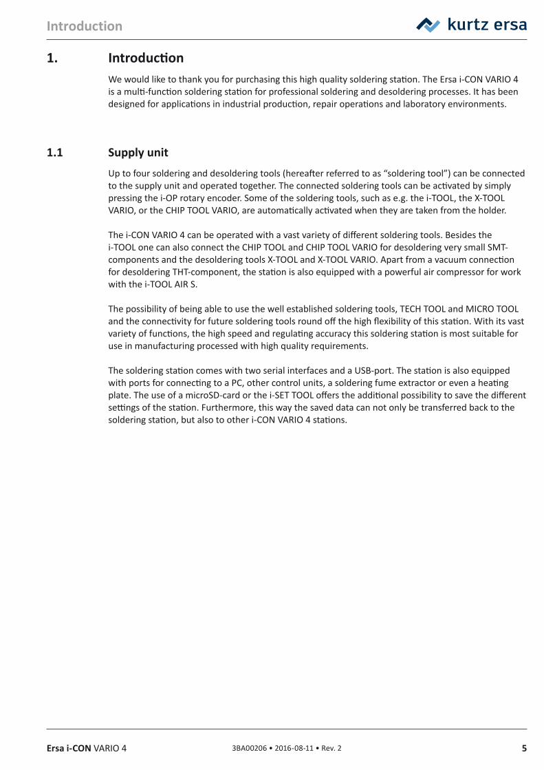
1. IntroductionWe would like to thank you for purchasing this high quality soldering station. The Ersa i-CON VARIO 4 is a multi-function soldering station for professional soldering and desoldering processes. It has been designed for applications in industrial production, repair operations and laboratory environments.
1.1 Supply unitUp to four soldering and desoldering tools (hereafter referred to as “soldering tool”) can be connected to the supply unit and operated together. The connected soldering tools can be activated by simply pressing the i-OP rotary encoder. Some of the soldering tools, such as e.g. the i-TOOL, the X-TOOL VARIO, or the CHIP TOOL VARIO, are automatically activated when they are taken from the holder.
The i-CON VARIO 4 can be operated with a vast variety of different soldering tools. Besides the i-TOOL one can also connect the CHIP TOOL and CHIP TOOL VARIO for desoldering very small SMT-components and the desoldering tools X-TOOL and X-TOOL VARIO. Apart from a vacuum connection for desoldering THT-component, the station is also equipped with a powerful air compressor for work with the i-TOOL AIR S.
The possibility of being able to use the well established soldering tools, TECH TOOL and MICRO TOOL and the connectivity for future soldering tools round off the high flexibility of this station. With its vast variety of functions, the high speed and regulating accuracy this soldering station is most suitable for use in manufacturing processed with high quality requirements.
The soldering station comes with two serial interfaces and a USB-port. The station is also equipped with ports for connecting to a PC, other control units, a soldering fume extractor or even a heating plate. The use of a microSD-card or the i-SET TOOL offers the additional possibility to save the different settings of the station. Furthermore, this way the saved data can not only be transferred back to the soldering station, but also to other i-CON VARIO 4 stations.
6 3BA00206 • 2016-08-11 • Rev. 2 Ersa i-CON VARIO 4
Technical data
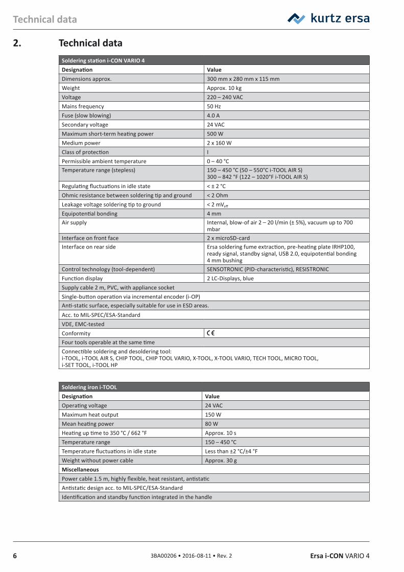
2. Technical dataSoldering station i‑CON VARIO 4Designation ValueDimensions approx. 300 mm x 280 mm x 115 mmWeight Approx. 10 kgVoltage 220 – 240 VACMains frequency 50 HzFuse (slow blowing) 4.0 ASecondary voltage 24 VACMaximum short-term heating power 500 WMedium power 2 x 160 W Class of protection IPermissible ambient temperature 0 – 40 °CTemperature range (stepless) 150 – 450 °C (50 – 550°C i-TOOL AIR S)
300 – 842 °F (122 – 1020°F i-TOOL AIR S)Regulating fluctuations in idle state < ± 2 °COhmic resistance between soldering tip and ground < 2 OhmLeakage voltage soldering tip to ground < 2 mVeff
Equipotential bonding 4 mmAir supply Internal, blow-of air 2 – 20 l/min (± 5%), vacuum up to 700
mbarInterface on front face 2 x microSD-cardInterface on rear side Ersa soldering fume extraction, pre-heating plate IRHP100,
ready signal, standby signal, USB 2.0, equipotential bonding 4 mm bushing
Control technology (tool-dependent) SENSOTRONIC (PID-characteristic), RESISTRONICFunction display 2 LC-Displays, blueSupply cable 2 m, PVC, with appliance socketSingle-button operation via incremental encoder (i-OP)Anti-static surface, especially suitable for use in ESD areas.Acc. to MIL-SPEC/ESA-StandardVDE, EMC-testedConformityFour tools operable at the same timeConnectible soldering and desoldering tool:i-TOOL, i-TOOL AIR S, CHIP TOOL, CHIP TOOL VARIO, X-TOOL, X-TOOL VARIO, TECH TOOL, MICRO TOOL, i-SET TOOL, i-TOOL HP
Soldering iron i‑TOOLDesignation ValueOperating voltage 24 VACMaximum heat output 150 WMean heating power 80 WHeating up time to 350 °C / 662 °F Approx. 10 sTemperature range 150 – 450 °CTemperature fluctuations in idle state Less than ±2 °C/±4 °FWeight without power cable Approx. 30 gMiscellaneousPower cable 1.5 m, highly flexible, heat resistant, antistaticAntistatic design acc. to MIL-SPEC/ESA-StandardIdentification and standby function integrated in the handle
73BA00206 • 2016-08-11 • Rev. 2Ersa i-CON VARIO 4
Technical data
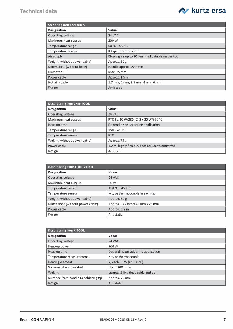
Soldering iron Tool AIR SDesignation ValueOperating voltage 24 VACMaximum heat output 200 WTemperature range 50 °C – 550 °CTemperature sensor K-type thermocoupleAir supply Blowing air up to 20 l/min, adjustable on the toolWeight (without power cable) Approx. 90 gDimensions (without hose) Handle approx. 220 mmDiameter Max. 25 mmPower cable Approx. 1.5 mHot air nozzle 1.7 mm, 2 mm, 3.5 mm, 4 mm, 6 mmDesign Antistatic
Desoldering iron CHIP TOOL Designation ValueOperating voltage 24 VACMaximum heat output PTC 2 x 30 W/280 °C, 2 x 20 W/350 °CHeat-up time Depending on soldering applicationTemperature range 150 – 450 °CTemperature sensor PTCWeight (without power cable) Approx. 75 gPower cable 1.2 m, highly flexible, heat resistant, antistaticDesign Antistatic
Desoldering CHIP TOOL VARIODesignation ValueOperating voltage 24 VACMaximum heat output 80 WTemperature range 150 °C – 450 °CTemperature sensor K-type thermocouple in each tipWeight (without power cable) Approx. 30 gDimensions (without power cable) Approx. 145 mm x 45 mm x 25 mmPower cable Approx. 1.2 mDesign Antistatic
Desoldering iron X‑TOOLDesignation ValueOperating voltage 24 VACHeat-up power 260 WHeat-up time Depending on soldering applicationTemperature measurement K-type thermocoupleHeating element 2, each 60 W (at 360 °C)Vacuum when operated Up to 800 mbarWeight approx. 240 g (incl. cable and tip)Distance from handle to soldering tip Approx. 70 mmDesign Antistatic
8 3BA00206 • 2016-08-11 • Rev. 2 Ersa i-CON VARIO 4
Technical data
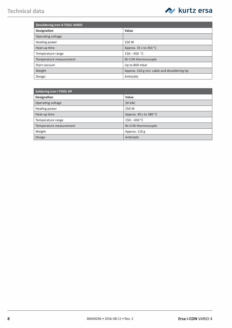
Desoldering iron X‑TOOL VARIO
Designation Value
Operating voltage
Heating power 150 W
Heat-up time Approx. 35 s to 350 °C
Temperature range 150 – 450 °C
Temperature measurement Ni-CrNi thermocouple
Start vacuum Up to 800 mbar
Weight Approx. 210 g incl. cable and desoldering tip
Design Antistatic
Soldering iron i‑TOOL HP
Designation Value
Operating voltage 24 VAC
Heating power 250 W
Heat-up time Approx. 40 s to 380 °C
Temperature range 150 – 450 °C
Temperature measurement Ni-CrNi thermocouple
Weight Approx. 110 g
Design Antistatic
93BA00206 • 2016-08-11 • Rev. 2Ersa i-CON VARIO 4
Concerning your safety
3. Concerning your safetyErsa products are developed, manufactured and tested in compliance with general requirements concerning health and safety.
However, residual risk do remain!
You should therefore read this instruction manual before you start to operate the device for the first time. It will help you to learn the functions of the device and to use it in the most optimal way. Keep this instruction manual in a place that can be accessed by all users at any time!
3.1 Explanations on pictograms and symbolsIn this instruction manual pictograms are used to highlight dangers.
Special information or mandatory instructions and prohibitions with the aim of preventing personal injury or extensive damage to property are identified by a pictogram, followed by hierarchically structured text with words written in bold:
WARNING! Is used for warnings of immediate danger. Not avoiding this danger may result in death, extremely serious injury or property damage.
ATTENTION! Is used for warnings of possibly dangerous situations. Not avoiding this danger may result in death, extremely serious injury or property damage.
ATTENTION! Is used for warnings of possibly dangerous situations. Not avoiding this danger may result in minor injuries, light injuries or property damage.
In addition to the hierarchically structured warning notes described above, we use the following symbols:
They are used to highlight any texts containing explanations, information and hints.
This symbol identifies
– activities that is strictly required, or
– instructions that must be strictly complied with.
10 3BA00206 • 2016-08-11 • Rev. 2 Ersa i-CON VARIO 4
Concerning your safety
3.2 Safety instructions
DANGER! Malfunctions of the device possible!Check all components before each use. Have damaged parts only repaired by a specialist or the manufacturer. If repairs are carried out inappropriately, the operator may become victim of accidents. Always use original Ersa spare parts for possible repairs.
ATTENTION! Risk of burning!Thermal tools get very hot. Before heating up the device check whether the tool insert (e.g. soldering tip, modelling insert, etc.) is correctly connected with the thermal tool. The hot tool insert should never come in contact with skin, hair or any heat-sensitive and combustible materials. Make sure you use a sufficiently heat proof work base.
ATTENTION! Risk of burning by hot air! The hot air jet should never come in contact with skin, hair or any heat-sensitive and combustible materials. Take care that you do not direct the hot air jet towards persons or yourself. Do not reach with your hands into the hot air jet. Use a sufficiently heat resistant work base and remove all combustible materials from your work environment.
CAUTION! Risk of injury!Keep unauthorized persons at a safe distance. Make sure that unauthorized persons, especially children, have no access to the thermal tools.
WARNING! Fire hazard! Before heating up the thermal tool remove any combustible objects, fluids and gases from the working range of the thermal tool. Always place the thermal tool into the holder provided for this purpose. Disconnect the thermal tool from the mains supply after use.
WARNING! Fire hazard!Do not leave your hot thermal tool unattended. Remember that it will take quite some time for the tool insert to cool down to a harmless temperature, after the device has been switched off.
CAUTION! Risk of injury!Keep your working area clean and tidy. A messy working area increases the risk of accidents.
CAUTION! Eating and drinking prohibited!Solders and solder auxiliaries are toxic. If they enter into the organism it will have a toxic effect. Eating, drinking and smoking is strictly prohibited. Always wash your hands thoroughly after having worked with solder and solder auxiliaries.
113BA00206 • 2016-08-11 • Rev. 2Ersa i-CON VARIO 4
Concerning your safety
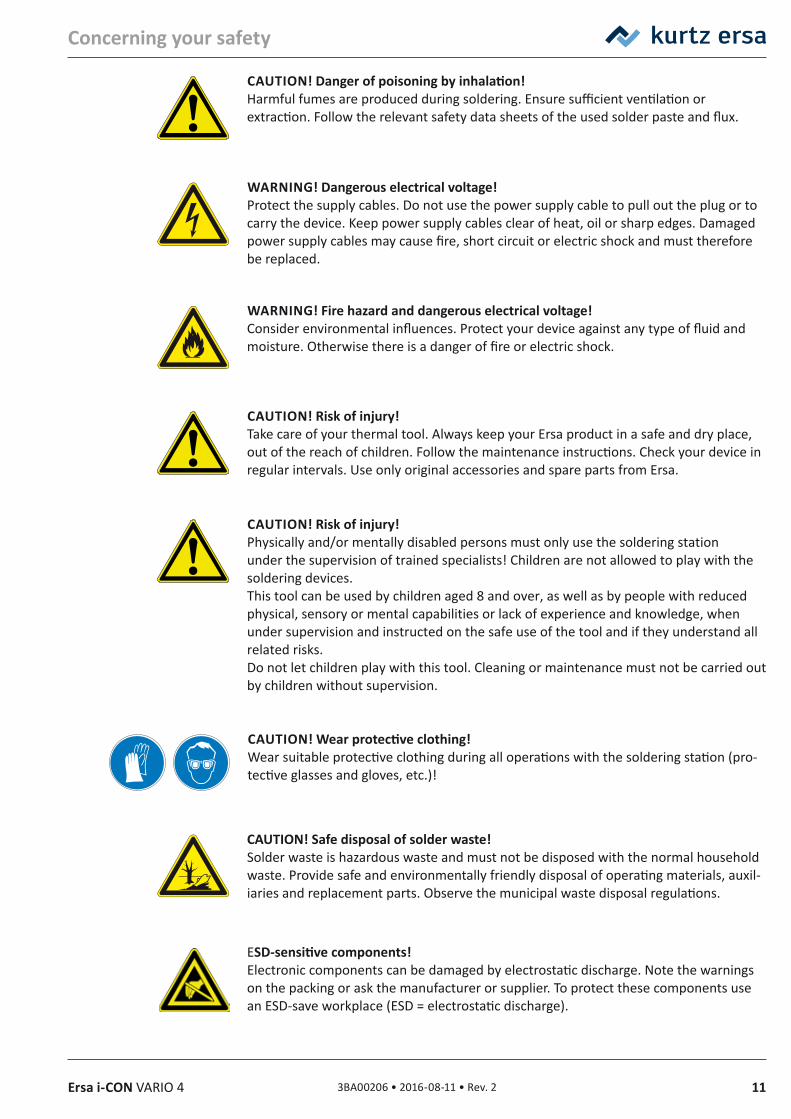
CAUTION! Danger of poisoning by inhalation! Harmful fumes are produced during soldering. Ensure sufficient ventilation or extraction. Follow the relevant safety data sheets of the used solder paste and flux.
WARNING! Dangerous electrical voltage!Protect the supply cables. Do not use the power supply cable to pull out the plug or to carry the device. Keep power supply cables clear of heat, oil or sharp edges. Damaged power supply cables may cause fire, short circuit or electric shock and must therefore be replaced.
WARNING! Fire hazard and dangerous electrical voltage!Consider environmental influences. Protect your device against any type of fluid and moisture. Otherwise there is a danger of fire or electric shock.
CAUTION! Risk of injury!Take care of your thermal tool. Always keep your Ersa product in a safe and dry place, out of the reach of children. Follow the maintenance instructions. Check your device in regular intervals. Use only original accessories and spare parts from Ersa.
CAUTION! Risk of injury!Physically and/or mentally disabled persons must only use the soldering station under the supervision of trained specialists! Children are not allowed to play with the soldering devices.This tool can be used by children aged 8 and over, as well as by people with reduced physical, sensory or mental capabilities or lack of experience and knowledge, when under supervision and instructed on the safe use of the tool and if they understand all related risks.Do not let children play with this tool. Cleaning or maintenance must not be carried out by children without supervision.
CAUTION! Wear protective clothing!Wear suitable protective clothing during all operations with the soldering station (pro-tective glasses and gloves, etc.)!
CAUTION! Safe disposal of solder waste! Solder waste is hazardous waste and must not be disposed with the normal household waste. Provide safe and environmentally friendly disposal of operating materials, auxil-iaries and replacement parts. Observe the municipal waste disposal regulations.
ESD‑sensitive components!Electronic components can be damaged by electrostatic discharge. Note the warnings on the packing or ask the manufacturer or supplier. To protect these components use an ESD-save workplace (ESD = electrostatic discharge).
12 3BA00206 • 2016-08-11 • Rev. 2 Ersa i-CON VARIO 4
Concerning your safety
3.3 Intended useThermal tools from Ersa must only be used for the processing of soft solder. However, if explicitly described in the operating instructions of the respective thermal tool, some thermal tools may, in exceptional cases, be used for the processing of plastic materials. In case of unintended use and tampering with the device, any warranty and liability claims of the buyer against the manufacturer will become null and void. Intended use also includes observing the operating instructions including the safety instructions.
3.4 National and international regulationsNational and international health and safety regulations as well as occupational health and accident prevention regulations must be complied with.
133BA00206 • 2016-08-11 • Rev. 2Ersa i-CON VARIO 4
Transport, storage, waste disposal
4. Transport, storage, waste disposal4.1 Transport and storage
The i-CON VARIO 4 is delivered in a strong cardboard box. Please use only the original packaging for transportation and intermediate storage. Strictly avoid jerky movements, impacts or putting down of the i-CON VARIO 2. The i-CON VARIO 4 must be adequately protected against weather influences like rain, fog or sea air, etc. For longer storage in high humidity environments the i-CON VARIO 4 must be packed up air tight, together with a dehumidifying agent. Damage caused by unprofessional transport or storage are not covered under warranty.
4.2 Waste disposalNotes on waste disposal acc. to the directive 2002/96/EC of the European Parliament and the Committee from 27th of January 2003 for used electric and electronic appliances:
Products marked with a crossed out waste bin must not be disposed of together with unsorted domestic waste. The municipalities established special collecting points for this type of waste.Please consult your council and ask for available possibilities for the separated collection of old appliances.You thereby contribute to the reuse or other forms of use of old appliances, with the aim of protecting the environment and human health.
14 3BA00206 • 2016-08-11 • Rev. 2 Ersa i-CON VARIO 4
Commissioning
5. Commissioning5.1 Before start‑up
Please check the contents in the package for completeness. In this context read chapter 9 [Spare parts, accessories]. Should any of the listed components be damaged or incomplete, you should immediately consult your supplier.
ContentsOrder no.
0ICV4000A 0ICV4000AI 0ICV4000AIC 0ICV4000AICX 0ICV4000AICXVi-CON VARIO 2 0ICV403A 1 x 1 x 1 x 1 x 1 x
i-TOOL AIR S 0470BRJ 1 x 1 x 1 x 1 x 1 x
i-TOOL 0100CDJ 1 x 1 x 1 x 1 x
CHIP TOOL VARIO 0460MDJ 1 x 1 x 1 x
X-TOOL 0720ENJ 1 x
X-TOOL VARIO 0740EDJ 1 x
All soldering irons come with a matching holder.
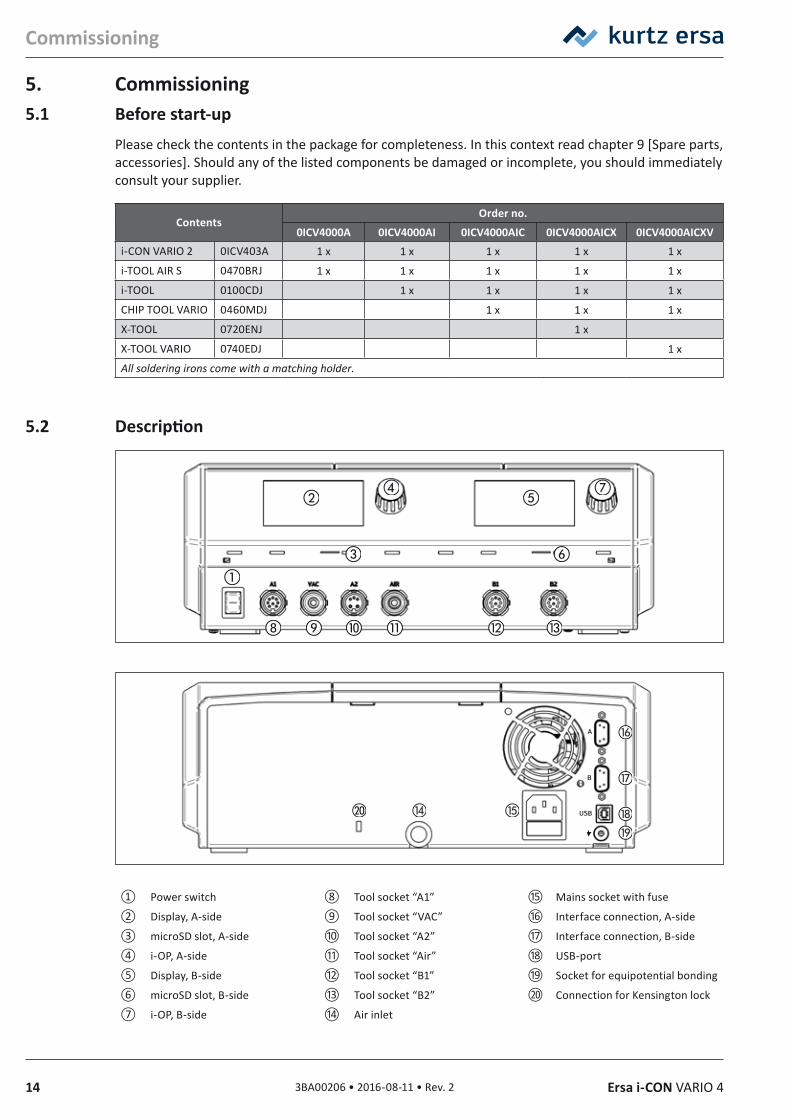
5.2 Description
① Power switch ⑧ Tool socket “A1” ⑮ Mains socket with fuse
② Display, A-side ⑨ Tool socket “VAC” ⑯ Interface connection, A-side
③ microSD slot, A-side ⑩ Tool socket “A2” ⑰ Interface connection, B-side
④ i-OP, A-side ⑪ Tool socket “Air” ⑱ USB-port
⑤ Display, B-side ⑫ Tool socket “B1” ⑲ Socket for equipotential bonding
⑥ microSD slot, B-side ⑬ Tool socket “B2” ⑳ Connection for Kensington lock
⑦ i-OP, B-side ⑭ Air inlet
153BA00206 • 2016-08-11 • Rev. 2Ersa i-CON VARIO 4
Commissioning
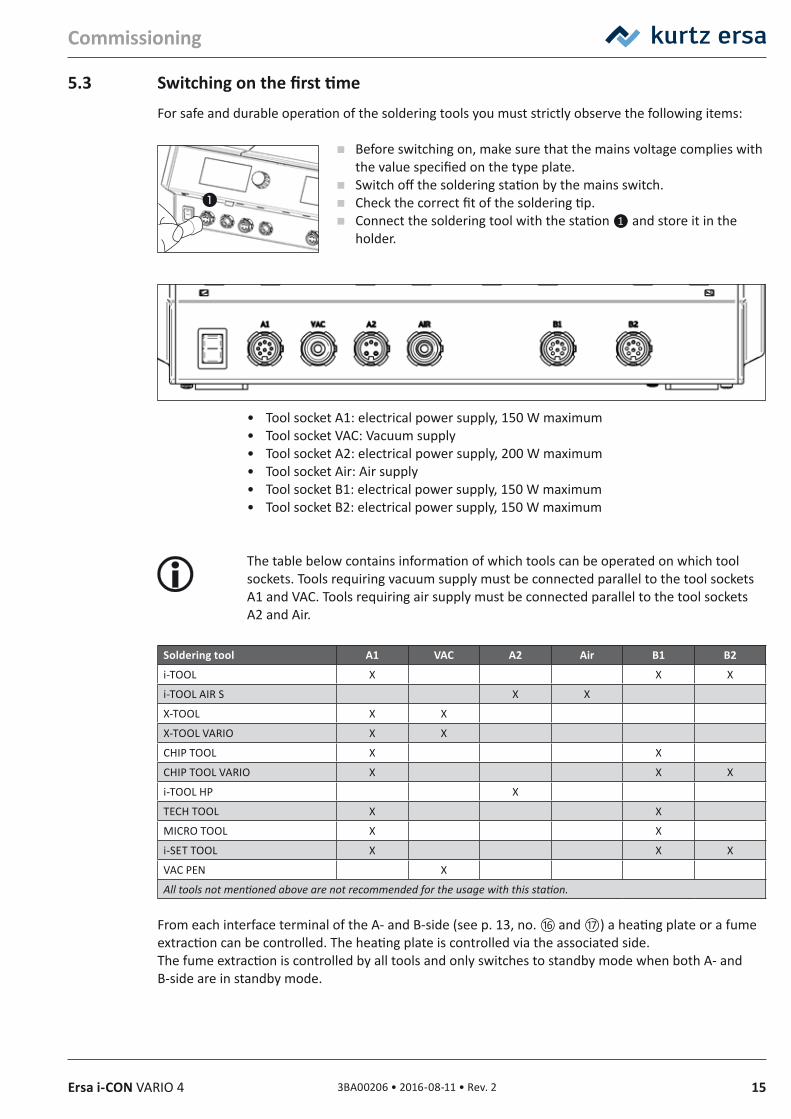
5.3 Switching on the first timeFor safe and durable operation of the soldering tools you must strictly observe the following items:
Before switching on, make sure that the mains voltage complies with the value specified on the type plate.
Switch off the soldering station by the mains switch. Check the correct fit of the soldering tip. Connect the soldering tool with the station ❶ and store it in the
holder.
• Tool socket A1: electrical power supply, 150 W maximum• Tool socket VAC: Vacuum supply• Tool socket A2: electrical power supply, 200 W maximum• Tool socket Air: Air supply• Tool socket B1: electrical power supply, 150 W maximum• Tool socket B2: electrical power supply, 150 W maximum
The table below contains information of which tools can be operated on which tool sockets. Tools requiring vacuum supply must be connected parallel to the tool sockets A1 and VAC. Tools requiring air supply must be connected parallel to the tool sockets A2 and Air.
Soldering tool A1 VAC A2 Air B1 B2
i-TOOL X X X
i-TOOL AIR S X X
X-TOOL X X
X-TOOL VARIO X X
CHIP TOOL X X
CHIP TOOL VARIO X X X
i-TOOL HP X
TECH TOOL X X
MICRO TOOL X X
i-SET TOOL X X X
VAC PEN X
All tools not mentioned above are not recommended for the usage with this station.
From each interface terminal of the A- and B-side (see p. 13, no. ⑯ and ⑰) a heating plate or a fume extraction can be controlled. The heating plate is controlled via the associated side. The fume extraction is controlled by all tools and only switches to standby mode when both A- and B-side are in standby mode.
16 3BA00206 • 2016-08-11 • Rev. 2 Ersa i-CON VARIO 4
Commissioning
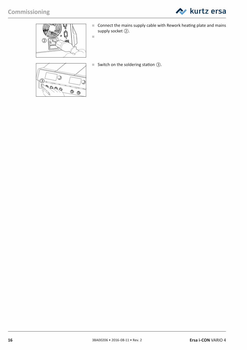
Connect the mains supply cable with Rework heating plate and mains supply socket ②.
Switch on the soldering station ③.
173BA00206 • 2016-08-11 • Rev. 2Ersa i-CON VARIO 4
Functional description
6. Functional description6.1 Operation
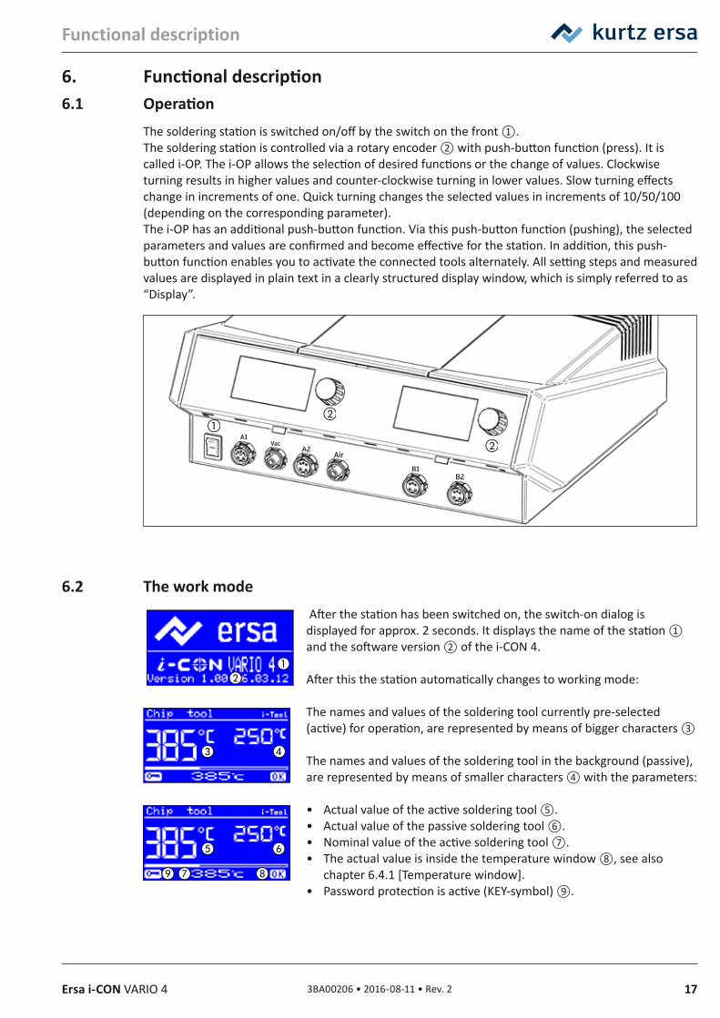
The soldering station is switched on/off by the switch on the front ①.The soldering station is controlled via a rotary encoder ② with push-button function (press). It is called i-OP. The i-OP allows the selection of desired functions or the change of values. Clockwise turning results in higher values and counter-clockwise turning in lower values. Slow turning effects change in increments of one. Quick turning changes the selected values in increments of 10/50/100 (depending on the corresponding parameter).The i-OP has an additional push-button function. Via this push-button function (pushing), the selected parameters and values are confirmed and become effective for the station. In addition, this push-button function enables you to activate the connected tools alternately. All setting steps and measured values are displayed in plain text in a clearly structured display window, which is simply referred to as “Display”.
6.2 The work mode After the station has been switched on, the switch-on dialog is displayed for approx. 2 seconds. It displays the name of the station ① and the software version ② of the i-CON 4.
After this the station automatically changes to working mode:
The names and values of the soldering tool currently pre-selected (active) for operation, are represented by means of bigger characters ③
The names and values of the soldering tool in the background (passive), are represented by means of smaller characters ④ with the parameters:
• Actual value of the active soldering tool ⑤.• Actual value of the passive soldering tool ⑥.• Nominal value of the active soldering tool ⑦.• The actual value is inside the temperature window ⑧, see also
chapter 6.4.1 [Temperature window].• Password protection is active (KEY-symbol) ⑨.
18 3BA00206 • 2016-08-11 • Rev. 2 Ersa i-CON VARIO 4
Functional description
In work mode the soldering tools connected to the tool sockets A1, A2, Air and VAC are displayed in the left and the soldering tools connected to the tool sockets B1 and B2 in the right display.
6.2.1 microSD‑cardThe use of a microSD card allows to make firmware updates. For more information on using the mi-croSD card, please refer to the firmware update instructions. The firmware and the update instructions can be found at www.kurtzersa.com in section “i-CON VARIO 4” under “Downloads”.
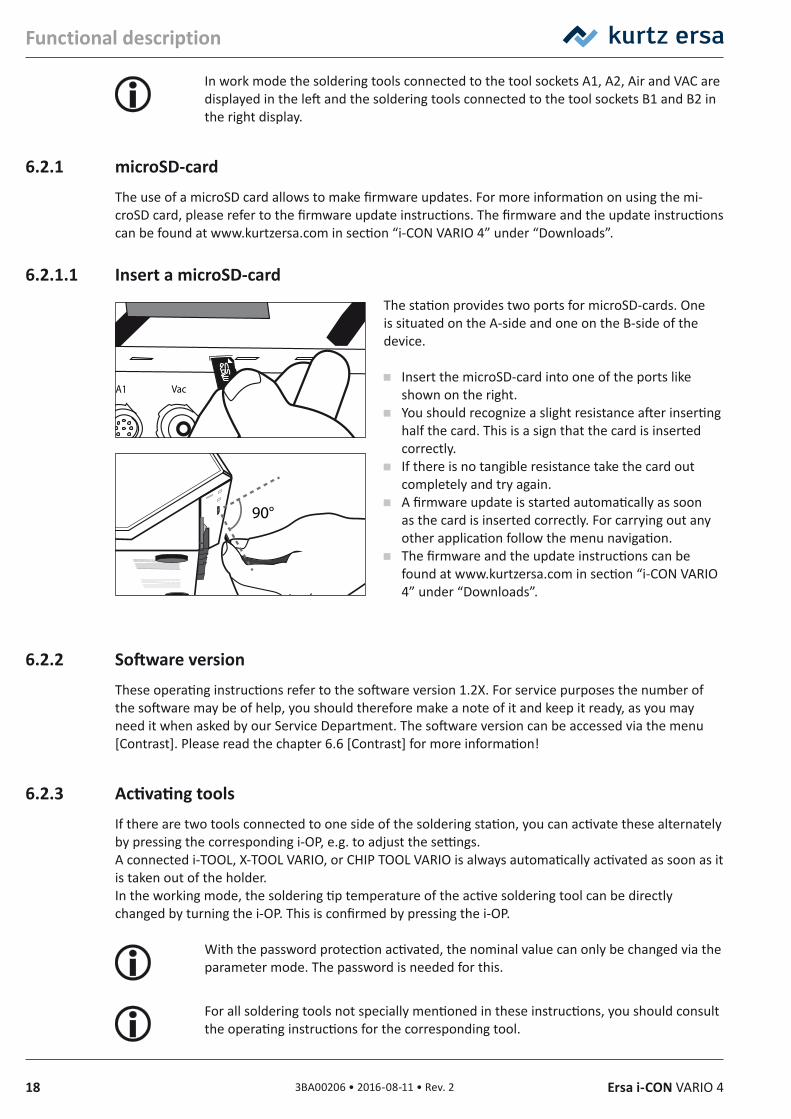
6.2.1.1 Insert a microSD‑card The station provides two ports for microSD-cards. One is situated on the A-side and one on the B-side of the device.
Insert the microSD-card into one of the ports like shown on the right.
You should recognize a slight resistance after inserting half the card. This is a sign that the card is inserted correctly.
If there is no tangible resistance take the card out completely and try again.
A firmware update is started automatically as soon as the card is inserted correctly. For carrying out any other application follow the menu navigation.
The firmware and the update instructions can be found at www.kurtzersa.com in section “i-CON VARIO 4” under “Downloads”.
6.2.2 Software versionThese operating instructions refer to the software version 1.2X. For service purposes the number of the software may be of help, you should therefore make a note of it and keep it ready, as you may need it when asked by our Service Department. The software version can be accessed via the menu [Contrast]. Please read the chapter 6.6 [Contrast] for more information!
6.2.3 Activating toolsIf there are two tools connected to one side of the soldering station, you can activate these alternately by pressing the corresponding i-OP, e.g. to adjust the settings.A connected i-TOOL, X-TOOL VARIO, or CHIP TOOL VARIO is always automatically activated as soon as it is taken out of the holder.In the working mode, the soldering tip temperature of the active soldering tool can be directly changed by turning the i-OP. This is confirmed by pressing the i-OP.
With the password protection activated, the nominal value can only be changed via the parameter mode. The password is needed for this.
For all soldering tools not specially mentioned in these instructions, you should consult the operating instructions for the corresponding tool.
193BA00206 • 2016-08-11 • Rev. 2Ersa i-CON VARIO 4
Functional description
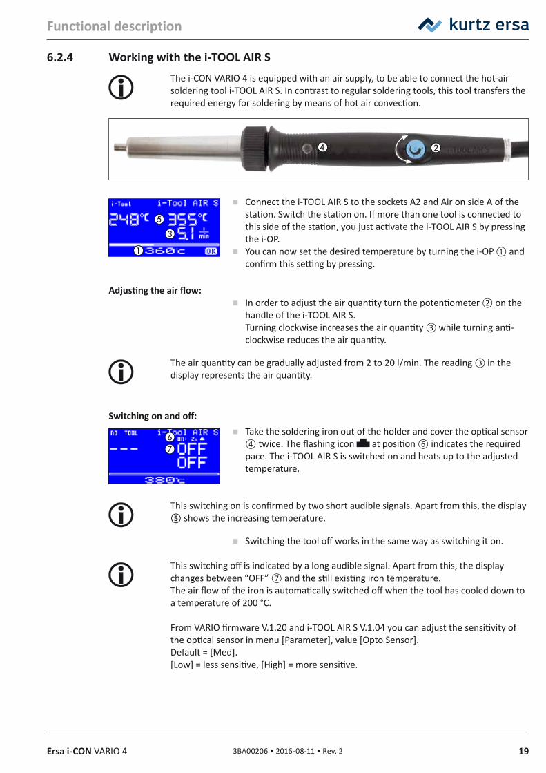
6.2.4 Working with the i‑TOOL AIR SThe i-CON VARIO 4 is equipped with an air supply, to be able to connect the hot-air soldering tool i-TOOL AIR S. In contrast to regular soldering tools, this tool transfers the required energy for soldering by means of hot air convection.
Connect the i-TOOL AIR S to the sockets A2 and Air on side A of the station. Switch the station on. If more than one tool is connected to this side of the station, you just activate the i-TOOL AIR S by pressing the i-OP.
You can now set the desired temperature by turning the i-OP ① and confirm this setting by pressing.
Adjusting the air flow: In order to adjust the air quantity turn the potentiometer ② on the
handle of the i-TOOL AIR S. Turning clockwise increases the air quantity ③ while turning anti-clockwise reduces the air quantity.
The air quantity can be gradually adjusted from 2 to 20 l/min. The reading ③ in the display represents the air quantity.
Switching on and off: Take the soldering iron out of the holder and cover the optical sensor
④ twice. The flashing icon at position ⑥ indicates the required pace. The i-TOOL AIR S is switched on and heats up to the adjusted temperature.
This switching on is confirmed by two short audible signals. Apart from this, the display ⑤ shows the increasing temperature.
Switching the tool off works in the same way as switching it on.
This switching off is indicated by a long audible signal. Apart from this, the display changes between “OFF” ⑦ and the still existing iron temperature.The air flow of the iron is automatically switched off when the tool has cooled down to a temperature of 200 °C.
From VARIO firmware V.1.20 and i-TOOL AIR S V.1.04 you can adjust the sensitivity of the optical sensor in menu [Parameter], value [Opto Sensor]. Default = [Med]. [Low] = less sensitive, [High] = more sensitive.
20 3BA00206 • 2016-08-11 • Rev. 2 Ersa i-CON VARIO 4
Functional description
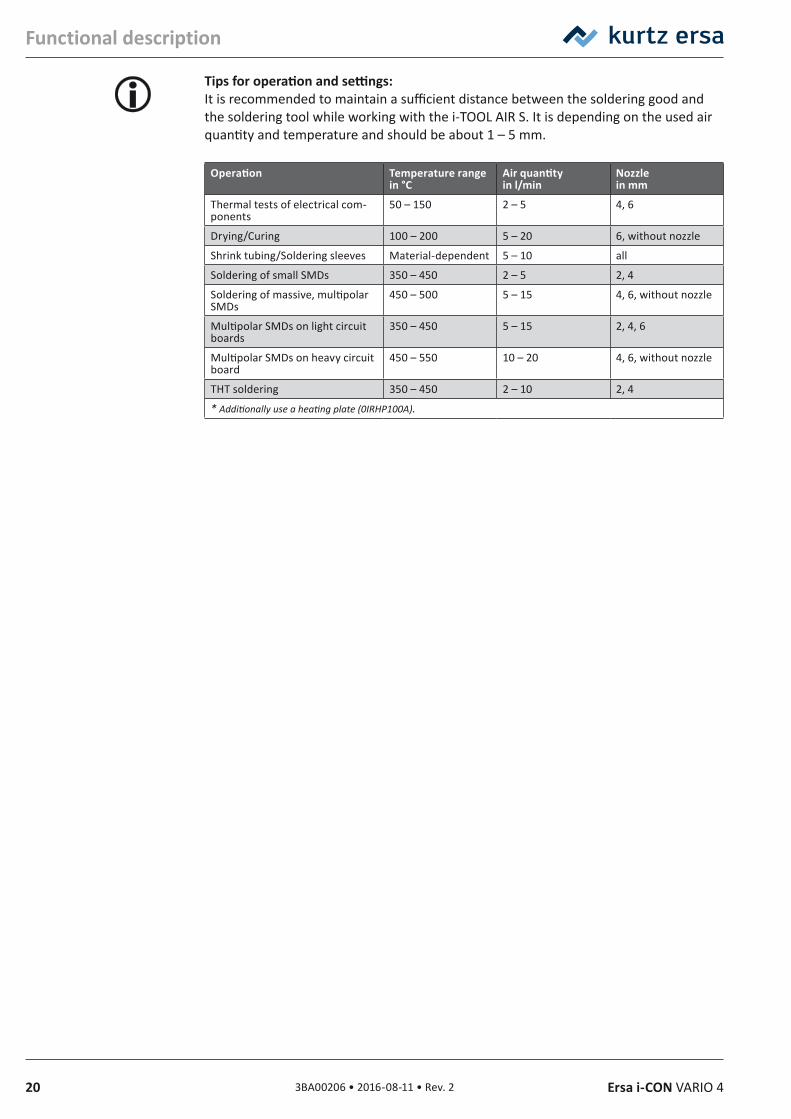
Tips for operation and settings:It is recommended to maintain a sufficient distance between the soldering good and the soldering tool while working with the i-TOOL AIR S. It is depending on the used air quantity and temperature and should be about 1 – 5 mm.
Operation Temperature range in °C
Air quantity in l/min
Nozzle in mm
Thermal tests of electrical com-ponents
50 – 150 2 – 5 4, 6
Drying/Curing 100 – 200 5 – 20 6, without nozzle
Shrink tubing/Soldering sleeves Material-dependent 5 – 10 all
Soldering of small SMDs 350 – 450 2 – 5 2, 4
Soldering of massive, multipolar SMDs
450 – 500 5 – 15 4, 6, without nozzle
Multipolar SMDs on light circuit boards
350 – 450 5 – 15 2, 4, 6
Multipolar SMDs on heavy circuit board
450 – 550 10 – 20 4, 6, without nozzle
THT soldering 350 – 450 2 – 10 2, 4
* Additionally use a heating plate (0IRHP100A).
213BA00206 • 2016-08-11 • Rev. 2Ersa i-CON VARIO 4
Functional description
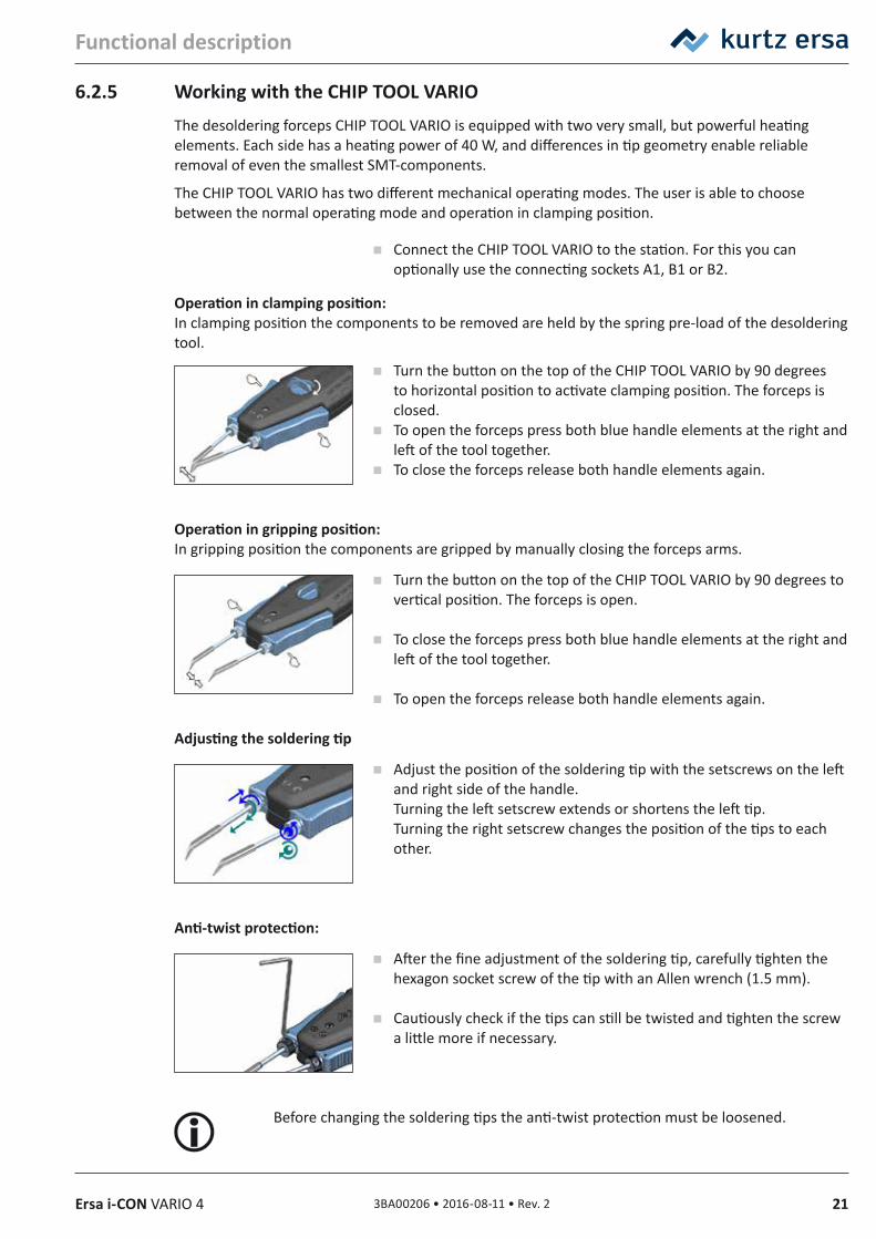
6.2.5 Working with the CHIP TOOL VARIOThe desoldering forceps CHIP TOOL VARIO is equipped with two very small, but powerful heating elements. Each side has a heating power of 40 W, and differences in tip geometry enable reliable removal of even the smallest SMT-components.
The CHIP TOOL VARIO has two different mechanical operating modes. The user is able to choose between the normal operating mode and operation in clamping position.
Connect the CHIP TOOL VARIO to the station. For this you can optionally use the connecting sockets A1, B1 or B2.
Operation in clamping position:In clamping position the components to be removed are held by the spring pre-load of the desoldering tool.
Turn the button on the top of the CHIP TOOL VARIO by 90 degrees to horizontal position to activate clamping position. The forceps is closed.
To open the forceps press both blue handle elements at the right and left of the tool together.
To close the forceps release both handle elements again.
Operation in gripping position:In gripping position the components are gripped by manually closing the forceps arms.
Turn the button on the top of the CHIP TOOL VARIO by 90 degrees to vertical position. The forceps is open.
To close the forceps press both blue handle elements at the right and left of the tool together.
To open the forceps release both handle elements again.
Adjusting the soldering tip
Adjust the position of the soldering tip with the setscrews on the left and right side of the handle. Turning the left setscrew extends or shortens the left tip. Turning the right setscrew changes the position of the tips to each other.
Anti‑twist protection:
After the fine adjustment of the soldering tip, carefully tighten the hexagon socket screw of the tip with an Allen wrench (1.5 mm).
Cautiously check if the tips can still be twisted and tighten the screw a little more if necessary.
Before changing the soldering tips the anti-twist protection must be loosened.
22 3BA00206 • 2016-08-11 • Rev. 2 Ersa i-CON VARIO 4
Functional description
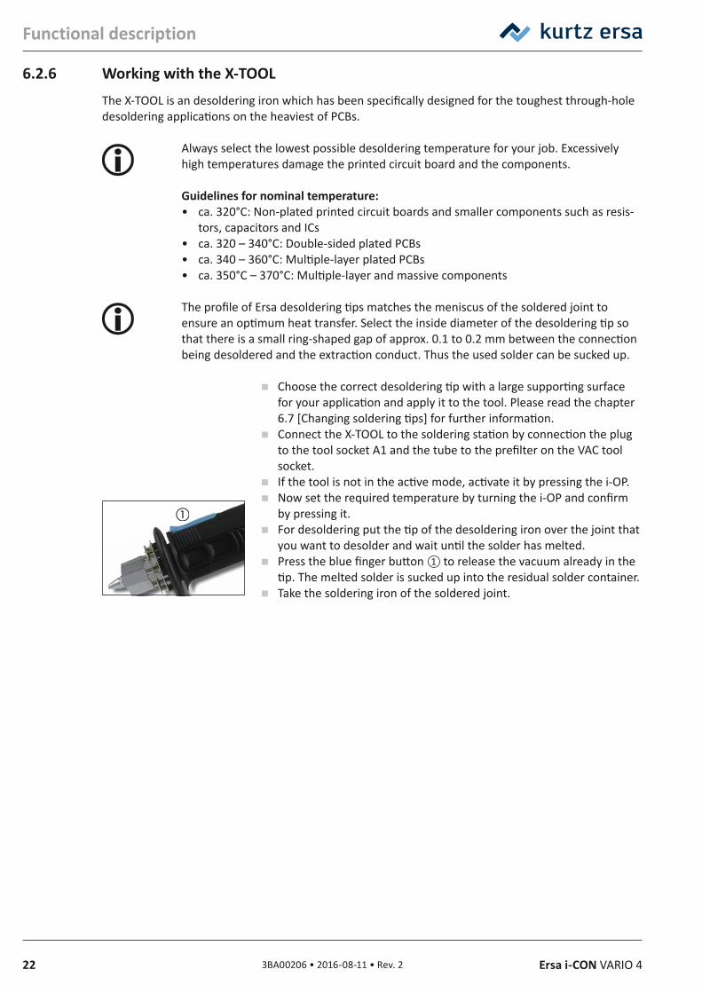
6.2.6 Working with the X‑TOOLThe X-TOOL is an desoldering iron which has been specifically designed for the toughest through-hole desoldering applications on the heaviest of PCBs.
Always select the lowest possible desoldering temperature for your job. Excessively high temperatures damage the printed circuit board and the components.
Guidelines for nominal temperature:• ca. 320°C: Non-plated printed circuit boards and smaller components such as resis-
tors, capacitors and ICs• ca. 320 – 340°C: Double-sided plated PCBs• ca. 340 – 360°C: Multiple-layer plated PCBs• ca. 350°C – 370°C: Multiple-layer and massive components
The profile of Ersa desoldering tips matches the meniscus of the soldered joint to ensure an optimum heat transfer. Select the inside diameter of the desoldering tip so that there is a small ring-shaped gap of approx. 0.1 to 0.2 mm between the connection being desoldered and the extraction conduct. Thus the used solder can be sucked up.
Choose the correct desoldering tip with a large supporting surface for your application and apply it to the tool. Please read the chapter 6.7 [Changing soldering tips] for further information.
Connect the X-TOOL to the soldering station by connection the plug to the tool socket A1 and the tube to the prefilter on the VAC tool socket.
If the tool is not in the active mode, activate it by pressing the i-OP. Now set the required temperature by turning the i-OP and confirm
by pressing it. For desoldering put the tip of the desoldering iron over the joint that
you want to desolder and wait until the solder has melted. Press the blue finger button ① to release the vacuum already in the
tip. The melted solder is sucked up into the residual solder container. Take the soldering iron of the soldered joint.
233BA00206 • 2016-08-11 • Rev. 2Ersa i-CON VARIO 4
Functional description
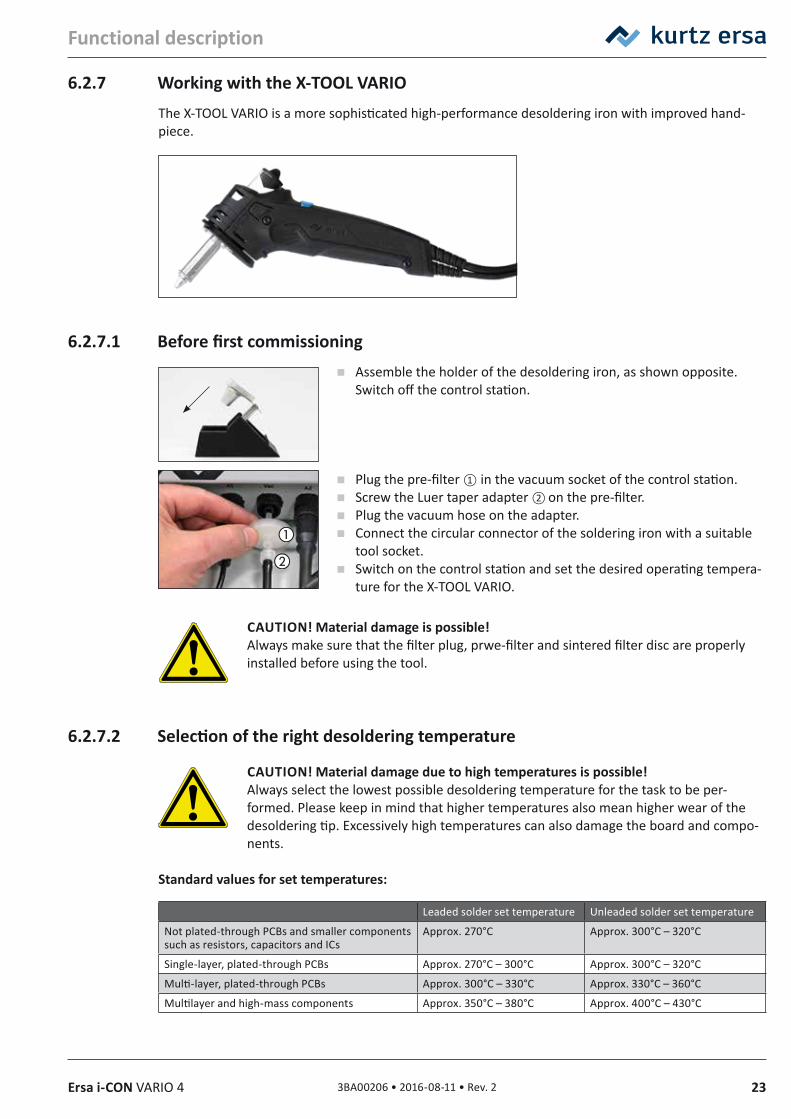
6.2.7 Working with the X‑TOOL VARIOThe X-TOOL VARIO is a more sophisticated high-performance desoldering iron with improved hand-piece.
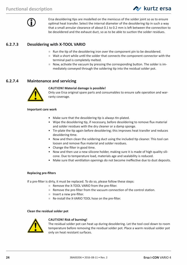
6.2.7.1 Before first commissioning Assemble the holder of the desoldering iron, as shown opposite.
Switch off the control station.
Plug the pre-filter ① in the vacuum socket of the control station. Screw the Luer taper adapter ② on the pre-filter. Plug the vacuum hose on the adapter. Connect the circular connector of the soldering iron with a suitable
tool socket. Switch on the control station and set the desired operating tempera-
ture for the X-TOOL VARIO.
CAUTION! Material damage is possible!Always make sure that the filter plug, prwe-filter and sintered filter disc are properly installed before using the tool.
6.2.7.2 Selection of the right desoldering temperature
CAUTION! Material damage due to high temperatures is possible! Always select the lowest possible desoldering temperature for the task to be per-formed. Please keep in mind that higher temperatures also mean higher wear of the desoldering tip. Excessively high temperatures can also damage the board and compo-nents.
Standard values for set temperatures:
Leaded solder set temperature Unleaded solder set temperature
Not plated-through PCBs and smaller components such as resistors, capacitors and ICs
Approx. 270°C Approx. 300°C – 320°C
Single-layer, plated-through PCBs Approx. 270°C – 300°C Approx. 300°C – 320°C
Multi-layer, plated-through PCBs Approx. 300°C – 330°C Approx. 330°C – 360°C
Multilayer and high-mass components Approx. 350°C – 380°C Approx. 400°C – 430°C
24 3BA00206 • 2016-08-11 • Rev. 2 Ersa i-CON VARIO 4
Functional description
Ersa desoldering tips are modelled on the meniscus of the solder joint so as to ensure optimal heat transfer. Select the internal diameter of the desoldering tip in such a way that a small annular clearance of about 0.1 to 0.2 mm is left between the connection to be desoldered and the exhaust duct, so as to be able to suction the solder residues.
6.2.7.3 Desoldering with X‑TOOL VARIO Run the tip of the desoldering iron over the component pin to be desoldered. Wait a short while until the solder that connects the component connector with the
terminal pad is completely melted. Now, activate the vacuum by pressing the corresponding button. The solder is im-
mediately conveyed through the soldering tip into the residual solder pot.
6.2.7.4 Maintenance and servicingCAUTION! Material damage is possible!Only use Ersa original spare parts and consumables to ensure safe operation and war-ranty coverage.
Important care work
• Make sure that the desoldering tip is always tin-plated. • Wipe the desoldering tip, if necessary, before desoldering to remove flux material
and solder residues with the dry cleaner or a damp sponge. • Tin-plate the tip again before desoldering; this improves heat transfer and reduces
desoldering time. • Now and then clean the soldering duct using the included tip cleaner. This tool can
loosen and remove flux material and solder residues. • Change the filter in good time. • Now and then use a new silicone holder, making sure it is made of high quality sili-
cone. Due to temperature load, materials age and sealability is reduced.• Make sure that ventilation openings do not become ineffective due to dust deposits.
Replacing pre‑filters
If a pre-filter is dirty, it must be replaced. To do so, please follow these steps: Remove the X-TOOL VARIO from the pre-filter. Remove the pre-filter from the vacuum connection of the control station. Insert a new pre-filter. Re-install the X-VARIO TOOL hose on the pre-filter.
Clean the residual solder pot
CAUTION! Risk of burning!The residual solder pot can heat up during desoldering. Let the tool cool down to room temperature before removing the residual solder pot. Place a warm residual solder pot only on heat resistant surfaces.
253BA00206 • 2016-08-11 • Rev. 2Ersa i-CON VARIO 4
Functional description
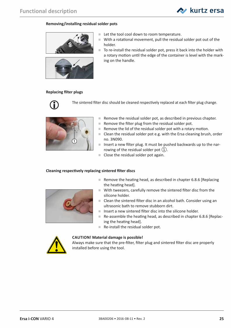
Removing/installing residual solder pots
Let the tool cool down to room temperature. With a rotational movement, pull the residual solder pot out of the
holder. To re-install the residual solder pot, press it back into the holder with
a rotary motion until the edge of the container is level with the mark-ing on the handle.
Replacing filter plugs
The sintered filter disc should be cleaned respectively replaced at each filter plug change.
Remove the residual solder pot, as described in previous chapter. Remove the filter plug from the residual solder pot. Remove the lid of the residual solder pot with a rotary motion. Clean the residual solder pot e.g. with the Ersa cleaning brush, order
no. 3N090. Insert a new filter plug. It must be pushed backwards up to the nar-
rowing of the residual solder pot ①. Close the residual solder pot again.
Cleaning respectively replacing sintered filter discs
Remove the heating head, as described in chapter 6.8.6 [Replacing the heating head].
With tweezers, carefully remove the sintered filter disc from the silicone holder.
Clean the sintered filter disc in an alcohol bath. Consider using an ultrasonic bath to remove stubborn dirt.
Insert a new sintered filter disc into the silicone holder. Re-assemble the heating head, as described in chapter 6.8.6 [Replac-
ing the heating head]. Re-install the residual solder pot.
CAUTION! Material damage is possible!Always make sure that the pre-filter, filter plug and sintered filter disc are properly installed before using the tool.
26 3BA00206 • 2016-08-11 • Rev. 2 Ersa i-CON VARIO 4
Functional description
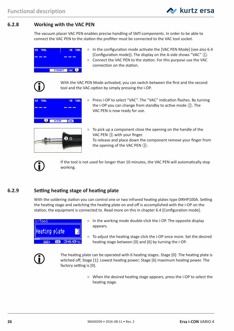
6.2.8 Working with the VAC PENThe vacuum placer VAC PEN enables precise handling of SMT-components. In order to be able to connect the VAC PEN to the station the prefilter must be connected to the VAC tool socket.
In the configuration mode activate the [VAC PEN Mode] (see also 6.4 [Configuration mode]). The display on the A-side shows “VAC” ①.
Connect the VAC PEN to the station. For this purpose use the VAC connection on the station.
With the VAC PEN Mode activated, you can switch between the first and the second tool and the VAC-option by simply pressing the i-OP.
Press i-OP to select “VAC”. The “VAC” indication flashes. By turning the i-OP you can change from standby to active mode ②. The VAC PEN is now ready for use.
To pick up a component close the opening on the handle of the VAC PEN ③ with your finger. To release and place down the component remove your finger from the opening of the VAC PEN ③.
If the tool is not used for longer than 10 minutes, the VAC PEN will automatically stop working.
6.2.9 Setting heating stage of heating plateWith the soldering station you can control one or two infrared heating plates type 0IRHP100A. Setting the heating stage and switching the heating plate on and off is accomplished with the i-OP on the station, the equipment is connected to. Read more on this in chapter 6.4 [Configuration mode].
In the working mode double-click the i-OP. The opposite display appears.
To adjust the heating stage click the i-OP once more. Set the desired heating stage between [0] and [6] by turning the i-OP.
The heating plate can be operated with 6 heating stages. Stage [0]: The heating plate is witched off; Stage [1]: Lowest heating power; Stage [6] maximum heating power. The factory setting is [0].
When the desired heating stage appears, press the i-OP to select the heating stage.
273BA00206 • 2016-08-11 • Rev. 2Ersa i-CON VARIO 4
Functional description
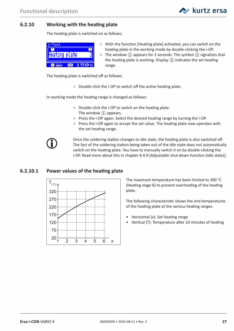
6.2.10 Working with the heating plateThe heating plate is switched on as follows:
With the function [Heating plate] activated, you can switch on the heating plate in the working mode by double-clicking the i-OP.
The window ① appears for 2 seconds. The symbol ② signalizes that the heating plate is working. Display ③ indicates the set heating range.
The heating plate is switched off as follows:
Double-click the i-OP to switch off the active heating plate.
In working mode the heating range is changed as follows:
Double-click the i-OP to switch on the heating plate. The window ① appears.
Press the i-OP again. Select the desired heating range by turning the i-OP. Press the i-OP again to accept the set value. The heating plate now operates with
the set heating range.
Once the soldering station changes to idle state, the heating plate is also switched off. The fact of the soldering station being taken out of the idle state does not automatically switch on the heating plate. You have to manually switch it on by double-clicking the i-OP. Read more about this in chapter 6.4.9 [Adjustable shut-down function (idle state)].
6.2.10.1 Power values of the heating plateThe maximum temperature has been limited to 300 °C (Heating stage 6) to prevent overheating of the heating plate.
The following characteristic shows the end temperatures of the heating plate at the various heating ranges.
• Horizontal (x): Set heating range• Vertical (T): Temperature after 10 minutes of heating
70
20
120
170
220
270
320
2 31 4 5 6 x
T(°C)
28 3BA00206 • 2016-08-11 • Rev. 2 Ersa i-CON VARIO 4
Functional description
6.3 Parameter modeThe following settings can be made in parameter mode:
• Nominal temperature (150 – 450 °C / 302 – 842 °F) (i-TOOL AIR S 50 – 550°C/122 – 1020 °F)
• Calibration temperature (–70 ... +50 °C/–126 ... +90 °F)• Peak offset (if required)• Energy function (3 stages)• Standby time (0 – 60 min)• Standby temperature (150 – 300 °C), except i-TOOL AIR S.
Please proceed as follows to activate the parameter mode:
Select the corresponding tool with the i-OP located on the side of the station, to which the soldering tool is connected.
Press the i-OP and keep pressed for 2 seconds.
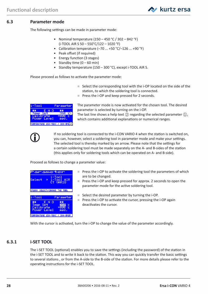
The parameter mode is now activated for the chosen tool. The desired parameter is selected by turning on the i-OP.The last line shows a help text ② regarding the selected parameter ①, which contains additional explanations or numerical ranges.
If no soldering tool is connected to the i-CON VARIO 4 when the station is switched on, you can, however, select a soldering tool in parameter mode and make your settings. The selected tool is thereby marked by an arrow. Please note that the settings for a certain soldering tool must be made separately on the A- and B-sides of the station (this applies only for soldering tools which can be operated on A- and B-side).
Proceed as follows to change a parameter value:
Press the i-OP to activate the soldering tool the parameters of which are to be changed.
Press the i-OP and keep pressed for approx. 2 seconds to open the parameter mode for the active soldering tool.
Select the desired parameter by turning the i-OP. Press the i-OP to activate the cursor, pressing the i-OP again
deactivates the cursor.
With the cursor is activated, turn the i-OP to change the value of the parameter accordingly.
6.3.1 i‑SET TOOLThe i-SET TOOL (optional) enables you to save the settings (including the password) of the station in the i-SET TOOL and to write it back to the station. This way you can quickly transfer the basic settings to several stations , or from the A-side to the B-side of the station. For more details please refer to the operating instructions for the i-SET TOOL.
293BA00206 • 2016-08-11 • Rev. 2Ersa i-CON VARIO 4
Functional description
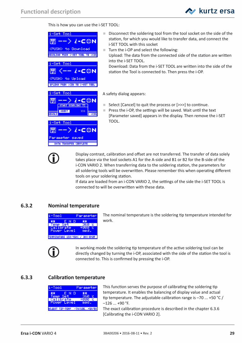
This is how you can use the i-SET TOOL:
Disconnect the soldering tool from the tool socket on the side of the station, for which you would like to transfer data, and connect the i-SET TOOL with this socket
Turn the i-OP and select the following: Upload: The data from the connected side of the station are written into the i-SET TOOL. Download: Data from the i-SET TOOL are written into the side of the station the Tool is connected to. Then press the i-OP.
A safety dialog appears:
Select [Cancel] to quit the process or [>>>] to continue. Press the i-OP, the settings will be saved. Wait until the text
[Parameter saved] appears in the display. Then remove the i-SET TOOL.
Display contrast, calibration and offset are not transferred. The transfer of data solely takes place via the tool sockets A1 for the A-side and B1 or B2 for the B-side of the i-CON VARIO 2. When transferring data to the soldering station, the parameters for all soldering tools will be overwritten. Please remember this when operating different tools on your soldering station.If data are loaded from an i-CON VARIO 2, the settings of the side the i-SET TOOL is connected to will be overwritten with these data.
6.3.2 Nominal temperatureThe nominal temperature is the soldering tip temperature intended for work.
In working mode the soldering tip temperature of the active soldering tool can be directly changed by turning the i-OP, associated with the side of the station the tool is connected to. This is confirmed by pressing the i-OP.
6.3.3 Calibration temperatureThis function serves the purpose of calibrating the soldering tip temperature. It enables the balancing of display value and actual tip temperature. The adjustable calibration range is –70 ... +50 °C / –126 ... +90 °F.The exact calibration procedure is described in the chapter 6.3.6 [Calibrating the i-CON VARIO 2].
30 3BA00206 • 2016-08-11 • Rev. 2 Ersa i-CON VARIO 4
Functional description
If you do not have appropriate measuring equipment for this measurement, please enter “0” into this parameter field.
6.3.4 Setting the size of the hot air nozzle i‑TOOL AIR SThe air quantity and temperature of the i-TOOL AIR S can be adapted to the hot air nozzle and the soldering process used. Once the i-TOOL AIR S is connected to the station, the option [Air nozzle] will appear. After pressing the i-OP one can adjust the type of the hot air nozzle used. Pressing again confirms the selection.
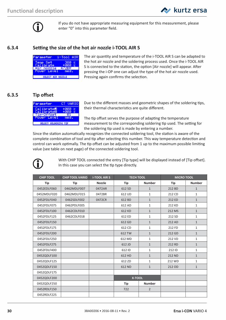
6.3.5 Tip offsetDue to the different masses and geometric shapes of the soldering tips, their thermal characteristics are quite different.
The tip offset serves the purpose of adapting the temperature measurement to the corresponding soldering tip used. The setting for the soldering tip used is made by entering a number.
Since the station automatically recognizes the connected soldering tool, the station is aware of the complete combination of tool and tip after selecting this number. This way temperature detection and control can work optimally. The tip offset can be adjusted from 1 up to the maximum possible limiting value (see table on next page) of the connected soldering tool.
With CHIP TOOL connected the entry [Tip type] will be displayed instead of [Tip offset]. In this case you can select the tip type directly.
CHIP TOOL CHIP TOOL VARIO i‑TOOL AIR S TECH TOOL MICRO TOOL
Tip Tip Nozzle Tip Number Tip Number
0452EDLF060 0462MDLF007 0472AR 612 SD 1 212 BD 1
0452MDLF020 0462MDLF015 0472BR 612 UD 1 212 CD 1
0452FDLF040 0462SDLF002 0472CR 612 BD 1 212 ED 1
0452FDLF075 0462PDLF005 612 AD 1 212 KD 1
0452FDLF100 0462CDLF010 612 KD 1 212 MS 1
0452FDLF125 0462CDLF018 612 ED 1 212 SD 1
0452FDLF150 612 GD 1 212 AD 1
0452FDLF175 612 CD 1 212 FD 1
0452FDLF200 612 TW 1 212 GD 1
0452FDLF250 612 MD 1 212 VD 1
0452FDLF275 612 JD 1 212 RD 1
0452FDLF400 612 ID 1 212 ID 1
0452QDLF100 612 HD 1 212 ND 1
0452QDLF125 612 ZD 1 212 WD 1
0452QDLF150 612 ND 1 212 OD 1
0452QDLF175
0452QDLF200 X‑TOOL
0452QDLF250 Tip Number
0452RDLF150 722 2
0452RDLF225
313BA00206 • 2016-08-11 • Rev. 2Ersa i-CON VARIO 4
Functional description
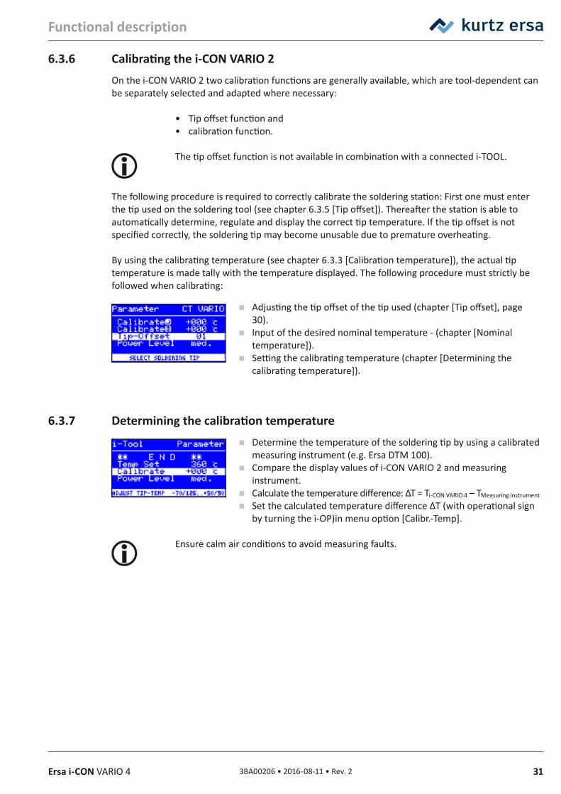
6.3.6 Calibrating the i‑CON VARIO 2On the i-CON VARIO 2 two calibration functions are generally available, which are tool-dependent can be separately selected and adapted where necessary:
• Tip offset function and• calibration function.
The tip offset function is not available in combination with a connected i-TOOL.
The following procedure is required to correctly calibrate the soldering station: First one must enter the tip used on the soldering tool (see chapter 6.3.5 [Tip offset]). Thereafter the station is able to automatically determine, regulate and display the correct tip temperature. If the tip offset is not specified correctly, the soldering tip may become unusable due to premature overheating.
By using the calibrating temperature (see chapter 6.3.3 [Calibration temperature]), the actual tip temperature is made tally with the temperature displayed. The following procedure must strictly be followed when calibrating:
Adjusting the tip offset of the tip used (chapter [Tip offset], page 30).
Input of the desired nominal temperature - (chapter [Nominal temperature]).
Setting the calibrating temperature (chapter [Determining the calibrating temperature]).
6.3.7 Determining the calibration temperature Determine the temperature of the soldering tip by using a calibrated
measuring instrument (e.g. Ersa DTM 100). Compare the display values of i-CON VARIO 2 and measuring
instrument. Calculate the temperature difference: ∆T = Ti-CON VARIO 4 – TMeasuring instrument
Set the calculated temperature difference ∆T (with operational sign by turning the i-OP)in menu option [Calibr.-Temp].
Ensure calm air conditions to avoid measuring faults.
32 3BA00206 • 2016-08-11 • Rev. 2 Ersa i-CON VARIO 4
Functional description
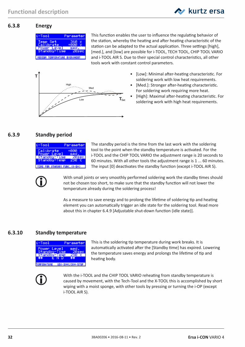
6.3.8 EnergyThis function enables the user to influence the regulating behavior of the station, whereby the heating and after heating characteristic of the station can be adapted to the actual application. Three settings [high], [med.], and [low] are possible for i-TOOL, TECH TOOL, CHIP TOOL VARIO and i-TOOL AIR S. Due to their special control characteristics, all other tools work with constant control parameters.
• [Low]: Minimal after-heating characteristic. For soldering work with low heat requirements.
• [Med.]: Stronger after-heating characteristic. For soldering work requiring more heat.
• [High]: Maximal after-heating characteristic. For soldering work with high heat requirements.
6.3.9 Standby periodThe standby period is the time from the last work with the soldering tool to the point when the standby temperature is activated. For the i-TOOL and the CHIP TOOL VARIO the adjustment range is 20 seconds to 60 minutes. With all other tools the adjustment range is 1 ... 60 minutes. The input [0] deactivates the standby function (except i-TOOL AIR S).
With small joints or very smoothly performed soldering work the standby times should not be chosen too short, to make sure that the standby function will not lower the temperature already during the soldering process!
As a measure to save energy and to prolong the lifetime of soldering tip and heating element you can automatically trigger an idle state for the soldering tool. Read more about this in chapter 6.4.9 [Adjustable shut-down function (idle state)].
6.3.10 Standby temperatureThis is the soldering tip temperature during work breaks. It is automatically activated after the [Standby time] has expired. Lowering the temperature saves energy and prolongs the lifetime of tip and heating body.
With the i-TOOL and the CHIP TOOL VARIO reheating from standby temperature is caused by movement, with the Tech-Tool and the X-TOOL this is accomplished by short wiping with a moist sponge, with other tools by pressing or turning the i-OP (except i-TOOL AIR S).
High
Set
Med
Low
333BA00206 • 2016-08-11 • Rev. 2Ersa i-CON VARIO 4
Functional description
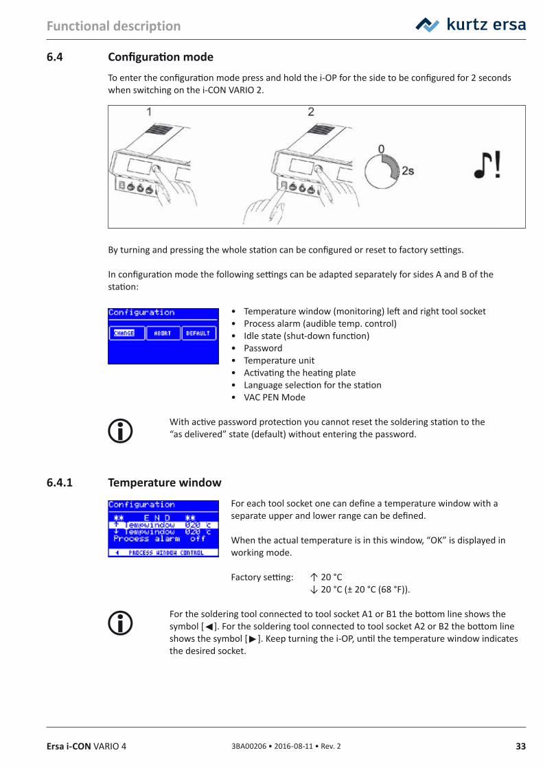
6.4 Configuration modeTo enter the configuration mode press and hold the i-OP for the side to be configured for 2 seconds when switching on the i-CON VARIO 2.
By turning and pressing the whole station can be configured or reset to factory settings.
In configuration mode the following settings can be adapted separately for sides A and B of the station:
• Temperature window (monitoring) left and right tool socket• Process alarm (audible temp. control)• Idle state (shut-down function)• Password• Temperature unit• Activating the heating plate• Language selection for the station• VAC PEN Mode
With active password protection you cannot reset the soldering station to the “as delivered” state (default) without entering the password.
6.4.1 Temperature windowFor each tool socket one can define a temperature window with a separate upper and lower range can be defined.
When the actual temperature is in this window, “OK” is displayed in working mode.
Factory setting: ↑ 20 °C ↓ 20 °C (± 20 °C (68 °F)).
For the soldering tool connected to tool socket A1 or B1 the bottom line shows the symbol []. For the soldering tool connected to tool socket A2 or B2 the bottom line shows the symbol []. Keep turning the i-OP, until the temperature window indicates the desired socket.
34 3BA00206 • 2016-08-11 • Rev. 2 Ersa i-CON VARIO 4
Functional description
6.4.2 Process alarmOnce the actual temperature leaves the temperature window, a single audible signal will sound. Once the actual temperature returns to temperature window, a double audible signal will sound. Factory setting: [off].
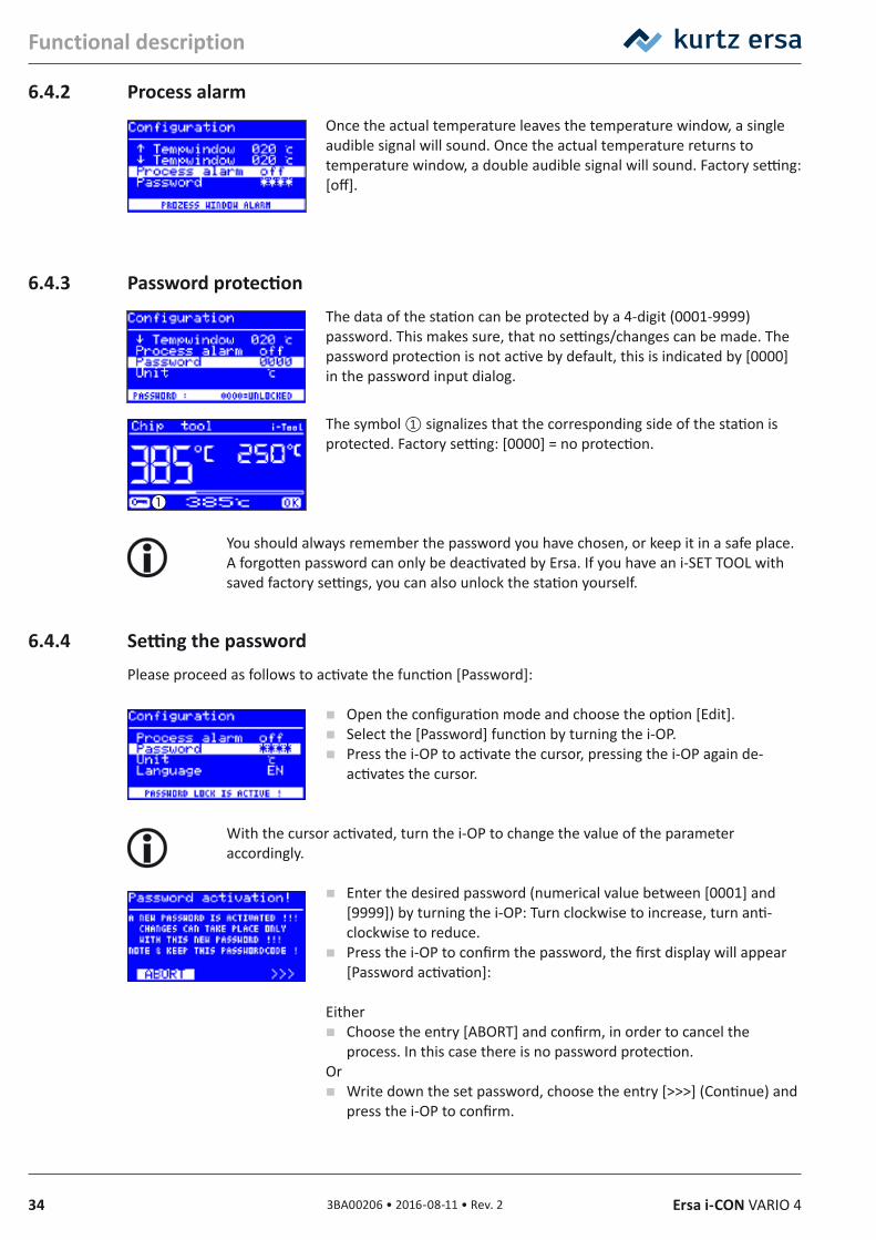
6.4.3 Password protectionThe data of the station can be protected by a 4-digit (0001-9999) password. This makes sure, that no settings/changes can be made. The password protection is not active by default, this is indicated by [0000] in the password input dialog.
The symbol ① signalizes that the corresponding side of the station is protected. Factory setting: [0000] = no protection.
You should always remember the password you have chosen, or keep it in a safe place. A forgotten password can only be deactivated by Ersa. If you have an i-SET TOOL with saved factory settings, you can also unlock the station yourself.
6.4.4 Setting the passwordPlease proceed as follows to activate the function [Password]:
Open the configuration mode and choose the option [Edit]. Select the [Password] function by turning the i-OP. Press the i-OP to activate the cursor, pressing the i-OP again de-
activates the cursor.
With the cursor activated, turn the i-OP to change the value of the parameter accordingly.
Enter the desired password (numerical value between [0001] and [9999]) by turning the i-OP: Turn clockwise to increase, turn anti-clockwise to reduce.
Press the i-OP to confirm the password, the first display will appear [Password activation]:
Either Choose the entry [ABORT] and confirm, in order to cancel the
process. In this case there is no password protection.Or
Write down the set password, choose the entry [>>>] (Continue) and press the i-OP to confirm.
353BA00206 • 2016-08-11 • Rev. 2Ersa i-CON VARIO 4
Functional description
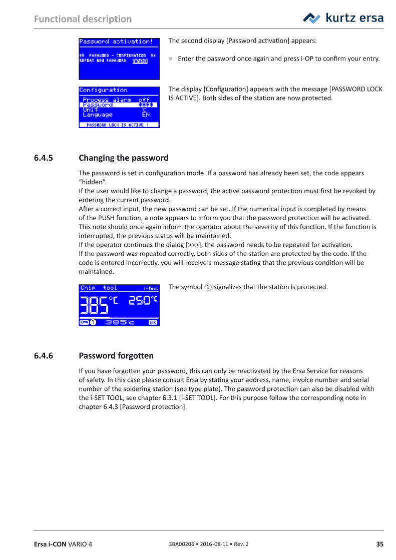
The second display [Password activation] appears:
Enter the password once again and press i-OP to confirm your entry.
The display [Configuration] appears with the message [PASSWORD LOCK IS ACTIVE]. Both sides of the station are now protected.
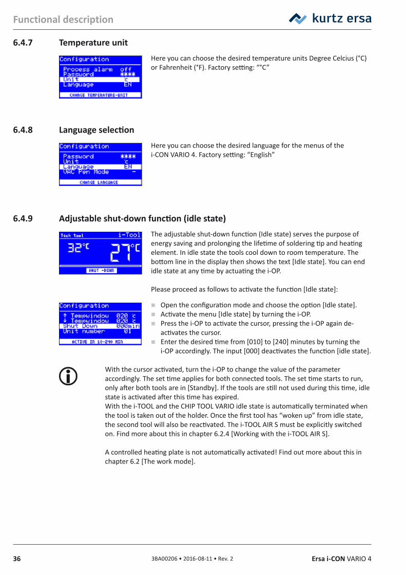
6.4.5 Changing the passwordThe password is set in configuration mode. If a password has already been set, the code appears “hidden”.If the user would like to change a password, the active password protection must first be revoked by entering the current password.After a correct input, the new password can be set. If the numerical input is completed by means of the PUSH function, a note appears to inform you that the password protection will be activated. This note should once again inform the operator about the severity of this function. If the function is interrupted, the previous status will be maintained.If the operator continues the dialog [>>>], the password needs to be repeated for activation.If the password was repeated correctly, both sides of the station are protected by the code. If the code is entered incorrectly, you will receive a message stating that the previous condition will be maintained.
The symbol ① signalizes that the station is protected.
6.4.6 Password forgottenIf you have forgotten your password, this can only be reactivated by the Ersa Service for reasons of safety. In this case please consult Ersa by stating your address, name, invoice number and serial number of the soldering station (see type plate). The password protection can also be disabled with the i-SET TOOL, see chapter 6.3.1 [i-SET TOOL]. For this purpose follow the corresponding note in chapter 6.4.3 [Password protection].
36 3BA00206 • 2016-08-11 • Rev. 2 Ersa i-CON VARIO 4
Functional description
6.4.7 Temperature unitHere you can choose the desired temperature units Degree Celcius (°C) or Fahrenheit (°F). Factory setting: “°C”
6.4.8 Language selectionHere you can choose the desired language for the menus of the i-CON VARIO 4. Factory setting: “English”
6.4.9 Adjustable shut‑down function (idle state)The adjustable shut-down function (Idle state) serves the purpose of energy saving and prolonging the lifetime of soldering tip and heating element. In idle state the tools cool down to room temperature. The bottom line in the display then shows the text [Idle state]. You can end idle state at any time by actuating the i-OP.
Please proceed as follows to activate the function [Idle state]:
Open the configuration mode and choose the option [Idle state]. Activate the menu [Idle state] by turning the i-OP. Press the i-OP to activate the cursor, pressing the i-OP again de-
activates the cursor. Enter the desired time from [010] to [240] minutes by turning the
i-OP accordingly. The input [000] deactivates the function [idle state].
With the cursor activated, turn the i-OP to change the value of the parameter accordingly. The set time applies for both connected tools. The set time starts to run, only after both tools are in [Standby]. If the tools are still not used during this time, idle state is activated after this time has expired. With the i-TOOL and the CHIP TOOL VARIO idle state is automatically terminated when the tool is taken out of the holder. Once the first tool has “woken up” from idle state, the second tool will also be reactivated. The i-TOOL AIR S must be explicitly switched on. Find more about this in chapter 6.2.4 [Working with the i-TOOL AIR S].
A controlled heating plate is not automatically activated! Find out more about this in chapter 6.2 [The work mode].
373BA00206 • 2016-08-11 • Rev. 2Ersa i-CON VARIO 4
Functional description
6.4.10 Heating plateYou can use the soldering station to control the infrared heating plate 0IRHP100A.
The following accessories are needed:• Control cable from soldering station to the infrared heating plate 0IRHP100A• Y-control cable given that the soldering smoke extractor and the infrared heating
plate 0IRHP100A are to be controlled together.
An infrared heating plate, a soldering fume extraction or both can be connected to the A- or B-side of the station. With the i-CON VARIO 2 you can operate up to four additional devices.
6.4.10.1 Connecting heating plate to soldering station Connect the heating plate control cable with the soldering station interface
connection A or B. Switch on the heating plate.
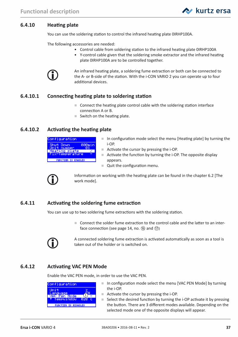
6.4.10.2 Activating the heating plate In configuration mode select the menu [Heating plate] by turning the
i-OP. Activate the cursor by pressing the i-OP. Activate the function by turning the i-OP. The opposite display
appears. Quit the configuration menu.
Information on working with the heating plate can be found in the chapter 6.2 [The work mode].
6.4.11 Activating the soldering fume extractionYou can use up to two soldering fume extractions with the soldering station.
Connect the solder fume extraction to the control cable and the latter to an inter-face connection (see page 14, no. ⑯ and ⑰)
A connected soldering fume extraction is activated automatically as soon as a tool is taken out of the holder or is switched on.
6.4.12 Activating VAC PEN ModeEnable the VAC PEN mode, in order to use the VAC PEN.
In configuration mode select the menu [VAC PEN Mode] by turning the i-OP.
Activate the cursor by pressing the i-OP. Select the desired function by turning the i-OP activate it by pressing
the button. There are 3 different modes available. Depending on the selected mode one of the opposite displays will appear.
38 3BA00206 • 2016-08-11 • Rev. 2 Ersa i-CON VARIO 4
Functional description
① The VAC PEN Mode is deactivated. ② The VAC-display appears on side A of the station. VAC PEN can be controlled via this side of the station. ③ The VAC-display appears on side B of the station. VAC PEN can be controlled via this side of the station.
Quit the configuration menu.
VAC PEN and X-TOOL or X-TOOL VARIO can not be operated simultaneously.
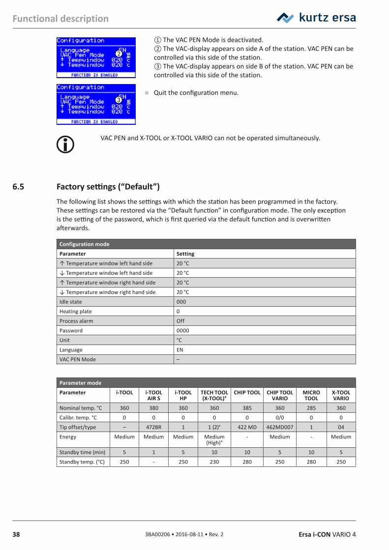
6.5 Factory settings (“Default”)The following list shows the settings with which the station has been programmed in the factory. These settings can be restored via the “Default function” in configuration mode. The only exception is the setting of the password, which is first queried via the default function and is overwritten afterwards.
Configuration mode
Parameter Setting
↑ Temperature window left hand side 20 °C
↓ Temperature window left hand side 20 °C
↑ Temperature window right hand side 20 °C
↓ Temperature window right hand side 20 °C
Idle state 000
Heating plate 0
Process alarm Off
Password 0000
Unit °C
Language EN
VAC PEN Mode –
Parameter mode
Parameter i‑TOOL i‑TOOL AIR S
i‑TOOL HP
TECH TOOL (X‑TOOL)°
CHIP TOOL CHIP TOOL VARIO
MICRO TOOL
X‑TOOL VARIO
Nominal temp. °C 360 380 360 360 385 360 285 360
Calibr. temp. °C 0 0 0 0 0 0/0 0 0
Tip offset/type – 472BR 1 1 (2)° 422 MD 462MD007 1 04
Energy Medium Medium Medium Medium(High)°
- Medium - Medium
Standby time (min) 5 1 5 10 10 5 10 5
Standby temp. (°C) 250 - 250 230 280 250 280 250
393BA00206 • 2016-08-11 • Rev. 2Ersa i-CON VARIO 4
Functional description
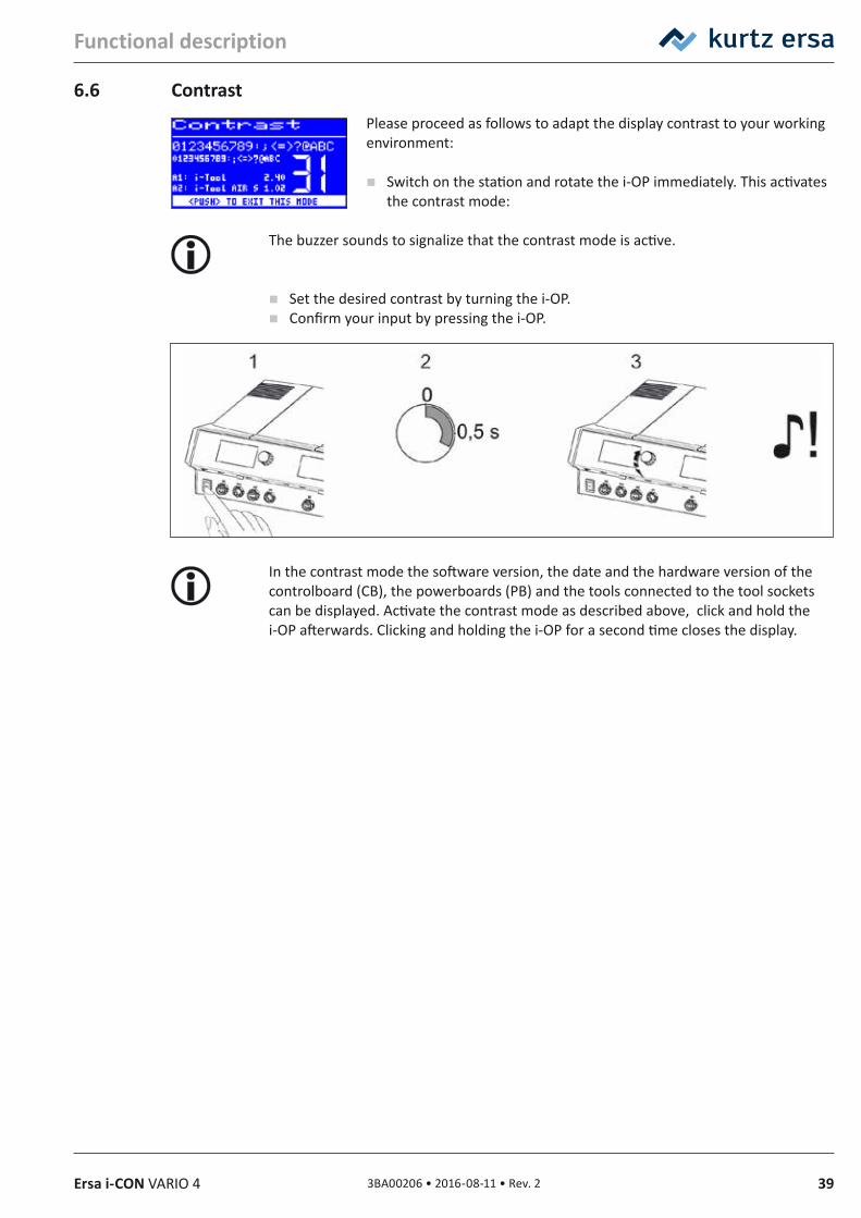
6.6 ContrastPlease proceed as follows to adapt the display contrast to your working environment:
Switch on the station and rotate the i-OP immediately. This activates the contrast mode:
The buzzer sounds to signalize that the contrast mode is active.
Set the desired contrast by turning the i-OP. Confirm your input by pressing the i-OP.
In the contrast mode the software version, the date and the hardware version of the controlboard (CB), the powerboards (PB) and the tools connected to the tool sockets can be displayed. Activate the contrast mode as described above, click and hold the i-OP afterwards. Clicking and holding the i-OP for a second time closes the display.
40 3BA00206 • 2016-08-11 • Rev. 2 Ersa i-CON VARIO 4
Functional description
6.7 Changing soldering tipsSoldering tips must be changed when:
• The size of the soldering tip does not match the soldering joint (current tip too big / too small).
• The soldering tip is worn or damaged (pitting corrosion, tip can no longer be wetted, mechanical damage).
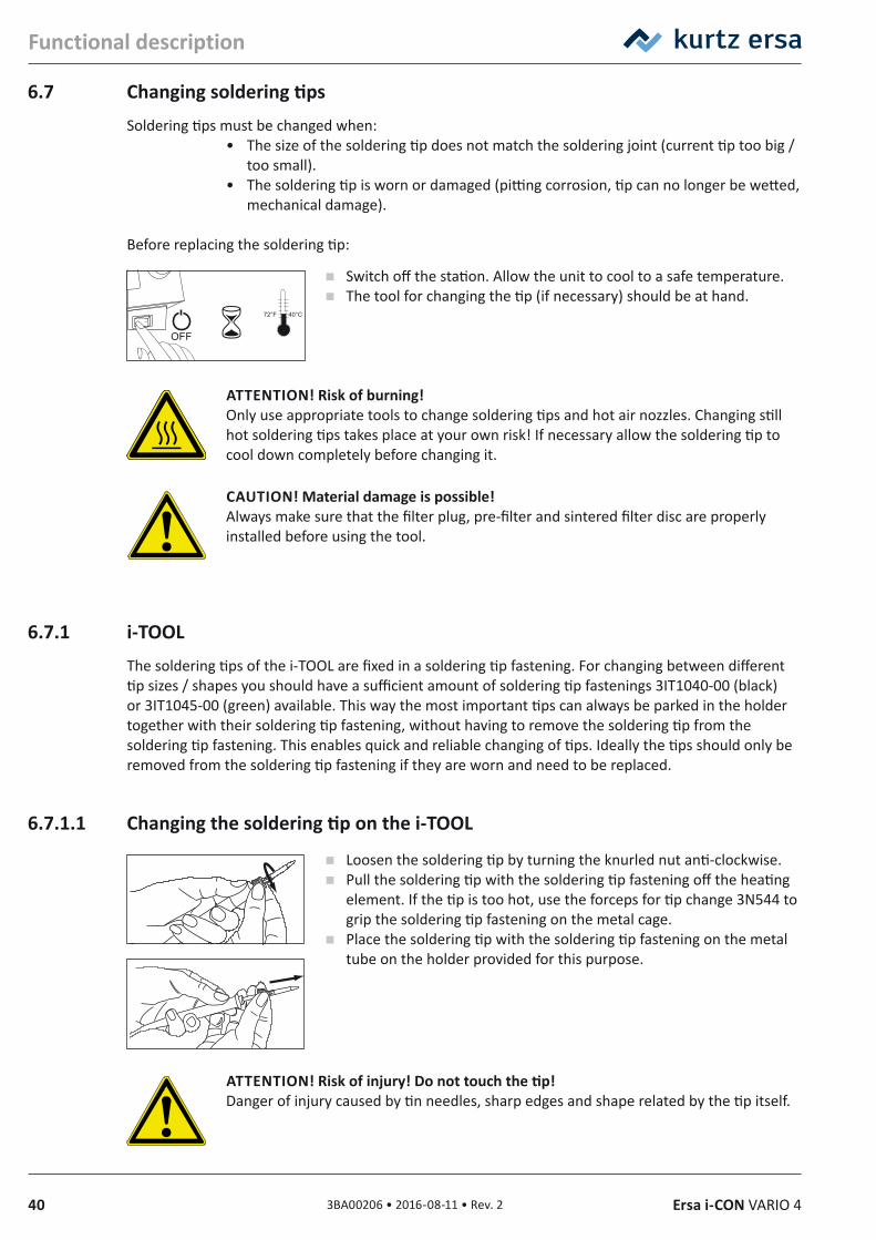
Before replacing the soldering tip:
Switch off the station. Allow the unit to cool to a safe temperature. The tool for changing the tip (if necessary) should be at hand.
ATTENTION! Risk of burning! Only use appropriate tools to change soldering tips and hot air nozzles. Changing still hot soldering tips takes place at your own risk! If necessary allow the soldering tip to cool down completely before changing it.
CAUTION! Material damage is possible!Always make sure that the filter plug, pre-filter and sintered filter disc are properly installed before using the tool.
6.7.1 i‑TOOLThe soldering tips of the i-TOOL are fixed in a soldering tip fastening. For changing between different tip sizes / shapes you should have a sufficient amount of soldering tip fastenings 3IT1040-00 (black) or 3IT1045-00 (green) available. This way the most important tips can always be parked in the holder together with their soldering tip fastening, without having to remove the soldering tip from the soldering tip fastening. This enables quick and reliable changing of tips. Ideally the tips should only be removed from the soldering tip fastening if they are worn and need to be replaced.
6.7.1.1 Changing the soldering tip on the i‑TOOL
Loosen the soldering tip by turning the knurled nut anti-clockwise. Pull the soldering tip with the soldering tip fastening off the heating
element. If the tip is too hot, use the forceps for tip change 3N544 to grip the soldering tip fastening on the metal cage.
Place the soldering tip with the soldering tip fastening on the metal tube on the holder provided for this purpose.
ATTENTION! Risk of injury! Do not touch the tip! Danger of injury caused by tin needles, sharp edges and shape related by the tip itself.
OFF
40°C72°F_
413BA00206 • 2016-08-11 • Rev. 2Ersa i-CON VARIO 4
Functional description
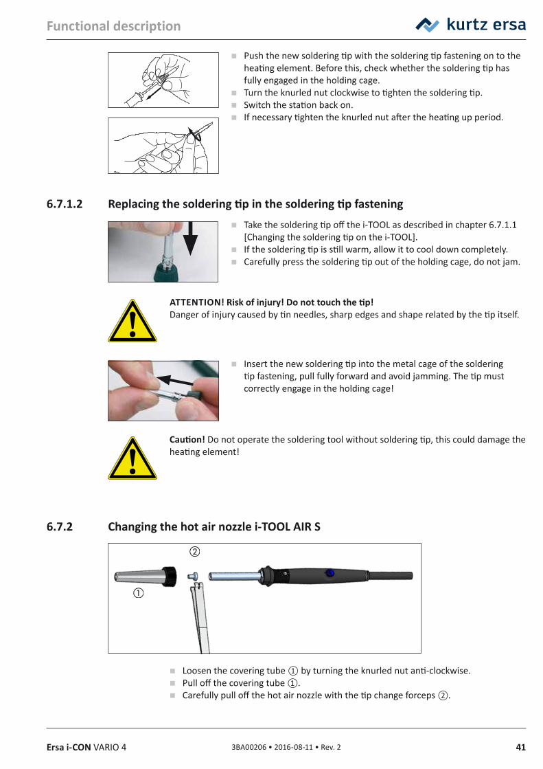
Push the new soldering tip with the soldering tip fastening on to the heating element. Before this, check whether the soldering tip has fully engaged in the holding cage.
Turn the knurled nut clockwise to tighten the soldering tip. Switch the station back on. If necessary tighten the knurled nut after the heating up period.
6.7.1.2 Replacing the soldering tip in the soldering tip fastening Take the soldering tip off the i-TOOL as described in chapter 6.7.1.1
[Changing the soldering tip on the i-TOOL]. If the soldering tip is still warm, allow it to cool down completely. Carefully press the soldering tip out of the holding cage, do not jam.
ATTENTION! Risk of injury! Do not touch the tip! Danger of injury caused by tin needles, sharp edges and shape related by the tip itself.
Insert the new soldering tip into the metal cage of the soldering tip fastening, pull fully forward and avoid jamming. The tip must correctly engage in the holding cage!
Caution! Do not operate the soldering tool without soldering tip, this could damage the heating element!
6.7.2 Changing the hot air nozzle i‑TOOL AIR S
Loosen the covering tube ① by turning the knurled nut anti-clockwise. Pull off the covering tube ①. Carefully pull off the hot air nozzle with the tip change forceps ②.
42 3BA00206 • 2016-08-11 • Rev. 2 Ersa i-CON VARIO 4
Functional description
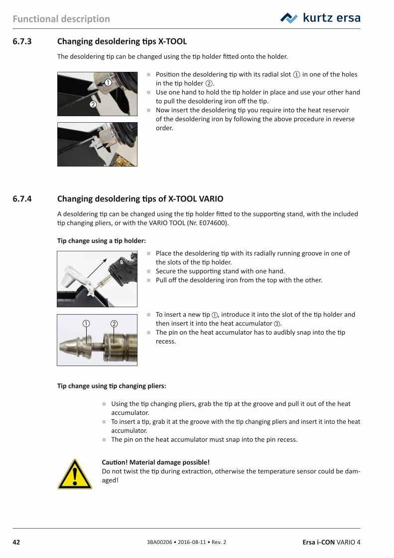
6.7.3 Changing desoldering tips X‑TOOLThe desoldering tip can be changed using the tip holder fitted onto the holder.
Position the desoldering tip with its radial slot ① in one of the holes in the tip holder ②.
Use one hand to hold the tip holder in place and use your other hand to pull the desoldering iron off the tip.
Now insert the desoldering tip you require into the heat reservoir of the desoldering iron by following the above procedure in reverse order.
6.7.4 Changing desoldering tips of X‑TOOL VARIOA desoldering tip can be changed using the tip holder fitted to the supporting stand, with the included tip changing pliers, or with the VARIO TOOL (Nr. E074600).
Tip change using a tip holder:
Place the desoldering tip with its radially running groove in one of the slots of the tip holder.
Secure the supporting stand with one hand. Pull off the desoldering iron from the top with the other.
To insert a new tip , introduce it into the slot of the tip holder and then insert it into the heat accumulator .
The pin on the heat accumulator has to audibly snap into the tip recess.
Tip change using tip changing pliers:
Using the tip changing pliers, grab the tip at the groove and pull it out of the heat accumulator.
To insert a tip, grab it at the groove with the tip changing pliers and insert it into the heat accumulator.
The pin on the heat accumulator must snap into the pin recess.
Caution! Material damage possible! Do not twist the tip during extraction, otherwise the temperature sensor could be dam-aged!
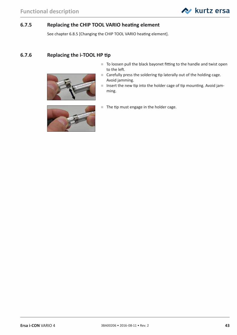
433BA00206 • 2016-08-11 • Rev. 2Ersa i-CON VARIO 4
Functional description
6.7.5 Replacing the CHIP TOOL VARIO heating elementSee chapter 6.8.5 [Changing the CHIP TOOL VARIO heating element].
6.7.6 Replacing the i‑TOOL HP tip To loosen pull the black bayonet fitting to the handle and twist open
to the left. Carefully press the soldering tip laterally out of the holding cage.
Avoid jamming. Insert the new tip into the holder cage of tip mounting. Avoid jam-
ming.
The tip must engage in the holder cage.
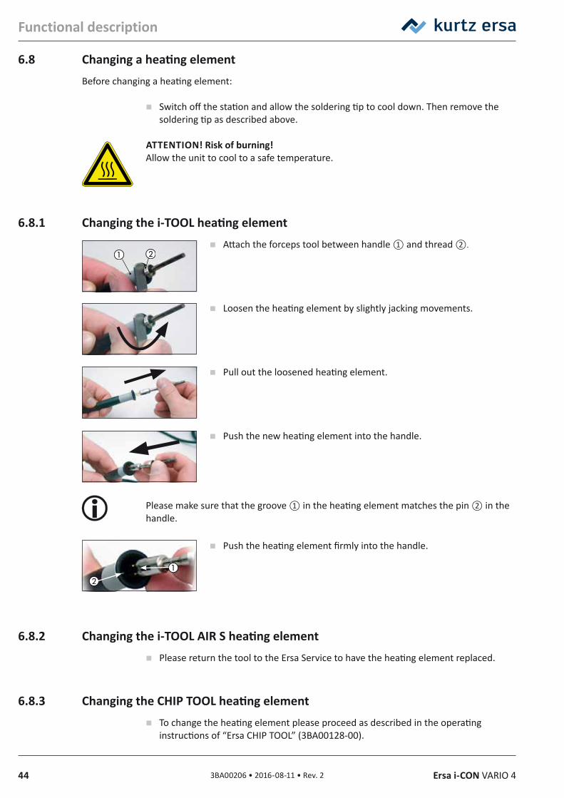
44 3BA00206 • 2016-08-11 • Rev. 2 Ersa i-CON VARIO 4
Functional description
6.8 Changing a heating elementBefore changing a heating element:
Switch off the station and allow the soldering tip to cool down. Then remove the soldering tip as described above.
ATTENTION! Risk of burning! Allow the unit to cool to a safe temperature.
6.8.1 Changing the i‑TOOL heating element Attach the forceps tool between handle ① and thread ②.
Loosen the heating element by slightly jacking movements.
Pull out the loosened heating element.
Push the new heating element into the handle.
Please make sure that the groove ① in the heating element matches the pin ② in the handle.
Push the heating element firmly into the handle.
6.8.2 Changing the i‑TOOL AIR S heating element Please return the tool to the Ersa Service to have the heating element replaced.
6.8.3 Changing the CHIP TOOL heating element To change the heating element please proceed as described in the operating
instructions of “Ersa CHIP TOOL” (3BA00128-00).
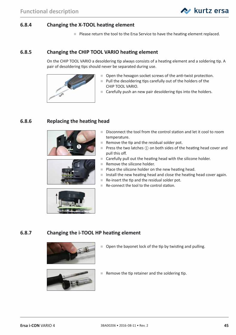
453BA00206 • 2016-08-11 • Rev. 2Ersa i-CON VARIO 4
Functional description
6.8.4 Changing the X‑TOOL heating element Please return the tool to the Ersa Service to have the heating element replaced.
6.8.5 Changing the CHIP TOOL VARIO heating elementOn the CHIP TOOL VARIO a desoldering tip always consists of a heating element and a soldering tip. A pair of desoldering tips should never be separated during use.
Open the hexagon socket screws of the anti-twist protection. Pull the desoldering tips carefully out of the holders of the
CHIP TOOL VARIO. Carefully push an new pair desoldering tips into the holders.
6.8.6 Replacing the heating head
Disconnect the tool from the control station and let it cool to room temperature.
Remove the tip and the residual solder pot. Press the two latches ① on both sides of the heating head cover and
pull this off. Carefully pull out the heating head with the silicone holder. Remove the silicone holder. Place the silicone holder on the new heating head. Install the new heating head and close the heating head cover again. Re-insert the tip and the residual solder pot. Re-connect the tool to the control station.
6.8.7 Changing the i‑TOOL HP heating element
Open the bayonet lock of the tip by twisting and pulling.
Remove the tip retainer and the soldering tip.
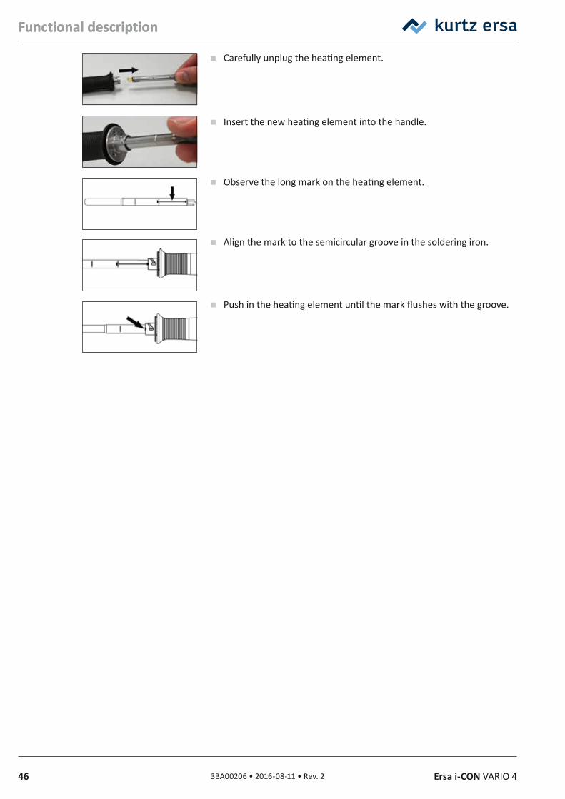
46 3BA00206 • 2016-08-11 • Rev. 2 Ersa i-CON VARIO 4
Functional description
Carefully unplug the heating element.
Insert the new heating element into the handle.
Observe the long mark on the heating element.
Align the mark to the semicircular groove in the soldering iron.
Push in the heating element until the mark flushes with the groove.
Functional description
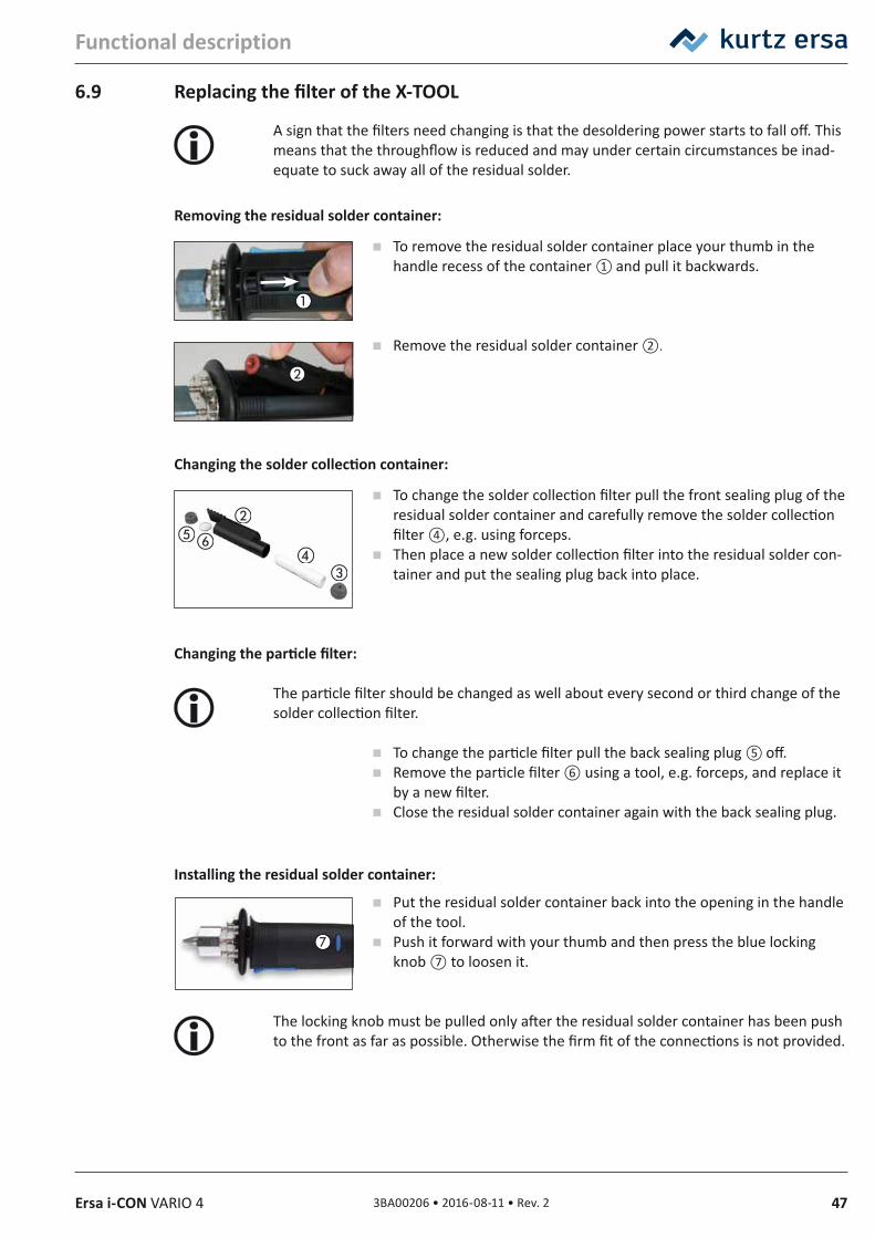
473BA00206 • 2016-08-11 • Rev. 2Ersa i-CON VARIO 4
Functional description
6.9 Replacing the filter of the X‑TOOL
A sign that the filters need changing is that the desoldering power starts to fall off. This means that the throughflow is reduced and may under certain circumstances be inad-equate to suck away all of the residual solder.
Removing the residual solder container:
To remove the residual solder container place your thumb in the handle recess of the container ① and pull it backwards.
Remove the residual solder container ②.
Changing the solder collection container:
To change the solder collection filter pull the front sealing plug of the residual solder container and carefully remove the solder collection filter ④, e.g. using forceps.
Then place a new solder collection filter into the residual solder con-tainer and put the sealing plug back into place.
Changing the particle filter:
The particle filter should be changed as well about every second or third change of the solder collection filter.
To change the particle filter pull the back sealing plug ⑤ off. Remove the particle filter ⑥ using a tool, e.g. forceps, and replace it
by a new filter. Close the residual solder container again with the back sealing plug.
Installing the residual solder container:
Put the residual solder container back into the opening in the handle of the tool.
Push it forward with your thumb and then press the blue locking knob ⑦ to loosen it.
The locking knob must be pulled only after the residual solder container has been push to the front as far as possible. Otherwise the firm fit of the connections is not provided.
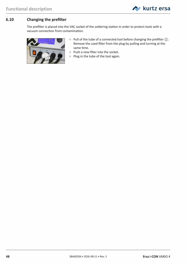
48 3BA00206 • 2016-08-11 • Rev. 2 Ersa i-CON VARIO 4
Functional description
6.10 Changing the prefilterThe prefilter is placed into the VAC socket of the soldering station in order to protect tools with a vacuum connection from contamination.
Pull of the tube of a connected tool before changing the prefilter ①. Remove the used filter from the plug by pulling and turning at the same time.
Push a new filter into the socket. Plug in the tube of the tool again.
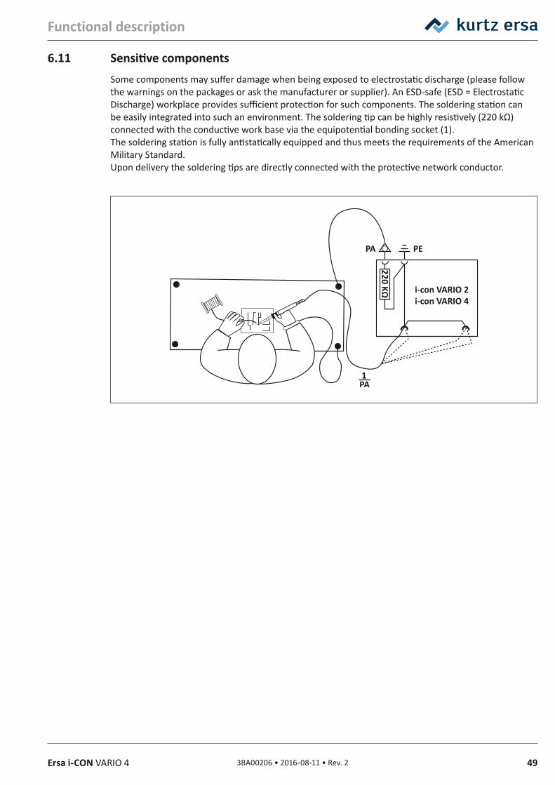
493BA00206 • 2016-08-11 • Rev. 2Ersa i-CON VARIO 4
Functional description
6.11 Sensitive componentsSome components may suffer damage when being exposed to electrostatic discharge (please follow the warnings on the packages or ask the manufacturer or supplier). An ESD-safe (ESD = Electrostatic Discharge) workplace provides sufficient protection for such components. The soldering station can be easily integrated into such an environment. The soldering tip can be highly resistively (220 kΩ) connected with the conductive work base via the equipotential bonding socket (1).The soldering station is fully antistatically equipped and thus meets the requirements of the American Military Standard.Upon delivery the soldering tips are directly connected with the protective network conductor.
220 KΩ
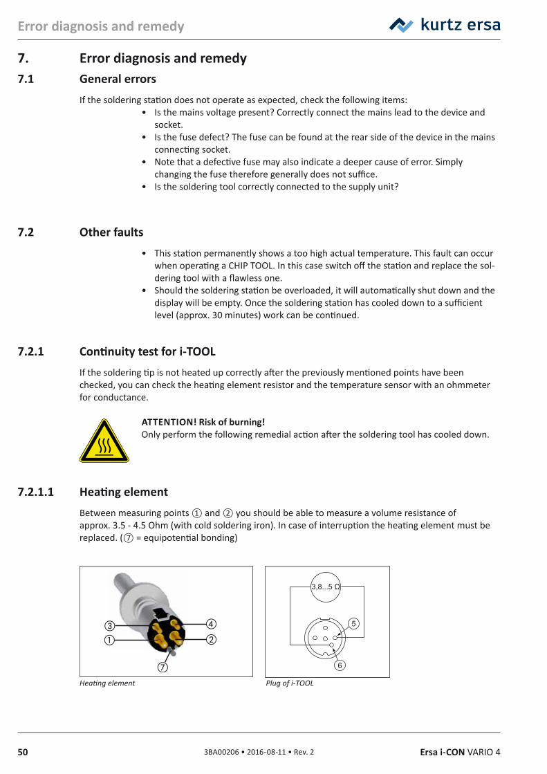
50 3BA00206 • 2016-08-11 • Rev. 2 Ersa i-CON VARIO 4
Error diagnosis and remedy
7. Error diagnosis and remedy7.1 General errors
If the soldering station does not operate as expected, check the following items:• Is the mains voltage present? Correctly connect the mains lead to the device and
socket.• Is the fuse defect? The fuse can be found at the rear side of the device in the mains
connecting socket.• Note that a defective fuse may also indicate a deeper cause of error. Simply
changing the fuse therefore generally does not suffice.• Is the soldering tool correctly connected to the supply unit?
7.2 Other faults• This station permanently shows a too high actual temperature. This fault can occur
when operating a CHIP TOOL. In this case switch off the station and replace the sol-dering tool with a flawless one.
• Should the soldering station be overloaded, it will automatically shut down and the display will be empty. Once the soldering station has cooled down to a sufficient level (approx. 30 minutes) work can be continued.
7.2.1 Continuity test for i‑TOOLIf the soldering tip is not heated up correctly after the previously mentioned points have been checked, you can check the heating element resistor and the temperature sensor with an ohmmeter for conductance.
ATTENTION! Risk of burning! Only perform the following remedial action after the soldering tool has cooled down.
7.2.1.1 Heating elementBetween measuring points ① and ② you should be able to measure a volume resistance of approx. 3.5 - 4.5 Ohm (with cold soldering iron). In case of interruption the heating element must be replaced. (⑦ = equipotential bonding)
Heating element Plug of i‑TOOL
3,8...5 Ω
5
6
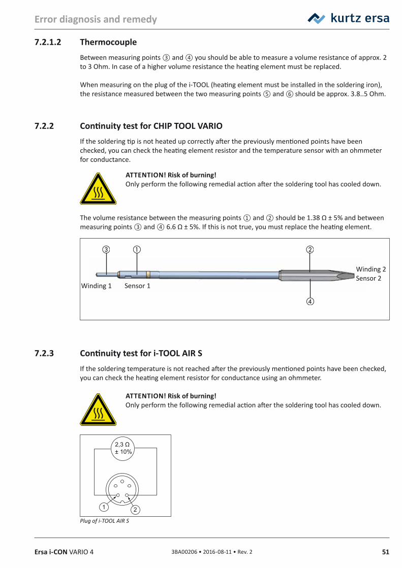
513BA00206 • 2016-08-11 • Rev. 2Ersa i-CON VARIO 4
Error diagnosis and remedy
7.2.1.2 ThermocoupleBetween measuring points ③ and ④ you should be able to measure a volume resistance of approx. 2 to 3 Ohm. In case of a higher volume resistance the heating element must be replaced.
When measuring on the plug of the i-TOOL (heating element must be installed in the soldering iron), the resistance measured between the two measuring points ⑤ and ⑥ should be approx. 3.8..5 Ohm.
7.2.2 Continuity test for CHIP TOOL VARIOIf the soldering tip is not heated up correctly after the previously mentioned points have been checked, you can check the heating element resistor and the temperature sensor with an ohmmeter for conductance.
ATTENTION! Risk of burning! Only perform the following remedial action after the soldering tool has cooled down.
The volume resistance between the measuring points ① and ② should be 1.38 Ω ± 5% and between measuring points ③ and ④ 6.6 Ω ± 5%. If this is not true, you must replace the heating element.
7.2.3 Continuity test for i‑TOOL AIR SIf the soldering temperature is not reached after the previously mentioned points have been checked, you can check the heating element resistor for conductance using an ohmmeter.
ATTENTION! Risk of burning! Only perform the following remedial action after the soldering tool has cooled down.
Plug of i‑TOOL AIR S
Sensor 1Winding 1
Winding 2Sensor 2
2,3 Ω± 10%
1 2
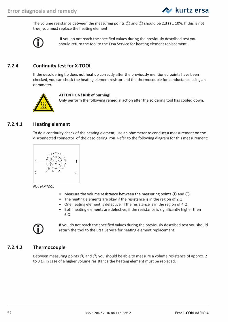
52 3BA00206 • 2016-08-11 • Rev. 2 Ersa i-CON VARIO 4
Error diagnosis and remedy
The volume resistance between the measuring points ① and ② should be 2.3 Ω ± 10%. If this is not true, you must replace the heating element.
If you do not reach the specified values during the previously described test you should return the tool to the Ersa Service for heating element replacement.
7.2.4 Continuity test for X‑TOOLIf the desoldering tip does not heat up correctly after the previously mentioned points have been checked, you can check the heating element resistor and the thermocouple for conductance using an ohmmeter.
ATTENTION! Risk of burning! Only perform the following remedial action after the soldering tool has cooled down.
7.2.4.1 Heating elementTo do a continuity check of the heating element, use an ohmmeter to conduct a measurement on the disconnected connector of the desoldering iron. Refer to the following diagram for this measurement:
Plug of X‑TOOL
• Measure the volume resistance between the measuring points ① and ⑥.• The heating elements are okay if the resistance is in the region of 2 Ω.• One heating element is defective, if the resistance is in the region of 4 Ω.• Both heating elements are defective, if the resistance is significantly higher then
6 Ω.
If you do not reach the specified values during the previously described test you should return the tool to the Ersa Service for heating element replacement.
7.2.4.2 ThermocoupleBetween measuring points ③ and ⑦ you should be able to measure a volume resistance of approx. 2 to 3 Ω. In case of a higher volume resistance the heating element must be replaced.
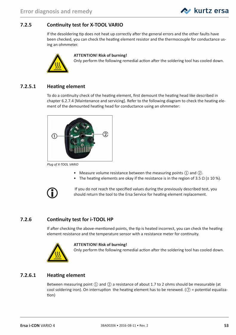
533BA00206 • 2016-08-11 • Rev. 2Ersa i-CON VARIO 4
Error diagnosis and remedy
7.2.5 Continuity test for X‑TOOL VARIOIf the desoldering tip does not heat up correctly after the general errors and the other faults have been checked, you can check the heating element resistor and the thermocouple for conductance us-ing an ohmmeter.
ATTENTION! Risk of burning! Only perform the following remedial action after the soldering tool has cooled down.
7.2.5.1 Heating elementTo do a continuity check of the heating element, first demount the heating head like described in chapter 6.2.7.4 [Maintenance and servicing]. Refer to the following diagram to check the heating ele-ment of the demounted heating head for conductance using an ohmmeter:
Plug of X‑TOOL VARIO
• Measure volume resistance between the measuring points ① and ②.• The heating elements are okay if the resistance is in the region of 3.5 Ω (± 10 %).
If you do not reach the specified values during the previously described test, you should return the tool to the Ersa Service for heating element replacement.
7.2.6 Continuity test for i‑TOOL HPIf after checking the above-mentioned points, the tip is heated incorrect, you can check the heating element resistance and the temperature sensor with a resistance meter for continuity.
ATTENTION! Risk of burning! Only perform the following remedial action after the soldering tool has cooled down.
7.2.6.1 Heating elementBetween measuring point ① and ② a resistance of about 1.7 to 2 ohms should be measurable (at cool soldering iron). On interruption the heating element has to be renewed. (⑦ = potential equaliza-tion)
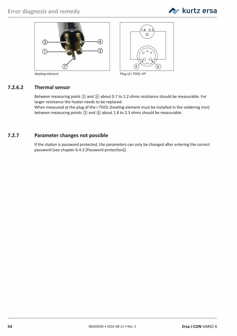
54 3BA00206 • 2016-08-11 • Rev. 2 Ersa i-CON VARIO 4
Error diagnosis and remedy
1,8...2,3Ω
5 6
Heating element Plug of i‑TOOL HP
7.2.6.2 Thermal sensorBetween measuring point ③ and ④ about 0.7 to 1.2 ohms resistance should be measurable. For larger resistance the heater needs to be replaced.When measured at the plug of the i-TOOL (heating element must be installed in the soldering iron) between measuring points ⑤ and ⑥ about 1.8 to 2.3 ohms should be measurable .
7.2.7 Parameter changes not possibleIf the station is password protected, the parameters can only be changed after entering the correct password (see chapter 6.4.3 [Password protection]).
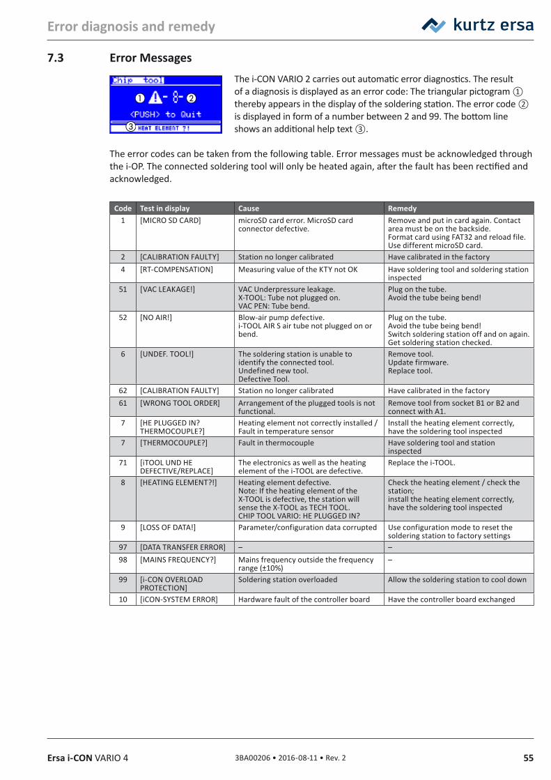
553BA00206 • 2016-08-11 • Rev. 2Ersa i-CON VARIO 4
Error diagnosis and remedy
7.3 Error MessagesThe i-CON VARIO 2 carries out automatic error diagnostics. The result of a diagnosis is displayed as an error code: The triangular pictogram ① thereby appears in the display of the soldering station. The error code ② is displayed in form of a number between 2 and 99. The bottom line shows an additional help text ③.
The error codes can be taken from the following table. Error messages must be acknowledged through the i-OP. The connected soldering tool will only be heated again, after the fault has been rectified and acknowledged.
Code Test in display Cause Remedy1 [MICRO SD CARD] microSD card error. MicroSD card
connector defective.Remove and put in card again. Contact area must be on the backside. Format card using FAT32 and reload file. Use different microSD card.
2 [CALIBRATION FAULTY] Station no longer calibrated Have calibrated in the factory4 [RT-COMPENSATION] Measuring value of the KTY not OK Have soldering tool and soldering station
inspected51 [VAC LEAKAGE!] VAC Underpressure leakage.
X-TOOL: Tube not plugged on. VAC PEN: Tube bend.
Plug on the tube. Avoid the tube being bend!
52 [NO AIR!] Blow-air pump defective. i-TOOL AIR S air tube not plugged on or bend.
Plug on the tube. Avoid the tube being bend! Switch soldering station off and on again. Get soldering station checked.
6 [UNDEF. TOOL!] The soldering station is unable to identify the connected tool. Undefined new tool. Defective Tool.
Remove tool. Update firmware. Replace tool.
62 [CALIBRATION FAULTY] Station no longer calibrated Have calibrated in the factory61 [WRONG TOOL ORDER] Arrangement of the plugged tools is not
functional.Remove tool from socket B1 or B2 and connect with A1.
7 [HE PLUGGED IN? THERMOCOUPLE?]
Heating element not correctly installed / Fault in temperature sensor
Install the heating element correctly, have the soldering tool inspected
7 [THERMOCOUPLE?] Fault in thermocouple Have soldering tool and station inspected
71 [iTOOL UND HE DEFECTIVE/REPLACE]
The electronics as well as the heating element of the i-TOOL are defective.
Replace the i-TOOL.
8 [HEATING ELEMENT?!] Heating element defective. Note: If the heating element of the X-TOOL is defective, the station will sense the X-TOOL as TECH TOOL. CHIP TOOL VARIO: HE PLUGGED IN?
Check the heating element / check the station; install the heating element correctly, have the soldering tool inspected
9 [LOSS OF DATA!] Parameter/configuration data corrupted Use configuration mode to reset the soldering station to factory settings
97 [DATA TRANSFER ERROR] – –98 [MAINS FREQUENCY?] Mains frequency outside the frequency
range (±10%)–
99 [i-CON OVERLOAD PROTECTION]
Soldering station overloaded Allow the soldering station to cool down
10 [iCON-SYSTEM ERROR] Hardware fault of the controller board Have the controller board exchanged
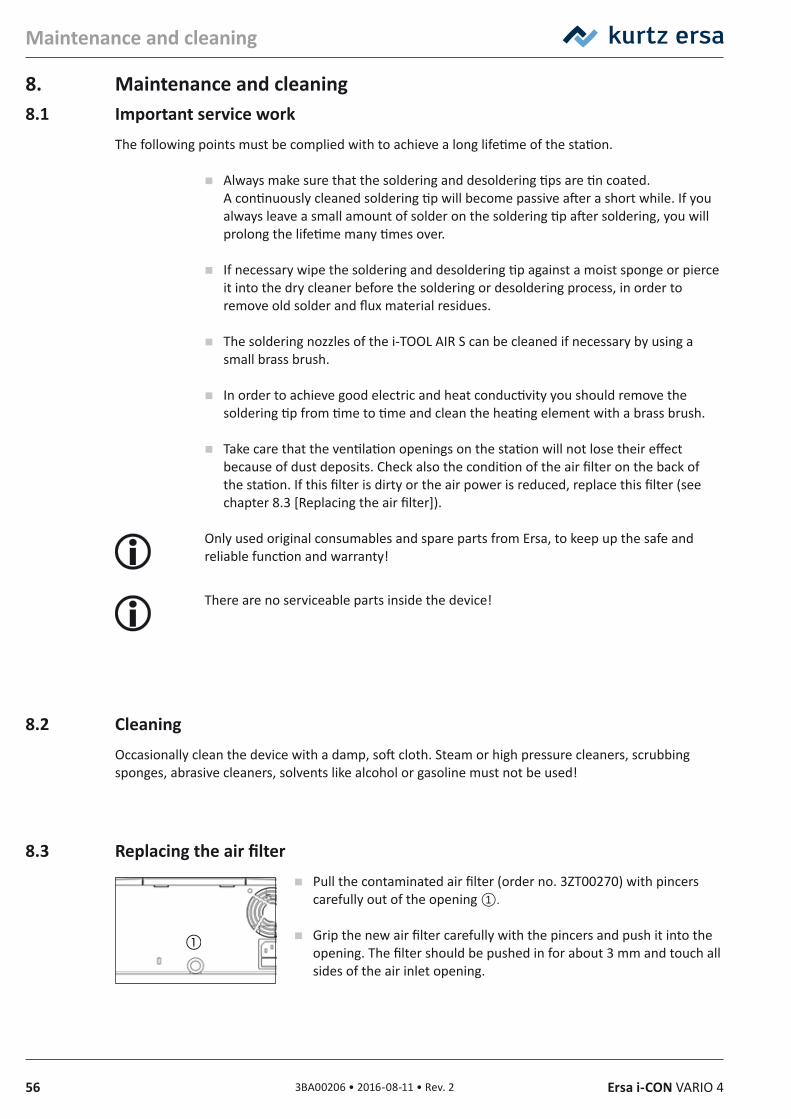
56 3BA00206 • 2016-08-11 • Rev. 2 Ersa i-CON VARIO 4
Maintenance and cleaning
8. Maintenance and cleaning8.1 Important service work
The following points must be complied with to achieve a long lifetime of the station.
Always make sure that the soldering and desoldering tips are tin coated. A continuously cleaned soldering tip will become passive after a short while. If you always leave a small amount of solder on the soldering tip after soldering, you will prolong the lifetime many times over.
If necessary wipe the soldering and desoldering tip against a moist sponge or pierce it into the dry cleaner before the soldering or desoldering process, in order to remove old solder and flux material residues.
The soldering nozzles of the i-TOOL AIR S can be cleaned if necessary by using a small brass brush.
In order to achieve good electric and heat conductivity you should remove the soldering tip from time to time and clean the heating element with a brass brush.
Take care that the ventilation openings on the station will not lose their effect because of dust deposits. Check also the condition of the air filter on the back of the station. If this filter is dirty or the air power is reduced, replace this filter (see chapter 8.3 [Replacing the air filter]).
Only used original consumables and spare parts from Ersa, to keep up the safe and reliable function and warranty!
There are no serviceable parts inside the device!
8.2 CleaningOccasionally clean the device with a damp, soft cloth. Steam or high pressure cleaners, scrubbing sponges, abrasive cleaners, solvents like alcohol or gasoline must not be used!
8.3 Replacing the air filter Pull the contaminated air filter (order no. 3ZT00270) with pincers
carefully out of the opening ①.
Grip the new air filter carefully with the pincers and push it into the opening. The filter should be pushed in for about 3 mm and touch all sides of the air inlet opening.
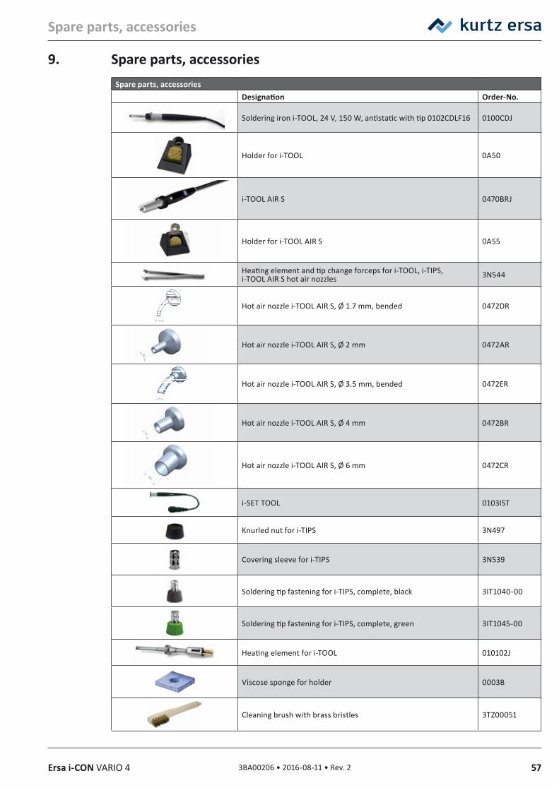
573BA00206 • 2016-08-11 • Rev. 2Ersa i-CON VARIO 4
Spare parts, accessories
9. Spare parts, accessoriesSpare parts, accessories
Designation Order‑No.
Soldering iron i-TOOL, 24 V, 150 W, antistatic with tip 0102CDLF16 0100CDJ
Holder for i-TOOL 0A50
i-TOOL AIR S 0470BRJ
Holder for i-TOOL AIR S 0A55
Heating element and tip change forceps for i-TOOL, i-TIPS, i-TOOL AIR S hot air nozzles 3N544
Hot air nozzle i-TOOL AIR S, Ø 1.7 mm, bended 0472DR
Hot air nozzle i-TOOL AIR S, Ø 2 mm 0472AR
Hot air nozzle i-TOOL AIR S, Ø 3.5 mm, bended 0472ER
Hot air nozzle i-TOOL AIR S, Ø 4 mm 0472BR
Hot air nozzle i-TOOL AIR S, Ø 6 mm 0472CR
i-SET TOOL 0103IST
Knurled nut for i-TIPS 3N497
Covering sleeve for i-TIPS 3N539
Soldering tip fastening for i-TIPS, complete, black 3IT1040-00
Soldering tip fastening for i-TIPS, complete, green 3IT1045-00
Heating element for i-TOOL 010102J
Viscose sponge for holder 0003B
Cleaning brush with brass bristles 3TZ00051
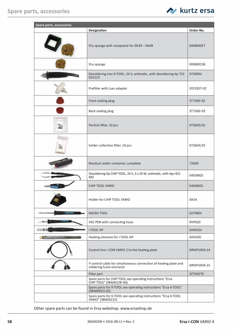
58 3BA00206 • 2016-08-11 • Rev. 2 Ersa i-CON VARIO 4
Spare parts, accessories
Spare parts, accessoriesDesignation Order‑No.
Dry sponge with receptacle for 0A39 – 0A48 0A08MSET
Dry sponge 0008M15B
Desoldering iron X-TOOL, 24 V, antistatic, with desoldering tip 722 ED1223
0720ENJ
Prefilter with Luer adapter 3YE1057-02
Front sealing plug 3T7260-02
Back sealing plug 3T7260-03
Particle filter, 10 pcs 072605/10
Solder collection filter, 10 pcs 072604/10
Residual solder container, complete 72600
Desoldering tip CHIP TOOL, 24 V, 2 x 20 W, antistatic, with tips 422 MD 0450MDJ
CHIP TOOL VARIO 0460MDJ
Holder for CHIP TOOL VARIO 0A54
MICRO TOOL 0270BDJ
VAC PEN with connecting hose 0VP020
i-TOOL HP 0240CDJ
Heating element for i-TOOL HP 024100J
Control line i-CON VARIO 2 to the heating plate 0IRHP100A-14
Y-control cable for simultaneous connection of heating plate and soldering fume extractor 0IRHP100A-15
Filter part 3ZT00270Spare parts for CHIP TOOL see operating instructions “Ersa CHIP TOOL” (3BA00128-00).Spare parts for X-TOOL see operating instructions “Ersa X-TOOL” (3BA00023-01)Spare parts for X-TOOL see operating instructions “Ersa X-TOOL VARIO“ (3BA00215)
Other spare parts can be found in Ersa webshop: www.ersashop.de
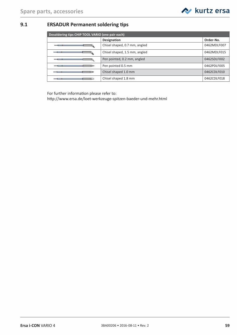
593BA00206 • 2016-08-11 • Rev. 2Ersa i-CON VARIO 4
Spare parts, accessories
9.1 ERSADUR Permanent soldering tips
Desoldering tips CHIP TOOL VARIO (one pair each)Designation Order‑No.Chisel shaped, 0.7 mm, angled 0462MDLF007
Chisel shaped, 1.5 mm, angled 0462MDLF015
Pen pointed, 0.2 mm, angled 0462SDLF002
Pen pointed 0.5 mm 0462PDLF005
Chisel shaped 1.0 mm 0462CDLF010
Chisel shaped 1.8 mm 0462CDLF018
For further information please refer to:http://www.ersa.de/loet-werkzeuge-spitzen-baeder-und-mehr.html
60 3BA00206 • 2016-08-11 • Rev. 2 Ersa i-CON VARIO 4
Warranty
10. Warranty© 7/2016, Ersa GmbH • 3BA00206 Rev. 2
Heating elements and soldering or desoldering tips are treated as wearing parts, and are therefore not subject to the warranty. Any return of goods must be accompanied by a written description of the material or construction fault that has occurred as well as a confirmed purchase invoice.
Ersa created these operating instructions with greatest care and attention to detail. However, no warranty can be granted with respect to contents, completeness and quality of data in this manual. The contents is continuously updated and adapted to prevailing conditions.
All data published in this manual, including specifications concerning products and procedures, were determined by us to the best of our knowledge and ability, and using cutting edge technical aids. These specifications are non-binding and for information only; they do not relieve the user from his responsibility of carrying out his own check before operating the device. We do not assume liability for violations of patent rights of third parties for applications and procedures without previous express and written confirmation. We reserve the right for technical modifications with the intention of improving the product.
Within the scope of legal possibilities, liability for immediate damage, including direct and indirect damage, which results from the acquisition of this product, is ruled out.All rights are reserved. This manual, or any parts thereof, may not be reproduced, changed, transferred or translated into another languages without the written consent of Ersa GmbH.
To the extend this product contains Atmel software, such software is copyrighted by Atmel: Copyright (c) 2009‑2012 Atmel Corporation. All rights reserved.THIS SOFTWARE IS PROVIDED BY ATMEL "AS IS" AND ANY EXPRESS OR IMPLIED WARRANTIES, INCLUDING, BUT NOT LIMITED TO, THE IMPLIED WARRANTIES OF MERCHANTABILITY, FITNESS FOR A PARTICULAR PURPOSE AND NON‑INFRINGEMENT ARE EXPRESSLY AND SPECIFICALLY DISCLAIMED. IN NO EVENT SHALL ATMEL BE LIABLE FOR ANY DIRECT, INDIRECT, INCIDENTAL, SPECIAL, EXEMPLARY, OR CONSEQUENTIAL DAMAGES (INCLUDING, BUT NOT LIMITED TO, PROCUREMENT OF SUBSTITUTE GOODS OR SERVICES; LOSS OF USE, DATA, OR PROFITS; OR BUSINESS INTERRUPTION) HOWEVER CAUSED AND ON ANY THEORY OF LIABILITY, WHETHER IN CONTRACT, STRICT LIABILITY, OR TORT (INCLUDING NEGLIGENCE OR OTHERWISE) ARISING IN ANY WAY OUT OF THE USE OF THIS SOFTWARE, EVEN IF ADVISED OF THE POSSIBILITY OF SUCH DAMAGE.
613BA00206 • 2016-08-11 • Rev. 2Ersa i-CON VARIO 4
Ersa GmbHLeonhard-Karl-Str. 2497877 Wertheim/Germany
Phone +49 9342 800-0Fax +49 9342 [email protected]
www.ersa.com
Production plants/ subsidiaries
Local agents Other presence
Electronics Production EquipmentWorldwide Presence
AmericaErsa North America1779 Pilgrim Road Plymouth, WI 53073 USAPhone +1 920 893 3772from the US: 1 800 363 3772Fax +1 920 893 [email protected]
MexicoKurtz Ersa, S.A. de C.V.Felipe Angeles No. 52Col. Bellavista Tacubaya01140 México, D.FMéxicofrom Mexico: 01 800 099 0357from the US: 1 800 848 5628from Germany: 0800 188 [email protected]
AsiaErsa Asia PacificUnit 03-05, 8th FloorOne Island SouthNo. 2 Heung Yip RoadWong Chuk HangHong KongChinaPhone +852 2331 2232Fax: +852 2758 [email protected]
ChinaErsa ShanghaiRoom 720, Tian Xiang BuildingNo. 1068 Mao Tai Rd.,Shanghai 200336ChinaPhone +86 213126 0818Fax +86 215239 [email protected]
Ersa FranceDivision deKurtz France S.A.R.L15 rue de la Sucharde21800 Chevigny Saint SauveurFrancePhone +33 38056 6610Fax +33 38056 [email protected]
Kurtz Holding GmbH & Co. Beteiligungs KGFrankenstr. 297892 KreuzwertheimGermanyPhone +49 9342 807-0Fax +49 9342 [email protected]