Embed Size (px)
Citation preview

The Quality Connection
ICON® Product Guide

www.leoni-industrial-projects.com2
This is not just a catalogue…
… it is what you have been looking for – a product guide to choos-
ing the design you need for your project, plant or application…
… created to provide you with the cable solution you need.
The European Standard EN 50288-7 is the first ever standard for
instrumentation and control cables to address the entire range of
demands and reqirements of general and specific industrial cable
applications.
In contrast to the existing official regulations and specifications,
the new standard covers the huge variety of cable designs used in
today‘s global business. The meaningful and comprehensive (but
nevertheless standardized) range of different versions in terms of
design and materials used allows you to select cable designs which
comply with the standard but still meet the requirements of the
application.
The Quality Connection
The new standard will be complemented by European standards
for materials and testing. These standards do not exist as yet, so we
shall refer to IEC standards or national standards here.
On the solid basis of many years of experience in international
business (either project-oriented or geared to the site requirements
of the customers) in conjunction with the new standard, we have
defined a very wide product range designed to meet all your field-
driven product requirements.
We have selected and elaborated a product programme designed to
cover all usual applications. The diversity of the environmental, elec-
trical, mechanical, installation and safety requirements produces a
need for an extensive range of products. This first section covers all
necessary information on product families. Information on specific
types will be provided on request or via other media.
The extremely systematic organisation of this guide to the various
product families will allow you to select your product to match your
application and meet your requirements with maximum efficiency.
Telecommunication cables
Data- and Bus cables (copper and fiber optic)
Mining cables
Cables for special applications
Instrumentation- and control cables
Thermocouple extension and compensating cables
Power cables (low and medium voltage)
Product range

www.leoni-industrial-projects.com 3
Content Page
Introduction 4The EN 50288-7 standard 6
The Customised Types 8General remarks 9
Design options and selection criteria for cable elements 9
Insulation 10
Cabling elements 11
Cable assembly 11
Screening 12
Plastic sheaths 14
Chemical and/or environmental protection 16
Armour 17
Design options/Construction details acc. to EN 50288-7 18
The Standard Types 20Structure of the product programme “standard types” 21
Presentation of product data and data sheets 21
Instrumentation Cable 22
• Common Types – 300 V and 500 V 22
• Zero halogen, flame-retardant types – 300 V and 500 V 26
• Fire resisting (CI), flame-retardant types – 500 V 30
Instrumentation Control Cable 34
• Common Types – 500 V 34
• Zero halogen, flame-retardant types – 500 V 38
• Fire resisting (CI), flame-retardant types – 500 V 42
Extension & Compensating Cable 46
• Common Types – 300 V 46
• Zero halogen, flame-retardant types – 300 V 50
General 54Standards for thermocouple extension &
compensating cables 55
Electrical characteristics of conductors 56
Loop resistance at 20 °C 56
Color codes 57
Cables under fire conditions 58
Type designation 60
Conductors – AWG and metric values by comparison 62
General units 63
Data sheets – examples 64
Content
LEONI Kerpen GmbH can not be held responsible in any form whatsover for any in-formation provided by this publication. Printing errors excepted. Subject to alterations.Issue August 2009

www.leoni-industrial-projects.com4 Introduction
ICON®arctic
ICON®chem
ICON®safe
ICON®base
ICON®bus
Five new brands posses the optimized cable solution for your plant:
ICON®
... ensures reliable performance in all usual conditions.
... ensures the safety and functionality of your plant in
aggressive environments.
... offers excellent properties for applications in
extremely cold environments.
... offers protection for saving lives and safeguarding
investments.
... meets or exceeds the increased requirements
of state-of-the-art automation technology.

www.leoni-industrial-projects.com 5Introduction
Please visit our websitewww.leoni-industrial-projects.com
LEONI Business Unit Industrial Projects –
your expert for a market that requires maximum reliability
LEONI is one of the leading suppliers of standardised and
customer-specific special cables and pre-assembled cable
systems worldwide.
The Business Unit Industrial Projects allows us to give our custom-
ers access to the entire competence of a worldwide corporation,
focused to meet the needs of industrial applications. We supply
our products and solutions wherever everything depends on
maximum reliability, quality and durability, such as in oil and gas
extraction and processing as well as in the petrochemical and
energy production industries. LEONI products are to be found in
many other applications such as the pulp and paper, cement and
pharmaceutical industries and in waste management, in which
processes have to run in a controlled way via sensors and actua-
tors.
For us reliability doesn’t just mean keeping the right product avail-
able for you as a standard product or developing a project solution
for you – it also means supplying it at precisely the agreed time.
Safety, availability and reliability are vital in industrial
plant engineering and energy provision. This is because these are
fields in which unexpected breakdowns are very expensive and have
critical effects on the environment.
Companies are asking for solutions which are perfectly tailored to
meet the application in question as well as the plant itself. 70 %
of the cables leaving our company are de veloped, manufactured
and assembled according to customer specifications. We produce
quantities depend ing on the requirements of the projects and sup-
ply according to cable drumming schedules. We are also equipped
to provide project quantities in a con side r able two-digit million euro
range. We take company-specific standards as well as all important
industrial and environ mental standards on the national and interna-
tional level into account.

www.leoni-industrial-projects.com6 Introduction
The EN 50288-7 standard
The European standard EN 50288-7 published in September 2005 is
the first ever standard governing instrumentation cables for onshore
applications to have been prepared by an established international
standardisation body.
The following features distinguish this standard from the wide
variety of existing product specifications:
it complements the relevant standards for materials and testing
it includes a wide range of design options
it effectively matches design regulations with test requirements.
This standard thus enables the user to convert all demands with
regard to systems, security, the environment, climate and installa-
tion into appropriate products in an efficient way.
The standard has been implemented in the form of national
standards by all Cenelec members (28 countries at present). Its
future significance is underlined by the fact that all former national
standards which conflict with the EN standard had been withdrawn
after a certain transitional period in April 2008 latest.
This standard also meets the requirements of the “European Low
Voltage Directive”.
The advantages
The application of this standard offers a number of advantages:
it was prepared by a recognized standardisation body
it represents the “state of the art” throughout
it is available to everyone everywhere
it specifies products easily, quickly, clearly and without ambiguity
it includes a wide range of design options
It thus allows consultants, engineers, manufacturers and others to
save time and money when
preparing specifications
dealing with inquiries, offers and orders
organizing product-programmes
Summary:
The application of the standard EN 50288-7 should
become as logical and widespread as the application of the
IEC 60502 standard for power cables.
The EN 50288-7 standard
CENELEC Members
CENELEC Affiliates

www.leoni-industrial-projects.com 7Introduction
The product programme
The EN 50288-7 standard does not comprise specific products;
instead it “merely” describes the individual cable elements and their
design (including options and the relevant rules), defines materials,
dimensions and test requirements and cites the relevant standards.
On the basis of more than thirty years of experience in the
international instrumentation cable business, the Business Unit
Industrial Projects has seized the opportunity and defined the
EN 50288-7-based ICON® product programme, which consists of two
sections:
“Customised types” and “Standard types”
Customised types
The “Customised types“ section gives an overview of the entire
range of design options covered by the standard and adds explana-
tions and selection criteria. It thus provides optimum support for
selecting and specifying products required. Product documentations
and quotations are available on request.
Standard types
The „Standard types“ section is an extract from the “Customized
types” section. It presents a comprehensive range of products of
the main types used in the market. A few thousand products are
described in detail complete with geometrical data and design data,
information on mechanical, thermal and flame behaviour proper-
ties and electrical data. For this information please see the attached
CD-ROM.
Summary of the structure
Standard types Customised types
Thousands of conventio-
nally used products
Complete technical
documentation
Available immediately
Quotes provided rapidly
Cost-effective
Short delivery time
Technical basis for entire
market demand
Allows specifications and
products to be tailor-made
Clear and unambiguous
design rules
Fast and flexible handling
of products
Documentation on request
Modular design concept
Well-known quality from reliable project partners based on
the international safety regulations
The ICON® product programme also covers instrumentation cables
complying with UL standards UL13, 2250 and 1277 as well as bus
cables according to PNO and FFO.
The Standard EN 50288-7
The ICON® Products

www.leoni-industrial-projects.com8 The Customised Types
The “Customised types” section gives a summary of the
entire range of design options and design rules concerning
the EN 50288-7 standard. A summary of it is shown in chart
form on the last page of this chapter.
The contents of the standard are complemented by explanations
and selection criteria to help you to find the best possible design
solution.
The Customised Types

www.leoni-industrial-projects.com 9The Customised Types
ApplicationsThe standard covers instrumentation cables as well as thermocouple
extension and compensating cables suitable for connecting instru-
ments and control systems for the purposes of analogue and digital
transmission.
The cables are not designed for use with power supplies and should
not be connected directly to the mains or to other low-impedance
power sources.
Valid local and national regulations must be taken into account
during installation.
The standard must be used in connection with the referenced stan-
dards for materials and testing.
DesignsThe cable can contain cores, pairs, triples or quads as cabling ele-
ments; they can have individual or overall screening and optionally
include armouring and/or additional layers for moisture resistance
or environmental protection. The maximum rated voltages of the
cables are either 300 V or 500 V.
Conductor for instrumentation cable Plain and metal coated copper conductors
according to EN 60228 (IEC 60228)
Class 1 (solid), class 2 (stranded) and class 5 (flexible)
Sizes: 0.5 mm² up to 2.5 mm²
Criteria for the choice of conductor design and size are
the DC-resistance
the connection technology used (including crimping, clamping,
soldering, wire wrap and termi-point)
the flexibility requirements
the diameter
the environmental conditions
7-strands conductors are used in most cases.
Conductor for thermocouple extension and compen-sating cable conductor material according to the requirements
of the HD 446.1 (IEC 60584-3); see table 2 on page 56
design: solid, stranded or flexible
sizes: 0.5 mm² up to 1.5 mm²
Criteria for the choice of type, design or size of conductor are:
the type of thermoelement used
the E.M.F-tolerances
the flexibility
Solid conductors are used in most cases.
General remarks Design options and selection criteria for cable elements

www.leoni-industrial-projects.com10 The Customised Types
Insulation materialsThe insulating materials used include:
The most widely used insulating material today is polyethylene,
followed by polyvinylchloride and cross-linked polyethylene. Other
materials such as materials resistant to high temperatures, polypro-
pylene and foamed materials are used for special purposes only.
Selection criteria for insulation materials are
electrical transmission properties
limited operating temperatures
The following criteria can also be significant in certain special cases:
flame behaviour
suitability for special connection techniques
resistance to oil and gas
resistance to radiation
compatibility with filling compounds
Radial thickness of the insulationTwo values must be considered with reference to the radial thickness
of the insulation:
the minimum radial thickness
the nominal radial thickness
The minimum radial thickness of the insulation is defined in the
standard. The measured radial thickness of the insulation must not
fall below the defined values at any point.
The nominal radial thickness of the insulation is a design value
defined by the manufacturer to guarantee the specified electrical
transmission properties. The nominal thickness is thus a reference
value only and will not be dealt with here. Depending on the con-
ductor size, the nominal thickness exceeds the minimum thickness
by approx. 0.05 and 0.1 mm.
Insulation
polyvinylchloride PVC EN 50290-2-21
polyethylene PE EN 50290-2-23
polypropylene PP EN 50290-2-25
Zero halogen,
flame-retardant compoundHFRC EN 50299-2-26
cross-linked polyethylene XLPE EN 50290-2-29
Table 1: Properties of the most important insulating materials
Properties Polyvinylchloride
PVC
Polyethylene
PE
Cross linked
polyethylene
Permittivity εr
4 – 7 2.3 2.3
Spec.volume resistance at 20 °C Ω x cm 1014 1016 1016
max. operating temperature °C 70 1) 70 2) 90 °C
Behaviour at low temperature stiff, tends to become brittle good good
Flammability self-extinguishing inflammable inflammable 3)
1) Heat resistant modified PVC for temperatures limited to 90 °C and 105 °C 2) 80 °C for high-density polyethylene HDPE3) also with self-extinguishing characteristic

www.leoni-industrial-projects.com 11The Customised Types
Cabling elements Cable assembly
Cabling elements according to the standard are cores, pairs, triples
and quads.
A core is an insulated conductor
A pair consists of two twisted cores which form a line circuit
A triple consists of three twisted cores which form line circuits
with one another
A quad consists of four twisted cores in which the diametrically
opposed cores form a line circuit
The length of lay of a part, triple or quad, must not exceed
100 mm for conductor sizes ≤ 1.5 mm² or
150 mm for conductor size 2.5 mm²
To keep internal interference of cabling elements – pairs, triples or
quads – as low as possible, adjacent elements have different lengths
of lay.
The cable elements must be assembled in concentric layers to form
the cable core either
directly or
in the form of units
Units consist of a certain number of cores, pairs, triples or quads.
The direction of lay of successive layers of multi layer cables changes
from layer to layer. This measure also contributes to the mutual
decoupling of unscreened pairs, triples or quads from each other.

www.leoni-industrial-projects.com12 The Customised Types
DesignScreening can be either screening of individual cable elements
and/or an overall screening. Screening measures according to the
standard are listed below:
plain or coated copper braid with a minimum filling factor of 0.6
a combination of plastic-laminated metal foil and a plain or
coated copper braid with a minimum filling factor of 0.3
plastic-laminated metal foil with
a minimum overlap of 20 %,
a drain wire in direct contact with the metallic side of the foil and
a laminated sheath (for overall screening only).
Screening measures must be provided in order to reduce or prevent
possible interference such as
cross-talk from adjacent line circuit in the cable itself or
externally induced interference from sources outside the cable.
Internal interferenceThe only significant factor for Screening against internal interfer-
ence is the capacitance (unbalanced) between the cabling elements.
Magnetic interference can be disregarded here.
Precautions used for reducing and to avoiding internal interference
are
different length of lay of the various cabling elements
(see page 9) or
individual screening of the various cabling elements
Individual screening usually consists of plastic-laminated aluminum
foil applied so as to overlap helically and a copper drain wire in
continuous contact with the metallic side of the foil.
An at least 20 % overlap of the foil guarantees 100 % coverage of the
cabling element even in small bends.
Screening
External interferenceScreening against external interference has to take the influence of
both electric and magnetic interference into account and make a
distinction between LF and HF fields.
The design of the required screen depends on the type and strength
of interference.
Screening in the LF-range
For screening in the LF-range – i.e. in the range of frequencies of up
to 10 kHz – the influence of both electric and magnetic interference
can be examined separately. Interference from electric fields can be
virtually disregarded if conductive screens are used; the lower the
dc resistance, the better the screening effect; however, care must be
taken to ensure a high degree of coverage as the electric field may
otherwise affect the cable core.
Screening against LF magnetic interference requires the use of
magnetic materials such as steel wires or (even better) tapes.
Materials of high permeability should be used for high levels of
screening.
The measure of the effect of the screening in the LF range is the
reduction factor. This is the ratio of the interference voltage with a
screen to the interference voltage without a screen and is calculated
according to the following formula:
rc
= R
O
√ (RO + R
E)2 + ω (L
M + L
E)²
with rc = reduction factor
The lower the rc the better the screening effect.
RO dc resistance of screen in Ω/km
RE dc resistance of earth loop in Ω/km
(normally evaluated as 0.05 Ω/km)
LM
internal screen inductance in H/km
(this value can be disregarded
for non-magnetic screens)
LE external inductance of the earth loop in H/km
(the usual value is 0.002 H/km)
ω angular frequency (2 f) in Hz

www.leoni-industrial-projects.com 13The Customised Types
Screening in the HF-range
Screening in the HF range is based on energy losses due to electro-
magnetic interference caused by absorption and reflection in or on
the Screening material.
The measure for the effect of screening in the HF range is the cou-
pling resistance, which is defined as follows
rc
= induced interference voltage in the disturbed system
current in the disturbing system
rc
= coupling resistance
The lower the rc the better the screening effect.
The coupling resistance depends on the frequency. The typical curve
of the coupling resistance is shown below.
Requirements for effective screening in the HF-range are basically
a low DC resistance and maximum coverage of the screen. Here is a
selection of screen designs (the screening effect increases from top
to bottom):
plastic laminated aluminum foil
laminated aluminum tape overlapping longitudinally
optimized copper braid of high density
copper tape, lapped or overlapping longitudinally
copper tubing
rc (Ω)
f (Hz)

www.leoni-industrial-projects.com14 The Customised Types
The different typesThe standard defines 4 different types of extruded plastic sheaths
the outer sheath
providing the protection of the cable from outside
the inner sheath
applied under a metallic protection and – optional – under a
lead sheath
the multi layer sheath
a special type of inner sheath; an alternative possibility for a lead
sheath as environmental and chemical protection
the bedding
a separation sheath applied between a lead sheath and a metallic
protection (may also consists of plastic tapes)
The following materials can be used for the inner and outer sheath
and for the bedding:
Inner sheath and beddingThe main function of the bedding and/or an inner sheath is to
protect the cable core from mechanical stress and moisture. Here are
some additional criteria which must be considered when the type of
material is determined:
maximum and minimum temperatures during operation
flame behaviour
halogen content
Multi layer sheathA multi layer sheath consists of a longitudinal plastic-coated
aluminum tape, a layer of high-density polyethylene bonded to the
aluminum tape and an additional layer of polyamide.
The high-density polyethylene must be in accordance with EN
50290-2-24, the material specification for polyamide is in the discus-
sion stage at present.
Overall sheathThe conditions prevailling during transportation and storage, instal-
lation and operation determine the type of material to be used. The
following criteria must be taken into account in the selection of a
suitable sheath material:
way of laying i.e.
mechanical stress
environmental conditions
climatic conditions
demands made on fire behaviour and flame retardancy
demand made on coloring and marking
Plastic sheaths
PVC according to EN 50290-2-22
polyethylene according to EN 50290-2-24
Zero halogen,
flame-retardant compoundaccording to EN 50290-2-27

www.leoni-industrial-projects.com 15The Customised Types
Sheathing materials
Polyvinylchloride (PVC)
As a result of its great value for money, PVC has been the most
widely used sheathing material for instrumentation cables up to
now. Its great ability to be modified allows a selective adaptation
of desired properties which makes it suitable for a wide range of
applications.
PVC is suited for indoor and outdoor laying in dry and wet locations,
in conduits and for direct burial.
Its maximum permissible temperature ranges from 70 °C for stan-
dard types to 90 °C or 105 °C for special heat-resistant types. The
recommended minimum temperatures for these types are - 5 °C for
installation and - 0 °C for operation.
Special cold resistant types permit significantly lower temperature
during operation and installation. The maximum permissible tem-
perature is 70 °C or 90 °C.
PVC is a flame-retardant, self-extinguishing material. Its flame re-
tardancy can be increased to higher levels. The emission of halogen
acid gas and the smoke density in the event of fire can be reduced in
the same way. Most PVC-compounds are resistant to oil and solvents
to a certain degree. Specially designed types are recommended for
more stringent requirements.
PVC can be supplied in a wide range of colors. When exposed to
sunlight, the colors fade, but this has no effect on the function. All
sheathing compounds are resistant to sunlight.
Zero halogen flame-retardant compound (LSZH)
Starting from a low level, the use of Zero halogen flame-retardant
compounds has increased steadily over the last ten years as a result
of the growing need for Zero halogen flame-retardant cables as a
special measure to protect persons and/or important material assets.
In the event of fire, Zero halogen flame-retardant compounds are
distinguished by characteristics such as the following:
reduced flame propagation
reduced acidity and toxicity of gases
reduced smoke density
no halogen acid gases
Zero halogen flame-retardant compounds are suitable for indoor
and outdoor application. Special compounds with reduced water
absorption are recommended for direct burial. The maximum
temperature limits of the types defined are 70 °C and 90 °C. The
recommended minimum temperatures are –5 °C for installation and
–30 °C for operation.
Standard Zero halogen flame-retardant compounds are only partly
resistant to oils and solvents. Standard compounds meet the
requirements of the oil resistance test according to ICEA S82-552.
Special types must be used for more stringent requirements.
Most Zero halogen flame-retardant compounds can be supplied in
a wide variety of colors. When exposed to sunlight, the colors fade,
but this has no effect on the function.
Polyethylene (PE)
Polyethylene sheaths can be made of LDPE, MDPE and HDPE materi-
als (low-density, medium-density and high-density polyethylene).
The lack of flame-retardancy restricts the use of polyethylene
sheathes to direct buried cables.
As a result of its excellent mechanical properties such as its high
tensile strength, its high resistance to abrasion, its hardness and its
extremely low water absorption, polyethylene is the ideal material
for this application.
The maximum permissible temperature is 70 °C for LDPE and MDPE
and 80 °C for HDPE. As a result of its outstanding resistance to low
tempeartures, cable insulated and sheathed with polyethylene can
be installed down to temperatures of –20 °C.
The material becomes harder in proportion to the temperature,
however. The bending resistance of the cable increases, with the
corresponding negative effects on handling during installation.
Polyethylene stands out through its high resistance to oil and chemi-
cals. This and the mechanical properties increase from LDPE to HDPE.
As mentioned above, polyethylene is not flame-retardant. When
ignited, it tends to drip and burn on after removal of the flame.
For this reason, polyethylene sheathing should not be used for
indoor applications. Polyethylene must stabilized against UV using
soot. This is why the outer sheath is black in color.

www.leoni-industrial-projects.com16 The Customised Types
If there is a risk of oils and chemicals affecting cables after installa-
tion, protective measures must be taken.
The grading of the possible effects on the cables is determined by
the nature, condition and quantity of the effecting medium, the
duration of immersion and the temperature. In certain cases, plastic
sheaths afford adequate protection, but more stringent measures
must usually be taken in order to avoid negative effects on the long-
term functioning of the cables involved.
For directly buried cables in particular, the EN standard recommends
the following structural elements:
Lead sheath
Lead sheathes are the best protective measure against oils and
chemicals. They are especially recommended where soils are heavily
polluted. Lead alloy sheathed types should be used where there are
high mechanical loads due to vibration.
Chemical and/or environmental protection
Lead sheath Multi layer sheath
Multi layer sheath
Multilayer sheaths consist of a longitudinal plastic-coated aluminum
foil, a layer of high-density polyethylene and an additional covering
of polyamide. The aluminum foil is bonded inside the overlap and
with the inner surface of the HDPE sheath.
Multilayer sheaths are an adequate alternative to lead sheaths for a
large number of applications. Compared to cables with lead sheaths,
those with multilayer sheaths are smaller and lighter, thus allowing
longer handling lengths.

www.leoni-industrial-projects.com 17The Customised Types
If an armour is specified, it should be selected from the types listed
below:
Galvanised round steel wire armour
The wire diameter depends on the cable diameter under armour,
min. diameter 0.9 mm
Galvanised flat steel wire armour
The minimum is wire diameter; this armour shall be used for
cables, where the diameter under armour is > 15 mm
Single or double layer of steel or brass tapes
The minimum thickness of a tape shall be 0.2 mm for steel and
0.075 for brass.
Metal braid
The minimum filling factor must be 0.57 (corresponding optical
coverage 81.5 %), the minimum wire diameter 0.3 mm.
The choice of the most suitable type of armour depends on the
demands of installation and operation. In addition, local and legal
regulations must be complied with.
The most important selection criteria are:
maximum expected tensile load and minimum required load-
bearing capacity during installation and/or operation
maximum expected pressure and tensile load after laying
protection against attack by rodents
minimum required bending radius
protection against external interferences
Armour
The types of armour listed above are characterized by the following
features:
Galvanised metal wire braid
Lightweight armour of galvanised steel or plain or tinned round
copper wire; suited for small tensile and pressure loads; permits
the smallest bending radii of all armour types; mainly used for
small cable diameters.
Galvanised steel tapes
Applied as single- or dual-layer armour with 100 % covering of
the cable assembly; excellent protection against pressure and
impact loads; not suitable for tensile loads; very good protection
against rodents; of all types of armour listed, they provide the best
inductive protection.
Brass tapes
These are applied in the same way as steel tapes; especially
recommended to prevent attack by rodents and termites.
Galvanised flat steel wires
Good protection against pressure and impact loads; suitable for
high tensile loads; the least flexibile of all types of armour listed.
Galvanised round steel wire
Coverage: more than 90 %; very good mechanical protection
against pressure and impact loads, suitable for high tensile loads,
good protection against rodents; the type of armour used most
frequently for direct buried cables.
Galvanised round steel wire armour Galvanised metal wire braid

www.leoni-industrial-projects.com18 The Customised Types
Design options/Construction details according to EN 50288-7 Multi-Element Metallic Cables for Analogue and Digital Communication and Control Systems
Design Options
Type Options
Construction DetailsReference Standards
Screening of cabling elements
Conductor InsulationTwisting
of pairs, triples and quads
Screening of cable element
assembly
Assembling of cabling elements
+/0 moisture barriers
Multicore types
Conductor*
Copper, plain or tinned
Conductor sizes: 0.5 mm² up to 2.5 mm²
Conductor shape: solid, stranded or flexible
*(for thermocouple & extension cables see to IEC 60584-3)
Insulation
PVC, PE (solid and foam), XLPE, PP
(solid and foam), zero halogen,
flame-retardant compounds
Additional materials under preparation
Conductor
According to EN 60228, class 1, 2 or 5
Max. conductor resistance
for multi-element cables (beside cores):
Standard value +2 %
Insulation
Acc. to EN 50290-2-21, 23, 25, 26 a. 29
Concentricity of insulation: min. 0.75 mm
Min. insulation thickness depending on
voltage rating and conductor size
Cabling elements
Cores, pairs, triples, quads
Individual screen
Plastic laminated metal foil
with drain wire
Plain or coated metal braid
Combination of a braid and a foil
Cabling elements
Max. length of lay:
up to 1.5 mm² ≤ 100 mm
2.5 mm² ≤ 150 mm
Identification: numbered cores or tapes
or acc. to IEC 60189-2 or IEC 60708-1
Individual screen
Overlapping of the foil: min. 20 %
Filling factor of the braid 0.6 and 0.3
resp. when combined with a foil
Assembling
Directly or in units in concentric layers
With or without moisture barrier
Moisture barriers
Dry swellable tapes, and/or cords,
swellable powder
Wet petrojelly filling compound
Overall screen
Plastic laminated metal foil with drain wire
Plain or coated metal braid
Combination of a braid and a foil
Laminated sheath
Assembling
Wrappings of non hygroscopic tapes
interstitial fillers, where neccessary
Moisture barriers
Petrojelly according to EN 50290-2-29
Overall screen
Overlapping of the foil min. 20 %
Filling factor of the braid >0.6 and >0.3
resp. when combined with a foil
One or both side laminated aluminum tape
longitudinally overlapped, bonded to the
inner surface of an extruded sheath, thickness
of alum. tape: min. 0.15 mm without coating

www.leoni-industrial-projects.com 19The Customised Types
Voltage rating 300 V / 500 V
Inner sheath Outer sheath
Bedding
Armouring
Lead sheath
Multilayer sheath
Inner sheath
PVC, PE, zero halogen, flame-retardant
compounds
Additional materials under preparation
Chemical and/or
environmental protection
a) Lead sheath or
b) Multi layer sheath
Laminated HDPE sheath and
an additional polyamid covering
Inner sheath
According to EN 50290-2-22 and 27
Optional under lead sheath
Thickness: 0.04 x D*+0.7 mm (min. 0.8 mm)
*(D = Diameter under inner sheath)
a) Lead sheath
According to EN 50307
Thickness: 0.03 x D*+0.7 mm (min. 0.8 mm)
*(D = Diameter under lead sheath)
b) Multi layer sheath
Thickness of polyamid covering: min. 0.3
Bedding
Extruded layer of PVC, PE or halogenfree,
flameretardant compounds or
Helically applied tape(s)
Bedding
According to EN 50290-2-22, 24 and 27
Thickness: depending on diameter
under bedding; min.1.0 mm
Armour
Single layer of round steel wires (SWA)
Single or double layer of steel or brass
tapes (B)
Metal braid (Q)
Outer sheath
PVC, PE, or halogenfree, flame-retardant
compounds
Additional materials under preparation
Armour
SWA: acc. to EN 10257-1; min. Ø 0.9 mm
B: min. thickness: 0.2 mm a. 0.075 mm resp.
Q: Filling factor:
min. 0.57, wire Ø min. 0.3. mm
Outer sheath
According to EN 50290-2-22, 24 and 27
Thickness for unarmoured types:
0.04 x D* + 0.7 mm (min. 0.8 mm)
Thickness for armoured types:
0.028 x D* + 1.1 mm (min. 1.3 mm)
(D = diameter under outer sheath)
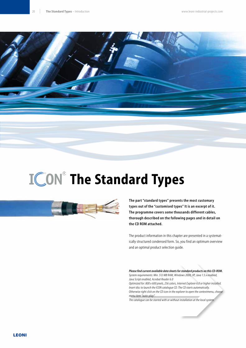
www.leoni-industrial-projects.com20 The Standard Types – Introduction
The part “standard types” presents the most customary
types out of the “customised types” It is an excerpt of it.
The programme covers some thousands different cables,
thorough described on the following pages and in detail on
the CD ROM attached.
The product information in this chapter are presented in a systemat-
ically structured condensed form. So, you find an optimum overview
and an optimal product selection guide.
The Standard Types
Please find current available data sheets for standard products on this CD-ROM.System requirements: Min. 512 MB RAM, Windows 2000, XP, Java 1.5.x enabled, Java Script enabled, Acrobat Reader 6.0Optimized for: 800 x 600 pixels, 256 colors, Internet Explorer 6.0 or higher installed. Insert disc to launch the ICON catalogue CD. The CD starts automatically. Otherwise right click on the CD icon in the explorer to open the contextmenu, choose menu item “auto-play”.The catalogue can be started with or without installation at the local system.

www.leoni-industrial-projects.com 21The Standard Types – Introduction
The product programme is arranged within three main groups:
Pairs and triples may be with or without individual screen.
Each main group is derived into three subgroups:
common types (PVC-sheathed)
Zero halogen, flame-retardant types (LSZH-sheathed)
fire-resisting, flame-retardant types (LSZH-sheathed)
Each sub-group describes different product-families (2 up to 4).
Product-family stands for a product line with a certain insulation
material, containing unarmoured and armoured products; and for
the subgroups “common types” armoured versions with chemical
environmental protection (lead or multi-layer sheath) additionally.
The miscellaneous insulation materials offers options for optimising
electrical, thermic or other relevant product properties.
Structure of the product programme “standard types”
Presentation of product data and data sheets
Main group Cabling elements
Instrumentation cables pair and triple
(instrumentation) control cables core
thermocouple extension
& compensating cablespair
The product data are headed:
Technical data
Contains information on application range, laying, temperature
limitations, bending radius, flame behaviour, and others.
Construction
Describes the design of the cables
Electrical data
Contains the electrical properties of the described products
Product data sheets:The product descriptions are completed by product data sheets
recorded on the attached CD-ROM. An example of a product data
sheet is shown on page 64. The data sheets also itemise the usual
geometrical data of every individual product.

www.leoni-industrial-projects.com22 The Standard Types Instrumentation Cable
Instrumentation Cable according to EN 50288-7
Common Types – 300 V and 500 V
* according to EN 50288-7
Common Types
300 V and 500 V
plain stranded copper conductor,
pairs and triples,
individual and/or overall static screen
PVC- or PVCw- or PE- or XLPE-
(70° C) (105 °C) (70 °C) (90 °C)
insulated/PVC-sheathed
Lead sheathed or
Multi layer sheathed, armoured
unarmoured unarmoured unarmouredarmoured armoured armoured
ICON® Instrumentation Cable
Zero halogen,
flame-retardant types
300 V and 500 V
plain stranded copper conductor,
pairs and triples,
individual and/or overall static screen
PE- or XLPE-
(70°C) (90°C)
insulated/LSZH-sheathed
Fire resisting (CI)*,
flame-retardant types
300 V and 500 V
plain stranded copper conductor,
pairs and triples,
individual and/or overall static screen
Mica/XLPE- or Silicone
(90°C) (90°C)
insulated/LSZH-sheathed

www.leoni-industrial-projects.com 23The Standard Types Instrumentation Cable
Technical Data
Type of insulation/sheath PVC/PVC PVCw/PVCw PE/PVC XLPE/PVC
Type of cabling elements Pair, Triple, PiMF, TiMF
No. of cabling elements 1, 2, 4, 5, 6, 8, 10, 12, 16, 20, 24
Conductor sizes 0.5 mm², 0.75 mm², 1.0 mm², 1.3 mm², 1.5 mm²
1. Unarmoured types RE-Y(St)Y-fl RE-Yw(St)Yw-fl RE-2Y(St)Y-fl 1) RE-2X (St)Y-fl
Laying Recommended for indoor and outdoor installation, on racks, trays, in conduits, in dry and wet locations
Bending radius 7.5 x cable Ø
2. Armoured types RE-Y(St)YSWAY-fl RE-Yw(St)YwSWAYw-fl RE-2Y(St)YSWAY-fl RE-2X(St)YSWAY-fl
Laying Recommended for outdoor installation, on racks, trays, in conduits, in dry and wet locations, for direct burial
Bending radius 10 x cable Ø
3. Armoured types with chemical protection
a) Lead sheathed RE-Y(St)YMYSWAY-fl — — RE-2X(St)YMYSWAY-fl
b) Multi layer sheathed — — — RE-2X(L)2Y4YSWAY 2) 3)
Laying Recommended for direct burial, especially in presence of oil and aggressive chemical substances
Bending radius 15 x cable Ø
Reaction to fire
Flame propagationa) Test on single cableb) Test on bunched cables
IEC 60332-1-2 IEC 60332-3 part 24 (Cat. C), (excluded types with multi layer-sheath)
Temperature range during operation during installation
–30 °C up to 70 °C –5 °C up to 50 °C
–30 °C up to 105 °C –5 °C up to 50 °C
–30 °C up to 70 °C –5 °C up to 50 °C
–30 °C up to 90 °C –5 °C up to 50 °C
Sunlight resistance UL 1581 Section 1200
Oil resistance ICEA S-82-552
Application For transmission of analogue and digital signals in instrument and control systems; allowed for use in zone 1 and zone 2, group II, classified areas (IEC 79-14), not allowed for direct connection to low impedance sources, e.g. public mains electricity supply
1) Also with increased thickness of outer sheath (Yv).2) Also with HDPE outer sheath; in this case tests “Reaction to Fire” are not passed.3) Max. operating temperature 80 °C.
ICON® Instrumentation Cable according to EN 50288-7
Common types
Single & Multi pair and Multi triple, individual and/or overall screen, PVC-sheath unarmoured armoured with chemical protection, armoured
300 V and 500 V

www.leoni-industrial-projects.com24 The Standard Types Instrumentation Cable
ICON® Instrumentation Cable according to EN 50288-7
Common types
Single & Multi pair and Multi triple, individual and/or overall screen, PVC-sheath unarmoured armoured with chemical protection, armoured
300 V and 500 V
Construction
Product types Unarmoured types Armoured typesLead sheathed, armoured
typesMulti layer sheathed,
armoured types
Conductor Plain annealed copper; 7 stranded according to EN 60228, Class 2
Cross-section mm²Conductor design mm
0.57 x 0.3
0.757 x 0.37
1.07 x 0.43
1.37 x 0.49
1.57 x 0.53
Insulation materials
Cross linked polyethylene XLPE orPolyethylene PE orPolyvinylchloride PVC orPolyvinylchloride heat resistant PVCw
PVC or XLPE
XLPE
Cabling element 1)
without individual screen Pair, Triple
with individual screen PiMF, TiMF
Individual screenAluminum/plastic-tape over solid tinned copper drain wire, 0.6 mm
plastic-tape under and above screen
Wrapping at least one plastic tape above cable core at least one plastic tape above cable core
Overall screenAluminum/plastic-tape over tinned copper drain wire
0.5 mm² / 7 x 0.3 mmsee multi layer sheath
Inner sheath — PVC and PVCw resp. , black PVC —
Metal sheath — — Lead sheath —
Bedding — — PVC —
Multi layer-sheath
— — —
Longitudinal one side plastic coated aluminum foil over tinned copper drain wire, 7 x 0.3 mm, high density polyethylene sheath with an additional polyamide covering. The aluminum foil is bonding within the overlapping and with the inner surface of the polyethylene sheath
Armouring —Galvanized steel wire;
wire Ø depending on cable-Ø under armouring, at least 0.9 mm
Outer sheath PVC and PVCw resp. PVC PVC or PE (high density)
Color black or blue for intrinsically safe systems black
Marking LEONI KERPEN ICON INSTRUMENTATION CABLE EN 50288-7 RATED VOLTAGE RP3) CE PRODUCTION LOT CODE LENGTH MARKING
1) Also with increased thickness of outer sheath (Yv) for PE-insulated, unarmoured types.2) Color code of cabling elements see page 57 .3) RP = Reduced flame propagation, excluded types with multi layer sheath.

www.leoni-industrial-projects.com 25The Standard Types Instrumentation Cable
ICON® Instrumentation Cable according to EN 50288-7
Common types
Single & Multi pair and Multi triple, individual and/or overall screen, PVC-sheath unarmoured armoured with chemical protection, armoured
300 V and 500 V
Electrical Data at 20 °C 300 V
Conductor sizes nom. mm² 0.5 0.75 1.0 1.3 1.5
Conductor resistance max. Ω/km 36.7 25.0 18.5 14.2 12.3
Insulation resistance PVC / PVCw-insulation min. MΩxkm 100
PE / XLPE-insulation min. MΩxkm 5000
L/R Ratio max. µH/Ω 25 40
Inductance max. mH/km 1
Mutual capacitance
PVC / PVCw-insulation Pair, Triple 1) 2)
PiMF, TiMFmax. nF/km
150190
160200
PE / XLPE-insulation Pair, Triple 1) 2)
PiMF, TiMFmax. nF/km
75115
85115
Capacitance unbalanced 3) Pair max. pF/500m 500
Test voltage Core/core (Urms
) Core/screen (U
rms)
V15001500
Operating voltage (Urms
) max. V 300
Electrical Data at 20 °C 500 V
Conductor sizes nom. mm² 0.5 0.75 1.0 1.3 1.5
Conductor resistance max. Ω/km 36.7 25.0 18.5 14.2 12.3
Insulation resistance PVC / PVCw-insulation min. MΩxkm 100
PE / XLPE-insulation min. MΩxkm 5000
L/R Ratio max. µH/Ω 25 40
Inductance max. mH/km 1
Mutual capacitance
PVC / PVCw-insulation Pair, Triple 1) 2)
PiMF, TiMFmax. nF/km
120160
130170
PE / XLPE-insulation Pair, Triple 1) 2)
PiMF, TiMFmax. nF/km
65100
75100
Capacitance unbalanced 3) Pair max. pF/500m 500
Test voltage Core/core (Urms
) Core/screen (U
rms)
V20002000
Operating voltage (Urms
) max. V 500
1) Values for cables with 1 element correspond to those for PiMF and TiMF resp..2) Values for cables with 2 up to 4 elements +20 %.3) To apply only for PE, XLPE-insulated types.

www.leoni-industrial-projects.com26 The Standard Types Instrumentation Cable
Instrumentation Cable according to EN 50288-7
Zero halogen, flame-retardant types 300 V and 500 V
* according to EN 50288-7
Common Types
300 V and 500 V
plain stranded copper conductor,
pairs and triples,
individual and/or overall static screen
PVC- or PVCw- or PE- or XLPE-
(70° C) (105 °C) (70 °C) (90 °C)
insulated/PVC-sheathed
Lead sheathed or
Multi layer sheathed, armoured
unarmoured unarmoured unarmouredarmoured armoured armoured
ICON® Instrumentation Cable
Zero halogen,
flame-retardant types
300 V and 500 V
plain stranded copper conductor,
pairs and triples,
individual and/or overall static screen
PE- or XLPE-
(70°C) (90°C)
insulated/LSZH-sheathed
Fire resisting (CI)*,
flame-retardant types
300 V and 500 V
plain stranded copper conductor,
pairs and triples,
individual and/or overall static screen
Mica/XLPE- or Silicone
(90°C) (90°C)
insulated/LSZH-sheathed

www.leoni-industrial-projects.com 27The Standard Types Instrumentation Cable
Technical Data
Type of insulation/sheath PE/LSZH XLPE/LSZH
Type of cabling elements Pair, Triple, PiMF, TiMF
No. of cabling elements 1, 2, 4, 5, 6, 8, 10, 12, 16, 20, 24
Conductor sizes 0.5 mm², 0.75 mm², 1.0 mm², 1.3 mm², 1.5 mm²
1. Unarmoured types RE-2Y(St)H RE-2X(St)H
Laying Recommended for indoor and outdoor installation, on racks, trays, in conduits, in dry and wet locations
Bending radius 7.5 x cable Ø
2. Armoured types RE-2Y(St)HSWAH RE-2X(St)HSWAH
Laying Recommended for indoor and outdoor installation, on racks, trays, in conduits, in dry and wet locations, for direct burial
Bending radius 10 x cable Ø
Reaction to fire
Flame propagationa) Test on single cableb) Test on bunched cables
IEC 60332-1IEC 60332-3 part 24 (Cat. C)
Test on gases evolved during combustiona) amount of halogen acid gasb) degree of acidity of gases
IEC 60754-1 (0 %) IEC 60754-2 (pH > 4.3, c < 10 µS/mm)
Measurement of smoke density IEC 61034-2 (L.T. 1) >60 %)
Temperature range during operation during installation
–30 °C up to 70 °C –5 °C up to 50 °C
–30 °C up to 105 °C –5 °C up to 50 °C
Sunlight resistance UL 1581 Section 1200
Oil resistance ICEA S-82-552
Application For transmission of analogue and digital signals in instrument and control systems; allowed for use in zone 1 and zone 2, group II, classified areas (IEC 79-14), not allowed for direct connection to low impedance sources, e.g. public mains electricity supply. Recommended for use as fire protection measure for people and important material assets.
1) L.T. = Light Transmission.
ICON® Instrumentation Cable according to EN 50288-7
Zero halogen, flame-retardant types
Single & Multi pair and Multi triple, individual and/or overall screen, LSZH-sheath unarmoured armoured
300 V and 500 V

www.leoni-industrial-projects.com28 The Standard Types Instrumentation Cable
ICON® Instrumentation Cable according to EN 50288-7
Zero halogen, flame-retardant types
Single & Multi pair and Multi triple, individual and/or overall screen, LSZH-sheath unarmoured armoured
300 V and 500 V
Construction
Product type Unarmoured types Armoured types
Conductor Plain annealed copper; 7 stranded according to EN 60228, Class 2
Cross-section mm²Conductor design mm
0.57 x 0.3
0.757 x 0.37
1.07 x 0.43
1.37 x 0.49
1.57 x 0.53
Insulation materials Cross linked polyethylene XLPE orPolyethylene PE
Cabling element 1)
without individual screen Pair, Triple
with individual screen PiMF, TiMF
Individual screen Aluminum/plastic-tape over tinned copper drain wire, 0.6 mm, plastic tape under and above screen
Wrapping at least one plastic tape above cable core
Overall screen Aluminum/plastic-tape over tinned copper drain wire 0.5 mm² / 7 x 0.3 mm
Inner sheath — LSZH, black
Armouring — Galvanized steel wire armouring; wire Ø depending on cable-Ø under armouring, at least 0.9 mm
Outer sheath PVC and PVCw resp.
Color black or blue for intrinsically safe systems
Marking LEONI KERPEN ICON INSTRUMENTATION CABLE EN 50288-7 RATED VOLTAGE LSZH CE PRODUCTION LOT CODE LENGTH MARKING
1) Color code of cabling elements see page 57.

www.leoni-industrial-projects.com 29The Standard Types Instrumentation Cable
ICON® Instrumentation Cable according to EN 50288-7
Zero halogen, flame-retardant types
Single & Multi pair and Multi triple, individual and/or overall screen, LSZH-sheath unarmoured armoured
300 V and 500 V
Electrical Data at 20 °C 300 V
Conductor sizes nom. mm² 0.5 0.75 1.0 1.3 1.5
Conductor resistance max. Ω/km 36.7 25.0 18.5 14.2 12.3
Insulation resistance PE / XLPE-insulation min. MΩxkm 5000
L/R Ratio max. µH/Ω 25 40
Inductance max. mH/km 1
Mutual capacitance
PE / XLPE-insulation Pair, Triple 1) 2) max. nF/km 75 85
PiMF, TiMF max. nF/km 115 115
Capacitance unbalanced 3) Pair max. pF/500m 500
Test voltage Core/core (Urms
) Core/screen (U
rms)
V15001500
Operating voltage (Urms
) max. V 300
Electrical Data at 20 °C 500 V
Conductor sizes nom. mm² 0.5 0.75 1.0 1.3 1.5
Conductor resistance max. Ω/km 36.7 25.0 18.5 14.2 12.3
Insulation resistance PE / XLPE-insulation min. MΩxkm 5000
L/R Ratio max. µH/Ω 25 40
Inductance max. mH/km 1
Mutual capacitance
PE / XLPE-insulation Pair, Triple 1) 2) max. nF/km 65 75
PiMF, TiMF max. nF/km 100 100
Capacitance unbalanced 3) Pair max. pF/500m 500
Test voltage Core/core (Urms
) Core/screen (U
rms)
V20002000
Operating voltage (Urms
) max. V 500
1) Values for cables with 1 element correspond to those for PiMF and TiMF resp..2) Values for cables with 2 up to 4 elements +20 %.

www.leoni-industrial-projects.com30 The Standard Types Instrumentation Cable
Instrumentation Cable according to EN 50288-7
Fire resisting (CI), flame-retardant types 500 V
* according to EN 50288-7
Common Types
300 V and 500 V
plain stranded copper conductor,
pairs and triples,
individual and/or overall static screen
PVC- or PVCw- or PE- or XLPE-
(70° C) (105 °C) (70 °C) (90 °C)
insulated/PVC-sheathed
Lead sheathed or
Multi layer sheathed, armoured
unarmoured unarmoured unarmouredarmoured armoured armoured
ICON® Instrumentation Cable
Zero halogen,
flame-retardant types
300 V and 500 V
plain stranded copper conductor,
pairs and triples,
individual and/or overall static screen
PE- or XLPE-
(70°C) (90°C)
insulated/LSZH-sheathed
Fire resisting (CI)*,
flame-retardant types
300 V and 500 V
plain stranded copper conductor,
pairs and triples,
individual and/or overall static screen
Mica/XLPE- or Silicone
(90°C) (90°C)
insulated/LSZH-sheathed
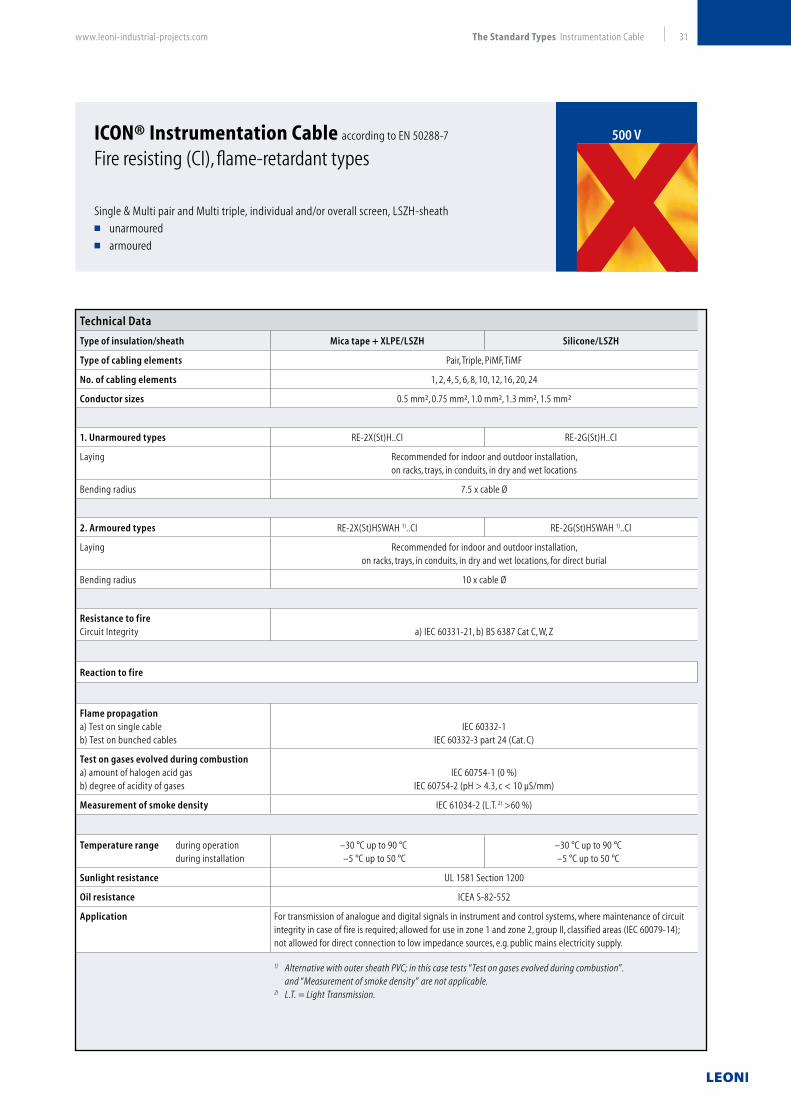
www.leoni-industrial-projects.com 31The Standard Types Instrumentation Cable
Technical Data
Type of insulation/sheath Mica tape + XLPE/LSZH Silicone/LSZH
Type of cabling elements Pair, Triple, PiMF, TiMF
No. of cabling elements 1, 2, 4, 5, 6, 8, 10, 12, 16, 20, 24
Conductor sizes 0.5 mm², 0.75 mm², 1.0 mm², 1.3 mm², 1.5 mm²
1. Unarmoured types RE-2X(St)H..CI RE-2G(St)H..CI
Laying Recommended for indoor and outdoor installation, on racks, trays, in conduits, in dry and wet locations
Bending radius 7.5 x cable Ø
2. Armoured types RE-2X(St)HSWAH 1)..CI RE-2G(St)HSWAH 1)..CI
Laying Recommended for indoor and outdoor installation, on racks, trays, in conduits, in dry and wet locations, for direct burial
Bending radius 10 x cable Ø
Resistance to fire Circuit Integrity a) IEC 60331-21, b) BS 6387 Cat C, W, Z
Reaction to fire
Flame propagationa) Test on single cableb) Test on bunched cables
IEC 60332-1IEC 60332-3 part 24 (Cat. C)
Test on gases evolved during combustiona) amount of halogen acid gasb) degree of acidity of gases
IEC 60754-1 (0 %)IEC 60754-2 (pH > 4.3, c < 10 µS/mm)
Measurement of smoke density IEC 61034-2 (L.T. 2) >60 %)
Temperature range during operation during installation
–30 °C up to 90 °C –5 °C up to 50 °C
–30 °C up to 90 °C –5 °C up to 50 °C
Sunlight resistance UL 1581 Section 1200
Oil resistance ICEA S-82-552
Application For transmission of analogue and digital signals in instrument and control systems, where maintenance of circuit integrity in case of fire is required; allowed for use in zone 1 and zone 2, group II, classified areas (IEC 60079-14); not allowed for direct connection to low impedance sources, e.g. public mains electricity supply.
1) Alternative with outer sheath PVC; in this case tests “Test on gases evolved during combustion”. and “Measurement of smoke density” are not applicable.2) L.T. = Light Transmission.
ICON® Instrumentation Cable according to EN 50288-7
Fire resisting (CI), flame-retardant types
Single & Multi pair and Multi triple, individual and/or overall screen, LSZH-sheath unarmoured armoured
500 V

www.leoni-industrial-projects.com32 The Standard Types Instrumentation Cable
ICON® Instrumentation Cable according to EN 50288-7
Fire resisting (CI), flame-retardant types
Single & Multi pair and Multi triple, individual and/or overall screen, LSZH-sheath unarmoured armoured
500 V
Construction
Product type Unarmoured types Armoured types
Conductor Plain annealed copper; 7 stranded according to EN 60228, Class 2
Cross-section mm²Conductor design mm
0.57 x 0.3
0.757 x 0.37
1.07 x 0.43
1.37 x 0.49
1.57 x 0.53
Insulation materials Mica tape + cross linked polyethylene XLPE or silicone
Cabling element 1)
without individual screen Pair, Triple
with individual screen PiMF, TiMF
Individual screen Aluminum/plastic-tape over tinned copper drain wire, 0.6 mm, plastic tape under and above screen
Wrapping at least one plastic tape above cable core
Overall screen Aluminum/plastic-tape over tinned copper drain wire 0.5 mm² / 7 x 0.3 mm
Inner sheath — LSZH, black
Armouring — Galvanized steel wire armouring; wire Ø depending on cable-Ø under armouring,
at least 0.9 mm
Outer sheath LSZH1)
Color black or blue for intrinsically safe systems
Marking LEONI KERPEN ICON INSTRUMENTATION CABLE GEN. TO EN 50288-7 RATED VOLTAGE LSZH2) CE PRODUCTION LOT CODE LENGTH MARKING
1) For armoured types also with outer sheath of PVC. 2) The sign “LSZH” is not applicable, if an outer sheath of PVC is applied.

www.leoni-industrial-projects.com 33The Standard Types Instrumentation Cable
ICON® Instrumentation Cable according to EN 50288-7
Fire resisting (CI), flame-retardant types
Single & Multi pair and Multi triple, individual and/or overall screen, LSZH-sheath unarmoured armoured
500 V
Electrical Data at 20 °C
Conductor sizes nom. mm² 0.5 0.75 1.0 1.3 1.5
Conductor resistance max. Ω/km 36.7 25.0 18.5 14.2 12.3
Insulation resistance
PE / XLPE-insulation min. MΩxkm 5000
Silicone min. MΩxkm 300
L/R Ratio max. µH/Ω 25 40
Inductance max. mH/km 1
Mutual capacitance
Mica tape + XLPE-insulation
Pair, Triple 1) 2) max. nF/km 65 75
PiMF, TiMF 100 100
Silicone
Pair, Triple 1) 2) max. nF/km 110 110
PiMF, TiMFmax. nF/km
150 150
Test voltage
Core/core (Urms
) Core/screen (U
rms)
V20002000
Operating voltage (Urms
) max. V 500
1) Values for cables with 1 element correspond to those for PiMF and TiMF resp..2) Values for cables with 2 up to 4 elements +20 %.

www.leoni-industrial-projects.com34 The Standard Types Instrumentation Control Cable
Instrumentation Control Cable according to EN 50288-7
Common Types 500 V
* according to EN 50288-7
Common Types
500 V
ICON® Instrumentation Control Cable
Zero halogen,
flame-retardant types
500 V
Fire resisting (CI)*,
flame-retardant types
500 V
plain stranded copper conductor,
cores,
overall static screen
PVC- or PVCw- or PE- or XLPE-
(70° C) (105 °C) (70 °C) (90 °C)
insulated/PVC-sheathed
Lead sheathed or
Multi layer sheathed, armoured
unarmoured unarmoured unarmouredarmoured armoured armoured
plain stranded copper conductor,
cores,
overall static screen
PE- or XLPE-
(70°C) (90°C)
insulated/LSZH-sheathed
plain stranded copper conductor,
cores,
overall static screen
Mica/XLPE- or Silicone
(90°C) (90°C)
insulated/LSZH-sheathed

www.leoni-industrial-projects.com 35The Standard Types Instrumentation Control Cable
ICON® Instrumentation Control Cable according to EN 50288-7
Common types
Multi core, overall screen, PVC-sheath unarmoured armoured with chemical protection, armoured
500 V
Technical Data
Type of insulation/sheath PVC/PVC PVCw/PVCw PE/PVC XLPE/PVC
Type of cabling elements Core
No. of cabling elements 2, 4, 5, 6, 8, 10, 12, 16, 20, 24, 36, 40
Conductor sizes 0.5 mm², 0.75 mm², 1.0 mm², 1.3 mm², 1.5 mm², 2.5 mm2
1. Unarmoured types RE-Y(St)Y-fl RE-Yw(St)Yw-fl RE-2Y(St)Y-fl 1) RE-2X (St)Y-fl
Laying Recommended for indoor and outdoor installation, on racks, trays, in conduits, in dry and wet locations
Bending radius 7.5 x cable Ø
2. Armoured types RE-Y(St)YSWAY-fl RE-Yw(St)YwSWAYw-fl RE-2Y(St)YSWAY-fl RE-2X(St)YSWAY-fl
Laying Recommended for outdoor installation, on racks, trays, in conduits, in dry and wet locations, for direct burial
Bending radius 10 x cable Ø
3. Armoured types with chemical protection
a) Lead sheathed RE-Y(St)YMYSWAY-fl — — RE-2X(St)YMYSWAY-fl
b) Multi layer sheathed — — — RE-2X(L)2Y4YSWAY 2) 3)
Laying Recommended for direct burial, especially in presence of oil and aggressive chemical substances
Bending radius 15 x cable Ø
Reaction to fire
Flame propagationa) Test on single cableb) Test on bunched cables
IEC 60332-1-2IEC 60332-3 part 24 (Cat. C), (excluded types with multi layer-sheath)
Temperature range during operation during installation
–30 °C up to 70 °C –5 °C up to 50 °C
–30 °C up to 105 °C –5 °C up to 50 °C
–30 °C up to 70 °C –5 °C up to 50 °C
–30 °C up to 90 °C –5 °C up to 50 °C
Sunlight resistance UL 1581 Section 1200
Oil resistance ICEA S-82-552
Application For control purposes, e.g. controlling of valves or engines; allowed for use in zone 1 and zone 2, group II, classified areas (IEC 60079-14); not allowed for direct connection to low impedance sources, e.g. public mains electricity supply
1) Also with increased thickness of outer sheath (Yv).2) Also with HDPE outer sheath; in this case tests “Reaction to Fire” are not passed.3) Max. operating temperature 80 °C.
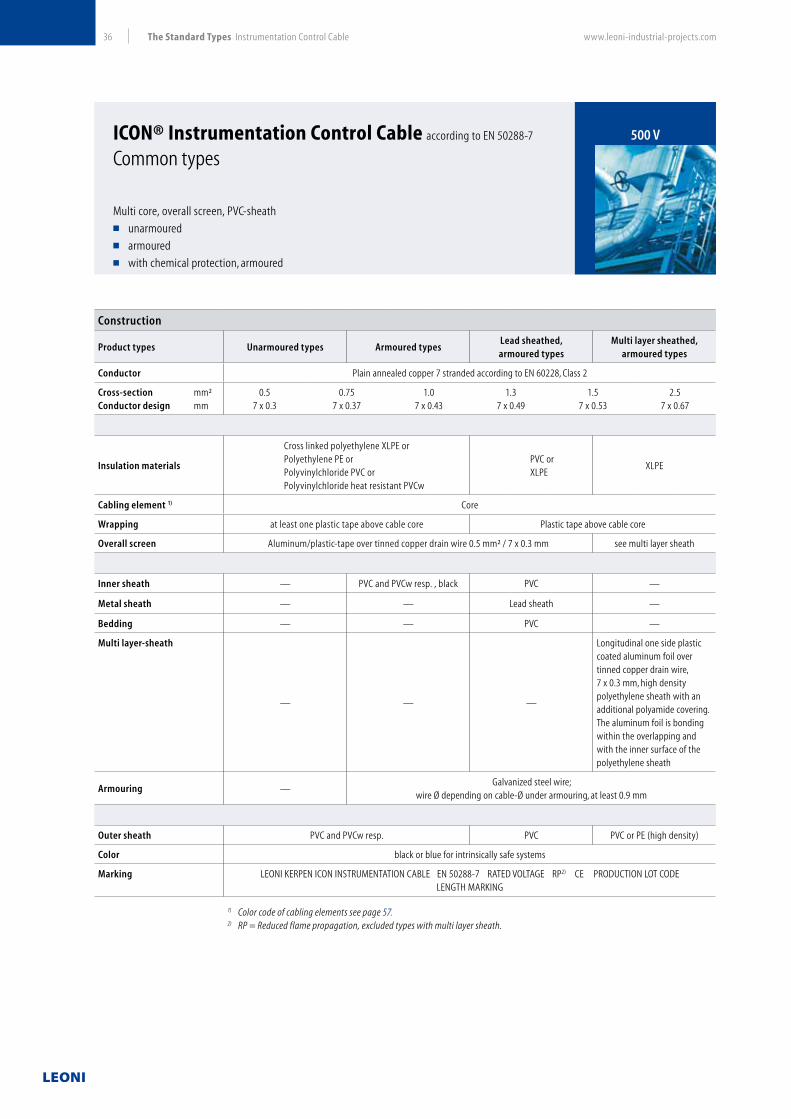
www.leoni-industrial-projects.com36 The Standard Types Instrumentation Control Cable
ICON® Instrumentation Control Cable according to EN 50288-7
Common types
Multi core, overall screen, PVC-sheath unarmoured armoured with chemical protection, armoured
500 V
Construction
Product types Unarmoured types Armoured typesLead sheathed, armoured types
Multi layer sheathed, armoured types
Conductor Plain annealed copper 7 stranded according to EN 60228, Class 2
Cross-section mm²Conductor design mm
0.57 x 0.3
0.757 x 0.37
1.07 x 0.43
1.37 x 0.49
1.57 x 0.53
2.57 x 0.67
Insulation materials
Cross linked polyethylene XLPE orPolyethylene PE orPolyvinylchloride PVC orPolyvinylchloride heat resistant PVCw
PVC or XLPE
XLPE
Cabling element 1) Core
Wrapping at least one plastic tape above cable core Plastic tape above cable core
Overall screen Aluminum/plastic-tape over tinned copper drain wire 0.5 mm² / 7 x 0.3 mm see multi layer sheath
Inner sheath — PVC and PVCw resp. , black PVC —
Metal sheath — — Lead sheath —
Bedding — — PVC —
Multi layer-sheath
— — —
Longitudinal one side plastic coated aluminum foil over tinned copper drain wire, 7 x 0.3 mm, high density polyethylene sheath with an additional polyamide covering. The aluminum foil is bonding within the overlapping and with the inner surface of the polyethylene sheath
Armouring —Galvanized steel wire;
wire Ø depending on cable-Ø under armouring, at least 0.9 mm
Outer sheath PVC and PVCw resp. PVC PVC or PE (high density)
Color black or blue for intrinsically safe systems
Marking LEONI KERPEN ICON INSTRUMENTATION CABLE EN 50288-7 RATED VOLTAGE RP2) CE PRODUCTION LOT CODE LENGTH MARKING
1) Color code of cabling elements see page 57. 2) RP = Reduced flame propagation, excluded types with multi layer sheath.

www.leoni-industrial-projects.com 37The Standard Types Instrumentation Control Cable
ICON® Instrumentation Control Cable according to EN 50288-7
Common types
Multi core, overall screen, PVC-sheath unarmoured armoured with chemical protection, armoured
500 V
Electrical Data at 20 °C
Conductor sizes nom. mm² 0.5 0.75 1.0 1.3 1.5 2.5
Conductor resistance max. Ω/km 36.0 24.5 18.1 13.9 12.1 7.41
Insulation resistance
PVC / PVCw insulation min. nF/km 100
PE / XLPE-insulation min. nF/km 5000
L/R Ratio max. µH/Ω 25 40 60
Inductance max. mH/km 1
Mutual capacitance
PVC / PVCw insulation max. nF/km 170
PE / XLPE-insulation max. nF/km 115
Test voltage
Core/core (Urms
) V 2000
Core/screen (Urms
) V 2000
Operating voltage (Urms
) max. V 500

www.leoni-industrial-projects.com38 The Standard Types Instrumentation Control Cable
Instrumentation Control Cable according to EN 50288-7
Zero halogen, flame-retardant types 500 V
* according to EN 50288-7
ICON® Instrumentation Control Cable
Common Types
500 V
Zero halogen,
flame-retardant types
500 V
Fire resisting (CI)*,
flame-retardant types
500 V
plain stranded copper conductor,
cores,
overall static screen
PVC- or PVCw- or PE- or XLPE-
(70° C) (105 °C) (70 °C) (90 °C)
insulated/PVC-sheathed
Lead sheathed or
Multi layer sheathed, armoured
unarmoured unarmoured unarmouredarmoured armoured armoured
plain stranded copper conductor,
cores,
overall static screen
PE- or XLPE-
(70°C) (90°C)
insulated/LSZH-sheathed
plain stranded copper conductor,
cores,
overall static screen
Mica/XLPE- or Silicone
(90°C) (90°C)
insulated/LSZH-sheathed

www.leoni-industrial-projects.com 39The Standard Types Instrumentation Control Cable
Technical Data
Type of insulation/sheath PE/LSZH XLPE/LSZH
Type of cabling elements Core
No. of cabling elements 2, 4, 5, 6, 8, 10, 12, 16, 20, 24, 36,40
Conductor sizes 0.5 mm², 0.75 mm², 1.0 mm², 1.3 mm², 1.5 mm², 2.5 mm²
1. Unarmoured types RE-2Y(St)H RE-2X(St)H
Laying Recommended for indoor and outdoor installation, on racks, trays, in conduits, in dry and wet locations
Bending radius 7.5 x cable Ø
2. Armoured types RE-2Y(St)HSWAH RE-2X(St)HSWAH
Laying Recommended for indoor and outdoor installation, on racks, trays, in conduits, in dry and wet locations, for direct burial
Bending radius 10 x cable Ø
Reaction to fire
Flame propagationa) Test on single cableb) Test on bunched cables
IEC 60332-1IEC 60332-3 part 24 (Cat. C)
Test on gases evolved during combustiona) amount of halogen acid gasb) degree of acidity of gases
IEC 60754-1 (0 %)IEC 60754-2 (pH > 4.3, c < 10 µS/mm)
Measurement of smoke density IEC 61034-2 (L.T. 1) >60 %)
Temperature range during operation during installation
–30 °C up to 70 °C –5 °C up to 50 °C
–30 °C up to 90 °C –5 °C up to 50 °C
Oil resistance ICEA S-82-552
Application For control purposes, e.g. controlling of valves or engines; allowed for use in zone 1 and zone 2, group II, classified areas (IEC 60079-14); not allowed for direct connection to low impedance sources, e.g. public mains electricity sup-ply. Recommended for use as fire protection measure for people and for important material assets.
1) L.T. = Light Transmission.
ICON® Instrumentation Control Cable according to EN 50288-7
Zero halogen, flame-retardant types
Multi core overall screen, LSZH-sheath unarmoured armoured
500 V

www.leoni-industrial-projects.com40 The Standard Types Instrumentation Control Cable
ICON® Instrumentation Control Cable according to EN 50288-7
Zero halogen, flame-retardant types
Multi core overall screen, LSZH-sheath unarmoured armoured
500 V
Construction
Product type unarmoured types armoured types
Conductor Plain annealed copper; 7 stranded according to EN 60228, Class 2
Cross-section mm²Conductor design mm
0.57 x 0.3
0.757 x 0.37
1.07 x 0.43
1.37 x 0.49
1.57 x 0.53
2.57 x 0.67
Insulation materials Cross linked polyethylene XLPE orPolyethylene PE
Cabling element Core
Wrapping at least one plastic tape above cable core
Overall screen Aluminum/plastic-tape over tinned copper drain wire 0.5 mm² / 7 x 0.3 mm
Inner sheath — LSZH, black
Armouring — Galvanized steel wire armouring; wire Ø depending on cable-Ø under armouring, at least 0.9 mm
Outer sheath LSZH
Color black or blue for intrinsically safe systems
Marking LEONI KERPEN ICON INSTRUMENTATION CABLE EN 50288-7 RATED VOLTAGE LSZH CE PRODUCTION LOT CODE LENGTH MARKING
1) Color code of cabling elements see page 57.

www.leoni-industrial-projects.com 41The Standard Types Instrumentation Control Cable
ICON® Instrumentation Control Cable according to EN 50288-7
Zero halogen, flame-retardant types
Multi core overall screen, LSZH-sheath unarmoured armoured
500 V
Electrical Data at 20 °C
Conductor sizes nom. mm² 0.5 0.75 1.0 1.3 1.5 2.5
Conductor resistance max. Ω/km 36.0 24.5 18.1 13.9 12.1 7.41
Insulation resistance
PE / XLPE-insulation min. MΩxkm 5000
L/R Ratio max. µH/Ω 25 40 60
Inductance max. mH/km 1
Mutual capacitance max. nF/km 115
Test voltage
Core/core (Urms
) Core/screen (U
rms)
V20002000
Operating voltage (Urms
) max. V 500

www.leoni-industrial-projects.com42 The Standard Types Instrumentation Control Cable
Instrumentation Contol Cable according to EN 50288-7
Fire resisting (CI), flame-retardant types – 500 V
* according to EN 50288-7
ICON® Instrumentation Control Cable
Common Types
500 V
Zero halogen,
flame-retardant types
500 V
Fire resisting (CI)*,
flame-retardant types
500 V
plain stranded copper conductor,
cores,
overall static screen
PVC- or PVCw- or PE- or XLPE-
(70° C) (105 °C) (70 °C) (90 °C)
insulated/PVC-sheathed
Lead sheathed or
Multi layer sheathed, armoured
unarmoured unarmoured unarmouredarmoured armoured armoured
plain stranded copper conductor,
cores,
overall static screen
PE- or XLPE-
(70°C) (90°C)
insulated/LSZH-sheathed
plain stranded copper conductor,
cores,
overall static screen
Mica/XLPE- or Silicone
(90°C) (90°C)
insulated/LSZH-sheathed

www.leoni-industrial-projects.com 43The Standard Types Instrumentation Control Cable
Technical Data
Type of insulation/sheath Mica tape + XLPE/LSZH Silicone/LSZH
Type of cabling elements Core
No. of cabling elements 2, 4, 5, 6, 8, 10, 12, 16, 20, 24, 36, 40
Conductor sizes 0.5 mm², 0.75 mm², 1.0 mm², 1.3 mm², 1.5 mm² , 2.5 mm²
1. Unarmoured types RE-2X(St)H..CI RE-2G(St)H..CI
Laying Recommended for indoor and outdoor installation, on racks, trays, in conduits, in dry and wet locations
Bending radius 7.5 x cable Ø
2. Armoured types RE-2X(St)HSWAH 1)..CI RE-2G(St)HSWAH 1)..CI
Laying Recommended for indoor and outdoor installation, on racks, trays, in conduits, in dry and wet locations, for direct burial
Bending radius 10 x cable Ø
Resistance to fire
Circuit Integrity a) IEC 60331-21 b) BS 6387 Cat. C, W, Z
Reaction to fire
Flame propagation a) Test on single cable b) Test on bunched cables
IEC 60332-1IEC 60332-3 part 24 (Cat. C)
Test on gases evolved during combustion a) amount of halogen acid gas b) degree of acidity of gases
IEC 60754-1 (0 %) IEC 60754-2 (pH > 4.3, c < 10 µS/mm)
Measurement of smoke density IEC 61034-2 (L.T. 2) >60 %)
Temperature range during operation during installation
–30 °C up to 70 °C –5 °C up to 50 °C
–30 °C up to 90 °C –5 °C up to 50 °C
Sunlight resistance UL 1581 Section 1200
Oil resistance ICEA S-82-552
Application For control purposes, e.g. controlling of valves or engines where maintenance of circuit integrity in case of fire is required; allowed for use in zone 1 and zone 2, group II, classified areas (IEC 60079-14); not allowed for direct connection to low impedance sources, e.g. public mains electricity supply.
1) Alternative with outer sheath PVC; in this case tests “Test on gases evolved during combustion”. and “Measurement of smoke density” are not applicable.2) L.T. = Light Transmission.
ICON® Instrumentation Control Cable according to EN 50288-7
Fire resisting (CI), flame-retardant types
Multi core overall screen, LSZH-sheath unarmoured armoured
500 V

www.leoni-industrial-projects.com44 The Standard Types Instrumentation Control Cable
ICON® Instrumentation Control Cable according to EN 50288-7
Fire resisting (CI), flame-retardant types
Multi core overall screen, LSZH-sheath unarmoured armoured
500 V
Construction
Product type Unarmoured types Armoured types
Conductor Plain annealed copper; 7 stranded according to EN 60228, Class 2
Cross-section mm²Conductor design mm
0.57 x 0.3
0.757 x 0.37
1.07 x 0.43
1.37 x 0.49
1.57 x 0.53
2.57 x 0.67
Insulation materials Mica tape + cross linked polyethylene XLPE orsilicone
Cabling element 1) Core
Wrapping at least one plastic tape above cable core
Overall screen Aluminum/plastic-tape over tinned copper drain wire 0.5 mm² / 7 x 0.3 mm
Inner sheath — LSZH, black
Armouring — Galvanized steel wire armouring; wire Ø depending on cable-Ø under armouring, at least 0.9 mm
Outer sheath LSZH
Color black or blue for intrinsically safe systems
Marking LEONI KERPEN ICON INSTRUMENTATION CABLE EN 50288-7 RATED VOLTAGE LSZH1) CI CE PRODUCTION LOT CODE LENGTH MARKING
1) The sign “LSZH” is not applicable, if an outer sheath of PVC is applied

www.leoni-industrial-projects.com 45The Standard Types Instrumentation Control Cable
ICON® Instrumentation Control Cable according to EN 50288-7
Fire resisting (CI), flame-retardant types
Multi core overall screen, LSZH-sheath unarmoured armoured
500 V
Electrical Data at 20 °C
Conductor sizes nom. mm² 0.5 0.75 1.0 1.3 1.5 2.5
Conductor resistance max. Ω/km 36.0 24.5 18.1 13.9 12.1 7.41
Insulation resistance
PE / XLPE-insulation min. MΩxkm 5000
Silicone min. MΩxkm 150
L/R Ratio max. µH/Ω 25 40 60
Inductance max. mH/km 1
Mutual capacitance
Mica tape + XLPE-insulation 100
Silicone min. nF/km 150
Test voltage
Core/core (Urms
) Core/screen (U
rms)
V20002000
Operating voltage (Urms
) max. V 500

www.leoni-industrial-projects.com46 The Standard Types Extension & Compensating Cable
Extension & Compensating Cable according to EN 50288-7
Common types300 V
* according to EN 50288-7** on request
ICON® Extension & Compensating Cable
Common Types
300 V
Zero halogen,
flame-retardant types
300 V
Fire resisting (CI)*,
flame-retardant types
500 V**
plain stranded copper conductor,
cores,
overall static screen
PVC- or PVCw- or PE- or XLPE-
(70° C) (105 °C) (70 °C) (90 °C)
insulated/PVC-sheathed
Lead sheathed or
Multi layer sheathed, armoured
unarmoured unarmouredarmoured armoured
plain stranded copper conductor,
cores,
overall static screen
PE- or XLPE-
(70°C) (90°C)
insulated/LSZH-sheathed

www.leoni-industrial-projects.com 47The Standard Types Extension & Compensating Cable
ICON® Extension & Compensating Cable according to EN 50288-7
Common types
Single & Multi pair, individual and/or overall screen, PVC-sheath unarmoured armoured with chemical protection, armoured
300 V
Technical Data
Type of insulation/sheath PVC/PVC PVCw/PVCw PE/PVC XLPE/PVC
Type of cabling elements Pair, PiMF
No. of cabling elements 1, 2, 4, 5, 6, 8, 10, 12, 16, 20, 24
Conductor material Extension or compensating material according to IEC 60584-3 (see page 55)
Conductor sizes 0.8 mm, 1.02 mm, 1.13 mm, 1.29 mm, 1.38 mm
1. Unarmoured types RE-Y(St)Y-fl RE-Yw(St)Yw-fl RE-2Y(St)Y-fl RE-2X (St)Y-fl
Laying Recommended for indoor and outdoor installation, on racks, trays, in conduits, in dry and wet locations
Bending radius 7.5 x cable Ø
2. Armoured types RE-Y(St)YSWAY-fl RE-Yw(St)YwSWAYw-fl RE-2Y(St)YSWAY-fl RE-2X(St)YSWAY-fl
Laying Recommended for outdoor installation, on racks, trays, in conduits, in dry and wet locations, for direct burial
Bending radius 10 x cable Ø
3. Armoured types with chemical protection
a) Lead sheathed RE-Y(St)YMYSWAY-fl — — RE-2X(St)YMYSWAY-fl
b) Multi layer sheathed — — — RE-2X(L)2Y4YSWAY 1) 2)
Laying Recommended for direct burial, especially in presence of oil and aggressive chemical substances
Bending radius 15 x cable Ø
Reaction to fire
Flame propagationa) Test on single cableb) Test on bunched cables
IEC 60332-1-2IEC 60332-3 part 24 (Cat. C), (excluded types with multi layer-sheath)
Temperature range during operation during installation
–30 °C up to 70 °C –5 °C up to 50 °C
–30 °C up to 105 °C –5 °C up to 50 °C
–30 °C up to 70 °C –5 °C up to 50 °C
–30 °C up to 90 °C –5 °C up to 50 °C
Sunlight resistance UL 1581 Section 1200
Oil resistance ICEA S-82-552
Application For transmission of thermoelectric voltage from measuring junction to reference junction; allowed for use in zone 1 and zone 2, group II (IEC 60079-14)
1) Also with HDPE outer sheath; in this case tests “Reaction to Fire” are not passed.2) Max. operating temperature 80 °C.

www.leoni-industrial-projects.com48 The Standard Types Extension & Compensating Cable
ICON® Extension & Compensating Cable according to EN 50288-7
Common types
Single & Multi pair, individual and/or overall screen, PVC-sheath unarmoured armoured with chemical protection, armoured
300 V
Construction
Product types Unarmoured types Armoured typesLead sheathed, armoured
typesMulti layer sheathed,
armoured types
Conductor Extension or compensating material according to IEC 60584-3 (see page 55)
Cross-section mm²Conductor design mm
0.51 x 0.8
0.751 x 1.02
1.01 x 1.13
1.31 x 1.29
1.51 x 1.38
Insulation materials
Cross linked polyethylene XLPE orPolyethylene PE orPolyvinylchloride PVC orPolyvinylchloride heat resistant PVCw
PVC or XLPE
XLPE
Cabling element 1) without individual screenwith individual screen
PairPiMF
Individual screenAluminum/plastic-tape over solid tinned copper drain wire, 0.6 mm
plastic-tape under and above screen
Wrapping at least one plastic tape above cable core
Overall screen Aluminum/plastic-tape over tinned copper drain wire 0.5 mm² / 7 x 0.3 mm see multi layer sheath
Inner sheath — PVC and PVCw resp. , black PVC —
Metal sheath — — Lead sheath —
Bedding — — PVC —
Multi layer-sheath
— — —
Longitudinal one side plastic coated aluminum foil over tinned copper drain wire, 7 x 0.3 mm, high density polyethylene sheath with an additional polyamide covering. The aluminum foil is bonding within the overlapping and with the inner surface of the polyethylene sheath
Armouring —Galvanized steel wire;
wire Ø depending on cable-Ø under armouring, at least 0.9 mm
Outer sheath PVC and PVCw resp. PVC PVC or PE (high density)
Coloraccording to color code 1)
or blue for intrinsically safe systemsaccording to color code 1)
Marking LEONI KERPEN ICON EXTENSION OR COMPENSATING CABLE EN 50288-7 RATED VOLTAGE RP2) CE PRODUCTION LOT CODE LENGTH MARKING
1) Color code of cabling elements see page 55.2) RP = Reduced flame propagation, excluded types with multi layer sheath.

www.leoni-industrial-projects.com 49The Standard Types Extension & Compensating Cable
ICON® Extension & Compensating Cable according to EN 50288-7
Common types
Single & Multi pair, individual and/or overall screen, PVC-sheath unarmoured armoured with chemical protection, armoured
300 V
Electrical Data at 20 °C
Conductor sizes nom. mm² 0.5 0.75 1.0 1.3 1.5
Conductor resistance max. Ω/km see table 2 (page 56)
Insulation resistance
PVC / PVCw-insulation min. MΩxkm 100
PE / XLPE-insulation min. MΩxkm 5000
Inductance max. mH/km see table 2 (page 56)
Mutual capacitance
PVC / PVCw-insulation
Pair 1) 2) max. nF/km 150 160
PiMF max. nF/km 190 200
PE / XLPE-insulation
Pair 1) 2) max. nF/km 75 85
PiMF max. nF/km 115 115
Test voltage
Core/core (Urms
) Core/screen (U
rms)
V15001500
Operating voltage (Urms
) max. V 300
1) Values for cables with 1 element correspond to those for PiMF.2) Values for cables with 2 up to 4 elements +20 %.
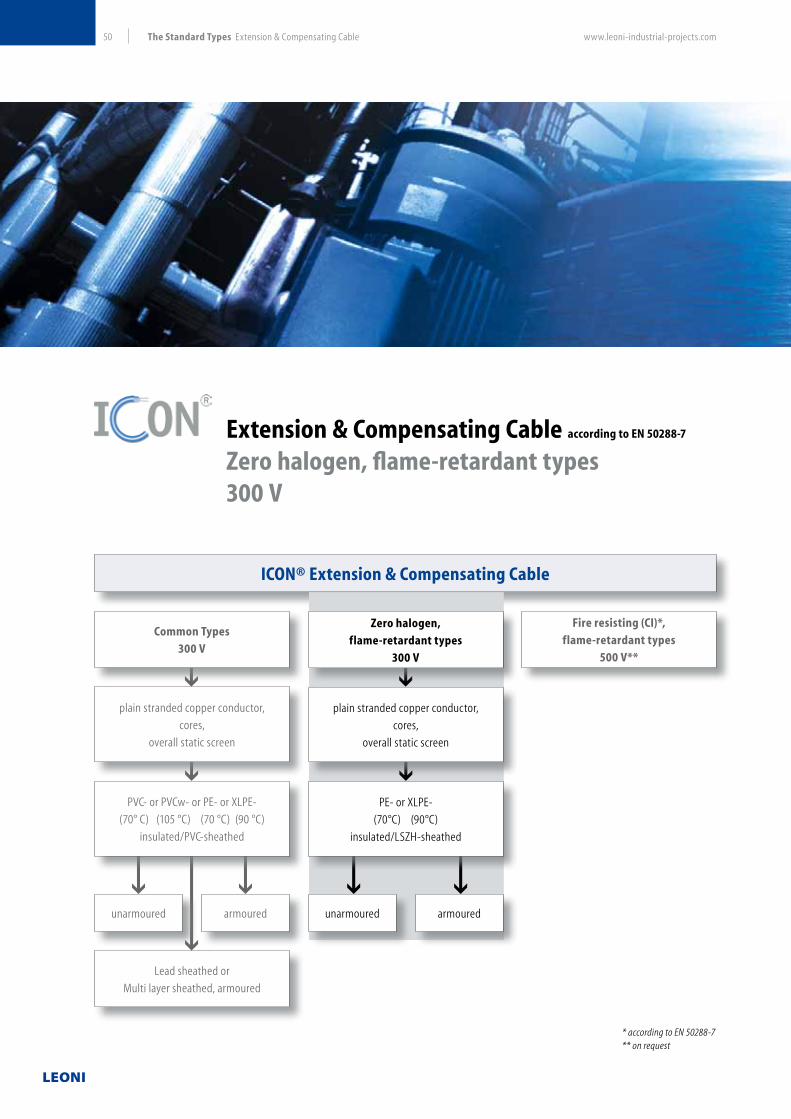
www.leoni-industrial-projects.com50 The Standard Types Extension & Compensating Cable
Extension & Compensating Cable according to EN 50288-7
Zero halogen, flame-retardant types 300 V
ICON® Extension & Compensating Cable
* according to EN 50288-7** on request
Common Types
300 V
Zero halogen,
flame-retardant types
300 V
Fire resisting (CI)*,
flame-retardant types
500 V**
plain stranded copper conductor,
cores,
overall static screen
PVC- or PVCw- or PE- or XLPE-
(70° C) (105 °C) (70 °C) (90 °C)
insulated/PVC-sheathed
Lead sheathed or
Multi layer sheathed, armoured
unarmoured unarmouredarmoured armoured
plain stranded copper conductor,
cores,
overall static screen
PE- or XLPE-
(70°C) (90°C)
insulated/LSZH-sheathed

www.leoni-industrial-projects.com 51The Standard Types Extension & Compensating Cable
ICON® Extension & Compensating Cable according to EN 50288-7
Zero halogen, flame-retardant types
Single & Multi pair, individual and/or overall screen, PVC-sheath unarmoured armoured
300 V
Technical Data
Type of insulation/sheath PE/LSZH XLPE/LSZH
Type of cabling elements Pair, PiMF
No. of cabling elements 1, 2, 4, 5, 6, 8, 10, 12, 16, 20, 24
Conductor material Extension or compensating material according to IEC 60584-3 (see table 2 on page 56)
Conductor sizes 0.5 mm, 0.75 mm, 1.0 mm, 1.3 mm, 1.5 mm
1. Unarmoured types RE-2Y(St)H RE-2X(St)H
Laying Recommended for indoor and outdoor installation, on racks, trays, in conduits, in dry and wet locations
Bending radius 7.5 x cable Ø
2. Armoured types RE-2Y(St)HSWAH RE-2X(St)HSWAH
Laying Recommended for indoor and outdoor installation, on racks, trays, in conduits, in dry and wet locations, for direct burial
Bending radius 10 x cable Ø
Reaction to fire
Flame propagationa) Test on single cableb) Test on bunched cables
IEC 60332-1 IEC 60332-3 part 24 (Cat. C)
Test on gases evolved during combustiona) amount of halogen acid gasb) degree of acidity of gases
IEC 60754-1 (0 %) IEC 60754-2 (pH > 4.3, c < 10 µS/mm)
Measurement of smoke density IEC 61034-2 (L.T. 1) >60 %)
Temperature range during operation during installation
–30 °C up to 70 °C –5 °C up to 50 °C
–30 °C up to 90 °C –5 °C up to 50 °C
Oil resistance ICEA S-82-552
Application For transmission of thermoelectric voltage from measuring junction to reference junction; allowed for use in zone 1 and zone 2, group II, classified areas (IEC 79-14).
1) L.T. = Light Transmission.
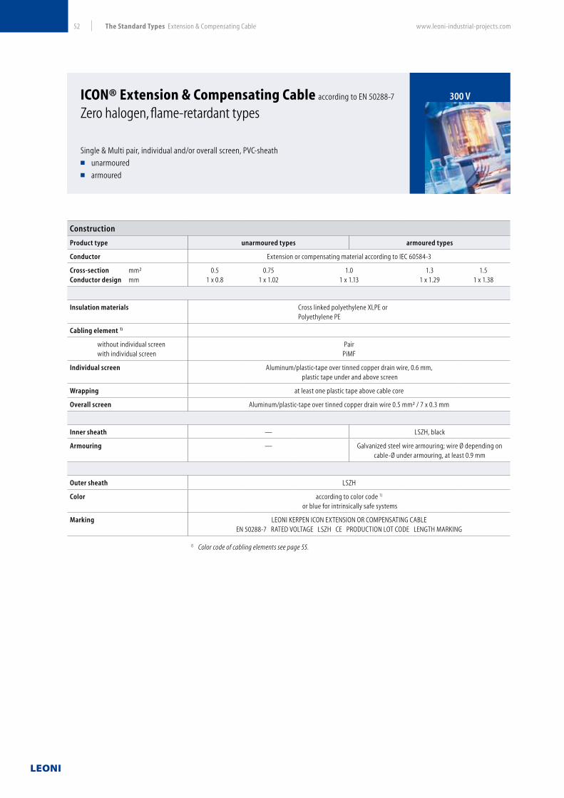
www.leoni-industrial-projects.com52 The Standard Types Extension & Compensating Cable
ICON® Extension & Compensating Cable according to EN 50288-7
Zero halogen, flame-retardant types
Single & Multi pair, individual and/or overall screen, PVC-sheath unarmoured armoured
300 V
Construction
Product type unarmoured types armoured types
Conductor Extension or compensating material according to IEC 60584-3
Cross-section mm²Conductor design mm
0.51 x 0.8
0.751 x 1.02
1.01 x 1.13
1.31 x 1.29
1.51 x 1.38
Insulation materials Cross linked polyethylene XLPE orPolyethylene PE
Cabling element 1)
without individual screen with individual screen
PairPiMF
Individual screen Aluminum/plastic-tape over tinned copper drain wire, 0.6 mm, plastic tape under and above screen
Wrapping at least one plastic tape above cable core
Overall screen Aluminum/plastic-tape over tinned copper drain wire 0.5 mm² / 7 x 0.3 mm
Inner sheath — LSZH, black
Armouring — Galvanized steel wire armouring; wire Ø depending on cable-Ø under armouring, at least 0.9 mm
Outer sheath LSZH
Color according to color code 1)
or blue for intrinsically safe systems
Marking LEONI KERPEN ICON EXTENSION OR COMPENSATING CABLE EN 50288-7 RATED VOLTAGE LSZH CE PRODUCTION LOT CODE LENGTH MARKING
1) Color code of cabling elements see page 55.

www.leoni-industrial-projects.com 53The Standard Types Extension & Compensating Cable
ICON® Extension & Compensating Cable according to EN 50288-7
Zero halogen, flame-retardant types
Single & Multi pair, individual and/or overall screen, PVC-sheath unarmoured armoured
300 V
Electrical Data at 20 °C
Conductor sizes nom. mm² 0.5 0.75 1.0 1.3 1.5
Conductor resistance max. Ω/km see table 2 on page 56
Insulation resistance
PE / XLPE-insulation min. MΩxkm 5000
L/R Ratio max. µH/Ω 25 40
Inductance max. mH/km see table 2 on page 56
Mutual capacitance
PE / XLPE-insulation
Pair 1) 2) max. nF/km 75 85
PiMF max. nF/km 115 115
Test voltage
Core/core (Urms
) Core/screen (U
rms)
V15001500
Operating voltage (Urms
) max. V 300
1) Values for cables with 1 element correspond to those for PiMF.2) Values for cables with 2 up to 4 elements +20 %.

www.leoni-industrial-projects.com54 General
General
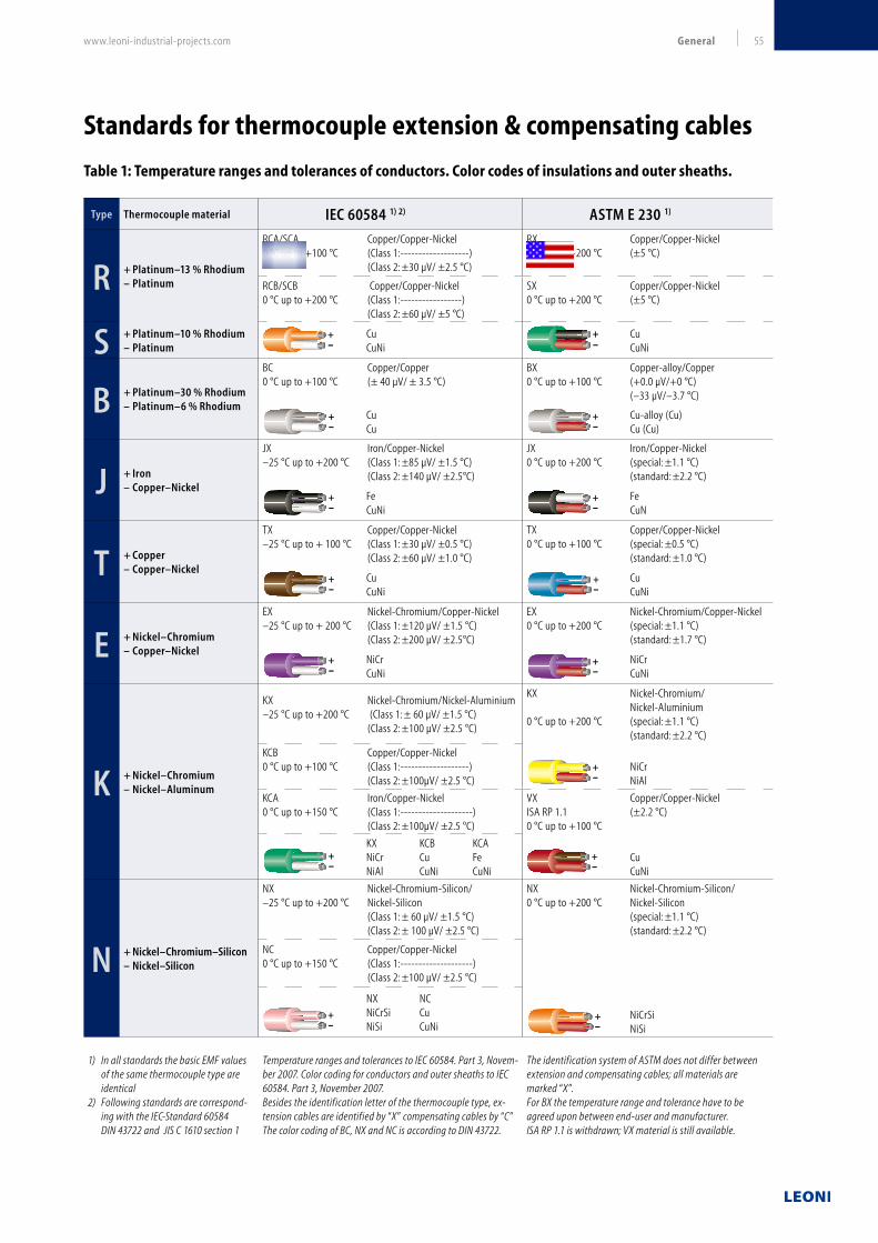
www.leoni-industrial-projects.com 55General
Type Thermocouple material IEC 60584 1) 2) ASTM E 230 1)
R + Platinum–13 % Rhodium– Platinum
RCA/SCA Copper/Copper-Nickel0 °C up to +100 °C (Class 1:-------------------) (Class 2: ±30 µV/ ±2.5 °C)
RX Copper/Copper-Nickel0 °C up to +200 °C (±5 °C)
RCB/SCB Copper/Copper-Nickel0 °C up to +200 °C (Class 1:-----------------) (Class 2: ±60 µV/ ±5 °C)
SX Copper/Copper-Nickel0 °C up to +200 °C (±5 °C)
S + Platinum–10 % Rhodium– Platinum
+-
Cu CuNi
+-
Cu CuNi
B + Platinum–30 % Rhodium – Platinum–6 % Rhodium
BC Copper/Copper0 °C up to +100 °C (± 40 µV/ ± 3.5 °C)
BX Copper-alloy/Copper 0 °C up to +100 °C (+0.0 µV/+0 °C) (–33 µV/–3.7 °C)
+-
CuCu
+-
Cu-alloy (Cu) Cu (Cu)
J + Iron – Copper–Nickel
JX Iron/Copper-Nickel–25 °C up to +200 °C (Class 1: ±85 µV/ ±1.5 °C) (Class 2: ±140 µV/ ±2.5°C)
JX Iron/Copper-Nickel0 °C up to +200 °C (special: ±1.1 °C) (standard: ±2.2 °C)
+-
FeCuNi
+-
FeCuN
T + Copper– Copper–Nickel
TX Copper/Copper-Nickel–25 °C up to + 100 °C (Class 1: ±30 µV/ ±0.5 °C) (Class 2: ±60 µV/ ±1.0 °C)
TX Copper/Copper-Nickel0 °C up to +100 °C (special: ±0.5 °C) (standard: ±1.0 °C)
+-
CuCuNi
+-
CuCuNi
E + Nickel–Chromium– Copper–Nickel
EX Nickel-Chromium/Copper-Nickel–25 °C up to + 200 °C (Class 1: ±120 µV/ ±1.5 °C) (Class 2: ±200 µV/ ±2.5°C)
EX Nickel-Chromium/Copper-Nickel0 °C up to +200 °C (special: ±1.1 °C) (standard: ±1.7 °C)
+-
NiCrCuNi
+-
NiCrCuNi
K + Nickel–Chromium– Nickel–Aluminum
KX Nickel-Chromium/Nickel-Aluminium–25 °C up to +200 °C (Class 1: ± 60 µV/ ±1.5 °C) (Class 2: ±100 µV/ ±2.5 °C)
KX Nickel-Chromium/ Nickel-Aluminium0 °C up to +200 °C (special: ±1.1 °C) (standard: ±2.2 °C)
KCB Copper/Copper-Nickel0 °C up to +100 °C (Class 1:-------------------) (Class 2: ±100µV/ ±2.5 °C)
+-
NiCrNiAl
KCA Iron/Copper-Nickel0 °C up to +150 °C (Class 1:--------------------) (Class 2: ±100µV/ ±2.5 °C)
VX Copper/Copper-NickelISA RP 1.1 (±2.2 °C)0 °C up to +100 °C
+-
KX KCB KCANiCr Cu FeNiAl CuNi CuNi
+-
CuCuNi
N + Nickel–Chromium–Silicon– Nickel–Silicon
NX Nickel-Chromium-Silicon/–25 °C up to +200 °C Nickel-Silicon (Class 1: ± 60 µV/ ±1.5 °C) (Class 2: ± 100 µV/ ±2.5 °C)
NX Nickel-Chromium-Silicon/0 °C up to +200 °C Nickel-Silicon (special: ±1.1 °C) (standard: ±2.2 °C)
+-
NiCrSi NiSi
NC Copper/Copper-Nickel0 °C up to +150 °C (Class 1:--------------------) (Class 2: ±100 µV/ ±2.5 °C)
+-
NX NCNiCrSi CuNiSi CuNi
1) In all standards the basic EMF values of the same thermocouple type are identical
2) Following standards are correspond-ing with the IEC-Standard 60584
DIN 43722 and JIS C 1610 section 1
Temperature ranges and tolerances to IEC 60584. Part 3, Novem-ber 2007. Color coding for conductors and outer sheaths to IEC 60584. Part 3, November 2007.Besides the identification letter of the thermocouple type, ex-tension cables are identified by “X” compensating cables by “C” The color coding of BC, NX and NC is according to DIN 43722.
The identification system of ASTM does not differ between extension and compensating cables; all materials are marked “X”. For BX the temperature range and tolerance have to be agreed upon between end-user and manufacturer.ISA RP 1.1 is withdrawn; VX material is still available.
Standards for thermocouple extension & compensating cables
Table 1: Temperature ranges and tolerances of conductors. Color codes of insulations and outer sheaths.

www.leoni-industrial-projects.com56 General
Table 2: Electrical characteristics of conductors (approx. values)
Table 3: Loop resistance at 20 °C (nominal value in Ω/km)
StandardCode Volume resistivity
Ω x mm
mLoop inductance
mH/km(+) leg (–) leg (+) leg (–) leg
IEC
IEC
ANSI
RPCA/SPCA
RPCB/SPCB
SPX
RNCA/SNCA
RNCA/SNCA
SNX
0.017
0.017
0.017
0.12
0.12
0.12
1
1
1
IEC
ANSI
BPC
BPX
BNC
BNX
0.017
0.125
0.017
0.017
1
1
IEC
ANSI
JPX
JPX
JNX
JNX
0.12
0.12
0.49
0.49
8
8
IEC
ANSI
TPC
TPX
TNC
TNX
0.017
0.017
0.49
0.49
1
1
IEC
ANSI
EPX
EPX
ENX
ENX
0.72
0.72
0.49
0.49
3
3
IEC
IEC
IEC
ANSI
ISA
KPX
KPCB
KPCA
KPX
VPX
KNX
KNCB
KNCA
KNX
VNX
0.72
0.017
0.12
0.72
0.017
0.27
0.49
0.51
0.27
0.49
3
1
8
3
1
IEC
IEC
ANSI
NPX
NPC
NPX
NNX
NNC
NNX
0.98
0.017
0.98
0.34
0.52
0.34
3
1
3
Thermo-
couple
Conductor material Conductor size
IEC 60584 ANSI MC 96.1 0.5 mm² 0.8 mm² 1.0 mm² 1.3 mm² 1.5 mm²
solid 0.8 mm Ø 1.02 mm Ø 1.13 mm Ø 1.29 mm Ø 1.38 mm Ø
R/S RC/SC SX 282 173 141 109 94
B … BX 293 179 148 112 98
B BC … 70 43 35 27 23
J JX JX 1257 769 628 483 418
T TX TX 1044 639 522 402 348
E EX Ex 2493 155 1246 958 831
K KX KX 2039 1248 1020 785 680
K KCB VX* 1044 639 522 402 348
K KCA … 1298 794 649 499 433
N NX … 2719 1663 1359 1046 906
N NC … 1106 677 553 425 369
* VX according to ISA RP 1.1
Standards for thermocouple extension & compensating cables

www.leoni-industrial-projects.com 57General
Colour Codes (approx. values)
Color code of instrumentation and instrumentation control cables according to EN 50288-7
Color code of standardized product programme.
Cabling element
Core * Pair ** Triple **
Rated voltage
300 V—
black/white black/white/red
continuously numbered on white core 1, 2, 3…
for multi-element cables,
starting with 1 in the center
Rated voltage
500 V
black
continuously numbered 1, 2, 3…
for multi-core cables,
starting with 1 in the center
black/blue black/blue/red
continuously numbered on blue core 1, 2, 3…
for multi-element cables,
starting with 1 in the center
* If specified green-yellow core principally applied as last element in the outer layer.
** Identification scheme for elements with and without individual screen.
Further color codes on request.

www.leoni-industrial-projects.com58 General
Cables under fire conditions (Common test methods)
Reaction to Fire – IEC and corresponding European Standards
IEC Standard CENELEC Standard
No. Title No. Title
IEC 60332 Test on electric and optical cables under
fire
conditions
EN 60332 Test on electrical and optical cables under
fire conditions. Test for vertical flame
propagation for a single insulated wire or
cableIEC 60332-1-1 Test on a single vertical insulated wire or cable
– Apparatus
EN 60332-1-1 - Apparatus
IEC 60332-1-2 – Procedure EN 60332-1-2 - Procedure for 1 kV pre-mixed flame
IEC 60332-1-3 – Procedure for determination of flaming
droplets / particles
EN 60332-1-3 - Procedure for determination of flaming droplets
/ particles
IEC 60332 Tests on electric cables under fire condi-
tions
EN 60332 Test for vertical flame propagation for a
single small insulated wire or cableIEC 60332-2-1 Test on a single vertical insulated wire or cable
– Apparatus
EN 60332-2-1 - Apparatus
IEC 60332-2-2 Test on a single vertical insulated wire or cable
– Procedure
EN 60332-2-2 - Procedure for diffusion flame
IEC 60332
IEC 60332-3
Tests on bunched wires or cables EN 50266 Test for vertical flame spread of vertically
mounted bunched wires o. cablesIEC 60332-10 Apparatus EN 50266-1 Apparatus
IEC 60332-21 Procedures Category A F/R EN 50266-2-1 Procedures – Category A F/R
IEC 60332-22 Procedures Category A EN 50266-2-2 Procedures – Category A
IEC 60332-23 Procedures Category B EN 50266-2-3 Procedures – Category B
IEC 60332-24 Procedures Category C EN 50266-2-4 Procedures – Category C
IEC 60332-25 Procedures – small cables – EN 50266-2-5 Procedures – small cables –
IEC 60754 Tests on gases evolved during combustion
of materials from cables
EN 50267 Tests on gases evolved during combus-
tion of materials from cablesIEC 60754-1 Determination of amount of halogen acid gas EN 50267-1 Apparatus
IEC 60754-2 Determination of degree of acidity of gases
evolved during the combustion of materials
taken from electric cables by measuring pH and
conductivity
EN 50267-2-1
EN 50267-2-2
Procedures – Determination of the amount of
halogen acid gas
Procedures – Determination of degree of acid-
ity of gases for materials by measuring pH and
conductivity
EN 50267-2.3 Procedures – Determination of degree of acid-
ity of gases for cables by determination of the
weighted average of pH and conductivity
IEC 61034 Measurement of smoke density of cables
burning under defined conditions
EN 61034 Measurement of smoke density of cables
burning under defined conditionsIEC 61034-1 Test apparatus EN 61034-1 Apparatus
IEC 61034-2 Test procedure and requirements EN 61034-2 Test procedure and requirements
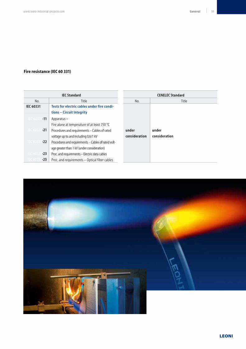
www.leoni-industrial-projects.com 59General
Fire resistance (IEC 60 331)
IEC Standard CENELEC Standard
No. Title No. Title
IEC 60331 Tests for electric cables under fire condi-
tions – Circuit Integrity
under
consideration
under
consideration
IEC 60331-11 Apparatus –
Fire alone at temperature of at least 750 °C
IEC 60331-21 Procedures and requirements – Cables of rated
voltage up to and including 0,6/1 kV
IEC 60331-22 Procedures and requirements – Cables of rated volt-
age greater than 1 kV (under consideration)
IEC 60331-23 Proc. and requirements – Electric data cables
IEC 60331-25 Proc. and requirements – Optical fiber cables

www.leoni-industrial-projects.com60 General
Type designation (for instrumentation and thermocouple cables)
The type designations of LEONI's instrumentation- and
thermocouple cables are read as follows:
type abbreviation
number of cabling elements
type of cabling element
conductor size in mm² (stranded conductors)
or conductor diameter in mm (solid conductors)
followed by (when applicable):
type of conductor material (for thermocouple cable only,
see table 1 on page 56
abbreviation for cables with circuit integrity properties
Individual screening of pairs and triples
rated voltage
standard
Examples
RE-2Y(St)YMYSWAY-fl 24 x 3 x 1.3 mm² TiMF 300 V EN 50288-7
Instrumentation cable (RE), 24 triples (3), conductor size 1.3 mm²,
insulation of PE (2Y), individual TiMF and overall screen (St),
inner sheath of PVC (Y), lead sheath (M), inner sheath made of PVC
(Y), steel wire armour (SWA), outer sheath of PVC (Y-fl),
rated voltage 300 V, standard EN 50288-7
RT-Yw(St)YwSWAYw-fl 8 x 2 x 0.8 mm KX 300 V EN 50288-7
Thermocouple extension (RT-), 8 pairs (2), conductor diameter 0,8
mm, conductor material (KX), insulation of heat resistant PVC (Yw),
overall screen (St), inner sheath made of heat resistant PVC (Yw),
steel wire armour (SWA), outer sheath made of heat resistant PVC (Yw),
rated voltage 300 V, standard EN 50288-7
RE-2X(St)H 8 x 2.5 mm² CI 500 V EN 50288-7
Instrumentation control cable (RE-),
Zero halogen with Circuit Integrity (CI),
8 cores, conductor size 2.5 mm², insulation of XLPE (2X),
overall screen (St), outer sheath made of Zero halogen,
flame-retardant compound (H), rated voltage 500 V,
standard EN 50288-7
RE-2X(L)2Y4YSWA2Y 12 x 2 x 1.5 mm² PiMF 300 V EN 50288-7
Instrumentation cable (RE), 12 pairs 2, conductor size 1.5 mm²,
insulation made of XLPE (2X), individual screen (PiMF),
multi layer sheath (L)(2Y), steel wire armour (SWA),
outer sheath made of PE (2Y), rated voltage 300 V,
standard EN 50288-7
Type of Cabling Elements
The type of cabling elements are indicated by figures responsible
by figures with an additional information for individual screened
cabling elements
Core no figure
Pair 2
Triple 3
Individual screened pair PiMF
Individual screened triple TiMF

www.leoni-industrial-projects.com 61General
* This property is indicated on the outer sheath of PVC-sheathed cables via the marking RP
Abbreviation code
Cable type CodeInstrumentation and instrumentation control cable RE-Thermocouple extension or compensating cable RT-
Metal cladding of conductor
Copper conductor, tinned -v
Insulation and/or sheath materials
Insulation, inner or outer sheath of polyvinylchloride (PVC) YInsulation, inner or outer sheath made of heat resistant polyvinylchloride (PVCw) Yw
Outer sheath made of polyvinylchloride of increased thickness YvInsulation, inner or outer sheath made of polyethylene (PE) 2YInsulation made of cross linked polyethylene (XLPE) 2XInner or outer sheath made of Zero halogen, flame-retardant compound (LSZH) HInsulation made of silicone (Sil) 2GCovering made of polyamide (nylon) 4Y
Screening
Static screen made of laminated plastic tape laminated with aluminum (ST)Longitudinally applied aluminum foil, one or both sides plastic-coated (L)Braid made of tinned or untinned copper wires over the cable core CWrapping made of copper foil KPair in Metal Foil PiMFTriple in Metal Foil TiMFBraid of tinned or untinned copper wires over a single cabling element (C)
Metal sheath
Sheath made of lead MSheath made of lead alloy Mz
Armour
Galvanized round steel wires SWAGalvanized round steel wires with counter helix made of galvanized steel tape RGGalvanized flat steel wires with counter helix made of galvanized steel tape FGDouble layer made of galvanized steel tapes BBraid made of galvanized round steel wires Q
Further properties
Circuit Integrity (resistance to f ire) CIIncreased flame retardancy; meeds requirements for IEC 60332-3-24 (cat. C) fulf illed * -fl
Cable core f illed with petrojelly F
RE-2Y(St)YMYSWAY-fl TiMF

www.leoni-industrial-projects.com62 General
Conductors – AWG and metric values by comparison
Solid plain annealed copper conductors
Conductor size Electrical resistance2)
AWG Metric No. of wires Conductor-Ø EN 50288-73) UL 134)
mm² mm Ω/km Ω/1000 ft. Ω/km Ω/1000 ft.
30 0.051 1 0.254 – – 361 110
28 0.081 1 0.320 – – 228 69.3
26 0.128 1 0.404 – – 154 46.9
24 0.205 1 0.511 – – 97.6 29.7
22 0.324 1 0.643 – – 56.3 17.2
– 0.5 1) 1 0.8 36.8 11.2 – –
20 0.517 1 0.813 – – 35.2 10.7
– 0.75 1) 1 1.0 25.0 7.6 – –
18 0.82 1 1.02 – – 22.3 6.8
– 1.0 1) 1 1.13 18.5 5.6 – –
16 1.3 1 1.29 – – 14.0 4.3
– 1.5 1) 1 1.37 12.3 3.76 – –
14 2.1 1 1.63 – – 8.79 2.67
– 2.5 1 1.76 7.56 2.31 – –
12 3.3 1 2.05 – – 5.52 1.68
– 4.0 1) 1 2.26 4.70 1.43 – –
Stranded plain annealed copper conductors
Conductor size Electrical resistance2)
AWG Metric No. of wires Conductor-Ø EN 50288-73) UL 134)
mm² mm Ω/km Ω/1000 ft. Ω/km Ω/1000 ft.
24 0.205 7 0.579 – – 91.1 27.8
22 0.327 7 0.729 – – 57.6 17.6
– 0.5 7 0.9 36.8 11.2 – —
20 0.517 7 0.919 – – 35.8 11.0
– 0.75 1) 7 1.11 25.0 7.6 – —
18 0.82 7 1.16 – – 22.8 6.9
– 1.0 1) 7 1.29 18.5 5.6 – —
16 1.3 7 1.46 – – 14.2 4.36
– 1.5 1) 7 1.59 12.3 3.76 – —
14 2.1 7 1.85 – – 8.94 2.72
– 2.5 1) 7 2.01 7.56 2.31 – —
12 3.3 7 2.32 – – 5.63 1.72
– 4.0 1) 7 2.58 4.70 1.43 – –1) Sizes according to EN 50288-7.2) The value for the electrical resistance is given for 20 °C (68.0 °F).
3) The value for the electrical resistance according to EN 50288-7 is for the finished cables with multi pairs/triples.
4) The value for the electrical resistance according to UL 13 is calculated for “one pair/triple and an assembly of pairs/triples”.

www.leoni-industrial-projects.com 63General
General units
Length Area1 mil = 0.0254 mm 1 circ. mil (CM) = 0.0005067 mm2
1 inch (in“) = 25.4 mm 1 MCM = 0.5067 mm2
1 foot (ft.‘) = 0.305 m 1 square inch (in2) = 645.16 mm2
1 yard (yd) = 0.914 m 1 square foot (ft2) = 0.0929 m2
1 mile (mi.) = 1.61 km 1 square yard (yd2) = 0.836 m2
1 statute mile (mi.) = 1.61 km 1 square mile (sq.mi.) = 2.59 km2
1 intern. naut. mile (sm) = 1.852 km
Volume Electrical Unit per Length1 cubic inch (m3) = 16.39 cm3 1 µ f per mile = 0.62 µ F/km
1 cubic foot (ft3) = 0.0283 m3 1 MΩ per mile = 1.61 MΩ x km
1 cubic yard (yd3) = 0.765 m3 1 decibel per mile = 0.62 dB/km
1 barrel = 159 l 1 pf per foot = 3.28 pF/m
1 US gallon (US gal) = 3.79 l 1 decibel per 1000 ft. = 3.28 dB/km
1 UK gallon (UK gal) = 4.55 l 1 Ω per 1000 ft. = 3.28 Ω/km
Force Mass1 poundal (pdl) = 0.1 38 N 1 ounce (oz) = 0.0284 kg
1 pound-force (lbf ) = 4.448 N 1 pound (lb) = 0.454 kg
1 Brit. ton-force = 9964 N 1 Brit. ton (long ton) = 1016 kg
1 US ton (short ton) = 907 kg
Power Energy1 horsepower (H.P.) = 0.746 kW 1 Brit. therm. unit (B U) = 1055 J
1 Brit. therm. unit = 0.000293 kWh
Pressure1 bf/in2 (psi) = 0.06895 bar = 6.895 N/m2
1 lbf/ft2 = 0.000479 bar = 47.9 N/m2
1 lbf/yd2 = 0.0000532 bar = 5.32 N/m2
1 lbf/in2 (psi) = 0.703 kp/cm2 = 0.0703 at
Abbreviations for multiples and submultiplesprefix abridged multiple prefix abridged sub multiple
mark power name mark power name
Tera T 1012 billion * Piko p 1012 billionth *
Giga G 109 milliard * Nano n 109 milliardth *
Mega M 106 million Mikro µ 106 millionth
Kilo k 103 thousand Milli m 103 thousanth
Hekto h 102 hundred Zenti c 102 hundredth
Deka da 101 ten Dezi d 101 tenth
*In USA 109 indicates a billion and 1012 indicates a trillion

www.leoni-industrial-projects.com64 General
Data sheets – examples

www.leoni-industrial-projects.com 65General

PM In
dust
rial/e
n/Re
v 8/
09
LEONI Kerpen GmbH
Business Unit Industrial Projects
Zweifaller Str. 275–287
D-52224 Stolberg
Germany
Phone +49 (0)24 02-17-307
Fax +49 (0)24 02-7 55 90
E-mail [email protected]
www.leoni-industrial-projects.com


![Antenna Pattern Builder Simulation Communicator · [ Tgt Emi tter On & Intermi ent - TDOA/FDOA - Predator North - 446.1 MHz ] Proposal Enhancement Features • Evaluate Product Claims](https://img.pdfslide.us/doc/110x75/5d07073288c9939a7f8bb005/antenna-pattern-builder-simulation-communicator-tgt-emi-tter-on-intermi.jpg)