Embed Size (px)
Citation preview

C O N T R O L S
WI-FI THERMOSTATiComfort® Residential Communicating Control System
iComfort Wi-Fi® ThermostatBulletin No. 210641
November 2015Supersedes October 2014
The iComfort Wi-Fi® Thermostat recognizes and connects to all iComfort®-enabled products to automatically configure and control the heating/cooling system (based on user-specified settings) for the highest level of comfort, performance and efficiency. Also recognizes model and serial number information for iComfort®-enabled products to simplify system setup.Advanced iComfort® controls in specific heating and cooling units communicate information about various operating parameters to the thermostat to constantly maintain the most efficient operating conditions possible. Additional conventional (not iComfort®-enabled) indoor air quality comfort products (PureAir™ Air Purification System, Healthy Climate® Humidifiers, Humiditrol® Enhanced Dehumidification Accessory, Healthy Climate® Energy/Heat Recovery Ventilators, Healthy Climate® Germicidal Lights) can be added to the system for a complete total-comfort system.Conventional outdoor units (not iComfort®-enabled) can easily be added and controlled by the iComfort Wi-Fi® Thermostat.Conventional HVAC systems (not iComfort®-enabled) can be controlled by the iComfort Wi-Fi® Thermostat with the addition of the optional iComfort® Equipment Interface Module (EIM).Optional iHarmony® Zoning System (for specific HVAC systems) allows whole-home zoning (up to 4 zones) with complete control from the iComfort Wi-Fi® Thermostat and individual In-Zone Thermostats.A simple easy-to-use touchscreen allows complete system configuration. Scheduled maintenance alerts, system warnings and troubleshooting are also displayed on thermostat screen.One-Touch Away Mode - A quick and easy way to set the cooling and heating setpoints while away.Weather-On-Demand - Live up-to-date weather data and five-day forecasts.Easy to read 7 in. color screen (measured diagonally).Installer setup screens allow quick and simple system configuration without a manual.Installer can also run tests on complete system or individual components for easy maintenance and troubleshooting.Dealer Dashboard features online real-time monitoring of installed iComfort systems.Serial communications bus (RSBus), with less wiring than a conventional heating/cooling system, allows system communication. Uses 4-wire, 18-gauge standard thermostat wiring.Subbase (with terminal strip) and all necessary mounting hardware is furnished for easy installation.
EQUIPMENT WARRANTY
Five years in residential installations and one year in non-residential installations.Refer to Lennox Equipment Limited Warranty certificate included with unit for specific details.
Wi-Fi remote monitoring and adjustment through a home wireless network for desktop PCs, laptops and apps for smartphones or tablets.Service alerts and reminders sent via text message or e-mail.
P R O D U C T S P E C I F I C AT I O N S
ICOMFORT® WI-FI THERMOSTAT

iComfort Wi-Fi® Thermostat / Page 2
icomfort™-enabledAir Conditioner
XC25 (Variable Capacity)XC21 (2-Stage) or
XC17 (1-Stage)Heat Pump
XP25 (Variable Capacity)XP21 (2-Stage) or
XP17 (1-Stage)
icomfort™-enabledFurnaceSLP98V
(Variable Capacity Heating,Variable Speed Blower),
SL280V or EL296V(Two-Stage Heating,
Variable Speed Blower)
Outdoor AirTemperature Sensor
(furnished on all outdooricomfort™-enabled products)
(Also available asan optional accessory)
icomfort™-enabledAir Handler
CBX40UHV or CBX32MV(Variable Speed Blower)
RSB
us
icomfort Wi-Fi®
Thermostat
icomfort Wi-Fi®
Web and Mobile Apps
FEATURED SYSTEM COMPONENTS
System Type iComfort Wi-Fi® Thermostat
Outdoor Unit Type (iComfort®-enabled Communicating or
Non-Communicating)
1 Indoor Unit Type (iComfort®-enabled
Communicating)
1 Indoor Unit Type (Non-Communicating) 2 Equipment Interface
Module (EIM) RequiredAir Conditioner Required Either type may be used EL296V, SL280V or SLP98V Furnace Most Furnaces
Required Either type may be used CBX32MV or CBX40UH Air Handler Most Air HandlersHeat Pump Required Either type may be used EL296V, SL280V or SLP98V Furnace Most Furnaces
Required Either type may be used CBX32MV or CBX40UH Air Handler Most Air Handlers1 Indoor unit must contain the iComfort® control or optional Equipment Interface Module (EIM). A non-communicating outdoor unit may be used (but some system features
will be reduced).2 Not for use with XC25 or XP25 outdoor units. Indoor unit must be factory iComfort®-enabled when iComfort Wi-Fi® thermostat is used with XC25 or XP25 outdoor units..
ContentsControl Ordering Information . . . . . . . 4Dealer Dashboard. . . . . . . . . . . . . 5Featured System Components . . . . . . 2Featured System Products . . . . . . . . 3Homeowner Remote Access . . . . . . . 6Installer Setup. . . . . . . . . . . . . . .17User Settings . . . . . . . . . . . . . . . 9

iComfort Wi-Fi® Thermostat / Page 3
FEATURED SYSTEM PRODUCTS
iComfort Wi-Fi® ThermostatLarge full color 7-in. touchscreen - no hidden buttons or doors.Temperature and humidity control (humidify/dehumidify). Sophisticated control and scheduling.Wi-Fi connectivity for remote temperature monitoring and adjustment via desktop PCs, laptops and apps for smartphones or tablets.Also controls conventional (not iComfort®-enabled) products.Dave Lennox Signature® Collection SLP98V Variable-Capacity, Variable-Speed Furnaces
Energy Star® qualified.98% AFUE energy efficiency.Variable-capacity operation.Multi-position design.iComfort®-enabled control.Precise Comfort® technology.AirFlex™ technology.Fully insulated cabinet.SureLight® Control delivers
operation reliability.Silicon nitride igniter.Also available - SL280V and Elite® EL296V Two-Stage, Variable-Speed Gas Furnaces.Dave Lennox Signature® Collection XC25 Variable Capacity Air Conditioners (SunSource®-Ready)Energy Star® qualified.Up to 26.00 SEER cooling efficiency.iComfort®-enabled control.Precise Comfort® Technology.SilentComfort™ Technology.Quiet operation, as low as 59 dB.R-410A refrigerant.Dependable and efficient variable capacity scroll compressor.SmartHinge™ louvered coil protection.Also available - XC21 Two-Stage or XC17 Single-Stage Air Conditioner (SunSource®-Ready).
Dave Lennox Signature® Collection XP25 Variable Capacity Heat Pumps (SunSource®-Ready)
Energy Star® qualifiedUp to 23.50 SEER and 10.20 HSPF heating efficiency.iComfort®-enabled control.Precise Comfort® Technology.SilentComfort™ Technology.Quiet operation, as low as 58 dB.R-410A refrigerant.Dependable and efficient variable capacity scroll compressor.
SmartHinge™ louvered coil protection.Also available - XP21 Two-Stage or XP17 Single-Stage Heat Pump (SunSource®-Ready).Dave Lennox Signature® Collection CBX40UHV Variable-Speed Air Handlers4-way multi-position design.iComfort®-enabled control.Variable-speed blower motor.R-410A refrigerant compatible.Automatic comfort control for lower, summertime humidity levels.Anti-microbial drain pan resists the growth of mold and mildew.Healthy Climate® MERV 16 high efficiency air filter factory installed.Includes knock-out for easy installation of Healthy Climate® germicidal light.Also available - CBX32MV Variable-Speed Air Handler.iComfort® Equipment Interface Module (EIM)Allows the iComfort Wi-Fi® Thermostat to be used with most non-communicating HVAC systems (24VAC).The EIM emulates an iComfort®-enabled communicating indoor unit (with reduced communication features).See the Equipment Interface Module (EIM) Product Specifications bulletin for additional information.
ATTENTION - The Lennox iComfort Wi-Fi® Thermostat with Equipment Interface Module (EIM) will work with most 24VAC furnaces, air conditioners, air handlers and heat pumps (up to 3 stages of heat and 2 stages of cooling), EXCEPT it will NOT work with any brand of communicating HVAC equipment other than LENNOX®.
iComfort Wi-Fi® Thermostat / Page 4
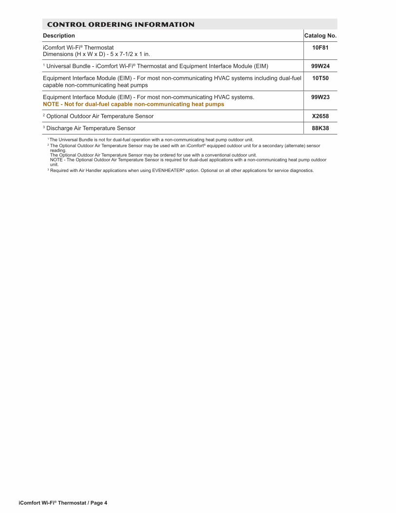
CONTROL ORDERING INFORMATION
Description Catalog No.
iComfort Wi-Fi® Thermostat Dimensions (H x W x D) - 5 x 7-1/2 x 1 in.
10F81
1 Universal Bundle - iComfort Wi-Fi® Thermostat and Equipment Interface Module (EIM) 99W24
Equipment Interface Module (EIM) - For most non-communicating HVAC systems including dual-fuel capable non-communicating heat pumps
10T50
Equipment Interface Module (EIM) - For most non-communicating HVAC systems. NOTE - Not for dual-fuel capable non-communicating heat pumps
99W23
2 Optional Outdoor Air Temperature Sensor X26583 Discharge Air Temperature Sensor 88K38
1 The Universal Bundle is not for dual-fuel operation with a non-communicating heat pump outdoor unit.2 The Optional Outdoor Air Temperature Sensor may be used with an iComfort® equipped outdoor unit for a secondary (alternate) sensor
reading. The Optional Outdoor Air Temperature Sensor may be ordered for use with a conventional outdoor unit. NOTE - The Optional Outdoor Air Temperature Sensor is required for dual-duel applications with a non-communicating heat pump outdoor unit.
3 Required with Air Handler applications when using EVENHEATER® option. Optional on all other applications for service diagnostics.

iComfort Wi-Fi® Thermostat / Page 5
DEALER DASHBOARD
Displays an individual Lennox dealer’s iComfort Wi-Fi® Thermostat installations in one convenient location.Accessible from the DaveNet® e-business website.Your Master Dealer iComfort Profile• Name• Address• Phone Your Active iComfort CustomersA list of customers with installed iComfort Wi-Fi® Thermostats, and their locations.• Name• Address• City• StatusLegend
• All systems are good• One or more reminders has been generated• An alert has been generated and needs immediate
attention• An iComfort in this house is no longer connected to
the internet The list of installed customer’s thermostats can be sorted
(ascending and descending) by the different columns and can be filtered to only show locations currently sending an alert or reminder.
Map• Interactive map shows all customer’s locations and
the nearest Lennox PartPlus™ store locations• Update All Homes Button pushes any updates to the
dealer’s profile to all homeowner’s thermostats on the dealer’s network.
Selecting a customer from the list displays detailed System Overview Screen including owner information, system components, system status and any alerts.
System Overview Screen Owner Information• Name, Address, E-Mail, PhoneOwner Allows Dealer To . . .• Receive Alert E-Mails?• Receive Reminder E-Mails?• View iComfort Settings?Dealer Configuration• Dealer Information
Using the Dealer Configuration area a Dealer can change Dealer Information displayed on the homeowner’s iComfort Wi-Fi® Thermostat and on the Homeowner Remote Access website (see page 6).
HVAC Systems for This Owner• List of owner’s installed systems with StatusSystem Details• Real time information of actual operating conditions
(heating, cooling, fan mode, etc.)Equipment Details• Installed iComfort®-enabled equipment details and
serial numbersActive Alerts/Cleared Alerts Tab

iComfort Wi-Fi® Thermostat / Page 6
HOMEOWNER REMOTE ACCESS
HOMEOWNER LOGIN
The Login screen is accessible to the homeowner at: www.myiComfort.com.
Thermostat must be registered before logging into the Homeowner Remote Access Website (see page 13).
Wi-Fi remote temperature monitoring and adjustment through a home wireless network via desktop PCs, laptops, and apps for smartphones or tablets.
After logging in and creating a profile (My Profile), the homeowner can enter specific information for the iComfort Wi-Fi® Thermostat (single or multiple systems), set up multiple homes (My System) and specify what alerts and reminders they would like to receive (My Dealer).The homeowner can control all iComfort Wi-Fi® Thermostats on the network remotely through the Website Dashboard.Multiple iComfort Wi-Fi® Thermostat Control• One home - one iComfort Wi-Fi® Thermostat• Two or more homes - one iComfort Wi-Fi® Thermostat
each• One home - multiple iComfort Wi-Fi® Thermostats• Two or more homes - multiple iComfort Wi-Fi®
Thermostats

iComfort Wi-Fi® Thermostat / Page 7
HOMEOWNER REMOTE ACCESS
WEBSITE DASHBOARDRemotely control any iComfort Wi-Fi® Thermostat on a home wireless network.Accessible to the homeowner at: www.myiComfort.com.• Tabs at the top for different locations (Home 1, Home
2, etc.)• Large display of current indoor temperature• Current Indoor Relative Humidity• Set Temperature
• Adjust Cool-To or Heat-To temperature setpoints (Up/Down Arrow Buttons)
• Program ON Tab• Program Setting
• Summer• Winter• Fall/Spring• Save Energy• CustomHomeowner can select Programs pre-set on thermostat
but cannot remotely adjust individual settings within Programs.
•
• Program OFF Tab (manual settings)• Mode Settings
• Cool Only• Heat Only• Heat or Cool• Off• Emergency Heat (heat pump)
• Fan Settings• Auto• On• Circulate
• Away Mode Button• Alerts / Reminders Tab
• Current Alerts with Date and Time• Service Information Tab
• Dealer Information• Change Dealer Button
• System Tab• System Name and information about HVAC
equipment• Zone Settings (for systems using the iHarmony®
Zoning System.)• ON/OFF
• Skins tab• Upload Image
• Current Weather Conditions• Local 5-Day Weather Forecast
• Show/Hide 5-Day Weather ForecastMY ACCOUNT SCREEN• My Profile
• Name• Phone Number• Mobile Phone Number• Primary E-mail (change e-mail)• Password (change password)
• My System• Home Name (default home checkbox)• Street Address, City, State, Zip/Postal Code• Alerts and Reminder Preferences• Home Details (show/hide)
• Building size, number of floors, number of occupants, building style, number of bedrooms, age of building, utility company
• My Dealer• Change Dealer

iComfort Wi-Fi® Thermostat / Page 8
HOMEOWNER REMOTE ACCESS
MOBILE APPS
The free iComfort® app is available for use on iPhone®, iPad®, Android™ and Windows® 8 devices.Control cooling/heating temperatures, fan operation, set programs and set Away mode for multiple locations.Also controls individual zone settings if system is equipped with the optional iHarmony® Zoning System.Apple, the Apple logo, iPhone and iPad are trademarks of Apple Inc. registered in the US and other countries.Android is a trademark of Google Inc. Use of this trademark is subject to Google permission.Windows is a registered trademark of Microsoft Corporation in the United States and other countries.
Available on the
Download from
Windows StoreDownload from
Windows Store
CUSTOM SCREEN SAVER (SKINS)
Any high quality image (JPG format only, 800 x 480, 300 dpi for best resolution) can be uploaded to www.myiComfort.com to change the appearance of the thermostat screen to match any color, pattern, design, or décor. Turn on Screen Saver on the iComfort Wi-Fi® ThermostatOn the thermostat, touch the Arrow Button on the home screen to access the Features Screen, touch the Display Settings Button, touch the Screen Saver Button and select Skins. The image will appear after 30 seconds of inactivity. Touch the screen at any time to access the Home Screen controls.

iComfort Wi-Fi® Thermostat / Page 9
HOME SCREEN (Thermostat ON)
Temperature Settings• Large display of current indoor temperature (°F or °C)
In Celsius mode only the Home Screen displays Celsius. All other thermostat settings displayed in Fahrenheit.
• Current cooling setpoint temperature Button (cool-to)• Current heating setpoint temperature Button (heat-to)• Raise / Lower temperature setting Arrows (up / down
arrows) to set cooling or heating setpoints indefinitelyTouch either setpoint temperature button to display up /
down temperature adjustment arrows. Touching either Temperature Setting Arrows (up / down
arrows) displays the Program Hold Screen. Preset 1, 2, 8, 24 hours or custom setting (date and time with Keyboard Tool). Set and hold the temperature for a preset or custom time period until the next time period setting. Cancel Button on Home Screen cancels the held setting.
Both setpoint temperatures are displayed if System is set to Heat or Cool mode.
System Status Button• Manual Settings
• Cool Only• Heat Only• Heat or Cool• Off (system is OFF)• Emergency Heat (if air handler or dual fuel system)
• Programs• Select or edit a program (See page 12)
Touch to select system operating mode menu. Humidity Display• Displays current indoor relative humidity
FEATURES
USER SETTINGSSystem Status Display (animated)• System is Heating• System is Cooling• System is Cooling and Dehumidifying• System is Dehumidifying• System is Waiting (time delay)Fan Button (animated)• On• Auto• CirculateCurrent Outdoor Temperature• Displays current outdoor temperature in °F or °C
The default outdoor temperature is supplied by the Outdoor Air Temperature Sensor or the Wi-Fi data connection (user selectable on the thermostat). The outdoor sensor is furnished as standard with iComfort®-enabled outdoor units, optional for conventional units.
Weather Forecast Display• Displays current weather forecast
Touch to display 5-Day Forecast screen. Arrow Button
Touch to display Features screen (See page 10). Enter Away Mode Button
Touch to display Away Mode screen (See page 16). Wi-Fi Indicator • Displays if Wi-Fi is enabled
Touch to display Wi-Fi-Settings Screen (See page 13). Time and Date Display• Displays current date and time
Touch to display Clock Settings screen (See page 11). Service Alerts • A red Alert indicates that service is required for a
major system component as soon as possible• A yellow Alert indicates required maintenance (filter
replacement, humidifier pad replacement, UV light replacement, PureAir™ Air Purification System servicing and Maintenance)
Touch to display Alerts Screen (See page 12).

iComfort Wi-Fi® Thermostat / Page 10
FEATURES
USER SETTINGSHelp Button • Displays help information
Touch to display Help information. Touch the question mark over each feature for additional information.
Logo Button• Switches to Installer Mode (See page 23)
Touch and hold for 3 seconds to display Installer Setup screen (See page 23).
Lock Icon• Indicates partially locked (allows temperature
adjustment up or down for a selectable time) or fully locked (no adjustment)
To unlock, touch and hold the lock icon for 5-6 seconds. FEATURES SCREEN
Touch any Button to display desired screen.
NOTE - The Zone Settings Button is only available when the iHarmony® is part of the complete system.
• Edit Program Button (see page 12)• System Settings Button (see page 10)• Display Settings Button (see page 11)• Zone Settings Button (see page 15)• Alerts Button (see page 12)• Reminders Button (see page 12)• Service Button (see page 16)• Home Icon (lower-right, returns to Home Screen)
SYSTEM SETTINGS SCREEN
Heating Mode Button• NORMAL• COMFORT
XP25
Humidifier Control Buttons• Humidifier is OFF• Humidifier is ON (15 to 45% RH - default is 40%)De-Humidifier Control Buttons
• ClimateIQ™ Setting• DRY• MODERATE• HUMIDXC
/XP1
7/21
/25
ClimateIQ™ - Select the humidity setting that matches your regional weather.
NOTE - ClimateIQ™ settings are only available for iComfort®-enabled outdoor units (XC17/XP17, XC21/XC21, XC25/XP25).
• Dehumidify (not shown)• OFF• MEDIUM• HIGH
NOTE - Dehumidify settings are only available for non iComfort®-enabled equipment.
• ON setting (40 to 85% RH - default is 50%)
Select the humidity level you want inside the home. • Humidity Display is OFF/ON (on Home Screen)

iComfort Wi-Fi® Thermostat / Page 11
FEATURES
USER SETTINGSCLOCK SETTINGS SCREEN
• Set current Time and Date• Time Format (12 or 24 Hour)• Daylight Savings Time (enabled/disabled)
DISPLAY SETTINGS SCREEN
Background Theme Button• Cobalt• Cotton• CarbonTemperature Scale Button• Fahrenheit or CelsiusScreen Saver Button• ON/OFF• SkinsScreen Lockout Button• Unlocked• Partially• LockedLanguage Button• English• Français• EspañolOutdoor Temperature Display Button• ON/OFFBacklight Intensity Button• Adjustable 20, 40, 60, 80, 100% (default 80%)Clean Screen Button• 30 Second Countdown timer without affecting settings

iComfort Wi-Fi® Thermostat / Page 12
FEATURES
USER SETTINGSWEATHER SCREEN
Displays local 5-Day Weather Forecast Wi-Fi must be enabled to access weather forecast
screen. EDIT PROGRAMS SCREEN
Select Programs Button• Summer• Winter• Spring/Fall• Save Energy• Custom
• Program will follow these settings for days selected
Touch and hold button to change Program name. Select Days Button• All 7 Days• Week/Weekend (Mon-Fri. and Sat-Sun.)• Individual Days (Monday, Tuesday, etc.)Program Setting Buttons• Time (Adjustable in 15 minute increments)• Cool-To (Adjustable in 1° increments)• Heat-To (Adjustable in 1° increments)• Fan Mode (On, Auto, Circulate)
Touch and hold any time button to disable that period.
ALERTS SCREEN
Displays Alert History• Alert Code• Date and Time Alert occurred• System ReportsSet Alert Button• Last 24 Hours• Last 30 Days• Last 12 MonthsREMINDERS SCREEN
Reminder Buttons• Replace Filter 1• Replace Filter 2• Replace Humidifier Pad• Replace UV Bulb• Maintenance Reminder Required• PureAir™ Maintenance Reminder Required• Settings
• Disabled• 3, 6, 12, 24 Months or Custom
Custom Button accesses Clock Settings Screen to input custom date and time settings.
iComfort Wi-Fi® Thermostat / Page 13
FEATURES
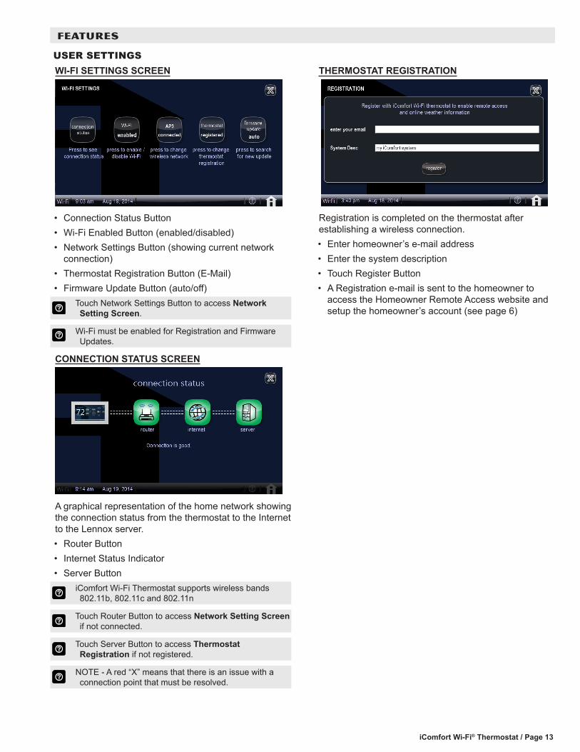
USER SETTINGSWI-FI SETTINGS SCREEN
• Connection Status Button• Wi-Fi Enabled Button (enabled/disabled)• Network Settings Button (showing current network
connection)• Thermostat Registration Button (E-Mail)• Firmware Update Button (auto/off)
Touch Network Settings Button to access Network Setting Screen.
Wi-Fi must be enabled for Registration and Firmware Updates.
CONNECTION STATUS SCREEN
A graphical representation of the home network showing the connection status from the thermostat to the Internet to the Lennox server.• Router Button• Internet Status Indicator• Server Button
iComfort Wi-Fi Thermostat supports wireless bands 802.11b, 802.11c and 802.11n
Touch Router Button to access Network Setting Screen if not connected.
Touch Server Button to access Thermostat Registration if not registered.
NOTE - A red “X” means that there is an issue with a connection point that must be resolved.
THERMOSTAT REGISTRATION
Registration is completed on the thermostat after establishing a wireless connection.• Enter homeowner’s e-mail address• Enter the system description• Touch Register Button• A Registration e-mail is sent to the homeowner to
access the Homeowner Remote Access website and setup the homeowner’s account (see page 6)

iComfort Wi-Fi® Thermostat / Page 14
NETWORK SETTINGS SCREEN
Displays available Wi-Fi Network Access Points• Available Network Buttons• Scan for Networks Button • Add New Network Button
Touch desired Network Button to connect to network, opens keyboard tool to input security key or passphrase.
FEATURES
USER SETTINGSNETWORK SETUP SCREEN
Touch the Add New Network Button to open the network setup screen.
• Enter Network Name (SSID)• Select security type (None, WEP, WPA, WPA2)• Enter Password• Touch Connect
iComfort Wi-Fi® Thermostat / Page 15
FEATURES
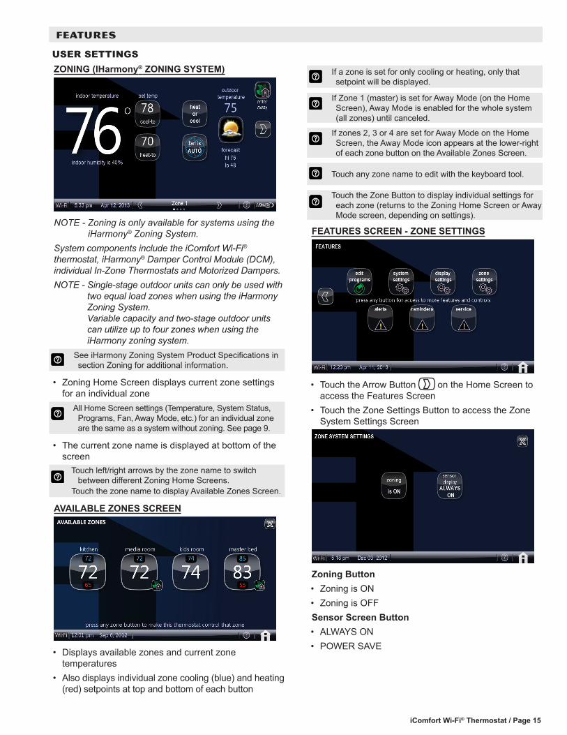
ZONING (IHarmony® ZONING SYSTEM)
NOTE - Zoning is only available for systems using the iHarmony® Zoning System.
System components include the iComfort Wi-Fi® thermostat, iHarmony® Damper Control Module (DCM), individual In-Zone Thermostats and Motorized Dampers.NOTE - Single-stage outdoor units can only be used with
two equal load zones when using the iHarmony Zoning System. Variable capacity and two-stage outdoor units can utilize up to four zones when using the iHarmony zoning system.
See iHarmony Zoning System Product Specifications in section Zoning for additional information.
• Zoning Home Screen displays current zone settings for an individual zone
All Home Screen settings (Temperature, System Status, Programs, Fan, Away Mode, etc.) for an individual zone are the same as a system without zoning. See page 9.
• The current zone name is displayed at bottom of the screen
Touch left/right arrows by the zone name to switch between different Zoning Home Screens.
Touch the zone name to display Available Zones Screen.
AVAILABLE ZONES SCREEN
• Displays available zones and current zone temperatures
• Also displays individual zone cooling (blue) and heating (red) setpoints at top and bottom of each button
If a zone is set for only cooling or heating, only that setpoint will be displayed.
If Zone 1 (master) is set for Away Mode (on the Home Screen), Away Mode is enabled for the whole system (all zones) until canceled.
If zones 2, 3 or 4 are set for Away Mode on the Home Screen, the Away Mode icon appears at the lower-right of each zone button on the Available Zones Screen.
Touch any zone name to edit with the keyboard tool.
Touch the Zone Button to display individual settings for each zone (returns to the Zoning Home Screen or Away Mode screen, depending on settings).
FEATURES SCREEN - ZONE SETTINGS
• Touch the Arrow Button on the Home Screen to access the Features Screen
• Touch the Zone Settings Button to access the Zone System Settings Screen
Zoning Button• Zoning is ON• Zoning is OFFSensor Screen Button• ALWAYS ON• POWER SAVE
USER SETTINGS
iComfort Wi-Fi® Thermostat / Page 16
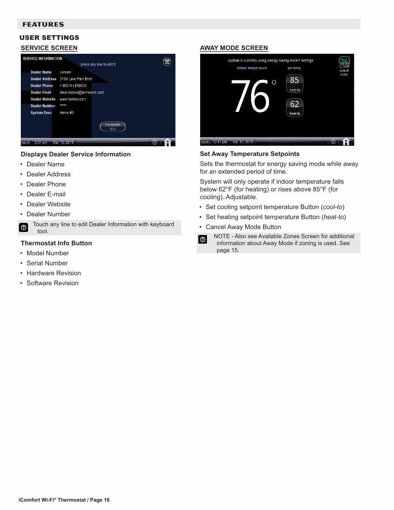
SERVICE SCREEN
Displays Dealer Service Information• Dealer Name• Dealer Address• Dealer Phone• Dealer E-mail• Dealer Website• Dealer Number
Touch any line to edit Dealer Information with keyboard tool.
Thermostat Info Button• Model Number• Serial Number• Hardware Revision• Software Revision
AWAY MODE SCREEN
Set Away Temperature SetpointsSets the thermostat for energy saving mode while away for an extended period of time.System will only operate if indoor temperature falls below 62°F (for heating) or rises above 85°F (for cooling). Adjustable.• Set cooling setpoint temperature Button (cool-to)• Set heating setpoint temperature Button (heat-to)• Cancel Away Mode Button
NOTE - Also see Available Zones Screen for additional information about Away Mode if zoning is used. See page 15.
FEATURES
USER SETTINGS

iComfort Wi-Fi® Thermostat / Page 17
FEATURES
INSTALLER SETUP
SYSTEM DISCOVERY
After power is applied to the thermostat for the first time, it displays the iComfort® “splash screen”, checks the system for installed communicating devices, and displays the “Use this thermostat?” screen.During the setup process, alerts may be displayed to inform the installer of any information that affects the setup process.
SYSTEM SETTINGS SCREEN
Use the up / down arrows to scroll through available settings. Right side of screen displays the current value of each setting.
Touch any line and touch Edit to change System Settings.
Installer System Settings and Default SettingSystem Setting
Range / Condition
Default Setting
Modify with
Time and Date - - - - - - Clock Setting Screen
Daylight Saving Time
Enabled/Disabled
Enabled Radio Buttons
Circulate Fan ON Time
15 to 45% 35% Up/Down Arrows
Temperature Unit Fahrenheit/Celsius
Fahrenheit Radio Buttons
System Name alpha-numeric characters
my iComfort system
Keyboard tool
Dealer Number - - -Dealer Name LennoxDealer Address - - -Dealer Phone 1-800-9-LENNOXDealer Email - - -Dealer Website www.lennox.com
DEALER NUMBER WARNING SCREEN
NOTE - Dealer must enter a valid Dealer Number to be able to remotely monitor the homeowner’s system status and receive e-mail alerts.

iComfort Wi-Fi® Thermostat / Page 18
FEATURES
INSTALLER SETTINGSABOUT SYSTEM DEVICES SCREEN
Use the up / down arrows to scroll through available system devices. Right side of screen displays the device description.
Touch any line and touch About to view device information. Displays equipment information depending on type (name, model, serial number, number of stages, cooling btuh, indoor blower cfm range, software version, outdoor air temp sensor installed, etc.).
System• Language Support• Equipment Type name• Control Software Revision• Control Model Number• Control Serial Number• Control Hardware Revision• Protocol Revision Number• Device Product Level• 24VAC Average Power Consumption• 24VAC Peak Power ConsumptionAir Conditioner• Language Support• Equipment Type name• Unit Model Number• Unit Serial Number• Unit Nominal Capacity• Number of Cooling Stages• Cooling Capacity by Stage• Control Software Revision• Control Model Number• Control Serial Number• Control Hardware Revision• Outdoor Air Temp Sensor• Protocol Revision Number• Device Product Level• 24VAC Average Power Consumption• 24VAC Peak Power Consumption
• Line Voltage Average Power Consumption• Line Voltage Peak Power Consumption• Outdoor Fan RPM ProfileHeat Pump• Language Support• Equipment Type name• Unit Model Number• Unit Serial Number• Unit Nominal Capacity• Number of Heating Stages• Number of Cooling Stages• Heating Capacity by Stage• Cooling Capacity by Stage• Control Software Revision• Control Model Number• Control Serial Number• Control Hardware Revision• Outdoor Air Temp Sensor• Protocol Revision Number• Device Product Level• 24VAC Average Power Consumption• 24VAC Peak Power Consumption• Line Voltage Average Power Consumption• Line Voltage Peak Power Consumption• Outdoor Fan RPM ProfileFurnace or Air Handler• Language Support• Equipment Type name• Unit Model Number• Unit Serial Number• Unit Nominal Capacity• Number of Heating Stages• Heating Capacity by Stage• Indoor Blower CFM Range• Control Software Revision• Control Model Number• Control Serial Number• Control Hardware Revision• Discharge Air Temp Sensor• Outdoor Air Temp Sensor• Protocol Revision Number• Device Product Level• Factory Installed Transformer• 24VAC Average Power Consumption• 24VAC Peak Power Consumption

iComfort Wi-Fi® Thermostat / Page 19
FEATURES
ABOUT SYSTEM DEVICES SCREEN (Continued)Furnace or Air Handler (Continued)• Line Voltage Average Power Consumption• Line Voltage Peak Power ConsumptionThermostat• Language Support• Equipment Type name• Control Software Revision• Control Model Number• Control Serial Number• Control Hardware Revision• Protocol Revision Number• Device Product Level• 24VAC Average Power Consumption• 24VAC Peak Power Consumption
Zoning Control (iHarmony® Zoning System Only)• Language Support• Equipment Type name• Control Software Revision• Control Model Number• Control Serial Number• Control Hardware Revision• Protocol Revision Number• Device Product Level• 24VAC Average Power Consumption• 24VAC Peak Power Consumption• Max Number of Zones• Supported Damper Types• Number of Damper Positions• Zone Temp Sensor 1 to 4
ZON
ING
INSTALLER SETTINGSADD OR REMOVE NON-COMMUNICATING DEVICES SCREEN
Use the up / down arrows to scroll through available system devices.
Touch any line and touch Yes to add or remove non-communicating equipment. Bold indicates default setting.
• Outdoor Unit Type (Not Installed, 2 Stage AC Unit, 2 Stage HP Unit, 1 Stage AC Unit, 1 Stage HP Unit)
• Outdoor Unit Capacity (18 to 60 kBtuh, default is 36 kBtuh)
• Outdoor Unit 1st Stage Capacity (30 to 100 kBtuh (default is 70 kBtuh)
NOTE - If Outdoor Unit is non-communicating type, screen will display the above parameters to set.
• Humidifier (Not Installed, Power (120VAC) Humidifier, Bypass (24VAC) Humidifier, Bypass and Power Humidifier)
NOTE - if Air Handler is used, Bypass is the only Humidifier option.
• Dehumidifier (Not Installed, Humiditrol, Auxiliary Dehumidifier)
iComfort Wi-Fi® Thermostat / Page 20
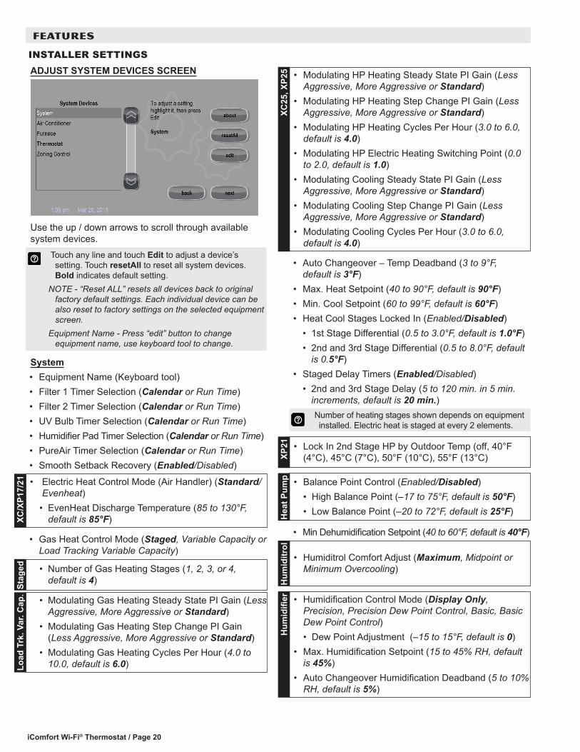
ADJUST SYSTEM DEVICES SCREEN
Use the up / down arrows to scroll through available system devices.
Touch any line and touch Edit to adjust a device’s setting. Touch resetAll to reset all system devices. Bold indicates default setting.
NOTE - “Reset ALL” resets all devices back to original factory default settings. Each individual device can be also reset to factory settings on the selected equipment screen.
Equipment Name - Press “edit” button to change equipment name, use keyboard tool to change.
System• Equipment Name (Keyboard tool)• Filter 1 Timer Selection (Calendar or Run Time)• Filter 2 Timer Selection (Calendar or Run Time)• UV Bulb Timer Selection (Calendar or Run Time)• Humidifier Pad Timer Selection (Calendar or Run Time)• PureAir Timer Selection (Calendar or Run Time)• Smooth Setback Recovery (Enabled/Disabled)
• Electric Heat Control Mode (Air Handler) (Standard/Evenheat)• EvenHeat Discharge Temperature (85 to 130°F,
default is 85°F)XC/X
P17/
21
• Gas Heat Control Mode (Staged, Variable Capacity or Load Tracking Variable Capacity)
• Number of Gas Heating Stages (1, 2, 3, or 4, default is 4)St
aged
• Modulating Gas Heating Steady State PI Gain (Less Aggressive, More Aggressive or Standard)
• Modulating Gas Heating Step Change PI Gain (Less Aggressive, More Aggressive or Standard)
• Modulating Gas Heating Cycles Per Hour (4.0 to 10.0, default is 6.0)Lo
ad T
rk. V
ar. C
ap.
• Modulating HP Heating Steady State PI Gain (Less Aggressive, More Aggressive or Standard)
• Modulating HP Heating Step Change PI Gain (Less Aggressive, More Aggressive or Standard)
• Modulating HP Heating Cycles Per Hour (3.0 to 6.0, default is 4.0)
• Modulating HP Electric Heating Switching Point (0.0 to 2.0, default is 1.0)
• Modulating Cooling Steady State PI Gain (Less Aggressive, More Aggressive or Standard)
• Modulating Cooling Step Change PI Gain (Less Aggressive, More Aggressive or Standard)
• Modulating Cooling Cycles Per Hour (3.0 to 6.0, default is 4.0)
XC25
, XP2
5
• Auto Changeover – Temp Deadband (3 to 9°F, default is 3°F)
• Max. Heat Setpoint (40 to 90°F, default is 90°F)• Min. Cool Setpoint (60 to 99°F, default is 60°F)• Heat Cool Stages Locked In (Enabled/Disabled)
• 1st Stage Differential (0.5 to 3.0°F, default is 1.0°F)• 2nd and 3rd Stage Differential (0.5 to 8.0°F, default
is 0.5°F)• Staged Delay Timers (Enabled/Disabled)
• 2nd and 3rd Stage Delay (5 to 120 min. in 5 min. increments, default is 20 min.) Number of heating stages shown depends on equipment
installed. Electric heat is staged at every 2 elements. • Lock In 2nd Stage HP by Outdoor Temp (off, 40°F
(4°C), 45°C (7°C), 50°F (10°C), 55°F (13°C)XP21
• Balance Point Control (Enabled/Disabled)• High Balance Point (–17 to 75°F, default is 50°F)• Low Balance Point (–20 to 72°F, default is 25°F)H
eat P
ump
• Min Dehumidification Setpoint (40 to 60°F, default is 40°F)
• Humiditrol Comfort Adjust (Maximum, Midpoint or Minimum Overcooling)
Hum
iditr
ol
• Humidification Control Mode (Display Only, Precision, Precision Dew Point Control, Basic, Basic Dew Point Control)• Dew Point Adjustment (–15 to 15°F, default is 0)
• Max. Humidification Setpoint (15 to 45% RH, default is 45%)
• Auto Changeover Humidification Deadband (5 to 10% RH, default is 5%)
Hum
idifi
er
FEATURES
INSTALLER SETTINGS

iComfort Wi-Fi® Thermostat / Page 21
FEATURES
INSTALLER SETTINGSADJUST SYSTEM DEVICES SCREEN (Continued)System (Continued)• Outdoor Temperature Reading Calibration (–10 to
10°F, default is 0)
• Zoning Gas Heating DAT Cooldown target (80 to 110°F, default is 100°F)
• Zoning Anticipated Discharge Air Temperature Adjustment (0 to 120 seconds, default is 60 seconds)
• Zoning Target Supply Air Temp for Cooling (50 to 60°F, default is 50°F)
• Zoning Target Supply Air Temp for Gas/Electric Heating (100 to 130°F, default is 100°F)
• Zoning Target Supply Air Temp for HP Heating (85 to 110°F, default is 90°F)
• Zoning Supply Air Temp Limit for Cooling (35 to 45°F, default is 40°F)
• Zoning Supply Air Temp Limit for Gas/Electric Heating (140 to 160°F, default is 140°F)
ZON
ING
• Humiditrol and Auxiliary Dehumidifier Minimum Runtime (5 to 30 min., default is 7 min.)
Hum
iditr
ol
• HP Heating Lockout Time (60 to 240 min., default is 120 min.)D
. Fue
l
• Zone 1 through 4 First Stage Differential (0.5 to 3.0°F, default is 1.0°F)
• Zone 1 through 4 Continuous Blower CFM• Zone 1 through 4 Cooling CFM• Zone 1 through 4 Heating CFM
ZON
ING
• Reset Button (resets system back to factory default settings)
NOTE - Depending on type of system (conventional heating/cooling or heat pump system) and optional equipment not all system settings will be displayed.
Air Conditioner or Heat Pump• Equipment Name (Keyboard tool)• Compressor Short Cycle Delay (60 to 300 sec.,
default is 300 sec.)• Defrost Termination Temp (Heat Pump only) (50 to
100°F, default is 50°F)• Compressor Shift Delay (Heat Pump only) (On/Off,
default is On)
• High Normal Cooling Airflow• Low Normal Cooling Airflow• High Normal HP Heating Airflow• Low Normal HP Heating Airflow• Dehum Airflow Adjustment Adder (0 to 30, default is 1)
XC25
, XP2
5
• Fan Cycling (On/Off, default is Off)
XP17
/21
Furnace• Equipment Name (Keyboard tool)
• Airflow Profile - Cooling (default is A)A. On (50% for 30 sec., 82% for 7.5 Minutes; Off
(50% for 30 sec. delayB. On (82% for 7.5 Minutes); Off (No delays)C. On (No delays); OFF (45 sec. delay)D. (No delays)
XC17
/21,
XP1
7/21
• Continuous Indoor Blower Airflow (250 to 1150 cfm, default is 315 cfm)
• Dehumidification Airflow % (60 to 80%, default is 70%)• Delay Settings
• Heating Indoor Blower OFF (60 to 180 sec., default is dependent on DIP switch setting in non-communicating furnace)
• Heating Indoor Blower ON (15 to 45 sec., default is 30 sec.)
• Cooling Indoor Blower OFF (0 to 30 sec., default is 0 sec.)
• Cooling Indoor Blower ON (0 to 10 sec., default is 2 sec.)
iComfort Wi-Fi® Thermostat / Page 22
FEATURES
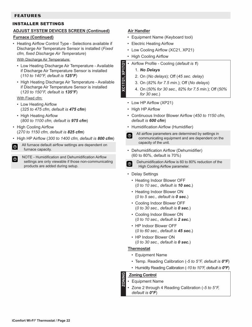
INSTALLER SETTINGSAir Handler• Equipment Name (Keyboard tool)• Electric Heating Airflow• Low Cooling Airflow (XC21, XP21)• High Cooling Airflow
• Airflow Profile - Cooling (default is 1)1. No Delays2. On (No delays); Off (45 sec. delay)3. On (82% for 7.5 min.); Off (No delays)4. On (50% for 30 sec., 82% for 7.5 min.); Off (50%
for 30 sec.)
XC17
/21,
XP1
7/21
• Low HP Airflow (XP21)• High HP Airflow• Continuous Indoor Blower Airflow (450 to 1150 cfm,
default is 600 cfm)• Humidification Airflow (Humidifier)
All airflow parameters are determined by settings in communicating equipment and are dependent on the capacity of the unit.
• Dehumidification Airflow (Dehumidifier) (60 to 80%, default is 70%)
Dehumidification Airflow is 60 to 80% reduction of the High Cooling Airflow parameter.
• Delay Settings• Heating Indoor Blower OFF
(0 to 10 sec., default is 10 sec.)• Heating Indoor Blower ON
(0 to 5 sec., default is 0 sec.)• Cooling Indoor Blower OFF
(0 to 30 sec., default is 0 sec.)• Cooling Indoor Blower ON
(0 to 10 sec., default is 2 sec.)• HP Indoor Blower OFF
(0 to 60 sec., default is 45 sec.)• HP Indoor Blower ON
(0 to 30 sec., default is 0 sec.)Thermostat
• Equipment Name• Temp. Reading Calibration (-5 to 5°F, default is 0°F)• Humidity Reading Calibration (-10 to 10°F, default is 0°F)
Zoning Control• Equipment Name• Zone 2 through 4 Reading Calibration (-5 to 5°F,
default is 0°F)
ZON
ING
ADJUST SYSTEM DEVICES SCREEN (Continued)Furnace (Continued)• Heating Airflow Control Type - Selections available if
Discharge Air Temperature Sensor is installed (Fixed cfm, fixed Discharge Air Temperature)With Discharge Air Temperature:
• Low Heating Discharge Air Temperature - Available if Discharge Air Temperature Sensor is installed (110 to 140°F, default is 125°F)
• High Heating Discharge Air Temperature - Available if Discharge Air Temperature Sensor is installed (120 to 150°F, default is 135°F)
With Fixed cfm:
• Low Heating Airflow (325 to 475 cfm, default is 475 cfm)
• High Heating Airflow (800 to 1100 cfm, default is 975 cfm)
• High Cooling Airflow (270 to 1150 cfm, default is 825 cfm)
• High HP Airflow (300 to 1400 cfm, default is 800 cfm) All furnace default airflow settings are dependent on
furnace capacity. NOTE - Humidification and Dehumidification Airflow
settings are only viewable if those non-communicating products are added during setup.

iComfort Wi-Fi® Thermostat / Page 23
FEATURES
INSTALLER SETTINGS
ZONING - EDIT AND TEST AIRFLOW PER ZONE
NOTE - Zoning is only available for systems using the iHarmony® Zoning System.
NOTE - The airflow per zone must be selected and verified before continuing.
Touch any Zone Button and select the desired airflow for each zone.
Touch each Start button to test, touch the Stop All Button to end test.
Touch each radio button in order to set each zone for Blower Circulation, Cooling Airflow and Heating Airflow.
NOTE - The Next Button will appear after all zone airflows have been set and verified.
The Maximum Airflow for the selected mode on the left is displayed at the top right of the screen.
The Assigned Airflow (the sum of the selected airflow for each zone) is displayed at the top right of the screen.
• Blower Circulation Airflow• Zone 1 through 4
• Cooling Airflow• Zone 1 through 4
• Heating Airflow• Zone 1 through 4
Default Airflow for Zones is dependent on which size and type of indoor unit is installed.
INSTALLER SETUP SCREEN
When the Home Screen is displayed touch and hold the Logo Button for 5-6 seconds to switch to the
Installer Mode Screen.
Touch each checkbox to select the equipment you want to setup or use the Select All Button. Use the Deselect All Button to uncheck all boxes.Setup Button• Allows installer to setup a new system or re-setup an
existing system (see page 17)Tests Button• Run system tests (see page 24) Equipment Button• Allows installer to edit system devices (see page
24)Alerts Button• View system alerts (see page 12) Diagnostics Button• Run system diagnostics (See page 24)View Active Button• View any active alertsView Cleared• View any previously cleared alerts

iComfort Wi-Fi® Thermostat / Page 24
FEATURES
INSTALLER SETTINGS
TESTS SCREEN
A variety of system tests can be performed by the installer. Select the tests to be performed individually by touching the checkboxes or use the Select All Button to run all available tests. Use the Deselect All Button to uncheck all boxes.The Skip Tests Button allows bypassing all system tests.
When a test is running, a status screen will show which test is being run and the results. Use the up / down arrows to scroll through the results.Touching the Next Button advances to the next test.A Testing Process is Finished confirmation screen will appear when testing is complete.
NOTE - The tests feature is not available until after setup has been completed at least once.
DIAGNOSTICS SCREEN
Allows installer to run diagnostic tests on any iComfort®-enabled product.
EQUIPMENT SCREEN
The Equipment Button allows the same equipment setting adjustments as in setup, see Adjust System Devices, page 20.


NOTE - Due to Lennox’ ongoing commitment to quality, Specifications, Ratings and Dimensions subject to change without notice and without incurring liability. Improper installation, adjustment, alteration, service or maintenance can cause property damage or personal injury. Installation and service must be performed by a qualified installer and servicing agency. ©2015 Lennox Industries, Inc.
Visit us at www.lennox.com For the latest technical information, www.lennoxdavenet.com Contact us at 1-800-4-LENNOX
REVISIONS
Sections Description of Change
Skins Removed custom skins option.
REVISIONS