Embed Size (px)
Citation preview

ICL TECHNICAL JOURNAL
Volume 7 Issue 1 May 1990
Published byInternational Computers Limited atOxford University Press
A N STC COM PANY
TECHNICAL JOURNAL
The ICL Technical Journal is published twice a year by International Computers Limited at Oxford University Press.
EditorJ.M.M. PinkertonICL, Lovelace Road, Bracknell, Berks RG12 4SN
Editorial Board
J.M.M. Pinkerton (Editor) K.H. MacdonaldP.J. Cropper M.R. MillerD.W. Davies FRS (British Telecom ResearchG.E. Felton Laboratories)P. Galais (ICL France) E.C.P. PortmanM.D. Godfrey (Imperial College, B.C. Warboys (UniversityLondon University) of Manchester)J. Howlett H.J. WinterbothamF.F. Land (STC Technology Ltd.)(London Business School)
All correspondence and papers to be considered for publication should be addressed to the Editor.
The views expressed in the papers are those of the authors and do not necessarily represent ICL policy.
1990 subscription rates: annual subscription £40 UK, £44 EEC, £48 rest of world, US $95 N. America; single issues £22 UK, £25 EEC, £27 rest of world, US $52 N. America. Orders with remittances should be sent to the Journals Subscriptions Department, Oxford University Press, Pinkhill House, Southfield Road, Eynsham, Oxford 0X8 1JJ.
This publication is copyright under the Berne Convention and the International Copyright Convention. All rights reserved. Apart from any copying under the UK Copyright Act 1956, part 1, section 7, whereby a single copy of an article may be supplied, under certain conditions, for the purposes of research or private study, by a library of a class prescribed by the UK Board of Trade Regulations (Statutory Instruments 1957, No. 868), no part of this publication may be reproduced, stored in a retrieval system or transmitted in any form or by any means without the prior permission of the copyright owners. Permission is, however, not required to copy abstracts of papers or articles on condition that a full reference to the source is shown. Multiple copying of the contents of the publication without permission is always illegal.© 1990 International Computers Limited
Printed by H Charlesworth & Co Ltd, Huddersfield ISSN 0142-1557

TECHNICAL JOURNALVolume 7 Issue 1
Contents
Obituary iii
Editorial iv
DRS6000 (UNICORN) 1
Foreword 3
Architecture of the DRS6000 (UNICORN) HardwareG. Poskitt 4
DRS6000 (UNICORN) software: an overviewT.M. Cole 23
Electromechanical Design of DRS6000 (UNICORN)R. Pullen 31
Interfaces 41
The User-System Interface - a challenge for application users and application developers?Dr A.T.F. Hutt and F. Flower 43
The emergence of the separable user interfaceProfessor E.A. Edmonds 54
SMIS - A Knowledge-Based Interface to Marketing DataC. Dobbyn and J. Cheesman 66
A Conversational Interface to a Constraint-Satisfaction SystemH. Lesan and Dr N.R. Seel 82
SODA: The ICL interface for ODA document access M. Coon 92
Human - Human co-operation and the design of co-operative mechanismsM. Smyth and A.A. Clarke 110
Regulatory Requirements for Security - User Access Control C. W, Blatchford 127
ICL Technical Journal May 1990 I
Standards for secure interfaces to distributed applicationsT.A. Parker 141
How to Use Colour in Displays - 1. Physiology Physics &PerceptionD, Van Laar and Dr R. Flag ell 154
Notes on Authors 180
Guidance for Authors 186
French Translations of Abstracts 188
ii ICL Technical Journal May 1990

Obituary
PROFESSOR COLIN GOODMAN
With great sadness we have to say that Professor C.H.L. Goodman, a member of the Editorial Board since the beginning of 1987, died of leukaemia on 7 January 1990 at the early age of 62. His illness had been diagnosed a little under a year ago but he had seemed to be responding well to chemotherapy and in fact, although in hospital for most of the time, he was working with his characteristic energy and incisiveness up to the middle of December. Knowing this, we were even more shocked by the news of his death.
Colin Goodman, F.Inst.Physics, F.Royal Inst, of Chemistry, had a distinguished career in materials science. He read chemistry at Oxford, where he did postgraduate research in the Metallurgy Department. He spent 10 years in the GEC Research laboratories at Wembley, where he made pioneering investigations into semiconductors, ultra-pure materials and high frequency silicon transistors. He joined Standard Telephone Laboratories at Harlow (now formally named STC Technology Limited) in 1960, where he set up a range of research projects concerned with electronics applications of high technology materials, and incidentally initiated and ran a flourishing seminar series. He held visiting professorships at Chelsea College of Science and Technology from 1970, at the University of Warwick from 1977 and at King’s College, University of London from 1987. He had a deep and life-long interest in the properties of materials and an encyclopedic knowledge of the field; latterly his imgination had been fired by the recently discovered phenomenon of superconductivity in certain ceramic materials at temperatures far higher than had previously been thought possible.
We shall miss him greatly, both as a very positive contributor to our discussions in the Editorial Board and as a very individual personality.
ICL Technical Journal May 1990 ill

Editorial
This issue of the Journal is devoted to two subjects: the recently announced DRS6000 series and interfaces of various kinds both to and within computers. The three papers on DRS6000 are introduced by Ed Parton. A few general remarks follow on interfaces, a subject that has interested the editor for many years.
Many different objectives may be met by including interfaces in computer systems. A supplier, for instance, may find them valuable because they allow a greater variety of market needs to be satisfied by fewer basic hardware or software components, and because they permit parallel but independent development of those components by separate teams, and also allow products to be enhanced individually.
Equally, interfaces appeal strongly to purchasers because they believe that, properly standardised, interfaces can: give better assurance of the interchangeability or interworking buyers may want: allow them to build systems out of components from a wider variety of suppliers: simplify managing the development of an application by speeding and cheapening it: and, finally, contribute to comprehension of the system as a whole and so facilitate staff training. Interfaces in products designed to established international standards can also permit independent verification of conformance by third parties.
Fundamentally, these purposes are all served by interfaces because they cater either for interworking between system components from various sources, or for interchangeability on the same side of an interface between components having similar or identical functionality. It is interesting that these concepts of interworking and interchangeability were firmly established in telecommunications practice long before computers appeared.
The art and practice of defining, standardising and designing interfaces between elements composed solely of hardware is reasonably well established. The kinds of difficulties that still arise with them are more often political or commercial than technical. Appropriate procedures for interface design and standardisation in telecommunications engineering have evolved over perhaps a century. Certainly there are many hardware interfaces still in use that are technically inferior or unsuitably located but this is usually for historical reasons.
iv ICL Technical Journal May 1990

The same is not so generally true of an interface involving software or a person; here there are real scientific and technical problems left to be solved. A common difficulty is to define abstract concepts with sufficient clarity and precision for designers working in separate teams on software products intended to interwork, to have the same understanding of how their respective products must perform, and then of how to test them to ensure that they always interwork correctly. Laying down and conforming to standards is often seen as a solution. The paper by Coon talks about standards for describing documents so that they may be exchanged between different systems and that by Parker discusses standards for ways to authorise access to distributed systems.
The growing practice of allowing public interrogation of centralised computer databases, while retaining secure control over what may or may not be seen through the user/system interface, creates major intellectual challenges for administrators and technical specialists alike. Two papers in this issue on security at the user interface complement one another and also those on security that appeared in the last.
To conclude I should like to pay a personal tribute to the retiring editor Dr Jack Howlett. He has brought to the job wide computing experience and many other abilities. Allied to his mathematical and management skills is a command of languages which enabled him to translate French mathematical works into English. He was a joint editor of the History of Computing in the Twentieth Century.
Starting as a mathematician with the LMS railway and after wartime research for the government, he joined the Atomic Research Establishment at Harwell in 1948. Here he became, first head of the Computer group and then head of the independent Atlas Laboratory which ran the most powerful machine of its day, and grew into the major centre of computing research which it has become.
For more than eleven years he has edited the Journal single-handed. Indeed he was responsible for persuading the Company to start it. He has shown the keenest perception of the technical subjects that were becoming important to the Company’s business and dedication to getting hold of the right authors. If they were not punctual in delivering their MS he chased them - in the most kindly way and if they did not find the right words to express their ideas, he would revise the text himself. All this he always did with the greatest good humour.
It has been tremendously encouraging that he continues not only as a member of the Editorial Board but has also volunteered actively to help with the considerable day to day detail entailed. I am amazed that he was able to do the job single handed and with time to spare for many other activities. The Company - as well as the present editor has every reason to be grateful to him.
J.M.M. Pinkerton
ICL Technical Journal May 1990 v


DRS6000 UNICORN


ForewordThe DRS6000 (UNICORN) Project
ICL’s commitment to the UNIX Operating System as an open standard, and in particular to AT&T's UNIX 5.0 and its successors, is now well known; as a founder member of X/OPEN and a key member of UNIX International the company’s international reputation and standing as a UNIX Systems Integrator have progressively increased throughout the latter half of the 1980s.
The UNICORN project was formally approved in December 1987; this was to be a major development program, intended to increase substantially ICL’s presence in the UNIX marketplace. A product centre - the Advanced Servers Product Centre - was formed in Bracknell, tasked with designing a new UNIX product, UNICORN, for manufacture at ICL’s Ashton (Manchester) plant and introduction in the first quarter of 1990.
The project was set up with the specific objective of providing a UNIX system that combined state-of-the-art technology with the accepted international Open Standards. The three papers that follow in this issue of the ICL Technical Journal show how these objectives were met in the three key areas of development -- the UNIX operating system, UNIX 5.4- the multiprocessing hardware architecture- the electromechanical packaging, which enabled ICL to deliver a product
for sale anywhere in the world.The UNICORN product was launched in January 1990 as the ICL DRS6000 series.
P.E. Par tonManager, Advanced Servers Product Centre
ICL Technical Journal May 1990 3

Architecture of the DRS6000 (UNICORN)Hardware
G. PoskittAdvanced Servers Product Centre, ICL Office Systems, Bracknell, Berks.
Abstract
UNICORN is a multi-user, multi-processor UNIX system implemented in RISC (Reduced Instruction Set Computer) technology. Cache memories are provided to enable the very high speed of the processors to be fully exploited, the multiple processors to share, efficiently, a common memory sub-system and the I/O traffic to be buffered. The paper describes the basic architecture of the system, In particular the caching mechanism and the means by which the various physical cache memories are kept consistent among themselves and with main memory.
The UNICORN product is a development by the Advanced Servers Product Centre which is part of the Servers Product Group, which itself is part of ICL’s Office Systems Division.
UNICORN is a multi-user UNIX system designed to meet the requirements for office applications for the nineties. The processing element of UNICORN is based on SPARC (Scaleable Processor ARChitecture) RISC technology.
One of the key features of UNICORN is scaleability. It has been designed to be cost effective from 32 users to several hundred. Scaleability in UNICORN includes the following:
Processor Power - UNICORN is a multi-processing system and from one to four processors may be configured.Memory Capacity through the use of multiple memory modules and 1 Mbit and 4 Mbit DRAM technology, memory capacities from 16 to 512 MBytes are configurable.Disc Capacity - UNICORN allows great flexibility in the number of disc drives which may be attached. Total capacity ranges from 760 MBytes to 5 GBytes in a single cabinet with capacities of up to 15 GBytes using expansion cabinets.
I/O Capability - through the use of multiple I/O cards and expansion cabinets there is extreme flexibility in the user connectivity, communications, and networking capability that may be configured.
4 ICL Technical Journal May 1990

A systems architecture has been defined for UNICORN that includes the CPU board set, including memory, and the I/O sub-system. It uses a dual bus architecture: the industry standard VMEbus (“Versa Module Europe” - the most popular 32-bit bus in the industry) for I/O and the 64-bit ICL proprietary HSPbus (High Speed Private) for interfacing to memory.
The architecture of UNICORN embodies certain principles which are fundamental to an understanding of the architecture.
Multiprocessing - In order to allow flexibility in configuring performance to user requirements and to provide the performance which will be required through into the 1990s, an architecture which supports true symmetrical shared memory multi-processing is mandatory. Symmetrical multi-processing allows any task to be executed by any processor in the system. This gives predictable performance which is scaleable with the number of processors. UNICORN allows up to four processors to be configured.Industry Standard I/O bus - One of the requirements for UNICORN is as an OEM platform. To allow third parties to have the option of utilising off the shelf I/O controllers, the I/O bus is an industry standard VMEbus.
Caching The UNICORN CPUs have caches. A cache is a very high speed local memory which contains frequently accessed instructions and operands. This is necessary to allow the SPARC microprocessor to run at full speed. Also a cache is necessary to reduce the bandwidth to main memory so that multiple processors can share a common memory subsystem. Thirdly I/O transfers also need to be buffered or cached so that I/O traffic does not interfere with and slow down CPU/Memory traffic on the High Speed Private Bus.Coherency - The use of caching on the processors and I/O is necessary for performance. This is a hardware technique for improving performance and so should be transparent to software as much as possible. Caching potentially introduces the problem of stale data when caches become out of step (incoherent or inconsistent) with main memory and each other. The architecture, is therefore designed to provide cache coherency through hardware snoop (bus watching) logic.
These fundamental design principles lead to the conceptual architecture shown in Fig. 1.
A CPU is buffered by a cache and sits on the HSPbus. Other CPUs (up to four) are buffered and interfaced in a similar way. Memory modules also sit on the HSPbus and thus are equally accessible from all processors. This creates a symmetrical shared memory multiprocessing system.
I/O controllers sit on the VMEbus and this is linked to the HSPbus via a cache; so the I/O and CPU interfaces are logically identical.
1 The UNICORN Architecture
ICL Technical Journal May 1990 5

Fig. 1 UNICORN conceptual block diagram
As all modules which talk to memory are buffered by caches and interface to memory via the HSPbus, this becomes the common point for implementing cache coherency. By adding hardware snoop facilities to each and every cache, a cache can be made aware of the activities of all other caches. An algorithm can then be established to maintain cache coherency.
f 1 UNICORN implementation
This section shows how the fundamental design principles outlined in the previous section become the implementation which is UNICORN. Figure 2 shows the architecture of UNICORN where it can be seen that it is equivalent to the logical architecture already described.
The I/O caching facility appears only once in a system, so other system facilities which are required only once have been incorporated into the I/O module and it is now named the Central Services Module. An example of the facilities included are the Boot and Diagnostics functions.
The CPU modules have gained an interface to the VMEbus. The cache in the Central Services Module is only useful for VMEbus slave transfers, i.e. those transfers which are initiated by another master on the VMEbus. VMEbus master transfers, initiated by the CPU, cannot be buffered by a cache and what is more may be slow. Therefore to avoid loading the HSPbus and because these accesses are not cached, the CPU modules have a separate VMEbus master interface.
The memory modules also have gained an interface to the VMEbus. This is a slave-only interface which gives access to diagnostic and configuration information on the memory module.
6 ICL Technical Journal May 1990

Fig. 2 UNICORN architecture
The following sections describe in more detail each of the major functional modules of the core UNICORN architecture. These are:
- CPU Module- Memory Module- Central Services Module
2 CPU Module
The CPU Module is a SPARC based processor module. Functionally it may be divided into several submodules. The submodules to be described in the following sections are as follows:
- Integer and Floating Point Coprocessor- Cache- Cache Management and Memory Management Units- Snoop- VMEbus Master and Slave Interfaces- Interrupt Handler.
A block diagram of the CPU Module is given in Fig. 3 which shows the relationship of the various submodules.
2.1 Integer Unit and Floating Point Coprocessor
The CPU module design is targeted at a particular implementation of the SPARC microprocessor; the integer unit runs at 33 MHz and gives a
ICL Technical Journal May 1990 7

Fig. 3 CPU Module Block Diagram
performance of 15 20 mips. This is described by the vendor as a 20 mips part. The processor has associated with it a floating point chip which interfaces to the main integer unit.
The integer unit does not include memory management and so generates a 32 bit virtual address. This is extended by a 16 bit context number to distinguish one task from another.
Context 0 is the kernel context used by the operating system.
Contexts 1 through FFFE (hexadecimal) are used for user contexts.
Context FFFF (hexadecimal) is reserved for cache flushing (clearing out the contents of the cache).
2.2 Cache
The SPARC CPU generates virtual addresses and it is not possible to translate the address through an external Memory Management Unit (MMU) to access a physical cache within the cycle time of 30 ns. A virtual
8 ICL Technical Journal May 1990

cache is therefore implemented where the cache is accessed directly with virtual addresses.
The cache has the following characteristics:
- 128 Kbyte cache- 64 bits wide for refill- 32 byte line- Copy back- Cache coherency.
A copy back strategy, where memory is only updated when a line is displaced, reduces bus bandwidth over a write through strategy. Copy back is necessary because of the bus bandwidth limitations in the multi-processor case. Copy back also increases CPU performance. It does, however, increase the complexity of cache coherency. Figure 4 shows a block diagram of the cache.
The cache comprises five RAM arrays.
Fig. 4 CPU module virtual cache
ICL Technical Journal May 1990 9

The data array contains the data which is cached. It logically has two ports; one to the CPU chip and one to main memory. The performance of the cache is very much dependent upon the product of the miss rate and the time to refill a cache line on a miss. The miss rate is minimised by having a large cache (128 Kbytes), and large line length (32 bytes), and the refill time is minimised by having a wide path to memory, in this case 64 bits wide. The data array organisation is therefore 16K x 64. Address bits VA3-16 address the data array.
When accessing the data array, a cache hit is dependent upon:
- The virtual address tag in the tag array matching the virtual address presented by the CPU chip.
- The context number from the context array matching the context register.- The status bits read from the status array, e.g. valid.
With a line length of 32 bytes, address bits VA5-VA16 address the tag, context, and status arrays.
Copy back means that writes go only to the cache and not immediately to main memory. Main memory is updated only when a modified cache line is flushed from the cache. Because the memory management unit can only translate addresses for the current context and the supervisor context, it is necessary to save the physical address associated with each line in the cache for use during copy backs. These are saved in the copy back address array.
The cache will need to be flushed under hardware control. On power-on reset the status RAM will be reset to make all cache lines invalid.
The cache will also need to be flushed under software control. This occurs when context numbers are to be reused. As at this point the cache may contain modified lines, it is not possible to flush the cache by resetting the valid bit in the status array otherwise the data in the modified lines will be lost. In this case the context array is reset to FFFF(Hex) and the status bits are maintained. Context FFFF(Hex) is not used by the processor and so effectively the cache has been flushed. Modified lines now in context FFFF(Hex) will be copied out to memory as they are displaced.
2.3 The Cache Coherency Protocol
Support for cache coherency is distributed through the system and resides in the cache controllers, the snoop logic, and the HSPbus protocol. A caching algorithm is defined which gives high performance with full cache coherency. This is a copy back algorithm which requires that each line in the cache can be in one of several states. Four cache line states are required. These are:
10 ICL Technical Journal May 1990

- INVALID- SHARED NON DIRTY (SHARED)- EXCLUSIVE NON DIRTY (PRIVATE)- EXCLUSIVE DIRTY (MODIFIED)
The meanings of these terms are:
DIRTY the cache line has been updated but the corresponding line in main memory has not; therefore this line must not be simply discarded but must first be copied back to main memory
SHARED the line may be present in more than one cache PRIVATE the line is present in one and only one cache.
The status of a cache line will transit from state to state on both processor based activities and bus activity. Bus activity is monitored by the snoop logic described in the following section. The cache consistency protocol is shown diagramatically in Fig. 5 and is described as follows:
Processor activityRead hit. Data is read directly from the cache and there is no state change.Read miss. If the line is MODIFIED it is copied back to main memory and the new line is read in. All other caches capture the address of the read and
Fig. 5 UNICORN state transition diagram
ICL Technical Journal May 1990 11

check whether they have cached that line. If it is in another cache as MODIFIED the read from memory is intervened (intercepted) and the MODIFIED line is written back to memory. The original read then continues. If the line was in another cache as PRIVATE or SHARED, then they will signal the fact via an HSPbus signal and the line will transit to SHARED. The other cache line, if PRIVATE, will also transit to SHARED. If no other cache signalled that it held the line, the line becomes PRIVATE.Write hit. If the line is PRIVATE, it is necessary to check for write permission before proceeding. If OK the line status changes to MODIFIED. If the state was already MODIFIED, the write proceeds immediately and there is no state change. If the line is SHARED then the physical address is broadcast on the HSPbus (ABI, address broadcast invalidate) to other caches holding the line. The other caches will transit to INVALID and the original cache will transit to MODIFIED.Write miss. A write must perform a write allocate. This means that the line must be read in before the write can proceed. Therefore first follow the sequence for a read miss, then the sequence for a write hit.
Bus activityAddress Broadcast Invalidate. When an address broadcast invalidate is transmitted over the HSPbus, each snoop unit will look up the address broadcast in its cache. If it hits in the cache then that line will transit to INVALID.Reads. The addresses of all reads are monitored by the snoop units. If the address hits in another cache and the line status is MODIFIED, then the snoop unit will intervene in the current bus transaction and copy the line back to memory. If it hits in the cache and the line was PRIVATE or SHARED then the snoop unit will signal “shared” on the HSPbus and the status of the line read and the line snooped will both transit to SHARED.Writes. Line writes will only ever occur when a MODIFIED line is displaced from the cache. By definition a MODIFIED line can only be in one cache and so line writes will not be snooped. The addresses of non-line writes may be snooped in another cache and the status of the snooped line may be PRIVATE, SHARED, or MODIFIED. PRIVATE and SHARED lines will transit to INVALID. A snoop hit on a MODIFIED line will cause intervention and the modified line will be copied back to memory before the original write is allowed to continue.
The cache coherency algorithm may also be described by a state transition diagram. This is given in Fig. 5.
2.4 CPU Module Snoop Unit
The snoop logic will capture all physical addresses which appear on the HSPbus and determine whether the line represented by that physical address has been cached in the CPU’s virtual cache.
12 ICL Technical Journal May 1990

The snoop therefore contains as tags all of the physical addresses which correspond to the virtual address tags in the CPU’s cache.
Using the physical address from the bus as an index into the snoop tag gives a choice of 16 physical tags to compare the physical address with. This is because the page size is 8K and the cache is large enough to contain 16 x 8K pages (128 Kbytes). A hit occurs when a physical address on the bus matches one of the tags. In this case the state of the corresponding line in the CPU’s cache must be modified (e.g. invalidated) or the shared state signalled on the bus. As a single physical memory location may map to several virtual addresses (i.e. shared memory synonyms) then there could be several hits in the snoop tag. This would be difficult to handle and so a restriction has been made such that synonyms will displace each other from the cache. There are two possible techniques to achieve this. The first is to align synonyms on 128 Kbyte boundaries, this being the cache size. Synonyms will then naturally displace one another from the cache. An alternative but more complex method is self snoop. Whenever a cache line refill takes place, the rest of the cache is snooped to check for synonyms. If a synonym is found then the entry is invalidated. Of course if it was MODIFIED it is copied back first. Either technique ensures that there is only ever one instance of a line of data in the cache and there are no synonyms.
As already described the snoop is required to match 16 tags simultaneously. In effect the snoop is a 16 way set associative cache. Normally the implementation of such a cache would be impractical in terms of the amount of hardware required. However, there is now available a 4 way associative tag RAM as a single chip. This makes a 16 way associative tag feasible with four chips.
There are two operations required of the snoop. The operation already mentioned is the snoop itself. The other operation is the loading of the snoop tag with the physical addresses corresponding to the virtual addresses in the CPU’s cache, i.e. on a cache refill.
On a cache refill the snoop array is addressed by the virtual address from the processor. VA0-VA4 address the byte within the cache line and so are not used here. VA5-VA12 are used to index into the tag selecting one of 256 sets, each set containing 16 tags. VA13-VA16 are used to select the way where the physical address used in the refill will be loaded as a new tag using PA13-PA31.
On a bus snoop the physical address from the bus is captured in a register. This is now used to address the snoop array. PA0-PA4 again are not used. PA5-PA12 are used to index into the array to select a set containing 16 tags. PA13-PA31 is then compared associatively with all 16 tags.
There are 16 separate hit lines from each of the ways but, because of the restriction on synonyms, only one hit line will assert if there is a hit. A 16 to 4
ICL Technical Journal May 1990 13

Fig. 6 CPU module bus snoop block diagram
encoder is then used to recreate the virtual address bits VA13-VA16 which together with PA5-PA12 give the location of the line in the CPU’s cache which has to be modified. With a page size of 8K, PA5-PA12 are the same as VA5-VA12, i.e. they are not translated. Figure 6 shows a diagram of the snoop.
2.5 Cache Management and Memory Management Units
The purpose of these submodules is to translate the virtual address emitted by the integer unit and to process integer unit cache misses and service snoop hits.
The memory management function provides a translation buffer of 64 page table entries and has hardware controlled page table walking for replacing entries on a miss.
The Cache Management Unit is implemented as a microprogrammed state machine executing the cache coherency algorithm.
2.6 VMBEbus Master and Slave Interfaces
The VMEbus Master function is required when the CPU needs to access devices (slaves) on the VMEbus. An ASI (Address Space Indication) decode is defined for addressing the VMEbus. On decode of this ASI the address is presented directly to the VMEbus. Both the cache and the MMU are
14 ICL Technical Journal May 1990

bypassed. The VMEbus is arbitrated for and the access to the slave takes place, either sourcing data from the CPU for a write or returning data to the CPU for a read.
All VMEbus accesses are qualified by an address modifier. The address modifier presented on the VMEbus is given by the contents of an internal register. Some of the address modifier codes define the following types of access.
- 32 bit (extended) addressing- 24 bit (standard) addressing- 16 bit (short) addressing.
A VMEbus slave module is also required. This will provide a number of registers in a user-defined VMEbus A16 address space. This reserved space is known as the Controller Interface Table (CIT). The address of the base of these registers will be determined by the geographical address lines picked up from the backplane, i.e. the slot number. Registers may be read from the VMEbus to provide the following information.
- Board type (CPU)- Board status (fail, etc.)- Interrupt status.
Registers may be written to from the VMEbus to drive the following on board functions.
- Board reset- CPU halt and restart- to cause and mask interrupts.
2.7 Interrupt Handler
An interrupt handler is provided to handle all seven VMEbus interrupts. In a multiprocessor system all CPUs will have the VMEbus interrupt handler logic but the task of interrupt handling at any one level will only be handled by one CPU at a time. The VMEbus interrupts are combined with other interrupts for presentation to the integer unit.
3 Memory Module
The memory module resides in the HSPbus and provides 32 MBytes of Memory using 1 MBit DRAMs or 128 MBytes using 4 MBit DRAMs. The boards are capable of being depopulated to 16 MBytes and 64/32 MBytes respectively. Figure 7 shows a block diagram of the memory modules.
The memory module receives a 32 bit address and sources or sinks data on a 64 bit data bus. The memory is designed to operate in either 32 bit or 64 bit
ICL Technical Journal May 1990 15

Fig. 7 UNICORN Memory Module
mode. In 32 bit mode, the data lines used are AD0-AD31. In other words the data is shifted to the least significant end of the data bus.
The memory module is capable of handling the following functions in 64 bit mode:
Read of 64 bits, representing 8 consecutive bytes.Read of 2 x 64 bits, representing 16 consecutive bytes.
- Read of 4 x 64 bits representing 32 consecutive bytes.- Read of 8 x 64 bits representing 64 consecutive bytes.- Write of 64 bits, representing 8 consecutive bytes.- Write of 2 x 64 bits, representing 16 consecutive bytes.- Write of 4 x 64 bits representing 32 consecutive bytes.- Write of 8 x 64 bits representing 64 consecutive bytes.
With writes for each 64 bit quantity 8 validity bits are presented, with the data corresponding to the bytes which are to be actually written.
16 ICL Technical Journal May 1990

The following operation is supported in 32 bit mode:
- Read of 32 bits, representing 4 consecutive bytes.- Write of 32 bits, representing 4 consecutive bytes.
With writes for each 32 bit quantity 4 validity bits are presented, with the data corresponding to the bytes which are to be actually written.
Reads and non-line writes are capable of being aborted by the “intervene” signal on the HSPbus. This turns the transaction into a line write and data is presented to the memory from a cache other than the one which was doing the original transaction. Upon completion of the write, the original transaction continues. This feature is required for the cache coherency protocol and is known as intervention.
Memory protection is provided by Hamming checks. Writes to the memory generate Hamming check bits which are written with the data. Hamming is generated over 32 bits and so each 32 bit word has associated with it 7 Hamming bits. Reads cause the Hamming bits associated with the data to be checked. An error will cause the HSPbus signal MERR* (Memory ERRor) to be asserted. Because of the fast access time of the memory module it is not possible to correct Hamming errors on the fly. On detection of an error, therefore, the memory module performs an internal correction cycle after the event. The master initiating the transfer has to repeat the failing transaction. The retry will succeed if the error was soft and was corrected internally by the memory. If the error was hard but correctable, it is necessary to set the memory into on the fly correction mode. This slows down the access time of the memory module but allows hard correctable errors to be corrected.
Although the main interface to the memory is via the HSPbus, a VMEbus slave interface is also required for status and configuration. This will provide a number of registers in the user defined VMEbus A16 address space. These registers are used for a Controller Interface Table (CIT). The address of the base of these registers is determined by the geographical address lines picked up from the backplane, i.e. the slot number. Registers may be read from the VMEbus to provide the following information.
- Board type (Memory, size)- Board status (Hamming failure)
Registers may be written to from the VMEbus to drive the following on board functions.
- Message register- Memory base address- Memory bank enable.
ICL Technical Journal May 1990 17

Fig. 8 Central Services Module
4 Central Services Module
The Central Services Module, as its name implies, provides services for the system. Only one CSM is configured into a system. It provides the following functionality:
- HSPbus services.- VMEbus Slot 1 controller functions.- VMEbus slave cache interface to memory.- Boot and diagnostic facilities.
Figure 8 shows a block diagram of the CSM.
4.1 HSPbus Services
This functional block provides the following facilities for the HSPbus.
- Clock - this is a free running 1:1 mark/space 60 ns clock which is the bus clock from which all bus transitions are timed.
18 ICL Technical Journal May 1990

- Reset - this is the reset on the HSPB and is controlled by a bit in a register which is controlled from the diagnostic micro.
- HSPbus Error - this is a signal which is asserted if the bus had been owned for longer than 15 microseconds by a single module.
4.2 VMEbus Slot 1 Controller Function
The VMEbus System Controller functions listed below are provided:
- System Clock driver- Serial Clock driver- SYSRESET driver by a bit in a register controlled by the diagnostic micro- Arbiter Module- Bus timer module- IACK (Interrupt ACKnowledge) daisy chain driver.
4.3 VMEbus Slave Cache Interface to Memory
This functional block provides a cache for transfers initiated by the VMEbus. Unlike the CPU caches, the VMEbus cache is a physical cache. However, it does conform to the cache coherency rules established for the system. For efficiency and maximum bandwidth, block mode transfer is used on the VMEbus where possible. To avoid the VMEbus I/O controller having to take notice of page boundaries, an MMU is included between the VMEbus and the I/O cache. I/Os are then allocated segments which link into a process’s page tables.
The operation of the I/O cache is as follows:
Reads All reads will cause a line to be allocated in the cache and subsequent reads within that line will come directly from the cache.
Writes Writes follow a rather more complicated procedure dependent upon whether the write is a block transfer and where the transfer begins and ends relative to line boundaries.
The first write of a non block mode write will cause write allocation, i.e. the relevant line will be read into the cache. If the line is SHARED, an address broadcast invalidate will be sent over the HSPbus to establish the line as PRIVATE and the line will be modified. Subsequent writes to that line take place without HSPbus action.
For a block mode write, if the write starts not on a line boundary, then a line in the cache is write allocated and the action is as in the previous paragraph.
If the block mode write begins on a line boundary then the write takes place to the cache line. The previous contents of the line are flushed to memory if the line status was MODIFIED. Subsequent writes also go to the cache. If
ICL Technical Journal May 1990 19

the block mode write continues to the end of the line then an address broadcast invalidate is sent over the HSPbus and the line status is set to MODIFIED. Up to that point, the line status was set to a special reserved value indicating this condition. An address broadcast invalidate is sent because the line may be SHARED.
If the block mode write ends before the end of the line, the remainder of the line is read in from memory. If the line was read in as SHARED, an address broadcast invalidate is sent over the HSPbus before the line state is then set to MODIFIED.
Snooping The I/O cache must maintain cache coherency with all other caches in the system and so snooping is required. Note that being a physical cache, snooping uses the physical address from the bus directly as a cache index.
4.4 Cache Configuration
The I/O cache size is 64 Kbytes containing 2K lines each of 32 bytes. As the addressing characteristics of I/O are different from that of a CPU, the address bits used for accessing the cache are ordered differently. Address bits used for indexing the cache are PAO-4 and PA 13-23. Address bits PA5-12 and PA24 31 are used as tags. This arrangement has the characteristics that an I/O in a single page will use only one cache line.
4.5 Boot and Diagnostic facilities
These are provided by a microprocessor controller subsystem resident on the CSM. As this will be involved in power-on diagnostics, power supply sequencing and remote access, this particular subsystem will be powered separately from the rest of the system. The following functional units are provided in the Boot and Diagnostics subsystem:
- Microprocessor- RAM- PROM
Local console interface- Remote console interface- Real time clock, calendar (battery backed)- Timers
VMEbus interrupter.
Power-on sequencing will be performed by the Boot and Diagnostics subsystem upon command from the control panel (on/off switch) or the remote console (remote access). It will check that all power rails are in specification before moving to the next step.
The core configuration is then established by groping the system, given that
20 ICL Technical Journal May 1990

the CFUs and memories have configuration information accessible by slot position over the VMEbus.
Next the Central Services Module is tested, followed by the memory modules. A CPU test program will then be downloaded into memory and a CPU released to execute it. In a multi-CPU system, the CPUs are tested one at a time.
Once all basic boards have checked out OK, a boot sequence is downloaded to memory and control is passed to a CPU.
Note that because of the control that the Boot and Diagnostics part of the CSM has over the system, it is not necessary for the CPUs to have boot PROMs.
5 I/O Controllers
I/O for the UNICORN system is provided by I/O controllers which sit on the VMEbus. These are standard VMEbus cards.
5.1 VMEbus Microlan II Interface
Microlan II is an ICL proprietary two wire multi-dropped interface which is used to connect Microlan II based terminals and workstations.
5.2 VMEbus Communications Controllers
Two VMEbus communications controllers are available.
One provides four independent full duplex V24 communications channels which operate at speeds up to 19-2 Kbps.
The other provides two independent channels operating at speeds up to 64 Kbps.
5.3 VMEbus Ethernet Controller
This is a single channel controller which provides UNICORN with the facilities to support OSLAN 100, 200, 300, and 500.
5.4 VMEbus SCSI Controller
This is a two channel controller which provides the ability to connect discs (magnetic and optical), and tapes (and, potentially, high speed printers) via the industry standard SCSI interface.
ICL Technical Journal May 1990 21
5.5 VMEbus Asynchronous Communications Controller
This is a 16 channel controller which provides the ability to connect VDUs, printers, and modems via the industry standard RS232 (CCITT V24) interface at speeds up to 38-4 Kbps.
5.6 VMEbus Repeater
The VMEbus repeater provides the means to expand the VMEbus beyond the 20 slots provided in the main cabinet card cage. The repeater comprises two VMEbus cards which are linked together by a cable. One resides in the main card cage and the other sits in the card cage in an expansion cabinet.
6 Summary
UNICORN provides a very flexible architecture to support its role as a multi-user UNIX platform.
The hardware allows great flexibility in configuration allowing cost effective solutions to be realised from 32 users to several hundred users.
The high performance of the SPARC microprocessor is supported by high performance caches with total hardware cache coherency through the system. This both improves performance and relieves the operating system software of the burden of maintaining cache coherency.
22 ICL Technical Journal May 1990

DRS6000 (UNICORN) software: an overview
T.M. ColeAdvanced Servers Product Centre, ICL Office Systems, Bracknell, Berkshire
Abstract
This paper gives a very brief overview of the version of UNIX which has been ported to the UNICORN. It also describes, in more detail, the extensions which have been made for UNICORN. In particular, the “extended streams" facility is described. This provides an environment which can be ported relatively easily to I/O Controller boards (lOCs) which can then support standard UNIX streams modules. This gives much greater flexibility in system configuration, as some facilities (embodied in streams modules) can be relegated to lOCs at a very low implementation cost.
Introduction
The UNICORN will support AT&T’s1 UNIX2 System V Version 4 in its SPARC3 ABI (Application Binary Interface) form - see [Ref. 1, 2, 3]. UNIX System V Version 4 incorporates the facilities of UNIX System V Version 3.2 and the Microsoft XENIX4 system, and some of the facilities of the Berkeley BSD5 system and Sun Microsystems’ SunOS6. This will conform to the POSIX7 (Portable Operating System Interface for Computer Environments) and X/OPEN8 standards - see [Ref. 4, 5]. The generic source is supplied to us by AT&T, in a form as implemented on an AT&T 3B2 series computer, and we “port” it to the UNICORN and merge in ICL’s “value added” components (e.g. Microlan support). This paper describes the software as it applies to this port. A general description of the software architecture of UNIX is available in [Ref. 6], for instance.
The “Porting " Task
The porting task involves taking the generic source and reworking the machine-specific parts to conform to the target machine - in this case the UNICORN. This includes removing all the AT&T 3B2-unique programs and interfaces, and modifying or rewriting others - for example the cartridge tape programs - where UNICORN equivalent hardware exists. The largest part of this task concerns the peripheral access, although a substantial amount of effort also has to be devoted to memory management and the bootstrap process.
ICL Technical Journal May 1990 23
The UNICORN hardware is described briefly in an accompanying paper in this issue. [Ref. 7]. There are three classes of hardware component in the UNICORN which are capable of executing code. The CPU (Central Processing Unit) is the only one concerned with executing application programs, as well as being responsible for the kernel functions: it does not have direct access to peripheral devices. The CSM (Central Services Module) and IOCs (Input/Output Controllers) are the only components with direct access to peripheral devices. The CSM is responsible for the system console device and an auxiliary RS232 port intended for use for diagnostic purposes. The CSM is also responsible for starting the system and for monitoring the health of the system, for example detecting cabinet overtemperature. The IOCs are responsible for all the other peripheral devices. Only the CSM and CPU have direct access to main memory: the IOCs are required to access main memory via the CSM.
The division of responsibility among the computational units requires coordination. This is achieved by exchanging messages over a bus which is accessible to all. This bus is called the IObus and is an implementation of the standard VMEbus [Ref. 8]: the “VME” here may stand for “Versa Module European”, in which case the “Versa” bit refers to a Motorola proprietary bus - but there are various opinions about this.
Peripherals are accessed by the UNIX kernel via device drivers. There is a standard interface between the drivers and the kernel known as the DKI, Driver-Kernel Interface [Ref. 9]. There are three types of device driver, known respectively as block (mainly for disc access), character (also known as raw or physical access when applied to disc or tape), and streams [Ref. 10]. Of these, by far the largest variety of usage goes to the streams drivers, as these support the communications facilities which are central to UNICORN’S departmental systems role.
Streams were introduced in UNIX System V Version 3 kernel to enable communications protocols to be modularised. [Ref. 11] defines as follows:
“STREAMS A set of kernel mechanisms that support the development of network services and data communications drivers. It defines interface standards for character input/output within the kernel and between the kernel and user level processes. The STREAMS mechanism is composed of utility routines, kernel facilities and a set of data structures.”
The OSI seven layer model, for example, lends itself to modularisation, the various layers providing the initial basis for defining the functions and interfaces of the component modules. The interfaces between the modules are expressed in a standardised (streams) message passing form. This standard enables them to be interconnected in any rational sequence at run time, without the need for further recompilation or linking. There is a “streams” scheduler in the kernel which causes the various streams modules to be executed from time to time as required, to process their input messages and
24 ICL Technical Journal May 1990

modify them or perhaps generate new messages which are output to the next module in the stream.
The UNICORN extends this streams environment to include the CSM and IOCs so that communications modules may be IOC, CSM or CPU resident without needing to rework the modules themselves, or any abridging of the former flexibility of interconnection. If versions of the modules are available ready-linked for the IOC, CSM or CPU environments, the choice of stream module location can be left to run time. This extended environment is referred to as “Extended Streams” in the context of the UNICORN port.
The porting tasks associated with the non streams drivers are fairly standard, and will not be discussed here.
Extended Streams on the UNICORN
This scheme is realised with:
- a driver which can pass messages along the IObus- a miniature kernel environment on each IOC sufficient to supply all the
needs of streams modules (qv DKI [Ref. 9])- a set of “stub” modules to represent, in the kernel environment in main
memory, those modules absent from that environment.
The “stub” modules are known collectively as relays, as they transparently “relay” messages across the IObus. The miniature kernel environment on each IOC is known as the ISMkernel (Intelligent SubModule kernel).
UNIX streams are described in [Ref. 10], but the following very brief and simplified overview may give a sufficient background against which to present the idea of Extended Streams.
A stream consists of a stream head (which mediates between the kernel environment and the user application); optionally followed by some streams modules; and terminated by a streams driver. The stream is constructed when the driver is first opened by the user application: this links the driver to the stream head and then proceeds to “push” the modules onto the stream immediately below the stream head (see Fig. 1).
The UNICORN Extended Streams could implement this stream where, say, module B and the driver C were IOC-resident, by substituting relays for B and C in the kernel resident stream (see Fig. 2). The relays on the CPU pass any messages they receive to the IOC relay, and pass upstream any messages they receive from the IOC relay. The link from relay C remains dormant until B is “popped” from the stream, as messages from the IOC are passed straight to relay B, and relay B receives any messages coming downstream before relay C.
ICL Technical Journal May 1990 25

Our goal was to avoid making any changes to the generic UNIX code supplied to us. The use of relays achieves this because the generic UNIX code can never detect the substitution. Each IOC-resident module or driver has to supply a corresponding relay which is able to locate “its” IOC and pass the IOC address to the relay support code. This structure could be advantageous as it is generally true that messages are more frequent at the lower levels of the communications protocol stacks. Hence the lower levels may be devolved to multiple instances of particular types of IOC.

Fig. 3
In the UNICORN, IOCs can communicate with each other on the IObus independently of the CPU, This allows a stream to be extended across more than one IOC (Fig. 3). This is not very useful in its own right, but can be exploited when streams multiplexorsjye involved (see below).
Some streams drivers are used to multiplex or demultiplex other streams connections. In this case, a single “upper” stream terminates on reaching the multiplexor, which acts as the origin for one or more streams on the “lower” side. This is constructed at run time out of a collection of streams which have already been opened and set up (Fig. 4), one of which is the stream to the multiplexor. The streams are linked to the multiplexor, one by one, until the structure is complete (Fig. 5). The stream heads which belonged to the “lower” streams are now redundant, and would be freed by the application. If modules A1 and A2 were IOC-resident, a multiplexor could be used to “drive” more than one IOC (see Fig. 6). The relay on the first IOC which was used to link relay A1 to the module A1 has become redundant in a similar way to the way the stream head would have become redundant had the stream been CPU-resident.
stream head stream head stream head
----- o ----- o ----- Q
_ _ □ _ _ _ _ _ LI_ _ _ _ _ _ U- - - -multiplexor X module A1 module A2
etc etc
Fig. 4
ICL Technical Journal May 1990 27

Fig. 5
However, this logical structure could also be built up as follows, with the multiplexor itself placed on one of the IOCs (see Fig. 7). In this case, the links from relays A1 and A2 to their respective IOCs become dormant until the multiplexor is dismantled, as the relay X intercepts all messages coming downstream and dispatches them to the IOC relay. Similarly, all messages from modules A1 and A2 flow to the multiplexor on the first IOC, and then via the multiplexor relay. This form may be advantageous if the multiplexor is capable of receiving messages from, say, module A1 and sending them on to module A2. Such a flow would never directly concern the CPU in this configuration.
The extended streams code is structured into layers to facilitate porting to other systems and IOCs, and also to allow for non-streams usage (see Fig. 8). There are various sub-systems which exchange messages, and are classed as different “services” within this layered structure. Hence, the extended streams use becomes the “extended streams service”. Some functions required by the ISMkernel environment (e.g. passing messages to be printed on the system console) are provided by a “kernel utilities” service.
At the first release, the Microlan IOC and CSM will be fully implemented to
Fig. 6
28 ICL Technical Journal May 1990
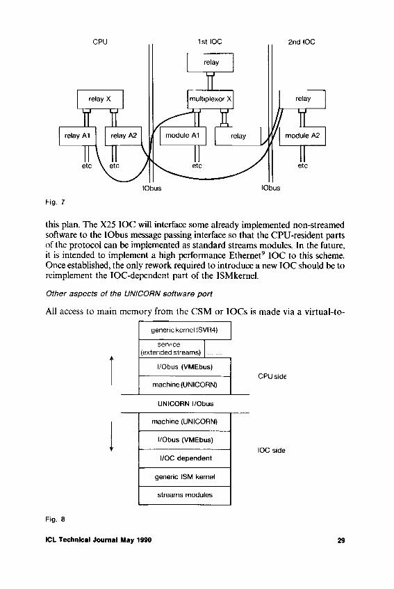
Fig. 7
this plan. The X25 IOC will interface some already implemented non-streamed software to the IObus message passing interface so that the CPU-resident parts of the protocol can be implemented as standard streams modules. In the future, it is intended to implement a high performance Ethernet9 IOC to this scheme. Once established, the only rework required to introduce a new IOC should be to reimplement the IOC-dependent part of the ISMkernel.
Other aspects of the UNICORN software port
All access to main memory from the CSM or IOCs is made via a virtual-to-
Fig. 8
ICL Technical Journal May 1990 29

physical address translation on the CSM board. This relieves the IOCs and CSM from having to “know” anything about the UNICORN memory management. It also removes the need for the CSM and IOCs to support “scatter/gather” DMA. The addresses passed to IOCs are virtual addresses within an address space which is reserved for i/o. Buffers are mapped into this space as required. Kernel-resident buffers are permanently mapped in. Application program-resident buffers are mapped in as required. The first 16 Mbytes of this i/o address space are reserved for buffers which are to be accessed by IOCs with only 24-bit addressing capability. These buffers can nevertheless exist anywhere within the HSPbus physical main memory (128 Mbytes maximum at first release).
The CSM is used to control the bootstrap process, including running establishment checks on the CPU and memory boards. In this way, it is not necessary to include any PROM code on the CPU boards. The CSM can also be used to run ETS (Engineering Test Software) which can be controlled remotely if required.
Conclusion
The Extended Streams facility will allow more flexibility in configuring UNICORN systems, especially where large amounts of communications are to be supported. The modules, multiplexors and drivers which implement the communications protocols may be positioned in IOCs or in the CPU to optimise the system performance. Future IOCs and communications facilities may be introduced with a minimum of rework, without detracting from this flexibility of configuration.
End Notes
1 AT&T is a registered trademark of AT&T in the USA and other countries2 UNIX is a registered trademark of AT&T in the USA and other countries3 SPARC is a trademark of Sun Microsystems Inc.4 XENIX is a registered trademark of Microsoft Inc.5 BSD is a trademark of the University of California at Berkeley6 SunOS is a trademark of Sun Microsystems Inc.7 POSIX is a trademark of the Institute of Electrical and Electronic Engineers Inc.8 X/OPEN is a trademark of the X/OPEN Company Ltd.9 Ethernet is a trademark of Xerox Corporation
References1 ‘AT&T System V Interface Definition’, Issue 3 - SVID892 ‘AT&T System V Application binary Interface’3 ‘AT&T SPARC Processor Supplement’4 IEEE standard 1000.3 - 19885 ‘X/OPEN portability guide’. Issue 36 BACH, M.J.: ‘The Design of the UNIX Operating System’. Prentice Hall, ISBN 0-13-
201799-77 POSKITT, G.: ‘The UNICORN Architecture’. ICL Tech. J. 6, 4 November 19898 IEEE standard 1014: ‘VMEbus Specification Revision Cl Oct 1985’. PRINTEX Publishing Inc.9 ‘AT&T System V Device Driver Interface/Driver-Kernel Interface’
10 ‘AT&T System V Streams Primer’11 ‘AT&T System V Programmer’s Reference Manual’
30 ICL Technical Journal May 1990
Electromechanical Design of DRS6000 (UNICORN)
Roger PullenAdvanced Servers Product Centre, ICL Office Systems, Bracknell, Berks.
Abstract
The paper gives the basic principles underlying the physical design of UNICORN and short accounts of the cabinet design and construction and of the equipment modules built into it: logic rack, disc units, cooling system, power supply and internal interconnections. It gives also the national and international standards to which UNICORN conforms.
1 Basic Principles and Strategy
The electro-mechanical development process for UNICORN has required a wide range of activities and called upon many diverse skills to produce the end product. From the designers point of view, the goal was to produce a simple cost-effective solution to a set of defined requirements. For UNICORN, these were:
- Small floor-standing, desk-high cabinet- Able to operate in an office environment- Aesthetic styling - part of a family of office products- Single design to cover all international requirements- Must meet all statutory safety requirements worldwide- Must be able to use existing production line facilities and more specifically
the Ashton Mercury production line- Easy to install- Minimum time to repair and service- Easy to re-configure.
The strategy we adopted in setting out to meet these requirements was:
- To design a simple unit to cover a wide range of system configurations and avoid costly cabinet swap-outs in the field
- To consist of simple fabricated frame and cover construction- To design for minimum number of mechanical fixings- To create a flexible design catering for either inhouse, subcontract or
overseas manufacture- To house industry-standard units, i.e. 19" rack type peripherals- To create flexible cabling system and eliminate connector bulkheads
ICL Technical Journal May 1990 31

- To maximise the use of computer aided tools throughout the design process
- To use a common power supply throughout the product range to reduce spares holding. This should also cater for international mains voltages and frequencies
- To design in quality through continuous validation throughout development
- To offer an uninterruptable power supply interface- To apply Value Engineering techniques throughout development.
Implementation
Past experience in the design of similar products has highlighted the advantages of using a simple open frame construction to house bolt-in equipment. This type of design enables future upgrades to be incorporated with the minimum of alteration to the basic cabinet. UNICORN has followed this principal throughout.
The UNICORN cabinet has been designed to provide a robust construction, with a pleasing appearance that blends agreeably with most environments, and offers a family image with other ICL products. The simple, but ingenious, construction gives a wide choice of mounting positions for individual bolt-in modules or alternatively standard 19" rack mounted equipment. Additional cabinets can be abutted to expand the system. The need to obtain relevant company and international approvals/certification has also been considered. Figure 1 shows the basic construction and the major items of equipment.
Fig. 1
32 ICL Technical Journal May 1990
2.1 Cabinet construction
Frame The cabinet frame is constructed of six pre-plated steel (Zintec) members - base, top and uprights spot-welded together to form a simple, robust, open framework which provides:
- 19" compatible front and rear access- Four adjustable feet to level the cabinet on uneven floors- Four castors for mobility during installation- Versatile design for mounting of equipment- Flexible system for securing and earthing interface cables without the
restriction of bulkhead connectors.
The frame has no costly secondary finishing operation as it is totally obscured by the decorative (external) covers.
External covers The appearance of the cabinet is designed to conform to the ICL product styling requirements to ensure visual compatibility with other ICL equipment, e.g. workstations.
The covers have been designed to enable them to be safely stored until the cabinet has been fully assembled and tested, i.e. covers are fitted just prior to packaging the equipment for delivery.
The painted steel top and side covers are secured in position by integral metal clips which engage in rectangular cut-outs on the frame. This has two advantages; firstly, there is no visual retention method, and secondly, the metal clips provide excellent earthing continuity for safety and radio frequency interference (RFI) shielding.
Front and rear door panels are moulded in Noryl structural foam. This material is a standard engineering plastic with a foaming agent added during the moulding process, which produces a fine, rigid honeycomb construction with a good impact strength. The cooling vents are an integral part of the moulding on both panels, but two secondary mouldings are added to provide access flaps to the exchangeable peripheral devices and the panel securing lock. See Fig. 2.
2.2 Cabinet Equipment Modules
There are five basic modules:
- Logic rack- Disc modules- Power supply shelf
Fan shelf- Control Panel
2 The UNICORN Cabinet
ICL Technical Journal May 1990 33

Fig, 2
Except for the logic rack, all modules are easily accessed from either the front or rear of the machine.
All of the modules except the logic rack are secured by either two or four fixings, with electrical connections plugable for ease of fitting and removal, i.e. for servicing.
2.2.1 Logic rack: The logic rack has been designed to support the industry-standard VME racking specification, and accepts standard 366 7 mm x 280 mm (9U) 9 off and 233-35 mm x 160 mm (6U) 11 off printed circuit boards plugged into a common backplane. The different depths of PCBs resulted in ICL-designed metalwork to enable advantage to be taken of VME standard proprietary parts - extrusions, tapped strips, insulators, guides and fixings. See Fig. 3.
A unique feature of the logic rack is the provision to allow small (I/O) PCBs (366-7 mm x 100 mm) to be mounted directly behind the existing PCBs; these mate with reverse DIN connectors on the backplane. Extensions to the rack side panels allow additional extrusions to be mounted both top and bottom, which in turn form the mountings for the card guides for the (I/O) PCBs.
The 6U PCB area of the rack accepts either ICL-designed or externally- sourced PCBs, all fitted with standard VME front panels.
The 9U PCBs and front panels are totally ICL-designed. Particular attention
34 ICL Technical Journal May 1990

Fig. 3
has been given to the design of the 9U PCB front panels so that a good EMC seal is achieved between the rack side panel and each PCB front panel. The 9U PCBs are also fitted with a purpose-designed board stiffener to assist with the alignment of the three connectors fitted to the backplane. See Fig. 4.
Fig. 4
ICL Technical Journal May 1990 35
2.2.2 Disc modules: The basic cabinet houses up to a maximum of nine 5-25" peripheral devices, which may be a combination of fixed discs, optical discs, floppy discs and cartridge magnetic tape drives.
The exchangeable media devices are mounted at the top of the machine, directly behind the hinged flap on the front moulding, so that the operator can load/exchange media.
Fixed disc drives are mounted within bolt-in modules, which provide a flexible system of enhancement that avoids modification to the basic cabinet. Each module kit consists of a housing, disc drive, mounting brackets, power and signal cables, ‘T’ connectors and terminators to enable up to two drives to be fitted and connected into the basic system. The ‘T connectors enable the signal cables to be daisy-chained, and a terminator to be fitted.
Under consideration for the future are plug-in drive adaptors to eliminate the power and signal cables completely; this would reduce the time for installation and maintenance and increase reliability. See Fig. 5.
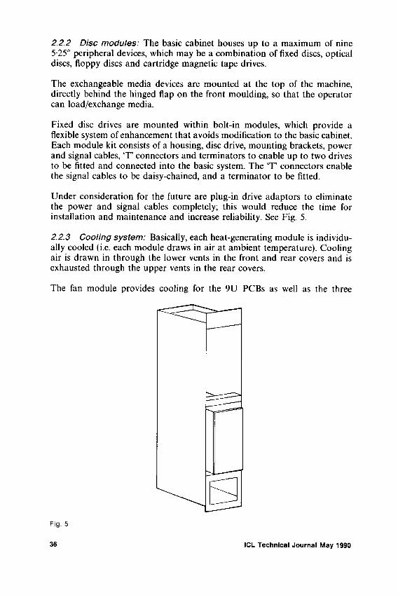
2.2.3 Cooling system: Basically, each heat-generating module is individually cooled (i.e. each module draws in air at ambient temperature). Cooling air is drawn in through the lower vents in the front and rear covers and is exhausted through the upper vents in the rear covers.
The fan module provides cooling for the 9U PCBs as well as the three
Fig. 5
36 ICL Technical Journal May 1990

peripheral devices mounted at the top of the cabinet. The 6U PCBs are cooled by a separate fan mounted at the front of the logic rack, which exhausts into a common plenum area within the fan module. Each disc module contains its own cooling fan.
Thermostats mounted above the logic rack monitor temperature within the machine and in the event of a system over-heat will instigate a controlled system shut down thus avoiding prolonged heat damage to sensitive devices.
2.2.4 Power supply unit: The power system for UNICORN was conceived as a single industry-standard package which derives all the necessary DC rails from the AC mains. Due to space constraints within the cabinet, switch mode techniques are necessary to achieve the required power conversion in the size, and weight, constraints imposed.
Sizing of the load produces a required power output of just under 1500 watts. The relatively high efficiency of switch mode power supplies (>75% ) means a manageable RMS current for normal domestic/office mains outlets within the UK. However, UNICORN is targeted at a worldwide market and a power system that accepts a range of input voltages and frequencies offers considerable manufacturing and servicing advantage. The big stumbling block in achieving this aim is the low single phase voltage (120 V) in North America, switchmode power supplies being tolerant to the frequency change between 50 and 60 Hertz.
A survey of electrical installations in North America reveals that phase-to- phase outlets are commonplace; a nominal voltage of 208 volts is available and applying tolerances to this and to the voltage ranges encountered in the UK, Mainland Europe, the Middle and Far East and Australia gives a working range of 180-264 volts, either 50 or 60 Hertz.
In order to give the UNICORN system a means of resilience to external AC power failures, an Uninterruptable Power Supply (UPS) is provided as an option. UPSs re-generate the AC voltage waveform from a static inverter. Usually, unless considerably over-rated for the job, UPSs are unable to supply large peak currents. But switchmode power supplies, by the very nature of their design, gave high repetitive peak currents, up to four times the RMS current, due to the repeated re-charging of the rectified mains reservoir capacitors every half cycle of AC input, and for the same reasons they have a high inrush current at switch on.
Both these characteristics are particularly unkind to a UPS. A market survey of UK power supply manufacturers showed that a number of the leaders were aware of this problem, and one manufacturer had a 1500 watt multioutput power supply in production with a front end “correcting” circuit which enabled a very near sinusoidal current to be drawn from the mains over the whole period of the AC cycle.
The overall strategy for UNICORN includes a facility for remote diagnos-
ICL Technical Journal May 1990 37

tics. This facility is included in a central services module (CSM) within the system. This module is powered separately from the main system, and allows diagnostics to be run from a remote user port. As it is impossible to perform any sort of diagnostics on a system with a power supply partly or wholly shutdown because of a fault, a small (50 watt) power supply is provided to power a subset of the interface logic on the central services module and its associated cooling fan, and thus make it independent of the main system power supply.
2.2.5 Interconnect and Backplane:Interconnect The overall philosophy adopted for UNICORN is to employ bus bars and/or woven pre-formed cableforms as much as possible. This enables Whole assemblies to be manufactured off-line and simply installed in the cabinet, with the aid of Velcro, or similar, at final assembly.
The system signal loom is such an assembly and carries cabinet housekeeping, control information and auxiliary power. It consists of discrete wires woven together and pre-formed into the required shape, with all the ends having correct terminations fitted.
The five volt feeds to the backplane are similarly treated, and employ a moulded bus bar assembly which bolts directly onto the main power supply terminals. From this moulding, separate cables extend to the backplane in pairs, the pairs being separated by weaving techniques.
To interconnect the data interfaces of the several in-cabinet small computer system interface (SCSI) peripherals, a novel approach was adopted. A kit of three parts, namely a woven cable, a moulded T junction, and a main SCSI terminator, are used to perform all interconnect functions. Each disc is fitted with a T ’junction, which provides an additional two connectors at the rear of the drive. The first connector receives the incoming SCSI cable from the adaptor, while the second either daisy-chains to the next device in the chain or is fitted with a SCSI line terminator. For field upgrades, the terminator is removed from the current last disc and plugged into the ‘T’junction on the new disc; a daisy-chain linker cable then connects the new disc into the system by plugging into the position previously occupied by the terminator. This arrangement allows very simple upgrading of an installation. See Fig. 6.
The DC power to the SCSI peripheral is routed from the power supply by bus bars formed of insulated copper laminates, the individual connections to the disc are effected by woven jumper cables. Where cables interfacing to external peripheral devices enter the cabinet a “window” is included in their construction to give all-round exposure to the overall braid screen of the cable. This screen “window” is placed under a clamping bar, which is secured to an integral part of the chassis, and thus effects a very positive method of strain relief while achieving the near 360 screen termination required to obtain a high level of resistance to static discharge and effective RF screening. This method is employed on all external interface cables.
38 ICL Technical Journal May 1990

Fig. 6
Backplane The UNICORN backplane carries two bus systems:
- VMEbus- A private bus of proprietary design (HSPbus)
It accepts up to a total of 20 PCBs. The first nine slots take triple-high (9U) Euro-card PCBs which interface to both bus systems. The remaining 11 slots take double-high (6U) PCBs conforming to the accepted VME standards, and thus only interface to the VMEbus.
Considerable thought has been given to the physical layout of the backplane, in two areas:
- The signal interface connector of the VME card slots- DC power distribution.
For the former case, an interface connector (reverse DIN) is provided on the rear of the backplane to allow an interface card to plug up into the same slot as the VME card. It is envisaged that these cards be used for custom interfacing and providing extra facilities not normally obtained with a standard VME card. The adoption of this policy dictates the use of a backplane with “press fit” connectors. This is a new process to ICL, but one that has been widely used in the telecommunications industry for some years, so the technical risk is felt to be minimal.
Regarding DC power distribution the need to minimise the inductance of the 5 volt distribution is judged as vital, to ensure there is no “current starvation” when very high speed clocks are employed and/or large banks of memory chips are refreshed simultaneously.
To achieve this, four 2 oz copper power planes are employed, laid up alternately, to improve high frequency decoupling, and 10000 pF of capacitance is distributed across the backplane. All the above requirements are
ICL Technical Journal May 1990 39
achieved on a six layer, one piece backplane, with a characteristic impedance of the logic tracking complying with that defined in the VMEbus specification.
3 Standards and Approvals
UNICORN is aimed at a worldwide market, so compliance where many national and international standards are considered mandatory. Typical examples are:
- Underwriters Lab UL478- Canadian Standards Assc. CSA C22.2 No. 220- Federal Communication Commission (FCC) Regulation Part 15 subpart J
class A- Special Committee of the International Electrotechnical Commission, for
Radio Interference (CISPR) Publication 22- Verband Deutscher Eletrotechniker (VDE) 0871, 0805 and 0806- International Electrotechnical Commission (IEC) 950- British Standard 6301- Local PTT Approvals
Many aspects of these standards are in-built into our own internal standards, and appropriate clauses regarding compliance with relevant standards always form mandatory clauses of purchase specifications of bought-out parts.
Complete machine approvals are carried out by extensive in-house testing and build appraisal, followed by a review of results by the relevant authority or submission to a recognised test house in the relevant country.
40 ICL Technical Journal May 1990

INTERFACES


The User System Interface— a challenge for application users and
application developers?
Andrew T. F. HuttICL HCI Strategy, Reading, Berkshire
Fiona FlowerICL CPS Author Region, Kidsgrove, Stoke-on-Trent
Abstract
Over the last few years, the User System Interface has become an increasingly important component of any application. This paper describes the major trends in the development of User System Interface technology from the point of view o( its impact on both the application user and the application developer. The paper concludes that the overall trends are that while users can expect their applications to become easier to use, applications developers have to face a major new set of challenges in order to design those applications.
Introduction
In its most basic sense, the User System Interface (USI) provides the means by which people and the computer communicate with each other. At a practical level, this interface is made up of a set of standardised elements and behaviour. At a theoretical level, it could be said to have three main components:
- The way the system communicates with the users- The way users communicate with the system- The users’ expectations of the interface
The way in which the system communicates with users is controlled by the computer application. Thus, for example, an application controls how information is accessed, how computations are performed, and how the computed information is translated into a form which users can readily understand.
Users in turn have to be able to interpret the information presented to them by the system. They have to be able to understand what it means, and provide an appropriate response. The way in which they do this, using
ICL Technical Journal May 1990 43

techniques such as key selection or mouse movement, represents the second aspect of the interface.
The third aspect may be summed up as the users’ understanding of the whole process. Users have expectations of what a user system interface is, what it does, and how it works. Some of these expectations are formed by their experience with machines such as typewriters or calculators, as well as other computer systems. A good user system interface capitalises on this experience, and enables users to build on skills and knowledge they already possess.
The USI may therefore be described, in very broad terms, as the ‘look and feel’ aspects of an application: that is, what the application looks like to the user, and what it feels like to use. It should be stressed that this description does not formally extend to the ergonomic design of keyboard, mouse and screen, which are an integral part of the workstation engineering, and do not form part of the USI. In practical terms, the ‘look and feel’ aspects are represented by the visuals (the display items, such as forms, menus, context help or diagrams), and by the behaviour of these items (for example, whether the menu pulls down from an action bar, and what effect this has for the user).
Fig. 1 Arrangement of display items on a screen
Figure 1 illustrates how display items might typically be presented to users through the USI.
The diagram shows groupings of information which might be displayed on the computer screen for a given application or service. Each of these groupings may be considered as a space which can be divided into smaller areas, each containing a particular type of information. The diagram identifies four
44 ICL Technical Journal May 1990

main areas:
1 Application title2 Action bar and pull-down menus3 Panel body with scroll bar4 Function key areas
Clearly, there are many factors influencing the presentation and behaviour of items in each of these areas: for example, the operating system under which the application or service runs, and other considerations, such as whether the input device is a keyboard or a mouse, or whether the application is character or graphics based. However, in general terms, these areas give a good indication of the type of items users are coming to expect from a computer interface.
The action bar, for example, is a useful device which provides visual cues to users to help them perform the desired action, without having to remember a name or type in a command. When users select an option, a pull-down menu appears, listing available actions. The user then selects the action he requires, using simple interaction techniques. An additional level can be provided by using pop-up windows which appear when users select an option from a pull-down menu.
Likewise, the function key area might be used to display a list of function key assignments. Users might be given the choice of either displaying this information in long or short form, or not displaying it at all.
The central area, or panel body, is tailored to meet the requirements of individual applications. It might have to be customised to suit specialised user actions, and may be used, for example, to display menus, forms, diagrams or charts. One of the key features of modern window management systems is that in general a panel body only contains one type of information.
Applications which need to display several types of information achieve this by using several different customised windows.
Why is the USI important?
In today’s highly competitive industrial climate, customer organisations are looking more and more to Information Technology to give them strategic advantage over their competitors. This has led to a rapid growth of I.T. products, and consequently a greater choice for customers. As a result, organisations are in a position to demand systems which can be readily integrated into their business environment, and which will also prove acceptable to their users.
Indeed, user expectations have developed rapidly over the past few years, to a point where people are no longer prepared to spend time using products
ICL Technical Journal May 1990 45

with poorly defined interfaces. Further, experience has proved that users find systems which support a common interface easier to learn and to use, since they are able to apply established techniques and skills to new applications. This has led to a marked preference for suppliers who can offer a consistent and coherent interface across a range of applications, products and services. As a result, recent years have brought an increasing trend towards specific USI styles (such as MOTIF, OPEN LOOK or MS,/Windows) which offer just such a consistent approach. Organisations, in turn, have been able to reap the dual benefit of lower staff training costs, and more effective use of their I.T. products.
This growth in demand has resulted in an increased investment in user system interface technology. This is amply demonstrated by the fact that, in the last 4 years, major suppliers have all made major product announcements and are working to establish a set of open common standards for the user system interface.
Developments in User System Interface
Over the last few years, application users have seen User System Interface technology advance rapidly through four distinct stages, as illustrated in Fig. 2 below:
Fig. 2 Four stages in USI development
Character-based styles
The User System Interface has traditionally been interpreted through character-based styles of presentation. In past years major suppliers including ICL
46 ICL Technical Journal May 1990

offered little consistency in style of presentation and many of the styles used were poorly designed or exhibited too many needless differences. Now, in common with the rest of the industry, ICL is working to reduce the variety of character-based styles to the minimum required to support its strategic products. As a result of this exercise ICL now has five character-based styles.
These styles have been vetted for consistency, and are defined in the ICL Register of USI Styles (see Ref. 4). All styles support USI objects such as forms, menus, context help and messages. Application development teams are being actively encouraged to develop products which support one or more of the registered styles. This should ensure that ICL’s future strategic products support an interface which meets users’ needs, is ergonomically sound, and at the same time exploits the capabilities of the workstations used to deliver it.
Graphical windows styles
The increasing popularity of IBM PCs and compatibles capable of supporting a graphical USI heralded the arrival of graphical windows styles. Some de facto standards have already been established in this area, notably Macintosh from Apple, OPEN LOOK from SUN, MOTIF from OSF, and Common User Access from IBM. ICL is investing heavily in applications which support graphical windows, and has decided to develop a range of software which will embrace one of the following industry standards for graphical styles.
- Windows- Presentation Manager- MOTIF- OPEN LOOK- Common User Access
Applications which conform to these styles provide users with USI objects such as windows, menus, forms and help and, in addition, graphical objects such as boxes, lines or circles. Each of the styles is accompanied by a style guide which defines how to design applications which conform to that particular style. It is worth noting that three of the graphical styles which have been adopted by ICL (Windows, Presentation Manager and MOTIF) are in fact broadly similar, resulting in what is effectively a consistent style across MSDOS, UNIX and OS/2 products supplied by a wide range of suppliers including ICL, IBM, DEC, Hewlett Packard and Microsoft.
Iconic desktops
Progress in the field of graphical USIs has led naturally to the third stage in USI development, which exploits the use of desktops. To date, there is a growing range of desktop products, all of which allow applications and files to be represented by icons. The major features supported by these products
ICL Technical Journal May 1990 47
are all broadly similar. For example:
- When the user selects an icon, the application or file is activated, and control is transferred to the resulting application/file pair
- Icons can be grouped on the desktop to reflect the logical relationships between the objects they represent.Users are able to perform simple object manipulations (for example, throwing a document away by moving a document icon to the wastepaper basket icon)
The market already offers a range of desktop products. Choice between competing products depends on two things: the preferred USI style, and the level of integration between that particular desktop product and the local operating system and the supporting network management system.
Object oriented USIs
The next logical step to follow iconic desktops is to provide an object oriented user system interface. To date, perhaps the best example of an object oriented USI is Hewlett Packard’s Object Management System (see Ref. 14). This system exploits both graphical windows and iconic desktops, but in addition allows application users to establish dynamic links between objects such as spreadsheets, charts and documents in such a way that changes to any one of these objects are automatically reflected in the others. For example, changing the numbers in the spreadsheet automatically leads to changes in the chart, or conversely, changing the shape of the chart causes the numbers in the spreadsheet to be altered.
USI: the application developer’s view
From the above it is clear that customer pressure is forcing a trend towards graphical and object oriented USIs. Further than that, there is a marked tendency towards a growth of standards, and towards achieving compatibility and consistency across the range of styles available.
How do these trends affect application developers, in terms of the kind of systems they are asked to provide?
The first problem designers face is that, unlike traditional applications, graphical and object oriented applications interact with the user at a number of different levels.
At the visual level, the application provides a set of visual images which represent the objects in the application. To be effective, these must be readily identifiable by the user, and must trigger the appropriate mental and manualresponses.
At a functional level, the application supports the user in carrying out a set
48 ICL Technical Journal May 1990

of tasks. Within a graphical interface, support for these tasks is provided by the user through direct manipulation of visual images.
Finally, the application semantics need to be presented to the user in a way that reinforces effective use of the product. As an example, if a user mishandles a visual object, he should not be presented with a complex error message. Instead, the user action should be disallowed, and a low key error response such as a ‘beep’ should be used.
Figure 3 shows a suggested architecture for the development of applications with a graphical USI:
Fig. 3 Architecture ot an application with a graphical USI
The diagram illustrates the three parts a graphical application must contain if it is to support the three levels of interaction defined above. The three parts are:
A dialogue model which represents the dialogue between the user and the system
Display components, which present the application objects and the dialogue to the user via one of the standard USI enablers (MS Windows, Presentation Manager, OPEN LOOK or MOTIF)
Application semantics, which represent the application rules
ICL Technical Journal May 1990 49
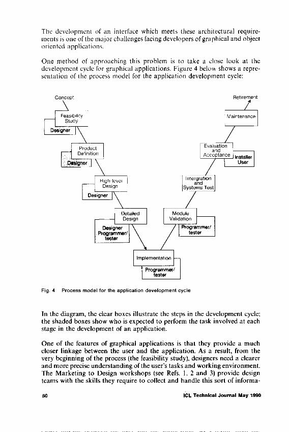
The development of an interface which meets these architectural requirements is one of the major challenges facing developers of graphical and object oriented applications.
One method of approaching this problem is to take a close look at the development cycle for graphical applications. Figure 4 below shows a representation of the process model for the application development cycle:
Fig. 4 Process model for the application development cycle
In the diagram, the clear boxes illustrate the steps in the development cycle; the shaded boxes show who is expected to perform the task involved at each stage in the development of an application.
One of the features of graphical applications is that they provide a much closer linkage between the user and the application. As a result, from the very beginning of the process (the feasibility study), designers need a clearer and more precise understanding of the user’s tasks and working environment. The Marketing to Design workshops (see Refs. 1, 2 and 3) provide design teams with the skills they require to collect and handle this sort of informa-
50 ICL Technical Journal May 1990

tion. The workshops aim to make sure that designers have a sound understanding of four essentials:
- the user of the application- the job the user is doing- the tasks the user has to carry out- the objects used in these tasks
This information is then used to develop process, task and object models which represent the functionality to be supplied by the application. Designers then learn how to select the USI style which is best suited to deliver this functionality to target users.
At the High Level Design stage, the process, task and object models require to be turned into low level task descriptions which will act as a first foundation for the Detailed Design. Once this has been done, the designer or programmer should be in a position to develop an effective User System Interface for the product as illustrated in Fig. 5.
Fig. 5 Process model for developing a user system interface
There are four key stages in this process:
The first is to establish the overall appearance for the user system interface. This requires the designer to develop a design metaphor (such as the desktop of the Macintosh) for the application, to provide a conceptual basis for
ICL Technical Journal May 1990 S1

an interface to which users can readily relate, and, within that metaphor, to establish the broad parameters to which the interface must conform (e.g. the USI style, the input methods and the look of the screen).
Working from this basis, the next step is to define a dialogue structure based on the task model. This dialogue structure shows the overall flow of control and navigation at the user system interface. The lack of an explicit dialogue structure for an application can lead to the situation where users can easily become lost in a complex navigation structure which does not readily support the user’s tasks.
Given the dialogue structure and the overall appearance of the interface, the next task is to define a set of visual images which represent the application objects, and which fit within the paradigm. The visual images are handled by the display component identified in the architectural model (Fig. 3), and are implemented using one of the standard tools which connect to the USI run-time systems (Windows, Presentation Manager, MOTIF or OPEN LOOK),
The final task is to define a low level dialogue model, which implements the dialogue structure. This model defines, for example, how the user will manipulate the visual images. At present, dialogue models are implemented using programs written in C or C ++. It is expected however, that these models will be implemented in Dialogue Description Languages such as SET and Actor. If the application is to be an object oriented application which is integrable with the Hewlett Packard Object Management System, the dialogue model should conform to the rules of the HP Dialogue Description Language (see Ref. 5).
Conclusion
From an application user’s point of view, the User System Interface has progressed rapidly over the past few years, as traditional character-based styles are being replaced by graphical and object oriented USIs. These advances have been welcomed enthusiastically by users, who find the new styles generally more attractive, more consistent, and easier to learn and use. As a result, the demand for products which exploit graphical USIs is growing day by day. In order to meet this demand, application developers now have to face a major new set of challenges, not least of which is the need to come to terms with and exploit a whole new concept in architectural design.
References
1 HUTT, A.T.F.: USTM F'inal Report. 1988 available from ICL HCI Strategy.2 HUTT, A.T.F.: Describing a Product Opportunity. Brochure, available ICL Internal Staff
Training, 1989.3 HUTT, A.T.F.: How to Identify a High Valued Solution. Brochure, available ICL Internal
Staff Training, 1989.
52 ICL Technical Journal May 1990

4 HUTT, A.T.F.: The ICL Register of USI Styles. ICL HC1 Strategy Internal Report, HC I SAM 259. 1989.
5 HEWLETT PACKARD: HP New Wave Environment— Programmer Reference Manual. Manual Part No. 01710-90001, Hewlett Packard, Santa Clara, 1988.
6 IBM: Common User Access - Panel Design and User Interaction. IBM technical publication SC26-4351-0, 1988.
7 MICROSOFT CORPORATION: Microsoft Windows - Software Development Kit - Application Style Guide, 1988.
8 SUN MICROSYSTEMS INC.: OPEN LOOK Graphical User Interface Functional Specification. Technical Publication 800-4085-01, 1989.
9 X-OPEN COMPANY LIMITED: X/Window System: X/Open Portability Guide, Volume 6, 1988 Edition. (Prentice Hall, Inc., USA, 1988).
10 P A. CONSULTANTS LIMITED: SET Tools Technical Overview, 1989.11 DUFF, Charles et al.: Actor Language Manual (The Whitewater Group, Inc. Evanston,
1987).
ICL Technical Journal May 1990 53

The emergence of the separable userinterface
Ernest EdmondsLUTCHI Research Centre, Loughborough University ol Technology, UK
Abstract
The meaning of the term “ user interface” is briefly reviewed and the concept of this as an identifiable component in a system is explored.The history of the development of separable user interfaces is reviewed, together with the growth of interest in user interface software systems and in techniques for user interface specification. Separable user interface architectures and practical problems that have arisen in the use of separable user interfaces are discussed.
Introduction
The user interface to a computer system goes under a number of names including the human-computer interface, the computer-human interface, the front end and the man machine interface. Whilst “front-end” tends to be used in the restricted domain of so called “ intelligent interfaces” and “man- machine interface” is sometimes used to refer to systems that do not involve computers, for the purpose of this paper they can all be considered to be synonymous. Many papers and books on the user interface exist, including ones that give detailed advice on how to design and how to construct them. Nevertheless, there is still no universally agreed definition of the user interface. For example,
“The human interface with computers is the physical, sensory and intellectual space that lies between computers and ourselves” . (Bolt, 1984),“The user interface is that part of a system that the user comes in contact with physically, perceptually, or conceptually.” (Moran, 1980) or“The functionality defines what the program can do, and the user interface defines how users tell the program what to do, and how the program tells users what it did.” (Szekely, 1988).
In fact many authors omit a definition altogether (e.g. Shneiderman, 1987).
In English, the normal use of the word “interface” is to name the relationship
54 ICL Technical Journal May 1990

between two entities, particularly where that relationship is well defined. Increasingly, however, the term “interface” has been applied to special devices that enable one of the objects to hold the given relationship with the other. Thus, for example, one might have to buy a special “interface” in order to enable one’s computer to operate a particular printer. A similar tendency has occurred in the case of the user interface. The study of the relationship between the user and the computer is, now, most frequently known as the study of human-computer interaction. The user interface normally refers to the hardware and software that enables the computer to play its part in the interaction. It is widely assumed that it is possible to identify this interface as part of the system and, conversely, that it is possible to identify components that perform functions that should not be seen as part of the interface. It is this assumption that is the central concern of this paper.
Early work
Without doubt, the most important early work in this field was done as William Newman. This work built upon Sutherland (1965) in important respects but, nevertheless, represents the first significant steps towards the current concern for the object known as the user interface.
Newman (1968a) describes a virtual input device that enabled the user to enter numerical data on a continuous scale with the aid of a light pen or a similar device. Newman terms his logical device a “light handle” because it can be seen as a simulation of a handle that can be wound in order to increase or decrease the associated numerical value. The significance of this work was that it demonstrated the possibility of constructing what, today, might be known as an “interaction object” : that is to say, a self-contained software module that uses the physical input/output devices available in order to enable the user to provide some particular kind of input to the machine. Whilst, in modern terms, this might be seen to be a very low level of separation, it represented an important conceptual step.
The most significant early work was, however, Newman’s system for interactive graphical programming (Newman 1968b). A network definition language was introduced that partly defined interactive software in the form of state diagrams. A compiler for this language could generate run time code. This system was based upon a distinction between the reaction handler, with its associated tables, and the procedure component. The network definition language was compiled into the tables that the reaction handler used, as it were, to run the user interface. The procedure component was written in a conventional language that did not deal directly with any interaction with the user. The mechanism for linking the two aspects was the insertion of program blocks into the definition of each appropriate state of the state diagram. Thus, the network definition language defined the user interface together with its links to the functional part of the system: the procedure component.
ICL Technical Journal May 1990 55

Whilst Newman’s Light Handle and his Reaction Handler both demonstrated the separation of user interface issues from functional ones, the distinction between them, in this respect, is very important. The separation offered by the Light Handle is that of an interaction object that can be evoked by the functional code but that looks after itself once active. The Reaction Handler is quite different in that it is in control of the system and evokes functional actions as required. It is, therefore, an example of a separate user interface. The paper did not, however, address the issue of the precise scope of concern of the procedure component. Indeed, at that time, this was perhaps not a major issue but more recently, as will be discussed below, this has become a significant point of debate.
Parnas (1969) also proposed the use of transition state diagrams for the representation of dialogues, although he only advocated them for the “top level” of user interface design and so, in his work, they did not lead directly to implementation. The links between the user interface and the functional components of the system were not associated with states, as in Newman’s case, but with the arcs. The method was to label each arc with an input/output pair, representing the user input that would cause the arc to be traversed and the output that would result. Only simple examples are discussed and, as with Newman, no detailed discussion of the issues of user interface/functional component separation is given.
Denert (1977), in considering the proposition described above, introduced two more innovations. Firstly, he recognised the computational limitations of state diagrams, which represent finite state machines, and proposed the use of recursive state diagrams, which are much more powerful. Secondly, he dealt with the interconnection of the user interface and the functional component by introducing “task nodes” into the diagrams, which call the functional code. In some respects, this is similar to Parnas’ scheme but it adds the possibility of different branching depending on the outcome of the functional operation. Thus we now have the concept of the functional code changing the course of the dialogue. It would seem that for the separation of the user interface from the functional code to be a reality for complex systems, both of Denert’s innovations are required.
First generation user interface systems
During the 1970’s a number of research workers followed William Newman’s early example and constructed user interface software systems that, in various ways, provided for a separation between the user interface and the functional code. Stalling (1974) demonstrated a system for generating dialogue code that worked somewhat after the manner of a report generator program. Florentin (1977) elaborated upon this and noted the importance of the linking of the dialogue code to the rest of the system. However, neither author added significantly to the specific discussion of separability.
Maher and Bell (1977) specifically proposed a virtual machine as the key user
56 ICL Technical Journal May 1990

interface module. They illustrated their work with a user interface to a database and briefly discussed some problems that arose with the separation of concerns. In particular, they found that it was convenient to organise the database in a particular way for the benefit of the user interface, but that this conflicted with other requirements.
Black (1977) described another system which provided a separate “dialogue processor” which managed the user interface. A dialogue specification language was provided that compiled into a form directly usable by the dialogue processor. In this system, the dialogue processor produced a “target file” which contained the input required by the functional component. Clearly, this was a simple view by today’s standards and so, again, problematic issues of separation were not addressed.
State diagrams are popular for the specification of user interfaces, but several other formalisms are also used. Green (1986) suggests that one of the earliest examples of a grammar-based user interface system was that reported by Edmonds and Guest (1977). It showed how a grammar-based language could be used to define an interface flexibly. It was used to construct a programming tutor and so was demonstrated as a feasible system. However, it is again true that the simplicity of the separation between user interface and functional system was such that the issues often seen now as the problems of separability were not discussed.
Ian Newman (1978) demonstrated how separation could be used to provide a variety of interfaces to a single system. Practical work, again, was done to prove the point but, as before, the particularly difficult issues of separability that are perceived today were not considered. Lafuente and Gries (1978) extended Pascal in order to provide what they called “dialogue frames” , each of which could include a procedural block. Thus the structure of this user interface was somewhat similar to Newman’s (1968b). The difference was that Lafuente and Gries provided an extension of a standard programming language, whereas Newman kept his interface code quite separate from the functional code.
User interface specification
Whilst the work on specifying user interfaces has not in general addressed the issue of separability directly, it is quite clear that the whole enterprise is founded upon the notion of separability. If it were not so, what would it be that one was specifying?
An important model for these specifications was Moran (1980) in which he proposed a view of the user interface that had a number of levels incorporated into three components: physical, communication and conceptual. A key point is that, in this view, only the conceptual component needs direct contact with the functional aspects of the system. In Moran’s view the conceptual component contained two levels. The task level is concerned with
ICL Technical Journal May 1990 57

the structuring of the task domain, for the benefit of the user, and the semantic level is “built around a set of objects and manipulations of those objects. To the system these are data structures and procedures; to the user they are conceptual entities and conceptual operations on those entities.” (Moran, 1980). The semantic level was seen as a way of representing the system’s functional capability. This particular aspect of the structure of a user interface has proved quite fruitful in attempts to clarify the separation from the functional code. This paper, and its elaboration (Moran, 1981), proposed that the user interface could be specified in a well-defined set of levels. This work has been influential both in the study of user interface specification and, more specifically, in the study of architectures for separable user interfaces.
Mark Green (1981) reported a notation for the specification of user interfaces and presented it in the context of a traditional software development model. Whilst that model is no longer necessarily accepted (see for example Hekmatpour and Ince (1987) or an earlier questioning by Edmonds (1974)), the specification ideas are not invalidated. Green’s notation includes the notion of atomic objects and operations that correspond to Moran’s objects and manipulations. These represent the lowest level of the system of concern to the interface. Beyond that, is the concern of the functional code. This has been the standard view of separation. In his paper, however, Green introduces an important additional property at this level. He allows for the specification of invariants. These are relationships which must hold between the operators and objects. Whilst he only gives a simple example of an invariant, it is clear that it is entirely unrealistic to consider these objects as independent and that quite complex invariants may be required. The only question at issue is whether the invariants can and should be seen as the concern of the user interface.
Edmonds (1981) consolidated earlier work and put forward a specification notation that combined state diagrams with grammars, each having their appropriate role. This work continued the tradition begun by William Newman in that a compiler was available for the notation. The links between the user interface and the functional code were provided partly in the manner of Parnas, as described above, except that the input/output specifications on an arc could have a complex transformation relating them, so that specific inputs in the appropriate class could generate relevant outputs. The outputs were passed to the functional code at a “task node” , as in Denert.
Naturally, the early work in the field did not address the issue of specifying user interfaces that handled direct manipulation specifically. However, Jacob (1986) has shown how the methods that employ state diagrams can accommodate direct manipulation.
Architectures
Following Moran’s work, discussed above, much debate has taken place about appropriate architectures for separable user interfaces and a large
58 ICL Technical Journal May 1990

Fig. 1
proportion of the issues of concern have been in the support for separability. In many ways the details of the architecture can be seen as a precise definition of the scope of the user interface.
A very important event in the development of separable user interface architectures was the workshop held in 1983 in Seeheim (Pfaff, 1985). One group in the meeting, consisting of Jan Darksen, Ernest Edmonds, Mark Green, Dan Olsen and Robert Spence, developed an architecture for the user interface (Green, 1985), see Fig. 1.
As Lôwgren (1988) points out, however, the first proposal of a user interface software architecture of this form was probably that of Edmonds (1982), see Fig. 2. It built directly upon Moran’s concept of layers. In this view the separation between user interface and functional code was precisely at Moran’s semantics level where the objects and manipulations that can be seen as atomic, from a user’s point of view, reside.
The Seeheim application interface model went further than either Edmonds’ or Green’s earlier proposals. The idea was that it might contain, for example, information about the effects of operations in order to assist the user interface in the provision of help. Also, in order to deal with larger amounts of data generated by the functional code, such as dynamic images, a direct
Fig. 2
ICL Technical Journal May 1990 59

Fig. 3
path to the display was proposed. In this case, the only functions of the user interface were to open such a path and to decide where it should point to on the screen. This architecture has become widely known as the Seeheim model and a good deal of the subsequent debate has used it as the base reference. It is, perhaps, not surprising that this model has been so important because, apart from the earlier architecture from Edmonds, position papers were presented at Seeheim by Thomas and Olsen, both of which proposed architectures in the same spirit as what became the Seeheim model.
Many papers have been written concerning modification to this model. For example, Dance et al (1987), see Fig. 3, and Edmonds and McDaid (1990), see Fig. 4. It is noticeable, however, that most are variations on the Seeheim view, rather than radical departures from it. We may assume, therefore, that the climate of opinion remains to favour something of this flavour as an architecture for the separable user interface. In particular, it can be seen that the user interface is seen to include a substantial part of the software of a system.
Practical issues of separability
Certain position papers presented at Seeheim were already addressing practical separability issues. In particular, Olsen (1985) and Sibert et al (1985) consider interdependencies between the layers with some care. One of the working groups, in fact, considered the issue specifically, as reported by
Fig. 4
60 ICL Technical Journal May 1990

Enderle (1985). Their basic conclusion was that separability, even for CAD/CAM applications, appeared to be possible given careful design. The group looked particularly at the services provided by the user interface to the functional code and vice versa. This was probably the first attempt to catalogue these difficult concerns (see Table 1).
Szelsky, in his PhD thesis (1988), considered separability in detail. He considered the interface as, perhaps, a slightly shallower entity than others have done, but this enabled him to identify clearly a set of interaction types. This classification is itself a contribution to the definition of the scope of the user interface. Even if one does not wish to limit ones view of the interface in Szelsky’s way, it is clear that his work is valuable as a contribution to our understanding of that part of the user interface termed the “presentation layer” at Seeheim.
Alty and McKell (1986) have made a valuable study of the application model in the Seeheim sense. They demonstrate an application model for a command driven system and show how a study of interaction sessions can help to identify the knowledge required in the model. A particular outcome of the empirical study was that they identified a need for a planning component in the application model. Thus, whilst they confirmed the viability of the separable user interface, they demonstrated in practice that the interface can require quite sophisticated components within it.
In another practical case study, Manheimer et al (1989) showed that the separable user interface is a quite realistic concept. It is of interest to note that the mechanisms for coupling user interfaces and functional components vary widely and that, in this case, more than one mechanism was found to be necessary. In applying their LUIS interface system they found the need for both “tightly” and “loosely” coupled relationships. “The tightly coupled routines are linked with the LUIS executable image. A subroutine interface is available for these routines to communicate with the LUIS interface manager, i.e., to send messages to manipulate the ongoing dialogue and to receive messages that inform the application of the state of the dialogue. When a tightly coupled routine is invoked, the user interface is suspended until the application has completed its processing.” (Manheimer et al, 1989).
In another practical investigation, Dance et al (1987) encountered the difficulty of rapid semantic feedback in a separable user interface much as discussed at Seeheim (Strubbe, 1985). If one considers a screen displaying three things, a window, an icon for a file and an icon for a disc, then consider the difference between the following two situations. If the user drags the window over the disc icon, the icon is simply obscured. If the user drags the file icon over the disc icon, then the latter is, typically, highlighted. The difference represents more or less instant semantic feedback.
It is sometimes argued that this semantic feedback problem is a case against separability, but in fact that case is far from clear. It is true that it would be
ICL Technical Journal May 1990 61

Table 1 Services at the application UIMS interface
Services of the UIMS for the application Services of the application for the UIMS
* Give a vahie matching constraints * Give a value (e.g.. for use in help functions)* Switch input sources (c.g. between user & journal) * Give a value to be used instead of user input* Tell the user a value * Perform graphics update* Display some graphics * Set application state variable to a given value* Handle an application error * Grant permission to change application data4 Set ouput context * Grant permission to change application data* Set dialogue scope * Give pick support
* Give task status* (Re-) Set task status to a (previously saved) state
* Undo something * Undo something

hard to achieve an acceptable performance if tokens had to be passed through the layers, to and from the application, in order to achieve it. However, there is no reason why the presentation layer itself should not contain the appropriate knowledge. After all, the example given above does not imply any application action.
This difficulty may have arisen because many researchers have been influenced by developments in computer graphics where closed packages are often used for implementing interactions. As even the simple example above makes clear, all levels of a separable user interface must be programmable in the sense that the system developer may need to build application specific knowledge into any part of it. This is not an argument against separability, of-course, although it suggests caution about the utility of completely general purpose user interface modules.
The difficulty here is whether the user interface might need too much knowledge (Strubbe, 1985). However, nobody has defined “too much” in this context. Even as early as 1978 Sutton and Sprague found that more than half of the code in interactive business applications was devoted to the user interface. Size is not the problem, although duplicating application code within the interface would be, of course. It would seem that where functional code has to be entered in order to generate the semantic feedback and where that feedback is required very quickly indeed, or where it involves large volumes of data, either the direct path, as proposed at Seeheim, or a closely coupled link, as in Manheimer et al, could be used. However, semantic feedback remains an area for investigation.
Conclusions
Issues of separability still remain to be resolved but there is enough evidence now that the separable user interface can be defined. Perhaps the biggest problem that has stood in the way of successful work in the area is that people have sometimes attempted to build general purpose front ends in the belief that (using the Seeheim terminology) only the application model needs to contain knowledge of application issues. In point of fact, even the presentation layer must often be programmed with specific application dependent knowledge. The separable user interface is not at all ignorant of the functions of the system.
If we return to the definitions of the user interface quoted at the beginning of this paper, it is interesting to notice that the separable user interface can be seen as a concrete elaboration of each of them. Moran (1980) went on to propose that “Any aspect of the system that shows through to the user and enters the user’s model is a part of the user interface” . The emergence of the separable user interface has occurred partly as an attempt to represent everything “that shows through to the user” in an identified software module. The degree to which this attempt has been successful remains to be fully assessed, but it is quite clear that the study of separable user interfaces is
ICL Technical Journal May 1990 63

becoming increasingly important in concentrating our attention on some of the most significant aspects of interactive systems.
Acknowledgement
The preparation of this paper was partly funded by the Alvey programme, grant reference MMI/062, and the ESPR1T2 FOCUS project, reference2620.
References
ALTY, J.L. & McKELL, P. (1986). Application modelling in a user interface management system. In People & Computers: Designing for Usability. Eds. M.D. Harrison & A.F. Monk, pp. 319-.35.
BLACK, J.L. (1977). A general purpose dialogue processor. Proc. Nat. Computer Conf. pp. 397^108.
BOLT, R.A. (1984). The human interface. Lifetime Learning Publications.DANCE, J.R., GRANOR, T.E., HILL, R.D., HUDSON, S.E., MEADS, J., MYERS, B.A. and
SCHULERT, A. (1987). The run-time structure of UIMS-supported applications. Computer Graphics 21, 2, pp. 97-101.
DENERT, E. (1977). Specification and design of dialogue systems with state diagrams. Proc. Int. Computing Symposium, Liège, pp. 417-23.
EDMONDS, E.A. (1974). A process for the development of software for non-tcchnical users as an adaptive system. General Systems, 19, pp. 215-17.
EDMONDS, E.A. & GUEST, S.P. (1977). An interactive tutorial system for teaching programming. 1ERE Proc. 36 - Computer Systems and Technology, pp. 263-70.
EDMONDS, E.A. (1981). Adaptive man-computer interfaces. In Coombs & Alty (eds.). Computing Skills and the User Interface. Academic Press, pp. 389-426.
EDMONDS, E.A. (1982). The man-computer interface: a note on concepts of design. Int. J. Man-Machine Studies, 16, pp. 2151-36.
EDMONDS, E.A. & McDAID. E. (1990). An architecture for knowledge-based front-ends. Knowledge-Based Systems. (To appear).
ENDERLE, G. (1985). Report on the interface of the UIMS to the application. In G.E. Pfaff(ed). User Interface Management Systems. Springer Verlag, pp. 21-9.
FLORENTIN, J.J. (1977). Automatic generation of interactor programs. Proc. Int. Conference on Displays for Man-machine Systems, Lancaster. IEE pub. no. 150, pp. 126-9.
GREEN, M. (1981). A methodology for the specification of graphical user interface. Computer Graphics, 15, 3, pp. 99-109.
GREEN, M. (1985). Report on dialogue specification tools. In G.E. Pfalf (F.d), User Interface Management Systems, Spring Verlag, pp. 9-20.
HEKMANPOUR, S. & INCE. D.C. (1987). Evolutionary prototyping and the human- computer interface. In: H.J. Bullinger& B. Shackel, eds. Proc. of INTERACT 87. Amsterdam: North Holland; IFIP, pp. 479-484.
JACOB, R.J.K. (1986). A specification language for direct manipulation user interfaces. ACM Transaction on Graphics. 5, 4, pp. 283-317.
LAFUENTE, J.M. & GRIES, D. (1978). Language facilities for programming user-computer dialogues. IBM J Res. Develop. 22, 2, pp. 145-58.
LÔWGREN, J. (1988). History, state and future of user interface management systems. S1GCH1 Bulletin, 20, 1, pp. 152-44.
MAHER, P.K.C. & BELL, H.V. (1977). The man machine interface - a new approach. Proc. Displays for Man-Machine Systems. IEE Publication 150, pp. 122-5.
MANHEIMER, J.M., BURNETT, R.C. & WALLERS, J.A. (1989). A case study of user interface management system development and application. Proc. CHF89, pp. 127-.32.
MORAN, T. (1980). A framework for studying human-computer interaction. In Guedj, R.A., Ten Hagen, P.J.W., Hopgood, F.R.A., Tucker, H.A. & Duce, D.A., Eds., Methodology of Interaction, Amsterdam: North-Holland, pp. 293-1302.
64 ICL Technical Journal May 1990

MORAN, T. (1981). The command language grammar, a representation for the user interface of interactive computer systems. Int. J. Man-Machine Studies, 15, pp. 3-50.
NEWMAN, W. (1968a). A graphical technique for numerical input. Computer Journal, II, pp. 63-4.
NEWMAN, W. (1968b). A system for interactive graphical programming. Proc. of Spring Joint Computer Conference, pp. 47-54.
NEWMAN, I. A. (1978). Personalised user interfaces to computer systems. Proc. of the European Computing Congress, London, pp. 473-86.
OLSEN, D.R. (1985). Presentational, syntactic and semantic components of interactive dialogue specifications. In G.E. PfalT (Ed.), User Interface Management Systems. Springer Verlag, pp. 125-33.
PARNAS, D.L. (1969). On the use of transition diagrams in the design of a computer interface for an interactive computer system. Proc. Nat. ACM Conference, pp. 379-85.
PFAFF, G.E. (Ed.) ( 1985). User interface management systems. Proc. of the Workshop on User Interface Management Systems, Seeheim, 1983. Springer Verlag.
SHNEIDERMAN, B. (1987). Designing the user interface. Addison-Wesley.SIBERT, J., BELLIARDI, R. and K.AMRAN, A. (1985). Some thoughts on the Interface
Between User Interface Management Systems and Application Software. In. G.E. Pfaff (Ed.), User Interface Management Systems. Springer Verlag, pp. 183-92.
STRUBBE, H.J. (1985). Report on role, model, structure and construction of a UIMS. In G.E. Pfaff (Ed.), User Interface Management Systems. Springer Verlag, pp. 3-8.
SUTHERLAND, LE. (1965). SKETCHPAD: A man-machine graphical communication system. MIT Lincoln Lab, Lexington, Mass. Tech. Report TR-296.
STALLING, W. (1974). Some aspects of an interactive dialogue-generation facility. Proc. Inti. Conf. on Systems, Man and Cybernetics, pp. 495-498.
SUTTON, J. and SPRAGUE, R. (1978). A study of display generation and management in interactive business applications. Tech. Report RJ2392 (31804). IBM San José Research Laboratory.
SZEKELY, P. (1988). Separating the user interface from the functionality of application programs. CMU-CS-88-101. Carnegie-Mellon University.
ICL Technical Journal May 1990 65

SMIS - A Knowledge-Based Interface to Marketing Data
Chris DobbynTechnical Consultant, ICL Retail, Bracknell, Berkshire
John CheesmanSenior Research Engineer, STC Technology Ltd, Harlow, Essex
Abstract
The SMIS (Strategie Marketing Information System) project arose from an ESPRIT project (P1098), the aim of which was to develop a methodology for the development of knowledge-based systems (KADS). This paper discusses the KADS background to SMIS, and then outlines the evolution of the SMIS project itself. SMIS is a system the function of which is to allow a marketeer to extract information from a range of data sources such as files, databases, etc. without any knowledge of query languages or the underlying structure of the data s/he is addressing. Queries and the information generated from them by SMIS are expressed in terms that are meaningful to the user.The high-level design of SMIS is discussed, and the paper concludes with an evaluation of SMIS and some reflections on the future of the system and of systems like it.
1 Introduction
The origins of SMIS (Strategic Marketing Information System) lie in the ESPRIT project PI098 Knowledge-Based Systems Methodology, a collaboration between STC Technology, SD-SCICON, SCS GmbH, KBSC, CAP Sogeti Innovation, and the University of Amsterdam. The aim of P 1098 was the development, from a theoretical basis, of a methodology for the development of commercial knowledge-based systems. This methodology, known as KADS (Knowledge Acquisition and Design, Structured) aimed to provide a number of tools, processes and techniques from which the user could select those most appropriate to his/her own domain. By the time of publication, this project will have been completed.
Associated with the main body of KADS work were a number of experiments and case-studies, whose aim was to test the viability of KADS as a system development technique by applying it to real problem domains. Of particular interest to the KADS workers at STC Technology were generic systems, systems which stood between the (often massively expensive), “one-
66 ICL Technical Journal May 1990

off" bespoke expert systems of the early days of knowledge-based technology, and general purpose tools such as expert systems shells, which are reusable, but less powerful. Since experience has proved it futile to look for a significant set of common approaches between practitioners in most commercially interesting domains, general purpose systems in such areas are infeasible. However, a generic system was seen rather as an architecture, a set of core functionalities and a reusable, tailorable software library, from which systems answering specific user demands could be built. SMIS (Strategic Marketing Information System) started life as KADS Experiment F8, a generic system to assist market analysts.
The chosen domain of SMIS was Retail, a major ICL vertical; the aim of the experiment was to design a system that would provide intelligent assistance to marketeers. Strategic marketing is a complex process involving the gathering, cross-referencing and analysis of large quantities of data, and developing from this data an understanding of customers, competitors, trends, etc. Companies accumulate vast amounts of data in corporate databases, files, EPOS systems, etc. and much more is available in external databases, etc. Thus the strategic marketing activity may be seen as breaking down into two main activities: the location, collection, integration and cross-referencing of appropriate data; and the carrying out of a number of analysis tasks on that data. The aim of SMIS is to automate the first process and to provide assistance in the second. Clearly, any system that can provide such support must carry a range of “knowledge”: of marketing activities, of marketing concepts, of information sources, of statistical analysis techniques. Hence, it is appropriate to think of SMIS as a knowledge-based system; further - in keeping with the theme of this edition of the Technical Journal - it is also apropriate to think of SMIS as an interface between marketeer users and a range of data sources.
The architecture and internal processes of SMIS will be discussed in some detail in Section 3, below; and an evaluation of the current state of the project in Section 4. Before that, however, we present a brief outline of KADS.
2 KADS
Until quite recently, much of the development work in KBS has been carried out in universities and other research and academic institutions; and the prevailing development paradigm has been that of prototyping and incremental development paralleling a knowledge acquisition process. KADS, with its focus on the development of commercially viable knowledge-based systems, breaks with this tradition. Four key elements in the KADS methodology are:
1 External requirements capture2 Knowledge acquisition techniques3 Separation of analysis, design and implementation4 A conceptual model
Each of these features is now briefly discussed.
ICL Technical Journal May 1990 67
2.1 KADS - external requirements capture
The systematic analysis of client needs and organisational background is a standard feature of the development of conventional software systems; knowledge-based system developers, however, have tended to ignore, or place little weight on, this activity. Clearly, in any commercial context, systems must operate within an operational environment with real users, must answer a proven need and must be cost-justified if they are to be developed at all.
In the KADS methodology, therefore, requirements analysis is an integral part of the development of the conceptual model, which is a central feature of the KBS development process as a whole. A distinct stream in the analysis phase is devoted to an “external view” of the system, and a number of techniques, focussing on organisational objectives, functional problems, system objectives and compatibility requirements, have been developed to facilitate this analysis stream. A detailed description of these techniques would take this paper beyond its intended scope: the reader is referred to (Barthélémy et al 1987).
2.2 KADS - knowledge acquisition techniques
In KADS, the knowledge acquisition process is based on established techniques of interviewing an expert. However, the process is model-driven rather than data-driven; that is, a set of initial interviews is used to construct a provisional model of the problem solving process, selected from a library of generic models, which is then used to focus and direct subsequent interviews, in the course of which the model is refined and/or adapted.
The output of the activities described in 2.1 and 2.2 will be, among other documents, a requirements specification and a conceptual model of the problem solving process.
2.3 KADS - separation of analysis, design and implementation
Traditionally, knowledge-based systems have been developed by means of a process in which analysis and implementation run side by side. KADS proposes a life-cycle model in which the analysis, design and implementation phases are separated from one another, as is the case with conventional software development methods. Such an approach allows much greater flexibility: it is easier to estimate feasibility and cost benefits; it is easier to control budgets and to plan; developers have greater control over the implementation process and, ultimately, system maintenance is facilitated.
2.4 KADS - the four-layer conceptual model
The conceptual model is a description of the subset of expertise that is to be embodied in the proposed system. This model is divided into four related layers, as in Fig. 1.
68 ICL Technical Journal May 1990

Fig. 1 KADS four-layer model
The lowest level of description is the domain layer, in which knowledge of the basic objects of the domain is represented. The inference layer incorporates knowledge about what inferences may be made given the knowledge expressed in the domain layer. The inferencing procedures are referred to as knowledge sources and the concepts on which they act, which are domain level entities or combinations of them, are named meta-classes. These are combined in the task layer, where knowledge of how inferencing is carried out in the problem solving context is expressed in the form of goals and tasks. The strategic layer represents the knowledge required to plan, guide and monitor the problem solving process.
2.5 System building under KADS
The full KADS life-cycle model is represented in Fig. 2. However, perhaps a simpler and more abstract way of thinking of the system building process is as a modelling process in which a real world domain is abstracted and then mapped onto a model of the system at the same level of abstraction as itself. This system model can then be mapped onto a more detailed and less abstract model, which can then be translated into an implemented system. This process is illustrated in Fig. 3. Model Ml is essentially the conceptual model, expressing a description of the desired behaviour of the system resulting from the analysis of the real-world behaviour of experts. M2 is a high-level design modelling Ml in terms of the system architecture. M3 would correspond to a detailed design, in which all the physical blocks, processes, data structures and internal interfaces are described: this may then be easily translated into an implemented system.
Any more detailed description of the work done on the KADS methodology
ICL Technical Journal May 1990 69

Fig.
2
KAD
S lif
e C
ycle
Mod
el

Fig. 3 KADS system Development
would be out of place here: interested readers are directed to the references given in the Bibliography. The remainder of this paper is devoted to an outline of the evolution of the SMIS project to its present state; a high level description of the system’s key concepts and design; and an evaluation of the project with some reflections on its implications for future systems.
3 SMIS - the Strategic Marketing information System
The scoping and analysis phase of the KADS F8 Experiment (SMIS) was accomplished by STC Technology Limited (STL), jointly funded by STL, ICL Retail and the EC through ESPRIT. The design phase, which is now concluding, has been carried out by designers from STL and ICL Retail (the authors), with funding from ICL Retail and ICL Public Services. The project is awaiting a decision on collaboration with a major provider pending the commencement of the detailed design and implementation phases. The principal concern of this paper will be an outline of the design of SMIS, but first a brief account of the earlier phases follows.
3.1 SMIS - scoping
Before any work in this phase started, a detailed set of aims and objectives was agreed with the client - ICL Retail. The agreed aim of the system was, basically, to improve the quality of information available to marketeers, through efficient and effective access to relevant information; and the
ICL Technical Journal May 1990 71

objectives of the client were to facilitate the sale of ICL hardware and software, obtain a competitive edge over other retail system suppliers and to enhance ICL’s image as an innovator by introducing a new generation of out-of-store systems.
Following this, a series of scoping interviews were conducted with ICL marketeers and industry consultants and with an external market research consultancy group. The methodology underlying these interviews was Checkland’s Soft Systems Methodology (SSM). The limits of the Strategic Marketing domain were agreed, a high-level functional decomposition of this domain developed, and a set of core functionalities outlined. The phase provided a good introduction to the marketing domain for STL researchers; but it was felt that the use of SSM was only a partial success, largely due to lack of access to end-users and the generic nature of the system.
3.2 SMIS - the analysis phase
This lengthy phase followed the KADS methodology with two streams of analysis - an external stream and an internal stream running in parallel with one another. The fundamental analysis technique was, once again, the structured interview and a set of guidelines and support documents for interviewers was developed. The deliverables were a Requirements Document, estimating the feasibility, scope and organisational requirements for SMIS, and a Model Document, which described the Conceptual Model that had been developed for the marketing domain. The Model Document used KADS techniques to draw up a functional description and decomposition of the proposed system, and offered preliminary and tentative pointers to the translation of the functional specification into a design.
Also delivered were two screen demonstration systems developed using PCE Prolog running under UNIX on SUNs. The first demonstrator illustrated the workings of a generic SMIS system, the second an SMIS system operating over the retail domain of the potential collaborator.
3.3 SMIS - design phase
This phase has concentrated on the development of a design for a pilot SMIS to be developed with a collaborator. Although technically a high-level design, we have found that the work has taken us into realms that might more properly be called low-level design - the distinction is a fairly arbitrary one anyway. The proposed pilot would possess the HCI and the complete system architecture of a full SMIS and would be restricted only in that a limited range of market models would be configured for it, and that it would only address one database (and database type) - a relational database. A set of system tools, proposed in the analysis phase, which would allow the user to configure models and tasks, is also to be omitted from the pilot (although it would be an essential part of any full SMIS).
72 ICL Technical Journal May 1990

The remainder of this paper is devoted to a description of this SMIS design and to an evaluation of the potential of such systems.
3,3 SMIS - the design
It is legitimate to view the SMIS system as an interface between the marketeer user and a range of data sources. This is not simply to say that the system retrieves data for a user, in the manner of a database management system. More subtly, SMIS allows the user to specify tasks expressed in terms of that user’s view of the world; interprets and translates those tasks into a set of operations (of which data-retrieval may only be one) expressed in terms of the system and database view of the world; retrieves appropriate data from the appropriate sources (the full SMIS will address a whole range of computerised data sources); and integrates and retranslates the results of these operations into objects existing in the user’s world-view.
Figure 4 illustrates the situation. The marketeer sees the world in terms of market models and processes, market segments etc. The organisation for which the marketeer works will have data available in the form of databases and files, relations, entities, tuples, records, etc. The purpose of SMIS is to mediate between the two views through a series of knowledge based mappings. Some of these key concepts in SMIS are now examined.
3,3,1 Key concepts - marketing
3,3. /. 1 Market models, processes and tasks Crucial to an understanding of a marketeer’s view of the world is the notion of a market model. This is an ill-defined term as it is used by marketeers themselves; perhaps a loose and
Fig. 4 SMIS - an interface between marketeers and data
ICL Technical Journal May 1990 73

unhelpful definition of it would be a structure representing some aspect of a market within a particular context. More rigorously, a market model may be defined as a specific relationship between entities in the marketing domain (marketing domain entities would include such things as product, customer, outlet, etc.) that describes which attributes of the given entities are to be highlighted, compared or contrasted. An example of such a model would be market share, in which the entity SALES is related to the entity MARKET- SIZE by a simple function. A marketing process may be defined as an activity involving the creation or analysis of a market model. A marketing task is some well-defined set of marketing processes.
3.3.1.2 Marketing context Many marketing models are generated within a particular context and only retain their particular meaning against that context. For instance, market share will have different values in the following situations:
Market shareMarket share Product PMarket share Product P Region R
The italicised qualifications attached to the second and third model specifications restrict the range of data that is relevant to the model. Thus, an essential part of the specification of any created market model will be its context.
3.3.1.3 Analyses The creation of market models is a generic marketing task: the subsequent analysis of them is another. Analyses of models may be either statistical (eg. discriminant analysis, cluster analysis) or heuristic (a more loosely defined group of functions comprising such things as model comparison, model classification, etc). Any marketing information system would be required to support at least some of these analyses.
3.3.1.4 SMIS - functionality The aim of SMIS is to allow the user to extract marketing information from a range of data sources. The emphasis here is on the word information. The user is assumed to have no knowledge of the underlying structure of the data sources or of the means the system uses to extract data from those sources. Furthermore, the data, when it is retrieved, is arranged and presented in such a way as to be meaningful to the user in marketing terms - in terms of market models, contexts, etc.
Thus the user specifies the market model s/he requires SMIS to generate in terms of a keyword chosen from a range of keywords available in the system. This keyword maps onto a Definition that has been set up and is stored in the system (see 3.3.2.1 below) and represents some marketing task, which may range in complexity from a simple extraction of data (eg. Total Sales for all stores in the SE region) to a complex marketing task (assess a particular
74 ICL Technical Journal May 1990

Fig. 5 Example Market Model 1
catchment area for its suitability for the building of a new store). From the point that the keyword is entered onwards, SMIS proceeds without further intervention from the user.
The resulting market model may be expressed in some graphical format. A choice of such formats is available; and a model may be displayed in any suitable format. Two examples are given below: the first (Fig. 5) is the result of a simple data extraction, the second (Fig. 6) is a more sophisticated model, expressing projected sales given known population trends.
3.3.2 The representation of market concepts in SMIS A number of structures are used in SMIS to map onto the generic marketeer’s world picture. The most important of these are
Fig. 6 Example Market Model 2
ICL Technical Journal May 1990 75

DefinitionsContextDomain Structures
These structures are the starting point for a mapping process, the end product of which will be some query (or set of queries) to a database, or some analysis of a previously created model, or some complex of model creation, analysis and other operations. A brief account of each of these now follows.
3.3.2.1 SMIS definitions Definitions in SMIS are frame-like objects which encapsulate, declaratively, marketing tasks. A frame - in A1 terms is simply a structured object with a name and a number of ‘slots’ containing information. The slots of each Definition frame in SMIS contain ‘housekeeping’ details such as the definition name, help and explanation pointers, but also a specification of the marketing task that the definition is to carry out in terms of operations and parameters. Operations are functions known to the system and may be of various types: database operations (usually data retrieval, but also data retrieval combined with some other numerical or formatting operation performable by the DBMS); statistical operations; and knowledge-based operations such as ‘compare’, ‘classify’ and ‘generalise’. The Definition frame also contains a declaration of the Definition’s result type, for internal type-checking purposes. Parameters may be marketing values stored declaratively in the system (eg. inflation rate), other models, other definitions, or special frame-like entities, known as atoms, that map directly onto datasets retrievable from databases or files.
It is an essential part of the SMIS philosophy that Definitions should be fully configurable and tailorable by the user, that new ones can be created and old ones deleted. A full SMIS will provide intelligent editing functions to make this possible.
3.3.2.2 SM/S context In SMIS, the marketing context is maintained throughout a user session as a dynamic data structure. Initially, it will be set to some default value, but will change throughout the course of the session as the user generates new models and/or alters the context explicitly. When a model is to be generated, the user is invited to leave the context at its current value or to alter it explicitly. It is also possible to configure Definitions that will generate a model with a pre-specified context.
3.3.2.3 Domain structures These data structures have a two-fold purpose. Firstly, they are a declarative representation of the entities and their interrelationships of which the user’s view of the domain is composed. This, in most cases, is some hierarchical conception - for instance, the PRODUCTS a retail company sells may comprise a number of PRODUCT- GROUPS, which in turn are made up of a number of PRODUCT-TYPES,
76 ICL Technical Journal May 1990

etc. However, the relationships within any one hierarchy have proved to be too complex to represent as a simple tree; a more complex data structure is required. Secondly, the Domain Structures represent the mapping of user- view entities onto database entities in the databases (or other storage system) of which SMIS is aware. This is expressed by a mapping from certain nodes in a Domain Structure onto elements of various logical data models - one for each database (or other storage system) that SMIS knows about. The nature and function of the logical data model is described more fully below.
There are a number of Domain Structures, one for each major marketing domain entity. Again, it is part of the SMIS philosophy that these structures should be tailorable.
3.4 SMIS mapping procedure
Thus the marketeer user’s view of the SMIS system is expressible entirely in terms with which s/he is familiar: market models and marketing processes (which may be named in any private way the user chooses); more complex marketing tasks; and a marketing domain comprising objects and relationships understood by the marketeer. As described in Section 3.3, the task of SMIS is to map from this view of the world to the computer view. Typically, this is done through a series of mappings and procedures, a simplified version of which is depicted in Fig. 7.
The detailed syntax/structure of each mapping entity has been worked out and is specified in the SMIS Design Document. However, most of these details are omitted, partly for reasons of confidentiality and partly for reasons of space. Below is given an outline account of the nature of each mapping and procedure.
3.4.1 Mapping 1 - Def—>IQL Marketeers may inspect any model that hasbeen generated at some previous time by a separate display process. Their access to marketing processes is through the invocation of a Definition. A Definition may simply be called by keyword at the HCI and the mapping process is set in train.
The first stage is the processing of the relevant parts of a Definition into a flat list of instructions to the system, expressed in an internal language named IQL (Internal Query Language). The instructions may concern the retrieval of some data, the application of some operation to data or to a previously generated model, etc. Before being interpreted by the next mapping phase, the stream of IQL statements, known as the IQL Statement Set is type checked to prevent an inconsistent set, or statements expressing irrational operations, being passed to the interpreter.
ICL Technical Journal May 1990 77

Fig. 7 SMIS - Mappings and Procedures
3,4.2 Mapping 2 - IQL-+DQL The processing of IQL statements may, in fact, yield a number of alternative results, depending on the nature of the statement processed. Some statements may be mapped onto system operations (a statistical operation, for instance, such as cluster analysis), others onto requests for data retrieval. Those IQL statements concerning data retrieval are mapped to DQL (Data Query Language).
DQL is an abstract internal language which expresses the data to be retrieved in terms of the databases known to SMIS, database entities and constraints on data. Since a full SMIS will access a number of databases, it is likely that any one Definition may require data items to be collected from more than one, so DQL must be able to express from which database an item is to be retrieved. Database entities may be particular relations, columns and tuples in the case of relational databases, or entities, entity sets, owners and members in the case of CODASYL databases. Constraints are introduced by the market context, as described in Section 3.3.1.2 above.
78 ICL Technical Journal May 1990

The actual process by which the mapping is achieved is a complex one, which involves the access of Domain Structures and a logical data model, a schematic map of each database addressed by SMIS and stored in the SMIS knowledge-base. Readers interested in the details of this mapping process are referred to the Design Document.
3.4.3 Mapping 3 - DQL-*RC The DQL statement set is then mapped onto an abstract model of the query that will be required to access the required data from the necessary database. Since the SMIS pilot will only access a single relational database, the mapping language in this case is Relational Calculus (RC). Relational calculus is a language based on predicate logic, embodying quantifiers, range variables and logical connectives, which is capable of expressing the full range of queries possible on a relational database. The general form of an RC statement is
{ < !, R2.A2,, ■ ,,IIn,An>\C\
Where R{ is the name of some set of tuples (relation), A-t is the name of some column and C is the condition representing the defining properties of the set.
3.4.4 Mapping 4 - RC—►RQL Relational Calculus is the foundation of a number of real query languages (RQL) such as SQL, QUEL, ILL, etc. The mapping from RC to any of these is straightforward. At the end of this mapping process, data is retrieved from the relevant databases, etc; integrated with other parameters retrieved from elsewhere (for instance, the current inflation rate, the GNP, etc.), and various numerical, statistical or heuristic operations are applied to it, as specified in the original definition (eg. data might be sorted, summed, or have some statistical operation performed on it). The result is known as a model value. This is stored and a new model frame created containing ‘housekeeping’ and reference data, such as the model name, date, help, etc and a pointer to the model value. This, in turn, is stored and the newly created model may be referenced for display, or as an input to some other modelling or interpretation process, at any future time.
3.5 Process and session histories
SMIS keeps records of the processes and tasks it has undertaken and of each session with a particular marketeer. These histories may be displayed and the models that have resulted from the execution of the processes and tasks classified in various ways.
3.6 SMIS HCI
SMIS has a WIMP-based, graphical HCI. Models may be displayed in a number of alternative graphical formats: bar-charts, line-graphs, pie-charts,
ICL Technical Journal May 1990 79

maps, trees, etc. and the user may switch display between formats as required and as appropriate.
The system provides context-sensitive, on-line help with any item of system functionality, and two varieties of explanation are provided: static and process. Static explanation explains the meanings of various constructs in the system, particularly Definitions; process explanation indicates to the user how a particular model came about, by what processes it was created.
3.7 SMIS Architecture
The proposed architecture of SMIS may be traced back to the origins of the system in KADS. The system does not have a separate knowledge-base and inference engine, supported by layers of more conventional software, in the manner of traditional expert systems. The system consists of a number of specialised modules, each committed to some highly explicit area of functionality, communicating via a CONTROL module and sharing results and conclusions with other modules via a BLACKBOARD. Certain of these modules correspond roughly to some layer in the KADS four-layer knowledge hierarchy: for instance, there is a module responsible for reasoning with objects in the marketing domain; certain other modules will encapsulate some area of system functionality: for instance, another module specialises in control of and access to the database, another in control of HCI functions. Each module may have a local database and inference capacity and will incorporate an appropriate mix of KB and conventional design and implementation techniques. The overall architectural conception of the system may thus be summarised in the diagram in Fig. 8.
The only communication that modules have with one another is through messages passed through the Control Module (which has no ‘intelligence’ of its own - it merely oversees the running of the system) and which are represented by thin lines; and through results of local operations, which are shared with other modules via the blackboard (thick lines).
Fig. 8 SMIS Architecture
80 ICL Technical Journal May 1990

3,8 SMIS implementation
No firm decisions have yet been taken as to implementation languages, etc. This decision will be taken finally at the detailed design stage. However, it seems likely that the SMIS system will run on a SUN 3 or 4, and that it will be implemented in a mixture of C and Prolog. The pilot system will have an internal relational database, probably INGRES.
4 Evaluation - the future of SMIS and intelligent modelling system s
It has been argued that SMIS is “not a knowledge-based system” . If this means that SMIS does not have a separate, monolithic knowledge-base with inference engine, and that the KB is not encoded in the form of production rules, and if the question of what label to apply to the system is deemed to be important at all, then the ‘charge’ is a true one - SMIS is not a copy of MYCIN, PROSPECTOR or any subsequent rule-based system. However, it is the designers’ belief that SMIS is not only a knowledge-based system but also a representative of an important generation of such systems. These systems are embedded in, or in close contact with, existing software (eg. databases, dp systems); they incorporate a mix of conventional and KB techniques; and - once delivered - they are configurable by the user organisation, and thus can be changed easily to meet changing demands.
At present, SMIS awaits decisions on industrial collaboration before it can be taken forward to the detailed design and implementation phases. The experience of the authors and the other designers of SMIS with customers all points to a requirement for such systems in industry and commerce. The value of SMIS need not be restricted to any particular sector, such as retail - it would be equally useful in insurance, manufacturing, public services, etc. In fact, any large organisation that maintains large quantities of data and seeks to use it effectively as a source of information would have a use for SMIS.
References
The following KADS and SMIS documents give greater detail of the points discussed in this paper - available on request:
BARTHELEMY, EDIN and TOUTA1N: Requirements Analysis in KBS , CAP Sogati Innovation, 1987.
SCHREIBER, BREDEWEG, DAVOODI and WIELENGA: Towards a Design Methodology for KBS, University of Amsterdam, 1987.
CAMPBELL, CHEESMAN, LEWIS and TANSLEY: SMIS - F8 System Documentation, STC Technology Ltd., 1989.
CHEESMAN, DOBBYN, TANSLEY and WALSH: SMIS - High Level Design Specification, STC Technology Ltd., 1989.
ICL Technical Journal May 1990 81

A Conversational Interface to a Constraint-Satisfaction System
H. Lesan & N. R. SeelSTC Technology Ltd,, London Road, Harlow, Essex CM17 9NA
Abstract
Many modelling problems, such as the construction of project plans, spreadsheets etc can be considered as the construction of a term in a formal language, under constraints.
The activities involved in such term-construction, such as expanding an activity into sub-activities, or querying a resource database, may rather naturally be given a hierarchical structure. As Grosz showed, such structures in their turn may induce a structured task-oriented dialogue.
The paper describes the way in which such construction, viewed as a cooperative problem solving activity, gives rise to a dialogue between the (two) participants. A system is described which uses internal task and term models to drive a mixed-initiative dialogue. At each point in the dialogue, the system generates a virtual tree of natural language sentences which constitute responses the user is able to make, including the giving of information, requests to the system for further information or opportunities for the user to move the focus of discourse,
The virtual tree is displayed on a high-resolution screen as initial phrases: the user may explore the tree structure to construct sentences by movement of the mouse, using the technology of “walking menus". A transcript of the dialogue, and a graphical model of the current state of the constructed model are also displayed on the screen. 1
1. Introduction
In 1987/88, the final phase of the Alvey “Adaptive Intelligent Dialogues” (AID) project developed a number of systems exploring aspects of adaptive user-interface design. The systems were all loosely connected within the framework of a collaborative authoring application, and were implemented in Smalltalk-80.
82 ICL Technical Journal May 1990

One such system was the Task Organiser, which looked at the problem of supporting a professional worker in the task of constructing a project plan1. We wanted particularly to capture the fact that project planning occurs in a sophisticated context of organisational goals, financial constraints, personnel availability, skills etc, and that the planning process is one which is repeatedly interrupted and returned to. This prompted us to take seriously questions of context and process (cf [WF86]), and in the process to reject a straightforward “direct manipulation” solution.
The purpose of this paper is to explain in more detail our contextual, process oriented view of much professional office work by taking the case of projectplanning, and the Task Organiser as an example. For more information about the Task Organiser system architecture, see [WL88],
2. The Project-Planning Example
2.7. An example project plan
Consider an informal representation of a project plan to produce a prototype from a requirements document (Fig. 1). Deliverables are represented by rectangles, activities by ellipses. Each deliverable or activity has a collection of attributes such as start-date, end-date, person responsible for it, etc. It is possible to expand an activity into a sub-plan, as shown in the case of activity a3 below.
Fig. 1
1 The AID implementation supported project planning for multi-author document preparation.
ICL Technical Journal May 1990 83

2.2. Project Plans as Syntactic Structures
We can formalise plans of this sort as terms generated by a grammar, thus:
ProjectPlan : : packagefname, start, end, persons, input, output, etc) | setOf( Project Plan | packagefname, start, ...))
The operator “package” is a syntax constructor which corresponds to activity. Items such as “name”, “start” etc in its argument list are variables, which may be bound to constants denoting activity name, activity start-date etc. The operator “setOf” organises a non-ordered collection of items in the category of its argument.
Well-formed Project Plans are subject to a number of constraints such as:
* start < end* persons are available in the period [start ... end]* person skills are appropriate to input, output* etc
Writing PP for project plans and p for packages, two examples of the “shape” of project plans constructed from this kind of grammar are shown in Fig. 2.
The construction of such a project plan is a dual-process:
(1) expand a non-terminal node, e.g. Project-Plan -> a set of packages,(2) bind the variables in packages to concrete values.
A project-planning support system such as the Task Organiser therefore needs to support project-plan and package objects as data, together with operations to expand them syntactically, and to bind variables2. In supporting the latter task especially, other resources are also necessary.
2 Some types of constraints could be represented as attributes in an attribute grammar. A very simple version of the Task Organiser could therefore be thought of as a syntax directed editor for an attribute grammar.
84 ICL Technical Journal May 1990

2.3. Other System Resources
Creating and maintaining Project Plans cannot be done in isolation. To determine suitable individuals to accomplish activities, there needs to be a database of personnel resources, linking individuals and their skills. Similarly, to determine availability, there needs to be access to diaries. This can be done either directly, via on-line diaries, or indirectly, by asking individuals about their availability by phone or e-mail. Similar considerations apply with respect to the customers of the project, management etc.
The office automation strategy at STL assumes that all these database and communicational resources will be accessible via the computer system. Hence the project planning task is conceptualised within this wider sphere of continuing negotiation: it is not simply a stand-alone “one-off” development of one person’s snapshot view.
We are therefore led to the notion of a project planning system, specifiable as a complex system involving project plans, personnel databases, machine- resource databases, personal diaries, deliverable databases etc.
2.3. Constraints and Sequencing
We have already seen how the information necessary to accomplish the project-planning task is distributed between the user, other people, and various databases.
The procedures involved in project-plan creation should also be distributed. As we saw, a project-plan is a heavily constrained term. For example, the start-date of an activity must precede its end-date; the utilisation of any individual across a collection of activities must not exceed 100%; skills must be matched to the nature of inputs and deliverables etc. It is usually not difficult to formalise such constraints, which are essentially constraints over how package variables are to be instantiated, but how should they be implemented?
Although in principle it could be left to the user to internalise such rules, in practice this is a recipe for user-error. A better design decision is to embed the constraints within the computer system, either to check user input, or better, to display to the user the options for instantiating each variable in a package, subject to the constraints as applied to previously instantiated variables.
On this basis the procedure for instantiating variables has been decomposed into two phases: “generate” followed by “test”. Generation-under-constraints is allocated to the machine, and selection (“test”) allocated to the user (we will mention the technology necessary to accomplish this below).
ICL Technical Journal May 1990 85

Although it may be less obvious, it is also useful to distribute responsibility for subtask sequencing. Although in principle it is possible to bind variables in a partially-constructed plan in an arbitrary order, this does not occur in practice. On the contrary, a systematic development of a project plan is the norm, corresponding to breadth/depth-wise expansion and instantiation at the package level (punctuated by interaction with other agencies and resources such as customers, personnel databases etc)3.
Considering the creation/maintenance of a project-plan as a mini-project in its own right, it seems plausible that a project-plan to construct project-plans would have a systematic character, imposed by the requirement to optimally organise the problem-solving activities necessary to accomplish this task. If we can identify normative models of the process of project-plan creation and maintenance, these may then be embedded in the computer system. This permits the generation of “contexts-of-work trajectories”: paths for the user to navigate through the task.
3. Designing the hci
3.1. Intensional and extensional modes of description
Direct manipulation (WIMP) interfaces are in some sense extensional, in that signs on the screen are meant to denote individuals directly in some semantic domain (the functions named in menu entries may be considered functional individuals, since in general one only wishes to apply them).
In principle it is always possible to treat a semantic domain set-theoretically, representing individuals by signs such as icons and strings, and indicating set membership by some binary attribute of signs such as inverse video, or spatially, by enclosing signs by grouping-constructs (boxes, folders etc). Individuals and sets can be indicated using these techniques both by the machine, and by users via keyboard and mouse. This works well for applications where the individuals and sets of interest can be easily delineated by mouse/screen/keyboard technology. Consider for example text processing, where cut/paste operations are applied to sets of contiguous strings, which have been previously identified by mouse-dragging.
Where the sets are more complex, as in database enquiry, or the individuals more abstract (consider which individuals are denoted in the sentence “I now want to consider manpower requirements”), then it is more convenient for the user to deploy intensional descriptions and let the system sort out the denotation. We take an intensional description to be one whose denotation cannot be computed without taking account of additional contextual values.
3 Note the analogy between the linking of plan structure and sequencing order here, and the close connection between task and dialogue hierarchies observed by Grosz [Gro77],
86 ICL Technical Journal May 1990

3.2, The T a s k O r g a n i s e r Design Rationale
In the case of the project-planning example, it would be a possible design option to treat a (partially constructed) project-plan as a displayable graphlike object, as in Fig. 1 above, to support editing operations to set node and link attributes, and to establish new links and nodes, in the style of hypermedia. Provision would have to be made for access to other resources, in the planning system, such as communications with colleagues, database query etc. This too could no doubt be coerced into a WIMP format.
In such an hci design, the project-plan artifact is considered primary, while the process of constructing it— assembling information, deciding what to do next—is only implicit in the history of the user’s navigational and selectional choices. We hypothesise however that for professionals such as project-plan constructors, the elaboration of the process is often of primary importance (e.g. because such people often get interrupted, and forget the strategies they were working to; or wish to leave a record of design decisions for colleagues). We therefore decided to make explicit representation of process a priority.
As discussed above (in 2.3), the process of project-plan creation is highly contextual, involving database enquiries, interrogative and confirmatory dialogues with colleagues, and plan-elaboration decisions made in the context of the development of the plan at that point. Although possible, the representation of design history and design options extensionally, in terms of “snapshots” of previous and potential system states, is unacceptably clumsy. We decided instead to present to the user intensional descriptions of the actions it was appropriate to carry out, using natural language sentences, and to preserve the history of the resulting dialogue as a transcript.
3.3. The system we built
At a certain point in a project-planning task the Task Organiser screen might look like Fig. 3 below. Here, the user has already volunteered the start date of the project (bold type), and has now been asked by the system to elaborate on the end date (plain type).
Opposite “yes” in the left hand menu is an arrow head > which indicates a further menu. In this way a branching structure of possible sentence continuations is made available. Menus such as the three right hand side ones, giving date information, are scrollable. The domain of values presented is sensitive to the constraint that the end-date of a project is after the start date, hence no values prior to 31 May 1988 are presented.
The user selects the required sentence by moving the mouse to the right, scrolling where necessary, and by finally confirming the selection. The selected sentence is then added to the transcript, the action effected by the sentence is carried out, and the system responds with a reply and a new menu choice.
ICL Technical Journal May 1990 87
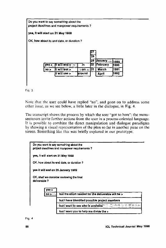
Fig. 3
Note that the user could have replied “no”, and gone on to address some other issue, as we see below, a little later in the dialogue, in Fig. 4.
The transcript shows the process by which the user “got to here”: the menu- sentences invite further actions from the user in a process-oriented language. It is possible to combine the direct manipulation and dialogue paradigms by showing a visual representation of the plan so far in another pane on the screen. Something like this was briefly explored in our prototype.
Fig. 4
88 ICL Technical Journal May 1990

At first sight, this “conversational” style of interaction looks remarkably like human dialogue. The user and the machine system are both generating utterances, which seem best understood in the framework of speech-act theory, as illocutionary acts such as commanding, requesting, and asserting.
It might be argued that both participants are violating the Gricean conditions, by which they ought to be intending that their conversation partner recognise their intensions [Gri57,69; Sea69]. Stripped of philosophical concerns about the nature of meaning, the main function of the Gricean conditions however is to permit each conversation partner to predict the cognitive situation and consequent behaviour of the other.
In the case of the dialogue model in the Task Organiser, the analysis of user beliefs and intentions at various points in the task was done by the Task Organiser designers at design-time. The Task Organiser certainly incorporates procedures for package-handling based on cooperative principles in dialogue4, but it does not model the beliefs or intentions of the user at interaction-time explicitly. It is an implementation, a performance model, built in accordance with a normative competence model of what we, the designers, anticipated a professional user and a cooperative assistant system would believe and intend at various points in the task. Our suggestion is that for a stereotyped process such as project-plan creation, such a fixed intentional structure is adequate.
4. Conclusions
The technology of natural language phrases selected and composed by the user is a useful addition to the hci designer’s toolkit. Using walking menus and a mouse, techniques of direct manipulation have been harnessed to the power of intensional description. This permits sentences to be input at speed, without the user-overheads of typing and the computational difficulties involved in parsing unrestricted natural language text5. We found two kinds of issues emerging in integrating this style of hci with application functionality: those of architecture and interaction structure.
4. L Architecture
A procedural implementation of this hci-style simply associates a sentenceprocessing procedure with each package-type, binding variables from sen-
4 In a fashion similar to the automated advisor for train information of [AP80],5 Another project which has found this technology useful is the Alvey DSS demonstrator project, which has a similar interface to its Welfare Rights Advice System [FL89]. See also the pioneering work at Texas Instruments in the early eighties, described in [TSTM83], [Tho83],
3.4. Is it dialogue?
ICL Technical Journal May 1990 89

tcnce-references at need. A more elegant solution would be to define a semantics at phrase level (perhaps as higher-order functions in the style of Montague [DWP85]), and compose the meaning of the sentence from the functionals associated with the phrase constituents of the sentence selected.
If this style of hci is used in connection with a constraint-based problem (as in the example above), then a local change may have global consequence propagated by the constraints. Some form of Truth-Maintenance System is then required to obviate re-entry of all values.
Finally, since the user has some freedom to sequence outstanding activities, the system maintains a (rather simple) “dialogue state model”, which it uses to suggest to the user new topics. In particular it ensures that deferred topics are eventually brought back into the dialogue. This brings us back to a consideration of interaction structuring.
4,2, Interaction Structuring
Although human-computer dialogues are not “like” at least some human- human dialogues, they can still be completely appropriate for the task in hand. As we move into more flexible, mixed-initiative type dialogues however, we find that interaction becomes less stereotyped, and that information contingently available in the discourse situation, especially information about the beliefs and intentions of the dialogue participants, becomes a causal factor in driving the dialogue.
The Task Organiser type of system described here relies upon the task being sufficiently stereotyped that the cognitive content of the discourse can be determined at design-time, and therefore appropriate conversation routines designed-in. At best this is a crude assumption, and it is hard to see how even the levels of cooperativeness in Allen and Perrault's train information model [AP80] could be achieved without deferring estimates of the conversation partner's intentions until the conversation itself. It is therefore to be hoped that Task Organiser-like systems can be an implementation route for some of the very interesting work currently being done in speech act and conversation theory.
Acknowledgements
This research was supported by ESPRIT II project 2105, MULTIWORKS. The building of the first exemplar was supported by Alvey project MM 1/006 "Adaptive Intelligent Dialogues”.
The authors would like to acknowledge the efforts of Albert Wong, who undertook much of the detailed design and implementation of the AID Task Organiser system.
90 ICL Technical Journal May 1990

This paper was presented to an IEE Colloquium on Formal Methods held in December 1989 and is published here with the permisssion of the IEE.
References
[AP80] ALLEN, J.F. & PERRAULT, C.R. “Analysing Intention in Utterances". Artificial Intelligence 15, pp. 143-178. 1980.
[DWP85] DOWTY, D.R., WALL, R.E., PETER, S. & REIDEL, D. Introduction to Montague Semantics. 1985.
[FL89] FROHL1CH, D.M. & LUFF, P. “Conversational Resources for Situated Action”. In Proc. CHI-89, pp. 255-258. 1989.
[Gri57] GRICE, P. “Meaning". Philosophical Review, vol. 66, 1957, pp. 377-388.[Gri69] GRICE, P. “Utterer’s Meaning and Intentions”. Philosophical Review, April 1969.[Gro77] GROSZ, B.G. “The Representation and Use of Focus in Dialog Understanding".
Dissertation, University of California at Berkeley, 1977.[Sea69] SEARLE, J.R. Speech acts: An essay in the philosophy of language. C.U.P. 1969.[TI1083] THOMPSON, C.W. “Building Usable Menu-based Natural Language Interfaces
to Databases”. In Proceedings of the 9th VLDB Conference, Florence, Italy, October 1983.
[TSTM83] TENNANT, H.R., SAENZ, R.M., THOMPSON, C.W. & MILLER, J.R. “Menu- based Natural Language Understanding”. In Proceedings of the 21st Annual Meeting of the Association for Computational Linguistics, pp. 151-158, Cambridge, Mass., June 1983.
[WF86] WINOGRAD, T. & FLORES, F. Understanding Computers and Cognition. Addison-Wesley 1986.
[WL88] WONG, A. & LESAN, H. 1988. "Task Organiser”. Unpublished AID document aid/3/report/s°234.1. (Available from the authors).
ICL Technical Journal May 1990 91

“SODA”: The ICL Interface for ODA Document Access
Michael J. CoonPODA Project, CIA, ICL Bracknell
Abstract
This paper introduces the international standard “ Office Document Architecture” (ODA), and the ICL PODA project which was crucial in formulating it and is piloting its exploitation. The project demonstrates the interchange of documents between computer-based systems using ODA.
The paper explains why the project developed a storage manager for manipulating ODA documents, and an Application Program Interface (API) for it, with commercial toolkits in support of this interface.
It explores the implications of having a published (probably standardised or public domain as well) interface for creating and manipulating ODA documents, with toolkits supporting them. The consequence is that the interface does not imply a particular format for stored documents, but that the toolkit does.
1 Introduction
T his article describes d em o n stra tio n s o f e lec tro n ic d o cu m en t in terch an ge to p la ce th e in tern ation a l stan d ard “ O D A ” in co n tex t. A n o v erv iew o f O ffice D o c u m e n t A rch itecture is p resen ted to sh o w h o w d o cu m en ts are co n stru cted .
T h e n eed for a r a n d o m -a c c e ss fo rm o f s to r e d d o c u m e n ts is e x p la in e d , a n d a lso h o w th is le a d s to a req u irem en t for a n A p p lic a t io n P ro g r a m In ter fa ce to m a n ip u la te th ese d o c u m e n ts .
F in a lly , th e a r tic le p r e se n ts th e IC L so lu t io n “ S O D A ” , a n d th e O D A to o lk it th a t it su p p o r ts . C u rren t a n d p o te n t ia l u se s o f th e to o lk it are d escr ib ed .
A t th e en d o f th e ar tic le is a S u m m a ry , a G lo s sa r y a n d lis t o f referen ces.
2 The PODA project demonstrations
In ea ch o f th e la s t th ree y ea rs , IC L h as d e m o n s tr a te d , a t th e C e B IT fair in H a n n o v e r , th e in te r c h a n g e o f e le c tr o n ic d o c u m e n ts w ith o th e r E u ro p ea n c o m p a n ie s .
92 ICL Technical Journal May 1990

I f th e d o c u m e n ts in te r c h a n g e d h a d b een m ere ly m e m o s , th e n th e t e c h n o lo g y in v o lv e d w o u ld h a v e b een n o d ifferen t fro m th a t u se d fo r d e m o n s tr a t io n s o f e le c tr o n ic m a il. T h e in te r n a tio n a l s ta n d a rd fo r e le c tr o n ic m a il, X .4 0 0 , is in r o u tin e u se for se n d in g m e m o s o f a few p a ra g ra p h s b o th w ith in a n d b e tw e e n o r g a n is a tio n s . M a n y d ifferen t m a n u fa c tu rers o ffer X .4 0 0 , a n d th is fo rm o f m a il ca n b e se n t b y u tilis in g sev era l d a ta in te r c h a n g e serv ices.
T h e s im p le m e m o is su ffic ien t fo r th e e x c h a n g e o f u n stru c tu red in fo r m a tio n . H o w e v e r it e x p lo its o n ly th e m o s t b a s ic c a p a b ilit ie s o f m o d e r n w o rd p r o c e sso r s . T h e sta te o f th e art p r o d u c ts in th is fie ld ca n c o p e w ith te x t w h ich is e m b o ld e n e d , u n d er lin ed , ita lic ise d a n d s o fo r th . A t th e le v e l o f d o c u m e n t stru ctu re , th e y offer a u to m a tic n u m b e r in g o f p a r a g r a p h s a n d p a g e s , fo o t n o te s , h ea d e r s a n d fo o te r s , ta b u la r m u lt i-c o lu m n la y o u t , a n d illu s tr a tio n s . N o n e o f th e se fea tu res c a n b e in c lu d e d in a “ s im p le m e m o ” , b u t w ere sh o w n in th e d e m o n s tr a tio n s .
T h e P O D A p ro jec t w a s se t u p , in it ia lly in 19 8 6 , to p ilo t th e u se o f a n ew s ta n d a r d , O ffice D o c u m e n t A rch itec tu re , fo r in te r c h a n g in g e le c tr o n ic d o c u m e n ts h a v in g a d v a n c e d fea tu res su c h a s th o se lis te d . T h e n a m e “ P O D A ” is a n a c r o n y m for P ilo t in g O ffice D o c u m e n t A rch itec tu re . It is n o w p ro jec t n u m b e r 2 3 7 4 in th e E E C ’s E S P R IT -I I in it ia t iv e to p r o m o te in fo r m a tio n t e c h n o lo g y in E u r o p e . A s w e ll a s IC L , th ere are n in e o th e r E u r o p e a n o r g a n is a t io n s c o lla b o r a t in g in th e p ro jec t , fro m five co u n tr ie s .
O ffice (o r “ O p e n ” ) D o c u m e n t A r c h ite c tu r e is a n ew in te r n a tio n a l s ta n d a r d (p u b lish e d a s IS O 8 6 1 3 , C C IT T T .4 1 0 a n d a ls o a s E C M A 101) fo r th e in te r c h a n g e o f e le c tr o n ic d o c u m e n ts . It la y s d o w n a fo rm a t in w h ich th e d o c u m e n ts a re in te r c h a n g e d , c a lle d O ffice D o c u m e n t In te r c h a n g e F o r m a t, so th e c o m p le te s ta n d a r d is o fte n k n o w n a s O D A /O D I F . It is p art o f th e se t o f s ta n d a r d s c a lle d O S I , O p e n S y ste m s In te r c o n n e c tio n . B e c a u se th e P O D A p ro jec t is a n in te r n a tio n a l o n e , it h a s c o n c e n tr a te d o n e x c h a n g in g d o c u m e n ts v ia X .4 0 0 m a il, b u t e x c h a n g e u s in g f lo p p y d isc s is p o s s ib le a n d h a s a ls o b een d o n e .
It is a n a im o f th e P O D A p ro jec t to e n c o u r a g e th e tran sfer o f O D A te c h n o lo g y in to th e w o r ld o f e le c tr o n ic d o c u m e n ts . C o m p le x d o c u m e n ts , fo r in s ta n c e c h a p te r s o f a m u lt i- lin g u a l rep o r t, c o u ld b e w r itten b y sev era l a u th o r s in d ifferen t c o u n tr ie s o n w o r d p r o c e sso r s h a v in g n a t io n a l fea tu res . T h e se p a r a te c o n tr ib u t io n s c o u ld th e n be sen t to a n e x e c u tiv e e d ito r w h o a sse m b le s th e m in to th e fin a l d o c u m e n t . A ll o f th e s tru c tu ra l in fo r m a tio n w o u ld b e m a in ta in e d , a n d n o n e o f it w o u ld h a v e to b e ty p e d tw ice . W h ere n e c e ssa r y , th e la y o u t w o u ld b e rea d ily m o d ifie d to g iv e a c o n s is te n t a p p e a r a n c e .
T h e c o m p a n ie s in th e P O D A c o n so r t iu m d o n o t u se O D A /O D I F o n ly for d e m o n s tr a t io n s . E a ch c o m p a n y h a s th e fa c ility p e r m a n e n tly se t u p , a n d it is in u se for te c h n ic a l c o m m u n ic a t io n s .
ICL Technical Journal May 1990 93
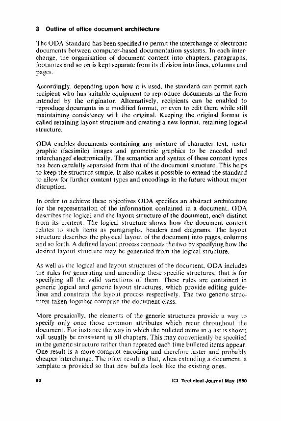
3 Outline of office document architecture
T h e O D A S ta n d a rd h a s b een sp ec ified to p erm it th e in te r c h a n g e o f e le c tr o n ic d o c u m e n ts b e tw e e n c o m p u te r -b a se d d o c u m e n ta t io n sy s te m s . In e a c h in ter c h a n g e , th e o r g a n is a t io n o f d o c u m e n t c o n te n t in to c h a p te r s , p a ra g ra p h s, fo o tn o te s a n d s o o n is k e p t se p a ra te fro m its d iv is io n in to lin e s , c o lu m n s an d p a g es .
A c c o r d in g ly , d e p e n d in g u p o n h o w it is u se d , th e s ta n d a r d ca n p e r m it e a c h rec ip ien t w h o h a s su ita b le e q u ip m e n t to r e p ro d u ce d o c u m e n ts in th e form in te n d e d b y th e o r ig in a to r . A lte r n a t iv e ly , r ec ip ien ts c a n b e e n a b le d to r e p ro d u ce d o c u m e n ts in a m o d if ie d fo rm a t, o r e v e n to e d it th em w h ile still m a in ta in in g c o n s is te n c y w ith th e o r ig in a l. K e e p in g th e o r ig in a l fo rm a t is ca lled r e ta in in g la y o u t stru c tu re a n d cr e a tin g a n ew fo rm a t, r e ta in in g lo g ic a l stru ctu re .
O D A e n a b le s d o c u m e n ts c o n ta in in g a n y m ix tu r e o f ch a ra c ter tex t, raster g ra p h ic (fa c s im ile ) im a g e s a n d g e o m e tr ic g r a p h ic s to b e e n c o d e d an d in terch a n g ed e le c tr o n ic a lly . T h e se m a n tic s a n d sy n ta x o f th e se c o n te n t ty p es h a s b een ca re fu lly sep a ra ted fro m th a t o f th e d o c u m e n t stru ctu re . T h is h e lp s to k e e p th e stru c tu re s im p le . It a ls o m a k e s it p o s s ib le to e x te n d th e sta n d a rd to a llo w fo r fu rth er c o n te n t ty p es a n d e n c o d in g s in th e fu tu re w ith o u t m a jo r d isr u p tio n .
In o rd er to a c h ie v e th e se o b je c t iv e s O D A sp ec ifie s a n a b str a c t a r ch itec tu re for th e r e p r e se n ta tio n o f th e in fo r m a tio n c o n ta in e d in a d o c u m e n t . O D A d escr ib es th e lo g ic a l a n d th e la y o u t stru ctu re o f th e d o c u m e n t , e a c h d is t in c t from its c o n te n t . T h e lo g ic a l s tru c tu re s h o w s h o w th e d o c u m e n t c o n te n t re la tes to su ch item s a s p a ra g ra p h s, h e a d e r s a n d d ia g r a m s. T h e la y o u t stru ctu re d escr ib es th e p h y s ic a l la y o u t o f th e d o c u m e n t in to p a g e s , c o lu m n s a n d so fo r th . A d e fin ed la y o u t p r o c e ss c o n n e c ts th e tw o b y sp e c ify in g h o w th e d esired la y o u t stru ctu re m a y be g en e r a te d fro m th e lo g ic a l stru ctu re .
A s w e ll as th e lo g ic a l a n d la y o u t stru c tu res o f th e d o c u m e n t , O D A in c lu d es th e ru les fo r g e n e r a tin g a n d a m e n d in g th ese sp ec ific stru c tu res , th a t is for sp e c ify in g a ll th e v a lid v a r ia t io n s o f th em . T h e se ru les are c o n ta in e d in g en er ic lo g ic a l a n d g en er ic la y o u t stru c tu res , w h ich p r o v id e e d it in g g u id e lin es a n d c o n s tr a in th e la y o u t p r o c e ss re sp ec tiv e ly . T h e tw o g e n e r ic s tr u c tu res ta k en to g e th e r c o m p r ise th e d o c u m e n t c la ss .
M o r e p r o sa ic a lly , th e e le m e n ts o f th e g en er ic stru c tu res p r o v id e a w a y to sp ec ify o n ly o n c e th o se c o m m o n a ttr ib u te s w h ich recu r th r o u g h o u t th e d o c u m e n t . F o r in s ta n c e th e w a y in w h ich th e b u lle ted item s in a lis t is sh o w n w ill u su a lly be c o n s is te n t in a ll ch a p ters . T h is m a y c o n v e n ie n t ly be sp ec ified in th e g e n e r ic s tru ctu re ra th er th a n rep ea ted e a ch tim e b u lle ted ite m s a p p ea r . O n e resu lt is a m o re c o m p a c t e n c o d in g a n d th erefo re fa ster a n d p r o b a b ly ch e a p e r in te r c h a n g e . T h e o th e r resu lt is th a t , w h e n e x te n d in g a d o c u m e n t , a te m p la te is p r o v id e d so th a t n ew b u lle ts lo o k lik e th e e x is t in g o n e s .
94 ICL Technical Journal May 1990

Fig. 1 Diagram of FPDA
T h e se fo u r m a jo r d iv is io n s (g en er ic a n d sp ec ific , lo g ic a l a n d la y o u t ) o f an O D A d o c u m e n t are lin k ed b y tw o se ts o f e le m e n ts ca lled s ty le s . L a y o u t sty les p r o v id e th e p a ra m eters for th e la y o u t p r o c e ss req u ired for a g iv e n d o c u m e n t , e q u iv a le n t to th e req u ired m a p p in g o f lo g ic a l e n tit ie s o n to la y o u t e n tit ie s . P r e se n ta t io n sty le s g o v e r n th e a p p e a r a n c e o f re g io n s o f c o n te n t . T h e p r o v is io n o f th ese tw o se ts o f c o n s t itu e n ts h e lp s in se g r e g a t in g th e in fo r m a tio n in th e d o c u m e n t a n d in a v o id in g u n n e c e ssa r y r e p e tit io n .
T h e c o n te n t o f th e d o c u m e n t is o r g a n ise d in to c o n te n t p o r tio n s . T h e se are a tta c h e d to c o n s t itu e n ts o f b o th th e lo g ic a l a n d la y o u t stru c tu res to s h o w th e p a rts o f th e d o c u m e n t to w h ic h th e y b e lo n g .
T h e d ia g ra m , F ig . 1, illu s tra te s a ll o f th e a b o v e su b d iv is io n s .
T h e d ia g ra m sh o w s (w ith s o m e s im p lif ic a t io n ) h o w th e p a rts o f a n O D A d o c u m e n t re la te to e a c h o th e r . W h ere a ll ty p e s o f c o n s t itu e n t a re p resen t th e d o c u m e n t is in “ fo r m a tte d /p r o c e ssa b le a r c h ite c tu r e ” b e c a u se th e p r esen ce o f th e la y o u t stru ctu re in d ic a te s th a t th e d o c u m e n t h a s b een fo r m a tte d . S im ila r ly , th e p r e se n c e o f th e lo g ic a l s tru c tu re m e a n s th a t th e d o c u m e n t c o u ld b e p r o c e sse d , fo r in s ta n c e fo r m a tte d a g a in w ith o r w ith o u t h a v in g b een e d ite d .
R e d u c e d fo rm s o f O D A d o c u m e n t are r e c o g n ise d a s d is tin c t a r c h itec tu res by th e s ta n d a rd . T h e se are
P r o c e ssa b le D o c u m e n t A rch itec tu re ,F o r m a tte d D o c u m e n t A r ch itec tu re a n d F o r m a tte d -P r o c e s sa b le D o c u m e n t A rch itec tu re .
T h e fo rm a tted fo rm is u se d w h ere th ere is n o req u irem en t for e d it in g o r fo r m a ttin g , for in s ta n c e w h e n se n d in g to a p r in ter . P r o c e s sa b le fo rm is u sed w h ere it is e x p e c te d th a t fo r m a ttin g w ill b e d o n e , if r eq u ired , b y th e rec ip ien t.
In th e c a se o f p r o c e ssa b le d o c u m e n t a r ch itec tu re o n ly th e sp ec if ic la y o u t
ICL Technical Journal May 1990 95

Fig. 2 Diagram of PDA
stru ctu re is o m itte d . T h is is b e c a u se it c a n b e reg en era ted u s in g th e ru les in th e g en er ic la y o u t stru ctu re , th e la y o u t sty le s an d o f co u r se th e lo g ic a l stru ctu res . T h e c o r r e sp o n d in g d ia g ra m , F ig . 2, sh o w s th is.
In th e c a se o f fo rm a tted d o c u m e n t a rch itec tu re b o th o f th e lo g ic a l stru ctu res are o m itte d . L a y o u t s ty le s are a lso n o t req u ired , b u t p r e se n ta tio n s ty le s m a y be p resen t. T h e c o r r e sp o n d in g d ia g ra m , F ig . 3, illu s tra te s th is.
A sp ects o f b o th the stru ctu rin g in fo rm a tio n and th e c o n te n t in a d o c u m e n t can a p p ea r m a n y tim es th r o u g h o u t the d o c u m e n t. O D A em b ra ces th e co n c e p t o f “ c la s se s” ; th ese are o b jec ts (or e lem en ts) w ith in the d o c u m e n t stru ctu re w h ich h a v e th e sa m e ch a ra cter istic s an d are c la ssified in to g ro u p s. A n o b ject c la ss is a sp ec ifica tio n o f th e set o f ch a ra cter istic s th at are c o m m o n to its m em b ers. T h e c o m p le te set o f o b ject c la sses in th e d o c u m e n t is in fact th e g en er ic stru ctu re, a lso ca lled th e d o c u m e n t c la ss . T h e c o n c e p t o f o b jec t c la sse s sim p lifie s th e crea tio n o f the d o c u m e n t , im p ro v es d o c u m e n t tra n sm iss io n effic ien cy an d p reserves th e in tegrity o f th e d o c u m e n t stru ctu re th ro u g h e d it in g se ss io n s .
T h e d o c u m e n t c o n te n t ca n be o f sev era l d ifferen t ty p es . T h o se cu rren tly
Fig. 3 Diagram of FDA
96 ICL Technical Journal May 1990
co v ered b y th e sta n d a rd are tex t, raster a n d g eo m etr ic g ra p h ics . E a ch c o n te n t ty p e h a s its o w n d efin ed c o n te n t a rch itectu re w h ich sp ecifies c o n te n t stru ctu res, c o d in g sch em es etc . A n im p o r ta n t feature o f c o n te n t arch itec tu res is their in d ep en d en ce . T h is en a b le s n ew c o n te n t arch itec tu res to b e in c lu d ed ea sily .
4 How to interchange ODA documents
A u th o r s a n d ty p is ts w h o are u s in g c o m p u te r -b a se d sy s te m s to d a y to p ro d u c e e le c tr o n ic d o c u m e n ts d o n o t k n o w O D A , n o r d o th e y p r o d u c e O D A d o c u m e n ts . N e v e r th e le s s it is fea s ib le to c o n v e r t th e ir d o c u m e n ts in to O D A fo r e x c h a n g e w ith o th e r sy s te m s , a n d th e n b a ck a g a in in to fa m ilia r w o r d p r o c e ss in g fo rm a ts . T h is is h o w th e P O D A p ilo t h a s o p e r a te d . O n ly th e w riter o f th e c o n v e r te r p r o g r a m s h a s to u n d e r sta n d O D A .
T h e O D A sta n d a r d sp ec ifie s a n in te r c h a n g e fo rm a t fo r p a ss in g d o c u m e n ts b e tw e e n u sers. T h is fo rm a t e m p lo y s a n in te r n a tio n a l s ta n d a rd fo r th e sp e c if ic a t io n o f th e e x c h a n g e o f d a ta in a n im p le m e n ta t io n - in d e p e n d e n t w a y , A b stra c t S y n ta x N o t a t io n O n e , o r A S N . l .
A S N . l in c o r p o r a te s a fo r m a l la n g u a g e for sp e c ify in g th e req u ired sy n ta x (th e n o ta t io n ) , a n d fo r in c lu d in g w ith in th is fo rm a l sp e c if ic a t io n so m e in fo r m a t io n a b o u t th e d e ta ile d e n c o d in g . T h is fo rm a l la n g u a g e is i t s e lf m a c h in e p r o c e ssa b le , a n d to o ls e x is t fo r p e r fo rm in g th is p r o c e ss in g .
T h e O D A in te r c h a n g e fo rm a t O D I F is sp ec if ied in th e s ta n d a rd in A S N . l , a n d m a c h in e r ea d a b le c o p ie s h a v e b e e n p r o c e sse d u s in g th e t o o ls m e n t io n e d a b o v e . T h e to o l in u se in th e IC L P O D A p ro jec t is c a p a b le o f g e n e r a tin g p r o g r a m s w h ic h ca n rea d a n d w rite O D I F . F o r m o r e d e ta il o f th is a sp e c t , refer to th e se c t io n s o n th e to o lk it b e lo w .
5 Document Application Profiles (DAP’s)
F o r e x is t in g d o c u m e n t p r o c e ss in g sy s te m s to in terw o rk u s in g O D A , it is n e c e ssa r y to h a v e D o c u m e n t A p p lic a t io n P r o file s w h ic h s ta n d a r d ise m a p p in g s to O D A o f th e c o n v e n t io n a l d o c u m e n t fea tu res ty p ic a lly e m b o d ie d w ith in , a n d m a n ip u la te d b y , su c h sy s te m s . It is a ls o n e c e ssa r y t o h a v e c o n v e r s io n so ftw a r e to tr a n s la te b e tw e e n th e p ro p r ie ta r y d o c u m e n t r ep resen ta t io n s w h ic h a re in u se a n d th e in te r n a tio n a l s ta n d a r d .
T h e O D A sta n d a r d , r e c o g n is in g th e c o m p le x ity o f O D A , sp e c if ie s h o w to fo rm su b se ts o f th e to ta l se t o f fea tu res a n d fa c ilit ie s fo r u se b y im p le m e n ta t io n s w h ic h se rv ice d ifferen t le v e ls o f u ser r eq u irem en ts . T h e se su b se ts are term ed “ D o c u m e n t A p p lic a t io n P r o f ile s” referred to la te r a s D A P ’s.
In itia lly th e s ta n d a r d s o r g a n is a t io n s in te n d e d t o d e fin e d o c u m e n t a p p lic a t io n p ro file s . H o w e v e r , w o r k b y th e P O D A p ro jec t fo u n d th a t a p p lic a t io n p ro file s w ere n o t su ffic ien t t o d e sc r ib e h o w e x is t in g e q u ip m e n t c o u ld su p p o r t a n d c o n fo r m to O D A .
ICL Technical Journal May 1990 97

S p ec ia l te c h n ic a l c o n s id e r a t io n s are req u ired for th e u se o f O D A for in te r w o r k in g b e tw een p r o d u c ts d e s ig n e d in d e p e n d e n t ly o f O D A . A lth o u g h th e p r o d u c ts m a k e th e ir o w n p a r ticu la r s ty le o f r e a lisa t io n for fea tu res su ch as p a g e h e a d in g s a n d fo o tn o te s , O D A h a s a p o w er fu l an d g en era lised a rch itec tu re fo r d esc r ib in g th e p r o p e r tie s u n d er ly in g th o se fea tu res. T h e fea tu res th e m se lv e s are n o t a ll id en tified in th e sta n d a rd .
T o so lv e th is p r o b le m th e c o n c e p t o f d o c u m e n t “ su p e r c la sse s” w a s c o n ce iv e d b y P O D A . A su p erc la ss is th e term u sed to sp ec ify h o w , for an O D A d o c u m e n t a p p lic a tio n p ro file , th e u se r s’ p erce iv ed fea tu res , su ch a s th o se m e n t io n e d a b o v e , are e n c o d e d in O D A u s in g stru ctu res a n d a ttr ib u te v a lu es .
T h e c o n c e p t o f a su p erc la ss h a s b een a d o p te d by th e v a r io u s s ta n d a rd s b o d ie s d e fin in g fu n c t io n a l p ro file s fo r O D A - first th e E u r o p e a n S ta n d a rd s a n d A p p lic a t io n s G r o u p (S P A G ) a n d th en C C IT T , a n d J a p a n ese and A m er ica n s ta n d a r d s b o d ie s . A s a resu lt th e su p erc la ss c o n c e p t h a s b een in c o r p o r a te d in to th e I S O /C C I T T ru les fo r th e d e fin it io n o f d o c u m e n t a p p lic a tio n p ro file s for th e u se o f O D A .
6 ODA application program interface
A lth o u g h IS O 8 6 1 3 d efin es an a b stra c t a rch itec tu re a n d d a ta s tr e a m e n c o d in g su ita b le for in te r c h a n g e o f e le c tr o n ic d o c u m e n ts , it d o e s n o t d e fin e a s to r a g e fo rm a t. T h e ser ia l fo rm w h ic h is d e fin ed for in te r c h a n g e is n o t id ea l for s to r a g e , a n d e v e n le s s s o for m a n ip u la tio n .
T h e E S P R IT p ro jec t P O D A r e c o g n ise d th e b en efit o f a n in te r m e d ia te c a n o n ic a l fo rm a t to b e u sed in th e c o n v e r s io n b e tw e e n th e c o lla b o r a to r s ’ sy s te m s. S in c e th ere are m a n y p o s s ib le d o c u m e n t r e p r e se n ta tio n s in u se , n o r e la t io n sh ip c a n b e a ssu m e d to h o ld b e tw e e n th e o r d e r in g o f in fo r m a tio n in O D A ( O D I F ) a n d a n y o th e r d o c u m e n t r e p r e se n ta tio n . It w a s th erefo re a p p a ren t th a t a r a n d o m a c c e ss s to r a g e m a n a g e r w a s n eed ed fo r th e p artia l resu lts o f th e d o c u m e n t c o n v e r s io n p r o c e ss . F u r th e r m o r e it w a s n a tu ra l to m o d e l th e p a r tia l r e su lts in fo r m a tio n o n O D A - w h ic h is th e c o m m o n fo rm a t in th e c o n v e r s io n s .
H e n c e o n e c o m m o n req u irem en t fo r r a n d o m a c c e ss to in fo r m a tio n rep rese n t in g O D A c o n s t itu e n ts w a s id en tified a n d a s o lu t io n h a s b een im p le m en ted .
In o rd er to w rite p r o g r a m s w h ic h m a n ip u la te th e s to r e d d o c u m e n t it w a s n e cessa ry to sp ec ify a n in ter fa ce to th e s to r a g e m a n a g e r . T h is is th e A p p lic a t io n P r o g r a m In ter fa ce o r A P I . O u r in ter fa ce is c a lle d “ S O D A ” (S to red O D A ) . T h e s to r a g e m a n a g e r w h ich su p p o r ts it h a s th e a cr o n y m “ O D A S M ” . B o th are in u se b y ten c o m p a n ie s a t th e tim e o f w r itin g .
S O D A h as b een d e s ig n e d a n d u sed to su p p o r t a p p lic a t io n s o th e r th a n
98 ICL Technical Journal May 1990

c o n v e r s io n . F o r e x a m p le , th e O D A la y o u t p r o c e ss a n d im a g in g t o v id e o screen s h a v e b een im p le m e n te d .
7 Higher levels of API
S O D A is v ery b a s ic a n d g e n e r a l. F o r e x a m p le it g iv e s d irec t a c c e ss to th e a ttr ib u te v a lu e s sp ec ified fo r a c o n s t itu e n t . It d o e s n o t c o n s tr a in th e v a lu es th a t th e a ttr ib u te m a y ta k e . S im ila r ly , it w a s d e s ig n e d a s a n o n -d e fe n s iv e in ter fa ce , th a t is , w ith litt le erro r c h e c k in g , to su p p o r t tru sted sy s te m c o d e . T h e in te n t io n w a s to m in im ise p e r fo r m a n c e o v e r h e a d s w h ils t m a x im is in g p o r ta b ility o v e r o p e r a tin g sy s tem s.
It h a s b een e n v isa g e d th a t a h ig h er le v e l in ter fa ce sh o u ld e x is t a b o v e S O D A . S u ch a n in ter fa ce w o u ld b e (m o r e ) d e fen s iv e for a p p lic a t io n s use; it w o u ld d ea l in D A P o b je c ts su ch as p a ssa g e a n d fo o tn o te a n d w o u ld g iv e m o r e c o n v e n ie n t fu n c t io n s su ch as fo l lo w in g th e te x tu a l s e q u e n c e , p er fo rm in g sea rch es a n d so o n . T h e in ter fa ce se m a n tic s sh o u ld b e d e fin ed w ith a g o o d d eg ree o f s e p a r a t io n from la n g u a g e b in d in g s . T h u s it sh o u ld b e p o s s ib le to m a p su ch a n a b str a c t sp e c if ic a t io n o f th e in ter fa ce o n to sev era l p r o g r a m m in g la n g u a g e s a s m a y b e req u ired in d ifferen t d e v e lo p m e n t e n v ir o n m e n ts . F ig u r e 4 sh o w s th is d ia g r a m m a tic a lly .
It is p r o b a b ly n o t a p p r o p r ia te to a tte m p t to c o n s tr u c t a s in g le in ter fa ce w h ic h w o u ld sa tisfy a ll p o s s ib le O D A a p p lic a tio n s . F o r in s ta n c e m a n y sea rch a n d in te r r o g a tio n fu n c t io n s w ill b e s ig n ific a n t o n ly fo r in te r a c tiv e u sa g e . O th e r fu n c t io n s o f an A P I m a y a p p ly th e c o n s tr a in ts a n d u se th e c o n s tr u c ts th a t are sp ec if ied in D A P s .
Fig. 4 Diagram of Layered API
ICL Technical Journal May 1990 gg

8 Local document interchange
F o r O D A th ere is a n im p le m e n ta tio n - in d e p e n d e n t fo rm a t ( A S N .I ) for in te r c h a n g e o f d o c u m e n ts . H o w e v e r th is fo rm a t is n o t id ea l for u se a s a s to r a g e fo r m a t w ith o u t a u g m e n ta t io n b e c a u se it is ser ia l w ith n o b u ilt-in m e c h a n ism s fo r th e fast lo c a t io n o f c o n s t itu e n ts . It is a ls o b u lk y b e c a u se m o s t c o n s t itu e n ts a n d th eir a ttr ib u te s are se lf-d e fin in g a n d m u lti- la y e r e d .
A s to r a g e fo r m a t, o n th e o th e r h a n d , sh o u ld b e m o r e c o m p a c t b e c a u se it ca n rely o n im p le m e n ta tio n a l d e ta ils (fo r e x a m p le , th a t th e c o m p ile r h a s d a ta ty p in g in fo r m a tio n so th a t few er, o r n o , ta g s are n e e d e d ). It m a y a ls o b e b u lk ier b e c a u se it h o ld s r e d u n d a n t in fo r m a tio n to o p t im is e a c c e ss . F o r in s ta n c e it m a y h a v e in d e x e s to a llo w r a n d o m a c c e ss a n d a ls o in d ir e c tio n m e c h a n ism s to fa c ilita te e x p a n s io n a n d c o n tr a c t io n d u r in g m a n ip u la tio n . T h e fin a l c o m p a r iso n o f b u lk d e p e n d s o n th e b a la n c e b e tw e e n th e se effects.
It is p o ss ib le th a t so m e s to r a g e fo r m a ts m a y b e u sed fo r n o n -s ta n d a r d d o c u m e n t in terch a n g e . H o w e v e r , w h ile a n in te r c h a n g e fo rm a t m a y b e u sed for lo c a l s to r a g e w ith d is a d v a n ta g e s o n ly o f d eg ree , a lo c a l s to r a g e fo rm a t w h ich c o n ta in s im p le m e n ta tio n -d e p e n d e n t fea tu res m a y b e in a p p r o p r ia te for in te r c h a n g e o u ts id e its h o m e e n v ir o n m e n t.
9 Program portability
In th e p resen t s ta te o f te c h n o lo g y , m o s t a p p lic a t io n p r o g r a m s n o lo n g e r run w ith o u t su p p o r t fro m d is tin c t la y ers o f se p a r a te so ftw a re , e v e n in p e r so n a l c o m p u te r s . F o r e x a m p le , u su a lly a t lea st th ere is a n o p e r a tin g sy s te m to c o n tr o l th e h a rd w a re , a n d th e v is ib le in ter fa ce m a y be m e d ia te d b y w in d o w in g or p r e se n ta tio n so ftw a re .
T h u s to th e c o n v e n t io n a l m ea su res o f p o r ta b ility a s sp ec if ied b y X /O p e n a n d o th e r g r o u p s is a d d ed th e rep erto ire o f a ll o f th e “ A p p lic a t io n P ro g ra m In ter fa ces” (h ere u sed n o t ju s t for O D A b u t m o re g e n e r a lly ) th a t are e m p lo y e d b y th e a p p lic a tio n .
10 An API and its toolkit
A n A P I w h ic h su p p o r ts th e m a n ip u la t io n o f a d o c u m e n t s to r e m a y b e im p le m e n te d in th e fo rm o f a to o lk it . T h is is a lib ra ry o f r o u tin e s to g e th e r w ith b o th h u m a n re a d a b le an d m a c h in e r ea d a b le d e fin it io n s o f th o se ro u tin e s a n d th e ir p a ra m eters .
T h e to o lk it m a y b e im p le m e n te d for d ifferen t e n v ir o n m e n ts , u s in g th e sa m e A P I a n d la n g u a g e . I f an a p p lic a tio n is p o r ta b le th r o u g h su ch g u id e lin e s as X /O p e n , th e n it c a n rem a in p o r ta b le th r o u g h u s in g th e p o r ta b le A P I .
A s in g le to o lk it in a g iv e n e n v ir o n m e n t sh o u ld g e n e r a te its d o c u m e n t s to r e in su c h a w a y th a t d o c u m e n ts ca n b e p a sse d b e tw e e n a p p lic a t io n s so th a t th o se
100 ICL Technical Journal May 1990

a p p lic a tio n s fo rm a c o -o p e r a t iv e su ite . T h is is th e c a se fo r S O D A /O D A S M , b u t m ig h t n o t b e th e c a se w h ere a to o lk it w o r k s o n ly in v ir tu a l s to r e , for in s ta n c e .
It is p o s s ib le th a t th e sa m e A P I c o u ld h a v e d ifferen t to o lk it s s u p p o r t in g it. W ith in th e sa m e e n v ir o n m e n t, su ch to o lk it s w o u ld p r e su m a b ly b e c o m p e t in g a n d se p a r a te ly so u r c e d . In d ifferen t e n v ir o n m e n ts , th e to o lk it s c o u ld o f c o u r se a ls o b e se p a r a te ly so u r c e d , b u t m ig h t a ls o b e d ifferen tly o p tim is e d v e r s io n s fro m th e sa m e so u r c e , ta ilo r e d for th a t e n v ir o n m e n t. T h e p h r a se “ sa m e A P I ” is in te n d e d to im p ly th a t th e s im ila r ity w o u ld b e s o p rec ise th a t p r o g r a m s c o u ld b e c o n s tr u c te d w ith a n y o f th e to o lk it s . W h e th e r th e u ser h a s a c h o ic e o f w h ic h to o lk it is u sed w o u ld d e p e n d o n h o w th e a p p lic a t io n w a s a sse m b le d a n d d e liv ered .
It w o u ld b e im p r o b a b le th a t th e d o c u m e n t s to r e s th a t w ere g en e r a te d a n d m a in ta in e d b y d ifferen t to o lk it s , e v e n if th e y w ere e m p lo y in g th e sa m e A P I , w o u ld b e c o m p a t ib le s o a s to a llo w th e a p p lic a t io n s to in terw o rk to fo rm a su ite . T o a llo w th is , e ith e r u se o f th e sa m e to o lk it , o r o f a s ta n d a r d in te r c h a n g e fo rm su c h a s O D I F , is req u ired .
H o w e v e r , if a se t o f a p p lic a tio n s is u s in g th e sa m e A P I , a n d la n g u a g e b in d in g s , th e n it sh o u ld b e p o ss ib le to b u ild a ll o f th e se a p p lic a t io n s u sin g th e sa m e to o lk it . T u r n in g su ch a p p lic a t io n s in to a c o -o p e r a t in g su ite sh o u ld th e n b e tr iv ia l. It m a y in v o lv e o n ly m a k in g p r o v is io n fo r su p p ly in g in p u t d o c u m e n ts in th e p e r m a n e n t s to r a g e fo rm o f th e to o lk it , su ch a s an O D A S M file . It m a y b e n e c e ssa r y to h a v e a c c e ss to th e so u r c e c o d e to b e a b le to d o th is . C r e a tin g su ch su ite s o f p r o g r a m s m u st b e th e p r im a ry b en e fit t o sy s te m s in te g r a to r s o f th e e x is te n c e o f o n ly a very few , id e a lly o n e , w id e ly a v a ila b le a n d u tilise d A P I .
A to o lk it m a y u se fu lly c o n ta in m o r e th a n th e s to r a g e m a n a g e r . T h e r e m a y b e g e n e r a lly a p p lic a b le a p p lic a tio n s th a t m a y b e b u n d le d w ith th e b a s ic to o lk it a n d m a r k e te d to g e th e r . E x a m p le s w ill b e fo u n d u n d er th e h e a d in g “ O D A c o n v e r te r s” in th is p a p er , a n d fo rm a tter s m a y b e in c lu d e d a s w e ll. (In O D A , fo rm a tter s im p le m e n t th e lin e -b r e a k in g a lg o r ith m , w h ic h is n a tu r a l- la n g u a g e se n s it iv e . T h u s th ere is n o t ju s t o n e d e fin it iv e fo r m a ttin g p r o c e ss .)
11 Potential applications
T h e o th e r se c t io n s o f th is p a p e r h a v e referred t o “ a p p lic a t io n s ” w ith o u t d isc u ss in g th e ir p u r p o se a n d c a p a b ilit ie s , o r h a v e m e n t io n e d w o r d p r o c e s so r s in p a r ticu la r . W o r d p r o c e sso r s are o f c o u r se th e m o s t c o m m o n e x a m p le s o f d o c u m e n t p r o c e sso r s , b u t it is w o r th w h ile to lis t so m e o th e r p o ss ib ilit ie s .
N o t e th a t th ere is n o im p lic a tio n th a t th ese p a rticu la r c o lle c t io n s o f fea tu res sh o u ld b e a ssem b led to g e th e r in to s in g le p ro g ra m s, o r th a t p ro g ra m s h a v in g o th er d escr ip tio n s m ig h t n o t , w o r k in g to g e th er , p ro v id e th e sa m e fac ilities . T h e fo llo w in g lis t o f a p p lic a tio n s is in ten d ed o n ly to b e a g u id e to a rea s o f re lev a n ce .
ICL Technical Journal May 1990 101

1 7. 1 Search and retrieval
G iv e n th a t d o c u m e n ts are h e ld in a fo rm w h ich re ta in s th e ir s tru ctu re and p r o c e ssa b ility , th is h a s tw o im p lic a t io n s for th e p r o v is io n o f re tr iev a l-b y - c o n te n t . F ir s t ly a sea rch p ro g ra m h a s to u n d ersta n d th e d o c u m e n t s to r a g e stru ctu re in o rd er to b e a b le to d is t in g u ish th e c o n te n t fro m stru ctu ra l in fo r m a tio n . S e c o n d ly th e stru ctu ra l in fo r m a tio n ca n be u sed to refin e th e search itse lf, for e x a m p le to sea rch se c t io n h e a d in g s o n ly , to ig n o r e fo o tn o te tex t, e tc .
T h is a p p lic a tio n h a s so m e p r o c e ss in g in c o m m o n w ith in d e x -g e n e r a tin g a p p lic a tio n s .
11.2 Forms design
T h e tw o ex trem e v a r ie tie s th a t th is a p p lic a t io n m a y ta k e are a p u re ly in tera c tiv e p ro g ra m w h ic h c o n s tr u c ts fo rm s u sin g th e lo g ic c a p a b ilit ie s o f the u ser, a n d an a u to m a tic o n e w h ich u ses a d a ta d ic t io n a r y to p r o v id e th e raw in fo r m a tio n a b o u t fie ld s. In p r a c tice , b o th , o r a m ix ed a p p r o a c h , w ill be n eed ed .
11.3 Report generators
A n y p ro g ra m th a t g en e r a te s d o c u m e n ts w ith s ig n ific a n t stru ctu re is a c a n d id a te for g e n e r a tin g ODA d o c u m e n ts u s in g a n ODA API. T h is in c lu d e s g ra p h ica l rep o rts from b u s in e ss g ra p h ic g e n e r a to r s a s w e ll a s tex t.
T h e a u to m a tic a lly g e n era ted re p o r ts m a y th e n be c o m b in e d w ith w o rd p r o c e sse d tex t, o th e r d ia g r a m s e tc ., to fo rm c o m p le te d o c u m e n ts . T h is is fa c ilita ted b y th e u se o f a c o n s is te n t fo rm a t.
A d is tin c t an d im p o r ta n t c la s s o f rep o r t g e n e r a to r is th e fo rm letter g e n era to r . F o r m le tter s are d ifferen t fro m o th e r ty p e s o f rep o r t o n ly in h a v in g th e a p p e a r a n c e o f a w o rd p r o c e sse d le tter .
11.4 Index generators
In d ex g e n e r a to r s are a v a r ie ty o f s im p le rep o rt g e n e r a to r w h ic h u se s a d o c u m e n t as its in p u t d a ta b a se . T h e in d e x m a y b e s to r e d w ith th e d o c u m e n t (a s a d is tin c t p art o f th e c o n te n t w h ic h sh o u ld n o t su b s e q u e n t ly b e in d e x e d a g a in ) , o r m a y be re ta in ed se p a ra te ly .
11.5 Converters
T h e e x is te n c e o f co n v e r te r s h a s b e e n a ssu m e d e lse w h e r e in th is p ap er . T h e y m a y be p resen t e x p lic it ly for users to in v o k e w h e n m o v in g files b e tw e e n in c o m p a tib le a p p lic a tio n s , or m a y b e e m b e d d e d in o th e r a p p lic a t io n s su ch as m a ilers.
102 ICL Technical Journal May 1990

T h ere are tw o v a r ie t ie s o f co n v er ters: th o s e b e tw e e n O D A a n d o th e r fo r m a ts , a n d th o s e w ith in th e O D A d e fin it io n .
11.5.1 Format converters T h e se a re th e c o n v e r te r s to w h ic h referen ce h as b een m a d e e ls e w h e r e in th is p a p er . T h e y c o n v e r t b e tw e e n O D A a n d o th e r s ta n d a r d o r p ro p r ie ta ry fo rm a ts .
11.5.2 ODA converters T h ere are tw o s ta n d a r d ise d in te r c h a n g e fo r m a ts fo r O D A : O D I F a n d O D L . T h e fo rm er h a s b e e n in tr o d u c e d a lr e a d y , a n d th e la tter e m p lo y s “ S ta n d a rd G e n e r a lise d M a r k u p L a n g u a g e ” (S G M L ) in s te a d o f A S N . l . ( O D L is n o t sp ec if ied for X .4 0 0 e le c tr o n ic m a il.) T h ere fo re th ere are p o te n t ia lly fo u r co n v e r te r s w h ic h to g e th e r d ea l w ith th e a c c e p ta n c e a n d g e n e r a tio n o f b o th o f th e se fo rm a ts .
W ith in O D A th ere are th ree “ d o c u m e n t a rch itec tu re c la s s e s ” : “ p r o c e s s a b le ” (P D A ) , “ fo r m a tte d ” (F D A ) a n d “ fo r m a tte d -p r o c e s sa b le ” ( F P D A ) a r c h ite c tu res. (R efer to S e c t io n 3 for m o r e d e ta il.)
T h e fo r m a ttin g p r o c e ss c o n v e r ts a d o c u m e n t in P D A to o n e in F P D A , an d th u s th is c o n v e r s io n is n o t in c lu d e d u n d er th is h e a d in g . A u to m a tic c o n v e r s io n fro m F D A to P D A o r F P D A is n o t p o s s ib le b e c a u se in fo r m a tio n is m iss in g w h ic h w o u ld b e req u ired fo r th is tr a n s it io n . T h e o th e r tw o c o n v e r s io n s , F P D A to P D A a n d F P D A to F D A , are c o m p a r a t iv e ly s im p le p r o c e sse s .
11.6 Mailers
T h e se a p p lic a t io n s m a y n o t g e n e r a lly b e c o n s id e r e d a s d o c u m e n t-h a n d lin g a p p lic a t io n s , b u t th a t is th e ir p u r p o se . T h e y m a y b e in d ifferen t to th e c o n te n t o f a d o c u m e n t , b u t are g e n e r a lly n o t in d ifferen t to th e d o c u m e n t fo rm a t.
11.7 Printers/Print Servers
In th e w o r ld o f th e p a p e r le s s o ffice th is c a te g o r y o f a p p lic a t io n is n o t th e fin a l d e s t in a t io n o f a ll d o c u m e n ts , b u t is st ill h ig h ly s ig n ifica n t.
A p r in t serv er m a y in c lu d e a fo rm a tter , o r th e fu n c t io n s m a y b e sep a ra te . T h is in f lu e n c e s th e d o c u m e n t fo r m a ts th a t m a y b e h a n d le d (in O D A term s, P D A v ersu s F P D A v ersu s F D A ) .
11.8 Formatters
T h is c la s s o f a p p lic a t io n s ren d ers th e lo g ic a l s tru c tu re a n d c o n te n t o f a d o c u m e n t in a fo rm a p p r o p r ia te to d isp la y a n d o r p r in tin g .
In p ra c tice , th e fu n c t io n a lity m a y b e in c lu d e d in a p r in t serv er o r m a iler . It is n o t lik e ly to b e in v o k e d e x p lic it ly b y a u ser e x c e p t in o rd er to im p o se a la y o u t th a t w a s n o t a n tic ip a te d w h en th e d o c u m e n t w a s c o n s tr u c te d . F o r
ICL Technical Journal May 1990 103
in s ta n c e , a r e fo r m a ttin g m a y be r eq u ested in o r d e r to re fo rm a t for la n d sc a p e ra th er th a n p o r tr a it p r e se n ta tio n .
12 A flavour of SODA
12.1 Purpose of application
T h e P O D A p ro jec t h a s a p e r m a n e n t fa c ility fo r th e c o lla b o r a to r s to e x c h a n g e d o c u m e n ts u s in g O D I F o v e r X .4 0 0 c o n n e c t io n s . M o s t p a rtn ers th en v iew , e d it a n d p r in t th e se d o c u m e n ts u s in g th e ir p ro p r ie ta r y w o rd p r o c e sso r s . T h u s e a c h o f th o s e p a r tn ers n e e d e d t o im p le m e n t a c o n v e r te r b etw een O D I F a n d th e fo rm a t u sed b y th e ir w o r d p r o c e sso r s . O n ly th e p a rtn ers w h o w o rk in n a tiv e O D A d o n o t n eed su ch co n v e r te r s .
12, /. 1 Software environment A d o c u m e n t c o n v e r te r is th e so ftw a r e to tran sfer a w h o le d o c u m e n t rep resen ted in O D I F d a ta strea m fo rm a t to a n d fro m o n e o f th e p ro p r ie ta ry d o c u m e n t fo r m a ts u sed fo r a p a r ticu la r m a n u fa c tu r e r ’s w o r d p r o c e sso r s . In th e d e m o n s tr a t io n s th a t h a v e b een m o u n te d b y th e P O D A p ro jec t tea m th e c o n v e r s io n h a s b een in it ia ted by th e sta n d a rd O ffic e p o w e r X .4 0 0 m a il so ftw a re .
F o r in c o m in g m a il th e fla g s in th e X .4 0 0 p r o to c o l are in te r r o g a te d to d e te r m in e w h eth er O D I F h a s b een rece iv ed a n d th a t c o n v e r s io n is th erefo re req u ired . F o r o u tg o in g m a il, th e sy s te m n e e d s to a v o id s e n d in g O D I F to rec ip ien ts w h o w o u ld be u n a b le to m a k e u se o f it. T o d o th is , it m a in ta in s in d ic a to r s o f th e c a p a b ilit ie s o f a ll k n o w n p o ss ib le a d d r e sse e s . T h e se in d ic a to r s are p art o f th e sy s te m ’s d a ta b a se o f th e a d d r e ss in g in fo r m a tio n for th e a d d r e sse e s . B y th is m e a n s , it is p o ss ib le to se n d a d o c u m e n t to a m ix tu re o f O D A -e q u ip p e d a n d n a iv e c o r r e sp o n d e n ts . T h e la tter w ill g e l a fa llb ack v e r s io n o f th e d o c u m e n t in s im p le tex t form .
T h e fo l lo w in g a rch itec tu re sh o w s h o w su ch a c o n v e r te r m a y be stru ctu red a r o u n d th e S O D A in ter fa ce . (In th is d ia g r a m th e a r r o w s in d ic a te f lo w o f in fo r m a tio n .)
T h e so ftw a re a rch itec tu re c o n s is ts o f, s ta r tin g w ith a d o c u m e n t to be p r o c e sse d in th e fo rm a t for w o rd p r o c e sso r A a n d w ith th e c o n v e r te d d o c u m e n t in th e fo rm a t for w o rd p r o c e sso r B , th e fo l lo w in g c o m p o n e n ts :
P r o p r ie ta r y F o r m a t E x tern a liser;- O D A S to r a g e M a n a g er ;
O D I F G en era to r ;- X .4 0 0 m a il n e tw o rk ;- O D I F A n a ly ser;- P ro p r ie ta ry F o r m a t In tern a liser .
O f th e se so ftw a re c o m p o n e n ts th e O D A S to r a g e M a n a g e r , th e O D I F G e n e r a to r a n d th e O D I F A n a ly se r w ere a ll w r itten in th e ‘C ’ p r o g r a m m in g
104 ICL Technical Journal May 1990

la n g u a g e a n d w ere p o r te d to e a c h o f th e p a rtn ers m a c h in e s a n d o p e r a tin g sy s te m s.
In a d d it io n to th e se m a jo r so ftw a r e c o m p o n e n ts o th e r c o m p o n e n ts , su ch as u tilit ie s to p r in t th e s to r e d O D A d o c u m e n t in h u m a n r ea d a b le fo rm w ere d e v e lo p e d to a id in te s t in g th e sy stem .
T h e O D A S to r a g e M a n a g e r w a s d e s ig n e d b y IC L a n d w a s p o r te d to b o th U n ix a n d M S -D O S sy s te m s a n d u sed b y th e o th e r p ro jec t p a rtn ers in th e ir c o m p o n e n ts o f th e sy s tem . T h e O D A s to r a g e fo rm a t, S O D A , w a s a lso d es ig n e d b y IC L .
U s e o f th is a rch itec tu re for d o c u m e n t c o n v e r s io n h a s th e fo l lo w in g b en efits .
D e v e lo p m e n t c o s t is r ed u ced b e c a u se it is n e cessa ry to im p le m e n t o n ly th e p a r ticu la r p r o g r a m s in t im a te ly c o n c e r n e d w ith th e p ro p r ie ta ry fo rm a t (th e “ in te r n a lisa t io n ” a n d “ e x te r n a lisa t io n ” so ftw a r e ) . T h e rest o f th e p r o g r a m s n e e d e d are a v a ila b le as th e to o lk it .
T h e p o r ta b ility , p er fo rm a n ce a n d res ilien ce o f th e to o lk it h a s a lrea d y b een e s ta b lish e d in v a r io u s e n v ir o n m e n ts .
T e s t in g o f th e n ew p ro p r ie ta ry c o d e is fa c ilita ted . T h ere are u tilit ie s to in sp e c t th e S O D A p r o d u c e d , a n d b e c a u se S O D A is a fo rm o f O D A o n e ca n th ereb y co n firm th a t th e so ftw a r e for e x te r n a lisa t io n p r o d u c e s
Fig. 5 Diagram of Conversion Architecture
ICL Technical Journal May 1990 105

c o rrec t r e p r e se n ta tio n s . S in c e S O D A is a file fo r m a l, n ew c o d e m o d u le s fo r e x te r n a lisa t io n a n d in te r n a lisa t io n ca n be e x te n s iv e ly lo o p te s ted v ia S O D A b e fo re sta r tin g re la t iv e ly m o r e e x p e n s iv e a n d le s s c o n v e n ie n t v a lid a tio n th r o u g h e x tern a l a g e n c ie s .
12.1.2 ODIF conversion T h e O D I F a n a ly se r a n d g e n e r a to r a re b a sed d irec t ly o n th e p u b lish e d g ra m m a r o f O D I F , u s in g an A S N .I p a rser. T h is p arser is p a rt o f a g e n e r a lly a v a ila b le su ite o f O S I c o n s tr u c t io n to o ls ca lled I S O D E w h ic h is d is tr ib u te d by a n u m b e r o f a g e n c ie s .
T h e I S O D E to o ls p erm it “ C ” c o d e to b e in te r p o la te d in th e g r a m m a r w h ere req u ired to h a n d le th e S O D A o b je c ts w h ic h c o r r e sp o n d to th e g ra m m a tic a l e le m e n ts . T h u s th e c lo s e a s s o c ia t io n w ith th e O D A sp e c ific a t io n is m a in ta in ed .
T h e I S O D E to o ls a ls o p erm it a “ p r e tty -p r in te r ” to b e c o n s tr u c te d w h ich p a rses O D I F , s h o w in g a ll th e g ra m m a tic a l e le m e n ts in p r in ta b le form . W h ere sy n ta x erro rs are fo u n d , th e c o n te x t o f th e erro r ca n rea d ily be seen .
12.2 SODA implementation details
12.2.1 Using the interface T h e so ftw a re c o m p o n e n ts d e v e lo p e d b y th e p ro jec t a c c o r d in g to th e a rch itec tu re are: c o m p a n y sp e c ific p ro p r ie ta ry fo rm a t c o n v e r s io n so ftw a re; a p o r ta b le O D A S to r a g e M a n a g e r su p p o r t in g a d a ta stru ctu re in terfa ce “ S O D A ” (p r o v id in g r a n d o m a c c e ss to s to r a g e stru ctu res rep resen tin g O D A c o n s t itu e n ts ); p o r ta b le so ftw a r e for c o n v e r tin g O D I F to S O D A a n d v ic e v ersa .
12.2.1.1 Constituents A s e x p la in e d in th e s e c t io n o n th e stru c tu re o f an O D A d o c u m e n t , su ch a d o c u m e n t is m a d e u p o f d a ta e le m e n ts ca lled c o n s t itu e n ts . E a ch c o n s t itu e n t m a y h a v e o n e o r m o r e o f a rep er to ire o f a ttr ib u te s , so m e o f w h ich re la te th a t c o n s t itu e n t to o th e r s in th e d o c u m e n t . T h ese r e la t io n sh ip s e x p r e ss th e stru c tu re o f th e d o c u m e n t . T h u s th e h iera rch y o f ch a p te r s c o n ta in in g s e c t io n s w h ich c o n ta in p a ra g ra p h s w h ic h m a y c o n ta in fo o tn o te s w ill b e re flec ted in c o n s t itu e n ts w h ich id en tify th e ir im m e d ia te ly su b o r d in a te c o n s t itu e n ts .
In S O D A , ea ch v a r ie ty o f c o n s t itu e n t is rep resen ted b y a “ C ” stru c tu re w h ich c o n ta in s fie ld s w h ic h rep resen t th e a ttr ib u te s w h ich are p erm iss ib le fo r th a t c o n s t itu e n t . C o m p a c t a ttr ib u te s are c o n ta in e d in th e se fie ld s w h ile lo n g e r a n d c o m p le x a ttr ib u te s are fo u n d b y a n in d ir e c t io n m e c h a n ism .
T h e fo l lo w in g O D A c o n s t itu e n ts are su p p o r te d b y th e c o r r e sp o n d in g d a ta stru ctu res n a m e d b e lo w :
106 ICL Technical Journal May 1990

Constituent Equivalent SODA structureD o c u m e n t p ro file P ro fileL a y o u t o b je c t c la s s L a y o u tC la ssL a y o u t o b je c t L a y o u tO b je c tC o n te n t p o r t io n C o n te n tP o r t io nL o g ic a l o b je c t c la s s L o g ic a lC la ssL o g ic a l o b je c t L o g ic a lO b je c tP r e se n ta t io n s ty le P r e se n ta t io n S ty leL a y o u t s ty le L a y o u tS ty le
12.2.1.2 Random access A p r im e req u irem en t for th e S O D A in ter fa ce w a s th a t it b e e ff ic ien t, th a t is , th e p r o g r a m s u sin g it c o u ld b e w r itten to run at r e a so n a b le sp eed w ith c h e a p p r o c e sso r s in lim ite d m e m o r y . T o m in im ise th e m o v e m e n t o f d a ta in m e m o r y , re feren ce to s o d a o b je c ts b y th e O D A S M c o d e a n d b y u ser c o d e refers to th e sa m e a rea s o f m e m o r y . T o m a k e ca lls a c r o ss th e in ter fa ce , o n ly p o in te r s h a v e to b e p a sse d (a n d so m e p a ra m eters) , n o t th e b u lk o f th e a ttr ib u te s .
A llo w a n c e is m a d e for th e fa c t th a t a la rg e d o c u m e n t m a y o c c u p y to o m u ch s to r a g e for a ll o f its p a rts to b e a c c e ss ib le s im u lta n e o u s ly . S o th a t th is is n o t a p r o b le m e v e n o n c o m p u te r s w h ic h h a v e n o v ir tu a l s to r e m e c h a n ism , S O D A in c lu d e s fea tu res to c o n tr o l th e a m o u n t o f s to r e th a t m a y b e o c c u p ie d b y a c c e ss ib le c o n s t itu e n ts . T h is is a rra n g ed b y th e u se o f a n o p e n a n d c lo s e p r o to c o l fo r r e lin q u ish in g a n d r eu sin g th e s to r e th a t e a c h S O D A o b je c t o c c u p ie s .
T h e v is ib ility o f th e in te r n a l s tru c tu res a c r o ss th e S O D A in ter fa ce offers o p p o r tu n it ie s a n d r e sp o n s ib ilit ie s . T h e fo rm er is p r in c ip a lly th a t a d d it io n a l fie ld s ca n b e a d d e d to th e S O D A stru c tu res , in o r d e r to h o ld in te r m e d ia te p r o c e ss in g resu lts . T h is h a s th e c o n se q u e n c e th a t th e O D A S M c o d e m u s t b e r e c o m p ile d , b u t th is is th e o n ly c o s t o f su c h s im p le e x te n s io n s . C o n v e r se ly , th e la tte r im p lic a tio n is th a t u ser p r o g r a m s m u st n o t d is tu r b th e h o u s e k e e p in g d a ta th a t is in th e stru c tu res a n d is n o t p a rt o f th e in ter fa ce .
12.2.2 Externalisation (word processor to SODA) D u r in g e x te r n a lisa t io n th e c o n v e r te r c o d e e x a m in e s th e w o rd p r o c e s s o r ’s in tern a l r e p r e se n ta tio n o f a d o c u m e n t a n d u ses th e S O D A in ter fa ce to a sse m b le a file s to r e r e p r e se n ta t io n o f th e e q u iv a le n t O D A d o c u m e n t . T h e O D I F b y te s tr in g g e n e r a to r ca n su b se q u e n t ly b e u se d to p r o d u c e th e c o r r e sp o n d in g O D I F d o c u m e n t .
(a ) In itia lis e th e d o c u m e n t file b y c a llin g th e fu n c t io n ‘c r e a te D o c u m e n t’.(b ) C a ll fu n c t io n s to crea te “ C ” la n g u a g e d a ta stru c tu res re p r e se n t
in g e a c h o f th e req u ired O D A c o n s t itu e n t d e sc r ip tio n s .(c ) S et v a lu e s in d a ta stru ctu re m em b ers c o r r e sp o n d in g to O D A a ttr ib u te s .
N o t e th a t a p p r o p r ia te O D A id en tifier s m u s t b e cr e a te d o n ly to id en tify s ty le s a n d c la sse s - th ey are n o t n e e d e d fo r lo g ic a l o b je c ts b e c a u se th e O D I F b y te s tr in g g e n e r a to r ca n sy n th e s is e th em .
ICL Technical Journal May 1990 107
(d ) C lo se th e c o n s t itu e n ts as s o o n a s th e y are c o m p le te ly d e fin ed - th is a llo w s th em to be c o p ie d to d isc a n d sto r e to b e re lea sed .
(e) C lo se th e d o c u m e n t file by c a llin g th e fu n c t io n ‘c lo s e D o c u m e n t ’ th is en su res th a t a ll c o n s t itu e n ts are secu red to f ile sto re .
12.2.3 Internalisation (SODA to word processor) D u r in g in te r n a lisa t io n th e w o rd p r o c e sso r c o d e u ses S O D A to a c c e ss an e x is t in g d o c u m e n t a n d b u ild s a n e q u iv a le n t d o c u m e n t in its o w n in tern a l r e p r e se n ta tio n . T h e S O D A d o c u m e n t m a y b e th e file s to r e r e p r e se n ta tio n r e su ltin g fro m a rece iv ed O D I F d o c u m e n t w h ic h h a s b een in te r n a lise d b y th e O D I F b y te s tr in g a n a ly ser .
(a ) In itia lise a c c e ss to th e S O D A d o c u m e n t file b y c a llin g th e fu n c t io n ‘o p e n D o c u m e n t ’.
(b ) T h e p ro file d e sc r ip tio n is o p e n e d b y u se o f th e fu n c t io n ‘o p e n P r o f ile ’. T h is c o n s t itu e n t m u st b e o p e n e d b efo re a n y o th e r c o n s t itu e n t . In a d d it io n , s in ce a c c e ss is u su a lly req u ired to th e P r o file th r o u g h o u t p r o c e ss in g o f a g iv e n S O D A file , it is g e n era lly b etter to o p e n th e P ro file at th e b e g in n in g o f p r o c e ss in g a n d to le a v e it o p e n th r o u g h o u t , o n ly c lo s in g it ju s t b e fo re th e c a ll to ‘c lo s e D o c u m e n t ’.
(c ) C o n s titu e n t d e sc r ip tio n s (a n y e x is t in g o b je c t , c la ss , s ty le , o r c o n te n t p o r tio n ) c a n be o p e n e d in a n y req u ired o rd er b y u s in g th e ‘o p e n D e s - c r ip t io n ’ fu n c t io n . T h is ta k e s a n O B J I D v a lu e to id e n tify th e c o n s t itu en t d e sc r ip tio n a n d it retu rn s a p o in te r to th e a p p r o p r ia te d a ta stru ctu re .
(d ) R ead O D A a ttr ib u te s v a lu e s fro m th e c o r r e sp o n d in g m em b ers o f thec o n s t itu e n t d a ta stru ctu res.
(e ) C lo se th e c o n s t itu e n ts - th is a llo w s th e ir s to r e to b e reu sed .( f ) C lo se th e d o c u m e n t file b y c a llin g th e fu n c t io n ‘c lo s e D o c u m e n t ’.
13 Summary
T h is ar tic le h a s d escr ib ed th e d e m o n s tr a t io n s o f e le c tr o n ic d o c u m e n t in terch a n g e in o rd er to p la ce th e in te r n a tio n a l s ta n d a rd “ O D A ” in c o n te x t . A n o v e r v ie w o f O ffice D o c u m e n t A rch itec tu re w a s p resen ted to sh o w h o w d o c u m e n ts are c o n str u c te d .
T h e n e e d for a r a n d o m -a c c e ss fo rm o f s to r e d d o c u m e n ts w a s e x p la in e d , and a lso h o w th is le a d s to a req u irem en t for an A p p lic a t io n P ro g ra m In terfa ce to m a n ip u la te th ese d o c u m e n ts .
It e x p lo r e d th e im p lic a tio n s o f h a v in g a p u b lish e d in terfa ce for crea tin g a n d m a n ip u la tin g O D A d o c u m e n ts , w ith to o lk it s su p p o r t in g th em . A c o n s e q u e n c e is th a t th e in terfa ce d o e s n o t im p ly a p a r ticu la r fo rm a t for sto red d o c u m e n ts , b u t th a t th e to o lk it d o e s .
F in a lly , th e a r tic le p resen ted th e IC L s o lu t io n “ S O D A ” , a n d th e O D A to o lk it th a t it su p p o r ts . C u rren t an d p o te n t ia l u ses o f th e to o lk it w ere
108 ICL Technical Journal May 1990

d e scr ib ed . T h e a p p r o a c h h a s b een h ig h ly su c c e ss fu l a n d w ill c o n t in u e to th e b a s is fo r w o r k w ith in th e cu rren t p ro jec t a n d , it is h o p e d , su b s e q u e n t o n e s .
14 Glossary
API “Application Program Interface”:A set o f fu n c t io n s th a t ca n b e c a lle d fro m a c o m p u te r p ro g ra m ; in th e c o n te x t o f th is p a p er in o rd er to crea te , m a in ta in o r u se an O D A d o c u m e n t .
Conversion:T h e p r o c e ss o f tr a n s fo r m in g in fo r m a tio n fro m o n e c o m p u te r re p r e se n ta t io n (“ fo r m a t” ) to a n o th e r .
DAP:D o c u m e n t A p p lic a t io n P r o file (see se c t io n 5).
Defensiveness:T h e e m p lo y m e n t o f th o r o u g h c h e c k in g o f in p u t p a ra m eters to en su re th a t resu lts are a s e x p e c te d a n d are n o t in e x p lic a b le .
Language binding:T h e sp e c if ic a t io n o f th e c o m p le te sy n ta x to b e u sed to rep resen t ea ch fu n c t io n o f a p r o g r a m m in g in ter fa ce (A P I ) in a c h o se n c o m p u te r la n g u a g e .
15 Bibliography
“Introducing ODA”, Ian Campbell-Grant, ICL Technical Journal 5(4) November 1987, pages 729-742.
“X.400 - International information distribution” , Dorothy M. Elliott, ICL Technical Journal 5(4) November 1987, pages 754-760.
ISO 86I3, “Office Document Architecture (ODA) and Interchange Format” .ECMA 101, “Office Document Architecture (ODA) and Interchange Format” (copies of this
version are available free from ECMA).CCITT Recommendations T.410 series, “Open Document Architecture (ODA) and Interchange
Format” .
ICL Technical Journal May 1990 109

Human-Human Co-operation and the Design of Co-operative Machines
Michael Smyth Anthony Clarke
LUTCHI Research Centre, Department of Computer Studies, Loughborough University ofTechnology
Abstract
The paper contrasts co-operation on mental tasks, as practised by groups of people (with or without computer assistance) with that which might be practised by a single individual interacting with a computer. The known benefits of interpersonal cooperation within a group are reviewed from the literature. A set of mechanisms is proposed whereby a single person may cooperate with a computer.These mechanisms have been studied experimentally at Loughborough University of Technology under Alvey research project number MMI/062 that also involved ICL. A set of tools were constructed that allowed the proposed mechanisms to be exemplified in practice in several ways, the simplest of which is briefly described here; it concerns the layout of furniture in an office under stated constraints. Some general conclusions are drawn on the potential benefits (and possible limitations) of catering for human/computer co-operation using the proposed mechanisms.
1 Introduction
A s in fo r m a tio n t e c h n o lo g y (IT ) te c h n iq u e s g r o w in s o p h is t ic a t io n , so ftw a re d esig n ers are a t te m p tin g to b u ild s o lu t io n s ta r g e te d to w a r d in crea s in g ly c o m p le x ta sk s . T h e resu lt h a s b een th e e v o lu t io n o f a n o v e l u ser c a te g o r y , th e h ig h ly sk illed , b u t n o t n e c e ssa r ily c o m p u te r lite r a te , p r o fe s s io n a l user. P r o fe ss io n a l u sers m a y b e ch a r a c te r ise d a s h a v in g d e ta ile d , ta sk sp ec ific k n o w le d g e an d th e r e q u ir e m e n t/d e s ir e t o u n d e r ta k e a w id e v a r ie ty o f c o m p le x ta sk s . H u m a n -C o m p u te r In te r a c tio n (H C I ) p r a c tit io n e r s are c u r ren tly in v e s t ig a t in g n o v e l m a c h in e in te r a c tio n m e th o d s a n d p a r a d ig m s w h ich e n a b le u sers to p erfo rm th e c o m p le x a c t iv it ie s req u ired b y th e ta sk , w h ils t k e e p in g tim e ta k e n to lea rn th e sy s te m to a m in im u m . S et a g a in s t th is b a c k g r o u n d th ere is a g r o w in g a w a r e n e ss a m o n g th e IT c o m m u n ity th a t su ccessfu l sy s te m d e s ig n w ill a c c o r d th e in ter fa ce b e tw e e n th e u ser a n d th e a p p lic a tio n so ftw a re an in c r e a s in g ly p iv o ta l ro le . T h is p a p er d e sc r ib e s in itia l a tte m p ts to id en tify a n d a p p ly th e c o n c e p ts o f h u m a n -h u m a n c o -o p e r a t io n as a te c h n iq u e fo r im p r o v in g in te r a c tio n w ith m a c h in e s .
110 ICL Technical Journal May 1990

S oftw are d esig n is n o e x c e p tio n to th e g en era l th em e th a t d esig n is co n cern ed p rim arily w ith th e p r o d u c tio n o f artifacts . In th is c o n te x t a n artifact is a p ro d u ct o r to o l to a ss ist a u ser in th e p erfo rm a n ce o f a sp ec ific task o r fu n c tio n . In ord er to d e v e lo p su ccessfu l so ftw a re th e d esig n er m u st first u n d ersta n d th e task at w h ich th e a p p lic a tio n is ta rg eted . S u ch u n d ersta n d in g in v o lv e s th e id en tif ica tio n o f term s a n d te r m in o lo g y sp ec ific to th e task and h o w th ese are u sed a n d c o m b in e d d u rin g th e ta sk . A se c o n d a n d eq u a lly d ifficu lt p ro b lem fa ces th e sy stem d esig n er , h o w to d esig n a sy stem w h ic h ca ters for th e v a r ia t io n in u ser ex p ertise a n d e x p e c ta t io n b o th a t th e o u tse t a n d d u r in g th e u se o f c o m p u te r b a sed to o ls . It is th e very g en era lity o f c o m p u tin g a n d its p o te n t ia l a p p lic a tio n d o m a in s w h ich p la ces su ch a b u rd en o n th e sy stem d esig n er , w h o se u lt im a te resp o n s ib ility m u st b e to th e p e o p le w h o w ill u se th e e v e n tu a l so lu tio n .
S o ftw a re u sa b ility w ill b e d e te r m in e d b y th e u ser d u r in g in te r a c tio n w ith th e m a c h in e . F o r e x a m p le , w h e th e r a ta sk c a n b e p er fo rm ed u s in g term s a n d p r o c e d u r e s fa m ilia r to th e u ser , w h e th e r th e sy s te m is e a sy to lea rn , w h e th e r o c c a s io n a l u sers c a n q u ic k ly reca ll h o w th e sy s te m o p e r a te s a n d w h e th e r th e sy s te m p r o v id e s a d e q u a te fe e d b a c k a n d erro r p r o te c t io n c o u p le d w ith a c o n s is te n c y o f p r e se n ta t io n th r o u g h o u t th e in te r a c tio n . In sh o r t , d o e s th e so ftw a r e s o lu t io n e n a b le th e u ser to in c r e a se ta sk p er fo rm a n ce . T h e k e y to th e d e s ig n o f u sa b le so ftw a r e is a n u n d e r s ta n d in g a n d e m p a th y w ith th e u ser g r o u p a n d th e ta sk th e y p er fo rm . T h e ta sk req u irem en t a n d c h a r a c te r is tic s o f th e u ser g r o u p sh o u ld b e c e n tr a l in th e so ftw a r e d e s ig n c y c le . T h e im p o r ta n c e o f th is p o s it io n h a s led to th e p h r a se U s e r C e n tr e d S y ste m D e s ig n (N o r m a n a n d D r a p e r , 1986). C o g n it iv e p s y c h o lo g is t s a im to p r o v id e so ftw a r e d e s ig n ers w ith to o ls a n d te c h n iq u e s fo r a c h ie v in g u sa b ility .
T h e g r o w th o f c o g n it iv e p sy c h o lo g y h a s p a ra lle led th a t o f c o m p u te r sc ien ce . C o g n it iv e p s y c h o lo g is t s w ere q u ic k to rea lise th e p o te n t ia l o f c o m p u t in g a s a m e ta p h o r for h u m a n in fo r m a tio n p r o c e ss in g . In d e e d th e cu rren t m o d e ls o f h u m a n m e m o r y a n d a tte n t io n h a v e b een p a r ticu la r ly in f lu e n c e d b y th is a s s o c ia t io n . T h e re su lt h a s b een th e d e v e lo p m e n t o f a n u m b er o f p red ic t iv e m o d e ls o f h u m a n b e h a v io u r . C o u p le d w ith d e s ig n g u id e lin e s (e .g . S m ith a n d M o sie r , 198 4 a n d S h n e id e r m a n , 19 8 7 ) a n d th e a d v o c a c y o f a m o r e cen tra l ro le fo r th e e n d u ser , th e se m o d e ls h a v e a llo w e d so ftw a re d e s ig n e r s to in c o r p o r a te a g rea ter s e n s it iv ity to h u m a n b e h a v io u r in th e ir so lu t io n s .
S ev era l o f th e p red ic t iv e m o d e ls sp a w n e d b y c o g n it iv e p sy c h o lo g y h a v e fo c u sse d o n h o w p e o p le p erfo rm ta sk s . F o r e x a m p le , th e H u m a n In fo r m a t io n P r o c e s s in g M o d e l (C a rd , M o r a n a n d N e w e ll , 19 8 3 ) a n d th e K e y s tr o k e M o d e l (C a rd , M o r a n a n d N e w e ll , 1 9 8 0 ), a tte m p t to d ra w c o n c lu s io n s a b o u t ta sk p er fo rm a n ce (i.e . h o w lo n g a ta sk w ill ta k e a n d w h a t are th e p r o c e ss in g r e q u irem en ts) . W h ile T a sk A c t io n G r a m m a r (P a y n e a n d G r e e n , 198 6 ) an d C o m m a n d L a n g u a g e G ra m m a r (M o r a n , 1 9 8 1 ), a tte m p t to id en tify th e ta sk s to b e carr ied o u t a n d , g iv e n th e a v a ila b le c o m m a n d se q u e n c e s , h o w th ese m ig h t b e a c h ie v e d . F in a lly , m o d e ls su ch as G O M S (C a rd , M o r a n a n d N e w e ll, 19 8 3 ) a n d P U M , referred to b y S im o n (1 9 8 8 ) , a n a ly se ex p er t
/ . 1 A question of software usability
ICL Technical Journal May 1990 111

b e h a v io u r , a lb e it in r o u tin e ta sk s . In g e n era l th e se m o d e ls a p p ly q u a n tif ia b le c h a ra c ter istic s o f h o w h u m a n s p r o c e ss in fo r m a tio n in a r tif ic ia lly c o n str a in e d ta sk s a n d a tte m p t to in fo rm th e so ftw a re d e s ig n e r h o w b est to stru ctu re c o m m u n ic a t io n b e tw e e n th e u ser a n d th e sy s te m .
O th e r m o d e ls d e v e lo p e d in c o g n it iv e p sy c h o lo g y h a v e s tu d ie d m a n -m a c h in e in te r a c tio n a n d are g e n e r a lly referred to a s la y er m o d e ls . T h e se m o d e ls a tte m p t to rep resen t h o w a h ig h le v e l id e a o n th e p art o f th e u ser is b ro k en d o w n in to c o m p o s ite p a rts a n d , a t th e lo w e s t le v e l, c o m m u n ic a te d to the m a c h in e w h ere it is r e c o m b in e d in to a c t io n s w ith in th e m a c h in e to a lev e l o f d e ta il th a t c a n b e r e c o g n ise d b y th e u ser . E x a m p le s o f su ch la y ered m o d e ls in c lu d e th o s e d e v e lo p e d b y C la rk e (C la rk e , 1986), M o r a n (M o r a n , 1981), N ie ls e n (N ie ls e n , 1984) a n d F o le y a n d v a n D a m (F o le y a n d v a n D a m , 1982).
A s a resu lt o f te c h n o lo g ic a l a d v a n ces a n d th e sp ecific req u irem en ts o f p a rticu la r a p p lic a tio n d o m a in s five m a jo r sty les o f in tera c tio n h a v e e v o lv e d . In n o p a rticu la r ord er th ese are fo rm fill, n a tu ra l la n g u a g e , d irect m a n ip u la tio n , m en u d riven a n d c o m m a n d la n g u a g e . W h a t is p erh a p s m o st n o ta b le is that rarely, if ever, h a v e in tera c tio n sty les b een d e v e lo p e d a s a d irect o u tc o m e o f a ttem p ts to m o d e l c o g n it iv e p ro cesse s in h u m a n b eh a v io u r . T h e m o d e ls o u tlin ed a b o v e m a y a ss ist w ith d esig n d e c is io n s , bu t c o g n it iv e p sy c h o lo g y d o e s n o t drive th e d e v e lo p m e n t o f in tera c tio n sty les . A p o ss ib le rea so n for th is m ig h t be th e a sso c ia te d d ifficu lty en co u n tered w h en a tte m p tin g to a p p ly m o d e ls o f c o g n it io n d u r in g th e so ftw a re d esig n cy c le . A lth o u g h la u d a b le in th eir o b jec tiv es th e sh eer c o m p le x ity o f th e m o d e ls o f h u m a n b eh a v io u r p ro d u ced so far, c o u p le d w ith th e a m o u n t o f d e v e lo p m e n t tim e a sso c ia te d w ith their u se , h a v e lim ited th eir d irect a p p lic a tio n in so ftw a re d esig n . T h eir in p u t ap p ea rs to be in a su p p o r tiv e ro le , th a t is , th e resu lts o f c o g n it iv e m o d e llin g are u sed as su p p o r tiv e ev id en ce for th e d e v e lo p m e n t o f n o v e l, m a in ly te c h n o lo g y d riven , in tera ctio n tech n iq u es , rather th a n d irec tly in flu en c in g in tera c tio n per se. W ith th e e x c e p tio n o f n a tu ra l la n g u a g e in tera c tio n , it w o u ld a p p ea r th a t w h ile c o m m u n ic a tin g w ith m a ch in es , an im p lic it em p h a s is is p la ced o n th e user to a d a p t to the in tera ctio n sty le se lec ted by th e sy stem d esig n er . It is true th a t h u m a n in tera c tio n is m u ch m o re c o m p le x a n d rich a n d it is th erefore w ith in th e u ser ’s ca p a b ility to a d a p t to th e m a c h in e ’s p o v er ty o f c o m m u n ic a t io n , but if th is is to o ccu r in a p o s it iv e sen se , it is e ssen tia l th a t the user d e v e lo p s a co rrect m en ta l m o d e l o f h o w th e sy stem b eh a v es . T h e c o n stru c tio n o f su ch a m o d e l is m a d e a ll th e m o re d ifficu lt b y th e u se o f in tera c tio n sty les w h ich are d ifferen t from th o se o f h u m a n -h u m a n in tera c tio n w ith w h ich the u ser is fam iliar. A s o b serv ed b y G a in e s (1 9 8 1 ), ‘to m a k e th e sy stem u n d ersta n d ab le is to m a x im ise th e p o ss ib ility o f th e u ser fo rm in g w ith th e m in im u m o f effort a m o d e l o f th e sy stem w h ich a id s h is e ffective use o f i t ’. S u ch m o d e ls are difficu lt to a ch iev e if th e in tera c tio n sty le o f th e sy stem b ears n o resem b la n ce to th a t o f th e h u m a n user. T o so m e ex te n t th is p r o b le m h as b een a llev ia ted by th e use o f m eta p h o rs d u rin g in tera ctio n , w h ich a c t as a link to the u ser ’s p rev io u s exp er ien ce th ereb y h e lp in g in th e p red ic tio n o f m a ch in e b eh a v io u r .
A n a lte r n a tiv e a p p r o a c h is to a tte m p t a c lo se r p a ra lle l to h u m a n in te r a c tio n w ith in th e a r tific ia l c o n s tr a in ts im p o se d d u r in g in te r a c tio n w ith m a c h in e s .
112 ICL Technical Journal May 1990

T h is id e a is n o t n e w , in d e e d S c r in iv a sa n a n d D a sc h e r (1 9 7 7 ) s ta te d th a t , ‘w e n eed to d e v e lo p a la n g u a g e stru c tu re th a t w ill e m b r a c e a b r o a d d iv e r s ity o f th e k in d s o f c o m m u n ic a t io n th a t u sers n o r m a lly u se ’. W h a t is n o t o b v io u s is h o w su ch a im s m ig h t b e tr a n s la te d in to u sa b le p r o c e d u r e s to a ss is t so ftw a re d e s ig n e r s . A p o s s ib le r o u te , e x p lo r e d in th is w o r k , m ig h t b e to u se so c ia l p s y c h o lo g y to p r o v id e a c lea r er p ic tu re o f h o w h u m a n s c o m m u n ic a te d u r in g c o m p le x ta sk s . T h e w o r k in so c ia l p s y c h o lo g y is n o t se e n a s a so lu t io n in itse lf , b u t a s a n o th e r p e r sp e c tiv e fro m w h ic h to v ie w th e p r o b le m o f h o w to d e s ig n m o r e u sa b le c o m p u te r sy s te m s.
1.2 Social psychology and the study of interpersonal behaviour
In te r p e r so n a l b e h a v io u r h a s b een e x te n s iv e ly s tu d ie d b y so c ia l p sy c h o lo g is t s . P r im a r ily it is c o n c e r n e d w ith th e id e n t if ic a t io n o f fa c to r s w h ich b o th m o t iv a te b e h a v io u r a n d a ffect a n d m o d ify c o m m u n ic a t io n b a sed o n th e in d iv id u a l a n d m u tu a l n e e d s a n d r eq u irem en ts o f p a r tic ip a n ts in a ta sk . S u ch w o r k c o u ld p r o v id e a r ich so u r c e o f d a ta for th e d e s ig n o f c o m p u te r sy s te m s w h ic h a im to ta k e a d v a n ta g e o f e x is t in g in te r a c tio n s ty le s a m o n g h u m a n s . H u m a n c o m m u n ic a t io n is a h ig h ly c o m p le x fo rm o f in te r a c tio n , m o t iv a te d b y b o th ta sk -r e la te d a n d s o c ia l g o a ls (M u r r a y a n d B e v a n , 1 9 8 4 ). T a sk s req u ir in g e ith e r j o in t o r d e p e n d e n t a c t io n s from p a r tic ip a n ts c a n le a d e ith er to c o -o p e r a t iv e o r to c o m p e t it iv e b e h a v io u r . S e v era l fa c to r s h a v e b een id e n tif ie d w h ic h a ffect th is c h o ic e o f b e h a v io u r stra teg y ; th e s e in c lu d e th e n a tu r e o f th e ta sk , th e e x p e c ta t io n s o f th e p a r tic ip a n ts a n d th e p e r so n a l g o a ls o f e ith er p a r ty . S u c h is th e d is t in c t io n th a t it h a s p r o m p te d so m e resea rch ers to c la im th a t th ere e x is t tw o b a s ic p e r so n a lity ty p e s in h u m a n s , th o s e e x p e c tin g c o -o p e r a t io n fro m o th e r s a n d th o s e e x p e c tin g c o m p e t it io n (K e lle y a n d S ta h e lsk i, 1970). I f c o -o p e r a t io n is to b e th e m o d e l o f m a c h in e in te r a c tio n , a n d n o t c o m p e t it io n , it is e sse n tia l to id e n tify th e ta sk -r e la te d , a n d th e so c ia l fa c to rs w h ic h in d u c e su c h b e h a v io u r a m o n g h u m a n s .
1.2.1 Factors which induce and maintain human co-operation C en tra l to th e m a in te n a n c e o f c o -o p e r a t iv e b e h a v io u r b e tw e e n h u m a n s is th e e x is te n c e o f su p e r o r d in a te g o a ls . T h e se are g o a ls w h ich are c o m p e llin g fo r th e in d iv id u a ls in v o lv e d , b u t th a t c a n n o t b e a c h ie v e d b y o n e in d iv id u a l b y h is o r h er o w n effo rts . S u ch w o rk w a s in it ia lly r ep o r ted b y S h er if a n d S h er if (1 9 5 3 ) , a n d la ter rep lica ted b y B la k e a n d M o u to n (1 9 6 2 ) , a n d b y B la k e , S h ep a rd an d M o u to n (1 9 6 4 ) , fo r a v a r ie ty o f ta sk s . T h e e x is te n c e o f su p e r o r d in a te g o a ls w o u ld a p p ea r to b e o n e o f th e s tr o n g e s t fa c to rs in th e d e v e lo p m e n t a n d m a in te n a n c e o f c o -o p e r a t io n , b o th b e tw e e n in d iv id u a ls a n d g r o u p s .
C o -o p e r a t io n is n o t a fix ed p a ttern o f b e h a v io u r , b u t is a c h a n g in g , a d a p tiv e p r o c e ss d irec ted to fu tu re resu lts . T h e r e p r e se n ta tio n (a n d u n d e r sta n d in g ) o f in te n t b y ev ery p a r tic ip a n t is th erefo re e s se n tia l to c o -o p e r a t io n , a n d so th e ro le o f c o m m u n ic a t io n in c o -o p e r a t io n is im p o r ta n t, (O b e r q u e lle 1 9 8 3 ,1 9 8 4 ) . G r ic e ’s ‘c o -o p e r a t iv e p r in c ip le ’ m a y b e c o n s id e r e d h ere , a n d h is ‘r u le s ’ o f Q u a lity , Q u a n tity , R e le v a n c e , a n d M a n n e r c a n serv e as g u id e lin e s to th e r eq u irem en ts o f c o m m u n ic a t io n in c o -o p e r a t io n , (G r ice 1 9 7 5 ). S ty le , as w ell
ICL Technical Journal May 1990 113

as c o n te n t , o f c o m m u n ic a t io n b e tw e e n p a rties fa c ilita te s c o -o p e r a t io n , but d o e s n o t crea te c o -o p e r a t io n , (S h u re et a l., 1965). C o m m u n ic a t io n w h ich ca n b e id en tif ied b y th e o th e r p a rty as red u c in g p o te n t ia l th rea t is b est su ite d to in c r e a s in g c o -o p e r a t iv e b e h a v io u r , (D e u ts c h a n d K r a u ss 1960). A h ig h lev e l o f c o m m u n ic a t io n is im p lic it in c o -o p e r a t iv e b e h a v io u r a n d it m a y b e d efin ed a s ‘a c o m p le x o f so c ia l a c t io n s fo r th e p u r p o se o f m u tu a l u n d e r sta n d in g and for a llo w in g c o -o r d in a te d a c t io n s to o c c u r ’.
In rea lity c o -o p e r a t iv e b e h a v io u r b e tw e e n h u m a n s is m a in ta in e d b y a c o m b in a t io n o f su ch fa c to rs a s o p e n c o m m u n ic a t io n , e x c h a n g e o f in fo r m a tio n a n d th e e x is te n c e o f su p e r o r d in a te g o a ls .
1.2.2 Task factors which support co-operation It m a y n o t b e im m ed ia te ly a p p a ren t th a t n o t a ll ta sk s a llo w th e p o te n t ia l o f c o -o p e r a tiv e b e h a v io u r to b e rea lised . F o r in sta n ce , ta sk s w h ich require a sin g le co rrect a n sw er (e .g . m a th em a tica l p ro b lem s) ten d to p ro v id e little sc o p e for c o -o p e r a t io n . W h erea s s itu a tio n s w h ere m o re th a n o n e a ltern a tiv e is so u g h t , p ro v id e a p ro b lem so lv in g en v iro n m en t w h ich fa v o u rs c o -o p e r a t iv e b e h a v io u r . E m p ir ica l e v id en ce to su p p o r t th is p o s it io n h a s b e e n p r o v id e d b y tw o ex p er im en ts . F irstly , T h o rn d ik e (1 9 3 9 ), co n d u c te d an ex p er im en t to te s t th e h y p o th e s is th a t the su p er io r ity o f the g ro u p o v er th e in d iv id u a l w ill b e g rea test for ta sk s w h ich afford a w id e ran ge o f p o ss ib le so lu tio n s . In g en era l th e h y p o th e s is w as co n firm ed . W h ile H u sb a n d (1 9 4 0 ) , fo u n d th a t p a irs w ere su p er io r to in d iv id u a ls w h en w o rk in g o n p ro b lem s req u ir in g so m e o r ig in a lity o r in s ig h t, bu t n o t o n m o re ro u tin e a r ith m etic p ro b lem s.
1.2.3 Advantages of co-operation during problem solving E m p ir ica l stu d ies o f c o -o p e r a t iv e b e h a v io u r b e tw een h u m a n s a p p ea r to su p p o r t the c o n te n t io n th a t jo in t effort d u r in g c o m p le x p ro b lem so lv in g ta sk s is reflected in b o th th e p ro cess o f a c h iev em en t a n d th e q u a lity o f so lu t io n (D e u tsc h , 1949, 1968, L a u g h lin et a l., 1969). W h ile s tu d y in g g r o u p p erfo rm a n ce , o f w h ich c o o p era tiv e b e h a v io u r is an e x a m p le , D a v is (1 9 6 9 ) c o m m e n te d th a t if ea ch p erso n p o sse sse s u n iq u e b u t re lev a n t in fo rm a tio n , a n d th e ta sk req u ires severa l p ieces o f in fo rm a tio n , th en p o o lin g o f th is in fo rm a tio n w ill a llo w g ro u p s p o te n tia lly to so lv e p ro b lem s th a t an in d iv id u a l c a n n o t a tta ck su ccessfu lly . H e further sta ted th a t if th e em p h a s is is o n a c h ie v in g a co rrect, g o o d o r early a n sw er, th en a g ro u p h as a h ig h er p ro b a b ility o f a c h ie v in g th is a im (o th er th in g s b e in g eq u a l) th a n an in d iv id u a l. D y n a m ic so c ia l in tera c tio n d u r in g c o m p le x p ro b lem so lv in g m a y rein force o r n eg a te ex is tin g beliefs a n d su p p o r t th e fo rm a tio n o f n ew a tt itu d es b e tw een an d in th e p a rtic ip a n ts . It is th is p o ten tia l for m u tu a l g ro w th th a t m a k es c o -o p e r a t iv e b e h a v io u r so im p o rta n t in h u m a n -h u m a n p ro b lem so lv in g .
1.3 Human computer co-operation
C o -o p e r a t io n is v iew ed as a n a c tiv e p r o c e ss . A m a c h in e e m p lo y in g th is te c h n iq u e m u st p a r tic ip a te o v e r tly w ith th e u ser d u r in g a ta sk . A c o o p e r a tiv e m a c h in e , w h ile r e m a in in g fo c u sse d to w a r d an e x p r e ss ib le g o a l, w ill
114 ICL Technical Journal May 1990

p r o m p t th e h u m a n p a r tn er to a d o p t a m o r e d iv e r g e n t s ty le o f th in k in g d u r in g p r o b le m so lv in g . It is su g g e s te d su c h in te r a c tio n w ill fo s te r a g rea ter in te r d e p e n d e n c y b e tw e e n th e h u m a n a n d th e m a c h in e a n d , a s a c o n se q u e n c e , in c r e a se th e q u a lity o f s o lu t io n a n d e n c o u r a g e g rea ter u ser sa t is fa c t io n .
A p r in c ip a l e le m e n t o f c o -o p e r a t iv e b e h a v io u r d u r in g p r o b le m s o lv in g is th e c r e a tio n o f a n e n v ir o n m e n t, w h ere s o lu t io n s c a n b e re fin ed b y lo g ic a l a r g u m e n t a n d th e r e so lu t io n o f d iffer in g p e r sp e c t iv e s . T h r o u g h th e se d is c u s s io n s th e v ery e sse n c e o f th e p r o b le m is r e v ea led . E x a m p le s o f te c h n iq u e s d e v e lo p e d to fo s ter d iv e r g e n t th in k in g b e tw e e n h u m a n s in c lu d e B r a in s to r m in g (O sb o r n , 19 5 3 ) a n d S y n e tic s (G o r d o n , 1 9 6 1 ). E sse n t ia l to th is v ie w o f th e c o -o p e r a t iv e d y a d is th e a b il ity o f e ith e r p a r ty to g e n e r a te a n d c o m m u n ic a te a lte r n a tiv e so lu t io n s , a s it is th e s e w h ic h sp a rk th e ite r a tiv e p r o c e ss o f so lu t io n im p lic it in c o -o p e r a t io n (B r o a d b e n t, 1 9 7 3 ). In sh o r t , d ifferen t b u t sy m p a th e tic b e lie fs are v ita l to a su c c e ss fu l a n d p r o d u c tiv e c o -o p e r a t iv e r e la t io n sh ip . T h e im p o r ta n c e o f su c h a d y n a m ic in te r a c tio n d u r in g c o m p le x p r o b le m s o lv in g b e h a v io u r is r e flec ted in F e y e r a b e n d ’s (F e y e r a b e n d , 1965) s ta te m e n t th a t ‘p ro g ress c a n o n ly b e b r o u g h t a b o u t b y th e a c t iv e ite r a tio n o f d ifferen t th e o r ie s ’. A lth o u g h r e c o g n is e d a s o n ly o n e fa ce t o f th e c o m p le x r e la t io n sh ip s in v o lv e d in h u m a n -h u m a n c o -o p e r a t io n , th e g e n e r a t io n o f a lte r n a tiv e s o lu t io n s is fe lt to p r o v id e a s ta r tin g p o in t fo r r e p resen tin g th e c o o p e r a tiv e r e la t io n sh ip b e tw e e n a h u m a n a n d a m a ch in e .
T h e fo c u s o f th e w o rk o u t l in e d h ere is to d e v e lo p a s in g le -u se r c o -o p e r a t iv e m e c h a n ism w h ere th e g e n e r a tio n o f a sa t is fa c to r y so lu t io n c o u ld b e e n h a n c e d b y a m a c h in e h a v in g th e a b il ity to g e n e r a te a lte r n a tiv e a n d su p p le m e n ta r y in fo r m a tio n b a se d o n a so lu t io n p r o p o se d b y th e u ser . A n y a tte m p t to h a r n e ss th e p o te n t ia l o f h u m a n -h u m a n c o -o p e r a t io n a n d a p p ly it to H C I w ill resu lt in v ie w in g th e m a c h in e a s a n a c t iv e a g e n t a n d n o t p u r e ly a s a p r o v id er o f in fo r m a tio n o n req u est.
S u ch m a c h in e g en e r a te d a lte r n a tiv e s , it is c o n te n d e d , c o u ld a c t a s c a ta ly s ts a n d s o p la y a m o r e a c tiv e rô le in th e fo r m a tio n o f id e a s b y c h a n g in g th e c o n te x t in w h ic h th e u ser p e r c e iv e s th e p r o b le m , th e r e b y p r o v id in g w h a t J o n e s (1 9 7 0 ) , c a lle d a ‘grea ter p e r c e p tu a l s p a n ’. T h e a im o f th e w o r k is to p r o v id e a p r o b le m s o lv in g e n v ir o n m e n t a im e d a t p r o fe s s io n a l u sers b a se d o n a c o -o p e r a t iv e p a ra d ig m .
2 The underlying mechanisms of a co-operative machine
E m p ir ica l a n d o b se r v a t io n a l s tu d ie s o f in te r p e r so n a l b e h a v io u r in so c ia l p sy c h o lo g y in d ic a te d a n u m b er o f fa c to rs w h ic h b o th in d u c e a n d m a in ta in c o -o p e r a t iv e b e h a v io u r b e tw e e n h u m a n p a rtn ers d u r in g p r o b le m so lv in g ta sk s . T h is ra ised th e q u e s t io n o f h o w b e s t t o tr a n s la te w h a t are e s se n tia lly b e h a v io u r a l ch a r a c te r is tic s in to m e c h a n ism s w h ic h c o u ld su c c e ss fu lly b e rep resen ted in a m a ch in e .
A fter p r o lo n g e d d e b a te , th ree fa c to rs w ere se le c te d th a t th e g r o u p th o u g h t reflec ted th e u n d e r ly in g p r o c e sse s o f c o -o p e r a t iv e b e h a v io u r . T h e se w ere ,
ICL Technical Journal May 1990 115

Fig. 1 Underlying Mechanisms of the Co-operative Machine
firstly , th e e x is te n c e o f su p e r o r d in a te g o a ls , referred to a s G o a l O rien ted W o r k in g , se c o n d ly , a m o d e l w h ic h c o n ta in e d k n o w le d g e a b o u t th e sp ec ific ta sk d o m a in a n d w o u ld th ereb y rep resen t th e k n o w le d g e o f th e c o m p u te r p a rtn er , referred to a s a P a rtn er M o d e l, a n d , fin a lly , a la n g u a g e c o m m o n to b o th th e c o -o p e r a t in g p a r tie s , referred to as th e A g reed D e f in it io n K n o w le d g e B a se . S ev era l fa c to rs a s s o c ia te d w ith c o -o p e r a t iv e b e h a v io u r , fo r e x a m p le th e ro le o f so c ia l g o a ls a s a rew ard m e c h a n ism for u n d e r ta k in g c o o p e r a tio n , w ere c o n s id e r e d sp ec if ica lly h u m a n tra its a n d w ere d is c o u n te d as cr it ica l to h u m a n c o m p u te r c o -o p e r a t io n .
A lth o u g h a c k n o w le d g e d a s r e p resen tin g o n ly a su b se t o f th e c o m p le x ity o f b e h a v io u r d isp la y e d d u r in g h u m a n -h u m a n c o -o p e r a t io n , it w a s fe lt th a t a m a c h in e r e p r e se n ta tio n o f g o a l o r ie n te d w o r k in g , a p a r tn er m o d e l a n d an a g reed d e fin it io n k n o w le d g e b a se w o u ld p r o v id e a n in it ia l a r c h ite c tu r e from w h ich to s tu d y h u m a n c o m p u te r c o -o p e r a t io n .
2,1 Goal oriented working
If a c o -o p e r a t iv e d y a d is to su c c e e d , b e it e ith er h u m a n -h u m a n o r h u m a n c o m p u te r , th ere m u s t b e a g r e e m e n t , fo rm a lly s ta te d a t th e o u ts e t o f th e in te r a c tio n , o n th e g o a l to b e a c c o m p lish e d . T w o p a r tie s w o r k in g to w a rd d ifferen t o r c o n fl ic t in g g o a ls w ill n ev er a c h ie v e c o -o p e r a t io n . It is o b v io u s ly e sse n tia l fo r c o -o p e r a t io n th a t th e p a r tie s , firstly , k n o w w h a t th e d esired g o a l is a n d , se c o n d ly , w o rk to w a r d s a t ta in in g it.
A g o a l m a y b e d e fin ed a s th e in te n d e d s ta te o f a n o b je c t o r th e in ten d ed r e la t io n sh ip b e tw e e n tw o o b je c ts o r m o re . T h e a c t io n o f a c h ie v in g th e g o a l is d irec ted a t g o a l o b je c ts , w h ic h m a y e ith er b e p h y s ic a l o r v ir tu a l, a n d ca n resu lt in th e ir c r e a tio n , e lim in a tio n o r m o d if ic a t io n . E a ch g o a l o b je c t h a s a n u m b e r o f a ttr ib u te s , su c h a s c o lo u r o r d im e n s io n , w h ich m a y be a ltered in th e a c t o f a c h ie v in g a g o a l. F o r e x a m p le , th e g o a l o f sh a r p e n in g a p en c il ca n b e r e sta ted in th e fo rm o f, th e g o a l is to h a v e p en c il in a sh a rp en ed sta te . In th is c a se th e g o a l o b je c t is th e p en c il a n d th e a c h ie v e m e n t o f th e g o a l w ill resu lt in th e a ttr ib u te s o f sh a r p n e ss a n d len g th b e in g c h a n g e d . F ig u r e 2 rep resen ts d ia g r a m m a tic a lly th e a u to n o m o u s a g e n ts o f h u m a n u ser a n d c o m p u te r c o m m u n ic a t in g a n d w o r k in g to w a r d a c h ie v in g a g o a l.
116 ICL Technical Journal May 1990

Fig. 2 Representation of Goal Oriented Working
2.2 The partner model
T h e a b ility to g e n e r a te a lte r n a tiv e so lu t io n s to a p r o b le m so lv in g ta sk is an im p o r ta n t stra n d in th e c o m p le x p r o c e sse s e x h ib ite d d u r in g c o -o p e r a t iv e b e h a v io u r . In o rd er to rep resen t a n e q u iv a le n t m e c h a n ism it is n e cessa ry to c o n s tr u c t a m o d e l, c o n s is t in g o f d o m a in sp ec ific ru les , w h ic h h a s a c c e ss to a k n o w le d g e b a se c o m m o n to b o th th e m a c h in e a n d u ser . T h e term a d o p te d for th e k n o w le d g e b a se is th e A g reed D e f in it io n K n o w le d g e B a se (A D K B ) . B y a p p ly in g th e m o d e l’s ru les to th e A D K B a n d c o m m u n ic a t in g th e resu lt to th e u ser it is h o p e d to reflect th e p r o c e ss o f g e n e r a tin g a lte r n a tiv e s o lu t io n s seen in h u m a n -h u m a n c o -o p e r a t io n .
In essen ce , th e c o -o p e r a t iv e m a ch in e req u ires a m o d e l, h ere referred to a s th e p artn er m o d e l, b o th to g en era te a ltern a tiv e s a n d to fa c ilita te in te r a c tio n w ith th e user. T h e p a rtn er m o d e l is e sse n tia lly d ifferen t from an e m b e d d e d u ser m o d e l, in th a t it p o sse sse s sim ila r d o m a in in fo rm a tio n to th e u ser, b u t d o e s n o t n ecessa r ily reflect th e w o r k in g sty le o f th e p a rticu la r en d user. T h e fa c ility to q u ery th e ru le b a se o f th e p a rtn er m o d e l is e ssen tia l if th e u ser is to c o m p reh en d th e p ro cesse s le a d in g to th e a ltern a tiv e so lu tio n . It is o n ly th r o u g h su c h u n d ersta n d in g th a t th e u ser m ig h t b eg in to in c o r p o r a te th e p a rtn er m o d e l’s te c h n iq u e s in h is o r h er o w n d es ig n so lu t io n stra teg y . C o m m u n ic a tio n o f a ltern a tiv e c o n fig u r a tio n s o f a d e s ig n s o lu t io n in a n in tera ctiv e e n v ir o n m e n t m ig h t fa c ilita te th e d e v e lo p m e n t o f a u ser ’s task exp ertise; th a t is d u r in g in tera c tio n th e h u m a n p a rtn er c o u ld b e g in to a d o p t th e ta sk sk ills rep resen ted in th e partn er m o d e l. A n e m b e d d e d u ser m o d e l a tte m p ts t o e x tra c t c o n c e p ts e x h ib ited b y th e u ser d u r in g th e in tera c tio n a n d u ltim a te ly m im ic o r p red ic t th e u ser’s so lu tio n s , a p r o c e ss fe lt to run co n tra ry to th e p h ilo so p h y o f h u m a n c o m p u ter c o -o p e r a t io n . T h e req u irem en t fo r a p a rtn er m o d e l p ro cess to b e a u to n o m o u s from th e u ser reflects th e essen tia l d ifferen ce b e tw een en tit ie s th a t m a k es c o -o p e r a t io n su ch a p o w erfu l tec h n iq u e for p ro b lem so lv in g .
2.3 The agreed definition knowledge base
C en tra l to c o -o p e r a t iv e b e h a v io u r is th e a b ility o f e ith er p a rty to c o m m u n i-
ICL Technical Journal May 1990 117
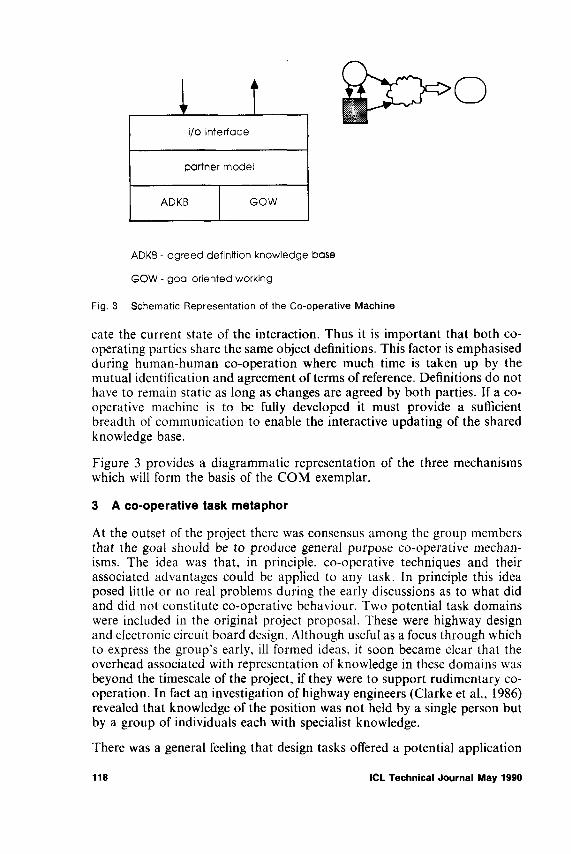
Fig. 3 Schematic Representation of the Co-operative Machine
ca te th e cu rren t s ta te o f th e in te r a c tio n . T h u s it is im p o r ta n t th a t b o th c o o p e r a tin g p a r tie s sh a re th e sa m e o b je c t d e f in it io n s . T h is fa c to r is e m p h a s ise d d u r in g h u m a n -h u m a n c o -o p e r a t io n w h e r e m u ch tim e is ta k e n u p b y th e m u tu a l id e n t if ic a t io n a n d a g r e e m e n t o f term s o f re feren ce . D e f in it io n s d o n o t h a v e to rem a in s ta t ic a s lo n g a s c h a n g e s are a g reed b y b o th p a r tie s . If a c o o p e r a tiv e m a c h in e is to b e fu lly d e v e lo p e d it m u st p r o v id e a su ffic ien t b rea d th o f c o m m u n ic a t io n to e n a b le th e in te r a c tiv e u p d a tin g o f th e sh a red k n o w le d g e b a se .
F ig u r e 3 p r o v id e s a d ia g r a m m a tic r e p r e se n ta tio n o f th e th ree m e c h a n ism s w h ich w ill form th e b a sis o f th e C O M ex em p la r .
3 A co-operative task metaphor
A t th e o u tse t o f th e p ro jec t th ere w a s c o n se n s u s a m o n g th e g r o u p m em b ers th a t th e g o a l sh o u ld be to p r o d u c e g en era l p u r p o se c o -o p e r a t iv e m e c h a n ism s. T h e id ea w a s th a t , in p r in c ip le , c o -o p e r a t iv e te c h n iq u e s a n d th eir a sso c ia te d a d v a n ta g e s c o u ld b e a p p lie d to a n y ta sk . In p r in c ip le th is id ea p o se d little o r n o real p r o b le m s d u r in g th e ea r ly d is c u s s io n s as to w h a t d id a n d d id n o t c o n s t itu te c o -o p e r a t iv e b e h a v io u r . T w o p o te n t ia l ta sk d o m a in s w ere in c lu d ed in th e o r ig in a l p ro jec t p r o p o sa l . T h e se w ere h ig h w a y d esig n a n d e le c tr o n ic c ircu it b o a rd d esig n . A lth o u g h u sefu l a s a fo c u s th r o u g h w h ich to ex p r e ss th e g r o u p ’s ea r ly , ill fo rm ed id ea s , it s o o n b e c a m e c lea r th a t the o v e r h e a d a s s o c ia te d w ith r e p r e se n ta tio n o f k n o w le d g e in th ese d o m a in s w a s b e y o n d th e t im e sc a le o f th e p ro jec t , i f th e y w ere to su p p o r t r u d im en ta ry c o o p e r a t io n . In fa c t a n in v e s t ig a t io n o f h ig h w a y e n g in e e r s (C la r k e e t a l., 1986) rev ea led th a t k n o w le d g e o f th e p o s it io n w a s n o t h e ld b y a s in g le p e r so n b u t b y a g r o u p o f in d iv id u a ls e a ch w ith sp e c ia lis t k n o w le d g e .
T h ere w a s a g e n e r a l fee lin g th a t d e s ig n ta sk s o ffered a p o te n t ia l a p p lic a tio n
118 ICL Technical Journal May 1990

fo r c o -o p e r a t iv e te c h n iq u e s . A s a resu lt sev era l p a p ers w ere p r o d u c e d (S h u tt le w o r th , 1988; S m y th , 1987 , 1988) w h ic h in v e s t ig a te d h o w d e s ig n e r s g o a b o u t g e n e r a tin g s o lu t io n s . In g e n e r a l, it w a s fo u n d th a t d e s ig n e r s are so lu t io n fo c u sse d , th a t is , th e y p o se te n ta tiv e s o lu t io n s to a p r o b le m a n d b y so d o in g lea rn a b o u t th e p r o b le m . T h r o u g h th is itera tiv e p r o c e ss o f a n a ly s is , sy n th e s is a n d e v a lu a t io n , th e d e s ig n c o n v e r g e s o n a sa t is fa c to r y so lu t io n .
A s th e p ro jec t p ro g r e sse d it b e c a m e c lea r th a t th e ea r ly a im s o f p r o d u c in g g e n e r a l c o -o p e r a t iv e te c h n iq u e s w ere im p ra c tic a l. T h ere w a s a p r e ss in g n eed fo r a n e a s ily u n d e r s to o d ta sk fa m ilia r to th e g r o u p , w h ic h c o u ld a c t a s a v e h ic le for d e ta ile d d is c u s s io n o f c o -o p e r a t iv e b e h a v io u r . A s a p r e lim in a ry to th e id e n t if ic a t io n o f su ch a ta sk d o m a in , a ser ies o f r eq u irem en ts w ere id en tified .
• th e ta sk sh o u ld b e r e c o g n ise d as ‘rea l w o r ld ’• th ere sh o u ld b e a fin ite v a r ie ty o f p o s s ib le s o lu t io n s , so as to e n a b le th e
p r o d u c t io n o f a lte r n a tiv e s b e tw e e n th e c o -o p e r a t iv e p a rties• ta sk g o a ls sh o u ld b e id e n tif ia b le a n d e x p r e ss ib le a t th e o u ts e t• e x p lic it ru les sh o u ld b e in v o lv e d in a rr iv in g a t s o lu t io n s• th e ta sk sh o u ld su p p o r t th e g e n e r a tio n o f p a r tia l s o lu t io n s• th e ta sk sh o u ld su p p o r t g ra p h ic b a se d in te r a c tio n
T h e p r o b le m d o m a in se le c te d w a s r o o m la y o u t d e s ig n , w h ich is o n e in s ta n c e o f sp a t ia l d e s ig n p r o b le m s.
T h e im p o r ta n c e o f th is d e c is io n s h o u ld n o t b e u n d e r sta te d a s it p r o v id e d a n a c h ie v a b le fo c u s fo r d is c u s s io n a n d th e e v e n tu a l im p le m e n ta t io n o f a c o o p e r a tiv e m a c h in e ex e m p la r . I t is s tr e sse d h ere th a t th e e v e n tu a l so ftw a re e x e m p la r w a s n e v e r se e n a s a p r a c tic a l r o o m la y o u t a p p lic a t io n , a s m a n y m o r e so p h is t ic a te d s o lu t io n s a lrea d y e x is te d . I t a im e d m ere ly t o u se th e a p p lic a t io n a s a n e x p r e s s io n o f th e th ree u n d e r ly in g m e c h a n ism s o f c o o p e r a tiv e b e h a v io u r ; r o o m d e s ig n a c te d a s a ta sk m e ta p h o r fo r c o -o p e r a t io n b e tw e e n h u m a n s a n d c o m p u te r s .
3.1 The design process - a vehicle for co-operative problem solving
It is c o m m o n ly fo u n d th a t h ig h lev e l d e s ig n g o a ls are ex p r e sse d in term s o f c o n s tr a in ts a n d req u irem en ts; th e y m a y b e a re su lt o f th e m e d iu m in w h ich d e s ig n e r s c h o o s e to w o r k , o r b e c a u se d b y c lie n t o r u ser re q u ir e m e n ts , o r f in a lly th e y m a y resu lt fro m th e ta sk itse lf. In d e e d d e s ig n c a n b e d e scr ib ed a s th e su c c e s s iv e a p p lic a t io n o f c o n s tr a in ts u n til a u n iq u e p r o d u c t is left. L a u rel (1 9 8 6 ) , s ta te s th a t , ra th er th a n re str ic tin g th e p r o c e ss o f d e s ig n , ‘c o n s tr a in ts p r o v id e th e se c u r ity n e t th a t e n a b le s p e o p le to m a k e im a g in a tiv e le a p s ’. T h e p o te n t ia l a d v a n ta g e s o f c o -o p e r a t iv e b e h a v io u r in th e d e s ig n p r o c e ss h a v e b een sh o w n b y sev era l resea rch ers . M id d le to n (1 9 6 7 ) o b se r v e d th a t te s t in g h y p o th e s e s b e n e fite d fro m g r o u p a c tiv ity ; h e s ta te d , ‘th e d is t in c t io n b e tw e e n o r ig in a l th o u g h t , w h ic h is a lo n e ly a c t iv ity , a n d th e te s t in g o f h y p o th e s e s , is a lo g ic a l p r o c e ss w h ere th e g r o u p c a n p a r tic ip a te w ith a d v a n ta g e ’. T h u s it
ICL Technical Journal May 1990 119

w o u ld a p p e a r th a t d e s ig n is id e a lly su ite d to b en efit from c o -o p e r a t iv e b e h a v io u r .
T h e n e x t q u e s t io n w a s , are th ere g e n e r a l ru les o f d e s ig n a n d in p a r ticu la r sp a t ia l la y o u t , w h ic h c o u ld b e in c o r p o r a te d w ith in th e p a rtn er m o d e l? S u ch ru les w o u ld fo rm th e m e c h a n ism w h e r e b y th e c o -o p e r a t iv e m a c h in e c o u ld g e n e r a te m e a n in g fu l a lte r n a tiv e so lu t io n s .
D e s ig n e r s are o fte n c o n fr o n te d w ith th e task o f c h o o s in g , fro m a m o n g se e m in g ly lim it le s s p o s s ib le a r r a n g e m e n ts , a n a e s th e tic a lly sa t is fy in g c o m p o s it io n o f o b je c ts in a g iv e n sp a c e . S o m e c h o o s e to rely o n th e in tu itiv e a p p lic a t io n o f th e ir sk ills . T u fte (1 9 8 3 ) p o in ts o u t , in referen ce to g r a p h ic d e s ig n , ‘th ere are n o c o m p o s it io n a l p r in c ip le s o n h o w to crea te th a t o n e g r a p h ic in a m ill io n ’. N o r are th ere a n y in o th e r fie ld s o f d e s ig n . N o n e th e le s s , so m e d e s ig n e r s c u t d o w n th e n u m b e r o f p o s s ib il it ie s in c o m p o s it io n a l ta sk s b y a p p ly in g ru les to g o v e r n th e p la c e m e n t o f o b je c ts in a few in it ia l sk e tc h e s . T h e y ca n th e n c h o o s e to e n fo r c e th e ru les m o r e o r le s s s tr ic tly , a p p ly further ru les a n d d e v e lo p c o m p o u n d e ffec ts , in r e sp o n se to th e re su ltin g c o m p o s it io n s . O n e fu n d a m e n ta l ru le o f c o m p o s it io n is to a rra n g e o b je c ts a lo n g lin es o f sy m m etry ; a n o th e r , th a t h a s b e e n a p p lie d for c e n tu r ie s , is th a t o f th e G o ld e n S e c tio n (H o lt , 1 9 7 1 ). R u le s o f th is n a tu r e w ere a g reed a s e s se n tia l to th e p a rtn er m o d e l if it w ere to c o -o p e r a te su c c e ss fu lly w ith th e d e s ig n er . S in ce th e ro le o f th e e x e m p la r w a s p a r a d ig m a tic an d c a lle d fo r o n ly a few a r c h e ty p a l ru les to il lu s tr a te th e p r in c ip le , it w a s n o t c o n s id e r e d a p p r o p r ia te to resea rch th e a rea e x h a u st iv e ly .
W ith th e a d o p t io n o f th e r o o m la y o u t a s a m e ta p h o r , it w a s c o n s id e r e d th a t th e r eq u irem en ts o f th e a g reed d e fin it io n k n o w le d g e b a se c o u ld b e m et b y in c lu d in g a su b se t o f g en er ic fu rn itu re o b je c ts to b e a c te d o n b y b o th g o a l d e fin it io n s a n d ru les w ith in th e p a rtn er m o d e l.
4 An exemplar of human/computer co-operation - room layout
A t th e o u ts e t o f th e im p le m e n ta t io n o f th is c o -o p e r a t iv e e x e m p la r , tw o sy stem d e s ig n d e c is io n s w ere m a d e ,
• w h en p o ss ib le to , p u t c o n tr o l o f th e in te r a c tio n in th e h a n d s o f th e user.
T h is refers sp e c if ic a lly to s ta g e s d u r in g th e in te r a c tio n req u ir in g ju d g e m e n ts , fo r e x a m p le , d e c id in g w h a t c o n f ig u r a t io n o f o b je c ts c o n s t itu te d a sa t is fa c to r y la y o u t .
• to m in im ise th e req u irem en t fo r e x p lic it b r o a d b a n d c o m m u n ic a t io n b e tw e e n th e u ser a n d th e m a c h in e , a n d t o in s te a d a d o p t a n im p lic it , g r a p h ic a lly b a se d , m e th o d o f c o m m u n ic a t io n .
T h e e x e m p la r w a s im p le m e n te d in C -P r o lo g m o u n te d o n a H e w le t t P a c k a r d w o r k s ta t io n a n d u se d a g e n e r a l p u r p o se e n v ir o n m e n t b u ilt b y th e A r c h ite c tu re S trea m o f th e H u m a n C o m p u te r C o -o p e r a t io n p ro jec t.
120 ICL Technical Journal May 1990
4.1 The interface
T h e p h ilo s o p h y a d o p te d b y th e g r o u p fo r th e e x e m p la r in ter fa ce e m p h a s ise d v isu a l r e p r e se n ta tio n o f ta sk in fo r m a tio n . O b s e r v a t io n o f tw o h u m a n d e s ig n e r s c o -o p e r a t in g d u r in g a c o m p le x p r o b le m s o lv in g ta sk in d ic a te d a r e q u irem en t fo r tw o d e d ic a te d g r a p h ic a l w in d o w s , w h ic h rep resen ted a v iew o f th e f lo o r p la n o f b o th th e u ser a n d th e p a r tn e r r e sp e c tiv e ly . T h is s im p le d e c is io n o v e r c a m e th e p r o b le m o f p r e se n t in g a lte r n a tiv e s o lu t io n s to th e u ser , w h ile n o t c a u s in g a d is tr a c tio n fr o m th e cu rren t ta sk . O th e r u ser a c t io n s , su c h a s th e c o n s tr u c t io n o f g o a ls , th e p r io r it isa t io n o f th e p a rtn er m o d e l ru le b a se a n d th e c r e a tio n o f o b je c ts w ere c a tered fo r b y se le c t io n o f a p p r o p r ia te so ftw a r e b u tto n s .
T h e e x e m p la r h a s tw o m o d e s o f o p e r a t io n , s o lv e a n d in te r a c tiv e . In th e so lv e m o d e th e p a r tn er m o d e l w ill im m e d ia te ly g e n e r a te a n a lte r n a tiv e so lu t io n b a se d o n th e cu rren t a c t iv e g o a ls a n d th e lo c a t io n o f o b je c ts in th e u se r ’s s o lu t io n . T h e so lv e m o d e w a s p r im a rily u se d d u r in g so ftw a r e d e v e lo p m e n t a n d w a s n e v e r c o n s id e r e d to b e c en tra l to th e d e v e lo p m e n t o f th e c o o p e r a tiv e r e la t io n sh ip . W h e r e a s in th e in te r a c tiv e m o d e th e p a r tn er m o d e l is c o n tr o lle d b y th e u ser ’s c h o ic e o f o b je c t lo c a t io n s , a m e th o d th o u g h t to ch a r a c te r ise , a lb e it a t a s im p lis t ic le v e l, th e e q u iv a le n t r e la t io n sh ip in h u m a n - h u m a n c o -o p e r a t io n .
4.2 The agreed definition knowledge base
T h e r o o m d e s ig n m e ta p h o r c o n ta in e d a d e lib e r a te ly c o n s tr a in e d , h a n d cra fted , o b je c t se t w h ic h w a s p resen ted v isu a lly to th e u ser th r o u g h o u t th e in te r a c tio n . S e le c t io n o f a n o b je c t ty p e c a u se d th e c r e a tio n o f an in s ta n c e o f th a t o b je c t to b e p la c e d in th e in v e n to r y . T h e u ser w a s th e n a t lib er ty to in c o r p o r a te th a t o b je c t in s ta n c e in a g o a l c o n s tr u c t o r s im p ly p la c e a g ra p h ic o f th e o b je c t in th e u ser w in d o w a t th e d esired lo c a t io n . B o th th e u ser an d p a r tn er w in d o w s rep resen t a n o t io n a l f lo o r p la n . A s o b je c ts are lo c a te d in th e u ser w in d o w th e p a r tn er m o d e l g en e r a te s a lte r n a tiv e p o s it io n s b a se d o n its ru les a n d d isp la y s its o p t io n in th e p a r tn er w in d o w . T h r o u g h o u t th is p r o c e ss p a ra lle l a g reed d e fin it io n k n o w le d g e b a se s are c o n t in u a lly u p d a te d a s th e u ser an d p a r tn er g e n e r a te a lte r n a tiv e s o f th e a v a ila b le o b je c ts . T h e sta n d a rd o b je c t d a ta stru ctu re is a s fo l lo w s ,
object) < user/partner>,object-type (object-instance), location,< permanent/moveable > ).
T ra n sfer o f d a ta fro m th e d a ta b a s e s w a s a t th e d is c r e t io n o f th e u ser , w h o c o u ld e ith er freeze o b je c ts in th e u se r ’s w in d o w , th ereb y d isa b lin g th e effect o f th e p a r tn er m o d e l, o r tra n sfer o b je c t c o n fig u r a tio n s g en e r a te d b y th e p a rtn er m o d e l to b e in c o r p o r a te d in th e u ser so lu t io n . It w a s fe lt th a t b o th th e se te c h n iq u e s re sem b le th o s e o b se r v e d in h u m a n -h u m a n c o -o p e r a t iv e b e h a v io u r .
ICL Technical Journal May 1990 121

4.3 Goal oriented working
A so ftw a re te c h n iq u e d e v e lo p e d w ith in th e A r ch itec tu re S trea m o f th e H C C p ro jec t, w h ic h w a s u sed e x te n s iv e ly th r o u g h o u t th e p ro jec t, p r o v id e d the e n a b lin g te c h n o lo g y for th e r e p r e se n ta tio n o f g o a l o r ie n te d w o r k in g in the ex em p la r . It e n a b le d th e u ser to c o n s tr u c t sp a tia l r e la t io n sh ip s b e tw een o b je c ts w h ic h w ere th e n tr a n s la te d in to th e P r o lo g ru le b a se w h ic h e n a b le d th e p a r tn er m o d e l to m a n ip u la te th em . T h e p r o v is io n o f a m e th o d w h ereb y th e u ser w a s a b le to c o n s tr u c t g o a ls v isu a lly w a s cen tra l to th e d e v e lo p m e n t o f th e so ftw a re ex em p la r .
A r e p resen ta tiv e n u m b er o f sp a tia l r e la t io n sh ip s w ere h a n d cra fted in th e sy s te m , a n d users w ere a b le to c o n s tr u c t a n d d e le te g o a ls as req u ired d u r in g th e in te r a c tio n . T h e r e la t io n sh ip s w ere o b je c t se n s it iv e , for e x a m p le th e c o n c e p t o f n ea rn ess is q u a n tita t iv e ly d ifferen t w h en a p p lied to a d e sk /w a ll c o m b in a t io n th a n to a d e sk /c h a ir c o m b in a t io n .
T h e g o a l o r ie n te d w o r k in g m e c h a n ism a ls o in c lu d ed s im p le error c h e c k in g w h ich a ler ted th e u ser to p o ss ib le so u r c e s o f g o a l c o n flic t . O n c e th e g o a l list h a s b een crea ted th e so ftw a re c a lc u la te s th e o rd er in w h ich to p la c e th e o b jec ts . If, for e x a m p le , th e fo l lo w in g g o a ls w ere crea ted ,
p h o n e o n d esk d esk n ea r w a ll
th e d esk w o u ld h a v e to be p o s it io n e d first b e fo re th e in it ia l g o a l c o u ld be sa tisf ied . I f g o a l fu lfilm en t w a s d e e m e d to b e o b je c t in d e p e n d e n t th e o rd er o f c r e a tio n w a s th e d e c id in g fa c to r . E x a m p le s o f u ser c o n s tr u c te d g o a ls a re asfo llo w s ,
c a b in e t 1 n ea r w a ll2b o o k c a s e 1 n ea r w a ll3b o o k c a s e 1 n ea r w a ll4d e sk ! n ea r w in d o w 1c h a ir 1 in - fr o n t-o f d e s k lch a ir2 in - fr o n t-o f d e sk 2
4.4 The partner model
T h e p a r tn er m o d e l c o n s is ts o f a su b se t o f d e s ig n k n o w le d g e c o n c e r n e d w ith th e p r o p o r t io n a lity o f o b je c ts w ith in a fin ite sp a c e , in th is c a se th e lo c a t io n o f fu rn itu re w ith in a r o o m . E x a m p le s o f th e ru les in th e p a r tn er m o d e l in c lu d e , sy m m e tr y , g o ld e n se c t io n a n d sa fe ty , th e la tte r b e in g c h o se n a s it reflected a d ifferen t s ty le o f ru le . T h e sa fe ty ru le c a u se d a n a c c e ss ro u te fro m th e w in d o w to th e d o o r a lw a y s to b e left c lea r . A t e a c h s ta g e in th e u ser ’s d e v e lo p m e n t o f a s o lu t io n th e p a rtn er m o d e l c a n in te r r o g a te th e re su ltin g o b je c t c o n fig u r a t io n a n d a p p ly its ru les th ereb y g e n e r a tin g , w ith in a n u m b e r o f u ser d e fin ed g o a ls , a n a lte r n a tiv e c o m p o s it io n o f th e o b je c ts b a sed o n th e u ser ’s so lu t io n .
122 ICL Technical Journal May 1990

T h e d e s ig n s o lu t io n g e n e r a te d b y th e p a r tn er m o d e l is n e ith e r r ig h t n o r w r o n g , b u t is a v ia b le , a lte r n a tiv e c o n f ig u r a t io n o f th e u se r ’s o b je c ts d e v e lo p e d u s in g a se t o f ru les d ifferen t fro m th a t o f th e u ser a n d its a im is to a c t a s a sp u r to th e u ser ’s im a g in a t io n . In c o r p o r a te d in th e p a r tn er m o d e l’s s o lu t io n s tr a te g y is a m e c h a n ism fo r id e n t ify in g a n d re jec tin g a lte r n a te s o lu t io n s w h ic h b reak fu n d a m e n ta l c o n s tr a in ts im p lic it in th e ta sk d o m a in . F o r e x a m p le , o b je c ts m u st rem a in w ith in th e b o u n d s o f th e r o o m a n d m u st n o t o c c u p y th e sa m e sp a c e .
T h e u ser c o u ld a lter th e o r d e r in w h ic h th e p a r tn er m o d e l ru les w ere a p p lie d . T h is e n a b le d th e u ser to v iew a n u m b e r o f a lte r n a tiv e o b je c t c o n fig u r a tio n s e a c h g e n e r a te d b y a p a r tn er m o d e l w ith a d ifferen t e m p h a s is o r s ty le . D iv is io n o f la b o u r w a s th u s p la c e d in th e h a n d s o f th e u ser s o , fo r in s ta n c e , th e u ser c o u ld in d ic a te th a t h e w ish e d th e p a r tn er m o d e l t o p la c e a h ig h p r io r ity o n sa fe ty , s o le a v in g h im se lf free to p a y m o r e a tte n t io n to th e s ty lis t ic d e ta ils o f th e s o lu t io n .
4.5 Role of the software in the development cycle
T h e d e v e lo p m e n t o f th e e x e m p la r w a s o f g rea t b e n e fit to th e g r o u p ’s w o rk a s it p r o v id e d a ta n g ib le d e m o n s tr a t io n w h ic h led to m a n y fru itfu l d is c u s s io n s a n d id e a s w h ic h c o u ld la ter b e in c o r p o r a te d in th e so ftw a r e . T o w a r d th e en d o f th e p ro jec t tw o fin a l y e a r d e s ig n s tu d e n ts p e r fo r m e d a n in fo rm a l e v a lu a t io n a n d th e ir c o m m e n ts w ere b o th v a lu a b le a n d e n lig h te n in g .
A lth o u g h a t a ru d im e n ta r y s ta g e in d e v e lo p m e n t , th e e x p e r ie n c e s g a in e d d u r in g th e p r o c e ss o n ly serv ed to c o n fir m th e g r o u p b e lie f in th e p o te n t ia l o f c o -o p e r a t iv e c o m p u tin g .
5 Conclusions
T h e p r im a ry o b je c t iv e s o f th e w o rk d e scr ib ed in th is p a p er w ere ,
• th e id e n t if ic a t io n o f th e m e c h a n ism s c en tra l to th e d e s ig n o f c o -o p e r a t iv e m a c h in e s
• th e e x e m p lif ic a t io n o f th e se m e c h a n ism s in so ftw a re
5.1 Conclusions from software development
T h e d eg ree o f c o -o p e r a t io n a c h ie v e d b y th e m a c h in e w ill b e d e te r m in e d b y in te r a c tio n b e tw e e n th e u n d e r ly in g m e c h a n ism s , n o t b y th e ir in d iv id u a l a c t io n s . H o w th is r e su ltin g m a c h in e b e h a v io u r w ill b e m a n ife s t to th e u ser w ill b e d e p e n d e n t o n th e in ter fa ce . In th e c o n te x t o f th e r o o m d e s ig n m e ta p h o r a n u m b er o f in ter fa ce r eq u irem en ts w ere id e n tif ie d . A d o p t in g th e p h ilo s o p h y o f v is u a lisa t io n o f k n o w le d g e , th e in ter fa ce sh o u ld e n a b le th e u ser firstly , to d e fin e ta sk o b je c ts a n d se c o n d ly , to su p p o r t th e in te r a c tiv e d e fin it io n o f g o a l r e la t io n sh ip s . In sh o r t , th e in ter fa ce o f a c o -o p e r a t iv e m a c h in e s h o u ld e n a b le th e u ser to e n h a n c e th e a g reed d e fin it io n k n o w le d g e
ICL Technical Journal May 1990 123

base and, thereby, more directly focus the process of generating alternative solutions and so increase the degree of co-operation perceived by the user.
• end user manipulation of the data shared with the partner is a technique central to the development of co-operative machines.
5.1.1 The partner model Adopting the technique of modelling a cooperative partner in the machine allowed an important conclusion to be drawn, namely,
• to be able to produce alternative solutions, the partner model rule base must remain autonomous from the user if the co-operative machine is to avoid the pitfall of simply mimicking solutions generated by that user.
Adherence to the above point raises some interesting issues about the nature of modelling partners in single user co-operative machines. Co-operation between humans is a dynamic relationship, as it is assumed that both parties are learning/reinforcing the concepts being expressed by their partner during the interaction. Over a sufficient time period it is foreseeable that the cooperative relationship could become static, as, without the introduction of new sources of information, a commonality of views might arise between partners so reducing the effectiveness and, ultimately the creative potential of the relationship. In human-human co-operation additional information can come from a multitude of sources as reflected, for example, in the background, education and personal preferences of the individuals. On the other hand the current machine model of the co-operative partner is static. A single-user system does not provide an alternative source of information necessary for the partner model to develop during the interaction, and the use of information gleaned from the user during interaction, as in dynamic, embedded-user models, would reduce the difference between partners and remove a plank vital to the co-operative relationship. In short, the ability of the human partner to learn during a co-operative interaction ensures a limited period of usefulness for a static partner model in a single-user system. As the user becomes aware of the partner model rule set, the machine generated alternatives become predictable and no longer a spur to the user’s imagination.
In the context of human computer co-operation a partner model is proposed as a technique to represent the essential difference between the user and the machine necessary to realise some of the dynamic qualities of co-opertive problem solving.
5.2 General conclusions
The work undertaken in this project has highlighted several important issues felt to be central to the development of future co-operative machines.
124 ICL Technical Journal May 1990

• the depth of knowledge required to support co-operative working suggests that the technique is domain specific
• what constitutes co-operation varies between tasks. The existing problem solving process adopted by human partners must be clearly identified before attempting to build a co-operative machine
• the mechanisms of Goal Oriented Working, the Partner Model and an Agreed Definition Knowledge Base, as described in this paper, provide an outline architecture for co-operative machines
• it is the interaction of these software mechanisms and how the resulting behaviour is manifested to the user, via the interface, that will determine the extent of machine co-operation perceived by the user.
The issues raised during this project are central to the development of computer systems which aim to actively participate with the user during complex problem solving and as such provide a platform for future research work.
6 Acknowledgements
The work described was funded by the Alvey programme MMI, HumanComputer Co-operation (MMI/062). Thanks are due to our colleagues at theLUTCHI Research Centre, in particular, Steve Bell, Mark Buckley, TomBayley, Andrée Woodcock with Mark Shuttleworth from ICL.
7 References
BLAKE, R.R. and MOUTON, J.S. (1962) The inter group dynamics of win-lose conflict and problem solving collaboration in union management relations, in M. Sherif (ed.), Intergroup Relations and Leadership, Wiley, NY.
BLAKE, R.R., SHEPARD, H.A. and MOUTON, J.S. (1964) Managing inter group conflict in industry. Houston: Gulf.
BROADBENT, G. (1973) Design in Architecture, John Wiley & Sons, London.CARD, S.K., MORAN, T.P. and NEWELL, A. (1983) The Psychology of Human Computer
Interaction, Lawrence Erlbaum Associates, Hillsdale, NJ.CARD, S.K., MORAN, T.P. and NEWELL, A. (1980) The Keystroke-Level Model for User
Performance Time with Interactive Systems, Communications of the ACM, Vol 23 No 7, 396-410.
CLARKE, A.A., WOODCOCK, A. and McDAID, E. (1986) The Highway Engineer; a Typical User? HCC Internal Report HCC/L/9, Loughborough University of Technology, UK.
CLARKE, A.A. (1986) A three-level human-computer interface model, Int Jour Man-Machine Studies, 24, 503-17.
DAVIS, J.H. (1969) Group Performance, Addison-Wesley.DEUTSCH, M. (1949) A Theory of Co-operation and Competition, Human Relations, 2,
129-152.DEUTSCH, M. (1949) An experimental study of the effects of co-operation and competition
upon group processes, Human Relations, 2, 199-231.DEUTSCH, M. (1968) The effects of co-operation and competition upon group processes. In D.
Cartwright and A. Zander (eds), Group Dynamics, Harper and Row, New York.DEUTSCH, M. and KRAUSS, R.M. (1960) The effect of threat on interpersonal bargaining,
Jour of Abnormal and Social Psychology, 61, 181-9.
ICL Technical Journal May 1990 125

FEYERABEND, P. (1965) Consolations for the Specialist. In I. Lakatos and A. Musgrave (eds), Criticism and the Growth of Knowledge, Cambridge University Press.
FOLEY, J.D. and van DAM, A. (1982) Fundamentals of Interactive Computer Graphics, Prentice-Hall, Englewood Cliffs, NJ.
GAINES, B.R. (1981) The technology of interaction - dialogue programming rules. Int Jour Man-Machine Studies, 14, 133.
GORDON, W.J.J. (1961) Syndics, the development of creative capacity. Harper & Row, New York, Evanston, London.
GRICE, H.P. (1975) Logic and Conversation, in Cole, P. & Morgan, J.L. (eds) Syntax and Semantics, Vol .3 ‘Speech Acts’, Academic Press, London.
HOLT, M. (1971) Mathematics in Art, Studio Vista, London.HUSBAND, R.W. (1940) Co-operation versus solitary problem solution, Jour of Soc Psychol
ogy, 11, 405-9.JONES, J.C. (1970) Design Methods: seeds of human features. John Willey, N.Y.KELLEY, H.H. and STAHELSKI, A.J. (1970) Social interaction basis of co-operators’ and
competitors’ beliefs about others, Jour of Personality and Social Psychology, 16, 66-91.LAUGHLIN, P.R., McGLYNN, R.P., ANDERSON, J.A. and JACOBSON, E.S. (1968)
Concept attainment by individuals versus co-operative pairs as a function of memory, sex and concept rule, Journal of Personality and Social Psychology, 8, 410-7.
LAUREL, B.K. (1986) Interface as Mimesis, in Norman, D.A. and Draper, S.W. (eds) User Centered System Design: A New Perspective on Human-Computer Interaction, Lawrence Erlbaum Assoc, Hillsdale, NJ.
MIDDLETON, J. (1967) Group Practice in Design, London.MORAN, T.P. (1981) The Command Language Grammar: A representation for the user
interface of interactive computer systems, Int Jour Man-Machine Studies, 15, 3-50.MURRAY, D. and BEVAN, N. (1984) The Social Psychology of Computer Conversations,
Interact'84, 268-73.NIELSEN, J. (1984) A virtual protocol model for computer-human interaction, DAIMI PB-
178, Aarhus University: Computer Science Dept.NORMAN. D.A. and DRAPER, S.W. (1986) User Centered System Design: A New Perspective
on Human-Computer Interaction, Lawrence Erlbaum Assoc, Hillsdale, NJ.OBERQUELLE, H., KUPKA, 1., MAASS, S. (1983) A view of human-computer communica
tion and co-operation, International Journal of Man-Machine Studies, 19, 309—Ü3.OBERQUELLE, H. (1984) On models and modelling in human-computer co-operation. In G
Van der Veer et al (eds) Reading in Cognitive Ergonomics, Springer Verlag.OSBORN, A.F. (1953) Applied imagination, Charles Scribner’s Sons, New York.PAYNE, S.J. and GREEN, T.R.G. (1986) Task Action Grammars: A Model of the Mental
Representation of Task Languages, Human Computer Interaction 2, 93 133.SHERIF, M. and SHERIF, C.W. (1953) Groups in Harmony and Tension, Harper, NY.SHNEIDERMAN, B. (1987) Designing the User Interface: Strategies for Effective Human-
Computer Interaction, Addison-Wesley Publishing Co.SHURE, G.H., MEEKER, L.J. and HANSFORD, E.A. (1965) The effectiveness of pacifist
strategies in bargaining games, Jour of Conflict Resolution, 9, 106-117.SHUTTLEWORTH, M. (1988) Office Layout: A user/task analysis, HCC Internal Report
HCC/1/25. Loughborough University of Technology, UK.SIMON, T. (1988) Analysing the Scope of Cognitive Models in HCI - A trade-off approach.
Proceedings of HCI’88, Cambridge University Press.SMITH, S.L. and MOSIER, J.N. (1984) Design Guidelines for the User Interface for Computer-
Based Information Systems, The MITRE Corp, Bedford, Mass.SMYTH, M. (1987) Toward a Co-operative Design System, HCC Internal Report HCC/L/20,
Loughborough University of Technology, UK.SMYTH, M. (1988) Articulating the Designers Mental Codes. HCC Internal Report HCC/L/24,
Loughborough University of Technology, UK.SRINIVASAN, C.A. and DASCHER, P.E. (1977) Information systems design: user psychology
considerations, MSU Business Topics, 25, 51.THORNDIKE, R.L. (1938) The effects of discussion upon the correctness of group decisions
when the factor of majority influence is allowed for, Jour Soc Psychology, 9, 343-62.TUFTE, E.R. (1983) The Visual Display of Quantitative Information, Graphic Press, Connecti
cut.
126 ICL Technical Journal May 1990

Regulatory Requirements for Security - User Access Control
C. W. Blatchford
Abstract
The Legal profession are divided on what constitutes a computer crime. In particular hacking, the gaining of unauthorised access to a computer is currently not contrary to criminal law in the UK,
Legislation is likely to be drafted for tabling at the next session of parliament.
Whatever the relevance of such legislation in controlling the spread of hacking, successful policing must be paralleled by changes to the way in which information systems are architected and implemented.
This article explores the current architectural problems, both administrative and technical, that need to be solved if computer security legislation is to be meaningful.
This may have a fundamental impact on the way in which Systems planners and engineers view the fitness for use of computer solutions.
Introduction
The Global Telecommunications Village! A hackneyed yet apt description of the society that could be created from the implementation of the various information technology telecommunications and broadcast services (ITT & BB) now being developed.
Anybody who has ever lived in a village, especially in the Celtic fringe of Europe, will realise that village life has its limitations. Paramount is the obstrusive nature of much of human relationships, the lack of personal privacy, the rumours, the half truths, the innuendo’s, the witchhunts. Information confidentiality and integrity are at a low premium.
Our Global Telecommunications Village may suffer from similar problems, compounded by the sheer volume and speed of communication. Misinformation could become fact in a few seconds!
ICL Technical Journal May 1990 127

There are two major ways of externally enforcing controls on any group of people
• by legislation & regulatory controls• by reducing the technical opportunity for adverse conditions. (In releas
ing, falsifying or destroying information.)
It is essential to have a balanced mixture to complement the basic human administration and relationships in society. Many of these controls are directed at the user interfacing with the information system in an authorised and correct manner.
Legislation/Regulation
There is a limited UK regulatory framework in which to place the access control requirements to electronic information systems.
In simple terms however many basic principles about respect for the property and privacy of others are covered in legislation although the offences may be civil not criminal and hence carry very little deterrent value.
There are some possible analogies with “trespass”, “theft”, breaking and entering and the traditional “property” offences but these are usually unsatisfactory and not well suited to the high technology issues that are being confronted in a computer literate world.
The most difficult situation is with “hackers”, people attempting to obtain unauthorised access to computer systems - who apparently do no more than browse the information system without any obvious attempt to cause obstruction, damage etc.
In the UK, like many countries, the legal profession are divided on what can constitute a crime in respect of hacking. The House of Lords decision on Regina v. Gold and Chifreen (1988), in effect, implied that just gaining unauthorised access to a computer is not contrary to criminal law. The Law Commission Working Paper No. 110 Computer Misuse (1989), generated a flurry of analysis into the legislative problems of unauthorised computer access and use, and the difficulty of defining and implementing controls.
Although there is a general consensus that an all embracing statute on computer crime is not appropriate, there have been calls from organisations such as CBI, ICA to make hacking (for whatever purpose) a crime in the UK.
ICL has been considering this problem for some time and has commented on the Law Commission’s Working Paper. It agrees that there should be an offence of hacking, however this should be based on the purpose of protecting the integrity of the computer systems and not related to some intrinsic property of value of the information being processed.
128 ICL Technical Journal May 1990

The system must utilise a recognised device or coding system designed to prevent unauthorised use of the computer. This would avoid the drafting of legislation that would be too wide to be effective. The concept of a barrier to access/cross in a computer system is fundamental to good information systems design.
ICL has come to the conclusion that a criminal offence of unlawful and unauthorised access to a computer system should be created, and that such illegal access should be penalised by an appropriate fine and/or imprisonment.
The revised Law Commission report on Computer Misuse embodying various inputs, including those of ICL has been published. It went via the Lord Chancellor to the House of Lords in late 1989, the aim being to approve legislation in the 1989/1990 session of Parliament. H. Colvin MP is to raise a Private Member’s Bill on the subject early in 1990.
The Law Commission has recommended the creation of three new offences
(i) Simple unauthorised access, punishable with a maximum of three months imprisonment or a fine
(ii) Unauthorised access, with the intent to commit or facilitate the commission of a serious crime punishable with a maximum penalty of five years imprisonment
(iii) Unauthorised modification of computer material punishable with a maximum penalty of up to five years imprisonment.
They have not addressed electronic eavesdropping or made changes to the Theft Act dealing with machine deception or made provisions governing the admissibility of computer evidence.
Users and vendors of information products/services alike are now facing a dilemma - How to improve the administrative and technical robustness of their solutions yet still maintain implementation momentum on a substantial information systems investment. The new Legislation may spawn a regulatory control framework that could demand changes to the way in which people interact with computer systems, access privileges are assigned and events are recorded and analysed (to use as evidence in criminal or civil court).
Good control to support legislation may add a substantial operational overhead in a distributed information system. This may be administrative as in human actions or technical as in the classes and types of hardware/software control devices to be applied (e.g. high speed Audit servers, Biometric authentication devices etc).
ICL has been considering the information security implications in a number of ways - from the overall architecture of information systems to specific components to support future regulatory frameworks.
ICL Technical Journal May 1990 129

This article is a preliminary review of the issues Strategic ‘generic’ solutions to these problems will be fed into the product/service development cycle to ensure that ICL users can implement detailed control procedures.
Information Systems Architecture
Any generic design of access controls to secure I.T. products must consider the overall architectural direction of information systems. The strategy for ‘computer’ security must consider the increasing demands by society for systems to be simple to design, develop and use, as well as administered in a cost effective robust manner.
Security control barriers must recognise the needs of ‘user friendly’ Human Computer/Man Machine interfaces (HCI) and speedy, responsive connection to distributed information services Service Connection Management (SCM). An understanding of the architectural integration may give some valuable insight into the controls that could be put in to achieve adequate protection and how these might be able to support and reinforce the policing of systems, both for conformity with corporate security policy and for adherence to legislation concerning misuse of computers.
Any Legislation in enforcement must recognise difficulties in defining what constitutes a computer. It is increasingly an arbitrary set of packaged services necessary to support the processing/storage needs of an information system. It may be considered as one or more physical and logical objects within the prime management responsibility (domain) of an individual function, department or enterprise. The services offered by the ‘computer’ may be physically/logically discrete or be distributed around a worldwide enterprise. The computer may be housed in a portable token - the Smart-VLSI chip card - or may be a fixed unit embraced in a single building or site.
The Management of Security
An information system can consist of single or multiple management domains each with their own security policies over what constitutes authorised use.
The boundary between domains may go through one or more computers with/without human intervention. The level of computer functionality may range from a full, comprehensive end user computer to a single telecommunication switch.
The boundary of the domain is recognised in any access authorisation decisions; this may not always coincide in the context of human computer interface with any specific computing device.
Each management domain has a security policy. This applies to the domain contents, the use of the contents and the style in which the contents operate.
130 ICL Technical Journal May 1390

Fig. 1 Domain Control (logical
The formality and obstrusiveness of the policy is decided by (or on behalf of) the prime authority for that domain.
The Security Policy
The security policy may be considered as constituting three elements between the user and the information system (3 ‘A’s) - Authentication (includes identification), Authorisation and Audit (both accountability and analysis).
The emphasis of how control is to be applied will vary by management domain and will require a balance of the 3 ‘A’s to a lesser or greater extent. Some commercial user friendly systems will emphasise minimal authentication and authorisation but robust/tamperproof audit, others as in defence/- central government will dictate fundamental enforcement of access control/authorisation rules. Some domains will be publicly available and service suppliers will demand identification for subsequent charging of services (e.g. broadcast media, information bulletins, library services etc).
Any practical enforcement of legislation must recognise the boundary of the information system domain, and how far the 3 ‘A’s of the security policy can be maintained at what level of attack. This would constitute the level of trust that any enterprise can have in its information systems.
The 3 ‘A’s may be supported by physical/logical servers that can reside in different domains, the access control rules being applied not just between the information system (I.S.) domain and the user but between the I.S. domains themselves.
ICL Technical Journal May 1990 131
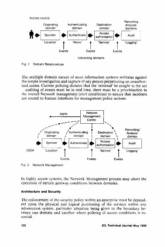
Fig. 2 Domain Relationships
The multiple domain nature of most information systems militates against the simple investigation and capture of any person perpetrating an unauthorised access. Current policing dictates that the ‘criminal’ be caught in the act - auditing of events must be in real time, there must be a prioritisation in the overall Network management (alert conditions) to ensure that incidents are routed to human interfaces for management/police actions.
Fig. 3 Network Management
In highly secure systems, the Network Management process may abort the operation of certain gateway conditions between domains.
Architecture and Security
The enforcement of the security policy within an enterprise must be dependent upon the physical and logical positioning of the services within any information system, particular attention being given to the boundary between one domain and another where policing of access conditions is essential.
132 ICL Technical Journal May 1990
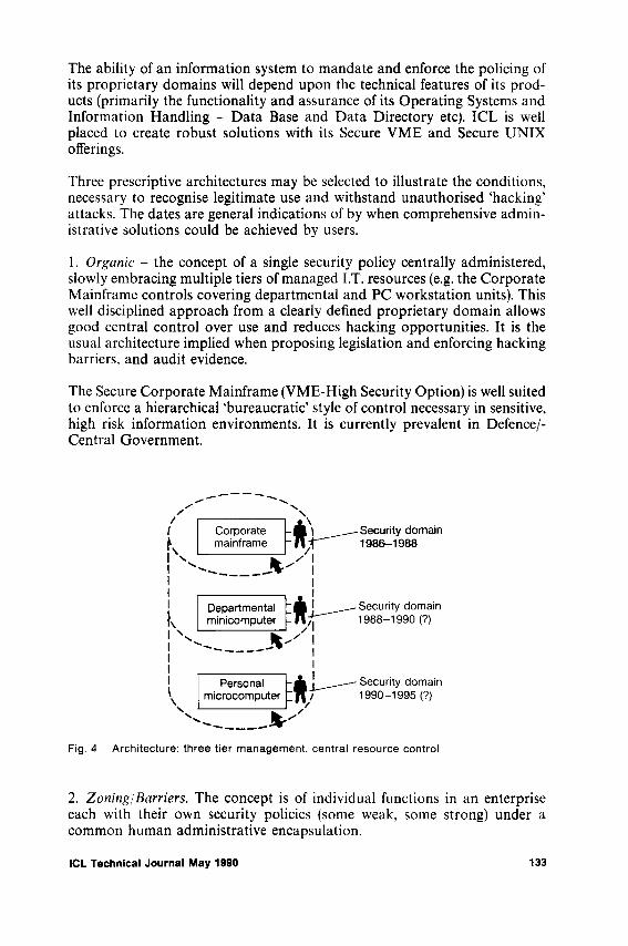
The ability of an information system to mandate and enforce the policing of its proprietary domains will depend upon the technical features of its products (primarily the functionality and assurance of its Operating Systems and Information Handling - Data Base and Data Directory etc). ICL is well placed to create robust solutions with its Secure VME and Secure U N I X offerings.
Three prescriptive architectures may be selected to illustrate the conditions, necessary to recognise legitimate use and withstand unauthorised ‘hacking’ attacks. The dates are general indications of by when comprehensive administrative solutions could be achieved by users.
1. Organic - the concept of a single security policy centrally administered, slowly embracing multiple tiers of managed I.T. resources (e.g. the Corporate Mainframe controls covering departmental and PC workstation units). This well disciplined approach from a clearly defined proprietary domain allows good central control over use and reduces hacking opportunities. It is the usual architecture implied when proposing legislation and enforcing hacking barriers, and audit evidence.
The Secure Corporate Mainframe (VME-High Security Option) is well suited to enforce a hierarchical ‘bureaucratic’ style of control necessary in sensitive, high risk information environments. It is currently prevalent in Defence/- Central Government.
/-rI Corporate tk 1____ — S e c u rity d o m a in ̂ mainframe “ I » 1! 1986=1988
I II I1 ------- , 1| Departmental : ■ Security domainf, minicomputer -11 /7- 1988-1990 (?)
! ______ \! ___________I Personal , Security domainV microcomputer “W / 1990-1995 (7)\ ___________ V
^ _______Fig, 4 Architecture: three tier management, central resource control
2. Zoning/Barriers. The concept is of individual functions in an enterprise each with their own security policies (some weak, some strong) under a common human administrative encapsulation.
ICL Technical Journal May 1990 133
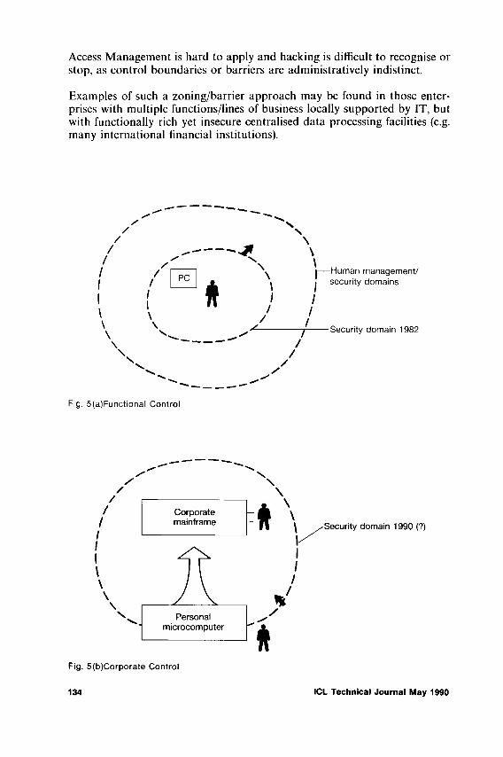
Access Management is hard to apply and hacking is difficult to recognise or stop, as control boundaries or barriers are administratively indistinct.
Examples of such a zoning/barrier approach may be found in those enterprises with multiple functions/lines of business locally supported by IT, but with functionally rich yet insecure centralised data processing facilities (e.g. many international financial institutions).
Fig. 5(a)Functional Control
Fig. 5(b)Corporate Control
134 ICL Technical Journal May 1990

3. Bonding. The example taken is of a third party service supplier (e.g. PTT or added value Network Service - INS, SWIFT etc.) offering a security service embracing the external interfacing to, and communication between, two or more enterprises.
Many enterprises are small, physically diverse and/or highly dependent upon externally supplied I.T. operational services. These may consider that existing security policy, especially in the short term, is adequately enforced at the human administrative level and that disjoints in any I.T. controls are not considered to result in vulnerabilities against the perceived threats. The risk is usually in how the enterprises interface with each other over communication networks. Trusted, supportive services based on these external links may be an adequate response. The security policy of the user enterprise will reflect the current evolution of the externally available ‘bonding’ services.
Many of the earlier demands for legislation on unauthorised access and usage of information services have come from such service providers, who may lose substantial revenue as well as service credibility from external attacks.
In parallel they have been instrumental in developing the key components of secure interworking (reference the Open Systems effort in X.500 Directory and X.400 Message handling/mail services).
The boundaries between domains can be defined in commercial as well as technical terms, and are thus well defined. Policing to ensure only authorised use between domains will require robust gatewaying processes at a high level of operational assurance.
Fig. 6 Single tier management, network control
ICL Technical Journal May 1990 ' 135

The typical larger enterprise will include examples of all three directions in the development and support of comprehensive security policies. Any convergence of the three approaches will result in a blurring of the control boundaries especially with the desired increase for publicly available services in the content of a more open society. Increasingly the information systems in any enterprise will lack strictly enforceable control boundaries unless rigorously enforced by corporate management.
Enforcing Access Control
Much of the debate surrounding the development of adequate legislation in the UK to counteract ‘hacking’ has revolved around the term ‘unauthorised’. This implies that what is authorised or unauthorised at the boundary of any information systems domain is known to the user. This may not always be true. Poor human and/or system administration may compound the problem.
The information system may dynamically allocate access authorities to any potential user to do things (privileges) depending upon a series of both end- user and systems contextual issues (the identification, quality of authentication, the work station, the time of day). These may not be notified to the user in that role. In addition, every user of any information system may have privileges not known to him/her that he will only find out about when services are requested.
The problem may be analysed under the 3 ‘A’s.
(a) Authentication
This must be considered to be more than just proving the identity of an individual human identity. It must be performed taking account of the organisation of society as a whole and of the specific enterprise concerned. Thus authentication must decide, for instance, between such alternatives as the following:
actual human actions and adventitious effects on the system due to natural causes or equipment failure, the identities of different individuals,the different roles the same person may play interacting with a system, where each role may carry different privileges and responsibilities, and
- the specific tasks an individual may be assigned either permanently or temporarily to achieve the objectives of that role.
Such checking can be compound as in recognition of individuals with multiple roles in an organisation (e.g. both public society and private enterprise), using a combination of criteria.
136 ICL Technical Journal May 1990

The individual may not know that he/she is being authenticated (covert), the control barrier of the information systems (proprietary, public) or the level of privileges that are/could be assigned. The authentication products must reflect the overall control philosophy in addition to just proving the identity of the individual from biometric or other means.
(b) Authorisation
The access authorities given to individuals and groups of individuals must be clearly stated, agreed and enforced.
In much discussion on legislation, authorisation implies that the role, and hence privileges, of an individual in an enterprise have been preassigned and are known to the individual, not whether the role is consequential to the identity and authentication of the human.
Increasingly the system contextual nature of control will condition the privileges and tasks that can be carried out by an individual (e.g. a specific terminal must mean Systems Administrator).
Authorisation/access control to any managed information systems domain must ensure a well defined boundary with suitable controls. This may mean integrated, ‘Warning banners/No Trespass signs’ on a machine, as a fundamental element of good man-machine relationships (The ergonomics of such apparent barriers as in the impact on ease of use for authorised individuals needs to be more fully explored). Such barriers when breached would trigger events that would be used for subsequent analysis.
It is currently difficult to achieve a common understanding of boundaries based on controls that are primarily driven by identity-based authentication and the supporting mechanism. This may be reflected in the poor record of convictions for hacking, under existing legislation.
• Does just taking the identity of someone else (masquerading) constitute a crime, if there is no obvious gain etc on the part of the perpetrator?
• Does a user-friendly Man Machine Interface ‘Welcome to the Data Centre’ constitute an invitation to hack the information system etc etc?
The judicial system has been benevolent in interpreting current weaknesses in systems design to the benefit of the plaintiff.
ICL Technical Journal May 1990 137
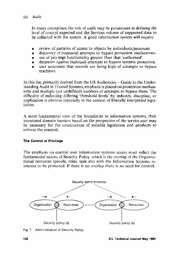
(c) Audit
In many enterprises, the role of audit may be paramount in defining the level of control expected and the Services volume of supported data to be collected with the system. A good information system will require
• review of patterns of access to objects by individuals/processes.• discovery of (repeated) attempts to bypass protection mechanisms.• use of privilege functionality greater than that ‘authorised’.• deterrent against (habitual) attempts to bypass systems protection.• user assurance that records are being kept of attempts to bypass
machines.
In this list, primarily derived from the US Authorities - Guide to the Understanding Audit in Trusted Systems, emphasis is placed on protection mechanisms and multiple (yet undefined) numbers of attempts to bypass them. The difficulty of enforcing differing ‘threshold levels’ by industry, discipline, or application is obvious especially in the context of liberally interpreted legislation.
A more fundamental view of the boundaries to information systems, their associated domain barriers based on the perspective of the service user may be necessary for the construction of suitable legislation and products to enforce the controls.
The Control of Privilege
The emphasis on control over information systems access must reflect the fundamental nature of Security Policy, which is the overlap of the Organisational resources (people, roles, task etc) with the Information Systems resources to be protected. If there is no overlap there is no need for control.
Fig. 7 Administration of Security Policy
138 ICL Technical Journal May 1990

Hardware/software control systems have primarily been developed by I.T. service suppliers who have a ‘resource’ contextual view of the world. The users, assisted by advisors (Auditors etc) have primarily approached control from the organisation viewpoint.
Current debate on legislation over access to systems must reflect administrative solutions that converge the two approaches.
Vendors, including ICL, can support this process by developing and implementing a common architectural approach to (distributed) information systems.
A common information system boundary of access control policing based on asking for and/or obtaining privilege could have an architectural simplicity. This could create a universal control point in any system that could be consistent for all potential users, whether internal or external, whether authorised or unauthorised. Those that asked for, obtained or accepted privileges beyond their agreed level would be carefully monitored.
The monitoring of privilege request or allocation post-ID/authentication is considered a more robust yet selective auditable process especially in the establishment of likely ‘hacking’ controls. The evidence relating to access or attempted access would be more selective and yet more likely to show some subsequent malicious intent.
A common philosophy would allow the unifying of technical solutions covering all types o f‘privilege packages’ in the form of VLSI ‘Smart Cards’ through to dynamic, run time, privilege certificates obtained from central I.T. sources. It could allow a single control barrier around any number of domains in a multi-domain information system.
A suitable positioning of the control boundary after the simple authentication stage would also reduce the problems associated with such large volumes of audit records of those events (for use as evidence both internally and, possibly, externally for civil litigation or criminal prosecution). It would also permit a common method of management of the records created by many of the authorisation controls for both internal and external “attackers”.
The Future
ICL, in collaboration with other I.T. service suppliers, is currently exploring the various architectural approaches, especially within distributed office information systems, to ensure adequate user access control systems.
Much of the security work is in the public domain in the standards bodies of ISO, CCITT and ECMA. Particularly relevant is the ECMA TC32 TG9 work on security, with its understanding of distributed secure services to support productive applications executed on behalf of the end users. The
ICL Technical Journal May 1990 139

concept is of locally trusted User Sponsors, representing the user, communicating with both productive applications and supportive systems’ contextual services. These use high integrity Privilege Attribute Certificates (PAC’s), to establish both good organisational definitions (identities/roles) as well as creating effective boundary conditions between information systems domains.
ICL with its partners in Bull and Siemens is prototyping many of these concepts in an EEC funded R&D programme - SESAME. Early trial facilities are currently being demonstrated. Deliverable products having this capability are expected in the early 1990’s.
Access control over information systems is a combination of legislation, and effective policing and control information systems products.
Legislation to be enforceable must recognise the changes in society brought about by the explosion of information services both public and proprietary, and the associated control solutions.
A society circumscribed by controls over information must allow some flexibility in what constitutes a computer access violation. The ITT&B industries in return must ensure that information systems’ architectures, services and products do reflect and support legislation.
NO criminal must ever go free because of the successful plea - there were no controls so I though I could do it!
ReferencesLaw Commission (89) - On Computer Misuse W.P. 110 (and associated working papers). F.CMA (88) TC32 TG9 - TR46 - Security in Open Systems - A Security Framework.IEEE (88) - The Source of Authority for Commercial Access Control. J. Moffett/M. Sloman. UPDATE (89) - An Abuse of Privilege - C. W. Blatchford (Volume 2.1-9/89).MILCOMP (88) - Management and Security - Six Principles. C. W. Blatchford. D.O.D./NSA-NCSC - ‘Rainbow Books’ and associated Implementation Guidelines, (ref. A
Guide to Understanding Audit in Trusted Systems 7/89).
140 ICL Technical Journal May 1990

Standards for secure interfaces to distributed applications
T. A. ParkerICL Defence Systems, Winnersh, Wokingham, Berkshire, UK
Abstract
The large distributed systems of the present day have users who access many different applications residing in different end-systems supplied by different vendors. The identity and access rights of these users need to be established, communicated and managed in a way which enables the disparate components involved to interwork in a secure manner. This paper describes work underway in ICL and the international standards arena to develop standards within which this can be achieved.
1 Background
This paper describes one topic of work recently completed within the European Computer Manufacturers Association (ECMA). The area covered deals with the topics of authentication and access control. The work was done by ECMA/TC32-TG9, which is the ECMA task group responsible for the definition of standards for security in open systems. The paper represents the author’s own interpretation of the work, and should not be taken as a definitive statement of an ECMA position.
The TG9 group started work in 1987 as a result of a joint initiative by ICL in the UK and NCR in the Netherlands. At that time, although work was being done within ISO on specific layered communications security services, there was no standards activity looking into the security information that needed to be communicated between standard applications for them to interwork in a secure manner. Within ECMA, the Task Group working on distributed office applications (ECMA/TC32-TG5) had specific requirements for expertise in this area, and one of TG9’s first tasks was to provide them with the necessary support. The scope of TG9’s activities was later widened to cover applications of all kinds.
The first ECMA Technical Report from TG9 [4] was produced in 1988. It gave an abstract framework within which security interworking standards could subsequently be defined; this work was reported in [1], [6] and [7]. The next phase of the work is now complete, and is documented in an
ICL Technical Journal May 1990 141

ECMA Standard [3], It gives the syntax and some semantics of the data elements which need to be exchanged, and outlines the security services which are appropriate candidates for further standardisation work.
Although the work embraces all aspects of security, including for example audit, interdomain working and recovery from security attack, the most critical and pervasive areas are those of authentication and access control. These topics are addressed in this paper.
ICL is actively supporting this architectural standardisation work. Its own internal company strategy [8] for security closely follows the precepts laid down in this paper and in the standards documents referenced from it. Products and prototypes are being developed within the company to conform to standards based on this architecture.
2 Definition of terms
There follows a short list of the main security terms used in this paper. The definitions are informal and are intended as an aid to understanding. They are compatible with the definitions and explanations given in the formal ECMA documents.
Control Attributes Attributes associated with a Security Object used in conjunction with Privilege Attributes to control access to that object. Examples are: an access control list, a security classification.
Privilege Attributes Attributes associated with a Security Subject which, when used together with the Control Attributes of a Security Object being accessed, define that Subject’s access rights with respect to that object. Examples are: the Subject’s identity, a security clearance, a group membership.
Privilege Attribute Certificate A collection of Privilege Attributes andinformation controlling their use, bound together under a cryptographic seal.
Security Object An entity to which access is controlled undera security policy. Examples are: a workstation, an application, a file, a data item.
Security Subject An entity in active mode requesting accessto a Security Object. A security subject can be compounded from a number of subject components, each of which contributes to the compound subject’s Privilege Attributes. Examples are: a user, an application, a workstation, a user and workstation in combination.
142 ICL Technical Journal May 1990

3 Requirements
Application standards are being defined for applications which are to be usable and manageable in the context of large distributed systems supporting multiple applications of different types. Such standards must therefore be developed to take account of this context.
As users of computer systems become more sophisticated, and as more activities in business begin to involve computers, each individual user will typically need to use an increasing number of applications, possibly in parallel. Also, the emergence of a variety of access control models based on access privileges other than simple user identity, coupled with the need in large distributed systems to manage these privileges independently of particular applications has led to a requirement to enrich a user’s identity with additional data which defines these privileges.
The ECMA Security Framework [4] offers an approach which permits a user to authenticate himself only once to a system, to obtain as a result a certified collection of access privileges, and to use these with a number of different applications. These privileges are represented in the Framework by Privilege Attributes associated with the user; the user’s identity may be one such attribute. Also, like users, applications themselves can be authenticated, and may possess Privilege Attributes to be used when accessing other applications; this will be elaborated in the next Section. In the ECMA Standard [3], developers of application standards are provided with a common mechanism for offering and accepting these values. The data construct central to this is the Privilege Attribute Certificate (PAC).
The next Section outlines some of the basic architectural principles upon which use of the PAC is based; this is followed by a Section giving a more detailed description of the internal contents of the PAC.
4 Architectural overview
If a Security Subject (e.g. a human user) is to authenticate himself only once to a distributed system, the points in the system at which access control decisions are made will not necessarily be co-located with the point of authentication. Therefore there must be some mechanism by which any proof of identity obtained as a result of authentication is subsequently propagated to the different access authorisation functions residing in the various End- systems of the distributed system. In the ECMA Standard, a certificate sealed by an Authority acceptable to the access authorisation functions of the system is used for this purpose.
Under many access control policies, a Security Subject’s access rights are not based simply on the Subject’s identity, but on attributes that the Subject possesses such as organisational role, or security clearance. These are the Privilege Attributes introduced in the previous Section. Attributes of this
ICL Technical Journal May 1990 143

kind are directly related to the Subject, not to the Objects that the Subject may wish to access, and they should therefore be handled and managed in relation to the Subject. Indeed from an access control point of view, the Subject’s identity is just another Privilege Attribute (it is only when accountability comes into the picture that any distinction has to be made). For these reasons, the certificate that is produced for an authenticated Subject contains all of that Subject’s Privilege Attributes (or at least all that the Subject asked for). This certificate is known as a Privilege Attribute Certificate, or PAC.
Before a PAC can be created and issued, the Subject must be authenticated. The security functionality which ensures that this is done, and which subsequently orchestrates all of the Subject’s security related interactions with the distributed system, is known as the Subject Sponsor. The scenario in outline is as follows:
The Subject Sponsor first directs an unknown Subject to an Authentication Service which engages in a standard protocol with the Subject Sponsor to authenticate the Subject, the Sponsor simultaneously interacting with the Subject as required to obtain the necessary authentication information. When the subject has been successfully authenticated, a certificate containing the Subject’s identity is generated by the Authentication Service. This certificate is passed to an Attribute Service which recognises the Authority of the Authentication Service. The Attribute Service then attaches the Subject’s other Privilege Attributes, adds various items of control information and seals the package; this package is the Subject’s PAC.
It should be noted that although the authentication and attribute handling functions are architecturally separate entities, they will commonly be implemented as one combined security service.
The sealed PAC is then returned to the Subject’s Sponsor for distribution to end-systems and their applications, as selected by the Subject.
5 PAC contents
Privilege Attributes are particularly susceptible to misuse because they are frequently under the control of software entities which cannot be trusted not to tamper with them. They may therefore need a variety of forms of protection as shown below:
• Protection against undetected modification• Protection against use by the wrong Subject• Protection against use outside stated constraints (for example a PAC
may be issued for use only with respect to a particular end-system or application, or may be valid only for a particular time period)
To provide these kinds of protection, a variety of optional control fields have
144 ICL Technical Journal May 1990

been defined for the PAC. For a detailed description and explanation of these and other fields within the PAC, the reader is referred to [3], The contents of a PAC are, however, outlined below:
ASN. I Field Name DescriptionsyntaxVersion For future-proofing purposescontainedPACs For combining PACs produced by different
AuthoritiesprivilegeAttributes The actual Privilege Attributes being carriedinitiatorQualifierAttributes Attributes that must be associated with the
submitter of the PAC for the PAC to be acceptable
targetQualifierAttributes Attributes that must be associated with theaccess authorising function with which the PAC is to be used
validationKeyldentifier The identifier of a cryptographic key that canbe used in a variety of ways to protect the PAC against misuse
creationTime Fields controlling PAC expiryvalidityTimepacldentifier Fields used for PAC usagerecoveryldentifier monitoring and revocationauditldentifier Used for accountability purposes when the
identity being used for access purposes is either not present or is different from the Subject’s true identity (e.g. someone acting for a person who is on leave)
chargingldentifier For allocation of resource use chargespacAuthority Identifies the Authority that sealed the PACpacSeal The PAC’s cryptographic seal
Of these fields, the only ones that are not optional are the syntax version, the Privilege Attributes themselves, and the Authority and Seal.
6 Standard attribute types
Like other kinds of attributes, Privilege and Control Attributes can be standardised, and [3] identifies a candidate selection. Since these security attributes will often be handled in a similar manner to other attributes, it is useful to define them with the same general syntax. However there is a difference between security and other attribute types which requires additional internal structuring of the attribute value. The difference is due to the fact that different Defining Authorities may be involved in defining security
ICL Technical Journal May 1990 145

attributes of the same general type. The value field is structured therefore into two parts, an Authority and a (true) value. Notice that a Defining Authority is different in kind from a PAC issuing authority, the former being a human administrative body, the latter being a software entity. To help highlight this distinction in the text below, the name of the former is capitalised.
One use of the Authority field arises because in a particular security domain there may be defined a security policy which demands that multiple sets of a given attribute type be supported, each set belonging to a different Defining Authority, and being used to support a different aspect of the policy. This means that applications must be able to distinguish between attributes of the same type belonging to different sets. The Authority field enables this distinction to be made. An example might be a system supporting two label hierarchies belonging to two different national governments. From an implementation point of view an application that supports two hierarchies is not concerned (apart perhaps from some simple name-value mapping tables) with what authorities they belong to but only that there are two distinguishable hierarchies.
A second use arises because some attribute types are related in that they have complementary functions within the same security policy. For example different types are used to specify upper and lower bounds of the same kind of access privilege. By separating type from Authority an application can more easily see the correspondence.
Finally, by separating type from Authority it is possible for an application developer to define the security attributes it supports, without being aware of the potentially long and certainly dynamic list of possible Defining Authorities whose identities would otherwise have to be bound into the type field.
7 Impact on application standards developers
The rest of this paper examines how adoption of the ideas developed above would affect the thinking of people developing international application standards. It first looks at how a standard application might receive PAC information, it then analyses the complications introduced by the possibility of applications acting by proxy for their users (which may be other applications), and finally gives some guidelines on how to define application standards in a way which maximises their independence from the different security policy regimes within which they may be required to operate.
7,1 Delivering PAC information to applications
External support for providing a target application with the attribute values in its accessing subjects’ PACs can be given in two ways:
1 The application can depend on a co-located trusted infrastructure (for example its host operating system, or in the future perhaps the ACSE
146 ICL Technical Journal May 1990

layer) to provide them. In the ECMA Framework, the infrastructure will have obtained the attributes in a PAC, via a Secure Association Service in a manner similar to that described below for the application itself. It will have checked the validity of the PAC, will have unpacked it, and may also have performed some mapping of the Privilege Attributes found in the PAC, into locally understood, possibly application-specific values. This mapping is an example of a mapping between the global system- wide Security Domain and the Sub-domain of the local End-system.
2 The application can obtain the identity of the accessing subject and other privilege attributes directly via a PAC which is certified by a (usually) remote authority.
In the first case, application access protocols are affected only in that no explicit authentication is visible; application standards designers should therefore permit this case as an option. Standardisation of the interface between the application and its host infrastructure is primarily an application portability issue, not an interworking standards issue. Standardisation of the relationship between an application and its OSI communications interface in respect of receipt of authentication data is an OSI standardisation matter.
Notice that the first case is useful for applications which were designed before the framework had been developed, and which previously depended on infrastructure-provided security controls and information to preserve their security. Using this approach it is possible for the infrastructure to conceal from the application any knowledge of the PAC itself, but instead to establish a working context for the application unchanged from its familiar one. Although this does not exploit the full power of the ECMA model, it nevertheless helps considerably in the integration of existing applications into the overall architecture.
In the second case, the PAC may be passed on any of three occasions, depending on the control relationship between the accessing subject and the communication association Bind operation. They are as follows:
1 When each accessing Subject connects to the application via an association which is dedicated to that Subject’s use, a PAC representing some or all of the Subject’s access rights is passed as a Bind argument (PAC A in Fig. 1).
2 When a single association is multiplexed between different accessing Subjects (for example in some transaction processing orientated environments), then if there is a concept, probably application-type specific, of a within-association ‘sub-connection’ the Subject’s PAC will be passed as an argument to the ‘sub- connect’ operation (PAC’s B1 and B2 in Figure 1); otherwise it can be passed with every operation, as in the connectionless relationship next described.
3 When a connectionless mode of access to the application is supported, a
ICL Technical Journal May 1990 147
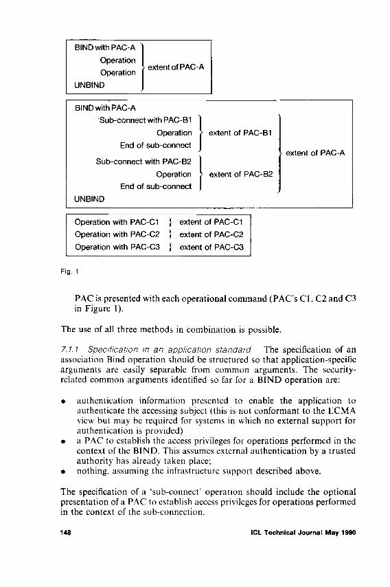
Fig. 1
PAC is presented with each operational command (PAC’s C l, C2 and C3 in Figure 1).
The use of all three methods in combination is possible.
7.1,1 Specification in an application standard The specification of an association Bind operation should be structured so that application-specific arguments are easily separable from common arguments. The security- related common arguments identified so far for a BIND operation are:
• authentication information presented to enable the application to authenticate the accessing subject (this is not conformant to the ECMA view but may be required for systems in which no external support for authentication is provided)
• a PAC to establish the access privileges for operations performed in the context of the BIND. This assumes external authentication by a trusted authority has already taken place;
• nothing, assuming the infrastructure support described above.
The specification of a ‘sub-connect’ operation should include the optional presentation of a PAC to establish access privileges for operations performed in the context of the sub-connection.
148 ICL Technical Journal May 1990

The specification of other kinds of operation should include the optional presentation of a PAC containing attributes required specifically for the operation.
7.2 Proxy and compound subjects
Some operations requested of an application are not performed directly or completely by that application, but are wholly or partially ‘sub-contracted’ out to another application; for example a text editing application may use a file server to hold files of text; when a user asks to start an edit, the editor must ask the file server for the user’s file. This is a case of Proxy; the editor is acting with respect to the file server as the user’s proxy, and it must convince the file server of its right to access the file. Depending on the trust relationship between the two applications (which is determined by the security policy in force); it may do this in a number of ways:
1 The editor may be trusted only to ask for files that the user may legitimately edit. In this case the editor acts as the only accessing subject; the file server sees only the editor’s access rights and expects a PAC from the editor, which belongs to the editor, and which is presented in one of the ways described in the previous clause.
2 The editor may have no access rights of its own to the files in the file server, and must prove to the file server that it has permission from the user to obtain the file. It does this by passing a Proxy PAC to the file server as a parameter to the access request for the file. The Proxy PAC belongs to the user, and was obtained from the user parametrically either with the user’s operation request or via a previous operation. The proxy PAC may have been constructed to constrain tightly the editor’s access (for example it may permit read access only to a particular named file)
3 As above, the editor has no rights of its own but a Referenced Data Transfer (RDT) facility [2] is supported by the file server. To perform a Referenced Data Transfer the user warns the file server in advance that the editor will be making the access request, and as a result obtains an RDT Reference from it. The RDT Reference is a tailor-made PAC authorising the transfer operation; it is sealed by the file server itself and is therefore usable only at the file server, and only for the operation specified. The user passes the RDT reference to the editor as a form of Proxy PAC and the editor uses it in its subsequent call on the file server as an operation PAC. The syntax of an RDT Reference was developed before the TC32-TG9 work matured and is at present special to the RDT Standard [2] but it is hoped that it will in future be possible to bring it and the PAC syntax in line.
4 The security policy in force takes into account both the access rights of the user and the access rights of the editor (for example the user may be permitted access to the file only if it uses the editor to access it, and the editor has access only if it is acting for the user). In this case a combination of 1. and 2. above occurs. The file server is being accessed by a Compound Subject.
ICL Technical Journal May 1990 149

7.2.1 Privileges required to form a bind When an association is being formed between two applications on behalf of a user, the access privileges required in order to make the BIND succeed may be different from those which will be established for operations conducted over the association. In particular, the user may not himself possess sufficient authority to form the association, and the relevant authorisation logic may require an additional PAC (e.g. from the initiating application) to be passed to it as a BIND argument.
7.2.2 Specification in an application standard The application standard writer cannot assume any particular trust relationship between two applications, since this will vary according to security policy. Therefore:
• for operations that may be devolved to a second application, the first application should be capable of accepting a Proxy PAC from the originator of the request, for use by it as the required operational PAC in its operation call on the second application;
• when an (initiator) application binds to another (target) application it must be able to pass a PAC representing the access privileges required to permit the establishment of the association, as well as one for use over the association.
7.3 Secure application associations
[3] defines a Secure Association Service which provides for secure communications between applications; this needs to be informed of the nature of the OSI communications security services wanted. The information must be passed when the association between the applications is formed at Bind time. Other responsibilities of the Secure Association Service do not impact on the specification of application standards.
7.4 Example ASN. 1
The following ASN. 1 is offered as an example of changes to interface definitions required to support a common application access control framework.
Bind- Argument ::= SEQUENCE japplication-specific-argument [0] App. common-security-argument [1] Sec OPTIONAL}App ::= whatever the application requires - Sec ::= SEQUENCE]
CHOICE {credentials-for-appl [0] Creds OPTIONAL, certified-id-and-privileges [1] Bind-PACs OPTIONAL}, bind-security ServicesRequired OPTIONAL}
150 ICL Technical Journal May 1990

Bind-PACs::= SEQUENCE SIZE (1...2) { required-bind-PAC [0]
PrivilegeAttributeCertificate OPTIONAL, context-PAC [1]
PrivilegeAttributeCertificate OPTIONAL}- PrivilegeAttributeCertificate as defined in [3] -
Sub-Connect-Argument :: = SEQUENCE}sub-connect-specific-argument [0] Sub, context-PAC [1]
PrivilegeAttributeCertificate OPTIONAL}Sub :: = whatever the sub-connect requires -
Operation-X-Argument :: = SEQUENCE}operation-specific-argument [0] Op, common-security-argument [1] Op-Sec}
- Op ::= whatever the operation requires - Op-Sec :: = SEQUENCE}
operation-PAC [0] Operation-PAC OPTIONAL, proxy-PAC [1] Proxy-PAC OPTIONAL}
Notes1. credentials-for-appl is used to pass actual authentication inform ation, for the
target application itself to authenticate the accessing subject. T his is appropriate only for use in system s not conform ant to the E C M A Fram ework.
2. bind-security is used to tell the Secure A ssociation M anagem ent Service what kind o f security protection is needed on the association that w ill result from the Bind.
3. required-bind-PAC is the PAC used to present the privilege attributes required to perform the Bind.
4. context-P A C is the PAC used to present the privilege attributes to be associated with operations to be perform ed in the context o f the B IN D or sub-connection .
5. required-operation-PA C is the PA C passed with an operation when the access privileges currently established are insufficient to perm it the requested operation. This m ay happen when either the operation requires special additional privileges, or when a Bind is being m ultiplexed between m ultiple subjects.
6. proxy-PA C is used when the target application needs to m ake further accesses to another application on behalf o f the calling subject, and itself w ould otherw ise have insufficient access rights. T he target application will itself then use this PAC as an operation-PA C when it acts as an initiator application in its call on the other (now the target) application.
7.5 Object security attributes
When an application object is created, the security control attributes that are used to protect it from unauthorised access need to be defined and established. The exact way in which this is done will be particular to the security policy in force, but under some policies some of these attributes will be specifiable as arguments to the ‘Create’ operation. When the object is accessed, its control attributes may need to be read or written. The syntax of a security attribute is the same as other kinds of object attribute and an
ICL Technical Journal May 1990 151

application need make no distinction between the two kinds, except in the following respects:
• the standards developer should clearly separate out any rules that may be specified about what security attribute values are acceptable in what contexts, so that the security policies supported are in this respect clearly identifiable;
• these rules should be specified as optional to allow for variations so that the application can be used in different security policy contexts;
• the definition of the types of control attribute that are to be supported should be similarly flexible and easily separable;
• the standards developer should consider the advantages of separating out operation arguments containing security attributes from other arguments to simplify any functionality that an implementer might provide to protect them and control their use.
7,6 Access authorisation
An application is responsible for authorising access only to its own objects, though it may use its host infrastructure to support it in doing this. It may optionally choose to control access to itself, though in many environments this control is provided externally. The authorisation logic needs information on which to base its decisions; these are the privilege and control attributes described extensively elsewhere, coupled with information about the access context pertaining at the time of the access requests.
An application standards developer defines the access controls that the application is required to support. However this definition will always constrain the security environments within which the application will be able to be used, and the definition should therefore be arranged to be optional and separable from the rest of the standard definition so that variants appropriate to different security policy environments can be defined and developed. In due course commonly used access control policies will be profiled. This is an area for further study.
8 Further work
TC32-TG9, (with the author as document editor), is now turning its attention to the detailed definition of a standard protocol to a combined Authentication and Security Attribute Service, by means of which users authenticate themselves and obtain PACs. Meanwhile testing of the practical feasibility of the approach is underway within a number of the companies involved in the work, including of course ICL, and intensive liaison work continues with ISO and CCITT, where the ideas behind the ECMA work are beginning to appear in draft standards, for example in [5],
152 ICL Technical Journal May 1990

9 Conclusions
The ECMA work has resulted in a framework within which access control information can be generated and distributed in standard ways. These permit existing systems to be evolved gradually to work within the framework; in particular, applications developed outside the context of the framework can benefit in part from it.The framework enables system users to authenticate themselves once to the distributed system as a whole, and supports a wide variety of access control policies. The framework is based on sound, practical implementation considerations which are continually being tested by experimental and product design and development.
References
1 COLE, R. Hewlett Packard, Bristol ‘A Model for Security in Distributed Systems', submitted for publication in Computers and Security magazine.
2 ECMA STANDARD ECMA-131 ‘Referenced Data Transfer’.3 ECMA STANDARD ECMA-I38 ‘Data Elements and Service Definitions’ December 1989.4 ECMA TR/46. ‘Security in Open Systems - A Security Framework’, July 1988.5 ISO/IEC JTC1/SC21/WG1/F29 ‘Working Draft Access Control Framework’, Florence
meeting November 1989.6 KRUYS, J. P. ‘Computer Security and Open Systems’, Computers and Security, 8,
pp 139-47, Elsevier, April 1989.7 PARKER, T. A. ‘Security in Open Systems - A Report on the Work of ECMA’s TC32-TG9’.
Proceedings of the 10th National Security Conference, Baltimore. September 1987.8 PARKER, T. A. ‘NPL Networked Security Architecture’, ICL Product Specification
Document PSD 2675 Issue 2, 8th March 1988.
ICL Technical Journal May 1990 153

How to Use Colour in Displays - I. Physiology, Physics & Perception
Darren Van Laar and Richard FlavellThe Management School, Imperial College, London
Abstract
Colour is often used in visual displays to improve human-computer interactions and achieve a more natural and representative display medium than monochrome coding alone can accomplish. In order to use colour on displays effectively it is important to understand how colour behaves as a physical phenomenon, how VDUs display colour, how people perceive colour and how colour can be used to encode displayed information.
This is the first of two papers discussing the effective use of colours in CRT displays and covers how colours are produced and measured, the physiological basis of human colour vision and the perceptual effects which can be expected when using colour on computer displays.
The second paper will discuss how to increase the eftectiveness of displays by using colour to link displayed information with the user's tasks. The different ways of applying colour to displays, and the advantages and disadvantages of each will also be described. The paper concludes with a summary of the physical and cognitive factors that have been highlighted by the two papers, together with some guidance as to how this advice may be implemented.
1 Introduction
Employing colour in displays is a task fraught with difficulties. The naïve programmer or designer will write a program or design a system and then decide to make the display ‘look more interesting’ by adding some colour. But already questions arise: which colours to add, how many colours to use, where to use them, how to make them look good in combination, how to find a particular colour, how to ensure the legibility of colour text and so on. Ten, even five years ago answers to such questions were easier to find as many of the options were limited by the technology of the display systems available. That is, if your display only has 4 or 8 colours, then it is easy enough to assign colours to everything in sight and stop when you run out. But with 16, 256, and 16 million colour systems being widely used today,
154 ICL Technical Journal May 1990
merely choosing between the colours becomes a problem let alone deciding which parts of the display ought to be colour coded, or considering how colour should support the task in hand.
This article will attempt to overcome such problems by explaining basic psychological and physical colour phenomena clearly and in simple terms. This is necessary because many people who might gain benefits from effectively employing colour are put off either by lists of unjustified guidelines, or by jargonised and incomprehensible physics, physiological and psychological text books.
This, the first paper of two looking at the use of colour on computer displays, will present the background necessary to understand how to employ colour, and will answer questions such as what are colour spaces, how can displays be designed to take account of colour blindness, what are the best ways to describe and think about colour, what makes some colours easier to see than others, and how do visual displays produce colour. The second paper will deal with the more psychological and cognitive aspects of colour use, discussing instances of where colour has helped in computing tasks, how to allocate colour to displays, how many colours to use in a display, how to make colour displays aesthetically pleasing and how to derive links between colour coding and the tasks it supports. At the end of these two papers the reader should be able to make much more sophisticated use of multi-colour displays, be able to understand colour terminology and concepts that human factors and computer graphics designers use, and be able to produce more informative, aesthetically pleasing and productive displays than before.
2 How do people sense colour?
The difference between sensing something and perceiving something can be quite subtle. This section will look at how light is sensed by the human visual system, and what this tells us about how colours are seen.
2,1 The spectrum
All modern theories of colour and colour vision stem from the discovery by Sir Isaac Newton that white light could be split by a prism into a ‘spectrum’ of colours and them recombined back into white light. Newton realised that as light passes through a prism the amount it is bent by the prism (refracted) depends on the wavelength of the light. The fact that we see this spread of light as differing in hue implies that the way we see colours depends on the wavelength of the light.
Visible light is a small part of the entire electromagnetic radiation spectrum which includes other forms of radiation such as X-rays (at the short wavelength end) and radio waves (at the longer wavelengths). The colours we see in the range of visible light gradually merge with one another as they change from the violet at a wavelength of about 380 nanometres (nm,
ICL Technical Journal May 1990 155

> <D g CD
U ltra -v io le t V io let B lu e G re e n == § R ed In fra -red> Ô
(x -ray s , e tc ) (R ad io w a v e s , e tc )
i H ---- ----h----- — n — -------1 i300 400 500 600 700 800
W av e le n g th nm
Fig. 1 Part of the electromagnetic spectrum, showing colour names usually associated with such areas by wavelength.
millionths of a millimetre) through the familiar rainbow colours to about 780 nm where red merges with the infra-red. Figure 1 shows the portion of the electro-magnetic spectrum from which visible light comes, along with common colour names typically associated with regions of the spectrum by wavelength. An important point to remember is that not all of the colours we can see are represented along the spectrum: purple is a mixture of red and blue light, and browns are actually dark yellows and oranges.
2,2 Basic physiology of colour vision
As light enters the eye it passes through a transparent protective covering (cornea), a fluid filled cavity is focused by a crystalline lens, passes through another fluid filled cavity, past layers of nerve cells and assorted internal wiring, through a light sensitive layer (retina), and finally is absorbed by a non-reflecting coating on the back of the eye (see Fig. 2).
The light sensitive layer consists of over 125 million cells of which approximately 95% are light intensity sensing ‘rods’, and 5% are colour sensitive ‘cones' (so-called because of their shape). The light sensitive cells are unevenly spread across the eye, with colour sensitive cones being most intensely concentrated at the point where light and images are focused at the back of the eye (the eye’s visual axis) at a point called the ‘fovea’. Few, if any, rods occur at the fovea, and it is the area of the eye with the greatest concentration of cones and where the finest detail and colour discrimination occurs. From the fovea cones are present to within about 50" of the eye’s axis, after this point only rods are present and only shades of grey are perceived.
Note that in the vision literature the size of objects is often measured in terms of degrees and minutes of ‘visual angle’, which corresponds to the size of image on the retina. Visual angle may be calculated by finding the arctan of the size of the object viewed divided by the distance from the object. For example, the visual angle subtended by a letter (0.5 cm approx) on an
380 450 490 560 590 630 780
156 ICL Technical Journal May 1990

Fig. 2 Cross section through the eye showing the passage of light along the visual axis, with degrees of visual angle from the fovea.
ordinary 80 x 25 column computer display at arms length (70 cm approx) would be: Arctan (0.5/70) = arctan (0.00714) = 0.41°, or 24' of arc of visual angle (1° = 60 minutes).
Another important feature of the eye is the presence of the blind spot. This is the point in the retina where no light receptors are present but where information from the retinal receptors is routed to the brain. This illustrates the tremendous data compression taking place within the visual system as signals from the 125 million receptors are coded and sent out through the one million nerve fibres of the optic nerve. The coding and decoding of signals from the eye is still being intensely researched, more details of which may be found in Coren, Porac and Ward (1984), Savoy (1987) and Livingstone (1988).
2,2.1 The retina/ receptors The rods allow vision at low levels of luminance down to hundredths of a candela per square metre, (cd/m2). This type of vision is called ‘scotopic’ vision, and is sensitive to movement and light intensities but not to colour. The cones function at high levels of luminance and give colour or ‘photopic’ vision at levels of luminance of a few cd/m2 or more. As luminance levels rise to between 1 and a couple of cd/m2 there
ICL Technical Journal May 1990 157

Fig. 3 The sensitivity of the eye under scotopic vision (broken line) and photopic vision (solid line) conditions by wavelength.
comes a point where both rods and cones are active and this is the ‘mesopic’ form of vision. In normal daylight illumination levels the rods have little or no contribution to make to what we see, (Hunt, 1987; Long and Garvey, 1988).
Rods and cones are not equally sensitive to all wavelengths of light, with rods (scotopic vision) being markedly more sensitive to the lower wavelengths (blues, violets) compared to photopic vision, which is more sensitive to the longer wavelengths (reds). Figure 3 shows the different sensitivities of the two systems. This difference means that the brightness of a blue and a red stimulus compared under normal levels of illumination will change when they are viewed under dim conditions, with the blue stimulus appearing relatively brighter and the red relatively darker. Note that the scale on the ordinate of Figure 3 is a scale of relative sensitivity to wavelength and the rods are actually many times more sensitive to each wavelength than the cones. Also, for colours viewed in normal daylight conditions the eye will be most sensitive to the yellow-green part of the spectrum and least sensitive to blues and reds. In other words, even though the actual physical luminance might be the same, light of wavelength 560 nm (a yellow-green) will be sensed as approximately twice as bright as a light of wavelength 510 nm (a green). This effect may be demonstrated by viewing a prism spectrum or a rainbow where the yellow-green areas of the spectrum appear much brighter than the red and blue parts.
2.2.2 Cones There are three different types of cone, and these are differentially sensitive to wavelengths of light, see Fig. 4. These cones are frequently called ‘blue’, ‘green’ and ‘red’ but this can cause confusion and are better described as short, medium and long wavelength sensitive cones respectively. For example, the so-called red cone has a maximum sensitivity in the yellow-orange part of the spectrum, and is also sensitive, although less strongly, to many of the wavelengths also covered by the green cone. The
158 ICL Technical Journal May 1990

Fig. 4 Spectral sensitivity of the three types of cone, with the broken line showing scotopic (rod) vision. Where S= short, M= medium and L= long wavelength sensitive cones.
different types of cones are not spread evenly across the retina, the central region of the fovea being blue-blind, red and green sensitivity being limited to about 30° from the fovea, (see fig.2) but with blues and yellows still be able to be sensed at up to 60°, (Coren et al, 1984). Research has also shown that there are different amounts of the three types of cone within the eye: estimates usually approximate to 40R:20G:1B. This has a number of effects on the sensation of colour, not least that the cones have to be stimulated in this proportion in order to experience the sensation of white.
The colour of an object is therefore determined by the ratio of cone responses. A colour with a hue of 550 nm will evoke a large ‘red’ response, a weaker ‘green’ response, and no response from the ‘blue’ cones.
2.3 Colour defective vision
It is well known that there are people who cannot discriminate colours as well as others and such people are commonly labelled ‘colour blind’. True colour blindness is however very rare, and perhaps a more accurate label for this problem would be ‘colour defective’. There are various types of colour defective vision, the causes of which are still not perfectly understood but may be classed into three categories: those in which either all of the rods or all of the cones are missing, those in which one of the different types of cone is missing, and those where there is a reduction in the sensitivity of one (or more) of the cone types in increasing order of occurrence. People who have normal colour vision are called ‘trichromats’, referring to the three normally functioning sets of cones, with 92% of males and 99 5% of females being normal trichromats, (Hunt, 1987; Wyszecki and Stiles, 1982).
People who suffer from true colour blindness, called ‘cone monochromatism’
ICL Technical Journal May 1990 159

experience many visual problems, not least of which is the inability to see objects at the fovea, resulting in functional ‘day blindness’. Those who have no rods, but working cones, are functionally blind at low levels of illumination.
By far the most common form of colour defective vision occurs within approximately 4-9% of males and is called deuteranomaly. This is a result of the green cones having a spectral sensitivity shifted along the wavelength axis towards the normal short wavelength (red) cones, (see fig.4), with a resulting loss of discriminations based on the ratio between red and green cones. The reason why colour defective vision is much more widespread in males than in females is that the genetic information is carried on the sex chromosomes. People with deuteranomalous vision can still see greens but will tend to confuse certain reds and greens, and some reds and greens with grey, (Long 1984). It is usually possible to predict colours which will be confused by people with such abnormalities, (Wyszecki and Stiles, 1982; Meyer and Greenberg, 1988). All of the defective colour vision problems will be successfully picked up by the familiar Ishihara colour vision test. However the Ishihara tests are not sensitive enough to say exactly which colour defect is present, e.g. lack of sensitivity in, or lack of, a set of cones, and usually more sophisticated and complex tests such as the City University or Farnsworth-Munsell tests are needed to give an exact diagnosis, (Fletcher and Voke, 1985; Meyer and Greenberg, 1988).
2.4 Models of colour vision
Thomas Young and later Von Helmholz were the first to realise, and then show with colour mixing experiments, that people with normal colour vision only need three suitably chosen primary colours to be able to match any colour stimulus. This gave rise to the theory that people did not need retinal cells individually sensitive to each wavelength of visible light, but only cells sensitive to short (e.g. blue), medium (e.g. green) and long (e.g. red) spectral wavelengths. Evidence from colour defective observers, whose deficiencies seemed to result from a lack or insensitivity in one or more of these cells, also gave weight to this ‘trichromatic theory’. Actual physiological evidence for these cells (which are of course the cones), has only been found in the last 25 years as microelectrode techniques improved, (Brown and Wald, 1964; Bowmaker and Dartnell, 1980).
The main problem with trichromatic theory is that when people are asked to describe colours, or to choose ‘pure’ colours from a set they tend to use four hue names, not three. These unique colours, which occur in cultures other than the West, are red, green, blue and yellow, (Zollinger, 1988; Uchikawa and Boynton, 1987). Ewald Hering used such evidence to fashion his ‘opponent theory’ of colour vision. In this theory the four primaries are in two sets of opponent pairs: yellow-blue and red-green, with a third primary pair black-white. Figure 5 shows the inputs to the opponent pairs from the cones, and the resulting information. Note that these opponent properties
160 ICL Technical Journal May 1990

Fig, 5 Schematic diagram of the cone inputs to the opponent colour process in vision.
mean that whilst we can easily see yellow-reds or greenish blues, we cannot see greenish reds or yellowish blues. In 1958 Svaetichin and MacNichol showed how some cells in the retina do indeed have the property of taking information inputs from the cones, and then responding, in the example of the blue-yellow opponent cell, with a low voltage to blue and a high voltage to yellow. Since this time further evidence has been found which shows that the story becomes even more complex as the nerve carrying information is traced to the brain, with neurones which respond specifically to, for example, green horizontal lines being found (Michael, 1981). For an up-to-date review of the research and the current theories of colour vision see Boynton (1988).
3 Colour as a physical phenomenon
3.1 Hue, saturation and brightness
The spectrum is an inadequate way of describing colour for many reasons, principally because a spectrum contains information only about ‘hue’. If people are asked to place coloured tiles or lights in an ordered sequence it is found that many colours which have the same hue still differ in some respects. For example some colours may appear washed out, almost white, but still have a discriminable hue. When the light from these colours is analyzed it becomes apparent that this difference is associated with the ‘purity’ of the colour, or the extent to which a hue has been diluted by being mixed with other hues. When a hue is mixed with all other hues the effect is to make the colour more like white light (which Newton showed is the sum of all colours). This purity is called ‘saturation’; for example a pink is an unsaturated red.
A ‘colour circle’ may be formed by thinking of the centre as white, and the
ICL Technical Journal May 1990 161

Fig. 6 The colour circle, illustrating the result of mixing a yellow and a red to get an orange colour.
outer edge as containing the fully saturated spectral hues (and non-spectral purples), as in Fig. 6. Hue angle is often referred to in the literature and is the angle between a reference hue (e.g. a fully saturated red on a monitor) and other colours around the hue circle. Colours on opposite sides of the circle are called ‘complementary colours’ and have a number of interesting features which will be described later.
If two colours are matched on hue and saturation but still appear to be different, this difference will be due to the respective lightnesses of those colours. Whilst hue and saturation can be represented by a two dimensional diagram, the introduction of the third (and final) dimension needs to be represented by a ‘colour solid’. Figure 7 shows a representation of such a colour solid. Brightness is a psychological correlate of luminance, which whilst easy to understand is difficult to incorporate into a colour space because hue, saturation, the relative lightness of an object and environmental factors such as illumination will effect how bright such an object will appear. Consequently colour spaces often employ hue, saturation and lightness (which ranges from black to white), or other combinations to avoid confusions with bright to dark scales.
3,2 Additive vs. subtractive colour mixtures
Only very rarely will people see colours which are truly ‘monochromatic’ outside of experimental labs. Monochromatic, meaning one-colour, refers to
162 ICL Technical Journal May 1990

Fig. 7 The hue, lightness and saturation colour solid, showing colour descriptions of various points of the space.
a colour which consists of light of only one wavelength. Most colours we see in the real world are mixtures of many wavelengths, and the overriding hue sensation of each mixture is called its ‘dominant wavelength’. When two colours are mixed, e.g. two coloured lights, we will see a new colour with a combination of the properties of its constituent parts. When these colours are mixed in certain ways the eye cannot discriminate the individual constituents, but instead will sense a single colour. Two colours which appear to be identical can consist of different mixtures of colours, in which case the mixtures are called ‘metamers’.
There are two types of colour mixture. The first is used to calculate the effect of mixing paint or pigments. Most people have dabbled with poster paints at school and know that blue added to yellow makes green, and a number of different paints makes a grey, and eventually a black. This form of mixing takes away light energy from the stimulus and so is called subtractive mixing, see Fig. 8. The type of mixing required when viewing luminous objects such as computer displays is called additive colour mixing because with each colour added light energy is given to the stimulus, with many colours together forming light greys, and eventually a white. Additively mixing yellow and blue together does not give rise to a green, but to a grey. A highly
ICL Technical Journal May 1990 163

Fig. 8 Subtractive colour mixture using three patches of paint.
saturated green cannot be created by additively mixing lights, but requires a pure, primary colour to be realised. One of the effects of additive colour mixing that people find most surprising is that by mixing red and green light yellow is produced (which would produce a grey in subtractive mixing), see Fig. 9. The difference between additive and subtractive mixing is one strong
Fig. 9 Additive colour mixture using three beams of light.
164 ICL Technical Journal May 1990
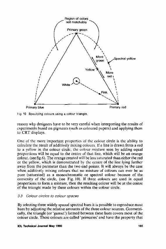
f
Fig. 10 Specifying colours using a colour triangle.
reason why designers have to be very careful when interpreting the results of experiments based on pigments (such as coloured papers) and applying them to CRT displays.
One of the more important properties of the colour circle is the ability to calculate the result of additively mixing colours. If a line is drawn from a red to a yellow in the colour circle, the colour mixture seen by adding equal proportions will be equal to the centre of that line, which will be an orange colour, (see fig.6). The orange created will be less saturated than either the red or the yellow, which is demonstrated by the centre of the line lying further away from the perimeter than the two end points. It will always be the case when additively mixing colours that no mixture of colours can ever be as pure (saturated) as a monochromatic or spectral colour because of the convexity of the circle, (see Fig. 10). If three colours are used in equal propertions to form a mixture, then the resulting colour will be at the centre of the triangle made by these colours within the colour circle.
3,3 Colour circles to colour spaces
By selecting three widely spaced spectral hues it is possible to reproduce most hues by adjusting the relative amounts of the three colour sources. Geometrically, the triangle (or ‘gamut’) formed between these hues covers most of the colour circle. These colours are called ‘primaries’ and have the property that
ICL Technical Journal May 1990 165

the hue of any one of them cannot be replicated by mixtures of the other two. Traditionally the red, green and blue hues which are used to calculate mixtures have wavelengths of 700 nm, 546J nm and 435-8 nm respectively. A three dimensional colour space may be constructed by plotting proportions of the red, green and blue values on its three axes. This may be reduced to two dimensions given that the three proportions must sum to 1.
However, as mentioned above, because of the curvature of the colour circle it is impossible for all hues to lie within the gamut formed by any three primaries. This is illustrated in Fig. 10 which shows the curved area of unrealisable colours. This shortcoming may be overcome by permitting a negative proportion of one primary. In practice this works by adding a primary to a test colour and then matching the outcome, for example:
Test colour + W(r) = W(g) + W(b) i.e. Test colour =W (g)+W (b)—W(r)
where W(r), W(g) and W(b) are different amounts of red, green and blue. The necessity of using negative weights is not thought to be conceptually desirable and in 1931 the Commission International de l’Éclairage (CIE) proposed a solution based upon imaginary (or super) primaries which themselves lie outside the colour circle but whose gamut encloses all hues that can be sensed. The super primaries were termed X, Y and Z, (Hunt, 1987; Wyszecki and Stiles, 1982).
The coefficients X , Y and Z were selected so the amounts needed to match any other colour in the circle would be positive. The relative magnitudes of these primaries or ‘tristimulus values’, calculated by x = X/ (X + Y+Z) etc., are called chromaticity coordinates and are used to plot colours on the 1931 chromaticity diagram. This is shown in Fig. 11 which illustrates how all of the colours may be reproduced using only positive combinations of the super primaries. Note that, because x + y + z= 1, if any two of the coordinates are known the third can be calculated by taking the difference of the sum of the two known coordinates from 1. Therefore only a two dimensional diagram is needed to represent x, y and z, and by tradition x is on the abscissa and y on the ordinate. See appendix B for instructions on how to derive chromaticity coordinates.
It was mentioned in Section 3.1 that the spectrum did not distinguish between colours of differing lightnesses. As only the relative values of the super primaries are used to identify the hue of a colour, the CIE defined the absolute value of Y to represent the luminance (which is a precise physical measure correlated with perceived brightness) of the colour as based upon colour matching experiments. Thus a colour may be uniquely identified by the triple ‘x,y,Y’, (pronounced little-x, little-y and big-y).
3.4 Perceptual spaces, Munsell, UCS, etc
The CIE 1931 diagram is very useful as a means of predicting the results of colour mixing and the physical relationship between colours. But the
166 ICL Technical Journal May 1990

Fig. 11 The CIE 1931 xy chromaticity space showing the three imaginary primaries, and colour names approximately associated with regions of the space.
physical production of a colour and its sensation or perception by a person are very different processes. If colours were generated from the (x,y) diagram by taking small, equal steps, the colours would not be sensed as being equally spaced. In some instances there would be little perceptual difference between steps, and in others quite big differences.
In 1976 the CIE developed the Uniform Chromaticity Scale diagram or UCS diagram in which much of the perceptual non-uniformity of the (x,y) diagram was removed. The UCS or u, v' (called u-dash, u-dash) diagram is a simple transformation of the 1931 diagram, and whereas in the 1931 space the ratio between the size of the largest just noticeable difference (JND) to the smallest JND between colours was 20:1, in the 1976 diagram this had been reduced to 4:1. The 1976 u\v diagram is shown in Fig. 12.
Chromaticity diagrams such as the x,y and the u',v' diagrams are of restricted use to the display designer because they only refer to the hue and saturation of colours which have the same luminance (i.e. are ‘isoluminant'). Instead for
ICL Technical Journal May 1990 167
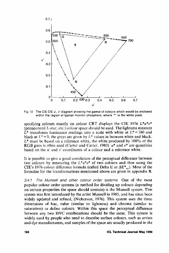
Fig. 12 The CIE CIE U, \7 diagram showing the gamut of colours which would be enclosed within the region of typical monitor phosphors, where '*' is the white point.
specifying colours exactly on colour CRT displays the CIE 1976 L*u*v* (pronounced L-star, etc.) colour space should be used. The lightness measure L* transforms luminance readings into a scale with white at L*= 100 and black at L* = 0, the greys are given by L* values in between white and black. L* must be based on a reference white, the white produced by 100% of the RGB guns is often used (Carter and Carter, 1983). u* and v* are quantities based on the u and v' coordinates of a colour and a reference white.
It is possible to give a good correlation of the perceptual difference between two colours by measuring the L*u*v* of two colours and then using the CIE’s 1976 colour difference formula (called Delta E or AE*UV). Most of the formulae for the transformations mentioned above are given in appendix B.
3.4.1 The Munsell and other colour order systems One of the most popular colour order systems (a method for dividing up colours depending on certain properties the space should contain) is the Munsell system. This system was first introduced by the artist Munsell in 1905, and has since been widely updated and refined, (Nickerson, 1976). This system uses the three dimensions of hue, value (similar to lightness) and chroma (similar to saturation) to define colours. Within this space the perceptual difference between any two HVC combinations should be the same. This system is widely used by people who need to describe surface colours, such as artists and dye manufacturers, and samples of the space are usually produced in the
168 ICL Technical Journal May 1990

form of books of coloured tiles, called the ‘Munsell book of colour’. The tiles are arranged such that each page represents a vertical slice of hue, with tile lightness arranged vertically, and chroma horizontally for each hue. A restricted set of colours is defined within the Munsell space. There are 40 hue pages with 10 value (lightness) steps, the number of chroma steps being dependent on the HVC combination being viewed, as some colours are naturally more highly saturated than others.
Other well known colour spaces include the Ostwald space, the Natural Colour Order System (NCS) and the Optical Society of American (OSA). The Ostwald colour system is similar in shape to the space shown in Figure 7 and is based on principles of additive colour mixture. The NCS is a perceptually based colour appearance system based on many measurements of coloured papers, and derived from the work and theories of Hering (see section 2.4). The OSA system is a space in which equal distances very closely relate to perceived differences, but which consequently lacks dimensions such as hue or saturation. See Hunt (1987) and Wyszecki and Stiles (1982) for examples of other colour order systems.
It should be noted that many people have cast doubt on the application of the CIE measures to CRT displays without qualification. Finding perceptually different colours for such displays is also problematic, and is probably dependent on the task to be performed, (Van Laar and Flavell, 1988; De Corte, 1986; Mollon and Cavonius, 1985).
4 How do visual displays produce colour?
4.1 CRT displays
The most common means of displaying coloured information is by utilising colour cathode-ray tubes (CRTs). In a CRT colours are produced by ‘shooting’ streams of electrons within a vacuum tube at colour phosphors embedded in the inside surface of the monitor or television screen. When stimulated in this way the phosphors emit light. Groups of red, blue and green phosphors are distributed evenly over the screen and respond to one of three corresponding electron guns. The different colours are produced by additively combining the light of the three phosphors, and when seen from a distance the colours are perceived as one (see section 3.2). A maximally saturated colour such as red is produced by stimulating the red phosphor at maximum. When maximum red and green phosphors are stimulated together the maximum saturated yellow is produced, blue and red give magenta and blue and green phosphors together produce cyan. All three phosphors stimulated together produce white, and the absence of all three is seen as black. Because phosphors in older displays were only capable of being stimulated at two levels, on and off, only eight colours were available (i.e. 23 colours). This may be contrasted with the huge number of colours produced on more modern displays by varying the intensity of the energy falling on each phosphor. For example, if the voltages applied to the electron
ICL Technical Journal May 1990 169
guns are able to be ‘stepped over’ 256 different levels then 2563 different combinations are possible, giving in theory over 16 million different colours. A common misunderstanding is to believe that people can discriminate all 16 million colours produced by such a display; however the actual estimated number of hue, saturation, lightness combinations that are just perceivably different (see JND in the glossary, appendix A) on a display is closer to 1.2 million (Tajima, 1983) under very good viewing conditions.
When stimulated by an electron beam the phosphors on the screen glow for a short time, allowing time for a raster-scan system to operate. With this system the electron gun stimulates each group of phosphors in turn, usually each group on a horizontal line, and then through each vertical line of the screen in turn. The phosphors are re-stimulated or ‘refreshed’ at a rate of many times (typically 50) a second, which is usually fast enough to give an illusion of a static colour screen display.
One of the problems with using this form of screen display technology is that sometimes, with many phosphors to refresh (high resolution), wide angled displays and bright colours, the screen may be seen to flicker, especially in the periphery of vision, (Tyler, 1985). In many cases flicker may be reduced by decreasing the brightness of the CRT, or by running the CRT at high refresh rates e.g. 100 times per second or higher. (Tyler, 1986).
Many algorithms exist for the display designer to predict the perceived colour of a display, given various phosphor types, filters and viewing environments, in particular Viveash and Laycock (1983) and Hunt (1987).
4.2 LCD and other colour display technologies
There are three main ways of producing colour Liquid Crystal Displays (LCDs): nematic crystal, smectic liquid crystals and ferroelectric crystals. These must usually be combined with backlights, polariser or filters. Liquid crystals have the physical properties of liquids but the optical properties associated more with solids. When a current is applied across a liquid crystal reservoir the crystals change from a random state to an aligned state, which if the reservoir is correctly positioned can change the viewed stimulus from white to black, or from one colour to another. LCDs are light scattering rather than light emitting, and although characters and graphics have good readability in high illumination, in medium or low illumination conditions the display must usually be backlit in order for the characters to be seen.
Although problems with current colour LCDs include poor resolution, poor contrast, bad response times and small colour gamut, because of the low power demands, light weight, small physical size and robustness to violent movements, these displays are still being actively researched, especially in the avionic and military industries.
Other types of technology include thin film transistor (TFT) displays, light
170 ICL Technical Journal May 1990

emitting diode (LED) displays and gas plasma displays. These all suffer from many disadvantages compared with the highly developed understanding of the CRT and it is very unlikely that any will take over from CRTs in general computer and other information displays except in specialist uses such as portable computers.
Given the ubiquitous nature of the CRT and the lack of data based on other forms of screen display, this paper has concentrated on the use of colour in CRT displays.
4,3 Colour spaces based on display technology
Colour spaces based on physical and perceptual criteria such as the CIE, Munsell and Ostwald spaces must be used in cases where the reproduction or cross referencing of colours between displays is to take place. The alternative is to use colours based on the RGB values of the monitor’s CRT guns, where colours are specified in percentages of each gun so that the most saturated yellow colour would be R = 100%, G = 100%, B = 0%, etc. It is crucial to understand the distinction between the colour primaries dicussed above and the RGB gun values. These latter are dependent upon the phosphors used in the construction of the CRT and the energy being transmitted by the guns to excite them. The RGB colour space is shaped like a cube, implying the independency of the three guns, unlike x,y,T which demonstrates the physical relationships between the dimensions. The derivation of colours in RGB space cannot be easily understood (Schwartz, Cowan and Beatty, 1987; Murch, 1984) and more importantly, colour produced by a particular combination of RGB values on one monitor are very unlikely to produce the same colour on another monitor. The lack of correspondence between monitors may be due to different ages of the monitor, the use of different phosphors, filters or driving voltages, or even the direction in which the monitor is facing (in or out of the earth’s magnetic field). It is possible to overcome these problems by calibrating a monitor so that a software program interprets instructions given in (e.g.) Munsell values and outputs the appropriate RGB values to the screen, (Cowan, 1983; Glassner, 1989). However, such methods of calibration take a long time, need frequent updates for most monitors and require specialist colour measurement equipment, at least to initiate the calibration.
The RGB space produces colours which must be combined in additive ways in order to produce the desired colours. As mentioned above, it is possible to work with additive colour mixtures but people do not find them intuitively useful and perform less well with them than with other more perceptually- orientated spaces, although they can be useful in specific tasks. One such space is the HLS space, based on the Ostwald colour system with a double hexacone shape; Fig.7 shows a similar double cone shape. Brown and Cunningham (1989) describe a number of such systems and their advantages and disadvantages. A simple algorithm exists to convert from RGB to HLS values and back (see Foley and Van Dam (1982), pp.618-619) but it must
ICL Technical Journal May 1990 171

Fig. 13 CIE 1931 xy chromaticity diagram showing the gamut of colours enclosed within typical monitor phosphors, where '* ’ is the white point.
always be remembered that within this space H (measured in degrees), S(%) and L (%) are only approximations to the hue, saturation and lightness of the physical and objective spaces described in section 3.1.
As previously mentioned in section 3.2 if there are two CRT phosphors which are plotted in an appropriate colour space, such as G and B in Fig. 13, then all the colours which lie along that line may be produced by different mixtures of the phosphors. In the same way if there are three phosphors, then all the colours lying on and within the triangle formed in the colour space are realisable by mixing these colours. One important point to remember is that the colours realisable on a CRT give only a restricted part, or ‘gamut’ of all colours that people can see; again this may be seen in Fig. 13.
5 How do people perceive colour?
When one colour is seen on a background of another the foreground colour seems to change hue in a direction roughly towards the complementary colour of the background. In the same way bright backgrounds tend to make the target colour appear darker, while dark backgrounds usually make the target appear brighter than is actually the case. These effects occur without any change in the physical light coming into the eye from the target. In other words there is often a difference between the physical colour of the target which is sensed, and the colour that is actually seen, or perceived, (Van Laar and Flavell, 1988).
It is very important when creating colour displays that the designer is aware
172 ICL Technical Journal May 1990

of the effect of background and nearby colours on the perceived colour of a stimulus. This is especially important when absolute colour judgements are to be made, such as when colour coded brain scans or temperature analyses are to be used, or in other situations where colour codes are used to portray meaning.
5.1 Chromatic adaptation and colour contrast
When coloured objects or objects illuminated by light of a certain colour are viewed, after a time the sensitivity of the eye to that colour changes; this is known as chromatic adaptation. For example, viewing a display with a blue background or illuminated by blue light will tend to fatigue the blue part of the visual system, with the result that other objects will appear to be yellower than they are normally (as yellow light is complementary to blue). Note that yellower does not mean yellow, for example a blue green on a blue background will actually look a purer green as the yellow light is perceived as mixed with the blue light. However this effect of coloured backgrounds does not usually become a problem in colour displays as the viewer will normally not stare at the screen for long enough at one time, but will swap his or her gaze to paper, to the keyboard, etc. Differently coloured illuminants will cause more of a problem with colours seen under tungsten light and daylight looking quite different. If one is required to look at one part of a colour display for a long period of time, such as when waiting for a value to appear at a certain cell of a spreadsheet, it is possible that this fatiguing effect may occur across only one part of the retina, the result being an after-image: the colour of the after-image again being complementary to that of the ‘inducing’ image.
Similar results are observed with ‘simultaneous colour contrast’ effects, where colour patches on a screen or other stimulus will induce a complementary colour in another part of the screen, and this hue shift will affect how objects are seen, (Krauskopf, Zaidi and Mandler, 1986). This effect is instantaneous and due to an automatic neurological response based on the spatial arrangement of the display and not due to fatigue. Effects can be very strong on some displays. When absolute colour judgements have to be made, such as when identifying areas on a colour map, these effects can cause large changes in the colours perceived. One of the current projects at Imperial is concerned with developing algorithms which will take such effects into account and change the displayed colours automatically.
The contrast effects discussed above may be termed ‘induction’ effects because a colour difference is induced onto a displayed object. The opposite effects also occur, where the colour of an object affects that of the background, and these are called ‘assimilation’ effects. Which effect actually occurs is not yet fully understood but evidence from brightness assimilation experiments has shown that whether assimilation or contrast occurs depends on whether the displayed object is seen as being the figure (i.e. in the foreground) or the ground (i.e. the background). For example, a display may
ICL Technical Journal May 1990 173

be seen as a yellow object on a blue background, or a blue object with a hole showing through to a yellow background, (Festinger, Coren & Rivers, 1970).
5.2 Other visual effects on colour perception
5.2.1 Effects on colour discrimination The colour of very small objects (<10-15 minutes of visual angle, see section 2.2) is usually perceived as different from that of larger objects of the same colour. One observation is that very small objects are seen as much less saturated. Another effect is that in the discrimination of small blue objects the visual system acts as if no blue cones were present. This effect is called ‘small field tritanopia’ after the colour vision deficiency with the same symptoms. Blue stimuli are also problematic because of the very small input to the luminance channel. The lack of such information from blue stimuli to the edge detecting mechanisms which depend on luminance differences means that letters on a screen which differ from a background only in blue will be very difficult to read, (Beck, Sutter and Ivry, 1987; Savoy, 1987). However in most instances blue lettering on displays is still satisfactorily seen because of the hue and saturation contrast between the letters and the backgrounds.
As mentioned in section 2.2 colour perception in the periphery of vision (away from the fovea) is reduced, the perceived effect being a desaturation of the colours in the periphery. This will of course affect colour discrimination on the larger displays currently becoming popular (e.g. colour Sun, Mac II machines). Information codes employed at the edges of such displays should therefore be blues or yellows, (because of the way the different cones are distributed, see section 2.2.2), be highly saturated and should have a large brightness contrast compared to other codes and colours if they expect to be seen.
As colours increase in brightness they appear to change hue, with violets and blue-greens (wavelengths <510 nm) becoming bluer and yellow-greens and reds (wavelengths >510 nm) becoming yellower. This shift in hue, called the Bezold-Briicke effect, is also seen when the colour of an object on a display is made to look brighter by surrounding it with a darker background.
5.2.2 The McCollough effect McCollough found that when people viewed coloured stripes in particular orientations, and then viewed black and white stripes in similar orientations, they would see imaginary, or subjective colours in the black and white grid. Even more surprising, after just 10 minutes or so of viewing green and red stripes these ‘colour contingent after effects’ lasted sometimes for months. These illusions are not therefore due to retinal fatigue but seem to have a neuronal or cortical component. This effect seems to be specific to the orientation of the lines involved and does not seem to work for the blue-yellow opponent system, (Savoy, 1987). Some computer operators have reported that after long term viewing of displays with green text on black backgrounds, then viewing black and white displays made characters and letters look pink, (Greenwald, Greenwald, and Blake, 1983)
174 ICL Technical Journal May 1990

and there is even evidence that the effect occurs only with understandable text, and not with nonsense words (Allen, Siegal, Collins and MacQueen, 1989).
5.2.3 Fluttering hearts phenomenon When two highly saturated complementary colours are combined on a display a disturbing visual effect occurs, where the colours appear to flicker or shimmer, called the ‘fluttering hearts phenomenon’. This effect, so called because of the shape of the stimuli in the first experiments, occurs mainly at the boundaries between coloured objects and is caused by differences in the adaptation of the cones at these edges as the tiny, constant, movements of the eye move the edges of the object across the retina. These effects may cause problems in colour displays but can be negated by using colours which are less different in hue and which are less saturated.
5.2.4 Chromatic abberation and colour stereopsis Coloured light entering through the edges of the lens of the eye is not focused on the retina in the same plane as light entering through the centre of the lens. This produces ‘chromatic abberation’. Because blue light is focused by the eye at a nearer point than green light, in turn focused nearer than red light, the eye, in order to maintain a sharp retinal image might need to change focus between objects. The result of such changes can be that the muscles which focus the lens (a process called accommodation) become tired or fatigued. Another effect would be that if text in one colour on a display were in focus, text of a colour far away in spectral composition would not and might appear to be in a different plane.
However, because of the lack of blue receptors in the fovea, the eye only needs to change focus in the green to red parts of the spectrum. Colours found on most VDUs are not monochromatic but are mixtures of hues from different parts of the spectrum, with the colour’s dominant wavelength determining the perceived hue. Also the eye’s focus to a visual display is determined by factors other than stimulus colour, such as eye convergence and stereo information from the visual system (Walraven, 1984). According to Campbell & Durden (1982), people who do not have marked lens ageing will rarely find, under normal viewing conditions, that chromatic abberation causes focus problems or fatigue.
Colour stereoscopic effects are caused by a combination of chromatic abberation and eyes aligned so that in most cases reds are seen as being in front of blues. However some individuals see blues in front of reds, and rarer still some see both reds and blues as lying on the same plane, (Hunt, 1987).
Colour stereoscopy is most pronounced for highly saturated combinations of red and blue on black or dark backgrounds (Hunt, 1987), which are common colour coding formats for some types of computer displays. Given that the screen designer would not want to harness this visual effect to show say, red objects as standing out from a blue background, (not recommended because
ICL Technical Journal May 1990 175

of other visual effects such as fluttering hearts phenomenon) colour stereoscopy may be overcome by choosing brighter backgrounds, less saturated colours and colours with less difference in spectral hue.
5.2,5 Age and physical condition The ability to discriminate colours changes systematically as people age, the lens becoming progressively yellower so that all light must pass through a gradually darkening yellow filter (Coren and Girgus, 1972). There is also a deterioration of blue-yellow discriminations as people get older (Verriest, 1972), and a reduction in the optical transmittance of the fluids in the eye so that colours are perceived as darker and less saturated (Murch, 1984). Unlike the colour deficiencies discussed in section 2.3, which are congenital, some diseases result in loss of colour vision or discrimination. Diabetics suffer losses in their blue-yellow discrimination abilities, and alcoholics are prone to reductions in blue- sensitivity (Coren et al 1984).
6 Summary
To understand how to employ colours effectively on displays it is necessary to appreciate the physics of colour science, the physiology of colour vision and the perceptual factors likely to be encountered when using colour displays. This paper has examined all of these topics and has given the reader an appreciation of the problems involved. For further information, consult the references given below and in the text. Note that explicit advice on how to colour code displays based on the information given in the present paper will be contained in the next paper of the series.
References
ALLEN, L.G., SIEGAL, S„ COLLINS, J.C. and MacQUEEN, G.M., Color aftereffect contingent on text. Perception and psychophysics, 46(2), 105-113, 1989.
BECK, J., SUTTER, A. and IVRY, R., Spatial frequency channels and perceptual grouping in texture segregation. Computer vision, graphics and image processing, 37, 299-325, 1987.
BOWMAKER, J.K. and DARTNELL, H.M.A., Visual pigments of rods and cones in a human retina. J of Physiology, 298, 501-11, 1980.
BOYNTON, R.M. Color Vision. Ann. Rev. Psychol, 39, 69-100, 1988.BROWN, J.R. and CUNNINGEIAM, S., Programming the user Interface: Principles and
examples. John Wiley, London, 1989.BROWN, P.K. and WALD, G., Visual pigments in single rods and cones of the human retina.
Science, 144, 45-52, 1964.CAMPBELL, F.W. and DURDEN, K., The visual display terminal issue; a consideration of its
physiological, psychological and clinical background. Ophthal. Physiol. Op. 3, 175-92, 1982. CARTER, C.C. and CARTER, E.C., CIE L*u*v* Color-difference equations for self-luminous
displays. Color Res. and Appl., 8(4), 252-3, 1983.Commission Internationale de TEdairage proceedings. Cambridge University Press, Cambridge,
1931.COREN, S. and GIRGUS, J.S., Density of human lens pigmentation: in vivo measures over an
extended age range. Vision Research, 12, 343-6, 1972.COREN, S., PORAC, C. and WARD, L.M., Sensation and perception, 2nd Ed., Academic Press.
London, 1984.COWAN, W.B., An inexpensive scheme for calibration o f a colour monitor in terms of CIE
standard coordinates. Computer Graphics, 17(3), 315-21, 1983.
176 ICL Technical Journal May 1990

De CORTE, W., Finding appropriate colours for colour displays. Col. Res. and Appl. 11(1), 56-61, 1986.
DURRETT, H.J., Color and the Computer. Academic Press, 1987.FLETCHER, R. and VOKE, J., Defective colour vision. Hilger, Bristol, 1985.FOLEY, J.D. and VAN DAM, A. Interactive computer graphics. Addison-Wesley, 1982.GLASSNER, A.S., How to derive a Spectrum from an RGB triplet. IEEE Computer Graphics
and Applications, July, 95-9, 1989.GREENWALD, M.J., GREENWALD, S.L. and BLAKE, R., Long lasting visual aftereffect from
viewing a computer video display. New England Journal of Medicine, 309, 315, 1983.HUNT, R.W.G., Measuring Colour, Ellis Horwood, 1987.ISHIHARA, S., Ishihara's tests for Colour-Blindness, 38 plate edition, Kanehara Ltd., Tokyo,
1983.JAMESON, D. and HURVICH, L.M., Theory of brightness and color contrast in human vision,
Vision Res. 4, pp. 135-54, 1964.KRAUSKOPF, J., ZAIDI, Q. and MANDLER, M.B., Mechanisms of simultaneous color
induction. J. Opt. Soc. Am., 3(10), 1752-7, 1986.LIVINGSTONE, M.S., Art, Illusion and the visual system, Scientific American, 68-75, 1982.LONG, T., Human factors principles for the design o f computer colour graphics displays. Br.
Telecom Technol. J. 2(3), 5-14, 1984.LONG, G.M. and GARVEY, P.M. The effects o f target wavelength on dynamic visual acuity
under photopic and scoptopic viewing. Human Factors, 30(1), 3-13, 1988.MEYER, G.W., GREENBERG, D.P., Colour defective vision and computer graphics displays.
IEEE Comp. Graphics and Appl., Sept, 28-39, 1988.MICHAEL, C.R., Columnar organisation o f color cells in monkey’s striate cortex. J. of
Neurophysiology, 46, 587-604, 1981.MOLLON, J.D. and CAVONIUS, C.R., Derivation of a uniform colour space from discriminative
reaction times. In Conference proceedings of 1ERE Colour in Information Technology and Visual Displays, University of Surrey, pp.27-31, March 1985.
MURCH, G.M., The Effective Use of Color: Cognitive Principles, TEKniques, 8(2), pp.25-31,1984.
SAVOY, R.L., Contingent aftereffects and isoluminance: psychophysical evidence for separation of color, orientation, and motion. Computer Vision, Graphics and Image Processing, Vol 37, 3-19, 1987.
SCHWARTZ, M., COWAN, W. and BEATTY, J., An experimental comparison of RGB, YIQ, LAB, HSV and opponent colour models. ACM Transactions on Graphics, April, 1987.
SVAETICHIN, G. and MacNICHOL, E.F., Retinal mechanisms for achromatic vision. Annals of the New York Academy of Sciences, 74, 385=404, 1958.
TAJIMA, J. Optical color display using uniform color scale. NEC Res. and Dev., Vol 70, pp.58-63, 1983.
TYLER, C.W., Analysis o f visual sensitivity modulation. J. Opt. Soc. Am. ‘A’, Vol 2, 1985.TYLER, C. W.. Interlacing eliminates crt perceptible flicker. Information Display, Vol 2, No 8,
1986.UCHIKAWA, K. and BOYNTON, R.M., Categorical colour perception of Japanese observers:
comparison with that of Americans. Color Vision, Vol 27, 1825-33,VAN LAAR, D.L. and FLAVELL, R., Towards a maximally contrasting set of colours. In Jones,
D. & Winder, R. Eds. ‘Interacting with Computers IV’. pp.:574-89, 1988.VERRIEST, G., Recent advances in the study of the acquired deficiencies of color vision.
Fondiazone ‘George Ranchi’, 24, 1-80.VIVEASH, J.P. and LAYCOCK, J., Computation of the resultant chromaticity coordinates and
luminance of combined and filtered sources in display design. Displays, Jan, 17-23, 1983.WALRAVEN, J., Perceptual artifacts that may interfere with colour coding on visual displays.
Proceedings of the workshop on colour coded vs monochrome electronic displays. Nato Report ds/a/dr84/431, 13.1-13.11, 1984.
WRIGHT, W.D., The sensitivity of the eye to small colour differences. Proceedings of the Physical Society (London), 53, 93-112, 1941.
WYSZECKI, G. and STILES, W.S., Colour Science, 2nd ed., Wiley, NY, 1982.ZOLLINGER, H., Categorical colour perception: influence of cultural factors on the differentia
tion of primary and basic colour terms and colour naming by Japanese children. Vision Research, vol 28, no.12, 1379-82, 1988.
ICL Technical Journal May 1990 177
Appendices
Appendix A: Glossary
Brightness The psychological or subjective impression of light intensity. (Adjectives: bright and dim.)
Cd/m2 Candela per square metre, an objective measure of physical luminance.Colour The subjective sensation associated with light.Hue The attribute of a visual sensation, approximately synonymous with the
common term colour, and described by terms such as red, green, yellow, blue and proportions of two of these.
Saturation The purity, richness or vividness of a colour relative to its hue. A pink is an unsaturated red, Post-office red a highly saturated red. (Similar to colourfulness.)
Lightness The brightness of an area judged relative to the brightness of a similarlyilluminated area. (Adjectives: light and dark.)
Chromatic Referring to the hue and saturation of a stimulus as opposed to the black- white or achromatic dimension.
Achromatic Literally, ‘without colour’, but meaning without the sensations of hue or saturation, i.e. from black through greys of varying luminance to white.
Luminance The physical intensity of fight, correlated with but different from brightness (a psychological, subjective measure), measured in candelas per square metre cd/m2.
Illumination The amount of light falling onto a surface, measured in lux.JND Just noticeable difference - the difference between two stimuli that, under
experimental conditions, is ‘just noticeable', statistically speaking - discriminated as often as it is not discriminated.
Gamut The space of possible colours which lie between, usually three phosphors on acolour monitor.
Fovea The point on the back of the eye at which incoming light is focused.
Appendix B
CIE transformations
CIE I93I
x = x / ( x + y + z ) y = Y / ( X+Y + Z) z = Z/ ( X+ Y + Z ) = \ - ( x + y)
T = luminance
CIE 1976 u, v'
u' = 4x/( - 2 x + 12y + .3) v' = 9y/( - 2 x + 12y + 3)
CIE 1976 K. v hue angle and saturation
huv = arctan[(e' - i>'„)/(ti' — «'„)]
where the actual value of hul depends on whether v' — v'„ and u' — u a r e positive or negative, and u'„ and e'„ are values of u and v' of the reference white.
s„, = 1 3[(m' - u'„)2 + (i/ - e'„)2]1M2
178 ICL Technical Journal May 1990

I976 Uniform colour space - L*, u*, v*
CIE 1976 lightness
L* = 116( Y/ 7")1,3 - 16 when 7/ 7" > 0.008856 L* = 9°3.3( 7 / r ) when 7 /7 n<=0.008856
The second formula is employed when the colour to be converted is quite dark.u*=l?,L*(u'-u'n)v*=l3L*(C-Cn)
note that
huv = arctan(r*/«*)
CIE I976 Colour difference formula
AE*uv = [AL*)2 + (Au*)2 + (Ar*)2]1/2
Where AL*, Au* and An* are the differences in I f , u* and v* between the two colours being considered.
For further details see Hunt (1987) or Wyszecki and Stiles (1982).
ICL Technical Journal May 1990 179

Notes on the authors
C.W. BlatchfordClive Blatchford is Manager, Secure Systems in the ICL Technical Directorate. In this capacity he has staff responsibility for definition, development and marketing of security in all ICL products and services.
He plays an active role in both National and International standards organisations and has lectured extensively in Europe, North America and Australia; he is currently Vice-Chairman of the USA Department of Com- merce/National Bureau of Standards Special Interest Group on Security. More recently he has been involved in studies of security programmes for the European Commission. Prior to joining ICL he had senior management experience in dataprocessing and/or security with Xerox Corporation and with Chase Manhattan Bank.
John CheesmanJohn Cheesman studied mathematics/computer science at the University of York, graduating in 1983, and joined ITT. He worked initially in software engineering on the System 12 tool chain, a major digital telecommunications switch, at a variety of sites throughout Europe. He then joined the ITT research centre at Harlow, working on the development and application of an in-house expert system. In 1988 he joined STC Technology, working in the Knowledge-Based Systems group, particularly on the requirements and design for the Strategic Marketing Information System (SMIS) discussed in the paper and employing the KADS technology.
A.A. ClarkeAnthony Clarke is a lecturer in the Department of computer studies at Loughborough University of Technology, and a Co-Director of the LUT- CHI research centre. Prior to joining the academic world as part of the Government’s IT’83 programme he was group leader, Man-Systems Interface with Plessey Electronic Systems Ltd. Before 1978 he was Head of the Ergonomics Laboratory, EMI Ltd., and before 1973 he was Human Factors Section Leader with EASAMS Ltd., responsible for Tornado cockpit design aspects. He graduated with a BSc(Tech). Hons, in Occupational Psychology in 1970, following 15 years in the RAF and the aerospace industry, gaining
180 ICL Technical Journal May 1990

aircraft and electrical engineering qualifications. He is a Fellow of the Ergonomics Society, an Associate Fellow of the British Psychological Society, and a Chartered Psychologist.
T.M . Cole
Terry Cole joined ICL in 1968 after graduating from Oxford University with a degree in Engineering Science. He has worked on George 3, VME/B and VME/K superstructure products, and then on the System Ten and its successor System 25. He has been involved with UNIX since the beginning of 1986 when this was ported to the System 25.
Christopher Dobbyn
Chris Dobbyn graduated from Keele University with honours in English and Philosophy in 1973 and received a post-graduate Certificate in Education from Birmingham in 1975. After working for ten years as a lecturer in English Literature in further education he took an MSc in computation at UMIST, specialising in Artificial Intelligence. For the past four years he has worked in the computing industry as a knowledge engineer and technical consultant, specialising in knowledge-based systems. He joined ICL Retail Systems in 1989.
Professor Ernest EdmondsProfessor Edmonds holds a PhD in mathematical logic from Nottingham University. He is Head of the Department of Computer Studies and Director of LUTCHI Research Centre at Loughborough University. His research has included work on graphics, speech input, computer-aided learning, computer communication and interactive dialogues. User interface software systems have been of central concern since the early 1970s.
He is the author of numerous papers in research topics, ranging from “An appraisal of some problems of achieving fluid Man/Machine interaction” to “Determining requirements and prototyping the User Interface Module” . He is General Editor of the journal “Knowledge Based Systems” for the publishers Butterworth Scientific.
Dr Richard FlavellRichard Flavell is a Reader at The Management School, Imperial College. He holds a BSc in Chemical Engineering and a PhD in Management Science, both from the University of London. He has taught at Imperial for the past 15 years, specialising in finance and project appraisal. He has published on these topics in a variety of journals. He has also worked in a bank dealing room and is a recognised financial trader.
Much of his work involves the production of computer-based financial models. Several years ago, this stimulated the question of how to produce
ICL Technical Journal May 1990 181

effective displays, and especially using colour, for these models. Casting around, very little useful guidance was found and hence an interesting sideline was born. This work has been funded solely by industry over the past seven years and is becoming widely recognised as a leading source of advice.
Fiona FlowerGraduated from University of Aberdeen in 1978 with MA Honours in Modern Languages (French and Spanish).
Joined ICL in September 1978 as a graduate recruit, and completed the graduate induction programme.
First assignment with ICL was with Local Government and Public Corporations (LGPC) in Bristol, as an account support executive. After a short secondment to Dataskil in Reading, she was tasked with providing all pre- and post-sales support for 7700 for LGPC customers in Wales and the West Country. In 1981 she transferred to major Accounts, and provided accounts support in office systems for Major customers such as House of Fraser and Dowty.
When Customer Services was formed, she joined the Small Systems support team in Bristol, providing support in DRS systems and applications to customers in the Wales and West Country area, and remained with Customer Services until May 1985, when she took 6 months’ maternity leave.
Following maternity leave, she joined CPS as a technical author, working part time from home. In the 4 years since then, she has completed a wide variety of projects, producing documentation for a number of clients, both internal and external. Internal clients included Defence Region, Office Systems, CRS&S, Networks Region, Northern Telecom and CIS. Her current project is to produce two of three booklets for Andrew Hutt, to complement his Marketing to Design lectures:
“How to Identify a High Valued Solution” (describing a process for deriving product attributes from user needs).
How to Deliver a Business Solution” (describing how to identify the manuals, man-machine interface and services to be delivered with a product).
Dr Andrew T.F. Hut IDr Hutt holds a BSc Mathematics from Durham University and PhD Computer Science from Southampton University and has worked for ICL since 1966.
At ICL between 1966 and 1973, he worked on the design of the Edinburgh Multi-Access system and of VME Operating System. In 1973, he was
182 ICL Technical Journal May 1990

seconded to Southampton University where he developed an early Relational Database Management system. On his return to ICL he led a 25 man team which produced QueryMaster, Personal Data System and CAFS Relational Interface which are based on his research work. These products are used widely throughout the ICL customer base.
In 1984, Dr Hutt became ICL’s HCI Strategy Manager responsible for coordinating all the HCI work in ICL. In this capacity he had led 2 Alvey projects: User Skills and Task Match and the Alvey Lab. Project: both of which have produced valuable reseach results. He has also contributed to other collaborations namely, the Alvey Early Evaluation Project, and the Esprit HUFIT and Eurohelp projects. Dr Hutt has been responsible for the industrialisation of the results of this research work and has developed the “Marketing to Design” human factors based methodology which is routinely used throughout ICL.
In the period 1985 to 1989, Dr Hutt has also worked on the MAP MultiStar Project on distributed relational database systems which has produced the only usable European system of this type.
H, L esanHamid Lesan received his Ph.D. in Mathematical Logic from the Department of Mathematics of the University of Manchester in 1978. After a brief period of teaching, he joined STL in 1980, where his work has been mainly concerned with Formal Methods and Natural Language Processing. He is currently working on tools for supporting the formal specification and development of software in the context of the ESPRIT project RAISE.
T.A. ParkerTom Parker graduated from Downing College, Cambridge, with a degree in mathematics in 1963. He first worked for Ferranti as a technician on a large in-flight simulator for the Bloodhound MK II missile before joining Fisons in 1966 as Systems Analyst and then Chief Programmer. He joined ICL in 1971 and worked on early design of major 2900 Series operating systems before transferring to Bureau West, where he was responsible for operating system support and for design and development of new security features. He is now a Security Consultant responsible for consultancy on all aspects of technical security within ICL.
He was responsible for the inception and for much of the design of the High Security Option of ICL’s VME operating system, and is chairman of ICL’s corporate Technical Security Strategy Subcommittee. He is actively involved in the design of high security network architecture within both ICL and standards organisations in Europe. He has written a number of technical papers on security and has lectured both in Europe and in America.
ICL Technical Journal May 1990 183

G. PoskittGeoff Poskitt joined ICL in 1978 to do the system design for System 25. In 1981 he was seconded to the Three Rivers Computer Corporation to work on graphics workstations. He returned to the U.K.. in 1983 and worked on ICL’s personal computer products, including the OPD and the ICL PC. For the past two years he has has been the systems architect and design authority for UNICORN.
Roger PullenRoger Pullen is Products Integration Manager within Office Systems Servers Product Group. He joined ICL in 1977 as a design/product engineer with the newly formed Product Development Group at Bracknell. This group was responsible for the electro/mechanical development on both System 10 and System 25 minicomputers. Over the years he has also gained considerable experience in working with the overseas agency approval test houses, such as Underwriters Laborities (UL), Canadian Standards Association (CSA) and Federal Communications Commission (FCC). Currently he manages the Products Integration Group responsible for UNICORN systems.
N.R, SeelAfter working for several software houses where he specialised in systems programming and formal software specification, Nigel Seel joined STL in 1982. Having initially worked on formal specification support tools and Artificial Intelligence systems, in 1985 he became manager of the Intelligent Systems laboratory, developing “computer-based assistants” . Two years later he was appointed technical manager of a major Alvey project, Adaptive Intelligent Dialogues, seeing the project through to its conclusion. He currently occupies a senior technical position in STL’s Professional Community Support programme, specialising in Computer Supported Cooperative Working (CSCW). He is a graduate of the Open University, and has recently received his Ph.D. in formal cognitive science from Surrey University.
M. SmythMichael Smyth is a research assistant at the Loughborough University of Technology Computer Human Interface (LUTCHI) Research Centre. After graduation from The Queen’s University of Belfast in 1983 with a B.A. (Hons) in Psychology, he completed a postgraduate course in Computer Science. In 1985 he joined Autographies Software (NI) as a programmer where he was part of a small team which specialised in the design and development of CAD products for education. Since joining LUCHI in 1987 he has been a member of the Alvey Project (MM 1/062) Human Computer Cooperation. He is a member of the European Association for Cognitive Ergonomics (EACE).
184 ICL Technical Journal May 1990

Darren van LaarDarren van Laar is a research assistant in Imperial College, London where he also lectures in Human-Computer Interaction (HCI). He is currently completing his PhD thesis on the use of colour with computers.
His first degree was in Psychology from Manchester Polytechnic in 1985 after which he studied computing and Human-computer interaction for his MSc. at York University. Since that time he has been working at Imperial College on various projects concerned with HCI, colour, statistics, computing and psychology.
ICL Technical Journal May 1990 185

ICL TECHNICAL JOURNAL
G uidance for Authors
1. CONTENTThe ICL Technical Journal has a large international circulation. It publishes papers of high standard having some relevance to lCL's business, aimed at the general technical community and in particular at ICL's users and customers. It is intended for readers who have an interest in the information technology field in general but who may not be informed on the aspect covered by a particular paper. To be acceptable, papers on more specialised aspects of design or applications must include some suitable introductory material or reference.
The Journal will usually not reprint papers already published, but this does not necessarily exclude papers presented at conferences. It is not necessary for the material to be entirely new or original. Papers will not reveal matter relating to unannounced products of any of the STC Group companies.
Letters to the Editor and reviews may also be published.
2. AUTHORSWithin the framework defined by §1 the Editor will be happy to consider a paper by any author or group of authors, whether or not an employee of a company in the STC Group. All papers are judged on their merit, irrespective of origin.
3. LENGTHThere is no fixed upper or lower limit, but a useful working range is 4000-6000 words; it may be difficult to accommodate a long paper in a particular issue. Authors should always keep brevity in mind but should not sacrifice necessary fullness of explanation to this.
4. ABSTRACTSAll papers should have an Abstract of not more than 200 words, suitable for the various abstracting journals to use without alteration, The Editor will arrange for each Abstract to be translated into French and German, for publication together with the English original.
5. PRESENTATION5.1 Printed (typed) copyTwo copies of the manuscript, typed ! 1/2 spaced on one side only of A4 paper, with right and left margins of at least 2.5 ems, and the pages numbered in sequence, should be sent to the Editor. Particular care should be taken to ensure that mathematical symbols and expressions, and any special characters such as Greek letters, are clear. Any detailed mathematical treatment should be put in an Appendix so that only essential results need be referred to in the text.
5.2 DiagramsLine diagrams will if necessary be redrawn and professionally lettered for publication, so it is essential that they are clear. Axes of graphs should be labelled with the relevant variables and, where this is desirable, marked off with their values. All diagrams should have a caption and be numbered for reference in the text, and the text marked to show where each should be placed - e.g. "Figure 5 here” . Authors should check that all diagrams are actually referred to in the text and that all diagrams referred to are supplied. Since diagrams are always separated from their text in the production process these should be presented each on a separate sheet and, most important, each sheet must carry the author's name and the title of the paper. The diagram captions and numbers should be listed on a separate sheet which also should give the author's name and the title of the paper.
5.3 TablesAs with diagrams, these should all be given captions and reference numbers; adequate row and column headings should be given, also the relevant units for all the quantities tabulated. Short tables can be given in the text but long tables are better submitted on separate sheets and these, as for diagrams, must carry the author’s name and the title of the paper.
5.4 PhotographsBlack-and-white photographs can be reproduced provided they are of good enough quality; they should be included only very sparingly. Colour reproduction involves an extra and expensive process and will be agreed to only exceptionally.

5.5 ReferencesAuthors are asked to use the Author/Date system, in which the aulhor(s) and the date o f the publication are given in the text, and all the references are listed in alphabetical order o f author at the end. e.g. in the text: " ... further details are given in [Henderson 1986J” with the corresponding entry in the reference list:
HENDERSON, P. Functional Programming, Formal Specification and Rapid Prototyping. IEEE Trans, on Software Engineering 1986, SE-12, 2, 241-250.
Where there are more than two authors it is usual to give the text reference as “[X et al ...]” .
Authors should cheek that all text references are listed, and only text references; references to works not quoted in the text should be listed under a heading such as “ Bibliography” or “Further reading” .
5.6 S ty leA note is available from the Editor summarising the main points of style - punctuation, spelling, use of initials and acronyms etc. - preferred for Journal papers.
6. REFEREESThe Editor may refer papers to independent referees for comment. If the referee recommends revisions to the draft the author will be asked to make those revisions. Referees are anonymous. Minor editorial corrections, as for example to conform to the Journal’s general style for spelling or notation, will be made by the Editor.
7. PROOFS, OFFPRINTSPrinted proofs are sent to authors for correction before publication. Authors receive 25 offprints o f their papers, free o f charge, and further copies can be purchased; an order form for copies is sent with the proofs.
8. COPYRIGHTCopyright in papers published in the ICL Technical Journal rests with ICL unless specifically agreed otherwise before publication. Publications may be reproduced with the Editor’s permission, which will normally be granted, and with due acknowledgement.
ICL Technical Journal May 1990 187

T ransla tions of A b strac ts
G. PoskittStructure d ’UNICORNUNICORN est un système UNIX multi-utilisateur et multiprocesseur mettant en oeuvre la technologie des ordinateurs à jeu d’instructions réduit (RISC). Des antémémoires permettent de tirer pleinement parti de l’extrême rapidité des processeurs. Elles facilitent le partage d’un sous-système de mémoire commun aux processeurs et la mise en mémoire tampon du trafic entrée/sortie.
Cet article décrit la structure de base du système, et en particulier les mécanismes de mise en mémoire et les moyens d’assurer la cohérence des différentes antémémoires entre elles et avec la mémoire centrale.
T. M. ColeL'aspect logiciel d ’UNICORNCet article décrit brièvement la version d’UNIX portée sur UNICORN. Il examine les ajouts qui ont été faits au système et en particulier les “chaînes étendues” .
L’environnement offert par cette fonction peut être facilement parté sur des cartes de contrôle d’entrée/sortie qui supportent des modules de chaînes UNIX. Le système acquiert ainsi une plus grande flexibilité. En effet, certaines options comprises dans les modules de chaîne peuvent alors être renvoyées aux cartes de contrôle d’entrée/sortie à un moindre coût de mise en oeuvre.
R. PullenLa conception électromécanique d ’UNICORNCet article présente les principes de base de la conception électromécanique d’UNICORN. Il décrit brièvement le boîtier et les éléments qui le composent: armoire logique, unités de disques, systèmes de refroidissement, alimentation et interconnexions internes.En fin d’article figure la liste des normes nationales et internationales auxquelles UNICORN répond.
À. T. F. I-.uU <•••>'/ F. FlowerL ’int -rf.-i-. sysieme-uiliisateur: un défi pour les utilisateurs et p-jur les concc. -<eurs d’applicaPc-osEn rapace de quelques années, l’interface système-utilisateur est devenu un
188 ICL Technical Journal May 1990

élément essentiel de toute application. L’auteur décrit son évolution technologique, tant du point de vue de l’utilisateur que du concepteur d’applications. Il en conclut que si le premier peut espérer une plus grande facilité d’utilisation, le second doit en revanche s’attendre à de plus grandes difficultés de mise en oeuvre.
E. A. EdmondsL ’émergence de l ’interface utilisateur séparableL’auteur examine brièvement le sens du terme “interface utilisateur” qu’il conçoit comme un élément identifiable d’un système. Puis il dresse l’historique de l’interface utilisateur séparable et souligne l’intérêt croissant soulevé par les logiciels d’interface et les techniques employées pour leurs spécifications. Enfin, il envisage l’architecture des interfaces utilisateur séparables et les conséquences pratiques de leur utilisation.
C. Dobbyn and J. CheesmanSMIS: un système expert destiné au traitement des données commercialesLe projet ESPRIT P1098, dont l’objet est de définir une méthode de développement des systèmes experts, a débouché sur la création du système SMIS (Strategie Marketing Information System).
Le SMIS permet d’extraire des informations de différentes sources telles que des fichiers ou des bases de données, sans que la connaissance d’un langage d’interrogation ou de la structure interne des données consultées soit nécessaire. Les informations sont ensuite présentées de façon claire et intelligible. Outre ces qualités, il faut remarquer l’admirable conception du système.L’auteur examine l’évolution de ce système et la référence que constitue la méthode KADS (Knowledge Acquisition Design, Structured). En conclusion, il en donne une appréciation globale et envisage l’avenir qui lui est réservé, comme à d’autres systèmes similaires.
H. Lesan and N. R. SeelUne interface de dialogue pour programmation par contraintesDe nombreux actes de modélisation tels que l’élaboration de plannings de travail ou de feuilles de calculs s’apparentent à la création de phrases dans un langage formel soumise à certaines contraintes.On est naturellement amené à hiérarchiser les opérations qui constituent cette création, par exemple la division d’un projet en sous-projets ou la consultation d’une base de données source. Comme l’a démontré Grosz, la structure dégagée permet d’organiser un dialogue en fonction des tâches effectuées.L’auteur explique dans quelle mesure ce processus d’élaboration, perçu comme une recherche de solution coopérative, engendre un dialogue à initiative mixte. A chaque étape du dialogue, un arbre virtuel, ou organigramme, s’affiche sur un écran à haute résolution. Chaque arbre est constitué
ICL Technical Journal May 1990 189

de phrases écrites en langage naturel qui permettent à l’utilisateur de formuler ses réponses, tout en fournissant ou demandant, le cas échéant, des informations complémentaires. Il est également possible de modifier l'objet du dialogue.
L'utilisateur se déplace dans l'organigramme au moyen d’une souris. Il peut en outre consulter à l'écran une transcription du dialogue et une représentation graphique du projet, même si ce dernier n’est pas définitif.
M. CoonSODA: l'interface ICL destinée a l'accès aux documents ODAAu cours de cet article, l'auteur se propose d’examiner la norme ODA (Office Document Architecture) et les recherches effectuées par ICL dans le cadre du projet PODA (Piloting Office Document Architecture). Ce projet, qui a joué un rôle déterminant dans le développement et l’application de la norme citée, consiste à choisir ce cadre normatif pour réaliser un échange expérimental de documents entre systèmes. Il justifie la mise au point d’un gestionnaire de mémoire dédié à la manipulation de documents ODA, accompagné d’une interface de programme d’application et d’utilitaires.
L’existence d'une interface publiée (qu’elle soit normalisée ou appartienne au domaine public) dédiée à la création et à la manipulation de documents ODA et dotée d’utilitaires de support implique que ces utilitaires et non l’interface elle-même imposent un format particulier pour les documents stockés.
M. Smyth and A. A. ClarkeLe processus de coopération au sein d ’un groupe et la conception de systèmes coopératifsCet article compare la coopération observée au sein d’un groupe d’individus sur des projets abstraits, avec ou sans recours à l’informatique et celle qui résulte de la relation homme-machine.
L’auteur cite un certain nombre d’ouvrages où apparaît clairement le bénéfice de la coopération au sein d’un groupe. Il présente les mécanismes de coopération homme-machine qui ont fait l’objet d’une étude expérimentale à l’université de Loughborough (University of Technology), en collaboration avec ICL au titre du projet Alvey numéro MMI/062.
A cette occasion, des cas fictifs de coopération ont été imaginés. Le plus simple d’entre eux, que l’article examine, concerne la disposition de mobilier dans un bureau, sachant que certaines contraintes doivent être respectées.En conclusion, l’auteur analyse les avantages et les limites des mécanismes étudiés dans la gestion de l’interaction homme-machine.
C. BlatchfordExigences légales de la sécurité informatique — contrôle des act esLes juristes restent divisés sur la définition de la violation d’un système informatique. Cette absence de consensus est d’autant plus préoccupante
190 ICL Technical Journal May 1990

qu’en droit pénal anglais, le piratage, à savoir l’accès illicite à un système informatique, ne constitue pas une infraction.Cependant, dès la prochaine session parlementaire, une proposition de loi devrait être à l’examen.Quelle que soit la portée de cette loi qui vise à prévenir des actes de piratage toujours plus nombreux, des modifications techniques dans l’architecture et les modalités d’exploitation des systèmes d’information devront être effectuées.Cet article examine les faiblesses, tant administratives que techniques, de l’architecture des systèmes qui, une fois surmontées permettront de renforcer l’efficacité de la législation en matière de protection informatique.Cette analyse pourrait bien influencer fondamentalement la façon dont les concepteurs de systèmes évaluent la pertinence des solutions informatiques.
T. A. ParkerNonnes garantissant la sécurité des interfaces destinées aux applications répartiesL’accès aux grands systèmes répartis soulève le problème de la sécurité de l’information. A la multitude des postes de travail s’ajoute celle des applications, et de façon plus générale, des constructeurs. Face à cet éclatement, l’identité et les droits d’accès des utilisateurs doivent être définis, puis communiqués et gérés afin d’assurer la sécurité des systèmes. Cet article présente les recherches effectuées dans ce domaine par les organismes de normalisation et par ICL dans le but d’élaborer des normes permettant de garantir la sécurité informatique.
R. Flavell and D. van LaarL ’utilisation de la couleur a l ’écran (1) Fondements physiologiques et physiques des couleursL’utilisation de couleurs à l’écran permet certes d’améliorer l’interaction homme-machine et d’obtenir une image plus fidèle que celle produite par un simple procédé de codage monochrome.Cependant, la connaissance du domaine plus général dans lequel l’utilisateur intervient constitue un atout important. C’est pourquoi deux articles seront consacrés à ce vaste sujet.Le premier traite de l’utilisation des couleurs sur écran cathodique, de la production et de la mesure des couleurs, du fondement physiologique de la sensation de couleur et des effets visuels dus à l’emploi de couleurs à l’écran.Quant au second article, il démontre qu’il est possible d’améliorer l’affichage en utilisant la couleur pour relier les informations affichées aux tâches de l’utilisateur. Il décrit par ailleurs différents procédés d’utilisation des couleurs à l’écran, ainsi que leurs avantages et leurs inconvénients. En conclusion, les facteurs physiques et cognitifs examinés au cours des deux articles sont rappelés et l’auteur ajoute quelques conseils adressés à ceux qui souhaiteraient tirer parti du contenu de ces articles.
ICL Technical Journal May 1990 191