Embed Size (px)
Citation preview

talrNASA CONTRACTOR REPORT 1773(,;5
PANELMETtlODSTUDYOF V()RTEX SHEETSWITH SPECIAt. EMPItASISON SttEETS OF AXISYMMETRICGEOMETRY
Ichiro SugiokaandSheilaE. Widnall
(NA_A-Ct{o lT"iJ_;5} & PAI_:I,. M_.itO_ STUU_t 01' 1185-32095VO_T_I 5Hh_,_ W.IT_ SPECIAL EMFUASIS ON_H_I;_ ok' AXI_I_.MI_TLtZC G_CM,E_UY fl.S. _hesi_|E_ssdchg_tts lla,'Jt,O,¢ Tecb.} t|5 p g_lcl_,
IIC AOO/M]c &J| CSCL OIA G3/02 2_q,85
(%; ,,_ 6"_ ¢
CONTRACT NAG2._.251 _,,,, , r_; _ ._ . ;'¢Au(lust1985 _ I _1_: ;'_J• _., ',.,, _,,.'_,f
!
................... 00000001
https://ntrs.nasa.gov/search.jsp?R=19850023782 2019-02-04T05:56:51+00:00Z

NASA C_NTRACTOR REPORT '177_55
A PANEl.METHOD STUI)YOF VORTEXSHEETSWITIISPECIALEMPHASISON SHEETSOF AXISYMMETRICGEDMETRY
IchiroSugiokaand SheilaE. WidnallFluid DynamicsResearchLaboratoryDepartmentof Aeronauticsand AstronauticsMassachusettsInstituteof TechnologyCambridge,Massachusetts
PreparedforAmes ResearchCenterunder ContractNAG2..251
N/ AN_lti()n;llA(;r()rlEIt Iti(;_;iJr1{i
AmosRosoarchC_nt@rM(_II(;III 'ield,(;_llilorrl_104()3,=}
00000001-TSA03

li
Table of Contents
Nomenclature 2
1. Introduction 4
1.1. Foundation of Vortex Sheet Studies 41.2. Instabilities in Numerical Vortex Sheet Models 61.3. Appli_tion to w_ke of a lifting surface 71.4. The Motivation for this Study 9
2. Mathematical Formulation of Vortex Elements 11
2.1. A Review of Coneepts Regarding Vorti¢ity 112.2.Two-Dhnensional Vortex Elements 12
2.2.1. The Poin Vortex 122.2.2. The Vortex Panel 13
2.3. Extension to Axisymmetric Geometries i52.3.1. The Axisymmetrie Problem 152.3.2. The Method of Matched Asymptotic Expansion 16
2.3.2.1. The Outer-Solution 17 _2.3.2.2. The Inner-Solution 172.3.2.3. The Inner/Outer Matching Solution 192.3.2A. The Composite, Uniformly-Valid Solution 21
2.3.3. The SeIf-lnduced Velocity 23 ;
3. Numerical Behavior of Vortex Elements 27 i
3.1. Th- Velocity Profiles of Two-Dimensional Elements 27 _:,3.2. Tt Velocity Profiles of Axisymmetric Elements 273.3. Integration of Vortices in the Form of a Vortex Panel 28
4. Discrete Numerical Approximation of a Vortex Sheet 35
4.1. The Uniform Downwash Solution for DiscretiTa_dVortex Sheets 35
4.1.1. Point Vortex Repremntations of the Vortex Sheet 364.1.2. Vortex Panel Repreeentation of the Vortex Sheet 384.1.3. Vortex Ikand Representation of the Vortex Sheet 39
4.2. Summuary 405. Numerical Simulation of Vortex Sheet Dynamics 48
.5.1. The Numericel RolloUp of Vortex Sheets 485.1.1. The Time-Integration Scheme 485.1.2.The Reconstruction and Rediscreti_tion of the Vortex Sheet 49
$.1.3. The Treatment of the Inner RolbUp Region 505.2. Rasulta of the Roll-Up C_tleulatio_ 51
5.2,1. Two_Dimensionel RolbUp 515.2.2. RolloUp Produced by an Impulsive Movement by a DLsk 53
b_
00000001-TSA04

iii
5.2,3. Roll*Up of a ltelicopter Wake 55
5.2.4. Kelvin-lle]mhol_ hmt_bJlity 566. Conclulionl 76
R©ferences 78
Appendix 80 _1
Appendix A. The Vortex-Velocity Routines 81
Appendix B. The Initial Conditions for Roll-Up Simulations 87
Appendix C_ The Vortex Sheet Dynamics Program 92
Appendix D. Inputs Used to Generate the Figures in the Text 107
\,

iv
List of Figures
Figure 2-I: Velocity Vectors Associated with a Vortex PAnel 25Figure 3-2: The Coordinate System 25Figure 2-3: Plot of the Axial Velocity end ire Constituent Parts 26Figure 3-1: _e velocity profile on axis tengential to the vortex panel 29Figure 3-2: The velocity profile on axis normal to the vortex panel 29Figure 3-3: The radial velocity profile of a 0 dug vortex band 30Figure 3-4: The axial velocity profile of a 0 dug vortex band 30Figure 3-5: The radial velocity profile of a 90 dug vortex band 31Figure 3-6: The axial velocigy profile of a 90 dug vortex band 31Figure 3-7: Baseline Flow:. a single vortex panel spanning x - _1 32Figure 3-B: Voint Vortex Flow: 4 vortices 32Figure 3-9: Point Vortex Flow: 10 vortices 33Figure 3-10: Vortex Panel Flow:. 2 panels 33Figure 3-11: Vortex Panel Flow: 10 panels 34
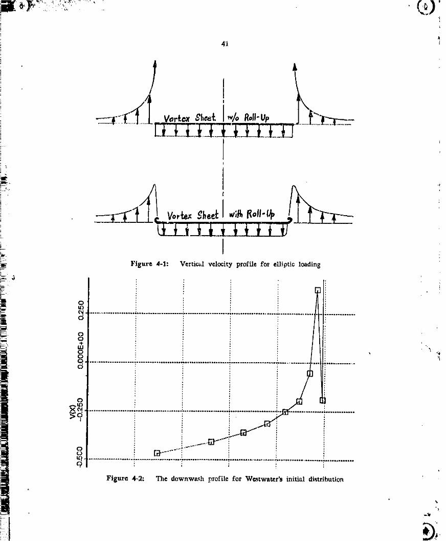
Figure 4-1: Vertical velocity prvfils for eIlJpti¢ loading 41Figure 4-2: The downwash profile for Westwater's initial distribution 41 ;Figure 4_3: Downwuh Profile: Integration of equal strength vortices 42 EFigure 4-4: I_wnwesh Profile: Integrationof equally spaced vortices 42Figure 4-$: Velocities half-way between equally spaced vortices 43Figure &6: Downwesh Profile: Integration of equal strength vortex panels 43
_o Figure 4-7: Downwash Profile: Integration of equal width vortex panels 44Figure 4-8: Downwash Profile: Equal width panels with zoll-up model 44Figure 4-9: I)ownwe._h Profile: The effect of virtual core 45
-_ Figure 4-10: Virtual_ore Lo_tion: Normalized w.r._, the tip pane_ 45Figure 4-11: Virtual-Core Strength: Normalized w.r.t, the tip panel 46 _'Figure 4-12: Moving Disk: Circulsr line vortex representation 46
---I Figure 4-13: Moving Disk: Vortex band representation 47Figure 4_14: Moving Disk: Vortex bands with tip _ore 47
i Figure 5-1: Flow Chart of the Vortex Dynamics Program 58
Figure 5-2: The First-Order Runge-Kutta Scheme 59Figure 5-3: The Reconstruction of the Vortex Sheet 60Figure 5-4: The Redi_retiT_tion of the Vortex Sheet 60Figure 5_5: Initial Configuration of the Vortex Sheet end Roll-Up 61
__[ Figure 5-6: The Core Dumping Approach 61
Flguro $_7: Roll-Up oE El_iptic_lly Loaded Wing Wake 62Figure 5oB: The Corresponding Circulation Distribution 62Figure 5°9: Distribution of Ci_ulation Surrounding the Roll-Up Core 63Figu_t_ 5-10: Blowoup of Fig. 5°9 63
: ; Figur,o 5-11: Roll-Up of Wing Wake at T - 1.00 64:, Figure 3o1_: Detail of Figure 5_11 64
-!I
00000001-TSA()6-
v
Figure 5-13: Roll-Up Produeed by It Moving Disk 65Figure 5-14: The Corresponding Circulation Distf|bution 65Figure 5`15: Distributions of Circulation Sux_unding the Roll-Up Core 66Figure 5-16: Detail of Fig. 5-15 66Figure 5-17: The Sheet Geometry: T - 0,55 67Figure 5-18: The Blow.,Up of the Spiral 67Figure 5-19: lI©licopter-type Loading Distribution 68Figure 5-20: Downwash Profile: Vortex Bands with the Above Loading 68Figure 5-,21: RoU-Up for a Helicopter Type Loading 69Figure 5-22: The Corresponding Circulation Distribution 69Figure 5-23: Distribution of Circulation Surrounding the Roll-Up Core 70Figure 5-24: Detail of Fig. 5`23 70Figure 5-25: Helicopter Ron-Up: T - 0_00 71Figure 5-26: Blow-Up of the Tip Spiral in Fig. 5`25 71 )Figure 5`27: Geometry of the Wake Vortex Sheet 72Figure 5-28: Repeated Magnification of a Section of Vortex Sheet 73Figure $-29: Repeat of Fig. 5-13 with Finer Paneling: T - 0.350 74Figure 5`30: The Corresponding Circulation Distribution 74Figure 5-31: Circulation Distribution Around the Main Roll-Up 75Figure 5-32: Detait of Fig. 5-31 75Figure B-l: Kaden's Similarity Solution and its Numerical Model 89Figure B-2: Initial Roll-Up Model for Axisymmetri¢ Vortex Sheet 89
00000001-TSA07

A PANEL MEI'IIODSTUDY OF VORTI.rXSIIl-q_'S: i WITll SPECIAl.EMPlIASIS ON SIU_'TS
'" O1+ AXISYMM_TRIC GI_OMh'I'RY'L
:- by
_ + lthiro So_i0ka and Sh©fla R WidnaU I+I.i
i--. FDRL Report No. 85-3 August. 1985
_--+ NASA/Amca Research Center contract NAG2-251i--J
Fluid Dynmuics Research LaboratoryDepartment of Aeronautics and AstronJutics
M_s_huNt_ lustRuteof Technology
_: CAmbridge,MA 02139
! _ The eelf-induced evolution of a vor_x sheet was simulated by modelling
the sheet using an integration of discrete elsmenm of vorticity.
Replacing renal1 mctioua of a vortex sheet by flat pan¢is of consr_nt
vorticity is found to Teproduce more accurately the initial conditions for
the Lagrangian simulation technique than replacement by point vortices.
Tie flat panel method for the vortex sheet was then extended to model
anisymme ,_. vortex sheet& The local and far field velocities induced
by the ax_.jmmetri_ panels were obtained using malched asymptotic
analysis, and eome of the uncertainties involved in other models of the
_ymmetric vortex sheet have b_n ellw.inatcd. One important result
of this analysis is the determination of the proper choice of core size
for a circular vortex filament which may replace a section of an
axisymmetfic vortex sheet. RoU-up of both two-dhnension_! eud
aTisymmetric vortex sheets was computed using the l_nel methods
developed in the report.
1AdaJpted £rom the S.H. T_e_t_ by Icl_ro Sugtoka, "The_'_udy of Vortex Bheete Using a _auel _ethoA", I_,I.T.,AUgur:t, _9_5.
-.......+-- 00000001 -TSA08

2
Nomenclatmoe
Roman Letters
a llalf-Width of a Panel (a - ¥_w)b Semi-Span of tile Wing or Radius of the Rotor(ao,b o) Position of Two_Dimensional Roll_up Core
t_ E 1 Elliptic Integral of tile Second KindF1 Elliptic Integral of tile First KindQn Panel-lk_ition Polynomials; Bee I_qnations (2,14) _ (2.18)
' R Radius of the Axisymmetrlc Vortex Element
(Ro,Co) Position of Axisymmetric RoLVUp Corer Distance Between Points or to the Symmetry Axisro Radius of Circular VorticRy lY_tribution
i. r 1 Shortest Distance _ the Vortex
• r_ Longest Distance to the Vortex_-_., (r_) Coordinates for an Axisymmetric Cylindrical Systemt s_ Line Integral Path Vectorf s Distance Along the 'Vortex Sheet or Panel
T Elapsed Time(u,v) Velocity Components for a Cartesian System
_," Velocity Vector !w Width of the Panel
Xo Distance from the PAge of the SheetPosition Vector
(x,y) Coordinates for a Cartesian System on the Vortex
Greek Letters
r Circulation
I"o Refercnt_e Circuhttion; Total Circulation
• Curvature; Small Quantity Parameter0 Inclination of a Fan¢l
K "Gradient of Circulation"; local Strength of the Vortex Sheet_, Elliptic Integral Parameter; see Equation (2.24)¢_ Vorticity Vector
i _ Stream Functkm
O0000001-TSA09

3
_o (gl) Stream I,'uw"tion _lutton
_l (Xe) Stream Fu_lction Soluthm
,SupcrJcrlp_
( )_ Th© lnner..l_mit( )o _e Outcr_Limit
Subscripts
( )_. l_crt_ining _ t_c i_Ix Panel
( )Vbyg Pert_fining to the Poi_xt llaLf-Way Between the Panels
( )_,on_o The Solution to the llomogerLco_s l_uaO, o_
( )sa Thc Inner-Solution
( )So The Intcrmcdiatc-Solu'don( )o Pcrtalning to the Mid-Point of a Panel( )ou_ The Outer*Solution
( )l_ The Solution ¢o _he Particular Equation i( )_D The Two_Dimensional Solution
aT_
- --- O-O000001-TSAIO

4
Chapter 1
Introduction
1.1. Fo=ndation of Vortox Sheot Studio=
A common feature of flows =t high Reynolds number is the formation of thin
regions of sharp changes in velocity known _ shear layers. In the limit of infinite
Reynolds Number, the diffusive effect of visc_ity is eliminated, and the regiol_ of
velocity gradients arc reduced to surfaces of step Ghanges in velocity. Such surfac_s
are km_wn as vortex sheets. Althougl_ the formation of shear layer is a viscous
proc_% she_tr layers are commonly approximated by vortex shests in the study of
invicid, irrotational "l_tcntiM" flow.
A vortex sheet can be represented as an integration over infini_esmal vortex lines.
The dynamics of vortex lhles, and thus the dynamics of the sheet, are given by
Helmholtz's vortex theorem. The theorem shows that vortex lines arc material lines of
the fluid and are convecl_d by the local flow. In flows w_.thout sourcas or sinks, the
distribution of vorticity determines the flow. If the flow is irvotational, the vorticity1
is concentrated in small regions of the fluid. Thus, an unsteady potential flow can be _
determined by tracking the vortex sheet as it is moved and deformed by the flow
field.
A rigorous approach to tracking a vortex sheet wil_ involve solving singular in_gro_
differential ©quations. The time integration can be simplified by using a numerical
_heme involving finite increments in time. llowever even with this simplification, a
rigorous reprtvcntation of the vortex sheet will t_ake the contour integral intractable,
Thus, a further numerical approximation n_ust be used to represent the continuous
w)rtex sheet using finite, di_rete elements of circulation.
The linear instability of a vortex sheet can be shown analytically, hut its sub_uent
00000001-TSA11

5
deveh_pment is dlffictdt to describe. IAIx]r_Tory ext_rinn_ntn with thin Nhcar ]ayel,_0
which are e_pected t_ I_ _imilar t_ vortex Nh_t_, nhow _p_ntane_ms generation and
gr_wth of sl_tt,tlly I_rkalh: r_dlup, TIds instability of the altear layer, knower, as the
KelvinIlehuhtdtz lnmt_d)ility, was the aub,_ct of tire first numerical atudy of vortex
|h_t_ |)y R_ltltcad [1_ lU this studyp a continut,_._ two dJmeoslooal VOrteX sheet W_;
reph_ed by a collection of diw_rete lX)hl_ of fiqite circulation, or l_int w)rtit_s, ?'he
initial flat geometry of the vor_x M_cet wan represented by a straight row of l_lnt
vorti_ lh_enbead titan adopted A Lagr_ngian approach of following each l_Aut vortex
over time. The motio_s t,f the vortices are ti_e _esult of the flow induced by the
l_rticular arrangement of vortit_ for e_ch step in time. R_enhead'u ceIculation_
_howed that the vorti_ form lc_ spiral_ within a small number of time stel_ if
the initial arrangement of vortices were given n small peri(_lic di_palcement, lkc_u_
of the tulious manual computationo involved, Rt_enhe_d proceeded no further than the
¢_rly stages of roltup. As a _esul_, the problems associated with this I_grangian
method were not k,_own until _any years l_ter.
The Legrsngisn approach to the initi_ value problem involving vortex sheets is not a
u_iversally aceepted concept. A pioneering effort by Birkhoff and Fisher [2] questio.ued
the foundation of vortex sheet studies for invicid fluids. They were skeptical of the
well lx_edness of applying invicid nnolysi_ to the dynamics of a viscously generated
phenomenon. A r_cent revLcw of the work in this area c_n be found in the article
by Self man and l_ker [3]. [[
Undaunted by questions regarding the welt-I_scdne_ of the method, for the last _ _
fifteen years there h_ been an increasing interest in refining R_nhcad's technique.
1"here are two reasons for the revival of interest in this area of study. First, the
incre_ in availablity of vowerful computers encouraged the development of
comput_ttonni fluid dynamics. Second, the desire to extend the invicid analysis for
high.sp¢_ aerodynamics to free vortex wakes ho_ encouraged the development of the
numeri_l appro_ch_.
0000000]-TSA] 2

f_
1.2, Irmtabllltles In N_me, Ic=l Vortex Sheet Modal_
The Lagrangi,m apim_ch to jimulattug a w)rt=x mhcct is often plagued by tnntzoliti_
(ztizg_l by the numerical appr_mcl_,the rammer in which vorl_x sll_t_ are m(_lelhy_,
and the inherent in_mhility of an actual vorl_x =heat, 'l'ite firaL IN ununlly due to the
ina_uraci¢_ hdmre_t in nutnetic_tl time integration tcc)nfltiu_ end in approzlnmthlg the
varylug geometry oi' the verier Miter, _11_e_md r_nw_ of Jnntahltity iH doe to lure
of a_u_acy dictated by tl_¢ atnount of a_mpututiotl available for the p_dtlcm, h_
order tit m_ttsfy the prnettegl }hntt_tion_ in _omputtug, the number end the e.ompiezity
of vortex elemcnt._ mu_t be reduced, Since tile J._g_aug!._ technique us¢_ tlxe r_tlit of
each time _tep _ the input for the next time step, lnaccuracica in th© technique
¢oml)oUn_ over time. llowcvcr, indi_crlmhmtc eliminatio_ of tns_biitty 1_ undesirable
since the phy_!cal ir,_tahility of a vortex street i_ indistingul_hMlle from tile artlfl¢l_l
inst_billty. "|he inherent inst_blHty of the vortex sheet is the mo_t Itnpormnt soux_¢
of difficulty in the coiculation of vortex aheet behavior.
Vortex sheet_ can be m_lclled in many way_ but whether tl_c models earl
realistically represent an inflniteamally thin sh_r layer is often not clear. Moore [4]
h_ demons_ratsd that point-vortex methods will always be unstable, lie found that
the numerical ix_tabLtity mimics the KelVinL.IIelmholtz instability in which the _mullcst
wavelength r_olvable, using points equal to twice the spacing, was found to be the
most rotatable. However, thi_ instability cou._ea the vortex _heet beh_g represented by
the point-.vortices to cro_ it.ll, which is inconsistent with the allowed behavior of
material surfaces. In tile most _uccc_t'ul rx)intovortex methods, the vortices are _'L
repeatsdly redistributed along the _hect which unintentionally acts as a low pa_ filter, _
damping out the instability to delay tile onset of chaos.
].laker [5] :,rid Murman [6] have tackled tile vortsx sheet problems truing a mixed
LagrangisnoIiul©rl_n approach, commonly refcred to _ the "¢lond-.in,_ll" approach, In
this re:heine, the Euler :Equation for the flow is solved for each ¢¢]1 formed by a
spatial grid network. The use nf the Euler Equation ellowq the use of a fast Poison
Solver to significantly increases the efficiency of the numerical m©thod, Murman
confin_ the cix_ulation to _ortice_ which are ¢x)nvectsd lndei_ndently. Otherwise
vet|icily diffuses nuraericMly, at_d ,_tructures with grid related length _les appear.
Whether them atructur_ repr_cnL_ physically te_|istic features which are tot) atoM1 to
00000001-TSA13

?
i_e re.dyed b_ tit," grid is n.t clet,;, On the _,lther hand, although the small .tale
structures f.und b.v Mtstre are aupptca_d, Murmuu's method _n n(_t reproduce, the
smtx|tb spiralling nail up existed in _ vnrf/_x shec.t.
Spectral mcthc_ds have b_en applied to a assail number of cas¢_ with simple
geometries to study W_xtex edteetitab!lity. Tiw, p:_oblcmaddre_cd by Rt_cnhead has
been studied using t,hc Sl_CCtraln_ethod by Mot)_e [7] mad by M©h'on) Baker, and ths,,_g
[[_ The f¢)rJner _dlh'c._,_edInfi.ite.'_mal pcrturl_ations, while the latter add_cA_ed finite
aml)litudc disturbartces. They Ix)th _rrived at ¢_)nsistent r_ult. SIngularitic.s in the
t'or_n of infinite curvature of the vortex sheet were detected within a finite amount
of evolution time. Although the method %csult__pt_ear to be extremely reliable, they
are too limited to be useful for practical problems such as the one di_u_d below.
They do however fllttstxate the futitlity of _lgorously following the evolation of a
vortex slteat at i_finite_nxal spatial mc_l_.
1.3. Applic_tion to w_ke of a lifting =;t_rf_ce
Any lifting surface of a finite span trails a shear layer ;n ,% _':.,ke, _.ommoniy
referred to es tile wake vortex sheet. This sllear layer can be p)_u'_ed by separation
at the leading edge of' a highly swept delta wing at high angles of attack or b_ the
It, s of vorticity from the vortex "bound" by the aerofoil. In the early 1920's. _taz_dtl
hypoth_izcd that the ¢(_ of wake vortex =sheets roll-up Into exlx)nenti_! spirals.
Keden [9_ using dimensio_at argument& derived the behavior near the edges of the
vortex sheet _.railed by a whig with an elliptic lift distribution. This distribuhon is
important in efficient airplane d_sign _ince it induces a ¢o_nt downwash which
minimi7_s the h_duccd drag for a given e_spact ratio. Using dimensional argu_euts,
Kaden found that the rollup produced a spiral of 2/3 l_Wer and from this the center
of the spi_l c_n be approximated. ]Betz it0] attempted to calculated the distribution
vorticity in tlie spiral by con_rving circulation and impulse, llowever, lktz's constant
which determines the exact shape end tile distibution of vorticity with the spiral w_
later shown to U¢ incorrvct by l_llin [11[
Rosenhead's method was first applied to "Keden's Problem" by We_twater [12_ In
order to study the three,dimensional geometry of the trailing vortex sheet, W_twater
replaced the stre_mw[_ coordinate by a time .like coordinate to form an unsteady, two-.
_t%
00000001-TSA14

i_.|_ dimensional pn_as. 'l'hiri is equivalent t_ havlug the sheet crcm-_ection being swept
away' from the wing which generated it. This prtr._hire, known as the Trefftz planeE
_!, method, is now universally used to ,tudy wake vortex sheets where the deformation
in the streamwise direction is amumed to be small. Weetwatar discrctizcd the trailing
vortex sheet by _mpl,cing 20 segments of the ahcct with point vortices of the Mine
i circulation. The vortices ,re convected for each tlm_tep by veloeitiea they induce oni .
each other. Although the vortices t_ll_ up more or less ,moothly, the spirM did not
i quite match Kaden's result. The inaccuracy of W_stwater's t'_ult w_ initially
i attributed to the insufficient number of vortices dictated by lack of computational
i_ .; devi_ea.
_: Attempts to improve W_stwater's results by using more point vortices have not been
[ ": : suecagsful. Increasing the number of point°-_orticas w an found to hasten the tend¢ncy_.*_. I
" toward chaotic displacement of vortices_ Such failures in achieving higher resolution
by increasing the number of point vortices are attributed to the singular nature ofi "'_ t
[ . , point vortices. The veloeity singularity at the location of the point vortex can bei_:" -in
,_, removed by replacing an individual or a group of vorticas with a nonsingnlar[ '
Lt I distribution of vorticity. However this method has bean found to only delay the onset
of numerical instability while introducing an ad hoe length parameter for the size of
the distribution. The failure of the discrete vortex approach may be due to the
imIx_Ssibility of reproducing the sheet-like nature by a finite member of positions. On
a sheet, each position _ its own unique orientation, which is the result of the I
sheet's continuous nature. I
The method of equal_spacad redLmretization introduced by Fink and Soh [13, 14] is
! notable for its simplicity and for its su¢¢¢_ in delaying or eliminating instability.Fink and Soh found that replach'_g a vortex sheet segment with a point vortex at the[
[_: middle of the segment will significantly t_tut_ the discretization error. This in fact
truncates the formula for the velocity associated with a vortex panel, a small segmentt
I"-7 of the vortex sheet. By placing point vortices at equM dist_mces along the sheet, it is
i: possible to replace equal length segments of vortex sheet by point vortices at the
[_ centers of the Jcgments. Since this procedure Is repeated after each time step, Fiuk
and Soh can decrease the distances between points $s desired to resolve the rollup of a
_ finite vortex sheet. In addition to maintaining the spatial resolution, the method[:F_, ' reduces the singular behavior inducad by a vortex on neighboring points alot_g the
-- |
00000001-TSB01

9
_heet, llow_ver, singular behavior will appear when two _rta of' the vortex sheet
apprtmch each other cloetfly _ In the tllrns of it spiral.
Baker [15] questioned Fink and Soh's practice of amalgamating the inner region of
the rollup t_to a single "core vortex". "Core dumping" la a simple approximation of
the singalarhy at the edge of a finite vortex sheet, In older to analyze iUs effect,
i--, Baker used Fink and Soh's method for d_ribing the wake trailed by a ring wing, a
circular vortex sheet with sinusoidal vorticity distribution, Upon observing the failure
i of Fink and Soh's methcxl in dealing with the double-branched rollup associated with
iD the ring wing, Baker concluded that the strong core vortex must be responsible for the
_ smooth roIlup ob_rved.
i-Hoeijmakers _nd Vtmtstra [t6] improved Fink and Soh's technique in several ways.
First, they introduced the use of u _phisticated splining technique for dividing the
_h_t into panels with small curvature and polynomial vorticity distribution,
_-. eharcterized as a second-order panel metk,od. Second, PuUJn's generalized similarity
_._ solution for rollup [11] is invoked to make core dumping acceptable. Since Punin'sanalysis also applies to the double-branched rollup, the vortex sheet trailed by a ring
wing can be made to rollup just as smoothly as that for a finite wing.
lligdon and Pozrikidls [17] introduced two-dimentional panels which are circular ares
i - with a polynomial circulation distribution. Since vortex dumping was not used, only
closed and infinite vortex shee_ were analyzed. Because the panels provide a
continuou_ representation of the sheet, there is no r_striction in width of the panels,
By using smaller panels to increase local resolution, double-branched rollup can be
d_scribed without the use of core dumping. The existence of a panel size dependent
instability was mentioned, but the nature of the instabiiity w_s not described.
_" 1.4. The Motivation for this Study
iThe sire of this thesis is to provide a foundation for a vortex sheet technique which
_. offers a more accurate simulation of a thin, a_isymmetrlc shear layer. The numerical
_, technique_ similar to those developed for point-vortex methods will be adopted for flat
: Icctions of azLsymmetric vortex sheet, giving us a simple panel method foraxisymmetric geometries. A careful, systematic study of vortex sheet_ represented by
i: flat panels has been parformed to ¢xplure the strengths and weaknesses of thL't
j;
00000001-TSB02

I0
apprcach. Unlike some studies of vortex wheet models, the accuracy of the model wHI
be ICressed more than the efficiency o£ the c_mput_tional technique, it is hoped that
much of tile artificial behavior, such as that introduced by a rigid wake analysis, can
be removed from the limulation of vortex _heet.
"]'he _xlsymmetric panel method is obtained through the extension of the two _
dimensional panel method to axlsymmetric geometries. The axisymmetric geometry is
unique for being the only three_dimentional geometry with only two-coordlnates.
Thus, unlike the general three-dimensional flow, an ax_symmetric flow can be described
by a stream function. Fortunately, many interesting flttid dynanfics phenomena exlfibit
axisymmetry. The circular jet and the buoyant plume are two examples of
axisymmetric flows which can b¢ studied easily in the laboratory. A probleJ_ of
special engineering interest is the axisymmetric equivalent of Westwater's work, the
roll-rip of the wake-sheets generated by a helicopter in hover. The roll-up of rotor
wake is extremely important to helicopter performm_c¢ because, unlike the ,,rake trailed
by airplane wing, the wake remains close to the rotor, significantly affecting the rotor
performance and acoustic.
it_k
e
00000001-TSB03

ll
Chapter 2
Mathematical Formulation of Vortex Elements
2,1. A Review of Concepts Regarding Vorticity
Vorticity, _, is a local property of the fluid, defined as the curl of the local! velocity, Q;
_(i_- V X v(_ (2.1)
This vector quantity describesthe rotation of an infinitesmal element of fluid. A
vortex line is a curve which is everywhere tangent to the local vorticity vector. To
be consistent with the rotational as_t of vorticity, a vortex line must end at the
boundaries of the fluid or form a cloeed curve and may never intersect itself or
another vortex Line.
In real flows, vorticity is produced as a 8heel of parallel vortex lin¢_ known as a
vortex sheet. In invicid flow, the vortex sheet remains infinitcsmally thin and defines
a stepwise jump in velocity tangent to the sheet. The difference in velocity across thet
sheet defines the "strength" at a point on the sheet. The vortex sheet usually roLls-up
to form what can be described as a vortex filament. In a rcal fluid, the vorticity
within the vortex filament will become smoothly distributed by viscous diffusion
within a finite time span. The structure of an evolved vortex filament is _ilar to
the asymptotic limit for an invicid vortex filament with an infinite number of layers
of vortex sheet rolled up into a region of finite ¢ro_._c.ction. In invicid analyses, a
vortex filament with a smooth distribution of vorticity i8 commonly used as a model
for a tightly wound section of a vortex sheet.
In potential flows, the circulation
r - ,,'. (2.2)
J
+,
O000000]-TSB04

12
is a conserved quantity. This allowm tha flow as_clated With a complex vortex
my_tem to be determin©d by _umming the contrlbutionR from a finite numt_r of vortex
elements which make up the system. The amount of cjrculatiorA in eaf,_helement mtmt
equal the circulation in the section of the vortex system the element replacers. I_y
r_placing a vortex system with a set of known vortex elements with a similar
distribution of vorticity, the flow of material points in a complex vortex syBtem can
be deduced.
2.2. Two-Dimensional Vortex Elements
2.2.1. The Point Vortex
The two-dimensional form of the line vorvex is the point vortex. The velocity
induced by a point vortex can be derived from the conservation of circulation, (2,2),
around a point:
-r
2_rV,a_I=I = 0 (2.4)
where r is the distance from the point vortex. The velocity iadncad by a point
vortex is singular when the distance from the vortex, r, equals zero. Prom the
velocity expression, the str¢_._ function of a point vortex is
-Fd./(r) --=_ In r (2.5)
or in Cart_ian coordJna_ centered on the vortex,
-r x.y) = --
The two-dimensional form of a vortex filament isa vortex with finite core. If the
crcm_soction of the core is clrcul_r, the flow outside the core is equivalent to the flow
induced by a point vortex of equal strength at the core's center. However, nnlike the
point vortex, the velocity i_duced by a vortex core is non_ingul_r since the vorticity
' is distributed over a fi_ite area. A Rankine vortex, an exampla of a vortex core,
conslst_ of a cylinder of fluid in solid body rotation surrounded by an irrotation_]
flow.m_-4
00000001-TSB05

13
2.2.2. The Vortex Panel
A vortex pax_el is n megment of a two-dimermlonal vortex sh_t. It ls equivalent in
thr_dimenslous to a strip of vortex nh_t compoa_ of parallel, straight vortex line_,
Sin_ invicld vortex eysteraa would be made up of vortex nh_ts, accurate modelling of
invlcid vortical flow should be ]po_Ible using vortex panels.
[: The strength of n vortex panel will dei_nd on the amount and distribution of
i circulation in the panel. For this study, a ]panel with unii_rra distribution of
I ¢ix_ulation is considered. Then the groin translation of the panel can be defined at its
mid,.poin¢, its ccntroid of vorticity. The strength of the panel can be determined by
its width and the "gradient of circulation", K, defined mathematically as
or
os
The disarete form of _ is obtained by the centrwl di-Cfercncescheme
where r t is the circulation of the i th position on the vortex sheet and S i_ the arc
length taken along tile vortex shee;, Then the strength of the i_h panel of width w
in given by
! ~ F* W-r'-Vz (22) :,-- W
,_ Thus, a panel is equivalent to a point vortex with the same circulation "6meared" into
"!. the shapo of a panel.
i lin_ making up the panel as point _orticea of inf/v.it_mal strengths. The velocity::,_: inducted by the panel can then be ¢_btained by integrating the contributions by the
_,*i point vorti_s. This is can be accomplished by integrating along the panel, the effecta
_i of point vortiv.as with the strengthi:i
_. where _ is given by (2.7).i
00000001-TSB06

14
In order to simplify the mathem_fi_ lnvolwd, wo shall limit ou_lves to flat
vortex p_nels. In a twodimensional representation, the panel will be represented by a
line _gment having the ('.artesian ¢_ordinates
zCs)- 3o + _ cos6 (2.9)._s) - Yo + s slnO (2.10)
where the panel at (xo,Y o) is inclined at an angle 0.
In a previo_s work on panel methods Morky [18], using fl_t panels, carried out the
direr integration of infinitesmal velocities to obtain the velocity field induced by a
panel. Since the velocity integrand is singular, this involves evaluating a Cauchy
principal value integral. However, the logarithmically singular stream function of a
point vortex is integrable. Using Equations (2.6X2.SX2.9) and (2.10), the stream
function is given by integrating along _he vortex panel:
mK
,/_x,y) = _ I'.,, tnl(x - s ¢ose)_+ (y - s stne)q as (2aI)4r¢
_g
- I_ tn [Q_- 2s Q3 + s_] as (2.12)47r
= _ [(_ - Q_)triO.,+ (a + Q_)tnQ, (2,1S)4_
a"Q:_ a+Q 1
+ 2Q, + 2Q, - 4,,IQ_ = x2 + f (2.14)Q, = ycosO -- x#lnO (2.15) '_
Q3 = zoo.sO + y.slnO (2.16)Q2 = Q_ - 2aQ_ + a2 (2.17)Q, ._. Q_ + 2aQ_ + a2 (2.18)
where a is the half-width of the panel (a _ V_w).
There are two methods for evaluating the velocities from the stream functions. One
method, most suitable for Eulerian analyses with its coordinatc-.mesh, is to take finite
differences over the control-volumes. 'l_he alternate method is to evaluate the velocities,
which are derivative_ of the strea_ functions, explicitly at the prints of interest.
b
00000001-TSB07

15
,,(x,y) = ---. (2._9)#y
a+O_--E_l-s_,o 02 , ,"¢2_ ,rc_s_T) l (2.20)4,r _Q_ + 2_,o i._c,8_ +O_
v(x,y) .__ (2,2_)8x
a-Q3 a+Q_= _'4,,l-co+ot,_,, - 2,1.0 (.,w-_. + .rcts-QT)1 (2.22)
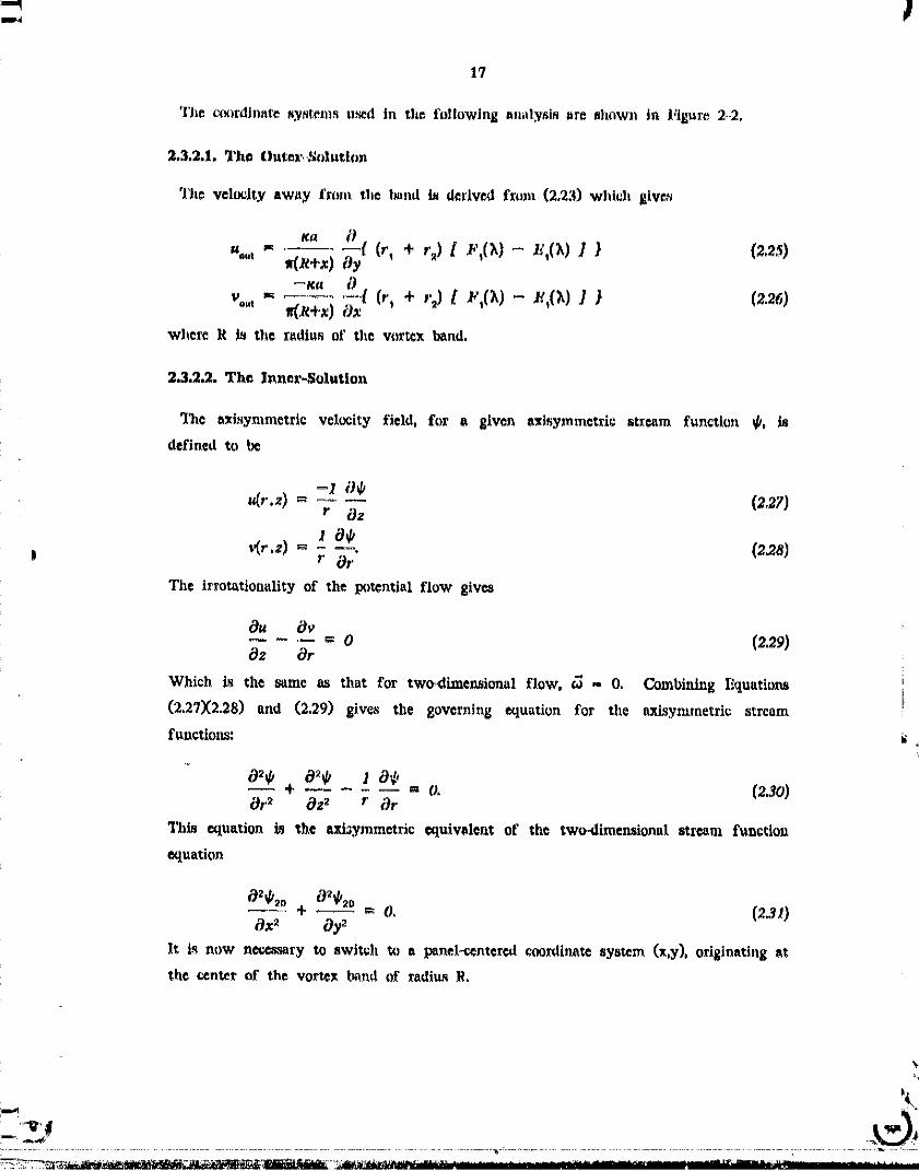
The velocity field produced by the equations ate ebown in Figure 2.-I. In theee
formulas, the arc-tangent, being multiple valued on the panel, models the jump in
tangential velocity as the panel is crossed. Mathematically, the panel is a branch cut
in the coordinate space connecting the two logarithmic singularities at tl_e edges of the
panels.
2.3. Extension to Axisymmetric Geometries
2.3.1. The Axisymmetric Problemi
An _lsymmetric vortex sheet is composed of coaxial, circular vortex lines. Thus, a
simple-minded extension c[ the Rosenhasd approach to sheet discreti_tion is to replace
point vortices by circular line vortices, However this straight-forward approach is
nnworkable because a curved line vortex is influenced by its own velocity singularity.
As a result, a circular line vortex will translate through the fluid at infinite velocities ' _'
[19_ One way of avoiding the infinite translation velocity involves using circular
vortex filaments, or vortex rings, in place of the singular line vortices. This
introduces a finite vorticity distribution which induces a finite translation velocity.
Another approach is to u_e polygons made of straight segemuts of line vortices in place
of the vortex rings. A network formed by vortex polygons is known _s a vortex
lattice. Unlike the strictly azlsymmetric models, the vortex polygons ahould be able to
display non_axLsymmetric deformetion,_ of the vortex sheet. A_Jmutlml deformations are
known to hasten the decay of vortex rings [20_ nnd should have an Ln_l_rtant
consequences for the behavior of three-dimensional vortex sheets.
tlowever, both of the above models of axlsymmetric vortex sheet require the _¢lection
of A length Parameter: the tadins of the vorte_ core or the length of a polygon
_tt
........... ............... = :====, ............. ...... ................ , == ,
00000001-TSB08

16
element. Thus bef.re any of the_ m_els can be used accurately, it t_ neceasarlV to
gain a better under_tanding of the behavior of vortex sheet the_e mt_els nre d_lgned
to reproduce.
The axisymmetri_ _qulvalent of the vortex panel is a "vortex band", a _¢_flon of an
axisyJnm©tric vortex sheet. It represents n finite plc_e of the vortex sheet Wldclh in
some models of the axlsymmetrlc vortex sheet, is _eplaced by vortex rings and vortex
polygons. Although a band does not _ any volume, by defining the band's
position at the mid-point of the band as was done i'or the two-dimentional panels, the
_elf-induced velocity of the based is shown to be finite.
The stream function for circular line vortic*s, expr_.d using complete elliptic
integrals EI(_,) and F1(70, is given by I_b [21_
= (r, + { F,(X)- B,(X)27t
_, = r_ -- r, (2.24)r_ + r I
r_ _ Least dis_nce between (x,y) and the vortex
r2 _ Oreatsst disutnca between (x,y) end the vortex
To obtain the flow for a vortex panel, this streara function must be integrated across
_he panel, resulting in n difficult double-integration of singular elliptic functions.
2.3.2. The Method of Matched Asymptotic Expansion _
If the width of the vortex baa_! is small relative to its _¢lius, an asymptotic
expansion for the stream function can be obURncd. The approach t_d here for the
vortex panel, known as the method of matched asymptotic expansion, wu also used in
a study of curved vortex filaments [22], "[_is method derivee an uniformly valid
solution which asymptotically apprcx_chca known bel_avior of the actusl stream
function. 'Dins, it is important to heuristically deduce what is exp_ted from the
stream function. We can expel the character of the stream function away from the
_and to a_pr,__.,_'hthat of the atre_m function for a circular line vortex. _hu., the
circular line vortex stream function will be used a._ the outer_solution. Near the band,
the strea_ function shonld reaerabte the two-diraensioa_l solution for a vortex panel.
llowever, the innerosotution must include efi'c_ts due to curvature in the axisymmetric
geometry.
, := =,, ......... ,,* == _= :-== = ,= ..... _ ,, :.... , ,, _ =- , ......... 2!
00000001-TSB09
17
The _rdinate _.y_t_ms used in the following analy_i_ are shown in Figure 2..2,
2.3.2.1. The Outer.,Suluthm
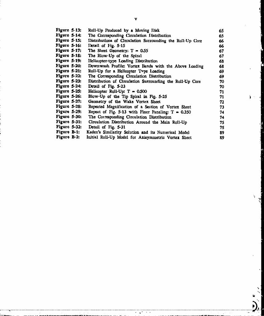
'l'he velocity away from the hand is derived from (2.23) which £1ve_
%' wry+x) Oy (r, + r_) [ _',(_1 _ _',(_,11 } (2.2.9
1t{_--_"- - (,, + ,_) I _',(_1- _g(_)I t (z2_)v°"t "_ _,R+x) Ox
where R is tide radius of tide vor_x band.
2.3.2.2. The Inner-Solution
The azisymmetric velocity field, for a given axisymmet_ic stxcam function _, is
defined _ be
_,.,z)= (z27)r Oz
| _r.z) _. - ---. (2.28)r Or
The irto_tionality of 1;he po_ntial flow gives
Ou O_= o (z29)
Oz Or
Which is the same as that for two_dimensional flow, _ - O. Combining E_luations
(2.27X2.28) and (2.29) gives the g(Ner/lir_g equation for zhe axisymmetric streamfunctions:
02_ 0_0 I 0¢,+ .... = o. (2._o)
Or_ Oz2 r Or
Tills equation is _he axi_ymmetric equivalen_ of the two-dimensional stream function
equation
_-- + _ -- O. (231)Ox_ Oy_
It is now nece_.ary to switch to a panel-centered coordinate system (x,y), originating at
the center of the vortex b._nd of radius R.
D_
O0000001-TSB10

18
Non dlmennlooallzlng with resident _) tlt¢ o;=tcr length,_ale, radius It, gives
-_.::.+ ,--_...... ,., m O, (23,_)#x 2 Of Z+x #x
The _oxdtuates r_n now _ xe.cated by a ,malt i_ramet_x', the curwture, which is
e _ _ where _ is the half-width of the b_nd, Resgaling (2,33) by e gives
e
Ox z Of _+ex Oz
with the understanding that (x,y) are non.dimensional, stretched ¢tx)rdinatfs,
_-- Tit. ¢xi_uded inner att_n_ function,!--
; is ta_d to expres_ the effects of cttrvature, e, due to the perturbation of the two _
dimensional stream function, ¢/.. Ia the above aeries, terras O(e n In.) have been
included wi_h terms O(e n'l loci. Uetug thi_ expansion, the 8overntug equation(2.34)
can be broken up into equations for each order in the expansion:
Ox z 8f
Ox "_ Of 0:,
The zerothoo_dc_ equation is the governtug e_lu_tion for the two_hmensxonal stream
function(2.31). The sutmquent equations for the higher,order terms of the tuner stream
function are all Poisson's 'Equations. with the non4tom_V,eneons terms involving the
_lutitms of lower_rder equatit_ns. Thus. repetitive ev:x_uati_u t_ the Poi._m'e F_tlUation
can he n_d to obtain the desired degrw of accuracy.
By _uming the effect of curvature to be s_all, we wilt orfly nce_tto evaluate the
first term _n the exl_ansk)n. Ti_e particular _olntion for the fiat.order Poi_)n's
l_uation is
!
.... " : ......... O0000001-TSB11

19
Then, using (2.13) for the zerllth-order term of tile ellmnnhl]l , tile Jr,net _treamfunction is
b 1
where _bhorao is some stream function satlsfylug the homogene(ms _luati(m, whidl
determined by starching the inner end outer solutiol_n nn _hown In _lte following
B': U_ing notations defined by (2.14X2.15X2.16X2.17) and (2.18), The Inner solution for
_i,'_'__ the velocity field is
- (1+_e_)t anOt,_Q_.+2co,O(,_as_T +,,mr_.)l (z4o)1 K 1 t Q'_,I - " "" a_,2_, a+Q_,.
_b- + _e[(a-O_)tap.2+ (a + O,_)tnf21-4u,a"O._ a+f2__" + 2Q_(arct 8 ........ + arct8 ......... )1
_. t f2, _2.-(4)
2.3.2.3,The InnerlOutcr Matching Solution
The vortex band inner stre_tu function solution (2.39) must be matched to _;he outer°
solution, w_ch i._ approximated by the circular lh_e vortex solution (2.23). First, the
._ circulations of the perturbed vortex panel and the circular line must ba alual. Then
it is necessary to equate the outerqimit of the inner-solution to tile inner-limit of the
outer-_olution using a matching criteria. The "matching solution", the intermediate
limit solution obtained using the matching criteria, will nub_luently be subtracted from
i the _um of the inner and outer solutions to produce the uniformly valid tt_ymptoticsolution. A distraction of the method of matched _symptotic analysis _n be found in
Reference [23],
The barters.limit of the outer soIution is found by expanding the elliptic integrals in
(2.23) for small complementary modulu.% I - _,_ (2.24), ns shown by Jahnke and
--f Emde [24]
¢,oo__ {_ + x ,', x
_L This result w_s _1_ obtained by Tung and Ting [25_
O0000001-TSB12

2O
The ¢_u_r,]tmit _i' the ttmerkdnllon J_ i_mud at tha llnfl1, r:L_,>a,W]L_,]_th_ panel
width and lnclhtation I_co]ne ttll|t_lj_rtant, 'i'herefor_, uHIng the apl_ro_imatlmJN
ta'c_g-_-, + ar_,tg Q4 r-_arctg Z-_ '_ 0_._ _'
w© ¢_u get tile outer-limit of tile tnnc_-solutioJ,,
--Ka X
¢J n= r!"(,t +neglecting the higher order ter,nn.
Since the pan¢]._ sl)an the width 2a, the definition for _(2.7)
F:p_,no1 - 2 s I_ (2.44)
is euhstituted into (2.42). The complete iaterme4iat¢ stream fnpction for a vortex band
is produced the matching criteria, _homo, which equates the two intermediate limits
(2.42) and (2.43). Neglecting the higher-order tern_ the matddng grRcria is _dded to
the innerolimit of the outer aolution (2.42)
'A"
'l?ac matching criteria, _homo is obtained by equating the inner-limit of the outer "_
solution (2.45) to the outer-iinfit of the inner solution (2.43)
-/ga Xd/_° .... {In_ (] 4" _-[_} (2.46)'iT a
X r_ X
Ti_cn the raatching criteria is found to
Ka X ¢
and the intermediate etreanz function is es_b]i._hed, as shown by Hquation (2.46), to he
00000001-TSB13

21
r2[
_, _ (1 + 2_) m'. (2,4s)ft. a
2,3.2,,4. 'l'h_ Uoml_mite, Unlfnrnd_..Valld _tduthm
'J'|iC taau_)lete, unlfnnnly,.valld stream :l'nnctlon i'nr the axlsymnLe.tflc vortex trend tl_ a
t;gnilx_Ita ot' the lnnr, l',_)Jutlon, _A_,' the outer,_duti_)n, _,x_,' and the Jutc,z'jncdia_,
(mat_hiug) mfltttltm, _Xn' The _mJ)let© _luflon can t_c £nrmulnted _ he
¢(='Y)= _,. + _o._- ¢,o (2m)W]lere ,
_,,, _'! Inner Sol_tioa (2,99)x
_o _ 2"wa_Dlmenslon_ Pamel ,S'oEm_n (2,13)
41r
+ 2f2, ,ms-_. _ + 2f2, ,me-_._ 4,
= _ (r,+r2) { F,(_) -- _,(_) }
ff
using notations introduced earlier. Notice that _t n and _l 0 have been [_
redimensionali_2cd with rCSlX_Ctto the outer-dimension, R.
The above stream function L_ axisymmetrlc, thus its velocity field is defined to be
R+x Oy
_(x.y) = ........ .a+x Ox
floweret, the tnuermolution, _tn, and the lntermcdiatc_olution0 _to' are valid only for
the inneroregion, x << R, Thus, the inner-legion velocity field, using R+x _ R, becom_
O0000001-TSB14

22
I 0
while the outer velocity field remains
-1 9*o.t
x, = R+x Oy
_j
v(x.y)= 8xTh_ th© velocity field in given by a comF,_ite _olution of the form
u(x,y)= u,.+ Uo.t.-% (2.50)vCx.y) = v,. + Vo,.._- v_ (2_1)
where,
-_ (l+x,2_AJ Q_ a"_s a+Qsu,. _ _4_r [--alnO In= _,_+ 200*0 (arC3g---A-__R4 + arOts_E'_ )]_,
- _ x lnQz a'-Q s a+O_v!.- 4_r(1 + _) [--cosO _,,- 2ano (arctt_- + arctr_-)l
I
4""2R [(a"_z)InQ z+ (a+Q_)lnQ, -- 4a
a-Qs a+Q.
+ 2Q,.rct_z + 212,arctg-_'el
_ _"-_a /(Z+Z)(/_-v) + (r,+r2)t_-_---_)1
_ [( + (K-E) + (r,+rz) ]Vo._ _R+:d Oy
--t_a + x y
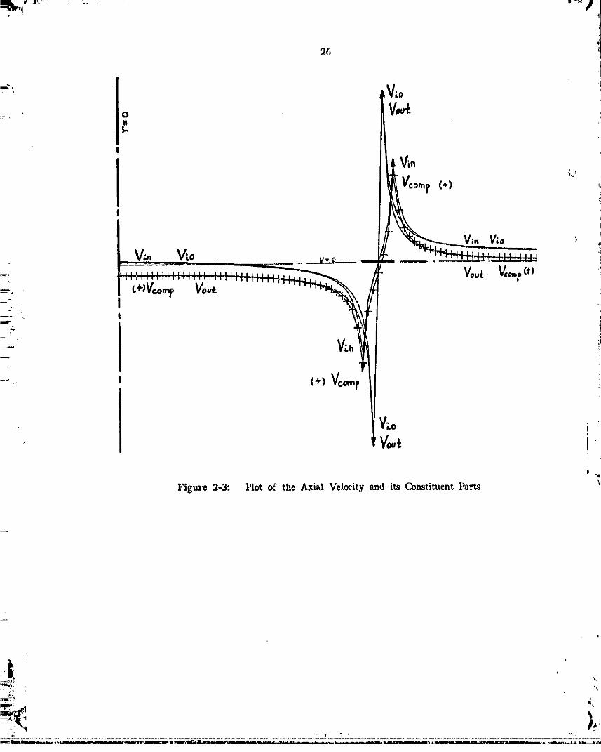
The relationship between l_trwof the e,o;_lplete _olution is shown by Figure 2-3,
uhowing the contributions to tile velocity profile taken radially from the cylindrical
coordinate tt_, denoted by the center-lhte, through a vortex Mud (O - 0). The
uniformly-valid, ¢oml_osit¢ _olution for the veh_:ity induced by the vortex panel,
VeereD, is denoted by cro_s_, l'_'omit,ent features in the plot are,
00000001-TSC01

:_pl_ _r II" t_ ]
I) the I/r type slngularlty of tile outar_Ivtion at the center of thepanel (x - 0. r1 ,_ 0) mawhed by the tntermediate-_lolution,2) the logarithmic singularities of the innsr_lution at the, panel edge,s.
The compo_i_ _olution xctalns tileOuter solutlon'a O(e erie) portion on the axis of
_ymmetry while smoothly blending in the two-dimensional inner-solution in place of
the singularity at rx ,, 0 before decaying off f-star than tile two-dimensional solution.
[_ Notice that the inner_sointion is displaced, representing the speed of the self-induced
tra_lation of the vor_x panel_lh)
2.3.3. The Self-Induced Velocity
An important result of the preceding analysis is the scl£-induced velocity of a vortex
band. Tile motion of the vortex band is defined at the mid-paint of the band. Thus,
• using Equation (2.51), the axial speed of the panel center is found to be
i v.oo ax
I 2fir a
The radial velocity at the panel center is zero for any orientation. Thus, for the
_ present order of accuracy, O(e), the self-induced trauslation of a vortex bend, defined
at the center of the band, is purely z_xial and independent of the panel orientation.
By applying (2.44) to equate the circulations, this result can be compared to the self-
induced velocity of a ulfiform vorticity vortex ring, where _ is constant, [21, 22]
i_ i 9nnQ 2_rR ro
, Thus, the core radius of an "uniform" vortex ring must be
i
U
: o_"_0.4724
i_ in order to translate at the same vel(_ity _s a vortex panel of the s_me circulation
_nd r_dius. Since tile _elf.-induced velocity reflects the energy of the vortex element.. the ratio pursued by equating the known energy of a vortex disk wi_h the energy
_, i numerically i_tegrate_ f,_r a set of equally spac¢_t vortex _ing_.'l_e c_e diameter of
00000001-TSC02

24 i
tile vortex rings giving tile same amount of e_lergy is obtained numerically and the
ratio is the quotient of this value over the ring _pacing. ]ly increasing tile num|_r of
vortex rings, the ratio w_ found to converge to about 0.50 [26_
00000001-TSC03
:- 25
Figure 2=1: VelocltyVectors.Associatedwith a VortexPanel
Ii
I
I
¢r,z)
Figure 2,-2: "J_e _ordtnace System
00000001-TSC04
26
Vin V_o
- _ š�Æ�Þ�Vo
( "Figure 2-3: Plot of the Axial Velocity and its Constituent Parts "_
00000001-TSC05

Chapter 3
Numerical Behavior of Vortex Elements
The FORTRAN subroutines for calculating the velocRies induced by different vortex
elements are presented in Appendix A. In this section, the differences between vortex
elements will be explored.
3.1. The Velocity Profiles of Two-Dimensional Elements
Figures 3-1 and 3-2 show velocity profiles for vortex panels. 111e velocities are
pe_pendicular to the panel-centered coordinate axes because of the panel's uniform
circulation distribution. The most important feature is the lack of a strong sigularity
| in the panel velocity profile. However, the normal velocity has a logarithmic
sigularity at the edges of the panel and no singularity in the tangential velocity, the !
latter being double-valued but finite on the panel itself. Away from the panel, the
velocity profile quickly approaches the point vortex profile. The difference in the
effect on the adjacent vortex elements is not obvious in this represen_tion.
3.2. The Velocity Profiles of Axisymmetric Elements -,
Figures 3-3,3-4,3°5, and 3-6 show the velocity profiles along the panel axes of vortex
bands _vith inclinatior_s of 0 and 90 degrees. The centerline to the right denotes the
location of the axis of symmetry with respect to the width of the panels. The self-
induced translation velocity of the vortex band appeam as the no_-zero axialvelocity
at the midpoint of the panel.
t.
00000001-TSC06

28
;_.3. Integration of Vortices in the Form of a Vortex Panel
As a simple te,_t of integrating vortex elements to slmu]ate a vortex sheet, vortex
elements were arranged to form a vortex panel. The flow prcxtuced by a vortex panel
of uniform circulation is de_cribed completely by Equation (2.13) and provid¢_ It
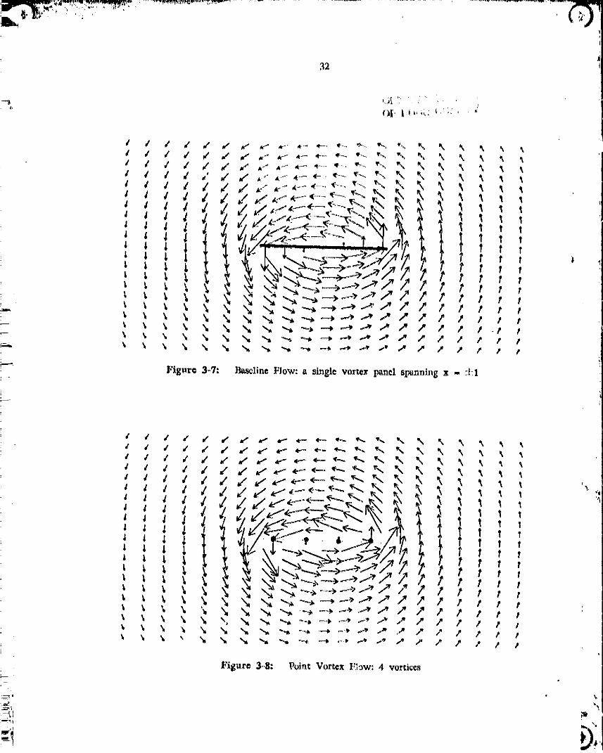
baseline for tile flow induced by the integration of "qortex elements. Figure 3"7 shows
the velocity vectors of flow around the baseline panel. The figur_ 3-8 and 3-9
shows the flow induced by four and ten point vortices, _pectively, arranged to
simulate a vortex panel. The accuracy in reproducing the baseline flow demonstrates
the gain in accuracy Itekieved by integrating more point vortice_ Of special
importance is the velocity induced on the panel repre_nted by the point vortices, The
velocities induced on the point vortices are shown along the dashed line representing
the vortex panel the point vortices repla_ For four point vortices, the singular
nature dominates the velocity near the panel. For ten point vortices, the velocity field
has a clo_er resemblence to the baseline flow. In comparison, Figures 3-10 =tad 3-11
show the flow field induced by two and ten vortex panels respectively. Unlike the
previous plots, the velocity along the integrated panel is determined along the
coordinate grid, they do not necessarily represent the velocities at the centers of the
panel& The uniform distribution of velocity along the integrated panel shows the
effective cancellation of the logarithmic _gular behavior at the panel edges. The
overall velocity fields are identical, indicating the validity of replacing a vortex sheet
with an integration of vortex panels.
00000001-TSC07

29
i
ira
!.m-i
Figure 3-1: The velocity profile on axis tangential to the vortex panel
Figur¢ 3-2: The velocity profile on axis normal to the vortex p_ncl
00000001-TSC08

|J.
Figure 3-3: The radial velocity profile of a 0 deg vortex band
k, %
00000001-TSC09

31
Figure 3-5: "l'l_c radial velocRy profile of a 90 dog vortex band
I
I
Figure 3-6: The axial velocity profile of a 90 de£ vortex band
s_
00000001-TSC10
32
4,
?
- Figure 3-'/: }_line Flow: a M_xglevortex panel spanning x - :i:l

¢ ¢ ,,. _,
)_ ¢" ._. _. --
1' t
I, _ ._, t t
Fl_,_r© 3-10: Vortex: Pnnel _low; 2 pane!_

34
Fggur_ 3-1_t: Vot't_x P"u_l Flow, 10 i_a_eI._

3_
Chapter 4
Discre_ Numerical Approximation of a Vortex Sheet
4.1. The Uniform Downwash Sol=tlon for Dl=cratlzad Vortex Sheet_
Tile mimulation of tit© vortex sheet tlailcxl by a wing with an eJlil_tic loading h_
bccn the most lx)pular application for numerical vortex sheet methods. This l_pularlty
is not 0nly due to tile practical significance of tile ©llil_tic loading but al_ bcoau_¢ tile
loading is prcdictc_l to generate only one ]_ir of _ll-up sl)iral._.
An ellil)tlc_lly loaded lifting llne, with _¢n_i_l_n b, _ the ¢i_ul_tion
distribution of tile form
X2
r(x) = ra / _ - g;/v,. (4a)
A straight lifting llnc with this distfi_t;tion will generate _ refit'otto downwash and a
flat vortex sheet into wlfich tile Ixmnd vorticity is lost a_ one proceeds outward from
mid. span. Thus the strength of tile sheet is given by
Oxx x 2
= r. K t - 1 (4.29llccau_.c of the ningularitias at the til_ the sheet will lmm_iately roll-up into
©xlx>_lential spirals. The rolling-up of the slicer relieves the di_v;ontinuities i,t tile
vertical velocity profile.
Num©rieal _imulation_ of the wak© sheet dynami_ nsu_P,y tgnor© the fluid dynaml(_
of the v,)rtcx sheet formation, for purples of numerical analysis, it is iml_)r_ant to
know the initial geometry of the sheet a_ld the flow a_oclated with it. In man_
Lagr_ngian approach_ to roll-up,an initial di_;tribt,tion of di._tete vortic_ is _elected
_tt
00000001-TSC14

without checking J_ ao_uracy in modelling _he initial _t_w of the vo_x she_t_ attd
the merltJ_ of the analysis af_ judge'_.lby the. quality of the resulting roll.urn.
A fla_ vt,rle_ ahe/_t wbi¢_h lr,;l,,_q a vel(_lty field which is c_)nstant Rlong the sheet
et,d singul_tr at the tip is not _dcquaTe a_ the initial r_ndition for a mlt.-up
ralcu]athm, ];_r a re|tlisti( model, ;he fla_ vortex sheet m¢xlel can only be relied for
_n "o_ter_o]uflon*'. valid awt_y from the singular d'L_o_xfir,uity at the _g¢ of the
sixeet The, an "renal _)lution" at the edge i_ need_ to give th© eff_,:t of the sh_t
roll-up which h_ exl_,ted to /'orr_ imm_iately upon the formation of th_ vortex sheet.
_lhu_ a rea]istic sirmtlation of th,.' wing wake n_uat begin with _me s_ of roll-up to
_pla_ the ti_ singularity. The same _onclush_n to have been _e_ehedflp])e_r_
_, : empirically by lloetjm_kcz_ _nd Vaa._tra [16]
"_'_ 4.L1. Point Vortex Repr©sentations of the Vortex Sheot
_._,_ For Lagrangian simulation of vortex _heet,_, the JJfitial downwa_h pr_."ile L_
_"_ reprinted by l_he velocitie_ htduc._d on each vortex e]entent. Su.rp.tisingly, past
_!_ Lnv*_tigator_ d_d not evaluate or _o_r_ment upon the aw, racy of the vort_,x she.'t mcgee!
to duplicate the jnitied condition. The ovJy pubK_hed result wi'Ach gi-;_s the Lnitial
downwash profile is We_twater's plon_riag work. I_ We_twater's h_itlal vorti_ity
distribution, an error tn the l_sition of three point vortices produvu_ a "ki_.k" in the
labial dow_wa_h prof:_le as shown by F_gute 4,,2. The toUfl circulation cot_tained by
• the sheet is 1.0, resulting in the uniform downwash result of 0.,5 for a c_ntinuov_,
flat wake vortex sheet. Although the kink is _pperent at the beginning of the
tabulated results [12], Westwater proc_dvd with the tediou_ manual calculations
: without c_rre_ting the error. Unfortunately. even though the initial downwash profile
_ cau indicate the accuracy of the vortex sheet model _nd the wlidity of the sub, queer
_,: roll-up, such ra_ult_ have not been published with the r_alte of other mi_-up
_, c_leulation_
There are two approach¢_ to _prc_cnting a vortex sheet tl_tng poin_ vortic_.
_-_ Weetwater intrt_lu_cd the method of dividing the sheet into strips of equal circulation
-L and replacing them by a pc!at vortex at tl_e centroid of vorticlty of the strip. The
• other method, used su_c._fully by F_nk and Soh, teplac._s stril_ of equal width with
:_ a p_int vortex of ¢qnivalen _. circulauon at the center of the strip. Wc_twater's method
O000000 -TSDO
i
37
W_S I_pular for s lo]tg time since it con_ntrate_ tl'.¢ voxtx_% _,J ,_1_,._.x,;c_ _ traces.
particles, where w,t_t action is. oxl_ectcd, Fink anti _oh, on the other hand, designed
their method to al_plozin_te an it_tegr_.tion of fi, t panek. The downw_sh profile
_t calcu_L_d using _hese two metilcds at_ Ihov,,n in l"_gutea 4-_ and 4_4. B_th methr_m
mhat'e the smooth*t,yet IQr£e, deviation f_m _he unifolm downwash value of 0.5,
which is h-qprovcA by incrc_ing the n.m_r of' vortices u_ed. The exaggerated
nmooth_n8 of the re)deity di_c_)nUnnity epi_rs to be r_pon_ib_e _'or the extrem©ly
=: awooth ro]l..up obtained using point vort=_e_ Figure A _ displays a secondary dsvistion
by the velocity of the h_ner-mc_t point _.,ortex of the distribution. This error is
caused by the proximity to the mirror in,age of th-_ vortex which, having opposite
_ i cix_uletion, adds a significant contdbu_ on *,he,d_,wnward -elocity of the, inner-_oet
-. _* point vortex. In Figure 4-3, where there is _or_ separa,Jon betwee_ the i_uer-m0b_
me! vortex and im ad._cent vortic_, thus no deviation is observed, t_,,erall, the deviations
_:i from the predicted value of the uniform downwash are surprisingly _rge. Point
._ vortex correction derived by Van der Vooren 1, as p_sented by Moore [4], is no_
.... appiicab_e for the eq_l epec_ discreti_tion. Appl_tion of Van der Vooren's correction
_ .: to the equal strengti_ discretization did nat hnprove the calculated downwash profile,
:-* : /.-.stead of usivg the velocities induced on the v_int vortices _o ca)=ulate the motion._._ ._' of the _or_x sheet, the downwe_h c_ be _tefined to be the velocities obtained at
-s poht_ ball.way b_tween eque£t2_ sl_r.ed _o_ir_. This is the _wo_iim_ns_a_l
equive3.ent of the quadrUater_l vortex-lattice (or "dipole") method which is ofteo used
for three-dimensioneJ fLow simulation& Figure 4_ shows the velocities at points half-
way between point vortices representing an eUiptic,ally l_ded wing wake. The !,_,
vvrtice_ are equally spaced _s in Figure 4-4. The downwa_h profile obtained by this
_- method differs substantially from the uniform lifting line downwa_h (0_) and displays
a characterdifferent from Figure_ 4-3 and 44. The "dip"in the downwash at the
_-__i end of the p_'ofll¢ is the r_u)_t of the l_rge _tep L_crease in the, vot_x _trength _t the
_, IVan der Vooren'm correction _nvolve_ the gradient o£ _he vortict_ydi_trlbut_on, result_ng in an additional point vortex_,likeoontrib_tlon
-* 'to the veloc:ti':y _nd_oad on each vortex.
i-__............................................................__
=- - ............ 00000001-TSD02

38
4.1.2. Vortex Pan_I _epr©snntatl'-:n of _he Vortex Sheet
The down.ash profil_ ¢orx_aponding to Figures 4.1 and &4 for integrations of
vortex ]_e1_ are shown in _igures 4-6 and &7 r_pectively. The figures show that
en integration of j_aneL_ will prtKluce m_ch better approximation of the downwash
profile expected for a fl_t vortex sheet than pt_ible truing the some number of potr, t _voxtic4_. N_r the tip, the d.,,viations from the uniform downw_h result x_eflocts the
large step incr_s¢ in the discretized distribution of the. vortex *beet strength. The
equal cireulatmn panel dLstlibution, Figure ,t-6, produces less panel_ where the sheet is
weak, resulting in the _naccurate velocity on the leftomo_t panel, Since the velocity
of a vortex paael is obtained at tl:o c_nter of the panel which are half-way bctWeeD ?
the loge.rithtMc singulariti_ At the panel edge, feature8 found in the velocitie_ obtained
between point vortices axe eXl_:ted. The only observed common feature is the '_ink"
ht the profile nt the next-to-_he_kst panel atso found in Figure 4-7. However, the
kink in the velocity indnced by panels is Itm .-_vere tha_ that for the velocitie_
t_ddway betwesn point vorti_ This reflects the difference in degree of regularity
pae_.._sed by the two vortex elements.
The downwash profile for the integration of equal width vortex panels clccmly
r_emble* the uniform downwash produ_d by an ellipticaLly loaded liftL_g line except
at the tip. The discontinuous nature of the downwash inhibits the smooth roLl-up of
a sheet modeiled using only vortex Imnel_ If the downwash induced on the panels
(di_regording the l_t panel at the tip) is taken to repnmcn_ the outer-_olution, then an
tnner_olution must be _Ul_rposed to represent the roLl-.up at the tip. The tip roll-up I_
can be represented by replacing the last panel on the sheet with a vortex core of the :_
e_me _trength, I_itioned in ac, ord_nce to the Keden's similarity eolution (Ses Appendix
B for details). Figure 4-8 shows the resulting smooth downwash profile. The right-
mc_t point in the profile is the downwa_h on the last panel and ire "relief" ttx tile
downw_sh profile is aigMficant: the velocity of the tip roll-up core is lxzitive and lies
ot, tside of the plot.
The downwash profile for the integlation of equal Itrength vortex panels appeatrs to
show the effect of a point vortex near the tip, the virtual core. The effoct of such tt
core c_n be demonstrated plotting the downwlmh profile cMculated with a point vortex
of the opposite sign at the tip to c_ncel out the virtual core t ct (Figure 4-9). The
t
00000001-TSD03
I shape of the downy;ash profile near the tip ls no( sensitive to the number cf pav._is,
St:gge_ting so_ne _rt of simllar,l,t._;sol_th_n at the tip. The velocltics induced on the
l_st thre_ par,©is by the tn_gration of 5 to 100 panels were ueed to de¢ermh_ _e
strength and pavilion of th_ point vortex needed to canc©l out the de,Tlation from the
m;tfovnt downwash vsine. The results, plet_.d in Figu_ 4-10 a:td 4-1_., allows tha_"
t_'.¢ vortex must be positioned 0,204 timt_ the half-width of th© le_t l_nel from the
edge of the l_st panel and contain aleut 0.0547 timc,_ the ci_:ula:ion coTt_ined J_ one
panel.
4.1.3. Vortex Band ltepresenta_lon of the Vortex She_,t
The exisymmctric equivalent of the wake _,or_e_ sheet of an elliptically lc_ded
liftin_ line is the d_k of _isymmetric vortex sheet w_ _ represents the translation of
a disk in a fluid at res*,. The first theoretical study of this flow was made by GJ...!
Taylor [27_ The vorticity distribution necess_,.y to obtain a ulzlform velocity profile
cn the disk of vorticity is equivalent to I_uation (4,2). "l]le only difference is thef
factor of _ gre_ter downw_sh induced by the same amount of tote! circulation. This
I means that using the same vorticity didtrtbution as before, we expect the uniform
velocity to have the velu_ of :- - 0.7854.
The straightforward discretiz_tior, of the ax_ymmetric vorta_ sheet into circular line
vortices will not be meaningful dt_e to the infit_te sel/'oindu_ed velocities of the
voxfic_ However, it" the circular line vortices are _eplaced by vortex rings with a
finite core dimension ro, the_ the _elf-induced v¢l_ity of the vortices wLll be O(olno).
where o is the ratio between the core dimensiot_ and the ring's r_i_s. I_ additiou,
since the core represents a section of the sheet of approxhua_ely the sewe size. the self.-
induced velo_it:, is expected to be O(o_lno) when compared to the (3(1) velocity
induced by the to_al di_k of vorticity. 'Ehns. if ¢ is smel), the eff_t of the selG
induced velocity is expected to ber,ome negligible, if we hypothetically allow the
infir, ite _:lf-]nduced velocities of the circular liu¢ vortices to be neglected, then the
d_reti_l disk of vorticity will induce the downweth profile shown by Figure 4-12.
The downwx_h profile for n set equally sp_ced circular line vortices _ surprisingly
uniform and n_r the corr_t value, thv-_ demo_tstreting the tr_signific_r,_e of the _]fo
induc¢_.i velocity.
ipa-I
0000000]-TSD04

40
If the Ir.oving disk _ di_,_r_ti'zed by" #ort_x bands, the s_if.-induced velocities of the
W! hanoi nmy be included. The r_ulting downwMh pm_i|_ is shown in l:Igure 4-.13.
l_c_pt for the magnitude of th_ velr_P._c,s, the profi!e dhtpl_ya tire same features found
tn the Win_ wake profile. Ilowever, It should b_ ,,oted _hat the sccurscy of the
velocities aoes not uniformly intprov_ with the /ncroMe in the number of vortex
b_nd_. Figure ,_-14 shows the use ,3f a tip-.ore to approxlmat_ the inner-solution
_epresenting t_'e roll-up of the tip (See Appc,dtx B for details). The shape of _e
r_,lting downw_h profile near the tip does not agree with the two-dir_ensloaal
e/.tuivalent produced by Kaden's sin_ilarity solution (Figure 4-8). This m_.y be an
Yndication th_,t the core is p_itioned too far away from the re_t of the sheet in the
apprm_nation 't_.d to model the tip region of an axisymmetric vortex sbeet. Since the
approximatio_ is no_ a similarity solution for the geometry of the tip roll-up, the
geometrical error will be reflected in the distance _etween the odge of the lest panel
and the tip-core.
. 4.2. Summttaryi
The calculated _elocitie_ of _:he vortex elements can be used to test the accuracy of
the vortex sheet model ff the velocities of the actual vortex sheet are know,_. For
elliptical loading case_ discu_'_._dabove, the velocities for each section of the vortex
sheet can be predicted. These cases also represent the initi_l conditions for interesting
problems in vortex sheet dynamics. The _bove results show the accuracy of equal
width panels in _eproducing the flow field s,way from the singular tip of the vortex
sheet. A near-field scintion for the flow a_ound the tip of the vortex shee_ can then
be approximated _ing a core o_" vorticity. The importance of the tip core is also ,,_
suggested by the virtual cote effect in the downwash calculated for the equal
ci_ulation segmentation of the Same vortex sheet. The incorporation ot a tip core in
the equal width panel method represents a etralghtforward modelling of the vortex
aheet with _ul_ which are more realistic than the results obtained using point
vortic_ alone.
00000001-TSD05
00000001-TSD06

0
"_,000E+00 0.200 0.400 0.600 0.800 1.00X
Figure 4-3: Downwash Pr01"i_e:Integrationof'equ&lstrengthv0rtic_s
OOLU
O
h
OtO
40 POINT VORTICES00 "i
;
10 POII_ VORTICES
Figure4.-4: I)uwnw_sh P_ofile:l_tegrationof cquaXlyspaccdvorti_
00000001-TSD07

b..._
43
10 POINT0
0tO
O.O00E+O0 0.200 0.400 0.600 0.800 1,00X
Figux'©&6: Downwash Profile: IntcgtatLon 0£ equal strength vortex Ix_neis
i- ;I
00000001-TSD08


45
c_cJ
•_J .........................................................................................................................
J
, È_D_"Mm_-_e_Èn_'_-=_I_nNn_An_*_-_H_n_n_n_N_Èn_'_n_P_ ._n_..=_._._nn'.._._e._ ,I
I0 PANELSV ,.-0.492_ + .0168
40 PANELS i iV - -0.497_ _, .0044 i
0m i i
i[ • ..... F .......
_n
O.O00E+O0 0.200 0.400 0.600 0.800 1.00X
Figure 4-9: Downw,ash Profile: The cff¢ct of virtual core
to
.......................................i......................................i......................................i......................................i
(,I
,O00[;+O0 12.5 2_.0 37.fi 60.0 62._ 76.0 87_5 100.
FLgur¢ 4-10: Virtual.Core l_ation: N,)rmalizcd W.r.t. the tip pane].
O0000001-TSDIO

46
3.OOG_:*00 12.5 25.0 37.5 5C,0 62"5 7b,0 87,5 10o.N.PANU. 29-.APR-8500:34,'05
Figure 4-11: Virtual-CoreStrelxl_th:Norn_liz_d w.r,t the tip p_nel
10 CIRCULARLIkeS
o V - -0,7800 + .0038!
40 CIRCULARLIN_$ ;V - -0,7792 + .00921
Cto.
b.OOOE+O0 0.200 0,400 0.600 0.800 1.00X
Figure 4,-12: MoVingDisk: Circular _ine vortex repre_nt_tion
O0000001-TSDll

i
4'/

D48
Chapter
Numerieal Shnulatton of Vortex Shc,.,t Dynamics
5.1. The I_merlcal Roll-Up of Vortex Sheets
The roll-up of t_,vodlmcnsitmal and axisymmetric vortex sheet_ were _imulated using
vortex p_me]s. The changing shape o_ the vortex sheet is determined in a L_g1_mgisn
fashion by follo;vin_ the vortex panels throughout cycle._ c_ numerical time integration.
Accuracy of the method is maintMued by reconstructing and redi_rctizing the sheet
_ime integration cycle in the manner pre_cribed by Vink and Sob [13]. A first-order
liungeoKutta scheme is u_d for each time integration cycle. The m_in differen_
between the panel method tu_d the point wrtcx method is the amount of data which
must be handled to deacriU¢ the shee_. Since the orientation and the width for each
Imnel must be recorded, the amount of geometrical data is effectiwly doubled. The
numerical scheme for following tl_e dynamics of the vortex sheet is sununurized by
the flow chart in Figure S_I.
5.1.1. The Time-lnt©gretion Scheme
The centers of the ",'ortex panels ar_ transleted using the RungeoKutta scheme duringr,I
each cycle of time integration. A vortical flow system is characterized by gradients in
velocity resulting in curved trajectories nf the conv_tr, M vorttccs. The RungeoKutta
scheme is gen©rall_ more efficient in describing curved trajectories thin the simpler
Euler scheme [28]. Euler scheme translates the control points for an short increment
in time along _ straight trajectory ba_d on the velocity at the beginning of each
cycle. Rung©-Kutta scheme, on the other hand, umm more than one wet of velocity
data to approximate t curved trajcctt_ry during each time integration cycle. If only
one additionnl velocity input is umd, the RungeoKutta scheme is refered to as being of
the first order. The panel method, un|ike the point vorte_t methods, rexluires the size
and the orisn_tion for eltch p_nel in order to cMeu]ttte meaningful velocities. Sin¢_
00000001-TSD13
49
¢,;;ty the ce_tte_:_t_f tim l;_V,e.tsP,'l'e_;,r,t_kedb,v the time lu_egrt_ti_tl, the tat_he _heet
n-,u_t I)o rer_m_,trm:fed in riffler _b ohtMa thL' r_l_e aud tim orienf[tl;l_ill of $11e I_tlttds.
Ilowcver, a rigor, ms reconstruction of the street tN ]d_hly t_nmputtttlon Jl_¢ensive,
Pr(_!mbly for this res_sm, _][_lJwn.k_l_ slid Vs*tt+ttra |1(_] ttsed _lt_ I!.ler _be_e with
th_h' pimel method, willie Fink _nd S_lt [14] were Mile t_ u_ a _ttnge _nttl_ _lieme
with their in,proved _)lttt vortex _cht'mc,
:t_ th© fi_st,_rdcr Ru_.,,,e,Kttt?_ _heme u_d in th_ st-tt_, tt t_'t,_q_le_pp[oxlm_t¢
reconstruction of tl_e Jnte_tedJatA4, vorr_( _heet geometry is u,ed to provide additional
velocity data. At the t_inning of the Integr_ttinn cycle., tile w,rtex pone_s arc
arranged by the t_discrctiz_tion scheme to form a contlnuoa_ vortex uhe_t attd tile
initl,,_, _t of veT,ociti_:_ are obtai_xed. Ti_etx tt_e intermediate Ix_ittons uf the l]a_el
centers arc derived using the Euler _cheme. To obtain the intermediate velocity, tl_e
fhtmges in th_ orientaion and slz_ of the panel due to the initiM deformation of the
sheet most I_. derived. Tile intermediate l_nels tire ox'lcnted l_Mlc! to the line
ei_tming the _itiuns of the two ad_cent lo_neis _entet_t (Figure _2), The width of
the intermediate panel i_ taken _o bc half th_ distance L_tween the ad,iac_nt panel
ceoter_. The new la_itions of the panel centers _re obtained by averaging the initial
and intermediate velocities end by translating the pe_el_ by the corrcc_'_ velocity for
twice the time increment used to obtain the intermediate eolutiom
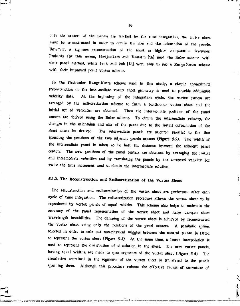
5.1.2. The Reconstruction and Rediscrctization of the Vortex Sheet
The reconstruction and redis_reti_atiou of the vortex sheet are performed after each
cycle of time integration. The redi_retiz_tion procedure eUows tile vortex sheet to _e
reprudu_d by vortex i_neL_ of CtlUal width_ This t_heme also helps to main_aiu the
ac,;uracy of the l_nel _'epre_ntatiou of the vortex sh_t end helps dem[,en elmer
wavelength instabilities. The damping of the vortex sheet is Itchieved by tet_onstructed
the vortex sheet using only the p_itions of the panel centers. A paraUt_llc spJine,
_elccted ire re'dee to tote o_tt not_.,physic;_l wiggles between the e_ntrt0, palette, is fitted
to rcpr¢_nt the vortex sheet (Figure 5-3). At tits same time. a linear interi_)latlon is
_d to repr*_nt the distribution of circulation in the sheet. The new vortex Ixanels,
having equal widths, are made to span segment_ of the vortex _heet (Figure 5-4). Tile
circu)att(_n contained in the segment,_ of tile vortex sheet is transfered to the pnnels
sImnuing them. Although thig procedure reduc_ the effective radius of curvature of
00000001-TSD14

)
50
the vortex sheoet by shifting tile patiels inside a curved spline reprceenting the w)rtex
l_ _heet, the effect can be minimized by docrcJudng the Ji2_ of tile panels. In any case,
_ becttme Jt_aight tegmei_ts are being used to repre_cnt it curve, small panel width is• neccz,_ry t_ _aeinte|n the geometrical accuracy of the panel repre_nt_tic_J_. "H,e ai_ of
the segments are s.lso adjusted to muhltain tt certain relative distance between the
outer..most panel end th-_ Vortex representing the inner region of the roll-up spiral.
I[$.1.3, The Treatment of tho Inner Roll-Up Region
As shown previously, the vortex panels alone can at mo_t reproduce the ou_r!{
solt_tion for the flow induced by a vortex sheet. This is inadequate as an hdtial
i condition without _ model to reprc_nt the initially infinitesmal roll-up at the end of
! the sheet. Thus, the simulation of vortex sheet roUup beflns by replacing the
_. ', tingula_lty at the edge of the sheet with a core representing the initial roll-up of the
--:. sheet edge (Figure 5-5). The placement of the tip roll-up core for the two-dimensional
n_._ , wake follows the result presented by Karman of IGtden's analysis for roll-wing von
: i
up by a par_bolically loaded vortex sheet. For the roll-up of agisyLumetric vortex
--=:_ sheets, due to the lack of a similarity solution, the a much simpler tip core is used.
The details of the initial conditions are described in Appendix B. Such models for the
initial condition of the vortex sheet is ncceet_ry for a realistic numerical app_ximation
of the flow when using vortex panels to model the vortex shee_
The core is a model for a tightly rolled-up section of vortex sheet, the core center
representing the center of the apiral. By knowing the position of the center of rolinp,
the inner_m¢_t resolvable section of the vortex sheet in the spiral can be handled more _ a
accurately. The spline representing the vortex sheet is derived from the panel centers,
tlie location of the edge of the l_st panel, corresponding to the end of the sheet and
the inner-mo_t re.livable section t_f the spiral, is uncertain. (See Figure 5_6,) Sinc_
the roll-up should be in the form of an exponential spiral with the core at its center,
the orientation of the _st panel may be used to blend the veeolved section of the
spira! with the core. It aL_ lX_sib|_ to truncate inneromost _¢¢tion of the reeolvable
vortex sheet and dump the circulation, momentum, and energy of the truncated _tion
into the core. (Although both methods may be treed concurrently, core Jumping was
_. not used in any of the results p_._ented below.) Core dumping is attractive for
numerical reasons s_nce the s_r_ of the pane?s cen I-_ kept relatively sm_]l even as the
00000001-TSE01

51
sheet stretc]w_ without being limited by compu_r memory slT_. As vorticity is
dumped into the cor_, the c_rv_tlon of ci_ulition, momentum and kinetic eflergy
determln_ the strength, _ltton, and siT_ of the core _pc_t]vely.
_" ft.2, Reetd_s of the Roll-Up CalculationsIlK
Tile numerical scheme gc_cribed above has been applied to simulate the roll-.up of
!_ twodJmensional and axisymmetrtc vortex shee_s. All _ll-up stmul_tJoJz_ were inJtisted
with v model representing a small amount of roll-up already in place at the edge of
_ the vortex sheet.
--- .
_ 5.2.1. Two_Dimenslonal Roll-Up
_it_ The roll-up of a two-dimensional vortex sheet trailed by a flat, elllpticaUy loaded
--_-, wing _ the classical test case for numerical vortex sheet methods. I_ o_der to
-_ simulate the geometry of the sheet, the Teefftz plane method, originally introduced to
_ roll-up studies by W_twater [12], is used. ._ach c_ve_-section of the wake vortex sheet
is treated as an unsteady two-dimensional vortex sheet. Thus, as described _bove, the
-_ sheet is repli_.d by a series of equal width flat panel of constant vorticity. Unlike
the axisymmetric flow system, this two-dimensional tell-up requires the program toi
aCCount for the mirror-image contribution acrc_ the plane of symmetry. The time
i_tegration cycle is _gun with a flat sheet at y - 0 and a tip core pa_ition,xt at the
_enter of Kaden's spiral for roll-up of the outer 5% of the vortex sheet. There are 76
panels da_ribing the sheet initially, the _umber increasing as the sheet stretches; the
size of the panel is kept constant. In this simulation, roll-up of the sheet has been
allowed to take place without c_re dumping to demonstrate th_ robustnets of the
model. The panel widths have been kept constant.
Figure .%7 shows the geometry of the sheet after every ten time integration cyle_,
each cycle rep_sen_ing a nondimensional elapsed time'of the the of 0.005 . "/'he
initial location of the roll-up core is given by a small ci_le0 p_rtly hidden by the
inner regioos of the spirals, at alT_ut z - 0.97 . Although the inner region of the
E _pir_l is obscured by the overlapping, smooth rollup of the outer region c_r_ be seen.
_The t[_e _s rtont_ens_onal[_.e_ by _he t[_e scale, t' - rO/_
00000001-TSE02

52
The core representing the inner region of the spiral initially moves inward and
upward n, colu_rve impub_. Aa the core app_'oaches the eentm|d of vorticRy for the
complete vortex systera, x_ - 0.7854, the uppsrward movement _ and begin
moving downward while asymptotically approaching Xo.
l_igure 5-8 shows the _mount of circulation contained by the sheet outboard of a
given _nel. The horJ_/_ttal axis gives the panel /rider, and since the panels are
constant in width, this is equ_Talant to the arc length along the shee_. Values of
circulation are negative since toe lmneW t_ were defined to be positive. The y-
intercept shows tie total simulation of the system which has been defined to be L0 .
The first ©urve, the stat't_p distribution, is elliptical and the strength of the tip core
appears as the jump from the end of the curve to I" - O. The lessening of the
gradient indieate_ the stretching of It section of the sheet. Stretching is extreme in the
hmsr-mcet region of the spiral as indicated by t_e nearly horizontal inclination of the
curve while the outer portion is stUl relatively m_affected by the roUup. Slight
bumps in the curves therefore mhows regions of differential stre_hing as_ciated with
the rolinp.
The roll-up of a vortex sheet must conserve circulation and momentum. The total
circulation computed for the numerical model of the vortex sheet as it deforw_ with
time shows a negligible fluctuation of about Dl% per time ,_tep from the ©xpected
value of 1.00 . The program maintained this value to better than 0.001% a_uracy,
representing only .as fluctuations du_ to numeric.at round-off errors. Calculated
cantroid of vorticity for a smooth elliptical distribution is 0.7854 . For the numerical
model of the initial condition twed, the centmid of _ortiCtty was found to be 0.7925 .
D_ring the subsquent steps in time, the centroid value was found to d_rease by le_
than 0.05% per time integration cycle, or time step. The steady decrease in c_ntroid
appears to be connected with the additional panels used to represent the stretching of
the vortex sheet.
Betz [10] has shown that the circuSation within the spiral, measured from the center
of the spiral, should approach a constant distribution. Figure 5-9 shows the
distribution of circulation versus the distance from the position of the roll°up core for
each time step plotted in Figures _7 and 5-8 along with a plot of the approximate
solution found by Bet_ F_ch curve reprt_e_ts the sheet for increments of 0.100 in
................ TSE03-- - .............. 00000001-

,_3
nondime_ioutlt time. Since each cycle of time tntegr_ttcn covers 0,O05 in
nondlmeutional time, each ounce represents the _ult of 20 time, Itel_. ,c_me of the
deviation f:mm Beth's r_ult can _oe explained by the fa_ tha_ L_etz did not u_ Knden's
Jdmilarity _intion but plsced his hyl_othetlcal roll.up at _he end of the sheet. Figure
_-JO dtows the blow-up of the region covered by the spiral. In _th flguroK, the are¢
over which che circulation is integr-tod iocreascs to the right of the plot; thus each
curve will converg_ on che Wt_l circulation of the mhce_, which in this case is unity,
toward the _ight of the plot. Although l_e_'s solution shows the general trends, the
_uraerical solution exl_ibits a tendency toward higher roncentratlon of circulation inside
the roll-up spiral.
Figure 5o_1 shows the geometry of the sheet at elapsed time of 1.00 . The spiral
planform gener_'Jy agrees with those generated by ocher inve_tigatols, the weeknea_ in
the flat paual method is apparent in t:_e tightly wound spiral. As the spiral tightens
near che center, the number of panels become insufficient to adequately resolve the
spiral. In this case, there are approximately 11 panels de_ribing the inner-mc_t turn
of the spiral. Due to the ¢mbigu[ty in the radial position caused by spanning f_t
l_unels ecro_s a tight curve, the end of the sheet has crossed over several turns of the
spiral (l:igurc 5-12). When this happens, the closed section of the vortex shee_, stops
stretching and become8 roughly equivalent to a core of vorticity.
While sheet crossing represents a violation of the physical nature of vortex sheet, t_',e
sin_u]ation can become unrealistic much eerlier. When the penels forming one turn of
the spiral roughly overlap with the panels forming an adjacent turn, the geometry of
the section have been found to stabflL_e in this comfiguration, Since the phenomenon is
produced by the fiat geometry of the pane_, this behavior is uncharacteristic of a
smooch vortex sheet, For this re_n, the width of the panels mus_ be reduced in
order to a_c.uxately resolve the inner _egions of the spiral.
_,2,2, Roll-Up Produced b_ au Impulsive Movement by a Dt_k
The problem ttudied by Taylor [27] is demonstarted by performing the allipttc_!ly
loaded wing wake with azisymmetric vortex band& The motion of the disk is
modelled by a flat azisymmetric vortex sheet. A rough approzimation of the initial
ro_-up o£ the tip is used (sea Appendix B). The a_i_ymroetric tip core, unlike the
-- 00000001-TSE04

54
two dimei_sional core, li_'_ a Jelf_induced velocity which mvst be determined using the
conservation of energy, The sub_iuent roll,.np of the vortex sliest int<_ a vortex ring
proceeds smoothly ,- shown in the ftgorcs. A! with the wing v,'ake, the simulation
begins with 80 panels with the outer 1.25% of the vortex sheet tranfforn_ed into the
initial roll-up core with no sut_qtlent core dumpi_Jg_
Figure 5-13 shows the roll-up of a vortex shaet produced by an impulsive m_tlon of
a flat dJ_k. There are 10 plots, each representing elsi_ed tires of .05, and the initial
configuration, with the tip core shown as a small circle, shown in this plot. The
roUup is similar to the wing wake loli_up with one important difference, the spiral
translation is augmented by the _eif-induced velocity. The spiral is behaving
essentially as a ring vortex. Figure 5-14 shows the circulation distribution
corresponding to the geometries above. The gap between the first curve, showing the
initial circulation distribution, and the rest of the curves is due to the decrease in
panel size and a proportional increase in the number of lxmeis imposed by the program
in the first few time stel_- This is porformed when the distance between the core
and the end of the sheet is reduced below defined lin_ite. Othe'wise, all of the
features of the wing wake case can be observed.
Centroid of vorticty for an azisynunetric vortex sheet is the radius of a vortex ring
with the same impulse. The calculatod value for the oentroid of a continuous vortex
sheet is xo - 0.8165; the total circulation should be 1. The panel-method introduces a
error in the centroid to give the computed value of 0,882 for the initial vortex sheet.
However, the important criteria for the accuracy of the numerical simulation is the
invarie_ace of these values as the ro.l-up proceed& The total circulation WaS found to
fluctuate by less than 0,001_o while the centroid of vorticity was maintained to about
0.05% change per time step where each time step is equal to elapsed time of 0.005 .
In addition, if the roll-up simulation is perfectly accurate, Beta hypothesized that the
circulation integrated away fxom the center of rolloup should approach a final
distribution. A lost of the hypothesis is shown by Figure 5-15. The circulation
distribution in the spiral, which is the region toward the left, apfe.ars to converge on
a relatively steep slot_e which refaiccts a high concentration of vorticity. This feature
i-_ more apparent here than in the two-dimensional _ because of the faSter rate of
roll.-up. Figure 5`16 shows the blowoup of the circulation distribution_ in the region
c_vered by the apira!.
00000001-TSE05

_ 55
Ib_. Figure 5,-17 shows in detail the sheet geometry at elaFed time of 0_._) As
_ comlmred to the wing wake l_llrup at the same Jtage of roll-up, the lpiral_ ere lo¢_r
but more tttrns of the spirals are pr_ment. 'I]_e invarisnt tip roll..up core is shown
' with ite ralculetted c_tional radltm whicll, as ran be obmerved, lit very jmlall; it
represents the tip 1.25% of the initial vortex sheet. Due to the higher _te of inward
motion in the spiral, the inner-most turn has _lready ranched the point where the -)
f' " imne]s are inade,_uute to resolve the curwture and s sheet etX_lng has taken place.i: 5.2.3. Roll-Up of a Helicopter Wake
_' [ The evolution of the wake produced by a single rotation of a helicopter rotor was
_'[ simulated by imposing an approximate rotor loading
"I r(x) = rox' l - (5.1)
_._] on the initially flat axisymmetric vortex sheet. This load distribution is shown
_, graphically in Figure 5-19. The downwash profile induced by vortex Immds,without a_' i tip roll-up model, for this distribution is shown in Figure 5-20. The numerical x_uit
for the velocity at the center of the disk agrees wed with the theory, which comes
i ! out to be 0.3927if the contributionsof allof the infi_itesmalcircularlinevortices
i areintagraredanalytically.
i Figure 5-21 shows the roll-up simulating the evolution of a wake due to one
_ rotation of the helicopter rotor at increments of 0.05 in nondimensional time. The tip !,= Core contains the ci_ulation of the outer 1,25% of the flat vortex sheet and each time
step reprcsents nondirnensional elapsed time of 0,005 . A prominent feature of the
vortex sheet geometry is the stationary point near the midpoint on the sheet, qt_xis: feature was also found in a similar investigation by $ohn Kantelis [26] using a
_ collection of vortex rings to represent the vortex sheet. It is noticed that the
mteepcning of the ciwuintion curve, indicating a concentration of vorticity which should
evcl_tually lead to another roLl-up of the vortex shee_, only develops at the center of
the axi_syrnmetric vortex sheet. Thus, although the vortex sheet contains regions with
- vorti_Ity of oplx_Site sigr_s, the sheet dues not al)I_ to roll-up intt_ two eelX_rate
vortex rings The circulation plot (Figure 5-22) shows a aigl_ificant decay of the
tgough in the circulation curve during the first ten or *o time steps. This is a
numerics1 error due the tns_uracy introduced by the linrar interpolation of circulation
treed in the recon.struction of the vortex sheet after each time atop.
0000000 -TS 06

_6
Tits vsUdity of the mimulation is indic-_d by the inva_isnce of total circulation.
equal to zero, and the impulse of the vortex Id_L Total circulation and total /reprise
are f[,m_d $o be con_rv_d to Within 0.001% and .002_% _pec_ively during each time
tutegratloJt cycle, In addition, the circulation distribution away from the n311-up Center
/J exelTected m converge On a final curve. Figure 523 shows the distribution of
circulation integra?_d away from the cen_er of the _oll-up for each xime step in
Figures 52! and 5_22 overlapl_d to show the comparative deviations, The blow-up of
the region covered by the spiral is shown in Figure 524.
The geome,ry of the vortex sheet at elspaed thus of 0_,_0 Is shown /n Fi_tre 525.
The panel which rep_,ents the minimum in the circulation distribution curve (Figure
522) has been circled to show the extent of the negative vor_icity in the mlloup. Tip
roll-up Is much faster than the two previous cases since there is more circulation
concentratedin the tip region. The blow-up, Figure 526. sho_ extensive sheet c_ing
for the inner-most turns of the spiral, Tip core. which appears as a dot in the
middle of the spiral, is shown with its croeHectlonel radius in w,ale.
I 5.2.4. Kelvin-H©lmhultz InatabiUt_
The instability, which is the di_retized from of the _nderlylng Kelvln-Hehnholtz
Instability. becomes evident under special condition& A wake vortex sheet which is
very fiuely discretized reached the geometry shown in Figure _27 after ten time staI_
During each time step. the panels were allowed to move the maximum of 0.1 times
the panel width. The circle on the right represents the location of Keden's core model.
If the sheet is magnified in the vertical direction, the development of Kelvin-
Hclmholtz-typa iusmbillty becomes visible (Figure 5_28). Further maginification shows
the waves to have a parlod of ll panels and the sc_le_ to be within the 8 digit
accuracy of the compeller.
The deanping of Kelvin-Helmholt_ Instability in the numeric,at simulation is in the
form oi_ low-pass filtering the wavinebs in the vortex sheet, This filtering occurs as
the panels span acrccs crc_t_ and troughs of short wavelength wav¢_ Due to the
stretching of the sheet, the panels which describe the geometry of the vortex sheet
following a time integration cycle wjl! be slightly displaced from the previous p_ne_
The amount of this displacement determines the amount of filtering which takes place.
" 00000001TSEO

5?
l_zis is becau_- wavin_ in the displacement of a jheet formed by panels can not be
rmolved unl¢_ the the next net of panels overlap the dkpinced panela For thl_
ra_ov., the tust_bility appeam wJlen the amount of displacement, llml_:d by the
amount of time elap_A In one cycle, is kep1. small This is what happened in Figure
5-28.
The filtering effect can al_o be nuppr_ed by continuously increasing the eI_tial
rc_olution of ¢h¢ panel_m¢thed. An example of this numerical behavior is shown in
Figure 5-29. The initial conditions on the _eet and the time integration ¢yclea arc
identical to the dh,k wake roll-up case presented earlier. To Plu_trate the filtering
effect, the size of the panels were coustantly rcduccd to about one half that of the
panel used for Figu_ 5-13. This is accomplished by specifying GFAC - 2 instead of
GFAC - L" s_e Appendix C. _is effectively suppressed the furring and the small
instabilities are able to grow more freely. As the roll-up proceeds, the secondary rollo
up spirals ere amalgamated into the tip roU_up spiral and the secondary spirals arc
also stretched as they spiral into the tip roll-up spiral. This behavior can be obasrved
directly above the main spiral where stretchh_g has deformed the secondary spiral,
Plot of the circulation distribution, Figure 5-30, show_ jumps in circu!ation which
corr_ponding to each eecondalN roll-up. The cin-ula_ion distribution in this plot was
initially e11iptical llke these in Figure 5-14. _cept for the existence of the secondary
roll-up, the simulation proceeded no differently than the previous case. The computer
program mainlined the invariance of circulation and momentum with the s_me degree
of accuracy as before. DJstributions of circulation taken from the center of the main
roU-up spiral is shown in Figure 5-31. Figure 5-32 shows the blow-up of the region
covered by the main roU-up spira_ They arc no different from the previous results
except for the effecte of eccondary roll-up in the circulation distribution.
]
00000001-TSE08

Time Integration: j - j + 1
xtj+l " fxn(xt$, I)xtj, q't$)
O0000001-TSE09

59
1. tliven hfitlal C_fl£mation: (x i J, 1)xlj), _+,_
(hlculat_ Velocity: v I j fxn(x_ j,
- Dx _j). _.V;.-ij
z:.,j j/2, Txansl_tioJ_ to tim Intermediate Position: _ I
'3. Approximate Iutermediat_ Panel lacl(natioa: "lO/A'|
E"#O.,-i,,,"* i.
...j,+,4, Approximate latermediate laanel Width:
I l)x_j+Val - V_ I x_.+:tJ+Va_ xl-,.3,j._.vaL _."10/
vlJ+V_ - fxa(xij+V_, DxIj+V,).
6. CombineVelocities,
Translation to the F_al P_ition: O_ /"xij+l - xlj + v_tc At. .,_ #
Figure 5-2: The Flrst,-OrdcrRunleoKUtta_hcm©
!
00000001-TSE10

6O
1, Oh_tn advent lmiuts _ m(l_tral_)|ate at the e)ltl._), it}
L'I
are obtained _rom fl,c
¢a_gents to the ar_(i.,Li,i+l)an_(i_,t,l,i,_,2).
3. A parabola is fittc.dt_tween i and i+l ", i
: i
_. Figure $*3: The RcaOnstruction of the Vortex Sh_t
J
I
ISubroutine "RUNGEI" giv¢_ the | /
translated panel e_nters, ztJ+l. *
Subroutine "RIIDISK" _pl_n_the '_
spatioJ2y equidistant poi_s, x_+V_, 1, _ ._ .along _he _pli_e.
: Subroufiu¢ "PANEL_" spans point_
z__¥_j ��„x_+_j+ _ with panel i.
Figure 5,,,4: The Redi_ret_izatioa of the Vortex Sheet
j
"_) .... O0000001-TSEI'
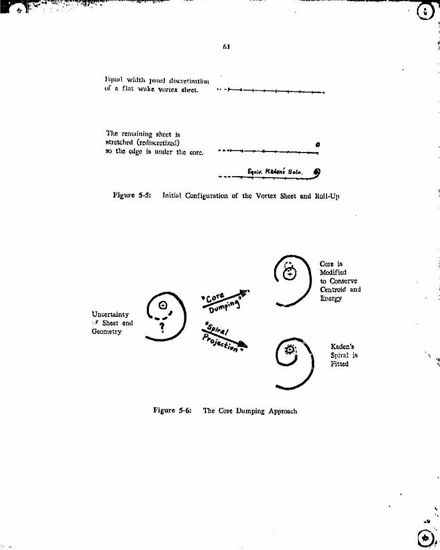
• • /,i r _.y," , kZJ
61
}_lual widthlJ_noldi.scret?tat|(_nof a flat wake Vortex _hect, "' "P-"_ ; : ; ; J P •
The rcm_dnlng_hect isstretched(rcdJ.'_rctizod) 0_'J the eAl_]c_ u_Idgrthe core,
•
Figure 5-5: hfithd Co_figu_ation of th_Vot_x Sheet and RolL-Up
Core is
Modifiedto Con._crvcCon's'oldau,:_Energy
Unc_rtalnty•.¢ Sheet _nd _,_ _Geometry
Spir_isF_
Figure 5-6: The Core Dumping Approach
_ 00000001-TSEi 2

62
00000001-TgE13

63
0
<_
BETZ (DASHED)
T ,, 1,00....... _ ..... :,:::::::;? ....
o _/ _'_Y"_"_...... ,.o/.o°0
I_ i! . . 1............ 1 ................ i - i0
O,O00E+O0 0.300t:1-01 0,600E. 01 0,900E. 01 0.120 O.150RADIUS
lElg,_r¢_5-10: lllow..ui_ _f" I:Jll. 5-9
t.
O0000001-TSE14

_4

65
| i I -i i _ ___ i0O.O00E+O0 0.200 0.400 0.600 0.800 1.00
RADIUS
Figure $-13: Roll-Up Produced by a Moving Disk
'_gl / "0o
g
%
00000001-TSF02

66
T- 0.55 , ,,- . -
f_/ T- 0.00
2 !/o.Q4-N0
_ i i i I
O.O00E+O0 0.200 0.400 0.600 0.800 1.00RADIUS
Figure 5-15: Distributions of Circulation Surrounding the RoLl-Up Core
i r-o.ss------ .__-_
/_/_J'/'_ T - 0.00
C_I ...... ",........... T .......... _ ....... •............ • .....O.000E#00 0.300f7-01 0.600E-01 0.900E-,01 0.120 0.150
RADIUS
Figure 5-16: Det_'1 of Fig. 5-15
,I
i
" " ' -- TSF0300000001

Y Figure 5-17. "/_e Sheet Geometry: T - 0.55
_ \
FJgur© S-IS: _ze BJow..Up of _he ,_plralo.e_o 1.o2

0Q
Figur© 5-20: Downw_h Prof£1¢: Vortex B_ds with the Above Loading
i D
00000001-TSF05

69
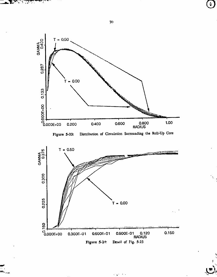
70
8,,+,o
0.200 0.400 0.600 0.800 1.00RADIUS
Figure 5-:23: DisttJbutioa of Circulation Surrounding the Roll-Up Cote
_. T - 0.00
O000000]-TSF07

., .. 0000000_-

72
1.
10 T+"II_1_+
g..,
• r- • • • • T , --- i
0,000E+00 0.125 0.250 0,375 0.500 0,625 0,750 0.675 1,00RADIUS
Pigurc 5-27: Gcomctry of the W_kc Vor_x Sheet
b_
00000001-TSF09

73
q*..
tL)
I
U.304 0,315 0.327 0.339 0.3fit 0.363 0.375 0,387 0.390RAr_ILF3
Figure 5-28: Repcat_ MagnJfic_ttionof a Section of Vortex Sheet
00000001-TSF10

74
O., U)
8
o
Figure 5-29: Rc_at of Fig. 5_13 with Finer Paneling: 1' .. 0,350
D
_d
Figure 5,-30: Ti_c Corresl.onding Circulation DJ.stributioyx
O0000001-TSFll

i:_::_ "" " 00000001-TSF12
76
Chapter 6
Conclusim
The behavior of vortex sh¢cte wlth axisymn_etric geometry prcscnte the next frontier
in the study of vortical flows. Axisymmettis flow lies between _he relatively well
undersV._l two-dimensional flows and the complex three.dimensional flows, For this
reason, unders_nding of axL_ymr_etric vor_x sheets is u_ful before _omplet_ly th_'_¢..
dimensional vortex sheet_ can be modelled. Due to the complexity imposed by the
increase in number of variable as the number cf dimensions are increased, three-
dimensional models using discrete vortices or dipoles are more de_qirable than panel
methods. However, the use of simpler models would be meaningless unless the
a_curacy of the models can be determined. For rids reason, the axisymmetrie panel
! method was developad as a higher-oder model to test the accuracy of simpler
axisymmetric vm_ex model_
To accurately formulate the behavior of an axisymmetri¢ vortex panel, a flat strip of
a uniform two_dimensional vortex sheet, called the vortex panel, was first studied.
Th_ calculations of the velocity field show that an assemblage of l_neL_ will mutually
induce motions which are more representative of a vortex aheet than an assemblage of
point vorti,'_s. Even when rcpr,_lucing a vortex sheet with non-uniform vo_ticity and ;'_
curved geometry, the panel method performs no worse than the discrete vortex method.
The eimple geometry of the vortex panel allows a straightforward derivation of a
matched _y_ptotJ¢ solution for the flow _ndu_ by an uisymmetris ¢quiwlent ot
the vortex panel, the vortex bend, Vortex ban& caw be assembled to accurately
reprint an axisymmetrlc vortex sheet, limited by the geometric inaccuracy in
• 3e_nting a smooth curve using straight line _gmen_ end, at l¢o_t for this study,
the no_osmoothness of the vorticity distribution. Both of the_ wcakn_ arc problems
of spatial resointion which can be aUevia_.d by incre_ing the number of elements,
Thu_, l_nel-meth_l can be u.'_! to accurately simulate the evolution of an
axisymn_ctricvortexsheet.
t
00000001-TSF13

77
'J'iiu v{nl_x _ll¢'el d_VJlalni[:,_ calculation ill nil initial c4,11ditil_|l pr(il)ilm, (hie iniJ_ntaut
rr_/_llit. |laN I)_}l lilt. l_l_:il]'ac;9 l_|" tile ]_ll'le, l.l}i_thlal ill r_l)l'{klilCJllj_ tile JJllw Jlldll_fAI ll_
A fJ.t V(U't¢X /_lleet which J_ tile Jllilial Simile Ill' tile _/(l|rle_ flll_'_t ill jn_il|_ plrlil)lclJlt tJi'
W(_l _ry flit IIAC Ae(:lllilte )rCJ))'(_lllliJtlo;I Of tlIC _Jl)_l| flow _Ji_J(l, it _l il_) UNC_'UI
for th© numeri_ll simulatio;_ of tlJe _7{',Juduccd def'oxlul_tio_ o£ the, vor_ca shc_t.
The _E,.lnduccd v_h_clty of' curved vortlc¢_ lmvc inhibited the study 0£ the dynamto_
of _xl_ymmct_g vogtex sheets, lly ualag dr© n_tkod of matc|u_l asympt_t_c ©xpansion.
th© s_lf,4ndut_ v©l_lW of an _xi_ymmet_l_ vo_ex p_n©l _onnistent xvtO_ Ox©ktn©'dc
©_ergy of a scctiol_ of an nxisymmctricvortex slicer w_ found. The axisymmetdc
]pancl-xn¢thod was u_d to sinxu]ate the Eoll.o_,p_uscd by th¢ Jmpulsiv¢ _notibn of a
circular disk m_d th© roll-up of n vortex sJxe©twith a ]o_ding which aplmsximat_ that
of _ helicopter rotor. In both c_,s_, smooth rolbup v,as ol_erwd _ad both total
gi_cuIatioa a_d impuhe _ve_e¢_m_vcd. By ¢cl_i_g the h'_w_-l_._ filtering inherent
the numeric! n_©thod, secondary rolbup due to K¢)vin-,ll¢_n_hol_z Instability _a _¢
observed, TILLsfeature for an axisymraetric vortex _ett was simulate! numcricaUy
using tl_c _nel-method de_crilxd above.
' 00000001-TSF14

78
/
References
1. Roscnhead, I., "fhe Formation of Vortica_s from a Surfaee of Discontinuity",-_' Proc.RZocJ_o_loa Set.A, VoL 134(1931),pp. 170-92,
"_'= 2. Blrkhoff, G, Fisher, J_ _Do Vortex Sheets Roll Up7", Clr¢.Mat.I'alerno, Vol..... 8(1959), pp. 77-90.
3. Saffman, P,G. Baker, G.R., "Vortex Interactions_, /inn, Re¢. Fluid Mech. Vol.11(1979), pp. 95-122.
4. Moore, D.W,, WOn the Point Vortex Method", SIAM Y._c|3tat.Comp. Vol,2(1980, pp. 65-84.
5. Baker, G.R., "the CloudoinoCell Technique Applied to the RoU-Up of Vortex_:_ i Sheets", d.Comp.Physlcs, VoL 31(1979), pp. 76-95,
6. Murman, F_IV[.Strcm¢l, *A Vortex-Wake Capturing Method fnr Potential Flow",:.| _AA Paper, No. 82-0947, Sane (1982).
-i % Moore, D.W., "l'he Spontaneous Ap_,rance of a Singularity in the Shap_ of anEvolvingVortexSheet", ProcJ_,_ooJ.amdonSer.A,Vol.365(1979),pp. IOS-I19.
8. Meiron,D.L,Baker,G, Orzsag,S.A. "rhe AnalyticalStructureof Vortex-SheetDynamics.P_rt I. Kelvin-I1elmholtzInstability_,?.F/u/dMech_ VoL 114(1979),pp.283-29U.
' 9. Karman, Th. yon, Burgers, J.M, Aerodynamb_ Theory, Sprhlger, (1935), pp.320_325, See also Westwater 1_
10. lktz, A, 'qkhav_or of Vortex Systems", IVACA TM-713(1933).
11. l)ttllin, D.I., "On It GenerMization of Kaden's Problem", ?. Fluid Mech_ VoL104(19M), pp. 45-53.
12. Westwater,l:J_,"RollingUp of the Surfaceof DiscontinuityBehindan Aerofoilof Finite Span", 4taroJCes.GommJ_&M_ No. 1692(1935).
13. Ftnk, P.T. Soh, W.K. '_atlcul_ion of Vortex Sheets in Unsteady Flow andApplications in Ship llyclrodynamics", ProC. lOth Syrup. Naval Hydrodynandc$,Cambridge, Mas% (1974), pp. 463.488.
14. Ftnk, P.T. S_)h, W.K., "A New Approach to Roll-Up CalcuLations of _:ortcx= Shcc.ts", l'roc.R.q_:,l/omlon get.A, Vol. 362(1978), pp. 195.209.
15. Baker, O., "A Test of the Mcth_l of l_ink & _)h for Following Vortex Sheet,, Motion", d. Fh_M Mecl_,, Vt)L !(_0(!_L(:), pp. 209--220,
00000001-TSG01

79
_--_]; 16, lloeijmaker,% II.W.M,, Vaatstva, "A lligher()rder Panel Methc_t Applied to VortexSheet l_oll,,Ilp", AIAA l'a1_r, No, g2.O096(1982),
17. lligdon, LL,, I)ozrikidJn, C_ "J'Jm Self-Induced Motion of Vortex Slmet_", J, J,'lu/dMech_ Vol. 1_0(1985), pp, 20,4.231,
18. Morky, M,, "(_dcnlatlon of Vortex Sheet Roll, Up tn _ Rectangular WindTunnel", d, Abcraf_, VoL 12, No, 9{1975),
I19. lhtchelor, G,K,, Introdw_tlon $o Fluid Dy:mndcs, Cambridg_ Univet_ity, (19:57),
20. WidnMl, S,]{,, ri'_ait C,Y., "l'he Instability of the Thin Vortex Ring of ConstantVorticity", PMI,Tran3L'_oc.I_orM_ VoL 2870977), pp. 273_305.
21. Lamb, IL Ilydrodwtamt¢$, Dover, (1932).
22. Bliss, D. '*l'he I)ynamic_ of Curved Rotational Vortex Lines", Master's thesis,M,I:r. Aero//Lstro, (1970).
=_' 23, Bender, C.M., Or_z_g, S.A,, Advaw_e,t Mathemat_ad Methods for Sclemlst$ andEngineers, McGraw-Hill, (1978).
I 24. Jabnke, E_ I'_md¢,F_ Tab/e of Fttrw,tlons, ]Dover, (1945),
! 25. "lMng, C_ Ting, L_ "Motion and Decay of a Vortex Ring", Tha Phyacs of-- _ F/u/ds, VoL 10, No. 5(1967).
26. Kantells, J. Priwte Communications
27. Tayor, G.I. "Formation of a Vortex Ring Giving an Impulse to a Circular Diskand then Dissolving it Away", .r. Appl. Phy. VoL 24(1953), pp. 104.
28. Roache. Pd. Computational Fluid Dynamfc$, Hermosa Publishing, (1972).
l
O000000]-TSG02

• } Appendix-_Lqh:
.!_1 The following pag_ are divided into three l_¢tiol_%
! 1) The ILstings of the FORTRAN rout|nes for comFztJng the velocity inducedby varlou_ wlrtex ¢lement_
2) Tile description of the rmmeri¢_l model of the initial state of the vortexsheet prior to the numerical roll-up simulation and the FORTRAN l_ting.
3) The listing of the FORTRAN program for the numerical simulation of vortex6b_et dynami_.
4) The inputs for the vortex ah_t dynamic_ B'mmlatiou program ugcd togenerate the figur_ within the text.
! All of the following program listings have been written in FORTRAN 77Version 3.0 for the Digital Iktuipment Corporation VAX-750 computer.
L.d
00000001-TSG03

81
Appendix A
The Vortex-Velocity Routines
The velocity in:._cml by a vortex element is colculated u_ing a Cartesian coordinate
system, (X,Y)0 centerc _, on the vort*v inducing the flow. Th_ panel's inclination
respect to the coordinate syvtem is exprea,_.d by (DX,DY), where DY/DX equals tile
tangent of the angle between the l_nel panel and the x-axLe. (W) is the half-width
of the panel and (G) is the vortisity along the panel. The velocity is obtained as
orthogonal components, (u,v).
The names of the twoMime_ionai velocity routines:VEL2D : The Vortex Panel RoutineVEL2DF: The Point Vortex Routine
The axisymmetric vortex routines differ from the two-dimensional vortex t_utines due
to the inclusion of the radius of the vortex element, R. The composite solution, Vcomp,for the velocity induced by a vortex band is
Vcomp - Via + Vou _ - V_o,
where the routine
VELIN computes the inner-solution, Vtn :_VELOUT computes the outer-solution, Vou tVFLIO cemputes the intermediate_3olution, Vto.
(Note: The Vou t alone gives the velocity induced by a simple vortex ring.)
_k
00000001-TSG04

_2
F_' SUBROUTIN_V_L2D (BIN. VIN)
* THIS fiUBH(_II'INECALCUlaTESTHE VEI.OCITYFIELD InDucED$ _Y A FLAT VORI£X STRIP OF e* WlUTIt : _* STRENGTH : G •e INCLINATION : ( DX, DY ) I* AT POSITION (X, Y) RELATIVETO THESTRIP MIDPOINT J• (DIJIAttYVARIABLE:RADIUS : R)•O*@e_Oe_IeOJeO*_*OOI_qO**O•eOae_Q*e_*mq•eODDQJOO_**I•DOO•OQIOJO*IOOB•OIQI_*O*
C RELATIVE COORDINATESANDQUAORATIC_'_OSITIONVARIABLESC
C_ /V_LO/ R. X, Y, DX. DY. W, GP! " 2*ASIN(,.)COST" DX / SDRT(DX*e2+DY*D2)SINT - DY / SDRT(DX*D2+DY**2)Q5 - (X_*2 + Y**2)/Wo*2Q4 - (YeCOST- XeSINT)/WQ3 - (XeCOST+ YeS|NT)/_NQ2 - QS- 2.Q3 + 1.QI - Q5 + 2.Q3 + 1.
tellliillOOSttl_li•$11tOllltlllltllttlllltlltOltOOilllllttlllillilleltll_ltllll
CHECKFORSINGULARCONDITION_=-"_- IF (Q4.EQ.e) THEN_--' ATN - ¢,e
GOTO 740END IF
ATN - ATAN((1..-_,_3)/Q4)+ATAN((1..t.Q3)/Q4)_: ?4e CONTINUE
i--., IF ((Q1.EQ.e).OR.(Q2.EQ.B)) THENUIN " eVIN -GO TO 75e
ENDIF••I•llll•_l•I•llllltilllillllll•ll•lltllllClll_ll_illlllll_l•ll*ll•llllI•l•
C PERTURBEDVORTEXSTRIP FORMULAU1 "=SINTeLOG(D2/Qt)+2 eCOST•ATNVl '_OST=LOG(Q2/Q1 )-2.=SINTeATNgIN *-=G / 4./ PI = UtVIN - G / 4,/ PI _ Vl
75e RETURNEND
i °L
O000000]-TSG05
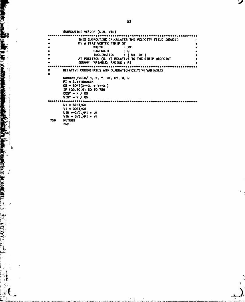
r
L c._i3ROUTINE VEJ_DF (UXN, VIN)mam*_m_ Jo_mo_li*Iooom*o_oJoali*o***_*osm*o**oon*l J_mlo_o***_ JI_O*_o$oomm j
_ : q " THIS SURROUTINECALCULATESTHE VELOCITY FIELD XNOLIC[r'O ,-
]I _ BY A FLAT VORTEX STRIP OF' *:_/f_'; ! • WIDTH : 2W, _' STRENGIH : O *
• INCLINATION : ( DX, DY ) *• AT POSITION (X. Y) RELATIVE TO THE STRIP MIDI_INT _,
i , (o_ ,_I^.LER_xusR) •._..: . _ **_*e*_ip_*_8**qp_pIq_u_p_up_8_o_B_*_I_8_me_*_Q_**_o_**_**
i_. ]i CC RELATIVE COORDINATES AND OUN)RATIC"PO$1TIC'N VARIAEILE_;
i i COMMON/VELO/ R. X, Y, DX, DY. W. GP| . 3.141S9;_6r_4
Q,_ m SQRT(X**2, + Y**2.)
i" IF (QS.EQ.B) GO TO 750
COST _ X / QFI
•! SlflT ',, Y / q5
! IleeQghat I*qqda*o******O IIPOOeHP 80OleOeOO00 foe O00eooIoeo OQ_ei oo_,e,eo,_****_, oe_o_ooo
, U1 _ SINT/Q5• I VI ,mCOST/Q5
_::_"I UIN '_G/2 /PI • UIVIN m G/2./PI • V1
_i 750 RETURNEND
i=:_
i kL_:!
00000001-TSG06

/
84
SUBROUTINE VELIN (UXN, VIN)Oogm*o***olma_oao*oe_QIo_oem*l*I_B**mJoIloellomnJ_ImoIBoa*_m**oIo_omJoomom_8_e*
J THIS 5UBRDUI"]NE CALCULATES_HE |NNE_ SOLUTION *I OF' THE VELOCITY FIELD INDLIC_ BY AXISYIAdETRICALLY me PERTURBING A FLAT VORTEX s'rRxP OF *• WIDTH : 2W *
STRENGTh1 : Q •
• INCLINATXOR : ( DX, BY ) •• RN)XU_ : R *
• AT POSXTION (X, Y) RELATIVE TO THE STRIP MIDPOINT *0
THE DERIVATIVES OF THE STREAM.FUNCTION HAS BEEN =• DIVIDER INTO TWO PARTS: =• 1 - RECTILXNEAR SOLUTION =• 2 -- F|RST ORDERPART_CULARSOLUT|ON *_l•oeoem*ele•e*eooeeee*i*eeololeemJeweee_llooleeeo•e*e*d_eeewe••eeloooee*ee****
C RELATIVE C_)RDXNATKS ANDQUADRAI'IC-PO$|TIONVAR|ABLESC
C(_AVON/VELO/ R, X, Y, OK, BY, W, GP! - 3.141592654
COST - DX / SORT(DX•*2.+DY**2.)SENT _ OY / SO_T(BXe*2.eOYee2.)QS " (X**2. + Y**2.)/W**2.Q4 - (Y,COST - XeSINT)/W_3 _ (X,COST + YeSINT)/WQ2 " Q5 - 2,*Q3 _ 1,Q1 _ O5 + 2.=Q3 + 1.
•llltl*l_•llllil_•lllll•llltlll••ll*llll•llll*l••lltlllll•lllll_l•*lllDlllllltl
CHECK FOR SINGULARCONDIT[ONIF (Q4,EQ,e) THEN
ATN - 0.06o TO74e
END IF••e•e*eeo•le=eeee*e*e**eeeI•••ee**eee*ee*e•*••eoeeoeee•*e_••ee*e•=ee•e*e**lee•*
ATN - ATAN((t.-Q3)/Q4)+ATAN((1.+Q3)/Q4)740 CONTINUE
•oI**••eoo•*eeolo•eee•*oo_•eeoe_***e_o••oe•eo_*_•**_**eee_o*•*_•_*u*_•o•leeee
C PERTURBEOVORTEX STRIP FOflMULA
U1 _-SINTeLOG(Q2/QI)+2.*COST*ATNVt =_COST*LOG(Q2/O1)-2.*SINT=ATNu2- (X/_./R) * U_V2 - (X/2./R) • Vl
• + .5*W/R e(LOG(Q2*Q1)• --Q3*LOG(Q2/Q1)• +2.*Q4*ATN• -4.)
UIN =,..G / 4. / PI * (U1 + U2)VIN - G / 4. / P! • (Vl + V2)
75e RETURNEND
-- 1
00000001-TSG07

8_
-_: SU_HOUT|NE VEL(_JT (_). ¥0) I ELLIPTIC ]NTEGHAL,_ tomJoo_oolmoDm_mlmim_IomJ_Ioio*mmi_mi*_A_QJ*ooOiomlloQiioi_m_oe,o_m,!momm_oi4
" tHIS 5UDR(XJT]NEC_LCULATE_ THE VELOCZTY FXELD* INDUCED BY A VORTEX R|NGWItICH _ USED A_ THL •* (XJTER VEL(X:XIYSDLUTION FOffAVCflTEK BANUOF •o WXDTH : 2W e* STRE _TH : "
* INCLINATXOR : (DX, DY) *• RADXU_ : R •* AT POSITION (X, Y) RELATIVE TO THE BANDMIDPOINT •
P.OMM(O/VELO/ R, X, Y. DX, DY, W, eREAL M1. I-/_q_ KO, KI, K2, KLO, KL1, KL2, K, KP
VO_O,_p! m 3,141592654
oooo_***ooo*ooooogo_oeo_*e**eeeoeeoootoeooeooeooemo_oooeeetoooooeo,,****_****o_
RIm Si_T(X*e2.+Yee2.)R2 _ SQ_T((X+2.*R)e*2.+_*e2o)LAM = (R2-_l)/(RI+R2)M1 _ 1. _ LAM.*2.
IF (R1.EQ.O) GO TO 73_IF (LAM.EQ,e) GO TO 730
i DXR1 - X/R1_: DYR1 - Y/R1
DXR2 - (X+2,eR)/R2i DYR2 - Y/R2
DXL - (DXR2-DXR1)/(R2+R1) - LAM/(R2+R1)*(DXRI+gXR2)DYL - (DYR2-DYR1)/(R2+R1) - LAM/(R2+RI)*(DYRI+DYR2)K_ _ 1.3862944K1 m .1119723 • MI[1 " .4630151 • M1K2 m ._725296 * Ml,e2.£2 - .1_77_12 * Mlee2.KLOm .5KL1 - .1213478 e MIEL1 - .2452727 * MIKL2 m .D£_8729 * Mlee2.EL2 - ._412496 * M1.o2
K m K@ �K_- (KLO 4" KL1 + KL2)*LOG(M1)E" 1. + E1 + E2 - (EL1 + EL2)*LOG(MI)KP. E/L_M/MI-K/ L_M -,EPº(E - K) / L_ ,4DXR - DXR1 + DXR2DYR - DYR1 + DYR2RR m R1 + R2
UO - G*W/PI/(R+X) • (DYR*(K-E)+RR*(KP-EP)eDYL)VO--_*W/P_/(R+X)• (DXe.(K-E)+RR.(KP-EP).DXL)
730 RETURNEND
00000001-TSG08

!-
i_
m
i,,c=,
00000001-TSG09

87
Appendix B
The Initial Conditions for l:toll-Up Simulations
The velocity field induced by a distribution of pnnc]s alone prcclude_ a smt_th roll,,
up unla_ th_ singularity at tile edge of the vortex sheet is corro_tly modelled. The
vorticity singularity at the edge of a vortex sheet is exlr,ctcd to prc_luc¢ an
infJnltesmal roll-up in an infinitesmal amount of time. Such a roll.-up xeltcv¢_ the
singular velocity di_ontinuity which would otherwise exist at the edge of the vortex
sheet.
]'he rollHup simulatiol_ uses an init_, _afiguration which rcprem_ut,_a vortex sh_t
with a model for an arbitrary amount of roll-up at the edge of the sheet, The
initially rolled-up _ction of the vortex sheet is replaced by a circular core of vortici1:y,
t:or the rotl_up of the wake vor_x sheet shed by an elliptically l_d_l _ing, Kaf_¢n's
similarity _lution for roll-up of parabolic loading is used to approximate tile po6ition
of the c_nter of the rolloup spiral, The positiou of the center of the roll-.up spiral is
given in Reference [9], Figure 1_1 show_ Kaden'._ solution for the roll-up of the outer
X0 segment oi" the vortexsheet.
no - 0_7 Xo "_
bo - 0.88 X o
A significant foature of Kaden's solution is the stretching of the l_:mainder of the
sheet up to the point diiectly under the center of the spiral, as noted by the
dispJacement of point A on the sheet to point A'. This displacement r_m._.rve._the
overall _ntroid of vorticity since the c_nter of the spiral, is I¢_ tJ,an the centroid for
the outer X0 _tion of the flat voxtex ahcct. The numerit_l model rvplac_ the
rolled_.up Xo sc_tion with a core at the center and Itn_ariy stretches the remaining flat
vortex sheet so its edge would come directly under the core. The re_ulting model
raproduc¢_ the centroid of vorticity for the elliptic loading, x c - _'/4, to within 1%
accuracy.
00000001 -TSG 10

86
_ White F_a_e_L'Smcth_l is av_ll_l)le _ al_Dr(ixim_tc t,h© l_catii_t_ _ a tip t_Te fo_ t_o-
dimen_dcmal r(Lll'_JL, itN apJdtcati0u tO _n azl_ymmetrJr_ 1"oH,up _,vllI not t_mse_ve
impulse, Therefore, A vorteI xJng with tile emme impulse cud energy as tl_e outer X 0
Me_tlolt o|' the a_lt;yJllmetl'lc Vortex slteet IN used ,_ R _)re, floweret, tile vertit,lll
l_tlo_l _f the r_)l_,ttp c_re ca_ _t b¢ t_htah_ed by th_ conservatism equations. Siu¢¢
90 thcoLy ©xlsls for OI)_linhLg the vcr[Io_| J(_t_tiOJh the ratio Of d_uc4_ for K_den*s
_10ltttl0n W_ trod lo a_q)r0_lmatc the _ot_tl(m. I_t addition, shx_ ti_e core c0nsexVCS the
¢¢ntroid of rotatory, tile rcmtdnL.g shee_ wt_q not stretched for this cv_¢, Figur© }I,2
_ltow_ the _umeric_t m_lci of tile iuiti_I mJL-'4p for txl_ymmet_c vortex nhee_ whk:h
%el)r_nts n tr_mslttti_g disk,
2X X_
, 3/___e
--II'_R 7
where, R : the radius of the orJ_i..l _x.LsymmetrJ_ vortex sheet,
re : the radi_ of the roll-up _ore.
The ivitittllzation of the simulation of vortex she.el dynamics is performed by the
routhle INFFIA.
............. ..... O0000001-TSG11

z= _./ Ii_ b. b,
= ".
i_ I,'tgtlre B-,I: Kadcn'_ Similarity &_lution aad tt_ Numcrica! Mode!
i
'3
Flguro IL2._ Iattlal RolloUp Model for Axisymmetrlc Vortex Sheet
00000001-TSG12
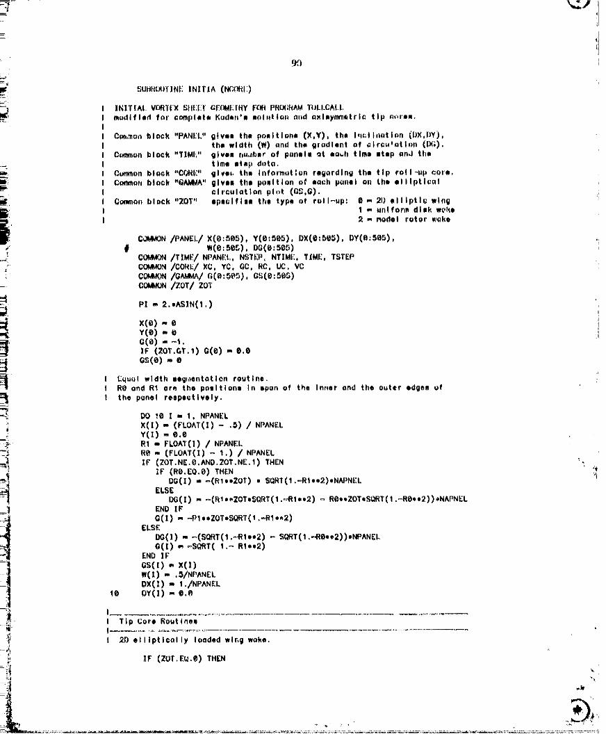

91
YC _ 1. '_ ._'/ • (P'LOAT(N(_(_I:) / NPANEI )y(;, . ._ • ( f'I,OA'|'(N(:L_d"_ / NPANEI, )
DXC ,', Xc. ,_ X(flPANH.,-'W,-!_')ffI:)_ W(NI_ANI:I,' N(,'I._':)_J 511 | -, 1, NI_ANI:i,'_f#;,OI¢I;X( ! ) ,., D_(C • |'LOA1(I-_)/(NPANI:L. N_ORh) + DXC/_,,/(Nt'ANI-:L_-N_L_I|:)+ X(! )W{I) ,,, [:IX(; i',_ /(NI_ANI::I, f,l_L)ffl:,_ + W(/)lX;(I) ,,, _._(I) -, G(I, I,_) /2 /'W(X)
! [_uII1|vwly _,av,Rd fl_t _Ilek w_k4R
EL_r_ IF (ZOT,lil::.l) THI:N
WO - I.'LOAT(NCO_t_) / NPANELxc - S_T( t. - _.,_13. + (_J,,_)/3.)YC _ .lib / .157 • (1. - X(,) I Thle le _ ilOeee: _qle Kgden.GC ,, _I_(NP^_EL.--NCOfII:)RC - 8. • XC / EXP( PX,*2 /4 *XC /S(,_'11'(2.*_ - WC*,_2) + 7./4,)
I Modal of n h_ilcopter rnt_,r woke
I ELSF, _F {ZOT.EQ,2) THEN
I _ _ F'LOAT(I_ORE) / NPANELl XC - $Q_I'( I .... 2.,I_//_I. + _*,2/3.) / (I. _)
I C-,C_, _-G(NPANi'.L..'I.:_.ORE)I tic - 8. ol<C li_XP( PI+,2 //4 *R //(1.=f¢)*+_ //'_._;14_T(_*_AK',L4qC,_,O2)+7.//4.)
I END If,'
I Inltlol C,ondlllon Record
l_l'rE(l_.._) 'INII"]IAL SHF:,I_:T:K. X(]). Y(1), W(1). I_(I)'I)0 3_ | ", 6, NPANEL_-S(_) - SQm'O. -- G(1)..2)
30 IqR_IT,_(I_,,) X, X(|), Y(1), iVl:|), DGC[)
IA_ITE(8,*) 'CORE= NCO_E, XC, YC, GC, RC', NCOflE, XC, YC, GG, RCWITE(8,*) ' '
NPA_"_EL_ KPANEL _ NC_I_
HETURNF,ND
00000001-TSG14

J[,
92
Appendix C
The Vortex Sheet Dynamics Program
! The program TOLLCALL combines the subroutin_ listed below _o simulate the _If_
t induced motions of a vortex sheet, Input file for the program is stored as daviee #7.
The input file is in the form: (RN, NPANEL, NSTrlP, TFAC, GFAC, NCORE, ZOT); RN
is the run's idantifi_tion number, NPANEL is the number of panels initially used to
describe the vortex sheet, and NS'II_P is the number of time Integration cycles for the
run. TFAC dafincs the length of time used in the time integration, TFAC - I is
equivalent to the nondimensional time span of .005, GFAC defines the size of the
panel relative to the die.nee between the sheet and the _enter of the roll-u_ spiral. '_
It is used to insure the accur_.'y of the tip region es the dietaries between the sheet
and t_e roll-up core is diminished during the roll-up. NCORE spafifies the number of : i
paite]s describing the initial vortex sheet to be amalgamated into a tip rolloup core.
"lg_e type of r_:J-up, as determined by the selected initial r_ndition, is controlled by the
parameter ZOT.
ZOT - @. Twoodimensional rolloup of wake vortex sheet shed by anellipticaily loaded wing.
ZOT - 1: The roll-up of a vortex sheet simulating the formation of _'a vortex ring by the impulsive motion of a circular disk. '_
ZOT - 2: Axtsymmetrl¢ roiloup of a ¢irrul_,r vertex sheet modelof the v/ake vortex sheet shed by a helicopt_r rotor.
The program version prc_nted here outputs two files describing the configuration of
the vortex sheet after every ten time integration cyl_cs The file containing the
geometrical data of the sheet ls in devi."_. #9 and the file containing the distribution of
vorticlty t.q in device #10. lkviee #8 holds a utility file describing the execution of
the ?_ogram.
00000002

93
PROGRAMTOLLCALI
I EXECUTIVE ROUTINE FO_ ROLLUP PROGRAM
COMMOR/P_EL/ x(e:_e_), Y(e:_e_), nx(e:ee_), DY(O:ses).
Co_ORICONVl u(e:_es), v(e:_e_)COMMON/TIME/NPNdEL. N_TEP, NTIME, TIME, TSTEP_/O19/l/_,/D(0:505), GS(e:SC_) I GS Ii o nut _e*dCOMMON/CORE/ XC, YC, GC, RC. UC, VC I In this version, bCO_ON /TFAC/ TFAC, _FACOOMMOR/zo'r/ ZOT
_ Input dutu read: a. Reference Number (|PUN)__, b. Number of panels initially in the sheet (NPANEL)c. Mcelmum number of thee atep* in the run (NSTEP)d. (.@85/TFAC) !e the al_e of ouch time ,tap
i :: *. (|cheat edge to tip core|/GFAC) Is the pone! widthf. Number of corn Initially dumped into the tip core
! .i g. Type of luading (ZOT)
i'_l READ(?.,) |RUN. NPANEL. NSTEP. TFAC. GFAC. NCORE. ZOTi " NINIT _ NPANEL
_ t Inlt(ullxe output file_ WRITE(O.') 'ROLL UP PROGRAMFOR VORTEXSHEET. |CHIRO SUGIOKA 37-481'
: WRITE(8.e) 'RUt/NUMBER: ', IRUN
_ t_RITE(8,.) '$PLINING BY ROUTINE RL_]SK'i WRITE(8.*) 'INTEGRATING TIM[ FACTOR : '. TFAC_ WRZTE(O.*) 'GEOMETR|C WIDTH FACTOR : ', GFAC
_<_ WR;TE(8.e) 'INPUTS: (NPN_tEL. NSTEP) 'o NPANEL0 NSTEP!. MtITE(8.*) 'ZOT FACTOr: LOADING Te_RM.AXISYMeETRIC IF >1 '. ZOT
: i! WI_ITE(8.*) ' '
I C:,_put* Initial ConditionCALL |NITIA (NCORE)
i.._: I ...... I '' I Time Integration Loop I
.-_: DO 10 NTIME _ O. NSTEP
i CALL tM_ITF.R I Write output dutu file
=" CALL RUNGE1 I Rlnge-Kutta time Intgrattan echeme
_&t_ I CALL EULER t [ulor time Integration scheme option
DELTAL m 2. • W(2) I Punel width purulnater (0ELTAL)I set to m data.It panel width
CALL RED_SK (X.Y.G,NPANEL.NPANEL.G/4_X.SUML.0£LTAL)I Spllnee und dtvldol the cheer
CALL PANELER(X,Y,DX,OY,W,DG,G,NPANEL)_:___ i t Fume the poneto
i "'_ le CO&ITINUE
I ..... _nd uf Loup ..... Ii .
CALL _|TER I Record the end raoulte
-==_ END
_= .
O0000002-TSA03

94
_LIt]_OLITINEWHITI_R
! This pregrem recorde the resulte of toll©ell e_l flluI FORa_U.DAT (Oenerel eacountlng Informotlon)I FORaOg.DAT ((;eo_etrlcal grepPlce dote)I FOROIO.DAT (Clroulotlon grephl©e dQto)
co_/P_EI/x(e:_).y(e:se_).Dx(e:se_),nY(e:_es).
/TXME/ NPANEL. NSTEP. NTIME. T_ME. TSTEPCOMMON/G_/ _(e:_e_). Os(e:se_)C_/CONV/ u(e:ses), v(e:ses)COMMON/CORE/ XC. YC. GC. RC. UC. VC
WRITE(B.e) 'RESULTS FOR NT|ME. TIME. NPANEL:*. NTIME. TIME. NPANEI
IF (FLOAT(NTIME/IO),NE.FLO_T(NTIME)/I@.) GO TO RiO
V_ITE(9.e) NT|ME. flPANELI_]TE(I@,e) NTIME, NPANEL
I Write 9eometrlcol dote for Ioter 9rophlce.DO 10 I _ O. NPANELWeXTE(9.,) X(X). Y(I). OX(]). oYEZ). W(X)
tO CONTINUE_tlTE(9,_) XC, YC, RC
I Write ¢lrculetlon dote for Ioter grephlce.DO 2e | _ e. NPNtELWRXTE(le..) I. GS(X). GEl). DQ(1)
2_ CONT|NUEI_IITE(IO.*) GO. RC
000 RETURNEND
00000002-TSA04

95
_ SUBROUTINERUN_I
I This program Je a modified Ronge-Kuttn Integration mchsmc
COMMON/P_£L/ x(e:se_), y(e:_es), Dx(e:ses), DY(e:se_),
CDMMON/TIM£/ NPANEL, NSTEP, NTIME, TIME, TSTEPr_W_ON/CON_'u(e:ses), v(e:ees)CO.,CON/CORE/ XC, YC. C.Co RC, t._, VCCOt_ /TFAC/ TFAC, CFAC I TFAC " FACYOR FOR SIZE OF TIME STEP
l: COWON/ZOT/lOTI Temporory Butlers
DIMENSION XB(B:SBS). YB(e:5_5). DX@(0:505). DYB(@:SeS).t ue(e:se_), ve(e;ses)
CALL VELOCT I Velocities to get to the Intsrmedlats points.
TSTEP - .OO25/TFAC I The Intsrmsdl_ts points ore ot hnlf,'_oy.
IX) 2e ! - e, NPANEL ! Get to the Intermediate points.XB(I) - XCX)Ye(_) - _(t)oxe(1) - ox(1)
ue(1) - u(ove(I) - v(I)X(I) - X(I) + O([) • TSTEP
:'! Y(I) - Y(I) + V(I) * TSTEP': 2@ GOHT[NU£L
XC8 - XC
i_ YCO - YC
!i UCe- ucI,! vce- vcXC - XC �UC* TSTEP
! i YC -- YC + VC • TSTEP
L,, DO 25 I - 1, NPANEL-t t EIt_moto Intsr_sd_oto pons_s.
,,i CX(1) - X(l+O - X([-t) [_DY(]) = Y(I+I) - YCI-I)
,,, wcz) - SQRTCCXCX+1)- x(z-s)).,2 + (Y(x+l) - Y(x-1)),.2)/4.i 25 CONTINUE
"i I - NPANEL I Extropolato =t the tip.
A - ((Y(I-2) - Y(I-I) ) • ( X(I-I)**2 - X([)**2 )= - (Y(I-1) - Y([) ) • ( X(1-2)**2 - X(l_l)**2 )• + (YCI-2) - Y(I-1) ) * ( Y(I-1)*.2 - Y(I)**2 )• - (Y(i_I) - Y(I) ) * ( Y(I-2)*.2 - Y([-1)*=2 ))• /((xo-z) - x(t-_)) , (Y(I-_)- Y(1) )• - (X(I-1) - X(I) ) * (Y(I-2) - Y(I-1) )) / 4.
- (( x(l_t),*2 _ x(1)*,2 ) + ( _(l-t)*,_ ~ v(1)**2 )• .- 2. * A * (XO-1) - XCX))) / 2 / (Y(X-S) - Y(X) )
OX(I)--(Y(I)-S)cYO)- (xcI)-^)w(I) -SO_T ((x(_) - xcH)),,2 + (Y(x) - _(x-o),,_)/2.
CALL VEL(X_T I The _ld-co.res correction
10 35 I - 1. NPANEL I Average I. the mld-co_r=e correctionU(X) - (ueCI) + u(l) ) / 2,
..... - - - ---- 000000-----02TSA05

96
v(x),,(ve(x)+ v(x))1 2.35 CONTINUE
oc,,( oce+ o.c) / 2.vc- (vce+ vc ) / 2.
TSTEP _ .Og,_/TFAC
DO 50 [ ,N l, NPANEL I Final tranmlatlon.X(I) - XO',I)+ U(I) * TSTEPv(x) ,, Y_(x) + vO) . TST_:F'
Se CONTXNUI':'
XC '_ XCO + UC • TSTEPYC " YCO + VC • TSTEP
I Stretching of tip core: coneerve volume of the vortex ring.RC m RC * XCe/XC
x(e) - eY(O) _' Y(1)v(o) - vO)
TIME m TIME • TSTEP
RETURNEND
00000002-TSA06

97
_UUR(_JTXNE EULER
I Thlm program leo Runge.-Kutto Integration echeme band _ limitingI the Iorgeet convection of pnnete to ease fraction of their wldthm,
/PANEL/ x(e:ses), '¢(e:se5), ox(e:se5), oY(e:ses),
COMMON/TXME/ NPANgL, NSTEP, NT]ME, TIME, TSTEPC0M,,_ON/CONV/u(e:se_), v(e:_e_)_IM_ON /TFAC/ TFAC, GF'^CCOM_ /CONE/xC, YC, r,C,RC,uc, vc
CALL V£LOC:T
T$TEP - .ees / TFAC
_ Ponel width based time etep option , ITSTEP m .1DO tei - I, NPANELTPAN - W(|) / SQRTC U(Z)**2 + V(I).*2) / TFAC
1_ IF (TPAN ,LT. TSTEP) TSTEP - TPAN
..... IDO 2_ I m e, NPANELX(Z) - X(I) + U(X) • TSTEPYC[) - YCI) + V([) * TSTEP
20 CONTINUE
XCe - XC iXC _ XC + UC * TSTEP i¥C _ YC • VC * TSTEP
!
RC m RC * XCe / XC !
x(e) m eY(e) - Y(I)
v(e) - v(1)TIME i, TIME + TSTEP
RETURNEND [_
00000002-TSA07

9H
5UL]R_JTI NE VELOCT
I Thin progrnm calculotee the velocity fieldI Induced by the penal• for thm program TCLLCALL.F_
COMMONpANEL/ x(e:_e5), Y(e:_ee), Dx(e:se_). oY(e:ser_).
COMMON/CONY/u(e:ee_), v(e:_e_)COMMON/PRIME/ NPANI_L. NS'rEP. NTIME. TIME. TSTEPCOMMON/VELO/ R. )iX. YY. DXT. DYT. WW. G
/lOT/ lOTCOMMON/CO•E/XC. YC, OC,RC,UC,VCp! m ASIN(1.) • 2,
IIIIlllllllllllllllllllll Loop over the tronlloted pan•In IIIIllllllllllllllllllDO le J a I, NPANELUJ ,- e._VJ m e.e
I ..... Loop over the Inducing ponell ........ IDO 2_ i m t, NPANELe = X(!)O = _(1)
= W(l)DXT- DX(I)DYT - DY(X)xx - x(J) - x(I)xY- Y(J) - Y(l)
I o¢. The Axllymmetrlc case ••*IF (ZOT.GE.1) THEN
| I !nterpoloto the eel f-Induced velocity!F ((XX.EQ.@),AHD.(YY.EQ.e)) THEN
XX,,-.1 • W#
CALL VELIN ( U!NA. V!NA)CALL VELIO ( UIOA. VIOA)CALL VELOUT( LK_TA. VOUTA)
_, XX" .1 *WW, CALL VELIN ( UINB. VlNB)
CALL VEL!O ( U!OB, VlOB)CALL VELOUT( UOUTB. VOUTB)UIN - (ULNA + UINB) / 2.VIN ... (VINA + VINB) / 2.UlO ,,, (UIOA + UIOO) / 2. _,;v!o - (VIOA+ VlO6) / 2.
| UOUT - (t_eJTA + UOUTB) / 2.VOUT - (VOUTA + VOUTB) / 2.
ELSECALL VELIN ( U!N. V!N)CALL VELIO ( UIO. VlO)CALL VELOUT( U(X,IT. VOUT)
END IFUJ - UJ + UIN + LI_T - UlOVd m VJ 4. VIN + VOUT - VIO
I •** 2D Co•o: Incl,dee the mirror Image component ***ELSE
CALL VEL2D (UI.Vl)xx - x(J) + x(1)Y_ - Y(J) + Y(l)4G. - DO(1)DYT ,", - DY(1)CALL VEL2D (U2.V2)
q_
00000002-TSA08

/i I
99 ,'
UJ - UJ + U1 + U2VJ _ VJ 4" Vl + V2
lEND W
2¢ CONTXNU_I' End of Loop ,I
U(J) ,. UJv(J) - vJ
le CONTINUEIIIliilllllllllllllli_llllilll ¢*nd of Loop Ilillillllilllllilllliilllllilllllill
I Cololote the velocity Induced by the ttp_core
U2 - eV2 m eR - XC
DOlee d - 1, NPANELR _ XCXX- X(J) - XCYY - Y(J) - YC
_-" G- GC
IF (ZOT.GE.1) THEN I Axlly_lletrlc Case, WWm .5
CALLV_LOU+(_,, vl) i_: GO TO 98 _'i END IF
pI
CALL VEL2DF (U1. V1) I 2D COle with mirror Imagexx - X(a) + XC i,;
iCALLVEL2Dr(U2, V2)
99 u(J) - u(J) + ul + u2v(J)=v(d)+vl +v2 I
le@ CONTINUE I:
I II Calculate tire veiaclty Induced on the tip core by the ponell
UCm e "_VC _ @
DO 110 Z _ 1, NPANELXX- XC- X(1)
.: YY=YC- Y(I)DXT - OX(1)DYT - DY(1)
_- w(1)_+ O -_(1)i R - X(l)
IF (ZOT,GE.1) THEN I Axlaymmntrlc CaseCALL VELIN {UIN, VlN)CALL VELIO (UIO, via)CALL VELOUT(ti_UT, VOUT)U1 ,. UIN �UOUT - UlOVl -, VIN �VOUT - VlOU2 ,,, 0
i _ V2 - e
E I GO TO 1@5 _,
00000002-TSA09

1(_
END IF
CALLV_L2D (UI,V1) I 2D caem with mirror ImaRexx. Re+ X(I)_YT - UY(1)ww-,- w(z)0 --DG(X)CALLVEL2D (U2,V2)
105 UO- UC + UI + U2VC- VC + V| +V2
11_ OONTINUE
I 20 Coee Oply: Velocity induced by the mirror Imoge of the tip coreIF (ZOT.EQ.e) THENXX _ 2eXCYY" e,OG -"GO
CALL VEL2DF (UO,VO)UC-UC+ U_VC m VC + V8
END_F
I Axleymmetric Coee Only: The Self-induced Velocity of the CoreIF (ZOT.GE.1)VC- VC- OC/4_I/XC,(LOO(e,XC/eC)- .25)
U(e) - e.e
RETURNEND
N.
P:
E
glF_
N
00000002-TSA10

AOI
SDBROLIHNE REDISK(R, ZoG.NIN,N(_I'o_X,SL_4L.,D_LTAL)
C--.TRI_ DOES CURVE FITTING USXN_ DLENDEDPARAUGLA_ON R, Z, IH3AMI Modified from SPIRAL,FOr( by John Knntellm for un with panelm
COMMON/TIME/ NP, N_, NT, T, TSCOMMON/CO_XC, YC, GOCOMMON/T_'AC/TFAC,OrACCOMe.lOOT/ ZOT
DIMENSION e(e:Se_),Z(e:_),G(e:_e_),S(e:Se_),Q_(e:_eS).$ az(e:seS).Ae(e=ee_).Al(e:_e_).A2(e:_).A_(_._es).$ ee(e:se_).m(e:_e_).,_(e=_es).e_Ce:_e_).ce(o:se_).$ cl(e:_es).c2(e:_e_).c3(e=_e_).GMID(e:ee_).SMXO(e_es).$ Q(e:_eS).R_(e:_ese).zs(a:ee_e).AL(e:_eee).os(e=_ase)
DATA NSUD/5/
C"_'GET STRAIGHT LINE DISTANCES BETWEENPOINTS, $(1) I$ THE TOTALC DISTANCE ALONGTHE STRAIGHT L_NES TO NODE I
s(e)-e.eDO 2g I-1,NIN
2D S(1)-S(I_I)+SQRT((Z(I)-Z(I_t))**2+(R(I)_R(I-1))=*2)
C--Get vnlul of I for the trolling extendod oegmont. Ohio voluoC of S Io out ot tha prooumod end of the sleet.
S(NINH)BS(NIN)*e.S*(S(NIN)-S(N]I_,I))
_=-_GET SLOPESAT _CH INTERIOR NCDE, Q_(I)._)(R)/DS AT NODE l
IX) 3_ |mt,NIN-I iSI"(S(I+O-SCI))I(S(H)-S(I))S2_1.e/S1s_-l.el(SCX+1)-sc]-.1))
_(|)-((R(I-1)-R(I))*SI-(R(I+I)-_t(I))*S2),S33e QZ(I)-((Z(I-t)-Z(I))*SI-(Z(I+I)-Z(I))*S2)*S3
C.-.-4_.OEF'SFOR INTERIOR SEGMENTS
DO 4e I=I,NIN-2
sl-t.e/(s(l+l)-S(]))AeCX)..e(z) ,_^_(x),,oeCx)A2(I)mSI.(-QR(I+I)-2*Qf_(I)+3.SI*(R(I+I)=4_(])))A_(I)-S_*S_*(Qe(X+_)_(I)-2.S_.(RO+_)-R(X)))Se(Z)-Z(X)m(1)-Qz(x)B2(I)-Sle(--QZ(I+I)-2*GZ(I)+3*SI*(Z(I+I)-Z(])))
4e B3(I)-SI*Sle(QZ(I+I)+QZ(I)-2*St,(Z(I+I)_Z(I)))
Co--COEF'S FOR FIRST SEGMENT
s_-s(t)-s(e)s_-s(2)-s(e)S_P_l.e/(S(2)-$(l))^e(e)-R(e)^I(e)-((R(1)-R(e))*S2/Sl-(R(2)_R(e))*Sl/S2),S_A2(e)-((R(2)-t_(_))/S2-(R(t)-R(e))/S1)*S_a_(e)-e.eee(e)-z(e)¢l(e)-((zo)-z(e)).s2/sl-(z(2)-z(e)).sMs2).s_
00000002-TSA11

102
.2(s)-Ciz(_,).,z(a))/_2-.Czil)..,zce))/aO.,_za3(a),-e.e
C--COE3"S FI_ LAST 5E(iMENT
N-NIN
St..S(N)_S(N-t )S2-S(N_2)_-S(N-,I)S_I .*I(S(N"2)-S(N))A, CN-I),.e(e_t)At(N-t).,((,(N)'-R(_I)),S21St_(R(N-2)'_(h_I))._IIS2).S_A2(N_I),.((_(N_2)--e(N-.t))/S2-(H(N).-e(N_I))/Sl),S_A3(N_I ),-e.O
ee(N_t)-Z(N_l),I(r_t)..((Z(N)-Z(_t)).S2/Sl-(Z(N-2)-Z(_O).SMS2)eS_,2(,-I)-((Z(N-2)-Z(_I))/S2-(Z(N)-Z(N-I))/Sl).S_
C_Get the ongle of the ring with Index NSMALL wrt the tip ©ore !
CALL PULANG(NIN, THNIN)
C_Oet the "A** ooefflclent for the Kodln eplrol
RNLImXNU(THNIN)IF (ABS(SIN(TIININ)) .G{, B.S) THEN/V-(YC_Z(NIN))/(TIININ**(--RNU)*SIN(THNIN))
EkSE
A-(XC--R(NXN))/(THN IN*•(-RNU)*COS (THNIN))ENOIF
|C---GETARRAY OF"R AND 7 AT THE SUBINTERVAL LOCATIONS, AND COMPUTEC THE TOTAL LENGTHOF THE CURVE
C--First do the blended porobolc eogmente
RS(g)-Ae(e)zs(e)..ee(e)AL(O)',(),QDO Sg I-O,NIN_I
DO 5g KSUI_.t ,NSUBJ'I*NSUB+KSUBT'(S(I+I )-5( ! ) ) *FLOAT(KSUB)/FLOAT (NSUB) "_.,RS(J ),.,AS( ! )+Te (At ( ! ) 2(! ) â�F 0�r�I) ) ) "_ZS( J).-B_(1)+T= (BI( i)+T= (B2(I)+T,S3(I)))
5g AL( J)-AL( J-I)+SQRT( (RS( J).-RS(J-1)).,2+(ZS(J)-Z$(J-I)),¢2)
C_The next few eectlonx find the volue of thet(] ot the end of theC trolling extended legment. I.e.. gets the theto oorroepondlngC to or¢length S(NIN+I)
C--Flret, before doing the numerl¢ol Integrdtlon. need to get oC vol.e to uee for delto there
]TER$'_B
DSGW-(S(N!H+I )-$(NIN))/20.ODT(_,8.el
62 TTEMP-TflN IN+DTG/2. @RNU.,XNG(TTEMP)| TERSQ.|TER$-_1IF (ITERS .GT. 1Be) STOP 'ITERS .OT. IS8 !N LOOP Cl'DSC._A*TTI[MPo• (_RNLF-!. B) eSt..'_T(RNUI e2+TTEldPee2 ) eDTG
.... 00000002-TSA12

103
DT(',t_,LO_;(;W/O_;) ,D'r_I1" (AD_;(I_'fGN-DTG) ,kl', 8,_B1) _J TO titDTG-DI'(_NCd) TO I_
81 DTG-DTGN
C---Nuw hnve diltn thet_ (I.e.. blC) which Mm.id yield opprox. 2_C Atepm In the mmlerl©ol Integrntlon fr_ S(NIN) to S(NXN'I.1).
C_--N_,wdo the numerical Integrntlon mid me(:rch for theta(NXNt,1)
SENI>,)S(NINI,) )_,$(NXN)ST;'_O. 0TH_THNIN
64 RNL,-XNU(TH)XTEt_',](TEN_+ 1
IF' (XTENe' .GT. lee) STOP '|TER_ .GT. leo LOOP G3'ARGI_A*TIf(,m (-RNU_I, 0 )*S(_T (RNU*o2+TH_)e2)RNU-XNU(TH+DTG)ANG_-A* ( TH+DTG) * e(--RNU_1,0) *_QRT(RNU* e2+(TIHDTG) ee2)D_(ARG I+Af_G2) *DTG/2. eXE (STH ��lSEND) GO TO 63STH,,_TH ‚�Î�TtIqTH+DTG
GO TO 64
G3 FI;_AC_( SENIP.$TH)/D$THNINImTH+F_ACeDTG
C_-'Now Don get the cut)--Inferrer Ioc¢lt|one over the extended eplrolC eegme.t.
DTH-( THNI NI-THN |N)/NSUDDO 65 KSUB_I)NSUBTHETA_THNI hLtKSUI]*DTHJ_'NXNeNSUB'FKSDDRNU,,XNU(THETA)R$( J)-XC-A*THETAe • (-_NU) ICO$ (THE:TA)Z$( d)-YC-AeTHCTA* * (-RNU) *S | N(THETA)AL( J),,AL(J-I)+SQRT((RS(J)-RS( J-t )) ee2+(ZS(d)-ZS(J._1)) **2)
6,5 CONT]NUE
I Redletrlbute the C|rculotlon over the S.b_egmente
DO 751 ! " @, NIN00 751 J a 1. NSUBK m I I NSUB + JIF (I,EO.e) THEN
IF (ZOT.LE.1) THENG$(K) - FLOAT(J)/HSUB • (1.+G(1))/2. - 1,_s(e) - -1,
ELSE
GS(K) ,, FLOAT(J)/NSUD ,) G(1)/2.GS(e) - O
END XE
ELSE IF (I.EO.NXN) THENDGN - (G(NIN) - G(NIN_I))/_G$(K) - FLOAT(J)/N,SUB * IDGH+ G(N;I_I) + DGN
ELSE_X - (O(X+I) .- 0(X_1))/2DGIMI - (G(I) - G(|-1))/2GS(K) - (FLOAT(J)/NSUEI * DG_) + GCX-1) + DGIMI
%
00000002-TSA13

104 c'i '
,g ,,ENI) IF
751 CDNTINIIE
C--TOTAL LLN_TH Of' CtlHVE 1_ 5LqL
SI_4L-AL((NIN+I)*NSOt])
IIIIIIIIIIIIIIIIIlllllllllllllltllilllllll|lllzltllllllllllllllllllllll|lll|lllI Panel Dlmeretlxatlon Crlterlum
IENU - (NIN+I) • NStJ_ I Limits Relotlve _Imt_uce End/CoreXLSE_ - _T((XC--RS(IEND))ee_+(YC-Z_(]END))z*2)/GF'AC|E (XLSEG.OT,DELTAL)
-_, _ XL_ES _ DELTAL I ^lwuym Shrinking Criteria_ DELTAL _ XLSEG
lllllllllllllllllllllllllllllllllllllllllllllllllllllllllllllllllllllllllllllll
--_ C--GET NEW R AND Z POINT8)
31_ lml
" _! DO 60 JmI.NSUe*(NIN_I)
' I. Cql¢.lotl the _Iitgnge to the powltlonm of the l_'puoell t
_+_ WJme- S_X((eSO)- r(;-l) ),,2 + (zsO) - Z(I-1) ),,2 )___i I...................................................... I
_'. IF (XLSEG .LT. WJMI .0_. XLS_G .ST, WJMe) GO TO 6e I If n,,t eno_lgh,--'_ FRAC._( XLS[G + WJM1 )/( WJMO- WJM1 ) I C_lQ.Inte wher_ th,, r,_w
R(I)-FRAC.(RS(J)_RB(J_I))+R_(d-1) I pnn_l edO_ will _ ,b ._p.z(x)._r^c,(zs(a)-zs(J-O)+zs(J-1)1-I+1
_'_ IF (I.GT._) GO TO 3_ I TOO _,'ny punelelGO TO _0
6e CONTINUE, : 7_ CONTINUE
R(1) - RS(NSOe,(NI,+O)z(I). ::, (N_U_.(n_n+O)
: , O(1) ¢ GS(NSUee(NIN_I))
_ i RETURN
I If the mheet II too atretched to the ponwled by SOO ponel|, then
I stretch the panels by le_.
.__ 3re XLSE_ - XLSEG e1.1
WRITE(8,*) '***_*** OVER _OO PANELS e******* TSTEP, DLSEG:', NT. XLSEGGOTO 310I ............................... I
"" EN_
w
,7
" -0-0-000002-TSA14

talk
105
SUI_8OUTIN_ PULANG(NIN,THNIN)
Special 5ubrcmtln¢ far routlnu REDISKwhich ¢xtrQpolotomthe lhePt edge ,mtng Kudmn'e exponential aplrut modat
COM,.tON/CONr.'/ XC, YC, C¢COMMON/PANEL/ R(@:5_5).Z(e:SeS).DX(e:SeS),DY(e:_eS),
S w(e:_es).(;Ak_(e:5e5)DIMENSIOND'tTA(_:5e5)
REAL*4 MAGC
RT..XCZT-YC
CA",,-,1 .eIb,,O,_
i C.,R(e).,-RT' _-Z(e)-ZT
DOT=,AeC+B*D- ' CRO,,,qS-A*D,"B•C
MAG_;Q_T((A*A+_*B) *(C*C )ARG,,,.DOT,t_IAGIF (ABS(ARG) .GT. 1.1}) ARG,,SlGN(I.e.NtG)
1 BETA(O)-$|GN(1.(}.CROSS)*AGOS(ARG)--_ c
DO 1(_@lml,NINA=R( X-1)-RTe-z ( H )-ZTC,.R(Z)-eTD,,Z(X)-ZTDOT'*A*C'+B*DCROS_A*D"6*C
MA_,SQRT((A,A.H_*S)• (C*C_*D))ARC,_DOT/MAGIF (ABS(ARG) .GT. l.e) ARG.*:;1GN(1.e.ARG)
lee BETA(I)-13ETA(I-1)+SIGN( 1.e.CROSS)*ACOS(ARG)
TH_IN-I_£TAiNIN)
RETURN
ENDFUNCTIONXNU(THETA)DATAPI/3. 141592654/XNU,,2.0/3. OIF (TH[TA ,LT. 2,@*PL) THEN
XNU,.,(I.e/(2.e,PX_l .e))-(t .e/(THET^-I .e)) _.eENDIF
RETURNEND
O0000002-TSB01

SIJgROUTXNEPANEL_R (X.Y.DX.DY.W.DG.G.NPANEL)
! Tl_ta progrom tak*! the rem.ltm from routlna REI)]SK _nd ¢raataa pan*la
DIMENSION e(e:s,_), z(e:ses)
DO 10 X m 1, NPANELR(X) - (XCX) + X(H) ) / 2.z(x) - (v(x) + Y(H) ) / 2.Dx(x) - x(1) _ x(x_l)
w(i) - SQR¥( DX(I)**2 + DY(|)*,2)/2._(x) - (_(x) - _(x._)) / w(x) 1 2.
1@ CA;_IT|NUE
DO 2e | - t. ;_P^NELX(Z) - e(x)
2e v([) - z(x)
RETURNEhID
e
O0000002-TSB02

I07
Appendix D
Inputs Used to Generate the Figures in the Text
Figure 5-7: FAUptie_lly L_ded Wing Wake C._¢NPANEL - 80TFAC - 1OFAC - 1NCORE = 47A)T -0
Figure5-13:Formulationof VortexRing by a DiskNPANEL - 80
"_ TFAC 1_, sm
=_,_ GFAC - l=A'_ NCORE - 1_,_:i ZOT " 1
: Figure5-21:Modelled llelicopter Rotor Wake Case--; NPANEL - 80_' TFAC - 1
GFAC - l" NCORE - 1.
ZOT - 2
Figure 5-28: I_monstration of Kelvin-ltslmholtz-type Ins_abiUty_is exlzrimentwas 1_fformcdusingan earlyvet#ionof the simulationprogram with different mt of inputs-
Figure 5-29: Instability in the l_olloUp of Disk WakeNPANF.L - gO
=_ TFAC - 1_' GFAC - 2-_ NCOR]'."- 1' Z_YI" -I
O0000002-TSB03
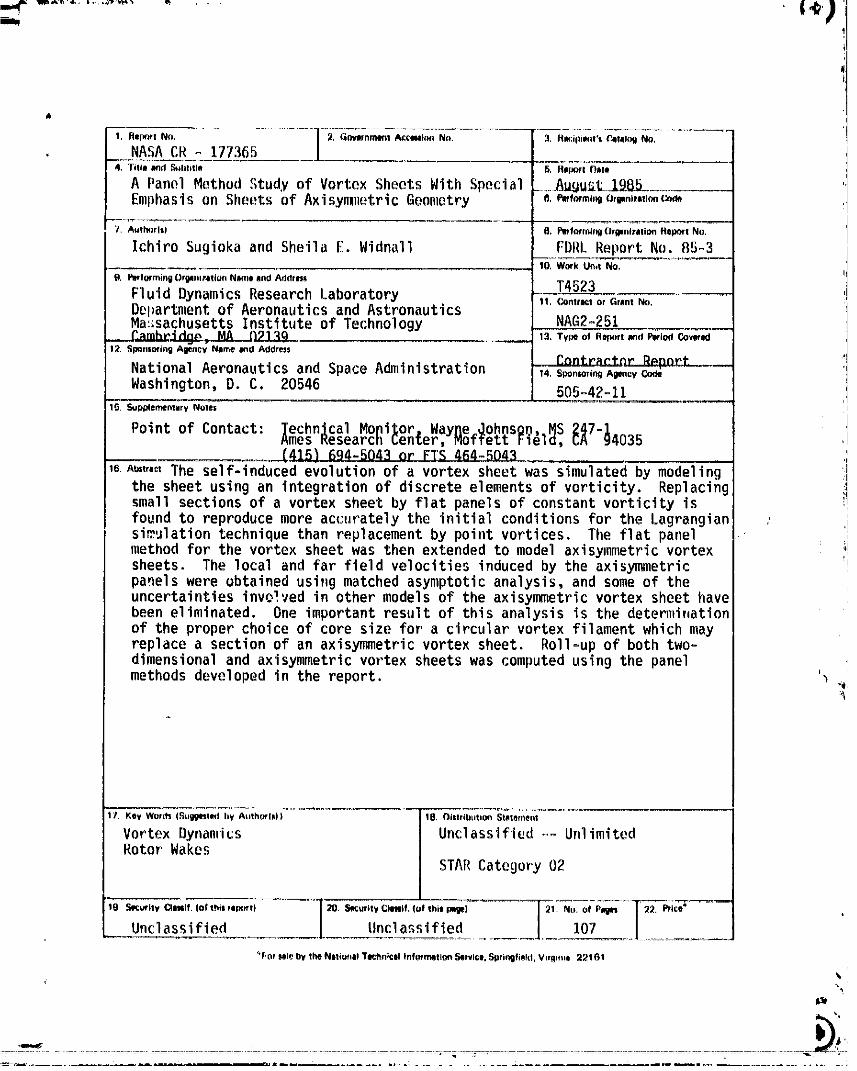
NASACR - 1773654, TiIIA _d _hlill# B. Rel_l Dmlo
A Panel Method Study of Vortex Sheets With Special ......Au_u:t ]._Emphasison Sheetsof AxisynliIetricGeometry a._,fn,,mo,mm,,,ImcQ_
7. A_lh_rls) IB, P_f_rrnlrq_Orgenixltio_ ffep_rt No.
IchiroSugiekaand SheilaE. Widnall FDRL ReportNo. 85-310, Work Un,tNo.
9. F_forming Or@ImrationNi_meand Addrlss T4523Fluid DynamicsResearchLaboratory II.co,,r_,o,_-,,m_.Departmentof Aeronauticsand AstronauticsMa:;sachusettsInstituteof Technology NAG2-251
__ 13. Type of Ropm't_(I Pwio,rl Covered12. Sp_nsofin9 Alency Nllmeand Address
NationalAeronauticsand Space Administration _t._14. Sponlorm9A_ncy Code
Washington,D. C. 20546 505-42-1115. Supp4ernQntaryNOteS
Point of Contact: lechnJcalMopi)or,WayI1e_ohnson,._SCA9247"14035Rmes Kesearcn_enter,moTrettFielo,.(4)6)694-5043or FTS 4fi4-SO43
m Am,,,,The self-inducedevolutionof a vortex sheetwas simulatedby modeling
the sheet using an integrationof discreteelementsof vorticity. Replacingsmall sectionsof a vortex sheet by flat panelsof constantvorticityisfound to reproducemore accuratelythe Initlalconditionsfor the Lagrangian :simulationtechniquethan replacementby point vortices. The flat panelmethod for the vortex sheetwas then extendedto model axisymmetricvortexsheets. The local and far field velocitiesinducedby the axisymmetricpanelswere obtainedusing matchedasymptoticanalysis,and some of theuncertaintiesinvolvedin other models of the axisymmetricvortex sheet havebeen eliminated. One importantresultof this analysisis the determinationof the proper choiceof core size for a circularvortexfilamentwhich mayreplacea sectionof an axisymmetricvortex sheet. Roll-upof both two-dimensionaland axisymmetricvortexsheetswas computedusing the panelmethodsdevelopedin the report. '_-,
1_. Key Wortts (Sull_t_l by Atltho_(|)) ] 10. Oistribution St_temenl
Vortex Dynamics I Unclassified-.-UnlimitedRotor Wakes
I STAR Category0219 S_¢_ity Cll_if. (of t_is _1_i} 29. SecurityC_mtf, (of 1himI_l_) 21+ No, of P_sg¢I 2_. P_ice*
Unclassified _____ Un£1flssi fled 107
_ForIIle by the NIti_mlt TIchllicII InfoemQti_ _rvi¢l, _plii_lfi_kl, V.lt..I 22101
O0000002-TSB04