Embed Size (px)
Citation preview
ICH Anchorage to Concrete Seminar Santiago, Chile
19 – 20 Marzo 2015
March 2015 1
Buenos días!2
www.sgh.com
Anchorage to ConcreteACI 318-11 Appendix DACI 318-14 Chapter 17
Neal S. Anderson, P.E., S.E.
Staff ConsultantSimpson Gumpertz & Heger, Chicago, [email protected]
Member ACI 318 – Structural Concrete Bldg. CodeChair 318B – Anchorage & Reinforcement
Seminar Materials Seminar slides handout
Other good reference material• ACI 318-11, Chapter 2 and Appendix D
• ACI 355.2-07 Qualification of Post-installed Mechanical Anchors in Concrete and Commentary
• ACI 355.4-11, qualification of Post-installed Adhesive Anchors in Concrete and Commentary
• ACI SP-17, ACI Design Handbook, Vol. 2
• SP-283, Understanding Adhesive Anchors: Behavior, Materials, Installation, Design
• Code justification technical references
4
Seminar Handout
5 6
ICH Anchorage to Concrete Seminar Santiago, Chile
19 – 20 Marzo 2015
March 2015 2
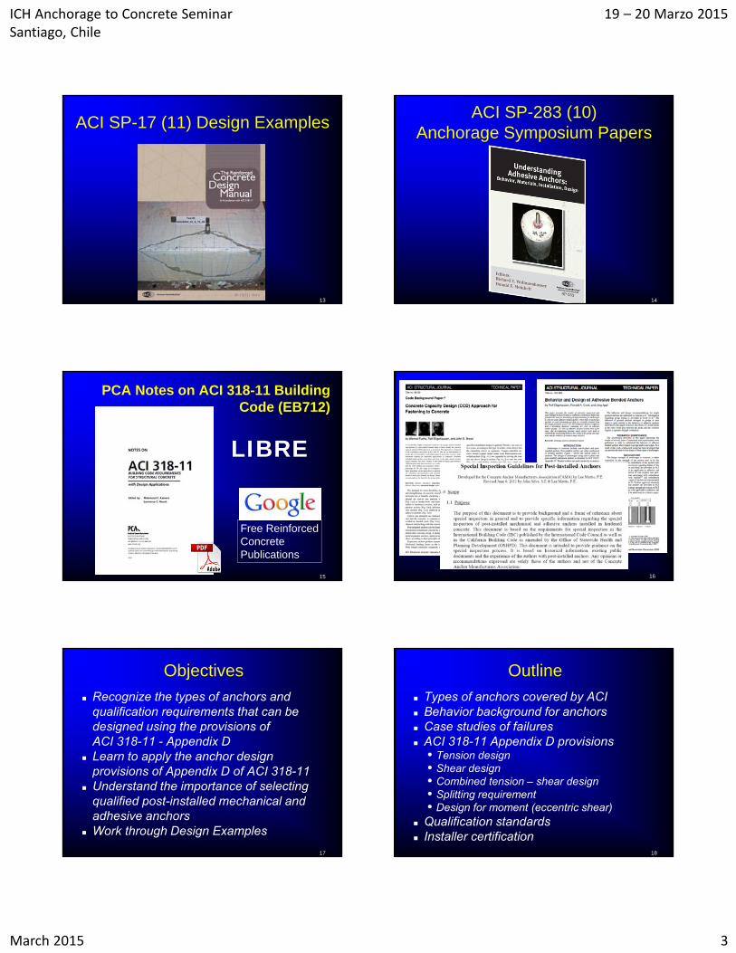
ACI 318-14
318–11 Appendix D
318-14 Chapter 17
D. 17.7
The Master Key
318-14 Resource CenterTransition Key: 318-14 to 318-11
Technical changes made to more than 200 individual provisions
11 12
ICH Anchorage to Concrete Seminar Santiago, Chile
19 – 20 Marzo 2015
March 2015 3
ACI SP-17 (11) Design Examples
13
ACI SP-283 (10) Anchorage Symposium Papers
14
PCA Notes on ACI 318-11 Building Code (EB712)
15
LIBRE
Free Reinforced Concrete Publications
16
Objectives
Recognize the types of anchors and qualification requirements that can be designed using the provisions of ACI 318-11 - Appendix D
Learn to apply the anchor design provisions of Appendix D of ACI 318-11
Understand the importance of selecting qualified post-installed mechanical and adhesive anchors
Work through Design Examples
17
Outline
Types of anchors covered by ACI Behavior background for anchors Case studies of failures ACI 318-11 Appendix D provisions
• Tension design• Shear design• Combined tension – shear design• Splitting requirement• Design for moment (eccentric shear)
Qualification standards Installer certification
18
ICH Anchorage to Concrete Seminar Santiago, Chile
19 – 20 Marzo 2015
March 2015 4
19
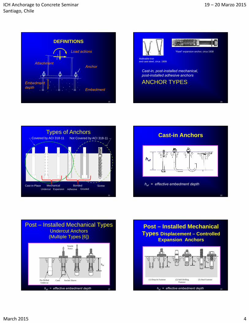
DEFINITIONS
Embedment
AttachmentAnchor
Load actions
Embedmentdepth
ANCHOR TYPES
Cast-in, post-installed mechanical, post-installed adhesive anchors
20
Malleable-iron and cast-steel, circa. 1909
“Rawl” expansion anchor, circa 1938
21
Types of Anchors
Grouted
Undercut Expansion
Cast-in-Place
Covered by ACI 318-11
Adhesive Grouted
BondedMechanical
Not Covered by ACI 318-11
Screw
22
Cast-in Anchors
hef = effective embedment depth
hef
23
Post – Installed Mechanical Types Undercut Anchors (Multiple Types [6])
Pre-DrilledUndercut
Cone Anchor Sleeve
TensileForce
hef
hef = effective embedment depth 24
Post – Installed Mechanical Types Displacement – Controlled
Expansion Anchors
(1) Drop-In Fastener (2) Self-Drilling (3) Stud Fastener Fastener
hefhef hef
hef = effective embedment depth
ICH Anchorage to Concrete Seminar Santiago, Chile
19 – 20 Marzo 2015
March 2015 5
25
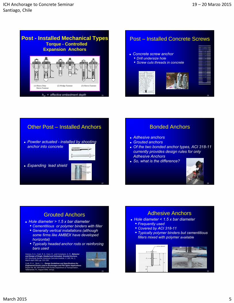
Post - Installed Mechanical TypesTorque - Controlled
Expansion Anchors
(1) Heavy Duty (2) Wedge Fastener (3) Sleeve Fastener Sleeve Fastener
hefhef hef
hef = effective embedment depth 26
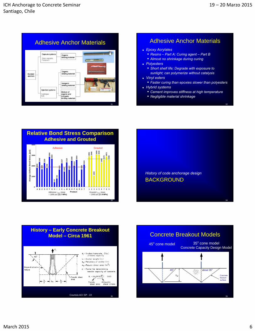
Post – Installed Concrete Screws
Concrete screw anchor• Drill undersize hole• Screw cuts threads in concrete
27
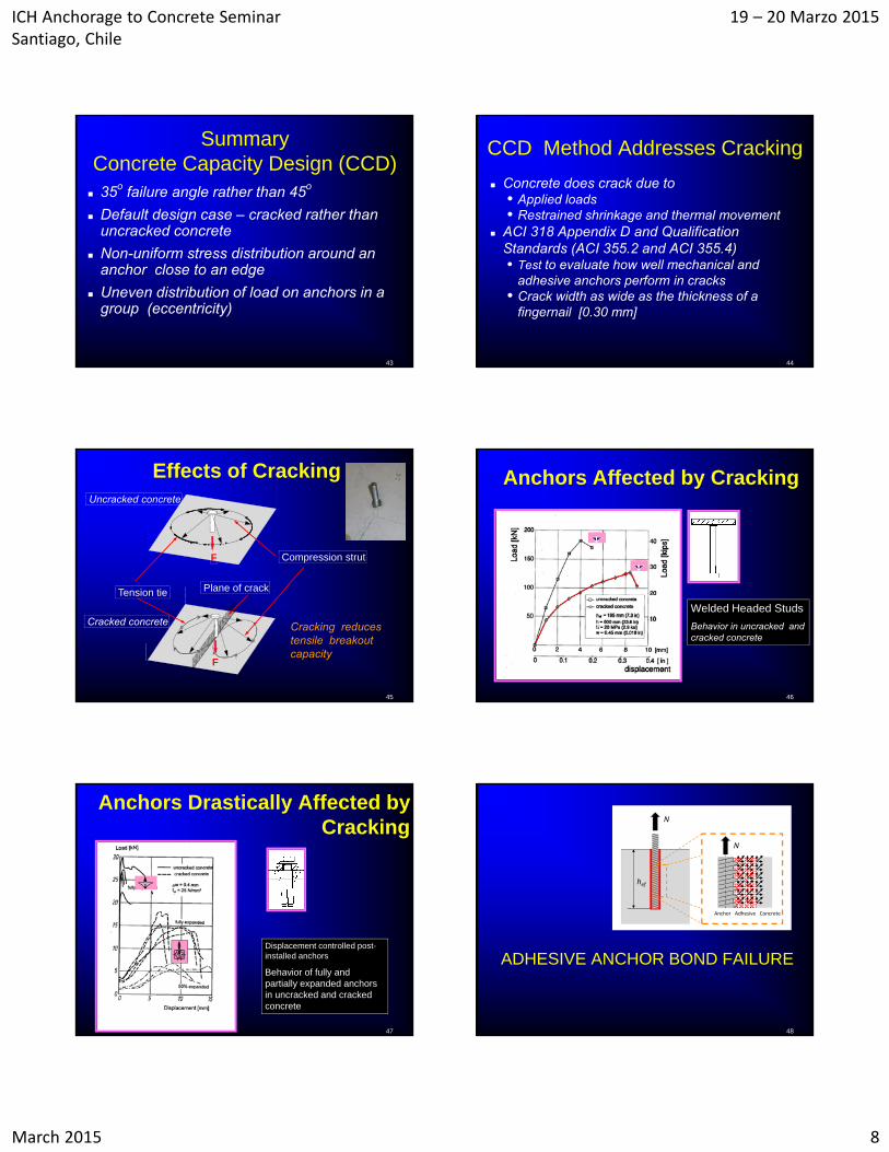
Other Post – Installed Anchors
Powder actuated - installed by shooting anchor into concrete
Expanding lead shield
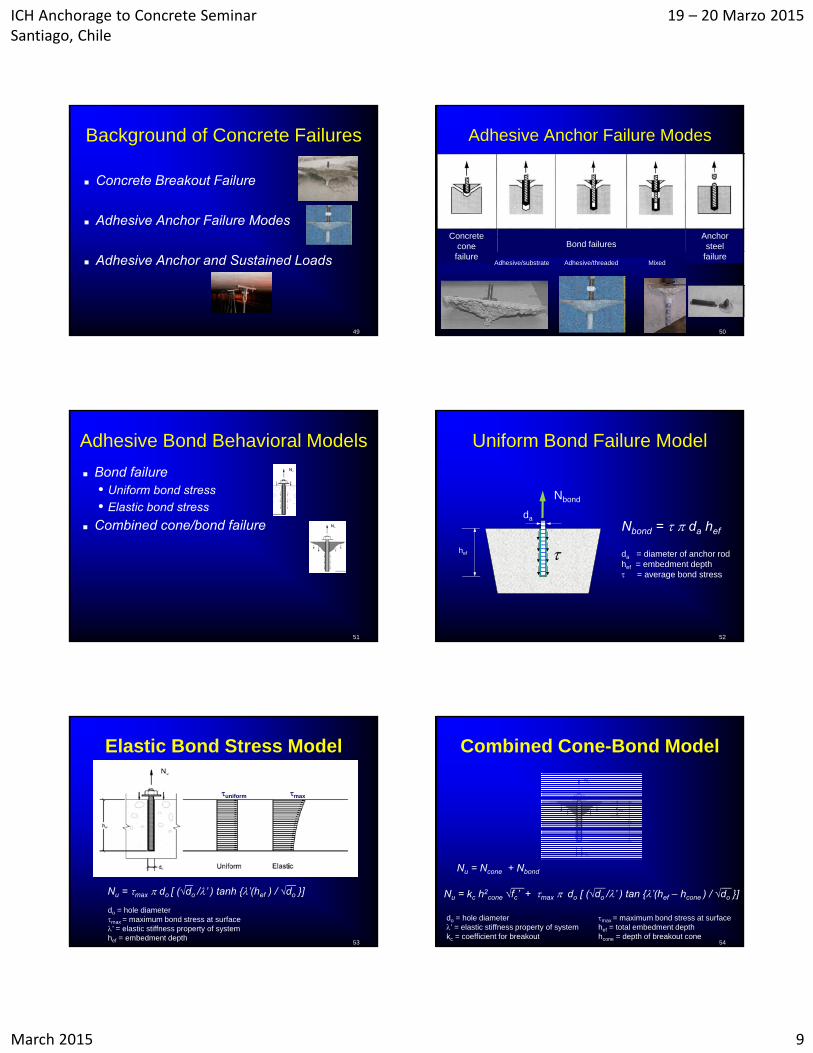
Bonded Anchors
Adhesive anchors Grouted anchors Of the two bonded anchor types, ACI 318-11
currently provides design rules for only Adhesive Anchors
So, what is the difference?
28
Grouted Anchors Hole diameter > 1.5 x bar diameter
• Cementitious or polymer binders with filler• Generally vertical installations (although
some firms like AMBEX have developed horizontal)
• Typically headed anchor rods or reinforcing bars used
29
Zamora, N. A., Cook, R. A., Konz, R., and Consolazio, G. R., Behavior and Design of Single, Headed and Unheaded, Grouted Anchors, ACI Structural Journal, American Concrete Institute, V. 100, No. 2, March-April 2003, pp. 222-230.
Cook, R. A., Burtz, J. L., Design Guidelines and Specifications for Engineered Grouts used in Anchorages and Pile Splice ApplicationsReport No. BC 354 RPWO #48 Florida Department of Transportation , Tallahassee, FL, August 2003, 119 pp.
Adhesive Anchors Hole diameter < 1.5 x bar diameter
• Frequently used • Covered by ACI 318-11• Typically polymer binders but cementitious
fillers mixed with polymer available
30
ICH Anchorage to Concrete Seminar Santiago, Chile
19 – 20 Marzo 2015
March 2015 6
Adhesive Anchor Materials
31
Adhesive Anchor Materials Epoxy Acrylates
• Resins – Part A; Curing agent – Part B• Almost no shrinkage during curing
Polyesters• Short shelf life; Degrade with exposure to
sunlight; can polymerize without catalysis Vinyl esters
• Faster curing than epoxies slower than polyesters Hybrid systems
• Cement improves stiffness at high temperature• Negligible material shrinkage
32
33
Relative Bond Stress ComparisonAdhesive and Grouted
1800
2342
1659
2259
1780
2850
2663
447
793
1631
2227
1450
2314
1627
2480
2013
2564
334
1656
2104
3055
3040
2306
2579
2872
2586
2901
2946
1063
0
1000
2000
3000
4000
A B C D E F G H I J K L M N O P Q R S T 1 2 3 4 5 6 7 8 9
Product
Ave
rag
e U
nif
orm
Bo
nd
Str
es
s, [
ps
i]
Adhesive uncr mean = 1850 psi [12.7 MPa]
Grouted uncr mean = 2590 psi [17.9 MPa]
Adhesive Grouted
BACKGROUNDHistory of code anchorage design
34
35
History – Early Concrete Breakout Model – Circa 1961
Courtois ACI SP - 22
Concrete Breakout Models
36
45o about 35o
45o cone model 35o cone modelConcrete Capacity Design Model
Concretefracturesurface

ICH Anchorage to Concrete Seminar Santiago, Chile
19 – 20 Marzo 2015
March 2015 7
37
Differences Between Models
CCD
45o Failure Angle 35 o Failure Angle
45o Cone
Nc = kc,45 fc’ hef2 Nc = kc,CCD fc’ hef
1.5
38
45o Cone Breakout Prediction
0
1
2
3
4
5
0 50 100 150 200
Effective Embedment , mm
Obs
erve
d /
Pre
dict
ed
Mean = 1.642COV = 0.338
45o cone method
Single anchor behavior
39
CCD Breakout Prediction
0
1
2
3
4
5
0 50 100 150 200
Effective Embedment, mm
Obs
erve
d /
Pre
dict
ed
Mean = 0.994COV = 0.196
CCD method
Single anchor behavior
40
Failure Angle
0
10
20
30
40
50
0 100 200 300 400 500Embedment length ( mm )
Fai
lure
ang
le (
degr
ees)
n = 11n = 9 n = 6
hef
hef
Failure angle
45o cone
41
History of ACI Anchorage Design ACI 318 Appendix D
Prior to 2002• Model codes (UBC), ACI 349 (Nuclear Structures) • Industry guidelines – PCI Design Handbook• Considered only cast-in-place anchors in uncracked
concrete• Only steel failure and concrete breakout considered
breakout based on 45 – degree cone model
2002 : ACI 318-02 Appendix D published• Cast – in and post – installed mechanical anchors• CCD Method (35 - degree pyramid model)• Cracked concrete
History of ACI 318 Appendix D
2011: ACI 318-11 Appendix D • Includes bonded anchors but only adhesive
anchors (polymeric adhesives)
• Places more emphasis on time-dependent loading
• Defines installation orientation
• Introduces Manufacturer’s Printed Installation Instructions (MPII)
• Introduces a new design model to code based on work of Eligehausen, Cook, and Appl
42
ICH Anchorage to Concrete Seminar Santiago, Chile
19 – 20 Marzo 2015
March 2015 8
43
35o failure angle rather than 45o
Default design case – cracked rather than uncracked concrete
Non-uniform stress distribution around an anchor close to an edge
Uneven distribution of load on anchors in a group (eccentricity)
Summary Concrete Capacity Design (CCD)
44
CCD Method Addresses Cracking
Concrete does crack due to• Applied loads• Restrained shrinkage and thermal movement
ACI 318 Appendix D and Qualification Standards (ACI 355.2 and ACI 355.4)• Test to evaluate how well mechanical and
adhesive anchors perform in cracks • Crack width as wide as the thickness of a
fingernail [0.30 mm]
45
Effects of Cracking
F
Uncracked concrete
Cracked concrete
Plane of crack
F
Compression strut
Tension tie
Cracking reduces tensile breakout capacity
46
Anchors Affected by Cracking
Welded Headed Studs
Behavior in uncracked and cracked concrete
47
Anchors Drastically Affected by Cracking
Displacement controlled post-installed anchors
Behavior of fully and partially expanded anchors in uncracked and cracked concrete
ADHESIVE ANCHOR BOND FAILURE
48
Anchor Adhesive Concrete
N
N
hef
ICH Anchorage to Concrete Seminar Santiago, Chile
19 – 20 Marzo 2015
March 2015 9
49
Background of Concrete Failures
Concrete Breakout Failure
Adhesive Anchor Failure Modes
Adhesive Anchor and Sustained Loads
Adhesive Anchor Failure Modes
50
Concrete cone failure
Bond failures
Adhesive/substrate Adhesive/threaded Mixed
Anchor steel
failure
Adhesive Bond Behavioral Models
Bond failure• Uniform bond stress
• Elastic bond stress
Combined cone/bond failure
51
Uniform Bond Failure Model
52
Nbond
hef
da
Nbond = da hef
da = diameter of anchor rodhef = embedment depth = average bond stress
Elastic Bond Stress Model
53
do = hole diametermax = maximum bond stress at surface’ = elastic stiffness property of systemhef = embedment depth
maxuniform
Nu = max do [ (√do /’ ) tanh {’(hef ) / √do }]
Combined Cone-Bond Model
54
do = hole diameter’ = elastic stiffness property of systemkc = coefficient for breakout
max = maximum bond stress at surfacehef = total embedment depthhcone = depth of breakout cone
Nu = Ncone + Nbond
Nu = kc h2cone √fc’ + max do [ (√do /’ ) tan {’(hef – hcone ) / √do }]
ICH Anchorage to Concrete Seminar Santiago, Chile
19 – 20 Marzo 2015
March 2015 10
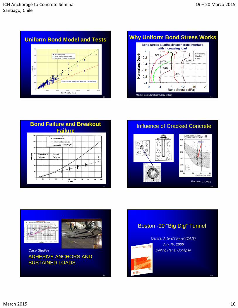
Uniform Bond Model and Tests
55
0
100
200
300
400
500
600
0 10000 20000 30000 40000 50000 60000
Lo
ad (
KN
)
measured loads
mean - uniform bond model
5% fractile - uniform bond model
Bond Area (A b ) (mm2)
Only 17 of 891 data points below 5% fractile (1.9%)
Why Uniform Bond Stress Works
56McVay, Cook, Krishnamurthy (1996)
Bond stress at adhesive/concrete interfacewith increasing load
SecondaryShallow Cone
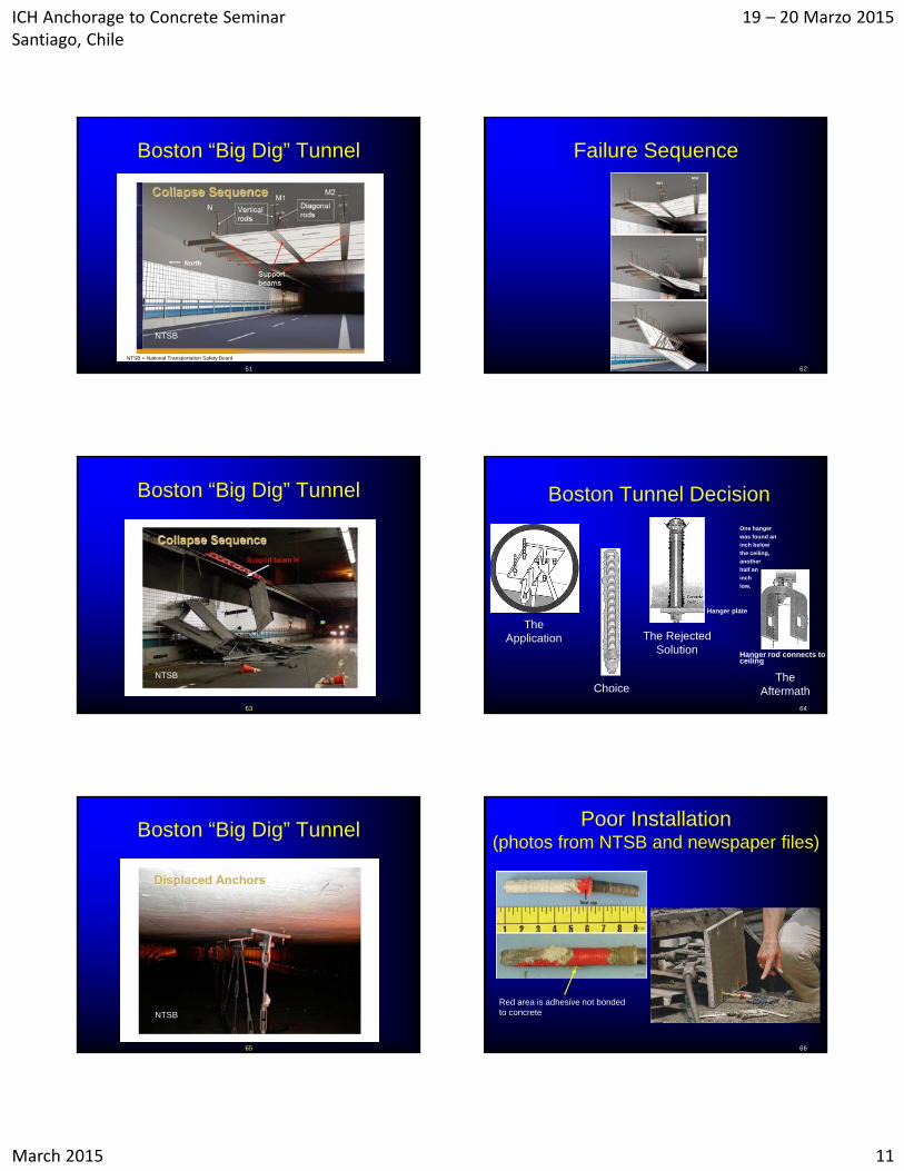
Bond Failure and Breakout Failure
57
Bond failure
Breakoutfailure
58
Influence of Cracked Concrete
0.30mm
ADHESIVE ANCHORS AND SUSTAINED LOADS
59
Case Studies
Creep failure
Boston -90 “Big Dig” Tunnel
Central Artery/Tunnel (CA/T)
July 10, 2006
Ceiling Panel Collapse
60
ICH Anchorage to Concrete Seminar Santiago, Chile
19 – 20 Marzo 2015
March 2015 11
Boston “Big Dig” Tunnel
61
NTSB
NTSB = National Transportation Safety Board
Failure Sequence
62
Boston “Big Dig” Tunnel
63
NTSB
64
Boston Tunnel Decision
The Application
Choice
The Rejected Solution
The Aftermath
Hanger plate
One hanger
was found an
inch below
the ceiling,
another
half an
inch
low.
Hanger rod connects to ceiling
Boston “Big Dig” Tunnel
65
NTSB
Poor Installation(photos from NTSB and newspaper files)
66
Red area is adhesive not bonded to concrete
ICH Anchorage to Concrete Seminar Santiago, Chile
19 – 20 Marzo 2015
March 2015 12
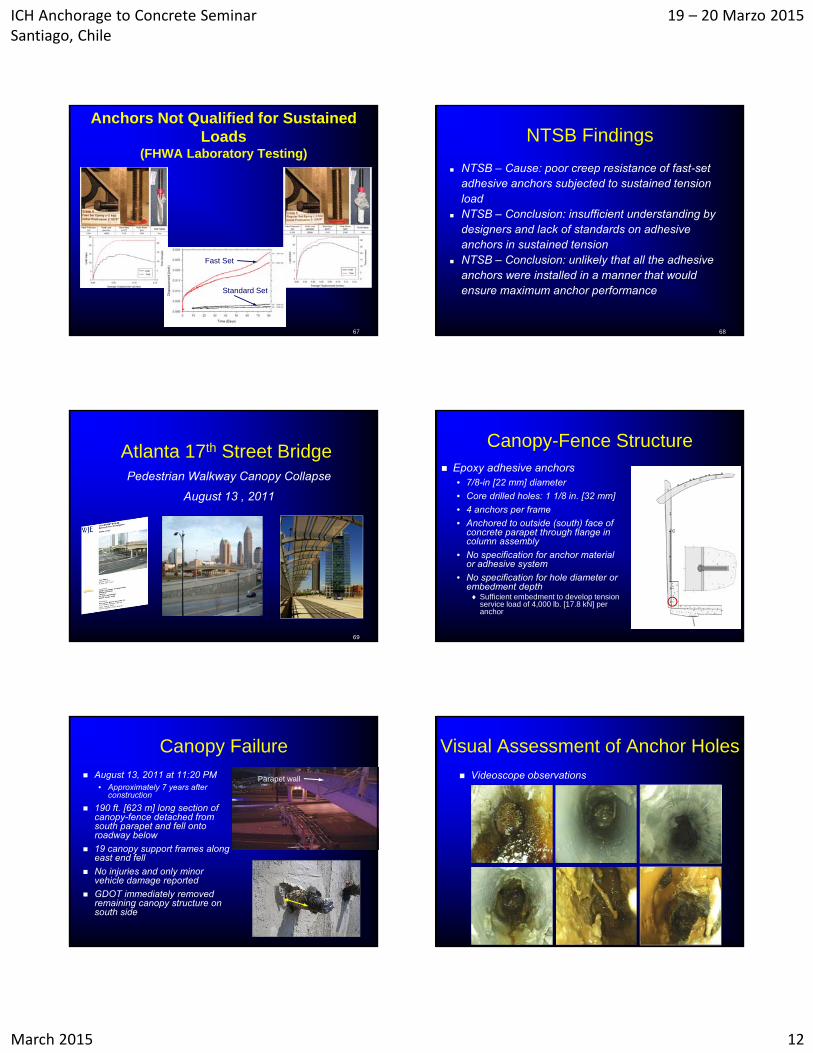
Anchors Not Qualified for Sustained Loads
(FHWA Laboratory Testing)
67
Fast Set
Standard Set
NTSB Findings
NTSB – Cause: poor creep resistance of fast-set adhesive anchors subjected to sustained tension load
NTSB – Conclusion: insufficient understanding by designers and lack of standards on adhesive anchors in sustained tension
NTSB – Conclusion: unlikely that all the adhesive anchors were installed in a manner that would ensure maximum anchor performance
68
Atlanta 17th Street BridgePedestrian Walkway Canopy Collapse
August 13 , 2011
69
Canopy-Fence Structure Epoxy adhesive anchors
• 7/8-in [22 mm] diameter
• Core drilled holes: 1 1/8 in. [32 mm]
• 4 anchors per frame
• Anchored to outside (south) face of concrete parapet through flange in column assembly
• No specification for anchor material or adhesive system
• No specification for hole diameter or embedment depth Sufficient embedment to develop tension
service load of 4,000 lb. [17.8 kN] per anchor
Canopy Failure August 13, 2011 at 11:20 PM
• Approximately 7 years after construction
190 ft. [623 m] long section of canopy-fence detached from south parapet and fell onto roadway below
19 canopy support frames along east end fell
No injuries and only minor vehicle damage reported
GDOT immediately removed remaining canopy structure on south side
Parapet wall
Visual Assessment of Anchor Holes Videoscope observations
ICH Anchorage to Concrete Seminar Santiago, Chile
19 – 20 Marzo 2015
March 2015 13
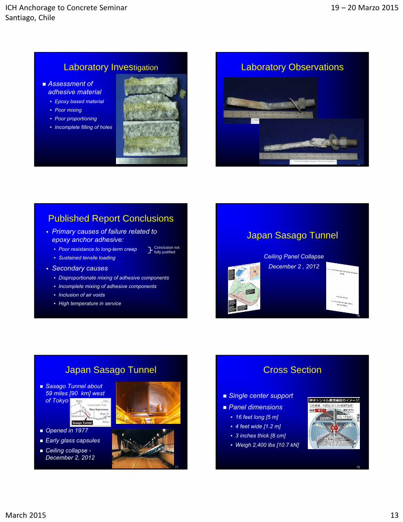
Laboratory Investigation
Assessment of adhesive material• Epoxy based material
• Poor mixing
• Poor proportioning
• Incomplete filling of holes
Core 55d split for visual assessment
Laboratory Observations
74
Published Report Conclusions Primary causes of failure related to
epoxy anchor adhesive:• Poor resistance to long-term creep
• Sustained tensile loading
Secondary causes• Disproportionate mixing of adhesive components
• Incomplete mixing of adhesive components
• Inclusion of air voids
• High temperature in service
Conclusion not fully justified
Japan Sasago Tunnel
Ceiling Panel Collapse
December 2 , 2012
76
Japan Sasago Tunnel
Sasago Tunnel about 59 miles [90 km] west of Tokyo
Opened in 1977
Early glass capsules
Ceiling collapse -December 2, 2012
77
Cross Section
Single center support
Panel dimensions
• 16 feet long [5 m]
• 4 feet wide [1.2 m]
• 3 inches thick [8 cm]
• Weigh 2,400 lbs [10.7 kN]
78
ICH Anchorage to Concrete Seminar Santiago, Chile
19 – 20 Marzo 2015
March 2015 14
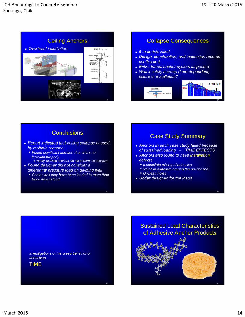
Ceiling Anchors Overhead installation
79
Collapse Consequences
9 motorists killed Design, construction, and inspection records
confiscated Entire tunnel anchor system inspected Was it solely a creep (time-dependent)
failure or installation?
80
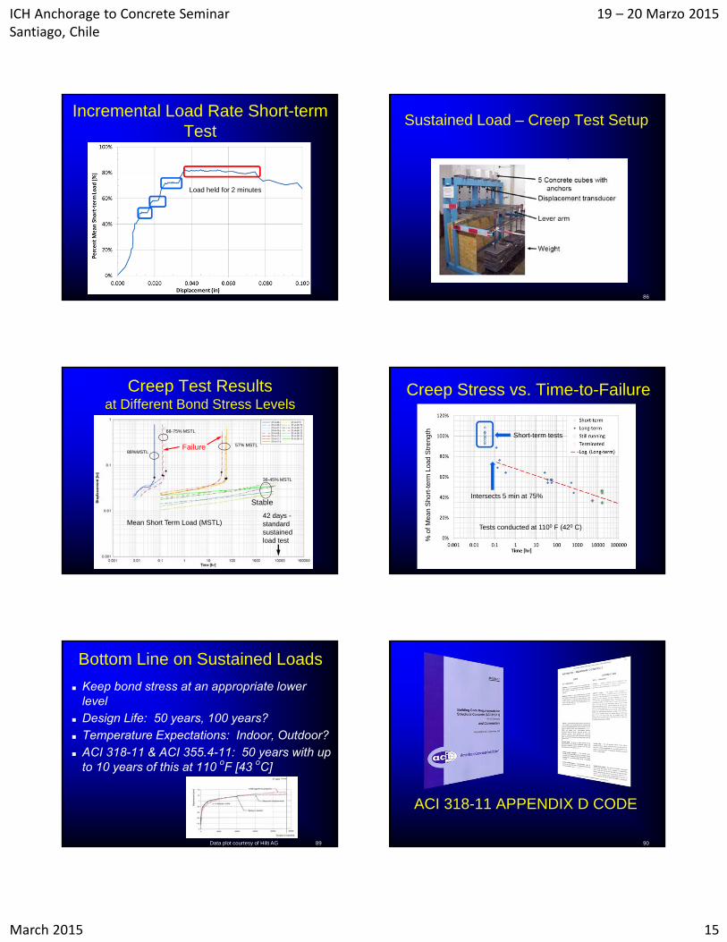
Conclusions
Report indicated that ceiling collapse caused by multiple reasons• Found significant number of anchors not
installed properlyPoorly installed anchors did not perform as-designed
Found designer did not consider a differential pressure load on dividing wall • Center wall may have been loaded to more than
twice design load
81
Case Study Summary
Anchors in each case study failed because of sustained loading – TIME EFFECTS
Anchors also found to have installationdefects• Incomplete mixing of adhesive• Voids in adhesive around the anchor rod• Unclean holes
Under designed for the loads
82
TIME
Investigations of the creep behavior of adhesives
83
Sustained Load Characteristics of Adhesive Anchor Products
84
ICH Anchorage to Concrete Seminar Santiago, Chile
19 – 20 Marzo 2015
March 2015 15
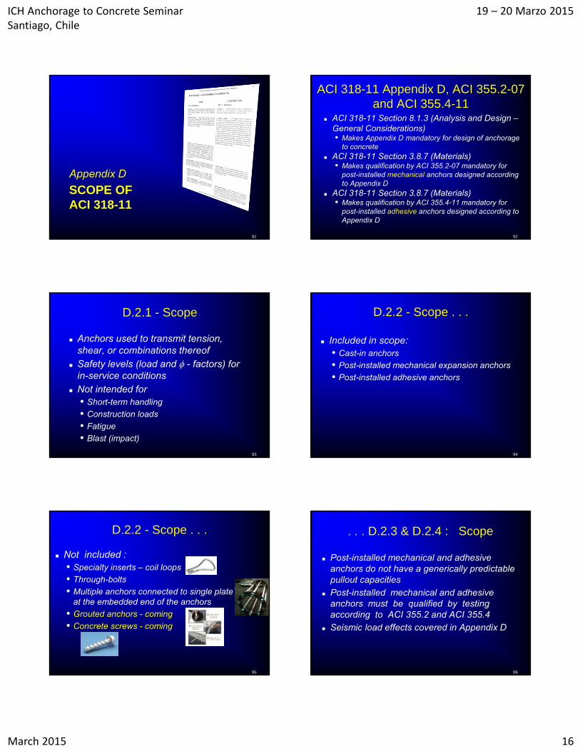
Incremental Load Rate Short-term Test
Load held for 2 minutes
Sustained Load – Creep Test Setup
86
Creep Test Results at Different Bond Stress Levels
See appendix G for all creep curves
Failure
Stable
42 days -standard sustained load test
88%MSTL
68-75% MSTL
57% MSTL
36-45% MSTL
Mean Short Term Load (MSTL)
Creep Stress vs. Time-to-Failure
Intersects 5 min at 75%
Short-term tests%
of M
ean
Sho
rt-t
erm
Loa
d S
tre
ngth
Tests conducted at 1100 F (420 C)
Bottom Line on Sustained Loads
Keep bond stress at an appropriate lower level
Design Life: 50 years, 100 years? Temperature Expectations: Indoor, Outdoor? ACI 318-11 & ACI 355.4-11: 50 years with up
to 10 years of this at 110 oF [43 oC]
89Data plot courtesy of Hilti AG
Creep Test on 16mm Capsule Anchor
ACI 318-11 APPENDIX D CODE
90
ICH Anchorage to Concrete Seminar Santiago, Chile
19 – 20 Marzo 2015
March 2015 16
SCOPE OF ACI 318-11
Appendix D
91 92
ACI 318-11 Appendix D, ACI 355.2-07and ACI 355.4-11
ACI 318-11 Section 8.1.3 (Analysis and Design –General Considerations) • Makes Appendix D mandatory for design of anchorage
to concrete ACI 318-11 Section 3.8.7 (Materials)
• Makes qualification by ACI 355.2-07 mandatory for post-installed mechanical anchors designed according to Appendix D
ACI 318-11 Section 3.8.7 (Materials) • Makes qualification by ACI 355.4-11 mandatory for
post-installed adhesive anchors designed according to Appendix D
93
D.2.1 - Scope
Anchors used to transmit tension, shear, or combinations thereof
Safety levels (load and - factors) for in-service conditions
Not intended for • Short-term handling
• Construction loads
• Fatigue
• Blast (impact)
94
D.2.2 - Scope . . .
Included in scope:• Cast-in anchors
• Post-installed mechanical expansion anchors
• Post-installed adhesive anchors
95
D.2.2 - Scope . . .
Not included :• Specialty inserts – coil loops
• Through-bolts
• Multiple anchors connected to single plate at the embedded end of the anchors
• Grouted anchors - coming
• Concrete screws - coming
96
. . . D.2.3 & D.2.4 : Scope
Post-installed mechanical and adhesive anchors do not have a generically predictable pullout capacities
Post-installed mechanical and adhesive anchors must be qualified by testing according to ACI 355.2 and ACI 355.4
Seismic load effects covered in Appendix D
ICH Anchorage to Concrete Seminar Santiago, Chile
19 – 20 Marzo 2015
March 2015 17
97
D.3.1 & D.3.2 – General Requirements
Factored loads from elastic analysis• Load combinations by § 9.2 and by § D.4.4
Plastic analysis permitted if ductile steel elements used in the anchor • Must consider deformation compatibility and
ductility of anchor (more information later) Must consider group effects (see § D.3.1.1
table)
D.3.3 - Seismic Design Requirements
Seismic load effects covered • Applicable to Seismic Design Categories (SDC)
C, D, E, and F
• Anchors must pass the seismic test protocol in the qualification standards - ACI 355.2 and ACI 355.4
• No special requirements for SDC A and B
Multiple options exist for seismic design –discuss details after covering other sections of Appendix D
98
99
D.3.4 & D.3.5 – General Requirements
Adhesive anchors installed horizontally or upwardly inclined• Must be qualified by ACI 355.4
• Must be installed by certified installer when subjected to sustained load
D.3.6 – Lightweight Concrete Lightweight concrete modification factor, a
Modification factor• Cast-in and undercut concrete failure: a = 1.0 • Expansion and adhesive anchors concrete failure: a = 0.8
• Adhesive anchor bond failure: a = 0.6 1.0 excluded
determined by Section 8.6.1 1.0 normal weight 0.85 sand-lightweight 0.75 all-lightweight
100
101
D.3.7 – Concrete Strength
Code equations are valid for :• fc 69 MPa for cast-in anchors• fc 55 MPa for post-installed anchors
Post-installed anchors in concrete with fc > 55 MPa must be tested according to ACI 355.2 or ACI 355.4
102
D.4.1 – Failure Modes in Tension
Yield and fracture of anchor steel Concrete breakout Pullout / pull-through Concrete side-face blowout Bond failure for adhesive anchors
• Sustained loading limit for adhesive anchors0.55 Nba > Nua,sustained (Eqn. D – 1)
Splitting failure must be precluded (§ D.8)
Weakest Governs
ICH Anchorage to Concrete Seminar Santiago, Chile
19 – 20 Marzo 2015
March 2015 18
103
D.4.1 – Failure Modes in Shear
Yield and fracture of anchor steel Concrete breakout Concrete pryout
Splitting failure must be precluded (§ D.8)
Weakest Governs
104
D.4.2 – Nominal Strength
Design models must be in substantial agreement with test results
Nominal design strength is based on 5 % fractile of basic individual anchor strength• 90% confidence that 95 % of actual strengths
will exceed nominal strength
105
Objective of Code Requirements
Load
Resistance
Load and Resistance Magnitudes
Pro
bab
ility Limit probability
of failure toacceptable level
106
Calculation of 5% Fractile Conduct large number of tests Derive an average equation Determine 5% fractile “design” resistance
value
5 % Fractile
Average (Mean) Strength Statistical parameters
•Average (mean)
•Standard deviation
•Coefficient of variation
•Number of samples
Test Capacity
Fre
qu
ency
Characteristic value“Nominal Design
Strength”
107
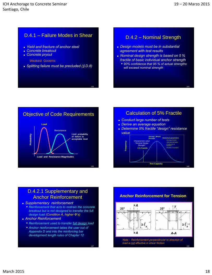
D.4.2.1 Supplementary and Anchor Reinforcement
Supplementary reinforcement • Reinforcement that acts to restrain the concrete
breakout but is not designed to transfer the full design load (Condition A, higher Φ’s)
Anchor Reinforcement• Reinforcement used to transfer full design load
• Anchor reinforcement takes the user out of Appendix D and into the reinforcing bar development length rules of Chapter 12
108
Anchor Reinforcement for Tension
Note : Reinforcement perpendicular to direction of load is not effective in shear friction
ICH Anchorage to Concrete Seminar Santiago, Chile
19 – 20 Marzo 2015
March 2015 19
109
Anchor Reinforcement as Noted in §D.4.2.1
Chapter 12
Anchor reinforcement used when concrete breakout strength by Appendix D is insufficient – concrete breakout will occur
Increasing for concrete breakout does not help
Use the provisions of ACI 318-08 Chapter 12 , and splice anchors to reinforcement to resist the design actions
A strength reduction factor of 0.75 is used in design of anchor reinforcement
110
Anchor Reinforcement for Shear
Anchor reinforcement has to be in the direction of the applied force and near the point of crack initiation
111
D.4.2.2 – Size Limitation(any anchor type)
For concrete breakout only
• Diameter 4 in [102 mm]
• No limitation on hef
Updated for 2011(was ≤ 50mm)
Updated for 2011(was 635mm)
D.4.2.3 – Embedment Depth Limitations For Adhesive Anchors
Limits of embedment depth for adhesive anchors
4 da ≤ hef ≤ 20 da Design using bond model of § D5.5
satisfactory
112
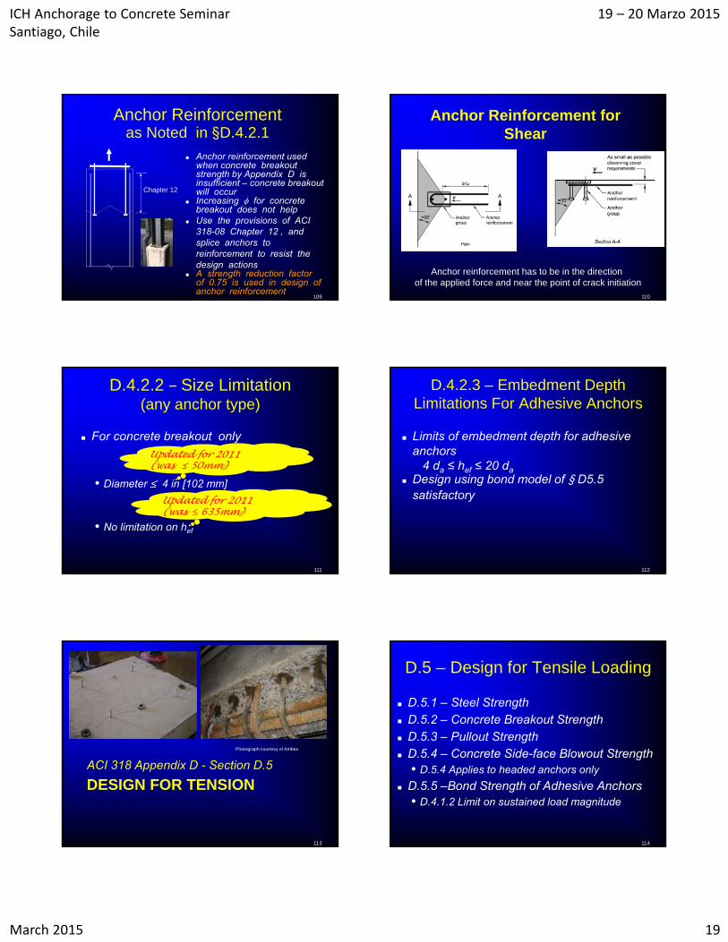
DESIGN FOR TENSIONACI 318 Appendix D - Section D.5
113
Photograph courtesy of Ambex
114
D.5 – Design for Tensile Loading
D.5.1 – Steel Strength D.5.2 – Concrete Breakout Strength D.5.3 – Pullout Strength D.5.4 – Concrete Side-face Blowout Strength
• D.5.4 Applies to headed anchors only
D.5.5 –Bond Strength of Adhesive Anchors• D.4.1.2 Limit on sustained load magnitude

ICH Anchorage to Concrete Seminar Santiago, Chile
19 – 20 Marzo 2015
March 2015 20
Tension Design
Designer must consider the following tension failure modes for adhesive anchors: • Steel failure
• Concrete breakout failure
• Bond failureSustained load (creep) failure
115
Why so many failure modes to check for a single design case?
For the best solution• Must look at all the
failure modes individually
But can the design be simplified?• Can the designer go
back to using manufacturer design tables?
116
117
Can it be simplified?
Yes, it can be simplified! We could develop one equation with all the
failure modes just like the development length equations in Chapter 12 • Development length equation incorporates:
steel strength, splitting, bond, and closely spaced bars are all in one equation
• Must have minimum ℓd = 300 mm
118
Consequences of simplification
Anchors are usually installed perpendicular to the member not parallel like reinforcing bars
The simplified “one-equation” approach to anchor design will result in a need for increased member thickness.
Try telling the owner that you need to double the slab thickness so that you can do an easy design!
Increased structural depth
Development for reinforcing bar
Using simplified “one-equation” approach for anchor design
Evaluation of each potential failure mode for anchors
Steel Failure Mode - Tension
Steel rupture
119
Nsa = Ase futa (D – 2)
futa < 1.9 fyfuta < 860 MPa
Concrete Breakout Failure Mode –Tension Cone Breakout
Courtesy of University of Stuttgart
ICH Anchorage to Concrete Seminar Santiago, Chile
19 – 20 Marzo 2015
March 2015 21
FracturedConcrete
Model reflecting actual behavior
Embedment Depth
Model used in design
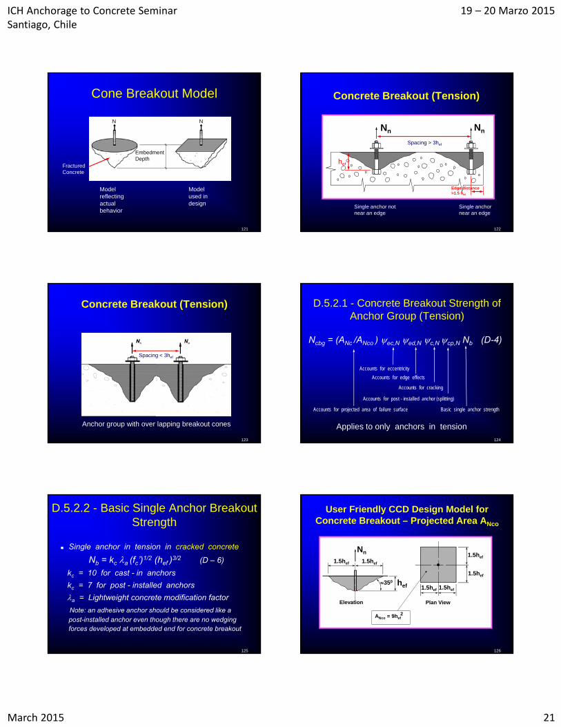
Cone Breakout Model
121
N N
122
Concrete Breakout (Tension)
NnNn
Single anchor not near an edge
Single anchor near an edge
Spacing > 3hef
hef
Edge distance>1.5 hef
Concrete Breakout (Tension)
123
Anchor group with over lapping breakout cones
Spacing < 3hef
D.5.2.1 - Concrete Breakout Strength of Anchor Group (Tension)
Accounts for post - installed anchor (splitting)
Accounts for cracking
Accounts for edge effects
Accounts for eccentricity
Accounts for projected area of failure surface Basic single anchor strength
Applies to only anchors in tension
Ncbg = (ANc /ANco ) ec,N ed,N c,N cp,N Nb (D-4)
124
D.5.2.2 - Basic Single Anchor Breakout Strength
Single anchor in tension in cracked concrete
Nb = kc a (fc’)1/2 (hef )3/2 (D – 6)
kc = 10 for cast - in anchors
kc = 7 for post - installed anchors
a = Lightweight concrete modification factor
Note: an adhesive anchor should be considered like a post-installed anchor even though there are no wedging forces developed at embedded end for concrete breakout
125
User Friendly CCD Design Model for Concrete Breakout – Projected Area ANco
hef
1.5hef
1.5hef
1.5hef
Plan ViewElevation
ANco = 9hef
1.5hef
Nn
1.5hef 1.5hef
2
350
126
ICH Anchorage to Concrete Seminar Santiago, Chile
19 – 20 Marzo 2015
March 2015 22
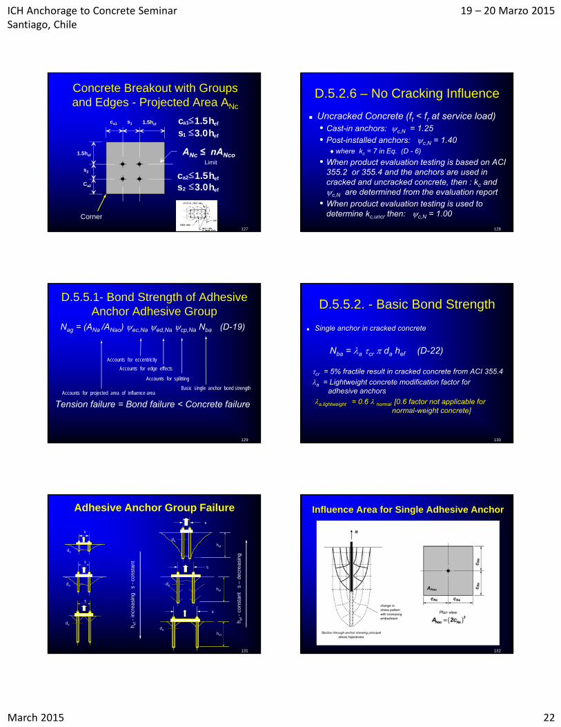
Concrete Breakout with Groups and Edges - Projected Area ANc
ca1 s1 1.5hef
1.5hef
Ca2
s2
ef1 h0.3s
efa2 h5.1c ef2 h0.3s
efa1 h5.1c
Limit
127
Corner
ANc ≤ nANco
128
D.5.2.6 – No Cracking Influence
Uncracked Concrete (ft < fr at service load)• Cast-in anchors: c,N = 1.25
• Post-installed anchors: c,N = 1.40 where kc = 7 in Eq. (D - 6)
• When product evaluation testing is based on ACI 355.2 or 355.4 and the anchors are used in cracked and uncracked concrete, then : kc and c,N are determined from the evaluation report
• When product evaluation testing is used to determine kc,uncr then: c,N = 1.00
D.5.5.1- Bond Strength of Adhesive Anchor Adhesive Group
Nag = (ANa /ANao) ec,Na ed,Na cp,Na Nba (D-19)
Tension failure = Bond failure < Concrete failure
129
Accounts for splitting
Accounts for edge effects
Accounts for eccentricity
Accounts for projected area of influence areaBasic single anchor bond strength
D.5.5.2. - Basic Bond Strength
Single anchor in cracked concrete
Nba = a cr da hef (D-22)
cr = 5% fractile result in cracked concrete from ACI 355.4
a = Lightweight concrete modification factor for adhesive anchors
a,lightweight = 0.6 normal [0.6 factor not applicable for normal-weight concrete]
130
h ef-
incr
easi
ng
s -
cons
tant
h ef-
cons
tant
s
–de
crea
sing
da
hef
hef
da
da
hef
s
da
s
da
s
da
Adhesive Anchor Group Failure
131
s
s
s
Influence Area for Single Adhesive Anchor
132
ICH Anchorage to Concrete Seminar Santiago, Chile
19 – 20 Marzo 2015
March 2015 23
Critical Spacing and Edge Distance
Cast-in-place and post-installed mechanical anchors• ACI 318-11
scritical = 2ccritical = 3.0 hef
Bonded anchors• ACI 318-11
scritical = 2ccrtical
where: ccritical = cNa = 10 da (uncr / 7.6)1/2 (D – 21)
133
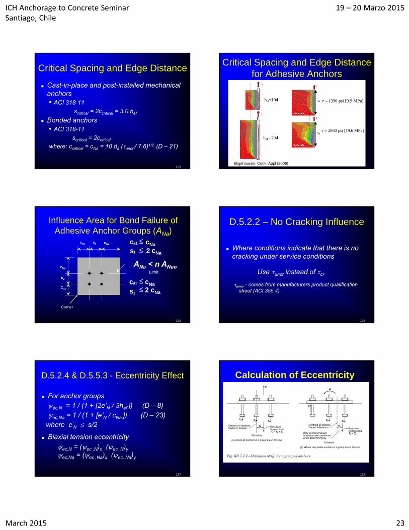
Critical Spacing and Edge Distance for Adhesive Anchors
1390 psi [9.9 MPa]
2850 psi [19.6 MPa]
Eligehausen, Cook, Appl (2006)
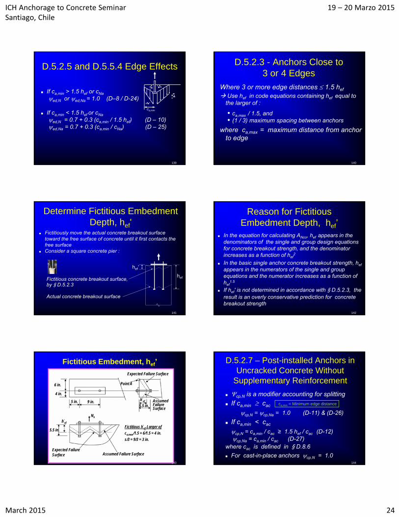
Influence Area for Bond Failure of Adhesive Anchor Groups (ANa)
ca1 s1 cNa
cNa
Ca2
s2
1 2 s
a2 cNac
22 cNas
a1 cNac
Limit
cNa
ANa < n ANao
Corner
135
D.5.2.2 – No Cracking Influence
Where conditions indicate that there is no cracking under service conditions
Use uncr instead of cr
uncr - comes from manufacturers product qualification sheet (ACI 355.4)
136
D.5.2.4 & D.5.5.3 - Eccentricity Effect
For anchor groupsec,N = 1 / (1 + [2e’N / 3hef ]) (D – 8)ec,Na = 1 / (1 + [e’N / cNa ]) (D – 23)
where e'N s/2
Biaxial tension eccentricity
ec,N = (ec ,N)x (ec, N)y
ec,Na = (ec ,Na)x (ec, Na)y
137
Calculation of Eccentricity
138
ICH Anchorage to Concrete Seminar Santiago, Chile
19 – 20 Marzo 2015
March 2015 24
D.5.2.5 and D.5.5.4 Edge Effects
If ca,min > 1.5 hef or cNa
edN or edNa = 1.0 (D–8 / D-24)
If ca,min < 1.5 hef or cNa
ed,N = 0.7 + 0.3 (ca,min / 1.5 hef) (D – 10)ed,Na = 0.7 + 0.3 (ca,min / cNa) (D – 25)
139
ca,min
140
D.5.2.3 - Anchors Close to 3 or 4 Edges
Where 3 or more edge distances 1.5 hef
Use hef in code equations containing hef equal to the larger of :
• ca,max / 1.5, and• (1 / 3) maximum spacing between anchors
where ca,max = maximum distance from anchor to edge
141
Determine Fictitious Embedment Depth, hef'
Fictitiously move the actual concrete breakout surface toward the free surface of concrete until it first contacts the free surface
Consider a square concrete pier :
hef
hef'
Actual concrete breakout surface
Fictitious concrete breakout surface,by § D.5.2.3
142
Reason for Fictitious Embedment Depth, hef’
In the equation for calculating ANco, hef appears in the denominators of the single and group design equations for concrete breakout strength, and the denominator increases as a function of hef
2
In the basic single anchor concrete breakout strength, hef
appears in the numerators of the single and group equations and the numerator increases as a function of hef
1.5
If hef' is not determined in accordance with § D.5.2.3, the result is an overly conservative prediction for concrete breakout strength
143
AssumedFailure Surface
4 in.
Expected Failure Surface
Nn
9 in.
6 in.
5.5 in.
5 in.
Point A
Expected Failure Surface Assumed Failure Surface
5.5 in.h’
ef
h’ef
Fictitious h’ef Larger of
ca,max/1.5 = 6/1.5 = 4 in.
s/3 = 9/3 = 3 in.
Fictitious Embedment, hef’
144
D.5.2.7 – Post-installed Anchors in Uncracked Concrete Without
Supplementary Reinforcement
cp,N is a modifier accounting for splitting
If ca,min cac
cp,N = cp,Na = 1.0 (D-11) & (D-26)
If ca,min < cac
cp,N = ca,min / cac ≥ 1.5 hef / cac (D-12)cp,Na = ca,min / cac (D-27)
where cac is defined in § D.8.6
For cast-in-place anchors cp,N = 1.0
ca,min = Minimum edge distance
ICH Anchorage to Concrete Seminar Santiago, Chile
19 – 20 Marzo 2015
March 2015 25
145
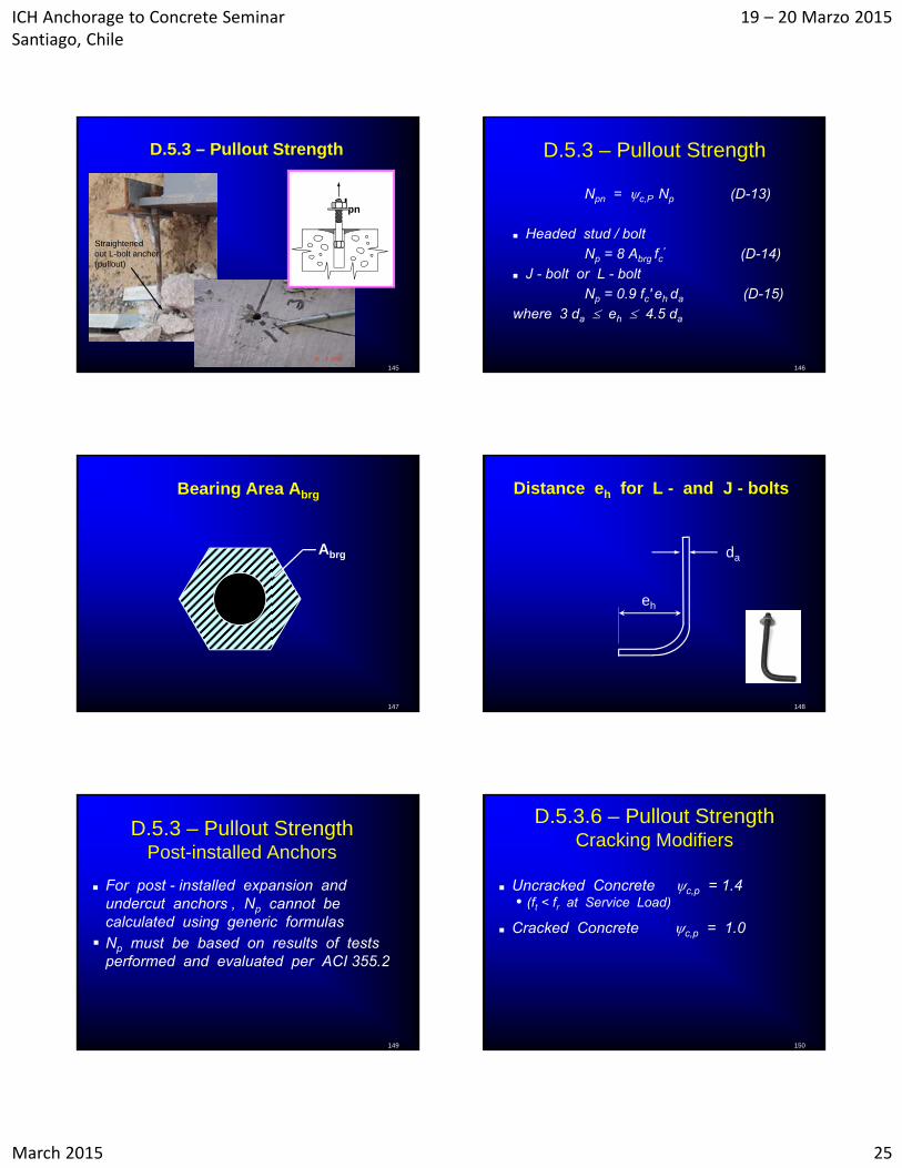
D.5.3 – Pullout Strength
Straightened out L-bolt anchor(pullout)
Npn
146
D.5.3 – Pullout Strength
Npn = c,P Np (D-13)
Headed stud / bolt
Np = 8 Abrg fc' (D-14)
J - bolt or L - bolt
Np = 0.9 fc' eh da (D-15)
where 3 da eh 4.5 da
147
Bearing Area Abrg
Abrg
148
Distance eh for L - and J - bolts
eh
da
149
D.5.3 – Pullout Strength Post-installed Anchors
For post - installed expansion and undercut anchors , Np cannot be calculated using generic formulas Np must be based on results of tests
performed and evaluated per ACI 355.2
150
D.5.3.6 – Pullout Strength Cracking Modifiers
Uncracked Concrete c,p = 1.4• (ft < fr at Service Load)
Cracked Concrete c,p = 1.0
ICH Anchorage to Concrete Seminar Santiago, Chile
19 – 20 Marzo 2015
March 2015 26
151
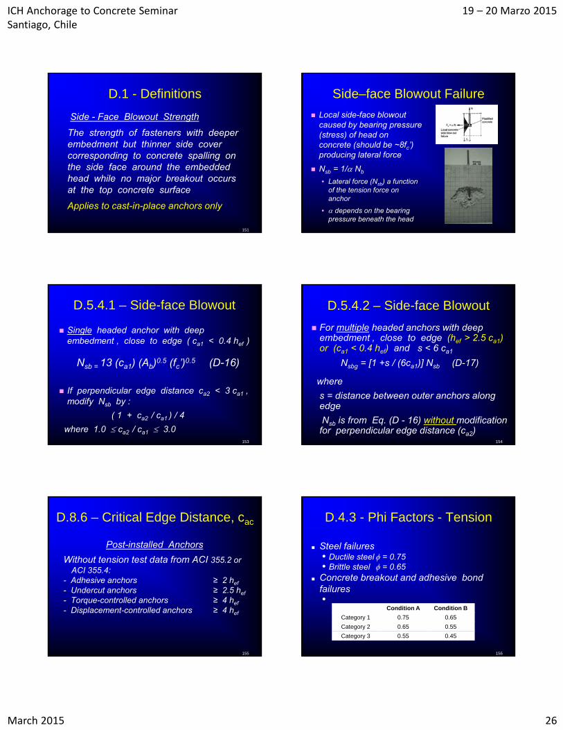
D.1 - Definitions
Side - Face Blowout Strength
The strength of fasteners with deeper embedment but thinner side cover corresponding to concrete spalling on the side face around the embedded head while no major breakout occurs at the top concrete surface
Applies to cast-in-place anchors only
Side–face Blowout Failure
Local side-face blowout caused by bearing pressure (stress) of head on concrete (should be ~8fc’) producing lateral force
Nsb = 1/ Nb
• Lateral force (Nsb) a function of the tension force on anchor
• depends on the bearing pressure beneath the head
153
D.5.4.1 – Side-face Blowout
Single headed anchor with deep embedment , close to edge ( ca1 < 0.4 hef )
Nsb = 13 (ca1) (Ab)0.5 (fc’)0.5 (D-16)
If perpendicular edge distance ca2 < 3 ca1 , modify Nsb by :
( 1 + ca2 / ca1 ) / 4
where 1.0 ca2 / ca1 3.0154
D.5.4.2 – Side-face Blowout
For multiple headed anchors with deep embedment , close to edge (hef > 2.5 ca1) or (ca1 < 0.4 hef) and s < 6 ca1
Nsbg = [1 +s / (6ca1)] Nsb (D-17)
where
s = distance between outer anchors along edge
Nsb is from Eq. (D - 16) without modification for perpendicular edge distance (ca2)
155
D.8.6 – Critical Edge Distance, cac
Post-installed Anchors
Without tension test data from ACI 355.2 or ACI 355.4:
- Adhesive anchors ≥ 2 hef
- Undercut anchors ≥ 2.5 hef
- Torque-controlled anchors ≥ 4 hef
- Displacement-controlled anchors ≥ 4 hef
D.4.3 - Phi Factors - Tension
Steel failures• Ductile steel = 0.75• Brittle steel = 0.65
Concrete breakout and adhesive bond failures•
156
Condition A Condition B
Category 1 0.75 0.65
Category 2 0.65 0.55
Category 3 0.55 0.45
ICH Anchorage to Concrete Seminar Santiago, Chile
19 – 20 Marzo 2015
March 2015 27
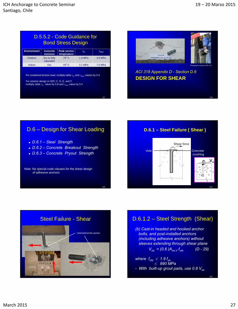
D.5.5.2 - Code Guidance for Bond Stress Design
Environment Concrete moisture
Peak service temperature
cr uncr
Outdoor Dry to fully saturated
79o C 1.4 MPa 4.5 MPa
Indoor Dry 43o C 2.1 MPa 7.0 MPa
157
For sustained tension load, multiply table cr and uncr values by 0.4
For seismic design in SDC C, D, E, and F, multiply table cr value by 0.8 and uncr value by 0.4
DESIGN FOR SHEARACI 318 Appendix D - Section D.6
159
Photograph courtesy of Hilti AG
160
D.6 – Design for Shear Loading
D.6.1 – Steel Strength D.6.2 – Concrete Breakout Strength D.6.3 – Concrete Pryout Strength
Note: No special code clauses for the shear design of adhesive anchors
161
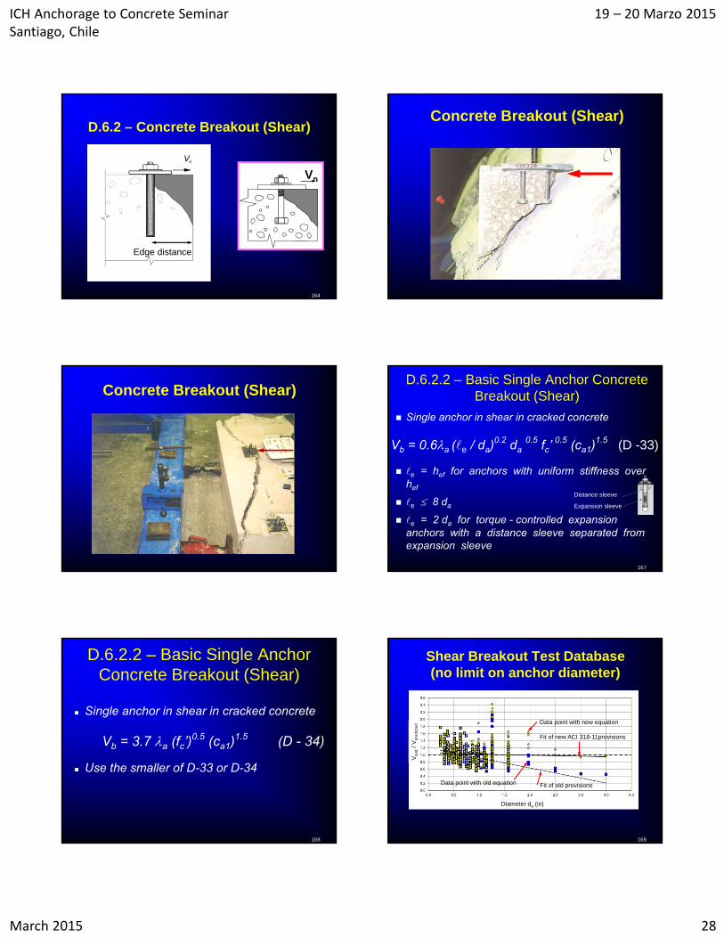
D.6.1 – Steel Failure ( Shear )
Concretecrushing
Void
Shear force
Vn
Steel Failure - Shear
Void behind the anchor
163
D.6.1.2 – Steel Strength (Shear)
(b) Cast-in headed and hooked anchor bolts, and post-installed anchors (including adhesive anchors) without sleeves extending through shear plane
Vsa = (0.6 )Ase,V futa (D - 29)
where futa 1.9 fya
890 MPa- With built-up grout pads, use 0.8 Vsa
ICH Anchorage to Concrete Seminar Santiago, Chile
19 – 20 Marzo 2015
March 2015 28
164
D.6.2 – Concrete Breakout (Shear)
Edge distance
Vn
Concrete Breakout (Shear)
Concrete Breakout (Shear)
167
D.6.2.2 – Basic Single Anchor Concrete Breakout (Shear)
Single anchor in shear in cracked concrete
e = hef for anchors with uniform stiffness over hef
e 8 da
e = 2 da for torque - controlled expansion anchors with a distance sleeve separated from expansion sleeve
Expansion sleeve
Distance sleeve
Vb = 0.6a (e / da)0.2 da
0.5 fc’ 0.5 (ca1)
1.5 (D -33)
D.6.2.2 – Basic Single Anchor Concrete Breakout (Shear)
Single anchor in shear in cracked concrete
Vb = 3.7 a (fc’)0.5 (ca1)
1.5 (D - 34)
Use the smaller of D-33 or D-34
168
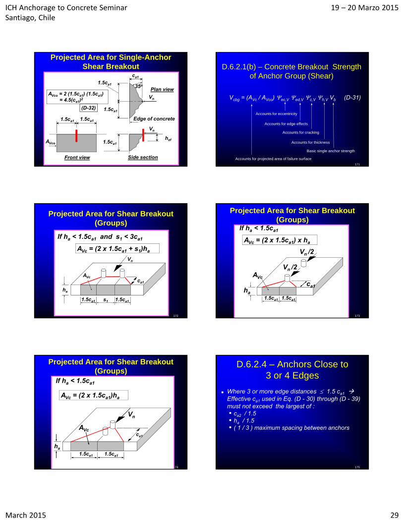
Shear Breakout Test Database(no limit on anchor diameter)
169
Data point with new equation
Fit of new ACI 318-11provisions
Data point with old equation Fit of old provisions
Diameter da (in)
Vte
st/
Vp
red
icte
d
ICH Anchorage to Concrete Seminar Santiago, Chile
19 – 20 Marzo 2015
March 2015 29
170
Front view
Vn
Edge of concrete
Plan view
Vn
hef
Side section
ca1
35o
1.5ca1 1.5ca1
1.5ca1
1.5ca1
1.5ca1AVco
AVco = 2 (1.5ca1) (1.5ca1)= 4.5(ca1)2
(D-32)
Projected Area for Single-Anchor Shear Breakout
171
D.6.2.1(b) – Concrete Breakout Strength of Anchor Group (Shear)
Vcbg = (AVc / AVco) ec,V ed,V c,V h,V Vb (D-31)
Accounts for projected area of failure surface
Accounts for eccentricity
Accounts for edge effects
Accounts for cracking
Accounts for thickness
Basic single anchor strength
172
AVcca1
1.5ca1 1.5ca1s1
Vn
ha
AVc = (2 x 1.5ca1 + s1)ha
If ha < 1.5ca1 and s1 < 3ca1
Projected Area for Shear Breakout (Groups)
173
ca1ha
AVc
If ha < 1.5ca1
AVc = (2 x 1.5ca1) x ha
Vn /2
Vn /2
1.5ca1 1.5ca1
Projected Area for Shear Breakout (Groups)
174
ca1
AVc
1.5ca1 1.5ca1
Vn
ha
If ha < 1.5ca1
AVc = (2 x 1.5ca1)ha
Projected Area for Shear Breakout (Groups)
175
D.6.2.4 – Anchors Close to 3 or 4 Edges
Where 3 or more edge distances 1.5 ca1 Effective ca1 used in Eq. (D - 30) through (D - 39) must not exceed the largest of :• ca2 / 1.5• ha / 1.5• ( 1 / 3 ) maximum spacing between anchors
ICH Anchorage to Concrete Seminar Santiago, Chile
19 – 20 Marzo 2015
March 2015 30
176
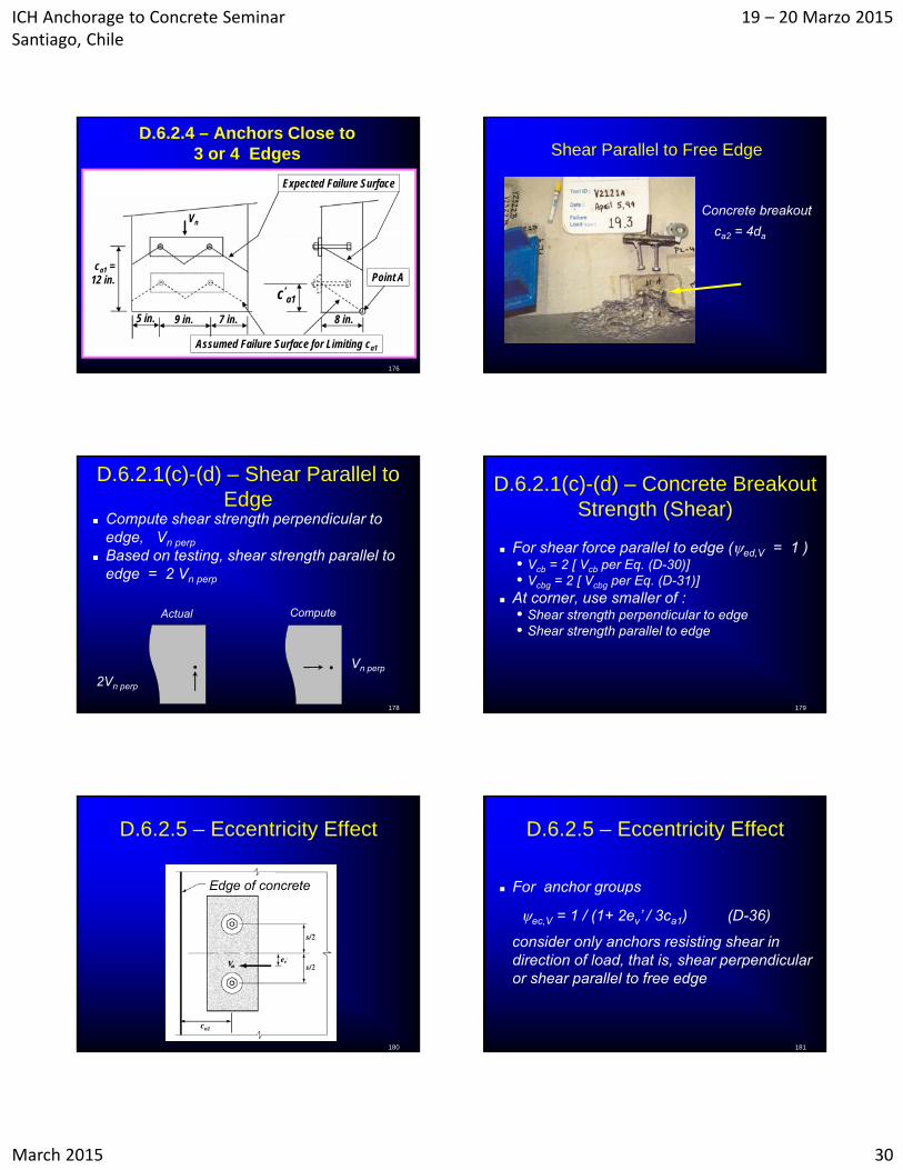
D.6.2.4 – Anchors Close to 3 or 4 Edges
c’a1
9 in. 8 in.
Vn
Point A
5 in. 7 in.
Assumed Failure Surface for Limiting ca1
ca1 =12 in.
Expected Failure Surface
Shear Parallel to Free Edge
Concrete breakout
ca2 = 4da
178
D.6.2.1(c)-(d) – Shear Parallel to Edge
Vn perp
2Vn perp
Actual Compute
Compute shear strength perpendicular to edge, Vn perp
Based on testing, shear strength parallel to edge = 2 Vn perp
179
D.6.2.1(c)-(d) – Concrete Breakout Strength (Shear)
For shear force parallel to edge (ed,V = 1 )• Vcb = 2 [ Vcb per Eq. (D-30)]• Vcbg = 2 [ Vcbg per Eq. (D-31)]
At corner, use smaller of :• Shear strength perpendicular to edge• Shear strength parallel to edge
D.6.2.5 – Eccentricity Effect
180
Edge of concrete
ca1
D.6.2.5 – Eccentricity Effect
For anchor groups
consider only anchors resisting shear in direction of load, that is, shear perpendicular or shear parallel to free edge
181
ec,V = 1 / (1+ 2ev’ / 3ca1) (D-36)
ICH Anchorage to Concrete Seminar Santiago, Chile
19 – 20 Marzo 2015
March 2015 31
182
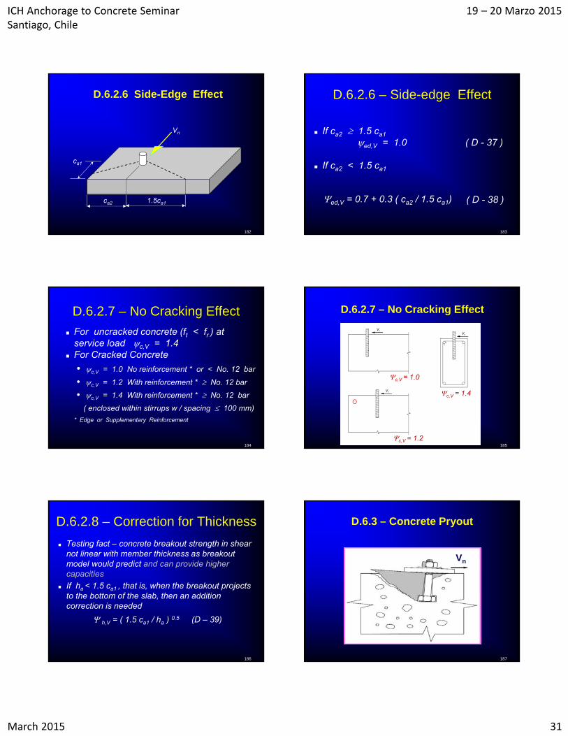
D.6.2.6 Side-Edge Effect
ca1
Vn
1.5ca1ca2
D.6.2.6 – Side-edge Effect
If ca2 1.5 ca1
ed,V = 1.0 ( D - 37 )
If ca2 < 1.5 ca1
183
( D - 38 )ed,V = 0.7 + 0.3 ( ca2 / 1.5 ca1)
184
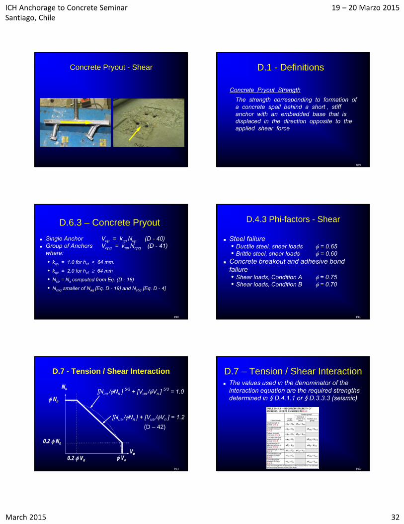
For uncracked concrete (ft < fr ) at service load c,V = 1.4
For Cracked Concrete
• c,V = 1.0 No reinforcement * or < No. 12 bar
• c,V = 1.2 With reinforcement * No. 12 bar
• c,V = 1.4 With reinforcement * No. 12 bar
( enclosed within stirrups w / spacing 100 mm)
* Edge or Supplementary Reinforcement
D.6.2.7 – No Cracking Effect
185
D.6.2.7 – No Cracking Effect
c,V = 1.0
c,V = 1.2
c,V = 1.4
D.6.2.8 – Correction for Thickness
Testing fact – concrete breakout strength in shear not linear with member thickness as breakout model would predict and can provide higher capacities
If ha < 1.5 ca1 , that is, when the breakout projects to the bottom of the slab, then an addition correction is needed
h,V = ( 1.5 ca1 / ha ) 0.5 (D – 39)
186 187
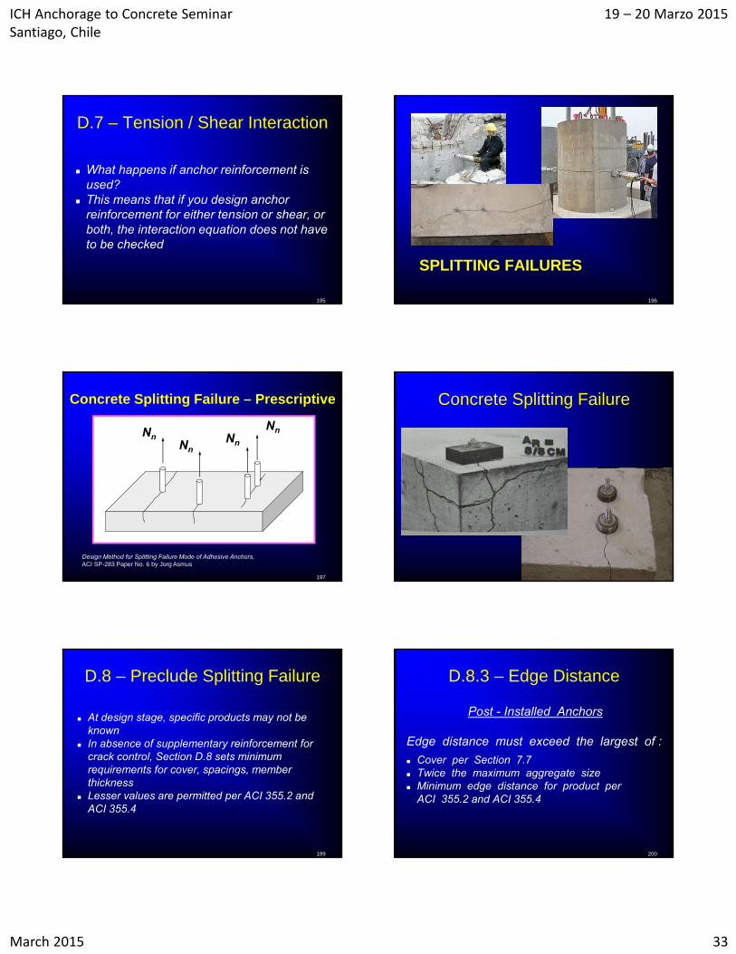
D.6.3 – Concrete Pryout
Vn
ICH Anchorage to Concrete Seminar Santiago, Chile
19 – 20 Marzo 2015
March 2015 32
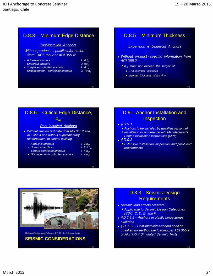
Concrete Pryout - Shear
189
D.1 - Definitions
Concrete Pryout Strength
The strength corresponding to formation of a concrete spall behind a short , stiff anchor with an embedded base that is displaced in the direction opposite to the applied shear force
190
D.6.3 – Concrete Pryout
Single Anchor Vcp = kcp Ncp (D - 40) Group of Anchors Vcpg = kcp Ncpg (D - 41)
where:
• kcp = 1.0 for hef < 64 mm.
• kcp = 2.0 for hef 64 mm
• Ncp = Na computed from Eq. (D - 18)
• Ncpg smaller of Nag [Eq. D - 19] and Ncbg [Eq. D - 4]
D.4.3 Phi-factors - Shear
Steel failure• Ductile steel, shear loads = 0.65• Brittle steel, shear loads = 0.60
Concrete breakout and adhesive bond failure• Shear loads, Condition A = 0.75• Shear loads, Condition B = 0.70
191
193
D.7 - Tension / Shear Interaction
Nu
Nn
0.2 Nn
0.2 Vn Vn
Vu
[Nua /Nn ] 5/3 + [Vua /Vn ]
5/3 = 1.0
[Nua /Nn ] + [Vua /Vn ] = 1.2
(D – 42)
D.7 – Tension / Shear Interaction The values used in the denominator of the
interaction equation are the required strengths determined in § D.4.1.1 or § D.3.3.3 (seismic)
194
ICH Anchorage to Concrete Seminar Santiago, Chile
19 – 20 Marzo 2015
March 2015 33
D.7 – Tension / Shear Interaction
What happens if anchor reinforcement is used?
This means that if you design anchor reinforcement for either tension or shear, or both, the interaction equation does not have to be checked
195
SPLITTING FAILURES
196
197
Concrete Splitting Failure – Prescriptive
NnNn
NnNn
Design Method for Splitting Failure Mode of Adhesive Anchors, ACI SP-283 Paper No. 6 by Jorg Asmus
Concrete Splitting Failure
199
D.8 – Preclude Splitting Failure
At design stage, specific products may not be known
In absence of supplementary reinforcement for crack control, Section D.8 sets minimum requirements for cover, spacings, member thickness
Lesser values are permitted per ACI 355.2 and ACI 355.4
200
D.8.3 – Edge Distance
Post - Installed Anchors
Edge distance must exceed the largest of :
Cover per Section 7.7 Twice the maximum aggregate size Minimum edge distance for product per
ACI 355.2 and ACI 355.4
ICH Anchorage to Concrete Seminar Santiago, Chile
19 – 20 Marzo 2015
March 2015 34
201
D.8.3 – Minimum Edge Distance
Post-installed Anchors
Without product – specific information from ACI 355.2 or ACI 355.4:
- Adhesive anchors ≥ 6da
- Undercut anchors ≥ 6da
- Torque – controlled anchors ≥ 8 da
- Displacement – controlled anchors ≥ 10 da
D.8.5 – Minimum Thickness
Expansion & Undercut Anchors
Without product - specific information from ACI 355.2 :
• hef must not exceed the larger of
2 / 3 member thickness
member thickness minus 4 in.
202
203
D.8.6 – Critical Edge Distance, cac
Post-installed Anchors
Without tension test data from ACI 355.2 and ACI 355.4 and without supplementary reinforcement to control splitting :
- Adhesive anchors ≥ 2 hef
- Undercut anchors ≥ 2.5 hef
- Torque-controlled anchors ≥ 4 hef
- Displacement-controlled anchors ≥ 4 hef
204
D.9 – Anchor Installation and Inspection
§ D.9.1• Anchors to be installed by qualified personnel• Installation in accordance with Manufacturer’s
Printed Installation Instructions (MPII) § D.9.2
• Extensive installation, inspection, and proof load requirements
SEISMIC CONSIDERATIONS
Chilean Earthquake February 27, 2010 - 8.8 magnitude
205
D.3.3 - Seismic Design Requirements
Seismic load effects covered • Applicable to Seismic Design Categories
(SDC) C, D, E, and F § D.3.3.2 – Anchors in plastic hinge zones
excluded § D.3.3.3 - Post-Installed Anchors shall be
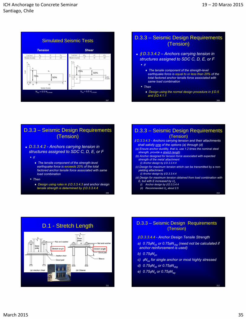
qualified for earthquake loading per ACI 355.2 or ACI 355.4 Simulated Seismic Tests
206
ICH Anchorage to Concrete Seminar Santiago, Chile
19 – 20 Marzo 2015
March 2015 35
Simulated Seismic Tests
Tension Shear
207
50%75%
Neq = 0.5 No,mean Veq = 0.5 Vo,mean
50%75%
208
D.3.3 – Seismic Design Requirements (Tension)
§ D.3.3.4.2 – Anchors carrying tension in structures assigned to SDC C, D, E, or F• If
The tensile component of the strength-level earthquake force is equal to or less than 20% of the total factored anchor tensile force associated with same load combination
• Then
Design using the normal design procedure in § D.5 and § D.4.1.1
209
D.3.3 – Seismic Design Requirements (Tension)
D.3.3.4.2 - Anchors carrying tension in structures assigned to SDC C, D, E, or F• If
The tensile component of the strength-level earthquake force is exceeds 20% of the total factored anchor tensile force associated with same load combination
• Then
Design using rules in § D.3.3.4.3 and anchor design tensile strength is determined by § D.3.3.4.4
210
D.3.3 – Seismic Design Requirements (Tension)
§ D.3.3.4.3 - Anchors carrying tension and their attachments shall satisfy one of the options (a) through (d)
(a) Ensure anchor ductility, that is, use 1.2 times the nominal steel strength, provide a stretch length
(b) Anchor designed for tension force associated with expected strength of the metal attachment
(i) Anchor design by § D.3.3.4.4
(c) Design for maximum tension which can be transmitted by a non-yielding attachment
(i) Anchor design by § D.3.3.4.4
(d) Design for maximum tension obtained from load combination with E, but with E increased by o
(i) Anchor design by § D.3.3.4.4
(ii) Recommended o about 2.5
211
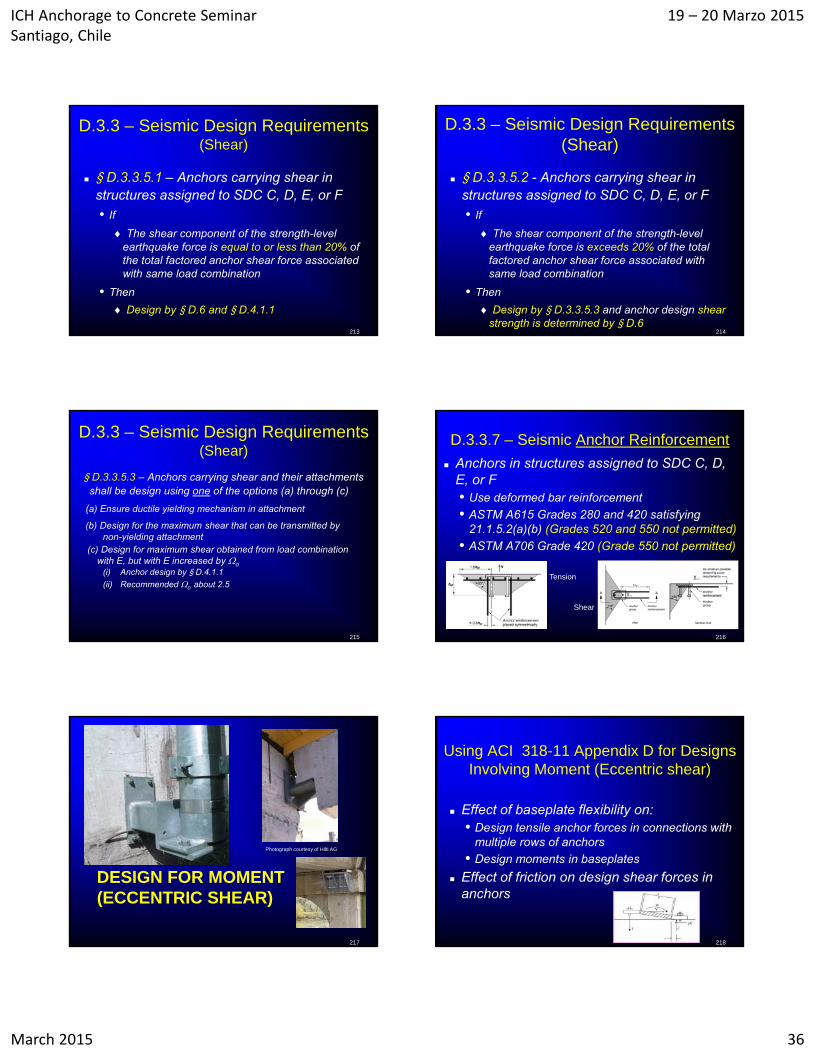
D.1 - Stretch Length
212
D.3.3 – Seismic Design Requirements (Tension)
§ D.3.3.4.4 - Anchor Design Tensile Strength
a) 0.75Ncb or 0.75Ncbg (need not be calculated if anchor reinforcement is used)
b) 0.75Npn
c) Nsa for single anchor or most highly stressed
d) 0.75Nsb or 0.75Nsbg
e) 0.75Na or 0.75Nag
ICH Anchorage to Concrete Seminar Santiago, Chile
19 – 20 Marzo 2015
March 2015 36
213
D.3.3 – Seismic Design Requirements (Shear)
§ D.3.3.5.1 – Anchors carrying shear in structures assigned to SDC C, D, E, or F• If
The shear component of the strength-level earthquake force is equal to or less than 20% of the total factored anchor shear force associated with same load combination
• Then
Design by § D.6 and § D.4.1.1
214
D.3.3 – Seismic Design Requirements (Shear)
§ D.3.3.5.2 - Anchors carrying shear in structures assigned to SDC C, D, E, or F• If
The shear component of the strength-level earthquake force is exceeds 20% of the total factored anchor shear force associated with same load combination
• Then
Design by § D.3.3.5.3 and anchor design shear strength is determined by § D.6
D.3.3 – Seismic Design Requirements (Shear)
§ D.3.3.5.3 – Anchors carrying shear and their attachments shall be design using one of the options (a) through (c)
(a) Ensure ductile yielding mechanism in attachment
(b) Design for the maximum shear that can be transmitted by non-yielding attachment
(c) Design for maximum shear obtained from load combination with E, but with E increased by o
(i) Anchor design by § D.4.1.1
(ii) Recommended o about 2.5
215 216
D.3.3.7 – Seismic Anchor Reinforcement
Anchors in structures assigned to SDC C, D, E, or F• Use deformed bar reinforcement
• ASTM A615 Grades 280 and 420 satisfying 21.1.5.2(a)(b) (Grades 520 and 550 not permitted)
• ASTM A706 Grade 420 (Grade 550 not permitted)
Tension
Shear
DESIGN FOR MOMENT (ECCENTRIC SHEAR)
217
Photograph courtesy of Hilti AG
218
Using ACI 318-11 Appendix D for Designs Involving Moment (Eccentric shear)
Effect of baseplate flexibility on:• Design tensile anchor forces in connections with
multiple rows of anchors
• Design moments in baseplates
Effect of friction on design shear forces in anchors
ICH Anchorage to Concrete Seminar Santiago, Chile
19 – 20 Marzo 2015
March 2015 37
219
Base Plate Flexibility Plane sections do not remain plane – beam
theory is not exactly correct, but close enough
For design purposes, bound the solution
• To size the anchors for tension, assume a flexible baseplate. This gives the smallest internal lever arm, and the largest design axial forces in the anchors
• To size the baseplate, assume a rigid baseplate. This gives the largest distance from the assumed location of the compression reaction to the critical point on the baseplate
220
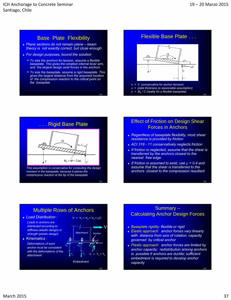
Flexible Base Plate . . .
x = 0 (conservative for anchor tension)x = plate thickness (a reasonable assumption)x = Mp / C (reality for a flexible baseplate)
221
. . . Rigid Base Plate
This assumption is conservative for computing the design moment in the baseplate, because it places the compressive reaction at the tip of the baseplate
222
Effect of Friction on Design Shear Forces in Anchors
Regardless of baseplate flexibility, most shear resistance is provided by friction
ACI 318 - 11 conservatively neglects friction
If friction is neglected, assume that the shear is transferred by the anchors closest to the nearest free edge
If friction is assumed to exist, use = 0.4 and assume that the shear is transferred to the anchors closest to the compression resultant
223
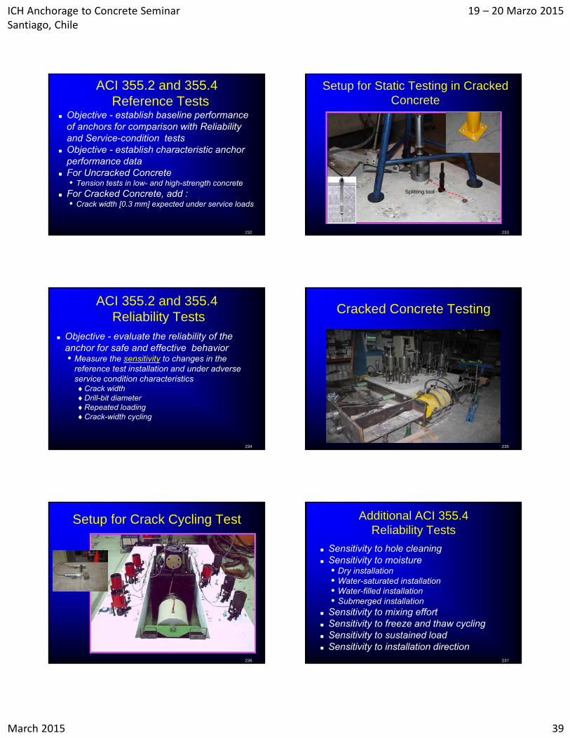
Multiple Rows of Anchors Load Distribution :
Loads in anchors are distributed according to stiffness (elastic design) or strength (plastic design)
Kinematics :Deformations of each anchor must be consistent with the deformations of the attachment
Embedment
T1T2 C = T1 + T2
C
V1 V2 V3
V = V1 + V2 + V3 + C
Attachment Anchor
V
224
Summary –Calculating Anchor Design Forces
Baseplate rigidity: flexible or rigid Elastic approach: anchor forces vary linearly
with distance from axis of rotation; capacity governed by critical anchor
Plastic approach: anchor forces are limited by anchor capacity; redistribution among anchors is possible if anchors are ductile; sufficient embedment is required to develop anchor capacity

ICH Anchorage to Concrete Seminar Santiago, Chile
19 – 20 Marzo 2015
March 2015 38
ACI QUALIFICATION TESTING STANDARDS
ACI 355.2 :Qualification of Post-Installed Mechanical Anchors in Concrete and Commentary
ACI 355.4 :Qualification of Post-Installed Adhesive Anchors in Concrete and Commentary
226 227
Scope of ACI 355.2 and ACI 355.4 355.2 Post-installed mechanical anchors
• Undercut anchors• Torque-controlled expansion anchors• Displacement-controlled expansion anchors
355.4 Post-installed adhesive anchors • Only polymeric adhesives
Conventional cast-in anchors do not require qualification (headed bolts, rods with nuts, J- and L-bolts, welded headed studs)
228
ACI 355.2 and 355.4 Prescribes Four Types of Tests
Identification tests
Reference tests
Reliability tests
Service-condition tests
229
Qualification - General Requirements
Concrete• Low- and high-strength concrete:
Low [17-24 MPa] High [45-55 MPa]
Cracked and uncracked concrete • Static tests• Crack-width cycling
Seismic cycling Evaluation by an Independent Testing and
Evaluation Agency (ITEA)
230
ACI 355.2 and 355.4 Identification Tests
Check conformance to product description• Generic or trade name• Anchor element
DimensionsPhysical propertiesTensile strengthHardnessCoatings
• Identification markings
• Quality-control requirements
Additional ACI 355.4 Identification Tests
Check conformance to product description• Adhesive components
Fingerprinting of adhesive materials
231
ICH Anchorage to Concrete Seminar Santiago, Chile
19 – 20 Marzo 2015
March 2015 39
232
ACI 355.2 and 355.4Reference Tests
Objective - establish baseline performance of anchors for comparison with Reliability and Service-condition tests
Objective - establish characteristic anchor performance data
For Uncracked Concrete• Tension tests in low- and high-strength concrete
For Cracked Concrete, add :• Crack width [0.3 mm] expected under service loads
233
Setup for Static Testing in Cracked Concrete
Splitting tool
234
ACI 355.2 and 355.4Reliability Tests
Objective - evaluate the reliability of the anchor for safe and effective behavior • Measure the sensitivity to changes in the
reference test installation and under adverse service condition characteristicsCrack widthDrill-bit diameterRepeated loadingCrack-width cycling
Cracked Concrete Testing
235
236
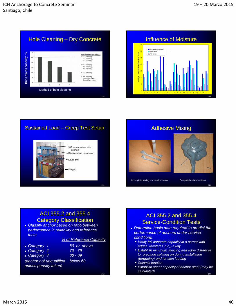
Setup for Crack Cycling Test Additional ACI 355.4 Reliability Tests
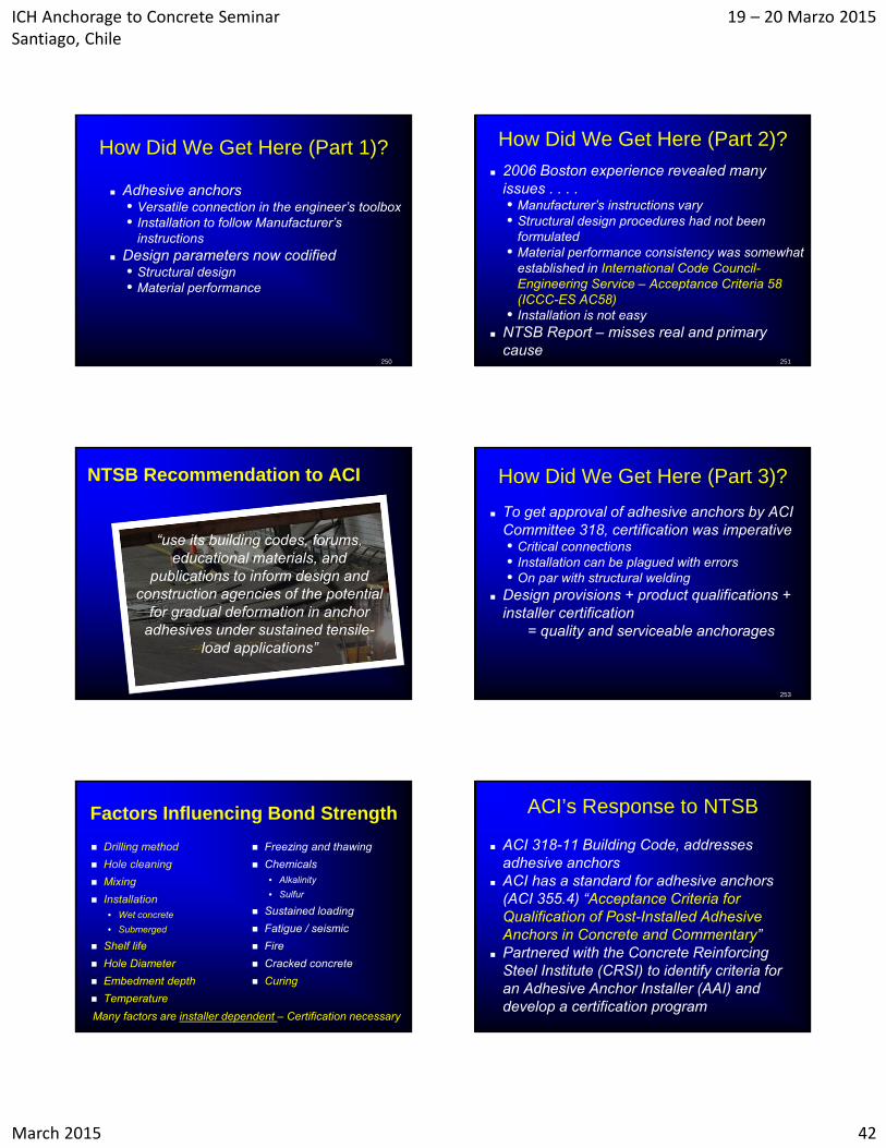
Sensitivity to hole cleaning Sensitivity to moisture
• Dry installation• Water-saturated installation• Water-filled installation• Submerged installation
Sensitivity to mixing effort Sensitivity to freeze and thaw cycling Sensitivity to sustained load Sensitivity to installation direction
237
ICH Anchorage to Concrete Seminar Santiago, Chile
19 – 20 Marzo 2015
March 2015 40
Hole Cleaning – Dry Concrete
238
Method of hole cleaning
Bo
nd
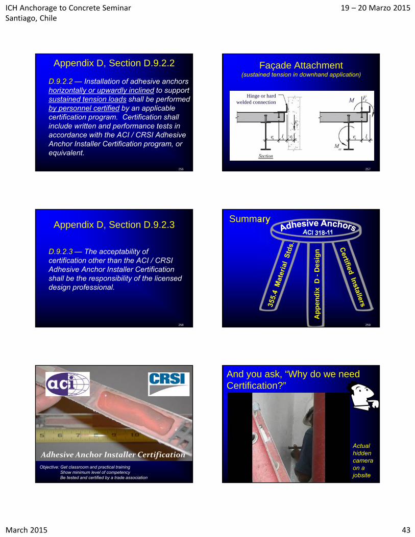
str
ess
ca
pa
city
, %
Influence of Moisture
0
5
10
15
20
25
30
35
A B C D E F G H I J K L M N O P Q R S T
Ave
rage
Uni
form
Bo
nd S
tre
ngth
, M
Pa
DRY HOLE (BASELINE)
DAMP HOLE
WET HOLE
239
Sustained Load – Creep Test Setup
240
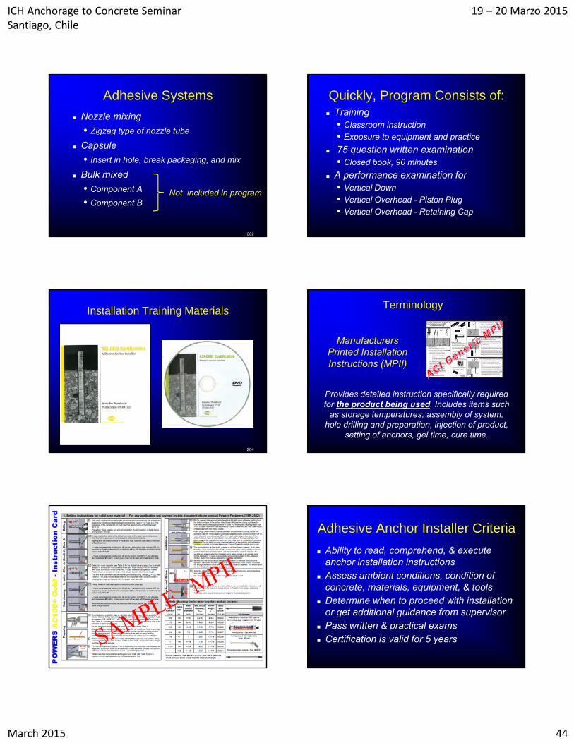
Adhesive Mixing
241
Incomplete mixing – nonuniform color Completely mixed material
242
ACI 355.2 and 355.4 Category Classification
Classify anchor based on ratio between performance in reliability and reference tests
% of Reference Capacity
Category 1 80 or above Category 2 70 - 79 Category 3 60 - 69(anchor not unqualified below 60unless penalty taken)
243
ACI 355.2 and 355.4Service-Condition Tests
Determine basic data required to predict the performance of anchors under service conditions• Verify full concrete capacity in a corner with
edges located 1.5 hef away• Establish minimum spacing and edge distances
to preclude splitting on during installation (torqueing) and tension loading
• Seismic tension• Establish shear capacity of anchor steel (may be
calculated)

ICH Anchorage to Concrete Seminar Santiago, Chile
19 – 20 Marzo 2015
March 2015 41
Additional ACI 355.4 Service-Condition Tests
Verify anchor behavior under• Elevated temperature installation• Curing time at low temperatures • Resistance to alkalinity• Resistance to sulfur
244
Influence of Temperature
245
ACI 355.2 and 355.4 Evaluation Report
Independent Testing and Evaluation Agency • Evaluates test results• Issues a report classifying the anchor for use
with ACI 318 Appendix D Bond Stress in the Evaluation Report is the
5% fractile including effects of all variables
246
Evaluation Report Data
247
INSTALLERCERTIFICATION
ACI 318-11 D.9.2
248
Courtesy of Hilti AG
Adhesive Anchor Installer Certification
A New ACI 318-11 Requirement
249
D9.2.2, D9.2.3, and D.9.2.4
ICH Anchorage to Concrete Seminar Santiago, Chile
19 – 20 Marzo 2015
March 2015 42
How Did We Get Here (Part 1)?
Adhesive anchors • Versatile connection in the engineer’s toolbox• Installation to follow Manufacturer’s
instructions Design parameters now codified
• Structural design• Material performance
250
How Did We Get Here (Part 2)?
2006 Boston experience revealed many issues . . . . • Manufacturer’s instructions vary• Structural design procedures had not been
formulated • Material performance consistency was somewhat
established in International Code Council-Engineering Service – Acceptance Criteria 58 (ICCC-ES AC58)
• Installation is not easy NTSB Report – misses real and primary
cause251
“use its building codes, forums, educational materials, and
publications to inform design and construction agencies of the potential
for gradual deformation in anchor adhesives under sustained tensile-
load applications”
NTSB Recommendation to ACI How Did We Get Here (Part 3)?
To get approval of adhesive anchors by ACI Committee 318, certification was imperative • Critical connections• Installation can be plagued with errors• On par with structural welding
Design provisions + product qualifications + installer certification
= quality and serviceable anchorages
253
Factors Influencing Bond Strength
Drilling method
Hole cleaning
Mixing
Installation• Wet concrete
• Submerged
Shelf life
Hole Diameter
Embedment depth
Temperature
Freezing and thawing
Chemicals • Alkalinity
• Sulfur
Sustained loading
Fatigue / seismic
Fire
Cracked concrete
Curing
Many factors are installer dependent – Certification necessary
ACI’s Response to NTSB
ACI 318-11 Building Code, addresses adhesive anchors
ACI has a standard for adhesive anchors (ACI 355.4) “Acceptance Criteria for Qualification of Post-Installed Adhesive Anchors in Concrete and Commentary”
Partnered with the Concrete Reinforcing Steel Institute (CRSI) to identify criteria for an Adhesive Anchor Installer (AAI) and develop a certification program
ICH Anchorage to Concrete Seminar Santiago, Chile
19 – 20 Marzo 2015
March 2015 43
Appendix D, Section D.9.2.2
D.9.2.2 — Installation of adhesive anchors horizontally or upwardly inclined to support sustained tension loads shall be performed by personnel certified by an applicable certification program. Certification shall include written and performance tests in accordance with the ACI / CRSI Adhesive Anchor Installer Certification program, or equivalent.
256
Façade Attachment(sustained tension in downhand application)
257
MHinge or hard
welded connection
Appendix D, Section D.9.2.3
D.9.2.3 — The acceptability of certification other than the ACI / CRSI Adhesive Anchor Installer Certification shall be the responsibility of the licensed design professional.
258
Summary
259
Ap
pen
dix
D -
Des
ign
Adhesive Anchor Installer Certification
Objective: Get classroom and practical training Show minimum level of competencyBe tested and certified by a trade association
And you ask, “Why do we need Certification?”
Actual hidden camera on a jobsite
ICH Anchorage to Concrete Seminar Santiago, Chile
19 – 20 Marzo 2015
March 2015 44
Adhesive Systems
Nozzle mixing
• Zigzag type of nozzle tube
Capsule
• Insert in hole, break packaging, and mix
Bulk mixed
• Component A
• Component BNot included in program
262
Quickly, Program Consists of: Training
• Classroom instruction
• Exposure to equipment and practice
75 question written examination• Closed book, 90 minutes
A performance examination for• Vertical Down
• Vertical Overhead - Piston Plug
• Vertical Overhead - Retaining Cap
Installation Training Materials
264
Terminology
Manufacturers Printed Installation Instructions (MPII)
Provides detailed instruction specifically required for the product being used. Includes items such
as storage temperatures, assembly of system, hole drilling and preparation, injection of product,
setting of anchors, gel time, cure time.
Adhesive Anchor Installer Criteria
Ability to read, comprehend, & execute anchor installation instructions
Assess ambient conditions, condition of concrete, materials, equipment, & tools
Determine when to proceed with installation or get additional guidance from supervisor
Pass written & practical exams Certification is valid for 5 years
ICH Anchorage to Concrete Seminar Santiago, Chile
19 – 20 Marzo 2015
March 2015 45
Local Certification Examinations
ACI Local Sponsoring Groups (LSGs) to• Support local training by manufacturer
Following a MPII is essential
• Maintain equipment and provide manpower
• Train the examiners
Conduct the 2-part examination
268
Performance Specifics
Downhand vertical position (1)• Concrete cylinder (block)
• Hole clean-out procedures
• Random choice of product
Overhead vertical position (2)• Acrylic tube
• Hole filling imperative
• Cap & piston plug systems
269
Vertical Down or Downhand
Hole depth Perpendicularity of hole Hole cleaning technique Initial discharge of adhesive product Adhesive dispensing Rod / bar installation
270
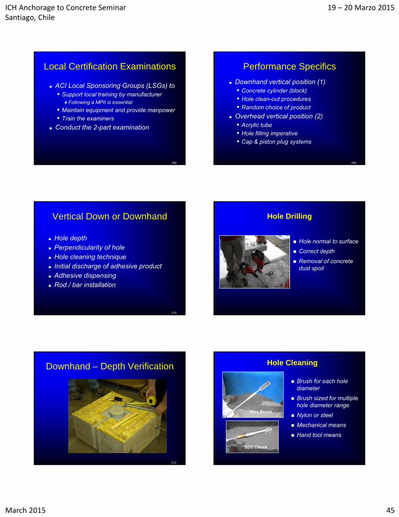
Hole Drilling
Hole normal to surface
Correct depth
Removal of concrete dust spoil
Downhand – Depth Verification
272
Hole Cleaning
Brush for each hole diameter
Brush sized for multiple hole diameter range
Nylon or steel
Mechanical means
Hand tool means
Wire Brush
SDS Chuck
ICH Anchorage to Concrete Seminar Santiago, Chile
19 – 20 Marzo 2015
March 2015 46
Hole Cleaning Hole Cleaning
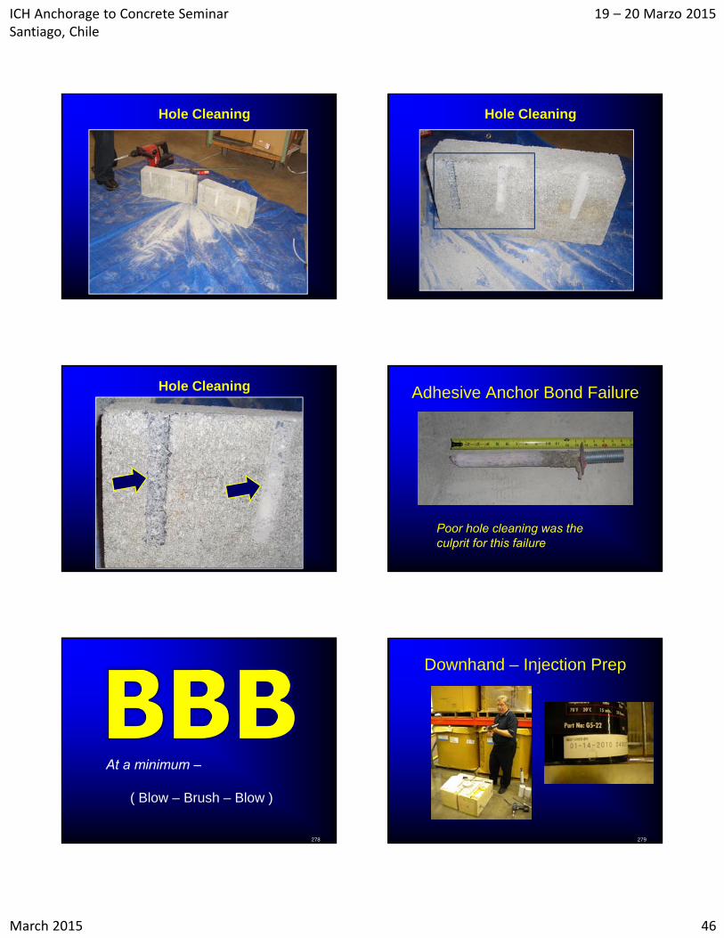
Hole Cleaning Adhesive Anchor Bond Failure
Poor hole cleaning was the culprit for this failure
278
At a minimum –
( Blow – Brush – Blow )
Downhand – Injection Prep
279
ICH Anchorage to Concrete Seminar Santiago, Chile
19 – 20 Marzo 2015
March 2015 47
Nozzle Mixed System
280
Mixing & Express Material
281
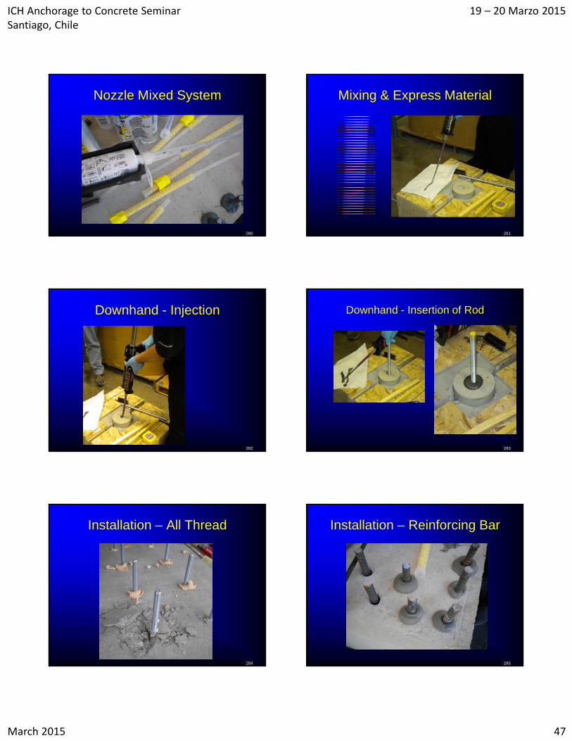
Downhand - Injection
282
Downhand - Insertion of Rod
283
Installation – All Thread
284
Installation – Reinforcing Bar
285
ICH Anchorage to Concrete Seminar Santiago, Chile
19 – 20 Marzo 2015
March 2015 48
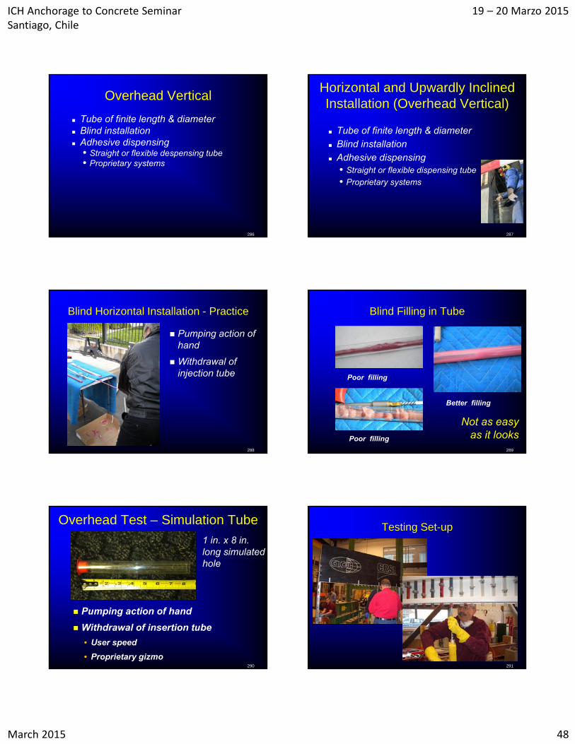
Overhead Vertical
Tube of finite length & diameter Blind installation Adhesive dispensing
• Straight or flexible despensing tube• Proprietary systems
286
Horizontal and Upwardly Inclined Installation (Overhead Vertical)
Tube of finite length & diameter Blind installation Adhesive dispensing
• Straight or flexible dispensing tube
• Proprietary systems
287
Blind Horizontal Installation - Practice
Pumping action of hand
Withdrawal of injection tube
288
Blind Filling in Tube
Poor filling
Poor filling
Better filling
289
Not as easyas it looks
Overhead Test – Simulation Tube
290
1 in. x 8 in. long simulated hole
Pumping action of hand
Withdrawal of insertion tube
• User speed
• Proprietary gizmo
Testing Set-up
291
ICH Anchorage to Concrete Seminar Santiago, Chile
19 – 20 Marzo 2015
March 2015 49
Testing Set-Up Blind Insertion & Injection - 1
Piston plug system
293
Blind Insertion & Injection - 2
Bottom cap system
294
Testing Set-Up
Overhead – Retaining Cap
Adhesive installation technique is important !
Overhead – Retaining Cap
ICH Anchorage to Concrete Seminar Santiago, Chile
19 – 20 Marzo 2015
March 2015 50
Overhead – Retaining Cap Overhead – Retaining Cap
Overhead – Retaining Cap Overhead – Retaining Cap
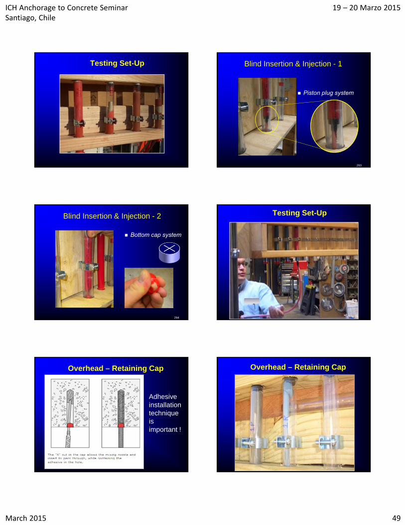
Evaluation of Overhead Tests Evaluation of Overhead Tests
• Cutting of Hardened Test Specimens
• Initial Pilot – all were sectioned
• Second Pilot all were cut longitudinally
• Size and location of voids are key
• Grading rubric
ICH Anchorage to Concrete Seminar Santiago, Chile
19 – 20 Marzo 2015
March 2015 51
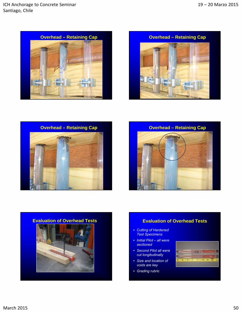
Evaluation of Overhead Tests
• Longitudinal cutting of hardened test specimens
• Size and location of voids are visually examined
• There is a rubric of acceptance
AAI Certification Review
Manufacturer training Written test
• Environmental conditions
• Equipment / materials
• OSHA issues
Performance test• Downhand vertical into concrete
• Vertical overhead into a tube
Certification good for 5 years305
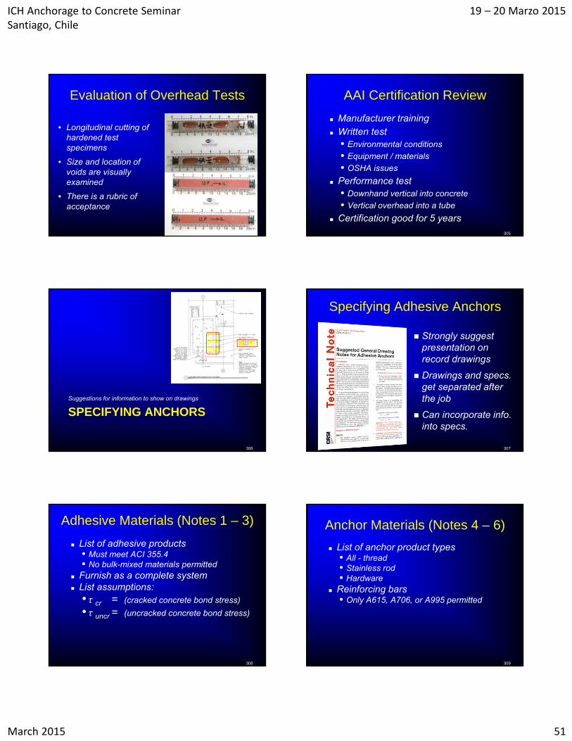
SPECIFYING ANCHORSSuggestions for information to show on drawings
306
Specifying Adhesive Anchors
Strongly suggest presentation on record drawings
Drawings and specs. get separated after the job
Can incorporate info. into specs.
307
Adhesive Materials (Notes 1 – 3)
List of adhesive products• Must meet ACI 355.4• No bulk-mixed materials permitted
Furnish as a complete system List assumptions:
• τ cr = (cracked concrete bond stress)
• τ uncr = (uncracked concrete bond stress)
308
Anchor Materials (Notes 4 – 6)
List of anchor product types• All - thread• Stainless rod• Hardware
Reinforcing bars• Only A615, A706, or A995 permitted
309
ICH Anchorage to Concrete Seminar Santiago, Chile
19 – 20 Marzo 2015
March 2015 52
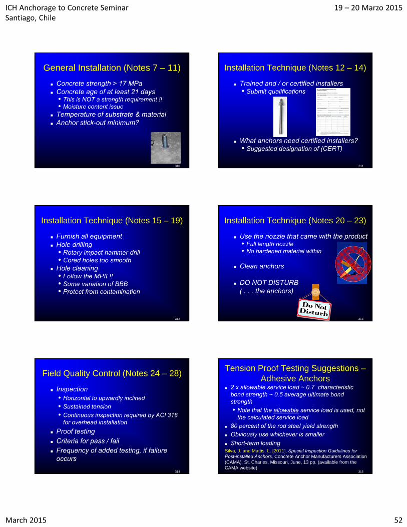
General Installation (Notes 7 – 11)
Concrete strength > 17 MPa Concrete age of at least 21 days
• This is NOT a strength requirement !!• Moisture content issue
Temperature of substrate & material Anchor stick-out minimum?
310
Installation Technique (Notes 12 – 14)
Trained and / or certified installers• Submit qualifications
What anchors need certified installers?• Suggested designation of (CERT)
311
Installation Technique (Notes 15 – 19)
Furnish all equipment Hole drilling
• Rotary impact hammer drill• Cored holes too smooth
Hole cleaning• Follow the MPII !!• Some variation of BBB• Protect from contamination
312
Installation Technique (Notes 20 – 23)
Use the nozzle that came with the product• Full length nozzle• No hardened material within
Clean anchors
DO NOT DISTURB( . . . the anchors)
313
Field Quality Control (Notes 24 – 28)
Inspection• Horizontal to upwardly inclined
• Sustained tension
• Continuous inspection required by ACI 318 for overhead installation
Proof testing Criteria for pass / fail Frequency of added testing, if failure
occurs
314
Tension Proof Testing Suggestions –Adhesive Anchors
2 x allowable service load ~ 0.7 characteristic bond strength ~ 0.5 average ultimate bond strength
• Note that the allowable service load is used, not the calculated service load
80 percent of the rod steel yield strength
Obviously use whichever is smaller
Short-term loadingSilva, J. and Mattis, L. [2011], Special Inspection Guidelines for Post-installed Anchors, Concrete Anchor Manufacturers Association (CAMA), St. Charles, Missouri, June, 13 pp. (available from the CAMA website)
315
ICH Anchorage to Concrete Seminar Santiago, Chile
19 – 20 Marzo 2015
March 2015 53
316
¿Preguntas?(Questions?)
¡Gracias!(Thank you)