Embed Size (px)
Citation preview
ICES REPORT 13-19
July 2013
Volumetric T-spline Construction Using BooleanOperations
by
L. Liu, Y. Zhang, T.J.R. Hughes, M.A. Scott, T.W. Sederberg
The Institute for Computational Engineering and SciencesThe University of Texas at AustinAustin, Texas 78712
Reference: L. Liu, Y. Zhang, T.J.R. Hughes, M.A. Scott, T.W. Sederberg, Volumetric T-spline Construction UsingBoolean Operations, ICES REPORT 13-19, The Institute for Computational Engineering and Sciences, TheUniversity of Texas at Austin, July 2013.
Report Documentation Page Form ApprovedOMB No. 0704-0188
Public reporting burden for the collection of information is estimated to average 1 hour per response, including the time for reviewing instructions, searching existing data sources, gathering andmaintaining the data needed, and completing and reviewing the collection of information. Send comments regarding this burden estimate or any other aspect of this collection of information,including suggestions for reducing this burden, to Washington Headquarters Services, Directorate for Information Operations and Reports, 1215 Jefferson Davis Highway, Suite 1204, ArlingtonVA 22202-4302. Respondents should be aware that notwithstanding any other provision of law, no person shall be subject to a penalty for failing to comply with a collection of information if itdoes not display a currently valid OMB control number.
1. REPORT DATE JUL 2013 2. REPORT TYPE
3. DATES COVERED 00-00-2013 to 00-00-2013
4. TITLE AND SUBTITLE Volumetric T-spline Construction Using Boolean Operations
5a. CONTRACT NUMBER
5b. GRANT NUMBER
5c. PROGRAM ELEMENT NUMBER
6. AUTHOR(S) 5d. PROJECT NUMBER
5e. TASK NUMBER
5f. WORK UNIT NUMBER
7. PERFORMING ORGANIZATION NAME(S) AND ADDRESS(ES) University of Texas at Austin,Institute for Computational Engineeringand Sciences,Austin,TX,78712
8. PERFORMING ORGANIZATIONREPORT NUMBER
9. SPONSORING/MONITORING AGENCY NAME(S) AND ADDRESS(ES) 10. SPONSOR/MONITOR’S ACRONYM(S)
11. SPONSOR/MONITOR’S REPORT NUMBER(S)
12. DISTRIBUTION/AVAILABILITY STATEMENT Approved for public release; distribution unlimited
13. SUPPLEMENTARY NOTES
14. ABSTRACT
15. SUBJECT TERMS
16. SECURITY CLASSIFICATION OF: 17. LIMITATION OF ABSTRACT Same as
Report (SAR)
18. NUMBEROF PAGES
19
19a. NAME OFRESPONSIBLE PERSON
a. REPORT unclassified
b. ABSTRACT unclassified
c. THIS PAGE unclassified
Standard Form 298 (Rev. 8-98) Prescribed by ANSI Std Z39-18
Volumetric T-spline Construction UsingBoolean Operations
Lei Liu1, Yongjie Zhang1,∗, Thomas J.R. Hughes2, Michael A. Scott3 andThomas W. Sederberg4
1 Department of Mechanical Engineering, Carnegie Mellon University, Pittsburgh,PA 15213, USA
2 Institute for Computational Engineering and Sciences, The University of Texasat Austin, Austin, TX 78712, USA
3 Department of Civil and Environmental Engineering, Brigham Young University,Provo, UT 84602, USA
4 Department of Computer Science, Brigham Young University, Provo, UT 84602,USA
Summary. In this paper, we present a novel algorithm for constructing a volumet-ric T-spline from B-reps inspired by Constructive Solid Geometry (CSG) Booleanoperations. By solving a harmonic field with proper boundary conditions, the inputsurface is automatically decomposed into regions that are classified into two groupsrepresented, topologically, by either a cube or a torus. We perform two Boolean op-erations (union and difference) with the primitives and convert them into polycubesthrough parametric mapping. With these polycubes, octree subdivision is carriedout to obtain a volumetric T-mesh, and sharp features detected from the inputmodel are also preserved. An optimization is then performed to improve the qualityof the volumetric T-spline. Finally we extract trivariate Bezier elements from thevolumetric T-spline, and use them directly in isogeometric analysis.
Key words: volumetric T-spline, Boolean operations, polycubes, parametric map-ping, sharp feature, isogeometric analysis
1 Introduction
Isogeometric analysis [7, 13] bridges Computer Aided Design (CAD) and Fi-nite Element Analysis (FEA) by using the same basis functions for geometricmodeling and numerical simulation. For many important application areas, ithas been demonstrated that isogeometric analysis, using smooth basis func-tions, is more accurate and robust than traditional FEA which uses C0 basisfunctions [8, 5, 32]. Additionally, the exact CAD geometry is embedded in
∗Corresponding author. Tel: (412) 268-5332; Fax: (412) 268-3348; Email:[email protected] (Yongjie Zhang).
2 L. Liu, Y. Zhang, T. J.R. Hughes, M.A. Scott, T.W. Sederberg
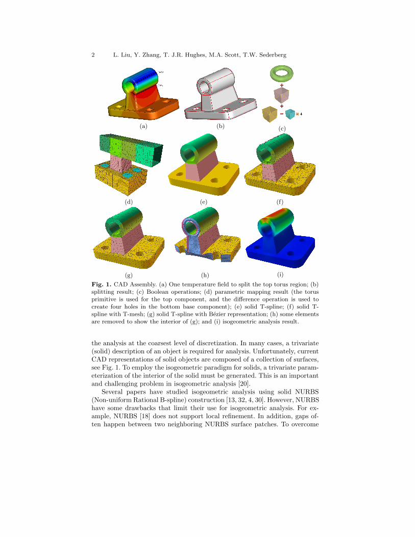
(a) (b) (c)
(d) (e) (f)
(g) (h) (i)
Fig. 1. CAD Assembly. (a) One temperature field to split the top torus region; (b)splitting result; (c) Boolean operations; (d) parametric mapping result (the torusprimitive is used for the top component, and the difference operation is used tocreate four holes in the bottom base component); (e) solid T-spline; (f) solid T-spline with T-mesh; (g) solid T-spline with Bezier representation; (h) some elementsare removed to show the interior of (g); and (i) isogeometric analysis result.
the analysis at the coarsest level of discretization. In many cases, a trivariate(solid) description of an object is required for analysis. Unfortunately, currentCAD representations of solid objects are composed of a collection of surfaces,see Fig. 1. To employ the isogeometric paradigm for solids, a trivariate param-eterization of the interior of the solid must be generated. This is an importantand challenging problem in isogeometric analysis [20].
Several papers have studied isogeometric analysis using solid NURBS(Non-uniform Rational B-spline) construction [13, 32, 4, 30]. However, NURBShave some drawbacks that limit their use for isogeometric analysis. For ex-ample, NURBS [18] does not support local refinement. In addition, gaps of-ten happen between two neighboring NURBS surface patches. To overcome
Volumetric T-spline Construction Using Boolean Operations 3
these limitations, Sederberg invented T-splines [23], which support local re-finement naturally by introducing T-junctions [22]. T-splines were introducedinto isogeometric analysis in [6, 4]. The initial research on T-splines-based iso-geometric analysis was limited to surface models. Reference [21] introduceda data structure for isogeometric analysis using T-splines. Conversion of un-structured meshes to T-splines has also been studied [28, 29]. A generalizedalgorithm was also developed to extract Bezier elements from volumetric T-splines, connecting the spline modeling with analysis data structure.
As for the construction of volumetric T-spline, different approaches havebeen developed. A method based on Periodic Global Parameterization wasproposed to convert triangular meshes to T-splines [16]. Other research focuseson parametric mapping of an input tetrahedral meshes to construct solid T-splines [9]. A harmonic mapping method has been proposed for developing a3D solid sphere from a 2-manifold for use in computer graphics and medicalimaging [11]. In [25], a parametric mapping between a polycube and a surfacegeometry was presented to construct trivariate T-splines from input triangularmeshes. Mapping, subdivision and pillowing techniques have been used togenerate good quality T-splines for genus-zero [33] and arbitrary genus objects[27]. Li et al. [15] proposed a generalized polycube method using T shapetemplates to handle high-genus models and extraordinary nodes.
Despite these advances, it remains a challenging problem to automaticallycreate a volumetric T-spline for models with arbitrary complicated geometryand topology. How to automatically and robustly split complex geometryinto different components and transfer the input geometric information to thedesired volumetric models are still open problems.
Inspired by CSG Boolean operations [1, 3, 24], in this paper we presenta novel algorithm to construct trivariate solid T-spline models using twoBoolean operations: union and difference. In our algorithm, we compute aharmonic field together with the boundary information to split the domain,and use primitives (cube and torus) and Boolean operations to generate poly-cubes1. Parametric mapping is then employed to transfer the input informa-tion to the volumetric T-spline. The four main contributions that this pa-per makes to the problem of volumetric T-splines parametrization are: (1)a harmonic field with proper boundary conditions is computed to automati-cally split the input geometry into different hexahedral components; (2) twoBoolean operations (especially the difference operation) are developed to con-struct polycubes conveniently and flexibly; (3) a novel torus primitive is intro-duced to deal with torus-like objects or holes, yielding few number of extraor-dinary nodes and high quality elements; and (4) sharp features are preservedand mesh quality is improved.
1Conventionally, a polycube is comprised of cubes of equal sizes with two neigh-boring cubes sharing a complete face [2]. In this paper, the “cubes” can be arbitraryhexahedra of different sizes.
4 L. Liu, Y. Zhang, T. J.R. Hughes, M.A. Scott, T.W. Sederberg
Although the proposed algorithm is automatic and robust for a large classof complex models, it also has limitations. For example, it cannot handle somespecial objects such as a tetrahedron or a cone, and it cannot preserve theinput surface parameterization.
The remainder of this paper is organized as follows. The main steps ofthe algorithm (illustrated in Fig. 1) are overviewed in Section 2. Section 3discusses extracting boundary information. Section 4 talks about differentprimitives and Boolean operations among them. Section 5 explains T-splineconstruction. Section 6 shows some results, and Section 7 draws conclusionsand points out the future work.
2 Algorithm Overview
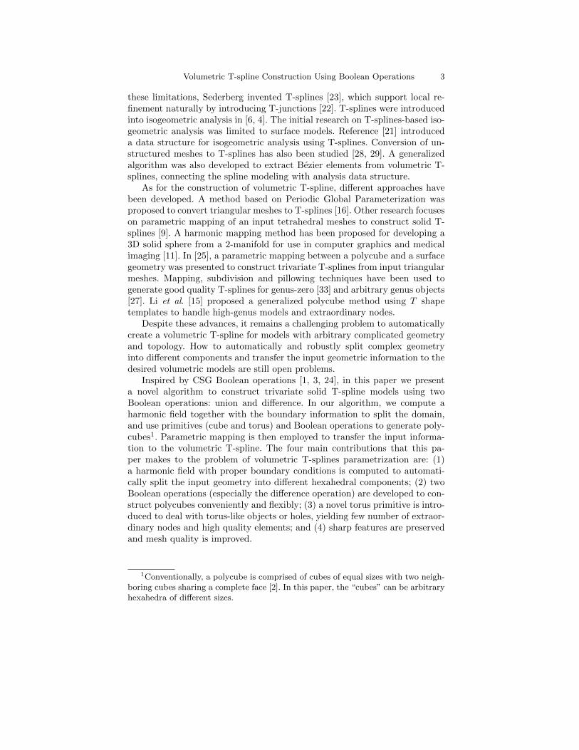
Polycube-based methods for volume parametrization [27, 26, 14] perform do-main decomposition by splitting the model into hexahedral regions that mapto cubes. However, sometimes the models are so complicated that it is diffi-cult to split the domain automatically. Inspired by CSG Boolean operations[1], here we propose to use Boolean operations to build the polycubes. Asshown in Fig. 2, there are three main stages to construct a trivariate solidT-spline from the given CAD model: curve extraction, domain decompositionand Boolean operations, and volumetric T-spline construction.
Fig. 2. Three stages of volumetric T-spline construction using Boolean operations.
Volumetric T-spline Construction Using Boolean Operations 5
The first stage initializes all the necessary boundary information for thefollowing stages. We first classify the curve information from the CAD modelinto two groups, and then use the commercial software ABAQUS to generatethe surface mesh.
Based on the curve information and surface mesh, we perform domaindecomposition and Boolean operations to generate polycubes. A harmonicfield with proper boundary conditions is computed to automatically split thesurface model into different components, topologically equivalent to either acube or a torus. As shown in Fig. 1, each torus is composed topologically offour cubes. All cubes generated by the domain decomposition are then uniontogether and holes (represented topologically as cubes) are subtracted (seeFig. 1(d)). We will refer to the resulting configuration as a polycube, realizingthat we take some liberties in using the term in this way. The CAD surfaceis then mapped to the polycube surface.
The volumetric T-spline is obtained by performing an octree subdivisionon the polycube. Here we use a separate octree for each cube and force twoneighboring cubes to have the same parameterization at the shared boundary.All the detected sharp feature information is preserved in this step. Pillow-ing, smoothing and optimization are then used to improve the quality of theT-mesh. To obtain a gap-free T-mesh, we apply templates [28, 29] to eachirregular node in the T-mesh. Finally, volumetric T-spline is generated andBezier elements are extracted for isogeometric analysis.
3 Curve Extraction
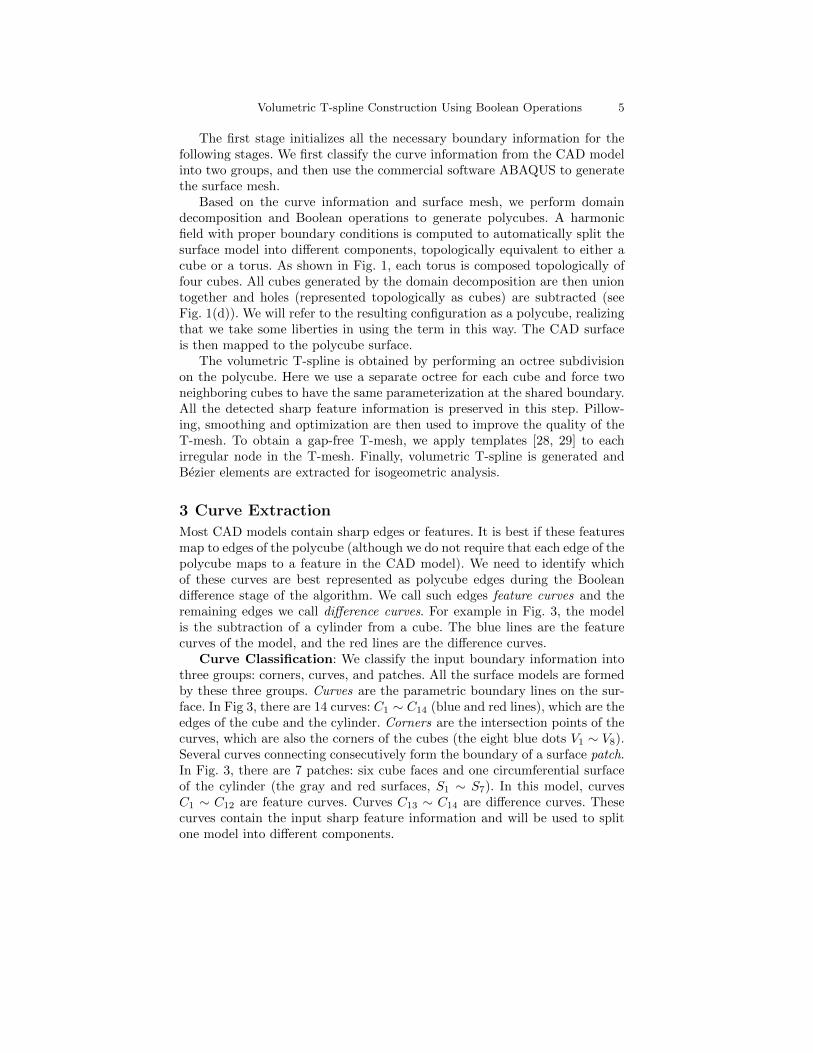
Most CAD models contain sharp edges or features. It is best if these featuresmap to edges of the polycube (although we do not require that each edge of thepolycube maps to a feature in the CAD model). We need to identify whichof these curves are best represented as polycube edges during the Booleandifference stage of the algorithm. We call such edges feature curves and theremaining edges we call difference curves. For example in Fig. 3, the modelis the subtraction of a cylinder from a cube. The blue lines are the featurecurves of the model, and the red lines are the difference curves.
Curve Classification: We classify the input boundary information intothree groups: corners, curves, and patches. All the surface models are formedby these three groups. Curves are the parametric boundary lines on the sur-face. In Fig 3, there are 14 curves: C1 ∼ C14 (blue and red lines), which are theedges of the cube and the cylinder. Corners are the intersection points of thecurves, which are also the corners of the cubes (the eight blue dots V1 ∼ V8).Several curves connecting consecutively form the boundary of a surface patch.In Fig. 3, there are 7 patches: six cube faces and one circumferential surfaceof the cylinder (the gray and red surfaces, S1 ∼ S7). In this model, curvesC1 ∼ C12 are feature curves. Curves C13 ∼ C14 are difference curves. Thesecurves contain the input sharp feature information and will be used to splitone model into different components.
6 L. Liu, Y. Zhang, T. J.R. Hughes, M.A. Scott, T.W. Sederberg
Fig. 3. Classification of curve information. Blue line: feature curves; and red lines:difference curves.
Sharp Feature Detection: There are two types of sharp features inthe designed models: sharp curves and sharp corners. Sharp curves are thosecurves across which the surface continuity is C0, and the sharp corners arethe intersection points of the sharp curves. For example in Fig. 3, all the 12edges of the cube (C1 ∼ C12) and the top and bottom outlines of the cylinder(C13 ∼ C14) are sharp curves, and the 8 corners of the cube (V1 ∼ V8) aresharp corners.
4 Domain Decomposition and Boolean Operations
To perform Boolean operations, we first split the model into different hexa-hedral components, and then use primitives to represent them.
4.1 Domain Decomposition
For simple CAD models, we can directly use the feature curves to generate thepolycube edges, and use the difference curves to define virtual components.Here a virtual component is a component which does not exist in the realmodel, but it can be deducted from the design process and boundary infor-mation. These virtual components are the result of CSG difference operationin design. For example in Fig. 3, the feature and difference curves can splitthe model into one cube and one virtual cylinder.
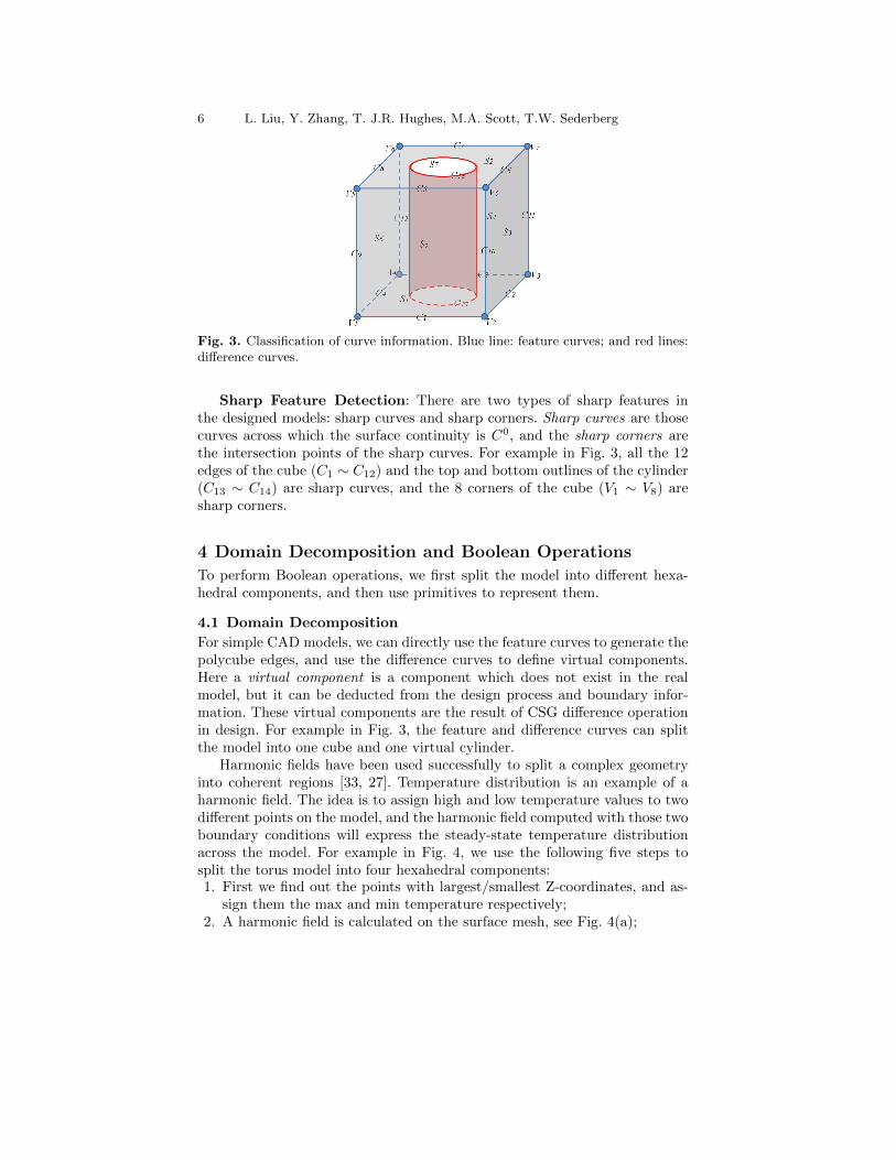
Harmonic fields have been used successfully to split a complex geometryinto coherent regions [33, 27]. Temperature distribution is an example of aharmonic field. The idea is to assign high and low temperature values to twodifferent points on the model, and the harmonic field computed with those twoboundary conditions will express the steady-state temperature distributionacross the model. For example in Fig. 4, we use the following five steps tosplit the torus model into four hexahedral components:1. First we find out the points with largest/smallest Z-coordinates, and as-
sign them the max and min temperature respectively;2. A harmonic field is calculated on the surface mesh, see Fig. 4(a);
Volumetric T-spline Construction Using Boolean Operations 7
3. We find out the critical points in the field, which are Min, Max, and twosaddle points (C1, C2). They form two cross sections;
4. We assign min temperature to one cross section, and max temperature tothe other one. The harmonic field is recalculated using the new boundaryconditions and the temperature distribution is shown in Fig. 4(b); and
5. Four equally-spaced points are selected on each cross section curve (blackcurves) in Fig. 4(b), which will be set as the cube corners. Then we tracethe gradient lines and finally split them into four parts to obtain all thered curves in Fig. 4(c).
Discussion: By using a harmonic field with proper boundary conditions,we can in many cases automatically split a complex geometry into multiplehexahedral components. Finding a proper boundary condition often requiresuser interactions. Sometimes we may need to compute the harmonic fieldseveral times before we can obtain an optimal domain decomposition result.
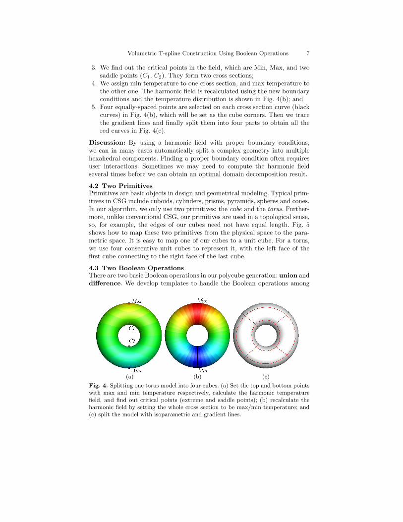
4.2 Two PrimitivesPrimitives are basic objects in design and geometrical modeling. Typical prim-itives in CSG include cuboids, cylinders, prisms, pyramids, spheres and cones.In our algorithm, we only use two primitives: the cube and the torus. Further-more, unlike conventional CSG, our primitives are used in a topological sense,so, for example, the edges of our cubes need not have equal length. Fig. 5shows how to map these two primitives from the physical space to the para-metric space. It is easy to map one of our cubes to a unit cube. For a torus,we use four consecutive unit cubes to represent it, with the left face of thefirst cube connecting to the right face of the last cube.
4.3 Two Boolean OperationsThere are two basic Boolean operations in our polycube generation: union anddifference. We develop templates to handle the Boolean operations among
(a) (b) (c)
Fig. 4. Splitting one torus model into four cubes. (a) Set the top and bottom pointswith max and min temperature respectively, calculate the harmonic temperaturefield, and find out critical points (extreme and saddle points); (b) recalculate theharmonic field by setting the whole cross section to be max/min temperature; and(c) split the model with isoparametric and gradient lines.
8 L. Liu, Y. Zhang, T. J.R. Hughes, M.A. Scott, T.W. Sederberg
(a) (b)
Fig. 5. Two primitives from the physical space to the parametric space. (a) Cube;and (b) torus.
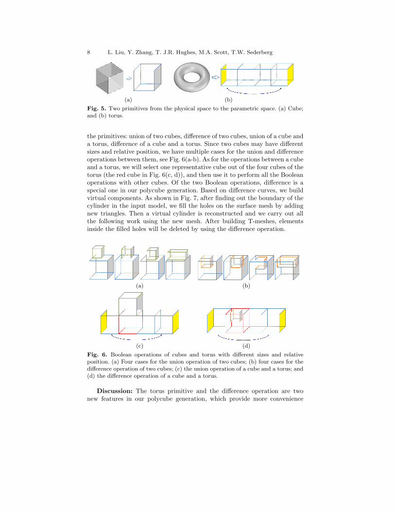
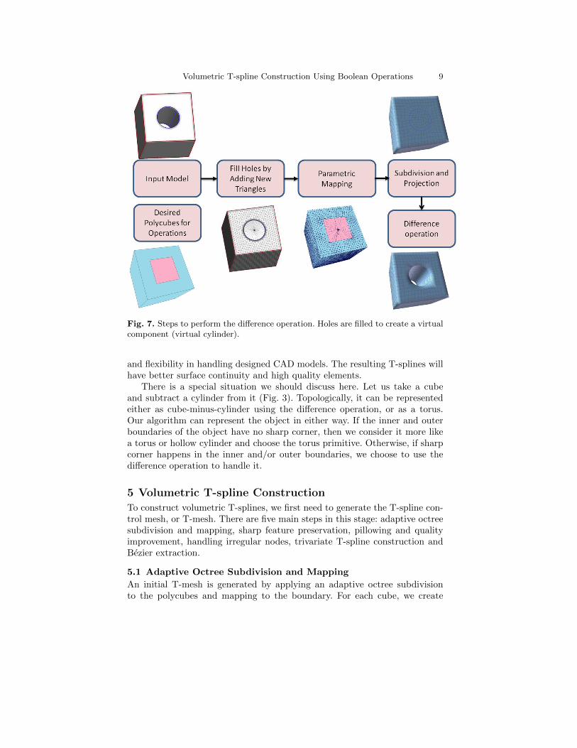
the primitives: union of two cubes, difference of two cubes, union of a cube anda torus, difference of a cube and a torus. Since two cubes may have differentsizes and relative position, we have multiple cases for the union and differenceoperations between them, see Fig. 6(a-b). As for the operations between a cubeand a torus, we will select one representative cube out of the four cubes of thetorus (the red cube in Fig. 6(c, d)), and then use it to perform all the Booleanoperations with other cubes. Of the two Boolean operations, difference is aspecial one in our polycube generation. Based on difference curves, we buildvirtual components. As shown in Fig. 7, after finding out the boundary of thecylinder in the input model, we fill the holes on the surface mesh by addingnew triangles. Then a virtual cylinder is reconstructed and we carry out allthe following work using the new mesh. After building T-meshes, elementsinside the filled holes will be deleted by using the difference operation.
(a) (b)
(c) (d)
Fig. 6. Boolean operations of cubes and torus with different sizes and relativeposition. (a) Four cases for the union operation of two cubes; (b) four cases for thedifference operation of two cubes; (c) the union operation of a cube and a torus; and(d) the difference operation of a cube and a torus.
Discussion: The torus primitive and the difference operation are twonew features in our polycube generation, which provide more convenience
Volumetric T-spline Construction Using Boolean Operations 9
Fig. 7. Steps to perform the difference operation. Holes are filled to create a virtualcomponent (virtual cylinder).
and flexibility in handling designed CAD models. The resulting T-splines willhave better surface continuity and high quality elements.
There is a special situation we should discuss here. Let us take a cubeand subtract a cylinder from it (Fig. 3). Topologically, it can be representedeither as cube-minus-cylinder using the difference operation, or as a torus.Our algorithm can represent the object in either way. If the inner and outerboundaries of the object have no sharp corner, then we consider it more likea torus or hollow cylinder and choose the torus primitive. Otherwise, if sharpcorner happens in the inner and/or outer boundaries, we choose to use thedifference operation to handle it.
5 Volumetric T-spline Construction
To construct volumetric T-splines, we first need to generate the T-spline con-trol mesh, or T-mesh. There are five main steps in this stage: adaptive octreesubdivision and mapping, sharp feature preservation, pillowing and qualityimprovement, handling irregular nodes, trivariate T-spline construction andBezier extraction.
5.1 Adaptive Octree Subdivision and Mapping
An initial T-mesh is generated by applying an adaptive octree subdivisionto the polycubes and mapping to the boundary. For each cube, we create
10 L. Liu, Y. Zhang, T. J.R. Hughes, M.A. Scott, T.W. Sederberg
one hexahedral root element, and then we subdivide one element into eightsmaller ones recursively to obtain the T-mesh after mapping. For each bound-ary element, we check the local distance from the T-mesh boundary to theinput boundary, and subdivide the element if the distance is greater thana given threshold ε. Each obtained T-mesh node has both parametric andphysical coordinates. The parametric coordinates represent its position in thepolycubes. For each boundary node, the physical coordinates are its corre-sponding position on the boundary. The physical coordinates of each interiornode are calculated by a linear interpolation. T-junctions are introduced iftwo neighboring elements have different subdivision levels.
(a) (b) (c)
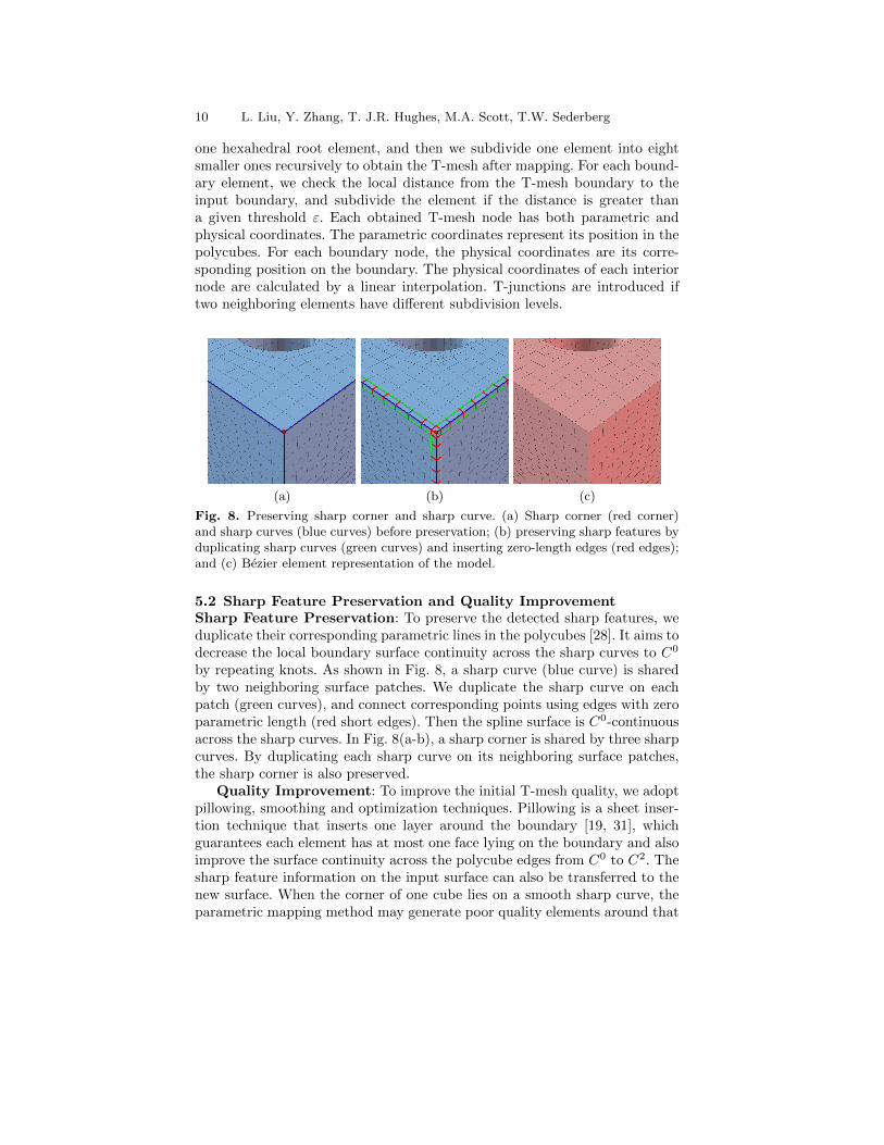
Fig. 8. Preserving sharp corner and sharp curve. (a) Sharp corner (red corner)and sharp curves (blue curves) before preservation; (b) preserving sharp features byduplicating sharp curves (green curves) and inserting zero-length edges (red edges);and (c) Bezier element representation of the model.
5.2 Sharp Feature Preservation and Quality ImprovementSharp Feature Preservation: To preserve the detected sharp features, weduplicate their corresponding parametric lines in the polycubes [28]. It aims todecrease the local boundary surface continuity across the sharp curves to C0
by repeating knots. As shown in Fig. 8, a sharp curve (blue curve) is sharedby two neighboring surface patches. We duplicate the sharp curve on eachpatch (green curves), and connect corresponding points using edges with zeroparametric length (red short edges). Then the spline surface is C0-continuousacross the sharp curves. In Fig. 8(a-b), a sharp corner is shared by three sharpcurves. By duplicating each sharp curve on its neighboring surface patches,the sharp corner is also preserved.
Quality Improvement: To improve the initial T-mesh quality, we adoptpillowing, smoothing and optimization techniques. Pillowing is a sheet inser-tion technique that inserts one layer around the boundary [19, 31], whichguarantees each element has at most one face lying on the boundary and alsoimprove the surface continuity across the polycube edges from C0 to C2. Thesharp feature information on the input surface can also be transferred to thenew surface. When the corner of one cube lies on a smooth sharp curve, theparametric mapping method may generate poor quality elements around that
Volumetric T-spline Construction Using Boolean Operations 11
(a) (b) (c) (d)
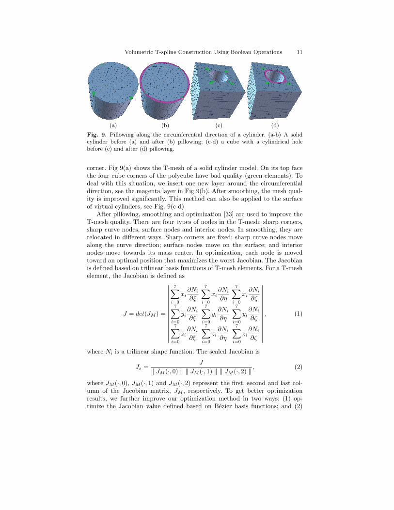
Fig. 9. Pillowing along the circumferential direction of a cylinder. (a-b) A solidcylinder before (a) and after (b) pillowing; (c-d) a cube with a cylindrical holebefore (c) and after (d) pillowing.
corner. Fig 9(a) shows the T-mesh of a solid cylinder model. On its top facethe four cube corners of the polycube have bad quality (green elements). Todeal with this situation, we insert one new layer around the circumferentialdirection, see the magenta layer in Fig 9(b). After smoothing, the mesh qual-ity is improved significantly. This method can also be applied to the surfaceof virtual cylinders, see Fig. 9(c-d).
After pillowing, smoothing and optimization [33] are used to improve theT-mesh quality. There are four types of nodes in the T-mesh: sharp corners,sharp curve nodes, surface nodes and interior nodes. In smoothing, they arerelocated in different ways. Sharp corners are fixed; sharp curve nodes movealong the curve direction; surface nodes move on the surface; and interiornodes move towards its mass center. In optimization, each node is movedtoward an optimal position that maximizes the worst Jacobian. The Jacobianis defined based on trilinear basis functions of T-mesh elements. For a T-meshelement, the Jacobian is defined as
J = det(JM ) =
∣∣∣∣∣∣∣∣∣∣∣∣∣∣∣
7∑i=0
xi∂Ni
∂ξ
7∑i=0
xi∂Ni
∂η
7∑i=0
xi∂Ni
∂ζ7∑
i=0
yi∂Ni
∂ξ
7∑i=0
yi∂Ni
∂η
7∑i=0
yi∂Ni
∂ζ7∑
i=0
zi∂Ni
∂ξ
7∑i=0
zi∂Ni
∂η
7∑i=0
zi∂Ni
∂ζ
∣∣∣∣∣∣∣∣∣∣∣∣∣∣∣, (1)
where Ni is a trilinear shape function. The scaled Jacobian is
Js =J
‖ JM (·, 0) ‖ ‖ JM (·, 1) ‖ ‖ JM (·, 2) ‖, (2)
where JM (·, 0), JM (·, 1) and JM (·, 2) represent the first, second and last col-umn of the Jacobian matrix, JM , respectively. To get better optimizationresults, we further improve our optimization method in two ways: (1) op-timize the Jacobian value defined based on Bezier basis functions; and (2)
12 L. Liu, Y. Zhang, T. J.R. Hughes, M.A. Scott, T.W. Sederberg
optimize the step size when moving the control nodes. Due to the enhancedrobustness of high order basis functions, distorted T-meshes may still be usedin isogeometric analysis [17], and the scaled Jacobian value is one quantita-tive standard to evaluate the quality of T-splines. The Jacobian is evaluatedat the Gaussian integration points and the corner points of one element. Instep size optimization, the objective function is f(δ) = min(1− J ′s(δ)), whereJ ′s is the new Jacobian value with respect to updated coordinates, and δ isthe step size. The Broyden-Fletcher-Goldfarb-Shanno (BFGS) method [12] isused here to perform the optimization and get an optimal step size.
5.3 Irregular Nodes and Volumetric T-spline ConstructionExtraordinary nodes or partial extraordinary nodes [33] are two types of ir-regular nodes in T-spline construction, which may introduce gaps to solidT-spline. These irregular nodes will reduce the continuity in its neighbor-hood and increase the degrees of freedom during analysis. Different templateshave been developed to handle the irregular nodes. The basic idea is to insertzero parametric length edges around the irregular nodes to make sure theextracted knot interval is correct. In referring knot vectors, knot values arerepeated whenever an irregular node is met. The detailed templates and knotinsertion algorithm are explained in [28, 29].
The rational solid T-spline is defined in [29]. Its basis function has theproperty of partition of unity by definition, which makes it suitable for anal-ysis. With the valid T-mesh, referred local knot vectors and the definition ofrational basis function, we can construct desired volumetric T-splines. Sincethe volumetric T-spline is defined on local knot vectors, we extract Bezier rep-resentation of solid T-spline for isogeometric analysis. Transformation matrixfrom T-spline basis functions to Bezier basis functions is calculated by theOslo knot insertion algorithm [10]. With the extracted Bezier elements, wecan perform isogeometric analysis on the volumetric T-spline models.
6 Results and Isogeometric AnalysisWe have applied the construction algorithm to several models on a 2.93GHzIntel Xeon CPU with 16GB RAM. Table 1 provides the statistics of four mod-els: torus (Fig. 10), eight (Figs. 11-12), rod (Fig. 13), and CAD assembly (Fig.1). We use the scaled Jacobian with Bezier basis function to evaluate the qual-ity of the trivariate T-splines. The number of irregular nodes on the surfaceand in the interior are also counted. We can see that our algorithm is fast andit produces high quality volumetric T-splines for isogeometric analysis.
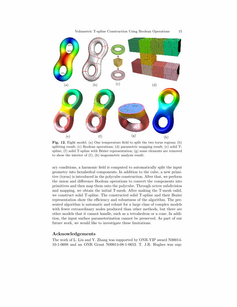
Fig. 10 shows the result of our torus primitive. It has no irregular nodes onthe surface, and the generated elements have high quality with the minimumJacobian of 0.42. For the eight model in Figs. 11-12, we compute the harmonicfield twice to obtain the desired domain decomposition result. Similar to Fig.4, we first set the bottom and top points with the min and max temperaturerespectively, compute the harmonic field and critical points to define threecross sections. As shown in Fig. 12(a), we then set two cross sections with the
Volumetric T-spline Construction Using Boolean Operations 13
(a) (b) (c)
(d) (e) (f)
(g) (h)
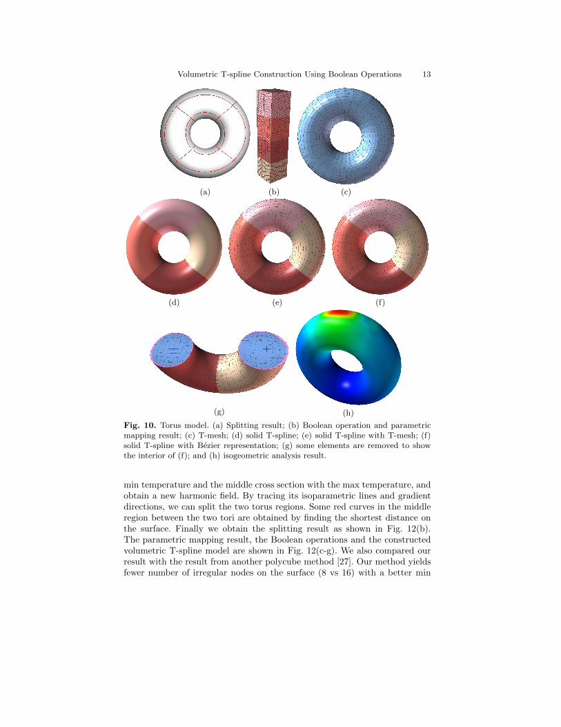
Fig. 10. Torus model. (a) Splitting result; (b) Boolean operation and parametricmapping result; (c) T-mesh; (d) solid T-spline; (e) solid T-spline with T-mesh; (f)solid T-spline with Bezier representation; (g) some elements are removed to showthe interior of (f); and (h) isogeometric analysis result.
min temperature and the middle cross section with the max temperature, andobtain a new harmonic field. By tracing its isoparametric lines and gradientdirections, we can split the two torus regions. Some red curves in the middleregion between the two tori are obtained by finding the shortest distance onthe surface. Finally we obtain the splitting result as shown in Fig. 12(b).The parametric mapping result, the Boolean operations and the constructedvolumetric T-spline model are shown in Fig. 12(c-g). We also compared ourresult with the result from another polycube method [27]. Our method yieldsfewer number of irregular nodes on the surface (8 vs 16) with a better min
14 L. Liu, Y. Zhang, T. J.R. Hughes, M.A. Scott, T.W. Sederberg
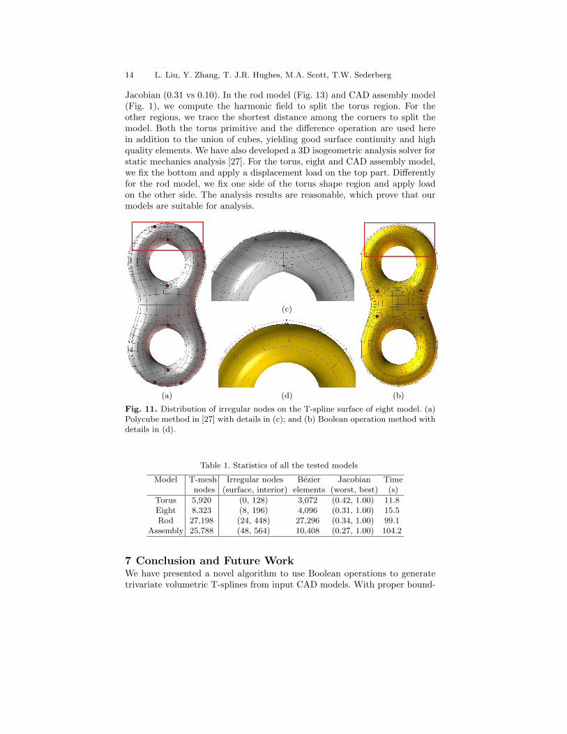
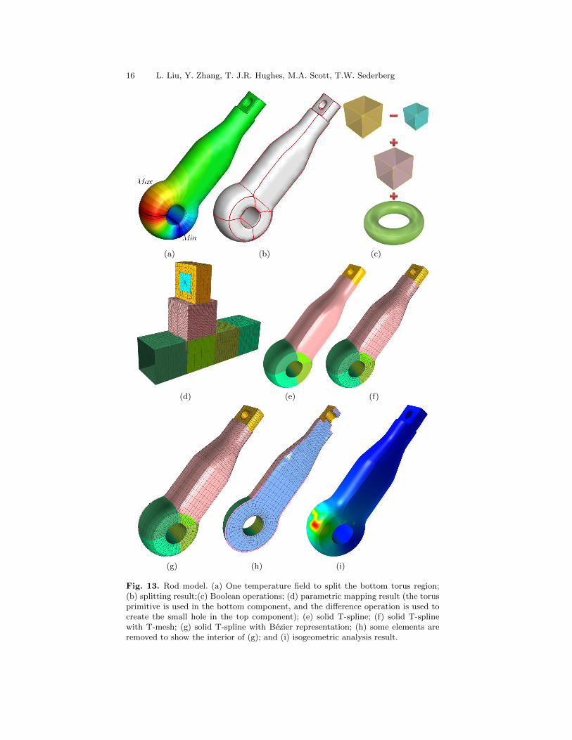
Jacobian (0.31 vs 0.10). In the rod model (Fig. 13) and CAD assembly model(Fig. 1), we compute the harmonic field to split the torus region. For theother regions, we trace the shortest distance among the corners to split themodel. Both the torus primitive and the difference operation are used herein addition to the union of cubes, yielding good surface continuity and highquality elements. We have also developed a 3D isogeometric analysis solver forstatic mechanics analysis [27]. For the torus, eight and CAD assembly model,we fix the bottom and apply a displacement load on the top part. Differentlyfor the rod model, we fix one side of the torus shape region and apply loadon the other side. The analysis results are reasonable, which prove that ourmodels are suitable for analysis.
(c)
(a) (d) (b)
Fig. 11. Distribution of irregular nodes on the T-spline surface of eight model. (a)Polycube method in [27] with details in (c); and (b) Boolean operation method withdetails in (d).
Table 1. Statistics of all the tested models
Model T-mesh Irregular nodes Bezier Jacobian Timenodes (surface, interior) elements (worst, best) (s)
Torus 5,920 (0, 128) 3,072 (0.42, 1.00) 11.8Eight 8,323 (8, 196) 4,096 (0.31, 1.00) 15.5Rod 27,198 (24, 448) 27,296 (0.34, 1.00) 99.1
Assembly 25,788 (48, 564) 10,408 (0.27, 1.00) 104.2
7 Conclusion and Future WorkWe have presented a novel algorithm to use Boolean operations to generatetrivariate volumetric T-splines from input CAD models. With proper bound-
Volumetric T-spline Construction Using Boolean Operations 15
(a) (b) (c) (d)
(e) (f) (g) (h)
Fig. 12. Eight model. (a) One temperature field to split the two torus regions; (b)splitting result; (c) Boolean operations; (d) parametric mapping result; (e) solid T-spline; (f) solid T-spline with Bezier representation; (g) some elements are removedto show the interior of (f); (h) isogeometric analysis result;
ary conditions, a harmonic field is computed to automatically split the inputgeometry into hexahedral components. In addition to the cube, a new primi-tive (torus) is introduced in the polycube construction. After that, we performthe union and difference Boolean operations to convert the components intoprimitives and then map them onto the polycube. Through octree subdivisionand mapping, we obtain the initial T-mesh. After making the T-mesh valid,we construct solid T-spline. The constructed solid T-spline and their Bezierrepresentation show the efficiency and robustness of the algorithm. The pre-sented algorithm is automatic and robust for a large class of complex modelswith fewer extraordinary nodes produced than other methods, but there areother models that it cannot handle, such as a tetrahedron or a cone. In addi-tion, the input surface parameterization cannot be preserved. As part of ourfuture work, we would like to investigate these limitations.
AcknowledgementsThe work of L. Liu and Y. Zhang was supported by ONR-YIP award N00014-10-1-0698 and an ONR Grant N00014-08-1-0653. T. J.R. Hughes was sup-
16 L. Liu, Y. Zhang, T. J.R. Hughes, M.A. Scott, T.W. Sederberg
(a) (b) (c)
(d) (e) (f)
(g) (h) (i)
Fig. 13. Rod model. (a) One temperature field to split the bottom torus region;(b) splitting result;(c) Boolean operations; (d) parametric mapping result (the torusprimitive is used in the bottom component, and the difference operation is used tocreate the small hole in the top component); (e) solid T-spline; (f) solid T-splinewith T-mesh; (g) solid T-spline with Bezier representation; (h) some elements areremoved to show the interior of (g); and (i) isogeometric analysis result.
Volumetric T-spline Construction Using Boolean Operations 17
ported by ONR Grant N00014-08-1-0992, NSF GOALI CMI-0700807/0700204,NSF CMMI-1101007 and a SINTEF grant UTA10-000374.
References
1. http://en.wikipedia.org/wiki/constructive solid geometry.2. http://en.wikipedia.org/wiki/polycube.3. B. Adams and P. Dutre. Interactive boolean operations on surfel-bounded solids.
ACM Trans. Graph., 22(3):651–656, July 2003.4. M. Aigner, C. Heinrich, B. Juttler, E. Pilgerstorfer, B. Simeon, and A.-V. Vuong.
Swept volume parameterization for isogeometric analysis. In IMA InternationalConference on Mathematics of Surfaces XIII, pages 19–44, 2009.
5. Y. Bazilevs, I. Akkerman, D.J. Benson, G. Scovazzi, and M.J. Shashkov. Isogeo-metric analysis of lagrangian hydrodynamics. Journal of Computational Physics,243:224–243, 2013.
6. Y. Bazilevs, V. M. Calo, J. A. Cottrell, J. A. Evans, T. J.R. Hughes, S. Lip-ton, M. A. Scott, and T. W. Sederberg. Isogeometric analysis using T-splines.Computer Methods in Applied Mechanics and Engineering, 199(5-8):229–263,2010.
7. J.A. Cottrell, T. J.R. Hughes, and Y. Bazilevs. Isogeometric analysis: towardintegration of CAD and FEA. Wiley, 2009.
8. J.A. Cottrell, A. Reali, Y. Bazilevs, and T.J.R. Hughes. Isogeometric analysis ofstructural vibrations. Computer Methods in Applied Mechanics and Engineering,195(41-43):5257–5296, 2006.
9. J. M. Escobar, J. M. Cascon, E. Rodrıguez, and R. Montenegro. A new approachto solid modeling with trivariate T-splines based on mesh optimization. Com-puter Methods in Applied Mechanics and Engineering, 200(45-46):3210–3222,2011.
10. R. Goldman and T. Lyche. Knot insertion and deletion algorithms for B-spline curves and surfaces. Society for Industrial and Applied Mathematics–Philadelphia, 1993.
11. X. Gu, Y. Wang, and S. Yau. Volumetric harmonic map. Communications inInformation and Systems, 3(3):191–202, 2003.
12. C.A.R. Guerra. Simultaneous untangling and smoothing of hexahedral meshes.Master’s thesis, University PolyTecnica De Catalunya, Barcelona Spain, 2010.
13. T. J.R. Hughes, J. A. Cottrell, and Y. Bazilevs. Isogeometric analysis: CAD,finite elements, NURBS, exact geometry, and mesh refinement. Computer Meth-ods in Applied Mechanics and Engineering, 194:4135–4195, 2005.
14. B. Li, X. Li, K. Wang, and H. Qin. Generalized polycube trivariate splines. InShape Modeling International Conference, pages 261–265, 2010.
15. B. Li, X. Li, K. Wang, and H. Qin. Surface mesh to volumetric spline con-version with Generalized Poly-cubes. IEEE Transactions on Visualization andComputer Graphics, 99:1–14, 2012.
16. W. Li, N. Ray, and B. Levy. Automatic and interactive mesh to T-spline con-version. In Eurographics Symposium on Geometry Processing, pages 191–200,2006.
17. S. Lipton, J.A. Evans, Y. Bazilevs, T. Elguedj, and T.J.R. Hughes. Robustnessof isogeometric structural discretizations under severe mesh distortion. Com-puter Methods in Applied Mechanics and Engineering, 199(58):357 – 373, 2010.
18 L. Liu, Y. Zhang, T. J.R. Hughes, M.A. Scott, T.W. Sederberg
18. L. A. Piegl and W. Tiller. The NURBS Book (Monographs in Visual Commu-nication), 2nd ed. Springer-Verlag, New York, 1997.
19. J. Qian, Y. Zhang, W. Wang, A.C. Lewis, MA Qidwai, and A.B. Geltmacher.Quality improvement of non-manifold hexahedral meshes for critical featuredetermination of microstructure materials. International Journal for NumericalMethods in Engineering, 82(11):1406–1423, 2010.
20. D. Schillinger, L. Dede, M. A. Scott, J. A. Evans, M. J. Borden, E. Rank, andT. J.R. Hughes. An isogeometric design-through-analysis methodology basedon adaptive hierarchical refinement of NURBS, immersed boundary methods,and T-spline CAD surfaces. Computer Methods in Applied Mechanics and En-gineering, 249-252:116–150, 2012.
21. M. A. Scott, M. J. Borden, C. V. Verhoosel, T. W. Sederberg, and T. J.R.Hughes. Isogeometric finite element data structures based on Bezier extrac-tion of T-splines. International Journal for Numerical Methods in Engineering,88(2):126–156, 2011.
22. T. W. Sederberg, D. L. Cardon, G. T. Finnigan, N. S. North, J. Zheng, andT. Lyche. T-spline simplification and local refinement. In ACM SIGGRAPH,pages 276–283, 2004.
23. T. W. Sederberg, J. Zheng, A. Bakenov, and A. Nasri. T-splines and T-NURCCs. ACM Transactions on Graphics, 22(3):477–484, 2003.
24. J.M. Smith and N.A. Dodgson. A topologically robust algorithm for booleanoperations on polyhedral shapes using approximate arithmetic. Computer-AidedDesign, 39(2):149–163, 2007.
25. H. Wang, Y. He, X. Li, X. Gu, and H. Qin. Polycube splines. In Symposium onSolid and Physical Modeling, pages 241–251, 2007.
26. K. Wang, X. Li, B. Li, H. Xu, and H. Qin. Restricted trivariate polycubesplines for volumetric data modeling. IEEE Transactions on Visualization andComputer Graphics, 18:703–716, 2012.
27. W. Wang, Y. Zhang, L. Liu, and T. J.R. Hughes. Solid T-spline constructionfrom boundary triangulations with arbitrary genus topolog. Computer AidedDesign, 45:351–360, 2013.
28. W. Wang, Y. Zhang, M. A. Scott, and T. J.R. Hughes. Converting an un-structured quadrilateral mesh to a standard T-spline surface. ComputationalMechanics, 48:477–498, 2011.
29. W. Wang, Y. Zhang, G. Xu, and T. J.R. Hughes. Converting an unstructuredquadrilateral/hexahedral mesh to a rational T-spline. Computational Mechan-ics, 50(1):65–84, 2012.
30. G. Xu, B. Mourrain, R. Duvigneau, and A. Galligo. Analysis-suitable volumeparameterization of multi-block computational domain in isogeometric applica-tions. Computer-Aided Design, 45(2):395–404, 2013.
31. Y. Zhang, C. L. Bajaj, and G. Xu. Surface smoothing and quality improvementof quadrilateral/hexahedral meshes with geometric flow. Communications inNumerical Methods in Engineering, 25:1–18, 2009.
32. Y. Zhang, Y. Bazilevs, S. Goswami, C. L. Bajaj, and T. J.R. Hughes. Patient-specific vascular NURBS modeling for isogeometric analysis of blood flow. Com-puter Methods in Applied Mechanics and Engineering, 196(29-30):2943–2959,2007.
33. Y. Zhang, W. Wang, and T. J.R. Hughes. Solid T-spline construction fromboundary representations for genus-zero geometry. Computer Methods in Ap-plied Mechanics and Engineering, (249-252):185–197, 2012.


![Volumetric Parameterization and Trivariate B-spline ... Parameterization and Trivariate B-spline Fitting using Harmonic ... [Mathematics of Computing]: ... and [Li et al. 2007] ...Published](https://img.pdfslide.us/doc/110x75/5aaad68f7f8b9a77188ebadf/volumetric-parameterization-and-trivariate-b-spline-parameterization-and-trivariate.jpg)


![Block Sparse Compressed Sensing of Electroencephalogram ... · derivative of Gaussian function), a linear spline, a cubic spline, and a linear B spline and cubic B-spline. In [7],](https://img.pdfslide.us/doc/110x75/5f870bc34c82e452c7534b24/block-sparse-compressed-sensing-of-electroencephalogram-derivative-of-gaussian.jpg)