Embed Size (px)
DESCRIPTION
ICEL Design Guide
Citation preview
ICEL1006 :EMERGENCY LIGHTING
DESIGN GUIDE
ICELGuide
For ICEL Members
M A Y99
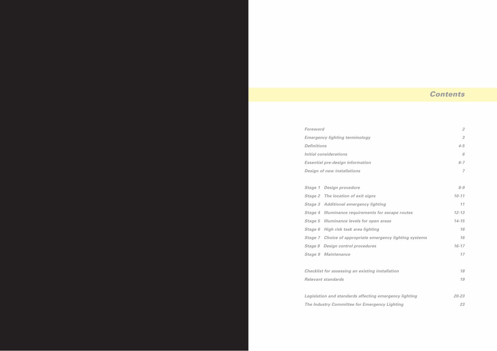
Foreword
Emergency lighting terminology
Definitions
Initial considerations
Essential pre-design information
Design of new installations
Stage 1 Design procedure
Stage 2 The location of exit signs
Stage 3 Additional emergency lighting
Stage 4 Illuminance requirements for escape routes
Stage 5 Illuminance levels for open areas
Stage 6 High risk task area lighting
Stage 7 Choice of appropriate emergency lighting systems
Stage 8 Design control procedures
Stage 9 Maintenance
Checklist for assessing an existing installation
Relevant standards
Legislation and standards affecting emergency lighting
The Industry Committee for Emergency Lighting
2
3
4-5
6
6-7
7
8-9
10-11
11
12-13
14-15
16
16
16-17
17
18
19
20-23
23
Contents

Emergency Lighting Terminology
For the purposes of the European standard EN 1838, emergency lighting is regarded as a
generic term of which there are a number of specific forms, as shown in the figure below:
Specific Forms of Emergency Lighting
Emergency escape lightingThat part of emergency lighting provided to enable safe exit in the event of failure of the
normal supply.
Standby lightingThat part of emergency lighting provided to enable normal activities to continue in the event
of failure of the normal mains supply.
Escape route lightingThat part of emergency lighting provided to enable safe exit for building occupants by
providing appropriate visual conditions and direction finding on escape routes and in special
areas/locations, and to ensure that fire fighting and safety equipment can be readily located
and used.
Open area (or anti-panic area) lightingThat part of emergency escape lighting provided to reduce the likelihood of panic and to
enable safe movement of occupants towards escape routes by providing appropriate visual
conditions and direction finding.
High risk task area lighting That part of emergency lighting provided to ensure the safety of people involved in a
potentially dangerous process or situation and to enable proper shut down procedures to be
carried out for the safety of other occupants of the premises.
Emergency Lighting
Emergency escape lighting Standby lighting
Escape route
lighting
Open area
(anti-panic area)
lighting
High risk
task area lighting
3
Foreword
Press Flash - EN 1838
The European Standard for Emergency Lighting Applications was voted positive!
This Guide has been prepared by the Industry Committee for Emergency Lighting (ICEL) to
promote a wider understanding of the different types of emergency lighting and to give
guidance on their correct application.
The Guide considers the requirements of the new European draft standards as well as the
current legislation and codes of practice. Although some new standards are still in draft form,
the content of these documents is reasonably well established. When the harmonised
European standards are available, they will replace many of the current requirements of
BS 5266: Pt 1: 1988 Information is provided on the difference between the current
requirements and those of the new European standards. The new harmonised European
standards may be retrospectively introduced after a transitional period. ICEL recommends
therefore that emergency lighting is designed and installed to the new standards to avoid
costly modifications at a later stage.
A reasonable working knowledge of emergency lighting is assumed on the part of the reader.
Further information can be obtained from ICEL at the address below:
The Industry Committee for Emergency Lighting
Swan House
207 Balham High Road
London SW17 7BQ
Most ICEL member companies can also provide detailed information and guidance about
both current and future emergency lighting requirements and many offer a free scheme
design service. The addresses of ICEL member companies can be found at the back of this
document.
Throughout this document, the most up-to-date information available has been used by ICEL.
Some documents referred to, and some requirements, are still undergoing review, so please
contact ICEL for advice on any changes that may affect the guidance contained in this
document.
Compliance with this Guide does not of itself confer immunity from legal obligations.
May 1999
2
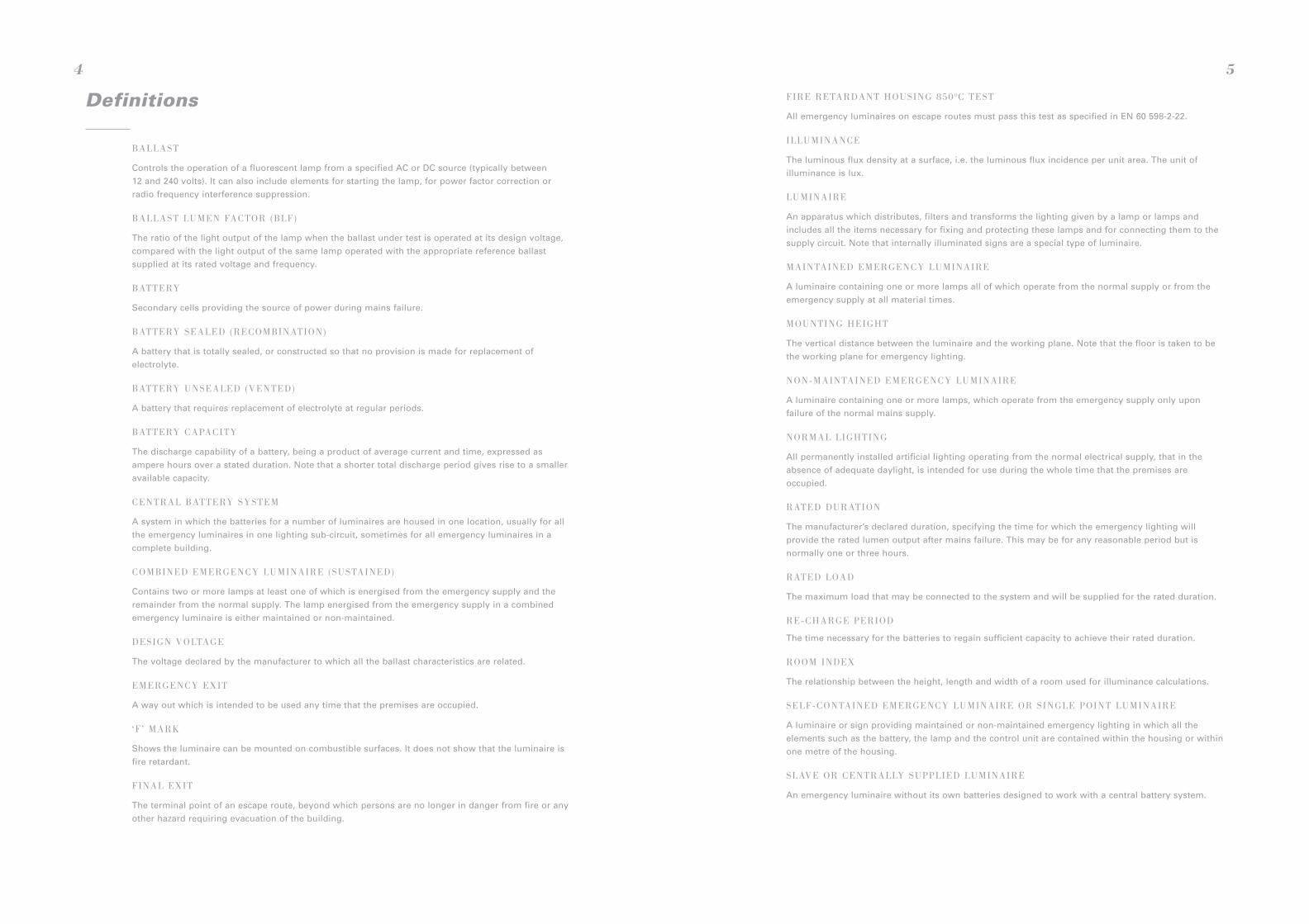
Definitions
BALLAST
Controls the operation of a fluorescent lamp from a specified AC or DC source (typically between
12 and 240 volts). It can also include elements for starting the lamp, for power factor correction or
radio frequency interference suppression.
BALLAST LUMEN FACTOR (BLF)
The ratio of the light output of the lamp when the ballast under test is operated at its design voltage,
compared with the light output of the same lamp operated with the appropriate reference ballast
supplied at its rated voltage and frequency.
BATTERY
Secondary cells providing the source of power during mains failure.
BATTERY SEALED (RECOMBINATION)
A battery that is totally sealed, or constructed so that no provision is made for replacement of
electrolyte.
BATTERY UNSEALED (VENTED)
A battery that requires replacement of electrolyte at regular periods.
BATTERY CAPACITY
The discharge capability of a battery, being a product of average current and time, expressed as
ampere hours over a stated duration. Note that a shorter total discharge period gives rise to a smaller
available capacity.
CENTRAL BATTERY SYSTEM
A system in which the batteries for a number of luminaires are housed in one location, usually for all
the emergency luminaires in one lighting sub-circuit, sometimes for all emergency luminaires in a
complete building.
COMBINED EMERGENCY LUMINAIRE (SUSTAINED)
Contains two or more lamps at least one of which is energised from the emergency supply and the
remainder from the normal supply. The lamp energised from the emergency supply in a combined
emergency luminaire is either maintained or non-maintained.
DESIGN VOLTAGE
The voltage declared by the manufacturer to which all the ballast characteristics are related.
EMERGENCY EXIT
A way out which is intended to be used any time that the premises are occupied.
‘F ’ MARK
Shows the luminaire can be mounted on combustible surfaces. It does not show that the luminaire is
fire retardant.
FINAL EXIT
The terminal point of an escape route, beyond which persons are no longer in danger from fire or any
other hazard requiring evacuation of the building.
4
FIRE RETARDANT HOUSING 850 OC TEST
All emergency luminaires on escape routes must pass this test as specified in EN 60 598-2-22.
ILLUMINANCE
The luminous flux density at a surface, i.e. the luminous flux incidence per unit area. The unit of
illuminance is lux.
LUMINAIRE
An apparatus which distributes, filters and transforms the lighting given by a lamp or lamps and
includes all the items necessary for fixing and protecting these lamps and for connecting them to the
supply circuit. Note that internally illuminated signs are a special type of luminaire.
MAINTAINED EMERGENCY LUMINAIRE
A luminaire containing one or more lamps all of which operate from the normal supply or from the
emergency supply at all material times.
MOUNTING HEIGHT
The vertical distance between the luminaire and the working plane. Note that the floor is taken to be
the working plane for emergency lighting.
NON-MAINTAINED EMERGENCY LUMINAIRE
A luminaire containing one or more lamps, which operate from the emergency supply only upon
failure of the normal mains supply.
NORMAL LIGHTING
All permanently installed artificial lighting operating from the normal electrical supply, that in the
absence of adequate daylight, is intended for use during the whole time that the premises are
occupied.
RATED DURATION
The manufacturer’s declared duration, specifying the time for which the emergency lighting will
provide the rated lumen output after mains failure. This may be for any reasonable period but is
normally one or three hours.
RATED LOAD
The maximum load that may be connected to the system and will be supplied for the rated duration.
RE-CHARGE PERIOD
The time necessary for the batteries to regain sufficient capacity to achieve their rated duration.
ROOM INDEX
The relationship between the height, length and width of a room used for illuminance calculations.
SELF-CONTAINED EMERGENCY LUMINAIRE OR SINGLE POINT LUMINAIRE
A luminaire or sign providing maintained or non-maintained emergency lighting in which all the
elements such as the battery, the lamp and the control unit are contained within the housing or within
one metre of the housing.
SLAVE OR CENTRALLY SUPPLIED LUMINAIRE
An emergency luminaire without its own batteries designed to work with a central battery system.
5
Initial Considerations
Emergency lighting is an essential part of the building services installation.
To ensure the system is well designed and as reliable as possible, ICEL stresses the
importance of planning through all phases of the project, from considering legal
requirements to final commissioning and maintenance. Consultation between all interested
parties at an early stage of the design cannot be overemphasised to avoid expensive
modifications to the completed system. Considerable legislation and associated standards
exist covering the various types of premises that involve the need to incorporate emergency
lighting. These are referred to later in the Guide.
The first stage of system design is to gather the information needed on the project, normally
by consultation with the Regulatory Authority and the user. This should cover legislative and
likely operational requirements, and customer preferences.
Essential Pre-Design Information
Before designing an emergency lighting scheme the following information needs to be
determined from the site drawings or from the specifier:
(I) The duration of the emergency lighting:
a) Three hour duration is required in places of entertainment and for sleeping risk;
b) Three hour duration is required if evacuation is not immediate, or early re-occupation
is likely to occur;
c) One hour duration may be acceptable, in some premises, if evacuation is immediate
and re-occupation is delayed until the system has recharged.
(II) Emergency lighting should be of the maintained type in areas in which the normal
lighting can be dimmed. In addition, the draft standard prEN 50172 stipulates that
emergency lighting is of the maintained type in common areas within shopping malls
where a build-up of smoke could reduce the effectiveness of normal lighting.
(III) The draft standard prEN 50172 requires that exit signs are of the maintained type
where the premises are used by people who are unfamiliar with its layout.
(IV) Building plans need to be assembled showing the location of the fire alarm call point
positions, the positions of fire fighting equipment, and fire and safety signs.
(V) Emergency escape routes should be established, and potential hazards investigated.
6
Design of New Installations
System design to meet BS 5266: Pt 1: 1988 and requirements of European and draft
European standards.
Design ObjectiveWhen the supply to any part of the normal lighting fails, the requirements of BS 5266 and
EN 1838 apply and escape lighting is required to fulfil the following functions:
(I) Show clearly and unambiguously the escape routes.
(II) Provide illumination along such routes to allow safe movement towards and through
the exits provided.
(III) Ensure that fire alarm call points and fire fighting equipment provided along escape
routes can be readily located.
(IV) Allow operations concerned with safety measures to continue.
(VI) Open areas larger than 60m2 floor area should be identified.
(VII) High risk task areas should be identified and normal lighting levels established.
(VIII) The need for external illumination outside final exit doors and on a route to a place of
safety should be determined.
(IX) Other areas that need illumination, although not part of the escape route, should be
located, e.g. lifts, moving stairways and walkways, plant rooms and toilet
accommodation over 8m2 gross area.
(X) If a central system is being used, the locations of central battery units and cable runs
should be established in areas of low fire risk.
(XI) For non-maintained applications the area covered by the final circuit of the normal
lighting has to be determined as it must be monitored by the central system.
Non-maintained self-contained luminaires must be fed from that final circuit.
(XII) Standby lighting requirements should be established if activities need to continue
during a failure of the normal lighting supply.
(XIII) The customer’s preference and operating considerations should be ascertained,
e.g. ceiling heights, mounting heights or wall mounting.
7
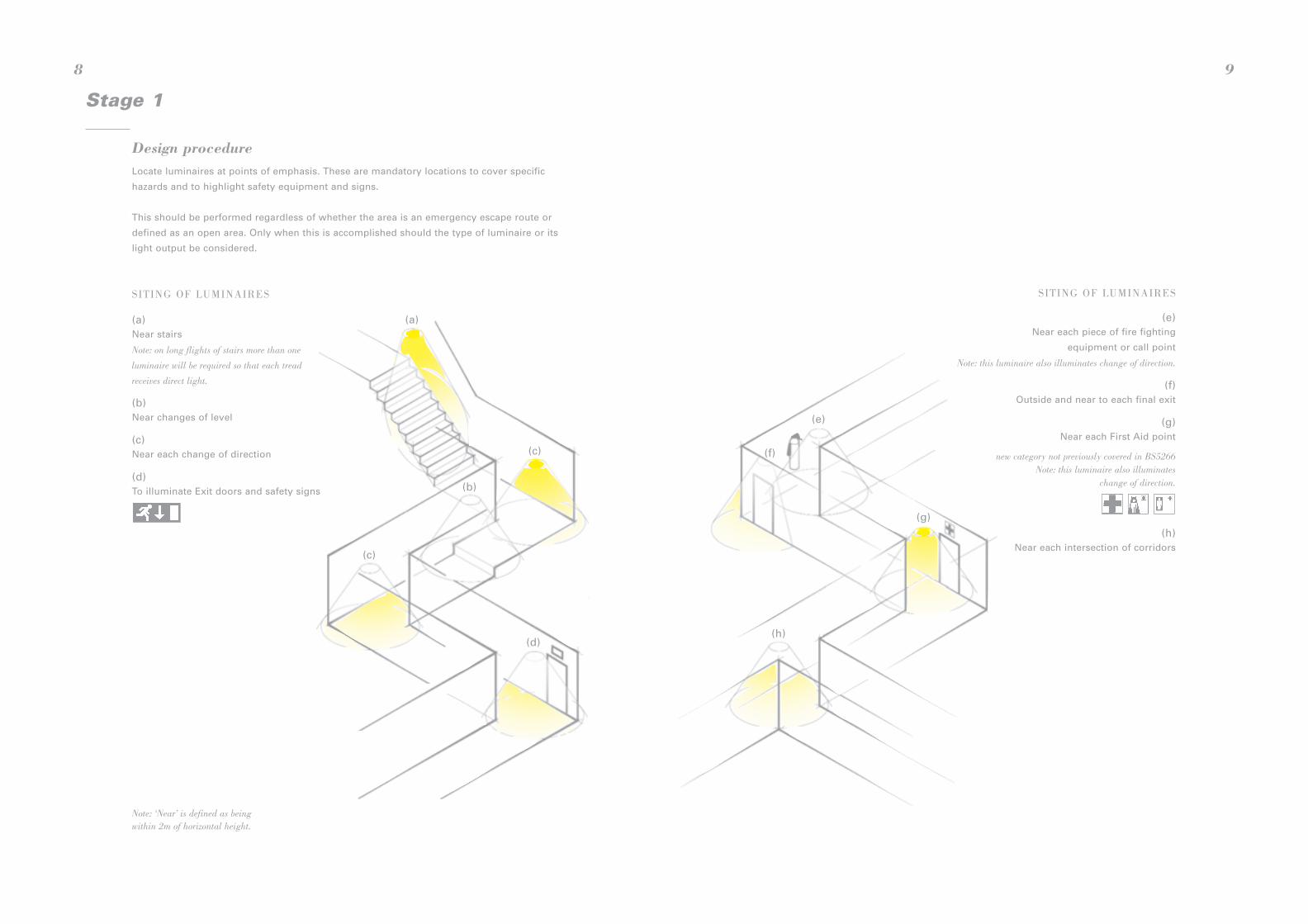
(e)
(e)Near each piece of fire fighting
equipment or call point
Note: this luminaire also illuminates change of direction.
(f)Outside and near to each final exit
(g)Near each First Aid point
new category not previously covered in BS5266Note: this luminaire also illuminates
change of direction.
(h)Near each intersection of corridors
(f)
(g)
(h)
SITING OF LUMINAIRES
9
Stage 1
Design procedureLocate luminaires at points of emphasis. These are mandatory locations to cover specific
hazards and to highlight safety equipment and signs.
This should be performed regardless of whether the area is an emergency escape route or
defined as an open area. Only when this is accomplished should the type of luminaire or its
light output be considered.
(a)
(b)
(c)
(c)
(d)
SITING OF LUMINAIRES
8
Note: ‘Near’ is defined as beingwithin 2m of horizontal height.
(a)Near stairs
Note: on long flights of stairs more than one
luminaire will be required so that each tread
receives direct light.
(b)Near changes of level
(c)Near each change of direction
(d)To illuminate Exit doors and safety signs

Maximum viewing distances
Viewing distances are given in the draft standard EN 1838 as 200 x H for internally
illuminated signs, and 100 x H for externally illuminated signs where H is the height
of the pictogram.
Sign Height (H)
11
Stage 3
Additional emergency lightingAdditional emergency lighting should be provided at these locations:
(I) Lift cars. Although they may be part of the escape route in exceptional
circumstances, they may present a problem if the public are trapped in
them in the event of a supply failure.
(II) Toilet facilities and other open tiled areas exceeding 8m2 floor area and
all toilets for the disabled.
(III) Escalators, to enable users to get off them safely.
(IV) Motor generator, control or plant rooms require battery supplied emergency
lighting to help any maintenance or operating personnel.
(V) Covered car parks along the normal pedestrian routes.
The format of signs
The following advice is based on the Health and Safety Executive guidance on the
Regulations (L64):
BS 2560 SIGNS
These signs should have been replaced by 24 December 1998. ICEL recommends that care
should be taken as the new pictogram formats with larger areas of green colour will
significantly reduce luminaire light output and installations may require additional emergency
illumination to compensate for the change.
BS 5499: PT 1: 1990
These signs - already installed - are of a similar pattern to the Signs Directive and are
considered to comply with the regulations and do not need to be replaced.
SIGNS DIRECTIVE
Implemented as a legal requirement in the UK by Statutory Instrument 1996 No. 341 on
1 April 1996.
FUTURE DEVELOPMENTS
BS 5499 Pt 1 is being revised to take account of the Signs Directive and to resolve the
difficulties in use of the variants - “Exit”, “Fire Exit”, and “Exit for Emergency Use Only” -
and to standardise the use of arrows.
Stage 2
The location of exit signsSection 5.6 of BS 5266 and EN 1838 state that:
“Signs are required at all exits, emergency exits and escape routes, such that the position of any
exit or route to it is easily recognised and followed in an emergency . Where direct sight of an
exit or emergency exit is not possible and doubt may exist as to its position, a directional sign (or
series of signs) should be provided, placed such that a person moving towards it will be progressed
towards
an exit or emergency exit.”
1975To be replaced by
24 December 1998
1990Deemed to comply with
Signs Directive for existing
installations
1996HSE Signs
Directive Format
10
100xH
200xH

ESCAPE ROUTES – COMPLIANCE
Verified values are given in ICEL registered spacing tables.
ESCAPE ROUTES – REQUIREMENTS
transverse spacing to wall
1 lux m
inimum on
centre lin
e of escape ro
ute
transverse spacing between luminaires
1 lux to wall
13
Spacing tablesSpacing tables provide the information to help you decide whether or not additional fittings
are needed besides those required for the points of emphasis. ICEL registered luminaires
have been independently tested to photometric performance and the tables generated have
been third party inspected.
Stage 4
Illuminance requirements for escape routesIn addition to luminaires at the points of emphasis, it may be necessary to provide extra
luminaires to ensure that minimum light (illuminance) levels are met along the whole escape
route. For 2m wide escape routes, the illuminance is specified along the centre line with 50%
of that illuminance over the 1 metre wide central band. Wider routes should be treated as
open areas or as multiple routes.
The European standard EN 1838 requires 1 lux along the centre line of escape routes
including those with minor obstructions such as hotel trolleys. The UK has a National
Exception which recommends 1 lux but accepts 0.2 lux along the centre line for
permanently unobstructed escape routes, with the points of emphasis illuminated to 1 lux.
BS 5266: Pt 1: 1988 will be amended to reflect this requirement.
BS 5266 and prEN 50172 recommend using a larger number of low power luminaires rather
than a few high power units. In this way, no part of the escape route is lit by just one
luminaire. Thus, if a luminaire fails, the route will not be plunged into darkness.
Escape routes
1 lux minimum
along centre line
Open (anti-panic) areas
0.5 lux minimum
Luminaires arranged in
a regular array
Ceiling
mounting
height (m)
Transverse
to wall
Transverse
spacing
Axial
to wall
Axial
spacing
Transverse
to wall
Transverse
spacing
Axial
to wall
Axial
spacing
2.5 1.8 5.6 1.5 4.7 2.1 5.6 1.7 4.6
3 1.5 5.5 1.2 4.6 2.0 5.8 1.7 4.8
4 - - - - 1.7 5.8 1.5 4.9
5 - - - - 0.8 5.4 0.6 4.6
12
SPACING TABLE FOR TYPICAL LUMINAIRE
2m maximum width of escape route –wider routes have to be considered as2m strips.
Minimum illuminance must be achievedat all points on the centre line.
Central band comprising 50% of corridorwidth must achieve 50% of the minimumilluminance specified for the centre lineanywhere within the central band.
1 lux minimum between luminaires(0.5 lux being provided by each luminaire)
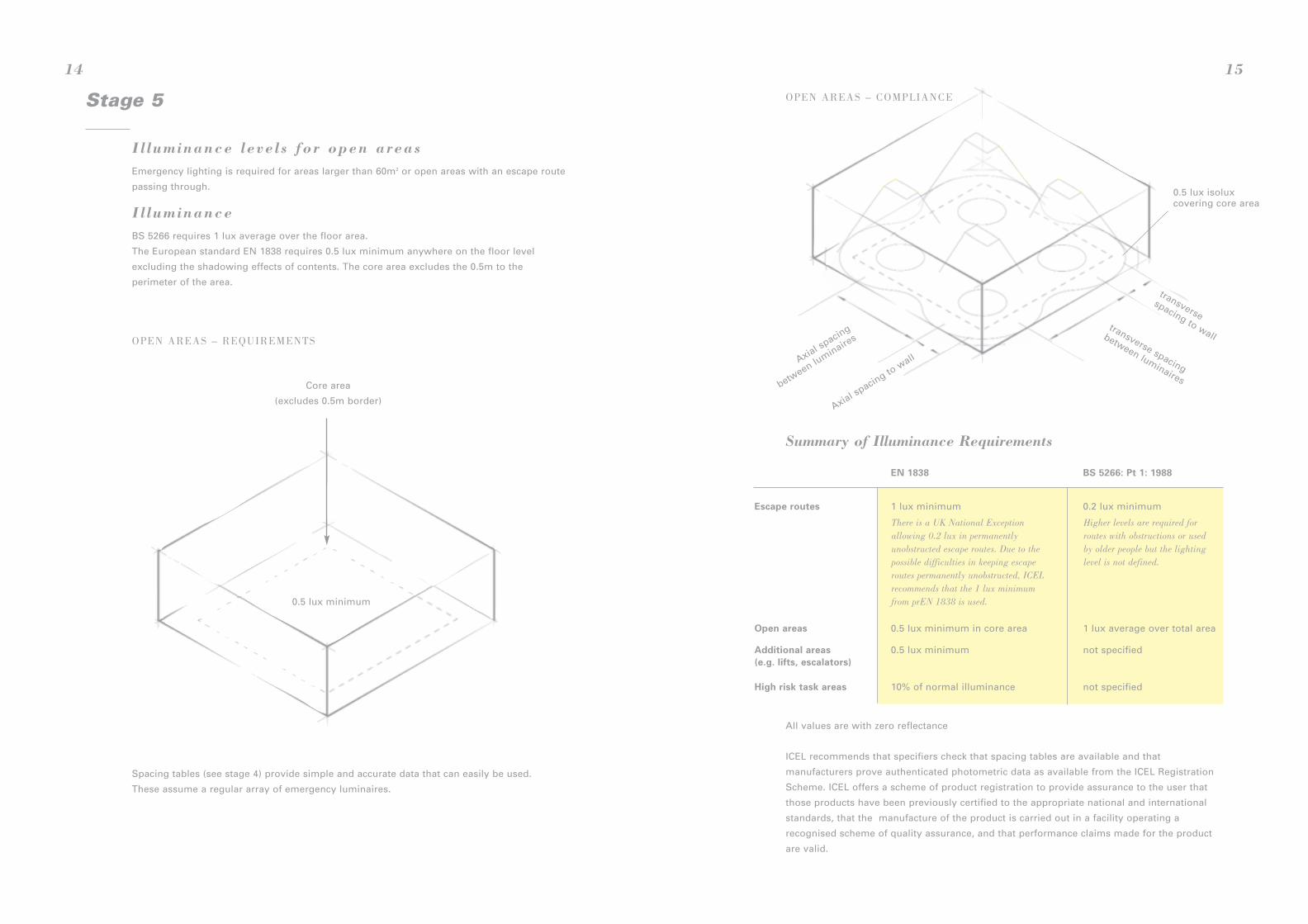
Summary of Illuminance Requirements
All values are with zero reflectance
ICEL recommends that specifiers check that spacing tables are available and that
manufacturers prove authenticated photometric data as available from the ICEL Registration
Scheme. ICEL offers a scheme of product registration to provide assurance to the user that
those products have been previously certified to the appropriate national and international
standards, that the manufacture of the product is carried out in a facility operating a
recognised scheme of quality assurance, and that performance claims made for the product
are valid.
EN 1838 BS 5266: Pt 1: 1988
Escape routes 1 lux minimum 0.2 lux minimum
Open areas 0.5 lux minimum in core area 1 lux average over total area
Additional areas 0.5 lux minimum not specified(e.g. lifts, escalators)
High risk task areas 10% of normal illuminance not specified
0.5 lux isoluxcovering core area
transversespacing to wall
transverse spacing
between luminaires
Axial spacing
between lu
minaires
Axial spacing to w
all
OPEN AREAS – COMPLIANCE
15
There is a UK National Exceptionallowing 0.2 lux in permanentlyunobstructed escape routes. Due to thepossible difficulties in keeping escaperoutes permanently unobstructed, ICELrecommends that the 1 lux minimumfrom prEN 1838 is used.
Higher levels are required forroutes with obstructions or usedby older people but the lightinglevel is not defined.
Stage 5
I l luminance leve l s for open areasEmergency lighting is required for areas larger than 60m2 or open areas with an escape route
passing through.
I l luminanceBS 5266 requires 1 lux average over the floor area.
The European standard EN 1838 requires 0.5 lux minimum anywhere on the floor level
excluding the shadowing effects of contents. The core area excludes the 0.5m to the
perimeter of the area.
Spacing tables (see stage 4) provide simple and accurate data that can easily be used.
These assume a regular array of emergency luminaires.
0.5 lux minimum
Core area
(excludes 0.5m border)
OPEN AREAS – REQUIREMENTS
14
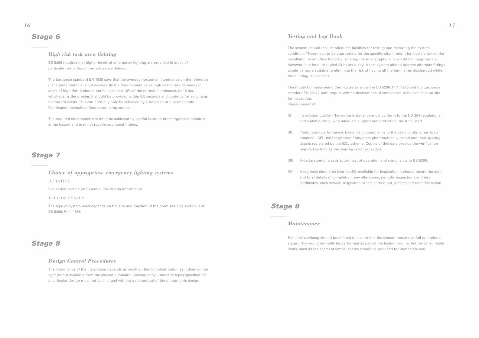
Stage 9
Maintenance
Essential servicing should be defined to ensure that the system remains at full operational
status. This would normally be performed as part of the testing routine, but for consumable
items, such as replacement lamps, spares should be provided for immediate use.
Testing and Log Book
The system should include adequate facilities for testing and recording the system
condition. These need to be appropriate for the specific site. It might be feasible to test the
installation in an office block by isolating the total supply. This would be inappropriate,
however, in a hotel occupied 24 hours a day. A test system able to operate alternate fittings
would be more suitable to eliminate the risk of having all the luminaires discharged while
the building is occupied.
The model Commissioning Certificates as shown in BS 5266: Pt 1: 1988 and the European
standard EN 50172 both require written declarations of compliance to be available on site
for inspection.
These consist of:
(I) Installation quality. The wiring installation must conform to the HD 384 regulations,
and suitable cable, with adequate support and protection, must be used.
(II) Photometric performance. Evidence of compliance to the design criteria has to be
obtained. ICEL 1002 registered fittings are photometrically tested and their spacing
data is registered by the ICEL scheme. Copies of this data provide the verification
required so long as the spacing is not exceeded.
(III) A declaration of a satisfactory test of operation and compliance to BS 5266.
(IV) A log book should be kept readily available for inspection. It should record the date
and brief details of completion, any alterations, periodic inspections and test
certificates, each service, inspection or test carried out, defects and remedial action.
17
Stage 6
High risk task area lightingBS 5266 requires that higher levels of emergency lighting are provided in areas of
particular risk, although no values are defined.
The European standard EN 1838 says that the average horizontal illuminance on the reference
plane (note that this is not necessarily the floor) should be as high as the task demands in
areas of high risk. It should not be less than 10% of the normal illuminance, or 15 lux,
whichever is the greater. It should be provided within 0.5 seconds and continue for as long as
the hazard exists. This can normally only be achieved by a tungsten or a permanently
illuminated maintained fluorescent lamp source.
The required illuminance can often be achieved by careful location of emergency luminaires
at the hazard and may not require additional fittings.
Stage 7
Choice of appropriate emergency lighting systemsDURATION
See earlier section on Essential Pre-Design Information.
TYPE OF SYSTEM
The type of system used depends on the size and function of the premises. See section 9 of
BS 5266: Pt 1: 1988
Stage 8
Design Control ProceduresThe illuminance of the installation depends as much on the light distribution as it does on the
light output available from the chosen luminaire. Consequently, luminaire types specified for
a particular design must not be changed without a reappraisal of the photometric design.
16
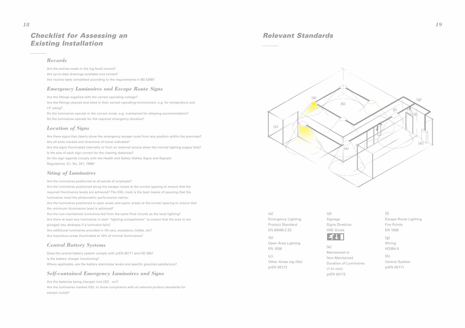
(a)Emergency Lighting
Product Standard
EN 60598.2.22
(b)Open Area Lighting
EN 1838
(c)Other Areas (eg lifts)
prEN 50172
(d)Signage
Signs Directive
HSE Guide
(e)Maintained or
Non-Maintained
Duration of Luminaires
(1 hr min)
prEN 50172
(f)Escape Route Lighting
Fire Points
EN 1838
(g)Wiring
HD384-5
(h)Central System
prEN 50171
Relevant Standards
19
Checklist for Assessing anExisting Installation
RecordsAre the entries made in the log book correct?
Are up-to-date drawings available and correct?
Are routine tests completed according to the requirements in BS 5266?
Emergency Luminaires and Escape Route SignsAre the fittings supplied with the correct operating voltage?
Are the fittings cleaned and sited in their correct operating environment, e.g. for temperature and
I.P. rating?
Do the luminaires operate in the correct mode, e.g. maintained for sleeping accommodation?
Do the luminaires operate for the required emergency duration?
Location of SignsAre there signs that clearly show the emergency escape route from any position within the premises?
Are all exits marked and directions of travel indicated?
Are the signs illuminated internally or from an external source when the normal lighting supply fails?
Is the size of each sign correct for the viewing distances?
Do the sign legends comply with the Health and Safety (Safety Signs and Signals)
Regulations, S.I. No. 341, 1996?
Siting of LuminairesAre the luminaires positioned at all points of emphasis?
Are the luminaires positioned along the escape routes at the correct spacing to ensure that the
required illuminance levels are achieved? The ICEL mark is the best means of assuring that the
luminaires meet the photometric performance claims.
Are the luminaires positioned in open areas (anti-panic areas) at the correct spacing to ensure that
the minimum illuminance level is achieved?
Are the non-maintained luminaires fed from the same final circuits as the local lighting?
Are there at least two luminaires in each “lighting compartment” to ensure that the area is not
plunged into darkness if a luminaire fails?
Are additional luminaires provided in lift cars, escalators, toilets, etc?
Are hazardous areas illuminated at 10% of normal illuminance?
Central Battery SystemsDoes the central battery system comply with prEN 50171 and HD 384?
Is the battery charger functioning?
Where applicable, are the battery electrolyte levels and specific gravities satisfactory?
Self-contained Emergency Luminaires and SignsAre the batteries being charged (red LED - on)?
Are the luminaires marked ICEL to show compliance with all relevant product standards for
escape routes?
18
(a)
(b)
(c)
(d)
(e)
(f)
(g)
(h)
European Directives and RecommendationsWorkplace Directive (89/654 EEC)
Construction Products Directive (89/106 EEC)
Safety Signs Directive (92/58 EEC)
Fire Safety in Hotels Recommendation - Requirements for Europe (86/666 EEC)
The Workplace Directive is partially implemented in the UK by The Workplace (Health, Safety
and Welfare) Regulations 1992. It includes within its scope of premises most buildings where
people are employed.
The Workplace Regulations apply to every workplace with certain exceptions such as ships,
construction sites, mines, temporary workplaces, fields, woods or other agricultural or
forestry land, aircraft, locomotive or rolling stock, trailers and some vehicles. The Regulations
require a risk assessment and an emergency plan to be prepared. The supporting guidance
stresses the need for cost benefit analysis and minimising burdens commensurate with
saving lives and the safe evacuation of premises.
The Workplace Directive is retrospective, i.e. it requires that, over time, all places of work
(with the above exemptions) are brought up to standard.
The Construction Products Directive covers both buildings and civil engineering works
including domestic, commercial industrial, agricultural, educational and recreational buildings
as well as roads and highways, bridges, docks and tunnels. It requires that such buildings or
works are designed and built in such a way that they do not present unacceptable risks of
accidents in service or in operation such as stumbling or tripping in poor visibility, and that
the safety of occupants and rescue workers is ensured in the case of fire. Minimum standards
of illumination are required so that people may move safely within the works, including if
they have to escape. In addition, escape routes are required to provide secure and adequate
lighting, capable of operating despite failure of the electrical supply.
The Safety Signs Directive is retrospective and was implemented in the UK on 1 April 1996.
It calls for the provision of emergency signs in all places of work. These signs must be
regularly cleaned, tested and maintained, and visible at all times. The traditional text EXIT
signs must be replaced by the pictogram by December 1998. A guide to Statutory Instrument
No. 341, The Health and Safety (Safety Signs and Signals) Regulations 1996, has been
published by the Health and Safety Executive - No. L64.
The Fire Safety in Hotels Recommendation applies to all establishments with 20 or more
paying guests. The Recommendation is intended to reduce the risk of fire breaking out,
prevent the spread of flames and smoke, and ensure that all occupants can be evacuated
safely. In particular the Recommendation requires that escape routes and doors are indicated
by safety signs visible day and night, and that an emergency lighting system is provided with
sufficient duration to enable evacuation for all occupants.
Note: the latest edition of documents (Directives, standards, guidance notes etc)
should be referred to.
21
Legislation & Standards AffectingEmergency Lighting
UK LegislationFire Precautions Act 1971
Health and Safety at Work etc Act 1974
The Workplace (Health, Safety and Welfare) Regulations 1992
The Building Regulations 1991
The Cinematograph Act 1952
Cinematograph (Safety) Regulations Statutory Instrument 1955 No. 1129
Health and Safety (Safety Signs and Signals), Statutory Instrument No. 1996/341
Other legislation dealing with premises licensed or registered for public assembly or
residential purposes, e.g. Licensing Act, Local Government (Miscellaneous Provisions) Act,
Theatres Act, Residential Homes Act etc, the guides for which all contain a requirement for
emergency lighting.
British Standards: General Series and Codes of PracticeBS 5266: Pt 1: 1988 Code of practice for the emergency lighting of premises other than
cinemas and certain other specified premises used for entertainment
CP1007: 1955 Maintained lighting for cinemas
BS EN 60598-2-22: 1998 Specification for luminaires for emergency lighting
BS 5499: Pt 1: 1990 (1995) Specification for self-luminous fire safety signs
BS 5499: Pt 3: 1990 Specification for internally-illuminated fire safety signs
Harmonised European StandardsElectrical installation of buildings HD 384
Specification for luminaires for emergency lighting EN 60598-2-22: 1998
Lighting applications - emergency lighting EN1838
Draft European StandardsCentral power supply systems prEN 50171
Emergency escape lighting systems prEN 50172
Measurement and presentation of photometric data for lamps and luminaires (doc. CEN/TC
169 WG7 N61D/E/F).
20
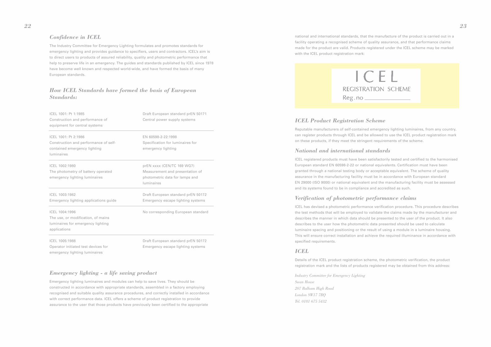
ICEL Product Registration SchemeReputable manufacturers of self-contained emergency lighting luminaires, from any country,
can register products through ICEL and be allowed to use the ICEL product registration mark
on these products, if they meet the stringent requirements of the scheme.
National and international standardsICEL registered products must have been satisfactorily tested and certified to the harmonised
European standard EN 60598-2-22 or national equivalents. Certification must have been
granted through a national testing body or acceptable equivalent. The scheme of quality
assurance in the manufacturing facility must be in accordance with European standard
EN 29000 (ISO 9000) or national equivalent and the manufacturing facility must be assessed
and its systems found to be in compliance and accredited as such.
Verification of photometric performance claimsICEL has devised a photometric performance verification procedure. This procedure describes
the test methods that will be employed to validate the claims made by the manufacturer and
describes the manner in which data should be presented to the user of the product. It also
describes to the user how the photometric data presented should be used to calculate
luminaire spacing and positioning or the result of using a module in a luminaire housing.
This will ensure correct installation and achieve the required illuminance in accordance with
specified requirements.
ICELDetails of the ICEL product registration scheme, the photometric verification, the product
registration mark and the lists of products registered may be obtained from this address:
Industry Committee for Emergency Lighting
Swan House
207 Balham High Road
London SW17 7BQ
Tel. 0181 675 5432
national and international standards, that the manufacture of the product is carried out in a
facility operating a recognised scheme of quality assurance, and that performance claims
made for the product are valid. Products registered under the ICEL scheme may be marked
with the ICEL product registration mark:
23
Confidence in ICELThe Industry Committee for Emergency Lighting formulates and promotes standards for
emergency lighting and provides guidance to specifiers, users and contractors. ICEL’s aim is
to direct users to products of assured reliability, quality and photometric performance that
help to preserve life in an emergency. The guides and standards published by ICEL since 1978
have become well known and respected world-wide, and have formed the basis of many
European standards.
How ICEL Standards have formed the basis of EuropeanStandards:
ICEL 1001: Pt 1:1985
Construction and performance of
equipment for central systems
ICEL 1001: Pt 2:1986
Construction and performance of self-
contained emergency lighting
luminaires
ICEL 1002:1980
The photometry of battery operated
emergency lighting luminaires
ICEL 1003:1982
Emergency lighting applications guide
ICEL 1004:1996
The use, or modification, of mains
luminaires for emergency lighting
applications
ICEL 1005:1988
Operator initiated test devices for
emergency lighting luminaires
Draft European standard prEN 50171
Central power supply systems
EN 60598-2-22:1998
Specification for luminaires for
emergency lighting
prEN xxxx (CEN/TC 169 WG7)
Measurement and presentation of
photometric data for lamps and
luminaires
Draft European standard prEN 50172
Emergency escape lighting systems
No corresponding European standard
Draft European standard prEN 50172
Emergency escape lighting systems
Emergency lighting - a life saving productEmergency lighting luminaires and modules can help to save lives. They should be
constructed in accordance with appropriate standards, assembled in a factory employing
recognised and suitable quality assurance procedures, and correctly installed in accordance
with correct performance data. ICEL offers a scheme of product registration to provide
assurance to the user that those products have previously been certified to the appropriate
22

ICEL Membership
Atlas Lighting Components
King George Close
Eastern Avenue West
Romford
Essex RM7 7PP
Tel. 01708 766033
Fax. 01708 776376
Bradley Lomas Electrolok Limited
Manor House
Church Street
Eckington
Sheffield S21 4BH
Tel. 01246 436361
Fax. 01246 436726
Caradon Gent Limited
Hamilton Industrial Park
Waterside Road
Leicester LE5 1TN
Tel. 0116 246200
Fax. 0116 2462019
Channel Safety Systems Limited
9 Petersfield Business Park
Bedford Road
Petersfield
Hants GU32 3QA
Tel. 01730 268231
Fax. 01730 265552
Crompton Lighting Limited
Wheatley Hall Road
Doncaster
South Yorkshire DN2 4NB
Tel. 01302 321541
Fax. 01302 340998
Emergency Lighting Products Ltd
Unit 19 & 20, Huffwood
Brookers Road
Billingshurst
West Sussex RH14 9UR
Tel. 01403 786601
Fax. 01403 786602
Emergi-Lite Safety Systems Limited
Bruntcliffe Lane
Morley
Leeds LS27 9LL
Tel. 0113 2810600
Fax. 0113 2810601
Existalite Limited
Project House
18 Tallon Road
Hutton
Essex CM13 1TZ
Tel. 01227 263660
Fax. 01227 263592
Fern-Howard Ltd
5 Woolmer Way
Bordon
Hampshire GU35 9QE
Tel. 01420 487172
Fax. 01420 489536
Fitzgerald Lighting Limited
Walker Lines Industrial Estate
Normandy Way
Bodmin
Cornwall PL31 1HH
Tel. 01208 73062
Fax. 01208 78805
Gradus Lighting
Chapel Mill
Park Green
Macclesfield
Cheshire SK11 7LZ
Tel. 01625 428922
Fax. 01625 433949
Legrand Electric Limited
Woodside Park
Foster Avenue
Dunstable
Bedfordshire LU5 5TA
Tel. 01582 676767
Fax. 01582 676771
Luxonic Lighting plc
Unit 15
Moniton Trading Estate
West Ham Lane
Basingstoke
Hampshire RG22 6NQ
Tel. 01256 363090
Fax. 01256 842349
Mackwell Electronics Limited
Vigo Place
Aldridge
Walsall
West Midlands WS9 8UG
Tel. 01922 458255
Fax. 01922 451263
Marlin Lighting
Hanworth Trading Estate
Hampton Road West
Feltham
Middlesex TW13 6DR
Tel. 0181 8945522
Fax. 0181 8944400
Menvier Ltd
Southam Road
Banbury
Oxfordshire OX16 7RX
Tel. 01295 256363
Fax. 01295 273543
Orbik Electronics Ltd
Orbik House
Northgate Way
Aldridge, Walsall
West Midlands WS9 8TX
Tel. 01922 743515
Fax. 01922 743173
P4 Ltd
Unit 4A, Stratton Park
Dunton Lane
Biggleswade
Bedfordshire SG18 8QS
Tel. 01767 600024
Fax. 01767 600808
Philips Lighting Limited
The Philips Centre
420-430 London Road
Croydon CR9 3QR
Tel. 0181 665 6655
Fax. 0181 6840136
Protec Fire Detection plc
Protec House
Churchill Way
Nelson
Lancashire BB9 6RT
Tel. 01282 717171
Fax. 01282 717273
Thorn Lighting Limited
The Towers
Wilmslow Road
Didsbury
Manchester M20 8SE
Tel. 0161 4459988
Fax. 0161 4461079
Ventilux (UK) Limited
Systems House
Wildmere Industrial Estate
Banbury
Oxfordshire OX16 7JU
Tel. 01295 279995
Fax. 01295 276799
Whitecroft Lighting Ltd
Burlington Street
Ashton-under-Lyne
Lancashire OL7 0AX
Tel. 0990 087087
Fax. 0990 084212
24

ICEL 1006: 1999
Third Edition May 1999Industry Committee for Emergency Lighting Limited
The rights of publication or of translation are reserved. Nopart of this publication may be reproduced, stored in aretrieval system or transmitted in any form or by any meanswithout the prior written permission of ICEL.
Published byIndustry Committee for Emergency Lighting LimitedSwan House207 Balham High RoadLondon SW17 7BQTel. +44(0)181 675 5432Fax. +44(0)181 673 5880
£35.00
TIM
OT
HY
GU
Y D
ES
IGN