Embed Size (px)
Citation preview

ICC2MODULAR RESIDENTIAL AND COMMERCIAL IRRIGATION CONTROLLER
Owner’s Manual• I2C-800-PL: 8-station base model, expandable to 38 stations, plastic outdoor cabinet
• I2C-800-M: 8-station base model, expandable to 54 stations, gray metal outdoor cabinet
• I2C-800-SS: 8-station base model, expandable to 54 stations, stainless steel outdoor cabinet
• I2C-800-PP: 8-station base model, expandable to 54 stations, plastic pedestal
Date/TimeSystem O�
Start Times
Run Times
Water Days
Solar Sync®
Manual
Seasonal Adjust

2 hunter.direct/ICC2help
Date/TimeSystem O�
Start Times
Run Times
Water Days
Solar Sync®
Manual
Seasonal Adjust
FORWARD DESIGN. BACKWARD COMPATIBLE.

Built on Innovation® 3
FORWARD DESIGN. BACKWARD COMPATIBLE.
Specifications ...................................................... 4Operating Specifications.................................... 4Dimensions .......................................................... 4Plastic Cabinet .................................................... 4Metal Cabinet (Gray or SS) ............................... 4Metal Pedestal (Gray or SS) .............................. 4Plastic Pedestal .................................................. 4
Electrical Specifications ..................................... 4Approvals ............................................................. 4Default Settings .................................................. 4
ICC2 Components ...............................................5Display Screens ....................................................5Control Buttons ....................................................5Control Dial .......................................................... 6Wiring Compartment ..........................................7Plastic Cabinet .....................................................7Metal Cabinet ......................................................7
Mounting the Controller ................................. 8Plastic Cabinet Wall Mounting .......................... 8Metal Cabinet Wall Mounting ........................... 9Metal Pedestal Mounting .................................10Prepare the Concrete.........................................11Install Controller on the Pedestal .....................11
Plastic Pedestal Mounting.................................11
Connecting AC Power ......................................12120 VAC Wire Nut ...............................................13230 VAC Wire Nut ..............................................13120 VAC Terminal Block .....................................13230 VAC Terminal Block ....................................13
Battery Activation ............................................14
Installing Modules ...........................................15Power Modules ...................................................16Station Modules .................................................16
Installation Instructions .................................18Connecting Station Wires .................................18Connecting a Master Valve (Optional) ............18Connecting a Pump Start Relay (Optional) ....19Connecting a Hunter Clik Sensor ....................20Sensor Bypass Switch ......................................20
Connecting a Hunter Solar Sync Sensor (Not Included) ..............................................................21
Wired Solar Sync Installation ...........................21Wireless Solar Sync Installation ......................21
Connecting a Hunter Remote (Not Included) .................................................... 22
Programming the Controller ....................... 23Setting Current Date and Time ....................... 23Setting Program Start Times .......................... 23Setting Station Run Times ...............................24Setting Water Days ...........................................24Selecting Odd or Even Days to Water ............24Selecting Interval Watering ............................ 25Selecting Pump/Master Valve Activation .... 26Setting Seasonal Adjust ................................... 26Setting Solar Sync ............................................. 27Manual Operation of a Single Station ............ 27Setting System Off ............................................ 28Programmable Rain Off .................................. 28
Hidden and Advanced Features ................. 29Features and Where They Are Found ............ 29Programmable Sensor Override ..................... 29Cycle and Soak ................................................... 29Delay Between Stations ...................................30Hide Programs ...................................................30Solar Sync Delay ................................................30Clik Delay .............................................................31Total Run Time ....................................................31Test Program ......................................................31Easy Retrieve™ ...................................................31Total Reset ......................................................... 32Quick Check™ ..................................................... 32Run Program (One-Touch Manual Start)....... 32
Troubleshooting ............................................... 33
Compliance Information ...............................34Certificate of Conformity to European Directives ..........................................34FCC Notice .........................................................34Industry of Canada Notice ...............................34
TABLE OF CONTENTS

4 hunter.direct/ICC2help
Specifications
Specifications
OPERATING SPECIFICATIONS
• Number of Stations: Modular design expandable from 8 to 38 (plastic), 8 to 54 (metal)
• Station Run Time: 1 minute up to 12 hours
• Start Times: 8 per program, 4 independent programs (A, B, C, and D)
• Simultaneous Program Operation: 2
• Sensor Inputs: 1
• Pump/Master Valve Outputs: 1
• Watering Schedule: 7-day calendar, interval watering up to a 31-day interval or true odd or even day programming
DIMENSIONS
PLASTIC CABINET• Height: 12" (30.5 cm)
• Width: 13.7" (34.8 cm)
• Depth: 5" (12.7 cm)
METAL CABINET (GRAY OR SS)• Height: 16" (40.6 cm)
• Width: 13" (33 cm)
• Depth: 5" (12.7 cm)
METAL PEDESTAL (GRAY OR SS)• Height: 36" (91.4 cm)
• Width: 11.5" (29.2 cm)
• Depth: 5" (12.7 cm)
PLASTIC PEDESTAL• Height: 39" (99.1 cm)
• Width: 24" (61 cm)
• Depth: 17" (43.2 cm)
ELECTRICAL SPECIFICATIONS
• Transformer Input: 120 VAC, 60 Hz (230 VAC, 50/60 Hz international use)
• Transformer Output: 24 VAC, 1.4 A
• Station Output: 24 VAC, up to 0.56 A
• Pump/Master Valve Output: 24 VAC, up to 0.56 A
• Battery: 9-volt alkaline battery (not included) used only for non-AC programming; non-volatile memory maintains program information
• Front Panel Battery: Internal CR2032 lithium (included) for real-time clock
APPROVALS
• CE, UL, cUL, FCC, RCM
• Plastic Cabinet: IP44, NEMA 3R
• Metal Cabinet (Gray or SS): IP44, NEMA 3R
• Metal Pedestal (Gray or SS): IP44, NEMA 3R
• Plastic Pedestal: IP24, NEMA 3R
DEFAULT SETTINGS
• All stations are set to zero run time. This controller has a non-volatile memory that retains all entered program data even during power outages, without the need for a battery.

Built on Innovation® 5
Components
Date/TimeSystem O�
Start Times
Run Times
Water Days
Solar Sync®
Manual
Seasonal Adjust
ICC2 Components
DISPLAY SCREENS
1. Station Running: Indicates when watering occurs.
2. Sprinkler Off Days: Indicates watering will not occur on selected day.
3. Program Indicators: Identifies the program in use (A, B, C, or D).
4. Water Days Symbol: Choose desired watering days.
5. Solar Sync Symbol: Indicates optional Hunter Solar Sync sensor is in use.
6. Days of the Week: Monday–Sunday.
7. Season Adjust %: Indicates seasonal adjustment percentage (increments of 5%).
8. Time Mode (AM/PM/24): Select AM, PM, or 24 HR display.
9. Rain Sensor Active/Override: Indicates if sensor is set to active or bypass.
10. Run Time Symbol: User can set each station run time from 1 minute to 12 hours.
11. Start Time Symbol: Schedule up to 8 start times per program in 15-minute increments.
12. Odd/Even/Interval Days: Indicates if odd, even, or interval watering days are selected.
CONTROL BUTTONS
+ Plus Button: Increases selected flashing display.
- Minus Button: Decreases selected flashing display.
► Forward Arrow: Advances selected flashing display to the next item; also use to start manual cycle.
◄ Back Arrow: Returns selected flashing display to the previous item.
P RG Program Button: Selects and programs (A, B, C, or D); also used to start a test program.
R AIN SENSOR Sensor Bypass Switch: Use to bypass optional Hunter “Clik-type” sensors.
Control Buttons
Sensor Bypass Switch
➐①
③
④
➑
➒➓
⓬⓫
⑤ ⑥
②

6 hunter.direct/ICC2help
Components
Date/TimeSystem O�
Start Times
Run Times
Water Days
Solar Sync®
Manual
Seasonal Adjust
CONTROL DIAL
1. Run: Normal dial position for automatic operation.
2. Date/Time: Set current date and time.
3. Start Times: Set 1 to 8 start times in each program.
4. Run Times: Set each station run time.
5. Water Days: Select individual, odd, even, or interval watering days.
6. Pump: Turn pump or master valve on or off for each station.
7. Seasonal Adjust: Change all run times in all programs by a percentage (5% to 300%).
8. Solar Sync®: Set up and adjust option for Hunter Solar Sync sensor.
9. Manual: Immediately activate a one-time watering of a single station.
10. System Off: Used to stop all watering until the dial is returned to the RUN position.
Date/TimeSystem O�
Start Times
Run Times
Water Days
Solar Sync®
Manual
Seasonal Adjust
➐
① ③
④➑
➒ ➓
⑤⑥
②

Built on Innovation® 7
Components
WIRING COMPARTMENT
1. Facepack/Control Panel: Primary console for programming the controller.
2. Power Module: Provides power to the controller and must be in place for controller to operate; contains 24 VAC, sensor, remote, and P/MV terminals.
3. SmartPort Connector: Enables use of Hunter ROAM and ROAM-XL remotes.
4. Transformer: Pre-installed with 120 VAC, 230 VAC, neutral, and ground wires (includes additional earth grounding lug for supplemental lighting protection).
5. Battery Compartment: Without AC power, a 9-volt battery (not included) allows programming, while a 3-volt CR2032 lithium battery (included) keeps real-time clock.
6. Ribbon Cable: Connects facepack to power module, and transmits information from the control panel to the inner controller assembly.
7. Station Output Modules: Plug-in station modules used to expand controller capacity in increments of 4, 8, and 22 stations (ICM-400, ICM-800, and ICM-2200).
8. Door Lock: Pre-installed lock assembly with 751 key (alternative 701, 702, or 703 key/lock assemblies also available).
PLASTIC CABINET
METAL CABINET
➐
➐
①
①
③
③
④
④
➑
➑
⑤
⑤
⑥
⑥
②
②

8 hunter.direct/ICC2help
Mounting the Controller
Mounting the Controller
PLASTIC CABINET WALL MOUNTING
1. Remove door and control panel for easier access. Use the enclosed hole template to mark and drill mounting holes. Be sure to leave enough room to open the door. Install screw anchors if attaching to drywall or masonry wall.
2. Secure a 1" (25 mm) screw into the wall, leaving ¼" (6 mm) free of the wall. Slide the top center keyhole on the rear of the controller over the screw and hang the cabinet on the screw head.
- Drill four pilot holes for the remaining mounting screws.
- Secure the controller in place by installing screws in the four remaining holes from inside the cabinet. Re-attach the control panel and the door.
Wall Mounting
Wall Mounting, plastic box.2
Wall Mounting, plastic box.2

Built on Innovation® 9
Mounting the Controller
METAL CABINET WALL MOUNTING
1. Remove door and control panel for easier access. Use the enclosed hole template to mark and drill mounting holes. Be sure to leave enough room to open the door. Install screw anchors if attaching to drywall or masonry wall.
2. Secure a 1" (25 mm) screw into the wall, leaving ¼" (6 mm) free of the wall. Slide the top center keyhole on the rear of the controller over the screw and hang the cabinet on the screw head.
- Drill four pilot holes for the remaining mounting screws.
- Secure the controller in place by installing screws in the four remaining holes from inside the cabinet. Re-attach the control panel and the door.
Wall Mounting
Wall Mounting, Metal box.3
Wall Mounting, Metal box.3

10 hunter.direct/ICC2help
Mounting the Controller
METAL PEDESTAL MOUNTING
1. ICC-PED or ICC-PED-SS
2. ICC Pedestal Door
3. Pedestal Mounting Template
4. Nut, #10-32 (qty: 2)
5. Screw, #10-32 x 7/ 8" (qty: 2)
6. Lock
7. Pedestal Mounting J-Bolt (qty: 4)
8. Nut, Hex 3/8" (qty: 8)
9. Washer, Flat 3/ 8" (qty: 8)
10. 2" Conduit Nipple
11. 2" Conduit Locknut
12. Hex Nut, Door Lock
13. 1/ 2" Conduit Coupler
14. 1/ 2" Conduit Nipple
➐
①
③
②
➑➒
⑥
⑫
⑬
⑭
④
➓⑪
⑤

Built on Innovation® 11
Mounting the Controller
PREPARE THE CONCRETE1. Prepare a form for a concrete pad, approximately
20" W x 16" D x 4" H (50 cm W x 40 cm D x 10 cm H) at grade level. Slope the concrete downward away from the pedestal.
2. Install the J-bolts and wire sweeps (power supply, ground wire, and irrigation control conduits) in the template and position them in the opening.
3. Remove the pedestal door and attach the base of the pedestal to the J-bolts in the concrete slab.
INSTALL CONTROLLER ON THE PEDESTALBefore installing controller to pedestal, ensure all necessary conduit plugs are removed from the bottom of the controller.
1. Secure the controller by inserting 2" conduit nipple up through the top of the pedestal into the bottom of the controller, and tighten the locknut on the threads.
2. Remove the wiring compartment cover from the front of the transformer junction box, and secure the controller with 1/ 2" conduit coupler and nipple.
3. Insert two #10-32 screws down through screw holes on the bottom right side of the cabinet, and tighten with corresponding nuts.
①
③ ② ④⑤
PLASTIC PEDESTAL MOUNTING
1. Mount the irrigation controller pedestal to the concrete form.
2. Electrical supply conduit: Connect to power source; J-box inside controller.
3. Ground wire conduit: Ground per ASIC guidelines.4. Run irrigation control wire through conduit per local codes.5. Pedestal base per plan: Ensure positive drainage away
from pedestal.
Note: Controller shall be hardwired to grounded 120 VAC or 230 VAC (international) power source.

12 hunter.direct/ICC2help
Connecting AC Power
Connecting AC Power
1. Turn off AC power at the source and verify it is off.
2. Disconnect the facepack ribbon cable, and remove the facepack from the cabinet.
3. Remove the screw and wiring compartment cover from the front of the transformer junction box.
Wiring Controller Power
Wiring Controller Power
Wiring Controller Power

Built on Innovation® 13
Connecting AC Power
4. Strip about 1/ 2" (13 mm) of insulation from the end of each AC power wire.
5. Route the wires through the conduit opening inside the junction box.
6. Connect AC wiring as shown above, using supplied terminal block or taped wire nuts where permissible.
7. Replace wiring compartment cover, turn on power, and test for functionality.
8. Insert copper wire from earth ground hardware, and tighten screw in front to secure the wire.
9. At minimum, use 10 AWG (5 mm2) wire to earth ground hardware (bare copper wire recommended).
10. Add copper-clad steel ground rods and/or plates sufficient to achieve 10Ω or less resistance at a minimum of 8' (2.5 m) away from controller.
Ground Neutral 120 Volt
Brown Wire (230 Volt)Black Wire (120 Volt)
Blue Wire (Neutral) Green Wire (Ground)
Wiring Controller Power, 120V-Wire nut
GroundNeutral120 Volt
Brown Wire(230 Volt)
Black Wire(120 Volt)
Blue Wire(Neutral)
Green Wire(Ground)
Wiring Controller Power, 120V - Wire block
Ground Neutral 230 Volt
Black Wire (120 Volt) Brown Wire (230 Volt)
Blue Wire (Neutral) Green Wire (Ground)
Wiring Controller Power, 230V - Wire nut
230 Volt Neutral Ground
Black Wire(120 Volt)
Brown Wire(230 Volt)
Blue Wire(Neutral)
Green Wire(Ground)
Wiring Controller Power, 230V - Wire block
Earth Ground Connection
120 VAC WIRE NUT 120 VAC TERMINAL BLOCK
230 VAC WIRE NUT 230 VAC TERMINAL BLOCK
Note: This step is highly recommended for all installations, and is required to properly ground metal and SS configurations.

14 hunter.direct/ICC2help
Battery Activation
Battery Activation
1. The battery compartment is located on the back side of the control panel. Remove cover plate to access both the 9-volt (optional) and 3-volt CR2032 lithium batteries.
2. Remove plastic tab from CR2032 battery slot to activate real-time date and time backup.
3. To replace the CR2032 battery, slide the blue lever down to eject the old one.
4. Optional 9-volt battery (not included) may be used only to program the control panel when removed from cabinet, and is not capable of running automatic schedules or activating stations.
5. Re-install cover plate to enclose battery compartment.
①
③
②
④ ⑤

Built on Innovation® 15
To add a station output module
To add a station output module
To add a station output module
①
③
②
④
Installing Modules
Installing Modules
1. Flip the blue locking lever into the vertical (unlocked) position.
2. Tip the two tabs on one end of the module into the mating holes in one end of the slot, and tip the module firmly into place. Note: Station modules will be installed upside-down in station output slots 3 and 4 (plastic) and slots 4, 5, and 6 (metal).
3. Flip the locking lever into the horizontal (locked) position.
4. Press the RESET button on the back of the control panel.
Note: Pressing the RESET button is required for the controller to recognize the new module.

16 hunter.direct/ICC2help
Installing Modules
POWER MODULES
1. Locking Lever: Flip up to remove or install module, or flip down to lock module into place.
2. C (Common Wire Connection): Makes common connection for P/MV and/or station wiring.
3. P/MV (Pump/Master Valve Connection): Up to 0.56 A for Master Valve or Pump Start Relay activation.
4. SEN (x2) Sensor Input: Standard inputs for Hunter normally-closed Clik sensors and/or Solar Sync sensor.
5. Test 24 VAC (always on): Used to test and locate valve wires.
6. REM (Remote Control Input): Pre-wired to Hunter SmartPort™ connector for use with Hunter ROAM and/or ROAM XL remotes.
7. 24VAC (x2) Transformer Connection: Connects 24 VAC yellow wires from transformer. Also used to power Hunter sensor modules and receivers.
8. GND: Connects green safety ground wire from transformer.
9. Ribbon Cable Connection: Connects controller to control panel.
10. Installation Tabs: Tip module and insert these tabs into station output slot.
STATION MODULES
11. Locking Lever: Flip up to remove or install module, or flip down to lock module into place.
12. C (Common Wire Connection): Makes common connections for station wiring.
13. Station Terminals: Numbered connections for each 24 VAC station output wire to valves. ICM400 has four, ICM800 has eight, and ICM2200 has 22 station output terminals.
14. Installation Tabs: Tip module and insert these tabs into station output slot.
Power Module Connections
Station Modules (ICM-800 shown)
①
①
➋
➋
➌
➌
➍
➍
➎
➏
➐
➑➒
⑩

Built on Innovation® 17
Installing Modules
The ICM2200 expansion module increases overall station count to 38 (plastic) and 54 (metal). This module can be installed exactly like the ICM400 and ICM800 station modules; however, it covers two station output slots.
Note: The ICM2200 must be installed in the highest two output slots: 3 and 4 (plastic) or 5 and 6 (metal). Also, there cannot be any empty slots before the ICM2200. Remember to press the RESET button on the back of the control panel after installation.

18 hunter.direct/ICC2help
Installation Instructions
Installation Instructions
CONNECTING STATION WIRES
Each ICC2 controller is supplied with a factory-installed base module for up to 8 stations (ICM-800). Multiple additional modules may be added in increments of 4 (ICM-400), 8 (ICM-800), or one 22-station expansion module (ICM-2200). Each station module has its own common terminal, which runs in conjunction with the corresponding station terminals within the module. Each station output is rated for 0.56 A maximum, which can safely operate up to two Hunter solenoids simultaneously.
1. Route station/valve wires between control valve and the controller.
2. At the valve(s), attach the common wire to either solenoid wire for each individual valve. This is most commonly a white-colored wire. Attach a separate control wire to the second remaining solenoid wire of each valve. All wire splice connections should be made using waterproof connectors.
3. Route all common and valve control wires through an incoming conduit to the controller. The conduit can attach to any of the knockout openings at the bottom of the cabinet from ½" (13 mm) up to 2" (50 mm) diameter.
4. Strip ½" (13 mm) of insulation from the ends of all wires. Secure the valve common wires to corresponding “COM” terminals. Attach all individual valve control wires to the appropriate station terminals.
COM
MASTER VALVE
P/MV
CONNECTING A MASTER VALVE (OPTIONAL)
Complete this section only if you have a Master Valve installed. The ICC2 has one Pump/Master Valve (P/MV) output, which is capable of activating either a normally closed Master Valve or a Pump Start Relay. A Master Valve is typically installed at the supply point of the main line, and opens only when the automatic system is activated. The purpose of a Master Valve is to shut off the water to the irrigation system when none of the station valves are operating. It is also beneficial for shutting off a system when a zone or mainline develops a leak or break. The P/MV output is rated for up to 0.56 A.
5. Route the Master Valve wire pair into and out of the cabinet similarly to the station wires.
6. The P/MV output is located on the power output module, in the upper left corner of the ICC2.
7. Connect either wire from the Master Valve to the P/MV terminal, and connect the remaining wire to the common “COM” terminal.
8. The Master Valve can be activated in accordance with any particular station. The controller default setting is to activate the Master Valve output with all stations; however, it can also be programmed to be active or disabled with any individual station.

Built on Innovation® 19
Installation Instructions
CONNECTING A PUMP START RELAY (OPTIONAL)
Complete this section only if you have a Pump Start Relay installed. The ICC2 has one Pump/Master Valve (P/MV) output, which is capable of activating either a normally closed Master Valve or a Pump Start Relay. A Pump Start Relay is an electrical device that uses the irrigation controller to activate a pump, when used to supply water to a system. When a pump is to be operated by the controller, a Pump Start Relay must be used. Do not connect the controller directly to the pump, as it will result in damage to the controller. The P/MV output is rated for up to 0.56 A.
1. Route the Pump Start Relay wire pair into and out of the cabinet similarly to the station wires.
2. The P/MV output is located on the power output module, in the upper left corner of the ICC2.
3. Hunter Pump Start Relays come with two yellow 24 VAC flying leads, one of which will connect to the common “COM” terminal and the other to the P/MV terminal.
4. Hunter recommends that the controller be mounted at least 15' (4.5 m) away from the Pump Start Relay. While most of the time the distance between the controller and Pump Start Relay doesn’t create any problems, sometimes the wires on the 24 VAC coil can allow electromagnetic noise to travel back to the controller. The 15' (4.5 m) distance between controller and Pump Start Relay helps dampen any potential electromagnetic noise.
5. The Pump Start Relay can be activated in accordance with any particular station. The controller default setting is to activate the Pump Start Relay output with all stations; however, it can also be programmed to be active or disabled with any individual station.
PSR
P/MV
COM

20 hunter.direct/ICC2help
Installation Instructions
CONNECTING A HUNTER CLIK SENSOR
A Hunter weather sensor or any normally closed, micro-switch-type sensor can be connected with the ICC2. The purpose of this sensor is to stop automatic watering when weather conditions dictate. The ICC2 has one sensor input available, and is compatible with Hunter’s full line of Clik-type sensors, including:
• Flow-Clik®
• Freeze-Clik®
• Mini-Clik®
• Rain-Clik® (wired and wireless, including Rain/Freeze-Clik)
• Soil-Clik®
• Solar Sync® (wired and wireless)
• Wind-Clik®
All Hunter Clik sensors are normally closed, and open on alarm, which alerts the controller to suspend watering. The ICC2 can be programmed to shut down the entire controller, or only individual stations, once the sensor is triggered (see Programmable Sensor Override instructions).
1. To connect a Hunter Clik sensor, locate the sensor inputs labeled “SEN” on the power module.
2. Route the wires from the Clik sensor through any of the available knockouts into the controller cabinet.
3. Remove the red jumper wire that is attached across the two SEN terminals.
4. Connect one wire to one SEN terminal, and the other wire to the other SEN terminal. It does not matter which wire connects to which SEN terminal.
Note: The Sensor Bypass Switch must be set to “Active” for the controller to react to a sensor alarm. Once an alarm is triggered, the display will read “OFF” and show a blinking symbol. Also, if there is no sensor installed, you must re-insert the jumper wire on the SEN terminals, or set the Sensor Bypass Switch to “Bypass.”
SENSOR BYPASS SWITCHThis switch will either enable or disable a weather sensor that has been connected to the controller. When the switch is in the “Active” position, the controller will adhere to the state of the sensor and shut down irrigation if the sensor is triggered. If the sensor is in a closed state, the controller will operate as normal. If the sensor is in an open state, but you would like your automatic irrigation to operate as normal, simply move the switch to the “Bypass” position. The sensor will now be overridden, and the controller will operate as programmed.
If you do not have a sensor installed, the position of the Sensor Bypass Switch can be in either Active or Bypass mode. This is true as long as the jumper wire connecting the two SEN terminals remains in place. If a jumper wire has been removed, keep the Sensor Bypass Switch in the Bypass mode. Otherwise, no automatic irrigation will occur.
Note: The Manual Single Station function ignores any attached sensor, and will allow manual watering to occur.
Third Normally Open Lead (Do Not Use)
C
P MV
SEN
SEN
TEST

Built on Innovation® 21
Installation Instructions
CONNECTING A HUNTER SOLAR SYNC SENSOR (NOT INCLUDED)
The Solar Sync is a smart sensor system that, when connected to a Hunter ICC2, will automatically adjust your programmed watering schedule based on changes in local climate conditions. Solar Sync utilizes a solar radiation and temperature sensor to measure on-site weather conditions and determine evapotranspiration (ET), which is the rate at which plants and turf use water. In addition, the Solar Sync sensor also includes a Hunter Rain-Clik and Freeze-Clik sensor that will shut down your irrigation system when it rains and/or during freezing conditions.
ICC2 has the Solar Sync software built in to the controller, and can be programmed on the control panel in a matter of minutes. The controller will automatically increase or decrease watering run times based on the sensor data learned from changes in on-site weather. This results in a water-efficient irrigation product that promotes water conservation and healthier landscapes. For further programming instructions, please refer to the Solar Sync Owner’s Manual or visit the Solar Sync support section on our website at www.hunterindustries.com/support/sensors/solar-sync.
WIRED SOLAR SYNC INSTALLATION1. Using the screws provided, mount the sensor in the
upright position on any surface where it will be exposed to unobstructed sun and rainfall, but not in the path of sprinkler spray. This can be a maximum 200' (60 m) from the controller.
2. Route the green and black wire pair through any of the available knockouts into the controller cabinet.
3. Remove the red jumper wire that is attached across the two SEN terminals.
4. Connect either wire to one SEN terminal, and the second wire to the other SEN terminal. It does not matter which wire connects to which SEN terminal.
WIRELESS SOLAR SYNC INSTALLATION1. Repeat steps 1–4 on the previous page; however, you will
connect the green and black wires from the Wireless Solar Sync Receiver to the SEN terminals, as opposed to wires coming from the sensor.
2. The receiver can be mounted in the knockouts provided on the side of the controller, or to a wall with the wall mounting bracket and hardware provided.
3. The sensor can be mounted up to 800' (240 m) from the receiver. The receiver and sensor are pre-paired with the same frequency. Once installed, the receiver will automatically go into a “search” mode to look for a signal from its paired sensor. However, it is a good idea to manually initialize communication between the sensor and receiver during installation to verify signal transmission.
4. After the receiver’s green and black wires have been connected to the controller, the red LED in the center of the receiver will turn on and stay solid for 10 seconds, indicating that it is searching for a signal from the sensor.
5. While the receiver is searching, press and hold the spindle on the sensor. The LED on the receiver will blink four times and then turn off, indicating that the signal from the sensor has been acknowledged.
6. To double-check or validate existing receiver/sensor communication, press and hold the spindle on the sensor. The LED on the receiver will blink twice, confirming that the receiver is addressed to the sensor properly.
22 hunter.direct/ICC2help
Installation Instructions
CONNECTING A HUNTER REMOTE (NOT INCLUDED)
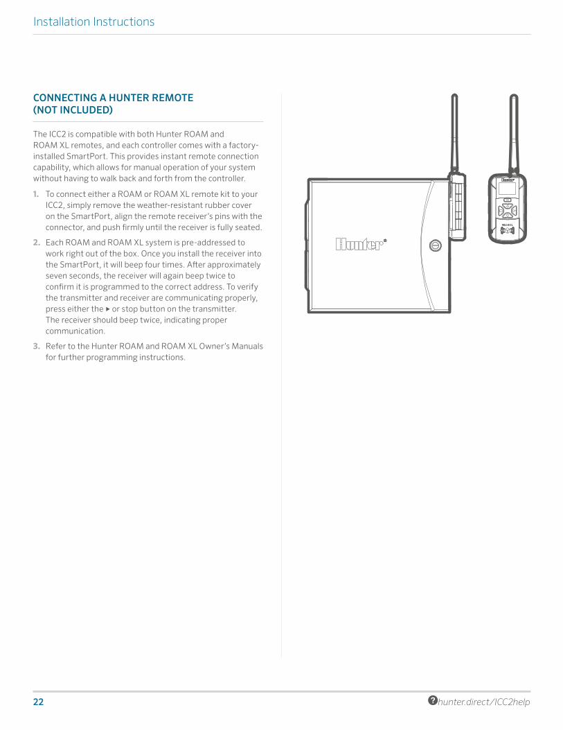
The ICC2 is compatible with both Hunter ROAM and ROAM XL remotes, and each controller comes with a factory-installed SmartPort. This provides instant remote connection capability, which allows for manual operation of your system without having to walk back and forth from the controller.
1. To connect either a ROAM or ROAM XL remote kit to your ICC2, simply remove the weather-resistant rubber cover on the SmartPort, align the remote receiver’s pins with the connector, and push firmly until the receiver is fully seated.
2. Each ROAM and ROAM XL system is pre-addressed to work right out of the box. Once you install the receiver into the SmartPort, it will beep four times. After approximately seven seconds, the receiver will again beep twice to confirm it is programmed to the correct address. To verify the transmitter and receiver are communicating properly, press either the ► or stop button on the transmitter. The receiver should beep twice, indicating proper communication.
3. Refer to the Hunter ROAM and ROAM XL Owner’s Manuals for further programming instructions.

Built on Innovation® 23
Programming the Controller
Programming the Controller
SETTING CURRENT DATE AND TIME
1. Turn the dial to the Date/Time position.
2. The current year will be flashing. Use the + and – buttons to change the year. Press the ► button to proceed to setting the month.
3. The month will be flashing. Use the + and – buttons to change the month. Press the ► button to proceed to setting the day.
4. The day will be flashing. Use the + and – buttons to change the day of the month. Press the ► button to proceed to setting the time.
5. The time will be will be displayed, and the time period will be flashing. Use the + and – buttons to select AM, PM, or 24 hr. mode.
6. Press the ► button to move to hours. Use the + and – buttons to change the hour.
7. Press the ► button to move to minutes. Use the + and – buttons to change the minutes.
SETTING PROGRAM START TIMES
1. Turn the dial to the Start Times position.
2. Press the PRG button to select A, B, C, or D.
3. The start time will be flashing. Use the + and – buttons to change the start time. Start times advance in 15-minute increments.
4. Press the ► button to add another start time, or the PRG button to set a start time for the next program. Note: The controller has eight start times available per program, and can run any two programs at once.
5. To eliminate a Program Start Time: With the dial set to the Start Times position, push the + and – buttons until you reach 12:00 AM (midnight). From here, press the – button once to reach the “OFF” position.

24 hunter.direct/ICC2help
Programming the Controller
SETTING STATION RUN TIMES
1. Turn the dial to the Run Times position.
2. Press the PRG button to select A, B, C, or D.
3. The run time for station 1 will be flashing. Use the + and – buttons to change the station run time. You can set station run times from 1 minute up to 12 hours.
4. Press the ► button to advance to the next station.
5. Repeat for each station and program that you wish to run.
6. Total Run Time Calculator: Turn the dial to the Run Times position. Press the ◄ button to view total run time for all stations in the program. Press PRG to see total run times for other programs.
SETTING WATER DAYS
1. Turn the dial to the Water Days position.
2. The display will show the last program selected (A, B, C, or D). Switch to desired program by pressing the PRG button.
3. The pointer at the bottom of the screen will be blinking above “MO” (Monday). Press the + or – buttons to select days for watering () or no water ( – ).
4. After selecting to whether to water for a specific day, the pointer will automatically advance to the next day. You can also toggle between individual days by pressing the ► and ◄ buttons.
SELECTING ODD OR EVEN DAYS TO WATER
This feature uses numbered days of the month for watering, instead of specific days of the week (i.e., odd: 1st, 3rd, 5th, etc.; even: 2nd, 4th, 6th, etc.).
1. Press the ► button past all days of the week so the pointer is blinking above “ODD” or “EVEN.”
2. Press the + button to select or the – button to cancel Odd or Even days.

Built on Innovation® 25
Programming the Controller
SELECTING INTERVAL WATERING
This feature is convenient if you want to have a more consistent watering schedule without having to worry about specific dates or days of the week. The interval number represents the actual interval of days during which watering will occur.
1. Press the ► button past “ODD” and “EVEN” until pointer is blinking above “INTERVAL.”
2. The number of interval days will be shown blinking (the default setting will be 1).
3. Press the + or – buttons to increase or decrease the interval days (up to 31 days).
4. Once the interval days are greater than 1, a second number will appear indicating days remaining in the interval. Press the ► button to select this number and press the + or – buttons to increase or decrease the days remaining until next watering. This number represents the desired number of days until the next watering. For example, if you select an interval of 3 days with 1 day remaining, watering will begin tomorrow at the scheduled start time(s), and will repeat the schedule every third day from that day forward.
5. Within the Interval Watering mode, there is also a No Water Days option. After setting your interval days and days remaining, press the ► button to select individual non-water days. The default setting shows all days available for watering. Press the ► and ◄ buttons to toggle between days, and the – button to set any specific day(s) you do not want to water. A will indicate which days are set as non-water days.
26 hunter.direct/ICC2help
Programming the Controller
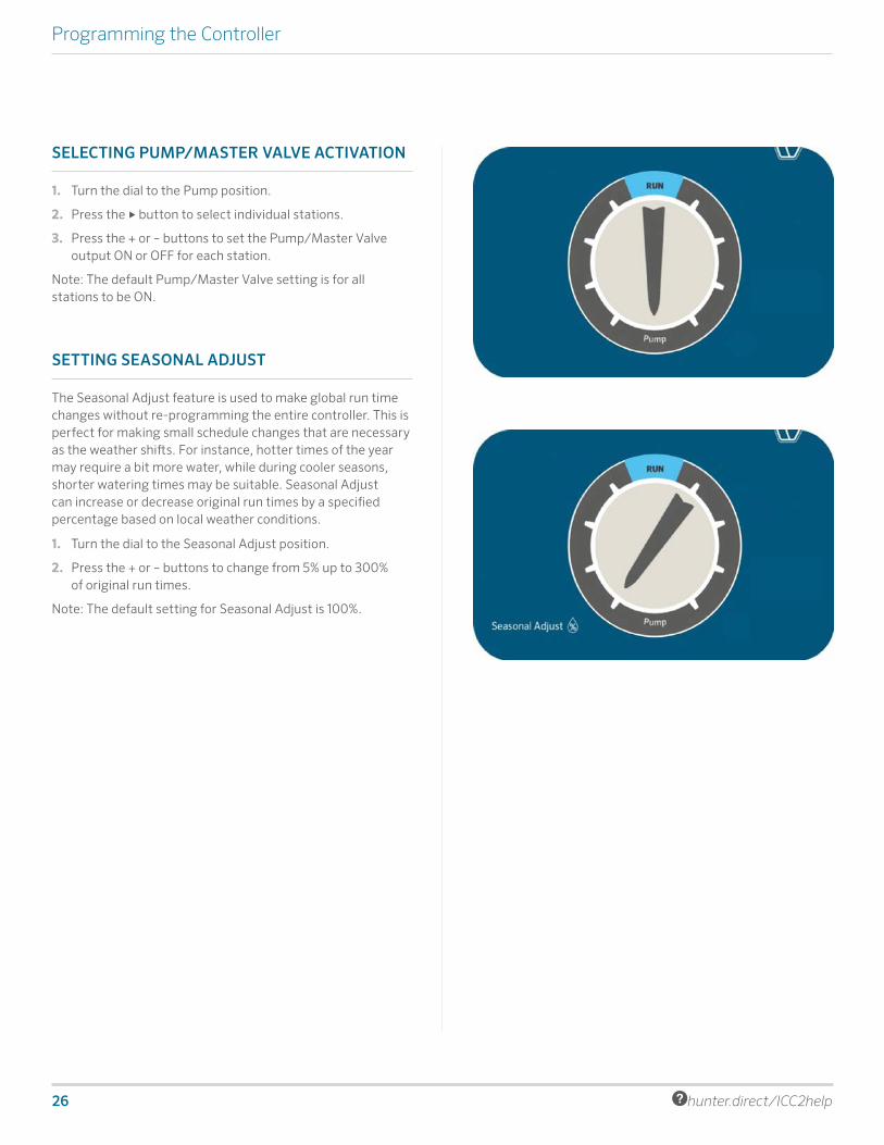
SELECTING PUMP/MASTER VALVE ACTIVATION
1. Turn the dial to the Pump position.
2. Press the ► button to select individual stations.
3. Press the + or – buttons to set the Pump/Master Valve output ON or OFF for each station.
Note: The default Pump/Master Valve setting is for all stations to be ON.
SETTING SEASONAL ADJUST
The Seasonal Adjust feature is used to make global run time changes without re-programming the entire controller. This is perfect for making small schedule changes that are necessary as the weather shifts. For instance, hotter times of the year may require a bit more water, while during cooler seasons, shorter watering times may be suitable. Seasonal Adjust can increase or decrease original run times by a specified percentage based on local weather conditions.
1. Turn the dial to the Seasonal Adjust position.
2. Press the + or – buttons to change from 5% up to 300% of original run times.
Note: The default setting for Seasonal Adjust is 100%.

Built on Innovation® 27
Programming the Controller
SETTING SOLAR SYNC
Add an optional Solar Sync sensor (wired or wireless) for automatic Seasonal Adjustment based on daily weather conditions on-site.
1. Turn the dial to the Solar Sync position.
2. The Region setting will be blinking. Press the + or – buttons to select Region 1–4. For accurate Solar Sync measurements, the Region needs to be programmed for the typical peak ET for your area (see the Solar Sync owner’s manual).
3. Press the ► button to select the Water Adjustment value. Press the + or – buttons to increase or decrease Water Adjustment from 1–10. The default setting is 5, and is recommended to remain at 5 after installation. However, if the Seasonal Adjustment appears to be changing too much or too little, the Water Adjustment value can be modified (see the Solar Sync owner’s manual).
MANUAL OPERATION OF A SINGLE STATION
1. Turn the dial to the Manual position.
2. Station run time will flash in the display. Press the ► button to advance to the desired station.
3. Press the + and – buttons to select run time duration (1 minute up to 12 hours).
4. Turn the dial to the Run position, and the station will begin watering. Only the designated station will water for its specified duration. Once completed, the controller will return to automatic run mode with no changes in the previously set program.
Note: Manual Single Station function ignores any attached sensor and will allow watering to occur. Do not use Manual Single Station to test a rain sensor. Use Run Program and One Touch Manual Start instead.

28 hunter.direct/ICC2help
Programming the Controller
SETTING SYSTEM OFF
To completely stop all irrigation, including any stations which are already running, turn the dial to the System Off position. “OFF” will appear on the display and within a few seconds, any stations that were running will shut down. No new automatic programming will be allowed to start while the controller is in the System Off position. To return the controller to normal operation, simply reset the dial to the Run position.
PROGRAMMABLE RAIN OFFThis feature permits the user to stop all programmed watering for a designated period from 1 to 31 days. At the end of the programmable rain off period, the controller will resume normal automatic operation.
1. Turn the dial to the System Off position, and wait for the “OFF” to stop blinking.
2. Press the + and – buttons to set the number of days to remain off.
3. Turn the dial back to the Run position. The display will show how many days off remain. The days off remaining will decrease at midnight of each day. Once it reaches 0, the display will revert to show the normal time of day, and automatic irrigation will resume at the next scheduled start time.
Note: To cancel Programmable Rain Off settings, turn the dial to the System Off position, wait for the “OFF” to stop blinking, and turn the dial back to the Run position.

Built on Innovation® 29
Hidden and Advanced Features
Hidden and Advanced Features
FEATURES AND WHERE THEY ARE FOUND
1. Programmable Sensor Override: Hold - and turn to Start Times.
2. Cycle and Soak: Hold + and turn to Run Times. Enter cycle time and Press PRG to set soak time.
3. Delay Between Stations: Hold - and turn to Run Times.
4. Hide Programs: Hold - and turn to Water Days.
5. Solar Sync Delay: Hold + and turn to Solar Sync
6. Clik Delay: Hold + and turn to System Off.
7. Total Run Time: Turn to Run Times. Press ◄ from Station 1. Press PRG to view other programs.
8. Test Program: Hold PRG for 3 seconds.
9. Easy Retrieve™: Hold + and PRG to save. Hold - and PRG to restore.
10. Total Reset: Hold PRG and Reset button.
11. Quick Check™: Hold +, -, ◄, ►, together. Press + to begin check.
12. Run Program: Hold ► and press PRG to select program. Press ► to advance stations.
PROGRAMMABLE SENSOR OVERRIDE
ICC2 allows the user to program the controller so a sensor response is independent from station to station. This feature allows the sensor to disable watering for only the desired stations (as opposed to the entire system). For example, patio gardens or other landscapes that are underneath overhangs or roofs may not receive water when it rains, and will still need to be watered during periods of rain.
Note: The controller default setting is to “ON,” which means the sensor is active and will disable watering on all zones once the sensor is triggered.
1. With the dial in the Run position, press and hold the – button, turn the dial to the Start Times position, and release the – button.
2. The display will show the station number, and “ON” will be flashing. Press the + and – buttons to enable or disable the sensor for the station shown.
ON = sensor enabled (will suspend irrigation)
OFF = sensor disabled (will allow watering)
3. Use the ► and ◄ buttons to scroll to the next desired station for Sensor Override.
4. Rotate the dial back to the Run position when finished programming all Sensor Overrides.
CYCLE AND SOAK
The Cycle and Soak feature allows you to split a station’s run time into cyclical, shorter watering durations. This feature is useful when applying water to slopes and tight soils because it automatically slows the application of water by irrigating with multiple shorter cycles, as opposed to one long run time. This helps to prevent runoff and excessive watering.
To do this, you should enter the Cycle time as a fraction of the station’s total desired watering time, and the Soak time as the minimum amount of time required before watering can occur again for the next cycle. The total number of cycles is determined by taking the total programmed station run time, and dividing it by the Cycle time.
For example, station 1 requires 20 minutes of watering, but after 5 minutes, runoff occurs. However, after 10 minutes, all water is absorbed into the soil. The solution would be to program 20 minutes for the station Run Time, 5 minutes for the Cycle time, and 10 minutes for the Soak time. This would create 4 separate cycles of watering, with 5 minutes per cycle, and 10 minutes of soak time in between watering.
However, if there are stations programmed to run after station 1, the Cycle and Soak process won’t complete until the end of all scheduled zones. This means that after station 1 runs its first cycle, the controller will proceed sequentially in numerical order until all programmed stations complete their run times. Then, the program will revert to station 1 and complete its remaining cycle and soak schedule.
1. To access the Cycle and Soak menu, with the dial in the RUN position, press and hold the + button, turn the dial to the Run Times position, and release the + button.
2. Initially, station 1 will be displayed. To access other stations, press the ► or ◄ buttons. Once the desired station is shown, use the + and – buttons to increase or decrease the Cycle time. The user can set the Cycle time from 1 minute up to 4 hours, or OFF if no Cycle and Soak is desired.
Note: When setting both Cycle and Soak times, any times less than 1 hour will only display the minutes (e.g., 30). For times greater than 1 hour, the display will change to include the hour digit (e.g., 2:45).
30 hunter.direct/ICC2help
DELAY BETWEEN STATIONS
This feature allows the user to program a delay between station activation and shutoff. This is particularly helpful on systems with slow-closing valves, pumps that are operating near maximum flow, and/or alternate water sources with slower recovery such as wells and water storage tanks.
1. With the dial in the Run position, press and hold the – button, turn the dial to the Run Times position, and release the – button.
2. The display will show a delay time in seconds, which is default set to 00 seconds. Press the + and – buttons to increase or decrease the delay times. For any delay time less than 1 minute, the display will show only seconds (e.g., SEC 45). Once you program over 59 seconds, “SEC” will change to “Hr” and the delay time converts into minutes and hour mode (e.g., Hr 0:30 represents 30 minutes, Hr 2:00 represents 2 hours).
3. The Delay Between Stations feature applies to all stations, and can be programmed from 1 second up to 10 hours.
4. Rotate the dial back to the Run position when finished programming all Delays Between Stations.
Note: The Master Valve/Pump Start circuit will remain active during the first 15 seconds of any programmed Delay Between Stations to aid in the closing of the valve and to avoid unnecessary cycling of the pump.
HIDE PROGRAMS
ICC2 is factory configured with 4 independent programs (A, B, C, and D) that are utilized when watering multiple different landscapes and plant-type requirements. The controller can be customized to display only the most basic programming, and thus, hide extra programs.
1. With the dial in the Run position, press and hold the – button, turn the dial to the Water Days position, and release the – button.
2. Use the + and – buttons to change between either 4 or 1. The default setting is set to 4, which shows all 4 programs available, and all 8 start times available. Switching to a setting of 1 will show only program A and only 1 start time available.
3. Rotate the dial back to the Run position when finished programming all Hide Programs.
Hidden and Advanced Features
SOLAR SYNC DELAY
ICC2 with built-in Solar Sync programming has the ability to delay the automatic, daily update of the Seasonal Adjustment value from Solar Sync for up to 99 days. This option may be advantageous to users who do not want the program run times to be adjusted by Solar Sync for a specific period of time (e.g., during an overseeding or overwatering schedule). This function allows the controller to operate with a manually set, fixed Seasonal Adjustment value, at least until the Solar Sync Delay period expires. However, even while Solar Sync Delay is active, the Solar Sync sensor will continue to gather weather information and calculate the Seasonal Adjust Value; it just won’t be applied to the run times. Once the Solar Sync Delay ends, the updated Seasonal Adjust value will be applied.
Note: Solar Sync Delay feature is only accessible when a Solar Sync sensor is installed.
4. With the dial in the Run position, press and hold the + button, turn the dial to the Solar Sync position, and release the + button.
5. The display will show “d:00,” where “d” indicates days and “00” indicates the number of days to be delayed.
6. Press the + or – buttons to increase or decrease the number of Solar Sync Delay days you desire. Once the correct number of days is displayed, return the dial to the Run position.
Note: The number of days remaining will not be displayed on the Run screen. To check if the Solar Sync Delay feature is active, open the Solar Sync Delay menu and check the number of days shown. If 1 or more days are programmed, then Solar Sync Delay is active, but if 0 days are programmed, then Solar Sync Delay is disabled.

Built on Innovation® 31
Hidden and Advanced Features
CLIK DELAY
This feature allows the user to delay programmed watering for a designated period of time AFTER a Clik event occurs. For example, heavy rain is in the forecast and you won’t need to irrigate for multiple days after the storm. The Clik Delay can postpone automatic programming from 1–7 days after the Clik sensor is triggered. At the end of the Clik Delay period, the controller will resume normal automatic watering.
1. With the dial in the Run position, press and hold the + button, turn the dial to the System Off position, and release the + button.
2. The display will show “OFF –” with the dash blinking. Press the + or – buttons to increase or decrease the number of Clik Delay days. Once the correct number of days is displayed, return the dial to the Run position.
3. After a Clik event ends (e.g., the rain sensor dries out and deactivates the sensor), the Clik Delay feature will become active and will be displayed on the screen for the entire Clik Delay duration.
Note: An active Clik Delay can be canceled at any time by simply turning the dial to the System Off position, waiting for “OFF” to stop blinking, and returning the dial to the Run position. Also, any station that is set with the Programmable Sensor Override feature will operate during a Clik Delay.
TOTAL RUN TIME
ICC2 keeps a running total of each program’s station run times. This feature provides a quick way to determine how long each program will irrigate.
1. Turn the dial to the Run Times position.
2. From the station 1 run time, press the ◄ button once to review the total of all run times in the program. You can also view the total run time by pressing the ► button once after advancing to the highest station run time.
3. Press the PRG button to review total run times of additional programs.
TEST PROGRAM
The Test Program feature offers users a simplified method for manually starting any or all stations sequentially. This feature operates each station in numerical order, from lowest to highest, and can be started from any specific station. This is beneficial for quick operation of your irrigation system.
1. With the dial in the Run position, press and hold the PRG button. Station 1 will appear with a run time flashing (controller default is set to 0:00).
2. Press the ► and ◄ buttons to select which station you would like to start from. Press the + and – buttons to increase or decrease the station run time (0 to 15 minutes). The run time entered will be applied to all stations.
3. After a two-second pause, the Test Program will begin. You can advance forward and backward through the stations if you don’t need a particular zone to run for the full duration.
EASY RETRIEVE™
ICC2 is capable of saving the preferred watering program into memory for retrieval at a later time. This feature creates a quick way to reset the controller to the original programmed watering schedule, and is particularly beneficial when overwriting any unwanted changes to the current program.
1. With the dial in the Run position, press and hold the + and PRG buttons simultaneously. Once three dashes appear on the screen, release the + and PRG buttons. The symbol will scroll left to right across the display indicating the program is being saved into memory. The display will show “DONE” once saved, and will then revert back to the time-of-day display.
2. To retrieve a program that was previously saved into memory, leave the dial in the Run position and press and hold the – and PRG buttons simultaneously. Once the same three dashes appear on the screen, release the – and PRG buttons. The symbol will scroll right to left across the display indicating the program is being loaded from memory. The display will show “DONE” once loaded, and will then revert back to the time-of-day display.

32 hunter.direct/ICC2help
Hidden and Advanced Features
TOTAL RESET
The Total Reset feature will erase all of the controller’s memory and set everything back to factory presets. Once you perform a Total Reset, all programming will be completely erased, including any Easy Retrieve programming that may have been saved. This feature is typically utilized when you need to reprogram the controller from the beginning, or if the controller is not responding to any commands.
1. Press and hold the PRG and RESET buttons simultaneously. Wait until the display shows 12:00 AM, and release both buttons. The controller is now ready to be reprogrammed.
QUICK CHECK™
This circuit diagnostic procedure can quickly identify wiring shorts commonly caused by faulty solenoids and poor or incorrect wire splices. Quick Check is an efficient and effective way to diagnose problems in the field, instead of having to physically check each wiring circuit for potential problems.
1. To initiate the Quick Check test procedure, press the +, –, ►, and ◄ buttons simultaneously. The display will show all icons on the screen.
2. Press the + button to begin the diagnostics. The controller will then search all stations to detect a high current path through the station terminals. When a field wiring short is detected, an “ERR” message, preceded by the station number, will flash momentarily on the display. The test will continue checking the remaining stations for faults, and once completed, will return to automatic watering mode.
RUN PROGRAM (ONE-TOUCH MANUAL START)
ICC2 is also capable of activating an entire program without using the dial. This option is great for a quick cycle when extra watering is needed or if you would like to scroll through the stations to inspect your system. The Run Program Feature differentiates from the Test Program feature by being able to select any of the four automatic programs to run their existing run times.
1. With the dial in the Run position, press and hold the ► button for two seconds and release.
2. This manual one touch start option automatically defaults to program A. You can select any of the four programs (A, B, C, or D) by pressing the PRG button.
3. The station number will flash on the display. Press the ► and ◄ buttons to scroll through the stations, and the + and – to adjust the pre-existing run times (0 minutes up to 12 hours). Once you’ve selected your desired station to run first, the program will begin automatically. You can advance forward and backward through the stations if you don’t need a particular zone to run for the full duration.

Built on Innovation® 33
Hidden and Advanced Features
Troubleshooting
Symptom Possible Cause Solution
Display shows a station number with "ERR"
Faulty station solenoid or short in the field wiring
Check field wiring and solenoids for continuity, and replace any faulty solenoids.
Display shows "P ERR"Short in the pump start/master valve wiring or faulty pump start or master valve solenoid
Check the master valve or pump start wires for continuity, and replace or repair any shorted wires. Check that all wire connections are good and watertight. Check pump start relay specifications for proper installation.
Display shows "SP ERR"SmartPort error; this represents electrical noise present near the connection to a remote receiver
Move connections away from electrical noise source. Check the SmartPort wiring harness and verify the red wire is attached to the AC 1 terminal, and the blue wire to the REM terminal If the SmartPort wiring harness is extended from the controller, ensure shielded cable is used (ROAM-SCWH).
Display shows "NO AC"No AC power present, and the controller is not receiving power
Check fuse/breaker and incoming power supply to the controller, ensure transformer is wired and installed properly.
Frozen or garbled display Power surge Reset the controller.
Controller not recognizing correct station count
Module installed incorrectly, forgot to press "Reset" button after installing new module, or faulty module
Verify modules are seated properly and locked into position, oriented the correct way in proper slots. Remember to press the "Reset" button on the back of the control panel after adding a new module.
Display shows the program is running, but no actual watering
Problem in field wiring, faulty solenoid(s), faulty valve(s), or no water pressure to system
Check field wiring and solenoids for continuity, replace any faulty solenoids and/or repair any poor wire connections. Check valves for debris, body breaks, diaphragm tears, and proper operation. Ensure the water source is open and pressurized.
Rain or other Clik-type sensor does not stop irrigation
Jumper wire is not removed, sensor switch is in "Bypass" position, or incompatible sensor installed
Remember to remove red jumper wire on SEN terminals. Ensure sensor switch is set to "active." Verify a normally closed (NC) sensor is installed.
Controller seems to water continuously Too many start times programmed
Only one start time is required to operate all stations within a program sequentially (you do not need to set a start time for each individual station). Remove all unnecessary start times.
Controller not running automatic programming
Possible programming error(s), sensor is activated and interrupting circuit, Programmable Off is in effect, time/date errors
Verify all programs, days to water, start times, and station run times are programmed correctly. Check display for sensor fault notification. Check display for "OFF" days. Check controller time, date, and AM/PM/24 hour mode settings.

34 hunter.direct/ICC2help
Compliance Information
Compliance Information
CERTIFICATE OF CONFORMITY TO EUROPEAN DIRECTIVES
Hunter Industries declares that the irrigation controller Model ICC2 complies with the standards of the European Directives of “electromagnetic compatibility” 2014/30/EU and “low voltage” 2014/35/EC.
FCC NOTICE
This equipment generates, uses, and can radiate radio frequency energy and, if not installed and used in accordance with the manufacturer's instruction manual, may cause interference with radio and television reception. This equipment has been tested and found to comply with the limits for a Class B digital device, pursuant to part 15 of the FCC Rules. Operation is subject to the following two conditions:
1) This device may not cause harmful interference.
2) This device must accept any interference received, including interference that may cause undesired operation.
Notice: The FCC regulations provide that changes or modifications not expressly approved by Hunter Industries could void your authority to operate this equipment. These limits are designed to provide reasonable protection against harmful interference in a residential installation. However, there is no guarantee that interference will not occur in a particular installation. If this equipment does cause harmful interference to radio or television reception, which can be determined by turning the equipment off and on, the user is encouraged to try to correct the interference by one or more of the following measures:
• Reorient or relocate the receiving antenna.
• Increase the separation between the equipment and receiver.
• Connect the equipment into an outlet on a circuit different from that to which the receiver is connected.
• Consult the dealer or an experienced radio/TV technician for help.
INDUSTRY OF CANADA NOTICE
This device complies with Industry Canada license-exempt RSS standard(s). Operation is subject to the following two conditions:
(1) this device may not cause interference, and
(2) this device must accept any interference, including interference that may cause undesired operation of the device.

Built on Innovation® 35
Notes
Built on Innovation® 35

RESIDENTIAL & COMMERCIAL IRRIGATION | Built on Innovation®
1940 Diamond Street, San Marcos, California 92078, USALearn more. Visit hunterindustries.com
© 2018 Hunter Industries Incorporated Please recycle. LIT-666 US 3/18
Helping our customers succeed is what drives us. While our passion for innovation and
engineering is built into everything we do, it is our commitment to exceptional support
that we hope will keep you in the Hunter family of customers for years to come.
Gregory R. Hunter, CEO of Hunter Industries
hunter.direct/icc2help 1-800-733-2823