Embed Size (px)
Citation preview

GE6261 COMPUTER AIDED DRAFTING AND MODELLING LABORATORY
VVIT DEPARTMENT OF CIVIL ENGINEERING Page 1
Dharmapuri – 636 703
Regulation : 2013Branch : B.E. - Civil EngineeringYear & Semester : I Year / II Semester
ICAL ENG
CE6261-COMPUTER AIDED DRAFTING ANDMODELLING LABORATORY
LAB MANUAL
GE6261 COMPUTER AIDED DRAFTING AND MODELLING LABORATORY
VVIT DEPARTMENT OF CIVIL ENGINEERING Page 2
INDEX
EXPT.
NODATE NAME OF THE EXPERIMENT
STAFF
SIGNREMARKS
1Study of Capabilities of Software for Drafting and
Modeling – Coordinate Systems
2Drawing of a Title Block with necessary Text and
Projection Symbol.
3
Drawing of Curves
a) Parabola
b) Spiral
c) Involutes
4
Drawing of Front View And Top View Of Simple
Solids
a) Prism
b) Pyramid
c) Cylinder
d) Cone
5
Drawing Front View, Top View And Side View
a) V-Block
b) Base Of A Mixie
c) Simple Stool
d) Objects With Hole And Curves
6 Drawing of a Plan of Residential Building
7 Drawing of a Simple Steel Truss
8
Drawing Sectional Views
a) Prism
b) Pyramid
c) Cylinder
d) Cone

GE6261 COMPUTER AIDED DRAFTING AND MODELLING LABORATORY
VVIT DEPARTMENT OF CIVIL ENGINEERING Page 3
9 Drawing Isometric Projection of Simple Objects
10 Creation Of 3-D Models of Simple Objects
11 Obtaining 2-D Multi-View Drawings from 3-D Model

GE6261 COMPUTER AIDED DRAFTING AND MODELLING LABORATORY
VVIT DEPARTMENT OF CIVIL ENGINEERING Page 4
ANNA UNIVERSITY-CHENNAI
Regulation 2013
GE6261 COMPUTER AIDED DRAFTING AND MODELING LABORATORY
OBJECTIVES:
To develop skill to use software to create 2D and 3D models.
LIST OF EXERCISES USING SOFTWARE CAPABLE OF DRAFTING AND
MODELING
1. Study of capabilities of software for Drafting and Modeling – Coordinate systems
(absolute, relative, polar, etc.) – Creation of simple figures like polygon and general multi-
line figures.
2. Drawing of a Title Block with necessary text and projection symbol.
3. Drawing of curves like parabola, spiral, involute using Bspline or cubic spline.
4. Drawing of front view and top view of simple solids like prism, pyramid, cylinder, cone,
etc, and dimensioning.
5. Drawing front view, top view and side view of objects from the given pictorial views (Ex.
V-block, Base of a mixie, Simple stool, Objects with hole and curves).
6. Drawing of a plan of residential building (Two bed rooms, kitchen, hall, etc.)
7. Drawing of a simple steel truss.
8. Drawing sectional views of prism, pyramid, cylinder, cone, etc,
9. Drawing isometric projection of simple objects.
10. Creation of 3-D models of simple objects and obtaining 2-D multi-view drawings from 3-
D model.
TOTAL HOURS=60Hrs
Note: Plotting of drawings must be made for each exercise and attached to the records
written by students.

GE6261 COMPUTER AIDED DRAFTING AND MODELLING LABORATORY
VVIT DEPARTMENT OF CIVIL ENGINEERING Page 5
INTRODUCTION TO AUTOCAD
DRAWING AND MODIFYING OBJECTS
AutoCAD is drafting/modeling software used all over the world by almost all
Manufacturing companies. It is variable software which can be used in all engineering
divisions. It is a drafting version popularly known to everyone associated with mechanical
engineering. The AutoCAD drawing enables the designer to communicate his ideas to the
outside of department easily.
Conversion of AutoCAD files to other software is also using drawing exchange
Formula. In the lesson, commands and procedures for drawing and modifying the Objects are
explored.
START AND SAVE A DRAWING
When you start a drawing, you specify the type of units and other settings you can
also choose how to save your files, including saving back up files.
The settings you select, English a metric determines default values used for many
system variables of controlling text dimensions, grid, snap and default line type and hatch
pattern life.
ENGLISH - Creates a new drawing based on Imperial Measurement System. The
drawing is based on cad.dwt template.
METRIC
Creates a new drawing based on metric measurement. The drawing is based on
Ocadiso.dwt template. Save drawing files for later use.
CONTROL THE VIEWS
You can magnify the details in your drawing for a closer view or shift the view to a
different part of the drawing. If you can save the view by name, you can restore them later.
UNITS
Every object is measured in units. In AutoCAD we can determine the value of the
units before we draw.

GE6261 COMPUTER AIDED DRAFTING AND MODELLING LABORATORY
VVIT DEPARTMENT OF CIVIL ENGINEERING Page 6
LIMITS
The drawings limits are two-dimensional points in the world coordinate that represent
a lower-left limit and an upper right limit. You cannot impose limits on the Z direction.
AUTOCAD COORDINATE ENTRY METHODS
ABSOLUTE METHOD: (X,Y)
Absolute Cartesian coordinates specify a point’s exact distance from the origin point of
the coordinate system, which is represented as (0,0). The absolute X and Y coordinates are
signed numbers.

GE6261 COMPUTER AIDED DRAFTING AND MODELLING LABORATORY
VVIT DEPARTMENT OF CIVIL ENGINEERING Page 7
RELATIVE METHOD: (@X,Y)
Relative Cartesian coordinates specify a point’s exact distance from the last point that
was entered.
For example, typing @4,2 tells AutoCAD to locate a point that is four X units and
two Y units away from the last point entered. The X and Y relative coordinates are signed
numbers.Direct distance entry is a shorthand relative coordinate entry method.
POLAR METHOD: (@DISTANCE<ANGLE)
Polar coordinates specify a point’s exact location by a distance and angle from the last
point that was entered. The distance is always positive and the angle is measured from the
positive X axis.
For example, typing @4<45 tells AutoCAD to locate a point that is four units away
from the current location and at an angle of 45 degrees from the horizontal.

GE6261 COMPUTER AIDED DRAFTING AND MODELLING LABORATORY
VVIT DEPARTMENT OF CIVIL ENGINEERING Page 8
Polar method

GE6261 COMPUTER AIDED DRAFTING AND MODELLING LABORATORY
VVIT DEPARTMENT OF CIVIL ENGINEERING Page 9
AUTO CAD COMMANDS:
LINE
Line command allows you to create a line where the end points are specified by two
dimensional or three dimensional coordinates.
POLYLINE
PLINE command allows you to draw line and arc segments, but from start to end, it is
treated as a sing object. With PLINE command, you can draw objects even with line width.
ARC
The ARC command allows you to create an arc segment. There are different methods
of creating an arc. The different methods of creating an arc are:
3 Points
Centre, Start, Radius
Start, Centre, End
Start, Centre, Angle
Start, Centre, Length
Start, End, Angle
Start, End, Direction
Start, End, Radius
CIRCLE
The CIRCLE command allows you to create a circle. There are four different methods for
drawing circles. They are:
Centre
Radius/Centre,
Diameter
3 Points (3P)
2 Points (2P)
Tangent, Tangent, Radius
POLYGON
Polygon command creates a regular polygon. You must specify the number of sides of
the polygon and whether it is Inscribed or Circumscribed polygon. Now, specify the centre
and radius of the polygon circle.

GE6261 COMPUTER AIDED DRAFTING AND MODELLING LABORATORY
VVIT DEPARTMENT OF CIVIL ENGINEERING Page 10
OSNAP
Osnap allow you to snap onto a specific object location when you are picking a point.
For example, using Osnap you can accurately pick the end point of a line or the center of a
circle.
ERASE
This command is used for deleting unwanted objects. You must select the object to be
erased.
COPY
The copy command is used for making copies of selected objects. The object to be
copied must be selected and the base point must be specified and the copy can be dragged
and placed at the required position.
MOVE
This command is used for moving selected objects. The object to be moved must be
selected and its base point must be specified then we can drag it to the required location
ROTATE
This command is used for rotating selected objects. To rotate an object, first select it
and specify a base point. Now enter an angle value or specify a second point to rotate the
object.
Entering a positive angle value rotates the objects counterclockwise or clockwise,
depending on the Direction Control setting and Drawing Units dialog box. The plane of
rotation and the direction of the zero angles depend on the orientation of the user coordinate
system.
MIRROR
The MIRROR command is used for creating mirror images of selected objects. You
must first select the object to be mirrored and then specify the axis along which it is mirrored,
to create an mirror image of the selected object. This is a very useful command for drawing
symmetrical objects about a particular axis.
OFFSET
Offset an object to create a new object whose shape parallels the shape of the original
object. Offsetting a circle or an arc creates a larger or smaller circle or arc, depending on
which side you specify for the offset.

GE6261 COMPUTER AIDED DRAFTING AND MODELLING LABORATORY
VVIT DEPARTMENT OF CIVIL ENGINEERING Page 11
POLAR ARRAY
This command creates an array of the selected object around a centre point. You must
specify the centre point of the array, the total number of items and the angle to fill for
creating a polar array.
RECTANGULAR ARRAY
This command creates an array of the selected objects defined by the number of rows
and columns and the offset between them.
EXTEND
The EXTEND command elongates the selected objects to a specified boundary.
TRIM
The TRIM command trims off an object using cutting edges defined by other objects.
Here the user is required to select object(s) to define cutting edge(s) then select the object to
be trimmed; the selected side of the object is removed based on the side of selection of the
object to be trimmed relative to the cutting edge.
BREAK
The BREAK command is used to remove only parts of an object. You must specify
the first and second points between which the object must be deleted.
FILLET
FILLET rounds of the edges of two arcs, circles, elliptical arcs, lines, polylines, rays,
splines or xlines with an arc of a specified radius. Rounds along the edges cannot be created
with zero radius.
CHAMFER
CHAMFER command draws a line at the corner between two selected lines. If the
lines do not intersect, it extends the lines. If they intersect, the lines extending beyond the
chamfer line can be trimmed or left as it is, by the trim mode.
LENGTHEN
The LENGTHEN command is used to increase/decrease the length of AutoCAD
objects.
DIVIDE
This command places evenly spaced point objects or blocks along the length or
perimeter of an object. You can select only one entity at a time to be divided. The entities that
can be selected are: line, arc, circle, polyline and spline.

GE6261 COMPUTER AIDED DRAFTING AND MODELLING LABORATORY
VVIT DEPARTMENT OF CIVIL ENGINEERING Page 12
ZOOM ALL
This zoom to display the entire drawing in the current viewport. The display shows all
the entities even if the drawing extends outside the drawing limits.
ZOOM WINDOW
ZOOM WINDOW commands to display an area specified by two diagonally opposite
corner points of a rectangle window.
ZOOM EXTENTS
This zoom to display the drawing extents. If the drawings are small in the existing
limits, then there is an enlarging effect on the screen. If the drawing occupies the complete
area of the limits, then there are many not being much difference between ZOOM ALL and
ZOOM EXTENTS.
DIMLINEAR
This command specifies the linear distance between two selected points.
DIMALIGNED
This command is used for specifying the linear distance (exact dimensional value)
between two points which are inclined at an angle.
DIMANGULAR
This command is used for obtaining the angle two selected points. The three types
are:
1) Arc Selection
2) Circle Selection
3) Line Selection
4) Three Point Selection
DIMRADIUS
This command gives the value of radius of the specified circle, arc or fillet. A radial
dimension consists of a radius dimension line with an arrowhead at the arc or circle end.
DIMCENTER
This command marks the centre point of the selected arc or circle. The center mark
cannot be updated, so set the required style before executing this command.
LINETYPE
LINETYPE greatly improves the readability of technical drawings. You can make
important features stand out with bold line weights.

GE6261 COMPUTER AIDED DRAFTING AND MODELLING LABORATORY
VVIT DEPARTMENT OF CIVIL ENGINEERING Page 13
LAYER
Layer is an organizing tool. Layers are like one, where you can keep various types of
information. It’s always a good idea to keep notes and reference symbols about each element
of the drawing as well as drawing dimensions on a new layer.
DISTANCE
This command lists the distance between the selected points and also lists out the
angle in current plane and 3D angle from the current plane, based on the direction of picking
the two points. It also lists the projected lengths on the three axes called the delta length.
TEXT
TEXT command creates text objects with specified height and orientation. Text
objects can be created with a variety of character patterns call style. This command allows
you to type a single line or multiple lines of text.
MTEXT
MTEXT creates paragraph that fit within a nonprinting text boundary. The user
specified text boundary determines the width of the paragraph and the justification of the text
within the paragraph. Each multiline text object is a single object, regardless of the number of
lines it contains.
HATCH
Hatches are shaded pattern which generally represent cross-section of a mechanical
component. Using BHATCH command the required area, type of hatch, hatch angle and scale
can be specified.
PROPERTIES
The PROPERTIES command displays the Properties palette. The Properties palette is
the main method for viewing and modifying the properties of AutoCAD objects.
VPORTS
Viewports are areas that display different views of your model. As you work on the
Model tab, you can split the drawing area into one or more adjacent rectangular views known
as model space viewports. In large or complex drawings, displaying different views reduces
the time needed to zoom or pan in a single view. Also, errors you might miss in one view
may be apparent in the others.
EXTRUDE
Solids can be created by extruding selected objects. Use the EXTRUDE command to
create a solid or surface from a common profile of an object.

GE6261 COMPUTER AIDED DRAFTING AND MODELLING LABORATORY
VVIT DEPARTMENT OF CIVIL ENGINEERING Page 14
REVOLVE
REVOLVE command can create a solid or surface by revolving open or closed objects
about an axis. The revolved objects define the profile of the solid or surface.
PYRAMID
This command can create a solid pyramid. The number of sides for a pyramid, from 3
to 32, can be defined. The axis endpoint defines the length and orientation of the pyramid.
CREATE LAYOUTS
A layout stimulates a sheet of paper and provides a predictable plotting setup for a
layout, you can create and position view post objects and you can add a title block or other
objects geometry.
PLOT DRAWINGS
Once you have completed a drawing you can plot the drawing on paper or create a file
for use with another application. In either case, you select the plot settings.

GE6261 COMPUTER AIDED DRAFTING AND MODELLING LABORATORY
VVIT DEPARTMENT OF CIVIL ENGINEERING Page 15

GE6261 COMPUTER AIDED DRAFTING AND MODELLING LABORATORY
VVIT DEPARTMENT OF CIVIL ENGINEERING Page 16
EX NO: 01
DATE:
STUDY OF CAPABILITIES OF SOFTWARE FOR DRAFTING
AND MODELING
AIM:
To create simple objects like polygon and general multi-line figures using Auto CAD
software.
SOFTWARE USED:
Auto CAD 2007 software.
COMMANDS USED:
Limits, Zoom, Line, Arc, Circle, co-ordinate systems, Dim linear.
PROCEDURE:
Limits are set for A4 standard drawing size. Margins are drawn using lines.
Using Line command and appropriate co-ordinate system, the given figures are drawn
and aligned
The drawn figures are dimensioned using respective dim command.
Finished work sheet is saved and hard copy is taken.
RESULT:
The given simple figures like polygon and general multi-line figures are drawn Using
Auto CAD software.

GE6261 COMPUTER AIDED DRAFTING AND MODELLING LABORATORY
VVIT DEPARTMENT OF CIVIL ENGINEERING Page 17
Drawing of A Title Block With Necessary Text And Projection
GE6261 COMPUTER AIDED DRAFTING AND MODELLING LABORATORY
VVIT DEPARTMENT OF CIVIL ENGINEERING Page 17
Drawing of A Title Block With Necessary Text And Projection
GE6261 COMPUTER AIDED DRAFTING AND MODELLING LABORATORY
VVIT DEPARTMENT OF CIVIL ENGINEERING Page 17
Drawing of A Title Block With Necessary Text And Projection

GE6261 COMPUTER AIDED DRAFTING AND MODELLING LABORATORY
VVIT DEPARTMENT OF CIVIL ENGINEERING Page 18
EX NO: 02
DATE:
DRAWING OF A TITLE BLOCK WITH NECESSARY
TEXT AND PROJECTION
AIM:
To draw a Title block for the given dimensions with necessary text and projection.
Using Auto CAD software.
SOFTWARE USED:
Auto CAD 2007
COMMANDS USED:
Limits, Zoom, Line, Arc, Circle, co-ordinate systems, Dim linear, Copy, Trim, Circle,
Dimensions
PROCEDURE:
Limits are set for standard drawing size. Margins are drawn using lines.
Using Line command and appropriate co-ordinate system, the given figures are drawn
and aligned
Using Line, Circle, poly line ,trim commands, and draw a Title Block with necessary
text and projection are drawn
The drawn figures are dimensioned using respective DIM command.
Title Block is drawn for the given dimension.
Finished work sheet is saved and hard copy is taken.
RESULT:
Thus the Title block was drawn for the given dimensions with all necessary text and
projection.

GE6261 COMPUTER AIDED DRAFTING AND MODELLING LABORATORY
VVIT DEPARTMENT OF CIVIL ENGINEERING Page 19

GE6261 COMPUTER AIDED DRAFTING AND MODELLING LABORATORY
VVIT DEPARTMENT OF CIVIL ENGINEERING Page 20
EX NO: 03
DATE:
DRAWING OF CURVES LIKE PARABOLA, SPIRAL, INVOLUTE
USING BSPLINE OR CUBIC LINE
AIM:
To create special curves like parabola, spiral, involute (square and Hexagon) using
Bspline or Cubic Spline using Auto CAD software.
SOFTWARE USED:
Auto CAD 2007
COMMANDS USED:
Limits, Zoom, Line, Polygon, Arc, Circle, Offset, Copy, Move, Trim, Pline, Pedit,
DIM.
PROCEDURE:
Limits are set for standard drawing size. Margins and title block are drawn using
lines.
From the given data, the Loci points of Parabola are found and joined using Pline and
then fitted using Pedit command
From the given data, the Loci points of square and hexagonal involutes are found and
joined using arc command.
From the given data, the Loci points of Spiral are found using concentric circles or arc
method, and joined using Pline and then fitted using Pedit command.
Drawn curves are dimensioned appropriately.
Finished work sheet is saved and hard copy is taken.

GE6261 COMPUTER AIDED DRAFTING AND MODELLING LABORATORY
VVIT DEPARTMENT OF CIVIL ENGINEERING Page 21
CUBIC SPLINE AND INVOLUTE
All dimensions are in ‘mm’
GE6261 COMPUTER AIDED DRAFTING AND MODELLING LABORATORY
VVIT DEPARTMENT OF CIVIL ENGINEERING Page 21
CUBIC SPLINE AND INVOLUTE
All dimensions are in ‘mm’
GE6261 COMPUTER AIDED DRAFTING AND MODELLING LABORATORY
VVIT DEPARTMENT OF CIVIL ENGINEERING Page 21
CUBIC SPLINE AND INVOLUTE
All dimensions are in ‘mm’

GE6261 COMPUTER AIDED DRAFTING AND MODELLING LABORATORY
VVIT DEPARTMENT OF CIVIL ENGINEERING Page 22
RESULT:
The special curves like parabola, spiral, involute (square and Hexagon) using Bspline
or Cubic Spline are drawn using Auto CAD spline.
GE6261 COMPUTER AIDED DRAFTING AND MODELLING LABORATORY
VVIT DEPARTMENT OF CIVIL ENGINEERING Page 23

GE6261 COMPUTER AIDED DRAFTING AND MODELLING LABORATORY
VVIT DEPARTMENT OF CIVIL ENGINEERING Page 24
EX NO: 04
DATE:
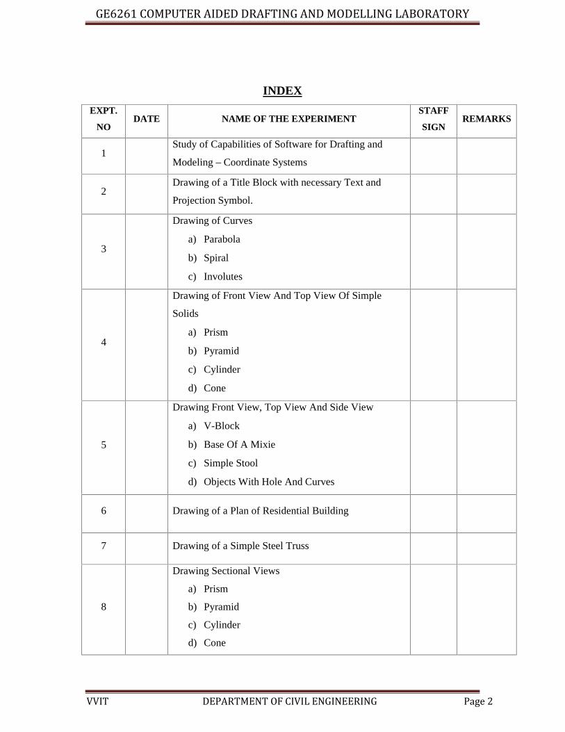
DRAWING OF FRONT VIEW ANT TOP VIEW OF SIMPLE SOLIDS LIKE PRISM,
PYRAMID, CYLINDER, CONE, AND DIMENSIONINS
AIM:
To draw front and top view of given simple solids (cone, cylinder, prism and
pyramid) using Auto CAD software.
SOFTWARE USED:
Auto CAD 2007
COMMANDS USED:
Limits, Zoom, Line, Polygon, Arc, Circle, Offset, Copy, Move, Trim, Layer, DIM,
Mtext.
PROCEDURE:
Limits are set for standard drawing size. Margins and title block are drawn using
lines.
Using Line, Circle, Polygon commands, front and top view of given simple Solids are
drawn.
Layer is defined (for line type, line weight and colour) separately for visible, hidden,
axis and dimension lines and applied.
Sectional views are drawn and section is created using Hatch command.
Drawn solids are named and dimensioned accordingly.
Finished work sheet is saved and hard copy is taken.
RESULT:
The front and top views of the given simple solids (cylinder, cone, prism and
pyramid) are drawn using Auto CAD software.
GE6261 COMPUTER AIDED DRAFTING AND MODELLING LABORATORY
VVIT DEPARTMENT OF CIVIL ENGINEERING Page 25
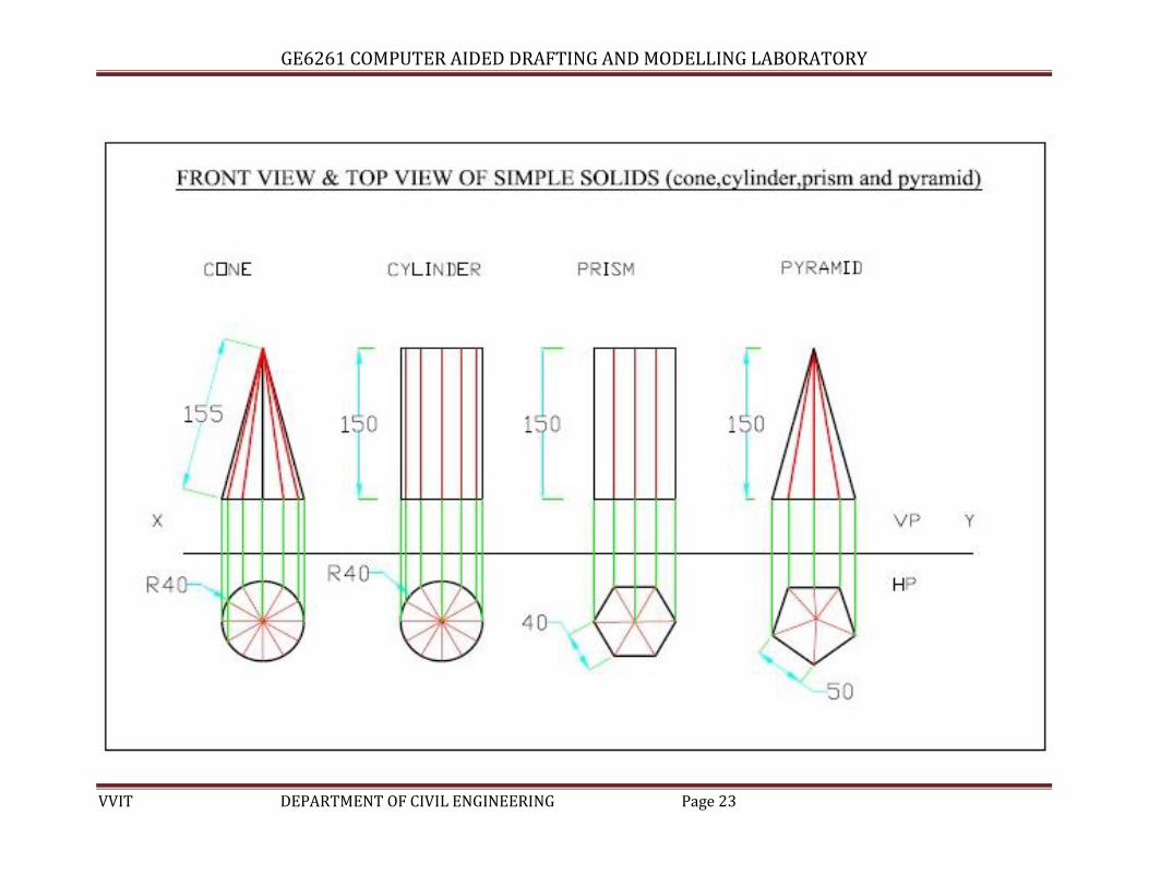
Drawing front view, top view, and side view of object from the given V-BLOCK
All dimensions are in ‘mm’

GE6261 COMPUTER AIDED DRAFTING AND MODELLING LABORATORY
VVIT DEPARTMENT OF CIVIL ENGINEERING Page 26
EX NO: 05
DATE:
DRAWING FRONT VIEW, TOP VIEW, AND SIDE VIEW OF OBJECT FROM THE
GIVEN PICTORIAL VIEWS
(V-BLOCK, BASE MIXIE AND SIMPLE STOOL)
AIM:
To draw front and top view of given simple solids (v-block, Base mixie, simple stool)
using Auto CAD software.
SOFTWARE USED:
Auto CAD 2007
COMMANDS USED:
Limits,
Zoom,
Line,
Polygon,
Arc,
Circle,
Offset,
Copy,
Move,
Trim,
Layer,
DIM,
Mtext.
PROCEDURE:
Limits are set for standard drawing size. Margins and title block are drawn using
lines.
Using Line, Circle, Polygon commands, front and top view of given simple solids are
drawn
Layer is defined (for line type, line weight and colour) separately for visible, hidden,
axis and dimension lines and applied.
Sectional views are drawn and section is created using Hatch command.
Drawn solids are named and dimensioned accordingly.
Finished work sheet is saved and hard copy is taken.

GE6261 COMPUTER AIDED DRAFTING AND MODELLING LABORATORY
VVIT DEPARTMENT OF CIVIL ENGINEERING Page 27
Drawing front view, top view, and side view of object from the given SIMPLE STOOL

GE6261 COMPUTER AIDED DRAFTING AND MODELLING LABORATORY
VVIT DEPARTMENT OF CIVIL ENGINEERING Page 28
Drawing front view, top view, and side view of object from the given MIXIE
All dimensions are in ‘mm’

GE6261 COMPUTER AIDED DRAFTING AND MODELLING LABORATORY
VVIT DEPARTMENT OF CIVIL ENGINEERING Page 29
RESULT:
The front and top views of the given simple solids (v-block, Base mixie, and simple
stool) are drawn using Auto CAD software.

GE6261 COMPUTER AIDED DRAFTING AND MODELLING LABORATORY
VVIT DEPARTMENT OF CIVIL ENGINEERING Page 30
GE6261 COMPUTER AIDED DRAFTING AND MODELLING LABORATORY
VVIT DEPARTMENT OF CIVIL ENGINEERING Page 31
EX NO: 06
DATE:
DRAWING OF A PLAN OF RESIDENTIAL BUILDING
AIM:
To create the plan of given residential building using Auto CAD software.
SOFTWARE USED:
Auto CAD 2007
COMMANDS USED:
Limits, Zoom, Line, Offset, Copy, Move, Multiline.
PROCEDURE:
Limits are set for standard drawing size. Margins and title block are drawn using
lines.
Using Multiline command, plan of the given residential building is drawn.
The plan is dimensioned and the rooms are named accordingly.
Finished work sheet is saved and hard copy is taken.
RESULT:
The plan of the given residential building is drawn using Auto CAD software.

GE6261 COMPUTER AIDED DRAFTING AND MODELLING LABORATORY
VVIT DEPARTMENT OF CIVIL ENGINEERING Page 32
Simple Steel Truss
GE6261 COMPUTER AIDED DRAFTING AND MODELLING LABORATORY
VVIT DEPARTMENT OF CIVIL ENGINEERING Page 33
EX NO: 07
DATE:
DRAWING OF A SIMPLE STEEL TRUSS
AIM:
To draw simple trusses using Auto CAD software.
SOFTWARE USED:
Auto CAD 2007
COMMANDS USED:
Limits, Zoom, Line, Offset, Copy, Move, Trim, Extend, DIM.
PROCEDURE:
Limits are set for standard drawing size. Margins and title block are drawn using
lines.
Using appropriate commands, simple trusses with combinations of King and Queen
posts are drawn.
Drawn figure is dimensioned accordingly.
Finished work sheet is saved and hard copy is taken.
RESULT:
The plan of simple trusses is drawn using Auto CAD software.

GE6261 COMPUTER AIDED DRAFTING AND MODELLING LABORATORY
VVIT DEPARTMENT OF CIVIL ENGINEERING Page 34

GE6261 COMPUTER AIDED DRAFTING AND MODELLING LABORATORY
VVIT DEPARTMENT OF CIVIL ENGINEERING Page 35
EX NO: 08
DATE:
DRAWING SECTIONAL VIEWS OF PRISM, PYRAMID, CYLINDER
AND CONE
AIM:
To draw sectional view of given simple solids (cylinder, cone, prism and pyramid)
using Auto CAD software.
SOFTWARE USED:
Auto CAD 2007
COMMANDS USED:
Limits, Zoom, Line, Polygon, Arc, Circle, Offset, Copy, Move, Trim, Layer,
DIM, Mtext.
PROCEDURE:
Limits are set for standard drawing size. Margins and title block are drawn using
lines.
Using Line, Circle, Polygon commands, front and top view of given simple solids are
drawn
Layer is defined (for line type, line weight and colour) separately for visible, hidden,
axis and dimension lines and applied.
Sectional views are drawn and section is created using Hatch command.
Drawn solids are named and dimensioned accordingly.
Finished work sheet is saved and hard copy is taken.

GE6261 COMPUTER AIDED DRAFTING AND MODELLING LABORATORY
VVIT DEPARTMENT OF CIVIL ENGINEERING Page 36

GE6261 COMPUTER AIDED DRAFTING AND MODELLING LABORATORY
VVIT DEPARTMENT OF CIVIL ENGINEERING Page 37
RESULT:
The sectional view of given simple solids (cylinder, cone, prism and pyramid) are
drawn using Auto CAD software.
GE6261 COMPUTER AIDED DRAFTING AND MODELLING LABORATORY
VVIT DEPARTMENT OF CIVIL ENGINEERING Page 38
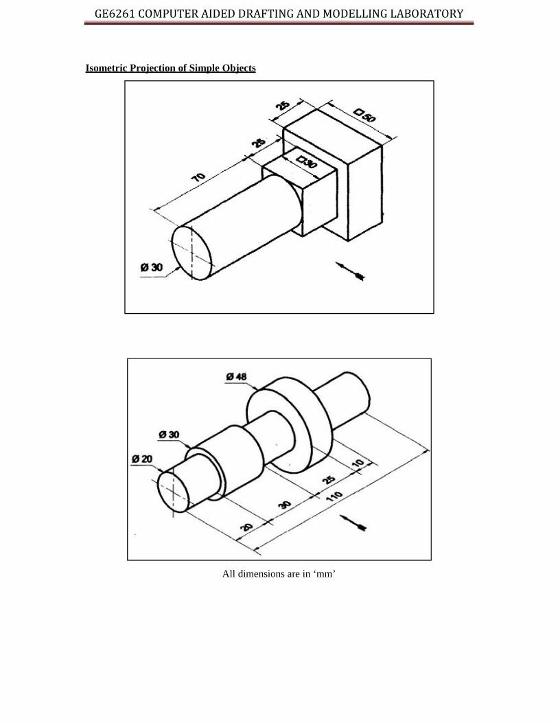
Isometric Projection of Simple Objects
All dimensions are in ‘mm’
GE6261 COMPUTER AIDED DRAFTING AND MODELLING LABORATORY
VVIT DEPARTMENT OF CIVIL ENGINEERING Page 38
Isometric Projection of Simple Objects
All dimensions are in ‘mm’
GE6261 COMPUTER AIDED DRAFTING AND MODELLING LABORATORY
VVIT DEPARTMENT OF CIVIL ENGINEERING Page 38
Isometric Projection of Simple Objects
All dimensions are in ‘mm’

GE6261 COMPUTER AIDED DRAFTING AND MODELLING LABORATORY
VVIT DEPARTMENT OF CIVIL ENGINEERING Page 39
EX NO: 09
DATE:
DRAWING ISOMETRIC PROJECTION OF SIMPLE OBJECTS
AIM:
To draw the isometric view of given simple objects using Auto CAD software.
SOFTWARE USED:
Auto CAD 2007
COMMANDS USED:
Limits, Zoom, Line, Polygon, Arc, Circle, Offset, Copy, Move, Trim, Layer, DIM,
Mtext
PROCEDURE:
Limits are set for standard drawing size. Margins and title block are drawn using
lines.
Using Line, Circle, Polygon commands, front and top view of given simple solids are
drawn.
Snap is changed from Rectangular to Isometric to help draw the Isometric view. F5
key is used to invoke/toggle between the different Isoplanes (Left, Top, Right)
accordingly.
Given objects are taken and drawn in Isometric.
Drawn solids are named and dimensioned accordingly.
Finished work sheet is saved and hard copy is taken.

GE6261 COMPUTER AIDED DRAFTING AND MODELLING LABORATORY
VVIT DEPARTMENT OF CIVIL ENGINEERING Page 40
RESULT:
The Isometric views of the given simple objects are drawn using Auto CAD software.

GE6261 COMPUTER AIDED DRAFTING AND MODELLING LABORATORY
VVIT DEPARTMENT OF CIVIL ENGINEERING Page 41
Creation Of 3-D Models of Simple Objects And Obtaining 2-D Multi-View

GE6261 COMPUTER AIDED DRAFTING AND MODELLING LABORATORY
VVIT DEPARTMENT OF CIVIL ENGINEERING Page 42
EX NO: 10
DATE:
CREATION OF 3-D MODELS OF SIMPLE OBJECTS
AIM:
To create 3-D Models of given simple solids and obtain 2-D multi view drawings
Auto CAD software.
SOFTWARE USED:
Auto CAD 2007
COMMANDS USED:
Zoom,
Line,
Polygon,
Arc,
Circle,
DIM,
Extrude,
Revolve.
PROCEDURE:
Auto CAD 3-D template is opened for creating 3-D models.
Prisms are created using Extrude command and pyramids by Pyramid command.
Objects of revolution like cylinder and cone are created using Revolve command.
Finished work sheet is saved and hard copy is taken.

GE6261 COMPUTER AIDED DRAFTING AND MODELLING LABORATORY
VVIT DEPARTMENT OF CIVIL ENGINEERING Page 43
Creation of 3-D Models of Simple Objects
All dimensions are in ‘mm’

GE6261 COMPUTER AIDED DRAFTING AND MODELLING LABORATORY
VVIT DEPARTMENT OF CIVIL ENGINEERING Page 44
RESULT:
3-D Models of given simple solids are created using Auto CAD software.

GE6261 COMPUTER AIDED DRAFTING AND MODELLING LABORATORY
VVIT DEPARTMENT OF CIVIL ENGINEERING Page 45
2D Multiple Views from 3D Model Object
All dimensions are in ‘mm’

GE6261 COMPUTER AIDED DRAFTING AND MODELLING LABORATORY
VVIT DEPARTMENT OF CIVIL ENGINEERING Page 46
EX NO: 11
DATE:
OBTAINING 2-D MULTI-VIEW DRAWINGS FROM 3-D MODEL
AIM:
To create a2d multiple views from 3d model using Auto CAD software.
SOFTWARE USED:
Auto CAD 2007
COMMANDS USED:
Limits, Zoom, Line, Circle, Layout, Text, Mtext.
PROCEDURE:
Limits are set for standard drawing size are drawn.
Given Solid is modeled using Extrude command.
Layout is created with four viewports for Front, Top, Left Side and Isometric views.
Dimensioning is done in the appropriate views.
Finished work sheet is saved and hard copy is taken.

GE6261 COMPUTER AIDED DRAFTING AND MODELLING LABORATORY
VVIT DEPARTMENT OF CIVIL ENGINEERING Page 47
2D Multiple Views
All dimensions are in ‘mm’

GE6261 COMPUTER AIDED DRAFTING AND MODELLING LABORATORY
VVIT DEPARTMENT OF CIVIL ENGINEERING Page 48
RESULT:
2D multiple views were obtained for the given solid using Auto CAD software.

GE6261 COMPUTER AIDED DRAFTING AND MODELLING LABORATORY
VVIT DEPARTMENT OF CIVIL ENGINEERING Page 49
SHORTCUT KEY FOR ALL THE COMMANDS
Line –L
Circle –c
Move –m
Copy –co
Hatching –h
Explode –x
Trim –tr
Mirror-mi
Offset –o
Dimension style –d
Text-t
Text edit –ed
Rotate –ro
Fillet –f
Break –br
Arc- a
Polygon –pol
Ellipse –el
Multiline –mline
Poly line-pline

GE6261 COMPUTER AIDED DRAFTING AND MODELLING LABORATORY
VVIT DEPARTMENT OF CIVIL ENGINEERING Page 50
FUNCTION KEYS
FUNCTION KEYS FUNCTION DEFINED
F1 Help
F2 Command window on/off
F3 Object Osnap on/off
F4 Tablet on/off
F5Isoplane top/right/left
F6Co-ordinate display on/off
F7 Grid on/off
F8 Ortho on/off
F9snap on/off
F10 Polar tracking on/off
F11 Object snap tracking on/off