Embed Size (px)
Citation preview

INSTRUCTION MANUAL
VHF MARINE TRANSCEIVER
iC-m1
This device complies with Part 15 ofthe FCC Rules. Operation is subject tothe condition that this device does notcause harmful interference.
i
RWARNING! NEVER hold the transceiver so thatthe antenna is very close to, or touching exposed parts of thebody, especially the face or eyes, while transmitting. Thetransceiver will perform best if the microphone is 2 to 4 in (5 to 10 cm) away from the lips and the transceiver is verti-cal.
MAKE SURE the flexible antenna and battery pack are se-curely attached to the transceiver and that the antenna andbattery pack are dry before attachment. Exposing the insideof the transceiver to water will result in serious damage to thetransceiver.
NEVER allow children to touch the transceiver.
NEVER charge battery packs except in the methods de-scribed in this manual.
KEEP the transceiver at least 3.3 ft (1 m) away from theship’s navigation compass.
DO NOT use or place the transceiver in areas with temper-atures below –4°F (–20°C) or above +140°F (+60°C) or, inareas subject to direct sunlight, such as the dashboard.
AVOID the use of chemical agents such as benzine or al-cohol when cleaning, as they may damage the transceiversurfaces.
BE CAREFUL! The transceiver rear panel will becomehot when operating continuously for long periods.
After exposure to saltwater, clean the transceiver thoroughlywith fresh water to avoid corrosion.
CAUTIONS
IMPORTANT
READ ALL INSTRUCTIONS carefully and completelybefore using the transceiver.
SAVE THIS INSTRUCTION MANUAL — This in-struction manual contains important operating instructions forthe IC-M1.

IMPORTANT ........................................................................ iCAUTIONS .......................................................................... iTABLE OF CONTENTS ..................................................... ii
1 PANEL DESCRIPTION ............................................. 1–3 Front panel ................................................................. 1 Top and side panels ................................................... 2 Function display ......................................................... 3
2 BASIC OPERATION ................................................. 4–9 Operating rules .......................................................... 4 Channel selection ...................................................... 5 Lock function .............................................................. 6 Adjusting the squelch level ........................................ 6 Receiving and transmitting ........................................ 7 Optional voice scrambler operation ........................... 8 Call channel programming ......................................... 9 Automatic backlighting ............................................... 9
3 DUALWATCH/TRI-WATCH ......................................... 10 Description ............................................................... 10 Operation ................................................................. 10
4 SCAN OPERATION .............................................. 11–12 Scan types ............................................................... 11 Setting tag channels ................................................ 12 Starting a scan ......................................................... 12
5 SET MODE ........................................................... 13–14 SET mode programming .......................................... 13 SET mode items ...................................................... 13
6 BATTERY CHARGING ......................................... 15–16 Battery cautions ....................................................... 15 Battery charging ...................................................... 15
7 UNPACKING AND ACCESSORY ATTACHMENT ..... 17
8 TROUBLESHOOTING ................................................ 18
9 CHANNEL LIST .......................................................... 19
10 SPECIFICATIONS AND OPTIONS ............................ 20 Specifications ........................................................... 20 Options .................................................................... 20
TABLE OF CONTENTS
ii
PANEL DESCRIPTION1
1
Front panel
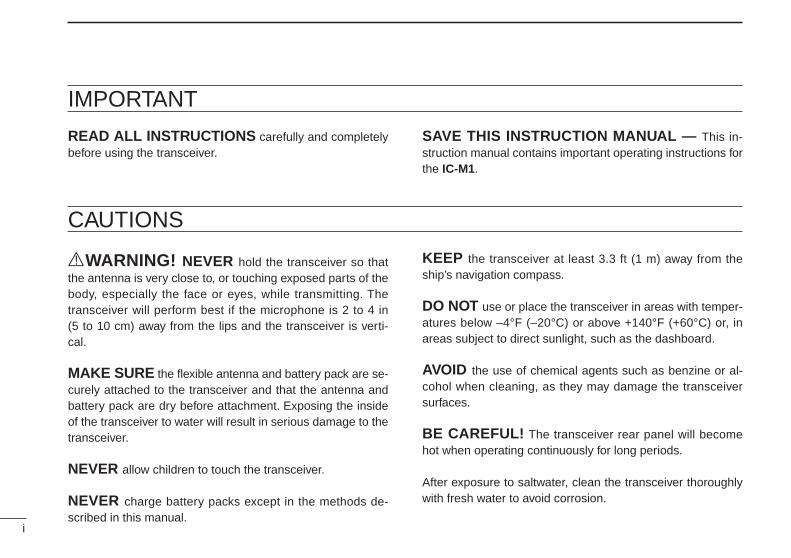
FUNCTION DISPLAY (p. 3)
DUALWATCH/TRI-WATCH SWITCH [DW•TRI] (p. 10)•Starts dualwatch when pushed momentarily.•Starts tri-watch when pushed for 1 sec.•Stops dualwatch/tri-watch when either is ac-tivated.
SCAN SWITCH [SCN•SCRM]•Starts and stops normal or priority scanwhen tag channels are programmed. (p. 12)
•Activates an optional voice scrambler func-tion when pushed for 1 sec. (p. 8)
TAG SWITCH [TAG•ALL CLR]•Sets the displayed channel as a tag(scanned) channel when pushed. (p. 12)
•Clears all tag channels in the selected regu-lar channel when pushed for 3 sec. (p. 12)
TRANSMIT POWER/LOCK SWITCH [H/L•LOCK]•Toggles high power and low power (1 W)when pushed. (p. 7)
•While pushing [SQL], push this key to selectextra low power (150 mW). (p. 7)
•Toggles the lock function ON and OFF whenpushed for 1 sec. (p. 6)
CHANNEL/WEATHER CHANNELSWITCH [CH/WX•U/I/C]•Selects and toggles the regular channelsand weather channel when pushed mo-mentarily. (pgs. 5, 6)
•Selects one of 3 regular channels in se-quence when pushed for 1 sec. (p. 5)- International, U.S.A. and Canadian channels
are available for regular channels.
CHANNEL 16 SWITCH [16•9]•Selects channel 16 when pushed. (p. 5)•Selects the call channel when pushed for1 sec. (p. 5)
•Enters call channel write mode when thecall channel is selected and this switch ispushed for 3 sec. (p. 9)
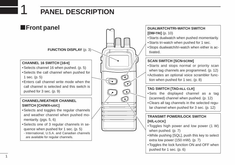
BATTERY PACK RELEASE BUTTONTo remove the battery pack:Push and hold the battery release buttondownwards, then open the battery pack asshown below.
To attach the battery pack:Mate the notched ends of the transceiverand the battery pack, and click the batterypack into place.
1PANEL DESCRIPTION
2
Top and side panels
PTT SWITCH [PTT]Push and hold to transmit; release to re-ceive. (p. 7)
SQUELCH/MONITOR SWITCH [SQL]•Opens the squelch and monitors the op-erating channel while being pushed.
•Sets the squelch level with the channelselector. (p. 6)
ANTENNA CONNECTOR (p. 17)Connects the supplied antenna.
CHANNEL SELECTOR [CH]•Sets an operating channel during normaloperation. (pgs. 5, 6)
•Sets a squelch threshold level whilepushing [SQL]. (p. 6)
•Checks tag channels or changes scan-ning direction during scan. (p. 12)
•Selects the set mode contents in SETmode. (pgs. 13, 14)
•Selects the optional scrambler codewhen [SCN•SCRM] is pushed and held.(p. 8)
VOLUME CONTROL [OFF/VOL]Turns power ON and adjusts the audiolevel. (p. 7)
BATTCALL LOW
WXDUPUSA
INTCAN
BUSYTX
SCRMDUAL TRIALT SCANTAG
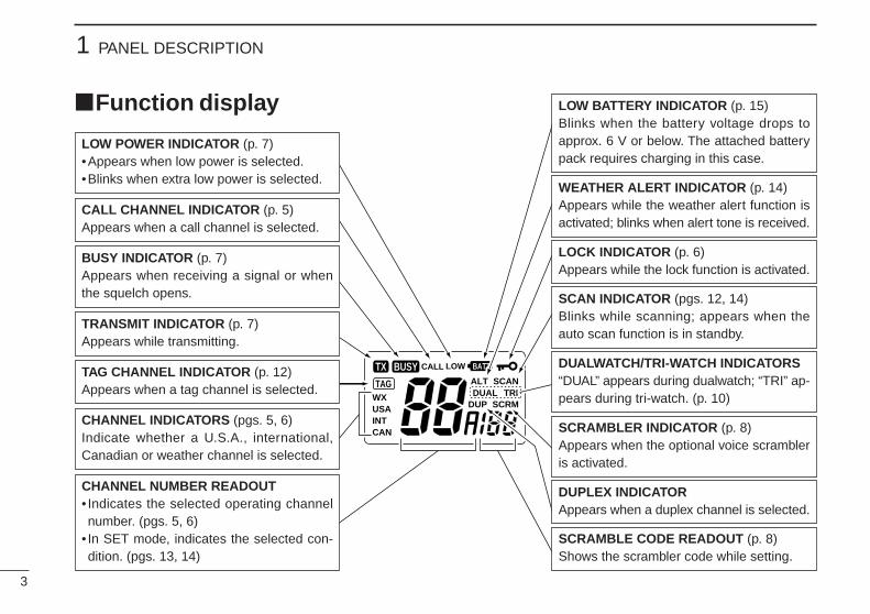
LOW BATTERY INDICATOR (p. 15)Blinks when the battery voltage drops to approx. 6 V or below. The attached batterypack requires charging in this case.
Function display
1 PANEL DESCRIPTION
3
CALL CHANNEL INDICATOR (p. 5)Appears when a call channel is selected.
TRANSMIT INDICATOR (p. 7)Appears while transmitting.
LOCK INDICATOR (p. 6)Appears while the lock function is activated.
WEATHER ALERT INDICATOR (p. 14)Appears while the weather alert function isactivated; blinks when alert tone is received.
SCAN INDICATOR (pgs. 12, 14)Blinks while scanning; appears when theauto scan function is in standby.
DUALWATCH/TRI-WATCH INDICATORS“DUAL” appears during dualwatch; “TRI” ap-pears during tri-watch. (p. 10)
DUPLEX INDICATORAppears when a duplex channel is selected.
SCRAMBLER INDICATOR (p. 8)Appears when the optional voice scrambleris activated.
SCRAMBLE CODE READOUT (p. 8)Shows the scrambler code while setting.
TAG CHANNEL INDICATOR (p. 12)Appears when a tag channel is selected.
CHANNEL INDICATORS (pgs. 5, 6)Indicate whether a U.S.A., international,Canadian or weather channel is selected.
CHANNEL NUMBER READOUT• Indicates the selected operating channelnumber. (pgs. 5, 6)
• In SET mode, indicates the selected con-dition. (pgs. 13, 14)
LOW POWER INDICATOR (p. 7)•Appears when low power is selected.•Blinks when extra low power is selected.
BUSY INDICATOR (p. 7)Appears when receiving a signal or whenthe squelch opens.
BASIC OPERATION 2
4
Inquire through your dealer or the appropriate governmentagency for a Ship-Radiotelephone license application. Thisgovernment-issued license states the call sign which is yourcraft’s identification for radio purposes.
(2) OPERATOR’S LICENSEA Restricted Radiotelephone Operator Permit is the licensemost often held by small vessel radio operators when a radiois not required for safety purposes.
The Restricted Radiotelephone Operator Permit must beposted or kept with the operator. Only a licensed radio opera-tor may operate a transceiver.
However, non-licensed individuals may talk over a transceiverif a licensed operator starts, supervises, ends the call andmakes the necessary log entries.
Keep a copy of the current government rules and regulationshandy.
Operating rules•PRIORITIES1 Read all rules and regulations pertaining to priorities and
keep an up-to-date copy handy. Safety and distress callstake priority over all others.
2 You must monitor channel 16 when you are not operatingon another channel.
3 False or fraudulent distress signals are prohibited and pun-ishable by law.
•PRIVACY1 Information overheard but not intended for you cannot law-
fully be used in any way.
2 Indecent or profane language is prohibited.
•RADIO LICENSES(1) SHIP STATION LICENSEYou must have a current radio station license before using thetransceiver. It is unlawful to operate a ship station which is notlicensed.

Channel selectionDChannel 16Channel 16 is the distress channel. It is used for establishinginitial contact with another station and for emergency com-munications. Channel 16 is monitored during dualwatch/tri-watch. While standing by you are required to monitor chan-nel 16.
DChannel 9 (Call channels)Channel 9 is the pleasure call channel. Each regular channelgroup has separate call channels. In addition, each call chan-nel is monitored during tri-watch. The call channels can beprogrammed (p. 9) and are used to store your most often-used channels in each channel group for quick recall.
•Push [16•9] for 1 sec. to selectthe call channel of the selectedchannel group.- “CALL” and call channel number
appear.- Each channel group may have an
independent call channel afterchanging a call channel.
Push
USA
9
16
2 BASIC OPERATION
5
USA
Push for 1 sec.
INT
DUP
U.S.A. channels
Canadian channelsInternational channels
CAN
TAG
U/I/C
CH/WX
U/I/C
CH/WX
U/I/C
CH/WX
CALL
USA
TAG
DU.S.A., Canadian and international channelsThere are 61 U.S.A., 57 Canadian and 57 international chan-nels. These channel groups may be specified for the operat-ing area.
1 Push [CH/WX] to select a regular channel.- If a weather channel appears, push [CH/WX] again.
2 Rotate the channel selector to select a channel.- “DUP” appears for duplex channels.
3 To change the channel group, push [CH/WX•U/I/C] for 1sec.- U.S.A., Canadian and international channels can be selected in
sequence.
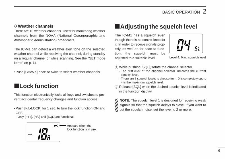
Adjusting the squelch levelThe IC-M1 has a squelch eventhough there is no control knob forit. In order to receive signals prop-erly, as well as for scan to func-tion, the squelch must beadjusted to a suitable level.
1While pushing [SQL], rotate the channel selector.- The first click of the channel selector indicates the current
squelch level.- There are 5 squelch levels to choose from: 0 is completely open;
4 is the maximum squelch level.
2 Release [SQL] when the desired squelch level is indicatedin the function display.
NOTE: The squelch level 1 is designed for receiving weaksignals so that the squelch delays to close. If you want tocut the squelch noise, set the level to 2 or more.
2BASIC OPERATION
6
DWeather channelsThere are 10 weather channels. Used for monitoring weatherchannels from the NOAA (National Oceanographic andAtmospheric Administration) broadcasts.
The IC-M1 can detect a weather alert tone on the selectedweather channel while receiving the channel, during standbyon a regular channel or while scanning. See the “SET modeitems” on p. 14.
•Push [CH/WX] once or twice to select weather channels.
Lock functionThis function electronically locks all keys and switches to pre-vent accidental frequency changes and function access.
•Push [H/L•LOCK] for 1 sec. to turn the lock function ON andOFF.- Only [PTT], [H/L] and [SQL] are functional.
Level 4: Max. squelch level
USA
Appears when the lock function is in use.

2 BASIC OPERATION
7
Receiving and transmitting
1 Rotate [OFF/VOL] clockwise to turn power ON, then set tothe 10 o’clock position.- Use the squelch function to mute any audio noise if necessary.
Refer to the previous page for details.
2 Rotate the channel selector to select the desired channel.- When receiving a signal, appears and audio is emitted
from the speaker.- Further adjustment of [OFF/VOL] may be necessary at this point.- Use the optional voice scrambler function for privacy. (p. 8)
3 Push [H/L] to select the output power if necessary.- “LOW” appears when low power is selected.- Choose low power to conserve battery power, choose high
power for longer distance communications.- Some channels are for low power only.- An extra low power is available for short distance communica-
tions. Push [H/L] while pushing [SQL] in such case.
4 Push and hold [PTT] to transmit, then speak into the mi-crophone.- appears.- Channel 70 cannot be used for transmission (for GMDSS use).
5 Release [PTT] to receive.
TX
BUSY
CAUTION: Transmitting without an antenna may dam-age the transceiver.
IMPORTANT: To maximize the readability of your trans-mitted signal, pause a few sec. after pushing [PTT], holdthe microphone 4 to 6 inches (10 to 15 cm) from yourmouth and speak at a normal voice level.
NOTE: The transceiver has power save function to con-serve the battery power and cannot be turned OFF. Thepower save function activates automatically when no sig-nal is received for 5 sec.
1 Set volume
3 Set output power
2 Set channel
4 Speak into microphone
Push to transmit4
5Release to receive
USA
Voice scrambler OFF
USA SCRM
Voice scrambler activated
USA SCRM
Set desired scramble code here
After “SCRM” appears, rotate:
[CH]
SCRM
SCN
Push and hold
2BASIC OPERATION
8
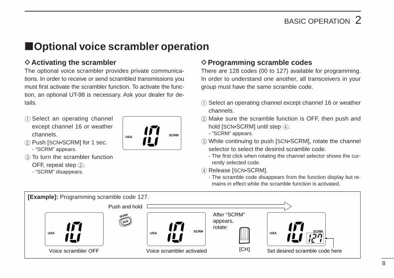
DActivating the scramblerThe optional voice scrambler provides private communica-tions. In order to receive or send scrambled transmissions youmust first activate the scrambler function. To activate the func-tion, an optional UT-98 is necessary. Ask your dealer for de-tails.
1 Select an operating channelexcept channel 16 or weatherchannels.
2 Push [SCN•SCRM] for 1 sec.- “SCRM” appears.
3 To turn the scrambler functionOFF, repeat step 2.- “SCRM” disappears.
DProgramming scramble codesThere are 128 codes (00 to 127) available for programming.In order to understand one another, all transceivers in yourgroup must have the same scramble code.
1 Select an operating channel except channel 16 or weatherchannels.
2 Make sure the scramble function is OFF, then push andhold [SCN•SCRM] until step 4.- “SCRM” appears.
3While continuing to push [SCN•SCRM], rotate the channelselector to select the desired scramble code.- The first click when rotating the channel selector shows the cur-
rently selected code.
4 Release [SCN•SCRM].- The scramble code disappears from the function display but re-
mains in effect while the scramble function is activated.
Optional voice scrambler operation
USA SCRM
[Example]: Programming scramble code 127.

2 BASIC OPERATION
9
Call channel programmingThe call channel key is used to select channel 9, however,you can program your most often-used channels in eachchannel group for quick recall.
1 Push [CH/WX•U/I/C] for 1 sec.several times to select the de-sired channel group (USA, INT,CAN) to be programmed.
2 Push [16•9] for 1 sec. to selectthe call channel of the selectedchannel group.- “CALL” and call channel number
appear.
3 Push [16•9] again for 3 sec.(until long beep changes to 2short beeps) to enter call chan-nel programming condition.- Call channel number and channel
group to be programmed flashes.
USA
TAG
CALL
USA
TAG
CALL
USA
TAG
4 Rotate the channel selector toselect the desired channel.
5 Push [16•9] to program the dis-played channel as the callchannel.- The call channel number and
channel group stop flashing.
Automatic backlightingThis function is convenient for nighttime operation. The auto-matic backlighting can be activated in SET mode. (p. 13)
•Push any key except for [PTT] to turn the backlighting ON.-The backlighting is automatically turned OFF 5 sec. after opera-tion.
-Push [SQL] to turn the backlighting ON without changing the op-erating condition.
CALL
USA
TAG
CALL
USA
TAG

DescriptionDualwatch monitors channel 16 while you are receiving an-other channel; tri-watch monitors channel 16 and the callchannel while receiving another channel.
DUALWATCH/TRI-WATCH SIMULATION
DUALWATCH/TRI-WATCH 3
10
Operation1 Select the desired operating channel.2 Push [DW•TRI] momentarily to start dualwatch; push
[DW•TRI] for 1 sec. to start tri-watch.- “DUAL” flashes during dualwatch; “TRI” flashes during tri-watch.- Beep tone sounds when a signal is received on channel 16.- Tri-watch becomes dualwatch when receiving a signal on the call
channel.
3 To cancel dualwatch/tri-watch, push [DW•TRI] again.Call channel
[Example]: Operating tri-watch on INT channel 07.
DUP
INT
TRITAG
CALL
INT
BUSY
TRITAG
DUP
DUP
INT
BUSY
TRITAG
INT
TRITAG
TRI
DW
Tri-watch starts.Push for 1 sec.
Signal is received on call channel.
Signal received on channel 16 takes priority.
Tri-watch resumes after the signal disappears.
• If a signal is received on channel 16, dualwatch/tri-watch pauseson channel 16 until the signal disappears.
• If a signal is received on the call channel during tri-watch, tri-watch becomes dualwatch until the signal disappears.
•To transmit on the selected channel during dualwatch/tri-watch,push and hold [PTT].
• If no signal is received, the transceiver enters the power savingcondition for 0.5 sec. after checking the operating channel everycycle.
Dualwatch Tri-watch

SCAN OPERATION4
11
Scan typesScanning is an efficient way to locate signals quickly over awide frequency range. The transceiver has priority scan andnormal scan.
In addition, weather alert and automatic scan start function isavailable for standby convenience. (p. 14)
Set the tag channels (scanned channel) before scanning.Clear the tag channels which inconveniently stop scanning,such as digital communication use.
PRIORITY SCAN
WX*
CH 01
CH 16
CH 02
CH 05 CH 04
CH 03
Priority scan searches through all tag channels in sequencewhile monitoring channel 16. When a signal is detected onchannel 16, scan pauses until the signal disappears; whena signal is detected on a channel other than channel 16,scan becomes dualwatch until the signal disappears.
NORMAL SCAN
CH 01 CH 02
WX*
CH 05 CH 04
CH 03
Normal scan, like priority scan, searches through all tagchannels in sequence. However, unlike priority scan, chan-nel 16 is not checked unless channel 16 is set as a tagchannel.
NOTE: Choose priority or normal scan in SET mode.(p. 14)
*Previously selected weather channel whenweather alert function is ON.
*Previously selected weather channel whenweather alert function is ON.

4SCAN OPERATION
12
Setting tag channelsFor more efficient scanning, add desired channels as tagchannels or clear tag channels for unwanted channels.Channels set as non-tag channels will be skipped duringscanning. Tag channels can be assigned to each channelgroup (USA, CAN, INT) independently.
1 Select the desired channel group (USA, CAN, INT) bypushing [CH/WX•U/I/C] for 1 sec., if desired.
2 Select the desired channel to set as a tag channel.3 Push [TAG] to set the displayed channel as a tag channel.
- appears in the function display.
4 To cancel the tag channel setting, push [TAG].- disappears.
•Clearing all tag channels in the selected channel group- Push [TAG•ALL CLR] for 3 sec. to clear all tag channels in
the channel group.
TAG
TAG
Starting a scanSet scan type, weather alert function, scan resume timer andauto scan function in advance using SET mode. (p. 14)
1 Select the desired channel group (USA, CAN, INT) bypushing [CH/WX•U/I/C] for 1 sec., if desired.- When the weather alert function is in use, select the desired
weather channel with [CH/WX] and the channel selector.
2 Push [SCN] to start priority or normal scan.- “SCAN” appears and flashes in the function display.- “16” appears during priority scan.- When a signal is detected, scan pauses until the signal disap-
pears or resumes after pausing 5 sec. according to SET modesetting. (Channel 16 is still monitored during priority scan.)
- Rotate the channel selector to check the scanning tag channels,to change the scanning direction or resume the scan manually.
3 To stop the scan, push [SCN].- “SCAN” disappears.- Pushing [PTT], [16•9], [CH/WX] or [DW•TRI] also stops the scan.
Scan starts.Scan pauses when receiving a signal and audio is emitted.
USA
SCANTAG
USA USA
BUSYSCANTAG
SCRM
SCN
SCRM
SCN
Push Push to stop the scan.
[Example]: Starting a normal scan.

SET MODE5
13
SET mode itemsDBeep tone “bP”You can select silent operation by turning beep tones OFF oryou can have confirmation beeps sound at the push of aswitch by turning beep tones ON. The beep tone volume islinked with [OFF/VOL].
DAutomatic backlighting “bL”This function is convenient for nighttime operation. The auto-matic backlighting turns the backlighting ON when pushingany key except for [PTT].•The backlighting is automatically turned OFF 5 sec. after operation.
•Push [SQL] to turn the backlighting ON without changing the oper-
ating condition.
SET mode programmingSET mode is used to change the conditions of 6 transceiverfunctions: the beep tone function, the automatic backlighting,weather alert function, normal/priority scan, scan resumetimer and auto scan function.
1 Turn power OFF.2While pushing [SQL], turn power ON and continue push-
ing [SQL] until “bP” appears.3 After the display appears, release [SQL].4 Push [SQL] to select the desired item, if necessary.5 Rotate the channel selector to select the desired condition
of the item.6 To exit SET mode, push [16].
- Turning power OFF, then ON again also exits SET mode.
Beep tone ON (default)
Automatic backlighting ON (default)
•SET MODE CONSTRUCTION
Automatic backlighting
Weather alertScan resumetimer
Scan type
Beep tone
Auto scan
Push

5SET MODE
14
DWeather alert function “AL”An NOAA broadcast station transmits an weather alert tonebefore an important weather information. When the weatheralert function is turned ON, the transceiver detects the alert,then flashes the “ALT” indicator until the transceiver is oper-ated. The previously selected (used) weather channel ischecked in any time during standby or while scanning.• “ALT” appears when the function is set ON.
DScan type selection “SC”The transceiver has 2 scan types: normal scan and priorityscan. Normal scan searches all tag channels in the selectedchannel group. Priority scan searches all tag channels in se-quence while monitoring channel 16.
Normal scan (default) Priority scan
DScan resume timer “St”The scan resume timer can be selected as a pause (OFF) ortimer scan (ON). When OFF is selected, the scan pausesuntil the signal disappears. When ON is selected, the scanpauses 5 sec. and resumes even if a signal is being receivedon channels except for channel 16.
DAuto scan function “At”While in standby, this function automatically starts the se-lected scan (normal or priority scan) 30 sec. after operation.• “SCAN” appears when the function is turned ON.
Scan timer OFF (default)
WX
Weather alert function OFF (default)
SCAN
Auto scan OFF (default)
NOTE: The transceiver has a power save function but thepower save function does not function when the auto scanfunction is in use.

BATTERY CHARGING6
15
Battery cautionsNEVER incinerate used battery packs. Internal battery gasmay cause an explosion.
NEVER immerse the battery pack in water. If the battery packbecomes wet, be sure to wipe it dry BEFORE attaching it tothe transceiver.
NEVER short terminals of the battery pack. Also, current mayflow into nearby metal objects so be careful when placing bat-tery packs in handbags, etc.
If your battery pack seems to have no capacity even afterbeing charged, completely discharge it by leaving the powerON overnight. Then, fully charge the battery pack again. If thebattery pack still does not retain a charge (or very little), anew battery pack must be purchased.
DRecycling informationThe product that you have purchased contains arechargeable battery. The battery is recyclable. Atthe end of its life, under various state and locallaws, it may be illegal to dispose of this battery into
the municipal waste stream. Call 1-800-8-BATTERY for bat-tery recycling options in your area or contact your dealer.
RBRC
RBRC
Ni-Cd
Battery chargingPrior to using the transceiver for the first time, the batterypack must be fully charged for optimum life and operation.
•Recommended temperature range for charging: +50°F to +104°F (+10°C to +40°C)
•Use the supplied charger (AD-58) or optional charger(BC-119 for rapid charging) only. NEVER use other manu-factures’ charger.
•An optional cable OPC-515L (for 13.8 V power source) orCP-17L (for 12 V cigarette lighter socket) can be used in-stead of the AC adapters of above chargers.
When using AD-58: If the charge indicator lights red, thevehicle battery voltage is low and charging may not beperformed. Check the vehicle battery voltage in this case.
When using BC-119: If the charge indicator flashes or-ange, the vehicle battery voltage is low and charging maynot be performed. Check the vehicle battery voltage in thiscase. If the charge indicator flashes red, there may be aproblem with the battery pack (or charger). Re-insert thebattery pack or contact your dealer.
CAUTION: To avoid damage to the transceiver, turn itOFF while charging.

DAttaching the AD-58 to awall
D Installing the AD-69 to theBC-119
1 Connect the cable as shown below.2 Attach the AD-69 with the 2 supplied
screws.
DCharging with the AD-581 Connect the AC adapter (BC-122) or
optional cable (CP-17L orOPC-515L) as shown below.
2 Insert the transceiver with attachedbattery pack into the charger.•The charge indicator lights orange.
3 Charge the battery pack for 15hours.
DCharging with the optionalBC-119+AD-69
1 Connect the AC adapter (BC-123) oroptional cable (CP-17L orOPC-515L) as shown below.
2 Insert the transceiver with attachedbattery pack (or the battery packonly) into the charger.•The charge indicator lights orange.
3 Charge the battery pack until thecharge indicator changes to green.•Charging time: Approx. 1 to 1.5 hours
BC-119
AD-69
6BATTERY CHARGING
16
Turn power OFF.
AD-58
BC-122A/E
CP-17L or OPC-515L
Turn power OFF.
BP-185 or BP-186
BC-123A/E
BC-119+AD-69
CP-17L orOPC-515L
AVOID overcharging!The AD-58 is NOT atransceiver hanger. Takeout the transceiver within48 hours.
Eyelet:
USE a rubberband to securethe transceiver, ifdesired.
UNPACKING AND ACCESSORY ATTACHMENT7
17
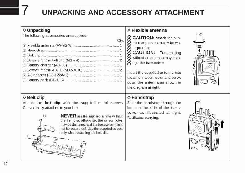
DUnpackingThe following accessories are supplied:
Qty.1 Flexible antenna (FA-S57V) ........................................... 12 Handstrap ....................................................................... 13 Belt clip ........................................................................... 14 Screws for the belt clip (M3 × 4) ..................................... 25 Battery charger (AD-58) ................................................. 16 Screws for the AD-58 (M3.5 × 30) .................................. 27 AC adapter (BC-122A/E) ................................................ 18 Battery pack (BP-185) .................................................... 1
DFlexible antenna
CAUTION: Attach the sup-plied antenna securely for wa-terproofing.CAUTION: Transmittingwithout an antenna may dam-age the transceiver.
Insert the supplied antenna intothe antenna connector and screwdown the antenna as shown inthe diagram at right.
DBelt clipAttach the belt clip with the supplied metal screws.Conveniently attaches to your belt.
DHandstrapSlide the handstrap through theloop on the side of the trans-ceiver as illustrated at right.Facilitates carrying.NEVER use the supplied screws without
the belt clip, otherwise, the screw holesmay be damaged and the transceiver mightnot be waterproof. Use the supplied screwsonly when attaching the belt clip.

TROUBLESHOOTING 8
18
PROBLEM POSSIBLE CAUSE SOLUTION REF.
No power comes ON. •The battery is exhausted.•Bad connection to the battery pack.
•Recharge the battery pack.•Check the connection to the transceiver.
p. 15p. 2
No sound comes fromthe speaker.
•Squelch level is too deep.•Volume level is too low.•Speaker has been exposed to water.
•Set squelch to the threshold point.•Set [OFF/VOL] to a suitable level.•Drain water from the speaker.
p. 6p. 7
—
Transmitting is impossi-ble, or high power can-not be selected.
•Some channels are for low power or re-ceive only.
•The battery is exhausted.•The output power is set to low or extra low.
•Change channels.
•Recharge the battery pack.•Push [H/L] to select high power.
pgs.5, 7p. 15p. 7
The displayed channelcannot be changed.
•Lock function is activated. •Push [H/L•LOCK] for 1 sec. to cancel thefunction.
p. 6
Scan does not start. • “TAG” channel is not programmed. •Set the desired channels as “TAG” chan-nels.
p. 12
Scan starts automati-cally.
•Auto scan function is activated. •Cancel the auto scan function in SETmode.
p. 14
No beep sounds. •Beep tone is turned OFF. •Turn the beep tone ON in SET mode. p. 13
Receive signal cannotbe understood.
•Optional voice scrambler is turned OFF.•Scramble code is not set correctly.
•Turn the optional voice scrambler ON.•Reset the scramble code.
p. 8p. 8

CHANNEL LIST9
19
Channel number
USA CAN Transmit Receive
01 156.050 160.650
01A 156.050 156.050
02 156.100 160.700
02A 156.100 156.100
03 156.150 160.750
03A 156.150 156.150
156.200 160.800
04A 04A 156.200 156.200
156.250 160.850
05A 05A 156.250 156.250
06 06 156.300 156.300
156.350 160.950
07A 07A 156.350 156.350
08 08 156.400 156.400
09 09 156.450 156.450
10 10 156.500 156.500
11 11 156.550 156.550
12 12 156.600 156.600
13† 13† 156.650 156.650
14 14 156.700 156.700
15† 15† 156.750 156.750
16 16 156.800 156.800
17† 17† 156.850 156.850
156.900 161.500
18A 18A 156.900 156.900
Frequency (MHz)
INT
01
02
03
04
05
06
07
08
09
10
11
12
13
14
15†
16
17
18
Channel number Frequency (MHz)
USA CAN Transmit Receive
156.950 161.550
19A 19A 156.950 156.950
20 20† 157.000 161.600
21 157.050 161.650
21A 21A 157.050 157.050
157.100 161.700
22A 22A 157.100 157.100
23 157.150 161.750
23A 157.150 157.150
24 24 157.200 161.800
25 25 157.250 161.850
26 26 157.300 161.900
27 27 157.350 161.950
28 28 157.400 162.000
60 156.025 160.625
60A 156.025 156.025
156.075 160.675
61A 61A 156.075 156.075
156.125 160.725
62A 62A 156.125 156.125
156.175 160.775
63A 156.175 156.175
64 156.225 160.825
64A 64A 156.225 156.225
INT
19
20
21
22
23
24
25
26
27
28
60
61
62
63
64
20A 157.000 157.000
Channel number
66A
Frequency (MHz)
66A†
USA CAN Transmit Receive
156.275 160.875
65A 65A 156.275 156.275
156.325 160.925
67† 67 156.375 156.375
68 68 156.425 156.425
69 69 156.475 156.475
70‡ 70‡ 156.525 156.525
71 71 156.575 156.575
72 72 156.625 156.625
73 73 156.675 156.675
74 74 156.725 156.725
75 75 Guard Guard
76 76 Guard Guard
77† 77† 156.875 156.875
156.925 161.525
78A 78A 156.925 156.925
156.975 161.575
79A 79A 156.975 156.975
157.025 161.625
80A 80A 157.025 157.025
157.075 161.675
81A 81A 157.075 157.075
157.125 161.725
82A 82A 157.125 157.125
INT
65
65A
66
67
68
69
70‡
71
72
73
74
75
76
77
78
79
80
81
82
156.325 156.32566A
Channel number
84A
Frequency (MHz)
USA CAN Transmit Receive
83 157.175 161.775
83A 83A 157.175 157.175
84 84 157.225 161.825
85 85 157.275 161.875
85A 157.275 157.275
86 86 157.325 161.925
86A 157.325 157.325
87 87 157.375 161.975
87A 157.375 157.375
88 88 157.425 162.025
88A 157.425 157.425
INT
83
84
85
86
87
88
157.225 157.225
WX channel
04
Frequency (MHz)
Transmit Receive
01 RX only 162.550
02 RX only 162.400
03 RX only 162.475
05 RX only 162.450
06 RX only 162.500
07 RX only 162.525
08 RX only 161.650
09 RX only 161.775
10 RX only 163.275
RX only 162.425
† Low power only. ‡ Receive only.

SPECIFICATIONS AND OPTIONS 10
20
Options•AD-58 BATTERY CHARGER + BC-122A/E AC ADAPTER
Used for regular charging of battery packs. The same as suppliedwith the transceiver. Charging time: 15 hours.
•BC-119 DESKTOP CHARGER (or BC-121 MULTI-CHARGER)
+ AD-69 DESKTOP CHARGER ADAPTERUsed for rapid charging of battery packs. Charging time: 1 to 1.5hours. An AC adapter is supplied with the chargers. BC-121 rapidlycharges up to 6 battery packs at once.
•CP-17L CIGARETTE LIGHTER CABLEConnects to a ship’s or vehicle’s cigarette lighter socket (12 V) foruse with the AD-58 or BC-119.
•FA-S57V FLEXIBLE ANTENNASame as supplied with the transceiver.
•OPC-515L DC POWER CABLEUsed for charging with external power supply.
•UT-98 VOICE SCRAMBLER UNITEnsures private communications. 128 codes are available. Not avail-able in some countries.
DBattery packs
Specifications•GENERALFrequency coverage : Transmit 156–157.5 MHz
Receive 156–163 MHzMode : FM (16K0G3E)Channel spacing : 25 kHzCurrent drain (at 8.4 V) : TX High 1.8 A max.
Max. audio 300 mA max.Power saved13 mA typ.
Power supply requirement : Icom battery packsFrequency stability : ±10 ppm (–20°C to +60°C)Useable temperature range : –20°C to +60°C; –4°F to +140°FDimensions (with BP-185) : 52.5 (W)×129(H)×30(D) mm(Projection is not included) 21⁄16 (W)×53⁄32 (H)×13⁄16 (D) inWeight (with BP-185) : 280 g (9.9 oz)
•TRANSMITTEROutput power (at 8.4 V) : 5 W, 1 W and 0.15 WModulation system : Variable reactance phase modulationMax. frequency deviation : ±5.0 kHzSpurious emissions : Less than –65 dB
•RECEIVERReceive system : Double-conversion superheterodyneSensitivity (12 dB SINAD) : Less than 0.35 µVSquelch sensitivity : Adjustable up to 23 dB SINADIntermodulation rejection ratio: More than 70 dBSpurious response rejection ratio : More than 70 dBAdjacent channel selectivity : More than 70 dBAudio output power : 400 mW at 5% distortion with an 8 Ω
load
All stated specifications are subject to change without notice or obligation.
Batterypack
Voltage/capacity
Outputpower
Height
BP-1858.4 V/
400 mAh5.0 W
129 mm;53⁄32 in
BP-1867.2 V/
1050 mAh4.5 W
159 mm;61⁄4 in
Approx. operating time*
4 h
10.5 h
*Condition: Tx : Rx : Standby (Power saved) = 5 : 5 : 90
High E Low
13 h
34 h
8 h
21 h
Low

A-5373H-1US-qPrinted in JapanCopyright © 1995 by Icom Inc. 6-9-16 Kamihigashi, Hirano-ku, Osaka 547 Japan