Embed Size (px)
Citation preview
www.fastsampling.com
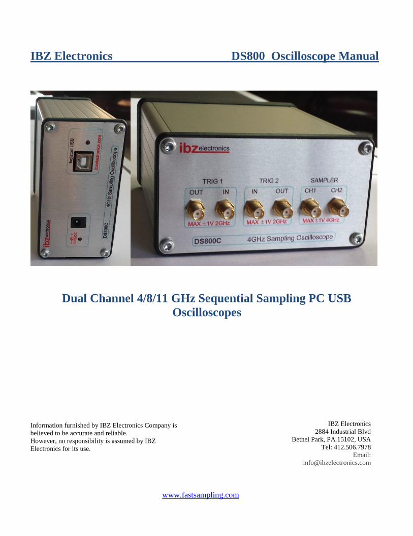
IBZ Electronics DS800 Oscilloscope Manual
Dual Channel 4/8/11 GHz Sequential Sampling PC USB
Oscilloscopes
Information furnished by IBZ Electronics Company is
believed to be accurate and reliable.
However, no responsibility is assumed by IBZ
Electronics for its use.
IBZ Electronics
2884 Industrial Blvd
Bethel Park, PA 15102, USA
Tel: 412.506.7978
Email:
www.fastsampling.com
Introduction
The DS800 is 4, 8 or 11GHz minimum Bandwidth Sequential Sampling Oscilloscope.
Oscilloscopes use external 9-16VDC/0.7A power supply and have 4 SMA inputs and 2 SMA
outputs.
All inputs and output have 50 Ohm impedance and is AC Coupled or DC coupled selected
during assembling process.
The small, portable hardware package connects to your PC via an optically isolated full speed
USB interface for PC protection and eliminates effects of noise from USB bus and PC ground.
All device control and monitoring is managed via an intuitive graphical PC software interface.
The use of small package high speed ECL components allows extremely wide bandwidth, highly
accurate self calibrated time base with 1 ps resolution.
This low cost, easy to use device is a perfect solution for engineers and hobbyists alike who need
to measure amplitude, rise time and propagation delay in high speed analog and digital circuit.
DS800 will work only with repetitive signals, since it requires multiple signal repetitions to
complete conversion.
When 2 channels are used then there must be some fixed timing correlation between 2 channels
in order for sampling to be accurate representation of real event.
If frequency on 2 channels is different, but there is clear timing correlation or synchronization
then channel with lower frequency should be used as trigger source.
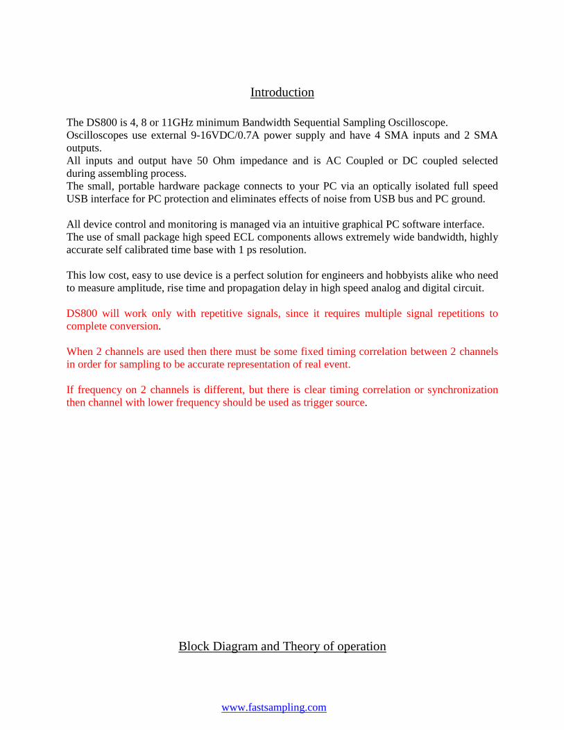
Block Diagram and Theory of operation
DS800 Manual
Page 4
IBZ Electronics 2884 Industrial Blvd, Bethel Park PA 15102 Ph: (412) 506-7978 [email protected]
DS8GA is simple, yet very fast and accurate oscilloscope made of Microcontroller and high speed ECL
differential circuitry.
Microcontroller receives commands and responds via isolated USB interface running at full USB speed
of 12Mbits/s.
Sequential scope works by inserting incremental delays between trigger and sample circuit.
ADC conversion can not start without trigger event.
Once trigger has fired, high speed flip flop is set and programmable delay lines starts counting time in
10 picoseconds increments.
Fine tuning voltage adjusts final time delay with one picosends resolution using DAC calibration data
from microcontroller flash memory.
Sample is taken on both channels simultaneously after delay line counting’s completed.
2 CH Sampler
8/4/11GHz
Bandwidth
Trigger
2GHz
POWER
SPLITER
POWER
SPLITER
Programmable delay line
1 ps resolution
Self calibration
CPU
ISOLATED USB
POWER REG
DS800 Oscilloscope
DS800 Manual
Page 5
IBZ Electronics 2884 Industrial Blvd, Bethel Park PA 15102 Ph: (412) 506-7978 [email protected]
It is important to note that each ADC conversion require multiple trigger events making some limits on
scope usage with only repetitive signals.
Achieving highly accurate and repeatable time base is done using proprietary self calibration and fine
tuning techniques.
Device time base is calibrated after assembly and user have option to run auto time base calibration.
Time base calibration take long time, since time base is scanned with 1 ps intervals and multiple cycles
are repeated, compared to time generated by crystal and store in flash calibration look up table.
There is no need for frequent time base calibration since PECL logic is stable over temperature range.
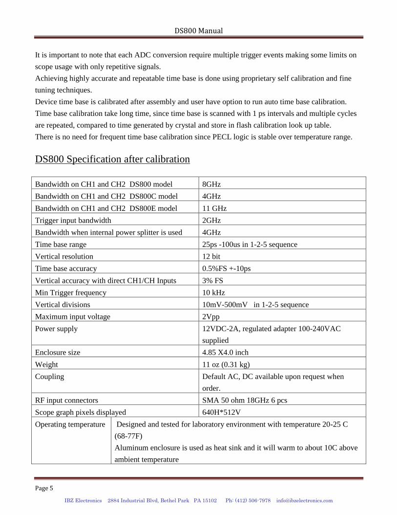
DS800 Specification after calibration
Bandwidth on CH1 and CH2 DS800 model 8GHz
Bandwidth on CH1 and CH2 DS800C model 4GHz
Bandwidth on CH1 and CH2 DS800E model 11 GHz
Trigger input bandwidth 2GHz
Bandwidth when internal power splitter is used 4GHz
Time base range 25ps -100us in 1-2-5 sequence
Vertical resolution 12 bit
Time base accuracy 0.5%FS +-10ps
Vertical accuracy with direct CH1/CH Inputs 3% FS
Min Trigger frequency 10 kHz
Vertical divisions 10mV-500mV in 1-2-5 sequence
Maximum input voltage 2Vpp
Power supply 12VDC-2A, regulated adapter 100-240VAC
supplied
Enclosure size 4.85 X4.0 inch
Weight 11 oz (0.31 kg)
Coupling Default AC, DC available upon request when
order.
RF input connectors SMA 50 ohm 18GHz 6 pcs
Scope graph pixels displayed 640H*512V
Operating temperature Designed and tested for laboratory environment with temperature 20-25 C
(68-77F)
Aluminum enclosure is used as heat sink and it will warm to about 10C above
ambient temperature
DS800 Manual
Page 6
IBZ Electronics 2884 Industrial Blvd, Bethel Park PA 15102 Ph: (412) 506-7978 [email protected]
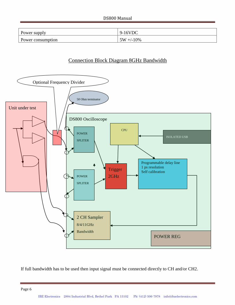
Power supply 9-16VDC
Power consumption 5W +/-10%
Connection Block Diagram 8GHz Bandwidth
If full bandwidth has to be used then input signal must be connected directly to CH and/or CH2.
2 CH Sampler
8/4/11GHz
Bandwidth
Trigger
2GHz
POWER
SPLITER
POWER
SPLITER
Programmable delay line
1 ps resolution
Self calibration
CPU
ISOLATED USB
POWER REG
50 Ohm terminator
Unit under test
Optional Frequency Divider
DS800 Oscilloscope
DS800 Manual
Page 7
IBZ Electronics 2884 Industrial Blvd, Bethel Park PA 15102 Ph: (412) 506-7978 [email protected]
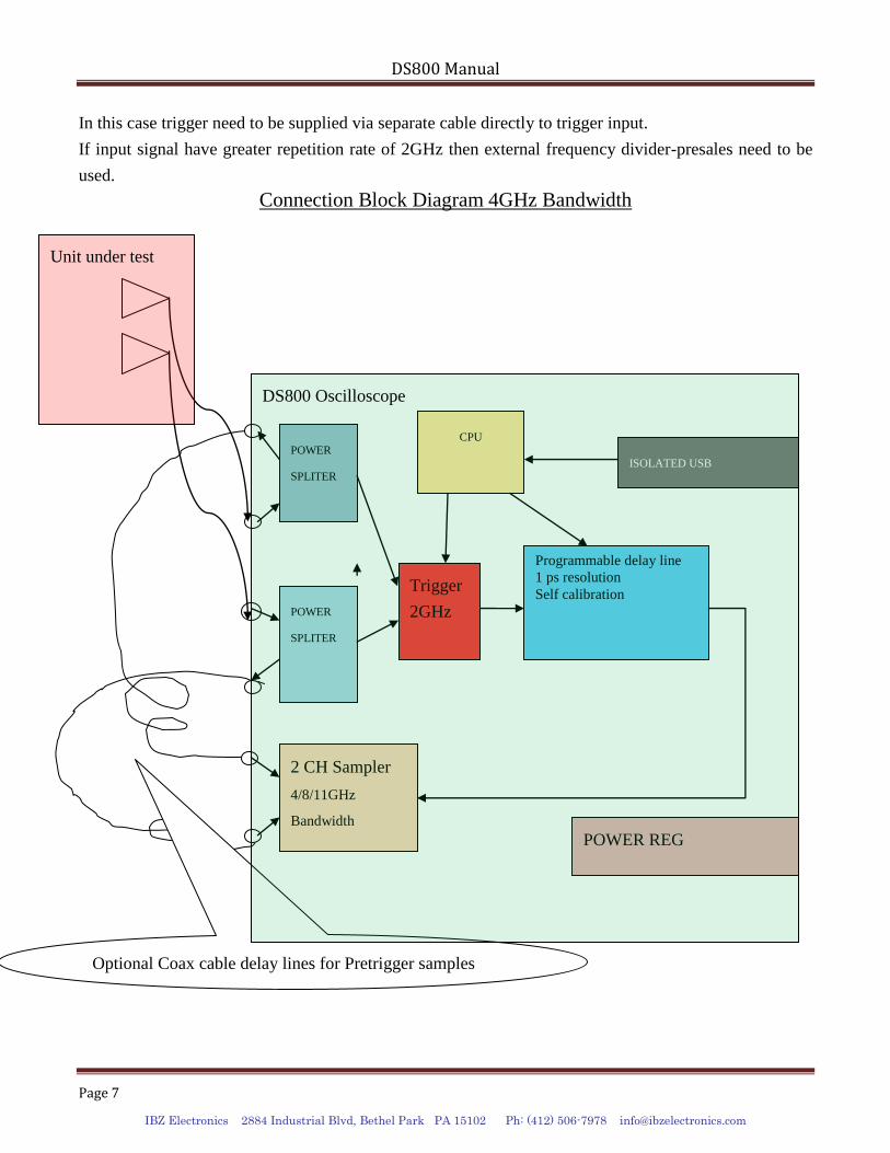
In this case trigger need to be supplied via separate cable directly to trigger input.
If input signal have greater repetition rate of 2GHz then external frequency divider-presales need to be
used.
Connection Block Diagram 4GHz Bandwidth
Optional Coax cable delay lines for Pretrigger samples
2 CH Sampler
4/8/11GHz
Bandwidth
Trigger
2GHz
POWER
SPLITER
POWER
SPLITER
Programmable delay line
1 ps resolution
Self calibration
CPU
ISOLATED USB
POWER REG
DS800 Oscilloscope
Unit under test
DS800 Manual
Page 8
IBZ Electronics 2884 Industrial Blvd, Bethel Park PA 15102 Ph: (412) 506-7978 [email protected]
If bandwidth required does not excide 4GHz then input connection can be simplified and trigger input
power divider can be used.
In this case input signal is divided by 2 and retrigger samples are available if 4 ft or longer external coax
cable is used as delay line.
Probes Connections
DS800 have input impedance of 50 ohm and can be used with any 50 Ohm active or passive probes.
Using active probe would require that probes have its own power supply and that output voltage never
excides 2Vpp or +-1VDC
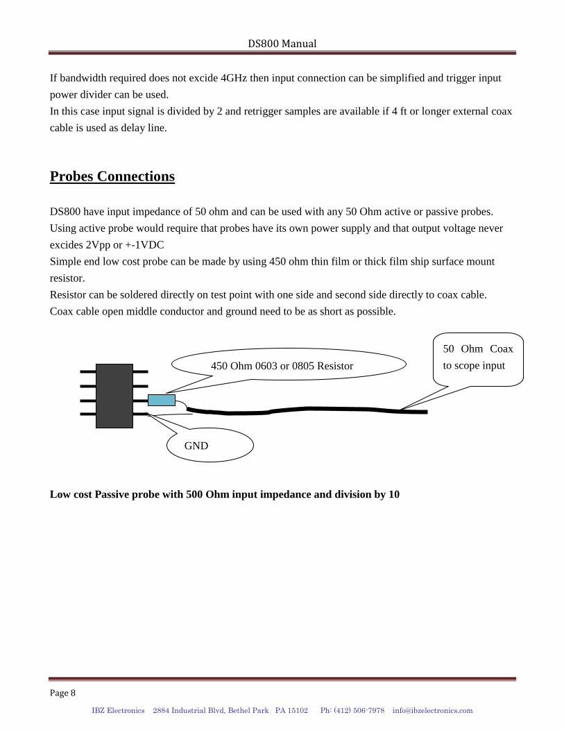
Simple end low cost probe can be made by using 450 ohm thin film or thick film ship surface mount
resistor.
Resistor can be soldered directly on test point with one side and second side directly to coax cable.
Coax cable open middle conductor and ground need to be as short as possible.
Low cost Passive probe with 500 Ohm input impedance and division by 10
450 Ohm 0603 or 0805 Resistor
GND
50 Ohm Coax
to scope input
DS800 Manual
Page 9
IBZ Electronics 2884 Industrial Blvd, Bethel Park PA 15102 Ph: (412) 506-7978 [email protected]
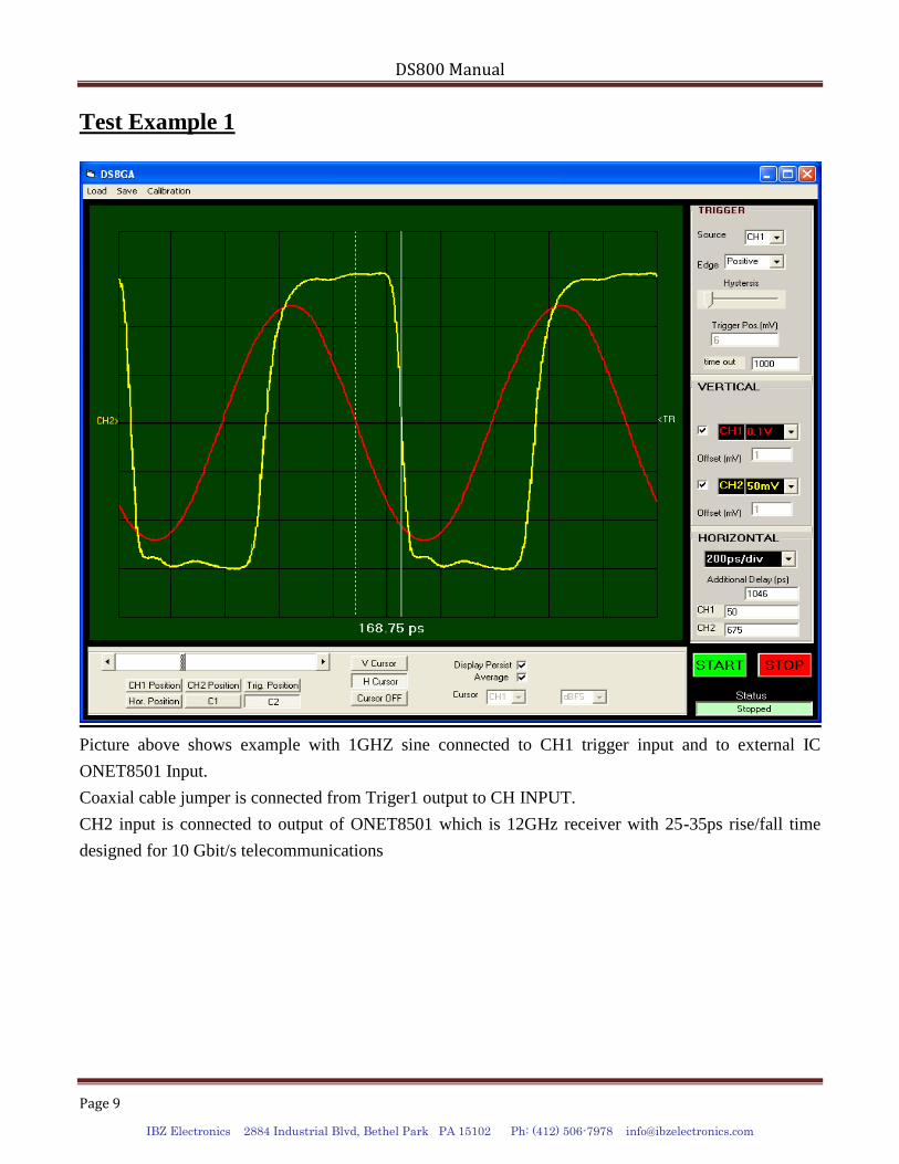
Test Example 1
Picture above shows example with 1GHZ sine connected to CH1 trigger input and to external IC
ONET8501 Input.
Coaxial cable jumper is connected from Triger1 output to CH INPUT.
CH2 input is connected to output of ONET8501 which is 12GHz receiver with 25-35ps rise/fall time
designed for 10 Gbit/s telecommunications
DS800 Manual
Page 10
IBZ Electronics 2884 Industrial Blvd, Bethel Park PA 15102 Ph: (412) 506-7978 [email protected]
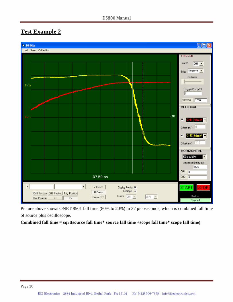
Test Example 2
Picture above shows ONET 8501 fall time (80% to 20%) in 37 picoseconds, which is combined fall time
of source plus oscilloscope.
Combined fall time = sqrt(source fall time* source fall time +scope fall time* scope fall time)
DS800 Manual
Page 11
IBZ Electronics 2884 Industrial Blvd, Bethel Park PA 15102 Ph: (412) 506-7978 [email protected]
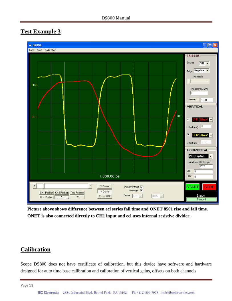
Test Example 3
Picture above shows difference between ecl series fall time and ONET 8501 rise and fall time.
ONET is also connected directly to CH1 input and ecl uses internal resistive divider.
Calibration
Scope DS800 does not have certificate of calibration, but this device have software and hardware
designed for auto time base calibration and calibration of vertical gains, offsets on both channels
DS800 Manual
Page 12
IBZ Electronics 2884 Industrial Blvd, Bethel Park PA 15102 Ph: (412) 506-7978 [email protected]
There is also software feature which allows manual calibration of time base in case that accuracy if
internal crystal and auto calibration is not sufficient.
If this device is to be used in production where certified calibration is required, then it need to
periodically to be calibrated against know calibrated source.
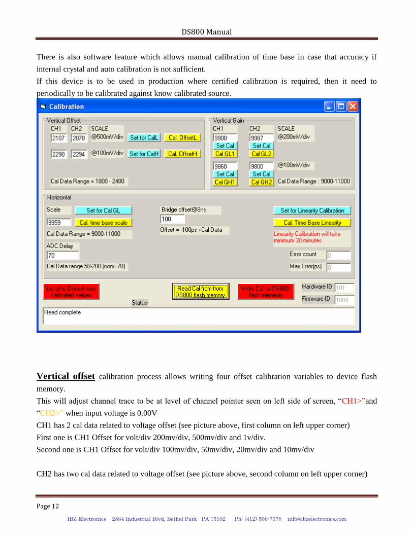
Vertical offset calibration process allows writing four offset calibration variables to device flash
memory.
This will adjust channel trace to be at level of channel pointer seen on left side of screen, “CH1>”and
“CH2>” when input voltage is 0.00V
CH1 has 2 cal data related to voltage offset (see picture above, first column on left upper corner)
First one is CH1 Offset for volt/div 200mv/div, 500mv/div and 1v/div.
Second one is CH1 Offset for volt/div 100mv/div, 50mv/div, 20mv/div and 10mv/div
CH2 has two cal data related to voltage offset (see picture above, second column on left upper corner)
DS800 Manual
Page 13
IBZ Electronics 2884 Industrial Blvd, Bethel Park PA 15102 Ph: (412) 506-7978 [email protected]
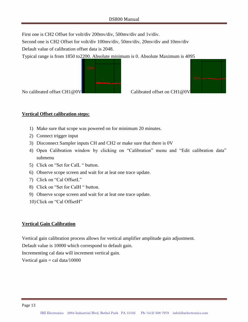
First one is CH2 Offset for volt/div 200mv/div, 500mv/div and 1v/div.
Second one is CH2 Offset for volt/div 100mv/div, 50mv/div, 20mv/div and 10mv/div
Default value of calibration offset data is 2048.
Typical range is from 1850 to2200. Absolute minimum is 0. Absolute Maximum is 4095
No calibrated offset CH1@0V Calibrated offset on CH1@0V
Vertical Offset calibration steps:
1) Make sure that scope was powered on for minimum 20 minutes.
2) Connect trigger input
3) Disconnect Sampler inputs CH and CH2 or make sure that there is 0V
4) Open Calibration window by clicking on “Calibration” menu and “Edit calibration data”
submenu
5) Click on “Set for CalL “ button.
6) Observe scope screen and wait for at leat one trace update.
7) Click on “Cal OffsetL”
8) Click on “Set for CalH “ button.
9) Observe scope screen and wait for at leat one trace update.
10) Click on “Cal OffsetH”
Vertical Gain Calibration
Vertical gain calibration process allows for vertical amplifier amplitude gain adjustment.
Default value is 10000 which correspond to default gain.
Incrementing cal data will increment vertical gain.
Vertical gain = cal data/10000
DS800 Manual
Page 14
IBZ Electronics 2884 Industrial Blvd, Bethel Park PA 15102 Ph: (412) 506-7978 [email protected]
Vertical Offset calibration steps:
1) Connect trigger 1 input to signal of 1Vpp, 10 MHz from calibrated source
2) Connect trigger output to CH1 input
3) Open Calibration window by clicking on “Calibration” menu and “Edit calibration data”
submenu
4) Click on “Set Cal” Button above “Cal GL1” Button.
5) Wait and observe at least one trace update.
6) Click on “Cal GL1” auto calibrate gain on CH1 low gain.
7) Click on “Set Cal” Button above “Cal GH1” Button.
8) Wait and observe at least one trace update.
9) Click on “Cal GH1” auto calibrate gain on CH1 low gain.
10) Connect trigger input 2 to 1Vpp, 10MHz from calibrated source and connect trigger 2 output to
CH2 input.
11) Repeat steps 4 to 9 to calibrate CH2
Horizontal Scale Calibration:
1) Connect trigger 1 input to signal of 1Vpp, 10 MHz from calibrated source
2) Connect trigger output to CH1 input
3) Click on “Set for Cal GL” button.
4) Wait and observe at least one trace update.
5) Click on button “Cal. Time base scale” to auto calibrate time base scale
Calibration data will take effect only after “Write Cal to DS800 flash memory” is used
ADC Delay
ADC delay is used to control conversion timing.
Default value is 70.
Increasing this value will increase conversion time slow scope.
If this value is too low then adc conversion error will increase.
If it is too high scope will update too slowly without significant gain in conversion quality.
Bridge offset@8ns
DS800 Manual
Page 15
IBZ Electronics 2884 Industrial Blvd, Bethel Park PA 15102 Ph: (412) 506-7978 [email protected]
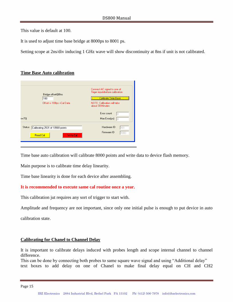
This value is default at 100.
It is used to adjust time base bridge at 8000ps to 8001 ps.
Setting scope at 2ns/div inducing 1 GHz wave will show discontinuity at 8ns if unit is not calibrated.
Time Base Auto calibration
Time base auto calibration will calibrate 8000 points and write data to device flash memory.
Main purpose is to calibrate time delay linearity.
Time base linearity is done for each device after assembling.
It is recommended to execute same cal routine once a year.
This calibration jut requires any sort of trigger to start with.
Amplitude and frequency are not important, since only one initial pulse is enough to put device in auto
calibration state.
Calibrating for Chanel to Channel Delay
It is important to calibrate delays induced with probes length and scope internal channel to channel
difference.
This can be done by connecting both probes to same square wave signal and using “Additional delay”
text boxes to add delay on one of Chanel to make final delay equal on CH and CH2
DS800 Manual
Page 16
IBZ Electronics 2884 Industrial Blvd, Bethel Park PA 15102 Ph: (412) 506-7978 [email protected]
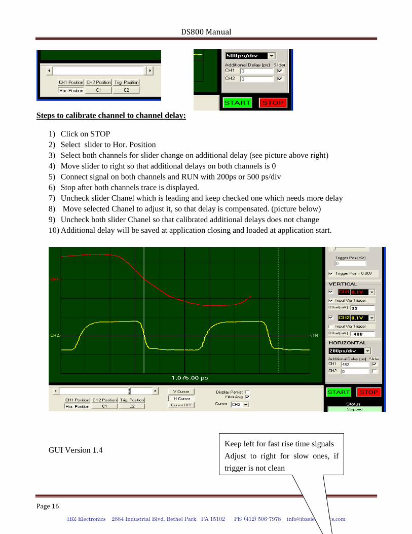
Steps to calibrate channel to channel delay:
1) Click on STOP
2) Select slider to Hor. Position
3) Select both channels for slider change on additional delay (see picture above right)
4) Move slider to right so that additional delays on both channels is 0
5) Connect signal on both channels and RUN with 200ps or 500 ps/div
6) Stop after both channels trace is displayed.
7) Uncheck slider Chanel which is leading and keep checked one which needs more delay
8) Move selected Chanel to adjust it, so that delay is compensated. (picture below)
9) Uncheck both slider Chanel so that calibrated additional delays does not change
10) Additional delay will be saved at application closing and loaded at application start.
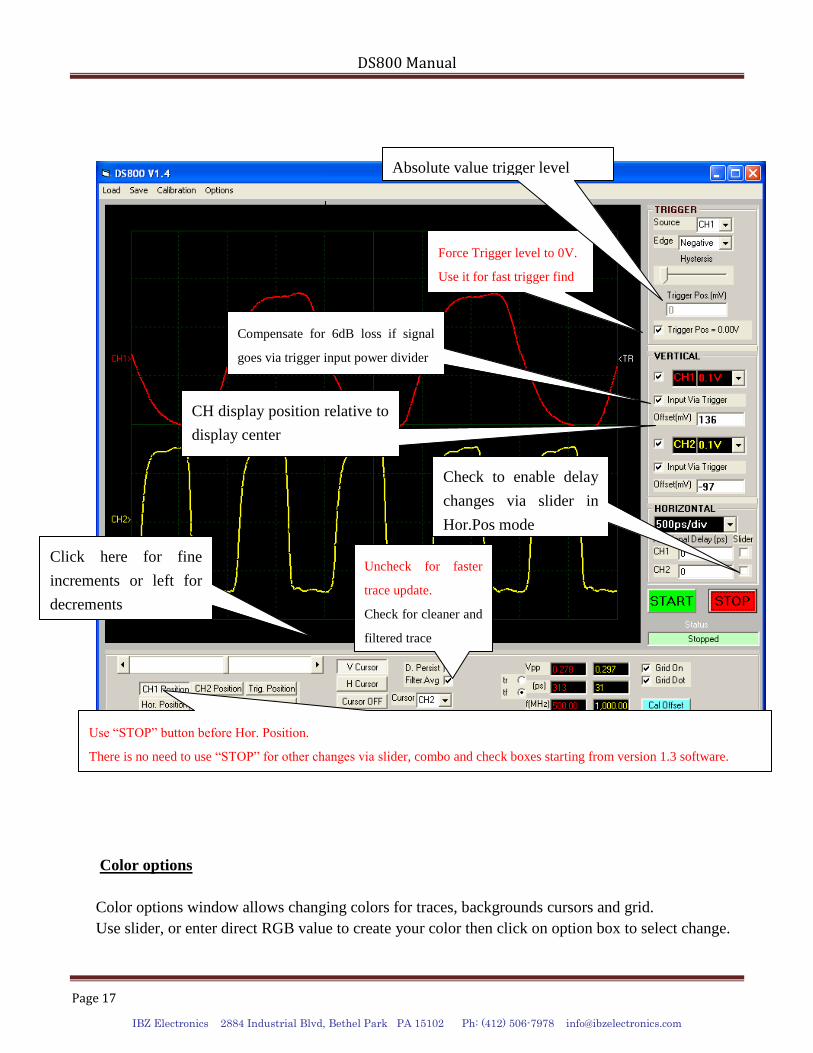
GUI Version 1.4
Keep left for fast rise time signals
Adjust to right for slow ones, if
trigger is not clean
DS800 Manual
Page 17
IBZ Electronics 2884 Industrial Blvd, Bethel Park PA 15102 Ph: (412) 506-7978 [email protected]
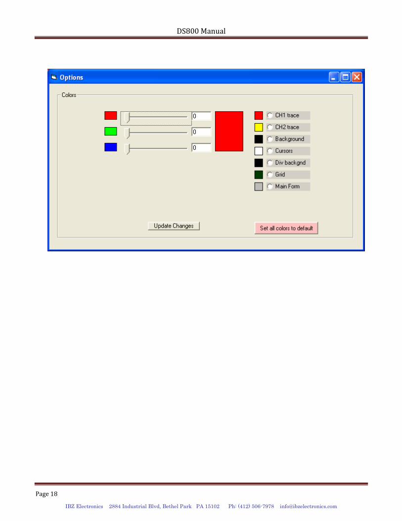
Color options
Color options window allows changing colors for traces, backgrounds cursors and grid.
Use slider, or enter direct RGB value to create your color then click on option box to select change.
Compensate for 6dB loss if signal
goes via trigger input power divider
Force Trigger level to 0V.
Use it for fast trigger find
Uncheck for faster
trace update.
Check for cleaner and
filtered trace
Check to enable delay
changes via slider in
Hor.Pos mode
Absolute value trigger level
CH display position relative to
display center
Click here for fine
increments or left for
decrements
Use “STOP” button before Hor. Position.
There is no need to use “STOP” for other changes via slider, combo and check boxes starting from version 1.3 software.
DS800 Manual
Page 18
IBZ Electronics 2884 Industrial Blvd, Bethel Park PA 15102 Ph: (412) 506-7978 [email protected]