Embed Size (px)
Citation preview

ibm.com/redbooks
Front cover
IBM System z10 Business ClassTechnical Overview
Marian GasparovicIvan Dobos
Per FremstadWolfgang FriesParwez HamidBrian Hatfield
Dick JornaFernando Nogal
Karl-Erik Stenfors
Describes the new IBM System z10 BC server and related features
Discusses server structure and design
Reviews software support

International Technical Support Organization
IBM System z10 Business Class Technical Overview
November 2009
SG24-7632-01
© Copyright International Business Machines Corporation 2008, 2009. All rights reserved.Note to U.S. Government Users Restricted Rights -- Use, duplication or disclosure restricted by GSA ADP ScheduleContract with IBM Corp.
Second Edition (November 2009)
This edition applies to the initial announcement of the IBM System z10 Business Class server.
Note: Before using this information and the product it supports, read the information in “Notices” on page ix.
Contents
Notices . . . . . . . . . . . . . . . . . . . . . . . . . . . . . . . . . . . . . . . . . . . . . . . . . . . . . . . . . . . . . . . . . ixTrademarks . . . . . . . . . . . . . . . . . . . . . . . . . . . . . . . . . . . . . . . . . . . . . . . . . . . . . . . . . . . . . . .x
Preface . . . . . . . . . . . . . . . . . . . . . . . . . . . . . . . . . . . . . . . . . . . . . . . . . . . . . . . . . . . . . . . . . xiThe team who wrote this book . . . . . . . . . . . . . . . . . . . . . . . . . . . . . . . . . . . . . . . . . . . . . . . . xiBecome a published author . . . . . . . . . . . . . . . . . . . . . . . . . . . . . . . . . . . . . . . . . . . . . . . . . xiiiComments welcome. . . . . . . . . . . . . . . . . . . . . . . . . . . . . . . . . . . . . . . . . . . . . . . . . . . . . . . xiii
Chapter 1. Introducing the IBM System z10 Business Class . . . . . . . . . . . . . . . . . . . . . 11.1 Wanted: an infrastructure (r)evolution. . . . . . . . . . . . . . . . . . . . . . . . . . . . . . . . . . . . . . . 21.2 System z10 BC highlights . . . . . . . . . . . . . . . . . . . . . . . . . . . . . . . . . . . . . . . . . . . . . . . . 71.3 z10 BC model structure. . . . . . . . . . . . . . . . . . . . . . . . . . . . . . . . . . . . . . . . . . . . . . . . . . 81.4 System functions and features . . . . . . . . . . . . . . . . . . . . . . . . . . . . . . . . . . . . . . . . . . . 10
1.4.1 Processor . . . . . . . . . . . . . . . . . . . . . . . . . . . . . . . . . . . . . . . . . . . . . . . . . . . . . . . 111.4.2 CPC drawer . . . . . . . . . . . . . . . . . . . . . . . . . . . . . . . . . . . . . . . . . . . . . . . . . . . . . 121.4.3 I/O connectivity . . . . . . . . . . . . . . . . . . . . . . . . . . . . . . . . . . . . . . . . . . . . . . . . . . . 121.4.4 Cryptography . . . . . . . . . . . . . . . . . . . . . . . . . . . . . . . . . . . . . . . . . . . . . . . . . . . . 141.4.5 Parallel Sysplex support . . . . . . . . . . . . . . . . . . . . . . . . . . . . . . . . . . . . . . . . . . . . 161.4.6 Reliability, availability, and serviceability. . . . . . . . . . . . . . . . . . . . . . . . . . . . . . . . 17
1.5 The performance advantage . . . . . . . . . . . . . . . . . . . . . . . . . . . . . . . . . . . . . . . . . . . . . 181.6 Operating systems and software. . . . . . . . . . . . . . . . . . . . . . . . . . . . . . . . . . . . . . . . . . 18
Chapter 2. Hardware components . . . . . . . . . . . . . . . . . . . . . . . . . . . . . . . . . . . . . . . . . . 212.1 Frame and drawers . . . . . . . . . . . . . . . . . . . . . . . . . . . . . . . . . . . . . . . . . . . . . . . . . . . . 222.2 Drawer concept . . . . . . . . . . . . . . . . . . . . . . . . . . . . . . . . . . . . . . . . . . . . . . . . . . . . . . . 252.3 The single-chip module . . . . . . . . . . . . . . . . . . . . . . . . . . . . . . . . . . . . . . . . . . . . . . . . . 262.4 The PU and SC chips . . . . . . . . . . . . . . . . . . . . . . . . . . . . . . . . . . . . . . . . . . . . . . . . . . 27
2.4.1 PU chip . . . . . . . . . . . . . . . . . . . . . . . . . . . . . . . . . . . . . . . . . . . . . . . . . . . . . . . . . 272.4.2 SC chip . . . . . . . . . . . . . . . . . . . . . . . . . . . . . . . . . . . . . . . . . . . . . . . . . . . . . . . . . 29
2.5 Memory . . . . . . . . . . . . . . . . . . . . . . . . . . . . . . . . . . . . . . . . . . . . . . . . . . . . . . . . . . . . . 302.5.1 Memory configurations . . . . . . . . . . . . . . . . . . . . . . . . . . . . . . . . . . . . . . . . . . . . . 302.5.2 Plan-ahead memory . . . . . . . . . . . . . . . . . . . . . . . . . . . . . . . . . . . . . . . . . . . . . . . 33
2.6 Connectivity. . . . . . . . . . . . . . . . . . . . . . . . . . . . . . . . . . . . . . . . . . . . . . . . . . . . . . . . . . 342.6.1 Types of fanouts . . . . . . . . . . . . . . . . . . . . . . . . . . . . . . . . . . . . . . . . . . . . . . . . . . 342.6.2 Redundant I/O interconnect . . . . . . . . . . . . . . . . . . . . . . . . . . . . . . . . . . . . . . . . . 35
2.7 Model configurations . . . . . . . . . . . . . . . . . . . . . . . . . . . . . . . . . . . . . . . . . . . . . . . . . . . 362.7.1 Upgrades . . . . . . . . . . . . . . . . . . . . . . . . . . . . . . . . . . . . . . . . . . . . . . . . . . . . . . . 372.7.2 Concurrent PU conversions . . . . . . . . . . . . . . . . . . . . . . . . . . . . . . . . . . . . . . . . . 372.7.3 Model capacity identifier . . . . . . . . . . . . . . . . . . . . . . . . . . . . . . . . . . . . . . . . . . . . 372.7.4 Capacity on Demand upgrades . . . . . . . . . . . . . . . . . . . . . . . . . . . . . . . . . . . . . . 39
2.8 Summary of the z10 BC . . . . . . . . . . . . . . . . . . . . . . . . . . . . . . . . . . . . . . . . . . . . . . . . 40
Chapter 3. System design . . . . . . . . . . . . . . . . . . . . . . . . . . . . . . . . . . . . . . . . . . . . . . . . 433.1 CPC Drawer . . . . . . . . . . . . . . . . . . . . . . . . . . . . . . . . . . . . . . . . . . . . . . . . . . . . . . . . . 443.2 Processing unit . . . . . . . . . . . . . . . . . . . . . . . . . . . . . . . . . . . . . . . . . . . . . . . . . . . . . . . 473.3 Processing unit functions . . . . . . . . . . . . . . . . . . . . . . . . . . . . . . . . . . . . . . . . . . . . . . . 50
3.3.1 Central processors . . . . . . . . . . . . . . . . . . . . . . . . . . . . . . . . . . . . . . . . . . . . . . . . 513.3.2 Integrated Facility for Linux. . . . . . . . . . . . . . . . . . . . . . . . . . . . . . . . . . . . . . . . . . 513.3.3 Internal Coupling Facility. . . . . . . . . . . . . . . . . . . . . . . . . . . . . . . . . . . . . . . . . . . . 52
© Copyright IBM Corp. 2008, 2009. All rights reserved. iii
3.3.4 System z10 Application Assist Processor . . . . . . . . . . . . . . . . . . . . . . . . . . . . . . . 533.3.5 System z10 Integrated Information Processor . . . . . . . . . . . . . . . . . . . . . . . . . . . 563.3.6 zAAP on zIIP capability . . . . . . . . . . . . . . . . . . . . . . . . . . . . . . . . . . . . . . . . . . . . . 583.3.7 System Assist Processors. . . . . . . . . . . . . . . . . . . . . . . . . . . . . . . . . . . . . . . . . . . 583.3.8 Reserved processors . . . . . . . . . . . . . . . . . . . . . . . . . . . . . . . . . . . . . . . . . . . . . . 593.3.9 Processing unit characterization . . . . . . . . . . . . . . . . . . . . . . . . . . . . . . . . . . . . . . 593.3.10 Transparent CP, IFL, ICF, zAAP, zIIP, and SAP sparing . . . . . . . . . . . . . . . . . . 60
3.4 Memory design . . . . . . . . . . . . . . . . . . . . . . . . . . . . . . . . . . . . . . . . . . . . . . . . . . . . . . . 603.4.1 Central storage . . . . . . . . . . . . . . . . . . . . . . . . . . . . . . . . . . . . . . . . . . . . . . . . . . . 613.4.2 Expanded storage. . . . . . . . . . . . . . . . . . . . . . . . . . . . . . . . . . . . . . . . . . . . . . . . . 613.4.3 Hardware system area . . . . . . . . . . . . . . . . . . . . . . . . . . . . . . . . . . . . . . . . . . . . . 62
3.5 Logical partitioning . . . . . . . . . . . . . . . . . . . . . . . . . . . . . . . . . . . . . . . . . . . . . . . . . . . . 623.6 Intelligent Resource Director . . . . . . . . . . . . . . . . . . . . . . . . . . . . . . . . . . . . . . . . . . . . . 673.7 Clustering technology . . . . . . . . . . . . . . . . . . . . . . . . . . . . . . . . . . . . . . . . . . . . . . . . . . 69
Chapter 4. I/O system structure . . . . . . . . . . . . . . . . . . . . . . . . . . . . . . . . . . . . . . . . . . . . 734.1 Introduction . . . . . . . . . . . . . . . . . . . . . . . . . . . . . . . . . . . . . . . . . . . . . . . . . . . . . . . . . . 74
4.1.1 InfiniBand advantages . . . . . . . . . . . . . . . . . . . . . . . . . . . . . . . . . . . . . . . . . . . . . 744.1.2 Data, signalling, and link rates . . . . . . . . . . . . . . . . . . . . . . . . . . . . . . . . . . . . . . . 75
4.2 I/O system overview . . . . . . . . . . . . . . . . . . . . . . . . . . . . . . . . . . . . . . . . . . . . . . . . . . . 754.3 I/O drawer . . . . . . . . . . . . . . . . . . . . . . . . . . . . . . . . . . . . . . . . . . . . . . . . . . . . . . . . . . . 774.4 Fanouts . . . . . . . . . . . . . . . . . . . . . . . . . . . . . . . . . . . . . . . . . . . . . . . . . . . . . . . . . . . . . 80
4.4.1 HCA2-C fanout . . . . . . . . . . . . . . . . . . . . . . . . . . . . . . . . . . . . . . . . . . . . . . . . . . . 814.4.2 HCA-2-O fanout . . . . . . . . . . . . . . . . . . . . . . . . . . . . . . . . . . . . . . . . . . . . . . . . . . 814.4.3 HCA2-O LR fanout . . . . . . . . . . . . . . . . . . . . . . . . . . . . . . . . . . . . . . . . . . . . . . . . 824.4.4 MBA fanout . . . . . . . . . . . . . . . . . . . . . . . . . . . . . . . . . . . . . . . . . . . . . . . . . . . . . . 834.4.5 Fanout considerations. . . . . . . . . . . . . . . . . . . . . . . . . . . . . . . . . . . . . . . . . . . . . . 834.4.6 Adapter ID number assignment . . . . . . . . . . . . . . . . . . . . . . . . . . . . . . . . . . . . . . 844.4.7 Fanout summary . . . . . . . . . . . . . . . . . . . . . . . . . . . . . . . . . . . . . . . . . . . . . . . . . . 85
4.5 I/O feature cards . . . . . . . . . . . . . . . . . . . . . . . . . . . . . . . . . . . . . . . . . . . . . . . . . . . . . . 854.5.1 I/O feature card types . . . . . . . . . . . . . . . . . . . . . . . . . . . . . . . . . . . . . . . . . . . . . . 854.5.2 PCHID report . . . . . . . . . . . . . . . . . . . . . . . . . . . . . . . . . . . . . . . . . . . . . . . . . . . . 86
4.6 Cryptographic feature . . . . . . . . . . . . . . . . . . . . . . . . . . . . . . . . . . . . . . . . . . . . . . . . . . 874.7 Connectivity. . . . . . . . . . . . . . . . . . . . . . . . . . . . . . . . . . . . . . . . . . . . . . . . . . . . . . . . . . 88
4.7.1 I/O feature support and configuration rules. . . . . . . . . . . . . . . . . . . . . . . . . . . . . . 884.7.2 ESCON channels . . . . . . . . . . . . . . . . . . . . . . . . . . . . . . . . . . . . . . . . . . . . . . . . . 894.7.3 FICON channels . . . . . . . . . . . . . . . . . . . . . . . . . . . . . . . . . . . . . . . . . . . . . . . . . . 904.7.4 OSA Express3 . . . . . . . . . . . . . . . . . . . . . . . . . . . . . . . . . . . . . . . . . . . . . . . . . . . 954.7.5 OSA-Express2 . . . . . . . . . . . . . . . . . . . . . . . . . . . . . . . . . . . . . . . . . . . . . . . . . . . 974.7.6 Open Systems Adapter selected functions . . . . . . . . . . . . . . . . . . . . . . . . . . . . . . 974.7.7 HiperSockets. . . . . . . . . . . . . . . . . . . . . . . . . . . . . . . . . . . . . . . . . . . . . . . . . . . . . 99
4.8 Parallel Sysplex connectivity . . . . . . . . . . . . . . . . . . . . . . . . . . . . . . . . . . . . . . . . . . . . 1014.8.1 Coupling links . . . . . . . . . . . . . . . . . . . . . . . . . . . . . . . . . . . . . . . . . . . . . . . . . . . 1014.8.2 External Time Reference . . . . . . . . . . . . . . . . . . . . . . . . . . . . . . . . . . . . . . . . . . 105
Chapter 5. Channel subsystem . . . . . . . . . . . . . . . . . . . . . . . . . . . . . . . . . . . . . . . . . . . 1075.1 Channel subsystem. . . . . . . . . . . . . . . . . . . . . . . . . . . . . . . . . . . . . . . . . . . . . . . . . . . 108
5.1.1 CSS elements . . . . . . . . . . . . . . . . . . . . . . . . . . . . . . . . . . . . . . . . . . . . . . . . . . . 1095.1.2 Multiple CSSs concept . . . . . . . . . . . . . . . . . . . . . . . . . . . . . . . . . . . . . . . . . . . . 1105.1.3 Multiple CSSs structure. . . . . . . . . . . . . . . . . . . . . . . . . . . . . . . . . . . . . . . . . . . . 1105.1.4 Logical partition name and identification. . . . . . . . . . . . . . . . . . . . . . . . . . . . . . . 1115.1.5 Physical channel ID . . . . . . . . . . . . . . . . . . . . . . . . . . . . . . . . . . . . . . . . . . . . . . 1125.1.6 Multiple subchannel sets. . . . . . . . . . . . . . . . . . . . . . . . . . . . . . . . . . . . . . . . . . . 113
iv IBM System z10 Business Class Technical Overview

5.1.7 Multiple CSS construct . . . . . . . . . . . . . . . . . . . . . . . . . . . . . . . . . . . . . . . . . . . . 1165.1.8 Adapter ID. . . . . . . . . . . . . . . . . . . . . . . . . . . . . . . . . . . . . . . . . . . . . . . . . . . . . . 1165.1.9 Channel spanning . . . . . . . . . . . . . . . . . . . . . . . . . . . . . . . . . . . . . . . . . . . . . . . . 1175.1.10 Summary of CSS-related numbers . . . . . . . . . . . . . . . . . . . . . . . . . . . . . . . . . . 118
5.2 I/O configuration management . . . . . . . . . . . . . . . . . . . . . . . . . . . . . . . . . . . . . . . . . . 1195.3 System-initiated CHPID reconfiguration . . . . . . . . . . . . . . . . . . . . . . . . . . . . . . . . . . . 1195.4 Multipath initial program load . . . . . . . . . . . . . . . . . . . . . . . . . . . . . . . . . . . . . . . . . . . 120
Chapter 6. Cryptography . . . . . . . . . . . . . . . . . . . . . . . . . . . . . . . . . . . . . . . . . . . . . . . . 1216.1 Cryptographic synchronous functions . . . . . . . . . . . . . . . . . . . . . . . . . . . . . . . . . . . . . 1226.2 Cryptographic asynchronous functions . . . . . . . . . . . . . . . . . . . . . . . . . . . . . . . . . . . . 123
6.2.1 Crypto Express coprocessor . . . . . . . . . . . . . . . . . . . . . . . . . . . . . . . . . . . . . . . . 1266.2.2 Crypto Express accelerator. . . . . . . . . . . . . . . . . . . . . . . . . . . . . . . . . . . . . . . . . 1286.2.3 Configuration rules . . . . . . . . . . . . . . . . . . . . . . . . . . . . . . . . . . . . . . . . . . . . . . . 128
6.3 TKE workstation feature . . . . . . . . . . . . . . . . . . . . . . . . . . . . . . . . . . . . . . . . . . . . . . . 1296.4 Cryptographic functions comparison. . . . . . . . . . . . . . . . . . . . . . . . . . . . . . . . . . . . . . 1316.5 Software support . . . . . . . . . . . . . . . . . . . . . . . . . . . . . . . . . . . . . . . . . . . . . . . . . . . . . 1336.6 Cryptographic feature codes . . . . . . . . . . . . . . . . . . . . . . . . . . . . . . . . . . . . . . . . . . . . 133
Chapter 7. Software support . . . . . . . . . . . . . . . . . . . . . . . . . . . . . . . . . . . . . . . . . . . . . 1357.1 Operating systems summary . . . . . . . . . . . . . . . . . . . . . . . . . . . . . . . . . . . . . . . . . . . 1367.2 Support by operating system . . . . . . . . . . . . . . . . . . . . . . . . . . . . . . . . . . . . . . . . . . . 136
7.2.1 z/OS . . . . . . . . . . . . . . . . . . . . . . . . . . . . . . . . . . . . . . . . . . . . . . . . . . . . . . . . . . 1367.2.2 z/VM . . . . . . . . . . . . . . . . . . . . . . . . . . . . . . . . . . . . . . . . . . . . . . . . . . . . . . . . . . 1377.2.3 z/VSE . . . . . . . . . . . . . . . . . . . . . . . . . . . . . . . . . . . . . . . . . . . . . . . . . . . . . . . . . 1377.2.4 Linux on System z. . . . . . . . . . . . . . . . . . . . . . . . . . . . . . . . . . . . . . . . . . . . . . . . 1377.2.5 TPF and z/TPF . . . . . . . . . . . . . . . . . . . . . . . . . . . . . . . . . . . . . . . . . . . . . . . . . . 1387.2.6 z10 BC functions support summary . . . . . . . . . . . . . . . . . . . . . . . . . . . . . . . . . . 138
7.3 Support by function . . . . . . . . . . . . . . . . . . . . . . . . . . . . . . . . . . . . . . . . . . . . . . . . . . . 1487.3.1 Single system image. . . . . . . . . . . . . . . . . . . . . . . . . . . . . . . . . . . . . . . . . . . . . . 1487.3.2 zAAP on zIIP capability . . . . . . . . . . . . . . . . . . . . . . . . . . . . . . . . . . . . . . . . . . . . 1497.3.3 Maximum main storage size . . . . . . . . . . . . . . . . . . . . . . . . . . . . . . . . . . . . . . . . 1507.3.4 Large-page support. . . . . . . . . . . . . . . . . . . . . . . . . . . . . . . . . . . . . . . . . . . . . . . 1507.3.5 Guest support for execute-extensions facility . . . . . . . . . . . . . . . . . . . . . . . . . . . 1517.3.6 Hardware decimal floating point . . . . . . . . . . . . . . . . . . . . . . . . . . . . . . . . . . . . . 1517.3.7 Up to 30 logical partitions . . . . . . . . . . . . . . . . . . . . . . . . . . . . . . . . . . . . . . . . . . 1527.3.8 Separate LPAR management of PUs . . . . . . . . . . . . . . . . . . . . . . . . . . . . . . . . . 1527.3.9 Dynamic LPAR memory upgrade . . . . . . . . . . . . . . . . . . . . . . . . . . . . . . . . . . . . 1527.3.10 Capacity Provisioning Manager . . . . . . . . . . . . . . . . . . . . . . . . . . . . . . . . . . . . 1537.3.11 Dynamic PU exploitation . . . . . . . . . . . . . . . . . . . . . . . . . . . . . . . . . . . . . . . . . . 1537.3.12 HiperDispatch . . . . . . . . . . . . . . . . . . . . . . . . . . . . . . . . . . . . . . . . . . . . . . . . . . 1537.3.13 The 63.75 K subchannels . . . . . . . . . . . . . . . . . . . . . . . . . . . . . . . . . . . . . . . . . 1547.3.14 Multiple subchannel sets. . . . . . . . . . . . . . . . . . . . . . . . . . . . . . . . . . . . . . . . . . 1547.3.15 MIDAW facility. . . . . . . . . . . . . . . . . . . . . . . . . . . . . . . . . . . . . . . . . . . . . . . . . . 1557.3.16 Enhanced CPACF. . . . . . . . . . . . . . . . . . . . . . . . . . . . . . . . . . . . . . . . . . . . . . . 1557.3.17 HiperSockets multiple write facility . . . . . . . . . . . . . . . . . . . . . . . . . . . . . . . . . . 1557.3.18 HiperSockets IPv6 . . . . . . . . . . . . . . . . . . . . . . . . . . . . . . . . . . . . . . . . . . . . . . 1557.3.19 HiperSockets Layer 2 Support . . . . . . . . . . . . . . . . . . . . . . . . . . . . . . . . . . . . . 1567.3.20 High Performance FICON for System z10 . . . . . . . . . . . . . . . . . . . . . . . . . . . . 1567.3.21 FCP has increased performance . . . . . . . . . . . . . . . . . . . . . . . . . . . . . . . . . . . 1577.3.22 Request node identification data. . . . . . . . . . . . . . . . . . . . . . . . . . . . . . . . . . . . 1587.3.23 FICON link incident reporting . . . . . . . . . . . . . . . . . . . . . . . . . . . . . . . . . . . . . . 1587.3.24 N_Port ID virtualization . . . . . . . . . . . . . . . . . . . . . . . . . . . . . . . . . . . . . . . . . . . 158
Contents v

7.3.25 VLAN management enhancements . . . . . . . . . . . . . . . . . . . . . . . . . . . . . . . . . 1597.3.26 OSA-Express3 10 Gigabit Ethernet LR and SR . . . . . . . . . . . . . . . . . . . . . . . . 1597.3.27 OSA-Express3 Gigabit Ethernet LX and SX . . . . . . . . . . . . . . . . . . . . . . . . . . . 1597.3.28 OSA-Express3-2P Gigabit Ethernet SX . . . . . . . . . . . . . . . . . . . . . . . . . . . . . . 1607.3.29 OSA-Express3 1000BASE-T Ethernet . . . . . . . . . . . . . . . . . . . . . . . . . . . . . . . 1617.3.30 OSA-Express3-2P 1000BASE-T Ethernet . . . . . . . . . . . . . . . . . . . . . . . . . . . . 1627.3.31 GARP VLAN Registration Protocol . . . . . . . . . . . . . . . . . . . . . . . . . . . . . . . . . . 1647.3.32 OSA-Express3 and OSA-Express2 OSN support. . . . . . . . . . . . . . . . . . . . . . . 1647.3.33 OSA-Express2 1000BASE-T Ethernet . . . . . . . . . . . . . . . . . . . . . . . . . . . . . . . 1647.3.34 OSA-Express2 10 Gigabit Ethernet LR. . . . . . . . . . . . . . . . . . . . . . . . . . . . . . . 1657.3.35 Program directed re-IPL . . . . . . . . . . . . . . . . . . . . . . . . . . . . . . . . . . . . . . . . . . 1657.3.36 Coupling over InfiniBand. . . . . . . . . . . . . . . . . . . . . . . . . . . . . . . . . . . . . . . . . . 1657.3.37 Dynamic I/O support for InfiniBand CHPIDs . . . . . . . . . . . . . . . . . . . . . . . . . . . 166
7.4 Cryptographic support . . . . . . . . . . . . . . . . . . . . . . . . . . . . . . . . . . . . . . . . . . . . . . . . . 1667.4.1 CP Assist for Cryptographic Function . . . . . . . . . . . . . . . . . . . . . . . . . . . . . . . . . 1677.4.2 Crypto Express3, Crypto Express2. . . . . . . . . . . . . . . . . . . . . . . . . . . . . . . . . . . 1677.4.3 Web deliverables . . . . . . . . . . . . . . . . . . . . . . . . . . . . . . . . . . . . . . . . . . . . . . . . 1687.4.4 z/OS ICSF FMIDs . . . . . . . . . . . . . . . . . . . . . . . . . . . . . . . . . . . . . . . . . . . . . . . . 168
7.5 Coupling facility and CFCC considerations. . . . . . . . . . . . . . . . . . . . . . . . . . . . . . . . . 1707.6 MIDAW facility . . . . . . . . . . . . . . . . . . . . . . . . . . . . . . . . . . . . . . . . . . . . . . . . . . . . . . . 171
7.6.1 Extended format data sets . . . . . . . . . . . . . . . . . . . . . . . . . . . . . . . . . . . . . . . . . 1727.6.2 Performance benefits . . . . . . . . . . . . . . . . . . . . . . . . . . . . . . . . . . . . . . . . . . . . . 172
7.7 IOCP . . . . . . . . . . . . . . . . . . . . . . . . . . . . . . . . . . . . . . . . . . . . . . . . . . . . . . . . . . . . . . 1737.8 Worldwide portname (WWPN) prediction tool. . . . . . . . . . . . . . . . . . . . . . . . . . . . . . . 1737.9 ICKDSF . . . . . . . . . . . . . . . . . . . . . . . . . . . . . . . . . . . . . . . . . . . . . . . . . . . . . . . . . . . . 1737.10 Software licensing considerations. . . . . . . . . . . . . . . . . . . . . . . . . . . . . . . . . . . . . . . 174
7.10.1 Workload License Charges. . . . . . . . . . . . . . . . . . . . . . . . . . . . . . . . . . . . . . . . 1747.10.2 System z New Application License Charges. . . . . . . . . . . . . . . . . . . . . . . . . . . 1757.10.3 Select Application License Charges . . . . . . . . . . . . . . . . . . . . . . . . . . . . . . . . . 1767.10.4 Midrange Workload License Charges. . . . . . . . . . . . . . . . . . . . . . . . . . . . . . . . 1767.10.5 Entry Workload License Charges . . . . . . . . . . . . . . . . . . . . . . . . . . . . . . . . . . . 1767.10.6 System z International Licensing Agreement . . . . . . . . . . . . . . . . . . . . . . . . . . 177
7.11 References . . . . . . . . . . . . . . . . . . . . . . . . . . . . . . . . . . . . . . . . . . . . . . . . . . . . . . . . 177
Chapter 8. System upgrades . . . . . . . . . . . . . . . . . . . . . . . . . . . . . . . . . . . . . . . . . . . . . 1798.1 Upgrade types. . . . . . . . . . . . . . . . . . . . . . . . . . . . . . . . . . . . . . . . . . . . . . . . . . . . . . . 180
8.1.1 Permanent and temporary upgrades . . . . . . . . . . . . . . . . . . . . . . . . . . . . . . . . . 1818.1.2 Summary of concurrent upgrades. . . . . . . . . . . . . . . . . . . . . . . . . . . . . . . . . . . . 1828.1.3 Nondisruptive upgrades . . . . . . . . . . . . . . . . . . . . . . . . . . . . . . . . . . . . . . . . . . . 182
8.2 MES upgrades . . . . . . . . . . . . . . . . . . . . . . . . . . . . . . . . . . . . . . . . . . . . . . . . . . . . . . 1838.3 Capacity on Demand upgrades. . . . . . . . . . . . . . . . . . . . . . . . . . . . . . . . . . . . . . . . . . 184
8.3.1 Permanent upgrades . . . . . . . . . . . . . . . . . . . . . . . . . . . . . . . . . . . . . . . . . . . . . 1858.3.2 Temporary upgrades. . . . . . . . . . . . . . . . . . . . . . . . . . . . . . . . . . . . . . . . . . . . . . 1858.3.3 Processor identification. . . . . . . . . . . . . . . . . . . . . . . . . . . . . . . . . . . . . . . . . . . . 1868.3.4 CIU facility . . . . . . . . . . . . . . . . . . . . . . . . . . . . . . . . . . . . . . . . . . . . . . . . . . . . . . 1878.3.5 Permanent upgrade through CIU facility . . . . . . . . . . . . . . . . . . . . . . . . . . . . . . . 1888.3.6 On/Off Capacity on Demand. . . . . . . . . . . . . . . . . . . . . . . . . . . . . . . . . . . . . . . . 1888.3.7 Capacity for Planned Event . . . . . . . . . . . . . . . . . . . . . . . . . . . . . . . . . . . . . . . . 1938.3.8 Capacity Backup . . . . . . . . . . . . . . . . . . . . . . . . . . . . . . . . . . . . . . . . . . . . . . . . . 194
Chapter 9. RAS . . . . . . . . . . . . . . . . . . . . . . . . . . . . . . . . . . . . . . . . . . . . . . . . . . . . . . . . 1979.1 Availability characteristics . . . . . . . . . . . . . . . . . . . . . . . . . . . . . . . . . . . . . . . . . . . . . . 1989.2 RAS functions . . . . . . . . . . . . . . . . . . . . . . . . . . . . . . . . . . . . . . . . . . . . . . . . . . . . . . . 198
vi IBM System z10 Business Class Technical Overview
9.3 Enhanced driver maintenance . . . . . . . . . . . . . . . . . . . . . . . . . . . . . . . . . . . . . . . . . . 2019.4 RAS Summary . . . . . . . . . . . . . . . . . . . . . . . . . . . . . . . . . . . . . . . . . . . . . . . . . . . . . . 201
Chapter 10. Environmental requirements . . . . . . . . . . . . . . . . . . . . . . . . . . . . . . . . . . . 20310.1 Power and cooling. . . . . . . . . . . . . . . . . . . . . . . . . . . . . . . . . . . . . . . . . . . . . . . . . . . 204
10.1.1 Power consumption . . . . . . . . . . . . . . . . . . . . . . . . . . . . . . . . . . . . . . . . . . . . . 20410.1.2 Internal Battery Feature . . . . . . . . . . . . . . . . . . . . . . . . . . . . . . . . . . . . . . . . . . 20510.1.3 Emergency power-off . . . . . . . . . . . . . . . . . . . . . . . . . . . . . . . . . . . . . . . . . . . . 20510.1.4 Cooling requirements . . . . . . . . . . . . . . . . . . . . . . . . . . . . . . . . . . . . . . . . . . . . 205
10.2 Physical specifications . . . . . . . . . . . . . . . . . . . . . . . . . . . . . . . . . . . . . . . . . . . . . . . 20610.2.1 Weights . . . . . . . . . . . . . . . . . . . . . . . . . . . . . . . . . . . . . . . . . . . . . . . . . . . . . . . 20610.2.2 Dimensions . . . . . . . . . . . . . . . . . . . . . . . . . . . . . . . . . . . . . . . . . . . . . . . . . . . . 207
10.3 Power estimation tool . . . . . . . . . . . . . . . . . . . . . . . . . . . . . . . . . . . . . . . . . . . . . . . . 208
Chapter 11. Hardware Management Console . . . . . . . . . . . . . . . . . . . . . . . . . . . . . . . . 21111.1 HMC and SE introduction . . . . . . . . . . . . . . . . . . . . . . . . . . . . . . . . . . . . . . . . . . . . . 21211.2 HMC and SE connectivity . . . . . . . . . . . . . . . . . . . . . . . . . . . . . . . . . . . . . . . . . . . . . 21211.3 Remote Support Facility . . . . . . . . . . . . . . . . . . . . . . . . . . . . . . . . . . . . . . . . . . . . . . 21611.4 HMC remote operations . . . . . . . . . . . . . . . . . . . . . . . . . . . . . . . . . . . . . . . . . . . . . . 21611.5 z10 BC HMC and SE key capabilities . . . . . . . . . . . . . . . . . . . . . . . . . . . . . . . . . . . . 217
11.5.1 CPC management . . . . . . . . . . . . . . . . . . . . . . . . . . . . . . . . . . . . . . . . . . . . . . 21811.5.2 LPAR management. . . . . . . . . . . . . . . . . . . . . . . . . . . . . . . . . . . . . . . . . . . . . . 21811.5.3 Operating system communication. . . . . . . . . . . . . . . . . . . . . . . . . . . . . . . . . . . 21911.5.4 SE access . . . . . . . . . . . . . . . . . . . . . . . . . . . . . . . . . . . . . . . . . . . . . . . . . . . . . 21911.5.5 Monitoring . . . . . . . . . . . . . . . . . . . . . . . . . . . . . . . . . . . . . . . . . . . . . . . . . . . . . 21911.5.6 HMC Console Messenger . . . . . . . . . . . . . . . . . . . . . . . . . . . . . . . . . . . . . . . . . 22011.5.7 Capacity on Demand support . . . . . . . . . . . . . . . . . . . . . . . . . . . . . . . . . . . . . . 22111.5.8 Server Time Protocol support . . . . . . . . . . . . . . . . . . . . . . . . . . . . . . . . . . . . . . 22211.5.9 NTP client/server support on HMC . . . . . . . . . . . . . . . . . . . . . . . . . . . . . . . . . . 22311.5.10 System Input/Output Configuration Analyzer on the SE/HMC . . . . . . . . . . . . 22311.5.11 Network Analysis Tool for SE Communication . . . . . . . . . . . . . . . . . . . . . . . . 22411.5.12 Automated operations. . . . . . . . . . . . . . . . . . . . . . . . . . . . . . . . . . . . . . . . . . . 22411.5.13 Cryptographic support. . . . . . . . . . . . . . . . . . . . . . . . . . . . . . . . . . . . . . . . . . . 22511.5.14 z/VM virtual machine management. . . . . . . . . . . . . . . . . . . . . . . . . . . . . . . . . 22511.5.15 Installation support for z/VM using the HMC. . . . . . . . . . . . . . . . . . . . . . . . . . 225
Related publications . . . . . . . . . . . . . . . . . . . . . . . . . . . . . . . . . . . . . . . . . . . . . . . . . . . . 227IBM Redbooks publications . . . . . . . . . . . . . . . . . . . . . . . . . . . . . . . . . . . . . . . . . . . . . . . . 227Other publications . . . . . . . . . . . . . . . . . . . . . . . . . . . . . . . . . . . . . . . . . . . . . . . . . . . . . . . 227Online resources . . . . . . . . . . . . . . . . . . . . . . . . . . . . . . . . . . . . . . . . . . . . . . . . . . . . . . . . 227How to get Redbooks publications. . . . . . . . . . . . . . . . . . . . . . . . . . . . . . . . . . . . . . . . . . . 228Help from IBM . . . . . . . . . . . . . . . . . . . . . . . . . . . . . . . . . . . . . . . . . . . . . . . . . . . . . . . . . . 228
Index . . . . . . . . . . . . . . . . . . . . . . . . . . . . . . . . . . . . . . . . . . . . . . . . . . . . . . . . . . . . . . . . . 229
Contents vii

viii IBM System z10 Business Class Technical Overview

Notices
This information was developed for products and services offered in the U.S.A.
IBM may not offer the products, services, or features discussed in this document in other countries. Consult your local IBM representative for information on the products and services currently available in your area. Any reference to an IBM product, program, or service is not intended to state or imply that only that IBM product, program, or service may be used. Any functionally equivalent product, program, or service that does not infringe any IBM intellectual property right may be used instead. However, it is the user's responsibility to evaluate and verify the operation of any non-IBM product, program, or service.
IBM may have patents or pending patent applications covering subject matter described in this document. The furnishing of this document does not give you any license to these patents. You can send license inquiries, in writing, to: IBM Director of Licensing, IBM Corporation, North Castle Drive, Armonk, NY 10504-1785 U.S.A.
The following paragraph does not apply to the United Kingdom or any other country where such provisions are inconsistent with local law: INTERNATIONAL BUSINESS MACHINES CORPORATION PROVIDES THIS PUBLICATION "AS IS" WITHOUT WARRANTY OF ANY KIND, EITHER EXPRESS OR IMPLIED, INCLUDING, BUT NOT LIMITED TO, THE IMPLIED WARRANTIES OF NON-INFRINGEMENT, MERCHANTABILITY OR FITNESS FOR A PARTICULAR PURPOSE. Some states do not allow disclaimer of express or implied warranties in certain transactions, therefore, this statement may not apply to you.
This information could include technical inaccuracies or typographical errors. Changes are periodically made to the information herein; these changes will be incorporated in new editions of the publication. IBM may make improvements and/or changes in the product(s) and/or the program(s) described in this publication at any time without notice.
Any references in this information to non-IBM Web sites are provided for convenience only and do not in any manner serve as an endorsement of those Web sites. The materials at those Web sites are not part of the materials for this IBM product and use of those Web sites is at your own risk.
IBM may use or distribute any of the information you supply in any way it believes appropriate without incurring any obligation to you.
Information concerning non-IBM products was obtained from the suppliers of those products, their published announcements or other publicly available sources. IBM has not tested those products and cannot confirm the accuracy of performance, compatibility or any other claims related to non-IBM products. Questions on the capabilities of non-IBM products should be addressed to the suppliers of those products.
This information contains examples of data and reports used in daily business operations. To illustrate them as completely as possible, the examples include the names of individuals, companies, brands, and products. All of these names are fictitious and any similarity to the names and addresses used by an actual business enterprise is entirely coincidental.
COPYRIGHT LICENSE:
This information contains sample application programs in source language, which illustrate programming techniques on various operating platforms. You may copy, modify, and distribute these sample programs in any form without payment to IBM, for the purposes of developing, using, marketing or distributing application programs conforming to the application programming interface for the operating platform for which the sample programs are written. These examples have not been thoroughly tested under all conditions. IBM, therefore, cannot guarantee or imply reliability, serviceability, or function of these programs.
© Copyright IBM Corp. 2008, 2009. All rights reserved. ix
Trademarks
IBM, the IBM logo, and ibm.com are trademarks or registered trademarks of International Business Machines Corporation in the United States, other countries, or both. These and other IBM trademarked terms are marked on their first occurrence in this information with the appropriate symbol (® or ™), indicating US registered or common law trademarks owned by IBM at the time this information was published. Such trademarks may also be registered or common law trademarks in other countries. A current list of IBM trademarks is available on the Web at http://www.ibm.com/legal/copytrade.shtml
The following terms are trademarks of the International Business Machines Corporation in the United States, other countries, or both:
CICS®Cool Blue™DB2 Connect™DB2®Domino®DRDA®DS8000®Dynamic Infrastructure®ECKD™ESCON®eServer™FICON®GDPS®HiperSockets™IBM Systems Director Active Energy
Manager™
IBM®IMS™Language Environment®Lotus®MQSeries®OS/390®Parallel Sysplex®PR/SM™Processor Resource/Systems
Manager™RACF®Redbooks®Redbooks (logo) ®Resource Link™S/390®Sysplex Timer®
System p®System Storage™System x®System z10™System z9®System z®TotalStorage®VM/ESA®WebSphere®z/Architecture®z/OS®z/VM®z/VSE™z9®zSeries®
The following terms are trademarks of other companies:
InfiniBand, and the InfiniBand design marks are trademarks and/or service marks of the InfiniBand Trade Association.
Ambassador, and the LSI logo are trademarks or registered trademarks of LSI Corporation.
Novell, SUSE, the Novell logo, and the N logo are registered trademarks of Novell, Inc. in the United States and other countries.
Oracle, JD Edwards, PeopleSoft, Siebel, and TopLink are registered trademarks of Oracle Corporation and/or its affiliates.
Red Hat, and the Shadowman logo are trademarks or registered trademarks of Red Hat, Inc. in the U.S. and other countries.
SAP, and SAP logos are trademarks or registered trademarks of SAP AG in Germany and in several other countries.
Java, and all Java-based trademarks are trademarks of Sun Microsystems, Inc. in the United States, other countries, or both.
Microsoft, Windows NT, Windows, and the Windows logo are trademarks of Microsoft Corporation in the United States, other countries, or both.
Intel, Intel logo, Intel Inside logo, and Intel Centrino logo are trademarks or registered trademarks of Intel Corporation or its subsidiaries in the United States and other countries.
UNIX is a registered trademark of The Open Group in the United States and other countries.
Linux is a trademark of Linus Torvalds in the United States, other countries, or both.
Other company, product, or service names may be trademarks or service marks of others.
x IBM System z10 Business Class Technical Overview
Preface
This IBM® Redbooks® publication introduces the IBM System z10™ Business Class (z10 BC) server, which is based on z/Architecture® and inherits many of the improvements made with the previously introduced System z10 Enterprise Class (z10 EC) server. With a focus on midrange enterprise computing, the z10 BC server delivers an entry point with very granular scalability and an unprecedented range of capacity settings to grow with the workload. It delivers unparalleled qualities of service to help manage growth and reduce cost and risk. The z10 BC server further extends System z® leadership by enriching its flexibility with enhancements to the just-in-time capacity deployment functions.
This book provides an overview of the z10 BC and its functions, features, and associated software support. Greater detail is offered in areas relevant to technical planning.
The changes in this edition are based on the IBM System z Hardware Announcement, dated October 20, 2009.
This book is intended for systems engineers, hardware planners, and anyone wanting to understand the System z10 Business Class functions and plan for their usage. It is not intended as an introduction to mainframes. Readers are expected to be generally familiar with existing System z technology and terminology.
The team who wrote this book
This book was produced by a team of specialists from around the world who are working at the International Technical Support Organization (ITSO), Poughkeepsie Center.
Marian Gasparovic is an IT Specialist working for the IBM Server and Technology Group in IBM Slovakia. He worked as an Administrator for z/OS® at Business Partner for 6 years. He joined IBM in 2004 as a Storage Specialist. Currently, he holds dual roles: one role is Field Technical Sales Support for System z in the CEMAAS region as a member of a team that handles new workloads; another role is for ITSO in Poughkeepsie, NY.
Ivan Dobos is a System z IT Specialist with 10 years of experience with System z. During the past 5 years he has worked with a large number of clients and spent most of his time supporting new workloads, z/VM® and Linux® on System z projects. Since 2005 he is based at the Products and Solutions Support Center (PSSC) Montpellier, France, where he spent 2 years as Technical Leader for Linux on System z projects in the System z Benchmark Center. He is currently working in System z New Technology Center where he specializes in IT Optimization and TCO studies. Ivan is a regular speaker at the Montpellier Executive Briefing Centre.
Per Fremstad is an IBM Certified Senior IT Specialist from the IBM Systems and Technology Group in IBM Norway. He has worked for IBM since 1982 and has extensive experience with mainframes and z/OS. Per also works extensively with Linux on System z and z/VM. During the past 25 years he has worked in various roles within IBM and with a large number of customers. He frequently teaches about z/OS and z/Architecture subjects, and has been actively teaching at Oslo University College for the last 5 years. Per holds a BSc from the University of Oslo, Norway.
© Copyright IBM Corp. 2008, 2009. All rights reserved. xi

Wolfgang Fries is a Senior Consultant in the System z Support Center in Germany. He spent several years in the European support center in Montpellier, France, to provide international HW support for System z servers. He has 31 years of experience in supporting large System z customers. His area of expertise includes System z servers and connectivity.
Parwez Hamid is a Executive IT Consultant working for the IBM Server and Technology Group. During the past 36 years he has worked in various IT roles within IBM. Since 1988 he has worked with a large number of IBM mainframe customers and spent much of his time introducing new technology. Currently, he provides pre-sales technical support for the IBM System z product portfolio and is the lead System z Technical Specialist for the United Kingdom and Ireland. Parwez co-authors a number of ITSO IBM Redbooks publications and prepares technical material for the world-wide announcement of System z servers. Parwez works closely with System z product development in Poughkeepsie, New York, and provides input and feedback for future product plans. Additionally, Parwez is a member of the IBM IT Specialist Professional Certification Board in the UK and is also a Technical Staff member of the IBM UK Technical Council, which comprises senior technical specialists representing all IBM client, consulting, services, and product groups. Parwez teaches and presents at numerous IBM user group and IBM internal conferences.
Brian Hatfield is a Certified Consulting Learning Specialist working for the IBM Systems and Technology Group in Atlanta, Georgia. He has over 30 years of experience in the IBM mainframe environment, starting his career as a Large System Customer Engineer in Southern California. He has been in education for the past 16 years and currently develops and delivers technical training for the System z environment.
Dick Jorna is an Executive IT Specialist working for IBM Server and Technology Group in the Netherlands. During the past 39 years he has worked in various roles within IBM and with a large number of mainframe customers. He currently provides pre-sales System z technical consultancy in support of large and small System z customers. In addition, he acts as a System z Product Manager in the Netherlands and is responsible for all activities related to System z.
Fernando Nogal is an IBM Certified Consulting IT Specialist working as an STG Technical Consultant for the Spain, Portugal, Greece, Israel, and Turkey IMT. He specializes in on-demand infrastructures and architectures. In his 26 years with IBM he has held a variety of technical positions, mainly providing support for mainframe customers. Previously, he was on assignment to the Europe Middle East and Africa (EMEA) zSeries® Technical Support group, working full time on complex solutions for e-business on zSeries. His job included, and still does, presenting and consulting in architectures and infrastructures, and providing strategic guidance to System z customers regarding the establishment and enablement of e-business technologies on System z, including the z/OS, z/VM, and Linux environments. He is a zChampion and a core member of the System z Business Leaders Council. An accomplished writer, he has authored and co-authored 16 Redbooks and several technical papers. Other activities include chairing a Virtual Team of IBMers interested in e-business on System z and serving as a University Ambassador. He travels extensively on direct customer engagements and as a speaker at IBM and customer events, and trade shows.
Karl-Erik Stenfors is a Senior IT Specialist in the Product and Solutions Support Centre (PSSC) in Montpellier, France. He has more than 40 years of experience in the large systems field, as a Systems Programmer, as a consultant with IBM customers, and, since 1986, with IBM. His areas of expertise include IBM System z hardware and operating systems, including z/VM, z/OS and Linux. He teaches at numerous IBM user group and IBM internal conferences. He currently works with the System z lab in Poughkeepsie, New York, providing customer requirement input to create an IBM System vision for the future—the zChampions workgroups.
xii IBM System z10 Business Class Technical Overview

Thanks to the following people for their contributions to this project:
Mike Augustine, Ivan Bailey, Connie Beuselinck, Frank Bosco, Bette Brody, William Clark, Cathy Cronin, Greg Daynes, Noshir Dhondy, Bill Kostenko, Jeff Kubala, Tom Mathias, Rob Overton, Dave Raften, Dale Riedy, Charles Webb, Barbara Weiler, and Frank WisnewskiIBM Poughkeepsie
Les Geer, Reed Mullen, Brian ValentineIBM Endicott
Become a published author
Join us for a two- to six-week residency program! Help write a book dealing with specific products or solutions, while getting hands-on experience with leading-edge technologies. You will have the opportunity to team with IBM technical professionals, Business Partners, and Clients.
Your efforts will help increase product acceptance and customer satisfaction. As a bonus, you will develop a network of contacts in IBM development labs, and increase your productivity and marketability.
Find out more about the residency program, browse the residency index, and apply online at:
ibm.com/redbooks/residencies.html
Comments welcome
Your comments are important to us!
We want our books to be as helpful as possible. Send us your comments about this book or other IBM Redbooks in one of the following ways:
� Use the online Contact us review Redbooks form found at:
ibm.com/redbooks
� Send your comments in an e-mail to:
� Mail your comments to:
IBM Corporation, International Technical Support OrganizationDept. HYTD Mail Station P0992455 South RoadPoughkeepsie, NY 12601-5400
Preface xiii

xiv IBM System z10 Business Class Technical Overview
Chapter 1. Introducing the IBM System z10 Business Class
The IBM System z10 Business Class (z10 BC) delivers a new face for midrange enterprise computing and provides a whole new world of capabilities to run modern applications. It draws heavily upon the structure and enhancements introduced by the previously announced IBM System z10 Enterprise Class (z10 EC) server.
The z10 BC exploits the System z10 processor quad-core chip, running at 3.5 GHz, and offers up to 10 configurable processing units (PUs). It is designed to provide performance enhancements of up to 1.5 times its predecessor, the System z9® BC, enabling the effective exploitation of an extensive software portfolio.
From IBM WebSphere®, full support for service-oriented architecture (SOA), Web services, J2EE, Linux, and open standards, to the more traditional batch and transactional environments such as CICS® and IMS™, the z10 BC is a well-balanced general-purpose server that is equally at ease on compute-intensive workloads as it is with I/O-intensive workloads. For instance, considering just the Linux on System z environment, more than 1,100 applications are offered by over 400 independent software vendors (ISVs).
The z10 BC has an innovative design based on drawers. One drawer is housing the Central Processing Complex (CPC) and from one to four drawers are housing the I/O features. The book and I/O cages of the z9 BC are not used, but most I/O features are supported and can be carried forward on upgrades.
New security and connectivity options are also available, including several exclusive Open Systems Adapter (OSA) features and exploitation of advanced technologies such as InfiniBand.
IBM mainframes traditionally provide an advanced combination of reliability, availability, security, scalability, and virtualization. The z10 BC has been designed with a midrange focus to extend these capabilities and is optimized for today's business needs. The z10 BC is intended to be a platform of choice for the integration of the new generations of applications with existing applications and data.
1
© Copyright IBM Corp. 2008, 2009. All rights reserved. 1

Most upgrades are concurrent to the hardware. As we describe later, the z10 BC reaches higher availability levels by eliminating various pre-planning requirements and other disruptive operations.
Up to 248 GB of memory can be configured, which is nearly four times the memory available on a z9 BC. The Hardware System Area (HSA) is now fixed, with an 8 GB size, and managed separately from the customer-purchased memory. This increases the server’s availability and supports operations continuity by allowing several configuration changes, which previously required pre-planning and were disruptive, to be done nondisruptively.
The z10 BC expands the granularity of subcapacity settings, offering 26 different subcapacity levels for the (up to five) configurable central processors (CPs). Thus a total of 130 distinct capacity settings are available in the system, providing a range of 1:100 in processing power. This allows more precise control of information technology (IT) investment and incremental growth, essential for small and medium-sized enterprises.
Five of the ten available PUs can only be configured as specialty processors. The z10 BC continues to offer all the specialty engines available with System z9.
IBM has an holistic approach to System z design, which includes hardware, software, and procedures, and takes into account a wide range of factors, including compatibility and investment protection, thus ensuring a tighter fit with the IT requirements of the whole enterprise.
1.1 Wanted: an infrastructure (r)evolution
Exploitation of information technology (IT) by enterprises continues to grow and the demands placed upon it are increasingly complex. The world is not stopping. In fact, business pace is accelerating. The pervasiveness of the Internet is fuelling ever-increasing utilization modes and users. And the most rapidly growing type of user is not people, but devices. All sorts of services are being offered and new business models are being implemented. The demands placed on the network and computing resources will reach a breaking point unless something changes.
Awareness that the very foundation of IT infrastructures is not up to the job is growing. Most existing infrastructures are too complex, too inefficient, and too inflexible. How, then, can those infrastructures evolve and what must they become in order to avoid the breaking point? And, while they are evolving, the need to improve service delivery, manage the escalating complexity, and maintain a secure enterprise continues to be felt. To compound it, there is a daily pressure to cost-effectively run the business while supporting growth and innovation. Aligning IT with the goals of the business is an absolute top priority.
In the IBM vision of the future, transformation of the IT delivery model is strongly based on new levels of efficiency and service excellence for businesses, driven by and from the data center.
To achieve success in the transformation of their IT model and to truly maximize the benefits of this new approach, organizations must develop and follow a plan for their transformation, or journey, towards that goal. IBM has developed a roadmap to help enterprises build such a plan. The roadmap lets IT free itself from operational complexity and reallocate scarce resources to drive business innovation. The roadmap follows a model based on an infrastructure supporting a highly dynamic, efficient, and shared environment. This is, indeed, a new view of the data center. It allows IT to better manage costs, improve operational performance and resiliency, and more quickly respond to business needs.
2 IBM System z10 Business Class Technical Overview
By implementing this evolved infrastructure, organizations can better position themselves to adopt and integrate new technologies, such as Web 2.0 and cloud computing, and deliver dynamic and seamless access to IT services and resources.
Clouds, as seen from the user side, offer services through the network. User requirements are in the functionality but also in the availability, ease of access, and security areas, so much so that organizations may decide to adopt private clouds, while also exploiting public or hybrid clouds. From the service provider viewpoint, guaranteeing availability and security, along with repeatable and predictable response times, requires a very flexible IT infrastructure and advanced resource management.
IBM calls this evolved environment a Dynamic Infrastructure® and the IBM System z10 is at its core. Due to its advanced characteristics, the mainframe already provides many of the qualities of service and functions required, as we discuss next.
Through its own transformation and engagements with thousands of enterprise clients, IBM has identified three stages of adoption along the way: simplified, shared, and dynamic, which we describe in this section.
SimplifiedIn this stage, to drive new levels of economics in the data center, operational issues are addressed through consolidation, virtualization, energy offerings, and service management. Most enterprises start their journey here.
The z10 BC supports advanced server consolidation and offers the best virtualization in the industry. The Processor Resource/Systems Manager™ (PR/SM™) function, responsible for hardware virtualization of the server, provides up to 30 logical partitions (LPARs). PR/SM technology has received Common Criteria EAL51 security certification for the System z10 BC. Each logical partition is as secure as a stand-alone server.
The z10 BC also offers software virtualization through z/VM. z/VM’s extreme virtualization capabilities, which have been perfected since its introduction in 1967, enable virtualization of hundreds of distributed servers on a single z10 BC server. IBM is conducting a very large internal consolidation project, which aims to consolidate approximately 3,900 distributed servers into approximately 30 mainframes using z/VM and Linux on System z. The project expects to achieve reductions of over 80% in the use of space and energy. So far, expectations are being fulfilled. Similar results have been publicly presented by various clients, and these reductions directly translate into significant monetary savings.
Consider also the potential gains in software licensing. The pricing model for many distributed software products is linked to the number of processors or processor cores. Consolidating under z/VM and exploiting the specialized Integrated Facility for Linux (IFL) processors can achieve a large reduction in the number of used cores.
In addition to server consolidation and image reduction by vertical growth under z/VM, z/OS provides a highly sophisticated environment for application integration and co-residence with data, especially for the mission-critical applications.
Most upgrades are concurrent to the hardware. As will be described later, the z10 BC reaches new availability levels by eliminating several pre-planning requirements and other disruptive operations.
Further simplification is possible by exploiting the z10 BC HiperSockets™2 and z/VM’s Virtual Switch functions. These may be used, at no additional cost, to replace physical routers,
1 Evaluation Assurance Level with specific Target of Evaluation, Certificate for System z10 BC published May 4th 2009
Chapter 1. Introducing the IBM System z10 Business Class 3
switches, and their cables, while eliminating security exposures and simplifying configuration and administration tasks. In some real simplification cases cables have been reduced by 97%.
IT operational simplification also benefits from the intrinsic autonomic characteristics of the z10 BC, the consolidation and reduction of the number of system images, and the management best practices and products developed and available for the mainframe, in particular for the z/OS environment.
SharedBy shifting the focus from operational management to service management, this stage creates a shared IT infrastructure that can be provisioned and scaled rapidly and efficiently. Organizations can create virtualized resource pools for server platforms, storage systems, networks, and applications, delivering IT capabilities to users in a more flexible way.
An important point is that the z10 stack consists of much more than just a server. This is because of the total systems view that guides System z development. The z-stack is built around services, systems management, software, and storage. It delivers a complete range of policy-driven functions, pioneered and most advanced in the z/OS environment, including:
� Access management to authenticate and authorize who can access specific business services and associated IT resources.
� Utilization management to drive maximum use of the system. Unlike other classes of servers, z10 is designed to run at 100% of utilization 100% of the time, based on the varied demands of its users.
� Just-in-time capacity to deliver additional processing power and capacity when needed.
� Virtualization security to enable clients to allocate resources on demand without fear of security risks.
� Enterprise-wide operational management and automation, leading to a more autonomic environment.
In addition to the hardware-enabled resource sharing, other uses of virtualization include:
� Isolating production, test, training, and development environments
� Supporting back-level applications
� Enabling parallel migration to new system or application levels, and providing easy back-out capabilities
The resource-sharing abilities of the z/VM operating system can drive additional savings by:
� Allowing dormant servers that do not use resources to be activated when required. This can help reduce hardware, software, and maintenance costs.
� Pooling resources such as processor, I/O facilities, and disk space. Virtual servers can be dynamically provisioned out of these pools, and, when their useful life ends, the resources are returned to the pools and recycled with the utmost security.
� Offering very fast virtual server provisioning. A complete server can be deployed and ready for use in just a few minutes, using resources from the pool and image cloning.
2 For a description of HiperSockets see “HiperSockets” on page 14. The z/VM Virtual Switch is a z/VM system function that uses memory to emulate switching hardware.
4 IBM System z10 Business Class Technical Overview
� Eliminating the need to re-certify servers for specific purposes. Environments are certified to the virtual server. This must be done only once, even if the server requires scaling up, because the underlying hardware and architecture does not change. Significant reductions in time and manpower can be achieved.
� Use virtualized resources to test hardware configurations without incurring the cost of buying the actual hardware, and providing the flexibility to easily optimize these configurations.
Dynamic At this stage, organizations achieve alignment with business goals and can respond dynamically as business needs arise. Opposite from the break/fix mentality gripping many data centers, this new environment creates an infrastructure that is economical, integrated, agile, and responsive, having harvested new technologies to support the new types of business enterprises. Social networks, highly integrated Web 2.0 applications, and cloud computing deliver a rich environment and real-time information, as needed.
System z is the premier server offering from IBM, and the result of sustained and continuous investment and development policies. Commitment to IBM Systems design means thatz10 BC brings all this innovation while helping customers leverage their current investment in the mainframe, as well as helping to improve the economics of IT.
The System z10 BC continues the evolution of the mainframe, building upon the z/Architecture definitions. The System z10 BC extends and integrates key platform characteristics such as dynamic and flexible partitioning, resource management for mixed and unpredictable workload environments, availability, scalability, clustering, and security, and systems management with emerging e-business on demand application technologies, such as WebSphere, Java™, and Linux.
All of these technologies and improvements come into play when the z10 BC is at the heart of the service-oriented architecture solutions for an enterprise. In particular, the high availability, security, and scalability requirements of an Enterprise Service Bus (ESB) make its deployment on a mainframe environment highly advisable.
z10 at the core of a dynamic infrastructureA dynamic infrastructure is able to rapidly respond to sudden requirements, even unforeseen ones. It is resilient, highly automated, optimized, and efficient and offers a catalog of services while granularly metering and billing those services.
The z10 BC enhances the availability and flexibility of just-in-time deployment of additional resources, known as Capacity on Demand (CoD). With the proper contracts, up to eight temporary capacity offerings can be installed on the server. Additional capacity resources can be dynamically activated, either fully or in part, by using granular activation controls directly from the management console, without having to interact with IBM Support.
IBM has further enhanced and extended the z10 EC leadership with improved access to data and the network. Some of many enhancements are:
� Tighter security with CPACF protected key and longer personal account numbers for stronger protection of data
� Enhancements for improved performance connecting to the network
� Increased flexibility in defining your options to handle backup requirements
� Enhanced time accuracy to an external time source
Chapter 1. Introducing the IBM System z10 Business Class 5
A fast-growing number of enterprises are reaching the limits of available space and power at their data centers. The extreme virtualization capabilities of the System z10 enable an enterprise to create dense and simplified infrastructures that are highly secure and can lower operational costs.
In summary, System z10 characteristics and qualities of service offer an excellent match to the requirements of a dynamic infrastructure, and this is why it is claimed to be at the core of such an infrastructure. System z10 is the most powerful tool available to enterprises to reduce cost, energy and complexity in their data centers.
Storage is part of the System z10 stackThe ongoing synergy between System z and System Storage™ design teams has resulted in compelling enhancements in the last few years, including:
� Modified Indirect Data Address Words (MIDAW), which helps improve channel efficiency and throughput for Extended Format data sets including DB2® and VSAM
� High Performance FICON® for System z (zHPF), which improves performance for small data transfers of online transaction processing (OLTP)
Recent advances in IBM System Storage disk technology give clients the opportunity to take advantage of IBM disk offerings’ increased function and value, especially in the area of secure data encryption. Those offerings include updated business continuity features that make the most of the new mainframe's power.
Also for the System z10, the IBM System Storage Virtual Tape solution delivers improved tape processing while supporting business continuity and security through innovative enhancements.
Several topics mentioned in this chapter are discussed in greater detail later in this book. You may also refer to the IBM System z10 Enterprise Class Technical Guide, SG24-7516, for details about functions and features that were first introduced with the z10 EC, for example InfiniBand and HiperDispatch.
6 IBM System z10 Business Class Technical Overview
1.2 System z10 BC highlights
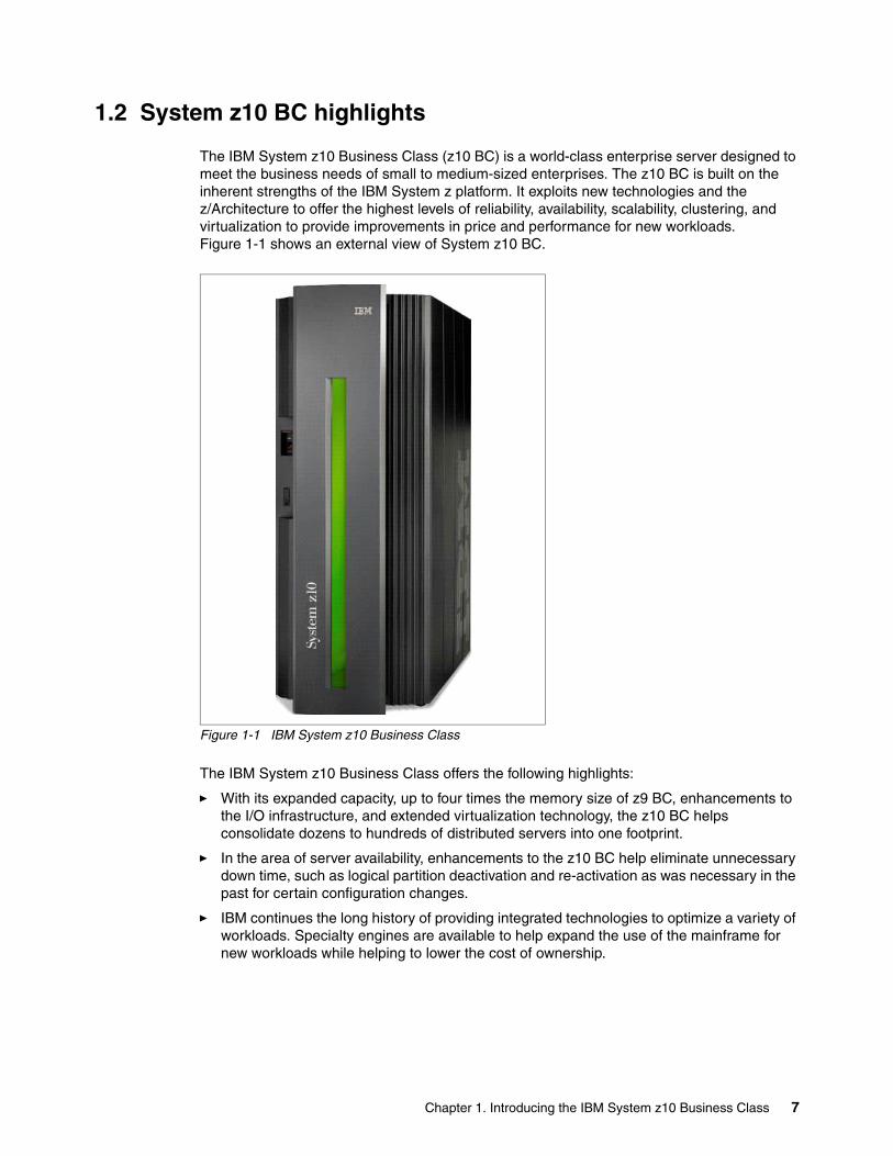
The IBM System z10 Business Class (z10 BC) is a world-class enterprise server designed to meet the business needs of small to medium-sized enterprises. The z10 BC is built on the inherent strengths of the IBM System z platform. It exploits new technologies and the z/Architecture to offer the highest levels of reliability, availability, scalability, clustering, and virtualization to provide improvements in price and performance for new workloads. Figure 1-1 shows an external view of System z10 BC.
Figure 1-1 IBM System z10 Business Class
The IBM System z10 Business Class offers the following highlights:
� With its expanded capacity, up to four times the memory size of z9 BC, enhancements to the I/O infrastructure, and extended virtualization technology, the z10 BC helps consolidate dozens to hundreds of distributed servers into one footprint.
� In the area of server availability, enhancements to the z10 BC help eliminate unnecessary down time, such as logical partition deactivation and re-activation as was necessary in the past for certain configuration changes.
� IBM continues the long history of providing integrated technologies to optimize a variety of workloads. Specialty engines are available to help expand the use of the mainframe for new workloads while helping to lower the cost of ownership.
Chapter 1. Introducing the IBM System z10 Business Class 7
� The z10 BC processing unit has an integrated hardware decimal floating point unit to accelerate decimal floating point transactions. This function is designed to markedly improve performance for decimal floating point operations, which offer increased precision compared to binary floating point operations. This is expected to be particularly useful for the calculations involved in many financial transactions.
� Integrated clear-key encryption security features on z10 BC include a higher advanced encryption standard and more secure hashing algorithms. Performing these functions in hardware contributes to improved performance in a security-rich environment.
Capacity on DemandOn-demand enhancements enable customers to have more flexibility in managing and administering their temporary capacity requirements. System z10 has an architectural approach for temporary offerings that has the potential to change the thinking about on-demand capacity. With the System z10, one or more flexible configuration definitions can be available to solve multiple temporary situations, and multiple capacity configurations can be active simultaneously.
Staged records can be created for various scenarios. Up to eight records can be installed on the server at any given time. Activation of the records can be done manually or the z/OS Capacity Provisioning Manager can automatically invoke them when Workload Manager (WLM) policy thresholds are reached. Tokens are available that can be purchased for On/Off Capacity on Demand (On/Off CoD) either before or after execution.
1.3 z10 BC model structure
The z10 BC has a newly designed Central Processing Complex (CPC) and I/O drawer structure. It has a machine type of 2098 and a single model, E10, with 130 capacity settings. The last two digits of the model indicate the maximum number of PUs available for purchase.
A processing unit (PU) is the generic term for the z/Architecture processor on the System z10 processor chip. The PU can be characterized as:
� Central processor (CP)
A maximum of five PUs are characterizable as CPs.
� Integrated Facility for Linux (IFL)
An IFL is used by Linux on System z and z/VM in support of Linux.
� System z10 Application Assist Processor (zAAP)
One CP must be installed with or prior to the installation of any zAAP.
� System z10 Integrated Information Processor (zIIP)
One CP must be installed with or prior to the installation of any zIIP.
� Internal Coupling Facility (ICF)
The ICF is used by the Coupling Facility Control Code (CFCC)
� System Assist Processor (SAP)
An additional SAP is to be used by the channel subsystem.
A minimum of one CP, IFL, or ICF has to be purchased and activated. For each CP purchased, one zAAP, or one zIIP, or one zAAP and one zIIP can be purchased. PUs can be purchased in single PU increments and are can be ordered by feature code. The total number of PUs purchased must not exceed the total number available for the z10 BC, that is, ten.
8 IBM System z10 Business Class Technical Overview
I/O features or channel types supported are:
� ESCON®
� FICON Express8
� FICON Express4, FICON Express2, and FICON Express (when carried forward from a previous System z server)
� OSA-Express3
� OSA-Express2 (until no longer available or when carried forward from a previous System z server)
� Crypto Express3
� Crypto Express2
� Coupling Links (in peer mode only; ICB-4 and ISC-3)
� The Parallel Sysplex® InfiniBand coupling link (PSIFB)
The z10 BC has the following additional cost effective options for customers requiring smaller I/O configurations:
� Two-channel FICON Express4 4 Km LX and SX feature� Two-port OSA Express3-2P GbE SX and 1000Base-T features� Single adapter Crypto Express3-1P feature
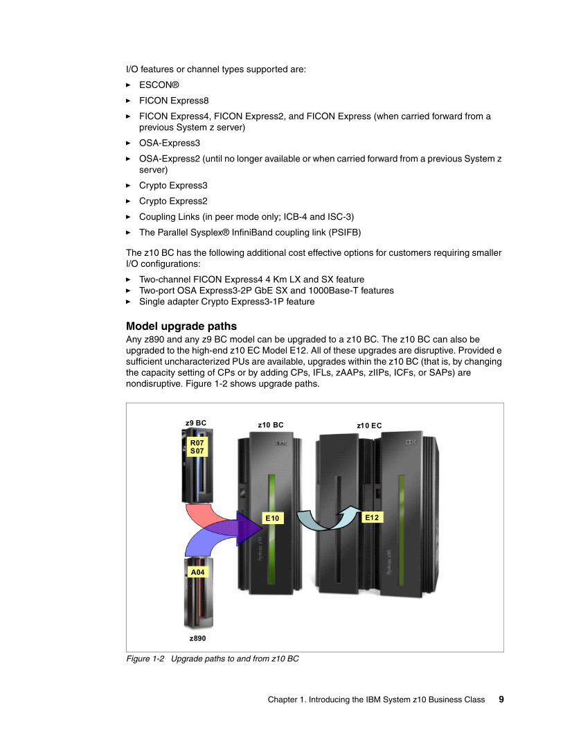
Model upgrade pathsAny z890 and any z9 BC model can be upgraded to a z10 BC. The z10 BC can also be upgraded to the high-end z10 EC Model E12. All of these upgrades are disruptive. Provided e sufficient uncharacterized PUs are available, upgrades within the z10 BC (that is, by changing the capacity setting of CPs or by adding CPs, IFLs, zAAPs, zIIPs, ICFs, or SAPs) are nondisruptive. Figure 1-2 shows upgrade paths.
Figure 1-2 Upgrade paths to and from z10 BC
R07S07
A04
E12
z9 BC
z890
z10 ECz10 BC
E10
Chapter 1. Introducing the IBM System z10 Business Class 9
Concurrent processing unit conversionsThe z10 BC supports concurrent conversion between different PU types, providing flexibility to meet changing business environments. Within the constraint of the maximum number configurable for each PU type, a PU of any type can be converted to any other type.
1.4 System functions and features
The z10 BC is a single frame server. The frame contains the key components. The server provides:
� One hardware model (E10) with up to ten PUs for customer use � One CPC drawer and up to four I/O drawers� Power supplies� An optional internal battery feature� Modular cooling units� Support Elements
Functions and features include:
� System z10 quad-core processor chip operating at 3.5 GHz.
� Uniprocessor improvement of up to 50% as compared to the z9 BC, based on the LSPR workload mix.
� Up to 48% more total system capacity than the z9 BC.
� Single processor core sparing.
� Hardware decimal floating point unit on each core.
� Up to a 10-way SMP server, with a maximum of five configurable CPs.
� Increased scalability with 130 available capacity settings.
� Up to 248 GB of real memory for customer use for growing application needs.
� Large page (1 MB) support.
� 8 GB fixed Hardware System Area (HSA), which is managed separately from customer memory. This fixed HSA is designed to improve availability by avoiding outages.
� Enhanced security features in CPACF, Crypto Express3 features, and TKE.
� High Performance FICON for System z (zHPF), which improves performance for small data transfers of OLTP.
� Seven OSA-Express3 features, two of which are exclusive to z10 BC.
� HiperSockets improvements.
� Just-in-time deployment of capacity resources, which can improve flexibility when making temporary or permanent changes. Activation can be further simplified and automated using z/OS Capacity Provisioning.
� 6.0 GBps InfiniBand (IB) memory bus adapter (MBA) to I/O interconnect.
� InfiniBand coupling links.
� STP over InfiniBand.
� Server Time Protocol enhancements including enhanced accuracy to an external time source, and Network Time Protocol (NTP) server on Hardware Management Console (HMC).
� Coupling Facility Control Code (CFCC) Level 16.
10 IBM System z10 Business Class Technical Overview
� Support for IBM Systems Director Active Energy Manager™ (AEM) for Linux on System z, for a single view of actual energy usage across multiple heterogeneous IBM platforms within the infrastructure. AEM is a key component of IBM Cool Blue™ portfolio within Project Big Green.
� Support for raised and non-raised floor installation.
1.4.1 Processor
In this section we describe several characteristics and functions introduced with the z10 BC server and enhancements made to functions that we already introduced.
Single-chip moduleSince the transition of System z from bipolar to CMOS technology, the base building block for System z has been the multi-chip module (MCM). The MCM is a compact, densely packed piece of technology with processing units (PUs), system controllers (SCs), memory bus adaptors (MBAs) and the clock chips. The MCM is cooled by a closed-circuit refrigeration fluid assisted by air. Over time, for different generations of servers, a single MCM has delivered from 11 MIPS for the 9672 R1, to over 8000 MIPS for the z10 EC.
For the z10 BC, the design of this building block has changed and been adapted to accommodate the faster processor in a single frame system. The single-chip module (SCM) is now the base unit and has its own heat-sink. Both the System z10 processor chip and SCs use individual SCMs. On the z10 BC, three cores of the quad-core z10 processor chip are active.
The key benefit of the SCM is that, in rare case of a PU or SC failure, the SCM can be replaced on-site. In the MCM case, the whole MCM or a book has to be replaced. Additionally, even with a 3.5 GHz multi-core chip, the server does not require additional cooling either by water or refrigeration. The two air-handling devices are sufficient to provide the necessary cooling.
Plan-ahead memoryFuture memory upgrades can now be pre-planned to be nondisruptive. The plan-ahead memory feature adds the physical memory required to support the target memory sizes. Then, memory upgrades can be made concurrently and nondisruptively if supported by the operating system. z/OS and z/VM V5R4 allow memory to be added nondisruptively.
Increased flexibility with z/VM-mode partitionsSystem z10 BC provides for the definition of a z/VM-mode LPAR containing a mix of processor types including CPs and specialty processors: IFLs, zIIPs, zAAPs, and ICFs.
z/VM V5R4 supports this capability, which increases flexibility and simplifies systems management. In a single LPAR, z/VM can:
� Manage guests that exploit Linux on System z on IFLs, z/VSE™, and z/OS on CPs.
� Execute designated z/OS workloads, such as parts of DB2 DRDA® processing and XML on zIIPs.
� Provide an economical Java execution environment under z/OS on zAAPs.
Chapter 1. Introducing the IBM System z10 Business Class 11
1.4.2 CPC drawer
In addition to the SCMs, the CPC drawer has the following components:
� Memory up to 256 GB (248 GB for customer use and 8 GB for the HSA)
� Flexible Support Processor for managing and monitoring the system internally
� Two Oscillator and ETR cards for providing timing function for the system and attachment to Sysplex Timers for Parallel Sysplex
� Up to six Host Channel Adaptors (HCAs) for connectivity to the I/O drawer or direct connections for Parallel Sysplex InfiniBand (PSIFB) coupling links
� Three DCAs for providing low voltage power supply to all the above mentioned components in the CPC drawer
1.4.3 I/O connectivity
The z/10 BC introduces several features, improves others, and exploits technologies such as InfiniBand. In this section, we briefly review the most relevant I/O capabilities.
InfiniBandIn 1999, two competing input/output (I/O) standards called Future I/O (developed by Compaq, IBM, and Hewlett-Packard) and Next Generation I/O (developed by Intel®, Microsoft®, and Sun) merged into a unified I/O standard called InfiniBand. InfiniBand is an industry-standard specification that defines an input/output architecture used to interconnect servers, communications infrastructure equipment, storage, and embedded systems. InfiniBand is a true fabric architecture that leverages switched, point-to-point channels with data transfers of up to 120 Gbps (gigabits per second), both in chassis backplane applications and through external copper and optical fiber connections.
InfiniBand is a pervasive, low-latency, high-bandwidth interconnect that requires low processing overhead and is ideal to carry multiple traffic types (clustering, communications, storage, management) over a single connection. As a mature and field-proven technology, InfiniBand is used in thousands of data centers, high-performance compute clusters, and embedded applications that scale from two nodes up to a single cluster that interconnects thousands of nodes.
The z10 BC takes advantage of InfiniBand to implement:
� An I/O bus that includes the InfiniBand Double Data Rate (IB-DDR) infrastructure. This replaces the self-timed interconnect features found in prior System z servers.
� Parallel Sysplex coupling over InfiniBand (PSIFB). This link has a bandwidth of 6 GBps between two System z10 servers, and 3 GBps between System z10 and System z9 servers for a short distance, or 5 Gbps between two System z10 servers for a long distance.
� Server Time Protocol (STP).
I/O subsystemsThe I/O subsystem direction is evolutionary, drawing on developments from z990 and System z9. The I/O subsystem is supported by an I/O bus that includes the InfiniBand Double Data Rate (IFB-DDR) infrastructure (replacing self-timed interconnect found in the prior System z servers). This infrastructure is designed to reduce overhead and latency, and provide increased throughput. The I/O expansion network uses the InfiniBand Link Layer (IB-2, Double Data Rate).
12 IBM System z10 Business Class Technical Overview
The z10 BC has Host Channel Adapter (HCA) fanouts residing on the front of the CPC drawer. The System z10 generation of the I/O platform is intended to provide significant performance improvement over the current I/O platform used for FICON, OSA-Express, and Crypto Express features. It will be the primary platform to support future high-bandwidth requirements for FICON/Fibre Channel, Open Systems adapters, and Crypto Express.
I/O drawerThe z10 BC has a minimum of one CPC drawer and can have up to four I/O drawers. No I/O drawer is required for a z10 BC server having only ICB-4 or PSIFB coupling links installed. The CEC and I/O cages present in z10 EC and System z9 are not used.
The I/O drawer for the z10 BC is a first for any System z. The newly designed I/O drawer enables concurrent add, remove, and repair of the drawer, and provides for an increased number of I/O cards, compared to all prior mid-range System z Servers. Concurrent remove or repair requires at least two I/O drawers and proper pre-planning of the I/O configuration.
In each I/O drawer, up to eight features can be installed, for a total of 32 features. As with the CPC drawer, the I/O drawer is installed horizontally. This orientation is different to the prior generation of servers.
An I/O drawer supports the following features:
� ESCON� FICON Express8, FICON Express4, FICON Express2, and FICON Express� OSA-Express3 and OSA-Express2� Crypto Express3 and Crypto Express2� ISC-3 Coupling Links
ESCON channelsThe high-density ESCON card has 16 ports, of which 15 can be activated. One port is always reserved as a spare, in the event of a failure of one of the other ports.
FICON channelsUp to 128 FICON Express8, up to 128 FICON Express4, up to 112 FICON Express2 channels, and up to 40 FICON Express channels are supported:
� The FICON Express8 features support a link data rate of 2, 4, or 8 Gbps, auto-negotiated.
� The FICON Express4 features support a link data rate of 1, 2, or 4 Gbps, auto-negotiated.
� The FICON Express2 features support a link data rate of 1 or 2 Gbps, auto-negotiated.
� FICON Express4, FICON Express2, and FICON Express features are only available when carried forward on an upgrade.
The z10 BC supports FCP channels, switches, and FCP/SCSI devices with full fabric connectivity under Linux on System z.
Open Systems AdapterThe z10 BC can have up to 24 features of the Open Systems Adapter (OSA) family, giving a maximum of 96 ports of LAN connectivity.
Choosing any combination of the supported OSA-Express2 or OSA-Express3 features is possible.
Chapter 1. Introducing the IBM System z10 Business Class 13
OSA-Express3 highlightsSystem z10 offers five OSA-Express3 features. When compared to similar OSA-Express2 features, which they replace, OSA-Express3 features provide the following important benefits:
� Doubling the density of ports � For TCP/IP traffic, reducing latency and improving throughput for standard and jumbo
frames
The z10 BC has two additional exclusive OSA-Express3 features.
The five System z10 features, plus the additional two z10 BC features, are discussed in 4.7.4, “OSA Express3” on page 95.
Performance enhancements are the result of the data router function present in all OSA-Express3 features. What previously was performed in firmware, the OSA-Express3 now performs in hardware. Additional logic in the IBM ASIC handles packet construction, inspection, and routing, thereby allowing packets to flow between host memory and the LAN at line speed without firmware intervention.
With the data router, the store and forward technique in direct memory address (DMA) is no longer used. The data router enables a direct host memory-to-LAN flow. This avoids a hop and is designed to reduce latency and to increase throughput for standard frames (1492 byte) and jumbo frames (8992 byte).
HiperSocketsThe HiperSockets function, also known as internal queued direct input/output (iQDIO, or internal QDIO), is an integrated function of the System z10 that provides users with attachments to up to 16 high-speed virtual LANs with minimal system and network overhead.
HiperSockets can be customized to accommodate varying traffic sizes. Because HiperSockets does not use an external network, it can free up system and network resources, eliminating attachment costs while improving availability and performance.
HiperSockets eliminates having to use I/O subsystem operations and to traverse an external network connection to communicate between logical partitions in the same System z10 server. HiperSockets offers significant value in server consolidation by connecting many virtual servers, and can be used instead of certain coupling link configurations in a Parallel Sysplex.
1.4.4 Cryptography
Integrated cryptographic features provide leading cryptographic performance and functionality. Reliability, availability, and serviceability (RAS) support is unmatched in the industry and the cryptographic solution has received the highest standardized security certification. The crypto cards are supported with additional capabilities to add or move crypto processors to logical partitions without pre-planning.
CP Assist for Cryptographic FunctionThe z10 BC continues to use the Cryptographic Assist Architecture first implemented on z990. The CP Assist for Cryptographic Function (CPACF) offers the full complement of Advanced Encryption Standard (AES) algorithm and Secure Hash Algorithm (SHA). Support for CPACF is also available using the Integrated Cryptographic Service Facility (ICSF). ICSF is a component of z/OS and can transparently use the available cryptographic functions, CPACF, Crypto Express2, or Crypto Express3, to balance the workload and help address the bandwidth requirements of your applications.
14 IBM System z10 Business Class Technical Overview
An enhancement to CPACF is designed to facilitate the continued privacy of cryptographic key material when used for data encryption. CPACF, using key wrapping, ensures that key material is not visible to applications or operating systems during encryption operations.
Protected key CPACF is designed to provide substantial throughput improvements for large volume data encryption as well as low latency for encryption of small blocks of data. Furthermore, changes to the information management tool, IBM Encryption Tool for IMS and DB2 Databases, improves performance for protected key applications.
Configurable Crypto Express2The Crypto Express2 feature has two PCI-X adapters, which can each be configured as a coprocessor or an accelerator:
� Crypto Express2 Coprocessor is for secure key encrypted transactions (default).� Crypto Express2 Accelerator is for Secure Sockets Layer (SSL) acceleration.
A recently added function includes support for secure key AES and 13-digit through 19-digit Personal Account Numbers, often used by credit card companies for security code computations.
Because the features are implemented in Licensed Internal Code, current Crypto Express2 features carried forward from z890 and z9 BC can take advantage of configuration options on z10 BC.
A version of the Crypto Express2 feature with a single adapter is also available.
Configurable Crypto Express3The Crypto Express3 feature has two PCI Express adapters, which can each be configured as a coprocessor or an accelerator:
� Crypto Express3 Coprocessor is for secure key encrypted transactions (default).� Crypto Express3 Accelerator is for Secure Sockets Layer (SSL) acceleration.
The Crypto Express3 feature has the same configuration options as, and contains all the functions of, the Crypto Express2 feature and introduces a number of additional functions, including:
� SHA2 functions similarly to the SHA2 function in CPACF.
� RSA functions similarly to the RSA function in CPACF.
� Dynamic power management designed to keep within the temperature limits of the feature and at the same time maximize RSA performance.
� Up to 32 LPARs in all logical channel subsystems have access to the feature.
� Improved RAS over previous crypto features due to dual processors and the service processor.
� Function update while installed using secure code load.
� When a PCI Express adapter is defined as a coprocessor lock-step checking by the dual processors enhances error detection and fault isolation.
� Dynamic addition and configuration of the Crypto Express3 features to LPARs without an outage.
The Crypto Express3 feature is designed to deliver throughput improvements for both symmetric and asymmetric operations.
Chapter 1. Introducing the IBM System z10 Business Class 15
For less error-prone and easier migration a Crypto Express3 migration wizard is available. The wizard allows the user to collect configuration data from a Crypto Express2 or Crypto Express3 feature configured as a coprocessor and migrate that data to a different Crypto Express coprocessor. The target for this migration must be a coprocessor with equivalent or greater capabilities.
A version of the Crypto Express3 feature with a single adapter is also available.
Trusted Key Entry workstation support for Smart Card ReaderThe Trusted Key Entry (TKE) workstation and the TKE 6.0 level of Licensed Internal Code are optional features on the System z10 BC. The TKE workstation offers security-rich local and remote key management, providing authorized persons a method of operational and master key entry, identification, exchange, separation, and update. Recent enhancements include support for the AES encryption algorithm, audit logging, and an infrastructure for payment card industry data security standard (PCIDSS).
Support for an optional Smart Card Reader attached to the TKE workstation allows for the use of smart cards that contain an embedded microprocessor and associated memory for data storage. Access to and the use of confidential data on the smart cards is protected by a user-defined personal identification number (PIN).
1.4.5 Parallel Sysplex support
Support for Parallel Sysplex includes the Coupling Facility Control Code and the coupling links.
Coupling links supportCoupling connectivity in support of Parallel Sysplex environments is improved with the Parallel Sysplex InfiniBand (PSIFB) link. Parallel Sysplex connectivity now supports:
� Internal Coupling Channels (ICs) operating at memory speed.
� Integrated Cluster Bus-4, operating at 2 GBps and supported by a 10-meter copper cable provided as a feature (maximum distance of 7 meters, in practice). ICB-4 uses a dedicated self-timed interconnect (STI) for communication.
� InterSystem Channel-3 operating at 2 Gbps and supporting an unrepeated link data rate of 2 Gbps over 9-µm single-mode fiber optic cabling with an LC Duplex connector.
� InfiniBand coupling links offer up to 6 GBps of bandwidth between System z10 servers and up to 3 GBps of bandwidth between System z10 and System z9 servers for a distance up to 150 m (492 feet).
� InfiniBand long reach (LR) links offer up to 5 Gbps of bandwidth between System z10 servers for a distance up to 10 km (6.2 miles).
InfiniBand coupling links can be used to carry Server Time Protocol (STP) messages.
Coupling Facility Control Code Level 16CFCC Level 16 is available for the System z10 BC server. It brings System-Managed CF Structure Duplexing enhancements and list notification improvements.
External time reference facilityTwo external time reference (ETR) cards are shipped as a standard feature with the server. They provide a dual-path interface to the IBM Sysplex Timers, which can be used for timing synchronization between systems in a sysplex environment. The ETR facility allows
16 IBM System z10 Business Class Technical Overview
continued operation even if a single ETR card fails. This redundant design also allows concurrent maintenance.
Each card has a coaxial connector to link to the pulse per second (PPS) signal.
Server Time Protocol facilityServer Time Protocol (STP) is a server-wide facility that is implemented in the Licensed Internal Code of System z servers and Coupling Facilities. STP presents a single view of time to PR/SM and provides the capability for multiple servers and Coupling Facilities to maintain time synchronization with each other. All System z servers can be enabled for STP by installing the STP feature. Each server and CF that are planned to be configured in a coordinated timing network (CTN) must be STP-enabled.
The STP feature is designed to be the supported method for maintaining time synchronization between System z servers and Coupling Facilities. The STP design uses the CTN concept, which is a collection of servers and Coupling Facilities that are time-synchronized to a time value called the coordinated server time.
Network Time Protocol (NTP) client support has been added to the STP code on the System z10 and on System z9. With this functionality, the System z10 and the System z9 can be configured to use an NTP server as an external time source.
The time accuracy of an STP-only CTN is improved by adding an NTP server with the pulse per second output signal (PPS) as the External Time Signal (ETS) device.
This implementation answers the need for a single time source across the heterogeneous platforms in the enterprise, allowing an NTP server to become the single time source for the System z10 and the System z9, as well as other servers that have NTP clients (UNIX®, NT, and so on). NTP can only be used for an STP-only CTN where no server can have an active connection to a Sysplex Timer®.
HMC can also act as an NTP server. With this support, System z10 can get time from HMC without accessing other than HMC-SE network.
1.4.6 Reliability, availability, and serviceability The reliability, availability, and serviceability (RAS) strategy is a building-block approach developed to meet the customer's stringent requirements of achieving continuous reliable operation. Those building blocks are error prevention, error detection, recovery, problem determination, service structure, change management, and measurement and analysis.
The initial focus is on preventing failures from occurring in the first place. This is accomplished by using Hi-Rel (highest reliability) components; using screening, sorting, burn-in, and run-in; and by taking advantage of technology integration. For Licensed Internal Code and hardware design, failures are eliminated through rigorous design rules; design walk-through; peer reviews; element, subsystem, and system simulation; and extensive engineering and manufacturing testing.
The RAS strategy is focused on a recovery design that is necessary to mask errors and make them transparent to customer operations. An extensive hardware recovery design has been implemented to detect and correct array faults. In cases where total transparency cannot be achieved, you may restart the server with the maximum possible capacity.
Chapter 1. Introducing the IBM System z10 Business Class 17
1.5 The performance advantage
IBM Large Systems Performance Reference (LSPR) method is designed to provide comprehensive z/Architecture processor capacity ratios for different configurations of servers across a wide variety of system control programs and workload environments. For z10 BC, z/Architecture processor subcapacity indicator is defined with the notation A0x-Z0x, where x is the number of installed CPs, from one to five. There are a total of 26 subcapacity levels, designated by the letters A through Z.
In addition to the general information provided for z/OS V1R9, the LSPR also contains performance relationships for z/VM and Linux on System z operating environments.
Based on using an LSPR mixed workload, the performance of the z10 BC (2098) Z01 is expected to be up to 1.5 times that of the z9 BC (2096) Z01.
Moving from a System z9 BC partition to an equivalently-sized System z10 BC partition, a z/VM workload will experience an internal throughput rate (ITR) ratio that is somewhat related to the workload's instruction mix, MP factor, and level of storage over commitment. Workloads with higher levels of storage over commitment or higher MP factors are likely to experience lower than average z10 BC to z9 BC ITR scaling ratios. The range of likely ITR ratios is wider than the range has been for previous processor migrations.
The LSPR contains the Internal Throughput Rate (ITR) ratios for the z10 BC and the previous-generation System z processor families based upon measurements and projections using standard IBM benchmarks in a controlled environment. The actual throughput that any user may experience will vary, depending upon considerations such as the amount of multiprogramming in the user's job stream, the I/O configuration, and the workload processed. Therefore, no assurance can be given that an individual user will achieve throughput improvements equivalent to the performance ratios stated.
For detailed performance information, consult the LSPR Web page:
http://www.ibm.com/servers/eserver/zseries/lspr/
To help size a server, IBM provides a free IBM Processor Capacity Reference (zPCR) tool that reflects the latest LSPR measurements. The tool can be downloaded from:
http://www.ibm.com/support/techdocs/atsmastr.nsf/WebIndex/PRS1381
The Capacity Planning for z10 Upgrades document provides guidelines for setting capacity expectation when using zPCR. It is available from:
http://www.ibm.com/support/techdocs/atsmastr.nsf/WebIndex/TD104738
1.6 Operating systems and software
The z10 BC is supported by a large set of software, including ISV applications. This section lists only the supported operating systems. Exploitation of some features might require the latest releases. Because this information is subject to change, for the most current information refer to the Preventive Service Planning (PSP) bucket for 2098DEVICE. Further information is contained in Chapter 7, “Software support” on page 135.
18 IBM System z10 Business Class Technical Overview
System z10 EC supports any of the following operating systems:
� z/OS Version 1 Release 7 with IBM Lifecycle Extension and z/OS Version 1 Release 8 with IBM Lifecycle Extension. Note that z/OS.e is not supported.
� z/OS Version 1 Release 9 and later.
� z/VM Version 5 Release 3 and later.
� z/VSE Version 4 Release 1 and later.
� TPF Version 4 Release 1 and z/TPF Version 1 Release 1.
� Linux on System z distributions:
– Novell SUSE: SLES3 9, SLES 10, and SLES 11– Red Hat: RHEL4 4 and RHEL 5
Finally, a large software portfolio is available to the IBM System z10 Business Class, including an extensive collection of middleware and ISV products that implement the most recent proven technologies.
With support for IBM WebSphere software, full support for SOA, Web services, J2EE, Linux, and Open Standards, the z10 BC is intended to be a platform of choice for integration of a new generation of applications with existing applications and data.
3 SLES is the abbreviation for Novell SUSE Linux Enterprise Server.4 RHEL is the abbreviation for Red Hat Enterprise Linux
Note: Regular service support for z/OS V1 R8 ended in September 2009. However, by ordering the IBM Lifecycle Extension for z/OS V1.8 product, fee-based corrective service can be obtained for up to two years after withdrawal of service. Similarly, by ordering the IBM Lifecycle Extension for z/OS V1.7 product, customers can obtain support up to September 2010.
Chapter 1. Introducing the IBM System z10 Business Class 19

20 IBM System z10 Business Class Technical Overview
Chapter 2. Hardware components
The objective of this chapter is to explain how the System z10 Business Class is structured, what the main components are, and how those components interconnect from a physical point of view. This information can be useful for planning purposes, helping define configurations that best fit your requirements.
This chapter discusses the following topics:
� 2.1, “Frame and drawers” on page 22� 2.2, “Drawer concept” on page 25� 2.3, “The single-chip module” on page 26� 2.4, “The PU and SC chips” on page 27� 2.5, “Memory” on page 30� 2.6, “Connectivity” on page 34� 2.7, “Model configurations” on page 36
2
© Copyright IBM Corp. 2008, 2009. All rights reserved. 21
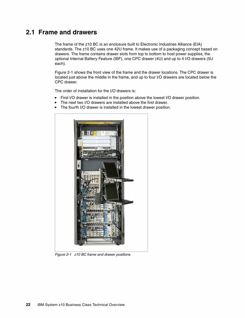
2.1 Frame and drawers
The frame of the z10 BC is an enclosure built to Electronic Industries Alliance (EIA) standards. The z10 BC uses one 42U frame. It makes use of a packaging concept based on drawers. The frame contains drawer slots from top to bottom to host power supplies, the optional Internal Battery Feature (IBF), one CPC drawer (4U) and up to 4 I/O drawers (5U each).
Figure 2-1 shows the front view of the frame and the drawer locations. The CPC drawer is located just above the middle in the frame, and up to four I/O drawers are located below the CPC drawer.
The order of installation for the I/O drawers is:
� First I/O drawer is installed in the position above the lowest I/O drawer position.� The next two I/O drawers are installed above the first drawer.� The fourth I/O drawer is installed in the lowest drawer position.
Figure 2-1 z10 BC frame and drawer positions
22 IBM System z10 Business Class Technical Overview

In Figure 2-1 on page 22, the following main components in the frame, shown from top to bottom, are:
� The optional 2U Internal Battery Feature (IBF) provides the function of a local uninterrupted power source.
The IBF further enhances the robustness of the power design, increasing Power Line Disturbance immunity. It provides battery power to preserve processor data in case of a loss of power on all four AC feeds from the utility company. The IBF can hold power briefly over a brownout, or for orderly shutdown in case of a longer outage. The IBF provides up to 13 minutes of full power, depending on the I/O configuration. Table 2-1 shows the IBF hold up times for configurations with one, two, three, or four I/O drawers.
Table 2-1 IBF estimated power time
The batteries are installed in pairs. One pair of battery units (FC 3211) can be installed.
� The system power supply (8U) is fed by two identical 3-phase power feeds (or alternately two single-phase power feeds). One feed comes to the front, and one to the rear of the frame.
� The CPC drawer contains PUs, memory, and connections to the I/O drawers.
� Up to four I/O drawers can house all supported types of channel cards. An I/O drawer has eight I/O card slots (four in the front and four in the rear) for installation of ESCON channels, FICON Express8 channels, OSA- Express3, ISC-3, Crypto Express2, and Crypto Express3 features. I/O card slots are oriented horizontally in the I/O drawer.
� The two Support Elements (SE) trays are located in front of the CPC drawer and the highest I/O drawer.
There are up to six dual port fanouts on the front side of the CPC drawer to transfer data, each port with a bi-directional bandwidth of up to 6 GBps. The HCA2 and ICB-4 fanouts each drive two ports. The up to 12 IB fanout connections provide an aggregated bandwidth of up to 72 GBps.
The HCA2-C fanout connects to up to four I/O drawers that may contain a variety of channel, Coupling Link, OSA-Express, and cryptographic feature cards:
� ESCON channels; 16 port cards, 15 usable ports, and one spare
� FICON channels (FICON or FCP modes)
– FICON Express channels, carried forward during an upgrade only for FCV
– FICON Express2 channels, carried forward during an upgrade only
– FICON Express4 channels, carried forward during an upgrade only (except for the 2-port features)
– FICON Express8 channels
� ISC-3 links in peer mode only (up to four coupling links, two links per daughter card). Two daughter cards (ISC-D) plug into one mother card (ISC-M).
One I/O drawer Two I/O drawers Three I/O drawers Four I/O drawers
13 minutes 11 minutes 9 minutes 7 minutes
Chapter 2. Hardware components 23
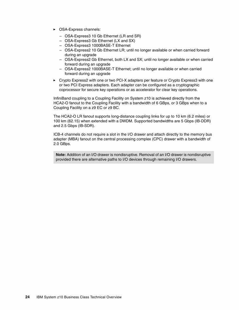
� OSA-Express channels:
– OSA-Express3 10 Gb Ethernet (LR and SR)– OSA-Express3 Gb Ethernet (LX and SX)– OSA-Express3 1000BASE-T Ethernet– OSA-Express2 10 Gb Ethernet LR; until no longer available or when carried forward
during an upgrade– OSA-Express2 Gb Ethernet, both LX and SX; until no longer available or when carried
forward during an upgrade– OSA-Express2 1000BASE-T Ethernet; until no longer available or when carried
forward during an upgrade
� Crypto Express2 with one or two PCI-X adapters per feature or Crypto Express3 with one or two PCI Express adapters. Each adapter can be configured as a cryptographic coprocessor for secure key operations or as accelerator for clear key operations.
InfiniBand coupling to a Coupling Facility on System z10 is achieved directly from the HCA2-O fanout to the Coupling Facility with a bandwidth of 6 GBps, or 3 GBps when to a Coupling Facility on a z9 EC or z9 BC.
The HCA2-O LR fanout supports long-distance coupling links for up to 10 km (6.2 miles) or 100 km (62.15) when extended with a DWDM. Supported bandwidths are 5 Gbps (IB-DDR) and 2.5 Gbps (IB-SDR).
ICB-4 channels do not require a slot in the I/O drawer and attach directly to the memory bus adapter (MBA) fanout on the central processing complex (CPC) drawer with a bandwidth of 2.0 GBps.
Note: Addition of an I/O drawer is nondisruptive. Removal of an I/O drawer is nondisruptive provided there are alternative paths to I/O devices through remaining I/O drawers.
24 IBM System z10 Business Class Technical Overview
2.2 Drawer concept
The central processing complex (CPC) and the physical I/O infrastructure make use of a packaging concept based on drawers. The CPC drawer contains processors (PUs), memory, connectors to I/O drawers and other servers, and power supplies. I/O drawers contain cards for all functions supported in the z10 BC such as FICON, ESCON, OSA Express3, ISC-3, and cryptographic functions. There is one CPC drawer in a z10 BC and up to four I/O drawers are supported. A CPC drawer and its components are shown Figure 2-2.
Figure 2-2 z10 BC CPC drawer structure and components
The CPC drawer contains:
� Six single-chip modules (SCMs).
� Twelve processing units (PUs). The PUs reside on microprocessor chips located in four SCMs. Three PUs per SCM are active.
� Two system controller (SC) microprocessor chips each located in one of two SCMs.
� Memory DIMMs plugged into 32 available slots, providing up to 256 GB of physical memory. The minimum physical memory size in the drawer is 16 GB (including 8 GB for HSA), installed in eight DIMMs of 2 GB each. For memory sizes beyond 64 GB, 4 GB DIMMs are used; beyond 128 GB, 8 GB DIMMs are used.
� Up to six fanouts, which can be a combination of two-port memory bus adapter (MBA) fanouts, optical or copper two-port Host Channel Adapter (HCA2-O, HCA2-O LR or HCA2-C) fanouts. Fanouts support up to 12 connections to the I/O drawers, and external coupling links.
� Two processor (FSP) cards, and two cards on each of which the oscillator and ETR functions are combined. The oscillators on both cards act as a primary and a backup. If the primary oscillator fails, the backup card detects the failure and continues to provide the clock signal so that no outage occurs due to an oscillator failure. Each card provides one BNC connector to an NTP device and one MTRJ connector to a Sysplex Timer unit.
Chapter 2. Hardware components 25
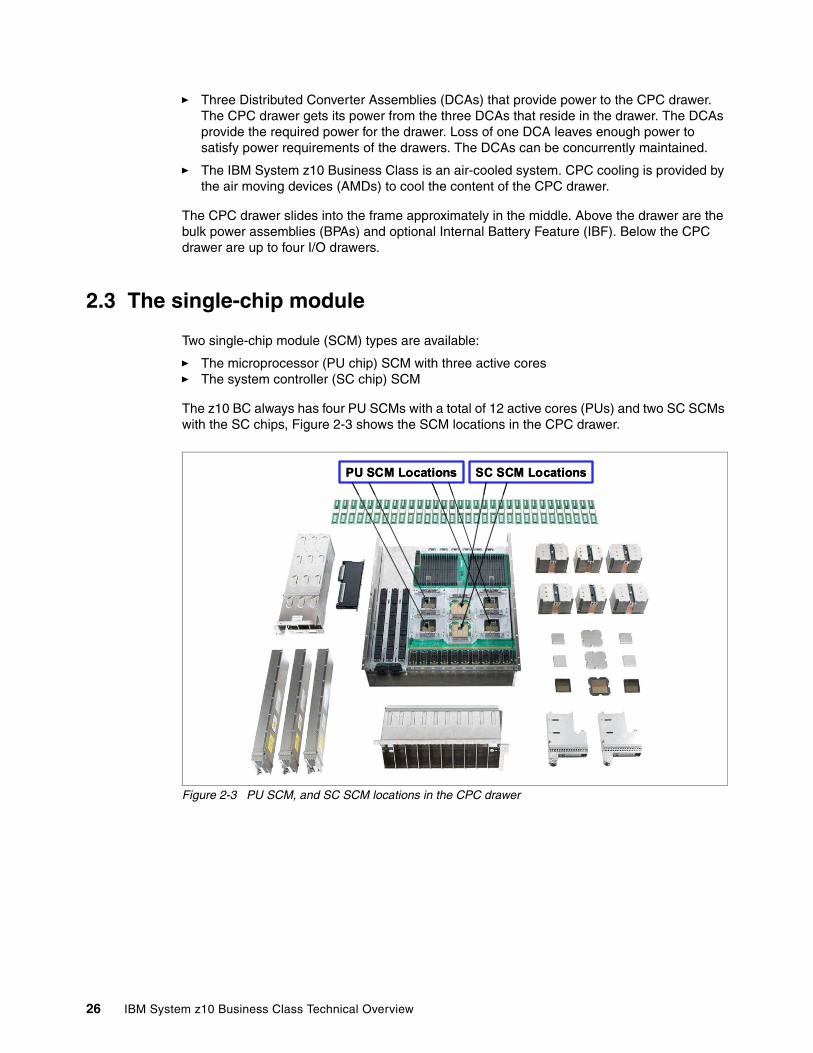
� Three Distributed Converter Assemblies (DCAs) that provide power to the CPC drawer. The CPC drawer gets its power from the three DCAs that reside in the drawer. The DCAs provide the required power for the drawer. Loss of one DCA leaves enough power to satisfy power requirements of the drawers. The DCAs can be concurrently maintained.
� The IBM System z10 Business Class is an air-cooled system. CPC cooling is provided by the air moving devices (AMDs) to cool the content of the CPC drawer.
The CPC drawer slides into the frame approximately in the middle. Above the drawer are the bulk power assemblies (BPAs) and optional Internal Battery Feature (IBF). Below the CPC drawer are up to four I/O drawers.
2.3 The single-chip module
Two single-chip module (SCM) types are available:
� The microprocessor (PU chip) SCM with three active cores � The system controller (SC chip) SCM
The z10 BC always has four PU SCMs with a total of 12 active cores (PUs) and two SC SCMs with the SC chips, Figure 2-3 shows the SCM locations in the CPC drawer.
Figure 2-3 PU SCM, and SC SCM locations in the CPC drawer
PU SCM Locations SC SCM LocationsPU SCM Locations SC SCM Locations
26 IBM System z10 Business Class Technical Overview
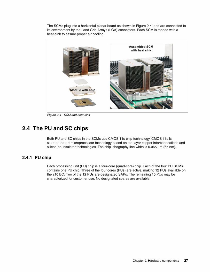
The SCMs plug into a horizontal planar board as shown in Figure 2-4, and are connected to its environment by the Land Grid Arrays (LGA) connectors. Each SCM is topped with a heat-sink to assure proper air cooling.
Figure 2-4 SCM and heat-sink
2.4 The PU and SC chips
Both PU and SC chips in the SCMs use CMOS 11s chip technology. CMOS 11s is state-of-the-art microprocessor technology based on ten-layer copper interconnections and silicon-on-insulator technologies. The chip lithography line width is 0.065 µm (65 nm).
2.4.1 PU chip
Each processing unit (PU) chip is a four-core (quad-core) chip. Each of the four PU SCMs contains one PU chip. Three of the four cores (PUs) are active, making 12 PUs available on the z10 BC. Two of the 12 PUs are designated SAPs. The remaining 10 PUs may be characterized for customer use. No designated spares are available.
Assembled SCM with heat sink
LGA
Module with chip
Assembled SCM with heat sink
LGA
Module with chip
Chapter 2. Hardware components 27
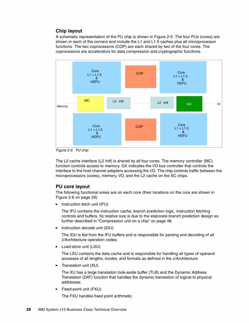
Chip layoutA schematic representation of the PU chip is shown in Figure 2-5. The four PUs (cores) are shown in each of the corners and include the L1 and L1.5 caches plus all microprocessor functions. The two coprocessors (COP) are each shared by two of the four cores. The coprocessors are accelerators for data compression and cryptographic functions.
Figure 2-5 PU chip
The L2 cache interface (L2 Intf) is shared by all four cores. The memory controller (MC) function controls access to memory. GX indicates the I/O bus controller that controls the interface to the host channel adapters accessing the I/O. The chip controls traffic between the microprocessors (cores), memory, I/O, and the L2 cache on the SC chips.
PU core layoutThe following functional areas are on each core (their locations on the core are shown in Figure 2-6 on page 29):
� Instruction fetch unit (IFU)
The IFU contains the instruction cache, branch prediction logic, instruction fetching controls and buffers. Its relative size is due to the elaborate branch prediction design as further described in “Compression unit on a chip” on page 48.
� Instruction decode unit (IDU)
The IDU is fed from the IFU buffers and is responsible for parsing and decoding of all z/Architecture operation codes.
� Load-store unit (LSU)
The LSU contains the data cache and is responsible for handling all types of operand accesses of all lengths, modes, and formats as defined in the z/Architecture.
� Translation unit (XU)
The XU has a large translation look-aside buffer (TLB) and the Dynamic Address Translation (DAT) function that handles the dynamic translation of logical to physical addresses.
� Fixed-point unit (FXU)
The FXU handles fixed point arithmetic.
MC
Core L1 + L1.5
&HDFU
COP
Core L1 + L1.5
& HDFU
Core L1 + L1.5
&HDFU
Core L1 + L1.5
&HDFU
COP
L2 IntfGXL2 Intf IO
Memory
28 IBM System z10 Business Class Technical Overview
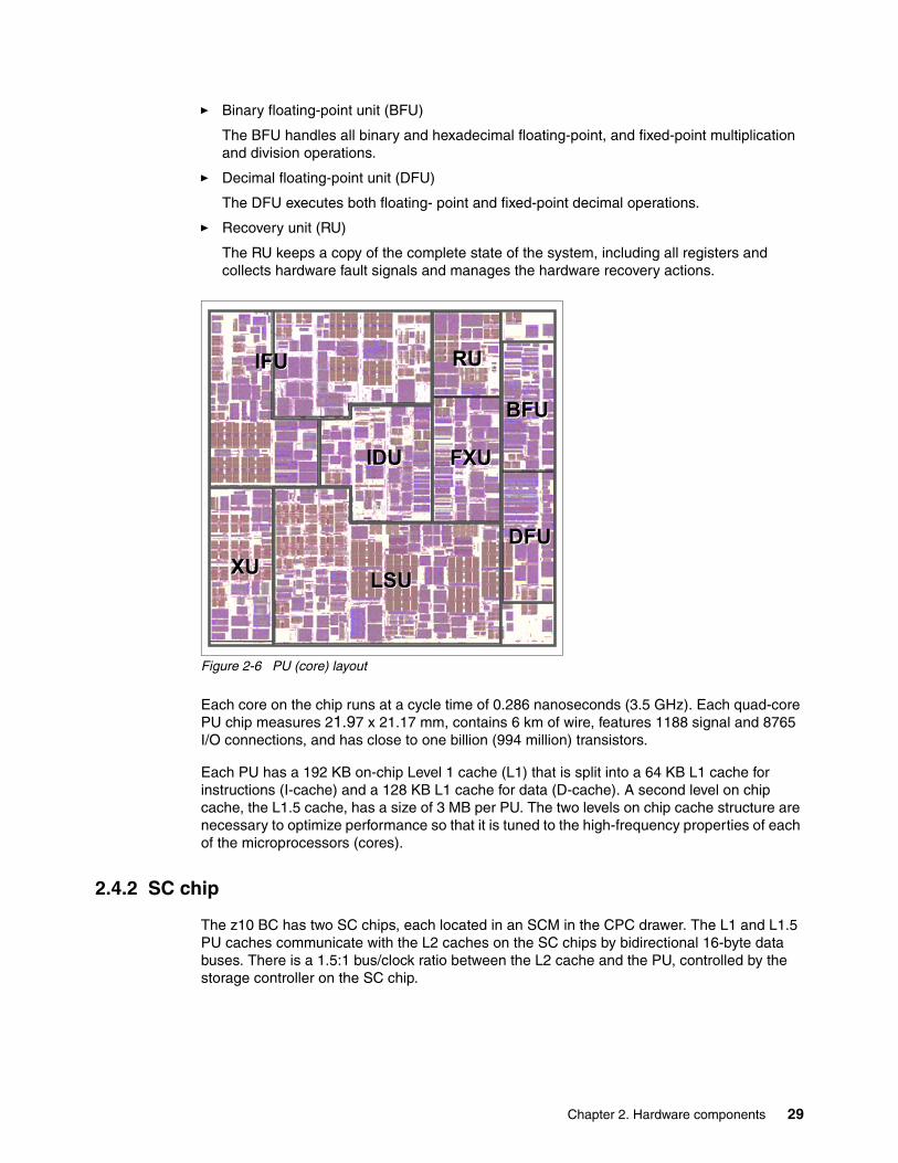
� Binary floating-point unit (BFU)
The BFU handles all binary and hexadecimal floating-point, and fixed-point multiplication and division operations.
� Decimal floating-point unit (DFU)
The DFU executes both floating- point and fixed-point decimal operations.
� Recovery unit (RU)
The RU keeps a copy of the complete state of the system, including all registers and collects hardware fault signals and manages the hardware recovery actions.
Figure 2-6 PU (core) layout
Each core on the chip runs at a cycle time of 0.286 nanoseconds (3.5 GHz). Each quad-core PU chip measures 21.97 x 21.17 mm, contains 6 km of wire, features 1188 signal and 8765 I/O connections, and has close to one billion (994 million) transistors.
Each PU has a 192 KB on-chip Level 1 cache (L1) that is split into a 64 KB L1 cache for instructions (I-cache) and a 128 KB L1 cache for data (D-cache). A second level on chip cache, the L1.5 cache, has a size of 3 MB per PU. The two levels on chip cache structure are necessary to optimize performance so that it is tuned to the high-frequency properties of each of the microprocessors (cores).
2.4.2 SC chip
The z10 BC has two SC chips, each located in an SCM in the CPC drawer. The L1 and L1.5 PU caches communicate with the L2 caches on the SC chips by bidirectional 16-byte data buses. There is a 1.5:1 bus/clock ratio between the L2 cache and the PU, controlled by the storage controller on the SC chip.
RURU
BFUBFU
IDUIDU FXUFXU
XUXU LSULSU
DFUDFU
IFUIFU
Chapter 2. Hardware components 29
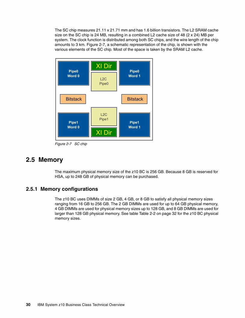
The SC chip measures 21.11 x 21.71 mm and has 1.6 billion transistors. The L2 SRAM cache size on the SC chip is 24 MB, resulting in a combined L2 cache size of 48 (2 x 24) MB per system. The clock function is distributed among both SC chips, and the wire length of the chip amounts to 3 km. Figure 2-7, a schematic representation of the chip, is shown with the various elements of the SC chip. Most of the space is taken by the SRAM L2 cache.
Figure 2-7 SC chip
2.5 Memory
The maximum physical memory size of the z10 BC is 256 GB. Because 8 GB is reserved for HSA, up to 248 GB of physical memory can be purchased.
2.5.1 Memory configurations
The z10 BC uses DIMMs of size 2 GB, 4 GB, or 8 GB to satisfy all physical memory sizes ranging from 16 GB to 256 GB. The 2 GB DIMMs are used for up to 64 GB physical memory, 4 GB DIMMs are used for physical memory sizes up to 128 GB, and 8 GB DIMMs are used for larger than 128 GB physical memory. See table Table 2-2 on page 32 for the z10 BC physical memory sizes.
Pipe0Word 0
Pipe0Word 1
L2C Pipe0
Pipe1Word 0
Pipe1Word 1
L2CPipe1
XI Dir
XI Dir
Bitstack Bitstack
30 IBM System z10 Business Class Technical Overview
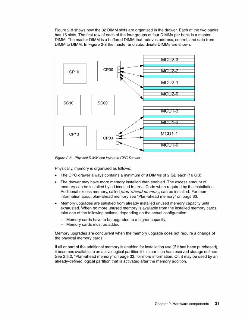
Figure 2-8 shows how the 32 DIMM slots are organized in the drawer. Each of the two banks has 16 slots. The first row of each of the four groups of four DIMMs per bank is a master DIMM. The master DIMM is a buffered DIMM that redrives address, control, and data from DIMM to DIMM. In Figure 2-8 the master and subordinate DIMMs are shown.
Figure 2-8 Physical DIMM slot layout in CPC Drawer
Physically, memory is organized as follows:
� The CPC drawer always contains a minimum of 8 DIMMs of 2 GB each (16 GB).
� The drawer may have more memory installed than enabled. The excess amount of memory can be installed by a Licensed Internal Code when required by the installation. Additional excess memory, called plan-ahead memory, can be installed. For more information about plan-ahead memory see “Plan-ahead memory” on page 33.
� Memory upgrades are satisfied from already installed unused memory capacity until exhausted. When no more unused memory is available from the installed memory cards, take one of the following actions, depending on the actual configuration:
– Memory cards have to be upgraded to a higher capacity.– Memory cards must be added.
Memory upgrades are concurrent when the memory upgrade does not require a change of the physical memory cards.
If all or part of the additional memory is enabled for installation use (if it has been purchased), it becomes available to an active logical partition if this partition has reserved storage defined. See 2.5.2, “Plan-ahead memory” on page 33, for more information. Or, it may be used by an already-defined logical partition that is activated after the memory addition.
CP00
SC00
CP03
CP10
SC10
CP13
MCU2-3
MCU2-2
MCU2-1
MCU1-3
MCU2-0
MCU1-2
MCU1-1
MCU1-0
Chapter 2. Hardware components 31
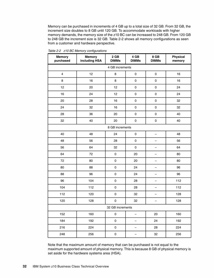
Memory can be purchased in increments of 4 GB up to a total size of 32 GB. From 32 GB, the increment size doubles to 8 GB until 120 GB. To accommodate workloads with higher memory demands, the memory size of the z10 BC can be increased to 248 GB. From 120 GB to 248 GB the increment size is 32 GB. Table 2-2 shows all memory configurations as seen from a customer and hardware perspective.
Table 2-2 z10 BC Memory configurations
Note that the maximum amount of memory that can be purchased is not equal to the maximum supported amount of physical memory. This is because 8 GB of physical memory is set aside for the hardware systems area (HSA).
Memory purchased
Memory including HSA
2 GB DIMMs
4 GB DIMMs
8 GB DIMMs
Physical memory
4 GB increments
4 12 8 0 0 16
8 16 8 0 0 16
12 20 12 0 0 24
16 24 12 0 0 24
20 28 16 0 0 32
24 32 16 0 0 32
28 36 20 0 0 40
32 40 20 0 0 40
8 GB increments
40 48 24 0 – 48
48 56 28 0 – 56
56 64 32 0 – 64
64 72 0 20 – 80
72 80 0 20 – 80
80 88 0 24 – 96
88 96 0 24 – 96
96 104 0 28 – 112
104 112 0 28 – 112
112 120 0 32 – 128
120 128 0 32 – 128
32 GB increments
152 160 0 – 20 160
184 192 0 – 24 192
216 224 0 – 28 224
248 256 0 – 32 256
32 IBM System z10 Business Class Technical Overview
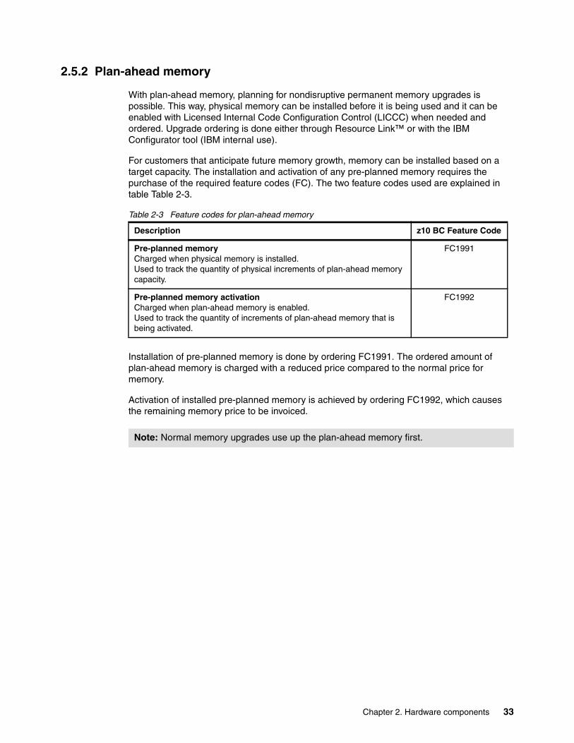
2.5.2 Plan-ahead memory
With plan-ahead memory, planning for nondisruptive permanent memory upgrades is possible. This way, physical memory can be installed before it is being used and it can be enabled with Licensed Internal Code Configuration Control (LICCC) when needed and ordered. Upgrade ordering is done either through Resource Link™ or with the IBM Configurator tool (IBM internal use).
For customers that anticipate future memory growth, memory can be installed based on a target capacity. The installation and activation of any pre-planned memory requires the purchase of the required feature codes (FC). The two feature codes used are explained in table Table 2-3.
Table 2-3 Feature codes for plan-ahead memory
Installation of pre-planned memory is done by ordering FC1991. The ordered amount of plan-ahead memory is charged with a reduced price compared to the normal price for memory.
Activation of installed pre-planned memory is achieved by ordering FC1992, which causes the remaining memory price to be invoiced.
Description z10 BC Feature Code
Pre-planned memoryCharged when physical memory is installed.Used to track the quantity of physical increments of plan-ahead memory capacity.
FC1991
Pre-planned memory activationCharged when plan-ahead memory is enabled.Used to track the quantity of increments of plan-ahead memory that is being activated.
FC1992
Note: Normal memory upgrades use up the plan-ahead memory first.
Chapter 2. Hardware components 33
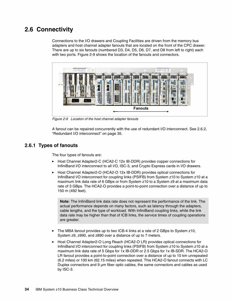
2.6 Connectivity
Connections to the I/O drawers and Coupling Facilities are driven from the memory bus adapters and host channel adapter fanouts that are located on the front of the CPC drawer. There are up to six fanouts (numbered D3, D4, D5, D6, D7, and D8 from left to right) each with two ports. Figure 2-9 shows the location of the fanouts and connectors.
Figure 2-9 Location of the host channel adapter fanouts
A fanout can be repaired concurrently with the use of redundant I/O interconnect. See 2.6.2, “Redundant I/O interconnect” on page 35.
2.6.1 Types of fanouts
The four types of fanouts are:
� Host Channel Adapter2-C (HCA2-C 12x IB-DDR) provides copper connections for InfiniBand I/O interconnect to all I/O, ISC-3, and Crypto Express cards in I/O drawers.
� Host Channel Adapter2-O (HCA2-O 12x IB-DDR) provides optical connections for InfiniBand I/O interconnect for coupling links (PSIFB) from System z10 to System z10 at a maximum link data rate of 6 GBps or from System z10 to a System z9 at a maximum data rate of 3 GBps. The HCA2-O provides a point-to-point connection over a distance of up to 150 m (492 feet).
� The MBA fanout provides up to two ICB-4 links at a rate of 2 GBps to System z10, System z9, z990, and z890 over a distance of up to 7 meters.
� Host Channel Adapter2-O Long Reach (HCA2-O LR) provides optical connections for InfiniBand I/O interconnect for coupling links (PSIFB) from System z10 to System z10 at a maximum link data rate of 5 Gbps for 1x IB-DDR or 2.5 Gbps for 1x IB-SDR. The HCA2-O LR fanout provides a point-to-point connection over a distance of up to 10 km unrepeated (6.2 miles) or 100 km (62.15 miles) when repeated. This HCA2-O fanout connects with LC Duplex connectors and 9 µm fiber optic cables, the same connectors and cables as used by ISC-3.
Fanouts
Note: The InfiniBand link data rate does not represent the performance of the link. The actual performance depends on many factors, such as latency through the adapters, cable lengths, and the type of workload. With InfiniBand coupling links, while the link data rate may be higher than that of ICB links, the service times of coupling operations are greater.
34 IBM System z10 Business Class Technical Overview
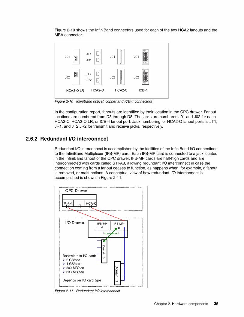
Figure 2-10 shows the InfiniBand connectors used for each of the two HCA2 fanouts and the MBA connector.
Figure 2-10 InfiniBand optical, copper and ICB-4 connectors
In the configuration report, fanouts are identified by their location in the CPC drawer. Fanout locations are numbered from D3 through D8. The jacks are numbered J01 and J02 for each HCA2-C, HCA2-O LR, or ICB-4 fanout port. Jack numbering for HCA2-O fanout ports is JT1, JR1, and JT2 JR2 for transmit and receive jacks, respectively.
2.6.2 Redundant I/O interconnect
Redundant I/O interconnect is accomplished by the facilities of the InfiniBand I/O connections to the InfiniBand Multiplexer (IFB-MP) card. Each IFB-MP card is connected to a jack located in the InfiniBand fanout of the CPC drawer. IFB-MP cards are half-high cards and are interconnected with cards called STI-A8, allowing redundant I/O interconnect in case the connection coming from a fanout ceases to function, as happens when, for example, a fanout is removed, or malfunctions. A conceptual view of how redundant I/O interconnect is accomplished is shown in Figure 2-11.
Figure 2-11 Redundant I/O interconnect
HCA2-O LR HCA2-O ICB-4HCA2-C
...HCA-C
Do
ma
in 0
Dom
ain 1
Interconnect
IF B-MP B
IFB-MP A
Bandwidth to I/O card:2 GB/sec 1 GB/sec500 MB/sec333 MB/sec
Depends on I/O card type
I/O Drawer
CPC Drawer
HCA-C
Chapter 2. Hardware components 35
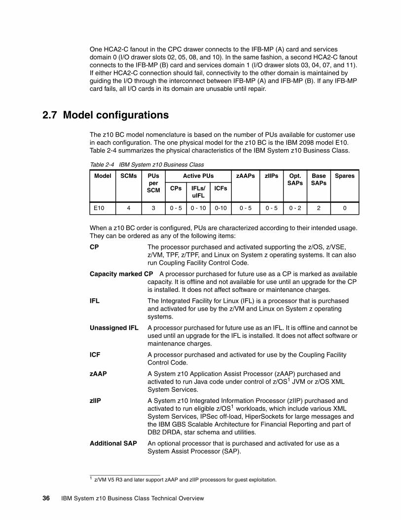
One HCA2-C fanout in the CPC drawer connects to the IFB-MP (A) card and services domain 0 (I/O drawer slots 02, 05, 08, and 10). In the same fashion, a second HCA2-C fanout connects to the IFB-MP (B) card and services domain 1 (I/O drawer slots 03, 04, 07, and 11). If either HCA2-C connection should fail, connectivity to the other domain is maintained by guiding the I/O through the interconnect between IFB-MP (A) and IFB-MP (B). If any IFB-MP card fails, all I/O cards in its domain are unusable until repair.
2.7 Model configurations
The z10 BC model nomenclature is based on the number of PUs available for customer use in each configuration. The one physical model for the z10 BC is the IBM 2098 model E10. Table 2-4 summarizes the physical characteristics of the IBM System z10 Business Class.
Table 2-4 IBM System z10 Business Class
When a z10 BC order is configured, PUs are characterized according to their intended usage. They can be ordered as any of the following items:
CP The processor purchased and activated supporting the z/OS, z/VSE, z/VM, TPF, z/TPF, and Linux on System z operating systems. It can also run Coupling Facility Control Code.
Capacity marked CP A processor purchased for future use as a CP is marked as available capacity. It is offline and not available for use until an upgrade for the CP is installed. It does not affect software or maintenance charges.
IFL The Integrated Facility for Linux (IFL) is a processor that is purchased and activated for use by the z/VM and Linux on System z operating systems.
Unassigned IFL A processor purchased for future use as an IFL. It is offline and cannot be used until an upgrade for the IFL is installed. It does not affect software or maintenance charges.
ICF A processor purchased and activated for use by the Coupling Facility Control Code.
zAAP A System z10 Application Assist Processor (zAAP) purchased and activated to run Java code under control of z/OS1 JVM or z/OS XML System Services.
zIIP A System z10 Integrated Information Processor (zIIP) purchased and activated to run eligible z/OS1 workloads, which include various XML System Services, IPSec off-load, HiperSockets for large messages and the IBM GBS Scalable Architecture for Financial Reporting and part of DB2 DRDA, star schema and utilities.
Additional SAP An optional processor that is purchased and activated for use as a System Assist Processor (SAP).
Model SCMs PUs per
SCM
Active PUs zAAPs zIIPs Opt. SAPs
Base SAPs
Spares
CPs IFLs/uIFL
ICFs
E10 4 3 0 - 5 0 - 10 0-10 0 - 5 0 - 5 0 - 2 2 0
1 z/VM V5 R3 and later support zAAP and zIIP processors for guest exploitation.
36 IBM System z10 Business Class Technical Overview
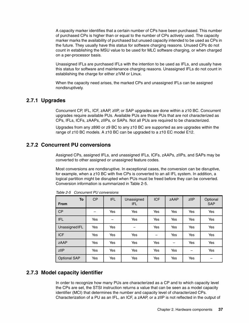
A capacity marker identifies that a certain number of CPs have been purchased. This number of purchased CPs is higher than or equal to the number of CPs actively used. The capacity marker marks the availability of purchased but unused capacity intended to be used as CPs in the future. They usually have this status for software charging reasons. Unused CPs do not count in establishing the MSU value to be used for MLC software charging, or when charged on a per-processor basis.
Unassigned IFLs are purchased IFLs with the intention to be used as IFLs, and usually have this status for software and maintenance charging reasons. Unassigned IFLs do not count in establishing the charge for either z/VM or Linux.
When the capacity need arises, the marked CPs and unassigned IFLs can be assigned nondisruptively.
2.7.1 Upgrades
Concurrent CP, IFL, ICF, zAAP, zIIP, or SAP upgrades are done within a z10 BC. Concurrent upgrades require available PUs. Available PUs are those PUs that are not characterized as CPs, IFLs, ICFs, zAAPs, zIIPs, or SAPs. Not all PUs are required to be characterized.
Upgrades from any z890 or z9 BC to any z10 BC are supported as are upgrades within the range of z10 BC models. A z10 BC can be upgraded to a z10 EC model E12.
2.7.2 Concurrent PU conversions
Assigned CPs, assigned IFLs, and unassigned IFLs, ICFs, zAAPs, zIIPs, and SAPs may be converted to other assigned or unassigned feature codes.
Most conversions are nondisruptive. In exceptional cases, the conversion can be disruptive, for example, when a z10 BC with five CPs is converted to an all IFL system. In addition, a logical partition might be disrupted when PUs must be freed before they can be converted. Conversion information is summarized in Table 2-5.
Table 2-5 Concurrent PU conversions
2.7.3 Model capacity identifier
In order to recognize how many PUs are characterized as a CP and to which capacity level the CPs are set, the STSI instruction returns a value that can be seen as a model capacity identifier (MCI) that determines the number and capacity level of characterized CPs. Characterization of a PU as an IFL, an ICF, a zAAP, or a zIIP is not reflected in the output of
ToFrom
CP IFL Unassigned IFL
ICF zAAP zIIP Optional SAP
CP – Yes Yes Yes Yes Yes Yes
IFL Yes – Yes Yes Yes Yes Yes
Unassigned IFL Yes Yes – Yes Yes Yes Yes
ICF Yes Yes Yes – Yes Yes Yes
zAAP Yes Yes Yes Yes – Yes Yes
zIIP Yes Yes Yes Yes Yes – Yes
Optional SAP Yes Yes Yes Yes Yes Yes –
Chapter 2. Hardware components 37

the store system information (STSI) instruction, since they have no effect on software charging. More information about the STSI can be found in 8.3.3, “Processor identification” on page 186.
The z10 BC has 26 capacity levels, named from A to Z. Within each capacity level a one-, two-, three-, four-, and five-way model is offered, each identified by its capacity level indicator (A through Z) followed by an indication of the number of CPs available (01 to 05). This way, the z10 BC offers 130 capacity settings. All models have a related MSU value that is used to determine the software license charge for MLC software as shown in Table 2-6.
Table 2-6 Model capacity identifier and MSU values
Note: In the table, model capacity identifier A00 is used only for IFL or ICF configurations.
Model capacity identifier
MSU Model capacity identifier
MSU Model capacity identifier
MSU
A01 3 B01 4 C01 5
A02 6 B02 7 C02 9
A03 9 B03 10 C03 12
A04 11 B04 13 C04 16
A05 13 B05 15 C05 19
D01 6 E01 7 F01 7
D02 11 E02 12 F02 14
D03 15 E03 17 F03 19
D04 19 E04 22 F04 25
D05 23 E05 27 F05 30
G01 9 H01 10 I01 11
G02 16 H02 18 I02 20
G03 23 H03 26 I03 29
G04 29 H04 33 I04 37
G05 36 H05 40 I05 45
J01 12 K01 14 L01 16
J02 23 K02 25 L02 30
J03 32 K03 36 L03 43
J04 41 K04 46 L04 55
J05 50 K05 56 L05 66
M01 19 N01 21 O01 24
M02 35 N02 40 O02 44
M03 49 N03 57 O03 63
M04 63 N04 72 O04 81
38 IBM System z10 Business Class Technical Overview

2.7.4 Capacity on Demand upgrades
Capacity on Demand (CoD) provides even greater flexibility for upgrades. Three offerings allow temporary upgrade of capacity for different types of situations: CBU, CPE, and On/Off CoD.
It is possible to upgrade CPs or specialty engines permanently or on a temporary basis, with or without IBM assistance on site.
Refer to Chapter 8, “System upgrades” on page 179, for detailed information.
Capacity BackupCapacity Backup (CBU) delivers temporary backup capacity. CBU is licensed only for disaster situations, when part of an enterprise capacity is lost. It allows to restore a lost capacity from one server to another server for up to 90 days.
When disaster strikes, the customer decides how many of each of the contracted CBUs of any type need to be activated. It can be reconfigured during the CBU activation as needed.
M05 76 N05 87 O05 98
P01 27 Q01 30 R01 33
P02 50 Q02 56 R02 62
P03 71 Q03 80 R03 89
P04 91 Q04 102 R04 113
P05 110 Q05 123 R05 137
S01 38 T01 42 U01 47
S02 70 T02 78 U02 88
S03 100 T03 112 U03 125
S04 127 T04 143 U04 160
S05 154 T05 173 U05 194
V01 53 W01 60 X01 67
V02 99 W02 111 X02 124
V03 141 W03 158 X03 177
V04 180 W04 202 X04 226
V05 218 W05 245 X05 274
Y01 76 Z01 83 – –
Y02 142 Z02 155 – –
Y03 202 Z03 221 – –
Y04 258 Z04 283 – –
Y05 313 Z05 342 – –
Model capacity identifier
MSU Model capacity identifier
MSU Model capacity identifier
MSU
Chapter 2. Hardware components 39
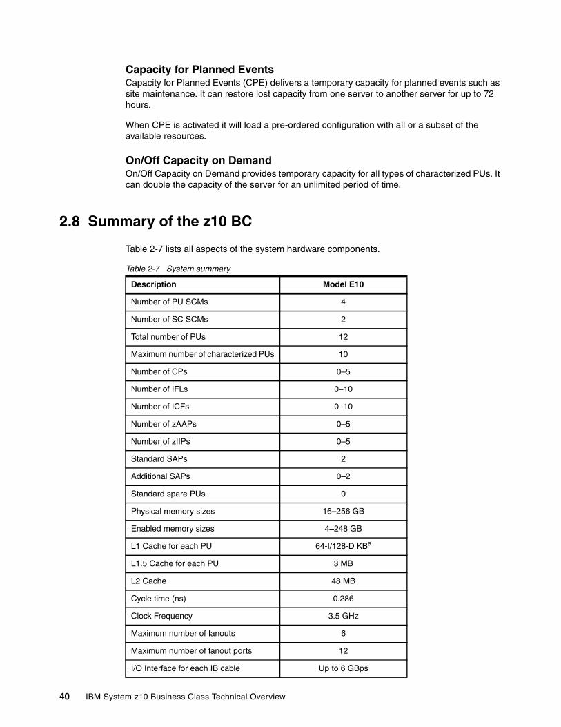
Capacity for Planned EventsCapacity for Planned Events (CPE) delivers a temporary capacity for planned events such as site maintenance. It can restore lost capacity from one server to another server for up to 72 hours.
When CPE is activated it will load a pre-ordered configuration with all or a subset of the available resources.
On/Off Capacity on DemandOn/Off Capacity on Demand provides temporary capacity for all types of characterized PUs. It can double the capacity of the server for an unlimited period of time.
2.8 Summary of the z10 BC
Table 2-7 lists all aspects of the system hardware components.
Table 2-7 System summary
Description Model E10
Number of PU SCMs 4
Number of SC SCMs 2
Total number of PUs 12
Maximum number of characterized PUs 10
Number of CPs 0–5
Number of IFLs 0–10
Number of ICFs 0–10
Number of zAAPs 0–5
Number of zIIPs 0–5
Standard SAPs 2
Additional SAPs 0–2
Standard spare PUs 0
Physical memory sizes 16–256 GB
Enabled memory sizes 4–248 GB
L1 Cache for each PU 64-I/128-D KBa
L1.5 Cache for each PU 3 MB
L2 Cache 48 MB
Cycle time (ns) 0.286
Clock Frequency 3.5 GHz
Maximum number of fanouts 6
Maximum number of fanout ports 12
I/O Interface for each IB cable Up to 6 GBps
40 IBM System z10 Business Class Technical Overview
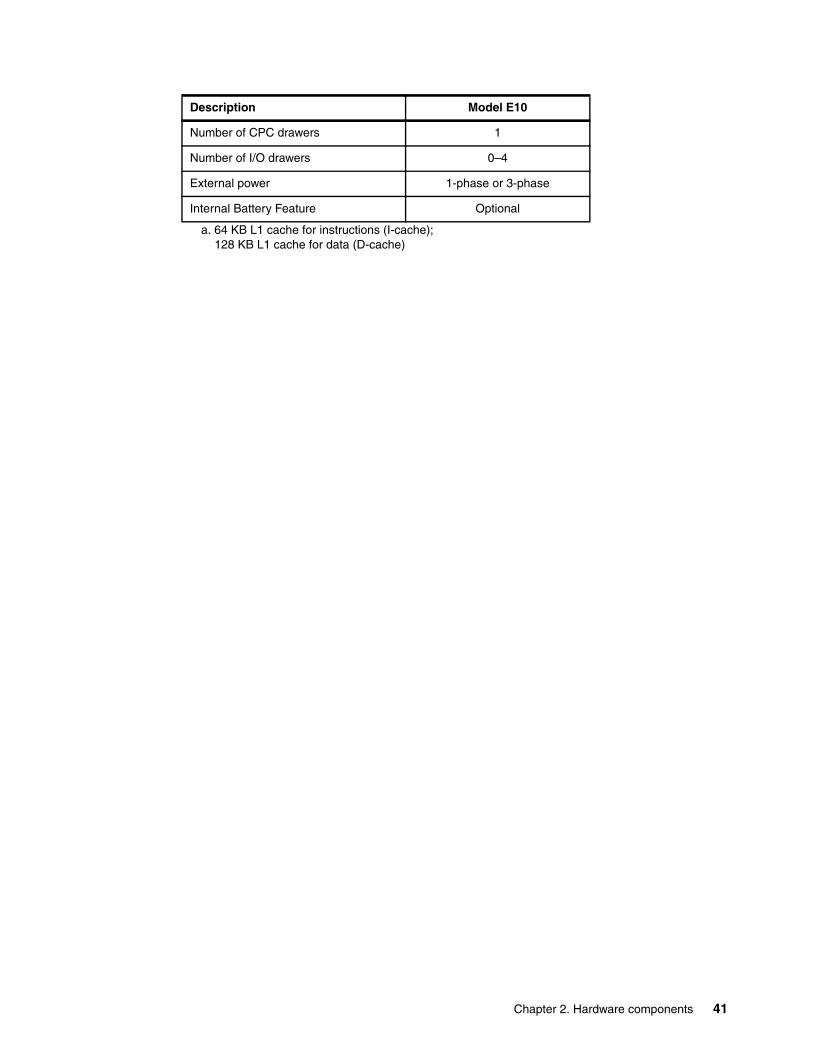
Number of CPC drawers 1
Number of I/O drawers 0–4
External power 1-phase or 3-phase
Internal Battery Feature Optional
a. 64 KB L1 cache for instructions (I-cache);128 KB L1 cache for data (D-cache)
Description Model E10
Chapter 2. Hardware components 41

42 IBM System z10 Business Class Technical Overview
Chapter 3. System design
The objective of this chapter is to explain how the IBM System z10 Business Class (z10 BC) is designed. This information can be used to understand the functions that make the z10 BC server that suits a broad mix of medium sized enterprises.
This chapter discusses the following topics:
� 3.1, “CPC Drawer” on page 44� 3.2, “Processing unit” on page 47� 3.3, “Processing unit functions” on page 50� 3.4, “Memory design” on page 60� 3.5, “Logical partitioning” on page 62� 3.6, “Intelligent Resource Director” on page 67� 3.7, “Clustering technology” on page 69
The design of the IBM System z10 Business Class Symmetrical Multi Processor (SMP) is a follow-on step in an evolutionary trajectory stemming from the introduction of CMOS technology back in 1994. Over time, and for the z10 BC once again, the design has been adapted to the changing requirements dictated by the shift towards contemporary business applications that customers are becoming more and more dependent on.
The z10 BC offers very high levels of serviceability, availability, reliability, resilience, and security, and fits in the IBM strategy in which mainframes play a central role in realizing an intelligent, energy efficient, integrated infrastructure. The z10 BC is designed in such a way that not only the server is considered important for the infrastructure, but also everything around it in terms of operating systems, middleware, storage, security, and network technologies supporting open standards, all to help customers achieve their business goals.
The design aims to reduce planned and unplanned outages by offering concurrent repair, replace, and upgrade functions for processors, memory, and I/O. The z10 BC with its high frequency, superscalar processor design, and flexible configuration options is the next implementation to address the ever-changing IT environment.
3
© Copyright IBM Corp. 2008, 2009. All rights reserved. 43

3.1 CPC Drawer
A CPC drawer contains four 4-core microprocessor chips. Three active cores are on each chip, offering 12 PUs for characterization. Two of the PUs are designated SAPs and the remaining 10 PUs are available as processing units for customer use. 32 DIMM slots can accommodate up to 256 GB of physical memory. Up to 12 I/O ports organized on up to six fanouts provide connectivity to the I/O drawers and coupling links to remote systems in a Parallel Sysplex. Additionally, the CPC drawer has its own power supplies (DCAs) and cooling fans.
Each PU has its own 192 KB Cache Level 1 (L1), split into 128 KB for data (D-cache) and 64 KB for instructions (I-cache). The L1 cache is designed as a store-through cache, meaning that altered data is also stored to the next level of memory.
The next level of memory is the L1.5 cache that is also on each PU and is 3 MB in size. It is a store-through cache. The Level 1.5 cache is required because, in servers with reduced cycle times, such as the z10 BC, the distance or latency between the processor and the shared cache (L2) is getting bigger (measured in the number of cycles required to go to the cache and get the data). The increase in latency is compensated by the insertion of an intermediate level cache reducing the traffic to and from the L2 cache.
The z10 BC uses CMOS 11S technology. The microprocessors are running at 3.5 GHz (0.286 ns cycle time).
The CPC drawer also contains two storage control (SC) chips, each with a Level 2 cache of 24 MB. The SC is responsible for coherent traffic between the L2 cache and the microprocessor caches.
Each memory DIMM has a capacity of 2, 4 or 8 GB, easily allowing installation of up to 256 GB of physical memory (L3). Of the installed amount of physical memory, 8 GB is set aside for the hardware system area (HSA). The 8 GB HSA does not belong to the memory purchased by the customer, meaning that a customer can purchase up to 248 GB.
The L2 cache is the aggregate of all cache space on the SC chips, resulting in L2 cache of 48 MB. The SC chips control the access and storing of data between the system memory (L3) and the on-chip caches. The L2 cache is shared by all PUs. The L2 has a store-in buffer design.
Access to the main memory (L3) is controlled from two of the four processor chips by their Memory Control (MC) function. Storage access is interleaved between the DIMMs, which tends to equalize storage activity across them.
Access to the I/O traffic is asymmetrically controlled from all four processor chips by their I/O controller function and eventually handled by up to 12 ports in up to six fanouts of four different types (numbered D3, D4, D5, D6, D7, and D8) in the front of the drawer.
44 IBM System z10 Business Class Technical Overview

Figure 3-1 shows the logical structure of the z10 BC.
Figure 3-1 z10 BC logical structure
Up to 12 connections transfer data. Each connection has a bidirectional bandwidth of up to 6.0 GBps. This leads to the support of a maximum aggregated data rate of 72 GBps per system.
Four I/O interconnect types are used for all I/O types:
� I/O interconnect based on a two-port (6.0 GBps each) Host Channel Adapter 2 - Copper (HCA2-C) fanout supports an IFB-MP card in an I/O drawer, to connect to:
– ESCON
ESCON channels (16 port cards)
– FICON
• FICON-Express, two port cards, carried forward on upgrade only for FCV
• FICON Express2, four port cards, carried forward on upgrade only
• FICON Express4 (four port cards), carried forward on upgrade only, used in FICON or FCP modes
• FICON Express4 (two port cards), used in FICON or FCP modes
• FICON Express8, four port cards, used in FICON or FCP modes
– OSA
• OSA-Express3 10 Gb Ethernet (LR and SR)
• OSA-Express3 Gb Ethernet (LX and SX), two and four port cards.
• OSA-Express3 1000BASE-T Ethernet, two and four port cards
• OSA-Express2 10 Gb Ethernet LR, until no longer available or carried forward during an upgrade only
• OSA-Express2 Gb Ethernet (LX and SX), until no longer available or carried forward during an upgrade
• OSA-Express2 1000BASE-T Ethernet, until no longer available or carried forward during an upgrade
SC00
SC10
CP00
CP10
CP03
CP13
I/O
I/OI/O
Node 0 I/O I/OI/O
Node 1
Memory Memory3 PUs3 x 3 MB L1.5 cacheCoprocessorsMemory controlI/O control
3 PUs3 x 3 MB L1.5 cacheCoprocessorsI/O Control
3 PUs3 x 3 MB L1.5 cacheCoprocessorsMemory controlI/O control
3 PUs3 x 3 MB L1.5 cacheCoprocessorsI/O Control
24 MB L2 cacheCoherency control
24 MB L2 cacheCoherency control
Chapter 3. System design 45

– Crypto
• Crypto Express2 with one (FC 0870), or two (FC 0863) PCI-X adapters per feature. A PCI-X adapter can be configured as a cryptographic coprocessor for secure key operations or as accelerator for clear key operations.
• Crypto Express3 with one (FC 0871) or two (FC 0864) PCI Express adapters per feature. A PCI Express adapter can be configured as a cryptographic coprocessor for secure key operations or as accelerator for clear key operations.
– ISC
ISC-3 links, up to four Coupling Links with two links per daughter card (ISC-D). Two daughter cards plug into one mother card (ISC-M).
� Coupling for up to 150 meters is based on a two-port (6.0 GBps each) Host Channel Adapter 2 - Optical (HCA2-O) fanout. HCA2-O fanouts support PSIFB coupling links for up to 16 CHPIDs, from System z10 to System z10 or from System z10 to a System z9 at 3.0 GBps.
� Coupling for up to 10 km (or up to 100 km with extenders) is based on a two-port Host Channel Adapter 2 - Optical LR (HCA2-O LR) fanout. This HCA2-O LR fanout support PSIFB coupling links for up to 16 CHPIDs, from System z10 to System z10.
� I/O interconnect based on a two-port Memory Bus Adapter fanout is used for ICB-4, directly attaching to a System z10, System z9, z990, or z890. The ICB-4 runs at 2.0 GBps for up to 7 meters.
See Chapter 4, “I/O system structure” on page 73, for more details about I/O connectivity and each channel type.
Dual external time referenceTwo external time reference (ETR) cards are automatically shipped with the server and provide a dual-path interface to IBM Sysplex Timers, which may be used for timing synchronization between systems in a sysplex environment. This allows continued operation even if a single ETR card fails. This redundant design also allows concurrent maintenance. The two connectors to external timers are located in the front of the CPC drawer, to the right of the fanout cards.
Server Time ProtocolServer Time Protocol (STP) is a server-wide facility that is implemented in the Licensed Internal Code of System z. The STP presents a single view of time to PR/SM and provides the capability for multiple servers and CFs to maintain time synchronization with each other and form a Coordinated Timing Network (CTN). A CTN is a collection of servers that are time synchronized to a time value called Coordinated Server Time (CST). An STP-only CTN is a CTN configuration where all servers are synchronized with CST and a Sysplex Timer is not required. A System z or CF may be enabled for STP by installing the STP feature. The STP feature is intended to be the supported method for maintaining time synchronization between System z servers and CFs.
Network Time Protocol (NTP) client support is available on the System z10 server and has been added to the STP code on System z9. This implementation answers the need for a single time source across the heterogeneous platforms in the enterprise. With this implementation the System z10 and the System z9 servers support the use of NTP servers as time sources.
When STP is used, the time of an STP-only CTN can be synchronized with the time provided by an NTP server as an External Time Source (ETS), allowing a heterogeneous platform
46 IBM System z10 Business Class Technical Overview

environment to have the same time source. Continuous availability of NTP servers can be achieved for System z by configuring different NTP servers for the CTN.
Improved security can be obtained by providing NTP server support on the Hardware Management Console (HMC), as the HMC is normally attached to the private dedicated LAN for System z maintenance and support.
The time accuracy of an STP-only CTN is improved by adding an NTP server with the pulse per second output signal (PPS) as the ETS device. This type of ETS is available from several vendors that offer network timing solutions.
STP tracks the highly stable accurate PPS signal from the NTP server and maintains and accuracy of 10 µs as measured at the PPS input of the System z server. In comparison, the IBM Sysplex Timer could maintain an accuracy of 100 µs when attached to an external time source.
If STP uses a dial-out time service or an NTP server without PPS a time accuracy of 100 milliseconds to the ETS is maintained.
OscillatorThe z10 BC has two oscillators (a primary and a backup). The oscillator function is combined with the ETR function on the two ETR cards. If the primary oscillator fails, the secondary detects the failure, takes over transparently, and continues to provide the clock signal to the server.
3.2 Processing unit
Today, system design is driven by processor cycle time, though faster cycle time does not automatically mean that the performance characteristics of the system improve. One of the first things to realize is that cache sizes are being limited by ever-increasing cycle times because they must respond quickly without creating bottlenecks. Access to large caches cost more cycles. Cache sizes must be limited because larger distances must be traveled to reach long cache lines. This phenomenon of shrinking cache sizes can already be seen in the design of the z10 BC where the instruction and data caches (L1) have been decreased to accommodate the reduced cycle times that limit the distance that can be traveled in one cycle, potentially causing increased latency. Also, the distance to remote caches as seen from the microprocessor becomes a factor to consider. An example is the L2 cache that is not on the microprocessor. One way to solve this problem is by the introduction of additional cache levels in combination with dense packaging.
Although the L2 cache is rather big, the reduced cycle time has the effect that more cycles are required to travel the same distance. To overcome this and to avoid potential latency, there is an intermediate local non-shared cache level on each microprocessor (the L1.5 cache) to reduce traffic to and from the shared L2 cache. Only when a cache miss occurs in both L1 and L1.5, a request is sent to L2. L2 is the coherence manager, meaning that all memory fetches must be in the L2 cache before that data can be used by the processor.
Note: Server Time Protocol is available as FC1021. STP is implemented in the Licensed Internal Code of the z10 BC and is designed for multiple servers to maintain time synchronization with each other. Refer to the Server Time Protocol Planning Guide, SG24-7280, and the Server Time Protocol Implementation Guide, SG24-7281.
Chapter 3. System design 47
Memory fetches go through the processor when transferred to L2 cache but bypass any processor function. Instruction fetches are fetched into the I-cache. If the instruction is not in L2, it is fetched from memory and installed in the I-cache, L1.5, and in L2 caches.
Each processing unit is optimized to meet the demands of a wide variety of business workload types without compromising the performance characteristics of traditional workloads. The PUs in the z10 BC have a superscalar design.
Compression unit on a chipEach two microprocessors (cores) on the quad-core chip share a compression unit, providing the hardware compression function. The compression unit is integrated with the CP Assist for Cryptographic Function (CPACF), benefiting from combining (sharing) the use of buffers and interfaces. One set of two microprocessors on the chip share the compression unit function, the third active microprocessor has its CPACF function for itself.
CP Assist for Cryptographic FunctionEach two microprocessors (cores) on the quad-core chip share a compression unit, providing the hardware compression function. The compression unit is integrated with the CP Assist for Cryptographic Function (CPACF), benefiting from combining (sharing) the use of buffers and interfaces. One set of two microprocessors on the chip share the compression unit function, the third active microprocessor has its CPACF function for itself. The CP Assist for Cryptographic Function accelerates the encrypting and decrypting of SSL transactions and VPN-encrypted data transfers. The assist function uses a special instruction set for symmetrical clear key cryptographic encryption and encryption operations. Five special instructions are used with the cryptographic assist function.
An enhancement to CPACF is designed to facilitate the continued privacy of cryptographic key material when used for data encryption such that the key material is not visible to applications or operating systems during encryption operations. Furthermore, CPACF is designed to provide significant performance improvement for encryption of large volumes of data, as well as low latency for encryption of small blocks of data. The information management tool, IBM Encryption Tool for IMS and DB2 Databases, improves performance for protected key encryption applications.
Protected key CPACF is designed to provide substantial throughput improvements for large volume data encryption as well as low latency for encryption of small blocks of data. Furthermore, changes to the information management tool, IBM Encryption Tool for IMS and DB2 Databases, improves performance for protected key applications.
CPACF offers a set of symmetric cryptographic functions for high encrypting and decrypting performance of clear key operations for SSL, VPN, and data-storing applications that do not require FIPS 140-2 level 4 certified security. The cryptographic architecture includes:
� Data Encryption Standard (DES) data encryption and decrypting� Triple Data Encryption Standard (TDES) data encrypting and decrypting� Advanced Encryption Standard (AES) for 128-bit, 192-bit, and 256-bit keys� Pseudo-random number generation (PRNG)� Random Number Generation Long (RNGL): 8 bytes to 8096 bytes� Random Number Generation Long (RNG) with up to 4096 bit key RSA support� MAC message authorization: single key or double key� Secure Hash Algorithm (SHA-1) hashing (SHA-160)� Secure Hash Algorithm (SHA-2) hashing (SHA-224, SHA-256, SHA-384, and SHA-512).� Personal identification number (PIN) processing� PIN generation, verification, and translation functions
48 IBM System z10 Business Class Technical Overview
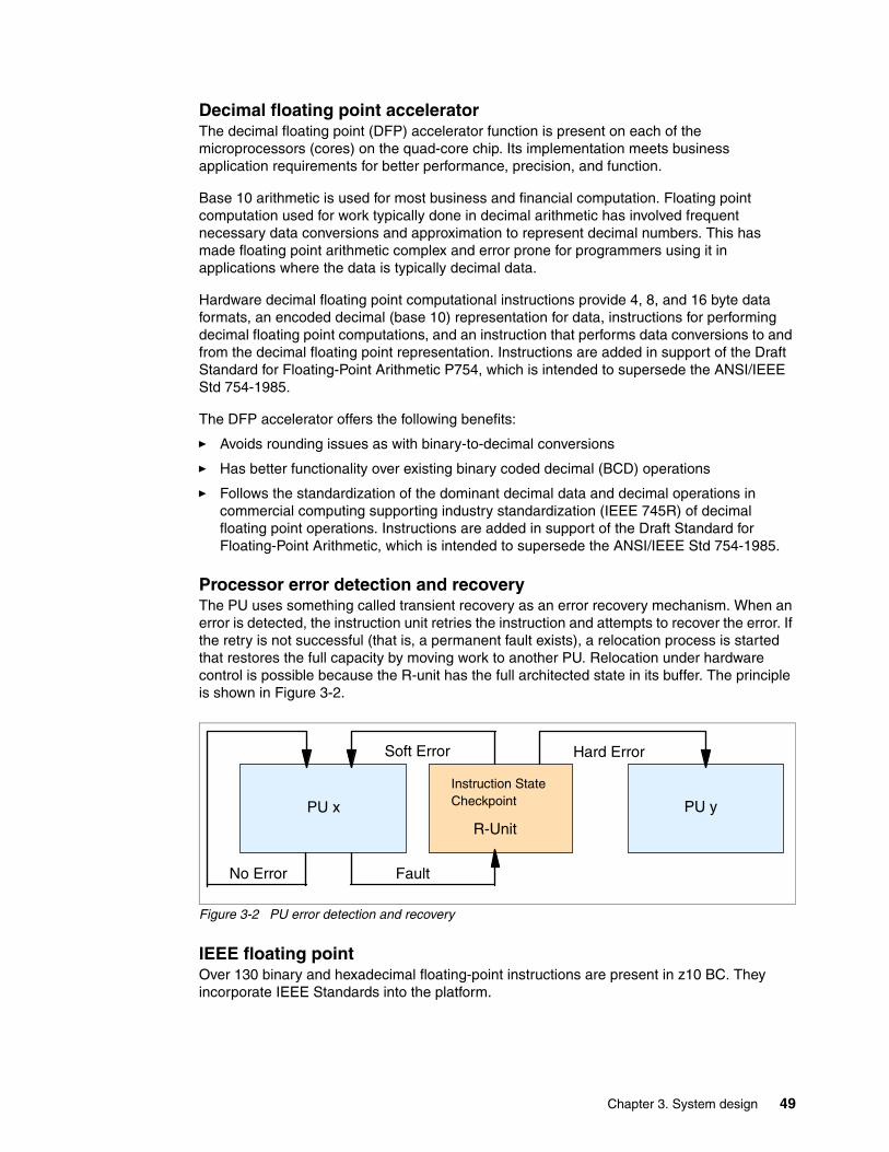
Decimal floating point acceleratorThe decimal floating point (DFP) accelerator function is present on each of the microprocessors (cores) on the quad-core chip. Its implementation meets business application requirements for better performance, precision, and function.
Base 10 arithmetic is used for most business and financial computation. Floating point computation used for work typically done in decimal arithmetic has involved frequent necessary data conversions and approximation to represent decimal numbers. This has made floating point arithmetic complex and error prone for programmers using it in applications where the data is typically decimal data.
Hardware decimal floating point computational instructions provide 4, 8, and 16 byte data formats, an encoded decimal (base 10) representation for data, instructions for performing decimal floating point computations, and an instruction that performs data conversions to and from the decimal floating point representation. Instructions are added in support of the Draft Standard for Floating-Point Arithmetic P754, which is intended to supersede the ANSI/IEEE Std 754-1985.
The DFP accelerator offers the following benefits:
� Avoids rounding issues as with binary-to-decimal conversions
� Has better functionality over existing binary coded decimal (BCD) operations
� Follows the standardization of the dominant decimal data and decimal operations in commercial computing supporting industry standardization (IEEE 745R) of decimal floating point operations. Instructions are added in support of the Draft Standard for Floating-Point Arithmetic, which is intended to supersede the ANSI/IEEE Std 754-1985.
Processor error detection and recoveryThe PU uses something called transient recovery as an error recovery mechanism. When an error is detected, the instruction unit retries the instruction and attempts to recover the error. If the retry is not successful (that is, a permanent fault exists), a relocation process is started that restores the full capacity by moving work to another PU. Relocation under hardware control is possible because the R-unit has the full architected state in its buffer. The principle is shown in Figure 3-2.
Figure 3-2 PU error detection and recovery
IEEE floating pointOver 130 binary and hexadecimal floating-point instructions are present in z10 BC. They incorporate IEEE Standards into the platform.
Soft Error Hard Error
No Error Fault
R-UnitPU yPU x
Instruction StateCheckpoint
Chapter 3. System design 49

The key point is that Java and C/C++ applications tend to use IEEE Binary Floating Point operations more frequently than earlier applications. This means that the better the hardware implementation of this set of instructions, the better the performance of e-business applications will be.
Translation look- aside bufferThe translation look-aside buffer (TLB) in the instruction and data L1 caches use a secondary TLB to enhance performance. In addition, a translator unit is added to translate misses in the secondary TLB.
The size of the TLB is kept as small as possible because of its low access time requirements and hardware space limitations. Because memory sizes have recently increased significantly, due to the introduction of 64-bit addressing, a smaller working set is represented by the TLB. To increase the working set representation in the TLB without enlarging the TLB, large page support is introduced and can be used when appropriate. See “Large page support” on page 60.
3.3 Processing unit functions
One of the key components of the z10 BC is the processing unit. This is the microprocessor where instructions are executed and the related data resides. The instructions and the data are stored in the PU’s high-speed Level 1 (L1) cache. Each PU has its own Level 1 cache, split into 128 KB for data and 64 KB for instructions.
The L1 cache is designed as a store-through cache, which means that altered data is synchronously stored into the next level, the L1.5 cache, that holds 3 MB on each PU, where altered data is synchronously passed through to the next level of cache, the L2 cache.
All PUs are physically identical. When the system is initialized, PUs can be characterized to specific functions, such as CP, IFL, ICF, zAAP, zIIP, or SAP. The function assigned to a PU is set by the Licensed Internal Code that is loaded when the system is initialized (power-on reset) and the PU is characterized. Only characterized PUs have a designated function. Non-characterized PUs are considered spares.
This design brings outstanding flexibility to the z10 BC server, as any PU can assume any available characterization. This also plays an essential role in system availability, because PU characterization can be done dynamically, with no server outage, allowing the actions discussed in the following sections.
Concurrent upgrades Except on a fully configured model, concurrent upgrades can be done by the Licensed Internal Code, which assigns a PU function to a previously non-characterized PU. No hardware changes are required, and the upgrade can be done concurrently through:
� Customer-initiated upgrade (CIU) facility for permanent upgrades� On/Off Capacity on Demand (On/Off CoD) for temporary upgrades� Capacity Backup (CBU) for temporary upgrades� Capacity for Planned Events (CPE) for temporary upgrades
Refer to Chapter 8, “System upgrades” on page 179, for more information about CoD.
PU sparingIn the rare event of a PU failure, the failed PU’s characterization is dynamically and transparently reassigned to another PU. Because no designated spare PUs are in the z10
50 IBM System z10 Business Class Technical Overview
BC, an unassigned PU is used as a spare when available. The PUs can be used for sparing any characterization, such as CP, IFL, ICF, zAAP, zIIP, or SAP.
A minimum of one PU per z10 BC must be ordered as one of the following items:
� A central processor (CP)� An Integrated Facility for Linux (IFL)� An internal Coupling Facility (ICF)
The number of CPs, IFLs, ICFs, zAAPs, zIIPs, or SAPs assigned depends on the configuration. Non-characterized PUs act as spares.
3.3.1 Central processors
A central processor (CP) is a PU that uses the z/Architecture instruction set. It can run operating systems based on z/Architecture (z/OS, z/VM, TPF, z/TPF, z/VSE, Linux) and the Coupling Facility Control Code (CFCC).
The z10 BC can be initialized only in LPAR mode. CPs are defined as either dedicated or shared. Reserved CPs can be defined to a logical partition to allow for nondisruptive image upgrades. If the operating system in the logical partition supports the logical processor add function, reserved processors are no longer necessary. The function is supported by z/OS V1R10 and z/VM V5R3 with PTFs and later.
Regardless of the installed model, a logical partition can have up to five defined logical CPs, which is the sum of active and reserved logical CPs. Defining more CPs than the operating system supports is not recommended.
All PUs characterized as CPs within a configuration are grouped into the CP pool. The CP pool can be seen on the hardware management console workplace. Any z/Architecture operating systems and CFCCs can run on CPs that are assigned from the CP pool.
Within the limit of all non-characterized PUs available in the installed configuration, CPs can be concurrently assigned to an existing configuration through On-line Permanent Upgrade, On/Off Capacity on Demand (On/Off CoD), Capacity Backup (CBU), or Capacity for Planned Events (CPE). More information about all forms of concurrent addition of CP resources can be found in Chapter 8, “System upgrades” on page 179.
A capacity marker indicates the purchased capacity. For example, a server model with five CPs can be purchased with only three CPs activated. Activated processors are known as a permanent capacity. The purchased capacity is identified in the configuration with a model capacity marker feature, identifying the purchased capacity, and another feature identifying the permanent capacity.
3.3.2 Integrated Facility for Linux
An Integrated Facility for Linux (IFL) is a PU that can be used to run Linux or Linux guests on z/VM operating systems. Up to 10 PUs may be characterized as IFLs, depending on the configuration. An IFL can be dedicated to a Linux or a z/VM logical partition, or it can be shared by multiple Linux guests or z/VM logical partitions running on the same z10 BC. Only z/VM and Linux on System z operating systems and designated software products can run on IFLs.
All PUs characterized as IFLs within a configuration are grouped into the IFL pool. The IFL pool can be seen on the hardware management console workplace.
Chapter 3. System design 51
IFLs do not change the model capacity identifier of the z10 BC. Software product license charges based on the model capacity identifier are not affected by the addition of IFLs.
Permanent or temporary upgradeWithin the limit of all non-characterized PUs available in the installed configuration, IFLs can be concurrently added to an existing configuration through a permanent or temporary upgrade. For more information see Chapter 8, “System upgrades” on page 179.
Unassigned IFLsAn IFL that is purchased but not activated is registered as an unassigned IFL. When the system is subsequently upgraded with an additional IFL, the system recognizes that an IFL was already purchased and is present.
3.3.3 Internal Coupling Facility
An Internal Coupling Facility (ICF) is a PU that runs the Coupling Facility Control Code for Parallel Sysplex environments. Within the capacity of the sum of all unassigned PUs up to 10 ICFs can be characterized depending on the model.
The ICF processors can only be used by Coupling Facility logical partitions. ICFs are either dedicated or shared. ICF processors can be dedicated to a CF logical partition, or shared by multiple CF logical partitions running in the same server. However, having a logical partition with dedicated and shared ICF processors at the same time is not possible.
All ICF processors within a configuration are grouped into the ICF pool. The ICF pool can be seen on the hardware management console workplace.
Only Coupling Facility Control Code can run on ICF processors. ICFs do not change the model capacity identifier of the z10 BC. Software product license charges based on the model capacity identifier are not affected by the addition of ICFs.
Coupling facility images exploiting ICFs must run on a logical partition. With Dynamic ICF Expansion, a Coupling Facility image can also use dedicated ICFs and shared CPs.
A Coupling Facility image can have one of the following combinations defined in the image profile:
� Dedicated ICFs� Shared ICFs� Dedicated CPs� Shared CPs� Dedicated ICFs and shared CPs
Shared ICFs add flexibility. However, running a Coupling Facility with only shared PUs (either ICFs or CPs) is not a recommended production configuration. We recommend that a production CF operate using ICF dedicated processors.
52 IBM System z10 Business Class Technical Overview

In Figure 3-3, the server on the left has two environments defined (production and test), each having one z/OS and one Coupling Facility image. The Coupling Facility images are sharing the same ICF processor.
Figure 3-3 ICF options: shared ICFs
The logical partition processing weights are used to define how much processor capacity each Coupling Facility image can have. The capped option can also be set for the test Coupling Facility image, to protect the production environment.
Connections between these z/OS and Coupling Facility images can use IC channels to avoid the use of real (external) coupling channels and to get the best link bandwidth available.
ICFs can be concurrently assigned to an existing configuration through Capacity on Demand. For more information about CoD see Chapter 8, “System upgrades” on page 179.
3.3.4 System z10 Application Assist Processor
A System z10 Application Assist Processor (zAAP) reduces the standard processor (CP) capacity requirements for z/OS Java or XML System Services applications, freeing up capacity for other workload requirements. zAAPs do not increase the MSU value of the processor and therefore do not affect the software license fee.
The System z10 Application Assist Processor (zAAP) is a PU that is used for running z/OS Java or z/OS XML System services workloads. IBM SDK for z/OS Java 2 Technology Edition (the Java Virtual Machine, JVM), in cooperation with z/OS dispatcher, directs JVM processing from CPs to zAAPs. Also, z/OS XML parsing performed in TCB mode is eligible to be executed on the zAAP processors.
Apart from the cost savings, the integration of new applications with their associated database systems and transaction middleware (such as DB2, IMS, or CICS) can simplify the infrastructure, for example, by introducing a uniform security environment, reducing the number of TCP/IP programming stacks and server interconnect links. Furthermore, processing latencies that would occur if Java application servers and their database servers were deployed on separate server platforms are prevented.
z/OSProd
z/OSProd
Setup
HMC
Partition ImageProfile
ICF CP
CF CF
Test Sysplex
z/OSTest
z/OSTest
CF
Chapter 3. System design 53
One CP must be installed with or prior to any zAAP being installed. The number of zAAPs in a server cannot exceed the number of purchased CPs. In the z10 BC, a maximum of five zAAPs can be characterized. Table 3-1 shows the allowed number of zAAPs per model.
Table 3-1 Number of zAAPs per n-way
Within the limit of all non-characterized PUs available in the installed configuration, zAAPs can be concurrently added to an existing configuration through Capacity on Demand (CoD). The quantity of permanent zAAPs plus temporary zAAPs cannot exceed the quantity of purchased (permanent plus unassigned) CPs plus temporary CPs. Also, the quantity of temporary zAAPs cannot exceed the quantity of permanent zAAPs. For more information about CoD see Chapter 8, “System upgrades” on page 179.
PUs characterized as zAAPs within a configuration are grouped into the zAAP pool. This allows zAAPs to have their own processing weights, independent of the weight of CPs. The zAAP pool can be seen on the hardware console.
zAAPs and logical partition definitionszAAPs are either dedicated or shared depending on whether they are part of a dedicated or shared logical partition. In a logical partition, at least one CP must be defined before zAAPs for that partition can be defined. As many zAAPs can be defined to a logical partition as are available in the system.
How zAAPs workzAAPs are designed for z/OS Java code execution. When Java code must be executed (for example, under control of WebSphere), the z/OS Java Virtual Machine (JVM) calls the function of the zAAP. The z/OS dispatcher then suspends the JVM task on the CP it is running on and dispatches it on an available zAAP. After the Java application code execution is finished, z/OS redispatches the JVM task on an available CP, after which normal processing is resumed. This reduces the CP time required to run Java WebSphere applications, freeing capacity for other workloads.
N-way E10 1-way E10 2-way E10 3-way E10 4-way E10 5-way
zAAPs 0–1 0–2 0–3 0–4 0–5
Restriction: A server cannot have more zAAPs than CPs, as stated before. In a logical partition, as many zAAPs as are available can be defined together with at least one CP.
54 IBM System z10 Business Class Technical Overview
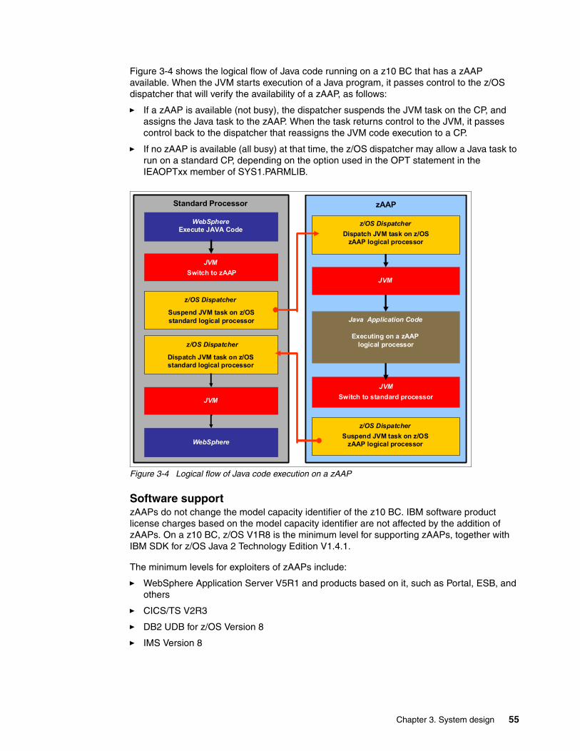
Figure 3-4 shows the logical flow of Java code running on a z10 BC that has a zAAP available. When the JVM starts execution of a Java program, it passes control to the z/OS dispatcher that will verify the availability of a zAAP, as follows:
� If a zAAP is available (not busy), the dispatcher suspends the JVM task on the CP, and assigns the Java task to the zAAP. When the task returns control to the JVM, it passes control back to the dispatcher that reassigns the JVM code execution to a CP.
� If no zAAP is available (all busy) at that time, the z/OS dispatcher may allow a Java task to run on a standard CP, depending on the option used in the OPT statement in the IEAOPTxx member of SYS1.PARMLIB.
Figure 3-4 Logical flow of Java code execution on a zAAP
Software supportzAAPs do not change the model capacity identifier of the z10 BC. IBM software product license charges based on the model capacity identifier are not affected by the addition of zAAPs. On a z10 BC, z/OS V1R8 is the minimum level for supporting zAAPs, together with IBM SDK for z/OS Java 2 Technology Edition V1.4.1.
The minimum levels for exploiters of zAAPs include:
� WebSphere Application Server V5R1 and products based on it, such as Portal, ESB, and others
� CICS/TS V2R3
� DB2 UDB for z/OS Version 8
� IMS Version 8
Standard Processor zAAP
WebSphereExecute JAVA Code
z/OS Dispatcher
Suspend JVM task on z/OS standard logical processor
WebSphere
Java Application Code
Executing on a zAAPlogical processorz/OS Dispatcher
JVMSwitch to zAAP
JVMJVMSwitch to
z/OS Dispatcher
JVM
Dispatch JVM task on z/OS standard logical processor
JVM
z/OS Dispatcher
logical processor
z/OS Dispatcher Dispatch JVM task on z/OS
zAAP logical processor
JVMSwitch to standard processor
z/OS Dispatcher Suspend JVM task on z/OS
zAAP logical processor
Chapter 3. System design 55

� All z/OS XML System Services validation and parsing that execute in TCB mode, may be eligible for zAAP processing.
This requires z/OS V1R9 and later. With z/OS V1R10 (with appropriate maintenance), this means that middleware and applications requesting z/OS XML System Services can have z/OS XML System Services processing execute on the zAAP.
� WebSphere WBI for z/OS
� Any Java application using the current IBM SDK
For more information about the IBM System z Application Assist Processor (zAAP) see:
http://www-03.ibm.com/systems/z/advantages/zaap/index.html
The functioning of a zAAP is transparent to all Java programs on JVM V1.4.1 and later.
A zAAP executes only JVM code. JVM is the only authorized user of a zAAP in association with certain parts of system code, such as the z/OS dispatcher and supervisor services. A zAAP is not able to process I/O or clock comparator interruptions and does not support operator controls such as IPL.
Java application code can either run on a CP or a zAAP. The installation can manage the use of CPs such that Java application code runs only on a CP, only on a zAAP, or on both.
Three execution options for Java code execution are available. These options are user specified in IEAOPTxx and can be dynamically altered by the SET OPT command.
3.3.5 System z10 Integrated Information Processor
A System z10 Integrated Information Processor (zIIP) enables eligible workloads to work with z/OS and have a portion of the workload’s enclave service request block (SRB) work directed to the zIIP. zIIPs do not increase the MSU value of the processor and therefore do not affect the software license fee.
z/OS Communication Server and DB2 UDB for z/OS Version 8 (and later) exploit the zIIP by indicating to z/OS which portions of the work are eligible to be routed to a zIIP.
Types of eligible DB2 UDB for z/OS V8 (and later) workloads that execute in SRBmode are:
� Query processing of network-connected applications that access the DB2 database over a TCP/IP connection using DRDA
DRDA enables relational data to be distributed among multiple platforms. It is native to DB2 for z/OS, thus reducing the need for additional gateway products that can affect performance and availability. The application uses the DRDA requestor or server to access a remote database. (DB2 Connect™ is an example of a DRDA application requester.)
� Star schema query processing, mostly used in Business Intelligence (BI) work
A star schema is a relational database schema for representing multidimensional data. It stores data in a central fact table and is surrounded by additional dimension tables holding information about each perspective of the data. A star schema query, for example, joins several dimensions of a star schema data set.
� DB2 utilities that are used for index maintenance such as LOAD, REORG, and REBUILD
Indices allow quick access to table rows, but over time as data in large databases is manipulated they become less efficient. They need to be maintained.
56 IBM System z10 Business Class Technical Overview
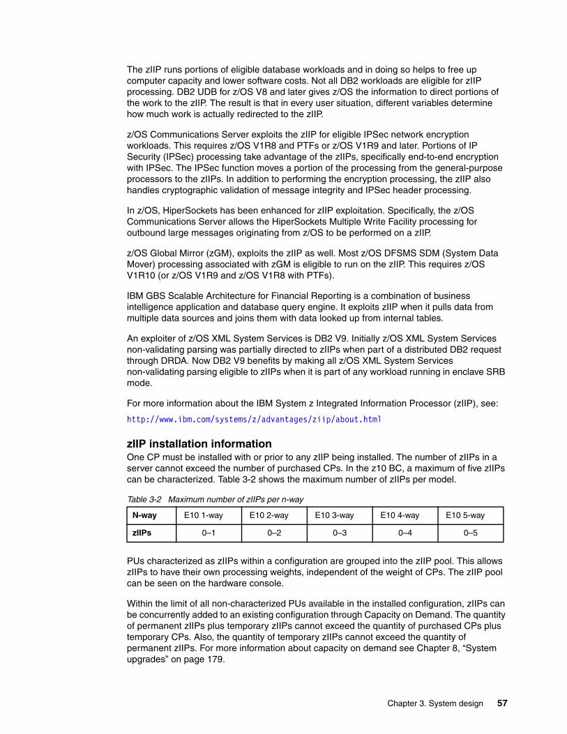
The zIIP runs portions of eligible database workloads and in doing so helps to free up computer capacity and lower software costs. Not all DB2 workloads are eligible for zIIP processing. DB2 UDB for z/OS V8 and later gives z/OS the information to direct portions of the work to the zIIP. The result is that in every user situation, different variables determine how much work is actually redirected to the zIIP.
z/OS Communications Server exploits the zIIP for eligible IPSec network encryption workloads. This requires z/OS V1R8 and PTFs or z/OS V1R9 and later. Portions of IP Security (IPSec) processing take advantage of the zIIPs, specifically end-to-end encryption with IPSec. The IPSec function moves a portion of the processing from the general-purpose processors to the zIIPs. In addition to performing the encryption processing, the zIIP also handles cryptographic validation of message integrity and IPSec header processing.
In z/OS, HiperSockets has been enhanced for zIIP exploitation. Specifically, the z/OS Communications Server allows the HiperSockets Multiple Write Facility processing for outbound large messages originating from z/OS to be performed on a zIIP.
z/OS Global Mirror (zGM), exploits the zIIP as well. Most z/OS DFSMS SDM (System Data Mover) processing associated with zGM is eligible to run on the zIIP. This requires z/OS V1R10 (or z/OS V1R9 and z/OS V1R8 with PTFs).
IBM GBS Scalable Architecture for Financial Reporting is a combination of business intelligence application and database query engine. It exploits zIIP when it pulls data from multiple data sources and joins them with data looked up from internal tables.
An exploiter of z/OS XML System Services is DB2 V9. Initially z/OS XML System Services non-validating parsing was partially directed to zIIPs when part of a distributed DB2 request through DRDA. Now DB2 V9 benefits by making all z/OS XML System Services non-validating parsing eligible to zIIPs when it is part of any workload running in enclave SRB mode.
For more information about the IBM System z Integrated Information Processor (zIIP), see:
http://www.ibm.com/systems/z/advantages/ziip/about.html
zIIP installation informationOne CP must be installed with or prior to any zIIP being installed. The number of zIIPs in a server cannot exceed the number of purchased CPs. In the z10 BC, a maximum of five zIIPs can be characterized. Table 3-2 shows the maximum number of zIIPs per model.
Table 3-2 Maximum number of zIIPs per n-way
PUs characterized as zIIPs within a configuration are grouped into the zIIP pool. This allows zIIPs to have their own processing weights, independent of the weight of CPs. The zIIP pool can be seen on the hardware console.
Within the limit of all non-characterized PUs available in the installed configuration, zIIPs can be concurrently added to an existing configuration through Capacity on Demand. The quantity of permanent zIIPs plus temporary zIIPs cannot exceed the quantity of purchased CPs plus temporary CPs. Also, the quantity of temporary zIIPs cannot exceed the quantity of permanent zIIPs. For more information about capacity on demand see Chapter 8, “System upgrades” on page 179.
N-way E10 1-way E10 2-way E10 3-way E10 4-way E10 5-way
zIIPs 0–1 0–2 0–3 0–4 0–5
Chapter 3. System design 57

zIIPs and logical partition definitionszIIPs are either dedicated or shared depending on whether they are part of a dedicated or shared logical partition. In a logical partition, at least one CP must be defined before zIIPs for that partition can be defined. The number of ZIIPs available in the system is the number of zIIPs that can be defined to a logical partition.
3.3.6 zAAP on zIIP capability
As described before, zAAPs and zIIPs support different types of workloads. However, there are installations that do not have enough eligible workloads to justify buying a zAAP or a zAAP and a zIIP. IBM is now making available the possibility of combining zAAP and zIIP workloads on zIIP processors, provided that no zAAPs are installed on the server. This may provide the following benefits:
� The combined eligible workloads may make the zIIP acquisition more cost effective.
� When zIIPs are already present, investment is maximized by running the Java and z/OS XML System Services-based workloads on existing zIIPs.
This capability does not eliminate the need to have one or more CPs for every zIIP processor in the server. Support is provided by z/OS. See 7.3.2, “zAAP on zIIP capability” on page 149.
When zAAPs are present this capability is not available, as it is neither intended as a replacement for zAAPs, which continue to be available, nor as an overflow possibility for zAAPs. IBM does not recommend converting zAAPs to zIIPs in order to take advantage of the zAAP to zIIP capability:
� Having both zAAPs and zIIPs maximizes the system potential for new workloads.
� zAAPs have been available for over five years and there may exist applications or middleware with zAAP-specific code dependencies. For example, the code may use the number of installed zAAP engines to optimize multithreading performance.
We recommend planning and testing before eliminating all zAAPs, as there may be application code dependencies that may affect performance.
3.3.7 System Assist Processors
A System Assist Processor (SAP) is a PU that runs the channel subsystem Licensed Internal Code to control I/O operations.
All SAPs perform I/O operations for all logical partitions. The IBM 2098 model E10 has two standard SAPs configured.
SAP configurationA standard SAP configuration provides a very well-balanced system for most environments. However, certain application environments with very high I/O rates (typically some TPF environments) exist. On the z10 BC, up to two optional additional SAPs can be ordered. Assignment of additional SAPs can increase the capability of the channel subsystem to perform I/O operations. In z10 BC servers, the number of SAPs can be greater than the number of CPs.
Restriction: A server cannot have more zIIPs than CPs. However, in a logical partition, as many zIIPs as are available can be defined together with at least one CP.
58 IBM System z10 Business Class Technical Overview
Optionally assignable SAPsAssigned CPs may be optionally reassigned as SAPs instead of CPs by using the reset profile on the Hardware Management Console (HMC). This reassignment increases the capacity of the channel subsystem to perform I/O operations, usually for some specific workloads or I/O-intensive testing environments.
If you intend to activate a modified server configuration with a modified SAP configuration, a reduction in the number of CPs available reduces the number of logical processors that can be activated. Activation of a logical partition will fail if the number of logical processors attempted to activate exceeds the number of CPs available. To avoid a logical partition activation failure, verify that the number of logical processors assigned to a logical partition does not exceed the number of CPs available.
3.3.8 Reserved processors
Reserved processors are defined by the Processor Resource/System Manager (PR/SM) to allow for a nondisruptive capacity upgrade. Reserved processors are like spare logical processors.
Reserved CPs should be defined to a logical partition to allow for nondisruptive image upgrades. If the operating system in the logical partition supports the logical processor add function, reserved processors are no longer needed. Logical processor add is supported by z/OS V1R10 and z/VM V5R3 with PTFs.
Reserved processors can be dynamically configured online by an operating system that supports this function, if enough unassigned PUs are available to satisfy this request. The PR/SM rules regarding logical processor activation remain unchanged.
Reserved processors provide the capability to define to a logical partition more logical processors than the number of available CPs, IFLs, ICFs, zAAPs, and zIIPs in the configuration. This makes it possible to configure online, nondisruptively, more logical processors after additional CPs, IFLs, ICFs, zAAPs, and zIIPs have been made available concurrently with one of the Capacity on Demand offerings.
On the IBM 2098 model E10, a logical partition can have up to five logical CPs defined (this is the sum of initial and reserved logical CPs). The maximum number of logical processors of all types (CPs, zAAPs, zIIPs, IFLs) cannot exceed ten.
When no reserved processors are defined to a logical partition, an addition of a processor to that logical partition is disruptive, requiring the following tasks:
� Partition deactivation� A logical processor definition change� Partition activation
For more information about logical processors and reserved processors definition see 3.5, “Logical partitioning” on page 62.
3.3.9 Processing unit characterization
Processing unit characterization is done at power-on reset time when the server is initialized. The z10 BC is always initialized in LPAR mode, and it is the PR/SM hypervisor that has responsibility for the PU assignment.
Additional SAPs are characterized first, then CPs, followed by IFLs, ICFs, zAAPs, and zIIPs.
Chapter 3. System design 59
3.3.10 Transparent CP, IFL, ICF, zAAP, zIIP, and SAP sparing
Characterized PUs, whether CPs, IFLs, ICFs, zAAPs, zIIPs, or SAPs, are transparently spared, according to distinct rules.
With transparent sparing, the status of the application that was running on the failed processor is preserved and continues processing on a newly assigned CP, IFL, ICF, zAAP, zIIP, or SAP without customer intervention. If no uncharacterized PU is available, application preservation (z/OS only) is invoked.
Systems with a failed PU for which no spare is available will call home for a replacement. A system with a failed PU that has been spared and requires an SCM to be replaced (called a pending repair) can still be upgraded when sufficient PUs are available.
When non-characterized PUs are used for sparing and might be needed to satisfy an On/Off CoD request, a remote support facility (RSF) call occurs to request a repair action.
3.4 Memory design
The memory design provides great flexibility and high availability, allowing:
� Concurrent memory upgrades (If the physically installed capacity is not yet reached)
The z10 BC might have more physically installed memory than the initial available capacity. Memory upgrades within the physically installed capacity can be done concurrently by the Licensed Internal Code, and no hardware changes are required. Concurrent memory upgrades can be done through only through permanent upgrade. Memory upgrades cannot be done through temporary Capacity on Demand offerings. See Table 8-1 on page 182 for more information.
� Partial memory restart
In the rare event of a memory card failure, a partial-memory restart enables the system to be restarted with only part of the original memory. The memory DIMMs that make up logical pair 0 or logical pair 1 (depending on where the failure resides) are deactivated, after which the system can be restarted with the memory in the remaining logical pair cards.
The memory DIMMs use the latest fast 1 Gb synchronous DRAMs. Memory access is interleaved to equalize memory activity across the DIMMs.
Memory DIMMs have 2 GB, 4 GB, or 8 GB of capacity. The total capacity installed may have more usable memory than required for a configuration, and Licensed Internal Code Configuration Control (LICCC) determines how much memory is used from each card. The sum of the LICCC provided memory from each card is the amount available for use in the system.
Memory allocationMemory assignment or allocation is done at power-on reset (POR) when the system is initialized. PR/SM is responsible for the memory assignments.
Large page supportBy default, page frames are allocated with a 4 KB size. The z10 BC supports a large page size of 1 MB.
60 IBM System z10 Business Class Technical Overview

The translation look-aside buffer (TLB) exists to reduce the amount of time required to translate a virtual address to a real address by dynamic address translation (DAT) when it needs to find the correct page for the correct address space. Each TLB entry represents one page. Like other buffers or caches, lines are discarded from the TLB on a least recently used (LRU) basis. The worst-case translation time occurs when there is a TLB miss and both the segment table (needed to find the page table) and the page table (needed to find the entry for the particular page in question) are not in cache. In this case, there are two complete real memory access delays plus the address translation delay.
It is very desirable to have one's addresses in the TLB to begin with. With 4 K pages it takes 256 TLB lines to hold all the addresses for 1 MB of storage. When using 1 MB pages, it takes just one. This means that large page size exploiters have a much smaller TLB footprint.
Large pages allow the TLB to better represent a large working set and suffer fewer TLB misses by allowing a single TLB entry to cover more address translations.
Exploiters of large pages are better represented in the TLB and are expected to see performance improvement in both elapsed time and processor time. This is because DAT and memory operations are part of processor busy time even though the processor waits for memory operations to complete without processing anything else in the meantime.
Large pages are treated as fixed pages. They are available only for 64-bit virtual private storage such as virtual memory located above 2 GB.
3.4.1 Central storage
Central storage (CS) consists of main storage, addressable by programs, and storage not directly addressable by programs. Non-addressable storage includes the hardware system area (HSA). Central storage provides:
� Data storage and retrieval for PUs and I/O� Communication with PUs and I/O� Communication with and control of optional expanded storage� Error checking and correction
Central storage can be accessed by all processors, but cannot be shared between logical partitions. Any system image (logical partition) must have a main storage size defined. This defined main storage is allocated exclusively to the logical partition during partition activation.
3.4.2 Expanded storage
Expanded storage (ES) can optionally be defined on z10 BC servers. Expanded storage is physically a section of processor storage. It is controlled by the operating system and transfers 4 KB pages to and from main storage.
Except for z/VM, z/Architecture operating systems do not use expanded storage. Because they operate in 64-bit addressing mode, all the required storage capacity can be allocated as main storage. z/VM is an exception because, even when operating in 64-bit mode, it can have guest virtual machines running in 31-bit addressing mode, which can use expanded storage.
Defining expanded storage to a Coupling Facility image is not possible. However, any other image type can have expanded storage defined, even if that image runs a 64-bit operating system and does not use expanded storage.
Chapter 3. System design 61
LPAR single storage poolThe z10 BC only runs in LPAR mode. In LPAR mode, storage is not split into main storage and expanded storage at power-on reset. Rather, the storage is placed into a single main storage pool that is dynamically assigned to expanded storage and back to main storage, as needed.
On the Hardware Management Console, the Storage Assignment tab of a reset profile shows only the customer storage, which is the total installed storage minus the 8 GB hardware system area. Logical partitions are still defined to have main storage and, optionally, expanded storage.
Activation of logical partitions as well as dynamic storage reconfiguration will cause the storage to be assigned to the type needed (central or expanded). This does not require a power-on reset.
3.4.3 Hardware system area
The hardware system area (HSA) is a non-addressable storage area that contains server Licensed Internal Code and configuration-dependent control blocks. The HSA size has a fixed size of 8 GB. It is not a part of the purchased memory that the customer has ordered and installed.
The fixed size of the HSA eliminates planning for future expansion of HSA because HCD/IOCP will always reserve:
� Two channel subsystems (CSSs)� Fifteen logical partitions in each CSS for a total of 30 logical partitions� Subchannel set 0 with 63.75 K devices in each CSS� Subchannel set 1 with 64 K devices in each CSS
The HSA has sufficient reserved space allowing for dynamic I/O reconfiguration changes to the maximum capability of the processor.
3.5 Logical partitioning
Logical partitioning is a function implemented by the Processor Resource/Systems Manager (PR/SM) on all System z servers. The z10 BC always runs in LPAR mode. This means that all system aspects are controlled by PR/SM functions.
Logical partitions have resources allocated to them. These resources come from a variety of physical resources. Logical partitions have no control over physical resources from a systems standpoint, all is controlled by PR/SM functions. PR/SM manages and optimizes allocation and dispatching work on the physical resources.
PR/SM enables z10 BC servers to be initialized for a logically partitioned operation, supporting up to 30 logical partitions. Each logical partition can run its own operating system image in any image mode, independent from the other logical partitions.
A logical partition can be added, removed, activated, or deactivated at any time. Changing the number of logical partitions is not disruptive and does not require power-on reset (POR). Certain facilities might not be available to all operating systems, because they might have software corequisites.
62 IBM System z10 Business Class Technical Overview
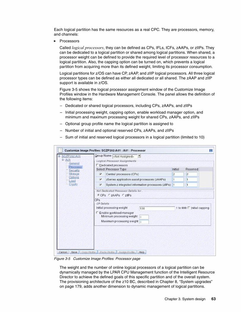
Each logical partition has the same resources as a real CPC. They are processors, memory, and channels:
� Processors
Called logical processors, they can be defined as CPs, IFLs, ICFs, zAAPs, or zIIPs. They can be dedicated to a logical partition or shared among logical partitions. When shared, a processor weight can be defined to provide the required level of processor resources to a logical partition. Also, the capping option can be turned on, which prevents a logical partition from acquiring more than its defined weight, limiting its processor consumption.
Logical partitions for z/OS can have CP, zAAP, and zIIP logical processors. All three logical processor types can be defined as either all dedicated or all shared. The zAAP and zIIP support is available in z/OS.
Figure 3-5 shows the logical processor assignment window of the Customize Image Profiles window in the Hardware Management Console. The panel allows the definition of the following items:
– Dedicated or shared logical processors, including CPs, zAAPs, and zIIPs
– Initial processing weight, capping option, enable workload manager option, and minimum and maximum processing weight for shared CPs, zAAPs, and zIIPs
– Optional group profile name the logical partition is assigned to
– Number of initial and optional reserved CPs, zAAPs, and zIIPs
– Sum of initial and reserved logical processors in a logical partition (limited to 10)
Figure 3-5 Customize Image Profiles: Processor page
The weight and the number of online logical processors of a logical partition can be dynamically managed by the LPAR CPU Management function of the Intelligent Resource Director to achieve the defined goals of this specific partition and of the overall system. The provisioning architecture of the z10 BC, described in Chapter 8, “System upgrades” on page 179, adds another dimension to dynamic management of logical partitions.
Chapter 3. System design 63
For z/OS Workload License Charge (WLC), a logical partition defined capacity can be set, enabling the soft capping function. Workload charging introduces the capability to pay software license fees based on the size of the logical partition the product is running in, rather than on the total capacity of the server.
– In support of WLC, the user can specify a defined capacity in millions of service units per hour (MSUs). The defined capacity sets the capacity of an individual logical partition when soft capping is selected.
The defined capacity value is specified on the Options tab on the Customize Image Profile panel.
– WLM keeps a 4-hour rolling average of the CPU usage of the logical partition, and when the 4-hour average CPU consumption exceeds the defined capacity limit, WLM dynamically activates LPAR capping (soft capping). When the rolling 4-hour average returns below the defined capacity, the soft cap is removed.
For more information regarding WLM refer to System Programmer's Guide to: Workload Manager, SG24-6472.
� Memory
Memory, either main storage or expanded storage, must be dedicated to a logical partition. The defined storage must be available during the logical partition activation. Otherwise, the activation fails.
Reserved storage can be defined to a logical partition, enabling nondisruptive memory add to and removal from a logical partition, using the LPAR Dynamic Storage Reconfiguration.
� Channels
Channels can be shared between logical partitions by including the partition name in the partition list of a Channel Path ID (CHPID). I/O configurations are defined by the I/O Configuration Program (IOCP) or the Hardware Configuration Dialog (HCD) in conjunction with the CHPID Mapping Tool (CMT). The CMT is an optional, but strongly recommended, tool used to map CHPIDs onto Physical Channel IDs (PCHIDs) that represent the physical location of a port on a card in an I/O drawer. More about CMT, CHPIDs, and PCHIDs can be found in Chapter 5, “Channel subsystem” on page 107.
IOCP is available on the z/OS, z/VM, VM/ESA®, and z/VSE operating systems, and as a stand-alone program on the Hardware Management Console. HCD is available on z/OS and z/VM operating systems.
ESCON and FICON channels can be managed by the Dynamic CHPID Management (DCM) function of the Intelligent Resource Director. DCM enables the system to respond to ever-changing channel requirements by moving channels from lesser-used control units to more heavily used control units, as needed.
Note: When Defined Capacity is used to define an uncapped logical partition’s capacity, looking at the weight settings of that logical partition is important. If the weight is much smaller than the Defined Capacity, WLM will direct PR/SM to use a non-contiguous cap pattern to achieve the Defined Capacity setting. This means that WLM will direct PR/SM to flip-flop between capping the LPAR at the MSU value corresponding to the relative weight settings, and no capping at all. Avoiding this situation is recommended; establish a Defined Capacity that is equal or close to the relative weight.
64 IBM System z10 Business Class Technical Overview
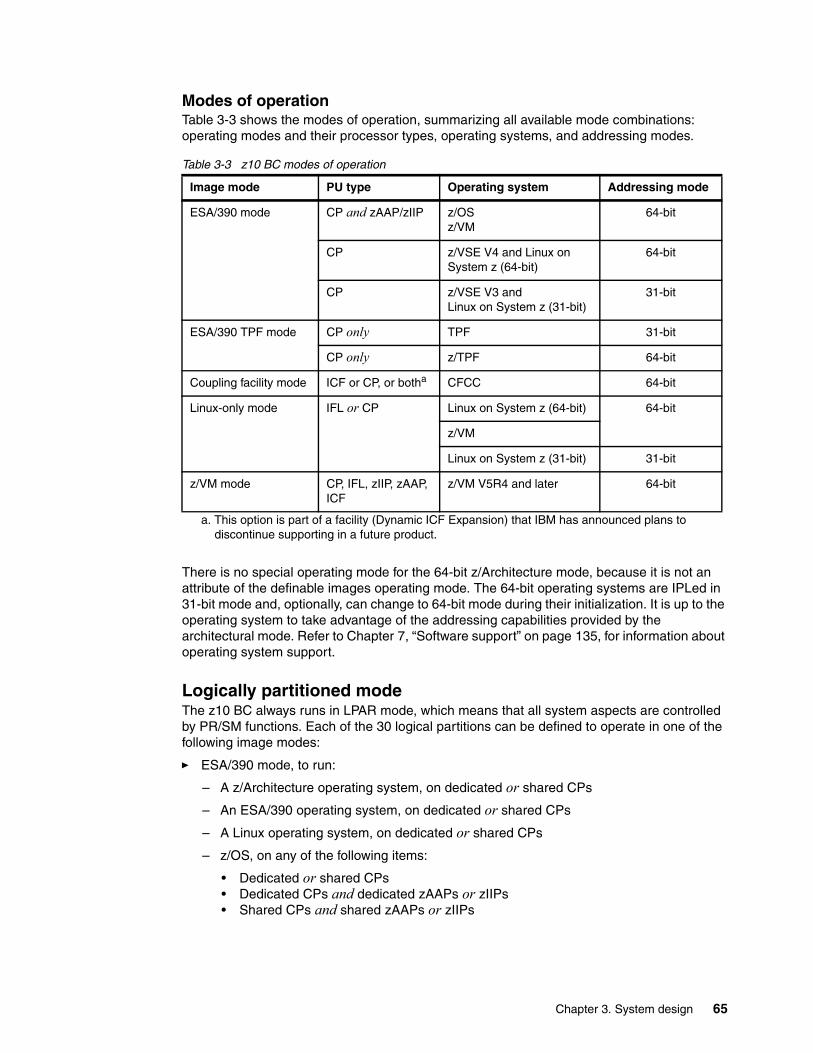
Modes of operationTable 3-3 shows the modes of operation, summarizing all available mode combinations: operating modes and their processor types, operating systems, and addressing modes.
Table 3-3 z10 BC modes of operation
There is no special operating mode for the 64-bit z/Architecture mode, because it is not an attribute of the definable images operating mode. The 64-bit operating systems are IPLed in 31-bit mode and, optionally, can change to 64-bit mode during their initialization. It is up to the operating system to take advantage of the addressing capabilities provided by the architectural mode. Refer to Chapter 7, “Software support” on page 135, for information about operating system support.
Logically partitioned modeThe z10 BC always runs in LPAR mode, which means that all system aspects are controlled by PR/SM functions. Each of the 30 logical partitions can be defined to operate in one of the following image modes:
� ESA/390 mode, to run:
– A z/Architecture operating system, on dedicated or shared CPs
– An ESA/390 operating system, on dedicated or shared CPs
– A Linux operating system, on dedicated or shared CPs
– z/OS, on any of the following items:
• Dedicated or shared CPs• Dedicated CPs and dedicated zAAPs or zIIPs• Shared CPs and shared zAAPs or zIIPs
Image mode PU type Operating system Addressing mode
ESA/390 mode CP and zAAP/zIIP z/OSz/VM
64-bit
CP z/VSE V4 and Linux on System z (64-bit)
64-bit
CP z/VSE V3 and Linux on System z (31-bit)
31-bit
ESA/390 TPF mode CP only TPF 31-bit
CP only z/TPF 64-bit
Coupling facility mode ICF or CP, or botha
a. This option is part of a facility (Dynamic ICF Expansion) that IBM has announced plans to discontinue supporting in a future product.
CFCC 64-bit
Linux-only mode IFL or CP Linux on System z (64-bit) 64-bit
z/VM
Linux on System z (31-bit) 31-bit
z/VM mode CP, IFL, zIIP, zAAP, ICF
z/VM V5R4 and later 64-bit
Chapter 3. System design 65
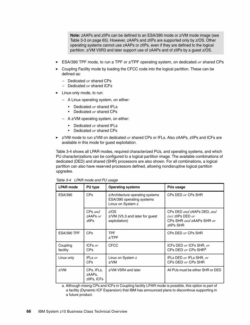
� ESA/390 TPF mode, to run a TPF or z/TPF operating system, on dedicated or shared CPs
� Coupling Facility mode by loading the CFCC code into the logical partition. These can be defined as:
– Dedicated or shared CPs – Dedicated or shared ICFs
� Linux-only mode, to run:
– A Linux operating system, on either:
• Dedicated or shared IFLs • Dedicated or shared CPs
– A z/VM operating system, on either:
• Dedicated or shared IFLs • Dedicated or shared CPs
� z/VM mode to run z/VM on dedicated or shared CPs or IFLs. Also zAAPs, zIIPs and ICFs are available in this mode for guest exploitation.
Table 3-4 shows all LPAR modes, required characterized PUs, and operating systems, and which PU characterizations can be configured to a logical partition image. The available combinations of dedicated (DED) and shared (SHR) processors are also shown. For all combinations, a logical partition can also have reserved processors defined, allowing nondisruptive logical partition upgrades.
Table 3-4 LPAR mode and PU usage
Note: zAAPs and zIIPs can be defined to an ESA/390 mode or z/VM mode image (see Table 3-3 on page 65). However, zAAPs and zIIPs are supported only by z/OS. Other operating systems cannot use zAAPs or zIIPs, even if they are defined to the logical partition. z/VM V5R3 and later support use of zAAPs and of zIIPs by a guest z/OS.
LPAR mode PU type Operating systems PUs usage
ESA/390 CPs z/Architecture operating systemsESA/390 operating systemsLinux on System z
CPs DED or CPs SHR
CPs and zAAPs or zIIPs
z/OS z/VM (V5.3 and later for guest exploitation)
CPs DED and zAAPs DED, and (or) zIIPs DED orCPs SHR and zAAPs SHR or zIIPs SHR
ESA/390 TPF CPs TPFz/TPF
CPs DED or CPs SHR
Coupling facility
ICFs orCPs
CFCC ICFs DED or ICFs SHR, orCPs DED or CPs SHRa
a. Although mixing CPs and ICFs in Coupling facility LPAR mode is possible, this option is part of a facility (Dynamic ICF Expansion) that IBM has announced plans to discontinue supporting in a future product.
Linux only IFLs or CPs
Linux on System zz/VM
IFLs DED or IFLs SHR, orCPs DED or CPs SHR
z/VM CPs, IFLs, zAAPs, zIIPs, ICFs
z/VM V5R4 and later All PUs must be either SHR or DED
66 IBM System z10 Business Class Technical Overview
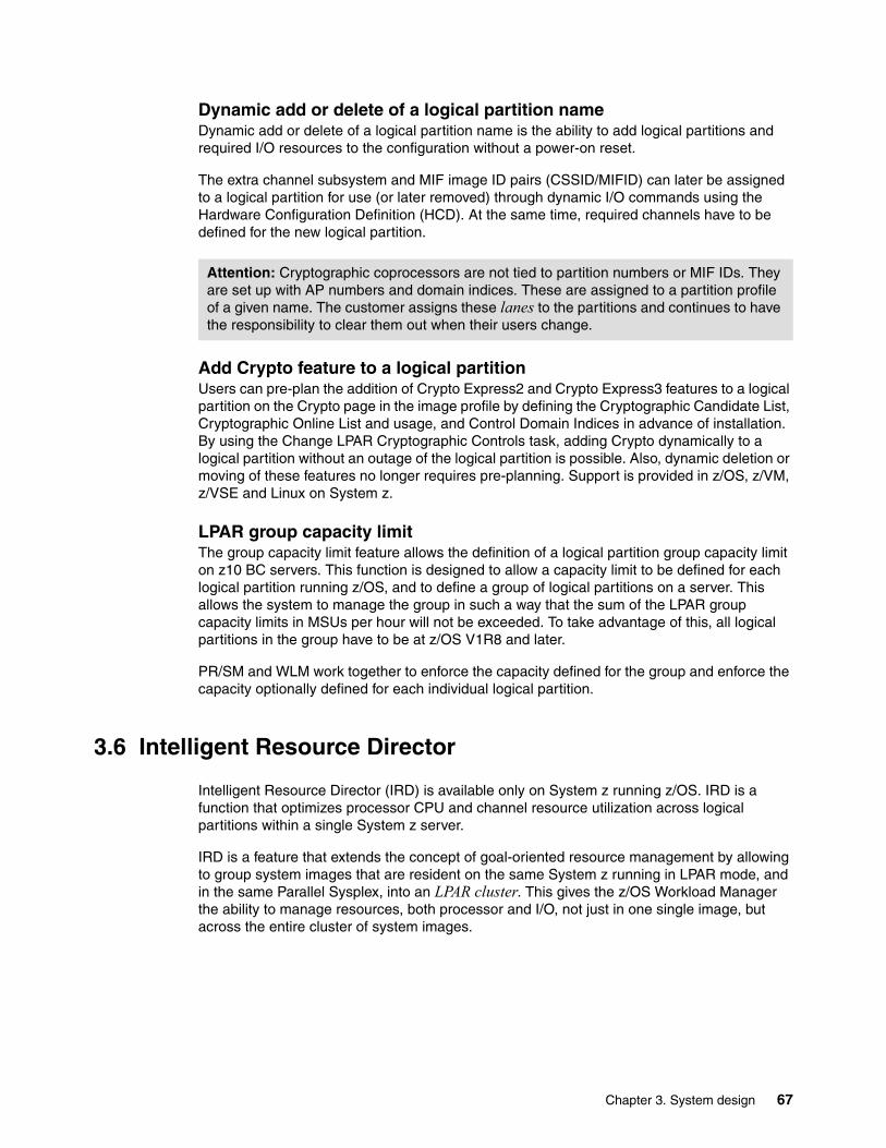
Dynamic add or delete of a logical partition nameDynamic add or delete of a logical partition name is the ability to add logical partitions and required I/O resources to the configuration without a power-on reset.
The extra channel subsystem and MIF image ID pairs (CSSID/MIFID) can later be assigned to a logical partition for use (or later removed) through dynamic I/O commands using the Hardware Configuration Definition (HCD). At the same time, required channels have to be defined for the new logical partition.
Add Crypto feature to a logical partition Users can pre-plan the addition of Crypto Express2 and Crypto Express3 features to a logical partition on the Crypto page in the image profile by defining the Cryptographic Candidate List, Cryptographic Online List and usage, and Control Domain Indices in advance of installation. By using the Change LPAR Cryptographic Controls task, adding Crypto dynamically to a logical partition without an outage of the logical partition is possible. Also, dynamic deletion or moving of these features no longer requires pre-planning. Support is provided in z/OS, z/VM, z/VSE and Linux on System z.
LPAR group capacity limitThe group capacity limit feature allows the definition of a logical partition group capacity limit on z10 BC servers. This function is designed to allow a capacity limit to be defined for each logical partition running z/OS, and to define a group of logical partitions on a server. This allows the system to manage the group in such a way that the sum of the LPAR group capacity limits in MSUs per hour will not be exceeded. To take advantage of this, all logical partitions in the group have to be at z/OS V1R8 and later.
PR/SM and WLM work together to enforce the capacity defined for the group and enforce the capacity optionally defined for each individual logical partition.
3.6 Intelligent Resource Director
Intelligent Resource Director (IRD) is available only on System z running z/OS. IRD is a function that optimizes processor CPU and channel resource utilization across logical partitions within a single System z server.
IRD is a feature that extends the concept of goal-oriented resource management by allowing to group system images that are resident on the same System z running in LPAR mode, and in the same Parallel Sysplex, into an LPAR cluster. This gives the z/OS Workload Manager the ability to manage resources, both processor and I/O, not just in one single image, but across the entire cluster of system images.
Attention: Cryptographic coprocessors are not tied to partition numbers or MIF IDs. They are set up with AP numbers and domain indices. These are assigned to a partition profile of a given name. The customer assigns these lanes to the partitions and continues to have the responsibility to clear them out when their users change.
Chapter 3. System design 67
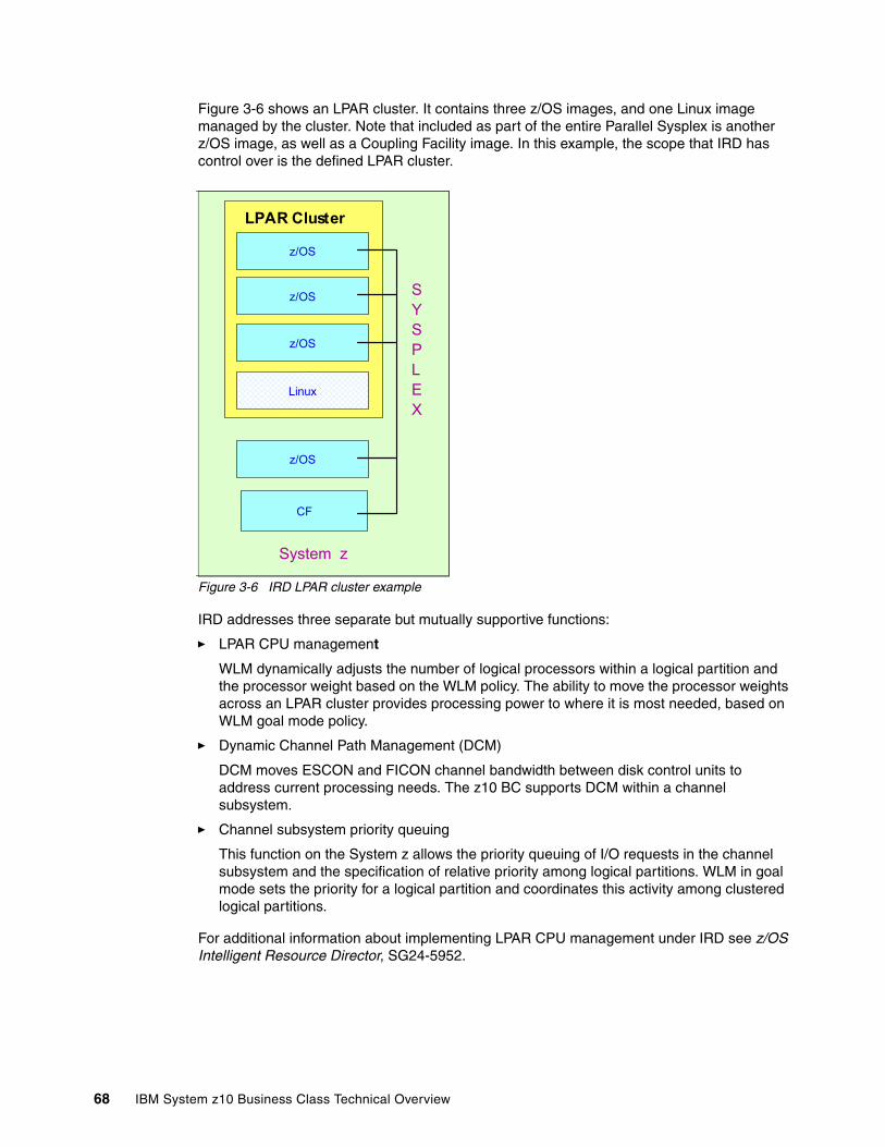
Figure 3-6 shows an LPAR cluster. It contains three z/OS images, and one Linux image managed by the cluster. Note that included as part of the entire Parallel Sysplex is another z/OS image, as well as a Coupling Facility image. In this example, the scope that IRD has control over is the defined LPAR cluster.
Figure 3-6 IRD LPAR cluster example
IRD addresses three separate but mutually supportive functions:
� LPAR CPU management
WLM dynamically adjusts the number of logical processors within a logical partition and the processor weight based on the WLM policy. The ability to move the processor weights across an LPAR cluster provides processing power to where it is most needed, based on WLM goal mode policy.
� Dynamic Channel Path Management (DCM)
DCM moves ESCON and FICON channel bandwidth between disk control units to address current processing needs. The z10 BC supports DCM within a channel subsystem.
� Channel subsystem priority queuing
This function on the System z allows the priority queuing of I/O requests in the channel subsystem and the specification of relative priority among logical partitions. WLM in goal mode sets the priority for a logical partition and coordinates this activity among clustered logical partitions.
For additional information about implementing LPAR CPU management under IRD see z/OS Intelligent Resource Director, SG24-5952.
z/OS
LPAR Cluster
z/OS
z/OS
z/OS
CF
System z
Linux
SYSPLEX
68 IBM System z10 Business Class Technical Overview
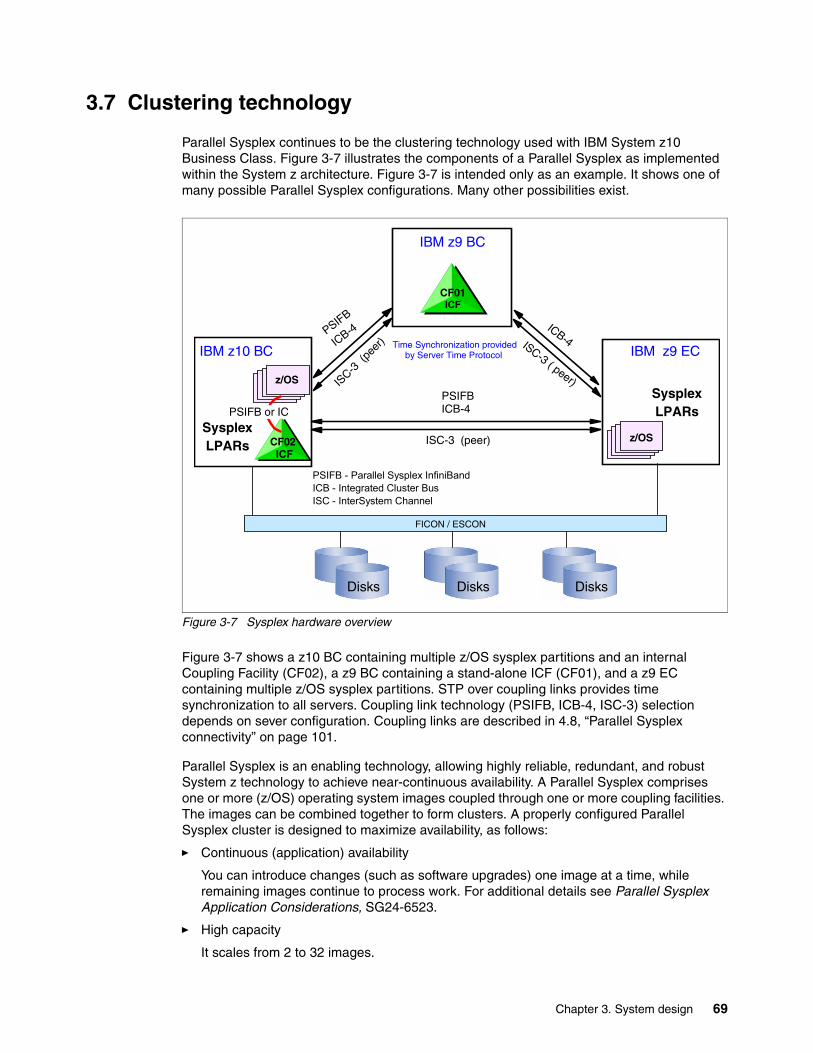
3.7 Clustering technology
Parallel Sysplex continues to be the clustering technology used with IBM System z10 Business Class. Figure 3-7 illustrates the components of a Parallel Sysplex as implemented within the System z architecture. Figure 3-7 is intended only as an example. It shows one of many possible Parallel Sysplex configurations. Many other possibilities exist.
Figure 3-7 Sysplex hardware overview
Figure 3-7 shows a z10 BC containing multiple z/OS sysplex partitions and an internal Coupling Facility (CF02), a z9 BC containing a stand-alone ICF (CF01), and a z9 EC containing multiple z/OS sysplex partitions. STP over coupling links provides time synchronization to all servers. Coupling link technology (PSIFB, ICB-4, ISC-3) selection depends on sever configuration. Coupling links are described in 4.8, “Parallel Sysplex connectivity” on page 101.
Parallel Sysplex is an enabling technology, allowing highly reliable, redundant, and robust System z technology to achieve near-continuous availability. A Parallel Sysplex comprises one or more (z/OS) operating system images coupled through one or more coupling facilities. The images can be combined together to form clusters. A properly configured Parallel Sysplex cluster is designed to maximize availability, as follows:
� Continuous (application) availability
You can introduce changes (such as software upgrades) one image at a time, while remaining images continue to process work. For additional details see Parallel Sysplex Application Considerations, SG24-6523.
� High capacity
It scales from 2 to 32 images.
Disks Disks Disks
CF02 ICF
CF01ICF
FICON / ESCON
z/OS
z/OS
PSIFB
ICB-4
PSIFB ICB-4
ICB-4
PSIFB or IC
ISC-3
(pe
er)
ISC-3 (peer)
ISC-3 ( peer)
IBM z10 BC
IBM z9 BC
IBM z9 EC
SysplexLPARs
SysplexLPARs
Time Synchronization provided by Server Time Protocol
PSIFB - Parallel Sysplex InfiniBand ICB - Integrated Cluster BusISC - InterSystem Channel
Chapter 3. System design 69

� Dynamic workload balancing
Viewed as a single logical resource, work can be directed to any image in a Parallel Sysplex cluster having the most available capacity at that point in time. This helps provide the best performance while optimizing usage of the server resources.
� Systems management
Architecture provides the infrastructure to satisfy a customer requirement for continuous availability, while providing techniques for achieving simplified systems management consistent with this requirement.
� Resource sharing
A number of base (z/OS) components exploit Coupling Facility shared storage. This exploitation enables sharing of physical resources with significant improvements in cost, performance, and simplified systems management.
� Single system image
The collection of system images in the Parallel Sysplex appears as a single entity to the operator, the user, the database administrator, and others. A single system image ensures reduced complexity from both operational and definition perspectives.
Through this state-of-the-art cluster technology, the power of multiple images can be harnessed to work in concert on common workloads. The System z Parallel Sysplex cluster takes the commercial strengths of the platform to improved levels of system management, competitive price/performance, scalable growth, and continuous availability.
Coupling Facility Control CodeThe IBM System z10 BC is equipped with Coupling Facility Control Code (CFCC) Level 16. Up to this level of CFCC, System Managed CF Structure Duplexing required two protocol exchanges to occur synchronously to CF processing of the duplex structure request. With CFCC Level 16 one of these signals can now be asynchronous. This can result in faster service times especially if both coupling facilities are further apart.
CFCC Level 16 also has better list notification processing. Previously, when a list changes its state from empty to non-empty, all its connectors are notified. The first connector notified reads the new message but subsequent readers will find nothing. CFCC Level 16 approaches this differently to improve processor utilization. It only notifies one connector in a round robin fashion, and if the shared queue (as in IMS Shared Queue and WebSphere MQ Shared Queue) is read within a fixed period of time, the other connectors do not have to be notified. If the list is not read again within the time limit the other connectors are informed, as previously.
The CF Control Code, the Licensed Internal Code that manages the CF logical partition, is implemented using the active wait technique. This means that the CF Control Code is always running (processing or searching for service) and never enters a wait state. This also means that it uses all the processor capacity (cycles) available for the Coupling Facility logical partition. If this logical partition has only dedicated processors (CPs or ICFs), this is not a problem. But this might not be desirable when shared processors are configured to the partition. A potential solution for the use of shared processors is enabling dynamic dispatching on the CF.
Dynamic CF dispatching Dynamic CF dispatching provides the following function on a Coupling Facility:
1. If there is no work to do, CF enters into a wait state (by time).
2. After an elapsed time, it wakes up to see whether there is any new work to do (requests in the CF Receiver buffer).
70 IBM System z10 Business Class Technical Overview

3. If there is no work, it sleeps again for a longer period of time.
4. If there is new work, it enters into the normal active wait until there is no more work, starting the process all over again.
This function saves processor cycles and is an excellent option to be used by a production backup CF or a testing environment CF. This function is activated by the CFCC command DYNDISP ON.
The CPs can run z/OS operating system images and CF images. For software charge reasons, it is better to only use ICF processors to run Coupling Facility images.
Figure 3-8 shows the dynamic CF dispatching.
Figure 3-8 Dynamic CF dispatching (shared CPs or shared ICF PUs)
Two CF logical partitions on general-purpose CPCs can be used in an environment of only Resource Sharing. If data sharing or queue sharing is being used, at least one stand-alone Coupling Facility should be used, or CF logical partition on general-purpose CPC with System-Managed CF Duplexing can be used. For additional details regarding CF configurations see Coupling Facility Configuration Options, ZSW01971USEN, available from the Parallel Sysplex Web page:
http://www.ibm.com/systems/z/advantages/pso/index.html
z/OSz/OS
Function
Setup
HMC
Partition ImageProfileCF
ICF CP
BAC
K UP
CF
z/OSz/OS CF
AC
TIVE C
F
With Dynamic CF dispacting enabled, backup CF becomes active only for new work
DYNDISP ON (CFCC cmd)IMAGE Profile setup
Chapter 3. System design 71

72 IBM System z10 Business Class Technical Overview
Chapter 4. I/O system structure
This chapter describes the I/O system and the connectivity options available on the System z10 BC server.
This chapter discusses the following topics:
� 4.1, “Introduction” on page 74� 4.2, “I/O system overview” on page 75� 4.3, “I/O drawer” on page 77� 4.4, “Fanouts” on page 80� 4.5, “I/O feature cards” on page 85� 4.7, “Connectivity” on page 88� 4.8, “Parallel Sysplex connectivity” on page 101
4
© Copyright IBM Corp. 2008, 2009. All rights reserved. 73
4.1 Introduction
The z10 BC uses InfiniBand as an interconnect protocol for connections for various connectivity types. Before describing the InfiniBand implementation on the z10 BC, this section provides a short general introduction of InfiniBand. Note that not all properties and functions offered by InfiniBand are implemented on the z10 BC. Only a subset is used to fulfill the interconnect requirements that are defined for z10 BC.
4.1.1 InfiniBand advantages
InfiniBand addresses the challenges IT infrastructures face as more demand is placed on the interconnect from ever-increasing demands for computing and storage resources. InfiniBand has the following advantages:
� Superior performance
InfiniBand provides superior bandwidth and latency performance, supporting 20 Gbps node-to-node and 60 Gbps switch-to-switch connections. Additionally, InfiniBand has a defined road map to 120 Gbps—the fastest support specification of any industry-standard interconnect.
� Reduced complexity
InfiniBand allows for the consolidation of multiple I/Os on a single cable or backplane interconnect, which is critical for blade servers, data center computers, storage clusters, and embedded systems. InfiniBand also consolidates the transmission of clustering, communications, storage and management data types over a single connection. The consolidation of I/O onto a unified InfiniBand fabric significantly lowers the overall power and infrastructure required for server and storage clusters. Other interconnect technologies are less well suited to be unified fabrics because their fundamental architectures are not designed to support multiple traffic types.
� Highest interconnect efficiency
InfiniBand is developed to provide efficient scalability of multiple systems. InfiniBand provides communication processing functions in hardware—relieving the CPU of this task—and enables the full resource utilization of each node added to the cluster. In addition, InfiniBand incorporates Remote Direct Memory Access, which is an optimized data transfer protocol that further enables the server processor to focus on application processing. This contributes to optimal application processing performance in server and storage clustered environments.
� Reliable and stable connections
InfiniBand provides reliable end-to-end data connections and defines this capability to be implemented in hardware. In addition, InfiniBand facilitates the deployment of virtualization solutions, which allow multiple applications to run on the same interconnect with dedicated application partitions. As a result, multiple applications run concurrently over stable connections, thereby minimizing downtime. InfiniBand fabrics are typically constructed with multiple levels of redundancy so that if a link goes down, not only is the fault limited to the link, but also failover can automatically occur to an additional link, thereby ensuring that connectivity continues throughout the fabric. Creating multiple paths through the fabric results in intra-fabric redundancy and further contributes to the reliability of the fabric.
The InfiniBand specification defines the raw bandwidth of the base one lane of fiber (referred to as 1x) connection at 2.5 Gb per second. It then specifies two additional bandwidths, referred to as 4x and 12x, as multipliers of the base link rate.
74 IBM System z10 Business Class Technical Overview
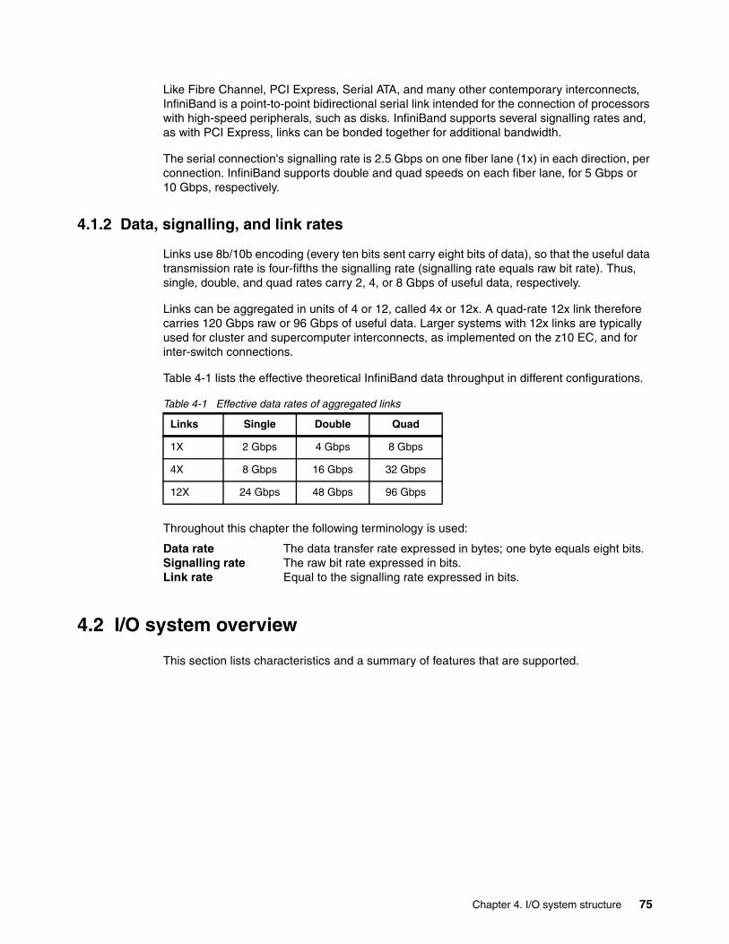
Like Fibre Channel, PCI Express, Serial ATA, and many other contemporary interconnects, InfiniBand is a point-to-point bidirectional serial link intended for the connection of processors with high-speed peripherals, such as disks. InfiniBand supports several signalling rates and, as with PCI Express, links can be bonded together for additional bandwidth.
The serial connection's signalling rate is 2.5 Gbps on one fiber lane (1x) in each direction, per connection. InfiniBand supports double and quad speeds on each fiber lane, for 5 Gbps or 10 Gbps, respectively.
4.1.2 Data, signalling, and link rates
Links use 8b/10b encoding (every ten bits sent carry eight bits of data), so that the useful data transmission rate is four-fifths the signalling rate (signalling rate equals raw bit rate). Thus, single, double, and quad rates carry 2, 4, or 8 Gbps of useful data, respectively.
Links can be aggregated in units of 4 or 12, called 4x or 12x. A quad-rate 12x link therefore carries 120 Gbps raw or 96 Gbps of useful data. Larger systems with 12x links are typically used for cluster and supercomputer interconnects, as implemented on the z10 EC, and for inter-switch connections.
Table 4-1 lists the effective theoretical InfiniBand data throughput in different configurations.
Table 4-1 Effective data rates of aggregated links
Throughout this chapter the following terminology is used:
Data rate The data transfer rate expressed in bytes; one byte equals eight bits.Signalling rate The raw bit rate expressed in bits.Link rate Equal to the signalling rate expressed in bits.
4.2 I/O system overview
This section lists characteristics and a summary of features that are supported.
Links Single Double Quad
1X 2 Gbps 4 Gbps 8 Gbps
4X 8 Gbps 16 Gbps 32 Gbps
12X 24 Gbps 48 Gbps 96 Gbps
Chapter 4. I/O system structure 75

CharacteristicsThe z10 BC I/O system design provides great flexibility, high availability, and excellent performance characteristics, as follows:
� High bandwidth
The z10 BC uses InfiniBand as the internal interconnect protocol to drive ESCON and FICON channels, OSA-Express2 and OSA-Express3 ports, and ISC-3 coupling links. As a connection protocol, InfiniBand supports ICB-4 links and InfiniBand coupling (PSIFB) with a link rate of up to 6 GBps. A 12x Double Data Rate (DDR) InfiniBand coupling link supports a link rate of 48 Gbps (refer to Table 4-1 on page 75), which relates to 6 GBps.
� Wide connectivity
The z10 BC can be connected to an extensive range of interfaces such as Gigabit Ethernet (GbE), FICON (Fibre Channel), ESCON, and coupling links.
� Concurrent I/O upgrade
Concurrently adding I/O cards to the server is possible if an unused I/O slot is available.
� Concurrent I/O drawer upgrade
The first and additional I/O drawers can be installed concurrently if required for additional I/O cards.
� Dynamic I/O configuration
Dynamic I/O configuration supports the dynamic addition, removal, or modification of logical partitions, channel subsystem, channel paths, control units, and I/O devices without a planned outage.
� ESCON port sparing
One unused port on the 16-port I/O card is dedicated for sparing in the event of a port failure on that card. Other unused ports are available for growth of ESCON channels without requiring new hardware. Unused ports can be enabled through Licensed Internal Code (LIC).
� Concurrent I/O card maintenance
Each I/O card plugged in an I/O drawer supports concurrent card replacement in case of a repair action.
� Concurrent I/O drawer maintenance
If more than one I/O drawer is present, concurrent I/O drawer maintenance is supported.
Summary of supported I/O featuresThe following I/O features are supported:
� Up to 480 ESCON channels� Up to 40 FICON Express channels� Up to 112 FICON Express2 channels� Up to 128 FICON Express4 channels� Up to 128 FICON Express8 channels� Up to 24 OSA-Express2 features� Up to 24 OSA Express3 features� Up to 48 ISC-3 coupling links� Up to 12 ICB-4 coupling links� Up to 12 PSIFB (12x) coupling links� Up to 12 PSIFB LR (1x) coupling links� Two External Time Reference (ETR) connections� Two pulse per second (PPS) connections
76 IBM System z10 Business Class Technical Overview
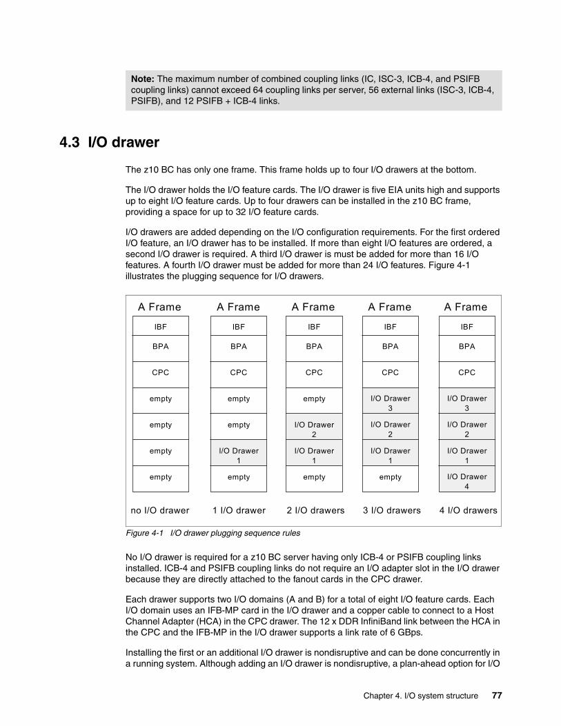
4.3 I/O drawer
The z10 BC has only one frame. This frame holds up to four I/O drawers at the bottom.
The I/O drawer holds the I/O feature cards. The I/O drawer is five EIA units high and supports up to eight I/O feature cards. Up to four drawers can be installed in the z10 BC frame, providing a space for up to 32 I/O feature cards.
I/O drawers are added depending on the I/O configuration requirements. For the first ordered I/O feature, an I/O drawer has to be installed. If more than eight I/O features are ordered, a second I/O drawer is required. A third I/O drawer is must be added for more than 16 I/O features. A fourth I/O drawer must be added for more than 24 I/O features. Figure 4-1 illustrates the plugging sequence for I/O drawers.
Figure 4-1 I/O drawer plugging sequence rules
No I/O drawer is required for a z10 BC server having only ICB-4 or PSIFB coupling links installed. ICB-4 and PSIFB coupling links do not require an I/O adapter slot in the I/O drawer because they are directly attached to the fanout cards in the CPC drawer.
Each drawer supports two I/O domains (A and B) for a total of eight I/O feature cards. Each I/O domain uses an IFB-MP card in the I/O drawer and a copper cable to connect to a Host Channel Adapter (HCA) in the CPC drawer. The 12 x DDR InfiniBand link between the HCA in the CPC and the IFB-MP in the I/O drawer supports a link rate of 6 GBps.
Installing the first or an additional I/O drawer is nondisruptive and can be done concurrently in a running system. Although adding an I/O drawer is nondisruptive, a plan-ahead option for I/O
Note: The maximum number of combined coupling links (IC, ISC-3, ICB-4, and PSIFB coupling links) cannot exceed 64 coupling links per server, 56 external links (ISC-3, ICB-4, PSIFB), and 12 PSIFB + ICB-4 links.
IBF
BPA
CPC
empty
empty
empty
empty
no I/O drawer
IBF
BPA
CPC
I/O Drawer1
empty
empty
empty
1 I/O drawer
IBF
BPA
CPC
I/O Drawer1
I/O Drawer2
empty
empty
2 I/O drawers
IBF
BPA
CPC
I/O Drawer1
I/O Drawer2
I/O Drawer3
empty
3 I/O drawers
IBF
BPA
CPC
I/O Drawer1
I/O Drawer2
I/O Drawer3
I/O Drawer4
4 I/O drawers
A Frame A Frame A Frame A Frame A Frame
Chapter 4. I/O system structure 77
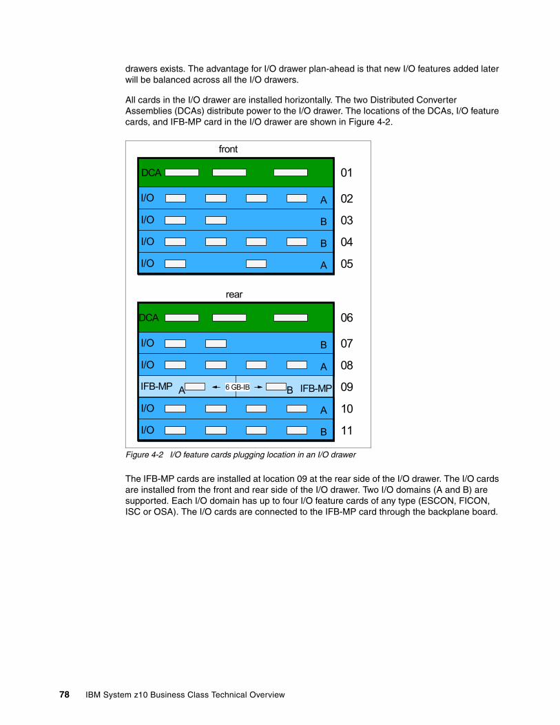
drawers exists. The advantage for I/O drawer plan-ahead is that new I/O features added later will be balanced across all the I/O drawers.
All cards in the I/O drawer are installed horizontally. The two Distributed Converter Assemblies (DCAs) distribute power to the I/O drawer. The locations of the DCAs, I/O feature cards, and IFB-MP card in the I/O drawer are shown in Figure 4-2.
Figure 4-2 I/O feature cards plugging location in an I/O drawer
The IFB-MP cards are installed at location 09 at the rear side of the I/O drawer. The I/O cards are installed from the front and rear side of the I/O drawer. Two I/O domains (A and B) are supported. Each I/O domain has up to four I/O feature cards of any type (ESCON, FICON, ISC or OSA). The I/O cards are connected to the IFB-MP card through the backplane board.
rear
DCA 01
I/O 02
03 I/O
I/O 04
I/O 05
front
DCA 06
I/O 07
08 I/O
I/O 10
I/O 11
09 IFB-MP IFB-MPA B6 GB-IB
A
A
A
A
B
B
B
B
78 IBM System z10 Business Class Technical Overview
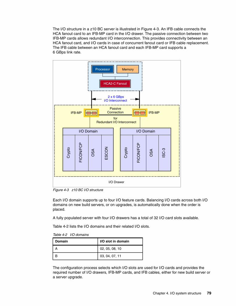
The I/O structure in a z10 BC server is illustrated in Figure 4-3. An IFB cable connects the HCA fanout card to an IFB-MP card in the I/O drawer. The passive connection between two IFB-MP cards allows redundant I/O interconnection. This provides connectivity between an HCA fanout card, and I/O cards in case of concurrent fanout card or IFB cable replacement. The IFB cable between an HCA fanout card and each IFB-MP card supports a 6 GBps link rate.
Figure 4-3 z10 BC I/O structure
Each I/O domain supports up to four I/O feature cards. Balancing I/O cards across both I/O domains on new build servers, or on upgrades, is automatically done when the order is placed.
A fully populated server with four I/O drawers has a total of 32 I/O card slots available.
Table 4-2 lists the I/O domains and their related I/O slots.
Table 4-2 I/O domains
The configuration process selects which I/O slots are used for I/O cards and provides the required number of I/O drawers, IFB-MP cards, and IFB cables, either for new build server or a server upgrade.
Domain I/O slot in domain
A 02, 05, 08, 10
B 03, 04, 07, 11
I/O Drawer
for Redundant I/O Interconnect
Passive Connection
2 x 6 GBpsI/O Interconnect
IFB-MP IFB-MP
I/O Domain
Cry
pto
FIC
ON
/FC
P
OS
A
ES
CO
N
I/O Domain
Cry
pto
FIC
ON
/FC
P
OS
A
ISC
-3
Processor Memory
HCA2-C Fanout
Chapter 4. I/O system structure 79
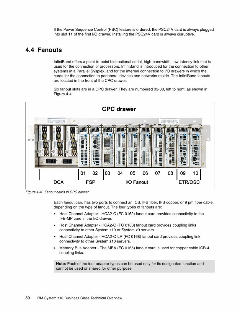
If the Power Sequence Control (PSC) feature is ordered, the PSC24V card is always plugged into slot 11 of the first I/O drawer. Installing the PSC24V card is always disruptive.
4.4 Fanouts
InfiniBand offers a point-to-point bidirectional serial, high-bandwidth, low-latency link that is used for the connection of processors. InfiniBand is introduced for the connection to other systems in a Parallel Sysplex, and for the internal connection to I/O drawers in which the cards for the connection to peripheral devices and networks reside. The InfiniBand fanouts are located in the front of the CPC drawer.
Six fanout slots are in a CPC drawer. They are numbered 03-08, left to right, as shown in Figure 4-4.
Figure 4-4 Fanout cards in CPC drawer
Each fanout card has two ports to connect an ICB, IFB fiber, IFB copper, or 9 µm fiber cable, depending on the type of fanout. The four types of fanouts are:
� Host Channel Adapter - HCA2-C (FC 0162) fanout card provides connectivity to the IFB-MP card in the I/O drawer.
� Host Channel Adapter - HCA2-O (FC 0163) fanout card provides coupling links connectivity to other System z10 or System z9 servers.
� Host Channel Adapter - HCA2-O LR (FC 0168) fanout card provides coupling link connectivity to other System z10 servers.
� Memory Bus Adapter - The MBA (FC 0165) fanout card is used for copper cable ICB-4 coupling links.
CPC Drawer - FRONT
CPC drawer
ETR/OSC
01 02 03 04 05 06 07 08 09 10
I/O FanoutFSPDCA
CPC Drawer - FRONT
CPC drawer
ETR/OSC
01 02 03 04 05 06 07 08 09 10
I/O FanoutFSPDCA
Note: Each of the four adapter types can be used only for its designated function and cannot be used or shared for other purpose.
80 IBM System z10 Business Class Technical Overview
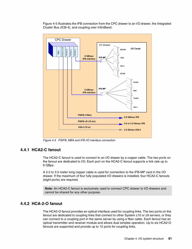
Figure 4-5 illustrates the IFB connection from the CPC drawer to an I/O drawer, the Integrated Cluster Bus (ICB-4), and coupling over InfiniBand.
Figure 4-5 PSIFB, MBA and IFB I/O interface connection
4.4.1 HCA2-C fanout
The HCA2-C fanout is used to connect to an I/O drawer by a copper cable. The two ports on the fanout are dedicated to I/O. Each port on the HCA2-C fanout supports a link rate up to 6 GBps.
A 2.5 to 3.5 meter long copper cable is used for connection to the IFB-MP card in the I/O drawer. If the maximum of four fully populated I/O drawers is installed, four HCA2-C fanouts (eight ports) are required.
4.4.2 HCA-2-O fanout
The HCA2-O fanout provides an optical interface used for coupling links. The two ports on the fanout are dedicated to coupling links that connect to other System z10 or z9 servers, or they can connect to a coupling port in the same server by using a fiber cable. Each fanout has an optical transmitter and receiver module and allows dual simplex operation. Up to six HCA2-O fanouts are supported and provide up to 12 ports for coupling links.
I/O Drawer
FICON
OSA
Crypto
ISC-3
ESCON
IFB-MP OSA
ISC-3
FICON
I/O Cards
IFB-MP
HC
A2-C
HC
A2-C
HC
A2-O
HC
A2-O
LR
MBA
CPC Drawer
6 GB/secIFB interface
6 GB/secIFB interface
PSIFB (150m)
PSIFB LR (10 km)
6.0 GB/sec IFB
5.0 or 2.5 Gb/sec IFB
2.0 Gb/sec ICB-4ICB-4 (10 m)
Note: An HCA2-C fanout is exclusively used to connect CPC drawer to I/O drawers and cannot be shared for any other purpose.
Chapter 4. I/O system structure 81
The HCA-O fanout supports InfiniBand Double Data Rate (12x IB-DDR) and InfiniBand Single Data Rate (12x IB-SDR) optical links that offer long distance, configuration flexibility, and high bandwidth for enhanced performance of coupling links. There are 12 lanes (two fibers per lane) in the cable, which means 24 fibers used in parallel for data transfer.
The fiber cables are industry standard OM3 (2000 MHz-km) 50 µm multimode optical cables with multifiber push-on (MPO) connectors. The maximum cable length is 150 meters (492 feet).
Each fiber supports a link rate of 6 GBps (12x IB-DDR) if connected to a System z10 server, or 3 GBps (12x IB-SDR) when connected to a System z9 server. The link rate is auto-negotiated to the highest common rate.
A fanout has two ports for optical link connections and supports up to 16 CHPIDs across both ports. These CHPIDs are defined in I/O configuration data set (IOCDS) as coupling links and require a fibre cable to connect to another server or the same server.
Each HCA2-O fanout used for coupling links has an assigned adapter ID (AID) number that must be used for definitions in IOCDS to create a relationship between the physical fanout location and the CHPID number. See 4.4.6, “Adapter ID number assignment” on page 84 for details about AID numbering.
Refer to Getting Started with InfiniBand on System z10 and System z9, SG24-7539, for detailed information about how the AID is used and referenced in HCD.
4.4.3 HCA2-O LR fanout
The HCA2-O LR fanout provides an optical interface used for coupling links. The two ports on the fanout are dedicated to coupling links to connect to other System z10 servers. Up to six HCA2-O LR fanouts are supported and provide up to 12 ports for coupling links.
The HCA-O LR fanout supports InfiniBand Double Data Rate (1x IB-DDR) and InfiniBand Single Data Rate (1x IB-SDR) optical links that offer longer distance of coupling links. In the one lane (two fibers per lane) of the cable, one fiber is used to transmit and one fiber is used to receive data.
Each fiber supports a link rate of 5 Gbps (1x IB-DDR) if connected to a System z10 server or to a repeater (DWDM, dense wavelength division multiplexing) supporting IB-DDR, and a data link rate of 2.5 Gbps (1x IB-SDR) when connected to a repeater (DWDM) which supports IB-SDR only. The link rate is auto-negotiated to the highest common rate.
The fiber cables are industry standard 9 µm single mode optical cables with LC Duplex connectors. The maximum unrepeated distance is 10 km, and up to 100 km with repeaters.
A fanout has two ports for optical link connections and supports up to 16 CHPIDs across both ports. These CHPIDs are defined in IOCDS as coupling links and require a fibre cable to connect to another server or the same server.
Note: Ports on the HCA2-O fanout are exclusively used for coupling links and cannot be shared for other purpose.
Note: Ports on the HCA2-O fanout are exclusively used for coupling links and cannot be shared for other purpose.
82 IBM System z10 Business Class Technical Overview
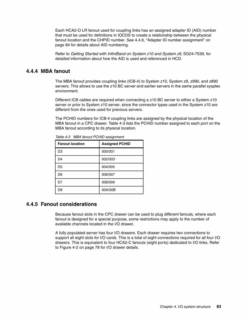
Each HCA2-O LR fanout used for coupling links has an assigned adapter ID (AID) number that must be used for definitions in IOCDS to create a relationship between the physical fanout location and the CHPID number. See 4.4.6, “Adapter ID number assignment” on page 84 for details about AID numbering.
Refer to Getting Started with InfiniBand on System z10 and System z9, SG24-7539, for detailed information about how the AID is used and referenced in HCD.
4.4.4 MBA fanout
The MBA fanout provides coupling links (ICB-4) to System z10, System z9, z990, and z890 servers. This allows to use the z10 BC server and earlier servers in the same parallel sysplex environment.
Different ICB cables are required when connecting a z10 BC server to either a System z10 server or prior to System z10 server, since the connector types used in the System z10 are different from the ones used for previous servers.
The PCHID numbers for ICB-4 coupling links are assigned by the physical location of the MBA fanout in a CPC drawer. Table 4-3 lists the PCHID number assigned to each port on the MBA fanout according to its physical location.
Table 4-3 MBA fanout PCHID assignment
4.4.5 Fanout considerations
Because fanout slots in the CPC drawer can be used to plug different fanouts, where each fanout is designed for a special purpose, some restrictions may apply to the number of available channels located in the I/O drawer.
A fully populated server has four I/O drawers. Each drawer requires two connections to support all eight slots for I/O cards. This is a total of eight connections required for all four I/O drawers. This is equivalent to four HCA2-C fanouts (eight ports) dedicated to I/O links. Refer to Figure 4-2 on page 78 for I/O drawer details.
Fanout location Assigned PCHID
D3 000/001
D4 002/003
D5 004/005
D6 006/007
D7 008/009
D8 00A/00B
Chapter 4. I/O system structure 83
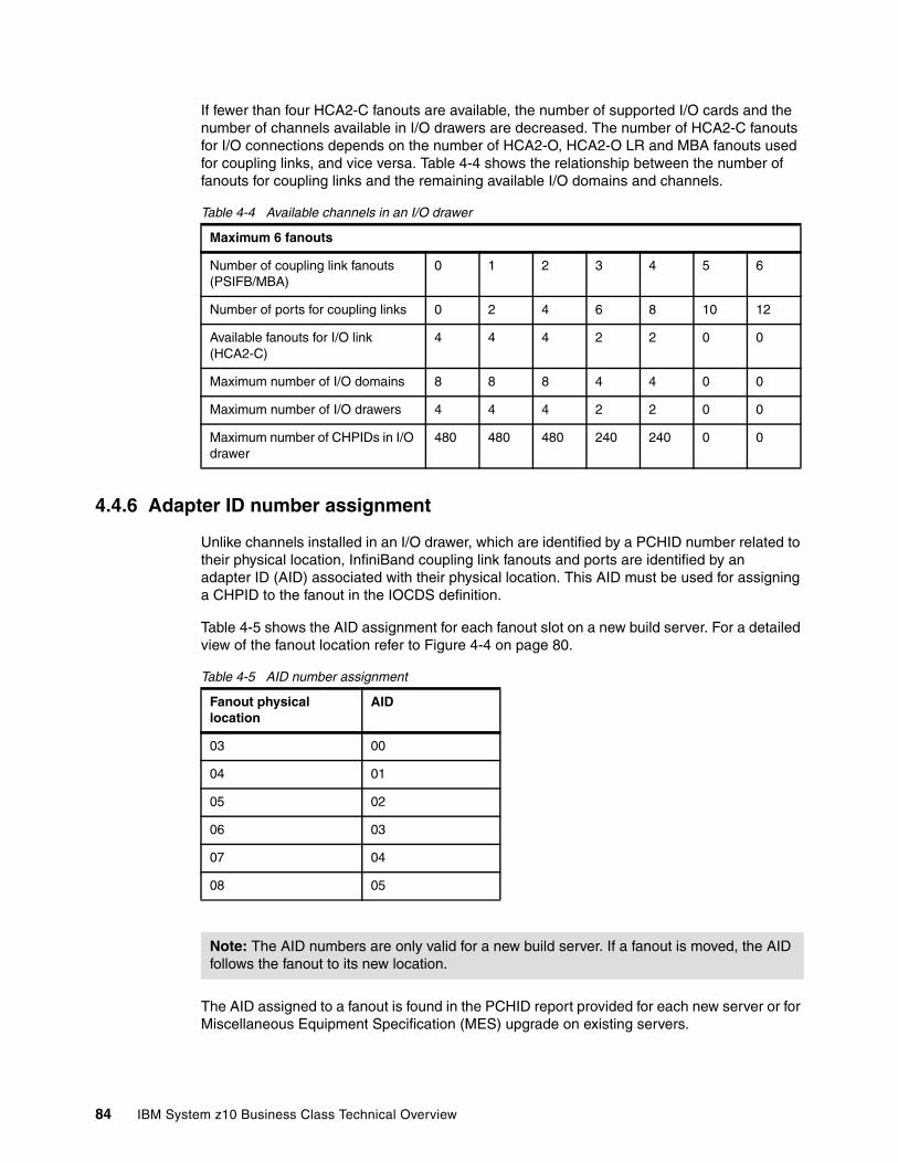
If fewer than four HCA2-C fanouts are available, the number of supported I/O cards and the number of channels available in I/O drawers are decreased. The number of HCA2-C fanouts for I/O connections depends on the number of HCA2-O, HCA2-O LR and MBA fanouts used for coupling links, and vice versa. Table 4-4 shows the relationship between the number of fanouts for coupling links and the remaining available I/O domains and channels.
Table 4-4 Available channels in an I/O drawer
4.4.6 Adapter ID number assignment
Unlike channels installed in an I/O drawer, which are identified by a PCHID number related to their physical location, InfiniBand coupling link fanouts and ports are identified by an adapter ID (AID) associated with their physical location. This AID must be used for assigning a CHPID to the fanout in the IOCDS definition.
Table 4-5 shows the AID assignment for each fanout slot on a new build server. For a detailed view of the fanout location refer to Figure 4-4 on page 80.
Table 4-5 AID number assignment
The AID assigned to a fanout is found in the PCHID report provided for each new server or for Miscellaneous Equipment Specification (MES) upgrade on existing servers.
Maximum 6 fanouts
Number of coupling link fanouts (PSIFB/MBA)
0 1 2 3 4 5 6
Number of ports for coupling links 0 2 4 6 8 10 12
Available fanouts for I/O link (HCA2-C)
4 4 4 2 2 0 0
Maximum number of I/O domains 8 8 8 4 4 0 0
Maximum number of I/O drawers 4 4 4 2 2 0 0
Maximum number of CHPIDs in I/O drawer
480 480 480 240 240 0 0
Fanout physical location
AID
03 00
04 01
05 02
06 03
07 04
08 05
Note: The AID numbers are only valid for a new build server. If a fanout is moved, the AID follows the fanout to its new location.
84 IBM System z10 Business Class Technical Overview
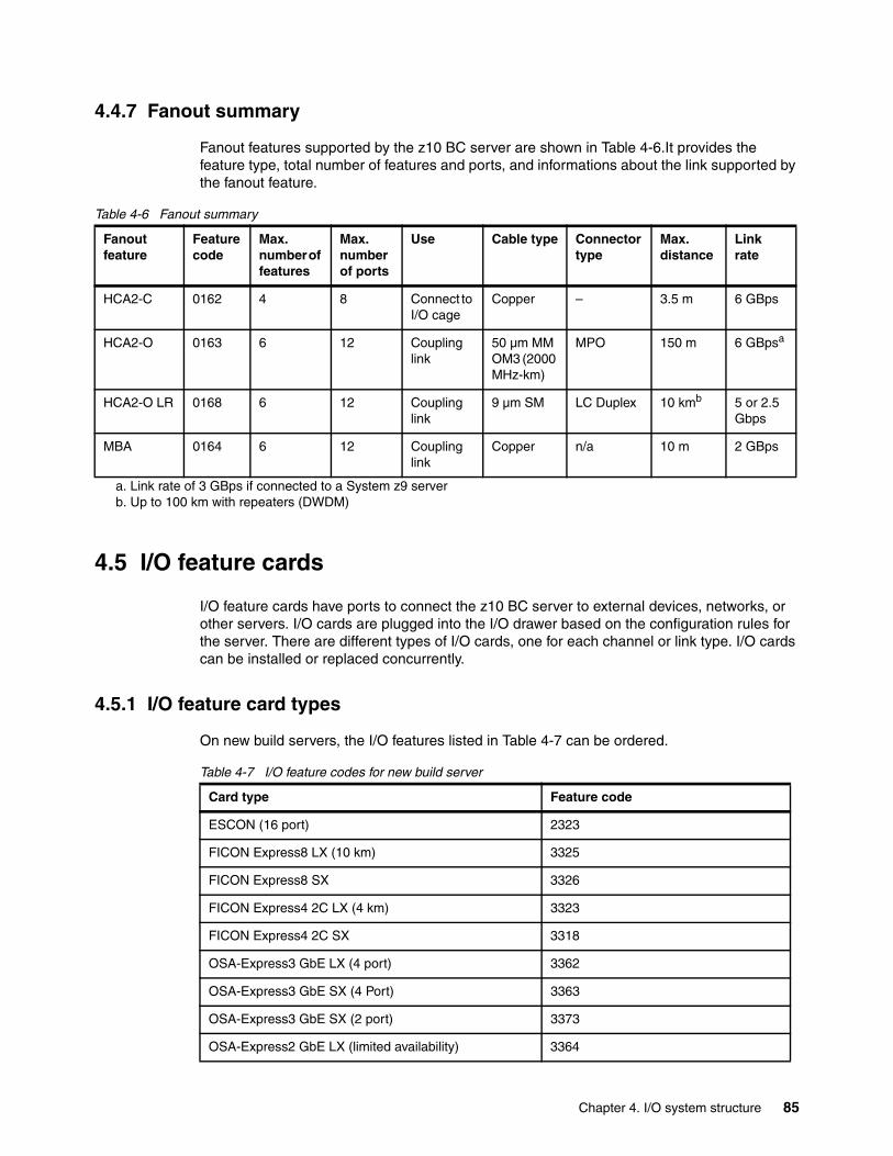
4.4.7 Fanout summary
Fanout features supported by the z10 BC server are shown in Table 4-6.It provides the feature type, total number of features and ports, and informations about the link supported by the fanout feature.
Table 4-6 Fanout summary
4.5 I/O feature cards
I/O feature cards have ports to connect the z10 BC server to external devices, networks, or other servers. I/O cards are plugged into the I/O drawer based on the configuration rules for the server. There are different types of I/O cards, one for each channel or link type. I/O cards can be installed or replaced concurrently.
4.5.1 I/O feature card types
On new build servers, the I/O features listed in Table 4-7 can be ordered.
Table 4-7 I/O feature codes for new build server
Fanout feature
Feature code
Max. number of features
Max. number of ports
Use Cable type Connector type
Max. distance
Link rate
HCA2-C 0162 4 8 Connect to I/O cage
Copper – 3.5 m 6 GBps
HCA2-O 0163 6 12 Coupling link
50 µm MM OM3 (2000 MHz-km)
MPO 150 m 6 GBpsa
a. Link rate of 3 GBps if connected to a System z9 server
HCA2-O LR 0168 6 12 Coupling link
9 µm SM LC Duplex 10 kmb
b. Up to 100 km with repeaters (DWDM)
5 or 2.5 Gbps
MBA 0164 6 12 Coupling link
Copper n/a 10 m 2 GBps
Card type Feature code
ESCON (16 port) 2323
FICON Express8 LX (10 km) 3325
FICON Express8 SX 3326
FICON Express4 2C LX (4 km) 3323
FICON Express4 2C SX 3318
OSA-Express3 GbE LX (4 port) 3362
OSA-Express3 GbE SX (4 Port) 3363
OSA-Express3 GbE SX (2 port) 3373
OSA-Express2 GbE LX (limited availability) 3364
Chapter 4. I/O system structure 85
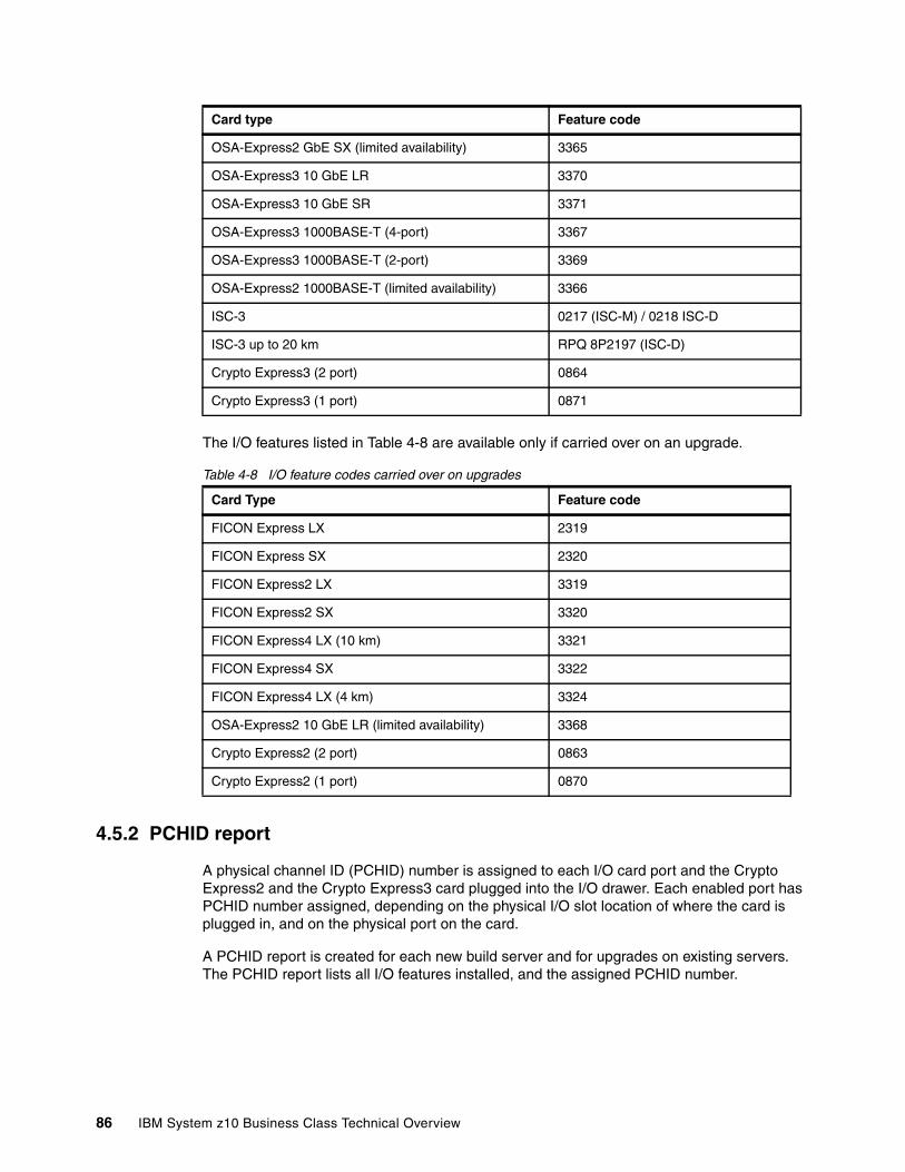
The I/O features listed in Table 4-8 are available only if carried over on an upgrade.
Table 4-8 I/O feature codes carried over on upgrades
4.5.2 PCHID report
A physical channel ID (PCHID) number is assigned to each I/O card port and the Crypto Express2 and the Crypto Express3 card plugged into the I/O drawer. Each enabled port has PCHID number assigned, depending on the physical I/O slot location of where the card is plugged in, and on the physical port on the card.
A PCHID report is created for each new build server and for upgrades on existing servers. The PCHID report lists all I/O features installed, and the assigned PCHID number.
OSA-Express2 GbE SX (limited availability) 3365
OSA-Express3 10 GbE LR 3370
OSA-Express3 10 GbE SR 3371
OSA-Express3 1000BASE-T (4-port) 3367
OSA-Express3 1000BASE-T (2-port) 3369
OSA-Express2 1000BASE-T (limited availability) 3366
ISC-3 0217 (ISC-M) / 0218 ISC-D
ISC-3 up to 20 km RPQ 8P2197 (ISC-D)
Crypto Express3 (2 port) 0864
Crypto Express3 (1 port) 0871
Card Type Feature code
FICON Express LX 2319
FICON Express SX 2320
FICON Express2 LX 3319
FICON Express2 SX 3320
FICON Express4 LX (10 km) 3321
FICON Express4 SX 3322
FICON Express4 LX (4 km) 3324
OSA-Express2 10 GbE LR (limited availability) 3368
Crypto Express2 (2 port) 0863
Crypto Express2 (1 port) 0870
Card type Feature code
86 IBM System z10 Business Class Technical Overview
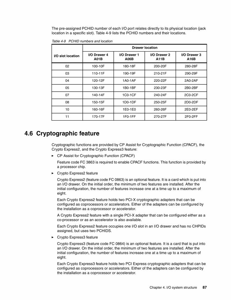
The pre-assigned PCHID number of each I/O port relates directly to its physical location (jack location in a specific slot). Table 4-9 lists the PCHID numbers and their locations.
Table 4-9 PCHID numbers and location
4.6 Cryptographic feature
Cryptographic functions are provided by CP Assist for Cryptographic Function (CPACF), the Crypto Express2, and the Crypto Express3 feature:
� CP Assist for Cryptographic Function (CPACF)
Feature code FC 3863 is required to enable CPACF functions. This function is provided by a processor chip.
� Crypto Express2 feature
Crypto Express2 (feature code FC 0863) is an optional feature. It is a card which is put into an I/O drawer. On the initial order, the minimum of two features are installed. After the initial configuration, the number of features increase one at a time up to a maximum of eight.
Each Crypto Express2 feature holds two PCI-X cryptographic adapters that can be configured as coprocessors or accelerators. Either of the adapters can be configured by the installation as a coprocessor or accelerator.
A Crypto Express2 feature with a single PCI-X adapter that can be configured either as a co-processor or as an accelerator is also available.
Each Crypto Express2 feature occupies one I/O slot in an I/O drawer and has no CHPIDs assigned, but uses two PCHIDS.
� Crypto Express3 feature
Crypto Express3 (feature code FC 0864) is an optional feature. It is a card that is put into an I/O drawer. On the initial order, the minimum of two features are installed. After the initial configuration, the number of features increase one at a time up to a maximum of eight.
Each Crypto Express3 feature holds two PCI Express cryptographic adapters that can be configured as coprocessors or accelerators. Either of the adapters can be configured by the installation as a coprocessor or accelerator.
I/O slot location
Drawer location
I/O Drawer 4A01B
I/O Drawer 1A06B
I/O Drawer 2A11B
I/O Drawer 3A16B
02 100-10F 180-18F 200-20F 280-28F
03 110-11F 190-19F 210-21F 290-29F
04 120-12F 1A0-1AF 220-22F 2A0-2AF
05 130-13F 1B0-1BF 230-23F 2B0-2BF
07 140-14F 1C0-1CF 240-24F 2C0-2CF
08 150-15F 1D0-1DF 250-25F 2D0-2DF
10 160-16F 1E0-1E0 260-26F 2E0-2EF
11 170-17F 1F0-1FF 270-27F 2F0-2FF
Chapter 4. I/O system structure 87

A Crypto Express3 feature with a single PCI Express adapter that can be configured either as a co-processor or as an accelerator is also available.
Each Crypto Express3 feature occupies one I/O slot in an I/O drawer and has no CHPIDs assigned, but uses two PCHIDS.
4.7 Connectivity
I/O channels are part of the channel subsystem (CSS). They provide connectivity for data exchange between servers, or between servers and external control units (CU) and devices, or networks.
Communication between servers is provided by InterSystem channels (ISC-3), Integrated Cluster Bus (ICB-4), coupling using InfiniBand (PSIFB), or channel-to-channel connection (CTC).
Communication to networks is provided by the OSA-Express2 and OSA-Express3 features.
Communication to I/O subsystems to exchange data is provided by ESCON and FICON channels.
4.7.1 I/O feature support and configuration rules
The I/O features supported are listed in Table 4-10. The table shows the feature code numbers, number of ports per card, port increments, the number of feature cards, the maximum number of channels for each feature code type, and the CHPID definition used in the IOCDS.
Table 4-10 Supported I/O features
I/O feature Feature codes
Number of Max. number of PCHID CHPID definition
Ports per card
Port increments
Ports I/O slots
ESCON 2323a
2324a16
(1 spare)4
(LICCC)480 32 Yes CNC, CVC, CTC, CBY
FICON Express LX/SXb
23192320
2 2 40 20 Yes FC, FCP, FCV
FICON Express2 LX/SXb
33193320
4 4 112 28 Yes FC,FCP
FICON Express4 LX/SXb
33183321332233233324
24424
24424
64128128
64128
32 Yes FC, FCP
FICON Express8 LX/SX
33253326
44
44
128128
32 Yes FC, FCP
OSA-Express2 GbE LX/SX
33643365
2 2 48 24 Yes OSD, OSN
OSA-Express3 GbE LX/SX
33623363
4 4 96 24 Yes OSD, OSN
88 IBM System z10 Business Class Technical Overview
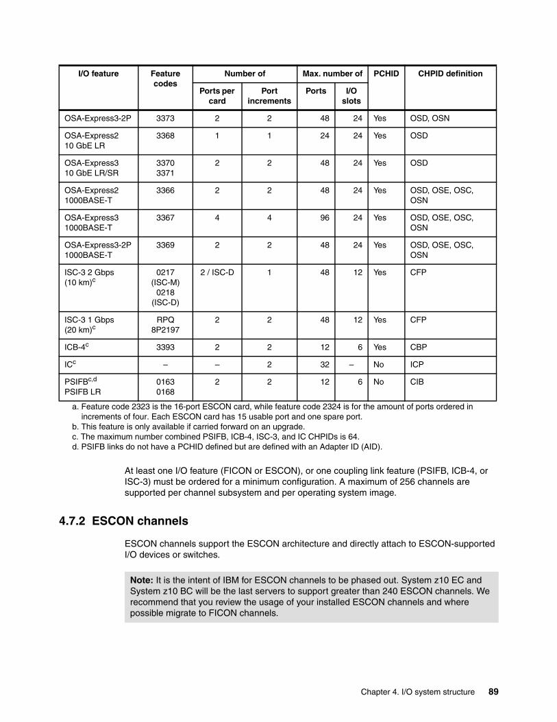
At least one I/O feature (FICON or ESCON), or one coupling link feature (PSIFB, ICB-4, or ISC-3) must be ordered for a minimum configuration. A maximum of 256 channels are supported per channel subsystem and per operating system image.
4.7.2 ESCON channels
ESCON channels support the ESCON architecture and directly attach to ESCON-supported I/O devices or switches.
OSA-Express3-2P 3373 2 2 48 24 Yes OSD, OSN
OSA-Express2 10 GbE LR
3368 1 1 24 24 Yes OSD
OSA-Express3 10 GbE LR/SR
33703371
2 2 48 24 Yes OSD
OSA-Express2 1000BASE-T
3366 2 2 48 24 Yes OSD, OSE, OSC, OSN
OSA-Express3 1000BASE-T
3367 4 4 96 24 Yes OSD, OSE, OSC, OSN
OSA-Express3-2P 1000BASE-T
3369 2 2 48 24 Yes OSD, OSE, OSC, OSN
ISC-3 2 Gbps (10 km)c
0217 (ISC-M)
0218 (ISC-D)
2 / ISC-D 1 48 12 Yes CFP
ISC-3 1 Gbps (20 km)c
RPQ 8P2197
2 2 48 12 Yes CFP
ICB-4c 3393 2 2 12 6 Yes CBP
ICc – – 2 32 – No ICP
PSIFBc,d
PSIFB LR01630168
2 2 12 6 No CIB
a. Feature code 2323 is the 16-port ESCON card, while feature code 2324 is for the amount of ports ordered in increments of four. Each ESCON card has 15 usable port and one spare port.
b. This feature is only available if carried forward on an upgrade.c. The maximum number combined PSIFB, ICB-4, ISC-3, and IC CHPIDs is 64.d. PSIFB links do not have a PCHID defined but are defined with an Adapter ID (AID).
I/O feature Feature codes
Number of Max. number of PCHID CHPID definition
Ports per card
Port increments
Ports I/O slots
Note: It is the intent of IBM for ESCON channels to be phased out. System z10 EC and System z10 BC will be the last servers to support greater than 240 ESCON channels. We recommend that you review the usage of your installed ESCON channels and where possible migrate to FICON channels.
Chapter 4. I/O system structure 89
The PRIZM Protocol Converter Appliance from Optica Technologies Incorporated provides a FICON-to-ESCON conversion function that has been System z qualified. For more information see:
http://www.opticatech.com/
Sixteen-port ESCON featureThe 16-port ESCON feature (FC 2323) occupies one I/O slot in an I/O drawer. Each port on the feature uses a 1300 nanometer (nm) light-emitting diode (LED) transceiver, designed to be connected to 62.5 µm multimode fiber optic cables only.
The feature has 16 ports with one PCHID associated with each port, up to a maximum of 15 active ESCON channels per feature. Each feature has a minimum of one spare port to allow for channel sparing in the event of a failure of one of the other ports.
The 16-port ESCON feature port utilizes a small form factor optical transceiver that supports a fiber optic connector called MT-RJ. The MT-RJ is an industry standard connector that has a much smaller profile compared with the original ESCON Duplex connector. The MT-RJ connector, combined with technology consolidation, allows for the much higher density packaging implemented with the 16-port ESCON feature.
4.7.3 FICON channels
The FICON Express8, FICON Express4, FICON Express2, and FICON Express features conform to the Fiber Connection (FICON) architecture and directly attach to FICON-supported I/O devices or switches.
FICON channels can be shared among logical partitions and can be defined as spanned. All ports on a FICON feature must be of the same type, either LX or SX.
Note: IBM cannot confirm the accuracy of compatibility, performance, or any other claims by vendors for products that have not been System z qualified. Questions regarding these capabilities and device support should be addressed to the suppliers of those products.
Note: The 16-port ESCON feature does not support a multimode fiber optic cable terminated with an ESCON Duplex connector. However, 62.5 µm multimode ESCON Duplex jumper cables can be reused to connect to the 16-port ESCON feature. This is done by installing an MT-RJ/ESCON Conversion kit between the 16-port ESCON feature MT-RJ port and the ESCON Duplex jumper cable. This protects the investment in the existing ESCON Duplex cabling infrastructure.
Fiber optic conversion kits and mode conditioning patch (MCP) cables are not orderable as features. Fiber optic cables, cable planning, labeling, and installation are all customer responsibilities for new installations and upgrades.
IBM Fiber Cabling Services offer a total cable solution service to help with cable ordering needs, and are highly recommended.
Recommendation: When upgrading to a System z10, replacing your FICON Express, FICON Express2, and FICON Express4 features with FICON Express8 features is beneficial. FICON Express8 features offer better performance and increased bandwidth and take up less real-estate in the I/O drawer than the other FICON features.
90 IBM System z10 Business Class Technical Overview
FICON Express8The two types of FICON Express8 channel transceivers supported on new build servers include a long wavelength (LX) laser version and a short wavelength (SX) LED version:
� FICON Express8 10km LX feature FC 3325, with four ports per feature, supporting LC Duplex connectors
� FICON Express8 SX feature FC 3326, with four ports per feature, supporting LC Duplex connectors
All channels on a feature are of the same type, either 10 km LX or SX. The features are connected to a FICON-capable control unit, either point-to-point or switched point-to-point, through a Fibre Channel switch.
Up to 128 FICON Express8 channels (up to 32 features) can be installed in the z10 BC server.
All FICON Express8 features use small form-factor pluggable (SFP) optics that allow for concurrent repair or replacement for each SFP. The data flow on the unaffected channels on the same feature can continue. A problem with one FICON port may no longer require replacement of a complete feature.
The FICON Express8 LX feature supports an unrepeated distance of 10 kilometers using a 9 µm single mode fiber. The FICON Express8 SX feature supports varying distances depending on the fiber used (50 or 62.5 µm multimode fiber) and the link speed (2 Gbps, 4 Gbps, or 8 Gbps).
FICON Express4The five types of FICON Express4 channel transceivers supported when carried over on an upgrade include three long wavelength (LX) laser versions and two short wavelength (SX) LED versions, as shown in the following list:
� FICON Express4 10km LX feature FC 3321, with four ports per feature, supporting LC Duplex connectors
� FICON Express4 4km LX feature FC 3324, with four ports per feature, supporting LC Duplex connectors
� FICON Express4 4 km LX 2C feature FC 3323, with two ports per feature, supporting LC Duplex connectors. This feature is also supported on new build servers.
� FICON Express4 SX feature FC 3322, with four ports per feature, supporting LC Duplex connectors
� FICON Express4 SX 2C feature FC 3318, with two ports per feature, supporting LC Duplex connectors. This feature is also supported on new build servers.
All channels on a feature are of the same type, either 10 km LX, 4 km LX, or SX. The features are connected to a FICON-capable control unit, either point-to-point or switched point-to-point, through a Fibre Channel switch.
Up to 128 FICON Express4 channels (up to 32 features) can be installed in the z10 BC server.
All FICON Express4 features use small form-factor pluggable (SFP) optics that allow for concurrent repair or replacement for each SFP. The data flow on the unaffected channels on the same feature can continue. A problem with one FICON port may no longer require replacement of a complete feature.
Chapter 4. I/O system structure 91

There are three FICON Express4 LX features. One supports a unrepeated distance of 10 kilometers, and the other two an unrepeated distance of four kilometers, using 9 µm single mode fiber. The FICON Express4 SX feature supports varying distances depending on the fiber used (50 or 62.5 µm multimode fiber) and the link speed (1 Gbps, 2 Gbps, or 4 Gbps).
FICON Express2The FICON Express2 feature is supported on a z10 BC servers only if carried over on an upgrade. Two types of FICON Express2 channel transceivers are supported on z10 BC servers when carried forward on an upgrade: a long wavelength (LX) laser version and a short wavelength (SX) LED version:
� FICON Express2 LX feature FC 3319, with four ports per feature, supporting LC duplex connectors
� FICON Express2 SX feature FC 3320, with four ports per feature, supporting LC Duplex connectors
The features are connected to a FICON-capable control unit, either point-to-point or switched point-to-point, through a Fibre Channel switch.
Up to 112 FICON Express2 channels (32 features) can be installed.
FICON ExpressFICON Express features are only available if carried forward on an upgrade to a z10 BC server.
High Performance FICON for System zHigh Performance FICON for System z (zHPF) is an enhancement of the FICON channel architecture and is compatible with:
� Fibre Channel Physical and Signaling standard (FC-FS)� Fibre Channel Switch Fabric and Switch Control Requirements (FC-SW)� Fibre Channel Single-Byte-4 standards (FC-SB-4)
Exploiting zHPF by the FICON channel, the z/OS operating system, and the control unit reduces the FICON channel overhead. This is achieved by protocol simplification and reducing the number of information units (IUs) processed, resulting in more efficient usage of the fiber link.
The FICON Express8, FICON Express4, and FICON Express2 features support both the existing FICON architecture and the zHPF architecture. From the z/OS point of view the existing FICON architecture is called command mode and the zHPF architecture is called transport mode. A parameter in the Operation Request Block (ORB) is used to determine whether the FICON channel is running in command or transport mode.
During link initialization both nodes, the channel node and the control unit node, indicate whether they support zHPF.
While in command mode, each single CCW is sent to the control unit for execution. In transport mode, all CCWs are sent over the link in one single frame to the control unit. This significantly improves the performance on a FICON link.
For z/OS exploitation there is a parameter in the IECIOSxx member of SYS1.PARMLIB (ZHPF=YES or NO) and in the SETIOS system command to control whether zHPF is enabled or disabled. The default is ZHPF=NO.
92 IBM System z10 Business Class Technical Overview
Support is also added for the D IOS,ZHPF system command to indicate whether zHPF is enabled, disabled, or not supported on the server.
For exploitation, the control unit must support the High Performance FICON for System z protocol. IBM System Storage DS8000® series supports zHPF in a System z environment.
Platform and name server registration in FICON channelThe FICON Express8, FICON Express4, FICON Express2, and FICON Express features on the System z10 servers support platform and name server registration to the fabric if the FICON feature is defined as CHPID type FC.
Information about the channels connected to a fabric, if registered, allow other nodes or SAN managers to query the name server to determine what is connected to the fabric. The attributes that are registered for the System z10 servers are:
� Platform information
– World Wide Node Name (WWNN)
This is the node name of the platform and is the same for all channels belonging to the platform.
– Platform type
This is the host computer type.
– Platform name, and vendor specific data from node descriptor
The platform name includes vendor ID, product ID, and vendor specific data from the node descriptor.
� Channel information
� World Wide Port name (WWPN)
� Port type (N-Port_ID)
� FC-4 types supported
� Classes of service supported by the channel
The platform and name server registration service is defined in the Fibre Channel - Generic Services 4 (FC-GS-4) standard.
Extended distance FICONAn enhancement to the industry standard FICON architecture (FC-SB-3) helps avoid degradation of performance at extended distances by implementing a new protocol for persistent information unit (IU) pacing. Extended distance FICON is transparent to operating systems and applies to all the FICON Express2, FICON Express4, and FICON Express8 features carrying native FICON traffic (CHPID type FC).
For exploitation, the control unit must support the new IU pacing protocol. IBM System Storage DS8000 series supports extended distance FICON for IBM System z environments. The channel will default to current pacing values when operating with control units that cannot exploit extended distance FICON.
Worldwide port name (WWPN) prediction toolA part of the installation of your IBM System z10 server is the pre-planning of the Storage Area Network (SAN) environment. IBM has made available a stand-alone tool to assist with this planning prior to the installation.
Chapter 4. I/O system structure 93
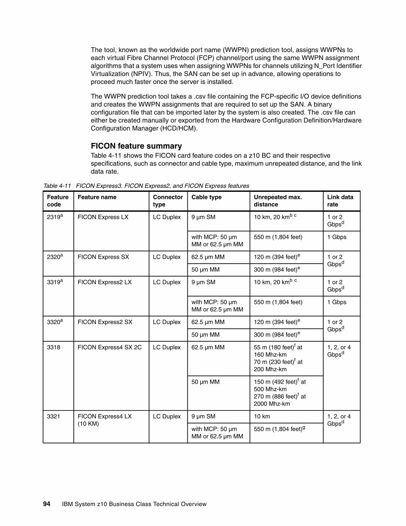
The tool, known as the worldwide port name (WWPN) prediction tool, assigns WWPNs to each virtual Fibre Channel Protocol (FCP) channel/port using the same WWPN assignment algorithms that a system uses when assigning WWPNs for channels utilizing N_Port Identifier Virtualization (NPIV). Thus, the SAN can be set up in advance, allowing operations to proceed much faster once the server is installed.
The WWPN prediction tool takes a .csv file containing the FCP-specific I/O device definitions and creates the WWPN assignments that are required to set up the SAN. A binary configuration file that can be imported later by the system is also created. The .csv file can either be created manually or exported from the Hardware Configuration Definition/Hardware Configuration Manager (HCD/HCM).
FICON feature summaryTable 4-11 shows the FICON card feature codes on a z10 BC and their respective specifications, such as connector and cable type, maximum unrepeated distance, and the link data rate.
Table 4-11 FICON Express3. FICON Express2, and FICON Express features
Feature code
Feature name Connector type
Cable type Unrepeated max. distance
Link data rate
2319a FICON Express LX LC Duplex 9 µm SM 10 km, 20 kmb c 1 or 2 Gbpsd
with MCP: 50 µm MM or 62.5 µm MM
550 m (1,804 feet) 1 Gbps
2320a FICON Express SX LC Duplex 62.5 µm MM 120 m (394 feet)e 1 or 2 Gbpsd
50 µm MM 300 m (984 feet)e
3319a FICON Express2 LX LC Duplex 9 µm SM 10 km, 20 kmb c 1 or 2 Gbpsd
with MCP: 50 µm MM or 62.5 µm MM
550 m (1,804 feet) 1 Gbps
3320a FICON Express2 SX LC Duplex 62.5 µm MM 120 m (394 feet)e 1 or 2 Gbpsd
50 µm MM 300 m (984 feet)e
3318 FICON Express4 SX 2C LC Duplex 62.5 µm MM 55 m (180 feet)f at 160 Mhz-km70 m (230 feet)f at 200 Mhz-km
1, 2, or 4 Gbpsd
50 µm MM 150 m (492 feet)f at 500 Mhz-km270 m (886 feet)f at 2000 Mhz-km
3321 FICON Express4 LX (10 KM)
LC Duplex 9 µm SM 10 km 1, 2, or 4 Gbpsd
with MCP: 50 µm MM or 62.5 µm MM
550 m (1,804 feet)g
94 IBM System z10 Business Class Technical Overview
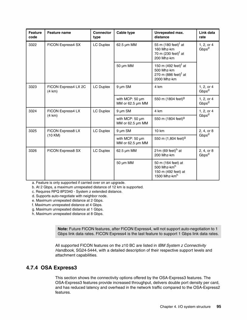
All supported FICON features on the z10 BC are listed in IBM System z Connectivity Handbook, SG24-5444, with a detailed description of their respective support levels and attachment capabilities.
4.7.4 OSA Express3
This section shows the connectivity options offered by the OSA-Express3 features. The OSA-Express3 features provide increased throughput, delivers double port density per card, and has reduced latency and overhead in the network traffic compared to the OSA-Express2 features.
3322 FICON Express4 SX LC Duplex 62.5 µm MM 55 m (180 feet)f at 160 Mhz-km70 m (230 feet)f at 200 Mhz-km
1, 2, or 4 Gbpsd
50 µm MM 150 m (492 feet)f at 500 Mhz-km270 m (886 feet)f at 2000 Mhz-km
3323 FICON Express4 LX 2C (4 km)
LC Duplex 9 µm SM 4 km 1, 2, or 4 Gbpsd
with MCP: 50 µm MM or 62.5 µm MM
550 m (1804 feet)g 1, 2, or 4 Gbpsd
3324 FICON Express4 LX (4 km)
LC Duplex 9 µm SM 4 km 1, 2, or 4 Gbpsd
with MCP: 50 µm MM or 62.5 µm MM
550 m (1804 feet)g
3325 FICON Express8 LX (10 KM)
LC Duplex 9 µm SM 10 km 2, 4, or 8 Gbpsd
with MCP: 50 µm MM or 62.5 µm MM
550 m (1,804 feet)g
3326 FICON Express8 SX LC Duplex 62.5 µm MM 21m (69 feet)h at 200 Mhz-km
2, 4, or 8 Gbpsd
50 µm MM 50 m (164 feet) at 500 Mhz-kmh
150 m (492 feet) at 1500 Mhz-kmh
a. Feature is only supported if carried over on an upgrade.b. At 2 Gbps, a maximum unrepeated distance of 12 km is supported.c. Requires RPQ 8P2340 - System z extended distance.d. Supports auto-negotiate with neighbor node.e. Maximum unrepeated distance at 2 Gbps.f. Maximum unrepeated distance at 4 Gbps.g. Maximum unrepeated distance at 1 Gbps.h. Maximum unrepeated distance at 8 Gbps.
Feature code
Feature name Connector type
Cable type Unrepeated max. distance
Link data rate
Note: Future FICON features, after FICON Express4, will not support auto-negotiation to 1 Gbps link data rates. FICON Express4 is the last feature to support 1 Gbps link data rates.
Chapter 4. I/O system structure 95

Features All OSA-Express3 features are available on a new build server. Up to 24 OSA-Express3 features (maximum 96 ports) are supported on the z10 BC. The maximum number of OSA-Express3 and OSA-Express2 features must not exceed a total of 24.
The OSA-Express3 features are listed in Table 4-12.
Table 4-12 OSA-Express3 feature
OSA-Express3 data routerOSA-Express3 features help reduce latency and improve throughput by providing a data router. What was previously done in firmware (packet construction, inspection, and routing) is now performed in hardware. With the data router, direct memory access is now available, packets flow directly from host memory to the LAN without firmware intervention. OSA-Express3 can also help reduce the round-trip networking time between systems. Up to a 45% reduction in latency at the TCP/IP application layer has been measured.
The OSA-Express3 features are also designed to improve throughput for standard frames (1492 bytes) and jumbo frames (8992 bytes) to help satisfy application’s bandwidth requirements. Up to a four times improvement has been measured (compared to OSA-Express2).
These statements are based on OSA-Express3 performance measurements performed in a laboratory environment on a System z10 and do not represent actual field measurements. Results can vary.
I/O feature Feature code
Number of Max. number of PCHID CHPID type
ports per card
port increments
ports I/O slots
OSA-Express3 GbE LX
3362 4 4 96 24 Yes OSD, OSN
OSA-Express3 GbE SX
3363 4 4 96 24 Yes OSD, OSN
OSA-Express3-2P GbE SX
3373 2 2 48 24 Yes OSD, OSN
OSA-Express3 10 GbE LR
3370 2 2 48 24 Yes OSD
OSA-Express310 GbE SR
3371 2 2 48 24 Yes OSD
OSA-Express3 1000BASE-T
3367 4 4 96 24 Yes OSD, OSN, OSC, OSE
OSA-Express3-2P 1000BASE-T
3369 2 2 48 24 Yes OSD, OSN, OSC, OSE
96 IBM System z10 Business Class Technical Overview
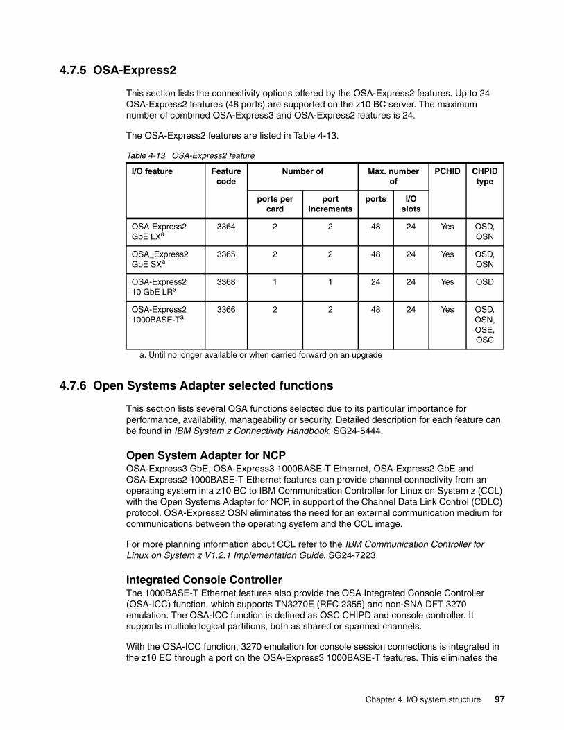
4.7.5 OSA-Express2
This section lists the connectivity options offered by the OSA-Express2 features. Up to 24 OSA-Express2 features (48 ports) are supported on the z10 BC server. The maximum number of combined OSA-Express3 and OSA-Express2 features is 24.
The OSA-Express2 features are listed in Table 4-13.
Table 4-13 OSA-Express2 feature
4.7.6 Open Systems Adapter selected functions
This section lists several OSA functions selected due to its particular importance for performance, availability, manageability or security. Detailed description for each feature can be found in IBM System z Connectivity Handbook, SG24-5444.
Open System Adapter for NCPOSA-Express3 GbE, OSA-Express3 1000BASE-T Ethernet, OSA-Express2 GbE and OSA-Express2 1000BASE-T Ethernet features can provide channel connectivity from an operating system in a z10 BC to IBM Communication Controller for Linux on System z (CCL) with the Open Systems Adapter for NCP, in support of the Channel Data Link Control (CDLC) protocol. OSA-Express2 OSN eliminates the need for an external communication medium for communications between the operating system and the CCL image.
For more planning information about CCL refer to the IBM Communication Controller for Linux on System z V1.2.1 Implementation Guide, SG24-7223
Integrated Console Controller The 1000BASE-T Ethernet features also provide the OSA Integrated Console Controller (OSA-ICC) function, which supports TN3270E (RFC 2355) and non-SNA DFT 3270 emulation. The OSA-ICC function is defined as OSC CHIPD and console controller. It supports multiple logical partitions, both as shared or spanned channels.
With the OSA-ICC function, 3270 emulation for console session connections is integrated in the z10 EC through a port on the OSA-Express3 1000BASE-T features. This eliminates the
I/O feature Feature code
Number of Max. number of
PCHID CHPID type
ports per card
port increments
ports I/O slots
OSA-Express2 GbE LXa
a. Until no longer available or when carried forward on an upgrade
3364 2 2 48 24 Yes OSD, OSN
OSA_Express2 GbE SXa
3365 2 2 48 24 Yes OSD, OSN
OSA-Express210 GbE LRa
3368 1 1 24 24 Yes OSD
OSA-Express2 1000BASE-Ta
3366 2 2 48 24 Yes OSD, OSN, OSE, OSC
Chapter 4. I/O system structure 97

requirement for external console controllers, such as 2074 or 3174, helping to reduce cost and complexity. Each port can support up to 120 console session connections.
Link aggregation support for z/VMz/VM Virtual Switch-controlled (VSWITCH-controlled) link aggregation (IEEE 802.3ad) allows to dedicate an OSA-Express3, OSA-Express2 or OSA-Express port to the z/VM operating system when the port is participating in an aggregated group configured in Layer 2 mode. Link aggregation (trunking) is designed to allow combining multiple physical OSA-Express3 or OSA-Express2 ports into a single logical link for increased throughput and for nondisruptive failover in the event that a port becomes unavailable.
QDIO data connection isolation for z/VM environmentsThe QDIO data connection isolation function provides a higher level of security on System z10 and System z9 servers when sharing the same OSA-Express port in z/VM environment that use the virtual switch (VSWITCH). The VSWITCH is a virtual network device that provides switching between OSA-Express ports and the connected guest system.
QDIO data connection isolation allows to disable the internal routing on a per QDIO connection basis, providing a means for creating security zones and preventing network traffic between the zones. For example, this function ensures that traffic to an external network is forced to flow only between a guest operating system and the external network.
Checksum offload for IPv4 packets when in QDIO modeA function called checksum offload, offered on the OSA-Express3 GbE, OSA-Express3 100BASE-T, OSA-Express2 GbE and OSA-Express2 1000BASE-T Ethernet features, is in support of z/OS and Linux on System z environments. Checksum offload provides the capability of calculating the Transmission Control Protocol (TCP), User Datagram Protocol (UDP), and Internet Protocol (IP) header checksum. Checksum verifies the accuracy of files. By moving the checksum calculations to an OSA feature, host CPU cycles are reduced and performance is improved.
Adapter interruptions for QDIOHardware, Linux on System z, and z/VM work together to provide performance improvements by exploiting extensions to the Queued Direct Input/Output (QDIO) architecture. Adapter interruptions, first added to z/Architecture with HiperSockets, provide an efficient, high-performance technique for I/O interruptions to reduce path lengths and overhead in both the host operating system and the adapter (OSA-Express3 and OSA-Express2 when using the OSD CHPID type).
OSA Dynamic LAN idle OSA Dynamic LAN idle parameter change is designed to help reduce latency and improve performance by dynamically adjusting the inbound blocking algorithm. System administrators can authorize the TCP/IP stack to enable a dynamic setting, which was previously a static setting.
VLAN managementTo simplify the network administration and management of VLANs, the GARP VLAN Registration Protocol (GVRP) is used. All OSA-Express3 and OSA-Express2 features support VLAN prioritization, a component of the IEEE 802.1 standard. With this support, manually entering VLAN IDs at the switch is no longer necessary. The OSA-Express features, when in QDIO mode (CHPID type OSD), can have GVRP dynamically register VLAN IDs.
98 IBM System z10 Business Class Technical Overview
OSA Layer 3 Virtual MAC for z/OS environmentsTo help simplify the infrastructure and to facilitate load balancing when a logical partition is sharing the same OSA Media Access Control (MAC) address with another logical partition, each operating system instance can have its own unique logical or virtual MAC (VMAC) address. All IP addresses associated with a TCP/IP stack are accessible using their own VMAC address, instead of sharing the MAC address of an OSA port. This applies to Layer 3 mode and to an OSA port spanned among channel subsystems.
QDIO Diagnostic SynchronizationQDIO Diagnostic Synchronization is designed to provide system programmers and network administrators with the ability to coordinate and simultaneously capture both software and hardware traces. It allows z/OS to signal an OSA-Express3 or OSA-Express2 feature (using a diagnostic assist function) to stop traces and capture the current trace records.
Network Traffic AnalyzerWith the large volume and complexity of today's network traffic, the System z10 offers systems programmers and network administrators the ability to more easily solve network problems. With the availability of the OSA-Express Network Traffic Analyzer and QDIO Diagnostic Synchronization on the server, customers have the ability to capture trace and trap data and forward it to z/OS tools for easier problem determination and resolution.
QDIO interface isolation for z/OSSome environments require strict controls for routing data traffic between severs or nodes. In certain cases, the LPAR-to-LPAR capability of a shared OSA port can prevent such controls from being enforced. With interface isolation, internal routing can be controlled on an LPAR basis. When interface isolation is enabled, the OSA will discard any packets destined for a z/OS LPAR that is registered in the OAT as isolated.
QDIO interface isolation is supported by Communications Server for z/OS V1R11 and all OSA-Express3 and OSA-Express2 features on System z10.
QDIO optimized latency modeQDIO optimized latency mode (OLM) can help improve performance for applications that have a critical requirement to minimize response times for inbound and outbound data.
OLM optimizes the interrupt processing as follows:
� For inbound processing, the TCP/IP stack looks more frequently for available data to process, ensuring that any new data is read from the OSA-Express3 without requiring additional program controlled interrupts (PCIs).
� For outbound processing, the OSA-Express3 also looks more frequently for available data to process from the TCP/IP stack, thus not requiring a Signal Adapter (SIGA) instruction to determine whether more data is available.
4.7.7 HiperSockets
The HiperSockets function, also known as internal Queued Direct Input/Output (iQDIO) or internal QDIO, is an integrated function of the System z10 server that provides users with attachments to up to sixteen high-speed virtual Local Area Networks with minimal system and network overhead. Because HiperSockets does not use an external network, it can free up system and network resources when not in use, eliminating attachment costs while improving availability and performance.
Chapter 4. I/O system structure 99
HiperSockets eliminates having to use I/O subsystem operations and having to traverse an external network connection to communicate between logical partitions in the same System z10 server. HiperSockets offers significant value in server consolidation connecting many virtual servers and eliminating physical network connectivity or for fast and secure communication among virtual servers.
HiperSockets Multiple Write FacilityThe HiperSockets function has been enhanced on the System z10 server to support multiple output buffers on a single SIGA write instruction. This operation is beneficial for the streaming of bulk data over a HiperSockets link between two logical partitions.
The receiving partition processes a much larger amount of data per I/O interrupt. This is transparent to the operating system in the receiving partition. HiperSockets Multiple Write Facility with fewer I/O interrupts is designed to reduce processor utilization of the sending and receiving partition.
HiperSockets MAC layer routingHiperSockets is a virtual network and was originally designed as an internal Layer 3 network. Various non-IP-based applications, such as SNA or NetBios, cannot use HiperSockets because a Layer 2 network and Layer 2 addresses are required for these applications.
HiperSockets MAC layer routing enables to use HiperSockets to bridge from and into distributed switched fabrics. The MAC addresses, are generated by the HiperSockets firmware for each device. For every IQD device HiperSockets firmware generates a MAC address that is unique within the system and cannot be altered. These generated MAC addresses can be read by software and can be used for Layer 2 processing.
System z10 HiperSockets Layer 2 supportHiperSockets internal networks on System z10 servers support two transport modes: Layer 2 (link layer) and Layer 3 (network or IP layer). Traffic can be IPv4 or IPv6, or non-IP based, such as AppleTalk, DECnet, IPX, NetBIOS, or SNA.
HiperSockets devices are protocol and Layer 3 independent. Each HiperSockets device has its own MAC address designed to allow the use of applications that depend on the existence of Layer 2 addresses such as DHCP servers and firewalls. Layer 2 support helps facilitate server consolidation, can reduce complexity, can simplify network configuration, and allows LAN administrators to maintain the mainframe network environment similarly as for non-mainframe environments.
Packet forwarding decisions are based on Layer 2 information instead of Layer 3. The HiperSockets device can perform automatic MAC address generation to create uniqueness within and across logical partitions and servers. The use of Group MAC addresses for multicast is supported as well as broadcasts to all other Layer 2 devices on the same HiperSockets networks.
Datagrams are delivered only between HiperSockets devices that use the same transport mode. A Layer 2 device cannot communicate directly to a Layer 3 device in another logical partition network. A HiperSockets device can filter inbound datagrams by VLAN identification, the destination MAC address, or both.
Analogous to the Layer 3 functions, HiperSockets Layer 2 devices can be configured as primary or secondary connectors or multicast routers. This enables the creation of high-performance and high-availability link layer switches between the internal HiperSockets network and an external Ethernet or to connect to the HiperSockets Layer 2 networks of different servers.
100 IBM System z10 Business Class Technical Overview
HiperSockets Layer 2 support is exclusive on System z10. It is supported by Linux on System z, and by z/VM for Linux guest exploitation.
zIIP-Assisted HiperSockets for large messagesHiperSockets has been enhanced for zIIP exploitation. Specifically, the z/OS Communications Server allows the HiperSockets Multiple Write Facility processing for outbound large messages originating from z/OS to be performed on a zIIP.
zIIP-Assisted HiperSockets can help make highly secure and available HiperSockets networking a more attractive option. z/OS application workloads based on XML, HTTP, SOAP, Java, as well as traditional file transfer, can benefit from zIIP enablement by lowering general purpose processor utilization for such TCP/IP traffic.
When the workload is eligible, the TCP/IP HiperSockets device driver layer (write) processing is redirected to a zIIP, which then unblocks the sending application.
zIIP-Assisted HiperSockets for large messages is available only with z/OS V1R10 and System z10.
4.8 Parallel Sysplex connectivity
This section discusses coupling links and External Time Reference.
4.8.1 Coupling links
Coupling links are required in a Parallel Sysplex configuration to provide connectivity from the z/OS images to the Coupling Facility. A properly configured Parallel Sysplex provides a highly reliable, redundant, and robust System z technology solution to achieve near-continuous availability. A Parallel Sysplex comprises one or more z/OS operating system images coupled through one or more coupling facilities.
The type of coupling link used for connecting an operating system to a CF is important because of different characteristics of different types of coupling links. For configurations covering large distances, the time spent on the link can be the largest part of the response time.
The types of links that are available to connect a z/OS to a Coupling Facility are:
� ISC-3
The ISC-3 feature is available in peer mode only. ISC-3 links can be used to connect to System z10, System z9, z990, or z890 servers. They are fiber links that support a maximum distance of 10 km, 20 km with RPQ 8P2197, and 100 km with Dense Wave Division Multiplexing (DWDM). ISC-3s operate in single mode only. Link bandwidth is 200 MBps for distances up to 10 km, and 100 MBps when RPQ 8P2197 is installed. Each port operates at 2 Gbps. Ports are ordered in increments of one. The maximum number of ISC-3 links per z10 BC server is 48. ISC-3 supports transmission of STP messages.
� ICB-4
ICB-4 connects a System z10 to a System z10, System z9, z990, or z890 server. The maximum distance between the two servers is seven meters (maximum cable length is 10 meters). The link bandwidth is 2 GBps. ICB-4 links can be defined only in peer mode. The maximum number of ICB-4 links is 12 per z10 BC server. ICB-4 supports transmission of STP messages.
Chapter 4. I/O system structure 101
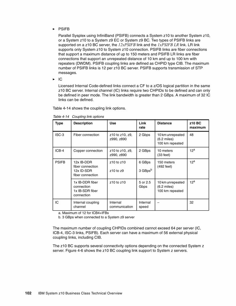
� PSIFB
Parallel Sysplex using InfiniBand (PSIFB) connects a System z10 to another System z10, or a System z10 to a System z9 EC or System z9 BC. Two types of PSIFB links are supported on a z10 BC server, the 12xPSIFB link and the 1xPSIFB LR link. LR link supports only System z10 to System z10 connection. PSIFB links are fiber connections that support a maximum distance of up to 150 meters and PSIFB LR links are fiber connections that support an unrepeated distance of 10 km and up to 100 km with repeaters (DWDM). PSIFB coupling links are defined as CHPID type CIB. The maximum number of PSIFB links is 12 per z10 BC server. PSIFB supports transmission of STP messages.
� IC
Licensed Internal Code-defined links connect a CF to a z/OS logical partition in the same z10 BC server. Internal channel (IC) links require two CHPIDs to be defined and can only be defined in peer mode. The link bandwidth is greater than 2 GBps. A maximum of 32 IC links can be defined.
Table 4-14 shows the coupling link options.
Table 4-14 Coupling link options
The maximum number of coupling CHPIDs combined cannot exceed 64 per server (IC, ICB-4, ISC-3 links, PSIFB). Each server can have a maximum of 56 external physical coupling links, including CIB.
The z10 BC supports several connectivity options depending on the connected System z server. Figure 4-6 shows the z10 BC coupling link support to System z servers.
Type Description Use Link rate
Distance z10 BC maximum
ISC-3 Fiber connection z10 to z10, z9, z990, z890
2 Gbps 10 km unrepeated (6.2 miles)100 km repeated
48
ICB-4 Copper connection z10 to z10, z9, z990, z890
2 GBps 10 meters (33 feet)
12a
a. Maximum of 12 for ICB4+IFBs
PSIFB 12x IB-DDR fiber connection12x ID-SDR fiber connection
z10 to z10
z10 to z9
6 GBps
3 GBpsb
b. 3 GBps when connected to a System z9 server
150 meters(492 feet)
12a
1x IB-DDR fiber connection1x IB-SDR fiber connection
z10 to z10 5 or 2.5 Gbps
10 km unrepeated (6.2 miles)100 km repeated
12a
IC Internal coupling channel
Internal communication
Internal speed
– 32
102 IBM System z10 Business Class Technical Overview
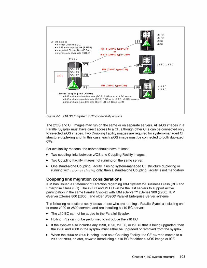
Figure 4-6 z10 BC to System z CF connectivity options
The z/OS and CF images may run on the same or on separate servers. All z/OS images in a Parallel Sysplex must have direct access to a CF, although other CFs can be connected only to selected z/OS images. Two Coupling Facility images are required for system-managed CF structure duplexing and, In this case, each z/OS image must be connected to both duplexed CFs.
For availability reasons, the server should have at least:
� Two coupling links between z/OS and Coupling Facility images.
� Two Coupling Facility images not running on the same server.
� One stand-alone Coupling Facility. If using system-managed CF structure duplexing or running with resource sharing only, then a stand-alone Coupling Facility is not mandatory.
Coupling link migration considerationsIBM has issued a Statement of Direction regarding IBM System z9 Business Class (BC) and Enterprise Class (EC). The z9 BC and z9 EC will be the last servers to support active participation in the same Parallel Sysplex with IBM eServer™ zSeries 900 (z900), IBM eServer zSeries 800 (z800), and older S/390® Parallel Enterprise Server systems.
The following restrictions apply to customers who are running a Parallel Sysplex including one or more z900 or z800 servers, and are installing a z10 BC server:
� The z10 BC cannot be added to the Parallel Sysplex.
� Rolling IPLs cannot be performed to introduce the z10 BC.
� If the sysplex also includes any z990, z890, z9 EC, or z9 BC that is being upgraded, then the z900 and z800 in the sysplex must either be upgraded or removed from the sysplex.
� When the z900 or z800 is being used as a Coupling Facility, the CF must be moved to a z990 or z890, or later, prior to introducing a z10 BC for either a z/OS image or ICF.
ISC-3 (CHPID type=CFP)or
ICB-4 (CHPID type=CBP)
z10 ECz10 BC
CF
OS LP1OS LP2OS LP3
z9 ECz9 BCz990 z890
STI
CF
z9 EC, z9 BCIFB
OS LP1OS LP2OS LP3
CF
CF
STI
IFB
IFB (CHPID type=CIB)
z10 EC coupling link (PSIFB)InfiniBand at double data rate (DDR) 6 GBps to z10 EC serverInfiniBand at single data rate (SDR) 3 GBps to z9 EC, z9 BC serversInfiniBand at single data rate (SDR) LR 2.5 Gbps to z10
IFB
CF link options Internal Channels (IC) InfiniBand coupling link (PSIFB)Integrated Cluster Bus (ICB-4)InterSystem Channels (ISC-3)
IFB (CHPID type=CIB)IFB
z10 BC
(IC)
OS LP1OS LP2OS LP3
OS LP1OS LP2OS LP3
Chapter 4. I/O system structure 103
The ICB connector is different from those on previous servers. It requires new cables and connectors to be installed on pre-z10 servers in order to connect the servers to z10 BC through ICB. This is a hardware-only migration action.
Refer to the Coupling Facility Configuration Options white paper for a more specific explanation of when to continue using the current ICB or ISC-3 technology versus migrating to InfiniBand coupling links:
http://www.ibm.com/systems/z/advantages/pso/whitepaper.html
Coupling links and Server Time ProtocolAll external coupling links can be used to pass time synchronization signals using Server Time Protocol (STP). STP is a message-based protocol in which STP messages are passed over data links between servers. The same coupling links can be used to exchange time and Coupling Facility messages in a Parallel Sysplex.
Advantages to using the coupling links to exchange STP messages are:
� By using the same links to exchange STP messages and Coupling Facility messages in a Parallel Sysplex, STP can scale with distance. Servers exchanging messages over short distances, such as PSIFB or ICB-4 links, can meet more stringent synchronization requirements than servers exchanging messages over long PSIFB LR or ISC-3 links (distances up to 100 km; Distances of up to 200 km are supported with RPQ 8P2263). This enhancement over the Sysplex Timer implementation, does not scale with distance.
� Coupling links also provide the connectivity needed in a Parallel Sysplex. Therefore, a potential benefit is the minimizing of the number of cross-site links required in a multi-site Parallel Sysplex.
Between any two servers that are intended to exchange STP messages, at least two coupling links should exist for communication between the servers. This prevents the loss of one link causing the loss of STP communication between the servers. If a server does not have a CF logical partition, timing-only links can be used to provide STP connectivity. STP is the System z technology that is replacing the Sysplex Timer function.
The z10 BC supports attachment to the Sysplex Timer through the External Time Reference (ETR) feature. Timing networks can be implemented using ETR only, Mixed (ETR and STP) or STP-only Coordinated Timing Network (CTN) in a Parallel Sysplex configuration.
Refer to IBM System z Connectivity Handbook, SG24-5444, for Sysplex Timer connectivity and configuration information.
Refer to Server Time Protocol Planning Guide, SG24-7280, and Server Time Protocol Implementation Guide, SG24-7281, for STP configuration information.
Note: The InfiniBand link data rates of 6 GBps, 3 GBps, 2.5 Gbps, or 5 Gbps do not represent the performance of the link. The actual performance depends on many factors, including latency through the adapters, cable lengths, and the type of workload.
When comparing coupling links data rates, InfiniBand (12x IB-SDR or 12x IB-DDR) might be higher than ICB-4, and InfiniBand (1x IB-SDR or 1x IB-DDR) might be higher than that of ISC-3, but with InfiniBand the service times of coupling operations are greater, and the actual throughput might be less than with ICB-4 links, but higher than for ISC-3 links.
104 IBM System z10 Business Class Technical Overview
4.8.2 External Time Reference
The External Time Reference (ETR) is a standard feature providing two ETR cards plugged in the CPC drawer. The ETR cards provide attachment to either a Network Time Protocol (NTP) server with pulse per second (PPS) support or an IBM Sysplex Timer.
In an expanded availability configuration (two ETR features), each ETR card connects to either a different NTP server with PPS support or to a different Sysplex Timer. The two ETR cards are located in two CPC drawer card slots on the right side of the drawer.
The Sysplex Timer or the Network Time Protocol (NTP) server with PPS provides the synchronization for the time-of-day (TOD) clocks of multiple servers, and thereby allow events started by different servers to be properly sequenced in time. When multiple servers update the same database and database reconstruction is necessary, all updates are required to be time stamped in proper sequence.
Port cards support concurrent maintenance. Each of the two standard ETR cards has one pulse per second (PPS) port for a coaxial cable connection to a PPS port on a Network Time Protocol server.
The ETR card also has a small form factor optical transceiver that supports an MT-RJ connector only for the System Timer. The ETR card does not support a multimode fiber optic cable terminated with an ESCON Duplex connector, as on the Sysplex Timer.
Current 62.5 µm multimode ESCON Duplex jumper cables can be reused to connect to the ETR card. This is done by installing an MT-RJ/ESCON Conversion kit between the ETR card MT-RJ port and the ESCON Duplex jumper cable.
Fiber optic conversion kits and Mode Conditioning Patch (MCP) cables are not orderable as features. Fiber optic cables, cable planning, labeling, and installation are all customer responsibilities for new z10 BC installations and upgrades. IBM Fiber Cabling Services offer a total cable solution service to help with cable ordering needs, and is highly recommended.
All supported I/O features on the z10 BC are listed in IBM System z Connectivity Handbook, SG24-5444, with a detailed description of their respective support levels and attachment capabilities.
Note: IBM Sysplex Timer Model 1 and IBM Sysplex Timer Model 2 have both been withdrawn from marketing. Service support for the IBM Sysplex Timer Model 1 is discontinued.
All strategic planning should include a plan to implement or migrate to a Coordinated Timing Network using the Server Time Protocol Facility and NTP support.
Chapter 4. I/O system structure 105

106 IBM System z10 Business Class Technical Overview
Chapter 5. Channel subsystem
This chapter describes the concept of multiple channel subsystems. It also discusses the technology, terminology, and implementation aspects of the channel subsystem.
This chapter discusses the following topics:
� 5.1, “Channel subsystem” on page 108� 5.2, “I/O configuration management” on page 119� 5.3, “System-initiated CHPID reconfiguration” on page 119� 5.4, “Multipath initial program load” on page 120
5
© Copyright IBM Corp. 2008, 2009. All rights reserved. 107
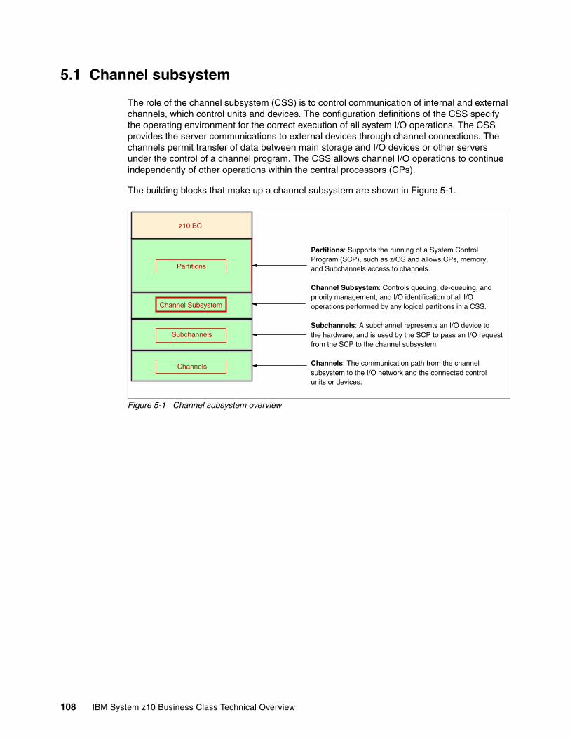
5.1 Channel subsystem
The role of the channel subsystem (CSS) is to control communication of internal and external channels, which control units and devices. The configuration definitions of the CSS specify the operating environment for the correct execution of all system I/O operations. The CSS provides the server communications to external devices through channel connections. The channels permit transfer of data between main storage and I/O devices or other servers under the control of a channel program. The CSS allows channel I/O operations to continue independently of other operations within the central processors (CPs).
The building blocks that make up a channel subsystem are shown in Figure 5-1.
Figure 5-1 Channel subsystem overview
Channels
Subchannels
Partitions
Channel Subsystem
z10 BC
Partitions: Supports the running of a System Control Program (SCP), such as z/OS and allows CPs, memory, and Subchannels access to channels.
Channel Subsystem: Controls queuing, de-queuing, andpriority management, and I/O identification of all I/O operations performed by any logical partitions in a CSS.
Subchannels: A subchannel represents an I/O device to the hardware, and is used by the SCP to pass an I/O request from the SCP to the channel subsystem.
Channels: The communication path from the channel subsystem to the I/O network and the connected control units or devices.
108 IBM System z10 Business Class Technical Overview

The architecture provides for up to four channel subsystems, but on z10 BC two channel subsystems are supported (Figure 5-2).
Figure 5-2 Two channel subsystems
Each CSS has from one to 256 CHPIDs, and may be configured with up to 15 logical partitions that relate to that particular channel subsystem. CSSs are numbered from 0 to 1, and are sometimes referred to as the CSS image ID (CSSID 0, 1).
The z10 BC provides for up to two channel subsystems, 512 CHPIDs, and up to 30 logical partitions.
The health checker function in z/OS V1.10 and later introduces a health check in the I/O Supervisor that can help system administrators identify single points of failure in the I/O configuration.
5.1.1 CSS elementsA CSS can have up to 256 channel paths. A channel path is a single interface between a server and one or more control units. Commands and data are sent across a channel path to perform I/O requests. The entities that encompass the CSS are described in this section.
SubchannelsA subchannel provides the logical representation of a device to the program and contains the information required for sustaining a single I/O operation. A subchannel is assigned for each device defined to the logical partition.
Note that multiple subchannel sets (MSS) are available on z10 BC to increase addressability. Two subchannel sets are supported on the z10 BC server. Subchannel set 0 can have up to 63.75 K subchannels and subchannel set 1 can have up to 64 K subchannels. See 5.1.6, “Multiple subchannel sets” on page 113, for more information.
z10 BC
Channels Channels
Partitions Partitions
CSS 0 CSS 1
Up to 15Logical Partitions
Up to 15Logical Partitions
CSS - 1 Subchannels
SS - 1SS - 0
CSS - 0 Subchannels
SS - 0
CSS - 0 Subchannels
SS - 1SS -0 SS - 0
CSS - 0 Subchannels
SS - 1SS -0
63.75K63.75K 64K64K
Two Channel Subsystems
Chapter 5. Channel subsystem 109

Channel path identifierA channel path identifier (CHPID) is a value assigned to each channel path of the system that uniquely identifies that path. A total of 256 CHPIDs are supported by the CSS.
The channel subsystem communicates with I/O devices by means of channel paths between the channel subsystem and control units. On System z, a CHPID number is assigned to a physical location (slot and port on that slot) by the user through HCD or IOCP.
Control unitsA control unit provides the logical capabilities necessary to operate and control an I/O device and adapts the characteristics of each device so that it can respond to the standard form of control provided by the CSS. A control unit may be housed separately, or it may be physically and logically integrated with the I/O device, the channel subsystem, or within the server itself.
I/O devicesAn I/O device provides external storage, a means of communication between data-processing systems, or a means of communication between a system and its environment. In the simplest case, an I/O device is attached to one control unit and is accessible through one channel path.
5.1.2 Multiple CSSs conceptThe multiple channel subsystems concept provides the ability to define more than 256 CHPIDs in System z servers. The z10 BC supports two CSSs. The design of the System z servers offers considerable processing power, memory sizes, and I/O connectivity. In support of the larger I/O capability, the CSS concept has been scaled up correspondingly to provide relief for the number of supported logical partitions, channels, and devices available to the server.
5.1.3 Multiple CSSs structureThe structure of the multiple CSSs provides channel connectivity to the defined logical partitions in a manner that is transparent to subsystems and application programs.
The System z servers provide the ability to define more than 256 CHPIDs in the system through the multiple CSSs. CSS defines CHPIDS, control units, subchannels, and so on, enabling the definition of a balanced configuration for the processor and I/O capabilities.
For ease of management, the Hardware Configuration Definitions (HCDs) should be used to build and control the I/O configuration definitions. HCD support for multiple channel subsystems is available with z/VM and z/OS. HCD provides the capability to make both dynamic hardware and software I/O configuration changes.
No logical partitions can exist without at least one defined CSS. Logical partitions are defined to a CSS, not to a server. A logical partition is associated with one CSS only. CHPID numbers are unique within a CSS and range from 00 to FF. However, the same CHPID number can be reused within any other CSS.
All channel subsystem images (CSS images) are defined within a single I/O configuration data set (IOCDS). The IOCDS is loaded and initialized into the hardware system area during power-on reset.
110 IBM System z10 Business Class Technical Overview
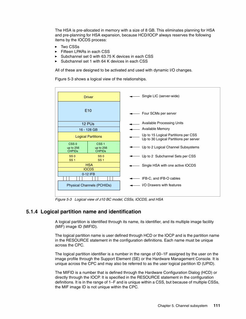
The HSA is pre-allocated in memory with a size of 8 GB. This eliminates planning for HSA and pre-planning for HSA expansion, because HCD/IOCP always reserves the following items by the IOCDS process:
� Two CSSs� Fifteen LPARs in each CSS� Subchannel set 0 with 63.75 K devices in each CSS� Subchannel set 1 with 64 K devices in each CSS
All of these are designed to be activated and used with dynamic I/O changes.
Figure 5-3 shows a logical view of the relationships.
Figure 5-3 Logical view of z10 BC model, CSSs, IOCDS, and HSA
5.1.4 Logical partition name and identification
A logical partition is identified through its name, its identifier, and its multiple image facility (MIF) image ID (MIFID).
The logical partition name is user defined through HCD or the IOCP and is the partition name in the RESOURCE statement in the configuration definitions. Each name must be unique across the CPC.
The logical partition identifier is a number in the range of 00–1F assigned by the user on the image profile through the Support Element (SE) or the Hardware Management Console. It is unique across the CPC and may also be referred to as the user logical partition ID (UPID).
The MIFID is a number that is defined through the Hardware Configuration Dialog (HCD) or directly through the IOCP. It is specified in the RESOURCE statement in the configuration definitions. It is in the range of 1–F and is unique within a CSS, but because of multiple CSSs, the MIF image ID is not unique within the CPC.
Single HSA with one active IOCDS
Available Processing Units
Up to 2 Logical Channel Subsystems
Up to 15 Logical Partitions per CSSUp to 30 Logical Partitions per server
Four SCMs per server
Available Memory
Physical Channels (PCHIDs)
HSAIOCDS
Driver
16 - 128 GB
E10
Logical Partitions
CSS 0 up to 256 CHPIDs
CSS 1 up to 256 CHPIDs
SS 0 SS 1
SS 0 SS 1
0-12 IFB
Single LIC (server-wide)
IFB-C, and IFB-O cables
I/O Drawers with features
Up to 2 Subchannel Sets per CSS
12 PUs
Chapter 5. Channel subsystem 111
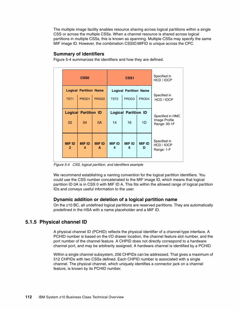
The multiple image facility enables resource sharing across logical partitions within a single CSS or across the multiple CSSs. When a channel resource is shared across logical partitions in multiple CSSs, this is known as spanning. Multiple CSSs may specify the same MIF image ID. However, the combination CSSID.MIFID is unique across the CPC.
Summary of identifiersFigure 5-4 summarizes the identifiers and how they are defined.
Figure 5-4 CSS, logical partition, and identifiers example
We recommend establishing a naming convention for the logical partition identifiers. You could use the CSS number concatenated to the MIF image ID, which means that logical partition ID 0A is in CSS 0 with MIF ID A. This fits within the allowed range of logical partition IDs and conveys useful information to the user.
Dynamic addition or deletion of a logical partition nameOn the z10 BC, all undefined logical partitions are reserved partitions. They are automatically predefined in the HSA with a name placeholder and a MIF ID.
5.1.5 Physical channel ID
A physical channel ID (PCHID) reflects the physical identifier of a channel-type interface. A PCHID number is based on the I/O drawer location, the channel feature slot number, and the port number of the channel feature. A CHPID does not directly correspond to a hardware channel port, and may be arbitrarily assigned. A hardware channel is identified by a PCHID.
Within a single channel subsystem, 256 CHPIDs can be addressed. That gives a maximum of 512 CHPIDs with two CSSs defined. Each CHPID number is associated with a single channel. The physical channel, which uniquely identifies a connector jack on a channel feature, is known by its PCHID number.
CSS0 Specified in HCD / IOCP
CSS1
Specified in HMCImage ProfileRange: 00-1F
Specified in HCD / IOCPTST1 PROD1 PROD2
02 04 0A
Logical Partition Name
Logical Partition ID
Specified in HCD / IOCPRange: 1-F
TST2 PROD3 PROD4
14 16 1D
MIF ID2
MIF ID4
MIF IDA
MIF ID4
MIF ID6
MIF IDD
Logical Partition Name
Logical Partition ID
112 IBM System z10 Business Class Technical Overview
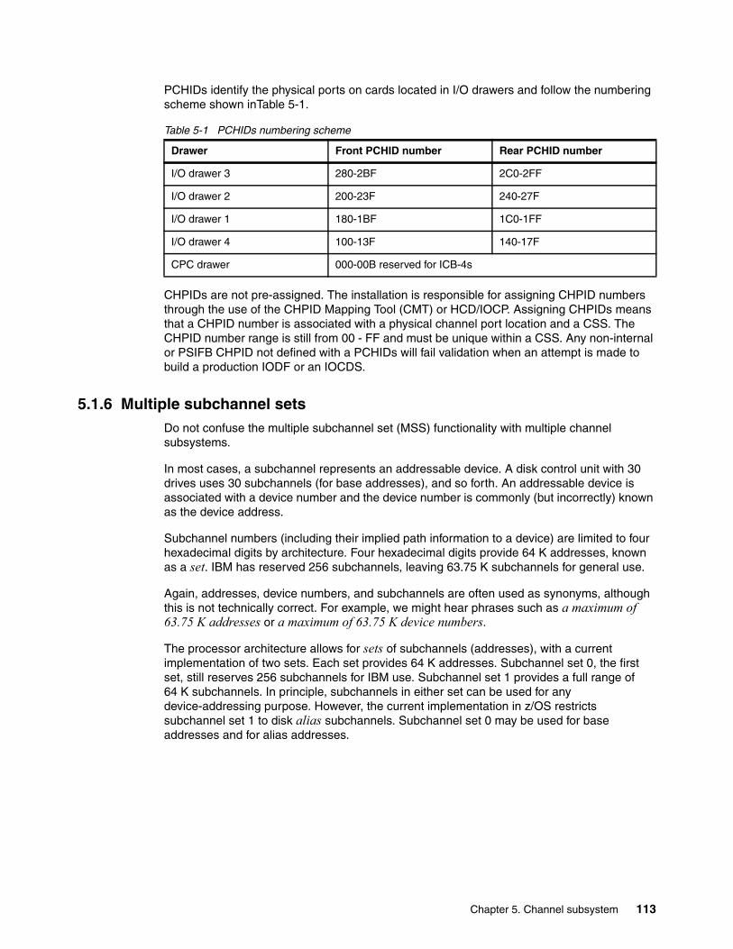
PCHIDs identify the physical ports on cards located in I/O drawers and follow the numbering scheme shown inTable 5-1.
Table 5-1 PCHIDs numbering scheme
CHPIDs are not pre-assigned. The installation is responsible for assigning CHPID numbers through the use of the CHPID Mapping Tool (CMT) or HCD/IOCP. Assigning CHPIDs means that a CHPID number is associated with a physical channel port location and a CSS. The CHPID number range is still from 00 - FF and must be unique within a CSS. Any non-internal or PSIFB CHPID not defined with a PCHIDs will fail validation when an attempt is made to build a production IODF or an IOCDS.
5.1.6 Multiple subchannel setsDo not confuse the multiple subchannel set (MSS) functionality with multiple channel subsystems.
In most cases, a subchannel represents an addressable device. A disk control unit with 30 drives uses 30 subchannels (for base addresses), and so forth. An addressable device is associated with a device number and the device number is commonly (but incorrectly) known as the device address.
Subchannel numbers (including their implied path information to a device) are limited to four hexadecimal digits by architecture. Four hexadecimal digits provide 64 K addresses, known as a set. IBM has reserved 256 subchannels, leaving 63.75 K subchannels for general use.
Again, addresses, device numbers, and subchannels are often used as synonyms, although this is not technically correct. For example, we might hear phrases such as a maximum of 63.75 K addresses or a maximum of 63.75 K device numbers.
The processor architecture allows for sets of subchannels (addresses), with a current implementation of two sets. Each set provides 64 K addresses. Subchannel set 0, the first set, still reserves 256 subchannels for IBM use. Subchannel set 1 provides a full range of 64 K subchannels. In principle, subchannels in either set can be used for any device-addressing purpose. However, the current implementation in z/OS restricts subchannel set 1 to disk alias subchannels. Subchannel set 0 may be used for base addresses and for alias addresses.
Drawer Front PCHID number Rear PCHID number
I/O drawer 3 280-2BF 2C0-2FF
I/O drawer 2 200-23F 240-27F
I/O drawer 1 180-1BF 1C0-1FF
I/O drawer 4 100-13F 140-17F
CPC drawer 000-00B reserved for ICB-4s
Chapter 5. Channel subsystem 113

Figure 5-5 summarizes what we have discussed.
Figure 5-5 Multiple subchannel sets
Correspondence is not required between addresses in the two sets. It is also not required between the device numbers used in the two subchannel sets.
The additional subchannel set, in effect, adds an extra high-order digit (either 0 or 1) to existing device numbers. For example, consider an address of 08000 (subchannel set 0) or 18000 (subchannel set 1). Adding a digit is not done in system code or in messages because of the architectural requirement for four-digit addresses (device numbers or subchannels). However, some messages do contain the subchannel set number, and you can mentally use that as a high-order digit for device numbers. There should be few requirements for this because subchannel set 1 is used only for alias addresses and users, through JCL, messages, or programs rarely refer directly to an alias address.
Moving the alias devices into the second subchannel set creates additional space for device number growth. The appropriate subchannel set number must be included in IOCP definitions or in the HCD definitions that produce the IOCDS. The subchannel set number defaults to 0. This ability is very useful for holding PPRC secondary devices in subchannel set 1, leaving more addresses available in subchannel set 0.
Parallel access volumes (PAVs) enables a single System z server to simultaneously process multiple I/O operations to the same logical volume, which can help to significantly reduce device queue delays. A dynamic PAV allows the dynamic assignment of aliases to volumes under WLM controls.
With the availability of HyperPAV, the requirement for PAV devices is greatly reduced. HyperPAV allows an alias address to be used to access any base on the same control unit image per I/O base. It also allows different HyperPAV hosts to use one alias to access different bases, which reduces the number of alias addresses required. HyperPAV is designed to enable applications to achieve equal or better performance than possible with the
z10 BC
Channels Channels
Partitions Partitions
Logical Channel Subsystem 0 Logical Channel Subsystem 1
Up to 15Logical Partitions
Up to 15Logical Partitions
CSS -1 Subchannels
SS - 1SS - 0
CSS - 0 Subchannels
SS - 0
CSS - 0 Subchannels
SS - 1SS - 0
63.75K63.75K 64K64K
Multiple Subchannel Sets (MSS)
114 IBM System z10 Business Class Technical Overview
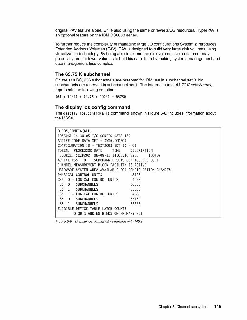
original PAV feature alone, while also using the same or fewer z/OS resources. HyperPAV is an optional feature on the IBM DS8000 series.
To further reduce the complexity of managing large I/O configurations System z introduces Extended Address Volumes (EAV). EAV is designed to build very large disk volumes using virtualization technology. By being able to extend the disk volume size a customer may potentially require fewer volumes to hold his data, thereby making systems-management and data management less complex.
The 63.75 K subchannelOn the z10 BC, 256 subchannels are reserved for IBM use in subchannel set 0. No subchannels are reserved in subchannel set 1. The informal name, 63.75 K subchannel, represents the following equation:
(63 x 1024) + (0.75 x 1024) = 65280
The display ios,config commandThe display ios,config(all) command, shown in Figure 5-6, includes information about the MSSs.
Figure 5-6 Display ios,config(all) command with MSS
D IOS,CONFIG(ALL) IOS506I 14.30.05 I/O CONFIG DATA 469 ACTIVE IODF DATA SET = SYS6.IODF09 CONFIGURATION ID = TEST2098 EDT ID = 01 TOKEN: PROCESSOR DATE TIME DESCRIPTION SOURCE: SCZP202 08-09-11 14:03:40 SYS6 IODF09 ACTIVE CSS: 0 SUBCHANNEL SETS CONFIGURED: 0, 1 CHANNEL MEASUREMENT BLOCK FACILITY IS ACTIVE HARDWARE SYSTEM AREA AVAILABLE FOR CONFIGURATION CHANGES PHYSICAL CONTROL UNITS 8162 CSS 0 - LOGICAL CONTROL UNITS 4058 SS 0 SUBCHANNELS 60538 SS 1 SUBCHANNELS 65535 CSS 1 - LOGICAL CONTROL UNITS 4080 SS 0 SUBCHANNELS 65160 SS 1 SUBCHANNELS 65535 ELIGIBLE DEVICE TABLE LATCH COUNTS 0 OUTSTANDING BINDS ON PRIMARY EDT
Chapter 5. Channel subsystem 115
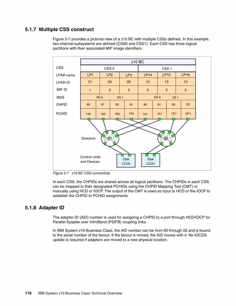
5.1.7 Multiple CSS construct
Figure 5-7 provides a pictorial view of a z10 BC with multiple CSSs defined. In this example, two channel subsystems are defined (CSS0 and CSS1). Each CSS has three logical partitions with their associated MIF image identifiers.
Figure 5-7 z10 BC CSS connectivity
In each CSS, the CHPIDs are shared across all logical partitions. The CHPIDs in each CSS can be mapped to their designated PCHIDs using the CHPID Mapping Tool (CMT) or manually using HCD or IOCP. The output of the CMT is used as input to HCD or the IOCP to establish the CHPID to PCHID assignments.
5.1.8 Adapter ID
The adapter ID (AID) number is used for assigning a CHPID to a port through HCD/IOCP for Parallel Sysplex over InfiniBand (PSIFB) coupling links.
In IBM System z10 Business Class, the AID number can be from 00 through 05 and is bound to the serial number of the fanout. If the fanout is moved, the AID moves with it. No IOCDS update is required if adapters are moved to a new physical location.
DiskLCUs
5
LP16LP2 LP3 LP14 LP15LP1
2 3531
SS 0
81 90 918081 90 9180
151 1E1 1F1141150 1E0 1F0140
CSS
LPAR name
PCHID
MIF ID
CHPID
DiskLCUs
Directors
Control Unitsand Devices
6261
LPAR ID 1503 05 12 1301
CSS 0 CSS 1
z10 BC
MSS SS 1 SS 0 SS 1
116 IBM System z10 Business Class Technical Overview
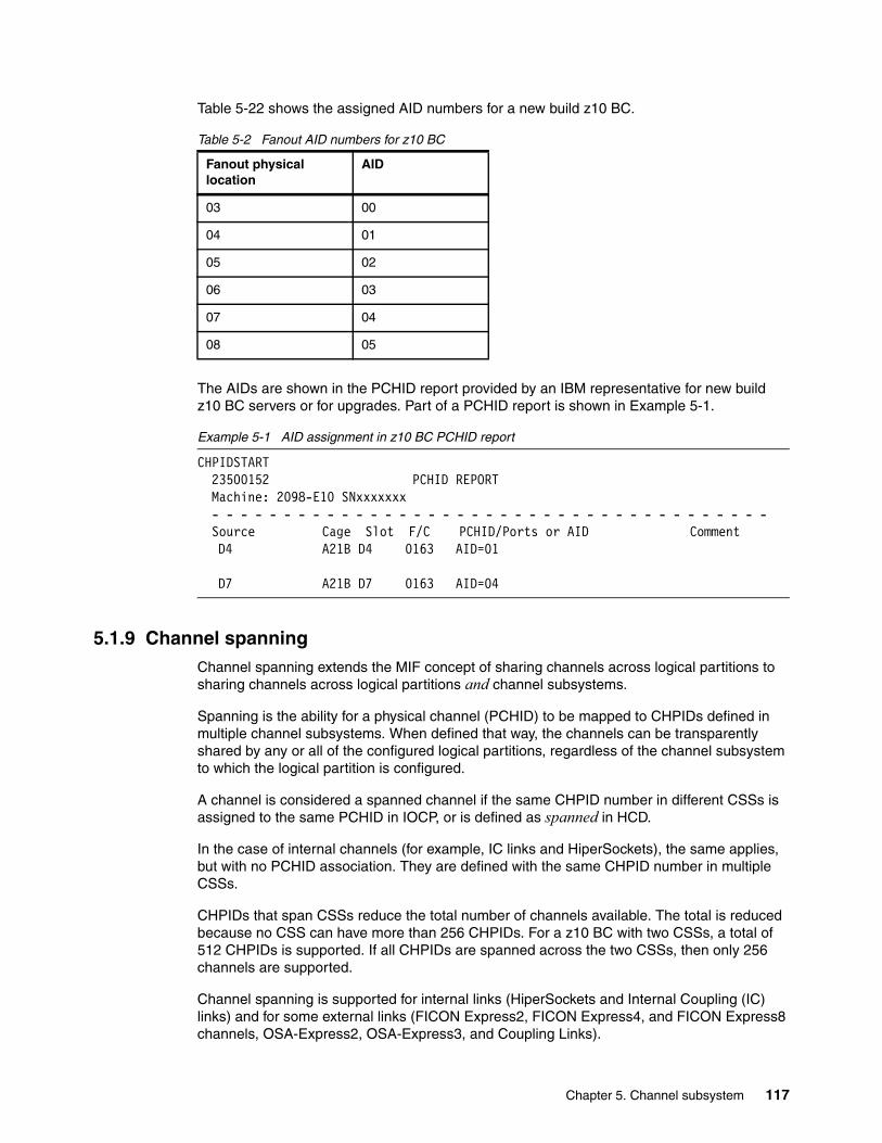
Table 5-22 shows the assigned AID numbers for a new build z10 BC.
Table 5-2 Fanout AID numbers for z10 BC
The AIDs are shown in the PCHID report provided by an IBM representative for new buildz10 BC servers or for upgrades. Part of a PCHID report is shown in Example 5-1.
Example 5-1 AID assignment in z10 BC PCHID report
CHPIDSTART 23500152 PCHID REPORT Machine: 2098-E10 SNxxxxxxx - - - - - - - - - - - - - - - - - - - - - - - - - - - - - - - - - - - - - - - Source Cage Slot F/C PCHID/Ports or AID Comment D4 A21B D4 0163 AID=01
D7 A21B D7 0163 AID=04
5.1.9 Channel spanningChannel spanning extends the MIF concept of sharing channels across logical partitions to sharing channels across logical partitions and channel subsystems.
Spanning is the ability for a physical channel (PCHID) to be mapped to CHPIDs defined in multiple channel subsystems. When defined that way, the channels can be transparently shared by any or all of the configured logical partitions, regardless of the channel subsystem to which the logical partition is configured.
A channel is considered a spanned channel if the same CHPID number in different CSSs is assigned to the same PCHID in IOCP, or is defined as spanned in HCD.
In the case of internal channels (for example, IC links and HiperSockets), the same applies, but with no PCHID association. They are defined with the same CHPID number in multiple CSSs.
CHPIDs that span CSSs reduce the total number of channels available. The total is reduced because no CSS can have more than 256 CHPIDs. For a z10 BC with two CSSs, a total of 512 CHPIDs is supported. If all CHPIDs are spanned across the two CSSs, then only 256 channels are supported.
Channel spanning is supported for internal links (HiperSockets and Internal Coupling (IC) links) and for some external links (FICON Express2, FICON Express4, and FICON Express8 channels, OSA-Express2, OSA-Express3, and Coupling Links).
Fanout physical location
AID
03 00
04 01
05 02
06 03
07 04
08 05
Chapter 5. Channel subsystem 117
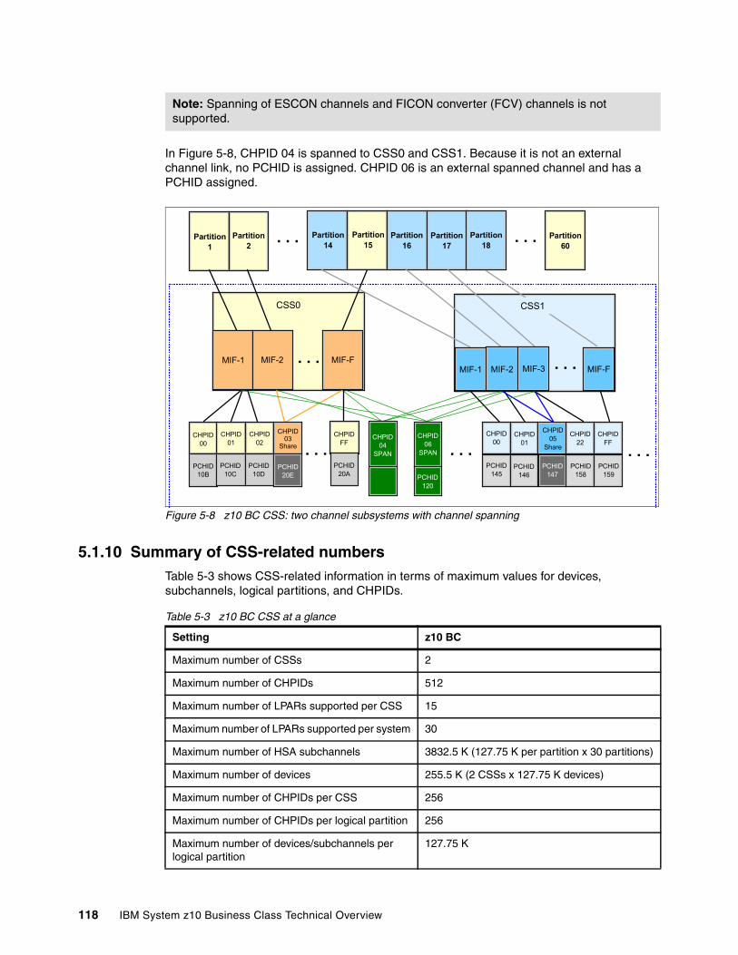
In Figure 5-8, CHPID 04 is spanned to CSS0 and CSS1. Because it is not an external channel link, no PCHID is assigned. CHPID 06 is an external spanned channel and has a PCHID assigned.
Figure 5-8 z10 BC CSS: two channel subsystems with channel spanning
5.1.10 Summary of CSS-related numbersTable 5-3 shows CSS-related information in terms of maximum values for devices, subchannels, logical partitions, and CHPIDs.
Table 5-3 z10 BC CSS at a glance
Note: Spanning of ESCON channels and FICON converter (FCV) channels is not supported.
CSS0
Partition1
. . .Partition2
Partition14
Partition15
Partition16
Partition17
Partition18
Partition60
. . .
MIF-1 MIF-2 MIF-F. . .
CSS1
MIF-1 MIF-2 MIF-3 MIF-F
CHPID00
CHPID01
CHPID02
CHPID03
Share
PCHID10B
PCHID10C
PCHID10D
PCHID20E
. . .CHPID
FF
PCHID20A
CHPID04
SPAN
CHPID06
SPAN
PCHID120
CHPID00
CHPID01
CHPID05
Share
CHPID22
CHPIDFF
PCHID145
PCHID146
PCHID147
PCHID158
PCHID159
. . . . . .
. . .
Setting z10 BC
Maximum number of CSSs 2
Maximum number of CHPIDs 512
Maximum number of LPARs supported per CSS 15
Maximum number of LPARs supported per system 30
Maximum number of HSA subchannels 3832.5 K (127.75 K per partition x 30 partitions)
Maximum number of devices 255.5 K (2 CSSs x 127.75 K devices)
Maximum number of CHPIDs per CSS 256
Maximum number of CHPIDs per logical partition 256
Maximum number of devices/subchannels per logical partition
127.75 K
118 IBM System z10 Business Class Technical Overview
5.2 I/O configuration management
Tools are provided to help maintain and optimize the I/O configuration:
� IBM Configurator for e-business (e-Config)
The e-Config tool is available to your IBM representative. It is used to configure new configurations or upgrades of an existing configuration, and maintains installed features of those configurations. Reports produced by e-Config are helpful in understanding the changes being made for a system upgrade and what the final configuration will look like.
� Hardware Configuration Dialog (HCD)
HCD supplies an interactive dialog to generate the I/O definition file (IODF) and subsequently the input/output configuration data set (IOCDS). We strongly recommend that HCD or HCM be used to generate the I/O configuration, as opposed to writing IOCP statements. The validation checking that HCD performs as data is entered helps minimize the risk of errors before the I/O configuration is implemented.
� CHPID Mapping Tool (CMT)
The CHPID Mapping Tool provides a mechanism to map CHPIDs onto PCHIDs as required. Additional enhancements have been built into the CMT to cater to the requirements of the z10 BC. It provides the best availability recommendations for the installed features and defined configuration. CMT is a workstation-based tool available for download from IBM Resource Link:
http://www.ibm.com/servers/resourcelink
5.3 System-initiated CHPID reconfiguration
The system-initiated CHPID reconfiguration function is designed to reduce the duration of a repair action and minimize operator interaction when an ESCON or FICON channel, an OSA port, or an ISC-3 link is shared across logical partitions on an z10 BC server. When an I/O card is replaced for a repair, it usually has some failed channels and some that are still functioning.
To remove the card, all channels must be configured offline from all logical partitions sharing those channels. Without system-initiated CHPID reconfiguration, this means that the CE must contact all logical partition operators and have them set the channels offline, and then after the repair, contact them again to configure the channels back online.
With system-initiated CHPID reconfiguration support, the Support Element sends a signal to the IOP that a channel needs to be configured offline. The IOP determines all the logical partitions sharing that channel and sends an alert to the operating systems in those logical partitions. The operating system then configures the channel offline without any operator intervention. This is repeated for each channel on the card. When the card is replaced, Support Element sends another signal to the IOP for each channel. This time the IOP alerts the operating system that the channel should be configured back online. This is designed to minimize operator interaction to configure channels offline and online.
System-initiated CHPID reconfiguration is supported by z/OS.
Chapter 5. Channel subsystem 119
5.4 Multipath initial program load
Multipath initial program load (multipath IPL) is designed to help increase availability and to help eliminate manual problem determination when executing an IPL. It does so by allowing IPL to complete if possible using alternate paths when executing an IPL from a device connected through ESCON and FICON channels. If an error occurs, an alternate path is selected.
Multipath IPL is applicable to ESCON channels (CHPID type CNC) and to FICON channels (CHPID type FC). z/OS supports multipath IPL.
120 IBM System z10 Business Class Technical Overview
Chapter 6. Cryptography
This chapter describes the hardware cryptographic functions available on the IBM System z10 Business Class. As for System z10 EC, System z9, and earlier generations, the Cryptographic Assist Architecture (CAA), along with the CP Assist for Cryptographic Function (CPACF), offer a balanced use of resources and unmatched scalability.
The z10 BC includes both standard cryptographic hardware and optional cryptographic features for flexibility and growth capability. IBM has a long history of providing hardware cryptographic solutions, from the development of Data Encryption Standard (DES) in the 1970s to having the Crypto Express tamper-resistant features designed to meet the U.S. Government's highest security rating FIPS 140-2 Level 41.
The cryptographic functions include the full range of cryptographic operations required for e-business, e-commerce, and financial institution applications. Custom cryptographic functions can also be added.
Today, e-business applications increasingly rely on cryptographic techniques to provide the confidentiality and authentication required in this environment.
This chapter discusses the following topics:
� 6.1, “Cryptographic synchronous functions” on page 122� 6.2, “Cryptographic asynchronous functions” on page 123� 6.3, “TKE workstation feature” on page 129� 6.4, “Cryptographic functions comparison” on page 131� 6.5, “Software support” on page 133
6
1 Federal Information Processing Standards (FIPS)140-2 Security Requirements for Cryptographic Modules
© Copyright IBM Corp. 2008, 2009. All rights reserved. 121
6.1 Cryptographic synchronous functions
Cryptographic synchronous functions are provided by the CP Assist for Cryptographic Function (CPACF).
The CPACF offers a set of symmetric cryptographic functions that enhance the encryption and decryption performance of clear-key operations for SSL, VPN, and data-storing applications that do not require FIPS 140-2 level 4 security.
Cryptographic keys must be protected by the application system because they have to be provided in clear form to the CPACF.
The z10 BC hardware includes the implementation of algorithms as hardware synchronous operations. The following secure key functions are:
� Data encryption and decryption algorithms:
– Data Encryption Standard (DES)– Double-length key DES– Triple-length key DES (TDES)– Advanced Encryption Standard (AES) with secure encrypted 128-bit, 192-bit, and
256-bit keys. Secure key AES is exclusive to System z10.
� Hashing algorithms, such as SHA-1 and SHA-2 support for SHA-224, SHA-256, SHA-384, and SHA-512
� Message authentication code (MAC)
– Single-key MAC– Double-key MAC
� Pseudo Random Number Generation (PRNG)
� Random Number Generation Long (RNGL) with 8 bytes to 8096 bytes
� Random Number Generation (RNG) with up to 4096-bit key RSA support
� Personal identification number (PIN) generation, verification, and translation functions
The functions of the CPACF must be explicitly enabled by using FC 3863 (by the manufacturing process) or at the customer site as an MES installation. However, SHA-1 and SHA-2 support for SHA-224, SHA-256, SHA-384, and SHA-512 are always enabled. The CPACF functions are supported by z/OS, z/VM, z/VSE, and Linux on System z.
An enhancement to CPACF is designed to facilitate the continued privacy of cryptographic key material when used for data encryption. CPACF ensures that key material is not visible to applications or operating systems during encryption operations.
122 IBM System z10 Business Class Technical Overview
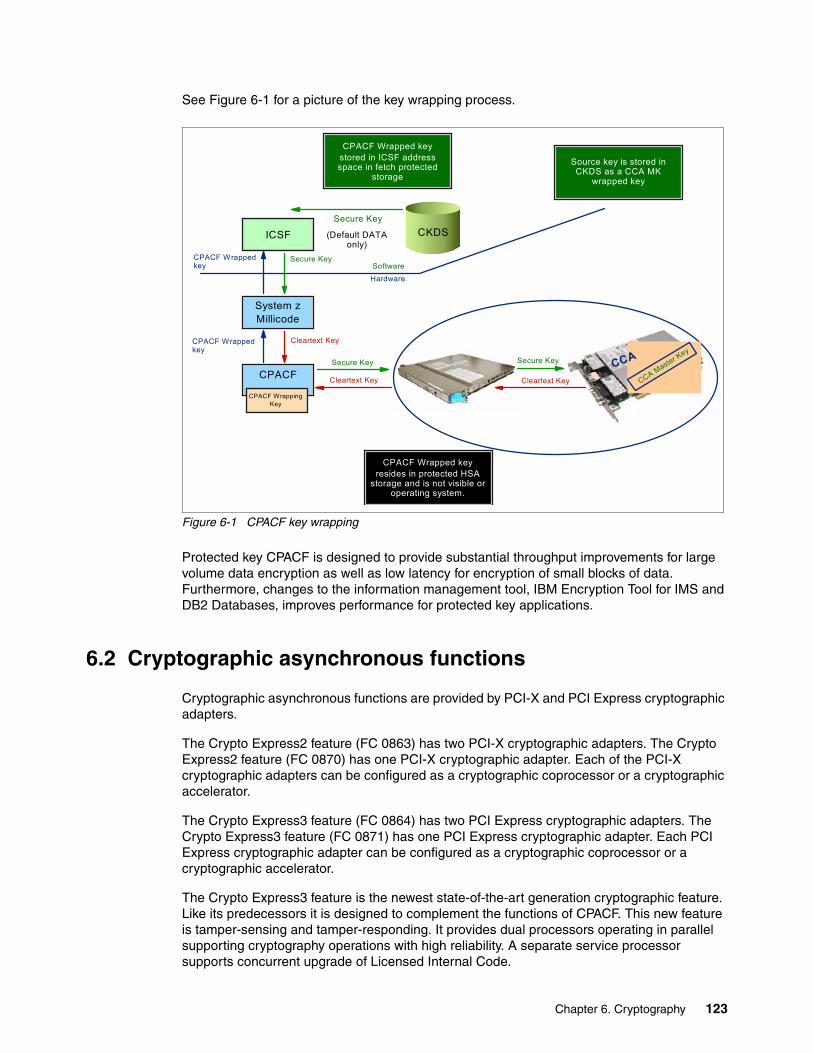
See Figure 6-1 for a picture of the key wrapping process.
Figure 6-1 CPACF key wrapping
Protected key CPACF is designed to provide substantial throughput improvements for large volume data encryption as well as low latency for encryption of small blocks of data. Furthermore, changes to the information management tool, IBM Encryption Tool for IMS and DB2 Databases, improves performance for protected key applications.
6.2 Cryptographic asynchronous functions
Cryptographic asynchronous functions are provided by PCI-X and PCI Express cryptographic adapters.
The Crypto Express2 feature (FC 0863) has two PCI-X cryptographic adapters. The Crypto Express2 feature (FC 0870) has one PCI-X cryptographic adapter. Each of the PCI-X cryptographic adapters can be configured as a cryptographic coprocessor or a cryptographic accelerator.
The Crypto Express3 feature (FC 0864) has two PCI Express cryptographic adapters. The Crypto Express3 feature (FC 0871) has one PCI Express cryptographic adapter. Each PCI Express cryptographic adapter can be configured as a cryptographic coprocessor or a cryptographic accelerator.
The Crypto Express3 feature is the newest state-of-the-art generation cryptographic feature. Like its predecessors it is designed to complement the functions of CPACF. This new feature is tamper-sensing and tamper-responding. It provides dual processors operating in parallel supporting cryptography operations with high reliability. A separate service processor supports concurrent upgrade of Licensed Internal Code.
CPACF Wrapped keystored in ICSF address space in fetch protected
storage
Source key is stored in CKDS as a CCA MK
wrapped key
ICSF
System zMillicode
CPACF
CPACF WrappingKey
CPACF Wrapped keyresides in protected HSA
storage and is not visible or operating system.
Secure Key
Cleartext KeyCleartext Key
Secure Key
Secure Key
(Default DATA only)
CKDS
Secure KeyCPACF Wrapped key Software
Hardware
CPACF Wrapped key
Cleartext Key
CCA
CCA Master Key
Chapter 6. Cryptography 123

The Crypto Express3 feature contains all the functions of the Crypto Express2 and introduces a number of new functions, including:
� SHA2 functions equivalent to the same function in CPACF.
� RSA functions similar to the same function in CPACF.
� Dynamic power management designed to keep within the temperature limits of the feature and at the same time maximize RSA performance.
� Up to 32 LPARs in all logical channel subsystems have access to the feature.
� Improved RAS over previous crypto features due to dual processors and the service processor.
� Function update while installed using secure code load.
� When a PCI Express adapter is defined as a coprocessor lock-step checking the dual processors enhances error detection and fault isolation.
� Dynamic addition and configuration of the crypto features to LPARs without an outage.
� Updated cryptographic algorithms used to load the LIC from the TKE.
� Support for smart card applications using Europay, MasterCard, and VISA specifications.
The Crypto Express3 feature is designed to deliver throughput improvements for both symmetric and asymmetric operations.
The z10 BC supports installation of up to eight Crypto Express features (up to 16 PCI-X or PCI Express cryptographic adapters on features with two adapters or up to eight PCI-X or PCI Express cryptographic adapters on features with one adapter). Each PCI-X or PCI Express adapter acts either as cryptographic coprocessor or as cryptographic accelerator. Access from a logical partition to the PCI-X and PCI Express cryptographic adapters is dynamically controlled through the image profile on the Hardware Management Console.
The Crypto Express features do not have ports and do not use fiber optic cables or other cables. Although they do not use CHPIDs, they do require one slot in the I/O drawer and one PCHID for each PCI-X and PCI Express cryptographic adapter. The feature is attached through the IFB-MP interface in an I/O drawer and has no other external interfaces. Removal of the feature zeroizes the keys that are saved in the adapter when the feature is used as a coprocessor.
The following secure key functions are provided as cryptographic asynchronous functions. System internal messages are passed to the cryptographic coprocessors to initiate the operation and messages are passed back from the coprocessors to signal completion of the operation.
� Data encryption and decryption algorithms:
– Data Encryption Standard (DES)– Double-length key DES– Triple-length key DES (TDES)– Advanced Encryption Standard (AES)
� DES key generation and distribution
� PIN generation, verification, and translation functions
� Pseudo Random Number Generation (PRNG)
124 IBM System z10 Business Class Technical Overview
� Public key algorithm (PKA) facility
These commands are intended for application programs using public key algorithms:
– Importing RSA public-private key pairs in clear and encrypted forms
– Rivest-Shamir-Adelman (RSA)
• Key generation, up to 4,096-bit• Signature verification, up to 4,096-bit• Import and export of DES keys under an RSA key, up to 4,096-bit
– Public Key Encrypt (PKE)
The PKE service is provided for assisting the SSL/TLS handshake. When used with the Mod_Raised_to Power (MRP) function, PKE is also used to offload compute-intensive portions of the Diffie-Hellman protocol onto the PCI-X cryptographic adapter.
– Public Key Decrypt (PKD)
PKD supports a zero-pad option for clear RSA private keys. PKD is used as an accelerator for raw RSA private operations, such as those required by the SSL/TLS handshake and digital signature generation. The zero-pad option is exploited by Linux to allow use of PCI-X cryptographic adapter for improved performance of digital signature generation.
– Derived Unique Key Per Transaction (DUKPT)
The service that provides DUKPT algorithms is provided to write applications that implement the DUKPT algorithms as defined by the ANSI X9.24 standard. DUKPT provides additional security for point-of-sale transactions that are standard in the retail industry. DUKPT algorithms are supported on the Crypto Express2 and Crypto Express3 feature coprocessor for triple-DES with double-length keys.
– Europay Mastercard VISA (EMV) 2000 standard
Applications may be written to comply with the EMV 2000 standard for financial transactions between heterogeneous hardware and software. Support for EMV 2000 applies to the Crypto Express2 and Crypto Express3 feature coprocessor of the z10 BC.
Other key functions of the Crypto Express features serve to enhance the security of public and private key encryption processing:
� Remote loading of initial ATM keys
This function provides the ability to remotely load the initial ATM keys. Remote-key loading refers to the process of loading DES keys to ATM from a central administrative site without requiring someone to manually load the DES keys on each machine. The process uses ICSF callable services along with the Crypto Express2 or Crypto Express3 feature to perform the remote load.
� Key exchange with non-CCA cryptographic systems
This function allows for the changing of the operational keys between the remote site and the non-CCA system, such as the ATM. IBM Common Cryptographic Architecture (CCA) employs control vectors to control usage of cryptographic keys. Non-CCA systems use other mechanisms, or can use keys that have no associated control information. The key exchange functions added to CCA enhance the ability to exchange keys between CCA systems, and systems that do not use control vectors, by allowing the CCA system owner to define permitted types of key import and export while preventing uncontrolled key exchange that can open the system to an increased threat of attack.
Chapter 6. Cryptography 125
� Support for ISO 16609 CBC Mode T-DES MAC
In support of ISO 16609:2004, the cryptographic facilities support the requirements for message authentication, using symmetric techniques. The Crypto Express2 and Crypto Express3 provide the ISO 16609 CBC Mode T-DES MAC support. This support is accessible through ICSF callable services. ICSF callable services used to invoke the support are MAC Generate (CSNBMGN) and MAC Verify (CSNVMVR).
� Retained key support (RSA private keys generated and kept stored within the secure hardware boundary)
� Support for 4753 Network Security Processor migration
� User-Defined Extensions (UDX) support, including:
– For Activate UDX requests:
• Establish owner• Relinquish owner• Emergency Burn of Segment• Remote Burn of Segment
– Import UDX File function
– Reset UDX to IBM default function
– Query UDX Level function
UDX allows the user to add customized operations to a cryptographic processor. User-defined extensions to the Common Cryptographic Architecture (CCA) support customized operations that execute within the Crypto Express2 and Crypto Express3 features. UDX is supported through an IBM or approved vendor service offering.
It is not possible to mix and match UDX definitions across the Crypto Express features. HMC and SE panels are in place to ensure that UDX files are applied to the appropriate crypto card types.
For more information see the IBM CryptoCards Web site:
http://www.ibm.com/security/cryptocards
Under a special contract with IBM, Crypto Express features customers can define and load custom cryptographic functions. A special contract is negotiated between you and IBM Global Services. This contract is for the development of the UDX by IBM Global Services according to your specifications and an agreed-upon development level of the UDX.
The UDX toolkit for System z with the Crypto Express3 feature is made available on the general availability date for the feature. In addition, there will be a migration path for customers with UDX on a previous feature to migrate their code to the Crypto Express3 feature. A UDX migration is no more disruptive than a normal MCL or ICSF release migration.
The Web site directs request to an IBM Global Services location appropriate for your geographic location. A special contract is negotiated between you and IBM Global Services. This contract is for the development of the UDX by IBM Global Services according to your specifications and an agreed-upon development level of the UDX.
6.2.1 Crypto Express coprocessor The Crypto Express coprocessor is a Peripheral Component Interconnect eXtended (PCI-X) or a Peripheral Component Interconnect express (PCI Express) cryptographic adapter configured as a coprocessor and provides a high-performance cryptographic environment with added functions.
126 IBM System z10 Business Class Technical Overview
The Crypto Express coprocessor provides asynchronous functions only.
The cryptographic adapters are tamper-resistant. When configured as coprocessors, they are designed for FIPS 140-2 Level 4 compliance rating for secure cryptographic hardware modules. Unauthorized removal of the adapter or feature zeroizes its content.
The Crypto Express coprocessor enables you to:
� Encrypt and decrypt data by utilizing secret-key algorithms. Algorithms supported are:
– Double-length key DES – Triple-length key DES – AES algorithms that have 128, 192 and 256 bit data-encrypting keys
� Generate, install, and distribute cryptographic keys securely using both public and secret key cryptographic methods.
� Generate, verify, and translate personal identification numbers (PINs).
� Generate, verify, and translate 13 through 19 digit personal account numbers (PANs).
� Ensure the integrity of data by using message authentication codes (MACs), hashing algorithms, and Rivest-Shamir-Adelman (RSA) public key algorithm (PKA) digital signatures.
The Crypto Express coprocessor also provides the functions described below for the Crypto Express accelerator, however, with a lower performance than the Crypto Express accelerator can provide.
Three methods of master key entry are provided by ICSF for the Crypto Express feature coprocessor:
� A pass-phrase initialization method, which generates and enters all master keys that are necessary to fully enable the cryptographic system in a minimal number of steps.
� A simplified master key entry procedure provided through a series of Clear Master Key Entry panels from a TSO terminal.
� A Trusted Key Entry (TKE) workstation, which is available as an optional feature in enterprises that require enhanced key-entry security.
The security-relevant portion of the cryptographic functions is performed inside the secure physical boundary of a tamper-resistant card. Master keys and other security-relevant information are also maintained inside this secure boundary.
A Crypto Express coprocessor operates with the Integrated Cryptographic Service Facility (ICSF) and IBM Resource Access Control Facility (RACF®), or equivalent software products, in a z/OS operating environment to provide data privacy, data integrity, cryptographic key installation and generation, electronic cryptographic key distribution, and personal identification number (PIN) processing.
The Processor Resource/Systems Manager (PR/SM) fully supports the Crypto Express feature coprocessors to establish a logically partitioned environment on which multiple logical partitions can use the cryptographic functions. A 128-bit data-protection master key and one 192 bit public key algorithm (PKA) master key are provided for each of 16 cryptographic domains that a coprocessor can serve.
Use the dynamic addition or deletion of a logical partition name facility to rename a logical partition. Its name can be changed from NAME1 to * (single asterisk) and then changed again from * to NAME2. The logical partition number and MIF ID are retained across the logical partition name change. The master keys in the Crypto Express feature coprocessor
Chapter 6. Cryptography 127
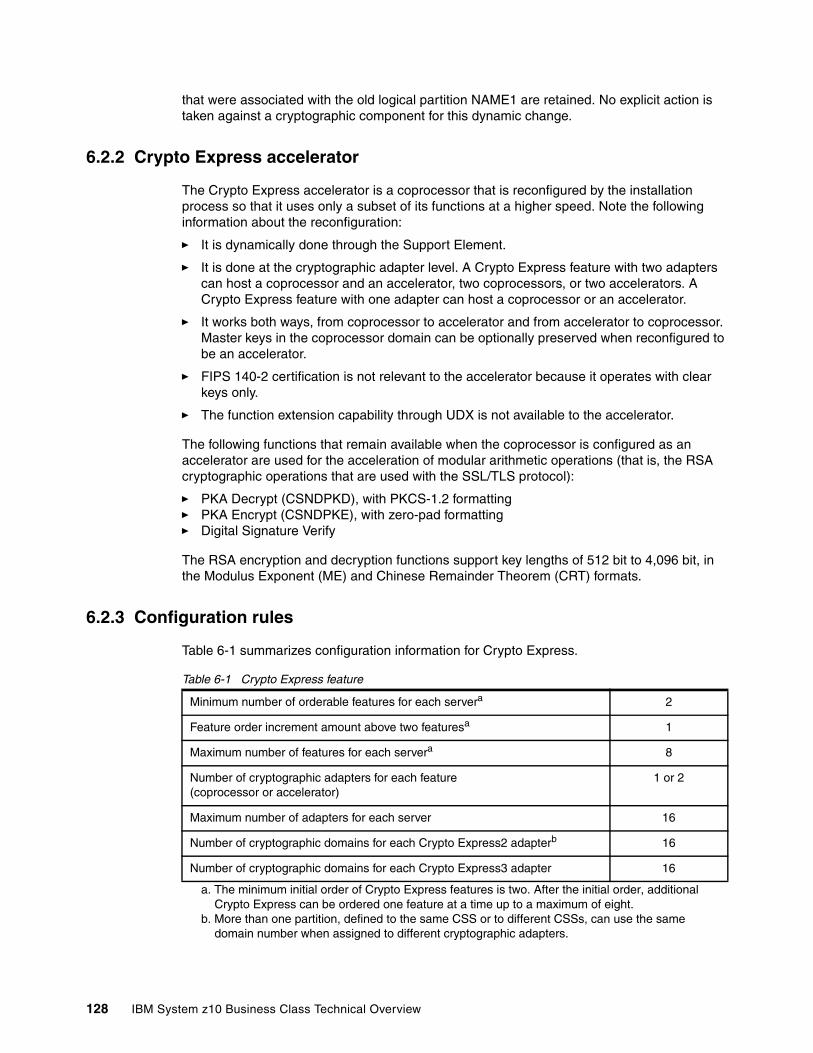
that were associated with the old logical partition NAME1 are retained. No explicit action is taken against a cryptographic component for this dynamic change.
6.2.2 Crypto Express accelerator
The Crypto Express accelerator is a coprocessor that is reconfigured by the installation process so that it uses only a subset of its functions at a higher speed. Note the following information about the reconfiguration:
� It is dynamically done through the Support Element.
� It is done at the cryptographic adapter level. A Crypto Express feature with two adapters can host a coprocessor and an accelerator, two coprocessors, or two accelerators. A Crypto Express feature with one adapter can host a coprocessor or an accelerator.
� It works both ways, from coprocessor to accelerator and from accelerator to coprocessor. Master keys in the coprocessor domain can be optionally preserved when reconfigured to be an accelerator.
� FIPS 140-2 certification is not relevant to the accelerator because it operates with clear keys only.
� The function extension capability through UDX is not available to the accelerator.
The following functions that remain available when the coprocessor is configured as an accelerator are used for the acceleration of modular arithmetic operations (that is, the RSA cryptographic operations that are used with the SSL/TLS protocol):
� PKA Decrypt (CSNDPKD), with PKCS-1.2 formatting� PKA Encrypt (CSNDPKE), with zero-pad formatting� Digital Signature Verify
The RSA encryption and decryption functions support key lengths of 512 bit to 4,096 bit, in the Modulus Exponent (ME) and Chinese Remainder Theorem (CRT) formats.
6.2.3 Configuration rules
Table 6-1 summarizes configuration information for Crypto Express.
Table 6-1 Crypto Express feature
Minimum number of orderable features for each servera
a. The minimum initial order of Crypto Express features is two. After the initial order, additional Crypto Express can be ordered one feature at a time up to a maximum of eight.
2
Feature order increment amount above two featuresa 1
Maximum number of features for each servera 8
Number of cryptographic adapters for each feature(coprocessor or accelerator)
1 or 2
Maximum number of adapters for each server 16
Number of cryptographic domains for each Crypto Express2 adapterb
b. More than one partition, defined to the same CSS or to different CSSs, can use the same domain number when assigned to different cryptographic adapters.
16
Number of cryptographic domains for each Crypto Express3 adapter 16
128 IBM System z10 Business Class Technical Overview
The concept of dedicated processor does not apply to the cryptographic adapters. Whether configured as coprocessor or accelerator, the cryptographic adapters are made available to a logical partition as directed by the domain assignment and the candidate list in the logical partition image profile, regardless of the shared or dedicated status given to the CPs in the partition.
When installed non-concurrently, Crypto Express features are assigned cryptographic adapter numbers sequentially during the power-on reset following the installation. When a Crypto Express feature is installed concurrently, the installation can select an out-of-sequence number from the unused range. When a Crypto Express feature is removed concurrently, the adapter numbers are automatically freed.
Plan for the definition of domain indexes and cryptographic adapter numbers in the candidate list for each logical partition, as follows:
� Operational changes can be made by using the Change LPAR Cryptographic Controls task from the Support Element. With this task, adding and removing the cryptographic feature without stopping a running operating system can be done dynamically.
� The cryptographic adapter number coupled with the usage domain index specified must be unique across all active logical partitions.
The z10 BC allows for up to 30 logical partitions to be active concurrently. Each PCI-X adapter supports 16 domains. Each PCI Express adapter supports 32 domains, whether the Crypto Express is configured as an accelerator or coprocessor. The server configuration must include at least two Crypto Express (up to four PCI-X adapters and 16 domains per PCI-X adapter) when all 30 logical partitions require concurrent access to cryptographic functions. More Crypto Express2 features might be required to satisfy application performance and availability requirements.
For availability, assignment of multiple adapters of the same type (Crypto Express accelerator or coprocessor) to one logical partition should be spread across multiple features.
6.3 TKE workstation feature
The TKE workstation is an optional feature that offers key management functions. The TKE workstation, with TKE 5.3 or later Licensed Internal Code (LIC), is required to support cryptographic key management on the z10 BC.
A TKE workstation is part of a customized solution for using the Integrated Cryptographic Service Facility for the z/OS (ICSF for z/OS) program product to manage cryptographic keys of a z10 BC, which has Crypto Express2 or Crypto Express3 features installed and that is configured for using DES and PKA cryptographic keys.
TKE 5.3 LIC and later supports the AES algorithm and includes master key management functions to load or generate AES master keys to cryptographic coprocessors.
TKE workstation with LIC 5.3 or later can control cryptographic features on z10 EC, z10 BC, z9 EC, and z9 BC servers.
Chapter 6. Cryptography 129
The TKE workstation with LIC 6.0 offers a number of usability enhancements:
� Grouping of up to 16 domains across one or more cryptographic adapters. These adapters may be installed in one or more servers or LPARs. Grouping of domains applies to CryptoExpress3 and Crypto Express2 features.
� Greater flexibility and efficiency by executing domain-scoped commands on every domain in the group. For example, a TKE user can load master key parts to all domains with one command.
� Efficiency by executing Crypto Express2 and Crypto Express3 scoped commands on every coprocessor in the group. This allows a substantial reduction of the time required for loading new master keys from a TKE workstation into a Crypto Express3 or Crypto Express2 feature.
Furthermore, the LIC 6.0 strengthens the cryptography for TKE protocol inbound and outbound authentication. TKE uses cryptographic algorithms and protocols in communication with the target cryptographic adapters on the host systems that it administers. Cryptography is first used to verify that each target adapter is a valid IBM cryptographic coprocessor. It then ensures that there are secure messages between the TKE workstation and the target Crypto Express2 and Crypto Express3 feature. The cryptography has been updated to keep pace with industry developments and with recommendations from experts and standards organizations.
The enhancements are in the following areas:
� TKE Certificate Authorities (CAs) initialized on a TKE workstation with TKE 6.0 LIC can issue certificates with 2048-bit keys. Previous versions of TKE used 1024-bit keys.
� The transport key used to encrypt sensitive data sent between the TKE workstation and a Crypto Express3 coprocessor has been strengthened from a 192-bit TDES key to a 256-bit AES key.
� The signature key used by the TKE workstation and the Crypto Express3 coprocessor has been strengthened from 1024-bit to a maximum of 4096-bit strength.
� Replies sent by a Crypto Express3 coprocessor on the host are signed with a 4096-bit key.
The TKE LIC 6.0 increases the key strength for TKE Certificate Authority smart cards, TKE smart cards, and signature keys stored on smart cards from 1024-bit to 2048-bit strength.
Only smart cards (0884) with smart card readers (0885) support the creation of TKE Certificate Authority (CA) smart cards, TKE smart cards, or signature keys with the new 2048-bit key strength. Smart cards (0888) and smart card readers (0887) will continue to work with the 1024-bit key strength. The older features, 0887 and 0888, will be withdrawn from marketing on November 20, 2009.
Logical partition, TKE host, and TKE targetIf one or more logical partitions are customized for using Crypto Express2 or Crypto Express3 coprocessors, the TKE workstation can be used to manage DES master keys and PKA master keys for all cryptographic domains of each coprocessor feature assigned to logical partitions defined by the TKE workstation.
Each logical partition, in the same system that uses a domain managed through a TKE workstation connection, is either a TKE host or a TKE target. A logical partition with a TCP/IP connection to the TKE is referred to as TKE host. All other partitions are TKE targets.
Note: TKE workstation supports only Ethernet adapters for connecting to a LAN.
130 IBM System z10 Business Class Technical Overview
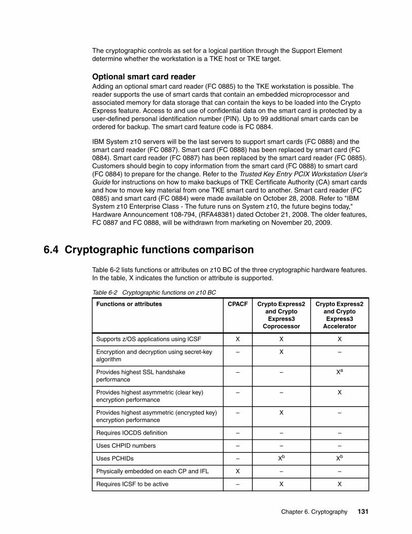
The cryptographic controls as set for a logical partition through the Support Element determine whether the workstation is a TKE host or TKE target.
Optional smart card readerAdding an optional smart card reader (FC 0885) to the TKE workstation is possible. The reader supports the use of smart cards that contain an embedded microprocessor and associated memory for data storage that can contain the keys to be loaded into the Crypto Express feature. Access to and use of confidential data on the smart card is protected by a user-defined personal identification number (PIN). Up to 99 additional smart cards can be ordered for backup. The smart card feature code is FC 0884.
IBM System z10 servers will be the last servers to support smart cards (FC 0888) and the smart card reader (FC 0887). Smart card (FC 0888) has been replaced by smart card (FC 0884). Smart card reader (FC 0887) has been replaced by the smart card reader (FC 0885). Customers should begin to copy information from the smart card (FC 0888) to smart card (FC 0884) to prepare for the change. Refer to the Trusted Key Entry PCIX Workstation User's Guide for instructions on how to make backups of TKE Certificate Authority (CA) smart cards and how to move key material from one TKE smart card to another. Smart card reader (FC 0885) and smart card (FC 0884) were made available on October 28, 2008. Refer to "IBM System z10 Enterprise Class - The future runs on System z10, the future begins today," Hardware Announcement 108-794, (RFA48381) dated October 21, 2008. The older features, FC 0887 and FC 0888, will be withdrawn from marketing on November 20, 2009.
6.4 Cryptographic functions comparison
Table 6-2 lists functions or attributes on z10 BC of the three cryptographic hardware features. In the table, X indicates the function or attribute is supported.
Table 6-2 Cryptographic functions on z10 BC
Functions or attributes CPACF Crypto Express2 and Crypto Express3
Coprocessor
Crypto Express2 and Crypto Express3
Accelerator
Supports z/OS applications using ICSF X X X
Encryption and decryption using secret-key algorithm
– X –
Provides highest SSL handshake performance
– – Xa
Provides highest asymmetric (clear key) encryption performance
– – X
Provides highest asymmetric (encrypted key) encryption performance
– X –
Requires IOCDS definition – – –
Uses CHPID numbers – – –
Uses PCHIDs – Xb Xb
Physically embedded on each CP and IFL X – –
Requires ICSF to be active – X X
Chapter 6. Cryptography 131
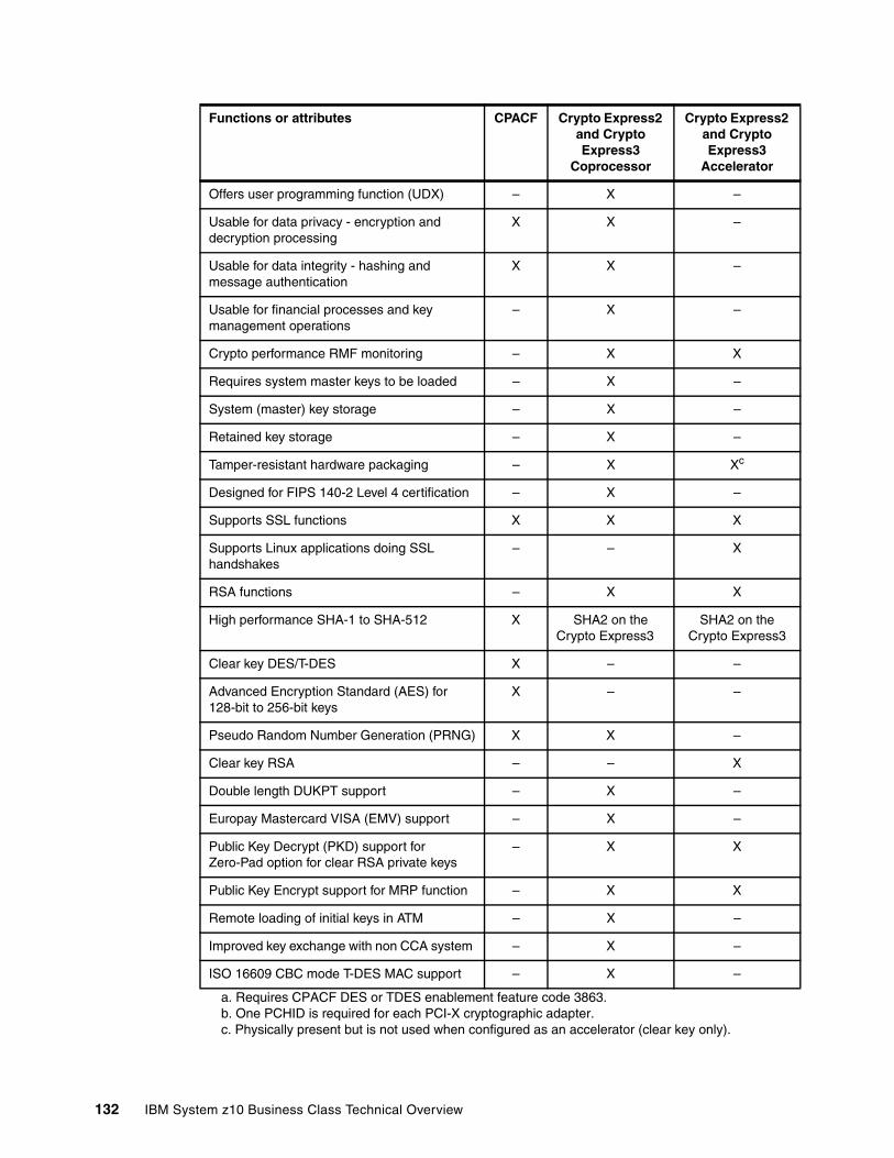
Offers user programming function (UDX) – X –
Usable for data privacy - encryption and decryption processing
X X –
Usable for data integrity - hashing and message authentication
X X –
Usable for financial processes and key management operations
– X –
Crypto performance RMF monitoring – X X
Requires system master keys to be loaded – X –
System (master) key storage – X –
Retained key storage – X –
Tamper-resistant hardware packaging – X Xc
Designed for FIPS 140-2 Level 4 certification – X –
Supports SSL functions X X X
Supports Linux applications doing SSL handshakes
– – X
RSA functions – X X
High performance SHA-1 to SHA-512 X SHA2 on theCrypto Express3
SHA2 on theCrypto Express3
Clear key DES/T-DES X – –
Advanced Encryption Standard (AES) for 128-bit to 256-bit keys
X – –
Pseudo Random Number Generation (PRNG) X X –
Clear key RSA – – X
Double length DUKPT support – X –
Europay Mastercard VISA (EMV) support – X –
Public Key Decrypt (PKD) support for Zero-Pad option for clear RSA private keys
– X X
Public Key Encrypt support for MRP function – X X
Remote loading of initial keys in ATM – X –
Improved key exchange with non CCA system – X –
ISO 16609 CBC mode T-DES MAC support – X –
a. Requires CPACF DES or TDES enablement feature code 3863.b. One PCHID is required for each PCI-X cryptographic adapter. c. Physically present but is not used when configured as an accelerator (clear key only).
Functions or attributes CPACF Crypto Express2 and Crypto Express3
Coprocessor
Crypto Express2 and Crypto Express3
Accelerator
132 IBM System z10 Business Class Technical Overview
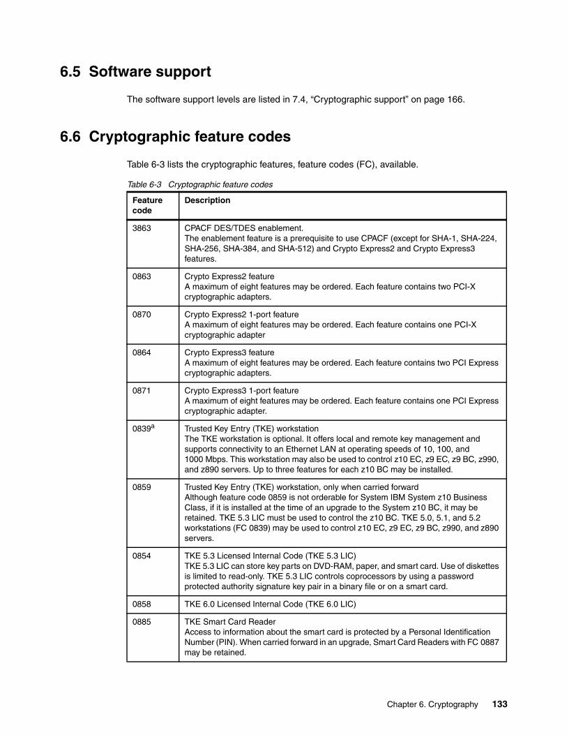
6.5 Software support
The software support levels are listed in 7.4, “Cryptographic support” on page 166.
6.6 Cryptographic feature codes
Table 6-3 lists the cryptographic features, feature codes (FC), available.
Table 6-3 Cryptographic feature codes
Feature code
Description
3863 CPACF DES/TDES enablement. The enablement feature is a prerequisite to use CPACF (except for SHA-1, SHA-224, SHA-256, SHA-384, and SHA-512) and Crypto Express2 and Crypto Express3 features.
0863 Crypto Express2 featureA maximum of eight features may be ordered. Each feature contains two PCI-X cryptographic adapters.
0870 Crypto Express2 1-port featureA maximum of eight features may be ordered. Each feature contains one PCI-X cryptographic adapter
0864 Crypto Express3 featureA maximum of eight features may be ordered. Each feature contains two PCI Express cryptographic adapters.
0871 Crypto Express3 1-port featureA maximum of eight features may be ordered. Each feature contains one PCI Express cryptographic adapter.
0839a Trusted Key Entry (TKE) workstationThe TKE workstation is optional. It offers local and remote key management and supports connectivity to an Ethernet LAN at operating speeds of 10, 100, and 1000 Mbps. This workstation may also be used to control z10 EC, z9 EC, z9 BC, z990, and z890 servers. Up to three features for each z10 BC may be installed.
0859 Trusted Key Entry (TKE) workstation, only when carried forwardAlthough feature code 0859 is not orderable for System IBM System z10 Business Class, if it is installed at the time of an upgrade to the System z10 BC, it may be retained. TKE 5.3 LIC must be used to control the z10 BC. TKE 5.0, 5.1, and 5.2 workstations (FC 0839) may be used to control z10 EC, z9 EC, z9 BC, z990, and z890 servers.
0854 TKE 5.3 Licensed Internal Code (TKE 5.3 LIC)TKE 5.3 LIC can store key parts on DVD-RAM, paper, and smart card. Use of diskettes is limited to read-only. TKE 5.3 LIC controls coprocessors by using a password protected authority signature key pair in a binary file or on a smart card.
0858 TKE 6.0 Licensed Internal Code (TKE 6.0 LIC)
0885 TKE Smart Card ReaderAccess to information about the smart card is protected by a Personal Identification Number (PIN). When carried forward in an upgrade, Smart Card Readers with FC 0887 may be retained.
Chapter 6. Cryptography 133
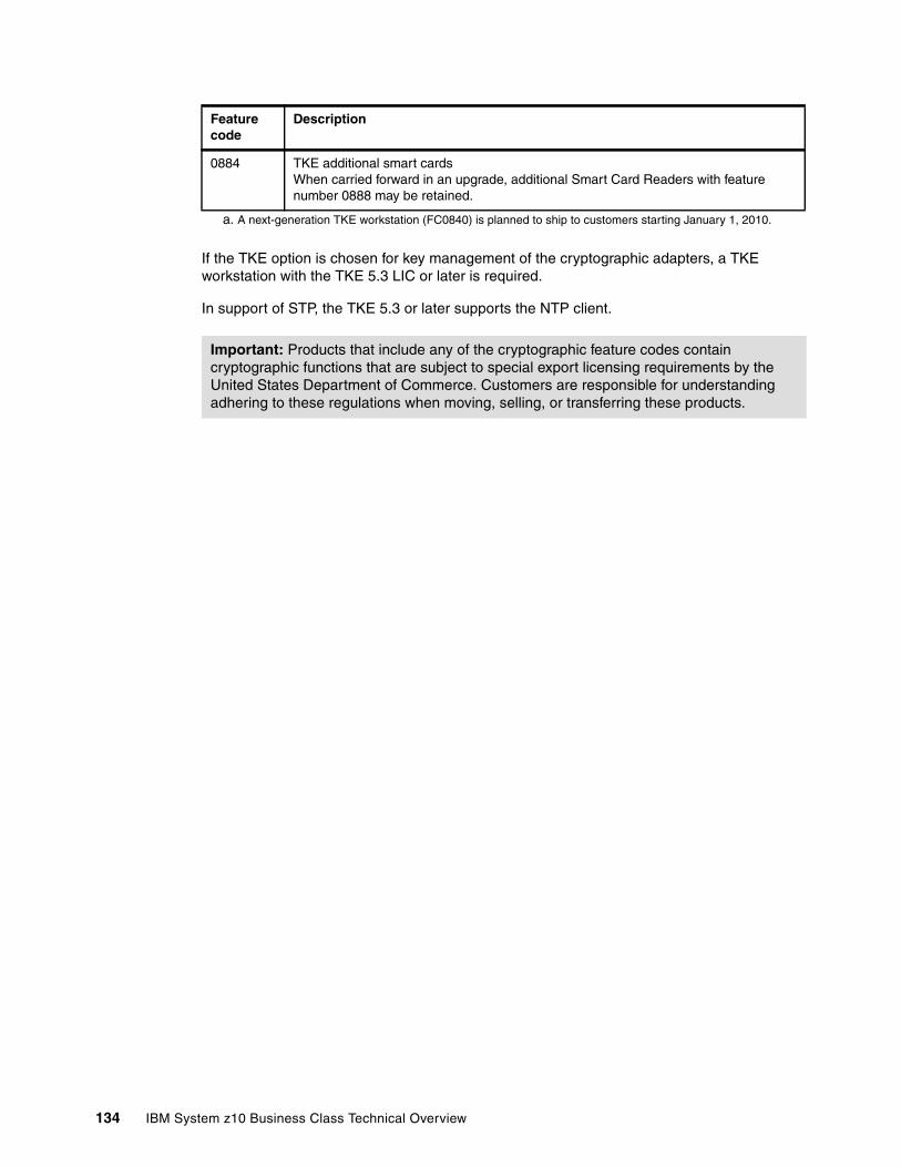
If the TKE option is chosen for key management of the cryptographic adapters, a TKE workstation with the TKE 5.3 LIC or later is required.
In support of STP, the TKE 5.3 or later supports the NTP client.
0884 TKE additional smart cardsWhen carried forward in an upgrade, additional Smart Card Readers with feature number 0888 may be retained.
a. A next-generation TKE workstation (FC0840) is planned to ship to customers starting January 1, 2010.
Important: Products that include any of the cryptographic feature codes contain cryptographic functions that are subject to special export licensing requirements by the United States Department of Commerce. Customers are responsible for understanding adhering to these regulations when moving, selling, or transferring these products.
Feature code
Description
134 IBM System z10 Business Class Technical Overview
Chapter 7. Software support
This chapter lists the minimum operating system requirements and support considerations for the z10 BC and its features. It covers z/OS, z/VM, z/VSE, TPF, z/TPF, and Linux on System z.
Information in this chapter is subject to change. Therefore, for the most current information, refer to the Preventive Service Planning (PSP) bucket for 2098DEVICE.
Support of IBM System z10 Business Class functions is dependent on the operating system, version, and release.
This chapter discusses the following topics:
� 7.1, “Operating systems summary” on page 136� 7.2, “Support by operating system” on page 136� 7.3, “Support by function” on page 148� 7.4, “Cryptographic support” on page 166� 7.5, “Coupling facility and CFCC considerations” on page 170� 7.6, “MIDAW facility” on page 171� 7.7, “IOCP” on page 173� 7.9, “ICKDSF” on page 173� 7.10, “Software licensing considerations” on page 174
7
© Copyright IBM Corp. 2008, 2009. All rights reserved. 135
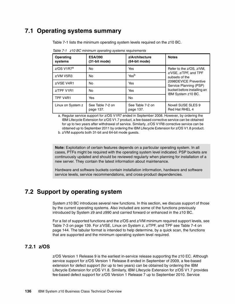
7.1 Operating systems summary
Table 7-1 lists the minimum operating system levels required on the z10 BC.
Table 7-1 z10 BC minimum operating systems requirements
7.2 Support by operating system
System z10 BC introduces several new functions. In this section, we discuss support of those by the current operating systems. Also included are some of the functions previously introduced by System z9 and z990 and carried forward or enhanced in the z10 BC.
For a list of supported functions and the z/OS and z/VM minimum required support levels, see Table 7-3 on page 139. For z/VSE, Linux on System z, z/TPF, and TPF see Table 7-4 on page 144. The tabular format is intended to help determine, by a quick scan, the functions that are supported and the minimum operating system level required.
7.2.1 z/OS
z/OS Version 1 Release 9 is the earliest in-service release supporting the z10 EC. Although service support for z/OS Version 1 Release 8 ended in September of 2009, a fee-based extension for defect support (for up to two years) can be obtained by ordering the IBM Lifecycle Extension for z/OS V1.8. Similarly, IBM Lifecycle Extension for z/OS V1.7 provides fee-based defect support for z/OS Version 1 Release 7 up to September 2010. Service
Operating systems
ESA/390(31-bit mode)
z/Architecture(64-bit mode)
Notes
z/OS V1R7a
a. Regular service support for z/OS V1R7 ended in September 2008. However, by ordering the IBM Lifecycle Extension for z/OS V1.7 product, a fee-based corrective service can be obtained for up to two years after withdrawal of service. Similarly, z/OS V1R8 corrective service can be obtained up to September 2011 by ordering the IBM Lifecycle Extension for z/OS V1.8 product.
No Yes Refer to the z/OS, z/VM, z/VSE, z/TPF, and TPF subsets of the 2098DEVICE Preventive Service Planning (PSP) bucket before installing an IBM System z10 BC.
z/VM V5R3 No Yesb
b. z/VM supports both 31-bit and 64-bit mode guests.
z/VSE V4R1 No Yes
z/TPF V1R1 No Yes
TPF V4R1 Yes No
Linux on System z See Table 7-2 on page 137.
See Table 7-2 on page 137.
Novell SUSE SLES 9 Red Hat RHEL 4
Note: Exploitation of certain features depends on a particular operating system. In all cases, PTFs might be required with the operating system level indicated. PSP buckets are continuously updated and should be reviewed regularly when planning for installation of a new server. They contain the latest information about maintenance.
Hardware and software buckets contain installation information, hardware and software service levels, service recommendations, and cross-product dependencies.
136 IBM System z10 Business Class Technical Overview
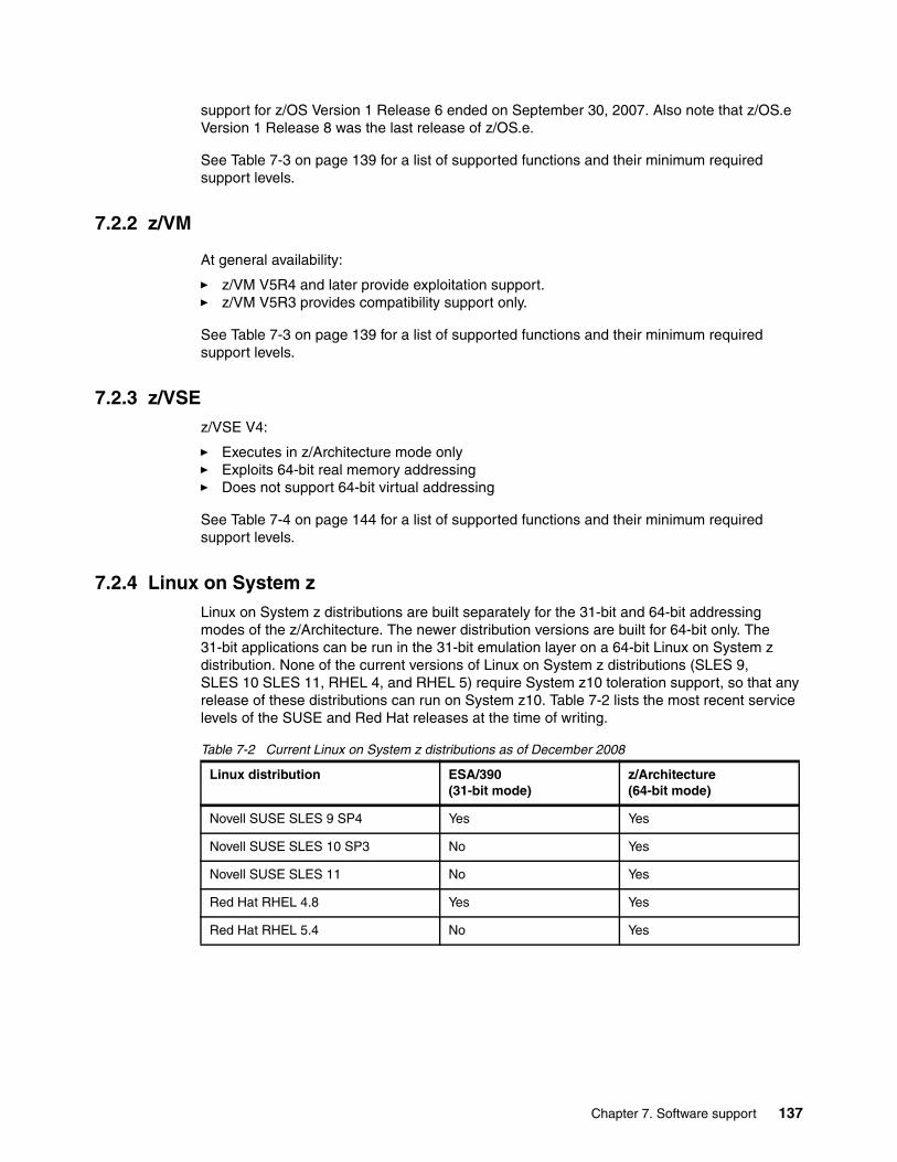
support for z/OS Version 1 Release 6 ended on September 30, 2007. Also note that z/OS.e Version 1 Release 8 was the last release of z/OS.e.
See Table 7-3 on page 139 for a list of supported functions and their minimum required support levels.
7.2.2 z/VM
At general availability:
� z/VM V5R4 and later provide exploitation support.� z/VM V5R3 provides compatibility support only.
See Table 7-3 on page 139 for a list of supported functions and their minimum required support levels.
7.2.3 z/VSEz/VSE V4:
� Executes in z/Architecture mode only� Exploits 64-bit real memory addressing� Does not support 64-bit virtual addressing
See Table 7-4 on page 144 for a list of supported functions and their minimum required support levels.
7.2.4 Linux on System zLinux on System z distributions are built separately for the 31-bit and 64-bit addressing modes of the z/Architecture. The newer distribution versions are built for 64-bit only. The 31-bit applications can be run in the 31-bit emulation layer on a 64-bit Linux on System z distribution. None of the current versions of Linux on System z distributions (SLES 9, SLES 10 SLES 11, RHEL 4, and RHEL 5) require System z10 toleration support, so that any release of these distributions can run on System z10. Table 7-2 lists the most recent service levels of the SUSE and Red Hat releases at the time of writing.
Table 7-2 Current Linux on System z distributions as of December 2008
Linux distribution ESA/390(31-bit mode)
z/Architecture(64-bit mode)
Novell SUSE SLES 9 SP4 Yes Yes
Novell SUSE SLES 10 SP3 No Yes
Novell SUSE SLES 11 No Yes
Red Hat RHEL 4.8 Yes Yes
Red Hat RHEL 5.4 No Yes
Chapter 7. Software support 137
For information about support availability for Linux on System z distributions see:
� For Novell:
http://support.novell.com/lifecycle/lcSearchResults.jsp?st=Linux+Enterprise+Server&x=32&y=11&sl=-1&sg=-1&pid=1000
� For Red Hat:
http://www.redhat.com/security/updates/errata/
IBM is working with its Linux distribution partners so that exploitation of further z10 BC functions will be provided in future Linux on System z distribution releases.
We recommend that:
� SUSE SLES 11 or Red Hat RHEL 5 be used in any new projects for the z10 BC
� Any Linux distributions be updated to their latest service level before migration to z10 BC
� The capacity of any z/VM and Linux logical partitions guests, and z/VM guests, in terms of the number of IFLs and CPs, real or virtual, be adjusted according to the PU capacity of the z10 BC
7.2.5 TPF and z/TPFFor TPF and zTPF, refer to Table 7-4 on page 144, which lists supported functions and their minimum required support levels.
7.2.6 z10 BC functions support summary
In the following tables we attempt to note all functions requiring support. For the most current maintenance information refer to the Preventive Service Planning (PSP) bucket for 2098DEVICE.
The following two tables summarize the z10 BC functions and their minimum required operating system support levels:
� Table 7-3 on page 139 (part 1) is for z/OS, z/OS.e, and z/VM.� Table 7-4 on page 144 (part 2) is for z/VSE, Linux on System z, z/TPF, and TPF.
Both tables use the following conventions:
Y The function is supported.N The function is not supported.– The function is not applicable to that specific operating system.
138 IBM System z10 Business Class Technical Overview

Table 7-3 z10 BC functions minimum support requirements summary, part 1
Function z/OS V1R11
z/OSV1R10
z/OSV1R9
z/OSV1R8
z/OSV1R7
z/VM V6R1
z/VMV5R4
z/VM V5R3
z10 BC Y Y Y Y Y Y Y Ya
More than 54 PUs single system imageb Y Y Y N N Nc Nc Nc
zIIP Y Y Y Y Y Yh Yh Yh
zAAP Y Y Y Y Y Yh Yh Yh
zAAP on zIIP Y Yl Yl N N Yd Yd N
Large memory (> 128 GB) Y Y Y Y N Ye Ye Ye
Large page support Y Y Y N N Nf Nf Nf
Guest support for execute-extensions facility
– – – – – Y Y Y
Hardware decimal floating point Yg Yg Yg Yg Yg Yh Yh Yh
CPU measurement facility Y Yl Yl Yl N N N N
Thirty logical partitions Y Y Y Y Y Y Y Y
LPAR group capacity limit Y Y Y Y N – – –
Separate LPAR management of PUs Y Y Y Y Y Y Y Y
Dynamic add or delete logical partition name
Y Y Y Y Y N N N
Capacity provisioning Y Y Yl N N Nf Nf Nf
Enhanced flexibility for CoD Yi Yi Yi Yi Yi Yi Yi Nf
HiperDispatch Y Y Y Y Yj Nf Nf Nf
63.75 K subchannels Y Y Y Y Y Y Y Y
Two logical channel subsystems (LCSS) Y Y Y Y Y Y Y Y
Dynamic I/O support for multiple LCSS Y Y Y Y Y Y Y Y
Multiple subchannel sets Y Y Y Y Y Nf Nf Nf
MIDAW facility Y Y Y Y Y Yh Yh Yh
Cryptography
CPACF protected public key Yk Yk Yk N N Nf Nf Nf
CPACF enhancements Yk Yk Yk Yk Yk Yh Yh Yh
CPACF AES, PRNG, and SHA-256 Y Y Y Y Yk Yh Yh Yh
CPACF Y Y Y Y Yk Yh Yh Yh
Personal account numbers of 13 to 19 digits Yk Yk Yk Yk Yk Yh Yh Yh
Crypto Express3 Yk Yk Yk N N Yh Yh Yh
Crypto Express2 Y Y Y Y Yk Yh Yh Yh
Chapter 7. Software support 139
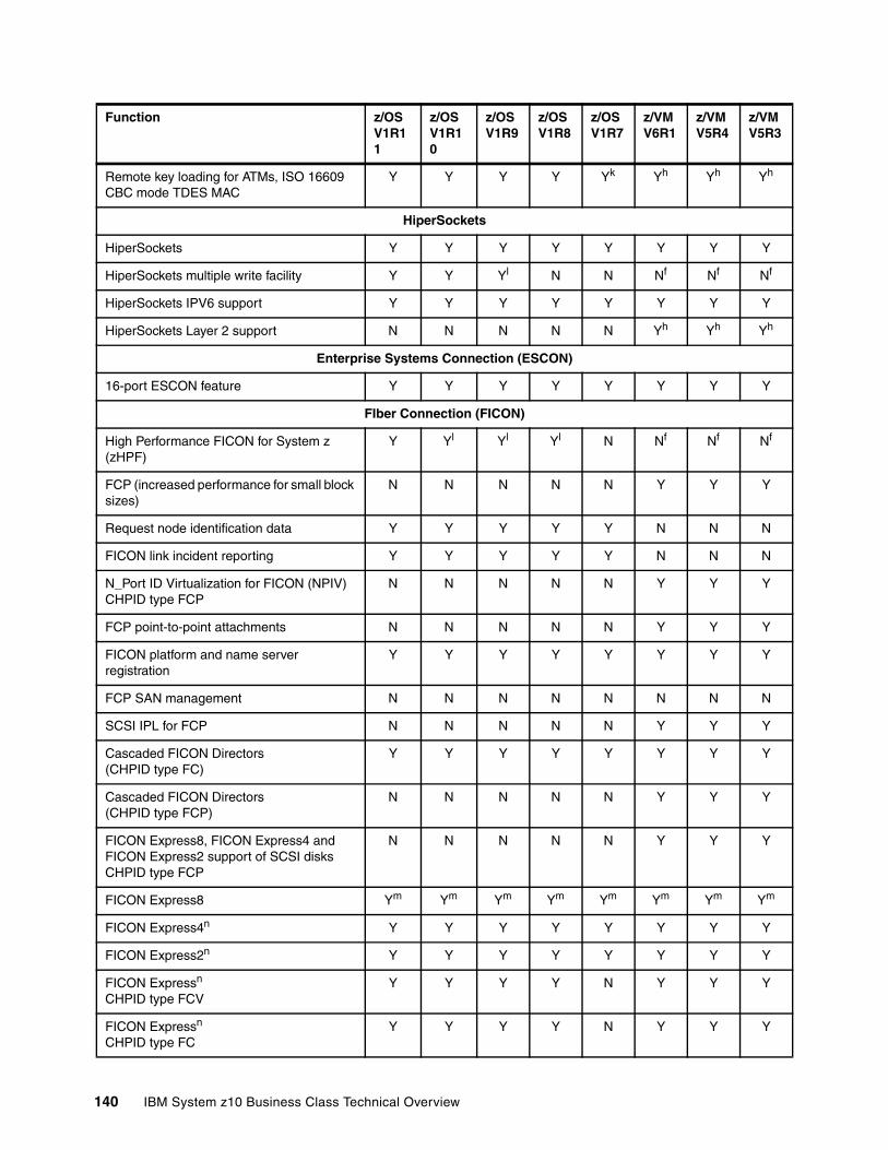
Remote key loading for ATMs, ISO 16609 CBC mode TDES MAC
Y Y Y Y Yk Yh Yh Yh
HiperSockets
HiperSockets Y Y Y Y Y Y Y Y
HiperSockets multiple write facility Y Y Yl N N Nf Nf Nf
HiperSockets IPV6 support Y Y Y Y Y Y Y Y
HiperSockets Layer 2 support N N N N N Yh Yh Yh
Enterprise Systems Connection (ESCON)
16-port ESCON feature Y Y Y Y Y Y Y Y
FIber Connection (FICON)
High Performance FICON for System z (zHPF)
Y Yl Yl Yl N Nf Nf Nf
FCP (increased performance for small block sizes)
N N N N N Y Y Y
Request node identification data Y Y Y Y Y N N N
FICON link incident reporting Y Y Y Y Y N N N
N_Port ID Virtualization for FICON (NPIV)CHPID type FCP
N N N N N Y Y Y
FCP point-to-point attachments N N N N N Y Y Y
FICON platform and name server registration
Y Y Y Y Y Y Y Y
FCP SAN management N N N N N N N N
SCSI IPL for FCP N N N N N Y Y Y
Cascaded FICON Directors (CHPID type FC)
Y Y Y Y Y Y Y Y
Cascaded FICON Directors (CHPID type FCP)
N N N N N Y Y Y
FICON Express8, FICON Express4 and FICON Express2 support of SCSI disksCHPID type FCP
N N N N N Y Y Y
FICON Express8 Ym Ym Ym Ym Ym Ym Ym Ym
FICON Express4n Y Y Y Y Y Y Y Y
FICON Express2n Y Y Y Y Y Y Y Y
FICON Expressn
CHPID type FCVY Y Y Y N Y Y Y
FICON Expressn
CHPID type FCY Y Y Y N Y Y Y
Function z/OS V1R11
z/OSV1R10
z/OSV1R9
z/OSV1R8
z/OSV1R7
z/VM V6R1
z/VMV5R4
z/VM V5R3
140 IBM System z10 Business Class Technical Overview

FICON Expressn
CHPID type FCPN N N N N Y Y Y
Open Systems Adapter (OSA)
VLAN management Y Y Y Y Y Y Y Y
VLAN (IEE 802.1q) support Y Y Y Y Y Y Y Y
QDIO data connection isolation for z/VM virtualized environments
- – – – – Y Yl Yl
OSA Layer 3 Virtual MAC Y Y Y Y N Yh Yh Yg
OSA Dynamic LAN idle Y Y Y Y N Yh Yh Yh
OSA/SF enhancements for IP, MAC addressing (CHPID=OSD)
Y Y Y Y Y Y Y Y
QDIO diagnostic synchronization Y Y Y Y N Yh Yh Yh
OSA-Express2 Network Traffic Analyzer Y Y Y Y N Yh Yh Yh
Broadcast for IPv4 packets Y Y Y Y Y Y Y Y
Checksum offload for IPv4 packets Y Y Y Y Y Yo Yo Yo
OSA-Express3 10 Gigabit Ethernet LR CHPID type OSD
Y Y Y N N Y Y Y
OSA-Express3 10 Gigabit Ethernet SR CHPID type OSD
Y Y Y Y Y Y Y Y
OSA-Express3 Gigabit Ethernet LX (using 4 ports) CHPID types OSD, OSN
Y Y Yl Yl N Y Y Yl
OSA-Express3 Gigabit Ethernet LX (using 2 ports) CHPID types OSD, OSN
Y Y Y Y Y Y Y Y
OSA-Express3 Gigabit Ethernet SX (using 4 ports) OSA-Express3-2P Gigabit Ethernet SX (using 2 ports)CHPID types OSD, OSN
Y Y Yl Yl N Y Y Yl
OSA-Express3 Gigabit Ethernet SX (using 2 ports) OSA-Express3-2P Gigabit Ethernet SX (using 1 port)CHPID types OSD, OSN
Y Y Y Y Y Y Y Y
OSA-Express3 1000BASE-T (using 1 + 1 port)OSA-Express3-2P1000BASE-T(using 1 port)CHPID type OSC
Y Y Y Y Y Y Y Y
Function z/OS V1R11
z/OSV1R10
z/OSV1R9
z/OSV1R8
z/OSV1R7
z/VM V6R1
z/VMV5R4
z/VM V5R3
Chapter 7. Software support 141
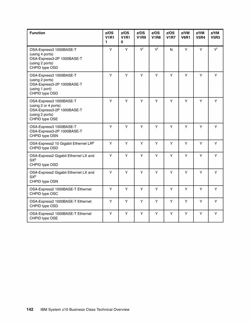
OSA-Express3 1000BASE-T (using 4 ports) OSA-Express3-2P 1000BASE-T (using 2 ports)CHPID type OSD
Y Y Yl Yl N Y Y Yl
OSA-Express3 1000BASE-T (using 2 ports) OSA-Express3-2P 1000BASE-T (using 1 port)CHPID type OSD
Y Y Y Y Y Y Y Y
OSA-Express3 1000BASE-T (using 2 or 4 ports)OSA-Express3-2P 1000BASE-T (using 2 ports)CHPID type OSE
Y Y Y Y Y Y Y Y
OSA-Express3 1000BASE-TOSA-Express3-2P 1000BASE-TCHPID type OSN
Y Y Y Y Y Y Y Y
OSA-Express2 10 Gigabit Ethernet LRp
CHPID type OSDY Y Y Y Y Y Y Y
OSA-Express2 Gigabit Ethernet LX and SXp
CHPID type OSD
Y Y Y Y Y Y Y Y
OSA-Express2 Gigabit Ethernet LX and SXp
CHPID type OSN
Y Y Y Y Y Y Y Y
OSA-Express2 1000BASE-T EthernetCHPID type OSC
Y Y Y Y Y Y Y Y
OSA-Express2 1000BASE-T EthernetCHPID type OSD
Y Y Y Y Y Y Y Y
OSA-Express2 1000BASE-T Ethernet CHPID type OSE
Y Y Y Y Y Y Y Y
Function z/OS V1R11
z/OSV1R10
z/OSV1R9
z/OSV1R8
z/OSV1R7
z/VM V6R1
z/VMV5R4
z/VM V5R3
142 IBM System z10 Business Class Technical Overview
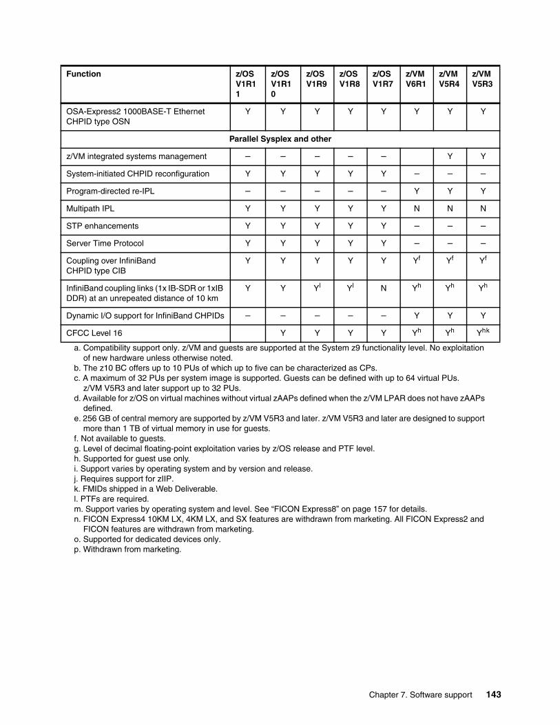
OSA-Express2 1000BASE-T Ethernet CHPID type OSN
Y Y Y Y Y Y Y Y
Parallel Sysplex and other
z/VM integrated systems management – – – – – Y Y
System-initiated CHPID reconfiguration Y Y Y Y Y – – –
Program-directed re-IPL – – – – – Y Y Y
Multipath IPL Y Y Y Y Y N N N
STP enhancements Y Y Y Y Y – – –
Server Time Protocol Y Y Y Y Y – – –
Coupling over InfiniBand CHPID type CIB
Y Y Y Y Y Yf Yf Yf
InfiniBand coupling links (1x IB-SDR or 1xIB DDR) at an unrepeated distance of 10 km
Y Y Yl Yl N Yh Yh Yh
Dynamic I/O support for InfiniBand CHPIDs – – – – – Y Y Y
CFCC Level 16 Y Y Y Y Yh Yh Yhk
a. Compatibility support only. z/VM and guests are supported at the System z9 functionality level. No exploitation of new hardware unless otherwise noted.
b. The z10 BC offers up to 10 PUs of which up to five can be characterized as CPs.c. A maximum of 32 PUs per system image is supported. Guests can be defined with up to 64 virtual PUs.
z/VM V5R3 and later support up to 32 PUs.d. Available for z/OS on virtual machines without virtual zAAPs defined when the z/VM LPAR does not have zAAPs
defined.e. 256 GB of central memory are supported by z/VM V5R3 and later. z/VM V5R3 and later are designed to support
more than 1 TB of virtual memory in use for guests.f. Not available to guests.g. Level of decimal floating-point exploitation varies by z/OS release and PTF level.h. Supported for guest use only.i. Support varies by operating system and by version and release.j. Requires support for zIIP.k. FMIDs shipped in a Web Deliverable.l. PTFs are required.m. Support varies by operating system and level. See “FICON Express8” on page 157 for details.n. FICON Express4 10KM LX, 4KM LX, and SX features are withdrawn from marketing. All FICON Express2 and
FICON features are withdrawn from marketing.o. Supported for dedicated devices only.p. Withdrawn from marketing.
Function z/OS V1R11
z/OSV1R10
z/OSV1R9
z/OSV1R8
z/OSV1R7
z/VM V6R1
z/VMV5R4
z/VM V5R3
Chapter 7. Software support 143
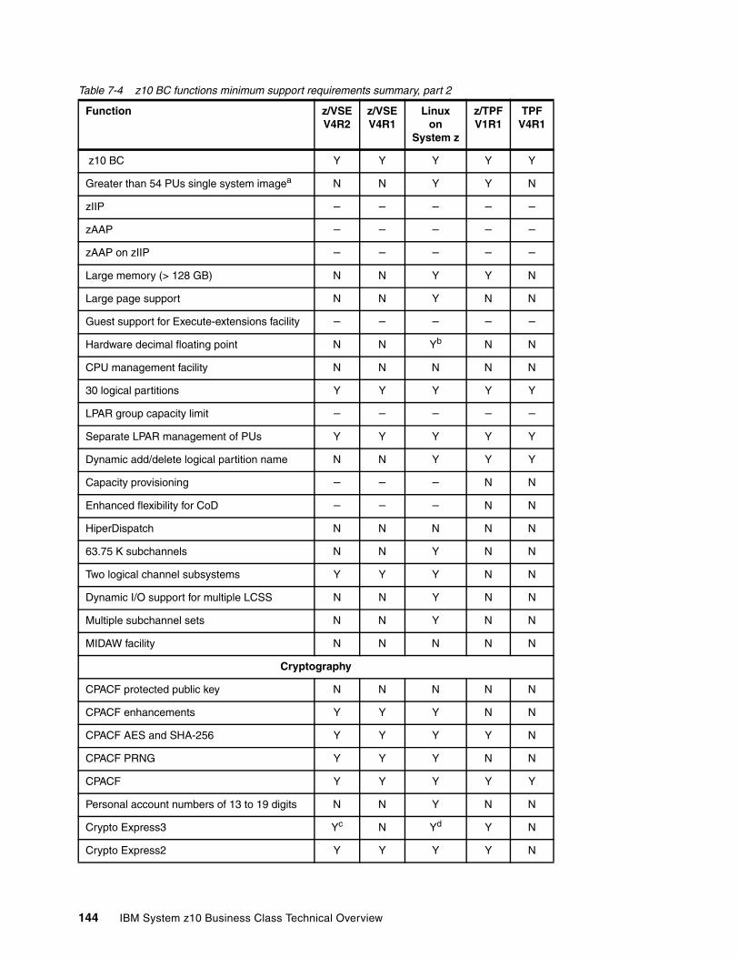
Table 7-4 z10 BC functions minimum support requirements summary, part 2
Function z/VSE V4R2
z/VSE V4R1
Linux on
System z
z/TPF V1R1
TPF V4R1
z10 BC Y Y Y Y Y
Greater than 54 PUs single system imagea N N Y Y N
zIIP – – – – –
zAAP – – – – –
zAAP on zIIP – – – – –
Large memory (> 128 GB) N N Y Y N
Large page support N N Y N N
Guest support for Execute-extensions facility – – – – –
Hardware decimal floating point N N Yb N N
CPU management facility N N N N N
30 logical partitions Y Y Y Y Y
LPAR group capacity limit – – – – –
Separate LPAR management of PUs Y Y Y Y Y
Dynamic add/delete logical partition name N N Y Y Y
Capacity provisioning – – – N N
Enhanced flexibility for CoD – – – N N
HiperDispatch N N N N N
63.75 K subchannels N N Y N N
Two logical channel subsystems Y Y Y N N
Dynamic I/O support for multiple LCSS N N Y N N
Multiple subchannel sets N N Y N N
MIDAW facility N N N N N
Cryptography
CPACF protected public key N N N N N
CPACF enhancements Y Y Y N N
CPACF AES and SHA-256 Y Y Y Y N
CPACF PRNG Y Y Y N N
CPACF Y Y Y Y Y
Personal account numbers of 13 to 19 digits N N Y N N
Crypto Express3 Yc N Yd Y N
Crypto Express2 Y Y Y Y N
144 IBM System z10 Business Class Technical Overview

Remote key loading for ATMs, ISO 16609 CBC mode TDES MAC
N N – N N
HiperSockets
HiperSockets Y Y Y N N
HiperSockets multiple write facility N N N N N
HiperSockets IPV6 support N N Y N N
HiperSockets Layer 2 support N N Y N N
Enterprise System Connection (ESCON)
16-port ESCON feature Y Y Y Y Y
FIber Connection (FICON) and Fibre Channel Protocol (FCP)
High Performance FICON for System z (zHPF) N N N N N
FCP - increased performance for small block sizes
Y Y Y N N
Request node identification data – – – – –
FICON link incident reporting N N N N N
N_Port ID Virtualization for FICON (NPIV)CHPID type FCP
Y Y Y N N
FCP point-to-point attachments Y Y Y N N
FICON platform and name server registration Y Y Y Y Y
FCP SAN management N N Y N N
SCSI IPL for FCP Y Y Y N N
Cascaded FICON Directors (CHPID type FC)
Y Y Y Y Y
Cascaded FICON Directors (CHPID type FCP)
Y Y Y N N
FICON Express8, FICON Express4, and FICON Express2 support of SCSI disksCHPID type FCP
Y Y Y N N
FICON Express8 Ye Y Y Y Y
FICON Express4f Y Y Y Y Y
FICON Express2f Y Y Y Y Y
FICON Expressf
CHPID type FCVY Y N N N
FICON Expressf
CHPID type FCY Y Y N N
FICON Expressf
CHPID type FCPY Y Y N N
Function z/VSE V4R2
z/VSE V4R1
Linux on
System z
z/TPF V1R1
TPF V4R1
Chapter 7. Software support 145
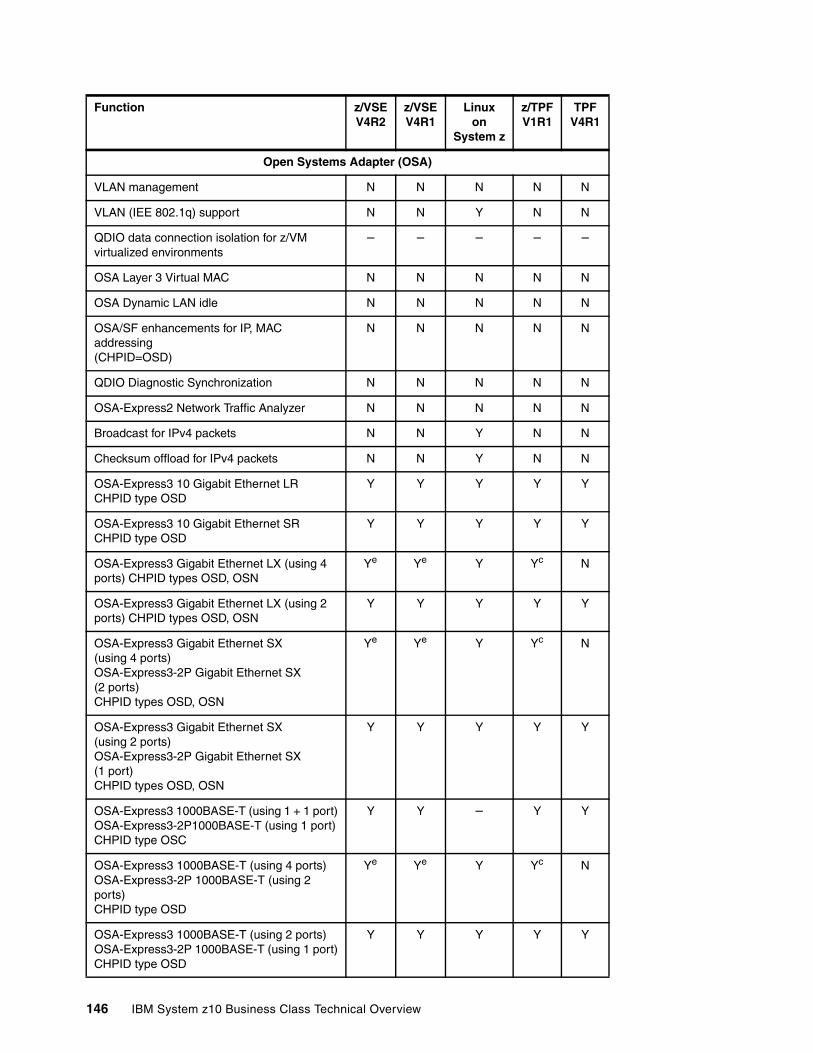
Open Systems Adapter (OSA)
VLAN management N N N N N
VLAN (IEE 802.1q) support N N Y N N
QDIO data connection isolation for z/VM virtualized environments
– – – – –
OSA Layer 3 Virtual MAC N N N N N
OSA Dynamic LAN idle N N N N N
OSA/SF enhancements for IP, MAC addressing(CHPID=OSD)
N N N N N
QDIO Diagnostic Synchronization N N N N N
OSA-Express2 Network Traffic Analyzer N N N N N
Broadcast for IPv4 packets N N Y N N
Checksum offload for IPv4 packets N N Y N N
OSA-Express3 10 Gigabit Ethernet LR CHPID type OSD
Y Y Y Y Y
OSA-Express3 10 Gigabit Ethernet SR CHPID type OSD
Y Y Y Y Y
OSA-Express3 Gigabit Ethernet LX (using 4 ports) CHPID types OSD, OSN
Ye Ye Y Yc N
OSA-Express3 Gigabit Ethernet LX (using 2 ports) CHPID types OSD, OSN
Y Y Y Y Y
OSA-Express3 Gigabit Ethernet SX (using 4 ports) OSA-Express3-2P Gigabit Ethernet SX (2 ports)CHPID types OSD, OSN
Ye Ye Y Yc N
OSA-Express3 Gigabit Ethernet SX (using 2 ports) OSA-Express3-2P Gigabit Ethernet SX (1 port)CHPID types OSD, OSN
Y Y Y Y Y
OSA-Express3 1000BASE-T (using 1 + 1 port)OSA-Express3-2P1000BASE-T (using 1 port)CHPID type OSC
Y Y – Y Y
OSA-Express3 1000BASE-T (using 4 ports) OSA-Express3-2P 1000BASE-T (using 2 ports)CHPID type OSD
Ye Ye Y Yc N
OSA-Express3 1000BASE-T (using 2 ports) OSA-Express3-2P 1000BASE-T (using 1 port)CHPID type OSD
Y Y Y Y Y
Function z/VSE V4R2
z/VSE V4R1
Linux on
System z
z/TPF V1R1
TPF V4R1
146 IBM System z10 Business Class Technical Overview
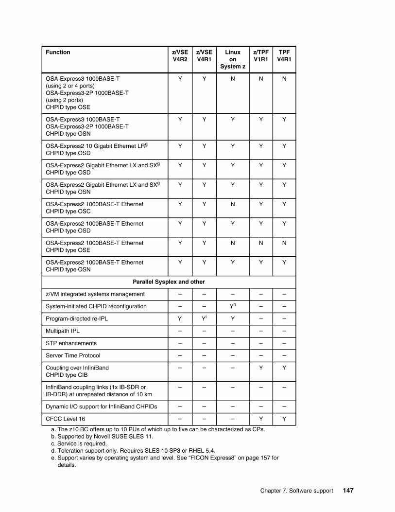
OSA-Express3 1000BASE-T (using 2 or 4 ports)OSA-Express3-2P 1000BASE-T (using 2 ports)CHPID type OSE
Y Y N N N
OSA-Express3 1000BASE-TOSA-Express3-2P 1000BASE-TCHPID type OSN
Y Y Y Y Y
OSA-Express2 10 Gigabit Ethernet LRg
CHPID type OSDY Y Y Y Y
OSA-Express2 Gigabit Ethernet LX and SXg
CHPID type OSDY Y Y Y Y
OSA-Express2 Gigabit Ethernet LX and SXg
CHPID type OSNY Y Y Y Y
OSA-Express2 1000BASE-T EthernetCHPID type OSC
Y Y N Y Y
OSA-Express2 1000BASE-T Ethernet CHPID type OSD
Y Y Y Y Y
OSA-Express2 1000BASE-T Ethernet CHPID type OSE
Y Y N N N
OSA-Express2 1000BASE-T EthernetCHPID type OSN
Y Y Y Y Y
Parallel Sysplex and other
z/VM integrated systems management – – – – –
System-initiated CHPID reconfiguration – – Yh – –
Program-directed re-IPL Yi Yi Y – –
Multipath IPL – – – – –
STP enhancements – – – – –
Server Time Protocol – – – – –
Coupling over InfiniBand CHPID type CIB
– – – Y Y
InfiniBand coupling links (1x IB-SDR or IB-DDR) at unrepeated distance of 10 km
– – – – –
Dynamic I/O support for InfiniBand CHPIDs – – – – –
CFCC Level 16 – – – Y Y
a. The z10 BC offers up to 10 PUs of which up to five can be characterized as CPs.b. Supported by Novell SUSE SLES 11.c. Service is required.d. Toleration support only. Requires SLES 10 SP3 or RHEL 5.4.e. Support varies by operating system and level. See “FICON Express8” on page 157 for
details.
Function z/VSE V4R2
z/VSE V4R1
Linux on
System z
z/TPF V1R1
TPF V4R1
Chapter 7. Software support 147
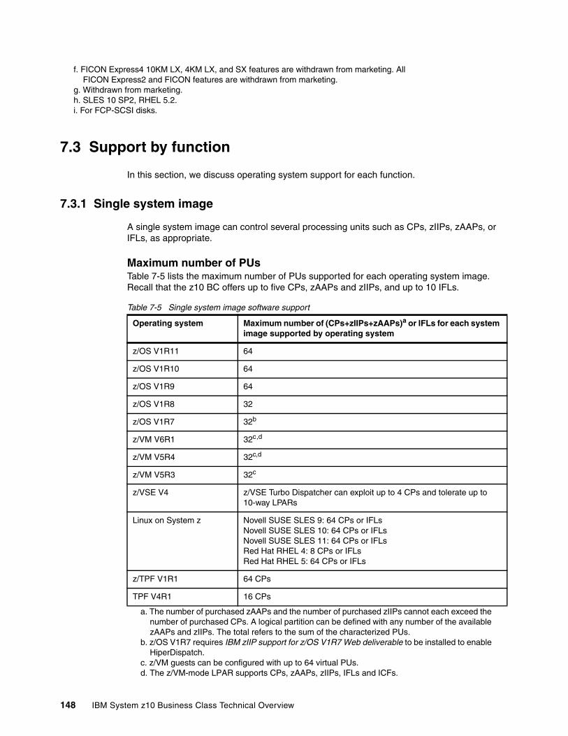
7.3 Support by function
In this section, we discuss operating system support for each function.
7.3.1 Single system image
A single system image can control several processing units such as CPs, zIIPs, zAAPs, or IFLs, as appropriate.
Maximum number of PUsTable 7-5 lists the maximum number of PUs supported for each operating system image. Recall that the z10 BC offers up to five CPs, zAAPs and zIIPs, and up to 10 IFLs.
Table 7-5 Single system image software support
f. FICON Express4 10KM LX, 4KM LX, and SX features are withdrawn from marketing. All FICON Express2 and FICON features are withdrawn from marketing.
g. Withdrawn from marketing.h. SLES 10 SP2, RHEL 5.2.i. For FCP-SCSI disks.
Operating system Maximum number of (CPs+zIIPs+zAAPs)a or IFLs for each system image supported by operating system
a. The number of purchased zAAPs and the number of purchased zIIPs cannot each exceed the number of purchased CPs. A logical partition can be defined with any number of the available zAAPs and zIIPs. The total refers to the sum of the characterized PUs.
z/OS V1R11 64
z/OS V1R10 64
z/OS V1R9 64
z/OS V1R8 32
z/OS V1R7 32b
b. z/OS V1R7 requires IBM zIIP support for z/OS V1R7 Web deliverable to be installed to enable HiperDispatch.
z/VM V6R1 32c,d
z/VM V5R4 32c,d
c. z/VM guests can be configured with up to 64 virtual PUs.d. The z/VM-mode LPAR supports CPs, zAAPs, zIIPs, IFLs and ICFs.
z/VM V5R3 32c
z/VSE V4 z/VSE Turbo Dispatcher can exploit up to 4 CPs and tolerate up to 10-way LPARs
Linux on System z Novell SUSE SLES 9: 64 CPs or IFLsNovell SUSE SLES 10: 64 CPs or IFLsNovell SUSE SLES 11: 64 CPs or IFLsRed Hat RHEL 4: 8 CPs or IFLsRed Hat RHEL 5: 64 CPs or IFLs
z/TPF V1R1 64 CPs
TPF V4R1 16 CPs
148 IBM System z10 Business Class Technical Overview
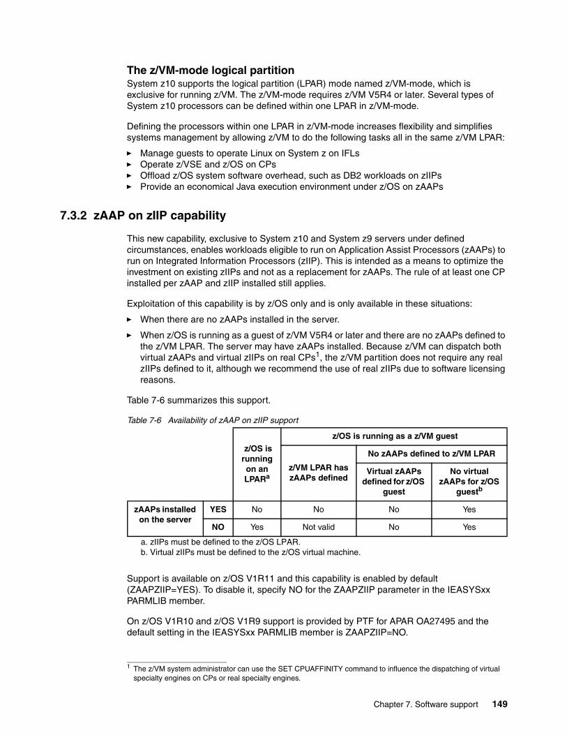
The z/VM-mode logical partitionSystem z10 supports the logical partition (LPAR) mode named z/VM-mode, which is exclusive for running z/VM. The z/VM-mode requires z/VM V5R4 or later. Several types of System z10 processors can be defined within one LPAR in z/VM-mode.
Defining the processors within one LPAR in z/VM-mode increases flexibility and simplifies systems management by allowing z/VM to do the following tasks all in the same z/VM LPAR:
� Manage guests to operate Linux on System z on IFLs� Operate z/VSE and z/OS on CPs� Offload z/OS system software overhead, such as DB2 workloads on zIIPs� Provide an economical Java execution environment under z/OS on zAAPs
7.3.2 zAAP on zIIP capability
This new capability, exclusive to System z10 and System z9 servers under defined circumstances, enables workloads eligible to run on Application Assist Processors (zAAPs) to run on Integrated Information Processors (zIIP). This is intended as a means to optimize the investment on existing zIIPs and not as a replacement for zAAPs. The rule of at least one CP installed per zAAP and zIIP installed still applies.
Exploitation of this capability is by z/OS only and is only available in these situations:
� When there are no zAAPs installed in the server.
� When z/OS is running as a guest of z/VM V5R4 or later and there are no zAAPs defined to the z/VM LPAR. The server may have zAAPs installed. Because z/VM can dispatch both virtual zAAPs and virtual zIIPs on real CPs1, the z/VM partition does not require any real zIIPs defined to it, although we recommend the use of real zIIPs due to software licensing reasons.
Table 7-6 summarizes this support.
Table 7-6 Availability of zAAP on zIIP support
Support is available on z/OS V1R11 and this capability is enabled by default (ZAAPZIIP=YES). To disable it, specify NO for the ZAAPZIIP parameter in the IEASYSxx PARMLIB member.
On z/OS V1R10 and z/OS V1R9 support is provided by PTF for APAR OA27495 and the default setting in the IEASYSxx PARMLIB member is ZAAPZIIP=NO.
1 The z/VM system administrator can use the SET CPUAFFINITY command to influence the dispatching of virtual specialty engines on CPs or real specialty engines.
z/OS is running on an LPARa
a. zIIPs must be defined to the z/OS LPAR.
z/OS is running as a z/VM guest
z/VM LPAR has zAAPs defined
No zAAPs defined to z/VM LPAR
Virtual zAAPs defined for z/OS
guest
No virtual zAAPs for z/OS
guestb
b. Virtual zIIPs must be defined to the z/OS virtual machine.
zAAPs installed on the server
YES No No No Yes
NO Yes Not valid No Yes
Chapter 7. Software support 149

Enabling or disabling this capability is disruptive. After changing the parameter, z/OS must be re-IPLed for the new setting to take effect.
7.3.3 Maximum main storage size
Table 7-7 lists the maximum amount of main storage supported by current operating systems. Expanded storage, although part of the z/Architecture, is currently exploited only by z/VM.
Table 7-7 Maximum memory supported by operating system
7.3.4 Large-page support
In addition to the existing 4 KB pages and page frames, z10 BC supports large pages and large-page frames that are 1 MB in size, as described in 2.5.2, “Plan-ahead memory” on page 33. Table 7-8 lists large-page support requirements.
Table 7-8 Minimum support requirements for large page
Note: When defining an image profile, a maximum of 1 TB of main storage can be defined for a logical partition.
Operating system Maximum supported main storagea
a. z10 BC supports up to 248 GB of memory. The initial memory offering was 120 GB.
z/OS z/OS V1R11 supports 4 TBz/OS V1R10 supports 4 TBz/OS V1R9 supports 4 TBz/OS V1R8 supports 4 TBz/OS V1R7 supports 128 GB
z/VM z/VM V6R1 supports 256 GBz/VM V5R4 supports 256 GBz/VM V5R3 supports 256 GB
Linux on System z (64-bit)
Novell SUSE SLES 11 supports 4 TBNovell SUSE SLES 10 supports 4 TBNovell SUSE SLES 9 supports 4 TBRed Hat RHEL 5 supports 64 GBRed Hat RHEL 4 supports 64 GB
z/VSE z/VSE V4R2 supports 32 GBz/VSE V4R1 supports 8 GB
TPF and z/TPF z/TPF supports 4 TB
TPF runs in ESA/390 mode and supports 2 GB.
Operating system Support requirements
z/OS z/OS V1R9
z/VM Not supported; not available to guests
Linux on System z Novell SUSE SLES 10 SP2Red Hat RHEL 5.2
150 IBM System z10 Business Class Technical Overview
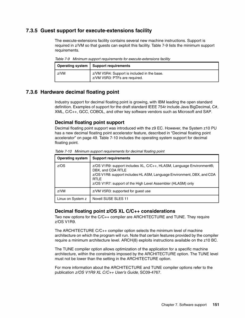
7.3.5 Guest support for execute-extensions facility
The execute-extensions facility contains several new machine instructions. Support is required in z/VM so that guests can exploit this facility. Table 7-9 lists the minimum support requirements.
Table 7-9 Minimum support requirements for execute-extensions facility
7.3.6 Hardware decimal floating point
Industry support for decimal floating point is growing, with IBM leading the open standard definition. Examples of support for the draft standard IEEE 754r include Java BigDecimal, C#, XML, C/C++, GCC, COBOL, and other key software vendors such as Microsoft and SAP.
Decimal floating point supportDecimal floating point support was introduced with the z9 EC. However, the System z10 PU has a new decimal floating point accelerator feature, described in “Decimal floating point accelerator” on page 49. Table 7-10 includes the operating system support for decimal floating point.
Table 7-10 Minimum support requirements for decimal floating point
Decimal floating point z/OS XL C/C++ considerationsTwo new options for the C/C++ compiler are ARCHITECTURE and TUNE. They require z/OS V1R9.
The ARCHITECTURE C/C++ compiler option selects the minimum level of machine architecture on which the program will run. Note that certain features provided by the compiler require a minimum architecture level. ARCH(8) exploits instructions available on the z10 BC.
The TUNE compiler option allows optimization of the application for a specific machine architecture, within the constraints imposed by the ARCHITECTURE option. The TUNE level must not be lower than the setting in the ARCHITECTURE option.
For more information about the ARCHITECTURE and TUNE compiler options refer to the publication z/OS V1R9 XL C/C++ User’s Guide, SC09-4767.
Operating system Support requirements
z/VM z/VM V5R4: Support is included in the base. z/VM V5R3: PTFs are required.
Operating system Support requirements
z/OS z/OS V1R9: support includes XL, C/C++, HLASM, Language Environment®, DBX, and CDA RTLEz/OS V1R8: support includes HL ASM, Language Environment, DBX, and CDA RTLEz/OS V1R7: support of the High Level Assembler (HLASM) only
z/VM z/VM V5R3: supported for guest use
Linux on System z Novell SUSE SLES 11
Chapter 7. Software support 151
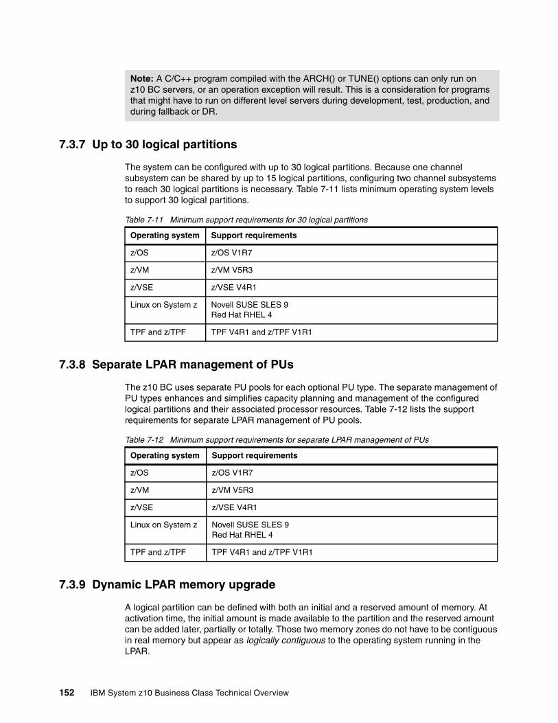
7.3.7 Up to 30 logical partitions
The system can be configured with up to 30 logical partitions. Because one channel subsystem can be shared by up to 15 logical partitions, configuring two channel subsystems to reach 30 logical partitions is necessary. Table 7-11 lists minimum operating system levels to support 30 logical partitions.
Table 7-11 Minimum support requirements for 30 logical partitions
7.3.8 Separate LPAR management of PUs
The z10 BC uses separate PU pools for each optional PU type. The separate management of PU types enhances and simplifies capacity planning and management of the configured logical partitions and their associated processor resources. Table 7-12 lists the support requirements for separate LPAR management of PU pools.
Table 7-12 Minimum support requirements for separate LPAR management of PUs
7.3.9 Dynamic LPAR memory upgrade
A logical partition can be defined with both an initial and a reserved amount of memory. At activation time, the initial amount is made available to the partition and the reserved amount can be added later, partially or totally. Those two memory zones do not have to be contiguous in real memory but appear as logically contiguous to the operating system running in the LPAR.
Note: A C/C++ program compiled with the ARCH() or TUNE() options can only run on z10 BC servers, or an operation exception will result. This is a consideration for programs that might have to run on different level servers during development, test, production, and during fallback or DR.
Operating system Support requirements
z/OS z/OS V1R7
z/VM z/VM V5R3
z/VSE z/VSE V4R1
Linux on System z Novell SUSE SLES 9Red Hat RHEL 4
TPF and z/TPF TPF V4R1 and z/TPF V1R1
Operating system Support requirements
z/OS z/OS V1R7
z/VM z/VM V5R3
z/VSE z/VSE V4R1
Linux on System z Novell SUSE SLES 9Red Hat RHEL 4
TPF and z/TPF TPF V4R1 and z/TPF V1R1
152 IBM System z10 Business Class Technical Overview
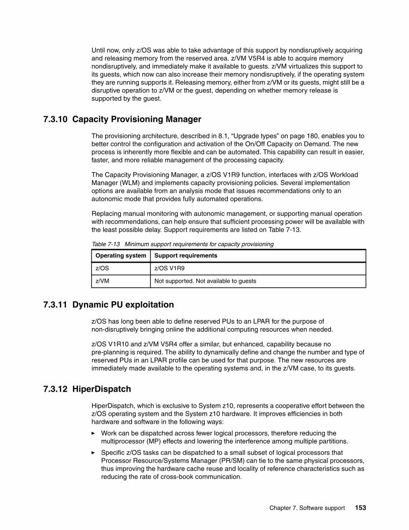
Until now, only z/OS was able to take advantage of this support by nondisruptively acquiring and releasing memory from the reserved area. z/VM V5R4 is able to acquire memory nondisruptively, and immediately make it available to guests. z/VM virtualizes this support to its guests, which now can also increase their memory nondisruptively, if the operating system they are running supports it. Releasing memory, either from z/VM or its guests, might still be a disruptive operation to z/VM or the guest, depending on whether memory release is supported by the guest.
7.3.10 Capacity Provisioning Manager
The provisioning architecture, described in 8.1, “Upgrade types” on page 180, enables you to better control the configuration and activation of the On/Off Capacity on Demand. The new process is inherently more flexible and can be automated. This capability can result in easier, faster, and more reliable management of the processing capacity.
The Capacity Provisioning Manager, a z/OS V1R9 function, interfaces with z/OS Workload Manager (WLM) and implements capacity provisioning policies. Several implementation options are available from an analysis mode that issues recommendations only to an autonomic mode that provides fully automated operations.
Replacing manual monitoring with autonomic management, or supporting manual operation with recommendations, can help ensure that sufficient processing power will be available with the least possible delay. Support requirements are listed on Table 7-13.
Table 7-13 Minimum support requirements for capacity provisioning
7.3.11 Dynamic PU exploitation
z/OS has long been able to define reserved PUs to an LPAR for the purpose of non-disruptively bringing online the additional computing resources when needed.
z/OS V1R10 and z/VM V5R4 offer a similar, but enhanced, capability because no pre-planning is required. The ability to dynamically define and change the number and type of reserved PUs in an LPAR profile can be used for that purpose. The new resources are immediately made available to the operating systems and, in the z/VM case, to its guests.
7.3.12 HiperDispatch
HiperDispatch, which is exclusive to System z10, represents a cooperative effort between the z/OS operating system and the System z10 hardware. It improves efficiencies in both hardware and software in the following ways:
� Work can be dispatched across fewer logical processors, therefore reducing the multiprocessor (MP) effects and lowering the interference among multiple partitions.
� Specific z/OS tasks can be dispatched to a small subset of logical processors that Processor Resource/Systems Manager (PR/SM) can tie to the same physical processors, thus improving the hardware cache reuse and locality of reference characteristics such as reducing the rate of cross-book communication.
Operating system Support requirements
z/OS z/OS V1R9
z/VM Not supported. Not available to guests
Chapter 7. Software support 153
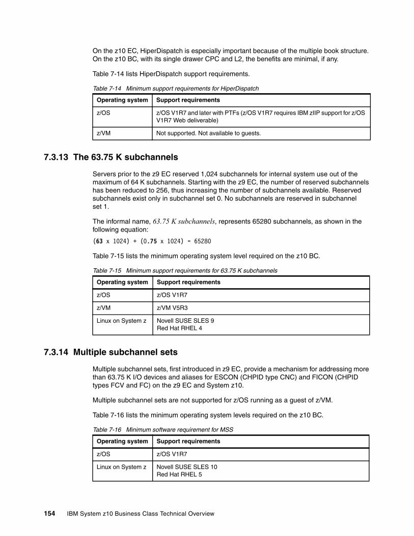
On the z10 EC, HiperDispatch is especially important because of the multiple book structure. On the z10 BC, with its single drawer CPC and L2, the benefits are minimal, if any.
Table 7-14 lists HiperDispatch support requirements.
Table 7-14 Minimum support requirements for HiperDispatch
7.3.13 The 63.75 K subchannels
Servers prior to the z9 EC reserved 1,024 subchannels for internal system use out of the maximum of 64 K subchannels. Starting with the z9 EC, the number of reserved subchannels has been reduced to 256, thus increasing the number of subchannels available. Reserved subchannels exist only in subchannel set 0. No subchannels are reserved in subchannel set 1.
The informal name, 63.75 K subchannels, represents 65280 subchannels, as shown in the following equation:
(63 x 1024) + (0.75 x 1024) = 65280
Table 7-15 lists the minimum operating system level required on the z10 BC.
Table 7-15 Minimum support requirements for 63.75 K subchannels
7.3.14 Multiple subchannel sets
Multiple subchannel sets, first introduced in z9 EC, provide a mechanism for addressing more than 63.75 K I/O devices and aliases for ESCON (CHPID type CNC) and FICON (CHPID types FCV and FC) on the z9 EC and System z10.
Multiple subchannel sets are not supported for z/OS running as a guest of z/VM.
Table 7-16 lists the minimum operating system levels required on the z10 BC.
Table 7-16 Minimum software requirement for MSS
Operating system Support requirements
z/OS z/OS V1R7 and later with PTFs (z/OS V1R7 requires IBM zIIP support for z/OS V1R7 Web deliverable)
z/VM Not supported. Not available to guests.
Operating system Support requirements
z/OS z/OS V1R7
z/VM z/VM V5R3
Linux on System z Novell SUSE SLES 9Red Hat RHEL 4
Operating system Support requirements
z/OS z/OS V1R7
Linux on System z Novell SUSE SLES 10Red Hat RHEL 5
154 IBM System z10 Business Class Technical Overview
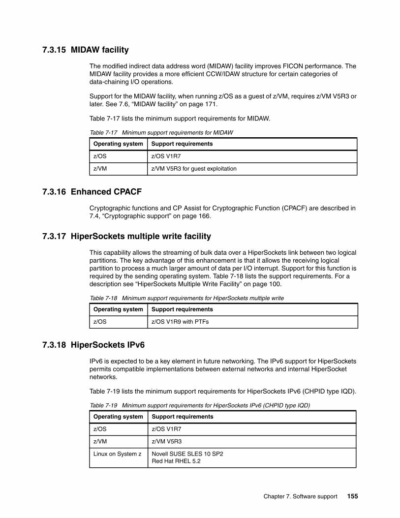
7.3.15 MIDAW facility
The modified indirect data address word (MIDAW) facility improves FICON performance. The MIDAW facility provides a more efficient CCW/IDAW structure for certain categories of data-chaining I/O operations.
Support for the MIDAW facility, when running z/OS as a guest of z/VM, requires z/VM V5R3 or later. See 7.6, “MIDAW facility” on page 171.
Table 7-17 lists the minimum support requirements for MIDAW.
Table 7-17 Minimum support requirements for MIDAW
7.3.16 Enhanced CPACF
Cryptographic functions and CP Assist for Cryptographic Function (CPACF) are described in 7.4, “Cryptographic support” on page 166.
7.3.17 HiperSockets multiple write facility
This capability allows the streaming of bulk data over a HiperSockets link between two logical partitions. The key advantage of this enhancement is that it allows the receiving logical partition to process a much larger amount of data per I/O interrupt. Support for this function is required by the sending operating system. Table 7-18 lists the support requirements. For a description see “HiperSockets Multiple Write Facility” on page 100.
Table 7-18 Minimum support requirements for HiperSockets multiple write
7.3.18 HiperSockets IPv6
IPv6 is expected to be a key element in future networking. The IPv6 support for HiperSockets permits compatible implementations between external networks and internal HiperSocket networks.
Table 7-19 lists the minimum support requirements for HiperSockets IPv6 (CHPID type IQD).
Table 7-19 Minimum support requirements for HiperSockets IPv6 (CHPID type IQD)
Operating system Support requirements
z/OS z/OS V1R7
z/VM z/VM V5R3 for guest exploitation
Operating system Support requirements
z/OS z/OS V1R9 with PTFs
Operating system Support requirements
z/OS z/OS V1R7
z/VM z/VM V5R3
Linux on System z Novell SUSE SLES 10 SP2Red Hat RHEL 5.2
Chapter 7. Software support 155
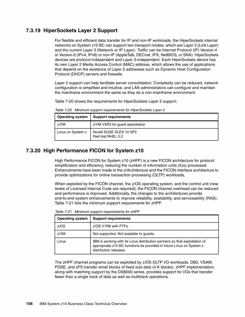
7.3.19 HiperSockets Layer 2 Support
For flexible and efficient data transfer for IP and non-IP workloads, the HiperSockets internal networks on System z10 BC can support two transport modes, which are Layer 2 (Link Layer) and the current Layer 3 (Network or IP Layer). Traffic can be Internet Protocol (IP) Version 4 or Version 6 (IPv4, IPv6) or non-IP (AppleTalk, DECnet, IPX, NetBIOS, or SNA). HiperSockets devices are protocol-independent and Layer 3-independent. Each HiperSockets device has its own Layer 2 Media Access Control (MAC) address, which allows the use of applications that depend on the existence of Layer 2 addresses such as Dynamic Host Configuration Protocol (DHCP) servers and firewalls.
Layer 2 support can help facilitate server consolidation. Complexity can be reduced, network configuration is simplified and intuitive, and LAN administrators can configure and maintain the mainframe environment the same as they do a non-mainframe environment.
Table 7-20 shows the requirements for HiperSockets Layer 2 support.
Table 7-20 Minimum support requirements for HiperSockets Layer 2
7.3.20 High Performance FICON for System z10
High Performance FICON for System z10 (zHPF) is a new FICON architecture for protocol simplification and efficiency, reducing the number of information units (IUs) processed. Enhancements have been made to the z/Architecture and the FICON interface architecture to provide optimizations for online transaction processing (OLTP) workloads.
When exploited by the FICON channel, the z/OS operating system, and the control unit (new levels of Licensed Internal Code are required), the FICON channel overhead can be reduced and performance is improved. Additionally, the changes to the architectures provide end-to-end system enhancements to improve reliability, availability, and serviceability (RAS). Table 7-21 lists the minimum support requirements for zHPF.
Table 7-21 Minimum support requirements for zHPF
The zHPF channel programs can be exploited by z/OS OLTP I/O workloads. DB2, VSAM, PDSE, and zFS transfer small blocks of fixed size data (4 K blocks). zHPF implementation, along with matching support by the DS8000 series, provides support for I/Os that transfer fewer than a single track of data as well as multitrack operations.
Operating system Support requirements
z/VM z/VM V5R3 for guest exploitation
Linux on System z Novell SUSE SLES 10 SP2Red Hat RHEL 5.2
Operating system Support requirements
z/OS z/OS V1R8 with PTFs.
z/VM Not supported. Not available to guests.
Linux IBM is working with its Linux distribution partners so that exploitation of appropriate z10 BC functions be provided in future Linux on System z distribution releases.
156 IBM System z10 Business Class Technical Overview
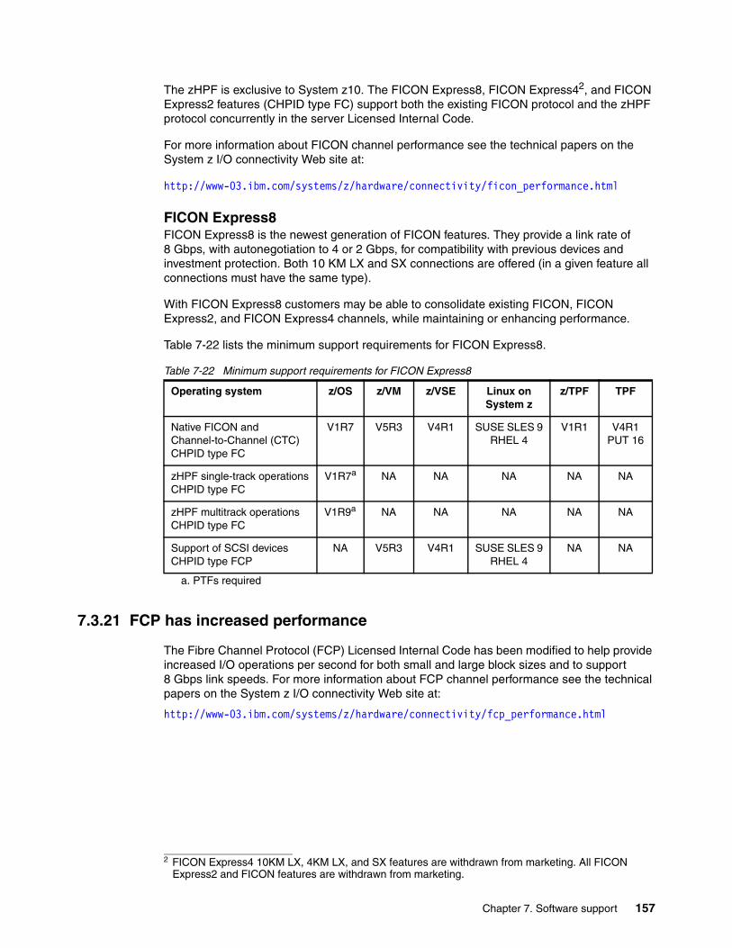
The zHPF is exclusive to System z10. The FICON Express8, FICON Express42, and FICON Express2 features (CHPID type FC) support both the existing FICON protocol and the zHPF protocol concurrently in the server Licensed Internal Code.
For more information about FICON channel performance see the technical papers on the System z I/O connectivity Web site at:
http://www-03.ibm.com/systems/z/hardware/connectivity/ficon_performance.html
FICON Express8FICON Express8 is the newest generation of FICON features. They provide a link rate of 8 Gbps, with autonegotiation to 4 or 2 Gbps, for compatibility with previous devices and investment protection. Both 10 KM LX and SX connections are offered (in a given feature all connections must have the same type).
With FICON Express8 customers may be able to consolidate existing FICON, FICON Express2, and FICON Express4 channels, while maintaining or enhancing performance.
Table 7-22 lists the minimum support requirements for FICON Express8.
Table 7-22 Minimum support requirements for FICON Express8
7.3.21 FCP has increased performance
The Fibre Channel Protocol (FCP) Licensed Internal Code has been modified to help provide increased I/O operations per second for both small and large block sizes and to support 8 Gbps link speeds. For more information about FCP channel performance see the technical papers on the System z I/O connectivity Web site at:
http://www-03.ibm.com/systems/z/hardware/connectivity/fcp_performance.html
2 FICON Express4 10KM LX, 4KM LX, and SX features are withdrawn from marketing. All FICON Express2 and FICON features are withdrawn from marketing.
Operating system z/OS z/VM z/VSE Linux on System z
z/TPF TPF
Native FICON and Channel-to-Channel (CTC)CHPID type FC
V1R7 V5R3 V4R1 SUSE SLES 9RHEL 4
V1R1 V4R1 PUT 16
zHPF single-track operationsCHPID type FC
V1R7a
a. PTFs required
NA NA NA NA NA
zHPF multitrack operationsCHPID type FC
V1R9a NA NA NA NA NA
Support of SCSI devicesCHPID type FCP
NA V5R3 V4R1 SUSE SLES 9RHEL 4
NA NA
Chapter 7. Software support 157
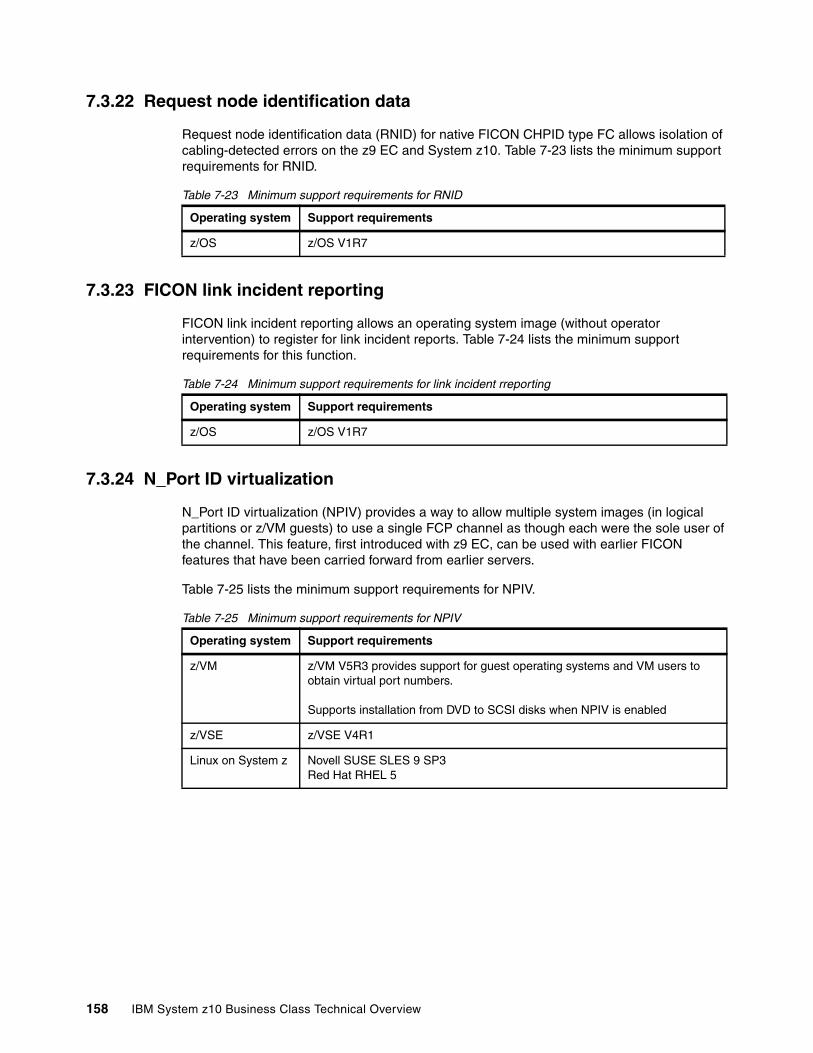
7.3.22 Request node identification data
Request node identification data (RNID) for native FICON CHPID type FC allows isolation of cabling-detected errors on the z9 EC and System z10. Table 7-23 lists the minimum support requirements for RNID.
Table 7-23 Minimum support requirements for RNID
7.3.23 FICON link incident reporting
FICON link incident reporting allows an operating system image (without operator intervention) to register for link incident reports. Table 7-24 lists the minimum support requirements for this function.
Table 7-24 Minimum support requirements for link incident rreporting
7.3.24 N_Port ID virtualization
N_Port ID virtualization (NPIV) provides a way to allow multiple system images (in logical partitions or z/VM guests) to use a single FCP channel as though each were the sole user of the channel. This feature, first introduced with z9 EC, can be used with earlier FICON features that have been carried forward from earlier servers.
Table 7-25 lists the minimum support requirements for NPIV.
Table 7-25 Minimum support requirements for NPIV
Operating system Support requirements
z/OS z/OS V1R7
Operating system Support requirements
z/OS z/OS V1R7
Operating system Support requirements
z/VM z/VM V5R3 provides support for guest operating systems and VM users to obtain virtual port numbers.
Supports installation from DVD to SCSI disks when NPIV is enabled
z/VSE z/VSE V4R1
Linux on System z Novell SUSE SLES 9 SP3Red Hat RHEL 5
158 IBM System z10 Business Class Technical Overview
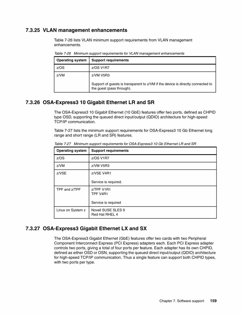
7.3.25 VLAN management enhancements
Table 7-26 lists VLAN minimum support requirements from VLAN management enhancements.
Table 7-26 Minimum support requirements for VLAN management enhancements
7.3.26 OSA-Express3 10 Gigabit Ethernet LR and SR
The OSA-Express3 10 Gigabit Ethernet (10 GbE) features offer two ports, defined as CHPID type OSD, supporting the queued direct input/output (QDIO) architecture for high-speed TCP/IP communication.
Table 7-27 lists the minimum support requirements for OSA-Express3 10 Gb Ethernet long range and short range (LR and SR) features.
Table 7-27 Minimum support requirements for OSA-Express3 10 Gb Ethernet LR and SR
7.3.27 OSA-Express3 Gigabit Ethernet LX and SX
The OSA-Express3 Gigabit Ethernet (GbE) features offer two cards with two Peripheral Component Interconnect Express (PCI Express) adapters each. Each PCI Express adapter controls two ports, giving a total of four ports per feature. Each adapter has its own CHPID, defined as either OSD or OSN, supporting the queued direct input/output (QDIO) architecture for high-speed TCP/IP communication. Thus a single feature can support both CHPID types, with two ports per type.
Operating system Support requirements
z/OS z/OS V1R7
z/VM z/VM V5R3
Support of guests is transparent to z/VM if the device is directly connected to the guest (pass through).
Operating system Support requirements
z/OS z/OS V1R7
z/VM z/VM V5R3
z/VSE z/VSE V4R1
Service is required.
TPF and z/TPF z/TPF V1R1TPF V4R1
Service is required
Linux on System z Novell SUSE SLES 9Red Hat RHEL 4
Chapter 7. Software support 159
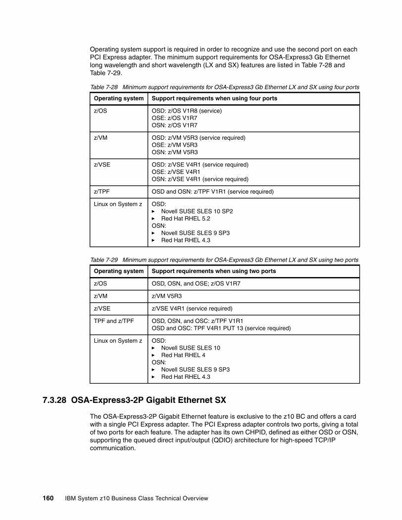
Operating system support is required in order to recognize and use the second port on each PCI Express adapter. The minimum support requirements for OSA-Express3 Gb Ethernet long wavelength and short wavelength (LX and SX) features are listed in Table 7-28 and Table 7-29.
Table 7-28 Minimum support requirements for OSA-Express3 Gb Ethernet LX and SX using four ports
Table 7-29 Minimum support requirements for OSA-Express3 Gb Ethernet LX and SX using two ports
7.3.28 OSA-Express3-2P Gigabit Ethernet SX
The OSA-Express3-2P Gigabit Ethernet feature is exclusive to the z10 BC and offers a card with a single PCI Express adapter. The PCI Express adapter controls two ports, giving a total of two ports for each feature. The adapter has its own CHPID, defined as either OSD or OSN, supporting the queued direct input/output (QDIO) architecture for high-speed TCP/IP communication.
Operating system Support requirements when using four ports
z/OS OSD: z/OS V1R8 (service)OSE: z/OS V1R7OSN: z/OS V1R7
z/VM OSD: z/VM V5R3 (service required)OSE: z/VM V5R3OSN: z/VM V5R3
z/VSE OSD: z/VSE V4R1 (service required)OSE: z/VSE V4R1OSN: z/VSE V4R1 (service required)
z/TPF OSD and OSN: z/TPF V1R1 (service required)
Linux on System z OSD:� Novell SUSE SLES 10 SP2� Red Hat RHEL 5.2OSN:� Novell SUSE SLES 9 SP3� Red Hat RHEL 4.3
Operating system Support requirements when using two ports
z/OS OSD, OSN, and OSE; z/OS V1R7
z/VM z/VM V5R3
z/VSE z/VSE V4R1 (service required)
TPF and z/TPF OSD, OSN, and OSC: z/TPF V1R1OSD and OSC: TPF V4R1 PUT 13 (service required)
Linux on System z OSD:� Novell SUSE SLES 10� Red Hat RHEL 4OSN:� Novell SUSE SLES 9 SP3� Red Hat RHEL 4.3
160 IBM System z10 Business Class Technical Overview
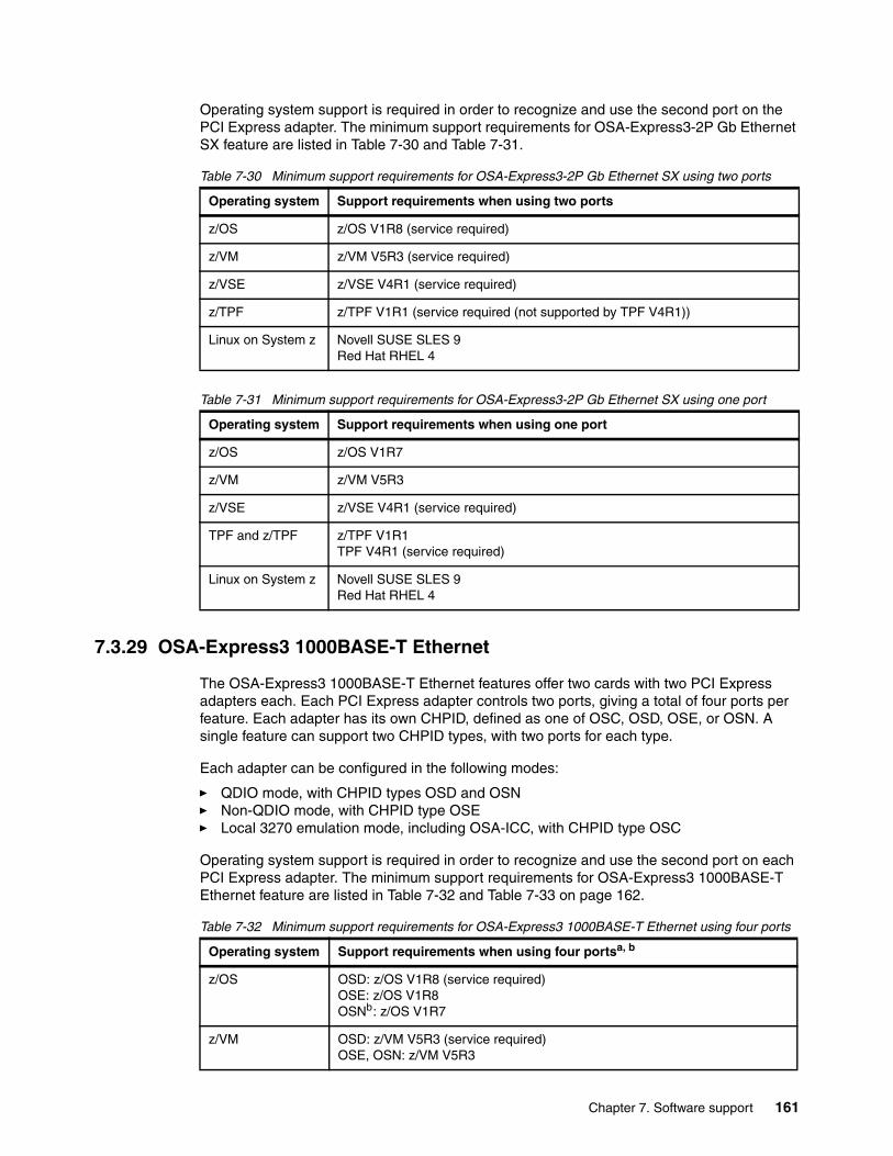
Operating system support is required in order to recognize and use the second port on the PCI Express adapter. The minimum support requirements for OSA-Express3-2P Gb Ethernet SX feature are listed in Table 7-30 and Table 7-31.
Table 7-30 Minimum support requirements for OSA-Express3-2P Gb Ethernet SX using two ports
Table 7-31 Minimum support requirements for OSA-Express3-2P Gb Ethernet SX using one port
7.3.29 OSA-Express3 1000BASE-T Ethernet
The OSA-Express3 1000BASE-T Ethernet features offer two cards with two PCI Express adapters each. Each PCI Express adapter controls two ports, giving a total of four ports per feature. Each adapter has its own CHPID, defined as one of OSC, OSD, OSE, or OSN. A single feature can support two CHPID types, with two ports for each type.
Each adapter can be configured in the following modes:
� QDIO mode, with CHPID types OSD and OSN � Non-QDIO mode, with CHPID type OSE � Local 3270 emulation mode, including OSA-ICC, with CHPID type OSC
Operating system support is required in order to recognize and use the second port on each PCI Express adapter. The minimum support requirements for OSA-Express3 1000BASE-T Ethernet feature are listed in Table 7-32 and Table 7-33 on page 162.
Table 7-32 Minimum support requirements for OSA-Express3 1000BASE-T Ethernet using four ports
Operating system Support requirements when using two ports
z/OS z/OS V1R8 (service required)
z/VM z/VM V5R3 (service required)
z/VSE z/VSE V4R1 (service required)
z/TPF z/TPF V1R1 (service required (not supported by TPF V4R1))
Linux on System z Novell SUSE SLES 9Red Hat RHEL 4
Operating system Support requirements when using one port
z/OS z/OS V1R7
z/VM z/VM V5R3
z/VSE z/VSE V4R1 (service required)
TPF and z/TPF z/TPF V1R1TPF V4R1 (service required)
Linux on System z Novell SUSE SLES 9Red Hat RHEL 4
Operating system Support requirements when using four portsa, b
z/OS OSD: z/OS V1R8 (service required)OSE: z/OS V1R8OSNb: z/OS V1R7
z/VM OSD: z/VM V5R3 (service required)OSE, OSN: z/VM V5R3
Chapter 7. Software support 161
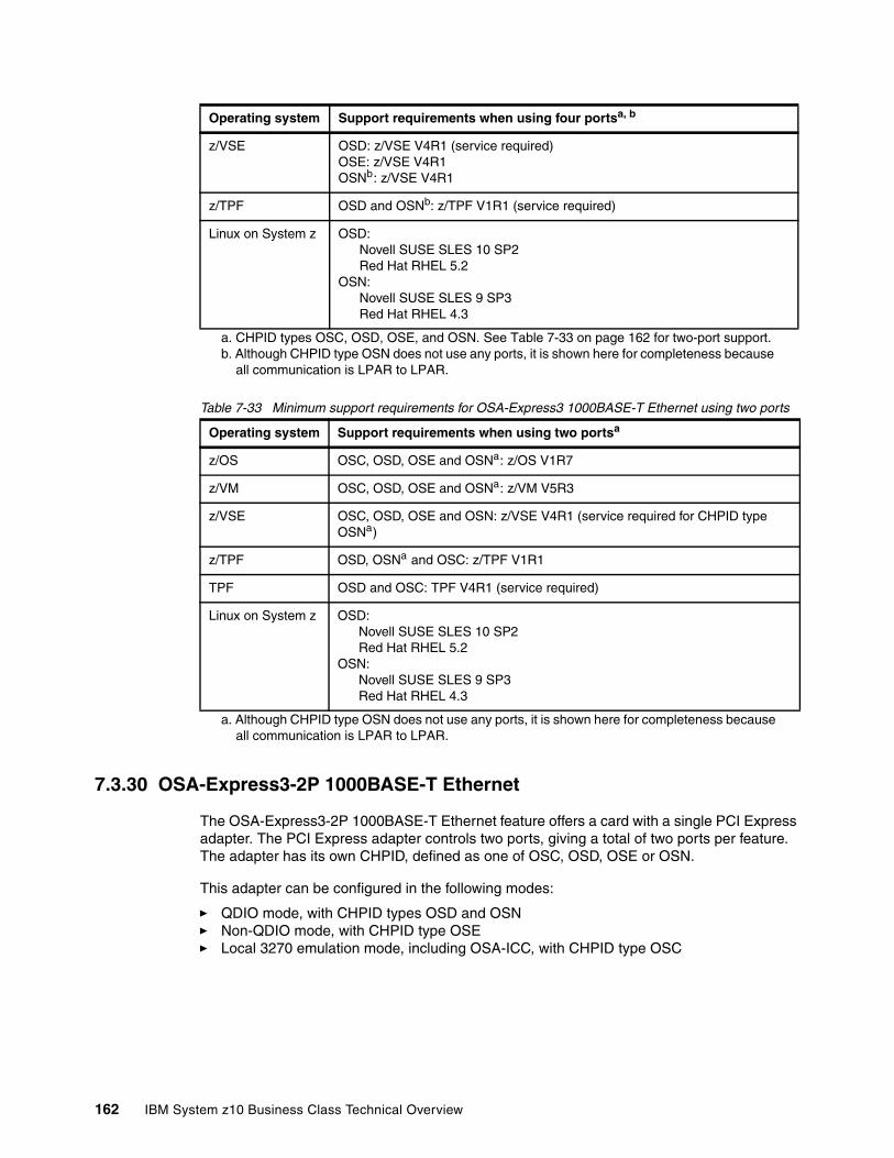
Table 7-33 Minimum support requirements for OSA-Express3 1000BASE-T Ethernet using two ports
7.3.30 OSA-Express3-2P 1000BASE-T Ethernet
The OSA-Express3-2P 1000BASE-T Ethernet feature offers a card with a single PCI Express adapter. The PCI Express adapter controls two ports, giving a total of two ports per feature. The adapter has its own CHPID, defined as one of OSC, OSD, OSE or OSN.
This adapter can be configured in the following modes:
� QDIO mode, with CHPID types OSD and OSN � Non-QDIO mode, with CHPID type OSE � Local 3270 emulation mode, including OSA-ICC, with CHPID type OSC
z/VSE OSD: z/VSE V4R1 (service required)OSE: z/VSE V4R1OSNb: z/VSE V4R1
z/TPF OSD and OSNb: z/TPF V1R1 (service required)
Linux on System z OSD:Novell SUSE SLES 10 SP2Red Hat RHEL 5.2
OSN:Novell SUSE SLES 9 SP3Red Hat RHEL 4.3
a. CHPID types OSC, OSD, OSE, and OSN. See Table 7-33 on page 162 for two-port support.b. Although CHPID type OSN does not use any ports, it is shown here for completeness because
all communication is LPAR to LPAR.
Operating system Support requirements when using two portsa
a. Although CHPID type OSN does not use any ports, it is shown here for completeness because all communication is LPAR to LPAR.
z/OS OSC, OSD, OSE and OSNa: z/OS V1R7
z/VM OSC, OSD, OSE and OSNa: z/VM V5R3
z/VSE OSC, OSD, OSE and OSN: z/VSE V4R1 (service required for CHPID type OSNa)
z/TPF OSD, OSNa and OSC: z/TPF V1R1
TPF OSD and OSC: TPF V4R1 (service required)
Linux on System z OSD:Novell SUSE SLES 10 SP2Red Hat RHEL 5.2
OSN:Novell SUSE SLES 9 SP3Red Hat RHEL 4.3
Operating system Support requirements when using four portsa, b
162 IBM System z10 Business Class Technical Overview
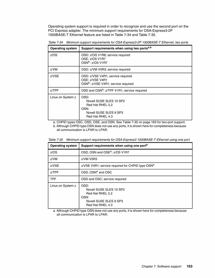
Operating system support is required in order to recognize and use the second port on the PCI Express adapter. The minimum support requirements for OSA-Express3-2P 1000BASE-T Ethernet feature are listed in Table 7-34 and Table 7-35.
Table 7-34 Minimum support requirements for OSA-Express3-2P 1000BASE-T Ethernet, two ports
Table 7-35 Minimum support requirements for OSA-Express3 1000BASE-T Ethernet using one port
Operating system Support requirements when using two portsa,b
a. CHPID types OSC, OSD, OSE, and OSN. See Table 7-35 on page 163 for two-port support.b. Although CHPID type OSN does not use any ports, it is shown here for completeness because
all communication is LPAR to LPAR.
z/OS OSD: z/OS V1R8; service requiredOSE: z/OS V1R7OSNb: z/OS V1R7
z/VM OSD: z/VM V5R3; service required
z/VSE OSD: z/VSE V4R1; service requiredOSE: z/VSE V4R1OSNb: z/VSE V4R1; service required
z/TPF OSD and OSNb: z/TPF V1R1; service required
Linux on System z OSD:Novell SUSE SLES 10 SP2Red Hat RHEL 5.2
OSN:Novell SUSE SLES 9 SP3Red Hat RHEL 4.3
Operating system Support requirements when using one porta
a. Although CHPID type OSN does not use any ports, it is shown here for completeness because all communication is LPAR to LPAR.
z/OS OSD, OSN and OSEa; z/OS V1R7
z/VM z/VM V5R3
z/VSE z/VSE V4R1; service required for CHPID type OSNa
z/TPF OSD, OSNa and OSC
TPF OSD and OSC; service required
Linux on System z OSD:Novell SUSE SLES 10 SP2Red Hat RHEL 5.2
OSN:Novell SUSE SLES 9 SP3Red Hat RHEL 4.3
Chapter 7. Software support 163

7.3.31 GARP VLAN Registration Protocol
GARP3 VLAN Registration Protocol (GVRP) support allows an OSA-Express3 or OSA-Express2 port to register or unregister its VLAN IDs with a GVRP-capable switch and dynamically update its table as the VLANs change. Minimum support requirements are listed in Table 7-36.
Table 7-36 Minimum support requirements for GVRP
7.3.32 OSA-Express3 and OSA-Express2 OSN support
Channel Data Link Control (CDLC), when used with the Communication Controller for Linux, emulates selected functions of IBM 3745/NCP operations. The port used with the OSN support appears as an ESCON channel to the operating system. This support can be used with OSA-Express3 GbE and 1000BASE-T, and OSA-Express2 GbE4 and 1000BASE-T features.
Table 7-37 lists the minimum support requirements for OSN.
Table 7-37 Minimum support requirements for OSA-Express3 and OSA-Express2 OSN
7.3.33 OSA-Express2 1000BASE-T Ethernet
This adapter can be configured in:
� QDIO mode, with CHPID type OSD or OSN � Non-QDIO mode, with CHPID type OSE � Local 3270 emulation mode with CHPID type OSC
3 Generic Attribute Registration Protocol
Operating system Support requirements
z/OS z/OS V1R7
z/VM z/VM V5R3
4 OSA Express2 GbE is withdrawn from marketing.
Operating system OSA-Express3 and OSA-Express2 OSN
z/OS z/OS V1R7
z/VM z/VM V5R3
z/VSE z/VSE V4R1
Linux on System z Novell SUSE SLES 9 SP3Red Hat RHEL 4.3
TPF and z/TPF TPF V4R1 and z/TPF V1R1
164 IBM System z10 Business Class Technical Overview
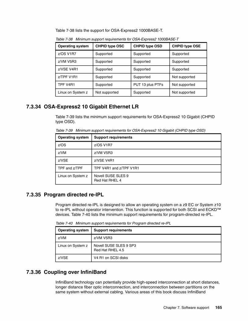
Table 7-38 lists the support for OSA-Express2 1000BASE-T.
Table 7-38 Minimum support requirements for OSA-Express2 1000BASE-T
7.3.34 OSA-Express2 10 Gigabit Ethernet LR
Table 7-39 lists the minimum support requirements for OSA-Express2 10 Gigabit (CHPID type OSD).
Table 7-39 Minimum support requirements for OSA-Express2 10 Gigabit (CHPID type OSD)
7.3.35 Program directed re-IPL
Program directed re-IPL is designed to allow an operating system on a z9 EC or System z10 to re-IPL without operator intervention. This function is supported for both SCSI and ECKD™ devices. Table 7-40 lists the minimum support requirements for program-directed re-IPL.
Table 7-40 Minimum support requirements for Program directed re-IPL
7.3.36 Coupling over InfiniBand
InfiniBand technology can potentially provide high-speed interconnection at short distances, longer distance fiber optic interconnection, and interconnection between partitions on the same system without external cabling. Various areas of this book discuss InfiniBand
Operating system CHPID type OSC CHPID type OSD CHPID type OSE
z/OS V1R7 Supported Supported Supported
z/VM V5R3 Supported Supported Supported
z/VSE V4R1 Supported Supported Supported
z/TPF V1R1 Supported Supported Not supported
TPF V4R1 Supported PUT 13 plus PTFs Not supported
Linux on System z Not supported Supported Not supported
Operating system Support requirements
z/OS z/OS V1R7
z/VM z/VM V5R3
z/VSE z/VSE V4R1
TPF and z/TPF TPF V4R1 and z/TPF V1R1
Linux on System z Novell SUSE SLES 9Red Hat RHEL 4
Operating system Support requirements
z/VM z/VM V5R3
Linux on System z Novell SUSE SLES 9 SP3Red Hat RHEL 4.5
z/VSE V4 R1 on SCSI disks
Chapter 7. Software support 165

characteristics and support. For an example see 4.8, “Parallel Sysplex connectivity” on page 101.
InfiniBand coupling linksTable 7-41 lists the minimum support requirements for coupling links over InfiniBand.
Table 7-41 Minimum support requirements for coupling links over InfiniBand
InfiniBand coupling links at an unrepeated distance of 10 km Support for HCA2-O LR fanout, which supports InfiniBand coupling links (1x IB-SDR or 1x IB-DDR) at an unrepeated distance of 10 KM (6.2 miles) is listed on Table 7-42.
Table 7-42 Minimum support requirements for coupling links over InfiniBand at 10 km
7.3.37 Dynamic I/O support for InfiniBand CHPIDs
This support refers exclusively to the z/VM support of dynamic I/O configuration of InfiniBand coupling links. Support is available for the CIB CHPID type in the z/VM dynamic commands, including the change channel path dynamic I/O command. Specifying and changing the system name when entering and leaving configuration mode is also supported. z/VM does not use InfiniBand coupling links and does not support the use of InfiniBand coupling links by guests.
Table 7-43 lists the minimum support requirements of dynamic I/O support for InfiniBand CHPIDs.
Table 7-43 Minimum support requirements for dynamic I/O support for InfiniBand CHPIDs
7.4 Cryptographic support
The z10 BC provides two major groups of cryptographic functions:
� Synchronous cryptographic functions are provided by the CP Assist for Cryptographic Function (CPACF).
� Asynchronous cryptographic functions are provided by the Crypto Express features.
Operating system Support requirements
z/OS z/OS V1R7
z/VM z/VM V5R3 (dynamic I/O support for InfiniBand CHPIDs. Coupling over InfiniBand is not supported for guest use.)
TPF and z/TPF TPF V4R1 compatibility support only
Operating system Support requirements
z/OS z/OS V1R8; service required
z/VM z/VM V5R3 (dynamic I/O support for InfiniBand CHPIDs. Coupling over InfiniBand is not supported for guest use.)
Operating system Support requirements
z/VM z/VM V5R3
166 IBM System z10 Business Class Technical Overview
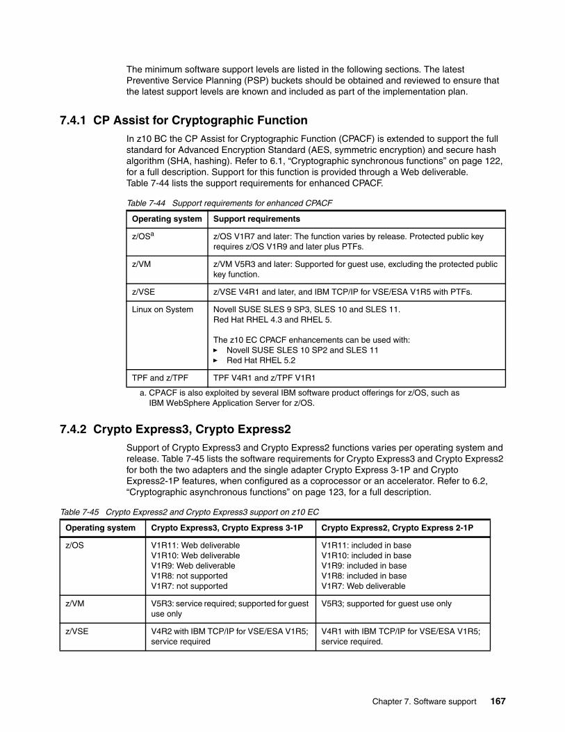
The minimum software support levels are listed in the following sections. The latest Preventive Service Planning (PSP) buckets should be obtained and reviewed to ensure that the latest support levels are known and included as part of the implementation plan.
7.4.1 CP Assist for Cryptographic FunctionIn z10 BC the CP Assist for Cryptographic Function (CPACF) is extended to support the full standard for Advanced Encryption Standard (AES, symmetric encryption) and secure hash algorithm (SHA, hashing). Refer to 6.1, “Cryptographic synchronous functions” on page 122, for a full description. Support for this function is provided through a Web deliverable. Table 7-44 lists the support requirements for enhanced CPACF.
Table 7-44 Support requirements for enhanced CPACF
7.4.2 Crypto Express3, Crypto Express2Support of Crypto Express3 and Crypto Express2 functions varies per operating system and release. Table 7-45 lists the software requirements for Crypto Express3 and Crypto Express2 for both the two adapters and the single adapter Crypto Express 3-1P and Crypto Express2-1P features, when configured as a coprocessor or an accelerator. Refer to 6.2, “Cryptographic asynchronous functions” on page 123, for a full description.
Table 7-45 Crypto Express2 and Crypto Express3 support on z10 EC
Operating system Support requirements
z/OSa
a. CPACF is also exploited by several IBM software product offerings for z/OS, such as IBM WebSphere Application Server for z/OS.
z/OS V1R7 and later: The function varies by release. Protected public key requires z/OS V1R9 and later plus PTFs.
z/VM z/VM V5R3 and later: Supported for guest use, excluding the protected public key function.
z/VSE z/VSE V4R1 and later, and IBM TCP/IP for VSE/ESA V1R5 with PTFs.
Linux on System Novell SUSE SLES 9 SP3, SLES 10 and SLES 11.Red Hat RHEL 4.3 and RHEL 5.
The z10 EC CPACF enhancements can be used with:� Novell SUSE SLES 10 SP2 and SLES 11� Red Hat RHEL 5.2
TPF and z/TPF TPF V4R1 and z/TPF V1R1
Operating system Crypto Express3, Crypto Express 3-1P Crypto Express2, Crypto Express 2-1P
z/OS V1R11: Web deliverableV1R10: Web deliverableV1R9: Web deliverableV1R8: not supportedV1R7: not supported
V1R11: included in baseV1R10: included in baseV1R9: included in baseV1R8: included in baseV1R7: Web deliverable
z/VM V5R3: service required; supported for guest use only
V5R3; supported for guest use only
z/VSE V4R2 with IBM TCP/IP for VSE/ESA V1R5; service required
V4R1 with IBM TCP/IP for VSE/ESA V1R5; service required.
Chapter 7. Software support 167
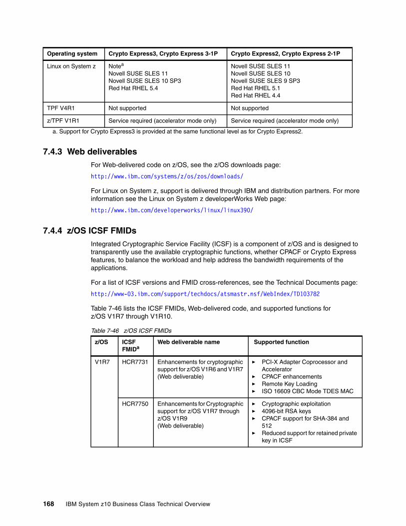
7.4.3 Web deliverablesFor Web-delivered code on z/OS, see the z/OS downloads page:
http://www.ibm.com/systems/z/os/zos/downloads/
For Linux on System z, support is delivered through IBM and distribution partners. For more information see the Linux on System z developerWorks Web page:
http://www.ibm.com/developerworks/linux/linux390/
7.4.4 z/OS ICSF FMIDsIntegrated Cryptographic Service Facility (ICSF) is a component of z/OS and is designed to transparently use the available cryptographic functions, whether CPACF or Crypto Express features, to balance the workload and help address the bandwidth requirements of the applications.
For a list of ICSF versions and FMID cross-references, see the Technical Documents page:
http://www-03.ibm.com/support/techdocs/atsmastr.nsf/WebIndex/TD103782
Table 7-46 lists the ICSF FMIDs, Web-delivered code, and supported functions for z/OS V1R7 through V1R10.
Table 7-46 z/OS ICSF FMIDs
Linux on System z Notea
Novell SUSE SLES 11Novell SUSE SLES 10 SP3Red Hat RHEL 5.4
Novell SUSE SLES 11Novell SUSE SLES 10Novell SUSE SLES 9 SP3Red Hat RHEL 5.1Red Hat RHEL 4.4
TPF V4R1 Not supported Not supported
z/TPF V1R1 Service required (accelerator mode only) Service required (accelerator mode only)
a. Support for Crypto Express3 is provided at the same functional level as for Crypto Express2.
Operating system Crypto Express3, Crypto Express 3-1P Crypto Express2, Crypto Express 2-1P
z/OS ICSF FMIDa
Web deliverable name Supported function
V1R7 HCR7731 Enhancements for cryptographic support for z/OS V1R6 and V1R7 (Web deliverable)
� PCI-X Adapter Coprocessor and Accelerator
� CPACF enhancements� Remote Key Loading � ISO 16609 CBC Mode TDES MAC
HCR7750 Enhancements for Cryptographic support for z/OS V1R7 through z/OS V1R9 (Web deliverable)
� Cryptographic exploitation � 4096-bit RSA keys� CPACF support for SHA-384 and
512� Reduced support for retained private
key in ICSF
168 IBM System z10 Business Class Technical Overview
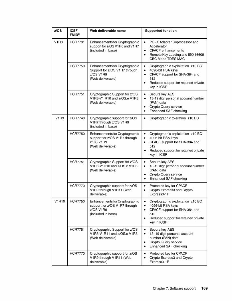
V1R8 HCR7731 Enhancements for Cryptographic support for z/OS V1R6 and V1R7 (included in base)
� PCI-X Adapter Coprocessor and Accelerator
� CPACF enhancements� Remote Key Loading and ISO 16609
CBC Mode TDES MAC
HCR7750 Enhancements for Cryptographic Support for z/OS V1R7 through z/OS V1R9 (Web deliverable)
� Cryptographic exploitation z10 BC� 4096-bit RSA keys� CPACF support for SHA-384 and
512� Reduced support for retained private
key in ICSF
HCR7751 Cryptographic Support for z/OS V1R8-V1 R10 and z/OS.e V1R8 (Web deliverable)
� Secure key AES� 13-19 digit personal account number
(PAN) data� Crypto Query service� Enhanced SAF checking
V1R9 HCR7740 Cryptographic support for z/OS V1R7 through z/OS V1R9 (included in base)
� Cryptographic toleration z10 BC
HCR7750 Enhancements for Cryptographic support for z/OS V1R7 through z/OS V1R9 (Web deliverable)
� Cryptographic exploitation z10 BC� 4096-bit RSA keys� CPACF support for SHA-384 and
512� Reduced support for retained private
key in ICSF
HCR7751 Cryptographic Support for z/OS V1R8-V1R10 and z/OS.e V1R8 (Web deliverable)
� Secure key AES� 13-19 digit personal account number
(PAN) data� Crypto Query service� Enhanced SAF checking
HCR7770 Cryptographic support for z/OS V1R9 through V1R11 (Web deliverable)
� Protected key for CPACF � Crypto Express3 and Crypto
Express3-1P
V1R10 HCR7750 Enhancements for Cryptographic support for z/OS V1R7 through z/OS V1R9 (included in base)
� Cryptographic exploitation z10 BC� 4096-bit RSA keys� CPACF support for SHA-384 and
512� Reduced support for retained private
key in ICSF
HCR7751 Cryptographic Support for z/OS V1R8-V1R11 and z/OS.e V1R8 (Web deliverable)
� Secure key AES� 13–19 digit personal account
number (PAN) data� Crypto Query service� Enhanced SAF checking
HCR7770 Cryptographic support for z/OS V1R9 through V1R11 (Web deliverable)
� Protected key for CPACF � Crypto Express3 and Crypto
Express3-1P
z/OS ICSF FMIDa
Web deliverable name Supported function
Chapter 7. Software support 169
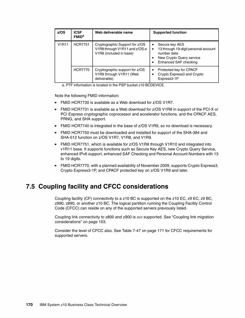
Note the following FMID information:
� FMID HCR7730 is available as a Web download for z/OS V1R7.
� FMID HCR7731 is available as a Web download for z/OS V1R8 in support of the PCI-X or PCI Express cryptographic coprocessor and accelerator functions, and the CPACF AES, PRNG, and SHA support.
� FMID HCR7740 is integrated in the base of z/OS V1R9, so no download is necessary.
� FMID HCR7750 must be downloaded and installed for support of the SHA-384 and SHA-512 function on z/OS V1R7, V1R8, and V1R9.
� FMID HCR7751, which is available for z/OS V1R8 through V1R10 and integrated into v1R11 base. It supports functions such as Secure Key AES, new Crypto Query Service, enhanced IPv6 support, enhanced SAF Checking and Personal Account Numbers with 13 to 19 digits.
� FMID HCR7770, with a planned availability of November 2009, supports Crypto Express3, Crypto Express3-1P, and CPACF protected key on z/OS V1R9 and later.
7.5 Coupling facility and CFCC considerations
Coupling facility (CF) connectivity to a z10 BC is supported on the z10 EC, z9 EC, z9 BC, z990, z890, or another z10 BC. The logical partition running the Coupling Facility Control Code (CFCC) can reside on any of the supported servers previously listed.
Coupling link connectivity to z800 and z900 is not supported. See “Coupling link migration considerations” on page 103.
Consider the level of CFCC also. See Table 7-47 on page 171 for CFCC requirements for supported servers.
V1R11 HCR7751 Cryptographic Support for z/OS V1R8 through V1R11 and z/OS.e V1R8 (included in base)
� Secure key AES� 13 through 19-digit personal account
number data� New Crypto Query service� Enhanced SAF checking
HCR7770 Cryptographic support for z/OS V1R9 through V1R11 (Web deliverable)
� Protected key for CPACF � Crypto Express3 and Crypto
Express3-1P
a. PTF information is located in the PSP bucket z10 BCDEVICE.
z/OS ICSF FMIDa
Web deliverable name Supported function
170 IBM System z10 Business Class Technical Overview

The z10 BC supports CFCC Level 16, which is exclusive to System z10. CFCC Level 16 brings the following enhancements:
� CF duplexing enhancements
Prior to CFCC Level 16, System-Managed CF Structure Duplexing required two protocol enhancements to occur synchronous to CF processing of the duplexed structure request. CFCC Level 16 allows one of these signals to be asynchronous to CF processing. This allows faster service time, with more benefits as the distances between coupling facilities are further apart, such as in a multi-site Parallel Sysplex.
� List notification improvements
Prior to CFCC Level 16, when a list changed state from empty to non-empty, it would notify its connectors. The first one to respond would read the new message, but when the others read, they would find nothing, paying the cost for the false scheduling.
CFCC Level 16 can help improve processor utilization for IMS Shared Queue and WebSphere MQ Shared Queue environments. The CF notifies only one connector in a round-robin fashion. If the shared queue is read within a fixed period of time, the other connectors do not have to be notified, saving the cost of the false scheduling. If a list is not read within the time limit, then the other connectors are notified as they are prior to CFCC Level 16.
Although no significant increase in storage requirements is expected when moving to CFCC Level 16, we strongly recommend using the CFSizer Tool, which is located on the Web:
http://www.ibm.com/systems/z/cfsizer
For guest virtual coupling, System z10 servers with CFCC Level 16 require z/OS V1R7 or later and z/VM V5R3 or later.
A planned outage is required when migrating the CF to CFCC Level 16.
Table 7-47 System z CFCC code level considerations
The current CFCC level for all System z9 servers is CFCC Level 15. To support migration from one CFCC level to the next, different levels of CFCC can be run concurrently as long as the Coupling Facility logical partitions are running on different servers (CF logical partitions running on the same server share the same CFCC level).
For additional details on CFCC code levels, see the Parallel Sysplex Web page:
http://www.ibm.com/systems/z/pso/cftable.html
7.6 MIDAW facility
The modified indirect data address word (MIDAW) facility is a system architecture and software exploitation designed to improve FICON performance. This facility is available only on System z9 and System z10 servers and is exploited by the media manager in z/OS.
z10 BC CFCC Level 16
z10 EC CFCC Level 15 or later
z9 EC or z9 BC CFCC Level 14 or later
z990 or z890 CFCC Level 13 or later
Chapter 7. Software support 171
The MIDAW facility provides a more efficient CCW/IDAW structure for certain categories of data-chaining I/O operations:
� MIDAW can significantly improve FICON performance for extended format data sets.� MIDAW can improve channel utilization and can significantly improve I/O response time.
MIDAW reduces FICON channel connect time, director ports, and control unit overhead.
MIDAW is supported on ESCON channels configured as CHPID type CNS and on FICON channels configured as CHPID types FCV and FC.
7.6.1 Extended format data sets
z/OS extended format data sets use internal structures (usually not visible to the application program) that require scatter-read (or scatter-write) operation. This means that CCW data chaining is required and this produces less than optimal I/O performance. The most significant performance benefit of MIDAWs is achieved with extended format (EF) data sets.
Besides reliability, EF data sets enable three other functions, which are DFSMS striping, access method compression, and extended addressability (EA). EA is especially useful for creating large DB2 partitions (larger than 4 GB). Striping can be used to increase sequential throughput or to spread random I/Os across multiple logical volumes. DFSMS striping is especially useful for utilizing multiple channels in parallel for one data set. The DB2 logs are often striped to optimize the performance of DB2 sequential inserts.
7.6.2 Performance benefits
z/OS Media Manager has the I/O channel program support for implementing EF data sets, and it automatically exploits MIDAWs when appropriate. Today, most disk I/Os in the system are generated using media manager.
Users of the Executing Fixed Channel Programs in Real Storage (EXCPVR) instruction may construct channel programs containing MIDAWs provided that they construct an IOBE with the IOBEMIDA bit set. Users of EXCP instruction may not construct channel programs containing MIDAWs.
The MIDAW facility removes the 4 K boundary restrictions of indirect data address words (IDAWs), and in the case of EF data sets, reduces the number of CCWs. Decreasing the number of CCWs helps to reduce the FICON channel processor utilization. Media manager and MIDAWs will not cause the bits to move any faster across the FICON link, but they reduce the number of frames and sequences flowing across the link, thus utilizing the channel resources more efficiently.
Use of the MIDAW facility with FICON Express4, operating at 4 Gbps, compared to use of IDAWs with FICON Express2, operating at 2 Gbps, showed an improvement in throughput for all reads on DB2 table scan tests with Extended Format data sets.
The performance of a specific workload can vary according to the conditions and hardware configuration of the environment. IBM laboratory tests found that DB2 gains significant performance benefits by using the MIDAW facility in the following areas:
� Table scans� Logging� Utilities� DFSMS striping for DB2 data sets
172 IBM System z10 Business Class Technical Overview
Media manager with the MIDAW facility can provide significant performance benefits when used in combination applications that use EF data sets (such as DB2) or long chains of small blocks.
For additional information relating to FICON and MIDAW, consult the following sources:
� I/O Connectivity Web site has material about FICON channel performance:
http://www.ibm.com/systems/z/connectivity/
� IBM TotalStorage® DS8000 Series: Performance Monitoring and Tuning, SG24-7146
7.7 IOCP
The required level of I/O Configuration Program (IOCP) for z10 BC is V2R1L0 (IOCP 2.1.0) or later.
7.8 Worldwide portname (WWPN) prediction tool
A part of the installation of your IBM System z10 server is the preplanning of the Storage Area Network (SAN) environment. IBM has made available a stand-alone tool to assist with this planning prior to the installation.
The tool, known as the worldwide port name (WWPN) prediction tool, assigns WWPNs to each virtual Fibre Channel Protocol (FCP) channel/port using the same WWPN assignment algorithms that a system uses when assigning WWPNs for channels utilizing N_Port Identifier Virtualization (NPIV). Thus, the SAN can be set up in advance, allowing operations to proceed much faster once the server is installed.
The WWPN prediction tool takes a .csv file containing the FCP-specific I/O device definitions and creates the WWPN assignments that are required to set up the SAN. A binary configuration file that can be imported later by the system is also created. The .csv file can either be created manually or exported from the Hardware Configuration Definition/Hardware Configuration Manager (HCD/HCM).
The WWPN prediction tool on System z10 (CHPID type FCP) requires at a minimum:
� z/OS V1R8, V1R9, V1R10, and V1R11 with PTFs � z/VM V5R3, V5R4, and V6R1 with PTFs
The WWPN prediction tool is available for download from the Resource Link and is applicable to all FICON channels defined as CHPID type FCP (for communication with SCSI devices) on System z10:
http://www.ibm.com/servers/resourcelink/
7.9 ICKDSF
The device support facility ICKDSF Release 17 is required on all systems that share disk subsystems with a z10 BC processor.
ICKDSF supports a modified format of the CPU information field, which contains a two-digit logical partition identifier. ICKDSF uses the CPU information field instead of CCW reserve/release for concurrent media maintenance. It prevents multiple systems from running
Chapter 7. Software support 173
ICKDSF on the same volume, and at the same time allows user applications to run while ICKDSF is processing. To prevent any possible data corruption, ICKDSF must be able to determine all sharing systems that can potentially run ICKDSF. Therefore, this support is required for z10 BC.
7.10 Software licensing considerations
The IBM System z10 mainframe software portfolio includes operating system software (z/OS, z/VM, z/VSE, and z/TPF) and middleware that runs on these operating systems. It also includes middleware for Linux on System z environments. Two major metrics for software licensing are available from IBM, depending on the software product:
� Monthly License Charges (MLC) � International Program License Agreement (IPLA)
Monthly License Charges pricing metrics have a recurring charge that applies each month. In addition to the right to use the product, the charge includes access to IBM product support during the support period. MLC metrics, in turn, include a variety of offerings. Applicable to the System z10 BC are:
� Workload License Charges (WLC)� System z New Application License Charges (zNALC)� Parallel Sysplex License Charges (PSLC)� Midrange Workload License Charges (MWLC)� Entry Workload License Charges (EWLC)
International Program License Agreement (IPLA) metrics have a single, up-front, charge for an entitlement to use the product. Optionally, a separate annual charge called subscription and support entitles customers to receive future releases and versions at no additional charge, and also allows an access to IBM product support during the support period.
For details, consult the IBM System z Software Pricing Reference Guide:
http://www.ibm.com/servers/eserver/zseries/library/refguides/sw_pricing.html
7.10.1 Workload License ChargesWorkload License Charges (WLC) requires z/OS or z/TPF operating systems in 64-bit mode. Any mix of z/OS, z/VM, Linux, VM/ESA, z/VSE, TPF, and z/TPF images is allowed.
Important: The need for ICKDSF Release 17 applies even to systems that are not part of the same sysplex, or that are running operating system other than z/OS, such as z/VM.
174 IBM System z10 Business Class Technical Overview
The two WLC license types are:
� Flat WLC (FWLC)
Software products licensed under FWLC are charged at the same flat rate, no matter what capacity (MSUs) the server is.
� Variable WLC (VWLC)
The VWLC type applies to products such as z/OS, DB2, IMS, CICS, MQSeries®, and Lotus® Domino®. VWLC software products can be charged in two different ways:
– Full-capacity is when the server’s total number of MSUs is used for charging. Full-capacity is applicable when the server is not eligible for subcapacity.
– Subcapacity is when software charges are based on the logical partition’s utilization where the product is running.
WLC subcapacity allows software charges based on logical partition utilizations instead of the server’s total number of MSUs. Subcapacity removes the dependency between software charges and server (hardware) installed capacity.
Subcapacity is based on the logical partition’s rolling 4-hour average utilization. It is not based on the utilization of each product5, but on the utilization of the logical partition or partitions where it runs. The VWLC licensed products running on a logical partition are charged by the maximum value of this partition’s rolling 4-hour average utilization within a month.
The logical partition’s rolling 4-hour average utilization can be limited by a defined capacity definition on the partition’s image profiles. The defined capacity definition activates the soft capping function of PR/SM, avoiding 4-hour average partition utilizations above the defined capacity value. Soft capping controls the maximum rolling 4-hour average utilization (the last 4-hour average value at every five minutes interval), but does not control the maximum instantaneous partition utilization.
Even using the soft-capping option, the partition’s utilization can reach up to its maximum share based on the number of logical processors and weights in the image profile. Only the rolling 4-hour average utilization is tracked, allowing utilization peaks above the defined capacity value.
As with the Parallel Sysplex License Charges (PSLC) software license charge type, the aggregation of server capacities within the same Parallel Sysplex is also possible in WLC, following the same prerequisites.
For further information about WLC and details about how to combine logical partitions utilization, refer to z/OS Planning for Workload License Charges, SA22-7506.
7.10.2 System z New Application License Charges
System z New Application License Charges (zNALC) offers a reduced price for the z/OS operating system on logical partitions running a qualified new workload application such as Java language business applications running under WebSphere Application Server for z/OS, Domino, SAP, PeopleSoft, and Siebel.
z/OS with zNALC provides a strategic pricing model available on the full range of System z servers for simplified application planning and deployment. zNALC allows for aggregation across a qualified Parallel Sysplex, which can provide a lower cost for incremental growth across new workloads that span a Parallel Sysplex.
5 With the exception of products licensed using the Select Application License Charges (SALC) pricing metric.
Chapter 7. Software support 175
For additional information see the zNALC Web page at:
http://www-03.ibm.com/servers/eserver/zseries/swprice/znalc.html
7.10.3 Select Application License ChargesSelect Application License Charges (SALC) applies to WebSphere MQ for System z only. It i allows a WLC customer to license MQ under product utilization rather than the subcapacity pricing provided under WLC.
WebSphere MQ is typically a low-usage product that runs pervasively throughout the customer environment. Clients who run WebSphere MQ at a very low usage can benefit from SALC. Alternatively, one can continue to choose to license WebSphere MQ under WLC.
A reporting function, which IBM provides in the operating system IBM Software Usage Report Program, is used to calculate the daily MSU number. The rules to determine the billable SALC MSUs for WebSphere MQ use the following algorithm:
1. Determines the highest daily usage of a program6 family, which is the highest of 24 hourly measurements recorded each day.
2. Determines the monthly usage of a program3 family, which is the fourth highest daily measurement recorded for a month.
3. Uses the highest monthly usage determined for the next billing period.
For additional information about SALC, see the MWLC Web page:
http://www.ibm.com/servers/eserver/zseries/swprice/other.html
7.10.4 Midrange Workload License Charges
Midrange Workload License Charges (MWLC) applies to z/VSE V4 when running on System z servers. The exception is the z10 BC and z9 BC servers at capacity setting A01 to which zELC applies.
Similarly to Workload License Charges, MWLC can be implemented in full capacity or subcapacity mode. MWLC applies to z/VSE V4 and several IBM middleware products for z/VSE. All other z/VSE programs continue to be priced as before.
The z/VSE pricing metric is independent of the pricing metric for other systems, for instance, z/OS, that might be running on the same server. When z/VSE is running as a guest of z/VM, z/VM V5R3 or later is required.
The Subcapacity Report Tool is used reports utilization. One SCRT report per server is required.
For additional information see the MWLC Web page:
http://www.ibm.com/servers/eserver/zseries/swprice/mwlc.html
7.10.5 Entry Workload License Charges
Entry Workload License Charges (EWLC) enables qualifying customers to pay for subcapacity-eligible IBM software based on the utilization of the LPAR or LPARs where that product executes. This subcapacity pricing provides the potential to lower software charges on a stand-alone z10 BC and z9 BC.
6 The term program refers to all active versions of MQ.
176 IBM System z10 Business Class Technical Overview
EWLC and Workload License Charges (WLC) are two subcapacity-capable monthly license charge pricing metrics from IBM. EWLC is similar to subcapacity WLC, in terms of implementation and mechanics. Both pricing metrics offer LPAR-based pricing for subcapacity-eligible software products, based on the highest rolling 4-hour average utilization of the LPAR or LPARs where the eligible product executes.
Both EWLC and WLC can be implemented at full capacity (based on the MSU rating of the machine), rather than subcapacity. Subcapacity pricing, for either EWLC or WLC, requires the customers to fully migrate all OS/390® to z/OS in 64-bit mode, discontinue their OS/390 licenses, and to use the Subcapacity Reporting Tool to generate subcapacity reports. Each month, these subcapacity reports must be generated and sent by e-mail to IBM.
For additional information see the EWLC Web page:
http://www.ibm.com/servers/eserver/zseries/swprice/ewlc.html
7.10.6 System z International Licensing Agreement
On the mainframe, the following types of products are generally in the IPLA category:
� Data Management Tools� CICS Tools� Application Development Tools� Certain WebSphere for System z products� System z Linux middleware products� z/VM Versions 4, 5, and 6
For additional information see the System z IPLA Web page:
http://www.ibm.com/servers/eserver/zseries/swprice/zipla/
7.11 References
For the most current planning information refer to the support Web page for each operating system:
� z/OS
http://www.ibm.com/systems/support/z/zos/
� z/VM
http://www.ibm.com/systems/support/z/zvm/
� z/TPF
http://www.ibm.com/software/htp/tpf/pages/maint.htm
� z/VSE
http://www.ibm.com/servers/eserver/zseries/zvse/support/preventive.html
� Linux on System z
http://www.ibm.com/systems/z/os/linux/
Chapter 7. Software support 177

178 IBM System z10 Business Class Technical Overview
Chapter 8. System upgrades
The objective of this chapter is to provide an overview z10 BC upgrade possibilities, with an emphasis on Capacity on Demand offerings.
The upgrade offerings to the IBM System z10 BC servers have been developed from previous IBM System z servers. In response to customer requests and changes in market requirements, a number of features have been added. The changes and additions are designed to provide increased customer control over the capacity upgrade offerings, with decreased administrative work and with extended levels of flexibility. The provisioning environment gives the customer an unprecedented flexibility and a finer control over cost and value.
Given today's business environment, the benefits of the growth capabilities provided by the z10 BC are plentiful, and include, but are not limited to:
� Enabling exploitation of new business opportunities� Supporting the growth of dynamic, on-demand environments� Managing the risk of volatile, high-growth, and high-volume applications� Supporting application availability 24 hours a day, every day� Enabling capacity growth during lock down periods� Enabling planned-downtime changes without affecting availability
This chapter discusses the following topics:
� 8.1, “Upgrade types” on page 180� 8.2, “MES upgrades” on page 183� 8.3, “Capacity on Demand upgrades” on page 184
8
© Copyright IBM Corp. 2008, 2009. All rights reserved. 179
8.1 Upgrade types
The IBM System z10 Business Class has the capability of concurrent upgrades, providing additional capacity with no server outage. In most cases, with prior planning and operating system support, a concurrent upgrade can also be nondisruptive to the operating system.
In general, concurrency addresses the continuity of hardware operations during an upgrade, for instance, whether a server (as a box) is required to be switched off during the upgrade. Disruptive versus nondisruptive refers to whether the running software or operating system has to be restarted for the upgrade to take an effect. Thus, even concurrent upgrades can be disruptive to those operating systems or programs that do not support them while at the same time being nondisruptive to others. Nondisruptive upgrades are described in 8.1.3, “Nondisruptive upgrades” on page 182.
The capabilities are based on the flexibility of the design and structure, which allows concurrent hardware installation and Licensed Internal Code (LIC) control over the configuration.
Upgrades can be ordered in two ways:
� Miscellaneous equipment specification (MES) process upgrade
MES grade order is always performed by IBM personnel. The result can be either real hardware added to the server or installation of LIC configuration control (LICCC) to the server. In both cases, installation is performed by IBM personnel.
� Customer initiated upgrade (CIU)
The CIU facility is an IBM online infrastructure through which customers can order upgrades for a System z server. Access to and use of the CIU facility requires the customer and IBM to sign a contract through which terms and conditions for use of the CIU facility are accepted. Using the CIU facility for a given server requires that the online CoD buying feature (FC 9900) is installed on the server. The CIU facility itself is enabled through FC 9898.
After all the prerequisites are in place, the entire process, from ordering to activation of the upgrade, is performed by the customer and does not require any on-site presence of IBM service personnel.
The CIU facility supports LICCC upgrades only. It does not support I/O upgrades. All additional capacity required for an upgrade must be previously installed. Additional I/O drawers or I/O cards cannot be installed as part of an order placed through the CIU facility.
Upgrades can be delivered in two ways:
� MES upgrade
MES upgrade, which can be ordered only by the MES process through an IBM representative, delivers new hardware to be installed. MES installations require an IBM service personnel to perform the upgrade.
� Capacity on Demand (CoD) upgrades
CoD upgrades are delivered in the LICCC record. LICCC provides for server upgrade without hardware changes by activation of additional, previously installed, unused capacity.
CoD upgrade can be ordered either by the MES process (with limitations) or by CIU. If you order by using the MES process, IBM personnel is required to install it. If you order by using CIU, you can install the record without any assistance.
180 IBM System z10 Business Class Technical Overview
8.1.1 Permanent and temporary upgrades
For different situations, different types of upgrades are needed. After some time, depending on your growing workload, you might require more memory, additional I/O cards, or process more capacity. On the other hand, in certain situations, only a short-term upgrade is necessary to handle a peak workload or to temporarily replace a server that is down during a disaster or data center maintenance. The z10 BC offers the following solutions for such situations:
� Permanent upgrade
Permanent upgrades are requested when more channels, more memory, or more processing capacity for growing workloads are needed. Permanent upgrades can be performed either by IBM or by the customer, without IBM personnel on site, as follows:
– MES (IBM performs the upgrade)
IBM performs the upgrade when the upgrade is ordered through the MES upgrade process. It can either add real hardware to the configuration or enable unused but present capacity through LICCC.
– Online permanent upgrade
CIU-based permanent upgrade always results in an LICCC record. The upgrade allows activation of unused PUs or changing CP capacity level. It also allows activation of installed but unused memory. The upgrade is activated from the Support Element (SE).
� Temporary upgrade
All temporary upgrades are LICCC-based. Although the upgrades can be installed either by downloading the code from IBM or by IBM installing the code on-site, the customer always performs the activation by using the Support Element. A temporary upgrade is used in two situations. The first situation is workload must be handled. The second situation is when a capacity of another server in an enterprise must be temporarily replaced. Therefore, two types of temporary offerings are available:
– Billable
To handle a peak workload, processors can be rented temporarily on a daily basis. Customers can activate up to double the purchased capacity of any PU type. The one billable capacity offering is On/Off Capacity on Demand (On/Off CoD).
– Replacement
When a processing capacity is lost in another part of an enterprise, replacement capacity can be activated. It allows you to activate any PU type up to the authorized limit. The two replacement capacity offerings available are Capacity Backup (CBU) and Capacity for Planned Event (CPE).
Chapter 8. System upgrades 181
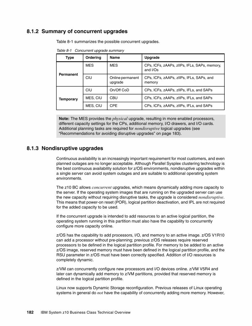
8.1.2 Summary of concurrent upgrades
Table 8-1 summarizes the possible concurrent upgrades.
Table 8-1 Concurrent upgrade summary
8.1.3 Nondisruptive upgrades
Continuous availability is an increasingly important requirement for most customers, and even planned outages are no longer acceptable. Although Parallel Sysplex clustering technology is the best continuous availability solution for z/OS environments, nondisruptive upgrades within a single server can avoid system outages and are suitable to additional operating system environments.
The z10 BC allows concurrent upgrades, which means dynamically adding more capacity to the server. If the operating system images that are running on the upgraded server can use the new capacity without requiring disruptive tasks, the upgrade is considered nondisruptive. This means that power-on reset (POR), logical partition deactivation, and IPL are not required for the added capacity to be used.
If the concurrent upgrade is intended to add resources to an active logical partition, the operating system running in this partition must also have the capability to concurrently configure more capacity online.
z/OS has the capability to add processors, I/O, and memory to an active image. z/OS V1R10 can add a processor without pre-planning; previous z/OS releases require reserved processors to be defined in the logical partition profile. For memory to be added to an active z/OS image, reserved memory must have been defined in the logical partition profile, and the RSU parameter in z/OS must have been correctly specified. Addition of I/O resources is completely dynamic.
z/VM can concurrently configure new processors and I/O devices online. z/VM V5R4 and later can dynamically add memory to z/VM partitions, provided that reserved memory is defined in the logical partition profile.
Linux now supports Dynamic Storage reconfiguration. Previous releases of Linux operating systems in general do not have the capability of concurrently adding more memory. However,
Type Ordering Name Upgrade
Permanent
MES MES CPs, ICFs, zAAPs, zIIPs, IFLs, SAPs, memory, and I/Os
CIU Online permanent upgrade
CPs, ICFs, zAAPs, zIIPs, IFLs, SAPs, and memory
Temporary
CIU On/Off CoD CPs, ICFs, zAAPs, zIIPs, IFLs, and SAPs
MES, CIU CBU CPs, ICFs, zAAPs, zIIPs, IFLs, and SAPs
MES, CIU CPE CPs, ICFs, zAAPs, zIIPs, IFLs, and SAPs
Note: The MES provides the physical upgrade, resulting in more enabled processors, different capacity settings for the CPs, additional memory, I/O drawers, and I/O cards. Additional planning tasks are required for nondisruptive logical upgrades (see “Recommendations for avoiding disruptive upgrades” on page 183).
182 IBM System z10 Business Class Technical Overview
Linux, as well as other types of virtual machines running under z/VM, can benefit from the z/VM V5R4 capability to concurrently add more memory.
Planning for nondisruptive upgradesCertain situations require a disruptive task to enable the new capacity that was just added to the server. However, if you plan in advance, some of the situations can be avoided. Planning ahead is a key factor for nondisruptive upgrades.
The following list indicates the current main reasons for disruptive upgrades. However, with careful planning, you can minimize the need for these outages:
� Conversion of a last processor of any type during a permanent upgrade, if that processor is in use, is disruptive because it must be taken offline before conversion.
� Logical partition memory upgrades when reserved storage was not previously defined are disruptive to image upgrades.
� An I/O upgrade when the operating system cannot use the dynamic I/O configuration function is disruptive. Linux, z/VSE, TPF, z/TPF, and CFCC do not support dynamic I/O configuration.
Recommendations for avoiding disruptive upgradesThe following recommendations can increase the possibilities for nondisruptive upgrades:
� Configure reserved storage to logical partitions.
Configuring reserved storage for all logical partitions before their activation enables them to be nondisruptively upgraded. The operating system running in the logical partition must have the ability to configure memory online.
� Consider the plan-ahead memory options.
Use a convenient entry point for memory capacity and consider the memory options to allow future upgrades within the memory cards already installed on the books. See 2.5.2, “Plan-ahead memory” on page 33, for details.
8.2 MES upgrades
The MES upgrade provides concurrent and permanent capacity growth. MES upgrades allow concurrent adding of processors (CPs, ICFs, zAAPs, zIIPs, IFLs, and SAPs), memory capacity, I/O drawers, and I/O cards. MES provides the ability to concurrently adjust both the number of processors and the capacity level. An MES upgrade requires IBM service personnel for the installation.
The MES upgrade can be performed by using LICCC, by installing additional I/O drawers, adding I/O cards, or a combination, as follows:
� MES upgrades for processors are done by adjusting the number and type of PUs, changing the CP capacity setting, or both.
Software charges based on the total capacity of the server on which the software is installed is adjusted to the new capacity after the MES upgrade.
� MES upgrades for memory are done by either of the following methods:
– Activating additional memory capacity up to the limit of the memory cards already installed
– By adding DIMMs to the server. The plan-ahead memory feature provides more control over future memory upgrades. See “Plan-ahead memory” on page 33 for details.
Chapter 8. System upgrades 183

� MES upgrades for I/O are done by either of the following methods:
– LICCC activating additional ports on already installed ESCON and ISC-3 cards
LICCC-only upgrades can be done for ESCON channels and ISC-3 links, activating ports on the existing 16-port ESCON or ISC-3 daughter (ISC-D) cards.
– Installing additional I/O cards
The installed I/O drawers must provide the number of I/O slots required by the target configuration.
– Installing additional I/O drawers
A maximum of four I/O drawers can be installed on the z10 BC.
8.3 Capacity on Demand upgrades
LICCC upgrades provide concurrent capacity growth. They are represented in the server by an LICCC record. Records can be ordered by either an MES upgrade process or by CIU. The LICCC record represents either a permanent or a temporary upgrade.
LICCC-based upgrades provide foundation for Capacity on Demand (CoD). The Capacity on Demand offerings provide permanent and temporary upgrades by activating one or more LICCC records. These records contain the information necessary to control the type of resource that can be enabled and to what extent. They also contain time elements, such as how many times the resource can be accessed, for how long, and whether it is for test purposes or for a real event.
The CoD implementation includes support for:
� Multiple (up to 200) temporary records concurrently staged on the Support Element (SE)
� Multiple (up to eight) temporary records installed on the CPC and active, at any given time, as follows:
– Installed means the record is promoted from the SE hard drive to one of the locations in a system memory reserved for temporary records.
– Active means part or all resources defined in the temporary record have been turned on and are available for use.
� Variability in the number of resources that can be activated for each temporary record
� The ability to change the activation level at any time for a record that is already active
� The ability to control and update each temporary record independently of each other
� Query function to monitor the state of temporary records
� Replenishment, which means the contents of the temporary entitlement record (capacity and expiration date) can be dynamically updated
� Permanent upgrades to be performed while a temporary upgrade is active
Note: Upgrades requiring DIMM changes is disruptive. Planning is required to determine whether this is a viable option in your configuration. The use of the plan-ahead memory features (FC1991 and FC1992) is the safest way to avoid a disruptive memory upgrade.
184 IBM System z10 Business Class Technical Overview
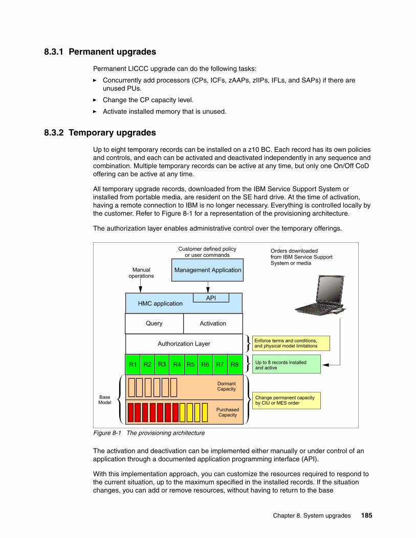
8.3.1 Permanent upgrades
Permanent LICCC upgrade can do the following tasks:
� Concurrently add processors (CPs, ICFs, zAAPs, zIIPs, IFLs, and SAPs) if there are unused PUs.
� Change the CP capacity level.
� Activate installed memory that is unused.
8.3.2 Temporary upgrades
Up to eight temporary records can be installed on a z10 BC. Each record has its own policies and controls, and each can be activated and deactivated independently in any sequence and combination. Multiple temporary records can be active at any time, but only one On/Off CoD offering can be active at any time.
All temporary upgrade records, downloaded from the IBM Service Support System or installed from portable media, are resident on the SE hard drive. At the time of activation, having a remote connection to IBM is no longer necessary. Everything is controlled locally by the customer. Refer to Figure 8-1 for a representation of the provisioning architecture.
The authorization layer enables administrative control over the temporary offerings.
Figure 8-1 The provisioning architecture
The activation and deactivation can be implemented either manually or under control of an application through a documented application programming interface (API).
With this implementation approach, you can customize the resources required to respond to the current situation, up to the maximum specified in the installed records. If the situation changes, you can add or remove resources, without having to return to the base
Customer defined policy or user commands
Management Application
HMC application
Query Activation
Authorization Layer
R1 R2 R3 R6
DormantCapacity
PurchasedCapacity
BaseModel
Change permanent capacity by CIU or MES order
Enforce terms and conditions,and physical model limitations
Up to 8 records installed and active
Orders downloaded from IBM Service Support System or media
API
Manual operations
R8R7R5R4
Chapter 8. System upgrades 185
configuration. This eliminates having to specify different temporary upgrades for all possible scenarios.
In addition, this approach allows you to update and replenish temporary upgrades, even in situations where the upgrades are already active. Likewise, depending on the configuration, permanent upgrades can be performed, while temporary upgrades are active.
Billable capacityOne billable capacity offering is available, which is On/Off Capacity on Demand (On/Off CoD).
On/Off CoD is a function that enables concurrent and temporary capacity growth of the server. On/Off CoD can be used for customer peak workload requirements, for any length of time, and has a daily hardware charge. The software charges vary according to the license agreement for the individual products. See your IBM Software Group representative for exact details.
On/Off CoD can concurrently add processors (CPs, ICFs, zAAPs. zIIPs, IFLs, and SAPs), increase the CP capacity level, or both. On/Off CoD is restricted to twice the purchased capacity. On/Off CoD requires a contract between the customer and IBM, where the terms and conditions are agreed upon.
On/Off CoD can be pre-paid or post-paid as decided by the customer. Capacity tokens inside the records can be used to control activation time and resources.
Replacement capacityTwo replacement capacity offerings are available, which are Capacity Backup (CBU) and Capacity for Planned Event (CPE):
� CBU is a concurrent and temporary activation of additional processors (CPs, ICFs, zAAPs, zIIPs, IFLs, and SAPs), an increase of the CP capacity level, or both. CBU cannot be used for peak workload management. A CBU activation can last up to 90 days when a disaster situation occurs.
CBU features are optional and require unused capacity to be available on a backup server, either as unused PUs or as a possibility to increase the CP capacity level, or both. A CBU contract must be in place before the LICCC that enables this capability can be loaded on the server. The standard CBU contract provides for five 10-day tests and one 90-day disaster activation over a five-year period. Additional tests can be purchased.
� Capacity for Planned Event is a concurrent and temporary activation of additional processors (CPs, ICFs, zAAPs, zIIPs, IFLs, and SAPs), an increase of the CP capacity level, or both. The CPE offering is used to replace temporary lost capacity within a customer’s enterprise for planned downtime events, for example, for data center maintenance. CPE cannot be used for peak load management of customer workload or for a disaster situation.
The CPE feature requires unused capacity to be available on an installed backup server, either as unused PUs, as a possibility to increase the CP capacity level on a server, or both. A CPE contract must be in place before the LICCC that enables this capability can be loaded on the server. The standard CPE contract provides for one 3-day activation at a time decided by the customer.
8.3.3 Processor identification
Enabling and using the additional capacity is transparent to most applications. However, certain programs might depend on information related to processor model, for example,
186 IBM System z10 Business Class Technical Overview
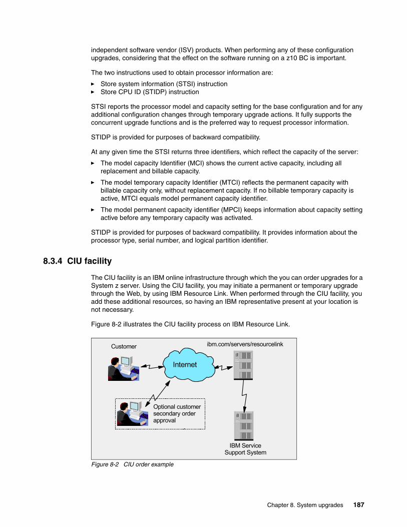
independent software vendor (ISV) products. When performing any of these configuration upgrades, considering that the effect on the software running on a z10 BC is important.
The two instructions used to obtain processor information are:
� Store system information (STSI) instruction� Store CPU ID (STIDP) instruction
STSI reports the processor model and capacity setting for the base configuration and for any additional configuration changes through temporary upgrade actions. It fully supports the concurrent upgrade functions and is the preferred way to request processor information.
STIDP is provided for purposes of backward compatibility.
At any given time the STSI returns three identifiers, which reflect the capacity of the server:
� The model capacity Identifier (MCI) shows the current active capacity, including all replacement and billable capacity.
� The model temporary capacity Identifier (MTCI) reflects the permanent capacity with billable capacity only, without replacement capacity. If no billable temporary capacity is active, MTCI equals model permanent capacity identifier.
� The model permanent capacity identifier (MPCI) keeps information about capacity setting active before any temporary capacity was activated.
STIDP is provided for purposes of backward compatibility. It provides information about the processor type, serial number, and logical partition identifier.
8.3.4 CIU facility
The CIU facility is an IBM online infrastructure through which the you can order upgrades for a System z server. Using the CIU facility, you may initiate a permanent or temporary upgrade through the Web, by using IBM Resource Link. When performed through the CIU facility, you add these additional resources, so having an IBM representative present at your location is not necessary.
Figure 8-2 illustrates the CIU facility process on IBM Resource Link.
Figure 8-2 CIU order example
ibm.com/servers/resourcelinkCustomer
IBM Service Support System
Internet
Optional customer secondary order approval
Chapter 8. System upgrades 187
After signing on to Resource Link, you choose the server to be upgraded. The current configuration (PU allocation and memory) is shown for the selected server and you can choose which type of upgrade to order and with which parameters. Resource Link limits parameters to those that are valid or possible for this configuration. After you submit the order, a secondary (if defined) order approval is automatically requested.
Upon confirmation, the order is processed. When the LICCC for the upgrade is available, you are notified by e-mail, and you may download the LICCC record.
8.3.5 Permanent upgrade through CIU facility
A permanent upgrade for CPs, ICFs, zAAPs, zIIPs, IFLs, SAPs, or memory can be ordered through the CIU facility. You add the resources so IBM representative does not have to be present at your location. You may also unassign previously purchased CPs and IFLs processors through the CIU facility.
Maintenance charges are automatically adjusted as a result of a permanent upgrade.
Software charges based on the total capacity of the server on which the software is installed are adjusted to the new capacity in place, after the permanent upgrade is installed. Software products that use Workload License Charge (WLC) might not be affected by the server upgrade, because their charges are based on a logical partition utilization and not based on the server total capacity. See 7.10.1, “Workload License Charges” on page 174, for more information about WLC.
OrderingResource Link provides the interface that enables you to order a concurrent upgrade for a server. You may create, cancel, and view the order. You may also view the history of orders that were placed through this interface. Configuration rules enforce only valid configurations being generated within the limits of the individual server. Warning messages are issued when invalid upgrade options are selected. The process allows only one permanent CIU-eligible order for each server to be placed at a time.
RetrievalAfter an order is placed and processed, the appropriate upgrade record is passed to the IBM support system for download.
When the order is available for download, you receive an e-mail containing an activation number. You may then retrieve the order by using the Perform Model Conversion task from the Support Element (SE), or through Single Object Operation to the SE from an HMC.
ActivationPermanent upgrade, when retrieved, can be installed at any time from SE, by using the Perform Model Conversion task.
8.3.6 On/Off Capacity on Demand
On/Off Capacity on Demand (On/Off CoD) enables you to temporarily turn on available PUs, or to increase CP capacity level to help meet workload requirements. The capacity for CPs is expressed in MSUs. Capacity for speciality engines is expressed in number of speciality engines. Capacity tokens can be used to limit the resource consumption for all types of processor capacity.
188 IBM System z10 Business Class Technical Overview

To participate in this offering, you must have accepted contractual terms for purchasing capacity through Resource Link, established a profile, and installed an Online CoD Buying enablement feature (FC 9900) on the server that is to be upgraded.
OrderingOn/Off CoD can be ordered only from Resource Link. Up to twice the currently purchased CP capacity and up to twice the number of ICFs, zAAPs, zIIPs, IFLs, or SAPs can be ordered in an On/Off CoD record. Temporary addition of memory, I/O drawers, and I/O ports is not supported.
Each On/Off CoD record contains information about the CP capacity and the number of specialty engines that can be activated. You may limit the usage of capacity through time by using capacity tokens. Capacity tokens provide more control over resource consumption when On/Off CoD records are activated as explained later in this section. Tokens are represented as follows:
� For CP capacity, each token represents one MSU of software cost for one day (an MSU day capacity token).
� For specialty engines, each token is equivalent to one speciality engine capacity for one day (engine day capacity token).
Each engine type has its own tokens, and each On/Off CoD record has separate token pools for each engine type. During the Resource Link ordering sessions, you decide how many tokens of each type will be created in a record. In a record with tokens, each engine type must have tokens for that engine type to be activated. An engine type that has no tokens in its token pool cannot be activated.
For capacity planning purposes, the large system performance reference information is used to evaluate the capacity requirements according to the specific workload type. Large system performance reference (LSPR) data for current IBM processors is available at:
http://www.ibm.com/servers/eserver/zseries/lspr/
On/Off CoD can be ordered as pre-paid or post-paid as decided by the customer:
� A pre-paid On/Off CoD record contains a record description, MSU capacity and number of speciality engines that can be activated, and tokens describing the total capacity that can be used through time. For CP capacity, the token contains MSU days; for speciality engines, the token contains speciality engine days.
� A post-paid On/Off CoD record contains resource descriptions, MSUs and speciality engines, and might contain capacity tokens describing MSU days and speciality engine days.
Staging multiple On/Off CoD LICCC records on the SE at any given time is possible. Doing this provides greater flexibility to quickly enable needed temporary capacity. Each record is easily identified with descriptive names, and users can select from a list of records to be activated. It is also possible to have only one record that is big enough to cover all needs and activate only parts of it as needed. With System z10 CoD, flexibility is up to you. You choose according to your requirements.
Activation and usageAn installed On/Off CoD record is activated from SE. You decide at activation time how much CP capacity and how many specialty engines to activate, of course up to the limits defined during ordering. Activation levels can be changed at any time.
Chapter 8. System upgrades 189

When resources from an On/Off CoD record are activated, a billing window is started. A billing window is always 24 hours in length. Billing takes place at the end of each billing window. The resources billed are the highest resource usage inside each billing window for each capacity type. An activation period is one or more complete billing windows, and represents the time from the first activation of resources in a record until the end of the billing window in which the last resource in a record is deactivated.
For an On/Off CoD record without tokens, at the end of each billing window the highest usage of each resource during the billing window is calculated.
For an On/Off CoD record with tokens, at the end of each billing window the tokens are decremented by the highest usage of each resource during the billing window. After the decrement, if any resource in a record does not have enough tokens to cover usage for the next billing window, the entire record will be deactivated. Of course, a record can be activated again for resources for which token pools are not empty. A record can be also replenished to add tokens.
There is a grace period at the end of the On/Off CoD billing window. This allows up to an hour after the 24-hour billing period when the record can be deactivating without starting the next billing window.
If On/Off CoD is already active, additional capacity can be added without having to return the server to its original capacity. If the capacity is increased multiple times within a 24-hour period, the charges apply to the highest amount of capacity active in the period. If additional capacity is added from an already active record containing capacity tokens, a check is made to control that the resource in question has enough capacity tokens to be active for an entire billing window. If that criteria is not met, no additional resources are activated from the record.
DeactivationIf the On/Off CoD record contains tokens, automatic deactivation of all resources activated from the On/Off CoD record will take place when one of the capacity tokens is completely consumed or when one of the capacity tokens does not contain enough capacity for another billing window. This is controlled at the end of each billing window after the decrement of capacity used during the last billing window.
You receive warning messages if capacity tokens are getting close to being consumed. Such messages start to appear five days before a capacity token pool is fully consumed. The five days are based on the assumption that the consumption will be constant for the five days.
A record is automatically deactivated when it expires.
Processors dedicated to logical partitions are never deactivated automatically.
ExpirationThe On/Off CoD record is valid for 180 days. You may replenish the expiration date free of charge at any time for another 180 days from ordering the replenishment.
On/Off CoD with pre-paid tokens does not expire.
Software billingCustomers are billed for a software at the MSU level represented by the combined permanent and temporary capacity. Products are billed at the peak MSUs enabled during the month, regardless of usage. Customers with WLC licenses are billed by product at the highest four-hour rolling average for the month. In this instance, temporary capacity does not
190 IBM System z10 Business Class Technical Overview
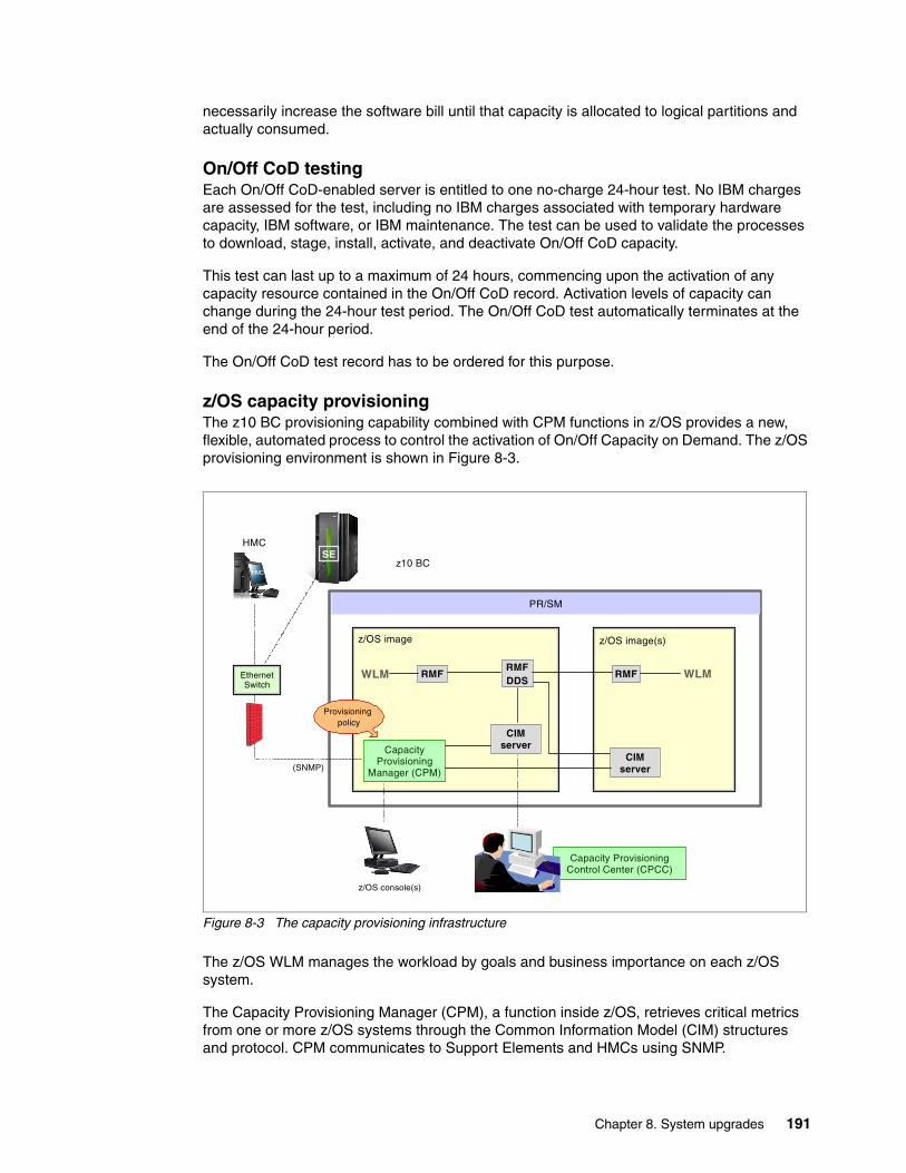
necessarily increase the software bill until that capacity is allocated to logical partitions and actually consumed.
On/Off CoD testingEach On/Off CoD-enabled server is entitled to one no-charge 24-hour test. No IBM charges are assessed for the test, including no IBM charges associated with temporary hardware capacity, IBM software, or IBM maintenance. The test can be used to validate the processes to download, stage, install, activate, and deactivate On/Off CoD capacity.
This test can last up to a maximum of 24 hours, commencing upon the activation of any capacity resource contained in the On/Off CoD record. Activation levels of capacity can change during the 24-hour test period. The On/Off CoD test automatically terminates at the end of the 24-hour period.
The On/Off CoD test record has to be ordered for this purpose.
z/OS capacity provisioning The z10 BC provisioning capability combined with CPM functions in z/OS provides a new, flexible, automated process to control the activation of On/Off Capacity on Demand. The z/OS provisioning environment is shown in Figure 8-3.
Figure 8-3 The capacity provisioning infrastructure
The z/OS WLM manages the workload by goals and business importance on each z/OS system.
The Capacity Provisioning Manager (CPM), a function inside z/OS, retrieves critical metrics from one or more z/OS systems through the Common Information Model (CIM) structures and protocol. CPM communicates to Support Elements and HMCs using SNMP.
PR/SM
Capacity Provisioning Control Center (CPCC)
z10 BC
Capacity Provisioning
Manager (CPM)
RMF
CIM server
z/OS console(s)
RMFDDS
WLM RMF WLM
CIM server
Provisioning policy
HMC
EthernetSwitch
SE
(SNMP)
z/OS image z/OS image(s)
HMCHMC
Chapter 8. System upgrades 191
CPM has visibility of the resources in the individual records, as well as the capacity tokens. When CPM chooses to activate resources, a check is performed to understand if enough capacity tokens remain for the resource in question to activate the resource for at least 24 hours.
CPM operates in four modes, allowing for different levels of automation:
� Manual mode
This is a command-driven mode with no CPM policy active.
� Analysis mode works as follows:
– CPM processes capacity-provisioning policies and informs the operator when a provisioning or deprovisioning action is required according to policy criteria.
– The operator chooses whether to ignore the information or to manually upgrade or downgrade the system by using the HMC, the SE, or available CPM commands.
� Confirmation mode
CPM processes capacity provisioning policies and interrogates the installed temporary offering records. Every action proposed by the CPM must be confirmed by the operator.
� Autonomic mode
This mode is similar to the confirmation mode, but no operator confirmation is necessary. CPM executes all necessary commands and posts a message to the console.
The provisioning policy defines the circumstances under which additional capacity may be provisioned. The three elements in the criteria are:
� Time condition indicates when provisioning is allowed.
� Workload condition indicates which work qualifies for provisioning, and which parameters are included.
� Provisioning scope indicates how much additional capacity can be activated.
The maximum provisioning scope is the maximum additional capacity that can be activated for all the rules in the Capacity Provisioning Domain.
Refer to z/OS MVS Capacity Provisioning User’s Guide, SA33-8299 ,for more information about z/OS Capacity Provisioning functions.
Planning considerationsAlthough only one On/Off CoD record can be active at any given time, several On/Off CoD records can be installed on the server. Either the administrator can specify to CPM which On/Off CoD to use or CPM can choose one.
To prevent CPM from choosing the record that does not have enough resources, specifying a record in CPM configuration is advisable. Such a record should contain all resources necessary for planned use of CPM. It is better to overallocate resources in the record than underallocate. The Provisioning Manager can then, at the time when an activation is needed, activate parts of the contents of the offering sufficient to satisfy the demand. If, at a later time, more capacity is needed, the Provisioning Manager can activate more capacity up to the maximum allowed increase. An administrator can still limit the maximum amount of resources used by CPM by defining limits in the provisioning policy.
As mentioned previously, the CPM has control over capacity tokens in the On/Off CoD records. In a situation where a capacity token is completely consumed, the server will deactivate all the resources activated from the corresponding record. A strong recommendation is to prepare routines for catching the warning messages about capacity
192 IBM System z10 Business Class Technical Overview
tokens being consumed, and have administrative routines in place for such a situation. To avoid capacity records from being deactivated in this situation, you may replenish the necessary capacity tokens before they are completely consumed.
The Provisioning Manager operates based on Workload Manager (WLM) indications. The construct used is the performance index (PI) of a service class period. An important point is to select service class periods that are appropriate for the business application that requires more capacity. For example, the application in question might be executing through several service class periods in which the first period is the important one. Although the application might be defined as importance level 2 or 3, the application might depend on other work executing with importance level 1. Considering which workloads to control, and which service class periods to specify is very important.
8.3.7 Capacity for Planned Event
Capacity for Planned Event (CPE) is offered for System z10 servers to provide replacement backup capacity for planned down-time events. For example, if a service room requires an extension or repair work, replacement capacity can be installed temporarily on another System z10 server in the customer’s environment.
A CPE contract must be in place before the record can be ordered.
OrderingA CPE record can be ordered from IBM through MES or online through the CIU application on Resource Link. CPE is always delivered as a LICCC record.
CPE is intended for short-duration events lasting up to a maximum of three days. Each CPE record, once activated, provides access to one predefined configuration as ordered by the customer.
A one-time fixed fee is applied for ordering a CPE record.
Activation and usageProcessing units can be configured in a combination of CP or specialty engine types (zIIP, zAAP, SAP, IFL, and ICF). The capacity required for a given situation is determined by the customer at the time of order. The standard relation between number of CPs and number of zIIPs and zAAPs must be adhered to. A CPE record can be activated only once.
The processors that can be activated by CPE come from the available spare PUs on the server. CPE features can be added to an existing z10 BC non-disruptively.
The base server configuration must have sufficient memory and channels to accommodate the potential requirements of the larger CPE-configured server. It is important to ensure that all required functions and resources are available on the server where CPE is activated, including CF LEVELs for Coupling Facility partitions, memory, and cryptographic functions, as well as connectivity capabilities.
DeactivationIf the CPE record is not deactivated manually by the administrator, it is deactivated automatically after 72 hours. Once the CPE record is deactivated (the last active resource is deactivated), the CPE record becomes unusable. The CPE record is deactivated either
Note: CPE is for planned replacement capacity only and cannot be used for peak workload management.
Chapter 8. System upgrades 193
manually or automatically. Processors dedicated to logical partitions are never deactivated automatically.
8.3.8 Capacity Backup
Capacity Backup (CBU) provides emergency backup processor capacity for unplanned situations in which capacity is lost in another part of your enterprise and you want to recover by adding a capacity on a designated z10 BC. CBU is the quick, temporary activation of PUs available as follows:
� For up to 90 contiguous days, in case of a loss of processing capacity as a result of an emergency or disaster recovery situation.
� For 10 days for tests of the your disaster recovery procedures.
OrderingA CBU contract must be in place before the record can be ordered. The length of a contract is from one to five years.
A CBU record can be ordered either from IBM through MES or online through a CIU application on a Resource Link. CBU is always delivered as an LICCC record.
During ordering, you specify the number of CBU features for each type of processor that is necessary for an upgrade during a disaster.
For specialty engines, the number of engines that will be temporarily added equals the number of CBU features ordered. For CPs, the number of ordered CBU features covers the number of permanent processors that will change a capacity level plus the number of added CPs. How features are used is up to you at an activation time. You may choose from all available target configurations. This feature is different from servers prior to System z10, in which target configuration was determined at the time of ordering.
For example, if a permanent configuration is C02 and a record contains three CP CBU features, during an activation you may choose among many target configurations. With three CP CBU features, you can add one to three CPs, which allow you to activate C03, C04, or C05. Or, two CP CBU features can be used to change capacity level of permanent CPs, which offers the possibility to activate D02, E02, F02 through Z02. Or two CP CBU features can be used to change capacity level of permanent CPs, and the third CP CBU feature can be used to add a CP, which allows activation of D03, E03, F03 through Z03. In this example, you are offered 49 possible configurations at activation time. While CBU is active, you may change the target configuration at any time. More flexibility is provided compared to servers earlier than System z10 servers.
The CBU activation allows you to activate CPs, ICFs, zAAPs, zIIPs, IFLs, and SAPs. The processors that can be activated by CBU come from the available unused PUs on the server. In the case of CPs, CBU can increase capacity level of permanent CPs also.
CBU does not allow decreasing the number of processors or the CP capacity level.
Note: CBU is for disaster and recovery purposes only and cannot be used for peak workload management or for a planned event.
194 IBM System z10 Business Class Technical Overview
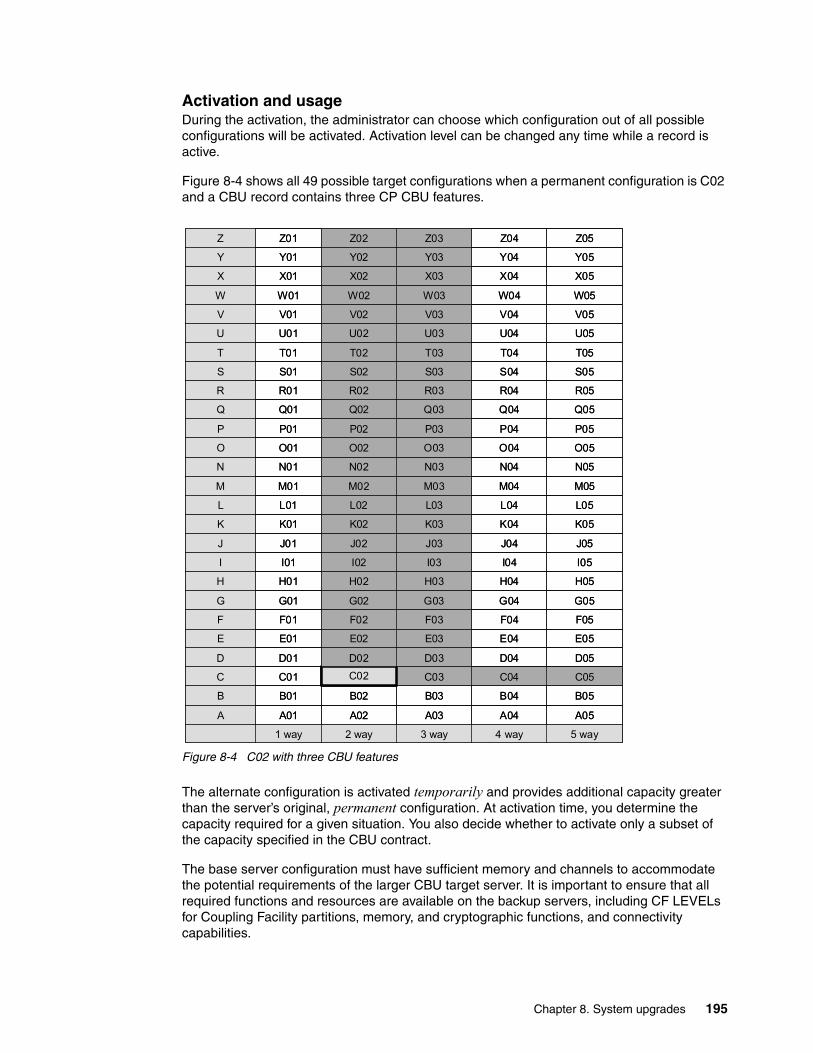
Activation and usageDuring the activation, the administrator can choose which configuration out of all possible configurations will be activated. Activation level can be changed any time while a record is active.
Figure 8-4 shows all 49 possible target configurations when a permanent configuration is C02 and a CBU record contains three CP CBU features.
Figure 8-4 C02 with three CBU features
The alternate configuration is activated temporarily and provides additional capacity greater than the server’s original, permanent configuration. At activation time, you determine the capacity required for a given situation. You also decide whether to activate only a subset of the capacity specified in the CBU contract.
The base server configuration must have sufficient memory and channels to accommodate the potential requirements of the larger CBU target server. It is important to ensure that all required functions and resources are available on the backup servers, including CF LEVELs for Coupling Facility partitions, memory, and cryptographic functions, and connectivity capabilities.
A
B
C
D
E
F
G
H
I
J
K
L
M
N
O
P
Q
R
S
T
U
V
W
X
Y
Z
A05A04A03A02A01
5 way4 way3 way2 way1 way
B05B04B03B02B01
C05C04C03C02C01
D05D04D03D02D01
E05E04E03E02E01
F05F03F02F01
G05G04G03G02G01
H05H04H03H02H01
I05I04I03I02I01
J05J04J03J02J01
K05K04K03K02K01
L05L04L03L02L01
M05M04M03M02M01
N05N04N03N02N01
O05O04O03O02O01
P05P04P03P02P01
Q05Q04Q03Q02Q01
R05R04R03R02R01
S05S04S03S02S01
T05T04T03T02T01
U05U04U03U02U01
V05V04V03V02V01
W05 W04 W03 W02 W01
X05 X04 X03 X02 X01
Y05 Y04 Y03 Y02 Y01
Z05 Z04 Z03 Z02 Z01
F04
Chapter 8. System upgrades 195
DeactivationWhen the emergency is over (or the CBU test is complete), the server must be taken back to its original configuration. You may deactivate the CBU feature at any time. It is deactivated automatically after 90 days for real activation and after 10 days after test activation. The system does not deactivate dedicated engines, or the last of in-use shared engines.
For details, refer to the System z Capacity on Demand User’s Guide, SC28-6846.
CBU testsFive CBU tests are provided as part of the CBU contract. Additional tests can be ordered in increments of one, up to a maximum of 15 tests for each record. Each CBU test can be used for 10 contiguous days. Failure to deactivate the CBU feature after 10 days causes the system to automatically deactivate the CBU test, returning the system to its original configuration. The system does not deactivate dedicated engines, or the last of in-use shared engine. You may purchase additional tests.
Automatic CBU enablement for GDPSThe intent of the GDPS® CBU is to enable automatic management of the PUs provided by the CBU feature in the event of a server or site failure. Upon detection of a site failure or planned disaster test, GDPS concurrently adds CPs to the servers in the take-over site to restore processing power for mission-critical production workloads. GDPS automation can:
� Perform the analysis required to determine the scope of the failure and to minimize operator intervention and the potential for errors.
� Automate authentication and activation of the reserved CPs.
� Automatically restart the critical applications after reserved CP activation.
� Reduce the outage time to restart critical workloads from several hours to minutes.
� The GDPS service offering is for z/OS only, or for z/OS in combination with Linux on System z.
For details about CoD, refer to IBM System z10 Capacity On Demand, SG24-7504.
Note: CBU for processors provides a concurrent upgrade, resulting in more enabled processors, changed capacity settings available to a server configuration, or both. The customer can decide, at activation time, to activate a subset of the CBU features ordered for the system. Thus, additional planning and tasks may be required for nondisruptive logical upgrades. See “Recommendations for avoiding disruptive upgrades” on page 183.
196 IBM System z10 Business Class Technical Overview
Chapter 9. RAS
This chapter describes the Reliability, Availability, and Serviceability (RAS) features of thez10 BC server.
The z10 BC design is focused on providing the industry-leading RAS that customers expect from System z servers. When properly configured, RAS can be accomplished with improved concurrent replace, repair, and upgrade functions for processors, memory, and I/O. RAS also extends to the nondisruptive capability to download Licensed Internal Code updates. In most cases, a capacity upgrade can be concurrent, without a system outage.
The design goal for the z10 BC has been to remove all sources of outages by reducing unscheduled, scheduled, and planned outages.
This chapter discusses the following topics:
� 9.1, “Availability characteristics” on page 198� 9.2, “RAS functions” on page 198� 9.3, “Enhanced driver maintenance” on page 201� 9.4, “RAS Summary” on page 201
9
© Copyright IBM Corp. 2008, 2009. All rights reserved. 197
9.1 Availability characteristics
The following functions include availability characteristics on the z10 BC:
� Concurrent memory upgrade
Memory can be upgraded concurrently using LICCC if physical memory is available. The plan-ahead memory function available with the z10 BC provides the ability to plan for nondisruptive memory upgrades by having the system pre-plugged based on a target configuration. Pre-plugged memory is enabled when you order through LICCC.
� Concurrent adding or replacing of an I/O drawer
Concurrently adding a new I/O drawer to the z10 BC is possible. With proper and good planning you may also concurrently repair and replace an I/O drawer.
� Enhanced driver maintenance (EDM)
One of the greatest contributors to downtime during planned outages is Licensed Internal Code driver updates performed in support of new features and functions. The z10 BC is designed to support activating a selected new driver level concurrently.
� Concurrent HCA/MBA fan-out addition or replacement
A Host Communication Adapter/Memory Bus Adapter (HCA/MBA) fan-out card provides the path for data between memory and I/O by using InfiniBand (IFB) cables. With the z10 BC, hot-pluggable HCA/MBA up to six HCA/MBA fan-out cards are available. In the event of an outage, an HCA/MBA fan-out card, used for I/O, may be concurrently repaired while redundant I/O interconnect ensures that no I/O connectivity is lost.
� Redundant I/O interconnect
Redundant I/O interconnect helps maintain critical connections to devices. If the connection from a fan-out ceases to function, redundant I/O interconnect maintains the connection to the devices normally covered by the malfunctioning fan-out. Refer to 2.6.2, “Redundant I/O interconnect” on page 35, for a more detailed description.
� Dynamic oscillator switch-over
The z10 BC has two oscillator cards, a primary and a backup. If a primary card fails, the backup card transparently detects the failure, switches over, and provides the clock signal to the server.
9.2 RAS functions
Hardware RAS function improvements focus on addressing all sources of outages. Sources of outages are categorized in three classes:
� Unscheduled � Scheduled � Planned
An unscheduled outage is an outage that happens because of an unrecoverable malfunction in a hardware component of the server.
A scheduled outage is caused by changes or updates that must be done to the server in a timely fashion. A scheduled outage could be caused by a disruptive patch that has to be installed, or other changes that have to be done to the system. A scheduled outage is usually requested by the vendor.
198 IBM System z10 Business Class Technical Overview
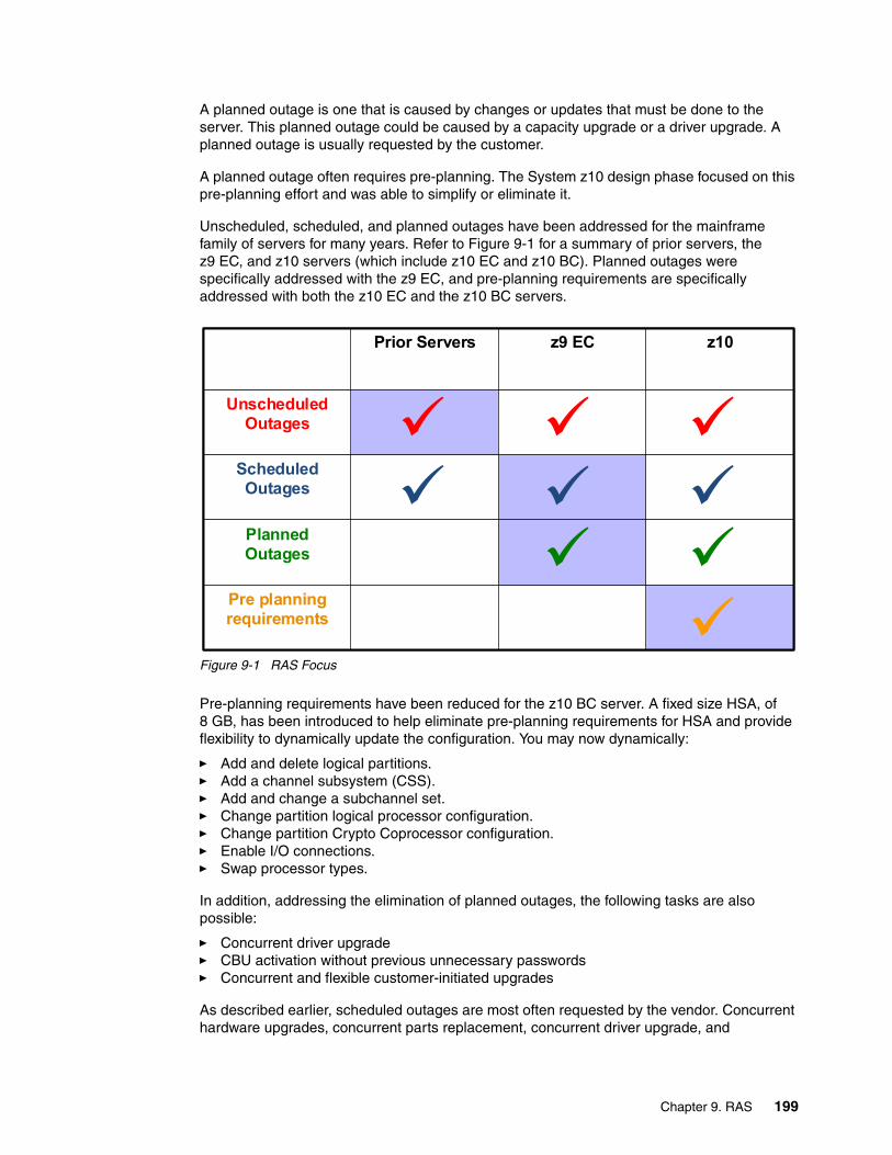
A planned outage is one that is caused by changes or updates that must be done to the server. This planned outage could be caused by a capacity upgrade or a driver upgrade. A planned outage is usually requested by the customer.
A planned outage often requires pre-planning. The System z10 design phase focused on this pre-planning effort and was able to simplify or eliminate it.
Unscheduled, scheduled, and planned outages have been addressed for the mainframe family of servers for many years. Refer to Figure 9-1 for a summary of prior servers, the z9 EC, and z10 servers (which include z10 EC and z10 BC). Planned outages were specifically addressed with the z9 EC, and pre-planning requirements are specifically addressed with both the z10 EC and the z10 BC servers.
Figure 9-1 RAS Focus
Pre-planning requirements have been reduced for the z10 BC server. A fixed size HSA, of 8 GB, has been introduced to help eliminate pre-planning requirements for HSA and provide flexibility to dynamically update the configuration. You may now dynamically:
� Add and delete logical partitions. � Add a channel subsystem (CSS).� Add and change a subchannel set.� Change partition logical processor configuration.� Change partition Crypto Coprocessor configuration.� Enable I/O connections.� Swap processor types.
In addition, addressing the elimination of planned outages, the following tasks are also possible:
� Concurrent driver upgrade � CBU activation without previous unnecessary passwords� Concurrent and flexible customer-initiated upgrades
As described earlier, scheduled outages are most often requested by the vendor. Concurrent hardware upgrades, concurrent parts replacement, concurrent driver upgrade, and
Prior Servers z9 EC z10
Unscheduled Outages
Scheduled Outages
Planned Outages
Pre planning requirements
Prior Servers z9 EC z10
Unscheduled Outages
Scheduled Outages
Planned Outages
Pre planning requirements
Chapter 9. RAS 199

concurrent firmware fixes available with the z10 BC all address elimination of scheduled outages. Furthermore, the following functions that address scheduled outages are included:
� Dual in-line memory module (DIMM) field replaceable unit (FRU) indicators
These indicators imply that a memory module is not error free and could fail sometime in the future. This gives IBM a warning, and the possibility and time to concurrently repair the storage module if possible.
� Single processor core checkstop and sparing
This indicator implies that a processor core has malfunctioned and has been spared. IBM has to consider what to do and also take into account the history of the server by asking the question: Has this type of incident happened previously to this server?
� Hot swap ICB-4 and InfiniBand (IFB) hub cards
When properly configured for redundancy, hot swapping (replacing) the ICB-4 (MBA) and the IFB (HCA2-O) hub cards is possible. This makes it possible to avoid any kind of interruption when the need for replacing these types of cards occurs.
� Redundant 100 Mb Ethernet service network w/VLAN
The service network in the machine gives the machine code the capability to monitor each single internal function in the machine. This helps to identify problems, maintain the redundancy, and provides assistance in concurrently replacing a part. Through the implementation of the VLAN to the redundant internal Ethernet service network, these advantages continue to improve, making the service network easier to handle and more flexible.
An unscheduled outage happens because of an unrecoverable malfunction in a hardware component of the server.
The following improvements towards minimizing unscheduled outages have been introduced:
� Reduced chip count on the single-chip module (SCM)
The number of chips on the SCM is reduced compared to the z9 BC MCM. Statistics collected over several years show that fewer parts in the hardware lead to fewer malfunctions. Fewer chips imply fewer unrecoverable malfunctions.
� Continued focus on firmware quality
For Licensed Internal Code and hardware design, failures are eliminated through rigorous design rules, design walk-through, peer reviews, element, subsystem and system simulation, and extensive engineering and manufacturing testing.
� Memory subsystem improvements
As for previous servers, error detection and recovery in the memory subsystem hardware are implemented by error correction code (ECC). The memory subsystem has been enhanced with additional robust data ECC. The connection between the memory DIMMs and the memory controller is now also ECC-protected. This ECC provides failure protection for virtually every type of packet transfer failure that can be corrected on the fly. The data portion of the packet transfers especially benefit since they are now protected.
� Soft-switch firmware
The capabilities of soft-switching firmware have been enhanced. Enhanced logic ensures that every and all affected circuits are turned off when soft-switching firmware components. For example, if the microcode of a FICON feature has to be upgraded, enhancements have been implemented to avoid any unwanted side-effects detected on previous servers.
200 IBM System z10 Business Class Technical Overview
9.3 Enhanced driver maintenance
Enhanced driver maintenance (EDM) is another step in reducing both the necessity and the eventual duration of a planned outage. One of the contributors to planned outages is Licensed Internal Code updates performed in support of new features and functions. When properly configured, the z10 BC supports concurrently activating a selected new LIC level. Concurrent activation of the selected new LIC level was previously supported only at specific sync points. Selected new LIC level anywhere in the maintenance stream can be concurrently activated. Certain LIC updates are still not supported this way.
The key points of EDM are:
� HMC capability to query whether a system is ready for concurrent driver upgrade.
� Firmware upgrades, which require that an initial machine load (IML) of the System z10 be activated, might not block concurrent driver upgrade.
� Icon on the Support Element (SE) allows the customer or IBM support personnel to define the concurrent driver upgrade sync point planned to be used.
� Concurrent driver upgrade is supported.
� The ability to concurrently install and activate a new driver can eliminate a planned outage.
� Concurrent crossover from driver level N to driver level N+1, to driver level N+2 must be done serially; no composite moves.
� Disruptive driver upgrades are permitted at any time.
� No concurrent back-off is possible. The driver level must move forward to driver level N+1 after enhanced driver maintenance is initiated. Catastrophic errors during an update can lead to an outage.
The EDM function does not completely eliminate the need for planned outages for driver-level upgrades. Although very infrequent, certain circumstances require that the system has to be scheduled for an outage. The following circumstances require a planned outage:
� Specific complex code changes might dictate a disruptive driver upgrade. You are alerted in advance so you can properly plan for the following changes:
– Design data fixes.– CFCC level change.
� Non-QDIO OSA CHPID types, CHPID type OSC, and CHPID type OSE require CHPID Vary OFF/ON in order to activate new code.
� For the Crypto Express2 feature a cryptographic code load requires a Config OFF/ON in order to activate new code. For the Crypto Express3 feature a code load is completely concurrent.
FICON and FCP code changes involving code loads require a CHPID reset to activate. Reduce all sources of outages by reducing unscheduled, scheduled, and planned outages.
9.4 RAS Summary
In summary, the System z10 server is designed to:
� Deliver the industry-leading RAS that customers expect from System z servers.� Eliminate the need for doing a logical partition deactivate, activate, and IPL.� Further reduce planned outages by eliminating pre-planning requirements.� Reduce the need for Power-on-Reset.
Chapter 9. RAS 201

202 IBM System z10 Business Class Technical Overview
Chapter 10. Environmental requirements
IBM System z10 Business Class comprises some of the most sophisticated and complex electronic equipment ever integrated into one computer. As such, this hardware must be protected from negative environmental impacts to ensure the utmost reliability. To ensure that optimum conditions are maintained, proper planning is required.
This chapter discusses the basic environmental requirements for the z10 BC server. It lists the dimensions, weights, power, and cooling requirements as an overview of what is necessary to plan for the installation of a z10 BC server.
This chapter discusses the following topics:
� 10.1, “Power and cooling” on page 204� 10.2, “Physical specifications” on page 206� 10.3, “Power estimation tool” on page 208
For detailed physical planning information refer to System z10 BC Installation Manual for Physical Planning, GC28-6875.
10
© Copyright IBM Corp. 2008, 2009. All rights reserved. 203
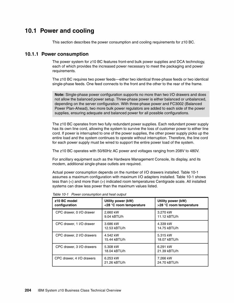
10.1 Power and cooling
This section describes the power consumption and cooling requirements for z10 BC.
10.1.1 Power consumptionThe power system for z10 BC features front-end bulk power supplies and DCA technology, each of which provides the increased power necessary to meet the packaging and power requirements.
The z10 BC requires two power feeds—either two identical three-phase feeds or two identical single-phase feeds. One feed connects to the front and the other to the rear of the frame.
The z10 BC operates from two fully redundant power supplies. Each redundant power supply has its own line cord, allowing the system to survive the loss of customer power to either line cord. If power is interrupted to one of the power supplies, the other power supply picks up the entire load and the system continues to operate without interruption. Therefore, the line cord for each power supply must be wired to support the entire power load of the system.
The z10 BC operates with 50/60Hz AC power and voltages ranging from 208V to 480V.
For ancillary equipment such as the Hardware Management Console, its display, and its modem, additional single-phase outlets are required.
Actual power consumption depends on the number of I/O drawers installed. Table 10-1 assumes a maximum configuration with maximum I/O adapters installed. Table 10-1 shows less than (<) and more than (>) indicated room temperatures Centigrade scale. All installed systems can draw less power than the maximum values listed.
Table 10-1 Power consumption and heat output
Note: Single-phase power configuration supports no more than two I/O drawers and does not allow the balanced power setup. Three-phase power is either balanced or unbalanced, depending on the server configuration. With three-phase power and FC3002 (Balanced Power Plan-Ahead), two more bulk power regulators are added to each side of the power supplies, ensuring adequate and balanced power for all possible configurations.
z10 BC model configuration
Utility power (kW)<28 °C room temperature
Utility power (kW)>28 °C room temperature
CPC drawer, 0 I/O drawer 2,660 kW9.04 kBTU/h
3.270 kW11.12 kBTU/h
CPC drawer, 1 I/O drawer 3.686 kW12.53 kBTU/h
4.339 kW14.75 kBTU/h
CPC drawer, 2 I/O drawers 4.542 kW15.44 kBTU/h
5.315 kW18.07 kBTU/h
CPC drawer, 3 I/O drawers 5.308 kW18.04 kBTU/h
6.291 kW21.39 kBTU/h
CPC drawer, 4 I/O drawers 6.253 kW21.26 kBTU/h
7.266 kW24.70 kBTU/h
204 IBM System z10 Business Class Technical Overview
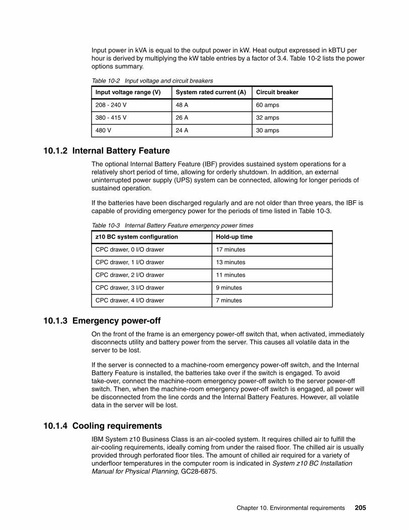
Input power in kVA is equal to the output power in kW. Heat output expressed in kBTU per hour is derived by multiplying the kW table entries by a factor of 3.4. Table 10-2 lists the power options summary.
Table 10-2 Input voltage and circuit breakers
10.1.2 Internal Battery FeatureThe optional Internal Battery Feature (IBF) provides sustained system operations for a relatively short period of time, allowing for orderly shutdown. In addition, an external uninterrupted power supply (UPS) system can be connected, allowing for longer periods of sustained operation.
If the batteries have been discharged regularly and are not older than three years, the IBF is capable of providing emergency power for the periods of time listed in Table 10-3.
Table 10-3 Internal Battery Feature emergency power times
10.1.3 Emergency power-offOn the front of the frame is an emergency power-off switch that, when activated, immediately disconnects utility and battery power from the server. This causes all volatile data in the server to be lost.
If the server is connected to a machine-room emergency power-off switch, and the Internal Battery Feature is installed, the batteries take over if the switch is engaged. To avoid take-over, connect the machine-room emergency power-off switch to the server power-off switch. Then, when the machine-room emergency power-off switch is engaged, all power will be disconnected from the line cords and the Internal Battery Features. However, all volatile data in the server will be lost.
10.1.4 Cooling requirementsIBM System z10 Business Class is an air-cooled system. It requires chilled air to fulfill the air-cooling requirements, ideally coming from under the raised floor. The chilled air is usually provided through perforated floor tiles. The amount of chilled air required for a variety of underfloor temperatures in the computer room is indicated in System z10 BC Installation Manual for Physical Planning, GC28-6875.
Input voltage range (V) System rated current (A) Circuit breaker
208 - 240 V 48 A 60 amps
380 - 415 V 26 A 32 amps
480 V 24 A 30 amps
z10 BC system configuration Hold-up time
CPC drawer, 0 I/O drawer 17 minutes
CPC drawer, 1 I/O drawer 13 minutes
CPC drawer, 2 I/O drawer 11 minutes
CPC drawer, 3 I/O drawer 9 minutes
CPC drawer, 4 I/O drawer 7 minutes
Chapter 10. Environmental requirements 205
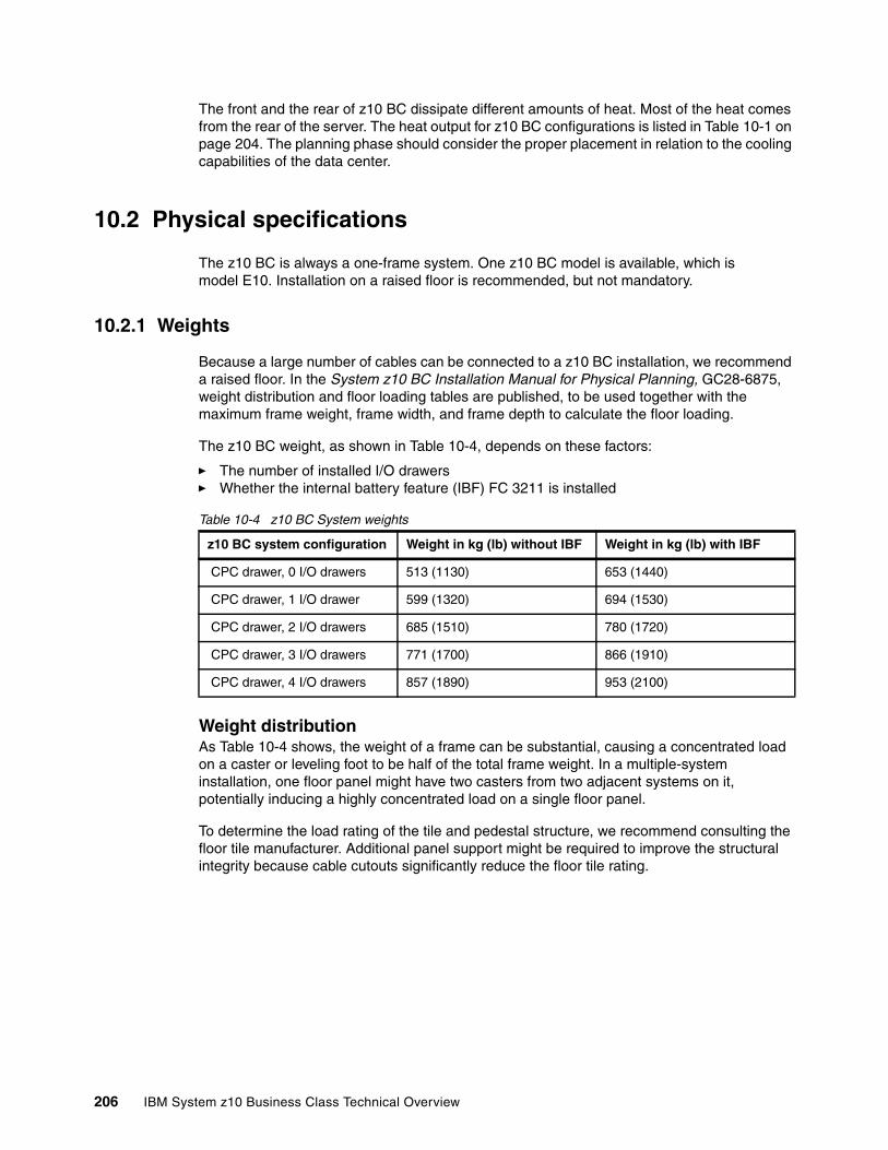
The front and the rear of z10 BC dissipate different amounts of heat. Most of the heat comes from the rear of the server. The heat output for z10 BC configurations is listed in Table 10-1 on page 204. The planning phase should consider the proper placement in relation to the cooling capabilities of the data center.
10.2 Physical specifications
The z10 BC is always a one-frame system. One z10 BC model is available, which is model E10. Installation on a raised floor is recommended, but not mandatory.
10.2.1 Weights
Because a large number of cables can be connected to a z10 BC installation, we recommend a raised floor. In the System z10 BC Installation Manual for Physical Planning, GC28-6875, weight distribution and floor loading tables are published, to be used together with the maximum frame weight, frame width, and frame depth to calculate the floor loading.
The z10 BC weight, as shown in Table 10-4, depends on these factors:
� The number of installed I/O drawers� Whether the internal battery feature (IBF) FC 3211 is installed
Table 10-4 z10 BC System weights
Weight distributionAs Table 10-4 shows, the weight of a frame can be substantial, causing a concentrated load on a caster or leveling foot to be half of the total frame weight. In a multiple-system installation, one floor panel might have two casters from two adjacent systems on it, potentially inducing a highly concentrated load on a single floor panel.
To determine the load rating of the tile and pedestal structure, we recommend consulting the floor tile manufacturer. Additional panel support might be required to improve the structural integrity because cable cutouts significantly reduce the floor tile rating.
z10 BC system configuration Weight in kg (lb) without IBF Weight in kg (lb) with IBF
CPC drawer, 0 I/O drawers 513 (1130) 653 (1440)
CPC drawer, 1 I/O drawer 599 (1320) 694 (1530)
CPC drawer, 2 I/O drawers 685 (1510) 780 (1720)
CPC drawer, 3 I/O drawers 771 (1700) 866 (1910)
CPC drawer, 4 I/O drawers 857 (1890) 953 (2100)
206 IBM System z10 Business Class Technical Overview
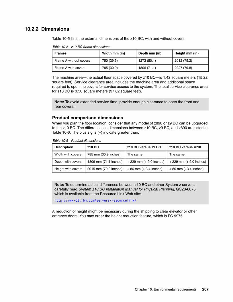
10.2.2 Dimensions
Table 10-5 lists the external dimensions of the z10 BC, with and without covers.
Table 10-5 z10 BC frame dimensions
The machine area—the actual floor space covered by z10 BC—is 1.42 square meters (15.22 square feet). Service clearance area includes the machine area and additional space required to open the covers for service access to the system. The total service clearance area for z10 BC is 3.50 square meters (37.62 square feet).
Product comparison dimensionsWhen you plan the floor location, consider that any model of z890 or z9 BC can be upgraded to the z10 BC. The differences in dimensions between z10 BC, z9 BC, and z890 are listed in Table 10-6. The plus signs (+) indicate greater than.
Table 10-6 Product dimensions
A reduction of height might be necessary during the shipping to clear elevator or other entrance doors. You may order the height reduction feature, which is FC 9975.
Frames Width mm (in) Depth mm (in) Height mm (in)
Frame A without covers 750 (29.5) 1273 (50.1) 2012 (79.2)
Frame A with covers 785 (30.9) 1806 (71.1) 2027 (79.8)
Note: To avoid extended service time, provide enough clearance to open the front and rear covers.
Description z10 BC z10 BC versus z9 BC z10 BC versus z890
Width with covers 785 mm (30.9 inches) The same The same
Depth with covers 1806 mm (71.1 inches) + 229 mm (+ 9.0 inches) + 229 mm (+ 9.0 inches)
Height with covers 2015 mm (79.3 inches) + 86 mm (+ 3.4 inches) + 86 mm (+3.4 inches)
Note: To determine actual differences between z10 BC and other System z servers, carefully read System z10 BC Installation Manual for Physical Planning, GC28-6875, which is available from the Resource Link Web site:
http://www-01.ibm.com/servers/resourcelink/
Chapter 10. Environmental requirements 207

Frame tie-down for raised floor and non-raised floorA bolt-down kit for raised floor and non-raised floor environments can be ordered for z10 BC. The kit provides hardware to tie down the frame to a concrete floor beneath a raised or non-raised floor installation. The kit is offered for the following configurations:
� The Bolt-Down Kit for Low-Raised Floor (FC 7990) provides frame stabilization and bolt-down hardware for securing a frame to a concrete floor beneath a 229 mm to 330 mm (9.00 to 13.00 inch) raised floor.
� The Bolt-Down Kit for High-Raised Floor (FC 7991) provides frame stabilization and bolt-down hardware for securing a frame to a concrete floor beneath a 305 mm to 559 mm (12.00 to 22.0 inch) raised floor.
� The Bolt-Down Kit for Non-Raised Floor (FC 7992) provides frame stabilization and bolt-down hardware for securing a frame to a non-raised floor.
These features help secure the frame and its content from damage when exposed to shocks and vibrations such as those generated by a seismic event.
10.3 Power estimation tool
Several aids are available to monitor the power consumption and heat dissipation of thez10 BC. This section summarizes the tools that are available to efficiently manage the energy consumption of a data center. The following tools are available:
� Power Estimation Tool� System Activity Display on HMC� IBM Systems Director Active Energy Manager
Power estimation toolThe power estimation tool for z10 BC is available at the IBM Resource Link Web page:
http://www.ibm.com/servers/resourcelink
This tool provides an estimate of the anticipated power consumption of a particular machine configuration. You input the machine model, memory size, number of I/O drawers, and quantity of each type of I/O feature card. The tool outputs an estimate of the power requirements necessary for this system.
The tool helps with power and cooling planning for new or currently installed IBM System z10 Business Class servers.
208 IBM System z10 Business Class Technical Overview
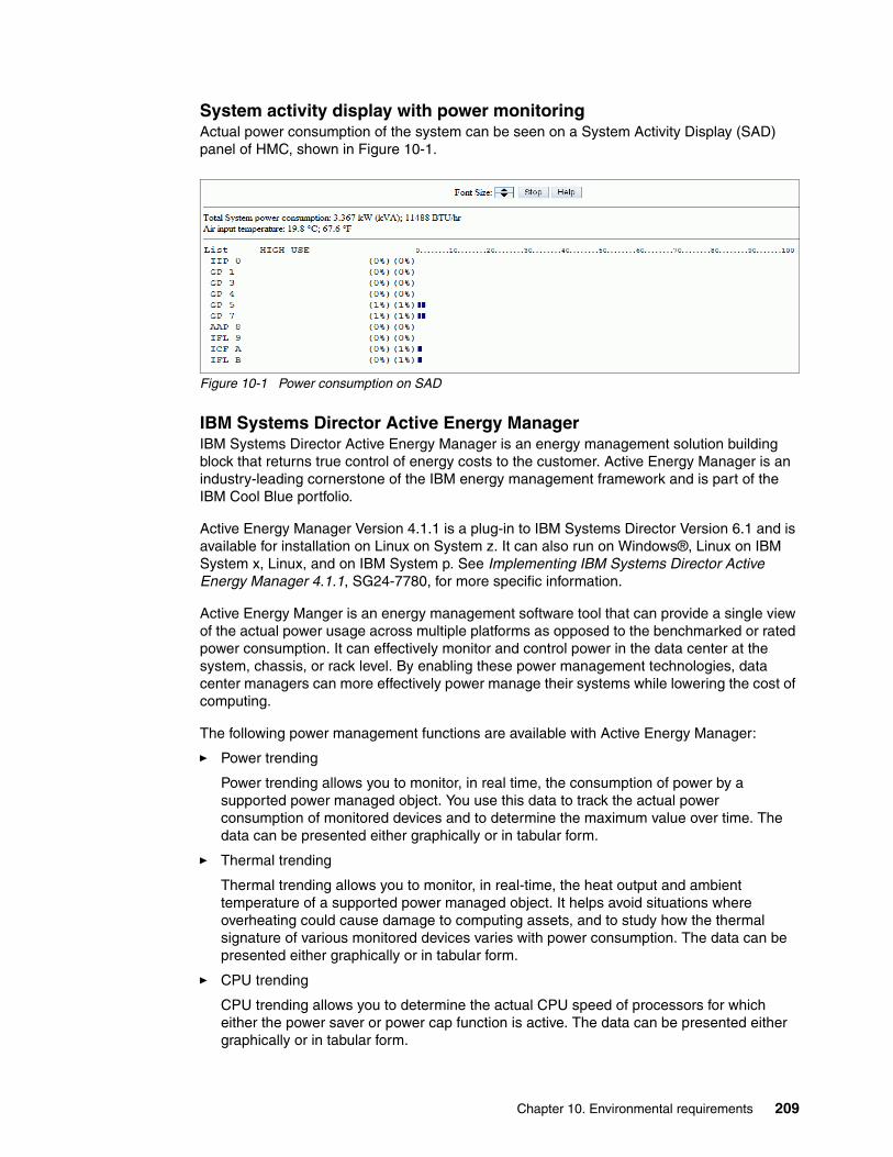
System activity display with power monitoringActual power consumption of the system can be seen on a System Activity Display (SAD) panel of HMC, shown in Figure 10-1.
Figure 10-1 Power consumption on SAD
IBM Systems Director Active Energy ManagerIBM Systems Director Active Energy Manager is an energy management solution building block that returns true control of energy costs to the customer. Active Energy Manager is an industry-leading cornerstone of the IBM energy management framework and is part of the IBM Cool Blue portfolio.
Active Energy Manager Version 4.1.1 is a plug-in to IBM Systems Director Version 6.1 and is available for installation on Linux on System z. It can also run on Windows®, Linux on IBM System x, Linux, and on IBM System p. See Implementing IBM Systems Director Active Energy Manager 4.1.1, SG24-7780, for more specific information.
Active Energy Manger is an energy management software tool that can provide a single view of the actual power usage across multiple platforms as opposed to the benchmarked or rated power consumption. It can effectively monitor and control power in the data center at the system, chassis, or rack level. By enabling these power management technologies, data center managers can more effectively power manage their systems while lowering the cost of computing.
The following power management functions are available with Active Energy Manager:
� Power trending
Power trending allows you to monitor, in real time, the consumption of power by a supported power managed object. You use this data to track the actual power consumption of monitored devices and to determine the maximum value over time. The data can be presented either graphically or in tabular form.
� Thermal trending
Thermal trending allows you to monitor, in real-time, the heat output and ambient temperature of a supported power managed object. It helps avoid situations where overheating could cause damage to computing assets, and to study how the thermal signature of various monitored devices varies with power consumption. The data can be presented either graphically or in tabular form.
� CPU trending
CPU trending allows you to determine the actual CPU speed of processors for which either the power saver or power cap function is active. The data can be presented either graphically or in tabular form.
Chapter 10. Environmental requirements 209
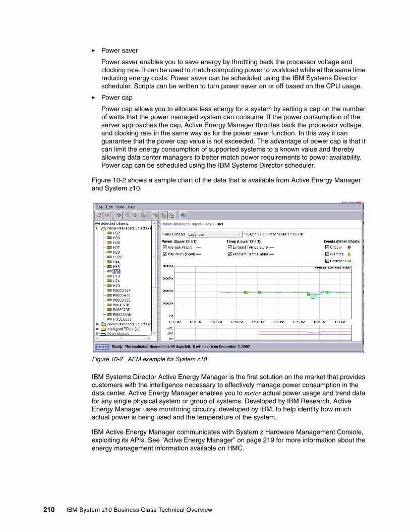
� Power saver
Power saver enables you to save energy by throttling back the processor voltage and clocking rate. It can be used to match computing power to workload while at the same time reducing energy costs. Power saver can be scheduled using the IBM Systems Director scheduler. Scripts can be written to turn power saver on or off based on the CPU usage.
� Power cap
Power cap allows you to allocate less energy for a system by setting a cap on the number of watts that the power managed system can consume. If the power consumption of the server approaches the cap, Active Energy Manager throttles back the processor voltage and clocking rate in the same way as for the power saver function. In this way it can guarantee that the power cap value is not exceeded. The advantage of power cap is that it can limit the energy consumption of supported systems to a known value and thereby allowing data center managers to better match power requirements to power availability. Power cap can be scheduled using the IBM Systems Director scheduler.
Figure 10-2 shows a sample chart of the data that is available from Active Energy Manager and System z10.
Figure 10-2 AEM example for System z10
IBM Systems Director Active Energy Manager is the first solution on the market that provides customers with the intelligence necessary to effectively manage power consumption in the data center. Active Energy Manager enables you to meter actual power usage and trend data for any single physical system or group of systems. Developed by IBM Research, Active Energy Manager uses monitoring circuitry, developed by IBM, to help identify how much actual power is being used and the temperature of the system.
IBM Active Energy Manager communicates with System z Hardware Management Console, exploiting its APIs. See “Active Energy Manager” on page 219 for more information about the energy management information available on HMC.
210 IBM System z10 Business Class Technical Overview
Chapter 11. Hardware Management Console
In the past several years the Hardware Management Console (HMC) has been enhanced to support many functions and tasks to extend the management capabilities of System z. This is also true with the System z10 servers and will continue in the future. Therefore, the HMC becomes more important in the overall management of the data center infrastructure.
This chapter describes the z10 EC HMC and Support Element (SE). It provides an overview of the HMC and SE functions. This chapter discusses the following topics:
� 11.1, “HMC and SE introduction” on page 212� 11.2, “HMC and SE connectivity” on page 212� 11.3, “Remote Support Facility” on page 216� 11.4, “HMC remote operations” on page 216� 11.5, “z10 BC HMC and SE key capabilities” on page 217
11
© Copyright IBM Corp. 2008, 2009. All rights reserved. 211
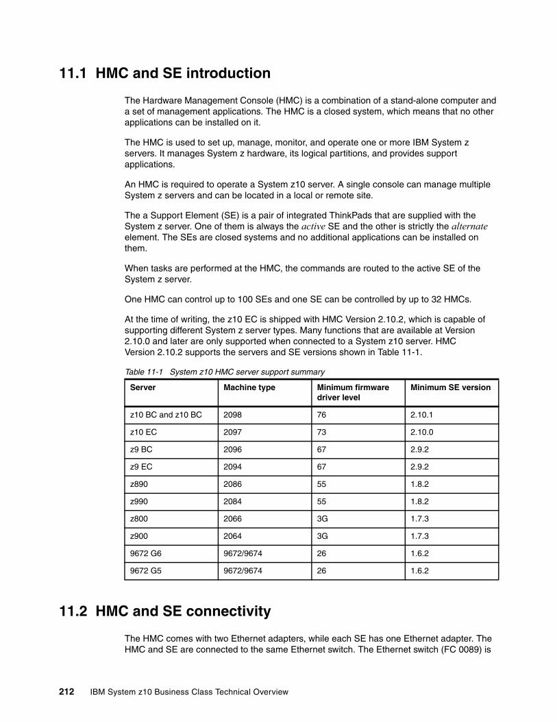
11.1 HMC and SE introduction
The Hardware Management Console (HMC) is a combination of a stand-alone computer and a set of management applications. The HMC is a closed system, which means that no other applications can be installed on it.
The HMC is used to set up, manage, monitor, and operate one or more IBM System z servers. It manages System z hardware, its logical partitions, and provides support applications.
An HMC is required to operate a System z10 server. A single console can manage multiple System z servers and can be located in a local or remote site.
The a Support Element (SE) is a pair of integrated ThinkPads that are supplied with the System z server. One of them is always the active SE and the other is strictly the alternate element. The SEs are closed systems and no additional applications can be installed on them.
When tasks are performed at the HMC, the commands are routed to the active SE of the System z server.
One HMC can control up to 100 SEs and one SE can be controlled by up to 32 HMCs.
At the time of writing, the z10 EC is shipped with HMC Version 2.10.2, which is capable of supporting different System z server types. Many functions that are available at Version 2.10.0 and later are only supported when connected to a System z10 server. HMC Version 2.10.2 supports the servers and SE versions shown in Table 11-1.
Table 11-1 System z10 HMC server support summary
11.2 HMC and SE connectivity
The HMC comes with two Ethernet adapters, while each SE has one Ethernet adapter. The HMC and SE are connected to the same Ethernet switch. The Ethernet switch (FC 0089) is
Server Machine type Minimum firmware driver level
Minimum SE version
z10 BC and z10 BC 2098 76 2.10.1
z10 EC 2097 73 2.10.0
z9 BC 2096 67 2.9.2
z9 EC 2094 67 2.9.2
z890 2086 55 1.8.2
z990 2084 55 1.8.2
z800 2066 3G 1.7.3
z900 2064 3G 1.7.3
9672 G6 9672/9674 26 1.6.2
9672 G5 9672/9674 26 1.6.2
212 IBM System z10 Business Class Technical Overview
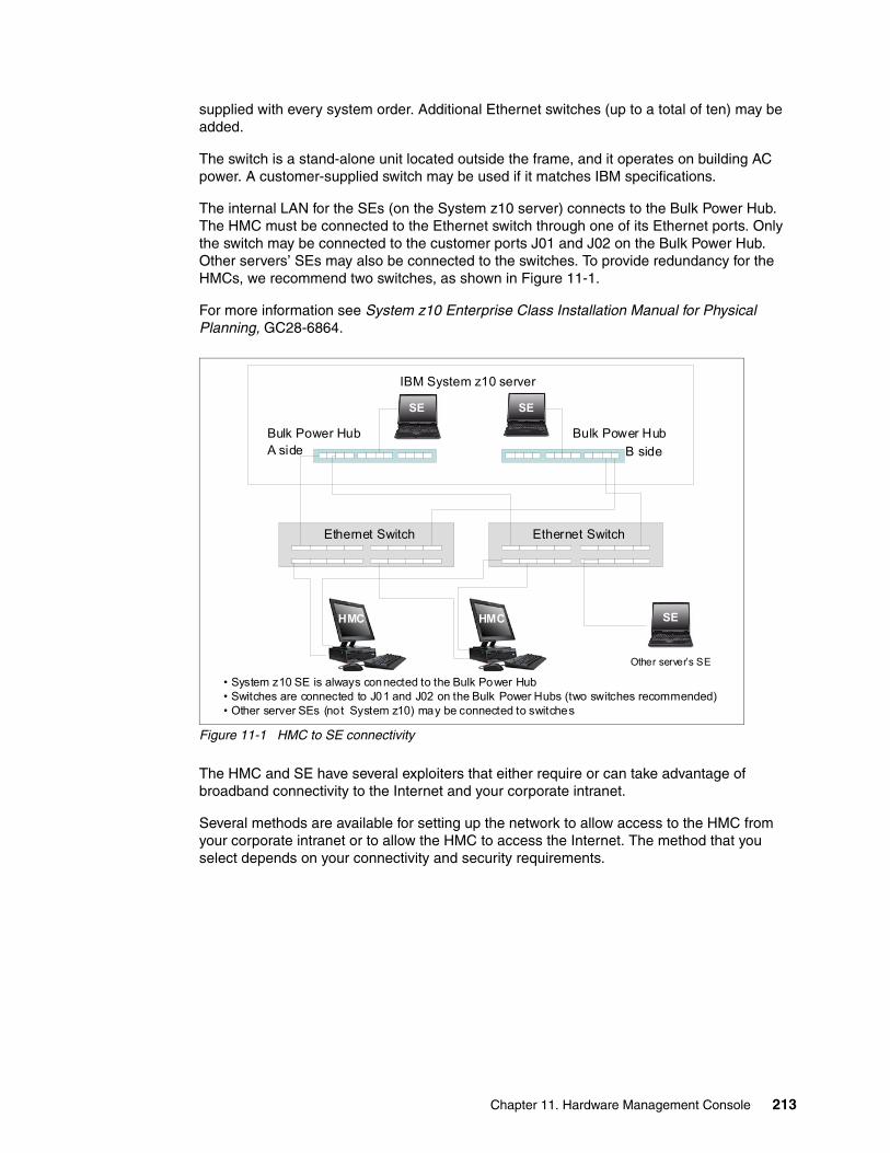
supplied with every system order. Additional Ethernet switches (up to a total of ten) may be added.
The switch is a stand-alone unit located outside the frame, and it operates on building AC power. A customer-supplied switch may be used if it matches IBM specifications.
The internal LAN for the SEs (on the System z10 server) connects to the Bulk Power Hub. The HMC must be connected to the Ethernet switch through one of its Ethernet ports. Only the switch may be connected to the customer ports J01 and J02 on the Bulk Power Hub. Other servers’ SEs may also be connected to the switches. To provide redundancy for the HMCs, we recommend two switches, as shown in Figure 11-1.
For more information see System z10 Enterprise Class Installation Manual for Physical Planning, GC28-6864.
Figure 11-1 HMC to SE connectivity
The HMC and SE have several exploiters that either require or can take advantage of broadband connectivity to the Internet and your corporate intranet.
Several methods are available for setting up the network to allow access to the HMC from your corporate intranet or to allow the HMC to access the Internet. The method that you select depends on your connectivity and security requirements.
SESE
Ethernet Switch Ethernet Switch
Bulk Power HubA side
Bulk Power HubB side
IBM System z10 server
SEHMC HMC
Other server’s SE
• System z10 SE is always connected to the Bulk Power Hub• Switches are connected to J01 and J02 on the Bulk Power Hubs (two switches recommended)• Other server SEs (not System z10) may be connected to switches
Chapter 11. Hardware Management Console 213
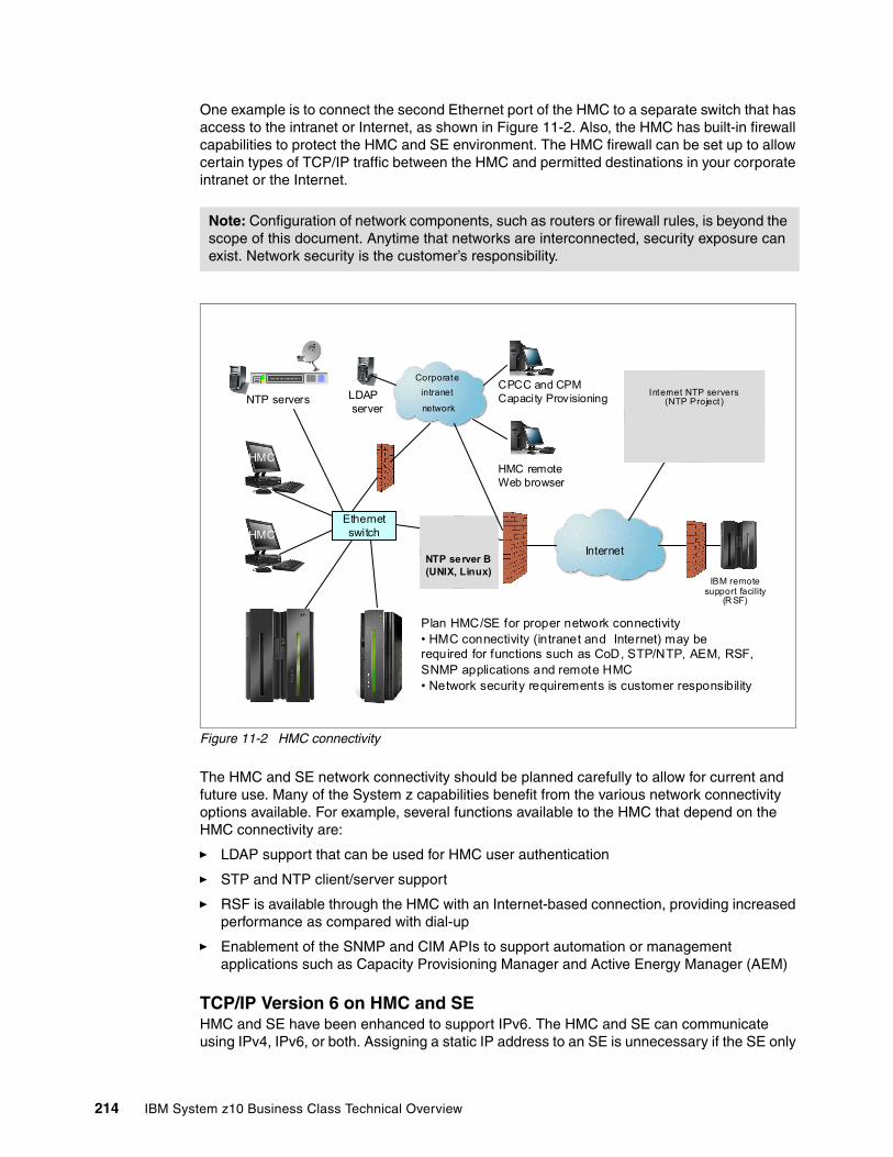
One example is to connect the second Ethernet port of the HMC to a separate switch that has access to the intranet or Internet, as shown in Figure 11-2. Also, the HMC has built-in firewall capabilities to protect the HMC and SE environment. The HMC firewall can be set up to allow certain types of TCP/IP traffic between the HMC and permitted destinations in your corporate intranet or the Internet.
Figure 11-2 HMC connectivity
The HMC and SE network connectivity should be planned carefully to allow for current and future use. Many of the System z capabilities benefit from the various network connectivity options available. For example, several functions available to the HMC that depend on the HMC connectivity are:
� LDAP support that can be used for HMC user authentication
� STP and NTP client/server support
� RSF is available through the HMC with an Internet-based connection, providing increased performance as compared with dial-up
� Enablement of the SNMP and CIM APIs to support automation or management applications such as Capacity Provisioning Manager and Active Energy Manager (AEM)
TCP/IP Version 6 on HMC and SEHMC and SE have been enhanced to support IPv6. The HMC and SE can communicate using IPv4, IPv6, or both. Assigning a static IP address to an SE is unnecessary if the SE only
Note: Configuration of network components, such as routers or firewall rules, is beyond the scope of this document. Anytime that networks are interconnected, security exposure can exist. Network security is the customer’s responsibility.
Corporateintranet
network
Internet
Internet N TP servers (NTP Project)
IBM f irewall
Ethernet switch
HMC
Jul y 14 1 4:2 1: 00 2 007 UT C
HMC
NTP servers
HMC remoteWeb browser
IBM remote support facility
(R SF)
Plan HMC/SE for proper network connectivity• HMC connectivity (intranet and Internet) may be required for functions such as CoD, STP/NTP, AEM, RSF, SNMP applications and remote HMC • Network security requirements is customer responsibility
Internet NTP servers (NTP Project)LDAP
server
CPCC and CPM Capacity Provisioning
NTP server B(UNIX, Linux)
214 IBM System z10 Business Class Technical Overview
must communicate with HMCs on the same subnet. An HMC and SE can use IPv6 link-local addresses to communicate with each other.
IPv6 link-local address characteristics are:
� Every IPv6 network interface is assigned a link-local IP address.
� A link-local address is for use on a single link (subnet) and is never routed.
� Two IPv6-capable hosts on a subnet can communicate by using link-local addresses without having any other IP addresses assigned.
Assigning addresses to HMC and SEAn HMC can have the following IP addresses:
� Statically assigned IPv4 or statically assigned IPv6
� DHCP assigned IPv4 or DHCP assigned IPv6
� Autoconfigured IPv6:
– Link-local is assigned to every network interface.
– Router-advertised, which is broadcast from the router, can be combined with a MAC address to create a totally unique address.
– Privacy extensions can be enabled for these addresses as a way to avoid using MAC address as part of the address to ensure uniqueness.
An SE can have the following IP addresses:
� Statically assigned IPv4 or statically assigned IPv6� Autoconfigured IPv6 as link-local or router-advertised
IP addresses on the SE cannot be dynamically assigned through DHCP to ensure repeatable address assignments. Privacy extensions are not used.
The HMC uses IPv4 and IPv6 multicasting to automatically discover SEs. The HMC Network Diagnostic Information task may be used to identify the IP addresses (IPv4 and IPv6) that are being used by the HMC to communicate to the CPC SEs.
IPv6 addresses are easily identified. A fully qualified IPV6 address has 16 bytes, written as eight 16-bit hex blocks separated by colons, as shown in the following example:
2001:0db8:0000:0000:0202:B3FF:fe1e:8329
Because many IPv6 addresses are not fully qualified, shorthand notation can be used. This is where the leading zeros can be omitted and consecutive zeros can be replaced with a double colon. The address in the previous example can also be written as:
2001:db8::202:B3FF:fe1e:8329
For remote operations using a Web browser, if an IPv6 address is assigned to the HMC, navigate to it by specifying that address. The address must be surrounded with square brackets in the browser’s address field:
https://[fdab:1b89:fc07:1:201:6cff:fe72:ba7c]
Using link-local addresses must be supported by browsers.
Chapter 11. Hardware Management Console 215

11.3 Remote Support Facility
The HMC Remote Support Facility (RSF) provides communication to a centralized IBM support network for hardware problem reporting and service. The types of communication provided include:
� Problem reporting and repair data� Fix delivery to the service processor and HMC� Hardware inventory data� On demand enablement
The HMC can be configured to send hardware service-related information to IBM by using a dialup connection over a modem or using an Internet connection. The advantages of using an Internet connection include:
� Significantly faster transmission speed
� Ability to send more data on an initial problem request, potentially resulting in more rapid problem resolution
� Reduced customer expense (for example, the cost of a dedicated analog telephone line)
� Greater reliability
Unless the enterprise’s security policy prohibits any connectivity from the HMC over the Internet, we recommend an Internet connection.
If both types of connections are configured, the Internet will be tried first, and if it fails the modem is used.
The following security characteristics are in effect regardless of the connectivity method chosen:
� Remote Support Facility requests are always initiated from the HMC to IBM. An inbound connection is never initiated from the IBM Service Support System.
� All data transferred between the HMC and the IBM Service Support System is encrypted in a high-grade Secure Sockets Layer (SSL) encryption.
� When initializing the SSL encrypted connection the HMC validates the trusted host by its digital signature issued for the IBM Service Support System.
� Data sent to the IBM Service Support System consists solely of hardware problems and configuration data. No application or customer data is transmitted to IBM.
11.4 HMC remote operations
The z10 EC HMC application simultaneously supports one local user and any number of remote users. Remote operations provide the same interface used by a local HMC operator. The two ways to perform remote manual operations are:
� Using a Remote HMC
A remote HMC is an HMC that is on a different subnet from the SE. Therefore, the SE cannot be automatically discovered with IP multicast.
� Using a Web browser to connect to an HMC
The choice between a remote HMC and a Web browser connected to a local HMC is determined by the scope of control needed. A remote HMC can control only a specific set of
216 IBM System z10 Business Class Technical Overview

objects, but a Web browser connected to a local HMC controls the same set of objects as the local HMC.
In addition, consider communications connectivity and speed. LAN connectivity provides acceptable communications for either a remote HMC or Web browser control of a local HMC, but dialup connectivity is only acceptable for occasional Web browser control.
Using a remote HMCAlthough a remote HMC is a complete HMC, its connection configuration differs from a local HMC. As a complete HMC, it requires the same setup and maintenance as other HMCs (see Figure 11-2 on page 214).
A remote HMC requires TCP/IP connectivity to each SE to be managed. Therefore, any existing customer-installed firewall between the remote HMC and its managed objects must permit communications between the HMC and SE. For service and support, the remote HMC also requires connectivity to IBM or to another HMC with connectivity to IBM.
Using a Web browserEach HMC contains a Web server that can be configured to allow remote access for a specified set of users. When properly configured, an HMC can provide a remote user with access to all the functions of a local HMC except those that require physical access to the diskette or DVD media. The user interface in the browser is the same as the local HMC and has the same functionality as the local HMC.
The Web browser can be connected to the local HMC by using either a LAN TCP/IP connection or a switched, dial-up, or network PPP TCP/IP connection. Both connection types use only encrypted (HTTPS) protocols, as configured in the local HMC. If a PPP connection is used, the PPP password must be configured in the local HMC and in the remote browser system. Logon security for a Web browser is provided by the local HMC user logon procedures. Certificates for secure communications are provided and can be changed by the user.
11.5 z10 BC HMC and SE key capabilities
The z10 EC comes with HMC application Version 2.10.2. For a complete list of HMC functions see System z HMC Operations Guide Version 2.10.2, SC28-6881.
Version 2.10.2 includes a number of enhancements:
� Digitally signed firmware
One critical issue with firmware upgrades is security and data integrity. Procedures are in place to use a process to digitally sign the firmware update files on the HMC, the SE, and the TKE. Using a hash-algorithm, a message digest is generated, which is then encrypted with a private key to produce a digital signature. This operation ensures that any changes made to the data will be detected during the upgrade process. It helps ensure that no malware can be installed on System z products during firmware updates. It enables, with other existing security functions, System z10 CPACF functions to comply with Federal Information Processing Standard (FIPS) 140-2 Level 1 for Cryptographic Licensed Internal Code (LIC) changes. The enhancement follows the System z focus of security for the HMC and the SE.
� Serviceability enhancements for FICON channels:
Simplified problem determination to more quickly detect fiber optic cabling problems in a Storage Area Network.
Chapter 11. Hardware Management Console 217
All FICON channel error information is forwarded to the HMC, thus facilitating detection and reporting trends and thresholds for the channels with aggregate views including data from multiple systems
� Optional user password on disruptive confirmation
The requirement to supply a user password on disruptive confirmation is optional. The general recommendation remains to require a password.
� Improved consistency of confirmation panels on the HMC and the SE
Attention indicators are on the top of panels and there will be a list of objects affected by the action, target as well as secondary objects, for example, LPARs if the target is CPC.
11.5.1 CPC management
The HMC is the primary place for central processor complex (CPC) control. For example, to define hardware to z10 EC, I/O configuration data set (IOCDS) must be defined. The IOCDS contains definitions of logical partitions, channel subsystems, control units, and devices and their accessibility from logical partitions. IOCDS can be created and put into production from the HMC.
The z10 EC server is powered on and off from the HMC. HMC is used to initiate power-on reset (POR) of the server. During the POR, among other things, PUs are characterized and placed into their respective pools, memory is put into a single main storage pool, and IOCDS is loaded and initialized into the hardware system area.
The hardware messages task displays hardware-related messages on the CPC level, a logical partition level, SE level, or hardware messages related to the HMC itself.
11.5.2 LPAR management
Use HMC to define logical partition properties, such as how many processors of each type, how many are reserved, or how much memory is assigned to it. These parameters are defined in logical partition profiles and they are stored on the SE.
Because PR/SM must manage logical partition access to processors and initial weights of each partition, weights are used to prioritize partition access to processors.
A Load task on the HMC enables you to IPL an operating system. It causes a program to be read from a designated device and initiates that program. The operating system can be IPLed from disk, HMC CD-ROM/DVD, or FTP server.
When a logical partition is active and an operating system is running in it, you may use the HMC to change certain logical partition parameters dynamically. The HMC also provides an interface to change partition weight, add logical processors to partitions, and add memory.
LPAR weights can be also be changed through a scheduled operation. Use the HMC’s Customize Scheduled Operations task to define the weights that will be set to logical partitions at the scheduled time.
Channel paths can be configured on and off dynamically, as needed, for each partition from an HMC.
218 IBM System z10 Business Class Technical Overview
11.5.3 Operating system communication
The operating system messages task displays messages from a logical partition. You may also enter operating system commands and interact with the system.
HMC also provides integrated 3270 and ASCII consoles, so you can access an operating system without requiring other networks or network devices (such as TCP/IP or control units).
11.5.4 SE access
To use an SE, being physically close to it is not necessary. Use the HMC to remotely access the SE. The same interface is provided on the SE.
The HMC enables you to:
� Synchronize content of the primary SE to the alternate SE.� Determine whether a switch from primary to the alternate can be performed.� Switch between primary and alternate SEs.
11.5.5 Monitoring
Use the System Activity Display (SAD) task on the HMC to monitor the activity of one or more CPCs. The task monitors processor and channel usage. You may define multiple activity profiles. The task also includes power monitoring information, the power being consumed, and the air input temperature for the server.
For HMC users with service authority, SAD shows information about each power cord. Power cord information should only be used by those with extensive knowledge about System z10 internals and three-phase electrical circuits. Weekly call-home data includes power information for each power cord.
Active Energy ManagerAs discussed in “IBM Systems Director Active Energy Manager” on page 209, the Active Energy Manager is an energy management solution building-block that returns true control of energy costs to the customer. It is a software tool that provides a single view of the actual power usage across multiple platforms and helps to increase energy efficiency by controlling power use across the data center.
Active Energy Manager runs on Windows, Linux on IBM System x®, Linux on IBM System p, and Linux on IBM System z.
How Active Energy Manager worksActive Energy Manager interacts with systems as follows:
� Hardware, firmware, and systems management software in servers and blades provide information to Active Energy Manager.
� Active Energy Manager calculates the power consumption for each component and tracks power usage over time.
� When power is constrained, Active Energy Manager allows power to be allocated on a server-by-server basis.
Chapter 11. Hardware Management Console 219

� Active Energy Manager ensures that limiting the power consumption does not affect performance.
� Sensors and alerts warn the user if limiting power to a particular server can affect performance.
Data available from z10 EC HMCThe following data is available from the z10 EC HMC:
� System name, machine type, model, serial number, and firmware level
� Ambient temperature
� Exhaust temperature
� Average power (over a 1-minute period)
� Peak power (over a 1-minute period)
� Limited status and configuration information. This information helps explain changes to the power consumption, called events, which can be:
– Changes in fan speed– Changes between power-off, power-on, and IML-complete states– Number of I/O drawers– CBU records expirations
11.5.6 HMC Console Messenger
The Console Messenger task provides basic messaging capabilities between users of the HMC and the SE. Console Messenger provides:
� Basic messaging capabilities that allow system operators or administrators to coordinate their activities
� Messaging capability to HMC and SE users
� Messaging between local and remote users by using existing HMC and SE interconnection protocols
� Interactive chats between two partners with send and receive messages, and chat history displayed in the task panel
� Broadcast message to all sessions on a selected console, with the ability to send one-shot message to all sessions on a selected console
� Plain text messages in chats and broadcast messages
220 IBM System z10 Business Class Technical Overview
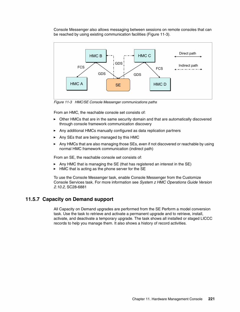
Console Messenger also allows messaging between sessions on remote consoles that can be reached by using existing communication facilities (Figure 11-3).
Figure 11-3 HMC/SE Console Messenger communications paths
From an HMC, the reachable console set consists of:
� Other HMCs that are in the same security domain and that are automatically discovered through console framework communication discovery
� Any additional HMCs manually configured as data replication partners
� Any SEs that are being managed by this HMC
� Any HMCs that are also managing those SEs, even if not discovered or reachable by using normal HMC framework communication (indirect path)
From an SE, the reachable console set consists of:
� Any HMC that is managing the SE (that has registered an interest in the SE)� HMC that is acting as the phone server for the SE
To use the Console Messenger task, enable Console Messenger from the Customize Console Services task. For more information see System z HMC Operations Guide Version 2.10.2, SC28-6881
11.5.7 Capacity on Demand support
All Capacity on Demand upgrades are performed from the SE Perform a model conversion task. Use the task to retrieve and activate a permanent upgrade and to retrieve, install, activate, and deactivate a temporary upgrade. The task shows all installed or staged LICCC records to help you manage them. It also shows a history of record activities.
Direct path
Indirect path
HMC BHMC B
HMC AHMC A
HMC CHMC C
FCSGDS GDS
HMC DHMC D
FCS
SE
GDS
Chapter 11. Hardware Management Console 221
HMC for System z10 CoD enhancements include:
� SNMP API support
– API interfaces for granular activation and deactivation.
– API interfaces for enhanced Capacity On Demand query information.
– API Event notification for any Capacity On Demand change activity on the system.
– Previous Capacity On Demand API interfaces (such as On/Off CoD and CBU) continue to be supported.
� SE panel enhancements (accessed through HMC Single Object Operations)
– Panel controls for granular activation and deactivation
– History panel for all Capacity On Demand actions
– Descriptions editing of Capacity On Demand records
HMC/SE Version 2.10.1 provides additional CoD updates, such as:
� MSU and processor tokens shown on panels.� Last activation time shown on panels.� Pending resources are shown by processor type instead of just a total count.� Option to show details of installed and staged permanent records.� More details for the attention state on panels (by providing seven additional flags).
HMC and SE are an integral part for the z/OS Capacity Provisioning environment. The Capacity Provisioning Manager (CPM) communicates with the HMC through System z APIs and enters CoD requests. For this reason, SNMP must be configured and enabled on the HMC.
For additional information about using and setting up CPM, see the publications:
� z/OS MVS Capacity Provisioning User’s Guide, SA33-8299� IBM System z10 Capacity On Demand, SG24-7504
11.5.8 Server Time Protocol support
Server Time Protocol (STP) is supported on System z servers. With the STP functions, the role of the HMC has been extended to provide the user interface for managing the Coordinated Timing Network (CTN).
In a mixed CTN (one containing both STP and Sysplex Timer) the HMC can be used to:
� Initialize or modify the CTN ID and ETR port states.� Monitor the status of the CTN.� Monitor the status of the coupling links initialized for STP message exchanges.
In an STP-only CTN, the HMC can be used to:
� Initialize or modify the CTN ID.
� Initialize the time, manually or by dialing out to a time service, so that the Coordinated Server Time (CST) can be set to within 100 ms of an international time standard, such as UTC.
� Initialize the time zone offset, daylight saving time offset, and leap second offset.
� Schedule periodic dial-outs to a time service so that CST can be steered to the international time standard.
� Assign the roles of preferred, backup, and current time servers, as well as arbiter.
222 IBM System z10 Business Class Technical Overview
� Adjust time by up to plus or minus 60 seconds.
� Schedule changes to the offsets listed. STP can automatically schedule daylight saving time, based on the selected time zone.
� Monitor the status of the CTN.
� Monitor the status of the coupling links initialized for STP message exchanges.
For additional planning and setup information, see the following publications:
� Server Time Protocol Planning Guide, SG24-7280� Server Time Protocol Implementation Guide, SG24-7281
11.5.9 NTP client/server support on HMC
The Network Time Protocol (NTP) client support allows an STP-only Coordinated Timing Network (CTN) to use an NTP server as an External Time Source (ETS) that addresses the requirement for:
� Customers who want time accuracy for the STP-only CTN� Using a common time reference across heterogeneous platforms
NTP client allows the same accurate time across an enterprise comprising heterogeneous platforms.
NTP server becomes the single time source, ETS for STP, as well as other servers that are not System z (such as UNIX, Windows NT®, and others) that have NTP clients.
When the HMC is configured to have an NTP client running, the HMC time will be continuously synchronized to an NTP server instead of synchronizing to the SE.
HMC can also act as an NTP server. With this support, z10 EC can get time from HMC without accessing other than the HMC/SE network.
When the HMC is used as an NTP server, it can be configured to get the NTP source from the Internet. For this type of configuration, a separate LAN is recommended from the HMC/SE LAN.
The NTP client support can be used to connect to other NTP servers that can potentially receive NTP through the Internet. When using another NTP server, then the NTP server becomes the single time source, ETS for STP, and other servers that are not System z servers (such as UNIX, Windows NT, and others) that have NTP clients.
When the HMC is configured to have an NTP client running, the HMC time will be continuously synchronized to an NTP server instead of synchronizing to a Support Element.
For additional planning and setup information for STP and NTP see the following manuals:
� Server Time Protocol Planning Guide, SG24-7280� Server Time Protocol Implementation Guide, SG24-7281
11.5.10 System Input/Output Configuration Analyzer on the SE/HMC
A System Input/Output Configuration Analyzer task is provided that supports the system I/O configuration function. The information necessary to manage a system's I/O configuration must be obtained from many separate applications. A System Input/Output Configuration Analyzer task enables the system hardware administrator to access, from one location, the information from these many sources. Managing I/O configurations then becomes easier,
Chapter 11. Hardware Management Console 223
particularly across multiple servers. The System Input/Output Configuration Analyzer task performs the following functions:
� Analyzes the current active IOCDS on the SE.
� Extracts information about the defined channel, partitions, link addresses, and control units.
� Requests the channel’s node ID information. The FICON channels support remote node ID information, which is also collected.
The System Input/Output Configuration Analyzer is a view-only tool. It does not offer any options other than viewing options. With the tool, data is formatted and displayed in five different views. Various sort options are available, and data can be exported to a USB flash drive for a later viewing. The five views are:
� PCHID Control Unit View, which shows PCHIDs, CSS, CHPIDs, and their control units
� PCHID Partition View, which shows PCHIDS, CSS, CHPIDs, and the partitions they are in
� Control Unit View, which shows the control units, their PCHIDs, and their link addresses in each CSS
� Link Load View, which shows the link address and the PCHIDs that use it
� Node ID View, which shows the node ID data under the PCHIDs
11.5.11 Network Analysis Tool for SE Communication
The Network Analysis Tool tests that communication between the HMC and SE is available. The tool performs five tests:
� HMC pings SE.� HMC connects to SE and also verifies that the SE is at the correct level.� HMC sends a message to SE and receives a response.� SE connects back to HMC.� SE sends a message to HMC and receives a response.
11.5.12 Automated operations
As an alternative to manual operations, a computer can interact with the consoles through an application programming interface (API). The interface allows a program to monitor and control the hardware components of the system in the same way a human can monitor and control the system. The HMC APIs provide monitoring and control functions through TCP/IP SNMP and CIM to an HMC. These APIs provide the ability to get and set a managed object’s attributes, issue commands, receive asynchronous notifications, and generate SNMP traps.
The HMC supports Common Information Model (CIM) as an additional systems management API. The focus is on attribute query and operational management functions for System z, such as CPCs, images, and activation profiles. The System z10 contains a number of enhancements to the CIM systems management API. The function is similar to that provided by the SNMP API.
For additional information about APIs see the System z Application Programming Interfaces, SB10-7030.
224 IBM System z10 Business Class Technical Overview
11.5.13 Cryptographic support
The z10 EC includes both standard cryptographic hardware and optional cryptographic features for flexibility and growth capability. The HMC/SE interface provides the capability to:
� Define the cryptographic controls.� Dynamically add a Crypto to a partition for the first time.� Dynamically add a Crypto to a partition already using Crypto.� Dynamically remove Crypto from a partition.
A Usage Domain Zeroize task is provided to clear the appropriate partition crypto keys for a given usage domain when removing a crypto card from a partition. For detailed setup information see IBM System z10 Enterprise Class Configuration Setup, SG24-7571.
11.5.14 z/VM virtual machine management
HMC can be used for basic management of z/VM and its virtual machines. HMC exploits the z/VM Systems Management Application Programming Interface (SMAPI) and provides a graphical user interface-based alternative to the 3270 interface.
Monitoring the status information and changing the settings of z/VM and its virtual machines is possible. From the HMC interface, virtual machines can be activated, monitored, and deactivated.
Authorized HMC users can obtain various status information, such as:
� Configuration of the particular z/VM virtual machine� z/VM image-wide information about virtual switches and guest LANs� Virtual Machine Resource Manager (VMRM) configuration and measurement data
The activation and deactivation of z/VM virtual machines is integrated into the HMC interface. You can select the Activate and Deactivate tasks on CPC and CPC image objects and for virtual machines management.
An event monitor is a trigger that is listening for events from objects managed by HMC. When z/VM virtual machines change their status, they generate such a events. You can create event monitors to handle the events coming from z/VM virtual machines. For example, selected users can be notified by an e-mail message if the virtual machine changes status from operating to exceptions, or any other state.
In addition, in z/VM V5.4, the APIs can perform the following functions:
� Create, delete, replace, query, lock, and unlock directory profiles.
� Manage and query LAN access lists (granting and revoking access to specific user IDs).
� Define, delete, and query virtual CPUs within an active virtual image and in a virtual image's directory entry.
� Set a maximum number of virtual processors that can be defined in a virtual image's directory entry.
11.5.15 Installation support for z/VM using the HMC
The traditional way of installing Linux on System z in the z/VM virtual machine requires a network connection to a file server that is hosting the installation files of the Linux distribution.
Chapter 11. Hardware Management Console 225

Starting with z/VM 5.4 and System z10, Linux on System z can be installed in a z/VM virtual machine from the HMC workstation DVD drive. This Linux on System z installation can exploit the existing communication path between the HMC and the SE, where no external network and no additional network setup is necessary for the installation. This simplification can eliminate potential customer concerns and additional configuration efforts.
226 IBM System z10 Business Class Technical Overview

Related publications
The publications listed in this section are considered particularly suitable for a more detailed discussion of the topics covered in this book.
IBM Redbooks publications
For information about ordering these publications, see “How to get Redbooks publications” on page 228. Note that some of the documents referenced here might be available in softcopy only.
� IBM System z10 Enterprise Class Technical Introduction, SG24-7515
� IBM System z10 Enterprise Class Technical Guide, SG24-7516
� Getting Started with InfiniBand on System z10 and System z9, SG24-7539
� IBM System z Connectivity Handbook, SG24-5444
� IBM System z10 Capacity On Demand, SG24-7504
� IBM System z10 Enterprise Class Configuration Setup, SG24-7571
Other publications
These publications are also relevant as further information sources:
� System z10 BC System Overview,SA22-1085
� System z10 BC Installation Manual, GC28-6874
� Hardware Management Console Operations Guide Version 2.10.1, SC28-6873
� Support Element Operations Guide V2.10.1, SC28-6879
� System z10 Capacity on Demand User’s Guide, SC28-6871
� System z10 BC Installation Manual for Physical Planning, GC28-6875
� z/Architecture Principles of Operation, SA22-7832
Online resources
These Web sites are also relevant as further information sources:
� Resource Link
http://www.ibm.com/servers/resourcelink
� IBM CryptoCards Web site
http://www.ibm.com/security/cryptocards
� Large Systems Performance Reference for IBM System z
http://www.ibm.com/servers/eserver/zseries/lspr/
© Copyright IBM Corp. 2008, 2009. All rights reserved. 227
� IBM Processor Capacity Reference (zPCR) tool
http://www.ibm.com/support/techdocs/atsmastr.nsf/WebIndex/PRS1381
� Capacity Planning for z10 Upgrades document
http://www.ibm.com/support/techdocs/atsmastr.nsf/WebIndex/TD104738
� IBM System z10 Integrated Information Processor (zIIP)
http://www.ibm.com/systems/z/advantages/ziip/about.html
� Parallel Sysplex Web site
http://www.ibm.com/systems/z/advantages/pso/index.html
� Coupling Facility Configuration Options white papers
http://www.ibm.com/systems/z/advantages/pso/whitepaper.html
� Web-delivered code on z/OS downloads
http://www.ibm.com/systems/z/os/zos/downloads/
� Linux on System z on the developerWorks Web site
http://www.ibm.com/developerworks/linux/linux390/
� CFSizer Tool
http://www.ibm.com/systems/z/cfsizer
� IBM System z Software Pricing Reference Guide
http://www.ibm.com/servers/eserver/zseries/library/refguides/sw_pricing.html
How to get Redbooks publications
You can search for, view, or download Redbooks publications, Redpapers publications, Technotes, draft publications and Additional materials, as well as order hardcopy Redbooks publications, at this Web site:
ibm.com/redbooks
Help from IBM
IBM Support and downloads
ibm.com/support
IBM Global Services
ibm.com/services
228 IBM System z10 Business Class Technical Overview
Index
Numerics30 logical partitions support 15263.75K subchannels 115, 153
AActive Energy Manager 219adapter interruptions 98addressing mode 65Advanced Encryption Standard (AES) 48, 122, 132application preservation 60
Bbalanced power 204
CCache Level 1 (L1 cache) 44Cache Level 1.5 (L1.5 cache) 44Capacity Backup (CBU) 39, 50–51, 186
contract 186enablement 196testing 196
Capacity for Planned Events 50Capacity for Planned Events (CPE) 40capacity marker 36–37, 51Capacity on Demand 39, 50–52, 54, 183–184Capacity Provisioning Manager 191capacity setting 187capacity tokens 189CBU 39, 50–51, 186Central Processing Complex 63central processor (CP) 48, 50–51, 108, 121–122, 131
pool 51central storage (CS) 61–62CF Control Code (CFCC) 51, 65, 70CFCC Level 16 70Channel Data Link Control (CDLC) 164channel path identifier 109channel spanning 117channel subsystem (CSS) 58, 67, 108, 110channel subsystem priority queuing 68Chinese Remainder Theorem (CRT) 128chip lithography 27CHPID 64, 109–110, 117–118CHPID Mapping Tool 64, 116, 119CIU facility 187–188cluster 175, 182clustering 69CMOS 44Common Cryptographic Architecture 125, 132compression unit 48concurrent memory upgrade 60, 198concurrent, definition of 182
© Copyright IBM Corp. 2008, 2009. All rights reserved.
configuration report 35Configurator for e-business 119connectors 35Console Messenger 220control unit 110cooling 26–27cooling requirements 205Coupling Facility (CF) 51–52, 61Coupling Facility Control Code 52Coupling Facility mode 66Coupling facility mode 66Coupling Link 23, 46CP 40, 51
assigned 37CP pool 51logical processors 59
CP Assist for Cryptographic Function 48CP Cryptographic Assist Facility 48CP/ICF/IFL sparing 60CPACF 48
cryptographic capabilities 14PU design 48
CPCmanagement 218
CPE 40, 50Crypto enablement 133Crypto Express2 15, 23, 46, 124–125, 127–128
accelerator 15, 123, 127–128, 131coprocessor 15, 123–127, 130–131support 167
cryptographicdomain 127–128feature codes 133features comparison 131synchronous function 122
Cryptographic Accelerator (CA) 123–124Cryptographic Coprocessor (CC) 123CSS 118
components 109configuration management 119ID 67Image ID 109structure 110
Customer Initiated Upgrade (CIU) 50, 188activation 188Ordering 188
DData Encryption Standard (DES) 48, 121–122, 124, 129DB2 with zIIP 56decimal floating point (DFP) accelerator 49dedicated processor 65DES. See Data Encryption Standard (DES)DFSMS striping 172
229
DIMM 25, 44disruptive upgrades 183double key MAC 122double length key DES 122drawer
CPC drawer 13, 22, 25, 44I/O drawer 22–23, 204I/O drawers 25installation order 22
Dynamic CF dispatching 70Dynamic Channel Path Management (DCM) 68dynamic sparing/reassignment 60Dynamic storage reconfiguration 62
EEDM 198Electronic Industry Association (EIA) 22emergency power off 205engine day token 189enhanced driver maintenance 198enterprise service bus (ESB) 5ESA/390 mode 66ESA/390 TPF mode 66ESCON channel 23, 45, 64, 118, 164, 184ETR 25Europay Mastercard VISA (EMV) 2000 125EWLC 176EXCP 172EXCPVR 172expanded storage 61extended addressability 172Extended Format Data Set 172External Time Reference 46
Ffanout 34fanout card 23FICON 23FICON channel 23, 154, 158FICON Express 45
channel 23, 117FICON Express2 13, 23, 45FICON Express4 23, 45FICON to ESCON
conversion function 90FIPS 140-2 Level 4 121frame 22FSP card 25
GGARP VLAN Registration Protocol (GVRP) 164GDPS 196group capacity limit 67
HHardware Configuration Dialog 110Hardware Management Console (HMC) 59, 62–63, 188hardware messages 218
hardware system area (HSA) 61–62, 110HCA, concurrent add or replace 198HCA2-C 23, 34HCA2-O 24, 34, 46HCA2-O LR 24, 34, 46HCD 64, 67, 110, 114, 119HiperSockets
with zIIP 57HMC 212
browser access 217firewall 214remote access 217
Host Channel Adapter2-C 34Host Channel Adapter2-O 34
Long Reach 34
II/O
cage, I/O slot 184card 183–184connectivity 46device 108domain 36drawer, concurrent add or replace 198operation 58, 108, 155, 172
I/O Configuration Program (IOCP) 64, 114, 116–117I/O device 110ICB-4 24, 34ICB-4 link 46ICF 36–37, 40, 51–52ICSF 127, 129, 168IEEE Binary Floating Point 50IEEE Floating Point 49IFB-MP card 36IFC 52IFL 36, 40, 51
assigned 37indirect address word (IDAW) 155, 172InfiniBand coupling 24input/output configuration data set (IOCDS) 119input/output configuration dataset (IOCDS) 119Integrated Facility for Linux 36, 50–51, 60Intelligent Resource Director (IRD) 63–64, 67Internal Battery Feature (IBF) 23, 41, 205
estimated power time 23Internal Coupling (IC) 36–37, 51–52, 117Internal Coupling Facility 52IOCDS 119IOCP 64IODF 119IRD 63–64, 67
LPAR CPU Management 63ISC-3
link 23, 46, 184ISO 16609 CBC Mode 126
JJava Virtual Machine (JVM) 53–54, 56
230 IBM System z10 Business Class Technical Overview

Kkey exchange 125
LL1 cache 29, 50L2 cache 29, 44large page support 60LIC. See Licensed Internal Code (LIC)LICCC. See Licensed Internal Code Configuration Control (LICCC)Licensed Internal Code (LIC) 31, 50, 76, 180, 183, 198Licensed Internal Code Configuration Control (LICCC) 33, 60, 180link aggregation 98Linux 51, 66, 125, 132, 138Linux on System z 51, 135–137, 154Linux-only mode 66Loading of Initial ATM Keys 125Local Area Network (LAN) 130
Open Systems Adapter family 13logical partition 62, 127, 139, 144
CFCC 66Dynamic Add/Delete 67I/O operations 58logical processors 63name add 67processor upgrade 59reserved storage 183
logical processor 59, 63logical processor add 51, 59LPAR
CPU management 68management 218mode 51, 59, 62, 65–66single storage pool 62
Mmaster key entry 127MBA, concurrent add or replace 198MCI. See model capacity identifier (MCI)media manager 173memory 25, 30
allocation 60card 31, 44concurrent upgrade 60, 198design 60size 30, 40
memory bus adapter (MBA) 34message authentication code (MAC) 122, 127MIDAW facility 13, 139, 144, 155, 171, 173Midrange Workload License Charges (MWLC) 176MIF ID 67Mod_Raised_to Power (MRP) 125model capacity identifier (MCI) 37, 52, 55, 187model configurations 36model E10 36, 40model permanent capacity identifier (MPCI) 187model temporary capacity identifier (MTCI) 187modes of operation 65
Modulus Exponent (ME) 128MPCI. See model permanent capacity identifier (MPCI)MSU day token 189MSU value 37–38, 53, 56MTCI. See model temporary capacity identifier (MTCI)multiple CSS 116–117multiple subchannel set (MSS) 113–114, 139, 144, 154
NN_Port ID Virtualization (NPIV) 158native FICON 158Network Analysis Tool 224nondisruptive upgrades 183nondistruptive upgrades 182
OOn/Off Capacity on Demand (CoD) 40, 50–51, 182operating system 59, 135–136, 180
messages 219requirements 135support 136support Web page 177
optionally assignable system assist processor 59OSA Dynamic LAN idle 98OSA-Express 13OSA-Express2
10 Gb Ethernet LR 24, 4510 Gigabit Ethernet LR 142, 147, 1651000BASE-T Ethernet 24, 45, 142, 147, 164Gb Ethernet LX 24, 45Gb Ethernet SX 24, 45Gigabit Ethernet LX and SX 142, 147OSN 164
OSA-Express3 23–24, 4510 Gb Ethernet LR 4510 Gb Ethernet LR and SR 15910 Gb Ethernet SR 4510 Gigabit Ethernet LR 141, 14610 Gigabit Ethernet SR 141, 1461000BASE-T 141, 1461000BASE-T Ethernet 24, 161Gb Ethernet LX 24, 45Gb Ethernet LX and SX 159Gb Ethernet SX 24, 45Gigabit Ethernet LX 141, 146Gigabit Ethernet SX 141, 146
OSA-Express3-2P1000BASE-T Ethernet 162Gb Ethernet SX 160
oscillator 25, 47, 198
PParallel Sysplex 69, 175, 182
license charge 175Web site 171
partial memory restart 60PCHID 116–118, 124, 132
assignment 116
Index 231

definition of 64PCICA 24, 46PCI-X
cryptographic adapter 24, 46, 123–125, 127–128, 133–134cryptographic coprocessor 123
pending repair 60permanent capacity 187personal identification number (PIN) 127physical memory 30–31PKA Encrypt, PKA Decrypt 128plan-ahead memory 33pool
ICF pool 52IFL pool 51
powerconsumption 204power supply 23single phase 204three phase 204
power-on reset (POR) 182expanded storage 62hardware system area 110
PR/SM. See Processor Resource/Systems Management (PR/SM)pre-planned memory 33pre-planned memory activation 33Preventive Service Planning (PSP) 18, 135, 138processing unit (PU) 25, 36, 40, 50–51, 59–60, 188
characterization 59, 66chip 26–27conversion 37cycle time 29pool 152sparing 50type 65–66
processorerror detection and recovery 49
Processor Resource/Systems Management (PR/SM) 17, 59, 62, 65, 67, 127, 153, 175program directed re-IPL 165pseudo random number generation (PRNG) 48, 122, 124, 132, 170PSIFB 34PSP buckets 136PU. See processing unit (PU)Public Key
Decrypt 125, 132Encrypt 125, 132
public key algorithm (PKA) 125, 127, 129
QQDIO interface isolation 99QDIO optimized latency mode 99Queued Direct Input/Output (QDIO) 161–162, 164
Rrandom number generation (RNG) 122Red Hat RHEL 136, 152, 154
Redbooks Web site 228Contact us xiii
redundant I/O interconnect 35, 198reliability, availability, serviceability (RAS) 17Remote HMC 216Remote Support Facility (RSF) 216replacement capacity 187Request Node Identification Data (RNID) 140, 145reserved
PUs 196reserved processors 59Resource Access Control Facility (RACF) 127Rivest-Shamir-Adelman (RSA) 125, 127–128
SSALC 176SC chip 25–26, 29, 44SCM 25–26SCSI disk 158SD chip 29Secure Sockets Layer (SSL) 15, 48, 122, 125, 128, 131Select Application License Charges 176Server Time Protocol (STP) 222SHA-1 122SHA-1 and SHA-256 122SHA-256 122shared processor 65single chip module (SCM) 25–26single storage pool 62single system image 148Single-key MAC 122soft capping 175software licensing 173software support 19, 55, 148standard SAP 40STI-MP card 35, 45, 198storage, expanded 61store CPU ID (STIDP) 187store system information (STSI) 37, 187STP 46STP-only CTN 46subchannel 109, 113, 154superscalar 48superscalar processor 48Support Element (SE) 23, 188, 212SUSE SLES 136, 152, 154, 164–165System Assist Processor (SAP) 36, 58
additional 36definition 58definition of 58number of 40
System Controller (SC) chip 25system image 61–62, 148, 158, 182System Input/Output Configuration Analyzer 223System z10 Integrated Information Processor (zIIP) 56
Ttemporary capacity 187TKE 5.0 workstation 133
232 IBM System z10 Business Class Technical Overview
TKE workstation 129, 134TKE workstation feature 129token
engine day 189MSU day 189
TPF mode 66translation look-aside buffer (TLB) 50Triple Data Encryption Standard (TDES) 48, 122Trusted Key Entry (TKE) 127, 133
UUDX 126unassigned
CP 37IFL 36–37
unassigned IFL 52unbalanced power 204unplanned upgrades 185upgrades 37
disruptive 183nondisruptive 183permanent upgrade 188
User Defined Extensions (UDX) 126, 128, 132
VVLAN ID 164
WWeb 2.0 5WebSphere 5WebSphere MQ 176Workload License Charge (WLC) 64, 174–175, 188
Flat WLC (FWLC) 175subcapacity 175Variable WLC (VWLC) 175
XXML and zIIP 57
Zz/Architecture 5, 65–66, 136–137z/OS 63, 137, 168, 170
Communications Server with zIIP 57Global Mirror and zIIP 57
z/TPF 19z/VM 51, 66
mode 66virtual machine management 225
z/VSE 165z9 BC 129zAAP 36, 40, 50–51, 53
and LPAR definitions 54definition of 8zAAP pool 54
zeroize 124zIIP 36, 40, 50–51, 56, 228
definition of 8
zIIP pool 57
Index 233

234 IBM System z10 Business Class Technical Overview

(0.2”spine)0.17”<
->0.473”
90<->
249 pages
IBM System
z10 Business Class Technical Overview
IBM System
z10 Business Class Technical Overview
IBM System
z10 Business Class Technical Overview
IBM System
z10 Business Class Technical Overview

IBM System
z10 Business Class Technical Overview
IBM System
z10 Business Class Technical Overview

®
SG24-7632-01 ISBN 0738433764
INTERNATIONAL TECHNICALSUPPORTORGANIZATION
BUILDING TECHNICAL INFORMATION BASED ON PRACTICAL EXPERIENCE
IBM Redbooks are developed by the IBM International Technical Support Organization. Experts from IBM, Customers and Partners from around the world create timely technical information based on realistic scenarios. Specific recommendations are provided to help you implement IT solutions more effectively in your environment.
For more information:ibm.com/redbooks
®
IBM System z10 Business Class Technical Overview
Describes the new IBM System z10 BC server and related features
Discusses server structure and design
Reviews software support
This IBM Redbooks publication introduces the IBM System z10 Business Class (z10 BC) server, which is based on z/Architecture and inherits many of the improvements made with the previously introduced System z10 Enterprise Class (z10 EC) server. With a focus on midrange enterprise computing, the z10 BC server delivers an entry point with very granular scalability and an unprecedented range of capacity settings to grow with the workload. It delivers unparalleled qualities of service to help manage growth and reduce cost and risk. The z10 BC server further extends System z leadership by enriching its flexibility with enhancements to the just-in-time capacity deployment functions.
This book provides an overview of the z10 BC and its functions, features, and associated software support. Greater detail is offered in areas relevant to technical planning.
This book is intended for systems engineers, hardware planners, and anyone wanting to understand the System z10 Business Class functions and plan for their usage. It is not intended as an introduction to mainframes. Readers are expected to be generally familiar with existing System z technology and terminology.
Back cover


![Design and microarchitecture of the IBM System z10 ... of RD... · goals. Since the introduction of the IBM s/390* G4 CMOS processor [4], the mainframe microprocessor pipeline had](https://img.pdfslide.us/doc/110x75/5f3c4d4a13c46d02664b0c5a/design-and-microarchitecture-of-the-ibm-system-z10-of-rd-goals-since-the.jpg)