Embed Size (px)
Citation preview

IBM System Storage DS3000, DS4000, and DS5000
Command Line Interface and ScriptCommands Programming Guide
���

IBM System Storage DS3000, DS4000, and DS5000
Command Line Interface and ScriptCommands Programming Guide
���
NoteBefore using this information and the product it supports, read the information in “Notices” on page 359.
Seventh Edition (December 2010)
This edition applies to DS5000 Storage Manager Version 10.60, DS4000 Storage Manager Version 10.50, and DS3000Storage Manager Version 10.35 software release levels and to all subsequent releases and modifications untilotherwise indicated in new editions.
© Copyright IBM Corporation 2010.US Government Users Restricted Rights – Use, duplication or disclosure restricted by GSA ADP Schedule Contractwith IBM Corp.
Contents
Figures . . . . . . . . . . . . . . vii
Tables . . . . . . . . . . . . . . . ix
About this document . . . . . . . . . xiDS3000, DS4000, and DS5000 software and firmwaresupport . . . . . . . . . . . . . . . . xiWho should read this document . . . . . . . xiNotices used in this document . . . . . . . . xiiGetting information, help, and service . . . . . xii
Before you call . . . . . . . . . . . . xiiUsing the documentation. . . . . . . . . xiiFinding Storage Manager software, controllerfirmware, and readme files . . . . . . . . xiiiEssential Web sites for DS3000, DS4000, andDS5000 support information . . . . . . . xiiiSoftware service and support . . . . . . . xivHardware service and support . . . . . . . xivIBM Taiwan product service . . . . . . . . xvFire suppression systems . . . . . . . . xv
Chapter 1. About the Command LineInterface . . . . . . . . . . . . . . 1How to Use the Command Line Interface. . . . . 1
Usage Notes . . . . . . . . . . . . . 2CLI Commands . . . . . . . . . . . . 2Command Line Terminals . . . . . . . . . 3Formatting Considerations. . . . . . . . . 6Detailed Error Reporting . . . . . . . . . 7Exit Status . . . . . . . . . . . . . . 8Usage Examples . . . . . . . . . . . . 9
Chapter 2. About the Script Commands 11Script Command Structure . . . . . . . . . 12Script Command Synopsis . . . . . . . . . 13Recurring Syntax Elements . . . . . . . . . 14Usage Guidelines . . . . . . . . . . . . 18Adding Comments to a Script File. . . . . . . 18
Chapter 3. Script Commands . . . . . 21Naming Conventions . . . . . . . . . . . 21Firmware Compatibility Levels . . . . . . . . 22Hardware Requirements for Firmware Compatibility 23Formatting Rules for Script Commands . . . . . 23DS3000, DS4000, and DS5000 commands withminimum firmware levels . . . . . . . . . 24Activate Enhanced Remote Mirroring Feature . . . 43Activate Host Port . . . . . . . . . . . . 45Activate iSCSI Initiator . . . . . . . . . . 45Activate Storage Subsystem Firmware . . . . . 45Autoconfigure Storage Subsystem . . . . . . . 45Autoconfigure Storage Subsystem Hot Spares . . . 48Check Logical Drive Parity . . . . . . . . . 48Check Remote Mirror Status . . . . . . . . . 49
Clear Drive Channel Statistics . . . . . . . . 49Clear Logical Drive Reservations . . . . . . . 50Clear Logical Drive Unreadable Sectors . . . . . 50Clear Storage Subsystem Configuration . . . . . 51Clear Storage Subsystem Event Log . . . . . . 51Clear Storage Subsystem Firmware Pending Area. . 52Create Array . . . . . . . . . . . . . . 52Create FlashCopy Logical Drive . . . . . . . 55Create Host . . . . . . . . . . . . . . 58Create Host Group . . . . . . . . . . . . 58Create Host Port. . . . . . . . . . . . . 59Create iSCSI Initiator . . . . . . . . . . . 60Create RAID Logical Drive (Automatic Drive Select) 60Create RAID Logical Drive (Free Capacity BaseSelect) . . . . . . . . . . . . . . . . 63Create RAID Logical Drive (Manual Drive Select) . 66Create Remote Mirror . . . . . . . . . . . 69Create Storage Subsystem Security Key . . . . . 71Create Volume Copy . . . . . . . . . . . 71Deactivate Remote Mirror . . . . . . . . . 72Delete Array . . . . . . . . . . . . . . 73Delete Host . . . . . . . . . . . . . . 73Delete Host Group . . . . . . . . . . . . 73Delete Host Port. . . . . . . . . . . . . 74Delete iSCSI Initiator . . . . . . . . . . . 74Delete Logical Drive . . . . . . . . . . . 74Diagnose Controller . . . . . . . . . . . 75Diagnose Remote Mirror . . . . . . . . . . 76Disable Storage Subsystem Feature . . . . . . 77Disable Storage Subsystem Feature Key . . . . . 77Download Disk Drive Firmware . . . . . . . 78Download Environmental Card Firmware . . . . 79Download Storage Subsystem Firmware/NVSRAM 79Download Storage Subsystem Drive Firmware . . 80Download Storage Subsystem NVSRAM. . . . . 81Enable Controller . . . . . . . . . . . . 81Enable Array Security . . . . . . . . . . . 82Export Storage Subsystem Security Key . . . . . 82Import Storage Subsystem Security Key . . . . . 83Recopy Volume Copy . . . . . . . . . . . 84Recover RAID Logical Drive. . . . . . . . . 85Recreate Enhanced Remote Mirroring RepositoryLogical Drive . . . . . . . . . . . . . . 87Recreate FlashCopy. . . . . . . . . . . . 88Remove Logical Drive LUN Mapping . . . . . 89Remove Remote Mirror . . . . . . . . . . 90Remove Volume Copy . . . . . . . . . . . 91Repair Logical Drive Parity . . . . . . . . . 91Replace Disk Drive . . . . . . . . . . . . 92Reset Controller . . . . . . . . . . . . . 92Reset Storage Subsystem Battery Install Date . . . 93Reset Storage Subsystem Diagnostic Data . . . . 93Reset Storage Subsystem iSCSI Baseline . . . . . 94Reset Storage Subsystem Logical Drive Distribution 94Reset Storage Subsystem RLS Baseline . . . . . 95Reset Storage Subsystem SOC Baseline . . . . . 95
© Copyright IBM Corp. 2010 iii
Resume Remote Mirror . . . . . . . . . . 95Revive Array . . . . . . . . . . . . . . 96Revive Disk Drive . . . . . . . . . . . . 96Save Controller NVSRAM . . . . . . . . . 97Save Disk Drive Channel Fault Isolation DiagnosticStatus . . . . . . . . . . . . . . . . 97Save Drive Log . . . . . . . . . . . . . 98Save Storage Subsystem Configuration . . . . . 98Save Storage Subsystem Diagnostic Data . . . . 99Save Storage Subsystem Events. . . . . . . . 99Save Storage Subsystem iSCSI Statistics . . . . 100Save Storage Subsystem Performance Statistics . . 100Save Storage Subsystem RLS Counts . . . . . 101Save Storage Subsystem SOC Counts . . . . . 101Save Storage Subsystem State Capture . . . . . 102Save Storage Subsystem Support Data . . . . . 102Set Array . . . . . . . . . . . . . . . 103Set Array Forced State . . . . . . . . . . 104Set Controller . . . . . . . . . . . . . 104Set Controller Service Action Allowed Indicator 107Set Drawer Service Action Allowed Indicator . . . 108Set Drive Channel Status . . . . . . . . . 109Set Disk Drive Hot Spare . . . . . . . . . 109Set Disk Drive Service Action Allowed Indicator 110Set Drive State . . . . . . . . . . . . . 110Set Enclosure Alarm . . . . . . . . . . . 111Set Enclosure Identification . . . . . . . . . 111Set Enclosure Service Action Allowed Indicator . . 112Set FlashCopy Logical Drive . . . . . . . . 113Set Foreign Disk Drive to Native . . . . . . . 114Set Host . . . . . . . . . . . . . . . 115Set Host Channel . . . . . . . . . . . . 116Set Host Group . . . . . . . . . . . . . 117Set Host Port . . . . . . . . . . . . . 117Set iSCSI Initiator . . . . . . . . . . . . 118Set iSCSI Target Properties . . . . . . . . . 119Set Logical Drive . . . . . . . . . . . . 119Set Remote Mirror. . . . . . . . . . . . 124Set Session . . . . . . . . . . . . . . 126Set Storage Subsystem . . . . . . . . . . 127Set Storage Subsystem Enclosure Positions . . . 130Set Storage Subsystem ICMP Response . . . . . 130Set Storage Subsystem iSNS Server IPv4 Address 131Set Storage Subsystem iSNS Server IPv6 Address 132Set Storage Subsystem iSNS Server Listening Port 132Set Storage Subsystem iSNS Server Refresh . . . 133Set Storage Subsystem Learn Cycle . . . . . . 133Set Storage Subsystem Redundancy Mode. . . . 134Set Storage Subsystem Security Key . . . . . . 134Set Storage Subsystem Time . . . . . . . . 135Set Unnamed Discovery Session . . . . . . . 135Set VolumeCopy . . . . . . . . . . . . 135Show Array . . . . . . . . . . . . . . 136Show Array Export Dependencies . . . . . . 137Show Array Import Dependencies . . . . . . 138Show Controller . . . . . . . . . . . . 138Show Controller NVSRAM . . . . . . . . . 145Show Current iSCSI Sessions . . . . . . . . 145Show Disk Drive . . . . . . . . . . . . 146Show Drive Channel Stats . . . . . . . . . 147Show Drive Download Progress . . . . . . . 148
Show Enhanced Remote Mirroring Logical DriveCandidates . . . . . . . . . . . . . . 148Show Enhanced Remote Mirroring Logical DriveSynchronization Progress . . . . . . . . . 149Show Host Ports . . . . . . . . . . . . 149Show Logical Drive . . . . . . . . . . . 150Show Logical Drive Action Progress . . . . . . 151Show Logical Drive Performance Statistics. . . . 151Show Logical Drive Reservations . . . . . . . 152Show Storage Subsystem . . . . . . . . . 152Show Storage Subsystem Auto Configure . . . . 158Show Storage Subsystem Host Topology . . . . 159Show Storage Subsystem LUN Mappings . . . . 160Show Storage Subsystem Negotiation Defaults . . 161Show Storage Subsystem Unreadable Sectors . . . 161Show String . . . . . . . . . . . . . . 162Show Unconfigured iSCSI Initiators . . . . . . 162Show VolumeCopy . . . . . . . . . . . 162Show VolumeCopy Source Candidates . . . . . 163Show VolumeCopy Target Candidates . . . . . 163Start Array Defragment . . . . . . . . . . 163Start Array Export . . . . . . . . . . . . 164Start Array Import. . . . . . . . . . . . 165Start Array Locate . . . . . . . . . . . . 165Start Drive Channel Fault Isolation Diagnostics . . 165Start Drive Channel Locate . . . . . . . . . 166Start Disk Drive Initialize . . . . . . . . . 167Start Disk Drive Locate . . . . . . . . . . 167Start Disk Drive Reconstruction . . . . . . . 168Start Enclosure Locate . . . . . . . . . . 168Start Enhanced Remote Mirroring Synchronization 168Start iSCSI DHCP Refresh . . . . . . . . . 169Start Logical Drive Initialization . . . . . . . 169Start Secure Disk Drive Erase . . . . . . . . 170Start Storage Subsystem Locate . . . . . . . 170Stop Array Locate . . . . . . . . . . . . 171Stop Drive Channel Fault Isolation Diagnostics . . 171Stop Drive Channel Locate . . . . . . . . . 171Stop Drive Locate . . . . . . . . . . . . 171Stop Enclosure Locate . . . . . . . . . . 172Stop FlashCopy . . . . . . . . . . . . 172Stop iSCSI Session. . . . . . . . . . . . 172Stop Storage Subsystem Drive Firmware Download 173Stop Storage Subsystem Locate . . . . . . . 173Stop VolumeCopy . . . . . . . . . . . . 173Suspend Remote Mirror . . . . . . . . . . 173Script Commands Listed by Function . . . . . 174
Controller Commands . . . . . . . . . 174Disk Drive Commands . . . . . . . . . 175Enclosure Commands . . . . . . . . . 175Host Topology Commands . . . . . . . . 176iSCSI Commands . . . . . . . . . . . 176Enhanced Remote Mirroring Commands . . . 177Session Command. . . . . . . . . . . 177FlashCopy Commands . . . . . . . . . 177Storage Subsystem Commands . . . . . . 177Uncategorized Commands . . . . . . . . 179Logical Drive Commands . . . . . . . . 179VolumeCopy Commands . . . . . . . . 180Array Commands . . . . . . . . . . . 180
iv IBM System Storage DS3000, DS4000, and DS5000: Command Line Interface and Script Commands Programming Guide
Chapter 4. Configuring a StorageSubsystem . . . . . . . . . . . . 183Configuration Concepts . . . . . . . . . . 184
Controllers . . . . . . . . . . . . . 184Disk Drives . . . . . . . . . . . . . 189Hot Spares . . . . . . . . . . . . . 190Arrays. . . . . . . . . . . . . . . 190Logical Drives . . . . . . . . . . . . 191RAID Levels. . . . . . . . . . . . . 193Hosts . . . . . . . . . . . . . . . 195Host Groups . . . . . . . . . . . . 195Host Bus Adapter Host Ports . . . . . . . 195Logical Unit Numbers . . . . . . . . . 196
Configuring a Storage Subsystem. . . . . . . 196Determining What Is on Your StorageSubsystem . . . . . . . . . . . . . 197Clearing the Configuration . . . . . . . . 212Using the Auto Configure Command . . . . 212Using the Create LogicalDrive Command . . . 215
Modifying Your Configuration. . . . . . . . 219Setting the Controller Clocks . . . . . . . 219Setting the Storage Subsystem Password . . . 219Setting the Storage Subsystem Host Type . . . 220Setting the Storage Subsystem Cache . . . . 220Setting the Modification Priority . . . . . . 224Assigning Global Hot Spares . . . . . . . 224Saving a Configuration to a File . . . . . . 225
Chapter 5. Using the FlashCopyPremium Feature . . . . . . . . . . 227How FlashCopy Works . . . . . . . . . . 227Creating a FlashCopy Logical Drive . . . . . . 228
Creating a FlashCopy Logical Drive withUser-Assigned Disk Drives . . . . . . . . 229Creating a FlashCopy Logical Drive withSoftware-Assigned Disk Drives . . . . . . 230Creating a FlashCopy Logical Drive bySpecifying a Number of Disk Drives. . . . . 230User-Defined Parameters . . . . . . . . 231FlashCopy Logical Drive Names and FlashCopyRepository Logical Drive Names . . . . . . 232
Changing FlashCopy Logical Drive Settings . . . 233Stopping, Restarting, and Deleting a FlashCopyLogical Drive . . . . . . . . . . . . . 234
Chapter 6. Using the EnhancedRemote Mirroring Premium Feature . . 237How Enhanced Remote Mirroring Works . . . . 237
Mirror Repository Logical Drives . . . . . . 238Mirror Relationships . . . . . . . . . . 239Data Replication . . . . . . . . . . . 239Link Interruptions or Secondary Logical DriveErrors . . . . . . . . . . . . . . . 240Resynchronization . . . . . . . . . . . 241
Creating a Remote Mirror Pair . . . . . . . 241Performance Considerations . . . . . . . 242Enabling the Enhanced Remote MirroringFeature . . . . . . . . . . . . . . 242Activating the Enhanced Remote MirroringFeature . . . . . . . . . . . . . . 242
Determining Candidates for a Remote-MirrorPair . . . . . . . . . . . . . . . 245Creating a Remote Mirror Pair . . . . . . 245
Changing Enhanced Remote Mirroring Settings 246Suspending and Resuming a Mirror Relationship 246Removing a Mirror Relationship . . . . . . . 247Deleting a Primary Logical Drive or a SecondaryLogical Drive . . . . . . . . . . . . . 248Disabling the Enhanced Remote Mirroring Feature 248Deactivating the Enhanced Remote MirroringFeature . . . . . . . . . . . . . . . 248Interaction with Other Features . . . . . . . 248
Storage Partitioning . . . . . . . . . . 249FlashCopy Logical Drives . . . . . . . . 249VolumeCopy . . . . . . . . . . . . 249Dynamic Logical Drive Expansion . . . . . 250
Asynchronous Enhanced Remote Mirroring Utility 250Description of the Asynchronous EnhancedRemote Mirroring Utility . . . . . . . . 250Operation of the Asynchronous EnhancedRemote Mirroring Utility . . . . . . . . 251Running the Asynchronous Enhanced RemoteMirroring Utility . . . . . . . . . . . 251Configuration Utility . . . . . . . . . . 252
Chapter 7. Using the VolumeCopyPremium Feature . . . . . . . . . . 255How VolumeCopy Works . . . . . . . . . 255
Source Logical Drive . . . . . . . . . . 255Target Logical Drive . . . . . . . . . . 256VolumeCopy and Persistent Reservations . . . 257Storage Subsystem Performance . . . . . . 257Restrictions . . . . . . . . . . . . . 257VolumeCopy Commands . . . . . . . . 258
Creating a VolumeCopy . . . . . . . . . . 258Enabling the VolumeCopy Feature . . . . . 259Determining VolumeCopy Candidates . . . . 259Creating a VolumeCopy . . . . . . . . . 259
Viewing VolumeCopy Properties . . . . . . . 260Changing VolumeCopy Settings . . . . . . . 261Recopying a Logical Drive . . . . . . . . . 262Stopping a VolumeCopy. . . . . . . . . . 263Removing Copy Pairs . . . . . . . . . . 263Interaction with Other Features . . . . . . . 264
Storage Partitioning . . . . . . . . . . 264FlashCopy Logical Drives . . . . . . . . 264Enhanced Remote Mirroring . . . . . . . 265
Chapter 8. Maintaining a StorageSystem . . . . . . . . . . . . . . 267Routine Maintenance . . . . . . . . . . . 267
Running a Media Scan . . . . . . . . . 267Running a Redundancy Check . . . . . . 268Resetting a Controller . . . . . . . . . 269Enabling a Controller Data Transfer . . . . . 269Resetting the Battery Age . . . . . . . . 269Removing Persistent Reservations . . . . . 269Synchronizing the Controller Clocks . . . . . 269Locating Disk Drives . . . . . . . . . . 270Relocating an Array . . . . . . . . . . 270
Contents v
Performance Tuning . . . . . . . . . . . 271Monitoring the Performance . . . . . . . 272Changing the RAID Levels . . . . . . . . 272Changing the Segment Size. . . . . . . . 273Changing the Cache Parameters . . . . . . 273Defragmenting an Array. . . . . . . . . 273
Troubleshooting and Diagnostics . . . . . . . 274Collecting All Support Data . . . . . . . 274Collecting Drive Data . . . . . . . . . 276Diagnosing a Controller . . . . . . . . . 276Running Read Link Status Diagnostics . . . . 277Collecting Switch-on-a-Chip Error Statistics . . 280
Recovery Operations . . . . . . . . . . . 281Setting the Controller Operational Mode . . . 281Changing the Controller Ownership . . . . . 282Initializing a Drive . . . . . . . . . . 282Reconstructing a Drive . . . . . . . . . 282Initializing a Logical Drive . . . . . . . . 282Redistributing Logical Drives . . . . . . . 283Replacing CRUs . . . . . . . . . . . 283
Chapter 9. Examples of InformationReturned by the Show Commands . . 285Show Storage Subsystem Command. . . . . . 285
Show Controller NVSRAM . . . . . . . . . 325Show Drive . . . . . . . . . . . . . . 329Show Drive Channel Status. . . . . . . . . 333Show Logical Drives . . . . . . . . . . . 338
Chapter 10. Example Script Files . . . 345Configuration Script Example 1 . . . . . . . 345Configuration Script Example 2 . . . . . . . 347
Chapter 11. Deprecated Commandsand Parameters . . . . . . . . . . 349Deprecated Commands . . . . . . . . . . 349Deprecated Parameters . . . . . . . . . . 353
Appendix. Additional Documentation 355
Notices . . . . . . . . . . . . . . 359Trademarks . . . . . . . . . . . . . . 360Important notes . . . . . . . . . . . . 360Documentation format . . . . . . . . . . 361
Index . . . . . . . . . . . . . . . 363
vi IBM System Storage DS3000, DS4000, and DS5000: Command Line Interface and Script Commands Programming Guide
Figures
1. Host and Storage Relationship . . . . . . 1842. DS3200 Host Ports . . . . . . . . . . 1863. DS3400 Host Ports . . . . . . . . . . 1864. DS3500 Series Host Ports . . . . . . . 186
5. DS4200 and DS4700 Host Ports . . . . . 1876. DS4800 Host Ports . . . . . . . . . . 1877. DS3950 and DS5020 Host Ports . . . . . 1888. DS5300 / DS5100 Host Ports . . . . . . 189
© Copyright IBM Corp. 2010 vii

viii IBM System Storage DS3000, DS4000, and DS5000: Command Line Interface and Script Commands Programming Guide
Tables
1. Command Name Syntax Conventions . . . . 22. Command Line Terminals . . . . . . . . 33. Exit Status . . . . . . . . . . . . . 84. Configuration and Management Operations 115. Object Types and Identifiers . . . . . . . 126. General Form of the Script Commands 137. Recurring Syntax Elements . . . . . . . 148. Valid Characters for a CHAP Secret . . . . 1169. Host Ports and the Type of Host Interfaces on
Controller Modules . . . . . . . . . 18510. Maximum Number of Disk Drives . . . . 18911. Maximum Number of Disk Drives in an
Array Based on Capacity. . . . . . . . 19112. Logical Drive Specifications by Supported
Controller Model . . . . . . . . . . 19213. RAID Level Configurations . . . . . . . 193
14. Maximum Number of HBA Host Ports perController . . . . . . . . . . . . . 196
15. Default Values for Segment Size and CacheRead Prefetch . . . . . . . . . . . 214
16. Values for the cacheFlushModifier Parameter 22217. Components of a FlashCopy Logical Drive 22718. FlashCopy Logical Drive Commands 22819. FlashCopy Logical Drive Parameters 23120. Maximum Number of Defined Mirrors 23721. VolumeCopy Commands. . . . . . . . 25822. Information About Storage Subsystem
Performance . . . . . . . . . . . . 27223. Support Data for the Storage Subsystem 27424. RLS Baseline Data for the Storage Subsystem 27725. Deprecated Commands . . . . . . . . 34926. Deprecated Parameters . . . . . . . . 353
© Copyright IBM Corp. 2010 ix

x IBM System Storage DS3000, DS4000, and DS5000: Command Line Interface and Script Commands Programming Guide
About this document
This document is a programming guide that describes the command line interfaceand the script commands for DS3000, DS4000®, and DS5000 Storage Managersoftware to configure, operate, and maintain a storage subsystem. This documentdescribes all of the script commands, explains the purpose of the commands,shows the complete syntax of the commands, and defines the parameters for thecommands. The command line interface code is automatically installed as part ofthe IBM DS Storage Manager client installation.
For information about using the Storage Manager graphical user interface (GUI) orconfiguring your host operating systems, see the IBM System Storage DS StorageManager Version 10 Installation and Host Support Guide.
This document does not cover hardware installation or integration. For informationabout these topics, see the Installation and Support Guide that is appropriate foryour storage subsystem. See “Additional Documentation,” on page 355 for a list ofthese documents.
Check the DS3000, DS4000, or DS5000 readme files for the most up-to-dateinformation regarding hardware, software, or firmware products that might not bedescribed in this document.
DS3000, DS4000, and DS5000 software and firmware supportThe command line interface and the script commands described in this documentare supported with the following software and firmware levels:v DS3000: DS3000 Storage Manager Version 10.xx software in conjunction with
firmware 07.xx.xx.xx and later.v DS4000: DS4000 Storage Manager Version 10.xx software in conjunction with the
DS4000 controller firmware version 07.xx.xx.xx and later.
Note: Some of the script commands are also supported in earlier versions ofDS4000 controller firmware. Please see “DS3000, DS4000, and DS5000 commandswith minimum firmware levels” on page 24 for the minimum controllerfirmware that is required to support each script command. This table also showswhich commands are supported with the DS3000, DS4000, or DS5000 productsonly, two of the three, or all three.
v DS5000: DS5000 Storage Manager Version 10.50 and later software inconjunction with the DS5000 controller firmware version 07.50 and later.
Who should read this documentThis document assumes that the user has a knowledge of basic storage areanetwork (SAN) hardware and installation skills.
This document is intended for system operators, system administrators, andservice personnel who are responsible for operating, maintaining, troubleshooting,and servicing a DS3000, DS4000, or DS5000 storage subsystem. Users must befamiliar with computer system operation, maintenance, and repair. In addition,they should understand disk storage technology, Redundant Array of Independent
© Copyright IBM Corp. 2010 xi
Disks (RAID) concepts, networking, and Fibre Channel and iSCSI technologies. Thereader must have a basic knowledge of SAN hardware functionality (controllers,drives, and hosts) and SAN cabling.
Notices used in this documentThis document contains the following notices that are designed to highlight keyinformation:
Note: These notices provide tips, guidance, or advice.
Important:These notices provide information or advice that might help you avoidinconvenient or problem situations.
Attention:These notices indicate possible damage to programs, devices or data. Anattention notice is placed just before the instruction or situation in whichdamage could occur.
Getting information, help, and serviceIf you need help, service, or technical assistance or just want more informationabout IBM® products, you will find a wide variety of sources available from IBMto assist you. This section contains information about where to go for additionalinformation about IBM and IBM products, what to do if you experience a problemwith your system, and whom to call for service, if it is necessary.
Before you callBefore you call, take these steps to try to solve the problem yourself:v Check all cables to make sure that they are connected.v Check the power switches to make sure that the system is turned on.v Use the troubleshooting information in your system documentation, and use the
diagnostic tools that come with your system.v Check for technical information, hints, tips, and new device drivers at the IBM
support Web site pages that are listed in this section.v Use an IBM discussion forum on the IBM Web site to ask questions.
You can solve many problems without outside assistance by following thetroubleshooting procedures that IBM provides in the Storage Manager online helpor in the documents that are provided with your system and software. Theinformation that comes with your system also describes the diagnostic tests thatyou can perform. Most subsystems, operating systems, and programs come withinformation that contains troubleshooting procedures and explanations of errormessages and error codes. If you suspect a software problem, see the informationfor the operating system or program.
Using the documentationInformation about your IBM system and preinstalled software, if any, is availablein the documents that come with your system. This includes printed books, onlinedocuments, readme files, and help files. See the troubleshooting information inyour system documentation for instructions for using the diagnostic programs. Thetroubleshooting information or the diagnostic programs might tell you that youneed additional or updated device drivers or other software.
xii IBM System Storage DS3000, DS4000, and DS5000: Command Line Interface and Script Commands Programming Guide
Finding Storage Manager software, controller firmware, andreadme files
Storage Manager software and controller firmware are available on the product CDand can also be downloaded from the Web. Storage Manager readme files are alsofound on the Web.
Important: Before you install Storage Manager software, consult the readme filefor your host operating system. Updated readme files contain the latest devicedriver versions, firmware levels, limitations, and other information not found inthis document.1. Go to the following Web site:
www.ibm.com/servers/storage/support/disk/2. Click the link for your storage subsystem (for example, DS3400 or DS4800).3. When the support page for your storage subsystem opens, click the Download
link in the Support & Downloads box. The Software and device drivers pageopens.
4. In the Storage Manager section of the table, locate your operating system andversion level, and click on the version link in the right hand column. Thespecific page for your storage subsystem and operating system version opens.
5. In the table under File details, click on the *.txt file link, and the README willopen in your Web browser.
Essential Web sites for DS3000, DS4000, and DS5000 supportinformation
The most up-to-date information about DS3000, DS4000, DS5000, and DS5020storage subsystems and Storage Manager, including documentation and the mostrecent software, firmware, and NVSRAM downloads, can be found at thefollowing Web sites.
IBM System Storage® Disk Storage SystemsFind links to software and firmware downloads, readmes, and supportpages for all IBM System Storage disk storage systems, including DS3000,DS4000, DS5000, and DS5020:
www.ibm.com/systems/support/storage/disk
IBM System Storage Interoperation Center (SSIC)Find technical support information for your specific DS3000, DS4000,DS5000, or DS5020 storage subsystem/host configuration, including thelatest recommended firmware versions for your system, by using thisinteractive Web-based utility:
www.ibm.com/systems/support/storage/config/ssic/index.jsp
IBM DS3000, DS4000, and DS5000 Premium Feature ActivationActivate a DS3000, DS4000, or DS5000 premium feature by using thisWeb-based utility:
https://www-912.ibm.com/PremiumFeatures/jsp/keyPrereq.jsp
IBM System Storage DS3000, DS4000, and DS5000 Interoperability SupportFind the latest information about operating system and HBA support,clustering support, storage area network (SAN) fabric support, and StorageManager feature support:v DS3000: www.ibm.com/systems/storage/disk/ds3000/pdf/interop.pdf
About this document xiii
v DS4000 / DS5000: www.ibm.com/systems/support/storage/config/ssic/index.jsp
Storage Area Network (SAN) SupportFind information about using SAN switches, including links to SAN userguides and other documents:
www.ibm.com/systems/support/storage/san
Support for IBM System p®, AIX 5L™, and Linux serversFind the latest support information for System p, AIX®, Linux,BladeCenter®, and i5/OS® servers:
www.ibm.com/systems/support/supportsite.wss/brandmain?brandind=5000025
Support for IBM System x® serversFind the latest support information for System x Intel- and AMD-basedservers:
www.ibm.com/systems/support/supportsite.wss/brandmain?brandind=5000008
eServer™ System p and AIX Information CenterFind everything you need to know about using AIX with System p andPOWER® servers:
publib.boulder.ibm.com/infocenter/pseries/index.jsp?
Fix CentralFind fixes and updates for your system's software, hardware, and hostoperating system:
www.ibm.com/eserver/support/fixes
IBM System Storage productsFind information about all IBM System Storage products:
www.storage.ibm.com
IBM Publications CenterFind IBM publications:
www.ibm.com/shop/publications/order/
Software service and supportThrough IBM Support Line, for a fee you can get telephone assistance with usage,configuration, and software problems. For information about which products aresupported by Support Line in your country or region, go to the following Web site:
www.ibm.com/services/sl/products
For more information about the IBM Support Line and other IBM services, go tothe following Web sites:v www.ibm.com/servicesv www.ibm.com/planetwide
Hardware service and supportYou can receive hardware service through IBM Integrated Technology Services orthrough your IBM reseller, if your reseller is authorized by IBM to providewarranty service. Go to the following Web site for support telephone numbers:
xiv IBM System Storage DS3000, DS4000, and DS5000: Command Line Interface and Script Commands Programming Guide
www.ibm.com/planetwide
In the U.S. and Canada, hardware service and support is available 24 hours a day,7 days a week. In the U.K., these services are available Monday through Friday,from 9 a.m. to 6 p.m.
IBM Taiwan product service
IBM Taiwan product service contact information:v IBM Taiwan Corporationv 3F, No 7, Song Ren Rd.v Taipei, Taiwanv Telephone: 0800-016-888
Fire suppression systemsA fire suppression system is the responsibility of the customer. The customer's owninsurance underwriter, local fire marshal, or a local building inspector, or both,should be consulted in selecting a fire suppression system that provides the correctlevel of coverage and protection. IBM designs and manufactures equipment tointernal and external standards that require certain environments for reliableoperation. Because IBM does not test any equipment for compatibility with firesuppression systems, IBM does not make compatibility claims of any kind nordoes IBM provide recommendations on fire suppression systems.
About this document xv

xvi IBM System Storage DS3000, DS4000, and DS5000: Command Line Interface and Script Commands Programming Guide
Chapter 1. About the Command Line Interface
Attention: IBM recommends using the Storage Manager client GUI to manageyour storage subsystems. – The command-line interface does not have anymechanisms to prevent you from inadvertently making unwanted changes to thestorage subsystem. Because the script commands are capable of damaging aconfiguration and causing loss of data access if not used correctly, IBMrecommends using the Storage Manager client GUI to manage your storagesubsystem configurations.
The command-line interface (CLI) is a software tool that lets storage subsysteminstallers, developers, and engineers configure and monitor storage subsystemsusing script commands. Using the CLI, you can run commands from an operatingsystem prompt, such as the Windows command prompt, a Linux operating systemconsole, or a Solaris operating system console. You have to install the IBM DSStorage Manager client in order to run the script commands either through thescript window, which is invoked from the IBM DS Storage Manager clientEnterprise window, or through the command line interface using the SMcliprogram. The script command engine is automatically installed as part of the IBMDS Storage Manager client installation.
Each command performs a specific action for managing a storage subsystem orreturning information about the status of a storage subsystem. You can enterindividual commands, or you can run script files when you need to performoperations more than once. For example, you can run script files when you wantto install the same configuration on several storage subsystems. The CLI lets youload a script file from a disk and run the script file. The CLI provides a way to runstorage management commands on more than one network storage subsystem. Youcan use the CLI both in installation sites and in development environments.
How to Use the Command Line InterfaceThe commands that you run on the CLI provide access to the script engine, specifythe storage subsystem to receive the script commands, and set operationenvironment parameters.
A CLI command consists of these elements:v The term SMcliv The storage subsystem identifierv Parametersv Script commands
A CLI command takes this form:
SMcli storageSubsystem parameters script-commands;
v SMcli invokes the command line interface.
Note: If you issue the command from the directory or folder that does notcontain the SMcli.exe program, you need to include the appropriate path:directoryName/SMcli.
v storageSubsystem is the name or the IP address of the storage subsystem.
© Copyright IBM Corp. 2010 1
v parameters are CLI parameters that define the environment and the purpose forthe command.
v script-commands are one or more script commands or the name of a script filethat contains script commands. (The script commands are the storage subsystemconfiguration commands.)
Usage NotesIf you enter SMcli and a storage subsystem name but do not specify CLIparameters, script commands, or a script file, the command line interface runs ininteractive mode. Interactive mode lets you run individual commands withoutprefixing the commands with SMcli. In interactive mode, you can enter a singlecommand, view the results, and enter the next command without typing thecomplete SMcli string. Interactive mode is useful for determining configurationerrors and quickly testing configuration changes.
To end an interactive mode session, type the operating system-specific commandfor terminating a program (such as Control-C on the UNIX operating system orthe Windows operating system). Typing the termination command (Control-C)while in interactive mode turns off interactive mode and returns operation of thecommand prompt to an input mode that requires you to type the complete SMclistring.
If you enter an incomplete or inaccurate SMcli string that does not have the correctsyntax, parameter names, options, or terminals, the script engine returns usageinformation.
CLI Commands
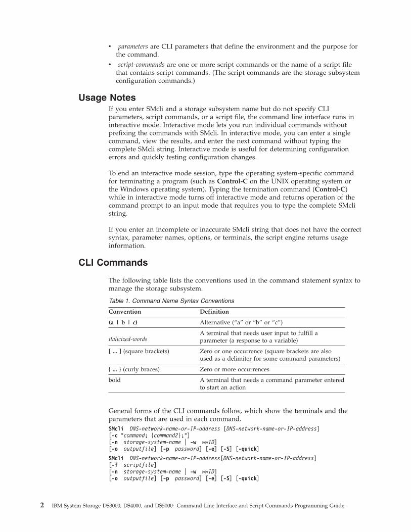
The following table lists the conventions used in the command statement syntax tomanage the storage subsystem.
Table 1. Command Name Syntax Conventions
Convention Definition
(a | b | c) Alternative (“a” or “b” or “c”)
italicized-wordsA terminal that needs user input to fulfill aparameter (a response to a variable)
[ ... ] (square brackets) Zero or one occurrence (square brackets are alsoused as a delimiter for some command parameters)
{ ... } (curly braces) Zero or more occurrences
bold A terminal that needs a command parameter enteredto start an action
General forms of the CLI commands follow, which show the terminals and theparameters that are used in each command.SMcli DNS-network-name-or-IP-address [DNS-network-name-or-IP-address][-c “command; {command2};”][-n storage-system-name | -w wwID][-o outputfile] [-p password] [-e] [-S] [-quick]
SMcli DNS-network-name-or-IP-address[DNS-network-name-or-IP-address][-f scriptfile][-n storage-system-name | -w wwID][-o outputfile] [-p password] [-e] [-S] [-quick]
2 IBM System Storage DS3000, DS4000, and DS5000: Command Line Interface and Script Commands Programming Guide
SMcli (-n storage-system-name | -w wwID)[-c “command; {command2};”][-o outputfile] [-p password] [-e] [-S] [-quick]
SMcli (-n storage-system-name -w wwID)[-f scriptfile][-o outputfile] [-p password] [-e] [-S] [-quick]
SMcli -a email: email-address [host-name-or-IP-address1[host-name-or-IP-address2]][-n storage-system-name | -w wwID | -h host-name | -r (host_sa | direct_sa)][-I information-to-include] [-q frequency] [-S]
SMcli -x email: email-address [host-name-or-IP-address1[host-name-or-IP-address2]][-n storage-system-name | -w wwID | -h host-name | -r (host_sa | direct_sa)] [-S]
SMcli (-a | -x) trap: community, host-name-or-IP-address[host-name-or-IP-address1 [host-name-or-IP-address2]][-n storage-system-name | -w wwID | -h host-name | -r (host_sa | direct_sa)] [-S]
SMcli -d [-w] [-i] [-s] [-v] [-S]
SMcli -m host-name-or-IP-address -F email-address[-g contactInfoFile] [-S]
SMcli -A [host-name-or-IP-address [host-name-or-IP-address]] [-S]
SMcli -X (-n storage-system-name | -w wwID | -h host-name)
SMcli -?
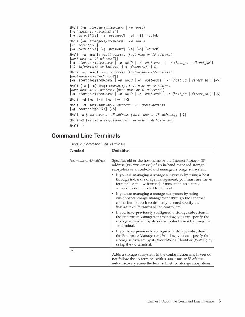
Command Line TerminalsTable 2. Command Line Terminals
Terminal Definition
host-name-or-IP-address Specifies either the host name or the Internet Protocol (IP)address (xxx.xxx.xxx.xxx) of an in-band managed storagesubsystem or an out-of-band managed storage subsystem.
v If you are managing a storage subsystem by using a hostthrough in-band storage management, you must use the -nterminal or the -w terminal if more than one storagesubsystem is connected to the host.
v If you are managing a storage subsystem by usingout-of-band storage management through the Ethernetconnection on each controller, you must specify thehost-name-or-IP-address of the controllers.
v If you have previously configured a storage subsystem inthe Enterprise Management Window, you can specify thestorage subsystem by its user-supplied name by using the-n terminal.
v If you have previously configured a storage subsystem inthe Enterprise Management Window, you can specify thestorage subsystem by its World-Wide Identifier (WWID) byusing the -w terminal.
-AAdds a storage subsystem to the configuration file. If you donot follow the -A terminal with a host-name-or-IP-address,auto-discovery scans the local subnet for storage subsystems.
Chapter 1. About the Command Line Interface 3
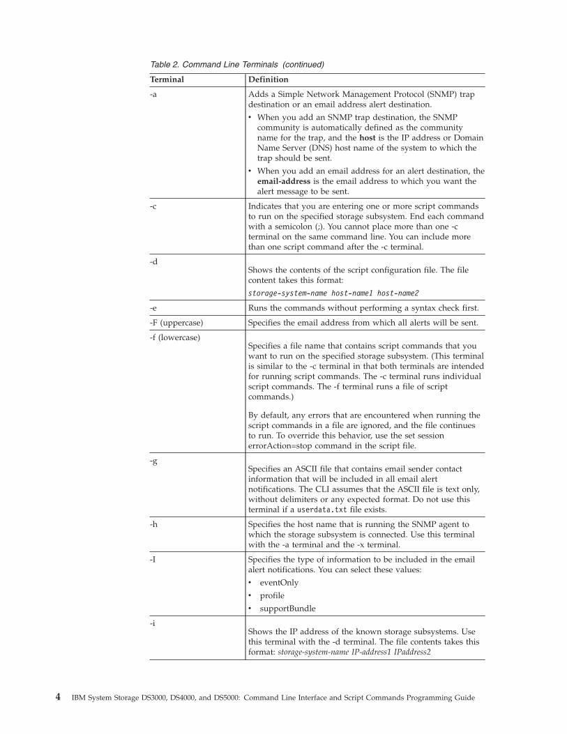
Table 2. Command Line Terminals (continued)
Terminal Definition
-a Adds a Simple Network Management Protocol (SNMP) trapdestination or an email address alert destination.
v When you add an SNMP trap destination, the SNMPcommunity is automatically defined as the communityname for the trap, and the host is the IP address or DomainName Server (DNS) host name of the system to which thetrap should be sent.
v When you add an email address for an alert destination, theemail-address is the email address to which you want thealert message to be sent.
-c Indicates that you are entering one or more script commandsto run on the specified storage subsystem. End each commandwith a semicolon (;). You cannot place more than one -cterminal on the same command line. You can include morethan one script command after the -c terminal.
-dShows the contents of the script configuration file. The filecontent takes this format:
storage-system-name host-name1 host-name2
-e Runs the commands without performing a syntax check first.
-F (uppercase) Specifies the email address from which all alerts will be sent.
-f (lowercase)Specifies a file name that contains script commands that youwant to run on the specified storage subsystem. (This terminalis similar to the -c terminal in that both terminals are intendedfor running script commands. The -c terminal runs individualscript commands. The -f terminal runs a file of scriptcommands.)
By default, any errors that are encountered when running thescript commands in a file are ignored, and the file continuesto run. To override this behavior, use the set sessionerrorAction=stop command in the script file.
-gSpecifies an ASCII file that contains email sender contactinformation that will be included in all email alertnotifications. The CLI assumes that the ASCII file is text only,without delimiters or any expected format. Do not use thisterminal if a userdata.txt file exists.
-h Specifies the host name that is running the SNMP agent towhich the storage subsystem is connected. Use this terminalwith the -a terminal and the -x terminal.
-I Specifies the type of information to be included in the emailalert notifications. You can select these values:
v eventOnly
v profile
v supportBundle
-iShows the IP address of the known storage subsystems. Usethis terminal with the -d terminal. The file contents takes thisformat: storage-system-name IP-address1 IPaddress2
4 IBM System Storage DS3000, DS4000, and DS5000: Command Line Interface and Script Commands Programming Guide
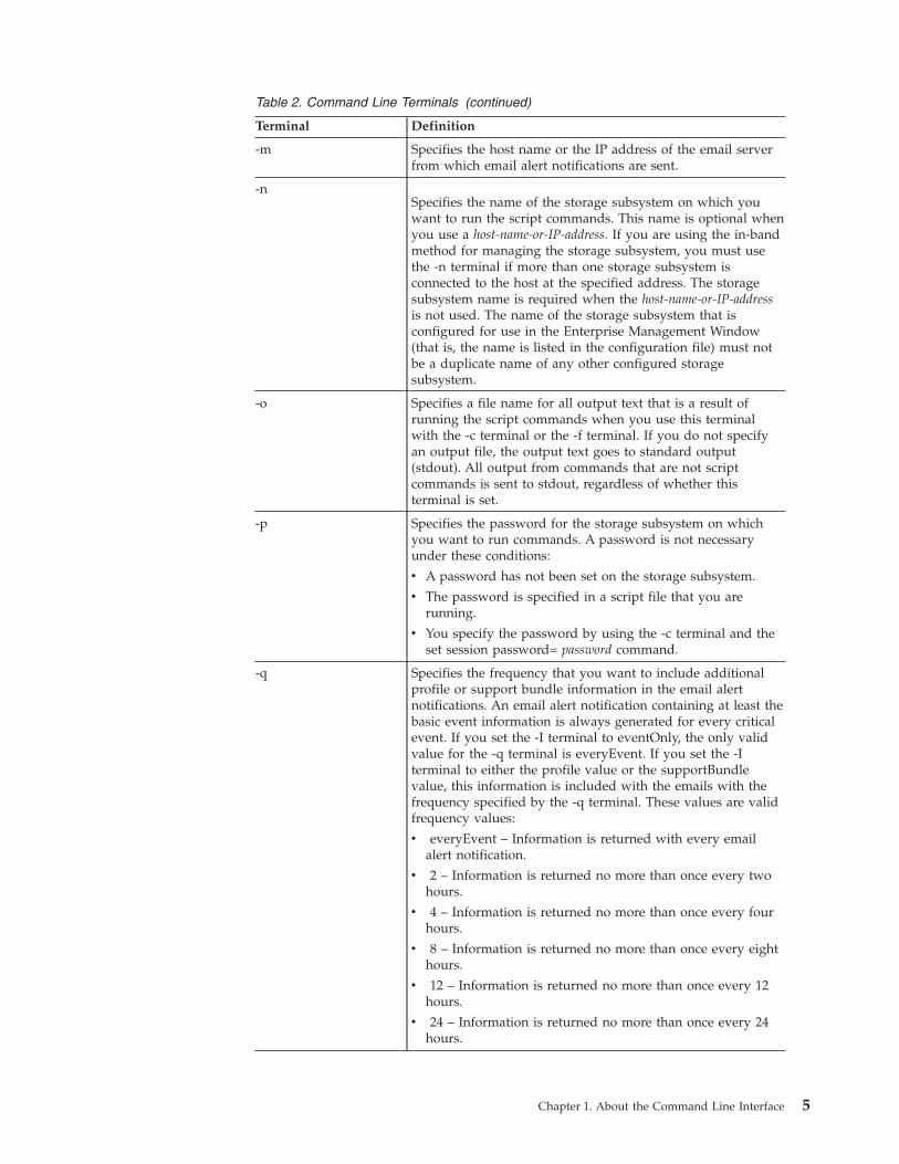
Table 2. Command Line Terminals (continued)
Terminal Definition
-m Specifies the host name or the IP address of the email serverfrom which email alert notifications are sent.
-nSpecifies the name of the storage subsystem on which youwant to run the script commands. This name is optional whenyou use a host-name-or-IP-address. If you are using the in-bandmethod for managing the storage subsystem, you must usethe -n terminal if more than one storage subsystem isconnected to the host at the specified address. The storagesubsystem name is required when the host-name-or-IP-addressis not used. The name of the storage subsystem that isconfigured for use in the Enterprise Management Window(that is, the name is listed in the configuration file) must notbe a duplicate name of any other configured storagesubsystem.
-o Specifies a file name for all output text that is a result ofrunning the script commands when you use this terminalwith the -c terminal or the -f terminal. If you do not specifyan output file, the output text goes to standard output(stdout). All output from commands that are not scriptcommands is sent to stdout, regardless of whether thisterminal is set.
-p Specifies the password for the storage subsystem on whichyou want to run commands. A password is not necessaryunder these conditions:
v A password has not been set on the storage subsystem.
v The password is specified in a script file that you arerunning.
v You specify the password by using the -c terminal and theset session password= password command.
-q Specifies the frequency that you want to include additionalprofile or support bundle information in the email alertnotifications. An email alert notification containing at least thebasic event information is always generated for every criticalevent. If you set the -I terminal to eventOnly, the only validvalue for the -q terminal is everyEvent. If you set the -Iterminal to either the profile value or the supportBundlevalue, this information is included with the emails with thefrequency specified by the -q terminal. These values are validfrequency values:
v everyEvent – Information is returned with every emailalert notification.
v 2 – Information is returned no more than once every twohours.
v 4 – Information is returned no more than once every fourhours.
v 8 – Information is returned no more than once every eighthours.
v 12 – Information is returned no more than once every 12hours.
v 24 – Information is returned no more than once every 24hours.
Chapter 1. About the Command Line Interface 5
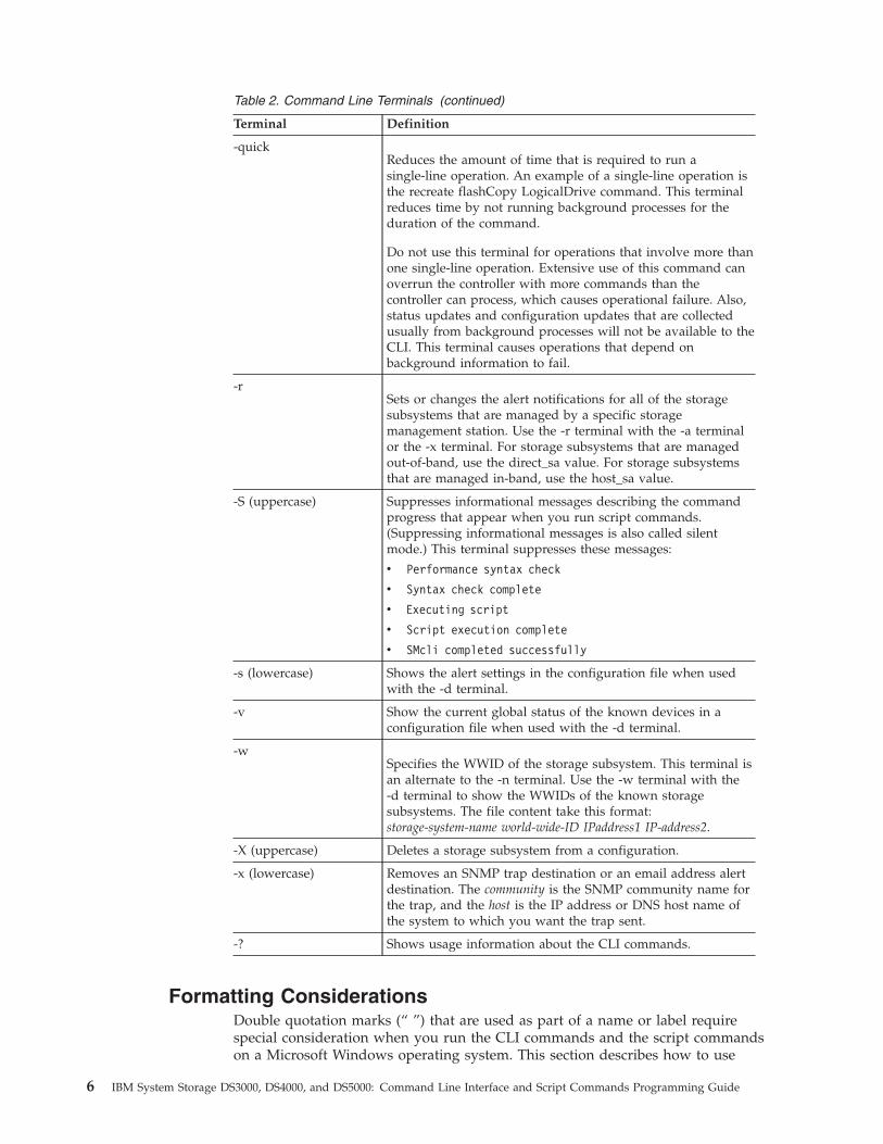
Table 2. Command Line Terminals (continued)
Terminal Definition
-quickReduces the amount of time that is required to run asingle-line operation. An example of a single-line operation isthe recreate flashCopy LogicalDrive command. This terminalreduces time by not running background processes for theduration of the command.
Do not use this terminal for operations that involve more thanone single-line operation. Extensive use of this command canoverrun the controller with more commands than thecontroller can process, which causes operational failure. Also,status updates and configuration updates that are collectedusually from background processes will not be available to theCLI. This terminal causes operations that depend onbackground information to fail.
-rSets or changes the alert notifications for all of the storagesubsystems that are managed by a specific storagemanagement station. Use the -r terminal with the -a terminalor the -x terminal. For storage subsystems that are managedout-of-band, use the direct_sa value. For storage subsystemsthat are managed in-band, use the host_sa value.
-S (uppercase) Suppresses informational messages describing the commandprogress that appear when you run script commands.(Suppressing informational messages is also called silentmode.) This terminal suppresses these messages:
v Performance syntax check
v Syntax check complete
v Executing script
v Script execution complete
v SMcli completed successfully
-s (lowercase) Shows the alert settings in the configuration file when usedwith the -d terminal.
-v Show the current global status of the known devices in aconfiguration file when used with the -d terminal.
-wSpecifies the WWID of the storage subsystem. This terminal isan alternate to the -n terminal. Use the -w terminal with the-d terminal to show the WWIDs of the known storagesubsystems. The file content take this format:storage-system-name world-wide-ID IPaddress1 IP-address2.
-X (uppercase) Deletes a storage subsystem from a configuration.
-x (lowercase) Removes an SNMP trap destination or an email address alertdestination. The community is the SNMP community name forthe trap, and the host is the IP address or DNS host name ofthe system to which you want the trap sent.
-? Shows usage information about the CLI commands.
Formatting ConsiderationsDouble quotation marks (“ ”) that are used as part of a name or label requirespecial consideration when you run the CLI commands and the script commandson a Microsoft Windows operating system. This section describes how to use
6 IBM System Storage DS3000, DS4000, and DS5000: Command Line Interface and Script Commands Programming Guide
double quotation marks in names while running CLI commands and scriptcommands on a Windows operating system.
When double quotation marks (“ ”) are part of a name or value, you must insert abackslash (\) before each double quotation mark character. For example:-c set storageSubsystem userLabel=\“Engineering\”;”
where “Engineering” is the storage subsystem name. A second example is:-n \“My\”_StorageSubsystem
where “My”_StorageSubsystem is the name of the storage subsystem.
You cannot use double quotation marks (“ ”) as part of a character string (alsocalled string literal) within a script command. For example, you cannot enter thefollowing string to set the storage subsystem name to “Finance Subsystem":-c “set storageSubsystem userLabel=\”\”Finance\”Subsystem\”;”
In the Linux operating system and the Solaris operating system, the delimitersaround names or labels are single quotation marks (‘ ’). The UNIX versions of theprevious examples are as follows:-c 'set storageSubsystem userLabel=“Engineering”;'
-n “My”_StorageSubsystem
In a Windows operating system, if you do not use double quotation marks (“ ”)around a name, you must insert a caret ( ^ ) before each special script character.Special characters are ^, | , <, and >.
Insert a caret before each special script character when used with the terminals -n,-o, -f, and -p. For example, to specify storage subsystem CLI>CLIENT, enter thisstring:-n CLI^>CLIENT
Insert one caret (^) before each special script character when used within a stringliteral in a script command. For example, to change the name of a storagesubsystem to FINANCE_|_PAYROLL, enter the following string:-c set storageSubsystem userLabel=\“FINANCE_^|_PAYROLL\”;”
Detailed Error ReportingError data collected from an error encountered by the CLI is written to a file.Detailed error reporting under the CLI works as follows:v If the CLI must abnormally end running CLI commands and script commands,
error data is collected and saved before the CLI finishes.v The CLI saves the error data by writing the data to a standard file name.v The CLI automatically saves the data to a file. Special command line options are
not required to save the error data.v You are not required to perform any action to save the error data to a file.v The CLI does not have any provision to avoid over-writing an existing version
of the file that contains error data.
For error processing, errors appear as two types:v Terminal errors or syntax errors that you might enterv Exceptions that occur as a result of an operational error
Chapter 1. About the Command Line Interface 7
When the CLI encounters either type of error, the CLI writes information thatdescribes the error directly to the command line and sets a return code. Dependingon the return code, the CLI also might write additional information about whichterminal caused the error. The CLI also writes information about what it wasexpecting in the command syntax to help you identify any syntax errors that youmight have entered.
When an exception occurs while a command is running, the CLI captures the error.At the end of processing the command (after the command processing informationhas been written to the command line), the CLI automatically saves the errorinformation to a file.
The name of the file to which error information is saved is excprpt.txt. The CLItries to place the excprpt.txt file in the directory that is specified by the systemproperty devmgr.datadir. If for any reason the CLI cannot place the file in thedirectory specified by devmgr.datadir, the CLI saves the excprpt.txt file in thesame directory from which the CLI is running. You cannot change the file name orthe location. The excprpt.txt file is overwritten every time that an exceptionoccurs. If you want to save the information in the excprpt.txt file, you must copythe information to a new file or a new directory.
Note: In Windows, this is specified by the registry key:
HKLM\SOFTWARE\storage\SMclient\SunJVMOption1
In a typical installation with no changes in the default installation directory, thelocation is:v Windows operating systems: c:\Program Files\IBM_DS....\client\datav UNIX-based operating systems: /var/opt/SM
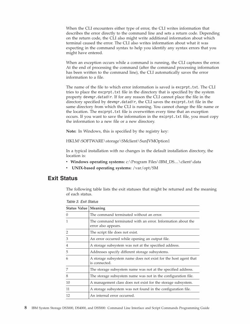
Exit Status
The following table lists the exit statuses that might be returned and the meaningof each status.
Table 3. Exit Status
Status Value Meaning
0 The command terminated without an error.
1 The command terminated with an error. Information about theerror also appears.
2 The script file does not exist.
3 An error occurred while opening an output file.
4 A storage subsystem was not at the specified address.
5 Addresses specify different storage subsystems.
6 A storage subsystem name does not exist for the host agent thatis connected.
7 The storage subsystem name was not at the specified address.
8 The storage subsystem name was not in the configuration file.
10 A management class does not exist for the storage subsystem.
11 A storage subsystem was not found in the configuration file.
12 An internal error occurred.
8 IBM System Storage DS3000, DS4000, and DS5000: Command Line Interface and Script Commands Programming Guide
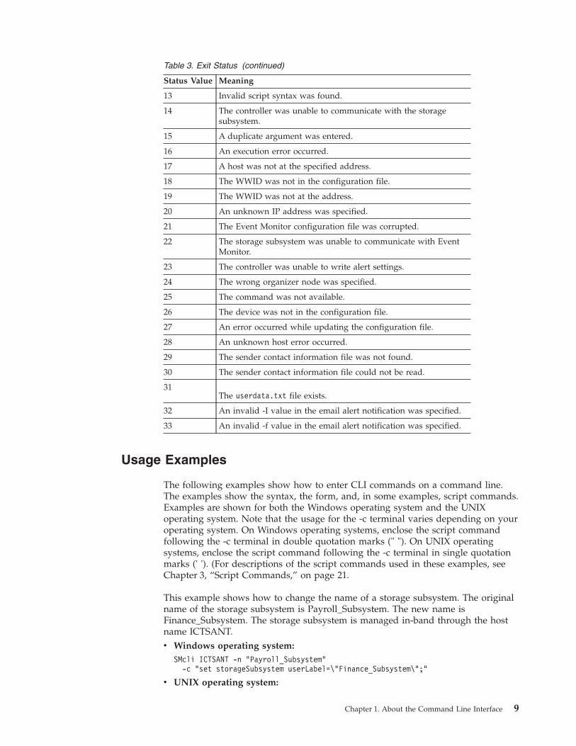
Table 3. Exit Status (continued)
Status Value Meaning
13 Invalid script syntax was found.
14 The controller was unable to communicate with the storagesubsystem.
15 A duplicate argument was entered.
16 An execution error occurred.
17 A host was not at the specified address.
18 The WWID was not in the configuration file.
19 The WWID was not at the address.
20 An unknown IP address was specified.
21 The Event Monitor configuration file was corrupted.
22 The storage subsystem was unable to communicate with EventMonitor.
23 The controller was unable to write alert settings.
24 The wrong organizer node was specified.
25 The command was not available.
26 The device was not in the configuration file.
27 An error occurred while updating the configuration file.
28 An unknown host error occurred.
29 The sender contact information file was not found.
30 The sender contact information file could not be read.
31The userdata.txt file exists.
32 An invalid -I value in the email alert notification was specified.
33 An invalid -f value in the email alert notification was specified.
Usage Examples
The following examples show how to enter CLI commands on a command line.The examples show the syntax, the form, and, in some examples, script commands.Examples are shown for both the Windows operating system and the UNIXoperating system. Note that the usage for the -c terminal varies depending on youroperating system. On Windows operating systems, enclose the script commandfollowing the -c terminal in double quotation marks (" "). On UNIX operatingsystems, enclose the script command following the -c terminal in single quotationmarks (' '). (For descriptions of the script commands used in these examples, seeChapter 3, “Script Commands,” on page 21.
This example shows how to change the name of a storage subsystem. The originalname of the storage subsystem is Payroll_Subsystem. The new name isFinance_Subsystem. The storage subsystem is managed in-band through the hostname ICTSANT.v Windows operating system:
SMcli ICTSANT -n "Payroll_Subsystem"-c "set storageSubsystem userLabel=\"Finance_Subsystem\";"
v UNIX operating system:
Chapter 1. About the Command Line Interface 9
SMcli ICTSANT -n ’Payroll_Subsystem’-c ’set storageSubsystem userLabel="Finance_Subsystem";’
This example shows how to delete an existing logical drive and create a newlogical drive on a storage subsystem. The existing logical drive name isStocks_<_Bonds. The new logical drive name is Finance. The controller host namesare finance1 and finance2. The storage subsystem is protected, requiring thepassword TestSubsystem.v Windows operating system:
SMcli finance1 finance2-c ’set session password=\"TestSubsystem\"; delete logicalDrive[\"Stocks_<Bonds\"];create logicalDrive driveCount[3] RAIDLEVEL=3 capacity=10GB userLabel=\"Finance\";show storageSubsystem healthStatus;"
v UNIX operating system:SMcli finance1 finance2 -c ’set session password="TestSubsystem";delete logicalDrive ["Stocks_<Bonds"];
create logicalDrive driveCount[3] RAIDLEVEL=3 capacity=10GB userLabel="Finance";
show storageSubsystem healthStatus;’
This example shows how to run commands in a script file named scriptfile.scron a storage subsystem named Example. The -e terminal causes the file to runwithout checking the syntax. Running a script file without checking the syntax letsthe file run more quickly; however, the file might not run correctly because thesyntax for a command might be incorrect.SMcli -n Example -f scriptfile.scr -e
This example shows how to run commands in a script file named scriptfile.scron a storage subsystem named Example. In this example, the storage subsystem isprotected by the password MySubsystem. Output, as a result of commands in thescript file, goes to file output.txt.v Windows operating system:
SMcli -n Example -f scriptfile.scr -p "My_Subsystem" -o output.txt
v UNIX operating system:SMcli -n Example -f scriptfile.scr -p ’My_Subsystem’ -o output.txt
This example shows how to show all of the storage subsystems in the currentconfiguration. The command in this example returns the host name of each storagesubsystem.SMcli -d
If you want to know the IP address of each storage subsystem in the configuration,add the -i terminal to the command.SMcli -d -i
10 IBM System Storage DS3000, DS4000, and DS5000: Command Line Interface and Script Commands Programming Guide
Chapter 2. About the Script Commands
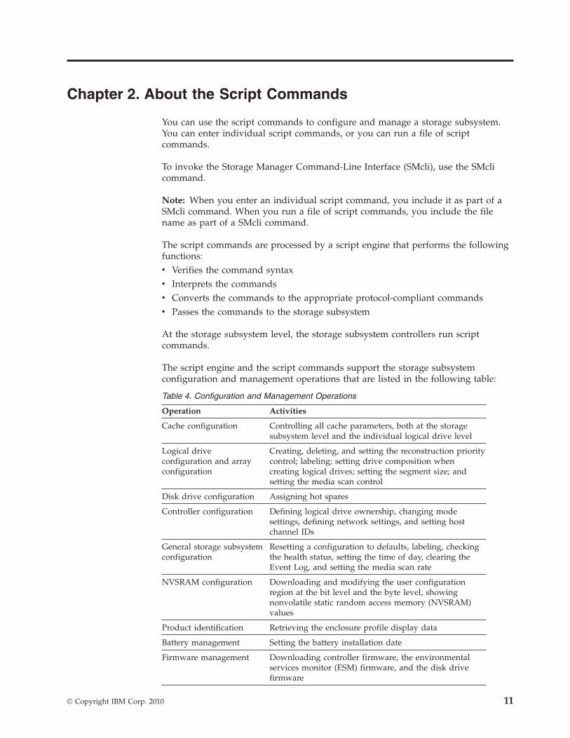
You can use the script commands to configure and manage a storage subsystem.You can enter individual script commands, or you can run a file of scriptcommands.
To invoke the Storage Manager Command-Line Interface (SMcli), use the SMclicommand.
Note: When you enter an individual script command, you include it as part of aSMcli command. When you run a file of script commands, you include the filename as part of a SMcli command.
The script commands are processed by a script engine that performs the followingfunctions:v Verifies the command syntaxv Interprets the commandsv Converts the commands to the appropriate protocol-compliant commandsv Passes the commands to the storage subsystem
At the storage subsystem level, the storage subsystem controllers run scriptcommands.
The script engine and the script commands support the storage subsystemconfiguration and management operations that are listed in the following table:
Table 4. Configuration and Management Operations
Operation Activities
Cache configuration Controlling all cache parameters, both at the storagesubsystem level and the individual logical drive level
Logical driveconfiguration and arrayconfiguration
Creating, deleting, and setting the reconstruction prioritycontrol; labeling; setting drive composition whencreating logical drives; setting the segment size; andsetting the media scan control
Disk drive configuration Assigning hot spares
Controller configuration Defining logical drive ownership, changing modesettings, defining network settings, and setting hostchannel IDs
General storage subsystemconfiguration
Resetting a configuration to defaults, labeling, checkingthe health status, setting the time of day, clearing theEvent Log, and setting the media scan rate
NVSRAM configuration Downloading and modifying the user configurationregion at the bit level and the byte level, showingnonvolatile static random access memory (NVSRAM)values
Product identification Retrieving the enclosure profile display data
Battery management Setting the battery installation date
Firmware management Downloading controller firmware, the environmentalservices monitor (ESM) firmware, and the disk drivefirmware
© Copyright IBM Corp. 2010 11
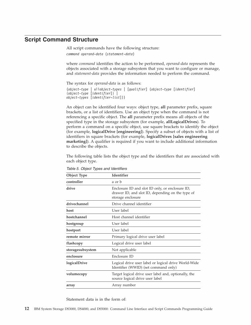
Script Command StructureAll script commands have the following structure:command operand-data (statement-data)
where command identifies the action to be performed, operand-data represents theobjects associated with a storage subsystem that you want to configure or manage,and statement-data provides the information needed to perform the command.
The syntax for operand-data is as follows:(object-type | allobject-types | [qualifier] (object-type [identifier]{object-type [identifier]} |object-types [identifier-list]))
An object can be identified four ways: object type, all parameter prefix, squarebrackets, or a list of identifiers. Use an object type when the command is notreferencing a specific object. The all parameter prefix means all objects of thespecified type in the storage subsystem (for example, allLogicalDrives). Toperform a command on a specific object, use square brackets to identify the object(for example, logicalDrive [engineering]). Specify a subset of objects with a list ofidentifiers in square brackets (for example, logicalDrives [sales engineeringmarketing]). A qualifier is required if you want to include additional informationto describe the objects.
The following table lists the object type and the identifiers that are associated witheach object type.
Table 5. Object Types and Identifiers
Object Type Identifier
controller a or b
drive Enclosure ID and slot ID only, or enclosure ID,drawer ID, and slot ID, depending on the type ofstorage enclosure
drivechannel Drive channel identifier
host User label
hostchannel Host channel identifier
hostgroup User label
hostport User label
remote mirror Primary logical drive user label
flashcopy Logical drive user label
storagesubsystem Not applicable
enclosure Enclosure ID
logicalDrive Logical drive user label or logical drive World-WideIdentifier (WWID) (set command only)
volumecopy Target logical drive user label and, optionally, thesource logical drive user label
array Array number
Statement data is in the form of:
12 IBM System Storage DS3000, DS4000, and DS5000: Command Line Interface and Script Commands Programming Guide
v Parameter=value (such as raidLevel=5)v Parameter-name (such as batteryInstallDate)v Operation-name (such as redundancyCheck)
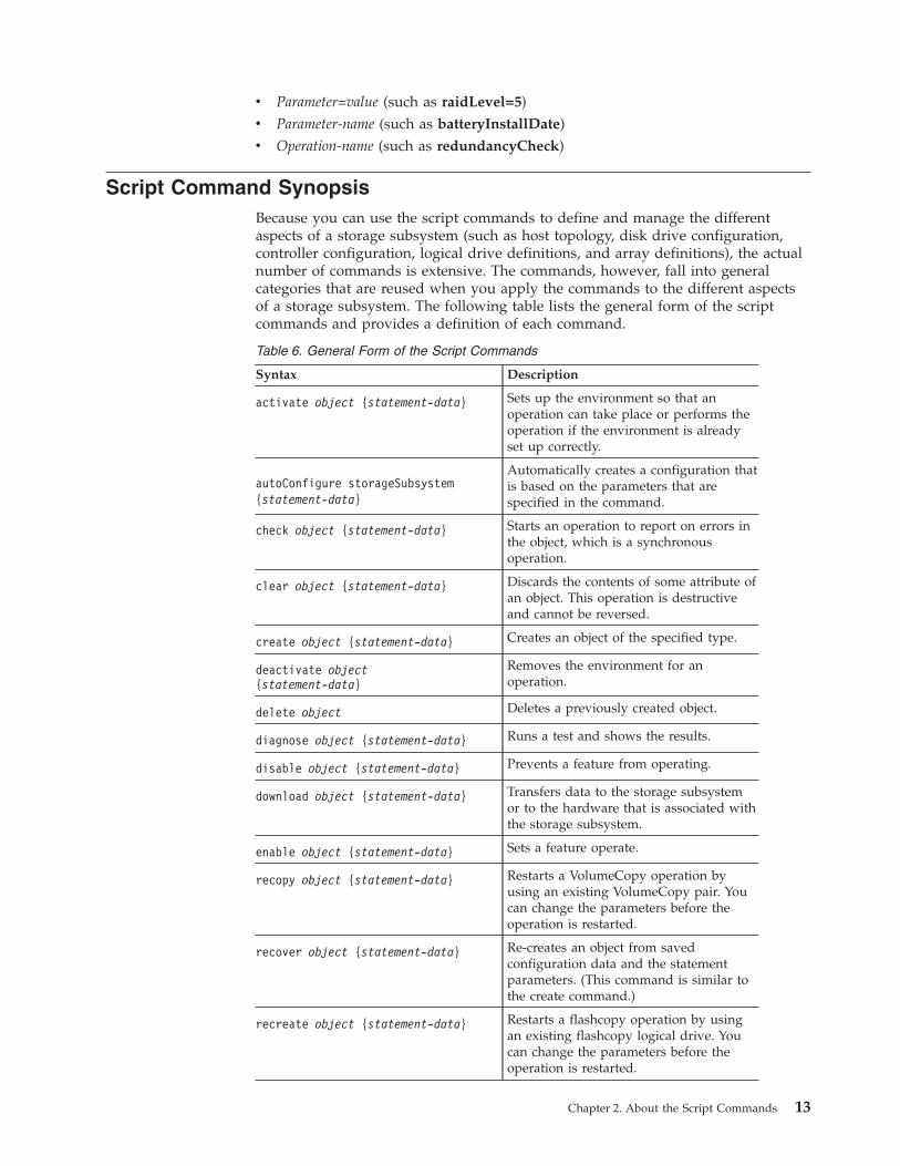
Script Command SynopsisBecause you can use the script commands to define and manage the differentaspects of a storage subsystem (such as host topology, disk drive configuration,controller configuration, logical drive definitions, and array definitions), the actualnumber of commands is extensive. The commands, however, fall into generalcategories that are reused when you apply the commands to the different aspectsof a storage subsystem. The following table lists the general form of the scriptcommands and provides a definition of each command.
Table 6. General Form of the Script Commands
Syntax Description
activate object {statement-data} Sets up the environment so that anoperation can take place or performs theoperation if the environment is alreadyset up correctly.
autoConfigure storageSubsystem{statement-data}
Automatically creates a configuration thatis based on the parameters that arespecified in the command.
check object {statement-data} Starts an operation to report on errors inthe object, which is a synchronousoperation.
clear object {statement-data} Discards the contents of some attribute ofan object. This operation is destructiveand cannot be reversed.
create object {statement-data} Creates an object of the specified type.
deactivate object{statement-data}
Removes the environment for anoperation.
delete object Deletes a previously created object.
diagnose object {statement-data} Runs a test and shows the results.
disable object {statement-data} Prevents a feature from operating.
download object {statement-data} Transfers data to the storage subsystemor to the hardware that is associated withthe storage subsystem.
enable object {statement-data} Sets a feature operate.
recopy object {statement-data} Restarts a VolumeCopy operation byusing an existing VolumeCopy pair. Youcan change the parameters before theoperation is restarted.
recover object {statement-data} Re-creates an object from savedconfiguration data and the statementparameters. (This command is similar tothe create command.)
recreate object {statement-data} Restarts a flashcopy operation by usingan existing flashcopy logical drive. Youcan change the parameters before theoperation is restarted.
Chapter 2. About the Script Commands 13

Table 6. General Form of the Script Commands (continued)
Syntax Description
remove object {statement-data} Removes a relationship from betweenobjects.
repair object {statement-data} Repairs errors found by the checkcommand.
reset object {statement-data} Returns the hardware or an object to aninitial state.
resume object Starts a suspended operation. Theoperation starts where it left off when itwas suspended.
revive object Forces the object from the Failed state tothe Optimal state. Use this commandonly as part of an error recoveryprocedure.
save object {statement-data} Writes information about the object to afile.
set object {statement-data} Changes object attributes. All changes arecompleted when the command returns.
show object {statement-data} Shows information about the object.
start object {statement-data} Starts an asynchronous operation. Youcan stop some operations after they havestarted. You can query the progress ofsome operations.
stop object {statement-data} Stops an asynchronous operation.
suspend object {statement-data} Stops an operation. You can then restartthe suspended operation, and it continuesfrom the point where it was suspended.
Recurring Syntax Elements
Recurring syntax elements are a general category of variables and options that youcan use in one or more script commands. The recurring syntax is used in thegeneral definitions of the script commands that are listed in Chapter 3, “ScriptCommands,” on page 21
The following table lists the recurring syntax and the syntax values that you canuse with the syntax.
Note: A command statement appears in a monospace font. The statement variablesare in a monospace italic font. Options are described separately, and usually thechoices are shown as TRUE or FALSE, as a letter (a), a number (42), or anumber-range (0-99) selection.
Table 7. Recurring Syntax Elements
Recurring Syntax Syntax Value
raid-level(0 | 1 | 3 | 5 | 6)
repository-raid-level(1 | 3 | 5 | 6)
14 IBM System Storage DS3000, DS4000, and DS5000: Command Line Interface and Script Commands Programming Guide
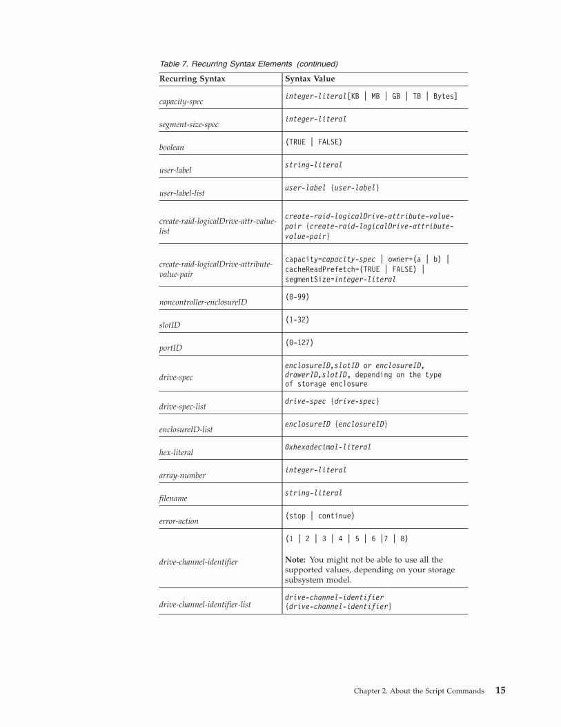
Table 7. Recurring Syntax Elements (continued)
Recurring Syntax Syntax Value
capacity-specinteger-literal[KB | MB | GB | TB | Bytes]
segment-size-specinteger-literal
boolean(TRUE | FALSE)
user-labelstring-literal
user-label-listuser-label {user-label}
create-raid-logicalDrive-attr-value-list
create-raid-logicalDrive-attribute-value-pair {create-raid-logicalDrive-attribute-value-pair}
create-raid-logicalDrive-attribute-value-pair
capacity=capacity-spec | owner=(a | b) |cacheReadPrefetch=(TRUE | FALSE) |segmentSize=integer-literal
noncontroller-enclosureID(0-99)
slotID(1-32)
portID(0-127)
drive-specenclosureID,slotID or enclosureID,drawerID,slotID, depending on the typeof storage enclosure
drive-spec-listdrive-spec {drive-spec}
enclosureID-listenclosureID {enclosureID}
hex-literal0xhexadecimal-literal
array-numberinteger-literal
filenamestring-literal
error-action(stop | continue)
drive-channel-identifier
(1 | 2 | 3 | 4 | 5 | 6 |7 | 8)
Note: You might not be able to use all thesupported values, depending on your storagesubsystem model.
drive-channel-identifier-listdrive-channel-identifier{drive-channel-identifier}
Chapter 2. About the Script Commands 15
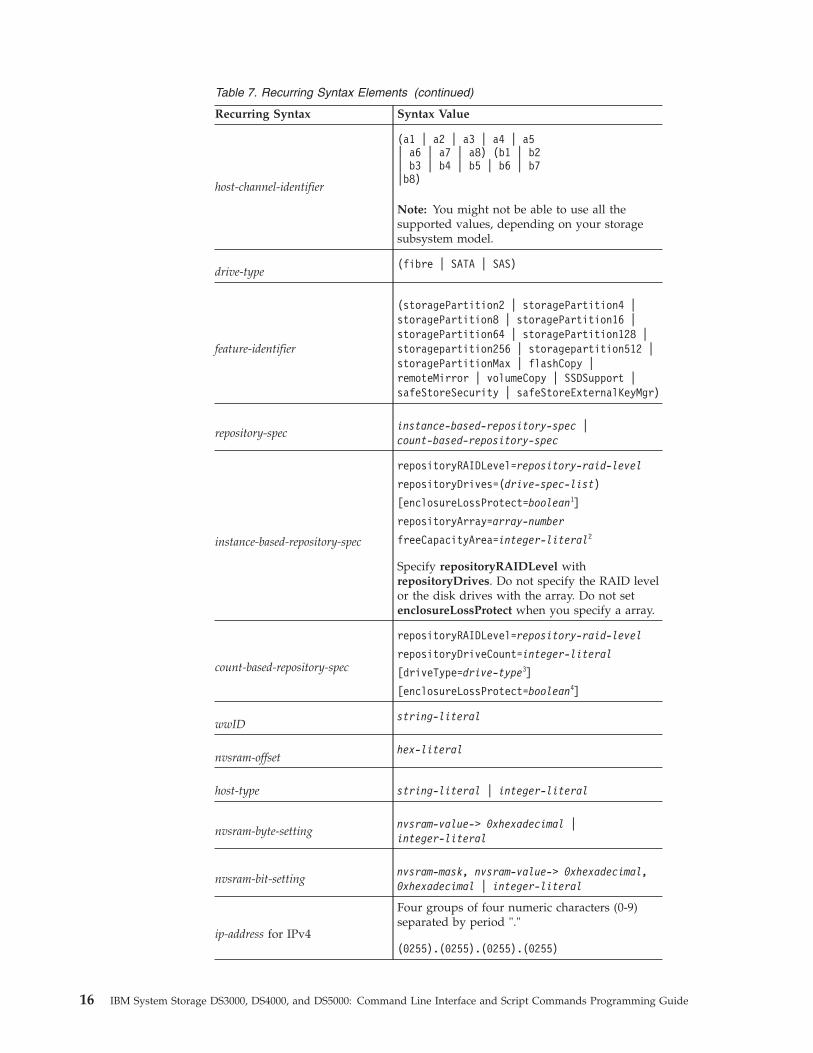
Table 7. Recurring Syntax Elements (continued)
Recurring Syntax Syntax Value
host-channel-identifier
(a1 | a2 | a3 | a4 | a5| a6 | a7 | a8) (b1 | b2| b3 | b4 | b5 | b6 | b7|b8)
Note: You might not be able to use all thesupported values, depending on your storagesubsystem model.
drive-type(fibre | SATA | SAS)
feature-identifier
(storagePartition2 | storagePartition4 |storagePartition8 | storagePartition16 |storagePartition64 | storagePartition128 |storagepartition256 | storagepartition512 |storagePartitionMax | flashCopy |remoteMirror | volumeCopy | SSDSupport |safeStoreSecurity | safeStoreExternalKeyMgr)
repository-specinstance-based-repository-spec |count-based-repository-spec
instance-based-repository-spec
repositoryRAIDLevel=repository-raid-level
repositoryDrives=(drive-spec-list)
[enclosureLossProtect=boolean1]
repositoryArray=array-number
freeCapacityArea=integer-literal2
Specify repositoryRAIDLevel withrepositoryDrives. Do not specify the RAID levelor the disk drives with the array. Do not setenclosureLossProtect when you specify a array.
count-based-repository-spec
repositoryRAIDLevel=repository-raid-level
repositoryDriveCount=integer-literal
[driveType=drive-type3]
[enclosureLossProtect=boolean4]
wwIDstring-literal
nvsram-offsethex-literal
host-type string-literal | integer-literal
nvsram-byte-settingnvsram-value-> 0xhexadecimal |integer-literal
nvsram-bit-settingnvsram-mask, nvsram-value-> 0xhexadecimal,0xhexadecimal | integer-literal
ip-address for IPv4
Four groups of four numeric characters (0-9)separated by period "."
(0255).(0255).(0255).(0255)
16 IBM System Storage DS3000, DS4000, and DS5000: Command Line Interface and Script Commands Programming Guide
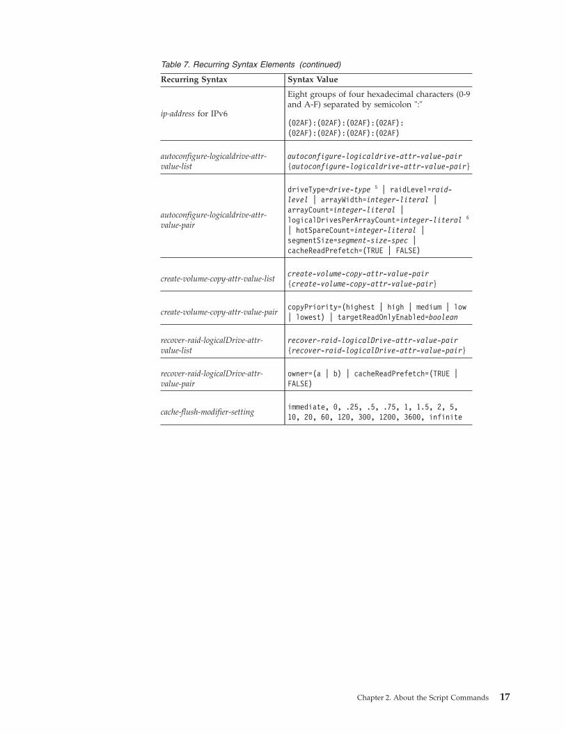
Table 7. Recurring Syntax Elements (continued)
Recurring Syntax Syntax Value
ip-address for IPv6
Eight groups of four hexadecimal characters (0-9and A-F) separated by semicolon ":"
(02AF):(02AF):(02AF):(02AF):(02AF):(02AF):(02AF):(02AF)
autoconfigure-logicaldrive-attr-value-list
autoconfigure-logicaldrive-attr-value-pair{autoconfigure-logicaldrive-attr-value-pair}
autoconfigure-logicaldrive-attr-value-pair
driveType=drive-type 5 | raidLevel=raid-level | arrayWidth=integer-literal |arrayCount=integer-literal |logicalDrivesPerArrayCount=integer-literal 6
| hotSpareCount=integer-literal |segmentSize=segment-size-spec |cacheReadPrefetch=(TRUE | FALSE)
create-volume-copy-attr-value-listcreate-volume-copy-attr-value-pair{create-volume-copy-attr-value-pair}
create-volume-copy-attr-value-paircopyPriority=(highest | high | medium | low| lowest) | targetReadOnlyEnabled=boolean
recover-raid-logicalDrive-attr-value-list
recover-raid-logicalDrive-attr-value-pair{recover-raid-logicalDrive-attr-value-pair}
recover-raid-logicalDrive-attr-value-pair
owner=(a | b) | cacheReadPrefetch=(TRUE |FALSE)
cache-flush-modifier-settingimmediate, 0, .25, .5, .75, 1, 1.5, 2, 5,10, 20, 60, 120, 300, 1200, 3600, infinite
Chapter 2. About the Script Commands 17
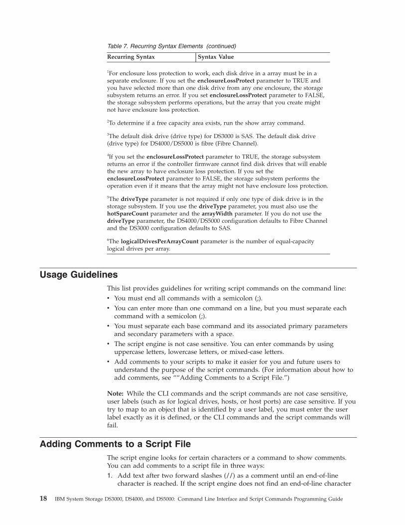
Table 7. Recurring Syntax Elements (continued)
Recurring Syntax Syntax Value
1For enclosure loss protection to work, each disk drive in a array must be in aseparate enclosure. If you set the enclosureLossProtect parameter to TRUE andyou have selected more than one disk drive from any one enclosure, the storagesubsystem returns an error. If you set enclosureLossProtect parameter to FALSE,the storage subsystem performs operations, but the array that you create mightnot have enclosure loss protection.
2To determine if a free capacity area exists, run the show array command.
3The default disk drive (drive type) for DS3000 is SAS. The default disk drive(drive type) for DS4000/DS5000 is fibre (Fibre Channel).
4If you set the enclosureLossProtect parameter to TRUE, the storage subsystemreturns an error if the controller firmware cannot find disk drives that will enablethe new array to have enclosure loss protection. If you set theenclosureLossProtect parameter to FALSE, the storage subsystem performs theoperation even if it means that the array might not have enclosure loss protection.
5The driveType parameter is not required if only one type of disk drive is in thestorage subsystem. If you use the driveType parameter, you must also use thehotSpareCount parameter and the arrayWidth parameter. If you do not use thedriveType parameter, the DS4000/DS5000 configuration defaults to Fibre Channeland the DS3000 configuration defaults to SAS.
6The logicalDrivesPerArrayCount parameter is the number of equal-capacitylogical drives per array.
Usage GuidelinesThis list provides guidelines for writing script commands on the command line:v You must end all commands with a semicolon (;).v You can enter more than one command on a line, but you must separate each
command with a semicolon (;).v You must separate each base command and its associated primary parameters
and secondary parameters with a space.v The script engine is not case sensitive. You can enter commands by using
uppercase letters, lowercase letters, or mixed-case letters.v Add comments to your scripts to make it easier for you and future users to
understand the purpose of the script commands. (For information about how toadd comments, see ““Adding Comments to a Script File.”)
Note: While the CLI commands and the script commands are not case sensitive,user labels (such as for logical drives, hosts, or host ports) are case sensitive. If youtry to map to an object that is identified by a user label, you must enter the userlabel exactly as it is defined, or the CLI commands and the script commands willfail.
Adding Comments to a Script FileThe script engine looks for certain characters or a command to show comments.You can add comments to a script file in three ways:1. Add text after two forward slashes (//) as a comment until an end-of-line
character is reached. If the script engine does not find an end-of-line character
18 IBM System Storage DS3000, DS4000, and DS5000: Command Line Interface and Script Commands Programming Guide
in the script after processing a comment, an error message appears, and thescript operation is terminated. This error usually occurs when a comment isplaced at the end of a script and you have forgotten to press the Enter key.// Deletes the existing configuration.set storageSubsystem resetConfiguration=true;
2. Add text between / * and * / as a comment. If the script engine does not findboth a starting comment notation and an ending comment notation, an errormessage appears, and the script operation is terminated./* Deletes the existing configuration */set storageSubsystem resetConfiguration=true;
3. Use the show statement to embed comments in a script file that you want toappear while the script file is running. Enclose the text that you want to appearby using double quotation marks (“ ”).show “Deletes the existing configuration”;set storageSubsystem resetConfiguration=true;
Chapter 2. About the Script Commands 19

20 IBM System Storage DS3000, DS4000, and DS5000: Command Line Interface and Script Commands Programming Guide
Chapter 3. Script Commands
Attention: The script commands are capable of damaging a configuration andcausing loss of data access if not used correctly – Command operations areperformed as soon as you run the commands. Some commands can immediatelydelete configurations or data. Before using the script commands, make sure thatyou have backed up all data, and have saved the current configuration so that youcan reinstall it if the changes you make do not work.
IBM recommends using the Storage Manager client GUI to manage your storagesubsystems. – The command line interface does not have any mechanisms toprevent you from inadvertently making unwanted changes to the storagesubsystem; therefore, IBM recommends using the Storage Manager client GUI tomanage your storage subsystem configurations.
This chapter has five sections to help you use script commands:v “Naming Conventions” lists the general formatting rules for entering the names
of storage subsystem entities, such as logical drives or disk drives, with thescript commands.
v “Firmware Compatibility Levels” on page 22 describes how to interpret thefirmware level information.
v “Formatting Rules for Script Commands” on page 23 lists the general formattingrules that apply to the script command syntax.
v “DS3000, DS4000, and DS5000 commands with minimum firmware levels” onpage 24 indicates which commands you can use for DS3000, DS4000, or DS5000with their minimum controller firmware requirements.
v “Script Commands Listed by Function” on page 174 lists the script commandsorganized into groups related to the physical features, the logical features, andthe operational features of the storage subsystem.
v Finally, the script commands are listed alphabetically with detailed informationincluding the command name, syntax, and parameters.
Naming Conventionsv Names can have a maximum of 30 characters.v You can use any combination of alphanumeric characters, hyphens, and
underscores for the names of the following components:– Storage subsystems– Host groups– Hosts– Arrays– Logical drives– HBA host ports
v You must use unique names. If you do not use unique names, the controllerfirmware returns an error.
v If the name contains more than one word, hyphens, or underscores, enclose thename in double quotation marks (“ ”). In some usages, you must also surround
© Copyright IBM Corp. 2010 21
the name with square brackets ([ ]). The description of each parameter indicateswhether you need to enclose a parameter in double quotation marks, squarebrackets, or both.
v The name character string cannot contain a new line.v On Windows operating systems, you must enclose the name between two back
slashes (\) in addition to other delimiters. For example, the following name isused in a command that runs under a Windows operating system:[\”Engineering\”]
v For a UNIX operating system and, when used in a script file, the name appearsas the following example:[“Engineering”]
v When you enter a World-Wide Identifier (WWID) of an HBA host port, someusages require that you surround the WWID with double quotation marks. Inother uses, you must surround the WWID with angle brackets (<>). Thedescription of the WWID parameter indicates whether you need to enclose theWWID in double quotation marks (“ ”) or angle brackets.
Entering Numerical Names
When the storage management software automatically configures a storagesubsystem, the storage management software assigns names that consist ofnumerical characters. Names that consist only of numerical characters are validnames. Numerical character names, however, must be treated differently thannames that start with alphabetic characters.
When you enter a script command that requires a name, the script engine looks fora name that starts with an alphabetic character. The script engine might notrecognize the following names:v Names that are only numbers, such as 1 or 2v Names that start with a number, such as 1Disk or 32Volume
To enter a name that consists only of numerical characters so that the script enginewill recognize the name, use a combination of back slashes and double quotationmarks. The following are examples of how you can enter names that consist onlyof numerical characters or start with numerical characters:v [\“1\”]
v [\“1Disk\”]
Firmware Compatibility Levels
Some of the script commands and the command parameters are not supportedwith every version of the controller firmware. Minimum controller firmware levelsare listed in “DS3000, DS4000, and DS5000 commands with minimum firmwarelevels” on page 24.
Note: For many commands, you can enable additional parameters by upgrading toa higher firmware level than the minimum.
22 IBM System Storage DS3000, DS4000, and DS5000: Command Line Interface and Script Commands Programming Guide
Hardware Requirements for Firmware Compatibility
Even though a command is supported by a storage subsystem, the feature must beinstalled to use the command. For example, the Full Disk Encryption (FDE)commands are supported for all DS5000 models, but you cannot use the commandunless the FDE premium feature is installed in the storage subsystem.
Not all models in the DS3000, DS4000, or DS5000 product lines support the sameset of functionality. For example, the DS3500 series of the DS3000 product linesupports Enhanced Remote Mirroring premium features, but the DS3200, DS3300,and DS3400 models of the DS3000 product line do not. You can only run thecommands for the functions supported by your storage subsystem model.
Formatting Rules for Script Commands
Syntax unique to a specific script command is explained in the Notes section at theend of each script command description.
Case sensitivity – The script commands are not case sensitive. You can type thescript commands in lowercase, uppercase, or mixed case. (In the followingcommand descriptions, mixed case is used as an aid to reading the commandnames and understanding the purpose of the command.)
Spaces – You must enter spaces in the script commands as they are shown in thecommand descriptions.
Square brackets – Square brackets are used in two ways:v As part of the command syntaxv To indicate that the parameters are optional. The description of each parameter
tells you if you need to enclose a parameter value in square brackets.
Parentheses – Parentheses shown in the command syntax enclose specific choicesfor a parameter. That is, if you want to use the parameter, you must enter one ofthe values enclosed in parentheses. Generally, you do not include parentheses in ascript command; however, in some instances, when you enter lists, you mustenclose the list in parentheses. Such a list might be a list of enclosure ID valuesand slot ID values. The description of each parameter tells you if you need toenclose a parameter value in parentheses.
Vertical bars – Vertical bars in a script command indicate “or” and separate thevalid values for the parameter. For example, the syntax for the raidLevelparameter in the command description appears as follows:raidLevel=(0 | 1 | 3 | 5 | 6)
To use the raidLevel parameter to set a RAID level of 5, enter this value:raidLevel=5
Drive locations – When you specify disk drive locations by using enclosure IDvalues and slot ID values, separate the ID values with a comma. If you enter morethan one set of ID values, separate each set of values with a space. Enclose the setof values in parentheses. For example:(1,1 1,2 1,3 1,4 2,1 2,2 2,3 2,4)
Chapter 3. Script Commands 23
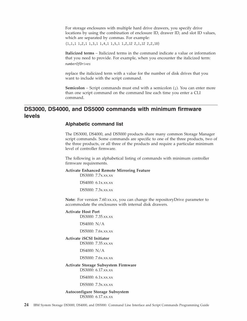
For storage enclosures with multiple hard drive drawers, you specify drivelocations by using the combination of enclosure ID, drawer ID, and slot ID values,which are separated by commas. For example:(1,1,1 1,2,1 1,3,1 1,4,1 1,5,1 1,2,12 2,1,12 2,2,10)
Italicized terms – Italicized terms in the command indicate a value or informationthat you need to provide. For example, when you encounter the italicized term:numberOfDrives
replace the italicized term with a value for the number of disk drives that youwant to include with the script command.
Semicolon – Script commands must end with a semicolon (;). You can enter morethan one script command on the command line each time you enter a CLIcommand.
DS3000, DS4000, and DS5000 commands with minimum firmwarelevels
Alphabetic command list
The DS3000, DS4000, and DS5000 products share many common Storage Managerscript commands. Some commands are specific to one of the three products, two ofthe three products, or all three of the products and require a particular minimumlevel of controller firmware.
The following is an alphabetical listing of commands with minimum controllerfirmware requirements.
Activate Enhanced Remote Mirroring FeatureDS3000: 7.7x.xx.xx
DS4000: 6.1x.xx.xx
DS5000: 7.3x.xx.xx
Note: For version 7.60.xx.xx, you can change the repositoryDrive parameter toaccommodate the enclosures with internal disk drawers.
Activate Host PortDS3000: 7.35.xx.xx
DS4000: N/A
DS5000: 7.6x.xx.xx
Activate iSCSI InitiatorDS3000: 7.35.xx.xx
DS4000: N/A
DS5000: 7.6x.xx.xx
Activate Storage Subsystem FirmwareDS3000: 6.17.xx.xx
DS4000: 6.1x.xx.xx
DS5000: 7.3x.xx.xx
Autoconfigure Storage SubsystemDS3000: 6.17.xx.xx
24 IBM System Storage DS3000, DS4000, and DS5000: Command Line Interface and Script Commands Programming Guide
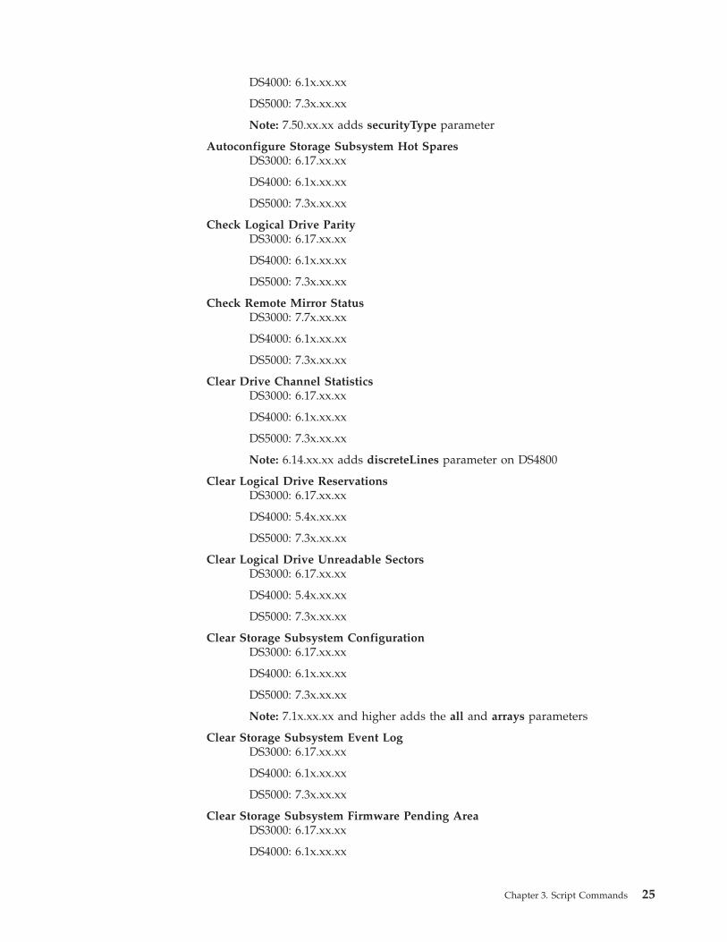
DS4000: 6.1x.xx.xx
DS5000: 7.3x.xx.xx
Note: 7.50.xx.xx adds securityType parameter
Autoconfigure Storage Subsystem Hot SparesDS3000: 6.17.xx.xx
DS4000: 6.1x.xx.xx
DS5000: 7.3x.xx.xx
Check Logical Drive ParityDS3000: 6.17.xx.xx
DS4000: 6.1x.xx.xx
DS5000: 7.3x.xx.xx
Check Remote Mirror StatusDS3000: 7.7x.xx.xx
DS4000: 6.1x.xx.xx
DS5000: 7.3x.xx.xx
Clear Drive Channel StatisticsDS3000: 6.17.xx.xx
DS4000: 6.1x.xx.xx
DS5000: 7.3x.xx.xx
Note: 6.14.xx.xx adds discreteLines parameter on DS4800
Clear Logical Drive ReservationsDS3000: 6.17.xx.xx
DS4000: 5.4x.xx.xx
DS5000: 7.3x.xx.xx
Clear Logical Drive Unreadable SectorsDS3000: 6.17.xx.xx
DS4000: 5.4x.xx.xx
DS5000: 7.3x.xx.xx
Clear Storage Subsystem ConfigurationDS3000: 6.17.xx.xx
DS4000: 6.1x.xx.xx
DS5000: 7.3x.xx.xx
Note: 7.1x.xx.xx and higher adds the all and arrays parameters
Clear Storage Subsystem Event LogDS3000: 6.17.xx.xx
DS4000: 6.1x.xx.xx
DS5000: 7.3x.xx.xx
Clear Storage Subsystem Firmware Pending AreaDS3000: 6.17.xx.xx
DS4000: 6.1x.xx.xx
Chapter 3. Script Commands 25
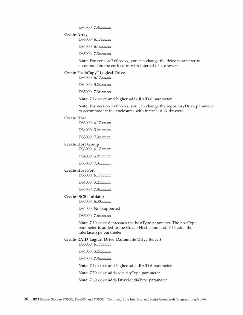
DS5000: 7.3x.xx.xx
Create ArrayDS3000: 6.17.xx.xx
DS4000: 6.1x.xx.xx
DS5000: 7.3x.xx.xx
Note: For version 7.60.xx.xx, you can change the drive parameter toaccommodate the enclosures with internal disk drawers
Create FlashCopy® Logical DriveDS3000: 6.17.xx.xx
DS4000: 5.2x.xx.xx
DS5000: 7.3x.xx.xx
Note: 7.1x.xx.xx and higher adds RAID 6 parameter
Note: For version 7.60.xx.xx, you can change the repositoryDrive parameterto accommodate the enclosures with internal disk drawers
Create HostDS3000: 6.17.xx.xx
DS4000: 5.2x.xx.xx
DS5000: 7.3x.xx.xx
Create Host GroupDS3000: 6.17.xx.xx
DS4000: 5.2x.xx.xx
DS5000: 7.3x.xx.xx
Create Host PortDS3000: 6.17.xx.xx
DS4000: 5.2x.xx.xx
DS5000: 7.3x.xx.xx
Create iSCSI InitiatorDS3000: 6.50.xx.xx
DS4000: Not supported
DS5000: 7.6x.xx.xx
Note: 7.10.xx.xx deprecates the hostType parameter. The hostTypeparameter is added to the Create Host command. 7.32 adds theinterfaceType parameter.
Create RAID Logical Drive (Automatic Drive Select)DS3000: 6.17.xx.xx
DS4000: 5.2x.xx.xx
DS5000: 7.3x.xx.xx
Note: 7.1x.xx.xx and higher adds RAID 6 parameter
Note: 7.50.xx.xx adds securityType parameter
Note: 7.60.xx.xx adds DriveMediaType parameter
26 IBM System Storage DS3000, DS4000, and DS5000: Command Line Interface and Script Commands Programming Guide
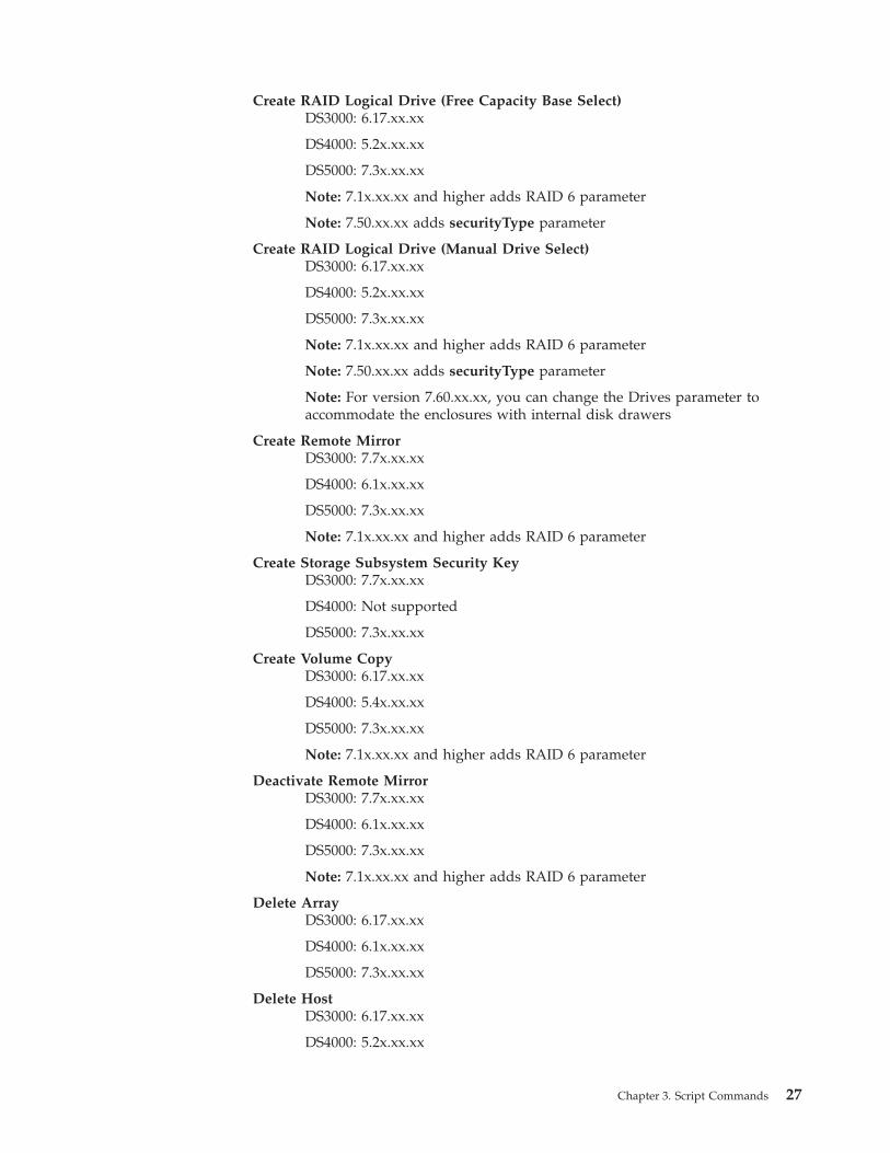
Create RAID Logical Drive (Free Capacity Base Select)DS3000: 6.17.xx.xx
DS4000: 5.2x.xx.xx
DS5000: 7.3x.xx.xx
Note: 7.1x.xx.xx and higher adds RAID 6 parameter
Note: 7.50.xx.xx adds securityType parameter
Create RAID Logical Drive (Manual Drive Select)DS3000: 6.17.xx.xx
DS4000: 5.2x.xx.xx
DS5000: 7.3x.xx.xx
Note: 7.1x.xx.xx and higher adds RAID 6 parameter
Note: 7.50.xx.xx adds securityType parameter
Note: For version 7.60.xx.xx, you can change the Drives parameter toaccommodate the enclosures with internal disk drawers
Create Remote MirrorDS3000: 7.7x.xx.xx
DS4000: 6.1x.xx.xx
DS5000: 7.3x.xx.xx
Note: 7.1x.xx.xx and higher adds RAID 6 parameter
Create Storage Subsystem Security KeyDS3000: 7.7x.xx.xx
DS4000: Not supported
DS5000: 7.3x.xx.xx
Create Volume CopyDS3000: 6.17.xx.xx
DS4000: 5.4x.xx.xx
DS5000: 7.3x.xx.xx
Note: 7.1x.xx.xx and higher adds RAID 6 parameter
Deactivate Remote MirrorDS3000: 7.7x.xx.xx
DS4000: 6.1x.xx.xx
DS5000: 7.3x.xx.xx
Note: 7.1x.xx.xx and higher adds RAID 6 parameter
Delete ArrayDS3000: 6.17.xx.xx
DS4000: 6.1x.xx.xx
DS5000: 7.3x.xx.xx
Delete HostDS3000: 6.17.xx.xx
DS4000: 5.2x.xx.xx
Chapter 3. Script Commands 27
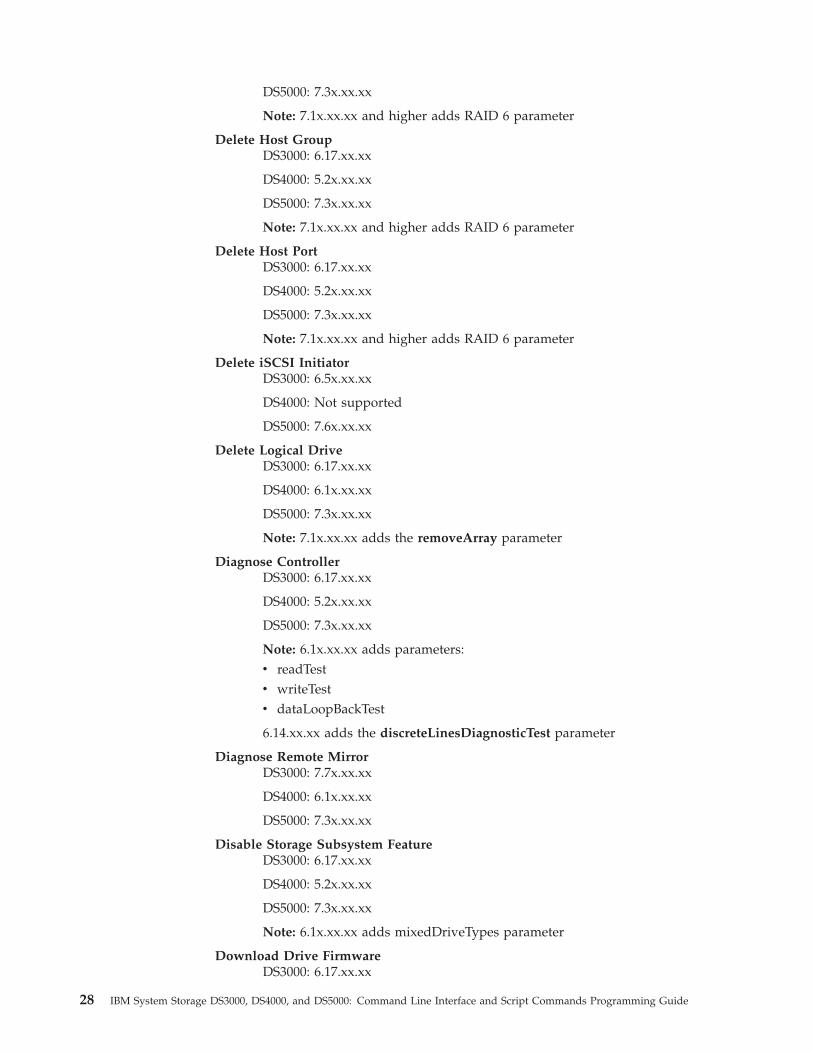
DS5000: 7.3x.xx.xx
Note: 7.1x.xx.xx and higher adds RAID 6 parameter
Delete Host GroupDS3000: 6.17.xx.xx
DS4000: 5.2x.xx.xx
DS5000: 7.3x.xx.xx
Note: 7.1x.xx.xx and higher adds RAID 6 parameter
Delete Host PortDS3000: 6.17.xx.xx
DS4000: 5.2x.xx.xx
DS5000: 7.3x.xx.xx
Note: 7.1x.xx.xx and higher adds RAID 6 parameter
Delete iSCSI InitiatorDS3000: 6.5x.xx.xx
DS4000: Not supported
DS5000: 7.6x.xx.xx
Delete Logical DriveDS3000: 6.17.xx.xx
DS4000: 6.1x.xx.xx
DS5000: 7.3x.xx.xx
Note: 7.1x.xx.xx adds the removeArray parameter
Diagnose ControllerDS3000: 6.17.xx.xx
DS4000: 5.2x.xx.xx
DS5000: 7.3x.xx.xx
Note: 6.1x.xx.xx adds parameters:v readTestv writeTestv dataLoopBackTest
6.14.xx.xx adds the discreteLinesDiagnosticTest parameter
Diagnose Remote MirrorDS3000: 7.7x.xx.xx
DS4000: 6.1x.xx.xx
DS5000: 7.3x.xx.xx
Disable Storage Subsystem FeatureDS3000: 6.17.xx.xx
DS4000: 5.2x.xx.xx
DS5000: 7.3x.xx.xx
Note: 6.1x.xx.xx adds mixedDriveTypes parameter
Download Drive FirmwareDS3000: 6.17.xx.xx
28 IBM System Storage DS3000, DS4000, and DS5000: Command Line Interface and Script Commands Programming Guide
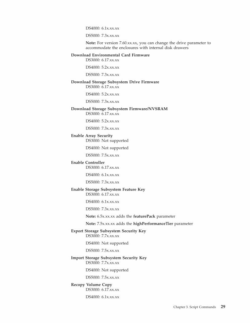
DS4000: 6.1x.xx.xx
DS5000: 7.3x.xx.xx
Note: For version 7.60.xx.xx, you can change the drive parameter toaccommodate the enclosures with internal disk drawers
Download Environmental Card FirmwareDS3000: 6.17.xx.xx
DS4000: 5.2x.xx.xx
DS5000: 7.3x.xx.xx
Download Storage Subsystem Drive FirmwareDS3000: 6.17.xx.xx
DS4000: 5.2x.xx.xx
DS5000: 7.3x.xx.xx
Download Storage Subsystem Firmware/NVSRAMDS3000: 6.17.xx.xx
DS4000: 5.2x.xx.xx
DS5000: 7.3x.xx.xx
Enable Array SecurityDS3000: Not supported
DS4000: Not supported
DS5000: 7.5x.xx.xx
Enable ControllerDS3000: 6.17.xx.xx
DS4000: 6.1x.xx.xx
DS5000: 7.3x.xx.xx
Enable Storage Subsystem Feature KeyDS3000: 6.17.xx.xx
DS4000: 6.1x.xx.xx
DS5000: 7.3x.xx.xx
Note: 6.5x.xx.xx adds the featurePack parameter
Note: 7.5x.xx.xx adds the highPerformanceTier parameter
Export Storage Subsystem Security KeyDS3000: 7.7x.xx.xx
DS4000: Not supported
DS5000: 7.5x.xx.xx
Import Storage Subsystem Security KeyDS3000: 7.7x.xx.xx
DS4000: Not supported
DS5000: 7.5x.xx.xx
Recopy Volume CopyDS3000: 6.17.xx.xx
DS4000: 6.1x.xx.xx
Chapter 3. Script Commands 29
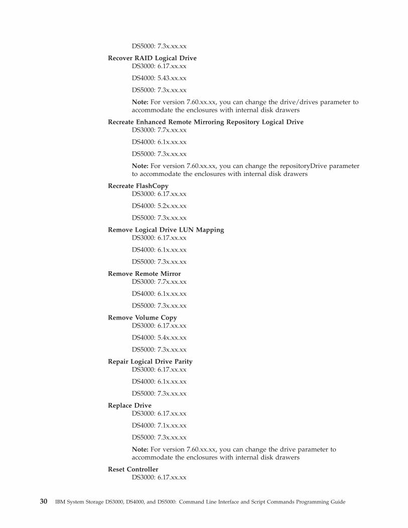
DS5000: 7.3x.xx.xx
Recover RAID Logical DriveDS3000: 6.17.xx.xx
DS4000: 5.43.xx.xx
DS5000: 7.3x.xx.xx
Note: For version 7.60.xx.xx, you can change the drive/drives parameter toaccommodate the enclosures with internal disk drawers
Recreate Enhanced Remote Mirroring Repository Logical DriveDS3000: 7.7x.xx.xx
DS4000: 6.1x.xx.xx
DS5000: 7.3x.xx.xx
Note: For version 7.60.xx.xx, you can change the repositoryDrive parameterto accommodate the enclosures with internal disk drawers
Recreate FlashCopyDS3000: 6.17.xx.xx
DS4000: 5.2x.xx.xx
DS5000: 7.3x.xx.xx
Remove Logical Drive LUN MappingDS3000: 6.17.xx.xx
DS4000: 6.1x.xx.xx
DS5000: 7.3x.xx.xx
Remove Remote MirrorDS3000: 7.7x.xx.xx
DS4000: 6.1x.xx.xx
DS5000: 7.3x.xx.xx
Remove Volume CopyDS3000: 6.17.xx.xx
DS4000: 5.4x.xx.xx
DS5000: 7.3x.xx.xx
Repair Logical Drive ParityDS3000: 6.17.xx.xx
DS4000: 6.1x.xx.xx
DS5000: 7.3x.xx.xx
Replace DriveDS3000: 6.17.xx.xx
DS4000: 7.1x.xx.xx
DS5000: 7.3x.xx.xx
Note: For version 7.60.xx.xx, you can change the drive parameter toaccommodate the enclosures with internal disk drawers
Reset ControllerDS3000: 6.17.xx.xx
30 IBM System Storage DS3000, DS4000, and DS5000: Command Line Interface and Script Commands Programming Guide
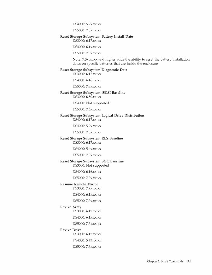
DS4000: 5.2x.xx.xx
DS5000: 7.3x.xx.xx
Reset Storage Subsystem Battery Install DateDS3000: 6.17.xx.xx
DS4000: 6.1x.xx.xx
DS5000: 7.3x.xx.xx
Note: 7.3x.xx.xx and higher adds the ability to reset the battery installationdates on specific batteries that are inside the enclosure
Reset Storage Subsystem Diagnostic DataDS3000: 6.17.xx.xx
DS4000: 6.16.xx.xx
DS5000: 7.3x.xx.xx
Reset Storage Subsystem iSCSI BaselineDS3000: 6.50.xx.xx
DS4000: Not supported
DS5000: 7.6x.xx.xx
Reset Storage Subsystem Logical Drive DistributionDS4000: 6.17.xx.xx
DS4000: 5.2x.xx.xx
DS5000: 7.3x.xx.xx
Reset Storage Subsystem RLS BaselineDS3000: 6.17.xx.xx
DS4000: 5.4x.xx.xx
DS5000: 7.3x.xx.xx
Reset Storage Subsystem SOC BaselineDS3000: Not supported
DS4000: 6.16.xx.xx
DS5000: 7.3x.xx.xx
Resume Remote MirrorDS3000: 7.7x.xx.xx
DS4000: 6.1x.xx.xx
DS5000: 7.3x.xx.xx
Revive ArrayDS3000: 6.17.xx.xx
DS4000: 6.1x.xx.xx
DS5000: 7.3x.xx.xx
Revive DriveDS3000: 6.17.xx.xx
DS4000: 5.43.xx.xx
DS5000: 7.3x.xx.xx
Chapter 3. Script Commands 31
Note: For version 7.60.xx.xx, you can change the drive parameter toaccommodate the enclosures with internal disk drawers
Save Controller NVSRAMDS3000: 6.17.xx.xx
DS4000: 6.1x.xx.xx
DS5000: 7.3x.xx.xx
Save Drive Channel Fault Isolation Diagnostic StatusDS3000: Not supported
DS4000: Not supported
DS5000: 7.3x.xx.xx
Save Drive LogDS3000: 6.17.xx.xx
DS4000: 6.1x.xx.xx
DS5000: 7.3x.xx.xx
Save Storage Subsystem ConfigurationDS3000: 6.17.xx.xx
DS4000: 6.1x.xx.xx
DS5000: 7.3x.xx.xx
Save Storage Subsystem Diagnostic DataDS3000: 6.17.xx.xx
DS4000: 6.16.xx.xx
DS5000: 7.3x.xx.xx
Save Storage Subsystem EventsDS3000: 6.17.xx.xx
DS4000: 6.1x.xx.xx
DS5000: 7.3x.xx.xx
Save Storage Subsystem iSCSI StatisticsDS3000: 6.50.xx.xx
DS4000: Not supported
DS5000: 7.6x.xx.xx
Save Storage Subsystem Performance StatisticsDS3000: 6.17.xx.xx
DS4000: 6.1x.xx.xx
DS5000: 7.3x.xx.xx
Save Storage Subsystem RLS CountsDS3000: 6.17.xx.xx
DS4000: 6.1x.xx.xx
DS5000: 7.3x.xx.xx
Save Storage Subsystem SOC CountsDS3000: Not supported
DS4000: 6.16.xx.xx
32 IBM System Storage DS3000, DS4000, and DS5000: Command Line Interface and Script Commands Programming Guide
DS5000: 7.3x.xx.xx
Save Storage Subsystem State CaptureDS3000: 6.17.xx.xx
DS4000: 6.1x.xx.xx
DS5000: 7.3x.xx.xx
Save Storage Subsystem Support DataDS3000: 6.17.xx.xx
DS4000: 6.1x.xx.xx
DS5000: 7.3x.xx.xx
Set ArrayDS3000: 6.17.xx.xx
DS4000: 6.10.xx.xx
DS5000: Not supported
Note: RAID 6 is supported with 7.xx.xx.xx and higher
Note: 7.30.xx.xx removes the availability parameter
Note: For version 7.60.xx.xx, you can change the addDrive parameter toaccommodate the enclosures with internal disk drawers
Set Array Forced StateDS3000: 6.17.xx.xx
DS4000: 7.1x.xx.xx
DS5000: 7.3x.xx.xx
Set ControllerDS3000: 6.17.xx.xx
DS4000: 6.14.xx.xx
DS5000: 7.3x.xx.xx
Note: 7.30.xx.xx removed the bootp parameter and added the newEthernet port options and the new iSCSI host-port options
Note: 7.50.xx.xx moved the IPV4Gateway parameter and theIPV6RouterAddress parameter from the iSCSI host port options, to thecommand
Set Controller Service Action Allowed IndicatorDS3000: 6.17.xx.xx
DS4000: 6.16.xx.xx
DS5000: 7.3x.xx.xx
Set Drawer Service Action Allow IndicatorDS3000: N/A
DS4000: N/A
DS5000: 7.60.xx.xx
Set Drive Channel StatusDS3000: 6.17.xx.xx
DS4000: 5.2x.xx.xx
Chapter 3. Script Commands 33
DS5000: 7.3x.xx.xx
Set Drive Hot SpareDS3000: 6.17.xx.xx
DS4000: 5.2x.xx.xx
DS5000: 7.3x.xx.xx
Set Disk Drive Service Action Allow IndicatorDS3000: 6.17.xx.xx
DS4000: 5.2x.xx.xx
DS5000: 7.3x.xx.xx
Set Drive StateDS3000: 6.17.xx.xx
DS4000: 5.2x.xx.xx
DS5000: 7.3x.xx.xx
Note: For version 7.60.xx.xx, you can change the drive parameter toaccommodate the enclosures with internal disk drawers
Set Enclosure AlarmDS3000: 6.17.xx.xx
DS4000: 6.16.xx.xx
DS5000: 7.3x.xx.xx
Set Enclosure IdentificationDS3000: 6.17.xx.xx
DS4000: 6.1x.xx.xx
DS5000: 7.3x.xx.xx
Note:
v 6.14.xx.xx adds support for DS4800v 6.16.xx.xx adds support for subsystems and enclosures that set enclosure
IDs through the controller firmware
Set Enclosure Service Action Allowed IndicatorDS3000: 6.17.xx.xx
DS4000: 6.1x.xx.xx
DS5000: 7.3x.xx.xx
Note:
v 6.14.xx.xx adds the powerfan and interconnect parametersv 6.16.xx.xx adds the enclosure and esm parameters
Set FlashCopy Logical DriveDS3000: 6.17.xx.xx
DS4000: 6.1x.xx.xx
DS5000: 7.3x.xx.xx
Set Foreign Drive to NativeDS3000: 7.xx.xx.xx
DS4000: 7.xx.xx.xx
34 IBM System Storage DS3000, DS4000, and DS5000: Command Line Interface and Script Commands Programming Guide
DS5000: 7.3x.xx.xx
Note: For version 7.60.xx.xx, you can change the drive parameter toaccommodate the enclosures with internal disk drawers
Set HostDS3000: 6.17.xx.xx
DS4000: 6.1x.xx.xx
DS5000: 7.3x.xx.xx
Set Host ChannelDS3000: 6.17.xx.xx
DS4000: 6.1x.xx.xx
DS5000: 7.3x.xx.xx
Set Host GroupDS3000: 6.17.xx.xx
DS4000: 6.1x.xx.xx
DS5000: 7.3x.xx.xx
Set Host PortDS3000: 6.17.xx.xx
DS4000: 6.1x.xx.xx
DS5000: 7.3x.xx.xx
Set iSCSI InitiatorDS3000: 6.50.xx.xx
DS4000: Not supported
DS5000: 7.6x.xx.xx
Set iSCSI Target PropertiesDS3000: 6.50.xx.xx
DS4000: Not supported
DS5000: 7.6x.xx.xx
Set Logical DriveDS3000: 6.17.xx.xx
DS4000: 5.2x.xx.xx
DS5000: 7.3x.xx.xx
Note: 7.1.xx.xx adds the preReadRedundancyCheck parameter
Note: For version 7.60.xx.xx, you can change the addDrive parameter toaccommodate the enclosures with internal disk drawers
Set Remote MirrorDS3000: 7.7x.xx.xx
DS4000: 6.1x.xx.xx
DS5000: 7.3x.xx.xx
Set SessionDS3000: 6.17.xx.xx
DS4000: 5.2x.xx.xx
Chapter 3. Script Commands 35
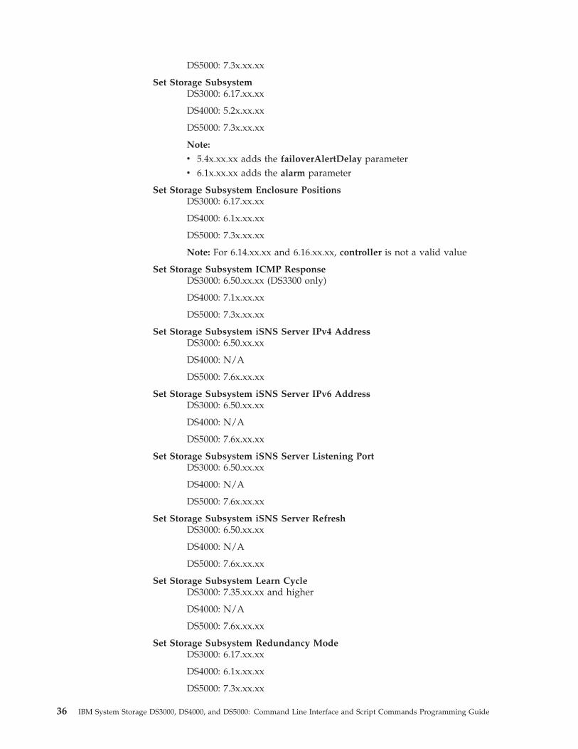
DS5000: 7.3x.xx.xx
Set Storage SubsystemDS3000: 6.17.xx.xx
DS4000: 5.2x.xx.xx
DS5000: 7.3x.xx.xx
Note:
v 5.4x.xx.xx adds the failoverAlertDelay parameterv 6.1x.xx.xx adds the alarm parameter
Set Storage Subsystem Enclosure PositionsDS3000: 6.17.xx.xx
DS4000: 6.1x.xx.xx
DS5000: 7.3x.xx.xx
Note: For 6.14.xx.xx and 6.16.xx.xx, controller is not a valid value
Set Storage Subsystem ICMP ResponseDS3000: 6.50.xx.xx (DS3300 only)
DS4000: 7.1x.xx.xx
DS5000: 7.3x.xx.xx
Set Storage Subsystem iSNS Server IPv4 AddressDS3000: 6.50.xx.xx
DS4000: N/A
DS5000: 7.6x.xx.xx
Set Storage Subsystem iSNS Server IPv6 AddressDS3000: 6.50.xx.xx
DS4000: N/A
DS5000: 7.6x.xx.xx
Set Storage Subsystem iSNS Server Listening PortDS3000: 6.50.xx.xx
DS4000: N/A
DS5000: 7.6x.xx.xx
Set Storage Subsystem iSNS Server RefreshDS3000: 6.50.xx.xx
DS4000: N/A
DS5000: 7.6x.xx.xx
Set Storage Subsystem Learn CycleDS3000: 7.35.xx.xx and higher
DS4000: N/A
DS5000: 7.6x.xx.xx
Set Storage Subsystem Redundancy ModeDS3000: 6.17.xx.xx
DS4000: 6.1x.xx.xx
DS5000: 7.3x.xx.xx
36 IBM System Storage DS3000, DS4000, and DS5000: Command Line Interface and Script Commands Programming Guide
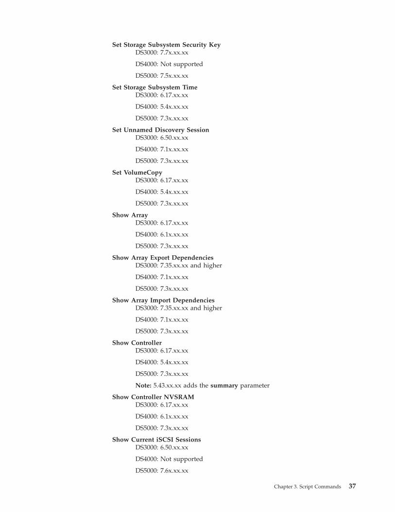
Set Storage Subsystem Security KeyDS3000: 7.7x.xx.xx
DS4000: Not supported
DS5000: 7.5x.xx.xx
Set Storage Subsystem TimeDS3000: 6.17.xx.xx
DS4000: 5.4x.xx.xx
DS5000: 7.3x.xx.xx
Set Unnamed Discovery SessionDS3000: 6.50.xx.xx
DS4000: 7.1x.xx.xx
DS5000: 7.3x.xx.xx
Set VolumeCopyDS3000: 6.17.xx.xx
DS4000: 5.4x.xx.xx
DS5000: 7.3x.xx.xx
Show ArrayDS3000: 6.17.xx.xx
DS4000: 6.1x.xx.xx
DS5000: 7.3x.xx.xx
Show Array Export DependenciesDS3000: 7.35.xx.xx and higher
DS4000: 7.1x.xx.xx
DS5000: 7.3x.xx.xx
Show Array Import DependenciesDS3000: 7.35.xx.xx and higher
DS4000: 7.1x.xx.xx
DS5000: 7.3x.xx.xx
Show ControllerDS3000: 6.17.xx.xx
DS4000: 5.4x.xx.xx
DS5000: 7.3x.xx.xx
Note: 5.43.xx.xx adds the summary parameter
Show Controller NVSRAMDS3000: 6.17.xx.xx
DS4000: 6.1x.xx.xx
DS5000: 7.3x.xx.xx
Show Current iSCSI SessionsDS3000: 6.50.xx.xx
DS4000: Not supported
DS5000: 7.6x.xx.xx
Chapter 3. Script Commands 37
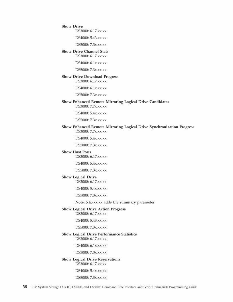
Show DriveDS3000: 6.17.xx.xx
DS4000: 5.43.xx.xx
DS5000: 7.3x.xx.xx
Show Drive Channel StatsDS3000: 6.17.xx.xx
DS4000: 6.1x.xx.xx
DS5000: 7.3x.xx.xx
Show Drive Download ProgressDS3000: 6.17.xx.xx
DS4000: 6.1x.xx.xx
DS5000: 7.3x.xx.xx
Show Enhanced Remote Mirroring Logical Drive CandidatesDS3000: 7.7x.xx.xx
DS4000: 5.4x.xx.xx
DS5000: 7.3x.xx.xx
Show Enhanced Remote Mirroring Logical Drive Synchronization ProgressDS3000: 7.7x.xx.xx
DS4000: 5.4x.xx.xx
DS5000: 7.3x.xx.xx
Show Host PortsDS3000: 6.17.xx.xx
DS4000: 5.4x.xx.xx
DS5000: 7.3x.xx.xx
Show Logical DriveDS3000: 6.17.xx.xx
DS4000: 5.4x.xx.xx
DS5000: 7.3x.xx.xx
Note: 5.43.xx.xx adds the summary parameter
Show Logical Drive Action ProgressDS3000: 6.17.xx.xx
DS4000: 5.43.xx.xx
DS5000: 7.3x.xx.xx
Show Logical Drive Performance StatisticsDS3000: 6.17.xx.xx
DS4000: 6.1x.xx.xx
DS5000: 7.3x.xx.xx
Show Logical Drive ReservationsDS3000: 6.17.xx.xx
DS4000: 5.4x.xx.xx
DS5000: 7.3x.xx.xx
38 IBM System Storage DS3000, DS4000, and DS5000: Command Line Interface and Script Commands Programming Guide
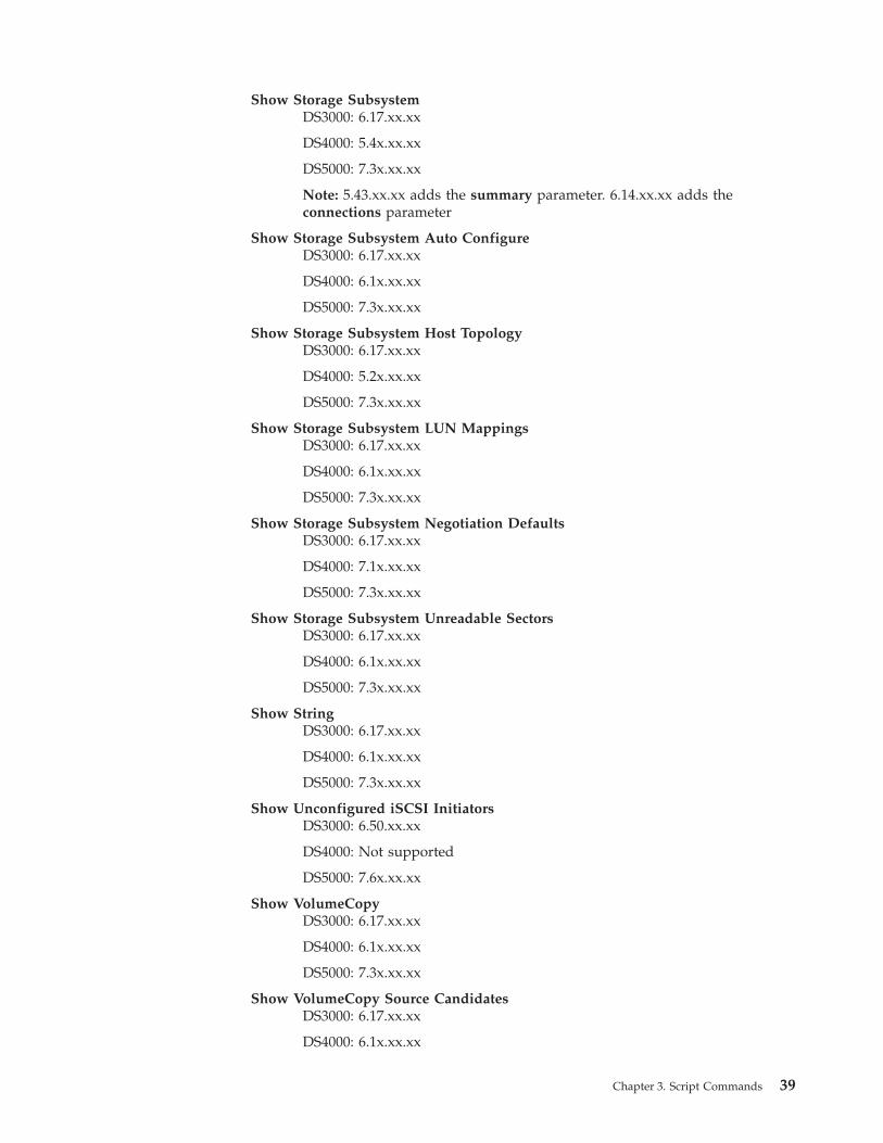
Show Storage SubsystemDS3000: 6.17.xx.xx
DS4000: 5.4x.xx.xx
DS5000: 7.3x.xx.xx
Note: 5.43.xx.xx adds the summary parameter. 6.14.xx.xx adds theconnections parameter
Show Storage Subsystem Auto ConfigureDS3000: 6.17.xx.xx
DS4000: 6.1x.xx.xx
DS5000: 7.3x.xx.xx
Show Storage Subsystem Host TopologyDS3000: 6.17.xx.xx
DS4000: 5.2x.xx.xx
DS5000: 7.3x.xx.xx
Show Storage Subsystem LUN MappingsDS3000: 6.17.xx.xx
DS4000: 6.1x.xx.xx
DS5000: 7.3x.xx.xx
Show Storage Subsystem Negotiation DefaultsDS3000: 6.17.xx.xx
DS4000: 7.1x.xx.xx
DS5000: 7.3x.xx.xx
Show Storage Subsystem Unreadable SectorsDS3000: 6.17.xx.xx
DS4000: 6.1x.xx.xx
DS5000: 7.3x.xx.xx
Show StringDS3000: 6.17.xx.xx
DS4000: 6.1x.xx.xx
DS5000: 7.3x.xx.xx
Show Unconfigured iSCSI InitiatorsDS3000: 6.50.xx.xx
DS4000: Not supported
DS5000: 7.6x.xx.xx
Show VolumeCopyDS3000: 6.17.xx.xx
DS4000: 6.1x.xx.xx
DS5000: 7.3x.xx.xx
Show VolumeCopy Source CandidatesDS3000: 6.17.xx.xx
DS4000: 6.1x.xx.xx
Chapter 3. Script Commands 39
DS5000: 7.3x.xx.xx
Show VolumeCopy Target CandidatesDS3000: 6.17.xx.xx
DS4000: 6.1x.xx.xx
DS5000: 7.3x.xx.xx
Start Array DefragmentDS3000: 6.17.xx.xx
DS4000: 7.1x.xx.xx
DS5000: 7.3x.xx.xx
Start Array ExportDS3000: 7.35.xx.xx and higher
DS4000: 7.1x.xx.xx
DS5000: 7.3x.xx.xx
Start Array ImportDS3000: 7.35.xx.xx and higher
DS4000: 7.1x.xx.xx
DS5000: 7.3x.xx.xx
Start Array LocateDS3000: 6.17.xx.xx
DS4000: 6.16.xx.xx
DS5000: 7.3x.xx.xx
Start Drive Channel Fault Isolation DiagnosticsDS3000: Not supported
DS4000: Not supported
DS5000: 7.3x.xx.xx
Note: For version 7.60.xx.xx, you can change the drive parameter toaccommodate the enclosures with internal disk drawers
Start Drive Channel LocateDS3000: 6.17.xx.xx
DS4000: 6.1x.xx.xx
DS5000: 7.3x.xx.xx
Start Drive InitializeDS3000: 6.17.xx.xx
DS4000: 6.1x.xx.xx
DS5000: 7.3x.xx.xx
Note: For version 7.60.xx.xx, you can change the drive parameter toaccommodate the enclosures with internal disk drawers
Start Drive LocateDS3000: 6.17.xx.xx
DS4000: 6.1x.xx.xx
DS5000: 7.3x.xx.xx
40 IBM System Storage DS3000, DS4000, and DS5000: Command Line Interface and Script Commands Programming Guide
Note: For version 7.60.xx.xx, you can change the drive parameter toaccommodate the enclosures with internal disk drawers
Start Drive ReconstructionDS3000: 6.17.xx.xx
DS4000: 5.43.xx.xx
DS5000: 7.3x.xx.xx
Note: For version 7.60.xx.xx, you can change the drive parameter toaccommodate the enclosures with internal disk drawers
Start Enhanced Remote Mirroring SynchronizationDS3000: 7.7x.xx.xx
DS4000: 6.1x.xx.xx
DS5000: 7.3x.xx.xx
Start iSCSI DHCP RefreshDS3000: 6.50.xx.xx
DS4000: Not supported
DS5000: 7.6x.xx.xx
Start Enclosure LocateDS3000: 6.17.xx.xx
DS4000: 6.1x.xx.xx
DS5000: 7.3x.xx.xx
Start Logical Drive InitializationDS3000: 6.17.xx.xx
DS4000: 6.1x.xx.xx
DS5000: 7.3x.xx.xx
Start Secure Drive EraseDS3000: 7.7x.xx.xx
DS4000: Not supported
DS5000: 7.5x.xx.xx
Note: For version 7.60.xx.xx, you can change the drive parameter toaccommodate the enclosures with internal disk drawers
Start Storage Subsystem LocateDS3000: 6.17.xx.xx
DS4000: 6.1x.xx.xx
DS5000: 7.3x.xx.xx
Stop Array LocateDS3000: 6.17.xx.xx
DS4000: 6.16.xx.xx
DS5000: 7.3x.xx.xx
Stop Drive Channel Fault Isolation DiagnosticsDS3000: Not supported
DS4000: 7.3x.xx.xx
Chapter 3. Script Commands 41
DS5000: 7.3x.xx.xx
Stop Drive Channel LocateDS3000: 6.17.xx.xx
DS4000: 6.1x.xx.xx
DS5000: 7.3x.xx.xx
Stop Drive LocateDS3000: 6.17.xx.xx
DS4000: 6.1x.xx.xx
DS5000: 7.3x.xx.xx
Stop Enclosure LocateDS3000: 6.17.xx.xx
DS4000: 6.1x.xx.xx
DS5000: 7.3x.xx.xx
Stop FlashCopyDS3000: 6.17.xx.xx
DS4000: 6.1x.xx.xx
DS5000: 7.3x.xx.xx
Stop iSCSI SessionDS3000: 6.50.xx.xx
DS4000: Not supported
DS5000: 7.6x.xx.xx
Stop Storage Subsystem Drive Firmware DownloadDS3000: 6.17.xx.xx
DS4000: 6.1x.xx.xx
DS5000: 7.3x.xx.xx
Stop Storage Subsystem LocateDS3000: 6.17.xx.xx
DS4000: 6.1x.xx.xx
DS5000: 7.3x.xx.xx
Stop VolumeCopyDS3000: 6.17.xx.xx
DS4000: 5.4x.xx.xx
DS5000: 7.3x.xx.xx
Suspend Remote MirrorDS3000: 7.7x.xx.xx
DS4000: 6.1x.xx.xx
DS5000: 7.3x.xx.xx
42 IBM System Storage DS3000, DS4000, and DS5000: Command Line Interface and Script Commands Programming Guide
Activate Enhanced Remote Mirroring Feature
This command creates the mirror repository logical drive and activates theEnhanced Remote Mirroring feature. When you use this command, you can definethe mirror repository logical drive in one of three ways:v User-defined disk drivesv User-defined arrayv User-defined number of disk drives
If you choose to define a number of disk drives, the controller firmware chooseswhich disk drives to use for the mirror repository logical drive.
Syntax (User-Defined Disk Drives)activate storageSubsystem feature=remoteMirrorrepositoryRAIDLevel=(1 | 3 | 5 | 6)repositoryDrives=(enclosureID1,drawerID1,slotID1 ... enclosureIDn,drawerIDn,slotIDn)repositoryArrayUserLabel=[arrayName][enclosureLossProtect=(TRUE | FALSE)][drawerLossProtect=(TRUE | FALSE)];
Syntax (User-Defined Array)activate storageSubsystem feature=remoteMirrorrepositoryArray=arrayName[freeCapacityArea=freeCapacityIndexNumber]
Syntax (User-Defined Number of Disk Drives)activate storageSubsystem feature=remoteMirrorrepositoryRAIDLevel=(1 | 3 | 5 | 6)repositoryDriveCount=numberOfDrivesrepositoryArrayUserLabel=[arrayName][driveType=(fibre | SATA | SAS)][enclosureLossProtect=(TRUE | FALSE)][drawerLossProtect=(TRUE | FALSE)];
Parameters
Parameter Description
repositoryRAIDLevel The RAID level for the mirror repository logical drive.Valid values are 1, 3, 5, or 6.
repositoryDrives The disk drives for the mirror repository logical drive.EnclosureID1,drawerID1, slotID1 ...enclosureIDn,drawerIDn,slotIDn is for enclosures withmultiple disk drive drawers. For enclosures withoutdisk drive drawers, use enclosureID1,slotID1 ...enclosureIDn,slotIDn. Enclosure ID values are 0 to 99.Drawer ID values are 1 to 5. Slot ID values are 1 to32. Enclose the values in parentheses.
repositoryarray The name of the mirror repository logical drive groupwhere the mirror repository logical drive is located.(To determine the names of the arrays in your storagesubsystem, run the show storageSubsystem profilecommand.)
Chapter 3. Script Commands 43
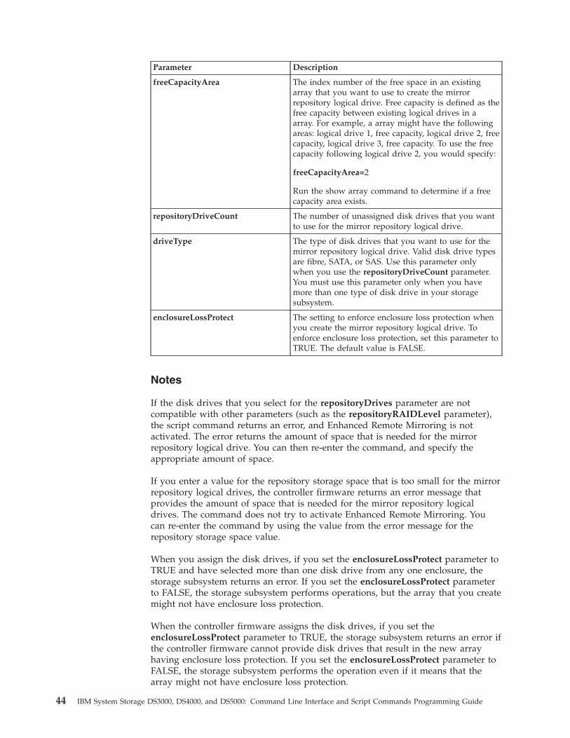
Parameter Description
freeCapacityArea The index number of the free space in an existingarray that you want to use to create the mirrorrepository logical drive. Free capacity is defined as thefree capacity between existing logical drives in aarray. For example, a array might have the followingareas: logical drive 1, free capacity, logical drive 2, freecapacity, logical drive 3, free capacity. To use the freecapacity following logical drive 2, you would specify:
freeCapacityArea=2
Run the show array command to determine if a freecapacity area exists.
repositoryDriveCount The number of unassigned disk drives that you wantto use for the mirror repository logical drive.
driveType The type of disk drives that you want to use for themirror repository logical drive. Valid disk drive typesare fibre, SATA, or SAS. Use this parameter onlywhen you use the repositoryDriveCount parameter.You must use this parameter only when you havemore than one type of disk drive in your storagesubsystem.
enclosureLossProtect The setting to enforce enclosure loss protection whenyou create the mirror repository logical drive. Toenforce enclosure loss protection, set this parameter toTRUE. The default value is FALSE.
Notes
If the disk drives that you select for the repositoryDrives parameter are notcompatible with other parameters (such as the repositoryRAIDLevel parameter),the script command returns an error, and Enhanced Remote Mirroring is notactivated. The error returns the amount of space that is needed for the mirrorrepository logical drive. You can then re-enter the command, and specify theappropriate amount of space.
If you enter a value for the repository storage space that is too small for the mirrorrepository logical drives, the controller firmware returns an error message thatprovides the amount of space that is needed for the mirror repository logicaldrives. The command does not try to activate Enhanced Remote Mirroring. Youcan re-enter the command by using the value from the error message for therepository storage space value.
When you assign the disk drives, if you set the enclosureLossProtect parameter toTRUE and have selected more than one disk drive from any one enclosure, thestorage subsystem returns an error. If you set the enclosureLossProtect parameterto FALSE, the storage subsystem performs operations, but the array that you createmight not have enclosure loss protection.
When the controller firmware assigns the disk drives, if you set theenclosureLossProtect parameter to TRUE, the storage subsystem returns an error ifthe controller firmware cannot provide disk drives that result in the new arrayhaving enclosure loss protection. If you set the enclosureLossProtect parameter toFALSE, the storage subsystem performs the operation even if it means that thearray might not have enclosure loss protection.
44 IBM System Storage DS3000, DS4000, and DS5000: Command Line Interface and Script Commands Programming Guide
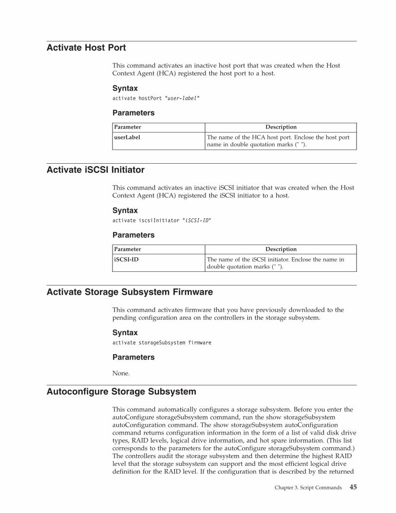
Activate Host Port
This command activates an inactive host port that was created when the HostContext Agent (HCA) registered the host port to a host.
Syntaxactivate hostPort "user-label"
Parameters
Parameter Description
userLabel The name of the HCA host port. Enclose the host portname in double quotation marks (" ").
Activate iSCSI Initiator
This command activates an inactive iSCSI initiator that was created when the HostContext Agent (HCA) registered the iSCSI initiator to a host.
Syntaxactivate iscsiInitiator "iSCSI-ID"
Parameters
Parameter Description
iSCSI-ID The name of the iSCSI initiator. Enclose the name indouble quotation marks (" ").
Activate Storage Subsystem Firmware
This command activates firmware that you have previously downloaded to thepending configuration area on the controllers in the storage subsystem.
Syntaxactivate storageSubsystem firmware
Parameters
None.
Autoconfigure Storage Subsystem
This command automatically configures a storage subsystem. Before you enter theautoConfigure storageSubsystem command, run the show storageSubsystemautoConfiguration command. The show storageSubsystem autoConfigurationcommand returns configuration information in the form of a list of valid disk drivetypes, RAID levels, logical drive information, and hot spare information. (This listcorresponds to the parameters for the autoConfigure storageSubsystem command.)The controllers audit the storage subsystem and then determine the highest RAIDlevel that the storage subsystem can support and the most efficient logical drivedefinition for the RAID level. If the configuration that is described by the returned
Chapter 3. Script Commands 45
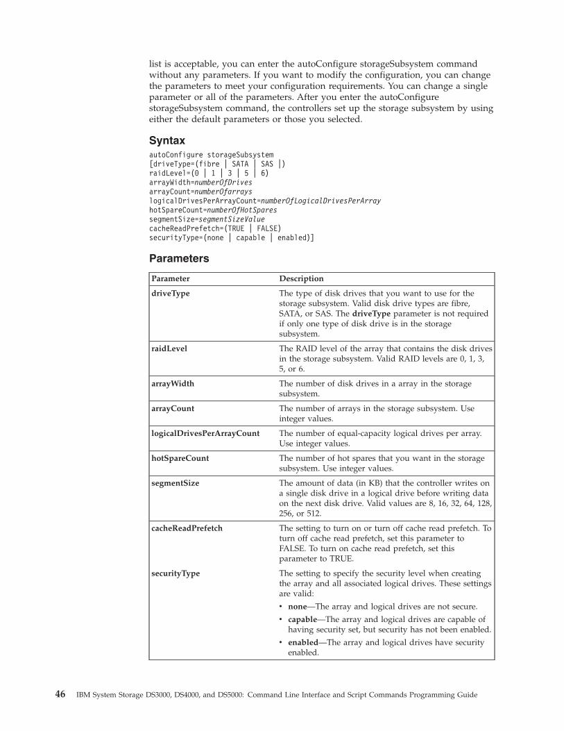
list is acceptable, you can enter the autoConfigure storageSubsystem commandwithout any parameters. If you want to modify the configuration, you can changethe parameters to meet your configuration requirements. You can change a singleparameter or all of the parameters. After you enter the autoConfigurestorageSubsystem command, the controllers set up the storage subsystem by usingeither the default parameters or those you selected.
SyntaxautoConfigure storageSubsystem[driveType=(fibre | SATA | SAS |)raidLevel=(0 | 1 | 3 | 5 | 6)arrayWidth=numberOfDrivesarrayCount=numberOfarrayslogicalDrivesPerArrayCount=numberOfLogicalDrivesPerArrayhotSpareCount=numberOfHotSparessegmentSize=segmentSizeValuecacheReadPrefetch=(TRUE | FALSE)securityType=(none | capable | enabled)]
Parameters
Parameter Description
driveType The type of disk drives that you want to use for thestorage subsystem. Valid disk drive types are fibre,SATA, or SAS. The driveType parameter is not requiredif only one type of disk drive is in the storagesubsystem.
raidLevel The RAID level of the array that contains the disk drivesin the storage subsystem. Valid RAID levels are 0, 1, 3,5, or 6.
arrayWidth The number of disk drives in a array in the storagesubsystem.
arrayCount The number of arrays in the storage subsystem. Useinteger values.
logicalDrivesPerArrayCount The number of equal-capacity logical drives per array.Use integer values.
hotSpareCount The number of hot spares that you want in the storagesubsystem. Use integer values.
segmentSize The amount of data (in KB) that the controller writes ona single disk drive in a logical drive before writing dataon the next disk drive. Valid values are 8, 16, 32, 64, 128,256, or 512.
cacheReadPrefetch The setting to turn on or turn off cache read prefetch. Toturn off cache read prefetch, set this parameter toFALSE. To turn on cache read prefetch, set thisparameter to TRUE.
securityType The setting to specify the security level when creatingthe array and all associated logical drives. These settingsare valid:
v none—The array and logical drives are not secure.
v capable—The array and logical drives are capable ofhaving security set, but security has not been enabled.
v enabled—The array and logical drives have securityenabled.
46 IBM System Storage DS3000, DS4000, and DS5000: Command Line Interface and Script Commands Programming Guide
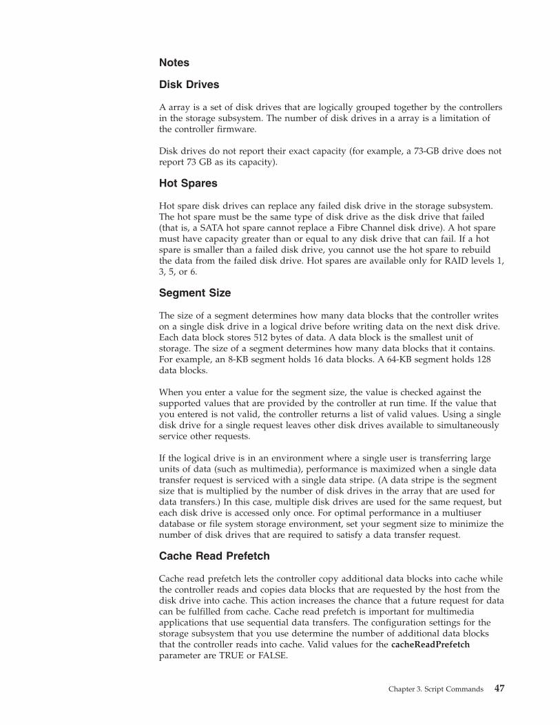
Notes
Disk Drives
A array is a set of disk drives that are logically grouped together by the controllersin the storage subsystem. The number of disk drives in a array is a limitation ofthe controller firmware.
Disk drives do not report their exact capacity (for example, a 73-GB drive does notreport 73 GB as its capacity).
Hot Spares
Hot spare disk drives can replace any failed disk drive in the storage subsystem.The hot spare must be the same type of disk drive as the disk drive that failed(that is, a SATA hot spare cannot replace a Fibre Channel disk drive). A hot sparemust have capacity greater than or equal to any disk drive that can fail. If a hotspare is smaller than a failed disk drive, you cannot use the hot spare to rebuildthe data from the failed disk drive. Hot spares are available only for RAID levels 1,3, 5, or 6.
Segment Size
The size of a segment determines how many data blocks that the controller writeson a single disk drive in a logical drive before writing data on the next disk drive.Each data block stores 512 bytes of data. A data block is the smallest unit ofstorage. The size of a segment determines how many data blocks that it contains.For example, an 8-KB segment holds 16 data blocks. A 64-KB segment holds 128data blocks.
When you enter a value for the segment size, the value is checked against thesupported values that are provided by the controller at run time. If the value thatyou entered is not valid, the controller returns a list of valid values. Using a singledisk drive for a single request leaves other disk drives available to simultaneouslyservice other requests.
If the logical drive is in an environment where a single user is transferring largeunits of data (such as multimedia), performance is maximized when a single datatransfer request is serviced with a single data stripe. (A data stripe is the segmentsize that is multiplied by the number of disk drives in the array that are used fordata transfers.) In this case, multiple disk drives are used for the same request, buteach disk drive is accessed only once. For optimal performance in a multiuserdatabase or file system storage environment, set your segment size to minimize thenumber of disk drives that are required to satisfy a data transfer request.
Cache Read Prefetch
Cache read prefetch lets the controller copy additional data blocks into cache whilethe controller reads and copies data blocks that are requested by the host from thedisk drive into cache. This action increases the chance that a future request for datacan be fulfilled from cache. Cache read prefetch is important for multimediaapplications that use sequential data transfers. The configuration settings for thestorage subsystem that you use determine the number of additional data blocksthat the controller reads into cache. Valid values for the cacheReadPrefetchparameter are TRUE or FALSE.
Chapter 3. Script Commands 47
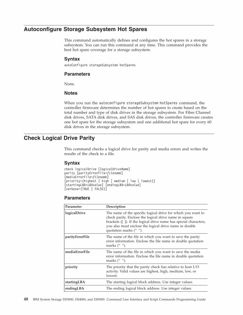
Autoconfigure Storage Subsystem Hot Spares
This command automatically defines and configures the hot spares in a storagesubsystem. You can run this command at any time. This command provides thebest hot spare coverage for a storage subsystem.
SyntaxautoConfigure storageSubsystem hotSpares
Parameters
None.
Notes
When you run the autoconfigure storageSubsystem hotSpares command, thecontroller firmware determines the number of hot spares to create based on thetotal number and type of disk drives in the storage subsystem. For Fibre Channeldisk drives, SATA disk drives, and SAS disk drives, the controller firmware createsone hot spare for the storage subsystem and one additional hot spare for every 60disk drives in the storage subsystem.
Check Logical Drive Parity
This command checks a logical drive for parity and media errors and writes theresults of the check to a file.
Syntaxcheck logicalDrive [logicalDriveName]parity [parityErrorFile=filename][mediaErrorFile=filename][priority=(highest | high | medium | low | lowest)][startingLBA=LBAvalue] [endingLBA=LBAvalue][verbose=(TRUE | FALSE)]
Parameters
Parameter Description
logicalDrive The name of the specific logical drive for which you want tocheck parity. Enclose the logical drive name in squarebrackets ([ ]). If the logical drive name has special characters,you also must enclose the logical drive name in doublequotation marks (“ ”).
parityErrorFile The name of the file in which you want to save the parityerror information. Enclose the file name in double quotationmarks (“ ”).
mediaErrorFile The name of the file in which you want to save the mediaerror information. Enclose the file name in double quotationmarks (“ ”).
priority The priority that the parity check has relative to host I/Oactivity. Valid values are highest, high, medium, low, orlowest.
startingLBA The starting logical block address. Use integer values.
endingLBA The ending logical block address. Use integer values.
48 IBM System Storage DS3000, DS4000, and DS5000: Command Line Interface and Script Commands Programming Guide
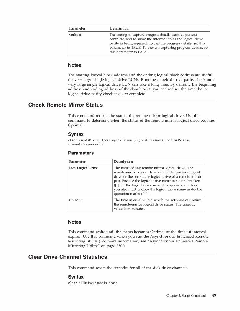
Parameter Description
verbose The setting to capture progress details, such as percentcomplete, and to show the information as the logical driveparity is being repaired. To capture progress details, set thisparameter to TRUE. To prevent capturing progress details, setthis parameter to FALSE.
Notes
The starting logical block address and the ending logical block address are usefulfor very large single-logical drive LUNs. Running a logical drive parity check on avery large single logical drive LUN can take a long time. By defining the beginningaddress and ending address of the data blocks, you can reduce the time that alogical drive parity check takes to complete.
Check Remote Mirror Status
This command returns the status of a remote-mirror logical drive. Use thiscommand to determine when the status of the remote-mirror logical drive becomesOptimal.
Syntaxcheck remoteMirror localLogicalDrive [logicalDriveName] optimalStatustimeout=timeoutValue
Parameters
Parameter Description
localLogicalDrive The name of any remote-mirror logical drive. Theremote-mirror logical drive can be the primary logicaldrive or the secondary logical drive of a remote-mirrorpair. Enclose the logical drive name in square brackets([ ]). If the logical drive name has special characters,you also must enclose the logical drive name in doublequotation marks (“ ”).
timeout The time interval within which the software can returnthe remote-mirror logical drive status. The timeoutvalue is in minutes.
Notes
This command waits until the status becomes Optimal or the timeout intervalexpires. Use this command when you run the Asynchronous Enhanced RemoteMirroring utility. (For more information, see “Asynchronous Enhanced RemoteMirroring Utility” on page 250.)
Clear Drive Channel Statistics
This command resets the statistics for all of the disk drive channels.
Syntaxclear allDriveChannels stats
Chapter 3. Script Commands 49
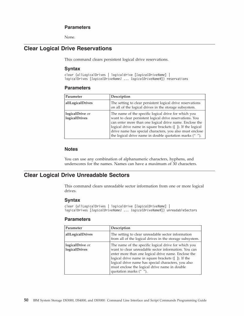
Parameters
None.
Clear Logical Drive Reservations
This command clears persistent logical drive reservations.
Syntaxclear (allLogicalDrives | logicaldrive [logicalDriveName] |logicalDrives [logicalDriveName1 ... logicalDriveNameN]) reservations
Parameters
Parameter Description
allLogicalDrives The setting to clear persistent logical drive reservationson all of the logical drives in the storage subsystem.
logicalDrive orlogicalDrives
The name of the specific logical drive for which youwant to clear persistent logical drive reservations. Youcan enter more than one logical drive name. Enclose thelogical drive name in square brackets ([ ]). If the logicaldrive name has special characters, you also must enclosethe logical drive name in double quotation marks (“ ”).
Notes
You can use any combination of alphanumeric characters, hyphens, andunderscores for the names. Names can have a maximum of 30 characters.
Clear Logical Drive Unreadable Sectors
This command clears unreadable sector information from one or more logicaldrives.
Syntaxclear (allLogicalDrives | logicaldrive [logicalDriveName] |logicalDrives [logicalDriveName1 ... logicalDriveNameN]) unreadableSectors
Parameters
Parameter Description
allLogicalDrives The setting to clear unreadable sector informationfrom all of the logical drives in the storage subsystem.
logicalDrive orlogicalDrives
The name of the specific logical drive for which youwant to clear unreadable sector information. You canenter more than one logical drive name. Enclose thelogical drive name in square brackets ([ ]). If thelogical drive name has special characters, you alsomust enclose the logical drive name in doublequotation marks (“ ”).
50 IBM System Storage DS3000, DS4000, and DS5000: Command Line Interface and Script Commands Programming Guide
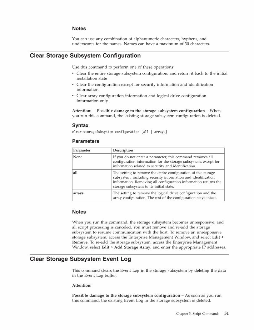
Notes
You can use any combination of alphanumeric characters, hyphens, andunderscores for the names. Names can have a maximum of 30 characters.
Clear Storage Subsystem Configuration
Use this command to perform one of these operations:v Clear the entire storage subsystem configuration, and return it back to the initial
installation statev Clear the configuration except for security information and identification
informationv Clear array configuration information and logical drive configuration
information only
Attention: Possible damage to the storage subsystem configuration – Whenyou run this command, the existing storage subsystem configuration is deleted.
Syntaxclear storageSubsystem configuration [all | arrays]
Parameters
Parameter Description
None If you do not enter a parameter, this command removes allconfiguration information for the storage subsystem, except forinformation related to security and identification.
all The setting to remove the entire configuration of the storagesubsystem, including security information and identificationinformation. Removing all configuration information returns thestorage subsystem to its initial state.
arrays The setting to remove the logical drive configuration and thearray configuration. The rest of the configuration stays intact.
Notes
When you run this command, the storage subsystem becomes unresponsive, andall script processing is canceled. You must remove and re-add the storagesubsystem to resume communication with the host. To remove an unresponsivestorage subsystem, access the Enterprise Management Window, and select Edit →Remove. To re-add the storage subsystem, access the Enterprise ManagementWindow, select Edit → Add Storage Array, and enter the appropriate IP addresses.
Clear Storage Subsystem Event Log
This command clears the Event Log in the storage subsystem by deleting the datain the Event Log buffer.
Attention:
Possible damage to the storage subsystem configuration – As soon as you runthis command, the existing Event Log in the storage subsystem is deleted.
Chapter 3. Script Commands 51
Syntaxclear storageSubsystem eventLog
Parameters
None.
Clear Storage Subsystem Firmware Pending Area
This command deletes a firmware image or NVSRAM values that you havepreviously downloaded from the pending area buffer.
Attention:
Possible damage to the storage subsystem configuration – As soon as you runthis command, the contents of the existing pending area in the storage subsystemare deleted.
Syntaxclear storageSubsystem firmwarePendingArea
Note: This command is not required for DS3000. Downloads for DS3000 areimmediately activated and are not staged. The pending area buffer will have nofirmware image or NVSRAM values for DS3000.
Parameters
None.
Create Array
This command creates either a free-capacity array or one logical drive on a set ofunassigned disk drives.
Syntaxcreate array [userLabel]Drives=(enclosureID1,drawerID1,slotID1 ... enclosureIDn,drawerIDn,slotIDn)raidLevel=(0 | 1 | 3 | 5 | 6)userLabel=arrayNameDriveMediaType=(HDD | SSD | unknown | allMedia)enclosureLossProtect=(TRUE | FALSE)drawerLossProtect=(TRUE | FALSE)securityType=(none | capable | enabled)]
Parameters
Parameter Description
array The alphanumeric identifier (including - and _) that youwant to give the new array. Enclose the array identifierin square brackets ([ ]).
52 IBM System Storage DS3000, DS4000, and DS5000: Command Line Interface and Script Commands Programming Guide
Parameter Description
drives The disk drives that you want to assign to the array.EnclosureID1,drawerID1,slotID1 ...enclosureIDn,drawerIDn,slotIDn is for enclosures withmultiple disk drive drawers. For enclosures without diskdrive drawers, use enclosureID1,slotID1 ...enclosureIDn,slotIDn instead. Enclosure ID values are 0to 99. Drawer ID values are 1 to 5. Slot ID values are 1to 32. Enclose all values in parentheses.
raidLevel The RAID level of the array that contains the logicaldrive. Valid values are 0, 1, 3, 5, or 6.
securityType The setting to specify the security level when creatingthe arrays and all associated logical drives. Thesesettings are valid:
v none—The array and logical drives are not secure.
v capable—The array and logical drives are capable ofhaving security set, but security has not been enabled.
v enabled—The array and logical drives have securityenabled.
drawerLossProtect The setting to enforce drawer loss protection when youcreate the mirror repository logical drive. To enforcedrawer loss protection, set this parameter to TRUE. Thedefault value is FALSE.
userLabel The alphanumeric identifier (including - and _) that youwant to give the new array. Enclose the array identifierin double quotation marks
DriveMediaType The type of disk drive medium that you want to use forthe create RAID logical drive. Values are
v HDD – Use this option when you have hard diskdrives in the expansion drawer.
v SSD – Use this option when you have solid state diskdrives in the expansion drawer.
v unknown – Use if you are not sure what types of diskdrive media are in the expansion drawer.
v allMedia – Use this option when you want to use alltypes of disk drive media that are in the expansiondrawer.
Use this parameter only when you use the DriveCountparameter. If you have only one type of disk drivemedia, you do not need to use this parameter. You mustuse this parameter when you have more than one typeof disk drive media in your storage subsystem.
Notes
The drives parameter lets you choose the number of disk drives that you want touse in the array. If you choose this option, you do not need to specify the diskdrives by enclosure ID and slot ID. The controllers choose the specific disk drivesto use for the array.
If you do not specify a capacity by using the capacity parameter, all of the diskdrive capacity that is available in the array is used. If you do not specify capacityunits, bytes is used as the default value.
Chapter 3. Script Commands 53
Cache Read Prefetch
The cacheReadPrefetch command lets the controller copy additional data blocksinto cache while the controller reads and copies data blocks that are requested bythe host from the disk drives into cache. This action increases the chance that afuture request for data can be fulfilled from cache. Cache read prefetch isimportant for multimedia applications that use sequential data transfers. Theconfiguration settings for the storage subsystem that you use determine thenumber of additional data blocks that the controller reads into cache. Valid valuesfor the cacheReadPrefetch parameter are TRUE or FALSE.
You do not need to enter a value for the cacheReadPrefetch parameter or thesegmentSize parameter. If you do not enter a value, the controller firmware usesthe usageHint parameter with fileSystem as the default value. Entering a value forthe usageHint parameter and a value for the cacheReadPrefetch parameter or avalue for the segmentSize parameter does not cause an error. The value that youenter for the cacheReadPrefetch parameter or the segmentSize parameter takespriority over the value for the usageHint parameter.
Segment Size
The size of a segment determines how many data blocks that the controller writeson a single disk drive in a logical drive before writing data on the next disk drive.Each data block stores 512 bytes of data. A data block is the smallest unit ofstorage. The size of a segment determines how many data blocks that it contains.For example, an 8 KB segment holds 16 data blocks. A 64 KB segment holds 128data blocks.
When you enter a value for the segment size, the value is checked against thesupported values that are provided by the controller at run time. If the value thatyou entered is not valid, the controller returns a list of valid values. Using a singledisk drive for a single request leaves other disk drives available to simultaneouslyservice other requests.
If the logical drive is in an environment where a single user is transferring largeunits of data (such as multimedia), performance is maximized when a single datatransfer request is serviced with a single data stripe. (A data stripe is the segmentsize that is multiplied by the number of disk drives in the array that are used fordata transfers.) In this case, multiple disk drives are used for the same request, buteach disk drive is accessed only once.
For optimal performance in a multiuser database or file system storageenvironment, set your segment size to minimize the number of disk drives that arerequired to satisfy a data transfer request.
enclosure Loss Protection
For enclosure loss protection to work, each disk drive in a array must be in aseparate enclosure. If you set the enclosureLossProtect parameter to TRUE andhave selected more than one disk drive from any one enclosure, the storagesubsystem returns an error. If you set the enclosureLossProtect parameter toFALSE, the storage subsystem performs operations, but the array that you createmight not have enclosure loss protection. enclosure loss protection is not validwhen you create logical drives on existing arrays.
54 IBM System Storage DS3000, DS4000, and DS5000: Command Line Interface and Script Commands Programming Guide
Security Type
See “Security Type” on page 214 for an explanation of this new parameter.
Create FlashCopy Logical Drive
This command creates a FlashCopy of a base logical drive. This command definesthree ways to create a FlashCopy logical drive:v User-defined disk drivesv User-defined arrayv User-defined number of disk drives
If you choose to define a number of disk drives, the controller firmware chooseswhich disk drives to use for the FlashCopy logical drive.
Syntax (User-Defined Disk Drives)create FlashCopyLogicalDrive baseLogicalDrive=”baselogical driveName”[repositoryRAIDLevel=(1 | 3 | 5 | 6)repositoryDrives=(enclosureID1,drawerID1,slotID1 ... enclosureIDn,drawerIDn,slotIDn)repositoryArrayUserLabel=”flashcopyLogicalDriveName”warningThresholdPercent=percentValuerepositoryPercentOfBase=percentValuerepositoryUserLabel=”repositoryName”repositoryFullPolicy=(failBaseWrites | failFlashCopy)
orcreate flashCopyLogicalDrive baseLogicalDrive=”baselogical driveName”[repositoryRAIDLevel=(1 | 3 | 5 | 6)repositoryDrives=(enclosureID1,drawerID1,slotID1 ... enclosureIDn,drawerIDn,slotIDn)UserLabel=”flashcopyLogicalDriveName”warningThresholdPercent=percentValuerepositoryPercentOfBase=percentValuerepositoryUserLabel=”repositoryName”repositoryFullPolicy=(failBaseWrites | failFlashCopy)
Syntax (User-Defined Array)create FlashCopylogical drive baselogical drive=”baselogical driveName”[repositoryArray=arrayNumberfreeCapacityArea=freeCapacityIndexNumberrepositoryArrayuserLabel=”flashcopyLogical DriveName”warningThresholdPercent=percentValuerepositoryPercentOfBase=percentValuerepositoryUserLabel=”repositoryName”repositoryFullPolicy=(failBaseWrites | failFlashCopy)
Syntax (User-Defined Number of Disk Drives)create flashcopyLogicalDrive baseLogicalDrive=”baseLogicalDriveName”[repositorRAIDLevel=(1 | 3 | 5 | 6)repositoryDriveCount=numberOfDrivesDriveMediaType=(HDD | SSD | unknown | allMedia)DriveType=(fibre | SATA | SAS | PATA)repositoryArrayUserLabel=”flashcopylogicalDriveName”warningThresholdPercent=percentValuerepositoryPercentOfBase=percentValuerepositoryUserLabel=”repositoryName”repositoryFullPolicy=(failBaseWrites | failFlashCopy)
A FlashCopy logical drive is a point-in-time image of a logical drive in a storagesubsystem, which is created by using the create FlashCopylogical drive command
Chapter 3. Script Commands 55
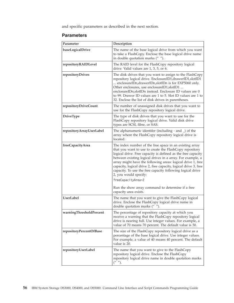
and specific parameters as described in the next section.
Parameters
Parameter Description
baseLogicalDrive The name of the base logical drive from which you wantto take a FlashCopy. Enclose the base logical drive namein double quotation marks (“ ”).
repositoryRAIDLevel The RAID level for the FlashCopy repository logicaldrive. Valid values are 1, 3, 5, or 6.
repositoryDrives The disk drives that you want to assign to the FlashCopyrepository logical drive. EnclosureID1,drawerID1,slotID1... enclosureIDn,drawerIDn,slotIDn is for EXP5060 only.Other enclosures, use enclosureID1,slotID1 ...enclosureIDn,slotIDn instead. Enclosure ID values are 0to 99. Drawer ID values are 1 to 5. Slot ID values are 1 to32. Enclose the list of disk drives in parentheses.
repositoryDriveCount The number of unassigned disk drives that you want touse for the FlashCopy repository logical drive.
DriveType The type of disk drives that you want to use for theFlashCopy repository logical drive. Valid disk drivetypes are SCSI, fibre, or SAS.
repositoryArrayUserLabel The alphanumeric identifer (including - and _) of thearray where the FlashCopy repository logical drive islocated.
freeCapacityArea The index number of the free space in an existing arraythat you want to use to create the FlashCopy repositorylogical drive. Free capacity is defined as the free capacitybetween existing logical drives in a array. For example, aarray might have the following areas: logical drive 1, freecapacity, logical drive 2, free capacity, logical drive 3, freecapacity. To use the free capacity following logical drive2, you would specify:
freeCapacityArea=2
Run the show array command to determine if a freecapacity area exists.
UserLabel The name that you want to give the FlashCopy logicaldrive. Enclose the FlashCopy logical drive name indouble quotation marks (“ ”).
warningThresholdPercent The percentage of repository capacity at which youreceive a warning that the FlashCopy repository logicaldrive is nearing full. Use integer values. For example, avalue of 70 means 70 percent. The default value is 50.
repositoryPercentOfBase The size of the FlashCopy repository logical drive as apercentage of the base logical drive. Use integer values.For example, a value of 40 means 40 percent. The defaultvalue is 20.
repositoryUserLabel The name that you want to give to the FlashCopyrepository logical drive. Enclose the FlashCopyrepository logical drive name in double quotation marks(“ ”).
56 IBM System Storage DS3000, DS4000, and DS5000: Command Line Interface and Script Commands Programming Guide
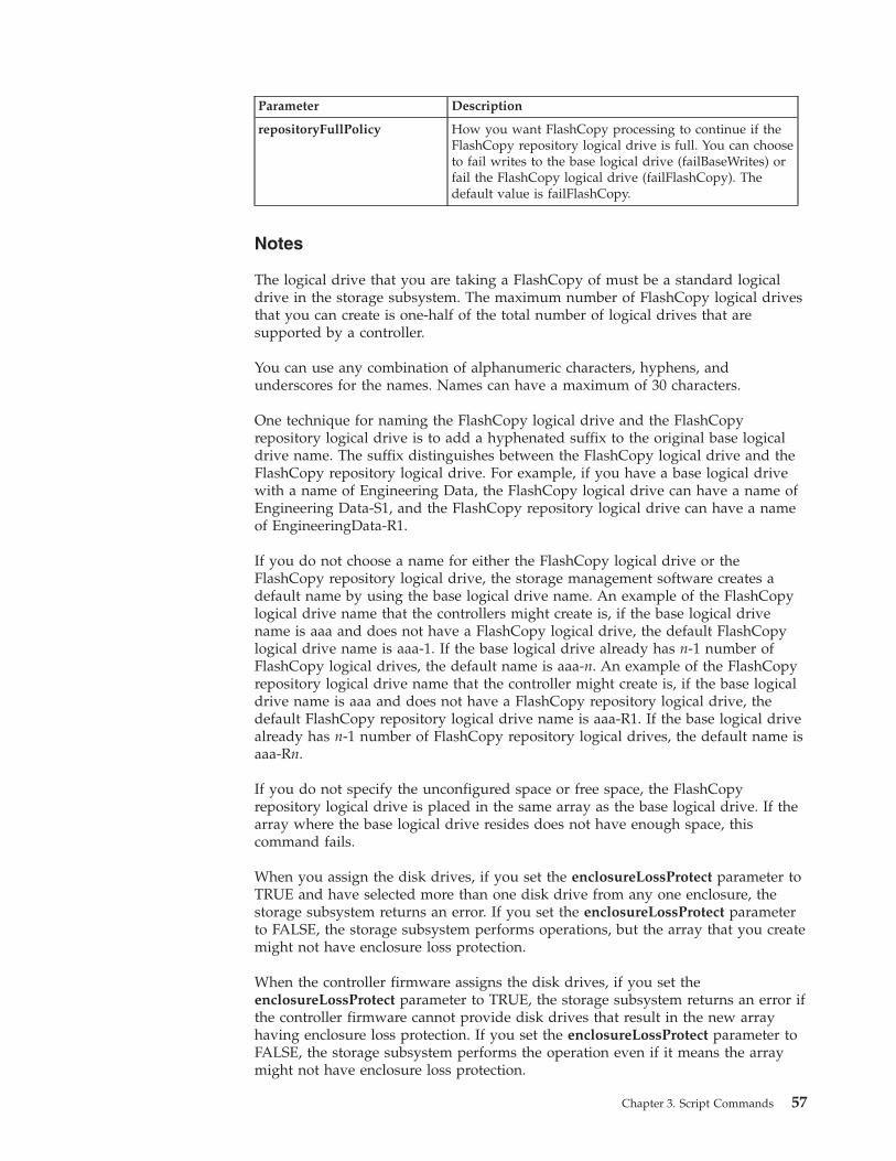
Parameter Description
repositoryFullPolicy How you want FlashCopy processing to continue if theFlashCopy repository logical drive is full. You can chooseto fail writes to the base logical drive (failBaseWrites) orfail the FlashCopy logical drive (failFlashCopy). Thedefault value is failFlashCopy.
Notes
The logical drive that you are taking a FlashCopy of must be a standard logicaldrive in the storage subsystem. The maximum number of FlashCopy logical drivesthat you can create is one-half of the total number of logical drives that aresupported by a controller.
You can use any combination of alphanumeric characters, hyphens, andunderscores for the names. Names can have a maximum of 30 characters.
One technique for naming the FlashCopy logical drive and the FlashCopyrepository logical drive is to add a hyphenated suffix to the original base logicaldrive name. The suffix distinguishes between the FlashCopy logical drive and theFlashCopy repository logical drive. For example, if you have a base logical drivewith a name of Engineering Data, the FlashCopy logical drive can have a name ofEngineering Data-S1, and the FlashCopy repository logical drive can have a nameof EngineeringData-R1.
If you do not choose a name for either the FlashCopy logical drive or theFlashCopy repository logical drive, the storage management software creates adefault name by using the base logical drive name. An example of the FlashCopylogical drive name that the controllers might create is, if the base logical drivename is aaa and does not have a FlashCopy logical drive, the default FlashCopylogical drive name is aaa-1. If the base logical drive already has n-1 number ofFlashCopy logical drives, the default name is aaa-n. An example of the FlashCopyrepository logical drive name that the controller might create is, if the base logicaldrive name is aaa and does not have a FlashCopy repository logical drive, thedefault FlashCopy repository logical drive name is aaa-R1. If the base logical drivealready has n-1 number of FlashCopy repository logical drives, the default name isaaa-Rn.
If you do not specify the unconfigured space or free space, the FlashCopyrepository logical drive is placed in the same array as the base logical drive. If thearray where the base logical drive resides does not have enough space, thiscommand fails.
When you assign the disk drives, if you set the enclosureLossProtect parameter toTRUE and have selected more than one disk drive from any one enclosure, thestorage subsystem returns an error. If you set the enclosureLossProtect parameterto FALSE, the storage subsystem performs operations, but the array that you createmight not have enclosure loss protection.
When the controller firmware assigns the disk drives, if you set theenclosureLossProtect parameter to TRUE, the storage subsystem returns an error ifthe controller firmware cannot provide disk drives that result in the new arrayhaving enclosure loss protection. If you set the enclosureLossProtect parameter toFALSE, the storage subsystem performs the operation even if it means the arraymight not have enclosure loss protection.
Chapter 3. Script Commands 57
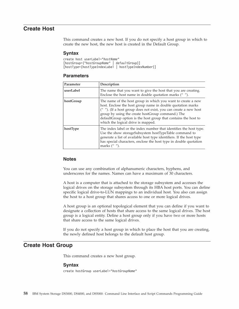
Create Host
This command creates a new host. If you do not specify a host group in which tocreate the new host, the new host is created in the Default Group.
Syntaxcreate host userLabel=”hostName”[hostGroup=(“hostGroupName” | defaultGroup)][hostType=(hostTypeIndexLabel | hostTypeIndexNumber)]
Parameters
Parameter Description
userLabel The name that you want to give the host that you are creating.Enclose the host name in double quotation marks (“ ”).
hostGroup The name of the host group in which you want to create a newhost. Enclose the host group name in double quotation marks(“ ”). (If a host group does not exist, you can create a new hostgroup by using the create hostGroup command.) ThedefaultGroup option is the host group that contains the host towhich the logical drive is mapped.
hostType The index label or the index number that identifies the host type.Use the show storageSubsystem hostTypeTable command togenerate a list of available host type identifiers. If the host typehas special characters, enclose the host type in double quotationmarks (“ ”).
Notes
You can use any combination of alphanumeric characters, hyphens, andunderscores for the names. Names can have a maximum of 30 characters.
A host is a computer that is attached to the storage subsystem and accesses thelogical drives on the storage subsystem through its HBA host ports. You can definespecific logical drive-to-LUN mappings to an individual host. You also can assignthe host to a host group that shares access to one or more logical drives.
A host group is an optional topological element that you can define if you want todesignate a collection of hosts that share access to the same logical drives. The hostgroup is a logical entity. Define a host group only if you have two or more hoststhat share access to the same logical drives.
If you do not specify a host group in which to place the host that you are creating,the newly defined host belongs to the default host group.
Create Host Group
This command creates a new host group.
Syntaxcreate hostGroup userLabel=”hostGroupName”
58 IBM System Storage DS3000, DS4000, and DS5000: Command Line Interface and Script Commands Programming Guide
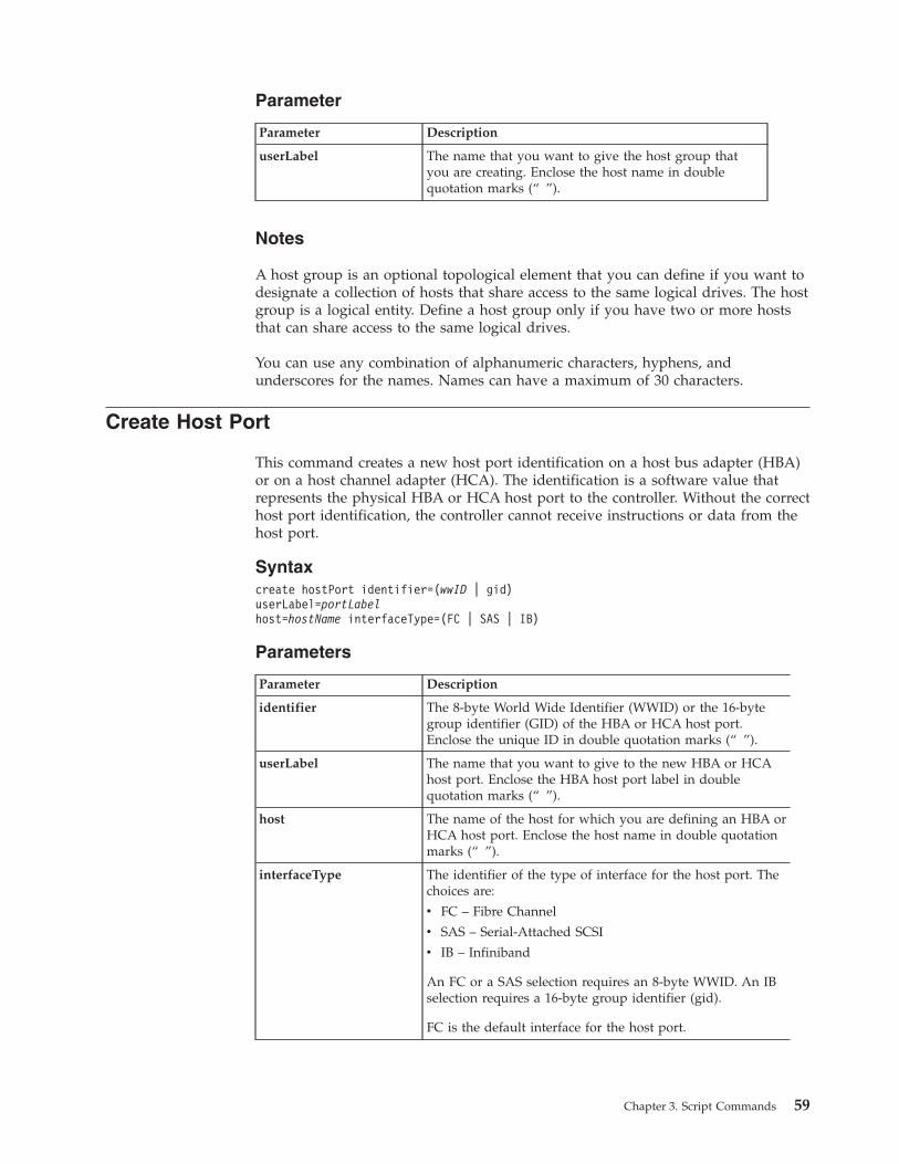
Parameter
Parameter Description
userLabel The name that you want to give the host group thatyou are creating. Enclose the host name in doublequotation marks (“ ”).
Notes
A host group is an optional topological element that you can define if you want todesignate a collection of hosts that share access to the same logical drives. The hostgroup is a logical entity. Define a host group only if you have two or more hoststhat can share access to the same logical drives.
You can use any combination of alphanumeric characters, hyphens, andunderscores for the names. Names can have a maximum of 30 characters.
Create Host Port
This command creates a new host port identification on a host bus adapter (HBA)or on a host channel adapter (HCA). The identification is a software value thatrepresents the physical HBA or HCA host port to the controller. Without the correcthost port identification, the controller cannot receive instructions or data from thehost port.
Syntaxcreate hostPort identifier=(wwID | gid)userLabel=portLabelhost=hostName interfaceType=(FC | SAS | IB)
Parameters
Parameter Description
identifier The 8-byte World Wide Identifier (WWID) or the 16-bytegroup identifier (GID) of the HBA or HCA host port.Enclose the unique ID in double quotation marks (“ ”).
userLabel The name that you want to give to the new HBA or HCAhost port. Enclose the HBA host port label in doublequotation marks (“ ”).
host The name of the host for which you are defining an HBA orHCA host port. Enclose the host name in double quotationmarks (“ ”).
interfaceType The identifier of the type of interface for the host port. Thechoices are:
v FC – Fibre Channel
v SAS – Serial-Attached SCSI
v IB – Infiniband
An FC or a SAS selection requires an 8-byte WWID. An IBselection requires a 16-byte group identifier (gid).
FC is the default interface for the host port.
Chapter 3. Script Commands 59
Notes
An HBA or HCA host port is a physical connection on a host adapter that resideswithin a host computer. An HBA or HCA host port provides access to the logicaldrives in a storage subsystem. If the host bus adapter has only one physicalconnection (one host port), the terms host port and host bus adapter aresynonymous.
You can use any combination of alphanumeric characters, hyphens, andunderscores for the names. Host names can have a maximum of 30 characters.
Create iSCSI Initiator
This command creates a new iSCSI initiator object.
Syntaxcreate iscsiInitiator iscsiName=iSCSI-IDuserLabel=”name”host=host-name[chapSecret=securityKey]
Parameters
Parameters Description
iscsiName The default identifier of the iSCSI initiator. Enclose the name indouble quotation marks (“ ”).
userLabel The name that you want to use for the iSCSI initiator. Enclosethe name in double quotation marks (“ ”).
host The name of the host in which the iSCSI initiator is installed.Enclose the name in double quotation marks (“ ”).
chapSecret The security key that you want to use to authenticate a peerconnection. Enclose the name in double quotation marks (“ ”).
Notes
Challenge Handshake Authentication Protocol (CHAP) is a protocol thatauthenticates the peer of a connection. CHAP is based upon the peers sharing a“secret.” A secret is a security key that is similar to a password.
Use the chapSecret parameter to set up the security keys for initiators that requirea mutual authentication.
Create RAID Logical Drive (Automatic Drive Select)This command creates a array across the disk drives in the storage subsystem, anda new logical drive in the array. The storage subsystem controllers choose the diskdrives to be included in the logical drive.
Syntax
Important: If you have disk drives with different capacities, you cannotautomatically create logical drives by specifying the driveCount parameter. If youwant to create logical drives with disk drives of different capacities, see “CreateRAID Logical Drive (Manual Drive Select)” on page 66.
60 IBM System Storage DS3000, DS4000, and DS5000: Command Line Interface and Script Commands Programming Guide
create logicalDrive driveCount=numberOfDrivesarrayUserLabel=arrayNameraidLevel=(0 | 1 | 3 | 5 | 6)userLabel=logicalDriveNameDriveType=(fibre | SATA | SAS)DriveMediaType=(HDD | SSD | unknown | allMedia)capacity=logicalDriveCapacityowner=(a | b)cacheReadPrefetch=(TRUE | FALSE)segmentSize=segmentSizeValueusageHint=(fileSystem | dataBase | multiMedia)enclosureLossProtect=(TRUE | FALSE)enclosureLossProtect=(TRUE | FALSE)drawerLossProtect=(TRUE | FALSE)dssPreAllocate=(TRUE | FALSE)]securityType=(none | capable | enabled)]
Parameters
Parameter Description
driveCount The number of unassigned disk drives that you want to use in thearray.
raidLevel The RAID level of the array that contains the logical drive. Validvalues are 0, 1, 3, 5, or 6.
userLabel The name that you want to give to the new logical drivev . Enclosethe new logical drive name in double quotation marks (“ ”).
driveType The type of disk drive that you want to use in the logical drive.You cannot mix disk drive types. Valid disk drive types are fibre,SATA, or SAS.
DriveMediaType The type of disk drive medium that you want to use for the createRAID logical drive. Values are
v HDD – Use this option when you have hard disk drives in theexpansion drawer.
v SSD – Use this option when you have solid state disk drives inthe expansion drawer.
v unknown – Use if you are not sure what types of disk drivemedia are in the expansion drawer.
v allMedia – Use this option when you want to use all types ofdisk drive media that are in the expansion drawer.
Use this parameter only when you use the DriveCount parameter.If you have only one type of disk drive media, you do not need touse this parameter. You must use this parameter when you havemore than one type of disk drive media in your storage subsystem.
capacity The size of the logical drive that you are adding to the storagesubsystem. Size is defined in units of bytes, KB, MB, GB, or TB.
owner The controller that owns the logical drive. Valid controlleridentifiers are a or b, where a is the controller in slot A, and b isthe controller in slot B. If you do not specify an owner, thecontroller firmware determines the owner.
cacheReadPrefetch The setting to turn on or turn off cache read prefetch. To turn offcache read prefetch, set this parameter to FALSE. To turn on cacheread prefetch, set this parameter to TRUE.
segmentSize The amount of data (in KB) that the controller writes on a singledisk drive in a logical drive before writing data on the next diskdrive. Valid values are 8, 16, 32, 64, 128, 256, or 512.
Chapter 3. Script Commands 61
Parameter Description
usageHint The setting for both cacheReadPrefetch parameter and thesegmentSize parameter to be default values. The default values arebased on the typical I/O usage pattern of the application that isusing the logical drive. Valid values are fileSystem, dataBase, ormultiMedia.
enclosureLossProtect The setting to enforce enclosure loss protection when you createthe array. To enforce enclosure loss protection, set this parameter toTRUE. The default setting is FALSE.
dssPreAllocate The setting to make sure that reserve capacity is allocated forfuture segment size increases. The default value is TRUE.
securityType The setting to specify the security level when creating the arraysand all associated logical drives. These settings are valid:
v none—The array and logical drives are not secure.
v capable—The arrays and logical drives are capable of havingsecurity set, but security has not been enabled.
v enabled—The array and logical drives have security enabled.
Notes
The driveCount parameter lets you choose the number of disk drives that youwant to use in the array. You do not need to specify the disk drives by enclosureID and slot ID. The controllers choose the specific disk drives to use for the array.
The owner parameter defines which controller owns the logical drive.
If you do not specify a capacity using the capacity parameter, all of the disk drivecapacity that is available in the array is used. If you do not specify capacity units,bytes is used as the default value.
Cache Read Prefetch
Cache read prefetch lets the controller copy additional data blocks into cache whilethe controller reads and copies data blocks that are requested by the host from thedisk drives into cache. This action increases the chance that a future request fordata can be fulfilled from cache. Cache read prefetch is important for multimediaapplications that use sequential data transfers. The configuration settings for thestorage subsystem that you use determine the number of additional data blocksthat the controller reads into cache. Valid values for the cacheReadPrefetchparameter are TRUE or FALSE.
Segment Size
The size of a segment determines how many data blocks that the controller writeson a single disk drive in a logical drive before writing data on the next disk drive.Each data block stores 512 bytes of data. A data block is the smallest unit ofstorage. The size of a segment determines how many data blocks that it contains.For example, an 8-KB segment holds 16 data blocks. A 64-KB segment holds 128data blocks.
When you enter a value for the segment size, the value is checked against thesupported values that are provided by the controller at run time. If the value that
62 IBM System Storage DS3000, DS4000, and DS5000: Command Line Interface and Script Commands Programming Guide
you entered is not valid, the controller returns a list of valid values. Using a singledisk drive for a single request leaves other disk drives available to simultaneouslyservice other requests.
If the logical drive is in an environment where a single user is transferring largeunits of data (such as multimedia), performance is maximized when a single datatransfer request is serviced with a single data stripe. (A data stripe is the segmentsize that is multiplied by the number of disk drives in the array that are used fordata transfers.) In this case, multiple disk drives are used for the same request, buteach disk drive is accessed only once.
For optimal performance in a multiuser database or file system storageenvironment, set your segment size to minimize the number of disk drives that arerequired to satisfy a data transfer request.
You do not need to enter a value for the cacheReadPrefetch parameter or thesegmentSize parameter. If you do not enter a value, the controller firmware usesthe usageHint parameter with fileSystem as the default value. Entering a value forthe usageHint parameter and a value for the cacheReadPrefetch parameter or avalue for the segmentSize parameter does not cause an error. The value that youenter for the cacheReadPrefetch parameter or the segmentSize parameter takespriority over the value for the usageHint parameter.
Enclosure Loss Protection
For enclosure loss protection to work, each disk drive in a array must be on aseparate enclosure. If you set the enclosureLossProtect parameter to TRUE andhave selected more than one disk drive from any one enclosure, the storagesubsystem returns an error. If you set the enclosureLossProtect parameter toFALSE, the storage subsystem performs operations, but the array that you createmight not have enclosure loss protection.
enclosure loss protection is not valid when you create logical drives on existingarrays.
Security Type
See “Security Type” on page 214 for an explanation of this new parameter.
Create RAID Logical Drive (Free Capacity Base Select)
This command creates a logical drive in the free space of an array.
Syntaxcreate logicalDrive array=arrayNumberuserLabel=”logicalDriveName”owner=(a | b)[freeCapacityArea=freeCapacityIndexNumbercapacity=logicalDriveCapacitycacheReadPrefetch=(TRUE | FALSE)segmentSize=segmentSizeValueusageHint=(fileSystem | dataBase | multiMedia)dssPreAllocate=(TRUE | FALSE)securityType=(none | capable | enabled)]
Chapter 3. Script Commands 63
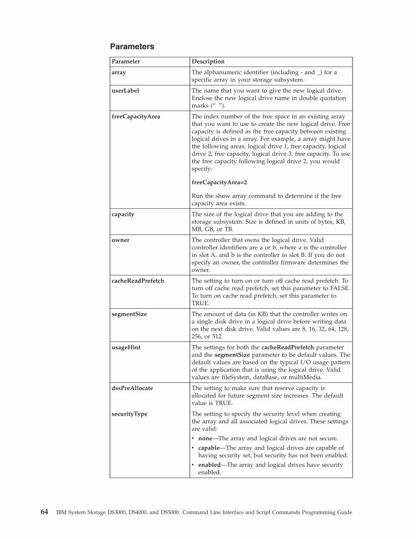
Parameters
Parameter Description
array The alphanumeric identifier (including - and _) for aspecific array in your storage subsystem.
userLabel The name that you want to give the new logical drive.Enclose the new logical drive name in double quotationmarks (“ ”).
freeCapacityArea The index number of the free space in an existing arraythat you want to use to create the new logical drive. Freecapacity is defined as the free capacity between existinglogical drives in a array. For example, a array might havethe following areas: logical drive 1, free capacity, logicaldrive 2, free capacity, logical drive 3, free capacity. To usethe free capacity following logical drive 2, you wouldspecify:
freeCapacityArea=2
Run the show array command to determine if the freecapacity area exists.
capacity The size of the logical drive that you are adding to thestorage subsystem. Size is defined in units of bytes, KB,MB, GB, or TB.
owner The controller that owns the logical drive. Validcontroller identifiers are a or b, where a is the controllerin slot A, and b is the controller in slot B. If you do notspecify an owner, the controller firmware determines theowner.
cacheReadPrefetch The setting to turn on or turn off cache read prefetch. Toturn off cache read prefetch, set this parameter to FALSE.To turn on cache read prefetch, set this parameter toTRUE.
segmentSize The amount of data (in KB) that the controller writes ona single disk drive in a logical drive before writing dataon the next disk drive. Valid values are 8, 16, 32, 64, 128,256, or 512.
usageHint The settings for both the cacheReadPrefetch parameterand the segmentSize parameter to be default values. Thedefault values are based on the typical I/O usage patternof the application that is using the logical drive. Validvalues are fileSystem, dataBase, or multiMedia.
dssPreAllocate The setting to make sure that reserve capacity isallocated for future segment size increases. The defaultvalue is TRUE.
securityType The setting to specify the security level when creatingthe array and all associated logical drives. These settingsare valid:
v none—The array and logical drives are not secure.
v capable—The array and logical drives are capable ofhaving security set, but security has not been enabled.
v enabled—The array and logical drives have securityenabled.
64 IBM System Storage DS3000, DS4000, and DS5000: Command Line Interface and Script Commands Programming Guide
Notes
You can use any combination of alphanumeric characters, hyphens, andunderscores for the names. Names can have a maximum of 30 characters.
The owner parameter defines which controller owns the logical drive. Thepreferred controller ownership of a logical drive is the controller that currentlyowns the array.
If you do not specify a capacity using the capacity parameter, all of the availablecapacity in the free capacity area of the array is used. If you do not specifycapacity units, bytes is used as the default value.
Segment Size
The size of a segment determines how many data blocks that the controller writeson a single disk drive in a logical drive before writing data on the next disk drive.Each data block stores 512 bytes of data. A data block is the smallest unit ofstorage. The size of a segment determines how many data blocks that it contains.For example, an 8-KB segment holds 16 data blocks. A 64-KB segment holds 128data blocks.
When you enter a value for the segment size, the value is checked against thesupported values that are provided by the controller at run time. If the value thatyou entered is not valid, the controller returns a list of valid values. Using a singledisk drive for a single request leaves other disk drives available to simultaneouslyservice other requests.
If the logical drive is in an environment where a single user is transferring largeunits of data (such as multimedia), performance is maximized when a single datatransfer request is serviced with a single data stripe. (A data stripe is the segmentsize that is multiplied by the number of disk drives in the array that are used fordata transfers.) In this case, multiple disk drives are used for the same request, buteach disk drive is accessed only once.
For optimal performance in a multiuser database or file system storageenvironment, set your segment size to minimize the number of disk drives that arerequired to satisfy a data transfer request.
Cache Read Prefetch
Cache read prefetch lets the controller copy additional data blocks into cache whilethe controller reads and copies data blocks that are requested by the host from thedisk drives into cache. This action increases the chance that a future request fordata can be fulfilled from cache. Cache read prefetch is important for multimediaapplications that use sequential data transfers. The configuration settings for thestorage subsystem that you use determine the number of additional data blocksthat the controller reads into cache. Valid values for the cacheReadPrefetchparameter are TRUE or FALSE. You do not need to enter a value for thecacheReadPrefetch parameter or the segmentSize parameter. If you do not enter avalue, the controller firmware uses the usageHint parameter with fileSystem as thedefault value.
Entering a value for the usageHint parameter and a value for thecacheReadPrefetch parameter or a value for the segmentSize parameter does notcause an error. The value that you enter for the cacheReadPrefetch parameter or
Chapter 3. Script Commands 65
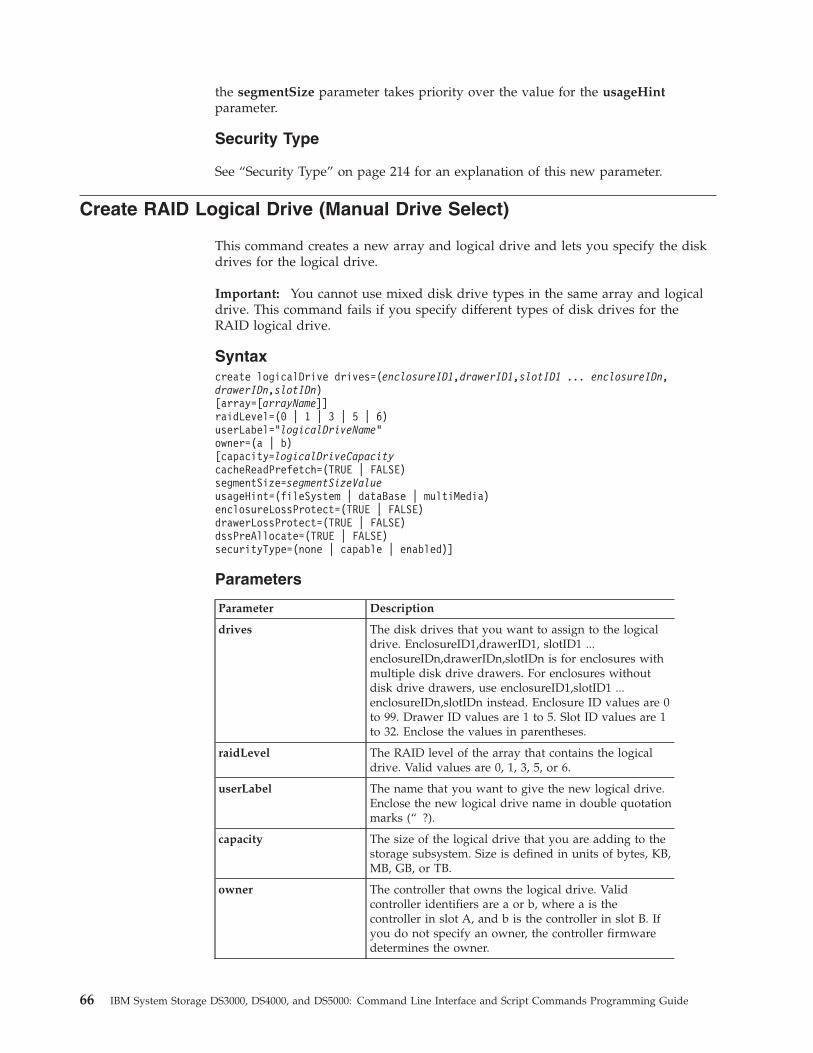
the segmentSize parameter takes priority over the value for the usageHintparameter.
Security Type
See “Security Type” on page 214 for an explanation of this new parameter.
Create RAID Logical Drive (Manual Drive Select)
This command creates a new array and logical drive and lets you specify the diskdrives for the logical drive.
Important: You cannot use mixed disk drive types in the same array and logicaldrive. This command fails if you specify different types of disk drives for theRAID logical drive.
Syntaxcreate logicalDrive drives=(enclosureID1,drawerID1,slotID1 ... enclosureIDn,drawerIDn,slotIDn)[array=[arrayName]]raidLevel=(0 | 1 | 3 | 5 | 6)userLabel="logicalDriveName"owner=(a | b)[capacity=logicalDriveCapacitycacheReadPrefetch=(TRUE | FALSE)segmentSize=segmentSizeValueusageHint=(fileSystem | dataBase | multiMedia)enclosureLossProtect=(TRUE | FALSE)drawerLossProtect=(TRUE | FALSE)dssPreAllocate=(TRUE | FALSE)securityType=(none | capable | enabled)]
Parameters
Parameter Description
drives The disk drives that you want to assign to the logicaldrive. EnclosureID1,drawerID1, slotID1 ...enclosureIDn,drawerIDn,slotIDn is for enclosures withmultiple disk drive drawers. For enclosures withoutdisk drive drawers, use enclosureID1,slotID1 ...enclosureIDn,slotIDn instead. Enclosure ID values are 0to 99. Drawer ID values are 1 to 5. Slot ID values are 1to 32. Enclose the values in parentheses.
raidLevel The RAID level of the array that contains the logicaldrive. Valid values are 0, 1, 3, 5, or 6.
userLabel The name that you want to give the new logical drive.Enclose the new logical drive name in double quotationmarks (“ ?).
capacity The size of the logical drive that you are adding to thestorage subsystem. Size is defined in units of bytes, KB,MB, GB, or TB.
owner The controller that owns the logical drive. Validcontroller identifiers are a or b, where a is thecontroller in slot A, and b is the controller in slot B. Ifyou do not specify an owner, the controller firmwaredetermines the owner.
66 IBM System Storage DS3000, DS4000, and DS5000: Command Line Interface and Script Commands Programming Guide
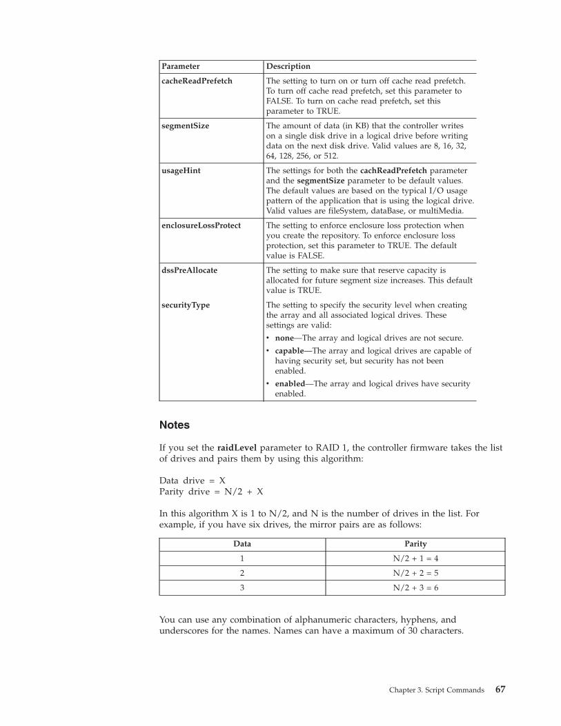
Parameter Description
cacheReadPrefetch The setting to turn on or turn off cache read prefetch.To turn off cache read prefetch, set this parameter toFALSE. To turn on cache read prefetch, set thisparameter to TRUE.
segmentSize The amount of data (in KB) that the controller writeson a single disk drive in a logical drive before writingdata on the next disk drive. Valid values are 8, 16, 32,64, 128, 256, or 512.
usageHint The settings for both the cachReadPrefetch parameterand the segmentSize parameter to be default values.The default values are based on the typical I/O usagepattern of the application that is using the logical drive.Valid values are fileSystem, dataBase, or multiMedia.
enclosureLossProtect The setting to enforce enclosure loss protection whenyou create the repository. To enforce enclosure lossprotection, set this parameter to TRUE. The defaultvalue is FALSE.
dssPreAllocate The setting to make sure that reserve capacity isallocated for future segment size increases. This defaultvalue is TRUE.
securityType The setting to specify the security level when creatingthe array and all associated logical drives. Thesesettings are valid:
v none—The array and logical drives are not secure.
v capable—The array and logical drives are capable ofhaving security set, but security has not beenenabled.
v enabled—The array and logical drives have securityenabled.
Notes
If you set the raidLevel parameter to RAID 1, the controller firmware takes the listof drives and pairs them by using this algorithm:
Data drive = XParity drive = N/2 + X
In this algorithm X is 1 to N/2, and N is the number of drives in the list. Forexample, if you have six drives, the mirror pairs are as follows:
Data Parity
1 N/2 + 1 = 4
2 N/2 + 2 = 5
3 N/2 + 3 = 6
You can use any combination of alphanumeric characters, hyphens, andunderscores for the names. Names can have a maximum of 30 characters.
Chapter 3. Script Commands 67
The owner parameter defines which controller owns the logical drive. Thepreferred controller ownership of a logical drive is the controller that currentlyowns the array.
If you do not specify a capacity using the capacity parameter, all of the disk drivecapacity that is available in the array is used. If you do not specify capacity units,bytes is used as the default value.
Segment Size
The size of a segment determines how many data blocks that the controller writeson a single disk drive in a logical drive before writing data on the next disk drive.Each data block stores 512 bytes of data. A data block is the smallest unit ofstorage. The size of a segment determines how many data blocks that it contains.For example, an 8-KB segment holds 16 data blocks. A 64-KB segment holds 128data blocks.
When you enter a value for the segment size, the value is checked against thesupported values that are provided by the controller at run time. If the value thatyou entered is not valid, the controller returns a list of valid values. Using a singledisk drive for a single request leaves other disk drives available to simultaneouslyservice other requests.
If the logical drive is in an environment where a single user is transferring largeunits of data (such as multimedia), performance is maximized when a single datatransfer request is serviced with a single data stripe. (A data stripe is the segmentsize that is multiplied by the number of disk drives in the array that are used fordata transfers.) In this case, multiple disk drives are used for the same request, buteach disk drive is accessed only once.
For optimal performance in a multiuser database or file system storageenvironment, set your segment size to minimize the number of disk drives that arerequired to satisfy a data transfer request.
Cache Read Prefetch
Cache read prefetch lets the controller copy additional data blocks into cache whilethe controller reads and copies data blocks that are requested by the host from thedisk drive into cache. This action increases the chance that a future request for datacan be fulfilled from cache. Cache read prefetch is important for multimediaapplications that use sequential data transfers. The configuration settings for thestorage subsystem that you use determine the number of additional data blocksthat the controller reads into cache. Valid values for the cacheReadPrefetchparameter are TRUE or FALSE.
You do not need to enter a value for the cacheReadPrefetch parameter or thesegmentSize parameter. If you do not enter a value, the controller firmware usesthe usageHint parameter with fileSystem as the default value. Entering a value forthe usageHint parameter and a value for the cacheReadPrefetch parameter or avalue for the segmentSize parameter does not cause an error. The value that youenter for the cacheReadPrefetch parameter or the segmentSize parameter takespriority over the value for the usageHint parameter.
For enclosure loss protection to work, each disk drive in a array must be on aseparate enclosure. If you set the enclosureLossProtect parameter to TRUE andhave selected more than one disk drive from any one enclosure, the storage
68 IBM System Storage DS3000, DS4000, and DS5000: Command Line Interface and Script Commands Programming Guide
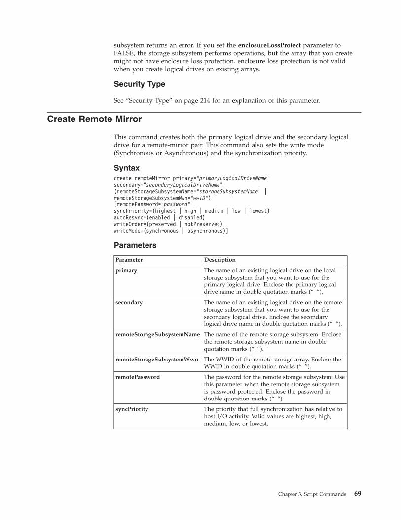
subsystem returns an error. If you set the enclosureLossProtect parameter toFALSE, the storage subsystem performs operations, but the array that you createmight not have enclosure loss protection. enclosure loss protection is not validwhen you create logical drives on existing arrays.
Security Type
See “Security Type” on page 214 for an explanation of this parameter.
Create Remote Mirror
This command creates both the primary logical drive and the secondary logicaldrive for a remote-mirror pair. This command also sets the write mode(Synchronous or Asynchronous) and the synchronization priority.
Syntaxcreate remoteMirror primary=”primaryLogicalDriveName”secondary=”secondaryLogicalDriveName”(remoteStorageSubsystemName=”storageSubsystemName” |remoteStorageSubsystemWwn=”wwID”)[remotePassword=”password”syncPriority=(highest | high | medium | low | lowest)autoResync=(enabled | disabled)writeOrder=(preserved | notPreserved)writeMode=(synchronous | asynchronous)]
Parameters
Parameter Description
primary The name of an existing logical drive on the localstorage subsystem that you want to use for theprimary logical drive. Enclose the primary logicaldrive name in double quotation marks (“ ”).
secondary The name of an existing logical drive on the remotestorage subsystem that you want to use for thesecondary logical drive. Enclose the secondarylogical drive name in double quotation marks (“ ”).
remoteStorageSubsystemName The name of the remote storage subsystem. Enclosethe remote storage subsystem name in doublequotation marks (“ ”).
remoteStorageSubsystemWwn The WWID of the remote storage array. Enclose theWWID in double quotation marks (“ ”).
remotePassword The password for the remote storage subsystem. Usethis parameter when the remote storage subsystemis password protected. Enclose the password indouble quotation marks (“ ”).
syncPriority The priority that full synchronization has relative tohost I/O activity. Valid values are highest, high,medium, low, or lowest.
Chapter 3. Script Commands 69
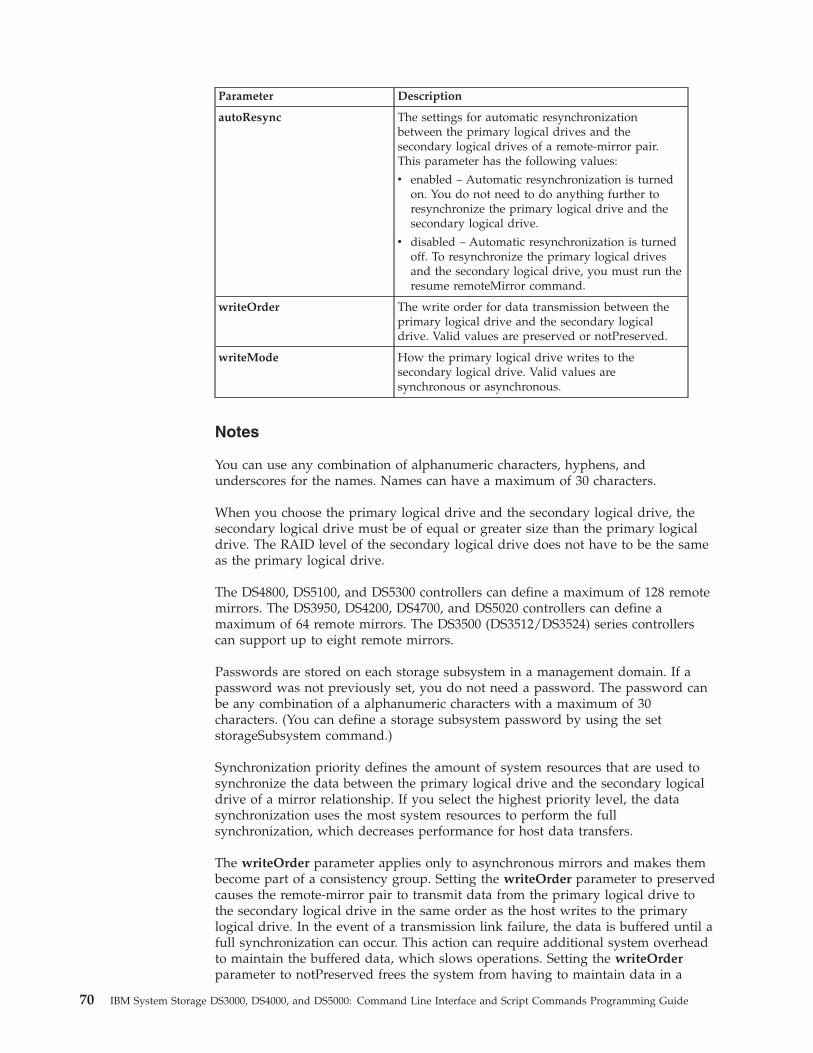
Parameter Description
autoResync The settings for automatic resynchronizationbetween the primary logical drives and thesecondary logical drives of a remote-mirror pair.This parameter has the following values:
v enabled – Automatic resynchronization is turnedon. You do not need to do anything further toresynchronize the primary logical drive and thesecondary logical drive.
v disabled – Automatic resynchronization is turnedoff. To resynchronize the primary logical drivesand the secondary logical drive, you must run theresume remoteMirror command.
writeOrder The write order for data transmission between theprimary logical drive and the secondary logicaldrive. Valid values are preserved or notPreserved.
writeMode How the primary logical drive writes to thesecondary logical drive. Valid values aresynchronous or asynchronous.
Notes
You can use any combination of alphanumeric characters, hyphens, andunderscores for the names. Names can have a maximum of 30 characters.
When you choose the primary logical drive and the secondary logical drive, thesecondary logical drive must be of equal or greater size than the primary logicaldrive. The RAID level of the secondary logical drive does not have to be the sameas the primary logical drive.
The DS4800, DS5100, and DS5300 controllers can define a maximum of 128 remotemirrors. The DS3950, DS4200, DS4700, and DS5020 controllers can define amaximum of 64 remote mirrors. The DS3500 (DS3512/DS3524) series controllerscan support up to eight remote mirrors.
Passwords are stored on each storage subsystem in a management domain. If apassword was not previously set, you do not need a password. The password canbe any combination of a alphanumeric characters with a maximum of 30characters. (You can define a storage subsystem password by using the setstorageSubsystem command.)
Synchronization priority defines the amount of system resources that are used tosynchronize the data between the primary logical drive and the secondary logicaldrive of a mirror relationship. If you select the highest priority level, the datasynchronization uses the most system resources to perform the fullsynchronization, which decreases performance for host data transfers.
The writeOrder parameter applies only to asynchronous mirrors and makes thembecome part of a consistency group. Setting the writeOrder parameter to preservedcauses the remote-mirror pair to transmit data from the primary logical drive tothe secondary logical drive in the same order as the host writes to the primarylogical drive. In the event of a transmission link failure, the data is buffered until afull synchronization can occur. This action can require additional system overheadto maintain the buffered data, which slows operations. Setting the writeOrderparameter to notPreserved frees the system from having to maintain data in a
70 IBM System Storage DS3000, DS4000, and DS5000: Command Line Interface and Script Commands Programming Guide
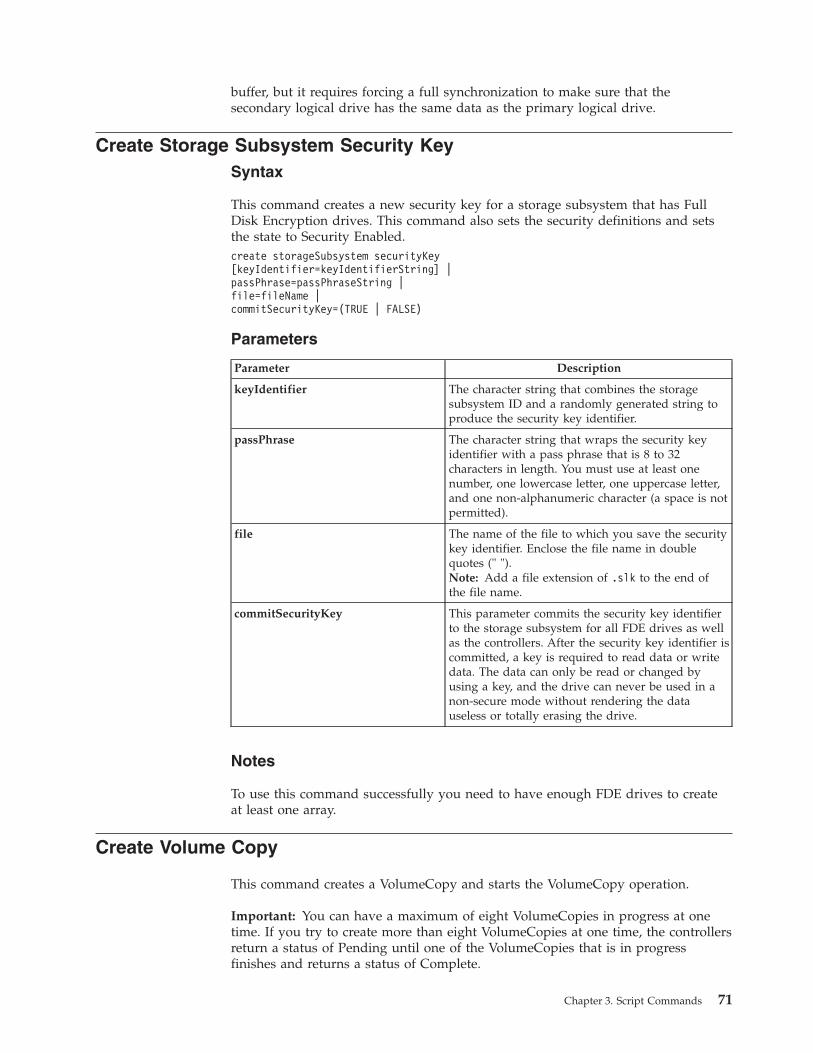
buffer, but it requires forcing a full synchronization to make sure that thesecondary logical drive has the same data as the primary logical drive.
Create Storage Subsystem Security KeySyntax
This command creates a new security key for a storage subsystem that has FullDisk Encryption drives. This command also sets the security definitions and setsthe state to Security Enabled.create storageSubsystem securityKey[keyIdentifier=keyIdentifierString] |passPhrase=passPhraseString |file=fileName |commitSecurityKey=(TRUE | FALSE)
Parameters
Parameter Description
keyIdentifier The character string that combines the storagesubsystem ID and a randomly generated string toproduce the security key identifier.
passPhrase The character string that wraps the security keyidentifier with a pass phrase that is 8 to 32characters in length. You must use at least onenumber, one lowercase letter, one uppercase letter,and one non-alphanumeric character (a space is notpermitted).
file The name of the file to which you save the securitykey identifier. Enclose the file name in doublequotes (" ").Note: Add a file extension of .slk to the end ofthe file name.
commitSecurityKey This parameter commits the security key identifierto the storage subsystem for all FDE drives as wellas the controllers. After the security key identifier iscommitted, a key is required to read data or writedata. The data can only be read or changed byusing a key, and the drive can never be used in anon-secure mode without rendering the datauseless or totally erasing the drive.
Notes
To use this command successfully you need to have enough FDE drives to createat least one array.
Create Volume Copy
This command creates a VolumeCopy and starts the VolumeCopy operation.
Important: You can have a maximum of eight VolumeCopies in progress at onetime. If you try to create more than eight VolumeCopies at one time, the controllersreturn a status of Pending until one of the VolumeCopies that is in progressfinishes and returns a status of Complete.
Chapter 3. Script Commands 71
Syntaxcreate volumeCopy source=”sourceName”target=”targetName”[copyPriority=(highest | high | medium | low | lowest)targetReadOnlyEnabled=(TRUE | FALSE)]
Parameters
Parameter Description
source The name of an existing logical drive that you want touse as the source logical drive. Enclose the sourcelogical drive name in double quotation marks (“ ”).
target The name of an existing logical drive that you want touse as the target logical drive. Enclose the target logicaldrive name in double quotation marks (“ ”).
copyPriority The priority that VolumeCopy has relative to host I/Oactivity. Valid values are highest, high, medium, low, orlowest.
targetReadOnlyEnabled The setting so that you can write to the target logicaldrive or only read from the target logical drive. Towrite to the target logical drive, set this parameter toFALSE. To prevent writing to the target logical drive,set this parameter to TRUE.
Notes
You can use any combination of alphanumeric characters, hyphens, andunderscores for the names. Names can have a maximum of 30 characters.
Copy priority defines the amount of system resources that are used to copy thedata between the source logical drive and the target logical drive of a VolumeCopypair. If you select the highest priority level, the VolumeCopy uses the most systemresources to perform VolumeCopy, which decreases performance for host datatransfers.
Deactivate Remote Mirror
This command deactivates the Enhanced Remote Mirroring feature, disassemblesthe mirror repository logical drive, and releases the controller-owner of thesecondary logical drive. The controller host port that is dedicated to the secondarylogical drive is available for host data transfers.
Syntaxdeactivate storageSubsystem feature=remoteMirror
Parameters
None.
72 IBM System Storage DS3000, DS4000, and DS5000: Command Line Interface and Script Commands Programming Guide
Delete Array
This command deletes an entire array and its associated logical drives.
Attention: Possible damage to the storage subsystem configuration – All of thedata in the array is lost as soon as you run this command.
Syntaxdelete array [arrayNumber]
Parameter
Parameter Description
array The alphanumeric identifier (including - and _) of thearray that you want to delete. Enclose the array identifierin square brackets ([ ]).
Delete Host
This command deletes a host.
Syntaxdelete host [hostName]
Delete Host Group
This command deletes a host group.
Attention:
Possible damage to the storage subsystem configuration – This command deletesall of the host definitions in the host group.
Syntaxdelete hostGroup [hostGroupName]
Parameter
Parameter Description
hostGroup The name of the host group that you want to delete.Enclose the host group name in square brackets ([ ]). If thehost group name has special characters, you also mustenclose the host group name in double quotation marks(“ ”).
Notes
A host group is an optional topological element that is a collection of hosts thatshare access to the same logical drives. The host group is a logical entity.
Chapter 3. Script Commands 73
Delete Host Port
This command deletes an HBA host port identification. The identification is asoftware value that represents the physical HBA host port to the controller. Bydeleting the identification, the controller no longer recognizes instructions and datafrom the HBA host port.
Syntaxdelete hostPort [hostPortName]
Parameter
Parameter Description
hostPort The name of the HBA host port that you want to delete.Enclose the name of the HBA host port in squarebrackets ([ ]).
Notes
An HBA host port is a physical connection on a host bus adapter that resideswithin a host computer. An HBA host port provides a host access to the logicaldrives in a storage subsystem. If the host bus adapter has only one physicalconnection (one host port), the terms HBA host port and host bus adapter aresynonymous.
Delete iSCSI Initiator
This command deletes a specific iSCSI initiator object.
Syntaxdelete iscsiInitiator (iSCSI-ID | name)
Parameters
Parameter Description
iSCSI-ID The identifier of the iSCSI initiator that you want to delete.Enclose the name in double quotation marks (“ ”).
name The name of the iSCSI initiator that you want to delete.Enclose the name in double quotation marks (“ ”).
Delete Logical Drive
This command deletes one or more standard logical drives, flashcopy logicaldrives, or flashcopy repository logical drives.
Attention: Possible damage to the storage subsystem configuration – All of thedata in the logical drive is lost as soon as you run this command.
Syntaxdelete (allLogicalDrives | logicalDrive [logicalDriveName] |logicalDrives [logicalDriveName1 ... logicalDriveNameN])removeArray=(TRUE | FALSE)
74 IBM System Storage DS3000, DS4000, and DS5000: Command Line Interface and Script Commands Programming Guide
Parameters
Parameter Description
allLogicalDrives This parameter deletes all of the logical drives in astorage subsystem.
logicalDrive orlogicalDrives
The name of the logical drive that you want to delete.You can enter more than one logical drive nameseparated by spaces. Enclose the logical drive name insquare brackets ([ ]). If the logical drive name hasspecial characters, you also must enclose the logicaldrive name in double quotation marks (“ ”).
removeArray Deleting the last logical drive in a array does not deletethe array. You can have a stand-alone array (minus anylogical drives). To remove the stand-alone array, set thisparameter to TRUE. To keep stand-alone arrays intact,set this parameter to FALSE.
Notes
When you use the allLogicalDrives parameter, this command deletes logical drivesuntil all of the logical drives are removed or until an error is encountered. If anerror is encountered, this command does not try to delete the remaining logicaldrives. Deleting logical drives from different arrays is possible. All of the arraysthat become empty are deleted if you set the removeArray parameter to TRUE.
If you want to delete an entire array, you can also use the delete array command.
Diagnose Controller
This command runs diagnostic tests on the controller. The diagnostic tests consistof loopback tests in which data is written to the disk drives and read from the diskdrives.
Syntaxdiagnose controller [(a | b)]loopbackDriveChannel=(allchannels | (1 | 2 | 3 | 4 | 5 | 6 | 7 | 8))testID=(1 | 2 | 3 | discreteLines)[patternFile=”filename”]
Parameters
Parameter Description
controller The controller on which you want to run thediagnostic tests. Valid controller identifiers are a orb, where a is the controller in slot A, and b is thecontroller in slot B. Enclose the controller identifierin square brackets ([ ]). If you do not specify acontroller, the storage management software returnsa syntax error.
loopbackDriveChannel The disk drive channels on which you want to runthe diagnostic tests. You can either choose to runthe diagnostics on all channels or select a specificchannel on which to run diagnostics. If you select aspecific channel, valid values for the disk drivechannels are 1, 2, 3, or 4.
Chapter 3. Script Commands 75
Parameter Description
testID The identifier for the diagnostic test you want torun. The identifier and corresponding tests are asfollows:
v 1 – Read test
v 2 – Write test
v 3 – Data loop-back test
v discreteLines – Discrete lines diagnostic test
patternFile The name of a file that contains a data pattern thatyou want to use as test data. Enclose the file nameof the data pattern in double quotation marks (“ ”).
Notes
When you run a data loop-back test, you can optionally specify a file that containsa data pattern. If you do not specify a file, the controller firmware provides adefault pattern.
Discrete lines are control lines and status lines that are connected between twocontrollers in a controller module. The discrete lines diagnostic test lets eachcontroller check that control signal transitions can be observed at the control inputsof the alternate controller. The discrete lines diagnostic test automatically runs aftereach power-cycle or each controller-reset. You can run the discrete lines diagnostictest after you have replaced a component that failed the initial discrete linesdiagnostic test. This test applies only to the DS5100, DS5300, and DS4800 (models82, 84, and 88) series controller modules. The discrete lines diagnostic test returnsone of the following messages:v When the discrete lines diagnostic test runs successfully, this message appears:
The controller discrete lines successfully passed the diagnostictest. No failures were detected.
v If the discrete lines diagnostic test fails, this message appears:One or more controller discrete lines failed the diagnostic test.
v If the CLI cannot run the discrete lines diagnostic test, the CLI returns Error 270,which means that the discrete lines diagnostic test could not start nor complete.
v The discrete lines diagnostic test is not functioning in SM release version10.60.x5.11. Check the SM release readme files for information.
Diagnose Remote Mirror
This command tests the connection between the specified primary logical drivesand the mirror logical drives on a storage subsystem with the Enhanced RemoteMirroring feature enabled.
Syntaxdiagnose remoteMirror (primary [primarylogicalDriveName] |primaries [primaryLogicalDriveName1 ... primarylogicalDriveNameN])testID=connectivity
76 IBM System Storage DS3000, DS4000, and DS5000: Command Line Interface and Script Commands Programming Guide
Parameters
Parameter Description
primary or primaries The name of the primary logical drive of the remote mirrorpair that you want to test. You can enter more than oneprimary logical drive name. Enclose the primary logicaldrive names in square brackets ([ ]). If the primary logicaldrive name has special characters, you also must enclose theprimary logical drive name in double quotation marks (“ ”).
Disable Storage Subsystem Feature
This command disables a storage subsystem feature. Run the showstorageSubsystem command to show a list of the feature identifiers for all enabledfeatures in the storage subsystem.
Syntax
disable storageSubsystem [featurePack | feature=(storagePartition2 |storagePartition4 |storagePartition8 | storagePartition16 |storagePartition64 | storagePartition128 | storagePartition256 |storagePartition512 | storagePartitionMax | flashcopy | remoteMirror |volumeCopy | goldKey | mixedDriveTypes| SSDSupport | safeStoreSecurity |safeStoreExternalKeyMgr)]
Parameters
None.
Notes
If you specify the remoteMirror parameter, this command disables the EnhancedRemote Mirroring feature and takes away the structure of the mirror repositorylogical drive.
Disable Storage Subsystem Feature Key
This command disables a feature by using a Feature Key file.
Syntaxdisable storageSubsystem [featurePack |feature=(storagePartition2 | storagePartition4 |storagePartition8 | storagePartition16 | storagePartition32 |storagePartition64 | storagePartition96 | storagePartition128 |storagePartition256 | storagePartitionMax |flashcopy | flashcopy2 | flashcopy4 | flashcopy8 | flashcopy16 |remoteMirror | remoteMirror16 | remoteMirror32 | remoteMirror64 | remoteMirror128 |volumeCopy | goldKey | mixedDiskDriveTypes | highPerformanceTier | SSDSupport)]
Chapter 3. Script Commands 77
Parameter
Parameter Description
file The file path and the file name of a valid feature key file.Valid file names for feature key files end with a .keyextension. Enclose the file path and file name in doublequotation marks (“ ”).
Notes
A feature pack is a predefined set of premium features, such as StoragePartitioning and Enhanced Remote Mirroring. These features are combined for theconvenience of the users.
A feature is an additional application to enhance the capabilities of a storagesubsystem.
Important: Before you enable the High Performance Tier premium feature, stop allhost I/O operations to the storage subsystem. When you enable the HighPerformance Tier premium feature, both controllers in the storage subsystem willimmediately reboot.
Download Disk Drive Firmware
This command downloads a firmware image to a disk drive.
Attention: Possible damage to the storage subsystem configuration –Downloading disk drive firmware incorrectly can result in damage to the diskdrives or a loss of data. As best practice, use the drive firmware downloadfunction of the Storage Manger client GUI. The Storage Manager will check thedrive firmware file for compatibility with the existing drives in the configuration.
Syntaxdownload drive [enclosureID,drawerID,slotID] firmware file=”filename”
Parameters
Parameter Description
drive The disk drive to which you want to download thefirmware image. EnclosureID1,drawerID1, slotID1 ...enclosureIDn,drawerIDn,slotIDn is for enclosures withmultiple disk drive drawers. For enclosures withoutdisk drive drawers, use enclosureID1,slotID1 ...enclosureIDn,slotIDn. Enclosure ID values are 0 to 99.Drawer ID values are 1 to 5. Slot ID values are 1 to 32.
filename The file path and the file name of the file that containsthe firmware image. Enclose the file path and the filename of the firmware image in double quotationmarks (“ ”).
Notes
Before trying to download disk drive firmware, take these precautions:
78 IBM System Storage DS3000, DS4000, and DS5000: Command Line Interface and Script Commands Programming Guide
v Stop all I/O activity to the storage subsystem before you download thefirmware image.
v Make sure that the firmware image file is compatible with the disk drive. If youdownload a firmware image file that is not compatible with the disk drive thatyou have selected, the disk drive might become unusable.
v Do not make any configuration changes to the storage subsystem while youdownload disk drive firmware. Trying to make a configuration change can causethe firmware download to fail and make the selected disk drives unusable.
You can use this command to test the firmware on one disk drive before youinstall the firmware on all of the disk drives in a storage subsystem. (Use thedownload storageSubsystem driveFirmware command to download firmware onall of the disk drives in the storage subsystem.) This command blocks all I/Oactivity until the download finishes or fails. The download returns one of thesestatuses:v Successfulv Unsuccessful With Reasonv Never Attempted With Reason
Download Environmental Card Firmware
This command downloads ESM firmware.
Syntaxdownload (allEnclosures | enclosure [enclosureID])firmware file=”filename”
Parameters
Parameter Description
enclosure The expansion drawer that contains the ESM card to whichyou want to load new firmware. enclosure ID values are 0 to99. Enclose the enclosure ID value in square brackets ([ ]).
file The file path and the file name of the file that contains thefirmware image. Enclose the file path and the file name of thefirmware image in double quotation marks (“ ”).
Notes
You can use these parameters:v The allEnclosures parameter downloads new firmware to all of the enclosures in
the storage subsystem.v The enclosure parameter downloads new firmware to a specific expansion
drawer. If you need to download new firmware to more than one expansiondrawer, but not all expansion drawers, you must enter this command for eachexpansion drawer.
Download Storage Subsystem Firmware/NVSRAM
This command downloads firmware and, optionally, NVSRAM values for thestorage subsystem controller. If you want to download only NVSRAM values, usethe downLoad storageSubsystem NVSRAM command.
Chapter 3. Script Commands 79
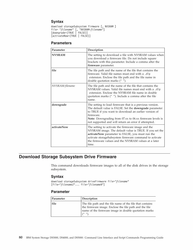
Syntaxdownload storageSubsystem firmware [, NVSRAM ]file= “filename” [, “NVSRAM-filename”][downgrade=(TRUE | FALSE)][activateNow=(TRUE | FALSE)]
Parameters
Parameter Description
NVSRAM The setting to download a file with NVSRAM values whenyou download a firmware file. Do not include squarebrackets with this parameter. Include a comma after thefirmware parameter.
file The file path and the name of the file that contains thefirmware. Valid file names must end with a .dlp
extension. Enclose the file path and the file name indouble quotation marks (“ ”).
NVSRAM-filename The file path and the name of the file that contains theNVSRAM values. Valid file names must end with a .dlp
extension. Enclose the NVSRAM file name in doublequotation marks (“ ”). Include a comma after the filename.
downgrade The setting to load firmware that is a previous version.The default value is FALSE. Set the downgrade parameterto TRUE if you want to download an earlier version offirmware.Note: Downgrading from 07.xx to 06.xx firmware levels isnot supported and will return an error if attempted.
activateNow The setting to activate the firmware image and theNVSRAM image. The default value is TRUE. If you set theactivateNow parameter to FALSE, you must run theactivate storageSubsystem firmware command to activatethe firmware values and the NVSRAM values at a latertime.
Download Storage Subsystem Drive Firmware
This command downloads firmware images to all of the disk drives in the storagesubsystem.
Syntaxdownload storageSubsystem driveFirmware file=”filename”[file=”filename2”... file=”filenameN”]
Parameter
Parameter Description
file The file path and the file name of the file that containsthe firmware image. Enclose the file path and the filename of the firmware image in double quotation marks(“ ”).
80 IBM System Storage DS3000, DS4000, and DS5000: Command Line Interface and Script Commands Programming Guide
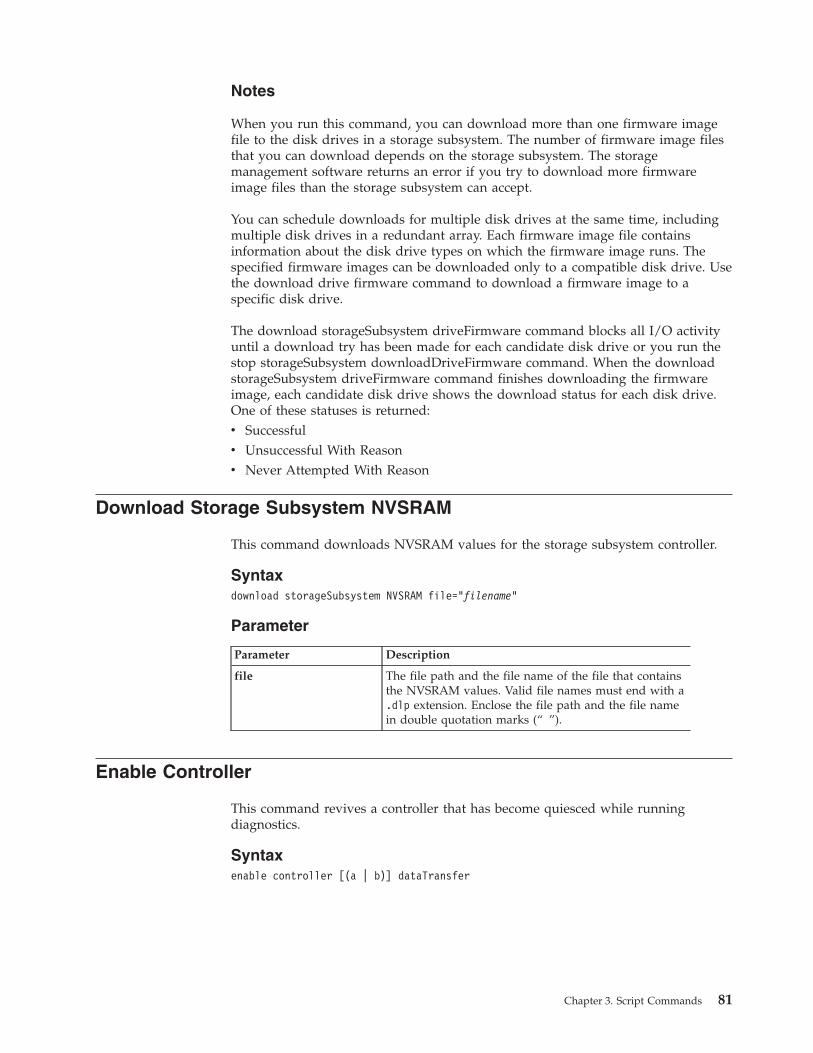
Notes
When you run this command, you can download more than one firmware imagefile to the disk drives in a storage subsystem. The number of firmware image filesthat you can download depends on the storage subsystem. The storagemanagement software returns an error if you try to download more firmwareimage files than the storage subsystem can accept.
You can schedule downloads for multiple disk drives at the same time, includingmultiple disk drives in a redundant array. Each firmware image file containsinformation about the disk drive types on which the firmware image runs. Thespecified firmware images can be downloaded only to a compatible disk drive. Usethe download drive firmware command to download a firmware image to aspecific disk drive.
The download storageSubsystem driveFirmware command blocks all I/O activityuntil a download try has been made for each candidate disk drive or you run thestop storageSubsystem downloadDriveFirmware command. When the downloadstorageSubsystem driveFirmware command finishes downloading the firmwareimage, each candidate disk drive shows the download status for each disk drive.One of these statuses is returned:v Successfulv Unsuccessful With Reasonv Never Attempted With Reason
Download Storage Subsystem NVSRAM
This command downloads NVSRAM values for the storage subsystem controller.
Syntaxdownload storageSubsystem NVSRAM file=”filename”
Parameter
Parameter Description
file The file path and the file name of the file that containsthe NVSRAM values. Valid file names must end with a.dlp extension. Enclose the file path and the file namein double quotation marks (“ ”).
Enable Controller
This command revives a controller that has become quiesced while runningdiagnostics.
Syntaxenable controller [(a | b)] dataTransfer
Chapter 3. Script Commands 81
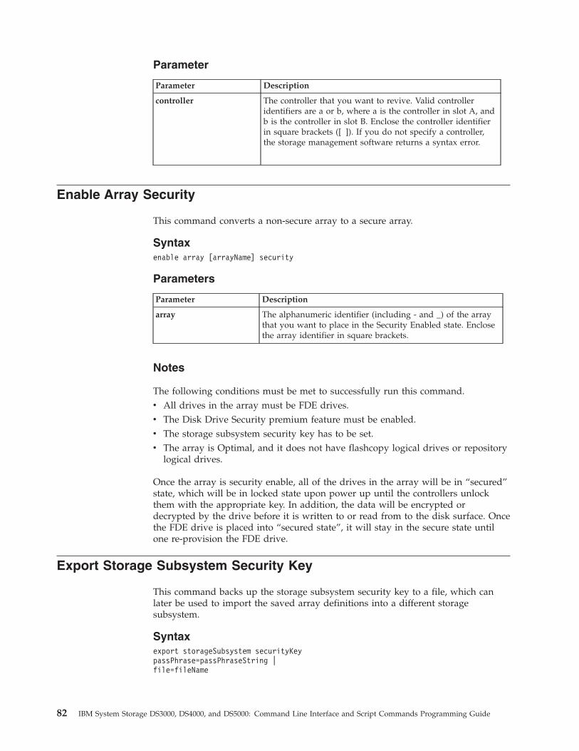
Parameter
Parameter Description
controller The controller that you want to revive. Valid controlleridentifiers are a or b, where a is the controller in slot A, andb is the controller in slot B. Enclose the controller identifierin square brackets ([ ]). If you do not specify a controller,the storage management software returns a syntax error.
Enable Array Security
This command converts a non-secure array to a secure array.
Syntaxenable array [arrayName] security
Parameters
Parameter Description
array The alphanumeric identifier (including - and _) of the arraythat you want to place in the Security Enabled state. Enclosethe array identifier in square brackets.
Notes
The following conditions must be met to successfully run this command.v All drives in the array must be FDE drives.v The Disk Drive Security premium feature must be enabled.v The storage subsystem security key has to be set.v The array is Optimal, and it does not have flashcopy logical drives or repository
logical drives.
Once the array is security enable, all of the drives in the array will be in “secured”state, which will be in locked state upon power up until the controllers unlockthem with the appropriate key. In addition, the data will be encrypted ordecrypted by the drive before it is written to or read from to the disk surface. Oncethe FDE drive is placed into “secured state”, it will stay in the secure state untilone re-provision the FDE drive.
Export Storage Subsystem Security Key
This command backs up the storage subsystem security key to a file, which canlater be used to import the saved array definitions into a different storagesubsystem.
Syntaxexport storageSubsystem securityKeypassPhrase=passPhraseString |file=fileName
82 IBM System Storage DS3000, DS4000, and DS5000: Command Line Interface and Script Commands Programming Guide
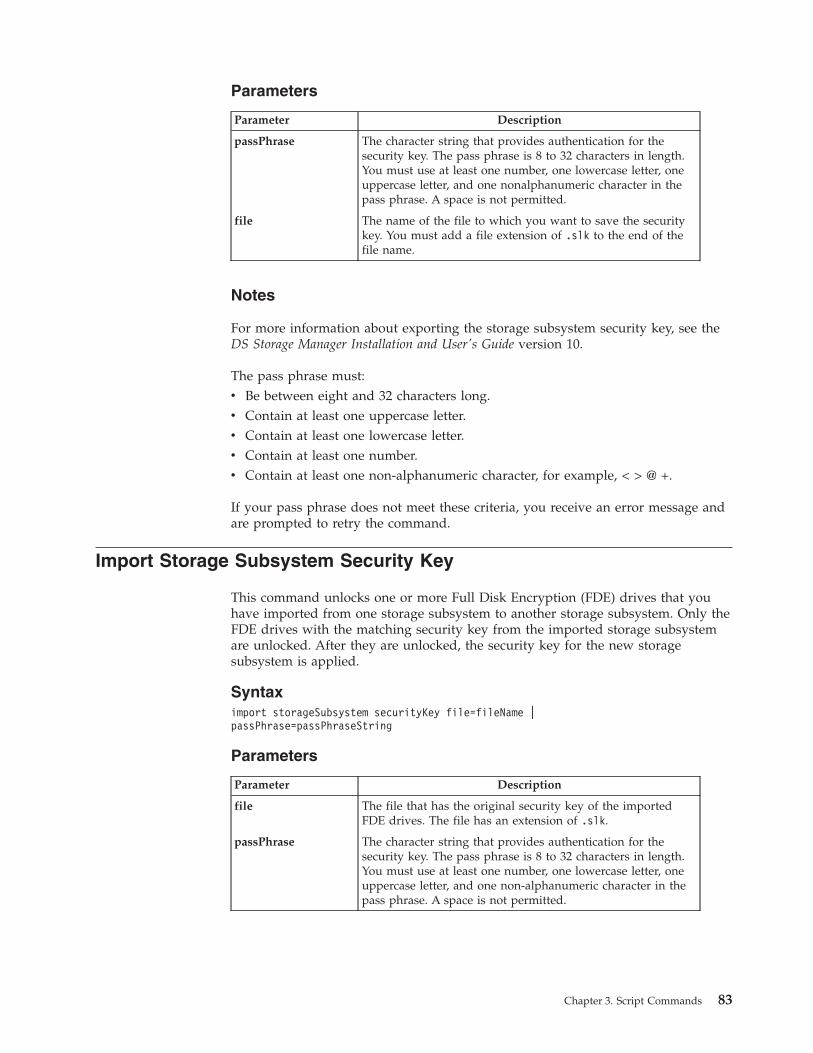
Parameters
Parameter Description
passPhrase The character string that provides authentication for thesecurity key. The pass phrase is 8 to 32 characters in length.You must use at least one number, one lowercase letter, oneuppercase letter, and one nonalphanumeric character in thepass phrase. A space is not permitted.
file The name of the file to which you want to save the securitykey. You must add a file extension of .slk to the end of thefile name.
Notes
For more information about exporting the storage subsystem security key, see theDS Storage Manager Installation and User's Guide version 10.
The pass phrase must:v Be between eight and 32 characters long.v Contain at least one uppercase letter.v Contain at least one lowercase letter.v Contain at least one number.v Contain at least one non-alphanumeric character, for example, < > @ +.
If your pass phrase does not meet these criteria, you receive an error message andare prompted to retry the command.
Import Storage Subsystem Security Key
This command unlocks one or more Full Disk Encryption (FDE) drives that youhave imported from one storage subsystem to another storage subsystem. Only theFDE drives with the matching security key from the imported storage subsystemare unlocked. After they are unlocked, the security key for the new storagesubsystem is applied.
Syntaximport storageSubsystem securityKey file=fileName |passPhrase=passPhraseString
Parameters
Parameter Description
file The file that has the original security key of the importedFDE drives. The file has an extension of .slk.
passPhrase The character string that provides authentication for thesecurity key. The pass phrase is 8 to 32 characters in length.You must use at least one number, one lowercase letter, oneuppercase letter, and one non-alphanumeric character in thepass phrase. A space is not permitted.
Chapter 3. Script Commands 83
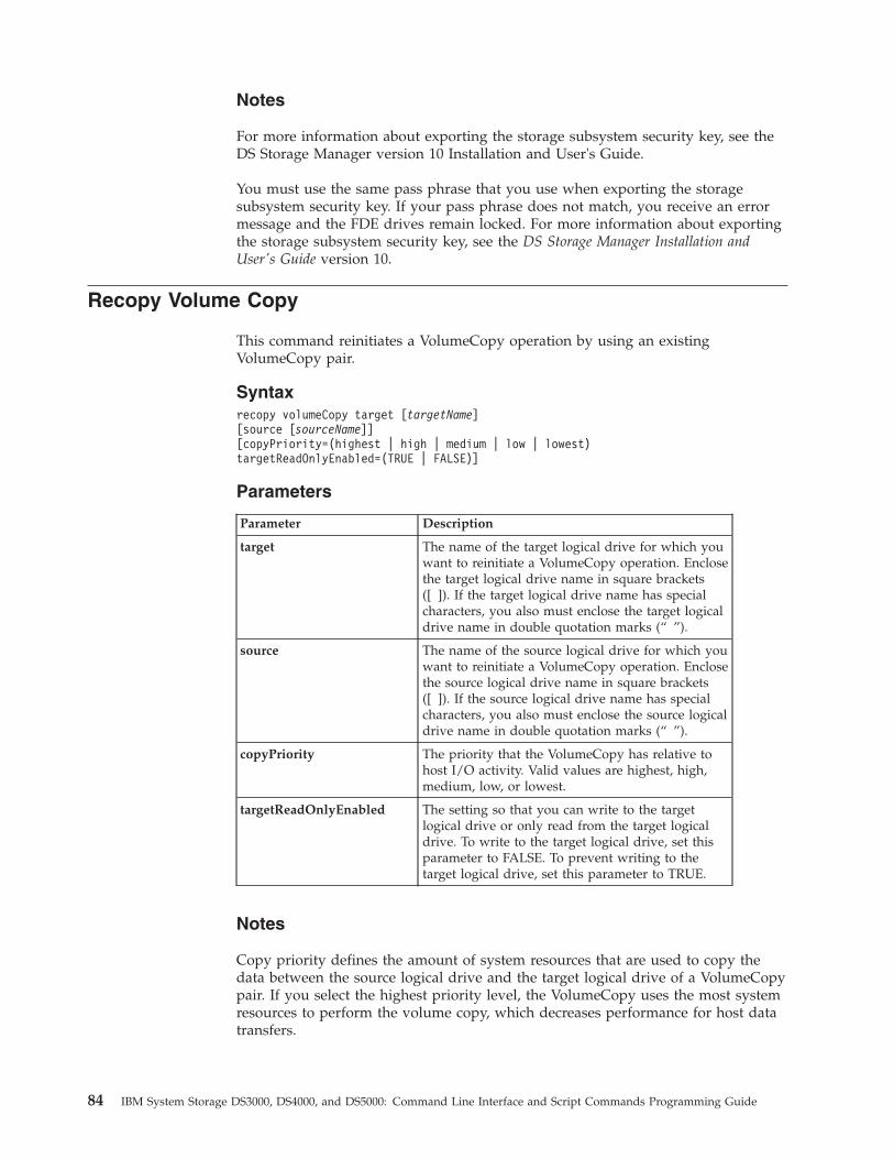
Notes
For more information about exporting the storage subsystem security key, see theDS Storage Manager version 10 Installation and User's Guide.
You must use the same pass phrase that you use when exporting the storagesubsystem security key. If your pass phrase does not match, you receive an errormessage and the FDE drives remain locked. For more information about exportingthe storage subsystem security key, see the DS Storage Manager Installation andUser's Guide version 10.
Recopy Volume Copy
This command reinitiates a VolumeCopy operation by using an existingVolumeCopy pair.
Syntaxrecopy volumeCopy target [targetName][source [sourceName]][copyPriority=(highest | high | medium | low | lowest)targetReadOnlyEnabled=(TRUE | FALSE)]
Parameters
Parameter Description
target The name of the target logical drive for which youwant to reinitiate a VolumeCopy operation. Enclosethe target logical drive name in square brackets([ ]). If the target logical drive name has specialcharacters, you also must enclose the target logicaldrive name in double quotation marks (“ ”).
source The name of the source logical drive for which youwant to reinitiate a VolumeCopy operation. Enclosethe source logical drive name in square brackets([ ]). If the source logical drive name has specialcharacters, you also must enclose the source logicaldrive name in double quotation marks (“ ”).
copyPriority The priority that the VolumeCopy has relative tohost I/O activity. Valid values are highest, high,medium, low, or lowest.
targetReadOnlyEnabled The setting so that you can write to the targetlogical drive or only read from the target logicaldrive. To write to the target logical drive, set thisparameter to FALSE. To prevent writing to thetarget logical drive, set this parameter to TRUE.
Notes
Copy priority defines the amount of system resources that are used to copy thedata between the source logical drive and the target logical drive of a VolumeCopypair. If you select the highest priority level, the VolumeCopy uses the most systemresources to perform the volume copy, which decreases performance for host datatransfers.
84 IBM System Storage DS3000, DS4000, and DS5000: Command Line Interface and Script Commands Programming Guide
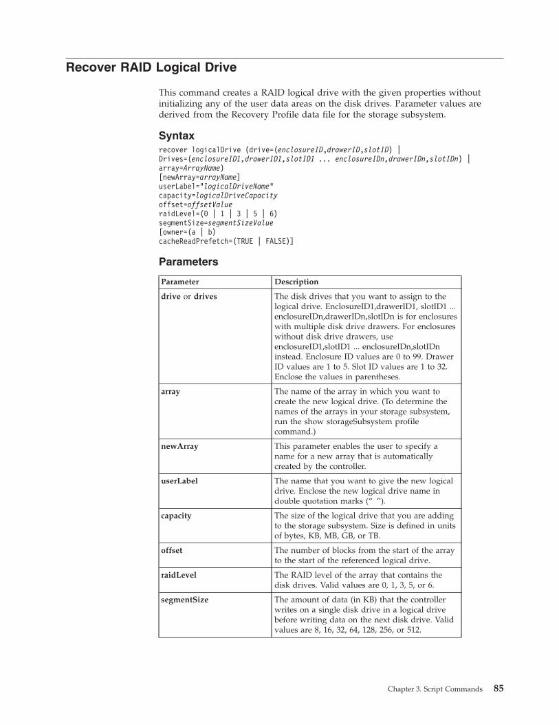
Recover RAID Logical Drive
This command creates a RAID logical drive with the given properties withoutinitializing any of the user data areas on the disk drives. Parameter values arederived from the Recovery Profile data file for the storage subsystem.
Syntaxrecover logicalDrive (drive=(enclosureID,drawerID,slotID) |Drives=(enclosureID1,drawerID1,slotID1 ... enclosureIDn,drawerIDn,slotIDn) |array=ArrayName)[newArray=arrayName]userLabel=”logicalDriveName”capacity=logicalDriveCapacityoffset=offsetValueraidLevel=(0 | 1 | 3 | 5 | 6)segmentSize=segmentSizeValue[owner=(a | b)cacheReadPrefetch=(TRUE | FALSE)]
Parameters
Parameter Description
drive or drives The disk drives that you want to assign to thelogical drive. EnclosureID1,drawerID1, slotID1 ...enclosureIDn,drawerIDn,slotIDn is for enclosureswith multiple disk drive drawers. For enclosureswithout disk drive drawers, useenclosureID1,slotID1 ... enclosureIDn,slotIDninstead. Enclosure ID values are 0 to 99. DrawerID values are 1 to 5. Slot ID values are 1 to 32.Enclose the values in parentheses.
array The name of the array in which you want tocreate the new logical drive. (To determine thenames of the arrays in your storage subsystem,run the show storageSubsystem profilecommand.)
newArray This parameter enables the user to specify aname for a new array that is automaticallycreated by the controller.
userLabel The name that you want to give the new logicaldrive. Enclose the new logical drive name indouble quotation marks (“ ”).
capacity The size of the logical drive that you are addingto the storage subsystem. Size is defined in unitsof bytes, KB, MB, GB, or TB.
offset The number of blocks from the start of the arrayto the start of the referenced logical drive.
raidLevel The RAID level of the array that contains thedisk drives. Valid values are 0, 1, 3, 5, or 6.
segmentSize The amount of data (in KB) that the controllerwrites on a single disk drive in a logical drivebefore writing data on the next disk drive. Validvalues are 8, 16, 32, 64, 128, 256, or 512.
Chapter 3. Script Commands 85
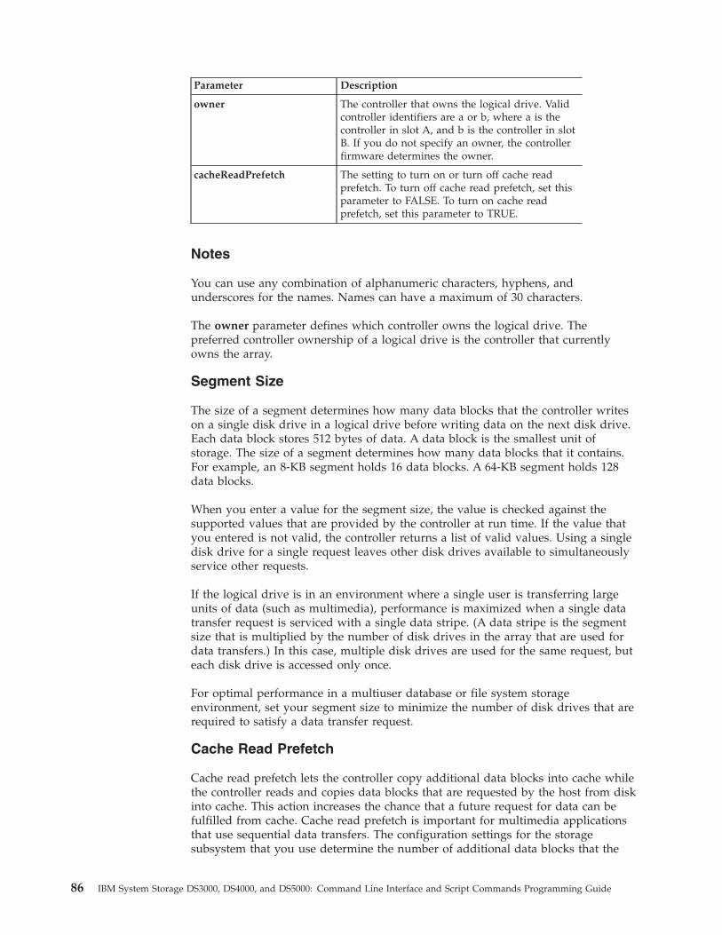
Parameter Description
owner The controller that owns the logical drive. Validcontroller identifiers are a or b, where a is thecontroller in slot A, and b is the controller in slotB. If you do not specify an owner, the controllerfirmware determines the owner.
cacheReadPrefetch The setting to turn on or turn off cache readprefetch. To turn off cache read prefetch, set thisparameter to FALSE. To turn on cache readprefetch, set this parameter to TRUE.
Notes
You can use any combination of alphanumeric characters, hyphens, andunderscores for the names. Names can have a maximum of 30 characters.
The owner parameter defines which controller owns the logical drive. Thepreferred controller ownership of a logical drive is the controller that currentlyowns the array.
Segment Size
The size of a segment determines how many data blocks that the controller writeson a single disk drive in a logical drive before writing data on the next disk drive.Each data block stores 512 bytes of data. A data block is the smallest unit ofstorage. The size of a segment determines how many data blocks that it contains.For example, an 8-KB segment holds 16 data blocks. A 64-KB segment holds 128data blocks.
When you enter a value for the segment size, the value is checked against thesupported values that are provided by the controller at run time. If the value thatyou entered is not valid, the controller returns a list of valid values. Using a singledisk drive for a single request leaves other disk drives available to simultaneouslyservice other requests.
If the logical drive is in an environment where a single user is transferring largeunits of data (such as multimedia), performance is maximized when a single datatransfer request is serviced with a single data stripe. (A data stripe is the segmentsize that is multiplied by the number of disk drives in the array that are used fordata transfers.) In this case, multiple disk drives are used for the same request, buteach disk drive is accessed only once.
For optimal performance in a multiuser database or file system storageenvironment, set your segment size to minimize the number of disk drives that arerequired to satisfy a data transfer request.
Cache Read Prefetch
Cache read prefetch lets the controller copy additional data blocks into cache whilethe controller reads and copies data blocks that are requested by the host from diskinto cache. This action increases the chance that a future request for data can befulfilled from cache. Cache read prefetch is important for multimedia applicationsthat use sequential data transfers. The configuration settings for the storagesubsystem that you use determine the number of additional data blocks that the
86 IBM System Storage DS3000, DS4000, and DS5000: Command Line Interface and Script Commands Programming Guide
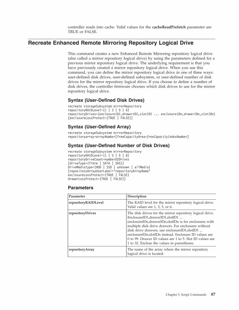
controller reads into cache. Valid values for the cacheReadPrefetch parameter areTRUE or FALSE.
Recreate Enhanced Remote Mirroring Repository Logical Drive
This command creates a new Enhanced Remote Mirroring repository logical drive(also called a mirror repository logical drive) by using the parameters defined for aprevious mirror repository logical drive. The underlying requirement is that youhave previously created a mirror repository logical drive. When you use thiscommand, you can define the mirror repository logical drive in one of three ways:user-defined disk drives, user-defined subsystem, or user-defined number of diskdrives for the mirror repository logical drive. If you choose to define a number ofdisk drives, the controller firmware chooses which disk drives to use for the mirrorrepository logical drive.
Syntax (User-Defined Disk Drives)recreate storageSubsystem mirrorRepositoryrepositoryRAIDLevel=(1 | 3 | 5 | 6)repositoryDrives=(enclosureID1,drawerID1,slotID1 ... enclosureIDn,drawerIDn,slotIDn)[enclosureLossProtect=(TRUE | FALSE)]
Syntax (User-Defined Array)recreate storageSubsystem mirrorRepositoryrepositoryarray=arrayNumber[freeCapacityArea=freeCapacityIndexNumber]
Syntax (User-Defined Number of Disk Drives)recreate storageSubsystem mirrorRepositoryrepositoryRAIDLevel=(1 | 3 | 5 | 6)repositoryDriveCount=numberOfDrives[driveType=(fibre | SATA | SAS)]DriveMediaType=(HDD | SSD | unknown | allMedia)[repositoryArrayUserLabel=”repositoryArrayName”enclosureLossProtect=(TRUE | FALSE)drawerLossProtect=(TRUE | FALSE)]
Parameters
Parameter Description
repositoryRAIDLevel The RAID level for the mirror repository logical drive.Valid values are 1, 3, 5, or 6.
repositoryDrives The disk drives for the mirror repository logical drive.EnclosureID1,drawerID1,slotID1 ...enclosureIDn,drawerIDn,slotIDn is for enclosures withmultiple disk drive drawers. For enclosures withoutdisk drive drawers, use enclosureID1,slotID1 ...enclosureIDn,slotIDn instead. Enclosure ID values are0 to 99. Drawer ID values are 1 to 5. Slot ID values are1 to 32. Enclose the values in parentheses.
repositoryArray The name of the array where the mirror repositorylogical drive is located.
Chapter 3. Script Commands 87
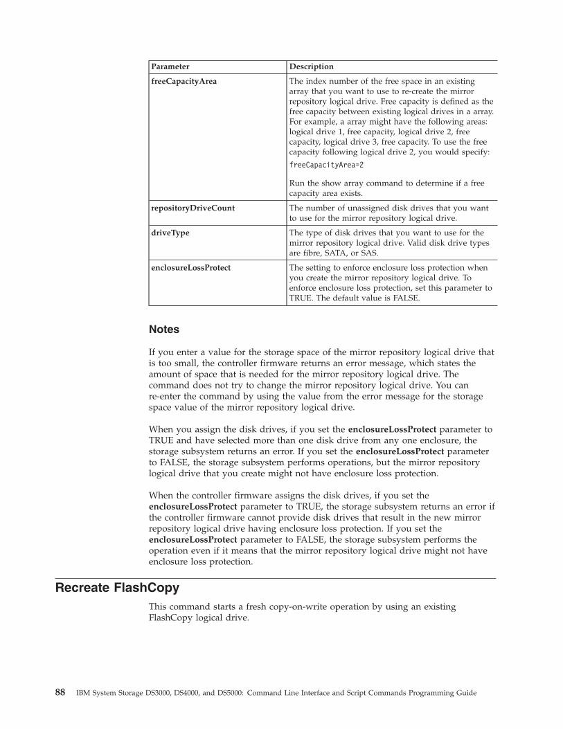
Parameter Description
freeCapacityArea The index number of the free space in an existingarray that you want to use to re-create the mirrorrepository logical drive. Free capacity is defined as thefree capacity between existing logical drives in a array.For example, a array might have the following areas:logical drive 1, free capacity, logical drive 2, freecapacity, logical drive 3, free capacity. To use the freecapacity following logical drive 2, you would specify:
freeCapacityArea=2
Run the show array command to determine if a freecapacity area exists.
repositoryDriveCount The number of unassigned disk drives that you wantto use for the mirror repository logical drive.
driveType The type of disk drives that you want to use for themirror repository logical drive. Valid disk drive typesare fibre, SATA, or SAS.
enclosureLossProtect The setting to enforce enclosure loss protection whenyou create the mirror repository logical drive. Toenforce enclosure loss protection, set this parameter toTRUE. The default value is FALSE.
Notes
If you enter a value for the storage space of the mirror repository logical drive thatis too small, the controller firmware returns an error message, which states theamount of space that is needed for the mirror repository logical drive. Thecommand does not try to change the mirror repository logical drive. You canre-enter the command by using the value from the error message for the storagespace value of the mirror repository logical drive.
When you assign the disk drives, if you set the enclosureLossProtect parameter toTRUE and have selected more than one disk drive from any one enclosure, thestorage subsystem returns an error. If you set the enclosureLossProtect parameterto FALSE, the storage subsystem performs operations, but the mirror repositorylogical drive that you create might not have enclosure loss protection.
When the controller firmware assigns the disk drives, if you set theenclosureLossProtect parameter to TRUE, the storage subsystem returns an error ifthe controller firmware cannot provide disk drives that result in the new mirrorrepository logical drive having enclosure loss protection. If you set theenclosureLossProtect parameter to FALSE, the storage subsystem performs theoperation even if it means that the mirror repository logical drive might not haveenclosure loss protection.
Recreate FlashCopyThis command starts a fresh copy-on-write operation by using an existingFlashCopy logical drive.
88 IBM System Storage DS3000, DS4000, and DS5000: Command Line Interface and Script Commands Programming Guide
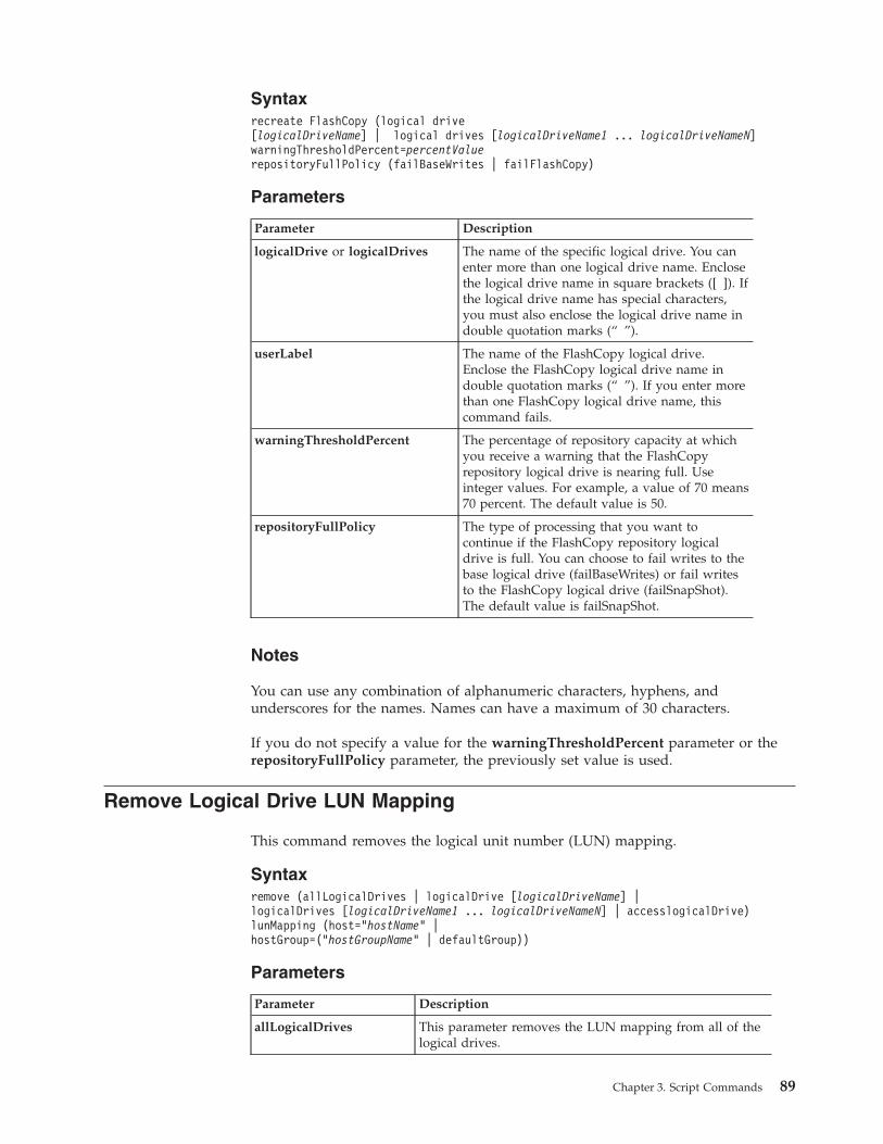
Syntaxrecreate FlashCopy (logical drive[logicalDriveName] | logical drives [logicalDriveName1 ... logicalDriveNameN]warningThresholdPercent=percentValuerepositoryFullPolicy (failBaseWrites | failFlashCopy)
Parameters
Parameter Description
logicalDrive or logicalDrives The name of the specific logical drive. You canenter more than one logical drive name. Enclosethe logical drive name in square brackets ([ ]). Ifthe logical drive name has special characters,you must also enclose the logical drive name indouble quotation marks (“ ”).
userLabel The name of the FlashCopy logical drive.Enclose the FlashCopy logical drive name indouble quotation marks (“ ”). If you enter morethan one FlashCopy logical drive name, thiscommand fails.
warningThresholdPercent The percentage of repository capacity at whichyou receive a warning that the FlashCopyrepository logical drive is nearing full. Useinteger values. For example, a value of 70 means70 percent. The default value is 50.
repositoryFullPolicy The type of processing that you want tocontinue if the FlashCopy repository logicaldrive is full. You can choose to fail writes to thebase logical drive (failBaseWrites) or fail writesto the FlashCopy logical drive (failSnapShot).The default value is failSnapShot.
Notes
You can use any combination of alphanumeric characters, hyphens, andunderscores for the names. Names can have a maximum of 30 characters.
If you do not specify a value for the warningThresholdPercent parameter or therepositoryFullPolicy parameter, the previously set value is used.
Remove Logical Drive LUN Mapping
This command removes the logical unit number (LUN) mapping.
Syntaxremove (allLogicalDrives | logicalDrive [logicalDriveName] |logicalDrives [logicalDriveName1 ... logicalDriveNameN] | accesslogicalDrive)lunMapping (host=”hostName” |hostGroup=(“hostGroupName” | defaultGroup))
Parameters
Parameter Description
allLogicalDrives This parameter removes the LUN mapping from all of thelogical drives.
Chapter 3. Script Commands 89
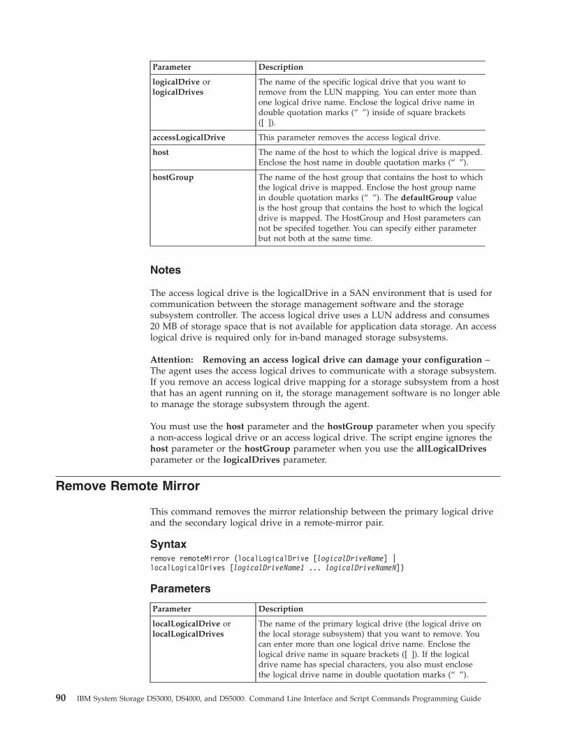
Parameter Description
logicalDrive orlogicalDrives
The name of the specific logical drive that you want toremove from the LUN mapping. You can enter more thanone logical drive name. Enclose the logical drive name indouble quotation marks (“ ”) inside of square brackets([ ]).
accessLogicalDrive This parameter removes the access logical drive.
host The name of the host to which the logical drive is mapped.Enclose the host name in double quotation marks (“ ”).
hostGroup The name of the host group that contains the host to whichthe logical drive is mapped. Enclose the host group namein double quotation marks (“ ”). The defaultGroup valueis the host group that contains the host to which the logicaldrive is mapped. The HostGroup and Host parameters cannot be specifed together. You can specify either parameterbut not both at the same time.
Notes
The access logical drive is the logicalDrive in a SAN environment that is used forcommunication between the storage management software and the storagesubsystem controller. The access logical drive uses a LUN address and consumes20 MB of storage space that is not available for application data storage. An accesslogical drive is required only for in-band managed storage subsystems.
Attention: Removing an access logical drive can damage your configuration –The agent uses the access logical drives to communicate with a storage subsystem.If you remove an access logical drive mapping for a storage subsystem from a hostthat has an agent running on it, the storage management software is no longer ableto manage the storage subsystem through the agent.
You must use the host parameter and the hostGroup parameter when you specifya non-access logical drive or an access logical drive. The script engine ignores thehost parameter or the hostGroup parameter when you use the allLogicalDrivesparameter or the logicalDrives parameter.
Remove Remote Mirror
This command removes the mirror relationship between the primary logical driveand the secondary logical drive in a remote-mirror pair.
Syntaxremove remoteMirror (localLogicalDrive [logicalDriveName] |localLogicalDrives [logicalDriveName1 ... logicalDriveNameN])
Parameters
Parameter Description
localLogicalDrive orlocalLogicalDrives
The name of the primary logical drive (the logical drive onthe local storage subsystem) that you want to remove. Youcan enter more than one logical drive name. Enclose thelogical drive name in square brackets ([ ]). If the logicaldrive name has special characters, you also must enclosethe logical drive name in double quotation marks (“ ”).
90 IBM System Storage DS3000, DS4000, and DS5000: Command Line Interface and Script Commands Programming Guide
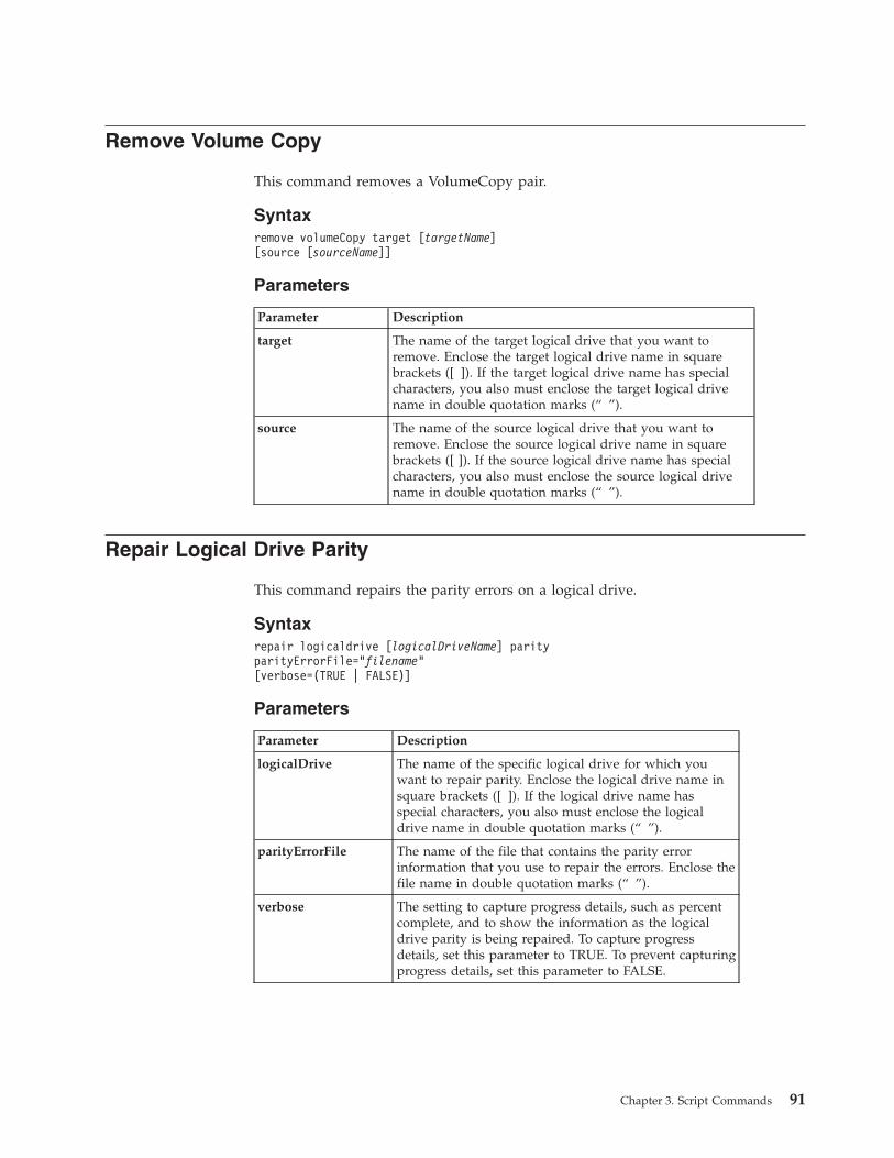
Remove Volume Copy
This command removes a VolumeCopy pair.
Syntaxremove volumeCopy target [targetName][source [sourceName]]
Parameters
Parameter Description
target The name of the target logical drive that you want toremove. Enclose the target logical drive name in squarebrackets ([ ]). If the target logical drive name has specialcharacters, you also must enclose the target logical drivename in double quotation marks (“ ”).
source The name of the source logical drive that you want toremove. Enclose the source logical drive name in squarebrackets ([ ]). If the source logical drive name has specialcharacters, you also must enclose the source logical drivename in double quotation marks (“ ”).
Repair Logical Drive Parity
This command repairs the parity errors on a logical drive.
Syntaxrepair logicaldrive [logicalDriveName] parityparityErrorFile=”filename”[verbose=(TRUE | FALSE)]
Parameters
Parameter Description
logicalDrive The name of the specific logical drive for which youwant to repair parity. Enclose the logical drive name insquare brackets ([ ]). If the logical drive name hasspecial characters, you also must enclose the logicaldrive name in double quotation marks (“ ”).
parityErrorFile The name of the file that contains the parity errorinformation that you use to repair the errors. Enclose thefile name in double quotation marks (“ ”).
verbose The setting to capture progress details, such as percentcomplete, and to show the information as the logicaldrive parity is being repaired. To capture progressdetails, set this parameter to TRUE. To prevent capturingprogress details, set this parameter to FALSE.
Chapter 3. Script Commands 91
Replace Disk Drive
This command redefines the composition of a array. You can use this command toreplace a disk drive with either an unassigned disk drive or a fully integrated hotspare.
Syntaxreplace Drive [enclosureID,drawerID,slotID]|Drive "wwID") replacementDrive=enclosureID,drawerID,slotID
Parameters
Parameter Description
drive The location of the disk drive that you want to replace.For high-capacity expansion drawers, specify theenclosure ID, the drawer ID, and the slot ID. Forlow-capacity expansion drawers, specify the enclosureID and the slot ID. Enclosure ID values are 0 to 99.Drawer ID values are 1 to 5. Slot ID values are 1 to 32.Enclose the enclosure ID value, the drawer ID value, andthe slot ID value in square brackets ([ ]).
You can also use the World Wide Identifier (WWID) ofthe disk drive. Enclose the WWID in double quotationmarks (“ ”).
replacementDrive The location of the replacement disk drive. Forhigh-capacity expansion drawers, specify the enclosureID, the drawer ID, and the slot ID for the disk drive. Forlow-capacity expansion drawers, specify the enclosureID and the slot ID. Enclosure ID values are 0 to 99.Drawer ID values are 1 to 5. Slot ID values are 1 to 32.
Notes
The diskDrive parameter supports both high-capacity expansion drawers andlow-capacity expansion drawers. A high-capacity expansion drawer has drawersthat hold the disk drives. The drawers slide out of the expansion drawer toprovide access to the disk drives. A low-capacity expansion drawer does not havedrawers. For a high-capacity expansion drawer, you must specify the identifier (ID)of the expansion drawer, the ID of the drawer, and the ID of the slot in which adisk drive resides. For a low-capacity expansion drawer, you need only specify theID of the expansion drawer and the ID of the slot in which a disk drive resides.For a low-capacity expansion drawer, an alternative method for identifying alocation for a disk drive is to specify the ID of the expansion drawer, set the ID ofthe drawer to 0, and specify the ID of the slot in which a disk drive resides.
Reset Controller
This command resets a controller, and it is disruptive to I/O operations.
Important: When you reset a controller, the controller is removed from the datapath and is not available for I/O operations until the reset operation is complete. Ifa host is using logical drives that are owned by the controller being reset, the I/Odirected to the controller is rejected. Before resetting the controller, either make
92 IBM System Storage DS3000, DS4000, and DS5000: Command Line Interface and Script Commands Programming Guide
sure that the logical drives that are owned by the controller are not in use or makesure that a multi-path driver is installed on all of the hosts that use these logicaldrives.
Syntaxreset controller [(a | b)]
Parameter
Parameter Description
controller The controller that you want to reset. Valid controller identifiersare a or b, where a is the controller in slot A, and b is thecontroller in slot B. Enclose the controller identifier in squarebrackets ([ ]). If you do not specify a controller owner, thecontroller firmware returns a syntax error.
Reset Storage Subsystem Battery Install Date
This command resets the age of the batteries in a storage subsystem to zero days.You can reset the batteries for an entire storage subsystem or just the battery for aspecific controller or in a specific battery pack.
Syntaxreset storageSubsystem batteryInstallDate [controller=(a | b)| batteryPack=(left | right)]
Parameter
Parameter Description
controller The controller that contains the battery for which you wantto reset the age. Valid controller identifiers are a or b, wherea is the controller in slot A, and b is the controller in slot B.
batteryPack The battery pack contains both a left battery and a rightbattery. Valid identifiers are left or right, where left is thebattery that supports the controller in slot A, and right is thebattery that supports the controller in slot B. Use thebatteryPack parameter only for controllers with batterypacks. The controller and batterypack parameters are mutualexclusive. You can specify either parameter but not both atthe same time.Note: The DS3000 does not have battery packs.
Notes
If the command statement uses the wrong parameter, an error appears.
Reset Storage Subsystem Diagnostic Data
This command resets the NVSRAM that contains the diagnostic data for thestorage subsystem. This command does not delete the diagnostic data. Thiscommand replaces the Needs Attention status with the Diagnostic Data Availablestatus. The old diagnostic data is written automatically over when new data iscaptured. The memory that contains the diagnostic data is also cleared when the
Chapter 3. Script Commands 93
controllers reboot. Before resetting the diagnostic data, use the savestorageSubsystem diagnosticData command to save the diagnostic data to a file.
Important: Run this command only with the assistance of a Customer andTechnical Support representative.
Syntaxreset storageSubsystem diagnosticData
Parameters
None.
Reset Storage Subsystem iSCSI Baseline
This command resets the iSCI baseline for the storage subsystem to 0.
Syntaxreset storageSubsystem iscsiStatsBaseline
Parameters
None.
Notes
This command resets the baseline to 0 for both controllers in the storagesubsystem. The purpose of resetting both of the controller baselines is to helpmake sure that the controller counts are synchronized between the controllers. Ifone controller resets but the second controller does not reset, the host is informedthat the controllers are out of synchronization. The host is informed by the timestamps that are reported with the statistics.
Reset Storage Subsystem Logical Drive Distribution
This command reassigns (moves) all of the logical drives to their preferredcontroller.
Syntaxreset storageSubsystem logicalDriveDistribution
Parameters
None.
Notes
If you use this command on a host without a multi-path driver, to preventapplication errors, you must stop I/O operations to the logical drives until thiscommand has completed.
Under certain host operating system environments, you might be required toreconfigure the multi-path host driver. You might also need to make operatingsystem modifications to recognize the new I/O path to the logical drives.
94 IBM System Storage DS3000, DS4000, and DS5000: Command Line Interface and Script Commands Programming Guide
Reset Storage Subsystem RLS Baseline
This command resets the Read Link Status (RLS) baseline for all devices by settingall of the RLS counts to 0.
Syntaxreset storageSubsystem RLSBaseline
Parameters
None.
Reset Storage Subsystem SOC Baseline
This command resets the baseline for all switch-on-a-chip (SOC) devices that areaccessed through the controllers. This command resets the baseline by setting all ofthe SOC counts to 0. This command is valid only for Fibre Channel devices in anArbitrated Loop topology.
Syntaxreset storageSubsystem SOCBaseline
Parameters
None.
Resume Remote Mirror
This command resumes a suspended Enhanced Remote Mirroring operation.
Syntaxresume remoteMirror (primary [logicalDriveName] |primaries [logicalDriveName1 ... logicalDriveNameN])[writeConsistency=(TRUE | FALSE)}
Parameters
Parameter Description
primary or primaries The name of the primary logical drive for which youwant to resume operation. You can enter more thanone primary logical drive name. Enclose the primarylogical drive name in square brackets ([ ]). If theprimary logical drive name has special characters, youalso must enclose the primary logical drive name indouble quotation marks (“ ”).
writeConsistency The setting to identify the logical drives in thiscommand that are in a write-consistency group or areseparate. For the logical drives to be in the samewrite-consistency group, set this parameter to TRUE.For the logical drives to be separate, set this parameterto FALSE.
Chapter 3. Script Commands 95
Notes
If you set the writeConsistency parameter to TRUE, the logical drives must be in awrite-consistency group (or groups). This command resumes all write-consistencygroups that contain the logical drives. For example, if logical drives A, B, and Care in a write-consistency group and they have remote counterparts A’, B’, and C’,the resume remoteMirror logicalDrive [“A”] writeConsistency=TRUE commandresumes A-A’, B-B’, and C-C’.
Revive Array
This command forces the specified array and its associated failed disk drives to theOptimal state.
Attention: Possible loss of data access – Correct use of this command dependson the data configuration on all of the disk drives in the array. Never try to revivea disk drive unless you are supervised by a Customer and Technical Supportrepresentative.
Syntaxrevive array [arrayNumber]
Parameter
Parameter Description
array The alphanumeric identifier (including - and _) of the arrayto be set to the Optimal state. Enclose the array identifier insquare brackets ([ ]).
Revive Disk Drive
This command forces the specified disk drive to the Optimal state.
Attention: Possible loss of data access – Correct use of this command dependson the data configuration on all of the disk drives in the array. Never try to revivea disk drive unless you are supervised by a Customer and Technical Supportrepresentative.
Syntaxrevive drive [enclosureID,drawerID,slotID]
Parameter
Parameter Description
drive The enclosure, drawer, and the slot where the disk driveresides. Enclosure ID values are 0 to 99. Drawer ID valuesare 1 to 5. Slot ID values are 1 to 32. Enclose the values insquare brackets ([ ]).
96 IBM System Storage DS3000, DS4000, and DS5000: Command Line Interface and Script Commands Programming Guide
Save Controller NVSRAM
This command saves a copy of the controller NVSRAM values to a file. Thiscommand saves all of the regions.
Syntaxsave controller [(a | b)]NVSRAM file=”filename”
Parameters
Parameter Description
controller The controller with the NVSRAM values that youwant to save. Valid controller identifiers are a or b,where a is the controller in slot A, and b is thecontroller in slot B. Enclose the controller identifier insquare brackets ([ ]).
file The name of the file in which you want to save thevalues. Enclose the file name in double quotationmarks (“ ”).
Save Disk Drive Channel Fault Isolation Diagnostic Status
This command saves the drive channel fault isolation diagnostic data that isreturned from the start diskDriveChannel faultDiagnostics command. You cansave the diagnostic data to a file as standard text or as XML.
See the “Start Drive Channel Fault Isolation Diagnostics” on page 165 commandfor more information.
Syntaxsave DriveChannel [drive-channel-Identifier] faultDiagnostics file=”filename”
Parameter
Parameter Description
Drive-channel identifier 1 |2 |3 |4|5|6|7|8. Only one drive channel can bespecified.
file The file path and the file name to which you want to savethe results of the fault isolation diagnostics test on the diskdrive channel. Enclose the file name in double quotationmarks (“ ”). For example: file="C:\ProgramFiles\CLI\sup\fltdiag.txt"
This command does not automatically append a fileextension to the saved file. You must specify a file extensionwhen entering the file name.
Notes
A file extension is not automatically appended to the saved file. You must specifythe applicable format suffix for the file. If you specify a file extension of .txt, then
Chapter 3. Script Commands 97
the output will be in a text file format. If you specify a file extension of .xml, thenthe output will be in an XML file format.
Save Drive Log
This command saves the log sense data to a file. Log sense data is maintained bythe storage subsystem for each disk drive.
Syntaxsave allDrives logFile=”filename”
Save Storage Subsystem Configuration
This command creates a script file that you can use to create the current storagesubsystem logical drive configuration.
Syntaxsave storageSubsystem configuration file=”filename”[(allconfig | globalSettings=(TRUE | FALSE)logicalDriveConfigAndSettings=(TRUE | FALSE)hostTopology=(TRUE | FALSE)lunMappings=(TRUE | FALSE))]
Parameters
Parameter Description
file The name of the file that contains theconfiguration values. Enclose the file name indouble quotation marks (“ ”).
allConfig The setting to save all of the configuration valuesto the file. (If you choose this parameter, all of theconfiguration parameters are set to TRUE.)
globalSettings The setting to save the global settings to the file.To save the global settings, set this parameter toTRUE. To prevent saving the global settings, setthis parameter to FALSE. The default value isTRUE.
logicalDriveConfigAndSettings The setting to save the logical drive configurationsettings and all of the global settings to the file. Tosave the logical drive configuration settings andglobal settings, set this parameter to TRUE. Toprevent saving the logical drive configurationsettings and global settings, set this parameter toFALSE. The default value is TRUE.
hostTopology The setting to save the host topology to the file. Tosave the host topology, set this parameter toTRUE. To prevent saving the host topology, setthis parameter to FALSE. The default value isFALSE.
lunMappings The setting to save the LUN mapping to the file.To save the LUN mapping, set this parameter toTRUE. To prevent saving the LUN mapping, setthis parameter to FALSE. The default value isFALSE.
98 IBM System Storage DS3000, DS4000, and DS5000: Command Line Interface and Script Commands Programming Guide
Notes
When you use this command, you can specify any combination of the parametersfor the global setting, the logical drive configuration setting, the host topology, orthe LUN mapping. If you want to enter all settings, use the allConfig parameter.The parameters are all optional.
Save Storage Subsystem Diagnostic Data
This command saves the storage subsystem diagnostic data from either thecontrollers or the environmental services monitors (ESMs) to a file. You can reviewthe file contents at a later time. You can also send the file to a Customer andTechnical Support representative for further review.
After you have saved the diagnostic data, you can reset the NVSRAM registersthat contain the diagnostic data so that the old data can be overwritten. Use thereset storageSubsystem diagnosticData command to reset the diagnostic dataregisters.
Important: Run this command only with the assistance of a Customer andTechnical Support representative.
Syntaxsave storageSubsystem diagnosticData [(controller | esm)]file=”filename”
Parameters
Parameter Description
diagnosticData This parameter allows you to downloads the diagnostic datafrom either the controllers or the ESMs.
file The name of the file to which you want to save the diagnosticdata. Enclose the file name in double quotation marks (“ ”).
Save Storage Subsystem Events
This command saves events from the Major Event Log to a file. You can save all ofthe events or only the critical events.
Syntaxsave storageSubsystem (allEvents | criticalEvents)file=”filename”[count=numberOfEvents]
Parameters
Parameter Description
file The name of the file to which you want to save the events. Enclosethe file name in double quotation marks (“ ”).
Chapter 3. Script Commands 99
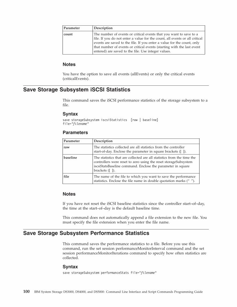
Parameter Description
count The number of events or critical events that you want to save to afile. If you do not enter a value for the count, all events or all criticalevents are saved to the file. If you enter a value for the count, onlythat number of events or critical events (starting with the last evententered) are saved to the file. Use integer values.
Notes
You have the option to save all events (allEvents) or only the critical events(criticalEvents).
Save Storage Subsystem iSCSI Statistics
This command saves the iSCSI performance statistics of the storage subsystem to afile.
Syntaxsave storageSubsystem iscsiStatistics [raw | baseline]file=“filename”
Parameters
Parameter Description
raw The statistics collected are all statistics from the controllerstart-of-day. Enclose the parameter in square brackets ([ ]).
baseline The statistics that are collected are all statistics from the time thecontrollers were reset to zero using the reset storageSubsystemiscsiStatsBaseline command. Enclose the parameter in squarebrackets ([ ]).
file The name of the file to which you want to save the performancestatistics. Enclose the file name in double quotation marks (“ ”).
Notes
If you have not reset the iSCSI baseline statistics since the controller start–of–day,the time at the start–of–day is the default baseline time.
This command does not automatically append a file extension to the new file. Youmust specify the file extension when you enter the file name.
Save Storage Subsystem Performance Statistics
This command saves the performance statistics to a file. Before you use thiscommand, run the set session performanceMonitorInterval command and the setsession performanceMonitorIterations command to specify how often statistics arecollected.
Syntaxsave storageSubsystem performanceStats file=”filename”
100 IBM System Storage DS3000, DS4000, and DS5000: Command Line Interface and Script Commands Programming Guide
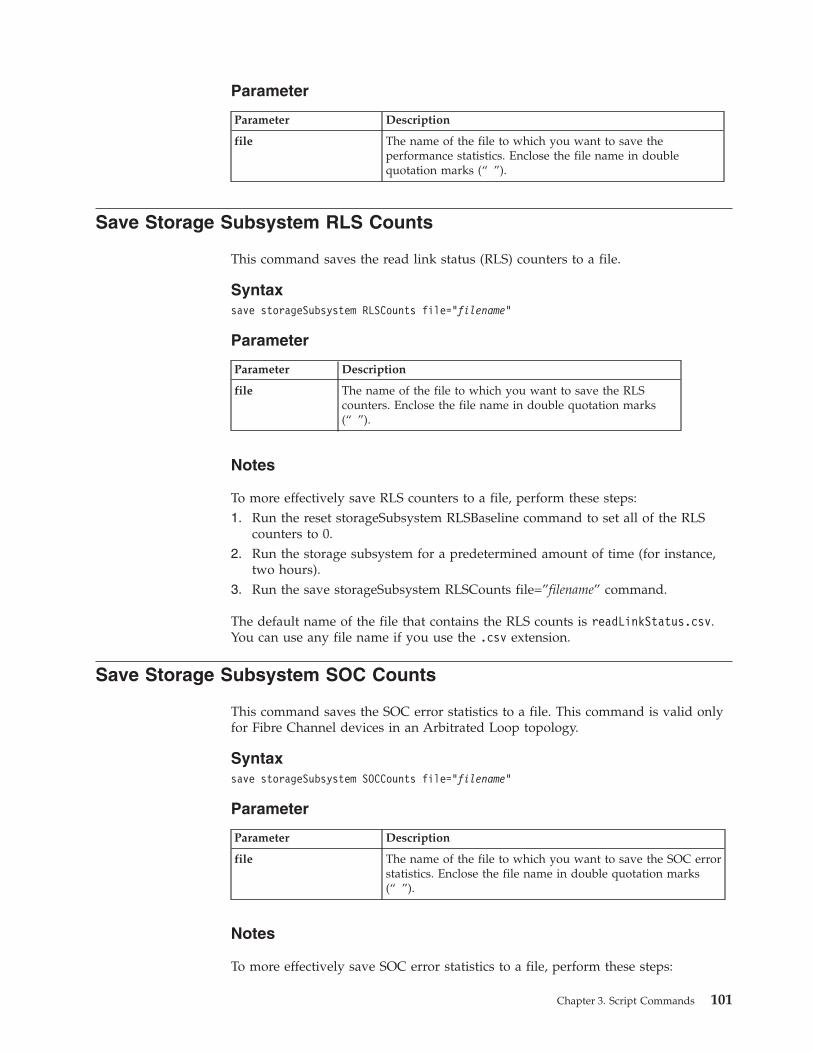
Parameter
Parameter Description
file The name of the file to which you want to save theperformance statistics. Enclose the file name in doublequotation marks (“ ”).
Save Storage Subsystem RLS Counts
This command saves the read link status (RLS) counters to a file.
Syntaxsave storageSubsystem RLSCounts file=”filename”
Parameter
Parameter Description
file The name of the file to which you want to save the RLScounters. Enclose the file name in double quotation marks(“ ”).
Notes
To more effectively save RLS counters to a file, perform these steps:1. Run the reset storageSubsystem RLSBaseline command to set all of the RLS
counters to 0.2. Run the storage subsystem for a predetermined amount of time (for instance,
two hours).3. Run the save storageSubsystem RLSCounts file=”filename” command.
The default name of the file that contains the RLS counts is readLinkStatus.csv.You can use any file name if you use the .csv extension.
Save Storage Subsystem SOC Counts
This command saves the SOC error statistics to a file. This command is valid onlyfor Fibre Channel devices in an Arbitrated Loop topology.
Syntaxsave storageSubsystem SOCCounts file=”filename”
Parameter
Parameter Description
file The name of the file to which you want to save the SOC errorstatistics. Enclose the file name in double quotation marks(“ ”).
Notes
To more effectively save SOC error statistics to a file, perform these steps:
Chapter 3. Script Commands 101
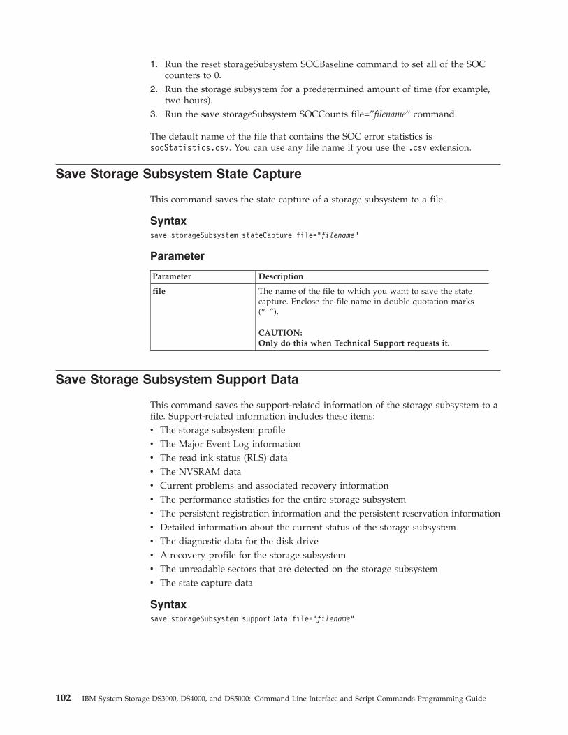
1. Run the reset storageSubsystem SOCBaseline command to set all of the SOCcounters to 0.
2. Run the storage subsystem for a predetermined amount of time (for example,two hours).
3. Run the save storageSubsystem SOCCounts file=”filename” command.
The default name of the file that contains the SOC error statistics issocStatistics.csv. You can use any file name if you use the .csv extension.
Save Storage Subsystem State Capture
This command saves the state capture of a storage subsystem to a file.
Syntaxsave storageSubsystem stateCapture file=”filename”
Parameter
Parameter Description
file The name of the file to which you want to save the statecapture. Enclose the file name in double quotation marks(“ ”).
CAUTION:Only do this when Technical Support requests it.
Save Storage Subsystem Support Data
This command saves the support-related information of the storage subsystem to afile. Support-related information includes these items:v The storage subsystem profilev The Major Event Log informationv The read ink status (RLS) datav The NVSRAM datav Current problems and associated recovery informationv The performance statistics for the entire storage subsystemv The persistent registration information and the persistent reservation informationv Detailed information about the current status of the storage subsystemv The diagnostic data for the disk drivev A recovery profile for the storage subsystemv The unreadable sectors that are detected on the storage subsystemv The state capture data
Syntaxsave storageSubsystem supportData file=”filename”
102 IBM System Storage DS3000, DS4000, and DS5000: Command Line Interface and Script Commands Programming Guide
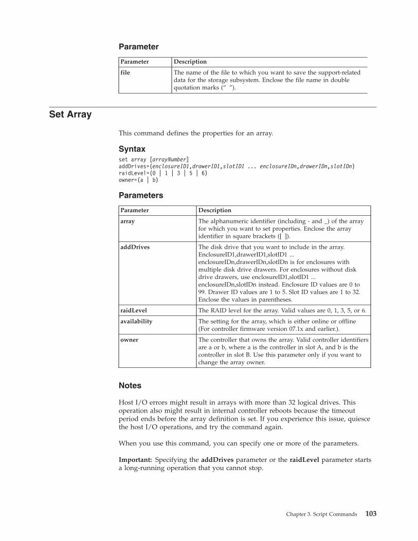
Parameter
Parameter Description
file The name of the file to which you want to save the support-relateddata for the storage subsystem. Enclose the file name in doublequotation marks (“ ”).
Set Array
This command defines the properties for an array.
Syntaxset array [arrayNumber]addDrives=(enclosureID1,drawerID1,slotID1 ... enclosureIDn,drawerIDn,slotIDn)raidLevel=(0 | 1 | 3 | 5 | 6)owner=(a | b)
Parameters
Parameter Description
array The alphanumeric identifier (including - and _) of the arrayfor which you want to set properties. Enclose the arrayidentifier in square brackets ([ ]).
addDrives The disk drive that you want to include in the array.EnclosureID1,drawerID1,slotID1 ...enclosureIDn,drawerIDn,slotIDn is for enclosures withmultiple disk drive drawers. For enclosures without diskdrive drawers, use enclosureID1,slotID1 ...enclosureIDn,slotIDn instead. Enclosure ID values are 0 to99. Drawer ID values are 1 to 5. Slot ID values are 1 to 32.Enclose the values in parentheses.
raidLevel The RAID level for the array. Valid values are 0, 1, 3, 5, or 6.
availability The setting for the array, which is either online or offline(For controller firmware version 07.1x and earlier.).
owner The controller that owns the array. Valid controller identifiersare a or b, where a is the controller in slot A, and b is thecontroller in slot B. Use this parameter only if you want tochange the array owner.
Notes
Host I/O errors might result in arrays with more than 32 logical drives. Thisoperation also might result in internal controller reboots because the timeoutperiod ends before the array definition is set. If you experience this issue, quiescethe host I/O operations, and try the command again.
When you use this command, you can specify one or more of the parameters.
Important: Specifying the addDrives parameter or the raidLevel parameter startsa long-running operation that you cannot stop.
Chapter 3. Script Commands 103
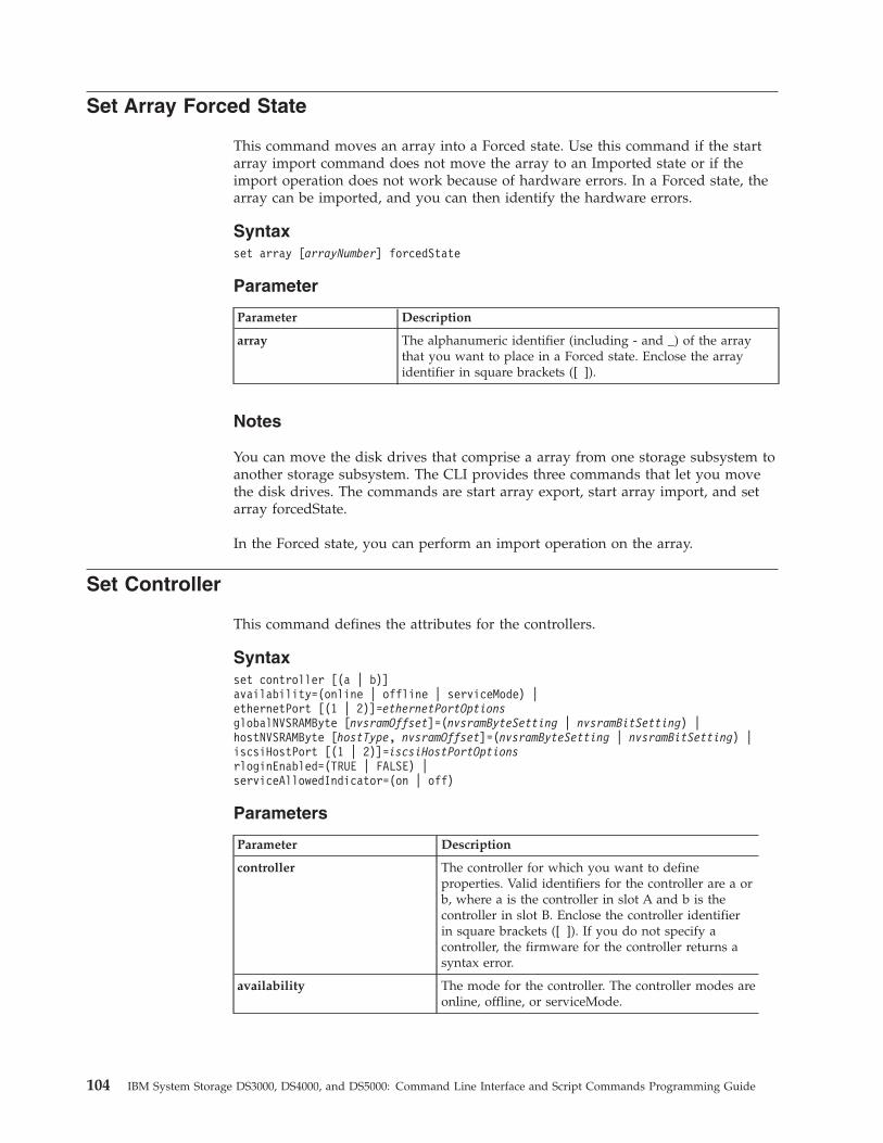
Set Array Forced State
This command moves an array into a Forced state. Use this command if the startarray import command does not move the array to an Imported state or if theimport operation does not work because of hardware errors. In a Forced state, thearray can be imported, and you can then identify the hardware errors.
Syntaxset array [arrayNumber] forcedState
Parameter
Parameter Description
array The alphanumeric identifier (including - and _) of the arraythat you want to place in a Forced state. Enclose the arrayidentifier in square brackets ([ ]).
Notes
You can move the disk drives that comprise a array from one storage subsystem toanother storage subsystem. The CLI provides three commands that let you movethe disk drives. The commands are start array export, start array import, and setarray forcedState.
In the Forced state, you can perform an import operation on the array.
Set Controller
This command defines the attributes for the controllers.
Syntaxset controller [(a | b)]availability=(online | offline | serviceMode) |ethernetPort [(1 | 2)]=ethernetPortOptionsglobalNVSRAMByte [nvsramOffset]=(nvsramByteSetting | nvsramBitSetting) |hostNVSRAMByte [hostType, nvsramOffset]=(nvsramByteSetting | nvsramBitSetting) |iscsiHostPort [(1 | 2)]=iscsiHostPortOptionsrloginEnabled=(TRUE | FALSE) |serviceAllowedIndicator=(on | off)
Parameters
Parameter Description
controller The controller for which you want to defineproperties. Valid identifiers for the controller are a orb, where a is the controller in slot A and b is thecontroller in slot B. Enclose the controller identifierin square brackets ([ ]). If you do not specify acontroller, the firmware for the controller returns asyntax error.
availability The mode for the controller. The controller modes areonline, offline, or serviceMode.
104 IBM System Storage DS3000, DS4000, and DS5000: Command Line Interface and Script Commands Programming Guide
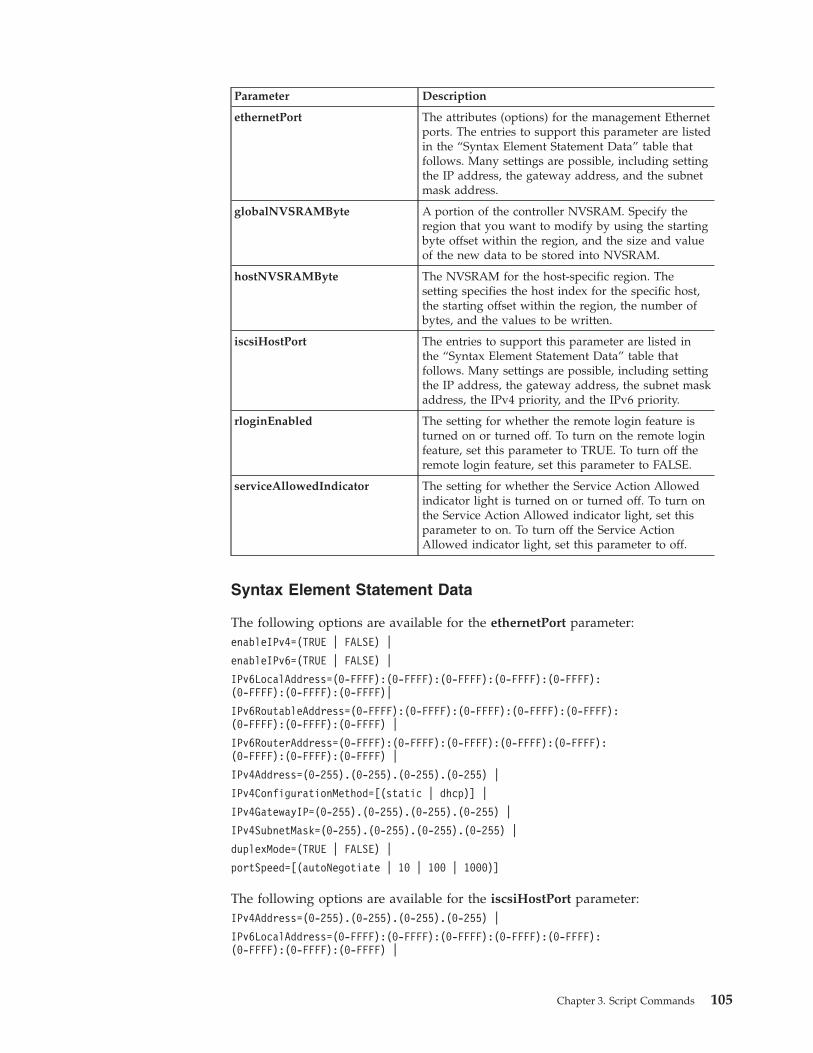
Parameter Description
ethernetPort The attributes (options) for the management Ethernetports. The entries to support this parameter are listedin the “Syntax Element Statement Data” table thatfollows. Many settings are possible, including settingthe IP address, the gateway address, and the subnetmask address.
globalNVSRAMByte A portion of the controller NVSRAM. Specify theregion that you want to modify by using the startingbyte offset within the region, and the size and valueof the new data to be stored into NVSRAM.
hostNVSRAMByte The NVSRAM for the host-specific region. Thesetting specifies the host index for the specific host,the starting offset within the region, the number ofbytes, and the values to be written.
iscsiHostPort The entries to support this parameter are listed inthe “Syntax Element Statement Data” table thatfollows. Many settings are possible, including settingthe IP address, the gateway address, the subnet maskaddress, the IPv4 priority, and the IPv6 priority.
rloginEnabled The setting for whether the remote login feature isturned on or turned off. To turn on the remote loginfeature, set this parameter to TRUE. To turn off theremote login feature, set this parameter to FALSE.
serviceAllowedIndicator The setting for whether the Service Action Allowedindicator light is turned on or turned off. To turn onthe Service Action Allowed indicator light, set thisparameter to on. To turn off the Service ActionAllowed indicator light, set this parameter to off.
Syntax Element Statement Data
The following options are available for the ethernetPort parameter:enableIPv4=(TRUE | FALSE) |
enableIPv6=(TRUE | FALSE) |
IPv6LocalAddress=(0-FFFF):(0-FFFF):(0-FFFF):(0-FFFF):(0-FFFF):(0-FFFF):(0-FFFF):(0-FFFF)|
IPv6RoutableAddress=(0-FFFF):(0-FFFF):(0-FFFF):(0-FFFF):(0-FFFF):(0-FFFF):(0-FFFF):(0-FFFF) |
IPv6RouterAddress=(0-FFFF):(0-FFFF):(0-FFFF):(0-FFFF):(0-FFFF):(0-FFFF):(0-FFFF):(0-FFFF) |
IPv4Address=(0-255).(0-255).(0-255).(0-255) |
IPv4ConfigurationMethod=[(static | dhcp)] |
IPv4GatewayIP=(0-255).(0-255).(0-255).(0-255) |
IPv4SubnetMask=(0-255).(0-255).(0-255).(0-255) |
duplexMode=(TRUE | FALSE) |
portSpeed=[(autoNegotiate | 10 | 100 | 1000)]
The following options are available for the iscsiHostPort parameter:IPv4Address=(0-255).(0-255).(0-255).(0-255) |
IPv6LocalAddress=(0-FFFF):(0-FFFF):(0-FFFF):(0-FFFF):(0-FFFF):(0-FFFF):(0-FFFF):(0-FFFF) |
Chapter 3. Script Commands 105
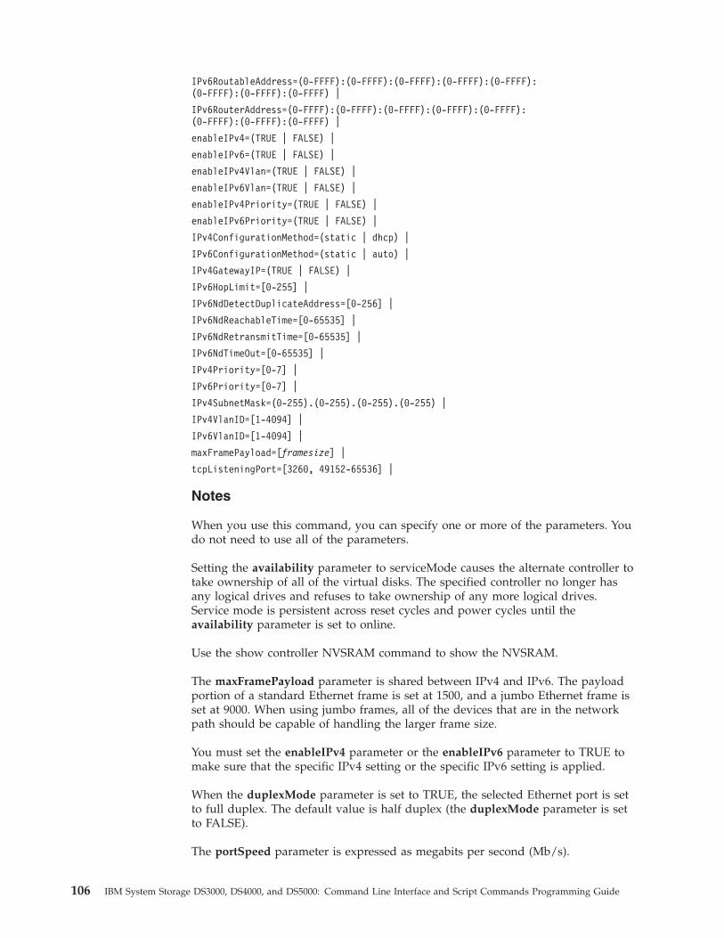
IPv6RoutableAddress=(0-FFFF):(0-FFFF):(0-FFFF):(0-FFFF):(0-FFFF):(0-FFFF):(0-FFFF):(0-FFFF) |
IPv6RouterAddress=(0-FFFF):(0-FFFF):(0-FFFF):(0-FFFF):(0-FFFF):(0-FFFF):(0-FFFF):(0-FFFF) |
enableIPv4=(TRUE | FALSE) |
enableIPv6=(TRUE | FALSE) |
enableIPv4Vlan=(TRUE | FALSE) |
enableIPv6Vlan=(TRUE | FALSE) |
enableIPv4Priority=(TRUE | FALSE) |
enableIPv6Priority=(TRUE | FALSE) |
IPv4ConfigurationMethod=(static | dhcp) |
IPv6ConfigurationMethod=(static | auto) |
IPv4GatewayIP=(TRUE | FALSE) |
IPv6HopLimit=[0-255] |
IPv6NdDetectDuplicateAddress=[0-256] |
IPv6NdReachableTime=[0-65535] |
IPv6NdRetransmitTime=[0-65535] |
IPv6NdTimeOut=[0-65535] |
IPv4Priority=[0-7] |
IPv6Priority=[0-7] |
IPv4SubnetMask=(0-255).(0-255).(0-255).(0-255) |
IPv4VlanID=[1-4094] |
IPv6VlanID=[1-4094] |
maxFramePayload=[framesize] |
tcpListeningPort=[3260, 49152-65536] |
Notes
When you use this command, you can specify one or more of the parameters. Youdo not need to use all of the parameters.
Setting the availability parameter to serviceMode causes the alternate controller totake ownership of all of the virtual disks. The specified controller no longer hasany logical drives and refuses to take ownership of any more logical drives.Service mode is persistent across reset cycles and power cycles until theavailability parameter is set to online.
Use the show controller NVSRAM command to show the NVSRAM.
The maxFramePayload parameter is shared between IPv4 and IPv6. The payloadportion of a standard Ethernet frame is set at 1500, and a jumbo Ethernet frame isset at 9000. When using jumbo frames, all of the devices that are in the networkpath should be capable of handling the larger frame size.
You must set the enableIPv4 parameter or the enableIPv6 parameter to TRUE tomake sure that the specific IPv4 setting or the specific IPv6 setting is applied.
When the duplexMode parameter is set to TRUE, the selected Ethernet port is setto full duplex. The default value is half duplex (the duplexMode parameter is setto FALSE).
The portSpeed parameter is expressed as megabits per second (Mb/s).
106 IBM System Storage DS3000, DS4000, and DS5000: Command Line Interface and Script Commands Programming Guide
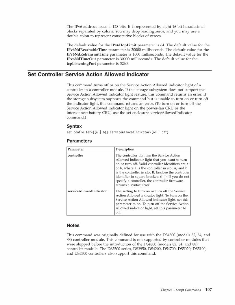
The IPv6 address space is 128 bits. It is represented by eight 16-bit hexadecimalblocks separated by colons. You may drop leading zeros, and you may use adouble colon to represent consecutive blocks of zeroes.
The default value for the IPv6HopLimit parameter is 64. The default value for theIPv6NdReachableTime parameter is 30000 milliseconds. The default value for theIPv6NdRetransmitTime parameter is 1000 milliseconds. The default value for theIPv6NdTimeOut parameter is 30000 milliseconds. The default value for thetcpListeningPort parameter is 3260.
Set Controller Service Action Allowed Indicator
This command turns off or on the Service Action Allowed indicator light of acontroller in a controller module. If the storage subsystem does not support theService Action Allowed indicator light feature, this command returns an error. Ifthe storage subsystem supports the command but is unable to turn on or turn offthe indicator light, this command returns an error. (To turn on or turn off theService Action Allowed indicator light on the power-fan CRU or theinterconnect-battery CRU, use the set enclosure serviceAllowedIndicatorcommand.)
Syntaxset controller=[(a | b)] serviceAllowedIndicator=(on | off)
Parameters
Parameter Description
controller The controller that has the Service ActionAllowed indicator light that you want to turnon or turn off. Valid controller identifiers are aor b, where a is the controller in slot A, and bis the controller in slot B. Enclose the controlleridentifier in square brackets ([ ]). If you do notspecify a controller, the controller firmwarereturns a syntax error.
serviceAllowedIndicator The setting to turn on or turn off the ServiceAction Allowed indicator light. To turn on theService Action Allowed indicator light, set thisparameter to on. To turn off the Service ActionAllowed indicator light, set this parameter tooff.
Notes
This command was originally defined for use with the DS4800 (models 82, 84, and88) controller module. This command is not supported by controller modules thatwere shipped before the introduction of the DS4800 (models 82, 84, and 88)controller module. The DS3500 series, DS3950, DS4200, DS4700, DS5020, DS5100,and DS5300 controllers also support this command.
Chapter 3. Script Commands 107
Set Drawer Service Action Allowed Indicator
This command turns on or turns off the Service Action Allowed indicator light ona drawer that holds disk drives. Drawers are used in high-capacity expansiondrawers. The drawers slide out of the expansion drawer to provide access to thedisk drives. Use this command only for expansion enclosures that use drawers. Ifthe storage subsystem does not support the Service Action Allowed indicator lightfeature, this command returns an error. If the storage subsystem supports thecommand but is unable to turn on or turn off the indicator light, this commandreturns an error.
Syntaxset enclosure [enclosureID]drawer [drawerID]serviceAllowedIndicator=(on | off | forceOnWarning)
Parameters
Parameter Description
enclosure The enclosure where the drawer resides. Enclosure IDvalues are 0 to 99. Enclose the enclosure ID value insquare brackets ([ ]). If you do not enter an enclosure IDvalue, the enclosure ID of the controller module is thedefault value.
drawer The location of the drawer for which you want to turnon or turn off the service action allowed indicator.Drawer ID values are 1 to 5. Enclose the value in squarebrackets ([ ]).
serviceAllowedIndicator The setting to turn on or turn off the Service ActionAllowed indicator light. To turn on the Service ActionAllowed indicator light, set this parameter to on. To turnoff the Service Action Allowed indicator light, set thisparameter to off.
Notes
Before you can enter this command, the expansion drawer must meet theseconditions:v The expansion drawer cannot be over temperature.v The fans must have a status of Optimal.v All expansion drawer components must be in place. The logical drives in the
disk drive drawer cannot be in a Degraded state. If you remove disk drives fromthe disk drive drawer and a logical drive is already in a Degraded state, thelogical drive can fail.
Attention
Read the following before you issue this command.v All logical drives with disk drives in the affected disk drive drawer are checked
to make sure that the logical drives have drawer loss protection before thecommand is sent. If the logical drives have drawer loss protection, the SetService Action Allowed command proceeds without stopping I/O activity to thelogical drive. If any logical drives in the affected drawer do not have drawer
108 IBM System Storage DS3000, DS4000, and DS5000: Command Line Interface and Script Commands Programming Guide
loss protection, you must stop I/O activity to those logical drives. A warningappears, which indicates that this command should not be completed.
v If you are preparing a component for removal and want to override the warningthat the logical drives do not have drawer loss protection, enter this parameter:serviceAllowedIndicator=forceOnWarning. This parameter sends the request toprepare to remove a component to the controller firmware, and forces the setdrawer serviceAllowedIndicator command to proceed.
v To turn on or turn off the Service Action Allowed indicator light for the entirehigh-capacity expansion drawer, use the set enclosure serviceAllowedIndicatorcommand.
Set Drive Channel Status
This command defines how the disk drive channel performs.
Syntaxset driveChannel [(1 | 2 | 3 | 4 | 5 | 6 | 7 | 8)]status=(optimal | degraded)
Parameters
Parameter Description
driveChannel The identifier number of the disk drive channel for whichyou want to set the status. Valid disk drive channel values are1, 2, 3, or 4. Enclose the disk drive channel number in squarebrackets ([ ]).
status The condition of the disk drive channel. You can set the diskdrive channel status to optimal or degraded.
Notes
Use the optimal value to move a degraded disk drive channel back to the Optimalstate. Use the degraded value when the disk drive channel is experiencingproblems, and the storage subsystem requires additional time for data transfers.
Set Disk Drive Hot Spare
This command assigns or unassigns one or more disk drives as a hot spare.
Syntaxset (Drive [enclosureID,drawerID1,slotID] |Drives (enclosureID1,drawerID1,slotID1 ... enclosureIDn,drawerIDn,slotIDn)hotSpare=(TRUE | FALSE)
Chapter 3. Script Commands 109
Parameters
Parameter Description
drive or drives EnclosureID1,drawerID1,slotID1 ...enclosureIDn,drawerIDn,slotIDn is for enclosures withmultiple disk drive drawers. For enclosures without diskdrive drawers, use enclosureID1,slotID1 ...enclosureIDn,slotIDn instead. Enclosure ID values are 0 to 99.Drawer ID values are 1 to 5. Slot ID values are 1 to 32.Enclose the values in square brackets ([ ]).
hotSpare The setting to assign the disk drive as the hot spare. To assignthe disk drive as the hot spare, set this parameter to TRUE.To remove a hot spare assignment from a disk drive, set thisparameter to FALSE.
Set Disk Drive Service Action Allowed Indicator
This command turns on or turns off the Service Action Allowed indicator light ona disk drive in expansion drawers that support the Service Action Allowedindicator light feature. If the storage subsystem does not support the ServiceAction Allowed indicator light feature, this command returns an error. If thestorage subsystem supports the command but is unable to turn on or turn off theindicator light, this command returns an error.
Syntaxset (Drive [enclosureID,drawerID1,slotID] |Drives (enclosureID1,drawerID1,slotID1 ... enclosureIDn,drawerIDn,slotIDn)serviceAllowedIndicator=(on | off)
Parameters
Parameter Description
drive or drives EnclosureID1,drawerID1,slotID1 ...enclosureIDn,drawerIDn,slotIDn is for enclosures withmultiple disk drive drawers. For enclosures without diskdrive drawers, use enclosureID1,slotID1 ...enclosureIDn,slotIDn instead. Enclosure ID values are 0to 99. Drawer ID values are 1 to 5. Slot ID values are 1 to32. Enclose the values in square brackets ([ ]).
serviceAllowedIndicator The setting to turn on or turn off the Service ActionAllowed indicator light. To turn on the Service ActionAllowed indicator light, set this parameter to on. To turnoff the Service Action Allowed indicator light, set thisparameter to off.
Set Drive State
This command sets a disk drive to the Failed state. (To return a disk drive to theOptimal state, use the revive drive command.)
Syntaxset Drive [enclosureID1,drawerID1,slotID1 ... enclosureIDn,drawerIDn,slotIDn]operationalState=failed
110 IBM System Storage DS3000, DS4000, and DS5000: Command Line Interface and Script Commands Programming Guide
Parameter
Parameter Description
drive The enclosure, drawer, and the slot where the disk drive resides.EnclosureID1,drawerID1,slotID1 ... enclosureIDn,drawerIDn,slotIDnis for enclosures with multiple disk drive drawers. For enclosureswithout disk drive drawers, use enclosureID1,slotID1 ...enclosureIDn,slotIDn instead. Enclosure ID values are 0 to 99.Drawer ID values are 1 to 5. Slot ID values are 1 to 32. Enclose thevalues in square brackets ([ ]).
Set Enclosure Alarm
This command turns on, turns off, or mutes the audible alarm for a specificenclosure or all of the enclosures in a storage subsystem.
Syntaxset (allenclosures | enclosure [enclosureID]alarm=(enable | disable | mute))
Parameters
Parameter Description
allEnclosures The setting to select all of the enclosures in a storagesubsystem that have audible alarms that you want to turn on,turn off, or mute.
enclosure The specific enclosure that has the audible alarm that youwant to turn on, turn off, or mute. Enclosure ID values are 0to 99. Enclose the enclosure ID value in square brackets ([ ]).You can specify only one enclosure ID at a time
alarm The setting for the audible alarm. This alarm has these values:
v enable – The audible alarm is turned on and sounds if afault occurs.
v disable – The audible alarm is turned off and does notsound if a fault occurs.
v mute – The audible alarm is turned off if it is sounding.
(If another fault occurs after you set the audible alarm tomute, the audible alarm sounds again.)
Set Enclosure Identification
This command sets the enclosure ID of a controller module or a expansion drawerin a storage subsystem. This command is valid only for controller modules orexpansion drawers that have enclosure IDs that you can set through the controllerfirmware. You cannot use this command for controller modules or expansiondrawers that have an enclosure ID that you set with a switch.
Syntaxset enclosure [“serial-number”] id=enclosureID
Chapter 3. Script Commands 111
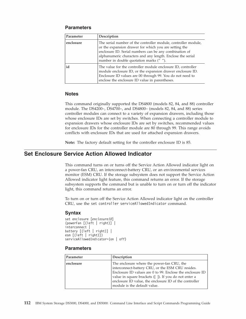
Parameters
Parameter Description
enclosure The serial number of the controller module, controller module,or the expansion drawer for which you are setting theenclosure ID. Serial numbers can be any combination ofalphanumeric characters and any length. Enclose the serialnumber in double quotation marks (“ ”).
id The value for the controller module enclosure ID, controllermodule enclosure ID, or the expansion drawer enclosure ID.Enclosure ID values are 00 through 99. You do not need toenclose the enclosure ID value in parentheses.
Notes
This command originally supported the DS4800 (models 82, 84, and 88) controllermodule. The DS4200–, DS4700–, and DS4800– (models 82, 84, and 88) seriescontroller modules can connect to a variety of expansion drawers, including thosewhose enclosure IDs are set by switches. When connecting a controller module toexpansion drawers whose enclosure IDs are set by switches, recommended valuesfor enclosure IDs for the controller module are 80 through 99. This range avoidsconflicts with enclosure IDs that are used for attached expansion drawers.
Note: The factory default setting for the controller enclosure ID is 85.
Set Enclosure Service Action Allowed Indicator
This command turns on or turns off the Service Action Allowed indicator light ona power-fan CRU, an interconnect-battery CRU, or an environmental servicesmonitor (ESM) CRU. If the storage subsystem does not support the Service ActionAllowed indicator light feature, this command returns an error. If the storagesubsystem supports the command but is unable to turn on or turn off the indicatorlight, this command returns an error.
To turn on or turn off the Service Action Allowed indicator light on the controllerCRU, use the set controller serviceAllowedIndicator command.
Syntaxset enclosure [enclosureID](powerFan [(left | right)] |interconnect |battery [(left | right)] |esm [(left | right)])serviceAllowedIndicator=(on | off)
Parameters
Parameter Description
enclosure The enclosure where the power-fan CRU, theinterconnect-battery CRU, or the ESM CRU resides.Enclosure ID values are 0 to 99. Enclose the enclosure IDvalue in square brackets ([ ]). If you do not enter aenclosure ID value, the enclosure ID of the controllermodule is the default value.
112 IBM System Storage DS3000, DS4000, and DS5000: Command Line Interface and Script Commands Programming Guide

Parameter Description
powerFan The Service Action Allowed indicator light on thepower-fan CRU that you want to turn on or turn off.Valid power-fan CRU identifiers are left or right. Thevalues left and right are with respect to the front of theDS5300–, DS5100–, and DS4800–series controllermodules. Enclose the power-fan CRU identifier in squarebrackets ([ ]).
interconnect The Service Action Allowed indicator light for theinterconnect-battery CRU DS5300–, DS5100–, andDS4800–series controller modules only.
battery The Service Action Allowed indicator light for a battery.Valid battery identifiers are left or right. The values leftand right are with respect to the front of the DS5300–,DS5100–, and DS4800–series controller modules.
esm The Service Action Allowed indicator light for an ESMCRU. Valid ESM CRU identifiers are left or right. (Thevalues left and right are with respect to the rear of thedrive expansion enclosure.)
serviceAllowedIndicator The setting to turn on or turn off the Service ActionAllowed indicator light. To turn on the Service ActionAllowed indicator light, set this parameter to on. To turnoff the Service Action Allowed indicator light, set thisparameter to off.
Example
This command turns on the Service Action Allowed indicator light for the left ESMon enclosure 5 with the IP address of 155.155.155.155.SMcli 155.155.155.155 -c “set enclosure [5] ESM [left] serviceAllowedIndicator=on”;
Notes
This command was originally defined for use with the DS4800 controller module.This command is not supported by controller modules (FAStT200, FAStT500,DS4100, DS4300, DS4400, and DS4500 storage subsystems) that were shippedbefore the introduction of the DS4800 controller module. The interconnect,powerFan, battery, and esm parameters are mutual exclusive. You can specify onlyone of the three at a time.
Set FlashCopy Logical Drive
This command defines the properties for a FlashCopy logical drive and lets yourename a FlashCopy logical drive.
Syntaxset (logicalDrive [logicalDriveName] |logicalDrives [logicalDriveName1 ... logicalDriveNameN])warningThresholdPercent=percentValuerepositoryFullPolicy=(failBaseWrites | failFlashCopy)
Chapter 3. Script Commands 113
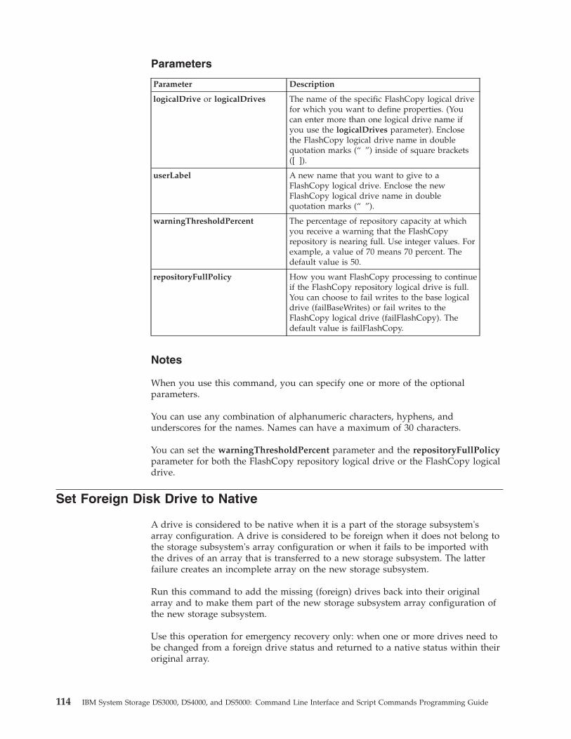
Parameters
Parameter Description
logicalDrive or logicalDrives The name of the specific FlashCopy logical drivefor which you want to define properties. (Youcan enter more than one logical drive name ifyou use the logicalDrives parameter). Enclosethe FlashCopy logical drive name in doublequotation marks (“ ”) inside of square brackets([ ]).
userLabel A new name that you want to give to aFlashCopy logical drive. Enclose the newFlashCopy logical drive name in doublequotation marks (“ ”).
warningThresholdPercent The percentage of repository capacity at whichyou receive a warning that the FlashCopyrepository is nearing full. Use integer values. Forexample, a value of 70 means 70 percent. Thedefault value is 50.
repositoryFullPolicy How you want FlashCopy processing to continueif the FlashCopy repository logical drive is full.You can choose to fail writes to the base logicaldrive (failBaseWrites) or fail writes to theFlashCopy logical drive (failFlashCopy). Thedefault value is failFlashCopy.
Notes
When you use this command, you can specify one or more of the optionalparameters.
You can use any combination of alphanumeric characters, hyphens, andunderscores for the names. Names can have a maximum of 30 characters.
You can set the warningThresholdPercent parameter and the repositoryFullPolicyparameter for both the FlashCopy repository logical drive or the FlashCopy logicaldrive.
Set Foreign Disk Drive to Native
A drive is considered to be native when it is a part of the storage subsystem'sarray configuration. A drive is considered to be foreign when it does not belong tothe storage subsystem's array configuration or when it fails to be imported withthe drives of an array that is transferred to a new storage subsystem. The latterfailure creates an incomplete array on the new storage subsystem.
Run this command to add the missing (foreign) drives back into their originalarray and to make them part of the new storage subsystem array configuration ofthe new storage subsystem.
Use this operation for emergency recovery only: when one or more drives need tobe changed from a foreign drive status and returned to a native status within theiroriginal array.
114 IBM System Storage DS3000, DS4000, and DS5000: Command Line Interface and Script Commands Programming Guide
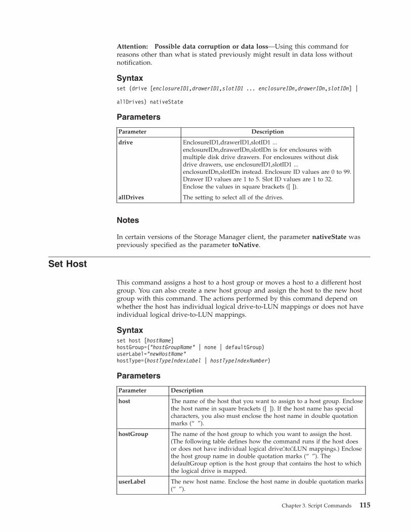
Attention: Possible data corruption or data loss—Using this command forreasons other than what is stated previously might result in data loss withoutnotification.
Syntaxset (drive [enclosureID1,drawerID1,slotID1 ... enclosureIDn,drawerIDn,slotIDn] |
allDrives) nativeState
Parameters
Parameter Description
drive EnclosureID1,drawerID1,slotID1 ...enclosureIDn,drawerIDn,slotIDn is for enclosures withmultiple disk drive drawers. For enclosures without diskdrive drawers, use enclosureID1,slotID1 ...enclosureIDn,slotIDn instead. Enclosure ID values are 0 to 99.Drawer ID values are 1 to 5. Slot ID values are 1 to 32.Enclose the values in square brackets ([ ]).
allDrives The setting to select all of the drives.
Notes
In certain versions of the Storage Manager client, the parameter nativeState waspreviously specified as the parameter toNative.
Set Host
This command assigns a host to a host group or moves a host to a different hostgroup. You can also create a new host group and assign the host to the new hostgroup with this command. The actions performed by this command depend onwhether the host has individual logical drive-to-LUN mappings or does not haveindividual logical drive-to-LUN mappings.
Syntaxset host [hostName]hostGroup=(“hostGroupName” | none | defaultGroup)userLabel=“newHostName”hostType=(hostTypeIndexLabel | hostTypeIndexNumber)
Parameters
Parameter Description
host The name of the host that you want to assign to a host group. Enclosethe host name in square brackets ([ ]). If the host name has specialcharacters, you also must enclose the host name in double quotationmarks (“ ”).
hostGroup The name of the host group to which you want to assign the host.(The following table defines how the command runs if the host doesor does not have individual logical drive�to�LUN mappings.) Enclosethe host group name in double quotation marks (“ ”). ThedefaultGroup option is the host group that contains the host to whichthe logical drive is mapped.
userLabel The new host name. Enclose the host name in double quotation marks(“ ”).
Chapter 3. Script Commands 115
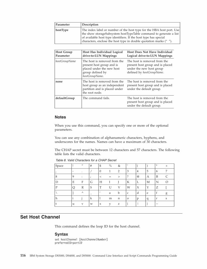
Parameter Description
hostType The index label or number of the host type for the HBA host port. Usethe show storageSubsystem hostTypeTable command to generate a listof available host type identifiers. If the host type has specialcharacters, enclose the host type in double quotation marks (“ ”).
Host GroupParameter
Host Has Individual Logicaldrive-to-LUN Mappings
Host Does Not Have IndividualLogical drive-to-LUN Mappings
hostGroupName The host is removed from thepresent host group and isplaced under the new hostgroup defined byhostGroupName.
The host is removed from thepresent host group and is placedunder the new host groupdefined by hostGroupName.
none The host is removed from thehost group as an independentpartition and is placed underthe root node.
The host is removed from thepresent host group and is placedunder the default group.
defaultGroup The command fails. The host is removed from thepresent host group and is placedunder the default group.
Notes
When you use this command, you can specify one or more of the optionalparameters.
You can use any combination of alphanumeric characters, hyphens, andunderscores for the names. Names can have a maximum of 30 characters.
The CHAP secret must be between 12 characters and 57 characters. The followingtable lists the valid characters.
Table 8. Valid Characters for a CHAP Secret
Space ! “ # $ % & ‘ ( ) * +
, - . / 0 1 2 3 4 5 6 7
8 9 : ; < = > ? @ A B C
D E F G H I J K L M N O
P Q R S T U V W X Y Z [
\ ] ^ _ ‘ a b c d e f g
h i j k l m n o p q r s
t u v w x y z { | } ~
Set Host Channel
This command defines the loop ID for the host channel.
Syntaxset hostChannel [hostChannelNumber]preferredID=portID
116 IBM System Storage DS3000, DS4000, and DS5000: Command Line Interface and Script Commands Programming Guide
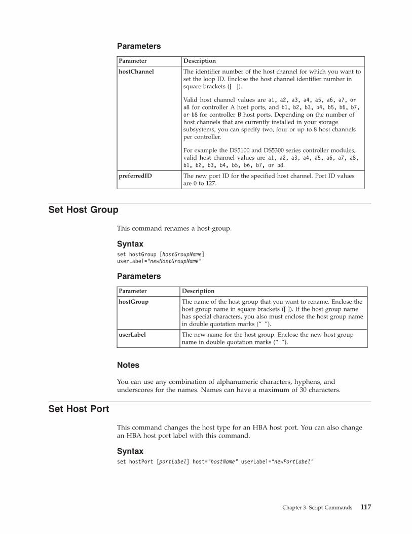
Parameters
Parameter Description
hostChannel The identifier number of the host channel for which you want toset the loop ID. Enclose the host channel identifier number insquare brackets ([ ]).
Valid host channel values are a1, a2, a3, a4, a5, a6, a7, ora8 for controller A host ports, and b1, b2, b3, b4, b5, b6, b7,or b8 for controller B host ports. Depending on the number ofhost channels that are currently installed in your storagesubsystems, you can specify two, four or up to 8 host channelsper controller.
For example the DS5100 and DS5300 series controller modules,valid host channel values are a1, a2, a3, a4, a5, a6, a7, a8,b1, b2, b3, b4, b5, b6, b7, or b8.
preferredID The new port ID for the specified host channel. Port ID valuesare 0 to 127.
Set Host Group
This command renames a host group.
Syntaxset hostGroup [hostGroupName]userLabel=”newHostGroupName”
Parameters
Parameter Description
hostGroup The name of the host group that you want to rename. Enclose thehost group name in square brackets ([ ]). If the host group namehas special characters, you also must enclose the host group namein double quotation marks (“ ”).
userLabel The new name for the host group. Enclose the new host groupname in double quotation marks (“ ”).
Notes
You can use any combination of alphanumeric characters, hyphens, andunderscores for the names. Names can have a maximum of 30 characters.
Set Host Port
This command changes the host type for an HBA host port. You can also changean HBA host port label with this command.
Syntaxset hostPort [portLabel] host=“hostName” userLabel=“newPortLabel”
Chapter 3. Script Commands 117
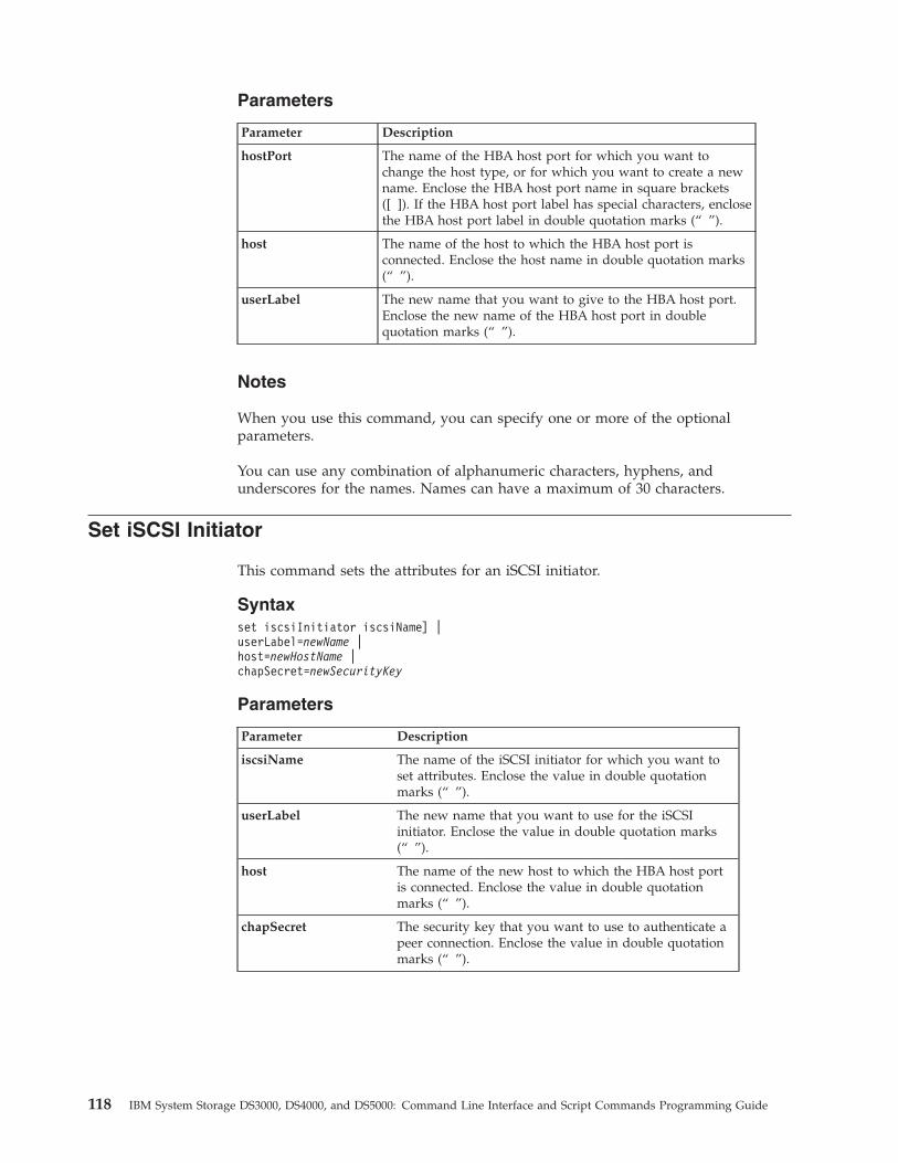
Parameters
Parameter Description
hostPort The name of the HBA host port for which you want tochange the host type, or for which you want to create a newname. Enclose the HBA host port name in square brackets([ ]). If the HBA host port label has special characters, enclosethe HBA host port label in double quotation marks (“ ”).
host The name of the host to which the HBA host port isconnected. Enclose the host name in double quotation marks(“ ”).
userLabel The new name that you want to give to the HBA host port.Enclose the new name of the HBA host port in doublequotation marks (“ ”).
Notes
When you use this command, you can specify one or more of the optionalparameters.
You can use any combination of alphanumeric characters, hyphens, andunderscores for the names. Names can have a maximum of 30 characters.
Set iSCSI Initiator
This command sets the attributes for an iSCSI initiator.
Syntaxset iscsiInitiator iscsiName] |userLabel=newName |host=newHostName |chapSecret=newSecurityKey
Parameters
Parameter Description
iscsiName The name of the iSCSI initiator for which you want toset attributes. Enclose the value in double quotationmarks (“ ”).
userLabel The new name that you want to use for the iSCSIinitiator. Enclose the value in double quotation marks(“ ”).
host The name of the new host to which the HBA host portis connected. Enclose the value in double quotationmarks (“ ”).
chapSecret The security key that you want to use to authenticate apeer connection. Enclose the value in double quotationmarks (“ ”).
118 IBM System Storage DS3000, DS4000, and DS5000: Command Line Interface and Script Commands Programming Guide
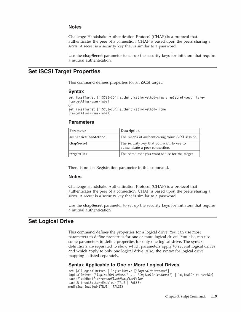
Notes
Challenge Handshake Authentication Protocol (CHAP) is a protocol thatauthenticates the peer of a connection. CHAP is based upon the peers sharing asecret. A secret is a security key that is similar to a password.
Use the chapSecret parameter to set up the security keys for initiators that requirea mutual authentication.
Set iSCSI Target Properties
This command defines properties for an iSCSI target.
Syntaxset iscsiTarget [“iSCSI-ID”] authenticationMethod=chap chapSecret=securityKey[targetAlias=user-label]Orset iscsiTarget [“iSCSI-ID”] authenticationMethod= none[targetAlias=user-label]
Parameters
Parameter Description
authenticationMethod The means of authenticating your iSCSI session.
chapSecret The security key that you want to use toauthenticate a peer connection.
targetAlias The name that you want to use for the target.
There is no isnsRegistration parameter in this command.
Notes
Challenge Handshake Authentication Protocol (CHAP) is a protocol thatauthenticates the peer of a connection. CHAP is based upon the peers sharing asecret. A secret is a security key that is similar to a password.
Use the chapSecret parameter to set up the security keys for initiators that requirea mutual authentication.
Set Logical Drive
This command defines the properties for a logical drive. You can use mostparameters to define properties for one or more logical drives. You also can usesome parameters to define properties for only one logical drive. The syntaxdefinitions are separated to show which parameters apply to several logical drivesand which apply to only one logical drive. Also, the syntax for logical drivemapping is listed separately.
Syntax Applicable to One or More Logical Drivesset (allLogicalDrives | logicalDrive [“logicalDriveName”] |logicalDrives [“logicalDriveName1” ... “logicalDriveNameN”] | logicalDrive <wwID>)cacheFlushModifier=cacheFlushModifierValuecacheWithoutBatteryEnabled=(TRUE | FALSE)mediaScanEnabled=(TRUE | FALSE)
Chapter 3. Script Commands 119
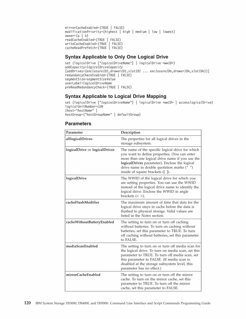
mirrorCacheEnabled=(TRUE | FALSE)modificationPriority=(highest | high | medium | low | lowest)owner=(a | b)readCacheEnabled=(TRUE | FALSE)writeCacheEnabled=(TRUE | FALSE)cacheReadPrefetch=(TRUE | FALSE)
Syntax Applicable to Only One Logical Driveset (logicalDrive [“logicalDriveName”] | logicalDrive <wwID>)addCapacity=logicalDriveCapacity[addDrives=(enclosureID1,drawerID1,slotID1 ... enclosureIDn,drawerIDn,slotIDn))]redundancyCheckEnabled=(TRUE | FALSE)segmentSize=segmentSizeValueuserLabel=logicalDriveNamepreReadRedundancyCheck=(TRUE | FALSE)
Syntax Applicable to Logical Drive Mappingset (logicalDrive [“logicalDriveName”] | logicalDrive <wwID> | accesslogicalDrive)logicalUnitNumber=LUN(host=”hostName” |hostGroup=(“hostGroupName” | defaultGroup)
Parameters
Parameter Description
alllogicalDrives The properties for all logical drives in thestorage subsystem.
logicalDrive or logicalDrives The name of the specific logical drive for whichyou want to define properties. (You can entermore than one logical drive name if you use thelogicalDrives parameter). Enclose the logicaldrive name in double quotation marks (“ ”)inside of square brackets ([ ]).
logicalDrive The WWID of the logical drive for which youare setting properties. You can use the WWIDinstead of the logical drive name to identify thelogical drive. Enclose the WWID in anglebrackets (< >).
cacheFlushModifier The maximum amount of time that data for thelogical drive stays in cache before the data isflushed to physical storage. Valid values arelisted in the Notes section.
cacheWithoutBatteryEnabled The setting to turn on or turn off cachingwithout batteries. To turn on caching withoutbatteries, set this parameter to TRUE. To turnoff caching without batteries, set this parameterto FALSE.
mediaScanEnabled The setting to turn on or turn off media scan forthe logical drive. To turn on media scan, set thisparameter to TRUE. To turn off media scan, setthis parameter to FALSE. (If media scan isdisabled at the storage subsystem level, thisparameter has no effect.)
mirrorCacheEnabled The setting to turn on or turn off the mirrorcache. To turn on the mirror cache, set thisparameter to TRUE. To turn off the mirrorcache, set this parameter to FALSE.
120 IBM System Storage DS3000, DS4000, and DS5000: Command Line Interface and Script Commands Programming Guide
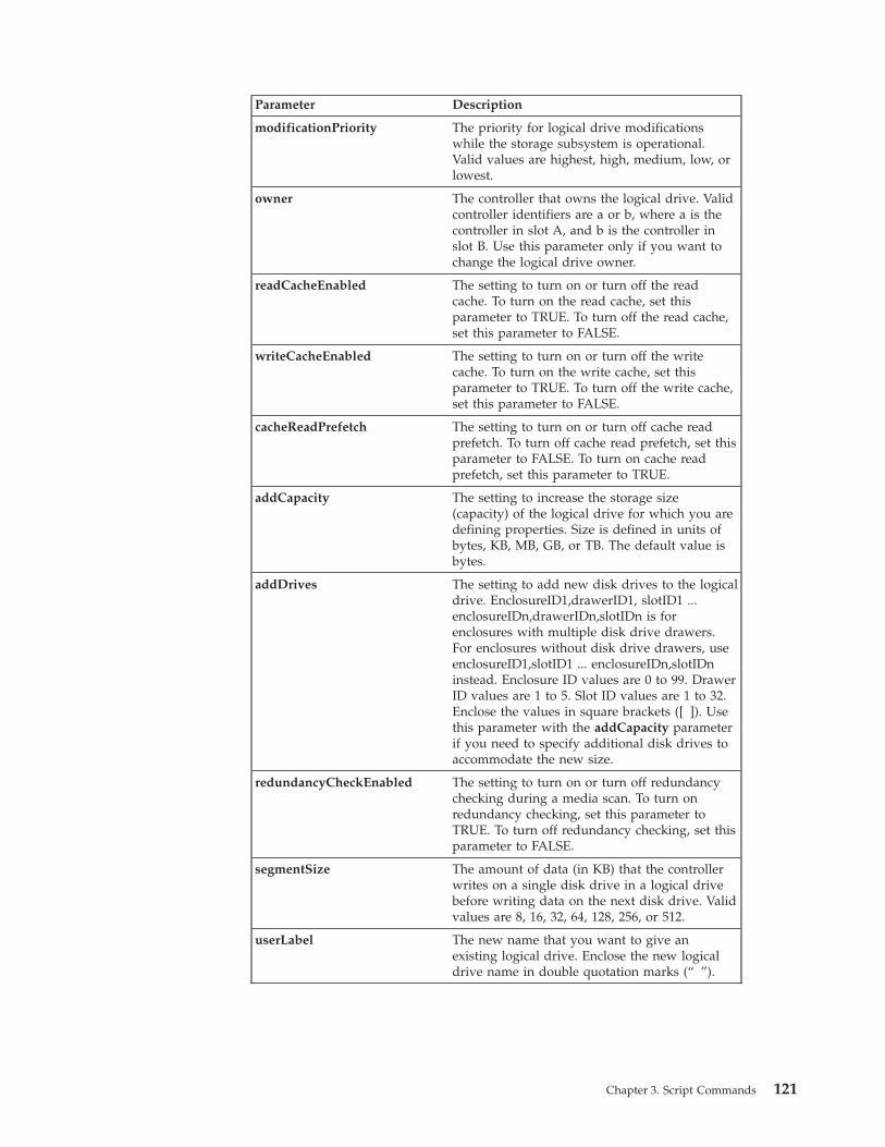
Parameter Description
modificationPriority The priority for logical drive modificationswhile the storage subsystem is operational.Valid values are highest, high, medium, low, orlowest.
owner The controller that owns the logical drive. Validcontroller identifiers are a or b, where a is thecontroller in slot A, and b is the controller inslot B. Use this parameter only if you want tochange the logical drive owner.
readCacheEnabled The setting to turn on or turn off the readcache. To turn on the read cache, set thisparameter to TRUE. To turn off the read cache,set this parameter to FALSE.
writeCacheEnabled The setting to turn on or turn off the writecache. To turn on the write cache, set thisparameter to TRUE. To turn off the write cache,set this parameter to FALSE.
cacheReadPrefetch The setting to turn on or turn off cache readprefetch. To turn off cache read prefetch, set thisparameter to FALSE. To turn on cache readprefetch, set this parameter to TRUE.
addCapacity The setting to increase the storage size(capacity) of the logical drive for which you aredefining properties. Size is defined in units ofbytes, KB, MB, GB, or TB. The default value isbytes.
addDrives The setting to add new disk drives to the logicaldrive. EnclosureID1,drawerID1, slotID1 ...enclosureIDn,drawerIDn,slotIDn is forenclosures with multiple disk drive drawers.For enclosures without disk drive drawers, useenclosureID1,slotID1 ... enclosureIDn,slotIDninstead. Enclosure ID values are 0 to 99. DrawerID values are 1 to 5. Slot ID values are 1 to 32.Enclose the values in square brackets ([ ]). Usethis parameter with the addCapacity parameterif you need to specify additional disk drives toaccommodate the new size.
redundancyCheckEnabled The setting to turn on or turn off redundancychecking during a media scan. To turn onredundancy checking, set this parameter toTRUE. To turn off redundancy checking, set thisparameter to FALSE.
segmentSize The amount of data (in KB) that the controllerwrites on a single disk drive in a logical drivebefore writing data on the next disk drive. Validvalues are 8, 16, 32, 64, 128, 256, or 512.
userLabel The new name that you want to give anexisting logical drive. Enclose the new logicaldrive name in double quotation marks (“ ”).
Chapter 3. Script Commands 121
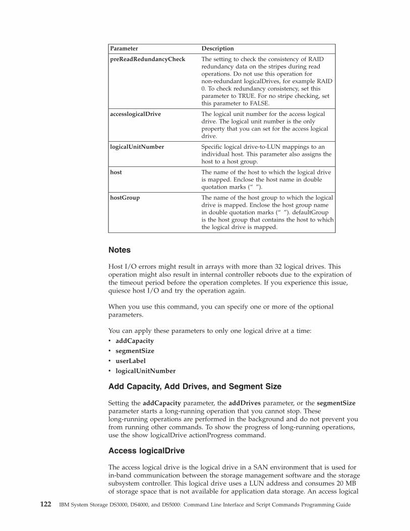
Parameter Description
preReadRedundancyCheck The setting to check the consistency of RAIDredundancy data on the stripes during readoperations. Do not use this operation fornon-redundant logicalDrives, for example RAID0. To check redundancy consistency, set thisparameter to TRUE. For no stripe checking, setthis parameter to FALSE.
accesslogicalDrive The logical unit number for the access logicaldrive. The logical unit number is the onlyproperty that you can set for the access logicaldrive.
logicalUnitNumber Specific logical drive-to-LUN mappings to anindividual host. This parameter also assigns thehost to a host group.
host The name of the host to which the logical driveis mapped. Enclose the host name in doublequotation marks (“ ”).
hostGroup The name of the host group to which the logicaldrive is mapped. Enclose the host group namein double quotation marks (“ ”). defaultGroupis the host group that contains the host to whichthe logical drive is mapped.
Notes
Host I/O errors might result in arrays with more than 32 logical drives. Thisoperation might also result in internal controller reboots due to the expiration ofthe timeout period before the operation completes. If you experience this issue,quiesce host I/O and try the operation again.
When you use this command, you can specify one or more of the optionalparameters.
You can apply these parameters to only one logical drive at a time:v addCapacity
v segmentSize
v userLabel
v logicalUnitNumber
Add Capacity, Add Drives, and Segment Size
Setting the addCapacity parameter, the addDrives parameter, or the segmentSizeparameter starts a long-running operation that you cannot stop. Theselong-running operations are performed in the background and do not prevent youfrom running other commands. To show the progress of long-running operations,use the show logicalDrive actionProgress command.
Access logicalDrive
The access logical drive is the logical drive in a SAN environment that is used forin-band communication between the storage management software and the storagesubsystem controller. This logical drive uses a LUN address and consumes 20 MBof storage space that is not available for application data storage. An access logical
122 IBM System Storage DS3000, DS4000, and DS5000: Command Line Interface and Script Commands Programming Guide
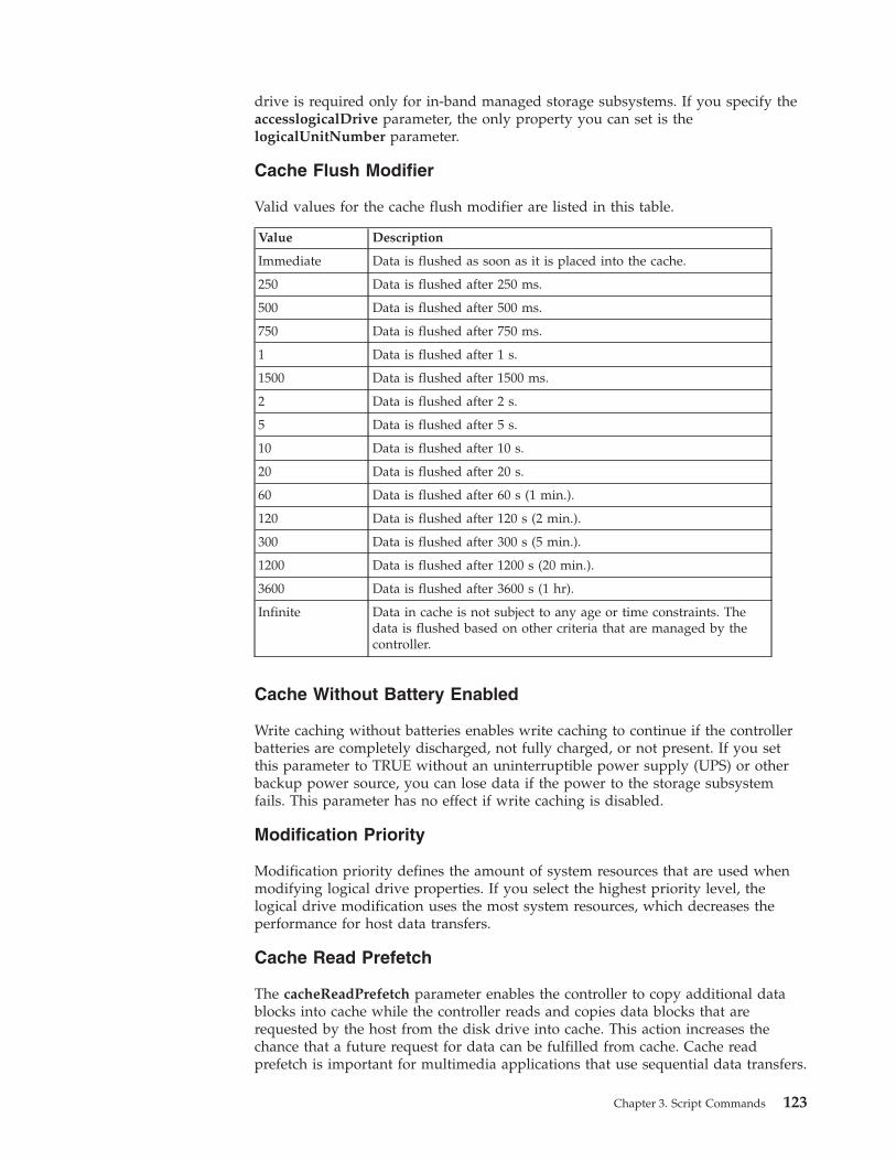
drive is required only for in-band managed storage subsystems. If you specify theaccesslogicalDrive parameter, the only property you can set is thelogicalUnitNumber parameter.
Cache Flush Modifier
Valid values for the cache flush modifier are listed in this table.
Value Description
Immediate Data is flushed as soon as it is placed into the cache.
250 Data is flushed after 250 ms.
500 Data is flushed after 500 ms.
750 Data is flushed after 750 ms.
1 Data is flushed after 1 s.
1500 Data is flushed after 1500 ms.
2 Data is flushed after 2 s.
5 Data is flushed after 5 s.
10 Data is flushed after 10 s.
20 Data is flushed after 20 s.
60 Data is flushed after 60 s (1 min.).
120 Data is flushed after 120 s (2 min.).
300 Data is flushed after 300 s (5 min.).
1200 Data is flushed after 1200 s (20 min.).
3600 Data is flushed after 3600 s (1 hr).
Infinite Data in cache is not subject to any age or time constraints. Thedata is flushed based on other criteria that are managed by thecontroller.
Cache Without Battery Enabled
Write caching without batteries enables write caching to continue if the controllerbatteries are completely discharged, not fully charged, or not present. If you setthis parameter to TRUE without an uninterruptible power supply (UPS) or otherbackup power source, you can lose data if the power to the storage subsystemfails. This parameter has no effect if write caching is disabled.
Modification Priority
Modification priority defines the amount of system resources that are used whenmodifying logical drive properties. If you select the highest priority level, thelogical drive modification uses the most system resources, which decreases theperformance for host data transfers.
Cache Read Prefetch
The cacheReadPrefetch parameter enables the controller to copy additional datablocks into cache while the controller reads and copies data blocks that arerequested by the host from the disk drive into cache. This action increases thechance that a future request for data can be fulfilled from cache. Cache readprefetch is important for multimedia applications that use sequential data transfers.
Chapter 3. Script Commands 123
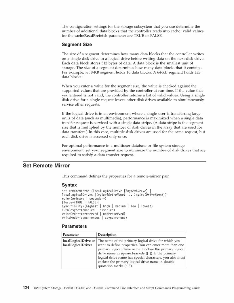
The configuration settings for the storage subsystem that you use determine thenumber of additional data blocks that the controller reads into cache. Valid valuesfor the cacheReadPrefetch parameter are TRUE or FALSE.
Segment Size
The size of a segment determines how many data blocks that the controller writeson a single disk drive in a logical drive before writing data on the next disk drive.Each data block stores 512 bytes of data. A data block is the smallest unit ofstorage. The size of a segment determines how many data blocks that it contains.For example, an 8-KB segment holds 16 data blocks. A 64-KB segment holds 128data blocks.
When you enter a value for the segment size, the value is checked against thesupported values that are provided by the controller at run time. If the value thatyou entered is not valid, the controller returns a list of valid values. Using a singledisk drive for a single request leaves other disk drives available to simultaneouslyservice other requests.
If the logical drive is in an environment where a single user is transferring largeunits of data (such as multimedia), performance is maximized when a single datatransfer request is serviced with a single data stripe. (A data stripe is the segmentsize that is multiplied by the number of disk drives in the array that are used fordata transfers.) In this case, multiple disk drives are used for the same request, buteach disk drive is accessed only once.
For optimal performance in a multiuser database or file system storageenvironment, set your segment size to minimize the number of disk drives that arerequired to satisfy a data transfer request.
Set Remote Mirror
This command defines the properties for a remote-mirror pair.
Syntaxset remoteMirror (localLogicalDrive [logicalDrive] |localLogicalDrives [logicalDriveName1 ... logicalDriveNameN])role=(primary | secondary)[force=(TRUE | FALSE)]syncPriority=(highest | high | medium | low | lowest)autoResync=(enabled | disabled)writeOrder=(preserved | notPreserved)writeMode=(synchronous | asynchronous)
Parameters
Parameter Description
localLogicalDrive orlocalLogicalDrives
The name of the primary logical drive for which youwant to define properties. You can enter more than oneprimary logical drive name. Enclose the primary logicaldrive name in square brackets ([ ]). If the primarylogical drive name has special characters, you also mustenclose the primary logical drive name in doublequotation marks (“ ”).
124 IBM System Storage DS3000, DS4000, and DS5000: Command Line Interface and Script Commands Programming Guide
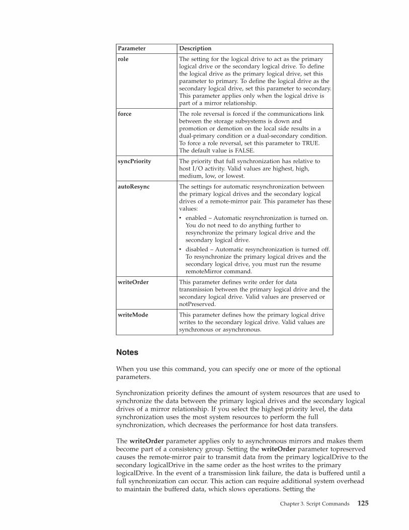
Parameter Description
role The setting for the logical drive to act as the primarylogical drive or the secondary logical drive. To definethe logical drive as the primary logical drive, set thisparameter to primary. To define the logical drive as thesecondary logical drive, set this parameter to secondary.This parameter applies only when the logical drive ispart of a mirror relationship.
force The role reversal is forced if the communications linkbetween the storage subsystems is down andpromotion or demotion on the local side results in adual-primary condition or a dual-secondary condition.To force a role reversal, set this parameter to TRUE.The default value is FALSE.
syncPriority The priority that full synchronization has relative tohost I/O activity. Valid values are highest, high,medium, low, or lowest.
autoResync The settings for automatic resynchronization betweenthe primary logical drives and the secondary logicaldrives of a remote-mirror pair. This parameter has thesevalues:
v enabled – Automatic resynchronization is turned on.You do not need to do anything further toresynchronize the primary logical drive and thesecondary logical drive.
v disabled – Automatic resynchronization is turned off.To resynchronize the primary logical drives and thesecondary logical drive, you must run the resumeremoteMirror command.
writeOrder This parameter defines write order for datatransmission between the primary logical drive and thesecondary logical drive. Valid values are preserved ornotPreserved.
writeMode This parameter defines how the primary logical drivewrites to the secondary logical drive. Valid values aresynchronous or asynchronous.
Notes
When you use this command, you can specify one or more of the optionalparameters.
Synchronization priority defines the amount of system resources that are used tosynchronize the data between the primary logical drives and the secondary logicaldrives of a mirror relationship. If you select the highest priority level, the datasynchronization uses the most system resources to perform the fullsynchronization, which decreases the performance for host data transfers.
The writeOrder parameter applies only to asynchronous mirrors and makes thembecome part of a consistency group. Setting the writeOrder parameter topreservedcauses the remote-mirror pair to transmit data from the primary logicalDrive to thesecondary logicalDrive in the same order as the host writes to the primarylogicalDrive. In the event of a transmission link failure, the data is buffered until afull synchronization can occur. This action can require additional system overheadto maintain the buffered data, which slows operations. Setting the
Chapter 3. Script Commands 125
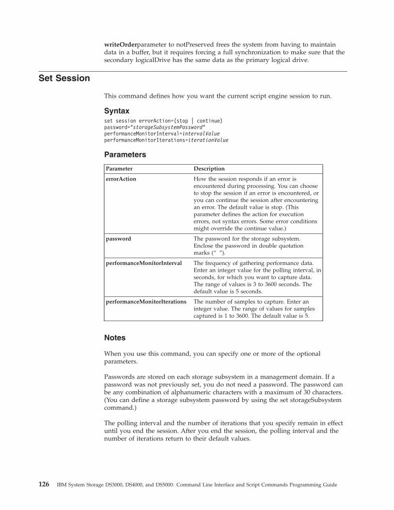
writeOrderparameter to notPreserved frees the system from having to maintaindata in a buffer, but it requires forcing a full synchronization to make sure that thesecondary logicalDrive has the same data as the primary logical drive.
Set Session
This command defines how you want the current script engine session to run.
Syntaxset session errorAction=(stop | continue)password=”storageSubsystemPassword”performanceMonitorInterval=intervalValueperformanceMonitorIterations=iterationValue
Parameters
Parameter Description
errorAction How the session responds if an error isencountered during processing. You can chooseto stop the session if an error is encountered, oryou can continue the session after encounteringan error. The default value is stop. (Thisparameter defines the action for executionerrors, not syntax errors. Some error conditionsmight override the continue value.)
password The password for the storage subsystem.Enclose the password in double quotationmarks (“ ”).
performanceMonitorInterval The frequency of gathering performance data.Enter an integer value for the polling interval, inseconds, for which you want to capture data.The range of values is 3 to 3600 seconds. Thedefault value is 5 seconds.
performanceMonitorIterations The number of samples to capture. Enter aninteger value. The range of values for samplescaptured is 1 to 3600. The default value is 5.
Notes
When you use this command, you can specify one or more of the optionalparameters.
Passwords are stored on each storage subsystem in a management domain. If apassword was not previously set, you do not need a password. The password canbe any combination of alphanumeric characters with a maximum of 30 characters.(You can define a storage subsystem password by using the set storageSubsystemcommand.)
The polling interval and the number of iterations that you specify remain in effectuntil you end the session. After you end the session, the polling interval and thenumber of iterations return to their default values.
126 IBM System Storage DS3000, DS4000, and DS5000: Command Line Interface and Script Commands Programming Guide
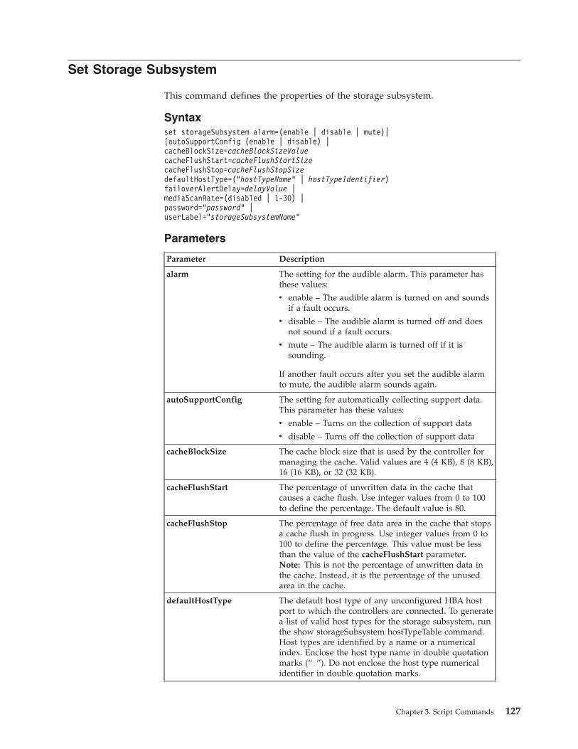
Set Storage Subsystem
This command defines the properties of the storage subsystem.
Syntaxset storageSubsystem alarm=(enable | disable | mute)|{autoSupportConfig (enable | disable) |cacheBlockSize=cacheBlockSizeValuecacheFlushStart=cacheFlushStartSizecacheFlushStop=cacheFlushStopSizedefaultHostType=(“hostTypeName” | hostTypeIdentifier)failoverAlertDelay=delayValue |mediaScanRate=(disabled | 1-30) |password=”password” |userLabel=”storageSubsystemName”
Parameters
Parameter Description
alarm The setting for the audible alarm. This parameter hasthese values:
v enable – The audible alarm is turned on and soundsif a fault occurs.
v disable – The audible alarm is turned off and doesnot sound if a fault occurs.
v mute – The audible alarm is turned off if it issounding.
If another fault occurs after you set the audible alarmto mute, the audible alarm sounds again.
autoSupportConfig The setting for automatically collecting support data.This parameter has these values:
v enable – Turns on the collection of support data
v disable – Turns off the collection of support data
cacheBlockSize The cache block size that is used by the controller formanaging the cache. Valid values are 4 (4 KB), 8 (8 KB),16 (16 KB), or 32 (32 KB).
cacheFlushStart The percentage of unwritten data in the cache thatcauses a cache flush. Use integer values from 0 to 100to define the percentage. The default value is 80.
cacheFlushStop The percentage of free data area in the cache that stopsa cache flush in progress. Use integer values from 0 to100 to define the percentage. This value must be lessthan the value of the cacheFlushStart parameter.Note: This is not the percentage of unwritten data inthe cache. Instead, it is the percentage of the unusedarea in the cache.
defaultHostType The default host type of any unconfigured HBA hostport to which the controllers are connected. To generatea list of valid host types for the storage subsystem, runthe show storageSubsystem hostTypeTable command.Host types are identified by a name or a numericalindex. Enclose the host type name in double quotationmarks (“ ”). Do not enclose the host type numericalidentifier in double quotation marks.
Chapter 3. Script Commands 127
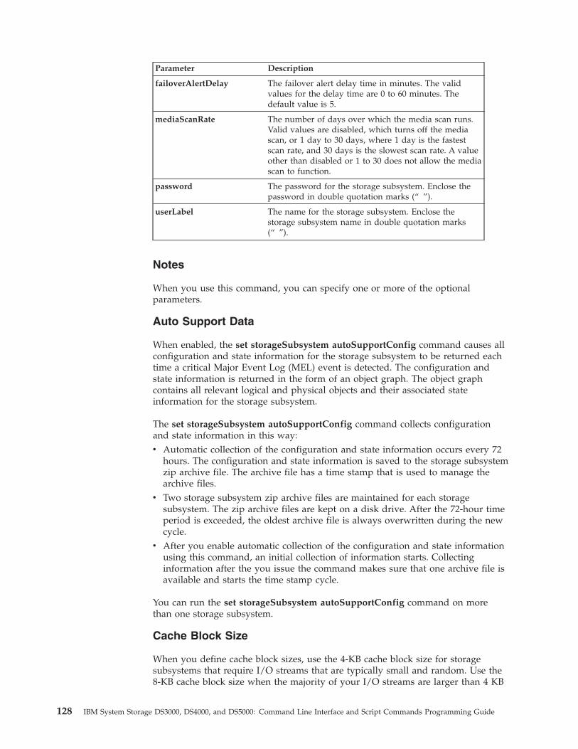
Parameter Description
failoverAlertDelay The failover alert delay time in minutes. The validvalues for the delay time are 0 to 60 minutes. Thedefault value is 5.
mediaScanRate The number of days over which the media scan runs.Valid values are disabled, which turns off the mediascan, or 1 day to 30 days, where 1 day is the fastestscan rate, and 30 days is the slowest scan rate. A valueother than disabled or 1 to 30 does not allow the mediascan to function.
password The password for the storage subsystem. Enclose thepassword in double quotation marks (“ ”).
userLabel The name for the storage subsystem. Enclose thestorage subsystem name in double quotation marks(“ ”).
Notes
When you use this command, you can specify one or more of the optionalparameters.
Auto Support Data
When enabled, the set storageSubsystem autoSupportConfig command causes allconfiguration and state information for the storage subsystem to be returned eachtime a critical Major Event Log (MEL) event is detected. The configuration andstate information is returned in the form of an object graph. The object graphcontains all relevant logical and physical objects and their associated stateinformation for the storage subsystem.
The set storageSubsystem autoSupportConfig command collects configurationand state information in this way:v Automatic collection of the configuration and state information occurs every 72
hours. The configuration and state information is saved to the storage subsystemzip archive file. The archive file has a time stamp that is used to manage thearchive files.
v Two storage subsystem zip archive files are maintained for each storagesubsystem. The zip archive files are kept on a disk drive. After the 72-hour timeperiod is exceeded, the oldest archive file is always overwritten during the newcycle.
v After you enable automatic collection of the configuration and state informationusing this command, an initial collection of information starts. Collectinginformation after the you issue the command makes sure that one archive file isavailable and starts the time stamp cycle.
You can run the set storageSubsystem autoSupportConfig command on morethan one storage subsystem.
Cache Block Size
When you define cache block sizes, use the 4-KB cache block size for storagesubsystems that require I/O streams that are typically small and random. Use the8-KB cache block size when the majority of your I/O streams are larger than 4 KB
128 IBM System Storage DS3000, DS4000, and DS5000: Command Line Interface and Script Commands Programming Guide
but smaller than 8 KB. Use the 16-KB cache block size or the 32-KB cache blocksize for storage subsystems that require large data transfer, sequential, orhigh-bandwidth applications.
This parameter defines the supported cache block size for all of the logical drivesin the storage subsystem. Not all controller types support all cache block sizes. Forredundant configurations, this parameter includes all of the logical drives that areowned by both controllers within the storage subsystem.
Cache Flush Start and Cache Flush Stop
When you define values to start a cache flush, a value that is too low increases thechance that data needed for a host read is not in the cache. A low value alsoincreases the number of disk drive writes that are necessary to maintain the cachelevel, which increases system overhead and decreases performance.
When setting storage subsystem cache settings, the value of cacheFlushStart mustbe greater than or equal to the value of cacheFlushStop. For example, if the valueof cacheFlushStart is set to 80, set the value of cacheFlushStop within the range of0 to 80.
When you define values to stop cache flush, the higher the value, the higher thechance that the data for a host read requires a drive read, rather than a readingfrom the cache.
Default Host Type
When you define host types, if Storage Partitioning is enabled, the default hosttype affects only those logical drives that are mapped in the default group. IfSANshare Storage Partitioning is not enabled, all of the hosts that are attached tothe storage subsystem must run the same operating system and be compatible withthe default host type.
Media Scan Rate
Media scan runs on all of the logical drives in the storage subsystem that haveOptimal status, do not have modification operations in progress, and have themediaScanRate parameter enabled. Use the set logicalDrive command to enable ordisable the mediaScanRate parameter.
Password
Passwords are stored on each storage subsystem. For best protection, the passwordmust:v Be between eight and 32 characters long.v Contain at least one uppercase letter.v Contain at least one lowercase letter.v Contain at least one number.v Contain at least one non-alphanumeric character, for example, < > @ +.
Note: If you are using Full Disk Encryption (FDE) disk drives in your storagesubsystem, you must use these criteria for your storage subsystem password.
Chapter 3. Script Commands 129
Important
You must set a password for your storage subsystem before you can create asecurity key for encrypted Full Disk Encryption (FDE) disk drives.
Set Storage Subsystem Enclosure Positions
This command defines the position of the storage expansion enclosures (EXPs) in astorage subsystem configuration. You must include all of the expansion enclosuresthat are in the storage subsystem when you enter this command.
Syntaxset storageSubsystem enclosurePositions=(controller | enclosureID-list)
Parameter
Parameter Description
enclosurePositions A list of all of the enclosure IDs. The sequence of theenclosure IDs in the list defines the positions for thecontroller module and the expansion drawers in astorage subsystem. Valid values are 0 to 99. Enter theenclosure ID values separated by a space. Enclose thelist of enclosure ID values in parentheses. For storagesubsystems where the controller module has apredefined identifier that is not in the range of validenclosure position values, use the controller value.
Notes
This command defines the position of a enclosure in a storage subsystem by theposition of the enclosure ID in the enclosurePositions list. For example, if youhave a controller module with an ID set to 84 and expansion drawers with IDs setto 1, 12, and 50, the enclosurePositions sequence (84 1 12 50) places the controllermodule in the first position, expansion drawer 1 in the second position, expansiondrawer 12 in the third position, and expansion drawer 50 in the fourth position.The enclosurePositions sequence (1 84 50 12) places the controller module in thesecond position, expansion drawer 1 in the first position, expansion drawer 50 inthe third position, and expansion drawer 12 in the fourth position.
Set Storage Subsystem ICMP Response
This command returns the default values for negotiable settings for sessions andconnections, which represent the starting point for the storage subsystem fornegotiations.
Syntaxset storageSubsystem icmpPingResponse=(TRUE | FALSE)
130 IBM System Storage DS3000, DS4000, and DS5000: Command Line Interface and Script Commands Programming Guide
Parameter
Parameter Description
icmpPingResponse This parameter turns on or turns off EchoRequest messages. Set the parameter to TRUEto turn on Echo Request messages. Set theparameter to FALSE to turn off Echo Requestmessages.
Notes
The Internet Control Message Protocol (ICMP) is used by operating systems in anetwork to send error messages, test packets, and informational messages relatedto the IP, such as a requested service is not available or that a host or router couldnot be reached. The ICMP response command sends ICMP Echo Request messagesand receives Echo Response messages to determine if a host is reachable and howlong packets take to get to and from that host.
Set Storage Subsystem iSNS Server IPv4 Address
This command sets the configuration method and address for an IPv4 InternetStorage Name Service (iSNS).
Syntaxset storageSubsystem isnsIPV4ConfigurationMethod=[static | dhcp]isnsIPV4Address=ip-address
Parameters
Parameters Description
isnsIPv4ConfigurationMethod The method that you want to use to define theiSNS server configuration. You can enter the IPaddress for the IPv4 iSNS servers by selectingstatic. For IPv4, you can choose to have aDynamic Host Configuration Protocol (DHCP)server select the iSNS server IP address byentering dhcp. To enable DCHP, you must setthe isnsIPv4Address parameter to 0.0.0.0.
isnsIPv4Address The IP address that you want to use for theiSNS server. Use this parameter with the staticvalue for IPv4 configurations. If you choose tohave a DHCP server set the IP address for anIPv4 Internet iSNS server, you must set theisnsIPv4Address parameter to 0.0.0.0.
Notes
The iSNS protocol facilitates the automated discovery, management, andconfiguration of iSCSI devices and Fibre Channel devices on a TCP/IP network.iSNS provides intelligent storage discovery and management services comparableto those found in Fibre Channel networks, which allow a commodity IP network tofunction in a similar capacity as a storage area network. iSNS also facilitates a
Chapter 3. Script Commands 131
seamless integration of IP networks and Fibre Channel networks, due to its abilityto emulate Fibre Channel fabric services and manage both iSCSI devices and FibreChannel devices.
The DHCP server passes configuration parameters, such as network addresses, toIP nodes. DHCP enables a client to acquire all of the IP configuration parametersthat it needs to operate. DHCP lets you automatically allocate reusable networkaddresses.
Set Storage Subsystem iSNS Server IPv6 Address
This command sets the IPv6 address for the iSNS server.
Syntaxset storageSubsystem isnsIPV6Address=ip-address
Parameters
Parameters Description
isnsIPv6Address The IPv6 address that you want to use for the iSNS server.
Notes
The iSNS protocol facilitates the automated discovery, management, andconfiguration of iSCSI and Fibre Channel devices on a TCP/IP network. iSNSprovides intelligent storage discovery and management services comparable tothose found in Fibre Channel networks, permitting a commodity IP network tofunction in a similar capacity as a storage area network. iSNS also facilitates aseamless integration of IP networks and Fibre Channel networks, due to its abilityto emulate Fibre Channel fabric services, and manage both iSCSI devices and FibreChannel devices. iSNS thereby provides value in any storage network that hasiSCSI devices, Fibre Channel devices, or any combination thereof.
Set Storage Subsystem iSNS Server Listening Port
This command sets the iSNS server listening port.
Syntaxset storageSubsystem isnsListeningPort=integer
Parameter
Parameter Description
isnsListeningPort The IP address that you want to use for the iSNS serverlistening port. The range of values for the listening portis 49152 to 65535. The default value is 3205.
Notes
A listening port resides on the database server and is responsible for theseactivities:v Listening (monitoring) for incoming client connection requests
132 IBM System Storage DS3000, DS4000, and DS5000: Command Line Interface and Script Commands Programming Guide
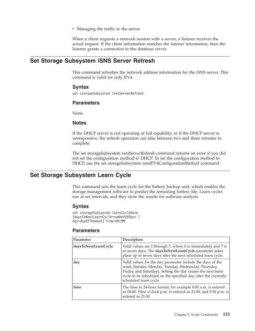
v Managing the traffic to the server
When a client requests a network session with a server, a listener receives theactual request. If the client information matches the listener information, then thelistener grants a connection to the database server.
Set Storage Subsystem iSNS Server Refresh
This command refreshes the network address information for the iSNS server. Thiscommand is valid for only IPv4.
Syntaxset storageSubsystem isnsServerRefresh
Parameters
None.
Notes
If the DHCP server is not operating at full capability, or if the DHCP server isunresponsive, the refresh operation can take between two and three minutes tocomplete.
The set storageSubsystem isnsServerRefresh command returns an error if you didnot set the configuration method to DHCP. To set the configuration method toDHCP, use the set storageSubsystem isnsIPV4ConfigurationMethod command.
Set Storage Subsystem Learn Cycle
This command sets the learn cycle for the battery backup unit, which enables thestorage management software to predict the remaining battery life. Learn cyclesrun at set intervals, and they store the results for software analysis.
Syntaxset storageSubsystem learnCycleDate(daysToNextLearnCycle=numberOfDays |day=dayOfTheWeek) time=HH:MM
Parameters
Parameter Description
daysToNextLearnCycle Valid values are 0 through 7, where 0 is immediately and 7 isin seven days. The daysToNextLearnCycle parameter takesplace up to seven days after the next scheduled learn cycle.
day Valid values for the day parameter include the days of theweek (Sunday, Monday, Tuesday, Wednesday, Thursday,Friday, and Saturday). Setting the day causes the next learncycle to be scheduled on the specified day, after the currentlyscheduled learn cycle.
time The time in 24-hour format; for example 8:00 a.m. is enteredas 08:00. Nine o’clock p.m. is entered as 21:00, and 9:30 p.m. isentered as 21:30.
Chapter 3. Script Commands 133
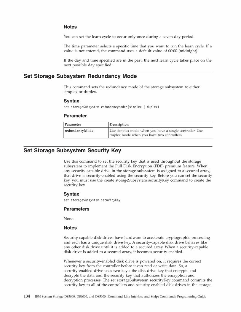
Notes
You can set the learn cycle to occur only once during a seven-day period.
The time parameter selects a specific time that you want to run the learn cycle. If avalue is not entered, the command uses a default value of 00:00 (midnight).
If the day and time specified are in the past, the next learn cycle takes place on thenext possible day specified.
Set Storage Subsystem Redundancy Mode
This command sets the redundancy mode of the storage subsystem to eithersimplex or duplex.
Syntaxset storageSubsystem redundancyMode=(simplex | duplex)
Parameter
Parameter Description
redundancyMode Use simplex mode when you have a single controller. Useduplex mode when you have two controllers.
Set Storage Subsystem Security Key
Use this command to set the security key that is used throughout the storagesubsystem to implement the Full Disk Encryption (FDE) premium feature. Whenany security-capable drive in the storage subsystem is assigned to a secured array,that drive is security-enabled using the security key. Before you can set the securitykey, you must use the create storageSubsystem securityKey command to create thesecurity key.
Syntaxset storageSubsystem securityKey
Parameters
None.
Notes
Security-capable disk drives have hardware to accelerate cryptographic processingand each has a unique disk drive key. A security-capable disk drive behaves likeany other disk drive until it is added to a secured array. When a security-capabledisk drive is added to a secured array, it becomes security-enabled.
Whenever a security-enabled disk drive is powered on, it requires the correctsecurity key from the controller before it can read or write data. So, asecurity-enabled drive uses two keys: the disk drive key that encrypts anddecrypts the data and the security key that authorizes the encryption anddecryption processes. The set storageSubsystem securityKey command commits thesecurity key to all of the controllers and security-enabled disk drives in the storage
134 IBM System Storage DS3000, DS4000, and DS5000: Command Line Interface and Script Commands Programming Guide
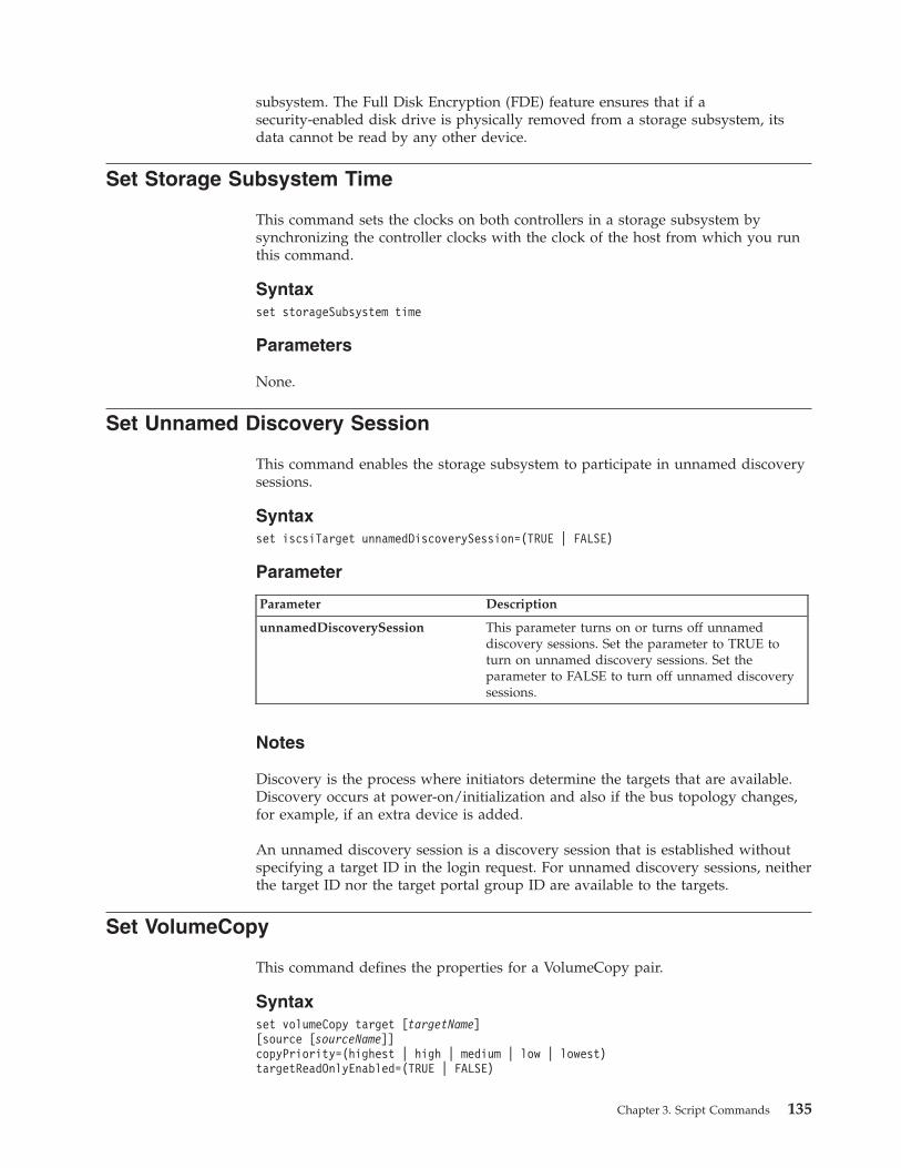
subsystem. The Full Disk Encryption (FDE) feature ensures that if asecurity-enabled disk drive is physically removed from a storage subsystem, itsdata cannot be read by any other device.
Set Storage Subsystem Time
This command sets the clocks on both controllers in a storage subsystem bysynchronizing the controller clocks with the clock of the host from which you runthis command.
Syntaxset storageSubsystem time
Parameters
None.
Set Unnamed Discovery Session
This command enables the storage subsystem to participate in unnamed discoverysessions.
Syntaxset iscsiTarget unnamedDiscoverySession=(TRUE | FALSE)
Parameter
Parameter Description
unnamedDiscoverySession This parameter turns on or turns off unnameddiscovery sessions. Set the parameter to TRUE toturn on unnamed discovery sessions. Set theparameter to FALSE to turn off unnamed discoverysessions.
Notes
Discovery is the process where initiators determine the targets that are available.Discovery occurs at power-on/initialization and also if the bus topology changes,for example, if an extra device is added.
An unnamed discovery session is a discovery session that is established withoutspecifying a target ID in the login request. For unnamed discovery sessions, neitherthe target ID nor the target portal group ID are available to the targets.
Set VolumeCopy
This command defines the properties for a VolumeCopy pair.
Syntaxset volumeCopy target [targetName][source [sourceName]]copyPriority=(highest | high | medium | low | lowest)targetReadOnlyEnabled=(TRUE | FALSE)
Chapter 3. Script Commands 135
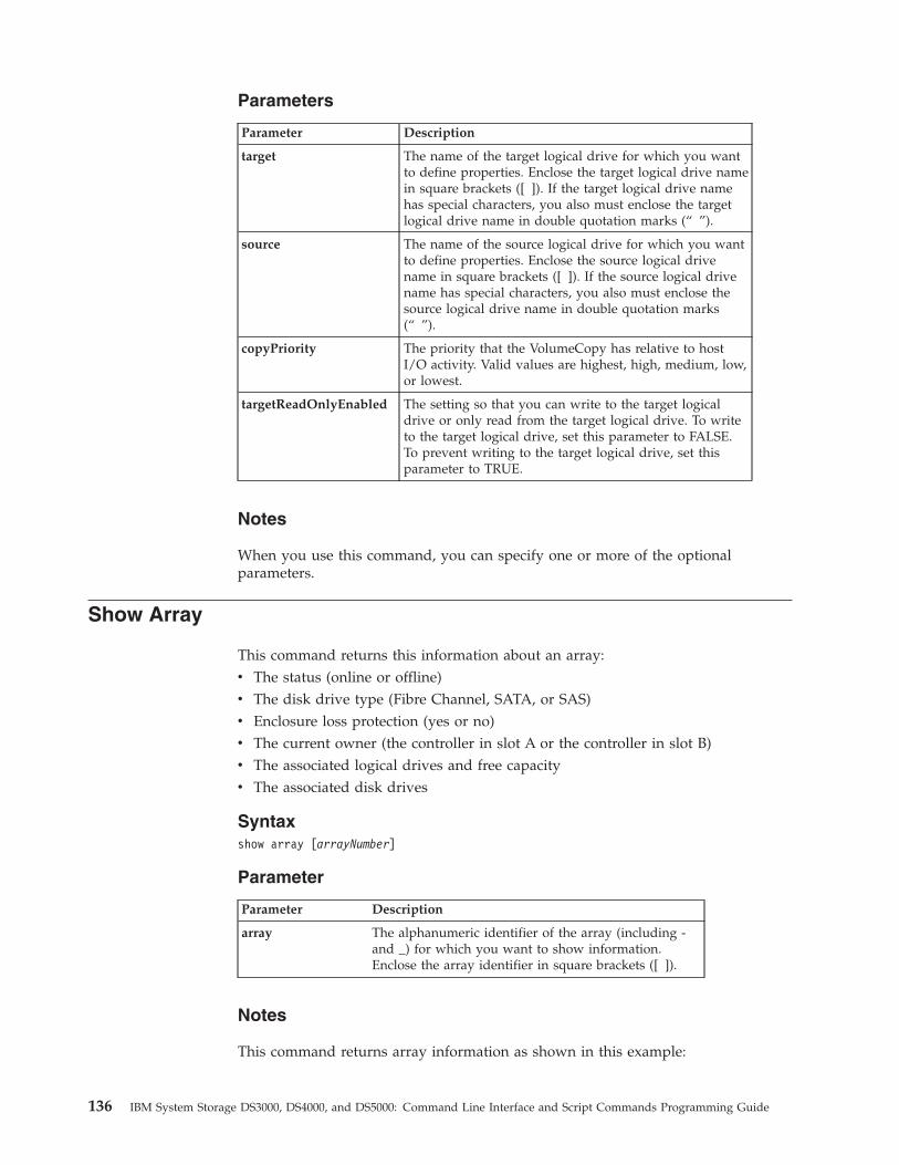
Parameters
Parameter Description
target The name of the target logical drive for which you wantto define properties. Enclose the target logical drive namein square brackets ([ ]). If the target logical drive namehas special characters, you also must enclose the targetlogical drive name in double quotation marks (“ ”).
source The name of the source logical drive for which you wantto define properties. Enclose the source logical drivename in square brackets ([ ]). If the source logical drivename has special characters, you also must enclose thesource logical drive name in double quotation marks(“ ”).
copyPriority The priority that the VolumeCopy has relative to hostI/O activity. Valid values are highest, high, medium, low,or lowest.
targetReadOnlyEnabled The setting so that you can write to the target logicaldrive or only read from the target logical drive. To writeto the target logical drive, set this parameter to FALSE.To prevent writing to the target logical drive, set thisparameter to TRUE.
Notes
When you use this command, you can specify one or more of the optionalparameters.
Show Array
This command returns this information about an array:v The status (online or offline)v The disk drive type (Fibre Channel, SATA, or SAS)v Enclosure loss protection (yes or no)v The current owner (the controller in slot A or the controller in slot B)v The associated logical drives and free capacityv The associated disk drives
Syntaxshow array [arrayNumber]
Parameter
Parameter Description
array The alphanumeric identifier of the array (including -and _) for which you want to show information.Enclose the array identifier in square brackets ([ ]).
Notes
This command returns array information as shown in this example:
136 IBM System Storage DS3000, DS4000, and DS5000: Command Line Interface and Script Commands Programming Guide
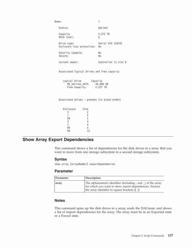
Name: 1
Status: Optimal
Capacity 2.272 TBRAID level: 6
Drive type: Serial ATA (SATA)Enclosure loss protection: No
Security Capable: NoSecure: No
Current owner: Controller in slot B
Associated logical drives and free capacity
Logical Drive CapacityR6_5drives_SATA 46.000 GBFree Capacity 2.227 TB
Associated drives - present (in piece order)
Enclosure Slot3 21 299 13 41 499 599 13
Show Array Export Dependencies
This command shows a list of dependencies for the disk drives in a array that youwant to move from one storage subsystem to a second storage subsystem.
Syntaxshow array [arrayNumber] exportDependencies
Parameter
Parameter Description
array The alphanumeric identifier (including - and _) of the arrayfor which you want to show export dependencies. Enclosethe array identifier in square brackets ([ ]).
Notes
This command spins up the disk drives in a array, reads the DACstore, and showsa list of import dependencies for the array. The array must be in an Exported stateor a Forced state.
Chapter 3. Script Commands 137
Show Array Import Dependencies
This command shows a list of dependencies for the disk drives in an array thatyou want to move from one storage subsystem to a second storage subsystem.
Syntaxshow array [arrayNumber] importDependencies [cancelImport=(TRUE | FALSE)]
Parameters
Parameter Description
array The alphanumeric identifier (including - and _) of the arrayfor which you want to show import dependencies. Enclose thearray identifier in square brackets ([ ]).
cancelImport The setting to spin the disk drives back down after the arraydependencies have been read. To spin down the disk drives,set this parameter to TRUE. To let the disk drives stayspinning, set this parameter to FALSE.
Notes
This command returns the dependencies of a specific array, which must be in anExported state or a Forced state. If a decision is made to retain the listeddependencies, then the cancelImport parameter can be enforced to spin the diskdrives back down.
The show array importDependencies command must be run before the start arrayimport command.
Show Controller
For each controller in a storage subsystem, this command returns the followinginformation:v The status (Online or Offline)v The current firmware and NVSRAM configurationv The pending firmware configuration and NVSRAM configuration (if any)v The board IDv The product IDv The product revisionv The serial numberv The date of manufacturev The cache size or the processor sizev The date and the time to which the controller is setv The associated logical drives (including the preferred owner)v The Ethernet portv The physical disk interfacev The host interface, which applies only to Fibre Channel host interfaces
Syntaxshow (allControllers | controller [(a | b)]) [summary]
138 IBM System Storage DS3000, DS4000, and DS5000: Command Line Interface and Script Commands Programming Guide
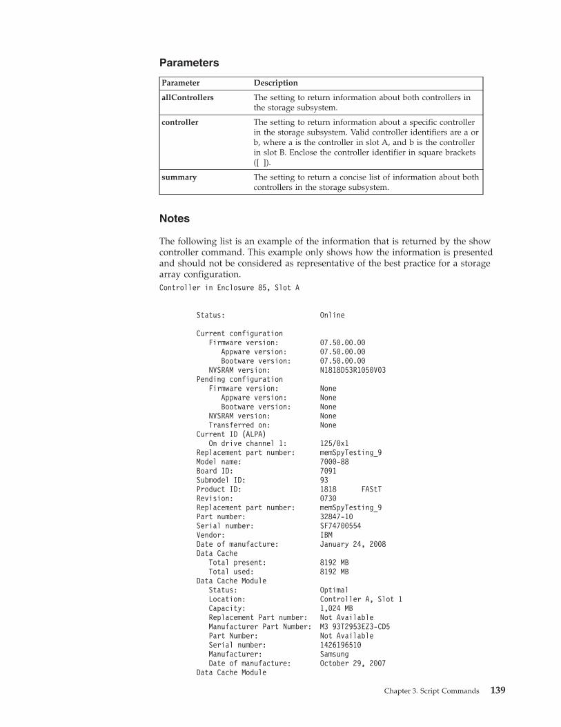
Parameters
Parameter Description
allControllers The setting to return information about both controllers inthe storage subsystem.
controller The setting to return information about a specific controllerin the storage subsystem. Valid controller identifiers are a orb, where a is the controller in slot A, and b is the controllerin slot B. Enclose the controller identifier in square brackets([ ]).
summary The setting to return a concise list of information about bothcontrollers in the storage subsystem.
Notes
The following list is an example of the information that is returned by the showcontroller command. This example only shows how the information is presentedand should not be considered as representative of the best practice for a storagearray configuration.Controller in Enclosure 85, Slot A
Status: Online
Current configurationFirmware version: 07.50.00.00
Appware version: 07.50.00.00Bootware version: 07.50.00.00
NVSRAM version: N1818D53R1050V03Pending configuration
Firmware version: NoneAppware version: NoneBootware version: None
NVSRAM version: NoneTransferred on: None
Current ID (ALPA)On drive channel 1: 125/0x1
Replacement part number: memSpyTesting_9Model name: 7000-88Board ID: 7091Submodel ID: 93Product ID: 1818 FAStTRevision: 0730Replacement part number: memSpyTesting_9Part number: 32847-10Serial number: SF74700554Vendor: IBMDate of manufacture: January 24, 2008Data Cache
Total present: 8192 MBTotal used: 8192 MB
Data Cache ModuleStatus: OptimalLocation: Controller A, Slot 1Capacity: 1,024 MBReplacement Part number: Not AvailableManufacturer Part Number: M3 93T2953EZ3-CD5Part Number: Not AvailableSerial number: 1426196510Manufacturer: SamsungDate of manufacture: October 29, 2007
Data Cache Module
Chapter 3. Script Commands 139
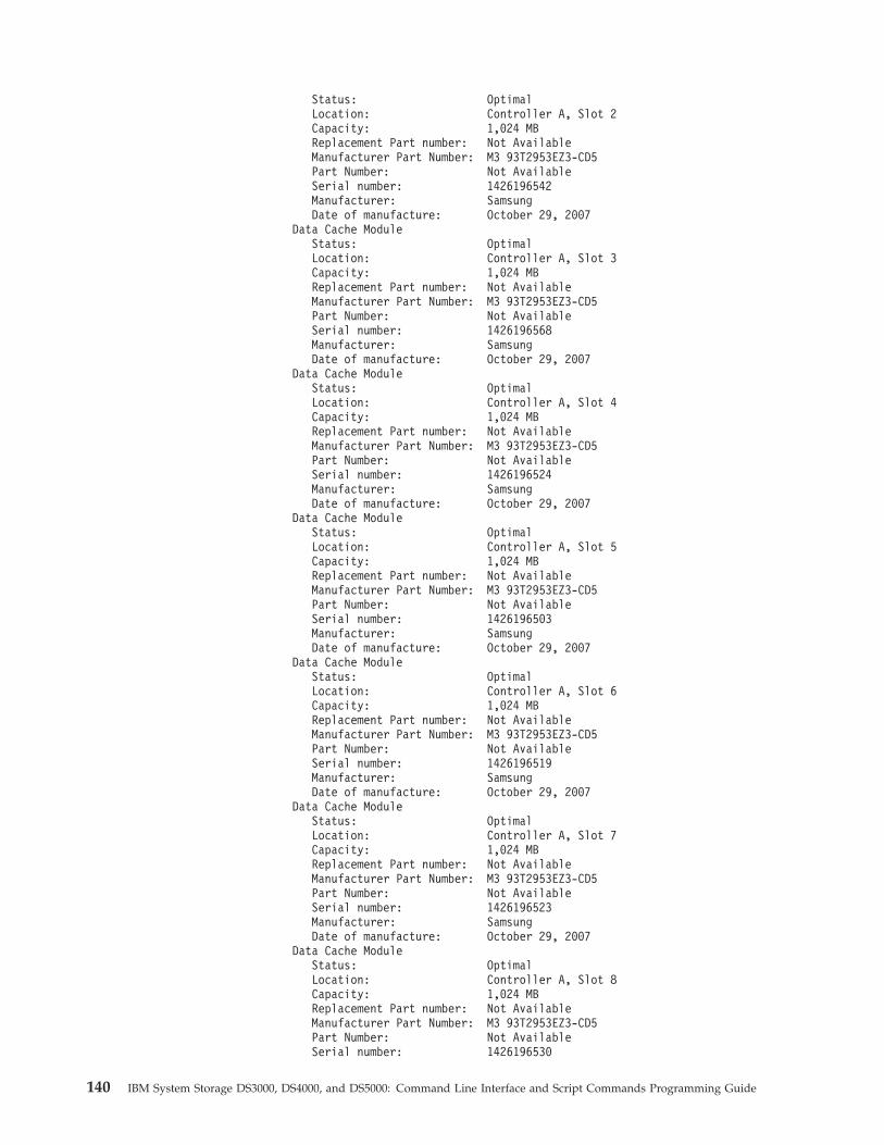
Status: OptimalLocation: Controller A, Slot 2Capacity: 1,024 MBReplacement Part number: Not AvailableManufacturer Part Number: M3 93T2953EZ3-CD5Part Number: Not AvailableSerial number: 1426196542Manufacturer: SamsungDate of manufacture: October 29, 2007
Data Cache ModuleStatus: OptimalLocation: Controller A, Slot 3Capacity: 1,024 MBReplacement Part number: Not AvailableManufacturer Part Number: M3 93T2953EZ3-CD5Part Number: Not AvailableSerial number: 1426196568Manufacturer: SamsungDate of manufacture: October 29, 2007
Data Cache ModuleStatus: OptimalLocation: Controller A, Slot 4Capacity: 1,024 MBReplacement Part number: Not AvailableManufacturer Part Number: M3 93T2953EZ3-CD5Part Number: Not AvailableSerial number: 1426196524Manufacturer: SamsungDate of manufacture: October 29, 2007
Data Cache ModuleStatus: OptimalLocation: Controller A, Slot 5Capacity: 1,024 MBReplacement Part number: Not AvailableManufacturer Part Number: M3 93T2953EZ3-CD5Part Number: Not AvailableSerial number: 1426196503Manufacturer: SamsungDate of manufacture: October 29, 2007
Data Cache ModuleStatus: OptimalLocation: Controller A, Slot 6Capacity: 1,024 MBReplacement Part number: Not AvailableManufacturer Part Number: M3 93T2953EZ3-CD5Part Number: Not AvailableSerial number: 1426196519Manufacturer: SamsungDate of manufacture: October 29, 2007
Data Cache ModuleStatus: OptimalLocation: Controller A, Slot 7Capacity: 1,024 MBReplacement Part number: Not AvailableManufacturer Part Number: M3 93T2953EZ3-CD5Part Number: Not AvailableSerial number: 1426196523Manufacturer: SamsungDate of manufacture: October 29, 2007
Data Cache ModuleStatus: OptimalLocation: Controller A, Slot 8Capacity: 1,024 MBReplacement Part number: Not AvailableManufacturer Part Number: M3 93T2953EZ3-CD5Part Number: Not AvailableSerial number: 1426196530
140 IBM System Storage DS3000, DS4000, and DS5000: Command Line Interface and Script Commands Programming Guide
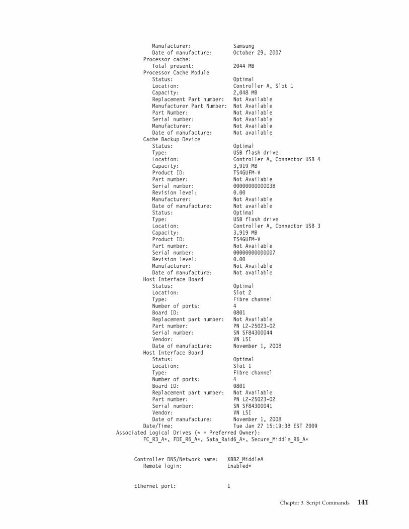
Manufacturer: SamsungDate of manufacture: October 29, 2007
Processor cache:Total present: 2044 MB
Processor Cache ModuleStatus: OptimalLocation: Controller A, Slot 1Capacity: 2,048 MBReplacement Part number: Not AvailableManufacturer Part Number: Not AvailablePart Number: Not AvailableSerial number: Not AvailableManufacturer: Not AvailableDate of manufacture: Not available
Cache Backup DeviceStatus: OptimalType: USB flash driveLocation: Controller A, Connector USB 4Capacity: 3,919 MBProduct ID: TS4GUFM-VPart number: Not AvailableSerial number: 0000000000003BRevision level: 0.00Manufacturer: Not AvailableDate of manufacture: Not availableStatus: OptimalType: USB flash driveLocation: Controller A, Connector USB 3Capacity: 3,919 MBProduct ID: TS4GUFM-VPart number: Not AvailableSerial number: 00000000000007Revision level: 0.00Manufacturer: Not AvailableDate of manufacture: Not available
Host Interface BoardStatus: OptimalLocation: Slot 2Type: Fibre channelNumber of ports: 4Board ID: 0801Replacement part number: Not AvailablePart number: PN L2-25023-02Serial number: SN SF84300044Vendor: VN LSIDate of manufacture: November 1, 2008
Host Interface BoardStatus: OptimalLocation: Slot 1Type: Fibre channelNumber of ports: 4Board ID: 0801Replacement part number: Not AvailablePart number: PN L2-25023-02Serial number: SN SF84300041Vendor: VN LSIDate of manufacture: November 1, 2008
Date/Time: Tue Jan 27 15:19:38 EST 2009Associated Logical Drives (* = Preferred Owner):
FC_R3_A*, FDE_R6_A*, Sata_Raid6_A*, Secure_Middle_R6_A*
Controller DNS/Network name: XBB2_MiddleARemote login: Enabled*
Ethernet port: 1
Chapter 3. Script Commands 141
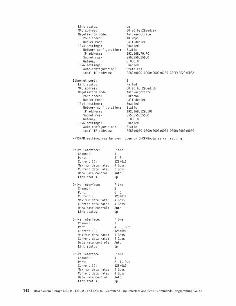
Link status: UpMAC address: 00:a0:b8:29:ed:8aNegotiation mode: Auto-negotiate
Port speed: 10 MbpsDuplex mode: Half duplex
IPv4 settings: EnabledNetwork configuration: StaticIP address: 192.168.70.70Subnet mask: 255.255.255.0Gateway: 0.0.0.0
IPv6 settings: EnabledAuto-configuration: StatelessLocal IP address: FE80:0000:0000:0000:02A0:B8FF:FE29:ED8A
Ethernet port: 2Link status: FailedMAC address: 00:a0:b8:29:ed:8bNegotiation mode: Auto-negotiate
Port speed: UnknownDuplex mode: Half duplex
IPv4 settings: EnabledNetwork configuration: StaticIP address: 192.168.129.101Subnet mask: 255.255.255.0Gateway: 0.0.0.0
IPv6 settings: EnabledAuto-configuration: StaticLocal IP address: FE80:0000:0000:0000:0000:0000:0000:0000
*NVSRAM setting, may be overridden by DHCP/Bootp server setting
Drive interface: FibreChannel: 1Port: 8, 7Current ID: 125/0x1Maximum data rate: 4 GbpsCurrent data rate: 2 GbpsData rate control: AutoLink status: Up
Drive interface: FibreChannel: 2Port: 6, 5Current ID: 125/0x1Maximum data rate: 4 GbpsCurrent data rate: 4 GbpsData rate control: AutoLink status: Up
Drive interface: FibreChannel: 3Port: 4, 3, OutCurrent ID: 125/0x1Maximum data rate: 4 GbpsCurrent data rate: 4 GbpsData rate control: AutoLink status: Up
Drive interface: FibreChannel: 4Port: 2, 1, OutCurrent ID: 125/0x1Maximum data rate: 4 GbpsCurrent data rate: 4 GbpsData rate control: AutoLink status: Up
142 IBM System Storage DS3000, DS4000, and DS5000: Command Line Interface and Script Commands Programming Guide
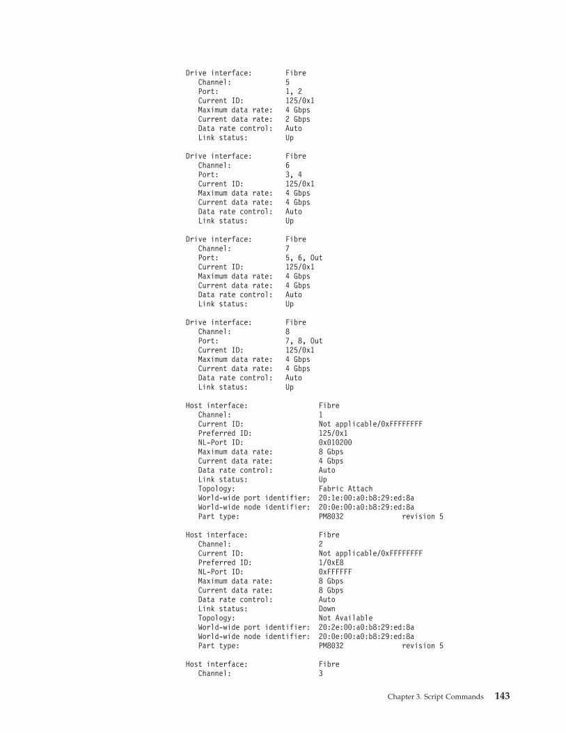
Drive interface: FibreChannel: 5Port: 1, 2Current ID: 125/0x1Maximum data rate: 4 GbpsCurrent data rate: 2 GbpsData rate control: AutoLink status: Up
Drive interface: FibreChannel: 6Port: 3, 4Current ID: 125/0x1Maximum data rate: 4 GbpsCurrent data rate: 4 GbpsData rate control: AutoLink status: Up
Drive interface: FibreChannel: 7Port: 5, 6, OutCurrent ID: 125/0x1Maximum data rate: 4 GbpsCurrent data rate: 4 GbpsData rate control: AutoLink status: Up
Drive interface: FibreChannel: 8Port: 7, 8, OutCurrent ID: 125/0x1Maximum data rate: 4 GbpsCurrent data rate: 4 GbpsData rate control: AutoLink status: Up
Host interface: FibreChannel: 1Current ID: Not applicable/0xFFFFFFFFPreferred ID: 125/0x1NL-Port ID: 0x010200Maximum data rate: 8 GbpsCurrent data rate: 4 GbpsData rate control: AutoLink status: UpTopology: Fabric AttachWorld-wide port identifier: 20:1e:00:a0:b8:29:ed:8aWorld-wide node identifier: 20:0e:00:a0:b8:29:ed:8aPart type: PM8032 revision 5
Host interface: FibreChannel: 2Current ID: Not applicable/0xFFFFFFFFPreferred ID: 1/0xE8NL-Port ID: 0xFFFFFFMaximum data rate: 8 GbpsCurrent data rate: 8 GbpsData rate control: AutoLink status: DownTopology: Not AvailableWorld-wide port identifier: 20:2e:00:a0:b8:29:ed:8aWorld-wide node identifier: 20:0e:00:a0:b8:29:ed:8aPart type: PM8032 revision 5
Host interface: FibreChannel: 3
Chapter 3. Script Commands 143
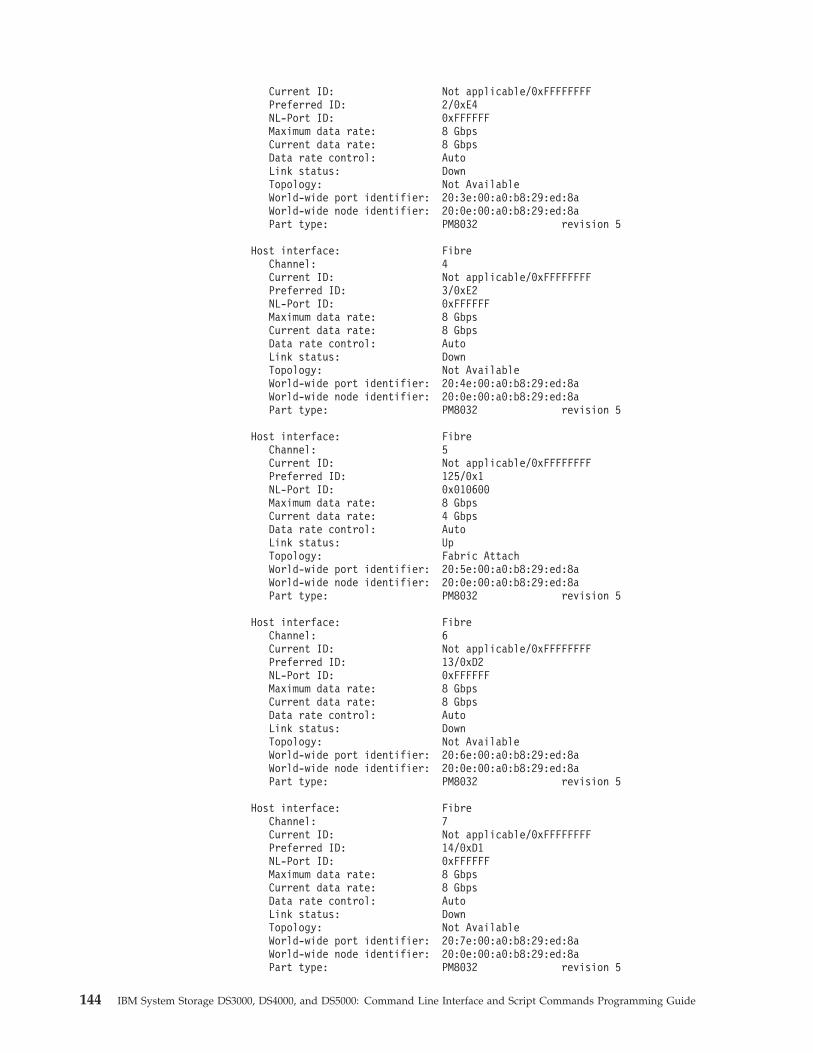
Current ID: Not applicable/0xFFFFFFFFPreferred ID: 2/0xE4NL-Port ID: 0xFFFFFFMaximum data rate: 8 GbpsCurrent data rate: 8 GbpsData rate control: AutoLink status: DownTopology: Not AvailableWorld-wide port identifier: 20:3e:00:a0:b8:29:ed:8aWorld-wide node identifier: 20:0e:00:a0:b8:29:ed:8aPart type: PM8032 revision 5
Host interface: FibreChannel: 4Current ID: Not applicable/0xFFFFFFFFPreferred ID: 3/0xE2NL-Port ID: 0xFFFFFFMaximum data rate: 8 GbpsCurrent data rate: 8 GbpsData rate control: AutoLink status: DownTopology: Not AvailableWorld-wide port identifier: 20:4e:00:a0:b8:29:ed:8aWorld-wide node identifier: 20:0e:00:a0:b8:29:ed:8aPart type: PM8032 revision 5
Host interface: FibreChannel: 5Current ID: Not applicable/0xFFFFFFFFPreferred ID: 125/0x1NL-Port ID: 0x010600Maximum data rate: 8 GbpsCurrent data rate: 4 GbpsData rate control: AutoLink status: UpTopology: Fabric AttachWorld-wide port identifier: 20:5e:00:a0:b8:29:ed:8aWorld-wide node identifier: 20:0e:00:a0:b8:29:ed:8aPart type: PM8032 revision 5
Host interface: FibreChannel: 6Current ID: Not applicable/0xFFFFFFFFPreferred ID: 13/0xD2NL-Port ID: 0xFFFFFFMaximum data rate: 8 GbpsCurrent data rate: 8 GbpsData rate control: AutoLink status: DownTopology: Not AvailableWorld-wide port identifier: 20:6e:00:a0:b8:29:ed:8aWorld-wide node identifier: 20:0e:00:a0:b8:29:ed:8aPart type: PM8032 revision 5
Host interface: FibreChannel: 7Current ID: Not applicable/0xFFFFFFFFPreferred ID: 14/0xD1NL-Port ID: 0xFFFFFFMaximum data rate: 8 GbpsCurrent data rate: 8 GbpsData rate control: AutoLink status: DownTopology: Not AvailableWorld-wide port identifier: 20:7e:00:a0:b8:29:ed:8aWorld-wide node identifier: 20:0e:00:a0:b8:29:ed:8aPart type: PM8032 revision 5
144 IBM System Storage DS3000, DS4000, and DS5000: Command Line Interface and Script Commands Programming Guide

Host interface: FibreChannel: 8Current ID: Not applicable/0xFFFFFFFFPreferred ID: 15/0xCENL-Port ID: 0xFFFFFFMaximum data rate: 8 GbpsCurrent data rate: 8 GbpsData rate control: AutoLink status: DownTopology: Not AvailableWorld-wide port identifier: 20:8e:00:a0:b8:29:ed:8aWorld-wide node identifier: 20:0e:00:a0:b8:29:ed:8aPart type: PM8032 revision 5
Note: The remainder of the example is not shown.
Show Controller NVSRAM
This command returns a list of the NVSRAM byte values for the specified hosttype. If you do not enter the optional parameters, this command returns a list of allof the NVSRAM byte values.
Syntaxshow (allControllers | controller [(a | b)]) NVSRAM [hostType=hostTypeIndexLabel| host=”hostName”]
Parameters
Parameter Description
allControllers The setting to return information about both controllers in thestorage subsystem.
controller The setting to return information about a specific controller inthe storage subsystem. Valid controller identifiers are a or b,where a is the controller in slot A, and b is the controller inslot B. Enclose the controller identifier in square brackets ([ ]).
hostType The index label or number of the host type. Use the showstorageSubsystem hostTypeTable command to generate a listof available host type identifiers.
host The name of the host that is connected to the controllers.Enclose the host name in double quotation marks (“ ”).
Notes
Use the show controller NVSRAM command to show parts of or all of theNVSRAM before using the set controller command to change NVSRAM values.
Show Current iSCSI Sessions
This command returns information about an iSCSI session.
Syntaxshow (iscsiInitiator | iscsiTarget) [iSCSI-ID] iscsiSessions
Chapter 3. Script Commands 145
Parameters
Parameter Description
iSCSI-ID The name of the iSCSI initiator or target for which youwant to obtain session information. Enclose the iSCSIinitiator name or target in square brackets ([ ]).
Notes
If you enter this command without defining any arguments, this command returnsinformation about all of the iSCSI sessions that are currently running. To limit theinformation that is returned, enter a specific iSCSI initiator or a specific iSCSItarget. This command then returns information about the session for only the iSCSIinitiator or the iSCSI target that you named.
Show Disk Drive
For each disk drive in the storage subsystem, this command returns the followinginformation:v The total number of disk drivesv The type of disk drive (Fibre Channel, SATA, or SAS)v Information about the basic disk drive:
– The enclosure location and the slot location– The status– The capacity– The data transfer rate– The product ID– The firmware level
v Information about the disk drive channel:– The enclosure location and the slot location– The preferred channel– The redundant channel
v Hot spare coveragev Details for each disk drive
Depending on the size of your storage subsystem, this information can be severalpages long. In addition, the disk drive information is returned for the showstorageSubsystem profile command.
Syntaxshow (allDrives[DriveMediaType=(HDD | SSD | unknown | allMedia)] |[DriveType=(fibre | SATA | SAS | PATA)]) |Drive [enclosureID,drawerID,slotID] |Drives [enclosureID1,drawerID1,slotID1 ... enclosureIDn,drawerIDn,slotIDn])summary
146 IBM System Storage DS3000, DS4000, and DS5000: Command Line Interface and Script Commands Programming Guide
Parameters
Parameter Description
allDrives The setting to return information about all of the diskdrives in the storage subsystem.
DriveMediaType The type of disk drive media for which you want toretrieve information. Valid are:
v HDD – Use this option when you have hard diskdrives in the expansion drawer.
v SSD – Use this option when you have solid state diskdrives in the expansion drawer.
v unknown – Use if you are not sure what types of diskdrive media are in the expansion drawer.
v allMedia – Use this option when you want to use alltypes of disk drive media that are in the expansiondrawer.
DriveType The type of disk drive for which you want to retrieveinformation. Valid are fibre, SATA, SAS, or PATA.
Drive or Drives EnclosureID1,drawerID1,slotID1 ...enclosureIDn,drawerIDn,slotIDn is for enclosures withmultiple disk drive drawers. For enclosures withoutdisk drive drawers, use enclosureID1,slotID1 ...enclosureIDn,slotIDn instead. Enclosure ID values are 0to 99. Drawer ID values are 1 to 5. Slot ID values are 1to 32. Enclose the values in parentheses.
summary The setting to return the status, the capacity, the datatransfer rate, the product ID, and the firmware versionfor the specified disk drives.
Notes
To determine information about the type and location of all of the disk drives inthe storage subsystem, use the allDrives parameter.
To determine the information about the Fibre Channel, SATA, SAS, PATA diskdrives in the storage subsystem, use the DriveType parameter.
To determine the type of disk drive in a specific location, use the Drive parameter,and enter the enclosure ID and the slot ID for the disk drive.
Show Drive Channel Stats
This command shows the cumulative data transfer for the disk drive channel anderror information. If the controller has automatically degraded a disk drivechannel, this command also shows interval statistics. When you use this command,you can show information about one specific disk drive channel, several disk drivechannels, or all disk drive channels.
Syntaxshow (driveChannel [(1 | 2 | 3 | 4 | 5 | 6 | 7 | 8)] |driveChannels [1 2 3 4 5 6 7 8] | allDriveChannels) stats
Chapter 3. Script Commands 147
Parameters
Parameter Description
driveChannel The identifier number of the disk drive channel forwhich you want to show information. Valid disk drivechannel values are 1, 2, 3, 4, 5, 6, 7, or 8. Enclose thedisk drive channel in square brackets ([ ]).
driveChannels The identifier number of the disk drive channels forwhich you want to show information. Valid disk drivechannel values are 1, 2, 3, 4, 5, 6, 7, or 8. Enclose thedisk drive channels in square brackets ([ ]) with thedisk drive channel value separated by a space.
allDriveChannels The identifier that selects all of the disk drive channels.
Show Drive Download Progress
This command returns the status of firmware downloads for the disk drives thatare targeted by the download drive firmware command or the downloadstorageSubsystem driveFirmware command.
Syntaxshow allDrives downloadProgress
Parameters
None.
Notes
When all of the firmware downloads have successfully completed, this commandreturns good status. If any firmware downloads fail, this command shows thefirmware download status of each disk drive that was targeted. This commandreturns the statuses shown in this table.
Status Definition
Successful The downloads completed without errors.
Not Attempted The downloads did not start.
Partial Download The download is in progress.
Failed The downloads completed with errors.
Show Enhanced Remote Mirroring Logical Drive Candidates
This command returns information about the candidate logical drives on a remotestorage subsystem that you can use as secondary logical drives in a EnhancedRemote Mirroring configuration.
Syntaxshow remoteMirror candidates primary=”logicalDriveName”remoteStorageSubsystemName=”storageSubsystemName”
148 IBM System Storage DS3000, DS4000, and DS5000: Command Line Interface and Script Commands Programming Guide
Parameters
Parameter Description
primary The name of the local logical drive that you want forthe primary logical drive in the remote-mirror pair.Enclose the primary logical drive name in doublequotation marks (“ ”).
remoteStorageSubsystemName The remote storage subsystem that contains possiblelogical drives for a secondary logical drive. If theremote storage subsystem name has specialcharacters, you must also enclose the remote storagesubsystem name in double quotation marks (“ ”).
Show Enhanced Remote Mirroring Logical Drive SynchronizationProgress
This command returns the progress of data synchronization between the primarylogical drive and the secondary logical drive in a Enhanced Remote Mirroringconfiguration. This command shows the progress as a percentage of datasynchronization that has been completed.
Syntaxshow remoteMirror (localLogicalDrive [“logicalDriveName”] |localLogicalDrives [“logicalDriveName1” ... “logicalDriveNameN”])synchronizationProgress
Parameter
Parameter Description
localLogicalDrive orlocalLogicalDrives
The name of the primary logical drive of the remote mirrorpair for which you want to check synchronization progress.Enclose the primary logical drive name in double quotationmarks (“ ”) inside of square brackets ([ ]).
Show Host Ports
For all of the HBA host ports that are connected to a storage subsystem, thiscommand returns this information:v The HBA host port identifierv The HBA host port namev The HBA host type
Syntaxshow allHostPorts
Parameters
None.
Chapter 3. Script Commands 149
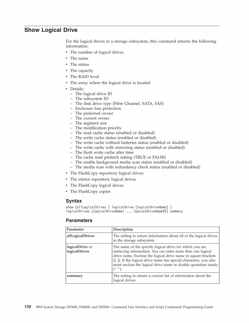
Show Logical Drive
For the logical drives in a storage subsystem, this command returns the followinginformation:v The number of logical drivesv The namev The statusv The capacityv The RAID levelv The array where the logical drive is locatedv Details:
– The logical drive ID– The subsystem ID– The disk drive type (Fibre Channel, SATA, SAS)– Enclosure loss protection– The preferred owner– The current owner– The segment size– The modification priority– The read cache status (enabled or disabled)– The write cache status (enabled or disabled)– The write cache without batteries status (enabled or disabled)– The write cache with mirroring status (enabled or disabled)– The flush write cache after time– The cache read prefetch setting (TRUE or FALSE)– The enable background media scan status (enabled or disabled)– The media scan with redundancy check status (enabled or disabled)
v The FlashCopy repository logical drivesv The mirror repository logical drivesv The FlashCopy logical drivesv The FlashCopy copies
Syntaxshow (allLogicalDrives | logicalDrive [logicalDriveName] |logicalDrives [logicalDriveName1 ... logicalDriveNameN]) summary
Parameters
Parameter Description
allLogicalDrives The setting to return information about all of the logical drivesin the storage subsystem.
logicalDrive orlogicalDrives
The name of the specific logical drive for which you areretrieving information. You can enter more than one logicaldrive name. Enclose the logical drive name in square brackets([ ]). If the logical drive name has special characters, you alsomust enclose the logical drive name in double quotation marks(“ ”).
summary The setting to return a concise list of information about thelogical drives.
150 IBM System Storage DS3000, DS4000, and DS5000: Command Line Interface and Script Commands Programming Guide
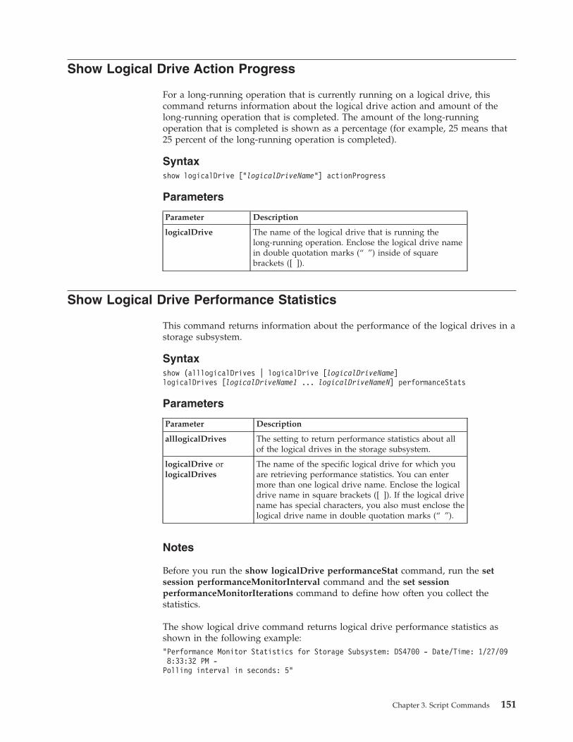
Show Logical Drive Action Progress
For a long-running operation that is currently running on a logical drive, thiscommand returns information about the logical drive action and amount of thelong-running operation that is completed. The amount of the long-runningoperation that is completed is shown as a percentage (for example, 25 means that25 percent of the long-running operation is completed).
Syntaxshow logicalDrive [“logicalDriveName”] actionProgress
Parameters
Parameter Description
logicalDrive The name of the logical drive that is running thelong-running operation. Enclose the logical drive namein double quotation marks (“ ”) inside of squarebrackets ([ ]).
Show Logical Drive Performance Statistics
This command returns information about the performance of the logical drives in astorage subsystem.
Syntaxshow (alllogicalDrives | logicalDrive [logicalDriveName]logicalDrives [logicalDriveName1 ... logicalDriveNameN] performanceStats
Parameters
Parameter Description
alllogicalDrives The setting to return performance statistics about allof the logical drives in the storage subsystem.
logicalDrive orlogicalDrives
The name of the specific logical drive for which youare retrieving performance statistics. You can entermore than one logical drive name. Enclose the logicaldrive name in square brackets ([ ]). If the logical drivename has special characters, you also must enclose thelogical drive name in double quotation marks (“ ”).
Notes
Before you run the show logicalDrive performanceStat command, run the setsession performanceMonitorInterval command and the set sessionperformanceMonitorIterations command to define how often you collect thestatistics.
The show logical drive command returns logical drive performance statistics asshown in the following example:"Performance Monitor Statistics for Storage Subsystem: DS4700 - Date/Time: 1/27/098:33:32 PM -Polling interval in seconds: 5"
Chapter 3. Script Commands 151
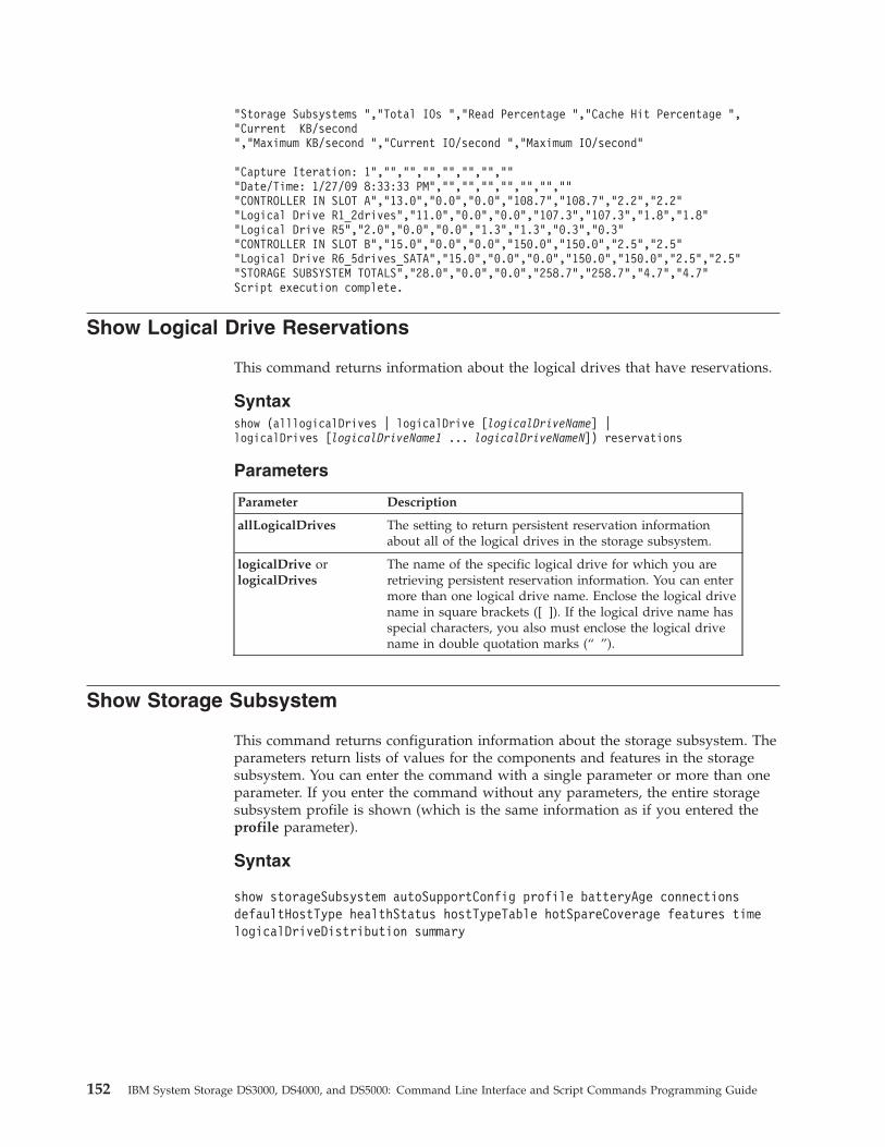
"Storage Subsystems ","Total IOs ","Read Percentage ","Cache Hit Percentage ","Current KB/second","Maximum KB/second ","Current IO/second ","Maximum IO/second"
"Capture Iteration: 1","","","","","","","""Date/Time: 1/27/09 8:33:33 PM","","","","","","","""CONTROLLER IN SLOT A","13.0","0.0","0.0","108.7","108.7","2.2","2.2""Logical Drive R1_2drives","11.0","0.0","0.0","107.3","107.3","1.8","1.8""Logical Drive R5","2.0","0.0","0.0","1.3","1.3","0.3","0.3""CONTROLLER IN SLOT B","15.0","0.0","0.0","150.0","150.0","2.5","2.5""Logical Drive R6_5drives_SATA","15.0","0.0","0.0","150.0","150.0","2.5","2.5""STORAGE SUBSYSTEM TOTALS","28.0","0.0","0.0","258.7","258.7","4.7","4.7"Script execution complete.
Show Logical Drive Reservations
This command returns information about the logical drives that have reservations.
Syntaxshow (alllogicalDrives | logicalDrive [logicalDriveName] |logicalDrives [logicalDriveName1 ... logicalDriveNameN]) reservations
Parameters
Parameter Description
allLogicalDrives The setting to return persistent reservation informationabout all of the logical drives in the storage subsystem.
logicalDrive orlogicalDrives
The name of the specific logical drive for which you areretrieving persistent reservation information. You can entermore than one logical drive name. Enclose the logical drivename in square brackets ([ ]). If the logical drive name hasspecial characters, you also must enclose the logical drivename in double quotation marks (“ ”).
Show Storage Subsystem
This command returns configuration information about the storage subsystem. Theparameters return lists of values for the components and features in the storagesubsystem. You can enter the command with a single parameter or more than oneparameter. If you enter the command without any parameters, the entire storagesubsystem profile is shown (which is the same information as if you entered theprofile parameter).
Syntax
show storageSubsystem autoSupportConfig profile batteryAge connectionsdefaultHostType healthStatus hostTypeTable hotSpareCoverage features timelogicalDriveDistribution summary
152 IBM System Storage DS3000, DS4000, and DS5000: Command Line Interface and Script Commands Programming Guide
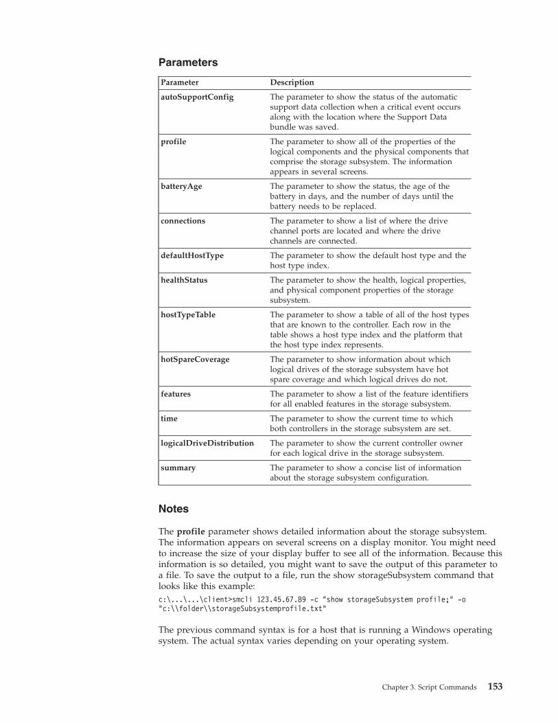
Parameters
Parameter Description
autoSupportConfig The parameter to show the status of the automaticsupport data collection when a critical event occursalong with the location where the Support Databundle was saved.
profile The parameter to show all of the properties of thelogical components and the physical components thatcomprise the storage subsystem. The informationappears in several screens.
batteryAge The parameter to show the status, the age of thebattery in days, and the number of days until thebattery needs to be replaced.
connections The parameter to show a list of where the drivechannel ports are located and where the drivechannels are connected.
defaultHostType The parameter to show the default host type and thehost type index.
healthStatus The parameter to show the health, logical properties,and physical component properties of the storagesubsystem.
hostTypeTable The parameter to show a table of all of the host typesthat are known to the controller. Each row in thetable shows a host type index and the platform thatthe host type index represents.
hotSpareCoverage The parameter to show information about whichlogical drives of the storage subsystem have hotspare coverage and which logical drives do not.
features The parameter to show a list of the feature identifiersfor all enabled features in the storage subsystem.
time The parameter to show the current time to whichboth controllers in the storage subsystem are set.
logicalDriveDistribution The parameter to show the current controller ownerfor each logical drive in the storage subsystem.
summary The parameter to show a concise list of informationabout the storage subsystem configuration.
Notes
The profile parameter shows detailed information about the storage subsystem.The information appears on several screens on a display monitor. You might needto increase the size of your display buffer to see all of the information. Because thisinformation is so detailed, you might want to save the output of this parameter toa file. To save the output to a file, run the show storageSubsystem command thatlooks like this example:c:\...\...\client>smcli 123.45.67.89 -c “show storageSubsystem profile;” -o“c:\\folder\\storageSubsystemprofile.txt”
The previous command syntax is for a host that is running a Windows operatingsystem. The actual syntax varies depending on your operating system.
Chapter 3. Script Commands 153
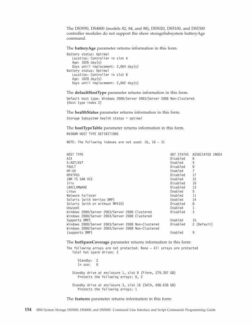
The DS3950, DS4800 (models 82, 84, and 88), DS5020, DS5100, and DS5300controller modules do not support the show storageSubsystem batteryAgecommand.
The batteryAge parameter returns information in this form.Battery status: Optimal
Location: Controller in slot AAge: 1026 day(s)Days until replacement: 2,664 day(s)
Battery status: OptimalLocation: Controller in slot BAge: 1028 day(s)Days until replacement: 2,662 day(s)
The defaultHostType parameter returns information in this form.Default host type: Windows 2000/Server 2003/Server 2008 Non-Clustered(Host type index 2)
The healthStatus parameter returns information in this form.Storage Subsystem health status = optimal
The hostTypeTable parameter returns information in this form.NVSRAM HOST TYPE DEFINITIONS
NOTE: The following indexes are not used: 16, 18 - 31
HOST TYPE ADT STATUS ASSOCIATED INDEXAIX Disabled 6X-ADT/AVT Enabled 4FAULT Disabled 0HP-UX Enabled 7HPXTPGS Disabled 17IBM TS SAN VCE Enabled 12Irix Disabled 10LNXCLVMWARE Disabled 13Linux Enabled 5Netware Failover Enabled 11Solaris (with Veritas DMP) Enabled 14Solaris (with or without MPXIO) Disabled 8Unused1 Enabled 1Windows 2000/Server 2003/Server 2008 Clustered Disabled 3Windows 2000/Server 2003/Server 2008 ClusteredSupports DMP) Enabled 15Windows 2000/Server 2003/Server 2008 Non-Clustered Disabled 2 (Default)Windows 2000/Server 2003/Server 2008 Non-Clustered(supports DMP) Enabled 9
The hotSpareCoverage parameter returns information in this form:The following arrays are not protected: None - All arrays are protected
Total hot spare drives: 2
Standby: 2In use: 0
Standby drive at enclosure 1, slot 8 (Fibre, 279.397 GB)Protects the following arrays: 0, 2
Standby drive at enclosure 3, slot 16 (SATA, 698.638 GB)Protects the following arrays: 1
The features parameter returns information in this form:
154 IBM System Storage DS3000, DS4000, and DS5000: Command Line Interface and Script Commands Programming Guide
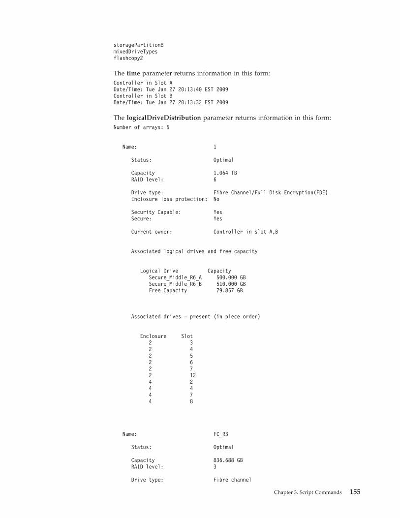
storagePartition8mixedDriveTypesflashcopy2
The time parameter returns information in this form:Controller in Slot ADate/Time: Tue Jan 27 20:13:40 EST 2009Controller in Slot BDate/Time: Tue Jan 27 20:13:32 EST 2009
The logicalDriveDistribution parameter returns information in this form:Number of arrays: 5
Name: 1
Status: Optimal
Capacity 1.064 TBRAID level: 6
Drive type: Fibre Channel/Full Disk Encryption(FDE)Enclosure loss protection: No
Security Capable: YesSecure: Yes
Current owner: Controller in slot A,B
Associated logical drives and free capacity
Logical Drive CapacitySecure_Middle_R6_A 500.000 GBSecure_Middle_R6_B 510.000 GBFree Capacity 79.857 GB
Associated drives - present (in piece order)
Enclosure Slot2 32 42 52 62 72 124 24 44 74 8
Name: FC_R3
Status: Optimal
Capacity 836.688 GBRAID level: 3
Drive type: Fibre channel
Chapter 3. Script Commands 155
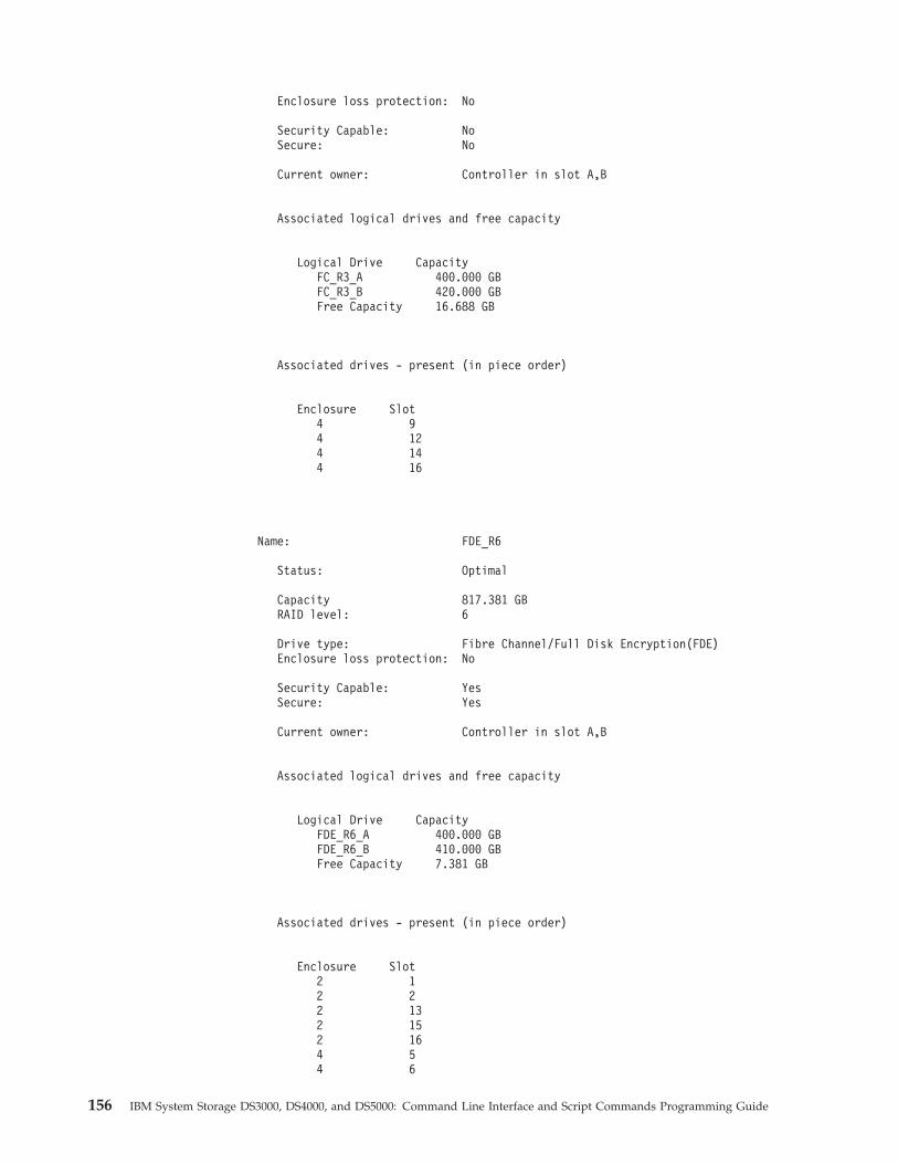
Enclosure loss protection: No
Security Capable: NoSecure: No
Current owner: Controller in slot A,B
Associated logical drives and free capacity
Logical Drive CapacityFC_R3_A 400.000 GBFC_R3_B 420.000 GBFree Capacity 16.688 GB
Associated drives - present (in piece order)
Enclosure Slot4 94 124 144 16
Name: FDE_R6
Status: Optimal
Capacity 817.381 GBRAID level: 6
Drive type: Fibre Channel/Full Disk Encryption(FDE)Enclosure loss protection: No
Security Capable: YesSecure: Yes
Current owner: Controller in slot A,B
Associated logical drives and free capacity
Logical Drive CapacityFDE_R6_A 400.000 GBFDE_R6_B 410.000 GBFree Capacity 7.381 GB
Associated drives - present (in piece order)
Enclosure Slot2 12 22 132 152 164 54 6
156 IBM System Storage DS3000, DS4000, and DS5000: Command Line Interface and Script Commands Programming Guide
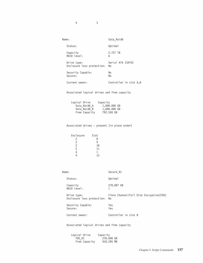
4 3
Name: Sata_Raid6
Status: Optimal
Capacity 2.727 TBRAID level: 6
Drive type: Serial ATA (SATA)Enclosure loss protection: No
Security Capable: NoSecure: No
Current owner: Controller in slot A,B
Associated logical drives and free capacity
Logical Drive CapacitySata_Raid6_A 1,000.000 GBSata_Raid6_B 1,000.000 GBFree Capacity 792.550 GB
Associated drives - present (in piece order)
Enclosure Slot2 82 92 102 114 14 13
Name: Secure_R1
Status: Optimal
Capacity 278.897 GBRAID level: 1
Drive type: Fibre Channel/Full Disk Encryption(FDE)Enclosure loss protection: No
Security Capable: YesSecure: Yes
Current owner: Controller in slot B
Associated logical drives and free capacity
Logical Drive CapacityFDE_R1 278.000 GBFree Capacity 918.295 MB
Chapter 3. Script Commands 157
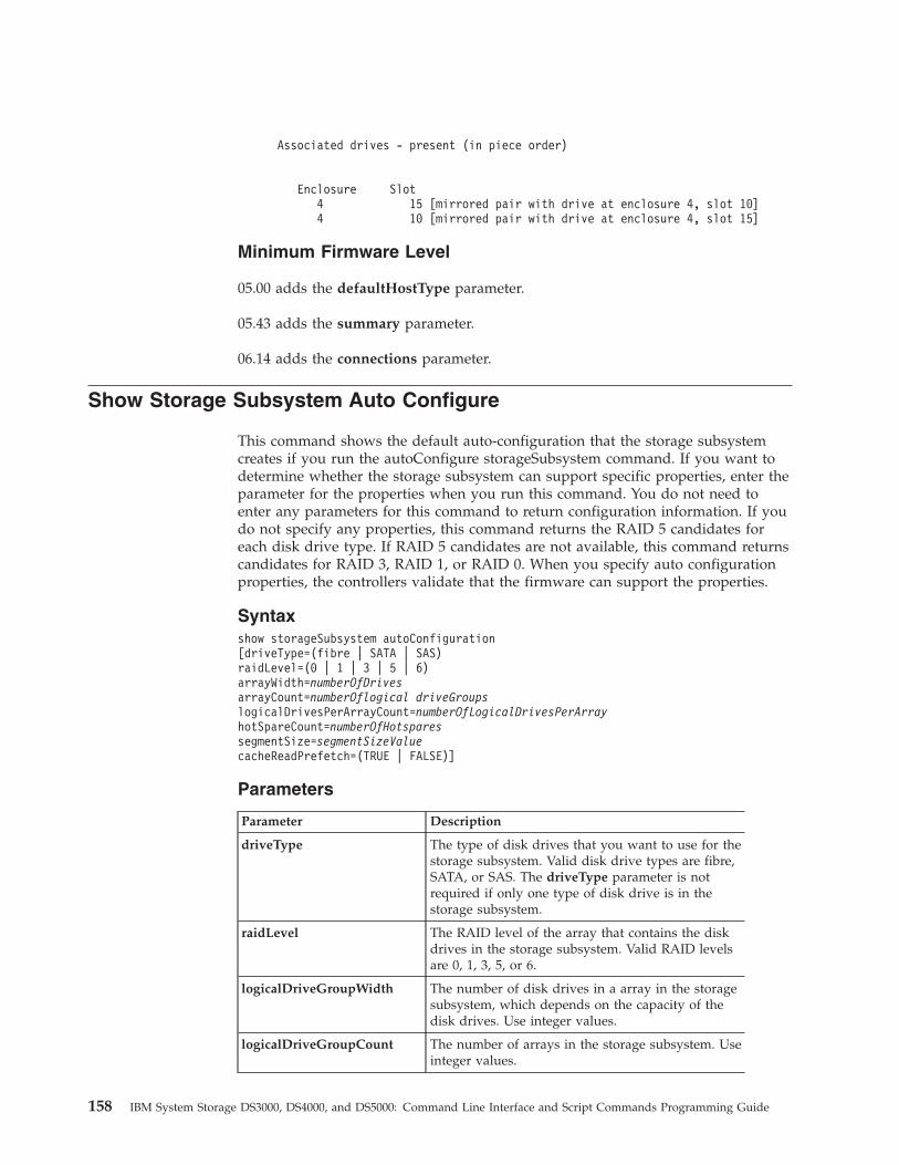
Associated drives - present (in piece order)
Enclosure Slot4 15 [mirrored pair with drive at enclosure 4, slot 10]4 10 [mirrored pair with drive at enclosure 4, slot 15]
Minimum Firmware Level
05.00 adds the defaultHostType parameter.
05.43 adds the summary parameter.
06.14 adds the connections parameter.
Show Storage Subsystem Auto Configure
This command shows the default auto-configuration that the storage subsystemcreates if you run the autoConfigure storageSubsystem command. If you want todetermine whether the storage subsystem can support specific properties, enter theparameter for the properties when you run this command. You do not need toenter any parameters for this command to return configuration information. If youdo not specify any properties, this command returns the RAID 5 candidates foreach disk drive type. If RAID 5 candidates are not available, this command returnscandidates for RAID 3, RAID 1, or RAID 0. When you specify auto configurationproperties, the controllers validate that the firmware can support the properties.
Syntaxshow storageSubsystem autoConfiguration[driveType=(fibre | SATA | SAS)raidLevel=(0 | 1 | 3 | 5 | 6)arrayWidth=numberOfDrivesarrayCount=numberOflogical driveGroupslogicalDrivesPerArrayCount=numberOfLogicalDrivesPerArrayhotSpareCount=numberOfHotsparessegmentSize=segmentSizeValuecacheReadPrefetch=(TRUE | FALSE)]
Parameters
Parameter Description
driveType The type of disk drives that you want to use for thestorage subsystem. Valid disk drive types are fibre,SATA, or SAS. The driveType parameter is notrequired if only one type of disk drive is in thestorage subsystem.
raidLevel The RAID level of the array that contains the diskdrives in the storage subsystem. Valid RAID levelsare 0, 1, 3, 5, or 6.
logicalDriveGroupWidth The number of disk drives in a array in the storagesubsystem, which depends on the capacity of thedisk drives. Use integer values.
logicalDriveGroupCount The number of arrays in the storage subsystem. Useinteger values.
158 IBM System Storage DS3000, DS4000, and DS5000: Command Line Interface and Script Commands Programming Guide
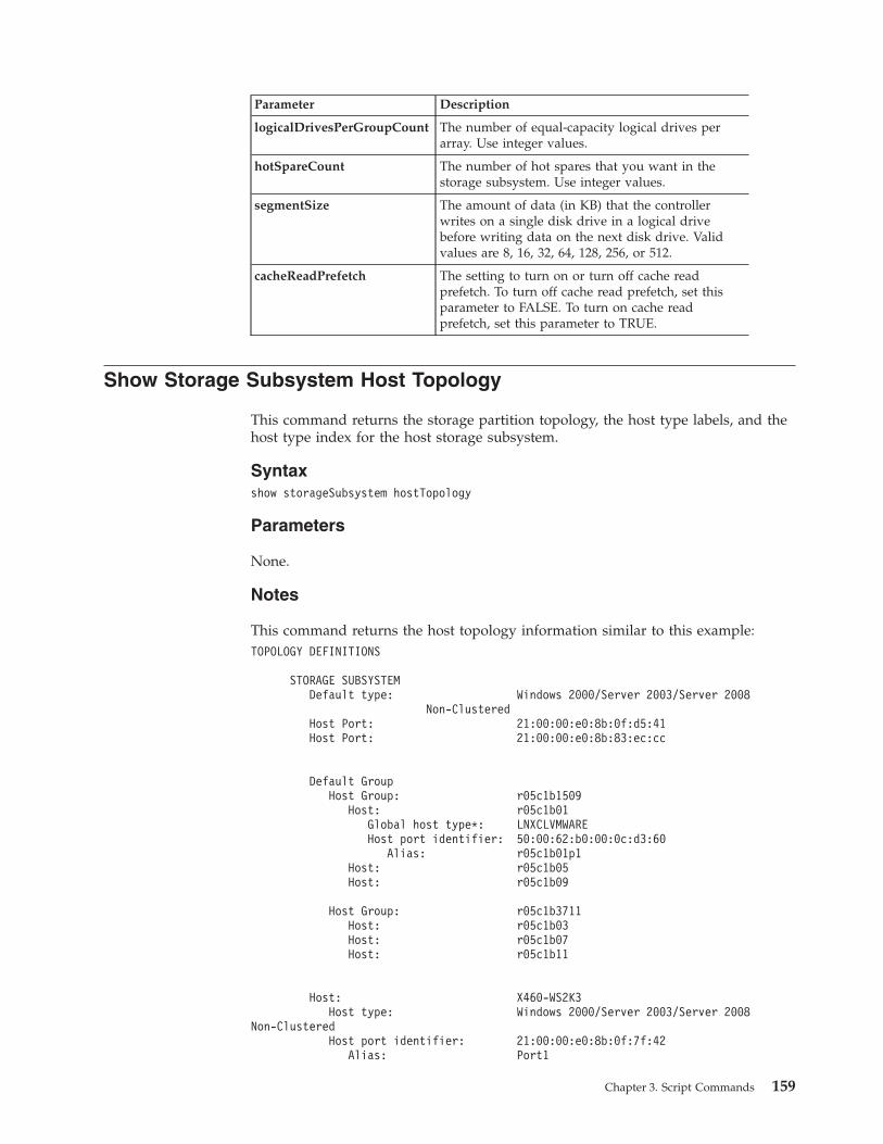
Parameter Description
logicalDrivesPerGroupCount The number of equal-capacity logical drives perarray. Use integer values.
hotSpareCount The number of hot spares that you want in thestorage subsystem. Use integer values.
segmentSize The amount of data (in KB) that the controllerwrites on a single disk drive in a logical drivebefore writing data on the next disk drive. Validvalues are 8, 16, 32, 64, 128, 256, or 512.
cacheReadPrefetch The setting to turn on or turn off cache readprefetch. To turn off cache read prefetch, set thisparameter to FALSE. To turn on cache readprefetch, set this parameter to TRUE.
Show Storage Subsystem Host Topology
This command returns the storage partition topology, the host type labels, and thehost type index for the host storage subsystem.
Syntaxshow storageSubsystem hostTopology
Parameters
None.
Notes
This command returns the host topology information similar to this example:TOPOLOGY DEFINITIONS
STORAGE SUBSYSTEMDefault type: Windows 2000/Server 2003/Server 2008
Non-ClusteredHost Port: 21:00:00:e0:8b:0f:d5:41Host Port: 21:00:00:e0:8b:83:ec:cc
Default GroupHost Group: r05c1b1509
Host: r05c1b01Global host type*: LNXCLVMWAREHost port identifier: 50:00:62:b0:00:0c:d3:60
Alias: r05c1b01p1Host: r05c1b05Host: r05c1b09
Host Group: r05c1b3711Host: r05c1b03Host: r05c1b07Host: r05c1b11
Host: X460-WS2K3Host type: Windows 2000/Server 2003/Server 2008
Non-ClusteredHost port identifier: 21:00:00:e0:8b:0f:7f:42
Alias: Port1
Chapter 3. Script Commands 159
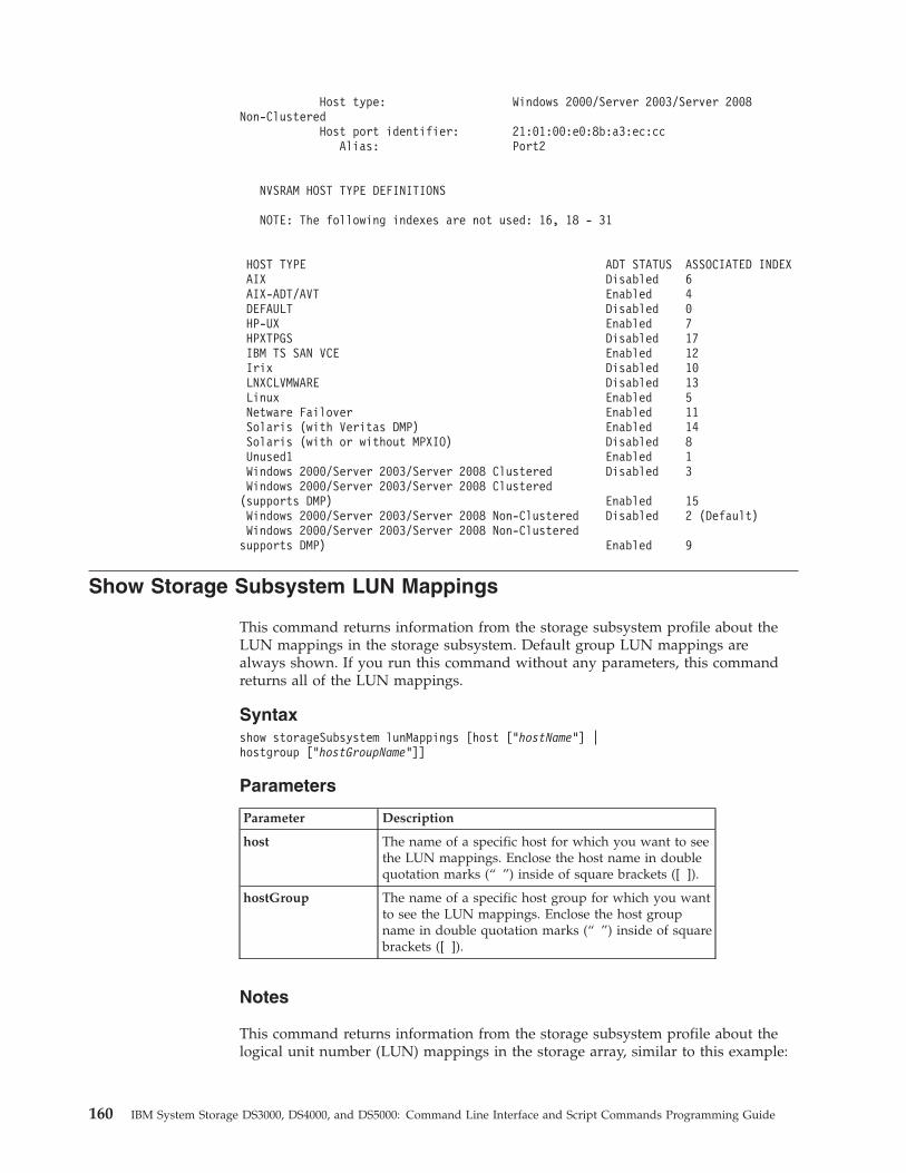
Host type: Windows 2000/Server 2003/Server 2008Non-Clustered
Host port identifier: 21:01:00:e0:8b:a3:ec:ccAlias: Port2
NVSRAM HOST TYPE DEFINITIONS
NOTE: The following indexes are not used: 16, 18 - 31
HOST TYPE ADT STATUS ASSOCIATED INDEXAIX Disabled 6AIX-ADT/AVT Enabled 4DEFAULT Disabled 0HP-UX Enabled 7HPXTPGS Disabled 17IBM TS SAN VCE Enabled 12Irix Disabled 10LNXCLVMWARE Disabled 13Linux Enabled 5Netware Failover Enabled 11Solaris (with Veritas DMP) Enabled 14Solaris (with or without MPXIO) Disabled 8Unused1 Enabled 1Windows 2000/Server 2003/Server 2008 Clustered Disabled 3Windows 2000/Server 2003/Server 2008 Clustered(supports DMP) Enabled 15Windows 2000/Server 2003/Server 2008 Non-Clustered Disabled 2 (Default)Windows 2000/Server 2003/Server 2008 Non-Clusteredsupports DMP) Enabled 9
Show Storage Subsystem LUN Mappings
This command returns information from the storage subsystem profile about theLUN mappings in the storage subsystem. Default group LUN mappings arealways shown. If you run this command without any parameters, this commandreturns all of the LUN mappings.
Syntaxshow storageSubsystem lunMappings [host [“hostName”] |hostgroup [“hostGroupName”]]
Parameters
Parameter Description
host The name of a specific host for which you want to seethe LUN mappings. Enclose the host name in doublequotation marks (“ ”) inside of square brackets ([ ]).
hostGroup The name of a specific host group for which you wantto see the LUN mappings. Enclose the host groupname in double quotation marks (“ ”) inside of squarebrackets ([ ]).
Notes
This command returns information from the storage subsystem profile about thelogical unit number (LUN) mappings in the storage array, similar to this example:
160 IBM System Storage DS3000, DS4000, and DS5000: Command Line Interface and Script Commands Programming Guide
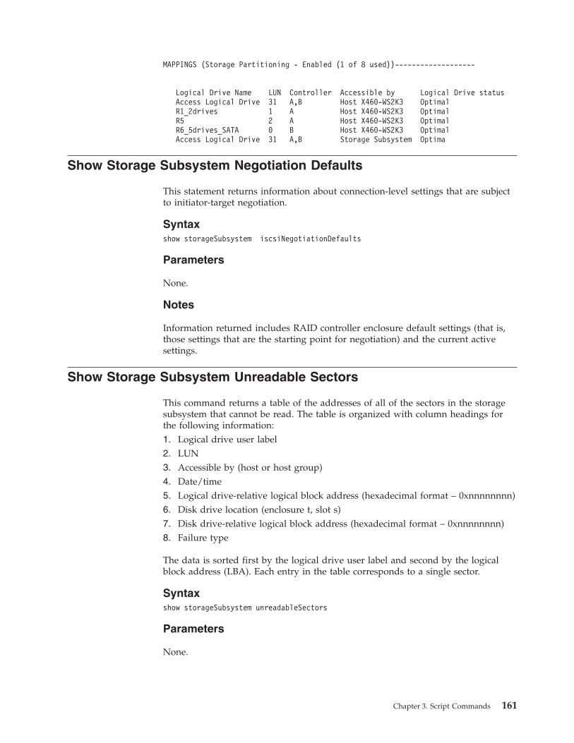
MAPPINGS (Storage Partitioning - Enabled (1 of 8 used))-------------------
Logical Drive Name LUN Controller Accessible by Logical Drive statusAccess Logical Drive 31 A,B Host X460-WS2K3 OptimalR1_2drives 1 A Host X460-WS2K3 OptimalR5 2 A Host X460-WS2K3 OptimalR6_5drives_SATA 0 B Host X460-WS2K3 OptimalAccess Logical Drive 31 A,B Storage Subsystem Optima
Show Storage Subsystem Negotiation Defaults
This statement returns information about connection-level settings that are subjectto initiator-target negotiation.
Syntaxshow storageSubsystem iscsiNegotiationDefaults
Parameters
None.
Notes
Information returned includes RAID controller enclosure default settings (that is,those settings that are the starting point for negotiation) and the current activesettings.
Show Storage Subsystem Unreadable Sectors
This command returns a table of the addresses of all of the sectors in the storagesubsystem that cannot be read. The table is organized with column headings forthe following information:1. Logical drive user label2. LUN3. Accessible by (host or host group)4. Date/time5. Logical drive-relative logical block address (hexadecimal format – 0xnnnnnnnn)6. Disk drive location (enclosure t, slot s)7. Disk drive-relative logical block address (hexadecimal format – 0xnnnnnnnn)8. Failure type
The data is sorted first by the logical drive user label and second by the logicalblock address (LBA). Each entry in the table corresponds to a single sector.
Syntaxshow storageSubsystem unreadableSectors
Parameters
None.
Chapter 3. Script Commands 161
Show String
This command shows a string of text from a script file. This command is similar tothe echo command in MS-DOS and UNIX.
Syntaxshow “string”
Parameters
None.
Notes
Enclose the string in double quotation marks (“ ”).
Show Unconfigured iSCSI Initiators
This command returns a list of initiators that have been detected by the storagesubsystem but are not yet configured into the storage subsystem topology.
Syntaxshow storageSubsystem unconfiguredIscsiInitiators
Parameters
None.
Show VolumeCopy
This command returns this information about VolumeCopy operations:v The copy statusv The start time stampv The completion time stampv The copy priorityv The source logical drive World-Wide Identifier (WWID) or the target logical
drive WWIDv The target logical drive Read-Only attribute setting
You can retrieve information about a specific VolumeCopy pair or all of theVolumeCopy pairs in the storage subsystem.
Syntaxshow volumeCopy (allLogicalDrives | source [“sourceName”] |target [“targetName”])
Parameters
Parameter Description
allLogicalDrives The setting to return information about VolumeCopyoperations for all of the VolumeCopy pairs.
162 IBM System Storage DS3000, DS4000, and DS5000: Command Line Interface and Script Commands Programming Guide
Parameter Description
source The name of the source logical drive about which youwant to retrieve information. Enclose the source logicaldrive name in double quotation marks (“ ”) inside ofsquare brackets ([ ]).
target The name of the target logical drive about which youwant to retrieve information. Enclose the target logicaldrive name in double quotation marks (“ ”) inside ofsquare brackets ([ ]).
Show VolumeCopy Source Candidates
This command returns information about the candidate logical drives that you canuse as the source for a VolumeCopy operation.
Syntaxshow VolumeCopy sourcecandidates
Parameters
None.Logical Drive Name: R1_2drives
Capacity: 40.0 GBArray: 0
Logical Drive Name: R6_5drives_SATACapacity: 46.0 GBArray: 1
Logical Drive Name: R5Capacity: 40.0 GBArray: 2
Show VolumeCopy Target Candidates
This command returns information about the candidate logical drives that you canuse as the target for a VolumeCopy operation.
Syntaxshow volumeCopy source [“sourceName”] targetCandidates
Parameter
Parameter Description
source The name of the source logical drive for which you aretrying to find a candidate target logical drive. Enclose thesource logical drive name in double quotation marks (“ ”)inside of square brackets ([ ]).
Start Array Defragment
This command starts a defragment operation on the specified array.
Note: Defragmenting an array starts a long-running operation that you cannotstop.
Chapter 3. Script Commands 163
Syntaxstart array [arrayNumber] defragment
Parameter
Parameter Description
array The alphanumeric identifier of the array (including - and_) that you want to defragment. Enclose the arrayidentifier in square brackets ([ ]).
Notes
Host I/O errors might result in the arrays with more than 32 logical drives. Thisoperation also might result in internal controller reboots because the timeoutperiod ends before the array definition is set. If you experience this issue, quiescethe host I/O operations, and try the command again.
Start Array Export
This command moves a array into an Exported state. Then you can remove thedisk drives that comprise the array and reinstall the disk drives in a differentstorage subsystem.
Note: Within the array, you cannot move logical drives that are associated with thepremium features from one storage subsystem to another storage subsystem.
Syntaxstart array [arrayNumber] export
Parameter
Parameter Description
array The alphanumeric identifier of the array (including - and _)that you want to export. Enclose the array identifier in squarebrackets ([ ]).
Notes
When this command is successful, you can run the start array import command tofinish moving the array to a Complete state, which makes the array available tothe new storage subsystem.
If this command is unsuccessful because hardware problems prevented thecompletion of the export, use the set array forceState command. The set arrayforceState command lets you use the start array import command to import aarray.
After the array is in an Exported state or a Forced state, you can remove the diskdrives that comprise the array from the storage subsystem. You can reinstall thedisk drives in a different storage subsystem.
164 IBM System Storage DS3000, DS4000, and DS5000: Command Line Interface and Script Commands Programming Guide
Start Array Import
This command moves a array into a Complete state to make a newly introducedarray available to its new storage subsystem. The array must be in an Exportedstate or a Forced state before you run this command. Upon successfully runningthe command, the array is operational.
Note: Within the array, you cannot move logical drives that are associated with thepremium features from one storage subsystem to another storage subsystem.
Syntaxstart array [arrayNumber] import
Parameter
Parameter Description
array The alphanumeric identifier of the array (including - and _)that you want to import. Enclose the array identifier in squarebrackets ([ ]).
Notes
Higher-level logical drives that are specifically related to premium features(FlashCopy, Enhanced Remote Mirroring, VolumeCopy, host-to-logical drivemapping, and persistent reservations) are removed as part of the import operation.
The show array importDependencies command must be run before the start arrayimport command.
Start Array Locate
This command identifies the disk drives that are logically grouped together toform the specified array by blinking the indicator lights on the disk drives. (Usethe stop array locate command to turn off the indicator lights on the disk drives.)
Syntaxstart array [arrayNumber] locate
Parameter
Parameter Description
array The alphanumeric identifier of the array (including - and_) for which you want to locate the disk drives that belongto that array. Enclose the array identifier in square brackets([ ]).
Start Drive Channel Fault Isolation Diagnostics
This command runs the drive channel fault isolation diagnostics and stores theresults.
Chapter 3. Script Commands 165
Syntaxstart diskDriveChannel [(1 | 2 | 3 | 4 | 5 | 6 | 7 | 8)]controller [(a | b)] faultDiagnostics{testDevices=[all | controller=(a | b) |esms=[enclosureID1 (left | right), ... enclosureIDn (left | right)] |Drives=[enclosureID1, drawerID1, slotID1, ... , enclosureIDn, drawerIDn, slotIDn]] |dataPattern=(fixed | pseudoRandom) |patternNumber=[(0xhexadecimal | number)] |maxErrorCount=integer |testIterations=integer |timeout=timeInterval}
Parameter
Parameter Description
controller The identifier letter of the controller that you want to test.Valid controller identifier values are a or b, where a is thecontroller in slot A, and b is the controller in slot B.
testDevices The identifiers of the devices (controllers, ESMs, or drives) thatyou want to test. You can specify all or enter the specificidentifiers for the devices that you want to diagnose.
Drives EnclosureID1,drawerID1, slotID1 ...enclosureIDn,drawerIDn,slotIDn is for enclosures withmultiple disk drive drawers. For enclosures without disk drivedrawers, use enclosureID1,slotID1 ... enclosureIDn,slotIDninstead. Enclosure ID values are 0 to 99. Drawer ID values are1 to 5. Slot ID values are 1 to 32. Enclose the values in squarebrackets ([ ]).
dataPattern The method of repeatability that you want to test.
patternNumber The hexadecimal data pattern you want to use to run the test.This number can be any hexadecimal number between 0000 toFFFF.
maxErrorCount The number of errors that you want to accept beforeterminating the test.
testIterations The number of times that you want to repeat the test.
timeout The length of time in minutes that you want to run the test.
Notes
Use the save driveChannel faultDiagnostics command and the stopdriveChannel faultDiagnostics command in association with the startdriveChannel faultDiagnostics command. These commands are needed to savethe diagnostic test results to a file and to stop the diagnostic test.
You can also stop this command at any time by pressing Ctrl+C
Start Drive Channel Locate
This command identifies the expansion drawers that are connected to a specificdisk drive channel by turning on the indicator lights for the expansion drawer thatis connected to the disk drive channel. (Use the stop driveChannel locate commandto turn off the indicator lights on the expansion drawer.)
166 IBM System Storage DS3000, DS4000, and DS5000: Command Line Interface and Script Commands Programming Guide
Syntaxstart driveChannel [(1 | 2 | 3 | 4 | 5 | 6 |7 | 8)] locate
Parameter
Parameter Description
driveChannel The identifier number of the disk drive channel that youwant to locate. Valid values for the identifier number forthe disk drive channel are 1, 2, 3, 4, 5, 6, 7, or 8. Enclose thedisk drive channel identifier number in square brackets([ ]).
Start Disk Drive Initialize
This command starts disk drive initialization.
Attention: Possible damage to the storage subsystem configuration – As soonas you enter this command, all user data is destroyed.
Syntaxstart Drive [enclosureID1,drawerID1,slotID1 ... enclosureIDn,drawerIDn,slotIDn]initialize
Parameter
Parameter Description
drive EnclosureID1,drawerID1,slotID1 ...enclosureIDn,drawerIDn,slotIDn is for enclosures withmultiple disk drive drawers. For enclosures without diskdrive drawers, use enclosureID1,slotID1 ...enclosureIDn,slotIDn instead. Enclosure ID values are 0 to99. Drawer ID values are 1 to 5. Slot ID values are 1 to 32.Enclose the values in square brackets ([ ]).
Start Disk Drive Locate
This command locates a disk drive by turning on an indicator light on the diskdrive. (Run the stop drive locate command to turn off the indicator light on thedisk drive.)
Syntaxstart Drive [enclosureID1,drawerID1,slotID1 ... enclosureIDn,drawerIDn,slotIDn]locate
Chapter 3. Script Commands 167
Parameter
Parameter Description
drive EnclosureID1,drawerID1,slotID1 ...enclosureIDn,drawerIDn,slotIDn is for enclosures withmultiple disk drive drawers. For enclosures withoutdisk drive drawers, use enclosureID1,slotID1 ...enclosureIDn,slotIDn instead. Enclosure ID values are 0to 99. Drawer ID values are 1 to 5. Slot ID values are 1to 32. Enclose the values in square brackets ([ ]).
Start Disk Drive Reconstruction
This command starts reconstructing a disk drive.
Syntaxstart Drive [enclosureID1,drawerID1,slotID1 ... enclosureIDn,drawerIDn,slotIDn]reconstruct
Parameter
Parameter Description
drive EnclosureID1,drawerID1,slotID1 ...enclosureIDn,drawerIDn,slotIDn is for enclosures withmultiple disk drive drawers. For enclosures without diskdrive drawers, use enclosureID1,slotID1 ...enclosureIDn,slotIDn instead. Enclosure ID values are 0 to 99.Drawer ID values are 1 to 5. Slot ID values are 1 to 32.Enclose values in square brackets ([ ]).
Start Enclosure Locate
This command locates an enclosure by turning on the indicator light. (Use the stopenclosure locate command to turn off the indicator light for the enclosure.)
Syntaxstart enclosure [enclosureID] locate
Parameter
Parameter Description
enclosure The enclosure that you want to locate. Enclosure ID valuesare 0 to 99. Enclose the enclosure ID value in square brackets([ ]).
Start Enhanced Remote Mirroring Synchronization
This command starts Enhanced Remote Mirroring synchronization.
Syntaxstart remoteMirror primary [“logicalDriveName”] synchronize
168 IBM System Storage DS3000, DS4000, and DS5000: Command Line Interface and Script Commands Programming Guide
Parameter
Parameter Description
primary The name of the primary logical drive for which you want tostart synchronization. Enclose the primary logical drive namein double quotation marks (“ ”) inside of square brackets ([ ]).
Start iSCSI DHCP Refresh
This command initiates a refresh of the DHCP parameters for the iSCSI interface. Ifthe configuration method for the interface is not set to DHCP, the procedurereturns an error.
Syntaxstart storageSubsystem [iscsi-host-port] dhcpRefresh
Parameter
Parameter Description
iscsi-host-port The identifier of the port on the storage subsystem onwhich you want to refresh the DHCP parameters. Enclosethe iSCSI host port name in square brackets ([ ]).
Notes
This operation ends the iSCSI connections for the portal and brings down theportal temporarily.
Start Logical Drive Initialization
This command starts the formatting of a logical drive in a storage subsystem.
Note: Formatting a logical drive starts a long-running operation that you cannotstop.
Syntaxstart logicalDrive [logicalDriveName] initialize
Parameter
Parameter Description
logicalDrive The name of the logical drive for which you are starting theformatting. Enclose the logical drive name in square brackets([ ]). If the logical drive name has special characters, you alsomust enclose the logical drive name in double quotationmarks (“ ”).
Chapter 3. Script Commands 169
Start Secure Disk Drive Erase
This command erases all of the data from one or more Full Disk Encryption (FDE)drives so that they can be reused as FDE drives. Run this command only when theFDE drives are no longer part of a secure array, or when the security key isunknown.
Syntaxstart secureErase (Drive [enclosureID,drawer ID,slotID] |Drives [enclosureID1,drawerID1,slotID1 ... enclosureIDn,drawerIDn,slotIDn])
Parameters
Parameter Description
Drive or Drives EnclosureID1,drawerID1,slotID1 ...enclosureIDn,drawerIDn,slotIDn is for enclosures withmultiple disk drive drawers. For enclosures without diskdrive drawers, use enclosureID1,slotID1 ...enclosureIDn,slotIDn instead Enclosure ID values are 0 to 99.Drawer ID values are 1 to 5. Slot ID values are 1 to 32.Enclose the values in square brackets ([ ]).
Notes
Note:
The controller firmware creates a lock that restricts access to the FDE drives. FDEdrives have a state called Security Capable. When you create a security key, thestate is set to Security Enabled, which restricts access to all FDE drives that existwithin the storage array.
Important
Do not run this command unless the data in the drive is backed up or is notneeded anymore. All of the data in the disk drive is lost when the commandcompletes.
Start Storage Subsystem Locate
This command locates a storage subsystem by turning on the indicator lights forthe storage subsystem. (Use the stop storageSubsystem locate command to turn offthe indicator lights for the storage subsystem.)
Syntaxstart storageSubsystem locate
Parameters
None.
170 IBM System Storage DS3000, DS4000, and DS5000: Command Line Interface and Script Commands Programming Guide
Stop Array Locate
This command turns off the indicator lights on the disk drives that were turned onby the start array locate command.
Syntaxstop array locate
Parameters
None.
Stop Drive Channel Fault Isolation Diagnostics
This command stops the drive channel fault isolation diagnostics, which stops thestart drive channel fault isolation diagnostics command before it completes.
See the “Start Drive Channel Fault Isolation Diagnostics” on page 165 commandfor more information.
Syntaxstop driveChannel faultDiagnostics
Parameters
None.
Notes
None.
Stop Drive Channel Locate
This command turns off the indicator lights on the expansion drawers that wereturned on by the start driveChannel locate command.
Syntaxstop driveChannel locate
Parameters
None.
Stop Drive Locate
This command turns off the indicator light on the disk drive that was turned on bythe start drive locate command.
Syntaxstop drive locate
Chapter 3. Script Commands 171
Parameters
None.
Stop Enclosure Locate
This command turns off the indicator light on the enclosure that was turned on bythe start enclosure locate command.
Syntaxstop enclosure locate
Parameters
None.
Stop FlashCopy
This command stops a copy-on-write operation.
Syntaxstop flashcopy (logicaDrive [logicaDriveName] |logicaDrives [logicaDriveName1 ... logicaDriveNameN])
Parameters
Parameter Description
logicaDrive orlogicaDrives
The name of the specific logical drive for which you want tostop a copy-on-write operation. You can enter more than onelogical drive name. Enclose the logical drive names in squarebrackets ([ ]). If the logical drive names have special characters,you also must enclose the logical drive names in doublequotation marks (“ ”).
Stop iSCSI Session
This command forces the termination of an iSCSI session.
Syntaxstop storageSubsystem iscsiSession [integer]
Parameter
Parameter Description
iscsiSession The identifier number of the iSCSI session. Enclose theidentifier number of the iSCSI session in square brackets ([ ]).
172 IBM System Storage DS3000, DS4000, and DS5000: Command Line Interface and Script Commands Programming Guide
Stop Storage Subsystem Drive Firmware Download
This command stops a firmware download to the disk drives in a storagesubsystem that was started with the download storageSubsystem driveFirmwarecommand. This command does not stop a firmware download that is already inprogress to a disk drive. This command stops all firmware downloads to diskdrives that are waiting for the download.
Syntaxstop storageSubsystem driveFirmwareDownload
Parameters
None.
Stop Storage Subsystem Locate
This command turns off the indicator lights on the storage subsystem that wereturned on by the start storageSubsystem locate command.
Syntaxstop storageSubsystem locate
Parameters
None.
Stop VolumeCopy
This command stops a VolumeCopy operation.
Syntaxstop volumeCopy target [targetName] source [sourceName]
Parameters
Parameter Description
target The name of the target logical drive for which you want tostop a VolumeCopy operation. Enclose the target logicaldrive name in square brackets ([ ]). If the target logical drivename has special characters, you also must enclose thetarget logical drive name in double quotation marks (“ ”).
source The name of the source logical drive for which you want tostop a VolumeCopy operation. Enclose the source logicaldrive name in square brackets ([ ]). If the source logicaldrive name has special characters, you also must enclose thesource logical drive name in double quotation marks (“ ”).
Suspend Remote Mirror
This command suspends a Enhanced Remote Mirroring operation.
Chapter 3. Script Commands 173
Syntaxsuspend remoteMirror (primary [primarylogicalDriveName]primaries [primarylogicalDriveName1 ... primarylogicalDriveNameN])writeConsistency=(TRUE | FALSE)
Parameters
Parameter Description
primary or primaries The name of the logical drive for which you want tosuspend operation. Enclose the logical drive name insquare brackets ([ ]). If the logical drive name hasspecial characters, you must also enclose the logicaldrive name in double quotation marks (“ ”).
writeConsistency This parameter defines whether the logical drivesidentified in this command are in a write-consistencygroup or are separate. For the logical drives in the samewrite-consistency group, set this parameter to TRUE.For the logical drives that are separate, set thisparameter to FALSE.
Notes
If you set the writeConsistency parameter to TRUE, the logical drives must be in awrite-consistency group (or groups). This command suspends all write-consistencygroups that contain the logical drives. For example, if logical drives A, B, and Care in a write-consistency group and they have remote counterparts A’, B’, and C’,the command:suspendremoteMirror logicalDrive [“A”] writeConsistency=TRUE
suspends A-A’, B-B’, and C-C’. If you have a write-consistency group 1={A, B, C}and write-consistency group 2={D, E, F}, the command:suspendremoteMirror logicalDrives=[“A”, “D”] writeConsistency=TRUE
suspends both write-consistency groups.
Script Commands Listed by Function
Controller Commands
“Clear Drive Channel Statistics” on page 49
“Diagnose Controller” on page 75
“Enable Controller” on page 81
“Reset Controller” on page 92
“Save Controller NVSRAM” on page 97
“Set Controller” on page 104
“Set Controller Service Action Allowed Indicator” on page 107
174 IBM System Storage DS3000, DS4000, and DS5000: Command Line Interface and Script Commands Programming Guide
“Set Drive Channel Status” on page 109
“Set Host Channel” on page 116
“Show Controller” on page 138
“Show Controller NVSRAM” on page 145
“Show Drive Channel Stats” on page 147
“Start Drive Channel Locate” on page 166
“Stop Drive Channel Locate” on page 171
Disk Drive Commands
“Download Disk Drive Firmware” on page 78
“Replace Disk Drive” on page 92
“Revive Disk Drive” on page 96
“Save Disk Drive Channel Fault Isolation Diagnostic Status” on page 97
“Save Drive Log” on page 98
“Set Disk Drive Hot Spare” on page 109
“Set Disk Drive Service Action Allowed Indicator” on page 110
“Set Drive State” on page 110
“Set Foreign Disk Drive to Native” on page 114
“Show Disk Drive” on page 146
“Show Drive Download Progress” on page 148
“Start Drive Channel Fault Isolation Diagnostics” on page 165
“Start Disk Drive Initialize” on page 167
“Start Disk Drive Locate” on page 167
“Start Disk Drive Reconstruction” on page 168
“Start Secure Disk Drive Erase” on page 170
“Stop Drive Locate” on page 171
Enclosure Commands
“Download Environmental Card Firmware” on page 79
“Set Enclosure Alarm” on page 111
Chapter 3. Script Commands 175
“Set Enclosure Identification” on page 111
“Set Enclosure Service Action Allowed Indicator” on page 112
“Start Enclosure Locate” on page 168
“Stop Enclosure Locate” on page 172
Host Topology Commands
“Activate Host Port” on page 45
“Create Host” on page 58
“Create Host Group” on page 58
“Create Host Port” on page 59
“Delete Host” on page 73
“Delete Host Group” on page 73
“Delete Host Port” on page 74
“Set Host” on page 115
“Set Host Group” on page 117
“Set Host Port” on page 117
“Show Host Ports” on page 149
iSCSI Commands
“Activate iSCSI Initiator” on page 45
“Create iSCSI Initiator” on page 60
“Delete iSCSI Initiator” on page 74
“Reset Storage Subsystem iSCSI Baseline” on page 94
“Save Storage Subsystem iSCSI Statistics” on page 100
“Set iSCSI Initiator” on page 118
“Set iSCSI Target Properties” on page 119
“Show Current iSCSI Sessions” on page 145
“Show Unconfigured iSCSI Initiators” on page 162
“Start iSCSI DHCP Refresh” on page 169
“Stop iSCSI Session” on page 172
176 IBM System Storage DS3000, DS4000, and DS5000: Command Line Interface and Script Commands Programming Guide
Enhanced Remote Mirroring Commands
“Activate Enhanced Remote Mirroring Feature” on page 43
“Check Remote Mirror Status” on page 49
“Create Remote Mirror” on page 69
“Deactivate Remote Mirror” on page 72
“Diagnose Remote Mirror” on page 76
“Recreate Enhanced Remote Mirroring Repository Logical Drive” on page 87
“Remove Remote Mirror” on page 90
“Resume Remote Mirror” on page 95
“Set Remote Mirror” on page 124
“Show Enhanced Remote Mirroring Logical Drive Candidates” on page 148
“Show Enhanced Remote Mirroring Logical Drive Synchronization Progress” onpage 149
“Start Enhanced Remote Mirroring Synchronization” on page 168
“Suspend Remote Mirror” on page 173
Session Command
“Set Session” on page 126
FlashCopy Commands
“Create FlashCopy Logical Drive” on page 55
“Recreate FlashCopy” on page 88
v747181.dita
“Set FlashCopy Logical Drive” on page 113
“Stop FlashCopy” on page 172
Storage Subsystem Commands
“Activate Storage Subsystem Firmware” on page 45
“Autoconfigure Storage Subsystem” on page 45
“Autoconfigure Storage Subsystem Hot Spares” on page 48
“Clear Storage Subsystem Configuration” on page 51
Chapter 3. Script Commands 177
“Clear Storage Subsystem Event Log” on page 51
“Clear Storage Subsystem Firmware Pending Area” on page 52
“Create Storage Subsystem Security Key” on page 71
“Disable Storage Subsystem Feature” on page 77
“Download Storage Subsystem Drive Firmware” on page 80
“Download Storage Subsystem Firmware/NVSRAM” on page 79
“Download Storage Subsystem NVSRAM” on page 81
“Disable Storage Subsystem Feature Key” on page 77
“Enable Array Security” on page 82
“Export Storage Subsystem Security Key” on page 82
“Import Storage Subsystem Security Key” on page 83
“Reset Storage Subsystem Battery Install Date” on page 93
“Reset Storage Subsystem Diagnostic Data” on page 93
“Reset Storage Subsystem RLS Baseline” on page 95
“Reset Storage Subsystem SOC Baseline” on page 95
“Reset Storage Subsystem Logical Drive Distribution” on page 94
“Save Storage Subsystem Configuration” on page 98
“Save Storage Subsystem Diagnostic Data” on page 99
“Save Storage Subsystem Events” on page 99
“Save Storage Subsystem Performance Statistics” on page 100
“Save Storage Subsystem RLS Counts” on page 101
“Save Storage Subsystem SOC Counts” on page 101
“Save Storage Subsystem State Capture” on page 102
“Save Storage Subsystem Support Data” on page 102
“Set Storage Subsystem” on page 127
“Set Storage Subsystem Learn Cycle” on page 133
“Set Storage Subsystem Redundancy Mode” on page 134
“Set Storage Subsystem Security Key” on page 134
178 IBM System Storage DS3000, DS4000, and DS5000: Command Line Interface and Script Commands Programming Guide
“Set Storage Subsystem Time” on page 135
“Set Storage Subsystem Enclosure Positions” on page 130
“Show Storage Subsystem” on page 152
“Show Storage Subsystem Auto Configure” on page 158
“Show Storage Subsystem Host Topology” on page 159
“Show Storage Subsystem LUN Mappings” on page 160
“Show Storage Subsystem Unreadable Sectors” on page 161
“Start Storage Subsystem Locate” on page 170
“Stop Storage Subsystem Drive Firmware Download” on page 173
“Stop Storage Subsystem Locate” on page 173
Uncategorized Commands
“Set Storage Subsystem ICMP Response” on page 130
“Set Storage Subsystem iSNS Server IPv4 Address” on page 131
“Set Storage Subsystem iSNS Server IPv6 Address” on page 132
“Set Storage Subsystem iSNS Server Listening Port” on page 132
“Set Storage Subsystem iSNS Server Refresh” on page 133
“Set Unnamed Discovery Session” on page 135
“Show Storage Subsystem Negotiation Defaults” on page 161
“Show String” on page 162
Logical Drive Commands
“Check Logical Drive Parity” on page 48
“Clear Logical Drive Reservations” on page 50
“Clear Logical Drive Unreadable Sectors” on page 50
“Create RAID Logical Drive (Automatic Drive Select)” on page 60
“Create RAID Logical Drive (Free Capacity Base Select)” on page 63
“Create RAID Logical Drive (Manual Drive Select)” on page 66
“Delete Logical Drive” on page 74
“Recover RAID Logical Drive” on page 85
Chapter 3. Script Commands 179
“Remove Logical Drive LUN Mapping” on page 89
“Repair Logical Drive Parity” on page 91
“Set Logical Drive” on page 119
“Show Logical Drive” on page 150
“Show Logical Drive Action Progress” on page 151
“Show Logical Drive Performance Statistics” on page 151
“Show Logical Drive Reservations” on page 152
“Start Logical Drive Initialization” on page 169
VolumeCopy Commands
“Create Volume Copy” on page 71
“Recopy Volume Copy” on page 84
“Remove Volume Copy” on page 91
“Set VolumeCopy” on page 135
“Show VolumeCopy” on page 162
“Show VolumeCopy Source Candidates” on page 163
“Show VolumeCopy Target Candidates” on page 163
“Stop VolumeCopy” on page 173
Array Commands
“Create Array” on page 52
“Delete Array” on page 73
“Revive Array” on page 96
“Set Array” on page 103
“Set Array Forced State” on page 104
“Show Array” on page 136
“Show Array Export Dependencies” on page 137
“Show Array Import Dependencies” on page 138
“Start Array Defragment” on page 163
“Start Array Export” on page 164
180 IBM System Storage DS3000, DS4000, and DS5000: Command Line Interface and Script Commands Programming Guide

“Start Array Import” on page 165
“Start Array Locate” on page 165
“Stop Array Locate” on page 171
Chapter 3. Script Commands 181

182 IBM System Storage DS3000, DS4000, and DS5000: Command Line Interface and Script Commands Programming Guide
Chapter 4. Configuring a Storage Subsystem
Before using script commands to manage a storage subsystem, you should befamiliar with these items:v Controllersv Disk drivesv Hot sparesv Arraysv Logical drivesv RAID technologyv Hostsv Host groupsv Host bus adapter (HBA) host portsv Logical unit numbers (LUNs)
Configuring a RAID storage subsystem requires caution and planning to make surethat you define the correct RAID level and configuration for your storagesubsystem. You configure a storage subsystem to create logical drives, which areaddressable by the hosts, from a collection of disk drives. The commands describedin this chapter help you to set up and run a RAID storage subsystem. Additionalcommands are also available to provide you with more control and flexibility.
Note: Many of these commands require a thorough understanding of the firmwareas well as an understanding of the network components that need to be mapped.Use the CLI commands and the script commands with caution.
The sections in this chapter show some, but not all, of the CLI commands and thescript commands. The commands in this chapter show how you can use thecommands to configure a storage subsystem. These presentations do not describeall possible usage and syntax for the commands. (For complete definitions of thecommands, including syntax, parameters, and usage notes, see Chapter 3, “ScriptCommands,” on page 21.
This chapter contains examples of CLI command usage and script command usage.The command syntax that is used in the examples is for a host running a Microsoftoperating system. As part of the examples, the complete C:\ prompt and the DOSpath for the commands are shown. Depending on your operating system, theprompt and path construct will vary.
For most commands, the syntax is the same for all Windows operating systemsand UNIX operating systems, as well as for a script file. Windows operatingsystems, however, have an additional requirement when entering names in acommand. On Windows operating systems, you must enclose the name betweentwo back slashes (\ \) in addition to other delimiters. For example, the followingname is used in a command running under a Windows operating system:[\”Engineering\”]
For a UNIX operating system, and when used in a script file, the name appears asfollows:[“Engineering”]
© Copyright IBM Corp. 2010 183
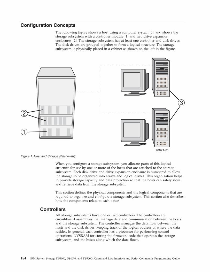
Configuration ConceptsThe following figure shows a host using a computer system [3], and shows thestorage subsystem with a controller module [1] and two drive expansionenclosures [2]. The storage subsystem has at least one controller and disk drives.The disk drives are grouped together to form a logical structure. The storagesubsystem is physically placed in a cabinet as shown on the left in the figure.
When you configure a storage subsystem, you allocate parts of this logicalstructure for use by one or more of the hosts that are attached to the storagesubsystem. Each disk drive and drive expansion enclosure is numbered to allowthe storage to be organized into arrays and logical drives. This organization helpsto provide storage capacity and data protection so that the hosts can safely storeand retrieve data from the storage subsystem.
This section defines the physical components and the logical components that arerequired to organize and configure a storage subsystem. This section also describeshow the components relate to each other.
ControllersAll storage subsystems have one or two controllers. The controllers arecircuit-board assemblies that manage data and communication between the hostsand the storage subsystem. The controller manages the data flow between thehosts and the disk drives, keeping track of the logical address of where the dataresides. In general, each controller has a processor for performing controloperations, NVSRAM for storing the firmware code that operates the storagesubsystem, and the buses along which the data flows.
Figure 1. Host and Storage Relationship
184 IBM System Storage DS3000, DS4000, and DS5000: Command Line Interface and Script Commands Programming Guide
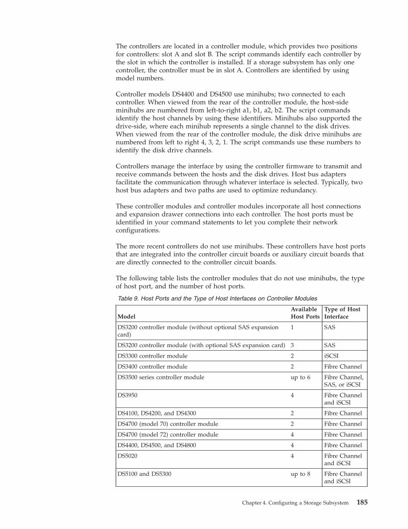
The controllers are located in a controller module, which provides two positionsfor controllers: slot A and slot B. The script commands identify each controller bythe slot in which the controller is installed. If a storage subsystem has only onecontroller, the controller must be in slot A. Controllers are identified by usingmodel numbers.
Controller models DS4400 and DS4500 use minihubs; two connected to eachcontroller. When viewed from the rear of the controller module, the host-sideminihubs are numbered from left-to-right a1, b1, a2, b2. The script commandsidentify the host channels by using these identifiers. Minihubs also supported thedrive-side, where each minihub represents a single channel to the disk drives.When viewed from the rear of the controller module, the disk drive minihubs arenumbered from left to right 4, 3, 2, 1. The script commands use these numbers toidentify the disk drive channels.
Controllers manage the interface by using the controller firmware to transmit andreceive commands between the hosts and the disk drives. Host bus adaptersfacilitate the communication through whatever interface is selected. Typically, twohost bus adapters and two paths are used to optimize redundancy.
These controller modules and controller modules incorporate all host connectionsand expansion drawer connections into each controller. The host ports must beidentified in your command statements to let you complete their networkconfigurations.
The more recent controllers do not use minihubs. These controllers have host portsthat are integrated into the controller circuit boards or auxiliary circuit boards thatare directly connected to the controller circuit boards.
The following table lists the controller modules that do not use minihubs, the typeof host port, and the number of host ports.
Table 9. Host Ports and the Type of Host Interfaces on Controller Modules
ModelAvailableHost Ports
Type of HostInterface
DS3200 controller module (without optional SAS expansioncard)
1 SAS
DS3200 controller module (with optional SAS expansion card) 3 SAS
DS3300 controller module 2 iSCSI
DS3400 controller module 2 Fibre Channel
DS3500 series controller module up to 6 Fibre Channel,SAS, or iSCSI
DS3950 4 Fibre Channeland iSCSI
DS4100, DS4200, and DS4300 2 Fibre Channel
DS4700 (model 70) controller module 2 Fibre Channel
DS4700 (model 72) controller module 4 Fibre Channel
DS4400, DS4500, and DS4800 4 Fibre Channel
DS5020 4 Fibre Channeland iSCSI
DS5100 and DS5300 up to 8 Fibre Channeland iSCSI
Chapter 4. Configuring a Storage Subsystem 185
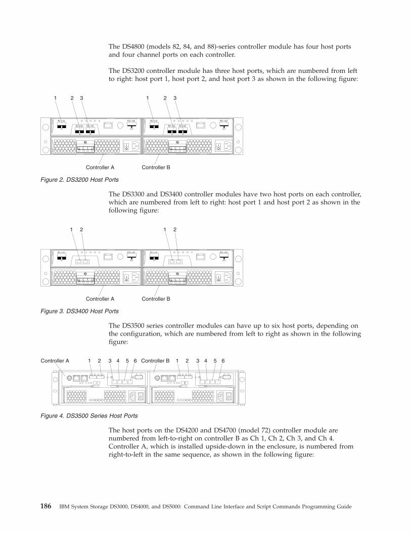
The DS4800 (models 82, 84, and 88)-series controller module has four host portsand four channel ports on each controller.
The DS3200 controller module has three host ports, which are numbered from leftto right: host port 1, host port 2, and host port 3 as shown in the following figure:
The DS3300 and DS3400 controller modules have two host ports on each controller,which are numbered from left to right: host port 1 and host port 2 as shown in thefollowing figure:
The DS3500 series controller modules can have up to six host ports, depending onthe configuration, which are numbered from left to right as shown in the followingfigure:
The host ports on the DS4200 and DS4700 (model 72) controller module arenumbered from left-to-right on controller B as Ch 1, Ch 2, Ch 3, and Ch 4.Controller A, which is installed upside-down in the enclosure, is numbered fromright-to-left in the same sequence, as shown in the following figure:
1 3 1 3
Controller A Controller B
2 2
Figure 2. DS3200 Host Ports
1 2 1 2
Controller A Controller B
Figure 3. DS3400 Host Ports
1Controller A 2 3 4 5 6 1 2 3 4 5 6Controller B
Figure 4. DS3500 Series Host Ports
186 IBM System Storage DS3000, DS4000, and DS5000: Command Line Interface and Script Commands Programming Guide
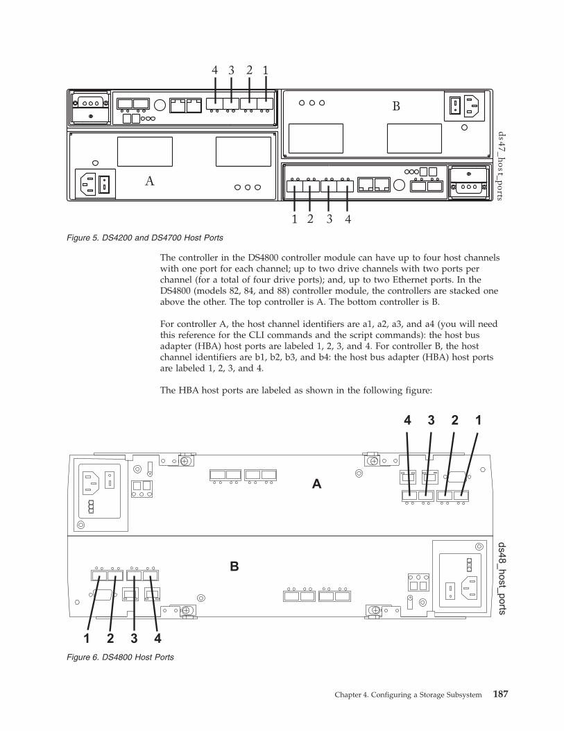
The controller in the DS4800 controller module can have up to four host channelswith one port for each channel; up to two drive channels with two ports perchannel (for a total of four drive ports); and, up to two Ethernet ports. In theDS4800 (models 82, 84, and 88) controller module, the controllers are stacked oneabove the other. The top controller is A. The bottom controller is B.
For controller A, the host channel identifiers are a1, a2, a3, and a4 (you will needthis reference for the CLI commands and the script commands): the host busadapter (HBA) host ports are labeled 1, 2, 3, and 4. For controller B, the hostchannel identifiers are b1, b2, b3, and b4: the host bus adapter (HBA) host portsare labeled 1, 2, 3, and 4.
The HBA host ports are labeled as shown in the following figure:
ds4
7_
ho
st_p
orts
A
B
1234
1 3 42
Figure 5. DS4200 and DS4700 Host Ports
A
B
ds4
8_
ho
st_
po
rts
4 3 2 1
1 2 3 4
Figure 6. DS4800 Host Ports
Chapter 4. Configuring a Storage Subsystem 187
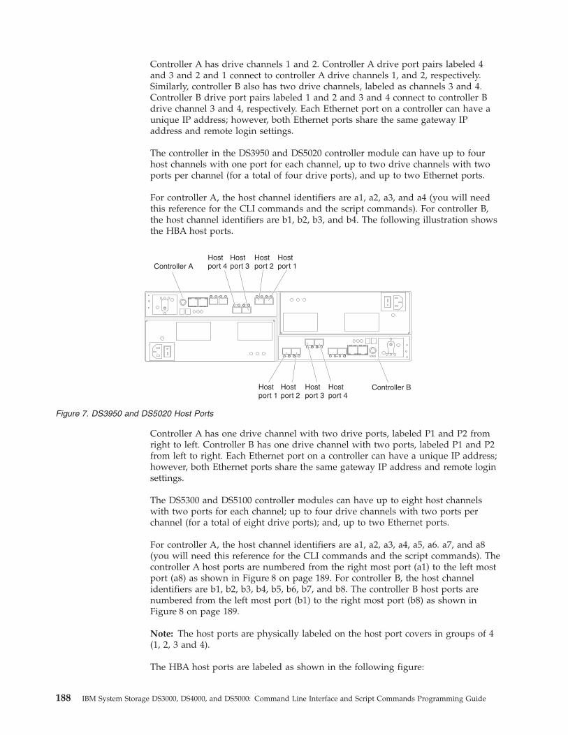
Controller A has drive channels 1 and 2. Controller A drive port pairs labeled 4and 3 and 2 and 1 connect to controller A drive channels 1, and 2, respectively.Similarly, controller B also has two drive channels, labeled as channels 3 and 4.Controller B drive port pairs labeled 1 and 2 and 3 and 4 connect to controller Bdrive channel 3 and 4, respectively. Each Ethernet port on a controller can have aunique IP address; however, both Ethernet ports share the same gateway IPaddress and remote login settings.
The controller in the DS3950 and DS5020 controller module can have up to fourhost channels with one port for each channel, up to two drive channels with twoports per channel (for a total of four drive ports), and up to two Ethernet ports.
For controller A, the host channel identifiers are a1, a2, a3, and a4 (you will needthis reference for the CLI commands and the script commands). For controller B,the host channel identifiers are b1, b2, b3, and b4. The following illustration showsthe HBA host ports.
Controller A has one drive channel with two drive ports, labeled P1 and P2 fromright to left. Controller B has one drive channel with two ports, labeled P1 and P2from left to right. Each Ethernet port on a controller can have a unique IP address;however, both Ethernet ports share the same gateway IP address and remote loginsettings.
The DS5300 and DS5100 controller modules can have up to eight host channelswith two ports for each channel; up to four drive channels with two ports perchannel (for a total of eight drive ports); and, up to two Ethernet ports.
For controller A, the host channel identifiers are a1, a2, a3, a4, a5, a6. a7, and a8(you will need this reference for the CLI commands and the script commands). Thecontroller A host ports are numbered from the right most port (a1) to the left mostport (a8) as shown in Figure 8 on page 189. For controller B, the host channelidentifiers are b1, b2, b3, b4, b5, b6, b7, and b8. The controller B host ports arenumbered from the left most port (b1) to the right most port (b8) as shown inFigure 8 on page 189.
Note: The host ports are physically labeled on the host port covers in groups of 4(1, 2, 3 and 4).
The HBA host ports are labeled as shown in the following figure:
Controller B
Controller AHostport 4
Hostport 3
Hostport 2
Hostport 1
Hostport 1
Hostport 2
Hostport 3
Hostport 4
Figure 7. DS3950 and DS5020 Host Ports
188 IBM System Storage DS3000, DS4000, and DS5000: Command Line Interface and Script Commands Programming Guide
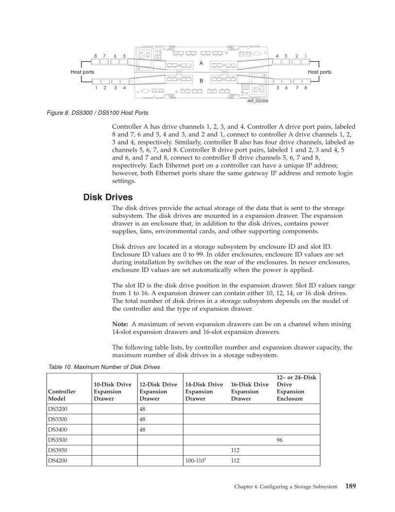
Controller A has drive channels 1, 2, 3, and 4. Controller A drive port pairs, labeled8 and 7, 6 and 5, 4 and 3, and 2 and 1, connect to controller A drive channels 1, 2,3 and 4, respectively. Similarly, controller B also has four drive channels, labeled aschannels 5, 6, 7, and 8. Controller B drive port pairs, labeled 1 and 2, 3 and 4, 5and 6, and 7 and 8, connect to controller B drive channels 5, 6, 7 and 8,respectively. Each Ethernet port on a controller can have a unique IP address;however, both Ethernet ports share the same gateway IP address and remote loginsettings.
Disk DrivesThe disk drives provide the actual storage of the data that is sent to the storagesubsystem. The disk drives are mounted in a expansion drawer. The expansiondrawer is an enclosure that, in addition to the disk drives, contains powersupplies, fans, environmental cards, and other supporting components.
Disk drives are located in a storage subsystem by enclosure ID and slot ID.Enclosure ID values are 0 to 99. In older enclosures, enclosure ID values are setduring installation by switches on the rear of the enclosures. In newer enclosures,enclosure ID values are set automatically when the power is applied.
The slot ID is the disk drive position in the expansion drawer. Slot ID values rangefrom 1 to 16. A expansion drawer can contain either 10, 12, 14, or 16 disk drives.The total number of disk drives in a storage subsystem depends on the model ofthe controller and the type of expansion drawer.
Note: A maximum of seven expansion drawers can be on a channel when mixing14-slot expansion drawers and 16-slot expansion drawers.
The following table lists, by controller number and expansion drawer capacity, themaximum number of disk drives in a storage subsystem.
Table 10. Maximum Number of Disk Drives
ControllerModel
10-Disk DriveExpansionDrawer
12-Disk DriveExpansionDrawer
14-Disk DriveExpansionDrawer
16-Disk DriveExpansionDrawer
12– or 24–DiskDriveExpansionEnclosure
DS3200 48
DS3300 48
DS3400 48
DS3500 96
DS3950 112
DS4200 100-1101 112
1 2 3
1234
4
Host ports
ds5_022309
5678
5 6 7 8
Host ports
A
B
Figure 8. DS5300 / DS5100 Host Ports
Chapter 4. Configuring a Storage Subsystem 189
Table 10. Maximum Number of Disk Drives (continued)
ControllerModel
10-Disk DriveExpansionDrawer
12-Disk DriveExpansionDrawer
14-Disk DriveExpansionDrawer
16-Disk DriveExpansionDrawer
12– or 24–DiskDriveExpansionEnclosure
DS4300–SCU 14
DS4300 112 100-1101
DS4500 220 224 224
DS4700 112 112
DS4800 224 224
DS5020 112
DS5100 256
DS5300 4481
Note: There are maximum limits to the number of Fibre Channel hard drives that you can configurein redundant drive loop pairs. The maximum number of drives dictates a fixed number of supported14-disk and 16-disk drive enclosure combinations. For more information, please refer to Chapter 1 ofthe DS4000 Hard Drive and Storage Expansion Enclosure Installation and Migration Guide.
Hot SparesA hot spare is a disk drive that acts as a standby in the event that a disk drivecontaining data fails. The hot spare is a disk drive that has not been assigned to aparticular array and, as such, can be used in any array. You can use the hot sparefeature with RAID 1, RAID 3, RAID 5, or RAID 6.
Note: Some DS3000 and DS4000 controller firmware versions do not support RAID6. (Firmware version 7.3x.xx.xx for the DS5000 supports RAID 6.) For moreinformation, see the DS3000 and DS4000 controller firmware readme files or theinteroperability matrices.
If a disk drive in a array fails, the controllers automatically replace the failed diskdrive with a hot spare. The controllers use redundancy data to reconstruct the datafrom the failed disk drive onto the hot spare. To be most effective, the disk drivethat you assign as a hot spare must have a capacity equal to or greater than thecapacity of the largest disk drive in the storage subsystem. The hot spare must bethe same type of disk drive as the disk drive that failed (for example, a SerialAdvanced Technology Attachment [SATA] hot spare cannot replace a FibreChannel hot spare).
You can assign disk drives to act as hot spares manually or have the scriptcommands automatically assign hot spares. If you manually assign a disk drive tobe a hot spare, you must identify the disk drive by enclosure ID and slot ID. Whenyou let the script commands automatically assign hot spares, you must enter thenumber of hot spares that you want in the storage subsystem. The maximumnumber of hot spare disk drives per storage subsystem is 15.
ArraysA array is a set of disk drives that are logically grouped together by the controllersin a storage subsystem. After you create a array, you can create one or more logicaldrives in the array. A array is identified by a sequence number that is defined bythe controller firmware when you created the array.
190 IBM System Storage DS3000, DS4000, and DS5000: Command Line Interface and Script Commands Programming Guide
To create a array, you must define the capacity and the RAID level.
Capacity is the size of the array. Capacity is determined by the number of diskdrives that you assign to the array. You can use only unassigned disk drives tocreate a array. (In this programming guide, the storage space on unassigned diskdrives constitutes the unconfigured capacity of a storage subsystem.)
Free capacity is a contiguous region of unassigned capacity in a designated array.Before you create a new logical drive in a array, you need to know the freecapacity space so that you can determine the size of the logical drive.
The number of disk drives you can include in a array is constrained by thecapacity of each disk drive. the following table relates the capacity of individualdisk drives to the number of disk drives that you can include in a array.
Table 11. Maximum Number of Disk Drives in an Array Based on Capacity
Controller firmware PRIORto 7.10 (DS4000) or 6.xx(DS3000)
Controller firmware 7.10 or later(DS3000/DS4000 / DS5000 only)
Number of drivesper array
30 for all RAID levels v RAID 3 and RAID 5: 30 drives
v RAID 0 and RAID 1: Maximumof drives supported for a givenstorage subsystem
Maximum logicaldrive size
2 TB Number of drives in an arraymultiplied by the size of thesmallest capacity drive in the array
Logical DrivesA logical drive is a logical component (object) that is the basic structure that iscreated on the storage subsystem to store data. A logical drive is a contiguoussubsection of a array that is configured to meet application needs for dataavailability and I/O performance. The IBM Storage Manager client softwareadministers a logical drive as if the logical drive is one “disk drive” for datastorage. Logical drives are identified by names or labels that users choose. Thelogical drive names can be any combination of alphanumeric characters, hyphens(-), and underscores (_). The maximum length of a logical drive name is 30characters.
The script commands support the following types of logical drives:v Standard logical drive – A logical structure that is the principal type of logical
drive for data storage. A standard logical drive is the most common type oflogical drive in a storage subsystem.
v Access logical drive – A factory-configured logical drive in a storage areanetwork (SAN) environment that is used for communication between the IBMStorage Manager client software and the storage subsystem controller. The accesslogical drive uses a logical unit number (LUN) address and consumes 20 MB ofstorage space. The 20 MB of access logical drive storage space is not availablefor data storage.
Note: You must use the access logical drive only for in-band-managed storagesubsystems.v FlashCopy logical drive – A logical point-in-time image of another logical
drive. A flashcopy logical drive is the logical equivalent of a complete physical
Chapter 4. Configuring a Storage Subsystem 191
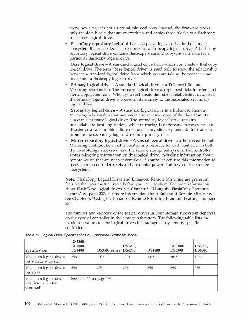
copy; however, it is not an actual, physical copy. Instead, the firmware tracksonly the data blocks that are overwritten and copies those blocks to a flashcopyrepository logical drive.
v FlashCopy repository logical drive – A special logical drive in the storagesubsystem that is created as a resource for a flashcopy logical drive. A flashcopyrepository logical drive contains flashcopy data and copy-on-write data for aparticular flashcopy logical drive.
v Base logical drive – A standard logical drive from which you create a flashcopylogical drive. The term “base logical drive” is used only to show the relationshipbetween a standard logical drive from which you are taking the point-in-timeimage and a flashcopy logical drive.
v Primary logical drive – A standard logical drive in a Enhanced RemoteMirroring relationship. The primary logical drive accepts host data transfers andstores application data. When you first create the mirror relationship, data fromthe primary logical drive is copied in its entirety to the associated secondarylogical drive.
v Secondary logical drive – A standard logical drive in a Enhanced RemoteMirroring relationship that maintains a mirror (or copy) of the data from itsassociated primary logical drive. The secondary logical drive remainsunavailable to host applications while mirroring is underway. In the event of adisaster or a catastrophic failure of the primary site, a system administrator canpromote the secondary logical drive to a primary role.
v Mirror repository logical drive – A special logical drive in a Enhanced RemoteMirroring configuration that is created as a resource for each controller in boththe local storage subsystem and the remote storage subsystem. The controllerstores mirroring information on this logical drive, including information aboutremote writes that are not yet complete. A controller can use this information torecover from controller resets and accidental power shutdown of the storagesubsystems.
Note: FlashCopy Logical Drive and Enhanced Remote Mirroring are premiumfeatures that you must activate before you can use them. For more informationabout FlashCopy logical drives, see Chapter 5, “Using the FlashCopy PremiumFeature,” on page 227. For more information about Enhanced Remote Mirroring,see Chapter 6, “Using the Enhanced Remote Mirroring Premium Feature,” on page237.
The number and capacity of the logical drives in your storage subsystem dependson the type of controller in the storage subsystem. The following table lists themaximum values for the logical drives in a storage subsystem by specificcontrollers.
Table 12. Logical Drive Specifications by Supported Controller Model
Specification
DS3200,DS3300,DS3400 DS3500 series
DS4200,DS4700 DS4800
DS5100,DS5300
DS3950,DS5020
Maximum logical drivesper storage subsystem
256 1024 1024 2048 2048 1024
Maximum logical drivesper array
256 256 256 256 256 256
Maximum logical drivesize (less 12 GB foroverhead)
See Table 11 on page 191.
192 IBM System Storage DS3000, DS4000, and DS5000: Command Line Interface and Script Commands Programming Guide
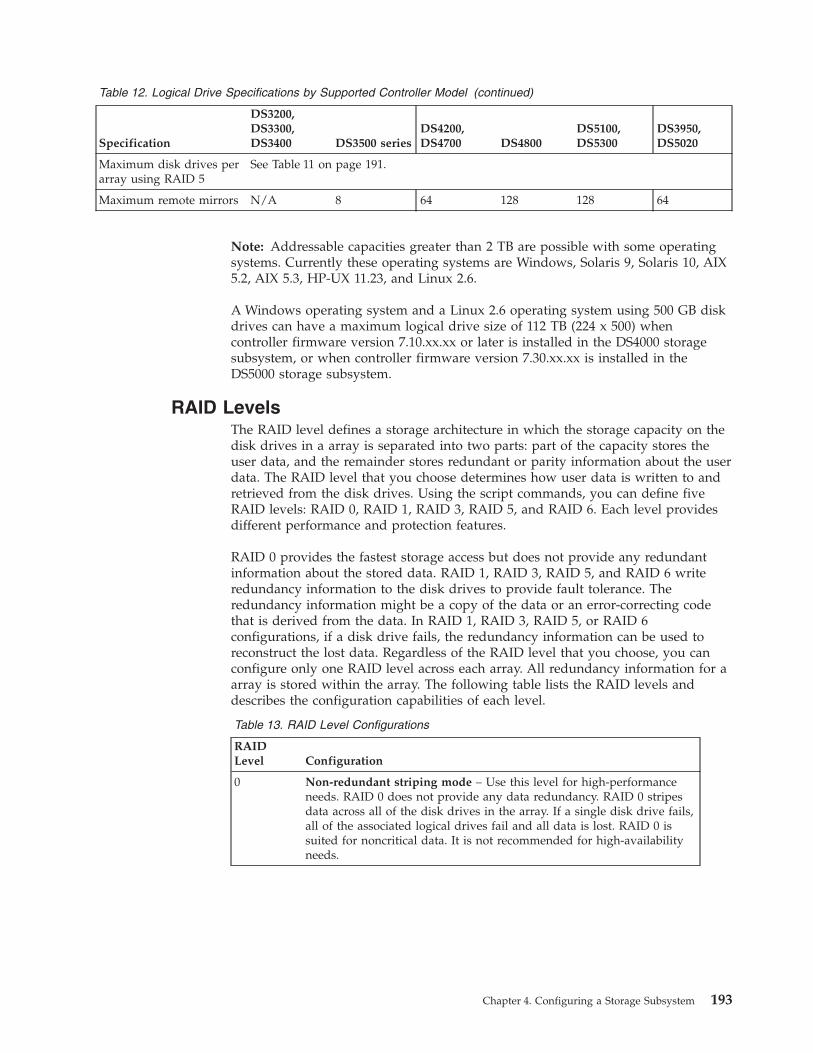
Table 12. Logical Drive Specifications by Supported Controller Model (continued)
Specification
DS3200,DS3300,DS3400 DS3500 series
DS4200,DS4700 DS4800
DS5100,DS5300
DS3950,DS5020
Maximum disk drives perarray using RAID 5
See Table 11 on page 191.
Maximum remote mirrors N/A 8 64 128 128 64
Note: Addressable capacities greater than 2 TB are possible with some operatingsystems. Currently these operating systems are Windows, Solaris 9, Solaris 10, AIX5.2, AIX 5.3, HP-UX 11.23, and Linux 2.6.
A Windows operating system and a Linux 2.6 operating system using 500 GB diskdrives can have a maximum logical drive size of 112 TB (224 x 500) whencontroller firmware version 7.10.xx.xx or later is installed in the DS4000 storagesubsystem, or when controller firmware version 7.30.xx.xx is installed in theDS5000 storage subsystem.
RAID LevelsThe RAID level defines a storage architecture in which the storage capacity on thedisk drives in a array is separated into two parts: part of the capacity stores theuser data, and the remainder stores redundant or parity information about the userdata. The RAID level that you choose determines how user data is written to andretrieved from the disk drives. Using the script commands, you can define fiveRAID levels: RAID 0, RAID 1, RAID 3, RAID 5, and RAID 6. Each level providesdifferent performance and protection features.
RAID 0 provides the fastest storage access but does not provide any redundantinformation about the stored data. RAID 1, RAID 3, RAID 5, and RAID 6 writeredundancy information to the disk drives to provide fault tolerance. Theredundancy information might be a copy of the data or an error-correcting codethat is derived from the data. In RAID 1, RAID 3, RAID 5, or RAID 6configurations, if a disk drive fails, the redundancy information can be used toreconstruct the lost data. Regardless of the RAID level that you choose, you canconfigure only one RAID level across each array. All redundancy information for aarray is stored within the array. The following table lists the RAID levels anddescribes the configuration capabilities of each level.
Table 13. RAID Level Configurations
RAIDLevel Configuration
0 Non-redundant striping mode – Use this level for high-performanceneeds. RAID 0 does not provide any data redundancy. RAID 0 stripesdata across all of the disk drives in the array. If a single disk drive fails,all of the associated logical drives fail and all data is lost. RAID 0 issuited for noncritical data. It is not recommended for high-availabilityneeds.
Chapter 4. Configuring a Storage Subsystem 193
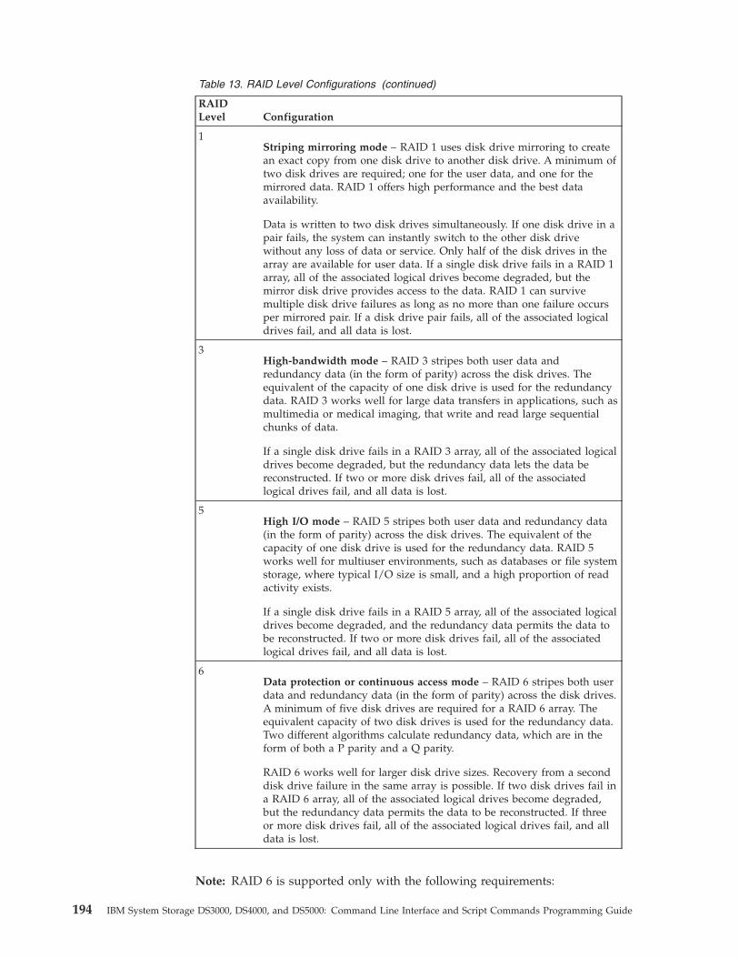
Table 13. RAID Level Configurations (continued)
RAIDLevel Configuration
1Striping mirroring mode – RAID 1 uses disk drive mirroring to createan exact copy from one disk drive to another disk drive. A minimum oftwo disk drives are required; one for the user data, and one for themirrored data. RAID 1 offers high performance and the best dataavailability.
Data is written to two disk drives simultaneously. If one disk drive in apair fails, the system can instantly switch to the other disk drivewithout any loss of data or service. Only half of the disk drives in thearray are available for user data. If a single disk drive fails in a RAID 1array, all of the associated logical drives become degraded, but themirror disk drive provides access to the data. RAID 1 can survivemultiple disk drive failures as long as no more than one failure occursper mirrored pair. If a disk drive pair fails, all of the associated logicaldrives fail, and all data is lost.
3High-bandwidth mode – RAID 3 stripes both user data andredundancy data (in the form of parity) across the disk drives. Theequivalent of the capacity of one disk drive is used for the redundancydata. RAID 3 works well for large data transfers in applications, such asmultimedia or medical imaging, that write and read large sequentialchunks of data.
If a single disk drive fails in a RAID 3 array, all of the associated logicaldrives become degraded, but the redundancy data lets the data bereconstructed. If two or more disk drives fail, all of the associatedlogical drives fail, and all data is lost.
5High I/O mode – RAID 5 stripes both user data and redundancy data(in the form of parity) across the disk drives. The equivalent of thecapacity of one disk drive is used for the redundancy data. RAID 5works well for multiuser environments, such as databases or file systemstorage, where typical I/O size is small, and a high proportion of readactivity exists.
If a single disk drive fails in a RAID 5 array, all of the associated logicaldrives become degraded, and the redundancy data permits the data tobe reconstructed. If two or more disk drives fail, all of the associatedlogical drives fail, and all data is lost.
6Data protection or continuous access mode – RAID 6 stripes both userdata and redundancy data (in the form of parity) across the disk drives.A minimum of five disk drives are required for a RAID 6 array. Theequivalent capacity of two disk drives is used for the redundancy data.Two different algorithms calculate redundancy data, which are in theform of both a P parity and a Q parity.
RAID 6 works well for larger disk drive sizes. Recovery from a seconddisk drive failure in the same array is possible. If two disk drives fail ina RAID 6 array, all of the associated logical drives become degraded,but the redundancy data permits the data to be reconstructed. If threeor more disk drives fail, all of the associated logical drives fail, and alldata is lost.
Note: RAID 6 is supported only with the following requirements:
194 IBM System Storage DS3000, DS4000, and DS5000: Command Line Interface and Script Commands Programming Guide
v Controller firmware version 7.xx.xx.xx and higher must be installed.v The controllers must be capable of supporting the P+Q calculation.v You must purchase and install a premium feature key to use RAID 6 and to use
dynamic RAID-level migration. (See “Set Array” on page 103 to set your arrayto RAID 6.)
v The DS4100, DS4300, DS4400, DS4500, DS4800, FAStT200, and FAStT500 storagesubsystems do not support RAID 6. The DS3500 series, DS3950, DS4200, DS4700,DS5020, DS5100, and DS5300 storage subsystems do support RAID 6.
HostsA host is a computer that is attached to the storage subsystem for accessing thelogical drives in the storage subsystem. The host is attached to the storagesubsystem through HBA host ports, which are connectors on host bus adaptercircuit boards. You can define specific logical drive-to-LUN mappings to anindividual host or assign the host to a host group that shares access to one or morelogical drives. Hosts are identified by names or labels that users choose. The hostname can be any combination of alphanumeric characters, hyphens, andunderscores. The maximum length of the host name is 30 characters.
In addition to a host name, some script commands require you to identify a hostby its “type.” A host type identifies the operating system under which the host isrunning (such as Windows, Solaris, or Linux). Specifying the host type lets thecontrollers in the storage subsystem adapt their behavior (such as LUN reportingand error conditions) to the operating system of the host that is sending theinformation. Host types are identified by a label or an index number that isgenerated by the controller firmware.
Host GroupsA host group is a topological element that you can define if you want to designatea collection of hosts that will share access to the same logical drives. A host groupis a logical entity. Host groups are identified by names or labels that users choose.The host group name can be any combination of alphanumeric characters with amaximum length of 30 characters.
Host Bus Adapter Host PortsA host bus adapter (HBA) provides the physical connection from the host to thestorage subsystem. The host port is a physical connector on an HBA. The HBA is acircuit board that is installed in the host. The HBA can have one or more hostports. Each host port is identified by a unique, 16-byte World-Wide Identifier(WWID). If the HBA has more than one host port, each host port has a unique ID.
When you first turn on the power to a storage subsystem, the Storage Managersoftware automatically detects the HBA host ports. Initially, all detected host portsbelong to a default group. You can use script commands to identify the WWIDs ona storage subsystem and, if you choose, change them. If you move an HBA hostport, you must remap any logical drive-to-LUN mappings. Access to your data islost until you remap the logical drives.
The maximum number of HBA host ports that you can logically define for yourstorage subsystem depends on the type of controller in the storage subsystem. Thefollowing table lists the maximum number of HBA host ports that you can define.
Chapter 4. Configuring a Storage Subsystem 195
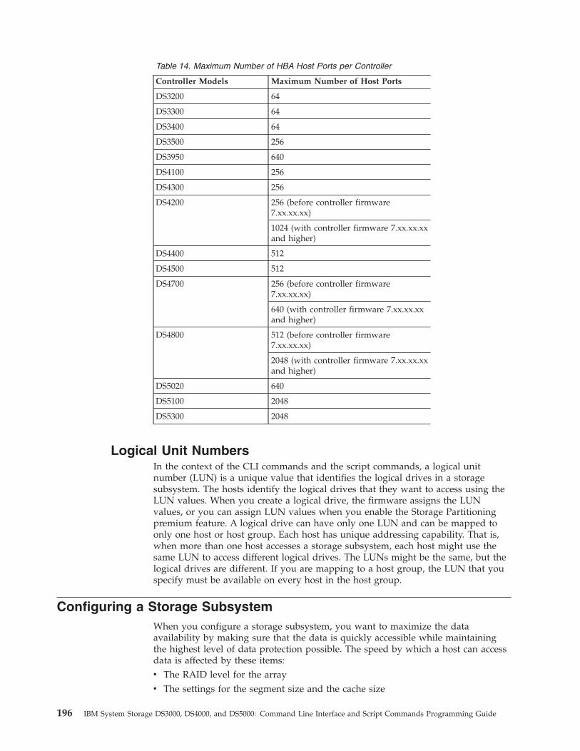
Table 14. Maximum Number of HBA Host Ports per Controller
Controller Models Maximum Number of Host Ports
DS3200 64
DS3300 64
DS3400 64
DS3500 256
DS3950 640
DS4100 256
DS4300 256
DS4200 256 (before controller firmware7.xx.xx.xx)
1024 (with controller firmware 7.xx.xx.xxand higher)
DS4400 512
DS4500 512
DS4700 256 (before controller firmware7.xx.xx.xx)
640 (with controller firmware 7.xx.xx.xxand higher)
DS4800 512 (before controller firmware7.xx.xx.xx)
2048 (with controller firmware 7.xx.xx.xxand higher)
DS5020 640
DS5100 2048
DS5300 2048
Logical Unit NumbersIn the context of the CLI commands and the script commands, a logical unitnumber (LUN) is a unique value that identifies the logical drives in a storagesubsystem. The hosts identify the logical drives that they want to access using theLUN values. When you create a logical drive, the firmware assigns the LUNvalues, or you can assign LUN values when you enable the Storage Partitioningpremium feature. A logical drive can have only one LUN and can be mapped toonly one host or host group. Each host has unique addressing capability. That is,when more than one host accesses a storage subsystem, each host might use thesame LUN to access different logical drives. The LUNs might be the same, but thelogical drives are different. If you are mapping to a host group, the LUN that youspecify must be available on every host in the host group.
Configuring a Storage SubsystemWhen you configure a storage subsystem, you want to maximize the dataavailability by making sure that the data is quickly accessible while maintainingthe highest level of data protection possible. The speed by which a host can accessdata is affected by these items:v The RAID level for the arrayv The settings for the segment size and the cache size
196 IBM System Storage DS3000, DS4000, and DS5000: Command Line Interface and Script Commands Programming Guide
v Whether the cache read prefetch capability is turned on or turned off
Data protection is determined by the RAID level, hardware redundancy (such asglobal hot spares), and software redundancy (such as the Enhanced RemoteMirroring premium feature and the FlashCopy Logical Drive premium feature).
In general, you configure a storage subsystem by defining a array and itsassociated RAID level, defining the logical drives, and defining which hosts haveaccess to the logical drives. This section explains how to use the script commandsto perform the general steps to create a configuration from an array of disk drives.
Determining What Is on Your Storage SubsystemEven when you create a configuration on a storage subsystem that has never beenconfigured, you still need to determine the hardware features and softwarefeatures that are to be included with the storage subsystem. When you configure astorage subsystem that has an existing configuration, you must make sure thatyour new configuration does not inadvertently alter the existing configuration,unless you are reconfiguring the entire storage subsystem. For example, considerthe case where you want to create a new array on unassigned disk drives. Beforeyou create a new array, you must determine which disk drives are available. Thecommands that are described in this section help you to determine the componentsand the features in your storage subsystem.
The command that returns general information about the storage subsystem is theshow storageSubsystem command. This command returns information about thecomponents and properties of your storage subsystem, including these items:v A detailed profile of the components and features in the storage subsystemv The age of the batteryv The default host type (which is the current host type)v Other host types that you can selectv The hot spare locationsv The identifiers for enabled featuresv The logical component profiles and the physical component profilesv The time to which both controllers are setv The controller that currently owns each logical drive in the storage subsystem
To return the most information about the storage subsystem, run the showstorageSubsystem command with the profile parameter. This example shows thecomplete CLI command and script command running on a Windows operatingsystem:c:\...\...\client>smcli 123.45.67.89 -c “show storageSubsystem profile;”
This example identifies the storage subsystem by the example IP address123.45.67.89. You can also identify the storage subsystem by name.
The show storageSubsystem profile command returns detailed information aboutthe storage subsystem. The information appears in several display screens. Youmight need to increase the size of your display buffer to see all of the information.Because this information is so detailed, you might want to save the output to a file.To save the output to a file, enter the command as shown in this example:c:\...\...\client>smcli 123.45.67.89 -c “show storageSubsystem profile;”-o c:\folder\storageSubsystemprofile.txt
Chapter 4. Configuring a Storage Subsystem 197
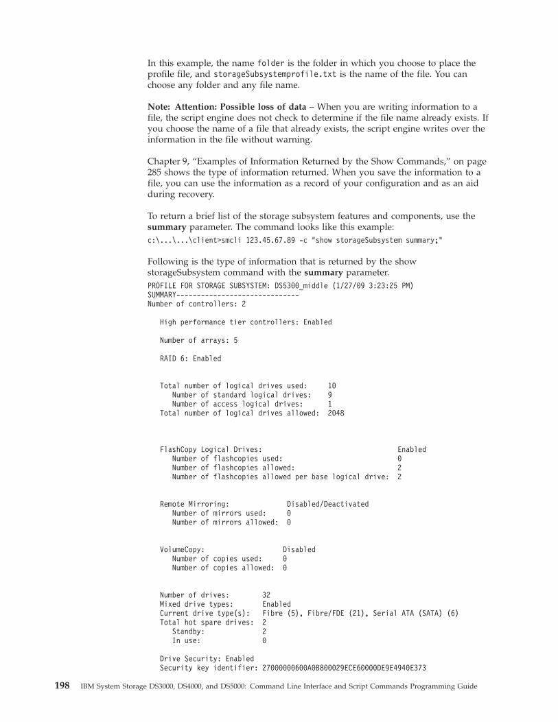
In this example, the name folder is the folder in which you choose to place theprofile file, and storageSubsystemprofile.txt is the name of the file. You canchoose any folder and any file name.
Note: Attention: Possible loss of data – When you are writing information to afile, the script engine does not check to determine if the file name already exists. Ifyou choose the name of a file that already exists, the script engine writes over theinformation in the file without warning.
Chapter 9, “Examples of Information Returned by the Show Commands,” on page285 shows the type of information returned. When you save the information to afile, you can use the information as a record of your configuration and as an aidduring recovery.
To return a brief list of the storage subsystem features and components, use thesummary parameter. The command looks like this example:c:\...\...\client>smcli 123.45.67.89 -c “show storageSubsystem summary;”
Following is the type of information that is returned by the showstorageSubsystem command with the summary parameter.PROFILE FOR STORAGE SUBSYSTEM: DS5300_middle (1/27/09 3:23:25 PM)SUMMARY------------------------------Number of controllers: 2
High performance tier controllers: Enabled
Number of arrays: 5
RAID 6: Enabled
Total number of logical drives used: 10Number of standard logical drives: 9Number of access logical drives: 1
Total number of logical drives allowed: 2048
FlashCopy Logical Drives: EnabledNumber of flashcopies used: 0Number of flashcopies allowed: 2Number of flashcopies allowed per base logical drive: 2
Remote Mirroring: Disabled/DeactivatedNumber of mirrors used: 0Number of mirrors allowed: 0
VolumeCopy: DisabledNumber of copies used: 0Number of copies allowed: 0
Number of drives: 32Mixed drive types: EnabledCurrent drive type(s): Fibre (5), Fibre/FDE (21), Serial ATA (SATA) (6)Total hot spare drives: 2
Standby: 2In use: 0
Drive Security: EnabledSecurity key identifier: 27000000600A0B800029ECE60000DE9E4940E373
198 IBM System Storage DS3000, DS4000, and DS5000: Command Line Interface and Script Commands Programming Guide
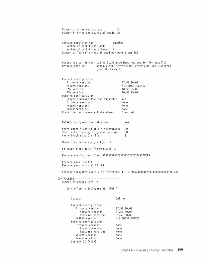
Number of drive enclosures: 2Number of drive enclosures allowed: 28
Storage Partitioning: EnabledNumber of partitions used: 2Number of partitions allowed: 2
Number of logical drives allowed per partition: 256
Access logical drive: LUN 31,31,31 (see Mappings section for details)Default host OS: Windows 2000/Server 2003/Server 2008 Non-Clustered
(Host OS index 2)
Current configurationFirmware version: 07.50.00.00NVSRAM version: N1818D53R1050V03EMW version: 10.50.G5.02AMW version: 10.50.G5.02
Pending configurationStaged firmware download supported: YesFirmware version: NoneNVSRAM version: NoneTransferred on: None
Controller enclosure audible alarm: Disabled
NVSRAM configured for batteries: Yes
Start cache flushing at (in percentage): 80Stop cache flushing at (in percentage): 80Cache block size (in KB): 8
Media scan frequency (in days): 1
Failover alert delay (in minutes): 5
Feature enable identifier: 303030323420303035353420493FECB1
Feature pack: DS5300Feature pack submodel ID: 93
Storage Subsystem world-wide identifier (ID): 600A0B800029ECE600000000493FECAB
CONTROLLERS------------------------------Number of controllers: 2
Controller in Enclosure 85, Slot A
Status: Online
Current configurationFirmware version: 07.50.00.00
Appware version: 07.50.00.00Bootware version: 07.50.00.00
NVSRAM version: N1818D53R1050V03Pending configuration
Firmware version: NoneAppware version: NoneBootware version: None
NVSRAM version: NoneTransferred on: None
Current ID (ALPA)
Chapter 4. Configuring a Storage Subsystem 199
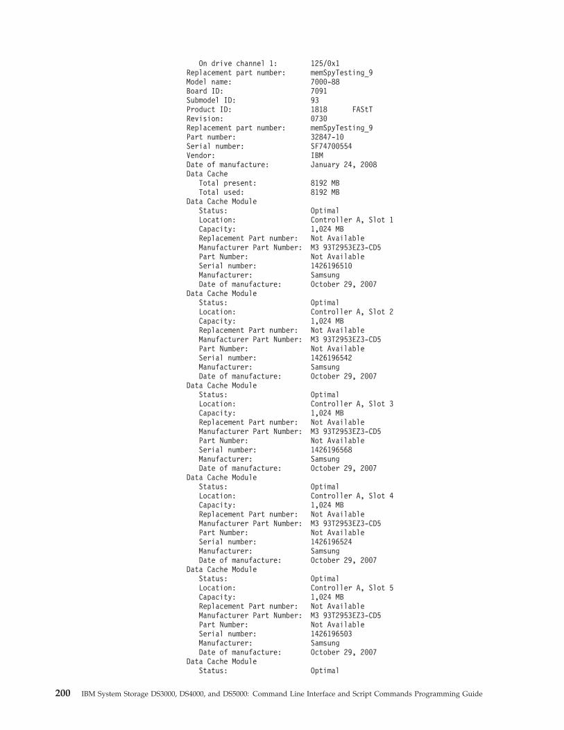
On drive channel 1: 125/0x1Replacement part number: memSpyTesting_9Model name: 7000-88Board ID: 7091Submodel ID: 93Product ID: 1818 FAStTRevision: 0730Replacement part number: memSpyTesting_9Part number: 32847-10Serial number: SF74700554Vendor: IBMDate of manufacture: January 24, 2008Data Cache
Total present: 8192 MBTotal used: 8192 MB
Data Cache ModuleStatus: OptimalLocation: Controller A, Slot 1Capacity: 1,024 MBReplacement Part number: Not AvailableManufacturer Part Number: M3 93T2953EZ3-CD5Part Number: Not AvailableSerial number: 1426196510Manufacturer: SamsungDate of manufacture: October 29, 2007
Data Cache ModuleStatus: OptimalLocation: Controller A, Slot 2Capacity: 1,024 MBReplacement Part number: Not AvailableManufacturer Part Number: M3 93T2953EZ3-CD5Part Number: Not AvailableSerial number: 1426196542Manufacturer: SamsungDate of manufacture: October 29, 2007
Data Cache ModuleStatus: OptimalLocation: Controller A, Slot 3Capacity: 1,024 MBReplacement Part number: Not AvailableManufacturer Part Number: M3 93T2953EZ3-CD5Part Number: Not AvailableSerial number: 1426196568Manufacturer: SamsungDate of manufacture: October 29, 2007
Data Cache ModuleStatus: OptimalLocation: Controller A, Slot 4Capacity: 1,024 MBReplacement Part number: Not AvailableManufacturer Part Number: M3 93T2953EZ3-CD5Part Number: Not AvailableSerial number: 1426196524Manufacturer: SamsungDate of manufacture: October 29, 2007
Data Cache ModuleStatus: OptimalLocation: Controller A, Slot 5Capacity: 1,024 MBReplacement Part number: Not AvailableManufacturer Part Number: M3 93T2953EZ3-CD5Part Number: Not AvailableSerial number: 1426196503Manufacturer: SamsungDate of manufacture: October 29, 2007
Data Cache ModuleStatus: Optimal
200 IBM System Storage DS3000, DS4000, and DS5000: Command Line Interface and Script Commands Programming Guide
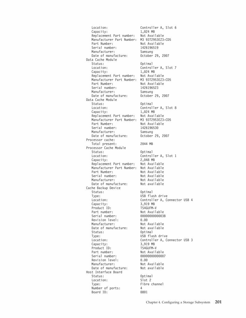
Location: Controller A, Slot 6Capacity: 1,024 MBReplacement Part number: Not AvailableManufacturer Part Number: M3 93T2953EZ3-CD5Part Number: Not AvailableSerial number: 1426196519Manufacturer: SamsungDate of manufacture: October 29, 2007
Data Cache ModuleStatus: OptimalLocation: Controller A, Slot 7Capacity: 1,024 MBReplacement Part number: Not AvailableManufacturer Part Number: M3 93T2953EZ3-CD5Part Number: Not AvailableSerial number: 1426196523Manufacturer: SamsungDate of manufacture: October 29, 2007
Data Cache ModuleStatus: OptimalLocation: Controller A, Slot 8Capacity: 1,024 MBReplacement Part number: Not AvailableManufacturer Part Number: M3 93T2953EZ3-CD5Part Number: Not AvailableSerial number: 1426196530Manufacturer: SamsungDate of manufacture: October 29, 2007
Processor cache:Total present: 2044 MB
Processor Cache ModuleStatus: OptimalLocation: Controller A, Slot 1Capacity: 2,048 MBReplacement Part number: Not AvailableManufacturer Part Number: Not AvailablePart Number: Not AvailableSerial number: Not AvailableManufacturer: Not AvailableDate of manufacture: Not available
Cache Backup DeviceStatus: OptimalType: USB flash driveLocation: Controller A, Connector USB 4Capacity: 3,919 MBProduct ID: TS4GUFM-VPart number: Not AvailableSerial number: 0000000000003BRevision level: 0.00Manufacturer: Not AvailableDate of manufacture: Not availableStatus: OptimalType: USB flash driveLocation: Controller A, Connector USB 3Capacity: 3,919 MBProduct ID: TS4GUFM-VPart number: Not AvailableSerial number: 00000000000007Revision level: 0.00Manufacturer: Not AvailableDate of manufacture: Not available
Host Interface BoardStatus: OptimalLocation: Slot 2Type: Fibre channelNumber of ports: 4Board ID: 0801
Chapter 4. Configuring a Storage Subsystem 201
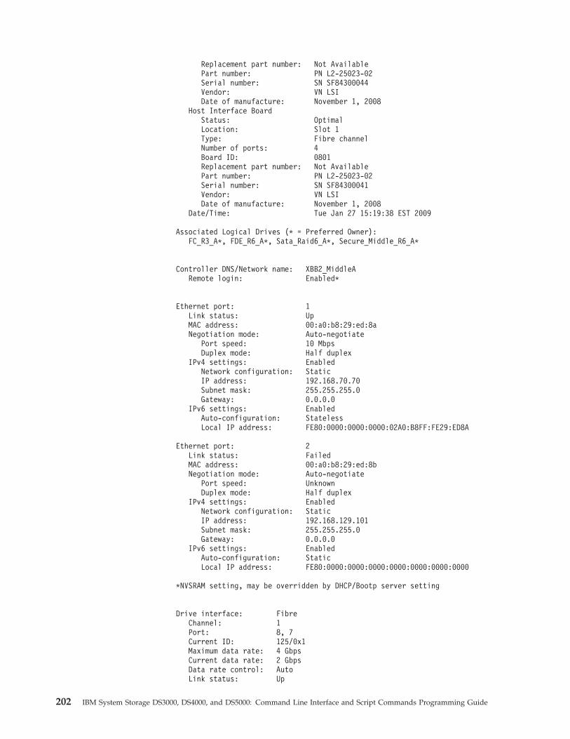
Replacement part number: Not AvailablePart number: PN L2-25023-02Serial number: SN SF84300044Vendor: VN LSIDate of manufacture: November 1, 2008
Host Interface BoardStatus: OptimalLocation: Slot 1Type: Fibre channelNumber of ports: 4Board ID: 0801Replacement part number: Not AvailablePart number: PN L2-25023-02Serial number: SN SF84300041Vendor: VN LSIDate of manufacture: November 1, 2008
Date/Time: Tue Jan 27 15:19:38 EST 2009
Associated Logical Drives (* = Preferred Owner):FC_R3_A*, FDE_R6_A*, Sata_Raid6_A*, Secure_Middle_R6_A*
Controller DNS/Network name: XBB2_MiddleARemote login: Enabled*
Ethernet port: 1Link status: UpMAC address: 00:a0:b8:29:ed:8aNegotiation mode: Auto-negotiate
Port speed: 10 MbpsDuplex mode: Half duplex
IPv4 settings: EnabledNetwork configuration: StaticIP address: 192.168.70.70Subnet mask: 255.255.255.0Gateway: 0.0.0.0
IPv6 settings: EnabledAuto-configuration: StatelessLocal IP address: FE80:0000:0000:0000:02A0:B8FF:FE29:ED8A
Ethernet port: 2Link status: FailedMAC address: 00:a0:b8:29:ed:8bNegotiation mode: Auto-negotiate
Port speed: UnknownDuplex mode: Half duplex
IPv4 settings: EnabledNetwork configuration: StaticIP address: 192.168.129.101Subnet mask: 255.255.255.0Gateway: 0.0.0.0
IPv6 settings: EnabledAuto-configuration: StaticLocal IP address: FE80:0000:0000:0000:0000:0000:0000:0000
*NVSRAM setting, may be overridden by DHCP/Bootp server setting
Drive interface: FibreChannel: 1Port: 8, 7Current ID: 125/0x1Maximum data rate: 4 GbpsCurrent data rate: 2 GbpsData rate control: AutoLink status: Up
202 IBM System Storage DS3000, DS4000, and DS5000: Command Line Interface and Script Commands Programming Guide
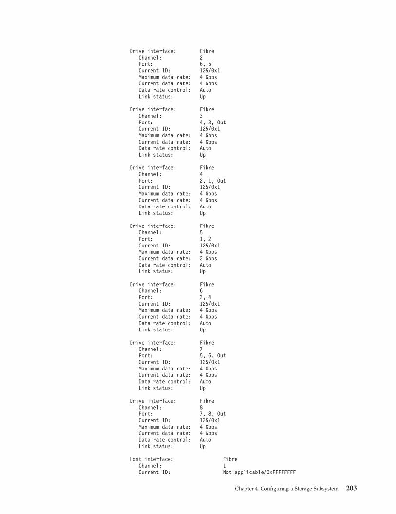
Drive interface: FibreChannel: 2Port: 6, 5Current ID: 125/0x1Maximum data rate: 4 GbpsCurrent data rate: 4 GbpsData rate control: AutoLink status: Up
Drive interface: FibreChannel: 3Port: 4, 3, OutCurrent ID: 125/0x1Maximum data rate: 4 GbpsCurrent data rate: 4 GbpsData rate control: AutoLink status: Up
Drive interface: FibreChannel: 4Port: 2, 1, OutCurrent ID: 125/0x1Maximum data rate: 4 GbpsCurrent data rate: 4 GbpsData rate control: AutoLink status: Up
Drive interface: FibreChannel: 5Port: 1, 2Current ID: 125/0x1Maximum data rate: 4 GbpsCurrent data rate: 2 GbpsData rate control: AutoLink status: Up
Drive interface: FibreChannel: 6Port: 3, 4Current ID: 125/0x1Maximum data rate: 4 GbpsCurrent data rate: 4 GbpsData rate control: AutoLink status: Up
Drive interface: FibreChannel: 7Port: 5, 6, OutCurrent ID: 125/0x1Maximum data rate: 4 GbpsCurrent data rate: 4 GbpsData rate control: AutoLink status: Up
Drive interface: FibreChannel: 8Port: 7, 8, OutCurrent ID: 125/0x1Maximum data rate: 4 GbpsCurrent data rate: 4 GbpsData rate control: AutoLink status: Up
Host interface: FibreChannel: 1Current ID: Not applicable/0xFFFFFFFF
Chapter 4. Configuring a Storage Subsystem 203
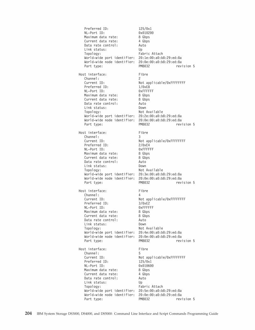
Preferred ID: 125/0x1NL-Port ID: 0x010200Maximum data rate: 8 GbpsCurrent data rate: 4 GbpsData rate control: AutoLink status: UpTopology: Fabric AttachWorld-wide port identifier: 20:1e:00:a0:b8:29:ed:8aWorld-wide node identifier: 20:0e:00:a0:b8:29:ed:8aPart type: PM8032 revision 5
Host interface: FibreChannel: 2Current ID: Not applicable/0xFFFFFFFFPreferred ID: 1/0xE8NL-Port ID: 0xFFFFFFMaximum data rate: 8 GbpsCurrent data rate: 8 GbpsData rate control: AutoLink status: DownTopology: Not AvailableWorld-wide port identifier: 20:2e:00:a0:b8:29:ed:8aWorld-wide node identifier: 20:0e:00:a0:b8:29:ed:8aPart type: PM8032 revision 5
Host interface: FibreChannel: 3Current ID: Not applicable/0xFFFFFFFFPreferred ID: 2/0xE4NL-Port ID: 0xFFFFFFMaximum data rate: 8 GbpsCurrent data rate: 8 GbpsData rate control: AutoLink status: DownTopology: Not AvailableWorld-wide port identifier: 20:3e:00:a0:b8:29:ed:8aWorld-wide node identifier: 20:0e:00:a0:b8:29:ed:8aPart type: PM8032 revision 5
Host interface: FibreChannel: 4Current ID: Not applicable/0xFFFFFFFFPreferred ID: 3/0xE2NL-Port ID: 0xFFFFFFMaximum data rate: 8 GbpsCurrent data rate: 8 GbpsData rate control: AutoLink status: DownTopology: Not AvailableWorld-wide port identifier: 20:4e:00:a0:b8:29:ed:8aWorld-wide node identifier: 20:0e:00:a0:b8:29:ed:8aPart type: PM8032 revision 5
Host interface: FibreChannel: 5Current ID: Not applicable/0xFFFFFFFFPreferred ID: 125/0x1NL-Port ID: 0x010600Maximum data rate: 8 GbpsCurrent data rate: 4 GbpsData rate control: AutoLink status: UpTopology: Fabric AttachWorld-wide port identifier: 20:5e:00:a0:b8:29:ed:8aWorld-wide node identifier: 20:0e:00:a0:b8:29:ed:8aPart type: PM8032 revision 5
204 IBM System Storage DS3000, DS4000, and DS5000: Command Line Interface and Script Commands Programming Guide
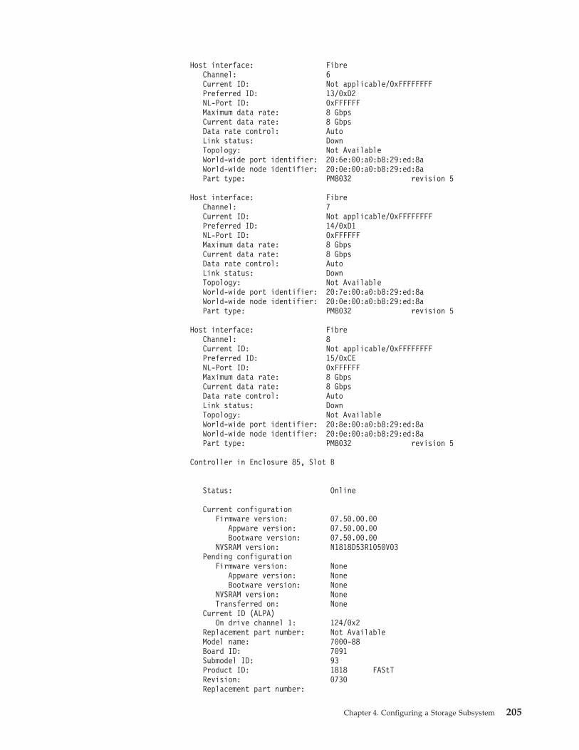
Host interface: FibreChannel: 6Current ID: Not applicable/0xFFFFFFFFPreferred ID: 13/0xD2NL-Port ID: 0xFFFFFFMaximum data rate: 8 GbpsCurrent data rate: 8 GbpsData rate control: AutoLink status: DownTopology: Not AvailableWorld-wide port identifier: 20:6e:00:a0:b8:29:ed:8aWorld-wide node identifier: 20:0e:00:a0:b8:29:ed:8aPart type: PM8032 revision 5
Host interface: FibreChannel: 7Current ID: Not applicable/0xFFFFFFFFPreferred ID: 14/0xD1NL-Port ID: 0xFFFFFFMaximum data rate: 8 GbpsCurrent data rate: 8 GbpsData rate control: AutoLink status: DownTopology: Not AvailableWorld-wide port identifier: 20:7e:00:a0:b8:29:ed:8aWorld-wide node identifier: 20:0e:00:a0:b8:29:ed:8aPart type: PM8032 revision 5
Host interface: FibreChannel: 8Current ID: Not applicable/0xFFFFFFFFPreferred ID: 15/0xCENL-Port ID: 0xFFFFFFMaximum data rate: 8 GbpsCurrent data rate: 8 GbpsData rate control: AutoLink status: DownTopology: Not AvailableWorld-wide port identifier: 20:8e:00:a0:b8:29:ed:8aWorld-wide node identifier: 20:0e:00:a0:b8:29:ed:8aPart type: PM8032 revision 5
Controller in Enclosure 85, Slot B
Status: Online
Current configurationFirmware version: 07.50.00.00
Appware version: 07.50.00.00Bootware version: 07.50.00.00
NVSRAM version: N1818D53R1050V03Pending configuration
Firmware version: NoneAppware version: NoneBootware version: None
NVSRAM version: NoneTransferred on: None
Current ID (ALPA)On drive channel 1: 124/0x2
Replacement part number: Not AvailableModel name: 7000-88Board ID: 7091Submodel ID: 93Product ID: 1818 FAStTRevision: 0730Replacement part number:
Chapter 4. Configuring a Storage Subsystem 205
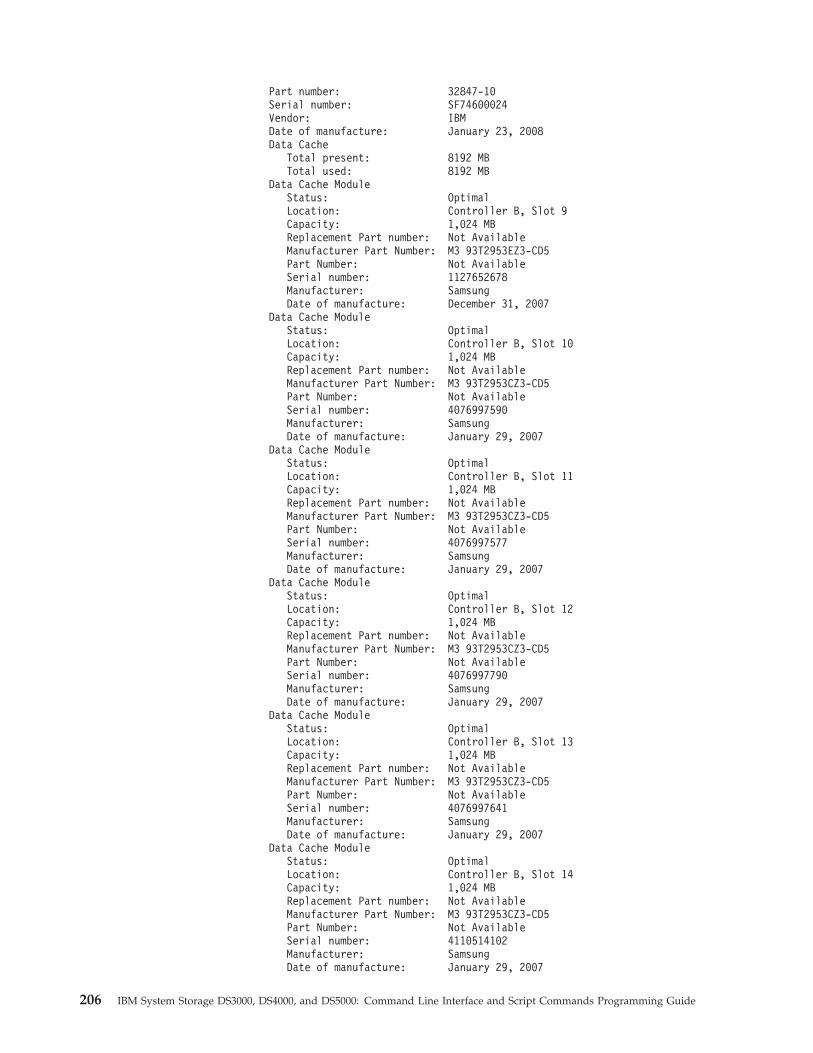
Part number: 32847-10Serial number: SF74600024Vendor: IBMDate of manufacture: January 23, 2008Data Cache
Total present: 8192 MBTotal used: 8192 MB
Data Cache ModuleStatus: OptimalLocation: Controller B, Slot 9Capacity: 1,024 MBReplacement Part number: Not AvailableManufacturer Part Number: M3 93T2953EZ3-CD5Part Number: Not AvailableSerial number: 1127652678Manufacturer: SamsungDate of manufacture: December 31, 2007
Data Cache ModuleStatus: OptimalLocation: Controller B, Slot 10Capacity: 1,024 MBReplacement Part number: Not AvailableManufacturer Part Number: M3 93T2953CZ3-CD5Part Number: Not AvailableSerial number: 4076997590Manufacturer: SamsungDate of manufacture: January 29, 2007
Data Cache ModuleStatus: OptimalLocation: Controller B, Slot 11Capacity: 1,024 MBReplacement Part number: Not AvailableManufacturer Part Number: M3 93T2953CZ3-CD5Part Number: Not AvailableSerial number: 4076997577Manufacturer: SamsungDate of manufacture: January 29, 2007
Data Cache ModuleStatus: OptimalLocation: Controller B, Slot 12Capacity: 1,024 MBReplacement Part number: Not AvailableManufacturer Part Number: M3 93T2953CZ3-CD5Part Number: Not AvailableSerial number: 4076997790Manufacturer: SamsungDate of manufacture: January 29, 2007
Data Cache ModuleStatus: OptimalLocation: Controller B, Slot 13Capacity: 1,024 MBReplacement Part number: Not AvailableManufacturer Part Number: M3 93T2953CZ3-CD5Part Number: Not AvailableSerial number: 4076997641Manufacturer: SamsungDate of manufacture: January 29, 2007
Data Cache ModuleStatus: OptimalLocation: Controller B, Slot 14Capacity: 1,024 MBReplacement Part number: Not AvailableManufacturer Part Number: M3 93T2953CZ3-CD5Part Number: Not AvailableSerial number: 4110514102Manufacturer: SamsungDate of manufacture: January 29, 2007
206 IBM System Storage DS3000, DS4000, and DS5000: Command Line Interface and Script Commands Programming Guide
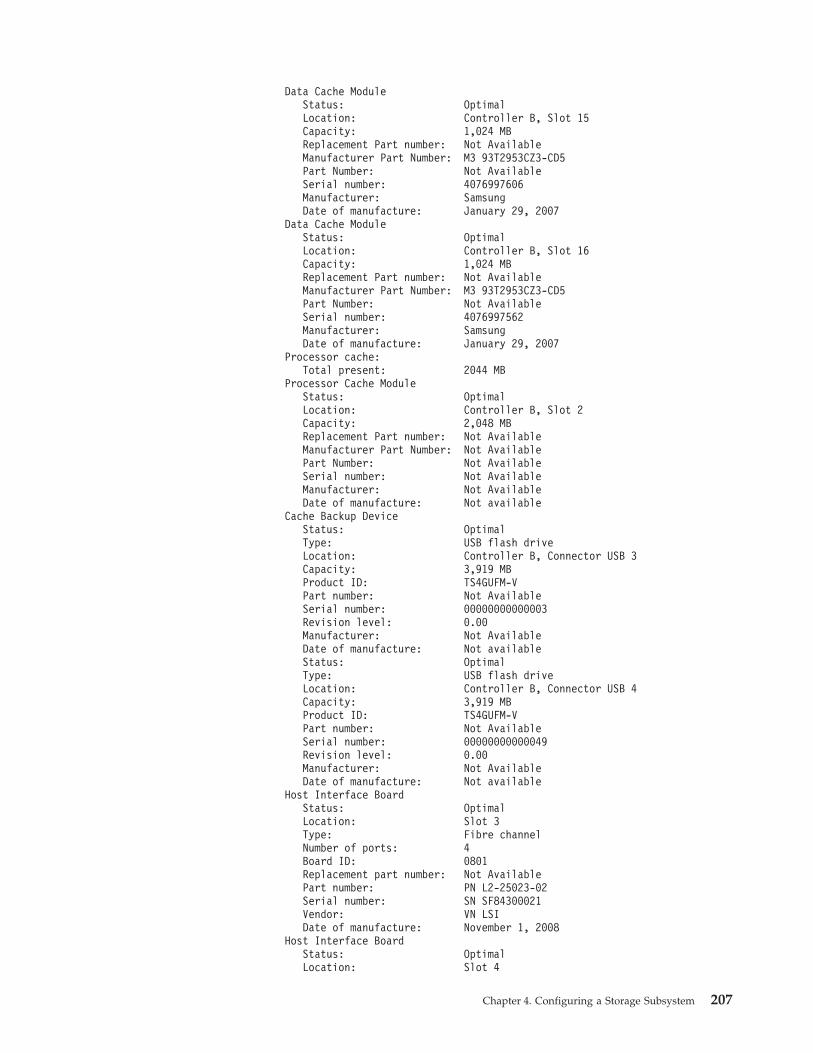
Data Cache ModuleStatus: OptimalLocation: Controller B, Slot 15Capacity: 1,024 MBReplacement Part number: Not AvailableManufacturer Part Number: M3 93T2953CZ3-CD5Part Number: Not AvailableSerial number: 4076997606Manufacturer: SamsungDate of manufacture: January 29, 2007
Data Cache ModuleStatus: OptimalLocation: Controller B, Slot 16Capacity: 1,024 MBReplacement Part number: Not AvailableManufacturer Part Number: M3 93T2953CZ3-CD5Part Number: Not AvailableSerial number: 4076997562Manufacturer: SamsungDate of manufacture: January 29, 2007
Processor cache:Total present: 2044 MB
Processor Cache ModuleStatus: OptimalLocation: Controller B, Slot 2Capacity: 2,048 MBReplacement Part number: Not AvailableManufacturer Part Number: Not AvailablePart Number: Not AvailableSerial number: Not AvailableManufacturer: Not AvailableDate of manufacture: Not available
Cache Backup DeviceStatus: OptimalType: USB flash driveLocation: Controller B, Connector USB 3Capacity: 3,919 MBProduct ID: TS4GUFM-VPart number: Not AvailableSerial number: 00000000000003Revision level: 0.00Manufacturer: Not AvailableDate of manufacture: Not availableStatus: OptimalType: USB flash driveLocation: Controller B, Connector USB 4Capacity: 3,919 MBProduct ID: TS4GUFM-VPart number: Not AvailableSerial number: 00000000000049Revision level: 0.00Manufacturer: Not AvailableDate of manufacture: Not available
Host Interface BoardStatus: OptimalLocation: Slot 3Type: Fibre channelNumber of ports: 4Board ID: 0801Replacement part number: Not AvailablePart number: PN L2-25023-02Serial number: SN SF84300021Vendor: VN LSIDate of manufacture: November 1, 2008
Host Interface BoardStatus: OptimalLocation: Slot 4
Chapter 4. Configuring a Storage Subsystem 207
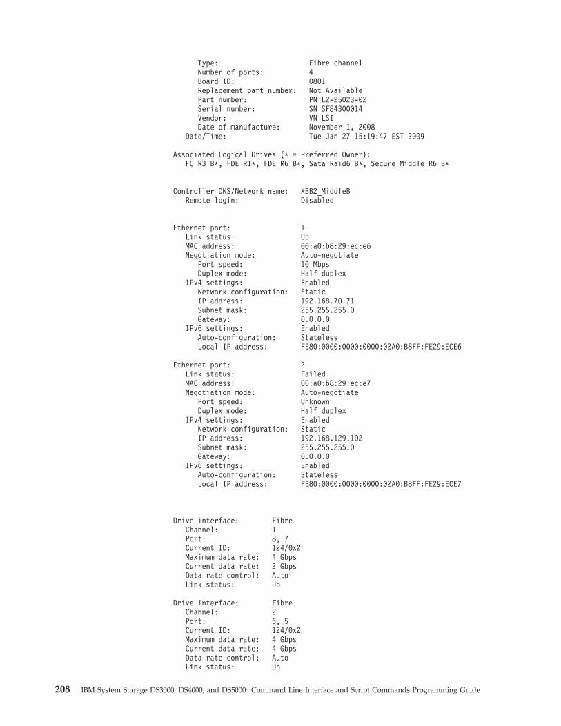
Type: Fibre channelNumber of ports: 4Board ID: 0801Replacement part number: Not AvailablePart number: PN L2-25023-02Serial number: SN SF84300014Vendor: VN LSIDate of manufacture: November 1, 2008
Date/Time: Tue Jan 27 15:19:47 EST 2009
Associated Logical Drives (* = Preferred Owner):FC_R3_B*, FDE_R1*, FDE_R6_B*, Sata_Raid6_B*, Secure_Middle_R6_B*
Controller DNS/Network name: XBB2_MiddleBRemote login: Disabled
Ethernet port: 1Link status: UpMAC address: 00:a0:b8:29:ec:e6Negotiation mode: Auto-negotiate
Port speed: 10 MbpsDuplex mode: Half duplex
IPv4 settings: EnabledNetwork configuration: StaticIP address: 192.168.70.71Subnet mask: 255.255.255.0Gateway: 0.0.0.0
IPv6 settings: EnabledAuto-configuration: StatelessLocal IP address: FE80:0000:0000:0000:02A0:B8FF:FE29:ECE6
Ethernet port: 2Link status: FailedMAC address: 00:a0:b8:29:ec:e7Negotiation mode: Auto-negotiate
Port speed: UnknownDuplex mode: Half duplex
IPv4 settings: EnabledNetwork configuration: StaticIP address: 192.168.129.102Subnet mask: 255.255.255.0Gateway: 0.0.0.0
IPv6 settings: EnabledAuto-configuration: StatelessLocal IP address: FE80:0000:0000:0000:02A0:B8FF:FE29:ECE7
Drive interface: FibreChannel: 1Port: 8, 7Current ID: 124/0x2Maximum data rate: 4 GbpsCurrent data rate: 2 GbpsData rate control: AutoLink status: Up
Drive interface: FibreChannel: 2Port: 6, 5Current ID: 124/0x2Maximum data rate: 4 GbpsCurrent data rate: 4 GbpsData rate control: AutoLink status: Up
208 IBM System Storage DS3000, DS4000, and DS5000: Command Line Interface and Script Commands Programming Guide
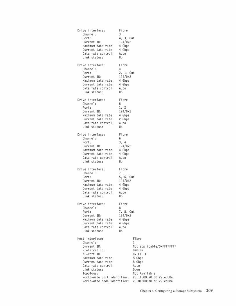
Drive interface: FibreChannel: 3Port: 4, 3, OutCurrent ID: 124/0x2Maximum data rate: 4 GbpsCurrent data rate: 4 GbpsData rate control: AutoLink status: Up
Drive interface: FibreChannel: 4Port: 2, 1, OutCurrent ID: 124/0x2Maximum data rate: 4 GbpsCurrent data rate: 4 GbpsData rate control: AutoLink status: Up
Drive interface: FibreChannel: 5Port: 1, 2Current ID: 124/0x2Maximum data rate: 4 GbpsCurrent data rate: 2 GbpsData rate control: AutoLink status: Up
Drive interface: FibreChannel: 6Port: 3, 4Current ID: 124/0x2Maximum data rate: 4 GbpsCurrent data rate: 4 GbpsData rate control: AutoLink status: Up
Drive interface: FibreChannel: 7Port: 5, 6, OutCurrent ID: 124/0x2Maximum data rate: 4 GbpsCurrent data rate: 4 GbpsData rate control: AutoLink status: Up
Drive interface: FibreChannel: 8Port: 7, 8, OutCurrent ID: 124/0x2Maximum data rate: 4 GbpsCurrent data rate: 4 GbpsData rate control: AutoLink status: Up
Host interface: FibreChannel: 1Current ID: Not applicable/0xFFFFFFFFPreferred ID: 8/0xD9NL-Port ID: 0xFFFFFFMaximum data rate: 8 GbpsCurrent data rate: 8 GbpsData rate control: AutoLink status: DownTopology: Not AvailableWorld-wide port identifier: 20:1f:00:a0:b8:29:ed:8aWorld-wide node identifier: 20:0e:00:a0:b8:29:ed:8a
Chapter 4. Configuring a Storage Subsystem 209
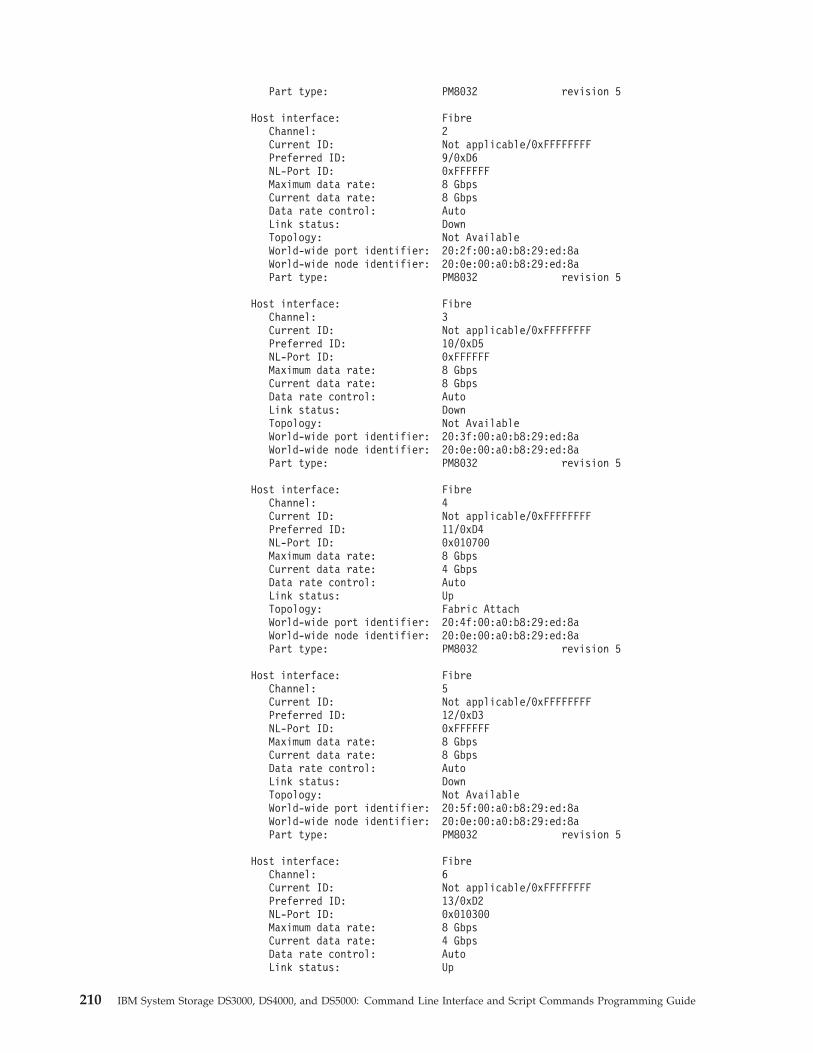
Part type: PM8032 revision 5
Host interface: FibreChannel: 2Current ID: Not applicable/0xFFFFFFFFPreferred ID: 9/0xD6NL-Port ID: 0xFFFFFFMaximum data rate: 8 GbpsCurrent data rate: 8 GbpsData rate control: AutoLink status: DownTopology: Not AvailableWorld-wide port identifier: 20:2f:00:a0:b8:29:ed:8aWorld-wide node identifier: 20:0e:00:a0:b8:29:ed:8aPart type: PM8032 revision 5
Host interface: FibreChannel: 3Current ID: Not applicable/0xFFFFFFFFPreferred ID: 10/0xD5NL-Port ID: 0xFFFFFFMaximum data rate: 8 GbpsCurrent data rate: 8 GbpsData rate control: AutoLink status: DownTopology: Not AvailableWorld-wide port identifier: 20:3f:00:a0:b8:29:ed:8aWorld-wide node identifier: 20:0e:00:a0:b8:29:ed:8aPart type: PM8032 revision 5
Host interface: FibreChannel: 4Current ID: Not applicable/0xFFFFFFFFPreferred ID: 11/0xD4NL-Port ID: 0x010700Maximum data rate: 8 GbpsCurrent data rate: 4 GbpsData rate control: AutoLink status: UpTopology: Fabric AttachWorld-wide port identifier: 20:4f:00:a0:b8:29:ed:8aWorld-wide node identifier: 20:0e:00:a0:b8:29:ed:8aPart type: PM8032 revision 5
Host interface: FibreChannel: 5Current ID: Not applicable/0xFFFFFFFFPreferred ID: 12/0xD3NL-Port ID: 0xFFFFFFMaximum data rate: 8 GbpsCurrent data rate: 8 GbpsData rate control: AutoLink status: DownTopology: Not AvailableWorld-wide port identifier: 20:5f:00:a0:b8:29:ed:8aWorld-wide node identifier: 20:0e:00:a0:b8:29:ed:8aPart type: PM8032 revision 5
Host interface: FibreChannel: 6Current ID: Not applicable/0xFFFFFFFFPreferred ID: 13/0xD2NL-Port ID: 0x010300Maximum data rate: 8 GbpsCurrent data rate: 4 GbpsData rate control: AutoLink status: Up
210 IBM System Storage DS3000, DS4000, and DS5000: Command Line Interface and Script Commands Programming Guide
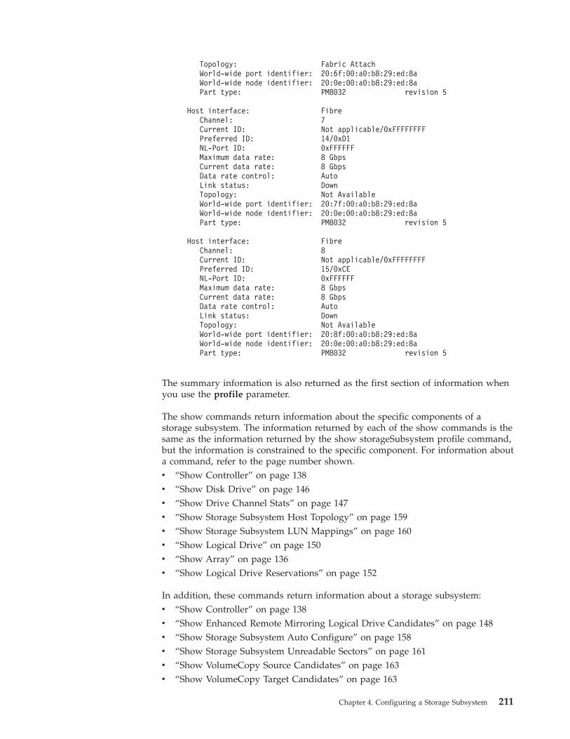
Topology: Fabric AttachWorld-wide port identifier: 20:6f:00:a0:b8:29:ed:8aWorld-wide node identifier: 20:0e:00:a0:b8:29:ed:8aPart type: PM8032 revision 5
Host interface: FibreChannel: 7Current ID: Not applicable/0xFFFFFFFFPreferred ID: 14/0xD1NL-Port ID: 0xFFFFFFMaximum data rate: 8 GbpsCurrent data rate: 8 GbpsData rate control: AutoLink status: DownTopology: Not AvailableWorld-wide port identifier: 20:7f:00:a0:b8:29:ed:8aWorld-wide node identifier: 20:0e:00:a0:b8:29:ed:8aPart type: PM8032 revision 5
Host interface: FibreChannel: 8Current ID: Not applicable/0xFFFFFFFFPreferred ID: 15/0xCENL-Port ID: 0xFFFFFFMaximum data rate: 8 GbpsCurrent data rate: 8 GbpsData rate control: AutoLink status: DownTopology: Not AvailableWorld-wide port identifier: 20:8f:00:a0:b8:29:ed:8aWorld-wide node identifier: 20:0e:00:a0:b8:29:ed:8aPart type: PM8032 revision 5
The summary information is also returned as the first section of information whenyou use the profile parameter.
The show commands return information about the specific components of astorage subsystem. The information returned by each of the show commands is thesame as the information returned by the show storageSubsystem profile command,but the information is constrained to the specific component. For information abouta command, refer to the page number shown.v “Show Controller” on page 138v “Show Disk Drive” on page 146v “Show Drive Channel Stats” on page 147v “Show Storage Subsystem Host Topology” on page 159v “Show Storage Subsystem LUN Mappings” on page 160v “Show Logical Drive” on page 150v “Show Array” on page 136v “Show Logical Drive Reservations” on page 152
In addition, these commands return information about a storage subsystem:v “Show Controller” on page 138v “Show Enhanced Remote Mirroring Logical Drive Candidates” on page 148v “Show Storage Subsystem Auto Configure” on page 158v “Show Storage Subsystem Unreadable Sectors” on page 161v “Show VolumeCopy Source Candidates” on page 163v “Show VolumeCopy Target Candidates” on page 163
Chapter 4. Configuring a Storage Subsystem 211
v “Show Logical Drive Performance Statistics” on page 151
There are other commands that can help you learn about your storage subsystem.To see a list of the commands, see Chapter 3, “Script Commands,” on page 21.These commands are organized by the storage subsystem activities that thecommands support, such as logical drive commands, host commands, enclosurecommands, and others.
Clearing the ConfigurationIf you want to create a completely new configuration on a storage subsystem thatalready has an existing configuration, use the clear storageSubsystem configurationcommand. This command deletes all of the existing configuration information,including all of the arrays, logical drives, and hot spare definitions from thecontroller memory.
Attention: Possible damage to the storage subsystem configuration – As soonas you run this command, the existing storage subsystem configuration is deleted.
The command takes this form:c:\...\...\client>smcli 123.45.67.89 -c “clear storageSubsystem configuration;”
With controller firmware 7.xx.xx.xx and higher, this command supports twoparameters that you can use to limit the amount of configuration informationremoved:v all – Removes the entire configuration of the storage subsystem, including
security information and identification information. Removing all of theconfiguration information returns the storage subsystem to its initial state. (Thisis what the command will assume if no parameters are specified.)
v arrays – Removes the logical drive configuration and the array configuration,but leaves the rest of the configuration intact.
Note: With controller firmware earlier than 7.xx.xx.xx,, there are no parameters.The default is the action described for the all parameter.
If you want to create new arrays and logical drives within the storage subsystem,you can use the clear storageSubsystem configuration command with the arraysparameter to remove existing arrays in a pre-existing configuration. This actiondestroys the pre-existing configuration. Use the clear storageSubsystemconfiguration command only when you create a new configuration.
Using the Auto Configure CommandThe autoConfigure storageSubsystem command creates the arrays on a storagesubsystem, the logical drives in the arrays, and the hot spares for the storagesubsystem. When you use the autoConfigure storageSubsystem command, youdefine these parameters:v The type of disk drives (Fibre, SATA, SAS)v The RAID levelv The number of disk drives in a arrayv The number of arraysv The number of logical drives in each arrayv The number of hot sparesv The size of each segment on the disk drives
212 IBM System Storage DS3000, DS4000, and DS5000: Command Line Interface and Script Commands Programming Guide
v A read ahead multiplier
After you define these parameters, the Storage Manager software creates thearrays, the logical drives, and the hot spares. The controllers assign array numbersand logical drive numbers as they are created. After the Storage Manager softwarecreates the initial configuration, you can use the set logicalDrive command todefine logical drive labels.
Before you run the autoConfigure storageSubsystem command, run the showstorageSubsystem autoConfigure command. The latter command returns a list ofparameter values that the Storage Manager software uses to automatically create astorage subsystem. If you would like to change any of the parameter values, youcan do so by entering new values for the parameters when you run theautoConfigure storageSubsystem command. If you are satisfied with the parametervalues that the show storageSubsystem autoConfiguration command returns, runthe autoConfigure storageSubsystem command without new parameter values.
The autoConfigure storageSubsystem command takes this form:autoConfigure storageSubsystem[driveType=(fibre | SATA | SAS)raidLevel=(0 | 1 | 3 | 5 | 6) |arrayWidth=numberOfDrives |arrayCount=numberOfLogicalDriveGroups |logicalDrivesPerArrayCount=numberOfLogicalDrivesPerArray |hotSpareCount=numberOfHotSpares |segmentSize=segmentSizeValue |cacheReadPrefetch=(TRUE | FALSE)securityType=(none | capable | enabled)]
When you use the autoConfigure storageSubsystem command, two symbolfunctions (getAutoConfigCandidates and createAutoConfig) are used that let theclient retrieve default settings for the various automatic configuration parameters,change the settings, query what the results of those changes would be and, finally,apply the desired parameters to create a configuration. The configurability portionof this feature provides enhancements to the automatic array creation algorithms,which produce arrays with improved performance and more information aboutdisk drive and logical drive attributes so the user can make better choices whenconfiguring logical drives manually.
The arrayWidth parameter defines the number of unassigned disk drives that youwant to use for each new array.
The arrayCount parameter defines the number of new arrays that you want in thestorage subsystem.
The LogicalDrivesPerArrayCount parameter defines the number of logical drivesthat you want in each array.
The hotSpareCount parameter defines the number of hot spares that you want ineach array.
The segmentSize parameter defines the amount of data, in KB, that the controllerwrites on a single disk drive in a logical drive before writing data on the next diskdrive. The smallest units of storage are data blocks. A data block stores 512 bytesof data. The size of a segment determines how many data blocks that it contains.An 8-KB segment holds 16 data blocks. A 64-KB segment holds 128 data blocks.
Chapter 4. Configuring a Storage Subsystem 213
Important: For optimal performance in a multiuser database or file system storageenvironment, set the segment size to minimize the number of disk drives that areneeded to satisfy an I/O request.
Using a single disk drive for a single request leaves other disk drives available tosimultaneously service other requests. Valid segment size values are 8, 16, 32, 64,128, 256, and 512.
Note: If you set the cache block size to 16, you cannot create a logical drive with asegment size of 8.
If the logical drive is for a single user with large I/O requests (such asmultimedia), performance is maximized when a single I/O request can be servicedwith a single data stripe. A data stripe is the segment size multiplied by thenumber of disk drives in the array that are used for data storage. In thisenvironment, multiple disk drives are used for the same request, but each diskdrive is accessed only once.
The cacheReadPrefetch parameter turns on or turns off the ability of the controllerto read additional data blocks into the cache. When you turn on cache readprefetch, the controller copies additional data blocks into the cache while it isreading requested data blocks from a disk drive into the cache. This actionincreases the chance that a future request for data can be fulfilled from the cache,which improves the speed with which data is accessed. The number of additionaldata blocks that the controller reads into the cache is determined by theconfiguration settings for the storage subsystem that you use. Cache read prefetchis important for applications that use sequential I/O, such as multimediaapplications.
Valid values for the cacheReadPrefetch parameter are TRUE or FALSE. If youwant to turn on cache read prefetch, set the cacheReadPrefetch parameter toTRUE. If you want to turn off cache read prefetch, set the cacheReadPrefetchparameter to FALSE.
The following table lists the default values for the segment size and cache readprefetch settings for different storage subsystem uses.
Table 15. Default Values for Segment Size and Cache Read Prefetch
Storage Subsystem Use Segment Size (KB) Cache Read Prefetch
File system 128 TRUE
Database 128 TRUE
Multimedia 256 TRUE
After you have finished creating the arrays and the logical drives by using theautoConfigure storageSubsystem command, you can further define the propertiesof the logical drives in a configuration by using the set logicalDrive command. (Fora description about how to further define your configuration, see “Modifying YourConfiguration” on page 219.)
Security Type
The securityType parameter is used to specify the security subsystems with FullDisk Encryption (FDE) drives. A Disk Encryption Activation premium feature mustbe purchased and enabled before you can take advantage of the FDE drive security
214 IBM System Storage DS3000, DS4000, and DS5000: Command Line Interface and Script Commands Programming Guide
feature. The minimum version of controller firmware that supports FDE drivesecurity features is 07.5x.xx.xx. If this parameter is set to none, the created arraysand logical drives will not be encrypted. If the parameter is set to enabled, thearrays and logical drives will have security enabled and encrypted.
With FDE, the controller firmware can create a key and activate the drive securityfeature. The drive security feature encrypts data as the data is written to the driveand decrypts the data as the data is read from the drive. Without the key createdby the controller, the data written to the drive is inaccessible.
Before you can set the securityType parameter to capable or enabled, you mustcreate a storage array security key. Use the create storageArray securityKeycommand to create a storage array security key. These commands are related to thesecurity key:v create storageArray securityKeyv set storageArray securityKeyv import storageArray securityKeyv export storageArray securityKeyv start secureErase (drive | drives)v enable volumeGroup [volumeGroupName] securityv create hostPort identifier
Note: Firmware version 07.50 adds the securityType parameter.
Example of the Auto Configuration Commandc:\...\...\client>smcli 123.45.67.89 -c “autoConfigurestorageSubsystem driveType=fibre raidLevel=5 arrayWidth=8arrayCount=3 logicalDrivesPerArrayCount=4 hotSpareCount=2segmentSize=8 cacheReadPrefetch=TRUE securityType=none;”
The command in this example creates a storage subsystem configuration by usingFibre Channel disk drives set to RAID level 5. Three arrays are created, and eacharray consists of eight disk drives, which are configured into four logical drives.The storage subsystem has two hot spares. The segment size for each logical driveis 8 KB. The cache read prefetch is turned on, which causes additional data blocksto be written into the cache.
Using the Create LogicalDrive CommandUse the create logicalDrive command to create new storage subsystem logicaldrives in three ways:v Create a new logical drive while simultaneously creating a new array to which
you assign the disk drivesv Create a new logical drive while simultaneously creating a new array to which
the Storage Manager software assigns the disk drivesv Create a new logical drive in an existing array
You must have unassigned disk drives in the array. You do not need to assign theentire capacity of the array to a logical drive.
Creating Logical Drives with User-Assigned Disk DrivesWhen you create a new logical drive and assign the disk drives you want to use,the Storage Manager software creates a new array. The controller firmware assignsa array number to the new array. The command takes this form:
Chapter 4. Configuring a Storage Subsystem 215
create logicalDrive drives=(enclosureID1,slotID1...enclosureIDn,slotIDn)raidLevel=(0 | 1 | 3 | 5 | 6) userLabel=logicalDrivesName[capacity=logicalDrivesCapacity] [owner=(a | b)cacheReadPrefetch=(TRUE | FALSE)segmentSize=segmentSizeValue]enclosureLossProtect=(TRUE | FALSE)securityType=(none | capable | enabled)]
Note: The capacity parameter, the owner parameter, the cacheReadPrefetchparameter, the segmentSize parameter, and the enclosureLossProtect parameterare optional parameters (indicated by the items inside the square brackets). Youcan use one or all of the optional parameters as needed to define yourconfiguration. If you choose not to use any of the optional parameters, the defaultvalues of the parameters are used for your configuration.
The userLabel parameter is the name that you want to give to the logical drive.The logical drive name can be any combination of alphanumeric characters,hyphens, and underscores. The maximum length of the logical drive name is 30characters. You must enclose the logical drive name with double quotation marks(“ ”).
The drives parameter is a list of the disk drives that you want to use for the array.Enter the enclosure ID and the slot ID of each disk drive that you want to use.Enclose the list in parentheses, separate the enclosure ID value and the slot IDvalue of a disk drive with a comma, and separate each enclosure ID and slot IDpair with a space. This example shows you how to enter enclosure ID values andslot ID values:(1,1 1,2 1,3 1,4 1,5)
The capacity parameter defines the size of the logical drive. You do not need toassign the entire capacity of the disk drives to the logical drive. Later, you canassign any unused space to another logical drive.
The owner parameter defines the controller to which you want to assign thelogical drive. If you do not specify a controller, the controller firmware determinesthe logical drive owner.
The cacheReadPrefetch parameter and the segmentSize parameter are the same asthose described for the autoConfigure storageSubsystem command.
The enclosureLossProtect parameter defines enclosure loss protection for the array.(For a description of how enclosure loss protection works, see “Enclosure LossProtection” on page 218.)
The securityType parameter is used to specify the security level when creatingarrays and logical drives in storage subsystems with Full Disk Encryption (FDE)drives.
Example of Creating Logical Drives with User-Assigned Disk Drivesc:\...\...\client>smcli 123.45.67.89 -c “create logicalDrive drives=(1,1 1,2 1,3 2,1 2,2 2,3) raidLevel=5 userLabel=\”Engineering_1\”capacity=20GB owner=a cacheReadPrefetch=TRUE segmentSize=128 securityType=enabled;”
The command in this example automatically creates a new array and a logicaldrive with the name Engineering_1. The array has a RAID level of 5 (RAID 5). Thecommand uses six disk drives to construct the array. The disk drives have a total
216 IBM System Storage DS3000, DS4000, and DS5000: Command Line Interface and Script Commands Programming Guide
logical drive capacity of 20 GB. If each disk drive has a capacity of 18 GB, the totalcapacity of all the assigned disks is 108 GB.18 GB x 6 disk drives = 108 GB
Because only 20 GB is assigned to the logical drive, 88 GB remains available (asunconfigured capacity) for other logical drives that a user can add to this arraylater.108 GB - 20 GB subsystem size = 88 GB
Cache read prefetch is turned on, which causes additional data blocks to be writteninto the cache. The segment size for each logical drive is 128 KB. Enclosure lossprotection is set to TRUE, which prevents any operations to disk drives in theexpansion drawer if the expansion drawer fails. Hot spares are not created for thisnew array. You must create hot spares after you run this command.
Creating Logical Drives with Software-Assigned Disk DrivesIf you choose to let the Storage Manager software assign the disk drives when youcreate the logical drive, you need only to specify the number of disk drives thatyou want to use. The Storage Manager software then assigns the disk drives. Thecontroller firmware assigns a array number to the new array. To manually createarrays and logical drives, use the create logicalDrive command:create logicalDrive driveCount=numberOfDrivesraidLevel=(0 | 1 | 3 | 5 | 6) userLabel=logicalDriveName[driveType=(fibre | SATA | SAS)][capacity=logicalDriveCapacity | owner=(a | b) |cacheReadPrefetch=(TRUE | FALSE) |segmentSize=segmentSizeValue][enclosureLossProtect=(TRUE | FALSE)securityType=(none | capable | enabled)]
This command is similar to the previous create logicalDrive command in whichusers assign the disk drives. The difference between this command and theprevious one is that this version of the command requires only the number and thetype of disk drives you want to use in the array. You do not need to enter a list ofdisk drives. All of the other parameters are the same. Enclosure loss protection isperformed differently when the Storage Manager software assigns the disk drivesthan when a user assigns the disk drives. (For a description of the difference, see“Enclosure Loss Protection” on page 218.)
Example of Creating Logical Drives with Software Assigned DiskDrivesc:\...\...\client>smcli 123.45.67.89 -c “create logicalDrive driveCount=6raidLevel=5 userLabel=\”Engineering_1\”capacity=20GB owner=a cacheReadPrefetch=TRUE segmentSize=128 securityType=capable;”
The command in this example creates the same logical drive as the example for theprevious create logicalDrive command in which a user assigns the disk drives. Thedifference is that a user does not know which disk drives are assigned to thisarray.
Creating Logical Drives in an Existing ArrayIf you want to add a new logical drive to an existing array, use this command:create logicalDrive array=arrayNumberuserLabel=logicalDriveName[freeCapacityArea=freeCapacityIndexNumber |
Chapter 4. Configuring a Storage Subsystem 217
capacity=logicalDriveCapacity | owner=(a | b) |cacheReadPrefetch=(TRUE | FALSE) |segmentSize=segmentSizeValuesecurityType=(none | capable | enabled)]
Note: Parameters wrapped in square brackets or curly brackets are optional. Youcan use one or all of the optional parameters as needed to define yourconfiguration. If you choose not to use any of the optional parameters, the defaultvalues of the parameter are provided for your configuration.
The array parameter is the number of the array in which you want to create a newlogical drive. If you do not know the array numbers on the storage subsystem, youcan use the show allLogicalDrives summary command to get a list of the logicaldrives and the arrays to which the logical drives belong.
The userLabel parameter is the name that you want to give to the logical drive.The logical drive name can be any combination of alphanumeric characters,hyphens, and underscores. The maximum length of the logical drive name is 30characters. You must enclose the logical drive name with double quotation marks(“ ”).
The freeCapacityArea parameter defines the free capacity area to use for thelogical drive. If a array has several free capacity areas, you can use this parameterto identify which free capacity area to use for logical drive creation. You do nothave to assign the entire capacity of the disk drives to the logical drive. Later, youcan assign any unused space to another logical drive.
The usage of the capacity parameter, the owner parameter, the cacheReadPrefetchparameter, and the segmentSize parameter is the same as described in theprevious examples of the create logicalDrive command.
Enclosure Loss ProtectionThe enclosureLossProtect parameter is a boolean switch that you set to turn on orturn off enclosure loss protection. For enclosure loss protection to work, each diskdrive in a array must be on a separate enclosure. The way in which enclosure lossprotection works depends on the method that you choose to assign the disk drivesfor a array.
When you assign the disk drives, if you set enclosureLossProtect=TRUE and haveselected more than one disk drive from any one enclosure, the storage subsystemreturns an error. If you set enclosureLossProtect=FALSE, the storage subsystemperforms operations, but the array that you create does not have enclosure lossprotection.
When the controller firmware assigns the disk drives, ifenclosureLossProtect=TRUE the storage subsystem posts an error if the controllerfirmware cannot provide disk drives that result in the new array having enclosureloss protection. If enclosureLossProtect=FALSE, the storage subsystem performsthe operation even if it means that the array might not have enclosure lossprotection.
Enclosure loss protection is not valid when creating logical drives on existingarrays.
218 IBM System Storage DS3000, DS4000, and DS5000: Command Line Interface and Script Commands Programming Guide
Modifying Your ConfigurationFor most configurations, after you have created your initial configuration by usingthe autoConfigure storageSubsystem command or the create logicalDrivecommand, you must modify the properties of your configuration to make sure thatit performs to meet the requirements for data storage. Use the set commands tomodify a storage subsystem configuration. This section describes how to modifythese properties:v The controller clocksv The storage subsystem passwordv The storage subsystem host typev The storage subsystem cachev The global hot spares
Setting the Controller ClocksTo synchronize the clocks on the controllers with the host, use the setstorageSubsystem time command. Run this command to make sure that event timestamps that are written by the controllers to the Event Log match the event timestamps that are written to the host log files. The controllers stay available duringsynchronization. This example shows the command:c:\...\...\client>smcli 123.45.67.89 -c “set storageSubsystem time;”
Setting the Storage Subsystem PasswordUse the set storageSubsystem command to define a password for a storagesubsystem. The command takes this form:set storageSubsystem password=”password”
The password parameter defines a password for the storage subsystem. Passwordsprovide added security to a storage subsystem to help reduce the possibility ofimplementing destructive commands.
Attention: Possible data corruption or data loss – Implementing destructivecommands can cause serious damage, including data loss.
Unless you define a password for the storage subsystem, you can run all of thescript commands. A password protects the storage subsystem from any commandthat the controllers consider destructive. A destructive command is any commandthat can change the state of the storage subsystem, such as logical drive creation;cache modification; or reset, delete, rename, or change commands.
If you have more than one storage subsystem in a storage configuration, eachstorage subsystem has a separate password. Passwords can have a maximumlength of 30 alphanumeric characters. You must enclose the password in doublequotation marks (“ ”). This example shows how to use the set storageSubsystemcommand to define a password:c:\...\...\client>smcli 123.45.67.89 -c “set storageSubsystempassword=”1a2b3c4d5e”;”
Important: Password cannot be reset without current password– If you forgetthe storage subsystem password, you cannot reset the password using StorageManager. To reset the password in that situation, you must contact your IBMsupport representative.
Chapter 4. Configuring a Storage Subsystem 219

Setting the Storage Subsystem Host TypeUse the set storageSubsystem command to define the default host type. Thecommand takes this form:set storageSubsystem defaultHostType=(hostTypeName | hostTypeIdentifier)
The defaultHostType parameter defines how the controllers in the storagesubsystem will communicate with the operating system on undefined hosts thatare connected to the storage subsystem SAN. This parameter defines the host typeonly for data I/O activities of the storage subsystem. This parameter does notdefine the host type for the management station. The operating system can beWindows, Linux, or Solaris.
For example, if you set the defaultHostType parameter to Linux, the controllercommunicates with any undefined host if the undefined host is running a Linuxoperating system. Typically, you would need to change the host type only whenyou are setting up the storage subsystem. The only time that you might need touse this parameter is if you need to change how the storage subsystem behavesrelative to the hosts that are connected to it.
Before you can define the default host type, you need to determine what hosttypes are connected to the storage subsystem. To return information about hosttypes that are connected to the storage subsystem, use the show storageSubsystemcommand with the defaultHostType parameter or the hostTypeTable parameter.This command returns a list of the host types with which the controllers cancommunicate. This command does not return a list of the hosts. These examplesshow the use of the show storageSubsystem command:c:\...\...\client>smcli 123.45.67.89 -c “show storageSubsystem defaultHostType;”
c:\...\...\client>smcli 123.45.67.89 -c “show storageSubsystem hostTypeTable;”
This example shows how to define a specific default host type after displaying thehost type table:c:\...\...\client>smcli 123.45.67.89 -c “set storageSubsystem defaultHostType=xx;”
where xx is the host type index value. For value xx, refer to thepreviously-displayed host type table. From the table, select the appropriate valuefor the host server that the LUN from the storage subsystem is mapped to.
Setting the Storage Subsystem CacheThe cache is high-speed memory that holds data that is either written to the diskdrives or read by the host. A controller has two memory areas used forintermediate storage of read data and write data. The read cache contains data thathas been read from the disk drives but not yet transferred to the host. The writecache contains data from the host but not yet written to the disk drives.
The cache acts as a buffer so that data transfers between the host and the diskdrive do not need to be synchronized. In read caching, the data for a readoperation from the host might already be in the cache from a previous operation,which eliminates the need to access the disk drives. The data stays in the readcache until it is flushed. For write caching, a write operation stores data from thehost in cache until it can be written to the disk drives.
Important: Changing default cache settings is not recommended – IBMrecommends that you do not change the default cache setting values. Incorrectcache settings might severely affect the storage subsystem performance.
220 IBM System Storage DS3000, DS4000, and DS5000: Command Line Interface and Script Commands Programming Guide
The script command set provides two commands to define cache properties:v set storageSubsystemv set logicalDrive
Use the set storageSubsystem command to change the cache block size, the cacheflush start value, and the cache stop value. The command takes this form:set storageSubsystem cacheBlockSize=cacheBlockSizeValue |cacheFlushStart=cacheFlushStartSize |cacheFlushStop=cacheFlushStopSize
You can enter one, two, or all three of the parameters on the command line.
The cache block size value defines the size of the data block that is used by thecontroller in transferring data into or out of the cache. You can set the cache blocksize to either 4KB or 16KB. The value that you use applies to the entire storagesubsystem and all of the logical drives in the storage subsystem. For redundantcontroller configurations, this value includes all logical drives owned by bothcontrollers. Use smaller cache block sizes for systems that require transactionprocessing requests or I/O streams that are typically small and random. Use largercache block sizes for large I/O, sequential, high-bandwidth applications. Thechoice of block size affects read/write performance. Large data transfers takelonger in 4-KB block sizes than 16-KB block sizes. This example shows how to setthe cacheBlockSize parameter:c:\...\...\client>smcli 123.45.67.89 -c “set storageSubsystem cacheBlockSize=16;”
To prevent data loss or corruption, the controller periodically writes cache data tothe disk drives (flushes the cache) when the amount of unwritten data in the cachereaches a predefined level, called a start percentage. The controller also writescache data to the disk drives when data has been in the cache for a predeterminedamount of time. The controller writes data to the disk drives until the amount ofdata in the cache drops to a stop percentage level. Use the set storageSubsystemcommand to set the start value and the stop value as percentages of the filled andunfilled, respectively, capacity of the cache. For example, you can specify that thecontroller start flushing the cache when it reaches 80 percent full (the default,which can be overridden) and stop flushing the cache when it reaches 84 percentempty. This example shows how to set these parameters:c:\...\...\client>smcli 123.45.67.89 -c “set storageSubsystemcacheFlushStart=80 cacheFlushStop=84;”
Low start percentages and low stop percentages provide for maximum dataprotection. For both low start percentages and low stop percentages, the chancethat data requested by a read command is not in the cache is increased. When thedata is not in the cache, the cache hit percentage for writes and I/O requestsdecreases. Low start values and low stop values also increase the number of writesthat are necessary to maintain the cache level. Increasing the number of writesincreases the system overhead and further decreases performance.
Use the set logicalDrive command to change settings for the cache flushmodifier, cache without batteries enabled, mirror cache enabled, the read aheadmultiplier, read cache enabled, and write cache enabled. Use this command to setproperties for all of the logical drives or for a specific logical drive in a array. Thecommand takes this form:set (allLogicalDrives | logicalDrive [logicalDriveName] |logicalDrives [logicalDriveName1 ... logicalDriveNameN]logicalDrive <wwID>) |cacheFlushModifier=cacheFlushModifierValue |
Chapter 4. Configuring a Storage Subsystem 221
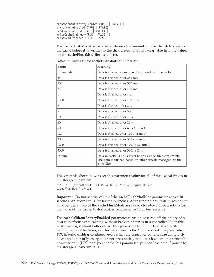
cacheWithoutBatteryEnabled=(TRUE | FALSE) |mirrorCacheEnabled=(TRUE | FALSE) |readCacheEnabled=(TRUE | FALSE) |writeCacheEnabled=(TRUE | FALSE) |cacheReadPrefetch=(TRUE | FALSE)
The cacheFlushModifier parameter defines the amount of time that data stays inthe cache before it is written to the disk drives. The following table lists the valuesfor the cacheFlushModifier parameter.
Table 16. Values for the cacheFlushModifier Parameter
Value Meaning
Immediate Data is flushed as soon as it is placed into the cache.
250 Data is flushed after 250 ms.
500 Data is flushed after 500 ms.
750 Data is flushed after 750 ms.
1 Data is flushed after 1 s.
1500 Data is flushed after 1500 ms.
2 Data is flushed after 2 s.
5 Data is flushed after 5 s.
10 Data is flushed after 10 s.
20 Data is flushed after 20 s.
60 Data is flushed after 60 s (1 min.).
120 Data is flushed after 120 s (2 min.).
300 Data is flushed after 300 s (5 min.).
1200 Data is flushed after 1200 s (20 min.).
3600 Data is flushed after 3600 s (1 hr.).
Infinite Data in cache is not subject to any age or time constraints.The data is flushed based on other criteria managed by thecontroller.
This example shows how to set this parameter value for all of the logical drives inthe storage subsystem:c:\...\...\client>smcli 123.45.67.89 -c “set alllogicalDrivescacheFlushModifier=10;”
Important: Do not set the value of the cacheFlushModifier parameter above 10seconds. An exception is for testing purposes. After running any tests in which youhave set the values of the cacheFlushModifier parameter above 10 seconds, returnthe value of the cacheFlushModifier parameter to 10 or less seconds.
The cacheWithoutBatteryEnabled parameter turns on or turns off the ability of ahost to perform write caching without backup batteries in a controller. To enablewrite caching without batteries, set this parameter to TRUE. To disable writecaching without batteries, set this parameter to FALSE. If you set this parameter toTRUE, write caching continues, even when the controller batteries are completelydischarged, not fully charged, or not present. If you do not have an uninterruptiblepower supply (UPS) and you enable this parameter, you can lose data if power tothe storage subsystem fails.
222 IBM System Storage DS3000, DS4000, and DS5000: Command Line Interface and Script Commands Programming Guide
Note: Attention: Possible loss of data – Because you can lose data when thecacheWithoutBatteryEnabled parameter is enabled, IBM recommends that you donot enable this parameter in a production environment.
This example shows how to set this parameter value:c:\...\...\client>smcli 123.45.67.89 -c “set logicalDrive[\”Engineering\”] cacheWithoutBatteryEnabled=FALSE;”
The mirrorCacheEnabled parameter turns on or turns off write caching withmirroring. Write caching with mirroring permits cached data to be mirrored acrossredundant controllers that have the same cache size. Data written to the cachememory of one controller is also written to the cache memory of the secondcontroller. If one controller fails, the second controller can complete all outstandingwrite operations.
Attention: Possible loss of data – If the mirrorCacheEnabled parameter isdisabled and one of the controllers fails, you might lose data that was cached inthe failed controller memory but not yet written to disk. Therefore, IBMrecommends that you do not disable this parameter in a production environment.
To use this option, these conditions must exist:v The controller pair must be an active/active pair.v The controllers must have the same size cache.
To enable write caching with mirroring, set this parameter to TRUE. To disablewrite caching with mirroring, set this parameter to FALSE. This example showshow to set this parameter:c:\...\...\client>smcli 123.45.67.89 -c “set logicalDrive[\”Accounting\”] mirrorCacheEnabled=TRUE;”
The readCacheEnabled parameter turns on or turns off the ability of the host toread data from the cache. Read caching enables read operations from the host to bestored in controller cache memory. If a host requests data that is not in the cache,the controller reads the needed data blocks from the disk drives and places themin the cache. Until the cache is flushed, all of the other requests for this data arefulfilled with cache data rather than from a read, which increases throughput. Toenable read caching, set this parameter to TRUE. To disable read caching, set thisparameter to FALSE. This example shows how to set this parameter:c:\...\...\client>smcli 123.45.67.89 -c “set logicalDrive[\”Balance_04\”] readCacheEnabled=TRUE;”
The writeCacheEnabled parameter turns on or turns off the ability of the host towrite data to the cache. Write caching enables write operations from the host to bestored in cache memory. The logical drive data in the cache is automaticallywritten to the disk drives every 10 seconds. To enable write caching, set thisparameter to TRUE. To disable write caching, set this parameter to FALSE. Thisexample shows how to set this parameter:c:\...\...\client>smcli 123.45.67.89 -c “set allLogicalDriveswriteCacheEnabled=TRUE;”
The cacheReadPrefetch parameter turns on or turns off the ability of the controllerto read additional data blocks into cache. When you turn on cache read prefetch,the controller copies additional data blocks into cache while it is reading requesteddata blocks from a disk drive into cache. This action increases the chance that afuture request for data can be fulfilled from the cache, which improves the speed
Chapter 4. Configuring a Storage Subsystem 223
with which data is accessed. The number of additional data blocks that thecontroller reads into cache is determined by the storage subsystem configurationsettings that you use. Cache read prefetch is important for applications that usesequential I/O, such as multimedia applications.
Valid values for the cacheReadPrefetch parameter are TRUE or FALSE. If youwant to turn on cache read prefetch, set the cacheReadPrefetch parameter toTRUE. If you want to turn off cache read prefetch, set the cacheReadPrefetchparameter to FALSE. This example shows how to set this parameter:c:\...\...\client>smcli 123.45.67.89 -c “set logicalDrive[\”Engineering_1\” \”Engineering_2\”] cacheReadPrefetch=TRUE;”
Setting the Modification PriorityModification priority defines how much processing time is allocated for logicaldrive modification operations. Time allocated for logical drive modificationoperations affects system performance. Increases in logical drive modificationpriority can reduce read/write performance. The modification priority affects theseoperations:v Copybackv Reconstructionv Initializationv Changing the segment sizev Defragmentation of a arrayv Adding free capacity to a arrayv Changing the RAID level of a array
The lowest priority rate favors system performance, but the modification operationtakes longer. The highest priority rate favors the modification operation, but thesystem performance might be degraded.
Use the set logicalDrive command to define the modification priority for a logicaldrive. The command takes this form:set (allLogicalDrives | logicalDrive [logicalDriveName] |logicalDrives [logicalDriveName1 ... logicalDriveNameN] logicalDrive <wwID> |accessLogicalDrive)modificationPriority=(highest | high | medium | low | lowest)
This example shows how to use this command to set the modification priority forlogical drives named Engineering_1 and Engineering_2:
c:\...\...\client>smcli 123.45.67.89 -c “set logicalDrive[\”Engineering_1\” \”Engineering_2\” modificationPriority=lowest;”
The modification rate is set to lowest so that system performance is notsignificantly reduced by modification operations.
Assigning Global Hot SparesYou can assign or unassign global hot spares by using the set drive command. Touse this command, you must identify the location of the disk drives by theenclosure ID and the slot ID. Then, you set the hotSpare parameter to TRUE toenable the hot spare or FALSE to disable an existing hot spare. The command takesthis form:set (drive [enclosureID,slotID] | drives[enclosureID1,slotID1 ... enclosureIDn,slotIDn]) hotSpare=(TRUE | FALSE)
224 IBM System Storage DS3000, DS4000, and DS5000: Command Line Interface and Script Commands Programming Guide
This example shows how to set hot spare disk drives:c:\...\...\client>smcli 123.45.67.89 -c “set drives [1,2 1,3] hotSpare=TRUE;”
Enter the enclosure ID and the slot ID of each disk drive that you want to use.Enclose the list in square brackets, separate the enclosure ID value and the slot IDvalue of a disk drive with a comma, and separate each enclosure ID and slot IDpair with a space.
Saving a Configuration to a FileAfter you have created a new configuration or if you want to copy an existingconfiguration for use on other storage subsystems, you can save the configurationto a file by using the save storageSubsystem configuration command. Saving theconfiguration creates a script file that you can run on the command line. Thecommand takes this form:save storageSubsystem configuration file=”filename”[(allconfig | globalSettings=(TRUE | FALSE)) |logicalDriveConfigAndSettings=(TRUE | FALSE) |hostTopology=(TRUE | FALSE) | lunMappings=(TRUE | FALSE)]
Attention: Possible loss of data – When information is written to a file, thescript engine does not check to determine if the file name already exists. If youchoose the name of a file that already exists, the script engine writes over theinformation in the file without warning.
You can choose to save the entire configuration or specific configuration features.This example shows how to set this parameter value:
c:\...\...\client>smcli 123.45.67.89 -c “save storageSubsystemconfiguration file=\”c:\\folder\\storageSubsystemconfig1.scr\”;”
In this example, the name folder is the folder in which you choose to place theprofile file and storageSubsystemconfig1.scr is the name of the file. You canchoose any folder and any file name. The file extension for a configuration file is.scr. The Storage Manager software uses this extension when it creates theconfiguration file.
Chapter 4. Configuring a Storage Subsystem 225

226 IBM System Storage DS3000, DS4000, and DS5000: Command Line Interface and Script Commands Programming Guide
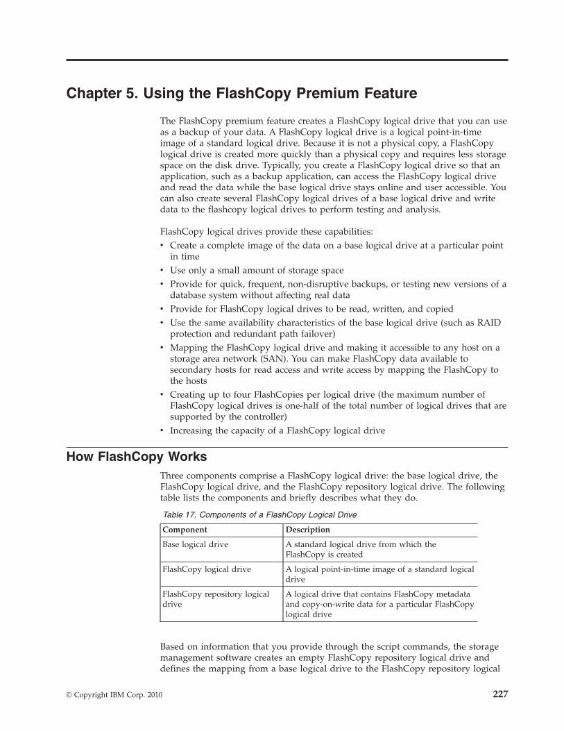
Chapter 5. Using the FlashCopy Premium Feature
The FlashCopy premium feature creates a FlashCopy logical drive that you can useas a backup of your data. A FlashCopy logical drive is a logical point-in-timeimage of a standard logical drive. Because it is not a physical copy, a FlashCopylogical drive is created more quickly than a physical copy and requires less storagespace on the disk drive. Typically, you create a FlashCopy logical drive so that anapplication, such as a backup application, can access the FlashCopy logical driveand read the data while the base logical drive stays online and user accessible. Youcan also create several FlashCopy logical drives of a base logical drive and writedata to the flashcopy logical drives to perform testing and analysis.
FlashCopy logical drives provide these capabilities:v Create a complete image of the data on a base logical drive at a particular point
in timev Use only a small amount of storage spacev Provide for quick, frequent, non-disruptive backups, or testing new versions of a
database system without affecting real datav Provide for FlashCopy logical drives to be read, written, and copiedv Use the same availability characteristics of the base logical drive (such as RAID
protection and redundant path failover)v Mapping the FlashCopy logical drive and making it accessible to any host on a
storage area network (SAN). You can make FlashCopy data available tosecondary hosts for read access and write access by mapping the FlashCopy tothe hosts
v Creating up to four FlashCopies per logical drive (the maximum number ofFlashCopy logical drives is one-half of the total number of logical drives that aresupported by the controller)
v Increasing the capacity of a FlashCopy logical drive
How FlashCopy WorksThree components comprise a FlashCopy logical drive: the base logical drive, theFlashCopy logical drive, and the FlashCopy repository logical drive. The followingtable lists the components and briefly describes what they do.
Table 17. Components of a FlashCopy Logical Drive
Component Description
Base logical drive A standard logical drive from which theFlashCopy is created
FlashCopy logical drive A logical point-in-time image of a standard logicaldrive
FlashCopy repository logicaldrive
A logical drive that contains FlashCopy metadataand copy-on-write data for a particular FlashCopylogical drive
Based on information that you provide through the script commands, the storagemanagement software creates an empty FlashCopy repository logical drive anddefines the mapping from a base logical drive to the FlashCopy repository logical
© Copyright IBM Corp. 2010 227
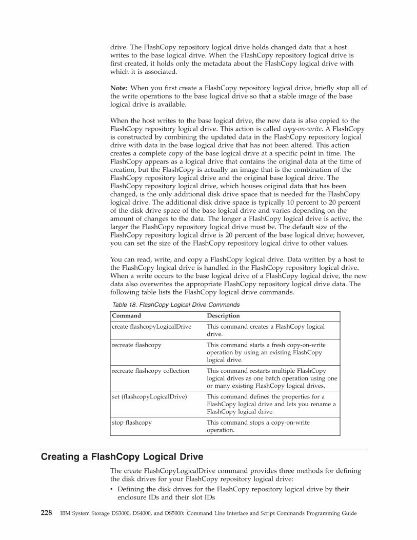
drive. The FlashCopy repository logical drive holds changed data that a hostwrites to the base logical drive. When the FlashCopy repository logical drive isfirst created, it holds only the metadata about the FlashCopy logical drive withwhich it is associated.
Note: When you first create a FlashCopy repository logical drive, briefly stop all ofthe write operations to the base logical drive so that a stable image of the baselogical drive is available.
When the host writes to the base logical drive, the new data is also copied to theFlashCopy repository logical drive. This action is called copy-on-write. A FlashCopyis constructed by combining the updated data in the FlashCopy repository logicaldrive with data in the base logical drive that has not been altered. This actioncreates a complete copy of the base logical drive at a specific point in time. TheFlashCopy appears as a logical drive that contains the original data at the time ofcreation, but the FlashCopy is actually an image that is the combination of theFlashCopy repository logical drive and the original base logical drive. TheFlashCopy repository logical drive, which houses original data that has beenchanged, is the only additional disk drive space that is needed for the FlashCopylogical drive. The additional disk drive space is typically 10 percent to 20 percentof the disk drive space of the base logical drive and varies depending on theamount of changes to the data. The longer a FlashCopy logical drive is active, thelarger the FlashCopy repository logical drive must be. The default size of theFlashCopy repository logical drive is 20 percent of the base logical drive; however,you can set the size of the FlashCopy repository logical drive to other values.
You can read, write, and copy a FlashCopy logical drive. Data written by a host tothe FlashCopy logical drive is handled in the FlashCopy repository logical drive.When a write occurs to the base logical drive of a FlashCopy logical drive, the newdata also overwrites the appropriate FlashCopy repository logical drive data. Thefollowing table lists the FlashCopy logical drive commands.
Table 18. FlashCopy Logical Drive Commands
Command Description
create flashcopyLogicalDrive This command creates a FlashCopy logicaldrive.
recreate flashcopy This command starts a fresh copy-on-writeoperation by using an existing FlashCopylogical drive.
recreate flashcopy collection This command restarts multiple FlashCopylogical drives as one batch operation using oneor many existing FlashCopy logical drives.
set (flashcopyLogicalDrive) This command defines the properties for aFlashCopy logical drive and lets you rename aFlashCopy logical drive.
stop flashcopy This command stops a copy-on-writeoperation.
Creating a FlashCopy Logical DriveThe create FlashCopyLogicalDrive command provides three methods for definingthe disk drives for your FlashCopy repository logical drive:v Defining the disk drives for the FlashCopy repository logical drive by their
enclosure IDs and their slot IDs
228 IBM System Storage DS3000, DS4000, and DS5000: Command Line Interface and Script Commands Programming Guide
v Defining a array in which the FlashCopy repository logical drive resides. Inaddition, you can define the capacity of the FlashCopy repository logical drive.
v Defining the number of disk drives, but not specific disk drives, for theFlashCopy repository logical drive.
When you use the create FlashCopyLogicalDrive command to create a FlashCopylogical drive, the minimum information that you need to provide is the standardlogical drive that you want to use for the base logical drive. When you create aFlashCopy logical drive by using minimum information, the storage managementsoftware provides default values for the other property parameters that arerequired for a completely defined FlashCopy logical drive.
Creating a FlashCopy Logical Drive with User-Assigned DiskDrives
Creating a FlashCopy logical drive by assigning the disk drives provides flexibilityin defining your configuration by letting you choose from the available disk drivesin your storage subsystem. When you choose the disk drives for your FlashCopylogical drive, you automatically create a new array. You can specify which diskdrives to use and the RAID level for the new array. The command takes this form:create flashcopyLogicalDrive baseLogicalDrive=”baseLogicalDriveName”[repositoryRAIDLevel=(1 | 3 | 5 | 6)(repositoryDrives=(enclosureID1,slotID1 ... enclosureIDn,slotIDn)userLabel=”flashcopyLogicalDriveName”warningThresholdPercent=percentValuerepositoryPercentOfBase=percentValuerepositoryUserLabel=”repositoryName”repositoryFullPolicy=(failBaseWrites | failFlashCopy)][enclosureLossProtect=(TRUE | FALSE)]
This example shows a command in which users assign the disk drives:
c:\...\...\client>smcli 123.45.67.89 -c “create flashcopyLogicalDrivebaseLogicalDrive=\”Mars_Spirit_4\” repositoryRAIDLevel=5repositoryDrives=(1,1 1,2 1,3 1,4 1,5);”
The command in this example creates a new FlashCopy of the base logical driveMars_Spirit_4. The FlashCopy repository logical drive consists of five disk drivesthat form a new array. The new array has a RAID level of 5. This command alsotakes a FlashCopy of the base logical drive, which starts the copy-on-writeoperation.
This example shows how to use the command in a script file:create flashcopyLogicalDrive baseLogicalDrive=”Mars_Spirit_4” repositoryRAIDLevel=5repositoryDrives=(1,1 1,2 1,3 1,4 1,5);
This example shows a minimal version of the command:c:\...\...\client>smcli 123.45.67.89 -c “create flashcopyLogicalDrivebaseLogicalDrive=\”Mars_Spirit_4\”;”
The command in this example creates a new FlashCopy for the base logical driveMars_Spirit_4. The FlashCopy repository logical drive is created in the same arrayas the base logical drive, which means that the FlashCopy repository logical drivehas the same RAID level as the base logical drive. This command starts thecopy-on-write operation.
This example shows how to use the command in a script file:
Chapter 5. Using the FlashCopy Premium Feature 229
create flashcopyLogicalDrive baseLogicalDrive=“Mars_Spirit_4”;
Creating a FlashCopy Logical Drive with Software-AssignedDisk Drives
With this version of the create FlashCopyLogicalDrive command, you choose anexisting array in which to place the FlashCopy repository logical drive. The storagemanagement software determines which disk drives to use. You can also definehow much space to assign to the FlashCopy repository logical drive. Because youare using an existing array, the RAID level for the FlashCopy logical drive defaultsto the RAID level of the array in which you place it. You cannot define the RAIDlevel for the FlashCopy logical drive. The command takes this form:create FlashCopyLogicalDrive baseLogicalDrive=”baseLogicalDriveName”[repositoryArray=ArrayNumberfreeCapacityArea=freeCapacityIndexNumberuserLabel=”FlashCopyLogicalDriveName”warningThresholdPercent=percentValuerepositoryPercentOfBase=percentValuerepositoryUserLabel=repositoryNamerepositoryFullPolicy=(failBaseWrites | failFlashCopy)][enclosureLossProtect=(TRUE | FALSE)]
This example shows a command in which the storage management softwareassigns the disk drives:c:\...\...\client>smcli 123.45.67.89 -c “createFlashCopyLogicalDrive baseLogicalDrive=\”Mars_Spirit_4\”repositoryArray=2 freeCapacityArea=2;”
The command in this example creates a new FlashCopy repository logical drive inarray 2. The base logical drive is Mars_Spirit_4. The size of the FlashCopyrepository logical drive is 4 GB. This command also takes a FlashCopy of the baselogical drive, starting the copy-on-write operation.
When you define the capacity of a FlashCopy repository logical drive, specify asize that is 20 percent of the size of the base logical drive. In the previous example,the size of the FlashCopy repository logical drive is set to 4 GB. The underlyingassumption is that the base logical drive size is 20 GB (0.2 x 20 GB= 4 GB).
This example shows how to use the command in a script file:create FlashCopyLogicalDrive baseLogicalDrive=”Mars_Spirit_4”repositoryArray=2 freeCapacityArea=2;
Creating a FlashCopy Logical Drive by Specifying a Numberof Disk Drives
With this version of the create flashcopyLogicalDrive command, you must specifythe number of disk drives and the RAID level that you want for the FlashCopyrepository logical drive. This version of the create flashcopyLogicalDrive commandcreates a new array. You must have disk drives in the storage subsystem that arenot assigned to a array for this command to work.create flashcopyLogicalDrive baseLogicaldrive=”baseLogicalDriveName”[repositoryRAIDLevel=(1 | 3 | 5 | 6)repositoryDriveCount=numberOfDrivesdriveType=(fibre | SATA | SAS)userLabel=”flashcopyLogicalDriveName”warningThresholdPercent=percentValue
230 IBM System Storage DS3000, DS4000, and DS5000: Command Line Interface and Script Commands Programming Guide
repositoryPercentOfBase=percentValuerepositoryUserLabel=”repositoryName”repositoryFullPolicy=(failBaseWrites | failFlashCopy)][enclosureLossProtect=(TRUE | FALSE)]
This example shows how to use a command in which users specify the number ofdisk drives:
c:\...\...\client>smcli 123.45.67.89 -c “create flashcopyLogicalDrivebaseLogicalDrive=\”Mars_Spirit_4\” repositoryRAIDLevel=5repositoryDriveCount=3;”
The command in this example creates a new FlashCopy repository logical drivethat consists of three disk drives. Three disk drives comprise a new array that hasa RAID level of 5. This command also takes a FlashCopy of the base logical drive,which starts the copy-on-write operation.
This example shows how to use the command in a script file:create flashcopyLogicalDrive baseLogicalDrive= “Mars_Spirit_4”repositoryRAIDLevel=5 repositoryDriveCount=3;
User-Defined Parameters
Use the parameters in the create flashcopyLogicalDrive command to define theFlashCopy logical drive to suit the requirements of your storage subsystem. Thefollowing table lists the parameters and briefly describes what the parameters do.
Table 19. FlashCopy Logical Drive Parameters
Parameter Description
driveType The type of disk drive that you want to use for theFlashCopy repository logical drive. Valid disk drivetypes are fibre, SATA, or SAS. This parameter worksonly with the count-based repository method ofdefining a FlashCopy logical drive.
repositoryArray The array in which you want to build theFlashCopy repository logical drive. The defaultvalue is to build the FlashCopy repository logicaldrive in the same array as the base logical drive.
freeCapacityArea The amount of storage space that you want to usefor the FlashCopy repository logical drive. Freestorage space is defined in units of bytes, KB, MB,GB, or TB.
userLabel The name that you want to give to the FlashCopylogical drive. If you do not choose a name for theFlashCopy logical drive, the software creates adefault name by using the base logical drive name.For example, with a base logical drive name ofMars_Spirit_4:
v When the base logical drive does not have aFlashCopy logical drive, the default FlashCopylogical drive name is Mars_Spirit_4-1.
v When the base logical drive already has n-1number of FlashCopy logical drives, the defaultname is Mars_Spirit_4-n.
Chapter 5. Using the FlashCopy Premium Feature 231
Table 19. FlashCopy Logical Drive Parameters (continued)
Parameter Description
repositoryUserLabelThe name that you want to give to the FlashCopyrepository logical drive. If you do not choose aname for the FlashCopy repository logical drive, thesoftware creates a default name by using the baselogical drive name. For example, if the base logicaldrive name is Mars_Spirit_4 and does not have anassociated FlashCopy repository logical drive, thedefault FlashCopy repository logical drive name isMars_Spirit_4-R1. If the base logical drive alreadyhas n-1 number of flashcopy repository logicaldrives, the default name is Mars_Spirit_4-Rn.
warningThresholdPercent The percentage of the capacity that you will permitthe FlashCopy repository logical drive to get beforeyou receive a warning that the FlashCopy repositorylogical drive is nearing full. The warning value is apercentage of the total capacity of the FlashCopyrepository logical drive. The default value is 50,which represents 50 percent of the total capacity.(You can change this value later by using the setflashcopyLogicalDrive command.)
repositoryPercentOfBase The size of the FlashCopy repository logical drive asa percentage of the base logical drive size. Thedefault value is 20, which represents 20 percent ofthe base logical drive size.
repositoryFullPolicy The type of FlashCopy processing that you want tocontinue if the FlashCopy repository logical drive isfull. You can choose to fail writes to the base logicaldrive (failBaseWrites) or fail writes to the FlashCopylogical drive (failFlashCopy). The default value isfailFlashCopy.
This example shows the create flashcopyLogicalDrive command that includesuser-defined parameters:c:\...\...\client>smcli 123.45.67.89 -c “createflashcopyLogicalDrive baseLogicalDrive=\”Mars_Spirit_4\”repositoryRAIDLevel=5 repositoryDriveCount=5driveType=fibre userLabel=\”Mars_Spirit_4_snap1\”repositoryUserLabel=\”Mars_Spirit_4rep1\”warningThresholdPercent=75 repositoryPercentOfBase=40repositoryFullPolicy=failSnapShot;”
This example shows how to use the command in a script file:create flashcopyLogicalDrive baseLogicalDrive=”Mars_Spirit_4”repositoryRAIDLevel=5 repositoryDriveCount=5 driveType=fibreuserLabel=”Mars_Spirit_4_snap1”repositoryUserLabel=”Mars_Spirit_4_rep1”warningThresholdPercent=75 repositoryPercentOfBase=40repositoryFullPolicy=failSnapShot;
FlashCopy Logical Drive Names and FlashCopy RepositoryLogical Drive Names
The FlashCopy logical drive names and the FlashCopy repository logical drivenames can be any combination of alphanumeric characters, hyphens, and
232 IBM System Storage DS3000, DS4000, and DS5000: Command Line Interface and Script Commands Programming Guide
underscores. The maximum length of the logical drive names is 30 characters. Youmust enclose the logical drive name in double quotation marks. The characterstring cannot contain a new line. Make sure that you use unique names; if you donot use unique names, the controller firmware returns an error.
One technique for naming the FlashCopy logical drive and the FlashCopyrepository logical drive is to add a hyphenated suffix to the original base logicaldrive name. The suffix distinguishes between the FlashCopy logical drive and theFlashCopy repository logical drive. For example, if you have a base logical drivewith a name of Engineering Data, the FlashCopy logical drive can have a name ofEngineering Data-S1, and the FlashCopy repository logical drive can have a nameof Engineering Data-R1.
If you do not choose a unique name for either the FlashCopy logical drive or theFlashCopy repository logical drive, the controllers create a default name by usingthe base logical drive name. These examples are FlashCopy logical drive namesthat the controllers might create:v If the base logical drive name is aaa and does not have a FlashCopy logical
drive, the default FlashCopy logical drive name is aaa1.v If the base logical drive already has n-1 number of FlashCopy logical drives, the
default name is aaa-n.v If the base logical drive name is aaa and does not have a FlashCopy repository
logical drive, the default FlashCopy repository logical drive name is aaa-R1v If the base logical drive already has n-1 number of FlashCopy repository logical
drives, the default name is aaa-Rn.
In the examples from the previous section, the user-defined FlashCopy logicaldrive name was Mars_Spirit_4_snap1, and the user-defined FlashCopy repositorylogical drive name was Mars_Spirit_4_rep1. The default name that was providedby the controller for the FlashCopy logical drive was Mars_Spirit_4-1. The defaultname that was provided by the controller for the FlashCopy repository logicaldrive was Mars_Spirit_4-R1.
Changing FlashCopy Logical Drive SettingsUse the set (FlashCopy) logicalDrive command to change these property settingsfor a FlashCopy logical drive:v The FlashCopy logical drive namev The warning threshold percentv The FlashCopy repository full policy
This example shows how to change a FlashCopy logical drive name.
c:\...\...\client>smcli 123.45.67.89 -c “set logicalDrive[\”Mars_Spirit_4-1\”] userLabel=\”Mars_Odyssey_3-2\”;”
This example shows how to use the command in a script file:set logicalDrive [“Mars_Spirit_4-1”] userLabel=”Mars_Odyssey_3-2”;
When you change the warning threshold percent and the FlashCopy repository fullpolicy, you can apply the changes to one or several FlashCopy logical drives withthis command. This example shows how to use the set (FlashCopy) logicalDrivecommand to change these properties on more than one FlashCopy logical drive:
Chapter 5. Using the FlashCopy Premium Feature 233
c:\...\...\client>smcli 123.45.67.89 -c “set logicalDrive[\”Mars_Spirit_4-1\” \”Mars_Spirit_4-2\” \”Mars_Spirit_4-3\”warningThresholdPercent=50repositoryFullPolicy=failBaseWrites;”
This example shows how to use the command in a script file:set logicalDrive [“Mars_Spirit_4-1” “Mars_Spirit_4-2”“Mars_Spirit_4-3”] warningThresholdPercent=50repositoryFullPolicy=failBaseWrites;
Stopping, Restarting, and Deleting a FlashCopy Logical DriveWhen you create a FlashCopy logical drive, copy-on-write starts runningimmediately. As long as a FlashCopy logical drive is enabled, storage subsystemperformance is impacted by the copy-on-write operations to the associatedFlashCopy repository logical drive.
If you no longer want copy-on-write operations to run, you can use the stopflashcopy logicalDrive command to stop the copy-on-write operations. When youstop a FlashCopy logical drive, the FlashCopy logicalDrive and the FlashCopyrepository logical drive are still defined for the base logical drive. Onlycopy-on-write has stopped. This example shows how to stop a FlashCopy logicaldrive:
c:\...\...\client>smcli 123.45.67.89 -c “stop flashcopy logicalDrives[\”Mars_Spirit_4-2\” \”Mars_Spirit_4-3\”];”
This example shows how to use the command in a script file:stop flashcopy logicalDrives [“Mars_Spirit_4-2” “Mars_Spirit_4-3”];
When you stop the copy-on-write operations for a specific FlashCopy logical drive,only that FlashCopy logical drive is disabled. All of the other FlashCopy logicaldrives stay in operation.
When you want to restart a copy-on-write operation, use the recreate flashcopylogicalDrive command or the recreate flashcopy collection command. The recreateflashcopy logicalDrive command starts a fresh copy-on-write operation by using anexisting FlashCopy logical drive.
Note: The FlashCopy logical drive must be in either an Optimal state or aDisabled state.When you restart a FlashCopy logical drive, these actions occur:v All copy-on-write data previously on the FlashCopy repository logical drive is
overwritten.v FlashCopy logical drive parameters and FlashCopy repository logical drive
parameters stay the same as the previously disabled FlashCopy logical drive andthe previously disabled FlashCopy repository logical drive. You can also changethe userLabel parameter, the warningThresholdPercent parameter, and therepositoryFullPolicy parameter when you restart the FlashCopy logical drive.
v The original names for the FlashCopy repository logical drive are retained.
This example shows how to restart a FlashCopy logical drive:
c:\...\...\client>smcli 123.45.67.89 -c “recreate flashcopy logicalDrives[\”Mars_Spirit_4-2\” \”Mars_Spirit_4-3\”];”
234 IBM System Storage DS3000, DS4000, and DS5000: Command Line Interface and Script Commands Programming Guide

This example shows how to use the command in a script file:recreate flashcopy logicalDrives [“Mars_Spirit_4-2” “Mars_Spirit_4-3”];
If you do not intend to use a FlashCopy logical drive again, you can delete theFlashCopy logical drive by using the delete logicalDrive command. When youdelete a FlashCopy logical drive, the associated FlashCopy repository logical drivealso is deleted.
Chapter 5. Using the FlashCopy Premium Feature 235

236 IBM System Storage DS3000, DS4000, and DS5000: Command Line Interface and Script Commands Programming Guide
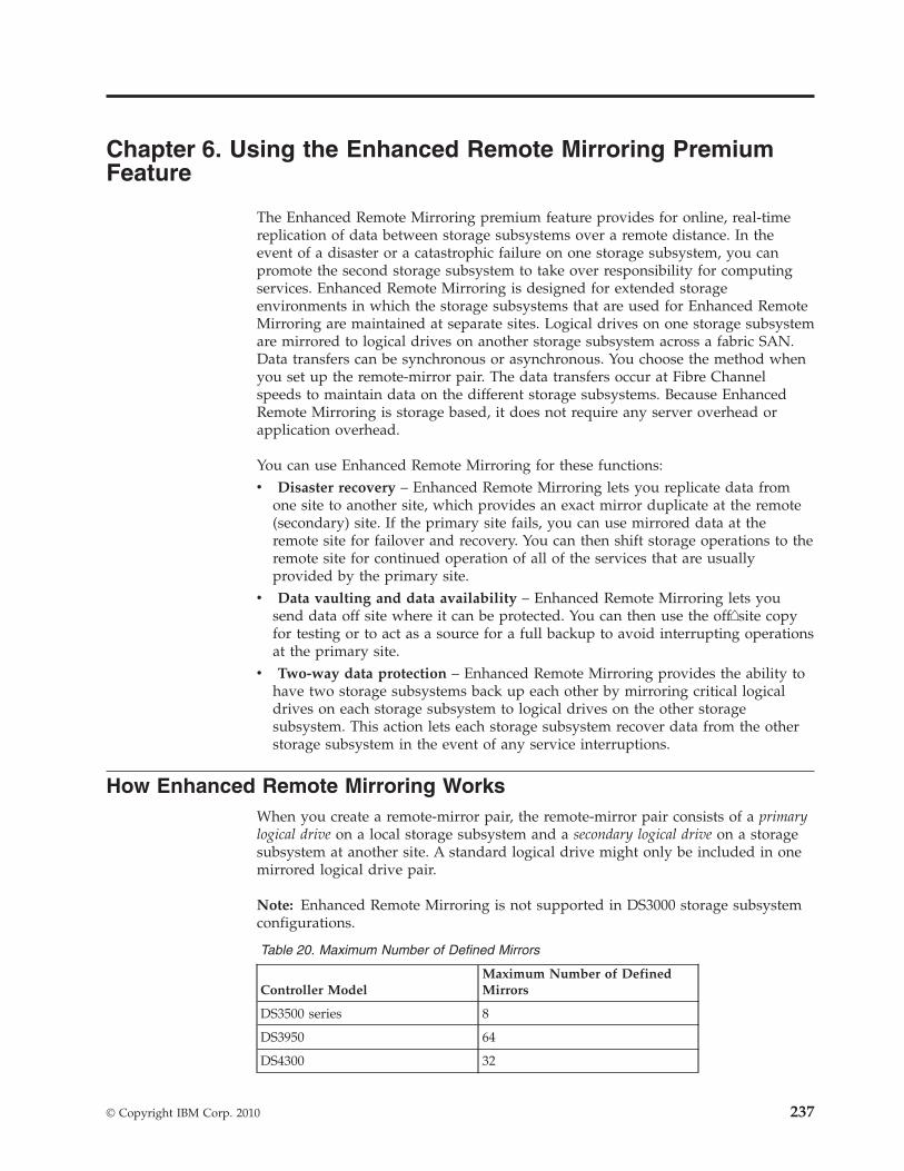
Chapter 6. Using the Enhanced Remote Mirroring PremiumFeature
The Enhanced Remote Mirroring premium feature provides for online, real-timereplication of data between storage subsystems over a remote distance. In theevent of a disaster or a catastrophic failure on one storage subsystem, you canpromote the second storage subsystem to take over responsibility for computingservices. Enhanced Remote Mirroring is designed for extended storageenvironments in which the storage subsystems that are used for Enhanced RemoteMirroring are maintained at separate sites. Logical drives on one storage subsystemare mirrored to logical drives on another storage subsystem across a fabric SAN.Data transfers can be synchronous or asynchronous. You choose the method whenyou set up the remote-mirror pair. The data transfers occur at Fibre Channelspeeds to maintain data on the different storage subsystems. Because EnhancedRemote Mirroring is storage based, it does not require any server overhead orapplication overhead.
You can use Enhanced Remote Mirroring for these functions:v Disaster recovery – Enhanced Remote Mirroring lets you replicate data from
one site to another site, which provides an exact mirror duplicate at the remote(secondary) site. If the primary site fails, you can use mirrored data at theremote site for failover and recovery. You can then shift storage operations to theremote site for continued operation of all of the services that are usuallyprovided by the primary site.
v Data vaulting and data availability – Enhanced Remote Mirroring lets yousend data off site where it can be protected. You can then use the off�site copyfor testing or to act as a source for a full backup to avoid interrupting operationsat the primary site.
v Two-way data protection – Enhanced Remote Mirroring provides the ability tohave two storage subsystems back up each other by mirroring critical logicaldrives on each storage subsystem to logical drives on the other storagesubsystem. This action lets each storage subsystem recover data from the otherstorage subsystem in the event of any service interruptions.
How Enhanced Remote Mirroring WorksWhen you create a remote-mirror pair, the remote-mirror pair consists of a primarylogical drive on a local storage subsystem and a secondary logical drive on a storagesubsystem at another site. A standard logical drive might only be included in onemirrored logical drive pair.
Note: Enhanced Remote Mirroring is not supported in DS3000 storage subsystemconfigurations.
Table 20. Maximum Number of Defined Mirrors
Controller ModelMaximum Number of DefinedMirrors
DS3500 series 8
DS3950 64
DS4300 32
© Copyright IBM Corp. 2010 237
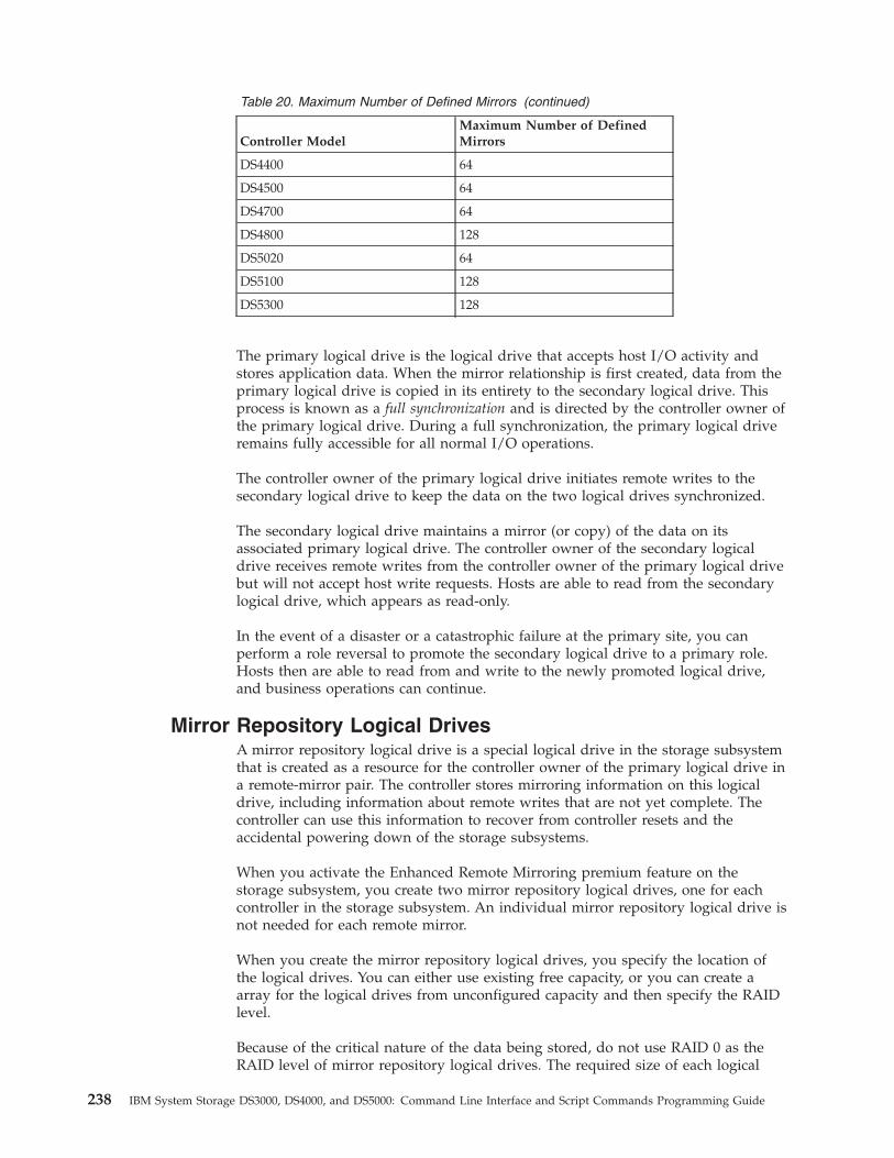
Table 20. Maximum Number of Defined Mirrors (continued)
Controller ModelMaximum Number of DefinedMirrors
DS4400 64
DS4500 64
DS4700 64
DS4800 128
DS5020 64
DS5100 128
DS5300 128
The primary logical drive is the logical drive that accepts host I/O activity andstores application data. When the mirror relationship is first created, data from theprimary logical drive is copied in its entirety to the secondary logical drive. Thisprocess is known as a full synchronization and is directed by the controller owner ofthe primary logical drive. During a full synchronization, the primary logical driveremains fully accessible for all normal I/O operations.
The controller owner of the primary logical drive initiates remote writes to thesecondary logical drive to keep the data on the two logical drives synchronized.
The secondary logical drive maintains a mirror (or copy) of the data on itsassociated primary logical drive. The controller owner of the secondary logicaldrive receives remote writes from the controller owner of the primary logical drivebut will not accept host write requests. Hosts are able to read from the secondarylogical drive, which appears as read-only.
In the event of a disaster or a catastrophic failure at the primary site, you canperform a role reversal to promote the secondary logical drive to a primary role.Hosts then are able to read from and write to the newly promoted logical drive,and business operations can continue.
Mirror Repository Logical DrivesA mirror repository logical drive is a special logical drive in the storage subsystemthat is created as a resource for the controller owner of the primary logical drive ina remote-mirror pair. The controller stores mirroring information on this logicaldrive, including information about remote writes that are not yet complete. Thecontroller can use this information to recover from controller resets and theaccidental powering down of the storage subsystems.
When you activate the Enhanced Remote Mirroring premium feature on thestorage subsystem, you create two mirror repository logical drives, one for eachcontroller in the storage subsystem. An individual mirror repository logical drive isnot needed for each remote mirror.
When you create the mirror repository logical drives, you specify the location ofthe logical drives. You can either use existing free capacity, or you can create aarray for the logical drives from unconfigured capacity and then specify the RAIDlevel.
Because of the critical nature of the data being stored, do not use RAID 0 as theRAID level of mirror repository logical drives. The required size of each logical
238 IBM System Storage DS3000, DS4000, and DS5000: Command Line Interface and Script Commands Programming Guide
drive is 128 MB, or 256 MB total for both mirror repository logical drives of adual-controller storage subsystem. In previous versions of the Enhanced RemoteMirroring feature, the mirror repository logical drives required less disk storagespace and needed to be upgraded to use the maximum amount of mirrorrelationships.
Mirror RelationshipsBefore you create a mirror relationship, you must enable the Enhanced RemoteMirroring premium feature on both the primary storage subsystem and thesecondary storage subsystem. You must also create a secondary logical drive on thesecondary site if one does not already exist. The secondary logical drive must be astandard logical drive of equal or greater capacity than the associated primarylogical drive.
When secondary logical drives are available, you can establish a mirrorrelationship in the storage management software by identifying the primary logicaldrive and the storage subsystem that contains the secondary logical drive.
When you first create the mirror relationship, a full synchronization automaticallyoccurs, with data from the primary logical drive copied in its entirety to thesecondary logical drive.
Data ReplicationThe controllers manage data replication between the primary logical drive and thesecondary logical drive. This process is transparent to host machines andapplications. This section describes how data is replicated between the storagesubsystems that are participating in Enhanced Remote Mirroring. This section alsodescribes the actions taken by the controller owner of the primary logical drive if alink interruption occurs between storage subsystems.
Write Modes
When the controller owner of the primary logical drive receives a write requestfrom a host, the controller first logs information about the write to a mirrorrepository logical drive, and then writes the data to the primary logical drive. Thecontroller then initiates a remote write operation to copy the affected data blocks tothe secondary logical drive at the secondary storage subsystem.
The Enhanced Remote Mirroring feature provides two write mode options thataffect when the I/O completion indication is sent back to the host: Synchronousand Asynchronous.
Metro Mirror
Metro mirror provides the highest level security for full data recovery from thesecondary storage subsystem in the event of a disaster. Metro mirror does reducehost I/O performance. When this write mode is selected, host write requests arewritten to the primary logical drive and then copied to the secondary logical drive.After the host write request has been written to the primary logical drive and thedata has been successfully copied to the secondary logical drive, the controllerremoves the log record on the mirror repository logical drive. The controller thensends an I/O completion indication back to the host system. Metro mirror isselected as the default value and is the recommended write mode.
Chapter 6. Using the Enhanced Remote Mirroring Premium Feature 239
Global Copy
Global copy offers faster host I/O performance but does not guarantee that a copyoperation has successfully completed before processing the next write request.When you use Global copy, host write requests are written to the primary logicaldrive. The controller then sends an “I/O complete” indication back to the hostsystem, without acknowledging that the data has been successfully copied to thesecondary (remote) storage subsystem.
When using Global copy, write requests are not guaranteed to be completed in thesame order on the secondary logical drive as they are on the primary logical drive.If the order of write requests is not retained, data on the secondary logical drivemight become inconsistent with the data on the primary logical drive. This eventcould jeopardize any attempt to recover data if a disaster occurs on the primarystorage subsystem.
Global Mirror
When multiple mirror relationships exist on a single storage subsystem and havebeen configured to use Global copy and to preserve consistent write order, they areconsidered to be an interdependent group that is in the Global mirror. The data onthe secondary, remote storage subsystem cannot be considered fully synchronizeduntil all of the remote mirrors that are in the Global mirror are synchronized.
If one mirror relationship in the group becomes unsynchronized, all of the mirrorrelationships in the group become unsynchronized. Any write activity to theremote, secondary storage subsystems is prevented to protect the consistency of theremote data set.
Link Interruptions or Secondary Logical Drive ErrorsWhen processing write requests, the primary controller might be able to write tothe primary logical drive, but a link interruption might prevent communicationwith the remote (secondary) controller.
In this case, the remote write operation cannot be completed to the secondarylogical drive, and the primary logical drive and the secondary logical drive are nolonger correctly mirrored. The primary controller transitions the mirrored pair intoan Unsynchronized state and sends an I/O completion to the primary host. Theprimary host can continue to write to the primary logical drive, but remote writesdo not take place.
When communication is restored between the controller owner of the primarylogical drive and the controller owner of the secondary logical drive, aresynchronization takes place. This resynchronization happens automatically, or itmust be started manually, depending on which write mode you chose when settingup the mirror relationship. During the resynchronization, only the blocks of datathat have changed on the primary logical drive during the link interruption arecopied to the secondary logical drive. After the resynchronization starts, themirrored pair transitions from an Unsynchronized status to a Synchronization inProgress status.
The primary controller also marks the mirrored pair as unsynchronized when alogical drive error on the secondary side prevents the remote write fromcompleting. For example, an offline secondary logical drive or a failed secondarylogical drive can cause the remote mirror to become unsynchronized. When the
240 IBM System Storage DS3000, DS4000, and DS5000: Command Line Interface and Script Commands Programming Guide
logical drive error is corrected (the secondary logical drive is placed online orrecovered to an Optimal status), then synchronization is required. The mirroredpair then transitions to a Synchronization in Progress status.
ResynchronizationData replication between the primary logical drive and the secondary logical drivein a mirror relationship is managed by the controllers and is transparent to hostmachines and applications. When the controller owner of the primary logical drivereceives a write request from a host, the controller first logs information about thewrite to a mirror repository logical drive. The controller then writes the data to theprimary logical drive. The controller then initiates a write operation to copy theaffected data to the secondary logical drive on the remote storage subsystem.
If a link interruption or a logical drive error prevents communication with thesecondary storage subsystem, the controller owner of the primary logical drivetransitions the mirrored pair into an Unsynchronized status. The controller ownerthen sends an I/O completion to the host sending the write request. The host cancontinue to issue write requests to the primary logical drive, but remote writes tothe secondary logical drive do not take place.
When connectivity is restored between the controller owner of the primary logicaldrive and the controller owner of the secondary logical drive, the logical drivesmust be resynchronized by copying the blocks of data that changed during theinterruption to the secondary logical drive. Only the blocks of data that havechanged on the primary logical drive during the link interruption are copied to thesecondary logical drive.
Attention: Possible loss of data access – Any communication disruptionsbetween the primary storage subsystem and the secondary storage subsystemwhile resynchronization is underway could result in a mix of new data and olddata on the secondary logical drive. This condition would render the data unusablein a disaster recovery situation.
Creating a Remote Mirror PairAbout this task
Before you create any mirror relationships, logical drives must exist at both theprimary site and the secondary site. The logical drive that resides on the localstorage subsystem is the primary logical drive. Similarly, the logical drive thatresides on the remote storage subsystem is the secondary logical drive. If neitherthe primary logical drive or the secondary logical drive exist, you must createthese logical drives. When you create the secondary logical drive, you mustconsider these items:v The secondary logical drive must be of equal or greater size than the primary
logical drive.v The RAID level of the secondary logical drive does not have to be the same as
the primary logical drive.
Use these steps to create the logical drive.
Procedure1. Enable the Enhanced Remote Mirroring Feature.2. Activate the Enhanced Remote Mirroring Feature.
Chapter 6. Using the Enhanced Remote Mirroring Premium Feature 241
3. Determine Candidates for a Remote Mirror Pair.4. Create the Remote Mirror Relationship.
Performance ConsiderationsConsider these performance issues when you create mirror relationships:v The controller owner of a primary logical drive performs a full synchronization
in the background while processing local I/O writes to the primary logical driveand associated remote writes to the secondary logical drive. Because the fullsynchronization diverts controller processing resources from I/O writes, fullsynchronization can have a performance impact to the host application.
v To reduce the performance impact, you can set the synchronization priority levelto determine how the controller owner will prioritize the full synchronizationrelative to other I/O activity. To set the synchronization priority level, considerthese guidelines:– A full synchronization at the lowest synchronization priority level takes
approximately eight times as long as a full synchronization at the highestsynchronization priority level.
– A full synchronization at the low synchronization priority level takesapproximately six times as long as a full synchronization at the highestsynchronization priority level.
– A full synchronization at the medium synchronization priority level takesapproximately three-and-a-half times as long as a full synchronization at thehighest synchronization priority level.
– A full synchronization at the high synchronization priority level takesapproximately twice as long as a full synchronization at the highestsynchronization priority level.
v When the mirrored logical drive pair is in a Synchronization in Progress state,all host write data is copied to the remote system. Both controller I/Obandwidth and I/O latency can affect host write performance. Host readperformance is not affected by the mirroring relationship.
v The time that it takes for data to be copied from the primary logical drive to thesecondary logical drive might impact overall performance. This impact isprimarily caused by the delay and system resource required for copying data tothe remote mirror. Some delay might also occur because of the limit to thenumber of simultaneous writes.
Enabling the Enhanced Remote Mirroring FeatureThe first step in creating a remote mirror is to make sure that the EnhancedRemote Mirroring feature is enabled on both storage subsystems. BecauseEnhanced Remote Mirroring is a premium feature, you need a Feature Key file toenable the feature. The command for enabling the Feature Key file is as follows:enable storageSubsystem feature file=”filename”
where the file parameter is the complete file path and file name of a valid FeatureKey file. Enclose the file path and the file name in double quotation marks (“ ”).Valid file names for Feature Key files end with a .key extension.
Activating the Enhanced Remote Mirroring Feature
Activating the Enhanced Remote Mirroring feature prepares the storagesubsystems to create and configure mirror relationships. After you activate thefeature, the secondary ports for each controller are reserved and dedicated to
242 IBM System Storage DS3000, DS4000, and DS5000: Command Line Interface and Script Commands Programming Guide
remote mirror use. In addition, a mirror repository logical drive is automaticallycreated for each controller in the storage subsystem. As part of the activationprocess, you can decide where the mirror repository logical drives will reside, freecapacity on an existing array or in a newly created array, and the RAID level forthe mirror repository logical drives.
The free capacity that you select for the mirror repository logical drive must have atotal of 256 MB of capacity available. Two mirror repository logical drives arecreated on this capacity, one for each controller. If you enter a value for therepository storage space that is too small for the mirror repository logical drives,the firmware returns an error message that gives the amount of space needed forthe mirror repository logical drives. The command does not try to activate theEnhanced Remote Mirroring feature. You can re-enter the command using thevalue from the error message for the repository storage space value.
The RAID level that you choose for the mirror repository logical drive has theseconstraints:v RAID 0 – You cannot use RAID 0.v RAID 1 – The number of drives must be an even number. If you select an odd
number of drives, the controller firmware returns an error.v RAID 3 or RAID 5 – You must have a minimum of three disk drives in the
array.v RAID 6 – You must have a minimum of five disk drives in the array.
To activate the Enhanced Remote Mirroring feature, use this command:activate storageSubsystem feature=remoteMirror
The activate storageSubsystem feature=remoteMirror command provides threemethods for defining the disk drives for your mirror repository logical drive:v You define each disk drive for the mirror repository logical drive by its
enclosure ID and its slot ID.v You define a array in which the mirror repository logical drive resides. You can
optionally define the capacity of the mirror repository logical drive.v You define the number of disk drives, but not specific disk drives, for the mirror
repository logical drive.
Activating the Enhanced Remote Mirroring Feature withUser-Assigned Disk Drives
Activating the Enhanced Remote Mirroring feature by assigning the disk drivesprovides flexibility in defining your configuration by letting you choose from theavailable disk drives in your storage subsystem. Choosing the disk drives for yourremote mirror automatically creates a new array. You can specify which disk drivesto use and the RAID level for the new array.
The command takes this form:activate storageSubsystem feature=remoteMirrorrepositoryRAIDLevel=(1 | 3 | 5 | 6) repositoryDrives=(enclosureID1,slotID1 ... enclosureIDn,slotIDn)enclosureLossProtect=(TRUE | FALSE)
This example shows a command in which you assign the disk drives:c:\...\...\client>smcli 123.45.67.89 -c “activatestorageSubsystem feature=remoteMirror repositoryRAIDLevel=5repositoryDrives=(1,1 1,2 1,3 1,4 1,5);”
Chapter 6. Using the Enhanced Remote Mirroring Premium Feature 243
The command in this example creates a new mirror repository logical driveconsisting of five disk drives that forms a new array. The new array has a RAIDlevel of 5.
This example shows how to use the command in a script file:activate storageSubsystem feature=remoteMirrorrepositoryRAIDLevel=5repositoryDrives=(1,1 1,2 1,3 1,4 1,5);
Activating the Enhanced Remote Mirroring Feature withSoftware-Assigned Disk Drives
With this version of the activate storageSubsystem feature=remoteMirrorcommand, you choose an existing array in which to place the mirror repositorylogical drive. The storage management software then determines which disk drivesto use. You can also define how much space to assign to the mirror repositorylogical drive. Because you are using an existing array, the RAID level for themirror repository logical drive defaults to the RAID level of the array in which youplace it. You cannot define the RAID level for the mirror repository logical drive.
The command takes this form:activate storageSubsystem feature=remoteMirror repositoryArray=arrayNumber[freeCapacityArea=freeCapacityIndexNumber]
This example shows a command in which the software assigns the disk drives:c:\...\...\client>smcli 123.45.67.89 -c “activate storageSubsystemfeature=remoteMirror repositoryArray=2 freeCapacityArea=2;”
The command in this example creates a new mirror repository logical drive inarray 2 using the second free capacity area.
This example shows how to use the command in a script file:activate storageSubsystem feature=remoteMirror repositoryArray=2 freeCapacityArea=2;
Activating the Enhanced Remote Mirroring Feature by Specifyinga Number of Disk Drives
With this version of the activate storageSubsystem feature=remoteMirrorcommand, you must specify the number of disk drives and the RAID level thatyou want for the mirror repository logical drive. This version of the commandcreates a new array. For this command to work, you must have disk drives in thestorage subsystem that are not assigned to a array.activate storageSubsystem feature=remoteMirrorrepositoryRAIDLevel=(1 | 3 | 5 | 6)repositoryDriveCount=numberOfDrives[driveType=(fibre | SATA | SAS |)][enclosureLossProtect=(TRUE | FALSE)]
This example shows a command in which you specify the number of disk drives:c:\...\...\client>smcli 123.45.67.89 -c “activate storageSubsystem feature=remoteMirror repositoryRAIDLevel=5 repositoryDriveCount=5driveType=fibre;”
The command in this example creates a new mirror repository logical drive byusing five software�selected disk drives for the mirror repository logical drive. Themirror repository logical drive has a RAID level of 5. The type of drive for themirror repository logical drive is Fibre Channel.
244 IBM System Storage DS3000, DS4000, and DS5000: Command Line Interface and Script Commands Programming Guide
This example shows how to use the command in a script file:activate storageSubsystem feature=remoteMirrorrepositoryRAIDLevel=5 repositoryDriveCount=5driveType=fibre;
Determining Candidates for a Remote-Mirror PairAll of the logical drives and disk drives on the remote storage subsystem mightnot be available for use as secondary logical drives. To determine which logicaldrives on a remote storage subsystem that you can use as candidates for secondarylogical drives, use the show remoteMirror candidates command. This commandreturns a list of the logical drives that you can use when creating a remote mirror.
The command takes this form:c:\...\...\client>smcli 123.45.67.89 -c “showremoteMirror candidates primary=\“logicalDriveName\”remoteStorageSubsystemName=\“storageSubsystemName\”;”
where logicalDriveName is the name of the logical drive that you want to use forthe primary logical drive, and StorageSubsystemName is the remote storagesubsystem that contains possible candidates for the secondary logical drive.Enclose both the logical drive name and the storage subsystem name in doublequotation marks (“ ”).
Creating a Remote Mirror PairWhen you create a new remote mirror, you must define which logical drives thatyou want to use for the primary (local) logical drive and the secondary (remote)logical drive. You define the primary logical drive by the name of the logical drive.You define the secondary logical drive by name with either the name or theWorld-Wide Identifier (WWID) of the storage subsystem on which the secondarylogical drive resides. The primary logical drive name, the secondary logical drivename, and the remote storage subsystem name (or WWID) are the minimuminformation that you need to provide. Using this command, you can also definesynchronization priority, write order, and write mode.
The command takes this form:create remoteMirror primary=“primaryLogicalDriveName”secondary=“secondaryLogicalDriveName”(remoteStorageSubsystemName=“storageSubsystemName” |remoteStorageSubsystemWwn=“wwID”) remotePassword=passwordsyncPriority=(highest | high | medium | low | lowest)writeOrder=(preserved | notPreserved)writeMode=(synchronous | asynchronous)
Note: You can use the optional parameters as needed to help define yourconfiguration.
This example shows the create remoteMirror command:c:\...\...\client>smcli 123.45.67.89 -c “createremoteMirror primary=\”Jan_04_Account\”secondary=\”Jan_04_Account_B\” remoteStorageSubsystemName=\”Tabor\”remotePassword=\”jdw2ga05\” syncPriority=highestwriteMode=synchronous;”
The command in this example creates a remote mirror in which the primary logicaldrive is named Jan_04_Account on the local storage subsystem. The secondarylogical drive is named Jan_04_Account_B on the remote storage subsystem that isnamed Tabor. The names used in this example are similar, but that is not a
Chapter 6. Using the Enhanced Remote Mirroring Premium Feature 245
requirement for the logical drive names in a remote-mirror pair. In this example,the remote storage subsystem has a password that you must enter when makingany change to the storage subsystem configuration. Creating a remote-mirror pairis a significant change to a storage subsystem configuration. Setting the write modeto synchronous and the synchronization priority to highest means that host writerequests are written to the primary logical drive and then immediately copied tothe secondary logical drive. These actions help to make sure that the data on thesecondary logical drive is as accurate a copy of the data on the primary logicaldrive as possible. The highest synchronization priority does, however, use moresystem resources, which can reduce system performance.
This example shows how to use the command in a script file:create remoteMirror primary=”Jan_04_Account”secondary=”Jan_04_Account_B” remoteStorageSubsystemName=”Tabor”remotePassword=”jdw2ga05” syncPriority=highestwriteMode=synchronous;
After you have created a remote mirror, you can see the progress of datasynchronization between the primary logical drive and the secondary logical driveby running the show remoteMirror synchronizationProgress command. Thiscommand shows the progress as a percentage of data synchronization that hascompleted.
Changing Enhanced Remote Mirroring SettingsThe set remoteMirror command lets you change the property settings for a remotemirror pair. Use this command to change these property settings:v The logical drive role (either primary or secondary)v The synchronization priorityv The write orderv The write mode
You can apply the changes to one or several remote mirror pairs by using thiscommand. Use the primary logical drive name to identify the remote mirror pairsfor which you are changing the properties.
This example shows how to use the set remoteMirror command:c:\...\...\client>smcli 123.45.67.89 -c “set remoteMirrorlocalLogicalDrive [Jan_04_Account] syncPriority=medium writeOrder=notpreservedwriteMode=asynchronous;”
This example shows how to use the command in a script file:set remoteMirror localLogicalDrive [Jan_04_Account]syncPriority=medium writeOrder=notpreservedwriteMode=asynchronous;
Suspending and Resuming a Mirror RelationshipUse the suspend remoteMirror command to stop data transfer between a primarylogical drive and a secondary logical drive in a mirror relationship withoutdisabling the mirror relationship. Suspending a mirror relationship lets you controlwhen the data on the primary logical drive and data on the secondary logical driveare synchronized. Suspending a mirror relationship helps to reduce anyperformance impact to the host application that might occur while any changeddata on the primary logical drive is copied to the secondary logical drive.
246 IBM System Storage DS3000, DS4000, and DS5000: Command Line Interface and Script Commands Programming Guide
Suspending a mirror relationship is particularly useful when you want to run abackup of the data on the secondary logical drive.
When a mirror relationship is in a suspended state, the primary logical drive doesnot make any attempt to contact the secondary logical drive. Any writes to theprimary logical drive are persistently logged in the mirror repository logical drives.After the mirror relationship resumes, any data that is written to the primarylogical drive is automatically written to the secondary logical drive. Only themodified data blocks on the primary logical drive are written to the secondarylogical drive. Full synchronization is not required.
Important: If you suspend a remote mirror that is set up in the Global mirror, yoususpend all remote mirror pairs within the group. You can then resume mirroroperations for any of the individual remote-mirror pairs that are in the group.
This example shows the suspend remoteMirror command:c:\...\...\client>smcli 123.45.67.89 -c “suspend remoteMirror primary Jan_04_AccountwriteConsistency=false;”
The writeConsistency parameter defines whether the logical drives identified inthis command are in a write-consistency group or are separate. For the logicaldrives in a write�consistency group, set this parameter to TRUE. For the logicaldrives that are not in a write-consistency group, set this parameter to FALSE.
This example shows how to use the command in a script file:suspend remoteMirror logicalDrive Jan_04_Account writeConsistency=false;
The mirror relationship remains suspended until you use the resume remoteMirrorcommand to restart synchronization activities. This command restarts datatransfers between a primary logical drive and a secondary logical drive in a mirrorrelationship after the mirror has been suspended or unsynchronized.
This example shows the resume remoteMirror command:c:\...\...\client>smcli 123.45.67.89 -c “resumeremoteMirror logicalDrive Jan_04_Account writeConsistency=false;”
The writeConsistency parameter in this command operates the same as in theprevious command.
This example shows how to use the command in a script file:resume remoteMirror logicalDrive Jan_04_AccountwriteConsistency=false;
Removing a Mirror RelationshipUse the remove remoteMirror command to remove the link between a primarylogical drive and a secondary logical drive. (Removing a mirror relationship issimilar to deleting a mirror relationship.) Removing the link between a primarylogical drive and a secondary logical drive does not affect any of the existing dataon either logical drive. The link between the logical drives is removed, but theprimary logical drive still continues normal I/O operations. Later, you canestablish the mirror relationship between the two logical drives and resume normalmirror operations. You can remove the mirror relationship for one or severalremote mirror pairs with this command.
This example shows the remove remoteMirror command:
Chapter 6. Using the Enhanced Remote Mirroring Premium Feature 247
c:\...\...\client>smcli 123.45.67.89 -c “remove remoteMirror localLogicalDrive[Jan_04_Account];”
When you run this command, use the name of the primary logical drive of theremote mirror pair.
This example shows how to use the command in a script file:remove remoteMirror localLogicalDrive [Jan_04_Account];
To re-establish the link between a primary logical drive and a secondary logicaldrive, use the create remoteMirror command.
Deleting a Primary Logical Drive or a Secondary Logical DriveUse the delete logicalDrive command to remove a primary logical drive or asecondary logical drive from a storage subsystem. Deleting a logical drive in amirror relationship removes the mirror relationship and completely deletes thelogical drive from the storage subsystem. You cannot redefine the mirrorrelationship until you create a new logical drive or choose an alternate logicaldrive to replace the deleted logical drive.
Attention: Possible loss of data access – Deleting a primary logical drive or asecondary logical drive permanently removes the data from the storage subsystem.
Disabling the Enhanced Remote Mirroring FeatureYou disable the Enhanced Remote Mirroring feature to prevent the new mirrorrelationship from being created. When you disable the Enhanced Remote Mirroringfeature, the feature is in a Disabled/Active state. In this state, you can maintainand manage previously existing mirror relationships; however, you cannot createnew relationships. To disable the Enhanced Remote Mirroring feature, use thiscommand:disable storageSubsystem feature=remoteMirror
Deactivating the Enhanced Remote Mirroring FeatureIf you no longer require the Enhanced Remote Mirroring feature and you haveremoved all of the mirror relationships, you can deactivate the feature.Deactivating the feature re�establishes the normal use of dedicated ports on bothstorage subsystems and deletes both mirror repository logical drives. To deactivatethe Enhanced Remote Mirroring feature, use this command:deactivate storageSubsystem feature=remoteMirror
Interaction with Other FeaturesYou can run the Enhanced Remote Mirroring feature while running these premiumfeatures:v Storage Partitioningv FlashCopy Logical Drivev VolumeCopy
When you run the Enhanced Remote Mirroring feature with other premiumfeatures, you must consider the requirements of the other premium features to helpmake sure that you set up a stable storage subsystem configuration.
248 IBM System Storage DS3000, DS4000, and DS5000: Command Line Interface and Script Commands Programming Guide
In addition to running with the premium features, you can also run the EnhancedRemote Mirroring feature while running Dynamic Logical Drive Expansion (DVE).
Storage PartitioningStorage Partitioning is a premium feature that lets hosts share access to logicaldrives in a storage subsystem. You create a storage partition when you define anyof these logical components in a storage subsystem:v A hostv A host groupv A logical drive-to-LUN mapping
The logical drive-to-LUN mapping lets you define which host group or host hasaccess to a particular logical drive in the storage subsystem.
When you create storage partitions, define the partitions after you have created theprimary logical drive and the secondary logical drive in a Enhanced RemoteMirroring configuration. The storage partition definitions for the primary storagesubsystem and the secondary storage subsystem are independent of each other. Ifthese definitions are put in place while the logical drive is in a secondary role, theadministrative effort associated with the site recovery is reduced if it becomesnecessary to promote the logical drive to a primary role.
FlashCopy Logical DrivesA FlashCopy logical drive is a point-in-time image of a logical drive. Typically, it iscreated so that an application, such as a backup application, can access theFlashCopy logical drive and read the data while the base logical drive stays onlineand is accessible to hosts.
The logical drive for which the point-in-time image is created is known as the baselogical drive and must be a standard logical drive in the storage subsystem. TheFlashCopy repository logical drive stores information about all data that changedsince the FlashCopy was created.
In this version of the storage management software, you can create FlashCopylogical drives based on the primary logical drive or secondary logical drive of aremote mirror.
VolumeCopyThe VolumeCopy premium feature copies data from one logical drive (the sourcelogical drive) to another logical drive (the target logical drive) within a singlestorage subsystem. You can use this feature to perform these functions:v Copy data from arrays that use smaller-capacity disk drives to arrays that use
larger-capacity disk drivesv Back up datav Restore FlashCopy logical drive data to the base logical drive.
You can use a primary logical drive in a remote mirror as a source logical drive ora target logical drive in a VolumeCopy. You cannot use a secondary logical drive asa source logical drive or a target logical drive.
Note: If you start a role reversal during a copy-in-progress, the copy fails andcannot be restarted.
Chapter 6. Using the Enhanced Remote Mirroring Premium Feature 249
Dynamic Logical Drive ExpansionA Dynamic Logical Drive Expansion (DVE) is a modification operation thatincreases the capacity of a standard logical drive or a FlashCopy repository logicaldrive. The increase in capacity is achieved by using the free capacity that isavailable in the array of the standard logical drive or the FlashCopy repositorylogical drive.
This modification operation is considered to be “dynamic” because you cancontinually access data on arrays, logical drives, and disk drives throughout theentire operation.
A DVE operation can be performed on a primary logical drive or a secondarylogical drive of a mirror relationship.
Note: Although the storage management software indicates that the logical drivehas increased capacity, its usable capacity is the size of the smaller of the primarylogical drive or the secondary logical drive.
You cannot perform a DVE operation on a mirror repository logical drive.
Asynchronous Enhanced Remote Mirroring Utility
This section describes the host utility to achieve periodic consistency withAsynchronous Enhanced Remote Mirroring configurations. This section alsodescribes how to run the Asynchronous Enhanced Remote Mirroring utility.
Description of the Asynchronous Enhanced Remote MirroringUtility
The Asynchronous Enhanced Remote Mirroring utility lets you periodicallysynchronize the Enhanced Remote Mirroring pairs in your storage subsystem.When defining a Enhanced Remote Mirroring configuration, you have the optionto set the write modes to either Synchronous or Asynchronous. Metro mirrorprovides the highest level security for full data recovery from the secondarystorage subsystem in the event of a disaster. Metro mirror does, however, reducehost I/O performance. Global copy offers faster host I/O performance, but it doesnot guarantee that a copy operation has successfully completed before processingthe next write request. With Global copy, you cannot make sure that a logicaldrive, or collection of logical drives, at a secondary site ever reach a consistent,recoverable state.
The Asynchronous Enhanced Remote Mirroring utility enables you to bring acollection of asynchronous remote logical drives into a mutually consistent andrecoverable state. You can choose to run the utility based on application demands,link state and speed, and other factors that are relevant to your environment.
The Asynchronous Enhanced Remote Mirroring utility has these characteristics:v The utility is implemented as a command line-invoked Java-based application.v The utility is bundled as part of the DS5000 Storage Manager installation
package.v The utility accepts a command line argument that lets you specify the name of a
configuration file that contains a complete specification of the work to be carriedout by the utility.
250 IBM System Storage DS3000, DS4000, and DS5000: Command Line Interface and Script Commands Programming Guide
v More than one instance of the utility can run concurrently, as long as the utilitiesdo not try to process any of the same logical drives and mirrors.
Note: The Asynchronous Enhanced Remote Mirroring utility does not check tomake sure that concurrently running instances of the utility are not trying toprocess the same logical drives and mirrors. If you choose to simultaneously runmore than one instance of the Asynchronous Enhanced Remote Mirroring utility,you must make sure that the configuration files that you choose to run do not listthe same logical drives and mirrors.
Operation of the Asynchronous Enhanced Remote MirroringUtility
The Asynchronous Enhanced Remote Mirroring utility performs steps that generatea recoverable state for multiple mirror logical drives at a secondary site. The utilityruns these steps to create consistent, recoverable images of a set of logical drives:1. On the primary storage subsystem – The utility reconfigures all of the
participating logical drives from asynchronous mirroring to synchronousmirroring. This action makes sure that the stream of write operations becomesrecoverable on the secondary side.
2. On the primary storage subsystem – The utility polls all of the participatinglogical drives until the associated mirror states all have the Optimal state. Incases where the remote link is slow or the primary host I/O activity is high,one or more mirrors are likely to be in the Unsynchronized state before theytransition to the Synchronized state. By waiting until all of the mirrors haveOptimal status, the utility makes sure that all of the delta logs for the affectedlogical drives are cleared, and the secondary logical drives are recoverable.
3. On the primary storage subsystem – The utility suspends the mirrored pairsfor all of the participating logical drives. This action causes updates to stop onthe secondary side, leaving the secondary logical drives in a recoverable statebecause they were being updated in Synchronous mode immediately before thesuspension. By separating the mirrors in this manner, the primary-sideapplications run faster, while leaving the secondary logical drives in arecoverable state. The delta log tracks changes made because of applicationwrites on the primary side while in this state.
4. On the secondary storage subsystem – The utility generates a flashcopy ofeach participating logical drive on the secondary side, which createspoint-in-time images that are recoverable.
5. On the primary storage subsystem – The utility resumes the mirroringoperations for all of the participating logical drives. This action causes themirrors to transition to the Synchronized state and start the process of restoringcoherency between the primary site and the secondary site.
6. On the primary storage subsystem – The utility reconfigures all of the affectedlogical drives for Asynchronous mode.
Running the Asynchronous Enhanced Remote Mirroring Utility
The Asynchronous Enhanced Remote Mirroring utility uses a command lineargument that lets you specify the name of a configuration file. The configurationfile contains a complete specification of the input parameters that are needed bythe utility. To run the utility, enter this syntax:asyncRVMUtil configuration_file -d debug_file
Chapter 6. Using the Enhanced Remote Mirroring Premium Feature 251
where configuration_file is the file that you provide as input. The configuration filespecifies the Enhanced Remote Mirroring logical drives that you want tosynchronize by using the utility. When you create the configuration file, use theseconditions to define the logical drives in the file:v All the primary logical drives in a logical drive set must belong to the same
storage subsystem.v The maximum number of logical drive sets that you can specify in the file is
four.v The maximum number of mirrored pairs that you can specify as part of a
consistency group is eight.
The optional parameter, -d, lets you specify a file to which you can sendinformation regarding how the utility runs. In this example, the file name isdebug_file. The debug file contains trace information that can be reviewed by aCustomer and Technical Support representative to determine how well theAsynchronous Enhanced Remote Mirroring utility has run.
Note: Depending on the location of the configuration file and the debug file, youmust specify the complete path with the file name.
To run the Asynchronous Enhanced Remote Mirroring utility, you must enter theasyncRVMUtil command from the command line. Because UNIX operating systemsare case sensitive, you must type the command exactly as shown. On Windowsoperating systems, you can type the command in all uppercase, in all lowercase, orin mixed case.
Note: To use the Asynchronous Enhanced Remote Mirroring utility, you must bemanaging the storage subsystem by using the command line interface, not thegraphical user interface of DS Storage Manager.
Configuration Utility
The configuration file is an ASCII flat text file that provides the information for theEnhanced Remote Mirroring synchronization used by the Asynchronous EnhancedRemote Mirroring utility. The file defines the mirror logical drive sets to besynchronized. All of the mirror logical drives in the logical drive sets defined inthe configuration file are run collectively to create a recoverable image. If any oneof the mirrors in the logical drive set fails, the operation is stopped for this logicaldrive set and carried on to the next logical drive set that is listed in theconfiguration file.
The configuration file supports this syntax:content ::= {spec}spec ::= logSpec | logicalDriveSetSpec
logSpec ::= "Log" "{" {logAttribute} "}"logAttribute ::= fileSpecfileSpec ::= "file" "=" fileName
LogicalDriveSetSpec ::= "LogicalDriveSet" LogicalDriveSetName"{" {LogicalDriveSetAttribute} "}"LogicalDriveSetAttribute ::= timeoutSpec | mirrorSpec
timeoutSpec ::= "OptimalWaitTimeLimit" "=" integer
mirrorSpec ::= "Mirror" "{" {mirrorAttribute} "}"mirrorAttribute ::= primarySpec | secondarySpec |FlashCopySpec
252 IBM System Storage DS3000, DS4000, and DS5000: Command Line Interface and Script Commands Programming Guide
primarySpec ::= "Primary" "=" LogicalDriveSpecsecondarySpec ::= "Secondary" "=" LogicalDriveSpecFlashCopySpec ::= "Copy" "=" logicalDriveSpeclogicalDriveSpec ::= storageSubsystemName"."logicalDriveUserLabel
In this syntax, items enclosed in double quotation marks (“ ”) are terminalsymbols. Items separated by a vertical bar (|) are alternative values (enter one orthe other, but not both). Items enclosed in curly braces ({ }) are optional (you canuse the item zero or more times).
These definitions are provided for non-terminals in the syntax:v integer – The timeout value must be an integer (decimal digits from 0–9).v logicalDriveSetName – The name of the set of logical drives on which you want
to run the Asynchronous Enhanced Remote Mirroring utility.v fileName – The name of a file, using characters and conventions that are
appropriate for the system on which the application is running.v storageSubsystemName – The label that you have assigned for a storage
subsystem, as would be used in the CLI to specify the name of the storagesubsystem.
v logicalDriveUserLabel – The label that you have assigned for a logical drive thatuniquely identifies the logicalDrive within the storage subsystem.
Note: Names and labels can be any characters that are defined as appropriate foryour operating system. The maximum length for a name or label is 30 characters.If the name or label contains special characters (as defined by the operatingsystem) or period characters, you must enclose the name or label in doublequotation marks (“ ”). You can, optionally, enclose the name or label in doublequotation marks at any time.
The following items are considered syntax errors:v More than one logSpec command in the input filev Zero or more than one fileSpec attribute in a logSpec command (you must
include exactly one fileSpec attribute in the logSpec command)v More than one timeoutSpec attribute in a logicalDriveSetSpec commandv Zero or more than one primarySpec attribute in a mirrorSpec command (you
must include exactly one primarySpec attribute in the mirrorSpec command)v Zero or more than one secondarySpec attribute in a mirrorSpec command (you
must include exactly one secondarySpec attribute in the mirrorSpec command)v Zero or more than one FlashCopySpec attribute in a mirrorSpec command (you
must include exactly one FlashCopySpec attribute in the mirrorSpec command)
Important: In the Asynchronous Enhanced Remote Mirroring utility configurationfile, you must specify the primary logical drive, the secondary logical drive, andthe copy (FlashCopy) logical drive. The utility does not make sure that thesecondary logical drive is correct for the Enhanced Remote Mirroring relationship.The utility also does not make sure that the FlashCopy logical drive is actually aFlashCopy for the secondary logical drive. You must make sure that these logicaldrives are correct. If the logical drives are not correct, the utility will run, but thelogical drives will not be consistent. For each mirror, the secondary logical driveand the copy logical drive must reside on the same storage subsystem.
This example shows a configuration file for the Asynchronous Enhanced RemoteMirroring utility.
Chapter 6. Using the Enhanced Remote Mirroring Premium Feature 253
Log{ file="d:\rvm-consistency.log" }LogicalDriveSet "set1" {optimalWaitTimeLimit = 15Mirror {Primary = LosAngelesSubsystem.PayrollLogicalDriveSecondary = NewYorkSubsystem.PayrollLogicalDriveCopy = NewYorkSubsystem.PayrollLogicalDriveImage
}Mirror {Primary = LosAngelesSubsystem.PayrollLogicalDriveSecondary = BostonSubsystem.PayrollLogicalDriveCopy = BostonSubsystem.PayrollLogicalDriveImage}}
LogicalDriveSet "set2" {Mirror {Primary = BostonSubsystem.HRLogicalDriveSecondary = LosAngelesSubsystem.HRLogicalDriveCopy = LosAngelesSubsystem.HRLogicalDriveImage}}
254 IBM System Storage DS3000, DS4000, and DS5000: Command Line Interface and Script Commands Programming Guide
Chapter 7. Using the VolumeCopy Premium Feature
The VolumeCopy premium feature lets you copy data from one logical drive (thesource) to another logical drive (the target) in a single storage subsystem. You canuse this feature to perform these tasks:v Back up datav Copy data from arrays that use smaller-capacity disk drives to arrays using
greater-capacity disk drivesv Restore FlashCopy logical drive data to the associated base logical drive
How VolumeCopy WorksWhen you create a VolumeCopy, you create a copy pair that consists of a sourcelogical drive and a target logical drive. Both the source logical drive and the targetlogical drive are located on the same storage subsystem. During a VolumeCopy,the controllers manage copying the data from the source logical drive to the targetlogical drive. The VolumeCopy is transparent to the host machines andapplications, except that you cannot write to the source logical drive during aVolumeCopy operation.
Tip: Because of this restriction, IBM strongly recommends using a FlashCopyversion of the logical drive as the source for the VolumeCopy, rather than using theoriginal logical drive as the source. If you use the FlashCopy as the source for theVolumeCopy operation, then I/O operations to the original logical drive cancontinue.
While a VolumeCopy is In Progress, the same controller must own both the sourcelogical drive and the target logical drive. If one controller does not own both thesource logical drive and the target logical drive before creating the VolumeCopy,ownership of the target logical drive is automatically transferred to the controllerthat owns the source logical drive. When the VolumeCopy is finished or stopped,ownership of the target logical drive is restored to its preferred controller. Ifownership of the source logical drive changes while a VolumeCopy is running,ownership of the target logical drive also changes.
Source Logical DriveThe source logical drive is the logical drive that accepts host I/O and stores data.When you start a VolumeCopy, data from the source logical drive is copied in itsentirety to the target logical drive. While a VolumeCopy has a status of InProgress, Pending, or Failed, the source logical drive is available only for readactivity.
After the VolumeCopy completes, the source logical drive becomes available tohost applications for write requests. The target logical drive automatically becomesread only to hosts, and write requests to the target logical drive are rejected.
The following are valid source logical drives:v A standard logical drivev A FlashCopy logical drivev The base logical drive of a FlashCopy logical drive
© Copyright IBM Corp. 2010 255
v A primary logical drive that is participating in a remote-mirror pair
The following are not valid source logical drives:v A secondary logical drive that is participating in a remote-mirror pairv A FlashCopy repository logical drivev A mirror repository logical drivev A failed logical drivev A missing logical drivev A logical drive currently in a modification operationv A logical drive that is holding a Small Computer System Interface-2 (SCSI-2)
reservation or a persistent reservationv A logical drive that is a source logical drive or a target logical drive in another
VolumeCopy that has a status of In Progress, Pending, or Failed
Target Logical DriveA target logical drive contains a copy of the data from the source logical drive.When a VolumeCopy is started, data from the source logical drive is copied in itsentirety to the target logical drive.
Attention: Possible loss of data access – A VolumeCopy overwrites data on thetarget logical drive. Before you start a new operation, make sure that you nolonger need the old data, or you have backed up the old data on the target logicaldrive.
While the VolumeCopy has a status of In Progress, Pending, or Failed, thecontrollers reject read and write requests to the target logical drive. After theVolumeCopy operation is finished, the target logical drive automatically becomesread only to the hosts, and write requests to the target logical drive are rejected.You can change the Read-Only attribute after the VolumeCopy has completed orhas been stopped. (For more information about the Read-Only attribute, see“Viewing VolumeCopy Properties” on page 260.)
The following logical drives are valid target logical drives:v A standard logical drivev The base logical drive of a disabled FlashCopy logical drive or failed FlashCopy
logical drivev A primary logical drive that is participating in a remote-mirror pair
The following logical drives are not valid target logical drives:v The base logical drive of an active FlashCopy logical drivev A FlashCopy logical drivev A mirror repository logical drivev A FlashCopy repository logical drivev A secondary logical drive in a remote-mirror pairv A failed logical drivev A missing logical drivev A logical drive with a status of Degradedv A logical drive that is currently in a modification operationv A logical drive that is holding a SCSI-2 reservation or a persistent reservation
256 IBM System Storage DS3000, DS4000, and DS5000: Command Line Interface and Script Commands Programming Guide
v A logical drive that is a source logical drive or a target logical drive in anotherVolumeCopy that has a status of In Progress, Pending, or Failed
VolumeCopy and Persistent ReservationsYou cannot use logical drives that hold persistent reservations for either a sourcelogical drive or a target logical drive. Persistent reservations are configured andmanaged through the server cluster software and prevent other hosts fromaccessing the reserved logical drive. Unlike other types of reservations, a persistentreservation reserves host access to the logical drive across multiple HBA host ports,which provides various levels of access control.
To determine which logical drives have reservations, run the show (logicalDrive)reservations command. To remove a reservation, run the clear (logicalDrive)reservations command.
Storage Subsystem PerformanceDuring a VolumeCopy operation, the resources of the storage subsystem might bediverted from processing I/O activity to completing a VolumeCopy, which mightaffect the overall performance of the storage subsystem.
These factors contribute to the performance of the storage subsystem:v The I/O activityv The logical drive RAID levelv The logical drive configuration (number of disk drives in the arrays and cache
parameters)v The logical drive type (flashcopy logical drives might take more time to copy
than standard logical drives)
When you create a new VolumeCopy, you define the copy priority to determinehow much controller processing time is allocated for a VolumeCopy comparedwith I/O activity.
Copy priority has five relative settings ranging from highest to lowest. The highestpriority rate supports the VolumeCopy, but I/O activity might be affected. Thelowest priority rate supports I/O activity, but the VolumeCopy takes longer. Youdefine the copy priority when you create the VolumeCopy pair. You can redefinethe copy priority later by using the set volumeCopy command. You can alsoredefine the VolumeCopy priority when you recopy a logical drive.
RestrictionsThese restrictions apply to the source logical drive, the target logical drive, and thestorage subsystem:v While a VolumeCopy operation has a status of In Progress, Pending, or Failed,
the source logical drive is available for read activity only. After the VolumeCopyfinishes, read activity from and write activity to the source logical drive ispermitted.
v A logical drive can be selected as a target logical drive for only one VolumeCopyat a time.
v The maximum allowable number of VolumeCopies per storage subsystemdepends upon the storage subsystem configuration.
v A logical drive that is reserved by the host cannot be selected as a source logicaldrive or as a target logical drive.
Chapter 7. Using the VolumeCopy Premium Feature 257
v A logical drive with a status of Failed cannot be used as a source logical drive oras a target logical drive.
v A logical drive with a status of Degraded cannot be used as a target logicaldrive.
v You cannot select a logical drive that is participating in a modification operationas a source logical drive or as a target logical drive. Modification operationsinclude Dynamic Capacity Expansion (DCE), Dynamic RAID Level Migration(DRM), Dynamic Segment Sizing (DSS), Dynamic Volume Expansion (DVE), anddefragmenting a array.
VolumeCopy CommandsThe following table lists the VolumeCopy commands and briefly describes whatthe commands do.
Table 21. VolumeCopy Commands
Command Description
create volumeCopy Creates a VolumeCopy and starts theVolumeCopy operation.
disable storageSubsystem featurevolumeCopy
Turns off the current VolumeCopy operation.
enable storageSubsystem feature Activates the VolumeCopy premium feature.
recopy volumeCopy Re-initiates a VolumeCopy operation using anexisting VolumeCopy pair.
remove volumeCopy Removes a VolumeCopy pair.
set volumeCopy Defines the properties for a VolumeCopy pair.
show volumeCopy Returns information about VolumeCopyoperations. You can retrieve information abouta specific VolumeCopy pair, or all of theVolumeCopy pairs in the storage subsystem.
show volumeCopysourceCandidates
Returns information about the candidatelogical drives that you can use as the sourcefor a VolumeCopy operation.
show volumeCopy targetCandidates Returns information about the candidatelogical drives that you can use as the target fora VolumeCopy operation.
stop volumeCopy Stops a VolumeCopy operation.
Creating a VolumeCopyBefore you create a VolumeCopy, make sure that a suitable target logical driveexists on the storage subsystem, or create a new target logical drive specifically forthe VolumeCopy. The target logical drive that you use must have a capacity equalto or greater than the source logical drive.
You can have a maximum of eight VolumeCopies with a status of In Progress atone time. Any VolumeCopy greater than eight has a status of Pending until one ofthe VolumeCopies with a status of In Progress has completed the VolumeCopyprocess.
To create a VolumeCopy, perform these general steps:1. Enable the VolumeCopy premium feature.
258 IBM System Storage DS3000, DS4000, and DS5000: Command Line Interface and Script Commands Programming Guide
2. Determine the candidates for a VolumeCopy.3. Create the target logical drive and the source logical drive for the VolumeCopy.
Enabling the VolumeCopy FeatureThe first step in creating a VolumeCopy is to make sure that the feature is enabledon the storage subsystem. Because VolumeCopy is a premium feature, you need aFeature Key file to enable the feature. This command enables the Feature Key file:enable storageSubsystem feature file=”filename”
where the file parameter is the complete file path and file name of a valid FeatureKey file. Enclose the file path and file name in double quotation marks (“ ”). Validfile names for Feature Key files usually end with a .key extension.
Determining VolumeCopy CandidatesAll logical drives and disk drives might not be available for use in VolumeCopyoperations. To determine which candidate logical drives on the storage subsystemthat you can use as a source logical drive, use the show volumeCopysourceCandidates command. To determine which candidate logical drives on thestorage subsystem that you can use as a target logical drive, use the showvolumeCopy targetCandidates command. These commands return a list of theexpansion drawer, slot, and capacity information for the source logical drivecandidates and the target logical drive candidates. You can use the showvolumeCopy sourceCandidates command and the show volumeCopytargetCandidates command only after you have enabled the VolumeCopy premiumfeature.
Creating a VolumeCopyAttention: Possible loss of data access – A VolumeCopy overwrites data on thetarget logical drive. Make sure that you no longer need the data or have backed upthe data on the target logical drive before you start a VolumeCopy operation.
When you create a VolumeCopy, you must define which logical drives that youwant to use for the source logical drive and the target logical drive. You define thesource logical drive and the target logical drive by the name of each logical drive.You can also define the copy priority and choose whether you want the targetlogical drive to be read only after the data is copied from the source logical drive.
The command takes this form:create volumeCopysource=”sourceName” target=”targetName”[copyPriority=(highest | high | medium | low | lowest)targetReadOnlyEnabled=(TRUE | FALSE)]
Important: Setting the targetReadOnlyEnabled attribute to false breaks theone-to-one relationship between the source and target VolumeCopy logical drives.Therefore, any data that are written to the target VolumeCopy logical drive willnot be copied to the source VolumeCopy logical drive. In addition, these data willbe lost if you recopy of the source VolumeCopy logical drive to the targetVolumeCopy logical drive.
Before you run the create volumeCopy command, perform these actions:v Stop all I/O activity to the source logical drive and the target logical drive.v Dismount any file systems on the source logical drive and the target logical
drive, if applicable.
Chapter 7. Using the VolumeCopy Premium Feature 259
This example shows the create volumeCopy command:c:\...\...\client>smcli 123.45.67.89 -c “createvolumeCopy source=\”Jaba_Hut\” target=\”Obi_1\”copyPriority=medium targetrReadOnlyEnabled=TRUE;”
The command in this example copies the data from the source logical drive namedJaba_Hut to the target logical drive named Obi_1. Setting the copy priority tomedium provides a compromise between how quickly the data is copied from thesource logical drive to the target logical drive and the amount of processingresources that are required for data transfers to other logical drives in the storagesubsystem. Setting the targetReadOnlyEnabled parameter to TRUE means thatwrite requests cannot be made to the target logical drive, making sure that the dataon the target logical drive stays unaltered.
This example shows how to use the command in a script file:create volumeCopy source=”Jaba_Hut” target=”Obi_1”copyPriority=medium targetReadOnlyEnabled=TRUE;
After the VolumeCopy operation is completed, the target logical driveautomatically becomes read only to hosts. Any write requests to the target logicaldrive are rejected, unless you disable the Read-Only attribute by using the setvolumeCopy command.
To view the progress of a VolumeCopy, use the show logicalDrive actionProgresscommand. This command returns information about the logical drive action, thepercentage completed, and the time remaining until the VolumeCopy is complete.
Viewing VolumeCopy PropertiesUse the show volumeCopy command to view information about one or moreselected source logical drives or target logical drives. This command returns thesevalues:v The rolev The copy statusv The start time stampv The completion time stampv The copy priorityv The Read-Only attribute setting for the target logical drivev The source logical drive World-Wide Identifier (WWID) or the target logical
drive WWID
If a logical drive is participating in more than one VolumeCopy (it can be a sourcelogical drive for one VolumeCopy operation and a target logical drive for anotherVolumeCopy operation), the details are repeated for each associated copy pair.
The command takes this form:show volumeCopy (allLogicalDrives | source [sourceName] |target [targetName])
This example shows the show volumeCopy command:c:\...\...\client>smcli 123.45.67.89 -c “show volumeCopy source [\”JabaHut\”];”
260 IBM System Storage DS3000, DS4000, and DS5000: Command Line Interface and Script Commands Programming Guide
The command in this example is requesting information about the source logicaldrive JabaHut. If you wanted information about all of the logical drives, youwould use the allLogicalDrives parameter. You can also request information abouta specific target logical drive.
This example shows how to use the command in a script file:show volumeCopy source [“JabaHut”];
Changing VolumeCopy SettingsThe set volumeCopy command lets you change these property settings for aVolumeCopy pair:v The copy priorityv The target logical drive read/write permission
Copy priority has five relative settings ranging from highest to lowest. The highestpriority supports the VolumeCopy, but I/O activity might be affected. The lowestpriority supports I/O activity, but the VolumeCopy takes longer. You can changethe copy priority at these times:v Before the VolumeCopy operation startsv While the VolumeCopy operation has a status of In Progressv After the VolumeCopy operation has completed when re-creating a VolumeCopy
operation by using the recopy volumeCopy command
When you create a VolumeCopy pair and after the original VolumeCopy hascompleted, the target logical drive is automatically defined as read-only to thehosts. The read-only status of the target logical drive helps to make sure that thecopied data on the target logical drive is not corrupted by additional writes to thetarget logical drive after the VolumeCopy is created. You want to maintain theread-only status when you are performing these tasks:v Using the target logical drive for backup purposesv Copying data from one array to a larger array for greater accessibilityv Planning to use the data on the target logical drive to copy back to the base
logical drive in case of a disabled FlashCopy logical drive or failed FlashCopylogical drive
At other times, you might want to write additional data to the target logical drive.You can use the set volumeCopy command to reset the read/write permission forthe target logical drive.
Note: If you have set the VolumeCopy parameters to enable host writes to thetarget logical drive, the read request and the write request to the target logicaldrive are rejected while the VolumeCopy operation has a status of In Progress,Pending, or Failed.
The command takes this form:set volumeCopy target [targetName] [source [sourceName]]copyPriority=(highest | high | medium | low | lowest)targetReadOnlyEnabled=(TRUE | FALSE)
Important: Setting the targetReadOnlyEnabled attribute to false breaks theone-to-one relationship between the source and target VolumeCopy logical drives.Therefore, any data that are written to the target VolumeCopy logical drive will
Chapter 7. Using the VolumeCopy Premium Feature 261
not be copied to the source VolumeCopy logical drive. In addition, these data willbe lost if you recopy of the source VolumeCopy logical drive to the targetVolumeCopy logical drive.
Note: You can use the parameters as needed to help define your configuration.
This example shows the set volumeCopy command:c:\...\...\client>smcli 123.45.67.89 -c “set volumeCopytarget [\”Obi_1\”] copyPriority=highesttargetReadOnlyEnabled=FALSE;”
This example shows how to use the command in a script file:set volumeCopy target [“Obi_1”] copyPriority=highest targetReadOnlyEnabled=FALSE;
Recopying a Logical DriveUse the recopy volumeCopy command to create a new VolumeCopy for apreviously defined copy pair that has a status of Stopped, Failed, or Completed.You can use the recopy volumeCopy command to create backups of the targetlogical drive. Then, you can copy the backup to tape for off-site storage.
When you use the recopy volumeCopy command to make a backup, you cannotwrite to the source logical drive while the recopy operation is running. The recopyoperation might take a long time.
Restriction: Because of this restriction, IBM strongly recommends using aFlashCopy version of the logical drive as the source for the VolumeCopy, ratherthan using the original logical drive as the source. If you use the FlashCopy as thesource for the VolumeCopy operation, then I/O operations to the original logicaldrive can continue.
When you run the recopy volumeCopy command, the data on the source logicaldrive is copied in its entirety to the target logical drive.
Attention: Possible loss of data access – The recopy volumeCopy commandoverwrites existing data on the target logical drive and makes the target logicaldrive read-only to hosts. The recopy volumeCopy command fails all of theflashcopy logical drives that are associated with the target logical drive, if anyexist.
You can also reset the copy priority by using the recopy volumeCopy command ifyou want to change the copy priority for the recopy operation. The higherpriorities allocate storage subsystem resources to the VolumeCopy at the expenseof storage subsystem performance.
The command takes this form:recopy volumeCopy target [targetName] [source [sourceName]copyPriority=(highest | high | medium | low | lowest)targetReadOnlyEnabled=(TRUE | FALSE)]
Note: You can use the optional parameters as needed to help define yourconfiguration.
This example shows the show volumeCopy command:c:\...\...\client>smcli 123.45.67.89 -c “recopy volumeCopy target [\”Obi_1\”]copyPriority=highest;”
262 IBM System Storage DS3000, DS4000, and DS5000: Command Line Interface and Script Commands Programming Guide
The command in this example copies data from the source logical drive that isassociated with the target logical drive Obi_1 to the target logical drive again. Thecopy priority is set to the highest value to complete the VolumeCopy as quickly aspossible. The underlying consideration for using this command is that you havealready created the VolumeCopy pair, which has already created one VolumeCopy.By using this command, you are copying the data from the source logical drive tothe target logical drive with the assumption that the data on the source logicaldrive has changed since the previous copy was made.
This example shows you how to use the command in a script file:recopy volumeCopy target [“Obi_1”] copyPriority=highest;
Stopping a VolumeCopyThe stop volumeCopy command lets you stop a VolumeCopy that has a status ofIn Progress, Pending, or Failed. After you have stopped a VolumeCopy, you canuse the recopy volumeCopy command to create a new VolumeCopy by using theoriginal VolumeCopy pair. After you stop a VolumeCopy operation, all of themapped hosts will have write access to the source logical drive.
The command takes this form:stop volumeCopy target [targetName] [source [sourceName]]
This example shows the show volumeCopy command:c:\...\...\client>smcli 123.45.67.89 -c “stop volumeCopy target [\”Obi_1\”];”
This example shows how to use the command in a script file:stop volumeCopy target [“Obi_1”];
Removing Copy PairsThe remove volumeCopy command lets you remove a VolumeCopy pair from thestorage subsystem configuration. All of the VolumeCopy-related information forthe source logical drive and the target logical drive is removed from the storagesubsystem configuration. The data on the source logical drive or the target logicaldrive is not deleted. Removing a VolumeCopy from the storage subsystemconfiguration also removes the Read-Only attribute for the target logical drive.
Important: If the VolumeCopy has a status of In Progress, you must stop theVolumeCopy before you can remove the VolumeCopy pair from the storagesubsystem configuration.
The command takes this form:remove volumeCopy target [targetName] [source [sourceName]]
This example shows the remove volumeCopy command:c:\...\...\client>smcli 123.45.67.89 -c “remove volumeCopy target [\”Obi_1\”];”
This example shows how to use the command in a script file:remove volumeCopy target [“Obi_1”];
Chapter 7. Using the VolumeCopy Premium Feature 263
Interaction with Other FeaturesYou can run the VolumeCopy premium feature while running the followingpremium features:v Storage Partitioningv FlashCopy Logical Drivev Enhanced Remote Mirroring
When you are running the VolumeCopy feature with other premium features, youmust consider the requirements of other premium features to help make sure thatyou set up a stable storage subsystem configuration.
In addition to the premium features, you also can run the VolumeCopy featurewhile running Dynamic Volume Expansion (DVE).
Storage PartitioningStorage Partitioning is a premium feature that lets hosts share access to logicaldrives in a storage subsystem. You create a storage partition when you define anyof these logical components in a storage subsystem:v A hostv A host groupv A logical drive-to-LUN mapping
The logical drive-to-LUN mapping lets you define which host group or host hasaccess to a particular logical drive in the storage subsystem.
After you create a VolumeCopy, the target logical drive automatically becomes readonly to hosts to make sure that the data is preserved. Hosts that have beenmapped to a target logical drive do not have write access to the logical drive, andany attempt to write to the read-only target logical drive results in a host I/Oerror.
If you want hosts to have write access to the data on the target logical drive, usethe set volumeCopy command to disable the Read-Only attribute for the targetlogical drive.
FlashCopy Logical DrivesA FlashCopy logical drive is a point-in-time image of a logical drive. It is usuallycreated so that an application, such as a backup application, can access theFlashCopy logical drive and read the data while the base logical drive stays onlineand is accessible to hosts.
The logical drive for which the point-in-time image is created is known as the baselogical drive and must be a standard logical drive in the storage subsystem. TheFlashCopy repository logical drive stores information about all of the data thatchanged since the FlashCopy was created.
Tip: You can select a FlashCopy logical drive as the source logical drive for aVolumeCopy. This selection is a good use of this feature, because it performscomplete backups without significant impact to the storage subsystem availability.Some I/O processing resources are lost to the copy operation.
264 IBM System Storage DS3000, DS4000, and DS5000: Command Line Interface and Script Commands Programming Guide
Important: If you choose the base logical drive of a FlashCopy logical drive asyour target logical drive, you must disable all of the FlashCopy logical drives thatare associated with the base logical drive before you can select it as a target logicaldrive.
When you create a FlashCopy logical drive, a FlashCopy repository logical drive isautomatically created. The FlashCopy repository logical drive stores informationabout the data that has changed since the FlashCopy logical drive was created. Youcannot select a FlashCopy repository logical drive as a source logical drive or atarget logical drive in a VolumeCopy.
You can use the FlashCopy Logical Drive premium feature with the VolumeCopypremium feature to back up data on the same storage subsystem and to restore thedata on the FlashCopy logical drive back to its original base logical drive.
Enhanced Remote MirroringThe Enhanced Remote Mirroring premium feature provides for online, real-timereplication of data between storage subsystems over a remote distance. In theevent of a disaster or a catastrophic failure of one storage subsystem, you canpromote a secondary storage subsystem to take over responsibility for data storage.
When you create a remote mirror, a remote mirror pair is created, which consists ofa primary logical drive at the primary storage subsystem and a secondary logicaldrive at a remote storage subsystem.
The primary logical drive is the logical drive that accepts host I/O and stores data.When the mirror relationship is initially created, data from the primary logicaldrive is copied in its entirety to the secondary logical drive. This process is knownas a full synchronization and is directed by the controller owner of the primarylogical drive. During a full synchronization, the primary logical drive remains fullyaccessible for all normal I/O activity.
The controller owner of the primary logical drive starts remote writes to thesecondary logical drive to keep the data on the two logical drives synchronized.Whenever the data on the primary logical drive and the secondary logical drivebecomes unsynchronized, the controller owner of the primary logical drive starts aresynchronization, where only the data that changed during the interruption iscopied.
The secondary logical drive maintains a mirror of the data on its associatedprimary logical drive. The controller owner of the secondary logical drive receivesremote writes from the controller owner of the primary logical drive but does notaccept host write requests.
The secondary logical drive stays available to host applications as read-only whilemirroring is underway. In the event of a disaster or a catastrophic failure at theprimary site, you can perform a role reversal to promote the secondary logicaldrive to a primary role. Hosts are then able to access the newly promoted logicaldrive, and business operations can continue.
You can select a primary logical drive that is participating in a remote mirror pairto be used as the source logical drive or a target logical drive for a VolumeCopy. Asecondary logical drive that is participating in a remote-mirror pair cannot beselected as a source logical drive or a target logical drive.
Chapter 7. Using the VolumeCopy Premium Feature 265
Role ReversalsA role reversal is the act of promoting the secondary logical drive to be theprimary logical drive of the remote mirror pair, and demoting the primary logicaldrive to be the secondary logical drive.
In the event of a disaster at the storage subsystem that contains the primary logicaldrive, you can fail over to the secondary site by performing a role reversal topromote the secondary logical drive to the primary logical drive role. This actionlets hosts continue to access data, and business operations can continue.
Trying a role reversal in which the original primary logical drive is the sourcelogical drive for an active VolumeCopy (the status is In Progress or Pending)causes the VolumeCopy to fail. The failure occurs when the original primarylogical drive becomes the new secondary logical drive. You cannot restart theVolumeCopy until you return the roles of the logical drives back to their originalstate; that is, the logical drive that was originally the primary logical drive is setonce again to be the primary logical drive.
If the primary storage subsystem is recovered but is unreachable due to a linkfailure, a forced promotion of the secondary logical drive will result in both theprimary logical drive and the secondary logical drive viewing themselves in theprimary logical drive role (dual-primary condition). If this condition occurs, theVolumeCopy in which the primary logical drive is participating is unaffected bythe role change.
You can perform a role reversal by using the set remoteMirror command. (Forinformation about the set remoteMirror command, see “Set Remote Mirror” onpage 124.)v To change a secondary logical drive to a primary logical drive, use this
command, which promotes the selected secondary logical drive to become theprimary logical drive of the remote mirror pair. Use this command after acatastrophic failure has occurred.set remoteMirror role=primary
v To change a primary logical drive to a secondary logical drive, use thiscommand, which demotes the selected primary logical drive to become thesecondary logical drive. Use this command after a catastrophic failure hasoccurred.set remoteMirror role=secondary
266 IBM System Storage DS3000, DS4000, and DS5000: Command Line Interface and Script Commands Programming Guide
Chapter 8. Maintaining a Storage System
About this task
Maintenance covers a broad spectrum of activity with the goal of keeping a storagesubsystem operational and available to all hosts. This chapter provides descriptionsof commands you can use to perform storage subsystem maintenance. Thecommands are organized into four sections:v Routine maintenancev Performance tuningv Troubleshooting and diagnosticsv Recovery operations
The organization is not a rigid approach, and you can use the commands asappropriate for your storage subsystem. The commands listed in this chapter donot cover the entire array of commands you can use for maintenance. Othercommands, particularly the set commands, can provide diagnostic or maintenancecapabilities.
Routine MaintenanceRoutine maintenance involves those tasks that you might perform periodically tomake sure that the storage subsystem is running as well as possible or to detectconditions before they become problems.
Running a Media ScanMedia scan provides a way of detecting disk drive media errors before they arefound during a normal read from or write to the disk drives. Any media scanerrors that are detected are reported to the Event Log. The Event Log provides anearly indication of an impending disk drive failure and reduces the possibility ofencountering a media error during host operations. A media scan is performed as abackground operation and scans all data and redundancy information in defineduser logical drives.
A media scan runs on all of the logical drives in the storage subsystem that havethese conditions:v Has Optimal statusv Has no modification operations in progressv Has media scan enabled
Errors that are detected during a scan of a user logical drive are reported to theMajor Event Log (MEL) and handled as follows:v Unrecovered media error – The disk drive could not read the requested data on
its first try or on any subsequent retries. The result of this action is that forlogical drives with redundancy protection, the data is reconstructed, rewritten tothe disk drive, and verified, and the error is reported to the Event Log. Forlogical drives without redundancy protection, the error is not corrected, but it isreported to the Event Log.
© Copyright IBM Corp. 2010 267
v Recovered media error – The disk drive could not read the requested data onits first attempt. The result of this action is that the data is rewritten to the diskdrive and verified. The error is reported to the Event Log.
v Redundancy mismatches – Redundancy errors are found, and a media error isforced on the block stripe so that it is found when the disk drive is scannedagain. If redundancy is repaired, this forced media error is removed. The resultof this action is that the first 10 redundancy mismatches found on a logical driveare reported to the Event Log.
v Unfixable error – The data could not be read, and parity information orredundancy information could not be used to regenerate it. For example,redundancy information cannot be used to reconstruct data on a degradedlogical drive. The result of this action is that the error is reported to the EventLog.
The script command set provides two commands to define media scan properties:v set logicalDrivev set storageSubsystem
The set logicalDrive command enables a media scan for the logical drive. Thecommand takes this form:set (allLogicalDrives | logicalDrive [logicalDriveName] | logicalDrives[logicalDriveName1 ... LogicalDriveNameN] | logicalDrive <wwID>)mediaScanEnabled=(TRUE | FALSE)
The set storageSubsystem command defines how frequently a media scan is run ona storage subsystem. The command takes this form:set storageSubsystem mediaScanRate=(disabled | 1-30)
The mediaScanRate values define the number of days over which the media scanruns. Valid values are disabled, which turns off the media scan; or 1 day to 30days, where 1 day is the fastest scan rate, and 30 days is the slowest. A value otherthan what is shown will not allow the media scan to function.
Running a Redundancy CheckRedundancy checks are performed when media scans are run. (For a descriptionabout how to set up and run media scans, see “Running a Media Scan” on page267.) During a redundancy check, all of the data blocks in a logical drive arescanned, and, depending on the RAID level, deteriorated data is corrected.Correction is performed as follows:v For RAID 3, RAID 5, or RAID 6 logical drives, redundancy is checked and
repaired.v For RAID 1 logical drives, the data is compared between the mirrored disk
drives and data inconsistencies are repaired.v RAID 0 logical drives have no redundancy.
Before you can run a redundancy check, you must enable redundancy checking byusing the set logicalDrive command. The command takes this form:
set (allLogicalDrives | logicalDrive [logicalDriveName] | logicalDrives[logicalDriveName1 ... logicalDriveNameN] | logicalDrive <wwID>)redundancyCheckEnabled=(TRUE | FALSE)
268 IBM System Storage DS3000, DS4000, and DS5000: Command Line Interface and Script Commands Programming Guide
Resetting a Controller
Important: When you reset a controller, the controller is no longer available forI/O operations until the reset is complete. If a host is using logical drives that areowned by the controller being reset, the I/O that is directed to the controller isrejected. Before resetting the controller, either make sure that the logical drives thatare owned by the controller are not in use, or make sure that a multi-path driver isinstalled on all of the hosts that are using these logical drives.
Resetting a controller is the same as rebooting the controller processors. To reset acontroller, use this command:reset controller [(a | b)]
Enabling a Controller Data TransferAt times, a controller might become quiescent while running diagnostics. If thiscondition occurs, the controller might become unresponsive. To revive a controllerthat has become quiescent while running diagnostics, use this command:enable controller [(a | b)] dataTransfer
Resetting the Battery AgeAfter you have replaced the batteries in the storage subsystem, you must reset theage of the battery. You can reset either the batteries for an entire storage subsystemor a battery in a specific controller. To reset the age of the batteries to zero days,use this command:reset storageSubystem batteryInstallDate [controller=(a | b)]
Note: The DS3950, DS4800 (models 82, 84, and 88), DS5020, DS5100, and DS5300controller modules do not support this command. The batteries in the DS3950,DS4800 (models 82, 84, and 88), DS5020, DS5100, and DS5300 controller modulesdo not require that you reset the battery age after you have replaced the batteries.
Removing Persistent ReservationsPersistent reservations preserve logical drive registrations, and they prevent hosts,other than the host defined for the logical drive, from accessing the logical drive.You must remove persistent reservations before you make these changes to yourconfiguration:v Change or delete LUN mappings on a logical drive holding a reservationv Delete arrays or logical drives that have any reservations
To determine which logical drives have reservations, use this command:
show (allLogicalDrives | logicalDrive [logicalDriveName] | logicalDrives[logicalDriveName1 ... logicalDriveNameN]) reservations
To clear persistent logical drive reservations, use this command:
clear (allLogicalDrives | logicalDrive [logicalDriveName] | logicalDrives[logicalDriveName1 ... logicalDriveNameN]) reservations
Synchronizing the Controller ClocksTo synchronize the clocks on both controllers in a storage subsystem with the hostclock, use this command:
Chapter 8. Maintaining a Storage System 269
set storageSubsystem time
Locating Disk DrivesAt times, you might need to locate a specific disk drive. In very large storagesubsystem configurations, this task can sometimes be awkward. If you need tolocate a specific disk drive, you can do so by turning on the indicator light on thefront of the disk drive. To locate a disk drive, use this command:start drive [enclosureID,slotID] locate
To turn off the indicator light after locating the disk drive, use this command:stop drive locate
Relocating an ArrayArray relocation describes the action of moving disk drives within the samestorage subsystem. This is a supported capability; however, any relocation ofstorage subsystem components must be completed under the guidance of aCustomer and Technical Support representative.
This section describes the commands that you use to remove a set of disk drivesand then reinstall them into a different storage subsystem.
Hot and Cold Array Relocation
There are two methods you can use to move arrays: hot array relocation and coldarray relocation.
Note: For more detailed information about relocating arrays, see one of thefollowing documents:v DS3000: IBM System Storage DS3000 Installation, User's and Maintenance Guide
v DS4000 / DS5000: IBM System Storage DS4000/DS5000 Hard Drive and StorageExpansion Enclosure Installation and Migration Guide
v Hot array relocation lets you add or move storage without reconfiguring thestorage subsystem and, in some cases, without rebooting. During hot arrayrelocation, the storage subsystem power is not turned off.
v Cold array relocation requires that the power to the source storage subsystemand the destination storage subsystem be turned off before moving the arraysfrom one storage subsystem to another. Then the power to the storagesubsystems can be turned on.
To ensure that any array being moved to a different destination storage subsystemis correctly recognized and managed by the new storage subsystem, use hot arrayrelocation whenever possible.
Attention: Possible loss of data access – You must move a single array at a time,and it must go into a storage subsystem with the same level of controller firmware.
Basic Process Steps
Relocating an array from one storage subsystem to another includes theseprocedures:1. Verifying the status of the storage subsystems2. Ensuring that both storage subsystems have the latest controller firmware
versions installed
270 IBM System Storage DS3000, DS4000, and DS5000: Command Line Interface and Script Commands Programming Guide
3. Locating the drives in the array4. Placing the array offline5. Removing drives from the storage subsystem6. Replacing an array into the new storage subsystem
Attention: Check firmware versions – Ensure that both existing and new storagesubsystems have the latest controller firmware versions installed.v See the IBM Disk Support Web site to find the latest firmware versions for your
storage subsystems:www.ibm.com/systems/support/storage/disk
v Also check the following documentation for more information:– DS3000: IBM System Storage DS3000 Installation, User's and Maintenance Guide
– DS4000 / DS5000: IBM System Storage DS4000/DS5000 Hard Drive and StorageExpansion Enclosure Installation and Migration Guide
To perform these steps, you must be familiar with the following CLI commands.The command syntax is provided to assist in your use of these new commands.
Array Relocation Commands
Note: Array relocation commands are supported with the following controllerfirmware only:v DS5000: 07.30.xx.xxv DS4000: 07.1x.xx.xxv DS3000: Not supported.
Use the following command to place a specific storage subsystem into an exportedstate so that its disk drives may be removed.start array [user-label] export
At this point you are allowed to remove the disk drives that comprise the array,and physically reinstall them into a different storage subsystem.
Use the following command to logically move a specific storage subsystem froman exported state to the complete state.start array [user-label] import
Your relocated array is now available for use.
For additional information, refer to these commands:v “Show Array Export Dependencies” on page 137v “Show Array Import Dependencies” on page 138v “Start Array Export” on page 164v “Start Array Import” on page 165
Performance TuningOver time, as a storage subsystem exchanges data between the hosts and the diskdrives, its performance can degrade. You can monitor the performance of a storagesubsystem and make adjustments to the operational settings on the storagesubsystem to help improve performance.
Chapter 8. Maintaining a Storage System 271
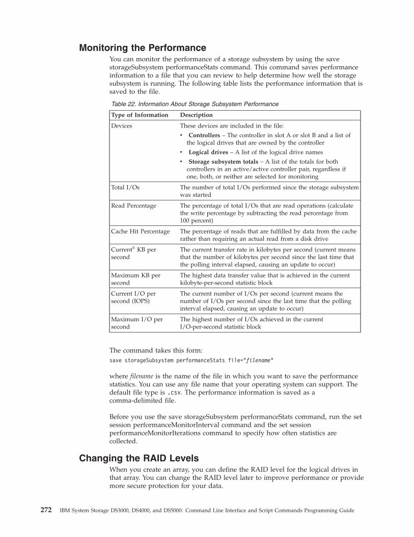
Monitoring the PerformanceYou can monitor the performance of a storage subsystem by using the savestorageSubsystem performanceStats command. This command saves performanceinformation to a file that you can review to help determine how well the storagesubsystem is running. The following table lists the performance information that issaved to the file.
Table 22. Information About Storage Subsystem Performance
Type of Information Description
Devices These devices are included in the file:
v Controllers – The controller in slot A or slot B and a list ofthe logical drives that are owned by the controller
v Logical drives – A list of the logical drive names
v Storage subsystem totals – A list of the totals for bothcontrollers in an active/active controller pair, regardless ifone, both, or neither are selected for monitoring
Total I/Os The number of total I/Os performed since the storage subsystemwas started
Read Percentage The percentage of total I/Os that are read operations (calculatethe write percentage by subtracting the read percentage from100 percent)
Cache Hit Percentage The percentage of reads that are fulfilled by data from the cacherather than requiring an actual read from a disk drive
Current® KB persecond
The current transfer rate in kilobytes per second (current meansthat the number of kilobytes per second since the last time thatthe polling interval elapsed, causing an update to occur)
Maximum KB persecond
The highest data transfer value that is achieved in the currentkilobyte-per-second statistic block
Current I/O persecond (IOPS)
The current number of I/Os per second (current means thenumber of I/Os per second since the last time that the pollinginterval elapsed, causing an update to occur)
Maximum I/O persecond
The highest number of I/Os achieved in the currentI/O-per-second statistic block
The command takes this form:save storageSubsystem performanceStats file=”filename”
where filename is the name of the file in which you want to save the performancestatistics. You can use any file name that your operating system can support. Thedefault file type is .csv. The performance information is saved as acomma-delimited file.
Before you use the save storageSubsystem performanceStats command, run the setsession performanceMonitorInterval command and the set sessionperformanceMonitorIterations command to specify how often statistics arecollected.
Changing the RAID LevelsWhen you create an array, you can define the RAID level for the logical drives inthat array. You can change the RAID level later to improve performance or providemore secure protection for your data.
272 IBM System Storage DS3000, DS4000, and DS5000: Command Line Interface and Script Commands Programming Guide
RAID 6 is supported in DS4000 and DS5000 storage products only, with controllerfirmware version 7.1x.xx.xx or higher.
To change the RAID level, use this command:set array [arrayNumber]raidLevel=(0 | 1 | 3 | 5 | 6)
where arrayNumber is the number of the array for which you want to change theRAID level.
Changing the Segment SizeWhen you create a new logical drive, you can define the segment size for thatlogical drive. In addition, you can change the segment size later to optimizeperformance. In a multiuser database or file system storage environment, set yoursegment size to minimize the number of disk drives that are needed to satisfy anI/O request. Use larger values for the segment size. Using a single disk drive for asingle request leaves other disk drives available to simultaneously service otherrequests. If the logical drive is in a single-user large I/O environment, performanceis maximized when a single I/O request is serviced with a single data stripe; usesmaller values for the segment size. To change the segment size, use thiscommand:set logicalDrive ([logicalDriveName] | <wwID>) segmentSize=segmentSizeValue
where segmentSizeValue is the new segment size that you want to set. Validsegment size values are 8, 16, 32, 64, 128, 256, and 512. You can identify the logicaldrive by name or by WWID. (For usage information, see “Set Logical Drive” onpage 119.)
Changing the Cache ParametersThe script command set provides two commands that you can use to change cacheparameter settings:v set storageSubsystemv set logicalDrive
The set storageSubsystem command lets you change settings for these items:v The cache block sizev The cache flush start percentagev The cache flush stop percentage
The set logicalDrive command lets you change settings for these items:v The cache flush modifierv The cache without batteries enabled or disabledv The mirror cache enabled or disabledv The read cache enabled or disabledv The write cache enabled or disabledv The read ahead multiplierv The redundancy check enabled or disabled
Defragmenting an ArrayWhen you defragment an array, you consolidate the free capacity in the array intoone contiguous area. Defragmentation does not change the way in which the data
Chapter 8. Maintaining a Storage System 273
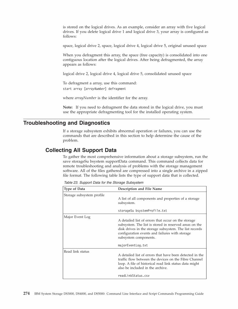
is stored on the logical drives. As an example, consider an array with five logicaldrives. If you delete logical drive 1 and logical drive 3, your array is configured asfollows:
space, logical drive 2, space, logical drive 4, logical drive 5, original unused space
When you defragment this array, the space (free capacity) is consolidated into onecontiguous location after the logical drives. After being defragmented, the arrayappears as follows:
logical drive 2, logical drive 4, logical drive 5, consolidated unused space
To defragment a array, use this command:start array [arrayNumber] defragment
where arrayNumber is the identifier for the array.
Note: If you need to defragment the data stored in the logical drive, you mustuse the appropriate defragmenting tool for the installed operating system.
Troubleshooting and DiagnosticsIf a storage subsystem exhibits abnormal operation or failures, you can use thecommands that are described in this section to help determine the cause of theproblem.
Collecting All Support DataTo gather the most comprehensive information about a storage subsystem, run thesave storageSu bsystem supportData command. This command collects data forremote troubleshooting and analysis of problems with the storage managementsoftware. All of the files gathered are compressed into a single archive in a zippedfile format. The following table lists the type of support data that is collected.
Table 23. Support Data for the Storage Subsystem
Type of Data Description and File Name
Storage subsystem profileA list of all components and properties of a storagesubsystem.
storageSu bsystemProfile.txt
Major Event LogA detailed list of errors that occur on the storagesubsystem. The list is stored in reserved areas on thedisk drives in the storage subsystem. The list recordsconfiguration events and failures with storagesubsystem components.
majorEventLog.txt
Read link statusA detailed list of errors that have been detected in thetraffic flow between the devices on the Fibre Channelloop. A file of historical read link status data mightalso be included in the archive.
readLinkStatus.csv
274 IBM System Storage DS3000, DS4000, and DS5000: Command Line Interface and Script Commands Programming Guide
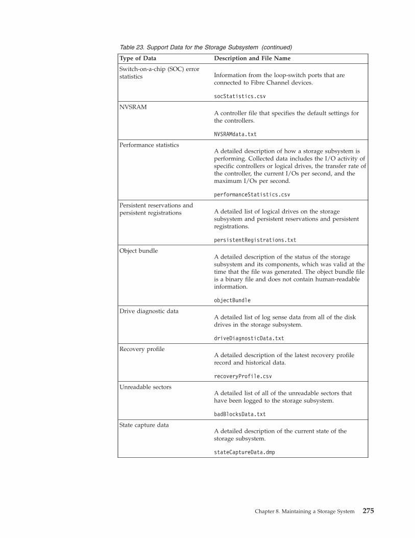
Table 23. Support Data for the Storage Subsystem (continued)
Type of Data Description and File Name
Switch-on-a-chip (SOC) errorstatistics Information from the loop-switch ports that are
connected to Fibre Channel devices.
socStatistics.csv
NVSRAMA controller file that specifies the default settings forthe controllers.
NVSRAMdata.txt
Performance statisticsA detailed description of how a storage subsystem isperforming. Collected data includes the I/O activity ofspecific controllers or logical drives, the transfer rate ofthe controller, the current I/Os per second, and themaximum I/Os per second.
performanceStatistics.csv
Persistent reservations andpersistent registrations A detailed list of logical drives on the storage
subsystem and persistent reservations and persistentregistrations.
persistentRegistrations.txt
Object bundleA detailed description of the status of the storagesubsystem and its components, which was valid at thetime that the file was generated. The object bundle fileis a binary file and does not contain human-readableinformation.
objectBundle
Drive diagnostic dataA detailed list of log sense data from all of the diskdrives in the storage subsystem.
driveDiagnosticData.txt
Recovery profileA detailed description of the latest recovery profilerecord and historical data.
recoveryProfile.csv
Unreadable sectorsA detailed list of all of the unreadable sectors thathave been logged to the storage subsystem.
badBlocksData.txt
State capture dataA detailed description of the current state of thestorage subsystem.
stateCaptureData.dmp
Chapter 8. Maintaining a Storage System 275
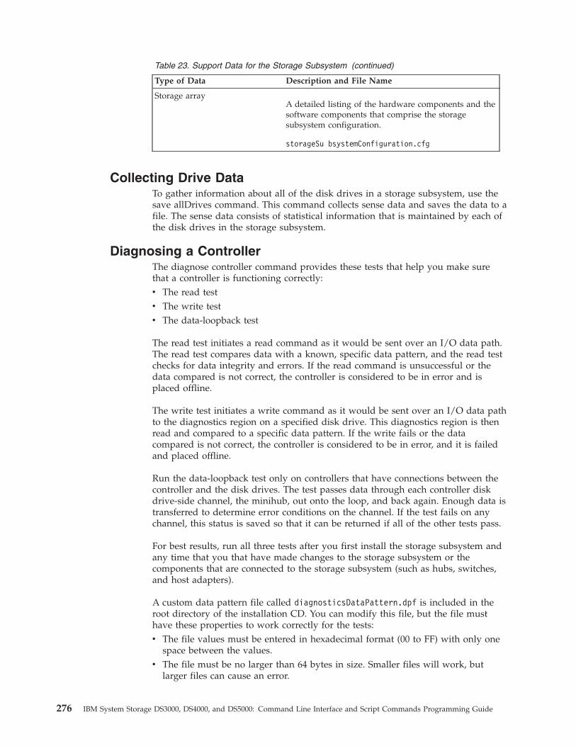
Table 23. Support Data for the Storage Subsystem (continued)
Type of Data Description and File Name
Storage arrayA detailed listing of the hardware components and thesoftware components that comprise the storagesubsystem configuration.
storageSu bsystemConfiguration.cfg
Collecting Drive DataTo gather information about all of the disk drives in a storage subsystem, use thesave allDrives command. This command collects sense data and saves the data to afile. The sense data consists of statistical information that is maintained by each ofthe disk drives in the storage subsystem.
Diagnosing a ControllerThe diagnose controller command provides these tests that help you make surethat a controller is functioning correctly:v The read testv The write testv The data-loopback test
The read test initiates a read command as it would be sent over an I/O data path.The read test compares data with a known, specific data pattern, and the read testchecks for data integrity and errors. If the read command is unsuccessful or thedata compared is not correct, the controller is considered to be in error and isplaced offline.
The write test initiates a write command as it would be sent over an I/O data pathto the diagnostics region on a specified disk drive. This diagnostics region is thenread and compared to a specific data pattern. If the write fails or the datacompared is not correct, the controller is considered to be in error, and it is failedand placed offline.
Run the data-loopback test only on controllers that have connections between thecontroller and the disk drives. The test passes data through each controller diskdrive-side channel, the minihub, out onto the loop, and back again. Enough data istransferred to determine error conditions on the channel. If the test fails on anychannel, this status is saved so that it can be returned if all of the other tests pass.
For best results, run all three tests after you first install the storage subsystem andany time that you that have made changes to the storage subsystem or thecomponents that are connected to the storage subsystem (such as hubs, switches,and host adapters).
A custom data pattern file called diagnosticsDataPattern.dpf is included in theroot directory of the installation CD. You can modify this file, but the file musthave these properties to work correctly for the tests:v The file values must be entered in hexadecimal format (00 to FF) with only one
space between the values.v The file must be no larger than 64 bytes in size. Smaller files will work, but
larger files can cause an error.
276 IBM System Storage DS3000, DS4000, and DS5000: Command Line Interface and Script Commands Programming Guide
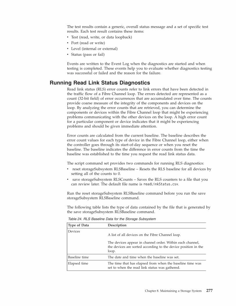
The test results contain a generic, overall status message and a set of specific testresults. Each test result contains these items:v Test (read, write, or data loopback)v Port (read or write)v Level (internal or external)v Status (pass or fail)
Events are written to the Event Log when the diagnostics are started and whentesting is completed. These events help you to evaluate whether diagnostics testingwas successful or failed and the reason for the failure.
Running Read Link Status DiagnosticsRead link status (RLS) error counts refer to link errors that have been detected inthe traffic flow of a Fibre Channel loop. The errors detected are represented as acount (32-bit field) of error occurrences that are accumulated over time. The countsprovide coarse measure of the integrity of the components and devices on theloop. By analyzing the error counts that are retrieved, you can determine thecomponents or devices within the Fibre Channel loop that might be experiencingproblems communicating with the other devices on the loop. A high error countfor a particular component or device indicates that it might be experiencingproblems and should be given immediate attention.
Error counts are calculated from the current baseline. The baseline describes theerror count values for each type of device in the Fibre Channel loop, either whenthe controller goes through its start-of-day sequence or when you reset thebaseline. The baseline indicates the difference in error counts from the time thebaseline was established to the time you request the read link status data.
The script command set provides two commands for running RLS diagnostics:v reset storageSubsystem RLSBaseline – Resets the RLS baseline for all devices by
setting all of the counts to 0.v save storageSubsystem RLSCounts – Saves the RLS counters to a file that you
can review later. The default file name is readLinkStatus.csv.
Run the reset storageSubsystem RLSBaseline command before you run the savestorageSubsystem RLSBaseline command.
The following table lists the type of data contained by the file that is generated bythe save storageSubsystem RLSBaseline command.
Table 24. RLS Baseline Data for the Storage Subsystem
Type of Data Description
DevicesA list of all devices on the Fibre Channel loop.
The devices appear in channel order. Within each channel,the devices are sorted according to the device position in theloop.
Baseline time The date and time when the baseline was set.
Elapsed time The time that has elapsed from when the baseline time wasset to when the read link status was gathered.
Chapter 8. Maintaining a Storage System 277
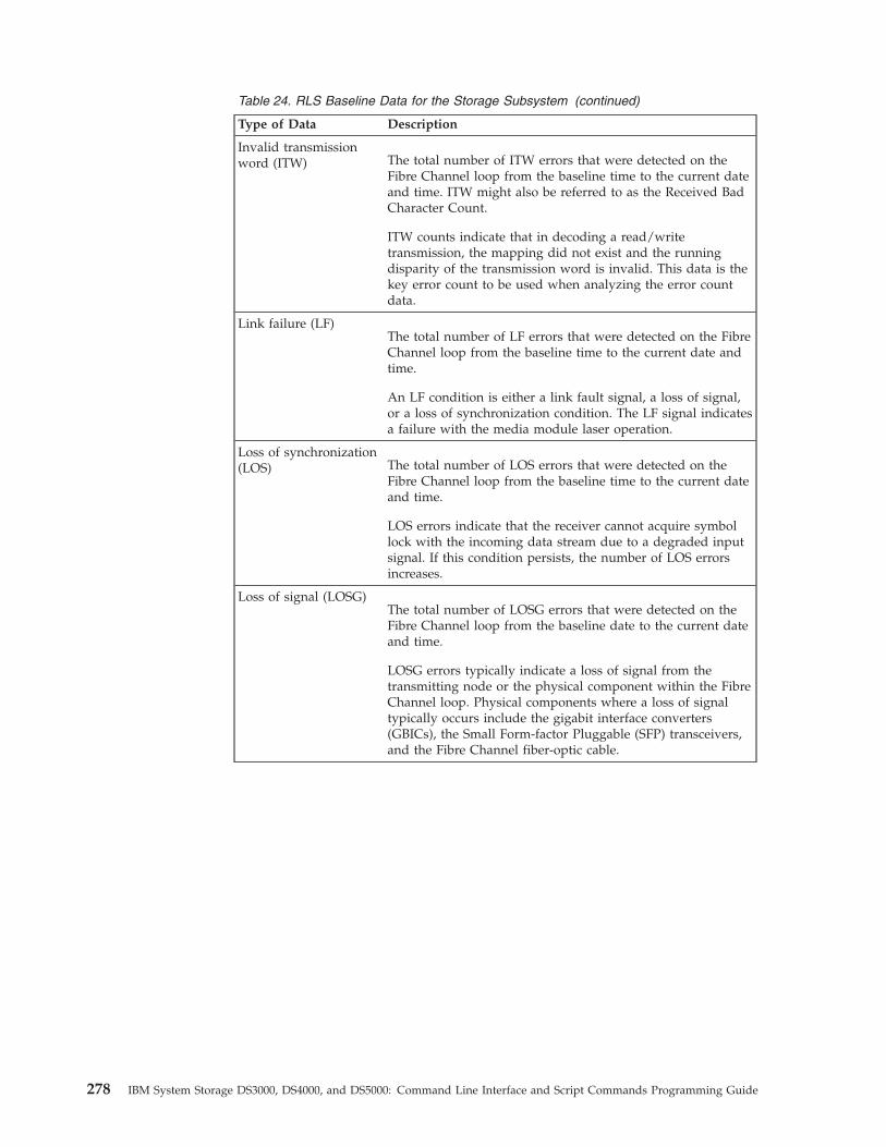
Table 24. RLS Baseline Data for the Storage Subsystem (continued)
Type of Data Description
Invalid transmissionword (ITW) The total number of ITW errors that were detected on the
Fibre Channel loop from the baseline time to the current dateand time. ITW might also be referred to as the Received BadCharacter Count.
ITW counts indicate that in decoding a read/writetransmission, the mapping did not exist and the runningdisparity of the transmission word is invalid. This data is thekey error count to be used when analyzing the error countdata.
Link failure (LF)The total number of LF errors that were detected on the FibreChannel loop from the baseline time to the current date andtime.
An LF condition is either a link fault signal, a loss of signal,or a loss of synchronization condition. The LF signal indicatesa failure with the media module laser operation.
Loss of synchronization(LOS) The total number of LOS errors that were detected on the
Fibre Channel loop from the baseline time to the current dateand time.
LOS errors indicate that the receiver cannot acquire symbollock with the incoming data stream due to a degraded inputsignal. If this condition persists, the number of LOS errorsincreases.
Loss of signal (LOSG)The total number of LOSG errors that were detected on theFibre Channel loop from the baseline date to the current dateand time.
LOSG errors typically indicate a loss of signal from thetransmitting node or the physical component within the FibreChannel loop. Physical components where a loss of signaltypically occurs include the gigabit interface converters(GBICs), the Small Form-factor Pluggable (SFP) transceivers,and the Fibre Channel fiber-optic cable.
278 IBM System Storage DS3000, DS4000, and DS5000: Command Line Interface and Script Commands Programming Guide
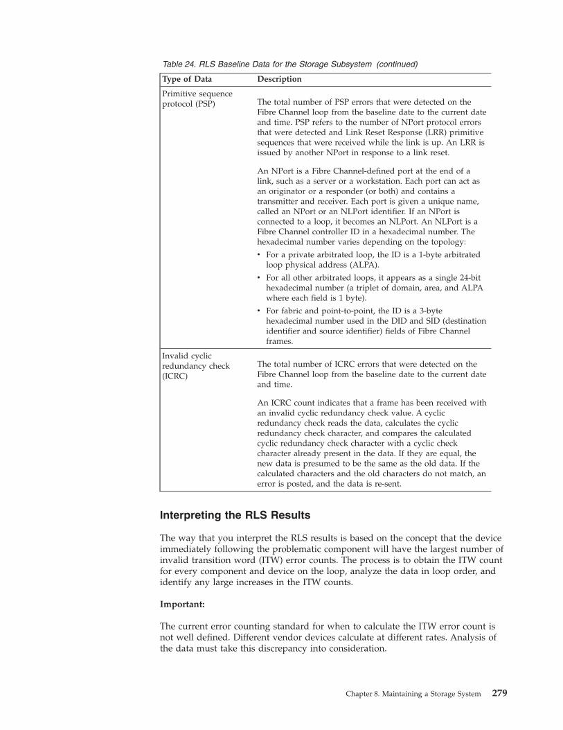
Table 24. RLS Baseline Data for the Storage Subsystem (continued)
Type of Data Description
Primitive sequenceprotocol (PSP) The total number of PSP errors that were detected on the
Fibre Channel loop from the baseline date to the current dateand time. PSP refers to the number of NPort protocol errorsthat were detected and Link Reset Response (LRR) primitivesequences that were received while the link is up. An LRR isissued by another NPort in response to a link reset.
An NPort is a Fibre Channel-defined port at the end of alink, such as a server or a workstation. Each port can act asan originator or a responder (or both) and contains atransmitter and receiver. Each port is given a unique name,called an NPort or an NLPort identifier. If an NPort isconnected to a loop, it becomes an NLPort. An NLPort is aFibre Channel controller ID in a hexadecimal number. Thehexadecimal number varies depending on the topology:
v For a private arbitrated loop, the ID is a 1-byte arbitratedloop physical address (ALPA).
v For all other arbitrated loops, it appears as a single 24-bithexadecimal number (a triplet of domain, area, and ALPAwhere each field is 1 byte).
v For fabric and point-to-point, the ID is a 3-bytehexadecimal number used in the DID and SID (destinationidentifier and source identifier) fields of Fibre Channelframes.
Invalid cyclicredundancy check(ICRC)
The total number of ICRC errors that were detected on theFibre Channel loop from the baseline date to the current dateand time.
An ICRC count indicates that a frame has been received withan invalid cyclic redundancy check value. A cyclicredundancy check reads the data, calculates the cyclicredundancy check character, and compares the calculatedcyclic redundancy check character with a cyclic checkcharacter already present in the data. If they are equal, thenew data is presumed to be the same as the old data. If thecalculated characters and the old characters do not match, anerror is posted, and the data is re-sent.
Interpreting the RLS Results
The way that you interpret the RLS results is based on the concept that the deviceimmediately following the problematic component will have the largest number ofinvalid transition word (ITW) error counts. The process is to obtain the ITW countfor every component and device on the loop, analyze the data in loop order, andidentify any large increases in the ITW counts.
Important:
The current error counting standard for when to calculate the ITW error count isnot well defined. Different vendor devices calculate at different rates. Analysis ofthe data must take this discrepancy into consideration.
Chapter 8. Maintaining a Storage System 279
Collecting Switch-on-a-Chip Error StatisticsSwitch-on-a-chip (SOC) error statistics provide information about the loop-switchports that are connected to the Fibre Channel devices in a storage subsystem. (RLScounts provide information about the Fibre Channel devices.) Reporting SOC errorstatistics is available only on storage subsystems that have SOC loop-switchdevices that are incorporated into the controller disk drive channel or the ESMcircuitry. SOC devices are integrated circuits that join together Fibre Channeldevices in arbitrated loop topologies. SOC devices automatically collect statisticalinformation for each SOC port that is connected to a controller port, an ESM port,a disk drive port, or an expansion connector. A Customer and Technical Supportrepresentative can use the statistical information with RLS counts to identifyproblems with Fibre Channel devices that are attached to the loop.
SOC error statics include this information:v The port statev The port insertion countv The loop statev The loop up countv The CRC error countv The relative frequency drift error averagev The loop cycle countv The operating system (OS) error countv The port connections attempted countv The port connections held off countv The port utilization
The method for collecting error statistics starts by establishing a baseline for theSOC error statistics. The baseline consists of SOC error statistics that areestablished at a set time for each SOC device on the loop. The baseline is set byclearing the error counters in each SOC device. You can set a device baseline byperforming one of these actions:v Turning on the power to the device or resetting the devicev Running the reset storageSubsystem SOCBaseline command
In addition, each controller also initializes the SOC error counters in all of theexpansion drawers that are attached to the controller following a cold boot(power-on or hot insertion). If you add a expansion drawer while the power isturned on to the storage subsystem, a new baseline is established for any device onthe expansion drawer.
After you have established the baseline for the SOC devices, you run the storagesubsystem for a predetermined amount of time (for example, two hours). At theend of the run time, you collect the SOC error statistics by saving the informationto a file. To save the information, run the save storageSubsystem SOCCounts filefilename command. The default name of the file that contains the SOC errorstatistics is socStatistics.csv. You can use any file name that has the .csvextension.
Analyzing the SOC error statistics is beyond the scope of normal storagesubsystem management. After you have collected the SOC error statistics in a file,send the file to a Customer and Technical Support representative.
280 IBM System Storage DS3000, DS4000, and DS5000: Command Line Interface and Script Commands Programming Guide
Recovery OperationsRecovery operations include repairing the storage subsystem and returning it to anoperational state. This might involve replacing a failed CRU, a failed controller, ora disk drive or restoring data or the storage subsystem to operation. Forinformation about when it is appropriate to replace a CRU, see “RoutineMaintenance” on page 267.
Setting the Controller Operational ModeA controller has three operational modes:v Onlinev Offlinev Service
Placing a controller online sets it to the Optimal state and makes it active andavailable for I/O operations. Placing a controller offline makes it unavailable forI/O operations and moves its arrays to the other controller if failover protection isenabled.
Taking a controller offline can seriously impact data integrity and storagesubsystem operation.v If you do not use write cache mirroring, data in the cache of the controller you
place offline is lost.v If you take a controller offline and you have controller failover protection
through a host multi-path driver, the other controller in the pair takes over.Arrays and their associated logical drives that were assigned to the offlinecontroller are automatically reassigned to the remaining controller. If you do nothave a multi-path driver installed on the application host and you take acontroller offline while the application is using associated logical drives,application errors will occur.
Attention: Possible loss of data access – Placing a controller offline can causeloss of data.
Use Service mode to replace CRUs, such as a controller. Placing a controller inService mode makes it unavailable for I/O operations and moves its arrays to thesecond controller without affecting the preferred path of the array. This actionmight significantly reduce performance. The arrays are automatically transferredback to the preferred controller when it is placed back online.
If you change a controller to Service mode while an application is using theassociated logical drives on the controller, the change causes I/O errors unless amulti-path driver is installed on the host. Before you place a controller in Servicemode, make sure that the logical drives are not in use, or a multi-path driver isinstalled on all of the hosts that are using these logical drives.
In addition, if you do not have a multi-path driver, you must make appropriateoperating system-specific modifications to make sure that the arrays moved areaccessed on the new path when you change to Service mode.
Important: Place a controller in Service mode only under the direction of aCustomer and Technical Support representative.
To change the operational mode of a controller, use this command:
Chapter 8. Maintaining a Storage System 281
set controller [(a | b)] availability=(online | offline | serviceMode)
Changing the Controller OwnershipYou can change which controller is the owner of a logical drive by using the setlogical drive command. The command takes this form:set(allLogicalDrives|logicalDrive [logicalDriveName]|logicalDrives[logicalDriveName1...logicalDriveNameN]
|logicalDrive <wwID>)owner=(a|b)
Initializing a DriveAttention: Possible loss of data access – When you initialize a disk drive, alldata on the disk drive is lost.
You must initialize a disk drive when you have moved a disk drive that waspreviously part of a multidisk array from one storage subsystem to another. If youdo not move the entire set of disk drives, the array information and the logicaldrive information on the disk drives that you move are incomplete. Each diskdrive that you move contains only part of the information that is defined for thelogical drive and the array. To be able to reuse the disk drives to create a newarray and logical drive, you must delete all of the old information from the diskdrives by initializing the disk drive.
When you initialize a disk drive, all of the old array information and logical driveinformation are deleted, and the disk drive is returned to an unassigned state.Returning a disk drive to an unassigned state adds unconfigured capacity to astorage subsystem. You can use this capacity to create additional arrays and logicaldrives.
To initialize a disk drive, use this command:start drive [enclosureID,slotID] initialize
where enclosureID and slotID are the identifiers for the disk drive.
Reconstructing a DriveIf two or more of the disk drives in a array have failed, the logical drive shows astatus of Failed. All of the logical drives in the array are no longer operating. Toreturn the array to an Optimal status, you must replace the failed disk drives.Then, you must reconstruct the data on the new disk drives. The data that youreconstruct is the data as it would appear on the failed disk drives.
Important: You can use this command only when the disk drive is assigned to aRAID 1, RAID 3, RAID 5, or RAID 6 array.
To reconstruct a disk drive, use this command:start drive [enclosureID,slotID] reconstruct
where enclosureID and slotID are the identifiers for the disk drive.
Initializing a Logical DriveAttention: Possible loss of data – When you initialize a logical drive, all existingdata on the logical drive and all of the information about the logical drive aredestroyed. Do not use this command unless you want to destroy all the data in thegiven disk drive.
282 IBM System Storage DS3000, DS4000, and DS5000: Command Line Interface and Script Commands Programming Guide
A logical drive is automatically initialized when you first create it. If the logicaldrive starts showing failures, you might be required to re-initialize the logical driveto correct the failure condition.
Consider these restrictions when you initialize a logical drive:v You cannot cancel the operation after it begins.v You cannot use this option if any modification operations are in progress on the
logical drive or the array.v You cannot change the cache parameters of the logical drive while the
initialization operation is in progress.
To initialize a logical drive, use this command:start logicalDrive [logicalDriveName] initialize
where logicalDriveName is the identifier for the logical drive.
Redistributing Logical DrivesWhen you redistribute logical drives, you return the logical drives to theirpreferred controller owners. The preferred controller ownership of a logical driveor a array is the controller of an active-active pair that is designated to own thelogical drives. The preferred owner for a logical drive is initially designated whenthe logical drive is created. If the preferred controller is being replaced orundergoing a firmware download, ownership of the logical drives is automaticallyshifted to the other controller. That controller becomes the current owner of thelogical drives. This change is considered to be a routine ownership change and isreported in the Event Log.
To redistribute logical drives to their preferred controllers, use this command:reset storageSubsystem logicalDriveDistribution
Important: If you run this command without a multi-path driver on the hosts,stop I/O activity to the logical drives to prevent application errors.
Important: You cannot run this command if all of the logical drives are currentlyowned by their preferred controller, or the storage subsystem does not havedefined logical drives.
Under some host operating systems, you must reconfigure the multi-path hostdriver. You might also need to make operating system modifications to recognizethe new I/O path to the logical drive.
Replacing CRUsThe DS3950, DS3000, DS4000, DS5000, and DS5020 controller module components,such as the controller CRUs, the power-fan CRUs, and the interconnect-batteryCRUs, have a Service Action Allowed (SAA) indicator light. This indicator light isa blue LED. The Service Action Allowed indicator light helps to make sure thatyou do not remove a CRU before it is safe to do so.
Attention: Possible loss of data access – Never remove a component that has aService Action Required indicator light on unless the Service Action Allowed(SAA) indicator light is on.
If a component fails and must be replaced, the Service Action Required indicatorlight on that CRU comes on to indicate that service action is required, provided no
Chapter 8. Maintaining a Storage System 283
data availability dependencies or other conditions exist that dictate the CRUshould not be removed. The Service Action Allowed indicator light automaticallycomes on or goes off when conditions change. In most cases, the Service ActionAllowed indicator light comes on steadily when the Service Action Requiredindicator light comes on for the CRU.
If the interconnect-battery CRU must be replaced, the Service Action Allowedindicator light does not come on automatically. Before the Service Action Allowedindicator light on the interconnect-battery CRU can come on, you must placecontroller CRU in slot B into Service mode. This action routes all control and I/Oactivity through one controller to help make sure that data access is maintainedwhile the interconnect-battery CRU is removed. The Service Action Allowedindicator light comes on after the new CRU has been installed.
The ability to remove a CRU depends on the data availability dependencies of thecontroller module or the controller module. The Service Action Allowed indicatorlight does not come on if removing a CRU jeopardizes data on the expansiondrawers or current I/O activity. An example of limiting when you can remove aCRU is when one controller CRU has a Service Action Required indicator light on.You cannot remove the other controller CRU (the Service Action Allowed indicatorlight does not come on), because doing so would jeopardize the data either on theexpansion drawers or transitioning through the controllers.
A less obvious example, as in the DS4800 storage subsystem, is when the powersupply for the controller CRU in slot A has failed, and the controller CRU in slot Bhas failed. Removing the controller CRU in slot B before replacing the failedpower-fan CRU causes the controller CRU in slot A to lose power, which results ina loss of data access. This action occurs because power distribution from eachpower-fan CRU is through the controller CRU that is physically connected to thatpower-fan CRU.
So, in the preceding example, these actions occur:v The power-fan CRU has both its Service Action Required indicator light and its
Service Action Allowed indicator light on.v The controller CRU in slot B has only its Service Action Required indicator light
on, but its Service Action Allowed indicator light is off.v After the failed power-fan CRU has been replaced, the Service Action Allowed
indicator light comes on for the controller CRU in slot B.
For more information about the Service Action Not Allowed indicator, please seethe IBM System Storage DSxxxx Storage Subsystem Installation, User's and MaintenanceGuide for your storage subsystem product.
284 IBM System Storage DS3000, DS4000, and DS5000: Command Line Interface and Script Commands Programming Guide
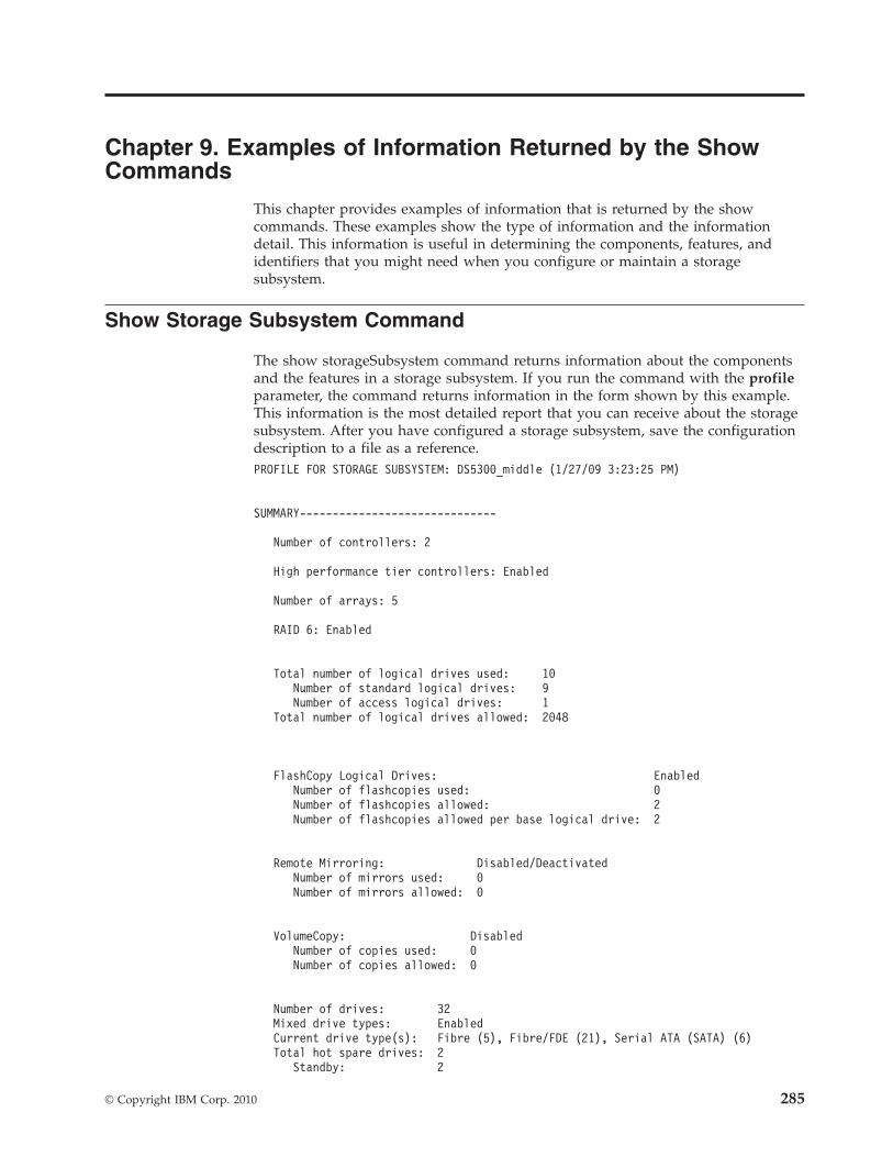
Chapter 9. Examples of Information Returned by the ShowCommands
This chapter provides examples of information that is returned by the showcommands. These examples show the type of information and the informationdetail. This information is useful in determining the components, features, andidentifiers that you might need when you configure or maintain a storagesubsystem.
Show Storage Subsystem Command
The show storageSubsystem command returns information about the componentsand the features in a storage subsystem. If you run the command with the profileparameter, the command returns information in the form shown by this example.This information is the most detailed report that you can receive about the storagesubsystem. After you have configured a storage subsystem, save the configurationdescription to a file as a reference.PROFILE FOR STORAGE SUBSYSTEM: DS5300_middle (1/27/09 3:23:25 PM)
SUMMARY------------------------------
Number of controllers: 2
High performance tier controllers: Enabled
Number of arrays: 5
RAID 6: Enabled
Total number of logical drives used: 10Number of standard logical drives: 9Number of access logical drives: 1
Total number of logical drives allowed: 2048
FlashCopy Logical Drives: EnabledNumber of flashcopies used: 0Number of flashcopies allowed: 2Number of flashcopies allowed per base logical drive: 2
Remote Mirroring: Disabled/DeactivatedNumber of mirrors used: 0Number of mirrors allowed: 0
VolumeCopy: DisabledNumber of copies used: 0Number of copies allowed: 0
Number of drives: 32Mixed drive types: EnabledCurrent drive type(s): Fibre (5), Fibre/FDE (21), Serial ATA (SATA) (6)Total hot spare drives: 2
Standby: 2
© Copyright IBM Corp. 2010 285
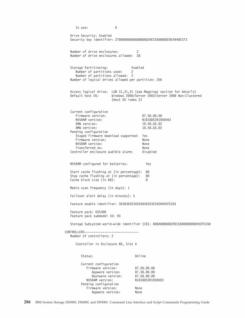
In use: 0
Drive Security: EnabledSecurity key identifier: 27000000600A0B800029ECE60000DE9E4940E373
Number of drive enclosures: 2Number of drive enclosures allowed: 28
Storage Partitioning: EnabledNumber of partitions used: 2Number of partitions allowed: 2
Number of logical drives allowed per partition: 256
Access logical drive: LUN 31,31,31 (see Mappings section for details)Default host OS: Windows 2000/Server 2003/Server 2008 Non-Clustered
(Host OS index 2)
Current configurationFirmware version: 07.50.00.00NVSRAM version: N1818D53R1050V03EMW version: 10.50.G5.02AMW version: 10.50.G5.02
Pending configurationStaged firmware download supported: YesFirmware version: NoneNVSRAM version: NoneTransferred on: None
Controller enclosure audible alarm: Disabled
NVSRAM configured for batteries: Yes
Start cache flushing at (in percentage): 80Stop cache flushing at (in percentage): 80Cache block size (in KB): 8
Media scan frequency (in days): 1
Failover alert delay (in minutes): 5
Feature enable identifier: 303030323420303035353420493FECB1
Feature pack: DS5300Feature pack submodel ID: 93
Storage Subsystem world-wide identifier (ID): 600A0B800029ECE600000000493FECAB
CONTROLLERS------------------------------Number of controllers: 2
Controller in Enclosure 85, Slot A
Status: Online
Current configurationFirmware version: 07.50.00.00
Appware version: 07.50.00.00Bootware version: 07.50.00.00
NVSRAM version: N1818D53R1050V03Pending configuration
Firmware version: NoneAppware version: None
286 IBM System Storage DS3000, DS4000, and DS5000: Command Line Interface and Script Commands Programming Guide
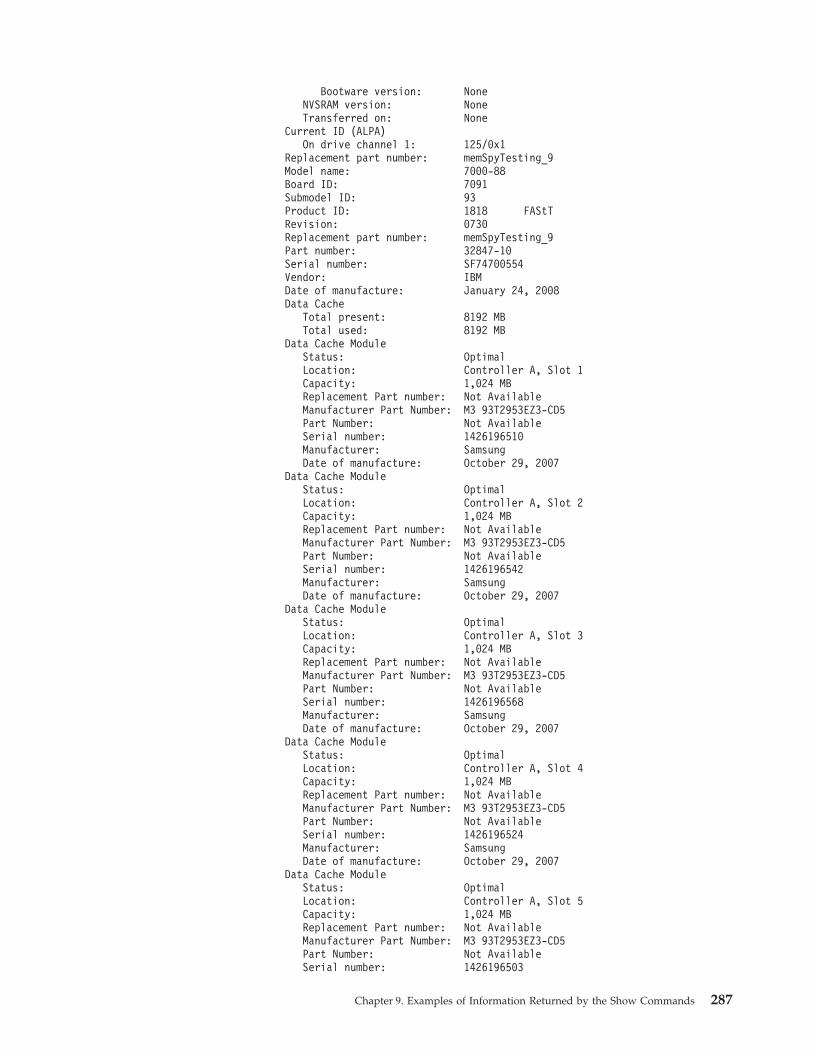
Bootware version: NoneNVSRAM version: NoneTransferred on: None
Current ID (ALPA)On drive channel 1: 125/0x1
Replacement part number: memSpyTesting_9Model name: 7000-88Board ID: 7091Submodel ID: 93Product ID: 1818 FAStTRevision: 0730Replacement part number: memSpyTesting_9Part number: 32847-10Serial number: SF74700554Vendor: IBMDate of manufacture: January 24, 2008Data Cache
Total present: 8192 MBTotal used: 8192 MB
Data Cache ModuleStatus: OptimalLocation: Controller A, Slot 1Capacity: 1,024 MBReplacement Part number: Not AvailableManufacturer Part Number: M3 93T2953EZ3-CD5Part Number: Not AvailableSerial number: 1426196510Manufacturer: SamsungDate of manufacture: October 29, 2007
Data Cache ModuleStatus: OptimalLocation: Controller A, Slot 2Capacity: 1,024 MBReplacement Part number: Not AvailableManufacturer Part Number: M3 93T2953EZ3-CD5Part Number: Not AvailableSerial number: 1426196542Manufacturer: SamsungDate of manufacture: October 29, 2007
Data Cache ModuleStatus: OptimalLocation: Controller A, Slot 3Capacity: 1,024 MBReplacement Part number: Not AvailableManufacturer Part Number: M3 93T2953EZ3-CD5Part Number: Not AvailableSerial number: 1426196568Manufacturer: SamsungDate of manufacture: October 29, 2007
Data Cache ModuleStatus: OptimalLocation: Controller A, Slot 4Capacity: 1,024 MBReplacement Part number: Not AvailableManufacturer Part Number: M3 93T2953EZ3-CD5Part Number: Not AvailableSerial number: 1426196524Manufacturer: SamsungDate of manufacture: October 29, 2007
Data Cache ModuleStatus: OptimalLocation: Controller A, Slot 5Capacity: 1,024 MBReplacement Part number: Not AvailableManufacturer Part Number: M3 93T2953EZ3-CD5Part Number: Not AvailableSerial number: 1426196503
Chapter 9. Examples of Information Returned by the Show Commands 287
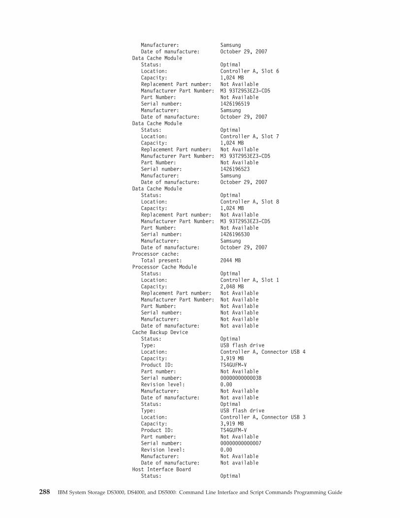
Manufacturer: SamsungDate of manufacture: October 29, 2007
Data Cache ModuleStatus: OptimalLocation: Controller A, Slot 6Capacity: 1,024 MBReplacement Part number: Not AvailableManufacturer Part Number: M3 93T2953EZ3-CD5Part Number: Not AvailableSerial number: 1426196519Manufacturer: SamsungDate of manufacture: October 29, 2007
Data Cache ModuleStatus: OptimalLocation: Controller A, Slot 7Capacity: 1,024 MBReplacement Part number: Not AvailableManufacturer Part Number: M3 93T2953EZ3-CD5Part Number: Not AvailableSerial number: 1426196523Manufacturer: SamsungDate of manufacture: October 29, 2007
Data Cache ModuleStatus: OptimalLocation: Controller A, Slot 8Capacity: 1,024 MBReplacement Part number: Not AvailableManufacturer Part Number: M3 93T2953EZ3-CD5Part Number: Not AvailableSerial number: 1426196530Manufacturer: SamsungDate of manufacture: October 29, 2007
Processor cache:Total present: 2044 MB
Processor Cache ModuleStatus: OptimalLocation: Controller A, Slot 1Capacity: 2,048 MBReplacement Part number: Not AvailableManufacturer Part Number: Not AvailablePart Number: Not AvailableSerial number: Not AvailableManufacturer: Not AvailableDate of manufacture: Not available
Cache Backup DeviceStatus: OptimalType: USB flash driveLocation: Controller A, Connector USB 4Capacity: 3,919 MBProduct ID: TS4GUFM-VPart number: Not AvailableSerial number: 0000000000003BRevision level: 0.00Manufacturer: Not AvailableDate of manufacture: Not availableStatus: OptimalType: USB flash driveLocation: Controller A, Connector USB 3Capacity: 3,919 MBProduct ID: TS4GUFM-VPart number: Not AvailableSerial number: 00000000000007Revision level: 0.00Manufacturer: Not AvailableDate of manufacture: Not available
Host Interface BoardStatus: Optimal
288 IBM System Storage DS3000, DS4000, and DS5000: Command Line Interface and Script Commands Programming Guide
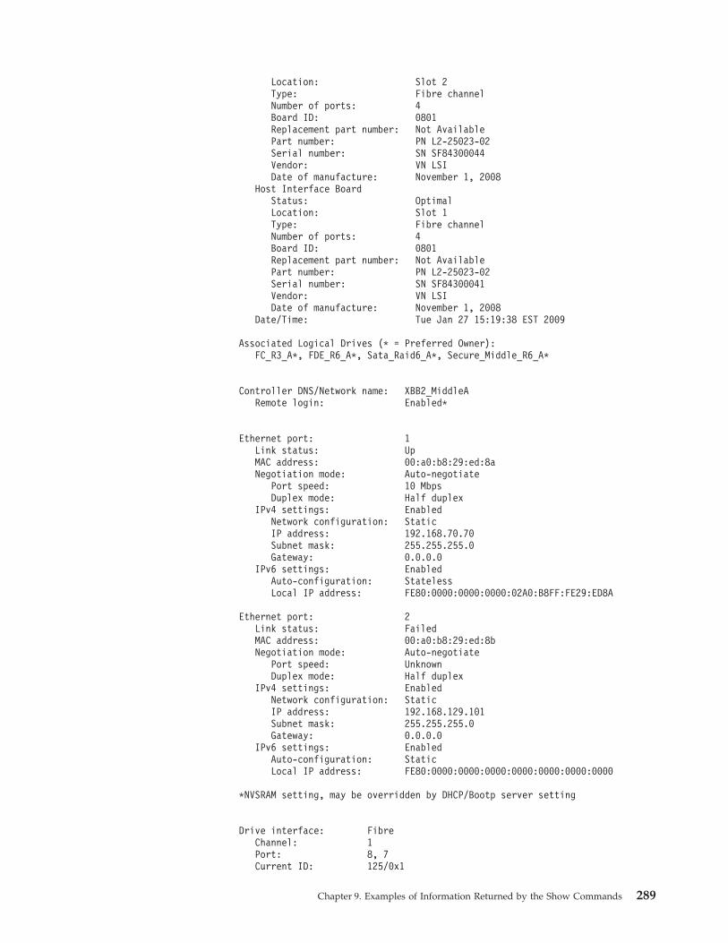
Location: Slot 2Type: Fibre channelNumber of ports: 4Board ID: 0801Replacement part number: Not AvailablePart number: PN L2-25023-02Serial number: SN SF84300044Vendor: VN LSIDate of manufacture: November 1, 2008
Host Interface BoardStatus: OptimalLocation: Slot 1Type: Fibre channelNumber of ports: 4Board ID: 0801Replacement part number: Not AvailablePart number: PN L2-25023-02Serial number: SN SF84300041Vendor: VN LSIDate of manufacture: November 1, 2008
Date/Time: Tue Jan 27 15:19:38 EST 2009
Associated Logical Drives (* = Preferred Owner):FC_R3_A*, FDE_R6_A*, Sata_Raid6_A*, Secure_Middle_R6_A*
Controller DNS/Network name: XBB2_MiddleARemote login: Enabled*
Ethernet port: 1Link status: UpMAC address: 00:a0:b8:29:ed:8aNegotiation mode: Auto-negotiate
Port speed: 10 MbpsDuplex mode: Half duplex
IPv4 settings: EnabledNetwork configuration: StaticIP address: 192.168.70.70Subnet mask: 255.255.255.0Gateway: 0.0.0.0
IPv6 settings: EnabledAuto-configuration: StatelessLocal IP address: FE80:0000:0000:0000:02A0:B8FF:FE29:ED8A
Ethernet port: 2Link status: FailedMAC address: 00:a0:b8:29:ed:8bNegotiation mode: Auto-negotiate
Port speed: UnknownDuplex mode: Half duplex
IPv4 settings: EnabledNetwork configuration: StaticIP address: 192.168.129.101Subnet mask: 255.255.255.0Gateway: 0.0.0.0
IPv6 settings: EnabledAuto-configuration: StaticLocal IP address: FE80:0000:0000:0000:0000:0000:0000:0000
*NVSRAM setting, may be overridden by DHCP/Bootp server setting
Drive interface: FibreChannel: 1Port: 8, 7Current ID: 125/0x1
Chapter 9. Examples of Information Returned by the Show Commands 289
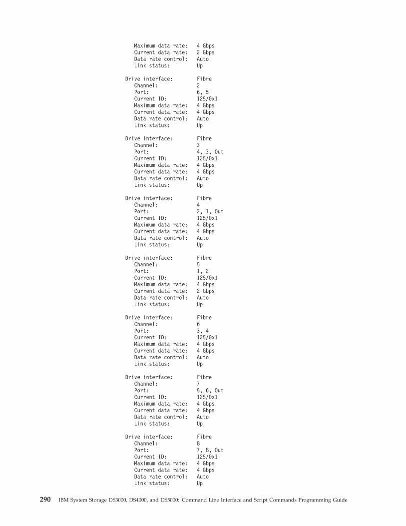
Maximum data rate: 4 GbpsCurrent data rate: 2 GbpsData rate control: AutoLink status: Up
Drive interface: FibreChannel: 2Port: 6, 5Current ID: 125/0x1Maximum data rate: 4 GbpsCurrent data rate: 4 GbpsData rate control: AutoLink status: Up
Drive interface: FibreChannel: 3Port: 4, 3, OutCurrent ID: 125/0x1Maximum data rate: 4 GbpsCurrent data rate: 4 GbpsData rate control: AutoLink status: Up
Drive interface: FibreChannel: 4Port: 2, 1, OutCurrent ID: 125/0x1Maximum data rate: 4 GbpsCurrent data rate: 4 GbpsData rate control: AutoLink status: Up
Drive interface: FibreChannel: 5Port: 1, 2Current ID: 125/0x1Maximum data rate: 4 GbpsCurrent data rate: 2 GbpsData rate control: AutoLink status: Up
Drive interface: FibreChannel: 6Port: 3, 4Current ID: 125/0x1Maximum data rate: 4 GbpsCurrent data rate: 4 GbpsData rate control: AutoLink status: Up
Drive interface: FibreChannel: 7Port: 5, 6, OutCurrent ID: 125/0x1Maximum data rate: 4 GbpsCurrent data rate: 4 GbpsData rate control: AutoLink status: Up
Drive interface: FibreChannel: 8Port: 7, 8, OutCurrent ID: 125/0x1Maximum data rate: 4 GbpsCurrent data rate: 4 GbpsData rate control: AutoLink status: Up
290 IBM System Storage DS3000, DS4000, and DS5000: Command Line Interface and Script Commands Programming Guide
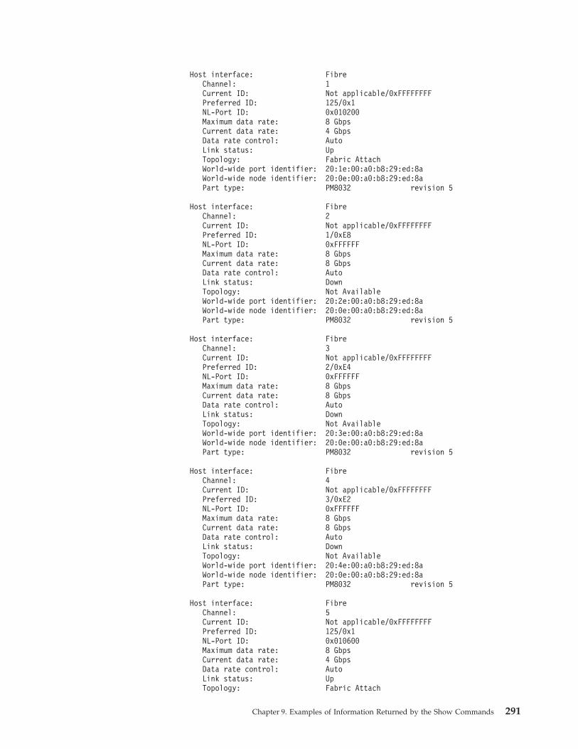
Host interface: FibreChannel: 1Current ID: Not applicable/0xFFFFFFFFPreferred ID: 125/0x1NL-Port ID: 0x010200Maximum data rate: 8 GbpsCurrent data rate: 4 GbpsData rate control: AutoLink status: UpTopology: Fabric AttachWorld-wide port identifier: 20:1e:00:a0:b8:29:ed:8aWorld-wide node identifier: 20:0e:00:a0:b8:29:ed:8aPart type: PM8032 revision 5
Host interface: FibreChannel: 2Current ID: Not applicable/0xFFFFFFFFPreferred ID: 1/0xE8NL-Port ID: 0xFFFFFFMaximum data rate: 8 GbpsCurrent data rate: 8 GbpsData rate control: AutoLink status: DownTopology: Not AvailableWorld-wide port identifier: 20:2e:00:a0:b8:29:ed:8aWorld-wide node identifier: 20:0e:00:a0:b8:29:ed:8aPart type: PM8032 revision 5
Host interface: FibreChannel: 3Current ID: Not applicable/0xFFFFFFFFPreferred ID: 2/0xE4NL-Port ID: 0xFFFFFFMaximum data rate: 8 GbpsCurrent data rate: 8 GbpsData rate control: AutoLink status: DownTopology: Not AvailableWorld-wide port identifier: 20:3e:00:a0:b8:29:ed:8aWorld-wide node identifier: 20:0e:00:a0:b8:29:ed:8aPart type: PM8032 revision 5
Host interface: FibreChannel: 4Current ID: Not applicable/0xFFFFFFFFPreferred ID: 3/0xE2NL-Port ID: 0xFFFFFFMaximum data rate: 8 GbpsCurrent data rate: 8 GbpsData rate control: AutoLink status: DownTopology: Not AvailableWorld-wide port identifier: 20:4e:00:a0:b8:29:ed:8aWorld-wide node identifier: 20:0e:00:a0:b8:29:ed:8aPart type: PM8032 revision 5
Host interface: FibreChannel: 5Current ID: Not applicable/0xFFFFFFFFPreferred ID: 125/0x1NL-Port ID: 0x010600Maximum data rate: 8 GbpsCurrent data rate: 4 GbpsData rate control: AutoLink status: UpTopology: Fabric Attach
Chapter 9. Examples of Information Returned by the Show Commands 291
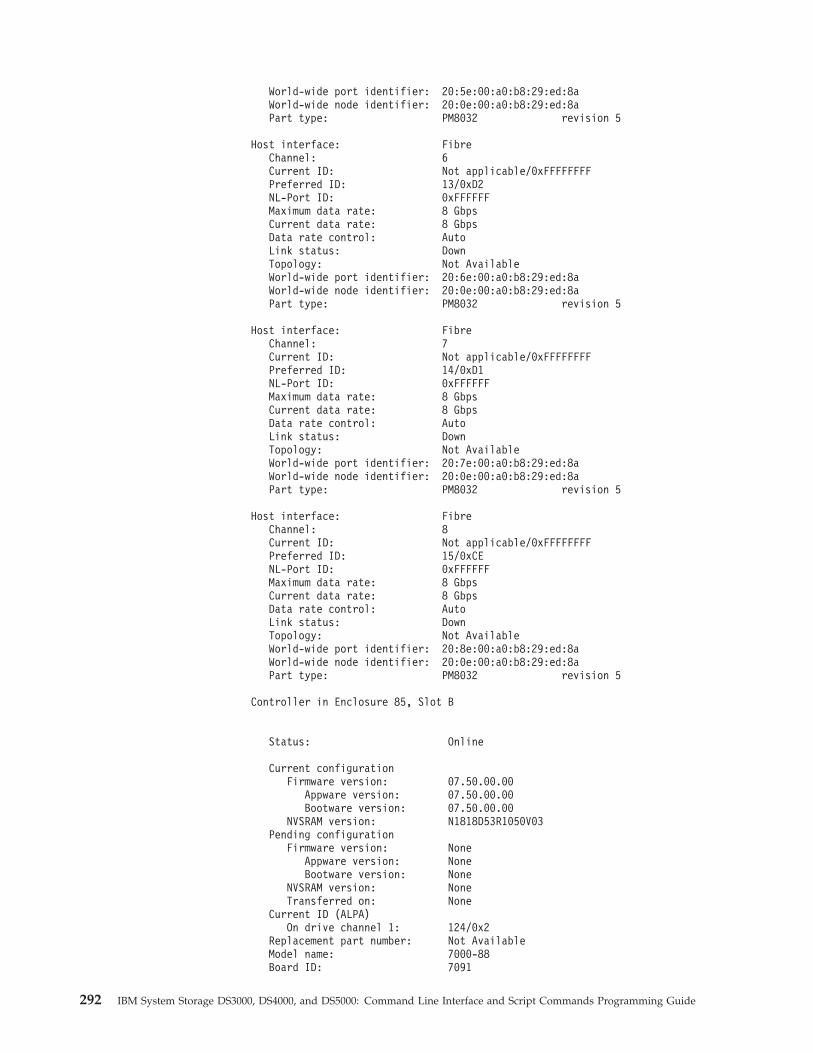
World-wide port identifier: 20:5e:00:a0:b8:29:ed:8aWorld-wide node identifier: 20:0e:00:a0:b8:29:ed:8aPart type: PM8032 revision 5
Host interface: FibreChannel: 6Current ID: Not applicable/0xFFFFFFFFPreferred ID: 13/0xD2NL-Port ID: 0xFFFFFFMaximum data rate: 8 GbpsCurrent data rate: 8 GbpsData rate control: AutoLink status: DownTopology: Not AvailableWorld-wide port identifier: 20:6e:00:a0:b8:29:ed:8aWorld-wide node identifier: 20:0e:00:a0:b8:29:ed:8aPart type: PM8032 revision 5
Host interface: FibreChannel: 7Current ID: Not applicable/0xFFFFFFFFPreferred ID: 14/0xD1NL-Port ID: 0xFFFFFFMaximum data rate: 8 GbpsCurrent data rate: 8 GbpsData rate control: AutoLink status: DownTopology: Not AvailableWorld-wide port identifier: 20:7e:00:a0:b8:29:ed:8aWorld-wide node identifier: 20:0e:00:a0:b8:29:ed:8aPart type: PM8032 revision 5
Host interface: FibreChannel: 8Current ID: Not applicable/0xFFFFFFFFPreferred ID: 15/0xCENL-Port ID: 0xFFFFFFMaximum data rate: 8 GbpsCurrent data rate: 8 GbpsData rate control: AutoLink status: DownTopology: Not AvailableWorld-wide port identifier: 20:8e:00:a0:b8:29:ed:8aWorld-wide node identifier: 20:0e:00:a0:b8:29:ed:8aPart type: PM8032 revision 5
Controller in Enclosure 85, Slot B
Status: Online
Current configurationFirmware version: 07.50.00.00
Appware version: 07.50.00.00Bootware version: 07.50.00.00
NVSRAM version: N1818D53R1050V03Pending configuration
Firmware version: NoneAppware version: NoneBootware version: None
NVSRAM version: NoneTransferred on: None
Current ID (ALPA)On drive channel 1: 124/0x2
Replacement part number: Not AvailableModel name: 7000-88Board ID: 7091
292 IBM System Storage DS3000, DS4000, and DS5000: Command Line Interface and Script Commands Programming Guide
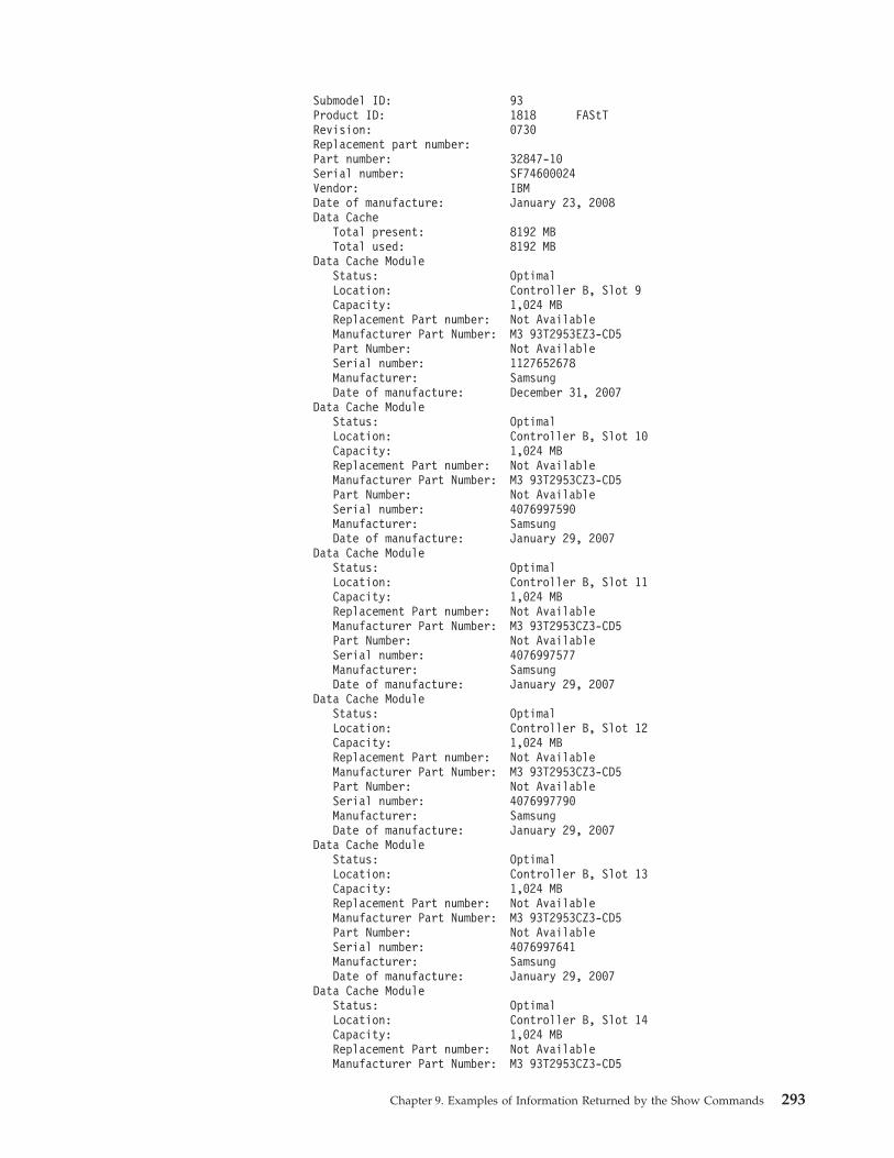
Submodel ID: 93Product ID: 1818 FAStTRevision: 0730Replacement part number:Part number: 32847-10Serial number: SF74600024Vendor: IBMDate of manufacture: January 23, 2008Data Cache
Total present: 8192 MBTotal used: 8192 MB
Data Cache ModuleStatus: OptimalLocation: Controller B, Slot 9Capacity: 1,024 MBReplacement Part number: Not AvailableManufacturer Part Number: M3 93T2953EZ3-CD5Part Number: Not AvailableSerial number: 1127652678Manufacturer: SamsungDate of manufacture: December 31, 2007
Data Cache ModuleStatus: OptimalLocation: Controller B, Slot 10Capacity: 1,024 MBReplacement Part number: Not AvailableManufacturer Part Number: M3 93T2953CZ3-CD5Part Number: Not AvailableSerial number: 4076997590Manufacturer: SamsungDate of manufacture: January 29, 2007
Data Cache ModuleStatus: OptimalLocation: Controller B, Slot 11Capacity: 1,024 MBReplacement Part number: Not AvailableManufacturer Part Number: M3 93T2953CZ3-CD5Part Number: Not AvailableSerial number: 4076997577Manufacturer: SamsungDate of manufacture: January 29, 2007
Data Cache ModuleStatus: OptimalLocation: Controller B, Slot 12Capacity: 1,024 MBReplacement Part number: Not AvailableManufacturer Part Number: M3 93T2953CZ3-CD5Part Number: Not AvailableSerial number: 4076997790Manufacturer: SamsungDate of manufacture: January 29, 2007
Data Cache ModuleStatus: OptimalLocation: Controller B, Slot 13Capacity: 1,024 MBReplacement Part number: Not AvailableManufacturer Part Number: M3 93T2953CZ3-CD5Part Number: Not AvailableSerial number: 4076997641Manufacturer: SamsungDate of manufacture: January 29, 2007
Data Cache ModuleStatus: OptimalLocation: Controller B, Slot 14Capacity: 1,024 MBReplacement Part number: Not AvailableManufacturer Part Number: M3 93T2953CZ3-CD5
Chapter 9. Examples of Information Returned by the Show Commands 293
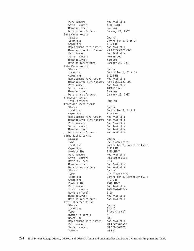
Part Number: Not AvailableSerial number: 4110514102Manufacturer: SamsungDate of manufacture: January 29, 2007
Data Cache ModuleStatus: OptimalLocation: Controller B, Slot 15Capacity: 1,024 MBReplacement Part number: Not AvailableManufacturer Part Number: M3 93T2953CZ3-CD5Part Number: Not AvailableSerial number: 4076997606Manufacturer: SamsungDate of manufacture: January 29, 2007
Data Cache ModuleStatus: OptimalLocation: Controller B, Slot 16Capacity: 1,024 MBReplacement Part number: Not AvailableManufacturer Part Number: M3 93T2953CZ3-CD5Part Number: Not AvailableSerial number: 4076997562Manufacturer: SamsungDate of manufacture: January 29, 2007
Processor cache:Total present: 2044 MB
Processor Cache ModuleStatus: OptimalLocation: Controller B, Slot 2Capacity: 2,048 MBReplacement Part number: Not AvailableManufacturer Part Number: Not AvailablePart Number: Not AvailableSerial number: Not AvailableManufacturer: Not AvailableDate of manufacture: Not available
Cache Backup DeviceStatus: OptimalType: USB flash driveLocation: Controller B, Connector USB 3Capacity: 3,919 MBProduct ID: TS4GUFM-VPart number: Not AvailableSerial number: 00000000000003Revision level: 0.00Manufacturer: Not AvailableDate of manufacture: Not availableStatus: OptimalType: USB flash driveLocation: Controller B, Connector USB 4Capacity: 3,919 MBProduct ID: TS4GUFM-VPart number: Not AvailableSerial number: 00000000000049Revision level: 0.00Manufacturer: Not AvailableDate of manufacture: Not available
Host Interface BoardStatus: OptimalLocation: Slot 3Type: Fibre channelNumber of ports: 4Board ID: 0801Replacement part number: Not AvailablePart number: PN L2-25023-02Serial number: SN SF84300021Vendor: VN LSI
294 IBM System Storage DS3000, DS4000, and DS5000: Command Line Interface and Script Commands Programming Guide
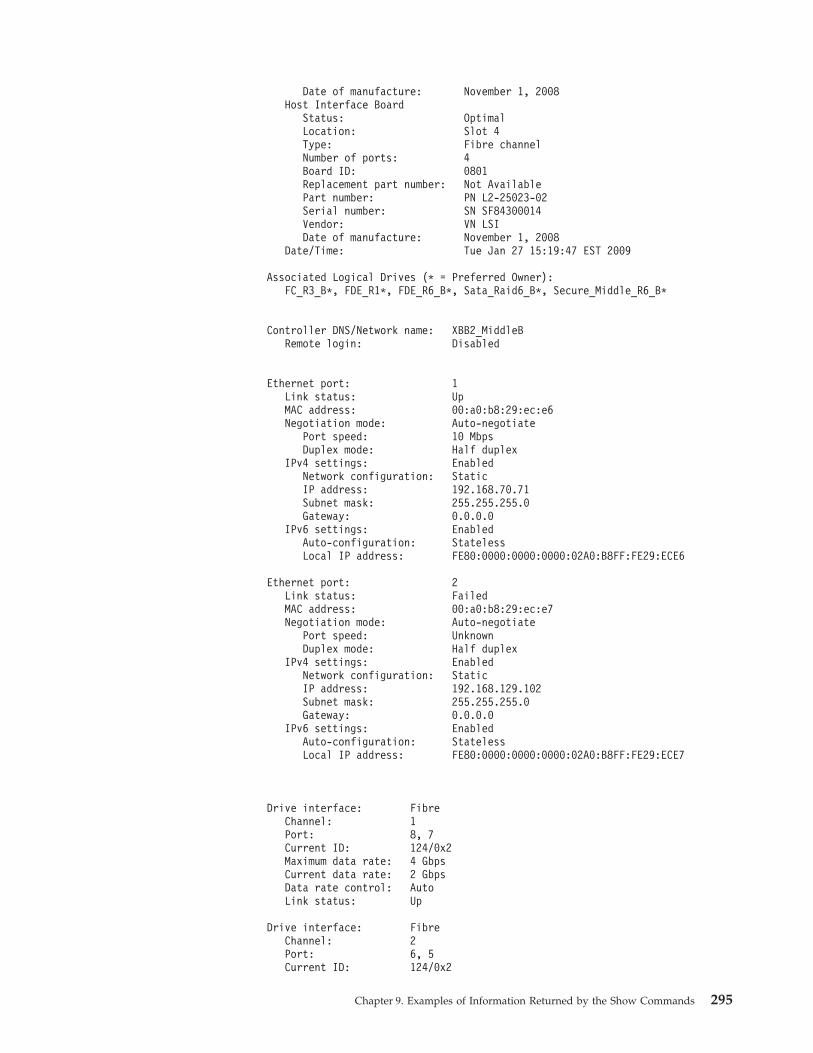
Date of manufacture: November 1, 2008Host Interface Board
Status: OptimalLocation: Slot 4Type: Fibre channelNumber of ports: 4Board ID: 0801Replacement part number: Not AvailablePart number: PN L2-25023-02Serial number: SN SF84300014Vendor: VN LSIDate of manufacture: November 1, 2008
Date/Time: Tue Jan 27 15:19:47 EST 2009
Associated Logical Drives (* = Preferred Owner):FC_R3_B*, FDE_R1*, FDE_R6_B*, Sata_Raid6_B*, Secure_Middle_R6_B*
Controller DNS/Network name: XBB2_MiddleBRemote login: Disabled
Ethernet port: 1Link status: UpMAC address: 00:a0:b8:29:ec:e6Negotiation mode: Auto-negotiate
Port speed: 10 MbpsDuplex mode: Half duplex
IPv4 settings: EnabledNetwork configuration: StaticIP address: 192.168.70.71Subnet mask: 255.255.255.0Gateway: 0.0.0.0
IPv6 settings: EnabledAuto-configuration: StatelessLocal IP address: FE80:0000:0000:0000:02A0:B8FF:FE29:ECE6
Ethernet port: 2Link status: FailedMAC address: 00:a0:b8:29:ec:e7Negotiation mode: Auto-negotiate
Port speed: UnknownDuplex mode: Half duplex
IPv4 settings: EnabledNetwork configuration: StaticIP address: 192.168.129.102Subnet mask: 255.255.255.0Gateway: 0.0.0.0
IPv6 settings: EnabledAuto-configuration: StatelessLocal IP address: FE80:0000:0000:0000:02A0:B8FF:FE29:ECE7
Drive interface: FibreChannel: 1Port: 8, 7Current ID: 124/0x2Maximum data rate: 4 GbpsCurrent data rate: 2 GbpsData rate control: AutoLink status: Up
Drive interface: FibreChannel: 2Port: 6, 5Current ID: 124/0x2
Chapter 9. Examples of Information Returned by the Show Commands 295
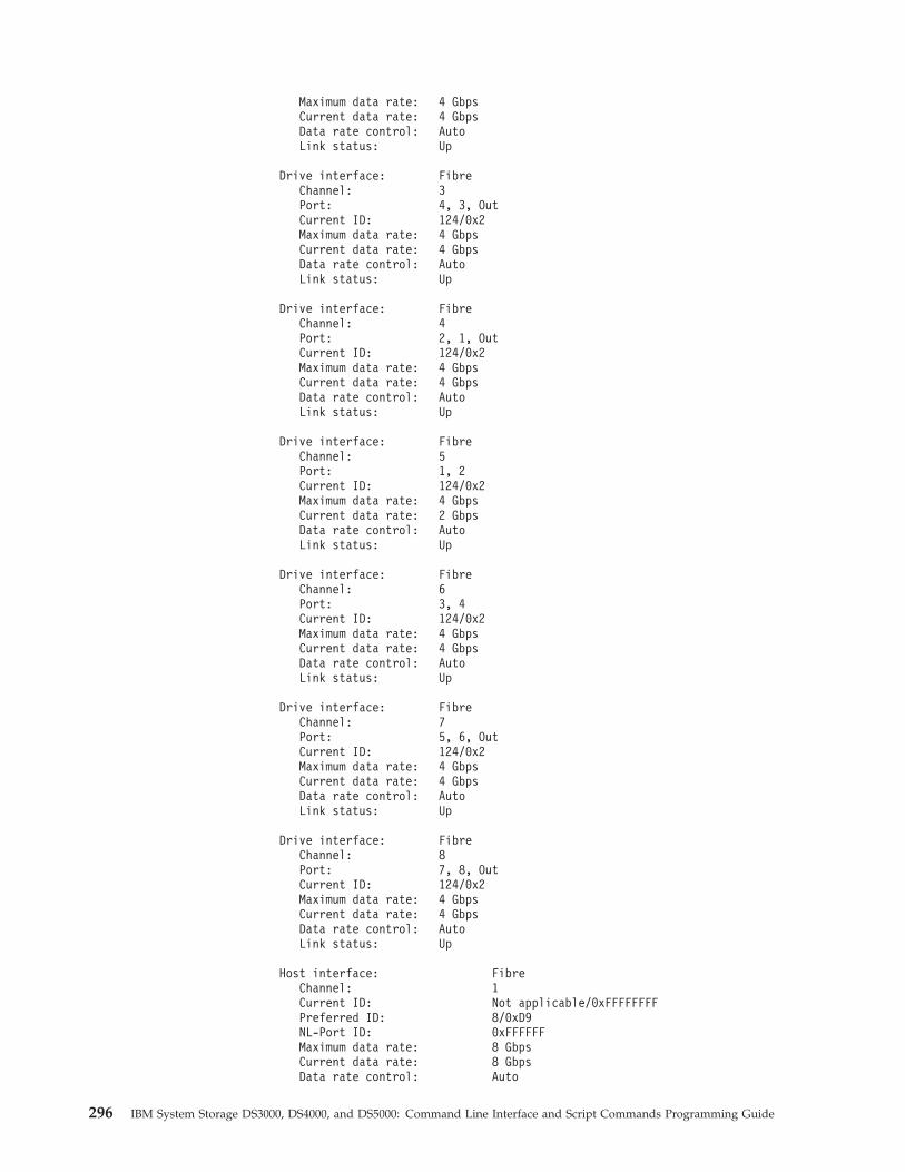
Maximum data rate: 4 GbpsCurrent data rate: 4 GbpsData rate control: AutoLink status: Up
Drive interface: FibreChannel: 3Port: 4, 3, OutCurrent ID: 124/0x2Maximum data rate: 4 GbpsCurrent data rate: 4 GbpsData rate control: AutoLink status: Up
Drive interface: FibreChannel: 4Port: 2, 1, OutCurrent ID: 124/0x2Maximum data rate: 4 GbpsCurrent data rate: 4 GbpsData rate control: AutoLink status: Up
Drive interface: FibreChannel: 5Port: 1, 2Current ID: 124/0x2Maximum data rate: 4 GbpsCurrent data rate: 2 GbpsData rate control: AutoLink status: Up
Drive interface: FibreChannel: 6Port: 3, 4Current ID: 124/0x2Maximum data rate: 4 GbpsCurrent data rate: 4 GbpsData rate control: AutoLink status: Up
Drive interface: FibreChannel: 7Port: 5, 6, OutCurrent ID: 124/0x2Maximum data rate: 4 GbpsCurrent data rate: 4 GbpsData rate control: AutoLink status: Up
Drive interface: FibreChannel: 8Port: 7, 8, OutCurrent ID: 124/0x2Maximum data rate: 4 GbpsCurrent data rate: 4 GbpsData rate control: AutoLink status: Up
Host interface: FibreChannel: 1Current ID: Not applicable/0xFFFFFFFFPreferred ID: 8/0xD9NL-Port ID: 0xFFFFFFMaximum data rate: 8 GbpsCurrent data rate: 8 GbpsData rate control: Auto
296 IBM System Storage DS3000, DS4000, and DS5000: Command Line Interface and Script Commands Programming Guide
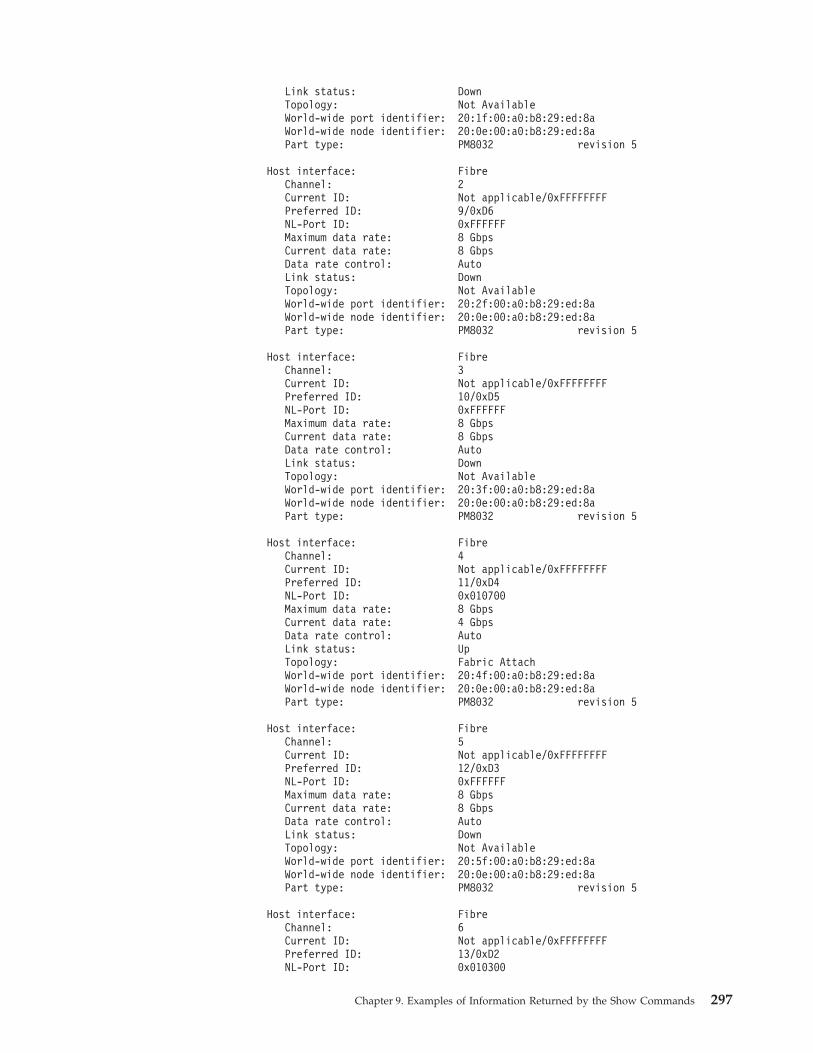
Link status: DownTopology: Not AvailableWorld-wide port identifier: 20:1f:00:a0:b8:29:ed:8aWorld-wide node identifier: 20:0e:00:a0:b8:29:ed:8aPart type: PM8032 revision 5
Host interface: FibreChannel: 2Current ID: Not applicable/0xFFFFFFFFPreferred ID: 9/0xD6NL-Port ID: 0xFFFFFFMaximum data rate: 8 GbpsCurrent data rate: 8 GbpsData rate control: AutoLink status: DownTopology: Not AvailableWorld-wide port identifier: 20:2f:00:a0:b8:29:ed:8aWorld-wide node identifier: 20:0e:00:a0:b8:29:ed:8aPart type: PM8032 revision 5
Host interface: FibreChannel: 3Current ID: Not applicable/0xFFFFFFFFPreferred ID: 10/0xD5NL-Port ID: 0xFFFFFFMaximum data rate: 8 GbpsCurrent data rate: 8 GbpsData rate control: AutoLink status: DownTopology: Not AvailableWorld-wide port identifier: 20:3f:00:a0:b8:29:ed:8aWorld-wide node identifier: 20:0e:00:a0:b8:29:ed:8aPart type: PM8032 revision 5
Host interface: FibreChannel: 4Current ID: Not applicable/0xFFFFFFFFPreferred ID: 11/0xD4NL-Port ID: 0x010700Maximum data rate: 8 GbpsCurrent data rate: 4 GbpsData rate control: AutoLink status: UpTopology: Fabric AttachWorld-wide port identifier: 20:4f:00:a0:b8:29:ed:8aWorld-wide node identifier: 20:0e:00:a0:b8:29:ed:8aPart type: PM8032 revision 5
Host interface: FibreChannel: 5Current ID: Not applicable/0xFFFFFFFFPreferred ID: 12/0xD3NL-Port ID: 0xFFFFFFMaximum data rate: 8 GbpsCurrent data rate: 8 GbpsData rate control: AutoLink status: DownTopology: Not AvailableWorld-wide port identifier: 20:5f:00:a0:b8:29:ed:8aWorld-wide node identifier: 20:0e:00:a0:b8:29:ed:8aPart type: PM8032 revision 5
Host interface: FibreChannel: 6Current ID: Not applicable/0xFFFFFFFFPreferred ID: 13/0xD2NL-Port ID: 0x010300
Chapter 9. Examples of Information Returned by the Show Commands 297
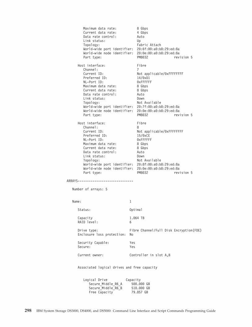
Maximum data rate: 8 GbpsCurrent data rate: 4 GbpsData rate control: AutoLink status: UpTopology: Fabric AttachWorld-wide port identifier: 20:6f:00:a0:b8:29:ed:8aWorld-wide node identifier: 20:0e:00:a0:b8:29:ed:8aPart type: PM8032 revision 5
Host interface: FibreChannel: 7Current ID: Not applicable/0xFFFFFFFFPreferred ID: 14/0xD1NL-Port ID: 0xFFFFFFMaximum data rate: 8 GbpsCurrent data rate: 8 GbpsData rate control: AutoLink status: DownTopology: Not AvailableWorld-wide port identifier: 20:7f:00:a0:b8:29:ed:8aWorld-wide node identifier: 20:0e:00:a0:b8:29:ed:8aPart type: PM8032 revision 5
Host interface: FibreChannel: 8Current ID: Not applicable/0xFFFFFFFFPreferred ID: 15/0xCENL-Port ID: 0xFFFFFFMaximum data rate: 8 GbpsCurrent data rate: 8 GbpsData rate control: AutoLink status: DownTopology: Not AvailableWorld-wide port identifier: 20:8f:00:a0:b8:29:ed:8aWorld-wide node identifier: 20:0e:00:a0:b8:29:ed:8aPart type: PM8032 revision 5
ARRAYS------------------------------
Number of arrays: 5
Name: 1
Status: Optimal
Capacity 1.064 TBRAID level: 6
Drive type: Fibre Channel/Full Disk Encryption(FDE)Enclosure loss protection: No
Security Capable: YesSecure: Yes
Current owner: Controller in slot A,B
Associated logical drives and free capacity
Logical Drive CapacitySecure_Middle_R6_A 500.000 GBSecure_Middle_R6_B 510.000 GBFree Capacity 79.857 GB
298 IBM System Storage DS3000, DS4000, and DS5000: Command Line Interface and Script Commands Programming Guide
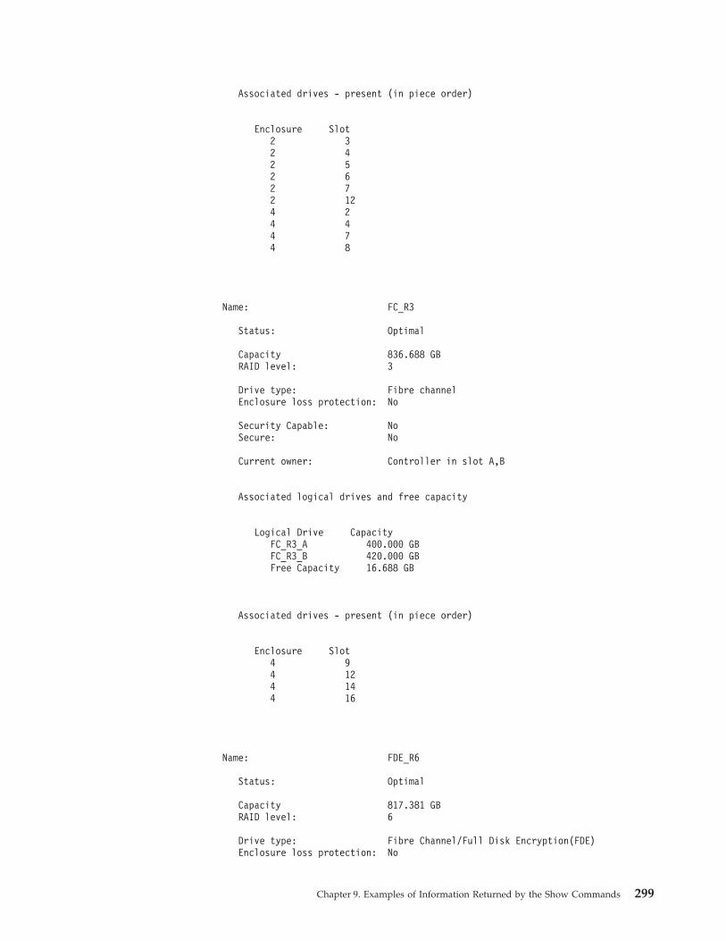
Associated drives - present (in piece order)
Enclosure Slot2 32 42 52 62 72 124 24 44 74 8
Name: FC_R3
Status: Optimal
Capacity 836.688 GBRAID level: 3
Drive type: Fibre channelEnclosure loss protection: No
Security Capable: NoSecure: No
Current owner: Controller in slot A,B
Associated logical drives and free capacity
Logical Drive CapacityFC_R3_A 400.000 GBFC_R3_B 420.000 GBFree Capacity 16.688 GB
Associated drives - present (in piece order)
Enclosure Slot4 94 124 144 16
Name: FDE_R6
Status: Optimal
Capacity 817.381 GBRAID level: 6
Drive type: Fibre Channel/Full Disk Encryption(FDE)Enclosure loss protection: No
Chapter 9. Examples of Information Returned by the Show Commands 299
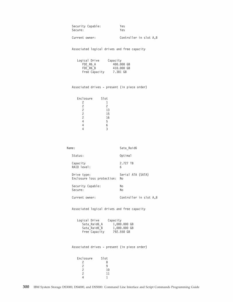
Security Capable: YesSecure: Yes
Current owner: Controller in slot A,B
Associated logical drives and free capacity
Logical Drive CapacityFDE_R6_A 400.000 GBFDE_R6_B 410.000 GBFree Capacity 7.381 GB
Associated drives - present (in piece order)
Enclosure Slot2 12 22 132 152 164 54 64 3
Name: Sata_Raid6
Status: Optimal
Capacity 2.727 TBRAID level: 6
Drive type: Serial ATA (SATA)Enclosure loss protection: No
Security Capable: NoSecure: No
Current owner: Controller in slot A,B
Associated logical drives and free capacity
Logical Drive CapacitySata_Raid6_A 1,000.000 GBSata_Raid6_B 1,000.000 GBFree Capacity 792.550 GB
Associated drives - present (in piece order)
Enclosure Slot2 82 92 102 114 1
300 IBM System Storage DS3000, DS4000, and DS5000: Command Line Interface and Script Commands Programming Guide
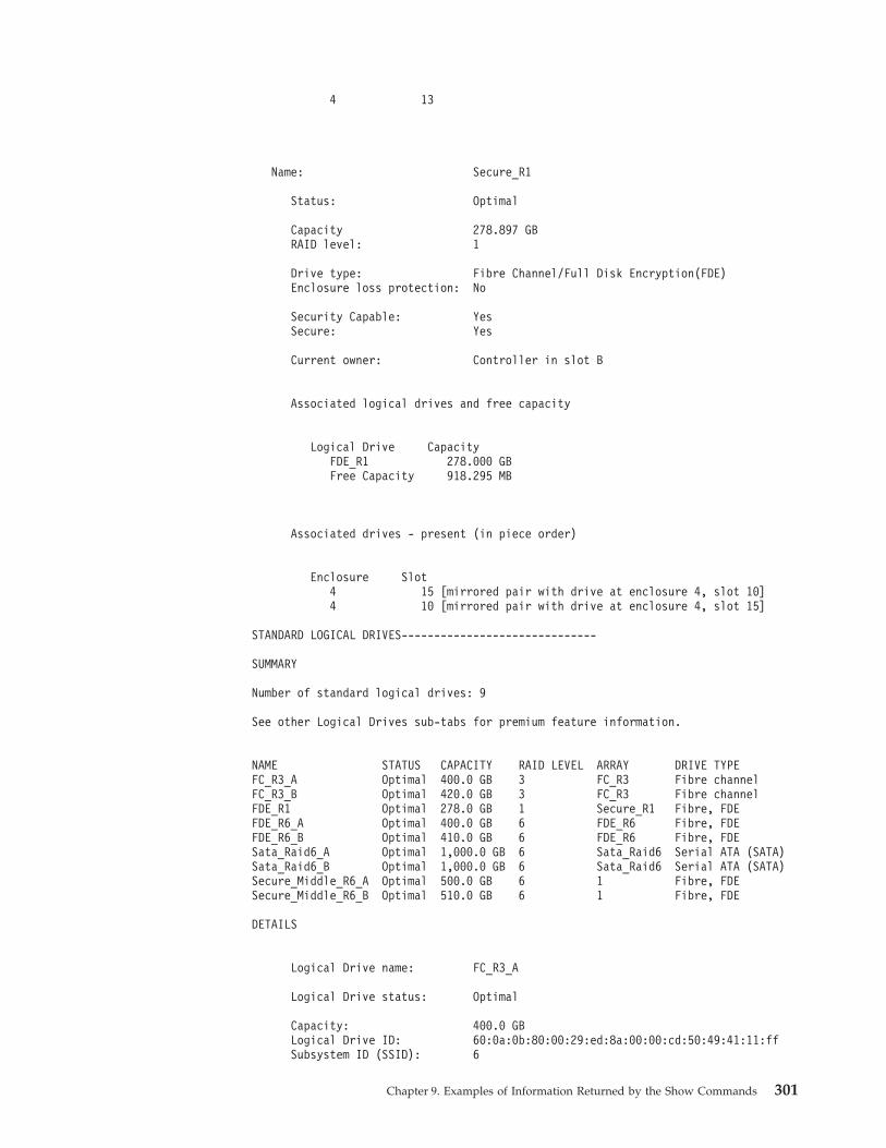
4 13
Name: Secure_R1
Status: Optimal
Capacity 278.897 GBRAID level: 1
Drive type: Fibre Channel/Full Disk Encryption(FDE)Enclosure loss protection: No
Security Capable: YesSecure: Yes
Current owner: Controller in slot B
Associated logical drives and free capacity
Logical Drive CapacityFDE_R1 278.000 GBFree Capacity 918.295 MB
Associated drives - present (in piece order)
Enclosure Slot4 15 [mirrored pair with drive at enclosure 4, slot 10]4 10 [mirrored pair with drive at enclosure 4, slot 15]
STANDARD LOGICAL DRIVES------------------------------
SUMMARY
Number of standard logical drives: 9
See other Logical Drives sub-tabs for premium feature information.
NAME STATUS CAPACITY RAID LEVEL ARRAY DRIVE TYPEFC_R3_A Optimal 400.0 GB 3 FC_R3 Fibre channelFC_R3_B Optimal 420.0 GB 3 FC_R3 Fibre channelFDE_R1 Optimal 278.0 GB 1 Secure_R1 Fibre, FDEFDE_R6_A Optimal 400.0 GB 6 FDE_R6 Fibre, FDEFDE_R6_B Optimal 410.0 GB 6 FDE_R6 Fibre, FDESata_Raid6_A Optimal 1,000.0 GB 6 Sata_Raid6 Serial ATA (SATA)Sata_Raid6_B Optimal 1,000.0 GB 6 Sata_Raid6 Serial ATA (SATA)Secure_Middle_R6_A Optimal 500.0 GB 6 1 Fibre, FDESecure_Middle_R6_B Optimal 510.0 GB 6 1 Fibre, FDE
DETAILS
Logical Drive name: FC_R3_A
Logical Drive status: Optimal
Capacity: 400.0 GBLogical Drive ID: 60:0a:0b:80:00:29:ed:8a:00:00:cd:50:49:41:11:ffSubsystem ID (SSID): 6
Chapter 9. Examples of Information Returned by the Show Commands 301
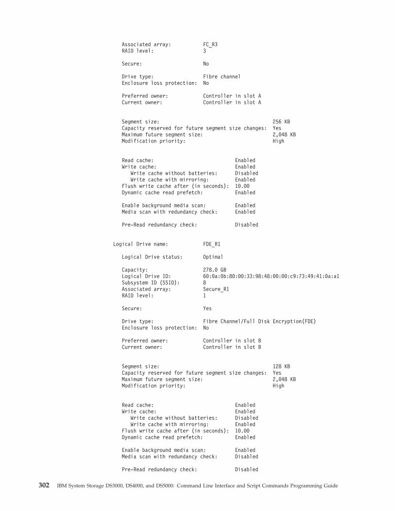
Associated array: FC_R3RAID level: 3
Secure: No
Drive type: Fibre channelEnclosure loss protection: No
Preferred owner: Controller in slot ACurrent owner: Controller in slot A
Segment size: 256 KBCapacity reserved for future segment size changes: YesMaximum future segment size: 2,048 KBModification priority: High
Read cache: EnabledWrite cache: Enabled
Write cache without batteries: DisabledWrite cache with mirroring: Enabled
Flush write cache after (in seconds): 10.00Dynamic cache read prefetch: Enabled
Enable background media scan: EnabledMedia scan with redundancy check: Enabled
Pre-Read redundancy check: Disabled
Logical Drive name: FDE_R1
Logical Drive status: Optimal
Capacity: 278.0 GBLogical Drive ID: 60:0a:0b:80:00:33:98:48:00:00:c9:73:49:41:0a:a1Subsystem ID (SSID): 8Associated array: Secure_R1RAID level: 1
Secure: Yes
Drive type: Fibre Channel/Full Disk Encryption(FDE)Enclosure loss protection: No
Preferred owner: Controller in slot BCurrent owner: Controller in slot B
Segment size: 128 KBCapacity reserved for future segment size changes: YesMaximum future segment size: 2,048 KBModification priority: High
Read cache: EnabledWrite cache: Enabled
Write cache without batteries: DisabledWrite cache with mirroring: Enabled
Flush write cache after (in seconds): 10.00Dynamic cache read prefetch: Enabled
Enable background media scan: EnabledMedia scan with redundancy check: Disabled
Pre-Read redundancy check: Disabled
302 IBM System Storage DS3000, DS4000, and DS5000: Command Line Interface and Script Commands Programming Guide
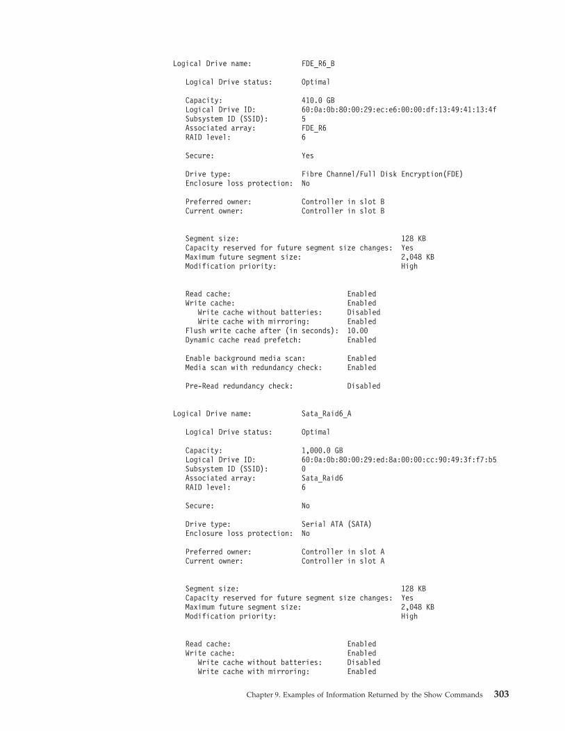
Logical Drive name: FDE_R6_B
Logical Drive status: Optimal
Capacity: 410.0 GBLogical Drive ID: 60:0a:0b:80:00:29:ec:e6:00:00:df:13:49:41:13:4fSubsystem ID (SSID): 5Associated array: FDE_R6RAID level: 6
Secure: Yes
Drive type: Fibre Channel/Full Disk Encryption(FDE)Enclosure loss protection: No
Preferred owner: Controller in slot BCurrent owner: Controller in slot B
Segment size: 128 KBCapacity reserved for future segment size changes: YesMaximum future segment size: 2,048 KBModification priority: High
Read cache: EnabledWrite cache: Enabled
Write cache without batteries: DisabledWrite cache with mirroring: Enabled
Flush write cache after (in seconds): 10.00Dynamic cache read prefetch: Enabled
Enable background media scan: EnabledMedia scan with redundancy check: Enabled
Pre-Read redundancy check: Disabled
Logical Drive name: Sata_Raid6_A
Logical Drive status: Optimal
Capacity: 1,000.0 GBLogical Drive ID: 60:0a:0b:80:00:29:ed:8a:00:00:cc:90:49:3f:f7:b5Subsystem ID (SSID): 0Associated array: Sata_Raid6RAID level: 6
Secure: No
Drive type: Serial ATA (SATA)Enclosure loss protection: No
Preferred owner: Controller in slot ACurrent owner: Controller in slot A
Segment size: 128 KBCapacity reserved for future segment size changes: YesMaximum future segment size: 2,048 KBModification priority: High
Read cache: EnabledWrite cache: Enabled
Write cache without batteries: DisabledWrite cache with mirroring: Enabled
Chapter 9. Examples of Information Returned by the Show Commands 303
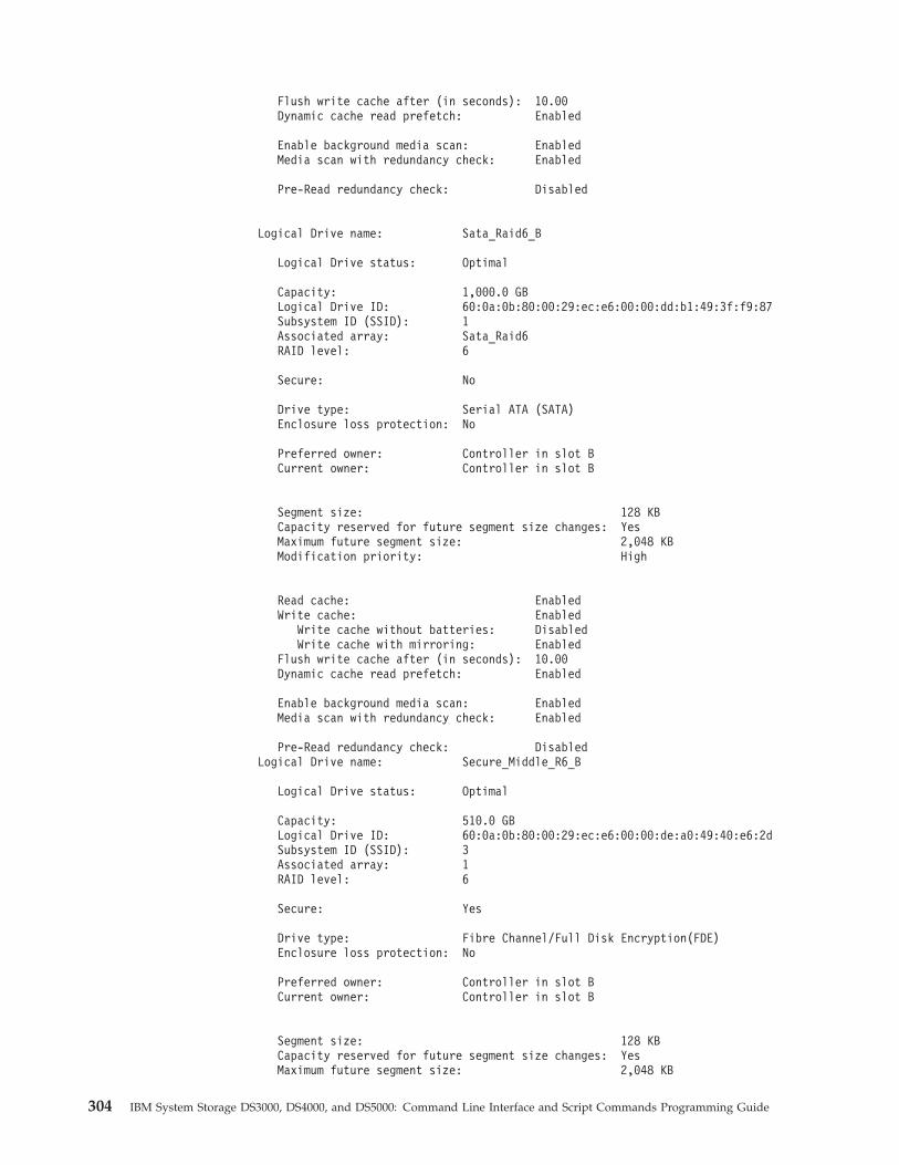
Flush write cache after (in seconds): 10.00Dynamic cache read prefetch: Enabled
Enable background media scan: EnabledMedia scan with redundancy check: Enabled
Pre-Read redundancy check: Disabled
Logical Drive name: Sata_Raid6_B
Logical Drive status: Optimal
Capacity: 1,000.0 GBLogical Drive ID: 60:0a:0b:80:00:29:ec:e6:00:00:dd:b1:49:3f:f9:87Subsystem ID (SSID): 1Associated array: Sata_Raid6RAID level: 6
Secure: No
Drive type: Serial ATA (SATA)Enclosure loss protection: No
Preferred owner: Controller in slot BCurrent owner: Controller in slot B
Segment size: 128 KBCapacity reserved for future segment size changes: YesMaximum future segment size: 2,048 KBModification priority: High
Read cache: EnabledWrite cache: Enabled
Write cache without batteries: DisabledWrite cache with mirroring: Enabled
Flush write cache after (in seconds): 10.00Dynamic cache read prefetch: Enabled
Enable background media scan: EnabledMedia scan with redundancy check: Enabled
Pre-Read redundancy check: DisabledLogical Drive name: Secure_Middle_R6_B
Logical Drive status: Optimal
Capacity: 510.0 GBLogical Drive ID: 60:0a:0b:80:00:29:ec:e6:00:00:de:a0:49:40:e6:2dSubsystem ID (SSID): 3Associated array: 1RAID level: 6
Secure: Yes
Drive type: Fibre Channel/Full Disk Encryption(FDE)Enclosure loss protection: No
Preferred owner: Controller in slot BCurrent owner: Controller in slot B
Segment size: 128 KBCapacity reserved for future segment size changes: YesMaximum future segment size: 2,048 KB
304 IBM System Storage DS3000, DS4000, and DS5000: Command Line Interface and Script Commands Programming Guide
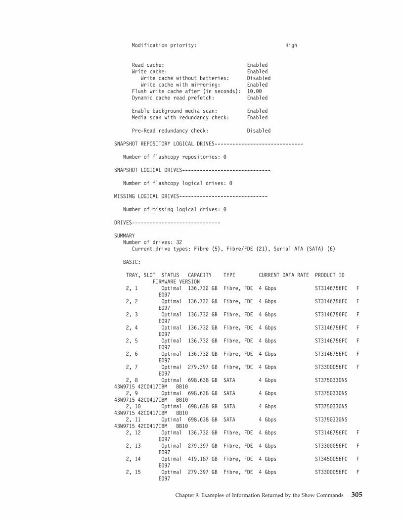
Modification priority: High
Read cache: EnabledWrite cache: Enabled
Write cache without batteries: DisabledWrite cache with mirroring: Enabled
Flush write cache after (in seconds): 10.00Dynamic cache read prefetch: Enabled
Enable background media scan: EnabledMedia scan with redundancy check: Enabled
Pre-Read redundancy check: Disabled
SNAPSHOT REPOSITORY LOGICAL DRIVES------------------------------
Number of flashcopy repositories: 0
SNAPSHOT LOGICAL DRIVES------------------------------
Number of flashcopy logical drives: 0
MISSING LOGICAL DRIVES------------------------------
Number of missing logical drives: 0
DRIVES------------------------------
SUMMARYNumber of drives: 32
Current drive types: Fibre (5), Fibre/FDE (21), Serial ATA (SATA) (6)
BASIC:
TRAY, SLOT STATUS CAPACITY TYPE CURRENT DATA RATE PRODUCT IDFIRMWARE VERSION
2, 1 Optimal 136.732 GB Fibre, FDE 4 Gbps ST3146756FC FE097
2, 2 Optimal 136.732 GB Fibre, FDE 4 Gbps ST3146756FC FE097
2, 3 Optimal 136.732 GB Fibre, FDE 4 Gbps ST3146756FC FE097
2, 4 Optimal 136.732 GB Fibre, FDE 4 Gbps ST3146756FC FE097
2, 5 Optimal 136.732 GB Fibre, FDE 4 Gbps ST3146756FC FE097
2, 6 Optimal 136.732 GB Fibre, FDE 4 Gbps ST3146756FC FE097
2, 7 Optimal 279.397 GB Fibre, FDE 4 Gbps ST3300056FC FE097
2, 8 Optimal 698.638 GB SATA 4 Gbps ST3750330NS43W9715 42C0417IBM BB10
2, 9 Optimal 698.638 GB SATA 4 Gbps ST3750330NS43W9715 42C0417IBM BB10
2, 10 Optimal 698.638 GB SATA 4 Gbps ST3750330NS43W9715 42C0417IBM BB10
2, 11 Optimal 698.638 GB SATA 4 Gbps ST3750330NS43W9715 42C0417IBM BB10
2, 12 Optimal 136.732 GB Fibre, FDE 4 Gbps ST3146756FC FE097
2, 13 Optimal 279.397 GB Fibre, FDE 4 Gbps ST3300056FC FE097
2, 14 Optimal 419.187 GB Fibre, FDE 4 Gbps ST3450056FC FE097
2, 15 Optimal 279.397 GB Fibre, FDE 4 Gbps ST3300056FC FE097
Chapter 9. Examples of Information Returned by the Show Commands 305
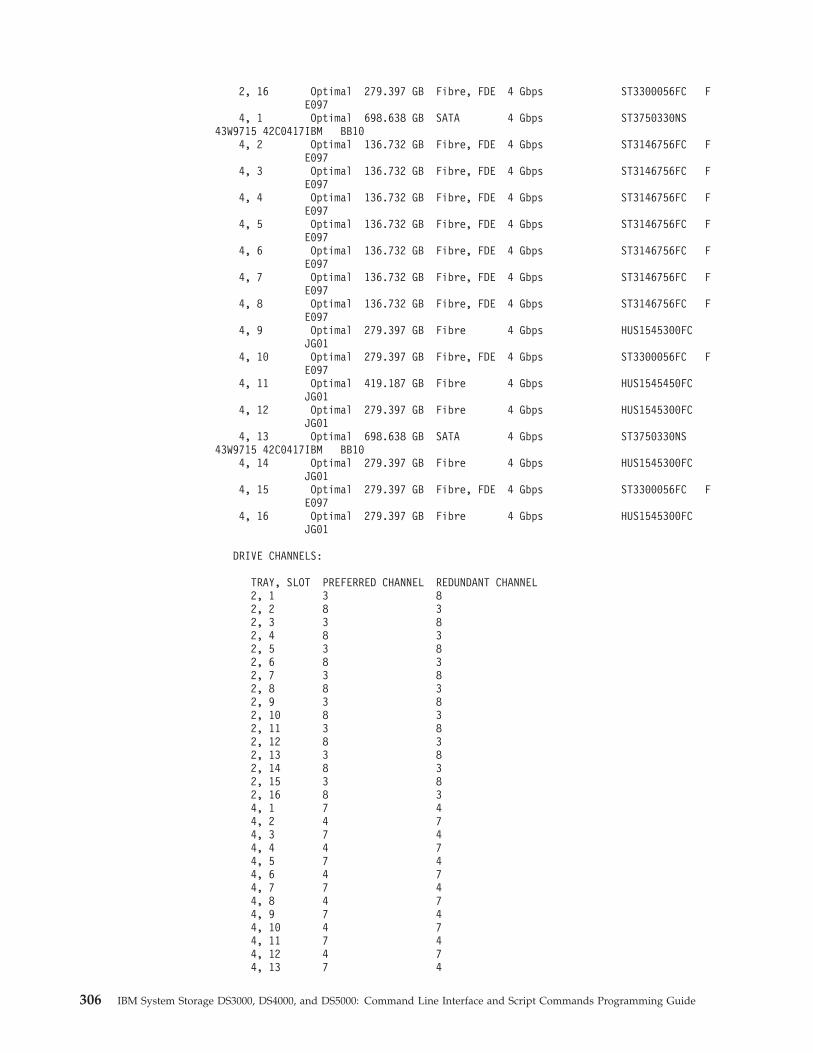
2, 16 Optimal 279.397 GB Fibre, FDE 4 Gbps ST3300056FC FE097
4, 1 Optimal 698.638 GB SATA 4 Gbps ST3750330NS43W9715 42C0417IBM BB10
4, 2 Optimal 136.732 GB Fibre, FDE 4 Gbps ST3146756FC FE097
4, 3 Optimal 136.732 GB Fibre, FDE 4 Gbps ST3146756FC FE097
4, 4 Optimal 136.732 GB Fibre, FDE 4 Gbps ST3146756FC FE097
4, 5 Optimal 136.732 GB Fibre, FDE 4 Gbps ST3146756FC FE097
4, 6 Optimal 136.732 GB Fibre, FDE 4 Gbps ST3146756FC FE097
4, 7 Optimal 136.732 GB Fibre, FDE 4 Gbps ST3146756FC FE097
4, 8 Optimal 136.732 GB Fibre, FDE 4 Gbps ST3146756FC FE097
4, 9 Optimal 279.397 GB Fibre 4 Gbps HUS1545300FCJG01
4, 10 Optimal 279.397 GB Fibre, FDE 4 Gbps ST3300056FC FE097
4, 11 Optimal 419.187 GB Fibre 4 Gbps HUS1545450FCJG01
4, 12 Optimal 279.397 GB Fibre 4 Gbps HUS1545300FCJG01
4, 13 Optimal 698.638 GB SATA 4 Gbps ST3750330NS43W9715 42C0417IBM BB10
4, 14 Optimal 279.397 GB Fibre 4 Gbps HUS1545300FCJG01
4, 15 Optimal 279.397 GB Fibre, FDE 4 Gbps ST3300056FC FE097
4, 16 Optimal 279.397 GB Fibre 4 Gbps HUS1545300FCJG01
DRIVE CHANNELS:
TRAY, SLOT PREFERRED CHANNEL REDUNDANT CHANNEL2, 1 3 82, 2 8 32, 3 3 82, 4 8 32, 5 3 82, 6 8 32, 7 3 82, 8 8 32, 9 3 82, 10 8 32, 11 3 82, 12 8 32, 13 3 82, 14 8 32, 15 3 82, 16 8 34, 1 7 44, 2 4 74, 3 7 44, 4 4 74, 5 7 44, 6 4 74, 7 7 44, 8 4 74, 9 7 44, 10 4 74, 11 7 44, 12 4 74, 13 7 4
306 IBM System Storage DS3000, DS4000, and DS5000: Command Line Interface and Script Commands Programming Guide
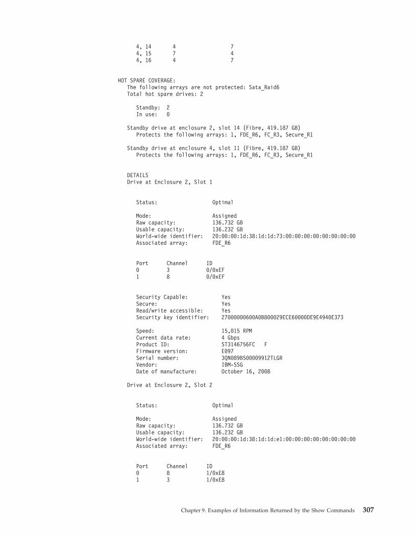
4, 14 4 74, 15 7 44, 16 4 7
HOT SPARE COVERAGE:The following arrays are not protected: Sata_Raid6Total hot spare drives: 2
Standby: 2In use: 0
Standby drive at enclosure 2, slot 14 (Fibre, 419.187 GB)Protects the following arrays: 1, FDE_R6, FC_R3, Secure_R1
Standby drive at enclosure 4, slot 11 (Fibre, 419.187 GB)Protects the following arrays: 1, FDE_R6, FC_R3, Secure_R1
DETAILSDrive at Enclosure 2, Slot 1
Status: Optimal
Mode: AssignedRaw capacity: 136.732 GBUsable capacity: 136.232 GBWorld-wide identifier: 20:00:00:1d:38:1d:1d:73:00:00:00:00:00:00:00:00Associated array: FDE_R6
Port Channel ID0 3 0/0xEF1 8 0/0xEF
Security Capable: YesSecure: YesRead/write accessible: YesSecurity key identifier: 27000000600A0B800029ECE60000DE9E4940E373
Speed: 15,015 RPMCurrent data rate: 4 GbpsProduct ID: ST3146756FC FFirmware version: E097Serial number: 3QN089B500009912TLGRVendor: IBM-SSGDate of manufacture: October 16, 2008
Drive at Enclosure 2, Slot 2
Status: Optimal
Mode: AssignedRaw capacity: 136.732 GBUsable capacity: 136.232 GBWorld-wide identifier: 20:00:00:1d:38:1d:1d:e1:00:00:00:00:00:00:00:00Associated array: FDE_R6
Port Channel ID0 8 1/0xE81 3 1/0xE8
Chapter 9. Examples of Information Returned by the Show Commands 307
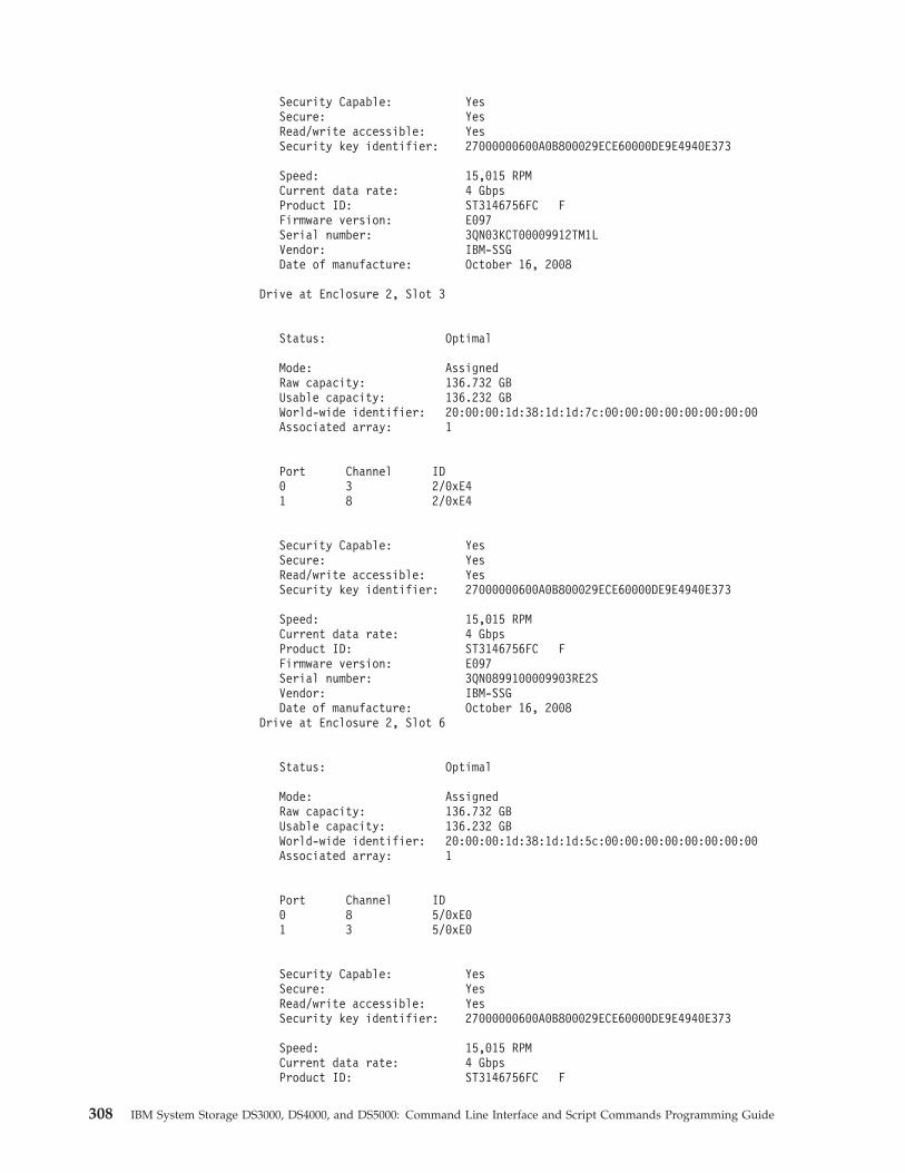
Security Capable: YesSecure: YesRead/write accessible: YesSecurity key identifier: 27000000600A0B800029ECE60000DE9E4940E373
Speed: 15,015 RPMCurrent data rate: 4 GbpsProduct ID: ST3146756FC FFirmware version: E097Serial number: 3QN03KCT00009912TM1LVendor: IBM-SSGDate of manufacture: October 16, 2008
Drive at Enclosure 2, Slot 3
Status: Optimal
Mode: AssignedRaw capacity: 136.732 GBUsable capacity: 136.232 GBWorld-wide identifier: 20:00:00:1d:38:1d:1d:7c:00:00:00:00:00:00:00:00Associated array: 1
Port Channel ID0 3 2/0xE41 8 2/0xE4
Security Capable: YesSecure: YesRead/write accessible: YesSecurity key identifier: 27000000600A0B800029ECE60000DE9E4940E373
Speed: 15,015 RPMCurrent data rate: 4 GbpsProduct ID: ST3146756FC FFirmware version: E097Serial number: 3QN0899100009903RE2SVendor: IBM-SSGDate of manufacture: October 16, 2008
Drive at Enclosure 2, Slot 6
Status: Optimal
Mode: AssignedRaw capacity: 136.732 GBUsable capacity: 136.232 GBWorld-wide identifier: 20:00:00:1d:38:1d:1d:5c:00:00:00:00:00:00:00:00Associated array: 1
Port Channel ID0 8 5/0xE01 3 5/0xE0
Security Capable: YesSecure: YesRead/write accessible: YesSecurity key identifier: 27000000600A0B800029ECE60000DE9E4940E373
Speed: 15,015 RPMCurrent data rate: 4 GbpsProduct ID: ST3146756FC F
308 IBM System Storage DS3000, DS4000, and DS5000: Command Line Interface and Script Commands Programming Guide
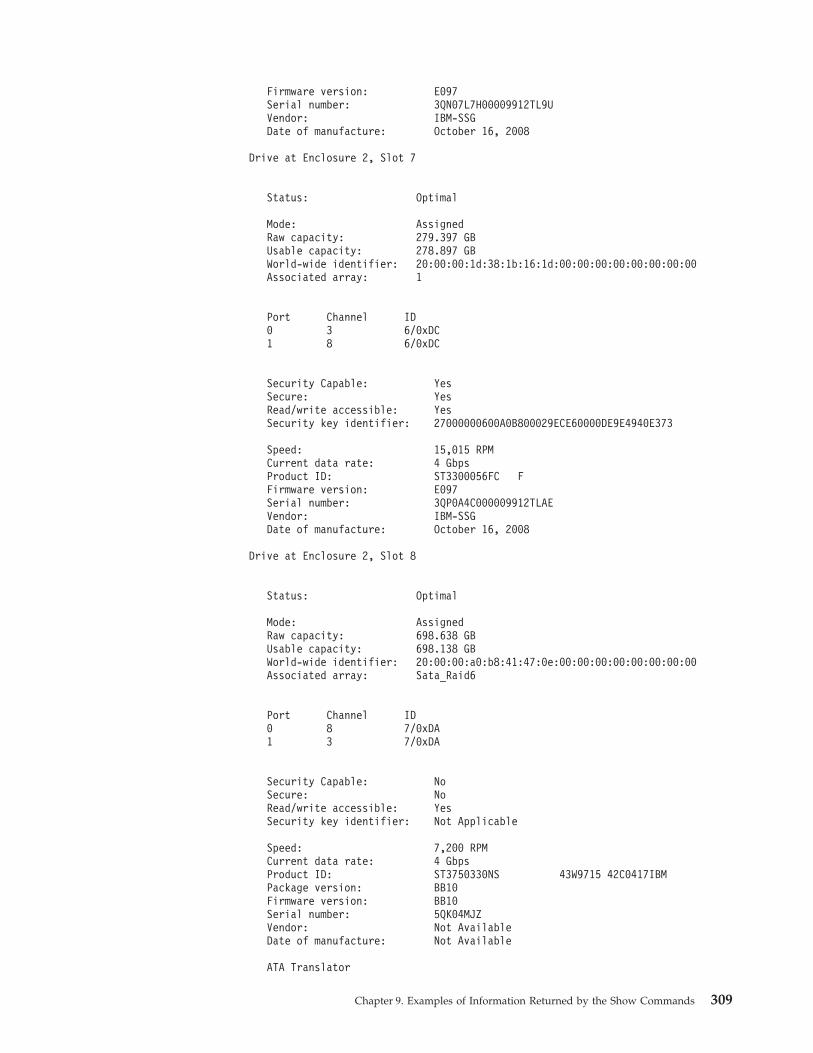
Firmware version: E097Serial number: 3QN07L7H00009912TL9UVendor: IBM-SSGDate of manufacture: October 16, 2008
Drive at Enclosure 2, Slot 7
Status: Optimal
Mode: AssignedRaw capacity: 279.397 GBUsable capacity: 278.897 GBWorld-wide identifier: 20:00:00:1d:38:1b:16:1d:00:00:00:00:00:00:00:00Associated array: 1
Port Channel ID0 3 6/0xDC1 8 6/0xDC
Security Capable: YesSecure: YesRead/write accessible: YesSecurity key identifier: 27000000600A0B800029ECE60000DE9E4940E373
Speed: 15,015 RPMCurrent data rate: 4 GbpsProduct ID: ST3300056FC FFirmware version: E097Serial number: 3QP0A4C000009912TLAEVendor: IBM-SSGDate of manufacture: October 16, 2008
Drive at Enclosure 2, Slot 8
Status: Optimal
Mode: AssignedRaw capacity: 698.638 GBUsable capacity: 698.138 GBWorld-wide identifier: 20:00:00:a0:b8:41:47:0e:00:00:00:00:00:00:00:00Associated array: Sata_Raid6
Port Channel ID0 8 7/0xDA1 3 7/0xDA
Security Capable: NoSecure: NoRead/write accessible: YesSecurity key identifier: Not Applicable
Speed: 7,200 RPMCurrent data rate: 4 GbpsProduct ID: ST3750330NS 43W9715 42C0417IBMPackage version: BB10Firmware version: BB10Serial number: 5QK04MJZVendor: Not AvailableDate of manufacture: Not Available
ATA Translator
Chapter 9. Examples of Information Returned by the Show Commands 309
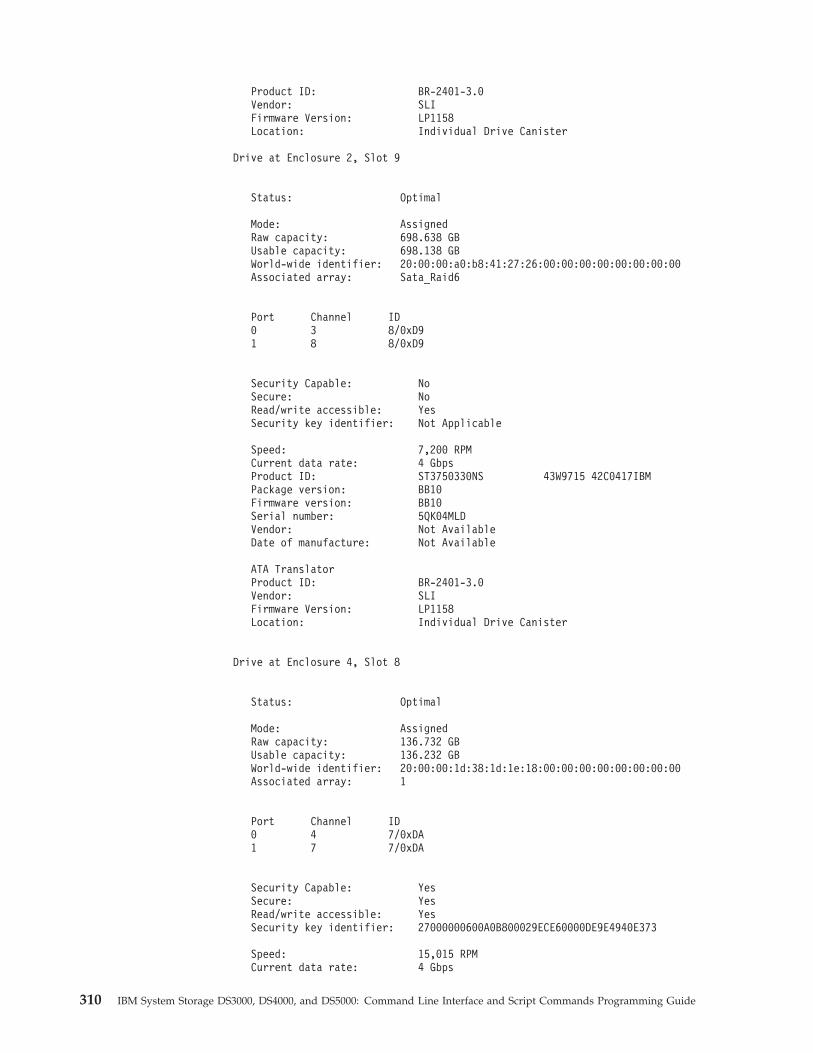
Product ID: BR-2401-3.0Vendor: SLIFirmware Version: LP1158Location: Individual Drive Canister
Drive at Enclosure 2, Slot 9
Status: Optimal
Mode: AssignedRaw capacity: 698.638 GBUsable capacity: 698.138 GBWorld-wide identifier: 20:00:00:a0:b8:41:27:26:00:00:00:00:00:00:00:00Associated array: Sata_Raid6
Port Channel ID0 3 8/0xD91 8 8/0xD9
Security Capable: NoSecure: NoRead/write accessible: YesSecurity key identifier: Not Applicable
Speed: 7,200 RPMCurrent data rate: 4 GbpsProduct ID: ST3750330NS 43W9715 42C0417IBMPackage version: BB10Firmware version: BB10Serial number: 5QK04MLDVendor: Not AvailableDate of manufacture: Not Available
ATA TranslatorProduct ID: BR-2401-3.0Vendor: SLIFirmware Version: LP1158Location: Individual Drive Canister
Drive at Enclosure 4, Slot 8
Status: Optimal
Mode: AssignedRaw capacity: 136.732 GBUsable capacity: 136.232 GBWorld-wide identifier: 20:00:00:1d:38:1d:1e:18:00:00:00:00:00:00:00:00Associated array: 1
Port Channel ID0 4 7/0xDA1 7 7/0xDA
Security Capable: YesSecure: YesRead/write accessible: YesSecurity key identifier: 27000000600A0B800029ECE60000DE9E4940E373
Speed: 15,015 RPMCurrent data rate: 4 Gbps
310 IBM System Storage DS3000, DS4000, and DS5000: Command Line Interface and Script Commands Programming Guide
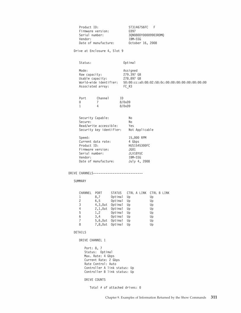
Product ID: ST3146756FC FFirmware version: E097Serial number: 3QN080DY00009903RDMQVendor: IBM-SSGDate of manufacture: October 16, 2008
Drive at Enclosure 4, Slot 9
Status: Optimal
Mode: AssignedRaw capacity: 279.397 GBUsable capacity: 278.897 GBWorld-wide identifier: 50:00:cc:a0:08:02:58:0c:00:00:00:00:00:00:00:00Associated array: FC_R3
Port Channel ID0 7 8/0xD91 4 8/0xD9
Security Capable: NoSecure: NoRead/write accessible: YesSecurity key identifier: Not Applicable
Speed: 15,000 RPMCurrent data rate: 4 GbpsProduct ID: HUS1545300FCFirmware version: JG01Serial number: JLV18YUCVendor: IBM-SSGDate of manufacture: July 4, 2008
DRIVE CHANNELS----------------------------
SUMMARY
CHANNEL PORT STATUS CTRL A LINK CTRL B LINK1 8,7 Optimal Up Up2 6,5 Optimal Up Up3 4,3,Out Optimal Up Up4 2,1,Out Optimal Up Up5 1,2 Optimal Up Up6 3,4 Optimal Up Up7 5,6,Out Optimal Up Up8 7,8,Out Optimal Up Up
DETAILS
DRIVE CHANNEL 1
Port: 8, 7Status: OptimalMax. Rate: 4 GbpsCurrent Rate: 2 GbpsRate Control: AutoController A link status: UpController B link status: Up
DRIVE COUNTS
Total # of attached drives: 0
Chapter 9. Examples of Information Returned by the Show Commands 311
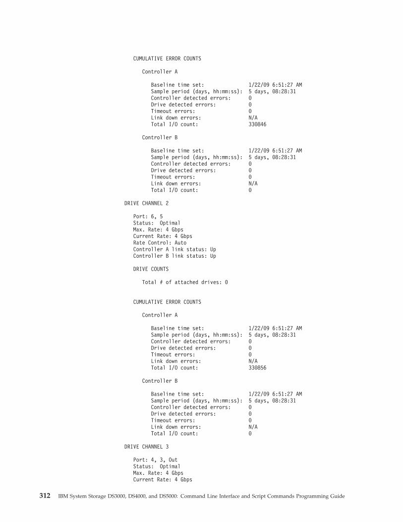
CUMULATIVE ERROR COUNTS
Controller A
Baseline time set: 1/22/09 6:51:27 AMSample period (days, hh:mm:ss): 5 days, 08:28:31Controller detected errors: 0Drive detected errors: 0Timeout errors: 0Link down errors: N/ATotal I/O count: 330846
Controller B
Baseline time set: 1/22/09 6:51:27 AMSample period (days, hh:mm:ss): 5 days, 08:28:31Controller detected errors: 0Drive detected errors: 0Timeout errors: 0Link down errors: N/ATotal I/O count: 0
DRIVE CHANNEL 2
Port: 6, 5Status: OptimalMax. Rate: 4 GbpsCurrent Rate: 4 GbpsRate Control: AutoController A link status: UpController B link status: Up
DRIVE COUNTS
Total # of attached drives: 0
CUMULATIVE ERROR COUNTS
Controller A
Baseline time set: 1/22/09 6:51:27 AMSample period (days, hh:mm:ss): 5 days, 08:28:31Controller detected errors: 0Drive detected errors: 0Timeout errors: 0Link down errors: N/ATotal I/O count: 330856
Controller B
Baseline time set: 1/22/09 6:51:27 AMSample period (days, hh:mm:ss): 5 days, 08:28:31Controller detected errors: 0Drive detected errors: 0Timeout errors: 0Link down errors: N/ATotal I/O count: 0
DRIVE CHANNEL 3
Port: 4, 3, OutStatus: OptimalMax. Rate: 4 GbpsCurrent Rate: 4 Gbps
312 IBM System Storage DS3000, DS4000, and DS5000: Command Line Interface and Script Commands Programming Guide
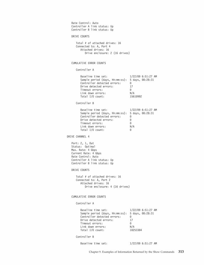
Rate Control: AutoController A link status: UpController B link status: Up
DRIVE COUNTS
Total # of attached drives: 16Connected to: A, Port 4
Attached drives: 16Drive enclosure: 2 (16 drives)
CUMULATIVE ERROR COUNTS
Controller A
Baseline time set: 1/22/09 6:51:27 AMSample period (days, hh:mm:ss): 5 days, 08:28:31Controller detected errors: 0Drive detected errors: 17Timeout errors: 0Link down errors: N/ATotal I/O count: 15610992
Controller B
Baseline time set: 1/22/09 6:51:27 AMSample period (days, hh:mm:ss): 5 days, 08:28:31Controller detected errors: 0Drive detected errors: 0Timeout errors: 0Link down errors: N/ATotal I/O count: 0
DRIVE CHANNEL 4
Port: 2, 1, OutStatus: OptimalMax. Rate: 4 GbpsCurrent Rate: 4 GbpsRate Control: AutoController A link status: UpController B link status: Up
DRIVE COUNTS
Total # of attached drives: 16Connected to: A, Port 2
Attached drives: 16Drive enclosure: 4 (16 drives)
CUMULATIVE ERROR COUNTS
Controller A
Baseline time set: 1/22/09 6:51:27 AMSample period (days, hh:mm:ss): 5 days, 08:28:31Controller detected errors: 0Drive detected errors: 17Timeout errors: 0Link down errors: N/ATotal I/O count: 10253384
Controller B
Baseline time set: 1/22/09 6:51:27 AM
Chapter 9. Examples of Information Returned by the Show Commands 313
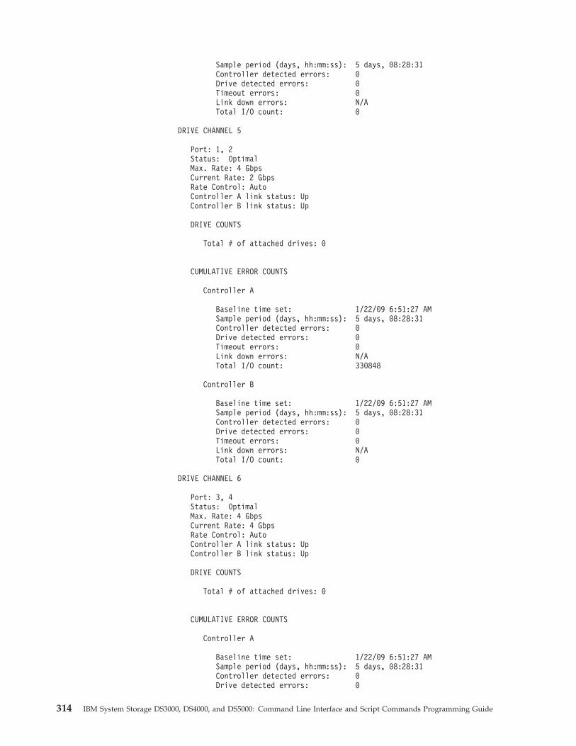
Sample period (days, hh:mm:ss): 5 days, 08:28:31Controller detected errors: 0Drive detected errors: 0Timeout errors: 0Link down errors: N/ATotal I/O count: 0
DRIVE CHANNEL 5
Port: 1, 2Status: OptimalMax. Rate: 4 GbpsCurrent Rate: 2 GbpsRate Control: AutoController A link status: UpController B link status: Up
DRIVE COUNTS
Total # of attached drives: 0
CUMULATIVE ERROR COUNTS
Controller A
Baseline time set: 1/22/09 6:51:27 AMSample period (days, hh:mm:ss): 5 days, 08:28:31Controller detected errors: 0Drive detected errors: 0Timeout errors: 0Link down errors: N/ATotal I/O count: 330848
Controller B
Baseline time set: 1/22/09 6:51:27 AMSample period (days, hh:mm:ss): 5 days, 08:28:31Controller detected errors: 0Drive detected errors: 0Timeout errors: 0Link down errors: N/ATotal I/O count: 0
DRIVE CHANNEL 6
Port: 3, 4Status: OptimalMax. Rate: 4 GbpsCurrent Rate: 4 GbpsRate Control: AutoController A link status: UpController B link status: Up
DRIVE COUNTS
Total # of attached drives: 0
CUMULATIVE ERROR COUNTS
Controller A
Baseline time set: 1/22/09 6:51:27 AMSample period (days, hh:mm:ss): 5 days, 08:28:31Controller detected errors: 0Drive detected errors: 0
314 IBM System Storage DS3000, DS4000, and DS5000: Command Line Interface and Script Commands Programming Guide
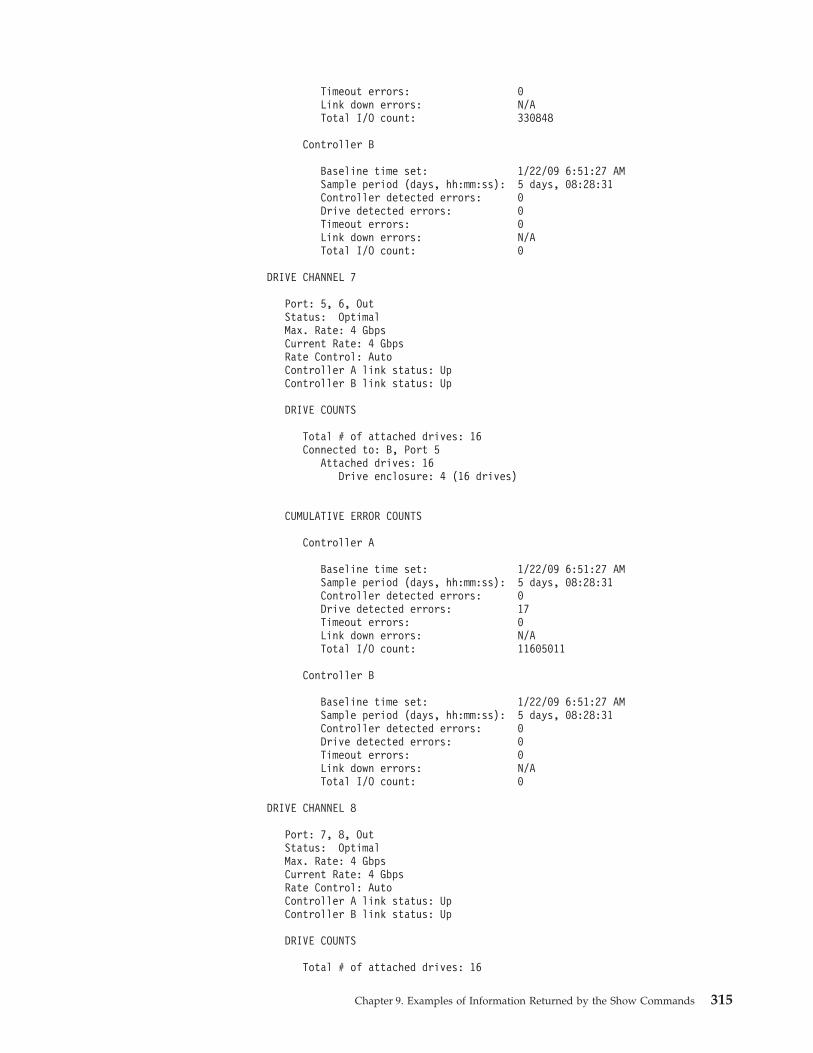
Timeout errors: 0Link down errors: N/ATotal I/O count: 330848
Controller B
Baseline time set: 1/22/09 6:51:27 AMSample period (days, hh:mm:ss): 5 days, 08:28:31Controller detected errors: 0Drive detected errors: 0Timeout errors: 0Link down errors: N/ATotal I/O count: 0
DRIVE CHANNEL 7
Port: 5, 6, OutStatus: OptimalMax. Rate: 4 GbpsCurrent Rate: 4 GbpsRate Control: AutoController A link status: UpController B link status: Up
DRIVE COUNTS
Total # of attached drives: 16Connected to: B, Port 5
Attached drives: 16Drive enclosure: 4 (16 drives)
CUMULATIVE ERROR COUNTS
Controller A
Baseline time set: 1/22/09 6:51:27 AMSample period (days, hh:mm:ss): 5 days, 08:28:31Controller detected errors: 0Drive detected errors: 17Timeout errors: 0Link down errors: N/ATotal I/O count: 11605011
Controller B
Baseline time set: 1/22/09 6:51:27 AMSample period (days, hh:mm:ss): 5 days, 08:28:31Controller detected errors: 0Drive detected errors: 0Timeout errors: 0Link down errors: N/ATotal I/O count: 0
DRIVE CHANNEL 8
Port: 7, 8, OutStatus: OptimalMax. Rate: 4 GbpsCurrent Rate: 4 GbpsRate Control: AutoController A link status: UpController B link status: Up
DRIVE COUNTS
Total # of attached drives: 16
Chapter 9. Examples of Information Returned by the Show Commands 315
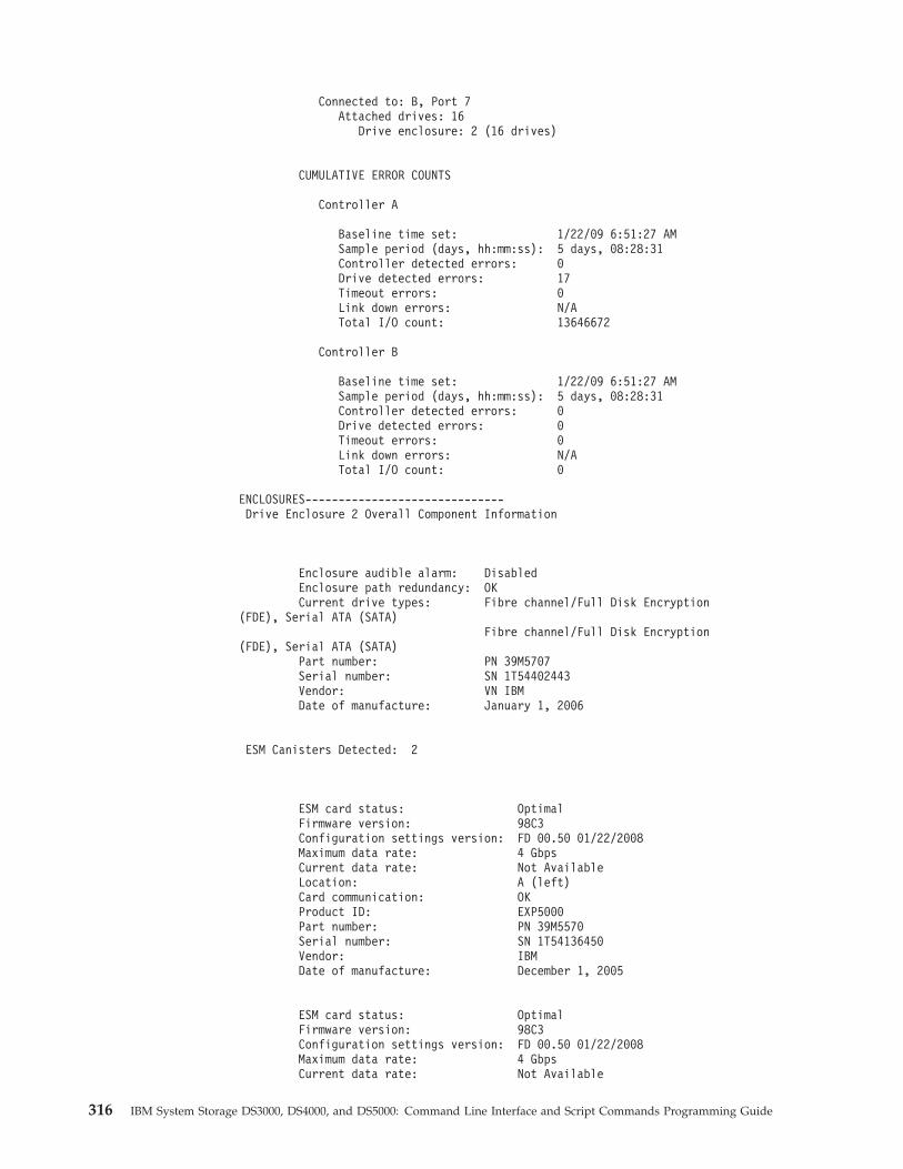
Connected to: B, Port 7Attached drives: 16
Drive enclosure: 2 (16 drives)
CUMULATIVE ERROR COUNTS
Controller A
Baseline time set: 1/22/09 6:51:27 AMSample period (days, hh:mm:ss): 5 days, 08:28:31Controller detected errors: 0Drive detected errors: 17Timeout errors: 0Link down errors: N/ATotal I/O count: 13646672
Controller B
Baseline time set: 1/22/09 6:51:27 AMSample period (days, hh:mm:ss): 5 days, 08:28:31Controller detected errors: 0Drive detected errors: 0Timeout errors: 0Link down errors: N/ATotal I/O count: 0
ENCLOSURES------------------------------Drive Enclosure 2 Overall Component Information
Enclosure audible alarm: DisabledEnclosure path redundancy: OKCurrent drive types: Fibre channel/Full Disk Encryption
(FDE), Serial ATA (SATA)Fibre channel/Full Disk Encryption
(FDE), Serial ATA (SATA)Part number: PN 39M5707Serial number: SN 1T54402443Vendor: VN IBMDate of manufacture: January 1, 2006
ESM Canisters Detected: 2
ESM card status: OptimalFirmware version: 98C3Configuration settings version: FD 00.50 01/22/2008Maximum data rate: 4 GbpsCurrent data rate: Not AvailableLocation: A (left)Card communication: OKProduct ID: EXP5000Part number: PN 39M5570Serial number: SN 1T54136450Vendor: IBMDate of manufacture: December 1, 2005
ESM card status: OptimalFirmware version: 98C3Configuration settings version: FD 00.50 01/22/2008Maximum data rate: 4 GbpsCurrent data rate: Not Available
316 IBM System Storage DS3000, DS4000, and DS5000: Command Line Interface and Script Commands Programming Guide
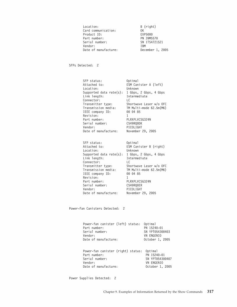
Location: B (right)Card communication: OKProduct ID: EXP5000Part number: PN 39M5570Serial number: SN 1T54721521Vendor: IBMDate of manufacture: December 1, 2005
SFPs Detected: 2
SFP status: OptimalAttached to: ESM Canister A (left)Location: UnknownSupported data rate(s): 1 Gbps, 2 Gbps, 4 GbpsLink length: IntermediateConnector: LCTransmitter type: Shortwave Laser w/o OFCTransmission media: TM Multi-mode 62.5m(M6)IEEE company ID: 00 04 85Revision: 1Part number: PLRXPLVCSG324NSerial number: C549RQ0DKVendor: PICOLIGHTDate of manufacture: November 29, 2005
SFP status: OptimalAttached to: ESM Canister B (right)Location: UnknownSupported data rate(s): 1 Gbps, 2 Gbps, 4 GbpsLink length: IntermediateConnector: LCTransmitter type: Shortwave Laser w/o OFCTransmission media: TM Multi-mode 62.5m(M6)IEEE company ID: 00 04 85Revision: 1Part number: PLRXPLVCSG324NSerial number: C549RQ0ERVendor: PICOLIGHTDate of manufacture: November 29, 2005
Power-Fan Canisters Detected: 2
Power-fan canister (left) status: OptimalPart number: PN 15240-01Serial number: SN YPT054300403Vendor: VN ENGENIODate of manufacture: October 1, 2005
Power-fan canister (right) status: OptimalPart number: PN 15240-01Serial number: SN YPT054300407Vendor: VN ENGENIODate of manufacture: October 1, 2005
Power Supplies Detected: 2
Chapter 9. Examples of Information Returned by the Show Commands 317
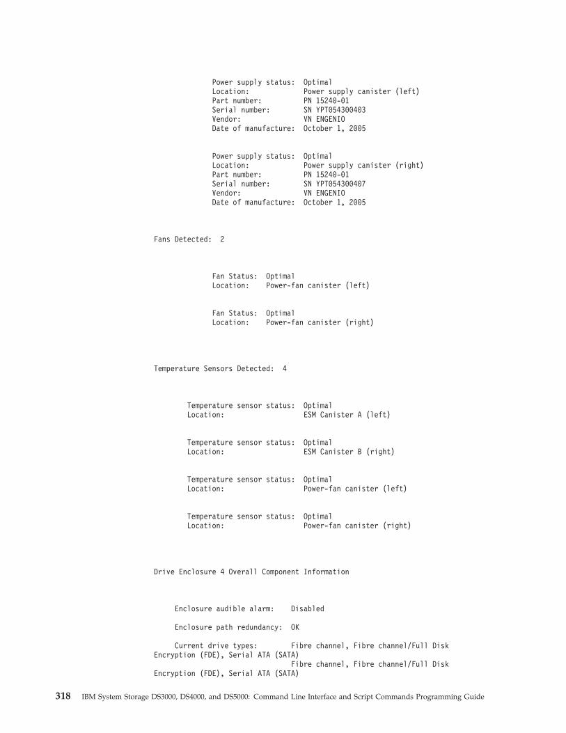
Power supply status: OptimalLocation: Power supply canister (left)Part number: PN 15240-01Serial number: SN YPT054300403Vendor: VN ENGENIODate of manufacture: October 1, 2005
Power supply status: OptimalLocation: Power supply canister (right)Part number: PN 15240-01Serial number: SN YPT054300407Vendor: VN ENGENIODate of manufacture: October 1, 2005
Fans Detected: 2
Fan Status: OptimalLocation: Power-fan canister (left)
Fan Status: OptimalLocation: Power-fan canister (right)
Temperature Sensors Detected: 4
Temperature sensor status: OptimalLocation: ESM Canister A (left)
Temperature sensor status: OptimalLocation: ESM Canister B (right)
Temperature sensor status: OptimalLocation: Power-fan canister (left)
Temperature sensor status: OptimalLocation: Power-fan canister (right)
Drive Enclosure 4 Overall Component Information
Enclosure audible alarm: Disabled
Enclosure path redundancy: OK
Current drive types: Fibre channel, Fibre channel/Full DiskEncryption (FDE), Serial ATA (SATA)
Fibre channel, Fibre channel/Full DiskEncryption (FDE), Serial ATA (SATA)
318 IBM System Storage DS3000, DS4000, and DS5000: Command Line Interface and Script Commands Programming Guide
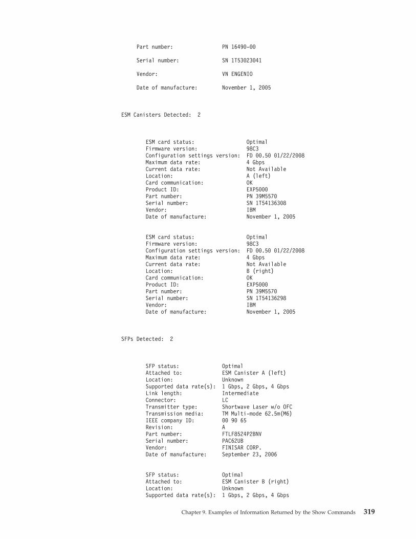
Part number: PN 16490-00
Serial number: SN 1T53023041
Vendor: VN ENGENIO
Date of manufacture: November 1, 2005
ESM Canisters Detected: 2
ESM card status: OptimalFirmware version: 98C3Configuration settings version: FD 00.50 01/22/2008Maximum data rate: 4 GbpsCurrent data rate: Not AvailableLocation: A (left)Card communication: OKProduct ID: EXP5000Part number: PN 39M5570Serial number: SN 1T54136308Vendor: IBMDate of manufacture: November 1, 2005
ESM card status: OptimalFirmware version: 98C3Configuration settings version: FD 00.50 01/22/2008Maximum data rate: 4 GbpsCurrent data rate: Not AvailableLocation: B (right)Card communication: OKProduct ID: EXP5000Part number: PN 39M5570Serial number: SN 1T54136298Vendor: IBMDate of manufacture: November 1, 2005
SFPs Detected: 2
SFP status: OptimalAttached to: ESM Canister A (left)Location: UnknownSupported data rate(s): 1 Gbps, 2 Gbps, 4 GbpsLink length: IntermediateConnector: LCTransmitter type: Shortwave Laser w/o OFCTransmission media: TM Multi-mode 62.5m(M6)IEEE company ID: 00 90 65Revision: APart number: FTLF8524P2BNVSerial number: PAC62UBVendor: FINISAR CORP.Date of manufacture: September 23, 2006
SFP status: OptimalAttached to: ESM Canister B (right)Location: UnknownSupported data rate(s): 1 Gbps, 2 Gbps, 4 Gbps
Chapter 9. Examples of Information Returned by the Show Commands 319
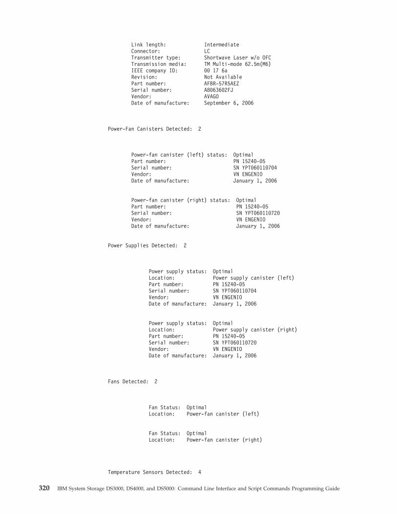
Link length: IntermediateConnector: LCTransmitter type: Shortwave Laser w/o OFCTransmission media: TM Multi-mode 62.5m(M6)IEEE company ID: 00 17 6aRevision: Not AvailablePart number: AFBR-57R5AEZSerial number: A8063602FJVendor: AVAGODate of manufacture: September 6, 2006
Power-Fan Canisters Detected: 2
Power-fan canister (left) status: OptimalPart number: PN 15240-05Serial number: SN YPT060110704Vendor: VN ENGENIODate of manufacture: January 1, 2006
Power-fan canister (right) status: OptimalPart number: PN 15240-05Serial number: SN YPT060110720Vendor: VN ENGENIODate of manufacture: January 1, 2006
Power Supplies Detected: 2
Power supply status: OptimalLocation: Power supply canister (left)Part number: PN 15240-05Serial number: SN YPT060110704Vendor: VN ENGENIODate of manufacture: January 1, 2006
Power supply status: OptimalLocation: Power supply canister (right)Part number: PN 15240-05Serial number: SN YPT060110720Vendor: VN ENGENIODate of manufacture: January 1, 2006
Fans Detected: 2
Fan Status: OptimalLocation: Power-fan canister (left)
Fan Status: OptimalLocation: Power-fan canister (right)
Temperature Sensors Detected: 4
320 IBM System Storage DS3000, DS4000, and DS5000: Command Line Interface and Script Commands Programming Guide
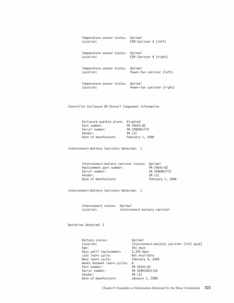
Temperature sensor status: OptimalLocation: ESM Canister A (left)
Temperature sensor status: OptimalLocation: ESM Canister B (right)
Temperature sensor status: OptimalLocation: Power-fan canister (left)
Temperature sensor status: OptimalLocation: Power-fan canister (right)
Controller Enclosure 85 Overall Component Information
Enclosure audible alarm: DisabledPart number: PN 24643-02Serial number: SN SP80961772Vendor: VN LSIDate of manufacture: February 1, 2008
Interconnect-Battery Canisters Detected: 1
Interconnect-battery canister status: OptimalReplacement part number: PN 24643-02Serial number: SN SP80961772Vendor: VN LSIDate of manufacture: February 1, 2008
Interconnect-Battery Canisters Detected: 1
Interconnect status: OptimalLocation: Interconnect-battery canister
Batteries Detected: 2
Battery status: OptimalLocation: Interconnect-battery canister (left pack)Age: 361 daysDays until replacement: 3,329 daysLast learn cycle: Not AvailableNext learn cycle: February 4, 2009Weeks between learn cycles: 8Part number: PN 24543-03Serial number: SN SE80100511SAVendor: VN LSIDate of manufacture: January 1, 2008
Chapter 9. Examples of Information Returned by the Show Commands 321
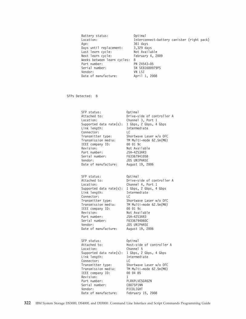
Battery status: OptimalLocation: Interconnect-battery canister (right pack)Age: 361 daysDays until replacement: 3,329 daysLast learn cycle: Not AvailableNext learn cycle: February 4, 2009Weeks between learn cycles: 8Part number: PN 24543-05Serial number: SN SE81600979PSVendor: VN LSIDate of manufacture: April 1, 2008
SFPs Detected: 8
SFP status: OptimalAttached to: Drive-side of controller ALocation: Channel 3, Port 1Supported data rate(s): 1 Gbps, 2 Gbps, 4 GbpsLink length: IntermediateConnector: LCTransmitter type: Shortwave Laser w/o OFCTransmission media: TM Multi-mode 62.5m(M6)IEEE company ID: 00 01 9cRevision: Not AvailablePart number: JSH-42S3AR3Serial number: F6336794105BVendor: JDS UNIPHASEDate of manufacture: August 19, 2006
SFP status: OptimalAttached to: Drive-side of controller ALocation: Channel 4, Port 1Supported data rate(s): 1 Gbps, 2 Gbps, 4 GbpsLink length: IntermediateConnector: LCTransmitter type: Shortwave Laser w/o OFCTransmission media: TM Multi-mode 62.5m(M6)IEEE company ID: 00 01 9cRevision: Not AvailablePart number: JSH-42S3AR3Serial number: F6336794060CVendor: JDS UNIPHASEDate of manufacture: August 19, 2006
SFP status: OptimalAttached to: Host-side of controller ALocation: Channel 5Supported data rate(s): 1 Gbps, 2 Gbps, 4 GbpsLink length: IntermediateConnector: LCTransmitter type: Shortwave Laser w/o OFCTransmission media: TM Multi-mode 62.5m(M6)IEEE company ID: 00 04 85Revision: 1Part number: PLRXPLVESG462NSerial number: C807SP1NNVendor: PICOLIGHTDate of manufacture: February 15, 2008
322 IBM System Storage DS3000, DS4000, and DS5000: Command Line Interface and Script Commands Programming Guide
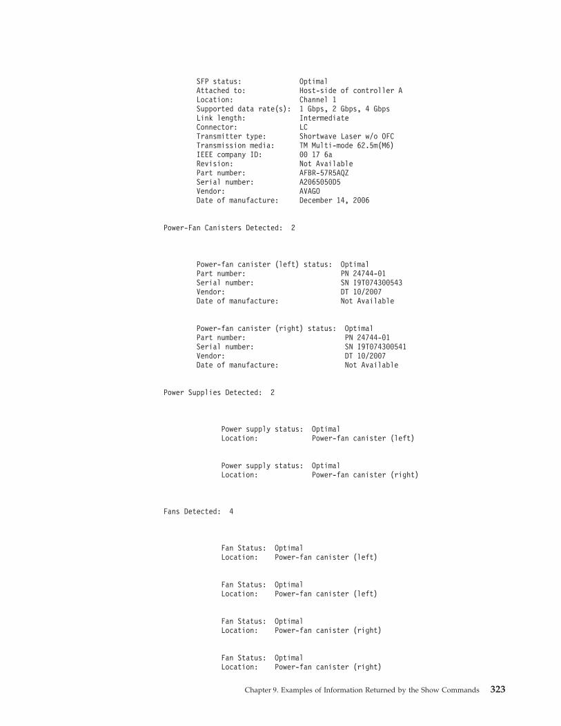
SFP status: OptimalAttached to: Host-side of controller ALocation: Channel 1Supported data rate(s): 1 Gbps, 2 Gbps, 4 GbpsLink length: IntermediateConnector: LCTransmitter type: Shortwave Laser w/o OFCTransmission media: TM Multi-mode 62.5m(M6)IEEE company ID: 00 17 6aRevision: Not AvailablePart number: AFBR-57R5AQZSerial number: A2065050D5Vendor: AVAGODate of manufacture: December 14, 2006
Power-Fan Canisters Detected: 2
Power-fan canister (left) status: OptimalPart number: PN 24744-01Serial number: SN I9T074300543Vendor: DT 10/2007Date of manufacture: Not Available
Power-fan canister (right) status: OptimalPart number: PN 24744-01Serial number: SN I9T074300541Vendor: DT 10/2007Date of manufacture: Not Available
Power Supplies Detected: 2
Power supply status: OptimalLocation: Power-fan canister (left)
Power supply status: OptimalLocation: Power-fan canister (right)
Fans Detected: 4
Fan Status: OptimalLocation: Power-fan canister (left)
Fan Status: OptimalLocation: Power-fan canister (left)
Fan Status: OptimalLocation: Power-fan canister (right)
Fan Status: OptimalLocation: Power-fan canister (right)
Chapter 9. Examples of Information Returned by the Show Commands 323
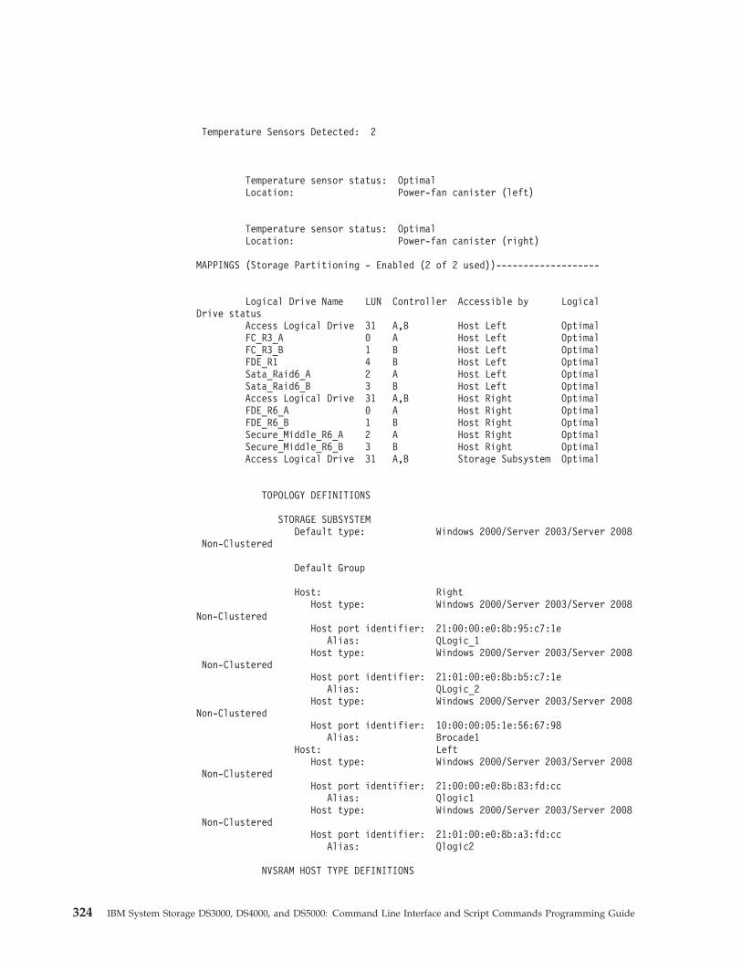
Temperature Sensors Detected: 2
Temperature sensor status: OptimalLocation: Power-fan canister (left)
Temperature sensor status: OptimalLocation: Power-fan canister (right)
MAPPINGS (Storage Partitioning - Enabled (2 of 2 used))-------------------
Logical Drive Name LUN Controller Accessible by LogicalDrive status
Access Logical Drive 31 A,B Host Left OptimalFC_R3_A 0 A Host Left OptimalFC_R3_B 1 B Host Left OptimalFDE_R1 4 B Host Left OptimalSata_Raid6_A 2 A Host Left OptimalSata_Raid6_B 3 B Host Left OptimalAccess Logical Drive 31 A,B Host Right OptimalFDE_R6_A 0 A Host Right OptimalFDE_R6_B 1 B Host Right OptimalSecure_Middle_R6_A 2 A Host Right OptimalSecure_Middle_R6_B 3 B Host Right OptimalAccess Logical Drive 31 A,B Storage Subsystem Optimal
TOPOLOGY DEFINITIONS
STORAGE SUBSYSTEMDefault type: Windows 2000/Server 2003/Server 2008
Non-Clustered
Default Group
Host: RightHost type: Windows 2000/Server 2003/Server 2008
Non-ClusteredHost port identifier: 21:00:00:e0:8b:95:c7:1e
Alias: QLogic_1Host type: Windows 2000/Server 2003/Server 2008
Non-ClusteredHost port identifier: 21:01:00:e0:8b:b5:c7:1e
Alias: QLogic_2Host type: Windows 2000/Server 2003/Server 2008
Non-ClusteredHost port identifier: 10:00:00:05:1e:56:67:98
Alias: Brocade1Host: Left
Host type: Windows 2000/Server 2003/Server 2008Non-Clustered
Host port identifier: 21:00:00:e0:8b:83:fd:ccAlias: Qlogic1
Host type: Windows 2000/Server 2003/Server 2008Non-Clustered
Host port identifier: 21:01:00:e0:8b:a3:fd:ccAlias: Qlogic2
NVSRAM HOST TYPE DEFINITIONS
324 IBM System Storage DS3000, DS4000, and DS5000: Command Line Interface and Script Commands Programming Guide
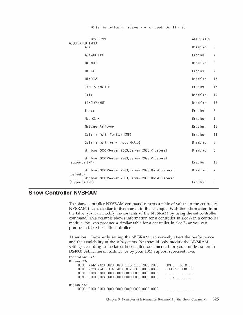
NOTE: The following indexes are not used: 16, 18 - 31
HOST TYPE ADT STATUSASSOCIATED INDEX
AIX Disabled 6
AIX-ADT/AVT Enabled 4
DEFAULT Disabled 0
HP-UX Enabled 7
HPXTPGS Disabled 17
IBM TS SAN VCE Enabled 12
Irix Disabled 10
LNXCLVMWARE Disabled 13
Linux Enabled 5
Mac OS X Enabled 1
Netware Failover Enabled 11
Solaris (with Veritas DMP) Enabled 14
Solaris (with or without MPXIO) Disabled 8
Windows 2000/Server 2003/Server 2008 Clustered Disabled 3
Windows 2000/Server 2003/Server 2008 Clustered(supports DMP) Enabled 15
Windows 2000/Server 2003/Server 2008 Non-Clustered Disabled 2(Default)
Windows 2000/Server 2003/Server 2008 Non-Clustered(supports DMP) Enabled 9
Show Controller NVSRAM
The show controller NVSRAM command returns a table of values in the controllerNVSRAM that is similar to that shown in this example. With the information fromthe table, you can modify the contents of the NVSRAM by using the set controllercommand. This example shows information for a controller in slot A in a controllermodule. You can produce a similar table for a controller in slot B, or you canproduce a table for both controllers.
Attention: Incorrectly setting the NVSRAM can severely affect the performanceand the availability of the subsystems. You should only modify the NVSRAMsettings according to the latest information documented for your configuration inDS4000 publications, readmes, or by your IBM support representative.Controller "a":Region 226:
0000: 4942 4d20 2020 2020 3138 3138 2020 2020 IBM.....1818....0010: 2020 4641 5374 5420 3037 3330 0000 0000 ..FAStT.0730....0020: 0000 0000 0000 0000 0000 0000 0000 0000 ................0030: 0000 0008 5600 0000 0000 0000 0000 0000 ....V...........
Region 232:0000: 0000 0000 0000 0000 0000 0000 0000 0000 ................
Chapter 9. Examples of Information Returned by the Show Commands 325
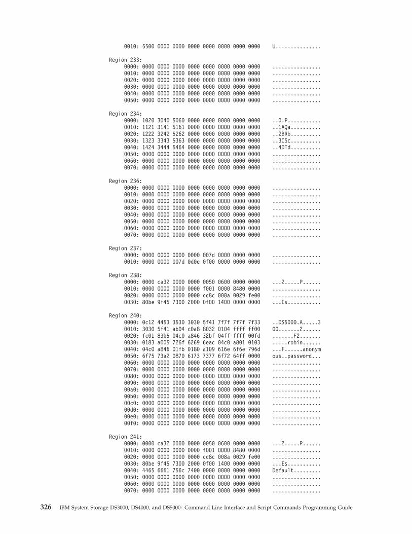
0010: 5500 0000 0000 0000 0000 0000 0000 0000 U...............
Region 233:0000: 0000 0000 0000 0000 0000 0000 0000 0000 ................0010: 0000 0000 0000 0000 0000 0000 0000 0000 ................0020: 0000 0000 0000 0000 0000 0000 0000 0000 ................0030: 0000 0000 0000 0000 0000 0000 0000 0000 ................0040: 0000 0000 0000 0000 0000 0000 0000 0000 ................0050: 0000 0000 0000 0000 0000 0000 0000 0000 ................
Region 234:0000: 1020 3040 5060 0000 0000 0000 0000 0000 ..0.P...........0010: 1121 3141 5161 0000 0000 0000 0000 0000 ..1AQa..........0020: 1222 3242 5262 0000 0000 0000 0000 0000 ..2BRb..........0030: 1323 3343 5363 0000 0000 0000 0000 0000 ..3CSc..........0040: 1424 3444 5464 0000 0000 0000 0000 0000 ..4DTd..........0050: 0000 0000 0000 0000 0000 0000 0000 0000 ................0060: 0000 0000 0000 0000 0000 0000 0000 0000 ................0070: 0000 0000 0000 0000 0000 0000 0000 0000 ................
Region 236:0000: 0000 0000 0000 0000 0000 0000 0000 0000 ................0010: 0000 0000 0000 0000 0000 0000 0000 0000 ................0020: 0000 0000 0000 0000 0000 0000 0000 0000 ................0030: 0000 0000 0000 0000 0000 0000 0000 0000 ................0040: 0000 0000 0000 0000 0000 0000 0000 0000 ................0050: 0000 0000 0000 0000 0000 0000 0000 0000 ................0060: 0000 0000 0000 0000 0000 0000 0000 0000 ................0070: 0000 0000 0000 0000 0000 0000 0000 0000 ................
Region 237:0000: 0000 0000 0000 0000 007d 0000 0000 0000 ................0010: 0000 0000 007d 0d0e 0f00 0000 0000 0000 ................
Region 238:0000: 0000 ca32 0000 0000 0050 0600 0000 0000 ...2.....P......0010: 0000 0000 0000 0000 f001 0000 8480 0000 ................0020: 0000 0000 0000 0000 cc8c 008a 0029 fe00 ................0030: 80be 9f45 7300 2000 0f00 1400 0000 0000 ...Es...........
Region 240:0000: 0c12 4453 3530 3030 5f41 7f7f 7f7f 7f33 ..DS5000.A.....30010: 3030 5f41 ab04 c0a8 8032 0104 ffff ff00 00.......2......0020: fc01 83b5 04c0 a846 32bf 04ff ffff 00fd .......F2.......0030: 0183 a005 726f 6269 6eac 04c0 a801 0103 .....robin......0040: 04c0 a846 01fb 0180 a109 616e 6f6e 796d ...F......anonym0050: 6f75 73a2 0870 6173 7377 6f72 64ff 0000 ous..password...0060: 0000 0000 0000 0000 0000 0000 0000 0000 ................0070: 0000 0000 0000 0000 0000 0000 0000 0000 ................0080: 0000 0000 0000 0000 0000 0000 0000 0000 ................0090: 0000 0000 0000 0000 0000 0000 0000 0000 ................00a0: 0000 0000 0000 0000 0000 0000 0000 0000 ................00b0: 0000 0000 0000 0000 0000 0000 0000 0000 ................00c0: 0000 0000 0000 0000 0000 0000 0000 0000 ................00d0: 0000 0000 0000 0000 0000 0000 0000 0000 ................00e0: 0000 0000 0000 0000 0000 0000 0000 0000 ................00f0: 0000 0000 0000 0000 0000 0000 0000 0000 ................
Region 241:0000: 0000 ca32 0000 0000 0050 0600 0000 0000 ...2.....P......0010: 0000 0000 0000 0000 f001 0000 8480 0000 ................0020: 0000 0000 0000 0000 cc8c 008a 0029 fe00 ................0030: 80be 9f45 7300 2000 0f00 1400 0000 0000 ...Es...........0040: 4465 6661 756c 7400 0000 0000 0000 0000 Default.........0050: 0000 0000 0000 0000 0000 0000 0000 0000 ................0060: 0000 0000 0000 0000 0000 0000 0000 0000 ................0070: 0000 0000 0000 0000 0000 0000 0000 0000 ................
326 IBM System Storage DS3000, DS4000, and DS5000: Command Line Interface and Script Commands Programming Guide
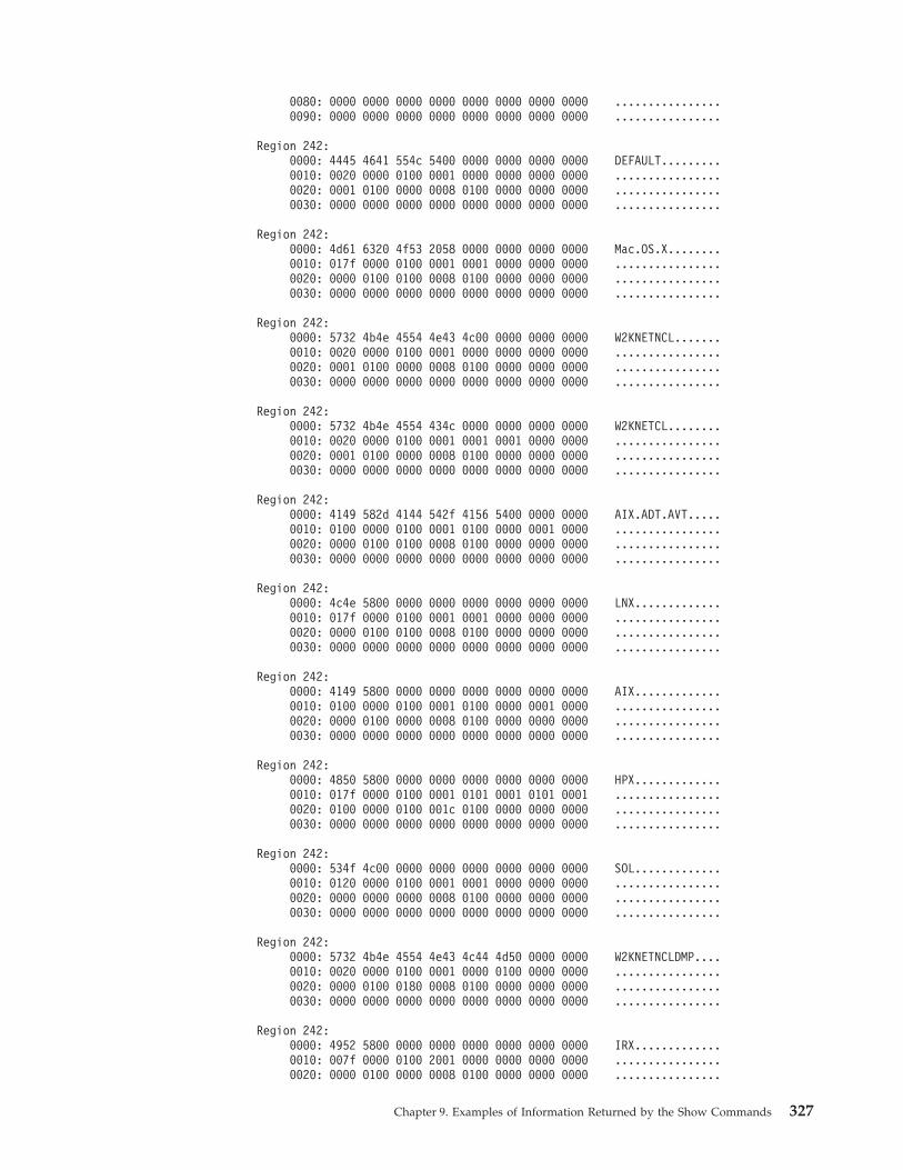
0080: 0000 0000 0000 0000 0000 0000 0000 0000 ................0090: 0000 0000 0000 0000 0000 0000 0000 0000 ................
Region 242:0000: 4445 4641 554c 5400 0000 0000 0000 0000 DEFAULT.........0010: 0020 0000 0100 0001 0000 0000 0000 0000 ................0020: 0001 0100 0000 0008 0100 0000 0000 0000 ................0030: 0000 0000 0000 0000 0000 0000 0000 0000 ................
Region 242:0000: 4d61 6320 4f53 2058 0000 0000 0000 0000 Mac.OS.X........0010: 017f 0000 0100 0001 0001 0000 0000 0000 ................0020: 0000 0100 0100 0008 0100 0000 0000 0000 ................0030: 0000 0000 0000 0000 0000 0000 0000 0000 ................
Region 242:0000: 5732 4b4e 4554 4e43 4c00 0000 0000 0000 W2KNETNCL.......0010: 0020 0000 0100 0001 0000 0000 0000 0000 ................0020: 0001 0100 0000 0008 0100 0000 0000 0000 ................0030: 0000 0000 0000 0000 0000 0000 0000 0000 ................
Region 242:0000: 5732 4b4e 4554 434c 0000 0000 0000 0000 W2KNETCL........0010: 0020 0000 0100 0001 0001 0001 0000 0000 ................0020: 0001 0100 0000 0008 0100 0000 0000 0000 ................0030: 0000 0000 0000 0000 0000 0000 0000 0000 ................
Region 242:0000: 4149 582d 4144 542f 4156 5400 0000 0000 AIX.ADT.AVT.....0010: 0100 0000 0100 0001 0100 0000 0001 0000 ................0020: 0000 0100 0100 0008 0100 0000 0000 0000 ................0030: 0000 0000 0000 0000 0000 0000 0000 0000 ................
Region 242:0000: 4c4e 5800 0000 0000 0000 0000 0000 0000 LNX.............0010: 017f 0000 0100 0001 0001 0000 0000 0000 ................0020: 0000 0100 0100 0008 0100 0000 0000 0000 ................0030: 0000 0000 0000 0000 0000 0000 0000 0000 ................
Region 242:0000: 4149 5800 0000 0000 0000 0000 0000 0000 AIX.............0010: 0100 0000 0100 0001 0100 0000 0001 0000 ................0020: 0000 0100 0000 0008 0100 0000 0000 0000 ................0030: 0000 0000 0000 0000 0000 0000 0000 0000 ................
Region 242:0000: 4850 5800 0000 0000 0000 0000 0000 0000 HPX.............0010: 017f 0000 0100 0001 0101 0001 0101 0001 ................0020: 0100 0000 0100 001c 0100 0000 0000 0000 ................0030: 0000 0000 0000 0000 0000 0000 0000 0000 ................
Region 242:0000: 534f 4c00 0000 0000 0000 0000 0000 0000 SOL.............0010: 0120 0000 0100 0001 0001 0000 0000 0000 ................0020: 0000 0000 0000 0008 0100 0000 0000 0000 ................0030: 0000 0000 0000 0000 0000 0000 0000 0000 ................
Region 242:0000: 5732 4b4e 4554 4e43 4c44 4d50 0000 0000 W2KNETNCLDMP....0010: 0020 0000 0100 0001 0000 0100 0000 0000 ................0020: 0000 0100 0180 0008 0100 0000 0000 0000 ................0030: 0000 0000 0000 0000 0000 0000 0000 0000 ................
Region 242:0000: 4952 5800 0000 0000 0000 0000 0000 0000 IRX.............0010: 007f 0000 0100 2001 0000 0000 0000 0000 ................0020: 0000 0100 0000 0008 0100 0000 0000 0000 ................
Chapter 9. Examples of Information Returned by the Show Commands 327
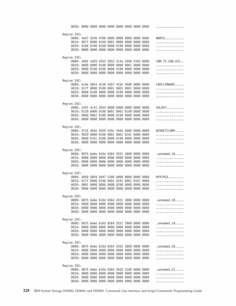
0030: 0000 0000 0000 0000 0000 0000 0000 0000 ................
Region 242:0000: 4e57 5246 4f00 0000 0000 0000 0000 0000 NWRFO...........0010: 007f 0000 0100 0001 0000 0000 0000 0000 ................0020: 0100 0100 0100 0008 0100 0000 0000 0000 ................0030: 0000 0000 0000 0000 0000 0000 0000 0000 ................
Region 242:0000: 4942 4d20 5453 2053 414e 2056 4345 0000 IBM.TS.SAN.VCE..0010: 0000 0000 0100 0000 0000 0001 0000 0000 ................0020: 0000 0100 0100 0008 0100 0000 0000 0000 ................0030: 0000 0000 0000 0000 0000 0000 0000 0000 ................
Region 242:0000: 4c4e 5843 4c56 4d57 4152 4500 0000 0000 LNXCLVMWARE.....0010: 017f 0000 0100 0001 0001 0001 0000 0000 ................0020: 0000 0100 0000 0008 0100 0000 0000 0000 ................0030: 0000 0000 0000 0000 0000 0000 0000 0000 ................
Region 242:0000: 534f 4c41 5654 0000 0000 0000 0000 0000 SOLAVT..........0010: 0120 0000 0100 0001 0001 0100 0000 0000 ................0020: 0000 0001 0180 0000 0100 0000 0000 0000 ................0030: 0000 0000 0000 0000 0000 0000 0000 0000 ................
Region 242:0000: 5732 4b4e 4554 434c 444d 5000 0000 0000 W2KNETCLDMP.....0010: 0020 0000 0100 0001 0001 0101 0000 0000 ................0020: 0000 0101 0180 0008 0100 0000 0000 0000 ................0030: 0000 0000 0000 0000 0000 0000 0000 0000 ................
Region 242:0000: 0075 6e6e 616d 6564 2031 3600 0000 0000 .unnamed.16.....0010: 0000 0000 0000 0000 0000 0000 0000 0000 ................0020: 0000 0000 0000 0000 0000 0000 0000 0000 ................0030: 0000 0000 0000 0000 0000 0000 0000 0000 ................
Region 242:0000: 4850 5854 5047 5300 0000 0000 0000 0000 HPXTPGS.........0010: 017f 0000 0100 0001 0101 0001 0101 0000 ................0020: 0001 0000 0000 0008 0200 0000 0000 0000 ................0030: 0000 0000 0000 0000 0000 0000 0000 0000 ................
Region 242:0000: 0075 6e6e 616d 6564 2031 3800 0000 0000 .unnamed.18.....0010: 0000 0000 0000 0000 0000 0000 0000 0000 ................0020: 0000 0000 0000 0000 0000 0000 0000 0000 ................0030: 0000 0000 0000 0000 0000 0000 0000 0000 ................
Region 242:0000: 0075 6e6e 616d 6564 2031 3900 0000 0000 .unnamed.19.....0010: 0000 0000 0000 0000 0000 0000 0000 0000 ................0020: 0000 0000 0000 0000 0000 0000 0000 0000 ................0030: 0000 0000 0000 0000 0000 0000 0000 0000 ................
Region 242:0000: 0075 6e6e 616d 6564 2032 3000 0000 0000 .unnamed.20.....0010: 0000 0000 0000 0000 0000 0000 0000 0000 ................0020: 0000 0000 0000 0000 0000 0000 0000 0000 ................0030: 0000 0000 0000 0000 0000 0000 0000 0000 ................
Region 242:0000: 0075 6e6e 616d 6564 2032 3100 0000 0000 .unnamed.21.....0010: 0000 0000 0000 0000 0000 0000 0000 0000 ................0020: 0000 0000 0000 0000 0000 0000 0000 0000 ................0030: 0000 0000 0000 0000 0000 0000 0000 0000 ................
328 IBM System Storage DS3000, DS4000, and DS5000: Command Line Interface and Script Commands Programming Guide
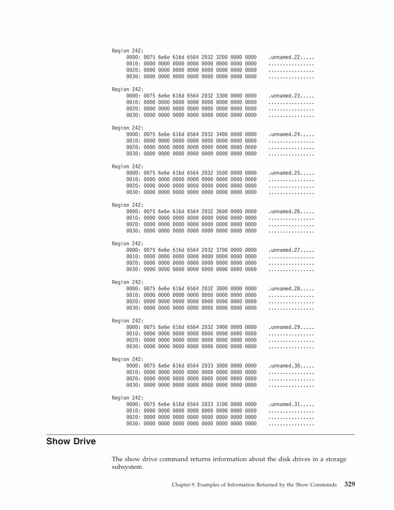
Region 242:0000: 0075 6e6e 616d 6564 2032 3200 0000 0000 .unnamed.22.....0010: 0000 0000 0000 0000 0000 0000 0000 0000 ................0020: 0000 0000 0000 0000 0000 0000 0000 0000 ................0030: 0000 0000 0000 0000 0000 0000 0000 0000 ................
Region 242:0000: 0075 6e6e 616d 6564 2032 3300 0000 0000 .unnamed.23.....0010: 0000 0000 0000 0000 0000 0000 0000 0000 ................0020: 0000 0000 0000 0000 0000 0000 0000 0000 ................0030: 0000 0000 0000 0000 0000 0000 0000 0000 ................
Region 242:0000: 0075 6e6e 616d 6564 2032 3400 0000 0000 .unnamed.24.....0010: 0000 0000 0000 0000 0000 0000 0000 0000 ................0020: 0000 0000 0000 0000 0000 0000 0000 0000 ................0030: 0000 0000 0000 0000 0000 0000 0000 0000 ................
Region 242:0000: 0075 6e6e 616d 6564 2032 3500 0000 0000 .unnamed.25.....0010: 0000 0000 0000 0000 0000 0000 0000 0000 ................0020: 0000 0000 0000 0000 0000 0000 0000 0000 ................0030: 0000 0000 0000 0000 0000 0000 0000 0000 ................
Region 242:0000: 0075 6e6e 616d 6564 2032 3600 0000 0000 .unnamed.26.....0010: 0000 0000 0000 0000 0000 0000 0000 0000 ................0020: 0000 0000 0000 0000 0000 0000 0000 0000 ................0030: 0000 0000 0000 0000 0000 0000 0000 0000 ................
Region 242:0000: 0075 6e6e 616d 6564 2032 3700 0000 0000 .unnamed.27.....0010: 0000 0000 0000 0000 0000 0000 0000 0000 ................0020: 0000 0000 0000 0000 0000 0000 0000 0000 ................0030: 0000 0000 0000 0000 0000 0000 0000 0000 ................
Region 242:0000: 0075 6e6e 616d 6564 2032 3800 0000 0000 .unnamed.28.....0010: 0000 0000 0000 0000 0000 0000 0000 0000 ................0020: 0000 0000 0000 0000 0000 0000 0000 0000 ................0030: 0000 0000 0000 0000 0000 0000 0000 0000 ................
Region 242:0000: 0075 6e6e 616d 6564 2032 3900 0000 0000 .unnamed.29.....0010: 0000 0000 0000 0000 0000 0000 0000 0000 ................0020: 0000 0000 0000 0000 0000 0000 0000 0000 ................0030: 0000 0000 0000 0000 0000 0000 0000 0000 ................
Region 242:0000: 0075 6e6e 616d 6564 2033 3000 0000 0000 .unnamed.30.....0010: 0000 0000 0000 0000 0000 0000 0000 0000 ................0020: 0000 0000 0000 0000 0000 0000 0000 0000 ................0030: 0000 0000 0000 0000 0000 0000 0000 0000 ................
Region 242:0000: 0075 6e6e 616d 6564 2033 3100 0000 0000 .unnamed.31.....0010: 0000 0000 0000 0000 0000 0000 0000 0000 ................0020: 0000 0000 0000 0000 0000 0000 0000 0000 ................0030: 0000 0000 0000 0000 0000 0000 0000 0000 ................
Show Drive
The show drive command returns information about the disk drives in a storagesubsystem.
Chapter 9. Examples of Information Returned by the Show Commands 329
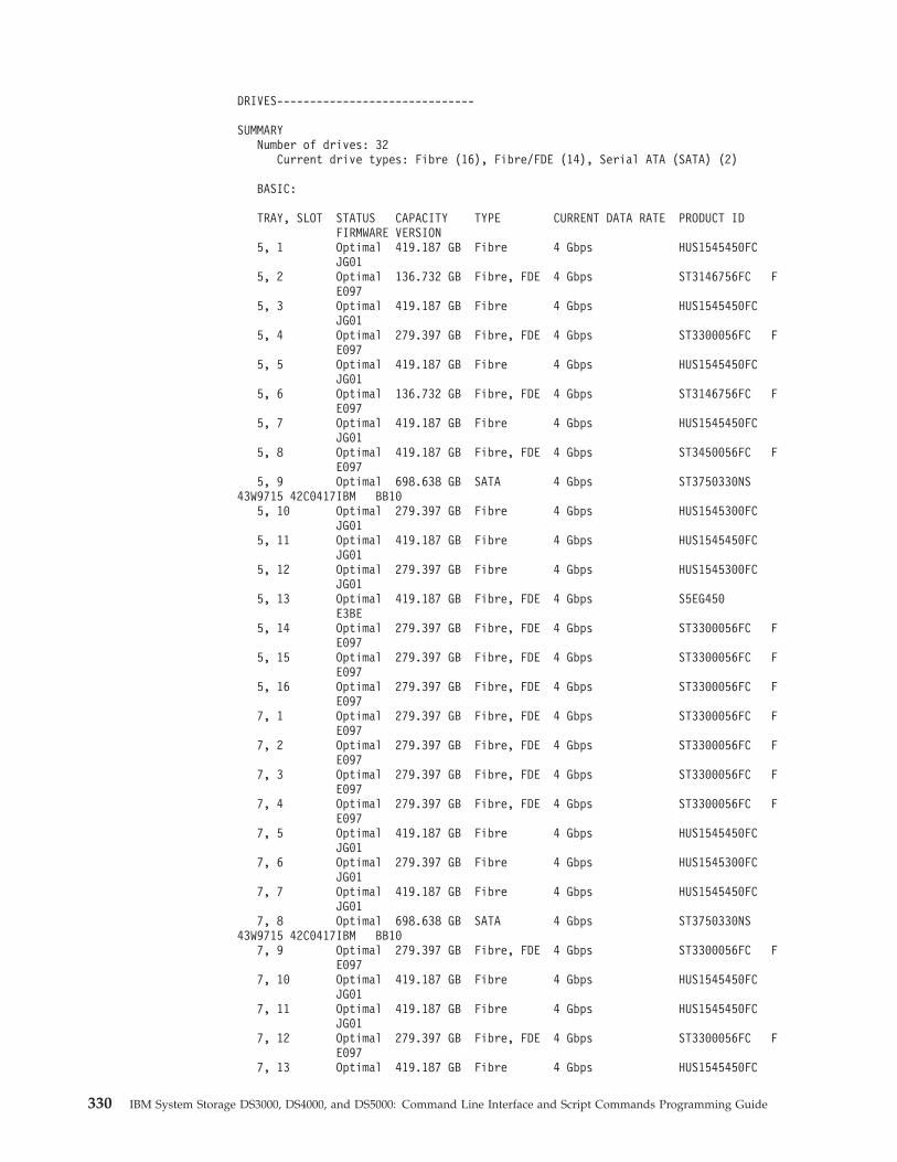
DRIVES------------------------------
SUMMARYNumber of drives: 32
Current drive types: Fibre (16), Fibre/FDE (14), Serial ATA (SATA) (2)
BASIC:
TRAY, SLOT STATUS CAPACITY TYPE CURRENT DATA RATE PRODUCT IDFIRMWARE VERSION
5, 1 Optimal 419.187 GB Fibre 4 Gbps HUS1545450FCJG01
5, 2 Optimal 136.732 GB Fibre, FDE 4 Gbps ST3146756FC FE097
5, 3 Optimal 419.187 GB Fibre 4 Gbps HUS1545450FCJG01
5, 4 Optimal 279.397 GB Fibre, FDE 4 Gbps ST3300056FC FE097
5, 5 Optimal 419.187 GB Fibre 4 Gbps HUS1545450FCJG01
5, 6 Optimal 136.732 GB Fibre, FDE 4 Gbps ST3146756FC FE097
5, 7 Optimal 419.187 GB Fibre 4 Gbps HUS1545450FCJG01
5, 8 Optimal 419.187 GB Fibre, FDE 4 Gbps ST3450056FC FE097
5, 9 Optimal 698.638 GB SATA 4 Gbps ST3750330NS43W9715 42C0417IBM BB10
5, 10 Optimal 279.397 GB Fibre 4 Gbps HUS1545300FCJG01
5, 11 Optimal 419.187 GB Fibre 4 Gbps HUS1545450FCJG01
5, 12 Optimal 279.397 GB Fibre 4 Gbps HUS1545300FCJG01
5, 13 Optimal 419.187 GB Fibre, FDE 4 Gbps S5EG450E3BE
5, 14 Optimal 279.397 GB Fibre, FDE 4 Gbps ST3300056FC FE097
5, 15 Optimal 279.397 GB Fibre, FDE 4 Gbps ST3300056FC FE097
5, 16 Optimal 279.397 GB Fibre, FDE 4 Gbps ST3300056FC FE097
7, 1 Optimal 279.397 GB Fibre, FDE 4 Gbps ST3300056FC FE097
7, 2 Optimal 279.397 GB Fibre, FDE 4 Gbps ST3300056FC FE097
7, 3 Optimal 279.397 GB Fibre, FDE 4 Gbps ST3300056FC FE097
7, 4 Optimal 279.397 GB Fibre, FDE 4 Gbps ST3300056FC FE097
7, 5 Optimal 419.187 GB Fibre 4 Gbps HUS1545450FCJG01
7, 6 Optimal 279.397 GB Fibre 4 Gbps HUS1545300FCJG01
7, 7 Optimal 419.187 GB Fibre 4 Gbps HUS1545450FCJG01
7, 8 Optimal 698.638 GB SATA 4 Gbps ST3750330NS43W9715 42C0417IBM BB10
7, 9 Optimal 279.397 GB Fibre, FDE 4 Gbps ST3300056FC FE097
7, 10 Optimal 419.187 GB Fibre 4 Gbps HUS1545450FCJG01
7, 11 Optimal 419.187 GB Fibre 4 Gbps HUS1545450FCJG01
7, 12 Optimal 279.397 GB Fibre, FDE 4 Gbps ST3300056FC FE097
7, 13 Optimal 419.187 GB Fibre 4 Gbps HUS1545450FC
330 IBM System Storage DS3000, DS4000, and DS5000: Command Line Interface and Script Commands Programming Guide
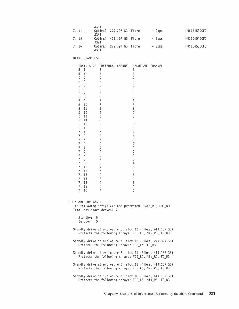
JG017, 14 Optimal 279.397 GB Fibre 4 Gbps HUS1545300FC
JG017, 15 Optimal 419.187 GB Fibre 4 Gbps HUS1545450FC
JG017, 16 Optimal 279.397 GB Fibre 4 Gbps HUS1545300FC
JG01
DRIVE CHANNELS:
TRAY, SLOT PREFERRED CHANNEL REDUNDANT CHANNEL5, 1 5 35, 2 3 55, 3 5 35, 4 3 55, 5 5 35, 6 3 55, 7 5 35, 8 3 55, 9 5 35, 10 3 55, 11 5 35, 12 3 55, 13 5 35, 14 3 55, 15 5 35, 16 3 57, 1 6 47, 2 4 67, 3 6 47, 4 4 67, 5 6 47, 6 4 67, 7 6 47, 8 4 67, 9 6 47, 10 4 67, 11 6 47, 12 4 67, 13 6 47, 14 4 67, 15 6 47, 16 4 6
HOT SPARE COVERAGE:The following arrays are not protected: Sata_R1, FDE_R0Total hot spare drives: 5
Standby: 5In use: 0
Standby drive at enclosure 5, slot 13 (Fibre, 419.187 GB)Protects the following arrays: FDE_R6, Mix_R5, FC_R3
Standby drive at enclosure 7, slot 12 (Fibre, 279.397 GB)Protects the following arrays: FDE_R6, FC_R3
Standby drive at enclosure 7, slot 11 (Fibre, 419.187 GB)Protects the following arrays: FDE_R6, Mix_R5, FC_R3
Standby drive at enclosure 5, slot 11 (Fibre, 419.187 GB)Protects the following arrays: FDE_R6, Mix_R5, FC_R3
Standby drive at enclosure 7, slot 10 (Fibre, 419.187 GB)Protects the following arrays: FDE_R6, Mix_R5, FC_R3
Chapter 9. Examples of Information Returned by the Show Commands 331
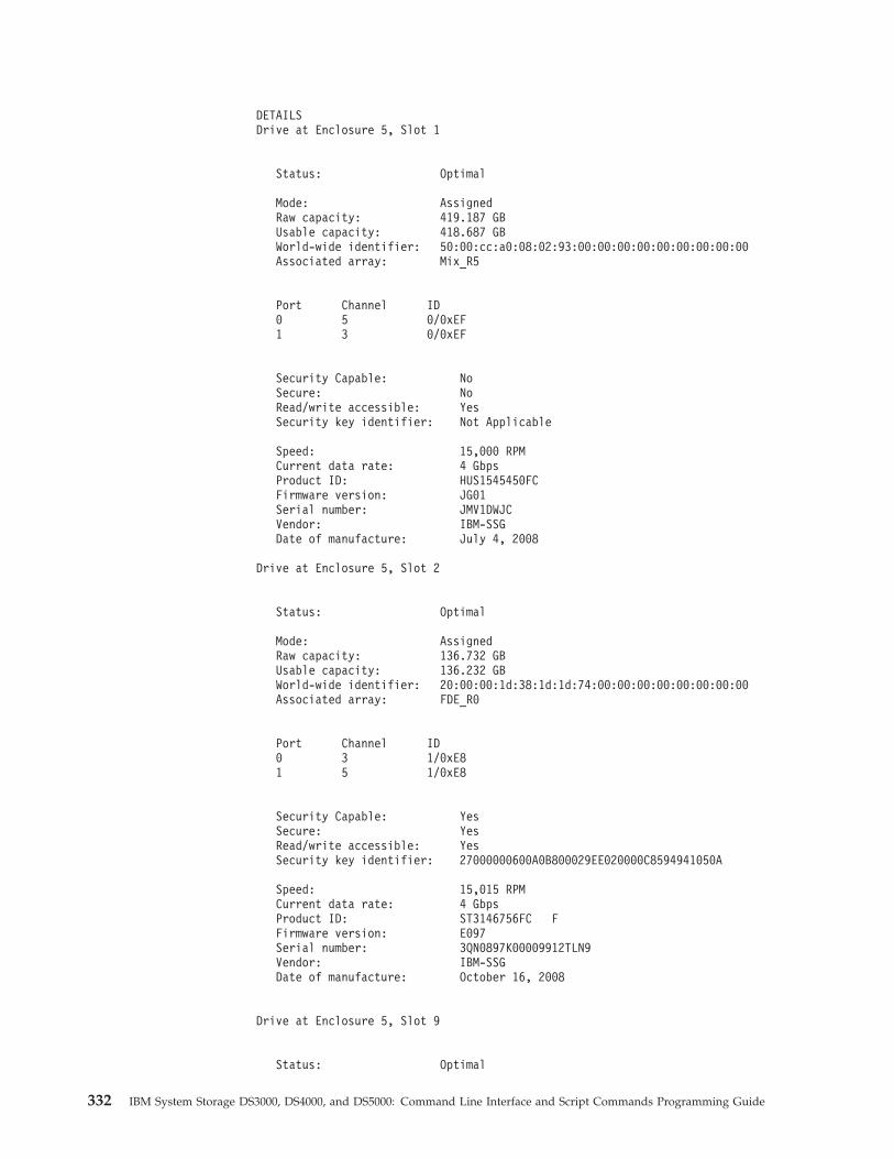
DETAILSDrive at Enclosure 5, Slot 1
Status: Optimal
Mode: AssignedRaw capacity: 419.187 GBUsable capacity: 418.687 GBWorld-wide identifier: 50:00:cc:a0:08:02:93:00:00:00:00:00:00:00:00:00Associated array: Mix_R5
Port Channel ID0 5 0/0xEF1 3 0/0xEF
Security Capable: NoSecure: NoRead/write accessible: YesSecurity key identifier: Not Applicable
Speed: 15,000 RPMCurrent data rate: 4 GbpsProduct ID: HUS1545450FCFirmware version: JG01Serial number: JMV1DWJCVendor: IBM-SSGDate of manufacture: July 4, 2008
Drive at Enclosure 5, Slot 2
Status: Optimal
Mode: AssignedRaw capacity: 136.732 GBUsable capacity: 136.232 GBWorld-wide identifier: 20:00:00:1d:38:1d:1d:74:00:00:00:00:00:00:00:00Associated array: FDE_R0
Port Channel ID0 3 1/0xE81 5 1/0xE8
Security Capable: YesSecure: YesRead/write accessible: YesSecurity key identifier: 27000000600A0B800029EE020000C8594941050A
Speed: 15,015 RPMCurrent data rate: 4 GbpsProduct ID: ST3146756FC FFirmware version: E097Serial number: 3QN0897K00009912TLN9Vendor: IBM-SSGDate of manufacture: October 16, 2008
Drive at Enclosure 5, Slot 9
Status: Optimal
332 IBM System Storage DS3000, DS4000, and DS5000: Command Line Interface and Script Commands Programming Guide
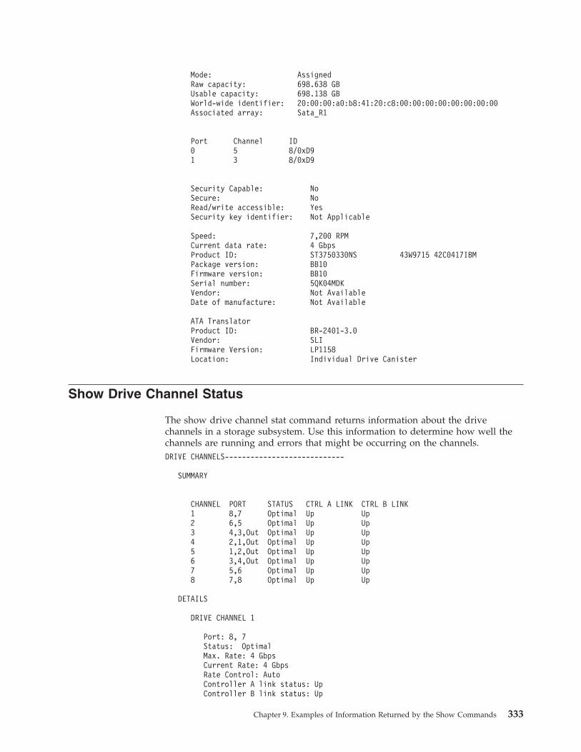
Mode: AssignedRaw capacity: 698.638 GBUsable capacity: 698.138 GBWorld-wide identifier: 20:00:00:a0:b8:41:20:c8:00:00:00:00:00:00:00:00Associated array: Sata_R1
Port Channel ID0 5 8/0xD91 3 8/0xD9
Security Capable: NoSecure: NoRead/write accessible: YesSecurity key identifier: Not Applicable
Speed: 7,200 RPMCurrent data rate: 4 GbpsProduct ID: ST3750330NS 43W9715 42C0417IBMPackage version: BB10Firmware version: BB10Serial number: 5QK04MDKVendor: Not AvailableDate of manufacture: Not Available
ATA TranslatorProduct ID: BR-2401-3.0Vendor: SLIFirmware Version: LP1158Location: Individual Drive Canister
Show Drive Channel Status
The show drive channel stat command returns information about the drivechannels in a storage subsystem. Use this information to determine how well thechannels are running and errors that might be occurring on the channels.DRIVE CHANNELS----------------------------
SUMMARY
CHANNEL PORT STATUS CTRL A LINK CTRL B LINK1 8,7 Optimal Up Up2 6,5 Optimal Up Up3 4,3,Out Optimal Up Up4 2,1,Out Optimal Up Up5 1,2,Out Optimal Up Up6 3,4,Out Optimal Up Up7 5,6 Optimal Up Up8 7,8 Optimal Up Up
DETAILS
DRIVE CHANNEL 1
Port: 8, 7Status: OptimalMax. Rate: 4 GbpsCurrent Rate: 4 GbpsRate Control: AutoController A link status: UpController B link status: Up
Chapter 9. Examples of Information Returned by the Show Commands 333
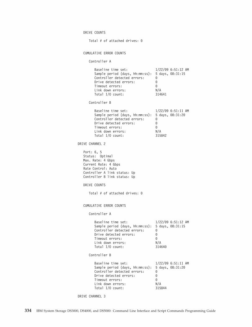
DRIVE COUNTS
Total # of attached drives: 0
CUMULATIVE ERROR COUNTS
Controller A
Baseline time set: 1/22/09 6:51:12 AMSample period (days, hh:mm:ss): 5 days, 08:31:15Controller detected errors: 0Drive detected errors: 0Timeout errors: 0Link down errors: N/ATotal I/O count: 314641
Controller B
Baseline time set: 1/22/09 6:51:11 AMSample period (days, hh:mm:ss): 5 days, 08:31:20Controller detected errors: 0Drive detected errors: 0Timeout errors: 0Link down errors: N/ATotal I/O count: 315842
DRIVE CHANNEL 2
Port: 6, 5Status: OptimalMax. Rate: 4 GbpsCurrent Rate: 4 GbpsRate Control: AutoController A link status: UpController B link status: Up
DRIVE COUNTS
Total # of attached drives: 0
CUMULATIVE ERROR COUNTS
Controller A
Baseline time set: 1/22/09 6:51:12 AMSample period (days, hh:mm:ss): 5 days, 08:31:15Controller detected errors: 0Drive detected errors: 0Timeout errors: 0Link down errors: N/ATotal I/O count: 314640
Controller B
Baseline time set: 1/22/09 6:51:11 AMSample period (days, hh:mm:ss): 5 days, 08:31:20Controller detected errors: 0Drive detected errors: 0Timeout errors: 0Link down errors: N/ATotal I/O count: 315844
DRIVE CHANNEL 3
334 IBM System Storage DS3000, DS4000, and DS5000: Command Line Interface and Script Commands Programming Guide
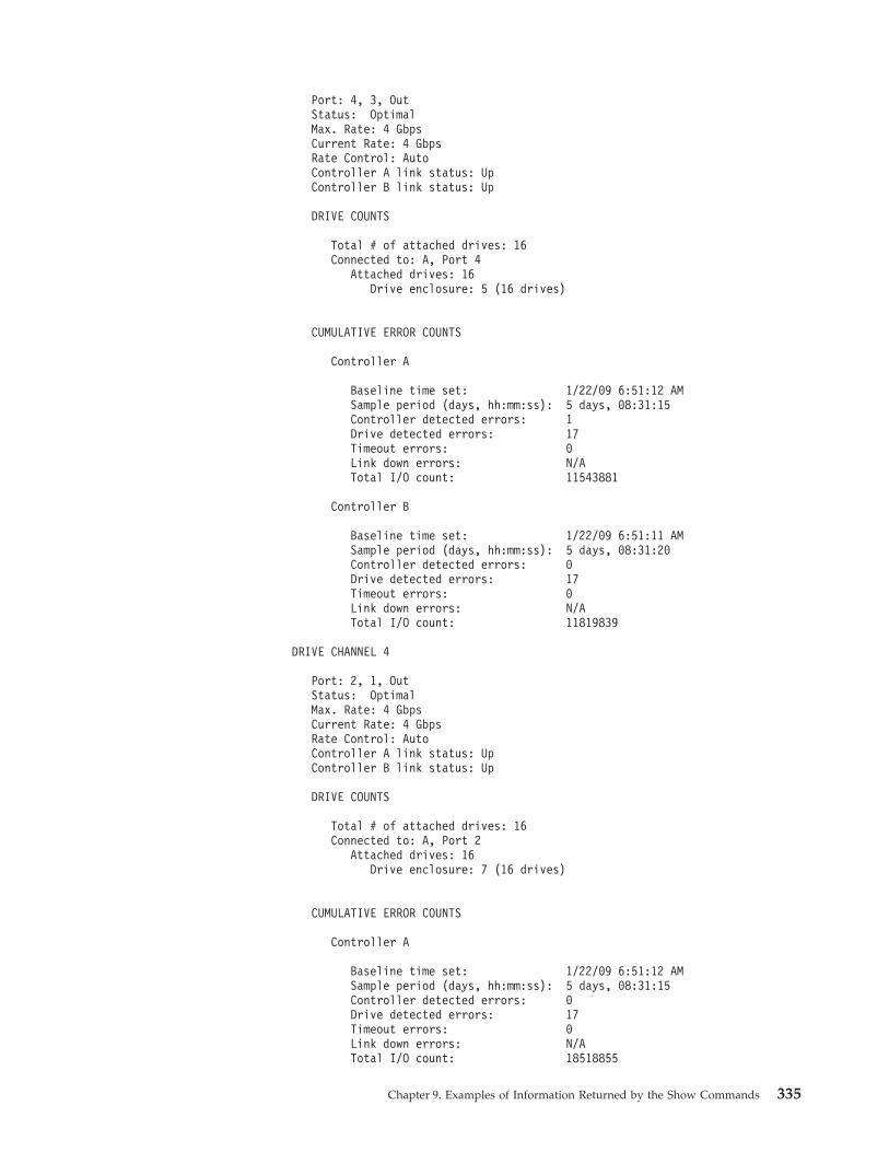
Port: 4, 3, OutStatus: OptimalMax. Rate: 4 GbpsCurrent Rate: 4 GbpsRate Control: AutoController A link status: UpController B link status: Up
DRIVE COUNTS
Total # of attached drives: 16Connected to: A, Port 4
Attached drives: 16Drive enclosure: 5 (16 drives)
CUMULATIVE ERROR COUNTS
Controller A
Baseline time set: 1/22/09 6:51:12 AMSample period (days, hh:mm:ss): 5 days, 08:31:15Controller detected errors: 1Drive detected errors: 17Timeout errors: 0Link down errors: N/ATotal I/O count: 11543881
Controller B
Baseline time set: 1/22/09 6:51:11 AMSample period (days, hh:mm:ss): 5 days, 08:31:20Controller detected errors: 0Drive detected errors: 17Timeout errors: 0Link down errors: N/ATotal I/O count: 11819839
DRIVE CHANNEL 4
Port: 2, 1, OutStatus: OptimalMax. Rate: 4 GbpsCurrent Rate: 4 GbpsRate Control: AutoController A link status: UpController B link status: Up
DRIVE COUNTS
Total # of attached drives: 16Connected to: A, Port 2
Attached drives: 16Drive enclosure: 7 (16 drives)
CUMULATIVE ERROR COUNTS
Controller A
Baseline time set: 1/22/09 6:51:12 AMSample period (days, hh:mm:ss): 5 days, 08:31:15Controller detected errors: 0Drive detected errors: 17Timeout errors: 0Link down errors: N/ATotal I/O count: 18518855
Chapter 9. Examples of Information Returned by the Show Commands 335
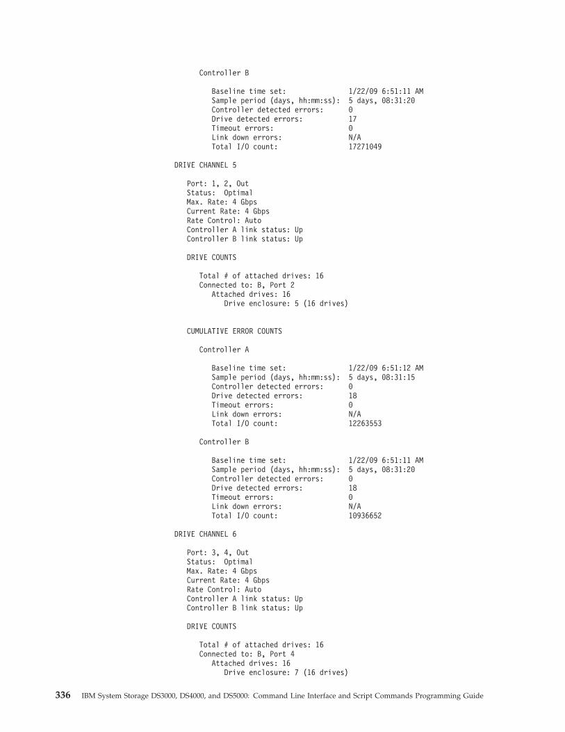
Controller B
Baseline time set: 1/22/09 6:51:11 AMSample period (days, hh:mm:ss): 5 days, 08:31:20Controller detected errors: 0Drive detected errors: 17Timeout errors: 0Link down errors: N/ATotal I/O count: 17271049
DRIVE CHANNEL 5
Port: 1, 2, OutStatus: OptimalMax. Rate: 4 GbpsCurrent Rate: 4 GbpsRate Control: AutoController A link status: UpController B link status: Up
DRIVE COUNTS
Total # of attached drives: 16Connected to: B, Port 2
Attached drives: 16Drive enclosure: 5 (16 drives)
CUMULATIVE ERROR COUNTS
Controller A
Baseline time set: 1/22/09 6:51:12 AMSample period (days, hh:mm:ss): 5 days, 08:31:15Controller detected errors: 0Drive detected errors: 18Timeout errors: 0Link down errors: N/ATotal I/O count: 12263553
Controller B
Baseline time set: 1/22/09 6:51:11 AMSample period (days, hh:mm:ss): 5 days, 08:31:20Controller detected errors: 0Drive detected errors: 18Timeout errors: 0Link down errors: N/ATotal I/O count: 10936652
DRIVE CHANNEL 6
Port: 3, 4, OutStatus: OptimalMax. Rate: 4 GbpsCurrent Rate: 4 GbpsRate Control: AutoController A link status: UpController B link status: Up
DRIVE COUNTS
Total # of attached drives: 16Connected to: B, Port 4
Attached drives: 16Drive enclosure: 7 (16 drives)
336 IBM System Storage DS3000, DS4000, and DS5000: Command Line Interface and Script Commands Programming Guide
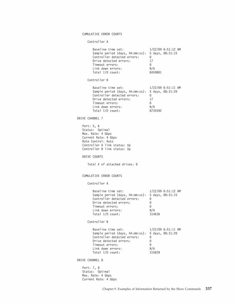
CUMULATIVE ERROR COUNTS
Controller A
Baseline time set: 1/22/09 6:51:12 AMSample period (days, hh:mm:ss): 5 days, 08:31:15Controller detected errors: 0Drive detected errors: 17Timeout errors: 0Link down errors: N/ATotal I/O count: 8459801
Controller B
Baseline time set: 1/22/09 6:51:11 AMSample period (days, hh:mm:ss): 5 days, 08:31:20Controller detected errors: 0Drive detected errors: 17Timeout errors: 0Link down errors: N/ATotal I/O count: 8735592
DRIVE CHANNEL 7
Port: 5, 6Status: OptimalMax. Rate: 4 GbpsCurrent Rate: 4 GbpsRate Control: AutoController A link status: UpController B link status: Up
DRIVE COUNTS
Total # of attached drives: 0
CUMULATIVE ERROR COUNTS
Controller A
Baseline time set: 1/22/09 6:51:12 AMSample period (days, hh:mm:ss): 5 days, 08:31:15Controller detected errors: 0Drive detected errors: 0Timeout errors: 0Link down errors: N/ATotal I/O count: 314636
Controller B
Baseline time set: 1/22/09 6:51:11 AMSample period (days, hh:mm:ss): 5 days, 08:31:20Controller detected errors: 0Drive detected errors: 0Timeout errors: 0Link down errors: N/ATotal I/O count: 315839
DRIVE CHANNEL 8
Port: 7, 8Status: OptimalMax. Rate: 4 GbpsCurrent Rate: 4 Gbps
Chapter 9. Examples of Information Returned by the Show Commands 337
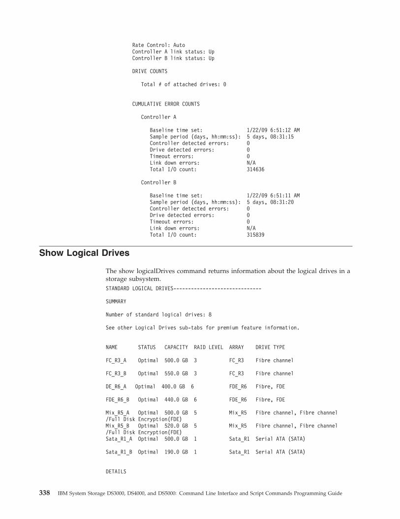
Rate Control: AutoController A link status: UpController B link status: Up
DRIVE COUNTS
Total # of attached drives: 0
CUMULATIVE ERROR COUNTS
Controller A
Baseline time set: 1/22/09 6:51:12 AMSample period (days, hh:mm:ss): 5 days, 08:31:15Controller detected errors: 0Drive detected errors: 0Timeout errors: 0Link down errors: N/ATotal I/O count: 314636
Controller B
Baseline time set: 1/22/09 6:51:11 AMSample period (days, hh:mm:ss): 5 days, 08:31:20Controller detected errors: 0Drive detected errors: 0Timeout errors: 0Link down errors: N/ATotal I/O count: 315839
Show Logical Drives
The show logicalDrives command returns information about the logical drives in astorage subsystem.STANDARD LOGICAL DRIVES------------------------------
SUMMARY
Number of standard logical drives: 8
See other Logical Drives sub-tabs for premium feature information.
NAME STATUS CAPACITY RAID LEVEL ARRAY DRIVE TYPE
FC_R3_A Optimal 500.0 GB 3 FC_R3 Fibre channel
FC_R3_B Optimal 550.0 GB 3 FC_R3 Fibre channel
DE_R6_A Optimal 400.0 GB 6 FDE_R6 Fibre, FDE
FDE_R6_B Optimal 440.0 GB 6 FDE_R6 Fibre, FDE
Mix_R5_A Optimal 500.0 GB 5 Mix_R5 Fibre channel, Fibre channel/Full Disk Encryption(FDE)Mix_R5_B Optimal 520.0 GB 5 Mix_R5 Fibre channel, Fibre channel/Full Disk Encryption(FDE)Sata_R1_A Optimal 500.0 GB 1 Sata_R1 Serial ATA (SATA)
Sata_R1_B Optimal 190.0 GB 1 Sata_R1 Serial ATA (SATA)
DETAILS
338 IBM System Storage DS3000, DS4000, and DS5000: Command Line Interface and Script Commands Programming Guide
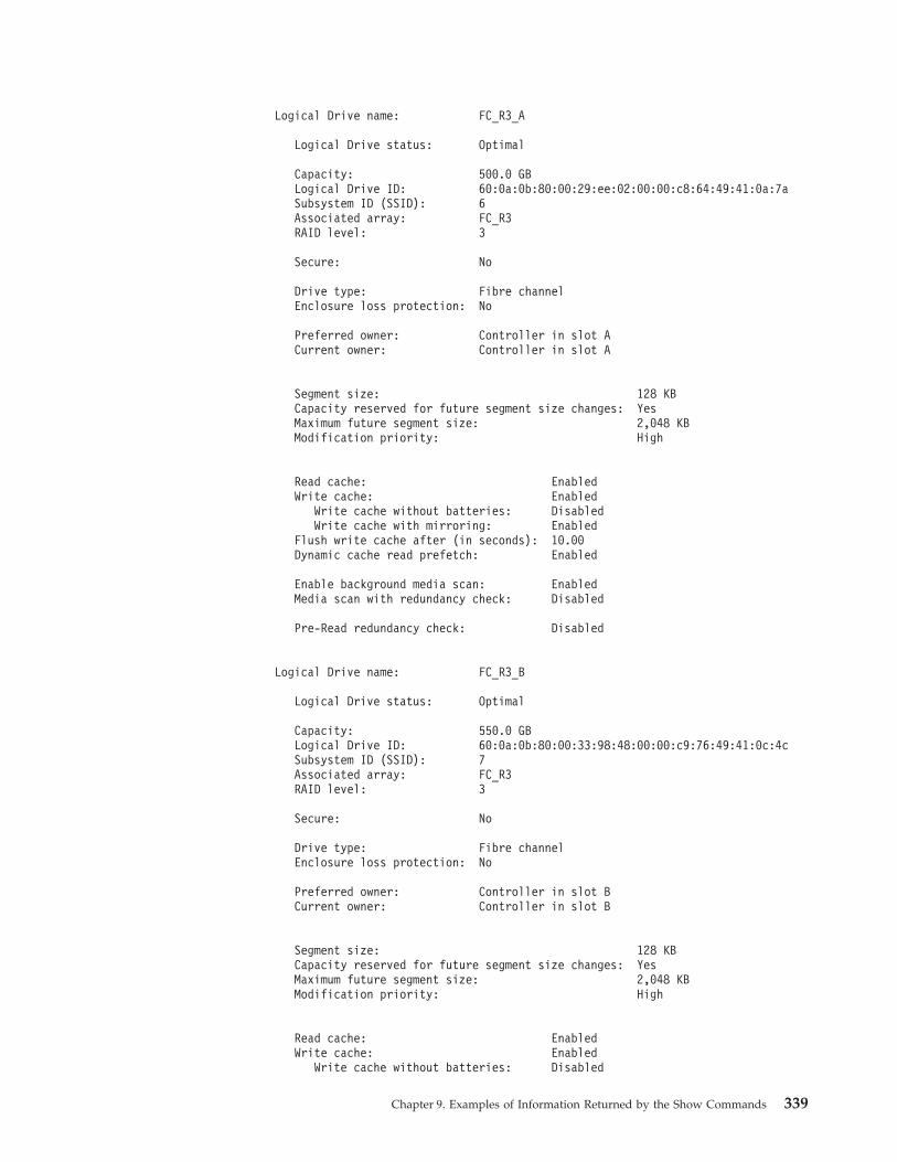
Logical Drive name: FC_R3_A
Logical Drive status: Optimal
Capacity: 500.0 GBLogical Drive ID: 60:0a:0b:80:00:29:ee:02:00:00:c8:64:49:41:0a:7aSubsystem ID (SSID): 6Associated array: FC_R3RAID level: 3
Secure: No
Drive type: Fibre channelEnclosure loss protection: No
Preferred owner: Controller in slot ACurrent owner: Controller in slot A
Segment size: 128 KBCapacity reserved for future segment size changes: YesMaximum future segment size: 2,048 KBModification priority: High
Read cache: EnabledWrite cache: Enabled
Write cache without batteries: DisabledWrite cache with mirroring: Enabled
Flush write cache after (in seconds): 10.00Dynamic cache read prefetch: Enabled
Enable background media scan: EnabledMedia scan with redundancy check: Disabled
Pre-Read redundancy check: Disabled
Logical Drive name: FC_R3_B
Logical Drive status: Optimal
Capacity: 550.0 GBLogical Drive ID: 60:0a:0b:80:00:33:98:48:00:00:c9:76:49:41:0c:4cSubsystem ID (SSID): 7Associated array: FC_R3RAID level: 3
Secure: No
Drive type: Fibre channelEnclosure loss protection: No
Preferred owner: Controller in slot BCurrent owner: Controller in slot B
Segment size: 128 KBCapacity reserved for future segment size changes: YesMaximum future segment size: 2,048 KBModification priority: High
Read cache: EnabledWrite cache: Enabled
Write cache without batteries: Disabled
Chapter 9. Examples of Information Returned by the Show Commands 339
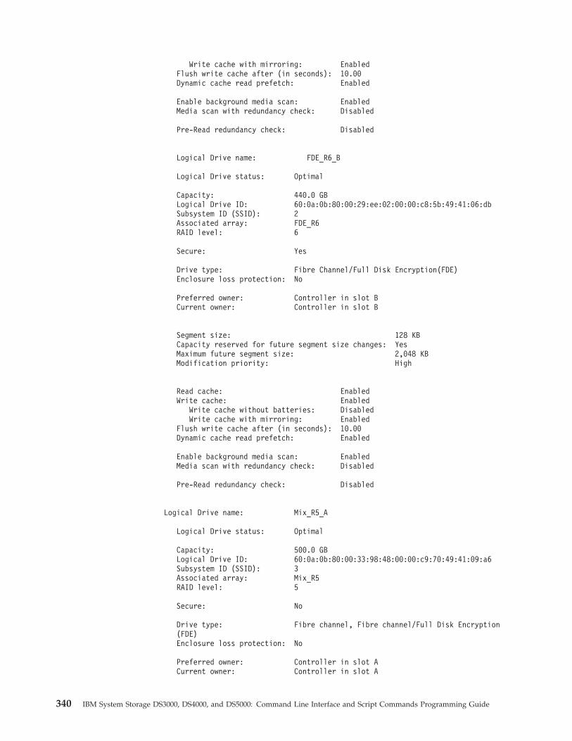
Write cache with mirroring: EnabledFlush write cache after (in seconds): 10.00Dynamic cache read prefetch: Enabled
Enable background media scan: EnabledMedia scan with redundancy check: Disabled
Pre-Read redundancy check: Disabled
Logical Drive name: FDE_R6_B
Logical Drive status: Optimal
Capacity: 440.0 GBLogical Drive ID: 60:0a:0b:80:00:29:ee:02:00:00:c8:5b:49:41:06:dbSubsystem ID (SSID): 2Associated array: FDE_R6RAID level: 6
Secure: Yes
Drive type: Fibre Channel/Full Disk Encryption(FDE)Enclosure loss protection: No
Preferred owner: Controller in slot BCurrent owner: Controller in slot B
Segment size: 128 KBCapacity reserved for future segment size changes: YesMaximum future segment size: 2,048 KBModification priority: High
Read cache: EnabledWrite cache: Enabled
Write cache without batteries: DisabledWrite cache with mirroring: Enabled
Flush write cache after (in seconds): 10.00Dynamic cache read prefetch: Enabled
Enable background media scan: EnabledMedia scan with redundancy check: Disabled
Pre-Read redundancy check: Disabled
Logical Drive name: Mix_R5_A
Logical Drive status: Optimal
Capacity: 500.0 GBLogical Drive ID: 60:0a:0b:80:00:33:98:48:00:00:c9:70:49:41:09:a6Subsystem ID (SSID): 3Associated array: Mix_R5RAID level: 5
Secure: No
Drive type: Fibre channel, Fibre channel/Full Disk Encryption(FDE)Enclosure loss protection: No
Preferred owner: Controller in slot ACurrent owner: Controller in slot A
340 IBM System Storage DS3000, DS4000, and DS5000: Command Line Interface and Script Commands Programming Guide
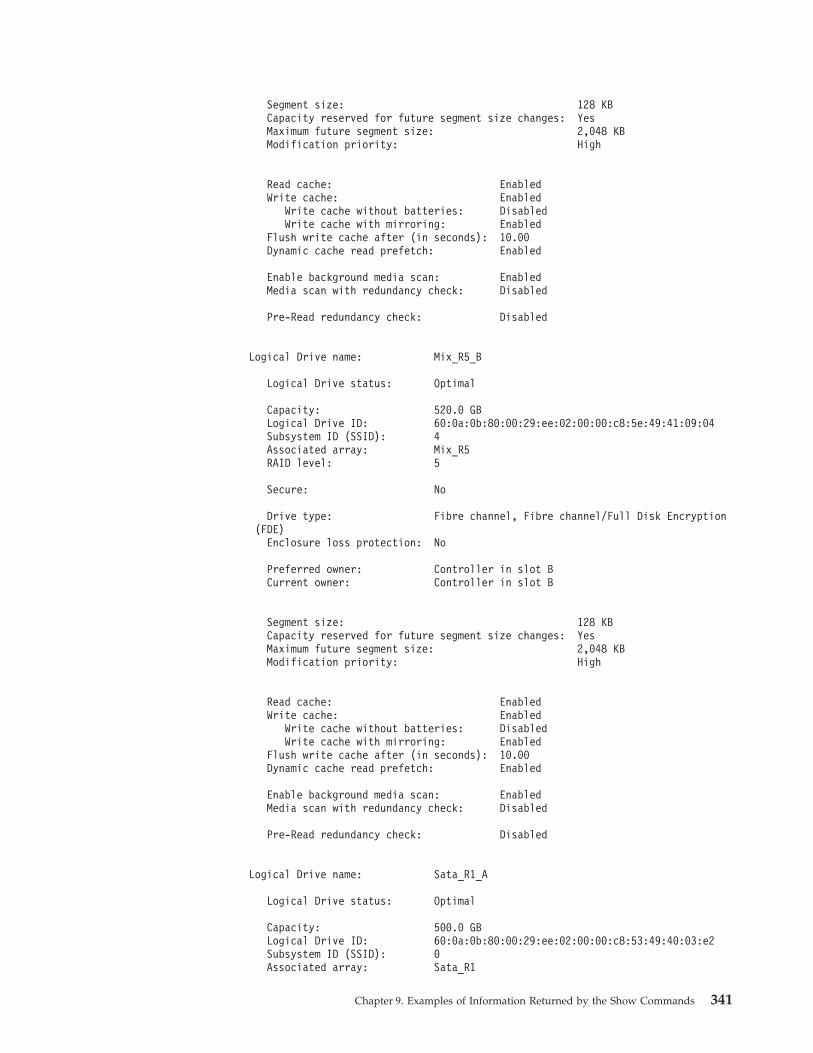
Segment size: 128 KBCapacity reserved for future segment size changes: YesMaximum future segment size: 2,048 KBModification priority: High
Read cache: EnabledWrite cache: Enabled
Write cache without batteries: DisabledWrite cache with mirroring: Enabled
Flush write cache after (in seconds): 10.00Dynamic cache read prefetch: Enabled
Enable background media scan: EnabledMedia scan with redundancy check: Disabled
Pre-Read redundancy check: Disabled
Logical Drive name: Mix_R5_B
Logical Drive status: Optimal
Capacity: 520.0 GBLogical Drive ID: 60:0a:0b:80:00:29:ee:02:00:00:c8:5e:49:41:09:04Subsystem ID (SSID): 4Associated array: Mix_R5RAID level: 5
Secure: No
Drive type: Fibre channel, Fibre channel/Full Disk Encryption(FDE)
Enclosure loss protection: No
Preferred owner: Controller in slot BCurrent owner: Controller in slot B
Segment size: 128 KBCapacity reserved for future segment size changes: YesMaximum future segment size: 2,048 KBModification priority: High
Read cache: EnabledWrite cache: Enabled
Write cache without batteries: DisabledWrite cache with mirroring: Enabled
Flush write cache after (in seconds): 10.00Dynamic cache read prefetch: Enabled
Enable background media scan: EnabledMedia scan with redundancy check: Disabled
Pre-Read redundancy check: Disabled
Logical Drive name: Sata_R1_A
Logical Drive status: Optimal
Capacity: 500.0 GBLogical Drive ID: 60:0a:0b:80:00:29:ee:02:00:00:c8:53:49:40:03:e2Subsystem ID (SSID): 0Associated array: Sata_R1
Chapter 9. Examples of Information Returned by the Show Commands 341
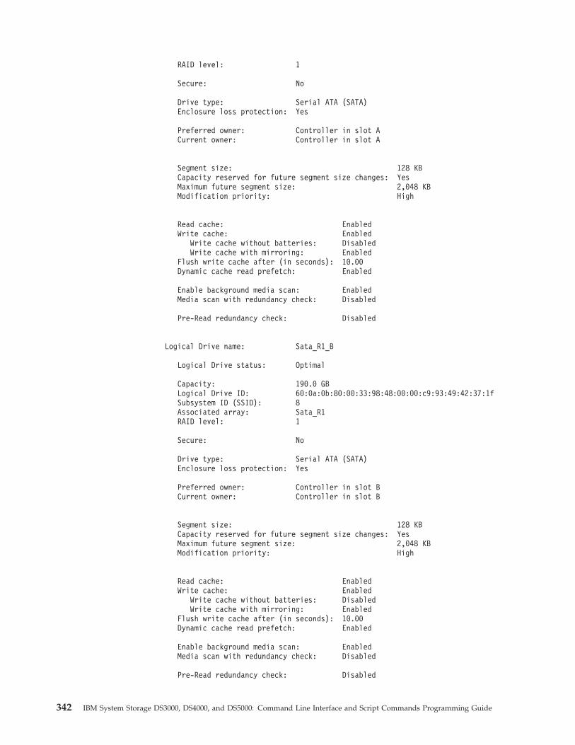
RAID level: 1
Secure: No
Drive type: Serial ATA (SATA)Enclosure loss protection: Yes
Preferred owner: Controller in slot ACurrent owner: Controller in slot A
Segment size: 128 KBCapacity reserved for future segment size changes: YesMaximum future segment size: 2,048 KBModification priority: High
Read cache: EnabledWrite cache: Enabled
Write cache without batteries: DisabledWrite cache with mirroring: Enabled
Flush write cache after (in seconds): 10.00Dynamic cache read prefetch: Enabled
Enable background media scan: EnabledMedia scan with redundancy check: Disabled
Pre-Read redundancy check: Disabled
Logical Drive name: Sata_R1_B
Logical Drive status: Optimal
Capacity: 190.0 GBLogical Drive ID: 60:0a:0b:80:00:33:98:48:00:00:c9:93:49:42:37:1fSubsystem ID (SSID): 8Associated array: Sata_R1RAID level: 1
Secure: No
Drive type: Serial ATA (SATA)Enclosure loss protection: Yes
Preferred owner: Controller in slot BCurrent owner: Controller in slot B
Segment size: 128 KBCapacity reserved for future segment size changes: YesMaximum future segment size: 2,048 KBModification priority: High
Read cache: EnabledWrite cache: Enabled
Write cache without batteries: DisabledWrite cache with mirroring: Enabled
Flush write cache after (in seconds): 10.00Dynamic cache read prefetch: Enabled
Enable background media scan: EnabledMedia scan with redundancy check: Disabled
Pre-Read redundancy check: Disabled
342 IBM System Storage DS3000, DS4000, and DS5000: Command Line Interface and Script Commands Programming Guide

SNAPSHOT REPOSITORY LOGICAL DRIVES------------------------------
Number of flashcopy repositories: 0
SNAPSHOT LOGICAL DRIVES------------------------------
Number of flashcopy logical drives: 0
MISSING LOGICAL DRIVES------------------------------
Number of missing logical drives: 0
Chapter 9. Examples of Information Returned by the Show Commands 343

344 IBM System Storage DS3000, DS4000, and DS5000: Command Line Interface and Script Commands Programming Guide
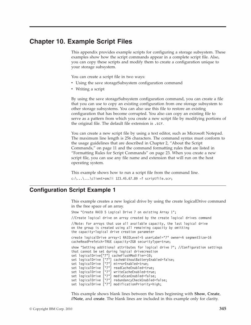
Chapter 10. Example Script Files
This appendix provides example scripts for configuring a storage subsystem. Theseexamples show how the script commands appear in a complete script file. Also,you can copy these scripts and modify them to create a configuration unique toyour storage subsystem.
You can create a script file in two ways:v Using the save storageSubsystem configuration commandv Writing a script
By using the save storageSubsystem configuration command, you can create a filethat you can use to copy an existing configuration from one storage subsystem toother storage subsystems. You can also use this file to restore an existingconfiguration that has become corrupted. You also can copy an existing file toserve as a pattern from which you create a new script file by modifying portions ofthe original file. The default file extension is .scr.
You can create a new script file by using a text editor, such as Microsoft Notepad.The maximum line length is 256 characters. The command syntax must conform tothe usage guidelines that are described in Chapter 2, “About the ScriptCommands,” on page 11 and the command formatting rules that are listed in“Formatting Rules for Script Commands” on page 23. When you create a newscript file, you can use any file name and extension that will run on the hostoperating system.
This example shows how to run a script file from the command line.c:\...\...\client>smcli 123.45.67.89 -f scriptfile.scr;
Configuration Script Example 1
This example creates a new logical drive by using the create logicalDrive commandin the free space of an array.Show “Create RAID 5 Logical Drive 7 on existing Array 1”;
//Create logical drive on array created by the create logical drives command
//Note: For arrays that use all available capacity, the last logical driveon the group is created using all remaining capacity by omittingthe capacity=logical drive creation parameter
create logicalDrive array=1 RAIDLevel=5 userLabel=”7” owner=A segmentSize=16cacheReadPrefetch=TRUE capacity=2GB securityType=true;
show “Setting additional attributes for logical drive 7”; //Configuration settingsthat cannot be set during logical drivecreationset logicalDrive[“7”] cacheFlushModifier=10;set logicalDrive [“7”] cacheWithoutBatteryEnabled=false;set logicalDrive [“7”] mirrorEnabled=true;set logicalDrive [“7”] readCacheEnabled=true;set logicalDrive [“7”] writeCacheEnabled=true;set logicalDrive [“7”] mediaScanEnabled=false;set logicalDrive [“7”] redundancyCheckEnabled=false;set logicalDrive [“7”] modificationPriority=high;
This example shows blank lines between the lines beginning with Show, Create,//Note, and create. The blank lines are included in this example only for clarity.
© Copyright IBM Corp. 2010 345
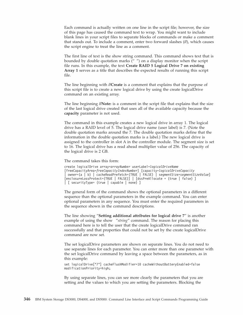
Each command is actually written on one line in the script file; however, the sizeof this page has caused the command text to wrap. You might want to includeblank lines in your script files to separate blocks of commands or make a commentthat stands out. To include a comment, enter two forward slashes (//), which causesthe script engine to treat the line as a comment.
The first line of text is the show string command. This command shows text that isbounded by double quotation marks (“ ”) on a display monitor when the scriptfile runs. In this example, the text Create RAID 5 Logical Drive 7 on existingArray 1 serves as a title that describes the expected results of running this scriptfile.
The line beginning with //Create is a comment that explains that the purpose ofthis script file is to create a new logical drive by using the create logicalDrivecommand on an existing array.
The line beginning //Note: is a comment in the script file that explains that the sizeof the last logical drive created that uses all of the available capacity because thecapacity parameter is not used.
The command in this example creates a new logical drive in array 1. The logicaldrive has a RAID level of 5. The logical drive name (user label) is 7. (Note thedouble quotation marks around the 7. The double quotation marks define that theinformation in the double quotation marks is a label.) The new logical drive isassigned to the controller in slot A in the controller module. The segment size is setto 16. The logical drive has a read ahead multiplier value of 256. The capacity ofthe logical drive is 2 GB.
The command takes this form:create logicalDrive array=arrayNumber userLabel=logicalDriveName[freeCapacityArea=freeCapacityIndexNumber] [capacity=logicalDriveCapacity| owner=(a | b) | cacheReadPrefetch=(TRUE | FALSE) | segmentSize=segmentSizeValue][enclosureLossProtect=(TRUE | FALSE)] | [dssPreAllocate = (true | false) ]| [ securityType= (true | capable | none) ]
The general form of the command shows the optional parameters in a differentsequence than the optional parameters in the example command. You can enteroptional parameters in any sequence. You must enter the required parameters inthe sequence shown in the command descriptions.
The line showing “Setting additional attributes for logical drive 7” is anotherexample of using the show “string” command. The reason for placing thiscommand here is to tell the user that the create logicalDrive command ransuccessfully and that properties that could not be set by the create logicalDrivecommand are now set.
The set logicalDrive parameters are shown on separate lines. You do not need touse separate lines for each parameter. You can enter more than one parameter withthe set logicalDrive command by leaving a space between the parameters, as inthis example:set logicalDrive[“7”] cacheFlushModifier=10 cacheWithoutBatteryEnabled=falsemodificationPriority=high;
By using separate lines, you can see more clearly the parameters that you aresetting and the values to which you are setting the parameters. Blocking the
346 IBM System Storage DS3000, DS4000, and DS5000: Command Line Interface and Script Commands Programming Guide
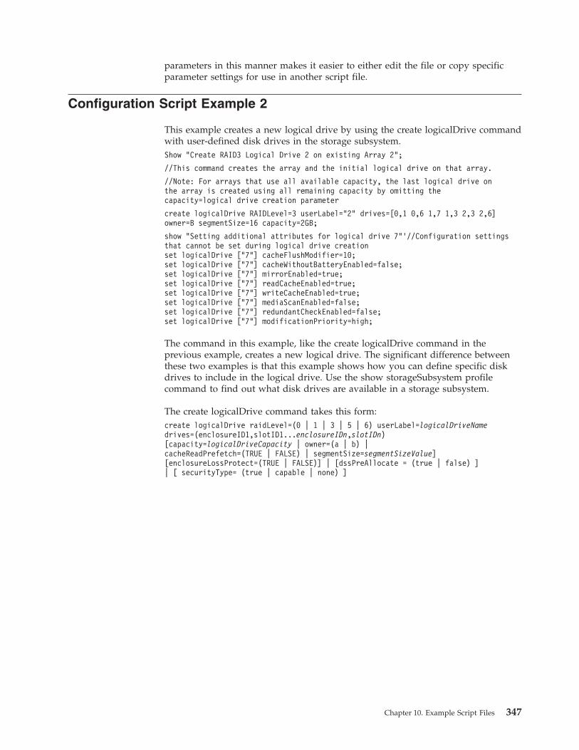
parameters in this manner makes it easier to either edit the file or copy specificparameter settings for use in another script file.
Configuration Script Example 2
This example creates a new logical drive by using the create logicalDrive commandwith user-defined disk drives in the storage subsystem.Show “Create RAID3 Logical Drive 2 on existing Array 2”;
//This command creates the array and the initial logical drive on that array.
//Note: For arrays that use all available capacity, the last logical drive onthe array is created using all remaining capacity by omitting thecapacity=logical drive creation parameter
create logicalDrive RAIDLevel=3 userLabel=”2” drives=[0,1 0,6 1,7 1,3 2,3 2,6]owner=B segmentSize=16 capacity=2GB;
show “Setting additional attributes for logical drive 7”’//Configuration settingsthat cannot be set during logical drive creationset logicalDrive [“7”] cacheFlushModifier=10;set logicalDrive [“7”] cacheWithoutBatteryEnabled=false;set logicalDrive [“7”] mirrorEnabled=true;set logicalDrive [“7”] readCacheEnabled=true;set logicalDrive [“7”] writeCacheEnabled=true;set logicalDrive [“7”] mediaScanEnabled=false;set logicalDrive [“7”] redundantCheckEnabled=false;set logicalDrive [“7”] modificationPriority=high;
The command in this example, like the create logicalDrive command in theprevious example, creates a new logical drive. The significant difference betweenthese two examples is that this example shows how you can define specific diskdrives to include in the logical drive. Use the show storageSubsystem profilecommand to find out what disk drives are available in a storage subsystem.
The create logicalDrive command takes this form:create logicalDrive raidLevel=(0 | 1 | 3 | 5 | 6) userLabel=logicalDriveNamedrives=(enclosureID1,slotID1...enclosureIDn,slotIDn)[capacity=logicalDriveCapacity | owner=(a | b) |cacheReadPrefetch=(TRUE | FALSE) | segmentSize=segmentSizeValue][enclosureLossProtect=(TRUE | FALSE)] | [dssPreAllocate = (true | false) ]| [ securityType= (true | capable | none) ]
Chapter 10. Example Script Files 347

348 IBM System Storage DS3000, DS4000, and DS5000: Command Line Interface and Script Commands Programming Guide
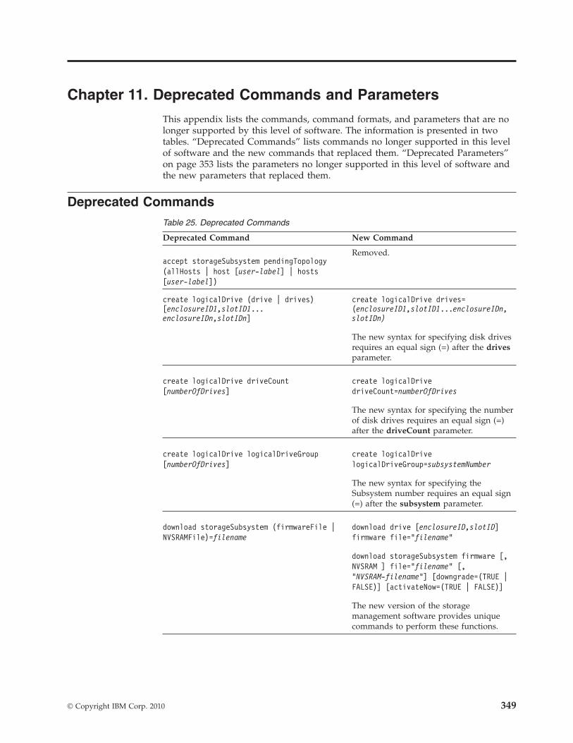
Chapter 11. Deprecated Commands and Parameters
This appendix lists the commands, command formats, and parameters that are nolonger supported by this level of software. The information is presented in twotables. “Deprecated Commands” lists commands no longer supported in this levelof software and the new commands that replaced them. “Deprecated Parameters”on page 353 lists the parameters no longer supported in this level of software andthe new parameters that replaced them.
Deprecated CommandsTable 25. Deprecated Commands
Deprecated Command New Command
accept storageSubsystem pendingTopology(allHosts | host [user-label] | hosts[user-label])
Removed.
create logicalDrive (drive | drives)[enclosureID1,slotID1...enclosureIDn,slotIDn]
create logicalDrive drives=(enclosureID1,slotID1...enclosureIDn,slotIDn)
The new syntax for specifying disk drivesrequires an equal sign (=) after the drivesparameter.
create logicalDrive driveCount[numberOfDrives]
create logicalDrivedriveCount=numberOfDrives
The new syntax for specifying the numberof disk drives requires an equal sign (=)after the driveCount parameter.
create logicalDrive logicalDriveGroup[numberOfDrives]
create logicalDrivelogicalDriveGroup=subsystemNumber
The new syntax for specifying theSubsystem number requires an equal sign(=) after the subsystem parameter.
download storageSubsystem (firmwareFile |NVSRAMFile)=filename
download drive [enclosureID,slotID]firmware file=”filename”
download storageSubsystem firmware [,NVSRAM ] file=”filename” [,“NVSRAM-filename”] [downgrade=(TRUE |FALSE)] [activateNow=(TRUE | FALSE)]
The new version of the storagemanagement software provides uniquecommands to perform these functions.
© Copyright IBM Corp. 2010 349
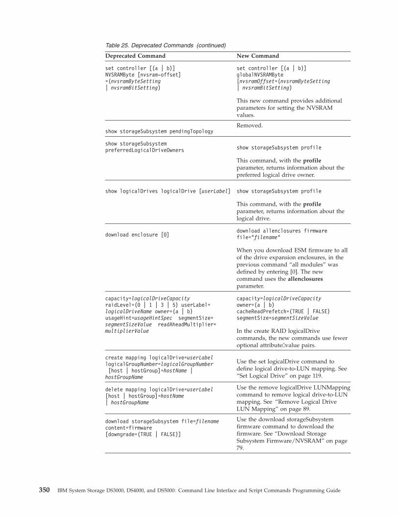
Table 25. Deprecated Commands (continued)
Deprecated Command New Command
set controller [(a | b)]NVSRAMByte [nvsram-offset]=(nvsramByteSetting| nvsramBitSetting)
set controller [(a | b)]globalNVSRAMByte[nvsramOffset=(nvsramByteSetting| nvsramBitSetting)
This new command provides additionalparameters for setting the NVSRAMvalues.
show storageSubsystem pendingTopologyRemoved.
show storageSubsystempreferredLogicalDriveOwners show storageSubsystem profile
This command, with the profileparameter, returns information about thepreferred logical drive owner.
show logicalDrives logicalDrive [userLabel] show storageSubsystem profile
This command, with the profileparameter, returns information about thelogical drive.
download enclosure [0]download allenclosures firmwarefile=”filename”
When you download ESM firmware to allof the drive expansion enclosures, in theprevious command “all modules” wasdefined by entering [0]. The newcommand uses the allenclosuresparameter.
capacity=logicalDriveCapacityraidLevel=(0 | 1 | 3 | 5) userLabel=logicalDriveName owner=(a | b)usageHint=usageHintSpec segmentSize=segmentSizeValue readAheadMultiplier=multiplierValue
capacity=logicalDriveCapacityowner=(a | b)cacheReadPrefetch=(TRUE | FALSE)segmentSize=segmentSizeValue
In the create RAID logicalDrivecommands, the new commands use feweroptional attribute�value pairs.
create mapping logicalDrive=userLabellogicalGroupNumber=logicalGroupNumber[host | hostGroup]=hostName |hostGroupName
Use the set logicalDrive command todefine logical drive-to-LUN mapping. See“Set Logical Drive” on page 119.
delete mapping logicalDrive=userLabel[host | hostGroup]=hostName| hostGroupName
Use the remove logicalDrive LUNMappingcommand to remove logical drive-to-LUNmapping. See “Remove Logical DriveLUN Mapping” on page 89.
download storageSubsystem file=filenamecontent=firmware[downgrade=(TRUE | FALSE)]
Use the download storageSubsystemfirmware command to download thefirmware. See “Download StorageSubsystem Firmware/NVSRAM” on page79.
350 IBM System Storage DS3000, DS4000, and DS5000: Command Line Interface and Script Commands Programming Guide
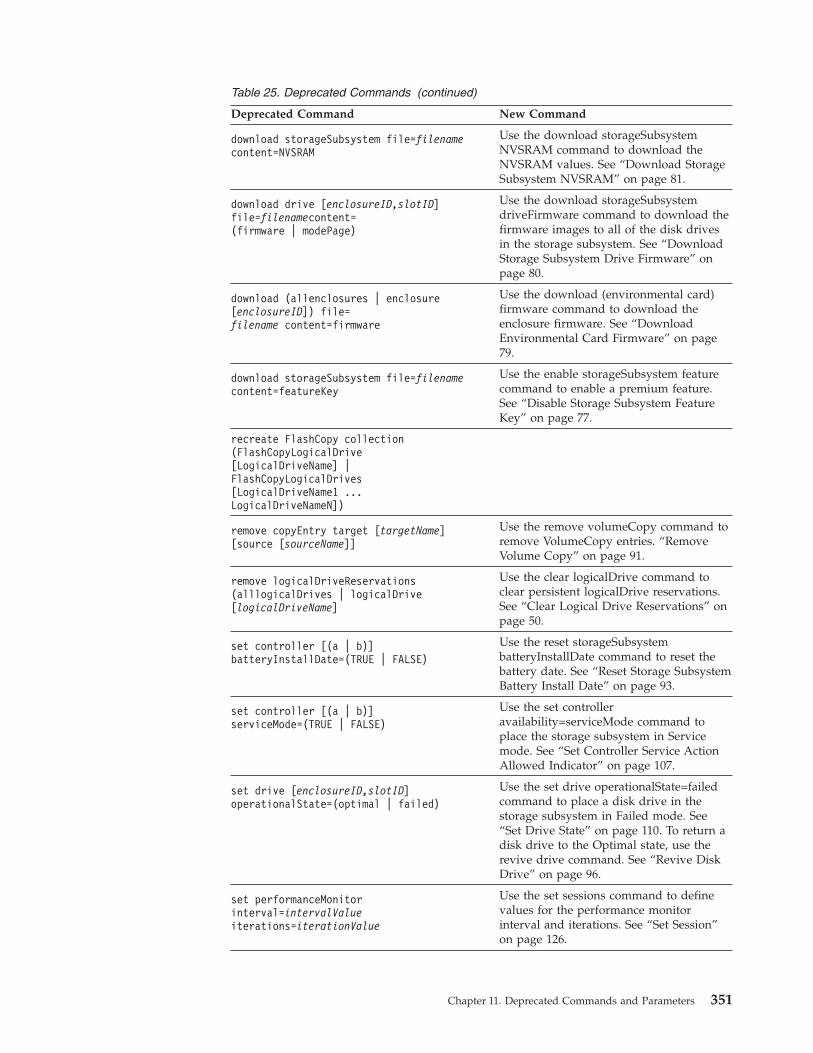
Table 25. Deprecated Commands (continued)
Deprecated Command New Command
download storageSubsystem file=filenamecontent=NVSRAM
Use the download storageSubsystemNVSRAM command to download theNVSRAM values. See “Download StorageSubsystem NVSRAM” on page 81.
download drive [enclosureID,slotID]file=filenamecontent=(firmware | modePage)
Use the download storageSubsystemdriveFirmware command to download thefirmware images to all of the disk drivesin the storage subsystem. See “DownloadStorage Subsystem Drive Firmware” onpage 80.
download (allenclosures | enclosure[enclosureID]) file=filename content=firmware
Use the download (environmental card)firmware command to download theenclosure firmware. See “DownloadEnvironmental Card Firmware” on page79.
download storageSubsystem file=filenamecontent=featureKey
Use the enable storageSubsystem featurecommand to enable a premium feature.See “Disable Storage Subsystem FeatureKey” on page 77.
recreate FlashCopy collection(FlashCopyLogicalDrive[LogicalDriveName] |FlashCopyLogicalDrives[LogicalDriveName1 ...LogicalDriveNameN])
remove copyEntry target [targetName][source [sourceName]]
Use the remove volumeCopy command toremove VolumeCopy entries. “RemoveVolume Copy” on page 91.
remove logicalDriveReservations(alllogicalDrives | logicalDrive[logicalDriveName]
Use the clear logicalDrive command toclear persistent logicalDrive reservations.See “Clear Logical Drive Reservations” onpage 50.
set controller [(a | b)]batteryInstallDate=(TRUE | FALSE)
Use the reset storageSubsystembatteryInstallDate command to reset thebattery date. See “Reset Storage SubsystemBattery Install Date” on page 93.
set controller [(a | b)]serviceMode=(TRUE | FALSE)
Use the set controlleravailability=serviceMode command toplace the storage subsystem in Servicemode. See “Set Controller Service ActionAllowed Indicator” on page 107.
set drive [enclosureID,slotID]operationalState=(optimal | failed)
Use the set drive operationalState=failedcommand to place a disk drive in thestorage subsystem in Failed mode. See“Set Drive State” on page 110. To return adisk drive to the Optimal state, use therevive drive command. See “Revive DiskDrive” on page 96.
set performanceMonitorinterval=intervalValueiterations=iterationValue
Use the set sessions command to definevalues for the performance monitorinterval and iterations. See “Set Session”on page 126.
Chapter 11. Deprecated Commands and Parameters 351
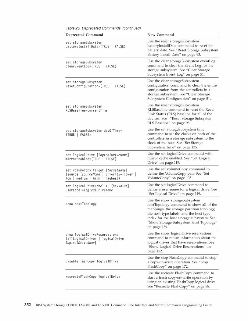
Table 25. Deprecated Commands (continued)
Deprecated Command New Command
set storageSubsystembatteryInstallDate=(TRUE | FALSE)
Use the reset storageSubsystembatteryInstallDate command to reset thebattery date. See “Reset Storage SubsystemBattery Install Date” on page 93.
set storageSubsystemclearEventLog=(TRUE | FALSE)
Use the clear storageSubsystem eventLogcommand to clear the Event Log for thestorage subsystem. See “Clear StorageSubsystem Event Log” on page 51.
set storageSubsystemresetConfiguration=(TRUE | FALSE)
Use the clear storageSubsystemconfiguration command to clear the entireconfiguration from the controllers in astorage subsystem. See “Clear StorageSubsystem Configuration” on page 51.
set storageSubsystemRLSBaseline=currentTime
Use the reset storageSubsystemRLSBaseline command to reset the ReadLink Status (RLS) baseline for all of thedevices. See “Reset Storage SubsystemRLS Baseline” on page 95.
set storageSubsystem dayOfTime=(TRUE | FALSE)
Use the set storageSubsystem timecommand to set the clocks on both of thecontrollers in a storage subsystem to theclock of the host. See “Set StorageSubsystem Time” on page 135.
set logicalDrive [logicalDriveName]mirrorEnabled=(TRUE | FALSE)
Use the set logicalDrive command withmirror cache enabled. See “Set LogicalDrive” on page 119.
set volumeCopy target [targetName][source [sourceName]] priority=(lower |low | medium | high | highest)
Use the set volumeCopy command todefine the VolumeCopy pair. See “SetVolumeCopy” on page 135.
set logicalDriveLabel ID [hexValue]userLabel=logicalDriveName
Use the set logicalDrive command todefine a user name for a logical drive. See“Set Logical Drive” on page 119.
show hostTopologyUse the show storageSubsystemhostTopology command to show all of themappings, the storage partition topology,the host type labels, and the host typeindex for the host storage subsystem. See“Show Storage Subsystem Host Topology”on page 159.
show logicalDriveReservations(allLogicalDrives | logicalDrivelogicalDriveName]
Use the show logicalDrive reservationscommand to return information about thelogical drives that have reservations. See“Show Logical Drive Reservations” onpage 152.
disableFlashCopy logicalDriveUse the stop FlashCopy command to stopa copy-on-write operation. See “StopFlashCopy” on page 172.
recreateFlashCopy logicalDriveUse the recreate FlashCopy command tostart a fresh copy-on-write operation byusing an existing FlashCopy logical drive.See “Recreate FlashCopy” on page 88.
352 IBM System Storage DS3000, DS4000, and DS5000: Command Line Interface and Script Commands Programming Guide
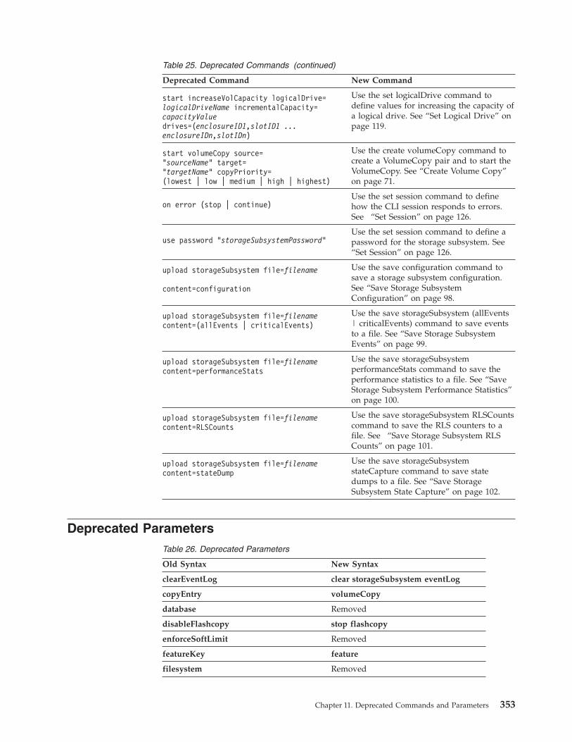
Table 25. Deprecated Commands (continued)
Deprecated Command New Command
start increaseVolCapacity logicalDrive=logicalDriveName incrementalCapacity=capacityValuedrives=(enclosureID1,slotID1 ...enclosureIDn,slotIDn)
Use the set logicalDrive command todefine values for increasing the capacity ofa logical drive. See “Set Logical Drive” onpage 119.
start volumeCopy source=”sourceName” target=”targetName” copyPriority=(lowest | low | medium | high | highest)
Use the create volumeCopy command tocreate a VolumeCopy pair and to start theVolumeCopy. See “Create Volume Copy”on page 71.
on error (stop | continue)Use the set session command to definehow the CLI session responds to errors.See “Set Session” on page 126.
use password “storageSubsystemPassword”Use the set session command to define apassword for the storage subsystem. See“Set Session” on page 126.
upload storageSubsystem file=filename
content=configuration
Use the save configuration command tosave a storage subsystem configuration.See “Save Storage SubsystemConfiguration” on page 98.
upload storageSubsystem file=filenamecontent=(allEvents | criticalEvents)
Use the save storageSubsystem (allEvents| criticalEvents) command to save eventsto a file. See “Save Storage SubsystemEvents” on page 99.
upload storageSubsystem file=filenamecontent=performanceStats
Use the save storageSubsystemperformanceStats command to save theperformance statistics to a file. See “SaveStorage Subsystem Performance Statistics”on page 100.
upload storageSubsystem file=filenamecontent=RLSCounts
Use the save storageSubsystem RLSCountscommand to save the RLS counters to afile. See “Save Storage Subsystem RLSCounts” on page 101.
upload storageSubsystem file=filenamecontent=stateDump
Use the save storageSubsystemstateCapture command to save statedumps to a file. See “Save StorageSubsystem State Capture” on page 102.
Deprecated ParametersTable 26. Deprecated Parameters
Old Syntax New Syntax
clearEventLog clear storageSubsystem eventLog
copyEntry volumeCopy
database Removed
disableFlashcopy stop flashcopy
enforceSoftLimit Removed
featureKey feature
filesystem Removed
Chapter 11. Deprecated Commands and Parameters 353
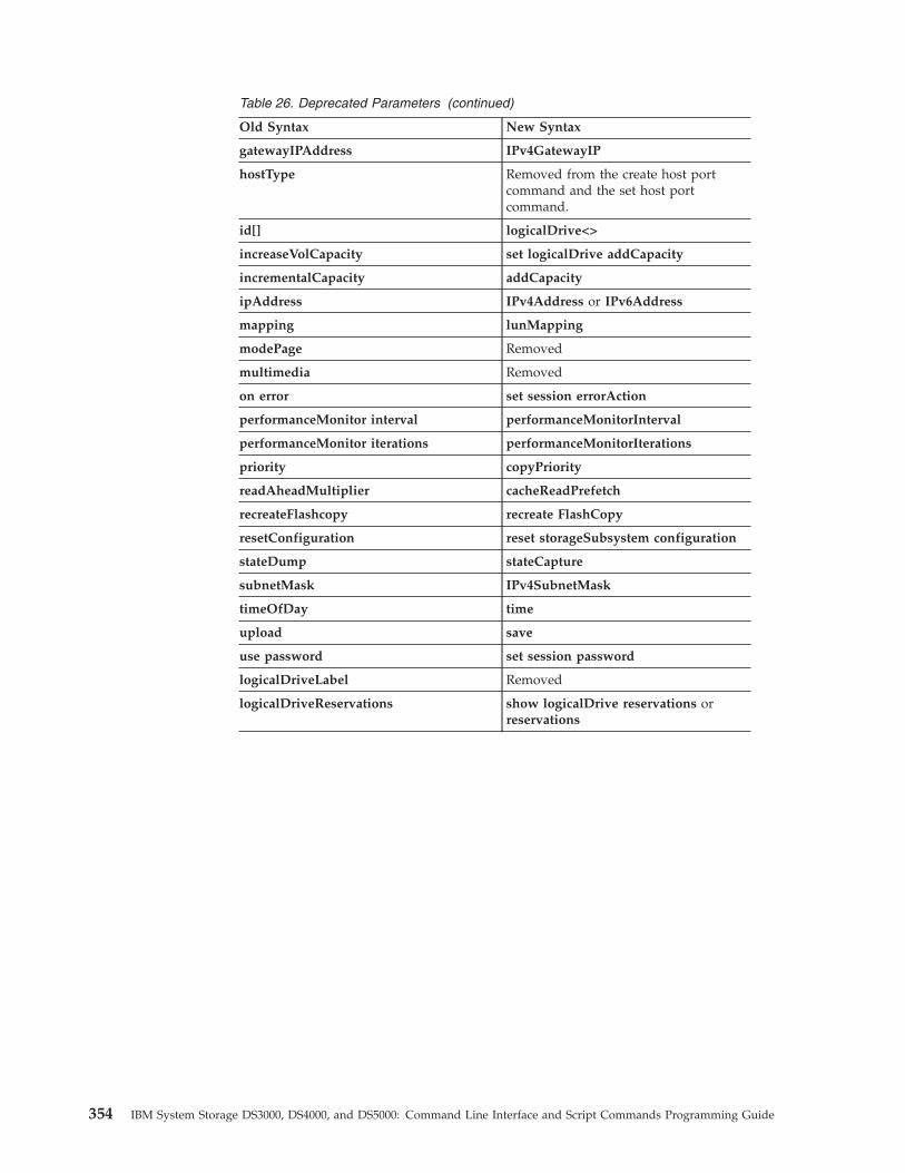
Table 26. Deprecated Parameters (continued)
Old Syntax New Syntax
gatewayIPAddress IPv4GatewayIP
hostType Removed from the create host portcommand and the set host portcommand.
id[] logicalDrive<>
increaseVolCapacity set logicalDrive addCapacity
incrementalCapacity addCapacity
ipAddress IPv4Address or IPv6Address
mapping lunMapping
modePage Removed
multimedia Removed
on error set session errorAction
performanceMonitor interval performanceMonitorInterval
performanceMonitor iterations performanceMonitorIterations
priority copyPriority
readAheadMultiplier cacheReadPrefetch
recreateFlashcopy recreate FlashCopy
resetConfiguration reset storageSubsystem configuration
stateDump stateCapture
subnetMask IPv4SubnetMask
timeOfDay time
upload save
use password set session password
logicalDriveLabel Removed
logicalDriveReservations show logicalDrive reservations orreservations
354 IBM System Storage DS3000, DS4000, and DS5000: Command Line Interface and Script Commands Programming Guide
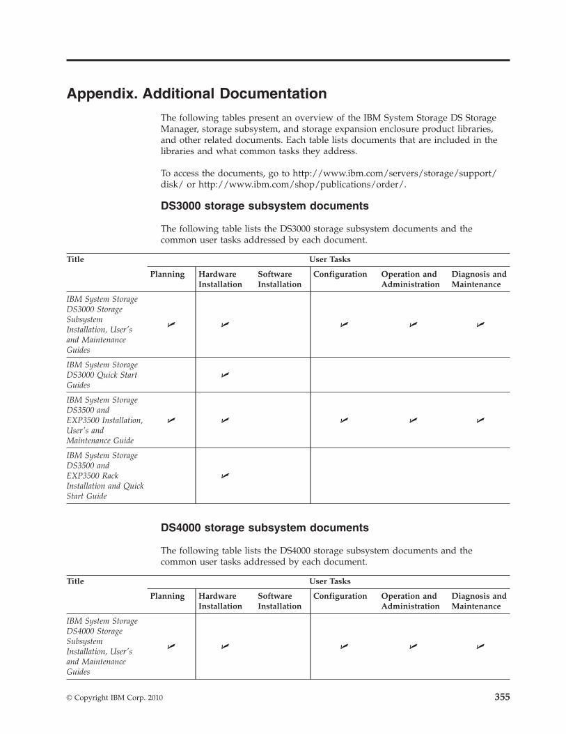
Appendix. Additional Documentation
The following tables present an overview of the IBM System Storage DS StorageManager, storage subsystem, and storage expansion enclosure product libraries,and other related documents. Each table lists documents that are included in thelibraries and what common tasks they address.
To access the documents, go to http://www.ibm.com/servers/storage/support/disk/ or http://www.ibm.com/shop/publications/order/.
DS3000 storage subsystem documents
The following table lists the DS3000 storage subsystem documents and thecommon user tasks addressed by each document.
Title User Tasks
Planning HardwareInstallation
SoftwareInstallation
Configuration Operation andAdministration
Diagnosis andMaintenance
IBM System StorageDS3000 StorageSubsystemInstallation, User'sand MaintenanceGuides
U U U U U
IBM System StorageDS3000 Quick StartGuides
U
IBM System StorageDS3500 andEXP3500 Installation,User's andMaintenance Guide
U U U U U
IBM System StorageDS3500 andEXP3500 RackInstallation and QuickStart Guide
U
DS4000 storage subsystem documents
The following table lists the DS4000 storage subsystem documents and thecommon user tasks addressed by each document.
Title User Tasks
Planning HardwareInstallation
SoftwareInstallation
Configuration Operation andAdministration
Diagnosis andMaintenance
IBM System StorageDS4000 StorageSubsystemInstallation, User'sand MaintenanceGuides
U U U U U
© Copyright IBM Corp. 2010 355
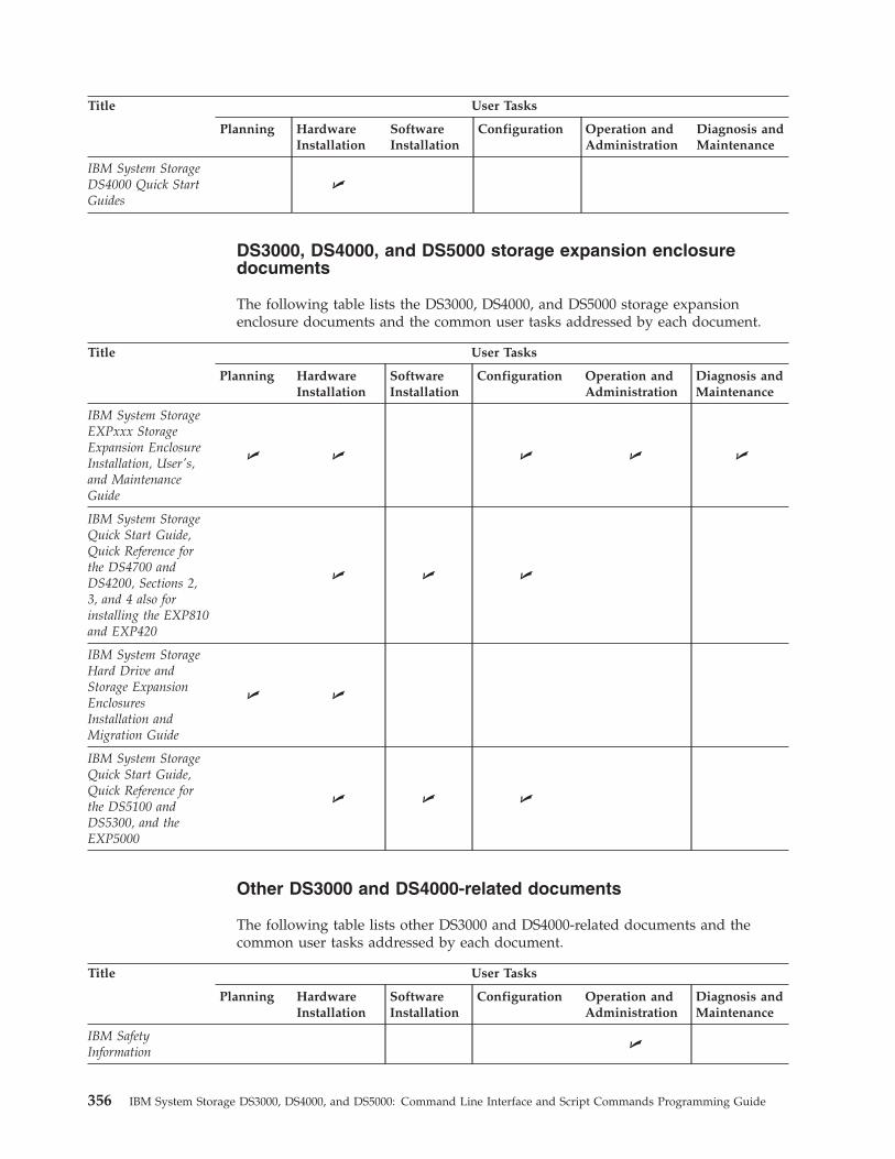
Title User Tasks
Planning HardwareInstallation
SoftwareInstallation
Configuration Operation andAdministration
Diagnosis andMaintenance
IBM System StorageDS4000 Quick StartGuides
U
DS3000, DS4000, and DS5000 storage expansion enclosuredocuments
The following table lists the DS3000, DS4000, and DS5000 storage expansionenclosure documents and the common user tasks addressed by each document.
Title User Tasks
Planning HardwareInstallation
SoftwareInstallation
Configuration Operation andAdministration
Diagnosis andMaintenance
IBM System StorageEXPxxx StorageExpansion EnclosureInstallation, User's,and MaintenanceGuide
U U U U U
IBM System StorageQuick Start Guide,Quick Reference forthe DS4700 andDS4200, Sections 2,3, and 4 also forinstalling the EXP810and EXP420
U U U
IBM System StorageHard Drive andStorage ExpansionEnclosuresInstallation andMigration Guide
U U
IBM System StorageQuick Start Guide,Quick Reference forthe DS5100 andDS5300, and theEXP5000
U U U
Other DS3000 and DS4000-related documents
The following table lists other DS3000 and DS4000-related documents and thecommon user tasks addressed by each document.
Title User Tasks
Planning HardwareInstallation
SoftwareInstallation
Configuration Operation andAdministration
Diagnosis andMaintenance
IBM SafetyInformation
U
356 IBM System Storage DS3000, DS4000, and DS5000: Command Line Interface and Script Commands Programming Guide
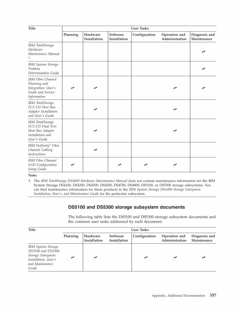
Title User Tasks
Planning HardwareInstallation
SoftwareInstallation
Configuration Operation andAdministration
Diagnosis andMaintenance
IBM TotalStorageHardwareMaintenance Manual¹
U
IBM System StorageProblemDetermination Guide
U
IBM Fibre ChannelPlanning andIntegration: User'sGuide and ServiceInformation
U U U U
IBM TotalStorageFC2-133 Host BusAdapter Installationand User's Guide
U U
IBM TotalStorageFC2-133 Dual PortHost Bus AdapterInstallation andUser's Guide
U U
IBM Netfinity® FibreChannel CablingInstructions
U
IBM Fibre ChannelSAN ConfigurationSetup Guide
U U U U
Note:
1. The IBM TotalStorage DS4000 Hardware Maintenance Manual does not contain maintenance information for the IBMSystem Storage DS4100, DS4200, DS4300, DS4500, DS4700, DS4800, DS5100, or DS5300 storage subsystems. Youcan find maintenance information for these products in the IBM System Storage DSx000 Storage SubsystemInstallation, User's, and Maintenance Guide for the particular subsystem.
DS5100 and DS5300 storage subsystem documents
The following table lists the DS5100 and DS5300 storage subsystem documents andthe common user tasks addressed by each document.
Title User Tasks
Planning HardwareInstallation
SoftwareInstallation
Configuration Operation andAdministration
Diagnosis andMaintenance
IBM System StorageDS5100 and DS5300Storage SubsystemInstallation, User'sand MaintenanceGuide
U U U U U
Appendix. Additional Documentation 357
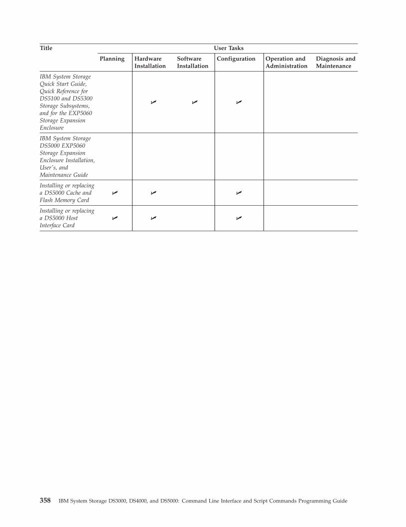
Title User Tasks
Planning HardwareInstallation
SoftwareInstallation
Configuration Operation andAdministration
Diagnosis andMaintenance
IBM System StorageQuick Start Guide,Quick Reference forDS5100 and DS5300Storage Subsystems,and for the EXP5060Storage ExpansionEnclosure
U U U
IBM System StorageDS5000 EXP5060Storage ExpansionEnclosure Installation,User's, andMaintenance Guide
Installing or replacinga DS5000 Cache andFlash Memory Card
U U U
Installing or replacinga DS5000 HostInterface Card
U U U
358 IBM System Storage DS3000, DS4000, and DS5000: Command Line Interface and Script Commands Programming Guide
Notices
This information was developed for products and services offered in the U.S.A.
IBM may not offer the products, services, or features discussed in this document inother countries. Consult your local IBM representative for information on theproducts and services currently available in your area. Any reference to an IBMproduct, program, or service is not intended to state or imply that only that IBMproduct, program, or service may be used. Any functionally equivalent product,program, or service that does not infringe any IBM intellectual property right maybe used instead. However, it is the user's responsibility to evaluate and verify theoperation of any non-IBM product, program, or service.
IBM may have patents or pending patent applications covering subject matterdescribed in this document. The furnishing of this document does not grant youany license to these patents. You can send license inquiries, in writing, to:
IBM Director of LicensingIBM CorporationNorth Castle DriveArmonk, NY 10504-1785U.S.A.
For license inquiries regarding double-byte (DBCS) information, contact the IBMIntellectual Property Department in your country or send inquiries, in writing, to:
IBM World Trade Asia CorporationLicensing2-31 Roppongi 3-chome, Minato-kuTokyo 106-0032, Japan
The following paragraph does not apply to the United Kingdom or any othercountry where such provisions are inconsistent with local law:INTERNATIONAL BUSINESS MACHINES CORPORATION PROVIDES THISPUBLICATIONS "AS IS" WITHOUT WARRANTY OF ANY KIND, EITHEREXPRESS OR IMPLIED, INCLUDING, BUT NOT LIMITED TO, THE IMPLIEDWARRANTIES OF NON-INFRINGEMENT, MERCHANTABILITY OR FITNESSFOR A PARTICULAR PURPOSE. Some states do not allow disclaimer of express orimplied warranties in certain transactions, therefore, this statement may not applyto you.
This information could include technical inaccuracies or typographical errors.Changes are periodically made to the information herein; these changes will beincorporated in new editions of the publications. IBM may make improvements orchanges (or both) in the product(s) or program(s) (or both), described in thispublication at any time without notice.
Any references in this information to non-IBM Web sites are provided forconvenience only and do not in any manner serve as an endorsement of those Websites. The materials at those Web sites are not part of the materials for this IBMproduct and use of those Web sites is at your own risk.
© Copyright IBM Corp. 2010 359
Information concerning non-IBM products was obtained from the suppliers ofthose products, their published announcements or other publicly available sources.IBM has not tested those products and cannot confirm the accuracy ofperformance, compatibility or any other claims related to non-IBM products.Questions on the capabilities of non-IBM products should be addressed to thesuppliers of those products.
IBM may use or distribute any of the information you supply in any way itbelieves appropriate without incurring any obligation to you.
Some software may differ from its retail version (if available), and may not includeuser manuals or all program functionality.
Trademarks
IBM, the IBM logo, and ibm.com are trademarks or registered trademarks ofInternational Business Machines Corporation in the United States, other countries,or both. If these and other IBM trademarked terms are marked on their firstoccurrence in this information with a trademark symbol (® or ™), these symbolsindicate U.S. registered or common law trademarks owned by IBM at the time thisinformation was published. Such trademarks may also be registered or commonlaw trademarks in other countries. A current list of IBM trademarks is available onthe Web at “Copyright and trademark information” at http://www.ibm.com/legal/copytrade.shtml.
Adobe and PostScript are either registered trademarks or trademarks of AdobeSystems Incorporated in the United States and/or other countries.
Cell Broadband Engine is a trademark of Sony Computer Entertainment, Inc., inthe United States, other countries, or both and is used under license therefrom.
Intel, Intel Xeon, Itanium, and Pentium are trademarks or registered trademarks ofIntel Corporation or its subsidiaries in the United States and other countries.
Java and all Java-based trademarks are trademarks of Sun Microsystems, Inc., inthe United States, other countries, or both.
Linux is a registered trademark of Linus Torvalds in the United States, othercountries, or both.
Microsoft, Windows, and Windows NT are trademarks of Microsoft Corporation inthe United States, other countries, or both.
UNIX is a registered trademark of The Open Group in the United States and othercountries.
Other company, product, or service names may be trademarks or service marks ofothers.
Important notes
Processor speed indicates the internal clock speed of the microprocessor; otherfactors also affect application performance.
360 IBM System Storage DS3000, DS4000, and DS5000: Command Line Interface and Script Commands Programming Guide
CD or DVD drive speed is the variable read rate. Actual speeds vary and are oftenless than the possible maximum.
When referring to processor storage, real and virtual storage, or channel volume,KB stands for 1024 bytes, MB stands for 1 048 576 bytes, and GB stands for1 073 741 824 bytes.
When referring to hard disk drive capacity or communications volume, MB standsfor 1 000 000 bytes, and GB stands for 1 000 000 000 bytes. Total user-accessiblecapacity can vary depending on operating environments.
Maximum internal hard disk drive capacities assume the replacement of anystandard hard disk drives and population of all hard disk drive bays with thelargest currently supported drives that are available from IBM.
Maximum memory might require replacement of the standard memory with anoptional memory module.
IBM makes no representation or warranties regarding non-IBM products andservices that are ServerProven®, including but not limited to the implied warrantiesof merchantability and fitness for a particular purpose. These products are offeredand warranted solely by third parties.
IBM makes no representations or warranties with respect to non-IBM products.Support (if any) for the non-IBM products is provided by the third party, not IBM.
Some software might differ from its retail version (if available) and might notinclude user manuals or all program functionality.
Documentation format
The publications for this product are in Adobe Portable Document Format (PDF)and should be compliant with accessibility standards. If you experience difficultieswhen you use the PDF files and want to request a Web-based format or accessiblePDF document for a publication, direct your mail to the following address:
Information Development
IBM Corporation
205/A015
3039 E. Cornwallis Road
P.O. Box 12195
Research Triangle Park, North Carolina 27709-2195
U.S.A.
In the request, be sure to include the publication part number and title.
When you send information to IBM, you grant IBM a nonexclusive right to use ordistribute the information in any way it believes appropriate without incurring anyobligation to you.
Notices 361

362 IBM System Storage DS3000, DS4000, and DS5000: Command Line Interface and Script Commands Programming Guide
Index
AActivate Host Port 45Activate iSCSI Initiator 45address
of the IBM director of licensing 359AIX host
support xiv
Ddevice drivers
downloading latest versions xiiidocumentation
Web sites xiiidocumentation, Storage Subsystem,
Storage Subsystem library 355drivers xiiiDS3000 software/firmware support xiDS4000 software/firmware support xiDS5000 software/firmware support xi
Ffire suppression xv
Hhardware service and support xiv
IIBM
director of licensing address 359Intel and AMD-based host
support xiv
LLinux host
support xiv
Nnotes, important 360notices
general 359
Pproducts, developed 359
Rresources
Web sites xiii
Sservices offered in the U.S.A. 359storage area network (SAN)
technical support Web site xivStorage Manager software
where to obtain xiiiswitch
technical support Web site xivSystem p host
support xivSystem Storage Interoperation Center
(SSIC) xiiiSystem x host
support xiv
Ttrademarks 360
WWeb sites
AIX xivFix central xivIBM publications center xivIBM System Storage product
information xivinteroperability matrix xiiilist xiiipremium feature activation xiiiSAN support xivSSIC xiiiswitch support xivSystem p xivSystem x xiv
© Copyright IBM Corp. 2010 363

364 IBM System Storage DS3000, DS4000, and DS5000: Command Line Interface and Script Commands Programming Guide

����
Part Number: 49Y0231
Printed in USA
(1P) P/N: 49Y0231