Embed Size (px)
Citation preview
IBM Integration Bus v9 for xLinux 64 bits
Performance Information ReportVersion 1.0
IBM Integration Bus DevelopmentIBM UK LaboratoriesHursley ParkWinchesterHampshireSO21 2JN
Before using this report, be sure to read the general information under"Notices".
First Edition, July 2014.This edition applies to IBM Integration Bus v9 for xLinux 64 bits and to all subsequent releases and modifications until otherwiseindicated in new editions.
(c) Copyright International Business Machines Corporation 2014. Allrights reserved. Note to U.S. Government Users -- Documentationrelated to restricted rights -- Use, duplication or disclosure is subject torestrictions set forth in GSA ADP Schedule contract with IBM Corp.
1
Table of ContentsNotices...................................................................................................................................3Trademarks and service marks..............................................................................................4Summary of Amendments......................................................................................................4Use Case Descriptions...........................................................................................................5
Aggregation Use Case.......................................................................................................6Coordinated Request-Reply Use Case.............................................................................8Data Warehouse Use Case.............................................................................................11Large Messaging Use Case............................................................................................12Transforming a Message by using ESQL Use Case.......................................................13SOAP Consumer Use Case............................................................................................14SOAP Provider Use Case................................................................................................15Message Routing Use Case............................................................................................16File Out, File In Use case................................................................................................17
Message Throughput...........................................................................................................18Information provided........................................................................................................18Performance Results.......................................................................................................19Message Throughput: Aggregation use case..................................................................20Message Throughput: Coordinated request/reply use case...........................................20Message Throughput: Data Warehouse use case..........................................................20Message Throughput: Large messaging use case.........................................................21Message Throughput: Transforming a message use case.............................................21Message Throughput: SOAP Consumer use case.........................................................21Message Throughput: SOAP Provider use case.............................................................22Message Throughput: Message routing use case..........................................................22Message Throughput: File out and file in use case.........................................................22
Measurement environment..................................................................................................23Tuning..................................................................................................................................24
Tuning IBM Integration Bus.............................................................................................24WebSphere MQ Tuning...................................................................................................26Tuning DB2......................................................................................................................28
Evaluation method...............................................................................................................29Message Generation and Consumption..........................................................................29MQ Transport...................................................................................................................30JMS Transport..................................................................................................................30SOAP and HTTP transport..............................................................................................31Machine Configuration.....................................................................................................31Reported Message Rates................................................................................................31
Useful links...........................................................................................................................32Feedback..............................................................................................................................34
2
Notices
The performance information provided in this report illustrates key processing characteristics of IBM Integration Bus version 9. It is intended for Architects, Systems Programmers, Analysts and Programmers wanting to understand the performance characteristics of IBM Integration Bus v9. You can use this information to understand the performance characteristics of IBM Integration Bus version 9. The data provided will assist you with sizing solutions. Please, note that it is assumed that the reader is familiar with the concepts and operation of IBM Integration Bus v9.
This information has been obtained by measuring the message throughput that is possible for a number of different types of message processing. The term "message" is used in a generic sense, and can mean any request or response into or out of an integration node, regardless of the transport or protocol.
The performance data contained in this report was measured in a controlled environment and results obtained in other environments might vary significantly. For more details on the measurement environments used, see the message throughput section for each platform.
The performance measurements focus on the throughput capabilities of the broker using different message formats and processing node types. The aim of the measurements is to help you understand the rate at which messages can be processed in different situations as well as helping you to understand the relative costs of the different node types and approaches to message processing.
You should not attempt to make any direct comparisons of the test results in this report with what may appear to be similar tests in previous performance reports. This is because the contents of the test messages are significantly different as is the processing in the tests. It is not meaningful to make such comparisons. In many cases the hardware, operating system and prerequisite software are also different, making any direct comparisons invalid.
Some optimizations of the test environment and procedures have been implemented to minimize the effect of logging for example and to ensure that messages do not accumulate on output queues which has a detrimental effect on message throughput. These are detailed under Tuning.
In many of the tests the user logic used is minimal so the results presented represent the best throughput that can be achieved for that node type. This should be borne in mind when sizing IBM Integration Bus.
References in this document to IBM products or programs do not imply that IBM intends to make these available in all countries in which IBM operates.
Information contained in this report has not been submitted to any formal IBM test and is distributed "as is". The use of this information and the implementation of any of the techniques is the responsibility of the customer. Much depends on the ability of the customer to evaluate these data and project the results to their operational environment.
3
Trademarks and service marks
The following terms, used in this document, are trademarks of the IBM Corporation in the United States or other countries or both:
IBM WebSphere MQ WebSphere Message Broker DB2
The following terms are trademarks of other companies:
Windows 2008 R2 Windows Microsoft Corporation
Other company, product, and service names may be trademarks or service marks of others.
Summary of Amendments
Date Changes
01/07/14 Initial Release
4
Use Case Descriptions
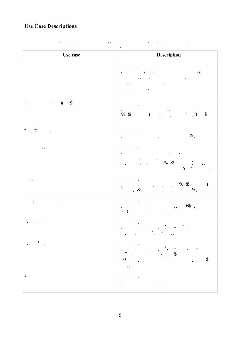
This section contains a description of the processing in each of the use cases which are used to characterize the performance of IBM Integration Bus v9.
Use case Description
Aggregation Measures the performance of an integration solution that splits an incoming XML message into 4 messages, and then performs a four message aggregation using the Aggregation nodes that are supplied with IBM Integration Bus
Coordinated request-reply Measures the performance of an integration solution that communicates through the use of WebSphere MQ messages in a request/reply processing pattern.
Data Warehouse Measures the performance of an integration solution that archives data into a database.
Large messaging Measures the performance of an integration solution that processes messages that contain repeating structures and writes each repeating instance as a separate WebSphere MQ message while minimizing overall memory requirements.
Message routing Measures the performance of an integration solution that routes messages to WebSphere MQ queues, based on data stored in a database.
Transforming a message Measures the performance of an integration solution that transforms a message by using ESQL
SOAP Provider Measures the performance of an integration solution that receives a SOAP request and responds with a SOAP message.
SOAP Consumer Measures the performance of an integration solution that receives a SOAP over HTTP request message, makes a synchronous call to an external service provider, and delivers a reply message.
File out and file in Measures the performance of an integration solution that handles files either in the middle of a flow or to initiate a transformation.
5
Aggregation Use Case
The aggregation use case is used to measure the performance of an integration solution that splits an incoming XML message into 4 messages, and then performs a four message aggregation using the Aggregation nodes that are supplied with IBM Integration Bus. For example, this scenario represents the type of processing that is required when travel is booked, and arrangements for a flight, hotel, car and money must be made. Requests to four different applications are made and the replies are consolidated into a single reply.
The Aggregation use case demonstrates a simple four-way aggregation operation, using the AggregateControl, AggregateRequest, and AggregateReply nodes. It contains three message flows to implement a four-way aggregation:
• FanOut
• RequestReplyApp
• FanIn
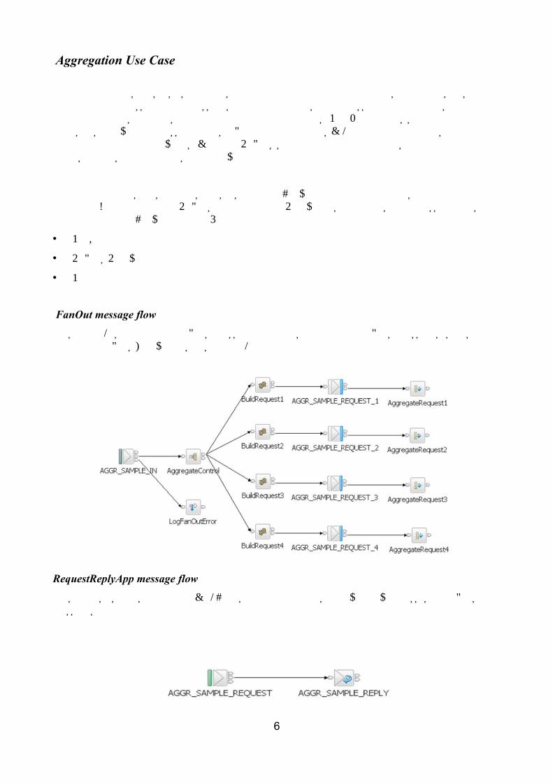
FanOut message flowThis flow takes the incoming request message, generates four different request messages, sends them out on request/reply, and starts the tracking of the aggregation operation.
RequestReplyApp message flowThis flow is used to simulate the back-end service applications that typically processes the request messages from the aggregation operation.
6
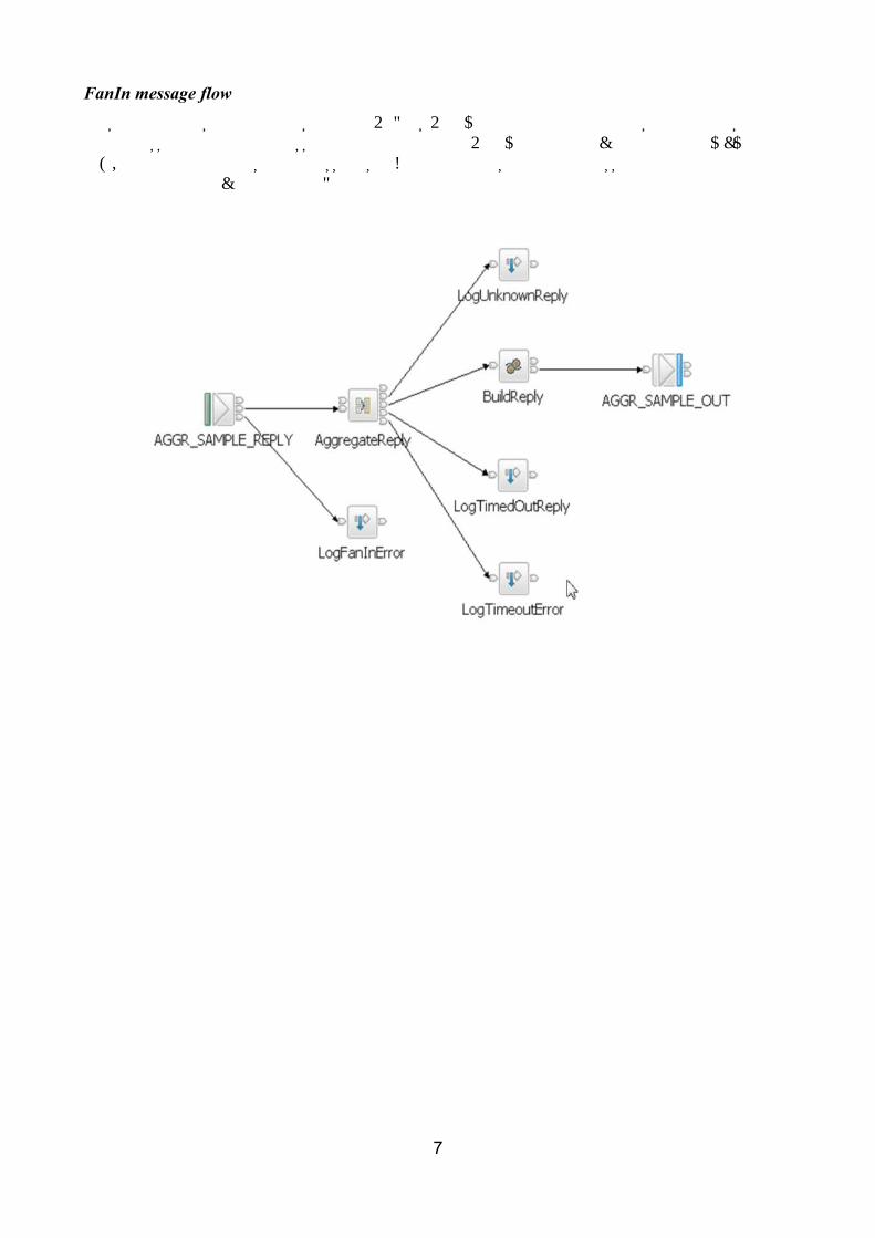
FanIn message flowThis flow receives all the replies from the RequestReplyApp flow, and aggregates them into a single output message. The output message from the AggregateReply node cannot be output directly by an MQOutput node without some processing so a Compute node is added to process the data into a format where it can be written to a queue.
7

Coordinated Request-Reply Use Case
The Coordinated Request-Reply use case is based on the scenario of a contemporary and established application communicating through the use of WebSphere MQ messages in a request/reply processing pattern.
• The contemporary application uses self-defining XML messages and issues a request message.• The established application uses Custom Wire Format (CWF) messages.
The Coordinated Request-Reply application receives a request message, processes it and delivers a reply message. For the applications to successfully communicate, the message formats must be transformed for both the request and reply messages.
The processing in this use case consists of three message flows and one message set. The message flows are the following:
• Request• Backend Reply• Reply
The Coordinated Request Reply message set project contains a sample MSET message set with the message definition SaleListMessage. This message set is used to convert the request message from XML format to CWF, and to convert the reply message from CWF to XML. The message set is used by both applications.
Request Message Flow
The request message flow performs the following processing:
• Reads a WebSphere MQ message containing an XML payload.• Converts the message into the equivalent CWF format.• Creates a WebSphere MQ message containing the transformed message.• Saves the original ReplyToQ and ReplyToQMgr details in a separate WebSphere MQ message
for subsequent retrieval by the Reply message flow.• Sets the ReplyToQ and ReplyToQMgr details to be the input of the Reply message flow.• Sends the message to the Backend Reply message flow.
8
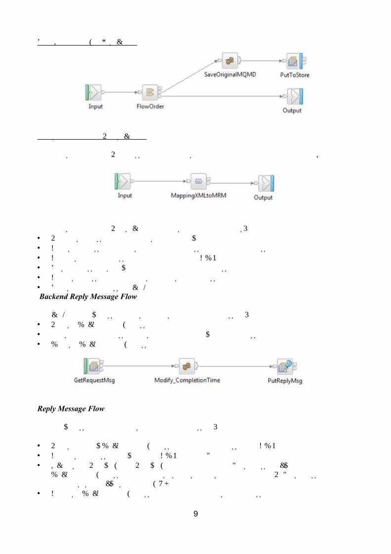
Store Original MQMD subflow
Transform XML to MRM subflow
The TransformXMLtoMRM message flow contains an Input node, a Mapping node, and an Output node.
The TransformXMLtoMRM subflow completes the following actions:• Receives a message that contains an XML payload• Copies the message headers from the input message to the output message tree• Converts the input message from XML format to CWF• Sets the message set, type, and format for the output message• Creates a message that contains the transformed message• Sends the output message back to the main flow Backend Reply Message Flow
The backend reply message flows performs the following processing:• Reads a WebSphere MQ message.• Adds the time the message was modified to the payload of the message.• Writes a WebSphere MQ message.
Reply Message Flow
The reply message flow performs the following processing:
• Reads the reply WebSphere MQ message containing a message in CWF format.• Converts the message payload from CWF into the equivalent XML format.• Obtains the ReplyToQ and ReplyToQ Mgr of the original request message by reading the
WebSphere MQ message which was used to store this information in the Request message flow. This is done by using the MQGET node.
• Creates a WebSphere MQ message containing the transformed message and the retrieved
9
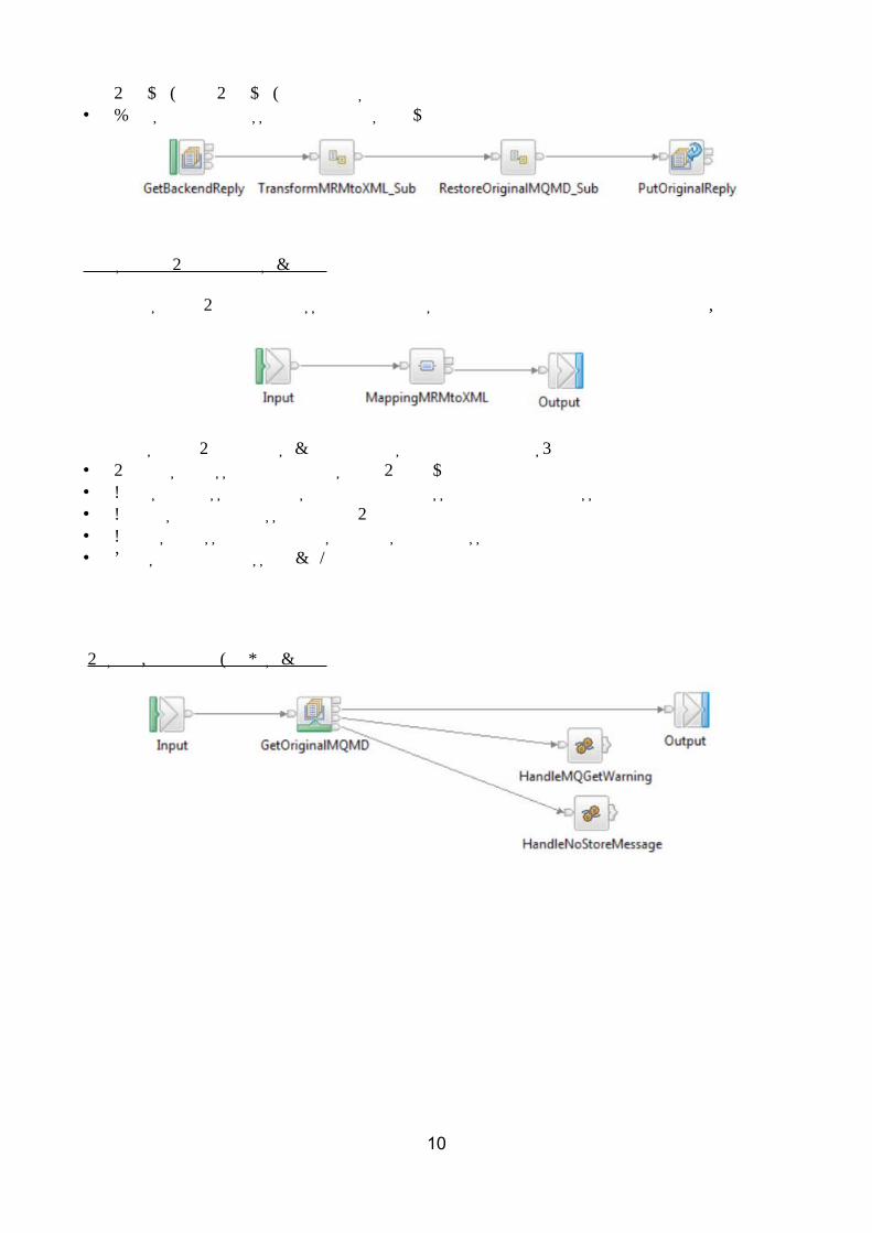
ReplyToQ and ReplyToQMgr values.• Writes an output message that contains a payload in XML format
Transform MRM to XML subflow
The TransformMRMtoXML message flow contains an Input node, a Mapping node, and an Output node.
The TransformMRMtoXML subflow completes the following actions:• Receives a message that contains an MRM payload• Copies the message headers from the input message to the output message tree• Converts the input message from MRM format to XML• Creates a message that contains the transformed message• Sends the output message back to the main flow
Restore Original MQMD subflow
10
Data Warehouse Use Case
The Data Warehouse use case demonstrates a scenario in which a message flow is used to archive data, such as sales data, into a database. The data is stored for later analysis by another message flow or application.
Because the sales data is analyzed at a later date, the storage of the messages has been organized in a way that makes it easy to select records for specified times. The date and time at which the WebSphere MQ message containing the sales record was written are stored as separate column values when the message is inserted into the database.
The database table contains four columns:• The message data, which is the payload of the WebSphere MQ message stored as a BLOB.• The date on which the WebSphere MQ message was created.• The time when the WebSphere MQ message was created.• A time stamp created by the database to record the time when the record was inserted.
By storing the data in this way, it is possible to retrieve records from specific periods; for example, 9:00 a.m. to 12:00 p.m. and 12:01 p.m. and 5:00 p.m., which would allow a comparison of morning and afternoon sales to be made.
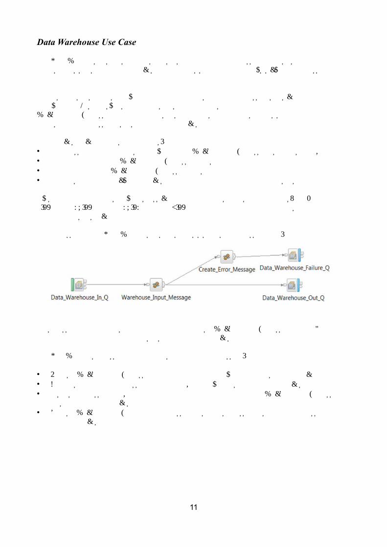
The processing in the Data Warehouse use case consists of a single message flow:
This message flow performs the data archiving. It reads a WebSphere MQ message from a queue containing the data to archive and inserts the data into a database.
The DataWarehouse message flow performs the following processing:
• Reads a WebSphere MQ message containing an XML payload, which is the data to be archived.• Converts a portion of the message tree to a BLOB ready for insertion into the database.• Inserts the message BLOB along with the date and time at which the WebSphere MQ message
was written into a database.• Sends a WebSphere MQ confirmation message to signal successful insertion of the message
into the database.
11
Large Messaging Use Case
The Large Messaging use case is based on the scenario of end-of-day processing of sales data.
• Messages recording the details of sales through the day are batched together in the store for transmission to the IT center.
• On receipt at the IT center, the batched messages are split into their constituent parts for subsequent processing.
The Large Messaging application process messages that contain repeating structures. It writes each repeating instance of the SaleList structure as a separate WebSphere MQ message while minimizing overall memory requirements.
• Message splitting is achieved by using the XMLwithRepeat_to_singleXML_slicer message flow.
• The message flow implements a memory saving technique by using a mutable message tree.• Each of the individual messages representing a sale has the same structure.• The input and output messages are implemented as self-defining XML messages.• Each input message consists of three parts:
▪ A header, which contains the number of repetitions of the repeating SaleList structure that follows.
▪ The body, which contains the repetitions of the repeating SaleList structure.▪ The trailer, which contains the time the message was processed.
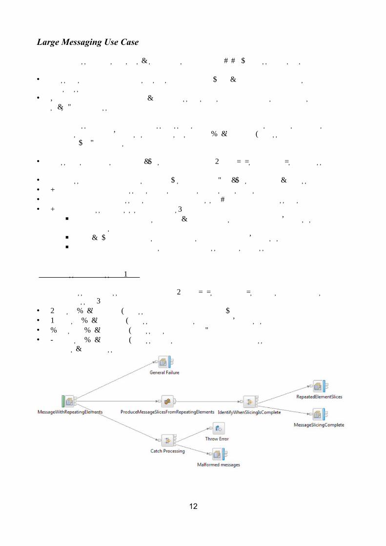
Large Messaging Message Flow
The large messaging message flow XMLwithRepeat_to_singleXML_slicer.msgflow performs the following processing:• Reads a WebSphere MQ message containing an XML payload.• Formats a WebSphere MQ message for each instance of the SaleList structure.• Writes the WebSphere MQ messages to the output queue.• Produces a WebSphere MQ message to signal completion of the processing when the final element has been processed.
12
Transforming a Message by using ESQL Use Case
IBM Integration Bus version 9 provides different techniques to transform a message. This use case is focus on message transformation by using ESQL.
This use case is based on a sales processing scenario. At the time of a sale, the customer's name, the code for the product, a description of the product, its category, the unit price, and quantity purchased are recorded. Each customer might purchase several items. A list with all the customer orders is created. The sample application transforms the incoming message and produces an invoice statement for each customer included in the list.
The messages used for input and output are self-defining XML messages. Each message consists of three parts: • A header, which contains a count of the number of repetitions of the repeating SaleList
structure that follows.• The body, which contains the repetitions of the repeating SaleList structure.• The trailer, which contains the time the message was processed.
The transformation and production of the statement for each customer within a SaleList is achieved with a single message flow.
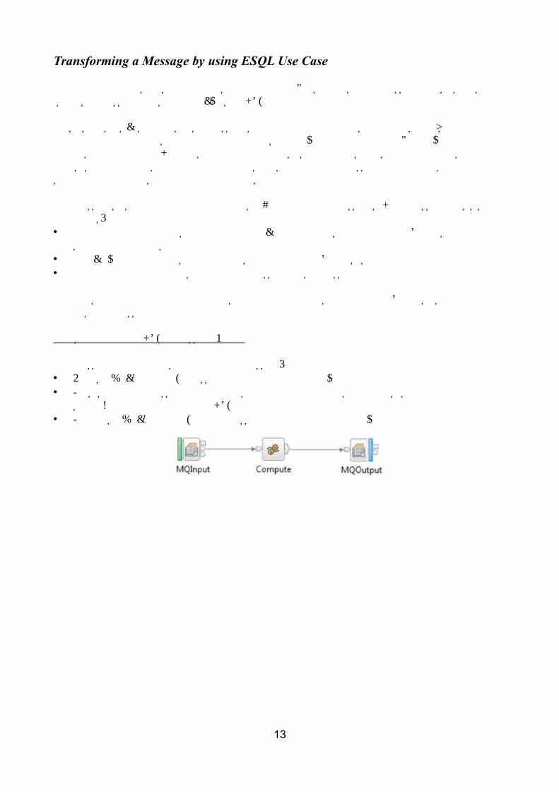
Transformation with ESQL Message Flow
The message flow performs the following processing:• Reads a WebSphere MQ message containing an XML payload.• Parses the input message and produces an invoice for each customer. This is achieved with a
single Compute node containing ESQL.• Produces a WebSphere MQ output message containing an XML payload.
13
SOAP Consumer Use Case
The SOAP consumer use case is based on a sales processing scenario. At the time of a sale, the customer's name, the code for the product, a description of the product, its category, the unit price, and quantity purchased are recorded. Each customer might purchase several items. At the end of each day, the sales of each store are consolidated in a single list that is sent to the company's billing system. The billing system responds with any currency updates that should be applied per purchase order.
The SOAP consumer application receives a SOAP over HTTP request message, makes a synchronous call to an external service provider, and delivers a reply message. For the applications to successfully communicate, the message formats must be transformed for both the request and reply messages.
The messages used for input and output are self-defining XML messages. Each message consists of three parts: • A header, which contains a count of the number of repetitions of the repeating SaleList
structure that follows.• The body, which contains the repetitions of the repeating SaleList structure.• The trailer, which contains the time the message was processed.
The transformation and calling to an the billing system (external service provider) is achieved with a single message flow.
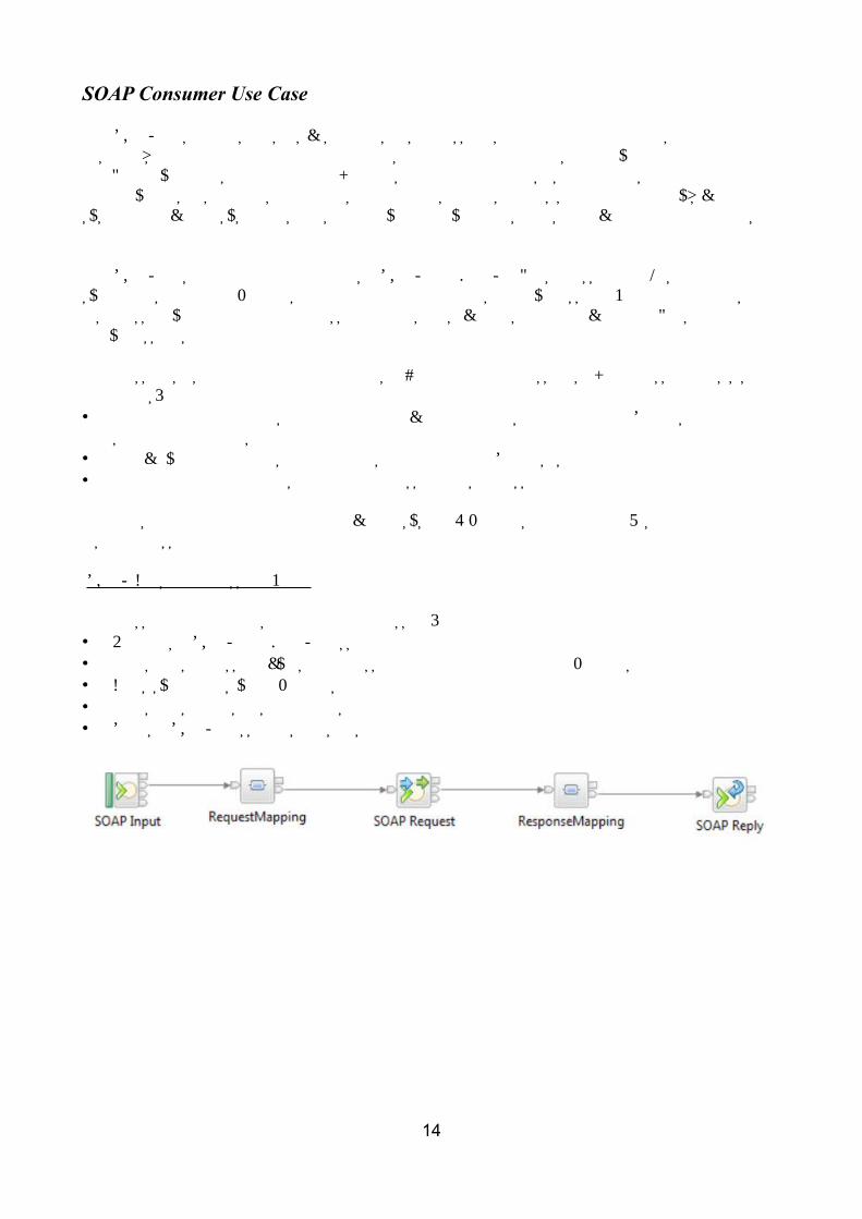
SOAP Consumer Message Flow
The message flow performs the following processing:• Receives a SOAP over HTTP message.• Transforms a message by using a message map prior to calling the external service provider.• Calls synchronously an external service provider.• Transforms the response from the service provider.• Sends a SOAP message as a response to the initial call.
14
SOAP Provider Use Case
The SOAP provider use case is based on a sales processing scenario. At the time of a sale, the customer's name, the code for the product, a description of the product, its category, the unit price, and quantity purchased are recorded. Each customer might purchase several items. At the end of each day, the sales of each store are consolidated in a single list. Any store can call this service to obtain the consolidated number of sales for the day, and the time at which the request was made.
The SOAP provider application receives a SOAP over HTTP request message, calculates the number of sales to record, and responds with the total number of sales for the day and the time at which the service was called.
The messages used for input and output are self-defining XML messages. Each message consists of three parts: • A header, which contains a count of the number of repetitions of the repeating SaleList
structure that follows.• The body, which contains the repetitions of the repeating SaleList structure.• The trailer, which contains the time the message was processed.
The transformation and calling to an the billing system (external service provider) is achieved with a single message flow.
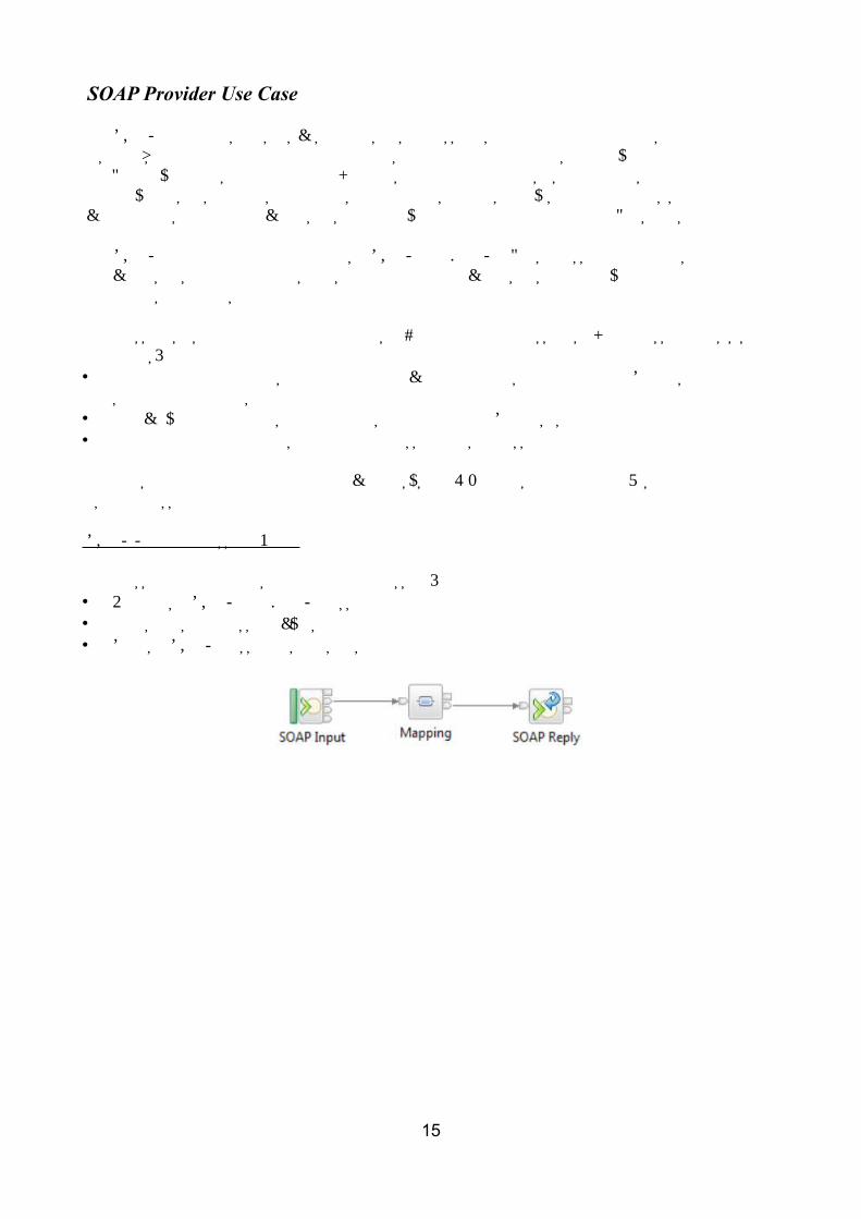
SOAP Provider Message Flow
The message flow performs the following processing:• Receives a SOAP over HTTP message.• Transforms the message by using a Mapping node.• Sends a SOAP message as a response to the initial call.
15
Message Routing Use Case
The message routing use case shows how a database table can be used to store routing information, which a message flow can then use to route messages to WebSphere MQ queues. It implements a routing table, and uses shared variables to route messages in a message flow.
Database definition
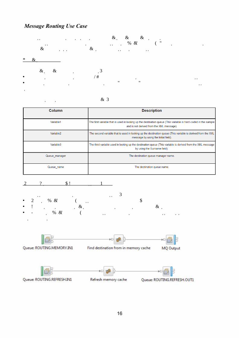
The database table contains five columns:• The first three columns contain look-up information that is derived from the incoming message.• The last two columns contain the details of the queue and queue manager to which the message is routed.
The columns are shown in the following table:
Routing Using Memory Cache Message Flow
The message flow performs the following processing:• Reads a WebSphere MQ message containing an XML payload.• Creates a destination list based on data that is held in shared variables.• Produces a WebSphere MQ output message. The destination of the message is specified in the destination list.
16
File Out, File In Use case
The File out and File in use case demonstrates how to output a message to a file part way through a message flow, and how to read a file and output a message to a WebSphere MQ queue.
The File out and File in use case uses the following nodes:• The FileOutput Node is used to write messages as files to the file system. You can create a new
file from a single message or to replace the contents of an existing file with a message. The records can be created directly from messages, and can be padded to a fixed length, or separated from other records by a delimiter character.
• The FileInput Node is used to process messages that are read from files. One or more messages can be read from a single file, and each message is propagated as a separate flow transaction. The part of a file that generates one message flow transaction is called a record. A file can be a single record, or a series of records. Properties on the node specify how the FileInput node determines the records in a file.
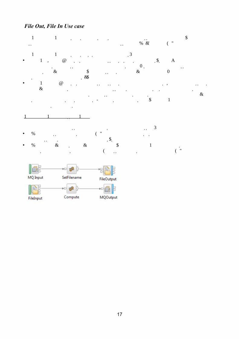
File out and File in Message Flow
The file out and file in message flow performs the following processing:• When a message arrives at the MQ queue, a compute node sets the name of the file name, and
the message is output to a file in the file system.• When a file becomes available in the directory from which the FileInput node is reading, the
file is read, and transformed into an MQ message, that is then output to an MQ queue.
17
Message Throughput
This section illustrates the message throughput per platform that is possible with IBM Integration Bus V9 for a number of common processing use cases.
The performance results provide data on CPU utilization and I/O contention:• CPU is limited by the speed of the CPU.• I/O is limited by the speed of the I/O subsystem.
There was no error processing and no error conditions set in any of the measurements.
All messages were successfully passed from one node to another through the Out or True terminal.
No messages were passed through the Failure terminal of a node.
Information provided
The results provided in this section include the following performance data:
Message Size: Records the approximate size of the message that is used as input to the test, not including the message header. This is the size of the XML or equivalent non-XML message payload.
Persistent State: Indicates whether the messages used in the test is persistent or not.This state can have the following two values:
• The value Full Persistent is used to indicate that the message tested is persistent.
This value is applicable only to WebSphere MQ messages.
If a message is persistent, WebSphere MQ ensures that the message is not lost when a failure occurs, by copying it to disk.
• The value Non Persistent is used for other type of messages.
Message Rate: Indicates the number of round trips or message flow invocations per second.
% CPU Busy: Indicates the percentage of CPU usage on the server machine. This includes the total of CPU used by all processes: IBM Integration Bus, WebSphere MQ queue manager, database manager and others. The rate is expressed as a percentage of the CPU's capacity that is used by all processors on the server machine.
CPU ms/msg: Indicates the overall CPU cost per message, that is, the CPU milliseconds per message.
You can calculate the value of the CPU cost per message by using the following formula:
((Number of cores * 1000) * (% of CPU / 100)) / Message Rate.
This cost includes IBM Integration Bus, WebSphere MQ, DB2, and any operating system costs.
18

Note: The results are specific to the system on from which they have been obtained. If you want to project (or predict) message processing capacity for other systems, you must make a suitable adjustment to allow for differences in the capacity of the two systems.
Performance Results
Typically, as the message size increases, the message rate decreases, and the cost of CPU per message increases.
Persistent MQ messages are written to the MQ log on disk. This causes an overhead in CPU and IO costs and a reduction in message rate. The speed of disk on which the MQ log is configured becomes a key factor. See Tuning for more information.
For details on the measurement environment, see Measurement environment.
When planning a system, it is important to understand the complexities of the processing required so that adequate resources can be provided to meet the requirements of the particular situation.
19
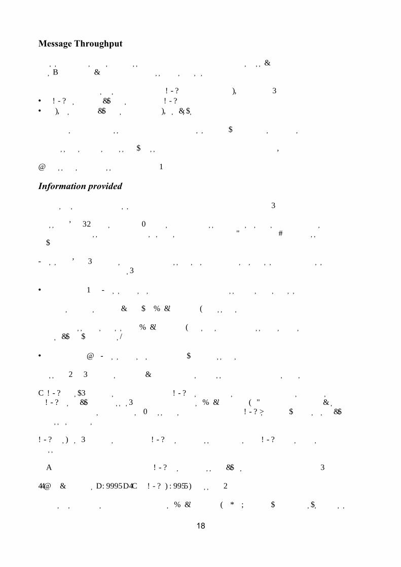
Message Throughput: Aggregation use case
Message Throughput: Coordinated request/reply use case
Message Throughput: Data Warehouse use case
20
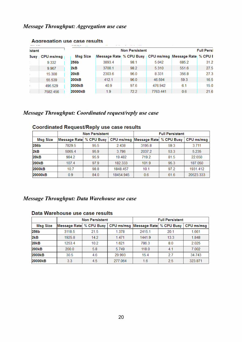
Message Throughput: Large messaging use case
Message Throughput: Transforming a message use case
Message Throughput: SOAP Consumer use case
21
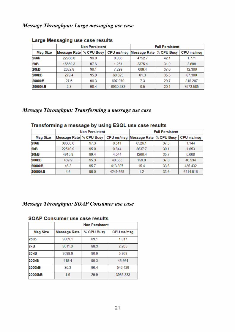
Message Throughput: SOAP Provider use case
Message Throughput: Message routing use case
Message Throughput: File out and file in use case
22

Measurement environment
All throughput measurements where taken on a single server machine. The client type and machine on which they ran varied with the test. The details are given below.
Server Machine
The hardware consisted of:
IBM xSeries x3690 X5 with 2 x Deca-Core Intel(R) Xeon(R) E7-2860
2.27GHz processors with HyperThreading turned off
146GB 15K 6.0Gbps SFF Serial SCSI / SAS Hard Drive - ST9146852SS
50GB SATA 3.5-INCH HOT-SWAP HIGH IOPS SOLID STATE DRIVE - 43W7701
16 GB RAM
10 GB Ethernet Card
The software consisted of:
Red Hat Enterprise Linux 6.5
WebSphere MQ V7.5.0.1
IBM Integration Bus V9
DB2 V9.7
Client Machine
The hardware consisted of:
IBM xSeries x3650 M3 with 2 x Hex-Core Intel(R) Xeon(R) X5660
2.80GHz processors with HyperThreading turned on
One 135 GB SCSI hard drive formatted with NTFS
16 GB RAM
10 GB Ethernet card
The software consisted of:
Microsoft Windows Server 2008 R2
WebSphere MQ V7.5.0.1
IBM Java v7
23
Tuning
Tuning IBM Integration Bus
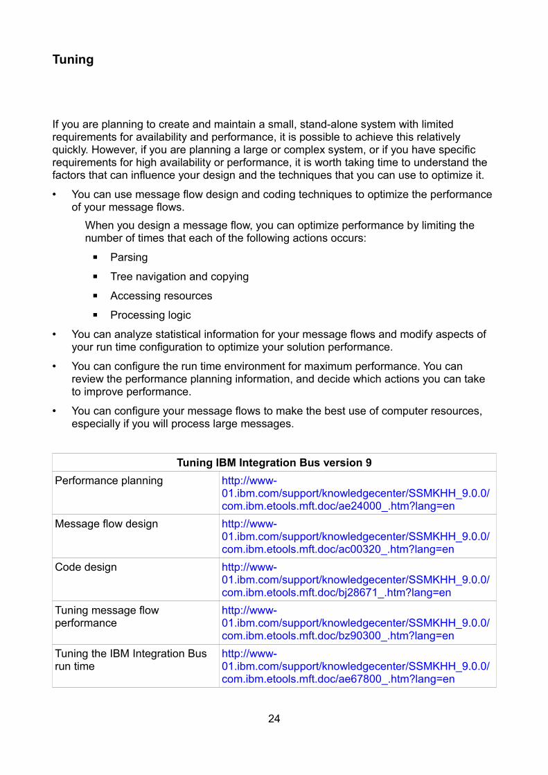
If you are planning to create and maintain a small, stand-alone system with limited requirements for availability and performance, it is possible to achieve this relatively quickly. However, if you are planning a large or complex system, or if you have specific requirements for high availability or performance, it is worth taking time to understand the factors that can influence your design and the techniques that you can use to optimize it.
• You can use message flow design and coding techniques to optimize the performance of your message flows.
When you design a message flow, you can optimize performance by limiting the number of times that each of the following actions occurs:
▪ Parsing
▪ Tree navigation and copying
▪ Accessing resources
▪ Processing logic
• You can analyze statistical information for your message flows and modify aspects of your run time configuration to optimize your solution performance.
• You can configure the run time environment for maximum performance. You can review the performance planning information, and decide which actions you can take to improve performance.
• You can configure your message flows to make the best use of computer resources, especially if you will process large messages.
Tuning IBM Integration Bus version 9Performance planning http://www-
01.ibm.com/support/knowledgecenter/SSMKHH_9.0.0/com.ibm.etools.mft.doc/ae24000_.htm?lang=en
Message flow design http://www-01.ibm.com/support/knowledgecenter/SSMKHH_9.0.0/com.ibm.etools.mft.doc/ac00320_.htm?lang=en
Code design http://www-01.ibm.com/support/knowledgecenter/SSMKHH_9.0.0/com.ibm.etools.mft.doc/bj28671_.htm?lang=en
Tuning message flow performance
http://www-01.ibm.com/support/knowledgecenter/SSMKHH_9.0.0/com.ibm.etools.mft.doc/bz90300_.htm?lang=en
Tuning the IBM Integration Bus run time
http://www-01.ibm.com/support/knowledgecenter/SSMKHH_9.0.0/com.ibm.etools.mft.doc/ae67800_.htm?lang=en
24
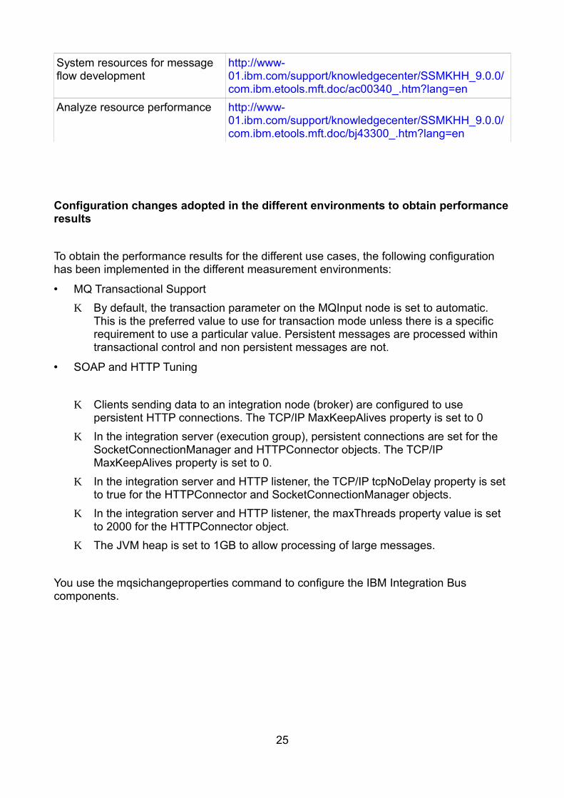
System resources for message flow development
http://www-01.ibm.com/support/knowledgecenter/SSMKHH_9.0.0/com.ibm.etools.mft.doc/ac00340_.htm?lang=en
Analyze resource performance http://www-01.ibm.com/support/knowledgecenter/SSMKHH_9.0.0/com.ibm.etools.mft.doc/bj43300_.htm?lang=en
Configuration changes adopted in the different environments to obtain performance results
To obtain the performance results for the different use cases, the following configuration has been implemented in the different measurement environments:
• MQ Transactional Support♦ By default, the transaction parameter on the MQInput node is set to automatic.
This is the preferred value to use for transaction mode unless there is a specific requirement to use a particular value. Persistent messages are processed within transactional control and non persistent messages are not.
• SOAP and HTTP Tuning
♦ Clients sending data to an integration node (broker) are configured to use persistent HTTP connections. The TCP/IP MaxKeepAlives property is set to 0
♦ In the integration server (execution group), persistent connections are set for the SocketConnectionManager and HTTPConnector objects. The TCP/IP MaxKeepAlives property is set to 0.
♦ In the integration server and HTTP listener, the TCP/IP tcpNoDelay property is set to true for the HTTPConnector and SocketConnectionManager objects.
♦ In the integration server and HTTP listener, the maxThreads property value is set to 2000 for the HTTPConnector object.
♦ The JVM heap is set to 1GB to allow processing of large messages.
You use the mqsichangeproperties command to configure the IBM Integration Bus components.
25
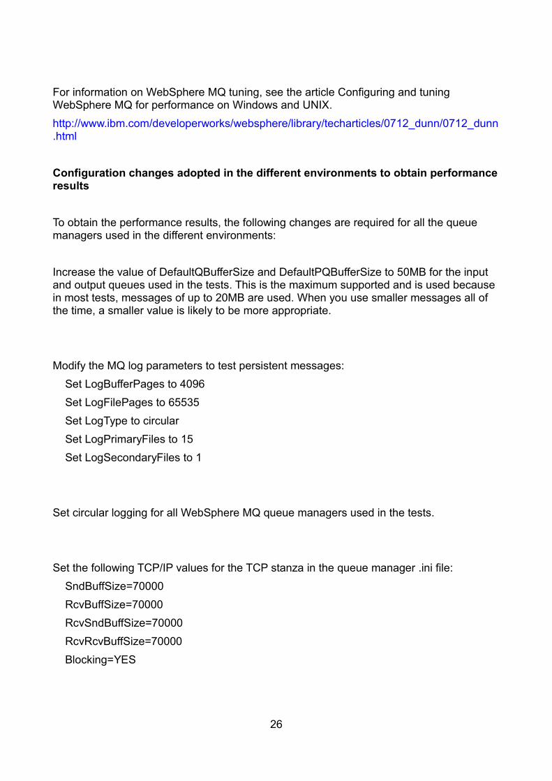
WebSphere MQ Tuning
For information on WebSphere MQ tuning, see the article Configuring and tuning WebSphere MQ for performance on Windows and UNIX.http://www.ibm.com/developerworks/websphere/library/techarticles/0712_dunn/0712_dunn.html Configuration changes adopted in the different environments to obtain performance results
To obtain the performance results, the following changes are required for all the queue managers used in the different environments:Buffer SizesIncrease the value of DefaultQBufferSize and DefaultPQBufferSize to 50MB for the input and output queues used in the tests. This is the maximum supported and is used because in most tests, messages of up to 20MB are used. When you use smaller messages all of the time, a smaller value is likely to be more appropriate.
Persistent MessagingModify the MQ log parameters to test persistent messages: Set LogBufferPages to 4096 Set LogFilePages to 65535 Set LogType to circular Set LogPrimaryFiles to 15 Set LogSecondaryFiles to 1
LoggingSet circular logging for all WebSphere MQ queue managers used in the tests.
TCPSet the following TCP/IP values for the TCP stanza in the queue manager .ini file: SndBuffSize=70000 RcvBuffSize=70000 RcvSndBuffSize=70000 RcvRcvBuffSize=70000 Blocking=YES
26

I/OThe WebSphere MQ queue manager log is located on a SAN disk with a non-volatile fast write cache used for the disk on which the log was located. Such disks are consistently capable of I/O times of 1 ms compared with a time of 6 ms for a 10,000 RPM SCSI disk.
When you use a disk with a fast write cache, it is important that it has a non-volatile capability because the log data is critical to the integrity of your queue manager.
27
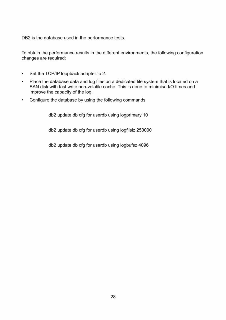
Tuning DB2
DB2 is the database used in the performance tests.
To obtain the performance results in the different environments, the following configuration changes are required:
• Set the TCP/IP loopback adapter to 2.
• Place the database data and log files on a dedicated file system that is located on a SAN disk with fast write non-volatile cache. This is done to minimise I/O times and improve the capacity of the log.
• Configure the database by using the following commands:
db2 update db cfg for userdb using logprimary 10
db2 update db cfg for userdb using logfilsiz 250000
db2 update db cfg for userdb using logbufsz 4096
28

Evaluation method
This section outlines the software components that are used to produce the measurements which are contained in the report.
Point to Point Message Processing is used to test the following transports:
• MQ
• JMS
• HTTP
• SOAP
Different configurations are used to generate and consume input and output messages due to different test cases using different types of input and output messages.
Message Generation and Consumption
The Performance Harness for JMS is a multi-threaded WebSphere MQ Client program written in Java that is used as follows:
• To generate input messages for the different test cases.
• To consume output messages.
The following PerfHarness modules are used for point to point testing:
• mqjava.Requestor . for MQ Messages
• http.Requestor . for Sending SOAP and HTTP messages
• jms.r11.Requestor . for sending and receiving JMS Messages
Note: The Performance Harness for JMS is used to generate and consume messages. The tool is useful as a simple way to send and receive messages. The documentation for the tool contains examples of how to run it to send and receive messages. More information about the currently available version can be found at AlphaWorks. https://www.ibm.com/developerworks/community/groups/service/html/communityview?communityUuid=18d10b14-e2c8-4780-bace-9af1fc463cc0&open&S_TACT=105AGX21&S_CMP=AWRSS
29
MQ Transport
• Both persistent and non persistent MQ messages are generated using the Performance Harness program.
• Persistent messages are sent as part of a transaction which is committed after every message.
• A number of threads (typically 20) are run in the multi-threaded client to ensure that there are always messages on the input queue waiting to be processed. This is important when measuring message throughput.
• Each thread sends a message and then waits to receive a reply on the output queue.
• Any thread within the client program is able to retrieve any message which has been processed by a message flow.
• No use is made of the WebSphere MQ correlation identifiers to limit consumption of a message to the thread which created it.
• As soon as a thread receives a reply, it sends another message.
• The message content is the same for all threads and all messages.
JMS Transport
• JMS messages are generated using the Performance Harness program.
• Non persistent JMS Bytes messages are sent to a JMS Destination.
• The connection factory for the client uses the MQ Client transport to send messages.
• The JMS destination is mapped to an MQ Queue.
• The JMS Input node is configured to read from this MQ queue.
• The connection factory for the nodes uses the MQ Bindings transport for connection.
• The message flow places the reply message on another MQ JMS queue. This output queue is where the client receives the reply.
• A number of threads (typically 20) are run in the multi-threaded client to ensure that there are always messages on the input queue waiting to be processed. This is important when measuring message throughput.
• Each thread sends a message and then waits to receive a reply on the output queue.
• Any thread within the client program is able to retrieve any message which has been processed by a message flow.
• No use is made of the JMS correlation identifiers to limit consumption of a message to the thread which created it.
• When a thread receives a reply, it sends another message.
• The message content is the same for all threads and all messages.
30
SOAP and HTTP transport
• SOAP and HTTP messages are generated using the Performance Harness program.
• Messages are sent through persistent HTTP connections. This means that each thread reuses the same TCPIP socket for each request. Each client thread has its own TCPIP socket connection to send and receive data.
• When a thread receives a reply, it sends another message.
• The message content is the same for all threads and all messages.
Machine Configuration
• The Performance Harness for JMS used to generate and consume messages for the message flows runs on a single client machine.
• IBM Integration Bus v9, its dedicated WebSphere MQ queue manager, and the database are all located on the server machine.
• There is a single client machine.
• For MQ and JMS performance tests, messages are transmitted from the client machine to the server machine over WebSphere MQ SVRCONN channels. The messages are received on the server by using the WebSphere MQ queue manager listener process. This was run as a trusted MQ application in order to improve message throughput.
• Messages are transmitted from the client machines to the server machine by using the WebSphere MQ transport, SOAP/HTTP, or JMS depending on the test use case.
• The client and the server machine are configured with sufficient memory to ensure that no paging takes place during the performance tests.
Reported Message Rates
• For tests that do not involve publish/subscribe, the message rates reported are the number of invocations of the message flow per second.
• For tests involving several message flows, such as the message aggregation tests, the rate reported is the number of complete operations or aggregations per second. Fan-out and fan-in processing is counted as one operation rather than separate operations.
• For tests using the JMS nodes, the message rate is the number of message flow invocations per second.
• The message rates quoted are an average taken over the measurement period. The start time used correspond to the time when the system initialization period has completed.
31
Useful links
This section contains links to information about IBM Integration Bus, previously known as WebSphere Message Broker, and associated products.
IBM Integration Bus
IBM Integration Bus v9 Announcement letter
http://www-01.ibm.com/common/ssi/cgi-bin/ssialias?subtype=ca&infotype=an&appname=iSource&supplier=877&letternum=ENUSZP13-0164
IBM Integration Bus v9 for zOS http://www-01.ibm.com/common/ssi/cgi-bin/ssialias?htmlfid=897/ENUS213-136&infotype=AN&subtype=CA
IBM Integration Bus Support page http://www-947.ibm.com/support/entry/portal/product/websphere/websphere_message_broker?productContext=-2089662493
IBM Integration Bus v9 product documentation
http://www-01.ibm.com/support/knowledgecenter/SSMKHH_9.0.0/com.ibm.etools.msgbroker.helphome.doc/help_home_msgbroker.htm?lang=en
IBM Integration Bus v9 Fixes http://www-933.ibm.com/support/fixcentral/swg/identifyFixes?query.parent=null&query.product=ibm~WebSphere~Integration%20Bus&query.release=All&query.platform=All
IBM Integration Bus SupportPacs http://www-01.ibm.com/support/docview.wss?rs=171&uid=swg27007197#2
WebSphere Message Broker Performance reports
http://www-01.ibm.com/support/docview.wss?rs=171&uid=swg27007150&loc=en_US&cs=utf-8&lang=en#2
IBM Integration Bus @ developerWorks http://www.ibm.com/developerworks/websphere/zones/businessintegration/wmb.html
IBM Integration Community Blog https://www.ibm.com/developerworks/community/blogs/c7e1448b-9651-456c-9924-f78bec90d2c2/?lang=en
IBM Integration Community Wiki https://www.ibm.com/developerworks/community/wikis/home?lang=en#!/wiki/W37b629a0f7aa_4709_9506_bba2a096693d
32
Related products:
WebSphere MQ SupportPacs http://www-01.ibm.com/support/docview.wss?rs=171&uid=swg27007197#1
WebSphere MQ http://www-01.ibm.com/software/websphere/ibm-mq.html
Business process Management (BPM) http://www-03.ibm.com/software/products/en/category/bpm-software
Tools
The Performance Harness for JMS was used to generate and consume messages. The tool is useful as a simple way to send and receive messages. The documentation for the tool contains examples of how to run it to send and receive messages.More information about the currently available version can be found at developerWorks .https://www.ibm.com/developerworks/community/groups/service/html/communityview?communityUuid=18d10b14-e2c8-4780-bace-9af1fc463cc0&open&S_TACT=105AGX21&S_CMP=AWRSS
33
Feedback
This report and other tools that are produced by the performance group are produced in order to help you understand the performance characteristics of IBM Integration Bus and to assist you with sizing.
It is important that the reports and tools are effective in what they do and it is very useful to have feedback on the content and style of the information which is produced. Your comments, both positive and negative, are therefore welcome.
Your answers to the following questions are particularly interesting:• What are your most common performance questions?• Do the reports provide what is needed?• Is there any other performance information which is required to• help you do your job?• Would you like to see any other aspects of WMB performance discussed?
Please supply feedback to us at the following e-mail addresses:Tim Dunn ([email protected])Dave Gorman([email protected])Rob Convery ([email protected])Martin Ross ([email protected])Marisa Lopez ([email protected])
34


![Probado con Windows 2000/XP/Vista/7 [32-bits ] Probado con Windows 7 64-bits](https://img.pdfslide.us/doc/110x75/5681359d550346895d9d11fa/probado-con-windows-2000xpvista7-32-bits-probado-con-windows-7-64-bits.jpg)

![Welcome. [jlikme.blob.core.windows.net]I learned performance on a Commodore 64. @JeremyLikness 8 bits vs. 64 bits •256 vs. 18,446,744,073,709,551,615 (quintillions) •Let 64 K =](https://img.pdfslide.us/doc/110x75/5ec980666ace79356a38eb7a/welcome-i-learned-performance-on-a-commodore-64-jeremylikness-8-bits-vs.jpg)