Embed Size (px)
Citation preview
IBM ISV & Developer Relations Manufacturing
IBM Information Technology Guide For ANSYS® Fluent® CustomersA collaborative effort between ANSYS and IBM
2 IBM Information Technology Guide For ANSYS Fluent Customers
Contents
3 1 Purpose 3 2 Scope 3 3 ANSYS Fluent Application Architecture3 3.1 Pre-ProcessingPhase3 3.2 SolutionPhase4 3.2.1 FluentRatingandSpeed-up4 3.3 Post-ProcessingPhase5 3.4 MajorComponentsofANSYSFluentArchitecture 6 4 System Selection for ANSYS Fluent6 4.1 SelectingtheBestProcessor6 4.1.1 ProcessorClockSpeed8 4.1.2 NumberofSockets9 4.1.3 ProcessorCoreDensity10 4.1.4 NumberofNodes(Cores)RequiredperSimulation12 4.1.5 ImprovingClockSpeedwithTurboBoostTechnology13 4.1.6 Hyper-Threading14 4.2 Memory15 4.2.1 MemoryConfigurationGuidelines17 4.2.2 NodeMemorySize18 4.3 InterconnectSelection20 4.3.1 Ethernet20 4.3.2 iWARP20 4.3.3 Infiniband23 4.3.4 LatencyandBandwidthPerformanceofGigabit,10-GigabitandInfinibandNetwork25 4.4 StorageSelectionGuide25 4.4.1 EstimatingStorageRequirements 28 5 Recommended IBM Configurations28 5.1 SmallConfiguration30 5.2 MediumConfiguration32 5.3 LargeConfiguration 34 6 Appendix34 6.1 IBMHardwareOfferings35 6.1.1 Systems35 6.1.2 NetworkSwitchesandAdapters36 6.2 ClusterSolutions36 6.2.1 BladeCenter37 6.2.2 iDataplex37 6.2.3 IBMSystemxRackServers37 6.3 FluentBenchmarkDescriptions38 6.4 FurtherInformation
IBMISV&DeveloperRelations 3
1 PurposeThis guide is intended to help customers make informed decisions about high-performance computing (HPC) hardware procurement and implementation to optimize the performance of ANSYS Fluent software. The document explains the benefits and trade-offs of various system component options that IBM and IBM partners offer. It also provides specific recommendations for systems running ANSYS Fluent.
2 ScopeThis guide explains the computational technology that is best suited to the ANSYS Fluent application as well as the IBM configurations that can optimize its performance. It emphasizes implementations of ANSYS Fluent on a cluster of servers, although some best practices presented here are also useful for evaluating system selection in workstation environments. All results discussed in this guide were generated with ANSYS Fluent 14.0. Total solution cost, where relevant, is considered only in a relative manner. The guide also indicates where customers can find more information from ANSYS and IBM (see Section 6.5).
3 ANSYS Fluent Application Architecture ANSYS Fluent is a computational fluid dynamics (CFD) software solution used to predict fluid flow, heat and mass transfer, chemical reactions, and related phenomena by numerically solving a set of governing mathematical equations (conservation of mass, momentum, energy, and others). ANSYS Fluent, along with other engineering simulation tools from ANSYS, help engineering teams understand product performance during conceptual studies of new designs, product development, troubleshooting and redesign.
ANSYS Fluent involves three distinct phases of use, each with its own hardware requirements.
3.1 Pre-Processing PhasePre-processing for ANSYS Fluent involves other ANSYS software applications, including ANSYS CAD Interfaces (for access to CAD geometries), ANSYS Design Modeler (for geometry creation or modification), ANSYS Meshing, and ANSYS Design Explorer. The ANSYS Fluent user interface also will be invoked during pre-processing. All of these applications are hosted in the ANSYS Workbench environment and are used in an interactive, graphical mode. Typically, these applications run on standalone desktop workstations and execute on single processors using a small amount of shared memory parallelism. Memory requirements for ANSYS Meshing, Design Modeler and Design Explorer depend on the size of the model, but often require large memory availability. Typical input files (also called “case files”) created during the pre-processing phase will range in size from 100 MB (or less) to 2 - 3 GB for larger workloads. Output files (also called “data files”), as noted below, will be significantly larger. Pre-processing is graphically intensive and requires a high-end certified graphics card. ANSYS tests and certifies the nVIDIA Quadro, Quadro FX and the ATI FireGL/Pro line only for pre- and post-processing.
3.2 Solution PhaseThe solution phase involves running the ANSYS Fluent solver to solve the equations that describe the physical behavior under consideration. This phase is computationally and memory-intensive and is optimized through the use of parallel processing on a multi- core workstation, a cluster of workstations, a server or a cluster of servers/blades. Appropriately sized hardware can reduce turnaround time from weeks to days or from days to hours. Proper hardware also enables larger, more detailed simulation models.
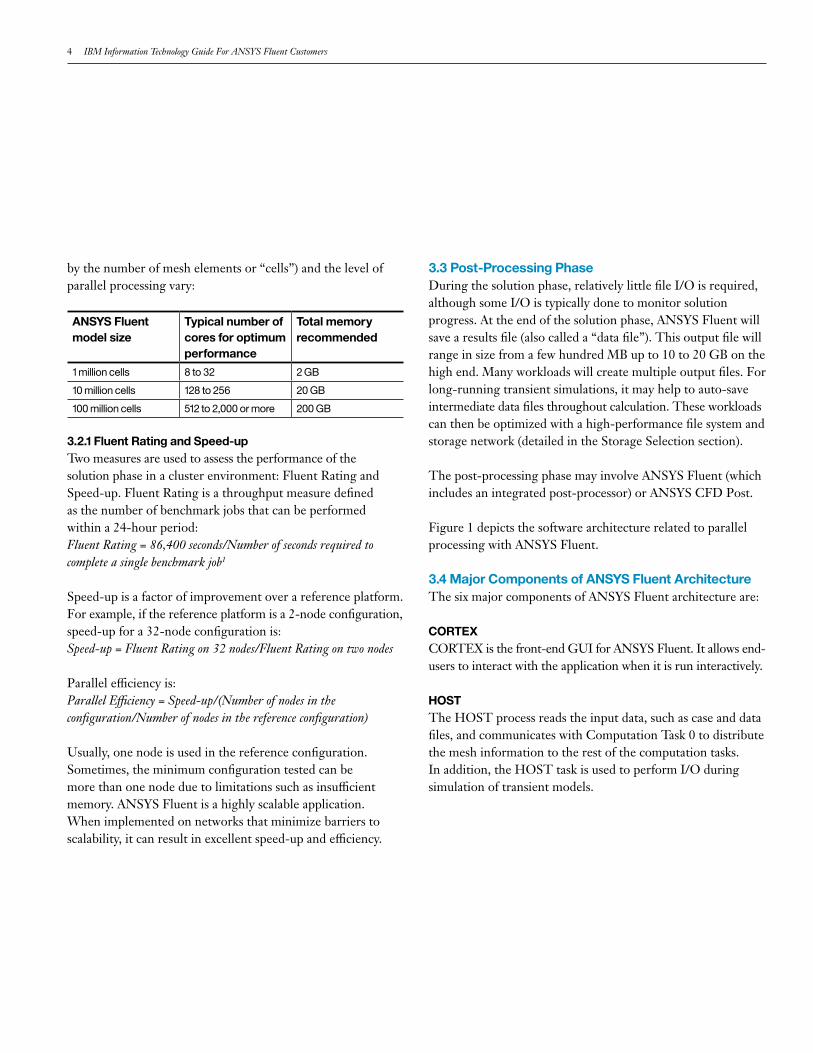
Today, most industrial ANSYS Fluent simulation models are executed on 16 to 64 computational cores, depending on the size of the model. The largest models may take advantage of hundreds or thousands of processing cores. Processor and memory requirements for ANSYS Fluent are model-specific. The following table provides estimates for typical models as model size (measured
4 IBM Information Technology Guide For ANSYS Fluent Customers
by the number of mesh elements or “cells”) and the level of parallel processing vary:
3.2.1 Fluent Rating and Speed-upTwo measures are used to assess the performance of the solution phase in a cluster environment: Fluent Rating and Speed-up. Fluent Rating is a throughput measure defined as the number of benchmark jobs that can be performed within a 24-hour period:Fluent Rating = 86,400 seconds/Number of seconds required to complete a single benchmark job1
Speed-up is a factor of improvement over a reference platform. For example, if the reference platform is a 2-node configuration, speed-up for a 32-node configuration is:Speed-up = Fluent Rating on 32 nodes/Fluent Rating on two nodes
Parallel efficiency is:Parallel Efficiency = Speed-up/(Number of nodes in the configuration/Number of nodes in the reference configuration)
Usually, one node is used in the reference configuration. Sometimes, the minimum configuration tested can be more than one node due to limitations such as insufficient memory. ANSYS Fluent is a highly scalable application. When implemented on networks that minimize barriers to scalability, it can result in excellent speed-up and efficiency.
3.3 Post-Processing PhaseDuring the solution phase, relatively little file I/O is required, although some I/O is typically done to monitor solution progress. At the end of the solution phase, ANSYS Fluent will save a results file (also called a “data file”). This output file will range in size from a few hundred MB up to 10 to 20 GB on the high end. Many workloads will create multiple output files. For long-running transient simulations, it may help to auto-save intermediate data files throughout calculation. These workloads can then be optimized with a high-performance file system and storage network (detailed in the Storage Selection section).
The post-processing phase may involve ANSYS Fluent (which includes an integrated post-processor) or ANSYS CFD Post.
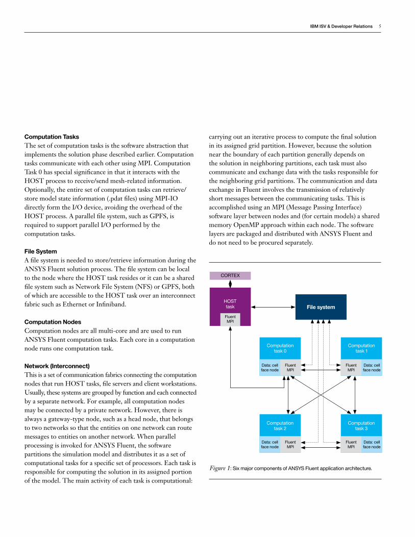
Figure 1 depicts the software architecture related to parallel processing with ANSYS Fluent.
3.4 Major Components of ANSYS Fluent ArchitectureThe six major components of ANSYS Fluent architecture are:
CORTEXCORTEX is the front-end GUI for ANSYS Fluent. It allows end- users to interact with the application when it is run interactively.
HOSTThe HOST process reads the input data, such as case and data files, and communicates with Computation Task 0 to distribute the mesh information to the rest of the computation tasks. In addition, the HOST task is used to perform I/O during simulation of transient models.
ANSYS Fluent model size
Typical number of cores for optimum performance
Total memory recommended
1 million cells 8 to 32 2 GB
10 million cells 128 to 256 20 GB
100 million cells 512 to 2,000 or more 200 GB
IBMISV&DeveloperRelations 5
Computation TasksThe set of computation tasks is the software abstraction that implements the solution phase described earlier. Computation tasks communicate with each other using MPI. Computation Task 0 has special significance in that it interacts with the HOST process to receive/send mesh-related information. Optionally, the entire set of computation tasks can retrieve/store model state information (.pdat files) using MPI-IO directly form the I/O device, avoiding the overhead of the HOST process. A parallel file system, such as GPFS, is required to support parallel I/O performed by the computation tasks.
File SystemA file system is needed to store/retrieve information during the ANSYS Fluent solution process. The file system can be local to the node where the HOST task resides or it can be a shared file system such as Network File System (NFS) or GPFS, both of which are accessible to the HOST task over an interconnect fabric such as Ethernet or Infiniband.
Computation NodesComputation nodes are all multi-core and are used to run ANSYS Fluent computation tasks. Each core in a computation node runs one computation task.
Network (Interconnect)This is a set of communication fabrics connecting the computation nodes that run HOST tasks, file servers and client workstations. Usually, these systems are grouped by function and each connected by a separate network. For example, all computation nodes may be connected by a private network. However, there is always a gateway-type node, such as a head node, that belongs to two networks so that the entities on one network can route messages to entities on another network. When parallel processing is invoked for ANSYS Fluent, the software partitions the simulation model and distributes it as a set of computational tasks for a specific set of processors. Each task is responsible for computing the solution in its assigned portion of the model. The main activity of each task is computational:
carrying out an iterative process to compute the final solution in its assigned grid partition. However, because the solution near the boundary of each partition generally depends on the solution in neighboring partitions, each task must also communicate and exchange data with the tasks responsible for the neighboring grid partitions. The communication and data exchange in Fluent involves the transmission of relatively short messages between the communicating tasks. This is accomplished using an MPI (Message Passing Interface) software layer between nodes and (for certain models) a shared memory OpenMP approach within each node. The software layers are packaged and distributed with ANSYS Fluent and do not need to be procured separately.
HOST task
CORTEX
Fluent MPI
Computation task 0
Computation task 2
Computation task 1
Computation task 3
File system
Fluent MPI
Data: cell face node
Data: cell face node
Data: cell face node
Data: cell face node
Fluent MPI
Fluent MPI
Fluent MPI
Figure 1: Six major components of ANSYS Fluent application architecture.
6 IBM Information Technology Guide For ANSYS Fluent Customers
4 System Selection for ANSYS Fluent
4.1 Selecting the Best ProcessorBecause ANSYS Fluent is both CPU- and memory-intensive, it is important to consider CPU speed, memory speed and memory bandwidth when selecting a processor. The speed of the processors measured as clock rate (GHz) has leveled off due to excessive heat generation. This is why processor design has shifted to adding cores (multi-core) to the chip. Intel processors contain 4, 6, 8, or 10 cores on one processor chip. A computer system (or node) includes one or more processors (also called sockets).
The memory subsystem is attached to a processor. When a system is configured with more than one processor, the operating system provides a global view of local memory attached to each processor, even though the memory is local to each processor. However, because physical memory is attached to a specific processor, it is important that applications running on CPU cores attached to the processor can access local memory. When ANSYS Fluent starts on a processor it is pinned to that processor. Memory for the application process is allocated from the local memory attached to that processor.
In order to select the best processors to run ANSYS Fluent workloads, the following factors need to be considered: • Processor clock speed• Number of sockets (2-socket vs. 4-socket)• Processor core density (quad-core, hex-core, 8-core)• Number of cores (or nodes) to run the simulation at
optimal speed• Memory configuration.
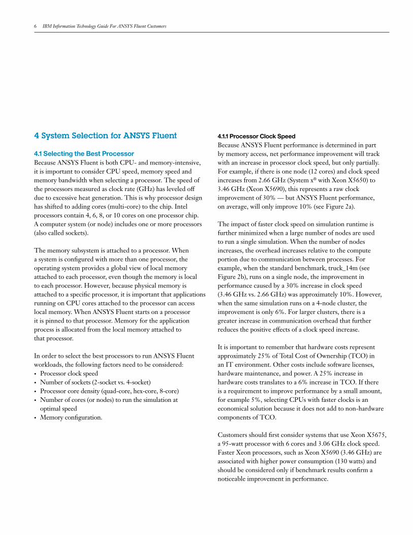
4.1.1 Processor Clock SpeedBecause ANSYS Fluent performance is determined in part by memory access, net performance improvement will track with an increase in processor clock speed, but only partially. For example, if there is one node (12 cores) and clock speed increases from 2.66 GHz (System x® with Xeon X5650) to3.46 GHz (Xeon X5690), this represents a raw clock improvement of 30% — but ANSYS Fluent performance, on average, will only improve 10% (see Figure 2a).
The impact of faster clock speed on simulation runtime is further minimized when a large number of nodes are used to run a single simulation. When the number of nodes increases, the overhead increases relative to the compute portion due to communication between processes. For example, when the standard benchmark, truck_14m (see Figure 2b), runs on a single node, the improvement in performance caused by a 30% increase in clock speed (3.46 GHz vs. 2.66 GHz) was approximately 10%. However, when the same simulation runs on a 4-node cluster, the improvement is only 6%. For larger clusters, there is a greater increase in communication overhead that further reduces the positive effects of a clock speed increase.
It is important to remember that hardware costs represent approximately 25% of Total Cost of Ownership (TCO) in an IT environment. Other costs include software licenses, hardware maintenance, and power. A 25% increase in hardware costs translates to a 6% increase in TCO. If there is a requirement to improve performance by a small amount, for example 5%, selecting CPUs with faster clocks is an economical solution because it does not add to non-hardware components of TCO.
Customers should first consider systems that use Xeon X5675, a 95-watt processor with 6 cores and 3.06 GHz clock speed. Faster Xeon processors, such as Xeon X5690 (3.46 GHz) are associated with higher power consumption (130 watts) and should be considered only if benchmark results confirm a noticeable improvement in performance.
IBMISV&DeveloperRelations 7
1.40
Impr
ovem
ent d
ue to
clo
ck
ANSYS Fluent model
2.66 GHz 2.93 GHz 3.47 GHz
Impact of CPU speed on ANSYS Fluent 14.0 performance Processor: Xeon X5600 series, 12 cores per node
Hyper-threading: OFF; Turbo: ONEach job uses one system with 12 cores
(performance measure is improvement relative to CPU clock 2.66 GHz)
1.35
1.30
1.25
1.20
1.15
1.10
1.05
1.00
0.95
0.90
0.85
0.80
Clock ratio eddy_417k aircraft_2m turbo_500k sedan_4m truck_14m
Hig
her i
s be
tter
Hig
her i
s be
tter
Clo
ck im
prov
emen
t rel
to 2
.67
GH
z
Number of nodes allocated to a single job
2.66 GHz 2.93 GHz 3.47 GHz
Impact of CPU Speed on ANSYS Fluent Performance Processor: Xeon X5600 Series, 12 cores per node
Hyper-threading: OFF, Turbo: ONModel: truck_14m
(performance measure is improvement relative to CPU clock 2.66 GHz)
1.35
1.30
1.25
1.20
1.15
1.10
1.05
1.00
0.95
0.90
0.85
0.80
Clock ratio 1 2 3
G slower clock (GHz)
Faster clock (GHz)
Raw clock ratio (%)
Relative system price
ratio* (%)
Average Fluent
improvement (%)
2.93 3.46 18 1 5
2.66 3.46 30 25 10
Best Practices: Processor Clock Speed
Thereisalwaysanimprovement(5%to10%)inapplicationperformancewhenclockspeedincreases.ComputenodesbasedonXeonX5675(3.06GHz,95watt)arerecommendedbecausetheactualperformanceimprovementwhenusingthefastestavailableclock(3.45GHz)isverysmall.Whilethereisnoharminchoosingthefastestprocessors,investinginotheraspectsoftheclusterislikelytobemorecost-effective.
Figure 2a: ANSYS Fluent performance increases with processor clock speed across five benchmark workloads (single node).
Table 1: Processor Clock Price Performance Analysis Processor: Xeon x5600 Series Processors.
Figure 2b: Number of nodes limits performance increases of faster clockspeed (cluster).
8 IBM Information Technology Guide For ANSYS Fluent Customers
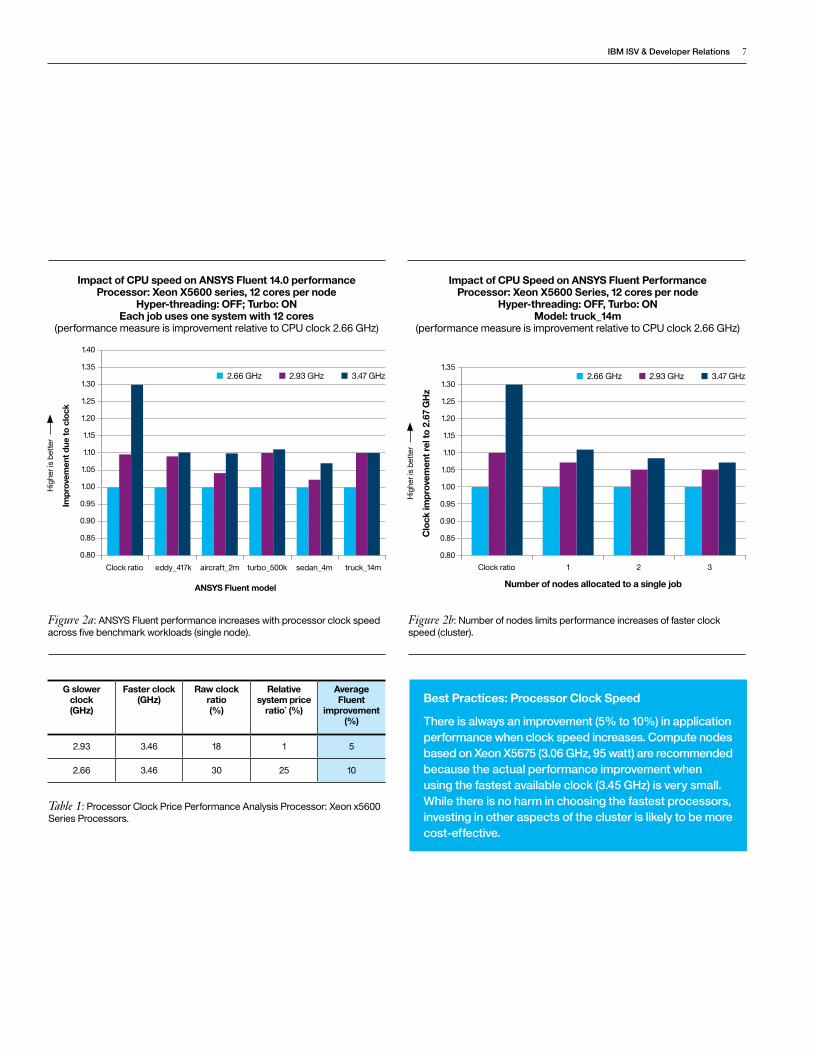
4.1.2 Number of SocketsIBM 2-processor (socket) systems use Xeon X5600 series processors. IBM 4-processor (socket) systems use Xeon E7-X8800 series processors. Due to the density of cores in 4-socket systems, the CPU and memory speeds are slightly slower. This slight reduction in speed is due to additional cores per processor with clock speeds of 2.6 GHz, bringing the total number of system cores to 32. The memory speed in 4-socket systems is also slower than in 2-socket systems (1066 MHz vs. 1333 MHz). Although CPU and memory speed of the cores in 4-socket systems are slower, system performance is comparable to two 2-socket systems connected via high-speed network because there are more cores per system (see Table 2). In addition, one 4-socket system and two 2-socket systems are comparable in price.
If the compute requirements of an ANSYS Fluent job can be satisfied by a single 4-socket system with 32 cores, it is recommended the customer purchase one or more 4-socket systems. Using a 4-socket system will simplify the total solution because complex high-speed interconnects and associated system administration are not required. This solution offers a natural progression for customers who are moving up from a desktop environment to consolidate workloads among several servers, where each server handles one or more jobs. Although a 4-socket system can achieve comparable performance to two 2-socket systems using a high-speed interconnect, more cores may require more ANSYS Fluent licenses. However, eliminating or reducing the high-speed interconnect may offset some of these costs. As always, total solution cost should be considered before making a final decision.
Performance measure is Fluent Rating (higher values are better)
2-socket based SystemsIBM HS22/HS22V Blade, 3550/3650 M3, Dx360 M3
(Xeon 5600 Series)
Nodes Sockets Cores Fluent rating
1 2 12 88
2 4 24 173
4-socket based SystemsIBM HX5 Blade, x3850 X5
(Xeon E7-8837 Series)
Nodes Sockets Cores Fluent rating
1 2 16 96
1 4 32 188
Table 2: Performance of ANSYS Fluent on 2-socket and 4-socket Systems.
Best Practices: Sockets
A4-socketsystemisrecommendediftheperformancerequirementsofasingleANSYSFluentjobcanbesatisfiedwithasingle4-socketsystem.Ifcapacityneedstoscalebeyonda4-socketsystem,itismorecost-effectivetobuy2-socketserversinordertobuildaclusterwithhigh-speedinterconnect,suchas10-gigabitEthernetorInfiniband.
IBMISV&DeveloperRelations 9
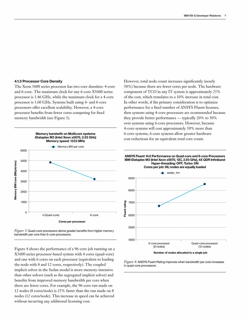
4.1.3 Processor Core DensityThe Xeon 5600 series processor has two core densities: 4-core and 6-core. The maximum clock for any 6-core X5600 series processor is 3.46 GHz, while the maximum clock for a 4-core processor is 3.60 GHz. Systems built using 4- and 6-core processors offer excellent scalability. However, a 4-core processor benefits from fewer cores competing for fixed memory bandwidth (see Figure 3).
Figure 4 shows the performance of a 96-core job running on a X5600 series processor-based system with 4 cores (quad-core) and one with 6 cores on each processor (equivalent to loading the node with 8 and 12 cores, respectively). The coupled implicit solver in the Sedan model is more memory-intensive than other solvers (such as the segregated implicit solver) and benefits from improved memory bandwidth per core when there are fewer cores. For example, the 96-core run made on 12 nodes (8 cores/node) is 25% faster than the run made on 8 nodes (12 cores/node). This increase in speed can be achieved without incurring any additional licensing cost.
However, total node count increases significantly (nearly 50%) because there are fewer cores per node. The hardware component of TCO in any IT system is approximately 25% of the cost, which translates to a 10% increase in total cost. In other words, if the primary consideration is to optimize performance for a fixed number of ANSYS Fluent licenses, then systems using 4-core processors are ecommended because they provide better performance — typically 20% to 30% over systems using 6-core processors. However, because 4-core systems will cost approximately 50% more than 6-core systems, 6-core systems allow greater hardware cost reductions for an equivalent total core count.
Flue
nt r
atin
g
Number of nodes allocated to a single job
ANSYS Fluent 14.0 Performance on Quad-core and 6-core Processors IBM iDataplex M3 (Intel Xeon x5670, 12C, 2.93 GHz), 4X QDR Infiniband
Hyper-threading: OFF; Turbo: ON Cores per job: 96; nodes are equally loaded
9000
8000
7000
6000
5000
40006-core processor
(8 nodes)Quad-core processor
(12 nodes)
sedan_4m
Figure 4: ANSYS Fluent Rating improves when bandwidth per core increases in quad-core processors.
Mem
ory
BW
/cor
e (M
byte
/sec
)
Cores per processor
Memory bandwith on Multicore systems iDataplex M3 (Intel Xeon x5670, 2.93 GHz)
Memory speed: 1333 MHz
6000
5000
4000
3000
2000
1000
04 (Quad-core) 6-core
Memory BW per core
Figure 3: Quad-core processors derive greater benefits from higher memory bandwidth per core than 6-core processors.

10 IBM Information Technology Guide For ANSYS Fluent Customers
4.1.4 Number of Nodes (Cores) Required per SimulationIn order to select the number of nodes required to run an individual ANSYS Fluent simulation, it is important to take into account the performance characteristics of the models that are being solved as well as the value of productivity improvements achieved. Productivity improvements can be quantified (based on benchmarks for a specific workload) or estimated (based on standard benchmark test cases presented here). Evaluations should yield a set of highly scalable configurations to be considered as candidates.
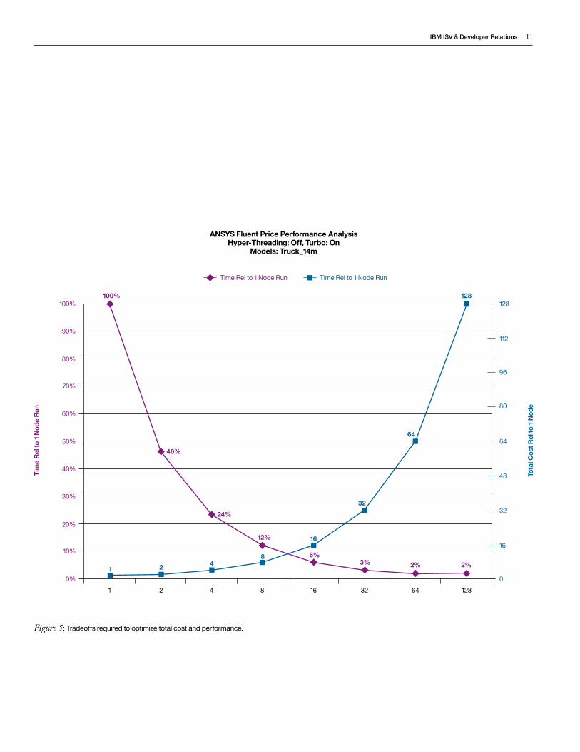
For example, Figure 5 plots total Fluent run times as a percentage of a single node run time for different configurations (purple graph) and the corresponding costs (blue graph). For high-end clusters, the performance levels off while the total cost rises linearly with the size of the cluster. In a configuration of 16 or more nodes, for example, there is little or no improvement as a percent of single node run time. Although low-end clusters reduce run times significantly, they may not satisfy the required productivity improvement.
For a given problem size, the optimal number of nodes in the cluster falls in the middle of the performance/price spectrum. The choices within this narrow range (e.g., the 4-, 8-, 16-, and 32-node configurations in Figure 5) are evaluated closely (using ROI analysis) to determine optimal cluster size.
The business value of faster run times should be matched against the cost of additional hardware and licenses before choosing the size of the cluster. Customers may already know what productivity improvements are needed. For example, business needs may dictate that turnaround time for ANSYS Fluent jobs must be reduced from 24 hours to overnight. In this case, customers can select the most economical hardware that meets the performance goal.
Best Practices: Processor Core Density
IftheprimaryconsiderationisoptimizingperformanceforafixednumberofANSYSFluentlicenses,systemswith4-coreprocessorsarerecommended becausetheyprovidebetterperformance—typically20%to30% oversystemsusing6-coreprocessors.However,iftheprimaryconsiderationiscost,6-coresystemsareabetterchoiceforanequivalenttotalcorecountbecausetheycostapproximately30%lessthan4-coresystems.
IBMISV&DeveloperRelations 11
Tota
l Cos
t Rel
to 1
Nod
e
Tim
e R
el to
1 N
ode
Run
Figure 5: Tradeoffs required to optimize total cost and performance.
100% 128
112
96
80
64
48
32
16
0
90%
80%
70%
60%
50%
40%
1 2 4
100% 128
46%
Time Rel to 1 Node Run Time Rel to 1 Node Run
ANSYS Fluent Price Performance Analysis Hyper-Threading: Off, Turbo: On
Models: Truck_14m
24%
12%
6%
16
8421
32
64
3% 2% 2%
8 16 32 64 128
30%
20%
10%
0%
12 IBM Information Technology Guide For ANSYS Fluent Customers
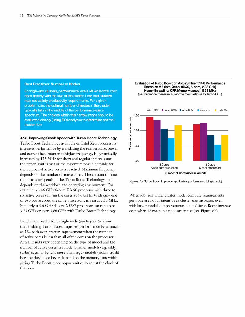
4.1.5 Improving Clock Speed with Turbo Boost TechnologyTurbo Boost Technology available on Intel Xeon processors increases performance by translating the temperature, power and current headroom into higher frequency. It dynamically increases by 133 MHz for short and regular intervals until the upper limit is met or the maximum possible upside for the number of active cores is reached. Maximum frequency depends on the number of active cores. The amount of time the processor spends in the Turbo Boost Technology state depends on the workload and operating environment. For example, a 3.46 GHz 6-core X5690 processor with three to six active cores can run the cores at 3.6 GHz. With only one or two active cores, the same processor can run at 3.73 GHz. Similarly, a 3.6 GHz 4-core X5687 processor can run up to 3.73 GHz or even 3.86 GHz with Turbo Boost Technology.
Benchmark results for a single node (see Figure 6a) show that enabling Turbo Boost improves performance by as much as 5%, with even greater improvement when the number of active cores is less than all of the cores on the processor. Actual results vary depending on the type of model and the number of active cores in a node. Smaller models (e.g. eddy, turbo) seem to benefit more than larger models (sedan, truck) because they place lower demand on the memory bandwidth, giving Turbo Boost more opportunities to adjust the clock of the cores.
When jobs run under cluster mode, compute requirements per node are not as intensive as cluster size increases, even with larger models. Improvements due to Turbo Boost increase even when 12 cores in a node are in use (see Figure 6b).
Best Practices: Number of Nodes
Forhigh-endclusters,performancelevelsoffwhiletotalcostriseslinearlywiththesizeofthecluster.Low-endclustersmaynotsatisfyproductivityrequirements.Foragivenproblemsize,theoptimalnumberofnodesintheclustertypicallyfallsinthemiddleoftheperformance/pricespectrum.Thechoiceswithinthisnarrowrangeshouldbeevaluatedclosely(usingROIanalysis)todetermineoptimalclustersize.
Figure 6a: Turbo Boost improves application performance (single node).
8 Cores (Quad core processor)
12 Cores (6 core processor)
Turb
o bo
ost i
mpr
ovem
ent
Number of Cores used in a Node
eddy_417k turbo_500k aircraft_2m sedan_4m truck_14m
Evaluation of Turbo Boost on ANSYS Fluent 14.0 Performance iDataplex M3 (Intel Xeon x5670, 6-core, 2.93 GHz) Hyper-threading: OFF, Memory speed: 1333 MHz
(performance measure is improvement relative to Turbo OFF)
1.06
1.04
1.02
1.00
IBMISV&DeveloperRelations 13
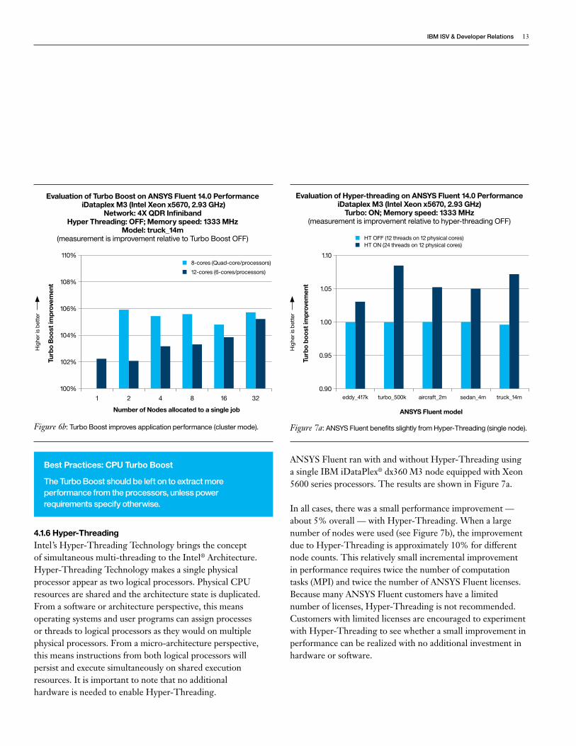
4.1.6 Hyper-ThreadingIntel’s Hyper-Threading Technology brings the concept of simultaneous multi-threading to the Intel® Architecture. Hyper-Threading Technology makes a single physical processor appear as two logical processors. Physical CPU resources are shared and the architecture state is duplicated. From a software or architecture perspective, this means operating systems and user programs can assign processes or threads to logical processors as they would on multiple physical processors. From a micro-architecture perspective, this means instructions from both logical processors will persist and execute simultaneously on shared execution resources. It is important to note that no additional hardware is needed to enable Hyper-Threading.
ANSYS Fluent ran with and without Hyper-Threading using a single IBM iDataPlex® dx360 M3 node equipped with Xeon 5600 series processors. The results are shown in Figure 7a.
In all cases, there was a small performance improvement — about 5% overall — with Hyper-Threading. When a large number of nodes were used (see Figure 7b), the improvement due to Hyper-Threading is approximately 10% for different node counts. This relatively small incremental improvement in performance requires twice the number of computation tasks (MPI) and twice the number of ANSYS Fluent licenses. Because many ANSYS Fluent customers have a limited number of licenses, Hyper-Threading is not recommended. Customers with limited licenses are encouraged to experiment with Hyper-Threading to see whether a small improvement in performance can be realized with no additional investment in hardware or software.
Turb
o B
oost
impr
ovem
ent
Number of Nodes allocated to a single job
Evaluation of Turbo Boost on ANSYS Fluent 14.0 Performance iDataplex M3 (Intel Xeon x5670, 2.93 GHz)
Network: 4X QDR InfinibandHyper Threading: OFF; Memory speed: 1333 MHz
Model: truck_14m (measurement is improvement relative to Turbo Boost OFF)
110%
108%
106%
104%
102%
100%
Hig
her i
s be
tter
1 2 4 8 16 32
8-cores (Quad-core/processors)
12-cores (6-cores/processors)
Figure 6b: Turbo Boost improves application performance (cluster mode).
Turb
o bo
ost i
mpr
ovem
ent
ANSYS Fluent model
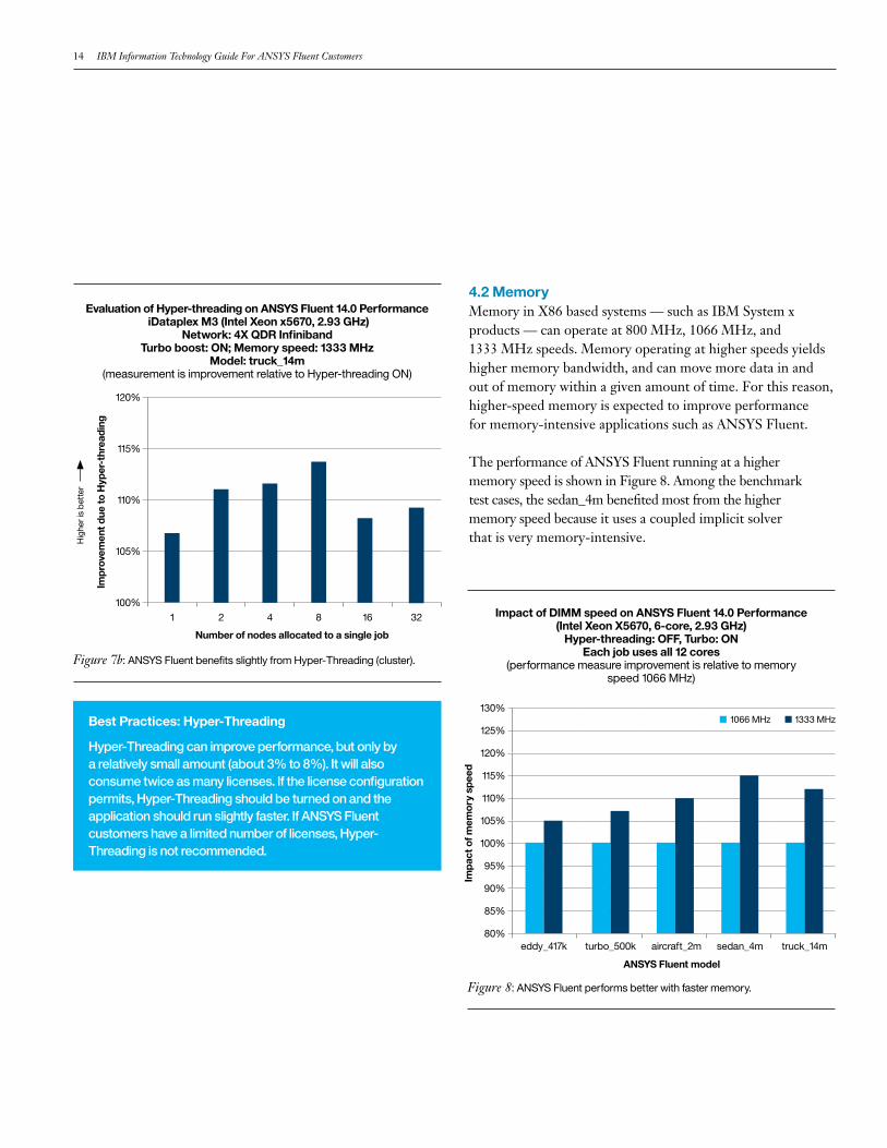
Evaluation of Hyper-threading on ANSYS Fluent 14.0 Performance iDataplex M3 (Intel Xeon x5670, 2.93 GHz)
Turbo: ON; Memory speed: 1333 MHz(measurement is improvement relative to hyper-threading OFF)
1.10
1.05
1.00
0.95
0.90
Hig
her i
s be
tter
eddy_417k turbo_500k aircraft_2m sedan_4m truck_14m
HT OFF (12 threads on 12 physical cores)HT ON (24 threads on 12 physical cores)
Figure 7a: ANSYS Fluent benefits slightly from Hyper-Threading (single node).
Best Practices: CPU Turbo Boost
TheTurboBoostshouldbeleftontoextractmoreperformancefromtheprocessors,unlesspowerrequirementsspecifyotherwise.
14 IBM Information Technology Guide For ANSYS Fluent Customers
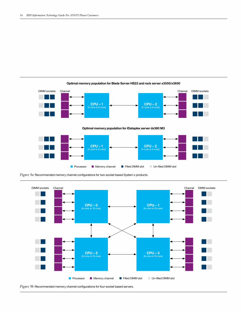
4.2 MemoryMemory in X86 based systems — such as IBM System x products — can operate at 800 MHz, 1066 MHz, and 1333 MHz speeds. Memory operating at higher speeds yields higher memory bandwidth, and can move more data in and out of memory within a given amount of time. For this reason, higher-speed memory is expected to improve performance for memory-intensive applications such as ANSYS Fluent.
The performance of ANSYS Fluent running at a higher memory speed is shown in Figure 8. Among the benchmark test cases, the sedan_4m benefited most from the higher memory speed because it uses a coupled implicit solver that is very memory-intensive.
eddy_417k turbo_500k aircraft_2m sedan_4m truck_14m
Impa
ct o
f mem
ory
spee
d
ANSYS Fluent model
1066 MHz 1333 MHz
Impact of DIMM speed on ANSYS Fluent 14.0 Performance (Intel Xeon X5670, 6-core, 2.93 GHz)
Hyper-threading: OFF, Turbo: ONEach job uses all 12 cores
(performance measure improvement is relative to memory speed 1066 MHz)
130%
125%
120%
115%
110%
105%
100%
95%
90%
85%
80%
Impr
ovem
ent d
ue to
Hyp
er-t
hrea
ding
Number of nodes allocated to a single job
Evaluation of Hyper-threading on ANSYS Fluent 14.0 Performance iDataplex M3 (Intel Xeon x5670, 2.93 GHz)
Network: 4X QDR InfinibandTurbo boost: ON; Memory speed: 1333 MHz
Model: truck_14m (measurement is improvement relative to Hyper-threading ON)
120%
115%
110%
105%
100%
Hig
her i
s be
tter
1 2 4 8 16 32
Figure 7b: ANSYS Fluent benefits slightly from Hyper-Threading (cluster).
Figure 8: ANSYS Fluent performs better with faster memory.
Best Practices: Hyper-Threading
Hyper-Threadingcanimproveperformance,butonlybyarelativelysmallamount(about3%to8%).Itwillalsoconsumetwiceasmanylicenses.Ifthelicenseconfigurationpermits,Hyper-Threadingshouldbeturnedonandtheapplicationshouldrunslightlyfaster.IfANSYSFluentcustomershavealimitednumberoflicenses,Hyper-Threadingisnotrecommended.

IBMISV&DeveloperRelations 15
It is important to estimate and configure memory properly in order for it to operate at maximum speed. First, memory size should be estimated to satisfy ANSYS Fluent simulation requirements, then adjusted by applying memory configuration rules to arrive at the final size. The next two sections describe memory configuration guidelines for Xeon x5600 processors, including memory size for a node running ANSYS Fluent.
4.2.1 Memory Configuration Guidelines Memory configuration significantly affects application performance. To configure memory properly, it is helpful to understand some essential terminology.
IBM System x products, which are built with Xeon X5600 series processors, make exclusive use of Double Data Rate III (DDR3) memory technology. These memory modules are called Direct In-line Memory Modules (DIMMs) and can operate at 800 MHz, 1066 MHz, and 1333 MHz speeds. In order for the DIMMs to operate at top speed, both the DIMM and the processor to which the DIMM is attached must be 1333 MHz capable. Xeon X5600 series processors are 1333 MHz capable, but the memory on 4-socket systems based on the Xeon E7-8837 processor operate at a maximum speed of 1066 MHz. The DIMMs are available in sizes of 2 GB, 4 GB, 8 GB, and 16 GB.
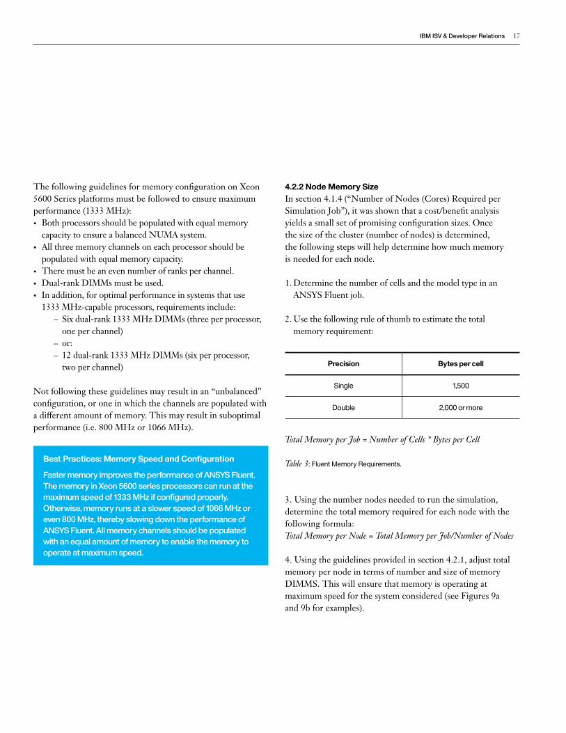
Memory DIMMS are inserted into DIMM slots, which are grouped under channels. The channels are attached to the processor (or socket). The number of DIMM slots per channel (DPC) and number of channels attached to a processor vary from one system to the next. Systems that use Xeon X5600 series systems — such as IBM HS22 and IBM dx360 (see Figure 9a) — use three channels per processor, although the DPC differ slightly. The 4-socket systems built using Xeon E7-8837 processors — such as IBM x3850 X5 — use four channels per processor and two DPC (see Figure 9b) for a total of 16 channels and 32 DIMM slots.
A memory rank is a segment of memory addressed by a specific address bit. DIMMs typically have 1, 2, or 4 memory ranks, as indicated by the size designation. To optimize performance, it is important to populate DIMMs with an appropriate number of ranks in each channel. Whenever possible, dual-rank DIMMs are recommended because they offer better interleaving and better performance than single-rank DIMMs.
If the memory channels or DPC are not populated as recommended here, the speed at which memory operates can drop from 1333 MHz to 800 MHz, significantly compromising both the memory bandwidth and performance of ANSYS Fluent.
16 IBM Information Technology Guide For ANSYS Fluent Customers
DIMM sockets DIMM socketsChannelChannel
CPU – 0 (8-core or 10-core)
CPU – 2 (8-core or 10-core)
CPU – 1 (8-core or 10-core)
CPU – 3 (8-core or 10-core)
Processor Memory channel Filled DIMM slot Un-filled DIMM slot
Optimal memory population for Blade Server HS22 and rack server x3550/x3650
Optimal memory population for iDataplex server dx360 M3
DIMM sockets DIMM socketsChannelChannel
CPU – 1 (4-core or 6-core)
CPU – 2 (4-core or 6-core)
CPU – 1 (4-core or 6-core)
CPU – 2 (4-core or 6-core)
Processor Memory channel Filled DIMM slot Un-filled DIMM slot
Figure 9a: Recommended memory channel configurations for two-socket based System x products.
Figure 9b: Recommended memory channel configurations for four-socket based servers.
IBMISV&DeveloperRelations 17
The following guidelines for memory configuration on Xeon 5600 Series platforms must be followed to ensure maximum performance (1333 MHz):• Both processors should be populated with equal memory
capacity to ensure a balanced NUMA system.• All three memory channels on each processor should be
populated with equal memory capacity.• There must be an even number of ranks per channel. • Dual-rank DIMMs must be used.• In addition, for optimal performance in systems that use
1333 MHz-capable processors, requirements include: – Six dual-rank 1333 MHz DIMMs (three per processor, one per channel)
– or: – 12 dual-rank 1333 MHz DIMMs (six per processor, two per channel)
Not following these guidelines may result in an “unbalanced” configuration, or one in which the channels are populated with a different amount of memory. This may result in suboptimal performance (i.e. 800 MHz or 1066 MHz).
4.2.2 Node Memory Size In section 4.1.4 (“Number of Nodes (Cores) Required per Simulation Job”), it was shown that a cost/benefit analysis yields a small set of promising configuration sizes. Once the size of the cluster (number of nodes) is determined, the following steps will help determine how much memory is needed for each node.
1. Determine the number of cells and the model type in an ANSYS Fluent job.
2. Use the following rule of thumb to estimate the total memory requirement:
Total Memory per Job = Number of Cells * Bytes per Cell
Table 3: Fluent Memory Requirements.
3. Using the number nodes needed to run the simulation, determine the total memory required for each node with the following formula:Total Memory per Node = Total Memory per Job/Number of Nodes
4. Using the guidelines provided in section 4.2.1, adjust total memory per node in terms of number and size of memory DIMMS. This will ensure that memory is operating at maximum speed for the system considered (see Figures 9a and 9b for examples).
Best Practices: Memory Speed and Configuration
FastermemoryimprovestheperformanceofANSYSFluent.ThememoryinXeon5600seriesprocessorscanrunatthemaximumspeedof1333MHzifconfiguredproperly.Otherwise,memoryrunsataslowerspeedof1066MHzoreven800MHz,therebyslowingdowntheperformanceofANSYSFluent.Allmemorychannelsshouldbepopulatedwithanequalamountofmemorytoenablethememorytooperateatmaximumspeed.
Precision Bytes per cell
Single 1,500
Double 2,000 or more
18 IBM Information Technology Guide For ANSYS Fluent Customers
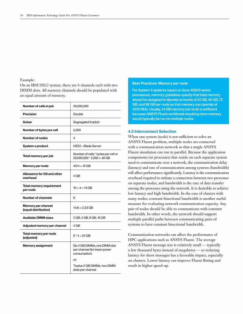
Example:On an IBM HS22 system, there are 6 channels each with two DIMM slots. All memory channels should be populated with an equal amount of memory.
4.3 Interconnect Selection When one system (node) is not sufficient to solve an ANSYS Fluent problem, multiple nodes are connected with a communication network so that a single ANSYS Fluent simulation can run in parallel. Because the application components (or processes) that reside on each separate system need to communicate over a network, the communication delay (latency) and rate of communication among systems (bandwidth) will affect performance significantly. Latency is the communication overhead required to initiate a connection between two processes on separate nodes, and bandwidth is the rate of data transfer among the processes using the network. It is desirable to achieve low latency and high bandwidth. In the case of clusters with many nodes, constant bisectional bandwidth is another useful measure for evaluating network communication capacity. Any pair of nodes should be able to communicate with constant bandwidth. In other words, the network should support multiple parallel paths between communicating pairs of systems to have constant bisectional bandwidth.
Communication networks can affect the performance of HPC applications such as ANSYS Fluent. The average ANSYS Fluent message size is relatively small — typically a few thousand bytes instead of megabytes — so reducing latency for short messages has a favorable impact, especially on clusters. Lower latency can improve Fluent Rating and result in higher speed-up.
Number of cells in job 20,000,000
Precision Double
Solver Segregated Implicit
Number of bytes pre cell 2,000
Number of nodes 4
System x product HS22 – Blade Server
Total memory per jobNumber of cells * bytes per cell or 20,000,000 * 2,000 = 40 GB
Memory per node 40/4 = 10 GB
Allowance for OS and other overhead
4 GB
Total memory requirement per node
10 + 4 = 14 GB
Number of channels 6
Memory per channel (equal distribution)
14/6 = 2.33 GB
Available DIMM sizes 2 GB, 4 GB, 8 GB, 16 GB
Adjusted memory per channel 4 GB
Total memory per node (adjusted)
6 * 4 = 24 GB
Memory assignment Six 4 GB DIMMs, one DIMM slot per channel (for lower power consumption)
or;
Twelve 2 GB DIMMs, two DIMM slots per channel
Best Practices: Memory per node
ForSystemXsystemsbasedonXeonX5600seriesprocessors,memoryguidelinesspecifythattotalmemoryshouldbeassignedindiscreteamountsof24GB,48GB,72GB,and96GBpernodesothatmemorycanoperateat1333MHz.Usually,24GBmemorypernodeissufficientbecauseANSYSFluentworkloadsrequiringmorememorywouldtypicallyberunonmultiplenodes.
IBMISV&DeveloperRelations 19
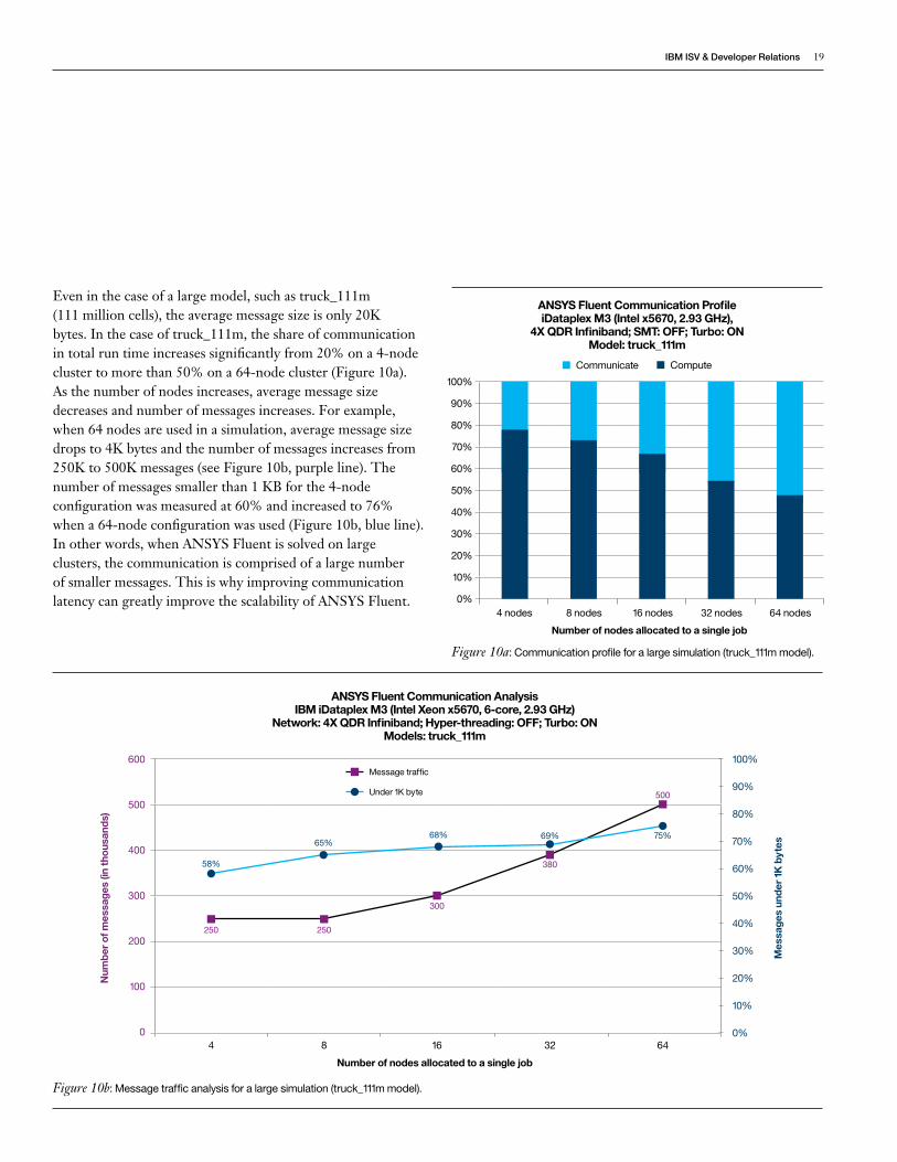
Even in the case of a large model, such as truck_111m (111 million cells), the average message size is only 20K bytes. In the case of truck_111m, the share of communication in total run time increases significantly from 20% on a 4-node cluster to more than 50% on a 64-node cluster (Figure 10a). As the number of nodes increases, average message size decreases and number of messages increases. For example, when 64 nodes are used in a simulation, average message size drops to 4K bytes and the number of messages increases from 250K to 500K messages (see Figure 10b, purple line). The number of messages smaller than 1 KB for the 4-node configuration was measured at 60% and increased to 76% when a 64-node configuration was used (Figure 10b, blue line). In other words, when ANSYS Fluent is solved on large clusters, the communication is comprised of a large number of smaller messages. This is why improving communication latency can greatly improve the scalability of ANSYS Fluent.
Mes
sage
s un
der
1K b
ytes
Num
ber
of m
essa
ges
(in th
ousa
nds)
Number of nodes allocated to a single job
4 8 16 32 64
600
250 250
75%69%68%65%
58%
500
380
300
500
400
300
200
100
0
100%
90%
80%
70%
60%
50%
40%
30%
20%
10%
0%
ANSYS Fluent Communication Analysis IBM iDataplex M3 (Intel Xeon x5670, 6-core, 2.93 GHz)
Network: 4X QDR Infiniband; Hyper-threading: OFF; Turbo: ONModels: truck_111m
Message traffic
Under 1K byte
Figure 10b: Message traffic analysis for a large simulation (truck_111m model).
Communicate Compute
Number of nodes allocated to a single job
ANSYS Fluent Communication Profile iDataplex M3 (Intel x5670, 2.93 GHz),
4X QDR Infiniband; SMT: OFF; Turbo: ONModel: truck_111m
4 nodes 8 nodes 16 nodes 32 nodes 64 nodes
100%
90%
80%
70%
60%
50%
40%
30%
20%
10%
0%
Figure 10a: Communication profile for a large simulation (truck_111m model).

20 IBM Information Technology Guide For ANSYS Fluent Customers
In the case of a small model, such as eddy_417k (see Figure 10c), the share of communication increases from 30% on a 2-node cluster to more than 80% on a 32-node cluster. Because the eddy_417k model is very small, communication dominates total runtime and becomes a barrier to scalability when a large number of nodes are used. A large number of messages are very short in the case of small models such as eddy_417k, so the network with the least amount of delay transferring short messages can maintain good scalability on a large network. In the next few sections, we will examine networks with varying latency and bandwidth and show how these networks affect the performance of ANSYS Fluent on clusters that use the two most common interconnects in HPC — Ethernet and Infiniband.
4.3.1 EthernetEthernet interconnects have been in use for several decades and are by far the most widely used interconnect technologies in the IT industry. For this reason, Ethernet has evolved over time to meet the increasing demands of applications requiring higher bandwidth and improved latency. The Institute of Electrical and Electronic Engineers (IEEE) publishes several Ethernet standards, including: 1-Gigabit, 10-Gigabit, 40-Gigabit and 100-Gigabit. The numbers in these labels represent data transfer rates of 1, 10, 40 and 100 Gigabits/second respectively. While 1-Gigabit is ubiquitous in IT, 10-Gigabit is gaining wider acceptance in HPC. Vendors have begun offering 100-Gigabit products only recently, and it will be a few years before they achieve widespread use in HPC. For this discussion, we will focus on 10-Gigabit Ethernet networks.
4.3.2 iWARPMost protocols used for communication between systems using Ethernet technology require the services of the operating system to manage the communication. This extra overhead (due to the OS involvement) significantly increases latency and can slow message bandwidth for smaller messages, resulting in unsatisfactory performance. Recently, a new standard called Internet Wide Area RDMA Protocol (iWARP) was introduced to bypass the OS kernel during communication along with some efficiency enhancements that significantly improved the latency problem.
4.3.3 Infiniband In large-scale parallel computation, aggregate inter-process communication bandwidth requirements may far exceed the capacity of Ethernet-based networks. Hardware vendors have tried to meet demand for higher bandwidth and lower latency by introducing special purpose interconnects. Infiniband is one such architecture. Interconnect products that are based on the Infiniband standard have been available since 2000, and it has become a popular network for HPC purposes.
Figure 10c: Communication profile for a small simulation (eddy_417k model).
Communicate Compute
Number of nodes allocated to a job
ANSYS Fluent Communication Profile iDataplex M3 (Intel x5670, 2.93 GHz),
4X QDR Infiniband; SMT: OFF; Turbo: ONModel: eddy_417k
2 nodes 4 nodes 8 nodes 16 nodes 32 nodes
100%
90%
80%
70%
60%
50%
40%
30%
20%
10%
0%
IBMISV&DeveloperRelations 21
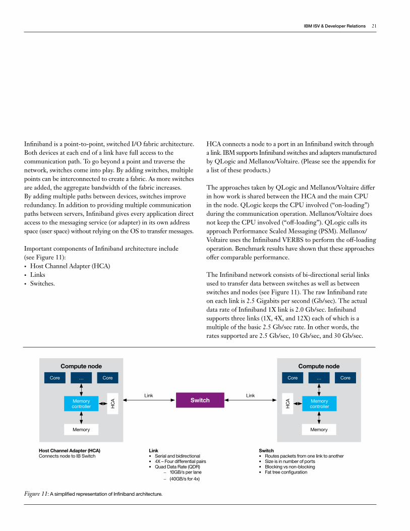
Infiniband is a point-to-point, switched I/O fabric architecture. Both devices at each end of a link have full access to the communication path. To go beyond a point and traverse the network, switches come into play. By adding switches, multiple points can be interconnected to create a fabric. As more switches are added, the aggregate bandwidth of the fabric increases. By adding multiple paths between devices, switches improve redundancy. In addition to providing multiple communication paths between servers, Infiniband gives every application direct access to the messaging service (or adapter) in its own address space (user space) without relying on the OS to transfer messages.
Important components of Infiniband architecture include (see Figure 11):• Host Channel Adapter (HCA)• Links• Switches.
HCA connects a node to a port in an Infiniband switch through a link. IBM supports Infiniband switches and adapters manufactured by QLogic and Mellanox/Voltaire. (Please see the appendix for a list of these products.)
The approaches taken by QLogic and Mellanox/Voltaire differ in how work is shared between the HCA and the main CPU in the node. QLogic keeps the CPU involved (“on-loading”) during the communication operation. Mellanox/Voltaire does not keep the CPU involved (“off-loading”). QLogic calls its approach Performance Scaled Messaging (PSM). Mellanox/Voltaire uses the Infiniband VERBS to perform the off-loading operation. Benchmark results have shown that these approaches offer comparable performance.
The Infiniband network consists of bi-directional serial links used to transfer data between switches as well as between switches and nodes (see Figure 11). The raw Infiniband rate on each link is 2.5 Gigabits per second (Gb/sec). The actual data rate of Infiniband 1X link is 2.0 Gb/sec. Infiniband supports three links (1X, 4X, and 12X) each of which is a multiple of the basic 2.5 Gb/sec rate. In other words, the rates supported are 2.5 Gb/sec, 10 Gb/sec, and 30 Gb/sec.
Figure 11: A simplified representation of Infiniband architecture.
LinkSwitch
Link
Compute node
Core …
Memory controller
Memory
HC
A
Core
Compute node
Core …
Memory controller
Memory
HC
A
Core
Host Channel Adapter (HCA) Connects node to IB Switch
Link• Serial and bidirectional • 4X – Four differential pairs• Quad Data Rate (QDR)
– 10GB/s per lane – (40GB/s for 4x)
Switch• Routes packets from one link to another • Size is in number of ports• Blocking vs non-blocking• Fat tree configuration
22 IBM Information Technology Guide For ANSYS Fluent Customers
The Infiniband specification also allows Double Data Rate (DDR), Quad Data Rate (QDR) and Full Data Rate (FDR) modes. In QDR, for example, each Infiniband lane (virtual session on a link) is clocked at quadruple the rate, allowing a 10 Gb/sec signaling rate per link. In this manner, a 4X QDR Infiniband link has a signaling rate of 40 Gb/sec.
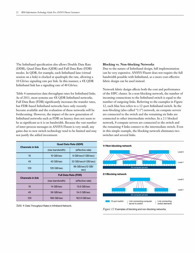
Table 4 summarizes data throughput rates for Infiniband links. As of 2011, most systems use 4X QDR Infiniband networks. Full Data Rate (FDR) significantly increases the transfer rates, but FDR-based Infiniband networks have only recently become available and the evaluation of these networks will be forthcoming. However, the impact of the new generation of Infiniband networks such as FDR on latency does not seem to be as significant as it is on bandwidth. Because the vast number of inter-process messages in ANSYS Fluent is very small, any gains due to new switch technology tend to be limited and may not justify the added investment.
Blocking vs. Non-blocking NetworksDue to the nature of Infiniband design, full implementation can be very expensive. ANSYS Fluent does not require the full bandwidth possible with Infiniband, so a more cost-effective fabric design can be used instead.
Network fabric design affects both the cost and performance of the HPC cluster. In a non-blocking network, the number of incoming connections to the Infiniband switch is equal to the number of outgoing links. Referring to the examples in Figure 12, each blue box refers to a 12-port Infiniband switch. In the non-blocking (also called “1:1”) network, six compute servers are connected to the switch and the remaining six links are connected to other intermediate switches. In a 2:1 blocked network, 8 compute servers are connected to the switch and the remaining 4 links connect to the intermediate switch. Even in this simple example, the blocking network eliminates two switches and several links.
Level 2
Level 2
1:1 Non-blocking network
2:1 Blocking network
Level 1
Level 1
24 compute servers
24 compute servers
12-port switch Link connecting computer server to switch
Link connecting switch elements
Figure 12: Examples of blocking and non-blocking networks.Table 4: Data Throughput Rates in Infiniband Network.
Channels in linkQuad Data Rate (QDR)
(raw bandwidth) (effective rate)
1X 10 GB/sec 8 GB/sec(1 GB/sec)
4X 40 GB/sec 32 GB/sec(4 GB/sec)
12X 120 GB/sec96 GB/sec(12 GB/
sec)
Channels in linkFull Data Rate (FDR)
(raw bandwidth) (effective rate)
1X 14 GB/sec 13.6 GB/sec
4X 56 GB/sec 54.3 GB/sec
12X 168 GB/sec 162.9 GB/sec
IBMISV&DeveloperRelations 23
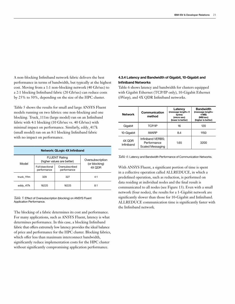
A non-blocking Infiniband network fabric delivers the best performance in terms of bandwidth, but typically at the highest cost. Moving from a 1:1 non-blocking network (40 Gb/sec) to a 2:1 blocking Infiniband fabric (20 Gb/sec) can reduce costs by 25% to 50%, depending on the size of the HPC cluster.
Table 5 shows the results for small and large ANSYS Fluent models running on two fabrics: one non-blocking and one blocking. Truck_111m (large model) ran on an Infiniband fabric with 4:1 blocking (10 Gb/sec vs. 40 Gb/sec) with minimal impact on performance. Similarly, eddy_417k (small model) ran on an 8:1 blocking Infiniband fabric with no impact on performance.
The blocking of a fabric determines its cost and performance. For many applications, such as ANSYS Fluent, latency is what determines performance. In this case, a blocking Infiniband fabric that offers extremely low latency provides the ideal balance of price and performance for the HPC cluster. Blocking fabrics, which offer less than maximum interconnect bandwidth, significantly reduce implementation costs for the HPC cluster without significantly compromising application performance.
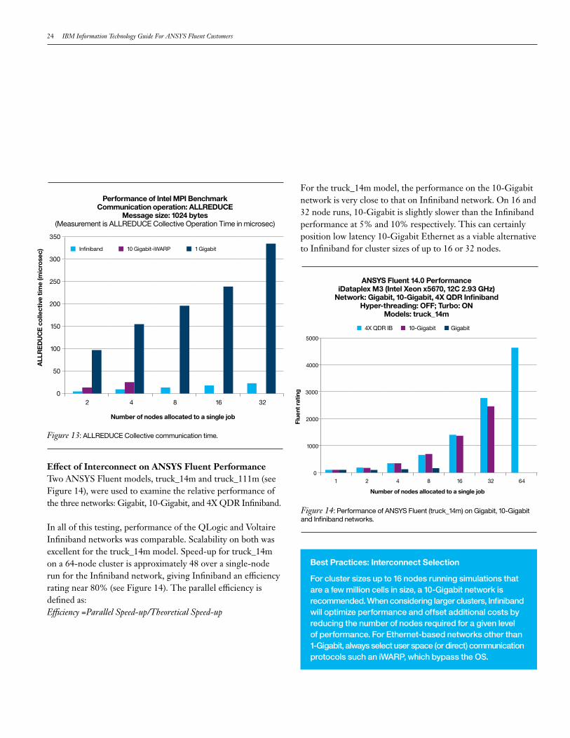
4.3.4 Latency and Bandwidth of Gigabit, 10-Gigabit and Infiniband NetworksTable 6 shows latency and bandwidth for clusters equipped with Gigabit Ethernet (TCP/IP only), 10-Gigabit Ethernet (iWarp), and 4X QDR Infiniband networks.
With ANSYS Fluent, a significant portion of time is spent in a collective operation called ALLREDUCE, in which a predefined operation, such as reduction, is performed on data residing at individual nodes and the final result is communicated to all nodes (see Figure 13). Even with a small network (four nodes), the results for a 1-Gigabit network are significantly slower than those for 10-Gigabit and Infiniband. ALLREDUCE communication time is significantly faster with the Infiniband network.
Table 5: Effect of Oversubscription (blocking) on ANSYS FluentApplication Performance.
Network: QLogic 4X Infiniband
Model
FLUENT Rating (higher values are better) Oversubscription
(or blocking) 4X QDRFull bisectional
performanceOversubscribed
performance
truck_111m 329 327 4:1
eddy_417k 16225 16225 8:1
NetworkCommunication
method
Latency(message length= 0
bytes)(micro sec)
(lower is better)
Bandwidth(message length=
4 MB)(MB/sec)
(higher is better)
Gigabit TCP/IP 16 120
10-Gigabit iWARP 8.4 1150
4X QDR Infiniband
Infiniband VERBS; Performance
Scaled Messaging1.65 3200
Table 6: Latency and Bandwidth Performance of Communication Networks.
24 IBM Information Technology Guide For ANSYS Fluent Customers
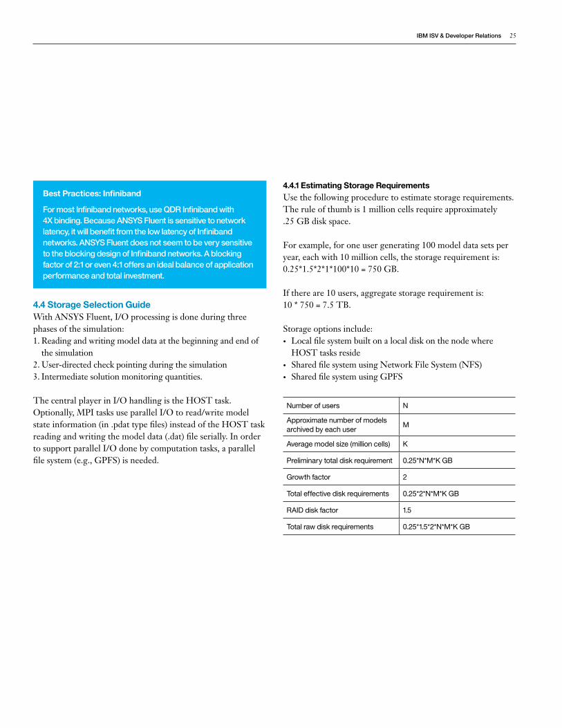
Effect of Interconnect on ANSYS Fluent PerformanceTwo ANSYS Fluent models, truck_14m and truck_111m (see Figure 14), were used to examine the relative performance of the three networks: Gigabit, 10-Gigabit, and 4X QDR Infiniband.
In all of this testing, performance of the QLogic and Voltaire Infiniband networks was comparable. Scalability on both was excellent for the truck_14m model. Speed-up for truck_14m on a 64-node cluster is approximately 48 over a single-node run for the Infiniband network, giving Infiniband an efficiency rating near 80% (see Figure 14). The parallel efficiency is defined as:Efficiency =Parallel Speed-up/Theoretical Speed-up
For the truck_14m model, the performance on the 10-Gigabit network is very close to that on Infiniband network. On 16 and 32 node runs, 10-Gigabit is slightly slower than the Infiniband performance at 5% and 10% respectively. This can certainly position low latency 10-Gigabit Ethernet as a viable alternative to Infiniband for cluster sizes of up to 16 or 32 nodes.
Best Practices: Interconnect Selection
Forclustersizesupto16nodesrunningsimulationsthatareafewmillioncellsinsize,a10-Gigabitnetworkisrecommended.Whenconsideringlargerclusters,Infinibandwilloptimizeperformanceandoffsetadditionalcostsbyreducingthenumberofnodesrequiredforagivenlevelofperformance.ForEthernet-basednetworksotherthan1-Gigabit,alwaysselectuserspace(ordirect)communicationprotocolssuchaniWARP,whichbypasstheOS.
Flue
nt r
atin
g
Number of nodes allocated to a single job
4X QDR IB 10-Gigabit Gigabit
ANSYS Fluent 14.0 PerformanceiDataplex M3 (Intel Xeon x5670, 12C 2.93 GHz)
Network: Gigabit, 10-Gigabit, 4X QDR InfinibandHyper-threading: OFF; Turbo: ON
Models: truck_14m
5000
4000
3000
2000
1000
01 2 4 8 16 6432
Figure 14: Performance of ANSYS Fluent (truck_14m) on Gigabit, 10-Gigabit and Infiniband networks.
Number of nodes allocated to a single job
Performance of Intel MPI Benchmark Communication operation: ALLREDUCE
Message size: 1024 bytes(Measurement is ALLREDUCE Collective Operation Time in microsec)
2 4 8 16 32
350
300
250
200
150
100
50
0
ALL
RE
DU
CE
col
lect
ive
time
(mic
rose
c) Infiniband 1 Gigabit10 Gigabit-iWARP
Figure 13: ALLREDUCE Collective communication time.
IBMISV&DeveloperRelations 25
4.4 Storage Selection GuideWith ANSYS Fluent, I/O processing is done during three phases of the simulation:1. Reading and writing model data at the beginning and end of
the simulation2. User-directed check pointing during the simulation3. Intermediate solution monitoring quantities.
The central player in I/O handling is the HOST task. Optionally, MPI tasks use parallel I/O to read/write model state information (in .pdat type files) instead of the HOST task reading and writing the model data (.dat) file serially. In order to support parallel I/O done by computation tasks, a parallel file system (e.g., GPFS) is needed.
4.4.1 Estimating Storage RequirementsUse the following procedure to estimate storage requirements. The rule of thumb is 1 million cells require approximately .25 GB disk space.
For example, for one user generating 100 model data sets per year, each with 10 million cells, the storage requirement is: 0.25*1.5*2*1*100*10 = 750 GB.
If there are 10 users, aggregate storage requirement is: 10 * 750 = 7.5 TB.
Storage options include:• Local file system built on a local disk on the node where
HOST tasks reside• Shared file system using Network File System (NFS)• Shared file system using GPFS
Best Practices: Infiniband
FormostInfinibandnetworks,useQDRInfinibandwith4Xbinding.BecauseANSYSFluentissensitivetonetworklatency,itwillbenefitfromthelowlatencyofInfinibandnetworks.ANSYSFluentdoesnotseemtobeverysensitivetotheblockingdesignofInfinibandnetworks.Ablockingfactorof2:1oreven4:1offersanidealbalanceofapplicationperformanceandtotalinvestment.
Number of users N
Approximate number of models archived by each user
M
Average model size (million cells) K
Preliminary total disk requirement 0.25*N*M*K GB
Growth factor 2
Total effective disk requirements 0.25*2*N*M*K GB
RAID disk factor 1.5
Total raw disk requirements 0.25*1.5*2*N*M*K GB
26 IBM Information Technology Guide For ANSYS Fluent Customers
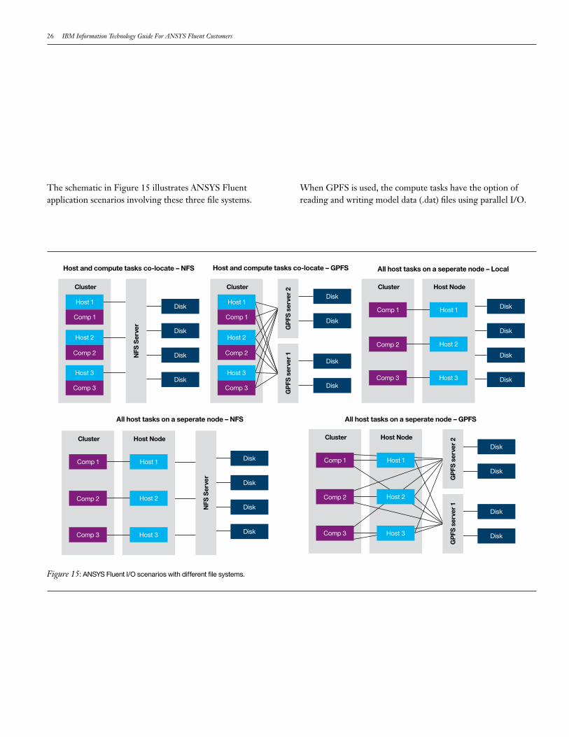
The schematic in Figure 15 illustrates ANSYS Fluent application scenarios involving these three file systems.
When GPFS is used, the compute tasks have the option of reading and writing model data (.dat) files using parallel I/O.
Disk
Disk
Disk
Disk
Disk
Disk
Disk
Disk
Host 1Comp 1
Host 2Comp 2
Host 3Comp 3
Cluster Cluster
Disk
Disk
Disk
Disk
Host 1Comp 1
Host 2Comp 2
Host 3Comp 3
Cluster Host Node
Host Node Host Node
NFS
Ser
ver
Comp 3 Host 3
Host 1Comp 1G
PFS
ser
ver
2G
PFS
ser
ver
1
Host 2Comp 2
Disk
Disk
Disk
Disk
Host 1
Comp 1
Host 2
Comp 2
Host 3
Comp 3
Cluster
NFS
Ser
ver
Host and compute tasks co-locate – NFS
Disk
Disk
Disk
Disk
Cluster
Host 1
Comp 1
Host 2
Comp 2
Host 3
Comp 3
GP
FS s
erve
r 2
GP
FS s
erve
r 1
Host and compute tasks co-locate – GPFS All host tasks on a seperate node – Local
All host tasks on a seperate node – NFS All host tasks on a seperate node – GPFS
Figure 15: ANSYS Fluent I/O scenarios with different file systems.
IBMISV&DeveloperRelations 27
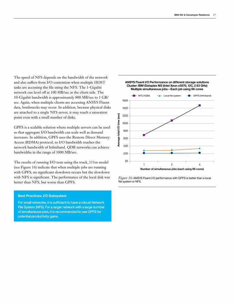
The speed of NFS depends on the bandwidth of the network and also suffers from I/O contention when multiple HOST tasks are accessing the file using the NFS. The 1-Gigabit network can level off at 100 MB/sec at the client side. The 10-Gigabit bandwidth is approximately 800 MB/sec to 1 GB/sec. Again, when multiple clients are accessing ANSYS Fluent data, bottlenecks may occur. In addition, because physical disks are attached to a single NFS server, it may reach a saturation point even with a small number of disks.
GPFS is a scalable solution where multiple servers can be used so that aggregate I/O bandwidth can scale well as demand increases. In addition, GPFS uses the Remote Direct Memory Access (RDMA) protocol, so I/O bandwidth reaches the network bandwidth of Infiniband. QDR networks can achieve bandwidths in the range of 3000 MB/sec.
The results of running I/O tests using the truck_111m model (see Figure 16) indicate that when multiple jobs are running with GPFS, no significant slowdown occurs but the slowdown with NFS is significant. The performance of the local disk was better than NFS, but worse than GPFS.
Best Practices: I/O Subsystem
Forsmallnetworks,itissufficienttohavearobustNetworkFileSystem(NFS).Foralargernetworkwithalargenumberofsimultaneousjobs,itisrecommendedtouseGPFSforpotentialproductivitygains.
Ave
rage
tota
l I/O
tim
e (s
ec)
Number of simultaneous jobs (each using 96 cores)
ANSYS Fluent I/O Performance on different storage solutions Cluster: IBM iDataplex M3 (Intel Xeon x5670, 12C, 2.93 GHz)
Multiple simultaneous jobs – Each job using 96 cores
1620
1220
1420
1020
620
820
420
20
220
1 2 4
NFS (1GBit) Local file system GPFS (Infiniband)
Figure 16: ANSYS Fluent I/O performance with GPFS is better than a local file system or NFS.
28 IBM Information Technology Guide For ANSYS Fluent Customers
5 Recommended IBM ConfigurationsThe requirements of ANSYS Fluent implementations vary significantly, so one configuration may not satisfy every customer’s needs. The configurations shown here are grouped into three categories: small, medium, and large, referring to the number of simultaneous users and/or jobs, as well as the sizes of the models. These categories form templates of major components and can be further refined to meet specific requirements.
For example, the memory size per node given in the 2-socket Xeon X5600 based configurations (48 GB) is the memory with which nodes can be configured and still maintain maximum clock speed of 1333 MHz. However, some customers may be able to use 24 GB of memory while maintaining 1333 MHz clock speed.
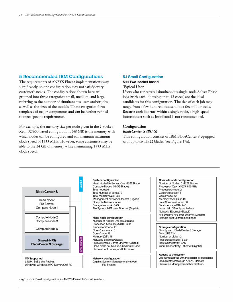
5.1 Small Configuration5.1.1 Two-socket basedTypical UserUsers who run several simultaneous single-node Solver Phase jobs (with each job using up to 12 cores) are the ideal candidates for this configuration. The size of each job may range from a few hundred thousand to a few million cells. Because each job runs within a single node, a high-speed interconnect such as Infiniband is not recommended.
ConfigurationBladeCenter S (BC-S) This configuration consists of IBM BladeCenter S equipped with up to six HS22 blades (see Figure 17a).
System configurationHead Node/File Server: One HS22 BladeCompute Nodes: 5 HSS BladesTotal nodes: 6Total Number of cores: 72Total Memory (GB): 288Management network: Ethernet (Gigabit)Compute Network: none Storage Network: SASFile System: NFS over Ethernet (Gigabit)
Compute node configurationNumber of Nodes: 5 HS22 BladesProcessor: Xeon X5675 3.06 GHzProcessors/node: 2Cores/processor: 6Cores/node: 12Memory/node (GB): 48 Total Compute Cores: 60Total memory (GB): 240Local disk: OS only or diskless Network: Ethernet (Gigabit) File System: NFS over Ethernet (Gigabit)Remote boot up from head nodeHead node configuration
Number of Nodes: One HS22 BladeProcessor: Xeon X5675 3.06 GHzProcessors/node: 2Cores/processor: 6Cores/node: 12Memory (GB): 48 Network: Ethernet Gigabit)File System: NFS over Ethernet (Gigabit)Head Node doubles up a Compute Node, Remote Boot Server, and File Server
Gig
abit
SA
S c
onne
ct
Shared (NFS)BladeCenter S Storage
BladeCenter S
Head Node/File Server/
Compute Node 1
Compute Node 2Compute Node 3
…Compute Node 6 Storage configuration
Disk System: BladeCenter S StorageDisk: 2TB 7.2KNumber of disks: 12Total storage size (TB): 24Host Connectivity: SASClient Connectivity: Ethernet (Gigabit)
Access to the systemUsers Interact the with the cluster by submitting jobs directly or through ANSYS Remote Simulation Manager from their desktop.
Network configurationGigabit: System Management Network File System
OS SupportedLINUX: SuSe and RedHatWindows: Windows HPC Server 2008 R2
Figure 17a: Small configuration for ANSYS Fluent, 2-Socket solution.
IBMISV&DeveloperRelations 29
Node Configuration Each node is a HSS22 blade that has two Xeon X5675 3.06 GHz 6-core processors (or sockets), giving the blade a total of 12 cores, 48 GB memory and two internal drives. One of the six HS22 blades can be designated as a system management node from which system management/job submission functions can be performed.
Network All HS22 blades are connected with Gigabit Ethernet. Because each job runs within a single node, a high-speed network is not required. Ethernet is used primarily to manage the BladeCenter S cluster.
File System/Storage BC-S contains room for up to 12 SAS disk drives outside the HS22 blades and can be connected to the blades using SAS connectors. This will provide disk storage of up to 24 TB without requiring a disk subsystem outside the BC-S. These disks can be divided among the HS22 blades or pooled together and attached to a single HS22 blade. Then a file system from that blade can be exported to other blades.
OS SupportLINUX: SuSe and RedHat Windows: Windows HPC Server 2008 R2
System AccessUsers interact with the cluster through a combination of Platform LSF and ANSYS Remote Simulation Manager from the desktop.
5.1.2 Four-socket basedTypical UserUsers who run several simultaneous single-node Solver Phase jobs (with each job using up to 32 cores) are the ideal candidates for this configuration. The size of each job may range from a few million cells up to 10 million cells. Because each job runs within a single node, a high-speed interconnect such as Infiniband is not recommended.
ConfigurationBladeCenter S (BC-S)This configuration consists of IBM BladeCenter S equipped with up to three HX5 blades (see Figure 17b).
Node ConfigurationEach node is a HX5 blade that has two Xeon X8837 2.7 GHz 8-core processors (or sockets), 128 GB memory and two internal drives. One of the three HX blades, in addition to being a compute platform, can also serve as a system management node from which system management/job submission functions can be performed.
NetworkAll HX5 blades are connected with Gigabit Ethernet. Because each job runs within a single node, a high-speed network is not required. Ethernet is used mainly to manage the BladeCenter S cluster.
File System/StorageBC-S contains room for up to 12 SAS disk drives outside the HX5 blades and can be connected to the blades using SAS connectors. This set of internal disks in the BC-S chassis provides storage of up to 24 TB without requiring a disk subsystem outside the BC-S. These disks can either be divided among the HX5 blades or pooled together and attached to a single HX5 blade. Then a file system from that blade can be exported to other blades.
30 IBM Information Technology Guide For ANSYS Fluent Customers
OS SupportLINUX: SuSe and RedHat Windows: Windows HPC Server 2008 R2
System AccessUsers interact with the cluster by submitting jobs directly or through ANSYS Remote Simulation Manager from the desktop.
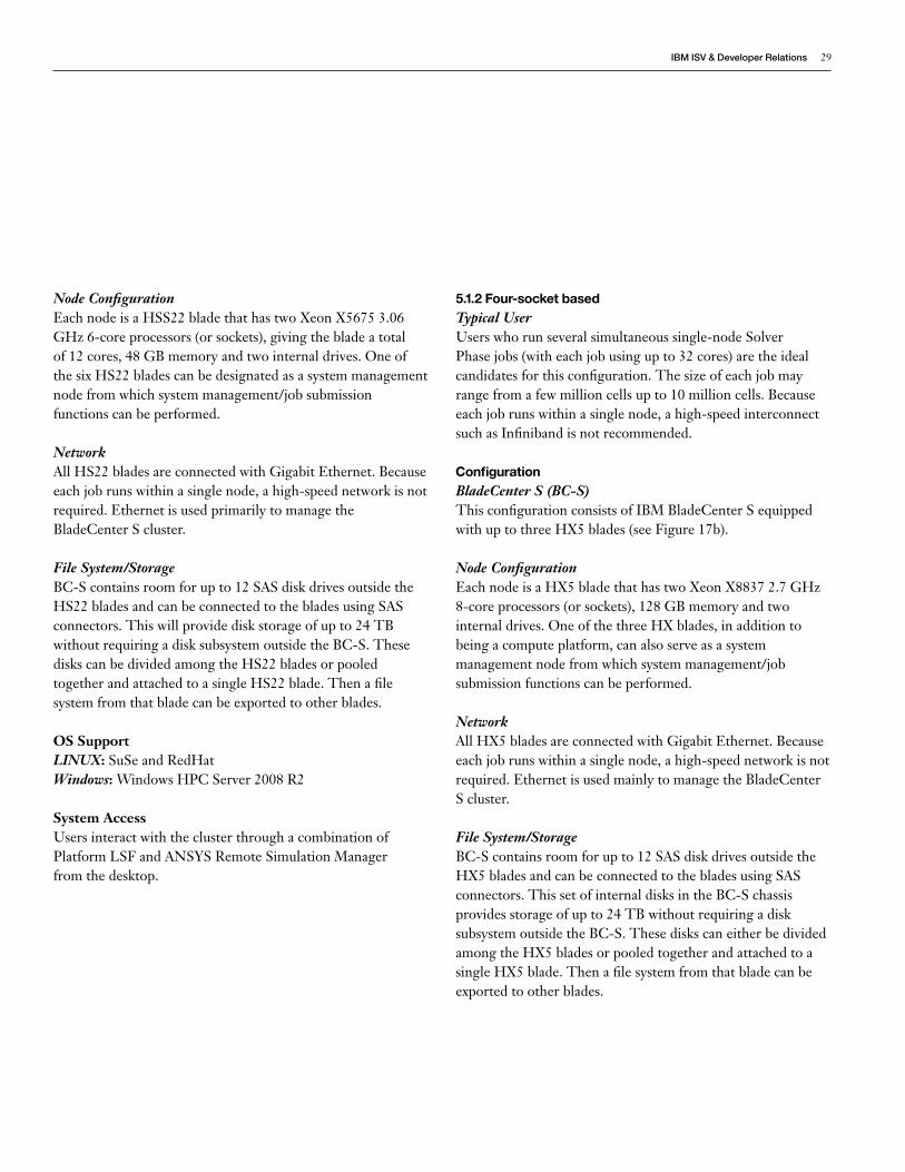
5.2 Medium ConfigurationTypical UserThe ideal user for this configuration runs several simultaneous single- or multi-node Solver Phase jobs and/or one very large job using all nodes (up to 168 cores). The size of each job ranges from a few million cells to 10s of millions of cells.
ConfigurationBladeCenter H (BC-H) This configuration consists of IBM BladeCenter H equipped with up to 14 HS22 blades (see Figure 17c).
System configurationHead node/File server: One HX5 BladeCompute nodes: 2 HX5 BladesTotal nodes: 3Total number of cores: 96Total memory (GB): 384Management network: Ethernet (Gigabit)Compute network: None Storage network: SASFile system: NFS over Ethernet (Gigabit)
Compute node configurationNumber of Nodes: 2 HX5 BladesProcessor: Xeon e7-8837 2.60 GHzProcessors/node: 4Cores/processor: 8Cores/node: 32Memory/node (GB): 128 Total Compute Cores: 64Total memory (GB): 256Local disk: OS only or diskless Network: Ethernet (Gigabit) File System: NFS over Ethernet (Gigabit)Remote boot up from head nodeHead node configuration
Number of nodes: One HX5 BladeProcessor: Xeon e7-8837 2.60 GHzProcessors/node: 4Cores/processor: 8Cores/node: 32Memory (GB): 128 Network: Ethernet (Gigabit)File system: NFS over Ethernet (Gigabit)Head node doubles up a compute node, remote boot server and file server
Gig
abit
SA
S c
onne
ct
Shared (NFS)BladeCenter S Storage
BladeCenter S
Compute Node2Compute Node3
Storage configurationDisk System: BladeCenter S StorageDisk: 2TB 7.2KNumber of disks: 12Total storage size (TB): 24Host Connectivity: SAS
Access to the systemUsers interact with the cluster by submitting jobs through a combination of ANSYS Remote Simulation Manager and Platform LSF from their desktop
Network configurationGigabit: System Management Network File System
OS SupportedLINUX: SuSe and RedHatWindows: Windows HPC Server 2008 R2
Head Node/File Server/
Compute Node1
Figure 17b: Small configuration for ANSYS Fluent, 4-socket solution.
IBMISV&DeveloperRelations 31
Node Configuration Each node is a HSS22 blade that has two Xeon X5675 3.06 GHz 6-core processors (or sockets), giving each blade a total of 12 cores, 48 GB memory and two internal drives. This configuration gives a combined total of up to 168 cores and 672 GB of memory for all blades. One of the 14 HS22 blades
can be designated as a system management node from which system management/job submission functions can be performed.
Network All HS22 blades are connected with Gigabit and 4X QDR Infiniband. The Gigabit network is used primarily to manage the BladeCenter H cluster and the Infiniband is used to carry message traffic for an ANSYS Fluent job running on more than one node.
File System/Storage An external DISK Subsystem, DS3500, is used to attach to a single HS22 blade using fiber optic or SSA connectivity. A file system from that blade can be exported to other blades.
OS SupportLINUX: SuSe and RedHatWindows: Windows HPC Server 2008 R2
System AccessUsers interact with the cluster directly or through a combination of Platform LSF and ANSYS Remote Simulation Manager from the desktop.
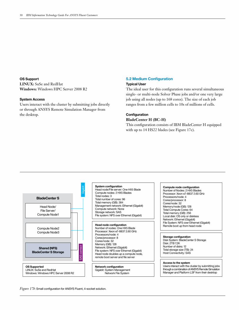
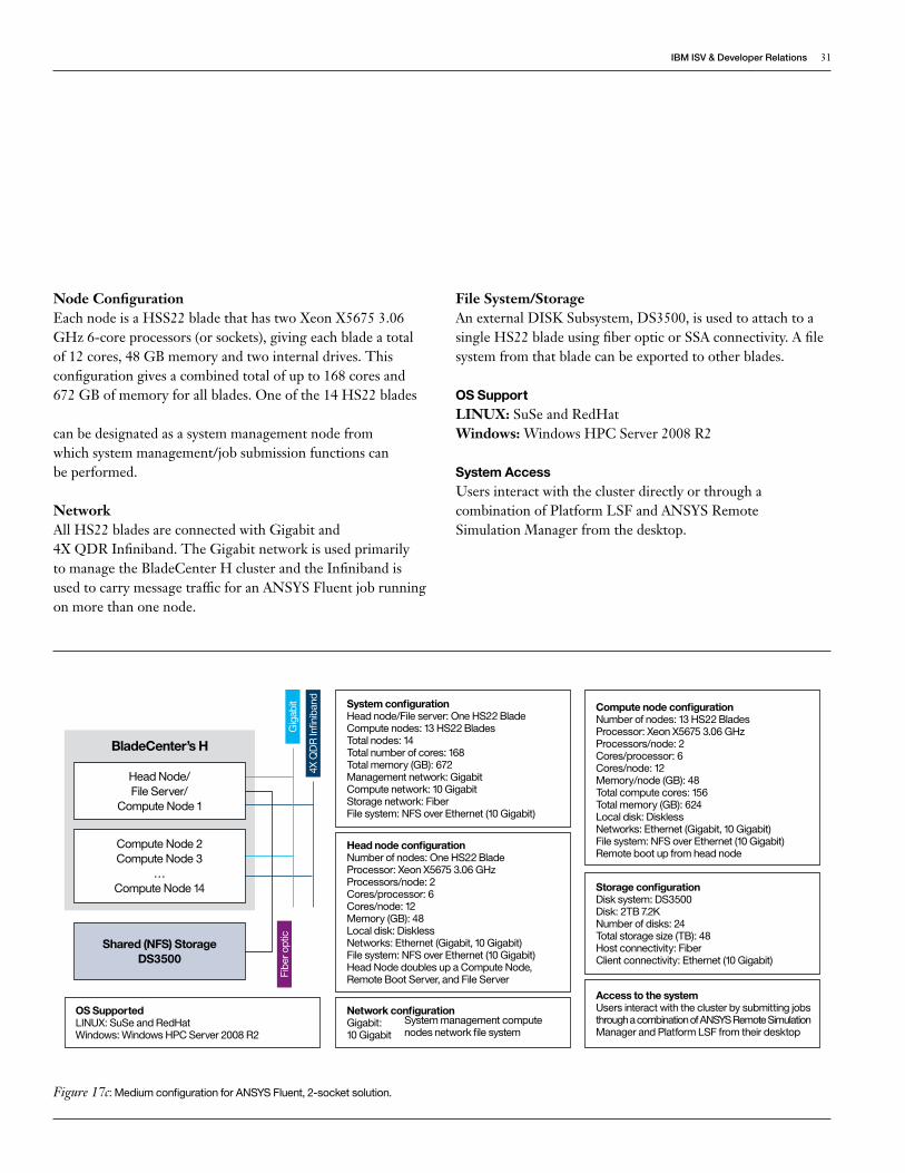
Figure 17c: Medium configuration for ANSYS Fluent, 2-socket solution.
Network configurationGigabit: 10 Gigabit
System configurationHead node/File server: One HS22 BladeCompute nodes: 13 HS22 BladesTotal nodes: 14Total number of cores: 168Total memory (GB): 672Management network: GigabitCompute network: 10 Gigabit Storage network: FiberFile system: NFS over Ethernet (10 Gigabit)
Compute node configurationNumber of nodes: 13 HS22 BladesProcessor: Xeon X5675 3.06 GHzProcessors/node: 2Cores/processor: 6Cores/node: 12Memory/node (GB): 48 Total compute cores: 156Total memory (GB): 624Local disk: Diskless Networks: Ethernet (Gigabit, 10 Gigabit) File system: NFS over Ethernet (10 Gigabit)Remote boot up from head node
Head node configurationNumber of nodes: One HS22 BladeProcessor: Xeon X5675 3.06 GHzProcessors/node: 2Cores/processor: 6Cores/node: 12Memory (GB): 48Local disk: DisklessNetworks: Ethernet (Gigabit, 10 Gigabit)File system: NFS over Ethernet (10 Gigabit)Head Node doubles up a Compute Node, Remote Boot Server, and File Server
Gig
abit
Fibe
r opt
ic
BladeCenter’s H
Storage configurationDisk system: DS3500Disk: 2TB 7.2KNumber of disks: 24Total storage size (TB): 48Host connectivity: FiberClient connectivity: Ethernet (10 Gigabit)
Access to the systemUsers interact with the cluster by submitting jobs through a combination of ANSYS Remote Simulation Manager and Platform LSF from their desktop
System management compute nodes network file system
OS SupportedLINUX: SuSe and RedHatWindows: Windows HPC Server 2008 R2
Shared (NFS) StorageDS3500
Head Node/File Server/
Compute Node 1
Compute Node 2Compute Node 3
…Compute Node 14
4X Q
DR
Infin
iban
d
32 IBM Information Technology Guide For ANSYS Fluent Customers
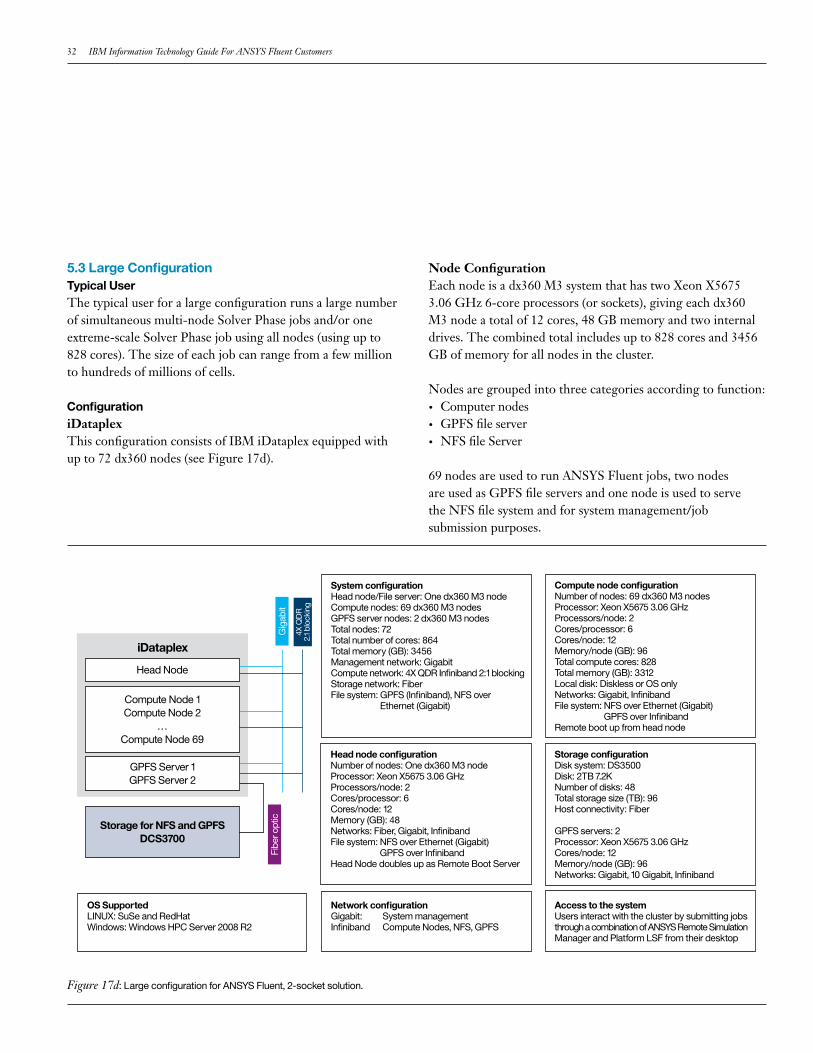
5.3 Large ConfigurationTypical UserThe typical user for a large configuration runs a large number of simultaneous multi-node Solver Phase jobs and/or one extreme-scale Solver Phase job using all nodes (using up to 828 cores). The size of each job can range from a few million to hundreds of millions of cells.
ConfigurationiDataplex This configuration consists of IBM iDataplex equipped with up to 72 dx360 nodes (see Figure 17d).
Node Configuration Each node is a dx360 M3 system that has two Xeon X5675 3.06 GHz 6-core processors (or sockets), giving each dx360 M3 node a total of 12 cores, 48 GB memory and two internal drives. The combined total includes up to 828 cores and 3456 GB of memory for all nodes in the cluster.
Nodes are grouped into three categories according to function:• Computer nodes• GPFS file server• NFS file Server
69 nodes are used to run ANSYS Fluent jobs, two nodes are used as GPFS file servers and one node is used to serve the NFS file system and for system management/job submission purposes.
Figure 17d: Large configuration for ANSYS Fluent, 2-socket solution.
System configurationHead node/File server: One dx360 M3 nodeCompute nodes: 69 dx360 M3 nodesGPFS server nodes: 2 dx360 M3 nodesTotal nodes: 72Total number of cores: 864Total memory (GB): 3456Management network: GigabitCompute network: 4X QDR Infiniband 2:1 blocking Storage network: FiberFile system: GPFS (Infiniband), NFS over Ethernet (Gigabit)
Compute node configurationNumber of nodes: 69 dx360 M3 nodesProcessor: Xeon X5675 3.06 GHzProcessors/node: 2Cores/processor: 6Cores/node: 12Memory/node (GB): 96 Total compute cores: 828Total memory (GB): 3312Local disk: Diskless or OS onlyNetworks: Gigabit, Infiniband File system: NFS over Ethernet (Gigabit) GPFS over InfinibandRemote boot up from head node
Head node configurationNumber of nodes: One dx360 M3 nodeProcessor: Xeon X5675 3.06 GHzProcessors/node: 2Cores/processor: 6Cores/node: 12Memory (GB): 48Networks: Fiber, Gigabit, InfinibandFile system: NFS over Ethernet (Gigabit) GPFS over InfinibandHead Node doubles up as Remote Boot Server
Gig
abit
4X Q
DR
2.
1 bl
ocki
ng
Fibe
r opt
ic
iDataplex
Storage configurationDisk system: DS3500Disk: 2TB 7.2KNumber of disks: 48Total storage size (TB): 96Host connectivity: Fiber
GPFS servers: 2Processor: Xeon X5675 3.06 GHzCores/node: 12Memory/node (GB): 96 Networks: Gigabit, 10 Gigabit, Infiniband
Access to the systemUsers interact with the cluster by submitting jobs through a combination of ANSYS Remote Simulation Manager and Platform LSF from their desktop
Network configurationGigabit: Infiniband
System management Compute Nodes, NFS, GPFS
OS SupportedLINUX: SuSe and RedHatWindows: Windows HPC Server 2008 R2
Head Node
GPFS Server 1 GPFS Server 2
Compute Node 1Compute Node 2
…Compute Node 69
Storage for NFS and GPFSDCS3700
IBMISV&DeveloperRelations 33
Network All dx360 M3 nodes are connected with Gigabit and 4X QDR 2:1 Blocking Infiniband. The Gigabit network is used primarily to manage the iDataplex cluster and the Infiniband is used to carry message traffic for an ANSYS Fluent job running on more than one node.
File System/Storage A set of external DISK Subsystems, DCS3700, are used to store data managed by GPFS and NFS files systems. DCS3700 subsystems are connected to the GPFS and NFS file servers using fiber optic connectors.
OS SupportLINUX: SuSe and RedHatWindows: Windows HPC Server 2008 R2
System AccessUsers interact with the cluster directly or through ANSYS Remote Simulation Manager from the desktop.
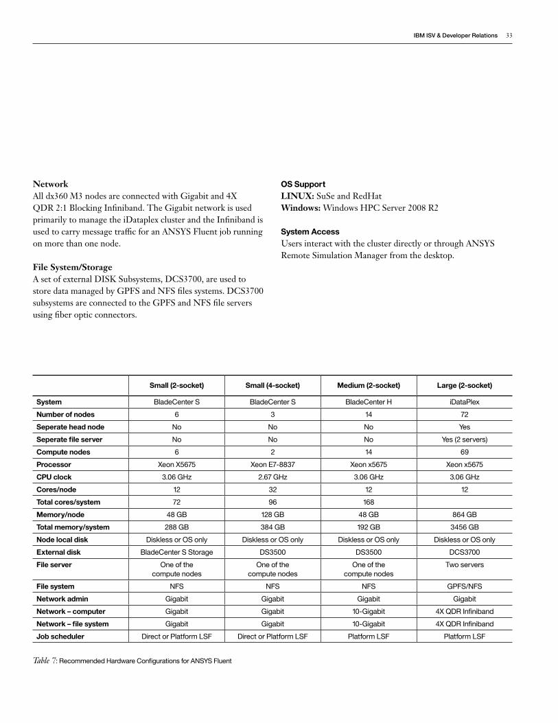
Table 7: Recommended Hardware Configurations for ANSYS Fluent
Small (2-socket) Small (4-socket) Medium (2-socket) Large (2-socket)
System BladeCenter S BladeCenter S BladeCenter H iDataPlex
Number of nodes 6 3 14 72
Seperate head node No No No Yes
Seperate file server No No No Yes (2 servers)
Compute nodes 6 2 14 69
Processor Xeon X5675 Xeon E7-8837 Xeon x5675 Xeon x5675
CPU clock 3.06 GHz 2.67 GHz 3.06 GHz 3.06 GHz
Cores/node 12 32 12 12
Total cores/system 72 96 168
Memory/node 48 GB 128 GB 48 GB 864 GB
Total memory/system 288 GB 384 GB 192 GB 3456 GB
Node local disk Diskless or OS only Diskless or OS only Diskless or OS only Diskless or OS only
External disk BladeCenter S Storage DS3500 DS3500 DCS3700
File server One of the compute nodes
One of the compute nodes
One of the compute nodes
Two servers
File system NFS NFS NFS GPFS/NFS
Network admin Gigabit Gigabit Gigabit Gigabit
Network – computer Gigabit Gigabit 10-Gigabit 4X QDR Infiniband
Network – file system Gigabit Gigabit 10-Gigabit 4X QDR Infiniband
Job scheduler Direct or Platform LSF Direct or Platform LSF Platform LSF Platform LSF
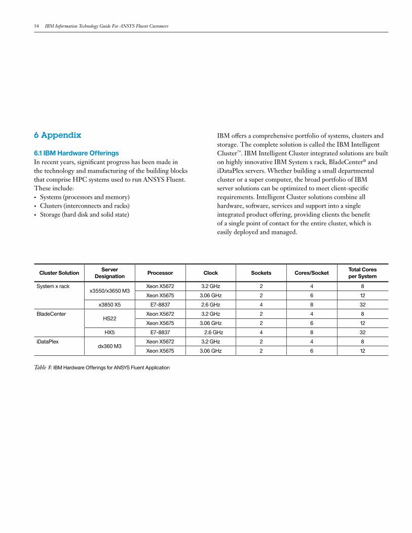
34 IBM Information Technology Guide For ANSYS Fluent Customers
6 Appendix
6.1 IBM Hardware OfferingsIn recent years, significant progress has been made in the technology and manufacturing of the building blocks that comprise HPC systems used to run ANSYS Fluent. These include: • Systems (processors and memory) • Clusters (interconnects and racks) • Storage (hard disk and solid state)
IBM offers a comprehensive portfolio of systems, clusters and storage. The complete solution is called the IBM Intelligent Cluster™. IBM Intelligent Cluster integrated solutions are built on highly innovative IBM System x rack, BladeCenter® and iDataPlex servers. Whether building a small departmental cluster or a super computer, the broad portfolio of IBM server solutions can be optimized to meet client-specific requirements. Intelligent Cluster solutions combine all hardware, software, services and support into a single integrated product offering, providing clients the benefit of a single point of contact for the entire cluster, which is easily deployed and managed.
Cluster SolutionServer
DesignationProcessor Clock Sockets Cores/Socket
Total Coresper System
System x rackx3550/x3650 M3
Xeon X5672 3.2 GHz 2 4 8
Xeon X5675 3.06 GHz 2 6 12
x3850 X5 E7-8837 2.6 GHz 4 8 32
BladeCenterHS22
Xeon X5672 3.2 GHz 2 4 8
Xeon X5675 3.06 GHz 2 6 12
HX5 E7-8837 2.6 GHz 4 8 32
iDataPlexdx360 M3
Xeon X5672 3.2 GHz 2 4 8
Xeon X5675 3.06 GHz 2 6 12
Table 8: IBM Hardware Offerings for ANSYS Fluent Application

IBMISV&DeveloperRelations 35
6.1.1 SystemsIBM’s System x portfolio offers systems with Xeon processors from Intel. Table 8 lists processors and systems that are recommended for use with ANSYS Fluent.
Four-socket systems are recommended when performance requirements can be satisfied with a single SMP system that has a large number of cores. A cluster of 2-socket based systems is recommended when the requirements exceed a single 4-socket system. Six-core-based 2-socket systems are generally recommended. Quad-core processors offer significant performance improvement, although at a higher hardware cost, and should be considered if an evaluation of TCO tilts in its favor.
6.1.2 Network Switches and AdaptersIBM offers a variety of network products with varying complexity and performance so that a cluster can be designed to suit a customer’s business needs. IBM network offerings include switches and adapters based on Ethernet and Infiniband standards.
Ethernet Switches and AdaptersIBM offers 10-Gigabit Ethernet switches/adapters made by the following vendors:
Device HW Partners
Ethernet Switches IBM, CISCO, Force10, LG Ericsson
Ethernet Adapters Chelsio and Mellanox
Infiniband Switches and Adapters
IBM offers Infiniband switches/adapters made by the following hardware partners: Mellanox and QLogic/Intel.
If the number of nodes required to solve ANSYS Fluent simulations is less than 14, both 10-Gigabit Ethernet (using the iWARP communication protocol) and 4X QDR Infiniband offer comparable performance. Infiniband offers superior performance in larger configurations due to its lower latency and higher bandwidth.
36 IBM Information Technology Guide For ANSYS Fluent Customers
6.2 Cluster SolutionsIBM offers the following packages designed to house a cluster of systems and networks: • BladeCenter• iDataPlex• IBM System x Rack.
Selection of the right cluster solution depends primarily on the number of nodes and the internal disk storage requirements.
BladeCenter is recommended when the number of nodes is not large, while iDataPlex is recommended for a large number of nodes. For example, a BladeCenter H can house 14 nodes, while iDataPlex can house up to 84 nodes. If the number of nodes required exceeds 42, a denser packaging (such as iDataPlex) should be considered.
Also, a node in a BladeCenter does not have space for a large number of disks, while several disks can be added to an iDataPlex node. If the application requires a large amount of local disk space, BladeCenter is not a good choice. Of course, large local disk space is not typically required for ANSYS Fluent and should not be a deciding factor.
Other than BladeCenter and iDataPlex, there are standard rack-based server nodes that offer the flexibility of a building block approach but lack appropriate density. If only a few nodes are required, and these nodes provide the flexibility of large amounts of internal storage, then rack-based servers are a sound alternative to iDataPlex. However, with ANSYS Fluent, internal storage is not recommended. BladeCenter S or BladeCenter H is a better choice.
6.2.1 BladeCenterSolutionThe BladeCenter chassis helps form an IT foundation and can be tailored to the different types of applications, environments and performance requirements of the enterprise. Choice of chassis, include chassis for data centers and non-traditional environments, ensure a solution can easily be tailored to meet business needs.
ServersIBM BladeCenter blade servers support a wide selection of processor technologies and operating systems, allowing clients to run diverse workloads inside a single architecture. IBM Blade Servers reduce complexity, improve systems management, and increase energy efficiency while driving down total cost of ownership.
Blade Server HS22The HS22 provides outstanding performance with support for the latest Intel Xeon® processors, high-speed I/O, and support for high memory capacity and fast memory throughput.
Blade Server HX5The Blade Server HX5 includes up to four Intel Xeon E7-8837 series processors and is scalable to four processors in a double-wide form factor. High-density, high-utilization computing allows superior price performance as well as superior performance perwatt.
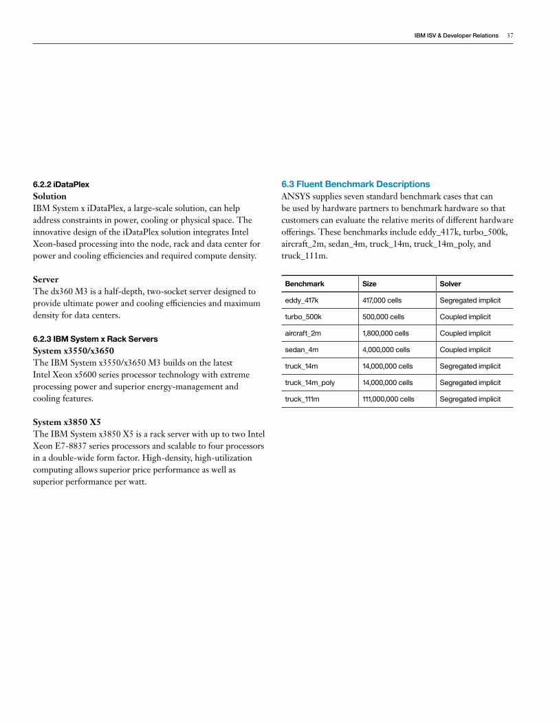
IBMISV&DeveloperRelations 37
6.2.2 iDataPlexSolutionIBM System x iDataPlex, a large-scale solution, can help address constraints in power, cooling or physical space. The innovative design of the iDataPlex solution integrates Intel Xeon-based processing into the node, rack and data center for power and cooling efficiencies and required compute density.
ServerThe dx360 M3 is a half-depth, two-socket server designed to provide ultimate power and cooling efficiencies and maximum density for data centers.
6.2.3 IBM System x Rack ServersSystem x3550/x3650The IBM System x3550/x3650 M3 builds on the latest Intel Xeon x5600 series processor technology with extreme processing power and superior energy-management and cooling features.
System x3850 X5The IBM System x3850 X5 is a rack server with up to two Intel Xeon E7-8837 series processors and scalable to four processors in a double-wide form factor. High-density, high-utilization computing allows superior price performance as well as superior performance per watt.
6.3 Fluent Benchmark DescriptionsANSYS supplies seven standard benchmark cases that can be used by hardware partners to benchmark hardware so that customers can evaluate the relative merits of different hardware offerings. These benchmarks include eddy_417k, turbo_500k, aircraft_2m, sedan_4m, truck_14m, truck_14m_poly, and truck_111m.
Benchmark Size Solver
eddy_417k 417,000 cells Segregated implicit
turbo_500k 500,000 cells Coupled implicit
aircraft_2m 1,800,000 cells Coupled implicit
sedan_4m 4,000,000 cells Coupled implicit
truck_14m 14,000,000 cells Segregated implicit
truck_14m_poly 14,000,000 cells Segregated implicit
truck_111m 111,000,000 cells Segregated implicit
38 IBM Information Technology Guide For ANSYS Fluent Customers
6.4 Further [email protected]
IBM [email protected]://www-03.ibm.com/systems/deepcomputing/
IBM x86 Servershttp://www-03.ibm.com/systems/x/hardware/index.html
IBM BladeCenterhttp://www-03.ibm.com/systems/bladecenter/hardware/chassis/index.htmlhttp://www-03.ibm.com/systems/bladecenter/hardware/servers/index.html#intelhttp://www-03.ibm.com/systems/bladecenter/hardware/servers/hx5/index.htmlhttp://www-03.ibm.com/systems/bladecenter/hardware/servers/hs22/index.html
IBM iDataPlexhttp://www-03.ibm.com/systems/x/hardware/idataplex/http://www-03.ibm.com/systems/x/hardware/idataplex/dx360m3/index.html
IBM System x Rackhttp://www-03.ibm.com/systems/x/hardware/rack/http://www-03.ibm.com/systems/x/hardware/rack/x3550m3/index.htmlhttp://www-03.ibm.com/systems/x/hardware/rack/x3650m3/index.html
IBM Enterprise Servershttp://www-03.ibm.com/systems/x/hardware/enterprise/x3850x5/index.html
IBM Storage Solutionshttp://www-03.ibm.com/systems/storage/disk/midrange/index.html
Memory Performance and Optimizationftp://public.dhe.ibm.com/common/ssi/ecm/en/xsw03075usen/XSW03075USEN.PDF
Intelligent Clusterhttp://public.dhe.ibm.com/common/ssi/ecm/en/cld00221usen/CLD00221USEN.PDF
Intel Processorshttp://ark.intel.com/
QLogic Infiniband Switches and Adaptershttp://www.qlogic.com/OEMPartnerships/ibm/Pages/IBMOEMProducts.aspx?productFamily=switches&productName=InfinibandSwitches
Mellanox Infiniband Switches and Adaptershttp://www.mellanox.com/content/pages.php?pg=ibm&menu_section=54

IBMISV&DeveloperRelations 39
XSO03160-USEN-00
© Copyright IBM Corporation 2012
IBM Global Services Route 100 Somers, NY 10589 U.S.A.
Produced in the United States of America April 2012 All Rights Reserved
IBM, the IBM logo, ibm.com, BladeCenter, iDataPlex, Intelligent Cluster and System x are trademarks or registered trademarks of International Business Machines Corporation in the United States, other countries, or both. If these and other IBM trademarked terms are marked on their first occurrence in this information with a trademark symbol (® or ™), these symbols indicate U.S. registered or common law trademarks owned by IBM at the time this information was published. Such trademarks may also be registered or common law trademarks in other countries. A current list of IBM trademarks is available on the Web at “Copyright and trademark information” at ibm.com/legal/copytrade.shtml
Intel, Intel logo, Intel Inside, Intel Inside logo, Intel Centrino, Intel Centrino logo, Celeron, Intel Xeon, Intel SpeedStep, Itanium, and Pentium are trademarks or registered trademarks of Intel Corporation or its subsidiaries in the United States and other countries.
Microsoft, Windows, Windows NT, and the Windows logo are trademarks of Microsoft Corporation in the United States, other countries, or both.
Linux is a registered trademark of Linus Torvalds in the United States, other countries, or both.
Other company, product and service names may be trademarks or service marks of others.
References in this publication to IBM products and services do not imply that IBM intends to make them available in all countries in which IBM operates.
Note that the “benchmark job” does not complete a full solution of the test problem, but rather a short snapshot for performance evaluation.
Please Recycle
1