Embed Size (px)
Citation preview

IBM
ibm.com/redbooks
Effective System ManagementUsing the IBM HardwareManagement Console for pSeries
Keigo MatsubaraMatt Robbins
Ron BarkerTheeraphong Thitayanun
Using service-related functions on the HMC
Planning and implementing a secure network
Exploiting HMC commands
Front cover


Effective System Management Using the IBM Hardware Management Console for pSeries
August 2003
International Technical Support Organization
SG24-7038-00

© Copyright International Business Machines Corporation 2003. All rights reserved.Note to U.S. Government Users Restricted Rights -- Use, duplication or disclosure restricted by GSA ADPSchedule Contract with IBM Corp.
First Edition (August 2003)
This edition applies to Release 3, Version 2 of the software (program number 5639-N47) installed on the IBM Hardware Management Console for pSeries.
Note: Before using this information and the product it supports, read the information in “Notices” on page xix.
Contents
Figures . . . . . . . . . . . . . . . . . . . . . . . . . . . . . . . . . . . . . . . . . . . . . . . . . . . . . . . xi
Tables . . . . . . . . . . . . . . . . . . . . . . . . . . . . . . . . . . . . . . . . . . . . . . . . . . . . . . xvii
Notices . . . . . . . . . . . . . . . . . . . . . . . . . . . . . . . . . . . . . . . . . . . . . . . . . . . . . . xixTrademarks . . . . . . . . . . . . . . . . . . . . . . . . . . . . . . . . . . . . . . . . . . . . . . . . . . . xx
Preface . . . . . . . . . . . . . . . . . . . . . . . . . . . . . . . . . . . . . . . . . . . . . . . . . . . . . . xxiThe team that wrote this redbook. . . . . . . . . . . . . . . . . . . . . . . . . . . . . . . . . . . xxiBecome a published author . . . . . . . . . . . . . . . . . . . . . . . . . . . . . . . . . . . . . . xxiiComments welcome. . . . . . . . . . . . . . . . . . . . . . . . . . . . . . . . . . . . . . . . . . . . xxiii
Chapter 1. Introduction to the HMC . . . . . . . . . . . . . . . . . . . . . . . . . . . . . . . . 11.1 What is the HMC? . . . . . . . . . . . . . . . . . . . . . . . . . . . . . . . . . . . . . . . . . . . . 2
1.1.1 HMC at a glance . . . . . . . . . . . . . . . . . . . . . . . . . . . . . . . . . . . . . . . . . 31.2 Supported managed systems . . . . . . . . . . . . . . . . . . . . . . . . . . . . . . . . . . . 6
1.2.1 pSeries 690 and pSeries 670 . . . . . . . . . . . . . . . . . . . . . . . . . . . . . . . 71.2.2 pSeries 655 . . . . . . . . . . . . . . . . . . . . . . . . . . . . . . . . . . . . . . . . . . . . . 91.2.3 pSeries 650 Model 6M2 . . . . . . . . . . . . . . . . . . . . . . . . . . . . . . . . . . 101.2.4 pSeries 630 models 6C4 and 6E4 . . . . . . . . . . . . . . . . . . . . . . . . . . 111.2.5 pSeries 615 models 6C3 and 6E3 . . . . . . . . . . . . . . . . . . . . . . . . . . 131.2.6 RS-422 serial connection to the 7040-W42 system rack . . . . . . . . . 14
1.3 HMC architecture . . . . . . . . . . . . . . . . . . . . . . . . . . . . . . . . . . . . . . . . . . . 161.4 HMC connectivity . . . . . . . . . . . . . . . . . . . . . . . . . . . . . . . . . . . . . . . . . . . 18
1.4.1 Serial connectivity . . . . . . . . . . . . . . . . . . . . . . . . . . . . . . . . . . . . . . . 181.4.2 Remote connectivity . . . . . . . . . . . . . . . . . . . . . . . . . . . . . . . . . . . . . 21
1.5 HMC order information . . . . . . . . . . . . . . . . . . . . . . . . . . . . . . . . . . . . . . . 231.5.1 Supported number of managed systems and partitions . . . . . . . . . . 241.5.2 HMC software release numbering scheme . . . . . . . . . . . . . . . . . . . . 241.5.3 Ethernet adapter configuration . . . . . . . . . . . . . . . . . . . . . . . . . . . . . 241.5.4 Asynchronous serial adapter configurations . . . . . . . . . . . . . . . . . . . 25
Chapter 2. HMC graphical user interface . . . . . . . . . . . . . . . . . . . . . . . . . . 312.1 Login and logout . . . . . . . . . . . . . . . . . . . . . . . . . . . . . . . . . . . . . . . . . . . . 322.2 HMC graphical user interface at a glance . . . . . . . . . . . . . . . . . . . . . . . . . 32
2.2.1 Navigation area . . . . . . . . . . . . . . . . . . . . . . . . . . . . . . . . . . . . . . . . . 342.2.2 Contents area . . . . . . . . . . . . . . . . . . . . . . . . . . . . . . . . . . . . . . . . . . 352.2.3 Menu bar . . . . . . . . . . . . . . . . . . . . . . . . . . . . . . . . . . . . . . . . . . . . . . 352.2.4 Tool bar . . . . . . . . . . . . . . . . . . . . . . . . . . . . . . . . . . . . . . . . . . . . . . . 36
© Copyright IBM Corp. 2003. All rights reserved. iii
2.2.5 Status bar . . . . . . . . . . . . . . . . . . . . . . . . . . . . . . . . . . . . . . . . . . . . . 382.3 HMC application overview. . . . . . . . . . . . . . . . . . . . . . . . . . . . . . . . . . . . . 402.4 Server and Partition. . . . . . . . . . . . . . . . . . . . . . . . . . . . . . . . . . . . . . . . . . 41
2.4.1 Connect and disconnect managed systems . . . . . . . . . . . . . . . . . . . 452.4.2 Server Management . . . . . . . . . . . . . . . . . . . . . . . . . . . . . . . . . . . . . 452.4.3 Server Management menus . . . . . . . . . . . . . . . . . . . . . . . . . . . . . . . 46
2.5 Virtual terminal window . . . . . . . . . . . . . . . . . . . . . . . . . . . . . . . . . . . . . . . 492.5.1 Virtual terminal window concept . . . . . . . . . . . . . . . . . . . . . . . . . . . . 492.5.2 Virtual terminal window in the Full System Partition . . . . . . . . . . . . . 522.5.3 Partition virtual terminal windows . . . . . . . . . . . . . . . . . . . . . . . . . . . 52
2.6 Open xterm to access remote system using telnet . . . . . . . . . . . . . . . . . . 52
Chapter 3. Basic managed system operation tasks . . . . . . . . . . . . . . . . . 553.1 Viewing properties of the managed system . . . . . . . . . . . . . . . . . . . . . . . 56
3.1.1 Machine property . . . . . . . . . . . . . . . . . . . . . . . . . . . . . . . . . . . . . . . 573.1.2 Processor property . . . . . . . . . . . . . . . . . . . . . . . . . . . . . . . . . . . . . . 583.1.3 Policy property . . . . . . . . . . . . . . . . . . . . . . . . . . . . . . . . . . . . . . . . . 593.1.4 I/O Slot property . . . . . . . . . . . . . . . . . . . . . . . . . . . . . . . . . . . . . . . . 603.1.5 Memory property . . . . . . . . . . . . . . . . . . . . . . . . . . . . . . . . . . . . . . . . 61
3.2 Power on the managed system. . . . . . . . . . . . . . . . . . . . . . . . . . . . . . . . . 613.2.1 Operation states of a managed system . . . . . . . . . . . . . . . . . . . . . . 643.2.2 Rebuild the managed system in the HMC. . . . . . . . . . . . . . . . . . . . . 64
3.3 Activate partitions . . . . . . . . . . . . . . . . . . . . . . . . . . . . . . . . . . . . . . . . . . . 653.3.1 Change the default partition profile . . . . . . . . . . . . . . . . . . . . . . . . . . 653.3.2 Activate a specific partition profile. . . . . . . . . . . . . . . . . . . . . . . . . . . 653.3.3 Activate partitions without selecting a specific partition profile . . . . . 663.3.4 Reactivating a partition with a different partition profile. . . . . . . . . . . 663.3.5 Partition operating states . . . . . . . . . . . . . . . . . . . . . . . . . . . . . . . . . 67
3.4 Shut down the operating system in a partition . . . . . . . . . . . . . . . . . . . . . 683.5 Reset the operating system in a partition . . . . . . . . . . . . . . . . . . . . . . . . . 703.6 Power off the managed system. . . . . . . . . . . . . . . . . . . . . . . . . . . . . . . . . 723.7 Operating the managed system with the HMC . . . . . . . . . . . . . . . . . . . . . 72
3.7.1 Operator panel . . . . . . . . . . . . . . . . . . . . . . . . . . . . . . . . . . . . . . . . . 723.7.2 Power button . . . . . . . . . . . . . . . . . . . . . . . . . . . . . . . . . . . . . . . . . . . 733.7.3 Reset button . . . . . . . . . . . . . . . . . . . . . . . . . . . . . . . . . . . . . . . . . . . 73
Chapter 4. Configuring the HMC . . . . . . . . . . . . . . . . . . . . . . . . . . . . . . . . . 754.1 HMC Management . . . . . . . . . . . . . . . . . . . . . . . . . . . . . . . . . . . . . . . . . . 76
4.1.1 User role descriptions . . . . . . . . . . . . . . . . . . . . . . . . . . . . . . . . . . . . 774.1.2 User Management. . . . . . . . . . . . . . . . . . . . . . . . . . . . . . . . . . . . . . . 78
4.2 HMC Maintenance. . . . . . . . . . . . . . . . . . . . . . . . . . . . . . . . . . . . . . . . . . . 804.2.1 System Configuration . . . . . . . . . . . . . . . . . . . . . . . . . . . . . . . . . . . . 814.2.2 Customize Console Date/Time . . . . . . . . . . . . . . . . . . . . . . . . . . . . . 81
iv Effective System Management Using the IBM Hardware Management Console for pSeries

4.2.3 View Console Events . . . . . . . . . . . . . . . . . . . . . . . . . . . . . . . . . . . . 824.2.4 Customize Network Settings . . . . . . . . . . . . . . . . . . . . . . . . . . . . . . . 834.2.5 Test Network Connectivity . . . . . . . . . . . . . . . . . . . . . . . . . . . . . . . . 914.2.6 Scheduled Operations. . . . . . . . . . . . . . . . . . . . . . . . . . . . . . . . . . . . 924.2.7 Enable/Disable Remote Command Execution . . . . . . . . . . . . . . . . . 954.2.8 Configure Serial Adapter. . . . . . . . . . . . . . . . . . . . . . . . . . . . . . . . . . 964.2.9 Enable/Disable Remote Virtual Terminal . . . . . . . . . . . . . . . . . . . . . 974.2.10 Change Current Locale . . . . . . . . . . . . . . . . . . . . . . . . . . . . . . . . . . 97
Chapter 5. Managing partition profile data on the HMC . . . . . . . . . . . . . . 995.1 Managing profile data . . . . . . . . . . . . . . . . . . . . . . . . . . . . . . . . . . . . . . . 100
5.1.1 Back up profile data . . . . . . . . . . . . . . . . . . . . . . . . . . . . . . . . . . . . 1035.1.2 Restore profile data. . . . . . . . . . . . . . . . . . . . . . . . . . . . . . . . . . . . . 1045.1.3 Initialize profile data . . . . . . . . . . . . . . . . . . . . . . . . . . . . . . . . . . . . 1055.1.4 Remove profile data . . . . . . . . . . . . . . . . . . . . . . . . . . . . . . . . . . . . 105
Chapter 6. Managing software levels on the HMC . . . . . . . . . . . . . . . . . . 1076.1 Software Maintenance. . . . . . . . . . . . . . . . . . . . . . . . . . . . . . . . . . . . . . . 108
6.1.1 Frame . . . . . . . . . . . . . . . . . . . . . . . . . . . . . . . . . . . . . . . . . . . . . . . 1086.1.2 HMC . . . . . . . . . . . . . . . . . . . . . . . . . . . . . . . . . . . . . . . . . . . . . . . . 1096.1.3 Microcode Updates . . . . . . . . . . . . . . . . . . . . . . . . . . . . . . . . . . . . . 117
6.2 Install, recover, and upgrade strategies . . . . . . . . . . . . . . . . . . . . . . . . . 1186.2.1 Refresh Install using the recovery CD. . . . . . . . . . . . . . . . . . . . . . . 1196.2.2 Recovery install using the critical console data backup . . . . . . . . . 1206.2.3 Upgrade install using the save upgrade data . . . . . . . . . . . . . . . . . 121
Chapter 7. Secure remote GUI access to the HMC . . . . . . . . . . . . . . . . . 1257.1 System Manager Security . . . . . . . . . . . . . . . . . . . . . . . . . . . . . . . . . . . . 126
7.1.1 Configuration steps to set up secure system manager server . . . . 1277.1.2 Certificate Authority. . . . . . . . . . . . . . . . . . . . . . . . . . . . . . . . . . . . . 1287.1.3 Server Security . . . . . . . . . . . . . . . . . . . . . . . . . . . . . . . . . . . . . . . . 1357.1.4 Overview and Status . . . . . . . . . . . . . . . . . . . . . . . . . . . . . . . . . . . . 1397.1.5 Object Manager Security. . . . . . . . . . . . . . . . . . . . . . . . . . . . . . . . . 140
7.2 Remote client setup on a Windows system. . . . . . . . . . . . . . . . . . . . . . . 1417.2.1 Install a remote client on a Windows system . . . . . . . . . . . . . . . . . 1427.2.2 Uninstall a remote client from a Windows system. . . . . . . . . . . . . . 1437.2.3 Install remote client security on a Windows system . . . . . . . . . . . . 1437.2.4 Uninstall remote client security from a Windows system . . . . . . . . 145
7.3 Remote client setup on a Linux system. . . . . . . . . . . . . . . . . . . . . . . . . . 1457.3.1 Install a remote client on a Linux system . . . . . . . . . . . . . . . . . . . . 1467.3.2 Uninstall a remote client from a Linux system. . . . . . . . . . . . . . . . . 1477.3.3 Install remote client security on a Linux system . . . . . . . . . . . . . . . 1477.3.4 Uninstall remote client security from a Linux system . . . . . . . . . . . 148
7.4 Remote access to the HMC graphical user interface . . . . . . . . . . . . . . . 148
Contents v
7.4.1 Using the remote client on Windows systems. . . . . . . . . . . . . . . . . 1497.4.2 Using the remote client on AIX systems . . . . . . . . . . . . . . . . . . . . . 151
Chapter 8. Secure networking in a partitioned environment . . . . . . . . . 1558.1 Networking in a partitioned environment . . . . . . . . . . . . . . . . . . . . . . . . . 1568.2 Network paths in a partitioned environment . . . . . . . . . . . . . . . . . . . . . . 157
8.2.1 HMC to partitions . . . . . . . . . . . . . . . . . . . . . . . . . . . . . . . . . . . . . . 1588.2.2 Administrative workstation to HMC . . . . . . . . . . . . . . . . . . . . . . . . . 1598.2.3 Administrative workstation to partition. . . . . . . . . . . . . . . . . . . . . . . 1618.2.4 HMC access to the enterprise network . . . . . . . . . . . . . . . . . . . . . . 162
8.3 Providing security to the HMC and partitions . . . . . . . . . . . . . . . . . . . . . 1638.3.1 Securing the HMC. . . . . . . . . . . . . . . . . . . . . . . . . . . . . . . . . . . . . . 1638.3.2 Separating partitions from the others . . . . . . . . . . . . . . . . . . . . . . . 165
8.4 A sample implementation of port filtering rules . . . . . . . . . . . . . . . . . . . . 1678.4.1 Between the HMC and partitions . . . . . . . . . . . . . . . . . . . . . . . . . . 1688.4.2 Between the administrative workstation and HMC . . . . . . . . . . . . . 1708.4.3 Between the administrative workstation and partitions . . . . . . . . . . 172
8.5 Service Agent and security concerns . . . . . . . . . . . . . . . . . . . . . . . . . . . 1728.5.1 Firewall and Service Agent . . . . . . . . . . . . . . . . . . . . . . . . . . . . . . . 173
Chapter 9. HMC command line interface . . . . . . . . . . . . . . . . . . . . . . . . . 1759.1 Secure remote connection to the HMC . . . . . . . . . . . . . . . . . . . . . . . . . . 176
9.1.1 Setting up OpenSSH on AIX . . . . . . . . . . . . . . . . . . . . . . . . . . . . . . 1779.2 Syntax and common HMC command line flags . . . . . . . . . . . . . . . . . . . 180
9.2.1 The -m flag . . . . . . . . . . . . . . . . . . . . . . . . . . . . . . . . . . . . . . . . . . . 1819.2.2 The -r flag . . . . . . . . . . . . . . . . . . . . . . . . . . . . . . . . . . . . . . . . . . . . 1829.2.3 The -n flag . . . . . . . . . . . . . . . . . . . . . . . . . . . . . . . . . . . . . . . . . . . . 1829.2.4 The -o flag . . . . . . . . . . . . . . . . . . . . . . . . . . . . . . . . . . . . . . . . . . . . 1829.2.5 The -p flag . . . . . . . . . . . . . . . . . . . . . . . . . . . . . . . . . . . . . . . . . . . . 1839.2.6 The -f flag . . . . . . . . . . . . . . . . . . . . . . . . . . . . . . . . . . . . . . . . . . . . 1839.2.7 The -F flag. . . . . . . . . . . . . . . . . . . . . . . . . . . . . . . . . . . . . . . . . . . . 1839.2.8 The --help flag . . . . . . . . . . . . . . . . . . . . . . . . . . . . . . . . . . . . . . . . . 184
9.3 HMC commands . . . . . . . . . . . . . . . . . . . . . . . . . . . . . . . . . . . . . . . . . . . 1849.3.1 Commands to manage HMC itself . . . . . . . . . . . . . . . . . . . . . . . . . 1849.3.2 Commands to manage users on the HMC . . . . . . . . . . . . . . . . . . . 1919.3.3 Commands for CUoD . . . . . . . . . . . . . . . . . . . . . . . . . . . . . . . . . . . 1949.3.4 Commands to manage system configuration . . . . . . . . . . . . . . . . . 1959.3.5 Commands to back up and restore partition profile data . . . . . . . . 2039.3.6 Commands to manage hardware resources . . . . . . . . . . . . . . . . . . 2059.3.7 Commands for virtual terminals . . . . . . . . . . . . . . . . . . . . . . . . . . . 2099.3.8 Commands used in recovery situations . . . . . . . . . . . . . . . . . . . . . 2119.3.9 Commands used for other purposes. . . . . . . . . . . . . . . . . . . . . . . . 212
Chapter 10. Advanced HMC command examples . . . . . . . . . . . . . . . . . . 217
vi Effective System Management Using the IBM Hardware Management Console for pSeries
10.1 Frequently asked questions and HMC commands . . . . . . . . . . . . . . . . 21810.1.1 What is the managed system name? . . . . . . . . . . . . . . . . . . . . . . 21810.1.2 What is my managed system’s MT-MDL*S/N? . . . . . . . . . . . . . . . 21910.1.3 What is my frame name? . . . . . . . . . . . . . . . . . . . . . . . . . . . . . . . 21910.1.4 Is my managed system CUoD-capable?. . . . . . . . . . . . . . . . . . . . 21910.1.5 How many affinity partitions are defined or running? . . . . . . . . . . 22010.1.6 Which partitions are DLPAR capable? . . . . . . . . . . . . . . . . . . . . . 22010.1.7 How many processors are allocated to each partition? . . . . . . . . 22110.1.8 How many processors are free? . . . . . . . . . . . . . . . . . . . . . . . . . . 22210.1.9 How much memory is allocated to each partition now? . . . . . . . . 22210.1.10 How much memory is free now?. . . . . . . . . . . . . . . . . . . . . . . . . 22310.1.11 Display empty I/O slots allocation status. . . . . . . . . . . . . . . . . . . 22310.1.12 Which partition currently has CD/DVD assigned to it? . . . . . . . . 22410.1.13 Is the system attention LED light on? . . . . . . . . . . . . . . . . . . . . . 22410.1.14 How can I turn off the system attention LED?. . . . . . . . . . . . . . . 22510.1.15 When was the critical console data backup performed?. . . . . . . 22510.1.16 When did I do the profile data backup?. . . . . . . . . . . . . . . . . . . . 22510.1.17 Display the operator panel while managed system boots. . . . . . 22610.1.18 Display the operator panel when the partition is activated . . . . . 226
10.2 Basic command line samples . . . . . . . . . . . . . . . . . . . . . . . . . . . . . . . . 22710.2.1 Power on the managed system. . . . . . . . . . . . . . . . . . . . . . . . . . . 22710.2.2 Activate a partition. . . . . . . . . . . . . . . . . . . . . . . . . . . . . . . . . . . . . 22910.2.3 Shut down the operating system in a partition . . . . . . . . . . . . . . . 23010.2.4 Reboot the operating system in a partition . . . . . . . . . . . . . . . . . . 23010.2.5 Reset the operating system in a partition . . . . . . . . . . . . . . . . . . . 23110.2.6 Hard reset a partition. . . . . . . . . . . . . . . . . . . . . . . . . . . . . . . . . . . 23110.2.7 Power off the managed system. . . . . . . . . . . . . . . . . . . . . . . . . . . 23210.2.8 Create a partition. . . . . . . . . . . . . . . . . . . . . . . . . . . . . . . . . . . . . . 23210.2.9 Create a partition profile . . . . . . . . . . . . . . . . . . . . . . . . . . . . . . . . 23310.2.10 Automate adding users to HMC . . . . . . . . . . . . . . . . . . . . . . . . . 23410.2.11 Record all partition/profile configurations for printing . . . . . . . . . 23710.2.12 Record current HMC information before upgrade . . . . . . . . . . . . 244
Chapter 11. Service functions on the HMC . . . . . . . . . . . . . . . . . . . . . . . . 24711.1 Service Applications . . . . . . . . . . . . . . . . . . . . . . . . . . . . . . . . . . . . . . . 24811.2 Inventory Scout Services. . . . . . . . . . . . . . . . . . . . . . . . . . . . . . . . . . . . 249
11.2.1 Inventory Scout Configuration. . . . . . . . . . . . . . . . . . . . . . . . . . . . 25011.2.2 Collect VPD Information . . . . . . . . . . . . . . . . . . . . . . . . . . . . . . . . 25211.2.3 Restart Inventory Scout Daemon . . . . . . . . . . . . . . . . . . . . . . . . . 253
11.3 Service Agent . . . . . . . . . . . . . . . . . . . . . . . . . . . . . . . . . . . . . . . . . . . . 25411.3.1 Service Agent UI - registration/customization . . . . . . . . . . . . . . . . 25711.3.2 Stop Service Agent UI. . . . . . . . . . . . . . . . . . . . . . . . . . . . . . . . . . 25711.3.3 Change Service Agent mode (server/client) . . . . . . . . . . . . . . . . . 257
Contents vii
11.3.4 Start Service Agent processes . . . . . . . . . . . . . . . . . . . . . . . . . . . 26011.3.5 Stop Service Agent processes . . . . . . . . . . . . . . . . . . . . . . . . . . . 260
11.4 Service Focal Point . . . . . . . . . . . . . . . . . . . . . . . . . . . . . . . . . . . . . . . . 26011.4.1 Service Focal Point Settings . . . . . . . . . . . . . . . . . . . . . . . . . . . . . 26211.4.2 Select Serviceable Event . . . . . . . . . . . . . . . . . . . . . . . . . . . . . . . 26511.4.3 Hardware Service Functions . . . . . . . . . . . . . . . . . . . . . . . . . . . . . 268
11.5 Microcode Updates . . . . . . . . . . . . . . . . . . . . . . . . . . . . . . . . . . . . . . . . 272
Chapter 12. Sample Service Agent configurations on the HMC . . . . . . . 28112.1 Configuring the Service Agent dialer. . . . . . . . . . . . . . . . . . . . . . . . . . . 28212.2 Testing the dialer settings . . . . . . . . . . . . . . . . . . . . . . . . . . . . . . . . . . . 28612.3 Registering your HMC with IBM . . . . . . . . . . . . . . . . . . . . . . . . . . . . . . 28712.4 Sending VPD to IBM . . . . . . . . . . . . . . . . . . . . . . . . . . . . . . . . . . . . . . . 29012.5 Define Service Agent clients on a gateway server . . . . . . . . . . . . . . . . 292
Appendix A. Configuring asynchronous adapters on the HMC . . . . . . . 295Hardware setup . . . . . . . . . . . . . . . . . . . . . . . . . . . . . . . . . . . . . . . . . . . . . . . 296
Add an 8-port asynchronous adapter . . . . . . . . . . . . . . . . . . . . . . . . . . . . 296Add a 128-port asynchronous adapter . . . . . . . . . . . . . . . . . . . . . . . . . . . 296Set the RAN node number . . . . . . . . . . . . . . . . . . . . . . . . . . . . . . . . . . . . 297
Configure Serial Adapter . . . . . . . . . . . . . . . . . . . . . . . . . . . . . . . . . . . . . . . . 2978-port asynchronous adapter configuration . . . . . . . . . . . . . . . . . . . . . . . . . . 299128-port asynchronous adapter configuration . . . . . . . . . . . . . . . . . . . . . . . . 301
Configuring RS-422 ports on an 8-port asynchronous adapter. . . . . . . . . 305Verifying asynchronous adapters . . . . . . . . . . . . . . . . . . . . . . . . . . . . . . . . . . 305
Adapter status . . . . . . . . . . . . . . . . . . . . . . . . . . . . . . . . . . . . . . . . . . . . . . 306Ports status (8-port asynchronous adapter) . . . . . . . . . . . . . . . . . . . . . . . 306RANs status (128-port asynchronous adapter) . . . . . . . . . . . . . . . . . . . . . 308
Removing an asynchronous adapter . . . . . . . . . . . . . . . . . . . . . . . . . . . . . . . 308
Appendix B. Recommended network configuration in a partitioned environment. . . . . . . . . . . . . . . . . . . . . . . . . . . . . . . . . . . . . . 309
Appropriate network configuration . . . . . . . . . . . . . . . . . . . . . . . . . . . . . . . . . 310Trouble-free network planning rules. . . . . . . . . . . . . . . . . . . . . . . . . . . . . . . . 312Diagnosing communication problems between the HMC and partitions . . . . 314
Appendix C. A brief introduction to VLAN . . . . . . . . . . . . . . . . . . . . . . . . 317Historical networking review. . . . . . . . . . . . . . . . . . . . . . . . . . . . . . . . . . . . . . 318What is a switch? . . . . . . . . . . . . . . . . . . . . . . . . . . . . . . . . . . . . . . . . . . . . . . 319What is VLAN? . . . . . . . . . . . . . . . . . . . . . . . . . . . . . . . . . . . . . . . . . . . . . . . . 320Several VLAN technologies . . . . . . . . . . . . . . . . . . . . . . . . . . . . . . . . . . . . . . 321
Port-based VLAN . . . . . . . . . . . . . . . . . . . . . . . . . . . . . . . . . . . . . . . . . . . 322Layer 2 VLAN . . . . . . . . . . . . . . . . . . . . . . . . . . . . . . . . . . . . . . . . . . . . . . 322Policy-based VLAN . . . . . . . . . . . . . . . . . . . . . . . . . . . . . . . . . . . . . . . . . . 323
viii Effective System Management Using the IBM Hardware Management Console for pSeries
802.1Q VLAN . . . . . . . . . . . . . . . . . . . . . . . . . . . . . . . . . . . . . . . . . . . . . . 323AIX VLAN support (802.1Q VLAN interface) . . . . . . . . . . . . . . . . . . . . . . . . . 325Vendor-specific VLAN technologies (Cisco). . . . . . . . . . . . . . . . . . . . . . . . . . 326
Private VLAN. . . . . . . . . . . . . . . . . . . . . . . . . . . . . . . . . . . . . . . . . . . . . . . 326VLAN ACL. . . . . . . . . . . . . . . . . . . . . . . . . . . . . . . . . . . . . . . . . . . . . . . . . 327
Abbreviations and acronyms . . . . . . . . . . . . . . . . . . . . . . . . . . . . . . . . . . . 329
Related publications . . . . . . . . . . . . . . . . . . . . . . . . . . . . . . . . . . . . . . . . . . 333IBM Redbooks . . . . . . . . . . . . . . . . . . . . . . . . . . . . . . . . . . . . . . . . . . . . . . . . 333
IBM Redpapers . . . . . . . . . . . . . . . . . . . . . . . . . . . . . . . . . . . . . . . . . . . . . 333pSeries hardware publications . . . . . . . . . . . . . . . . . . . . . . . . . . . . . . . . . . . . 333AIX official publications . . . . . . . . . . . . . . . . . . . . . . . . . . . . . . . . . . . . . . . . . 335CSM for AIX official publications . . . . . . . . . . . . . . . . . . . . . . . . . . . . . . . . . . 335CSM for Linux official publications . . . . . . . . . . . . . . . . . . . . . . . . . . . . . . . . . 336Other publications . . . . . . . . . . . . . . . . . . . . . . . . . . . . . . . . . . . . . . . . . . . . . 336Online resources . . . . . . . . . . . . . . . . . . . . . . . . . . . . . . . . . . . . . . . . . . . . . . 337How to get IBM Redbooks . . . . . . . . . . . . . . . . . . . . . . . . . . . . . . . . . . . . . . . 337
Index . . . . . . . . . . . . . . . . . . . . . . . . . . . . . . . . . . . . . . . . . . . . . . . . . . . . . . . 339
Contents ix

x Effective System Management Using the IBM Hardware Management Console for pSeries

Figures
1-1 7135-C02 rear view . . . . . . . . . . . . . . . . . . . . . . . . . . . . . . . . . . . . . . . . . 41-2 Communication between the HMC and the service processor . . . . . . . . 51-3 pSeries 670 and pSeries 690 CEC rear view (primary I/O book) . . . . . . 81-4 Rear view of pSeries 655. . . . . . . . . . . . . . . . . . . . . . . . . . . . . . . . . . . . 101-5 Rear view of pSeries 650 Model 6M2 . . . . . . . . . . . . . . . . . . . . . . . . . . 111-6 Views of pSeries 630 models 6C4 and 6E4. . . . . . . . . . . . . . . . . . . . . . 121-7 Views of pSeries 615 models 6C3 and 6E3. . . . . . . . . . . . . . . . . . . . . . 131-8 RS-422 serial cable connection from HMC to 7040-W42 system rack . 151-9 HMC software architecture overview . . . . . . . . . . . . . . . . . . . . . . . . . . . 171-10 Serial connectivity option . . . . . . . . . . . . . . . . . . . . . . . . . . . . . . . . . . . . 191-11 Remote connectivity option . . . . . . . . . . . . . . . . . . . . . . . . . . . . . . . . . . 221-12 8-port fanout box with a connector cable . . . . . . . . . . . . . . . . . . . . . . . . 251-13 Connecting with an 8-port asynchronous adapter . . . . . . . . . . . . . . . . . 261-14 Connecting with a 128-port asynchronous adapter . . . . . . . . . . . . . . . . 271-15 128-port asynchronous adapter card edge . . . . . . . . . . . . . . . . . . . . . . 271-16 Enhanced Remote Asynchronous Node 16-port (FC 8137) . . . . . . . . . 281-17 Distance solution . . . . . . . . . . . . . . . . . . . . . . . . . . . . . . . . . . . . . . . . . . 292-1 HMC graphical user interface . . . . . . . . . . . . . . . . . . . . . . . . . . . . . . . . 332-2 Reload button. . . . . . . . . . . . . . . . . . . . . . . . . . . . . . . . . . . . . . . . . . . . . 362-3 Details, Tree, Tree-Details buttons . . . . . . . . . . . . . . . . . . . . . . . . . . . . 372-4 Detailed view . . . . . . . . . . . . . . . . . . . . . . . . . . . . . . . . . . . . . . . . . . . . . 372-5 Tree view . . . . . . . . . . . . . . . . . . . . . . . . . . . . . . . . . . . . . . . . . . . . . . . . 372-6 Tree-Details view . . . . . . . . . . . . . . . . . . . . . . . . . . . . . . . . . . . . . . . . . . 382-7 Status bar. . . . . . . . . . . . . . . . . . . . . . . . . . . . . . . . . . . . . . . . . . . . . . . . 382-8 HMC application folders in the Navigation area. . . . . . . . . . . . . . . . . . . 402-9 Object hierarchy for the Server Management application . . . . . . . . . . . 422-10 Server Management (one managed system). . . . . . . . . . . . . . . . . . . . . 432-11 Server Management (three pSeries 655 servers) . . . . . . . . . . . . . . . . . 442-12 Server Management (four managed systems). . . . . . . . . . . . . . . . . . . . 442-13 Server Management options . . . . . . . . . . . . . . . . . . . . . . . . . . . . . . . . . 472-14 Virtual terminal window on the HMC . . . . . . . . . . . . . . . . . . . . . . . . . . . 502-15 Virtual terminal window on the remote WebSM client . . . . . . . . . . . . . . 513-1 System properties: Machine . . . . . . . . . . . . . . . . . . . . . . . . . . . . . . . . . 573-2 System properties: Processor . . . . . . . . . . . . . . . . . . . . . . . . . . . . . . . . 583-3 System properties: Policy . . . . . . . . . . . . . . . . . . . . . . . . . . . . . . . . . . . 593-4 System properties: I/O Slot . . . . . . . . . . . . . . . . . . . . . . . . . . . . . . . . . . 603-5 System properties: Memory . . . . . . . . . . . . . . . . . . . . . . . . . . . . . . . . . . 613-6 Power On Modes panel . . . . . . . . . . . . . . . . . . . . . . . . . . . . . . . . . . . . . 62
© Copyright IBM Corp. 2003. All rights reserved. xi
3-7 Activate a partition . . . . . . . . . . . . . . . . . . . . . . . . . . . . . . . . . . . . . . . . . 663-8 Partition activation failure. . . . . . . . . . . . . . . . . . . . . . . . . . . . . . . . . . . . 683-9 Read Boot Error Values . . . . . . . . . . . . . . . . . . . . . . . . . . . . . . . . . . . . . 683-10 Operating System shutdown or reset. . . . . . . . . . . . . . . . . . . . . . . . . . . 693-11 Operating System shutdown . . . . . . . . . . . . . . . . . . . . . . . . . . . . . . . . . 703-12 Operating system reset options . . . . . . . . . . . . . . . . . . . . . . . . . . . . . . . 713-13 Hardware Management Console operator panel codes . . . . . . . . . . . . 734-1 HMC Management, Users . . . . . . . . . . . . . . . . . . . . . . . . . . . . . . . . . . . 764-2 Adding a new user . . . . . . . . . . . . . . . . . . . . . . . . . . . . . . . . . . . . . . . . . 784-3 System Configuration application . . . . . . . . . . . . . . . . . . . . . . . . . . . . . 804-4 Date/Time Properties . . . . . . . . . . . . . . . . . . . . . . . . . . . . . . . . . . . . . . . 824-5 View Console Events logs . . . . . . . . . . . . . . . . . . . . . . . . . . . . . . . . . . . 834-6 Network Configuration: IP Address tab . . . . . . . . . . . . . . . . . . . . . . . . . 844-7 Network Configuration: Name Services tab . . . . . . . . . . . . . . . . . . . . . . 864-8 Network Configuration: Hosts tab . . . . . . . . . . . . . . . . . . . . . . . . . . . . . 874-9 Host Entries window . . . . . . . . . . . . . . . . . . . . . . . . . . . . . . . . . . . . . . . 884-10 Network Configuration: Routing tab . . . . . . . . . . . . . . . . . . . . . . . . . . . . 894-11 Routing Entries window . . . . . . . . . . . . . . . . . . . . . . . . . . . . . . . . . . . . . 904-12 Network Configuration: Device Attributes tab . . . . . . . . . . . . . . . . . . . . 914-13 Ping Utility . . . . . . . . . . . . . . . . . . . . . . . . . . . . . . . . . . . . . . . . . . . . . . . 924-14 Customize Scheduled Operations window . . . . . . . . . . . . . . . . . . . . . . 934-15 Set up a Scheduled Operation: Date and time tab . . . . . . . . . . . . . . . . 944-16 Set up a Scheduled Operation: Repeat tab . . . . . . . . . . . . . . . . . . . . . . 954-17 Remote Execution Options window . . . . . . . . . . . . . . . . . . . . . . . . . . . . 964-18 Enable Remote Virtual Terminal . . . . . . . . . . . . . . . . . . . . . . . . . . . . . . 974-19 Change Locale. . . . . . . . . . . . . . . . . . . . . . . . . . . . . . . . . . . . . . . . . . . . 985-1 Profile Data submenus. . . . . . . . . . . . . . . . . . . . . . . . . . . . . . . . . . . . . 1015-2 Four partition data locations. . . . . . . . . . . . . . . . . . . . . . . . . . . . . . . . . 1015-3 Profile Data Backup window . . . . . . . . . . . . . . . . . . . . . . . . . . . . . . . . 1035-4 Profile Data Restore window . . . . . . . . . . . . . . . . . . . . . . . . . . . . . . . . 1045-5 Profile Data Remove window. . . . . . . . . . . . . . . . . . . . . . . . . . . . . . . . 1056-1 Software Maintenance . . . . . . . . . . . . . . . . . . . . . . . . . . . . . . . . . . . . . 1086-2 Software Maintenance: Frame. . . . . . . . . . . . . . . . . . . . . . . . . . . . . . . 1096-3 Software Maintenance: HMC . . . . . . . . . . . . . . . . . . . . . . . . . . . . . . . . 1106-4 Backup Critical Console Data (insert DVD-RAM media) . . . . . . . . . . . 1136-5 Save Upgrade Data (Hard drive) . . . . . . . . . . . . . . . . . . . . . . . . . . . . . 1146-6 Save Upgrade Data (warning) . . . . . . . . . . . . . . . . . . . . . . . . . . . . . . . 1146-7 Install Corrective Service window . . . . . . . . . . . . . . . . . . . . . . . . . . . . 1156-8 Format Media. . . . . . . . . . . . . . . . . . . . . . . . . . . . . . . . . . . . . . . . . . . . 1166-9 Software Maintenance: Microcode Updates . . . . . . . . . . . . . . . . . . . . 1176-10 Install/Recovery or Upgrade selection . . . . . . . . . . . . . . . . . . . . . . . . . 1197-1 System Manager Security folder . . . . . . . . . . . . . . . . . . . . . . . . . . . . . 1267-2 Warning window. . . . . . . . . . . . . . . . . . . . . . . . . . . . . . . . . . . . . . . . . . 127
xii Effective System Management Using the IBM Hardware Management Console for pSeries
7-3 Certificate Authority (after being configured) . . . . . . . . . . . . . . . . . . . . 1297-4 Define Internal Certificate Authority wizard . . . . . . . . . . . . . . . . . . . . . 1307-5 Organization name. . . . . . . . . . . . . . . . . . . . . . . . . . . . . . . . . . . . . . . . 1307-6 Certificate expiration date . . . . . . . . . . . . . . . . . . . . . . . . . . . . . . . . . . 1317-7 Entering password for the CA key ring file . . . . . . . . . . . . . . . . . . . . . . 1317-8 CA configured message. . . . . . . . . . . . . . . . . . . . . . . . . . . . . . . . . . . . 1327-9 Certificate Authority Status . . . . . . . . . . . . . . . . . . . . . . . . . . . . . . . . . 1327-10 Entering certificate authority password . . . . . . . . . . . . . . . . . . . . . . . . 1337-11 Generate Servers’ Private Key Ring Files . . . . . . . . . . . . . . . . . . . . . . 1337-12 Copy CA Public Key to Diskette. . . . . . . . . . . . . . . . . . . . . . . . . . . . . . 1347-13 Server Security (after being configured) . . . . . . . . . . . . . . . . . . . . . . . 1367-14 Server Security Properties (Server Certificate) . . . . . . . . . . . . . . . . . . 1377-15 Install Private Key Ring file . . . . . . . . . . . . . . . . . . . . . . . . . . . . . . . . . 1377-16 Configure System Manager Security . . . . . . . . . . . . . . . . . . . . . . . . . . 1397-17 Overview and Status (after being configured) . . . . . . . . . . . . . . . . . . . 1397-18 Object Manager Security . . . . . . . . . . . . . . . . . . . . . . . . . . . . . . . . . . . 1407-19 Configure Object Manager Security . . . . . . . . . . . . . . . . . . . . . . . . . . . 1407-20 Remote client install image download . . . . . . . . . . . . . . . . . . . . . . . . . 1427-21 Remote client security install image download . . . . . . . . . . . . . . . . . . 1447-22 Web-based Sysyem Manager Windows client Log On dialog box . . . 1497-23 File Chooser dialogue box . . . . . . . . . . . . . . . . . . . . . . . . . . . . . . . . . . 1507-24 Web-based System Manager Windows client managing the HMC . . . 1517-25 The locked keypad icon (SSL connection). . . . . . . . . . . . . . . . . . . . . . 1517-26 Web-based System Manager on AIX 5L Version 5.2 . . . . . . . . . . . . . 1527-27 Add a host dialog box . . . . . . . . . . . . . . . . . . . . . . . . . . . . . . . . . . . . . 1527-28 Remote HMC is shown in the Navigation Area . . . . . . . . . . . . . . . . . . 1537-29 Managing HMC from the Web-based System Manager on AIX . . . . . 1548-1 Network paths in a partitioned environment. . . . . . . . . . . . . . . . . . . . . 1578-2 Possible attacks from compromised partitions or rogue users . . . . . . 1658-3 Multiple security zones for partitions . . . . . . . . . . . . . . . . . . . . . . . . . . 1668-4 Primary network interface must be IP-reachable from all partitions. . . 1668-5 Sample firewall placement (1) . . . . . . . . . . . . . . . . . . . . . . . . . . . . . . . 1688-6 Sample firewall placement (2) . . . . . . . . . . . . . . . . . . . . . . . . . . . . . . . 17011-1 Service Applications. . . . . . . . . . . . . . . . . . . . . . . . . . . . . . . . . . . . . . . 24811-2 Error reporting and consolidation. . . . . . . . . . . . . . . . . . . . . . . . . . . . . 24911-3 Inventory Scout Services . . . . . . . . . . . . . . . . . . . . . . . . . . . . . . . . . . . 25011-4 Inventory Scout Configuration Assistant (select managed system). . . 25111-5 Inventory Scout Configuration Assistant (select partitions) . . . . . . . . . 25211-6 Initiate Inventory Scout Data Collection . . . . . . . . . . . . . . . . . . . . . . . . 25311-7 Inventory Scout: VPD Capture. . . . . . . . . . . . . . . . . . . . . . . . . . . . . . . 25311-8 Service Agent on the HMC . . . . . . . . . . . . . . . . . . . . . . . . . . . . . . . . . 25411-9 Service Agent on the HMC . . . . . . . . . . . . . . . . . . . . . . . . . . . . . . . . . 25611-10 Service Agent client/server configuration on multiple HMCs . . . . . . . . 258
Figures xiii

11-11 Change Service Agent mode (server/client) . . . . . . . . . . . . . . . . . . . . 25911-12 Service Focal Point . . . . . . . . . . . . . . . . . . . . . . . . . . . . . . . . . . . . . . . 26211-13 Service Focal Point Settings: CEC Call Home. . . . . . . . . . . . . . . . . . . 26311-14 Service Focal Point Settings: Surveillance Setup . . . . . . . . . . . . . . . . 26411-15 Service Focal Point Settings: Surveillance Notification . . . . . . . . . . . . 26511-16 Select Serviceable Event . . . . . . . . . . . . . . . . . . . . . . . . . . . . . . . . . . . 26611-17 Serviceable Event Overview . . . . . . . . . . . . . . . . . . . . . . . . . . . . . . . . 26711-18 Serviceable event details . . . . . . . . . . . . . . . . . . . . . . . . . . . . . . . . . . . 26811-19 Hardware Service Functions overview. . . . . . . . . . . . . . . . . . . . . . . . . 26911-20 FRU LED Management . . . . . . . . . . . . . . . . . . . . . . . . . . . . . . . . . . . . 27011-21 FRU LED Management: manual changes . . . . . . . . . . . . . . . . . . . . . . 27111-22 Umber LED flashing in a PCI slot . . . . . . . . . . . . . . . . . . . . . . . . . . . . 27211-23 Mechanism of the Microcode Updates. . . . . . . . . . . . . . . . . . . . . . . . . 27411-24 Download and Apply Microcode Updates . . . . . . . . . . . . . . . . . . . . . . 27511-25 Select Repository Location . . . . . . . . . . . . . . . . . . . . . . . . . . . . . . . . . 27511-26 Microcode License Agreement Message. . . . . . . . . . . . . . . . . . . . . . . 27611-27 Microcode Survey Results . . . . . . . . . . . . . . . . . . . . . . . . . . . . . . . . . . 27711-28 Microcode Installation - Device Information . . . . . . . . . . . . . . . . . . . . . 27811-29 Confirmation message . . . . . . . . . . . . . . . . . . . . . . . . . . . . . . . . . . . . . 27911-30 Microcode Updates Finished . . . . . . . . . . . . . . . . . . . . . . . . . . . . . . . . 27912-1 Service Agent – Enter the Password . . . . . . . . . . . . . . . . . . . . . . . . . . 28212-2 Service Agent - blank dialer configuration . . . . . . . . . . . . . . . . . . . . . . 28312-3 Service Agent - select dialer location. . . . . . . . . . . . . . . . . . . . . . . . . . 28412-4 Service Agent: configured dialer . . . . . . . . . . . . . . . . . . . . . . . . . . . . . 28512-5 Service Agent: testing the dialer . . . . . . . . . . . . . . . . . . . . . . . . . . . . . 28612-6 Registration information . . . . . . . . . . . . . . . . . . . . . . . . . . . . . . . . . . . . 28812-7 Service Agent: registering HMC. . . . . . . . . . . . . . . . . . . . . . . . . . . . . . 28912-8 Service Agent Registration . . . . . . . . . . . . . . . . . . . . . . . . . . . . . . . . . 28912-9 Service Agent: VPD tasks . . . . . . . . . . . . . . . . . . . . . . . . . . . . . . . . . . 29012-10 Service Agent: VPD collection status. . . . . . . . . . . . . . . . . . . . . . . . . . 29112-11 Service Agent - VPD Collection Results . . . . . . . . . . . . . . . . . . . . . . . 29112-12 Service Agent: VPD transmittal . . . . . . . . . . . . . . . . . . . . . . . . . . . . . . 29212-13 Network, Add, Child, Machine . . . . . . . . . . . . . . . . . . . . . . . . . . . . . . . 29212-14 Defining an Service Agent client . . . . . . . . . . . . . . . . . . . . . . . . . . . . . 293A-1 RAN front view . . . . . . . . . . . . . . . . . . . . . . . . . . . . . . . . . . . . . . . . . . . 297A-2 Configure Serial Adapter . . . . . . . . . . . . . . . . . . . . . . . . . . . . . . . . . . . 298A-3 configAsync window. . . . . . . . . . . . . . . . . . . . . . . . . . . . . . . . . . . . . . . 299A-4 Specify number of adapters and adapter type . . . . . . . . . . . . . . . . . . . 300A-5 Specify total number of ports . . . . . . . . . . . . . . . . . . . . . . . . . . . . . . . . 302A-6 Specify number of RANs and wiring scheme. . . . . . . . . . . . . . . . . . . . 303A-7 Specify bit rate . . . . . . . . . . . . . . . . . . . . . . . . . . . . . . . . . . . . . . . . . . . 304A-8 Adapter status . . . . . . . . . . . . . . . . . . . . . . . . . . . . . . . . . . . . . . . . . . . 306A-9 Port status for 8-port asynchronous adapter . . . . . . . . . . . . . . . . . . . . 307
xiv Effective System Management Using the IBM Hardware Management Console for pSeries
A-10 Successful microcode download to RAN . . . . . . . . . . . . . . . . . . . . . . . 308C-1 OSI seven-layered networking reference model and TCP/IP model . . 318C-2 VLAN concept . . . . . . . . . . . . . . . . . . . . . . . . . . . . . . . . . . . . . . . . . . . 321C-3 Port-based VLAN concept . . . . . . . . . . . . . . . . . . . . . . . . . . . . . . . . . . 322C-4 Overlapping port definition based on the port-based VLAN. . . . . . . . . 322C-5 VLAN-tagged Ethernet frame. . . . . . . . . . . . . . . . . . . . . . . . . . . . . . . . 323C-6 802.1Q VLAN concept . . . . . . . . . . . . . . . . . . . . . . . . . . . . . . . . . . . . . 324C-7 Private VLAN concept . . . . . . . . . . . . . . . . . . . . . . . . . . . . . . . . . . . . . 327
Figures xv

xvi Effective System Management Using the IBM Hardware Management Console for pSeries

Tables
1-1 Supported managed systems . . . . . . . . . . . . . . . . . . . . . . . . . . . . . . . . . 61-2 Maximum number of processors, memory size, and partitions . . . . . . . . 61-3 Description of components in the primary I/O book . . . . . . . . . . . . . . . . . 81-4 Previous Hardware Management Console feature code or MT-MDL . . 232-1 Elements in the HMC graphical user interface. . . . . . . . . . . . . . . . . . . . 332-2 HMC application folders . . . . . . . . . . . . . . . . . . . . . . . . . . . . . . . . . . . . . 403-1 Properties of the managed system . . . . . . . . . . . . . . . . . . . . . . . . . . . . 563-2 Operating states of managed systems . . . . . . . . . . . . . . . . . . . . . . . . . 643-3 Operating states of partitions . . . . . . . . . . . . . . . . . . . . . . . . . . . . . . . . . 674-1 Tasks in the System Configuration application . . . . . . . . . . . . . . . . . . . 816-1 Applications in the Software Maintenance folder . . . . . . . . . . . . . . . . . 1087-1 System Manager Security applications . . . . . . . . . . . . . . . . . . . . . . . . 1268-1 Network paths in a partitioned environment. . . . . . . . . . . . . . . . . . . . . 1578-2 Required TCP and UDP ports (HMC to partitions) . . . . . . . . . . . . . . . 1588-3 Required TCP ports (Administrative workstation to HMC) . . . . . . . . . . 1608-4 TCP ports (an administrative workstation to a partition) . . . . . . . . . . . 1619-1 Command groups . . . . . . . . . . . . . . . . . . . . . . . . . . . . . . . . . . . . . . . . 1849-2 Values for affinity_capability . . . . . . . . . . . . . . . . . . . . . . . . . . . . . . . . 1969-3 Values for cec_capability . . . . . . . . . . . . . . . . . . . . . . . . . . . . . . . . . . . 1979-4 Values for runtime_capability . . . . . . . . . . . . . . . . . . . . . . . . . . . . . . . . 1979-5 Values for mode. . . . . . . . . . . . . . . . . . . . . . . . . . . . . . . . . . . . . . . . . . 1979-6 Values for BootMode . . . . . . . . . . . . . . . . . . . . . . . . . . . . . . . . . . . . . . 19811-1 Service Applications. . . . . . . . . . . . . . . . . . . . . . . . . . . . . . . . . . . . . . . 24811-2 Inventory Scout Services tasks . . . . . . . . . . . . . . . . . . . . . . . . . . . . . . 25011-3 Service Agent tasks . . . . . . . . . . . . . . . . . . . . . . . . . . . . . . . . . . . . . . . 25511-4 Service Focal Point tasks. . . . . . . . . . . . . . . . . . . . . . . . . . . . . . . . . . . 261B-1 Authentication process. . . . . . . . . . . . . . . . . . . . . . . . . . . . . . . . . . . . . 310
© Copyright IBM Corp. 2003. All rights reserved. xvii

xviii Effective System Management Using the IBM Hardware Management Console for pSeries

Notices
This information was developed for products and services offered in the U.S.A.
IBM may not offer the products, services, or features discussed in this document in other countries. Consult your local IBM representative for information on the products and services currently available in your area. Any reference to an IBM product, program, or service is not intended to state or imply that only that IBM product, program, or service may be used. Any functionally equivalent product, program, or service that does not infringe any IBM intellectual property right may be used instead. However, it is the user's responsibility to evaluate and verify the operation of any non-IBM product, program, or service.
IBM may have patents or pending patent applications covering subject matter described in this document. The furnishing of this document does not give you any license to these patents. You can send license inquiries, in writing, to: IBM Director of Licensing, IBM Corporation, North Castle Drive Armonk, NY 10504-1785 U.S.A.
The following paragraph does not apply to the United Kingdom or any other country where such provisions are inconsistent with local law: INTERNATIONAL BUSINESS MACHINES CORPORATION PROVIDES THIS PUBLICATION "AS IS" WITHOUT WARRANTY OF ANY KIND, EITHER EXPRESS OR IMPLIED, INCLUDING, BUT NOT LIMITED TO, THE IMPLIED WARRANTIES OF NON-INFRINGEMENT, MERCHANTABILITY OR FITNESS FOR A PARTICULAR PURPOSE. Some states do not allow disclaimer of express or implied warranties in certain transactions, therefore, this statement may not apply to you.
This information could include technical inaccuracies or typographical errors. Changes are periodically made to the information herein; these changes will be incorporated in new editions of the publication. IBM may make improvements and/or changes in the product(s) and/or the program(s) described in this publication at any time without notice.
Any references in this information to non-IBM Web sites are provided for convenience only and do not in any manner serve as an endorsement of those Web sites. The materials at those Web sites are not part of the materials for this IBM product and use of those Web sites is at your own risk.
IBM may use or distribute any of the information you supply in any way it believes appropriate without incurring any obligation to you.
Information concerning non-IBM products was obtained from the suppliers of those products, their published announcements or other publicly available sources. IBM has not tested those products and cannot confirm the accuracy of performance, compatibility or any other claims related to non-IBM products. Questions on the capabilities of non-IBM products should be addressed to the suppliers of those products.
This information contains examples of data and reports used in daily business operations. To illustrate them as completely as possible, the examples include the names of individuals, companies, brands, and products. All of these names are fictitious and any similarity to the names and addresses used by an actual business enterprise is entirely coincidental.
COPYRIGHT LICENSE: This information contains sample application programs in source language, which illustrates programming techniques on various operating platforms. You may copy, modify, and distribute these sample programs in any form without payment to IBM, for the purposes of developing, using, marketing or distributing application programs conforming to the application programming interface for the operating platform for which the sample programs are written. These examples have not been thoroughly tested under all conditions. IBM, therefore, cannot guarantee or imply reliability, serviceability, or function of these programs. You may copy, modify, and distribute these sample programs in any form without payment to IBM for the purposes of developing, using, marketing, or distributing application programs conforming to IBM's application programming interfaces.
© Copyright IBM Corp. 2003. All rights reserved. xix
TrademarksThe following terms are trademarks of the International Business Machines Corporation in the United States, other countries, or both:
AIX®AIX 5L™DB2 Universal Database™DB2®^™
™
Electronic Service Agent™ibm.com®IBM®POWER4+™POWER4™pSeries™
Redbooks (logo) ™Redbooks™RS/6000®SP™
The following terms are trademarks of other companies:
ActionMedia, LANDesk, MMX, Pentium and ProShare are trademarks of Intel Corporation in the United States, other countries, or both.
Microsoft, Windows, Windows NT, and the Windows logo are trademarks of Microsoft Corporation in the United States, other countries, or both.
Java and all Java-based trademarks and logos are trademarks or registered trademarks of Sun Microsystems, Inc. in the United States, other countries, or both.
C-bus is a trademark of Corollary, Inc. in the United States, other countries, or both.
UNIX is a registered trademark of The Open Group in the United States and other countries.
SET, SET Secure Electronic Transaction, and the SET Logo are trademarks owned by SET Secure Electronic Transaction LLC.
Other company, product, and service names may be trademarks or service marks of others.
xx Effective System Management Using the IBM Hardware Management Console for pSeries
Preface
The IBM Hardware Management Console for pSeries (hereafter referred to as HMC) is a tool used for administering and managing IBM Eserver pSeries™ servers. It was first announced in late 2001 with the IBM Eserver pSeries 690 Model 681, the first partitioning-capable pSeries server model, then has been supporting the other partitioning-capable pSeries server models in conjunction with several software release level updates.
The major function provided by the HMC is partitioning management, which is well covered by several publications, including the sibling redbook The Complete Partitioning Guide for IBM Eserver pSeries Servers, SG24-7039. This IBM Redbook, designed to be used as a deskside reference for systems administrators who manage partitioning-capable pSeries servers using the HMC, is meant to complement other publications by covering the following topics:
� Configuring the HMC� Managing software levels on the HMC� Secure remote GUI access to the HMC� Secure networking in a partitioned environment� Service functions on the HMC
In addition, this book covers the basic usage of the HMC graphical user interface. New HMC commands, available with the HMC software Release 3, Version 2, are fully exploited in Chapter 9, “HMC command line interface” and Chapter 10, “Advanced HMC command examples”.
The team that wrote this redbookThis book was produced by a team of specialists from around the world working at the International Technical Support Organization, Austin Center.
Keigo Matsubara is an advisory IT specialist at the International Technical Support Organization (ITSO), Austin Center. Before joining the ITSO, he worked in the System and Web Solution Center in Japan as a Field Technical Support Specialist (FTSS) for pSeries. He has worked for IBM for 11 years.
Matt Robbins is a pSeries Technical Sales Specialist in Dallas, Texas. He has more than eight years of experience working with pSeries systems and AIX®. His areas of expertise include UNIX, TCP/IP, and designing e-business solutions for
© Copyright IBM Corp. 2003. All rights reserved. xxi

Internet security and Web traffic. He attended the University of North Texas as a student of computer science.
Ron Barker is a Consulting IT Specialist for pSeries Advanced Technical Support in the Americas. He has 16 years of experience in AIX and RISC-based systems. He has worked at IBM for 20 years. His areas of expertise include mid-range and high-end pSeries hardware, logical partitioning, AIX systems management, and AIX Workload Manager.
Theeraphong Thitayanun is a Certified Consulting IT Specialist for IBM Thailand. His main responsibility is to provide billable services and support in all areas of high-end pSeries products. His areas of expertise include PSSP, HACMP, and DB2® Universal Database™. He holds a Bachelors degree in Computer Engineering from Chulalongkorn University and, as a Monbusho student, a Masters degree in Information Technology from Nagoya Institute of Technology, Japan.
Thanks to the following people for their contributions to this project:
International Technical Support Organization, Austin CenterScott Vetter and Betsy Thaggard
IBM AustinBob Minns, Andy McLaughlin, Bob Foster, Christine Trinh, Christine Wang, Christopher Chan, Dave Willoughby, Eric Marshall, Stephanie Jensen, Minh Nguyen, Quan Wang, Richard Cutler, Trish Pierce, Truc Nguyen, and Walter Lipp
IBM EndicottScott Nettleship and Lenny Nichols
IBM JapanTomoyuki Niijima and Yuan Zong
IBM PoughkeepsieMichael Schmidt and Anthony Pioli
IBM U.K.Dave Williams
Become a published authorJoin us for a two- to six-week residency program! Help write an IBM Redbook dealing with specific products or solutions, while getting hands-on experience with leading-edge technologies. You will team with IBM technical professionals, Business Partners and/or customers.
xxii Effective System Management Using the IBM Hardware Management Console for pSeries

Your efforts will help increase product acceptance and customer satisfaction. As a bonus, you will develop a network of contacts in IBM development labs, and increase your productivity and marketability.
Find out more about the residency program, browse the residency index, and apply online at:
ibm.com/redbooks/residencies.html
Comments welcomeYour comments are important to us!
We want our Redbooks™ to be as helpful as possible. Send us your comments about this or other Redbooks in one of the following ways:
� Use the online Contact us review redbook form found at:
ibm.com/redbooks
� Send your comments in an e-mail to:
� Mail your comments to:
IBM® Corporation, International Technical Support OrganizationDept. JN9B Building 003 Internal Zip 283411400 Burnet RoadAustin, Texas 78758-3493
Preface xxiii

xxiv Effective System Management Using the IBM Hardware Management Console for pSeries
Chapter 1. Introduction to the HMC
This chapter introduce the IBM Hardware Management Console for pSeries by providing the following sections:
� “What is the HMC?” on page 2� “Supported managed systems” on page 6� “HMC architecture” on page 16� “HMC connectivity” on page 18� “HMC order information” on page 23
For the detailed information about the HMC, refer to the following publications:
� IBM Hardware Management Console for pSeries Maintenance Guide, SA38-0603
� IBM Hardware Management Console for pSeries Installation and Operations Guide, SA38-0590
You can access the soft copy of these publications, by accessing the IBM Eserver pSeries Information Center, found at:
http://publib16.boulder.ibm.com/pseries/en_US/infocenter/base/index.htm
Click Hardware documentation → Hardware Management Console for pSeries.
1
© Copyright IBM Corp. 2003. All rights reserved. 1

1.1 What is the HMC?The HMC is a dedicated desktop PC workstation that provides several functions for configuring and operating pSeries servers functioning either partitioned or in the Full System Partition, using the graphical user interface1(GUI) or command line interface2 (CLI). The functions provided by HMC include:
� Logical partitioning management
The HMC provides a set of tasks that are necessary to manage logical partitions. These tasks include:
– Starting, stopping, resetting, and shutting down a partition.
We explain these tasks in sections 3.3, “Activate partitions” on page 65 through 3.5, “Reset the operating system in a partition” on page 70.
– Opening a virtual console for each partition or connected pSeries server system.
We explain this task in sections 2.5, “Virtual terminal window” on page 49 through 3.5, “Reset the operating system in a partition” on page 70.
– Creating partition profiles that define the processor, memory, and I/O resources allocated to an individual partition.
This book does not contain detailed information about these tasks except for the advanced command line interface examples explained in Chapter 10, “Advanced HMC command examples” on page 217. Refer to these publications for this subject:
• IBM Hardware Management Console for pSeries Installation and Operations Guide, SA38-0590
• The Complete Partitioning Guide for IBM Eserver pSeries Servers, SG24-7039
– Performing DLPAR operations that dynamically change the resource allocation (such as processor, memory, and I/O) for the specified partition.
This task is not also covered by this book. Refer to the publications listed above for this subject:
� Displaying system resources and status.
We explain these tasks in 3.1, “Viewing properties of the managed system” on page 56.
� Booting, starting, and stopping the connected pSeries server systems.
We explain these tasks in 3.2, “Power on the managed system” on page 61.
1 See Chapter 2, “HMC graphical user interface” on page 31.2 See Chapter 9, “HMC command line interface” on page 175.
2 Effective System Management Using the IBM Hardware Management Console for pSeries
� Configuring the HMC itself
We explain these tasks in 4.2, “HMC Maintenance” on page 80.
� Managing the HMC software level
We explain these tasks in Chapter 6, “Managing software levels on the HMC” on page 107.
� A service focal point that gives you tools for problem determination and service support such as call-home and error log notification through an analog phone line
We explain these tasks in Chapter 11, “Service functions on the HMC” on page 247.
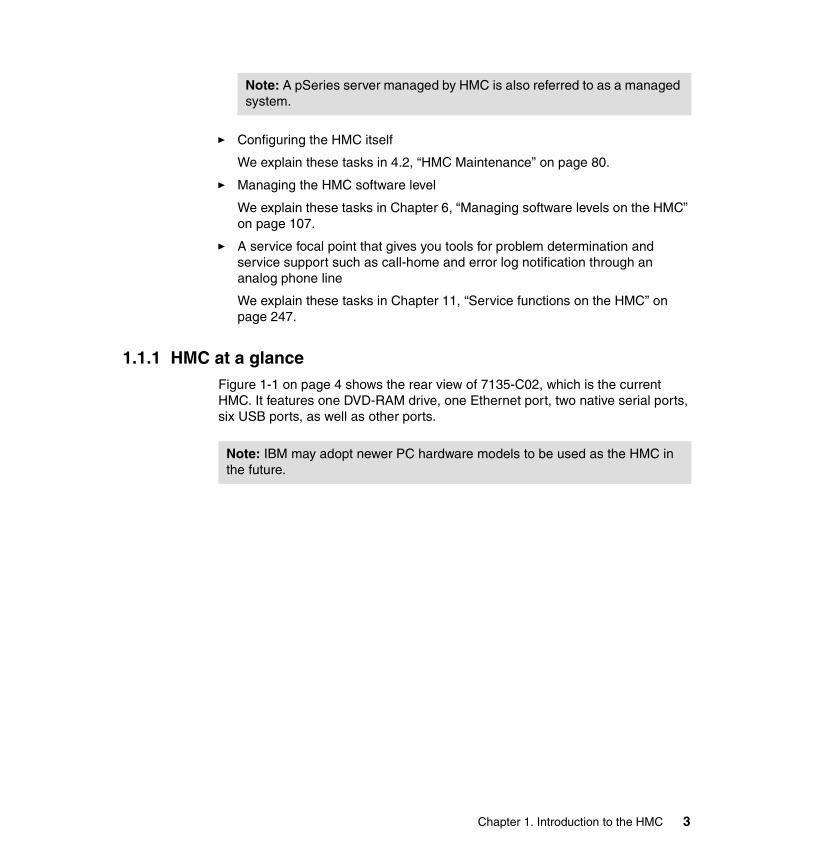
1.1.1 HMC at a glanceFigure 1-1 on page 4 shows the rear view of 7135-C02, which is the current HMC. It features one DVD-RAM drive, one Ethernet port, two native serial ports, six USB ports, as well as other ports.
Note: A pSeries server managed by HMC is also referred to as a managed system.
Note: IBM may adopt newer PC hardware models to be used as the HMC in the future.
Chapter 1. Introduction to the HMC 3
Figure 1-1 7135-C02 rear view3
Numbers shown in Figure 1-1 represents the following connectors:
1. Power connector2. Mouse connector3. Serial connector (S2)4. Parallel connector5. Ethernet connector6. Audio line in connector7. PCI slots (three available)8. AGP slot (not used)9. Audio line out connector (not used)10.Microphone connector (not used)11.USB connectors12.VGA monitor connector13.Serial connector (S1)
3 Two USB connectors are located in the front.
4 Effective System Management Using the IBM Hardware Management Console for pSeries
14.USB connectors15.Keyboard connector
The HMC provides two native serial ports. One serial port should be used to attach a modem for the Service Agent. The second port can be used to attach a server. If multiple servers are attached to the HMC, additional serial ports are necessary. The ports can be provided by adding asynchronous adapters.4
The HMC also provides an Ethernet port to connect to partitions on its managed systems. The network connection is mandatory for the support of the following functions as well as the system management purpose on those partitions:
� Dynamic logical partitioning� Service functions (for example, Microcode Updates and Service Focal Point)
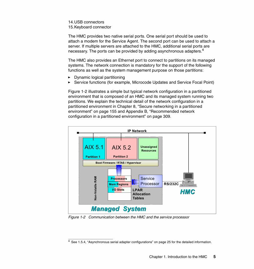
Figure 1-2 illustrates a simple but typical network configuration in a partitioned environment that is composed of an HMC and its managed system running two partitions. We explain the technical detail of the network configuration in a partitioned environment in Chapter 8, “Secure networking in a partitioned environment” on page 155 and Appendix B, “Recommended network configuration in a partitioned environment” on page 309.
Figure 1-2 Communication between the HMC and the service processor
4 See 1.5.4, “Asynchronous serial adapter configurations” on page 25 for the detailed information.
Non
-Vol
atile
RAM
Boot Firmware / RTAS / Hypervisor
Partition 1
UnassignedResources
LPARAllocation Tables
HMCHMC
AIX 5.1
ServiceProcessor
Processors
Mem Regions
I/O Slots
Partition 2
Managed SystemManaged System
AIX 5.2
RS/232C
IP Network
Chapter 1. Introduction to the HMC 5
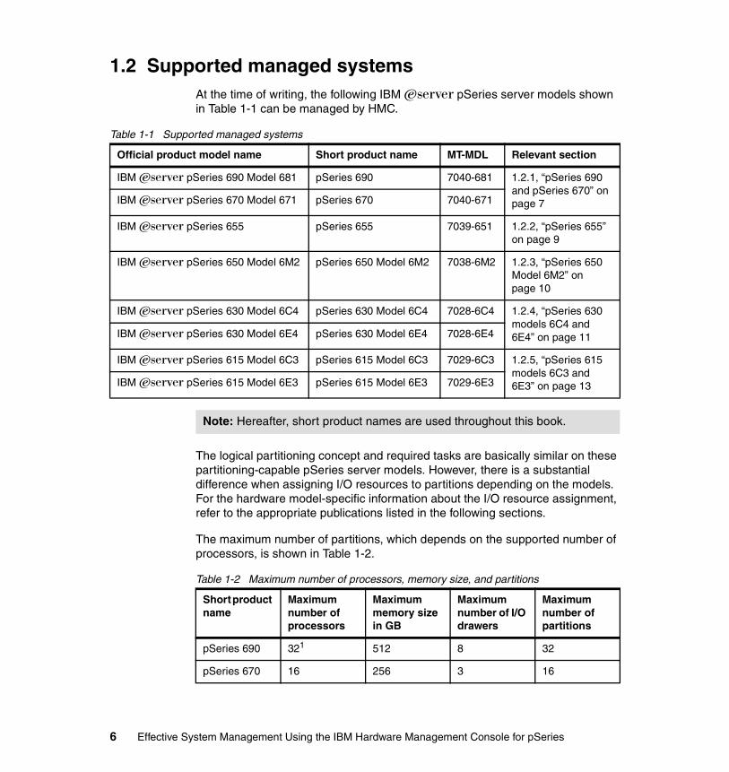
1.2 Supported managed systemsAt the time of writing, the following IBM Eserver pSeries server models shown in Table 1-1 can be managed by HMC.
Table 1-1 Supported managed systems
The logical partitioning concept and required tasks are basically similar on these partitioning-capable pSeries server models. However, there is a substantial difference when assigning I/O resources to partitions depending on the models. For the hardware model-specific information about the I/O resource assignment, refer to the appropriate publications listed in the following sections.
The maximum number of partitions, which depends on the supported number of processors, is shown in Table 1-2.
Table 1-2 Maximum number of processors, memory size, and partitions
Official product model name Short product name MT-MDL Relevant section
IBM Eserver pSeries 690 Model 681 pSeries 690 7040-681 1.2.1, “pSeries 690 and pSeries 670” on page 7IBM Eserver pSeries 670 Model 671 pSeries 670 7040-671
IBM Eserver pSeries 655 pSeries 655 7039-651 1.2.2, “pSeries 655” on page 9
IBM Eserver pSeries 650 Model 6M2 pSeries 650 Model 6M2 7038-6M2 1.2.3, “pSeries 650 Model 6M2” on page 10
IBM Eserver pSeries 630 Model 6C4 pSeries 630 Model 6C4 7028-6C4 1.2.4, “pSeries 630 models 6C4 and 6E4” on page 11IBM Eserver pSeries 630 Model 6E4 pSeries 630 Model 6E4 7028-6E4
IBM Eserver pSeries 615 Model 6C3 pSeries 615 Model 6C3 7029-6C3 1.2.5, “pSeries 615 models 6C3 and 6E3” on page 13IBM Eserver pSeries 615 Model 6E3 pSeries 615 Model 6E3 7029-6E3
Note: Hereafter, short product names are used throughout this book.
Short product name
Maximum number of processors
Maximum memory size in GB
Maximum number of I/O drawers
Maximum number of partitions
pSeries 690 321 512 8 32
pSeries 670 16 256 3 16
6 Effective System Management Using the IBM Hardware Management Console for pSeries
1.2.1 pSeries 690 and pSeries 670The high-end pSeries 690 and the mid-range pSeries 670 are both partitioning-capable pSeries server models that share the same physical component design. Several hardware components, Bulk Power Assembly (BPA), Central Electronics Complex (CEC), media drawer, and I/O drawers, as well as optional internal battery features (IBFs) are combined in one or two 7040-61R system racks.5
The pSeries 690 and pSeries 670 are equipped with two HMC ports (HMC1 and HMC2) in the primary I/O book, which is plugged into the rear of CEC, as shown in Figure 1-3 on page 8.
pSeries 655 8 32 1 2
pSeries 650 Model 6M2
8 64 8 82
pSeries 630 Model 6C4
4 32 2 43
pSeries 630 Model 6E4
4 32 0 2
1. The High Performance Computing (HPC) feature of pSeries 690 is equipped with up to 16 processors.
2. Needs external disk subsystems for the boot disk.3. When equipped with I/O drawers.
Note: pSeries 615 models 6C3 and 6E3 do not support partitioning.
Short product name
Maximum number of processors
Maximum memory size in GB
Maximum number of I/O drawers
Maximum number of partitions
5 The pSeries 690 supports up to two system racks, whereas the pSeries 670 supports only one.
Chapter 1. Introduction to the HMC 7
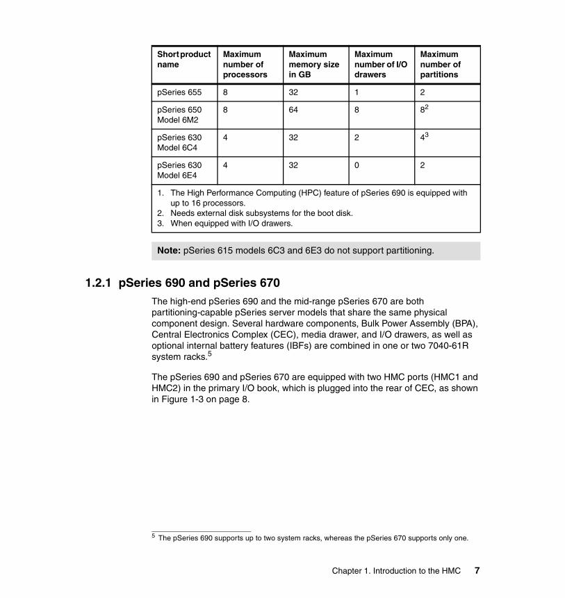
Figure 1-3 pSeries 670 and pSeries 690 CEC rear view (primary I/O book)
Table 1-3 explains numbers shown in Figure 1-3.
Table 1-3 Description of components in the primary I/O book
Number Description
1 Primary I/O book, GX slot 0 (U1.18-P1-H2)
4 I/O port 0 (A0) (U1.18-P1-H2/Q1)
5 I/O port 0 (A1) (U1.18-P1-H2/Q2)
6 Operator panel (U1.18-P1-H2/Q7)
7 BPC Y-cable connector1
8 I/O port 1 (B0) (U1.18-P1-H2/Q3)
9 I/O port 1 (B1) (U1.18-P1-H2/Q4)
10 Diskette Drive (U1.18-P1-H2/Q10)
8 Effective System Management Using the IBM Hardware Management Console for pSeries
For further detailed information about these models, refer to the following publications:
� IBM Eserver pSeries 670 and pSeries 690 System Handbook, SG24-7040� IBM Eserver pSeries 670 Service Guide, SA38-0615� IBM Eserver pSeries 670 User’s Guide, SA38-0614� IBM Eserver pSeries 670 Installation Guide, SA38-0613� IBM Eserver pSeries 690 Service Guide, SA38-0589� IBM Eserver pSeries 690 User’s Guide, SA38-0588� IBM Eserver pSeries 690 Installation Guide, SA38-0587
1.2.2 pSeries 655The mid-range pSeries 655 is a partitioning-capable pSeries server model. The pSeries 655 is designed as a building block of clusters, especially for the high-performance computing (HPC) area, therefore multiple pSeries 655 servers can be accommodated in a single 7040-W42 system rack. The 7040-W42 system rack shares the same physical form factor with 7040-R61 used for pSeries 670 or pSeries 690, but the BPA of 7040-W42 must be connected to HMC using RS-422.6
The pSeries 655 is equipped with two HMC ports (HMC1 and HMC2) on the rear side as shown in Figure 1-4 on page 23.
11 HMC port 1 (U1.18-P1-H2/S3)
12 HMC port 2 (U1.18-P1-H2/S4)
13 Serial port 1 (U1.18-P1-H2/S1)
14 Serial port 2 (U1.18-P1-H2/S2)
15 SPCN 0 (manufacturing use only)
16 SPCN 1 (manufacturing use only)
17 Debug (manufacturing use only)
24 Indicator LEDs
26 Camming latches
1. The Y-cable that attaches to this connector, terminates at BPC-A connector U1.35-P1-X4/Q10 and BPC-B connector U1.35-P2-X4/Q10.
Number Description
6 See 1.2.6, “RS-422 serial connection to the 7040-W42 system rack” on page 14 for the detailed information about the RS-422 connection between the HMC and 7040-W42.
Chapter 1. Introduction to the HMC 9

Figure 1-4 Rear view of pSeries 6557
For further detailed information about the pSeries 655, refer to the following publications:
� IBM Eserver pSeries 655 Installation Guide, SA38-0616� IBM Eserver pSeries 655 Service Guide, SA38-0618� IBM Eserver pSeries 655 User’s Guide, SA38-0617
1.2.3 pSeries 650 Model 6M2The mid-range pSeries 650 Model 6M2 is a partitioning-capable pSeries server model. It is a rack mount server that can be accommodated in an industry standard 19-inch rack.
The pSeries 650 Model 6M2 is equipped with two HMC ports (HMC1 and HMC2) on the rear side as shown in Figure 1-5 on page 11.
Note: The pSeries 655 has no native serial or parallel port.
7 Two pSeries 655 processor systems are contained in a single frame cage in a rack drawer position.
Second processor subsystem First processor subsystem
PCI slots
1 2 3
RIO connectors Ethernetconnectors
Debugconnector
HMC connector 2
HMC connector 1
10 Effective System Management Using the IBM Hardware Management Console for pSeries

Figure 1-5 Rear view of pSeries 650 Model 6M2
For further detailed information about the pSeries 650 Model 6M2, refer to the following technical white paper and publications:
� IBM Eserver pSeries 650 Model 6M2 Technical Overview and Introduction, REDP0194, available at:http://www.redbooks.ibm.com/redpapers/pdfs/redp0194.pdf
� IBM Eserver pSeries 650 Model 6M2 Installation Guide, SA38-0610� IBM Eserver pSeries 650 Model 6M2 User’s Guide, SA38-0611� IBM Eserver pSeries 650 Model 6M2 Service Guide, SA38-0612
1.2.4 pSeries 630 models 6C4 and 6E4The low-end pSeries 630 models 6C4 and 6E4 are both partitioning-capable pSeries server models. The pSeries 630 Model 6C4 is a rack mount server that can be accommodated in an industry standard 19 inch rack, whereas the pSeries 630 Model 6E4 is a deskside-type server.
The pSeries 630 models 6C4 and 6E4 are equipped with two HMC ports (HMC1 and HMC2) on the rear side as shown in Figure 1-6 on page 12.
Powersupply 1
Fan 1
PCI-X slots SCSI
ETH
GX slots
1 2 3 4 5 6 7
reserved
SPCN 1 SPCN 0
OP PNLDEBUG
KBD
MOUSE
SER 3
SER 1SER 2
SER 4 HMC 2
HMC 1
RackIndicator
1 2
Powersupply 2
Fan 2
reserved
Chapter 1. Introduction to the HMC 11

Figure 1-6 Views of pSeries 630 models 6C4 and 6E48
For further detailed information about the pSeries 630 models 6C4 and 6E4, refer to the following technical white paper and publications:
� IBM Eserver pSeries 630 Models 6C4 and 6E4 Technical Overview and Introduction, REDP0195, available at:http://www.redbooks.ibm.com/redpapers/pdfs/redp0195.pdf
� IBM Eserver pSeries 630 Model 6C4 and 6E4 Installation Guide, SA38-0605
� IBM Eserver pSeries 630 Model 6C4 and 6E4 User’s Guide, SA38-0606� IBM Eserver pSeries 630 Model 6C4 and 6E4 Service Guide, SA38-0604
8 This figure shows the views of latest pSeries 630 models 6C4 and 6E4 (POWER4™+ system with six PCI-X slots).
Power supply #2
Power supply #2
Processor card #1
Processor card #2
Operator panel
Processor card cooling fan bays 1 and 2
PCI cooling fan bays 1 and 2
Six PCI-X slots
Media bay #1 Media bay #2
4-pack disk backplane and disks
Power supply LED indicators
Six PCI-X slots
Power supply #1
Power supply #1
Model 6E4 Model 6C4 Keyboard and mouse ports
Serial ports 1, 2, and 3
SPCN ports
Parallel port
Ethernet ports HMC port 1
Operator panel
Front serial connector
4-pack disk backplane and disks
Media bay #2
Media bay #1
Six PCI-X slots
Rackindicator
Keyboard and mouse ports
Serial ports 1, 2, and 3
Ethernet ports
HMC port 1
SPCN portblanks
Power supply #1
Power supply #2
Parallel portRIO ports
Power supply LED indicators
Power supply LED indicators
HMC port 2
HMC port 2
12 Effective System Management Using the IBM Hardware Management Console for pSeries

1.2.5 pSeries 615 models 6C3 and 6E3The low-end pSeries 615 models 6C3 and 6E3 are both non partitioning-capable pSeries server models. The pSeries 615 Model 6C3 is a rack mount server that can be accommodated in an industry standard 19-inch rack, whereas the pSeries 615 Model 6E3 is a deskside-type server.
The pSeries 615 Model 6C3 can be used as a building block of the IBM cluster product IBM Eserver Cluster 1600, so multiple pSeries 615 Model 6C3 servers can be incorporated into the cluster, which is managed by Cluster Systems Management (CSM).9
The pSeries 615 models 6C3 and 6E3 are equipped with two HMC ports (HMC1 and HMC2) on the rear side as shown in Figure 1-7.
Figure 1-7 Views of pSeries 615 models 6C3 and 6E3
9 Refer to the publications listed in “CSM for AIX official publications” on page 335 for detailed information about CSM.
Power supply LED indicators
Six PCI-X slots
Power supply #1 (redundant option)
Power supply #2 (default)
Full height media bayTwo slim line media bays
Operator panel
Operator panelHot-swap disk drives
Cooling fans
#1
#2
#3
CSP and I/O ports card
Parallel portSerial port 3
Serial port 2
Serial port 1Rack indicator
Keyboard & Mouse
10/100 Ethernet10/100/1000 Ethernet
Power supplyconnector #2
Power supplyconnector #1
Model 6C3
Front view
Rear view
Model 6E3
Test port (only MFG)
Front view
Operator panel
Full height media bayTwo slim linemedia bays
Hot-swap disk drives
Rear view
Six PCI-X slots
10/100 Ethernet
10/100/1000 Ethernet Test port (only MFG)
Serial port 2Serial port 3Parallel port
Serial port 1
Rack indicator
Keyboard & Mouse
Power supplyconnector #1
HMC port 1HMC port 2
HMC port 1HMC port 2
(Base power supply)
Power supplyconnector #2
(Base power supply)
Power supplyconnector #2(Base power
supply)
!
Chapter 1. Introduction to the HMC 13
If a pSeries 615 Model 6C3 or pSeries 615 Model 6E3 is managed by CSM, an HMC must be attached to an HMC port of these models for power management.
For further detailed information about the pSeries 630 models 6C4 and 6E4, refer to the following technical white paper and publications:
� IBM Eserver pSeries 615 Models 6C3 and 6E3 Technical Overview and Introduction, REDP0160, available at:http://www.redbooks.ibm.com/redpapers/pdfs/redp0160.pdf
� IBM Eserver pSeries 615 Model 6C3 and 6E3 Installation Guide, SA38-0628
� IBM Eserver pSeries 615 Model 6C3 and 6E3 User’s Guide, SA38-0630� IBM Eserver pSeries 615 Model 6C3 and 6E3 Service Guide, SA38-0629
1.2.6 RS-422 serial connection to the 7040-W42 system rackIf the 7040-W42 system rack is used to accommodate hardware components, such as pSeries 655 servers, the BPA of the rack must be connected to an HMC using RS-422, as shown in Figure 1-8 on page 15.
14 Effective System Management Using the IBM Hardware Management Console for pSeries
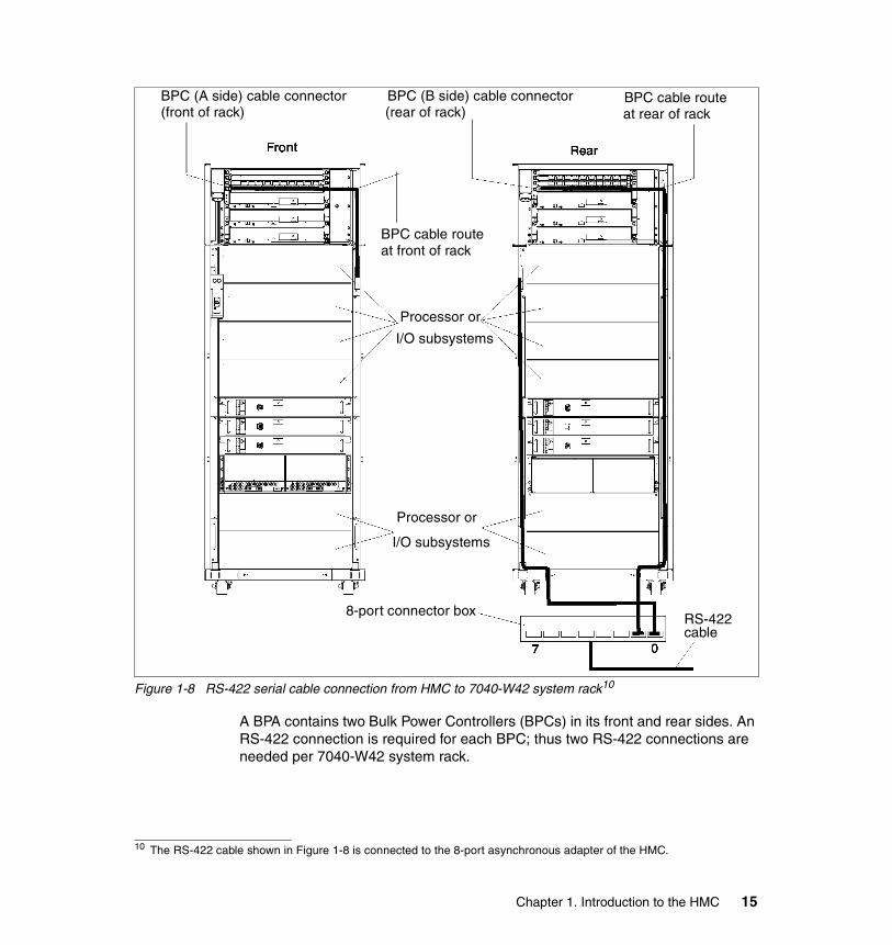
Figure 1-8 RS-422 serial cable connection from HMC to 7040-W42 system rack10
A BPA contains two Bulk Power Controllers (BPCs) in its front and rear sides. An RS-422 connection is required for each BPC; thus two RS-422 connections are needed per 7040-W42 system rack.
10 The RS-422 cable shown in Figure 1-8 is connected to the 8-port asynchronous adapter of the HMC.
BPC (A side) cable connector(front of rack)
BPC cable routeat front of rack
Processor or
I/O subsystems
BPC (B side) cable connector(rear of rack)
BPC cable routeat rear of rack
Processor or
I/O subsystems
8-port connector boxRS-422cable
Chapter 1. Introduction to the HMC 15
1.3 HMC architectureThe HMC provides a graphical user interface for configuring and operating single or multiple managed systems. It consists of a 32-bit Intel-based desktop PC with a DVD-RAM drive and running the Linux operating system. The application environment, with a set of hardware management applications for configuration and partitioning, is written in Java. The applications are based on the object-oriented schema using the Common Information Model (CIM), an industry standard sponsored by the Distributed Management Task Force (DMTF). A CIM Object Manager acts as repository and database look-up for all managed objects.
The DMTF Standards web site can be a good starting point to learn these technologies, found at:
http://www.dmtf.org/standards/standard_cim.php
The graphical user interface is based on the AIX 5L™ Version 5.2 Web-based System Manager, which allows the management integration of other HMCs or pSeries systems running AIX 5L Version 5.1 and 5.2. Except for IBM customer engineers and debugging purposes, the native Linux interfaces are hidden from the user and are not accessible. No Linux skills are required to operate the HMC. The graphical user interface can display dynamic events and static information from pSeries machines running AIX as well as from partitions on any partitioning-capable pSeries servers.
Figure 1-9 on page 17 shows an overview of the HMC software architecture.
� A user who logs in to the HMC from the local console is accessing the application using the Web-based System Manager graphical user interface as represented in the big upper arrow.
� The HMC communicates with the service processor on the managed system using the serial communication.
� If configured, the Service Agent communicates with the modem using the serial communication.
� The Resource Monitoring and Control (RMC) subsystem on the HMC connects the RMC subsystem on remote nodes, such as partitions, over the TCP/IP network (shown as A in Figure 1-9 on page 17).
Note: If the 8-port asynchronous adapter (FC 2943) is used to connect the HMC to the BPCs of 7040-W42, the corresponding serial ports must be explicitly set to the RS-422 mode (see Appendix , “Configuring RS-422 ports on an 8-port asynchronous adapter” on page 305).
16 Effective System Management Using the IBM Hardware Management Console for pSeries
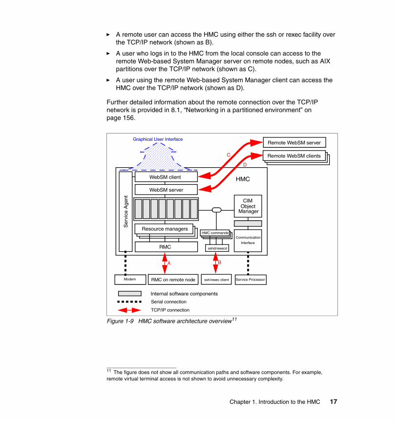
� A remote user can access the HMC using either the ssh or rexec facility over the TCP/IP network (shown as B).
� A user who logs in to the HMC from the local console can access to the remote Web-based System Manager server on remote nodes, such as AIX partitions over the TCP/IP network (shown as C).
� A user using the remote Web-based System Manager client can access the HMC over the TCP/IP network (shown as D).
Further detailed information about the remote connection over the TCP/IP network is provided in 8.1, “Networking in a partitioned environment” on page 156.
Figure 1-9 HMC software architecture overview11
11 The figure does not show all communication paths and software components. For example, remote virtual terminal access is not shown to avoid unnecessary complexity.
Resource managers
RMC
Internal software components
WebSM server
WebSM client
Communication
Interface
CIM
ManagerObject
sshd/rexecd
HMC commands
Ser
vice
Age
nt
Service Processor
Serial connection
Graphical User InterfaceRemote WebSM server
Modem RMC on remote node
HMC
ssh/rexec client
TCP/IP connection
A B
C
D
Remote WebSM clients
Chapter 1. Introduction to the HMC 17
1.4 HMC connectivityIn this section, we explain several HMC connectivity configurations. We group these configurations into two categories: 1.4.1, “Serial connectivity” on page 18 and 1.4.2, “Remote connectivity” on page 21.
1.4.1 Serial connectivityA managed system has to be connected by at least one HMC using a serial connection. To connect a serial line between an HMC and a managed system, use one of the serial ports on the HMC and one of two dedicated serial ports (HMC1 and HMC2) on the managed system.
As long as at least one serial connection is configured, you can configure the following serial connectivity options:
� Redundant HMC configuration
For redundancy of the system management control point, you can configure a redundant HMC configuration, as shown in Figure 1-10 on page 19. In this case, both serial ports have one HMC connected.
For further information about redundant HMC configuration, see “Redundant HMC configuration consideration” on page 19.
� Multiple managed system configuration
To save space and to centralize multiple system management control points, you can configure multiple managed systems using a single HMC, as shown in Figure 1-10 on page 19. If more than two managed systems are connected with one HMC, asynchronous adapters must be configured on the HMC.12
The information is considered as objects in the HMC applications. Because the serial connection is relatively slow (19200 bps), the HMC applications run slower as the number of objects increases.
The performance of the HMC applications are affected by three factors:
– Number of the managed systems– Number of the equipped I/O devices on each managed system– Number of defined partitions defined on each managed system
Note: You should not confuse the managed system name with the host name. Because multiple operating system instances can run concurrently on a single partitioning-capable pSeries server, you cannot use the host name, which usually depends on the IP address, to distinguish multiple partitioning-capable pSeries servers. The managed system name is a label used for this purpose.
12 See 1.4.1, “Serial connectivity” on page 18 for the detailed information.
18 Effective System Management Using the IBM Hardware Management Console for pSeries
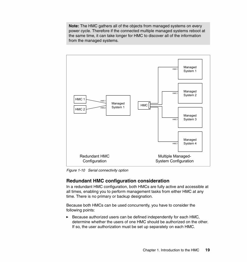
Figure 1-10 Serial connectivity option
Redundant HMC configuration considerationIn a redundant HMC configuration, both HMCs are fully active and accessible at all times, enabling you to perform management tasks from either HMC at any time. There is no primary or backup designation.
Because both HMCs can be used concurrently, you have to consider the following points:
� Because authorized users can be defined independently for each HMC, determine whether the users of one HMC should be authorized on the other. If so, the user authorization must be set up separately on each HMC.
Note: The HMC gathers all of the objects from managed systems on every power cycle. Therefore if the connected multiple managed systems reboot at the same time, it can take longer for HMC to discover all of the information from the managed systems.
HMC 1
HMC 2
ManagedSystem 1
HMC1
HMC2
ManagedSystem 1
ManagedSystem 2
ManagedSystem 3
ManagedSystem 4
HMC
HMC1
HMC1
HMC1
HMC1
Redundant HMCConfiguration
Multiple Managed-System Configuration
Chapter 1. Introduction to the HMC 19

� Because both HMCs provide Service Focal Point and Service Agent functions, connect a modem and phone line to only one of the HMCs and enable its Service Agent. To prevent redundant service calls, do not enable the Service Agent on both HMCs.
� Perform software maintenance separately on each HMC, at separate times, so that there is no interruption in accessing HMC function. This allows one HMC to run at the new fix level, while the other HMC can continue to run at the previous fix level. However, the best practice is to upgrade both HMCs to the same fix level as soon as possible.
The basic design of HMC eliminates the possible operation conflicts issued from two HMCs in the redundant HMC configuration. A locking mechanism provided by the service processor allows inter-operation in a parallel environment. This allows an HMC to temporarily take exclusive control of the interface, effectively locking out the other HMC. Usually, this locking is held only for the short duration of time it takes to complete an operation, after which the interface is available for further commands.
Both HMCs are automatically notified of any changes that occur in the managed systems, so the results of commands issued by one HMC are visible in the other. For example, if you choose to activate a partition from one HMC, you will observe the partition going to the Starting and Running states on both HMCs.
The locking between HMCs does not prevent users from running commands that might seem to be in conflict with each other. For example, if the user on one HMC activates a partition, and a short time later a user on the other HMC selects to power the system off, the system will power off. Effectively, any sequence of commands that you can do from a single HMC is also permitted when it comes from redundant HMCs. For this reason, it is important to consider carefully how to use this redundant capability to avoid such conflicts. You might choose to use them in a primary and backup role, even though the HMCs are not restricted in that way. The interface locking between two HMCs is automatic, usually of short duration, and most console operations wait for the lock to release without requiring user intervention. However, if one HMC experiences a problem while in the middle of an operation, it may be necessary to manually release the lock.13
Connect and disconnect managed systemsBecause the HMC is not required for managed systems to properly function, you can connect or disconnect them from the HMC without service interruption of managed systems. For further details about connecting or disconnecting managed systems to or from the HMC, see 2.4.1, “Connect and disconnect managed systems” on page 45.
13 See “Release Console Lock” on page 48.
20 Effective System Management Using the IBM Hardware Management Console for pSeries

1.4.2 Remote connectivityDepending on what communication method or protocols are used, there are several options in the remote connectivity of HMC, as illustrated in Figure 1-11 on page 22. In this figure, we assume the following points:
� The dashed lines between HMCs and managed systems are serial connections.
� The solid lines connecting HMCs and other systems are Ethernet connections. These systems have appropriate TCP/IP configuration, so they can communicate using various TCP/IP protocols supported by the HMC.
� We exclude the possible connection to the AIX systems managed by Web-based System Manager from the HMC to avoid complexity in Figure 1-11 on page 22. You can also manage these AIX systems from the HMC, even if the AIX system is running in a partition.
� We assume that the HMC1 shown in Figure 1-11 on page 22 is a server; all connections are made to HMC1 from the other systems, and some operations are executed on it, such as configuring a partition or powering on the managed system.
Note: If your managed system is connected to only one HMC, you cannot perform several administration tasks, such as partition management and DLPAR operation, while the HMC is disconnected from the managed system.
Chapter 1. Introduction to the HMC 21

Figure 1-11 Remote connectivity option
Figure 1-11 shows two categories of remote connectivity options explained in the following sections: remote access to the HMC graphical user interface, as shown by 1-A, 1-B, and 1-C (using the dotted line), and the remote execution of command line function, as shown by 2 (using the dotted line).
Remote access to the HMC graphical user interfaceThe HMC allows remote access to the graphical user interface from the Web-based System Manager client installed on the following operating systems:
� AIX� Linux14
� Windows
For installation and usage of the remote client, see 7.2, “Remote client setup on a Windows system” on page 141 and 7.3, “Remote client setup on a Linux system” on page 145.
14 Only the Linux operating system for the IA-32 architecture is supported.
HMC 1
HMC 2
ManagedSystem 1
ManagedSystem 2
SerialConnection
SerialConnection
Any TCP/IPCapableSystem
Linux WebSMClient
WindowsWebSM Client
1-A1-B
1-C
2
22 Effective System Management Using the IBM Hardware Management Console for pSeries
Remote execution of command line functionsThe HMC provides a set of commands in order to be used for many management tasks; however, those commands are only accessible from the remote system, not from the HMC local console. This remote connectivity option is shown as 2 in Figure 1-11 on page 22, and any TCP/IP-capable system that supports rexec or ssh can use the remote execution of command line functions.
For further information about the command line interface on the HMC, see Chapter 9, “HMC command line interface” on page 175.
1.5 HMC order informationIn order to configure and administer a partitioning-capable pSeries server, you must attach at least one IBM Hardware Management Console for pSeries (HMC) to the system. Depending on the partitioning-capable pSeries server model, the HMC is ordered as a feature code or a separate orderable product, as shown in Table 1-4.
Table 1-4 Previous Hardware Management Console feature code or MT-MDL
Note: We recommend that you use ssh instead of rexec, because the rexec method transports a non-secure clear text copy of the password across the network.
Note: Currently, only the 7315-C02 is orderable. The 7316 and 7315-C01 are shown only for reference purposes.
Short product name HMC FC or MT-MDL Note
pSeries 690 FC 7316 1
pSeries 670 FC 7316 1
pSeries 655 MT-MDL 7315-C01 1
pSeries 650 Model 6M2 MT-MDL 7315-C01 2
pSeries 630 Model 6C4 MT-MDL 7315-C01 2
pSeries 630 Model 6E4 MT-MDL 7315-C01 2
1. The HMC is required regardless of whether the system is partitioned or running in the Full System Partition.
2. The HMC is required if the system is partitioned. If the system is running in the Full System Partition, the HMC is not required.
Chapter 1. Introduction to the HMC 23

To place an order of a new HMC (7315-C02), use the IBM Configurator for e-business (e-config). The redbook IBM Eserver pSeries 670 and pSeries 690 System Handbook, SG24-7040, can be used as a good example of how to use this application.
1.5.1 Supported number of managed systems and partitionsOne HMC is capable of controlling multiple pSeries servers. As this publication is being written, an HMC can control any of the following:
� 12 pSeries 670 and pSeries 690 servers with 64 partitions
� 16 pSeries 655 servers with up to 32 partitions
� 16 pSeries 630 models 6C4 and 6E4 or pSeries 650 Model 6M2 servers with up to 64 partitions
� 16 pSeries servers and 64 partitions in a mixed server environment
A mixed server environment can contain a combined maximum of eight pSeries 670 or pSeries 690 servers.
1.5.2 HMC software release numbering schemeThe latest HMC software release (program number 5639-N47) is preloaded on the HMC upon product shipment.
Although many IBM software products follow the release numbering scheme known as V.R.M.F (version, release, maintenance, and fix), the current HMC uses a different scheme, represented as R.V.M.F (release, version, maintenance, and fix). Therefore, the latest release available at the time of writing this book is represented as Release 3, Version 2.2, not Version 3, Release 2.2.
1.5.3 Ethernet adapter configurationThe HMC can be equipped with an optional Ethernet adapter in addition to the built-in Ethernet port. To use the second Ethernet port, the following feature must be configured:
� 10/100 Mbps Ethernet PCI adapter II (FC 4962)
The second Ethernet port typically is used when the HMC is incorporated into a cluster complex that is managed by CSM.
24 Effective System Management Using the IBM Hardware Management Console for pSeries

1.5.4 Asynchronous serial adapter configurationsThe HMC can be equipped with none, one, or both of these asynchronous adapters:
� 8-port asynchronous adapter (FC 2943)� 128-port asynchronous adapter (FC 2944)
Use these adapters if more than two serial ports are required on your HMC. To configure these adapters, see Appendix A, “Configuring asynchronous adapters on the HMC” on page 295.
Using 8-port asynchronous adaptersFC 2943 is composed of the following:
� A PCI adapter card with a physical port
� A cable with a breakout box that has eight DB-25 connectors (see Figure 1-12)
Figure 1-12 8-port fanout box with a connector cable
To connect between an FC 2943 port and one of the HMC ports on a managed system, the following cables are used:
FC 8120 Attachment Cable, HMC to Host, 6 metersFC 8121 Attachment Cable, HMC to Host, 15 meters
To connect between an FC 2943 port and one of the BPC RS-422 ports on the 7040-W42 system rack, the following cables are used:
FC 8122 Attachment Cable, HMC to 7040-W42, 6 meters
Note:
� To ensure that the asynchronous adapter is installed in the HMC and not in the server, make sure that the adapter is configured as a feature of the HMC at the time of order.
� A combination of an FC 2943 and an FC 2944 is supported; however, the total number of asynchronous adapters cannot exceed two.
Chapter 1. Introduction to the HMC 25
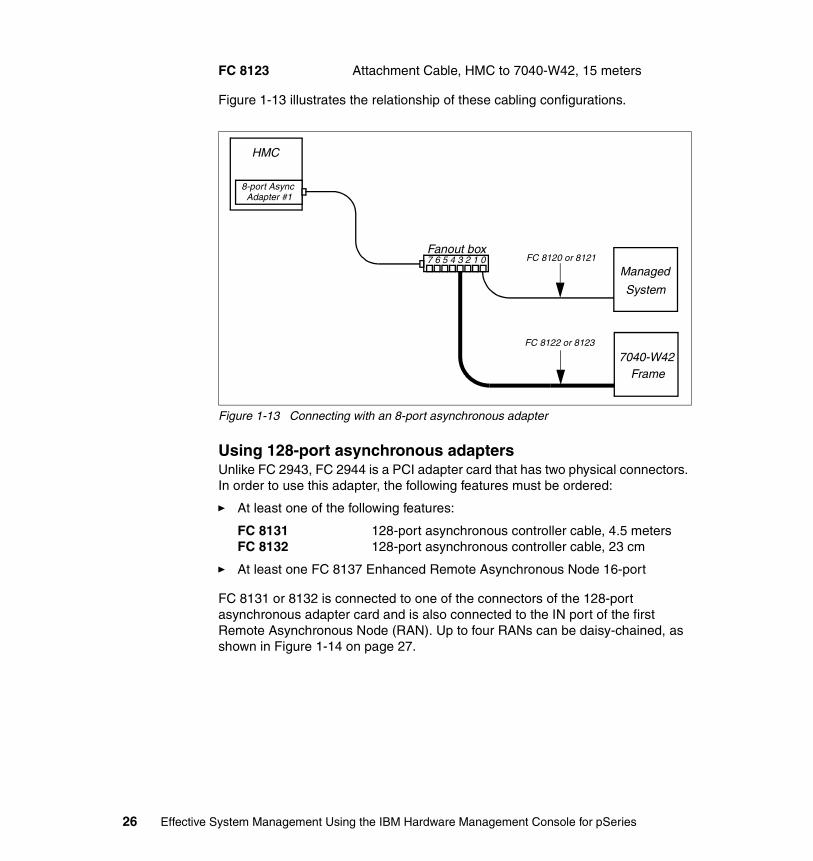
FC 8123 Attachment Cable, HMC to 7040-W42, 15 meters
Figure 1-13 illustrates the relationship of these cabling configurations.
Figure 1-13 Connecting with an 8-port asynchronous adapter
Using 128-port asynchronous adaptersUnlike FC 2943, FC 2944 is a PCI adapter card that has two physical connectors. In order to use this adapter, the following features must be ordered:
� At least one of the following features:
FC 8131 128-port asynchronous controller cable, 4.5 metersFC 8132 128-port asynchronous controller cable, 23 cm
� At least one FC 8137 Enhanced Remote Asynchronous Node 16-port
FC 8131 or 8132 is connected to one of the connectors of the 128-port asynchronous adapter card and is also connected to the IN port of the first Remote Asynchronous Node (RAN). Up to four RANs can be daisy-chained, as shown in Figure 1-14 on page 27.
HMC
8-port AsyncAdapter #1
Fanout box0
Managed
System
7040-W42Frame
FC 8120 or 8121
FC 8122 or 8123
1234567
26 Effective System Management Using the IBM Hardware Management Console for pSeries
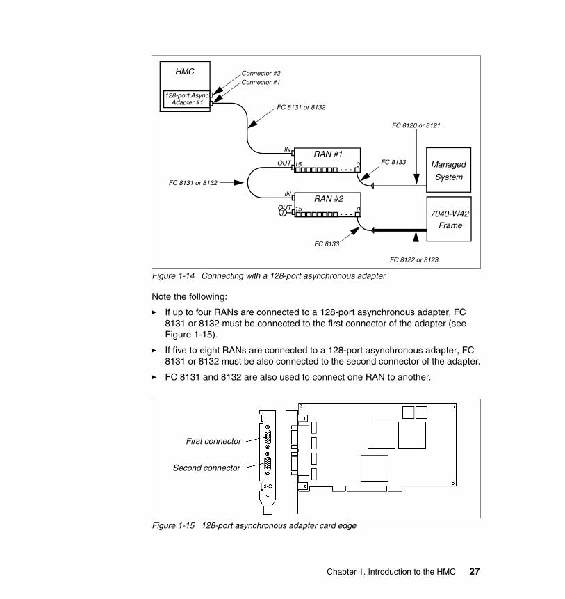
Figure 1-14 Connecting with a 128-port asynchronous adapter
Note the following:
� If up to four RANs are connected to a 128-port asynchronous adapter, FC 8131 or 8132 must be connected to the first connector of the adapter (see Figure 1-15).
� If five to eight RANs are connected to a 128-port asynchronous adapter, FC 8131 or 8132 must be also connected to the second connector of the adapter.
� FC 8131 and 8132 are also used to connect one RAN to another.
Figure 1-15 128-port asynchronous adapter card edge
HMC
128-port AsyncAdapter #1
RAN #1
T
015
Connector #2Connector #1
FC 8131 or 8132
FC 8133 Managed
System
IN
OUT
RAN #2015
IN
OUT
FC 8133
7040-W42Frame
FC 8120 or 8121
FC 8122 or 8123
FC 8131 or 8132
First connector
Second connector
Chapter 1. Introduction to the HMC 27

Enhanced Remote Asynchronous Node 16-port (FC 8137)The RAN is a separate box that has the following ports (see Figure 1-16):
� An IN connector� An OUT connector� 16 RJ-45 asynchronous ports
The IN and OUT connectors are used to connect an RAN with the 128-port asynchronous adapter or another RAN.
Figure 1-16 Enhanced Remote Asynchronous Node 16-port (FC 8137)
The 16 RJ-45 ports are connected to managed systems or BPC ports on the 7040-W42 system rack.
To connect between a port on an RAN and one of the HMC ports on a managed system, the following cables are used:
FC 8120 Attachment Cable, HMC to Host, 6 metersFC 8121 Attachment Cable, HMC to Host, 15 metersFC 8133 RJ-45 to DB-25 Converter cable
To connect between a port on an RAN and one of the BPC RS-422 ports on the 7040-W42 frame, the following cables are used:
FC 8122 Attachment Cable, HMC to 7040-W42, 6 meters
Note: If the RAN is the last in a daisy chain, the OUT port must be terminated.
28 Effective System Management Using the IBM Hardware Management Console for pSeries
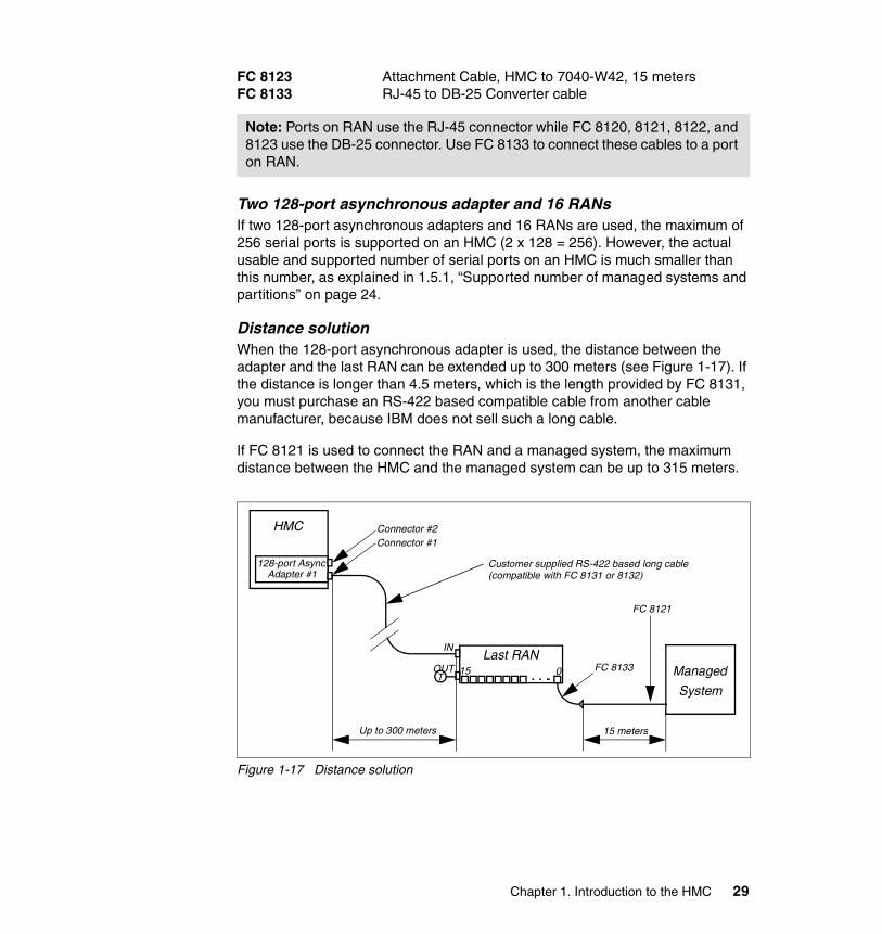
FC 8123 Attachment Cable, HMC to 7040-W42, 15 metersFC 8133 RJ-45 to DB-25 Converter cable
Two 128-port asynchronous adapter and 16 RANsIf two 128-port asynchronous adapters and 16 RANs are used, the maximum of 256 serial ports is supported on an HMC (2 x 128 = 256). However, the actual usable and supported number of serial ports on an HMC is much smaller than this number, as explained in 1.5.1, “Supported number of managed systems and partitions” on page 24.
Distance solutionWhen the 128-port asynchronous adapter is used, the distance between the adapter and the last RAN can be extended up to 300 meters (see Figure 1-17). If the distance is longer than 4.5 meters, which is the length provided by FC 8131, you must purchase an RS-422 based compatible cable from another cable manufacturer, because IBM does not sell such a long cable.
If FC 8121 is used to connect the RAN and a managed system, the maximum distance between the HMC and the managed system can be up to 315 meters.
Figure 1-17 Distance solution
Note: Ports on RAN use the RJ-45 connector while FC 8120, 8121, 8122, and 8123 use the DB-25 connector. Use FC 8133 to connect these cables to a port on RAN.
HMC
128-port AsyncAdapter #1
Last RAN
T015
Connector #2Connector #1
FC 8133 Managed
System
IN
OUT
FC 8121
15 metersUp to 300 meters
Customer supplied RS-422 based long cable(compatible with FC 8131 or 8132)
Chapter 1. Introduction to the HMC 29

Note: The distance shown as “Up to 300 meters” in Figure 1-17 means that the distance between the 128-port asynchronous adapter and the last RAN in the daisy chain; therefore, if multiple RANs exist, the distance between the adapter and the first RAN in the daisy chain is shorter than 300 meters.
30 Effective System Management Using the IBM Hardware Management Console for pSeries
Chapter 2. HMC graphical user interface
This chapter describes the HMC graphical user interface by providing the following sections:
� “Login and logout” on page 32� “HMC graphical user interface at a glance” on page 32� “HMC application overview” on page 40� “Server and Partition” on page 41� “Virtual terminal window” on page 49� “Open xterm to access remote system using telnet” on page 52
Before proceeding to following chapters, you should be familiar with the terms and concepts used in the HMC graphical user interface explained in this chapter.
2
© Copyright IBM Corp. 2003. All rights reserved. 31
2.1 Login and logoutAfter power-on, the HMC shows the graphical login panel prompting for the user ID and the password. The HMC is supplied with a predefined user ID hscroot and the default password abc123. Both the user ID and password are case sensitive and must be typed exactly as shown. After the successful login, the HMC graphical user interface opens, as shown in Figure 2-1 on page 33.
To log out from the HMC graphical user interface, do the following:
1. From the menu bar, select Console → Exit.
At this point, you can choose to save the state of the console for the next session by selecting the check box next to the option.
2. Select Exit Now.
3. When you exit from your HMC session, you have to choose from the following three logout modes:1
Shutdown Console Powers off the HMC system.
Reboot Console Shuts down the HMC system and then reboots it to the login prompt.
Logout Returns the user to the login prompt without shutting down the HMC system.
In either mode, the managed systems are not affected by these operations.
2.2 HMC graphical user interface at a glanceThe HMC graphical user interface has the same appearance, key concepts, and basic tasks and tools as the AIX 5L Version 5.2 Web-based System Manager. For further information about the Web-based System Manager, refer to AIX 5L Version 5.2 System Management Guide: AIX 5L Version 5.2 Web-based System Manager Administration Guide, available at:
http://techsupport.services.ibm.com/server/library
1 You can also use the hmcshutdown command to shut down or reboot your HMC (see “hmcshutdown” on page 190).
32 Effective System Management Using the IBM Hardware Management Console for pSeries
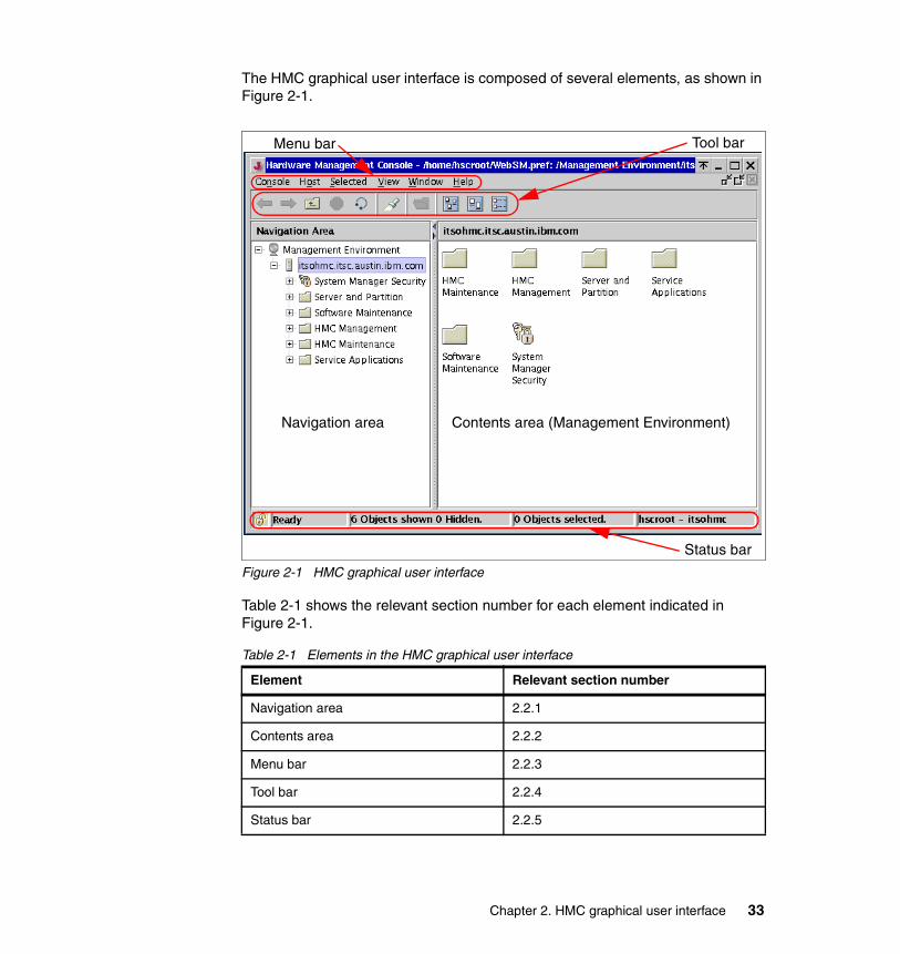
The HMC graphical user interface is composed of several elements, as shown in Figure 2-1.
Figure 2-1 HMC graphical user interface
Table 2-1 shows the relevant section number for each element indicated in Figure 2-1.
Table 2-1 Elements in the HMC graphical user interface
Element Relevant section number
Navigation area 2.2.1
Contents area 2.2.2
Menu bar 2.2.3
Tool bar 2.2.4
Status bar 2.2.5
Menu bar Tool bar
Navigation area Contents area (Management Environment)
Status bar
Chapter 2. HMC graphical user interface 33

2.2.1 Navigation areaThe left side of the HMC graphical user interface is the Navigation area. It displays a hierarchy of items ordered in a tree structure. The root of the tree is the Management Environment. It contains the name of the HMC that you are currently logged in to. For example, you can see the icon with the host name itsohmc.itsc.austin.ibm.com in the Navigation area in Figure 2-1 on page 33. It is the host name of the HMC from which this panel image has been taken. In this example, there is only one host system, the HMC itsohmc.itsc.austin.ibm.com.
The Management Environment is a set of host systems that can be managed from the HMC. The host systems can be the HMC into which you are currently logged, the other remote HMCs, and also AIX systems managed by their Web-based System Manager interface.
To add a host system under the Management Environment, do the following:
1. From the menu bar, select Console → Add → Hosts.
You have two options here: you can add a single host or multiple hosts. For a single host, add the host name of the system that you want to add; for multiple hosts, provide the path name of the file that contains the hosts to be added.
You also have the option to verify whether the hosts added are on the network by selecting the option provided to you.
To remove a host system under the Management Environment, do the following2:
1. From the menu bar, select Console → Remove.
2. Select the host name from the displayed list that you want to remove, and then confirm in the next panel that you want to remove the designated host.
Every folder contains different HMC applications used in the specific management task, such as Server and Partition or Software Maintenance, as shown in the Navigation area in Figure 2-1 on page 33. If you choose one of these HMC applications, it provides its own submenus and objects in the Contents area determined by the application context.
2 This remove operation does not affect the managed system deleted from the HMC application.
Note: The managed system itself never appears in the Navigation area unless you manage AIX instances running in partitions managed by the Web-based System Manager.
34 Effective System Management Using the IBM Hardware Management Console for pSeries

2.2.2 Contents areaThe right side of the panel is the Contents area. It displays managed objects and related tasks. You can choose different views in the Contents area: large icons, small icons, or details in the form of a list.
2.2.3 Menu barThe following six menu items are provided in the menu bar:
Console The Console menu contains choices that control the console. It enables you to add and remove managed systems, other HMCs, or other AIX systems managed by Web-based System Manager from the management environment. It also enables you to change themes on the desktop, change font sizes, open an outbound Telnet terminal session using an IP address or a host name, and exit the console.
Object The title of the Object menu changes to indicate the type of resource managed by the current HMC application. For example, when the Server Management application is selected, the Object menu title becomes Server Management. The Object menu contains general choices and actions for a HMC application that do not require the selection of specific objects to act on. The find function is also located in the Object menu. The contents of the Object menu are updated when a new HMC application is selected. In the case where you are managing an AIX system remotely, the AIX 5L Version 5.2 Web-based System Manager applications appear here.
Selected The Selected menu contains the set of actions that are applicable to the object selected in the Contents pane. The contents of the Selected menu are updated based on which object you select. It is disabled when Overview and Launch applications are loaded. The open tab in the Selected menu expands the view of a managed system in the Navigation area.
Note: The label of the Contents area is changed depending on the application context. For example, if you select Management Environment in the Navigation area, the label is changed to Management Environment, as shown in Figure 2-1 on page 33.
Chapter 2. HMC graphical user interface 35
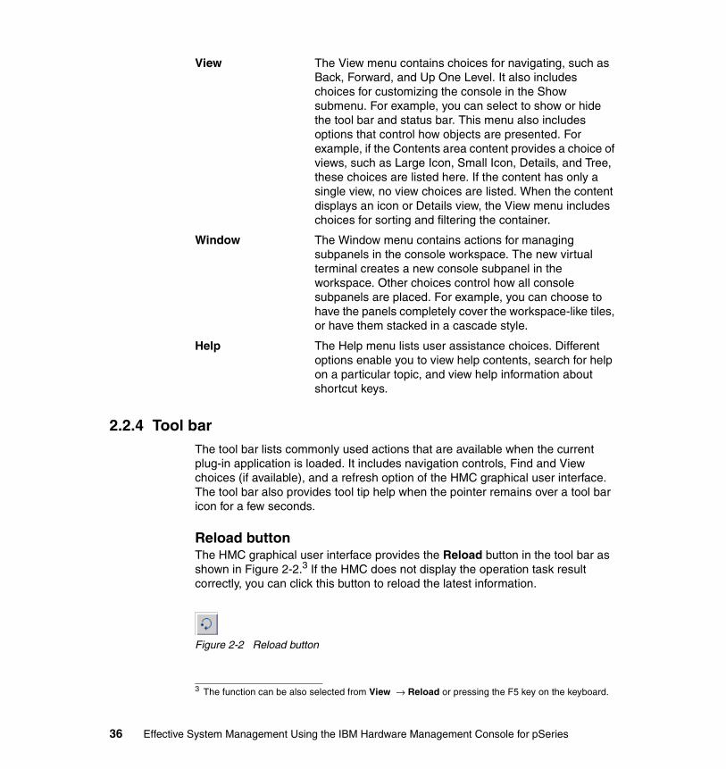
View The View menu contains choices for navigating, such as Back, Forward, and Up One Level. It also includes choices for customizing the console in the Show submenu. For example, you can select to show or hide the tool bar and status bar. This menu also includes options that control how objects are presented. For example, if the Contents area content provides a choice of views, such as Large Icon, Small Icon, Details, and Tree, these choices are listed here. If the content has only a single view, no view choices are listed. When the content displays an icon or Details view, the View menu includes choices for sorting and filtering the container.
Window The Window menu contains actions for managing subpanels in the console workspace. The new virtual terminal creates a new console subpanel in the workspace. Other choices control how all console subpanels are placed. For example, you can choose to have the panels completely cover the workspace-like tiles, or have them stacked in a cascade style.
Help The Help menu lists user assistance choices. Different options enable you to view help contents, search for help on a particular topic, and view help information about shortcut keys.
2.2.4 Tool barThe tool bar lists commonly used actions that are available when the current plug-in application is loaded. It includes navigation controls, Find and View choices (if available), and a refresh option of the HMC graphical user interface. The tool bar also provides tool tip help when the pointer remains over a tool bar icon for a few seconds.
Reload buttonThe HMC graphical user interface provides the Reload button in the tool bar as shown in Figure 2-2.3 If the HMC does not display the operation task result correctly, you can click this button to reload the latest information.
Figure 2-2 Reload button
3 The function can be also selected from View → Reload or pressing the F5 key on the keyboard.
36 Effective System Management Using the IBM Hardware Management Console for pSeries
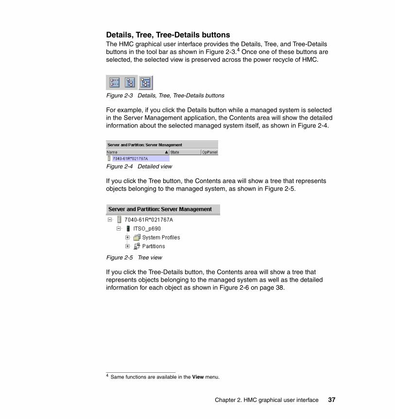
Details, Tree, Tree-Details buttonsThe HMC graphical user interface provides the Details, Tree, and Tree-Details buttons in the tool bar as shown in Figure 2-3.4 Once one of these buttons are selected, the selected view is preserved across the power recycle of HMC.
Figure 2-3 Details, Tree, Tree-Details buttons
For example, if you click the Details button while a managed system is selected in the Server Management application, the Contents area will show the detailed information about the selected managed system itself, as shown in Figure 2-4.
Figure 2-4 Detailed view
If you click the Tree button, the Contents area will show a tree that represents objects belonging to the managed system, as shown in Figure 2-5.
Figure 2-5 Tree view
If you click the Tree-Details button, the Contents area will show a tree that represents objects belonging to the managed system as well as the detailed information for each object as shown in Figure 2-6 on page 38.
4 Same functions are available in the View menu.
Chapter 2. HMC graphical user interface 37
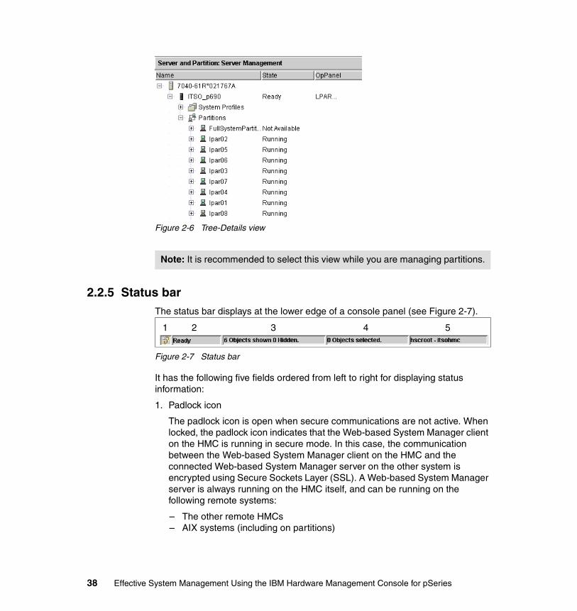
Figure 2-6 Tree-Details view
2.2.5 Status barThe status bar displays at the lower edge of a console panel (see Figure 2-7).
Figure 2-7 Status bar
It has the following five fields ordered from left to right for displaying status information:
1. Padlock icon
The padlock icon is open when secure communications are not active. When locked, the padlock icon indicates that the Web-based System Manager client on the HMC is running in secure mode. In this case, the communication between the Web-based System Manager client on the HMC and the connected Web-based System Manager server on the other system is encrypted using Secure Sockets Layer (SSL). A Web-based System Manager server is always running on the HMC itself, and can be running on the following remote systems:
– The other remote HMCs– AIX systems (including on partitions)
Note: It is recommended to select this view while you are managing partitions.
1 2 3 4 5
38 Effective System Management Using the IBM Hardware Management Console for pSeries

The padlock icon indicates whether the Web-based System Manager client on the HMC is running in secure mode. It does not indicate whether the Web-based System Manager server on the HMC is running in secure mode. Therefore, while you are logging in to your HMC from its local console, the padlock icon is locked only when:
– You are accessing to other manageable systems, including the other HMCs.
– A public key ring file that was generated on the remote system has been already copied onto the local HMC.5
2. Plug-in loading status
When a plug-in application is loaded, the text Ready is present. When an application is in the process of loading, a graphic bounce bar is displayed.
3. Number of objects visible in the Contents area
Objects can be present on the managed system but hidden from the view by the view filter.
4. Number of objects selected in the Contents area
5. Security context (user name and host name)
This displays the administrator user name and the HMC host name for the currently active HMC.
The status bar can be hidden or shown by clearing or checking the Status Bar option in the Show submenu under View.
The HMC also provides a pop-up menu (it is also called context menu) for quick access to menu choices. To use pop-up menus with a mouse, point to an object, and then right-click. The pop-up menu lists the actions found in the Selected and Object menus for the current object or objects.
Reset the current HMC graphical user interface sessionIf your HMC graphical user interface session hangs, it means that even if you wait 10 minutes after an operation, and the pointer is still a clock-shaped icon, you can restart the X server to reset the session. You can reset your hung session by pressing the Ctrl+Alt+Backspace key combination. The X server restarts and displays the HMC login prompt. All messages and panels regarding the hung session will be lost.
5 This operation is performed by the “Copy another Certificate Authority’s Public Key Ring File from diskette” task, which is shown in Figure 7-3 on page 129.
Chapter 2. HMC graphical user interface 39
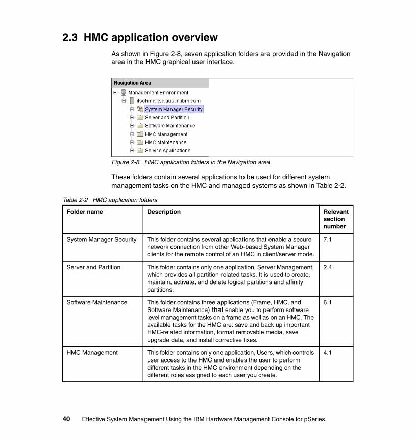
2.3 HMC application overviewAs shown in Figure 2-8, seven application folders are provided in the Navigation area in the HMC graphical user interface.
Figure 2-8 HMC application folders in the Navigation area
These folders contain several applications to be used for different system management tasks on the HMC and managed systems as shown in Table 2-2.
Table 2-2 HMC application folders
Folder name Description Relevant section number
System Manager Security This folder contains several applications that enable a secure network connection from other Web-based System Manager clients for the remote control of an HMC in client/server mode.
7.1
Server and Partition This folder contains only one application, Server Management, which provides all partition-related tasks. It is used to create, maintain, activate, and delete logical partitions and affinity partitions.
2.4
Software Maintenance This folder contains three applications (Frame, HMC, and Software Maintenance) that enable you to perform software level management tasks on a frame as well as on an HMC. The available tasks for the HMC are: save and back up important HMC-related information, format removable media, save upgrade data, and install corrective fixes.
6.1
HMC Management This folder contains only one application, Users, which controls user access to the HMC and enables the user to perform different tasks in the HMC environment depending on the different roles assigned to each user you create.
4.1
40 Effective System Management Using the IBM Hardware Management Console for pSeries

2.4 Server and PartitionThe Server and Partition folder contains only the Server Management application, which provides all partition-related tasks.
It is important to understand how to select the managed system that you are going to manage using the Server Management application. If this application is selected, you will see the object hierarchy illustrated in Figure 2-9 on page 42 in the content area.
HMC Maintenance This folder contains several applications that enable you to set the console’s date and time, modify and view HMC network information, view console events, and schedule routine backups. It is also used to enable and disable remote command execution and secure shell access, change the language locale, and configure the serial adapter.
4.2
Service Applications This folder contains several applications to be used for service-related tasks, such as Inventory Scout, Service Agent, and Service Focal Point.
11.1
Folder name Description Relevant section number
Chapter 2. HMC graphical user interface 41
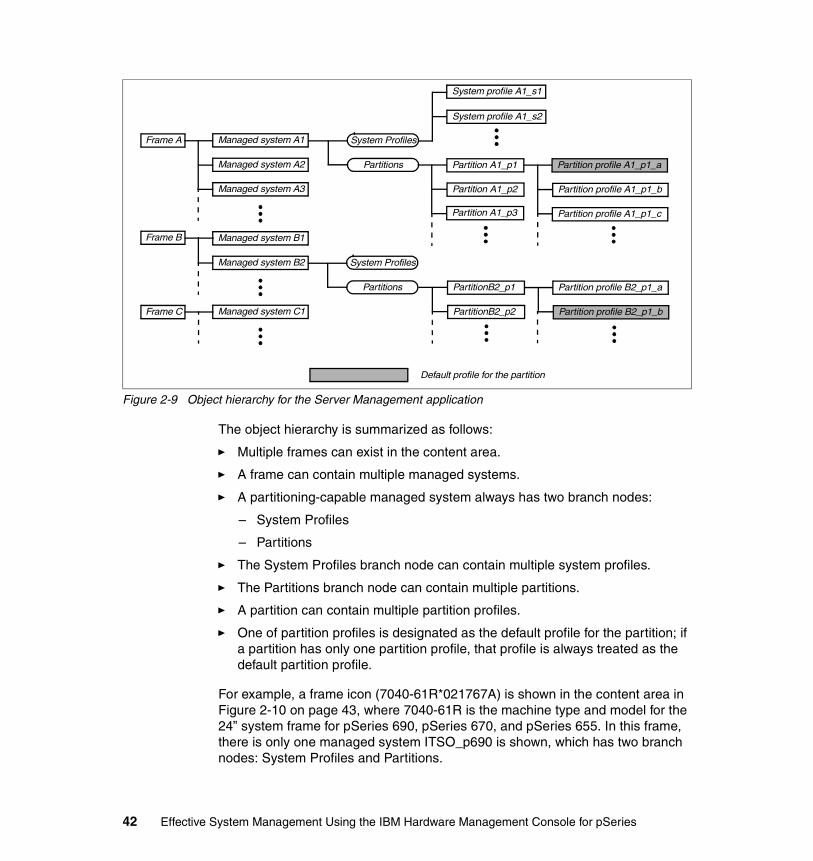
Figure 2-9 Object hierarchy for the Server Management application
The object hierarchy is summarized as follows:
� Multiple frames can exist in the content area.
� A frame can contain multiple managed systems.
� A partitioning-capable managed system always has two branch nodes:
– System Profiles
– Partitions
� The System Profiles branch node can contain multiple system profiles.
� The Partitions branch node can contain multiple partitions.
� A partition can contain multiple partition profiles.
� One of partition profiles is designated as the default profile for the partition; if a partition has only one partition profile, that profile is always treated as the default partition profile.
For example, a frame icon (7040-61R*021767A) is shown in the content area in Figure 2-10 on page 43, where 7040-61R is the machine type and model for the 24” system frame for pSeries 690, pSeries 670, and pSeries 655. In this frame, there is only one managed system ITSO_p690 is shown, which has two branch nodes: System Profiles and Partitions.
Frame A
Frame B
Frame C
Managed system A1
Managed system A2
Managed system A3
Managed system B1
Managed system B2
Managed system C1
System Profiles
Partitions
System Profiles
Partitions
Partition A1_p1
Partition A1_p2
Partition A1_p3
Partition profile A1_p1_a
Partition profile A1_p1_b
Partition profile A1_p1_c
PartitionB2_p1
PartitionB2_p2
Partition profile B2_p1_a
Partition profile B2_p1_b
System profile A1_s1
Default profile for the partition
System profile A1_s2
42 Effective System Management Using the IBM Hardware Management Console for pSeries
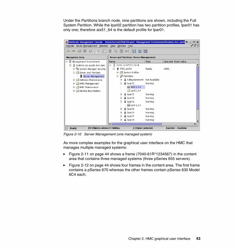
Under the Partitions branch node, nine partitions are shown, including the Full System Partition. While the lpar02 partition has two partition profiles, lpar01 has only one; therefore aix51_64 is the default profile for lpar01.
Figure 2-10 Server Management (one managed system)
As more complex examples for the graphical user interface on the HMC that manages multiple managed systems:
� Figure 2-11 on page 44 shows a frame (7040-61R*1234567) in the content area that contains three managed systems (three pSeries 655 servers).
� Figure 2-12 on page 44 shows four frames in the content area. The first frame contains a pSeries 670 whereas the other frames contain pSeries 630 Model 6C4 each.
Chapter 2. HMC graphical user interface 43
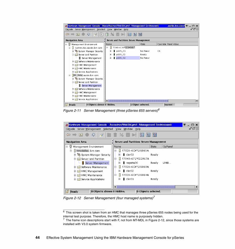
Figure 2-11 Server Management (three pSeries 655 servers)6
Figure 2-12 Server Management (four managed systems)7
6 This screen shot is taken from an HMC that manages three pSeries 655 nodes being used for the internal test purpose. Therefore, the HMC host name is purposely hidden.7 The frame icon descriptions start with F, not from MT-MDL in Figure 2-12, since those systems are installed with V3.0 system firmware.
IH_hmc
1234567
hmcdallas
44 Effective System Management Using the IBM Hardware Management Console for pSeries
2.4.1 Connect and disconnect managed systemsYou can connect or disconnect managed systems on the HMC using the following procedures.
Connect to the managed systemsThe first time you connect a managed system to the HMC, a predefined name of the managed system appears in the Contents area of Partition Management. You can change this name by selecting the managed system in the Contents area, selecting the Select option in the menu bar, and clicking the Properties menu option.8
Disconnect from the managed systemsYou can delete managed systems from the HMC graphical user interface if you no longer want to manage a particular system.
To delete the managed system from the Contents area, do the following:
1. In the Contents area, select the managed system.2. From the menu bar, choose Selected → Delete.3. Click Yes to delete the managed system from the Contents area.4. Pull out the serial cable from the managed system.
2.4.2 Server ManagementThe Server Management application is used to create, maintain, activate, and delete logical partitions and affinity partitions. It is also used to power on and power off the managed system and partitions, open and close virtual terminal
Note:
� A single 7040-61R frame can accommodate only one pSeries 670 or pSeries 690 server.
� A single 7040-61R frame can accommodate multiple pSeries 655 servers.� Although multiple pSeries 650 Model 6M2 server, and pSeries 630 models
6C4 and 6E4 servers can be physically accommodated in a single 19-inch rack, those servers always appear in separate frames in the content area of Server Management.
8 The properties panel is shown in Figure 3-1 on page 57.
Note: Do not physically disconnect the serial connection before performing the procedures explained here.
Chapter 2. HMC graphical user interface 45
windows for the partitions, view properties of the managed system, perform backups, restore profile data, and rebuild the managed system.9 For more information about the use of this application, see the following sections:
� 2.4.3, “Server Management menus” on page 46� Chapter 3, “Basic managed system operation tasks” on page 55
For further detailed information how to create and manage partitions and partition profiles, refer to the following publications:
� IBM Hardware Management Console for pSeries Installation and Operations Guide, SA38-0590
� The Complete Partitioning Guide for IBM Eserver pSeries Servers, SG24-7039
2.4.3 Server Management menusAs shown in Figure 2-13 on page 47, the following 10 menus are available in this application if you select a managed system.
9 You can create, view, and remove partitions (including affinity partitions), system profiles, and partition profiles using the mksyscfg, lssyscfg, and rmsyscfg commands. The chsyscfg command can be also used to modify those already created objects. See 9.3.4, “Commands to manage system configuration” on page 195 for the detailed information about these commands.
46 Effective System Management Using the IBM Hardware Management Console for pSeries
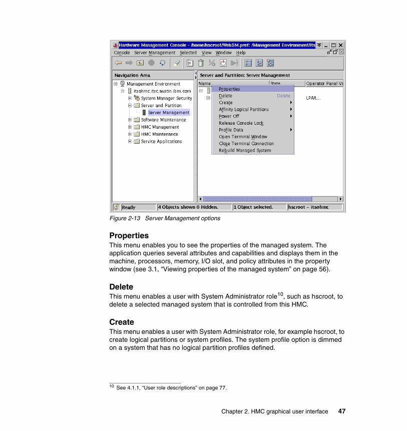
Figure 2-13 Server Management options
PropertiesThis menu enables you to see the properties of the managed system. The application queries several attributes and capabilities and displays them in the machine, processors, memory, I/O slot, and policy attributes in the property window (see 3.1, “Viewing properties of the managed system” on page 56).
DeleteThis menu enables a user with System Administrator role10, such as hscroot, to delete a selected managed system that is controlled from this HMC.
CreateThis menu enables a user with System Administrator role, for example hscroot, to create logical partitions or system profiles. The system profile option is dimmed on a system that has no logical partition profiles defined.
10 See 4.1.1, “User role descriptions” on page 77.
Chapter 2. HMC graphical user interface 47
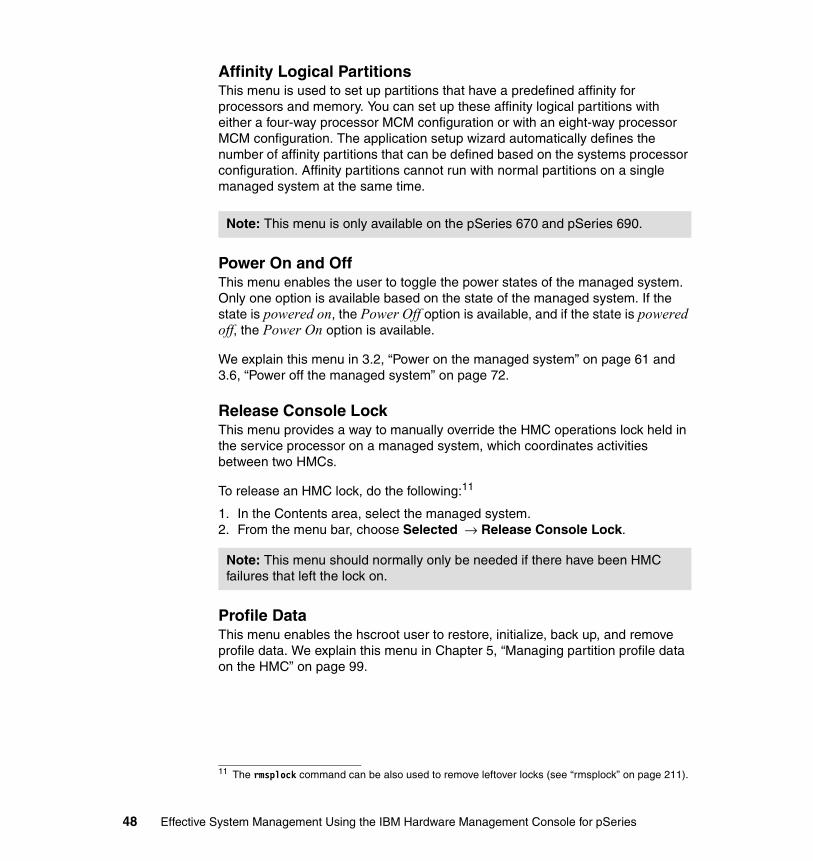
Affinity Logical PartitionsThis menu is used to set up partitions that have a predefined affinity for processors and memory. You can set up these affinity logical partitions with either a four-way processor MCM configuration or with an eight-way processor MCM configuration. The application setup wizard automatically defines the number of affinity partitions that can be defined based on the systems processor configuration. Affinity partitions cannot run with normal partitions on a single managed system at the same time.
Power On and OffThis menu enables the user to toggle the power states of the managed system. Only one option is available based on the state of the managed system. If the state is powered on, the Power Off option is available, and if the state is powered off, the Power On option is available.
We explain this menu in 3.2, “Power on the managed system” on page 61 and 3.6, “Power off the managed system” on page 72.
Release Console LockThis menu provides a way to manually override the HMC operations lock held in the service processor on a managed system, which coordinates activities between two HMCs.
To release an HMC lock, do the following:11
1. In the Contents area, select the managed system.2. From the menu bar, choose Selected → Release Console Lock.
Profile DataThis menu enables the hscroot user to restore, initialize, back up, and remove profile data. We explain this menu in Chapter 5, “Managing partition profile data on the HMC” on page 99.
Note: This menu is only available on the pSeries 670 and pSeries 690.
11 The rmsplock command can be also used to remove leftover locks (see “rmsplock” on page 211).
Note: This menu should normally only be needed if there have been HMC failures that left the lock on.
48 Effective System Management Using the IBM Hardware Management Console for pSeries

Open Terminal WindowThis menu enables the opening of a virtual terminal window to the partition. This connection is necessary to define the default console and the network interface for the partition when it is created.
Close Terminal ConnectionThis menu enables the closing of the virtual terminal window to the partition.
Rebuild managed systemThis menu instructs the HMC to retrieve the information from the NVRAM in the managed system and then refresh the graphical user interface using the retrieved information.12
2.5 Virtual terminal windowAIX needs a console for installation and some service activities. The native serial ports on the managed system are only assignable together to one partition. The virtual terminal window provides virtual terminal console access to every partition without a physical device assigned.
2.5.1 Virtual terminal window conceptA virtual terminal window is available for each partition or Full System Partition of the managed system. Some functions are limited, and the performance cannot be guaranteed because of the limited bandwidth of the serial connection between the HMC and the managed system.
To open the virtual terminal window, do the following:13
1. Expand the System and Partition folder in the navigation area.2. Select the Server Management application.3. Select the frame in which the target managed system resides.4. Select the managed system on which the target partition is running.5. Expand the Partitions tree.
Note: Clicking the X at the top-right of the opened virtual terminal window is not enough to close the terminal connection. You must explicitly select this menu in order to close the opened virtual terminal connection.
12 The chsysstate command can be also used to rebuild the managed system (see “chsysstate” on page 213).13 The mkvterm and rmvterm commands can be also used to open and close a virtual terminal to the specified partition (see 9.3.7, “Commands for virtual terminals” on page 209).
Chapter 2. HMC graphical user interface 49
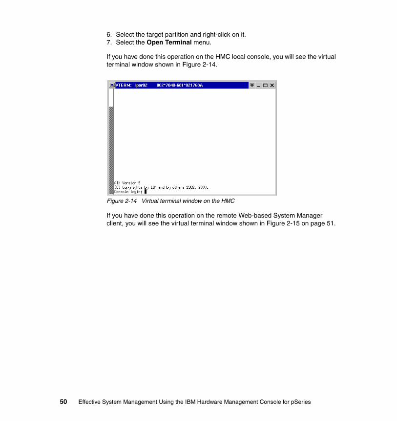
6. Select the target partition and right-click on it.7. Select the Open Terminal menu.
If you have done this operation on the HMC local console, you will see the virtual terminal window shown in Figure 2-14.
Figure 2-14 Virtual terminal window on the HMC
If you have done this operation on the remote Web-based System Manager client, you will see the virtual terminal window shown in Figure 2-15 on page 51.
50 Effective System Management Using the IBM Hardware Management Console for pSeries
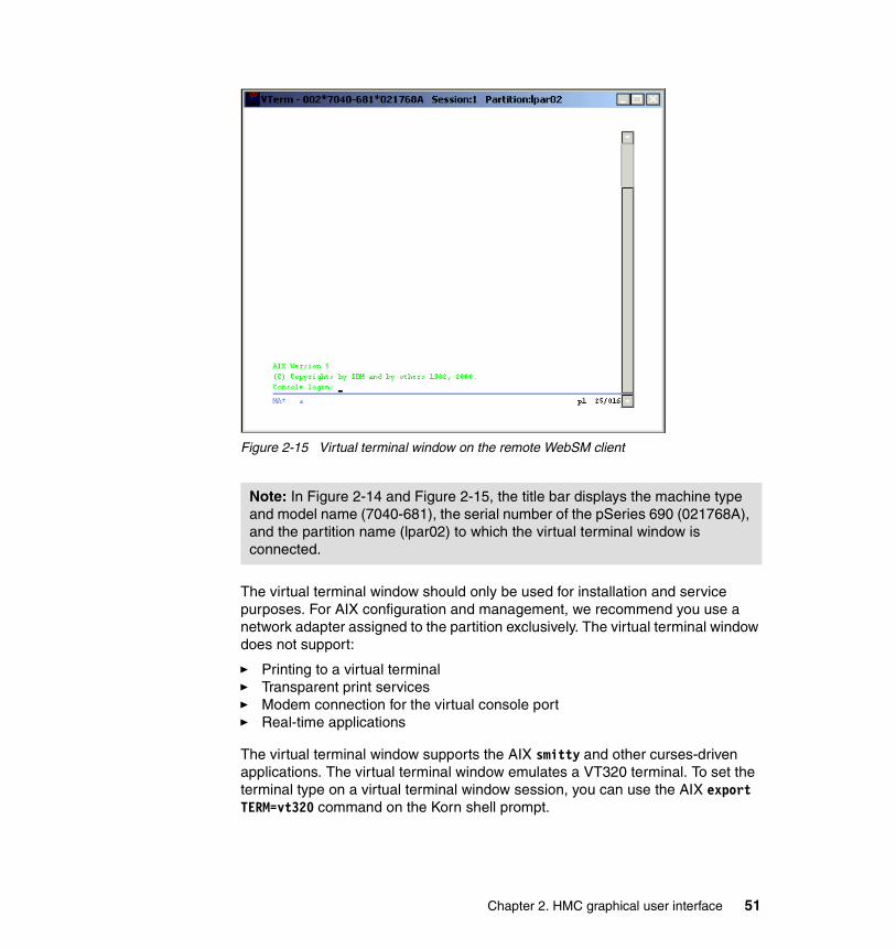
Figure 2-15 Virtual terminal window on the remote WebSM client
The virtual terminal window should only be used for installation and service purposes. For AIX configuration and management, we recommend you use a network adapter assigned to the partition exclusively. The virtual terminal window does not support:
� Printing to a virtual terminal� Transparent print services� Modem connection for the virtual console port� Real-time applications
The virtual terminal window supports the AIX smitty and other curses-driven applications. The virtual terminal window emulates a VT320 terminal. To set the terminal type on a virtual terminal window session, you can use the AIX export TERM=vt320 command on the Korn shell prompt.
Note: In Figure 2-14 and Figure 2-15, the title bar displays the machine type and model name (7040-681), the serial number of the pSeries 690 (021768A), and the partition name (lpar02) to which the virtual terminal window is connected.
Chapter 2. HMC graphical user interface 51
The following operations are available for the virtual terminal window:
� Open a virtual terminal window
From the HMC graphical user interface, select a partition or the Full System Partition in the Contents area using Partition Management, right-click, and select Open Terminal Window.
� Close a virtual terminal window
To close a virtual terminal window, click the X in the top-right corner of the panel. To force a virtual terminal window to close, select the partition, right-click, and then select Close Terminal Connection.
2.5.2 Virtual terminal window in the Full System PartitionWhen you open a virtual terminal window to the Full System Partition, the output of the native S1 serial port is redirected to the virtual terminal window. Then, the output of any command is directed from the serial port S1 to the virtual terminal window. After closing the virtual terminal window, the serial port S1 is normally accessible.
In the No Power state, you can access the service processor of a managed system with a virtual terminal window.
2.5.3 Partition virtual terminal windowsYou can open a virtual terminal window at any time, regardless of the state of a partition, but only one per partition. The virtual terminal window is blank until the partition is activated. After you activate one of partitions, you cannot connect a virtual terminal window to the service processor of the managed system. In a partitioned environment, the native serial port S1 is not redirected to the virtual terminal of that partition.
2.6 Open xterm to access remote system using telnetYou can open xterm windows to connect to the other hosts14 using telnet over the network in order to access the other hosts, including partitions.
To use this function, do the following from the HMC graphical user interface:
1. From the menu bar, select Console → Open Terminal.2. Enter the host name or the IP address, then click OK.
14 Except for the HMC itself.
52 Effective System Management Using the IBM Hardware Management Console for pSeries

To access to a partition using this function, the partition has to be assigned at least one network adapter, and the adapter has to be configured with an IP address that can be accessible from the HMC.
Note: The Open Terminal menu is available only on the local HMC console.
Chapter 2. HMC graphical user interface 53

54 Effective System Management Using the IBM Hardware Management Console for pSeries
Chapter 3. Basic managed system operation tasks
This chapter explains in the following sections how to start, stop, and reset an operating system on a managed system in both a partitioned environment and Full System Partition using the Server Management application:
� “Viewing properties of the managed system” on page 56� “Power on the managed system” on page 61� “Activate partitions” on page 65� “Shut down the operating system in a partition” on page 68� “Reset the operating system in a partition” on page 70� “Power off the managed system” on page 72� “Operating the managed system with the HMC” on page 72
In addition, the Contents area of the Server Management application provides status information about the managed system and the partitions and displays the operator panel value of the managed system and the partitions.
3
© Copyright IBM Corp. 2003. All rights reserved. 55
3.1 Viewing properties of the managed systemTo view the properties of your managed system, select the managed system in the Contents area, and from the menu bar choose Selected → Properties. Or select the managed system in the Contents area, right-click, and select Properties. The property panel shown in Figure 3-1 on page 57 opens.
The properties panel includes the five property tabs of the managed system shown in Table 3-1.
Table 3-1 Properties of the managed system
Property name Figure number
Machine Figure 3-1 on page 57
Processor Figure 3-2 on page 58
Policy Figure 3-3 on page 59
I/O Slot Figure 3-4 on page 60
Memory Figure 3-5 on page 61
56 Effective System Management Using the IBM Hardware Management Console for pSeries
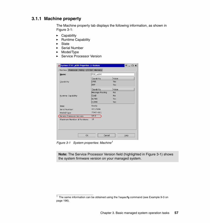
3.1.1 Machine propertyThe Machine property tab displays the following information, as shown in Figure 3-1:
� Capability� Runtime Capability� State� Serial Number� Model/Type� Service Processor Version
Figure 3-1 System properties: Machine1
1 The same information can be obtained using the lssyscfg command (see Example 9-3 on page 196).
Note: The Service Processor Version field (highlighted in Figure 3-1) shows the system firmware version on your managed system.
Chapter 3. Basic managed system operation tasks 57
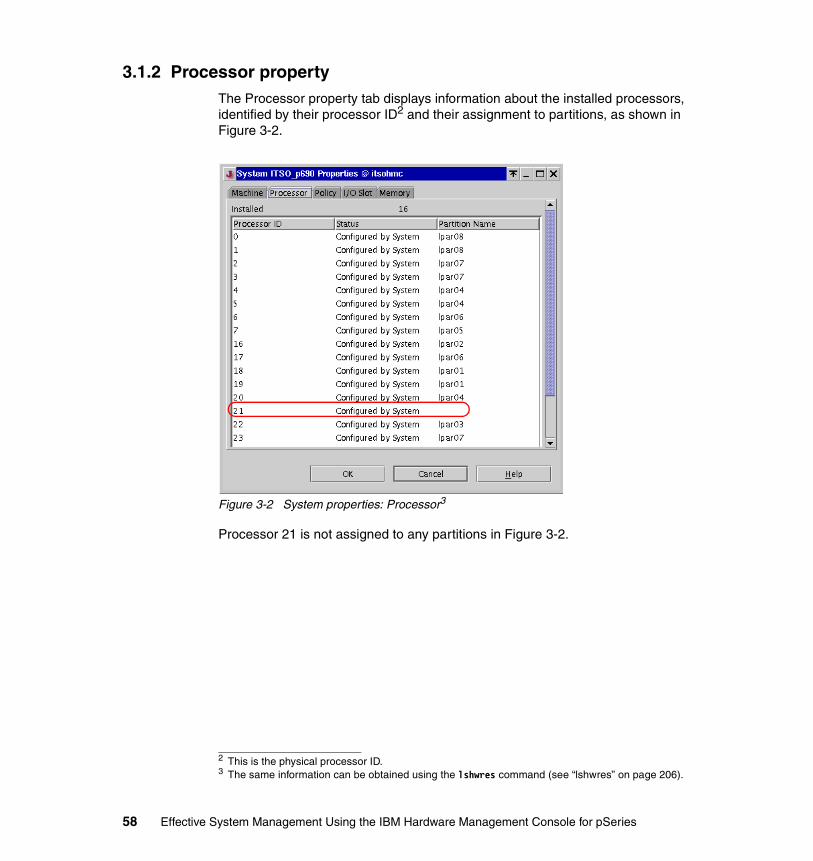
3.1.2 Processor propertyThe Processor property tab displays information about the installed processors, identified by their processor ID2 and their assignment to partitions, as shown in Figure 3-2.
Figure 3-2 System properties: Processor3
Processor 21 is not assigned to any partitions in Figure 3-2.
2 This is the physical processor ID.3 The same information can be obtained using the lshwres command (see “lshwres” on page 206).
58 Effective System Management Using the IBM Hardware Management Console for pSeries
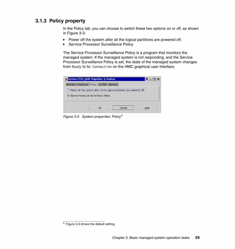
3.1.3 Policy propertyIn the Policy tab, you can choose to switch these two options on or off, as shown in Figure 3-3:
� Power off the system after all the logical partitions are powered off.� Service Processor Surveillance Policy.
The Service Processor Surveillance Policy is a program that monitors the managed system. If the managed system is not responding, and the Service Processor Surveillance Policy is set, the state of the managed system changes from Ready to No Connection on the HMC graphical user interface.
Figure 3-3 System properties: Policy4
4 Figure 3-3 shows the default setting.
Chapter 3. Basic managed system operation tasks 59
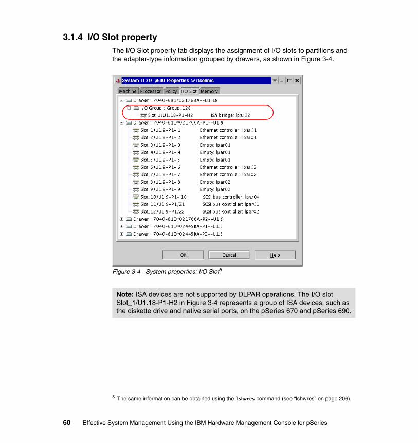
3.1.4 I/O Slot propertyThe I/O Slot property tab displays the assignment of I/O slots to partitions and the adapter-type information grouped by drawers, as shown in Figure 3-4.
Figure 3-4 System properties: I/O Slot5
5 The same information can be obtained using the lshwres command (see “lshwres” on page 206).
Note: ISA devices are not supported by DLPAR operations. The I/O slot Slot_1/U1.18-P1-H2 in Figure 3-4 represents a group of ISA devices, such as the diskette drive and native serial ports, on the pSeries 670 and pSeries 690.
60 Effective System Management Using the IBM Hardware Management Console for pSeries
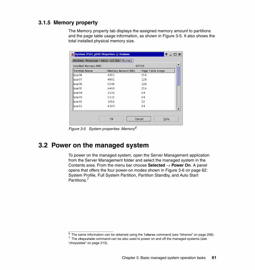
3.1.5 Memory propertyThe Memory property tab displays the assigned memory amount to partitions and the page table usage information, as shown in Figure 3-5. It also shows the total installed physical memory size.
Figure 3-5 System properties: Memory6
3.2 Power on the managed systemTo power on the managed system, open the Server Management application from the Server Management folder and select the managed system in the Contents area. From the menu bar choose Selected → Power On. A panel opens that offers the four power-on modes shown in Figure 3-6 on page 62: System Profile, Full System Partition, Partition Standby, and Auto Start Partitions.7
6 The same information can be obtained using the lshwres command (see “lshwres” on page 206).7 The chsysstate command can be also used to power on and off the managed systems (see “chsysstate” on page 213).
Chapter 3. Basic managed system operation tasks 61
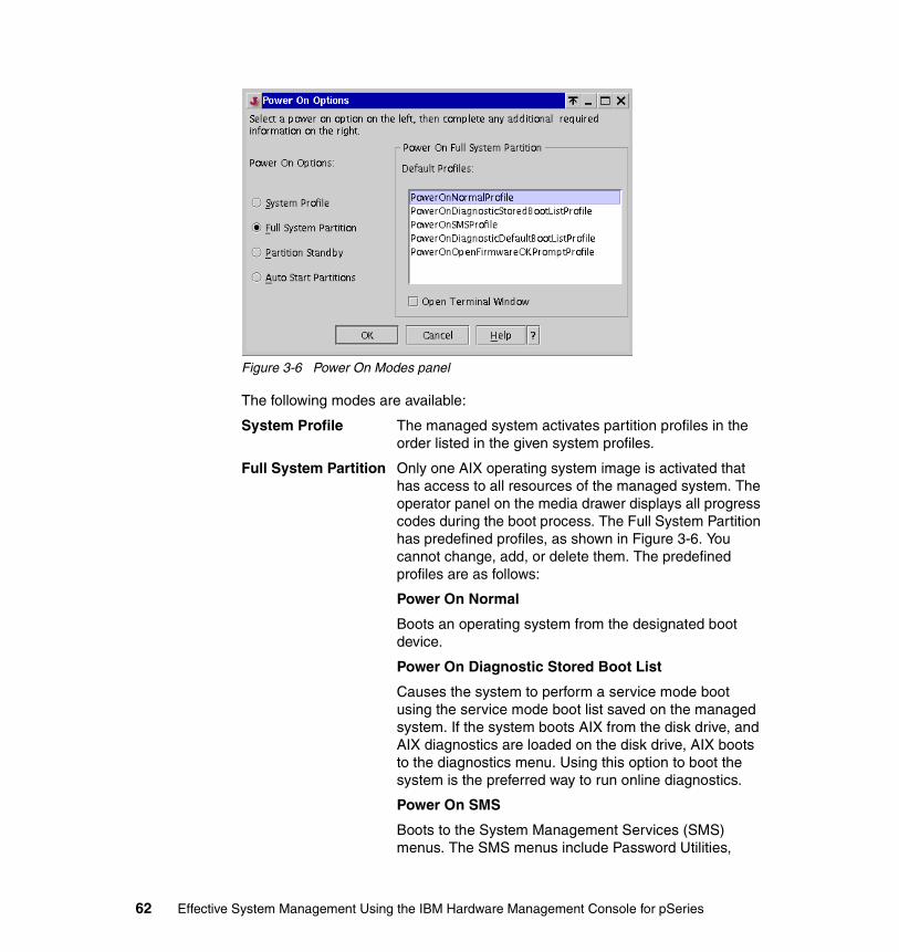
Figure 3-6 Power On Modes panel
The following modes are available:
System Profile The managed system activates partition profiles in the order listed in the given system profiles.
Full System Partition Only one AIX operating system image is activated that has access to all resources of the managed system. The operator panel on the media drawer displays all progress codes during the boot process. The Full System Partition has predefined profiles, as shown in Figure 3-6. You cannot change, add, or delete them. The predefined profiles are as follows:
Power On Normal
Boots an operating system from the designated boot device.
Power On Diagnostic Stored Boot List
Causes the system to perform a service mode boot using the service mode boot list saved on the managed system. If the system boots AIX from the disk drive, and AIX diagnostics are loaded on the disk drive, AIX boots to the diagnostics menu. Using this option to boot the system is the preferred way to run online diagnostics.
Power On SMS
Boots to the System Management Services (SMS) menus. The SMS menus include Password Utilities,
62 Effective System Management Using the IBM Hardware Management Console for pSeries

Display Error Log, Remote Initial Program Load Setup, SCSI Utilities, Select Console, MultiBoot, Select Language, and the OK Prompt.
Power On Diagnostic Default Boot List
Similar to Power On Diagnostic Stored Boot List Profile, except the system boots using the Default Boot List that is stored in the system firmware. This is normally used to try to boot diagnostics from the CD-ROM drive. Using this option to boot the system is the preferred way to run stand-alone diagnostics.
Power On Open Firmware OK Prompt
Used only by service personnel to obtain additional debug information. When this selection is enabled, the system boots to the Open Firmware prompt.
Partition Standby This power-on mode provides two actions:
– Creating partitions
– Activation of individual partitions
When the Partition Standby power-on is completed, the operator panel on the managed system displays LPAR…, indicating that the managed system is ready for you to use the HMC to partition its resources or to activate configured partitions.
In Partition Standby power-on mode, the state of the Full System Partition is shown as Not Available.
Auto Start Partitions8 Powers on the managed system to partition standby mode and then activates all partitions that have been powered on by the HMC at least once. For example, if you create a partition with four processors, use DLPAR operation to remove one processor, then shut down the system, the Auto Start Partitions power-on mode activates this partition with three processors. This is because the three-processor configuration was the last configuration used, and the HMC ignores whatever you have specified in the partition’s profile. Using this option, the activated partitions boot the operating system using a normal mode boot, even if the default profile for the partition specifies the other modes, such as boot to SMS.
8 This power-on mode is available on the HMC software release beginning with Release 3, Version 2.
Chapter 3. Basic managed system operation tasks 63
3.2.1 Operation states of a managed systemThis attribute of the managed system is displayed in the content area of the HMC window under the State label (see Table 3-2).
Table 3-2 Operating states of managed systems9
3.2.2 Rebuild the managed system in the HMCThe Rebuild managed system function downloads the data stored in the NVRAM of the managed system to the HMC. The NVRAM contains the properties of the managed system, the partition, system profile information, and the current states. Rebuilding the managed system is useful when the operating state
State Description
Initializing The managed system is powered on and is initializing. The initialization time may vary depending on the hardware and partition configuration of the managed system.
Ready The managed system is powered on and is operating normally.
No Power The managed system is powered off.
Error The operating system or the hardware of the managed system is experiencing errors.
Incomplete The HMC cannot gather complete partition, profile, orresource information from the managed system. To rebuild the managed system, see 3.2.2, “Rebuild the managed system in the HMC” on page 64.
No Connection The HMC cannot contact the managed system. Check the serial cable or delete and configure the managed system again.
Recovery The partition and profile data stored in the managed system must be refreshed. To initialize the data, see 5.1.3, “Initialize profile data” on page 105.
Version Mismatch The managed system’s service processor level is later than the code level of the HMC.
CUOD CTA You must accept the CUoD license.
9 As for the recovery and imcomplete status, see 5.1, “Managing profile data” on page 100 for further detailed information.
64 Effective System Management Using the IBM Hardware Management Console for pSeries
indicator of a managed system in the Contents area is shown as Incomplete. This operation is different from performing a reload of the local HMC panel. In this operation, the HMC reloads from the information that is stored on the local database on the HMC.
To rebuild the managed system, select the managed system in the Contents area, and from the menu bar choose Selected → Rebuild managed system. When the operation finishes, the current system information of the managed system appears.
3.3 Activate partitionsIf you activate a partition, you are virtually powering on the partition. To activate a partition, select the partition name and select activate by right-clicking. This opens a window that enables you to choose the profile that you want to activate for this partition. If the minimum and required resources you specified when you created the partition profile exceeds the amount of available resources, this partition will not be activated with the selected profile. Available resources are all resources currently not being used by other active partitions. It is important that you keep track of your system’s resources at all times.
3.3.1 Change the default partition profileWhen a partition is created, a profile also has to be created by default to define the resources associated with this partition. The application requires that you create at least one profile when a partition is created. The first profile created is the default profile. Additionally, the default partition profile is marked with an icon. The default partition profile can be changed at any time. To change the default partition profile, select the partition profile name in the Contents area, from the menu bar choose Selected → Change Default Profile, and select the profile name from the list that you want to make the default. This operation can also be completed by selecting the profile name, right-clicking, and following the menus. The default profile can be changed even when the partition is in the active state with the profile running.
3.3.2 Activate a specific partition profileTo activate a partition profile, select one of the partition profiles you created, and from the menu bar choose Selected → Activate. The profile name is highlighted. Click OK to activate the partition using this partition profile. If you want to activate using the other partition profiles, select another profile in the list and then click OK. This operation can also be accomplished by selecting the desired profile name, right-clicking, and selecting the Activate option.
Chapter 3. Basic managed system operation tasks 65
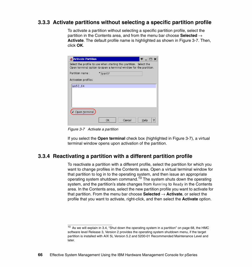
3.3.3 Activate partitions without selecting a specific partition profileTo activate a partition without selecting a specific partition profile, select the partition in the Contents area, and from the menu bar choose Selected → Activate. The default profile name is highlighted as shown in Figure 3-7. Then, click OK.
Figure 3-7 Activate a partition
If you select the Open terminal check box (highlighted in Figure 3-7), a virtual terminal window opens upon activation of the partition.
3.3.4 Reactivating a partition with a different partition profileTo reactivate a partition with a different profile, select the partition for which you want to change profiles in the Contents area. Open a virtual terminal window for that partition to log in to the operating system, and then issue an appropriate operating system shutdown command.10 The system shuts down the operating system, and the partition’s state changes from Running to Ready in the Contents area. In the Contents area, select the new partition profile you want to activate for that partition. From the menu bar choose Selected → Activate, or select the profile that you want to activate, right-click, and then select the Activate option.
10 As we will explain in 3.4, “Shut down the operating system in a partition” on page 68, the HMC software level Release 3, Version 2 provides the operating system shutdown menu, if the target partition is installed with AIX 5L Version 5.2 and 5200-01 Recommended Maintenance Level and later.
66 Effective System Management Using the IBM Hardware Management Console for pSeries
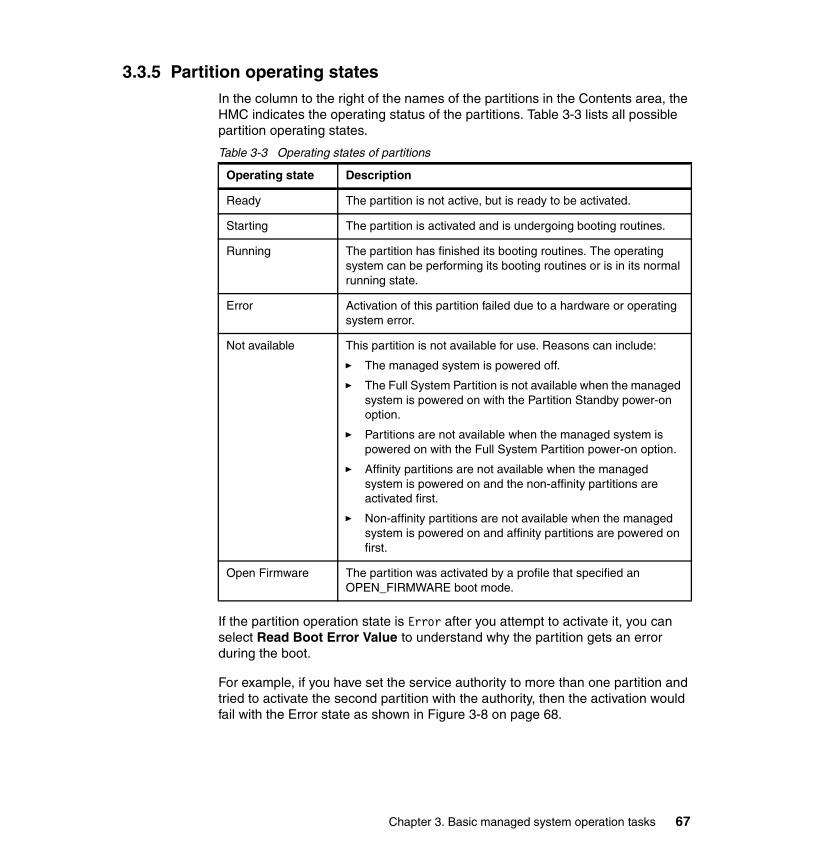
3.3.5 Partition operating statesIn the column to the right of the names of the partitions in the Contents area, the HMC indicates the operating status of the partitions. Table 3-3 lists all possible partition operating states.
Table 3-3 Operating states of partitions
If the partition operation state is Error after you attempt to activate it, you can select Read Boot Error Value to understand why the partition gets an error during the boot.
For example, if you have set the service authority to more than one partition and tried to activate the second partition with the authority, then the activation would fail with the Error state as shown in Figure 3-8 on page 68.
Operating state Description
Ready The partition is not active, but is ready to be activated.
Starting The partition is activated and is undergoing booting routines.
Running The partition has finished its booting routines. The operating system can be performing its booting routines or is in its normal running state.
Error Activation of this partition failed due to a hardware or operating system error.
Not available This partition is not available for use. Reasons can include:
� The managed system is powered off.
� The Full System Partition is not available when the managed system is powered on with the Partition Standby power-on option.
� Partitions are not available when the managed system is powered on with the Full System Partition power-on option.
� Affinity partitions are not available when the managed system is powered on and the non-affinity partitions are activated first.
� Non-affinity partitions are not available when the managed system is powered on and affinity partitions are powered on first.
Open Firmware The partition was activated by a profile that specified an OPEN_FIRMWARE boot mode.
Chapter 3. Basic managed system operation tasks 67

Figure 3-8 Partition activation failure
In this case, the boot error message shown in Figure 3-9 explains the reason for the failure of this partition activation.
Figure 3-9 Read Boot Error Values
3.4 Shut down the operating system in a partitionTo shut down the operating system in a partition, do the following:
1. In the Contents area, select the partition you want to shut down.
2. From the menu bar choose Selected → Operating System → Shutdown.
This function is available when the following requirements are met:
� HMC is installed with software Release 3, Version 2 and later.11
11 The menu does not exist on the HMC installed with software Release 3, Version 1 and before.
68 Effective System Management Using the IBM Hardware Management Console for pSeries
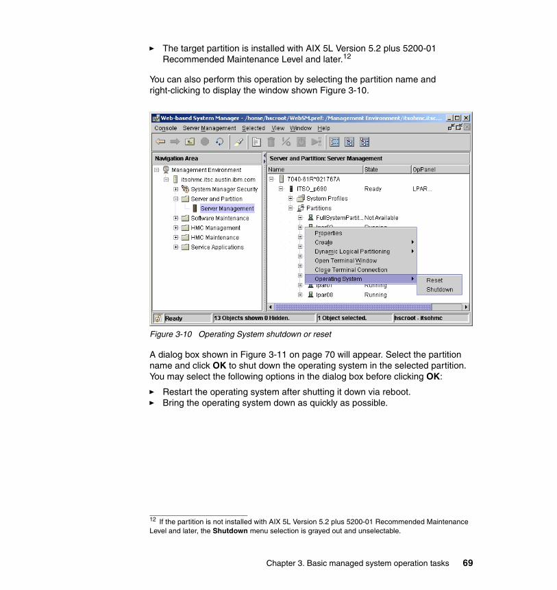
� The target partition is installed with AIX 5L Version 5.2 plus 5200-01 Recommended Maintenance Level and later.12
You can also perform this operation by selecting the partition name and right-clicking to display the window shown Figure 3-10.
Figure 3-10 Operating System shutdown or reset
A dialog box shown in Figure 3-11 on page 70 will appear. Select the partition name and click OK to shut down the operating system in the selected partition. You may select the following options in the dialog box before clicking OK:
� Restart the operating system after shutting it down via reboot.� Bring the operating system down as quickly as possible.
12 If the partition is not installed with AIX 5L Version 5.2 plus 5200-01 Recommended Maintenance Level and later, the Shutdown menu selection is grayed out and unselectable.
Chapter 3. Basic managed system operation tasks 69

Figure 3-11 Operating System shutdown
3.5 Reset the operating system in a partitionWhen an operating system in a partition stalls, you can use the HMC to restart the operating system.
In the Contents area, select the partition you want to reset. From the menu bar choose Selected → Operating System → Reset. You can also perform this operation by selecting the partition name and right-clicking to display the window shown in Figure 3-10 on page 69.
A dialog box opens that offers two reset options, as shown in Figure 3-12 on page 71.
Important: This operation may corrupt data on the resetting partition. Perform this procedure only after you have attempted to restart the operating system manually.
70 Effective System Management Using the IBM Hardware Management Console for pSeries
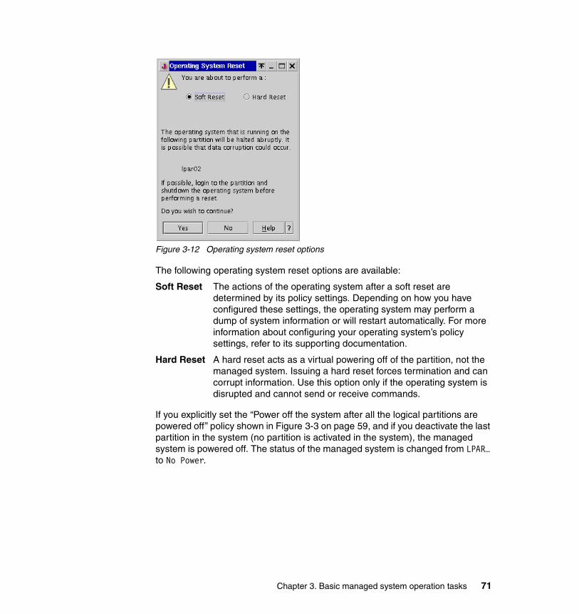
Figure 3-12 Operating system reset options
The following operating system reset options are available:
Soft Reset The actions of the operating system after a soft reset are determined by its policy settings. Depending on how you have configured these settings, the operating system may perform a dump of system information or will restart automatically. For more information about configuring your operating system’s policy settings, refer to its supporting documentation.
Hard Reset A hard reset acts as a virtual powering off of the partition, not the managed system. Issuing a hard reset forces termination and can corrupt information. Use this option only if the operating system is disrupted and cannot send or receive commands.
If you explicitly set the “Power off the system after all the logical partitions are powered off” policy shown in Figure 3-3 on page 59, and if you deactivate the last partition in the system (no partition is activated in the system), the managed system is powered off. The status of the managed system is changed from LPAR… to No Power.
Chapter 3. Basic managed system operation tasks 71

3.6 Power off the managed systemBefore powering off the managed system, ensure that all partitions or the Full System Partition have been shut down and their states have changed from Running to Ready. To shut down a partition, you can use a virtual terminal window to run the shutdown command or Telnet into the partition and issue the shutdown command.
To power off the managed system, select the managed system in the Contents area, and from the menu bar choose Selected → Power Off. If you attempt to power off a system that has active partitions, you will receive a warning to that effect, but you will still be able to power off the managed system.
3.7 Operating the managed system with the HMCAlthough the managed system is designed not to put any dependency on the HMC, except the specific system management operation, you should not plan to run the managed system without an HMC. The HMC is required for the operations, such as to set up or change the partition configurations, and is also a key element in configuring the Service Applications. Without an HMC, the Service Applications will not be able to provide the extended RAS capabilities that are available on the partitioning-capable pSeries servers. The call home feature available with Service Focal Point provides this function through the HMC.
Without an HMC, it is still possible to bring up a managed system in its last configured partition state, including a boot of defined partitions, by pressing the power button on the operator panel. However, running partitions can be rebooted and restarted using the shutdown command, even if the HMC is not present.
3.7.1 Operator panelThe operator panel13 is used to track the progress of the system unit’s self tests and configuration program, to display codes when the operating system comes to an abnormal end, and to display system messages. In a logical partitioned environment, the operator panel displays an error code for most hardware or firmware problems, but you need the HMC to display any error information written to a partition’s virtual operator panel. The operator panel values of the partitions are displayed in the HMC main menu for every partition, as shown in Figure 3-13 on page 73.
13 The operator panel is physically located in the media drawer in the pSeries 670 and pSeries 690.
72 Effective System Management Using the IBM Hardware Management Console for pSeries
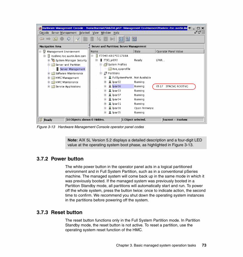
Figure 3-13 Hardware Management Console operator panel codes
3.7.2 Power buttonThe white power button in the operator panel acts in a logical partitioned environment and in Full System Partition, such as in a conventional pSeries machine. The managed system will come back up in the same mode in which it was previously booted. If the managed system was previously booted in a Partition Standby mode, all partitions will automatically start and run. To power off the whole system, press the button twice: once to indicate action, the second time to confirm. We recommend you shut down the operating system instances in the partitions before powering off the system.
3.7.3 Reset buttonThe reset button functions only in the Full System Partition mode. In Partition Standby mode, the reset button is not active. To reset a partition, use the operating system reset function of the HMC.
Note: AIX 5L Version 5.2 displays a detailed description and a four-digit LED value at the operating system boot phase, as highlighted in Figure 3-13.
Chapter 3. Basic managed system operation tasks 73

74 Effective System Management Using the IBM Hardware Management Console for pSeries
Chapter 4. Configuring the HMC
In this chapter, we describe the administration and management tasks that you can perform from the Hardware Management Console (HMC) graphical user interface. We assume that you have system administrator authority on the HMC.
The management tasks are described in the following sections:
� “HMC Management” on page 76� “HMC Maintenance” on page 80
4
© Copyright IBM Corp. 2003. All rights reserved. 75

4.1 HMC ManagementAn HMC system administrator can manage users and assign roles with the Users application in the HMC Management folder (see Figure 4-1).
Figure 4-1 HMC Management, Users
To use the Users application, first determine who will use the HMC. After designating the user name, assign a role to that user based on the level of access that you want to grant that user. For example, you can create general users and assign operator roles to them so that they can perform basic HMC tasks.
Note: You must create a user named hscpe for your software support representative so that they have access to perform fixes on the HMC code. This user name is reserved for your support representative and is considered a predefined role. Do not assign the hscpe user name to any of your users. For more information about creating users and assigning roles, see Chapter 12, “User Management,” in the IBM Hardware Management Console for pSeries Installation and Operations Guide, SA38-0590.
76 Effective System Management Using the IBM Hardware Management Console for pSeries
4.1.1 User role descriptionsEach defined user on the HMC can have one of six different roles that enable the user to access different parts of the HMC. The user roles specified by the HMC are as follows:
� System Administrator
The System Administrator acts as the root user, or manager, of the HMC system. The System Administrator has unrestricted authority to access and modify most of the HMC system.
� Advanced Operator
An Advanced Operator can perform some partition-related tasks (for example, creating partition profiles, saving profile data, and resetting partitions) in addition to some system administration tasks on the HMC (for example, performing the “Backup Critical Console Data” or “Save Upgrade Data” task).
� Service Representative
The Service Representative role is reserved for IBM service representatives who install, repair, or do problem determination tasks on systems at your location. Only the hscpe user should be given this role, which is not defined by default.
� Operator
An Operator is responsible for daily system operation.
� User Administrator
A User Administrator can perform user-management tasks but cannot perform any other HMC functions.
� Viewer
A Viewer can view HMC information, but cannot change any configuration information.
Refer to Chapter 12, “User Management,” in the IBM Hardware Management Console for pSeries Installation and Operations Guide, SA38-0590 for more information.
Note: The hscroot user is a just predefined user with the System Administrator role. If needed, you can delete hscroot after defining the other users with the System Administrator role on your HMC.
Chapter 4. Configuring the HMC 77
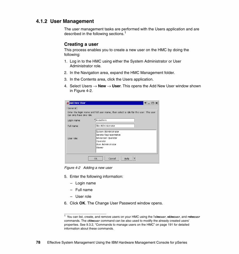
4.1.2 User ManagementThe user management tasks are performed with the Users application and are described in the following sections.1
Creating a userThis process enables you to create a new user on the HMC by doing the following:
1. Log in to the HMC using either the System Administrator or User Administrator role.
2. In the Navigation area, expand the HMC Management folder.
3. In the Contents area, click the Users application.
4. Select Users → New → User. This opens the Add New User window shown in Figure 4-2.
Figure 4-2 Adding a new user
5. Enter the following information:
– Login name
– Full name
– User role
6. Click OK. The Change User Password window opens.
1 You can list, create, and remove users on your HMC using the lshmcusr, mkhmcusr, and rmhmcusr commands. The chhmcusr command can be also used to modify the already created users’ properties. See 9.3.2, “Commands to manage users on the HMC” on page 191 for detailed information about these commands.
78 Effective System Management Using the IBM Hardware Management Console for pSeries

7. In the Change User Password window, type the user’s password twice. Click OK.
Deleting a userThis process enables you to delete a user on the HMC. To delete a user from the system, do the following:
1. Log in to the HMC using either the System Administrator or User Administrator role.
2. In the Navigation area, expand the HMC Management folder.
3. In the Contents area, select the Users application.
4. In the Contents area, right-click the appropriate user icon.
5. Select Delete, and then click OK to confirm that you want to delete this user.
Changing a user’s propertiesThis process enables you to modify a user’s properties on the HMC. To change a user’s properties, do the following:
1. Log in to the HMC using either the System Administrator or User Administrator role.
2. In the Navigation area, click the HMC Management folder.
3. In the Contents area, double-click the Users application.
4. In the Contents area, right-click the appropriate user icon.
5. Select Properties.
6. Edit the user’s base information (Login name, Full name, and User role).
7. Click OK. The Change User Password window opens.
8. Type the user’s password twice.
9. Click OK.
Changing a user’s passwordThis process enables you to change a user’s password on the HMC. To change a user’s password, do the following:
1. Log in to the HMC using either the System Administrator or User Administrator role.
2. In the Navigation area, expand the HMC Management folder.
3. In the Contents area, double-click the Users application.
4. In the Contents area, right-click the appropriate user icon.
5. Select Change Password.
Chapter 4. Configuring the HMC 79
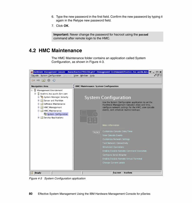
6. Type the new password in the first field. Confirm the new password by typing it again in the Retype new password field.
7. Click OK.
4.2 HMC MaintenanceThe HMC Maintenance folder contains an application called System Configuration, as shown in Figure 4-3.
Figure 4-3 System Configuration application
Important: Never change the password for hscroot using the passwd command after remote login to the HMC.
80 Effective System Management Using the IBM Hardware Management Console for pSeries
4.2.1 System ConfigurationThe System Configuration application is used to modify and set several configuration options that are available on the HMC. The application enables you to configure the environmental variables, network connectivity, logging, hardware configurations, and backup and recovery.
As shown in Figure 4-3 on page 80, the System Configuration application contains the nine tasks shown in Table 4-1.
Table 4-1 Tasks in the System Configuration application
4.2.2 Customize Console Date/TimeThis task allows you to set the data, time, and time zone for the HMC. To increase or decrease any value for date and time, just highlight the field you want to change and then press the down or up arrows.
For time zone, click on the down arrow in the grey field and it will bring up a dialog box to scroll through with all the available time zones.
Changing any of these fields is automatically applied and does not require an HMC reboot.
Task Relevant section number
Customize Console Date/Time 4.2.2
View Console Events 4.2.3
Customize Network Settings 4.2.4
Test Network Connectivity 4.2.5
Scheduled Operations 4.2.6
Enable/Disable Remote Command Execution 4.2.7
Configure Serial Adapter 4.2.8
Enable/Disable Remote Virtual Terminal 4.2.9
Change Current Locale 4.2.10
Chapter 4. Configuring the HMC 81
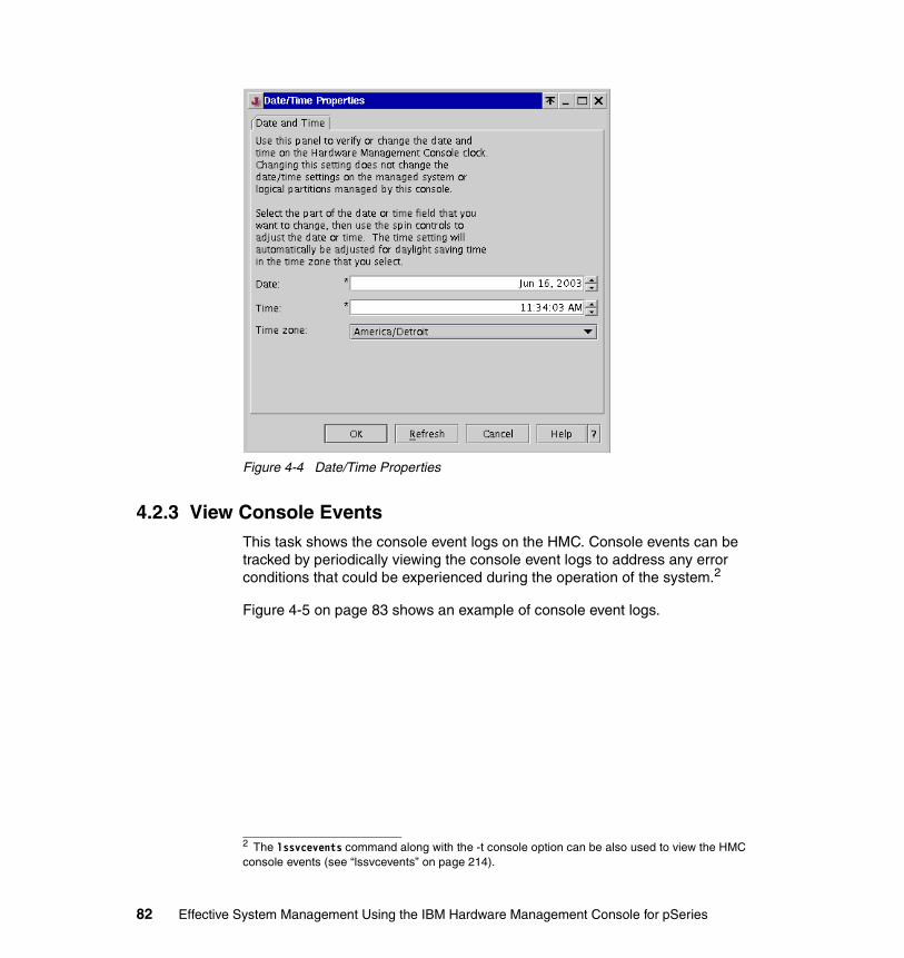
Figure 4-4 Date/Time Properties
4.2.3 View Console EventsThis task shows the console event logs on the HMC. Console events can be tracked by periodically viewing the console event logs to address any error conditions that could be experienced during the operation of the system.2
Figure 4-5 on page 83 shows an example of console event logs.
2 The lssvcevents command along with the -t console option can be also used to view the HMC console events (see “lssvcevents” on page 214).
82 Effective System Management Using the IBM Hardware Management Console for pSeries
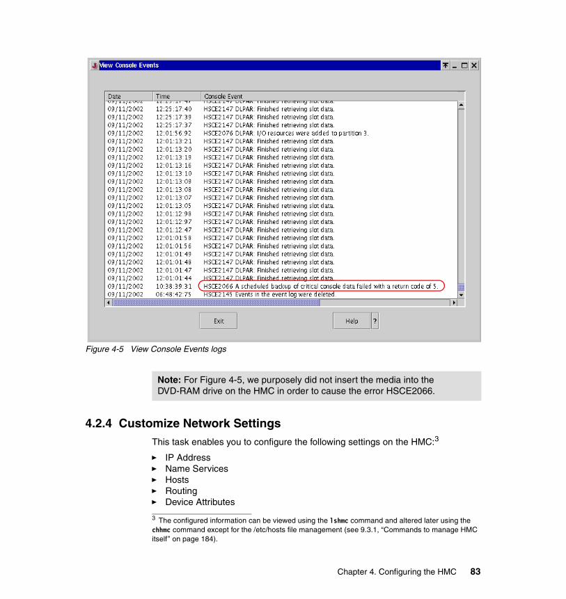
Figure 4-5 View Console Events logs
4.2.4 Customize Network SettingsThis task enables you to configure the following settings on the HMC:3
� IP Address� Name Services� Hosts� Routing� Device Attributes
Note: For Figure 4-5, we purposely did not insert the media into the DVD-RAM drive on the HMC in order to cause the error HSCE2066.
3 The configured information can be viewed using the lshmc command and altered later using the chhmc command except for the /etc/hosts file management (see 9.3.1, “Commands to manage HMC itself” on page 184).
Chapter 4. Configuring the HMC 83
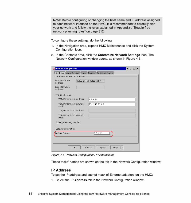
To configure these settings, do the following:
1. In the Navigation area, expand HMC Maintenance and click the System Configuration icon.
2. In the Contents area, click the Customize Network Settings icon. The Network Configuration window opens, as shown in Figure 4-6.
Figure 4-6 Network Configuration: IP Address tab
These tasks’ names are shown on the tab in the Network Configuration window.
IP AddressTo set the IP address and subnet mask of Ethernet adapters on the HMC:
1. Select the IP Address tab in the Network Configuration window.
Note: Before configuring or changing the host name and IP address assigned to each network interface on the HMC, it is recommended to carefully plan your network and follow the rules explained in Appendix , “Trouble-free network planning rules” on page 312.
84 Effective System Management Using the IBM Hardware Management Console for pSeries
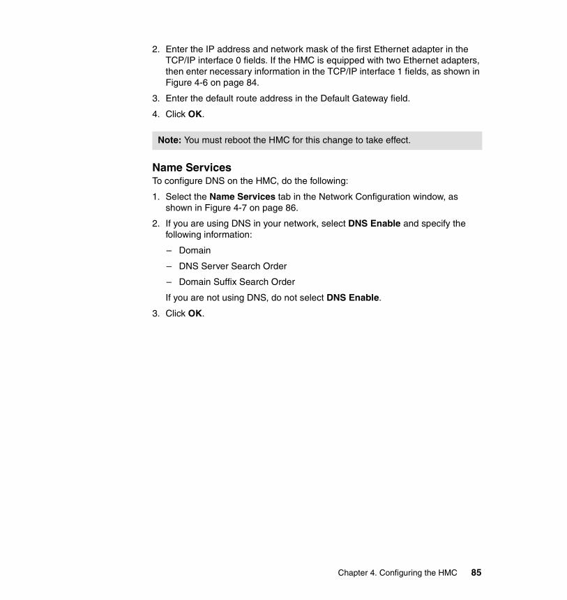
2. Enter the IP address and network mask of the first Ethernet adapter in the TCP/IP interface 0 fields. If the HMC is equipped with two Ethernet adapters, then enter necessary information in the TCP/IP interface 1 fields, as shown in Figure 4-6 on page 84.
3. Enter the default route address in the Default Gateway field.
4. Click OK.
Name ServicesTo configure DNS on the HMC, do the following:
1. Select the Name Services tab in the Network Configuration window, as shown in Figure 4-7 on page 86.
2. If you are using DNS in your network, select DNS Enable and specify the following information:
– Domain
– DNS Server Search Order
– Domain Suffix Search Order
If you are not using DNS, do not select DNS Enable.
3. Click OK.
Note: You must reboot the HMC for this change to take effect.
Chapter 4. Configuring the HMC 85
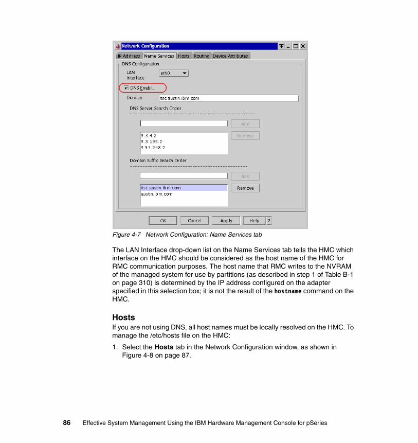
Figure 4-7 Network Configuration: Name Services tab
The LAN Interface drop-down list on the Name Services tab tells the HMC which interface on the HMC should be considered as the host name of the HMC for RMC communication purposes. The host name that RMC writes to the NVRAM of the managed system for use by partitions (as described in step 1 of Table B-1 on page 310) is determined by the IP address configured on the adapter specified in this selection box; it is not the result of the hostname command on the HMC.
HostsIf you are not using DNS, all host names must be locally resolved on the HMC. To manage the /etc/hosts file on the HMC:
1. Select the Hosts tab in the Network Configuration window, as shown in Figure 4-8 on page 87.
86 Effective System Management Using the IBM Hardware Management Console for pSeries
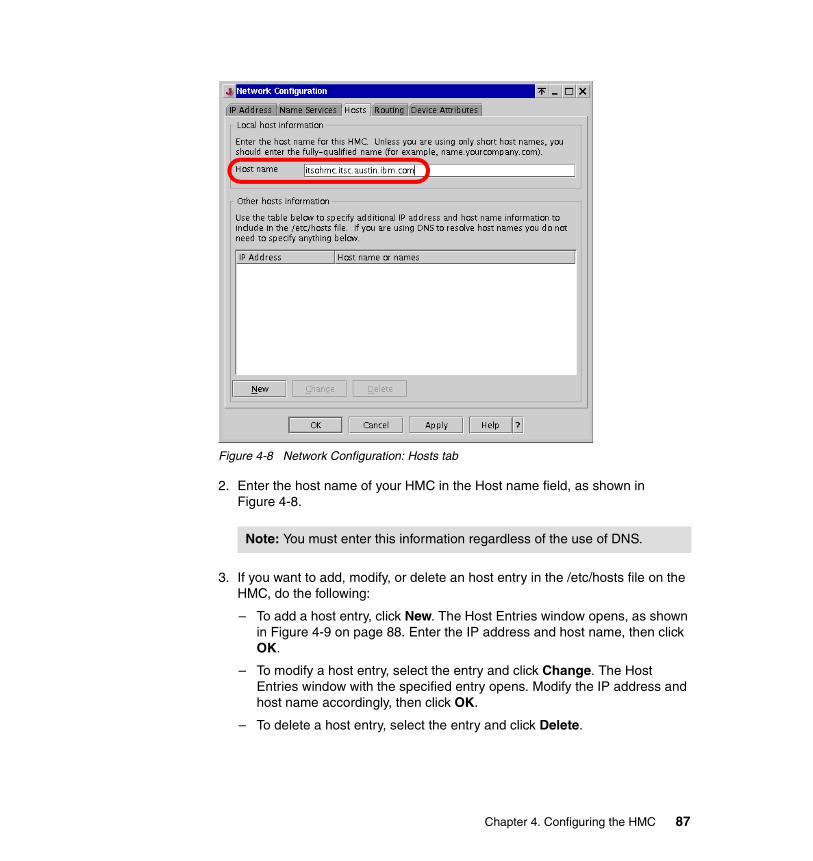
Figure 4-8 Network Configuration: Hosts tab
2. Enter the host name of your HMC in the Host name field, as shown in Figure 4-8.
3. If you want to add, modify, or delete an host entry in the /etc/hosts file on the HMC, do the following:
– To add a host entry, click New. The Host Entries window opens, as shown in Figure 4-9 on page 88. Enter the IP address and host name, then click OK.
– To modify a host entry, select the entry and click Change. The Host Entries window with the specified entry opens. Modify the IP address and host name accordingly, then click OK.
– To delete a host entry, select the entry and click Delete.
Note: You must enter this information regardless of the use of DNS.
Chapter 4. Configuring the HMC 87
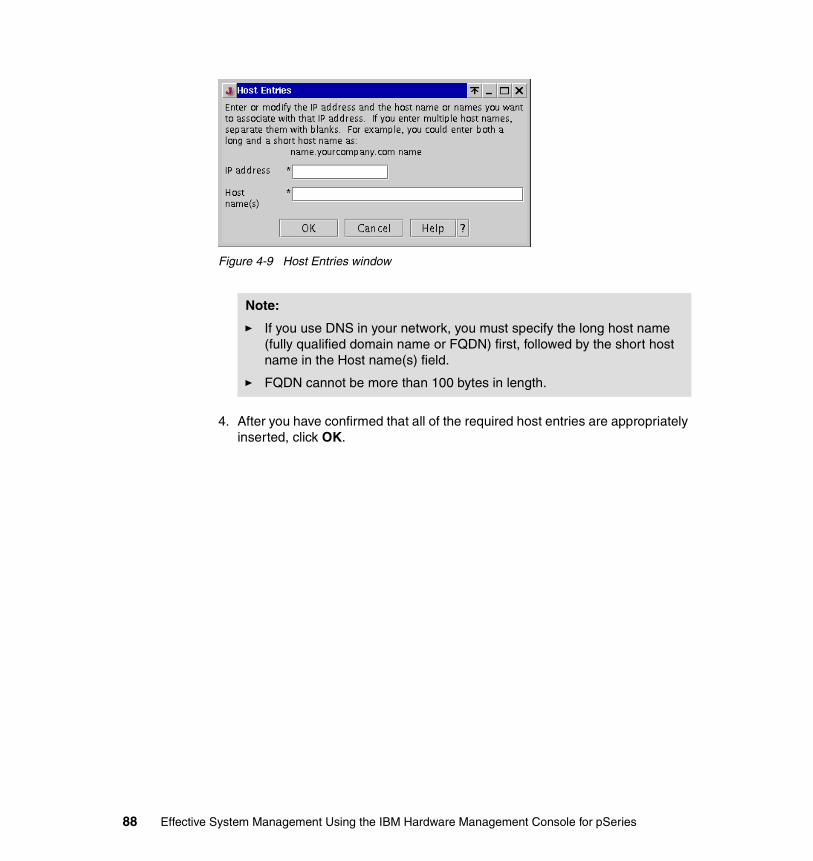
Figure 4-9 Host Entries window
4. After you have confirmed that all of the required host entries are appropriately inserted, click OK.
Note:
� If you use DNS in your network, you must specify the long host name (fully qualified domain name or FQDN) first, followed by the short host name in the Host name(s) field.
� FQDN cannot be more than 100 bytes in length.
88 Effective System Management Using the IBM Hardware Management Console for pSeries
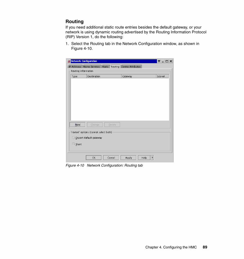
RoutingIf you need additional static route entries besides the default gateway, or your network is using dynamic routing advertised by the Routing Information Protocol (RIP) Version 1, do the following:
1. Select the Routing tab in the Network Configuration window, as shown in Figure 4-10.
Figure 4-10 Network Configuration: Routing tab
Chapter 4. Configuring the HMC 89
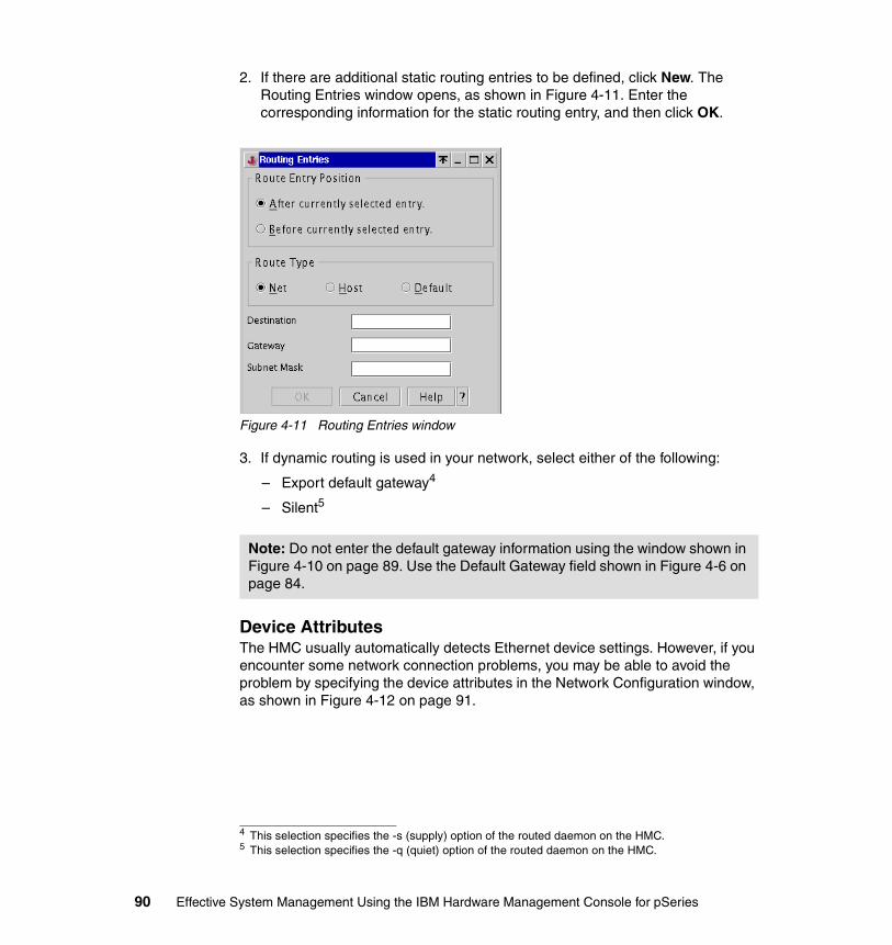
2. If there are additional static routing entries to be defined, click New. The Routing Entries window opens, as shown in Figure 4-11. Enter the corresponding information for the static routing entry, and then click OK.
Figure 4-11 Routing Entries window
3. If dynamic routing is used in your network, select either of the following:
– Export default gateway4
– Silent5
Device AttributesThe HMC usually automatically detects Ethernet device settings. However, if you encounter some network connection problems, you may be able to avoid the problem by specifying the device attributes in the Network Configuration window, as shown in Figure 4-12 on page 91.
4 This selection specifies the -s (supply) option of the routed daemon on the HMC.5 This selection specifies the -q (quiet) option of the routed daemon on the HMC.
Note: Do not enter the default gateway information using the window shown in Figure 4-10 on page 89. Use the Default Gateway field shown in Figure 4-6 on page 84.
90 Effective System Management Using the IBM Hardware Management Console for pSeries
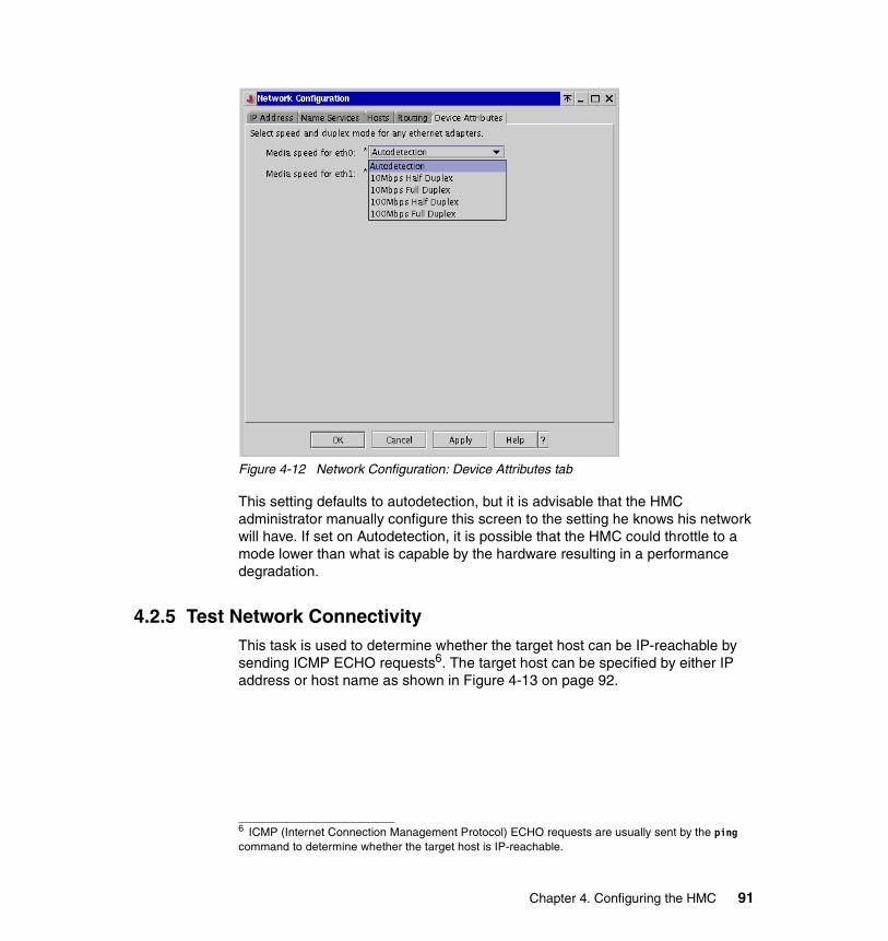
Figure 4-12 Network Configuration: Device Attributes tab
This setting defaults to autodetection, but it is advisable that the HMC administrator manually configure this screen to the setting he knows his network will have. If set on Autodetection, it is possible that the HMC could throttle to a mode lower than what is capable by the hardware resulting in a performance degradation.
4.2.5 Test Network ConnectivityThis task is used to determine whether the target host can be IP-reachable by sending ICMP ECHO requests6. The target host can be specified by either IP address or host name as shown in Figure 4-13 on page 92.
6 ICMP (Internet Connection Management Protocol) ECHO requests are usually sent by the ping command to determine whether the target host is IP-reachable.
Chapter 4. Configuring the HMC 91
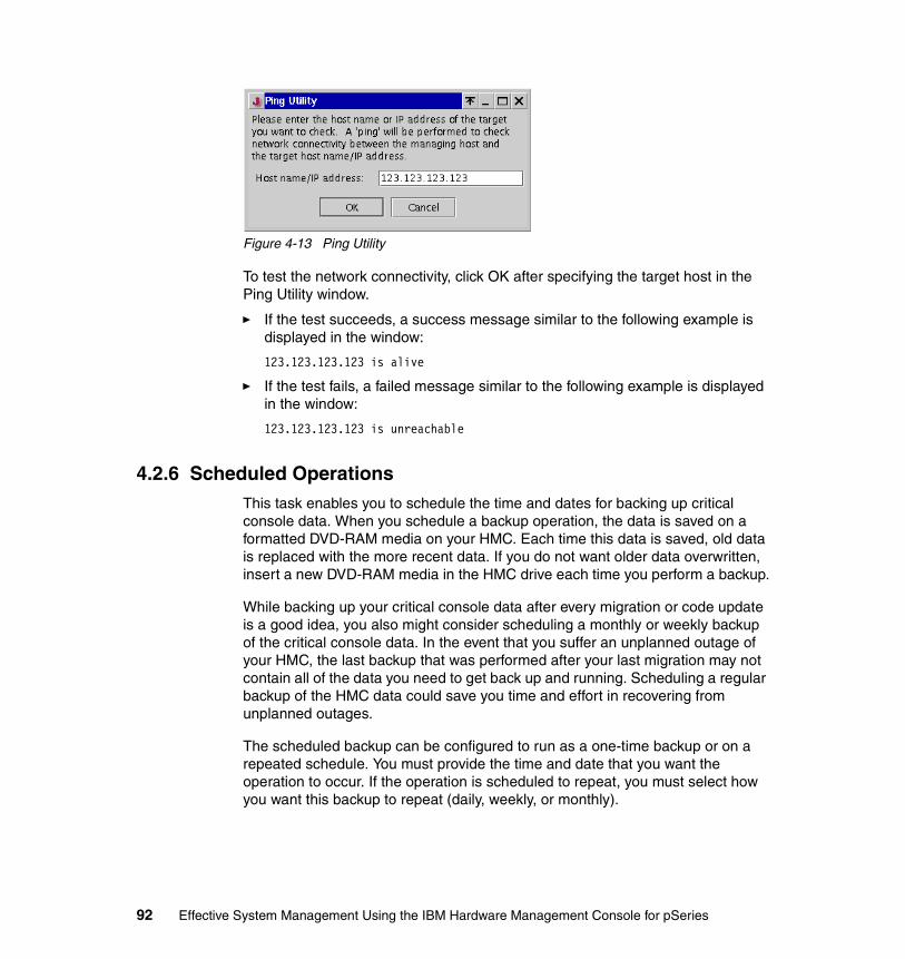
Figure 4-13 Ping Utility
To test the network connectivity, click OK after specifying the target host in the Ping Utility window.
� If the test succeeds, a success message similar to the following example is displayed in the window:
123.123.123.123 is alive
� If the test fails, a failed message similar to the following example is displayed in the window:
123.123.123.123 is unreachable
4.2.6 Scheduled OperationsThis task enables you to schedule the time and dates for backing up critical console data. When you schedule a backup operation, the data is saved on a formatted DVD-RAM media on your HMC. Each time this data is saved, old data is replaced with the more recent data. If you do not want older data overwritten, insert a new DVD-RAM media in the HMC drive each time you perform a backup.
While backing up your critical console data after every migration or code update is a good idea, you also might consider scheduling a monthly or weekly backup of the critical console data. In the event that you suffer an unplanned outage of your HMC, the last backup that was performed after your last migration may not contain all of the data you need to get back up and running. Scheduling a regular backup of the HMC data could save you time and effort in recovering from unplanned outages.
The scheduled backup can be configured to run as a one-time backup or on a repeated schedule. You must provide the time and date that you want the operation to occur. If the operation is scheduled to repeat, you must select how you want this backup to repeat (daily, weekly, or monthly).
92 Effective System Management Using the IBM Hardware Management Console for pSeries
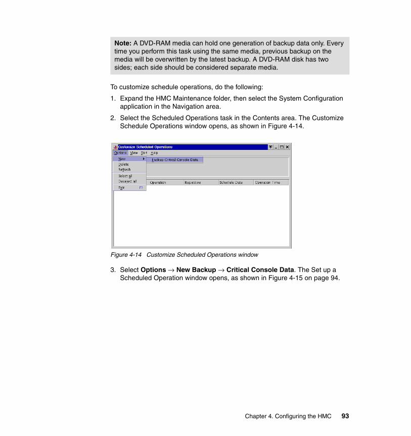
To customize schedule operations, do the following:
1. Expand the HMC Maintenance folder, then select the System Configuration application in the Navigation area.
2. Select the Scheduled Operations task in the Contents area. The Customize Schedule Operations window opens, as shown in Figure 4-14.
Figure 4-14 Customize Scheduled Operations window
3. Select Options → New Backup → Critical Console Data. The Set up a Scheduled Operation window opens, as shown in Figure 4-15 on page 94.
Note: A DVD-RAM media can hold one generation of backup data only. Every time you perform this task using the same media, previous backup on the media will be overwritten by the latest backup. A DVD-RAM disk has two sides; each side should be considered separate media.
Chapter 4. Configuring the HMC 93
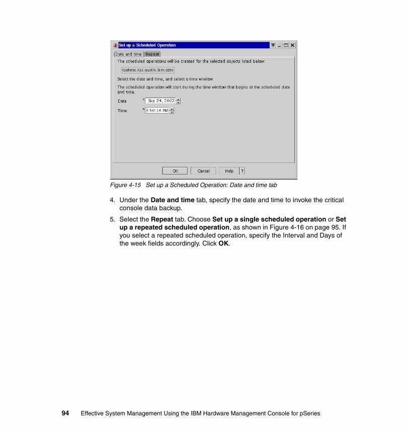
Figure 4-15 Set up a Scheduled Operation: Date and time tab
4. Under the Date and time tab, specify the date and time to invoke the critical console data backup.
5. Select the Repeat tab. Choose Set up a single scheduled operation or Set up a repeated scheduled operation, as shown in Figure 4-16 on page 95. If you select a repeated scheduled operation, specify the Interval and Days of the week fields accordingly. Click OK.
94 Effective System Management Using the IBM Hardware Management Console for pSeries
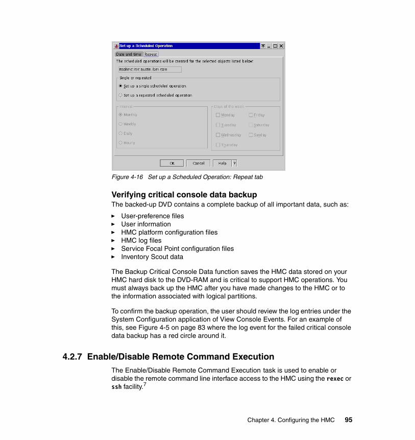
Figure 4-16 Set up a Scheduled Operation: Repeat tab
Verifying critical console data backupThe backed-up DVD contains a complete backup of all important data, such as:
� User-preference files� User information� HMC platform configuration files� HMC log files� Service Focal Point configuration files� Inventory Scout data
The Backup Critical Console Data function saves the HMC data stored on your HMC hard disk to the DVD-RAM and is critical to support HMC operations. You must always back up the HMC after you have made changes to the HMC or to the information associated with logical partitions.
To confirm the backup operation, the user should review the log entries under the System Configuration application of View Console Events. For an example of this, see Figure 4-5 on page 83 where the log event for the failed critical console data backup has a red circle around it.
4.2.7 Enable/Disable Remote Command ExecutionThe Enable/Disable Remote Command Execution task is used to enable or disable the remote command line interface access to the HMC using the rexec or ssh facility.7
Chapter 4. Configuring the HMC 95
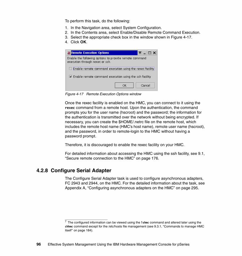
To perform this task, do the following:
1. In the Navigation area, select System Configuration.2. In the Contents area, select Enable/Disable Remote Command Execution.3. Select the appropriate check box in the window shown in Figure 4-17.4. Click OK.
Figure 4-17 Remote Execution Options window
Once the rexec facility is enabled on the HMC, you can connect to it using the rexec command from a remote host. Upon the authentication, the command prompts you for the user name (hscroot) and the password; the information for the authentication is transmitted over the network without being encrypted. If necessary, you can create the $HOME/.netrc file on the remote host, which includes the remote host name (HMC’s host name), remote user name (hscroot), and the password, in order to remote-login to the HMC without having a password prompt.
Therefore, it is discouraged to enable the rexec facility on your HMC.
For detailed information about accessing the HMC using the ssh facility, see 9.1, “Secure remote connection to the HMC” on page 176.
4.2.8 Configure Serial AdapterThe Configure Serial Adapter task is used to configure asynchronous adapters, FC 2943 and 2944, on the HMC. For the detailed information about the task, see Appendix A, “Configuring asynchronous adapters on the HMC” on page 295.
7 The configured information can be viewed using the lshmc command and altered later using the chhmc command except for the /etc/hosts file management (see 9.3.1, “Commands to manage HMC itself” on page 184).
96 Effective System Management Using the IBM Hardware Management Console for pSeries
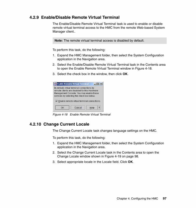
4.2.9 Enable/Disable Remote Virtual TerminalThe Enable/Disable Remote Virtual Terminal task is used to enable or disable remote virtual terminal access to the HMC from the remote Web-based System Manager client..
To perform this task, do the following:
1. Expand the HMC Management folder, then select the System Configuration application in the Navigation area.
2. Select the Enable/Disable Remote Virtual Terminal task in the Contents area to open the Enable Remote Virtual Terminal window in Figure 4-18.
3. Select the check box in the window, then click OK.
Figure 4-18 Enable Remote Virtual Terminal
4.2.10 Change Current LocaleThe Change Current Locale task changes language settings on the HMC.
To perform this task, do the following:
1. Expand the HMC Management folder, then select the System Configuration application in the Navigation area.
2. Select the Change Current Locale task in the Contents area to open the Change Locale window shown in Figure 4-19 on page 98.
3. Select appropriate locale in the Locale field. Click OK.
Note: The remote virtual terminal access is disabled by default.
Chapter 4. Configuring the HMC 97
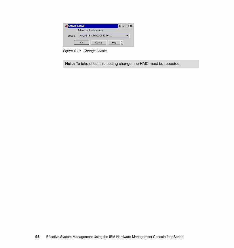
Figure 4-19 Change Locale
Note: To take effect this setting change, the HMC must be rebooted.
98 Effective System Management Using the IBM Hardware Management Console for pSeries
Chapter 5. Managing partition profile data on the HMC
This short chapter focuses on the following four operations provided by the HMC and the situations in which these operations should be performed:
Backup Reads the profile data from the CIM Object Manager on the HMC and writes it to a backup file on the HMC.
Restore Reads the profile data from the previously backed-up file on the HMC and loads this data to the NVRAM on the managed system. Once loaded successfully, the HMC reconstructs its copy on the CIM Object Manager. There are several options to tell the HMC which data is honored.
Initialize Initializes the profile data on the HMC and the NVRAM on the managed system.
Remove Removes the previously backed-up file on the HMC.
These operations can be selected from the Selected → Profile Data menu as shown in Figure 5-1 on page 101.
5
© Copyright IBM Corp. 2003. All rights reserved. 99
5.1 Managing profile dataThe profile data for partitions of a managed system is stored in at least the following three locations at any given time:
� NVRAM of the managed system
� CIM Object Manager on the HMC
� Profile data backup file(s) under the /var/hsc/profile/MT-MDL*S/N directory on the HMC
In addition to these three locations, if the Save Upgrade Data task is performed, then a special disk partition1 on the HMC can be also used to store the profile data.
The HMC provides four operations, backup, restore, initialize, and remove, to manage profile data. To perform these operations, do the following:
1. Log in to the HMC using either the System Administrator, Advanced Operator, or Service Representative role.
2. In the Navigation area, select the Server and Management icon.
3. In the Contents area, select the managed system to perform the operation.
4. Choose Selected → Profile Data.
5. Select the appropriate operation in the submenu, as shown Figure 5-1 on page 101.
Note: The data stored on the NVRAM acts as the primary copy. The information stored in the NVRAM is always honored, unless it is determined corrupted.
1 The special disk partition is mounted and accessible only when the “Save Upgrade Data” task (see “Save Upgrade Data” on page 113) or the “Upgrade of the HMC software” operation is performed (see 6.2.3, “Upgrade install using the save upgrade data” on page 121).
100 Effective System Management Using the IBM Hardware Management Console for pSeries

Figure 5-1 Profile Data submenus
Figure 5-2 illustrates the relationship of these locations and relevant tasks.
Figure 5-2 Four partition data locations
CIM ObjectManager
/var/hsc/profile/MT-MDL*S/N
Profile Data "Back Up" Profile Data "Restore"
/mnt/upgrade(special disk
partition)
Save Upgrade Data
Store data in the NVRAM
Read data from the NVRAM(populated in the CIM Object Manager)
NVRAM
Managed system
Chapter 5. Managing partition profile data on the HMC 101

The following list explains the relationship between the components and operations shown in the previous figure:
� If a user issues some requests that require a reference to the partitioning configuration data, the data will be read from the NVRAM on the managed system first, then populated in the CIM Object Manager on the HMC. The CIM Object Manager acts as a broker of this information to its clients: local and remote Web-based System Manager clients and HMC commands are the user interface to the CIM Object Manager clients.
� When changes are made to the partitioning configuration data of a managed system, changes are validated on the HMC first, then stored on the NVRAM of the managed system. For consistency between the data stored on the NVRAM and its copy on the HMC, a lock mechanism is used.
� The partitioning configuration data can be backed up if the backup2 operation is performed. This operation reads all the data from the NVRAM and stores it in a file under the /var/hsc/profile/MT-MDL*SN directory. If multiple backup operations are performed, each backup file may contain different partitioning configuration data that reflects the data when the backup operation was performed.
� The default backup file, /var/hsc/profile/MT-MDL*SN/backupFile, always exists and gets updated whenever changes are made to the partitioning configuration. This file is automatically created when the HMC is first connected to its managed system and the data gets written to the file from the NVRAM. If the default backup file does not exist, it will be created with the data from the NVRAM upon the next HMC reboot.
� Upon the managed system’s reboot, the HMC performs the following operations:
a. It first verifies the check sum value of the default backup file and the data stored on the managed system’s NVRAM.
b. If the data stored on the NVRAM is determined corrupted, the HMC will display the Recovery state for this managed system (see Table 3-2 on page 64). The Recovery state indicates that either restore3 or initialize4 operation is required against the managed system.
c. If the data stored on the NVRAM is determined not corrupted, the HMC reads the data from the managed system’s NVRAM and populates it in the CIM Object Manager. The default backup file is also updated using this data.
d. If the communication between the HMC and the service processor on the managed system did not successfully complete because of some
2 See 5.1.1, “Back up profile data” on page 1033 See 5.1.2, “Restore profile data” on page 104.4 See 5.1.3, “Initialize profile data” on page 105.
102 Effective System Management Using the IBM Hardware Management Console for pSeries

communication failure, the HMC will display the Incomplete state for this managed system (see Table 3-2 on page 64). The Incomplete state indicates that rebuild operation is required against the managed system.
� The partitioning configuration data can be restored from the backup file if the restore operation is performed. This operation first reads and verifies all of the data from the specified backup file, then loads the data into the NVRAM on the managed system. Once successfully loaded, the HMC reconstructs its copy on the CIM Object Manager from the NVRAM.
5.1.1 Back up profile dataTo back up profile data5, do the following:
1. In the Contents area, select the managed system.
2. From the menu bar, choose Selected → Profile Data → Backup to open the Profile Data Backup window shown in Figure 5-3.
Figure 5-3 Profile Data Backup window
3. Type the file name in the Backup file name field, then click OK.
The backup file is saved in the /var/hsc/profiles/MT-MDL*S/N directory on the HMC, as shown in the following example:
[user1@remote_host]$ ssh -l hscroot itsohmc.itsc.austin.ibm.comhscroot@itsohmc's password: XXXXXX[hscroot@itsohmc]$ cd /var/hsc/profiles/7040-681*021768A[hscroot@itsohmc 7040-681*021768A]$ ls -ltotal 40-rw-r--r-- 1 root root 20464 Nov 27 12:00 backupFile-rw-r--r-- 1 root root 20464 Nov 27 12:18 ITSO_p690
MT, MDL, and S/N are the system machine type, model, and serial number.
5 The bkprofdata command can be also used to perform this operation (see “bkprofdata” on page 203).
Note: To delete created backup files, use the Delete option explained in 5.1.4, “Remove profile data” on page 105.
Chapter 5. Managing partition profile data on the HMC 103
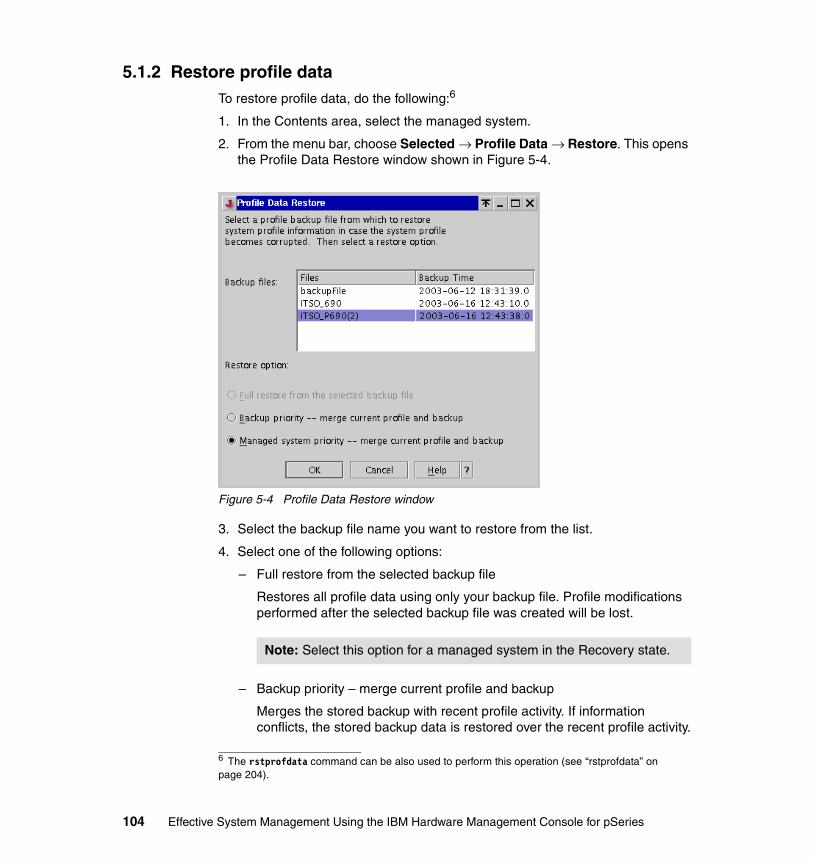
5.1.2 Restore profile dataTo restore profile data, do the following:6
1. In the Contents area, select the managed system.
2. From the menu bar, choose Selected → Profile Data → Restore. This opens the Profile Data Restore window shown in Figure 5-4.
Figure 5-4 Profile Data Restore window
3. Select the backup file name you want to restore from the list.
4. Select one of the following options:
– Full restore from the selected backup file
Restores all profile data using only your backup file. Profile modifications performed after the selected backup file was created will be lost.
– Backup priority – merge current profile and backup
Merges the stored backup with recent profile activity. If information conflicts, the stored backup data is restored over the recent profile activity.
6 The rstprofdata command can be also used to perform this operation (see “rstprofdata” on page 204).
Note: Select this option for a managed system in the Recovery state.
104 Effective System Management Using the IBM Hardware Management Console for pSeries
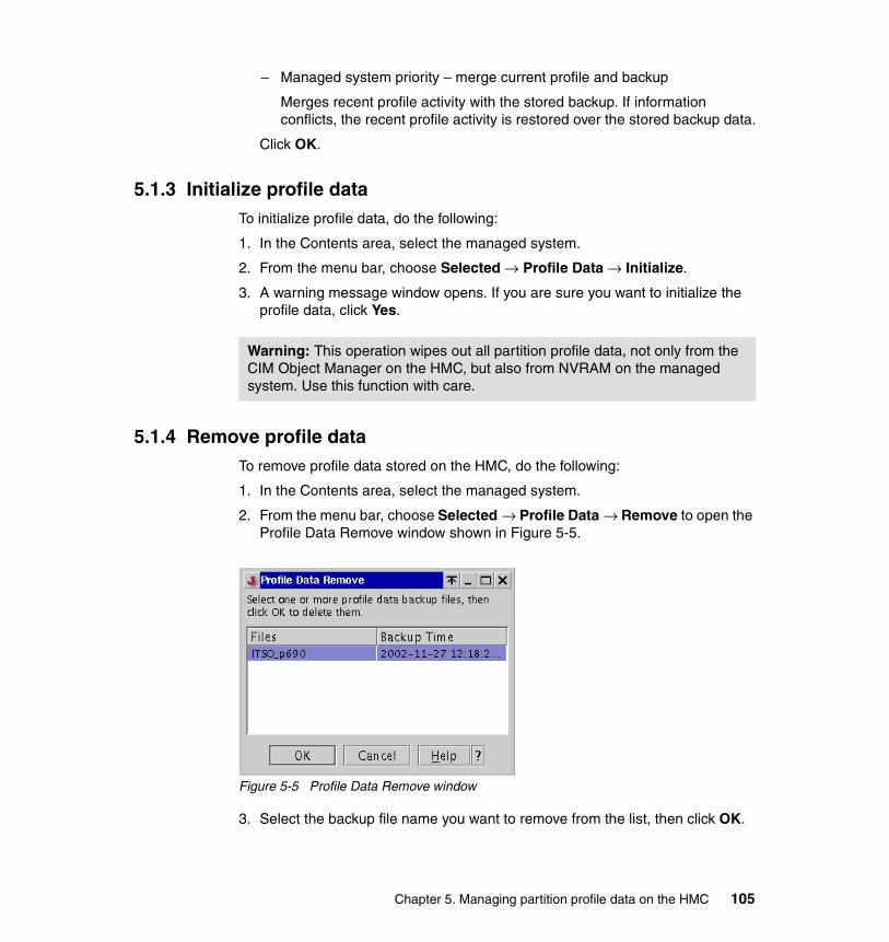
– Managed system priority – merge current profile and backup
Merges recent profile activity with the stored backup. If information conflicts, the recent profile activity is restored over the stored backup data.
Click OK.
5.1.3 Initialize profile dataTo initialize profile data, do the following:
1. In the Contents area, select the managed system.
2. From the menu bar, choose Selected → Profile Data → Initialize.
3. A warning message window opens. If you are sure you want to initialize the profile data, click Yes.
5.1.4 Remove profile dataTo remove profile data stored on the HMC, do the following:
1. In the Contents area, select the managed system.
2. From the menu bar, choose Selected → Profile Data → Remove to open the Profile Data Remove window shown in Figure 5-5.
Figure 5-5 Profile Data Remove window
3. Select the backup file name you want to remove from the list, then click OK.
Warning: This operation wipes out all partition profile data, not only from the CIM Object Manager on the HMC, but also from NVRAM on the managed system. Use this function with care.
Chapter 5. Managing partition profile data on the HMC 105

Note: This operation simply removes the specified backup file that was already created using the Backup profile data operation (see 5.1.1, “Back up profile data” on page 103). The removal of the backup file does not affect the partitioning configuration data currently in use on the managed system and its copy held by the CIM Object Manager on the HMC.
106 Effective System Management Using the IBM Hardware Management Console for pSeries

Chapter 6. Managing software levels on the HMC
This chapter explains how to install, recover, and upgrade the HMC software in the following sections:
� “Software Maintenance” on page 108� “Install, recover, and upgrade strategies” on page 118
For further information about these tasks, refer to the following publications:
� IBM Hardware Management Console for pSeries Installation and Operations Guide, SA38-0590
� IBM Hardware Management Console for pSeries Maintenance Guide, SA38-0603
6
© Copyright IBM Corp. 2003. All rights reserved. 107
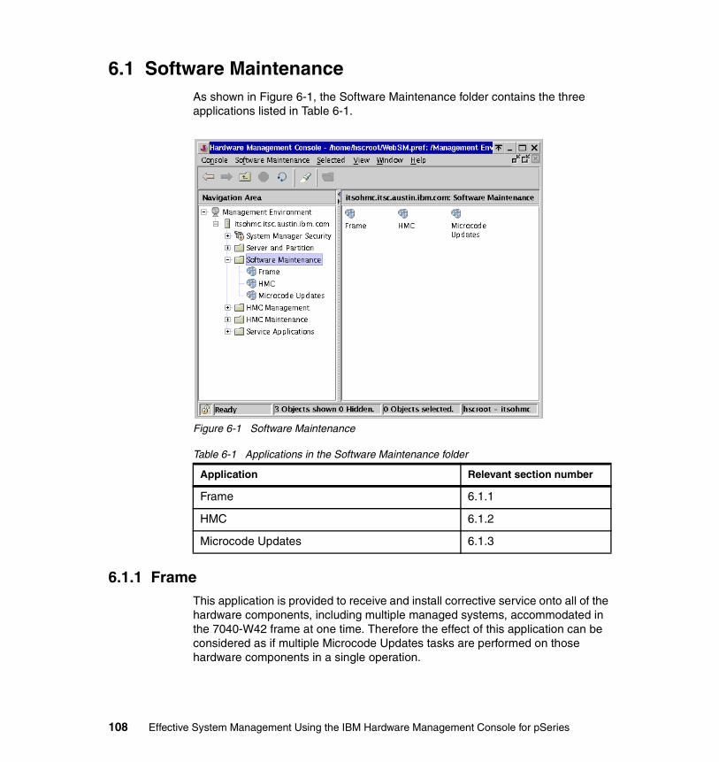
6.1 Software MaintenanceAs shown in Figure 6-1, the Software Maintenance folder contains the three applications listed in Table 6-1.
Figure 6-1 Software Maintenance
Table 6-1 Applications in the Software Maintenance folder
6.1.1 FrameThis application is provided to receive and install corrective service onto all of the hardware components, including multiple managed systems, accommodated in the 7040-W42 frame at one time. Therefore the effect of this application can be considered as if multiple Microcode Updates tasks are performed on those hardware components in a single operation.
Application Relevant section number
Frame 6.1.1
HMC 6.1.2
Microcode Updates 6.1.3
108 Effective System Management Using the IBM Hardware Management Console for pSeries

These tasks are provided in the Frame application, as shown in Figure 6.1.2:
� Receive Corrective Services� Install Corrective Services
For further information about the use of this application, refer to the IBM Hardware Management Console for pSeries Installation and Operations Guide, SA38-0590.
Figure 6-2 Software Maintenance: Frame
6.1.2 HMCThe HMC application is used for creating backups, installing corrective service, and formatting removable media on the HMC through the following four tasks, as shown in Figure 6-3 on page 110.
� Backup Critical Console Data� Save Upgrade Data� Install Corrective Services� Format Removable Media
Note: In order for this application to function, the BPA of the frame must be connected to one of the serial ports on the HMC using RS-422.
Chapter 6. Managing software levels on the HMC 109

Figure 6-3 Software Maintenance: HMC
Difference between two backup tasksThe two backup-related tasks, Backup Critical Console Data and Save Upgrade Data, are provided for different purposes:
� Backup Critical Console Data
Backs up all HMC configuration data to a DVD-RAM media, capturing any and all changes made to the HMC after initial installation from the recovery CD.
The following data is included in the backup DVD-RAM media:
– User configuration
– User preferences, including each user’s home directory
– HMC configuration files that record the following customizing:
• TCP/IP
• Rexec/ssh facility setting
• Remote virtual terminal setting
110 Effective System Management Using the IBM Hardware Management Console for pSeries

• Time zone setting
– HMC log files located in the /var/log directory
– Service functions settings, such as Inventory Scout, Service Agent, and Service Focal Point
– Partition profile data backup
This task should be performed each time configuration changes are made to the system or the HMC. You might even schedule the “Backup Critical Console Data” task explained in 4.2.6, “Scheduled Operations” on page 92.
� Save Upgrade Data
Creates several archive files for the following configuration information, then saves those archive files in the special disk partition on the HMC:
– User configuration
– User preferences, including each user’s home directory
– HMC configuration files that record the following customizing:
• TCP/IP
• Rexec/ssh facility setting
• Remote virtual terminal setting
Note: The partition profile data must be backed up before performing the “Backup Critical Console Data” task as explained in 5.1.1, “Back up profile data” on page 103. The task simply backs up files in the /var/hsc/profiles/MT-MDL*S/N directory, if they already exist.
Note:
� The backup DVD-RAM created using this task is only used for the system recovery situation explained in 6.2.1, “Refresh Install using the recovery CD” on page 119. When updating from an HMC software level to another, the backup DVD-RAM media is not used.
� The DVD-RAM media has two sides. Each side should be considered as a separate media.
� Each side of a DVD-RAM media must be formatted beforehand. To format the media, see “Format Removable Media” on page 116.
� Each side of a DVD-RAM media can hold only one generation of the backup; if you performed this task multiple times, only the last backup would be preserved.
Chapter 6. Managing software levels on the HMC 111
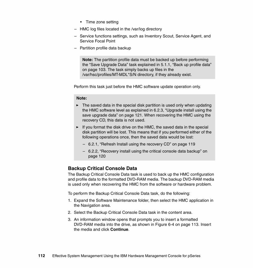
• Time zone setting
– HMC log files located in the /var/log directory
– Service functions settings, such as Inventory Scout, Service Agent, and Service Focal Point
– Partition profile data backup
Perform this task just before the HMC software update operation only.
Backup Critical Console DataThe Backup Critical Console Data task is used to back up the HMC configuration and profile data to the formatted DVD-RAM media. The backup DVD-RAM media is used only when recovering the HMC from the software or hardware problem.
To perform the Backup Critical Console Data task, do the following:
1. Expand the Software Maintenance folder, then select the HMC application in the Navigation area.
2. Select the Backup Critical Console Data task in the content area.
3. An information window opens that prompts you to insert a formatted DVD-RAM media into the drive, as shown in Figure 6-4 on page 113. Insert the media and click Continue.
Note: The partition profile data must be backed up before performing the “Save Upgrade Data” task explained in 5.1.1, “Back up profile data” on page 103. The task simply backs up files in the /var/hsc/profiles/MT-MDL*S/N directory, if they already exist.
Note:
� The saved data in the special disk partition is used only when updating the HMC software level as explained in 6.2.3, “Upgrade install using the save upgrade data” on page 121. When recovering the HMC using the recovery CD, this data is not used.
� If you format the disk drive on the HMC, the saved data in the special disk partition will be lost. This means that if you performed either of the following operations once, then the saved data would be lost:
– 6.2.1, “Refresh Install using the recovery CD” on page 119
– 6.2.2, “Recovery install using the critical console data backup” on page 120
112 Effective System Management Using the IBM Hardware Management Console for pSeries
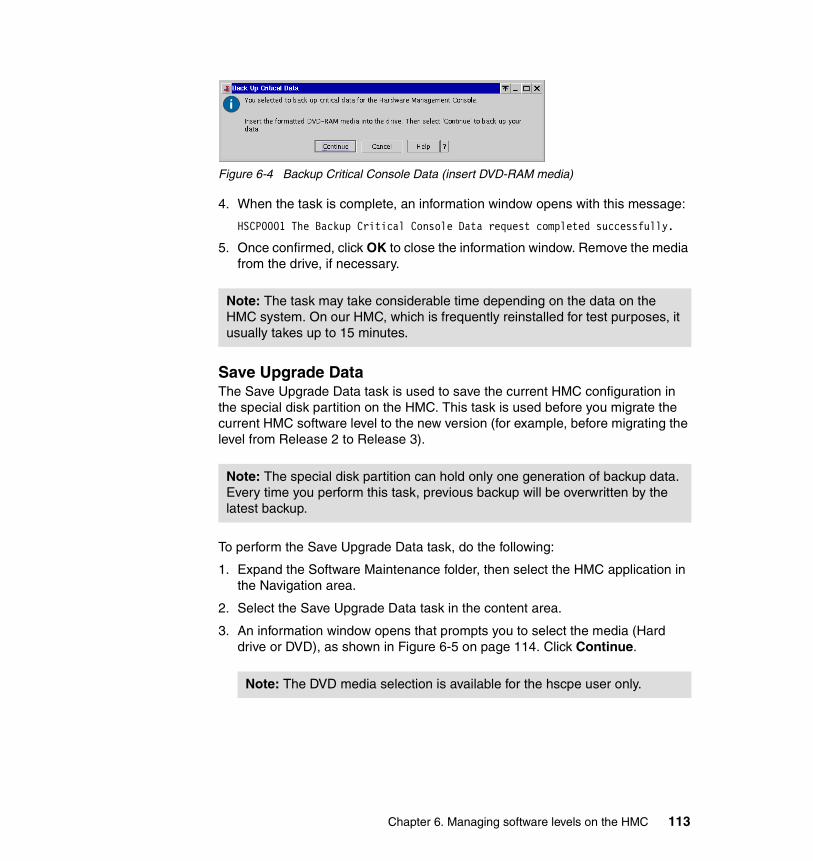
Figure 6-4 Backup Critical Console Data (insert DVD-RAM media)
4. When the task is complete, an information window opens with this message:
HSCP0001 The Backup Critical Console Data request completed successfully.
5. Once confirmed, click OK to close the information window. Remove the media from the drive, if necessary.
Save Upgrade DataThe Save Upgrade Data task is used to save the current HMC configuration in the special disk partition on the HMC. This task is used before you migrate the current HMC software level to the new version (for example, before migrating the level from Release 2 to Release 3).
To perform the Save Upgrade Data task, do the following:
1. Expand the Software Maintenance folder, then select the HMC application in the Navigation area.
2. Select the Save Upgrade Data task in the content area.
3. An information window opens that prompts you to select the media (Hard drive or DVD), as shown in Figure 6-5 on page 114. Click Continue.
Note: The task may take considerable time depending on the data on the HMC system. On our HMC, which is frequently reinstalled for test purposes, it usually takes up to 15 minutes.
Note: The special disk partition can hold only one generation of backup data. Every time you perform this task, previous backup will be overwritten by the latest backup.
Note: The DVD media selection is available for the hscpe user only.
Chapter 6. Managing software levels on the HMC 113
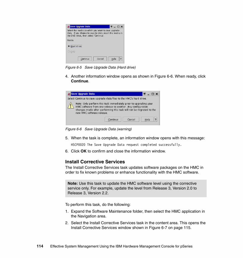
Figure 6-5 Save Upgrade Data (Hard drive)
4. Another information window opens as shown in Figure 6-6. When ready, click Continue.
Figure 6-6 Save Upgrade Data (warning)
5. When the task is complete, an information window opens with this message:
HSCP0020 The Save Upgrade Data request completed successfully.
6. Click OK to confirm and close the information window.
Install Corrective ServicesThe Install Corrective Services task updates software packages on the HMC in order to fix known problems or enhance functionality with the HMC software.
To perform this task, do the following:
1. Expand the Software Maintenance folder, then select the HMC application in the Navigation area.
2. Select the Install Corrective Services task in the content area. This opens the Install Corrective Services window shown in Figure 6-7 on page 115.
Note: Use this task to update the HMC software level using the corrective service only. For example, update the level from Release 3, Version 2.0 to Release 3, Version 2.2.
114 Effective System Management Using the IBM Hardware Management Console for pSeries
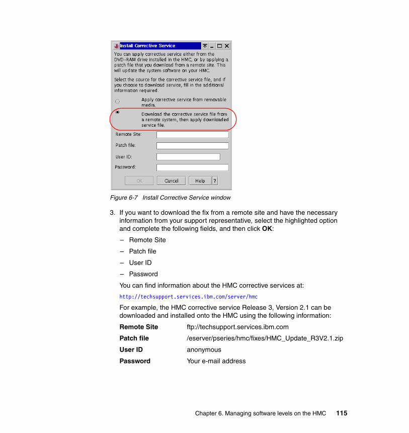
Figure 6-7 Install Corrective Service window
3. If you want to download the fix from a remote site and have the necessary information from your support representative, select the highlighted option and complete the following fields, and then click OK:
– Remote Site
– Patch file
– User ID
– Password
You can find information about the HMC corrective services at:
http://techsupport.services.ibm.com/server/hmc
For example, the HMC corrective service Release 3, Version 2.1 can be downloaded and installed onto the HMC using the following information:
Remote Site ftp://techsupport.services.ibm.com
Patch file /eserver/pseries/hmc/fixes/HMC_Update_R3V2.1.zip
User ID anonymous
Password Your e-mail address
Chapter 6. Managing software levels on the HMC 115
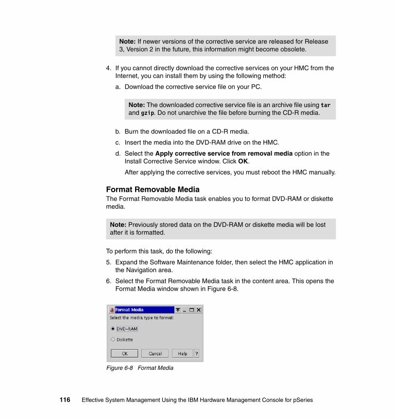
4. If you cannot directly download the corrective services on your HMC from the Internet, you can install them by using the following method:
a. Download the corrective service file on your PC.
b. Burn the downloaded file on a CD-R media.
c. Insert the media into the DVD-RAM drive on the HMC.
d. Select the Apply corrective service from removal media option in the Install Corrective Service window. Click OK.
After applying the corrective services, you must reboot the HMC manually.
Format Removable MediaThe Format Removable Media task enables you to format DVD-RAM or diskette media.
To perform this task, do the following:
5. Expand the Software Maintenance folder, then select the HMC application in the Navigation area.
6. Select the Format Removable Media task in the content area. This opens the Format Media window shown in Figure 6-8.
Figure 6-8 Format Media
Note: If newer versions of the corrective service are released for Release 3, Version 2 in the future, this information might become obsolete.
Note: The downloaded corrective service file is an archive file using tar and gzip. Do not unarchive the file before burning the CD-R media.
Note: Previously stored data on the DVD-RAM or diskette media will be lost after it is formatted.
116 Effective System Management Using the IBM Hardware Management Console for pSeries
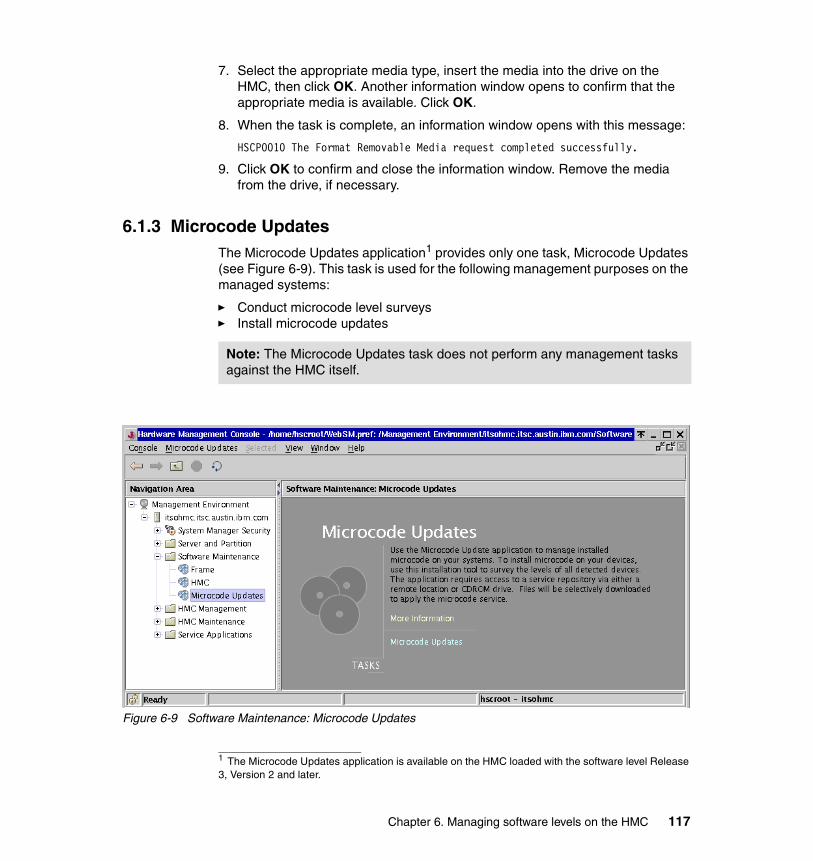
7. Select the appropriate media type, insert the media into the drive on the HMC, then click OK. Another information window opens to confirm that the appropriate media is available. Click OK.
8. When the task is complete, an information window opens with this message:
HSCP0010 The Format Removable Media request completed successfully.
9. Click OK to confirm and close the information window. Remove the media from the drive, if necessary.
6.1.3 Microcode UpdatesThe Microcode Updates application1 provides only one task, Microcode Updates (see Figure 6-9). This task is used for the following management purposes on the managed systems:
� Conduct microcode level surveys� Install microcode updates
Figure 6-9 Software Maintenance: Microcode Updates
1 The Microcode Updates application is available on the HMC loaded with the software level Release 3, Version 2 and later.
Note: The Microcode Updates task does not perform any management tasks against the HMC itself.
Chapter 6. Managing software levels on the HMC 117

Although the Microcode Updates application is provided in the Software Maintenance folder, we explain this application in 11.5, “Microcode Updates” on page 272 because it does not relate to any management tasks on the HMC itself.
6.2 Install, recover, and upgrade strategiesThere are three operations for installing, recovering, or upgrading the HMC software:
� Refresh Install using the recovery CD
Used to perform overwrite and install the newer version of HMC software on the HMC (path A in Figure 6-10 on page 119). If all customizing and partition configurations are properly recorded, this operation can be also used to recover from system failure. To record the information, see “Recording the current HMC configuration information” on page 122.
� Recovery install using the critical console data backup
Recovers the HMC in case of system failure, such as disk drive replacement (path B in Figure 6-10 on page 119).
You need to have the backup DVD-RAM media created beforehand with the “Backup Critical Console Data” task explained in “Backup Critical Console Data” on page 112.
� Upgrade install using the save upgrade data
Used to update the HMC software from an older version to a newer one (path C in Figure 6-10 on page 119).
You need to perform the “Save Upgrade Data” task beforehand, as explained in “Save Upgrade Data” on page 113.
Figure 6-10 on page 119 illustrates the process flow of these operations.
Note: This operation formats the disk drive on the HMC.
Note: This operation formats the disk drive on the HMC.
Note: The disk drive on the HMC will not be formatted in this operation.
118 Effective System Management Using the IBM Hardware Management Console for pSeries
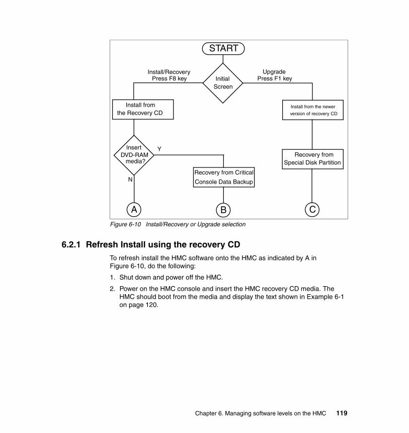
Figure 6-10 Install/Recovery or Upgrade selection
6.2.1 Refresh Install using the recovery CDTo refresh install the HMC software onto the HMC as indicated by A in Figure 6-10, do the following:
1. Shut down and power off the HMC.
2. Power on the HMC console and insert the HMC recovery CD media. The HMC should boot from the media and display the text shown in Example 6-1 on page 120.
START
A B C
Recovery from Critical
Console Data Backup
Special Disk PartitionRecovery from
Install/RecoveryPress F8 key
UpgradePress F1 keyInitial
Screen
InsertDVD-RAM
media?
Y
N
Install from the newer
version of recovery CDthe Recovery CDInstall from
Chapter 6. Managing software levels on the HMC 119
Example 6-1 Initial selection screen on the HMC
YOU HAVE REQUESTED TO INSTALL/UPGRADE YOUR HMC HARD DISK FROM THE BASECODE CD-ROM. PLEASE SELECT ONE OF THE BELOW OPTIONS (OR ESC TO EXIT):
WARNING: CONTINUING WITH THIS TASK WILL RESULT IN THE DESTRUCTION OF INFORMATION CURRENTLY ON YOUR HMC HARD DISK.
1 - INSTALL/RECOVERY: CHOOSE THIS OPTION WHEN YOU ARE INSTALLING FOR THE FIRST TIME OR IF YOU WISH TO RELOAD THE HMC HARD DISK USING THE BASE CODE CD-ROM. YOU WILL HAVE THE OPTION TO INSERT THE DVD-RAM MEDIA TO RESTORE PREVIOUSLY BACKED UP CRITICAL DATA. SELECT F8 TO CONTINUE WITH THIS PROCESS.
2 - UPGRADE: CHOOSE THIS OPTION WHEN YOU ARE UPGRADING YOUR HMC HARD DISK TO A NEW CODE LEVEL. THIS OPTION WILL PRESERVE PREVIOUSLY SAVED UPGARDE DATA ON DISK, AND RESTORE THAT DATA AFTER THE UPGRADE HAS BEEN COMPLETED. SELECT F1 TO CONTINUE WITH THIS PROCESS.
3. Press F8 to select the “1 - Install/Recover” option.
4. When the following message is displayed, press F1 to confirm that you wish to continue:
PRESS F1 TO CONTINUE WITH THE RESTORE / PRELOAD PROCESS.PRESS ESC TO EXIT THE PROCESS
5. When the installation from the CD media finishes, the following message displays to prompt you to insert the DVD-RAM media for the critical console data backup:
REMOVE THE CD-ROM AND PLACE THE BACKUP DVD-RAM CARTRIDGE IN THE DRIVE.WHEN THE BACKUP DVD-RAM CARTRIDGE IS IN THE PLACE,PRESS ENTER AND THE HARDWARE MANAGEMENT CONSOLE WILL REBOOT.
6. Remove the CD media from the drive and do not insert the DVD-RAM media. Type Enter to reboot the HMC.
7. After the HMC reboot, the Kudzu screen is displayed to confirm the removal and addition of hardware resources on the HMC. Select the option as instructed in the screen.
8. In a few minutes, the HMC logon panel displays.
6.2.2 Recovery install using the critical console data backupTo recover install the HMC software onto your HMC as indicated by B in Figure 6-10 on page 119, do the following:
120 Effective System Management Using the IBM Hardware Management Console for pSeries

1. Shut down and power off the HMC.
2. Power on the HMC console and insert the HMC recovery CD media. The HMC should boot from the media and display the screen shown in Example 6-1 on page 120.
3. Press F8 to select the “1 - Install/Recover” option.
4. When the following message is displayed, press F1 to confirm that you wish to continue:
PRESS F1 TO CONTINUE WITH THE RESTORE / PRELOAD PROCESS.PRESS ESC TO EXIT THE PROCESS
5. When the installation from the CD media finishes, the following message is displayed to prompt you to insert the DVD-RAM media for the critical console data backup:
REMOVE THE CD-ROM AND PLACE THE BACKUP DVD-RAM CARTRIDGE IN THE DRIVE.WHEN THE BACKUP DVD-RAM CARTRIDGE IS IN THE PLACE,PRESS ENTER AND THE HARDWARE MANAGEMENT CONSOLE WILL REBOOT.
6. Remove the CD media from the drive and insert the DVD-RAM media. Type Enter to reboot the HMC.
7. After the HMC reboot, the Kudzu screen is displayed to confirm the removal and addition of hardware resources on the HMC. Select the option as instructed onscreen.
8. The HMC logon panel will be displayed in a couple of minutes.
6.2.3 Upgrade install using the save upgrade data
Note: For this operation, you must have the backup DVD-RAM media created using the “Backup Critical Console Data” task.
Note:
� You must perform the “Save Upgrade Data” task before for this operation.
� This operation can be only used when upgrading the software release from N to N+1, such as from the HMC software level Release 2 to Release 3. If you need to upgrade the HMC software more than one level, for example from Release 1 to Release 3, then you must record the current HMC configuration information, then install the newest HMC software level using the product recovery CD, then apply all recorded configuration information. To record the HMC configuration information, see “Recording the current HMC configuration information” on page 122.
Chapter 6. Managing software levels on the HMC 121
To upgrade install the HMC software onto your HMC as indicated by C in Figure 6-10 on page 119, do the following:
1. Perform the Save Upgrade Data task on the HMC (see “Save Upgrade Data” on page 113).
2. Power off the HMC.
3. Power on the HMC console, and insert the HMC installation/update CD media. The HMC should boot from the CD and display the screen shown in Example 6-1 on page 120.
4. Press F1 to begin the upgrade process and F1 again to confirm that you wish to begin the migration.
5. When the HMC finishes installing the new software code it will prompt you to remove the HMC recovery media. Remove the CD, close the DVD tray, and type Enter to reboot the HMC.
6. After the HMC reboot, the Kudzu screen is displayed to confirm the removal and addition of hardware resources on the HMC. Select the option as instructed in the screen.
7. The HMC logon panel will be displayed in a couple of minutes.
To verify that the upgrade is successfully performed, do the following:
1. Expand the Software Maintenance folder then select HMC in the navigation area.
2. The HMC software level is shown highlighted in Figure 6-3 on page 110.
Recording the current HMC configuration informationTo record the current HMC configuration information, do the following:
1. Expand the HMC Maintenance folder then click the System Configuration application in the Navigation area.
2. Select the Scheduled Operations task in the Content area. The Scheduled Operations window opens.
3. Select Sort → By Object.
4. Select each object. Record the following information:
– Object Name
– Schedule Date
– Operation Time (displayed in 24-hour format)
– Repetitive. If repetitive is YES, do the following:
i. Select View → Schedule Details.
ii. Record the interval information.
122 Effective System Management Using the IBM Hardware Management Console for pSeries
iii. Close the Scheduled Operations window.
5. Repeat the previous step for each scheduled operation.
6. Close the Scheduled Operations window.
7. Expand the Server and Partition folder then click the Server Management application in the Navigation area.
8. Right-click the managed system in the Content area, then select Profile Data → Backup.
9. Type a backup file name and record this information.
10.Click OK.
11.Repeat steps 12 - 14 for each managed system.
12.Expand the Server and Partition folder then click the System Configuration application in the Navigation area.
13.Select the Enable/Disable Remote Command Execution task in the Content area.
14.Record the settings of the following options:
– Enable remote command execution using the rexec facility
– Enable remote command execution using the ssh facility
15.Select the Enable/Disable Remote Virtual Terminal task in the Content area.
16.Record the setting.
Note: Except for the recording of scheduled operations, you can use the steps explained in 10.2.12, “Record current HMC information before upgrade” on page 244 to record the current HMC configuration information.
Chapter 6. Managing software levels on the HMC 123

124 Effective System Management Using the IBM Hardware Management Console for pSeries
Chapter 7. Secure remote GUI access to the HMC
The HMC supports remote access to the graphical user interface from the Web-based System Manager client installed on the AIX, Linux, and Windows operating systems. However, care must be taken to secure the connection between the remote client and the HMC.
This chapter contains the following sections:
� “System Manager Security” on page 126� “Remote client setup on a Windows system” on page 141� “Remote client setup on a Linux system” on page 145� “Remote access to the HMC graphical user interface” on page 148
For further information about the System Manager Security and the remote Web-based System Manager client, refer to IBM Hardware Management Console for pSeries Installation and Operations Guide, SA38-0590.
7
Note: Several applications and tasks, such as System Manager Security, configuring asynchronous adapters, and Service Agent cannot be performed using the remote Web-based System Manager client.
© Copyright IBM Corp. 2003. All rights reserved. 125

7.1 System Manager SecurityThe systems administrator has the option of configuring the HMC to use the Secure Sockets Layer (SSL) protocol when communicating with remote Web-based System Manager clients. This protocol provides server authentication, data encryption, and data integrity.
Configuration is accomplished by the applications in the System Manager Security folder, as shown in Figure 7-1.
Figure 7-1 System Manager Security folder
If the folder is selected, it contains the applications shown in Table 7-1 in the Navigation area.
Table 7-1 System Manager Security applications
Application Relevant section number
Certificate Authority 7.1.2
Server Security 7.1.3
Overview and Status 7.1.4
Object Manager Security 7.1.5
Note: To use the applications, the user must be a member of the System Administrator role.
126 Effective System Management Using the IBM Hardware Management Console for pSeries

If you access applications in the System Manager Security folder from the remote Web-based System Manager client, you will be notified that the access is prohibited as shown in Figure 7-2.
Figure 7-2 Warning window
7.1.1 Configuration steps to set up secure system manager serverTo set up the secure system manager server on your HMC, which means the Web-based System Manager server uses the private key ring file to establish the secure network connection using SSL, the following steps must be followed:
1. Configure Certificate Authority on your HMC.
This step is done using the “Configure this system as a System Manager Certificate Authority” task (see “Configuring CA on your HMC” on page 129).
2. Generate a pair of private and public key ring files on your HMC.
This step is done using the “Generate Servers’ Private Key Ring Files” task (see “Generating private key ring files for the HMC” on page 133).
3. Install the private key file on your HMC.
This step is done using the “Install the private key ring file for this server” task (see “Install the private key ring file for this server” on page 137).
4. Select the security connection mode on your HMC.
This step is done using the “Configure this system as a Secure System Manager Server” task (see “Configure this system as a Secure System Manager Server” on page 138).
5. Copy the public key file to the formatted diskette media.
This step is done using the “Copy this Certificate Authority’s Public Key Ring File to diskette” task (see “Copy the public key ring file to diskette” on page 134).
6. Distribute the public key file to remote Web-based System Manager clients.
This step is done using the diskette created in the previous step (see 7.4, “Remote access to the HMC graphical user interface” on page 148).
Chapter 7. Secure remote GUI access to the HMC 127
7.1.2 Certificate AuthorityThe Certificate Authority application contains the following seven tasks (see the content area shown in Figure 7-3 on page 129).
� Configure this system as a System Manager Certificate Authority
Use this task to configure your HMC as a Certificate Authority (CA). Once CA is configured on your HMC, this task is grayed out and not selectable unless the “Unconfigure Certificate Authority” task is performed.
See “Configuring CA on your HMC” on page 129 for how to use this task.
� Properties
Use this task to display the current CA configuration on the HMC.
See “Viewing security configuration properties” on page 132 for using this task.
� Unconfigure Certificate Authority
Use this task to unconfigure the CA on your HMC.
� Generate Servers’ Private Key Ring Files
Use this task to generate a pair of private and public key ring files on your HMC. To perform this task, the CA must be configured on the HMC beforehand.
See “Generating private key ring files for the HMC” on page 133 for how to use this task.
� Copy Servers’ Private Key Ring Files to diskette
Use this task to back up the generated private key ring file to diskette. Place the backup media in a safe place.
� Copy this Certificate Authority’s Public Key Ring File to diskette
Use this task to copy the generated public key ring file to diskette. The diskette is used for distributing the public key ring file to remote Web-based System Manager clients.
See “Copy the public key ring file to diskette” on page 134 for how to use this task.
Note: If a Certificate Authority (CA) is not configured on the HMC, all tasks except for the following are grayed out and not selectable until the CA is configured:
� Configure this system as a System Manager Certificate Authority� Copy another Certificate Authority’s Public Key Ring File from diskette
128 Effective System Management Using the IBM Hardware Management Console for pSeries
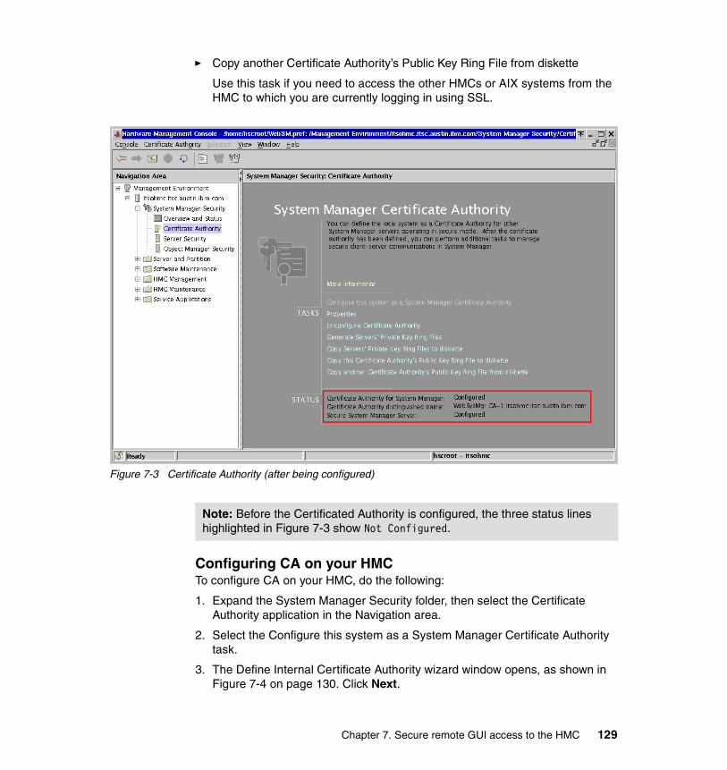
� Copy another Certificate Authority’s Public Key Ring File from diskette
Use this task if you need to access the other HMCs or AIX systems from the HMC to which you are currently logging in using SSL.
Figure 7-3 Certificate Authority (after being configured)
Configuring CA on your HMCTo configure CA on your HMC, do the following:
1. Expand the System Manager Security folder, then select the Certificate Authority application in the Navigation area.
2. Select the Configure this system as a System Manager Certificate Authority task.
3. The Define Internal Certificate Authority wizard window opens, as shown in Figure 7-4 on page 130. Click Next.
Note: Before the Certificated Authority is configured, the three status lines highlighted in Figure 7-3 show Not Configured.
Chapter 7. Secure remote GUI access to the HMC 129
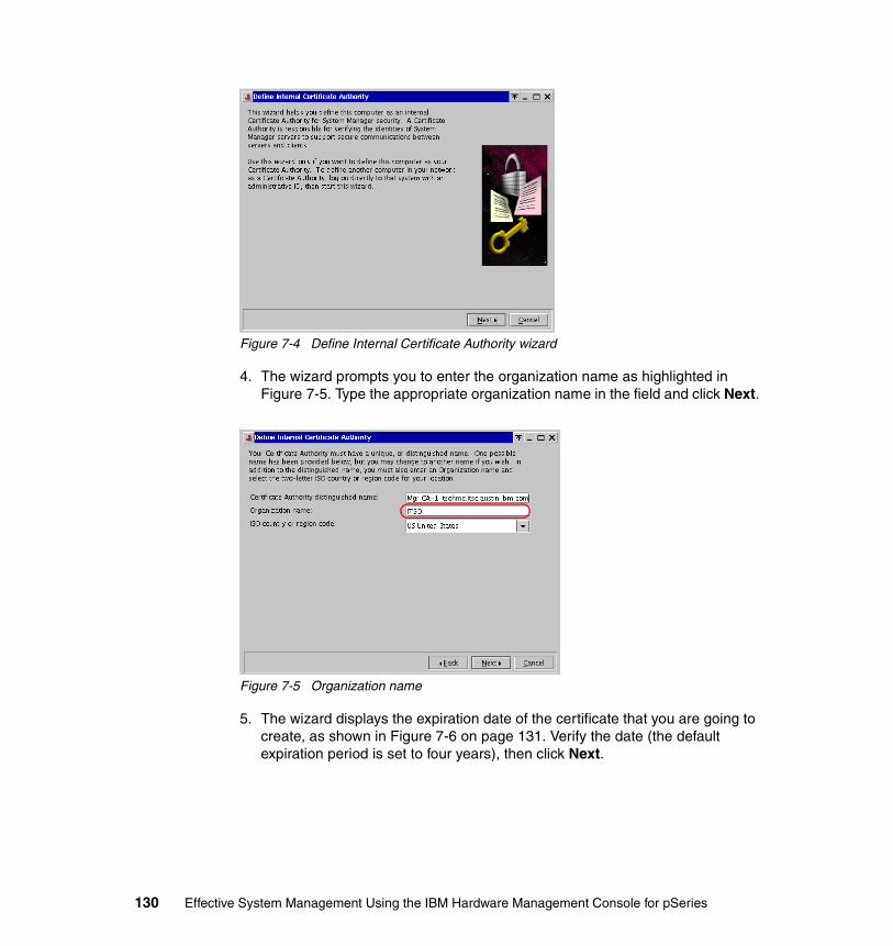
Figure 7-4 Define Internal Certificate Authority wizard
4. The wizard prompts you to enter the organization name as highlighted in Figure 7-5. Type the appropriate organization name in the field and click Next.
Figure 7-5 Organization name
5. The wizard displays the expiration date of the certificate that you are going to create, as shown in Figure 7-6 on page 131. Verify the date (the default expiration period is set to four years), then click Next.
130 Effective System Management Using the IBM Hardware Management Console for pSeries
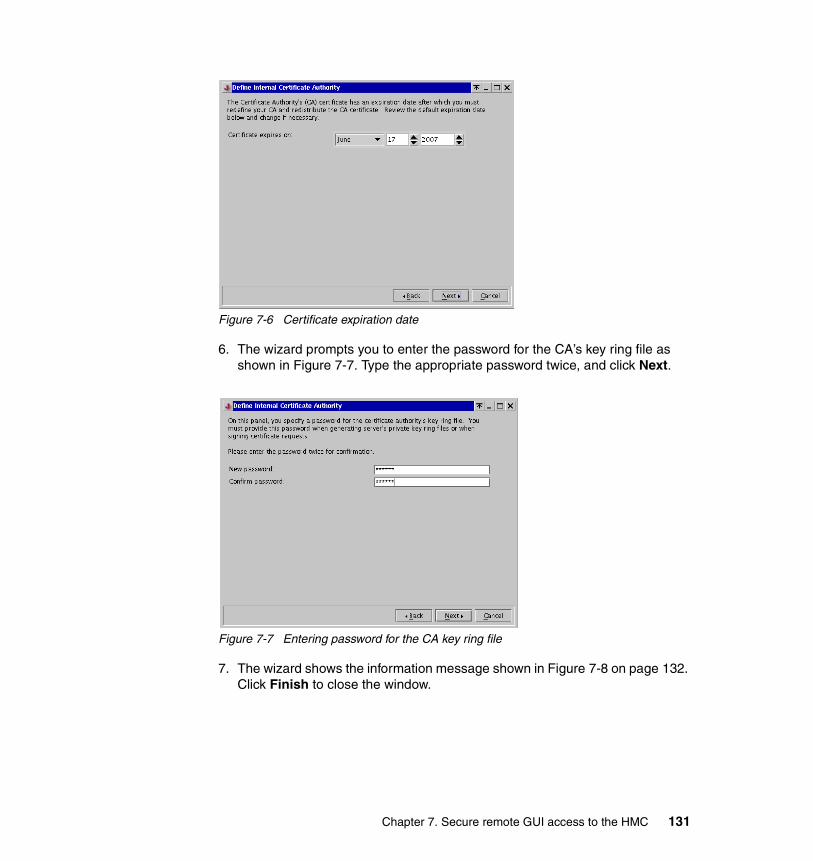
Figure 7-6 Certificate expiration date
6. The wizard prompts you to enter the password for the CA’s key ring file as shown in Figure 7-7. Type the appropriate password twice, and click Next.
Figure 7-7 Entering password for the CA key ring file
7. The wizard shows the information message shown in Figure 7-8 on page 132. Click Finish to close the window.
Chapter 7. Secure remote GUI access to the HMC 131
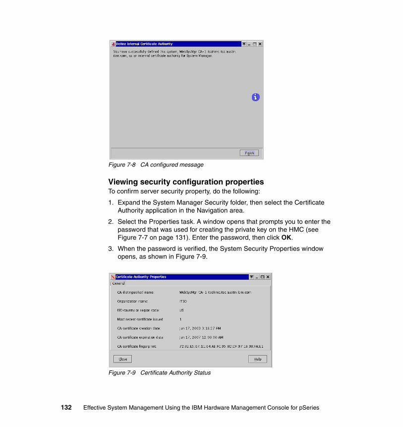
Figure 7-8 CA configured message
Viewing security configuration propertiesTo confirm server security property, do the following:
1. Expand the System Manager Security folder, then select the Certificate Authority application in the Navigation area.
2. Select the Properties task. A window opens that prompts you to enter the password that was used for creating the private key on the HMC (see Figure 7-7 on page 131). Enter the password, then click OK.
3. When the password is verified, the System Security Properties window opens, as shown in Figure 7-9.
Figure 7-9 Certificate Authority Status
132 Effective System Management Using the IBM Hardware Management Console for pSeries

Generating private key ring files for the HMCTo generate private key ring files for the HMC, do the following:
1. Expand the System Manager Security folder, then select the Certificate Authority application in the Navigation area.
2. Select the Generate Servers’ Private Key Ring Files task.
3. The window shown in Figure 7-10 opens and prompts you to enter the password that was used for creating the private key on the HMC (see Figure 7-7 on page 131). Enter the password, then click OK.
Figure 7-10 Entering certificate authority password
4. The window shown in Figure 7-11 opens. Verify whether the HMC host name is shown correctly in the field indicated by A in Figure 7-11, then click Add.
Figure 7-11 Generate Servers’ Private Key Ring Files
Note: Before selecting this task, a CA is must be configured on the HMC.
A
B
C
Chapter 7. Secure remote GUI access to the HMC 133
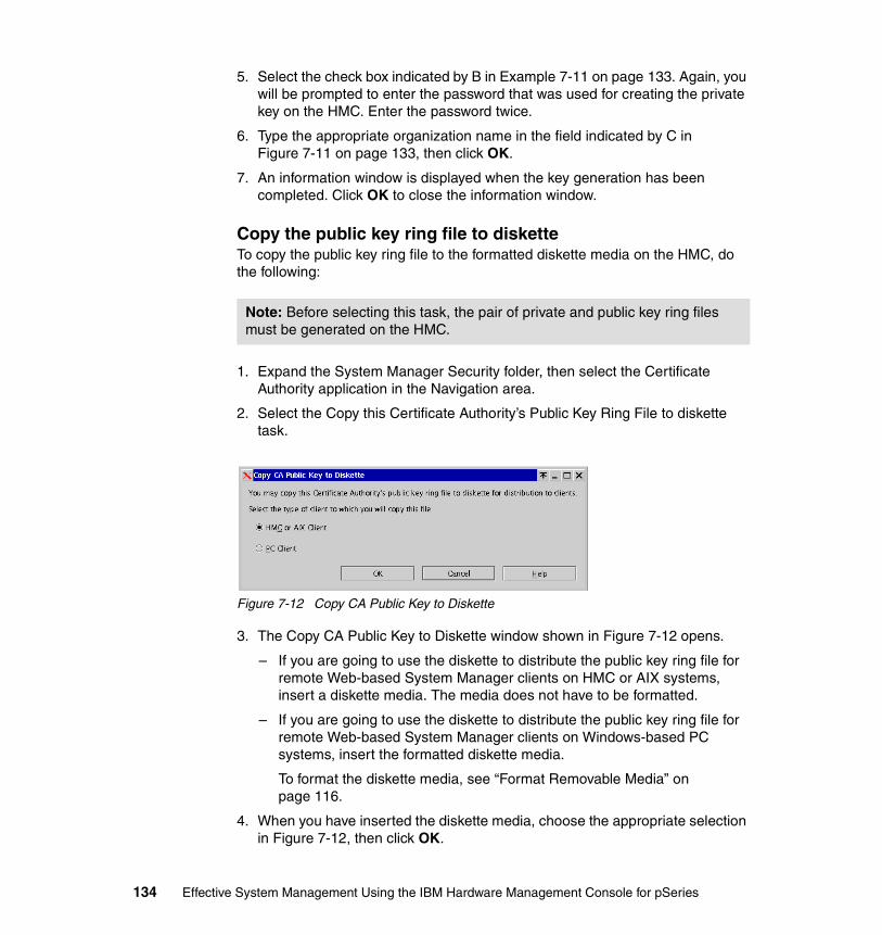
5. Select the check box indicated by B in Example 7-11 on page 133. Again, you will be prompted to enter the password that was used for creating the private key on the HMC. Enter the password twice.
6. Type the appropriate organization name in the field indicated by C in Figure 7-11 on page 133, then click OK.
7. An information window is displayed when the key generation has been completed. Click OK to close the information window.
Copy the public key ring file to disketteTo copy the public key ring file to the formatted diskette media on the HMC, do the following:
1. Expand the System Manager Security folder, then select the Certificate Authority application in the Navigation area.
2. Select the Copy this Certificate Authority’s Public Key Ring File to diskette task.
Figure 7-12 Copy CA Public Key to Diskette
3. The Copy CA Public Key to Diskette window shown in Figure 7-12 opens.
– If you are going to use the diskette to distribute the public key ring file for remote Web-based System Manager clients on HMC or AIX systems, insert a diskette media. The media does not have to be formatted.
– If you are going to use the diskette to distribute the public key ring file for remote Web-based System Manager clients on Windows-based PC systems, insert the formatted diskette media.
To format the diskette media, see “Format Removable Media” on page 116.
4. When you have inserted the diskette media, choose the appropriate selection in Figure 7-12, then click OK.
Note: Before selecting this task, the pair of private and public key ring files must be generated on the HMC.
134 Effective System Management Using the IBM Hardware Management Console for pSeries
5. An information window is displayed when the copy has been completed. Click OK to close the information window.
The public key ring file, SM.pubkr, is now copied from the System Manager Certificate Authority menu to a diskette.
� If you selected “HMC or AIX Client” in step 3, the diskette contains only one file, SM.pubkr, in the tar archive format.
� If you selected “PC Client” in step 3, the diskette contains only one file, SM.pubkr, in the DOS format.
7.1.3 Server SecurityThe Server Security application contains the following three tasks (see the Content area shown in Figure 7-13 on page 136).
� View properties for this server
Use this task to view the security configuration properties on your HMC. See “Viewing security configuration properties” on page 136 to use this task.
� Install the private key ring file for this server
Use this task to install the private key ring file on your HMC. See “Install the private key ring file for this server” on page 137 to use this task.
� Configure this system as a Secure System Manager Server
Use this task to configure the Web-based System Manager server to use the private key ring file to establish a secure network connection using SSL.
See “Configure this system as a Secure System Manager Server” on page 138 to use this task.
Important: Do not copy the public key file to a network-accessible place, such as on an anonymous ftp server. If a malicious user steals the file, the security mechanism provided by HMC does not block the access from this user.
Chapter 7. Secure remote GUI access to the HMC 135
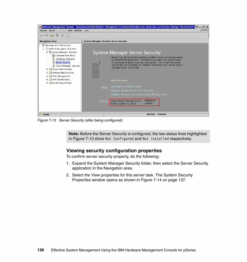
Figure 7-13 Server Security (after being configured)
Viewing security configuration propertiesTo confirm server security property, do the following:
1. Expand the System Manager Security folder, then select the Server Security application in the Navigation area.
2. Select the View properties for this server task. The System Security Properties window opens as shown in Figure 7-14 on page 137.
Note: Before the Server Security is configured, the two status lines highlighted in Figure 7-13 show Not Configured and Not installed respectively.
136 Effective System Management Using the IBM Hardware Management Console for pSeries

Figure 7-14 Server Security Properties (Server Certificate)
3. Once you have confirmed the properties, click Close to close the window.
Install the private key ring file for this server
To install the private key ring file on the HMC, do the following:
1. Expand the System Manager Security folder, then select the Server Security application in the Navigation area.
Figure 7-15 Install Private Key Ring file
2. Select the Install the private key ring file for this server task. The Install Private Key Ring File window opens as shown in Figure 7-15.
– If you have just generated the pair of private and public key ring files on your HMC (“Generating private key ring files for the HMC” on page 133), select the Directory option, then click OK.
Note: Before selecting this task, the pair of private and public key ring files must be generated on the HMC.
Chapter 7. Secure remote GUI access to the HMC 137

– If the private key ring file is stored in a tar archive on the HMC, select the tar file option, and click OK. Specify the file name location.
– If you have the backup diskette media that stores the server private key ring file1, select the tar diskette option, and click OK.
3. A window shown in Figure 7-10 on page 133 opens that prompts you to enter a password that was used for creating the private key on the HMC (see Figure 7-7 on page 131). Enter the password, then click OK.
4. An information window is displayed once the server configuration has been completed. Click OK to close the information window.
Configure this system as a Secure System Manager Server
To configure your HMC as a secure system manager server, do the following:
1. Expand the System Manager Security folder, then select the Server Security application in the Navigation area.
2. Select the Configure this system as a Secure System Manager Server task.
3. The Configure System Manager Security wizard window opens. Click Next.
4. The wizard prompts you to select either of the following options, as shown in Figure 7-16 on page 139:
– Always use a secure connection
Select this option if you wish to disallow unsecure connection from remote Web-based System Manager clients to the HMC.
– Allow the user to chose secure or unsecure connections
Select this option if you have decided to let users select either secure or unsecure connection from their from remote Web-based System Manager clients to the HMC.
1 You can back up the server private key file using the “Copy Servers’ Private Key Ring Files to diskette” task provided in the Certificate Authority application.
Note: Before selecting this task, the private key ring file must be installed on the HMC.
138 Effective System Management Using the IBM Hardware Management Console for pSeries
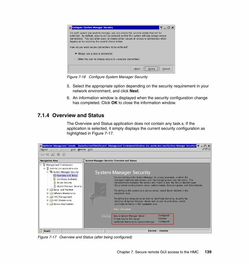
Figure 7-16 Configure System Manager Security
5. Select the appropriate option depending on the security requirement in your network environment, and click Next.
6. An information window is displayed when the security configuration change has completed. Click OK to close the information window.
7.1.4 Overview and StatusThe Overview and Status application does not contain any task.s. If the application is selected, it simply displays the current security configuration as highlighted in Figure 7-17.
Figure 7-17 Overview and Status (after being configured)
Chapter 7. Secure remote GUI access to the HMC 139
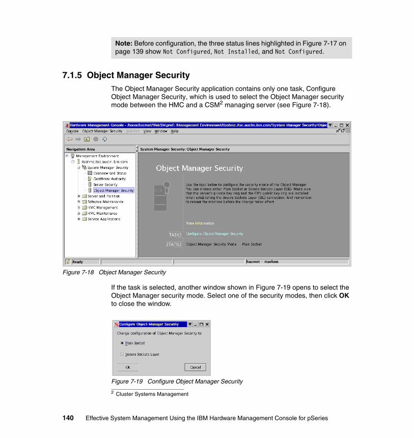
7.1.5 Object Manager SecurityThe Object Manager Security application contains only one task, Configure Object Manager Security, which is used to select the Object Manager security mode between the HMC and a CSM2 managing server (see Figure 7-18).
Figure 7-18 Object Manager Security
If the task is selected, another window shown in Figure 7-19 opens to select the Object Manager security mode. Select one of the security modes, then click OK to close the window.
Figure 7-19 Configure Object Manager Security
Note: Before configuration, the three status lines highlighted in Figure 7-17 on page 139 show Not Configured, Not Installed, and Not Configured.
2 Cluster Systems Management
140 Effective System Management Using the IBM Hardware Management Console for pSeries

For further information about CSM, refer to the following publications:
� IBM Cluster Systems Management for AIX 5L, Planning and Installation Guide, SA22-7919
� IBM Cluster Systems Management for AIX 5L, Administration Guide, SA22-7918
7.2 Remote client setup on a Windows systemThe remote Web-based System Manager client3 can be installed from the HMC by accessing specific URLs4 using a Web browser on your Windows-based PC.
If you are planning to use the remote client on a PC with Microsoft Windows installed, the OS must be one of the following operating systems:
� Microsoft Windows NT� Microsoft Windows 2000� Microsoft Windows XP
In addition, the PC should have the following hardware resources:
� 150 MB of free disk space on the default drive for temporary use during the installation procedure
� 150 MB of free disk space on the drive that you plan to use to install the remote client
� PC processor speed of at least 800 MHz
� A minimum of 256 MB of memory (512 MB recommended)
It is strongly recommended that you configure a secure network connection between your remote clients and the HMC using the SSL protocol. To configure the security configuration on the HMC, see 7.1.1, “Configuration steps to set up secure system manager server” on page 127.
Note: After changing the security mode, the HMC must be rebooted for the change to take effect.
3 The Web-based System Manager client package contains the Java runtime environment.4 While the web server process is always running on the HMC, access to the TCP port 80 is denied in all cases except for access to the specific URLs.
Note: To use SSL with the remote client, you must install the remote client security package in addition to the Web-based System Manager client.
Chapter 7. Secure remote GUI access to the HMC 141
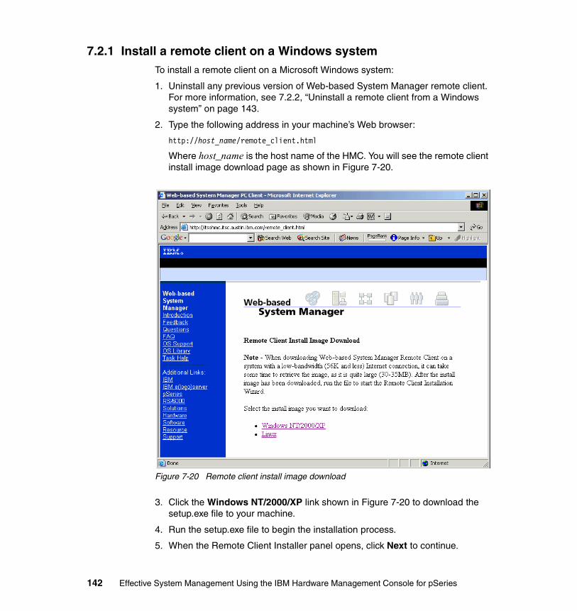
7.2.1 Install a remote client on a Windows systemTo install a remote client on a Microsoft Windows system:
1. Uninstall any previous version of Web-based System Manager remote client. For more information, see 7.2.2, “Uninstall a remote client from a Windows system” on page 143.
2. Type the following address in your machine’s Web browser:
http://host_name/remote_client.html
Where host_name is the host name of the HMC. You will see the remote client install image download page as shown in Figure 7-20.
Figure 7-20 Remote client install image download
3. Click the Windows NT/2000/XP link shown in Figure 7-20 to download the setup.exe file to your machine.
4. Run the setup.exe file to begin the installation process.
5. When the Remote Client Installer panel opens, click Next to continue.
142 Effective System Management Using the IBM Hardware Management Console for pSeries
6. To install using the default location, click Next. Otherwise, type the desired location and click Next.
7. A confirmation panel opens, showing you the installation location, the package being installed, and the approximate size of the installation package. Click Next to start the installation. If any of the information shown is incorrect, click Back to make corrections.
8. A status panel displays a message that says that the installation completed successfully or error messages if errors occurred during the installation. Click Finish to close the panel.
7.2.2 Uninstall a remote client from a Windows systemTo uninstall a remote client from a Microsoft Windows system, do the following:
1. From the taskbar, select Start → Settings → Control Panel.
2. In the Control Panel, double-click the Add/Remove Programs icon. Select Web-based System Manager Remote Client from the list of programs on the Install/Uninstall tab, then click Add/Remove to start the Uninstall wizard.
3. Click Next in the initial panel.
4. Click Next in the Confirmation panel to uninstall the remote client.
A status panel opens showing either that the uninstallation completed successfully or error messages if errors occurred during the uninstallation. Click Finish to close the panel.
7.2.3 Install remote client security on a Windows system
To install remote client security on the Microsoft Windows system, do the following:
1. Type the following Web address into your machine’s Web browser:
http://host_name/remote_client_security.html
Where host_name is the host name of the HMC. You will see the remote client security install image download page, as shown in Figure 7-21 on page 144.
Note: The Web-based System Manager client must be installed before installing remote client security.
Chapter 7. Secure remote GUI access to the HMC 143
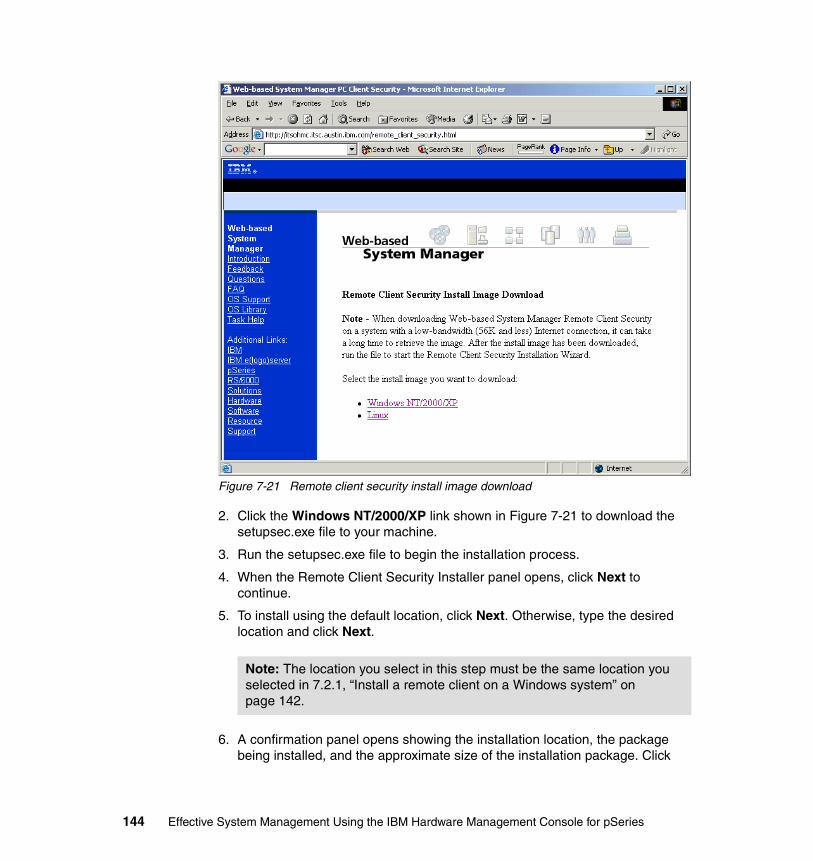
Figure 7-21 Remote client security install image download
2. Click the Windows NT/2000/XP link shown in Figure 7-21 to download the setupsec.exe file to your machine.
3. Run the setupsec.exe file to begin the installation process.
4. When the Remote Client Security Installer panel opens, click Next to continue.
5. To install using the default location, click Next. Otherwise, type the desired location and click Next.
6. A confirmation panel opens showing the installation location, the package being installed, and the approximate size of the installation package. Click
Note: The location you select in this step must be the same location you selected in 7.2.1, “Install a remote client on a Windows system” on page 142.
144 Effective System Management Using the IBM Hardware Management Console for pSeries
Next to start the installation. If any of the information shown is incorrect, click b to make corrections.
A status panel displays a message that says that the installation completed successfully or showing error messages if an error occurred during the installation. Click Finish to close the panel.
7.2.4 Uninstall remote client security from a Windows systemTo uninstall remote client from a Microsoft Windows system, do the following:
1. From the taskbar, select Start → Settings → Control Panel.
2. In Control Panel, double-click the Add/Remove Programs icon.
3. Select Remote Client Security from the list of programs on the Install/Uninstall tab, then click Add/Remove to start the Uninstall wizard.
4. Click Next in the initial panel.
5. Click Next in the Confirmation panel to uninstall remote client security.
A status panel opens showing either that the installation completed successfully or any messages if errors occurred during the installation. Click Finish to close the panel.
7.3 Remote client setup on a Linux systemThe remote Web-based System Manager client5 can be installed from the HMC by accessing specific URLs6 using a Web browser on your Linux-based PC.
If you are planning to use the remote client on a PC installed with Linux, one of the following operating systems must be installed on your PC:
� Red Hat Release 7.2� Red Hat Release 7.3
In addition, the PC should have the following hardware resources:
� 150 MB of free disk space on the default drive for temporary use during the installation procedure
� 150 MB of free disk space on the drive that you plan to use to install the remote client
� PC processor speed of at least 800 MHz
5 The Web-based System Manager client package contains the Java runtime environment.6 While the Web server process is always running on the HMC, access to the TCP port 80 is denied in all cases except for access to the specific URLs.
Chapter 7. Secure remote GUI access to the HMC 145
� A minimum of 256 MB of memory (512 MB recommended)
It is strongly recommended to configure a secure network connection between your remote clients and the HMC using the SSL protocol. To configure the security configuration on the HMC, see 7.1, “System Manager Security” on page 126.
7.3.1 Install a remote client on a Linux systemTo install a remote client on a Linux system, do the following:
1. Uninstall any previous version of the remote client on your machine. For more information, see 7.3.2, “Uninstall a remote client from a Linux system” on page 147.
2. Type the following address in your machine’s Web browser:
http://host_name/remote_client.html
Where host_name is the host name of the HMC. You will see the remote client install image download page as shown in Figure 7-20 on page 142.
3. Click the Linux link shown in Figure 7-20 on page 142 to download the wsmlinuxclient.exe file to your machine.
4. Run the wsmlinuxclient.exe file to begin the installation process. If the file does not run, modify the permissions on the file so that you have execute permissions. At a command prompt, type the following:
# chmod 755 wsmlinuxclient.exe
5. When the Remote Client Installer panel opens, click Next to continue.
6. To install using the default location, click Next. Otherwise, type the desired location and click Next.
7. A confirmation panel opens showing the installation location, the package being installed, and the approximate size of the installation package. Click Next to start the installation. If any of the information shown is incorrect, click Back to make corrections.
A status panel displays either a message that says that the installation completed successfully or error messages if errors occurred during the installation. Click Finish to close the panel.
Note: To use SSL with the remote client, you must install the remote client security package in addition to the Web-based System Manager client.
146 Effective System Management Using the IBM Hardware Management Console for pSeries
7.3.2 Uninstall a remote client from a Linux systemTo uninstall a remote client from a Linux system, run the following command:
installdir/_uninst/uninstall
Where installdir is the name of the directory in which your remote client resides.
7.3.3 Install remote client security on a Linux systemTo install remote client security on a Linux system, do the following:
1. Uninstall any previous version of remote client security on your machine. For more information, see 7.3.2, “Uninstall a remote client from a Linux system” on page 147.
2. Type the following address in your machine’s Web browser:
http://host_name/remote_client_security.html
Where host_name is the host name of the HMC.
3. Click the Linux link shown in Figure 7-21 on page 144 to download the setupsecl.exe file to your machine.
4. Run the setupsecl.exe file to begin the installation process. If the file does not run, modify the permissions on the file so that you have execute permissions. At a command prompt, type the following:
chmod 755 setupsecl.exe
5. When the Remote Client Security Installer panel opens, click Next to continue.
6. To install using the default location, click Next. Otherwise, type the desired location and click Next.
Note: If changes do not take effect immediately, either log out of your current session and log in again, or read the /etc/profile file again by issuing:
# . /etc/profile
Note: The Web-based System Manager client must be installed before installing the remote client security.
Note: Be sure that the location you designate is the same location you selected in 7.3.1, “Install a remote client on a Linux system” on page 146.
Chapter 7. Secure remote GUI access to the HMC 147
7. A confirmation panel opens showing the installation location, the package being installed, and the approximate size of the installation package. Click Next to start the installation. If any of the information shown is incorrect, click Back to make corrections.
A status panel displays a message that either says that the installation completed successfully or shows error messages if errors occurred during the installation. Click Finish to close the panel.
7.3.4 Uninstall remote client security from a Linux systemTo uninstall the remote client security from a Linux system, run the following command:
installdir/_uninstssl/uninstallssl
Where installdir is the name of the directory in which your remote client resides.
7.4 Remote access to the HMC graphical user interfaceThis section explains how to use the remote client on Windows and AIX systems to remotely access the HMC graphical user interface.
To secure the connection between client and server, you should configure the secure communication using the HMC System Manager Security application on the HMC (see 7.1, “System Manager Security” on page 126). It provides the Secure Socket Layer (SSL) encrypted communication path between the client and the server.
Note: If changes do not take effect immediately, either log out of your current session and log in again, or read the /etc/profile file by issuing:
# . /etc/profile
Note: While using the remote Web-based System Manager client, the menu (Help → About) tells you the software version of the Web-based System Manager client software you are using currently, not the software release level on the HMC. To use the remote Web-based System Manager client to confirm the software release level on the HMC, select Software Maintenance → HMC (see Figure 6-3 on page 110).
148 Effective System Management Using the IBM Hardware Management Console for pSeries
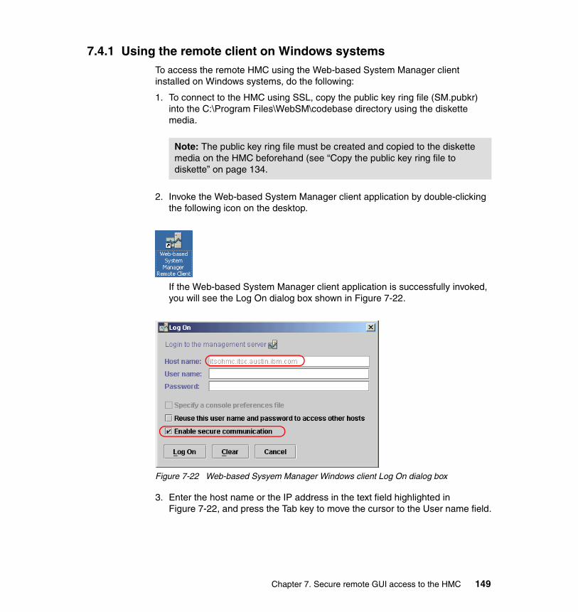
7.4.1 Using the remote client on Windows systemsTo access the remote HMC using the Web-based System Manager client installed on Windows systems, do the following:
1. To connect to the HMC using SSL, copy the public key ring file (SM.pubkr) into the C:\Program Files\WebSM\codebase directory using the diskette media.
2. Invoke the Web-based System Manager client application by double-clicking the following icon on the desktop.
If the Web-based System Manager client application is successfully invoked, you will see the Log On dialog box shown in Figure 7-22.
Figure 7-22 Web-based Sysyem Manager Windows client Log On dialog box
3. Enter the host name or the IP address in the text field highlighted in Figure 7-22, and press the Tab key to move the cursor to the User name field.
Note: The public key ring file must be created and copied to the diskette media on the HMC beforehand (see “Copy the public key ring file to diskette” on page 134.
Chapter 7. Secure remote GUI access to the HMC 149
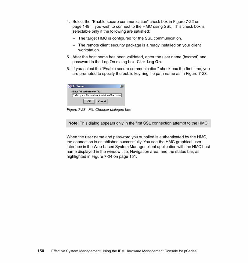
4. Select the “Enable secure communication” check box in Figure 7-22 on page 149, if you wish to connect to the HMC using SSL. This check box is selectable only if the following are satisfied:
– The target HMC is configured for the SSL communication.
– The remote client security package is already installed on your client workstation.
5. After the host name has been validated, enter the user name (hscroot) and password in the Log On dialog box. Click Log On.
6. If you select the “Enable secure communication” check box the first time, you are prompted to specify the public key ring file path name as in Figure 7-23.
Figure 7-23 File Chooser dialogue box
When the user name and password you supplied is authenticated by the HMC, the connection is established successfully. You see the HMC graphical user interface in the Web-based System Manager client application with the HMC host name displayed in the window title, Navigation area, and the status bar, as highlighted in Figure 7-24 on page 151.
Note: This dialog appears only in the first SSL connection attempt to the HMC.
150 Effective System Management Using the IBM Hardware Management Console for pSeries
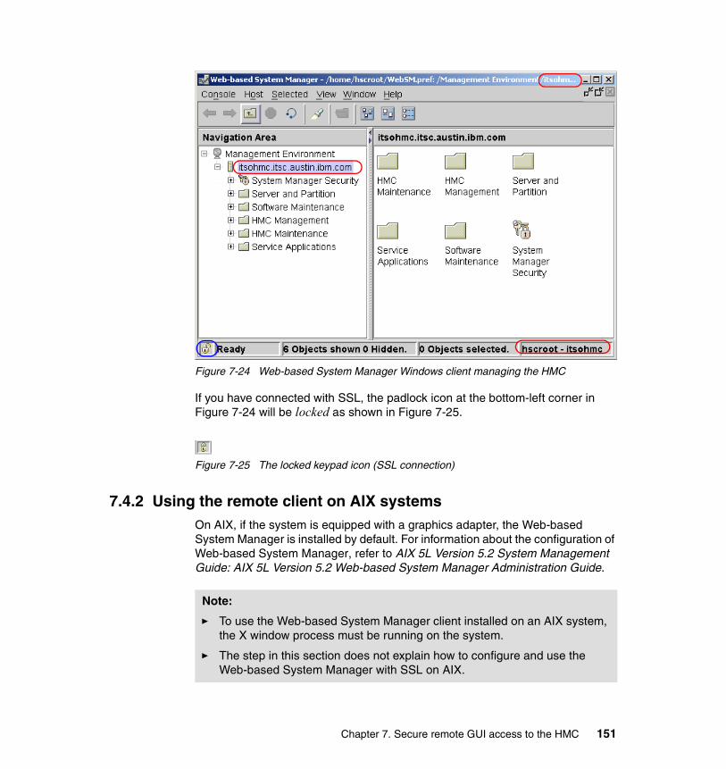
Figure 7-24 Web-based System Manager Windows client managing the HMC
If you have connected with SSL, the padlock icon at the bottom-left corner in Figure 7-24 will be locked as shown in Figure 7-25.
Figure 7-25 The locked keypad icon (SSL connection)
7.4.2 Using the remote client on AIX systemsOn AIX, if the system is equipped with a graphics adapter, the Web-based System Manager is installed by default. For information about the configuration of Web-based System Manager, refer to AIX 5L Version 5.2 System Management Guide: AIX 5L Version 5.2 Web-based System Manager Administration Guide.
Note:
� To use the Web-based System Manager client installed on an AIX system, the X window process must be running on the system.
� The step in this section does not explain how to configure and use the Web-based System Manager with SSL on AIX.
Chapter 7. Secure remote GUI access to the HMC 151
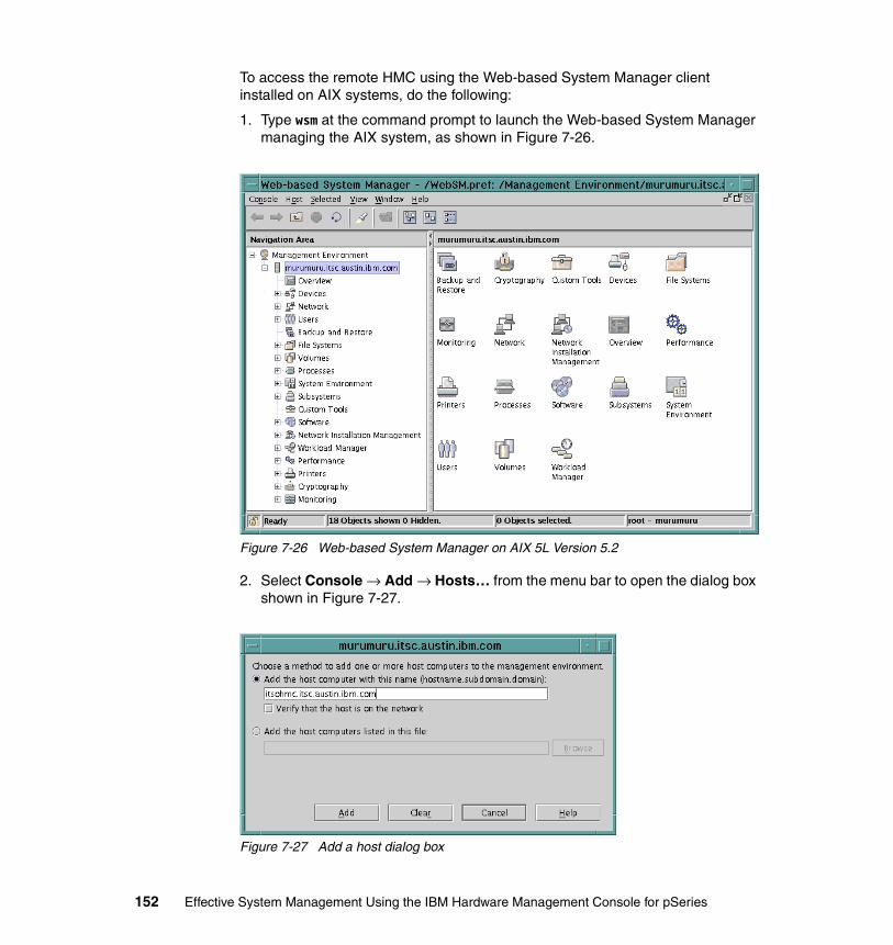
To access the remote HMC using the Web-based System Manager client installed on AIX systems, do the following:
1. Type wsm at the command prompt to launch the Web-based System Manager managing the AIX system, as shown in Figure 7-26.
Figure 7-26 Web-based System Manager on AIX 5L Version 5.2
2. Select Console → Add → Hosts… from the menu bar to open the dialog box shown in Figure 7-27.
Figure 7-27 Add a host dialog box
152 Effective System Management Using the IBM Hardware Management Console for pSeries

3. Type the HMC host name or IP address in the text field. Click Add.
4. The added HMC will be shown in the Navigation Area of Web-based System Manager as shown in Figure 7-28.
Figure 7-28 Remote HMC is shown in the Navigation Area
5. Click the icon representing the HMC to open the Log On dialog box.
6. Enter the host name or the IP address in the text field.
7. After the host name has been validated, enter the User name (hscroot) and Password in the Log On dialog box. Click Log On.
When the user name and password you supplied is authenticated by the HMC, the connection is established successfully and you see the HMC graphical user interface in the Web-based System Manager client application shown in Figure 7-29 on page 154. The HMC host name will be displayed in the window title, Navigation area, and the status bar, as highlighted in Figure 7-29 on page 154.
Chapter 7. Secure remote GUI access to the HMC 153

Figure 7-29 Managing HMC from the Web-based System Manager on AIX
Using command line options of wsmThe wsm command on AIX has the following command line syntax:
$ wsm -?USAGE: wsm [-host <host name of managing machine>] [-port <inetd port>] [-profile <pathname of wconsole.pref file>] [-user <login name>]
Therefore, you can quickly connect to the HMC if you invoke this command:
$ wsm -host host_name -user hscroot
Use your HMC’s host name or IP address for host_name.
154 Effective System Management Using the IBM Hardware Management Console for pSeries

Chapter 8. Secure networking in a partitioned environment
This chapter discusses how to plan and implement a secure network in a partitioned environment where your HMC and managed systems are installed. It includes the following sections:
� “Networking in a partitioned environment” on page 156� “Network paths in a partitioned environment” on page 157� “Providing security to the HMC and partitions” on page 163� “A sample implementation of port filtering rules” on page 167� “Service Agent and security concerns” on page 172
8
Note: Throughout this chapter, the host name resolution for the network interfaces of the HMC and partition follows the network planning rules explained in Appendix , “Trouble-free network planning rules” on page 312.
© Copyright IBM Corp. 2003. All rights reserved. 155
8.1 Networking in a partitioned environmentUnlike the IBM RS/6000® SP™ control workstation, an HMC does not have to be in the same broadcast domain as the partitions that it manages. This is because the HMC, as opposed to the control workstation, does not participate in the network boot process.1
An HMC does not even have to be on the same network segment as a partition that it manages, as long as they can reach each other via IP routing. A partition must be IP-accessible for the following functions to be supported:
� DLPAR operations
For detailed information about the DLPAR operations, refer to The Complete Partitioning Guide for IBM Eserver pSeries Servers, SG24-7039.
� Service functions, such as Service Focal Point and Inventory Scout
See Chapter 11, “Service functions on the HMC” on page 247.
These operations and services rely on the secure and reliable connection channel, which is established and provided by Resource Monitoring and Control (RMC) over the TCP/IP network between the HMC and partitions.
The HMC performs many of its management functions using the serial network connecting it to the service processors on its managed systems. This usually means that the HMC is physically located within 15 meters (50 feet) of the servers it manages. Most often, the HMC will be located in a machine room, possibly with restricted access. This can make systems management at the HMC itself somewhat inconvenient.
The physical placement of the HMC becomes irrelevant if the systems administrator is using a remote user interfaces, such as the Web-based System Manager client (see Chapter 7, “Secure remote GUI access to the HMC” on page 125) or the secure shell (see 9.1, “Secure remote connection to the HMC” on page 176). In the following sections, we describe how to implement a secure network configuration in a partitioned environment.
1 The network boot process using the BOOTP protocol is used when AIX is installed over the network using Network Installation Manager (NIM).
Note: If the distance solution (see “Distance solution” on page 29) is used, the distance from the HMC to the managed system can be extended up to 315 meters (1050 feet).
156 Effective System Management Using the IBM Hardware Management Console for pSeries
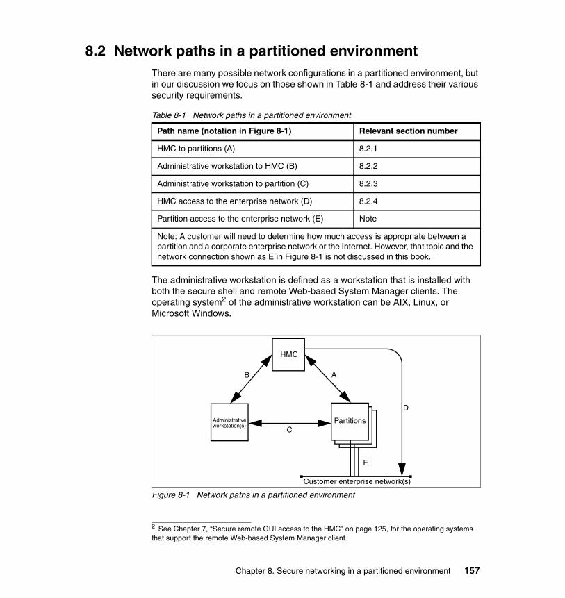
8.2 Network paths in a partitioned environmentThere are many possible network configurations in a partitioned environment, but in our discussion we focus on those shown in Table 8-1 and address their various security requirements.
Table 8-1 Network paths in a partitioned environment
The administrative workstation is defined as a workstation that is installed with both the secure shell and remote Web-based System Manager clients. The operating system2 of the administrative workstation can be AIX, Linux, or Microsoft Windows.
Figure 8-1 Network paths in a partitioned environment
Path name (notation in Figure 8-1) Relevant section number
HMC to partitions (A) 8.2.1
Administrative workstation to HMC (B) 8.2.2
Administrative workstation to partition (C) 8.2.3
HMC access to the enterprise network (D) 8.2.4
Partition access to the enterprise network (E) Note
Note: A customer will need to determine how much access is appropriate between a partition and a corporate enterprise network or the Internet. However, that topic and the network connection shown as E in Figure 8-1 is not discussed in this book.
2 See Chapter 7, “Secure remote GUI access to the HMC” on page 125, for the operating systems that support the remote Web-based System Manager client.
HMC
PartitionsAdministrativeworkstation(s)
AB
C
Customer enterprise network(s)
E
D
Chapter 8. Secure networking in a partitioned environment 157
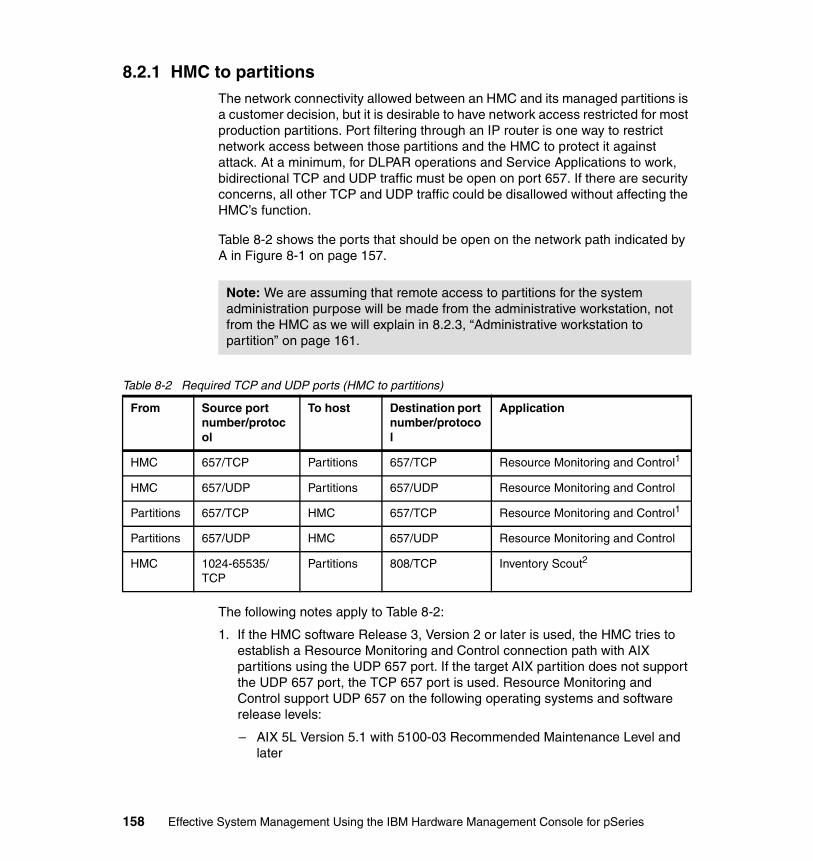
8.2.1 HMC to partitionsThe network connectivity allowed between an HMC and its managed partitions is a customer decision, but it is desirable to have network access restricted for most production partitions. Port filtering through an IP router is one way to restrict network access between those partitions and the HMC to protect it against attack. At a minimum, for DLPAR operations and Service Applications to work, bidirectional TCP and UDP traffic must be open on port 657. If there are security concerns, all other TCP and UDP traffic could be disallowed without affecting the HMC’s function.
Table 8-2 shows the ports that should be open on the network path indicated by A in Figure 8-1 on page 157.
Table 8-2 Required TCP and UDP ports (HMC to partitions)
The following notes apply to Table 8-2:
1. If the HMC software Release 3, Version 2 or later is used, the HMC tries to establish a Resource Monitoring and Control connection path with AIX partitions using the UDP 657 port. If the target AIX partition does not support the UDP 657 port, the TCP 657 port is used. Resource Monitoring and Control support UDP 657 on the following operating systems and software release levels:
– AIX 5L Version 5.1 with 5100-03 Recommended Maintenance Level and later
Note: We are assuming that remote access to partitions for the system administration purpose will be made from the administrative workstation, not from the HMC as we will explain in 8.2.3, “Administrative workstation to partition” on page 161.
From Source port number/protocol
To host Destination port number/protocol
Application
HMC 657/TCP Partitions 657/TCP Resource Monitoring and Control1
HMC 657/UDP Partitions 657/UDP Resource Monitoring and Control
Partitions 657/TCP HMC 657/TCP Resource Monitoring and Control1
Partitions 657/UDP HMC 657/UDP Resource Monitoring and Control
HMC 1024-65535/TCP
Partitions 808/TCP Inventory Scout2
158 Effective System Management Using the IBM Hardware Management Console for pSeries

– AIX 5L Version 5.2 with 5200-01 Recommended Maintenance Level and later
– If the HMC software Release 3, Version 1 and earlier is used, the HMC always uses TCP 657 port to communicate with AIX partitions
2. On systems installed with earlier software levels, Inventory Scout required that TCP port 808 be open. If an AIX partition supports the Inventory Scout automatic configuration, then the TCP port 808 does not have to be open (see 11.2.1, “Inventory Scout Configuration” on page 250 for the required software levels to support the Inventory Scout automatic configuration).
8.2.2 Administrative workstation to HMCThe HMC supports the following three remote access methods:
Access from remote Web-based System Manager clientsAs explained in 7.4, “Remote access to the HMC graphical user interface” on page 148, remote Web-based System Manager clients can connect to the HMC. The connection process is explained as follows:
1. On the HMC, the Web-based System Manager server process (wsmserver) listens on TCP port 9090 for a connection request from a remote client.
2. Before establishing a session, wsmserver opens two TCP ports, one for receiving and another for sending data between the client and itself. The source TCP ports on the client are randomly selected.
On the HMC loaded with the software level Release 3 Version 2 and later, only 10 ports within the port range of 30000-30009 are used for wsmserver, therefore the number of concurrent remote client sessions is limited to five.3
Remote access to the virtual terminalYou can access the virtual terminal from the remote Web-based System Manager client, if it is enabled as explained in 4.2.9, “Enable/Disable Remote Virtual Terminal” on page 97.
Note: It is recommended that the latest maintenance level be applied for each AIX version being used in a partition.
3 If HMC software earlier than Release 3 Version 2 is being used, this restriction does not apply.
Note: The same process is performed regardless of the use of the SSL protocol.
Chapter 8. Secure networking in a partitioned environment 159
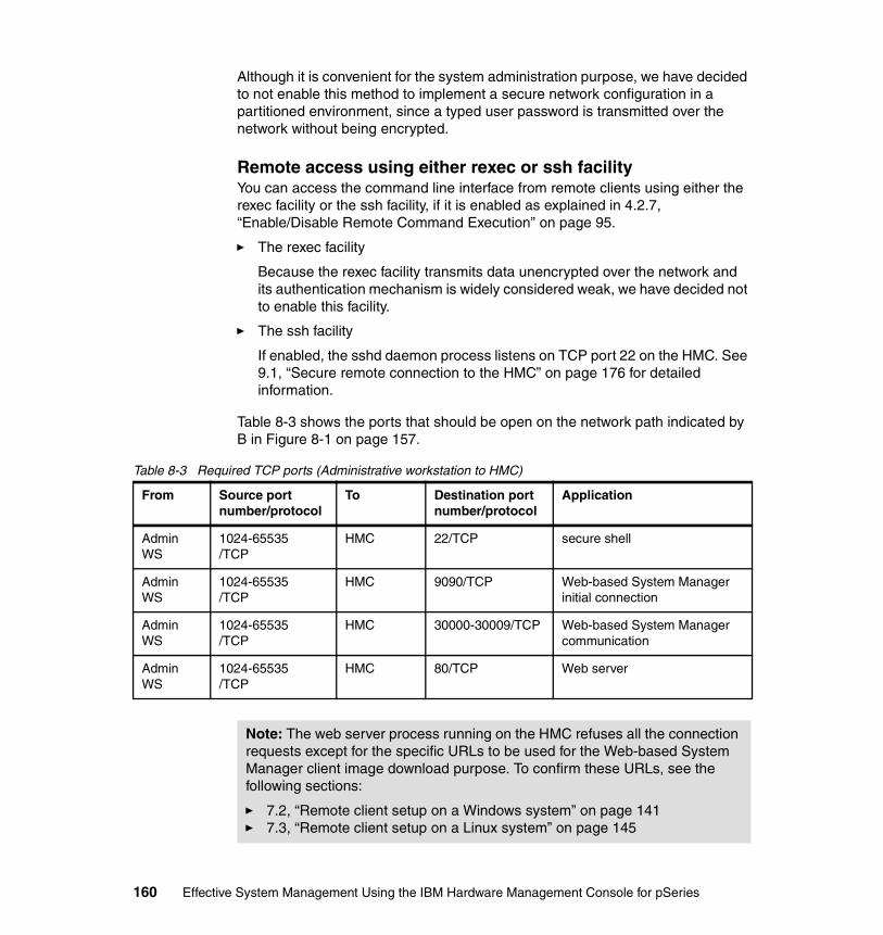
Although it is convenient for the system administration purpose, we have decided to not enable this method to implement a secure network configuration in a partitioned environment, since a typed user password is transmitted over the network without being encrypted.
Remote access using either rexec or ssh facilityYou can access the command line interface from remote clients using either the rexec facility or the ssh facility, if it is enabled as explained in 4.2.7, “Enable/Disable Remote Command Execution” on page 95.
� The rexec facility
Because the rexec facility transmits data unencrypted over the network and its authentication mechanism is widely considered weak, we have decided not to enable this facility.
� The ssh facility
If enabled, the sshd daemon process listens on TCP port 22 on the HMC. See 9.1, “Secure remote connection to the HMC” on page 176 for detailed information.
Table 8-3 shows the ports that should be open on the network path indicated by B in Figure 8-1 on page 157.
Table 8-3 Required TCP ports (Administrative workstation to HMC)
From Source port number/protocol
To Destination port number/protocol
Application
Admin WS
1024-65535/TCP
HMC 22/TCP secure shell
Admin WS
1024-65535/TCP
HMC 9090/TCP Web-based System Manager initial connection
Admin WS
1024-65535/TCP
HMC 30000-30009/TCP Web-based System Manager communication
Admin WS
1024-65535/TCP
HMC 80/TCP Web server
Note: The web server process running on the HMC refuses all the connection requests except for the specific URLs to be used for the Web-based System Manager client image download purpose. To confirm these URLs, see the following sections:
� 7.2, “Remote client setup on a Windows system” on page 141� 7.3, “Remote client setup on a Linux system” on page 145
160 Effective System Management Using the IBM Hardware Management Console for pSeries
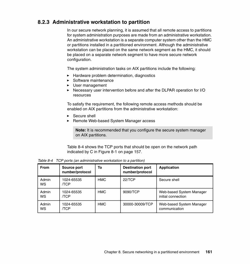
8.2.3 Administrative workstation to partitionIn our secure network planning, it is assumed that all remote access to partitions for system administration purposes are made from an administrative workstation. An administrative workstation is a separate computer system other than the HMC or partitions installed in a partitioned environment. Although the administrative workstation can be placed on the same network segment as the HMC, it should be placed on a separate network segment to have more secure network configuration.
The system administration tasks on AIX partitions include the following:
� Hardware problem determination, diagnostics� Software maintenance� User management� Necessary user intervention before and after the DLPAR operation for I/O
resources
To satisfy the requirement, the following remote access methods should be enabled on AIX partitions from the administrative workstation:
� Secure shell� Remote Web-based System Manager access
Table 8-4 shows the TCP ports that should be open on the network path indicated by C in Figure 8-1 on page 157.
Table 8-4 TCP ports (an administrative workstation to a partition)
Note: It is recommended that you configure the secure system manager on AIX partitions.
From Source port number/protocol
To Destination port number/protocol
Application
Admin WS
1024-65535/TCP
HMC 22/TCP Secure shell
Admin WS
1024-65535/TCP
HMC 9090/TCP Web-based System Manager initial connection
Admin WS
1024-65535/TCP
HMC 30000-30009/TCP Web-based System Manager communication
Chapter 8. Secure networking in a partitioned environment 161

Specifying a port range for remote WebSM access on AIXUnlike the HMC, the Web-based System Manager server process (wsmserver) on AIX partitions has no default port range restrictions. To enable wsmserver on an AIX partition, type the following command as the root user:
/usr/websm/bin/wsmserver -enable
To specify the connection port range, find the following line in /etc/inetd.conf on the partition:
wsmserver stream tcp nowait root /usr/websm/bin/wsmserver wsmserver -start
Append the options highlighted in the following example, replacing range_start and range_end with the appropriate port numbers:
wsmserver stream tcp nowait root /usr/websm/bin/wsmserver wsmserver -start -portstart range_start -portend range_end
After saving this file, issue refresh -s inetd on the partition.
By making this change, more secure port filtering rules can be implemented as explained in 8.2.2, “Administrative workstation to HMC” on page 159.
For further information about the configuration of the Web-based System Manager server process, refer to AIX 5L Version 5.2 System Management Guide: AIX 5L Version 5.2 Web-based System Manager Administration Guide.
8.2.4 HMC access to the enterprise networkIt becomes necessary occasionally for the HMC to access the Internet to obtain corrective service and microcode updates. If the HMC does not have direct access, it needs to access a server on the corporate backbone that can be used to stage these updates before loading them on the HMC. These updates can be obtained from IBM Web sites by either HTTP or FTP. While the HMC cannot be an FTP server, it can be an FTP client. 4
Note: For some application requirements on the administrative workstation and AIX partitions, more ports should be open. For example, if the CSM management server is defined on the administrative workstation and AIX partitions are participated in the same management domain, the TCP and UDP ports 657 must be open on the network path between them.
Note: These two example lines must be a single line in the /etc/inetd.conf file.
4 Firewalls or application proxy gateways are most likely deployed between the enterprise network and the Internet. The security of the enterprise network is not discussed in this book.
162 Effective System Management Using the IBM Hardware Management Console for pSeries
HMC software includes a Web browser that can be launched from the HMC console by clicking a button in the task bar located at the bottom of screen. However, only registered Web addresses provided by IBM for technical support can be accessed using the browser.
8.3 Providing security to the HMC and partitionsOur security objectives in the partitioned environment are twofold:
� Protecting the HMC itself� Protecting partitions in a secure zone from those that are less secure
These objects can be achieved using either port filtering (see 8.4, “A sample implementation of port filtering rules” on page 167), or vendor-specific advanced VLAN technologies (see Appendix , “Vendor-specific VLAN technologies (Cisco)” on page 326).
8.3.1 Securing the HMCThe HMC is designed to be a dedicate system — an appliance — for the control of managed systems. The software installed on HMC is based on the Linux operating system, but it has been customized to increase security and discourage uses other than those intended.
As explained in 8.2.2, “Administrative workstation to HMC” on page 159, there are a few accessible services available on the HMC. Popular services on UNIX-based operating systems, such as telnet, FTP, SMTP, and rsh, are disabled on the HMC.
No additional third-party applications should be installed on the HMC. Neither should systems administrators store scripts on the HMC, as they could be lost during software maintenance.
Because of its central role in managing multiple partitions, it is imperative that the HMC remain secure.
Controlling access on the HMCFunctions on the HMC are performed by the hscroot user or one created with the System Administrator role.5 Although the root user exists on the HMC, its uses are restricted to certain problem determination, system security, and code maintenance purposes.
5 See 4.1.1, “User role descriptions” on page 77 for the detailed information about roles on the HMC.
Chapter 8. Secure networking in a partitioned environment 163
No one may log in remotely to the HMC using the root user ID, either through the Web-based System Manager or the secure shell. In order to log in as root, a user would have to be at the HMC console. However, a remote user could become root after logging in as hscroot and supplying the necessary passwords. For this reason, the hscroot and root passwords should be very closely guarded.
In some companies, concern over root access has led to the installation of third-party programs that monitor root logins and audit activity. IBM does not support such programs; be sure they do not interfere with HMC functioning. If a customer installs such a security application, IBM software support may require that it be deinstalled before doing troubleshooting and problem determination.
Secure remote access facilitiesIf the secure shell and the secure Web-based System Manager are used, data crossing the network from the HMC will be encrypted and secure. This will protect against unauthorized snooping by other users on the network.
However, it is advisable to disable the remote virtual terminal facility, even from the secure Web-based System Manager clients. This is because text entered in the virtual terminal windows is not encrypted.
Protecting the HMC from malicious attacksIn addition to closely managing passwords and providing physical security for the HMC, specific steps can be taken to protect it in a networked environment. As shown in Figure 8-2 on page 165, the HMC must be protected from malicious users’ attacks, while it must provide the minimum network services explained in 8.2.1, “HMC to partitions” on page 158 and 8.2.2, “Administrative workstation to HMC” on page 159.
The most obvious solution is to put an IP router with port filtering on each network path, as explained in 8.2, “Network paths in a partitioned environment” on page 157.
164 Effective System Management Using the IBM Hardware Management Console for pSeries
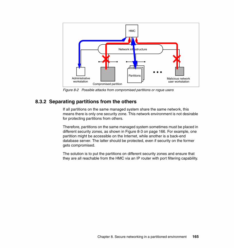
Figure 8-2 Possible attacks from compromised partitions or rogue users
8.3.2 Separating partitions from the othersIf all partitions on the same managed system share the same network, this means there is only one security zone. This network environment is not desirable for protecting partitions from others.
Therefore, partitions on the same managed system sometimes must be placed in different security zones, as shown in Figure 8-3 on page 166. For example, one partition might be accessible on the Internet, while another is a back-end database server. The latter should be protected, even if security on the former gets compromised.
The solution is to put the partitions on different security zones and ensure that they are all reachable from the HMC via an IP router with port filtering capability.
HMC
Network infrastructure
PartitionsMalicious networkuser workstation
Administrativeworkstation
Compromised partition
Chapter 8. Secure networking in a partitioned environment 165
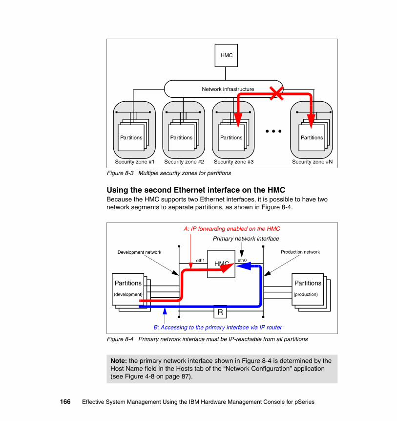
Figure 8-3 Multiple security zones for partitions
Using the second Ethernet interface on the HMCBecause the HMC supports two Ethernet interfaces, it is possible to have two network segments to separate partitions, as shown in Figure 8-4.
Figure 8-4 Primary network interface must be IP-reachable from all partitions
Note: the primary network interface shown in Figure 8-4 is determined by the Host Name field in the Hosts tab of the “Network Configuration” application (see Figure 4-8 on page 87).
Security zone #3Security zone #1 Security zone #2
Partitions
HMC
Network infrastructure
Partitions Partitions Partitions
Security zone #N
Partitions
(development)
HMC
Partitions
(production)
Production networkDevelopment network
eth0eth1
A: IP forwarding enabled on the HMC
R
B: Accessing to the primary interface via IP router
Primary network interface
166 Effective System Management Using the IBM Hardware Management Console for pSeries
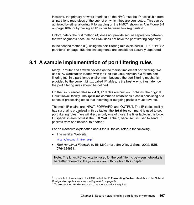
However, the primary network interface on the HMC must be IP accessible from all partitions regardless of the subnet on which they are connected. This can be achieved by either allowing IP forwarding on the HMC6 (shown as A in Figure 8-4 on page 166), or by having an IP router between two segments (B).
Unfortunately, the first method (A) does not provide secure separation between the two segments because the HMC does not have the port filtering capability.
In the second method (B), using the port filtering rule explained in 8.2.1, “HMC to partitions” on page 158, the two segments are considered securely separated.
8.4 A sample implementation of port filtering rulesMany IP router and firewall devices on the market implement port filtering. We use a PC workstation loaded with the Red Hat Linux Version 7.3 for the port filtering test in a partitioned environment because the port filtering mechanism provided by the current Linux, called IP tables, is the best way to illustrate how the port filtering rules should be defined.
On the Linux kernel release 2.4.X, IP tables are built on IP chains, the original Linux firewall facility. The ipchains command establishes a chain consisting of a series of processing steps that incoming or outgoing packets must traverse.
The main IP chains are INPUT, FORWARD, and OUTPUT. The IP tables facility has six chains organized in three tables; the iptables command is used to set port filtering rules.7 We will discuss only one of those, the filter table, in this book. Of special interest to us is the FORWARD chain, because it is used to send IP packets from one network to another.
For an extensive explanation about the IP tables, refer to the following:
� The netfilter Web site:
http://www.netfilter.org/
� Red Hat Linux Firewalls by Bill McCarty; John Wiley & Sons, 2002, ISBN 0764524631.
6 To enable IP forwarding on the HMC, select the IP Forwarding Enabled check box in the Network Configuration application shown in Figure 4-6 on page 84.7 To execute the iptables command, the root authority is required.
Note: The Linux PC workstation used for the port filtering between networks is hereafter referred to the firewall system throughout this chapter.
Chapter 8. Secure networking in a partitioned environment 167
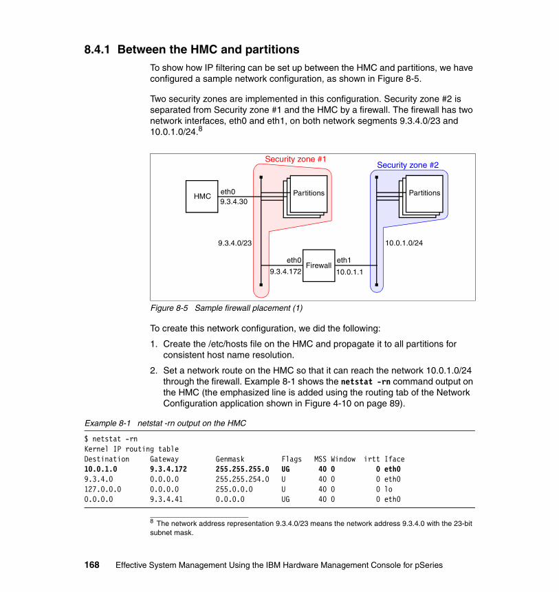
8.4.1 Between the HMC and partitionsTo show how IP filtering can be set up between the HMC and partitions, we have configured a sample network configuration, as shown in Figure 8-5.
Two security zones are implemented in this configuration. Security zone #2 is separated from Security zone #1 and the HMC by a firewall. The firewall has two network interfaces, eth0 and eth1, on both network segments 9.3.4.0/23 and 10.0.1.0/24.8
Figure 8-5 Sample firewall placement (1)
To create this network configuration, we did the following:
1. Create the /etc/hosts file on the HMC and propagate it to all partitions for consistent host name resolution.
2. Set a network route on the HMC so that it can reach the network 10.0.1.0/24 through the firewall. Example 8-1 shows the netstat -rn command output on the HMC (the emphasized line is added using the routing tab of the Network Configuration application shown in Figure 4-10 on page 89).
Example 8-1 netstat -rn output on the HMC
$ netstat -rnKernel IP routing tableDestination Gateway Genmask Flags MSS Window irtt Iface10.0.1.0 9.3.4.172 255.255.255.0 UG 40 0 0 eth09.3.4.0 0.0.0.0 255.255.254.0 U 40 0 0 eth0127.0.0.0 0.0.0.0 255.0.0.0 U 40 0 0 lo0.0.0.0 9.3.4.41 0.0.0.0 UG 40 0 0 eth0
8 The network address representation 9.3.4.0/23 means the network address 9.3.4.0 with the 23-bit subnet mask.
HMC
eth0
Partitions
Firewall
Partitions
eth1
9.3.4.0/23 10.0.1.0/24
10.0.1.19.3.4.172
eth09.3.4.30
Security zone #2Security zone #1
168 Effective System Management Using the IBM Hardware Management Console for pSeries

3. Set a host type network route on the partitions in Security zone #2 so that they can reach the HMC through the firewall. Example 8-2 shows the netstat -rn command output on one of the partitions on Security zone #2. (The emphasized line is the added host route entry.)
Example 8-2 netstat -rn output on a partition in security zone #2
# netstat -rnRouting tablesDestination Gateway Flags Refs Use If PMTU Exp Groups
Route Tree for Protocol Family 2 (Internet):9.3.4.30 10.0.1.1 UGH 1 20 en0 - -10.0.1/24 10.0.1.8 U 1 1115 en0 - -127/8 127.0.0.1 U 5 27604 lo0 - -
Route Tree for Protocol Family 24 (Internet v6):::1 ::1 UH 0 0 lo0 16896 -
4. Enable IP forwarding on the firewall by inserting the following line in the /etc/sysctl.conf file and then rebooting the system:
net.ipv4.ip_foward = 1
5. Issue the following set of commands to set up necessary port filtering on the firewall. These commands can be included in the /etc/sysconfig/firewall file in order to execute upon the firewall reboot.
a. The following commands clear any existing port filtering rules and to set the default rule action to allow packets to pass:
iptables -Fiptables -Xiptables -P INPUT ACCEPTiptables -P OUTPUT ACCEPTiptables -P FORWARD ACCEPT
b. The following command blocks all packets from the hosts on the 10.0.1.0 network from being forwarded outside that network:
iptables -A FORWARD -i eth1 -s 10.0.1.0/24 -j REJECT
This effectively isolates the partitions on Security zone #2 from both the HMC and other partitions on Security zone #1. However, it also cuts off the RMC communication between the HMC and those partitions, which is required for DLPAR operations and service functions.
Note: the /etc/sysctl.conf file is read by the sysctl command upon reboot on the Linux operating system.
Chapter 8. Secure networking in a partitioned environment 169
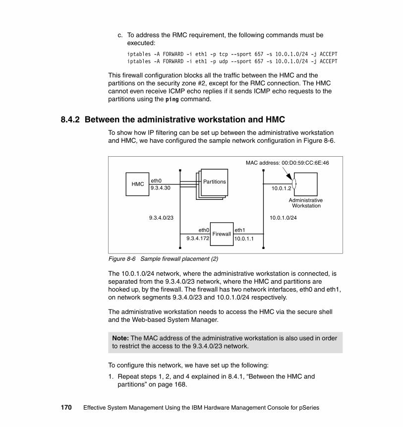
c. To address the RMC requirement, the following commands must be executed:
iptables -A FORWARD -i eth1 -p tcp --sport 657 -s 10.0.1.0/24 -j ACCEPTiptables -A FORWARD -i eth1 -p udp --sport 657 -s 10.0.1.0/24 -j ACCEPT
This firewall configuration blocks all the traffic between the HMC and the partitions on the security zone #2, except for the RMC connection. The HMC cannot even receive ICMP echo replies if it sends ICMP echo requests to the partitions using the ping command.
8.4.2 Between the administrative workstation and HMCTo show how IP filtering can be set up between the administrative workstation and HMC, we have configured the sample network configuration in Figure 8-6.
Figure 8-6 Sample firewall placement (2)
The 10.0.1.0/24 network, where the administrative workstation is connected, is separated from the 9.3.4.0/23 network, where the HMC and partitions are hooked up, by the firewall. The firewall has two network interfaces, eth0 and eth1, on network segments 9.3.4.0/23 and 10.0.1.0/24 respectively.
The administrative workstation needs to access the HMC via the secure shell and the Web-based System Manager.
To configure this network, we have set up the following:
1. Repeat steps 1, 2, and 4 explained in 8.4.1, “Between the HMC and partitions” on page 168.
Note: The MAC address of the administrative workstation is also used in order to restrict the access to the 9.3.4.0/23 network.
HMC
eth0
Partitions
Firewalleth1
9.3.4.0/23 10.0.1.0/24
10.0.1.19.3.4.172
eth09.3.4.30
AdministrativeWorkstation
MAC address: 00:D0:59:CC:6E:46
10.0.1.2
170 Effective System Management Using the IBM Hardware Management Console for pSeries

2. Issue the following a set of commands to set up necessary port filtering on the firewall. These commands can be included in the /etc/sysconfig/firewall file in order to execute upon the firewall reboot.
a. Execute the following command on the firewall in order to open the appropriate port to allow secure shell traffic between the administrative workstation and HMC:
iptables -A FORWARD -i eth1 -p tcp --dport 22 -s 10.0.1.2 \--sport 1024:65535 -j ACCEPT
The destination port for the secure shell on the HMC is port 22, and that the request can come from any port in the range 1024 to 65535 on the administrative workstation. The IP address of the administrative workstation is 10.0.1.2. This rule allows a secure shell session from the workstation to the HMC.
b. Execute the following command on the firewall in order to open the appropriate ports to allow Web-based System Manager traffic between the administrative workstation and HMC:
iptables -A FORWARD -i eth1 -p tcp -s 10.0.1.2 -d 9.3.4.30 -j ACCEPT
c. Execute the following command on the firewall in order to block all connection requests to the IP address 9.3.4.30, except for the IP packets sent from the MAC address 00:D0:59:CC:6E:46, which is the MAC address of the Ethernet adapter on the administrative workstation in our test environment:
iptables -A FORWARD -i eth1 -m --mac-source 00:D0:59:CC:6E:46 \-d 9.3.4.30 -j ACCEPT
This firewall configuration blocks all traffic from the 10.0.1.0/24 network to the the HMC, except for the TCP connection requests from the administrative workstation.
Note: The port filtering rules above do not allow the administrative workstation to access the HMC via the remote Web-based System Manager.
Note: The current IP tables implementation on the Linux operating system does not allow you to specify a port number larger than 65535. Therefore, this configuration, unfortunately, allows all TCP connection requests from the source IP address 10.0.1.2 to the destination IP address 9.3.4.30. However, it is possible to restrict this access using the other IP filtering function implementations on some IP router and firewall products currently available in the market.
Chapter 8. Secure networking in a partitioned environment 171
8.4.3 Between the administrative workstation and partitionsTo demonstrate IP filtering between an administrative workstation and production partitions, we again used the network described in Figure 8-6 on page 170. This configuration illustrates the ability of a systems administrator to perform work on production systems located on the other side of a firewall.
Note that it is important for a systems administrator to have access to a production partition, not only for day-to-day administration but also to facilitate moving PCI adapters using dynamic logical partitioning. The two preferred access methods are the secure shell and the Web-based System Manager.
To configure this access, we did the following:
1. Repeat steps 1, 2, and 4 explained in 8.4.1, “Between the HMC and partitions” on page 168.
2. Assuming the production partition had an IP address of 9.3.4.117, this rule would enable both the secure shell and the Web-based System Manager:
iptables -A FORWARD -i eth1 -p tcp -s 10.0.1.0 -d 9.3.4.117 -j ACCEPT
8.5 Service Agent and security concernsThe Service Agent application that runs on the HMC is an integral part of the IBM service strategy for partitioning-capable pSeries server. One of the most valuable features of Service Agent is its ability to call IBM Service and report hardware failures, often providing specifics as to which Field Replaceable Unit needs to be installed by the IBM service representatives.
Despite the value of this capability, some customers are wary of configuring a modem in a server room. If they have several HMCs supporting multiple managed systems, the concern spreads to having several modems and the need to support multiple phone lines.
These concerns are summarized into the following questions:
� Could an enterprise’ proprietary data be transferred over the dial-up connection?
The answer is No.
The data sent to IBM by Service Agent contains no customer proprietary information. It reports the date and time of specific hardware errors on
Note: Before the Web-based System Manager could be started on the partition, the wsmserver commands referenced in 8.2.3, “Administrative workstation to partition” on page 161 have to be issued.
172 Effective System Management Using the IBM Hardware Management Console for pSeries
specific servers, and it includes diagnostic information that can be used to fix a hardware problem. It is used to identify a part that needs to be replaced.
� Can the modem be used to dial into the HMC and therefore provide an entry point to the customer’s networks?
The answer is No.
Service Agent uses the modem in dial-out mode only. Confirmation that a message has been received by IBM comes through a phone call to a customer contact specified in Service Agent. The 7852-400 modem9 supplied by IBM is configured for dial-out only by flipping a switch located at the front of modem. Also, the serial port used by Service Agent does not have a getty process running on it, so there can be no inbound connection.
The detailed information about how to configure Service Agent is provided in Chapter 12, “Sample Service Agent configurations on the HMC” on page 281.
8.5.1 Firewall and Service AgentAn HMC can be configured to run Service Agent in client or server (gateway) mode. The HMC with the modem attached is the gateway system. One that forwards its service events over the network to a gateway machine is a client.
The gateway HMC has the dialer configured and runs the Electronic Server System (ESS) process. ESS runs only on the gateway. It handles all requests for data input and retrieval from the centralized database. The On Demand Server (ODS) process runs on all HMCs running Service Agent, and it handles all Service Agent communication activities for that host. ODS sends data to the ESS process as necessary.
ESS listens on the TCP port 1199 for incoming communication requests. When a remote ODS has contacted ESS and is authenticated, ESS tells a new port number to ODS in order to establish the session between the ESS and that remote ODS. The new port number is unpredictable and chosen above port number 1024 on both the source and destination nodes.
Therefore, if you have multiple HMCs and one serves as a gateway, those HMCs should not be separated by firewalls.10
9 IBM does not supply modems for the pSeries 615 models 6C3 and 6E3, pSeries 630 models 6C4 and 6E4, and pSeries 650 Model 6M2.10 This limiitation is anticipated to be relaxed in future HMC software releases.
Chapter 8. Secure networking in a partitioned environment 173
To configure the Service Agent in this client/server configuration on multiple HMCs, see the following sections:
� 11.3.3, “Change Service Agent mode (server/client)” on page 257� 12.5, “Define Service Agent clients on a gateway server” on page 292
174 Effective System Management Using the IBM Hardware Management Console for pSeries
Chapter 9. HMC command line interface
This chapter provides information about using the command line interface on the IBM Hardware Management Console for pSeries (HMC). The command line interface is especially useful in the following two situations:
� Consistent results are required.
If you have to administer several managed systems, you can achieve consistent results by using the command line interface. The command sequence can be stored in scripts and executed remotely.
� Automated operations are required.
After you have developed a consistent way to manage your managed systems, you can automate the operations by invoking the scripts from batch processing applications, such as the cron daemon, from other systems.
For further information about the command line interface on the HMC, refer to IBM Hardware Management Console for pSeries Installation and Operations Guide, SA38-0590.
9
Note: Avoid copying any files onto the HMC other than those detailed in IBM publications, as this can interfere with problem determination by IBM support personnel. Therefore, from remote systems, all supported commands should be executed via either the rexec or ssh facility. We suggest you store such files as administrative scripts on systems other than the HMC.
© Copyright IBM Corp. 2003. All rights reserved. 175

9.1 Secure remote connection to the HMCHMCs typically are placed inside the machine room where managed systems are located, so you might not be allowed to physically access the HMC. In this case, you can remotely access it using either the remote Web-based System Manager client (see Chapter 7, “Secure remote GUI access to the HMC” on page 125) or the remote command line interface. The HMC supports two facilities, secure shell (ssh) and rexec, to execute commands remotely.
Throughout this book, we assume that you use OpenSSH to securely connect between AIX systems (including partitions) and the HMC. You have two ways to remotely execute the command line interface on the HMC using OpenSSH:
� Execute commands remotely.
The following sample shows that the /opt/hsc/bin/lshmc -r command is remotely executed using the ssh command. In this example, a remote user on a remote AIX system is executing the /opt/hsc/bin/lshmc -r command as the hscroot user on the HMC (itsohmc). You will be prompted to enter the login password of the hscroot user, and then the command will list the status of the remote command execution configuration:1
$ ssh hscroot@itsohmc /opt/hsc/bin/lshmc -rhscroot@itsohmc's password: XXXXXXRemote Command Execution Configuration:Remote command execution using the rexec facility: disabledRemote command execution using the ssh facility: enabled
� Execute commands after logging in to the HMC.
The following sample shows that the lshmc -r command is executed on the HMC after logging in to the HMC as the hscroot user:
$ ssh hscroot@itsohmchscroot@itsohmc's password: XXXXXXLast login: Mon May 26 14:32:13 2003 from lpar03.itsc.austin.ibm.com[hscroot@itsohmc hscroot]$ lshmc -rRemote Command Execution Configuration:Remote command execution using the rexec facility: disabledRemote command execution using the ssh facility: enabled
Note: As explained in 4.2.7, “Enable/Disable Remote Command Execution” on page 95, either ssh or rexec facility must be explicitly enabled on the HMC beforehand in order to remotely execute commands.
1 This configuration can also be verified and changed using the graphical user interface on the HMC (see 4.2.7, “Enable/Disable Remote Command Execution” on page 95).
176 Effective System Management Using the IBM Hardware Management Console for pSeries
9.1.1 Setting up OpenSSH on AIXTo use OpenSSH on AIX, the tasks described in this section must be performed.
For further information about setting up OpenSSH on AIX, refer to Chapter 4: Secure network connection on AIX in Managing AIX Server Farms, SG24-6606.
Installing OpenSSH packagesOpenSSH is offered as several AIX standard installp packages in the Bonus Pack CD-ROM media or in several RPM format packages provided in the AIX toolbox for Linux applications.
You can also download the latest OpenSSH packages from the OpenSSH on AIX site, found at:
http://oss.software.ibm.com/developerworks/projects/opensshi
To install OpenSSH on AIX 5L Version 5.2:
1. Use SMIT to install the openssl package from the AIX toolbox for Linux CD. Install the openssl package first as it is a prerequisite for OpenSSH.
2. Verify that openssl is installed:
# rpm -qa|grep opensslopenssl-0.9.6e-2
3. Use SMIT to install the following filesets:
– openssh.base.client
– openssh.base.server
– openssh.license
– openssh.msg.en_US
4. Verify that all filesets are installed, as shown in Example 9-1 on page 178.
Note: Starting in April 2002, IBM offers OpenSSH in the updated Bonus Pack CD-ROM media as several AIX standard install packages (installp format) on AIX 5L Version 5.1 and later.
The OpenSSH program contained in the Bonus Pack CD-ROM media is offered as is and is licensed under the terms and conditions of the IBM International Program License Agreement (IPLA) for Non-Warranted Programs.
Chapter 9. HMC command line interface 177
Example 9-1 lslpp -L openssh.*
# lslpp -L openssh.* Fileset Level State Type Description (Uninstaller) ---------------------------------------------------------------------------- openssh.base.client 3.4.0.5200 C F Open Secure Shell Commands openssh.base.server 3.4.0.5200 C F Open Secure Shell Server openssh.license 3.4.0.5200 C F Open Secure Shell License openssh.msg.en_US 3.4.0.5200 C F Open Secure Shell Messages - U.S. English
Configure the OpenSSH clientTo configure the OpenSSH client on AIX systems, the steps explained in this section must be performed. The following configuration is used:
OpenSSH client system host name: murumuru.itsc.austin.ibm.comUser name on the client: koaOpenSSH server system host name (HMC): itsohmc.itsc.austin.ibm.comUser name on the server: hscroot
1. Log in to the client system as the user to use ssh:
AIX Version 5(C) Copyrights by IBM and by others 1982, 2002.login: koakoa's Password: XXXXXX
2. Generate the user public and private key files:
/home/koa ) ssh-keygen -t dsaGenerating public/private dsa key pair.Enter file in which to save the key (/home/koa/.ssh/id_dsa):Enter passphrase (empty for no passphrase): YYYYYYEnter same passphrase again: YYYYYYYour identification has been saved in /home/koa/.ssh/id_dsa.Your public key has been saved in /home/koa/.ssh/id_dsa.pub.The key fingerprint is:cf:3a:6a:e8:d0:14:5a:a4:8d:55:7e:98:c0:78:b7:d7 [email protected]/home/koa ) ls -al .sshtotal 7drwx------ 2 koa staff 512 Jun 19 17:26 .drwxr-xr-x 3 koa staff 512 Jun 19 17:22 ..-rw------- 1 koa staff 744 Jun 19 17:26 id_dsa-rw-r--r-- 1 koa staff 622 Jun 19 17:26 id_dsa.pub-rw-r--r-- 1 koa staff 226 Jun 19 17:22 known_hosts
Note: Do not forget the pass phrase; otherwise you must generate new key files and distribute the public key file again.
178 Effective System Management Using the IBM Hardware Management Console for pSeries

3. Confirm whether there is a public key ring file (authorized_keys22) in the .ssh directory under the remote user’s home directory on the HMC:
/home/koa ) ssh hscroot@itsohmc ls -l .sshhscroot@itsohmc's password: XXXXXX
If the file exists, the command returns output similar to the following example:
total 24-rw-r--r-- 1 hscroot HSC_Sys_ 2352 Jul 30 14:49 authorized_keys2-rw------- 1 hscroot HSC_Sys_ 736 Jun 2 06:41 id_dsa-rw-r--r-- 1 hscroot HSC_Sys_ 625 Jun 2 06:41 id_dsa.pub-rw-r--r-- 1 hscroot HSC_Sys_ 7372 Jun 17 16:38 known_hosts
Then proceed to the next step. Otherwise, do the following and skip to step 7:
/home/koa ) cp .ssh/id_dsa.pub /tmp/authorized_keys2
4. Copy the public key file on the HMC to the local host:
/home/koa ) scp -p hscroot@itsohmc:/home/hscroot/.ssh/authorized_keys2 /tmphscroot@itsohmc's password: XXXXXXauthorized_keys2 100% |*****************************| 2352 00:00
5. Concatenate the local user’s public key file to the one you have just copied:
/home/koa ) cat .ssh/id_dsa.pub >> /tmp/authorized_keys2
6. If the remote user already has the .ssh directory under his home directory, skip to the next step. Otherwise create the .ssh directory under his home directory:
/home/koa ) ssh hscroot@itsohmc ls -ld .sshhscroot@itsohmc's password: XXXXXXdrwx------ 2 hscroot HSC_Sys_ 4096 Jun 9 10:32 .ssh
7. Copy back the public key ring file iton the .ssh directory under the remote user’s home directory on the HMC:
/home/koa ) scp -p /tmp/authorized_keys2 hscroot@itsohmc:/home/hscroot/.sshhscroot@itsohmc's password: XXXXXXauthorized_keys2 100% |*****************************| 2974 00:00
When your public key file is appended to the hscroot user’s public key ring file (authorized_keys2), enter your pass phrase instead of the login password in order to log in to the HMC using OpenSSH.
2 The authorized_keys2 public key ring file can store the public keys generated by both RSA and DSA in the protocol version 2, while authorized_keys can only store the keys generated by DSA.
Note: You must use >> instead of > for the concatenation.
Chapter 9. HMC command line interface 179
Configure OpenSSH serverTo access to an AIX 5L Version 5.2 system using OpenSSH, in other words, to configure an AIX system as an OpenSSH server, the PAM3 configuration file /etc/pam.conf4 (see Example 9-2) must be created on the AIX system.
Example 9-2 /etc/pam.conf on AIX 5L Version 5.2
## PAM configuration for OpenSSH#sshd auth required /usr/lib/security/pam_aixOTHER auth required /usr/lib/security/pam_aix
sshd account required /usr/lib/security/pam_aixOTHER account required /usr/lib/security/pam_aix
sshd password required /usr/lib/security/pam_aixOTHER password required /usr/lib/security/pam_aix
sshd session required /usr/lib/security/pam_aixOTHER session required /usr/lib/security/pam_aix
The /etc/pam.conf file must have the following permission mode:
# ls -l /etc/pam.conf-rw-r--r-- 1 root system 473 May 14 2003 /etc/pam.conf
9.2 Syntax and common HMC command line flagsThis section covers the syntax used to describe the HMC commands and some of the commonly used command line flags shared by many HMC commands.
To explain the common syntax, we use the lshwres command5 as an example:
lshwres -m <managed-system> -r {ALL|cpu|mem|slot|led}[-p <partition-name>| --all] [-y <led-type>] [-F <format>] [--help]
The following conventions are used:
� Items representing variables that must be replaced by a value are enclosed in brackets: <>. For example, <partition-name> specifies that this is a variable that should be replaced by a partition name.
� Items that are not enclosed in brackets must be entered literally.
3 Pluggable Authentication Module4 The /etc/pam.conf file does not exist by default.5 The lshwres command is explained in “lshwres” on page 206.
180 Effective System Management Using the IBM Hardware Management Console for pSeries
� Parameters enclosed in square brackets, [], are optional.
� Parameters enclosed in braces, {}, are required.
� A vertical bar signifies that you choose only one parameter. For example, {ALL | cpu | mem | slot | led} indicates that you have to choose one of these: ALL, cpu, mem, slot, or led.
Besides the syntax, you must also pay attention to:
� You must insert a blank between the flag and the parameter. The following sample shows that, without a blank between the flag, -r, and the parameter, ALL, the command will fail:
$ lssyscfg -r ALLName FrameNum IsReal PortNums Frame Type7040-61R*021767A 0 No 2...... omitted lines ......$ lssyscfg -rALLAccess denied. Please check to see you have included all required parameters particularly the managed system and partition parameters. Please try again.
� If, before sending to it HMC for final execution, the supplied parameter or value contains spaces or other special characters that may be interpreted by the local shell, it should be enclosed in double quotes or in some other way prevent the shell misinterpretation.
9.2.1 The -m flagThe -m flag specifies the managed system on which you wish to perform operations. Although this flag can be seen as an unnecessary flag in a simple, but typical, configuration where only one managed system is connected to an HMC, it is required to explicitly specify the target managed system, because multiple managed systems can be connected to a single HMC.
The -m flag must be used with either of the following arguments:
� The managed system name
In our example, ITSO_p690 is the managed system name. Therefore, the flag can be specified as -m ITSO_p690.
To confirm the managed system name, see 10.1.1, “What is the managed system name?” on page 218.
Chapter 9. HMC command line interface 181
� The machine type, model, and serial number of the managed system in the form of MT-MDL*S/N
In our example the argument is expressed as 7040-681*021768A, where:
– 7040 is the machine type (MT) of our test system.
– 681 is the model number (MDL) of our test system.
– 021768A is the serial number (S/N) of our test system.
Therefore, the flag also can be specified as -m 7040-681*021768A.
To confirm this information, see 10.1.2, “What is my managed system’s MT-MDL*S/N?” on page 219.
9.2.2 The -r flagThe -r flag specifies the resource of the managed system on which you wish to perform operations. Depending on the context in which the command is used, the -r flag can be specified with the following arguments:
cpu CPUmem Memoryslot Adapter slotled LED6
alpar Affinity partitionlpar Logical partitionprof Partition profilesysprof System profilesys Managed systemframe Frame7
ALL Specifies all possible types of the resources
9.2.3 The -n flagThe -n flag specifies the name of the specific object on which you wish to perform operations.
In the listing context (e.g. lsXXXX command), the --all flag can also be used in place of -n to specify that all objects are to be listed.
9.2.4 The -o flagThe -o flag specifies the operation that we want to perform on the resource. For example, when you wish to perform dynamic logical partitioning (DLPAR)
6 We also must use the -y flag to specify whether it is the system attention LED or identify LED.7 See 10.1.3, “What is my frame name?” on page 219
182 Effective System Management Using the IBM Hardware Management Console for pSeries
operations using the chhwres command, one of the following arguments must be specified:
-o a Add a resource.-o r Remove a resource.-o m Move a resource.-o s Set a value8.
When it is used with the chsysstate command, one of the following arguments must be specified:
-o on Power on the managed system or activate a partition.
-o off Power off the managed system or perform a hard reset on a partition.
-o reset Reset the managed system (works only in Full System Partition) or perform a soft reset on a partition.
-o osreset Reboot a partition.
-o osshutdown Shut down a partition.
-o rebuild Rebuild the managed system.
9.2.5 The -p flagThe -p flag specifies the partition on which you wish to perform the operation. For the DLPAR move operation, the -p flag specifies the source partition.
9.2.6 The -f flagThe -f flag is generally used to specify a file name.
When the flag is used with the bkprofdata or rstprofdata command, it specifies the profile data file name to be used as the output or input for the backup and restore operation, respectively.
When the flag is used with the mksyscfg or chsyscfg command, it specifies the configuration data file name to be used as the input for the operation.
9.2.7 The -F flagThe -F flag specifies which formatted fields will be used when displaying the output from the lsXXXX command.
8 The set operation can be used only with the LED resource.
Chapter 9. HMC command line interface 183
For example, the following use of the -F flag instructs the lshwres command to display the partition_name, min, allocated, and max fields only.
$ lshwres -m ITSO_p690 -r cpu --all -F partition_name:min:allocated:max
9.2.8 The --help flagThe --help flag is used to display the syntax and sample use of the command.
9.3 HMC commandsIn this section, we have classified the supported HMC commands from the system administrators’ view into the groups shown in Table 9-1.
Table 9-1 Command groups
Unless otherwise specified, all commands used in the examples sections are issued by the hscroot user on the HMC.
9.3.1 Commands to manage HMC itselfThe following commands are used to manage HMC itself. This group of commands interacts only with the HMC so the -m flag, which is used to specify the managed system, is not needed:
lshmc Lists the HMC network or remote command configuration. It also can be used to show VPD data for the HMC.
Command classification Relevant section number
Commands to manage HMC itself 9.3.1
Commands to manage users on the HMC 9.3.2
Commands for CUoD 9.3.3
Commands to manage system configuration 9.3.4
Commands to back up and restore partition profile data
9.3.5
Commands to manage hardware resources 9.3.6
Commands for virtual terminals 9.3.7
Commands used in recovery situations 9.3.8
Commands used for other purposes 9.3.9
184 Effective System Management Using the IBM Hardware Management Console for pSeries
chhmc Changes the HMC network configuration or enables/disables the remote command.
hmcshutdown Shuts down or reboots the HMC.
lshmcThis command is used to list HMC network configuration, remote command configuration, and VPD data.
Syntaxlshmc [-n][-r][-v][-F <format>][--help]
-n Lists HMC network configuration.
-r Lists HMC remote command configuration.
-v Lists HMC VPD data.
-F Specifies the formatted fields to list. Valid values are hostname, domain, nameserver, domainsuffix, gateway, ipaddr, networkmask, rexec, and ssh.
ExampleTo list the HMC network configuration:
$ lshmc -nNetwork Configuration:Host Name: itsohmc.itsc.austin.ibm.comTCP/IP Interface 0 Address: 9.3.4.30TCP/IP Interface 0 Network Mask: 255.255.254.0Default Gateway: 9.3.4.41Domain Name: itsc.austin.ibm.comDNS Server Search Order: 9.3.4.2Domain Suffix Search Order: itsc.austin.ibm.com austin.ibm.com
To list the HMC remote command configuration:
$ lshmc -rRemote Command Execution Configuration:Remote command execution using the rexec facility: disabledRemote command execution using the ssh facility: enabled
To list the VPD information for the HMC:
$ lshmc -vVital Product Data Information:*FC ????????*VC 20.0*N2 Mon Jun 09 10:09:02 EDT 2003*FC ????????
Chapter 9. HMC command line interface 185
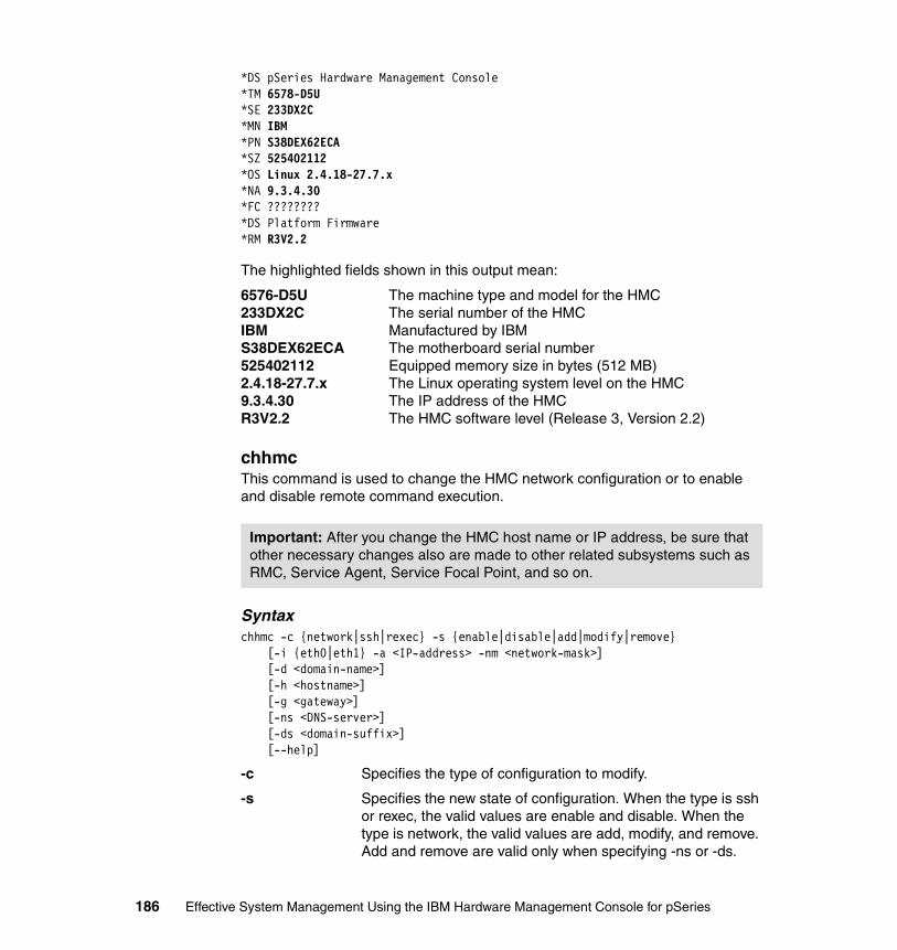
*DS pSeries Hardware Management Console*TM 6578-D5U*SE 233DX2C*MN IBM*PN S38DEX62ECA*SZ 525402112*OS Linux 2.4.18-27.7.x*NA 9.3.4.30*FC ????????*DS Platform Firmware*RM R3V2.2
The highlighted fields shown in this output mean:
6576-D5U The machine type and model for the HMC233DX2C The serial number of the HMCIBM Manufactured by IBMS38DEX62ECA The motherboard serial number525402112 Equipped memory size in bytes (512 MB)2.4.18-27.7.x The Linux operating system level on the HMC9.3.4.30 The IP address of the HMCR3V2.2 The HMC software level (Release 3, Version 2.2)
chhmcThis command is used to change the HMC network configuration or to enable and disable remote command execution.
Syntaxchhmc -c {network|ssh|rexec} -s {enable|disable|add|modify|remove}
[-i {eth0|eth1} -a <IP-address> -nm <network-mask>][-d <domain-name>][-h <hostname>][-g <gateway>][-ns <DNS-server>][-ds <domain-suffix>][--help]
-c Specifies the type of configuration to modify.
-s Specifies the new state of configuration. When the type is ssh or rexec, the valid values are enable and disable. When the type is network, the valid values are add, modify, and remove. Add and remove are valid only when specifying -ns or -ds.
Important: After you change the HMC host name or IP address, be sure that other necessary changes also are made to other related subsystems such as RMC, Service Agent, Service Focal Point, and so on.
186 Effective System Management Using the IBM Hardware Management Console for pSeries

-i Specifies the interface to configure.
-a Specifies the IP address. Can be used only with -i flag.
-nm Specifies the network mask. Can be used only with -i flag.
-d Specifies the domain name. Can be used only with -s modify.
-h Specifies the new host name. Can be used only with -s modify.
-g Specifies the gateway IP address or host name. Can be used only with -s modify.
-ns Specifies the DNS server. Can be used only with -s add or -s remove.
-ds Specifies the domain suffix. Can be used only with -s add or -s remove.
ExampleTo add another DNS server of IP address 1.1.1.1:
$ lshmc -nNetwork Configuration:Host Name: itsohmc.itsc.austin.ibm.comTCP/IP Interface 0 Address: 9.3.4.30TCP/IP Interface 0 Network Mask: 255.255.254.0TCP/IP Interface 1 Address: 10.0.1.1TCP/IP Interface 1 Network Mask: 255.255.255.0Default Gateway: 9.3.4.41Domain Name: itsc.austin.ibm.comDNS Server Search Order: 9.3.4.2Domain Suffix Search Order: itsc.austin.ibm.com austin.ibm.com$ chhmc -c network -s add -ns 1.1.1.1$ lshmc -nNetwork Configuration:Host Name: itsohmc.itsc.austin.ibm.comTCP/IP Interface 0 Address: 9.3.4.30TCP/IP Interface 0 Network Mask: 255.255.254.0TCP/IP Interface 1 Address: 10.0.1.1TCP/IP Interface 1 Network Mask: 255.255.255.0Default Gateway: 9.3.4.41Domain Name: itsc.austin.ibm.comDNS Server Search Order: 9.3.4.2 1.1.1.1Domain Suffix Search Order: itsc.austin.ibm.com austin.ibm.com
Chapter 9. HMC command line interface 187
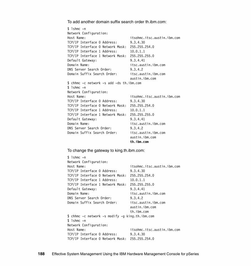
To add another domain suffix search order th.ibm.com:
$ lshmc -nNetwork Configuration:Host Name: itsohmc.itsc.austin.ibm.comTCP/IP Interface 0 Address: 9.3.4.30TCP/IP Interface 0 Network Mask: 255.255.254.0TCP/IP Interface 1 Address: 10.0.1.1TCP/IP Interface 1 Network Mask: 255.255.255.0Default Gateway: 9.3.4.41Domain Name: itsc.austin.ibm.comDNS Server Search Order: 9.3.4.2Domain Suffix Search Order: itsc.austin.ibm.com austin.ibm.com$ chhmc -c network -s add -ds th.ibm.com$ lshmc -nNetwork Configuration:Host Name: itsohmc.itsc.austin.ibm.comTCP/IP Interface 0 Address: 9.3.4.30TCP/IP Interface 0 Network Mask: 255.255.254.0TCP/IP Interface 1 Address: 10.0.1.1TCP/IP Interface 1 Network Mask: 255.255.255.0Default Gateway: 9.3.4.41Domain Name: itsc.austin.ibm.comDNS Server Search Order: 9.3.4.2Domain Suffix Search Order: itsc.austin.ibm.com austin.ibm.com th.ibm.com
To change the gateway to king.th.ibm.com:
$ lshmc -nNetwork Configuration:Host Name: itsohmc.itsc.austin.ibm.comTCP/IP Interface 0 Address: 9.3.4.30TCP/IP Interface 0 Network Mask: 255.255.254.0TCP/IP Interface 1 Address: 10.0.1.1TCP/IP Interface 1 Network Mask: 255.255.255.0Default Gateway: 9.3.4.41Domain Name: itsc.austin.ibm.comDNS Server Search Order: 9.3.4.2Domain Suffix Search Order: itsc.austin.ibm.com austin.ibm.com th.ibm.com$ chhmc -c network -s modify -g king.th.ibm.com$ lshmc -nNetwork Configuration:Host Name: itsohmc.itsc.austin.ibm.comTCP/IP Interface 0 Address: 9.3.4.30TCP/IP Interface 0 Network Mask: 255.255.254.0
188 Effective System Management Using the IBM Hardware Management Console for pSeries

TCP/IP Interface 1 Address: 10.0.1.1TCP/IP Interface 1 Network Mask: 255.255.255.0Default Gateway: king.th.ibm.comDomain Name: itsc.austin.ibm.comDNS Server Search Order: 9.3.4.2Domain Suffix Search Order: itsc.austin.ibm.com austin.ibm.com th.ibm.com
To disable the rexec facility:
$ lshmc -rRemote Command Execution Configuration:Remote command execution using the rexec facility: enabledRemote command execution using the ssh facility: enabled$ chhmc -c rexec -s disable$ lshmc -rRemote Command Execution Configuration:Remote command execution using the rexec facility: disabledRemote command execution using the ssh facility: enabled
To enable the ssh facility:
$ lshmc -rRemote Command Execution Configuration:Remote command execution using the rexec facility: disabledRemote command execution using the ssh facility: disabled$ chhmc -c ssh -s enable$ lshmc -rRemote Command Execution Configuration:Remote command execution using the rexec facility: disabledRemote command execution using the ssh facility: enabled
Additional informationWhen you enable the ssh facility, the main sshd daemon process starts to accept the connection via the TCP port 22. For each ssh client connecting in, a new sshd process is spawned to service the client.
When you disable the ssh facility, the main sshd daemon is terminated, without terminating all other child sshd daemon processes. As each ssh client starts to log out, these processes will go away eventually. During that period, no new ssh client connections will be allowed.
However, if you do not wait, but try to disable the ssh facility twice from the same ssh session, the sshd daemon process that serves that client will be also terminated, therefore immediately terminating the current ssh session.
Chapter 9. HMC command line interface 189
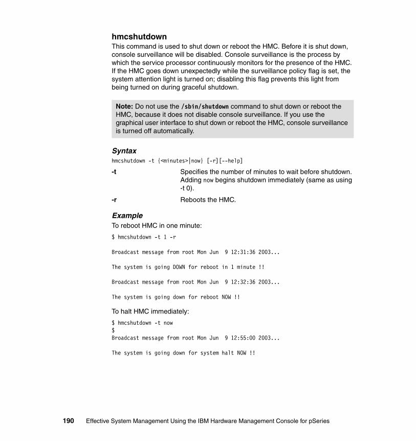
hmcshutdownThis command is used to shut down or reboot the HMC. Before it is shut down, console surveillance will be disabled. Console surveillance is the process by which the service processor continuously monitors for the presence of the HMC. If the HMC goes down unexpectedly while the surveillance policy flag is set, the system attention light is turned on; disabling this flag prevents this light from being turned on during graceful shutdown.
Syntaxhmcshutdown -t {<minutes>|now} [-r][--help]
-t Specifies the number of minutes to wait before shutdown. Adding now begins shutdown immediately (same as using -t 0).
-r Reboots the HMC.
ExampleTo reboot HMC in one minute:
$ hmcshutdown -t 1 -r
Broadcast message from root Mon Jun 9 12:31:36 2003...
The system is going DOWN for reboot in 1 minute !!
Broadcast message from root Mon Jun 9 12:32:36 2003...
The system is going down for reboot NOW !!
To halt HMC immediately:
$ hmcshutdown -t now$Broadcast message from root Mon Jun 9 12:55:00 2003...
The system is going down for system halt NOW !!
Note: Do not use the /sbin/shutdown command to shut down or reboot the HMC, because it does not disable console surveillance. If you use the graphical user interface to shut down or reboot the HMC, console surveillance is turned off automatically.
190 Effective System Management Using the IBM Hardware Management Console for pSeries
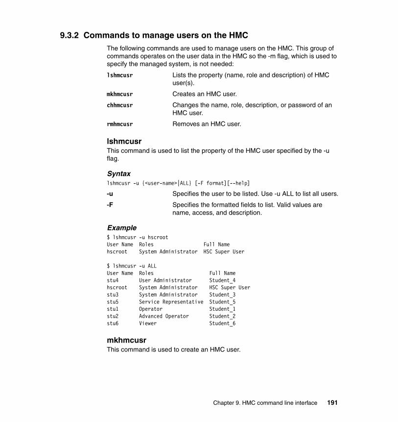
9.3.2 Commands to manage users on the HMCThe following commands are used to manage users on the HMC. This group of commands operates on the user data in the HMC so the -m flag, which is used to specify the managed system, is not needed:
lshmcusr Lists the property (name, role and description) of HMC user(s).
mkhmcusr Creates an HMC user.
chhmcusr Changes the name, role, description, or password of an HMC user.
rmhmcusr Removes an HMC user.
lshmcusrThis command is used to list the property of the HMC user specified by the -u flag.
Syntaxlshmcusr -u {<user-name>|ALL} [-F format][--help]
-u Specifies the user to be listed. Use -u ALL to list all users.
-F Specifies the formatted fields to list. Valid values are name, access, and description.
Example$ lshmcusr -u hscrootUser Name Roles Full Namehscroot System Administrator HSC Super User
$ lshmcusr -u ALLUser Name Roles Full Namestu4 User Administrator Student_4hscroot System Administrator HSC Super Userstu3 System Administrator Student_3stu5 Service Representative Student_5stu1 Operator Student_1stu2 Advanced Operator Student_2stu6 Viewer Student_6
mkhmcusrThis command is used to create an HMC user.
Chapter 9. HMC command line interface 191

syntaxmkhmcusr -u <user-name> -a <access-name> [-d <description>][--help]
-u Specifies the user to be created.
-a Specifies the access group name. Valid values are viewer, op, advop, usradmin, sysadmin, and svcrep.
-d Specifies the description associated with the user.
ExampleTo add the hscpe user with the mkhmcusr command, do the following:
$ lshmcusr -u hscpeUser hscpe does not exist or is not an HMC user. Please retry the command.$ mkhmcusr -u hscpe -a svcrep -d "IBM Service Representatives userid"Enter the new password for user hscpe: XXXXXXRetype the new password for user hscpe: XXXXXX$ lshmcusr -u hscpeUser Name Roles Full Namehscpe Service Representative IBM Service Representatives userid
As highlighted in the example output, you type the password for the hscpe user twice. If you need to add many HMC users, see 10.2.10, “Automate adding users to HMC” on page 234.
chhmcusrThis command is used to change the name, role, description, or password of an HMC user.
Syntaxchhmcusr -u <user-name> -t {name|access|desc|passwd} -v <new-value> [--help]
-u Specifies the user to be modified.
-t Specifies the property to change:
name Changes the user name.
access Changes the user role.
desc Changes the user description.
passwd Changes the user password.
-v Specifies the value. The valid values for access are viewer, op, advop, usradmin, sysadmin, and svcrep. When changing the password, if no value is specified, the command prompts the user to enter the password.
192 Effective System Management Using the IBM Hardware Management Console for pSeries

ExampleTo rename user leaf to leaves:
$ lshmcusr -u leafUser Name Roles Full Nameleaf Viewer Leaf user$ chhmcusr -u leaf -t name -v leaves$ lshmcusr -u leafUser leaf does not exist or is not an HMC user. Please retry the command.$ lshmcusr -u leavesUser Name Roles Full Nameleaves Viewer Leaf user
To change the description for user leaves:
$ chhmcusr -u leaves -t desc -v "leaves user..."$ lshmcusr -u leavesUser Name Roles Full Nameleaves Viewer leaves user...
To change the access group for user leaves:
$ chhmcusr -u leaves -t access -v sysadmin$ lshmcusr -u leavesUser Name Roles Full Nameleaves System Administrator leaves user...
To change the password for user leaves to leaves2root:
$ chhmcusr -u leaves -t passwd -v leaves2root
rmhmcusrThis command is used to remove an HMC user.
Syntaxrmhmcusr -u <user-name> [--help]
-u Specifies the HMC user to be removed.
Example$ lshmcusr -u leavesUser Name Roles Full Nameleaves System Administrator leaves user...$ rmhmcusr -u leaves$ lshmcusr -u leavesUser leaves does not exist or is not an HMC user. Please retry the command.
Chapter 9. HMC command line interface 193
9.3.3 Commands for CUoDThe following commands are used to manage Capacity Upgrade on Demand (CUoD) operations on the HMC:
lscuod Lists the information related to CUoD.chcuod Changes a CUoD attribute.
For further information about CUoD, refer to IBM Eserver pSeries 670 and pSeries 690 System Handbook, SG24-7040.
lscuodThis command is used to list the information related to CUoD.
Syntaxlscuod -m <managed-system> -r {cpu|mem} -t {reg|order} [-F <format>][--help]
-m Specifies the managed system.
-r Specifies the resource to query the information.
-t Specifies the type of listing to display. Valid values are reg (regular CUoD resource information) and order (for CUoD resource order information).
Example� If your system is not processor CUoD-capable:
$ lscuod -m ITSO_p690 -r cpu -t regThe managed system is not CUoD capable at the present time.
� If your system is not memory CUoD-capable:
$ lscuod -m ITSO_p690 -r mem -t regThe managed system is not CUoD capable at the present time.
Additional informationYour system can be any of the following:
� Processor and memory CUoD-capable� Processor CUoD-capable but memory CUoD-incapable� Memory CUoD-capable but CPU CUoD-incapable� Processor and memory CUoD-incapable
chcuodThis command is used to activate the key for CUoD, or to enable/disable Trial CoD9.
9 Trial Capacity on Demand
194 Effective System Management Using the IBM Hardware Management Console for pSeries
Syntaxchcuod -m <managed-system> -o {e|d|s} -k <activation-key> -r {cpu|mem}
-q <quantity> [--help]
-m Specifies the managed system.
-o Specifies the operation to perform:
e Enables Trial CoD.
d Disables Trial CoD.
s Sets activation key.
-k Specifies the activation key for the managed system.
-r Specifies the resource to query the information.
-q Specifies the quantity of processors or memory to enable Trial CoD. For memory, the unit used is GB, not LMB.
9.3.4 Commands to manage system configurationThe following commands are used to manage the system configuration (frame, managed system, partition, and partition profiles):
lssyscfg Lists the hardware resource configuration.mksyscfg Creates the hardware resource configuration.chsyscfg Changes the hardware resource configuration.rmsyscfg Removes the hardware resource configuration.
lssyscfgThis command is used to list the attributes of the frame, managed system, affinity partition, partition, system profile, and profile.
Syntaxlssyscfg -r {ALL|frame|sys|alpar|lpar|prof|sysprof} {-n <object-name>|--all}
[-m <managed-system>][-p <partition-name>][-F <format>|-z][--help]
-r Specifies the resource type to query.
-n Specifies the name of the object. Use --all to query all objects of that type.
-m Specifies the managed system.
-p Specifies the partition name. Use only with -r prof.
-F Specifies the formatted fields to list. Valid values are: affinity_capability, boot_mode, cage_number, cec_capability, cuod_capability, csp_surveillance_policy,
Chapter 9. HMC command line interface 195
csp_version, default_profile, desired_cpu, desired_io, desired_mem, lmb_size, maximum_cpu, maximum_mem, minimum_cpu, minimum_mem, mode, model, name, op_panel_value, op_panel_window_count, partition_profile, power_off_policy, required_io, runtime_capability, serial_number, service_authority, sfp_surveillance, small_rmo, sni_config_mode, sni_device_id, sni_windows, state, and type.
-z Mutually exclusive with the -F flag; if this flag is specified, attributes will be displayed per line in the form attr=value.
Example� To list all frames, see Example 10-4 on page 219.� To list all managed systems, see Example 10-2 on page 218.� To list the detail of a managed system, see Example 9-3.
Example 9-3 List the detailed information of managed systems
$ lssyscfg -r sys --all -zname=ITSO_p690state=Readymodel=7040-681serial_number=021768Aaffinity_capability=6cec_capability=195runtime_capability=24cuod_capability=0power_off_policy=falsecage_number=csp_surveillance_policy=20csp_version=V4.0mode=255lmb_size=256op_panel_value=LPAR...
In Example 9-3, affinity_capability equals 6 (2 + 4), which means that ITSO_p690 is both 4-way and 8-way ALPAR capable, as explained in Table 9-2.
Table 9-2 Values for affinity_capability
Value Meaning
null ALPAR incapable
2 4-way ALPAR capable
4 8-way ALPAR capable
196 Effective System Management Using the IBM Hardware Management Console for pSeries

In Example 9-3 on page 196, cec_capability equals 195 (1 + 2 + 64 + 128), meaning that ITSO_p690 is Multi interface version capable, External BPA communication possible, LPAR capable, and SMP capable, as explained in Table 9-3.
Table 9-3 Values for cec_capability
In Example 9-3 on page 196, runtime_capability=24 (8 + 16) indicates that ITSO_p690 is ALPAR- and DLPAR-capable, as explained in Table 9-4.
Table 9-4 Values for runtime_capability
In Example 9-3 on page 196, mode=255 indicates that ITSO_p690 is partitioned, as explained in Table 9-5.
Table 9-5 Values for mode
� To list all affinity partitions, see Example 10-6 on page 220.
� To list all partitions, see Example 10-7 on page 221.
Value Meaning
1 SMP capable
2 LPAR capable
4 NUMA capable
64 External BPA communication possible
128 Multi interface version capable
Value Meaning
8 ALAPR-capable
16 DLPAR-capable
32 Message-passing-capable
64 CUoD-capable
Value Meaning
0 The managed system is running Full System Partition.
255 The managed system is partitioned.
Chapter 9. HMC command line interface 197
� To list all system profiles:
$ lssyscfg -r sysprof -m ITSO_p690 --allName ProfileUp5200-01Before5100-04 aix51_64/lpar01, aix52_64/lpar05, aix51_64/lpar02, aix52_64/lpar04, aix52_64/lpar08, aix52_64/lpar03, aix52_64/lpar06, aix52_64/lpar07
� To list all profiles for the partition lpar05:
$ lssyscfg -r prof -m ITSO_p690 -p lpar05 --allName BootMode DesiredCPU DesiredMEM MaxCPU MaxMEM MinCPU MinMEMaix52_64 1 2 2048 6 8192 1 2048SMS 3 2 8 8 16 1 4
Table 9-6 shows the meaning of the BootMode column.
Table 9-6 Values for BootMode
mksyscfgThis command is used to create affinity partition, partition, system profile, and profile. You can create them by either specifying the attributes in a configuration file specified with the -f flag, or on the command line specified with the -i flag.
Syntaxmksyscfg -r {alpar|lpar|prof|sysprof} -m <managed-system>
[-p <partition-name>]{-f <config-file> | -i <attr1=value1> <atr2=value2> ...}[--help]
-r Specifies the resource type to create.
-m Specifies the managed system.
-p Specifies the partition name. Use only with -r prof.
-f Specifies the file containing the configuration information.
-i Specifies the value of each parameter directly on the command line; for example, -i name=NightProfile.
Value Meaning
1 Power on normal
2 Power on diagnostic default boot list
3 Power on SMS
4 Power on open firmware OK prompt
5 Power on diagnostic stored boot list
198 Effective System Management Using the IBM Hardware Management Console for pSeries

� To create affinity partitions:
– You must create an input configuration file.
– Use a partition_type attribute as the first line of the file:
• partition_type=2 creates a 4-way affinity partition
• partition_type=3 creates a 8-way affinity partition
– Use <RECSP> as a record separator between each partition.
– The minimum required attributes are name and profile_name.
Other attributes that can be specified are: desired_io, required_io, service_authority (0-off, 1-on), sfp_surveillance (0-off, 1-on), sni_config_mode, sni_windows, sni_device_id, small_rmo (1-off, 2-on), and boot_mode (norm, dd, sms, of, ds).
� To create a partition, the minimum required attributes are name, profile_name, minimum_cpu, desired_cpu, maximum_cpu, minimum_mem, desired_mem, and maximum_mem.
Other attributes that can be specified are: desired_io, required_io, service_authority (0-off 1-on), sfp_surveillance (0-off, 1-on), sni_config_mode, sni_device_id, sni_windows, small_rmo (1-off, 2-on), and boot_mode (norm, dd, sms, of, ds).
� To create a system profile, the minimum required attributes are name, partitions, and profile_names.
� To create a profile, the minimum required attributes are name, minimum_cpu, desired_cpu, maximum_cpu, minimum_mem, desired_mem, and maximum_mem.
Other attributes that can be specified are: desired_io, required_io, service_authority (0-off 1-on), sfp_surveillance (0-off 1-on), sni_config_mode, sni_device_id, sni_windows, sni_windows, sni_device_id, small_rmo (1-off, 2-on), and boot_mode (norm, dd, sms, of, ds).
Note: A partitioning-capable pSeries server can have only one set of affinity partitions at any given time.
Note: The minimum required attributes are the minimum that you must specify in order for the command to work. However, you will not be able to activate and boot the partition if you do not specify any I/O slot that contains a bootable disk. Therefore, most likely you should specify the boot disk adapter, such as: required_io=’U1.9-P1/Z1’…
Chapter 9. HMC command line interface 199
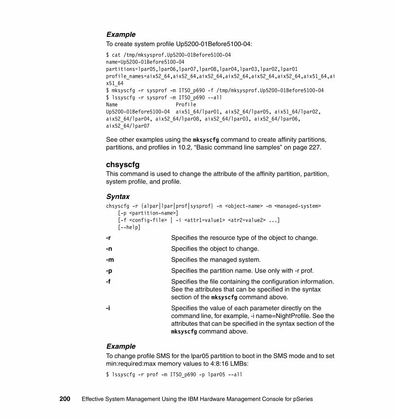
ExampleTo create system profile Up5200-01Before5100-04:
$ cat /tmp/mksysprof.Up5200-01Before5100-04name=Up5200-01Before5100-04partitions=lpar05,lpar06,lpar07,lpar08,lpar04,lpar03,lpar02,lpar01profile_names=aix52_64,aix52_64,aix52_64,aix52_64,aix52_64,aix52_64,aix51_64,aix51_64$ mksyscfg -r sysprof -m ITSO_p690 -f /tmp/mksysprof.Up5200-01Before5100-04$ lssyscfg -r sysprof -m ITSO_p690 --allName ProfileUp5200-01Before5100-04 aix51_64/lpar01, aix52_64/lpar05, aix51_64/lpar02, aix52_64/lpar04, aix52_64/lpar08, aix52_64/lpar03, aix52_64/lpar06, aix52_64/lpar07
See other examples using the mksyscfg command to create affinity partitions, partitions, and profiles in 10.2, “Basic command line samples” on page 227.
chsyscfgThis command is used to change the attribute of the affinity partition, partition, system profile, and profile.
Syntaxchsyscfg -r {alpar|lpar|prof|sysprof} -n <object-name> -m <managed-system>
[-p <partition-name>][-f <config-file> | -i <attr1=value1> <atr2=value2> ...][--help]
-r Specifies the resource type of the object to change.
-n Specifies the object to change.
-m Specifies the managed system.
-p Specifies the partition name. Use only with -r prof.
-f Specifies the file containing the configuration information. See the attributes that can be specified in the syntax section of the mksyscfg command above.
-i Specifies the value of each parameter directly on the command line, for example, -i name=NightProfile. See the attributes that can be specified in the syntax section of the mksyscfg command above.
ExampleTo change profile SMS for the lpar05 partition to boot in the SMS mode and to set min:required:max memory values to 4:8:16 LMBs:
$ lssyscfg -r prof -m ITSO_p690 -p lpar05 --all
200 Effective System Management Using the IBM Hardware Management Console for pSeries
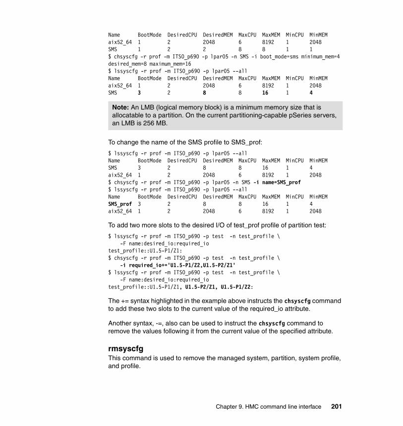
Name BootMode DesiredCPU DesiredMEM MaxCPU MaxMEM MinCPU MinMEMaix52_64 1 2 2048 6 8192 1 2048SMS 1 2 2 8 8 1 1$ chsyscfg -r prof -m ITSO_p690 -p lpar05 -n SMS -i boot_mode=sms minimum_mem=4 desired_mem=8 maximum_mem=16$ lssyscfg -r prof -m ITSO_p690 -p lpar05 --allName BootMode DesiredCPU DesiredMEM MaxCPU MaxMEM MinCPU MinMEMaix52_64 1 2 2048 6 8192 1 2048SMS 3 2 8 8 16 1 4
To change the name of the SMS profile to SMS_prof:
$ lssyscfg -r prof -m ITSO_p690 -p lpar05 --allName BootMode DesiredCPU DesiredMEM MaxCPU MaxMEM MinCPU MinMEMSMS 3 2 8 8 16 1 4aix52_64 1 2 2048 6 8192 1 2048$ chsyscfg -r prof -m ITSO_p690 -p lpar05 -n SMS -i name=SMS_prof$ lssyscfg -r prof -m ITSO_p690 -p lpar05 --allName BootMode DesiredCPU DesiredMEM MaxCPU MaxMEM MinCPU MinMEMSMS_prof 3 2 8 8 16 1 4aix52_64 1 2 2048 6 8192 1 2048
To add two more slots to the desired I/O of test_prof profile of partition test:
$ lssyscfg -r prof -m ITSO_p690 -p test -n test_profile \-F name:desired_io:required_io
test_profile::U1.5-P1/Z1:$ chsyscfg -r prof -m ITSO_p690 -p test -n test_profile \
-i required_io+='U1.5-P1/Z2,U1.5-P2/Z1'$ lssyscfg -r prof -m ITSO_p690 -p test -n test_profile \
-F name:desired_io:required_iotest_profile::U1.5-P1/Z1, U1.5-P2/Z1, U1.5-P1/Z2:
The += syntax highlighted in the example above instructs the chsyscfg command to add these two slots to the current value of the required_io attribute.
Another syntax, -=, also can be used to instruct the chsyscfg command to remove the values following it from the current value of the specified attribute.
rmsyscfgThis command is used to remove the managed system, partition, system profile, and profile.
Note: An LMB (logical memory block) is a minimum memory size that is allocatable to a partition. On the current partitioning-capable pSeries servers, an LMB is 256 MB.
Chapter 9. HMC command line interface 201

Syntaxrmsyscfg -r {sys|lpar|prof|sysprof} -n <object-name>
[-m <managed-system>][-p <partition-name>][--help]
ExampleTo remove all of the defined affinity partitions:
$ lssyscfg -r alpar -m ITSO_p690 --allName id DLPAR State Profile OpPanelaaa 011 0 Not Available aaaa 009 0 Not Available aaaaa 012 0 Not Available aaaaaa 010 0 Not Available aa$ rmsyscfg -r alpar -m ITSO_p690 --all$ lssyscfg -r alpar -m ITSO_p690 --allNo results were found.
To remove the partition test:
$ rmsyscfg -r lpar -m ITSO_p690 -n test$ lssyscfg -r lpar -m ITSO_p690 -n testThe partition entered was not found. Please check your entry and retry the command.
To remove the system profile Up5200-01Before5100-04:
$ lssyscfg -r sysprof -m ITSO_p690 --allName ProfileUp5200-01Before5100-04 aix52_64/lpar03, aix52_64/lpar06, aix52_64/lpar07, aix51_64/lpar01, aix51_64/lpar02, aix52_64/lpar05, aix52_64/lpar04, aix52_64/lpar08$ rmsyscfg -r sysprof -m ITSO_p690 -n Up5200-01Before5100-04$ lssyscfg -r sysprof -m ITSO_p690 --allNo results were found.
To remove profile OF for lpar05:
$ lssyscfg -r prof -m ITSO_p690 -p lpar05 -n OFName BootMode DesiredCPU DesiredMEM MaxCPU MaxMEM MinCPU MinMEMOF 4 2 2 8 8 1 1$ rmsyscfg -r prof -m ITSO_p690 -p lpar05 -n OF$ lssyscfg -r prof -m ITSO_p690 -p lpar05 -n OFThe profile entered was not found. Please check your entry and retry the command.
202 Effective System Management Using the IBM Hardware Management Console for pSeries
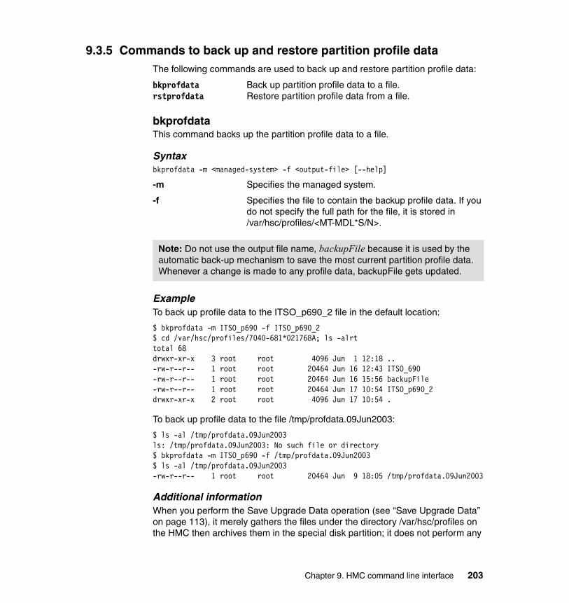
9.3.5 Commands to back up and restore partition profile dataThe following commands are used to back up and restore partition profile data:
bkprofdata Back up partition profile data to a file.rstprofdata Restore partition profile data from a file.
bkprofdataThis command backs up the partition profile data to a file.
Syntaxbkprofdata -m <managed-system> -f <output-file> [--help]
-m Specifies the managed system.
-f Specifies the file to contain the backup profile data. If you do not specify the full path for the file, it is stored in /var/hsc/profiles/<MT-MDL*S/N>.
ExampleTo back up profile data to the ITSO_p690_2 file in the default location:
$ bkprofdata -m ITSO_p690 -f ITSO_p690_2$ cd /var/hsc/profiles/7040-681*021768A; ls -alrttotal 68drwxr-xr-x 3 root root 4096 Jun 1 12:18 ..-rw-r--r-- 1 root root 20464 Jun 16 12:43 ITSO_690-rw-r--r-- 1 root root 20464 Jun 16 15:56 backupFile-rw-r--r-- 1 root root 20464 Jun 17 10:54 ITSO_p690_2drwxr-xr-x 2 root root 4096 Jun 17 10:54 .
To back up profile data to the file /tmp/profdata.09Jun2003:
$ ls -al /tmp/profdata.09Jun2003ls: /tmp/profdata.09Jun2003: No such file or directory$ bkprofdata -m ITSO_p690 -f /tmp/profdata.09Jun2003$ ls -al /tmp/profdata.09Jun2003-rw-r--r-- 1 root root 20464 Jun 9 18:05 /tmp/profdata.09Jun2003
Additional informationWhen you perform the Save Upgrade Data operation (see “Save Upgrade Data” on page 113), it merely gathers the files under the directory /var/hsc/profiles on the HMC then archives them in the special disk partition; it does not perform any
Note: Do not use the output file name, backupFile because it is used by the automatic back-up mechanism to save the most current partition profile data. Whenever a change is made to any profile data, backupFile gets updated.
Chapter 9. HMC command line interface 203
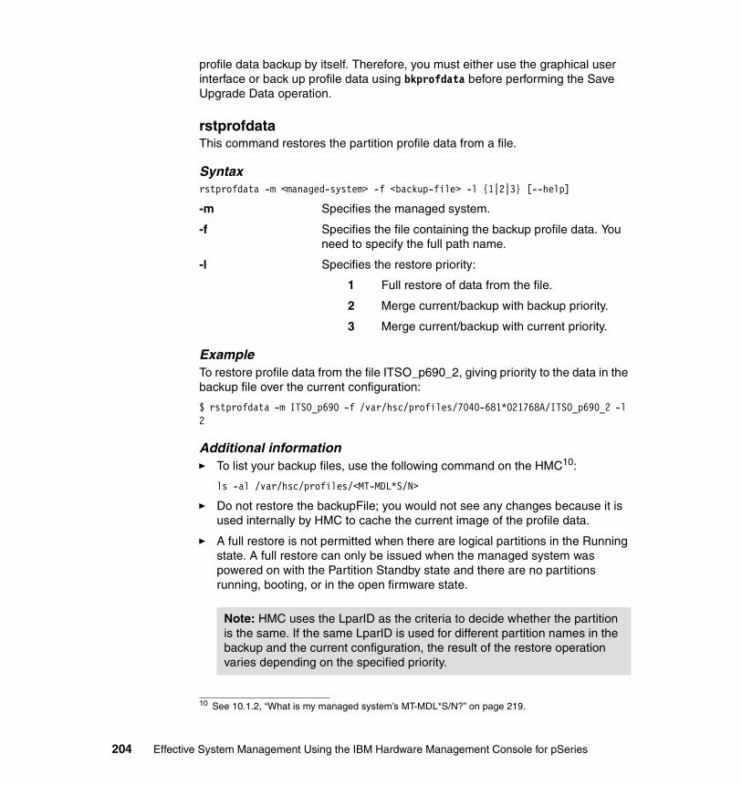
profile data backup by itself. Therefore, you must either use the graphical user interface or back up profile data using bkprofdata before performing the Save Upgrade Data operation.
rstprofdataThis command restores the partition profile data from a file.
Syntaxrstprofdata -m <managed-system> -f <backup-file> -l {1|2|3} [--help]
-m Specifies the managed system.
-f Specifies the file containing the backup profile data. You need to specify the full path name.
-l Specifies the restore priority:
1 Full restore of data from the file.
2 Merge current/backup with backup priority.
3 Merge current/backup with current priority.
ExampleTo restore profile data from the file ITSO_p690_2, giving priority to the data in the backup file over the current configuration:
$ rstprofdata -m ITSO_p690 -f /var/hsc/profiles/7040-681*021768A/ITSO_p690_2 -l 2
Additional information� To list your backup files, use the following command on the HMC10:
ls -al /var/hsc/profiles/<MT-MDL*S/N>
� Do not restore the backupFile; you would not see any changes because it is used internally by HMC to cache the current image of the profile data.
� A full restore is not permitted when there are logical partitions in the Running state. A full restore can only be issued when the managed system was powered on with the Partition Standby state and there are no partitions running, booting, or in the open firmware state.
10 See 10.1.2, “What is my managed system’s MT-MDL*S/N?” on page 219.
Note: HMC uses the LparID as the criteria to decide whether the partition is the same. If the same LparID is used for different partition names in the backup and the current configuration, the result of the restore operation varies depending on the specified priority.
204 Effective System Management Using the IBM Hardware Management Console for pSeries
9.3.6 Commands to manage hardware resourcesThe following commands are used to manage hardware resources:
lshwinfo Displays the temperature of the managed system.lshwres Lists the hardware resource configuration.chhwres Changes the hardware resource configuration.
lshwinfoThis command displays hardware information, such as temperature, of the specified managed system.
Syntaxlshwinfo -e <frame-name> -r sys [-n <object-name>|--all] [-F <format>] [--help]
-e Specifies the frame name.
-n Specifies the object name in the frame. Use --all to list all objects.
-F Specifies the formatted fields to list. Currently, temperature is the only valid value.
ExampleIn the following example, the managed system 7039-651*020032, which is pSeries 655, shows that the temperature is 28 degrees centigrade.
$ lssyscfg -r frame --allName FrameNum IsReal PortNums7040-61R*1234567 0 -505$ lshwinfo -e 7040-61R*1234567 -r sys --allcec_mtms temperature7039-651*0200032 28
If the command is issued against a managed system other than pSeries 655, the following error message will be displayed:
$ lssyscfg -r frame --allName FrameNum IsReal PortNums Frame Type7040-61R*021767A 0 No 2$ lshwinfo -r sys -e '7040-61R*021767A' --allEither the connection to the bulk power assembly was lost, or there is no bulk power assembly. Retry the operation.
Note: The lshwinfo command works for managed systems that are accommodated in the 7040-W42 frame managed by the HMC. (The BPC for the frame must be connected to the HMC via RS-422.)
Chapter 9. HMC command line interface 205
lshwresThis command is used to list hardware resources for the managed system. Specify the -p flag to list hardware resources in the partition.
Syntaxlshwres -m <managed-system> -r {ALL|cpu|mem|slot|led}
[-p <partition-name> | --all] [-y {sys|ident}] [-F <format>] [--help]
-m Specifies the managed system.
-r Specifies the resource to list. Use -r ALL to list all resources (cpu, memory, slot, and LED).
-p Specifies the partition to list the resource. Use --all to list resources for all partitions.
-y Specifies the LED type: sys (system attention LED) or ident (identify LED).
-F Specifies the formatted fields to list. Valid values are: name, state, status, id, parent, location, classcode, assigned_to, system, index, location_code, max, min, allocated, free, lmb_size, drawer_id, slot_id, slot_type, partition, partition_name, and phys_loc.
ExampleTo list all processors in the managed system ITSO_p690, use the lshwres command as follows:
$ lshwres -m ITSO_p690 -r cpuid Status partition assigned_to22 Configured by System 003*7040-681*021768A lpar0323 Configured by System 002*7040-681*021768A lpar023 Configured by System 008*7040-681*021768A lpar082 Configured by System 007*7040-681*021768A lpar071 Configured by System 005*7040-681*021768A lpar0516 Configured by System 004*7040-681*021768A lpar0417 Configured by System 003*7040-681*021768A lpar035 Configured by System 004*7040-681*021768A lpar040 Configured by System 005*7040-681*021768A lpar0520 Configured by System21 Configured by System6 Configured by System 006*7040-681*021768A lpar067 Configured by System 008*7040-681*021768A lpar0818 Configured by System 001*7040-681*021768A lpar0119 Configured by System 007*7040-681*021768A lpar074 Configured by System 008*7040-681*021768A lpar08
206 Effective System Management Using the IBM Hardware Management Console for pSeries

In this example output, you can see that there are 16 processors, and two (physical processor ID 20 and 21) are not allocated to any partition.
To list the memory resource for partition lpar06, use the lshwres command as follows:
$ lshwres -m ITSO_p690 -r mem -p lpar06allocated free lmb_size max min partition system partition_name8 193 256 12 4 006*7040-681*021768A ITSO_p690 lpar06
This output shows that lpar06 is allocated eight LMBs and the LMB size (lmb_size) is 256 MB; therefore, it is allocated the memory size of 2048 MB, while the managed system still has 48.25 GB free memory (193 LMBs times 256 MB) in total.
To check whether the system attention LED is on, see 10.1.13, “Is the system attention LED light on?” on page 224.
chhwresThis command is used to make changes (add, remove, move) to the resources (CPU, memory, slot) of the partitions. It performs dynamic logical partitioning (DLPAR) to reconfigure the partition resources dynamically.
It can also be used to set and reset various LEDs on the managed system.
Syntaxchhwres -m <managed-system> -o {a|r|m|s} -r {cpu|mem|slot|led}
[-p <partition-name>][-t <target-partition-name>][-q <quantity>][-i <drawer-id> -s <slot-id> | -l <location-code>][-y {sys|ident} -x <LED-index> -v <LED-setting>][-w <timeout>][-d <detail-level>][--help]
-m Specifies the managed system.
-o Specifies the operation to perform:
a Addr Removem Moves Set11
-r Specifies the resource to perform the operation.
11 Set is the only operation valid for the LED resource type.
Chapter 9. HMC command line interface 207
-p Specifies the partition to perform the operation or the source partition (for move operation).
-t Specifies the target partition (for move operation).
-q Specifies the quantity of CPUs or of LMBs for memory.
-i Specifies the drawer ID.
-s Specifies the slot ID.
-l Specifies the physical location code.
-y Specifies the LED type: sys (system attention LED) or ident (identify LED).
-x Specifies the LED index.
-v Specifies the LED setting. Valid values are on and off.
-w Specifies the timeout for the operation. Default is 0 (zero), which means no timeout (that is, the operation can take as much time as it needs).
-d Specifies the detail level for the drmgr12 command. Valid values are 0 to 5.
ExampleTo add two processors to lpar05:
$ ssh root@lpar05 lsdev -Cc processorproc0 Available 00-00 Processorproc1 Available 00-01 Processor$ chhwres -m ITSO_p690 -o a -r cpu -q 2 -p lpar05$ ssh root@lpar05 lsdev -Cc processorproc0 Available 00-00 Processorproc1 Available 00-01 Processorproc20 Available 00-20 Processorproc21 Available 00-21 Processor
To remove 1 GB (four LMBs) from lpar06:
$ ssh root@lpar06 lsattr -El mem0goodsize 2048 Amount of usable physical memory in Mbytes Falsesize 2048 Total amount of physical memory in Mbytes False$ chhwres -m ITSO_p690 -o r -r mem -q 4 -p lpar06$ ssh root@lpar06 lsattr -El mem0goodsize 1024 Amount of usable physical memory in Mbytes Falsesize 1024 Total amount of physical memory in Mbytes False
12 The drmgr command is invoked on an AIX partition if a DLPAR operation is requested from the HMC.
208 Effective System Management Using the IBM Hardware Management Console for pSeries
To move one processor from lpar05 to lpar06:
$ ssh root@lpar05 lsdev -Cc processorproc0 Available 00-00 Processorproc1 Available 00-01 Processorproc20 Available 00-20 Processorproc21 Available 00-21 Processor$ ssh root@lpar06 lsdev -Cc processorproc6 Available 00-06 Processor$ chhwres -m ITSO_p690 -o m -r cpu -q 1 -p lpar05 -t lpar06$ ssh root@lpar05 lsdev -Cc processorproc1 Available 00-01 Processorproc20 Available 00-20 Processorproc21 Available 00-21 Processor[hscroot@itsohmc hscroot]$ ssh root@lpar06 lsdev -Cc processor proc0 Available 00-00 Processorproc6 Available 00-06 Processor
To turn off the system attention LED, see 10.1.14, “How can I turn off the system attention LED?” on page 225.
9.3.7 Commands for virtual terminalsThe following commands are used to manage virtual terminals:
mkvterm Open a virtual terminal.rmvterm Close a virtual terminal.
mkvtermThis command opens a virtual terminal. The virtual terminal is opened in the same window that you issue the mkvterm command.
The recommended approach to open a virtual terminal is to log on to HMC by using ssh (for example, ssh -l hscroot itsohmc.itsc.austin.ibm.com), then use the mkvterm command to open the virtual terminal.
To close the opened virtual terminal session, do either of the following:
� Issue the rmvterm command from another ssh session.
� In the virtual terminal window, type a tilde and a period (~.).
A message “Terminate session? [y/n]” appears. Reply y to close the virtual terminal.
Note: If the virtual terminal shows the AIX login or password prompt line, you may need to type the key sequence several times to close the virtual terminal.
Chapter 9. HMC command line interface 209
Syntaxmkvterm -m <managed-system> [-p <partition-name>][--help]
-m Specifies the managed system.
-p Specifies the partition to open the virtual terminal session. If omitted, opens the virtual terminal on the Full System Partition.
Example[hscroot@itsohmc hscroot]$ mkvterm -m ITSO_p690 -p lpar05NVTS itsohmc.itsc.austin.ibm.com 9734 005*7040-681*021768A 1 005*7040-681*021768A _VT_...... omitted blank lines ......AIX Version 5(C) Copyrights by IBM and by others 1982, 2002.Console login:
rmvtermThis command closes a virtual terminal.
Syntaxrmvterm -m <managed-system> [-p <partition-name>][--help]
-m Specifies the managed system.
-p Specifies the partition to close the virtual terminal session. If omitted, closes the virtual terminal on the Full System Partition.
Example$ rmvterm -m ITSO_p690 -p lpar05
After the message Connection has closed appears on the opened virtual terminal, press Enter to return to the prompt.
root@lpar05:/ [581] # Connection has closed/opt/hsc/bin/command/mkvterm: line 40: 675 Broken pipe /opt/hsc/bin/vxterm $s [hscroot@itsohmc hscroot]$ [hscroot@itsohmc hscroot]$
Note: When the managed system is powered off, you can use mkvterm -m <managed-system> to open a virtual terminal to access the service processor menu.
210 Effective System Management Using the IBM Hardware Management Console for pSeries
Additional informationProcesses named [mkvterm] and vxterm can remain on the system even though no virtual terminal is active. To clean up these processes, use the kill command as the root user.
9.3.8 Commands used in recovery situationsThe following commands are used in recovery situations:
rmsplock Removes the lock set in the service processor.rsthwres Restores the hardware resource configuration.
rmsplockThis command removes the lock set in the service processor in the redundant HMC configuration. In a very rare situation, HMC might fail to remove the lock set in the service processor on a managed system. This command removes all leftover locks.
Syntaxrmsplock -m <managed-system> [--help]
-m Specifies the managed system.
ExampleTo remove any leftover lock on the managed system ITSO_p690:
$ rmsplock -m ITSO_p690; echo $?
rsthwresThis command restores the hardware resource configuration to a consistent state. Use it when a DLPAR operation fails to complete successfully, thus leaving the hardware resource assignment in NVRAM on the managed system and, on AIX, inconsistent.
If you have a failed DLPAR operation, run this command before continuing to perform any DLPAR operation.
Syntaxrsthwres -m <managed-system> -r {cpu|mem|slot} [-p <partition-name>][-u <processor-id>][-i <drawer-id> -s <slot-id>|-l <location-code>][--help]
Note: Currently, besides trying to open a virtual terminal to the partition, there is no better way to check which partition’s virtual terminal is currently opened.
Chapter 9. HMC command line interface 211

-m Specifies the managed system.-r Specifies the resource to restore.-p Specifies the partition to restore.-u Specifies the processor ID to restore.-i Specifies the drawer ID to restore.-s Specifies the slot ID to restore.-l Specifies the physical location code to restore.
ExampleTo restore the CPU configuration after a failed DLPAR operation:
$ rsthwres -m ITSO_p690 -r cpu
If there is no inconsistency for the CPU resource assignment on the managed system, the command displays the following message:
$ rsthwres -m ITSO_p690 -r cpuThere are no recoverable processor resources in the system.
To restore the memory configuration after a failed DR operation:
$ rsthwres -m ITSO_p690 -r mem
To restore the I/O device configuration after a failed DLPAR operation:
$ rsthwres -m ITSO_p690 -r slot
If there is no inconsistency for the I/O resource assignment on the managed system, the command displays one of the following messages:
$ rsthwres -m ITSO_p690 -r slotThe I/O device with the slot ID and drawer ID entered is not a recoverable resource.$ rsthwres -m ITSO_p690 -r slot -l U1.5-P1-I5The I/O device with the physical location code entered is not a recoverable resource.$ rsthwres -m ITSO_p690 -r slot -i '7040-61D*021766A-P2' -s 5The I/O device with the slot ID and drawer ID entered is not a recoverable resource.
9.3.9 Commands used for other purposesThe following commands are used for purposes not explained in the other subsections of 9.3, “HMC commands” on page 184:
chsysstate Change system state.lssvcevents List the HMC events
212 Effective System Management Using the IBM Hardware Management Console for pSeries
chsysstateThis command is used to change system state. By changing the system state, you can perform various operations on the managed system and partitions, such as: power on, power off, reset, activate, shutdown, and so on.
Syntaxchsysstate -m <managed-system> -o {on|off|reset|osreset|osshutdown|rebuild}
-r {sys|lpar|sysprof}[-n <object-name>][-f <profile-name>][-c {full|lpar}][-b {norm|dd|sms|of|ds|std|auto}][--help]
-m Specifies the managed system.
-o Specifies the operation to perform:
on Power on the managed system or activate a partition.
off Power off the managed system or perform a hard reset on a partition.
reset Reset the managed system (works only in Full System Partition) or perform a soft reset on a partition.
osreset Reboot a partition.
osshutdown Shut down a partition.
rebuild Rebuild the manage system.
-r Specifies the resource type of the object to perform the operation.
-n Specifies the object to perform the operation.
-f Specifies the partition profile to use.
-c Specifies the mode to power on the managed system:
full Full System Partition
lpar Logical partition
-b Specifies the boot mode:
norm Normal
dd Diagnostic default boot list
sms SMS
of Open firmware OK prompt
Chapter 9. HMC command line interface 213
ds Diagnostic stored boot list
std Partition standby
auto Automatically start partitions
ExampleTo rebuild a managed system:
$ chsysstate -o rebuild -r sys -n ITSO_p690
This chsysstate command has more uses; for example, you can use it to activate, shut down, reboot, soft reset, and hard reset a partition, or to power on, reset, and power off a managed system. More example uses are provided in 10.2, “Basic command line samples” on page 227.
lssvceventsThis command is used to display hardware-serviceable events or HMC console events.
Syntaxlssvcevents -t {hardware|console}[-d <#days-to-go-back>]
[-m <managed-system> -s {sp|lpar|ALL} [-p <partition-name>]][--help]
-t Specifies the type of event to query.
-d Specifies the number of days to go back and query for the events. Default is seven days. The maximum for hardware event is 90 days.
-m Specifies the managed system (required only for -t hardware).
-s Specifies the source of events to query (required only for -t hardware):
sp Query from the Service Processor
lpar Query from the partitions
ALL Query all above events
-p Specifies the partition to query (optional for -t hardware).
ExampleTo view HMC console events for the past week:
$ lssvcevents -t consoleEarliest Timestamp Description06/10/03 02:45:20 PM HSCE2156 DLPAR: Completed moving cpus.06/10/03 02:45:20 PM HSCE2156 DLPAR: Completed moving cpus.06/10/03 02:45:16 PM HSCE2072 DLPAR: Processor ID 0 was added to partition 6.
214 Effective System Management Using the IBM Hardware Management Console for pSeries

06/10/03 02:45:16 PM HSCE2071 DLPAR: Processor ID 0 was removed from partition5.06/10/03 02:39:06 PM HSCE2158 DLPAR: Completed removing memory from the partition.06/10/03 02:39:06 PM HSCE2158 DLPAR: Completed removing memory from the partition.06/10/03 02:39:02 PM HSCE2073 DLPAR: 1024 MB of memory was removed from partition 6.06/10/03 02:38:39 PM HSCE2154 DLPAR: Completed adding cpus to the partition.06/10/03 02:38:12 PM HSCE2072 DLPAR: Processor ID 21 was added to partition 5.06/10/03 02:38:11 PM HSCE2072 DLPAR: Processor ID 20 was added to partition 5....... omitted lines ......06/03/03 05:44:09 AM HSCE2155 DLPAR: Completed removing cpus from the partition.06/03/03 05:44:07 AM HSCE2071 DLPAR: Processor ID 2 was removed from partition7.06/03/03 05:42:44 AM HSCE2072 DLPAR: Processor ID 19 was added to partition 7.06/03/03 05:29:34 AM HSCE2167 User hscroot: Forced Virtual Terminal Session onlogical partition lpar08 in managed system ITSO_p690 to close06/03/03 05:23:27 AM HSCE2014 UserName hscroot Virtual terminal has been open on partition lpar08 of lpar id 008*7040-681*021768A of managed system ITSO_p690;
To view any hardware-serviceable events from the service processor:
$ lssvcevents -t hardware -d 90 -m DEV -s spManaged System Earliest Timestamp Call Home Called Home Error Class DescriptionDEV 05/27/2003 11:15:37 Yes Yes CECCSP Bootfailuredetected
To view hardware-serviceable events from lpar05 during the past month:
$ lssvcevents -t hardware -d 30 -m ITSO_p690 -s lpar -p lpar05Managed System Earliest Timestamp Call Home Called Home Error Class DescriptionITSO_p690 05/14/2003 17:55:53 Yes Yes OS The drive cannot be started.ITSO_p690 05/14/2003 17:47:50 Yes Yes OS Error log analysis indicates a hardware failure.ITSO_p690 06/03/2003 17:56:56 No No SURVALNC Communications to the SFP component on partition lpar08 are unavailable.
To view the time when critical console data was performed, see Example 10-16 on page 225.
Chapter 9. HMC command line interface 215

To view the time partition profile data backup was performed, see Example 10-17 on page 225.
216 Effective System Management Using the IBM Hardware Management Console for pSeries

Chapter 10. Advanced HMC command examples
This chapter provides more-advanced information about using the command line interface on the IBM Hardware Management Console for pSeries (HMC).
The first section describes how we can use the commands to answer many simple questions that the system administrators would like to know.
Next, we describe the use of the command line to do the tasks that are traditionally done by the GUI. We also include a few examples of Perl scripts for the advanced usage of the command line interface.
For further information about the command line interface on the HMC, refer to IBM Hardware Management Console for pSeries Installation and Operations Guide, SA38-0590.
10
Note: Avoid copying any files onto the HMC other than those detailed in IBM publications, as this can interfere with problem determination by IBM support personnel. Therefore, all supported commands should be executed via either the rexec or ssh facility from remote systems. We suggest you store such files as administrative scripts on systems other than the HMC.
© Copyright IBM Corp. 2003. All rights reserved. 217
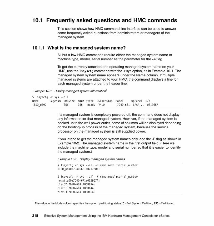
10.1 Frequently asked questions and HMC commandsThis section shows how HMC command line interface can be used to answer some frequently asked questions from administrators or managers of the managed system.
10.1.1 What is the managed system name?All but a few HMC commands require either the managed system name or machine type, model, serial number as the parameter for the -m flag.
To get the currently attached and operating managed system name on your HMC, use the lssyscfg command with the -r sys option, as in Example 10-1. The managed system system name appears under the Name column. If multiple managed systems are attached to your HMC, the command displays a line for each managed system under the header line.
Example 10-1 Display managed system information1
$ lssyscfg -r sys --allName CageNum LMBSize Mode State CSPVersion Model OpPanel S/NITSO_p690 256 255 Ready V4.0 7040-681 LPAR... 021768A
If a managed system is completely powered off, the command does not display any information for that managed system. However, if the managed system is hooked up to the wall power outlet, some of columns will be displayed depending on the booting-up process of the managed system, because the service processor on the managed system is still supplied power.
If you intend to get the managed system names only, add the -F flag as shown in Example 10-2. The managed system name is the first output field. (Here we include the machine type, model and serial number so that it is easier to identify the managed system.)
Example 10-2 Display managed system names
$ lssyscfg -r sys --all -F name:model:serial_numberITSO_p690:7040-681:021768A:
$ lssyscfg -r sys --all -F name:model:serial_numberregatta00:7040-671:022967A:cler02:7028-6C4:106B69A:cler01:7028-6C4:106B64A:cler03:7028-6C4:106B65A:
1 The value in the Mode column specifies the system partitioning status: 0 =Full System Partition; 255 =Partitioned.
218 Effective System Management Using the IBM Hardware Management Console for pSeries

10.1.2 What is my managed system’s MT-MDL*S/N?To get the MT-MDL*S/N2 information for a managed system, use the lssyscfg command with the -r sys option and -F flag as shown in Example 10-3.
Here, we use Perl to concatenate the model and serial number strings together with the asterisk character (*).
Example 10-3 Display MT-MDL*S/N of a managed system
$ lssyscfg -r sys --all -F name:model:serial_number|perl -F: -ane 'print "The MT-MDL*S/N of $F[0] is $F[1]*$F[2]\n"'The MT-MDL*S/N of ITSO_p690 is 7040-681*021768A
$ lssyscfg -r sys --all -F name:model:serial_number|perl -F: -ane 'print "The MT-MDL*S/N of $F[0] is $F[1]*$F[2]\n"'The MT-MDL*S/N of regatta00 is 7040-671*022967AThe MT-MDL*S/N of cler02 is 7028-6C4*106B69AThe MT-MDL*S/N of cler01 is 7028-6C4*106B64AThe MT-MDL*S/N of cler03 is 7028-6C4*106B65A
10.1.3 What is my frame name?To get the frame name, use the lssyscfg command with the -r frame option as shown in Example 10-4.
Example 10-4 Display frame name
$ lssyscfg -r frame --all -F name7040-61R*021767A
10.1.4 Is my managed system CUoD-capable?To verify whether your managed system is processor CUoD capable, use the lscuod command with the -r cpu option. To verify whether your managed system is memory CUoD capable or not, use the lscuod command with -r mem option.
Example 10-5 shows an output example when the command is executed on a CUoD non-capable system; ITSO_p690 is neither processor CUoD capable nor memory CUoD capable in this example.
Example 10-5 Verify CUoD capabilities
$ lscuod -m ITSO_p690 -r cpu -t regThe managed system is not CUoD capable at the present time.
2 MT-MDL*S/N: machine type, model, and serial number
Chapter 10. Advanced HMC command examples 219

$ lscuod -m ITSO_p690 -r mem -t regThe managed system is not CUoD capable at the present time.
10.1.5 How many affinity partitions are defined or running?To check the affinity partitions, use the lssyscfg command with the -r alpar option as shown in Example 10-6.
Example 10-6 Display all affinity partitions3
$ lssyscfg -r alpar -m regatta00 --allNo results were found.
$ lssyscfg -r alpar -m ITSO_p690 --allName id DLPAR State Profile OpPanelaaa 011 0 Running aaaa 009 0 Running aaaaa 012 0 Running aaaaaa 010 0 Running aa
$ lssyscfg -r alpar -m ITSO_p690 --allName id DLPAR State Profile OpPanelaaa 011 0 Not Available aaaa 009 0 Not Available aaaaa 012 0 Not Available aaaaaa 010 0 Not Available aa
If the output of the lssyscfg command with -r alpar option is No results were found, this managed system does not have any defined affinity partitions.
Notice that if the affinity partitions are running, the regular partitions will not be available. The same is true vice versa.
10.1.6 Which partitions are DLPAR capable?For the list of DLPAR capable partitions using the Web-based System Manager, select each partition and right-click on it. If the pop-up menu does not contain Dynamic Logical Partitioning, then the partition is not DLPAR capable.
If the Dynamic Logical Partitioning entry appears on the pop-up menu, move the mouse to the entry to see whether its submenu (Adapters, Processors, Memory) is enabled. If it is grayed out, the partition is not DLPAR capable.
3 The id column shown in the output represents the partition ID, which is used internally in the HMC software to uniquely identify each partition.
220 Effective System Management Using the IBM Hardware Management Console for pSeries

This information also can be obtained by using the lssyscfg command with the -r lpar option as shown in Example 10-7.
Example 10-7 Display all logical partitions
$ lssyscfg -r lpar -m ITSO_p690 --allName id DLPAR State Profile OpPanellpar06 006 15 Running aix52_64lpar03 003 15 Running aix52_64FullSystemPartition 000 0 Not Available PowerOnNormalProfilelpar07 007 15 Running aix52_64lpar04 004 15 Running aix52_64lpar01 001 0 Running aix51_64lpar08 008 15 Running aix52_64lpar05 005 15 Running aix52_64lpar02 002 0 Running aix51_64
If the value in the DLPAR column is 15, the partition is DLPAR capable4.
10.1.7 How many processors are allocated to each partition?To display the number of processors allocated to each partition, use the lshwres command with the -r cpu option and -F flag as shown in Example 10-8.
Example 10-8 Display CPU allocated to each partition
$ lshwres -r cpu -m ITSO_p690 --all -F partition_name:allocatedlpar06:1lpar03:2FullSystemPartition:nulllpar07:2lpar04:2lpar01:1lpar08:2lpar05:2lpar02:1
Notice that you must specify the --all flag to tell the lshwres command to list the information for all partitions.
4 In the future HMC software release, the value is anticipated to be changed to YES for DLPAR capable and NO for DLPAR incapable.
Chapter 10. Advanced HMC command examples 221

10.1.8 How many processors are free?To display the number of free processors (processors that are not assigned to any partition), use the lshwres command with the -r cpu option and -F flag as shown in Example 10-9.
Example 10-9 Display the number of free CPUs
$ lshwres -r cpu -m ITSO_p690 -p lpar01 -F free3
Notice that you can specify any partition name, including the one that is not currently active, for the -p flag.
10.1.9 How much memory is allocated to each partition now?To display the amount of memory allocated to each partition, use the lshwres command with the -r mem option and -F flag as shown in Example 10-10.
Here, we use Perl to multiply the lmb_size and allocated to get the size of memory allocated in MB.
Example 10-10 Display memory allocated to each partition
$ lshwres -r mem -m ITSO_p690 --all -F partition_name:lmb_size:allocated|grep -v null|perl -F: -ane '$mem=$F[1]*$F[2]; print "Partition $F[0] has $mem MB allocated..\n"'Partition lpar06 has 2048 MB allocated..Partition lpar03 has 3072 MB allocated..Partition lpar07 has 2048 MB allocated..Partition lpar04 has 1024 MB allocated..Partition lpar01 has 1024 MB allocated..Partition lpar08 has 2048 MB allocated..Partition lpar05 has 2048 MB allocated..
Notice that you must specify the --all flag to tell the lshwres command to list the information on all partitions.
222 Effective System Management Using the IBM Hardware Management Console for pSeries

10.1.10 How much memory is free now?To display the amount of free memory, use the lshwres command with the -r mem option and -F flag as shown in Example 10-11.
Here, we use Perl to multiply the lmb_size and free to get the number of MB free.
Example 10-11 Display free memory
$ lshwres -r mem -m ITSO_p690 -p test -F lmb_size:free|perl -F: -ane '$mem=$F[0]*$F[1]; print "There is $mem MB free..\n"'There is 50432 MB free..
Notice that you can specify any partition name, including the one that is not currently active, for the -p flag.
10.1.11 Display empty I/O slots allocation statusTo display the list of I/O slots that are empty and whether they are allocated to any partition, use the lshwres command with the -r slot option and -F flag as shown in Example 10-12.
Example 10-12 Display empty I/O slots and their allocation status
$ lshwres -r slot -m ITSO_p690 -F phys_loc:slot_type:assigned_to|grep 'Empty'U1.9-P1-I3:Empty:lpar01U1.9-P1-I9:Empty:lpar02
Note: The amount of memory allocated to each partition above is the amount that each partition ‘sees.’ It does not include the page_table overhead.
To get the total amount of memory including page_table overhead, use the following command:
$ lshwres -r mem -m ITSO_p690allocated page_table partition assigned_to2112 64 006*7040-681*021768A lpar063584 512 003*7040-681*021768A lpar032112 64 007*7040-681*021768A lpar071088 64 004*7040-681*021768A lpar041088 64 001*7040-681*021768A lpar012176 128 008*7040-681*021768A lpar082176 128 005*7040-681*021768A lpar051088 64 002*7040-681*021768A lpar02The allocated column is the total amount of memory.
Chapter 10. Advanced HMC command examples 223

U1.9-P1-I5:Empty:lpar02U1.9-P1-I8:Empty:lpar02U1.9-P1-I4:Empty:lpar01U1.5-P2-I5:Empty:nullU1.5-P2-I8:Empty:lpar08U1.5-P2-I1:Empty:lpar07U1.5-P2-I4:Empty:lpar07U1.5-P2-I3:Empty:nullU1.5-P2-I9:Empty:lpar08U1.5-P1-I4:Empty:lpar05U1.5-P1-I3:Empty:lpar05U1.9-P2-I4:Empty:lpar03U1.9-P2-I3:Empty:lpar03U1.9-P2-I5:Empty:lpar04U1.9-P2-I8:Empty:lpar04
10.1.12 Which partition currently has CD/DVD assigned to it?To display the partition to which the CD/DVD device is assigned, use the lshwres command withthe -r slot option and -F flag as shown in Example 10-13.
Example 10-13 Display the partition that has the CD-DVD allocated to it
$ lshwres -r slot -m ITSO_p690 -F phys_loc:slot_type:assigned_to|grep 'U1.9-P1-I10'U1.9-P1-I10:SCSI bus controller:lpar05
10.1.13 Is the system attention LED light on?To check whether the system attention LED is on, use the lshwres command with the -r led -y sys option as shown in Example 10-14.
Example 10-14 Display the system attention LED
$ lshwres -m ITSO_p690 -r led -y sysindex State location_code884737 on U1.18
Note: If the assigned_to field is null, then the slot is not allocated.
Note: This example shows that the CD/DVD device is connected to the SCSI adapter in the U1.9-P1-I10 PCI slot on the pSeries 690 or pSeries 670.
224 Effective System Management Using the IBM Hardware Management Console for pSeries

10.1.14 How can I turn off the system attention LED?To turn off the system attention LED, use the chhwres command with the -o s option as shown in Example 10-14 on page 224.
Example 10-15 Turn off the system attention LED - p690
$ lshwres -m ITSO_p690 -r led -y sysindex State location_code884737 on U1.18$ chhwres -m ITSO_p690 -o s -r led -y sys -x 884737 -v off$ lshwres -m ITSO_p690 -r led -y sysindex State location_code884737 off U1.18
To specify the -x flag, you must get the index value for the specific physical location code using the lshwres command.
10.1.15 When was the critical console data backup performed?To display the date and time of the critical console data backup, use the lssvcevents command with the -t console option as shown in Example 10-16.
Example 10-16 Display the date and time when critical console data backup was performed
$ lssvcevents -t console -d 9999|grep 'backup of critical'05/23/03 05:25:39 PM HSCE2062 A backup of critical console data was performed.05/21/03 09:44:17 AM HSCE2062 A backup of critical console data was performed.05/20/03 03:22:32 PM HSCE2062 A backup of critical console data was performed.05/15/03 11:01:23 PM HSCE2062 A backup of critical console data was performed.05/15/03 05:48:52 AM HSCE2062 A backup of critical console data was performed.
Notice that you can use the -d flag to specify how far back in time (number of days) you want to go for the list of events. Default is 7 (seven) days.
10.1.16 When did I do the profile data backup?To display the date and time that the profile data backup was performed, use the lssvcevents command withthe -t console option as shown in Example 10-17.
Example 10-17 Display the date and time when profile data backup was performed
$ lssvcevents -t console -d 9999|grep 'Profile data'05/20/03 02:44:32 PM HSCE2004 UserName hscroot Profile data of managed system ITSO_p690 has been backup to file /var/hsc/profiles/7040-681*021768A/Theeraphong;05/20/03 01:44:55 PM HSCE2004 UserName hscroot Profile data of managed system ITSO_p690 has been backup to file /var/hsc/profiles/7040-681*021768A/Theeraphong;
Chapter 10. Advanced HMC command examples 225
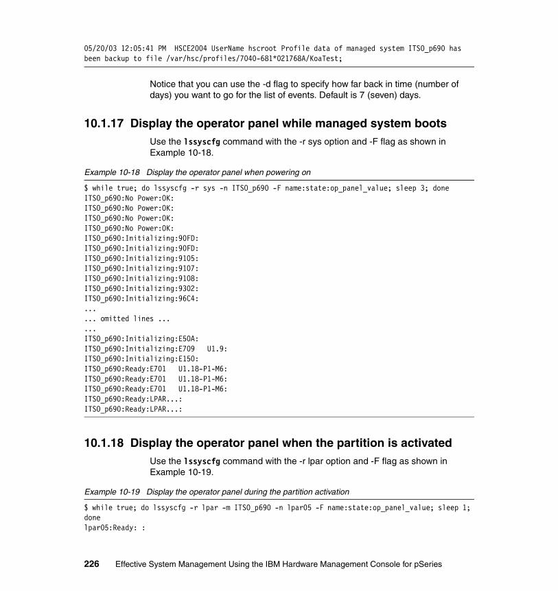
05/20/03 12:05:41 PM HSCE2004 UserName hscroot Profile data of managed system ITSO_p690 has been backup to file /var/hsc/profiles/7040-681*021768A/KoaTest;
Notice that you can use the -d flag to specify how far back in time (number of days) you want to go for the list of events. Default is 7 (seven) days.
10.1.17 Display the operator panel while managed system bootsUse the lssyscfg command with the -r sys option and -F flag as shown in Example 10-18.
Example 10-18 Display the operator panel when powering on
$ while true; do lssyscfg -r sys -n ITSO_p690 -F name:state:op_panel_value; sleep 3; doneITSO_p690:No Power:OK:ITSO_p690:No Power:OK:ITSO_p690:No Power:OK:ITSO_p690:No Power:OK:ITSO_p690:Initializing:90FD:ITSO_p690:Initializing:90FD:ITSO_p690:Initializing:9105:ITSO_p690:Initializing:9107:ITSO_p690:Initializing:9108:ITSO_p690:Initializing:9302:ITSO_p690:Initializing:96C4:...... omitted lines ......ITSO_p690:Initializing:E50A:ITSO_p690:Initializing:E709 U1.9:ITSO_p690:Initializing:E150:ITSO_p690:Ready:E701 U1.18-P1-M6:ITSO_p690:Ready:E701 U1.18-P1-M6:ITSO_p690:Ready:E701 U1.18-P1-M6:ITSO_p690:Ready:LPAR...:ITSO_p690:Ready:LPAR...:
10.1.18 Display the operator panel when the partition is activatedUse the lssyscfg command with the -r lpar option and -F flag as shown in Example 10-19.
Example 10-19 Display the operator panel during the partition activation
$ while true; do lssyscfg -r lpar -m ITSO_p690 -n lpar05 -F name:state:op_panel_value; sleep 1; donelpar05:Ready: :
226 Effective System Management Using the IBM Hardware Management Console for pSeries

lpar05:Ready: :lpar05:Starting:E1FA 1,7:lpar05:Starting:E1FA 7,2:lpar05:Starting:E1FA c,2:lpar05:Starting:E1FB:lpar05:Starting:E1FA 3,6:lpar05:Starting:E1FA a,1:lpar05:Starting:E1F1:lpar05:Running:AIX is starting.:lpar05:Running:2520 U1.5-P1/Z1:lpar05:Running:2520 U1.5-P1/Z1:lpar05:Running:0517 SYNCVG ROOTVG:lpar05:Running:2520 U1.5-P1/Z1:lpar05:Running:0c33:lpar05:Running: :lpar05:Running: :
10.2 Basic command line samplesIn this section, we describe some tasks that were documented in Chapter 3, “Basic managed system operation tasks” on page 55. Here, we perform the tasks using the command line interface instead of the GUI.
We also include scripts for some tasks that may be tedious or error-prone when performed on the GUI, such as adding many HMC users, creating partitions and profiles, and documenting the configurations of all partitions and profiles.
10.2.1 Power on the managed systemThere are many options for powering on the managed system; for example:
� To power on the managed system into partition standby mode, see Example 10-20.
� To power on the managed system and start system profile, see Example 10-20 and Example 10-21 on page 228.
� To power on the managed system and autostart all partitions, see Example 10-22 on page 229.
Example 10-20 Power on the managed system: partition standby mode
$ lssyscfg -r sys --allName CageNum LMBSize Mode State CSPVersion Model OpPanel S/NITSO_p690 256 255 No Power V4.0 7040-681 OK 021768A$ chsysstate -o on -r sys -n ITSO_p690
Chapter 10. Advanced HMC command examples 227
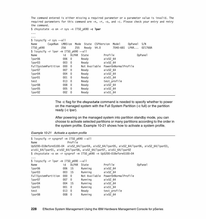
The command entered is either missing a required parameter or a parameter value is invalid. The required parameters for this command are -n, -r, -o, and -c. Please check your entry and retry the command.$ chsysstate -o on -r sys -n ITSO_p690 -c lpar......$ lssyscfg -r sys --allName CageNum LMBSize Mode State CSPVersion Model OpPanel S/NITSO_p690 256 255 Ready V4.0 7040-681 LPAR... 021768A$ lssyscfg -r lpar -m ITSO_p690 --allName id DLPAR State Profile OpPanellpar06 006 0 Ready aix52_64lpar03 003 0 Ready aix52_64FullSystemPartition 000 0 Not Available PowerOnNormalProfilelpar07 007 0 Ready aix52_64lpar04 004 0 Ready aix52_64lpar01 001 0 Ready aix51_64test 013 0 Ready test_profilelpar08 008 0 Ready aix52_64lpar05 005 0 Ready aix52_64lpar02 002 0 Ready aix51_64
The -c flag for the chsysstate command is needed to specify whether to power on the managed system with the Full System Partition (-c full) or the partition ready (-c lpar).
After powering on the managed system into partition standby mode, you can choose to activate selected partitions or many partitions according to the order in the system profile. Example 10-21 shows how to activate a system profile.
Example 10-21 Activate a system profile
$ lssyscfg -r sysprof -m ITSO_p690 --allName ProfileUp5200-01Before5100-04 aix52_64/lpar04, aix52_64/lpar05, aix52_64/lpar06, aix52_64/lpar03, aix51_64/lpar01, aix52_64/lpar08, aix52_64/lpar07, aix51_64/lpar02$ chsysstate -o on -r sysprof -m ITSO_p690 -n Up5200-01Before5100-04...$ lssyscfg -r lpar -m ITSO_p690 --allName id DLPAR State Profile OpPanellpar06 006 15 Running aix52_64lpar03 003 15 Running aix52_64FullSystemPartition 000 0 Not Available PowerOnNormalProfilelpar07 007 0 Running aix52_64lpar04 004 15 Running aix52_64lpar01 001 0 Running aix51_64test 013 0 Ready test_profilelpar08 008 0 Running aix52_64
228 Effective System Management Using the IBM Hardware Management Console for pSeries

lpar05 005 15 Running aix52_64lpar02 002 0 Running aix52_64
The test partition is not started, as it is not included in the system profile Up5200-01Before5100-04.
Example 10-22 shows how to power on the managed system and autostart all partitions with a single chsysstate command invocation with the -b auto option.
Example 10-22 Power on the managed system and start all partitions
$ lssyscfg -r sys --allName CageNum LMBSize Mode State CSPVersion Model OpPanel S/NITSO_p690 256 255 No Power V4.0 7040-681 OK 021768A$ chsysstate -r sys -o on -n ITSO_p690 -c lpar -b auto......$ lssyscfg -r sys --all Name CageNum LMBSize Mode State CSPVersion Model OpPanel S/NITSO_p690 256 255 Ready V4.0 7040-681 LPAR... 021768A[hscroot@itsohmc hscroot]$ lssyscfg -r lpar -m ITSO_p690 --allName id DLPAR State Profile OpPanellpar06 006 15 Running aix52_64lpar03 003 15 Running aix52_64FullSystemPartition 000 0 Not Available PowerOnNormalProfilelpar07 007 0 Running aix52_64lpar04 004 15 Running aix52_64lpar01 001 0 Running aix51_64test 013 0 Error test_profile 20EE000Blpar08 008 0 Running aix52_64lpar05 005 15 Running aix52_64lpar02 002 0 Running aix52_64
Notice that all partitions are activated. However, partition test cannot be activated, as it has some conflict with other partitions on the boot disk.
10.2.2 Activate a partitionTo activate a partition, use the chsysstate command with -o on option as shown in Example 10-23.
Example 10-23 Activate a partition
$ lssyscfg -r lpar -m ITSO_p690 -n lpar05Name id DLPAR State Profile OpPanel
Note: With the -b auto option, partitions are activated in order of partition ID.
Chapter 10. Advanced HMC command examples 229
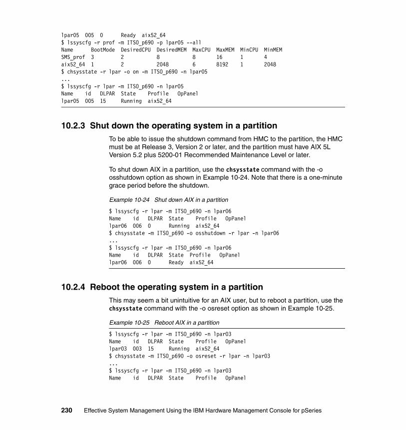
lpar05 005 0 Ready aix52_64$ lssyscfg -r prof -m ITSO_p690 -p lpar05 --allName BootMode DesiredCPU DesiredMEM MaxCPU MaxMEM MinCPU MinMEMSMS_prof 3 2 8 8 16 1 4aix52_64 1 2 2048 6 8192 1 2048$ chsysstate -r lpar -o on -m ITSO_p690 -n lpar05...$ lssyscfg -r lpar -m ITSO_p690 -n lpar05Name id DLPAR State Profile OpPanellpar05 005 15 Running aix52_64
10.2.3 Shut down the operating system in a partitionTo be able to issue the shutdown command from HMC to the partition, the HMC must be at Release 3, Version 2 or later, and the partition must have AIX 5L Version 5.2 plus 5200-01 Recommended Maintenance Level or later.
To shut down AIX in a partition, use the chsysstate command with the -o osshutdown option as shown in Example 10-24. Note that there is a one-minute grace period before the shutdown.
Example 10-24 Shut down AIX in a partition
$ lssyscfg -r lpar -m ITSO_p690 -n lpar06Name id DLPAR State Profile OpPanellpar06 006 0 Running aix52_64$ chsysstate -m ITSO_p690 -o osshutdown -r lpar -n lpar06...$ lssyscfg -r lpar -m ITSO_p690 -n lpar06Name id DLPAR State Profile OpPanellpar06 006 0 Ready aix52_64
10.2.4 Reboot the operating system in a partitionThis may seem a bit unintuitive for an AIX user, but to reboot a partition, use the chsysstate command with the -o osreset option as shown in Example 10-25.
Example 10-25 Reboot AIX in a partition
$ lssyscfg -r lpar -m ITSO_p690 -n lpar03Name id DLPAR State Profile OpPanellpar03 003 15 Running aix52_64$ chsysstate -m ITSO_p690 -o osreset -r lpar -n lpar03...$ lssyscfg -r lpar -m ITSO_p690 -n lpar03Name id DLPAR State Profile OpPanel
230 Effective System Management Using the IBM Hardware Management Console for pSeries

lpar03 003 0 Running aix52_64 0517 MOUNT ROOT
10.2.5 Reset the operating system in a partitionTo perform the reset or soft reset of AIX in a partition, use the chsysstate command with the -o reset option as shown in Example 10-26.
When the partition is reset, AIX will force a kernel dump and then reboot5.
Example 10-26 Soft reset a partition
$ chsysstate -m ITSO_p690 -o reset -r lpar -n lpar03...$ lssyscfg -r lpar -m ITSO_p690 -n lpar03Name id DLPAR State Profile OpPanellpar03 003 0 Starting aix52_64 00c2 6619136...$ lssyscfg -r lpar -m ITSO_p690 -n lpar03Name id DLPAR State Profile OpPanellpar03 003 15 Running aix52_64
10.2.6 Hard reset a partitionTo perform the hard reset or power off the partition, use the chsysstate command with the -o off option as shown in Example 10-27.
Example 10-27 Hard reset a partition
$ lssyscfg -r lpar -m ITSO_p690 -n lpar04Name id DLPAR State Profile OpPanellpar04 004 15 Running aix52_64$ chsysstate -m ITSO_p690 -o off -r lpar -n lpar04...$ lssyscfg -r lpar -m ITSO_p690 -n lpar04Name id DLPAR State Profile OpPanellpar04 004 15 Ready aix52_64
5 The autorestart parameter of AIX, which is used to specify whether to automatically reboot the system after a crash, is not supported in a partitioned environment. Thus, AIX always reboots after system crash on a partition.
Note: You should always try to shut down or perform a soft reset to the partition first. Use the hard reset as the last resort.
Chapter 10. Advanced HMC command examples 231
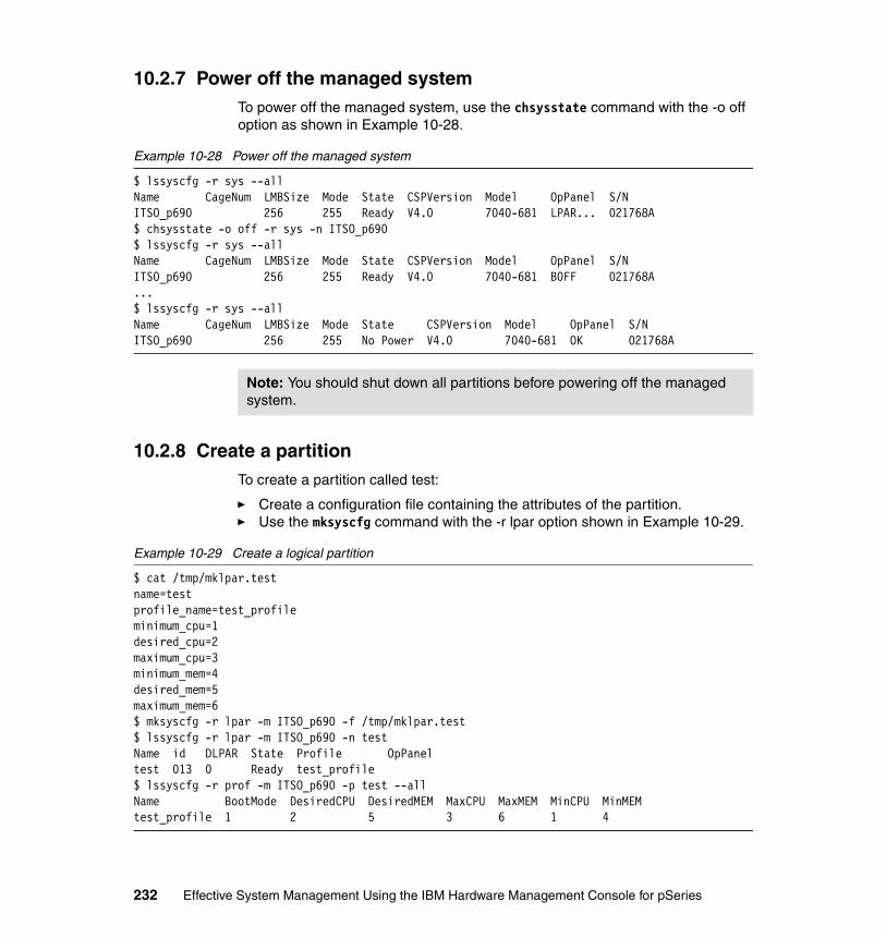
10.2.7 Power off the managed systemTo power off the managed system, use the chsysstate command with the -o off option as shown in Example 10-28.
Example 10-28 Power off the managed system
$ lssyscfg -r sys --allName CageNum LMBSize Mode State CSPVersion Model OpPanel S/NITSO_p690 256 255 Ready V4.0 7040-681 LPAR... 021768A$ chsysstate -o off -r sys -n ITSO_p690$ lssyscfg -r sys --allName CageNum LMBSize Mode State CSPVersion Model OpPanel S/NITSO_p690 256 255 Ready V4.0 7040-681 B0FF 021768A...$ lssyscfg -r sys --allName CageNum LMBSize Mode State CSPVersion Model OpPanel S/NITSO_p690 256 255 No Power V4.0 7040-681 OK 021768A
10.2.8 Create a partitionTo create a partition called test:
� Create a configuration file containing the attributes of the partition.� Use the mksyscfg command with the -r lpar option shown in Example 10-29.
Example 10-29 Create a logical partition
$ cat /tmp/mklpar.testname=testprofile_name=test_profileminimum_cpu=1desired_cpu=2maximum_cpu=3minimum_mem=4desired_mem=5maximum_mem=6$ mksyscfg -r lpar -m ITSO_p690 -f /tmp/mklpar.test$ lssyscfg -r lpar -m ITSO_p690 -n testName id DLPAR State Profile OpPaneltest 013 0 Ready test_profile$ lssyscfg -r prof -m ITSO_p690 -p test --allName BootMode DesiredCPU DesiredMEM MaxCPU MaxMEM MinCPU MinMEMtest_profile 1 2 5 3 6 1 4
Note: You should shut down all partitions before powering off the managed system.
232 Effective System Management Using the IBM Hardware Management Console for pSeries

We intentionally include only the minimum attributes required by the mksyscfg command. In real-life use, you must specify at least the required_io attribute that points to the slot for the boot disk (and maybe a network adapter) for the partition.
10.2.9 Create a partition profileTo create a partition profile for lpar05 called SMS:
� Create a configuration file containing the attributes of the profile.� Use the mksyscfg command with -r prof option as shown in Example 10-30.
Example 10-30 Create a partition profile
$ lssyscfg -r prof -m ITSO_p690 -p lpar05 --allName BootMode DesiredCPU DesiredMEM MaxCPU MaxMEM MinCPU MinMEMaix52_64 1 2 2048 6 8192 1 2048$ cat /tmp/mkprof_lpar05.SMSname=SMSminimum_cpu=1desired_cpu=2maximum_cpu=8minimum_mem=1desired_mem=2maximum_mem=8$ mksyscfg -r prof -m ITSO_p690 -p lpar05 -f /tmp/mkprof_lpar05.SMS$ lssyscfg -r prof -m ITSO_p690 -p lpar05 --all Name BootMode DesiredCPU DesiredMEM MaxCPU MaxMEM MinCPU MinMEMaix52_64 1 2 2048 6 8192 1 2048SMS 1 2 2 8 8 1 1
Note: Within the input file, the attributes for only one partition can be specified. If you try to create more than one partition with an input file, the command displays the following error message:
$ mksyscfg -r lpar -m ITSO_p690 -f ./mklpar.manyThere cannot be any duplicate attributes entered. Please retry command.
Restriction: Within the input file, you can specify the attributes for only one profile. If you try to create many profiles with one input file, you will receive this message:
$ mksyscfg -r prof -m ITSO_p690 -p lpar07 -f ./mkprof_lpar07.manyThere cannot be any duplicate attributes entered. Please retry command.
Chapter 10. Advanced HMC command examples 233
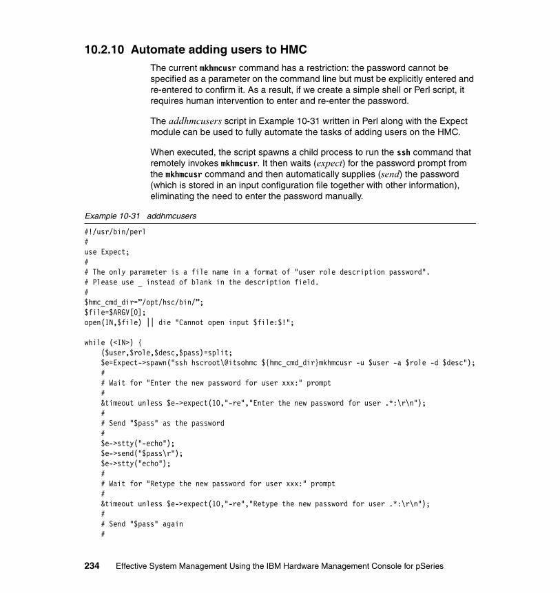
10.2.10 Automate adding users to HMCThe current mkhmcusr command has a restriction: the password cannot be specified as a parameter on the command line but must be explicitly entered and re-entered to confirm it. As a result, if we create a simple shell or Perl script, it requires human intervention to enter and re-enter the password.
The addhmcusers script in Example 10-31 written in Perl along with the Expect module can be used to fully automate the tasks of adding users on the HMC.
When executed, the script spawns a child process to run the ssh command that remotely invokes mkhmcusr. It then waits (expect) for the password prompt from the mkhmcusr command and then automatically supplies (send) the password (which is stored in an input configuration file together with other information), eliminating the need to enter the password manually.
Example 10-31 addhmcusers
#!/usr/bin/perl#use Expect;# # The only parameter is a file name in a format of "user role description password".# Please use _ instead of blank in the description field.#$hmc_cmd_dir=”/opt/hsc/bin/”;$file=$ARGV[0];open(IN,$file) || die "Cannot open input $file:$!";
while (<IN>) {($user,$role,$desc,$pass)=split;$e=Expect->spawn("ssh hscroot\@itsohmc ${hmc_cmd_dir}mkhmcusr -u $user -a $role -d $desc");## Wait for "Enter the new password for user xxx:" prompt#&timeout unless $e->expect(10,"-re","Enter the new password for user .*:\r\n");## Send "$pass" as the password#$e->stty("-echo");$e->send("$pass\r");$e->stty("echo");## Wait for "Retype the new password for user xxx:" prompt#&timeout unless $e->expect(10,"-re","Retype the new password for user .*:\r\n");## Send "$pass" again#
234 Effective System Management Using the IBM Hardware Management Console for pSeries

$e->stty("-echo");$e->send("$pass\r");$e->stty("echo");## End the process#$e->soft_close();print "\n";
}exit 0;sub timeout {
sleep 1;$e->hard_close();printf "Timeout has occurred!\n";exit 1;
}
Before using this addhmcusers script, make sure that the following tasks have been done on the machine you want to run this script:
� Install OpenSSH packages:
Refer to 9.1.1, “Setting up OpenSSH on AIX” on page 177.
� Configure OpenSSH client:
Refer to 9.1.1, “Setting up OpenSSH on AIX” on page 177.
� Install necessary modules for Perl/Expect:
For further information about how to set up Perl/Expect, refer to Section 3.3.1 Install Perl/Expect of Managing AIX Server Farms, SG24-6606.
The following shows the sample execution of this script:
tt@murumuru:/home/tt $ ssh-agent $SHELLtt@murumuru:/home/tt $ ssh-addEnter passphrase for /home/tt/.ssh/id_dsa: YYYYYIdentity added: /home/tt/.ssh/id_dsa (/home/tt/.ssh/id_dsa)tt@murumuru:/home/tt $ ssh hscroot@itsohmc /opt/hsc/bin/lshmcusr -u ALLUser Name Roles Full Nameuser_admin User Administrator User Administrator IDhscroot System Administrator HSC Super Usermrobbins System Administrator Matt Robbinsalt_sysadmin System Administrator Alternate System Administrator IDtt Service Representative Theeraphong Thitayanunadv_op Advanced Operator Advanced Operator IDhscpe Service Representativett@murumuru:/home/tt $ cd perltt@murumuru:/home/tt/perl $ cat userliststu1 op Student_1 stu1stu
Chapter 10. Advanced HMC command examples 235

stu2 advop Student_2 stu2stustu3 sysadmin Student_3 stu3stustu4 usradmin Student_4 stu4stustu5 svcrep Student_5 stu5stustu6 viewer Student_6 stu6stutt@murumuru:/home/tt/perl $ addhmcusers userlistEnter the new password for user stu1:Retype the new password for user stu1:
Enter the new password for user stu2:Retype the new password for user stu2:
Enter the new password for user stu3:Retype the new password for user stu3:
Enter the new password for user stu4:Retype the new password for user stu4:
Enter the new password for user stu5:Retype the new password for user stu5:
Enter the new password for user stu6:Retype the new password for user stu6:
tt@murumuru:/home/tt $ ssh hscroot@itsohmc /opt/hsc/bin/lshmcusr -u ALLUser Name Roles Full Nameuser_admin User Administrator User Administrator IDstu4 User Administrator Student_4hscroot System Administrator HSC Super Usermrobbins System Administrator Matt Robbinsalt_sysadmin System Administrator Alternate System Administrator IDstu3 System Administrator Student_3tt Service Representative Theeraphong Thitayanunstu5 Service Representative Student_5stu1 Operator Student_1adv_op Advanced Operator Advanced Operator IDstu2 Advanced Operator Student_2hscpe Service Representativestu6 Viewer Student_6
Notice that since we do not want to enter the password for hscroot user every time the ssh command runs, in the beginning, we invoke the ssh-agent and ssh-add commands to help us.
For further information about ssh-agent, refer to Managing AIX Server Farms, SG24-6606.
236 Effective System Management Using the IBM Hardware Management Console for pSeries
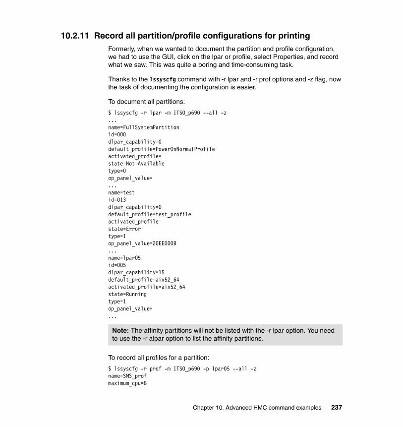
10.2.11 Record all partition/profile configurations for printingFormerly, when we wanted to document the partition and profile configuration, we had to use the GUI, click on the lpar or profile, select Properties, and record what we saw. This was quite a boring and time-consuming task.
Thanks to the lssyscfg command with -r lpar and -r prof options and -z flag, now the task of documenting the configuration is easier.
To document all partitions:
$ lssyscfg -r lpar -m ITSO_p690 --all -z...name=FullSystemPartitionid=000dlpar_capability=0default_profile=PowerOnNormalProfileactivated_profile=state=Not Availabletype=0op_panel_value=...name=testid=013dlpar_capability=0default_profile=test_profileactivated_profile=state=Errortype=1op_panel_value=20EE000B...name=lpar05id=005dlpar_capability=15default_profile=aix52_64activated_profile=aix52_64state=Runningtype=1op_panel_value=...
To record all profiles for a partition:
$ lssyscfg -r prof -m ITSO_p690 -p lpar05 --all -zname=SMS_profmaximum_cpu=8
Note: The affinity partitions will not be listed with the -r lpar option. You need to use the -r alpar option to list the affinity partitions.
Chapter 10. Advanced HMC command examples 237

maximum_mem=16minimum_cpu=1minimum_mem=4desired_cpu=2desired_mem=8service_authority=0sfp_surveillance=1small_rmo=0sni_config_mode=0sni_device_id=sni_windows=desired_io=required_io=name=aix52_64maximum_cpu=6maximum_mem=8192minimum_cpu=1minimum_mem=2048desired_cpu=2desired_mem=2048service_authority=1sfp_surveillance=1small_rmo=2sni_config_mode=0sni_device_id=sni_windows=desired_io=U1.5-P1-I3, U1.5-P1-I4, U1.9-P1-I10required_io=U1.5-P1-I1, U1.5-P1-I2, U1.5-P1/Z1
Because there is no option in the lssyscfg command that lists all profiles for all partitions in a managed system, the listallconfig script in Example 10-32 was created to help with this task.
Given an HMC name, the script lists all profiles for all partitions in all managed systems controlled by that HMC.
Two output files in a print-ready format are produced per managed system:
� /tmp/<hmcname>_<managedsystemname>_lpar.report contains information about all partitions on that managed system.
� /tmp/<hmcname>_<managedsystemname>_profile.report contains information about all profiles on that managed system.
Example 10-32 listallconfig
#!/usr/bin/perl## This program will list all lpar/profile information # for all managed systems controlling by a given HMC.
238 Effective System Management Using the IBM Hardware Management Console for pSeries

## Usage: listallconfig <hmc-name>## The only input parameter needed is the name of the HMC# There will be 2 output files generated per a managed system# 1. /tmp/<hmcname>_<managedsystemname>_lpar.report# contains the information about all partitions on the managed system.# 2. /tmp/<hmcname>_<managedsystemname>_profile.report# contains the information about all profiles on the managed system.#$hmc_cmd_dir=”/opt/hsc/bin/”;@lpartype=(“Full system”,”lpar”,”4-way alpar”,”8-way alpar”);
($ARGV[0] eq ““) ? ($hmc=”itsohmc.itsc.austin.ibm.com”) : ($hmc=$ARGV[0]);
print “\tGetting the managed system name from $hmc...\n”;@sys=‘ssh hscroot\@$hmc ${hmc_cmd_dir}lssyscfg -r sys --all -F name‘;
foreach $sys (@sys) {chomp $sys;open(LPAR, ”>>/tmp/${hmc}_${sys}_lpar.report”);open(PROFILE, ”>>/tmp/${hmc}_${sys}_profile.report”);
print “\tGetting partition information for $sys...\n”;@lpar =‘ssh hscroot\@$hmc ${hmc_cmd_dir}lssyscfg -r lpar -m $sys --all -F
name:id:default_profile:type‘;foreach (sort @lpar) {
chomp;($lpar, $id, $defprof, $type) = (split /:/);$lpartype = $lpartype[$type];write(LPAR);next if ($lpar eq “FullSystemPartition”);
print “\t\tGetting profile information for $lpar...\n”;@profile = ‘ssh hscroot\@$hmc ${hmc_cmd_dir}lssyscfg -r prof -m $sys -p $lpar --all -F
name:minimum_cpu:desired_cpu:maximum_cpu:minimum_mem:desired_mem:maximum_mem:required_io:desired_io:service_authority:sfp_surveillance:small_rmo‘;
foreach (sort @profile) {chomp;($profile, $mincpu, $decpu, $maxcpu, $minmem, $demem, $maxmem, $reqio, $deio, $serv, $sfp, $rmo) = (split /:/);($serv == 1) ? ($serv = ”Yes”) : ($serv = ”No”);($sfp == 1) ? ($sfp = ”Yes”) : ($sfp = ”No”);($rmo == 2) ? ($rmo = ”Yes”) : ($rmo = ”No”);write(PROFILE);
}}close(PROFILE);close(LPAR);
Chapter 10. Advanced HMC command examples 239

}exit 0;
format LPAR_TOP =
Managed system: @<<<<<<<<<<<<<<<<<<<<<< HMC: @<<<<<<<<<<<<<<<<<<<<<< P.@<$sys $hmc $%
==============================================================================Lpar name Lpar ID Default profile Partition type==============================================================================.format LPAR =
@<<<<<<<<<<<<<<<<<<<<<<<< @## @<<<<<<<<<<<<<<<<<<<<<< @<<<<<<<<<<<$lpar $id $defprof $lpartype.format PROFILE_TOP =
Managed system: @<<<<<<<<<<<<<<<<<<<<<<<< P.@< $sys $%
------------------------------------------------------------------------------.format PROFILE =
Partition: @<<<<<<<<<<<<<<<<<<<< Profile name: @<<<<<<<<<<<<<<<<<<<<<<<<<<<<< $lpar $profile Minimum CPU: @# Desired CPU: @# Maximum CPU: @# $mincpu $decpu $maxcpu Minimum mem: @#### Desired mem: @#### Maximum mem: @#### $minmem $demem $maxmem Required IO: ^<<<<<<<<<<<<<<<<<<<<<<<<<<<<<<<<<<<<<<<<<<<<<<<<<<<<<<<<<<<<< $reqio~ ^<<<<<<<<<<<<<<<<<<<<<<<<<<<<<<<<<<<<<<<<<<<<<<<<<<<<<<<<<<<<< $reqio~ ^<<<<<<<<<<<<<<<<<<<<<<<<<<<<<<<<<<<<<<<<<<<<<<<<<<<<<<<<<<<<< $reqio~ ^<<<<<<<<<<<<<<<<<<<<<<<<<<<<<<<<<<<<<<<<<<<<<<<<<<<<<<<<<<<<< $reqio Desired IO: ^<<<<<<<<<<<<<<<<<<<<<<<<<<<<<<<<<<<<<<<<<<<<<<<<<<<<<<<<<<<<< $deio~ ^<<<<<<<<<<<<<<<<<<<<<<<<<<<<<<<<<<<<<<<<<<<<<<<<<<<<<<<<<<<<< $deio~ ^<<<<<<<<<<<<<<<<<<<<<<<<<<<<<<<<<<<<<<<<<<<<<<<<<<<<<<<<<<<<< $deio~ ^<<<<<<<<<<<<<<<<<<<<<<<<<<<<<<<<<<<<<<<<<<<<<<<<<<<<<<<<<<<<< $deio
240 Effective System Management Using the IBM Hardware Management Console for pSeries

Service Authority: @<< SFP Surveillance: @<< Small RMO: @<< $serv $sfp $rmo.
Before using this listallconfig script, make sure that the following tasks have been done on the machine you want to run this script:
� Install OpenSSH packages:
Refer to 9.1.1, “Setting up OpenSSH on AIX” on page 177.
� Configure OpenSSH client:
Refer to 9.1.1, “Setting up OpenSSH on AIX” on page 177.
The following shows the sample execution of this script:
tt@murumuru:/home/tt/perl $ ssh-agent $SHELLtt@murumuru:/home/tt/perl $ ssh-addEnter passphrase for /home/tt/.ssh/id_dsa: YYYYYYIdentity added: /home/tt/.ssh/id_dsa (/home/tt/.ssh/id_dsa)tt@murumuru:/home/tt/perl $ ./listallconfig Getting the managed system name from itsohmc.itsc.austin.ibm.com... Getting partition information for ITSO_p690... Getting profile information for lpar01... Getting profile information for lpar02... Getting profile information for lpar03... Getting profile information for lpar04... Getting profile information for lpar05... Getting profile information for lpar06... Getting profile information for lpar07... Getting profile information for lpar08... Getting profile information for test...
We invoked the ssh-agent and ssh-add commands at the start so we do not have to enter the password for hscroot user every time the ssh command runs.
For further information about ssh-agent, refer to Managing AIX Server Farms, SG24-6606.
Example 10-33 shows the partition configuration output file, lpar.report:
Example 10-33 lpar.report sample
Managed system: ITSO_p690 HMC: itsohmc.itsc.austin.ibm P.1
==============================================================================Lpar name Lpar ID Default profile Partition type==============================================================================
FullSystemPartition 0 PowerOnNormalProfile Full system
Chapter 10. Advanced HMC command examples 241
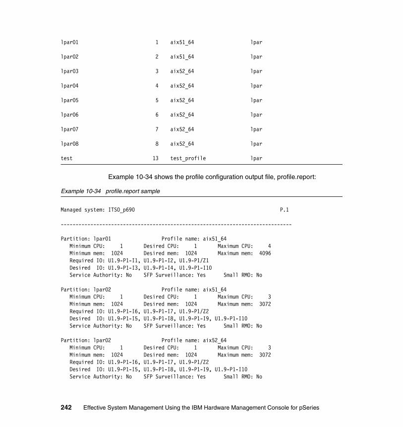
lpar01 1 aix51_64 lpar
lpar02 2 aix51_64 lpar
lpar03 3 aix52_64 lpar
lpar04 4 aix52_64 lpar
lpar05 5 aix52_64 lpar
lpar06 6 aix52_64 lpar
lpar07 7 aix52_64 lpar
lpar08 8 aix52_64 lpar
test 13 test_profile lpar
Example 10-34 shows the profile configuration output file, profile.report:
Example 10-34 profile.report sample
Managed system: ITSO_p690 P.1
------------------------------------------------------------------------------
Partition: lpar01 Profile name: aix51_64 Minimum CPU: 1 Desired CPU: 1 Maximum CPU: 4 Minimum mem: 1024 Desired mem: 1024 Maximum mem: 4096 Required IO: U1.9-P1-I1, U1.9-P1-I2, U1.9-P1/Z1 Desired IO: U1.9-P1-I3, U1.9-P1-I4, U1.9-P1-I10 Service Authority: No SFP Surveillance: Yes Small RMO: No
Partition: lpar02 Profile name: aix51_64 Minimum CPU: 1 Desired CPU: 1 Maximum CPU: 3 Minimum mem: 1024 Desired mem: 1024 Maximum mem: 3072 Required IO: U1.9-P1-I6, U1.9-P1-I7, U1.9-P1/Z2 Desired IO: U1.9-P1-I5, U1.9-P1-I8, U1.9-P1-I9, U1.9-P1-I10 Service Authority: No SFP Surveillance: Yes Small RMO: No
Partition: lpar02 Profile name: aix52_64 Minimum CPU: 1 Desired CPU: 1 Maximum CPU: 3 Minimum mem: 1024 Desired mem: 1024 Maximum mem: 3072 Required IO: U1.9-P1-I6, U1.9-P1-I7, U1.9-P1/Z2 Desired IO: U1.9-P1-I5, U1.9-P1-I8, U1.9-P1-I9, U1.9-P1-I10 Service Authority: No SFP Surveillance: Yes Small RMO: No
242 Effective System Management Using the IBM Hardware Management Console for pSeries

Partition: lpar03 Profile name: aix52_64 Minimum CPU: 1 Desired CPU: 2 Maximum CPU: 8 Minimum mem: 1024 Desired mem: 3072 Maximum mem: 32768 Required IO: U1.9-P2-I1, U1.9-P2-I2, U1.9-P2/Z1 Desired IO: U1.9-P2-I3, U1.9-P2-I4, U1.9-P1-I10 Service Authority: No SFP Surveillance: Yes Small RMO: Yes
Partition: lpar04 Profile name: aix52_64 Minimum CPU: 1 Desired CPU: 2 Maximum CPU: 3 Minimum mem: 1024 Desired mem: 1024 Maximum mem: 3072 Required IO: U1.9-P2-I6, U1.9-P2-I7, U1.9-P2/Z2 Desired IO: U1.9-P2-I5, U1.9-P2-I8, U1.9-P2-I9, U1.9-P1-I10 Service Authority: No SFP Surveillance: Yes Small RMO: Yes
Partition: lpar05 Profile name: SMS_prof Minimum CPU: 1 Desired CPU: 2 Maximum CPU: 8 Minimum mem: 4 Desired mem: 8 Maximum mem: 16 Required IO: Desired IO: Service Authority: No SFP Surveillance: Yes Small RMO: No
Partition: lpar05 Profile name: aix52_64 Minimum CPU: 1 Desired CPU: 2 Maximum CPU: 6 Minimum mem: 2048 Desired mem: 2048 Maximum mem: 8192 Required IO: U1.5-P1-I1, U1.5-P1-I2, U1.5-P1/Z1 Desired IO: U1.5-P1-I3, U1.5-P1-I4, U1.9-P1-I10 Service Authority: Yes SFP Surveillance: Yes Small RMO: Yes
Partition: lpar06 Profile name: aix52_64 Minimum CPU: 1 Desired CPU: 1 Maximum CPU: 4 Minimum mem: 1024 Desired mem: 2048 Maximum mem: 3072 Required IO: U1.5-P1-I5, U1.5-P1-I6, U1.5-P1/Z2 Desired IO: U1.5-P1-I7, U1.5-P1-I8, U1.5-P1-I9, U1.5-P1-I10, U1.9-P1-I10 Service Authority: No SFP Surveillance: Yes Small RMO: Yes
Managed system: ITSO_p690 P.2
------------------------------------------------------------------------------
Partition: lpar07 Profile name: aix52_64 Minimum CPU: 1 Desired CPU: 2 Maximum CPU: 6 Minimum mem: 1024 Desired mem: 2048 Maximum mem: 3072 Required IO: U1.5-P2-I1, U1.5-P2-I2, U1.5-P2/Z1 Desired IO: U1.5-P2-I3, U1.5-P2-I4, U1.9-P1-I10 Service Authority: No SFP Surveillance: Yes Small RMO: Yes
Partition: lpar08 Profile name: aix52_64 Minimum CPU: 1 Desired CPU: 2 Maximum CPU: 3
Chapter 10. Advanced HMC command examples 243

Minimum mem: 1024 Desired mem: 2048 Maximum mem: 5120 Required IO: U1.5-P2-I6, U1.5-P2-I7, U1.5-P2-I8, U1.5-P2-I9, U1.5-P2-I10, U1.5-P2/Z2 Desired IO: U1.9-P1-I10 Service Authority: No SFP Surveillance: Yes Small RMO: Yes
Partition: test Profile name: OF_profile Minimum CPU: 1 Desired CPU: 2 Maximum CPU: 8 Minimum mem: 1 Desired mem: 2 Maximum mem: 8 Required IO: Desired IO: Service Authority: No SFP Surveillance: Yes Small RMO: No
Partition: test Profile name: test_profile Minimum CPU: 1 Desired CPU: 2 Maximum CPU: 3 Minimum mem: 4 Desired mem: 5 Maximum mem: 6 Required IO: U1.5-P1/Z1, U1.5-P2/Z1, U1.5-P1/Z2 Desired IO: Service Authority: No SFP Surveillance: Yes Small RMO: No
10.2.12 Record current HMC information before upgradeBefore you upgrade the HMC software from one release to another, one of the tasks that you must perform is the Save Upgrade Data task.
However, if your HMC software level is earlier than Release 3, Save Upgrade Data task may not perform correctly in some situations. Thus, it is recommended that you perform the following tasks manually:
� Document the scheduled operation.� Back up profile data for all managed systems.� Document the HMC remote command execution configuration.
The saveHMCconfig script shown in Example 10-35 helps automate these tasks.
Example 10-35 saveHMCconfig
#!/usr/bin/perl## This script automates the task of saving/recording the HMC information# before performing the Save Upgrade Data task.## The only input parameter needed is the name of the HMC# The output is a file named /tmp/$hmc.rcmd on localhost#$hmc_cmd_dir=”/opt/hsc/bin/”;$dayofyear=(localtime)[7];
244 Effective System Management Using the IBM Hardware Management Console for pSeries

($ARGV[0] eq "") ? ($hmc="itsohmc.itsc.austin.ibm.com") : ($hmc=$ARGV[0]);$outfile="/tmp/$hmc.rcmd";
print "\tGetting the managed system name from $hmc...\n";@sys=`ssh hscroot\@$hmc ${hmc_cmd_dir}lssyscfg -r sys --all -F name`;
foreach $sys (@sys) { chomp $sys; print "\tBackup profile data for $sys to $sys.profdata.$dayofyear..\n"; system "ssh hscroot\@$hmc ${hmc_cmd_dir}bkprofdata -m $sys -f $sys.profdata.$dayofyear";}
print "\tRecording HMC remote command execution config to $outfile..\n";system "ssh hscroot\@$hmc ${hmc_cmd_dir}lshmc -r > $outfile";
Before using this saveHMCconfig script, ensure that the following tasks have been done on the machine you want to run this script:
� Install OpenSSH packages:
Refer to 9.1.1, “Setting up OpenSSH on AIX” on page 177.
� Configure OpenSSH client:
Refer to 9.1.1, “Setting up OpenSSH on AIX” on page 177
The following shows the sample execution of this script:
tt@murumuru $ ssh-agent $SHELLtt@murumuru $ ssh-addEnter passphrase for /home/tt/.ssh/id_dsa: YYYYYIdentity added: /home/tt/.ssh/id_dsa (/home/tt/.ssh/id_dsa)tt@murumuru $ ls -al /tmp/*.rcmdls: 0653-341 The file /tmp/*.rcmd does not exist.tt@murumuru $ ./saveHMCconfig itsohmc Getting the managed system name from itsohmc... Backup profile data for ITSO_p690 to ITSO_p690.profdata.167.. Recording HMC remote command execution config to /tmp/itsohmc.rcmd..
tt@murumuru $ ssh hscroot@itsohmc ls -al /var/hsc/profiles/*/*profdata* -rw-r--r-- 1 root root 20464 Jun 17 17:53 /var/hsc/profiles/7040-681*021768A/ITSO_p690.profdata.167tt@murumuru $ ls -al /tmp/*.rcmd-rw-r--r-- 1 tt system 161 Jun 17 17:55 /tmp/itsohmc.rcmdtt@murumuru $ cat /tmp/*.rcmdRemote Command Execution Configuration:Remote command execution using the rexec facility: disabledRemote command execution using the ssh facility: enabledtt@murumuru $
Chapter 10. Advanced HMC command examples 245
Notice that since we do not want to enter the password for hscroot user every time the ssh command runs, we invoke the ssh-agent and ssh-add command at the start.
For further information about ssh-agent, refer to Managing AIX Server Farms, SG24-6606.
Note: It is our intention to automate the tasks as much as possible; unfortunately, we could not automate the “Document the scheduled operation” task. This is because the scheduled operation is performed by root user on the HMC and is not supported for remote login to the HMC as the root user. Therefore, the scheduled operation task must be recorded by using the graphical user interface on your HMC.
246 Effective System Management Using the IBM Hardware Management Console for pSeries
Chapter 11. Service functions on the HMC
This chapter explains the following applications that are provided in the Service Applications folder on the HMC:
� Inventory Scout Services� Service Agent� Service Focal Point
These applications are provided to increase the serviceability of managed systems attached to the HMC and for an easy-to-use interface for servicing managed systems.
In addition to the applications in the Service Applications folder, we explain the Microcode Updates application provided in the Software Maintenance folder in this chapter. It is used for the following purposes for the managed systems:
� Conduct microcode level surveys� Install Microcode Updates
For further information about the use of these applications, refer to IBM Hardware Management Console for pSeries Installation and Operations Guide, SA38-0590.
11
© Copyright IBM Corp. 2003. All rights reserved. 247
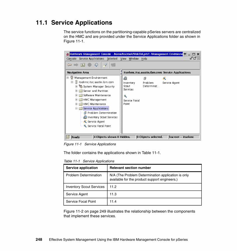
11.1 Service ApplicationsThe service functions on the partitioning-capable pSeries servers are centralized on the HMC and are provided under the Service Applications folder as shown in Figure 11-1.
Figure 11-1 Service Applications
The folder contains the applications shown in Table 11-1.
Table 11-1 Service Applications
Figure 11-2 on page 249 illustrates the relationship between the components that implement these services.
Service application Relevant section number
Problem Determination N/A (The Problem Determination application is only available for the product support engineers.)
Inventory Scout Services 11.2
Service Agent 11.3
Service Focal Point 11.4
248 Effective System Management Using the IBM Hardware Management Console for pSeries
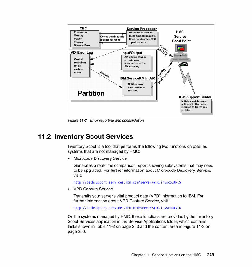
Figure 11-2 Error reporting and consolidation
11.2 Inventory Scout ServicesInventory Scout is a tool that performs the following two functions on pSeries systems that are not managed by HMC:
� Microcode Discovery Service
Generates a real-time comparison report showing subsystems that may need to be upgraded. For further information about Microcode Discovery Service, visit:
http://techsupport.services.ibm.com/server/aix.invscoutMDS
� VPD Capture Service
Transmits your server’s vital product data (VPD) information to IBM. For further information about VPD Capture Service, visit:
http://techsupport.services.ibm.com/server/aix.invscoutVPD
On the systems managed by HMC, these functions are provided by the Inventory Scout Services application in the Service Applications folder, which contains tasks shown in Table 11-2 on page 250 and the content area in Figure 11-3 on page 250.
ProcessorsMemoryPowerThermalBlowers/Fans
Service Processor On-board in the CEC.Runs asynchronously.Does not degrade CEC performance.
Cycles continuouslylooking for faults
AIX Error Log
Central repositoryfor all systemerrors
Input/Output AIX device driversprovide error information to theAIX error log
IBM.ServiceRM in AIXNotifies errorinformation tothe HMC
IBM Support CenterInitiates maintenance action with the parts required to fix the realproblem
Monitors Notifie
s
Notifies
HMC Service Focal Point
Partition
(RS/232C)
(RMC fr
amew
ork)
CEC
Chapter 11. Service functions on the HMC 249
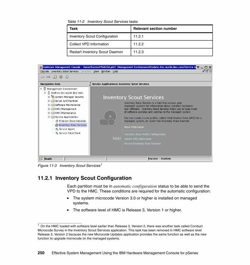
Table 11-2 Inventory Scout Services tasks
Figure 11-3 Inventory Scout Services1
11.2.1 Inventory Scout ConfigurationEach partition must be in automatic configuration status to be able to send the VPD to the HMC. These conditions are required for the automatic configuration:
� The system microcode Version 3.0 or higher is installed on managed systems.
� The software level of HMC is Release 3, Version 1 or higher.
Task Relevant section number
Inventory Scout Configuration 11.2.1
Collect VPD Information 11.2.2
Restart Inventory Scout Daemon 11.2.3
1 On the HMC loaded with software level earlier than Release 3, Version 2, there was another task called Conduct Microcode Survey in the Inventory Scout Services application. This task has been removed in HMC software level Release 3, Version 2 because the new Microcode Updates application provides the same function as well as the new function to upgrade microcode on the managed systems.
250 Effective System Management Using the IBM Hardware Management Console for pSeries
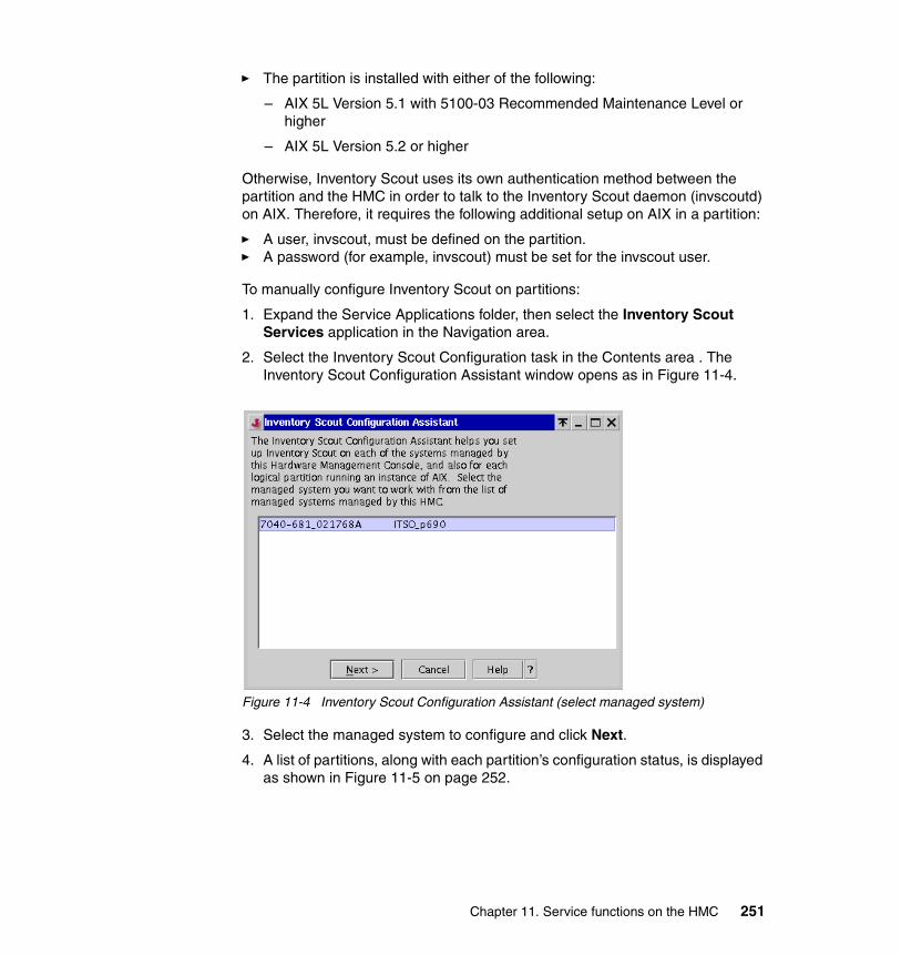
� The partition is installed with either of the following:
– AIX 5L Version 5.1 with 5100-03 Recommended Maintenance Level or higher
– AIX 5L Version 5.2 or higher
Otherwise, Inventory Scout uses its own authentication method between the partition and the HMC in order to talk to the Inventory Scout daemon (invscoutd) on AIX. Therefore, it requires the following additional setup on AIX in a partition:
� A user, invscout, must be defined on the partition.� A password (for example, invscout) must be set for the invscout user.
To manually configure Inventory Scout on partitions:
1. Expand the Service Applications folder, then select the Inventory Scout Services application in the Navigation area.
2. Select the Inventory Scout Configuration task in the Contents area . The Inventory Scout Configuration Assistant window opens as in Figure 11-4.
Figure 11-4 Inventory Scout Configuration Assistant (select managed system)
3. Select the managed system to configure and click Next.
4. A list of partitions, along with each partition’s configuration status, is displayed as shown in Figure 11-5 on page 252.
Chapter 11. Service functions on the HMC 251
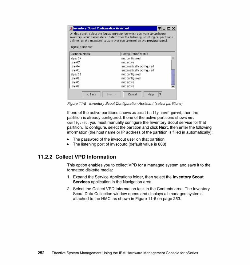
Figure 11-5 Inventory Scout Configuration Assistant (select partitions)
If one of the active partitions shows automatically configured, then the partition is already configured. If one of the active partitions shows not configured, you must manually configure the Inventory Scout service for that partition. To configure, select the partition and click Next, then enter the following information (the host name or IP address of the partition is filled in automatically):
� The password of the invscout user on that partition� The listening port of invscoutd (default value is 808)
11.2.2 Collect VPD InformationThis option enables you to collect VPD for a managed system and save it to the formatted diskette media:
1. Expand the Service Applications folder, then select the Inventory Scout Services application in the Navigation area.
2. Select the Collect VPD Information task in the Contents area. The Inventory Scout Data Collection window opens and displays all managed systems attached to the HMC, as shown in Figure 11-6 on page 253.
252 Effective System Management Using the IBM Hardware Management Console for pSeries
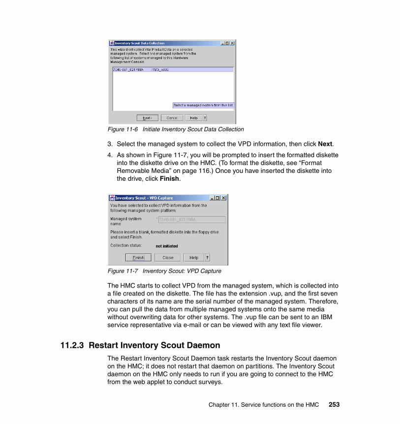
Figure 11-6 Initiate Inventory Scout Data Collection
3. Select the managed system to collect the VPD information, then click Next.
4. As shown in Figure 11-7, you will be prompted to insert the formatted diskette into the diskette drive on the HMC. (To format the diskette, see “Format Removable Media” on page 116.) Once you have inserted the diskette into the drive, click Finish.
Figure 11-7 Inventory Scout: VPD Capture
The HMC starts to collect VPD from the managed system, which is collected into a file created on the diskette. The file has the extension .vup, and the first seven characters of its name are the serial number of the managed system. Therefore, you can pull the data from multiple managed systems onto the same media without overwriting data for other systems. The .vup file can be sent to an IBM service representative via e-mail or can be viewed with any text file viewer.
11.2.3 Restart Inventory Scout DaemonThe Restart Inventory Scout Daemon task restarts the Inventory Scout daemon on the HMC; it does not restart that daemon on partitions. The Inventory Scout daemon on the HMC only needs to run if you are going to connect to the HMC from the web applet to conduct surveys.
Chapter 11. Service functions on the HMC 253

11.3 Service AgentElectronic Service Agent™ (or simply Service Agent) is an application program that runs on either AIX or Linux2 to monitor the system for hardware errors. On pSeries systems managed by the HMC, the primary path for system hardware error detection and analysis consists of the diagnostics function provided by AIX, the service processor, and the Service Focal Point (see “Service Agent” on page 254). Service Agent provides the transport facility to IBM.
Service Agent can execute several tasks, including:
� Automatic problem analysis� Problem-definable threshold levels for error reporting� Automatic problem reporting� Automatic customer notification� Visualize hardware error logs
Although there are several scenarios available for the Service Agent network configuration, we only explain the configuration, which is used on the HMC with managed systems and shown in Figure 11-8.
Figure 11-8 Service Agent on the HMC
Note: If you use the Microcode Update application on the HMC (explained in 11.5, “Microcode Updates” on page 272) to conduct surveys, the Inventory Scout daemon does not have to be running on the HMC.
2 Service Agent supports the Linux operating system on HMC only.
partition(AIX)
IBM.ServiceRM resource manager running on AIX in a partition
IBMSupportCenter
HMC (Linux)
pSeries 670 or pSeries 690 in a partitioned environment
partition(AIX) Dial-up
connectionMode
m
Service Agentgateway process
IBM.ServiceRM
Service Focal PointGUI
254 Effective System Management Using the IBM Hardware Management Console for pSeries

In this configuration, the Service Agent gateway process running on the HMC places service calls to the IBM support center via a dial-up connection with the attached modem, if necessary.
By utilizing Service Agent, managed systems can reduce the amount of downtime experienced in the event of a system component failure by giving the service provider the ability to view the error report entry and, if needed, order any necessary replacement parts prior to arriving on site. The opportunity for human misinterpretation or miscommunication in problem determination is therefore mitigated.
The Service Agent application contains tasks shown in Table 11-3 and in the Content area in Figure 11-9 on page 256.
Table 11-3 Service Agent tasks
Note: No human intervention is required for this process.
Task Relevant section number
Service Agent UI - registration/customization 11.3.1
Stop Service Agent UI 11.3.2
Change Service Agent mode (server/client) 11.3.3
Start Service Agent processes 11.3.4
Stop Service Agent processes 11.3.5
Chapter 11. Service functions on the HMC 255
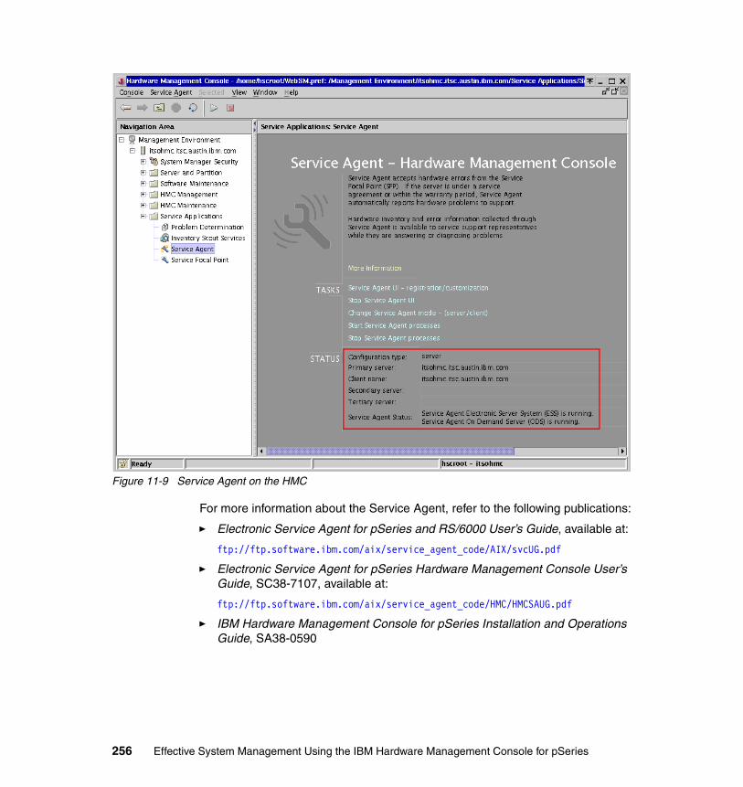
Figure 11-9 Service Agent on the HMC
For more information about the Service Agent, refer to the following publications:
� Electronic Service Agent for pSeries and RS/6000 User’s Guide, available at:
ftp://ftp.software.ibm.com/aix/service_agent_code/AIX/svcUG.pdf
� Electronic Service Agent for pSeries Hardware Management Console User’s Guide, SC38-7107, available at:
ftp://ftp.software.ibm.com/aix/service_agent_code/HMC/HMCSAUG.pdf
� IBM Hardware Management Console for pSeries Installation and Operations Guide, SA38-0590
256 Effective System Management Using the IBM Hardware Management Console for pSeries
11.3.1 Service Agent UI - registration/customizationIf the Service Agent UI - registration/customization task is selected, a Service Agent window opens after prompting for password input.
From the Service Agent window, you can:
� Configure the Service Agent dialer.� Test the dialer.� Register the HMC with IBM.
Several basic usage examples of the Service Agent window are provided in Chapter 12, “Sample Service Agent configurations on the HMC” on page 281.
11.3.2 Stop Service Agent UIThe “Stop Service Agent UI” task closes the Service Agent window if it is already opened.
11.3.3 Change Service Agent mode (server/client)If you are using multiple HMCs, you may wish to have one HMC be a focal point for all Service Agent dialing. Setting up one HMC as the Service Agent server (gateway) and all other HMCs as Service Agent clients can eliminate the need to have each and every individual HMC hooked up with a phone line (see Figure 11-10 on page 258).
Each client HMC must define a primary gateway. Secondary and tertiary gateways can be defined as well. When the On Demand Server (ODS) process on an Service Agent client seeks to send a message to the IBM Support Center, it will first contact the primary gateway that is running the Electronic Server System (ESS) process. If it is unavailable (for example, if the modem is busy on another outbound call), ODS will try the secondary server, and then the tertiary.
Note: At the time of writing this book, the Service Agent ODS process running on HMC cannot communicate with the Service Agent ESS processes running on AIX systems.
Chapter 11. Service functions on the HMC 257
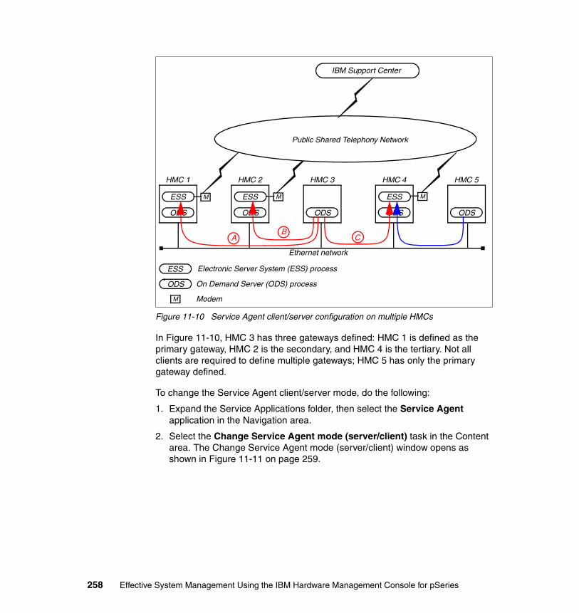
Figure 11-10 Service Agent client/server configuration on multiple HMCs
In Figure 11-10, HMC 3 has three gateways defined: HMC 1 is defined as the primary gateway, HMC 2 is the secondary, and HMC 4 is the tertiary. Not all clients are required to define multiple gateways; HMC 5 has only the primary gateway defined.
To change the Service Agent client/server mode, do the following:
1. Expand the Service Applications folder, then select the Service Agent application in the Navigation area.
2. Select the Change Service Agent mode (server/client) task in the Content area. The Change Service Agent mode (server/client) window opens as shown in Figure 11-11 on page 259.
HMC 1
ODS
ESS
HMC 2
ODS
ESS
HMC 3
ODS
HMC 4
ODS
ESS
HMC 5
ODS
M M M
IBM Support Center
Public Shared Telephony Network
M
ODS
ESS
Ethernet network
AB
C
Electronic Server System (ESS) process
On Demand Server (ODS) process
Modem
258 Effective System Management Using the IBM Hardware Management Console for pSeries
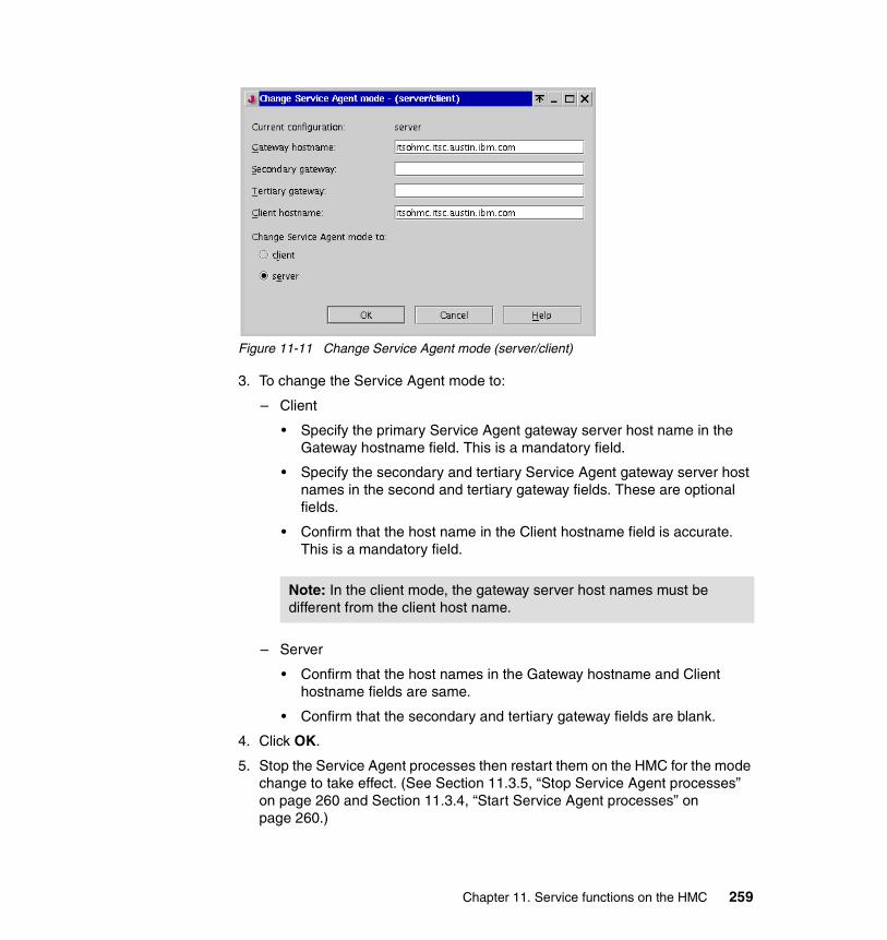
Figure 11-11 Change Service Agent mode (server/client)
3. To change the Service Agent mode to:
– Client
• Specify the primary Service Agent gateway server host name in the Gateway hostname field. This is a mandatory field.
• Specify the secondary and tertiary Service Agent gateway server host names in the second and tertiary gateway fields. These are optional fields.
• Confirm that the host name in the Client hostname field is accurate. This is a mandatory field.
– Server
• Confirm that the host names in the Gateway hostname and Client hostname fields are same.
• Confirm that the secondary and tertiary gateway fields are blank.
4. Click OK.
5. Stop the Service Agent processes then restart them on the HMC for the mode change to take effect. (See Section 11.3.5, “Stop Service Agent processes” on page 260 and Section 11.3.4, “Start Service Agent processes” on page 260.)
Note: In the client mode, the gateway server host names must be different from the client host name.
Chapter 11. Service functions on the HMC 259

11.3.4 Start Service Agent processesThis task is used to start or restart Service Agent processes on the HMC. If processes are started, the status lines show running as highlighted in Figure 11-9 on page 256.
11.3.5 Stop Service Agent processesThis task is used to stop Service Agent processes on the HMC. If processes are stopped, the status lines show stopped in the highlighted area in Figure 11-9 on page 256.
11.4 Service Focal PointTraditional service strategies become more complicated in a partitioned environment. Each partition runs on its own, unaware that other partitions exist on the same system. If one partition reports an error for a shared resource, such as a managed system power supply, other active partitions report the same error. To enable service representatives to avoid long lists of repetitive call-home information, the HMC provides the Service Focal Point application. Service Focal Point recognizes that these errors repeat, and it filters them into one serviceable event for the service representative to review.
The Service Focal Point is a system infrastructure on the HMC that manages serviceable event information for the system building blocks. It includes resource managers that monitor and record information about different objects in the system. It is designed to filter and correlate events from the resource managers and initiate a call to the service provider when appropriate. It also provides a user interface that enables a user to view the events and perform problem determination (see Figure 11-2 on page 249).
Note: This task only switches the mode on the Service Agent client side. To connect to the Service Agent server (gateway), all clients must be defined on the gateway as explained in Section 12.5, “Define Service Agent clients on a gateway server” on page 292.
Note: Service Focal Point only collects hardware errors, such as PERMANENT errors from AIX (marked as P) and NON BOOT errors from the service processor.
260 Effective System Management Using the IBM Hardware Management Console for pSeries

Upon hardware failure events, the corresponding error entry is notified from the partition to the HMC, as shown in Figure 11-2 on page 249. The IBM.ServiceRM subsystem is in charge of this notification. The AIX diagnostic function creates a serviceable event through IBM.ServiceRM when a hardware problem is determined, and events are notified to the HMC using the Resource Monitoring and Control (RMC) framework.
The IBM.ServiceRM is running as the IBM.ServiceRMd daemon and packaged in the devices.chrp.base.ServiceRM fileset in AIX:
# lssrc -g rsct_rm | head -1; lssrc -g rsct_rm | grep ServiceRMSubsystem Group PID Status IBM.ServiceRM rsct_rm 307354 active# ps -ef | head -1; ps -ef | grep ServiceRM | grep -v grepUID PID PPID C STIME TTY TIME CMDroot 307354 122982 0 Sep 11 - 0:31 /usr/sbin/rsct/bin/IBM.ServiceRMd# lslpp -w /usr/sbin/rsct/bin/IBM.ServiceRMd File Fileset Type ---------------------------------------------------------------------------- /usr/sbin/rsct/bin/IBM.ServiceRMd devices.chrp.base.ServiceRM File# lslpp -L devices.chrp.base.ServiceRM Fileset Level State Type Description (Uninstaller) ---------------------------------------------------------------------------- devices.chrp.base.ServiceRM 1.2.0.0 C F RSCT Service Resource Manager
From the Service Focal Point interface, you can execute maintenance procedures such as examining the error log history, checking for components requiring replacement, and performing a Field Replaceable Unit (FRU) replacement. If Service Agent is configured on the HMC, the serviceable events are automatically sent to IBM (call-home support) for automatic generation of a maintenance request.
The Service Focal Point application contains tasks shown in Table 11-4 and in the Content area in Figure 11-12 on page 262.
Table 11-4 Service Focal Point tasks
Task Relevant section number
Service Focal Point Settings 11.4.1
Select Serviceable Event 11.4.2
Hardware Service Functions 11.4.3
Chapter 11. Service functions on the HMC 261

Figure 11-12 Service Focal Point
For further information about Service Focal Point, refer to Appendix A, “Service Focal Point”, IBM Hardware Management Console for pSeries Maintenance Guide, SA38-0603.
11.4.1 Service Focal Point SettingsThe task opens the Service Focal Point Settings window, which has the following tabs:
� CEC Call Home
Enable/disable call home for managed systems
� Surveillance Setup
Set surveillance parameters for managed systems
� Surveillance Notification
Enable/disable surveillance notification to managed systems
Customization of these settings can enable the HMC administrator to perform system tests, maintenance, and parts replacement without alerting IBM to each and every individual change on managed systems.
262 Effective System Management Using the IBM Hardware Management Console for pSeries
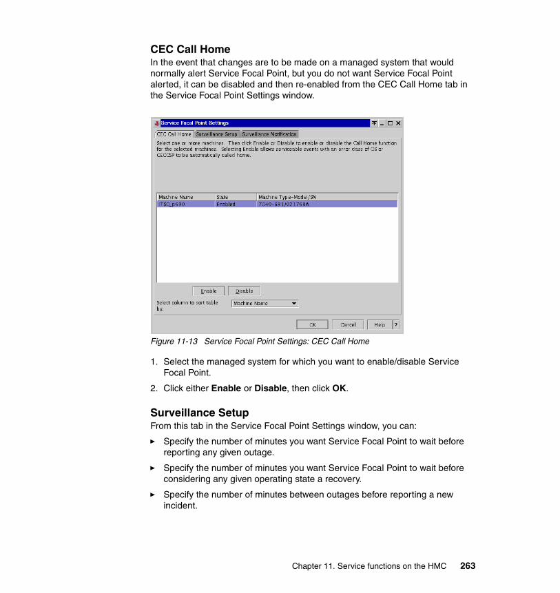
CEC Call HomeIn the event that changes are to be made on a managed system that would normally alert Service Focal Point, but you do not want Service Focal Point alerted, it can be disabled and then re-enabled from the CEC Call Home tab in the Service Focal Point Settings window.
Figure 11-13 Service Focal Point Settings: CEC Call Home
1. Select the managed system for which you want to enable/disable Service Focal Point.
2. Click either Enable or Disable, then click OK.
Surveillance SetupFrom this tab in the Service Focal Point Settings window, you can:
� Specify the number of minutes you want Service Focal Point to wait before reporting any given outage.
� Specify the number of minutes you want Service Focal Point to wait before considering any given operating state a recovery.
� Specify the number of minutes between outages before reporting a new incident.
Chapter 11. Service functions on the HMC 263
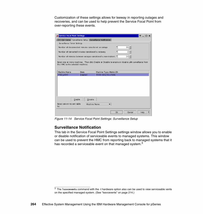
Customization of these settings allows for leeway in reporting outages and recoveries, and can be used to help prevent the Service Focal Point from over-reporting these events.
Figure 11-14 Service Focal Point Settings: Surveillance Setup
Surveillance NotificationThis tab in the Service Focal Point Settings settings window allows you to enable or disable notification of serviceable events to managed systems. This window can be used to prevent the HMC from reporting back to managed systems that it has recorded a serviceable event on that managed system.3
3 The lssvcevents command with the -t hardware option also can be used to view serviceable vents on the specified managed system. (See “lssvcevents” on page 214.)
264 Effective System Management Using the IBM Hardware Management Console for pSeries
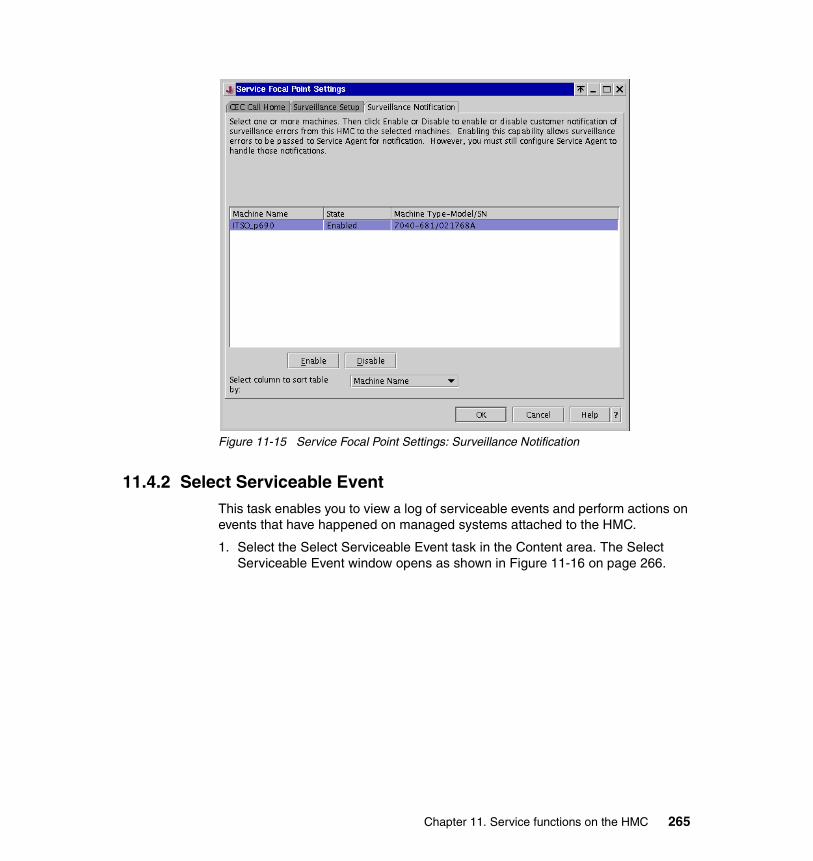
Figure 11-15 Service Focal Point Settings: Surveillance Notification
11.4.2 Select Serviceable EventThis task enables you to view a log of serviceable events and perform actions on events that have happened on managed systems attached to the HMC.
1. Select the Select Serviceable Event task in the Content area. The Select Serviceable Event window opens as shown in Figure 11-16 on page 266.
Chapter 11. Service functions on the HMC 265
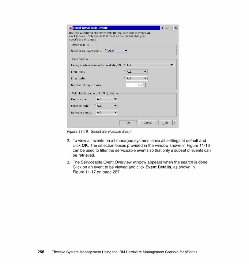
Figure 11-16 Select Serviceable Event
2. To view all events on all managed systems leave all settings at default and click OK. The selection boxes provided in the window shown in Figure 11-16 can be used to filter the serviceable events so that only a subset of events can be retrieved.
3. The Serviceable Event Overview window appears when the search is done. Click on an event to be viewed and click Event Details, as shown in Figure 11-17 on page 267.
266 Effective System Management Using the IBM Hardware Management Console for pSeries
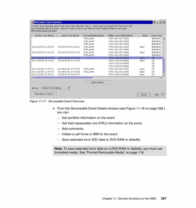
Figure 11-17 Serviceable Event Overview
4. From the Serviceable Event Details window (see Figure 11-18 on page 268 ), you can:
– Get partition information on the event.
– Get field replaceable unit (FRU) information on the event.
– Add comments.
– Initiate a call home to IBM for the event.
– Save extended error (EE) data to DVD-RAM or diskette.
Note: To save extended error data on a DVD-RAM or diskette, you must use formatted media. See “Format Removable Media” on page 116.
Chapter 11. Service functions on the HMC 267
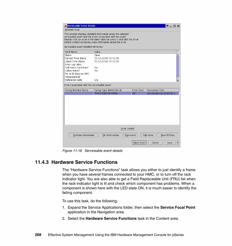
Figure 11-18 Serviceable event details
11.4.3 Hardware Service FunctionsThe “Hardware Service Functions” task allows you either to just identify a frame when you have several frames connected to your HMC, or to turn off the rack indicator light. You are also able to get a Field Replaceable Unit (FRU) list when the rack indicator light is lit and check which component has problems. When a component is shown here with the LED state ON, it is much easier to identify the failing component.
To use this task, do the following:
1. Expand the Service Applications folder, then select the Service Focal Point application in the Navigation area.
2. Select the Hardware Service Functions task in the Content area.
268 Effective System Management Using the IBM Hardware Management Console for pSeries
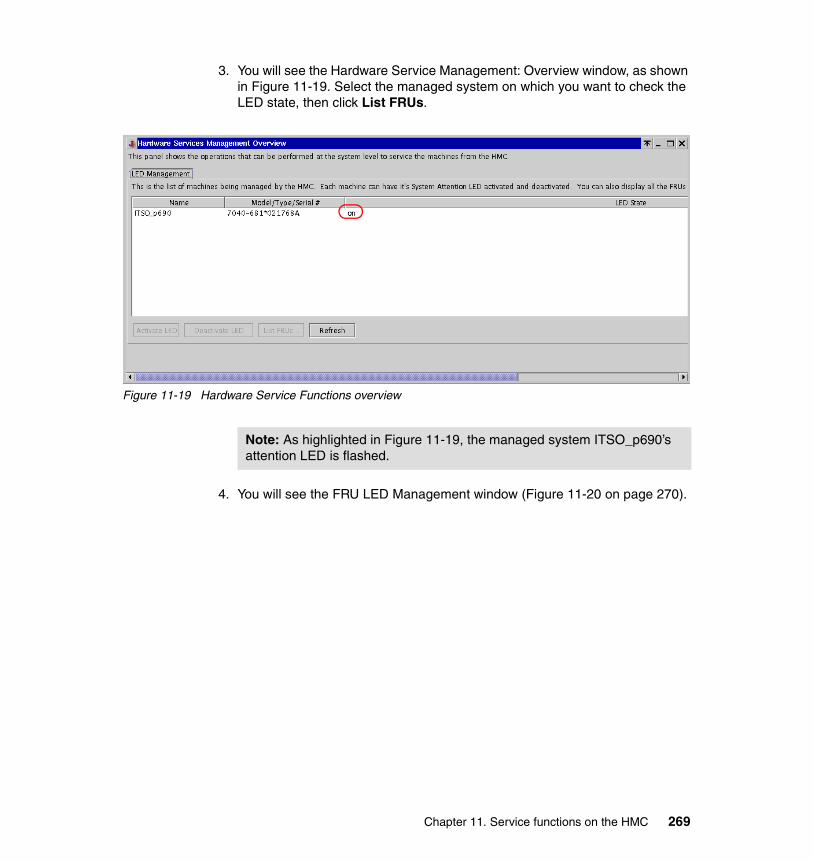
3. You will see the Hardware Service Management: Overview window, as shown in Figure 11-19. Select the managed system on which you want to check the LED state, then click List FRUs.
Figure 11-19 Hardware Service Functions overview
4. You will see the FRU LED Management window (Figure 11-20 on page 270).
Note: As highlighted in Figure 11-19, the managed system ITSO_p690’s attention LED is flashed.
Chapter 11. Service functions on the HMC 269
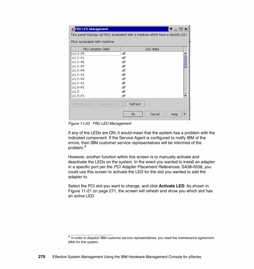
Figure 11-20 FRU LED Management
If any of the LEDs are ON, it would mean that the system has a problem with the indicated component. If the Service Agent is configured to notify IBM of the errors, then IBM customer service representatives will be informed of the problem.4
However, another function within this screen is to manually activate and deactivate the LEDs on the system. In the event you wanted to install an adapter in a specific port per the PCI Adapter Placement References, SA38-0538, you could use this screen to activate the LED for the slot you wanted to add the adapter to.
Select the PCI slot you want to change, and click Activate LED. As shown in Figure 11-21 on page 271, the screen will refresh and show you which slot has an active LED.
4 In order to dispatch IBM customer service representatives, you need the maintenance agreement (MA) for this system.
270 Effective System Management Using the IBM Hardware Management Console for pSeries
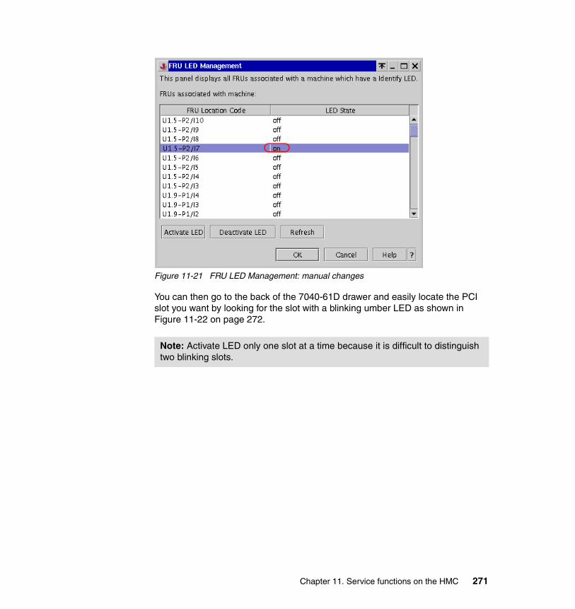
Figure 11-21 FRU LED Management: manual changes
You can then go to the back of the 7040-61D drawer and easily locate the PCI slot you want by looking for the slot with a blinking umber LED as shown in Figure 11-22 on page 272.
Note: Activate LED only one slot at a time because it is difficult to distinguish two blinking slots.
Chapter 11. Service functions on the HMC 271
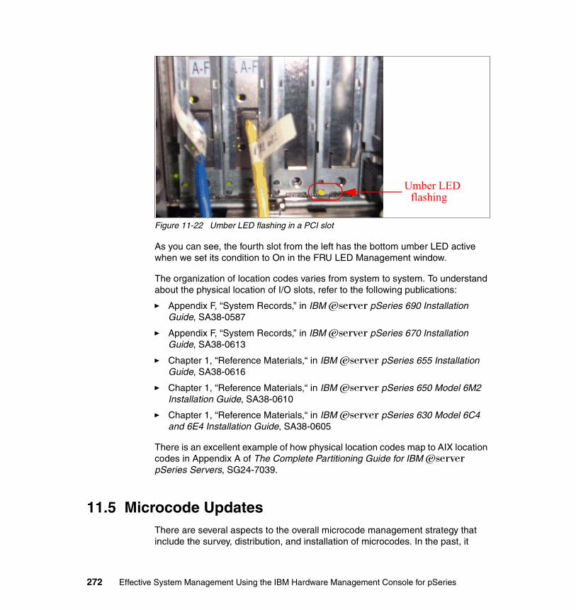
Figure 11-22 Umber LED flashing in a PCI slot
As you can see, the fourth slot from the left has the bottom umber LED active when we set its condition to On in the FRU LED Management window.
The organization of location codes varies from system to system. To understand about the physical location of I/O slots, refer to the following publications:
� Appendix F, “System Records,” in IBM Eserver pSeries 690 Installation Guide, SA38-0587
� Appendix F, “System Records,” in IBM Eserver pSeries 670 Installation Guide, SA38-0613
� Chapter 1, “Reference Materials,“ in IBM Eserver pSeries 655 Installation Guide, SA38-0616
� Chapter 1, “Reference Materials,“ in IBM Eserver pSeries 650 Model 6M2 Installation Guide, SA38-0610
� Chapter 1, “Reference Materials,“ in IBM Eserver pSeries 630 Model 6C4 and 6E4 Installation Guide, SA38-0605
There is an excellent example of how physical location codes map to AIX location codes in Appendix A of The Complete Partitioning Guide for IBM Eserver pSeries Servers, SG24-7039.
11.5 Microcode UpdatesThere are several aspects to the overall microcode management strategy that include the survey, distribution, and installation of microcodes. In the past, it
Umber LEDflashing
272 Effective System Management Using the IBM Hardware Management Console for pSeries

required an IBM service representitive to go to the customer’s site to survey and update the microcode. With the Microcode Updates function available in the HMC and AIX, the customer can now manage their microcode management without IBM service representitives’ help.
Furthermore, IBM has recently introduced the Customer Managed Microcode method of updating microcode on pSeries systems. Using CMM a customer can survey and update microcode for a standalone pSeries system that is not managed by HMC, as well as the pSeries system managed by HMC.
For more information about the CMM method, vist the following URL:
http://techsupport.services.ibm.com/server/mdownload
Although this method can be used to update the microcode on individual AIX partitions, the Microcode Updates application is a more centralized and convenient function for performing the same task for all the hardware components that are allocated to multiple partitions on a managed system.
Figure 11-23 on page 274 shows how the mechanism of the microcode update works from a standalone AIX server and from an HMC.
The application is able to survey and report the existing and latest microcode levels and provide suggested actions for each device. It also provides the capability for installation of microcodes and warns the user before a reboot or installation of back level codes. With this, the customer is able to keep current on the microcode levels at their convenience.
Note: In order to have the Microcode Updates function, the following conditions must be satisfied:
� AIX– AIX 5L Version 5.1 plus 5100-04 Recommended Maintenance Level or
later– AIX 5L Version 5.2 plus 5200-01 Recommended Maintenance Level or
later.� The HMC software must be Release 3, Version 2.1 or later.
Chapter 11. Service functions on the HMC 273

Figure 11-23 Mechanism of the Microcode Updates
Here are the steps to survey and install the latest microcode levels from the HMC:
1. Expand the Software Maintenance folder, then select the Microcode Updates applicaiton in the Navigation area.
2. Select the Microcode Updates task in the Content area. The Download and Apply Microcode Update window opens as shown in Figure 11-24 on page 275.
AIXStandalone
WebSM GUI
WebSM Server
InventoryScout
DeviceFirmware
SystemFirmware
WebSM GUI
WebSM Server
InventoryScout
HMC
RMC
SwitchesDCABPA
Partition
Inv Scout
ServicePartition
Inv Scout
Partition
Inv Scout
DeviceFirmware
DeviceFirmware
DeviceFirmware
System Firmware
274 Effective System Management Using the IBM Hardware Management Console for pSeries
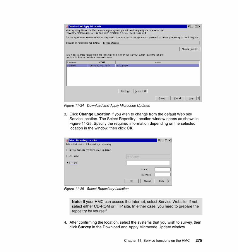
Figure 11-24 Download and Apply Microcode Updates
3. Click Change Location if you wish to change from the default Web site Service location. The Select Repositry Location window opens as shown in Figure 11-25. Specify the required information depending on the selected location in the window, then click OK.
Figure 11-25 Select Repository Location
4. After confirming the location, select the systems that you wish to survey, then click Survey in the Download and Apply Microcode Update window
Note: If your HMC can access the Internet, select Service Website. If not, select either CD-ROM or FTP site. In either case, you need to prepare the repositry by yourself.
Chapter 11. Service functions on the HMC 275
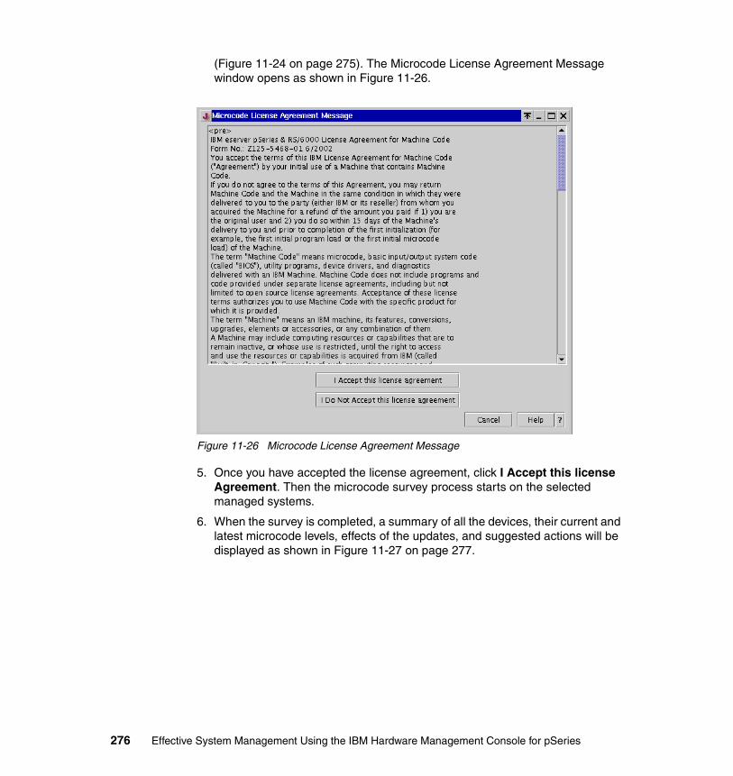
(Figure 11-24 on page 275). The Microcode License Agreement Message window opens as shown in Figure 11-26.
Figure 11-26 Microcode License Agreement Message
5. Once you have accepted the license agreement, click I Accept this license Agreement. Then the microcode survey process starts on the selected managed systems.
6. When the survey is completed, a summary of all the devices, their current and latest microcode levels, effects of the updates, and suggested actions will be displayed as shown in Figure 11-27 on page 277.
276 Effective System Management Using the IBM Hardware Management Console for pSeries

Figure 11-27 Microcode Survey Results
For any selected devices, the Effect column includes:
Take Offline The user must take devices offline prior the update of the microcode; otherwise the update will fail.
Reboot The user must confirm that he understands that the system will reboot as a result of the Microcode Updates. Applications should be stopped, all users should be notified, and the non-service partitions should be shut down.
7. It is also possible to view the details for each device. Select the device to be viewed and click View Information. The details of the device will be shown as in Figure 11-28 on page 278.
Chapter 11. Service functions on the HMC 277

Figure 11-28 Microcode Installation - Device Information
8. Update some or all of the devices by selecting Install check boxes on the device line(s) and clicking Apply in the Microcode Survey Results window.
The confirmation message shown in Figure 11-29 on page 279 appears. You can either proceed with the update by selecting OK or abort the update by selecting Cancel.
Note: Only one device at a time can be selected when you click View Information.
278 Effective System Management Using the IBM Hardware Management Console for pSeries
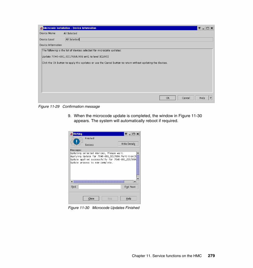
Figure 11-29 Confirmation message
9. When the microcode update is completed, the window in Figure 11-30 appears. The system will automatically reboot if required.
Figure 11-30 Microcode Updates Finished
Chapter 11. Service functions on the HMC 279

280 Effective System Management Using the IBM Hardware Management Console for pSeries
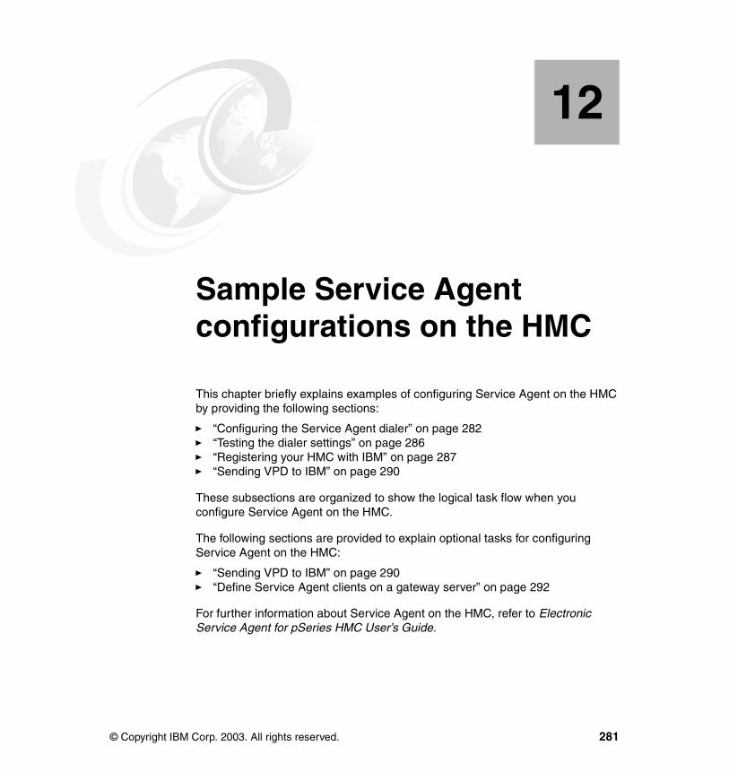
Chapter 12. Sample Service Agent configurations on the HMC
This chapter briefly explains examples of configuring Service Agent on the HMC by providing the following sections:
� “Configuring the Service Agent dialer” on page 282� “Testing the dialer settings” on page 286� “Registering your HMC with IBM” on page 287� “Sending VPD to IBM” on page 290
These subsections are organized to show the logical task flow when you configure Service Agent on the HMC.
The following sections are provided to explain optional tasks for configuring Service Agent on the HMC:
� “Sending VPD to IBM” on page 290� “Define Service Agent clients on a gateway server” on page 292
For further information about Service Agent on the HMC, refer to Electronic Service Agent for pSeries HMC User’s Guide.
12
© Copyright IBM Corp. 2003. All rights reserved. 281
12.1 Configuring the Service Agent dialerFor the Service Agent to perform any of its call home functions the dialer must first be properly configured.
To configure the Service Agent dialer, do the following:
10.Expand the Service Applications folder in theNavigation area, then click Service Agent.
11.Click Service Agent UI - registration/customization as shown in Figure 11-9 on page 256.
12.When prompted to enter a password as shown in Figure 12-1, type the default password (password), then click OK.
Figure 12-1 Service Agent – Enter the Password
13.AThe Electronic Service Agent for pSeries - Hardware Management Console window opens.
Note: The following steps can be performed from the local HMC console only.
Note: Hereafter this window is referred to as the Service Agent window.
282 Effective System Management Using the IBM Hardware Management Console for pSeries
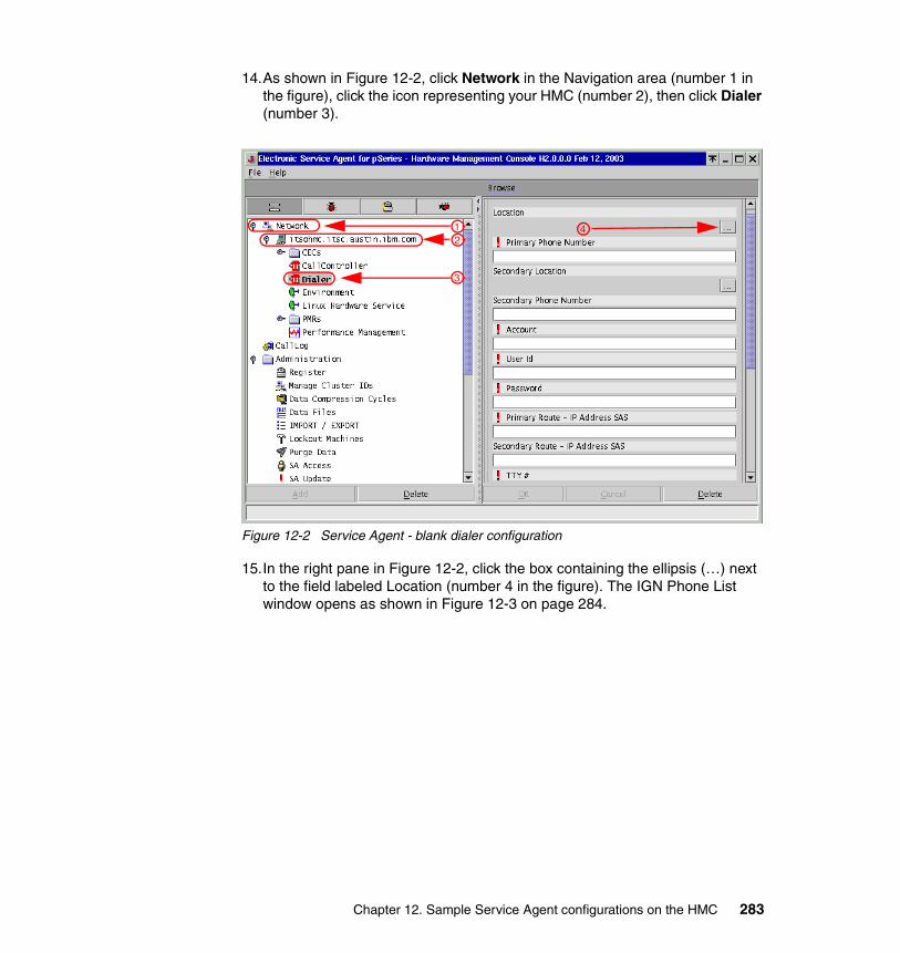
14.As shown in Figure 12-2, click Network in the Navigation area (number 1 in the figure), click the icon representing your HMC (number 2), then click Dialer (number 3).
Figure 12-2 Service Agent - blank dialer configuration
15.In the right pane in Figure 12-2, click the box containing the ellipsis (…) next to the field labeled Location (number 4 in the figure). The IGN Phone List window opens as shown in Figure 12-3 on page 284.
12
3
4
Chapter 12. Sample Service Agent configurations on the HMC 283

16.Choose your country, state (or province), and city in this window, then click Select.
Figure 12-3 Service Agent - select dialer location
17.In the right pane in Figure 12-2 on page 283, click the … next to the field labeled Secondary Location. Select the secondary phone number in the IGN Phone List window.
18.Now all of the Service Agent dialer configuration fields should be automatically filled out as shown in Figure 12-4 on page 285. Click OK and the dialer should be properly configured.
Note: If necessary, modify the primary and secondary phone numbers. For example, if your phone system requires a dial-out extension number, such as 9, modify the phone numbers to 9-1-512-691-4485.
284 Effective System Management Using the IBM Hardware Management Console for pSeries
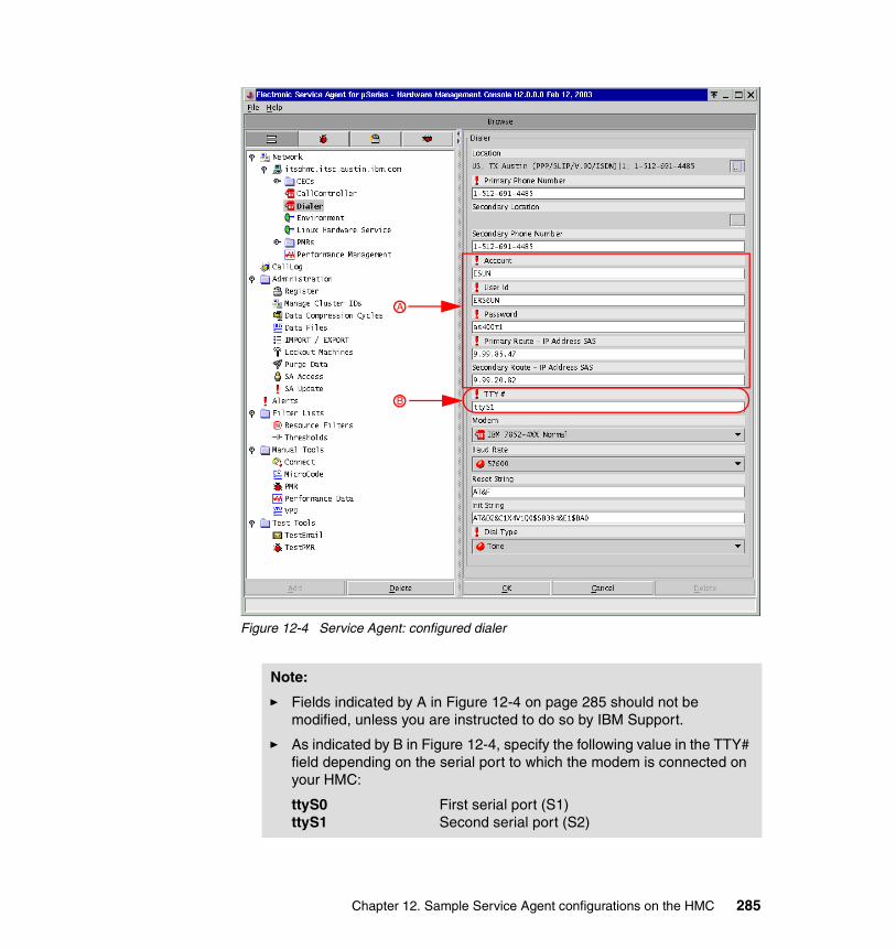
Figure 12-4 Service Agent: configured dialer
Note:
� Fields indicated by A in Figure 12-4 on page 285 should not be modified, unless you are instructed to do so by IBM Support.
� As indicated by B in Figure 12-4, specify the following value in the TTY# field depending on the serial port to which the modem is connected on your HMC:
ttyS0 First serial port (S1)ttyS1 Second serial port (S2)
B
A
Chapter 12. Sample Service Agent configurations on the HMC 285
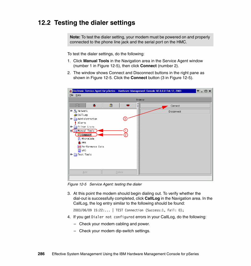
12.2 Testing the dialer settings
To test the dialer settings, do the following:
1. Click Manual Tools in the Navigation area in the Service Agent window (number 1 in Figure 12-5), then click Connect (number 2).
2. The window shows Connect and Disconnect buttons in the right pane as shown in Figure 12-5. Click the Connect button (3 in Figure 12-5).
Figure 12-5 Service Agent: testing the dialer
3. At this point the modem should begin dialing out. To verify whether the dial-out is successfully completed, click CallLog in the Navigation area. In the CallLog, the log entry similar to the following should be found:
2003/06/09 15:22:... | TEST Connection (Success:1, Fail: 0);
4. If you get Dialer not configured errors in your CallLog, do the following:
– Check your modem cabling and power.
– Check your modem dip-switch settings.
Note: To test the dialer setting, your modem must be powered on and properly connected to the phone line jack and the serial port on the HMC.
1
2
3
286 Effective System Management Using the IBM Hardware Management Console for pSeries
– Review the configuration steps explained in 12.1, “Configuring the Service Agent dialer” on page 282.
12.3 Registering your HMC with IBM
To register your HMC with IBM, do the following:
1. In the Navigation area on the Service Agent window, click Network.
Note: Along with the entry in the CallLog, you will receive a phone call from an IBM service representative to notify you that the test connection has been successfully completed at the phone number specified in the location fields shown in Figure 12-6 on page 288.
Note: Before registering your HMC with IBM, you must first properly configure the dialer (see 12.1, “Configuring the Service Agent dialer” on page 282).
Chapter 12. Sample Service Agent configurations on the HMC 287
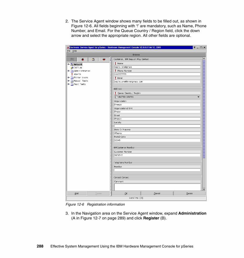
2. The Service Agent window shows many fields to be filled out, as shown in Figure 12-6. All fields beginning with ‘!’ are mandatory, such as Name, Phone Number, and Email. For the Queue Country / Region field, click the down arrow and select the appropriate region. All other fields are optional.
Figure 12-6 Registration information
3. In the Navigation area on the Service Agent window, expand Administration (A in Figure 12-7 on page 289) and click Register (B).
288 Effective System Management Using the IBM Hardware Management Console for pSeries

Figure 12-7 Service Agent: registering HMC
4. Select the HMC to be registered from the right pane, then click Register as indicated by C.
5. When prompted to connect to IBM as shown in Figure 12-8, select Yes or No.
If Yes is selected, then the modem should start dialing out within a minute; if No is selected it should start within 15 to 20 minutes.
Figure 12-8 Service Agent Registration
6. After the modem has finished dialing out, click CallLog as indicated by D in Figure 12-7 in order to confirm whether the registration has successfully completed. If it succeeded, this or a similar log entry should be found:
2003/06/09 15:47:... | LICENSE (Success: 1, Fail: 0);
AB
C
D
Chapter 12. Sample Service Agent configurations on the HMC 289

12.4 Sending VPD to IBMIn the event an IBM representative asks you to submit VPD for one of your managed systems, you can transmit the data to IBM using the Service Agent as follows:
1. In the navigation area under Manual Tools click VPD. This will open a menu of managed systems for which VPD tasks are accessible, shown in Figure 12-9.
Figure 12-9 Service Agent: VPD tasks
290 Effective System Management Using the IBM Hardware Management Console for pSeries
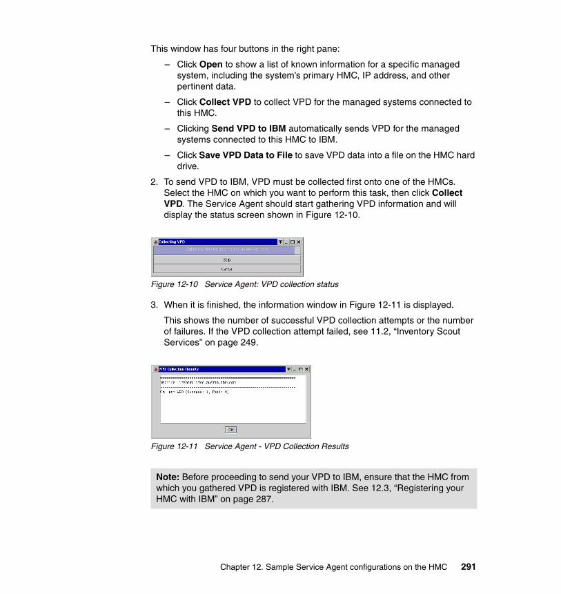
This window has four buttons in the right pane:
– Click Open to show a list of known information for a specific managed system, including the system’s primary HMC, IP address, and other pertinent data.
– Click Collect VPD to collect VPD for the managed systems connected to this HMC.
– Clicking Send VPD to IBM automatically sends VPD for the managed systems connected to this HMC to IBM.
– Click Save VPD Data to File to save VPD data into a file on the HMC hard drive.
2. To send VPD to IBM, VPD must be collected first onto one of the HMCs. Select the HMC on which you want to perform this task, then click Collect VPD. The Service Agent should start gathering VPD information and will display the status screen shown in Figure 12-10.
Figure 12-10 Service Agent: VPD collection status
3. When it is finished, the information window in Figure 12-11 is displayed.
This shows the number of successful VPD collection attempts or the number of failures. If the VPD collection attempt failed, see 11.2, “Inventory Scout Services” on page 249.
Figure 12-11 Service Agent - VPD Collection Results
Note: Before proceeding to send your VPD to IBM, ensure that the HMC from which you gathered VPD is registered with IBM. See 12.3, “Registering your HMC with IBM” on page 287.
Chapter 12. Sample Service Agent configurations on the HMC 291
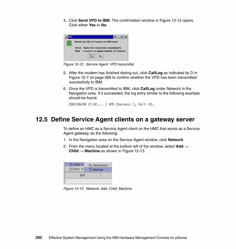
4. Click Send VPD to IBM. The confirmation window in Figure 12-12 opens. Click either Yes or No.
Figure 12-12 Service Agent: VPD transmittal
5. After the modem has finished dialing out, click CallLog as indicated by D in Figure 12-7 on page 289 to confirm whether the VPD has been transmitted successfully to IBM.
6. Once the VPD is transmitted to IBM, click CallLog under Network in the Navigation area. If it succeeded, the log entry similar to the following example should be found:
2003/06/09 17:42:... | VPD (Success: 1, Fail: 0);
12.5 Define Service Agent clients on a gateway serverTo define an HMC as a Service Agent client on the HMC that works as a Service Agent gateway, do the following:
1. In the Navigation area on the Service Agent window, click Network.
2. From the menu located at the bottom left of the window, select Add → Child → Machine as shown in Figure 12-13.
Figure 12-13 Network, Add, Child, Machine
292 Effective System Management Using the IBM Hardware Management Console for pSeries

3. A window opens to define the Service Agent client on the gateway as shown in Figure 12-14.
Figure 12-14 Defining an Service Agent client
4. Complete the required fields for the HMC by providing the host name and IP address (all fields starting with a ‘!’ are mandatory), then click OK to save the information.
Chapter 12. Sample Service Agent configurations on the HMC 293

294 Effective System Management Using the IBM Hardware Management Console for pSeries
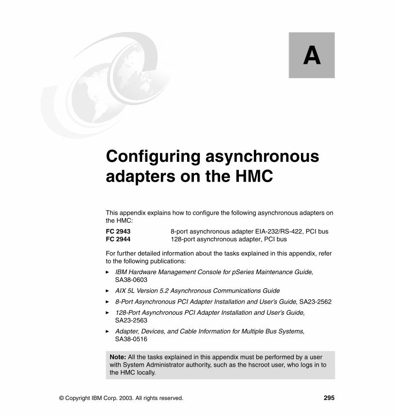
Appendix A. Configuring asynchronous adapters on the HMC
This appendix explains how to configure the following asynchronous adapters on the HMC:
FC 2943 8-port asynchronous adapter EIA-232/RS-422, PCI busFC 2944 128-port asynchronous adapter, PCI bus
For further detailed information about the tasks explained in this appendix, refer to the following publications:
� IBM Hardware Management Console for pSeries Maintenance Guide, SA38-0603
� AIX 5L Version 5.2 Asynchronous Communications Guide
� 8-Port Asynchronous PCI Adapter Installation and User’s Guide, SA23-2562
� 128-Port Asynchronous PCI Adapter Installation and User’s Guide, SA23-2563
� Adapter, Devices, and Cable Information for Multiple Bus Systems, SA38-0516
A
Note: All the tasks explained in this appendix must be performed by a user with System Administrator authority, such as the hscroot user, who logs in to the HMC locally.
© Copyright IBM Corp. 2003. All rights reserved. 295

Hardware setupBefore configuring asynchronous adapters in the HMC graphical user interface, the adapter and related hardware must be set up as explained in this section.
Add an 8-port asynchronous adapterTo add an 8-port asynchronous adapter on the HMC:
1. Power off the HMC.
2. Insert the 8-port asynchronous adapter into one of the available PCI slots.
3. Connect the 8-port fanout box cable to the adapter (see “Using 8-port asynchronous adapters” on page 25).
4. Power on the HMC. The Linux kernel should detect the adapter, and the Kudzu1 configuration screens will be displayed on the HMC. Confirm the addition of the asynchronous adapter.
Add a 128-port asynchronous adapterTo add a 128-port asynchronous adapter on the HMC:
1. Power off the HMC.
2. Insert the 128-port asynchronous adapter into one of the available PCI slots.
3. Connect RANs to the adapter appropriately (see “Using 128-port asynchronous adapters” on page 26).
4. Power on the RANs.
5. Program the RAN node number on each RAN as explained in , “Set the RAN node number” on page 297.
6. Power on the HMC. The Linux kernel should detect the adapter, and the Kudzu configuration screens will be displayed on the HMC. Confirm the addition of the asynchronous adapter.
1 Kudzu is a hardware probing tool that automatically detects and configures devices on the IA-32 architecture Linux operating system.
Note: If the Linux kernel detects the 128-port asynchronous adapter, it displays a message in the boot phase similar to the following:
epca: IBM 8-Port Async (PCI) I/O = 0xfea00000, Mem = 0xfe800000 Ports = 8
296 Effective System Management Using the IBM Hardware Management Console for pSeries
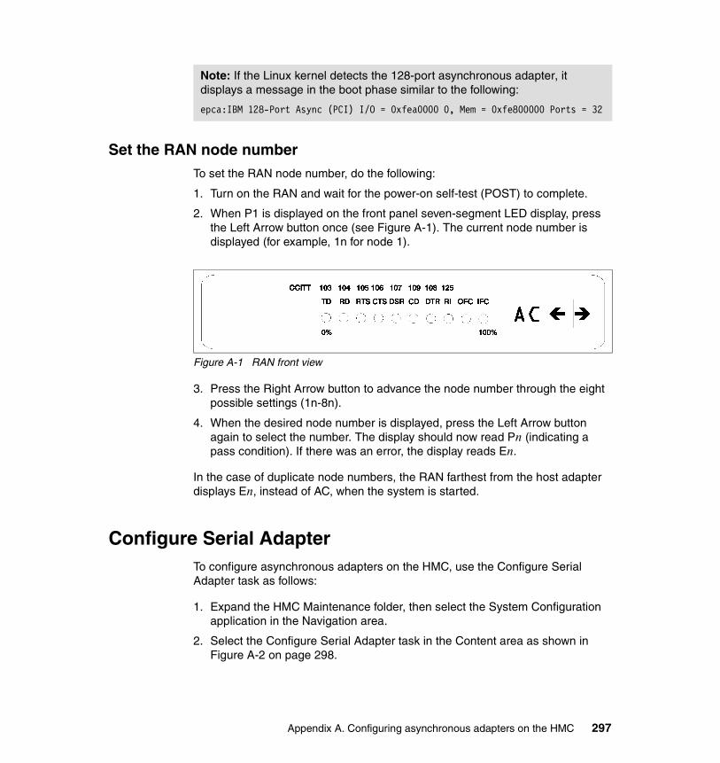
Set the RAN node numberTo set the RAN node number, do the following:
1. Turn on the RAN and wait for the power-on self-test (POST) to complete.
2. When P1 is displayed on the front panel seven-segment LED display, press the Left Arrow button once (see Figure A-1). The current node number is displayed (for example, 1n for node 1).
Figure A-1 RAN front view
3. Press the Right Arrow button to advance the node number through the eight possible settings (1n-8n).
4. When the desired node number is displayed, press the Left Arrow button again to select the number. The display should now read Pn (indicating a pass condition). If there was an error, the display reads En.
In the case of duplicate node numbers, the RAN farthest from the host adapter displays En, instead of AC, when the system is started.
Configure Serial AdapterTo configure asynchronous adapters on the HMC, use the Configure Serial Adapter task as follows:
1. Expand the HMC Maintenance folder, then select the System Configuration application in the Navigation area.
2. Select the Configure Serial Adapter task in the Content area as shown in Figure A-2 on page 298.
Note: If the Linux kernel detects the 128-port asynchronous adapter, it displays a message in the boot phase similar to the following:
epca:IBM 128-Port Async (PCI) I/O = 0xfea0000 0, Mem = 0xfe800000 Ports = 32
Appendix A. Configuring asynchronous adapters on the HMC 297
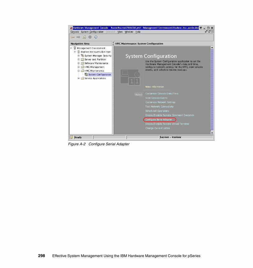
Figure A-2 Configure Serial Adapter
298 Effective System Management Using the IBM Hardware Management Console for pSeries

3. This opens the configAsync window, shown in Figure A-3, which offers the following options:
– 1. Configure a serial adapter.
– 2. Configure RS422 ports on an 8-port serial adapter.
– 3. Query all configured adapters on the HMC.
To select an option, type the corresponding number and press Enter. To close this window when you have finished using it, type 0 (zero) and press Enter.
Figure A-3 configAsync window
8-port asynchronous adapter configurationTo configure 8-port asynchronous adapters on the HMC:
1. Select option 1 from the configAsync window menu shown in Figure A-3.
2. The following message is displayed in the window, as indicated by A in Figure A-4 on page 300:
How many boards would like to install? (1-12)
Type the number of adapters to be configured and press Enter.
Note: If an asynchronous adapter is already configured on the HMC and you are going to configure another, type 2, not 1, then press Enter.
Appendix A. Configuring asynchronous adapters on the HMC 299

3. The following message is displayed in the window, as indicated by B in Figure A-4:
What type of board is this? (‘L’ for list) (1-16)
Type 15 and press Enter. If you type L, the selection list will be displayed.
Figure A-4 Specify number of adapters and adapter type
4. The following message is displayed in the window:
Do you want to set Altpin on this board? (‘y’ or ‘n’)
Type n and press Enter.
5. Depending on the number you have specified in step 2, do the following:
– If you specified 1, the configuration tool displays the main menu shown in Figure A-3 on page 299. Type 0 and press Enter to close the window.
– If you specified 2, the configuration tool will continue the process to configure another adapter. Depending on the type of the second adapter, follow one of these sections:
• , “8-port asynchronous adapter configuration” on page 299
• , “128-port asynchronous adapter configuration” on page 301
A
B
300 Effective System Management Using the IBM Hardware Management Console for pSeries
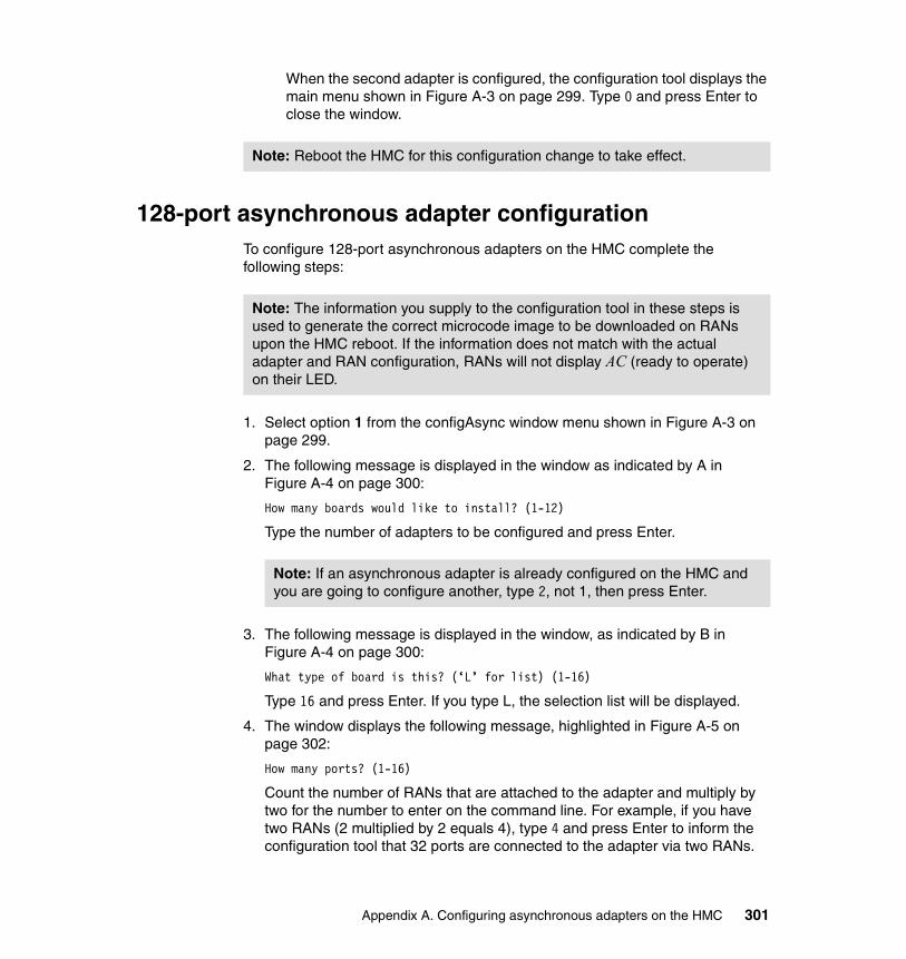
When the second adapter is configured, the configuration tool displays the main menu shown in Figure A-3 on page 299. Type 0 and press Enter to close the window.
128-port asynchronous adapter configurationTo configure 128-port asynchronous adapters on the HMC complete the following steps:
1. Select option 1 from the configAsync window menu shown in Figure A-3 on page 299.
2. The following message is displayed in the window as indicated by A in Figure A-4 on page 300:
How many boards would like to install? (1-12)
Type the number of adapters to be configured and press Enter.
3. The following message is displayed in the window, as indicated by B in Figure A-4 on page 300:
What type of board is this? (‘L’ for list) (1-16)
Type 16 and press Enter. If you type L, the selection list will be displayed.
4. The window displays the following message, highlighted in Figure A-5 on page 302:
How many ports? (1-16)
Count the number of RANs that are attached to the adapter and multiply by two for the number to enter on the command line. For example, if you have two RANs (2 multiplied by 2 equals 4), type 4 and press Enter to inform the configuration tool that 32 ports are connected to the adapter via two RANs.
Note: Reboot the HMC for this configuration change to take effect.
Note: The information you supply to the configuration tool in these steps is used to generate the correct microcode image to be downloaded on RANs upon the HMC reboot. If the information does not match with the actual adapter and RAN configuration, RANs will not display AC (ready to operate) on their LED.
Note: If an asynchronous adapter is already configured on the HMC and you are going to configure another, type 2, not 1, then press Enter.
Appendix A. Configuring asynchronous adapters on the HMC 301

Figure A-5 Specify total number of ports
5. The following message is displayed in the window:
Do you want to set Altpin on this board? (‘y’ or ‘n’)
Type n, then press Enter.
302 Effective System Management Using the IBM Hardware Management Console for pSeries
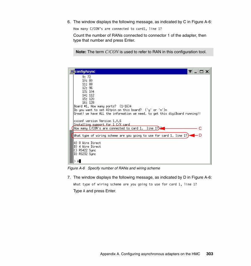
6. The window displays the following message, as indicated by C in Figure A-6:
How many C/CON’s are connected to card1, line 1?
Count the number of RANs connected to connector 1 of the adapter, then type that number and press Enter.
Figure A-6 Specify number of RANs and wiring scheme
7. The window displays the following message, as indicated by D in Figure A-6:
What type of wiring scheme are you going to use for card 1, line 1?
Type A and press Enter.
Note: The term C/CON is used to refer to RAN in this configuration tool.
C
D
Appendix A. Configuring asynchronous adapters on the HMC 303

8. The window displays the following message, as highlighted in Figure A-7:
Enter the communication mode to use on line 1 (Type ‘L’ for a list) [14]:
Type 14 and press Enter.
9. The window displays the following message:
How many ports does this C/CON (RAN) support?
Type 16 and press Enter.
Figure A-7 Specify bit rate
10.To specify the appropriate settings for line 2, the configuration tool repeats steps 6 through 9.
11.Depending on the number you have specified in step 2, do the following:
– If you specified 1, the configuration tool will display the main menu shown in Figure A-3 on page 299. Type 0 and press Enter to close the window.
– If you specified 2, the configuration tool will continue the process to configure another adapter. Depending on the type of the second adapter, follow one of these sections:
• , “8-port asynchronous adapter configuration” on page 299
• , “128-port asynchronous adapter configuration” on page 301
304 Effective System Management Using the IBM Hardware Management Console for pSeries
When the second adapter is configured, the configuration tool displays the main menu shown in Figure A-3 on page 299. Type 0 and press Enter to close the window.
Configuring RS-422 ports on an 8-port asynchronous adapterThis task enables you to switch a port on the 8-port asynchronous adapter from RS-232 to RS-422.
To configure RS-422 ports on an 8-port asynchronous adapter on the HMC:
1. Select option 2 from the configAsync window menu shown in Figure A-3 on page 299.
2. From the list, select the 8-port adapter on which you wish to change the configuration.
3. From the menu bar, select the port change.
Verifying asynchronous adaptersTo verify whether the asynchronous adapters are configured correctly on your HMC, use option 3, Query a Serial Adapter, in the configAsync window main menu (see Figure A-3 on page 299).
Note: Reboot the HMC for this configuration change to take effect.
Note: Use RS-422 for the ports that are connected to the BPC in 7040-42W frame.
Appendix A. Configuring asynchronous adapters on the HMC 305
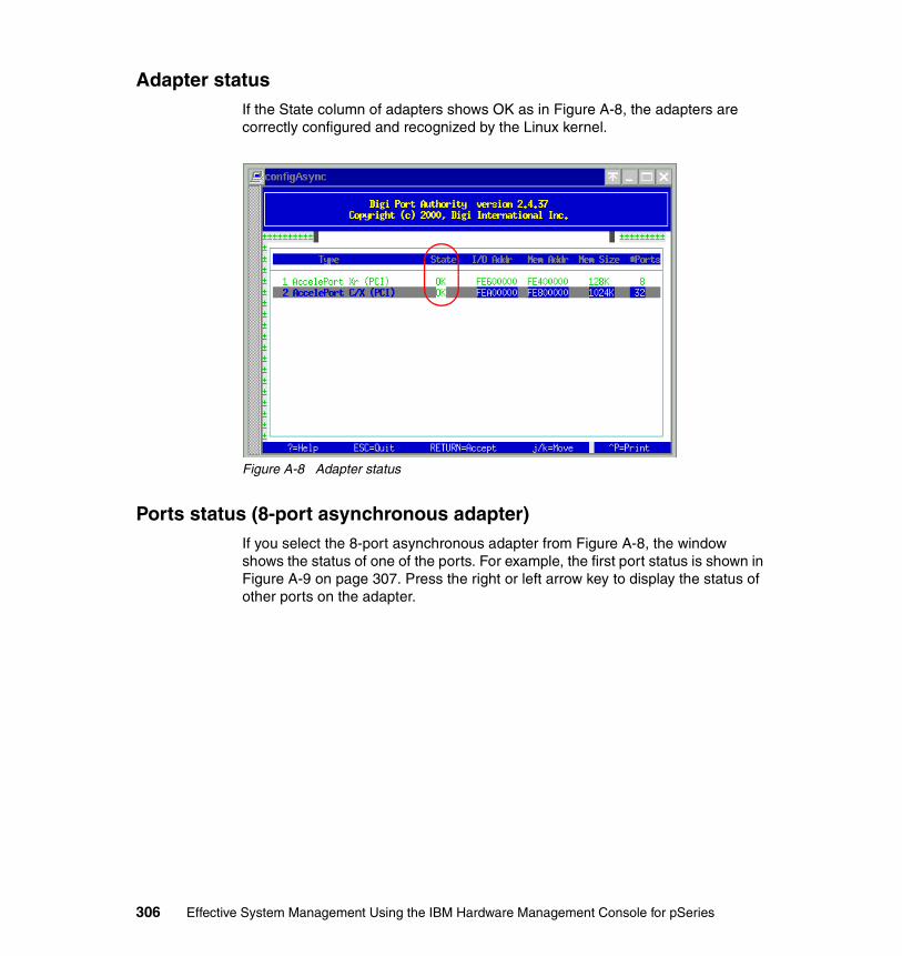
Adapter statusIf the State column of adapters shows OK as in Figure A-8, the adapters are correctly configured and recognized by the Linux kernel.
Figure A-8 Adapter status
Ports status (8-port asynchronous adapter)If you select the 8-port asynchronous adapter from Figure A-8, the window shows the status of one of the ports. For example, the first port status is shown in Figure A-9 on page 307. Press the right or left arrow key to display the status of other ports on the adapter.
306 Effective System Management Using the IBM Hardware Management Console for pSeries
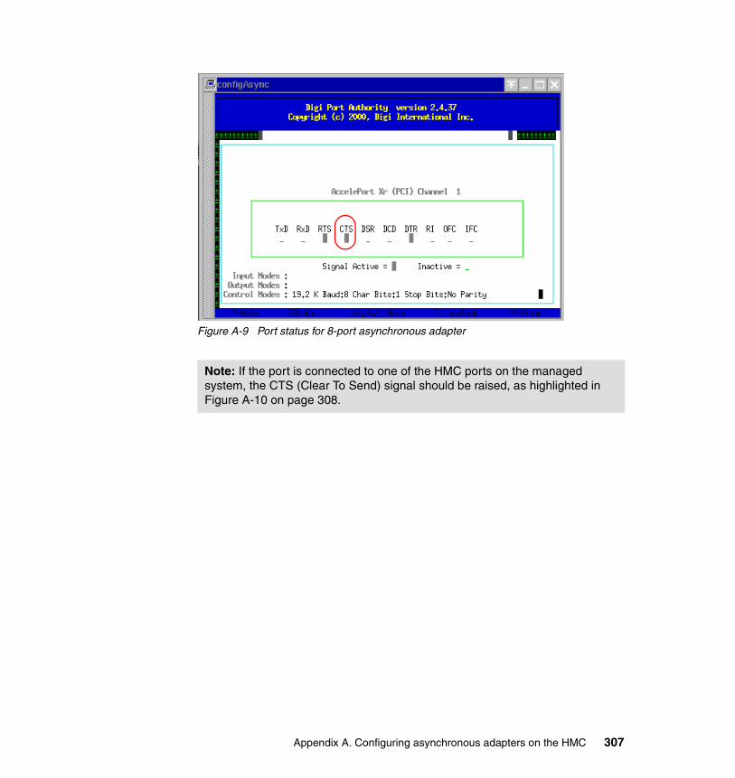
Figure A-9 Port status for 8-port asynchronous adapter
Note: If the port is connected to one of the HMC ports on the managed system, the CTS (Clear To Send) signal should be raised, as highlighted in Figure A-10 on page 308.
Appendix A. Configuring asynchronous adapters on the HMC 307

RANs status (128-port asynchronous adapter)If you select the 128-port asynchronous adapter from Figure A-8 on page 306, the window shows the status of one of the RANs. For example, the first RAN status is shown in Figure A-10.
If the RAN does not correctly download the microcode from the adapter, it shows DN in the highlighted area in Figure A-10.
Figure A-10 Successful microcode download to RAN
Removing an asynchronous adapterAfter you remove an asynchronous adapter, take the following steps:
1. Log in with the ID hscpe and open a command prompt window.
2. Type su -, then log in with the root password.
3. At the command prompt, type /usr/sbin/digiConf.
4. When prompted, set the configuration to the correct number of adapters in the HMC.
Note: These steps are supposed to be done by IBM service representitives. The passwords for hscpe and root must be provided by the customer.
308 Effective System Management Using the IBM Hardware Management Console for pSeries
Appendix B. Recommended network configuration in a partitioned environment
The Ethernet adapter and TCP/IP configuration on the HMC and the partitions must be configured appropriately so that they can communicate with each other as explained in this appendix.
To configure the network settings on the HMC, see 4.2.4, “Customize Network Settings” on page 83.
B
© Copyright IBM Corp. 2003. All rights reserved. 309
Appropriate network configurationTo prevent problems with DLPAR operations on the HMC, as well as the Inventory Scout, Service Agent, and Service Focal Point, you should view the Ethernet network between the HMC and partitions as a mandatory administrative network used for these purposes. This network can be considered equivalent to the SP Ethernet network used in the RS/6000 SP environment.
With careful network planning, you should not have any problems using these applications; however, if an AIX administrator mistakenly changes the TCP/IP configuration on a partition without notifying the HMC administrator, it might result in severe communication problems.
Authentication mechanismThe Service Focal Point and DLPAR functions rely on the Resource Monitoring and Control (RMC) framework between the HMC and partitions. The RMC framework performs not only session management, but also authentication between network peers.
The ctcas subsystem, also known as the cluster authentication daemon, is in charge of this authentication mechanism. It is running as the ctcasd daemon and is packaged in the rsct.core.sec fileset in AIX, as shown in the following:
# lssrc -g rsctSubsystem Group PID Status ctrmc rsct 299204 active ctcas rsct 188658 active# ps -ef | head -1; ps -ef | grep ctcas | grep -v grep UID PID PPID C STIME TTY TIME CMD root 188658 139350 0 Sep 11 - 0:03 /usr/sbin/rsct/bin/ctcasd# lslpp -w /usr/sbin/rsct/bin/ctcasd File Fileset Type ---------------------------------------------------------------------------- /usr/sbin/rsct/bin/ctcasd rsct.core.sec File
The configuration process of authentication between the HMC and partitions is briefly summarized in Table B-1.
Table B-1 Authentication process
Sequence On the HMC On an AIX partition
1 The DMSRM resource manager places the secret key and the HMC host name in the NVRAM of the managed system. For every reboot of the HMC, it places a new secret key.
310 Effective System Management Using the IBM Hardware Management Console for pSeries
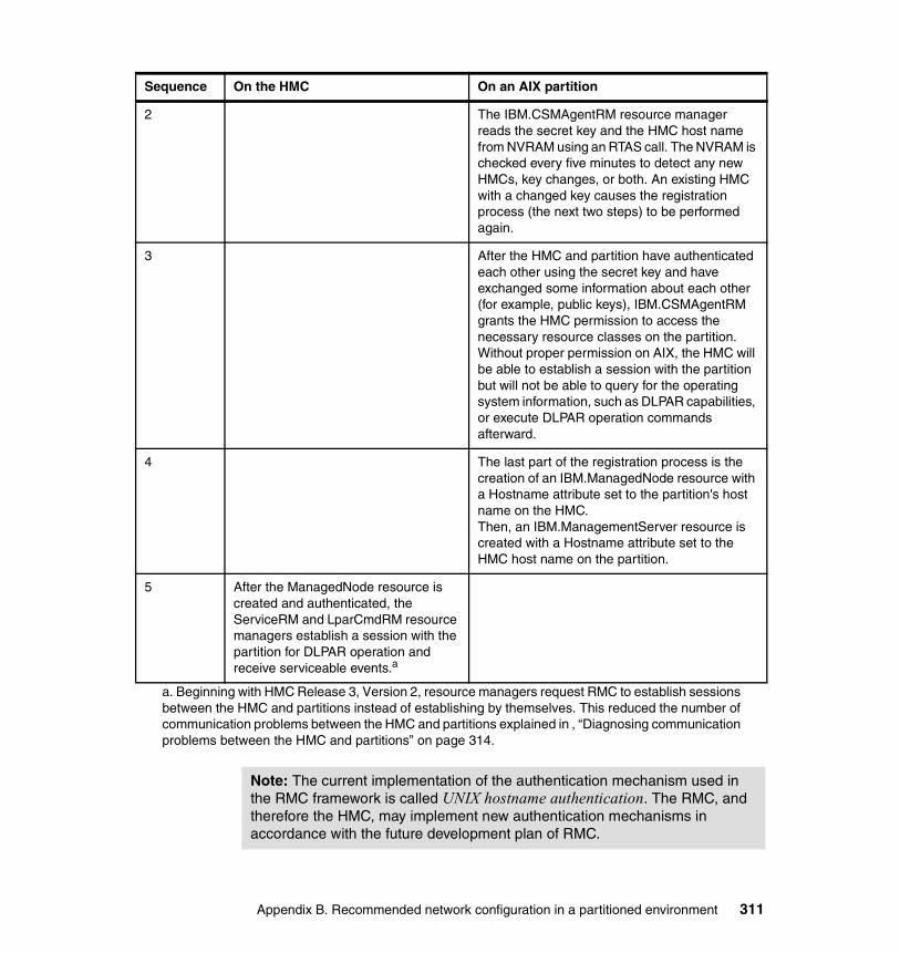
2 The IBM.CSMAgentRM resource manager reads the secret key and the HMC host name from NVRAM using an RTAS call. The NVRAM is checked every five minutes to detect any new HMCs, key changes, or both. An existing HMC with a changed key causes the registration process (the next two steps) to be performed again.
3 After the HMC and partition have authenticated each other using the secret key and have exchanged some information about each other (for example, public keys), IBM.CSMAgentRM grants the HMC permission to access the necessary resource classes on the partition. Without proper permission on AIX, the HMC will be able to establish a session with the partition but will not be able to query for the operating system information, such as DLPAR capabilities, or execute DLPAR operation commands afterward.
4 The last part of the registration process is the creation of an IBM.ManagedNode resource with a Hostname attribute set to the partition's host name on the HMC. Then, an IBM.ManagementServer resource is created with a Hostname attribute set to the HMC host name on the partition.
5 After the ManagedNode resource is created and authenticated, the ServiceRM and LparCmdRM resource managers establish a session with the partition for DLPAR operation and receive serviceable events.a
a. Beginning with HMC Release 3, Version 2, resource managers request RMC to establish sessionsbetween the HMC and partitions instead of establishing by themselves. This reduced the number ofcommunication problems between the HMC and partitions explained in , “Diagnosing communicationproblems between the HMC and partitions” on page 314.
Sequence On the HMC On an AIX partition
Note: The current implementation of the authentication mechanism used in the RMC framework is called UNIX hostname authentication. The RMC, and therefore the HMC, may implement new authentication mechanisms in accordance with the future development plan of RMC.
Appendix B. Recommended network configuration in a partitioned environment 311
Trouble-free network planning rulesTo avoid unnecessary configuration errors in DLPAR operations, you must understand the following rules:
� All combinations of a host name and an IP address must be unique.
� All network interfaces on the HMC and partitions must be assigned different host names and, therefore, different IP addresses.
� The assigned IP address must be consistently resolved regardless of the location (on the HMC or partitions). If some name services, such as NIS, DNS, and LDAP, are used, they must be reliable and return consistent results.
� The network interface on the HMC, which is resolved to the node name (the string returned from the hostname command), must be reachable from all of the partitions.
The following examples show inappropriate network configurations:
� Duplicate IP addresses
Two partitions have different host names but the same IP address on their network interface.
� Unresolvable host name
A partition does not have the valid DNS configuration, while the HMC uses DNS for the name resolution. The partition cannot resolve the HMC host name to an IP address (unresolvable).
� Inconsistent name resolution
The HMC is assigned the fully qualified domain name (FQDN) itsohmc.itsc.austin.ibm.com for both the node name and the host name for eth0 interface. An AIX partition uses DNS for the name resolution, but there are the following files on the partition:
# cat /etc/netsvc.confhosts=local,bind# grep itsohmc /etc/hosts9.3.4.30 itsohmc itsohmc.itsc.austin.ibm.com
Therefore, the same IP address 9.3.4.30 is resolved as:
On the HMC itsohmc.itsc.austin.ibm.com
On the partition itsohmc
� Unreachable network interface
The HMC has two network interfaces, eth0 and eth1. Although the FQDN itsohmc.itsc.austin.ibm.com is assigned for both the node name and the host name for the eth0 interface, all partitions can reach the eth1 interface only.
312 Effective System Management Using the IBM Hardware Management Console for pSeries

We strongly suggest that you do the following before doing any recovery activities:
1. Issue the hostname command on the HMC and all partitions. To issue the hostname command on the HMC, you can use OpenSSH, as shown in the following example:
$ whence ssh/usr/bin/ssh$ ssh -l hscroot itsohmc.itsc.austin.ibm.com [email protected]'s password: XXXXXXitsohmc.itsc.austin.ibm.com
For further information about how to use OpenSSH on AIX, refer to Managing AIX Server Farms, SG24-6606.
2. Issue the host command against all of the network interfaces on the HMC and all of the partitions:
a. Confirm how many interfaces are available:
$ ssh -l hscroot itsohmc.itsc.austin.ibm.com\“/sbin/ifconfig -l | grep Link”
[email protected]'s password: XXXXXXeth0 Link encap:Ethernet HWaddr 00:02:55:13:85:2Elo Link encap:Local Loopback
b. Confirm the IP address of eth0:
$ ssh -l hscroot itsohmc.itsc.austin.ibm.com /sbin/ifconfig [email protected]'s password: XXXXXXeth0 Link encap:Ethernet HWaddr 00:02:55:13:85:2E inet addr:9.3.4.30 Bcast:9.3.5.255 Mask:255.255.254.0 UP BROADCAST RUNNING MULTICAST MTU:1500 Metric:1 RX packets:1256676 errors:0 dropped:0 overruns:0 frame:7 TX packets:1381966 errors:0 dropped:0 overruns:0 carrier:13 collisions:404844 txqueuelen:100 RX bytes:132305448 (126.1 Mb) TX bytes:1048151698 (999.5 Mb) Interrupt:10 Base address:0x5000
c. Confirm both the reverse and regular name resolutions:
# ssh -l hscroot itsohmc.itsc.austin.ibm.com host [email protected]'s password: XXXXXX30.4.3.9.in-addr.arpa. domain name pointer itsohmc.itsc.austin.ibm.com.# ssh -l hscroot itsohmc.austin.ibm.com host [email protected]'s password:itsohmc.itsc.austin.ibm.com. has address 9.3.4.30
For further information about the RMC framework and its resource managers, refer to the following publications:
� A Practical Guide for Resource Monitoring and Control, SG24-6615
Appendix B. Recommended network configuration in a partitioned environment 313

� IBM Reliable Scalable Cluster Technology for AIX 5L: Messages, GA22-7891
� IBM Reliable Scalable Cluster Technology for AIX 5L: RSCT Guide and Reference, SA22-7889
� IBM Reliable Scalable Cluster Technology for AIX 5L: Technical Reference, SA22-7890
Diagnosing communication problems between the HMC and partitions
Prior to the HMC software Release 3, Version 2, there were cases communication problems occurred between the HMC and partitions:
If the host name resolution in the environment was carefully planned and implemented as explained in , “Trouble-free network planning rules” on page 312, those problems most likely did not occur. If not, or the host names for the HMC and partitions were changed after the initial configuration, the communication problems arose, then they were sometimes very difficult to solve.
In this case, not only for DLPAR operations, but also most service functions were affected and unable to be used until the problem was resolved.
Beginning with the following software levels, the communication and authentication mechanism between the HMC and partitions become more robust in terms of the host name resolution, therefore the communication problem hardly occurs in the configuration where these software levels are used:
� HMC software Release 3, Version 2 and later� AIX 5L Version 5.1 plus 5100-03 Recommended Maintenance Level and later� AIX 5L Version 5.2 and later
Once the problem occurs, you can use the DiagnoseHMC command on the HMC and the AIX partition that has the problem in order to verify the communication and authentication mechanism between the HMC and the partition is correctly configured.
If the DiagnoseHMC command is executed on an AIX partition (AIX 5L Version 5.2 plus 5200-01 Recommended Maintenance Level), the command prints the
Note: It is highly recommended to use fully qualified host names when you configure the network interfaces. This setup is critical because dynamic logical partitioning operations, Service Focal Point, and Inventory Scout rely on the networking between the HMC and the logical partitions being set up correctly.
314 Effective System Management Using the IBM Hardware Management Console for pSeries

message shown in Example B-1 that verifies no configuration problem exists on the partition.
Example: B-1 DiagnoseHMC output
# /opt/csm/csmbin/diagnostics/DiagnoseHMC- Check local RMC subsystem. - Get the installed versions of RMC packages. - Check the primary hostname of the local machine. - Check the amount of free space in /var. - Check that the RSCT registry data is not corrupted. - Check node ID information. Checking resources of class AuditLog: ok Checking resources of class AuditLogTemplate: ok Checking resources of class ManagementServer: ok - Check that the CT security files look ok. checking /var/ct/cfg/ct_has.pkf: ok checking /var/ct/cfg/ct_has.qkf: ok checking /var/ct/cfg/ct_has.thl: ok - Check local RSCT daemons. - Check the ctrmc subsystem. - Check the ctcasd subsystem. ctcas is not running.------------------------ Findings ----------------------------(1) ctcas is not running. Ensure that /usr/sbin/rsct/bin/ctcasd is present and executable.Try to start ctcas by running: startsrc -s ctcas------------------------------------------------------
The ctcas subsystem is started on-demand basis by the RMC, if the /usr/sbin/rsct/bin/ctstrtcasd command exists. Therefore, you can ignore the warning message regarding the ctsasd subsystem on AIX partitions installed with AIX 5L Version 5.2 plus 5200-01 Recommended Maintenance Level and later.
The DiagnoseHMC is installed in the /opt/csm/csmbin/diagnostics directory on both AIX and HMC. On AIX, it is included in the csm.core fileset, which is installed by default. On HMC, the command requires the root authority.
# oslevel -r5200-01# lslpp -w /opt/csm/csmbin/diagnostics/DiagnoseHMC File Fileset Type ---------------------------------------------------------------------------- /opt/csm/csmbin/diagnostics/DiagnoseHMC csm.core File# lslpp -L csm.core Fileset Level State Type Description (Uninstaller) ----------------------------------------------------------------------------
Appendix B. Recommended network configuration in a partitioned environment 315

csm.core 1.3.1.0 C F Cluster Systems Management Core
316 Effective System Management Using the IBM Hardware Management Console for pSeries

Appendix C. A brief introduction to VLAN
This appendix gives you a brief introduction of the VLAN (Virtual LAN) technology, which is commonly found on today’s switching devices, by providing the following sections:
� “Historical networking review” on page 318� “What is a switch?” on page 319� “What is VLAN?” on page 320� “Several VLAN technologies” on page 321� “AIX VLAN support (802.1Q VLAN interface)” on page 325� “Vendor-specific VLAN technologies (Cisco)” on page 326
The last section contains useful information to implement a secure network configuration in a partitioned environment.
C
© Copyright IBM Corp. 2003. All rights reserved. 317
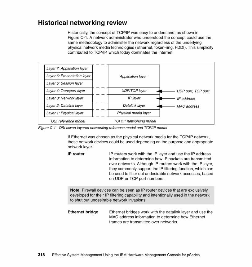
Historical networking reviewHistorically, the concept of TCP/IP was easy to understand, as shown in Figure C-1. A network administrator who understood the concept could use the same methodology to administer the network regardless of the underlying physical network media technologies (Ethernet, token-ring, FDDI). This simplicity contributed to TCP/IP, which today dominates the Internet.
Figure C-1 OSI seven-layered networking reference model and TCP/IP model
If Ethernet was chosen as the physical network media for the TCP/IP network, these network devices could be used depending on the purpose and appropriate network layer.
IP router IP routers work with the IP layer and use the IP address information to determine how IP packets are transmitted over networks. Although IP routers work with the IP layer, they commonly support the IP filtering function, which can be used to filter out undesirable network accesses, based on UDP or TCP port numbers.
Ethernet bridge Ethernet bridges work with the datalink layer and use the MAC address information to determine how Ethernet frames are transmitted over networks.
Layer 1: Physical layer
Layer 2: Datalink layer
Layer 3: Network layer
Layer 4: Transport layer
Layer 5: Session layer
Layer 6: Presentation layer
Layer 7: Application layer
OSI reference model
Physical media layer
Datalink layer
TCP/IP networking model
IP layer
UDP/TCP layer
Application layer
MAC address
IP address
UDP port, TCP port
Note: Firewall devices can be seen as IP router devices that are exclusively developed for their IP filtering capability and intentionally used in the network to shut out undesirable network invasions.
318 Effective System Management Using the IBM Hardware Management Console for pSeries

Ethernet hub1 An Ethernet hub, typically used for the 10 BASE-T Ethernet network, provided a single broadcast domain for all of the nodes connected to its ports. Because those Ethernet hubs did not have an intelligent processing unit inside, sometimes they were referred to as unintelligent or dumb hubs.
When the 100 BASE-TX Ethernet (Fast Ethernet) technology was evolved, limited processing capabilities were added to some Ethernet hub devices in order to support half- and full-duplex 100 Mbps Ethernet. These types of Ethernet hub devices are actually bridges rather than traditional (repeater type) hubs, therefore they are sometimes referred to as intelligent hubs.
What is a switch?In the past, typical IP routers used processors designed for general purposes and ran with software that supported many functions, such as IP forwarding, IP filtering, and security policies. Therefore, those IP routers were usually slower than bridges but provided more functions. Also bridges were slow and seldom supported the actual wire-speed operations between any two given ports.
During the 1990s, several network hardware vendors developed high-speed bridges and marketed Ethernet switches (or simply switches) that were designed to use ASIC (Application-Specific Integrated Circuit) and advanced memory technology in order to improve performance. This type of switch is now known as an L2 switch.
Current L2 switches generally provide the following capabilities, as well as higher network traffic speed compared to the bridges in the past:
� Separate access domains� Network segmentation� Extended distance limitations� Increased aggregate capacity� Data rate flexibility
After L2 switches had dominated the network hardware market, several network hardware vendors coined a new term, L3 switch, to advertise their high-speed IP router products that were designed using hardware components and concepts similar to the L2 switches.
1 If 10 BASE2 or 10 BASE5 Ethernet was used as the physical network media, repeaters were used instead of hubs.
Appendix C. A brief introduction to VLAN 319

Unlike L2 switches that operate using MAC address information, L3 switches operate using IP address information, as IP routers do.
Many L3 switch products also support a function very similar to the IP filtering function found on traditional IP routers; a switch product that supports this function is commonly referred to as an L4 switch and can be used to filter out undesirable network access based on UDP or TCP port numbers.
Some network switch products support L2 switching only, while others support L3 or L4 switching, depending on the product range and configuration; it is not rare that an L2 switch product that supports L3/L4 switching capabilities by plugging in hardware modules.
To configure L2, L3, or L4 switches, most products provide several methods to access their operating system, such as:
� Serial port access
� Telnet access
� Web browser based access
� SNMP MIB-based access2
� Proprietary application access connected to switches either over the serial line or using the management network port
Enterprise networks nowadays commonly are based on switching technology. Those networks are composed of different kinds of network switch devices and can be very complex. In fact, every network device used for LAN can be a switch. Therefore, it is important to understand the switching technologies in order to share the switching world with your network administrators, so that your pSeries servers can perform more efficiently and securely.
What is VLAN?VLAN is a technology used for establishing virtual network segments on top of physical switch devices. If configured appropriately, a VLAN definition can straddle multiple switches. Typically, a VLAN is a broadcast domain that enables all nodes in the VLAN to communicate each other without any L3 routing or inter-VLAN bridging. (There are exceptions explained in the following sections.)
For example, two VLANs (VLAN 1 and 2) are defined on three switches (Switch A, B, and C) in Figure C-2 on page 321. Although nodes C-1 and C-2 are physically connected to the same switch C, traffic between two nodes can be
2 SNMP stands for Simple Network Management Protocol. MIB stands for Management Information Base.
320 Effective System Management Using the IBM Hardware Management Console for pSeries
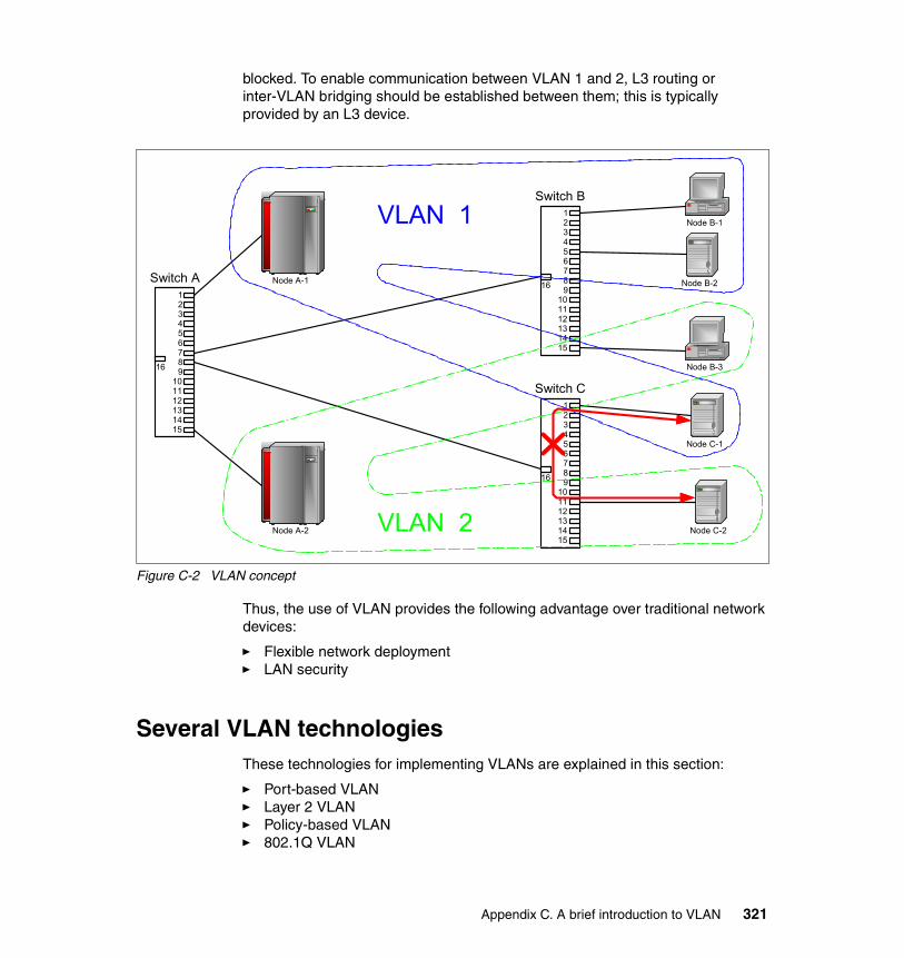
blocked. To enable communication between VLAN 1 and 2, L3 routing or inter-VLAN bridging should be established between them; this is typically provided by an L3 device.
Figure C-2 VLAN concept
Thus, the use of VLAN provides the following advantage over traditional network devices:
� Flexible network deployment� LAN security
Several VLAN technologiesThese technologies for implementing VLANs are explained in this section:
� Port-based VLAN� Layer 2 VLAN� Policy-based VLAN� 802.1Q VLAN
Switch B123456789
101112131415
16
123456789
101112131415
16
Switch C
Switch A123456789
101112131415
16
Node B-2
Node B-1
Node B-3
Node C-1
Node C-2
Node A-1
Node A-2
VLAN 1
VLAN 2
Appendix C. A brief introduction to VLAN 321
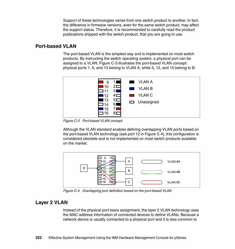
Support of these technologies varies from one switch product to another. In fact, the difference in firmware versions, even for the same switch product, may affect the support status. Therefore, it is recommended to carefully read the product publications shipped with the switch product, that you are going to use.
Port-based VLANThe port-based VLAN is the simplest way and is implemented on most switch products. By instructing the switch operating system, a physical port can be assigned to a VLAN. Figure C-3 illustrates the port-based VLAN concept: physical ports 1, 6, and 13 belong to VLAN A, while 3, 12, and 15 belong to B.
Figure C-3 Port-based VLAN concept
Although the VLAN standard enables defining overlapping VLAN ports based on the port-based VLAN technology (see port 12 in Figure C-4), this configuration is considered obsolete and is not implemented on most switch products available on the market.
Figure C-4 Overlapping port definition based on the port-based VLAN
Layer 2 VLANInstead of the physical port-basis assignment, the layer 2 VLAN technology uses the MAC address information of connected devices to define VLANs. Because a network device is usually connected to a physical port and it is less common to
12345678
910111213141516
VLAN AVLAN BVLAN CUnassigned
12345678
910111213141516
D
A
B
C
VLAN #A
VLAN #B
VLAN #C
322 Effective System Management Using the IBM Hardware Management Console for pSeries
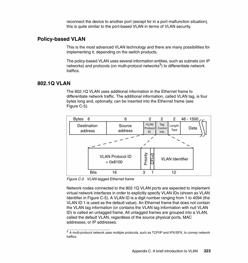
reconnect the device to another port (except for in a port malfunction situation), this is quite similar to the port-based VLAN in terms of VLAN security.
Policy-based VLANThis is the most advanced VLAN technology and there are many possibilities for implementing it, depending on the switch products.
The policy-based VLAN uses several information entities, such as subnets (on IP networks) and protocols (on multi-protocol networks3) to differentiate network traffics.
802.1Q VLANThe 802.1Q VLAN uses additional information in the Ethernet frame to differentiate network traffic. The additional information, called VLAN tag, is four bytes long and, optionally, can be inserted into the Ethernet frame (see Figure C-5).
Figure C-5 VLAN-tagged Ethernet frame
Network nodes connected to the 802.1Q VLAN ports are expected to implement virtual network interfaces in order to explicitly specify VLAN IDs (shown as VLAN Identifier in Figure C-5). A VLAN ID is a digit number ranging from 1 to 4094 (the VLAN ID 1 is used as the default value). An Ethernet frame that does not contain the VLAN tag information (or contains the VLAN tag information with null VLAN ID) is called an untagged frame. All untagged frames are grouped into a VLAN, called the default VLAN, regardless of the source physical ports, MAC addresses, or IP addresses.
3 A multi-protocol network uses multiple protocols, such as TCP/IP and IPX/SPX, to convey network traffics.
Destinationaddress address
Source
Bytes 6 6 2 2 2 46 - 1500VLAN
ProtocolID
TagControl
Info
Length/
Type Data
Bits 16 3 1 12
VLAN Protocol ID= 0x8100 P
riori
ty
CF
I=0
VLAN Identifier
Appendix C. A brief introduction to VLAN 323
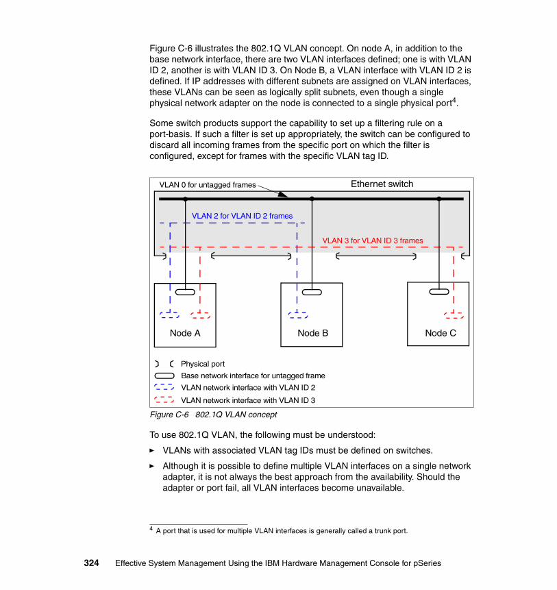
Figure C-6 illustrates the 802.1Q VLAN concept. On node A, in addition to the base network interface, there are two VLAN interfaces defined; one is with VLAN ID 2, another is with VLAN ID 3. On Node B, a VLAN interface with VLAN ID 2 is defined. If IP addresses with different subnets are assigned on VLAN interfaces, these VLANs can be seen as logically split subnets, even though a single physical network adapter on the node is connected to a single physical port4.
Some switch products support the capability to set up a filtering rule on a port-basis. If such a filter is set up appropriately, the switch can be configured to discard all incoming frames from the specific port on which the filter is configured, except for frames with the specific VLAN tag ID.
Figure C-6 802.1Q VLAN concept
To use 802.1Q VLAN, the following must be understood:
� VLANs with associated VLAN tag IDs must be defined on switches.
� Although it is possible to define multiple VLAN interfaces on a single network adapter, it is not always the best approach from the availability. Should the adapter or port fail, all VLAN interfaces become unavailable.
4 A port that is used for multiple VLAN interfaces is generally called a trunk port.
Ethernet switchVLAN 0 for untagged frames
Physical port
VLAN 2 for VLAN ID 2 frames
VLAN 3 for VLAN ID 3 frames
Base network interface for untagged frame
VLAN network interface with VLAN ID 2
VLAN network interface with VLAN ID 3
Node A Node B Node C
324 Effective System Management Using the IBM Hardware Management Console for pSeries
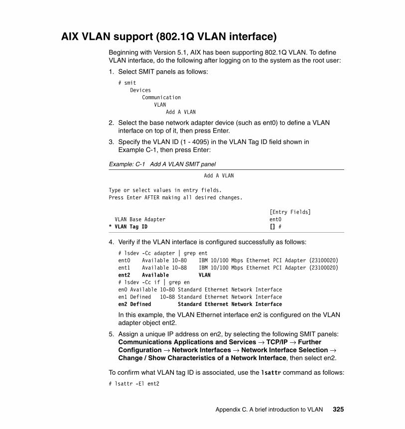
AIX VLAN support (802.1Q VLAN interface)Beginning with Version 5.1, AIX has been supporting 802.1Q VLAN. To define VLAN interface, do the following after logging on to the system as the root user:
1. Select SMIT panels as follows:
# smitDevices
CommunicationVLAN
Add A VLAN
2. Select the base network adapter device (such as ent0) to define a VLAN interface on top of it, then press Enter.
3. Specify the VLAN ID (1 - 4095) in the VLAN Tag ID field shown in Example C-1, then press Enter:
Example: C-1 Add A VLAN SMIT panel
Add A VLAN
Type or select values in entry fields.Press Enter AFTER making all desired changes.
[Entry Fields] VLAN Base Adapter ent0* VLAN Tag ID [] #
4. Verify if the VLAN interface is configured successfully as follows:
# lsdev -Cc adapter | grep entent0 Available 10-80 IBM 10/100 Mbps Ethernet PCI Adapter (23100020)ent1 Available 10-88 IBM 10/100 Mbps Ethernet PCI Adapter (23100020)ent2 Available VLAN# lsdev -Cc if | grep enen0 Available 10-80 Standard Ethernet Network Interfaceen1 Defined 10-88 Standard Ethernet Network Interfaceen2 Defined Standard Ethernet Network Interface
In this example, the VLAN Ethernet interface en2 is configured on the VLAN adapter object ent2.
5. Assign a unique IP address on en2, by selecting the following SMIT panels: Communications Applications and Services → TCP/IP → Further Configuration → Network Interfaces → Network Interface Selection → Change / Show Characteristics of a Network Interface, then select en2.
To confirm what VLAN tag ID is associated, use the lsattr command as follows:
# lsattr -El ent2
Appendix C. A brief introduction to VLAN 325
base_adapter ent0 VLAN Base Adapter Truevlan_tag_id 10 VLAN Tag ID True
Vendor-specific VLAN technologies (Cisco)As explained in the previous sections in this appendix, standard VLAN technologies cannot be used to implement a secure network in a partitioned environment, which is explained in 8.1, “Networking in a partitioned environment” on page 156.
However, several network hardware vendors, such as Cisco, provide vendor-specific advanced VLAN technologies in order to implement the secure network in a partitioned environment.
Private VLANThe private VLAN technology, or PVLAN, enables you to define multiple secondary VLANs in a single primary VLAN as shown in Figure C-7 on page 327. The HMC belongs to the primary VLAN. The switch port to which the HMC is connected is called a promiscuous port. Each partition (partition 1, 2, and 3) belongs to its own secondary VLAN; therefore there are three secondary VLANs defined in total.
Although partitions can communicate with the HMC, they cannot communicate with each other in this configuration. The ports belonging to the partitions are called isolated ports.
Note: Currently, HMC does not support 802.1Q VLAN.
Note: Before implementing the secure network in a partitioned environment using the technologies explained in this section, we strongly recommend you consult with your network hardware vendor or reseller to verify the detailed information about the switch product you are going to install.
326 Effective System Management Using the IBM Hardware Management Console for pSeries

Figure C-7 Private VLAN concept
PVLAN is only supported on the high-end Cisco Catalyst switch products, such as Catalyst 6500 series and Catalyst 4500 series.
Most low-end switch products, for example Catalyst 2950, only support a subset of the PVLAN function. On Catalyst 2950, there is a concept of protected or non-protected ports instead of promiscuous and isolated ports.
The concept of protected ports is summarized as follows:
� A protected port can not forward any traffic (uni-cast, multicast, or broadcast) to any other protected ports. Traffic cannot be forwarded between protected ports at Layer 2; all traffic between protected ports must be forwarded through an L3 device.
� A protected port can forward traffic to any non-protected ports within the VLAN.
� By default, all ports on Catalyst 2950 are set to the non-protected port mode; you must explicitly set the protected port mode on port-basis.
VLAN ACLVLAN ACL (Access Control List) can be set on port-basis to control access for all packets that are bridged within a VLAN or that are routed into or out of a VLAN. The access control function found on conventional router devices, which is configured only on routed interfaces, is applied only on routed packets. However, VLAN ACLs are applied to all network frames and can be applied to any VLANs or network interfaces.
HMC
Partition 1
Partition 2
Partition 3
Secondary VLANs
Primary VLAN
Promiscuous port
Appendix C. A brief introduction to VLAN 327

When you define a VLAN ACL and apply it to a VLAN, all packets entering the VLAN are checked against this VLAN ACL. If you apply a VLAN ACL to the VLAN and an ACL to a routed interface in the VLAN, a packet coming in to the VLAN is first checked against the VLAN ACL; then, if permitted, it is checked against the input ACL before it is handled by the routed interface. When the packet is routed to another VLAN, it is first checked against the output ACL applied to the routed interface; then, if permitted, it is checked against the VACL configured for the destination VLAN. If a VLAN ACL is defined for a specific type of packets and a packet does not match with the ACL, the default action is to deny.
Note: VLAN ACLs can be defined on protocol-basis (IP or IPX) or MAC-address basis.
Note: At the time of writing this book, most Cisco Catalyst products, except for Catalyst 2950 Series, support the VLAN ACL function.
328 Effective System Management Using the IBM Hardware Management Console for pSeries

acronyms
ACL Access Control List
AIX Advanced Interactive Executive
ALPAR Affinity Logical Partition
APAR Authorized Problem Analysis Report
ASIC Application-Specific Integrated Circuit
ASCII American National Standard Code for Information Interchange
BOS Base Operating System
BPA Bulk Power Assembly
BPC Bulk Power Controller
CA Certified Authority
CD Compact Disk
CDE Common Desktop Environment
CD-R CD - Recordable
CD-ROM CD - Read Only Media
CEC Central Electronics Complex
CIM Common Interface Method
CMM Customer Managed Microcode
CPU Central Processing Unit
CSM Cluster Systems Management
CSP Converged Service Processor
CUoD Capacity Upgrade on Demand
DCE Data Communication Equipment
DLPAR Dynamic logical partitioning
DMTF Desktop Management Task Force
Abbreviations and
© Copyright IBM Corp. 2003. All rights reserved.
DNS Domain Name Service
DoS Denial of Service
DSA Digital Signature Algorithm
DTE Data Terminal Equipment
DVD Digital Versatile Disk
DVD-RAM DVD - Random Access Media
DVD-ROM DVD - Read Only Media
EIA Electronic Industry Association
ESS Electronic Server System
FC Feature Code
FDDI Fibre Distributed Data Interface
FQDN Fully Qualified Domain Name
FRU Field Replaceable Unit
FTP File Transfer Protocol
FTSS Field Technical Support Specialist
GB Gigabyte
GID Group Identification
GUI Graphical User Interface
HACMP Highly Available Cluster Multiprocessing
HMC IBM Hardware Management Console for pSeries
HPC High Performance Computing
HTML Hypertext Markup Language
HTTP Hypertext Transfer Protocol
IBF Internal Battery Feature
IBM International Business Machines Corporation
ICMP Internet Control Protocol Message
329

IEEE Institute of Electrical and Electronic Engineers
IHS IBM HTTP Server
I/O Input/Output
IP Internet Protocol
ISO International Organization for Standardization
IT Information Technology
ITSO International Technical Support Organization
L2 Level 2
L3 Level 3
L4 Level 4
LAN Local Area Network
LDAP Light Directory Access Protocol
LED Light Emitting Diode
LMB Logical Memory Block
LPAR Logical Partition
LPP Licensed Program Product
MA Maintenance Agreement
MAC Media Access Control
MB Megabyte
MT-MDL Machine Type - Model
MTU Maximum Transfer Unit
NFS Network File System
NIM Network Installation Manager
NIS Network Information System
NVRAM Non-volatile random access memory
ODM Object Database Manager
ODS On-demand service
OF Open Firmware
OS Operating System
PAM Pluggable Authentication Module
PC Personal Computer
PCI Peripheral Component Interface
PID Process ID
PMR Problem Management Record
POWER Performance Optimized with Enhanced RISC
PMTU Path Maximum Transfer Unit
PPID Parent Process ID
PSSP Parallel System Support Program
PTF Program Temporary Fix
PVLAN Private VLAN
RAN Remote Access Node
RAS Reliability, Availability, and Serviceability
RFC Request for Comment
RISC Reduced Instruction Set Computer
RIP Routing Information Protocol
RMC Resource Monitoring and Control
RMO Real Mode Offset
RPM Red Hat Package Manager
RS Recommended Standard
RSA Rivest-Shamir-Adleman Algorithm
RSCT Reliable Scalable Cluster Technology
S/N Serial Number
SCSI Small Computer System Interface
SFP Service Focal Point
SMIT System Management Interface Tool
SMP Symmetrical Multi-Processing
SMS Systems Management Service
SMTP Simple Mail Transfer Protocol
330 Effective System Management Using the IBM Hardware Management Console for pSeries

SNMP Simple Network Management Protocol
SP Service Processor
SSH Secure Shell
SSL Secure Socket Layer
TCP Transmission Control Protocol
TTY Teletypewriter
UDP User Datagram Protocol
UID User Identification
URL Universal Resource Locator
USB Universal Serial Bus
VACL VLAN ACL
VGA Video Graphics Adapter
VLAN Virtual LAN
VPD Vital Product Data
WebSM Web-based System Manager
Abbreviations and acronyms 331

332 Effective System Management Using the IBM Hardware Management Console for pSeries
Related publications
The publications listed in this section are considered particularly suitable for a more detailed discussion of the topics covered in this book.
IBM RedbooksFor information about ordering these publications, see “How to get IBM Redbooks” on page 337.
� A Practical Guide for Resource Monitoring and Control, SG24-6615
� IBM Eserver pSeries 670 and pSeries 690 System Handbook, SG24-7040
� Linux Applications on pSeries, SA24-6033
� Managing AIX Server Farms, SG24-6606
� POWER4 Processor Introduction and Tuning Guide, SG24-7041
� The Complete Partitioning Guide for IBM Eserver pSeries Servers, SG24-7039
IBM RedpapersIBM Redpapers are available only in softcopy.
� IBM Eserver pSeries 615 Models 6C3 and 6E3 Technical Overview and Introduction, REDP0160
� IBM Eserver pSeries 630 Models 6C4 and 6E4 Technical Overview and Introduction, REDP0195
� IBM Eserver pSeries 650 Model 6M2 Technical Overview and Introduction, REDP0194
pSeries hardware publicationsThe following publications are shipped with the IBM Eserver pSeries servers. These publications are also available through this Web site:
http://publib16.boulder.ibm.com/pseries/en_US/infocenter/base/hardware.htm
© Copyright IBM Corp. 2003. All rights reserved. 333

� 128-Port Asynchronous PCI Adapter Installation and User’s Guide, SA23-2563
� 8-Port Asynchronous PCI Adapter Installation and User’s Guide, SA23-2562
� Adapter, Devices, and Cable Information for Multiple Bus Systems, SA38-0516
� D10 I/O Drawer Installation Guide, SA23-1296
� D20 I/O Drawer Installation Guide, SA23-1295
� IBM Eserver pSeries 615 Model 6C3 and 6E3 Installation Guide, SA38-0628
� IBM Eserver pSeries 615 Model 6C3 and 6E3 Service Guide, SA38-0629
� IBM Eserver pSeries 615 Model 6C3 and 6E3 User’s Guide, SA38-0630
� IBM Eserver pSeries 630 Model 6C4 and 6E4 Installation Guide, SA38-0605
� IBM Eserver pSeries 630 Model 6C4 and 6E4 Service Guide, SA38-0604
� IBM Eserver pSeries 630 Model 6C4 and 6E4 User’s Guide, SA38-0606
� IBM Eserver pSeries 650 Model 6M2 Installation Guide, SA38-0610
� IBM Eserver pSeries 650 Model 6M2 Service Guide, SA38-0612
� IBM Eserver pSeries 650 Model 6M2 User’s Guide, SA38-0611
� IBM Eserver pSeries 655 Installation Guide, SA38-0616
� IBM Eserver pSeries 655 Service Guide, SA38-0618
� IBM Eserver pSeries 655 User’s Guide, SA38-0617
� IBM Eserver pSeries 670 Installation Guide, SA38-0613
� IBM Eserver pSeries 670 Service Guide, SA38-0615
� IBM Eserver pSeries 670 User’s Guide, SA38-0614
� IBM Eserver pSeries 690 Installation Guide, SA38-0587
� IBM Eserver pSeries 690 Service Guide, SA38-0589
� IBM Eserver pSeries 690 User’s Guide, SA38-0588
� IBM Eserver pSeries 7311 Model D10 and Model D20 Service Guide, SA38-0627
� IBM Hardware Management Console for pSeries Maintenance Guide, SA38-0603
� IBM Hardware Management Console for pSeries Installation and Operations Guide, SA38-0590
� Installation Guide 61D I/O drawer 61R Second I/O Rack, SA23-1281
334 Effective System Management Using the IBM Hardware Management Console for pSeries
� PCI Adapter Placement References, SA38-0538
AIX official publicationsThe following publications are contained in the AIX 5L for POWER V 5.2 Documentation CD, 5765-E62, that is shipped as a part of the AIX 5L Version 5.2 CD-ROM media set. These publications are also available from this Web site:
http://publib16.boulder.ibm.com/pseries/en_US/infocenter/base/aix.htm
� AIX 5L Version 5.2 Asynchronous Communications Guide
� AIX 5L Version 5.2 Installation Guide and Reference
� AIX 5L Version 5.2 Reference Documentation: Commands Reference
� AIX 5L Version 5.2 Security Guide
� AIX 5L Version 5.2 System Management Guide: AIX 5L Version 5.2 Web-based System Manager Administration Guide
� AIX 5L Version 5.2 System Management Guide: Communications and Networks
� AIX 5L Version 5.2 System Management Guide: Operating System and Devices
� AIX 5L Version 5.2 Understanding the Diagnostic Subsystem for AIX
� AIX Installation in a Partitioned Environment, SC23-4382
� IBM Reliable Scalable Cluster Technology for AIX 5L: Messages, SA22-7891
� IBM Reliable Scalable Cluster Technology for AIX 5L, RSCT Guide and Reference, SA22-7889
� IBM Reliable Scalable Cluster Technology for AIX 5L, Technical Reference, SA22-7890
� IBM Reliable Scalable Cluster Technology for AIX 5L and Linux, Group Services Programming Guide and Reference, SA22-7888
CSM for AIX official publicationsThe following publications are contained in the Cluster Systems Management for AIX 5L product (Program Number: 5765-F67). These publications are also available at this Web site:
http://www.ibm.com/servers/eserver/pseries/library/clusters/aix.html
� IBM Cluster Systems Management for AIX 5L, Administration Guide, SA22-7918
Related publications 335
� IBM Cluster Systems Management for AIX 5L, Hardware Control Guide, SA22-7920
� IBM Cluster Systems Management for AIX 5L, Planning and Installation Guide, SA22-7919
CSM for Linux official publicationsThe following publications are contained in the Cluster Systems Management for Linux product (Program Number: 5765-E88). These publications are also available at this Web site:
http://www.ibm.com/servers/eserver/clusters/library/linux.html
� IBM Cluster Systems Management for Linux, Administration Guide, SA22-7873
� IBM Cluster Systems Management for Linux, Hardware Control Guide, SA22-7856
� IBM Cluster Systems Management for Linux, Planning and Installation Guide, SA22-7853
� IBM Reliable Scalable Cluster Technology for Linux, Mesages, SA22-7894
� IBM Reliable Scalable Cluster Technology for Linux, RSCT Guide and Reference, SA22-7892
� IBM Reliable Scalable Cluster Technology for Linux, Technical Reference, SA22-7893
� IBM Reliable Scalable Cluster Technology for AIX 5L and Linux, Group Services Programming Guide and Reference, SA22-7888
Other publicationsThese publications are also relevant as further information sources:
� Bill McCarty, Red Hat Linux Firewalls, John Wiley & Sons, 2002, ISBN 0-764-52463-1.
� Rich Seifert, The Switch Book: The Complete Guide to LAN Switching Technology, John Wiley & Sons, 2002, ISBN 0-471-34586-5
� Larry Wall, Programming Perl, O'Reilly & Associates, 2000, ISBN 0-596-00027-8
336 Effective System Management Using the IBM Hardware Management Console for pSeries
Online resourcesThese Web sites are also relevant as further information sources:
� AIX toolkit for Linux applications
http://www.ibm.com/servers/aix/products/aixos/linux/download.html
� The DMTF Standards web site
http://www.dmtf.org/standards/standard_cim.php
� IBM Eserver pSeries Information Center
http://publib16.boulder.ibm.com/pseries/en_US/infocenter/base/index.htm
� IBM Eserver pSeries & RS/6000 Microcode Updates
http://techsupport.services.ibm.com/server/mdownload
� IBM Eserver pSeries Support Hardware Management Console
https://techsupport.services.ibm.com/server/hmc?fetch=home.html
� Electronic Service Agent for pSeries and RS/6000 User’s Guide
ftp://service.software.ibm.com/aix/service_agent_code/AIX/svcUG.pdf
� Electronic Service Agent for pSeries HMC User’s Guide
ftp://service.software.ibm.com/aix/service_agent_code/HMC/HMCSAUG.pdf
� Microcode Discovery Service
http://techsupport.services.ibm.com/server/aix.invscoutMDS
� OpenSSH Web site
http://www.openssh.com
� VPD Capture Service
http://techsupport.services.ibm.com/server/aix.invscoutVPD
How to get IBM RedbooksYou can search for, view, or download Redbooks, Redpapers, Hints and Tips, draft publications, and Additional materials, as well as order hardcopy Redbooks or CD-ROMs, at this Web site:
ibm.com/redbooks
Related publications 337

338 Effective System Management Using the IBM Hardware Management Console for pSeries

Index
Symbols/etc/hosts 86, 312/etc/inetd.conf 162/etc/netsvc.conf 312/etc/pam.conf 180/etc/profile 147/etc/sysctl.conf 169/opt/csm/csmbin/diagnostics 315/sbin/shutdown 190/usr/sbin/digiConf 308/var/hsc/profiles/MT-MDL*S/N 103
Numerics10 BASE2 Ethernet 31910 BASE5 Ethernet 31910 BASE-T Ethernet 319100 BASE-TX Ethernet 31932-bit Intel-based desktop PC 16
AACL 327Activate partitions 65Activating a specific partition profile 65Adapter
10/100 Mbps Ethernet PCI adapter II 24128-port asynchronous adapter 25, 2968-port asynchronous adapter 25, 296
addhmcusers script 234administrative workstation 157Advanced Operator 100AIX 5L Version 5.2 Web-based System Manager 16, 32AIX VLAN support 325ALPAR capable 196ALPAR incapable 196anonymous 115Application folder
HMC Maintenance 41, 80HMC Management 40Server and Partition 40Service Applications 41, 248Software Maintenance 40, 108
© Copyright IBM Corp. 2003. All rights reserved.
System Manager Security 40Application-Specific Integrated Circuit 319ASIC 319Authentication mechanism 310Auto Start Partitions 63automatic configuration 250autorestart parameter 231
BBacking up profile data 103bkprofdata 203Bonus Pack 177BOOTP 156BPA 7, 15BPC 15broadcast domain 156Bulk Power Assembly 7Bulk Power Controller 15
Ccall home 267Capacity Upgrade on Demand 194CEC 7CEC Call Home 263Central Electronics Complex 7Certificate Authority 128Certificate Authority task
Configure this system as a System Manager Certificate Authority 129Copy this Certificate Authority’s Public Key Ring File to diskette 134Generate Servers’ Private Key Ring Files 133Properties 132
Changedefault partition profile 65user properties 79
Change user’s password 79chcuod 194chhmc 186chhmcusr 192chhwres 207chsyscfg 200chsysstate 213
339

CIM 16CIM Object Manager 16, 100Cisco Catalyst switch products 327Clear To Send 307cluster authentication daemon 310Cluster Systems Management 13CMM 273command
cat 312head 310host 313
Common flags-F 183-f 183--help 184-m 181-n 182-o 182-p 183-r 182
Common Information Model 16Configuration steps to set up secure system manag-er server 127Configure Serial Adapter
128-port asynchronous adapter configuration 3018-port asynchronous adapter configuration 299Configuring RS-422 ports on an 8-port asyn-chronous adapter 305
Configure this system as a Secure System Manager Server 138Configuring asynchronous adapters 295Configuring CA on your HMC 129Configuring the Service Agent dialer 282Connect to the managed systems 45Contents area 35context menu 39control workstation 156Copy the public key ring file to diskette 134Creating a user 78cron 175CSM 13csm.core 315ctcas 315ctcas subsystem 310ctcasd daemon 310Ctrl+Alt+Backspace 39CTS 307ctstrtcasd 315
CUoD 194CUoD-capable 197curses-driven applications 51Customer Managed Microcode 273Customize Network Settings 83
DDB-25 connector 29default route address 85Define Service Agent clients on a gateway server 292Deleting a user 79devices.chrp.base.ServiceRM fileset 261DiagnoseHMC 314Disconnect from the managed systems 45Distributed Management Task Force 16DLPAR operations 2, 310DLPAR resource
I/O 2memory 2processor 2
DLPAR-capable 197DMTF 16DNS 187, 312DNS Enable 85DNS server 187domain suffix 187Duplicate IP address 312DVD-RAM drive 16DVD-RAM media 92dynamic routing 89
Ee-config 24Electronic Server System 173Electronic Service Agent 254e-mail address 115ESS 173Ethernet bridge 318Ethernet hub 319Ethernet port 3Export default gateway 90
FFast Ethernet 319FC
2943 25
340 Effective System Management Using the IBM Hardware Management Console for pSeries

2944 254962 247316 238120 25, 288121 25, 288122 25, 288123 26, 298131 268132 268133 28–298137 28
Firewall and Service Agent 173firewall system 167FQDN 312Full System Partition 62fully qualified domain name 312
GGenerating private key ring files for the HMC 133grep 310, 312group of ISA devices 60gzip 116
HHard reset 71hardware serviceable events 214high-performance computing 9HMC
command line interface 175execute commands after logging in 176execute commands remotely 176functions overview 2managing software levels 107
difference between two backup tasks 110Backup Critical Console Data 110Save Upgrade Data 111
install, recover, and upgrade strategies 118N to N+1 121Recovery install using the critical console data backup 120Refresh Install using the recovery CD 119Upgrade install using the save upgrade data 121
remote command line functions 23user interface 16
HMC (application) taskBackup Critical Console Data 112
Format Removable Media 116Install Corrective Services 114Save Upgrade Data 113
HMC applicationCertificate Authority 128Configure Serial Adapter 297Frame 108HMC 109Inventory Scout Services 248Microcode Updates 117, 272Object Manager Security 140Overview and Status 139Problem Determination 248Server Management 41, 45
object hierarchy 42Partitions 43System Profiles 42
Server Security 135Service Agent 248, 254Service Focal Point 248, 260System Configuration 80–81User Management 78
HMC commands 184advanced examples 217Basic command line samples 227
Activate a partition 229Automating adding users to HMC 234Creating a partition 232Creating a partition profile 233Hard reset a partition 231Power off the managed system 232Power on the managed system 227Reboot the operating system in a partition 230Recording all partition/profile configurations for printing 237Recording current HMC information before upgrade 244Reset the operating system in a partition 231Shutdown the operating system in a partition 230
Commands for CUoD 194Commands for virtual terminals 209Commands to backup/restore partition profile data 203Commands to manage hardware resources 205Commands to manage HMC itself 184
Index 341
Commands to manage system configuration 195Commands to manage users on the HMC 191Commands used for other purposes 212Commands used in recovery situations 211Display empty I/O slots allocation status 223Display the operator panel while the managed system boots 226Displaying the operator panel when the partition is activated 226Do I have a light on the system attention LED 224Frequently asked questions and HMC com-mands 218How can I turn off the system attention LED 225How many affinity partitions are defined or run-ning 220How many processors are allocated to each par-tition 221How many processors are free 222How much memory are allocated to each parti-tion now 222How much memory is free now 223Is the managed system CUoD capable 219What is my frame name 219What is my managed system name 218What is my managed system’s MT-MDL*S/N 219When did I do the profile data backup 225When was the critical console data backup per-formed 225Which partition currently has CD/DVD assigned to it 224Which partitions are DLPAR capable 220
HMC connectivity 18remote 21serial 18
HMC console events 214HMC customize network setting
Device Attributes 90Hosts 86IP Address 84Name Services 85Routing 89
HMC graphical user interfaceContents area 35login and logout 32Menu bar 35Navigation area 34
Status bar 38Tool bar 36
HMC Maintenance 80HMC menu
Console 35Help 36Object 35Selected 35View 36Window 36
HMC native serial portsS1 4S2 4
HMC order informationAsynchronous serial adapter configurations 25
128-port asynchronous adapters 268-port asynchronous adapters 25distance solution 29Enhanced Remote Asynchronous Node 28
Ethernet adapter configuration 24software release numbering scheme 24supported number of managed systems and partitions 24
HMC remote accesscommand line interface 23Web-based System Manager 22
HMC software architecture overview 17hmcshutdown 190hostname 312HPC 9HSCE2066 83hscpe 76hscroot 32
default password 32
II/O drawers 7I/O Slot property 60IBF 7IBM Configurator for e-business 24IBM Eserver Cluster 1600 13IBM Eserver pSeries 6IBM Eserver pSeries 615 Model 6C3 6IBM Eserver pSeries 615 Model 6E3 6IBM Eserver pSeries 630 Model 6C4 6IBM Eserver pSeries 630 Model 6E4 6IBM Eserver pSeries 650 Model 6M2 6IBM Eserver pSeries 655 Model 651 6
342 Effective System Management Using the IBM Hardware Management Console for pSeries

IBM Eserver pSeries 670 Model 671 6IBM Eserver pSeries 690 Model 681 6IBM Eserver pSeries Information Center 1IBM International Program License Agreement 177IBM RS/6000® SP 156IBM.ManagedNode resource 311IBM.ManagementServer resource 311IBM.ServiceRM subsystem 261ICMP 91Inappropriate network configurations 312Inconsistent name resolution 312Initializing profile data 105Install the private key ring file for this server 137Installing a remote client on a Linux system 146internal battery feature 7Inventory Scout 310Inventory Scout daemon 251Inventory Scout Services 249Inventory Scout Services task
Collect VPD Information 252Inventory Scout Configuration 250Restart Inventory Scout Daemon 253
Inventory Scout Services tasksCollect VPD information 250Inventory Scout profile configuration 250Restart Inventory Scout Daemon 250
invscoutd 251IP router 318IP tables 167ipchains 167IPLA 177iptables 167isolated port 326
JJava 16
KKudzu 296Kudzu screen 121
LL2 switch 319L3 switch 319L4 switch 320language settings 97LDAP 312
Linux operating system 16Red Hat Release 7.2 145Red Hat Release 7.3 145
listallconfig script 238locking between HMC 20Log On dialog box 149, 153log out from the HMC 32logout 32LPAR capable 197lscuod 194lshmc 185lshmcusr 191lshwinfo 205lshwres 206lslpp 261, 310lssrc 261, 310lssvcevents 214lssyscfg 195
MMA 270MAC address 171Machine property 57maintenance agreement 270managed system 3, 34managed system HMC ports
HMC1 18HMC2 18
managed system name 18managed system state
CUOD CTA 64Error 64Incomplete 64Initializing 64No Connection 64No Power 64Ready 64Recovery 64Version Mismatch 64
managed system statusIncomplete 103Recovery 102
Management Environment 34Managing profile data 100
operations 100backup 100initialize 100remove 100
Index 343
restore 100Maximum number of processors, memory size, and partitions 6media drawer 7Memory property 61Menu bar 35Message-passing-capable 197Microcode Discovery Service 249mkhmcusr 191mksyscfg 198mkvterm 209MT-MDL
7028-6C4 67028-6E4 67029-6C3 67029-6E3 67038-6M2 67039-651 67040-61R 77040-671 67040-681 67040-W42 9, 147135-C02 37315-C01 23
Multiple managed system configuration 18
Nname resolution 312native serial ports 3Navigation area 34netstat 168network boot process 156Network Installation Manager 156Network path
Administrative workstation to HMC 157, 159Administrative workstation to partition 157, 161HMC access to the enterprise network 157, 162HMC to partitions 157–158Partition access to the enterprise network 157
Network paths in a partitioned environment 157NIM 156NIS 312node name 312NON BOOT error 260non-protected port 327Non-Warranted Programs 177NUMA capable 197NVRAM 100
OODS 173On Demand Server 173OpenSSH 176, 313openssl 177Operating System Reset 68, 70Operation states of a managed system 64Operator panel 72
PPadlock icon 38padlock icon 151PAM 180partition operating states 67Partition Standby 63Partition state
Error 67Not available 67Open Firmware 67Ready 67Running 67Starting 67
Partition virtual terminal windows 52passwd 80Perl with the Expect module 234PERMANENT error 260physical processor ID 58Placing a firewall
between the administrative workstation and HMC 170between the administrative workstation and par-titions 172between the HMC and partitions 168
Pluggable Authentication Module 180Plug-in loading status 39Policy property 59pop-up menu 39Power button 73Power off the managed system 72Power On Diagnostic Default Boot List 63Power On Diagnostic Stored Boot List 62Power On Normal 62Power On Open Firmware OK Prompt 63Power On SMS 62power on the managed system 61primary I/O book 7primary VLAN 326Private VLAN 326
344 Effective System Management Using the IBM Hardware Management Console for pSeries
processor 2Processor property 58Program number
5639-N47 24promiscuous port 326protected port 327Providing security to the HMC and partitions 163ps 261, 310pSeries 615 Model 6C3 6, 13pSeries 615 Model 6E3 6, 13pSeries 615 Models 6C3 and 6E3 13pSeries 630 Model 6C4 6, 11pSeries 630 Model 6E4 6, 11pSeries 630 Models 6C4 and 6E4 11pSeries 650 Model 6M2 6, 10pSeries 655 9pSeries 655 Model 651 6pSeries 670 6–7pSeries 690 6–7PVLAN 326
RR.V.M.F 24rack indicator light 268RAN 28Read Boot Error Value 67Reboot Console 32Rebuild the managed system in the HMC 64Redbooks Web site 337
Contact us xxiiiRedundant HMC configuration 18Registering your HMC with IBM 287Reload the HMC graphical user interface 36Remote access to the HMC graphical user interface 22, 148Remote Asynchronous Node 28Remote client setup 141, 145Remote client setup on a Windows system 141Remote execution of command line functions 23Removing an asynchronous adapter 308Removing profile data 105Reset button 73Reset the current HMC graphical user interface ses-sion 39Reset the operating system in a partition 70resource manager
DMSRM 310IBM.CSMAgentRM 311
LparCmdRM 311ServiceRM 311
Resource Monitoring and Control 16, 156resource monitoring and control 261Restoring profile data 104reverse and regular name resolutions 313rexec 23, 95
$HOME/.netrc 96RIP 89RJ-45 connector 29RMC 16, 156, 261RMC framework 310rmhmcusr 193rmsplock 211rmsyscfg 201rmvterm 210routed 90Routing Information Protocol 89RS/6000 SP environment 310RS-422 9RS-422 connection 15rsct.core.sec 310rsthwres 211rstprofdata 204
SSample implementation of port filtering rules 167Sample Service Agent configurations on the HMC 281saveHMCconfig script 244Scheduled Operations 92secondary VLAN 326secure network in a partitioned environment 155Secure remote connection to HMC 176Secure Sockets Layer 38Securing the HMC 163
Controlling access on the HMC 163Protecting the HMC from malicious attacks 164Secure remote access facilities 164
Security context 39Sending VPD to IBM 290Separating partitions from the others 165
Using the second Ethernet interface on the HMC 166
Server and Partition 41Server Management menu
Affinity logical partitions 48Close Terminal Connection 49
Index 345

Create 47Delete 47Open Terminal Window 49Power On/Off 48Profile Data 48Properties 47Rebuild managed system 49Release Console Lock 48
Server Security 135Server Security task
Configure this system as a Secure System Man-ager Server 138Install the private key ring file for this server 137View properties for this server 136
Service Agent 254, 310Service Agent and security concerns 172Service Agent gateway process 255Service Agent task
Change Service Agent mode - (server/client) 255Change Service Agent mode (server/client) 257Service Agent UI - registration/configuration 255Service Agent UI - registration/customization 257Start Service Agent processes 255, 260Stop Service Agent processes 255, 260Stop Service Agent UI 255, 257
Service Focal Point 260, 310Service Focal Point task
Hardware Service Function 261Hardware Service Functions 268Select Serviceable Event 265Select Serviceable Events 261Service Focal Point Settings 261–262
Service Processor Surveillance Policy 59Service Representative 100Setting 177Setting up OpenSSH on AIX 177
Configure OpenSSH client 178Configure OpenSSH server 180Installing OpenSSH packages 177
Shutdown Console 32Silent 90smitty 51SMP capable 197Soft reset 71Software Maintenance 108SP Ethernet 310
special disk partition 100ssh 23, 95, 176ssh-add 236, 241, 246ssh-agent 236, 241, 246SSL 38, 141, 146static route entries 89Status bar 38Supported partitioning-capable pSeries servers 6Surveillance Notification 264Surveillance Setup 263Switch 319Syntax and common HMC command line flags 180sysctl 169system administrator authority 75System Configuration task
Change Current Locale 97Configure Serial Adapter 96Customize Console Date/Time 81Customize Network Settings 83Enable/Disable Remote Command Execution 95Enable/Disable Remote Virtual Terminal 97Scheduled Operations 92Test Network Connectivity 91View Console Events 82
System Manager SecurityCertificate Authority 126Object Manager Security 126Overview and Status 126Server Security 126
System profile 62
Ttar 116TERM=vt320 51Testing the dialer settings 286Tool bar 36Trial Capacity on Demand 194Trial CoD 194Trouble-free network planning rules 312two dedicated serial ports 18
UUNIX hostname authentication 311Unreachable network interface 312Un-resolvable host name 312USB ports 3User management 78
346 Effective System Management Using the IBM Hardware Management Console for pSeries
User roleAdvanced Operator 77Operator 77Service Representative 77System Administrator 77User Administrator 77Viewer 77
User role descriptions 77
VV.R.M.F 24Vendor-specific VLAN technologies 326Verify data backed-up during a scheduled backup 95Verifying asynchronous adapters 305
Adapter status 306Ports status (8-port asynchronous adapter) 306RANs status (128-port asynchronous adapter) 308
ViewDetails 37Tree 37Tree-Details 37
View Console Events 82Viewing properties of the managed system 56Viewing security configuration properties 132, 136Virtual LAN 317virtual terminal
accessing to the service processor 52close 52on the HMC 50on the remote Web-based System Manager cli-ent 51open 52to partitions 52to the Full System Partition 52
VLAN 317, 320A brief introduction 317Historical networking review 318
VLAN ACL 327VLAN ID 323VLAN tag 323VLAN technologies 321
802.1Q VLAN 323Layer 2 VLAN 322Policy based VLAN 323Port-based VLAN 322
VPD Capture Service 249
WWeb-based System Manager client application 149, 152Windows 2000 141Windows NT 141Windows XP 141wsm 152wsmlinuxclient.exe 146wsmserver 162
XX server 39xterm 52
Index 347

348 Effective System Management Using the IBM Hardware Management Console for pSeries

(0.5” spine)0.475”<->
0.875”250 <->
459 pages
Effective System M
anagement Using the IBM
Hardware M
anagement Console for pSeries


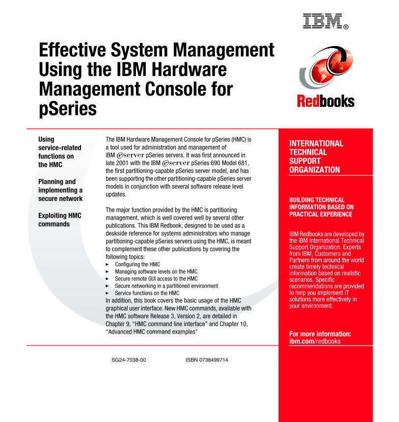
®
SG24-7038-00 ISBN 0738499714
INTERNATIONAL TECHNICALSUPPORTORGANIZATION
BUILDING TECHNICALINFORMATION BASED ONPRACTICAL EXPERIENCE
IBM Redbooks are developed by the IBM International Technical Support Organization. Experts from IBM, Customers and Partners from around the world create timely technical information based on realistic scenarios. Specific recommendations are provided to help you implement IT solutions more effectively in your environment.
For more information:ibm.com/redbooks
Effective System ManagementUsing the IBM HardwareManagement Console for pSeriesUsing service-related functions on the HMC
Planning and implementing a secure network
Exploiting HMC commands
The IBM Hardware Management Console for pSeries (HMC) is a tool used for administration and management of IBM Eserver pSeries servers. It was first announced in late 2001 with the IBM Eserver pSeries 690 Model 681, the first partitioning-capable pSeries server model, and has been supporting the other partitioning-capable pSeries server models in conjunction with several software release level updates.
The major function provided by the HMC is partitioning management, which is well covered well by several other publications. This IBM Redbook, designed to be used as a deskside reference for systems administrators who manage partitioning-capable pSeries servers using the HMC, is meant to complement these other publications by covering the following topics:� Configuring the HMC� Managing software levels on the HMC� Secure remote GUI access to the HMC� Secure networking in a partitioned environment� Service functions on the HMCIn addition, this book covers the basic usage of the HMC graphical user interface. New HMC commands, available with the HMC software Release 3, Version 2, are detailed in Chapter 9, “HMC command line interface” and Chapter 10, “Advanced HMC command examples”
Back cover