Embed Size (px)
Citation preview
System Storage DS3400 Storage Subsystem
Installation, User’s, and Maintenance Guide
���


System Storage DS3400 Storage Subsystem
Installation, User’s, and Maintenance Guide
���
Note: Before using this information and the product it supports, read the general information in Appendix C, “Notices,” on page 127and see the Warranty Information document that comes with the storage subsystem.
Fifth Edition (October 2009)
© Copyright International Business Machines Corporation 2006, 2009.US Government Users Restricted Rights – Use, duplication or disclosure restricted by GSA ADP Schedule Contractwith IBM Corp.
Contents
Figures . . . . . . . . . . . . . . . . . . . . . . . . . . . vii
Tables . . . . . . . . . . . . . . . . . . . . . . . . . . . . ix
Safety . . . . . . . . . . . . . . . . . . . . . . . . . . . . xi
Chapter 1. Introduction . . . . . . . . . . . . . . . . . . . . . . 1Overview . . . . . . . . . . . . . . . . . . . . . . . . . . . 1Notices and statements in this document . . . . . . . . . . . . . . . . 3Features and operating specifications . . . . . . . . . . . . . . . . . 4Models and optional devices . . . . . . . . . . . . . . . . . . . . 5Operating-system support . . . . . . . . . . . . . . . . . . . . . 5Fibre Channel overview . . . . . . . . . . . . . . . . . . . . . . 5Product updates . . . . . . . . . . . . . . . . . . . . . . . . . 5Best practices guidelines. . . . . . . . . . . . . . . . . . . . . . 6Storage subsystem components . . . . . . . . . . . . . . . . . . . 7
Disk drives and bezels . . . . . . . . . . . . . . . . . . . . . 7Controllers . . . . . . . . . . . . . . . . . . . . . . . . . 10Power supply and fans . . . . . . . . . . . . . . . . . . . . . 11Battery units . . . . . . . . . . . . . . . . . . . . . . . . . 12SFP modules . . . . . . . . . . . . . . . . . . . . . . . . 12
Software and hardware compatibility and upgrades . . . . . . . . . . . 13Software and firmware support code upgrades . . . . . . . . . . . . 13Determining firmware levels . . . . . . . . . . . . . . . . . . . 14
Specifications . . . . . . . . . . . . . . . . . . . . . . . . . 15Area requirements . . . . . . . . . . . . . . . . . . . . . . 15
Dimensions . . . . . . . . . . . . . . . . . . . . . . . . 15Weight . . . . . . . . . . . . . . . . . . . . . . . . . . 15
Temperature and humidity . . . . . . . . . . . . . . . . . . . . 16Electrical requirements . . . . . . . . . . . . . . . . . . . . . 16
Site wiring and power . . . . . . . . . . . . . . . . . . . . 16AC power recovery . . . . . . . . . . . . . . . . . . . . . 16Power cords and receptacles. . . . . . . . . . . . . . . . . . 17
Heat output, airflow, and cooling . . . . . . . . . . . . . . . . . 17
Chapter 2. Installing the storage subsystem . . . . . . . . . . . . . 19Inventory checklist . . . . . . . . . . . . . . . . . . . . . . . 19Installation overview . . . . . . . . . . . . . . . . . . . . . . . 20Handling static-sensitive devices . . . . . . . . . . . . . . . . . . 21Preparing for installation . . . . . . . . . . . . . . . . . . . . . 22
Required tools and hardware. . . . . . . . . . . . . . . . . . . 22Preparing the site . . . . . . . . . . . . . . . . . . . . . . . 23
Installing the DS3400 in a rack cabinet . . . . . . . . . . . . . . . . 23
Chapter 3. Cabling the storage subsystem. . . . . . . . . . . . . . 25Fibre Channel controller connectors . . . . . . . . . . . . . . . . . 25Enclosure ID settings . . . . . . . . . . . . . . . . . . . . . . 25Working with SFP modules and fiber optic cables . . . . . . . . . . . . 25
Handling fiber optic cables . . . . . . . . . . . . . . . . . . . 26Installing SFP modules . . . . . . . . . . . . . . . . . . . . . 26Removing SFP modules . . . . . . . . . . . . . . . . . . . . 28Using LC-LC Fibre Channel cables . . . . . . . . . . . . . . . . 29
Connecting an LC-LC cable to an SFP module . . . . . . . . . . . 30
© Copyright IBM Corp. 2006, 2009 iii
Removing an LC-LC Fibre Channel cable . . . . . . . . . . . . . 32Using LC-SC Fibre Channel cable adapters . . . . . . . . . . . . . 32
Connecting an LC-SC cable adapter to a device . . . . . . . . . . 33Removing an LC-LC cable from an LC-SC cable adapter . . . . . . . 34
Working with SAS cables . . . . . . . . . . . . . . . . . . . . . 35Connecting storage expansion enclosures to the DS3400 . . . . . . . . . 37
Redundant drive channel pair . . . . . . . . . . . . . . . . . . 38Overview of steps to connect storage expansion enclosures to a storage
subsystem. . . . . . . . . . . . . . . . . . . . . . . . . 39DS3400 storage subsystem drive cabling topologies . . . . . . . . . . 39
One single-controller DS3400 and one or more storage expansionenclosures. . . . . . . . . . . . . . . . . . . . . . . . 40
One dual-controller DS3400 and one storage expansion enclosure . . . . 41One dual-controller DS3400 and two storage expansion enclosures . . . 41One dual-controller DS3400 and three storage expansion enclosures . . . 42
Adding a storage expansion enclosure to a dual-controller configuration thatis running . . . . . . . . . . . . . . . . . . . . . . . . . 42
Upgrading a single-controller to a dual-controller when there is no attachedEXP3000 enclosure . . . . . . . . . . . . . . . . . . . . . . 44
Upgrading a single-controller to a dual-controller when there is one or moreEXP3000 enclosures attached to the storage subsystem. . . . . . . . . 44
Connecting secondary interface cables . . . . . . . . . . . . . . . . 44Configuring the storage subsystem . . . . . . . . . . . . . . . . . 46
Storage subsystem management methods. . . . . . . . . . . . . . 46Host-agent (in-band) management method. . . . . . . . . . . . . 47Direct (out-of-band) management method . . . . . . . . . . . . . 47
Installing the storage subsystem configuration . . . . . . . . . . . . 48Connecting hosts to the DS3400 . . . . . . . . . . . . . . . . . 48
Direct-attached single-controller connections . . . . . . . . . . . . 49Direct-attached dual-controller connections . . . . . . . . . . . . 51
Fibre Channel connections . . . . . . . . . . . . . . . . . . . 52Fibre Channel host loop configurations . . . . . . . . . . . . . . . 52
Redundant host loops . . . . . . . . . . . . . . . . . . . . 52Cabling the DS3400 power supplies . . . . . . . . . . . . . . . . . 54
Chapter 4. Operating the storage subsystem . . . . . . . . . . . . . 55Performing the DS3000 Health Check process . . . . . . . . . . . . . 55Hardware inspection . . . . . . . . . . . . . . . . . . . . . . . 56Turning on the storage subsystem . . . . . . . . . . . . . . . . . . 57Installing the DS3000 Storage Manager Client . . . . . . . . . . . . . 58Monitoring status through software . . . . . . . . . . . . . . . . . 59
Firmware updates . . . . . . . . . . . . . . . . . . . . . . . 60Troubleshooting the storage subsystem . . . . . . . . . . . . . . . 61
Checking the LEDs . . . . . . . . . . . . . . . . . . . . . . . 62Power-supply LEDs . . . . . . . . . . . . . . . . . . . . . . 62Front LEDs . . . . . . . . . . . . . . . . . . . . . . . . . 63Controller LEDs . . . . . . . . . . . . . . . . . . . . . . . 64
Turning off the storage subsystem . . . . . . . . . . . . . . . . . . 65Performing an emergency shutdown . . . . . . . . . . . . . . . . 68Restoring power after an unexpected shutdown . . . . . . . . . . . . 68
Recovering from an overheated power supply . . . . . . . . . . . . . 69Cache memory and cache battery . . . . . . . . . . . . . . . . . . 71
Cache memory . . . . . . . . . . . . . . . . . . . . . . . . 71Controller cache battery . . . . . . . . . . . . . . . . . . . . 72Controller battery age timer . . . . . . . . . . . . . . . . . . . 73
iv System Storage DS3400 Storage Subsystem: Installation, User’s, and Maintenance Guide
Chapter 5. Replacing components . . . . . . . . . . . . . . . . . 75Service action allowed LED . . . . . . . . . . . . . . . . . . . . 75Removing a controller . . . . . . . . . . . . . . . . . . . . . . 75Installing a controller . . . . . . . . . . . . . . . . . . . . . . . 77Replacing a controller . . . . . . . . . . . . . . . . . . . . . . 80Working with hot-swap hard disk drives . . . . . . . . . . . . . . . . 84
Removing a hard disk drive . . . . . . . . . . . . . . . . . . . 85Installing a hard disk drive. . . . . . . . . . . . . . . . . . . . 86Replacing a hot-swap hard disk drive . . . . . . . . . . . . . . . 87Replacing multiple drives . . . . . . . . . . . . . . . . . . . . 89
Replacing all drives at the same time . . . . . . . . . . . . . . 90Replacing the drives one at a time. . . . . . . . . . . . . . . . 92
Replacing a power supply . . . . . . . . . . . . . . . . . . . . . 94Replacing a battery . . . . . . . . . . . . . . . . . . . . . . . 99Replacing the memory cache DIMM . . . . . . . . . . . . . . . . 101
Removing the DIMM . . . . . . . . . . . . . . . . . . . . . 102Installing the DIMM . . . . . . . . . . . . . . . . . . . . . . 103
Replacing an SFP module . . . . . . . . . . . . . . . . . . . . 104Replacing the bezels . . . . . . . . . . . . . . . . . . . . . . 106
Removing the bezels . . . . . . . . . . . . . . . . . . . . . 106Installing the bezels. . . . . . . . . . . . . . . . . . . . . . 107
Replacing the release tab on a controller or power supply . . . . . . . . 107Replacing a drive compatibility key . . . . . . . . . . . . . . . . . 108
Chapter 6. Solving problems . . . . . . . . . . . . . . . . . . . 111
Chapter 7. Parts listing, DS3400 storage subsystem . . . . . . . . . 117Replaceable components. . . . . . . . . . . . . . . . . . . . . 117Power cords . . . . . . . . . . . . . . . . . . . . . . . . . 118
Appendix A. Records . . . . . . . . . . . . . . . . . . . . . 121Identification numbers . . . . . . . . . . . . . . . . . . . . . . 121Hard disk drive locations . . . . . . . . . . . . . . . . . . . . . 122Storage subsystem and controller information record . . . . . . . . . . 123
Appendix B. Getting help and technical assistance . . . . . . . . . . 125Before you call . . . . . . . . . . . . . . . . . . . . . . . . 125Using the documentation . . . . . . . . . . . . . . . . . . . . . 125Getting help and information from the World Wide Web . . . . . . . . . 125Software service and support . . . . . . . . . . . . . . . . . . . 126Hardware service and support . . . . . . . . . . . . . . . . . . . 126IBM Taiwan product service . . . . . . . . . . . . . . . . . . . . 126
Appendix C. Notices . . . . . . . . . . . . . . . . . . . . . . 127Trademarks. . . . . . . . . . . . . . . . . . . . . . . . . . 127Important notes . . . . . . . . . . . . . . . . . . . . . . . . 128Particulate contamination. . . . . . . . . . . . . . . . . . . . . 129Documentation format . . . . . . . . . . . . . . . . . . . . . . 129Electronic emission notices . . . . . . . . . . . . . . . . . . . . 130
Federal Communications Commission (FCC) statement . . . . . . . . 130Industry Canada Class A emission compliance statement . . . . . . . . 130Avis de conformité à la réglementation d’Industrie Canada . . . . . . . 130Australia and New Zealand Class A statement . . . . . . . . . . . . 130United Kingdom telecommunications safety requirement . . . . . . . . 130European Union EMC Directive conformance statement . . . . . . . . 131Taiwanese Class A warning statement . . . . . . . . . . . . . . . 131
Contents v
Germany Electromagnetic Compatibility Directive . . . . . . . . . . . 131Deutschland: Einhaltung des Gesetzes über die elektromagnetische
Verträglichkeit von Geräten . . . . . . . . . . . . . . . . . 132Zulassungsbescheinigung laut dem Deutschen Gesetz über die
elektromagnetische Verträglichkeit von Geräten (EMVG) (bzw. der EMCEG Richtlinie 2004/108/EG) für Geräte der Klasse A . . . . . . . . 132
People's Republic of China Class A warning statement. . . . . . . . . 132Japanese Voluntary Control Council for Interference (VCCI) statement 132Korean Class A warning statement . . . . . . . . . . . . . . . . 132
Index . . . . . . . . . . . . . . . . . . . . . . . . . . . . 133
vi System Storage DS3400 Storage Subsystem: Installation, User’s, and Maintenance Guide
Figures
1. Example of DS3400 serial number label, product name, and machine type and model numberlocations . . . . . . . . . . . . . . . . . . . . . . . . . . . . . . . . . . 2
2. DS3400 hot-swap drive bays and bezels . . . . . . . . . . . . . . . . . . . . . . 83. Bezel (left side) . . . . . . . . . . . . . . . . . . . . . . . . . . . . . . . . 94. Bezel (right side) . . . . . . . . . . . . . . . . . . . . . . . . . . . . . . . 95. Rear view, single-controller model . . . . . . . . . . . . . . . . . . . . . . . . 116. Rear view, dual-controller model . . . . . . . . . . . . . . . . . . . . . . . . . 117. Power-supply unit components for DS3400 . . . . . . . . . . . . . . . . . . . . . 118. Airflow through the storage subsystem . . . . . . . . . . . . . . . . . . . . . . . 129. Battery unit . . . . . . . . . . . . . . . . . . . . . . . . . . . . . . . . . 12
10. SFP module and fiber optic cable. . . . . . . . . . . . . . . . . . . . . . . . . 1311. DS3400 dimensions. . . . . . . . . . . . . . . . . . . . . . . . . . . . . . 1512. DS3400 airflow . . . . . . . . . . . . . . . . . . . . . . . . . . . . . . . 1713. Example of cold aisle/hot aisle rack configuration . . . . . . . . . . . . . . . . . . . 1814. DS3400 storage subsystem ports and controllers . . . . . . . . . . . . . . . . . . . 2515. SFP module and protective cap . . . . . . . . . . . . . . . . . . . . . . . . . 2816. Installing an SFP module into the host port . . . . . . . . . . . . . . . . . . . . . 2817. Unlocking the SFP module latch - plastic variety . . . . . . . . . . . . . . . . . . . 2918. Unlocking the SFP module latch - wire variety . . . . . . . . . . . . . . . . . . . . 2919. LC-LC Fibre Channel cable . . . . . . . . . . . . . . . . . . . . . . . . . . . 3020. Removing fiber optic cable protective caps . . . . . . . . . . . . . . . . . . . . . 3121. Inserting an LC-LC Fibre Channel cable into an SFP module . . . . . . . . . . . . . . 3122. LC-LC Fibre Channel cable lever and latches . . . . . . . . . . . . . . . . . . . . 3223. Removing the LC-LC Fibre Channel cable . . . . . . . . . . . . . . . . . . . . . 3224. LC-SC Fibre Channel cable adapter . . . . . . . . . . . . . . . . . . . . . . . . 3325. Removing the LC-SC cable adapter protective caps . . . . . . . . . . . . . . . . . . 3426. Connecting an LC-LC cable into the LC-SC cable adapter . . . . . . . . . . . . . . . 3427. LC-LC Fibre Channel cable lever and latches . . . . . . . . . . . . . . . . . . . . 3528. Removing the LC-LC Fibre Channel cable from an LC-SC Fibre Channel cable adapter. . . . . 3529. Mini-SAS cable . . . . . . . . . . . . . . . . . . . . . . . . . . . . . . . 3630. Connecting a mini-SAS cable . . . . . . . . . . . . . . . . . . . . . . . . . . 3631. Removing a mini-SAS cable. . . . . . . . . . . . . . . . . . . . . . . . . . . 3732. Example of a redundant drive path . . . . . . . . . . . . . . . . . . . . . . . . 3833. One single-controller DS3400 and multiple single-ESM storage expansion enclosures . . . . . 4034. One dual-controller DS3400 and one storage expansion enclosure . . . . . . . . . . . . 4135. One dual-controller DS3400 and two storage expansion enclosure . . . . . . . . . . . . 4136. One dual-controller DS3400 and three storage expansion enclosure . . . . . . . . . . . . 4237. Ethernet connector locations on a dual-controller DS3400 . . . . . . . . . . . . . . . . 4638. Host-agent (in-band) managed storage subsystems . . . . . . . . . . . . . . . . . . 4739. Direct (out-of-band) managed storage subsystems . . . . . . . . . . . . . . . . . . 4840. Location of host connectors on RAID controllers on the DS3400 . . . . . . . . . . . . . 4941. Single-contoller direct-attached connection to a single host HBA . . . . . . . . . . . . . 4942. Single-controller direct-attached connection to dual HBAs (redundant host connection) . . . . . 5043. Single-controller direct-attached connection to single HBAs in multiple hosts . . . . . . . . . 5044. Dual-controller direct-attached connection to two HBAs in the same host (redundant host
connection) . . . . . . . . . . . . . . . . . . . . . . . . . . . . . . . . . 5145. Dual-controller direct-attached connections to multiple HBAs in multiple hosts . . . . . . . . 5246. Example of a single SAN fabric configuration . . . . . . . . . . . . . . . . . . . . 5347. Example of a dual SAN fabric configuration . . . . . . . . . . . . . . . . . . . . . 5348. Example of two storage subsystems in a dual SAN environment . . . . . . . . . . . . . 5449. Power-supply switches and connectors for the DS3400. . . . . . . . . . . . . . . . . 5850. Power-supply LEDs . . . . . . . . . . . . . . . . . . . . . . . . . . . . . . 6251. Front LEDs and controls . . . . . . . . . . . . . . . . . . . . . . . . . . . . 63
© Copyright IBM Corp. 2006, 2009 vii
52. Controller LEDs . . . . . . . . . . . . . . . . . . . . . . . . . . . . . . . 6453. Unlocking the SFP module latch - plastic variety . . . . . . . . . . . . . . . . . . . 7654. Unlocking the SFP module latch - wire variety . . . . . . . . . . . . . . . . . . . . 7655. Removing a controller . . . . . . . . . . . . . . . . . . . . . . . . . . . . . 7756. Installing a controller . . . . . . . . . . . . . . . . . . . . . . . . . . . . . 7857. SFP module and protective cap . . . . . . . . . . . . . . . . . . . . . . . . . 7958. Installing an SFP module into the host port . . . . . . . . . . . . . . . . . . . . . 7959. Unlocking the SFP module latch - plastic variety . . . . . . . . . . . . . . . . . . . 8160. Unlocking the SFP module latch - wire variety . . . . . . . . . . . . . . . . . . . . 8161. Removing and replacing a controller. . . . . . . . . . . . . . . . . . . . . . . . 8262. Removing the battery from a controller . . . . . . . . . . . . . . . . . . . . . . . 8263. Hard disk drive LEDs . . . . . . . . . . . . . . . . . . . . . . . . . . . . . 8564. Removing a drive . . . . . . . . . . . . . . . . . . . . . . . . . . . . . . 8665. Installing and removing a hard disk drive . . . . . . . . . . . . . . . . . . . . . . 8766. Replacing a power-supply unit . . . . . . . . . . . . . . . . . . . . . . . . . . 9867. Removing and replacing a controller . . . . . . . . . . . . . . . . . . . . . . . 10068. Removing and replacing a battery unit from the controller . . . . . . . . . . . . . . . 10069. Memory cache DIMM location . . . . . . . . . . . . . . . . . . . . . . . . . 10170. Removing a controller . . . . . . . . . . . . . . . . . . . . . . . . . . . . 10271. Removing the battery from the controller . . . . . . . . . . . . . . . . . . . . . 10272. Removing the DIMM from the connector . . . . . . . . . . . . . . . . . . . . . . 10373. Installing the DIMM in the controller . . . . . . . . . . . . . . . . . . . . . . . 10374. Reinstalling the controller . . . . . . . . . . . . . . . . . . . . . . . . . . . 10475. Replacing an SFP module . . . . . . . . . . . . . . . . . . . . . . . . . . . 10676. Removing the bezels . . . . . . . . . . . . . . . . . . . . . . . . . . . . . 10677. Controller and power supply release tabs . . . . . . . . . . . . . . . . . . . . . 10778. Removing the release tab on a power supply . . . . . . . . . . . . . . . . . . . . 10879. Drive compatibility key . . . . . . . . . . . . . . . . . . . . . . . . . . . . 10980. Installing a drive compatibility key . . . . . . . . . . . . . . . . . . . . . . . . 10981. DS3400 storage subsystem parts . . . . . . . . . . . . . . . . . . . . . . . . 11782. Serial number location on DS3400 . . . . . . . . . . . . . . . . . . . . . . . . 121
viii System Storage DS3400 Storage Subsystem: Installation, User’s, and Maintenance Guide
Tables
1. Features and operating specifications. . . . . . . . . . . . . . . . . . . . . . . . 42. Software and firmware levels for the DS3400 storage subsystem . . . . . . . . . . . . . 143. DS3400 weights . . . . . . . . . . . . . . . . . . . . . . . . . . . . . . . 154. DS3400 component weights. . . . . . . . . . . . . . . . . . . . . . . . . . . 165. Fibre Channel port LEDs . . . . . . . . . . . . . . . . . . . . . . . . . . . . 656. Troubleshooting . . . . . . . . . . . . . . . . . . . . . . . . . . . . . . . 1127. Parts listing for DS3400 . . . . . . . . . . . . . . . . . . . . . . . . . . . . 1188. IBM power cords . . . . . . . . . . . . . . . . . . . . . . . . . . . . . . 1199. Product identification record . . . . . . . . . . . . . . . . . . . . . . . . . . 121
10. Drive location information record . . . . . . . . . . . . . . . . . . . . . . . . 12211. Storage subsystem and controller information record . . . . . . . . . . . . . . . . . 12312. Sample information record . . . . . . . . . . . . . . . . . . . . . . . . . . . 12413. Limits for particulates and gases . . . . . . . . . . . . . . . . . . . . . . . . 129
© Copyright IBM Corp. 2006, 2009 ix

x System Storage DS3400 Storage Subsystem: Installation, User’s, and Maintenance Guide
Safety
Before installing this product, read the Safety Information.
Antes de instalar este produto, leia as Informações de Segurança.
Pred instalací tohoto produktu si prectete prírucku bezpecnostních instrukcí.
Læs sikkerhedsforskrifterne, før du installerer dette produkt.
Lees voordat u dit product installeert eerst de veiligheidsvoorschriften.
Ennen kuin asennat tämän tuotteen, lue turvaohjeet kohdasta Safety Information.
Avant d’installer ce produit, lisez les consignes de sécurité.
Vor der Installation dieses Produkts die Sicherheitshinweise lesen.
Prima di installare questo prodotto, leggere le Informazioni sulla Sicurezza.
Les sikkerhetsinformasjonen (Safety Information) før du installerer dette produktet.
Antes de instalar este produto, leia as Informações sobre Segurança.
Antes de instalar este producto, lea la información de seguridad.
Läs säkerhetsinformationen innan du installerar den här produkten.
© Copyright IBM Corp. 2006, 2009 xi
Important:
Each caution and danger statement in this document is labeled with anumber. This number is used to cross reference the English-languagecaution or danger statement with translated versions of the caution ordanger statement in the IBM Systems Safety Notices document.
For example, if a caution statement is labeled “D005a,” translations forthat caution statement are in the IBM Systems Safety Noticesdocument under “D005a.”
Be sure to read all caution and danger statements in this documentbefore you perform the procedures. Read any additional safetyinformation that comes with the server or optional device before youinstall the device.
DANGER
Hazardous voltage, current, or energy levels are present inside anycomponent that has this label attached. Do not open any cover or barrierthat contains this label.
(L001)
xii System Storage DS3400 Storage Subsystem: Installation, User’s, and Maintenance Guide
DANGER
Rack-mounted devices are not to be used as shelves or work spaces.
(L002)
Safety xiii
DANGER
Multiple power cords. The product might be equipped with multiple powercords. To remove all hazardous voltages, disconnect all power cords.
(L003)
1 2
or
!
1
2
xiv System Storage DS3400 Storage Subsystem: Installation, User’s, and Maintenance Guide
DANGER
When working on or around the system, observe the following precautions:
Electrical voltage and current from power, telephone, and communicationcables are hazardous. To avoid a shock hazard:
v Connect power to this unit only with the provided power cord. Do notuse the provided power cord for any other product.
v Do not open or service any power supply assembly.
v Do not connect or disconnect any cables or perform installation,maintenance, or reconfiguration of this product during an electricalstorm.
v The product might be equipped with multiple power cords. To remove allhazardous voltages, disconnect all power cords.
v Connect all power cords to a properly wired and grounded electricaloutlet. Ensure that the outlet supplies proper voltage and phase rotationaccording to the system rating plate.
v Connect any equipment that will be attached to this product to properlywired outlets.
v When possible, use one hand only to connect or disconnect signalcables.
v Never turn on any equipment when there is evidence of fire, water, orstructural damage.
v Disconnect the attached power cords, telecommunications systems,networks, and modems before you open the device covers, unlessinstructed otherwise in the installation and configuration procedures.
v Connect and disconnect cables as described in the following procedureswhen installing, moving, or opening covers on this product or attacheddevices.
To disconnect:
1. Turn off everything (unless instructed otherwise).
2. Remove the power cords from the outlets.
3. Remove the signal cables from the connectors.
4. Remove all cables from the devices.
To connect:
1. Turn off everything (unless instructed otherwise).
2. Attach all cables to the devices.
3. Attach the signal cables to the connectors.
4. Attach the power cords to the outlets.
5. Turn on the devices.
(D005a)
Safety xv
CAUTION:This product might contain one or more of the following devices: CD-ROMdrive, DVD-ROM drive, DVD-RAM drive, or laser module, which are Class 1laser products. Note the following information:
v Do not remove the covers. Removing the covers of the laser product couldresult in exposure to hazardous laser radiation. There are no serviceableparts inside the device.
v Use of the controls or adjustments or performance of procedures otherthan those specified herein might result in hazardous radiation exposure.
(C026)
CAUTION:Data processing environments can contain equipment transmitting on systemlinks with laser modules that operate at greater than Class 1 power levels. Forthis reason, never look into the end of an optical fiber cable or openreceptacle. (C027)
CAUTION:
or
>18 kg (39.7 lb)
or18-32 kg (39.7-70.5 lb)
The weight of this part or unit is between 18 and 32 kg (39.7 and 70.5 lb). Ittakes two persons to safely lift this part or unit. (C009)
xvi System Storage DS3400 Storage Subsystem: Installation, User’s, and Maintenance Guide
Chapter 1. Introduction
This chapter describes the operating specifications, features, and components ofthe IBM® System Storage™ DS3400 storage subsystem (hereafter referred to asDS3400 or storage subsystem).
This chapter also includes an inventory checklist and important information aboutbest practices guidelines and product updates for the DS3400.
OverviewThe IBM System Storage DS3400 storage subsystem is designed to providesolutions to meet the needs of departmental and midrange storage requirements,delivering high performance and availability, advanced functionality, along with amodular and scalable storage capacity design. With direct-attached and fabric FibreChannel host connectivity and support for RAID levels 0, 1, 3, 5, and 6, the DS3400provides an internal physical storage capacity that is scalable up to 5.4 TB(terabytes) when using 450 GB Serial Attached SCSI (SAS) hard disk drives or upto 12.0 TB (terabytes) when using 1000 GB Serial Advanced TechnologyAttachment (SATA) hard disk drives.
Notes:
1. RAID 6 uses a P+Q design implementation.
2. When RAID level 1 is implemented and the number of hard disk drivesincreases to more than two, RAID level 10 is automatically implemented.
A 2U rack-mountable DS3400 enclosure houses one or two RAID controllers withtwo 4 Gbps Fibre Channel ports per controller for attachment of host servers andFibre Channel switches, and one SAS port for the attachment of storage expansionenclosures. The DS3400 enclosure supports up to twelve 3 Gbps SAS or SATAhard disk drives.
The DS3400 supports attachment of up to three storage expansion enclosures,resulting in the capability to connect to up to 48 hard disk drives and enablingstorage configurations of over 21 TB using 450 GB hard disk drives or 48 TB using1000 GB SATA hard disk drives. The DS3400 supports configurations of SAS orSATA disks, or a mix of both types of disk drives in the same enclosure. AdvancedDS3000 storage management and copy service options are available for theDS3400, including FlashCopy® and VolumeCopy.
The DS3000 Storage Manager version 10 software is also available for theDS3400. This storage management software is designed to help centralize storagemanagement, help simplify partitioning of the DS3000 series storage into as manyas 32 virtual servers, and strategically allocate storage capacity to maximizestorage space.
If firmware and documentation updates are available, you can download them fromthe IBM Web site. The DS3400 might have features that are not described in thedocumentation that comes with the unit, and the documentation might be updatedoccasionally to include information about those features, or technical updates mightbe available to provide additional information that is not included in the DS3400documentation. To check for updates, complete the following steps:
1. Go to http://www.ibm.com/servers/storage/support/.
© Copyright IBM Corp. 2006, 2009 1
2. On the “Support for System Storage and TotalStorage products” page, underSelect your product, in the Product family field, select Disk systems.
3. In the Product field, select IBM System Storage DS3400.
4. Click Go.
5. Make the following selections:
v For firmware updates, click the Download tab.
Important: If you are using SATA hard disk drives, the ESM firmware mustbe at version 1.86 or later. Check the RAID controllermanagement software for the firmware version that is installed onthe environmental services module (ESM).
v For documentation updates, click the Install and use tab.
Note: Changes are made periodically to the IBM Web site. Procedures for locatingfirmware and documentation might vary slightly from what is described in thisdocument.
The DS3400 comes with a limited warranty. For more information about the termsof your warranty, see the Warranty Information document that comes with thestorage subsystem.
Record information about the DS3400 in Table 9 on page 121. You will need thisinformation if you have to call for service.
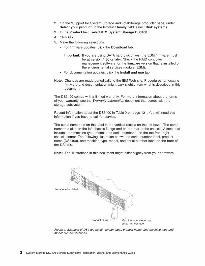
The serial number is on the label in the vertical recess on the left bezel. The serialnumber is also on the left chassis flange and on the rear of the chassis. A label thatincludes the machine type, model, and serial number is on the top front rightchassis corner. The following illustration shows the serial number label, productname (DS3400), and machine type, model, and serial number label on the front ofthe DS3400.
Note: The illustrations in this document might differ slightly from your hardware.
Serial number label
Product name Machine type, model, andserial number label
Figure 1. Example of DS3400 serial number label, product name, and machine type andmodel number locations
2 System Storage DS3400 Storage Subsystem: Installation, User’s, and Maintenance Guide
Use Table 10 on page 122 to keep a record of the hard disk drives that are installedin or attached to the DS3400. This information can be helpful when you installadditional hard disk drives or if you have to report a hardware problem. Make acopy of this table before you record information in it, in case you need extra spaceto write new values later, or when you update the DS3400 configuration.
Notices and statements in this documentThe caution and danger statements in this document are also in the multilingualIBM Systems Safety Notices document, which is in the Documentation folder on theIBM System Storage DS3000 Support CD. Each statement is followed by areference number that you can use to locate the corresponding statement in yourlanguage in the IBM Systems Safety Notices document.
The following notices and statements are used in this document:
v Note: These notices provide important tips, guidance, or advice.
v Important: These notices provide information or advice that might help you avoidinconvenient or problem situations.
v Attention: These notices indicate potential damage to programs, devices, ordata. An attention notice is placed just before the instruction or situation in whichdamage might occur.
v Caution: These statements indicate situations that can be potentially hazardousto you. A caution statement is placed just before the description of a potentiallyhazardous procedure step or situation.
v Danger: These statements indicate situations that can be potentially lethal orextremely hazardous to you. A danger statement is placed just before thedescription of a potentially lethal or extremely hazardous procedure step orsituation.
Chapter 1. Introduction 3
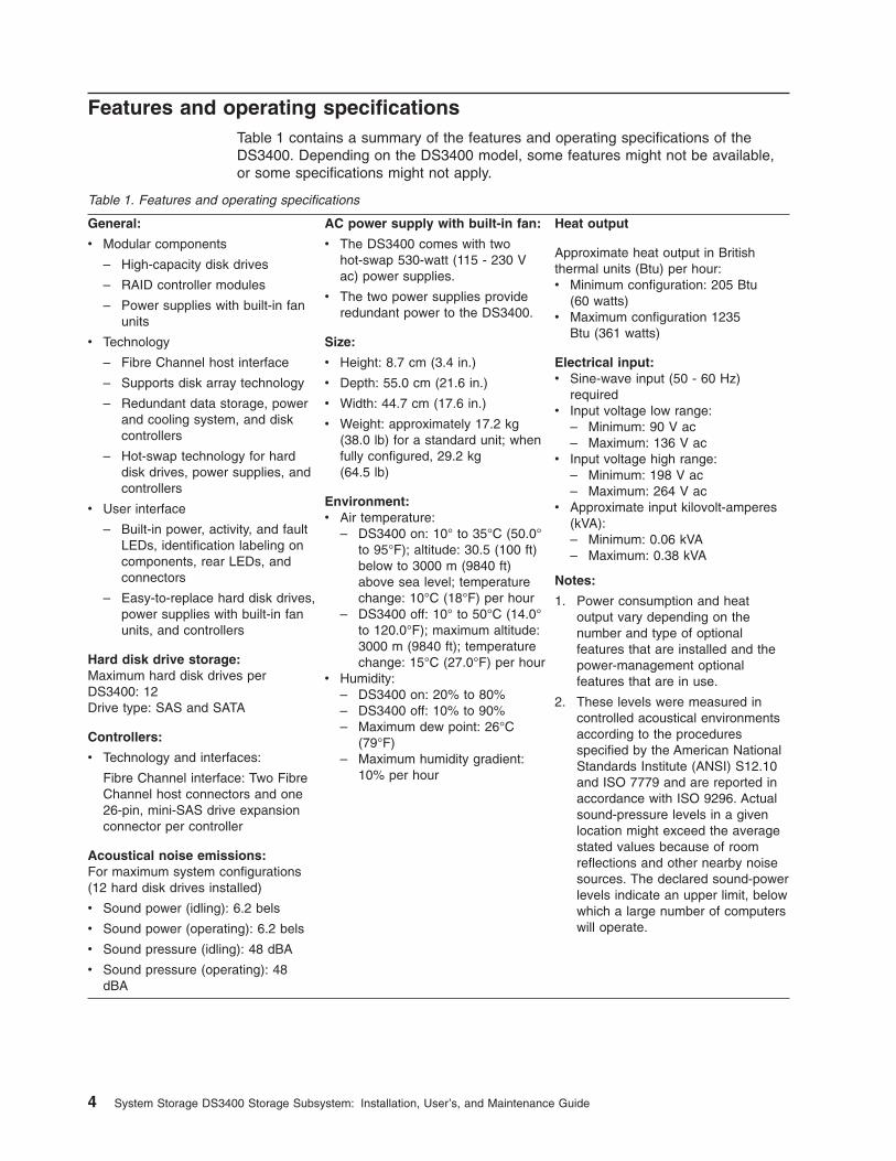
Features and operating specificationsTable 1 contains a summary of the features and operating specifications of theDS3400. Depending on the DS3400 model, some features might not be available,or some specifications might not apply.
Table 1. Features and operating specifications
General:
v Modular components
– High-capacity disk drives
– RAID controller modules
– Power supplies with built-in fanunits
v Technology
– Fibre Channel host interface
– Supports disk array technology
– Redundant data storage, powerand cooling system, and diskcontrollers
– Hot-swap technology for harddisk drives, power supplies, andcontrollers
v User interface
– Built-in power, activity, and faultLEDs, identification labeling oncomponents, rear LEDs, andconnectors
– Easy-to-replace hard disk drives,power supplies with built-in fanunits, and controllers
Hard disk drive storage:Maximum hard disk drives perDS3400: 12Drive type: SAS and SATA
Controllers:
v Technology and interfaces:
Fibre Channel interface: Two FibreChannel host connectors and one26-pin, mini-SAS drive expansionconnector per controller
Acoustical noise emissions:For maximum system configurations(12 hard disk drives installed)
v Sound power (idling): 6.2 bels
v Sound power (operating): 6.2 bels
v Sound pressure (idling): 48 dBA
v Sound pressure (operating): 48dBA
AC power supply with built-in fan:
v The DS3400 comes with twohot-swap 530-watt (115 - 230 Vac) power supplies.
v The two power supplies provideredundant power to the DS3400.
Size:
v Height: 8.7 cm (3.4 in.)
v Depth: 55.0 cm (21.6 in.)
v Width: 44.7 cm (17.6 in.)
v Weight: approximately 17.2 kg(38.0 lb) for a standard unit; whenfully configured, 29.2 kg(64.5 lb)
Environment:v Air temperature:
– DS3400 on: 10° to 35°C (50.0°to 95°F); altitude: 30.5 (100 ft)below to 3000 m (9840 ft)above sea level; temperaturechange: 10°C (18°F) per hour
– DS3400 off: 10° to 50°C (14.0°to 120.0°F); maximum altitude:3000 m (9840 ft); temperaturechange: 15°C (27.0°F) per hour
v Humidity:– DS3400 on: 20% to 80%– DS3400 off: 10% to 90%– Maximum dew point: 26°C
(79°F)– Maximum humidity gradient:
10% per hour
Heat output
Approximate heat output in Britishthermal units (Btu) per hour:v Minimum configuration: 205 Btu
(60 watts)v Maximum configuration 1235
Btu (361 watts)
Electrical input:v Sine-wave input (50 - 60 Hz)
requiredv Input voltage low range:
– Minimum: 90 V ac– Maximum: 136 V ac
v Input voltage high range:– Minimum: 198 V ac– Maximum: 264 V ac
v Approximate input kilovolt-amperes(kVA):– Minimum: 0.06 kVA– Maximum: 0.38 kVA
Notes:
1. Power consumption and heatoutput vary depending on thenumber and type of optionalfeatures that are installed and thepower-management optionalfeatures that are in use.
2. These levels were measured incontrolled acoustical environmentsaccording to the proceduresspecified by the American NationalStandards Institute (ANSI) S12.10and ISO 7779 and are reported inaccordance with ISO 9296. Actualsound-pressure levels in a givenlocation might exceed the averagestated values because of roomreflections and other nearby noisesources. The declared sound-powerlevels indicate an upper limit, belowwhich a large number of computerswill operate.
4 System Storage DS3400 Storage Subsystem: Installation, User’s, and Maintenance Guide
Models and optional devicesThe DS3400 RAID controller cache size, partitions, and other features varydepending the DS3400 model and optional devices.
Contact your IBM marketing representative or authorized reseller for moreinformation about the DS3400 models and options.
Operating-system supportThe following operating systems are supported for host servers that have mappedLUNs that are created in the DS3400 with storage expansion enclosures:
v IBM AIX
v IBM Linux on POWER (LoP)
v Microsoft® Windows® Server 2003
v Red Hat® Enterprise Linux®
v SuSE Linux Enterprise Server
v Novell Netware
v VMware ESX Server
For additional host operating-system support, see the latest DS3000 StorageManager Version 2 software readme file and the IBM DS3000 series productsinteroperability matrix at http://www.ibm.com/systems/storage/disk/ds3000/ds3400/.
Fibre Channel overviewFibre Channel technology is outlined in the SCSI-3 Fibre Channel Protocol(SCSI-FCP) standard. Fibre Channel is a high-speed data transport technology thatis used for mass storage and networking.
Using a Fibre Channel arbitrated loop (FC-AL), more than 100 Fibre Channeldevices can be supported, compared to 15 small computer system interface (SCSI)devices. The Fibre Channel connection speed from the DS3400 to a Fibre Channelswitch or host bus adapter (HBA) is either 2 Gbps or 4 Gbps depending on the typeof device to which the DS3400 is connected, allowing data transfer rates up to 400MBps half-duplex and 800 MBps full-duplex on optical interfaces.
Product updatesImportant: To keep your storage subsystem up-to-date with the latest firmware andother product updates, register the storage subsystem. Go to http://www.ibm.com/servers/storage/support/disk/. From the menu at the top of the page, click Myaccount. From the My IBM menu at the top, select My Support. On the next page,click register now.
Download the latest version of the DS3000 Storage Manager software, DS3400storage subsystem controller firmware, DS3000 series storage expansion enclosurefirmware, and drive firmware when you initially install the storage subsystem andwhen product updates become available.
To receive product updates, complete the following steps:
1. After you have registered at http://www.ibm.com/servers/storage/support/disk/,type your user ID and password to log in to the site. The “My support” pageopens.
Chapter 1. Introduction 5
2. Click add products.
3. From the menu, select Storage.
4. In the next menu, and in subsequent menus, select the following topics:
v Computer Storage
v Disk Storage Systems
v System Storage DS3000
Note: During this process a check list is displayed. Do not select any of theitems in the check list until you complete the selections in the menus.
5. When you finish selecting the menu topics, select the boxes for the machinetype of your DS3000 series product and any other attached DS3000 seriesproducts for which you want to receive information; then, click Add products.The “My support” page reopens.
6. On the “My support” page, click the Edit profile tab; then, click Subscribe toemail.
7. In the menu, select Storage.
8. On the next page, select the check boxes for the following items:
v Please send these documents by weekly email
v Downloads and drivers
v Flashes
v Any other topics that you are interested in
Then, click Update.
9. Click Sign out to log out of My Support.
Best practices guidelinesTo ensure optimal operation of your system, always follow these best practicesguidelines:
v Make sure that the storage subsystem is in an optimal state before you shut itdown. Never turn off the power if any amber LED is lit; be sure to resolve anyerror conditions before you shut down the storage subsystem.
v Back up the data on your storage drives periodically.
v To maintain power redundancy, connect the DS3400 right and left power-supplyunits to two independent external power circuits through ac power distributionunits (PDUs) inside a rack cabinet or directly into external receptacles. Similarly,the right and left power supplies of the storage expansion enclosures (such asthe EXP3000) that are attached to the DS3400 should be connected to the sametwo independent external power circuits as the DS3400. This ensures that theDS3400 and all its attached storage expansion enclosures will have power in theevent that only one power circuit is available. In addition, having all the right orall the left power cables connected to the same power circuit enables theDS3000 devices in the configuration to power-on simultaneously during anunattended restoration of power.
Note: Do not overload the circuits that power your storage subsystem andstorage expansion enclosures. Use additional pairs of ac PDUs ifnecessary. See Table 1 on page 4 for information about storagesubsystem power requirements. Contact your technical-supportrepresentative for additional information.
v Before any planned system shutdown or after any system additions, removals, ormodifications (including firmware updates, logical drive creations, storage
6 System Storage DS3400 Storage Subsystem: Installation, User’s, and Maintenance Guide
partitioning definitions, hardware changes, and so on), save the storagesubsystem profile as explained in the DS3000 Storage Manager V2 Installationand User's Guide for your operating system. Save the profile in a location otherthan in the logical drives that are created for the DS3400.
v During any maintenance or attended power-on procedure, carefully follow thepower-on sequence that is described in “Turning on the storage subsystem” onpage 57. Make sure that each component of the storage subsystem ispowered-on in the correct order during this entire power-on procedure to be surethat the controller is able to optimally access all of the storage subsystems.
v The storage subsystem supports simultaneous power-on to the systemcomponents; however, you should always follow the power-on sequence that isdescribed in “Turning on the storage subsystem” on page 57 during any attendedpower-on procedure.
v A storage subsystem in an optimal state should recover automatically from anunexpected shutdown and unattended simultaneous restoration of power tosystem components. After power is restored, call your IBM technical-supportrepresentative if any of the following conditions occur:
– The storage subsystem logical drives and subsystems are not displayed in theDS3000 Storage Manager Version 2 graphical user interface.
– The storage subsystem logical drives and subsystems do not come online.
– The storage subsystem logical drives and subsystems seem to be degraded.
Storage subsystem componentsThe storage subsystem has the following removable components. Thesecomponents, called customer replaceable units (CRUs), are accessible from thefront or rear of the storage subsystem.
v Up to twelve 3 Gbps SAS or SATA hard disk drives
v Up to two RAID controllers
v Two power supplies
Disk drives and bezelsFigure 2 on page 8 shows the locations of hot-swap disk drives and bezels. Thehot-swap features enable you to remove and replace SAS or SATA hard disk drives,power supplies, and Fibre Channel RAID controllers (in a dual-controller storagesubsystem) without turning off the storage subsystem. You can maintain theavailability of the storage subsystem while you remove, install, or replace ahot-swap device.
Chapter 1. Introduction 7
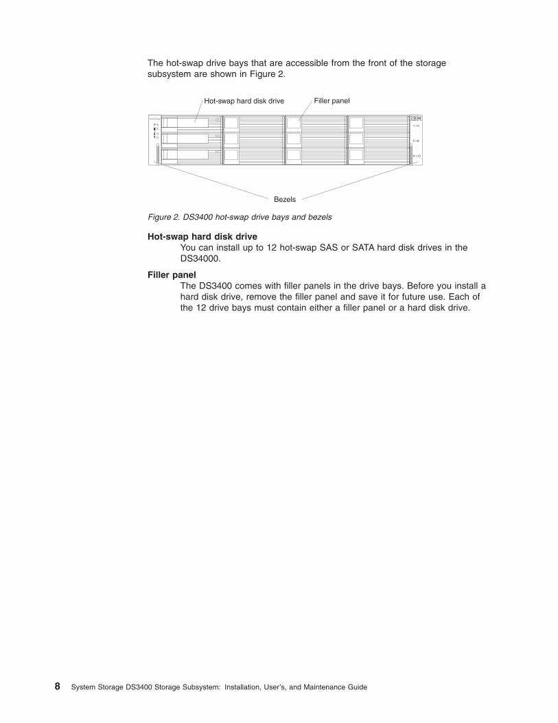
The hot-swap drive bays that are accessible from the front of the storagesubsystem are shown in Figure 2.
Hot-swap hard disk driveYou can install up to 12 hot-swap SAS or SATA hard disk drives in theDS34000.
Filler panelThe DS3400 comes with filler panels in the drive bays. Before you install ahard disk drive, remove the filler panel and save it for future use. Each ofthe 12 drive bays must contain either a filler panel or a hard disk drive.
Hot-swap hard disk drive Filler panel
System Storage
Bezels
Figure 2. DS3400 hot-swap drive bays and bezels
8 System Storage DS3400 Storage Subsystem: Installation, User’s, and Maintenance Guide
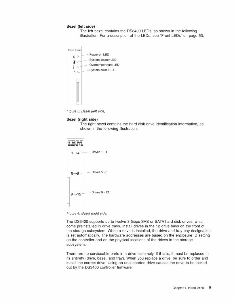
Bezel (left side)The left bezel contains the DS3400 LEDs, as shown in the followingillustration. For a description of the LEDs, see “Front LEDs” on page 63.
Bezel (right side)The right bezel contains the hard disk drive identification information, asshown in the following illustration.
The DS3400 supports up to twelve 3 Gbps SAS or SATA hard disk drives, whichcome preinstalled in drive trays. Install drives in the 12 drive bays on the front ofthe storage subsystem. When a drive is installed, the drive and tray bay designationis set automatically. The hardware addresses are based on the enclosure ID settingon the controller and on the physical locations of the drives in the storagesubsystem.
There are no serviceable parts in a drive assembly. If it fails, it must be replaced inits entirety (drive, bezel, and tray). When you replace a drive, be sure to order andinstall the correct drive. Using an unsupported drive causes the drive to be lockedout by the DS3400 controller firmware.
Power-on LED
System locator LED
System error LED
Overtemperature LED
Figure 3. Bezel (left side)
Drives 1 - 4
Drives 5 - 8
Drives 9 - 12
Figure 4. Bezel (right side)
Chapter 1. Introduction 9
Attention:
1. After you remove a drive from a bay, wait 70 seconds to allow the drive to spindown before you replace or reseat the drive. Failure to do so might causeunpredictable results.
2. Never hot-swap a drive when its associated green activity LED is flashing or itsassociated amber status LED is flashing. Hot-swap a drive only when itsassociated amber status LED is lit continuously or when the drive is inactiveand its associated green activity LED is not flashing.
Note: If the hard disk drive that you want to remove is not in a failed or bypassstate, always use the Storage Manager Version 2 software either to placethe drive in a failed state or to place the array that is associated with thedrive (or drives) in an offline state before you remove the drive from theenclosure.
ControllersThe DS3400 has one or two hot-swappable and redundant RAID controllers. Thecontrollers are at the rear of the storage subsystem. The left controller is controllerA, and the right controller is controller B. When the DS3400 has two controllers,one controller will continue to operate if the other controller fails.
The controllers contain the storage subsystem control logic, interface ports, andLEDs. Each controller contains the following ports:
v Two 4 Gbps Fibre Channel ports on a Fibre Channel host port adapter
v One SAS drive port to connect the DS3400 to storage expansion enclosures
v One Ethernet port for DS3400 subsystem management purposes
See Figure 14 on page 25 and Figure 37 on page 46.
The default IP address for the Ethernet port on controller A is 192.168.128.101. Thedefault IP address for the Ethernet port on controller B is 192.168.128.102. Thesubnet mask for both Ethernet ports is 255.255.255.0.
Attention: When a DS3400 has two controllers, the controllers must be identicalto each other in hardware (part number, DIMM size) and firmware.
The storage management software automatically sets the enclosure ID number forthe controllers. You can change the enclosure ID setting through the DS3000storage management software only. There are no switches on the DS3400 chassisto manually set the enclosure ID. Both controller enclosure ID numbers are identicalunder normal operating conditions.
10 System Storage DS3400 Storage Subsystem: Installation, User’s, and Maintenance Guide
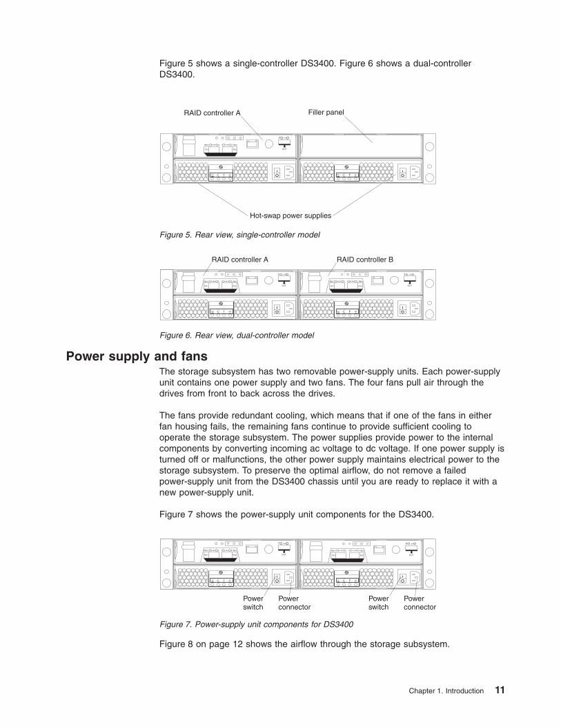
Figure 5 shows a single-controller DS3400. Figure 6 shows a dual-controllerDS3400.
Power supply and fansThe storage subsystem has two removable power-supply units. Each power-supplyunit contains one power supply and two fans. The four fans pull air through thedrives from front to back across the drives.
The fans provide redundant cooling, which means that if one of the fans in eitherfan housing fails, the remaining fans continue to provide sufficient cooling tooperate the storage subsystem. The power supplies provide power to the internalcomponents by converting incoming ac voltage to dc voltage. If one power supply isturned off or malfunctions, the other power supply maintains electrical power to thestorage subsystem. To preserve the optimal airflow, do not remove a failedpower-supply unit from the DS3400 chassis until you are ready to replace it with anew power-supply unit.
Figure 7 shows the power-supply unit components for the DS3400.
Figure 8 on page 12 shows the airflow through the storage subsystem.
Hot-swap power supplies
RAID controller A Filler panel
Figure 5. Rear view, single-controller model
RAID controller A RAID controller B
Figure 6. Rear view, dual-controller model
Powerconnector
Powerswitch
Powerconnector
Powerswitch
Figure 7. Power-supply unit components for DS3400
Chapter 1. Introduction 11
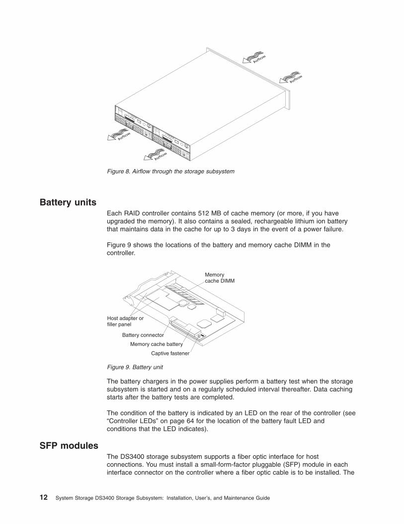
Battery unitsEach RAID controller contains 512 MB of cache memory (or more, if you haveupgraded the memory). It also contains a sealed, rechargeable lithium ion batterythat maintains data in the cache for up to 3 days in the event of a power failure.
Figure 9 shows the locations of the battery and memory cache DIMM in thecontroller.
The battery chargers in the power supplies perform a battery test when the storagesubsystem is started and on a regularly scheduled interval thereafter. Data cachingstarts after the battery tests are completed.
The condition of the battery is indicated by an LED on the rear of the controller (see“Controller LEDs” on page 64 for the location of the battery fault LED andconditions that the LED indicates).
SFP modulesThe DS3400 storage subsystem supports a fiber optic interface for hostconnections. You must install a small-form-factor pluggable (SFP) module in eachinterface connector on the controller where a fiber optic cable is to be installed. The
Airflow
Airflow
Airflow
Airflow
Figure 8. Airflow through the storage subsystem
Memorycache DIMM
Host adapter orfiller panel
Battery connector
Captive fastener
Memory cache battery
Figure 9. Battery unit
12 System Storage DS3400 Storage Subsystem: Installation, User’s, and Maintenance Guide
DS3400 storage subsystem Fibre Channel host ports support 1, 2, and 4 GbpsFibre Channel speeds. The DS3400 storage subsystem drive port supports SASonly.
Attention: The speed of the SFP module determines the maximum operatingspeed of the Fibre Channel port in which the SFP module is installed. For example,a 2-Gbps SFP module that is connected to a 4-Gbps-capable port will limit thespeed of that port to a maximum of 2 Gbps. Carefully check the IBM part number,option number, and CRU/FRU part number of the SFP module to identify its speed.There are no physical features that distinguish a 4 Gbps from a 2 Gbps SFPmodule.
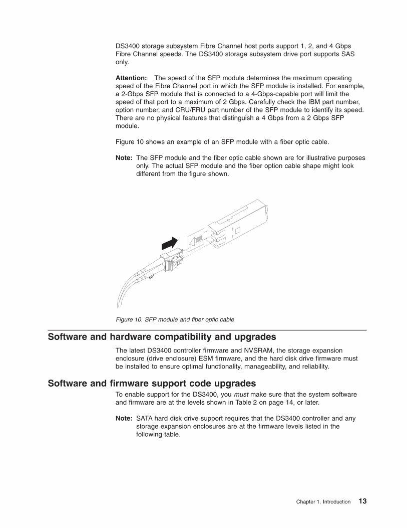
Figure 10 shows an example of an SFP module with a fiber optic cable.
Note: The SFP module and the fiber optic cable shown are for illustrative purposesonly. The actual SFP module and the fiber option cable shape might lookdifferent from the figure shown.
Software and hardware compatibility and upgradesThe latest DS3400 controller firmware and NVSRAM, the storage expansionenclosure (drive enclosure) ESM firmware, and the hard disk drive firmware mustbe installed to ensure optimal functionality, manageability, and reliability.
Software and firmware support code upgradesTo enable support for the DS3400, you must make sure that the system softwareand firmware are at the levels shown in Table 2 on page 14, or later.
Note: SATA hard disk drive support requires that the DS3400 controller and anystorage expansion enclosures are at the firmware levels listed in thefollowing table.
Figure 10. SFP module and fiber optic cable
Chapter 1. Introduction 13
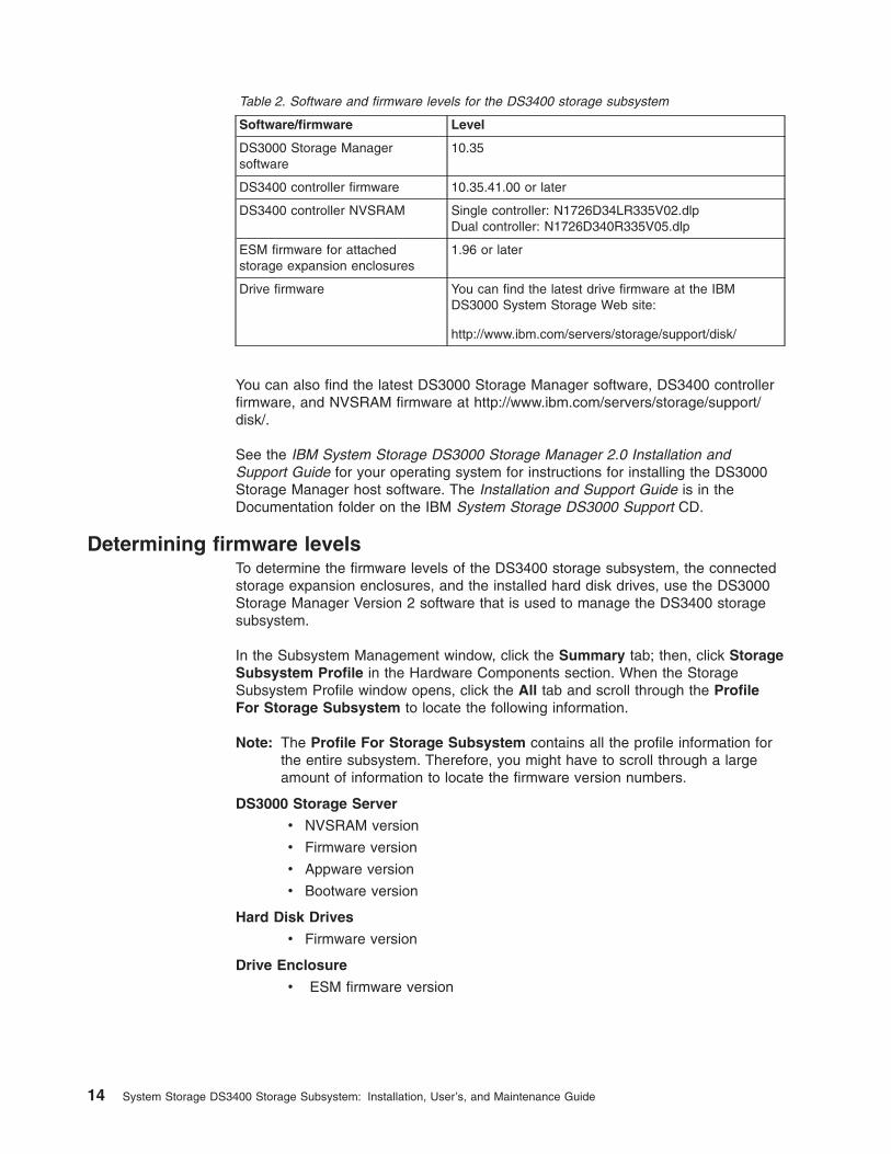
Table 2. Software and firmware levels for the DS3400 storage subsystem
Software/firmware Level
DS3000 Storage Managersoftware
10.35
DS3400 controller firmware 10.35.41.00 or later
DS3400 controller NVSRAM Single controller: N1726D34LR335V02.dlpDual controller: N1726D340R335V05.dlp
ESM firmware for attachedstorage expansion enclosures
1.96 or later
Drive firmware You can find the latest drive firmware at the IBMDS3000 System Storage Web site:
http://www.ibm.com/servers/storage/support/disk/
You can also find the latest DS3000 Storage Manager software, DS3400 controllerfirmware, and NVSRAM firmware at http://www.ibm.com/servers/storage/support/disk/.
See the IBM System Storage DS3000 Storage Manager 2.0 Installation andSupport Guide for your operating system for instructions for installing the DS3000Storage Manager host software. The Installation and Support Guide is in theDocumentation folder on the IBM System Storage DS3000 Support CD.
Determining firmware levelsTo determine the firmware levels of the DS3400 storage subsystem, the connectedstorage expansion enclosures, and the installed hard disk drives, use the DS3000Storage Manager Version 2 software that is used to manage the DS3400 storagesubsystem.
In the Subsystem Management window, click the Summary tab; then, click StorageSubsystem Profile in the Hardware Components section. When the StorageSubsystem Profile window opens, click the All tab and scroll through the ProfileFor Storage Subsystem to locate the following information.
Note: The Profile For Storage Subsystem contains all the profile information forthe entire subsystem. Therefore, you might have to scroll through a largeamount of information to locate the firmware version numbers.
DS3000 Storage Server
v NVSRAM version
v Firmware version
v Appware version
v Bootware version
Hard Disk Drives
v Firmware version
Drive Enclosure
v ESM firmware version
14 System Storage DS3400 Storage Subsystem: Installation, User’s, and Maintenance Guide
SpecificationsThe specifications of the DS3400 are listed in Table 1 on page 4. This sectionprovides additional site specifications for the DS3400 storage subsystem. Beforeyou install the storage subsystem, you must either make sure that your plannedinstallation site meets these requirements or prepare the site so that it does meetthese requirements. Preparations might involve meeting area requirements,environmental requirements, and electrical requirements for DS3400 storagesubsystem installation, service, and operation.
Area requirementsThe floor space at the installation site must provide enough strength to support theweight of the storage subsystem and associated equipment; sufficient space toinstall, operate, and service the storage subsystem; and sufficient ventilation toprovide a free flow of air to the unit.
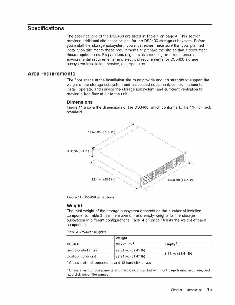
DimensionsFigure 11 shows the dimensions of the DS3400, which conforms to the 19-inch rackstandard.
WeightThe total weight of the storage subsystem depends on the number of installedcomponents. Table 3 lists the maximum and empty weights for the storagesubsystem in different configurations. Table 4 on page 16 lists the weight of eachcomponent.
Table 3. DS3400 weights
DS3400
Weight
Maximum 1 Empty 2
Single-controller unit 28.31 kg (62.41 lb)9.71 kg (21.41 lb)
Dual-controller unit 29.24 kg (64.47 lb)1 Chassis with all components and 12 hard disk drives.
2 Chassis without components and hard disk drives but with front cage frame, midplane, andhard disk drive filler panels.
System
Storage
48.20 cm (18.98 in.)
44.67 cm (17.59 in.)
8.72 cm (3.4 in.)
52.1 cm (20.5 in.)
Figure 11. DS3400 dimensions
Chapter 1. Introduction 15
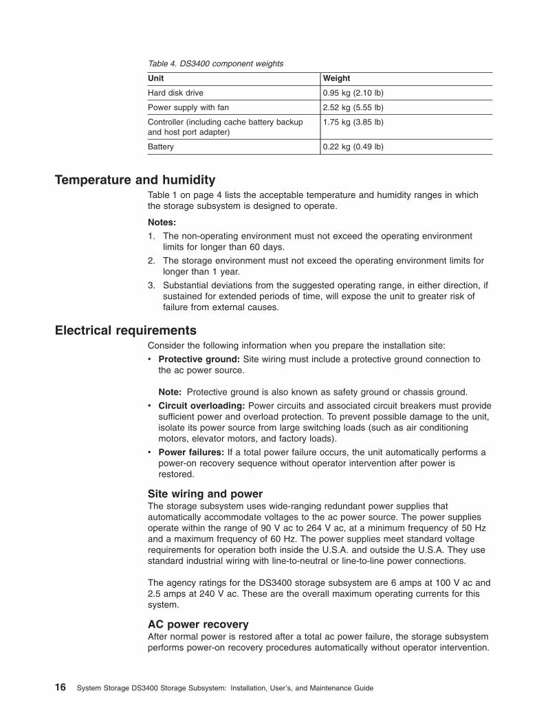
Table 4. DS3400 component weights
Unit Weight
Hard disk drive 0.95 kg (2.10 lb)
Power supply with fan 2.52 kg (5.55 lb)
Controller (including cache battery backupand host port adapter)
1.75 kg (3.85 lb)
Battery 0.22 kg (0.49 lb)
Temperature and humidityTable 1 on page 4 lists the acceptable temperature and humidity ranges in whichthe storage subsystem is designed to operate.
Notes:
1. The non-operating environment must not exceed the operating environmentlimits for longer than 60 days.
2. The storage environment must not exceed the operating environment limits forlonger than 1 year.
3. Substantial deviations from the suggested operating range, in either direction, ifsustained for extended periods of time, will expose the unit to greater risk offailure from external causes.
Electrical requirementsConsider the following information when you prepare the installation site:
v Protective ground: Site wiring must include a protective ground connection tothe ac power source.
Note: Protective ground is also known as safety ground or chassis ground.
v Circuit overloading: Power circuits and associated circuit breakers must providesufficient power and overload protection. To prevent possible damage to the unit,isolate its power source from large switching loads (such as air conditioningmotors, elevator motors, and factory loads).
v Power failures: If a total power failure occurs, the unit automatically performs apower-on recovery sequence without operator intervention after power isrestored.
Site wiring and powerThe storage subsystem uses wide-ranging redundant power supplies thatautomatically accommodate voltages to the ac power source. The power suppliesoperate within the range of 90 V ac to 264 V ac, at a minimum frequency of 50 Hzand a maximum frequency of 60 Hz. The power supplies meet standard voltagerequirements for operation both inside the U.S.A. and outside the U.S.A. They usestandard industrial wiring with line-to-neutral or line-to-line power connections.
The agency ratings for the DS3400 storage subsystem are 6 amps at 100 V ac and2.5 amps at 240 V ac. These are the overall maximum operating currents for thissystem.
AC power recoveryAfter normal power is restored after a total ac power failure, the storage subsystemperforms power-on recovery procedures automatically without operator intervention.
16 System Storage DS3400 Storage Subsystem: Installation, User’s, and Maintenance Guide
Power cords and receptaclesThe storage subsystem comes with two jumper cords that are used to connect tothe rack PDU. You must purchase the power cords that are applicable for use in atypical receptacle in your country. See “Power cords” on page 118 for moreinformation.
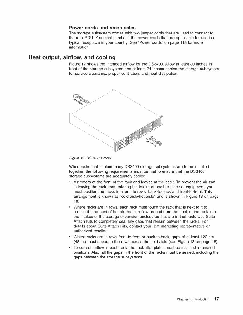
Heat output, airflow, and coolingFigure 12 shows the intended airflow for the DS3400. Allow at least 30 inches infront of the storage subsystem and at least 24 inches behind the storage subsystemfor service clearance, proper ventilation, and heat dissipation.
When racks that contain many DS3400 storage subsystems are to be installedtogether, the following requirements must be met to ensure that the DS3400storage subsystems are adequately cooled:
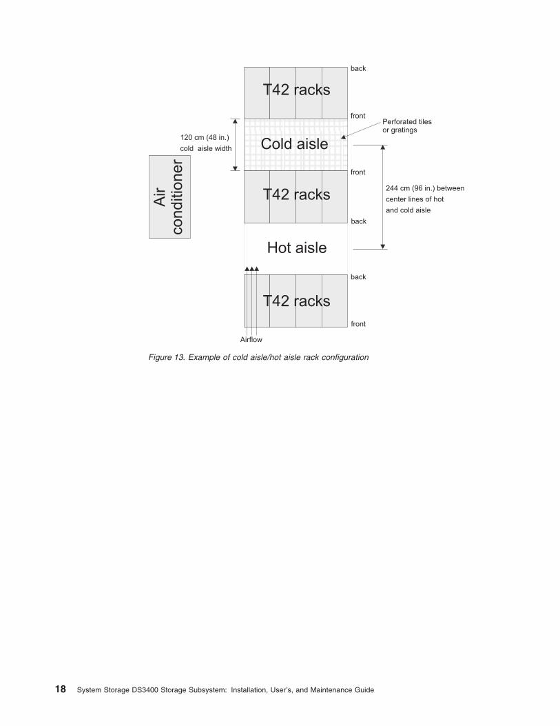
v Air enters at the front of the rack and leaves at the back. To prevent the air thatis leaving the rack from entering the intake of another piece of equipment, youmust position the racks in alternate rows, back-to-back and front-to-front. Thisarrangement is known as “cold aisle/hot aisle” and is shown in Figure 13 on page18.
v Where racks are in rows, each rack must touch the rack that is next to it toreduce the amount of hot air that can flow around from the back of the rack intothe intakes of the storage expansion enclosures that are in that rack. Use SuiteAttach Kits to completely seal any gaps that remain between the racks. Fordetails about Suite Attach Kits, contact your IBM marketing representative orauthorized reseller.
v Where racks are in rows front-to-front or back-to-back, gaps of at least 122 cm(48 in.) must separate the rows across the cold aisle (see Figure 13 on page 18).
v To correct airflow in each rack, the rack filler plates must be installed in unusedpositions. Also, all the gaps in the front of the racks must be sealed, including thegaps between the storage subsystems.
System
Storage
Airflow
Airflow
Figure 12. DS3400 airflow
Chapter 1. Introduction 17
120 cm (48 in.)
cold aisle width
244 cm (96 in.) between
center lines of hot
and cold aisle
Perforated tilesor gratings
back
back
T42 racks
T42 racks
T42 racks
Hot aisle
Air
co
nd
itio
ne
r
back
front
front
front
Airflow
Cold aisle
Figure 13. Example of cold aisle/hot aisle rack configuration
18 System Storage DS3400 Storage Subsystem: Installation, User’s, and Maintenance Guide
Chapter 2. Installing the storage subsystem
This chapter provides the information about installing the storage subsystem into arack cabinet.
Before you begin the installation, review the safety information in “Safety” on pagexi and “Handling static-sensitive devices” on page 21.
“Installation overview” on page 20 provides an overview of the entire DS3400installation process. Read this overview before you begin the installation.
Inventory checklistAfter you unpack the DS3400, make sure that you have the following items.Depending on your DS3400 order, your shipping box might contain additionalmaterials that are not included in the following list.
v Hardware
– Hard disk drive filler panels (12) (Your storage subsystem might come with upto 12 hard disk drives.)
– RAID controllers (up to 2)
– Power supplies (2)
– Power cables (2 jumper line cords)
– Rack-mounting hardware kit (1), including:
- Rails (2) (right and left assembly)
- Rail end plate covers (2) (right and left assembly)
- M5 black hex-head slotted screws (12)
- Washers (8)
Attention: The DS3400 does not come with region-specific power cords. Youmust obtain the IBM-approved power cords for your region. See “Power cords”on page 118 for the IBM-approved power cords for your region.
v Software and documentation
– IBM System Storage DS3000 Support CD
The support CD contains the IBM DS3000 Storage Manager Version 2 hostsoftware. The CD also includes firmware, online help, and the followingdocumentation in Adobe Acrobat Portable Document Format (PDF):
- IBM System Storage DS3400 Storage Subsystem Installation, User’s, andMaintenance Guide (this document)
- IBM System Storage DS3000 Storage Manager Version 2 Installation andSupport Guide for your operating system
- IBM Systems Safety Notices
– IBM System Storage DS3200, DS3300, and DS3400 Quick Installation Guide
– Rack Installation Instructions
Instructions for installing the DS3400 in a rack cabinet are provided in theRack Installation Instructions.
– Box of ID labels (used to label the enclosure IDs on the front of the DS3400)
If you ordered additional premium features or entitlements, the premium featuresactivation or entitlement kits might also come inside the box.
© Copyright IBM Corp. 2006, 2009 19
If an item is missing or damaged, contact your IBM marketing representative orauthorized reseller.
Instructions for installing the DS3400 in a rack cabinet are provided in the RackInstallation Instructions.
To connect the DS3400 to other devices, use the following options, which must bepurchased separately:
v IBM 1M SAS cable
v IBM 3M SAS cable
v SFP modules
v IBM 1M fiber optic cable
v IBM 5M fiber optic cable
v IBM 25M fiber optic cable
v Host bus adapters (HBAs)
Installation overviewCAUTION:
or
>18 kg (39.7 lb)
or18-32 kg (39.7-70.5 lb)
The weight of this part or unit is between 18 and 32 kg (39.7 and 70.5 lb). Ittakes two persons to safely lift this part or unit. (C009)
Attention: A fully configured DS3400 weighs up to 30 kg (66 lb). At least twopeople should lift the DS3400 from the shipping box. You might want to open thesides of the shipping box and remove the components from the DS3400 before youlift it from the shipping box, to lighten the storage subsystem.
The following steps summarize the DS3400 installation process:
1. Review the preparation recommendations. See “Preparing for installation” onpage 22.
2. Prepare the installation site. See “Preparing the site” on page 23.
3. Prepare the rack cabinet. See the Rack Installation Instructions.
4. Record the serial number, machine type and model number, and RAIDcontroller MAC addresses for the DS3400 storage subsystem in Appendix A,“Records,” on page 121. See Figure 1 on page 2 for the location of the serialnumber.
The MAC addresses are labeled near the Ethernet port on each RAIDcontroller.
5. Install and secure the DS3400 chassis and components in the rack cabinet.See Rack Installation Instructions.
6. Install in the rack cabinet the storage expansion enclosures that you will cableto the DS3400. To set up and mount the storage expansion enclosures, seethe Rack Installation Instructions that come with the storage expansionenclosure.
20 System Storage DS3400 Storage Subsystem: Installation, User’s, and Maintenance Guide
AttentionBefore you power-on the storage subsystem, it must contain at least fourdrives. If at least four drives are not installed in each attached storageexpansion enclosure and in the DS3400 storage subsystem, when youpower-on the DS3400 and its attached storage expansion enclosures,your standard storage partition key might be lost and you mustregenerate it, using instructions at http://www.ibm.com/storage/fasttkeys.
In addition, the resulting insufficient load to the enclosure power suppliesmight cause them to intermittently appear to have failed, falsely indicatingthat the power supplies are bad. All drives in the DS3400 storagesubsystem and the connected storage expansion enclosures mustcontain no prior configuration data.
7. Use SAS cables to cable the DS3400 to the storage expansion enclosures.See “Connecting storage expansion enclosures to the DS3400” on page 37.
8. Complete one of the following cabling tasks to enable management of theDS3400 configuration:
v If you are using out-of-band management, cable the DS3400 Ethernet portsto either the management workstation or the host.
v If you are using in-band management, cable the DS3400 host channels tothe Fibre Channel host bus adapters (HBAs) in the hosts. See “Connectinghosts to the DS3400” on page 48.
9. Connect the power cables for the DS3400. See “Cabling the DS3400 powersupplies” on page 54.
10. Power-on the attached storage expansion enclosure and the DS3400 storagesubsystem, using the procedure in “Turning on the storage subsystem” onpage 57.
11. Install the DS3000 Storage Manager Version 2 software on the managementworkstation (for out-of-band management) or on the host (for in-bandmanagement). See the IBM System Storage DS3000 Storage Manager 2Installation and Support Guide for the management-workstation or hostoperating system for instructions for installing the DS3000 Storage ManagerVersion 2 software. The Installation and Support Guide is in the Documentationfolder on the IBM System Storage DS3000 Support CD.
12. Use the DS3000 Storage Manager software to verify the configuration.
13. Review and perform the procedures in “Performing the DS3000 Health Checkprocess” on page 55.
Handling static-sensitive devicesAttention: Static electricity can damage the storage subsystem and otherelectronic devices. To avoid damage, keep static-sensitive devices in theirstatic-protective packages until you are ready to install them.
To reduce the possibility of electrostatic discharge, observe the followingprecautions:
v Limit your movement. Movement can cause static electricity to build up aroundyou.
v Handle the device carefully, holding it by its edges or its frame.
v Do not touch solder joints, pins, or exposed printed circuitry.
Chapter 2. Installing the storage subsystem 21
v Do not leave the device where others can handle and damage it.
v While the device is still in its static-protective package, touch it to an unpaintedmetal part of the system unit for at least 2 seconds. This drains static electricityfrom the package and from your body.
v Remove the device from its package and install it directly into the system unitwithout setting it down. If it is necessary to set down the device, put it back intoits static-protective package. Do not place the device on the system unit cover oron a metal surface.
v Take additional care when you handle devices during cold weather. Heatingreduces indoor humidity and increases static electricity.
Preparing for installationBefore you install the DS3400 storage subsystem, create a detailed plan of how thisunit will be used in your storage configuration. The plan should include determiningRAID levels, failover requirements, operating systems that are to be used, and totalstorage capacity requirements.
To prepare the DS3400 storage subsystem for installation into a rack cabinet,complete the following steps:
1. Prepare the site to meet all area, environmental, power, and site requirements.For more information, see “Specifications” on page 15.
2. Move the shipping box that contains the DS3400 to the site.
CAUTION:
or
>18 kg (39.7 lb)
or18-32 kg (39.7-70.5 lb)
The weight of this part or unit is between 18 and 32 kg (39.7 and 70.5 lb).It takes two persons to safely lift this part or unit. (C009)
3. Make sure that you have the correct host software for your operating system.
The support CD that comes with the DS3400 has the correct IBM DS3000Storage Manager Version 2 host software.
The CD also includes the DS3400 storage subsystem controller firmware. Forthe latest controller firmware, see http://www.ibm.com/servers/storage/support/disk/.
4. Read the applicable readme files that are included in the Storage Manager hostsoftware or DS3400 controller firmware packages for any updated informationabout hardware, software, or firmware products.
5. Continue with “Required tools and hardware.”
Required tools and hardwareHave the following tools and equipment available:
v Region-specific power cords that are required for the DS3400
v 5/16 (8 mm) hex nut driver
v #0 and #1 Phillips screwdrivers
v Electrostatic-discharge protection (such as a grounding wrist strap)
22 System Storage DS3400 Storage Subsystem: Installation, User’s, and Maintenance Guide
v Ethernet interface cables
v Rack power jumper cords that come with the DS3400
v Rack-mounting hardware that comes with the DS3400
v SAS cables (1-meter or 3-meter)
v Fibre Channel cables, interface cables, and cable straps
v SFP modules
Preparing the siteThis section lists the floor space requirements and weight information for theDS3400. For information about interface cables and connections, see Chapter 3,“Cabling the storage subsystem,” on page 25.
The floor area at the installation site must provide the following conditions:
v Sufficient space to install the DS3400
v Enough stability to support the weight of the fully configured DS3400 andassociated systems (A fully configured DS3400 weighs 30 kg [66 lb].)
Make sure that all requirements, such as floor space, air conditioning, and electricalservice, have been met. Other site preparation activities include the following tasks:
v Make sure that there is enough room to move around the rack cabinet and toinstall the devices.
v Install uninterruptible-power-supply devices.
v If applicable, install host servers with Fibre Channel host bus adapters (HBAs),Fibre Channel switches, or other devices.
v Route interface cables from the Fibre Channel HBA ports in the hosts or FibreChannel switches to the installation area.
v Route main power cords to the installation area.
Continue with “Installing the DS3400 in a rack cabinet.”
Installing the DS3400 in a rack cabinetTo install the DS3400 in a rack cabinet, follow the instructions in the RackInstallation Instructions that come with the DS3400. Then, continue with Chapter 3,“Cabling the storage subsystem,” on page 25.
Chapter 2. Installing the storage subsystem 23

24 System Storage DS3400 Storage Subsystem: Installation, User’s, and Maintenance Guide
Chapter 3. Cabling the storage subsystem
After the storage subsystem is installed in its permanent location, you must cable itto hosts, drives, and other external devices, depending on your hardwareconfiguration.
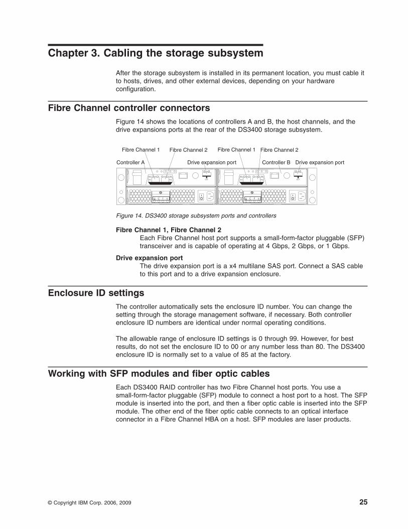
Fibre Channel controller connectorsFigure 14 shows the locations of controllers A and B, the host channels, and thedrive expansions ports at the rear of the DS3400 storage subsystem.
Fibre Channel 1, Fibre Channel 2Each Fibre Channel host port supports a small-form-factor pluggable (SFP)transceiver and is capable of operating at 4 Gbps, 2 Gbps, or 1 Gbps.
Drive expansion portThe drive expansion port is a x4 multilane SAS port. Connect a SAS cableto this port and to a drive expansion enclosure.
Enclosure ID settingsThe controller automatically sets the enclosure ID number. You can change thesetting through the storage management software, if necessary. Both controllerenclosure ID numbers are identical under normal operating conditions.
The allowable range of enclosure ID settings is 0 through 99. However, for bestresults, do not set the enclosure ID to 00 or any number less than 80. The DS3400enclosure ID is normally set to a value of 85 at the factory.
Working with SFP modules and fiber optic cablesEach DS3400 RAID controller has two Fibre Channel host ports. You use asmall-form-factor pluggable (SFP) module to connect a host port to a host. The SFPmodule is inserted into the port, and then a fiber optic cable is inserted into the SFPmodule. The other end of the fiber optic cable connects to an optical interfaceconnector in a Fibre Channel HBA on a host. SFP modules are laser products.
Controller A Controller B
Fibre Channel 1 Fibre Channel 1Fibre Channel 2 Fibre Channel 2
Drive expansion port Drive expansion port
Figure 14. DS3400 storage subsystem ports and controllers
© Copyright IBM Corp. 2006, 2009 25
CAUTION:This product might contain one or more of the following devices: CD-ROMdrive, DVD-ROM drive, DVD-RAM drive, or laser module, which are Class 1laser products. Note the following information:
v Do not remove the covers. Removing the covers of the laser product couldresult in exposure to hazardous laser radiation. There are no serviceableparts inside the device.
v Use of the controls or adjustments or performance of procedures otherthan those specified herein might result in hazardous radiation exposure.
(C026)
CAUTION:Data processing environments can contain equipment transmitting on systemlinks with laser modules that operate at greater than Class 1 power levels. Forthis reason, never look into the end of an optical fiber cable or openreceptacle. (C027)
Handling fiber optic cables
Attention: To avoid damage to the fiber optic cables, follow these guidelines:
v Do not route the cable along a folding cable-management arm.
v For devices on slide rails, leave enough slack in the cables so they do not bendto a diameter of less than 76 mm (3 in.), or a radius less than 38 mm (1.5 in.),when extended or become pinched when retracted.
v Route the cable away from places where it can be damaged by other devices inthe rack cabinet.
v Do not use plastic cable ties in place of the provided cable straps.
v Do not overtighten the cable straps or bend the cables to a diameter of less than76 mm (3 in.), or a radius less than 38 mm (1.5 in.).
v Do not put excess weight on the cable at the connection point. Be sure that thecable is well supported.
v The following are the recommended maximum cable lengths.
– 1 Gbps: 500 meters 50/125 um fiber, 300 meters 62.5/125 um fiber
– 2 Gbps: 300 meters 50/125 um fiber, 150 meters 62.5/125 um fiber
– 4 Gbps: 150 meters 50/125 um fiber, 70 meters 62.5/125 um fiber
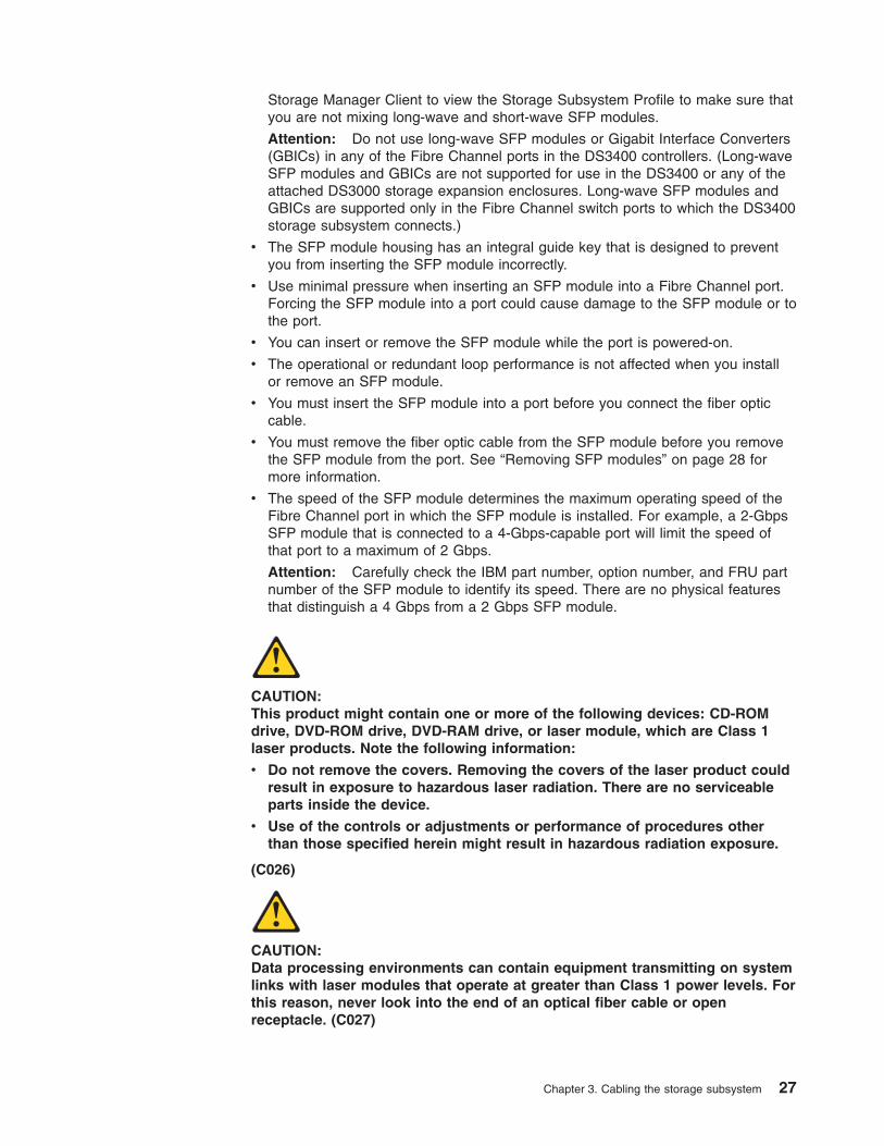
Installing SFP modulesThe DS3400 requires SFP modules. SFP modules convert electrical signals tooptical signals that are required for Fibre Channel transmission to and from RAIDcontrollers. After you install the SFP modules, you use fiber optic cables to connectthe DS3400 to other Fibre Channel devices.
Before installing SFP modules and fiber optic cables, read the following information:
v Do not mix long-wave SFP modules and short-wave SFP modules on a singlestorage subsystem. Use only short-wave SFP modules. You can use the DS3000
26 System Storage DS3400 Storage Subsystem: Installation, User’s, and Maintenance Guide
Storage Manager Client to view the Storage Subsystem Profile to make sure thatyou are not mixing long-wave and short-wave SFP modules.
Attention: Do not use long-wave SFP modules or Gigabit Interface Converters(GBICs) in any of the Fibre Channel ports in the DS3400 controllers. (Long-waveSFP modules and GBICs are not supported for use in the DS3400 or any of theattached DS3000 storage expansion enclosures. Long-wave SFP modules andGBICs are supported only in the Fibre Channel switch ports to which the DS3400storage subsystem connects.)
v The SFP module housing has an integral guide key that is designed to preventyou from inserting the SFP module incorrectly.
v Use minimal pressure when inserting an SFP module into a Fibre Channel port.Forcing the SFP module into a port could cause damage to the SFP module or tothe port.
v You can insert or remove the SFP module while the port is powered-on.
v The operational or redundant loop performance is not affected when you installor remove an SFP module.
v You must insert the SFP module into a port before you connect the fiber opticcable.
v You must remove the fiber optic cable from the SFP module before you removethe SFP module from the port. See “Removing SFP modules” on page 28 formore information.
v The speed of the SFP module determines the maximum operating speed of theFibre Channel port in which the SFP module is installed. For example, a 2-GbpsSFP module that is connected to a 4-Gbps-capable port will limit the speed ofthat port to a maximum of 2 Gbps.
Attention: Carefully check the IBM part number, option number, and FRU partnumber of the SFP module to identify its speed. There are no physical featuresthat distinguish a 4 Gbps from a 2 Gbps SFP module.
CAUTION:This product might contain one or more of the following devices: CD-ROMdrive, DVD-ROM drive, DVD-RAM drive, or laser module, which are Class 1laser products. Note the following information:
v Do not remove the covers. Removing the covers of the laser product couldresult in exposure to hazardous laser radiation. There are no serviceableparts inside the device.
v Use of the controls or adjustments or performance of procedures otherthan those specified herein might result in hazardous radiation exposure.
(C026)
CAUTION:Data processing environments can contain equipment transmitting on systemlinks with laser modules that operate at greater than Class 1 power levels. Forthis reason, never look into the end of an optical fiber cable or openreceptacle. (C027)
Chapter 3. Cabling the storage subsystem 27
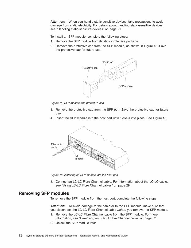
Attention: When you handle static-sensitive devices, take precautions to avoiddamage from static electricity. For details about handling static-sensitive devices,see “Handling static-sensitive devices” on page 21.
To install an SFP module, complete the following steps:
1. Remove the SFP module from its static-protective package.
2. Remove the protective cap from the SFP module, as shown in Figure 15. Savethe protective cap for future use.
3. Remove the protective cap from the SFP port. Save the protective cap for futureuse.
4. Insert the SFP module into the host port until it clicks into place. See Figure 16.
5. Connect an LC-LC Fibre Channel cable. For information about the LC-LC cable,see “Using LC-LC Fibre Channel cables” on page 29.
Removing SFP modulesTo remove the SFP module from the host port, complete the following steps:
Attention: To avoid damage to the cable or to the SFP module, make sure thatyou disconnect the LC-LC Fibre Channel cable before you remove the SFP module.
1. Remove the LC-LC Fibre Channel cable from the SFP module. For moreinformation, see “Removing an LC-LC Fibre Channel cable” on page 32.
2. Unlock the SFP module latch:
Protective cap
SFP module
Plastic tab
Figure 15. SFP module and protective cap
SFPmodule
Fiber opticcable
Figure 16. Installing an SFP module into the host port
28 System Storage DS3400 Storage Subsystem: Installation, User’s, and Maintenance Guide
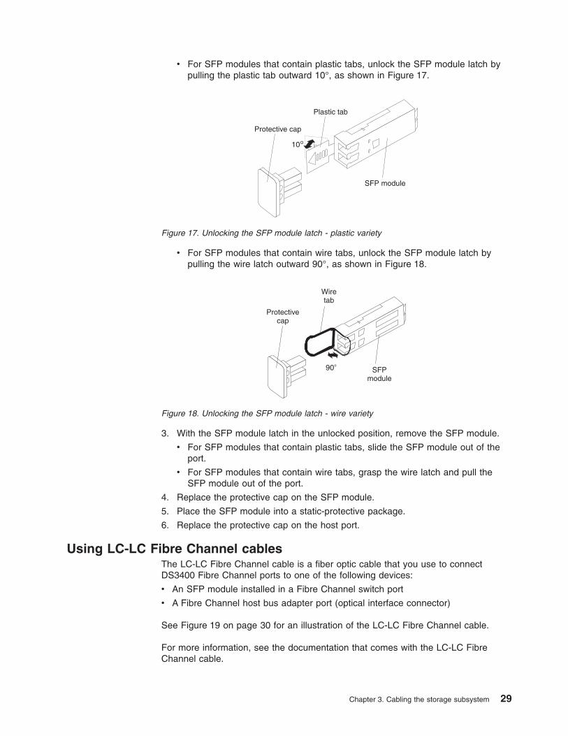
v For SFP modules that contain plastic tabs, unlock the SFP module latch bypulling the plastic tab outward 10°, as shown in Figure 17.
v For SFP modules that contain wire tabs, unlock the SFP module latch bypulling the wire latch outward 90°, as shown in Figure 18.
3. With the SFP module latch in the unlocked position, remove the SFP module.
v For SFP modules that contain plastic tabs, slide the SFP module out of theport.
v For SFP modules that contain wire tabs, grasp the wire latch and pull theSFP module out of the port.
4. Replace the protective cap on the SFP module.
5. Place the SFP module into a static-protective package.
6. Replace the protective cap on the host port.
Using LC-LC Fibre Channel cablesThe LC-LC Fibre Channel cable is a fiber optic cable that you use to connectDS3400 Fibre Channel ports to one of the following devices:
v An SFP module installed in a Fibre Channel switch port
v A Fibre Channel host bus adapter port (optical interface connector)
See Figure 19 on page 30 for an illustration of the LC-LC Fibre Channel cable.
For more information, see the documentation that comes with the LC-LC FibreChannel cable.
Protective cap
SFP module
10
Plastic tab
Figure 17. Unlocking the SFP module latch - plastic variety
Protectivecap
SFPmodule
90
Wiretab
Figure 18. Unlocking the SFP module latch - wire variety
Chapter 3. Cabling the storage subsystem 29
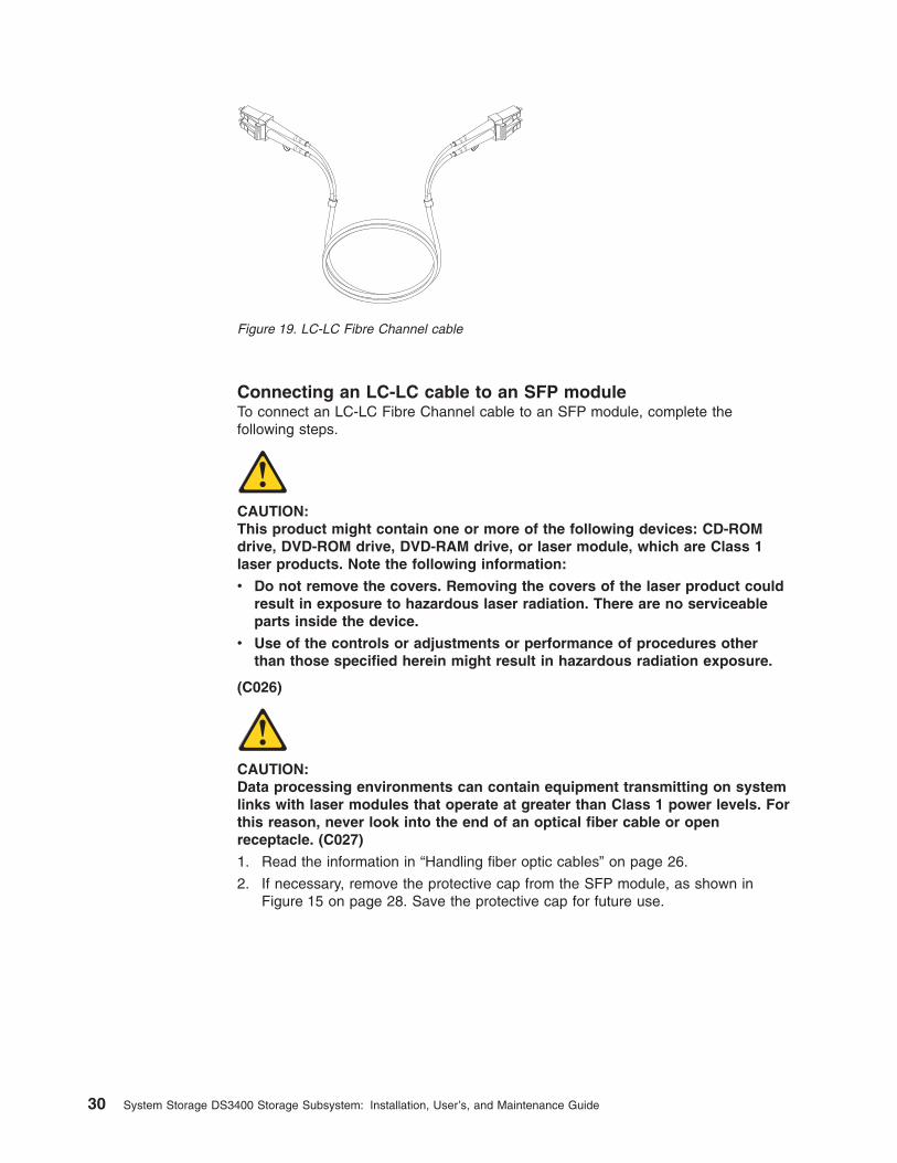
Connecting an LC-LC cable to an SFP moduleTo connect an LC-LC Fibre Channel cable to an SFP module, complete thefollowing steps.
CAUTION:This product might contain one or more of the following devices: CD-ROMdrive, DVD-ROM drive, DVD-RAM drive, or laser module, which are Class 1laser products. Note the following information:
v Do not remove the covers. Removing the covers of the laser product couldresult in exposure to hazardous laser radiation. There are no serviceableparts inside the device.
v Use of the controls or adjustments or performance of procedures otherthan those specified herein might result in hazardous radiation exposure.
(C026)
CAUTION:Data processing environments can contain equipment transmitting on systemlinks with laser modules that operate at greater than Class 1 power levels. Forthis reason, never look into the end of an optical fiber cable or openreceptacle. (C027)
1. Read the information in “Handling fiber optic cables” on page 26.
2. If necessary, remove the protective cap from the SFP module, as shown inFigure 15 on page 28. Save the protective cap for future use.
Figure 19. LC-LC Fibre Channel cable
30 System Storage DS3400 Storage Subsystem: Installation, User’s, and Maintenance Guide
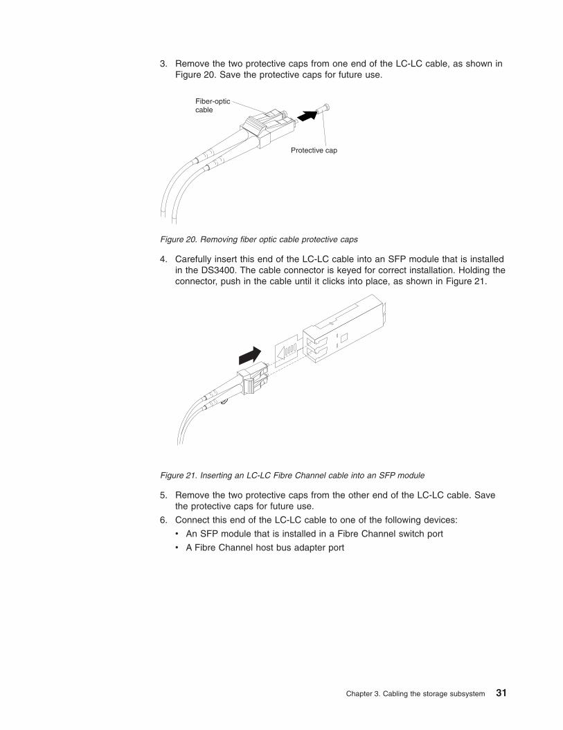
3. Remove the two protective caps from one end of the LC-LC cable, as shown inFigure 20. Save the protective caps for future use.
4. Carefully insert this end of the LC-LC cable into an SFP module that is installedin the DS3400. The cable connector is keyed for correct installation. Holding theconnector, push in the cable until it clicks into place, as shown in Figure 21.
5. Remove the two protective caps from the other end of the LC-LC cable. Savethe protective caps for future use.
6. Connect this end of the LC-LC cable to one of the following devices:
v An SFP module that is installed in a Fibre Channel switch port
v A Fibre Channel host bus adapter port
Protective cap
Fiber-opticcable
Figure 20. Removing fiber optic cable protective caps
Figure 21. Inserting an LC-LC Fibre Channel cable into an SFP module
Chapter 3. Cabling the storage subsystem 31
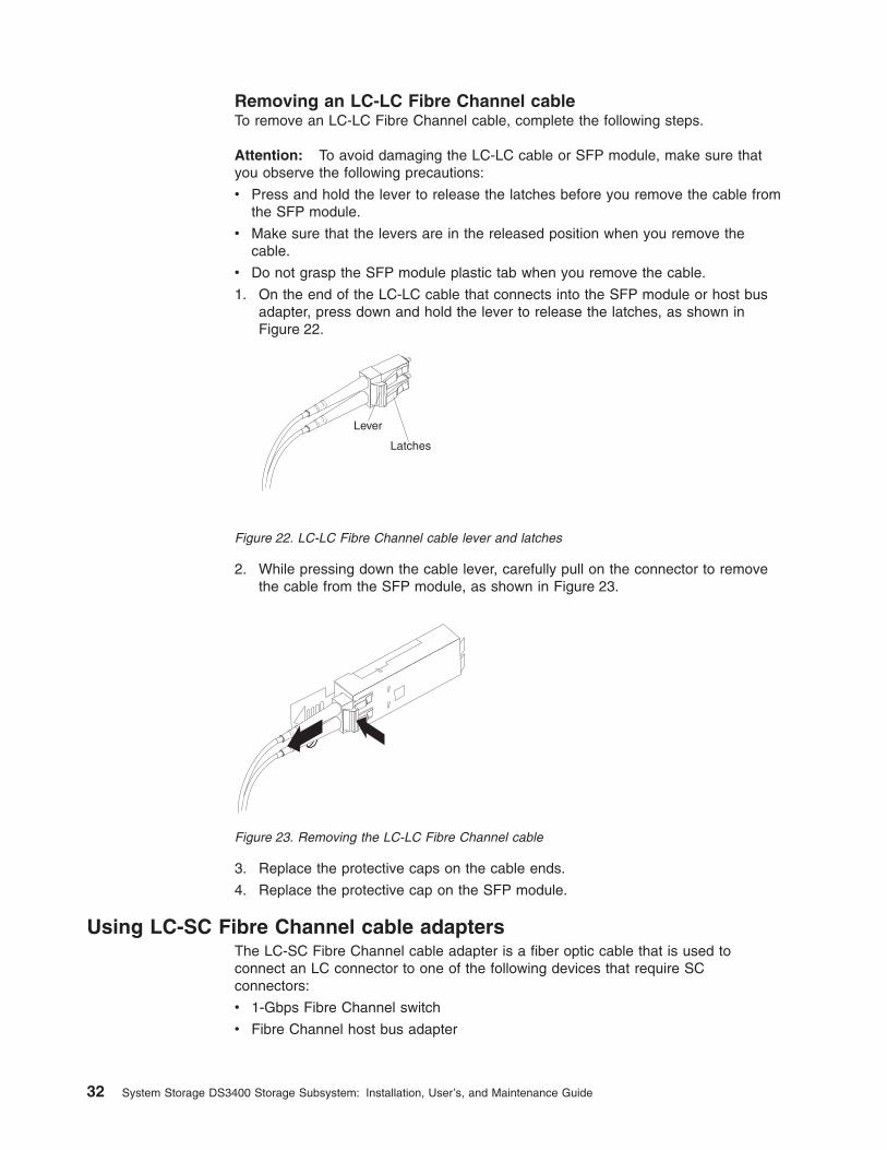
Removing an LC-LC Fibre Channel cableTo remove an LC-LC Fibre Channel cable, complete the following steps.
Attention: To avoid damaging the LC-LC cable or SFP module, make sure thatyou observe the following precautions:
v Press and hold the lever to release the latches before you remove the cable fromthe SFP module.
v Make sure that the levers are in the released position when you remove thecable.
v Do not grasp the SFP module plastic tab when you remove the cable.
1. On the end of the LC-LC cable that connects into the SFP module or host busadapter, press down and hold the lever to release the latches, as shown inFigure 22.
Lever
Latches
2. While pressing down the cable lever, carefully pull on the connector to removethe cable from the SFP module, as shown in Figure 23.
3. Replace the protective caps on the cable ends.
4. Replace the protective cap on the SFP module.
Using LC-SC Fibre Channel cable adaptersThe LC-SC Fibre Channel cable adapter is a fiber optic cable that is used toconnect an LC connector to one of the following devices that require SCconnectors:
v 1-Gbps Fibre Channel switch
v Fibre Channel host bus adapter
Figure 22. LC-LC Fibre Channel cable lever and latches
Figure 23. Removing the LC-LC Fibre Channel cable
32 System Storage DS3400 Storage Subsystem: Installation, User’s, and Maintenance Guide
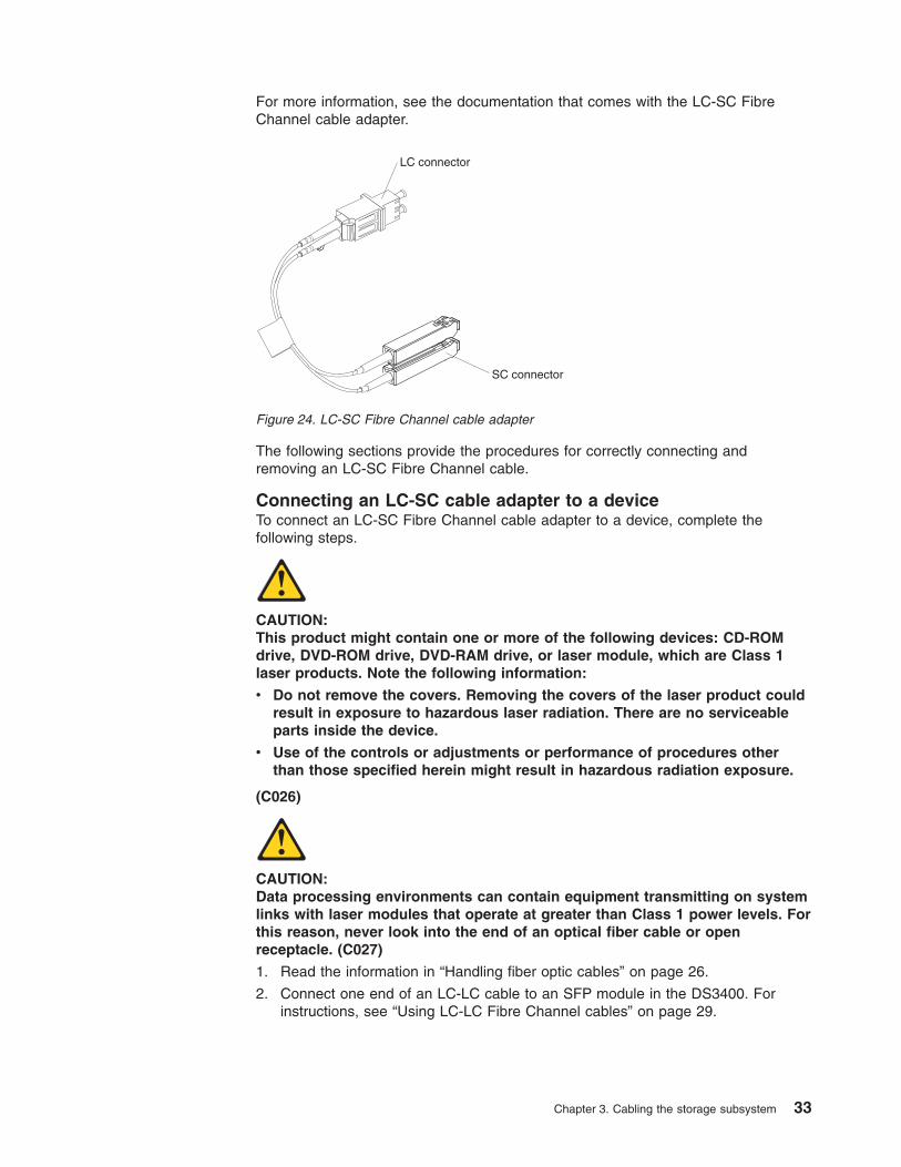
For more information, see the documentation that comes with the LC-SC FibreChannel cable adapter.
The following sections provide the procedures for correctly connecting andremoving an LC-SC Fibre Channel cable.
Connecting an LC-SC cable adapter to a deviceTo connect an LC-SC Fibre Channel cable adapter to a device, complete thefollowing steps.
CAUTION:This product might contain one or more of the following devices: CD-ROMdrive, DVD-ROM drive, DVD-RAM drive, or laser module, which are Class 1laser products. Note the following information:
v Do not remove the covers. Removing the covers of the laser product couldresult in exposure to hazardous laser radiation. There are no serviceableparts inside the device.
v Use of the controls or adjustments or performance of procedures otherthan those specified herein might result in hazardous radiation exposure.
(C026)
CAUTION:Data processing environments can contain equipment transmitting on systemlinks with laser modules that operate at greater than Class 1 power levels. Forthis reason, never look into the end of an optical fiber cable or openreceptacle. (C027)
1. Read the information in “Handling fiber optic cables” on page 26.
2. Connect one end of an LC-LC cable to an SFP module in the DS3400. Forinstructions, see “Using LC-LC Fibre Channel cables” on page 29.
LC connector
SC connector
Figure 24. LC-SC Fibre Channel cable adapter
Chapter 3. Cabling the storage subsystem 33
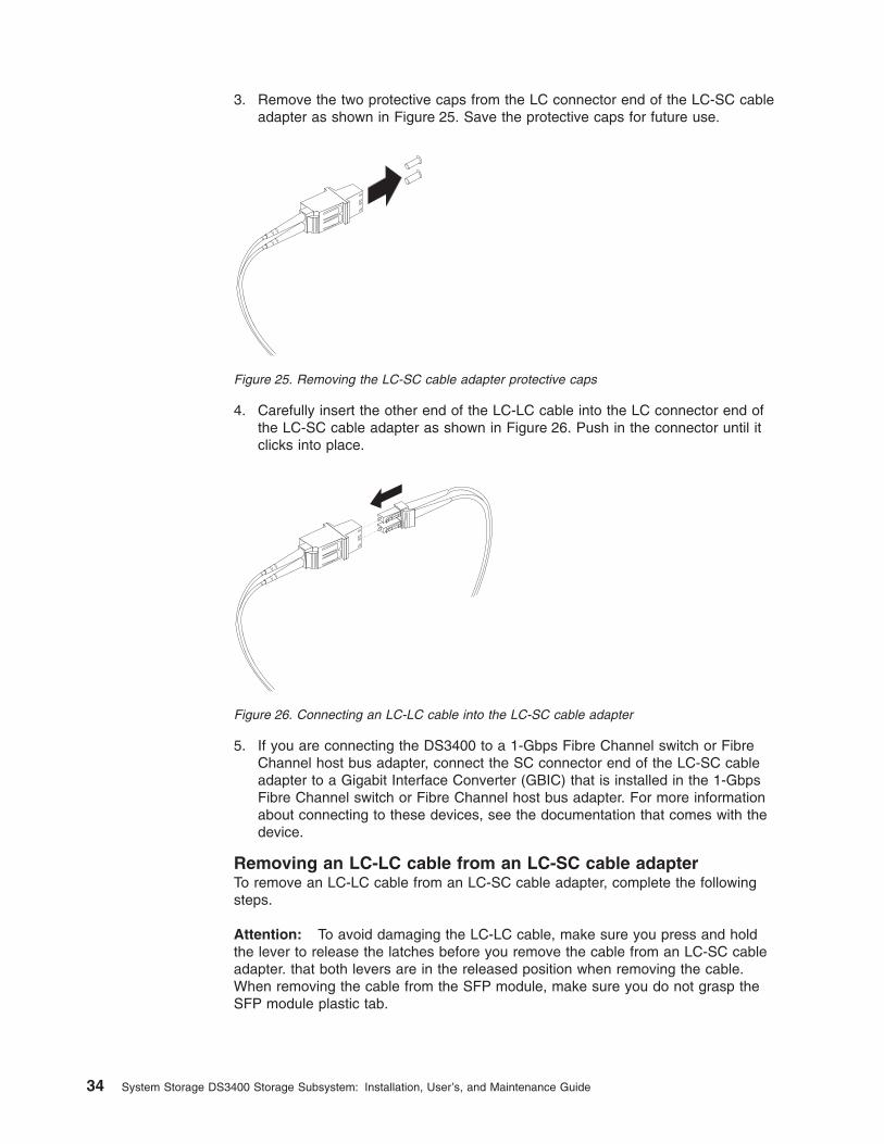
3. Remove the two protective caps from the LC connector end of the LC-SC cableadapter as shown in Figure 25. Save the protective caps for future use.
4. Carefully insert the other end of the LC-LC cable into the LC connector end ofthe LC-SC cable adapter as shown in Figure 26. Push in the connector until itclicks into place.
5. If you are connecting the DS3400 to a 1-Gbps Fibre Channel switch or FibreChannel host bus adapter, connect the SC connector end of the LC-SC cableadapter to a Gigabit Interface Converter (GBIC) that is installed in the 1-GbpsFibre Channel switch or Fibre Channel host bus adapter. For more informationabout connecting to these devices, see the documentation that comes with thedevice.
Removing an LC-LC cable from an LC-SC cable adapterTo remove an LC-LC cable from an LC-SC cable adapter, complete the followingsteps.
Attention: To avoid damaging the LC-LC cable, make sure you press and holdthe lever to release the latches before you remove the cable from an LC-SC cableadapter. that both levers are in the released position when removing the cable.When removing the cable from the SFP module, make sure you do not grasp theSFP module plastic tab.
Figure 25. Removing the LC-SC cable adapter protective caps
Figure 26. Connecting an LC-LC cable into the LC-SC cable adapter
34 System Storage DS3400 Storage Subsystem: Installation, User’s, and Maintenance Guide
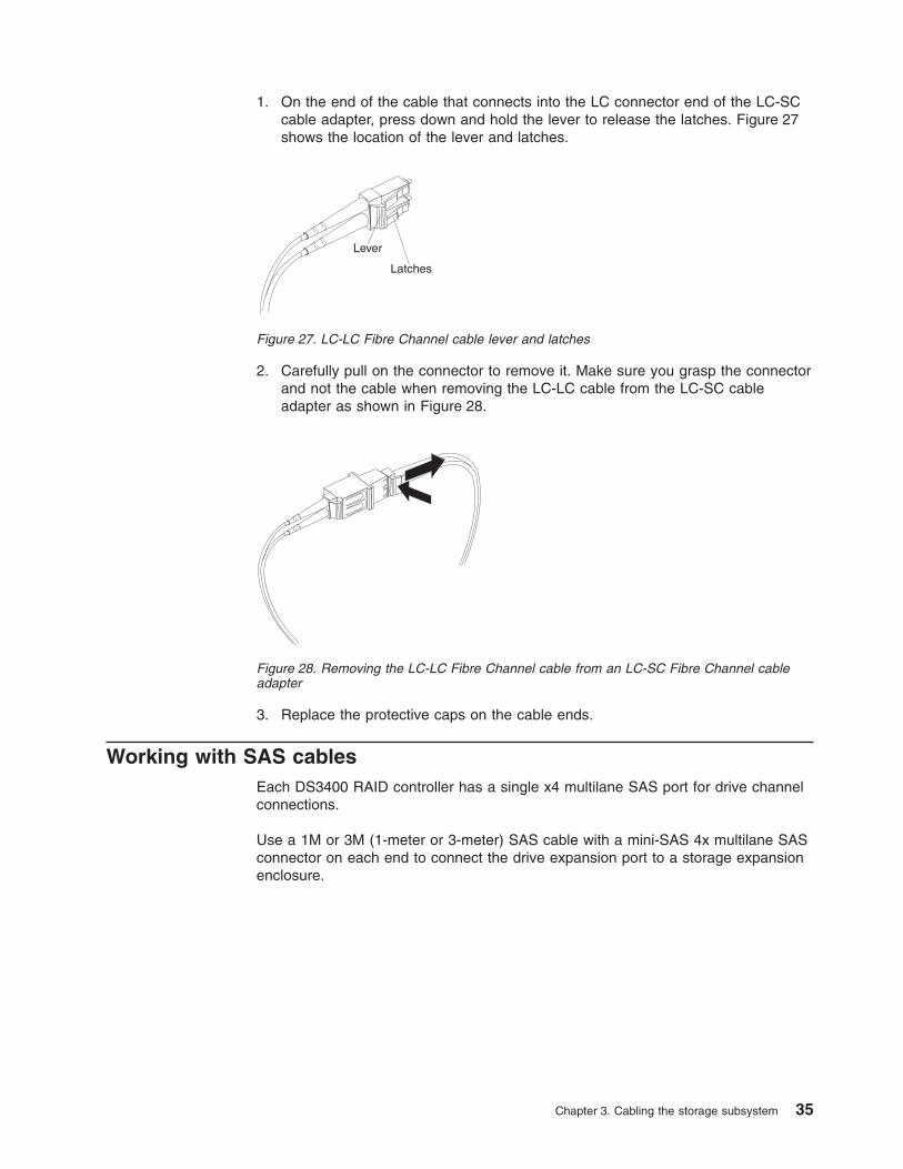
1. On the end of the cable that connects into the LC connector end of the LC-SCcable adapter, press down and hold the lever to release the latches. Figure 27shows the location of the lever and latches.
2. Carefully pull on the connector to remove it. Make sure you grasp the connectorand not the cable when removing the LC-LC cable from the LC-SC cableadapter as shown in Figure 28.
3. Replace the protective caps on the cable ends.
Working with SAS cablesEach DS3400 RAID controller has a single x4 multilane SAS port for drive channelconnections.
Use a 1M or 3M (1-meter or 3-meter) SAS cable with a mini-SAS 4x multilane SASconnector on each end to connect the drive expansion port to a storage expansionenclosure.
Lever
Latches
Figure 27. LC-LC Fibre Channel cable lever and latches
Figure 28. Removing the LC-LC Fibre Channel cable from an LC-SC Fibre Channel cableadapter
Chapter 3. Cabling the storage subsystem 35
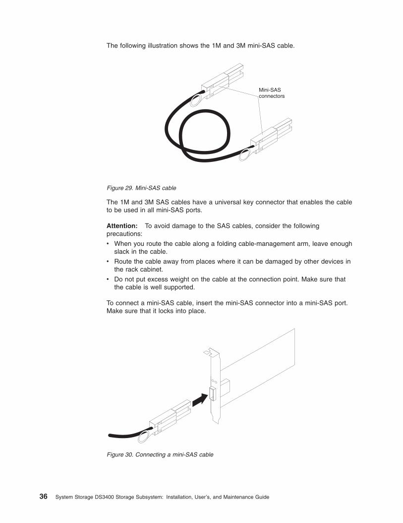
The following illustration shows the 1M and 3M mini-SAS cable.
The 1M and 3M SAS cables have a universal key connector that enables the cableto be used in all mini-SAS ports.
Attention: To avoid damage to the SAS cables, consider the followingprecautions:
v When you route the cable along a folding cable-management arm, leave enoughslack in the cable.
v Route the cable away from places where it can be damaged by other devices inthe rack cabinet.
v Do not put excess weight on the cable at the connection point. Make sure thatthe cable is well supported.
To connect a mini-SAS cable, insert the mini-SAS connector into a mini-SAS port.Make sure that it locks into place.
Mini-SASconnectors
Figure 29. Mini-SAS cable
Figure 30. Connecting a mini-SAS cable
36 System Storage DS3400 Storage Subsystem: Installation, User’s, and Maintenance Guide
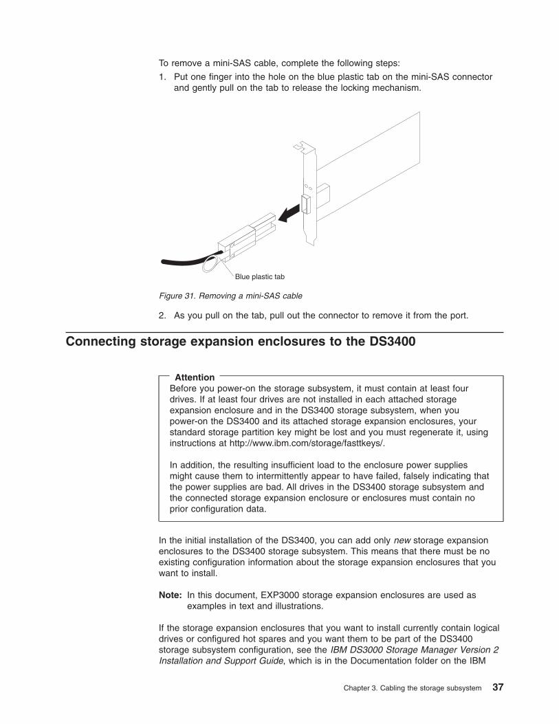
To remove a mini-SAS cable, complete the following steps:
1. Put one finger into the hole on the blue plastic tab on the mini-SAS connectorand gently pull on the tab to release the locking mechanism.
2. As you pull on the tab, pull out the connector to remove it from the port.
Connecting storage expansion enclosures to the DS3400
AttentionBefore you power-on the storage subsystem, it must contain at least fourdrives. If at least four drives are not installed in each attached storageexpansion enclosure and in the DS3400 storage subsystem, when youpower-on the DS3400 and its attached storage expansion enclosures, yourstandard storage partition key might be lost and you must regenerate it, usinginstructions at http://www.ibm.com/storage/fasttkeys/.
In addition, the resulting insufficient load to the enclosure power suppliesmight cause them to intermittently appear to have failed, falsely indicating thatthe power supplies are bad. All drives in the DS3400 storage subsystem andthe connected storage expansion enclosure or enclosures must contain noprior configuration data.
In the initial installation of the DS3400, you can add only new storage expansionenclosures to the DS3400 storage subsystem. This means that there must be noexisting configuration information about the storage expansion enclosures that youwant to install.
Note: In this document, EXP3000 storage expansion enclosures are used asexamples in text and illustrations.
If the storage expansion enclosures that you want to install currently contain logicaldrives or configured hot spares and you want them to be part of the DS3400storage subsystem configuration, see the IBM DS3000 Storage Manager Version 2Installation and Support Guide, which is in the Documentation folder on the IBM
Blue plastic tab
Figure 31. Removing a mini-SAS cable
Chapter 3. Cabling the storage subsystem 37
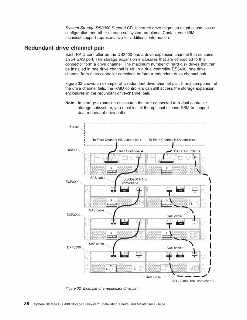
System Storage DS3000 Support CD. Incorrect drive migration might cause loss ofconfiguration and other storage subsystem problems. Contact your IBMtechnical-support representative for additional information.
Redundant drive channel pairEach RAID controller on the DS3400 has a drive expansion channel that containsan x4 SAS port. The storage expansion enclosures that are connected to thisconnector form a drive channel. The maximum number of hard disk drives that canbe installed in one drive channel is 48. In a dual-controller DS3400, one drivechannel from each controller combines to form a redundant drive-channel pair.
Figure 32 shows an example of a redundant drive-channel pair. If any component ofthe drive channel fails, the RAID controllers can still access the storage expansionenclosures in the redundant drive-channel pair.
Note: In storage expansion enclosures that are connected to a dual-controllerstorage subsystem, you must install the optional second ESM to supportdual redundant drive paths.
DS3400
Server
To Fibre Channel HBA controller 1 To Fibre Channel HBA controller 1
RAID Controller BRAID Controller A
SAS cable
SAS cableEXP3000
To DS3200 RAIDcontroller A
To DS3400 RAID controller B
SAS cable
SAS cableEXP3000
SAS cableSAS cableEXP3000
Figure 32. Example of a redundant drive path
38 System Storage DS3400 Storage Subsystem: Installation, User’s, and Maintenance Guide
Overview of steps to connect storage expansion enclosures to astorage subsystem
To connect storage expansion enclosures to the storage subsystem, complete thefollowing steps:
1. Follow the instructions in the Installation, User's, and Maintenance Guide for thestorage expansion enclosure and the Rack Installation Instructions to set up andmount the storage expansion enclosures.
2. Select a cabling topology applicable to the number of ESMs in the storageexpansion enclosures that you will connect to the DS3400. If you are connectingexternal storage expansion enclosures to the DS3400, make sure that eachstorage expansion enclosure contains at least four drives before you power iton. In addition, make sure that the DS3400 storage subsystem contains at leastfour drives before you power it on.
“DS3400 storage subsystem drive cabling topologies” describes therecommended schemes for cabling storage expansion enclosures with one ESMor two ESMs to the DS3400 and to each other (if you are connecting more thanone storage expansion enclosure).
3. Follow the cabling diagram for your chosen topology.
4. If required, set unique enclosure IDs for all storage expansion enclosures thatare cabled to the DS3400. See the DS3000 Storage Manager Version 2Installation and Support Guide for information about setting the enclosure ID.
The DS3400 storage subsystem locates the drives in the storage expansionenclosures after you power-on the configuration. Always turn on the storageexpansion enclosures first and then turn on the DS3400. After you havepowered-on the configuration, use the DS3000 Storage Manager software to checkthe status of the new drives, correct any errors, and configure the new drives.
DS3400 storage subsystem drive cabling topologiesThis section describes the following preferred cabling topologies for cabling storageexpansion enclosures to the DS3400 storage subsystem:
v “One single-controller DS3400 and one or more storage expansion enclosures”on page 40
v “One dual-controller DS3400 and one storage expansion enclosure” on page 41
v “One dual-controller DS3400 and two storage expansion enclosures” on page 41
v “One dual-controller DS3400 and three storage expansion enclosures” on page42
Each example provides redundant paths to the drives. If one of these examples issuitable for your hardware and application, complete the cabling connections asshown in the illustrations. If you have hardware other than what is shown in theseexamples to include in your topology, use these examples as a starting point forcreating your specific topology.
Important:
1. The DS3400 supports the connection of a maximum of three storage expansionenclosures.
2. The DS3400 supports one redundant drive-channel pair.
3. In storage expansion enclosures that are connected to a dual-controller storagesubsystem, you must install the optional second ESM to support dual redundantdrive paths.
Chapter 3. Cabling the storage subsystem 39
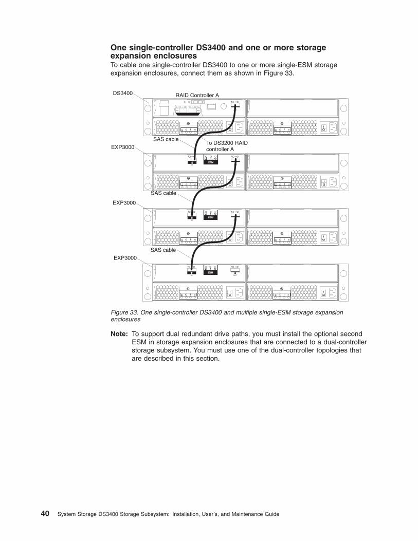
One single-controller DS3400 and one or more storageexpansion enclosuresTo cable one single-controller DS3400 to one or more single-ESM storageexpansion enclosures, connect them as shown in Figure 33.
Note: To support dual redundant drive paths, you must install the optional secondESM in storage expansion enclosures that are connected to a dual-controllerstorage subsystem. You must use one of the dual-controller topologies thatare described in this section.
DS3400 RAID Controller A
SAS cable
EXP3000To DS3200 RAIDcontroller A
SAS cable
EXP3000
SAS cable
EXP3000
Figure 33. One single-controller DS3400 and multiple single-ESM storage expansionenclosures
40 System Storage DS3400 Storage Subsystem: Installation, User’s, and Maintenance Guide
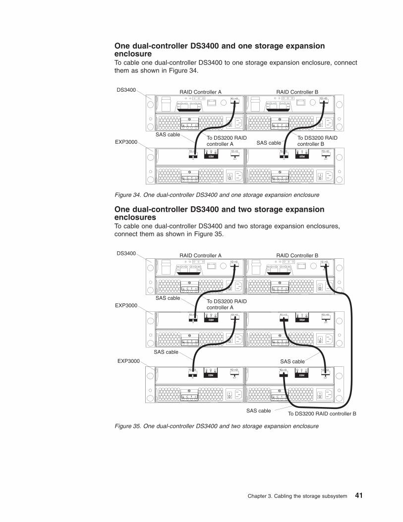
One dual-controller DS3400 and one storage expansionenclosureTo cable one dual-controller DS3400 to one storage expansion enclosure, connectthem as shown in Figure 34.
One dual-controller DS3400 and two storage expansionenclosuresTo cable one dual-controller DS3400 and two storage expansion enclosures,connect them as shown in Figure 35.
DS3400 RAID Controller A RAID Controller B
SAS cable
SAS cableEXP3000
To DS3200 RAIDcontroller A
To DS3200 RAIDcontroller B
Figure 34. One dual-controller DS3400 and one storage expansion enclosure
DS3400 RAID Controller A RAID Controller B
SAS cable
SAS cableEXP3000
To DS3200 RAIDcontroller A
To DS3200 RAID controller B
SAS cable
SAS cableEXP3000
Figure 35. One dual-controller DS3400 and two storage expansion enclosure
Chapter 3. Cabling the storage subsystem 41
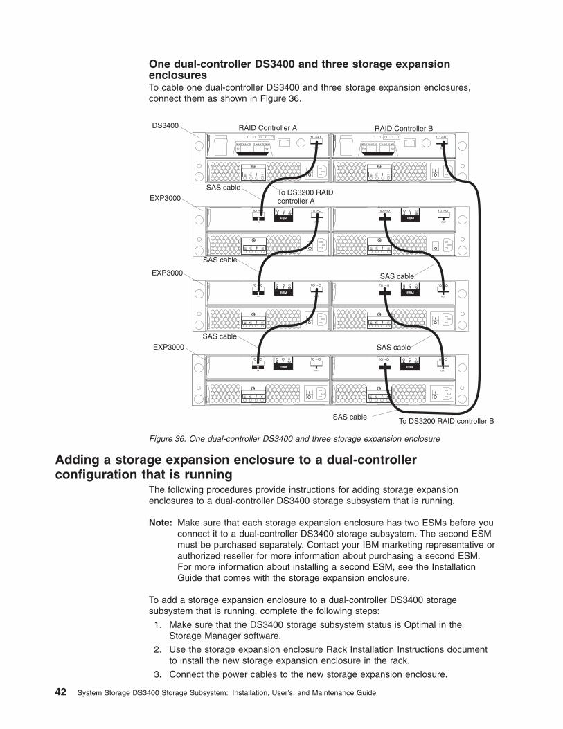
One dual-controller DS3400 and three storage expansionenclosuresTo cable one dual-controller DS3400 and three storage expansion enclosures,connect them as shown in Figure 36.
Adding a storage expansion enclosure to a dual-controllerconfiguration that is running
The following procedures provide instructions for adding storage expansionenclosures to a dual-controller DS3400 storage subsystem that is running.
Note: Make sure that each storage expansion enclosure has two ESMs before youconnect it to a dual-controller DS3400 storage subsystem. The second ESMmust be purchased separately. Contact your IBM marketing representative orauthorized reseller for more information about purchasing a second ESM.For more information about installing a second ESM, see the InstallationGuide that comes with the storage expansion enclosure.
To add a storage expansion enclosure to a dual-controller DS3400 storagesubsystem that is running, complete the following steps:
1. Make sure that the DS3400 storage subsystem status is Optimal in theStorage Manager software.
2. Use the storage expansion enclosure Rack Installation Instructions documentto install the new storage expansion enclosure in the rack.
3. Connect the power cables to the new storage expansion enclosure.
DS3400
SAS cable
SAS cable
EXP3000To DS3200 RAIDcontroller A
To DS3200 RAID controller B
SAS cable
SAS cableEXP3000
SAS cable
SAS cableEXP3000
RAID Controller A RAID Controller B
Figure 36. One dual-controller DS3400 and three storage expansion enclosure
42 System Storage DS3400 Storage Subsystem: Installation, User’s, and Maintenance Guide
4. Power-on the storage expansion enclosure.
5. Connect one end of a Serial Attached SCSI (SAS) cable to the Driveexpansion port on Controller A in the DS3400 storage subsystem.
6. Connect the other end of the SAS cable to the In port on the left ESM in thestorage expansion enclosure.
7. Connect one end of a second SAS cable to the Drive expansion port onController B in the DS3400 storage subsystem.
8. Connect the other end of the second SAS cable to the In port on the rightESM in the storage expansion enclosure.
9. Wait until the DS3400 storage subsystem status is Optimal in the StorageManager software before proceeding to step 10.
10. Add the hard disk drives to the storage expansion enclosure. Make sure thatyou wait at least 30 seconds for the Storage Manager software to recognizeeach newly added drive before you install another drive.
To add additional storage expansion enclosures after the first expansion unit isconnected to a dual-controller DS3400 storage subsystem that is running, completethe following steps:
1. Make sure that the DS3400 storage subsystem status is Optimal in theStorage Manager software.
2. Use the storage expansion enclosure Rack Installation Instructions documentto install the new storage expansion enclosure in the rack.
3. Connect the power cables to the new storage expansion enclosure.
4. Power on the storage expansion enclosure.
5. Connect one end of a Serial Attached SCSI (SAS) cable to the In port on theleft ESM in the storage expansion enclosure that is being added to theconfiguration.
6. Connect the other end of the SAS cable to the Out port on the left ESM in thelast storage expansion enclosure in the configuration (this storage expansionenclosure is directly connected to the Drive expansion port on controller A ofthe DS3400).
7. On the last storage expansion enclosure in the configuration, disconnect theSAS cable from the In port on the right ESM and connect it to the In port onthe right ESM on the new storage expansion enclosure that is being added tothe configuration.
Note: When the SAS cable is disconnected in step 7, a loss of pathredundancy occurs and an error message is displayed in the StorageManager Recovery GURU. Disregard the error message. The redundantpath is restored in step 8 after the SAS cable is connected.
8. Connect a SAS cable to the Out port on the right ESM of the new storageexpansion enclosure and connect the other end to the In port on the right ESMin the storage expansion enclosure that was previously connected to controllerB of the DS3400.
9. Wait until the DS3400 storage subsystem status is Optimal in the StorageManager software before proceeding to step 10.
10. Add the hard disk drives to the storage expansion enclosure. Make sure thatyou wait at least 30 seconds for the Storage Manager software to recognizeeach newly added drive before you install another drive.
Chapter 3. Cabling the storage subsystem 43
Upgrading a single-controller to a dual-controller when there is noattached EXP3000 enclosure
If you are upgrading a single-controller DS3400 storage subsystem to adual-controller DS3400 storage subsystem and there are no EXP3000 storageexpansion enclosures attached to the DS3400 storage subsystem, see “Installing acontroller” on page 77.
Upgrading a single-controller to a dual-controller when there is one ormore EXP3000 enclosures attached to the storage subsystem
Before you upgrade the DS3400 storage subsystem from a single-controller to adual-controller, make sure that:
v You purchase a second environmental services module (ESM) for each EXP3000storage expansion unit that is attached to the DS3400 storage subsystem. Youinstall the second ESM during this procedure.
v You purchase the SAS cables that are required to create a redundant driveenclosure path.
To upgrade a single-controller DS3400 storage subsystem to a dual-controllerDS3400 storage subsystem when there are EXP3000 storage expansion enclosuresattached to the DS3400, complete the following steps:
1. Turn off the DS3400 storage subsystem and all attached EXP3000 storageexpansion enclosures.
2. Install a second RAID controller in the DS3400 storage subsystem by using theinstructions in “Installing a controller” on page 77.
3. Install a second ESM in each EXP3000 that is connected to the DS3400storage subsystem:
a. Read the safety information that begins on page xi and “Best practicesguidelines” on page 6.
b. Remove the ESM filler panel from the rightmost ESM bay of the EXP3000:
1) On the left side of the ESM filler panel, press the orange release tab tothe right just enough to release the handle (no more than 6 mm[0.25 in.]) as you rotate the handle upward.
2) Using the handle, gently slide the ESM filler panel out of the EXP3000.Save the ESM filler panel for future use.
c. Hold the new ESM so that the handle is fully extended.
d. Gently slide the ESM into the bay until it stops. Rotate the handle downwardinto the closed position until it clicks.
4. Using the information provided in “DS3400 storage subsystem drive cablingtopologies” on page 39, use SAS cables to create a redundant drive-channelpath from the DS3400 RAID controllers to the EXP3000 ESMs.
Connecting secondary interface cablesThis section applies to direct (out-of-band) management configurations only. If yourconfiguration uses host-agent (in-band) management, skip this section.
Use the Ethernet management port on the rear of the storage subsystem to connectthe controllers for direct management of the storage subsystems (see “Direct(out-of-band) management method” on page 47).
44 System Storage DS3400 Storage Subsystem: Installation, User’s, and Maintenance Guide
Important:
1. To minimize security risks, do not connect the DS3400 to a public LAN or publicsubnet. Use a local private network for the DS3400 and the managementstation Ethernet connectors.
2. For proper EMI shielding, always use quality braided and shielded serial cables.
Chapter 3. Cabling the storage subsystem 45
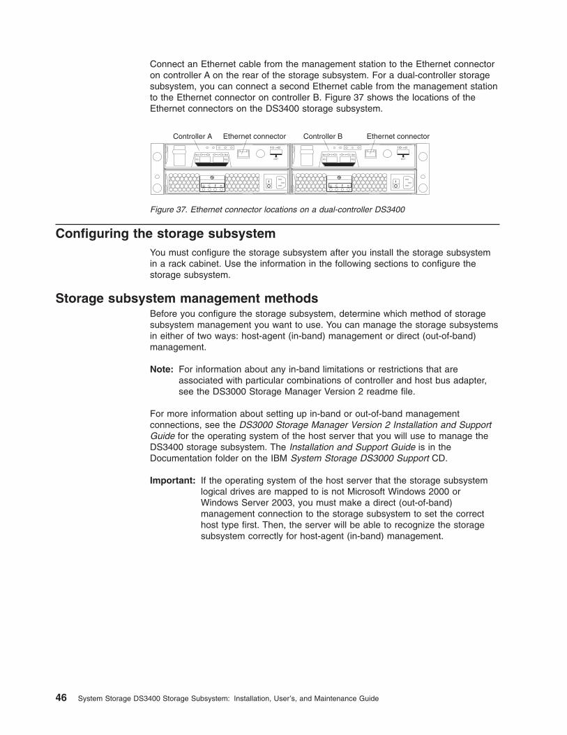
Connect an Ethernet cable from the management station to the Ethernet connectoron controller A on the rear of the storage subsystem. For a dual-controller storagesubsystem, you can connect a second Ethernet cable from the management stationto the Ethernet connector on controller B. Figure 37 shows the locations of theEthernet connectors on the DS3400 storage subsystem.
Configuring the storage subsystemYou must configure the storage subsystem after you install the storage subsystemin a rack cabinet. Use the information in the following sections to configure thestorage subsystem.
Storage subsystem management methodsBefore you configure the storage subsystem, determine which method of storagesubsystem management you want to use. You can manage the storage subsystemsin either of two ways: host-agent (in-band) management or direct (out-of-band)management.
Note: For information about any in-band limitations or restrictions that areassociated with particular combinations of controller and host bus adapter,see the DS3000 Storage Manager Version 2 readme file.
For more information about setting up in-band or out-of-band managementconnections, see the DS3000 Storage Manager Version 2 Installation and SupportGuide for the operating system of the host server that you will use to manage theDS3400 storage subsystem. The Installation and Support Guide is in theDocumentation folder on the IBM System Storage DS3000 Support CD.
Important: If the operating system of the host server that the storage subsystemlogical drives are mapped to is not Microsoft Windows 2000 orWindows Server 2003, you must make a direct (out-of-band)management connection to the storage subsystem to set the correcthost type first. Then, the server will be able to recognize the storagesubsystem correctly for host-agent (in-band) management.
Controller A Ethernet connector Ethernet connectorController B
Figure 37. Ethernet connector locations on a dual-controller DS3400
46 System Storage DS3400 Storage Subsystem: Installation, User’s, and Maintenance Guide
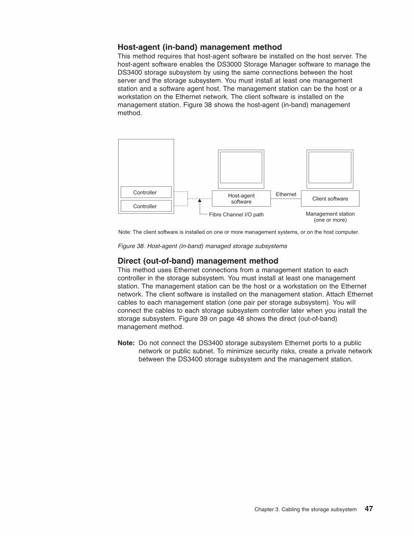
Host-agent (in-band) management methodThis method requires that host-agent software be installed on the host server. Thehost-agent software enables the DS3000 Storage Manager software to manage theDS3400 storage subsystem by using the same connections between the hostserver and the storage subsystem. You must install at least one managementstation and a software agent host. The management station can be the host or aworkstation on the Ethernet network. The client software is installed on themanagement station. Figure 38 shows the host-agent (in-band) managementmethod.
Direct (out-of-band) management methodThis method uses Ethernet connections from a management station to eachcontroller in the storage subsystem. You must install at least one managementstation. The management station can be the host or a workstation on the Ethernetnetwork. The client software is installed on the management station. Attach Ethernetcables to each management station (one pair per storage subsystem). You willconnect the cables to each storage subsystem controller later when you install thestorage subsystem. Figure 39 on page 48 shows the direct (out-of-band)management method.
Note: Do not connect the DS3400 storage subsystem Ethernet ports to a publicnetwork or public subnet. To minimize security risks, create a private networkbetween the DS3400 storage subsystem and the management station.
Host-agentsoftware
Controller
Controller
Fibre Channel I/O path
Client softwareEthernet
Management station(one or more)
Note: The client software is installed on one or more management systems, or on the host computer.
Figure 38. Host-agent (in-band) managed storage subsystems
Chapter 3. Cabling the storage subsystem 47
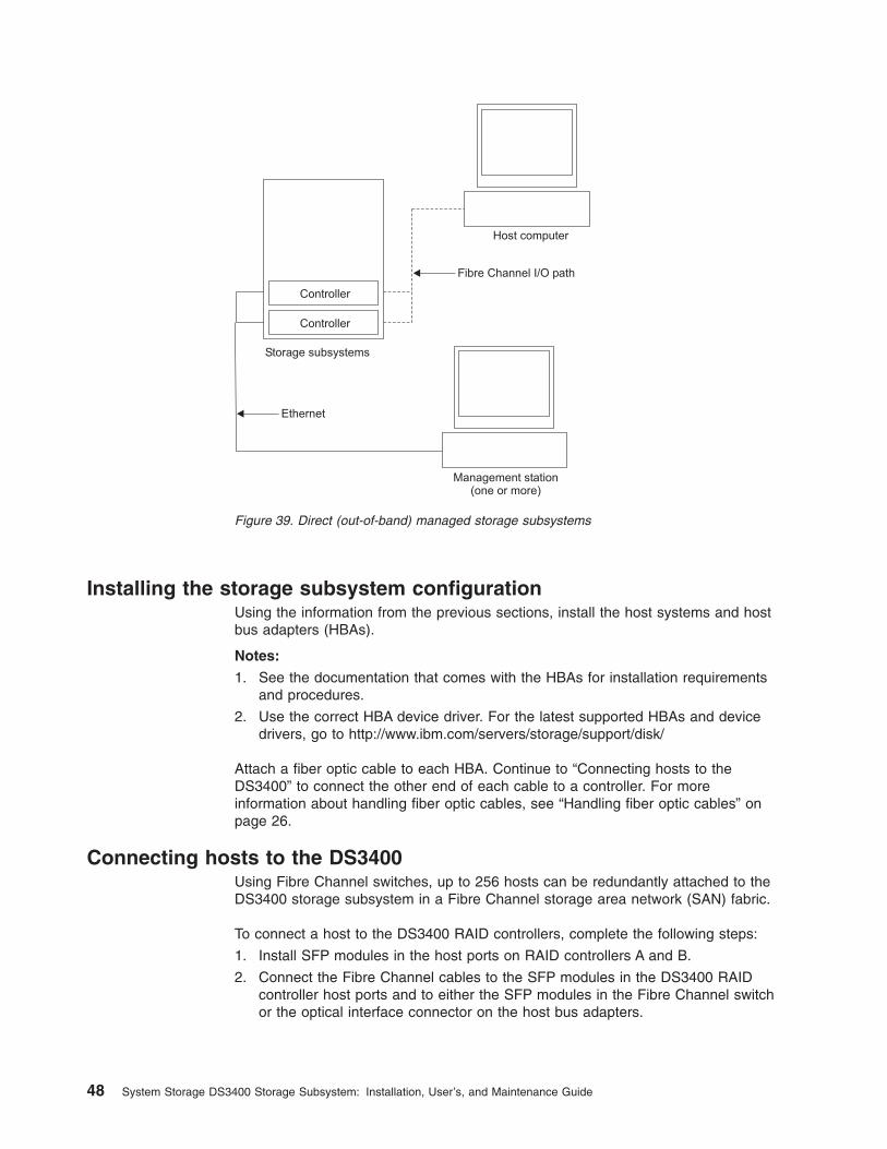
Installing the storage subsystem configurationUsing the information from the previous sections, install the host systems and hostbus adapters (HBAs).
Notes:
1. See the documentation that comes with the HBAs for installation requirementsand procedures.
2. Use the correct HBA device driver. For the latest supported HBAs and devicedrivers, go to http://www.ibm.com/servers/storage/support/disk/
Attach a fiber optic cable to each HBA. Continue to “Connecting hosts to theDS3400” to connect the other end of each cable to a controller. For moreinformation about handling fiber optic cables, see “Handling fiber optic cables” onpage 26.
Connecting hosts to the DS3400Using Fibre Channel switches, up to 256 hosts can be redundantly attached to theDS3400 storage subsystem in a Fibre Channel storage area network (SAN) fabric.
To connect a host to the DS3400 RAID controllers, complete the following steps:
1. Install SFP modules in the host ports on RAID controllers A and B.
2. Connect the Fibre Channel cables to the SFP modules in the DS3400 RAIDcontroller host ports and to either the SFP modules in the Fibre Channel switchor the optical interface connector on the host bus adapters.
Ethernet
Fibre Channel I/O path
Host computer
Management station(one or more)
Controller
Controller
Storage subsystems
Figure 39. Direct (out-of-band) managed storage subsystems
48 System Storage DS3400 Storage Subsystem: Installation, User’s, and Maintenance Guide
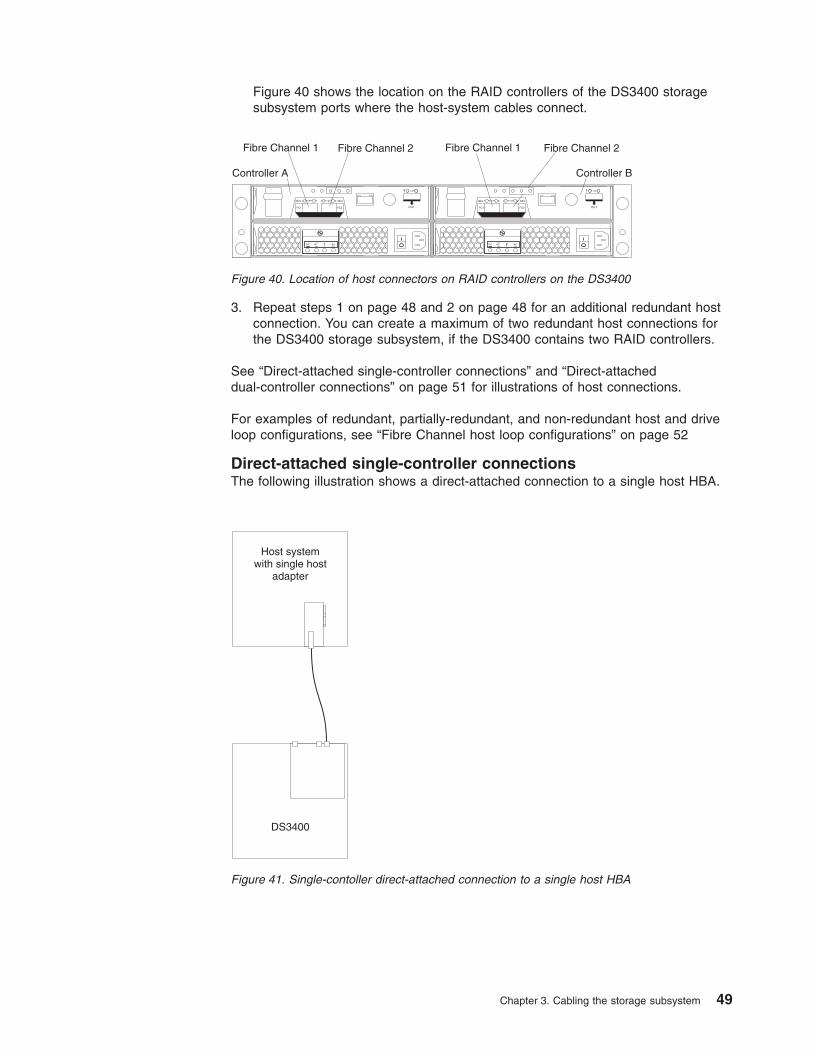
Figure 40 shows the location on the RAID controllers of the DS3400 storagesubsystem ports where the host-system cables connect.
3. Repeat steps 1 on page 48 and 2 on page 48 for an additional redundant hostconnection. You can create a maximum of two redundant host connections forthe DS3400 storage subsystem, if the DS3400 contains two RAID controllers.
See “Direct-attached single-controller connections” and “Direct-attacheddual-controller connections” on page 51 for illustrations of host connections.
For examples of redundant, partially-redundant, and non-redundant host and driveloop configurations, see “Fibre Channel host loop configurations” on page 52
Direct-attached single-controller connectionsThe following illustration shows a direct-attached connection to a single host HBA.
Controller A Controller B
Fibre Channel 1 Fibre Channel 1Fibre Channel 2 Fibre Channel 2
Figure 40. Location of host connectors on RAID controllers on the DS3400
Host systemwith single host
adapter
DS3400
Figure 41. Single-contoller direct-attached connection to a single host HBA
Chapter 3. Cabling the storage subsystem 49
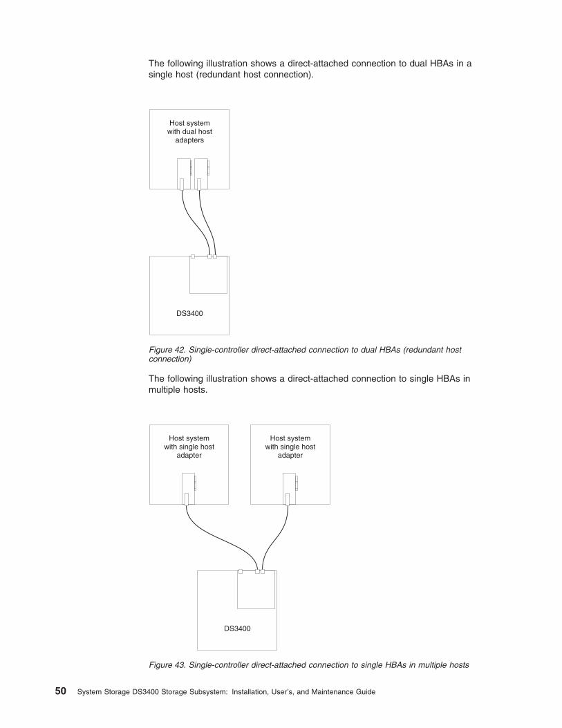
The following illustration shows a direct-attached connection to dual HBAs in asingle host (redundant host connection).
The following illustration shows a direct-attached connection to single HBAs inmultiple hosts.
Host systemwith dual host
adapters
DS3400
Figure 42. Single-controller direct-attached connection to dual HBAs (redundant hostconnection)
DS3400
Host systemwith single host
adapter
Host systemwith single host
adapter
Figure 43. Single-controller direct-attached connection to single HBAs in multiple hosts
50 System Storage DS3400 Storage Subsystem: Installation, User’s, and Maintenance Guide
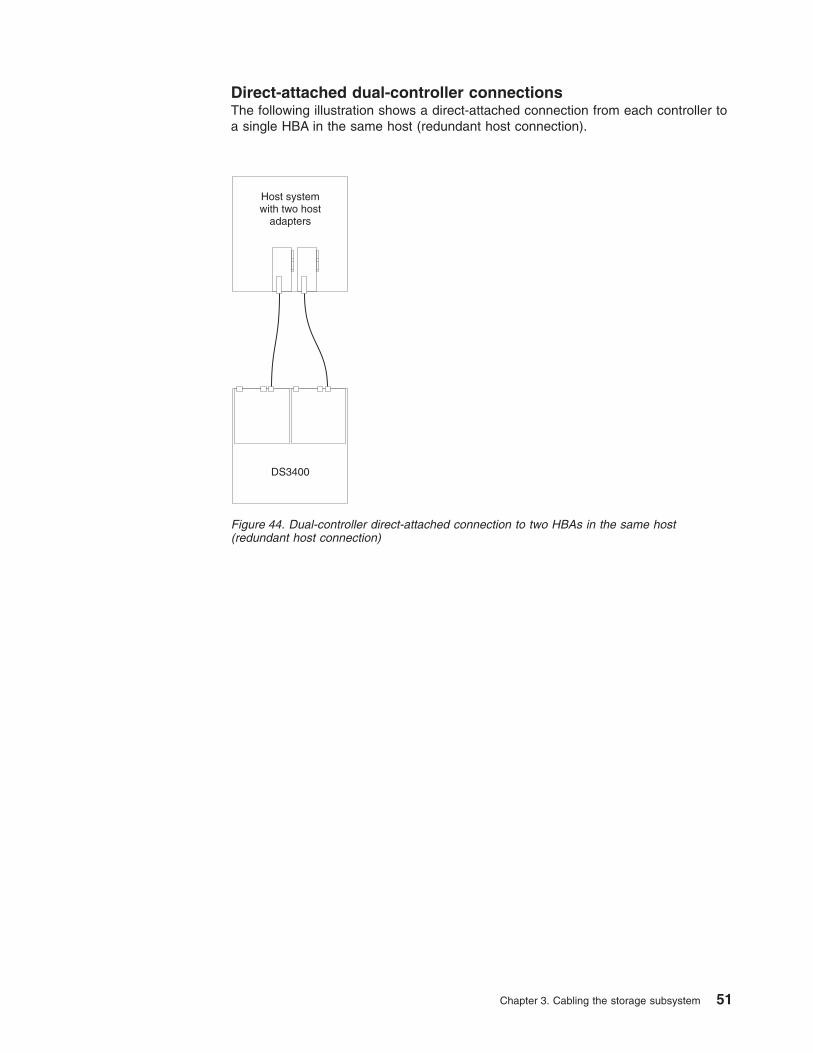
Direct-attached dual-controller connectionsThe following illustration shows a direct-attached connection from each controller toa single HBA in the same host (redundant host connection).
Host systemwith two host
adapters
DS3400
Figure 44. Dual-controller direct-attached connection to two HBAs in the same host(redundant host connection)
Chapter 3. Cabling the storage subsystem 51
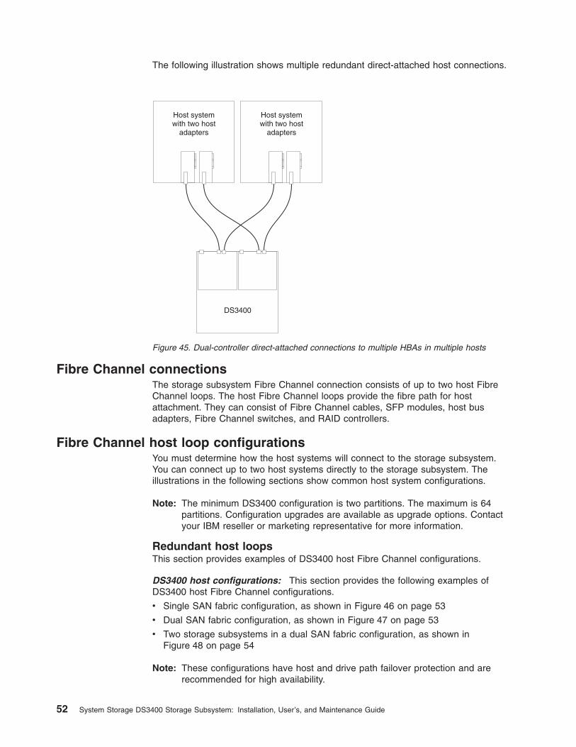
The following illustration shows multiple redundant direct-attached host connections.
Fibre Channel connectionsThe storage subsystem Fibre Channel connection consists of up to two host FibreChannel loops. The host Fibre Channel loops provide the fibre path for hostattachment. They can consist of Fibre Channel cables, SFP modules, host busadapters, Fibre Channel switches, and RAID controllers.
Fibre Channel host loop configurationsYou must determine how the host systems will connect to the storage subsystem.You can connect up to two host systems directly to the storage subsystem. Theillustrations in the following sections show common host system configurations.
Note: The minimum DS3400 configuration is two partitions. The maximum is 64partitions. Configuration upgrades are available as upgrade options. Contactyour IBM reseller or marketing representative for more information.
Redundant host loopsThis section provides examples of DS3400 host Fibre Channel configurations.
DS3400 host configurations: This section provides the following examples ofDS3400 host Fibre Channel configurations.
v Single SAN fabric configuration, as shown in Figure 46 on page 53
v Dual SAN fabric configuration, as shown in Figure 47 on page 53
v Two storage subsystems in a dual SAN fabric configuration, as shown inFigure 48 on page 54
Note: These configurations have host and drive path failover protection and arerecommended for high availability.
DS3400
Host systemwith two host
adapters
Host systemwith two host
adapters
Figure 45. Dual-controller direct-attached connections to multiple HBAs in multiple hosts
52 System Storage DS3400 Storage Subsystem: Installation, User’s, and Maintenance Guide
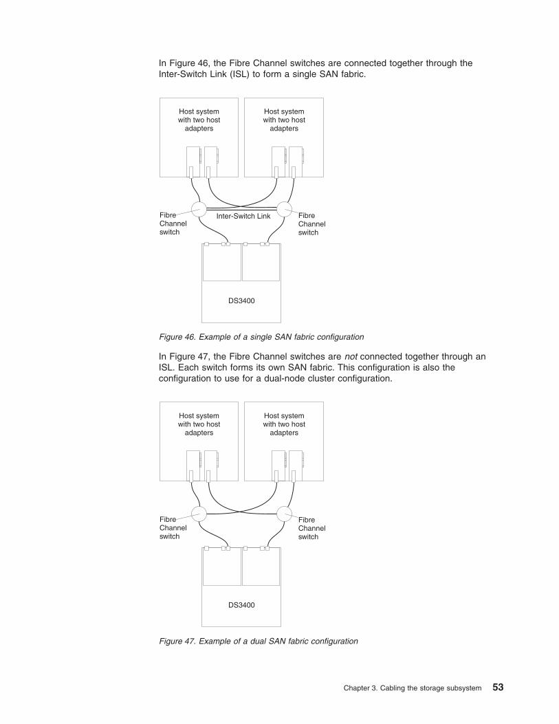
In Figure 46, the Fibre Channel switches are connected together through theInter-Switch Link (ISL) to form a single SAN fabric.
In Figure 47, the Fibre Channel switches are not connected together through anISL. Each switch forms its own SAN fabric. This configuration is also theconfiguration to use for a dual-node cluster configuration.
Host systemwith two host
adapters
Host systemwith two host
adapters
FibreChannelswitch
FibreChannelswitch
DS3400
Inter-Switch Link
Figure 46. Example of a single SAN fabric configuration
Host systemwith two host
adapters
Host systemwith two host
adapters
FibreChannelswitch
FibreChannelswitch
DS3400
Figure 47. Example of a dual SAN fabric configuration
Chapter 3. Cabling the storage subsystem 53
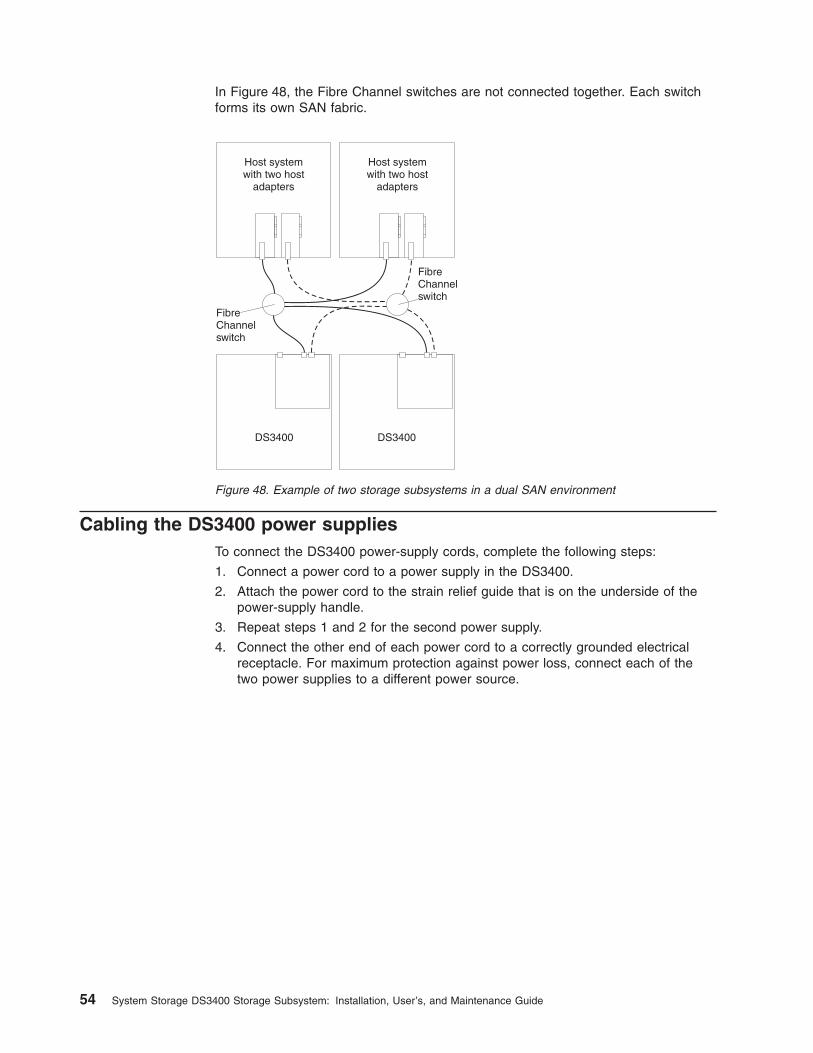
In Figure 48, the Fibre Channel switches are not connected together. Each switchforms its own SAN fabric.
Cabling the DS3400 power suppliesTo connect the DS3400 power-supply cords, complete the following steps:
1. Connect a power cord to a power supply in the DS3400.
2. Attach the power cord to the strain relief guide that is on the underside of thepower-supply handle.
3. Repeat steps 1 and 2 for the second power supply.
4. Connect the other end of each power cord to a correctly grounded electricalreceptacle. For maximum protection against power loss, connect each of thetwo power supplies to a different power source.
DS3400 DS3400
Host systemwith two host
adapters
Host systemwith two host
adapters
FibreChannelswitch
FibreChannelswitch
Figure 48. Example of two storage subsystems in a dual SAN environment
54 System Storage DS3400 Storage Subsystem: Installation, User’s, and Maintenance Guide
Chapter 4. Operating the storage subsystem
This chapter describes operating procedures for the DS3400.
To ensure optimal operation of the storage subsystem, see “Best practicesguidelines” on page 6.
Performing the DS3000 Health Check processThe DS3000 Health Check process is a sequence of suggested actions that weredeveloped by IBM to help you verify and maintain the optimal performance of theDS3400 storage configuration. The information that you collect in these steps alsohelps provide IBM Service with important information that is needed during aservice call.
Perform the following Health Check tasks after the initial configuration of theDS3400 storage subsystems and after all configuration sessions. Set a regularschedule of periodic Health Check evaluations to keep the DS3400 code currentand to preserve optimal data access and performance.
1. Monitor the Recovery Guru in the Storage Manager software for any obviousstorage subsystem errors or problem conditions.
2. Gather and save the following DS3400 storage subsystem event logs for reviewby IBM Service. These event logs should be gathered periodically for regularHealth Check monitoring regardless of the state of the Recovery Guru. (You cancollect all these logs at once and compress them into a single file by clicking theSupport tab and then Gather Support Information in the DS3000 StorageManager Subsystem Management window.)
v DS3400 storage subsystem management event log (MEL)
v Storage Subsystem Profile or DS3400 Profile
v SAS PHY error log
In addition, you should also collect event logs for the host servers that havemapped logical drives from the storage subsystem.
Attention: Save these event-log files to a server disk that will remainaccessible in the event of a DS3400 storage configuration failure. Do not savethese event log files only to a LUN in the DS3400 storage subsystem.
3. Use the Storage Subsystem Profile or DS3400 Profile to make sure that thefollowing firmware levels are at the latest versions that the DS3400 storagesubsystem supports:
v Controller firmware
v ESM firmware
v Drive firmware
If the firmware is not up-to-date, upgrade the firmware and software to the latestlevel that is applicable to the DS3400 storage configuration. See “Overview” onpage 1 for information about where to find the latest firmware and software.
Attention: You must resolve Recovery Guru errors or problems before youupgrade firmware.
Save the storage subsystem profile before you perform any controller or ESMfirmware upgrades. Save the storage subsystem profile and all .cfg files to aserver disk that will remain accessible in the event of a DS3400 storageconfiguration failure.
© Copyright IBM Corp. 2006, 2009 55
4. Use the Storage Subsystem Profile or DS3000 Profile to make sure that thefollowing functions are enabled:
v For all DS3000 models, enable Media Scan both at the controller level and atthe LUN level.
v For all DS3000 models, enable the read/write cache. In addition, use theStorage Subsystem Profile to make sure that cache is matched between thecontrollers.
Hardware inspectionIn addition to the Health Check process, regular hardware inspection andmaintenance helps to support the optimal performance of the DS3400 storageconfiguration. Periodically inspect the components of the DS3400 storageconfiguration.
For best results, follow these guidelines:
v Maintain an up-to-date storage subsystem profile for the DS3400 storageconfiguration. Save the profile to a server disk that will remain accessible in caseof a DS3400 storage configuration failure. Do not save the profile only to a LUNin the DS3400 storage subsystem.
v Develop a change management plan. The plan should include schedules forupdating subsystem firmware and server host software.
Note: Some updates might require storage subsystem downtime.
v Use applicable IBM-approved cables for all situations. Note in the configurationdocumentation whether any cables are not IBM-approved.
v Create and maintain a cabling diagram of the current SAN configuration. Keepthis diagram updated as you make configuration changes, and keep the cablingdiagram available for review.
v Create and maintain a list of other components that are being used within thecabling diagram (such as the host system, Fibre Channel switches, and otherSAN attachments).
v Make sure that all controllers and ESMs are correctly seated.
v Make sure that all drives are correctly seated.
v Make sure that all SFP modules are correctly seated.
v Confirm the Fibre Channel cable loop size. (IBM specifications call for at least3-inch cable loops, but use 6-inch cable loops or longer.)
v Ensure correct cable management.
v Ensure proper air flow and temperature for all components in the storageconfiguration.
You can find details about many of these inspection and maintenanceresponsibilities in the applicable sections of this document.
In addition to these inspection and maintenance responsibilities, conduct DS3400training for staff that support DS3400 storage configurations. Although training is nota part of the Health Check process, training reduces the potential for configurationproblems and contributes to the correct operation of the system.
56 System Storage DS3400 Storage Subsystem: Installation, User’s, and Maintenance Guide
Turning on the storage subsystemThis section contains instructions for turning on the storage subsystem undernormal situations. “Turning off the storage subsystem” on page 65 containsinstructions for turning off the storage subsystem under normal and emergencysituations. When you turn on and turn off the DS3400, be sure to use the startupsequence that is described in this section. If you are turning on the storagesubsystem after an emergency shutdown or power outage, see “Restoring powerafter an unexpected shutdown” on page 68.
The following procedure addresses two situations:
v The entire storage subsystem has been shut down (the main circuit breakers forthe rack cabinet are off).
v Some storage expansion enclosures are being powered-on while others remainonline (the main circuit breakers for the rack cabinet are on). You mightencounter this if you are adding a storage expansion enclosure to increasestorage capacity.
Attention:
1. Repeatedly turning the power off and on without waiting for the drives to spindown can damage the drives. Always wait at least 70 seconds after you turnoff the power before you turn it on again.
2. If you are connecting a power cord to a DS3400 or storage expansionenclosure, turn off both of its power switches first. If the main circuit breakeris off, make sure that both power switches are off on each storage expansionenclosure in the rack cabinet before you turn on the main circuit breakers.
1. Are the main circuit breakers turned on?
v Yes: Turn off both power switches on each enclosure that you intend toconnect to the power.
v No: Turn off both power switches on all enclosures in the storage subsystem.
2. Make sure that all power cords are connected.
Note: If the power cords are not connected, turn off both power switches on allmodules in the configuration before you connect power cords or turn onthe main circuit breakers.
3. If the main circuit breakers are turned off, turn them on.
Attention: You must turn on power to each attached storage expansionenclosure before you turn on power to the DS3400 so that the controllersrecognize all drives in the configuration during the startup process.
4. Turn on both power switches on the rear of each storage expansion enclosurethat is attached to the storage subsystem. While each storage expansionenclosure powers up, the green and amber LEDs on the front and rear of thestorage expansion enclosure turn on and off intermittently. Depending on yourconfiguration, it can take several minutes for each storage expansion enclosureto power-on.
Check the LEDs on the front and rear of all the storage expansion enclosures.Make sure that no amber LEDs are lit on any of the storage expansionenclosures.
Note: The drive activity LEDs will flash slowly (once every 2 seconds) until thedrive is started by the DS3400 controller.
5. Turn on both ac power switches on the rear of the storage subsystem. Figure 49on page 58 shows the locations of the ac power switches on the DS3400.
Chapter 4. Operating the storage subsystem 57
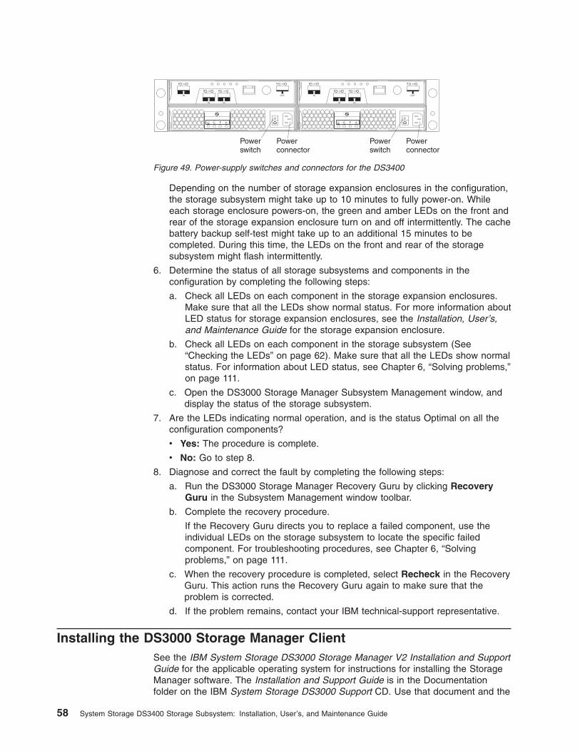
Depending on the number of storage expansion enclosures in the configuration,the storage subsystem might take up to 10 minutes to fully power-on. Whileeach storage enclosure powers-on, the green and amber LEDs on the front andrear of the storage expansion enclosure turn on and off intermittently. The cachebattery backup self-test might take up to an additional 15 minutes to becompleted. During this time, the LEDs on the front and rear of the storagesubsystem might flash intermittently.
6. Determine the status of all storage subsystems and components in theconfiguration by completing the following steps:
a. Check all LEDs on each component in the storage expansion enclosures.Make sure that all the LEDs show normal status. For more information aboutLED status for storage expansion enclosures, see the Installation, User’s,and Maintenance Guide for the storage expansion enclosure.
b. Check all LEDs on each component in the storage subsystem (See“Checking the LEDs” on page 62). Make sure that all the LEDs show normalstatus. For information about LED status, see Chapter 6, “Solving problems,”on page 111.
c. Open the DS3000 Storage Manager Subsystem Management window, anddisplay the status of the storage subsystem.
7. Are the LEDs indicating normal operation, and is the status Optimal on all theconfiguration components?
v Yes: The procedure is complete.
v No: Go to step 8.
8. Diagnose and correct the fault by completing the following steps:
a. Run the DS3000 Storage Manager Recovery Guru by clicking RecoveryGuru in the Subsystem Management window toolbar.
b. Complete the recovery procedure.
If the Recovery Guru directs you to replace a failed component, use theindividual LEDs on the storage subsystem to locate the specific failedcomponent. For troubleshooting procedures, see Chapter 6, “Solvingproblems,” on page 111.
c. When the recovery procedure is completed, select Recheck in the RecoveryGuru. This action runs the Recovery Guru again to make sure that theproblem is corrected.
d. If the problem remains, contact your IBM technical-support representative.
Installing the DS3000 Storage Manager ClientSee the IBM System Storage DS3000 Storage Manager V2 Installation and SupportGuide for the applicable operating system for instructions for installing the StorageManager software. The Installation and Support Guide is in the Documentationfolder on the IBM System Storage DS3000 Support CD. Use that document and the
Powerconnector
Powerswitch
Powerconnector
Powerswitch
Figure 49. Power-supply switches and connectors for the DS3400
58 System Storage DS3400 Storage Subsystem: Installation, User’s, and Maintenance Guide
online help to configure the logical drives, partitions, and so on for the RAIDcontrollers. Follow the instructions in the operating-system documentation to makethe new logical drives accessible to the operating system. Do not proceed with theconfiguration setup until you have completed the DS3000 Storage Managerinstallation.
Assemble any additional items in preparation for software installation. These itemsmight include the following items:
v HBA device drivers
v Controller firmware
v IP addresses for RAID controllers (for out-of-band management only)
v Additional documentation for hosts, HBAs, and storage expansion enclosures
Before any planned system shutdown or after any system additions, removals, ormodifications (including firmware updates, logical drive creations, storagepartitioning definitions, hardware changes, and so on), save the storage subsystemprofile as explained in the DS3000 Storage Manager guide for the operatingsystem. Save the profile in a location other than the logical drives that are createdfor the DS3400.
Always see the readme file that is included with the DS3400 Storage Subsystemfirmware package (whether the firmware is accessed by the Web or a CD) for anyspecial requirements or restrictions that apply to that firmware version.
Note: Be sure to install the DS3000 Storage Manager event monitoring service toenable continuous monitoring of the status of the storage subsystem. Formore information about the importance of this information, see “Monitoringstatus through software.”
Monitoring status through softwareUse the DS3000 Storage Manager software to monitor the status of the storagesubsystem. Run the software constantly, and check it frequently.
Notes:
1. You can monitor only storage subsystems that are within the managementdomain of the storage-management software.
2. If you have not installed the DS3000 Storage Manager Event Monitor service aspart of the storage-management software installation, the DS3000 StorageManager Enterprise Management window must remain open. (If you close thewindow, you will not receive any alert notifications from the managed storagesubsystems.)
For more information, see the Enterprise Management online help.
Important: See the IBM System Storage DS3000 Storage Manager V2 Installationand Support Guide for the applicable operating system for instructionsfor installing the DS3000 Storage Manager Version 2 software. TheInstallation and Support Guide is in the Documentation folder on theIBM System Storage DS3000 Support CD.
In addition, to download the latest version of the DS3000 StorageManager host software, the DS3400 storage subsystem controllerfirmware and NVSRAM, and the latest DS3000 ESM firmware, go tohttp://www.ibm.com/servers/storage/support/disk/.
Chapter 4. Operating the storage subsystem 59
The DS3000 Storage Manager software provides the best way to diagnose andrepair storage-subsystem failures. The software can help you:
v Determine the nature of the failure
v Locate the failed component
v Determine the recovery procedures to repair the failure
Amber (needs attention) LEDs do not necessarily indicate which component hasfailed or must be replaced or which type of recovery procedure you must perform.In some cases (such as when a hard disk drive exceeds its Predictive FailureAnalysis [PFA] threshold), the amber LED is not lit. Only the DS3000 StorageManager software can detect the failure.
For example, the recovery procedure for a PFA flag (impending drive failure) on adrive varies depending on the drive status (hot spare, unassigned, RAID level,current logical drive status, and so on). Depending on the circumstances, a PFAflag on a drive can indicate a high risk of data loss (if the drive is in a RAID 0volume) or a minimal risk (if the drive is unassigned). Only the DS3000 StorageManager software can identify the risk level and provide the necessary recoveryprocedures.
Note: For PFA flags, the system-error LED and hard disk drive status LEDs are notlit, so checking the LEDs will not notify you of the failure, even if the risk ofdata loss is high.
Recovering from a storage-subsystem failure might require you to performprocedures other than replacing the component (such as backing up the logicaldrive). The DS3000 Storage Manager software provides these procedures.
Attention: Not following the software-recovery procedures can result in data loss.In addition, always replace a failing component as soon as possible to minimizeadditional failures that might occur, causing loss of data access.
Firmware updates
Attention: Save the storage subsystem profile before you perform any controlleror ESM firmware upgrades. Save the profile and all configuration (.cfg) files to aserver disk that will remain accessible in the event of a DS3400 storageconfiguration failure. Do not save these files only to a LUN in the storagesubsystem.
To ensure the optimal operation of the storage subsystem and its attached storageexpansion enclosures, the storage expansion enclosure ESM firmware, the DS3400controller firmware, the hard disk drive firmware, and the NVSRAM (for controllersonly) must be up-to-date. Go to http://www.ibm.com/servers/storage/support/disk/ toget the latest updates.
Always see the readme files that are included with the firmware packages for themost up-to-date information about firmware prerequisites, firmware updateinstructions, download-sequence information, and host I/O restrictions, if any. Applythe necessary updates before you configure the storage subsystem arrays andlogical drives. Subscribe to My Support for automatic notifications of firmware orStorage Manager software updates or any important information about the DS3000storage subsystems (see “Product updates” on page 5).
60 System Storage DS3400 Storage Subsystem: Installation, User’s, and Maintenance Guide
Attention: Failure to observe the limitations, prerequisites, sequences, anddependencies in the readme file might result in a loss of data access.
Unless the readme file contains special requirements for the sequence in which youupgrade firmware, perform firmware upgrades in the following sequence:
1. ESM firmware for the storage expansion enclosures
2. Controller firmware
3. Controller NVSRAM
4. Drive firmware
Troubleshooting the storage subsystemThe DS3000 Storage Manager software is the best way to monitor the storagesubsystem, diagnose a problem, and recover from a hardware failure. Run theDS3000 Storage Manager continuously, and frequently check the configurationstatus.
To check the status of and identify a problem with the storage subsystem, completethe following steps. If a problem has occurred, use the DS3000 Storage Managersoftware and the LEDs on the storage subsystem to help locate a failed component.
1. Open the Subsystem Management window.
2. Click the Summary tab, and view the status of the storage subsystem.
3. Does any storage subsystem have a Needs Attention status?
v Yes: Go to step 4.
v No: All components are Optimal. Go to step 5.
4. Click Recovery Guru on the toolbar. Perform the procedure in the RecoveryGuru to correct the problem. The Recovery Guru might direct you to replace thefailed component. If so, go to step 5.
Attention: If the fault requires you to power-off an attached storage expansionenclosure, you might have to cycle the power on the DS3400 storagesubsystem and all remaining storage expansion enclosures that are connectedto the storage subsystem. Contact your IBM technical-support representativebefore you power-off any attached storage expansion enclosures.
5. Check the LEDs on the front and the rear of the storage expansion enclosure. Agreen LED indicates a normal status; an amber LED indicates a hardware fault.
6. Is an amber LED lit?
v Yes: Locate and troubleshoot the failed components. See “Checking theLEDs” on page 62.
v No: You are finished with this procedure. If you are still experiencing aproblem with the storage subsystem, create, save, and print a storagesubsystem profile, and contact your IBM technical-support representative forassistance. When the recovery procedure is completed, select Recheck inthe Recovery Guru to run the Recovery Guru again to make sure that theproblem is corrected.
Chapter 4. Operating the storage subsystem 61
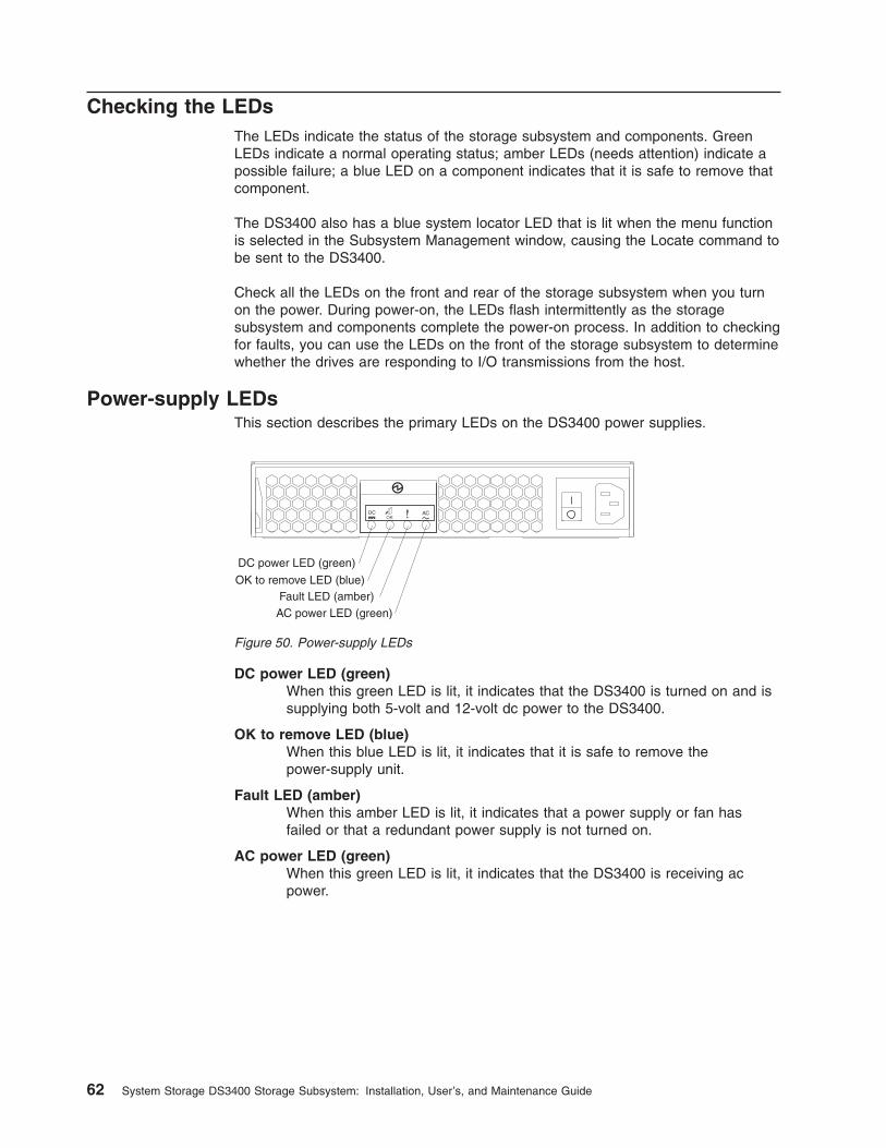
Checking the LEDsThe LEDs indicate the status of the storage subsystem and components. GreenLEDs indicate a normal operating status; amber LEDs (needs attention) indicate apossible failure; a blue LED on a component indicates that it is safe to remove thatcomponent.
The DS3400 also has a blue system locator LED that is lit when the menu functionis selected in the Subsystem Management window, causing the Locate command tobe sent to the DS3400.
Check all the LEDs on the front and rear of the storage subsystem when you turnon the power. During power-on, the LEDs flash intermittently as the storagesubsystem and components complete the power-on process. In addition to checkingfor faults, you can use the LEDs on the front of the storage subsystem to determinewhether the drives are responding to I/O transmissions from the host.
Power-supply LEDsThis section describes the primary LEDs on the DS3400 power supplies.
DC power LED (green)When this green LED is lit, it indicates that the DS3400 is turned on and issupplying both 5-volt and 12-volt dc power to the DS3400.
OK to remove LED (blue)When this blue LED is lit, it indicates that it is safe to remove thepower-supply unit.
Fault LED (amber)When this amber LED is lit, it indicates that a power supply or fan hasfailed or that a redundant power supply is not turned on.
AC power LED (green)When this green LED is lit, it indicates that the DS3400 is receiving acpower.
Fault LED (amber)AC power LED (green)
OK to remove LED (blue)
DC power LED (green)
Figure 50. Power-supply LEDs
62 System Storage DS3400 Storage Subsystem: Installation, User’s, and Maintenance Guide
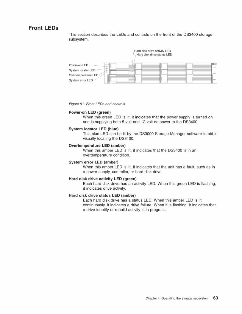
Front LEDsThis section describes the LEDs and controls on the front of the DS3400 storagesubsystem.
Power-on LED (green)When this green LED is lit, it indicates that the power supply is turned onand is supplying both 5-volt and 12-volt dc power to the DS3400.
System locator LED (blue)This blue LED can be lit by the DS3000 Storage Manager software to aid invisually locating the DS3400.
Overtemperature LED (amber)When this amber LED is lit, it indicates that the DS3400 is in anovertemperature condition.
System error LED (amber)When this amber LED is lit, it indicates that the unit has a fault, such as ina power supply, controller, or hard disk drive.
Hard disk drive activity LED (green)Each hard disk drive has an activity LED. When this green LED is flashing,it indicates drive activity.
Hard disk drive status LED (amber)Each hard disk drive has a status LED. When this amber LED is litcontinuously, it indicates a drive failure. When it is flashing, it indicates thata drive identify or rebuild activity is in progress.
Hard disk drive activity LEDHard disk drive status LED
System StoragePower-on LED
System locator LED
System error LED
Overtemperature LED
Figure 51. Front LEDs and controls
Chapter 4. Operating the storage subsystem 63
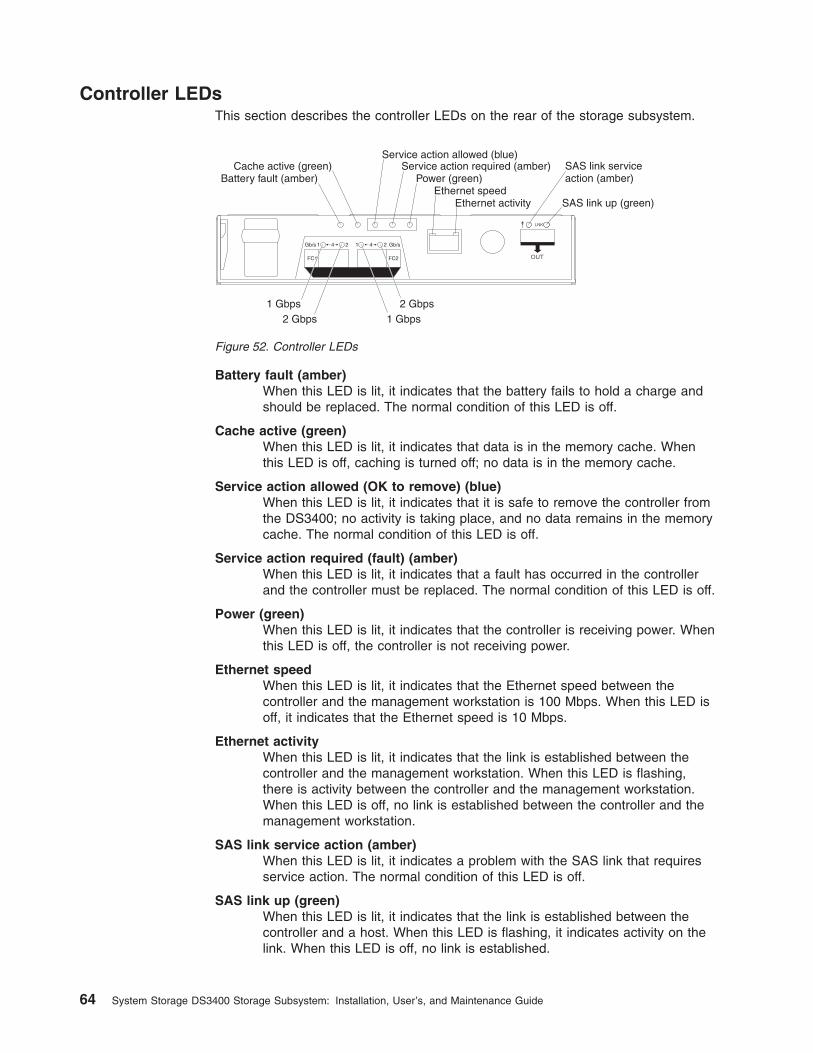
Controller LEDsThis section describes the controller LEDs on the rear of the storage subsystem.
Battery fault (amber)When this LED is lit, it indicates that the battery fails to hold a charge andshould be replaced. The normal condition of this LED is off.
Cache active (green)When this LED is lit, it indicates that data is in the memory cache. Whenthis LED is off, caching is turned off; no data is in the memory cache.
Service action allowed (OK to remove) (blue)When this LED is lit, it indicates that it is safe to remove the controller fromthe DS3400; no activity is taking place, and no data remains in the memorycache. The normal condition of this LED is off.
Service action required (fault) (amber)When this LED is lit, it indicates that a fault has occurred in the controllerand the controller must be replaced. The normal condition of this LED is off.
Power (green)When this LED is lit, it indicates that the controller is receiving power. Whenthis LED is off, the controller is not receiving power.
Ethernet speedWhen this LED is lit, it indicates that the Ethernet speed between thecontroller and the management workstation is 100 Mbps. When this LED isoff, it indicates that the Ethernet speed is 10 Mbps.
Ethernet activityWhen this LED is lit, it indicates that the link is established between thecontroller and the management workstation. When this LED is flashing,there is activity between the controller and the management workstation.When this LED is off, no link is established between the controller and themanagement workstation.
SAS link service action (amber)When this LED is lit, it indicates a problem with the SAS link that requiresservice action. The normal condition of this LED is off.
SAS link up (green)When this LED is lit, it indicates that the link is established between thecontroller and a host. When this LED is flashing, it indicates activity on thelink. When this LED is off, no link is established.
1 Gbps1 Gbps2 Gbps
2 Gbps
SAS link serviceaction (amber)
SAS link up (green)
Battery fault (amber)Cache active (green) Service action required (amber)
Service action allowed (blue)
Power (green)Ethernet speed
Ethernet activity
Figure 52. Controller LEDs
64 System Storage DS3400 Storage Subsystem: Installation, User’s, and Maintenance Guide
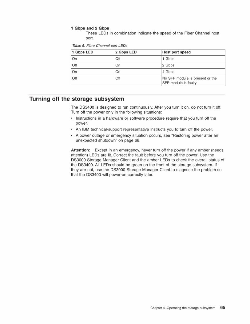
1 Gbps and 2 GbpsThese LEDs in combination indicate the speed of the Fiber Channel hostport.
Table 5. Fibre Channel port LEDs
1 Gbps LED 2 Gbps LED Host port speed
On Off 1 Gbps
Off On 2 Gbps
On On 4 Gbps
Off Off No SFP module is present or theSFP module is faulty
Turning off the storage subsystemThe DS3400 is designed to run continuously. After you turn it on, do not turn it off.Turn off the power only in the following situations:
v Instructions in a hardware or software procedure require that you turn off thepower.
v An IBM technical-support representative instructs you to turn off the power.
v A power outage or emergency situation occurs, see “Restoring power after anunexpected shutdown” on page 68.
Attention: Except in an emergency, never turn off the power if any amber (needsattention) LEDs are lit. Correct the fault before you turn off the power. Use theDS3000 Storage Manager Client and the amber LEDs to check the overall status ofthe DS3400. All LEDs should be green on the front of the storage subsystem. Ifthey are not, use the DS3000 Storage Manager Client to diagnose the problem sothat the DS3400 will power-on correctly later.
Chapter 4. Operating the storage subsystem 65
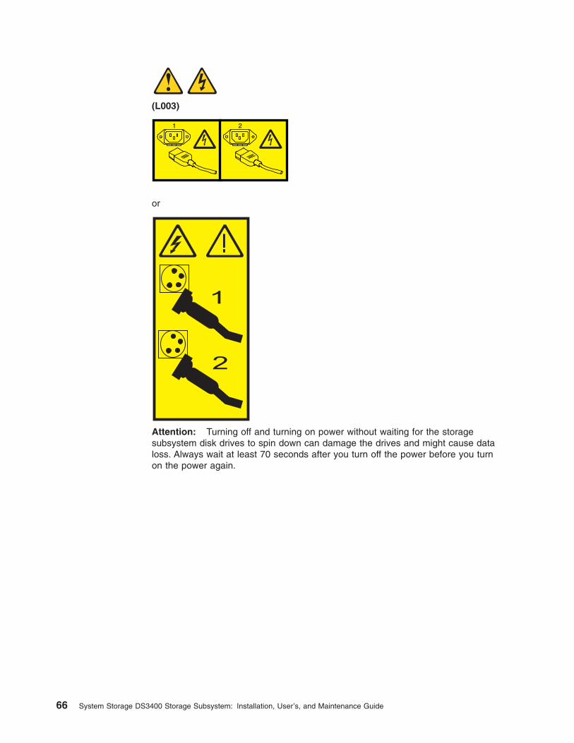
(L003)
1 2
or
!
1
2
Attention: Turning off and turning on power without waiting for the storagesubsystem disk drives to spin down can damage the drives and might cause dataloss. Always wait at least 70 seconds after you turn off the power before you turnon the power again.
66 System Storage DS3400 Storage Subsystem: Installation, User’s, and Maintenance Guide
Power-off overviewReview the following information before you continue with the power-offprocedure.
Turn off the power to each device according to the following shutdownsequence:
1. Turn off power to the host before the storage subsystem. If the host muststay powered-on to support a network, see the operating-systemdocumentation for information about disconnecting the storage subsystemlogical drives from the host before the storage subsystem is powered-off.
2. Turn off power to the storage subsystem before you turn off power to thestorage expansion enclosures. Turn off both power-supply switches on therear of the storage subsystem.
3. Turn off power to other supporting devices (for example, managementstations or Fibre Channel switches).
Note: You do not have to perform this step if you are servicing only thestorage subsystem.
To turn off power to one or more storage subsystems for a planned shutdown,complete the steps in the following procedure. To turn off power for an unplannedshutdown, see “Restoring power after an unexpected shutdown” on page 68.Figure 49 on page 58 shows the locations of the power switches on a storagesubsystem.
Before you proceed, use the Storage Manager software to determine the status ofthe system components and special instructions. The operating-system softwaremight require you to perform other procedures before you turn off the power.
1. Stop all I/O activity to each storage subsystem.
2. Determine the status of all storage subsystems and components in theconfiguration by completing the following steps:
a. Check all LEDs on each component in the storage expansion enclosures.Make sure that all the LEDs show normal status.
b. Check all LEDs on each component in the storage subsystem. Make surethat all the LEDs show normal status.
c. Review the status of the configuration in the Subsystem Managementwindow by clicking the Summary tab.
The status is either Optimal or Needs Attention.
3. Do the LEDs indicate normal operation, and is the status Optimal on allconfiguration components?
v Yes: Go to step 5 on page 68.
v No: Go to step 4.
4. To diagnose and correct the fault, complete the following steps:
a. Run the Recovery Guru by clicking Recovery Guru in the toolbar in theSubsystem Management window.
b. Complete the recovery procedure.
If the Recovery Guru directs you to replace a failed component, use theindividual LEDs to locate the failed component.
Chapter 4. Operating the storage subsystem 67
c. When the recovery procedure is completed, click Recheck in the RecoveryGuru. This action runs the Recovery Guru again to make sure that theproblem is corrected.
d. If the problem has not been corrected, contact your IBM technical-supportrepresentative. Do not turn off power until all problems are corrected.
5. Check the cache active LED, and make sure that it is off.
If the cache active LED is lit, the cache contains data. Wait for the data to clearfrom cache memory before you turn off the power.
6. Check the LEDs on the storage expansion enclosures to make sure that alldrive activity LEDs are off.
If one or more LEDs are flashing, data is being written to or from the drives.Wait for all activity LEDs to stop flashing.
7. Turn off the ac power switch on the rear of each controller in the storagesubsystem.
Note: Until the power switch on each controller is turned off, power remainsturned on for both controllers.
8. Turn off both power switches on the rear of each storage expansion enclosurein the configuration.
9. After you perform the necessary maintenance procedures, turn on the power,using the procedure in “Turning on the storage subsystem” on page 57.
Performing an emergency shutdownAttention: Emergency situations might include fire, flood, extreme weatherconditions, or other hazardous circumstances. If a power outage or emergencysituation occurs, always turn off all power switches on all computing equipment.This helps to safeguard your equipment from potential damage due to electricalsurges when power is restored. If the storage subsystem loses power unexpectedly,it might be due to a hardware failure in the power system or in the midplane.
To shut down the system during an emergency, complete the following steps:
1. If you have time, stop all I/O activity to the storage subsystem by shutting downthe host or disconnecting the storage subsystem logical drives through the host.
2. Check the LEDs. Make note of any amber LEDs that are lit so that you cancorrect the problem when you turn on the power again.
3. Turn off all power-supply switches, starting with the DS3400 storage subsystemfirst and followed by the storage expansion enclosures. Then, disconnect thepower cables from the storage subsystem.
Restoring power after an unexpected shutdownTo restore power to the storage subsystem in a configuration after an unplannedshutdown, complete the following steps..
DANGER
Never turn on any equipment when there is evidence of fire, water, orstructural damage.
1. After the emergency situation is over or power is restored, visually check thestorage subsystem for damage. Is there evidence of damage to any of thestorage subsystem components, cables, or equipment that is attached to thestorage subsystem?
68 System Storage DS3400 Storage Subsystem: Installation, User’s, and Maintenance Guide
v Yes: Do not continue with this procedure. Contact your IBM technical-supportrepresentative for assistance. Depending on the current service agreements,you might have to return the equipment to the factory or local service centerfor repair.
v No: Go to step 2.
Attention: To avoid potential data loss, make sure that the storagesubsystem and storage expansion enclosure power switches are turned offbefore you reset circuit breakers in the rack cabinet. Resetting circuitbreakers after an emergency situation while the storage subsystem andstorage expansion enclosure power switches are turned on can cause dataloss, because the configuration components might not be powered-on in thecorrect sequence. See “Turning on the storage subsystem” on page 57 fordetails about the correct power-on sequence.
2. After you check the storage subsystem for damage, make sure that the powerswitches are off; then connect the DS3400 power cables, if required.
3. Check the system documentation of the hardware devices that you want to turnon and determine the correct startup sequence.
Be sure to turn on all of the storage expansion enclosures and make sure thatno ESM or power-supply fault LEDs are lit before you turn on the DS3400.
In addition, consider the following items:
v The storage subsystem supports simultaneous power-on of the systemcomponents; however, always follow the power-on sequence that is describedin the “Turning on the storage enclosure" section of the applicableInstallation, User’s, and Maintenance Guide during any attended power-onprocedure.
v A storage subsystem in an optimal state recovers automatically from anunexpected shutdown and unattended simultaneous restoration of power tosystem components. After power is restored, contact your IBMtechnical-support representative if any of the following conditions occur:
– The storage subsystem logical drives and subsystems are not displayed inthe Storage Manager graphical user interface.
– The storage subsystem logical drives and subsystems do not come online.
– The storage subsystem logical drives and subsystems seem to bedegraded.
4. Turn on the power to each device, according to the startup sequence.
5. Turn on both of the power-supply switches on the DS3400. The green LEDs onthe front and the rear of the DS3400 should remain lit. If other amber LEDs arelit, see Chapter 6, “Solving problems,” on page 111.
Recovering from an overheated power supplyEach storage subsystem contains two power supplies. Each power supply containsa built-in temperature sensor to prevent the power supply from overheating. Undernormal operating conditions, with an ambient air temperature range of 10°C to 35°C(50°F to 95°F), the fans in the power-supply units maintain a suitable operatingtemperature inside the module.
If the internal temperature reaches 65°C (149°F), the power supply shuts downautomatically. If both power supplies shut down because of overheating, the storagesubsystem has no power, and all LEDs are off.
The following factors can cause the power supplies to overheat:
Chapter 4. Operating the storage subsystem 69
v An unusually high room temperature
v Fan failures in the power-supply units
v Defective circuitry in a power supply
v Blocked air vents
v Failures in other devices in the configuration or rack cabinet
If a fan failure causes overheating, the system-error LED and overtemperatureLEDs on the storage subsystem are lit. The fault LED on the power supply mightalso be lit. “Checking the LEDs” on page 62 shows the location of the LEDs on theDS3400.
If the storage subsystem temperature exceeds 45°C (113°F), the storagemanagement software displays a Needs Attention icon in the SubsystemManagement window. If the air temperature inside the rack cabinet reaches 65°C(149°F), the power supplies automatically shut down. If event monitoring is enabledand event notification is configured, the software issues two critical-problemnotifications.
v If one power supply shuts down, the storage management software displays aNeeds Attention status in the Subsystem Management window.
v If both power supplies shut down, the storage subsystem shuts down, and thestorage management software displays a Not Responding status in the ArrayManagement window.
Attention: To prevent damage to the DS3400 storage subsystem componentswhen the power supplies automatically shut down, immediately remove all rackcabinet panels to help reduce the rack cabinet air temperature.
To resume normal operation after a power-supply shutdown, complete the followingsteps:
1. Did you use the procedure in “Troubleshooting the storage subsystem” onpage 61 to identify an overheating problem?
v Yes: Go to step 2.
v No: Perform the procedure in “Troubleshooting the storage subsystem” onpage 61 to make sure that the power supplies have shut down because ofan overheating problem, and then go to step 2.
2. Stop I/O activity to the storage subsystem and all attached storage expansionenclosures.
3. Take all or some of the following measures to alleviate the overheatingproblem:
v Remove all panels from the rack cabinet immediately.
v Use external fans to cool the area.
v Shut down the power to the storage expansion enclosure, using theprocedure that is described in “Performing an emergency shutdown” onpage 68.
4. Wait for the air in and around the storage subsystem to cool.
After the temperature inside the power supplies drops to below 65°C (149°F),the storage subsystem is capable of power-on recovery without operatorintervention. After the air has cooled, the power supplies should turn onautomatically. If the power supplies restart automatically, the controllers willreset and return to normal operation.
5. Did the power supplies restart automatically?
v Yes: Go to step 8 on page 71.
70 System Storage DS3400 Storage Subsystem: Installation, User’s, and Maintenance Guide
v No: Go to step 6.
6. Turn off both power switches on the DS3400 (see Figure 49 on page 58) andthen power-off all connected storage expansion enclosures. Wait 1 minute andthen turn on power to all connected storage expansion enclosures.
While a storage expansion enclosure powers-on, the LEDs on the front andthe rear of the enclosure flash intermittently. Depending on your configuration,the storage expansion enclosure can take between 20 seconds and severalminutes to power-on.
7. Turn on both power switches on the rear of the DS3400. See Figure 49 onpage 58.
A storage subsystem can take 10 seconds to power-on and up to 15 minutesfor the battery self-test to be completed. During this time, the LEDs on thefront and the rear of the DS3400 flash intermittently.
8. Check the LEDs on the front and rear of the DS3400 storage subsystem andeach attached storage expansion enclosure (a green LED indicates a normalstatus; an amber LED indicates a hardware fault); then, check the array statusin the Subsystem Management window.
a. Open the Subsystem Management window for the storage array.
b. Click the Summary tab and review the status of the configuration.
The status is either Optimal or Needs Attention.
9. Does each module (RAID controller, power supply, ESM) display green statusLEDs only, and is the status Optimal for each module component?
v Yes: Go to step 11.
v No: Go to step 10.
10. Diagnose and correct the fault.
a. To run the Recovery Guru, click Recovery Guru in the SubsystemManagement window toolbar.
b. Complete the recovery procedure.
If the Recovery Guru directs you to replace a failed component, locate andtroubleshoot that component. See “Checking the LEDs” on page 62.
c. When the procedure is completed, select Recheck in the Recovery Guru.This runs the Recovery Guru again to make sure that the problem iscorrected.
d. If the problem remains, contact your IBM technical-support representative.
11. Replace the bezel on the storage expansion enclosure, if applicable.
Cache memory and cache batteryEach RAID controller in the DS3400 storage subsystem supports either 512 MB or1 GB of cache memory to store read and write operations. (Both RAID controllers inthe DS3400 must have the same amount of cache memory.) The battery in eachcontroller can maintain the data in the RAID controller cache for up to 3 days in theevent that the DS3400 storage subsystem loses power.
Cache memoryCache memory is memory on the RAID controller that is used for intermediatestorage of read and write data on the DS3400 RAID controllers. Using cachememory can increase system performance. The data for a read operation from thehost might be in the cache memory from a previous operation (thus eliminating theneed to access the drive itself), and a write operation is completed when it is writtento the cache, rather than to the drives.
Chapter 4. Operating the storage subsystem 71
The RAID controller has a cache active LED that indicates the current status of thecache. The LED is lit if there is data in the cache, and it is off if there is no data inthe cache.
If caching is enabled and the cache active LED is not lit during I/O activity, itindicates one of the following conditions:
v The cache memory from either controller A or controller B has failed.
v The cache sizes in controller A and controller B are not the same.
v The battery has failed. (In this case, the amber battery fault LED is lit.)
Note: Always use the DS3000 Storage Manager software to check the cachememory settings before you assume that a hardware failure has occurred.
See “Controller LEDs” on page 64 for the location of the cache active LED on aRAID controller.
Controller cache batteryThe battery in each controller provides backup power to maintain any cached datathat was not written to disks, in the event of a power loss. The battery in acontroller can provide power to the data cache in the controller for up to3 days.
CAUTION:The battery is a lithium ion battery. To avoid possible explosion, do not burn.Exchange only with the IBM-approved part. Recycle or discard the battery asinstructed by local regulations. In the United States, IBM has a process forthe collection of this battery. For information, call 1-800-426-4333. Have theIBM part number for the battery unit available when you call. (C007)
Replace a battery in the DS3400 when it is identified as failing by the DS3000Storage Manager Subsystem Management window, or when the battery fault LEDon the RAID controller is lit. See “Controller LEDs” on page 64 for the location ofthe battery fault LED.
If the DS3400 has two RAID controllers, replace only the battery that is indicated asfailed in the DS3000 Storage Manager Subsystem Management window. You do nothave to replace the batteries in both controllers if only one battery has failed.
The controller performs a learn-cycle test every thirteen weeks. During thelearn-cycle test, the controller cache battery is discharged and then recharged todetermine the full charge capacity of the battery pack and to extend the life of thebattery.
Note: The controller performs a learn-cycle test after a controller cache battery isreplaced.
If the battery fails the learn-cycle test, the battery fault LED is lit, indicating a batteryfault, and a Defect Battery error message is displayed in the event log.
72 System Storage DS3400 Storage Subsystem: Installation, User’s, and Maintenance Guide
In the Storage Manager software, if the battery age timer indicates that the batteryis 2 years old, but the battery is not reported as failed, do not call your IBMtechnical-support representative to replace the battery. Instead, reset the batteryage by using the procedure that is described in the Storage Manager softwareonline help.
Attention: Write caching is suspended while a battery is either charging orperforming learn-cycle testing.
Controller battery age timerThe controller maintains a battery age timer for the controller cache battery. Thetimer is set to indicate when the battery is 2 years old. Thirty days before thebattery expiration date, a warning message is displayed in the DS3000 StorageManager software.
After you replace a controller cache battery, reset the battery age timer. Forinformation about resetting the batter age timer, see the Storage Manager softwareonline help.
If the controller is running firmware version 07.35.41.00 or later, the controller usesa smart battery learn-cycle test. The smart battery learn-cycle determines when thecache battery is defective and needs to be replaced. The battery learn-cycle testremoves the need to rely on the battery age timer to determine the expiration dateof the cache battery. If the cache battery expiration message is still displayed afteryou replace a controller cache battery, reset the battery age timer.
Chapter 4. Operating the storage subsystem 73

74 System Storage DS3400 Storage Subsystem: Installation, User’s, and Maintenance Guide
Chapter 5. Replacing components
This chapter contains information about replacing the storage subsystemcomponents.
Attention: Always replace a failed component as soon as possible. The RecoveryGuru in the DS3000 Storage Manager software identifies failed components.
Service action allowed LEDEach controller and power supply has a blue service action allowed LED. Thepurpose of the service action allowed LED is to help ensure that a component is notremoved before it is safe to do so. Do not remove any DS3400 component unlessthe component service action allowed LED is lit.
AttentionIf you remove a controller or power supply when the service action allowedLED is not lit, a loss of data availability can result. If an amber LED is lit andthe associated service action allowed LED is not lit, you must performadditional diagnostics before you can remove the indicated component. Usethe Recovery Guru instructions in the DS3000 Storage Manager SubsystemManagement window or see the applicable component replacementinstructions in this chapter for the additional diagnostics that are required inthis case.
The service action allowed LED is lit or turned off automatically as conditionschange. Wait at least 2 minutes after you replace a component for the storagesubsystem to recognize the new component and update the LED status. In mostcases, when a single component fails, the service action allowed LED remains litwhen the amber LED is lit for the component.
Removing a controller
Attention: Before you remove a controller in a single-controller DS3400, shutdown the DS3400 to avoid data loss (see “Turning off the storage subsystem” onpage 65).
To remove a controller from the storage subsystem, complete the following steps:
1. Read the safety information that begins on page xi and “Best practicesguidelines” on page 6.
Attention: Never remove a controller unless the service action allowed LED islit. Doing so can result in a loss of data.
2. If the controller has failed, do not continue with this procedure. Instead, go to“Replacing a controller” on page 80.
Attention: Handle and install fiber optic or SAS cables correctly to avoiddegraded performance or loss of communication with devices. When you workwith fiber optic or SAS cables, do not pinch them, step on them, or locate themin aisles or walkways. Do not overtighten the cable straps or bend the cables toa radius smaller than 38 mm (1.5 in.).
3. Disconnect all attached interface cables from the failed controller, including theSFP modules. Be sure to label each cable so that you can reconnect it correctly.
© Copyright IBM Corp. 2006, 2009 75
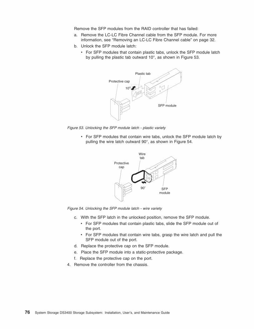
Remove the SFP modules from the RAID controller that has failed:
a. Remove the LC-LC Fibre Channel cable from the SFP module. For moreinformation, see “Removing an LC-LC Fibre Channel cable” on page 32.
b. Unlock the SFP module latch:
v For SFP modules that contain plastic tabs, unlock the SFP module latchby pulling the plastic tab outward 10°, as shown in Figure 53.
v For SFP modules that contain wire tabs, unlock the SFP module latch bypulling the wire latch outward 90°, as shown in Figure 54.
c. With the SFP latch in the unlocked position, remove the SFP module.
v For SFP modules that contain plastic tabs, slide the SFP module out ofthe port.
v For SFP modules that contain wire tabs, grasp the wire latch and pull theSFP module out of the port.
d. Replace the protective cap on the SFP module.
e. Place the SFP module into a static-protective package.
f. Replace the protective cap on the port.
4. Remove the controller from the chassis.
Protective cap
SFP module
10
Plastic tab
Figure 53. Unlocking the SFP module latch - plastic variety
Protectivecap
SFPmodule
90
Wiretab
Figure 54. Unlocking the SFP module latch - wire variety
76 System Storage DS3400 Storage Subsystem: Installation, User’s, and Maintenance Guide
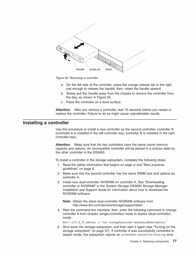
a. On the left side of the controller, press the orange release tab to the rightjust enough to release the handle; then, rotate the handle upward.
b. Slowly pull the handle away from the chassis to remove the controller fromthe bay, as shown in Figure 55.
c. Place the controller on a level surface.
Attention: After you remove a controller, wait 70 seconds before you reseat orreplace the controller. Failure to do so might cause unpredictable results.
Installing a controllerUse this procedure to install a new controller as the second controller, controller B(controller A is installed in the left controller bay; controller B is installed in the rightcontroller bay).
Attention: Make sure that the two controllers have the same cache memorycapacity and options. An incompatible controller will be placed in a lockout state bythe other controller in the DS3400.
To install a controller in the storage subsystem, complete the following steps:
1. Read the safety information that begins on page xi and “Best practicesguidelines” on page 6.
2. Make sure that the second controller has the same DIMM size and options ascontroller A.
3. Install new dual-controller NVSRAM on controller A. See “Downloadingcontroller or NVSRAM” in the System Storage DS3000 Storage ManagerInstallation and Support Guide for information about how to download theNVSRAM software.
Note: Obtain the latest dual-controller NVSRAM software fromhttp://www.ibm.com/servers/storage/support/disk/.
4. Start the command-line interface; then, enter the following command to changecontroller A from simplex (single-controller) mode to duplex (dual-controller)mode:Smcli ctlr_A_IP_address -c "set storageSubsystem redundancyMode=duplex;"
5. Shut down the storage subsystem, and then start it again (see “Turning on thestorage subsystem” on page 57). If controller A was successfully converted toduplex mode, the subsystem reports an alternate controller missing error
Handle Guide pin Notch
Figure 55. Removing a controller
Chapter 5. Replacing components 77
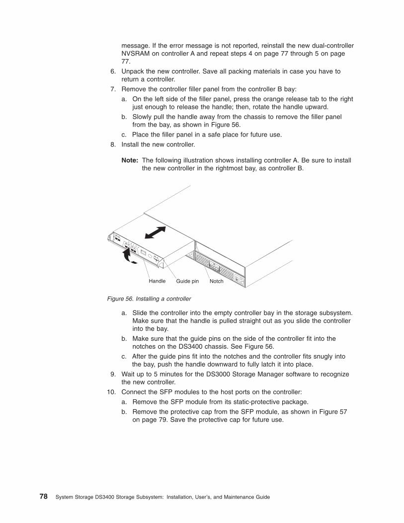
message. If the error message is not reported, reinstall the new dual-controllerNVSRAM on controller A and repeat steps 4 on page 77 through 5 on page77.
6. Unpack the new controller. Save all packing materials in case you have toreturn a controller.
7. Remove the controller filler panel from the controller B bay:
a. On the left side of the filler panel, press the orange release tab to the rightjust enough to release the handle; then, rotate the handle upward.
b. Slowly pull the handle away from the chassis to remove the filler panelfrom the bay, as shown in Figure 56.
c. Place the filler panel in a safe place for future use.
8. Install the new controller.
Note: The following illustration shows installing controller A. Be sure to installthe new controller in the rightmost bay, as controller B.
a. Slide the controller into the empty controller bay in the storage subsystem.Make sure that the handle is pulled straight out as you slide the controllerinto the bay.
b. Make sure that the guide pins on the side of the controller fit into thenotches on the DS3400 chassis. See Figure 56.
c. After the guide pins fit into the notches and the controller fits snugly intothe bay, push the handle downward to fully latch it into place.
9. Wait up to 5 minutes for the DS3000 Storage Manager software to recognizethe new controller.
10. Connect the SFP modules to the host ports on the controller:
a. Remove the SFP module from its static-protective package.
b. Remove the protective cap from the SFP module, as shown in Figure 57on page 79. Save the protective cap for future use.
Handle Guide pin Notch
Figure 56. Installing a controller
78 System Storage DS3400 Storage Subsystem: Installation, User’s, and Maintenance Guide
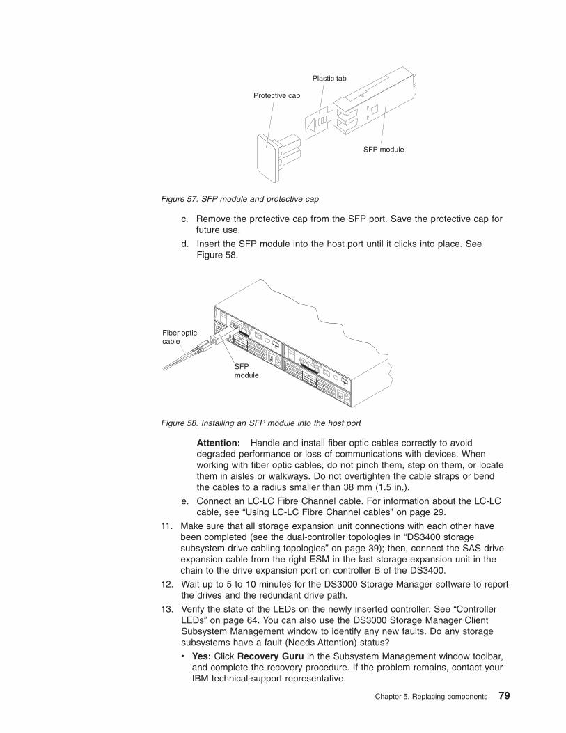
c. Remove the protective cap from the SFP port. Save the protective cap forfuture use.
d. Insert the SFP module into the host port until it clicks into place. SeeFigure 58.
Attention: Handle and install fiber optic cables correctly to avoiddegraded performance or loss of communications with devices. Whenworking with fiber optic cables, do not pinch them, step on them, or locatethem in aisles or walkways. Do not overtighten the cable straps or bendthe cables to a radius smaller than 38 mm (1.5 in.).
e. Connect an LC-LC Fibre Channel cable. For information about the LC-LCcable, see “Using LC-LC Fibre Channel cables” on page 29.
11. Make sure that all storage expansion unit connections with each other havebeen completed (see the dual-controller topologies in “DS3400 storagesubsystem drive cabling topologies” on page 39); then, connect the SAS driveexpansion cable from the right ESM in the last storage expansion unit in thechain to the drive expansion port on controller B of the DS3400.
12. Wait up to 5 to 10 minutes for the DS3000 Storage Manager software to reportthe drives and the redundant drive path.
13. Verify the state of the LEDs on the newly inserted controller. See “ControllerLEDs” on page 64. You can also use the DS3000 Storage Manager ClientSubsystem Management window to identify any new faults. Do any storagesubsystems have a fault (Needs Attention) status?
v Yes: Click Recovery Guru in the Subsystem Management window toolbar,and complete the recovery procedure. If the problem remains, contact yourIBM technical-support representative.
Protective cap
SFP module
Plastic tab
Figure 57. SFP module and protective cap
SFPmodule
Fiber opticcable
Figure 58. Installing an SFP module into the host port
Chapter 5. Replacing components 79
v No: Go to step 14.
14. Use the DS3000 Storage Manager software to print a new storage subsystemprofile.
Replacing a controller
Attention: Before you replace a controller, take the following precautions:
v Make sure that the replacement controller part number matches the part numberof the controller to be replaced. To provide full functionality, the two controllersmust have the same cache memory capacity and FRU part number. Anoncompatible replacement controller will be placed in a lockout state by theother controller in the DS3400.
v Make sure that both power-supply units are connected and powered-on and thatno amber LEDs are lit. Make sure that the power LEDs on both power-supplyunits are lit. If the status of either of the power-supply units is not Optimal,replace that power supply before you proceed with the controller replacementprocedure.
v If you are replacing an Optimal controller in a dual-controller DS3400, first makesure that the other controller is optimal and that the path from the hosts to theother controller is also optimal.
To replace a controller in a DS3400, complete the following steps.
Attention: If you are replacing a failed controller with a replacement controllerfrom IBM Service, you will transfer the controller battery to the replacementcontroller. The replacement controller contains a 512 MB DIMM; if the capacity ofthe DIMM in the failed controller is larger than 512 MB, you will also transfer thatDIMM to the replacement controller. Transfer the DIMM and battery exactly asdescribed in this procedure; failure to remove and insert these items in the correctsequence can damage the DIMM.
1. Read the safety information that begins on page xi and “Best practicesguidelines” on page 6.
2. In a single-controller storage subsystem, shut down the storage subsystem(see “Turning off the storage subsystem” on page 65 for the correct sequenceof steps); Then, continue with step 4.
3. Use the DS3000 Storage Manager software to print a storage subsystemprofile. Move logical drive ownership to the other controller. If the controller thatyou are replacing has failed but is still operating, move the failed controller tothe Offline state.
Attention: Never remove a controller unless the service action allowed LEDis lit. Doing so can result in a loss of data.
4. Locate the failed controller by checking the amber LEDs on the controllers inthe storage subsystem.
5. Is the service action allowed LED lit?
v Yes: Go to step 6 on page 81.
v No: Another component might require attention before you can remove thecontroller. Use the Recovery Guru in the DS3000 Subsystem Managementwindow to identify and correct any additional failures. If there are none,proceed with step 6 on page 81 to replace the controller.
80 System Storage DS3400 Storage Subsystem: Installation, User’s, and Maintenance Guide
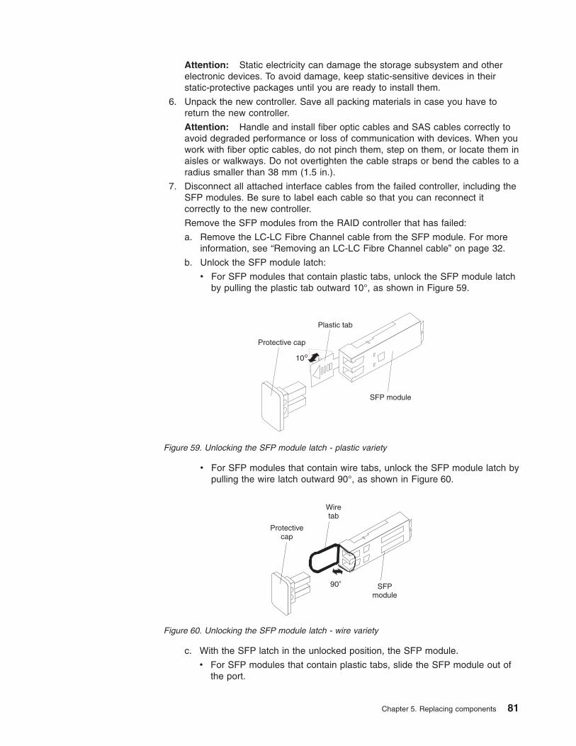
Attention: Static electricity can damage the storage subsystem and otherelectronic devices. To avoid damage, keep static-sensitive devices in theirstatic-protective packages until you are ready to install them.
6. Unpack the new controller. Save all packing materials in case you have toreturn the new controller.
Attention: Handle and install fiber optic cables and SAS cables correctly toavoid degraded performance or loss of communication with devices. When youwork with fiber optic cables, do not pinch them, step on them, or locate them inaisles or walkways. Do not overtighten the cable straps or bend the cables to aradius smaller than 38 mm (1.5 in.).
7. Disconnect all attached interface cables from the failed controller, including theSFP modules. Be sure to label each cable so that you can reconnect itcorrectly to the new controller.
Remove the SFP modules from the RAID controller that has failed:
a. Remove the LC-LC Fibre Channel cable from the SFP module. For moreinformation, see “Removing an LC-LC Fibre Channel cable” on page 32.
b. Unlock the SFP module latch:
v For SFP modules that contain plastic tabs, unlock the SFP module latchby pulling the plastic tab outward 10°, as shown in Figure 59.
v For SFP modules that contain wire tabs, unlock the SFP module latch bypulling the wire latch outward 90°, as shown in Figure 60.
c. With the SFP latch in the unlocked position, the SFP module.
v For SFP modules that contain plastic tabs, slide the SFP module out ofthe port.
Protective cap
SFP module
10
Plastic tab
Figure 59. Unlocking the SFP module latch - plastic variety
Protectivecap
SFPmodule
90
Wiretab
Figure 60. Unlocking the SFP module latch - wire variety
Chapter 5. Replacing components 81
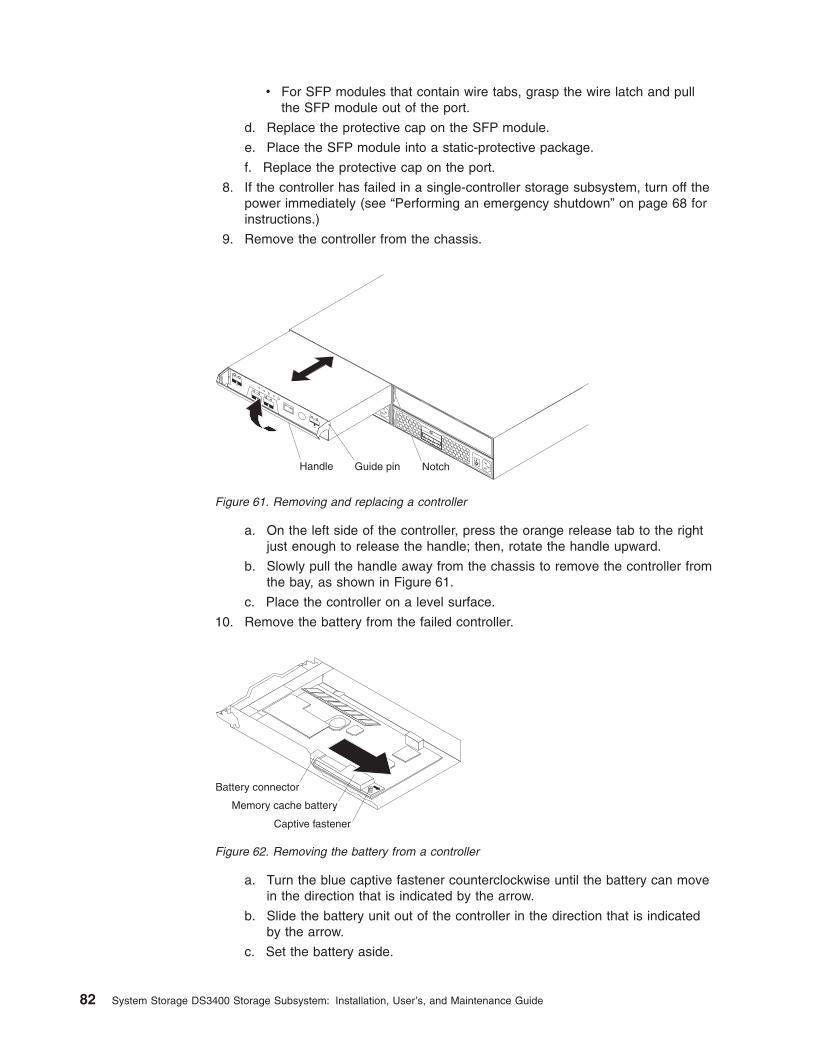
v For SFP modules that contain wire tabs, grasp the wire latch and pullthe SFP module out of the port.
d. Replace the protective cap on the SFP module.
e. Place the SFP module into a static-protective package.
f. Replace the protective cap on the port.
8. If the controller has failed in a single-controller storage subsystem, turn off thepower immediately (see “Performing an emergency shutdown” on page 68 forinstructions.)
9. Remove the controller from the chassis.
a. On the left side of the controller, press the orange release tab to the rightjust enough to release the handle; then, rotate the handle upward.
b. Slowly pull the handle away from the chassis to remove the controller fromthe bay, as shown in Figure 61.
c. Place the controller on a level surface.
10. Remove the battery from the failed controller.
a. Turn the blue captive fastener counterclockwise until the battery can movein the direction that is indicated by the arrow.
b. Slide the battery unit out of the controller in the direction that is indicatedby the arrow.
c. Set the battery aside.
Handle Guide pin Notch
Figure 61. Removing and replacing a controller
Battery connector
Captive fastener
Memory cache battery
Figure 62. Removing the battery from a controller
82 System Storage DS3400 Storage Subsystem: Installation, User’s, and Maintenance Guide
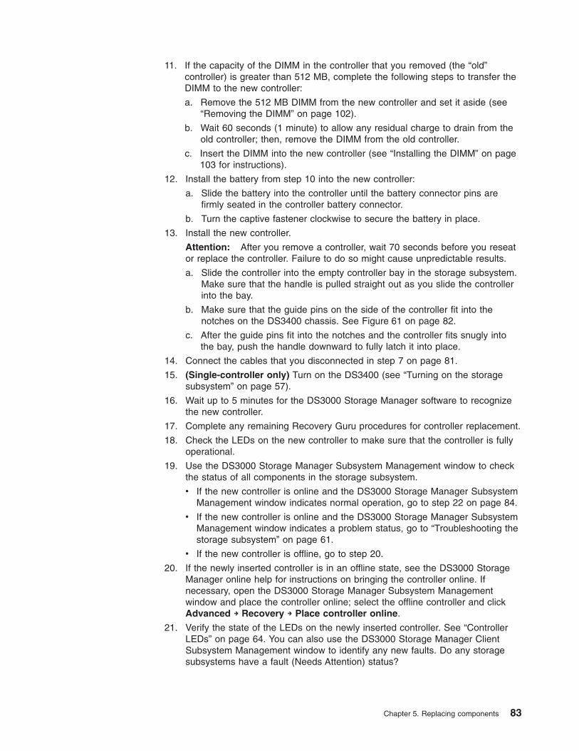
11. If the capacity of the DIMM in the controller that you removed (the “old”controller) is greater than 512 MB, complete the following steps to transfer theDIMM to the new controller:
a. Remove the 512 MB DIMM from the new controller and set it aside (see“Removing the DIMM” on page 102).
b. Wait 60 seconds (1 minute) to allow any residual charge to drain from theold controller; then, remove the DIMM from the old controller.
c. Insert the DIMM into the new controller (see “Installing the DIMM” on page103 for instructions).
12. Install the battery from step 10 into the new controller:
a. Slide the battery into the controller until the battery connector pins arefirmly seated in the controller battery connector.
b. Turn the captive fastener clockwise to secure the battery in place.
13. Install the new controller.
Attention: After you remove a controller, wait 70 seconds before you reseator replace the controller. Failure to do so might cause unpredictable results.
a. Slide the controller into the empty controller bay in the storage subsystem.Make sure that the handle is pulled straight out as you slide the controllerinto the bay.
b. Make sure that the guide pins on the side of the controller fit into thenotches on the DS3400 chassis. See Figure 61 on page 82.
c. After the guide pins fit into the notches and the controller fits snugly intothe bay, push the handle downward to fully latch it into place.
14. Connect the cables that you disconnected in step 7 on page 81.
15. (Single-controller only) Turn on the DS3400 (see “Turning on the storagesubsystem” on page 57).
16. Wait up to 5 minutes for the DS3000 Storage Manager software to recognizethe new controller.
17. Complete any remaining Recovery Guru procedures for controller replacement.
18. Check the LEDs on the new controller to make sure that the controller is fullyoperational.
19. Use the DS3000 Storage Manager Subsystem Management window to checkthe status of all components in the storage subsystem.
v If the new controller is online and the DS3000 Storage Manager SubsystemManagement window indicates normal operation, go to step 22 on page 84.
v If the new controller is online and the DS3000 Storage Manager SubsystemManagement window indicates a problem status, go to “Troubleshooting thestorage subsystem” on page 61.
v If the new controller is offline, go to step 20.
20. If the newly inserted controller is in an offline state, see the DS3000 StorageManager online help for instructions on bringing the controller online. Ifnecessary, open the DS3000 Storage Manager Subsystem Managementwindow and place the controller online; select the offline controller and clickAdvanced → Recovery → Place controller online.
21. Verify the state of the LEDs on the newly inserted controller. See “ControllerLEDs” on page 64. You can also use the DS3000 Storage Manager ClientSubsystem Management window to identify any new faults. Do any storagesubsystems have a fault (Needs Attention) status?
Chapter 5. Replacing components 83
v Yes: Click Recovery Guru in the Subsystem Management window toolbar,and complete the recovery procedure. If the problem remains, contact yourIBM technical-support representative.
v No: Go to step 22.
22. Use the DS3000 Storage Manager software to print a new storage subsystemprofile.
Working with hot-swap hard disk drivesThis section explains how you can increase the storage subsystem capacity byadding more hard disk drives or by replacing existing drives with ones that have alarger capacity.
Before you begin, complete the following tasks:
v Read the safety information that begins on page xi and “Handling static-sensitivedevices” on page 21.
v Make sure that your current system configuration is working correctly.
v Back up all important data before you make changes to data storage devices.
Before you install or remove drives, review the following information:
v Filler panels: A storage subsystem without a full set of drives (12) contains fillerpanels in the unused drive bays. Before you install new drives, you must removethese filler panels. Save the filler panels for future use. For proper cooling andEMC protection, each of the 12 bays must always contain either a filler panel ora hot-swap hard disk drive.
v Drives:
– The DS3400 supports 3 Gbps SAS or SATA hard disk drives.
– For optimum performance, never insert a drive into the storage subsystemwithout first confirming the drive firmware level. Contact your IBMtechnical-support representative for information about supported drivefirmware levels.
– Use of unsupported drives can cause the storage subsystem to fail.
– All storage subsystems and storage expansion enclosures on a fibre loopmust be operating at the same interface speed.
– After you remove a drive, wait 70 seconds before you replace or reseat thedrive to allow the drive to spin down. Failure to do so might causeunpredictable results.
AttentionBefore you power-on the storage subsystem, it must contain at least fourdrives. If at least four drives are not installed in each attached storageexpansion enclosure and in the DS3400 storage subsystem, when youpower-on the DS3400 and its attached storage expansion enclosures, yourstandard storage partition key might be lost and you must regenerate it,using instructions at http://www.ibm.com/storage/fasttkeys.
In addition, the resulting insufficient load to the enclosure power suppliesmight cause them to intermittently appear to have failed, falsely indicatingthat the power supplies are bad. All drives in the DS3400 storagesubsystem and the connected storage expansion enclosure or enclosuresmust contain no prior configuration data.
84 System Storage DS3400 Storage Subsystem: Installation, User’s, and Maintenance Guide
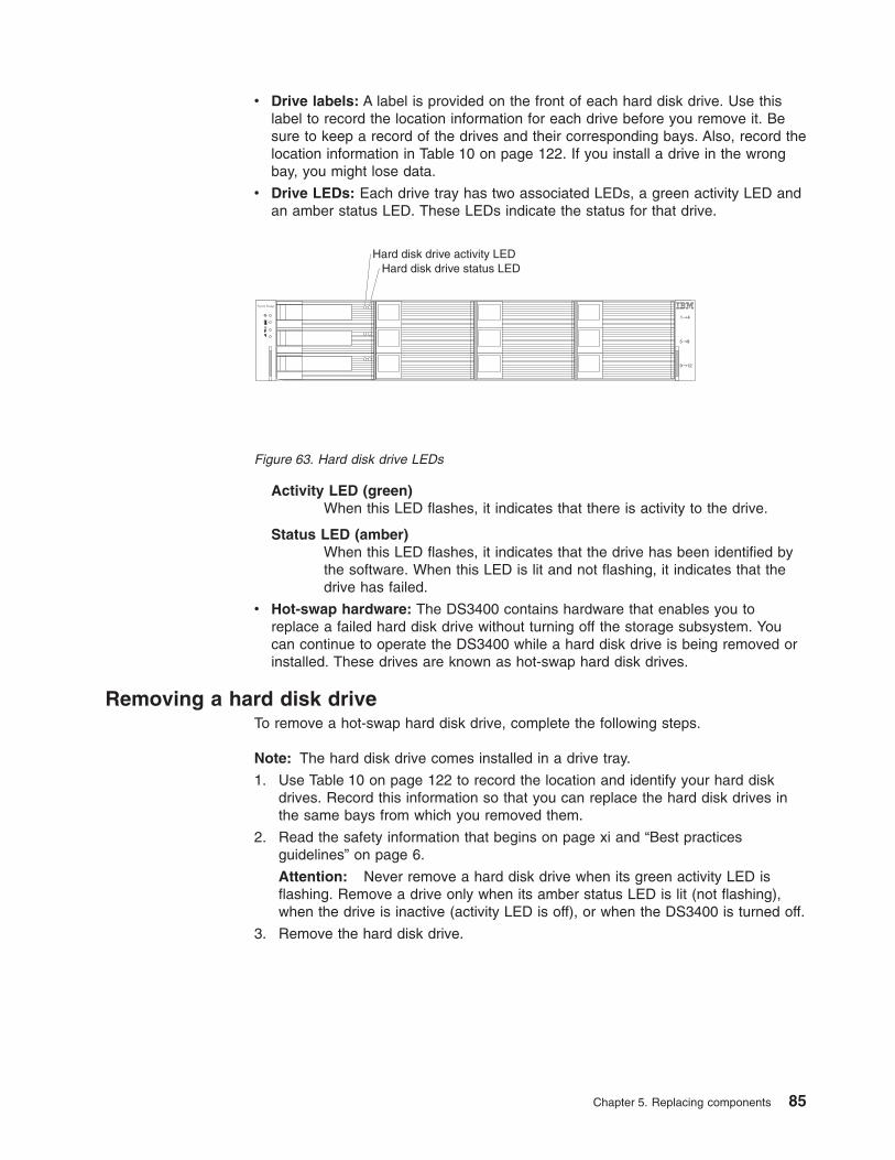
v Drive labels: A label is provided on the front of each hard disk drive. Use thislabel to record the location information for each drive before you remove it. Besure to keep a record of the drives and their corresponding bays. Also, record thelocation information in Table 10 on page 122. If you install a drive in the wrongbay, you might lose data.
v Drive LEDs: Each drive tray has two associated LEDs, a green activity LED andan amber status LED. These LEDs indicate the status for that drive.
Activity LED (green)When this LED flashes, it indicates that there is activity to the drive.
Status LED (amber)When this LED flashes, it indicates that the drive has been identified bythe software. When this LED is lit and not flashing, it indicates that thedrive has failed.
v Hot-swap hardware: The DS3400 contains hardware that enables you toreplace a failed hard disk drive without turning off the storage subsystem. Youcan continue to operate the DS3400 while a hard disk drive is being removed orinstalled. These drives are known as hot-swap hard disk drives.
Removing a hard disk driveTo remove a hot-swap hard disk drive, complete the following steps.
Note: The hard disk drive comes installed in a drive tray.
1. Use Table 10 on page 122 to record the location and identify your hard diskdrives. Record this information so that you can replace the hard disk drives inthe same bays from which you removed them.
2. Read the safety information that begins on page xi and “Best practicesguidelines” on page 6.
Attention: Never remove a hard disk drive when its green activity LED isflashing. Remove a drive only when its amber status LED is lit (not flashing),when the drive is inactive (activity LED is off), or when the DS3400 is turned off.
3. Remove the hard disk drive.
Hard disk drive activity LEDHard disk drive status LED
System Storage
Figure 63. Hard disk drive LEDs
Chapter 5. Replacing components 85
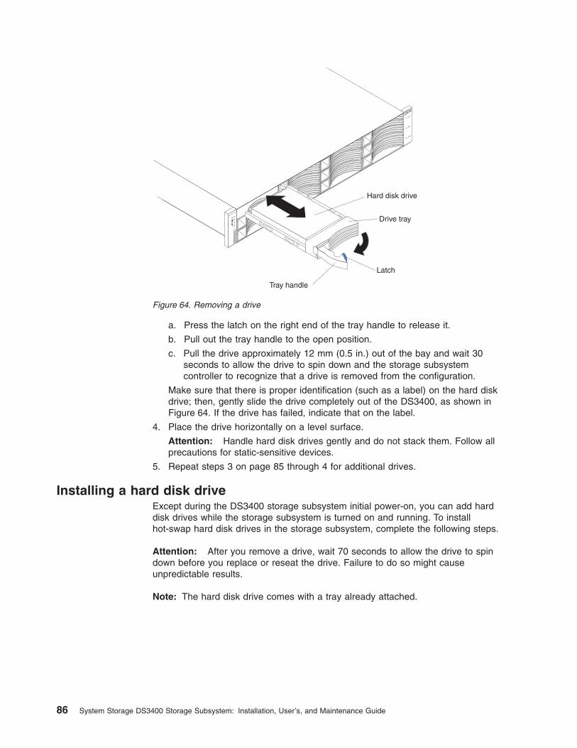
a. Press the latch on the right end of the tray handle to release it.
b. Pull out the tray handle to the open position.
c. Pull the drive approximately 12 mm (0.5 in.) out of the bay and wait 30seconds to allow the drive to spin down and the storage subsystemcontroller to recognize that a drive is removed from the configuration.
Make sure that there is proper identification (such as a label) on the hard diskdrive; then, gently slide the drive completely out of the DS3400, as shown inFigure 64. If the drive has failed, indicate that on the label.
4. Place the drive horizontally on a level surface.
Attention: Handle hard disk drives gently and do not stack them. Follow allprecautions for static-sensitive devices.
5. Repeat steps 3 on page 85 through 4 for additional drives.
Installing a hard disk driveExcept during the DS3400 storage subsystem initial power-on, you can add harddisk drives while the storage subsystem is turned on and running. To installhot-swap hard disk drives in the storage subsystem, complete the following steps.
Attention: After you remove a drive, wait 70 seconds to allow the drive to spindown before you replace or reseat the drive. Failure to do so might causeunpredictable results.
Note: The hard disk drive comes with a tray already attached.
Drive tray
Tray handle
Latch
Hard disk drive
System
Storage
Figure 64. Removing a drive
86 System Storage DS3400 Storage Subsystem: Installation, User’s, and Maintenance Guide
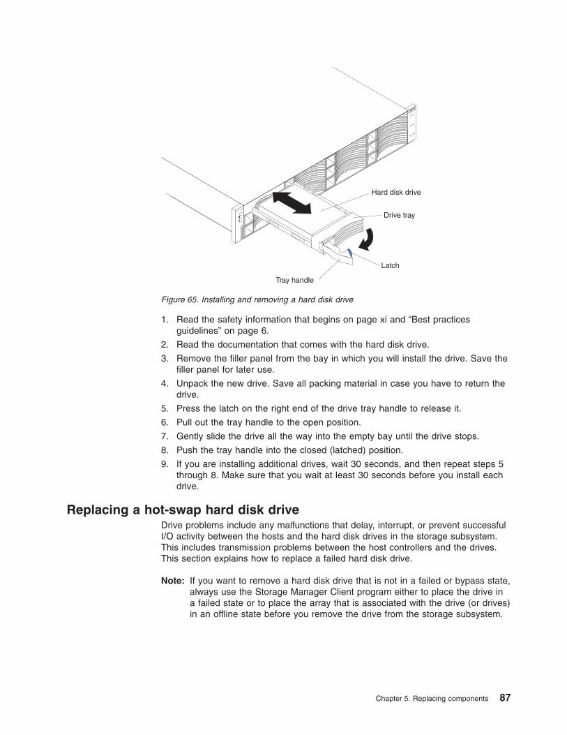
1. Read the safety information that begins on page xi and “Best practicesguidelines” on page 6.
2. Read the documentation that comes with the hard disk drive.
3. Remove the filler panel from the bay in which you will install the drive. Save thefiller panel for later use.
4. Unpack the new drive. Save all packing material in case you have to return thedrive.
5. Press the latch on the right end of the drive tray handle to release it.
6. Pull out the tray handle to the open position.
7. Gently slide the drive all the way into the empty bay until the drive stops.
8. Push the tray handle into the closed (latched) position.
9. If you are installing additional drives, wait 30 seconds, and then repeat steps 5through 8. Make sure that you wait at least 30 seconds before you install eachdrive.
Replacing a hot-swap hard disk driveDrive problems include any malfunctions that delay, interrupt, or prevent successfulI/O activity between the hosts and the hard disk drives in the storage subsystem.This includes transmission problems between the host controllers and the drives.This section explains how to replace a failed hard disk drive.
Note: If you want to remove a hard disk drive that is not in a failed or bypass state,always use the Storage Manager Client program either to place the drive ina failed state or to place the array that is associated with the drive (or drives)in an offline state before you remove the drive from the storage subsystem.
Drive tray
Tray handle
Latch
Hard disk drive
System
Storage
Figure 65. Installing and removing a hard disk drive
Chapter 5. Replacing components 87
Attention: Failure to replace a hard disk drive in its correct bay might result inloss of data. If you are replacing a hard disk drive that is part of a configured arrayand logical drive, be sure to install the replacement hard disk drive in the correctbay. See the hardware and software documentation that comes with your DS3400to determine whether there are restrictions regarding hard disk drive configurations.
To replace a hot-swap hard disk drive, complete the following steps:
1. Read the safety information that begins on page xi and “Best practicesguidelines” on page 6.
2. Use the DS3000 Storage Manager software to print a new storage systemprofile.
3. Determine the location of the drive that you want to remove.
Attention: Never hot-swap a drive when its associated green activity LED isflashing. Hot-swap a drive only when its associated amber status LED is lit andnot flashing.
4. Remove the drive:
a. Press the latch on the right end of the tray handle to release it.
b. Pull the tray handle out into the open position.
c. Pull the drive approximately 12 mm (0.5 in.) out of the bay and wait 30seconds to allow the drive to spin down and the storage subsystemcontroller to recognize that a drive is removed from the configuration.
Make sure that there is proper identification (such as a label) on the hard diskdrive; then, gently slide the drive completely out of the DS3400, as shown inFigure 64 on page 86. If the drive has failed, indicate that on the label.
Attention: After you remove a drive, wait 70 seconds to allow the drive tospin down before you replace or reseat the drive. Failure to do so might causeunpredictable results.
5. Unpack the new drive. Save all packing material in case you have to return thedrive.
Note: Use Table 10 on page 122 to make sure that you replace the hard diskdrive into the correct bay.
6. Install the new drive:
a. Press the latch on the right end of the tray handle to release it.
b. Pull out the tray handle to the open position.
c. Gently slide the drive all the way into the empty bay until the drive stops.
d. Push the tray handle into the closed (latched) position.
e. Wait 30 seconds for the system discovery process to be completed.
7. Check the drive LEDs:
v When a drive is ready for use, the green activity LED is lit and the amberfault LED is off.
v If the amber fault LED is lit and is not flashing, remove the drive from the unitand wait 70 seconds; then, install the drive again.
8. Make sure that the drive is shown in the DS3000 Storage Manager SubsystemManagement window.
Note: If you are replacing more than one hard disk drive, replace only one drive ata time.
88 System Storage DS3400 Storage Subsystem: Installation, User’s, and Maintenance Guide
Replacing multiple drivesThis section provides guidelines for upgrading the drives in the storage subsystem.Read the software documentation and this entire section to determine whether youshould use this procedure, use a modified version of this procedure, or use adifferent procedure that is provided by your operating system.
Notes:
1. Instructions that are provided with your software supersede any instructions andinformation in this document.
2. Use Table 10 on page 122 to make sure that you replace the hard disk drivesinto the correct bays.
Attention: After you remove a drive, wait 70 seconds to allow the drive to spindown before you replace or reseat the drive. Failure to do so might causeunpredictable results.
There are two methods for upgrading drives:
v Replacing all the drives at the same time
This method requires that you back up the data on the affected drives and thenturn off the DS3400 storage subsystem.
Attention: Turn off the DS3400 storage subsystem before you turn off theattached storage expansion enclosures.
After you replace all the drives, you must reconfigure the new drives and restoredata from backup. See the procedure in “Replacing all drives at the same time”on page 90.
This is the safest way to exchange drives without losing data. However, thismethod might take a long time to complete because of the backup,reconfiguration, and restoration processes. In addition, other users are not ableto use the storage subsystem (or any storage expansion enclosures attached tothe storage subsystem) until you finish the procedure. You must use this methodon RAID 0 logical drives.
v Replacing the drives one at a time
In this method, you manually fail each drive, replace it, and wait for the system torestore data to the new drive before you install the next drive. After you install thenew drives, you can configure them to make the additional drive space available.See the procedure in “Replacing the drives one at a time” on page 92.
Using this method, you can replace the drives while the storage expansionenclosures and the DS3400 are running, eliminating the downtime that isrequired if you replace all the drives at once. However, this method is more riskybecause you can lose data if the drive restoration or storage subsystemreconfiguration process fails. In addition, the reconstruction process might take along time. This method works only on redundant logical drives (RAID 1, 3, or 5).You cannot use this method with any drives that contains RAID 0 logical drives.
Consider backing up your data if you use this method. This safeguards your dataif the restoration and reconfiguration process fails or the new drive malfunctions.
The method that you use depends on the following considerations:
v Which method most closely matches the recommended drive upgrade procedurethat is provided in the operating-system or storage-management softwaredocumentation.
v Which RAID level is used on the affected drives (RAID 0 requires you to replaceall the drives at the same time).
Chapter 5. Replacing components 89
v How much downtime is acceptable as you swap the drives.
v The number of drives in an array. Replacing drives one at a time is better suitedto arrays that consist of three to five drives. If you have more than 10 drives,consider replacing all drives at the same time.
v How much risk of losing data is acceptable. Because the array is in a degradedstate during the RAID array reconstruction and copyback process as result ofreplacing a drive in the array, any new drive failure will cause the array to fail(causing a loss of data availability and even a loss of data). The duration of thereconstruction and copyback process can be quite long, depending on the size ofthe RAID array.
v How extensively the data will be changed while the array is in a degraded stateduring the RAID array reconstruction and copyback process as a result ofreplacing a drive in the array. The more extensive the data changes are, themore work that will have to be performed to restore the data in the event that thearray fails because an additional drive fails while the array is in a degraded state.
Replacing all drives at the same timeUse this procedure to replace all drives at the same time. You must use this methodif you are upgrading drives that contain RAID 0 logical drives. All the data currentlyon the drives is lost when you replace the drives; therefore, you must back up alldata that is currently on the drives. This procedure also requires you to turn off thestorage expansion enclosures and the DS3400, which makes the storagesubsystem (and any attached storage expansion enclosures) inaccessible to otherusers.
Attention: After you remove a drive, wait 70 seconds before you replace orreseat the drive to allow the drive to spin down. Failure to do so might causeunpredictable results.
To replace all the drives at the same time, complete the following steps:
1. Read the following information:
v The information in “Replacing multiple drives” on page 89, particularly theparagraphs that explain the differences between the two possible upgradeprocedures
v The information in your software documentation about drive upgrades andinstallation
v The documentation that comes with the new drives
Read all precautionary notes, kit instructions, and other information. Kitinstructions often contain the most current information about the drives andtheir installation, plus upgrade or servicing procedures. Compare the kitinstructions with this procedure to determine whether you must modify thisprocedure.
2. Use the DS3000 Storage Manager software to check the status of theDS3400. Correct any problems that are reported.
3. Perform a complete backup of the drives that you are replacing.
You need the backup to restore data on the drives later in this procedure.
Attention: When you handle static-sensitive devices, take precautions toavoid damage from static electricity. For details about handling static-sensitivedevices, see “Handling static-sensitive devices” on page 21.
4. Unpack the new drives.
Set the drives on a dry, level surface away from magnetic fields. Save thepacking material and documentation in case you have to return the drives.
90 System Storage DS3400 Storage Subsystem: Installation, User’s, and Maintenance Guide
5. Complete the following steps:
a. Stop all I/O activity to the storage subsystem and attached storageexpansion enclosures.
b. Make sure that all of the green drive activity LEDs on the front of thestorage subsystem (and on all attached storage expansion enclosures) arenot flashing.
c. Make sure that the green cache active LEDs are off. See “Controller LEDs”on page 64 for the location of the cache active LEDs.
d. If applicable, use the operating-system software to disconnect the storagesubsystem logical drives from the host before you power-off the storagesubsystem.
Attention: To turn off all power to the storage subsystem, you must turn offboth power-supply switches and disconnect both power cords. Use theprocedure in step 6 for the correct shutdown sequence.
6. Turn off the power to each device according to the following shutdownsequence:
a. Turn off power to the host before you turn off power to the storagesubsystem. If the host must stay powered-on to support a network, see theoperating-system documentation for information about disconnecting thestorage subsystem logical drives from the host before the storagesubsystem is powered-off.
b. Turn off power to the storage subsystem before you turn off power to thestorage expansion enclosures. Turn off both power-supply switches on therear of the storage subsystem.
c. Turn off power to other supporting devices (for example, managementstations or Fibre Channel switches).
7. Use the procedures in “Replacing a hot-swap hard disk drive” on page 87 toremove the drives that you want to replace. Use the procedures in “Installing ahard disk drive” on page 86 to install the new drives in the storage subsystem.
8. After you install all the new drives, check the system documentation for thehardware devices that you intend to power-on, and then determine the correctstartup sequence. Use the following power-on sequence, where applicable:
a. Turn on the power to the supporting devices (for example, Ethernetswitches and management stations) before you turn off power to thestorage subsystem.
b. Turn on the storage expansion enclosures before the storage subsystem.The controllers might not recognize the correct configuration if the drivesare powered-on after the storage subsystem. For instructions forpowering-on the storage subsystem, see the storage subsystemdocumentation.
c. Turn on the power to the storage subsystem; then, restart or turn on thepower to the host.
9. Turn on the power to each device, according to the power-on sequence in step8. To turn on power to the storage subsystem and the storage expansionenclosures, turn on the power-supply switches on the rear of the storagesubsystem. You must turn on both power-supply switches to take advantage ofthe redundant power supplies.
10. Check the green drive activity LEDs and the amber drive fault LEDs above thenew drives.
Make sure that the drive activity LEDs are lit and the drive fault LEDs are off.
Chapter 5. Replacing components 91
Note: The drive fault LEDs might flash intermittently while the drives spin up.
v If a drive activity LED is off, the drive might not be installed correctly.Remove the drive, wait 70 seconds, and then reinstall it.
v If the drive fault LED stays lit or the drive activity LED stays off, the newdrive might be faulty. See the DS3000 Storage Manager software forproblem determination.
11. Use the DS3000 Storage Manager software to configure the new drives. Seethe DS3000 Storage Manager software online help for detailed instructions.
12. Restore the data from backup to all the drives.
Replacing the drives one at a timeUse this procedure to replace all the drives one at a time. You cannot use thisprocedure on RAID 0 logical drives (use the procedure in “Replacing all drives atthe same time” on page 90).
Note: If hot spares are assigned in the storage subsystem, you might want tounassign the hot spares while you perform this procedure. If you do not,reconstruction might start on the hot spare before you insert the new drive.The data on the new drive is still rebuilt, but the process takes longer foreach drive. Remember to reassign the hot spares when you are finished withthis procedure.
Attention: After you remove a drive, wait 70 seconds to allow the drive to spindown before you replace or reseat the drive. Failure to do so might causeunpredictable results.
To replace the drives one at a time, complete the following steps:
1. Read the following information:
v “Replacing multiple drives” on page 89, particularly the paragraphs thatexplain the differences between the two possible upgrade procedures
v Your software documentation about drive upgrades and installation
v The documentation that comes with the new drives
Read all precautionary notes, kit instructions, and other information. Kitinstructions often contain the most current information about the drives andtheir installation, plus upgrade or servicing procedures. Compare the kitinstructions with this procedure to determine whether you must modify thisprocedure.
2. Use the DS3000 Storage Manager software to check the status of the unit.Correct any problems that are reported.
3. Back up the data in the arrays and logical drives that are configured, using thedrives that you are replacing.
Attention: When you handle static-sensitive devices, take precautions toavoid damage from static electricity. For details about handling static-sensitivedevices, see “Handling static-sensitive devices” on page 21.
4. Unpack the new drives.
Set the drives on a dry, level surface away from magnetic fields. Save thepacking material and documentation in case you have to return the drives.
5. Use the DS3000 Storage Manager software to make sure that the array thatwas defined using these drives is in Optimal (not Degraded) state before youmanually fail the first drive that you want to replace. If the array is in aDegraded state, use the recovery procedures to bring the array into theoptimal state.
92 System Storage DS3400 Storage Subsystem: Installation, User’s, and Maintenance Guide
Make sure that:
v You fail only one drive
v The software status display shows a Failed status for the applicable drive
v The amber drive fault LED (on the front bezel below the drive) is lit
Attention: Removing the wrong drive can cause data loss. Make sure thatyou remove only the failed drive. A lit drive fault LED indicates the failed drive.
If you remove an active drive accidentally, wait at least 70 seconds and thenreinstall it. Because you have failed two drives in a RAID array, the array mightbe marked as failed by the controller. This array will not be available to thehost for I/O. See the DS3000 Storage Manager software for further recoveryinstructions. Do not attempt to replace any drives until the array is broughtback to Optimal state.
6. Use the procedures in “Replacing a hot-swap hard disk drive” on page 87 toremove the drive. Use the procedures in “Installing a hard disk drive” on page86 to install the new drives in the storage subsystem.
The new drive automatically reconstructs the data after you install it in thedrive bay.
During data reconstruction, the amber drive fault LED might be lit for a fewminutes and then turn off when the green drive activity LED begins flashing. Aflashing drive activity LED indicates that data reconstruction is in progress.
Note: If your storage subsystem has active hot spares, data might not startcopying to the new drive until the data is reconstructed on the hotspare. This increases the time that is required to complete theprocedure.
7. Check the green drive activity LED and the amber drive fault LED on each ofthe new drives.
Make sure that the drive activity LEDs are lit and the drive fault LEDs are off.
Note: The drive fault LEDs might flash intermittently while the drives spin up.
v If the drive activity LED is off, the drive might not be installed correctly.Remove the drive, wait 70 seconds, and then reinstall it.
v If the drive fault LED stays lit or the drive activity LED stays off, the newdrive might be faulty or might be an uncertified drive. Use the DS3000Storage Manager software for problem determination. In the case of anuncertified drive, make sure that the drive options or drive FRU part numberis correct for your storage subsystem.
8. Use the DS3000 Storage Manager software to monitor the status of the newdrive and the progress of the data reconstruction. Wait for data reconstructionto finish (the drive activity LED stops flashing).
Note: The drive activity LED continues to flash after reconstruction is finishedif there is I/O activity to that drive. In that case, use the host software todetermine whether the data reconstruction is finished.
9. When reconstruction is finished on the new drive, repeat step 5 on page 92through step 8 for each additional drive that you want to install.
10. Use the DS3000 Storage Manager software to configure the additional spaceon the new drives.
Chapter 5. Replacing components 93
Replacing a power supply
(L003)
1 2
or
!
1
2
The power-supply unit is a component that includes a 515-watt power supply andtwo fans. The power-supply units provide power and cooling for the DS3400. Thepower-supplies circulate air from the front to the rear of the storage subsystem.
The power-supply units are customer replaceable units (CRUs) and do not requirepreventive maintenance. Use only the supported power-supply units for yourspecific storage subsystem.
Each power supply has a built-in sensor that detects the following conditions:
v Over-voltage
v Over-current
v Overheated power supply
If any of these conditions occurs, one or both power supplies will shut down. If thepower remains off (does not automatically restart), make sure that the environmentis optimal (no overheating has occurred, all electrical receptacles are working, andso on). For more information, see “Restoring power after an unexpected shutdown”on page 68.
94 System Storage DS3400 Storage Subsystem: Installation, User’s, and Maintenance Guide
If both power supplies fail or if the power supplies cannot maintain an internaltemperature below 70°C (158°F), the power supplies in the storage subsystem willautomatically shut down (an overtemperature condition). If this occurs, you mustcool the storage subsystem and restart it. See “Restoring power after anunexpected shutdown” on page 68.
Attention: The fans in the power-supply units draw in fresh air and force out hotair. The power-supply units are hot-swappable and redundant; however, if the fansin one power-supply unit fail, you must replace the entire failed power-supply unitwithin 72 hours to maintain redundancy and optimum cooling. Do not remove thefailed power-supply unit until you have the replacement power-supply unit. Whenyou do remove the failed power-supply unit, be sure to install the secondpower-supply unit within 10 minutes to prevent any overheating due to theinterruption to the air flow that cools the storage subsystem.
Do not run the storage subsystem without adequate ventilation and cooling,because it might cause damage to the internal components and circuitry.
To replace a power-supply unit, complete the following steps. Figure 66 on page 98illustrates removing and inserting a unit.
Attention: To prevent damage to the storage subsystem components fromoverheating, replace a failed power-supply unit within 10 minutes of removal. Ifreplacing it will take longer than 10 minutes, stop all I/O activity to the storagesubsystem and turn off the power until you complete the replacement.
(L001)
1. If necessary, use the DS3000 Storage Manager Client software to print astorage system profile.
2. Read the safety information that begins on page xi and “Best practicesguidelines” on page 6.
3. Did the Recovery Guru direct you to replace a failed power supply?
v Yes: Go to step 4.
v No: Run the Recovery Guru to identify the failed component, and then go tostep 4.
4. Unpack the new power-supply unit. Save all packing material in case you haveto return the failed power-supply unit.
Note: The new power-supply unit comes with an instruction sheet and labelsheet. The instruction sheet provides instructions for placing the correctlabels on the power supply to mark the LEDs correctly. The label sheetcontains the peel-off labels that you actually place on the power supply.
5. Using the information on the instruction sheet, place the labels on the powersupply to correctly mark the LEDs.
Chapter 5. Replacing components 95
6. Turn off the power switch on the new unit.
7. Check the fault LED to locate the failed power supply. If a fault is detected, theamber fault LED is lit.
8. Make sure that the service action allowed LED is lit. Do not remove the powersupply if the LED is off. For more information about the service action allowedLED, see “Service action allowed LED” on page 75.
96 System Storage DS3400 Storage Subsystem: Installation, User’s, and Maintenance Guide
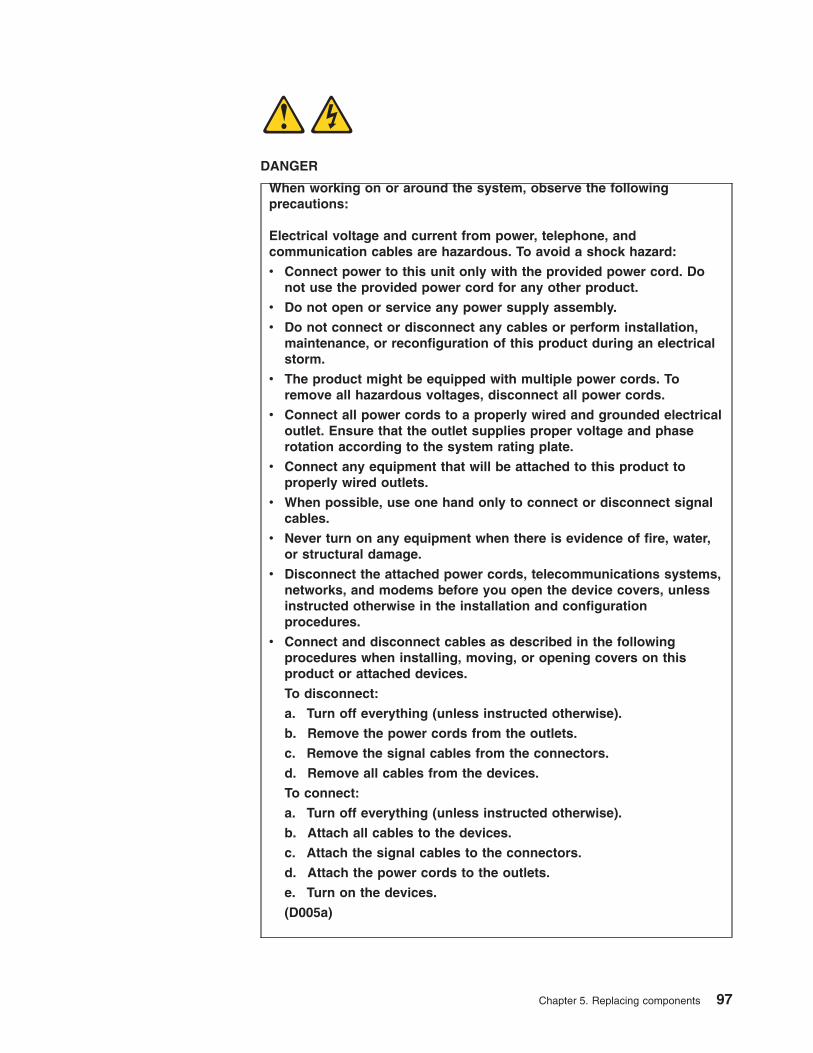
DANGER
When working on or around the system, observe the followingprecautions:
Electrical voltage and current from power, telephone, andcommunication cables are hazardous. To avoid a shock hazard:
v Connect power to this unit only with the provided power cord. Donot use the provided power cord for any other product.
v Do not open or service any power supply assembly.
v Do not connect or disconnect any cables or perform installation,maintenance, or reconfiguration of this product during an electricalstorm.
v The product might be equipped with multiple power cords. Toremove all hazardous voltages, disconnect all power cords.
v Connect all power cords to a properly wired and grounded electricaloutlet. Ensure that the outlet supplies proper voltage and phaserotation according to the system rating plate.
v Connect any equipment that will be attached to this product toproperly wired outlets.
v When possible, use one hand only to connect or disconnect signalcables.
v Never turn on any equipment when there is evidence of fire, water,or structural damage.
v Disconnect the attached power cords, telecommunications systems,networks, and modems before you open the device covers, unlessinstructed otherwise in the installation and configurationprocedures.
v Connect and disconnect cables as described in the followingprocedures when installing, moving, or opening covers on thisproduct or attached devices.
To disconnect:
a. Turn off everything (unless instructed otherwise).
b. Remove the power cords from the outlets.
c. Remove the signal cables from the connectors.
d. Remove all cables from the devices.
To connect:
a. Turn off everything (unless instructed otherwise).
b. Attach all cables to the devices.
c. Attach the signal cables to the connectors.
d. Attach the power cords to the outlets.
e. Turn on the devices.
(D005a)
Chapter 5. Replacing components 97
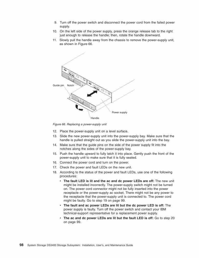
9. Turn off the power switch and disconnect the power cord from the failed powersupply.
10. On the left side of the power supply, press the orange release tab to the rightjust enough to release the handle; then, rotate the handle downward.
11. Slowly pull the handle away from the chassis to remove the power-supply unit,as shown in Figure 66.
12. Place the power-supply unit on a level surface.
13. Slide the new power-supply unit into the power-supply bay. Make sure that thehandle is pulled straight out as you slide the power-supply unit into the bay.
14. Make sure that the guide pins on the side of the power supply fit into thenotches along the sides of the power-supply bay.
15. Push the handle upward to fully latch it into place. Gently push the front of thepower-supply unit to make sure that it is fully seated.
16. Connect the power cord and turn on the power.
17. Check the power and fault LEDs on the new unit.
18. According to the status of the power and fault LEDs, use one of the followingprocedures:
v The fault LED is lit and the ac and dc power LEDs are off: The new unitmight be installed incorrectly. The power-supply switch might not be turnedon. The power cord connector might not be fully inserted into the powerreceptacle or the power-supply ac socket. There might not be any power tothe receptacle that the power-supply unit is connected to. The power cordmight be faulty. Go to step 19 on page 99.
v The fault and ac power LEDs are lit but the dc power LED is off: Thepower supply is faulty. Turn off the power switch and contact your IBMtechnical-support representative for a replacement power supply.
v The ac and dc power LEDs are lit but the fault LED is off: Go to step 20on page 99.
Handle
Power supply
Guide pin Notch
Figure 66. Replacing a power-supply unit
98 System Storage DS3400 Storage Subsystem: Installation, User’s, and Maintenance Guide
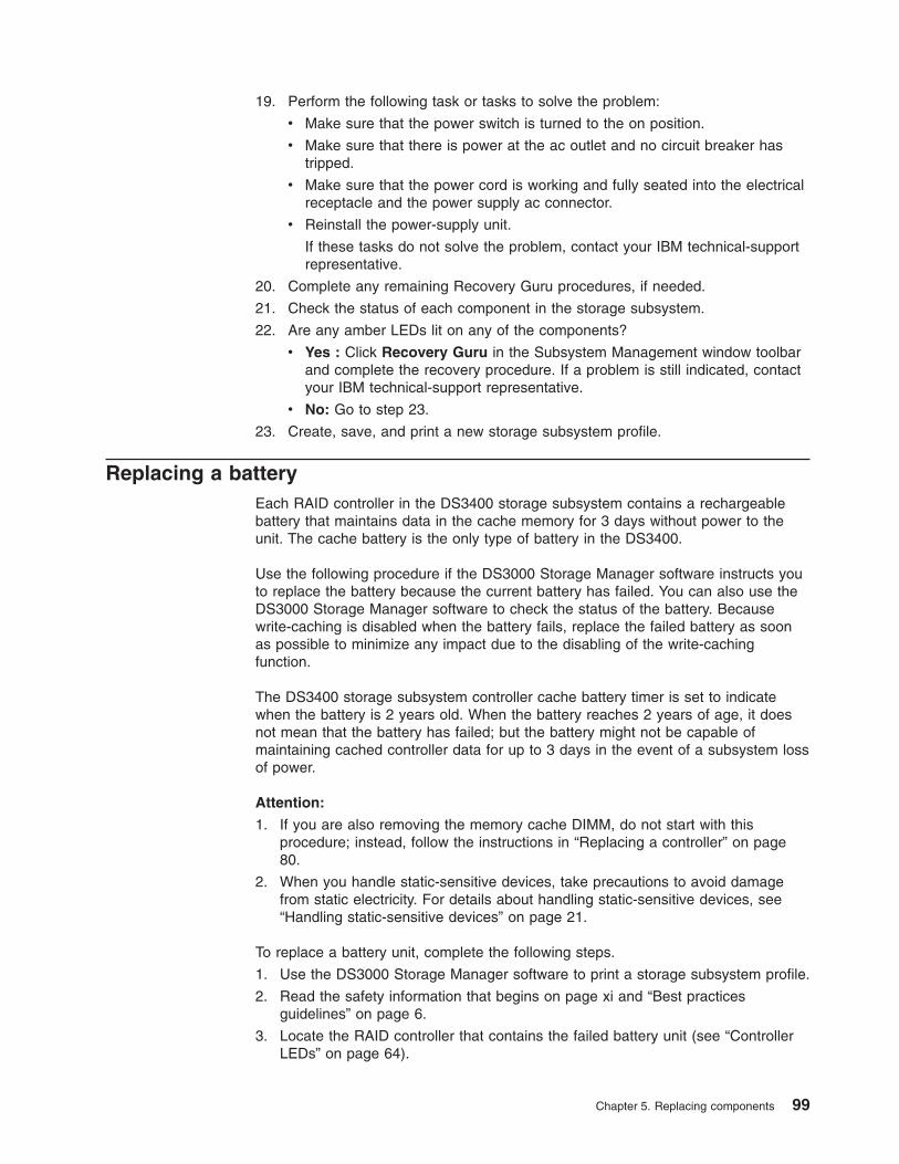
19. Perform the following task or tasks to solve the problem:
v Make sure that the power switch is turned to the on position.
v Make sure that there is power at the ac outlet and no circuit breaker hastripped.
v Make sure that the power cord is working and fully seated into the electricalreceptacle and the power supply ac connector.
v Reinstall the power-supply unit.
If these tasks do not solve the problem, contact your IBM technical-supportrepresentative.
20. Complete any remaining Recovery Guru procedures, if needed.
21. Check the status of each component in the storage subsystem.
22. Are any amber LEDs lit on any of the components?
v Yes : Click Recovery Guru in the Subsystem Management window toolbarand complete the recovery procedure. If a problem is still indicated, contactyour IBM technical-support representative.
v No: Go to step 23.
23. Create, save, and print a new storage subsystem profile.
Replacing a batteryEach RAID controller in the DS3400 storage subsystem contains a rechargeablebattery that maintains data in the cache memory for 3 days without power to theunit. The cache battery is the only type of battery in the DS3400.
Use the following procedure if the DS3000 Storage Manager software instructs youto replace the battery because the current battery has failed. You can also use theDS3000 Storage Manager software to check the status of the battery. Becausewrite-caching is disabled when the battery fails, replace the failed battery as soonas possible to minimize any impact due to the disabling of the write-cachingfunction.
The DS3400 storage subsystem controller cache battery timer is set to indicatewhen the battery is 2 years old. When the battery reaches 2 years of age, it doesnot mean that the battery has failed; but the battery might not be capable ofmaintaining cached controller data for up to 3 days in the event of a subsystem lossof power.
Attention:
1. If you are also removing the memory cache DIMM, do not start with thisprocedure; instead, follow the instructions in “Replacing a controller” on page80.
2. When you handle static-sensitive devices, take precautions to avoid damagefrom static electricity. For details about handling static-sensitive devices, see“Handling static-sensitive devices” on page 21.
To replace a battery unit, complete the following steps.
1. Use the DS3000 Storage Manager software to print a storage subsystem profile.
2. Read the safety information that begins on page xi and “Best practicesguidelines” on page 6.
3. Locate the RAID controller that contains the failed battery unit (see “ControllerLEDs” on page 64).
Chapter 5. Replacing components 99
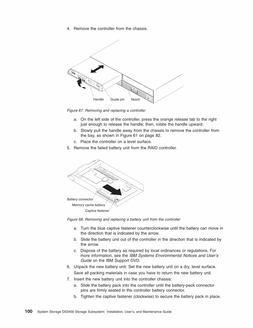
4. Remove the controller from the chassis.
a. On the left side of the controller, press the orange release tab to the rightjust enough to release the handle; then, rotate the handle upward.
b. Slowly pull the handle away from the chassis to remove the controller fromthe bay, as shown in Figure 61 on page 82.
c. Place the controller on a level surface.
5. Remove the failed battery unit from the RAID controller.
a. Turn the blue captive fastener counterclockwise until the battery can move inthe direction that is indicated by the arrow.
b. Slide the battery unit out of the controller in the direction that is indicated bythe arrow.
c. Dispose of the battery as required by local ordinances or regulations. Formore information, see the IBM Systems Environmental Notices and User’sGuide on the IBM Support DVD.
6. Unpack the new battery unit. Set the new battery unit on a dry, level surface.
Save all packing materials in case you have to return the new battery unit.
7. Insert the new battery unit into the controller chassis:
a. Slide the battery pack into the controller until the battery-pack connectorpins are firmly seated in the controller battery connector.
b. Tighten the captive fastener (clockwise) to secure the battery pack in place.
Handle Guide pin Notch
Figure 67. Removing and replacing a controller
Battery connector
Captive fastener
Memory cache battery
Figure 68. Removing and replacing a battery unit from the controller
100 System Storage DS3400 Storage Subsystem: Installation, User’s, and Maintenance Guide
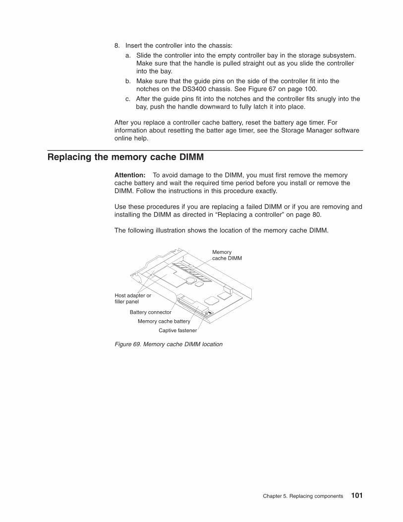
8. Insert the controller into the chassis:
a. Slide the controller into the empty controller bay in the storage subsystem.Make sure that the handle is pulled straight out as you slide the controllerinto the bay.
b. Make sure that the guide pins on the side of the controller fit into thenotches on the DS3400 chassis. See Figure 67 on page 100.
c. After the guide pins fit into the notches and the controller fits snugly into thebay, push the handle downward to fully latch it into place.
After you replace a controller cache battery, reset the battery age timer. Forinformation about resetting the batter age timer, see the Storage Manager softwareonline help.
Replacing the memory cache DIMM
Attention: To avoid damage to the DIMM, you must first remove the memorycache battery and wait the required time period before you install or remove theDIMM. Follow the instructions in this procedure exactly.
Use these procedures if you are replacing a failed DIMM or if you are removing andinstalling the DIMM as directed in “Replacing a controller” on page 80.
The following illustration shows the location of the memory cache DIMM.
Memorycache DIMM
Host adapter orfiller panel
Battery connector
Captive fastener
Memory cache battery
Figure 69. Memory cache DIMM location
Chapter 5. Replacing components 101
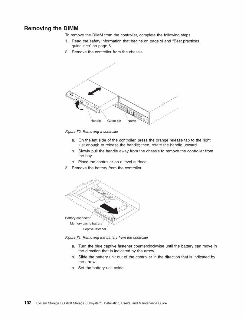
Removing the DIMMTo remove the DIMM from the controller, complete the following steps:
1. Read the safety information that begins on page xi and “Best practicesguidelines” on page 6.
2. Remove the controller from the chassis.
a. On the left side of the controller, press the orange release tab to the rightjust enough to release the handle; then, rotate the handle upward.
b. Slowly pull the handle away from the chassis to remove the controller fromthe bay.
c. Place the controller on a level surface.
3. Remove the battery from the controller.
a. Turn the blue captive fastener counterclockwise until the battery can move inthe direction that is indicated by the arrow.
b. Slide the battery unit out of the controller in the direction that is indicated bythe arrow.
c. Set the battery unit aside.
Handle Guide pin Notch
Figure 70. Removing a controller
Battery connector
Captive fastener
Memory cache battery
Figure 71. Removing the battery from the controller
102 System Storage DS3400 Storage Subsystem: Installation, User’s, and Maintenance Guide
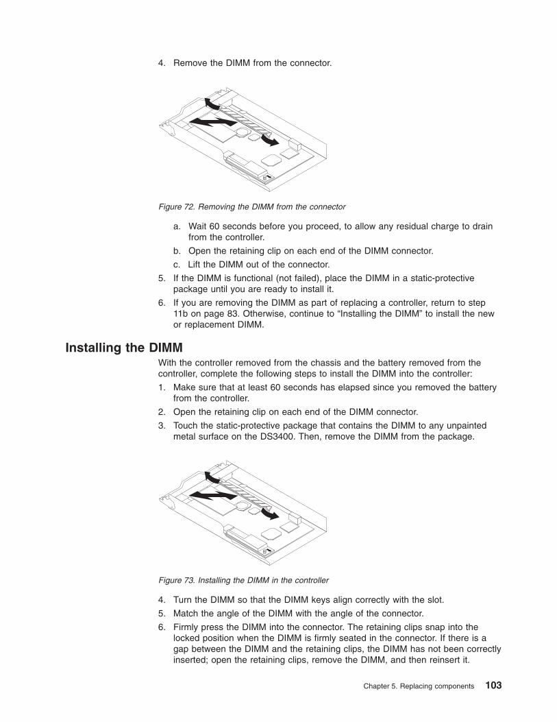
4. Remove the DIMM from the connector.
a. Wait 60 seconds before you proceed, to allow any residual charge to drainfrom the controller.
b. Open the retaining clip on each end of the DIMM connector.
c. Lift the DIMM out of the connector.
5. If the DIMM is functional (not failed), place the DIMM in a static-protectivepackage until you are ready to install it.
6. If you are removing the DIMM as part of replacing a controller, return to step11b on page 83. Otherwise, continue to “Installing the DIMM” to install the newor replacement DIMM.
Installing the DIMMWith the controller removed from the chassis and the battery removed from thecontroller, complete the following steps to install the DIMM into the controller:
1. Make sure that at least 60 seconds has elapsed since you removed the batteryfrom the controller.
2. Open the retaining clip on each end of the DIMM connector.
3. Touch the static-protective package that contains the DIMM to any unpaintedmetal surface on the DS3400. Then, remove the DIMM from the package.
4. Turn the DIMM so that the DIMM keys align correctly with the slot.
5. Match the angle of the DIMM with the angle of the connector.
6. Firmly press the DIMM into the connector. The retaining clips snap into thelocked position when the DIMM is firmly seated in the connector. If there is agap between the DIMM and the retaining clips, the DIMM has not been correctlyinserted; open the retaining clips, remove the DIMM, and then reinsert it.
Figure 72. Removing the DIMM from the connector
Figure 73. Installing the DIMM in the controller
Chapter 5. Replacing components 103
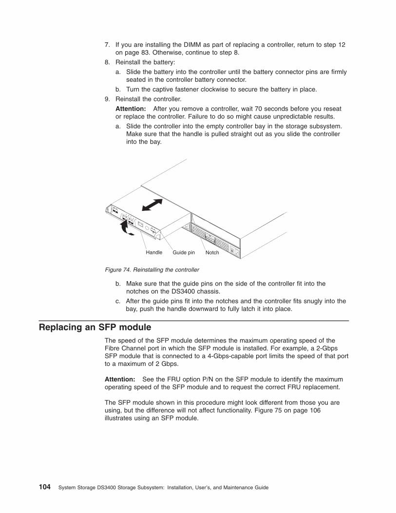
7. If you are installing the DIMM as part of replacing a controller, return to step 12on page 83. Otherwise, continue to step 8.
8. Reinstall the battery:
a. Slide the battery into the controller until the battery connector pins are firmlyseated in the controller battery connector.
b. Turn the captive fastener clockwise to secure the battery in place.
9. Reinstall the controller.
Attention: After you remove a controller, wait 70 seconds before you reseator replace the controller. Failure to do so might cause unpredictable results.
a. Slide the controller into the empty controller bay in the storage subsystem.Make sure that the handle is pulled straight out as you slide the controllerinto the bay.
b. Make sure that the guide pins on the side of the controller fit into thenotches on the DS3400 chassis.
c. After the guide pins fit into the notches and the controller fits snugly into thebay, push the handle downward to fully latch it into place.
Replacing an SFP moduleThe speed of the SFP module determines the maximum operating speed of theFibre Channel port in which the SFP module is installed. For example, a 2-GbpsSFP module that is connected to a 4-Gbps-capable port limits the speed of that portto a maximum of 2 Gbps.
Attention: See the FRU option P/N on the SFP module to identify the maximumoperating speed of the SFP module and to request the correct FRU replacement.
The SFP module shown in this procedure might look different from those you areusing, but the difference will not affect functionality. Figure 75 on page 106illustrates using an SFP module.
Handle Guide pin Notch
Figure 74. Reinstalling the controller
104 System Storage DS3400 Storage Subsystem: Installation, User’s, and Maintenance Guide
CAUTION:This product might contain one or more of the following devices: CD-ROMdrive, DVD-ROM drive, DVD-RAM drive, or laser module, which are Class 1laser products. Note the following information:
v Do not remove the covers. Removing the covers of the laser product couldresult in exposure to hazardous laser radiation. There are no serviceableparts inside the device.
v Use of the controls or adjustments or performance of procedures otherthan those specified herein might result in hazardous radiation exposure.
(C026)
CAUTION:Data processing environments can contain equipment transmitting on systemlinks with laser modules that operate at greater than Class 1 power levels. Forthis reason, never look into the end of an optical fiber cable or openreceptacle. (C027)
Attention: When you handle static-sensitive devices, take precautions to avoiddamage from static electricity. For details about handling static-sensitive devices,see “Handling static-sensitive devices” on page 21.
To replace a small-form-factor pluggable (SFP) module in the storage subsystem,complete the following steps:
1. Use the DS3000 Storage Manager Client software to print a new storagesubsystem profile.
2. Using the Recovery Guru, identify the failed component that needs to bereplaced.
3. Check the LEDs on the Fibre Channel host ports to locate the failed SFPmodule. If a fault is detected, both LEDs are lit on the host port.
Attention: To prevent loss of access to data, remove only the SFP modulethat has a failed status in the storage management software and both host portLEDs are lit.
4. Unpack the new SFP module. Make sure that it is the same type of moduleyou are replacing. If it is not, contact your IBM technical-supportrepresentative.
Attention: Handle and install fiber optic cables correctly to avoid degradedperformance or loss of communications with devices. When working with fiberoptic cables, do not pinch them, step on them, or locate them in aisles orwalkways. Do not overtighten the cable straps or bend the cables to a radiussmaller than 38 mm (1.5 inches).
5. Disconnect the interface cables from the SFP module (see “Removing anLC-LC Fibre Channel cable” on page 32).
6. Remove the failed SFP module from the controller (see “Removing SFPmodules” on page 28).
7. Install the new SFP module into the controller (see “Installing SFP modules” onpage 26).
Chapter 5. Replacing components 105
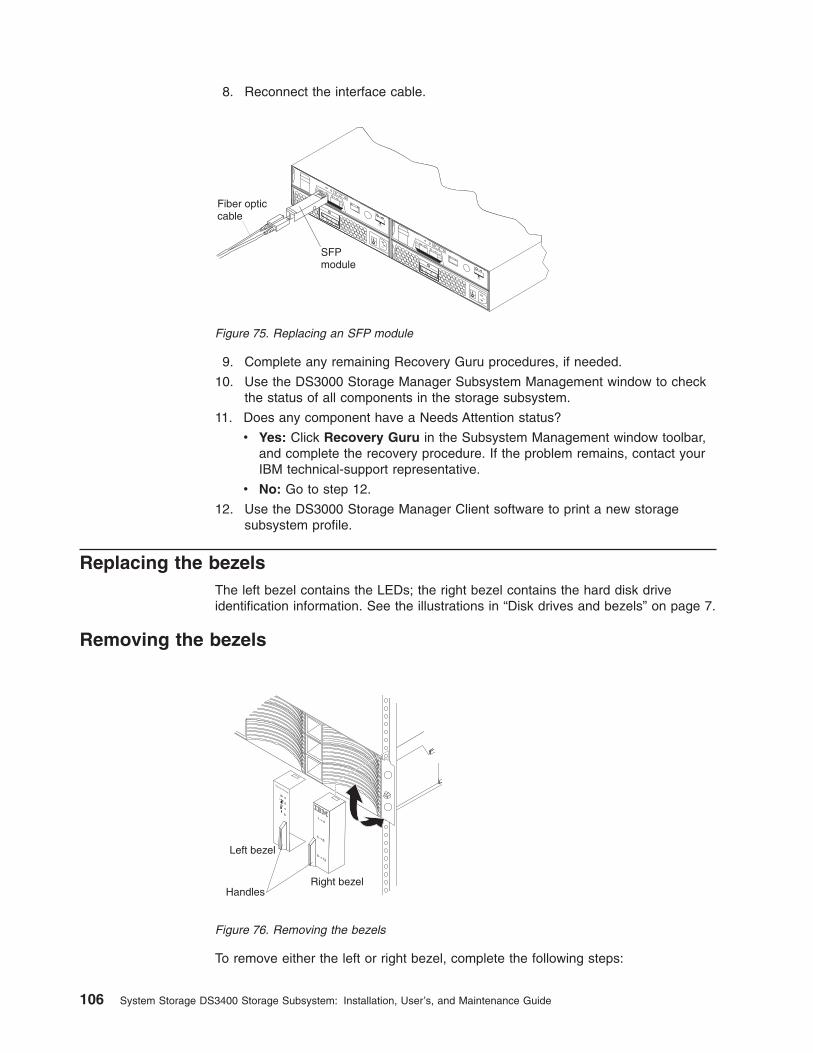
8. Reconnect the interface cable.
9. Complete any remaining Recovery Guru procedures, if needed.
10. Use the DS3000 Storage Manager Subsystem Management window to checkthe status of all components in the storage subsystem.
11. Does any component have a Needs Attention status?
v Yes: Click Recovery Guru in the Subsystem Management window toolbar,and complete the recovery procedure. If the problem remains, contact yourIBM technical-support representative.
v No: Go to step 12.
12. Use the DS3000 Storage Manager Client software to print a new storagesubsystem profile.
Replacing the bezelsThe left bezel contains the LEDs; the right bezel contains the hard disk driveidentification information. See the illustrations in “Disk drives and bezels” on page 7.
Removing the bezels
To remove either the left or right bezel, complete the following steps:
SFPmodule
Fiber opticcable
Figure 75. Replacing an SFP module
Right bezel
Left bezel
Handles
Figure 76. Removing the bezels
106 System Storage DS3400 Storage Subsystem: Installation, User’s, and Maintenance Guide
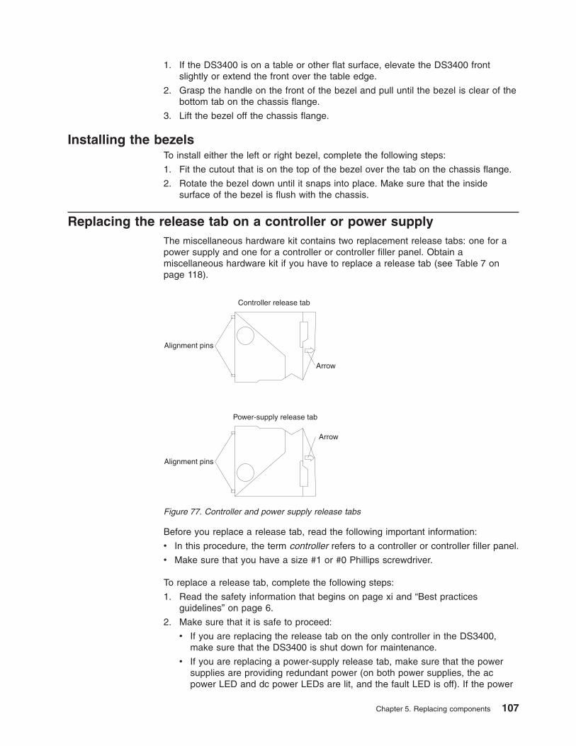
1. If the DS3400 is on a table or other flat surface, elevate the DS3400 frontslightly or extend the front over the table edge.
2. Grasp the handle on the front of the bezel and pull until the bezel is clear of thebottom tab on the chassis flange.
3. Lift the bezel off the chassis flange.
Installing the bezelsTo install either the left or right bezel, complete the following steps:
1. Fit the cutout that is on the top of the bezel over the tab on the chassis flange.
2. Rotate the bezel down until it snaps into place. Make sure that the insidesurface of the bezel is flush with the chassis.
Replacing the release tab on a controller or power supplyThe miscellaneous hardware kit contains two replacement release tabs: one for apower supply and one for a controller or controller filler panel. Obtain amiscellaneous hardware kit if you have to replace a release tab (see Table 7 onpage 118).
Before you replace a release tab, read the following important information:
v In this procedure, the term controller refers to a controller or controller filler panel.
v Make sure that you have a size #1 or #0 Phillips screwdriver.
To replace a release tab, complete the following steps:
1. Read the safety information that begins on page xi and “Best practicesguidelines” on page 6.
2. Make sure that it is safe to proceed:
v If you are replacing the release tab on the only controller in the DS3400,make sure that the DS3400 is shut down for maintenance.
v If you are replacing a power-supply release tab, make sure that the powersupplies are providing redundant power (on both power supplies, the acpower LED and dc power LEDs are lit, and the fault LED is off). If the power
Controller release tab
Power-supply release tab
Alignment pins
Alignment pins
Arrow
Arrow
Figure 77. Controller and power supply release tabs
Chapter 5. Replacing components 107
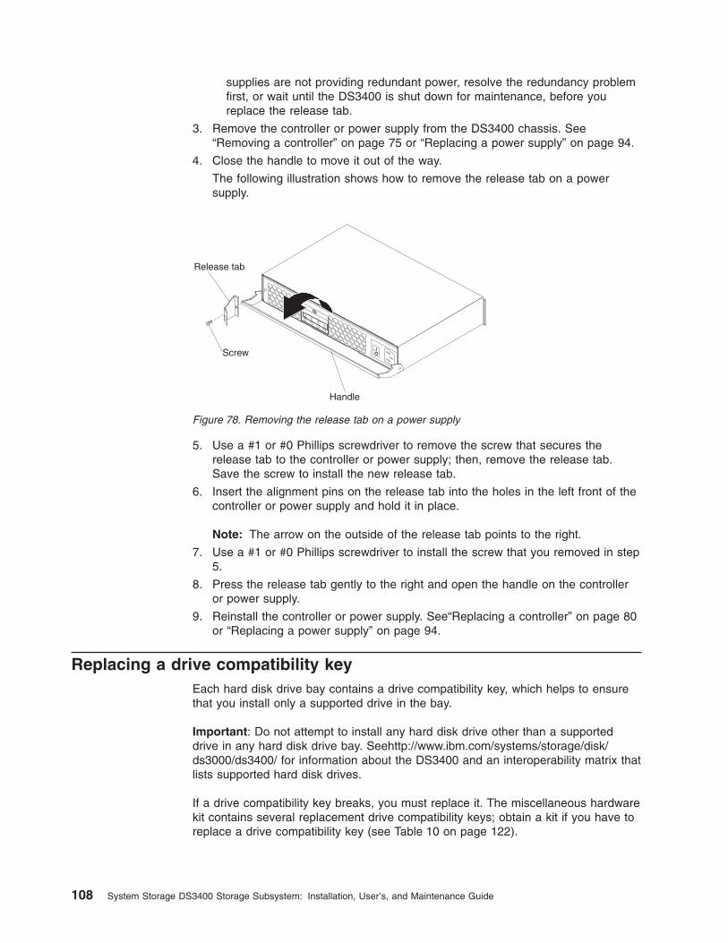
supplies are not providing redundant power, resolve the redundancy problemfirst, or wait until the DS3400 is shut down for maintenance, before youreplace the release tab.
3. Remove the controller or power supply from the DS3400 chassis. See“Removing a controller” on page 75 or “Replacing a power supply” on page 94.
4. Close the handle to move it out of the way.
The following illustration shows how to remove the release tab on a powersupply.
5. Use a #1 or #0 Phillips screwdriver to remove the screw that secures therelease tab to the controller or power supply; then, remove the release tab.Save the screw to install the new release tab.
6. Insert the alignment pins on the release tab into the holes in the left front of thecontroller or power supply and hold it in place.
Note: The arrow on the outside of the release tab points to the right.
7. Use a #1 or #0 Phillips screwdriver to install the screw that you removed in step5.
8. Press the release tab gently to the right and open the handle on the controlleror power supply.
9. Reinstall the controller or power supply. See“Replacing a controller” on page 80or “Replacing a power supply” on page 94.
Replacing a drive compatibility keyEach hard disk drive bay contains a drive compatibility key, which helps to ensurethat you install only a supported drive in the bay.
Important: Do not attempt to install any hard disk drive other than a supporteddrive in any hard disk drive bay. Seehttp://www.ibm.com/systems/storage/disk/ds3000/ds3400/ for information about the DS3400 and an interoperability matrix thatlists supported hard disk drives.
If a drive compatibility key breaks, you must replace it. The miscellaneous hardwarekit contains several replacement drive compatibility keys; obtain a kit if you have toreplace a drive compatibility key (see Table 10 on page 122).
Handle
Release tab
Screw
Figure 78. Removing the release tab on a power supply
108 System Storage DS3400 Storage Subsystem: Installation, User’s, and Maintenance Guide
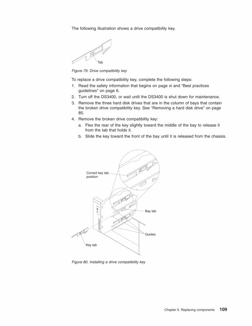
The following illustration shows a drive compatibility key.
To replace a drive compatibility key, complete the following steps:
1. Read the safety information that begins on page xi and “Best practicesguidelines” on page 6.
2. Turn off the DS3400, or wait until the DS3400 is shut down for maintenance.
3. Remove the three hard disk drives that are in the column of bays that containthe broken drive compatibility key. See “Removing a hard disk drive” on page85.
4. Remove the broken drive compatibility key:
a. Flex the rear of the key slightly toward the middle of the bay to release itfrom the tab that holds it.
b. Slide the key toward the front of the bay until it is released from the chassis.
Tab
Figure 79. Drive compatibility key
System Storage
Key tab
Bay tab
Guides
Correct key tabposition
Figure 80. Installing a drive compatibility key
Chapter 5. Replacing components 109
5. Install the replacement drive compatibility key:
a. Orient the key as shown in the illustration.
b. Place the key between the drive guides in the left wall of the bay, flush withthe wall.
c. Slide the key tab under the metal tab that is on the left wall of the bay; then,slide the key toward the rear of the chassis until the key stops (the key isflush with the side wall, the tab is covered, and the front of the key extendsapproximately 1 mm [0.04 in.] in front of the short metal upper guide).
6. Reinstall the hard disk drives in the bays from which they were removed. See“Replacing a hot-swap hard disk drive” on page 87.
7. If you turned off the DS3400 in step 2 on page 109, turn it on.
110 System Storage DS3400 Storage Subsystem: Installation, User’s, and Maintenance Guide
Chapter 6. Solving problems
This chapter contains information to help you solve some of the simpler problemsthat you might have with your storage subsystem. It describes the problemindicators, error messages, and suggested actions.
For instructions for obtaining service and technical assistance for your storagesubsystem and other IBM products, see “Getting help and information from theWorld Wide Web” on page 125.
Use the LEDs, the diagnostics and test information, the symptom-to-FRU index, andthe connected server Hardware Maintenance Manual or Problem Determination andService Guide to diagnose problems.
Use Table 6 on page 112 and the DS3000 Storage Manager Recovery Guru todiagnose storage subsystem problems and component failures and find solutions toproblems that have definite symptoms. Do not depend solely on Table 6 on page112 for a replacement decision.
© Copyright IBM Corp. 2006, 2009 111
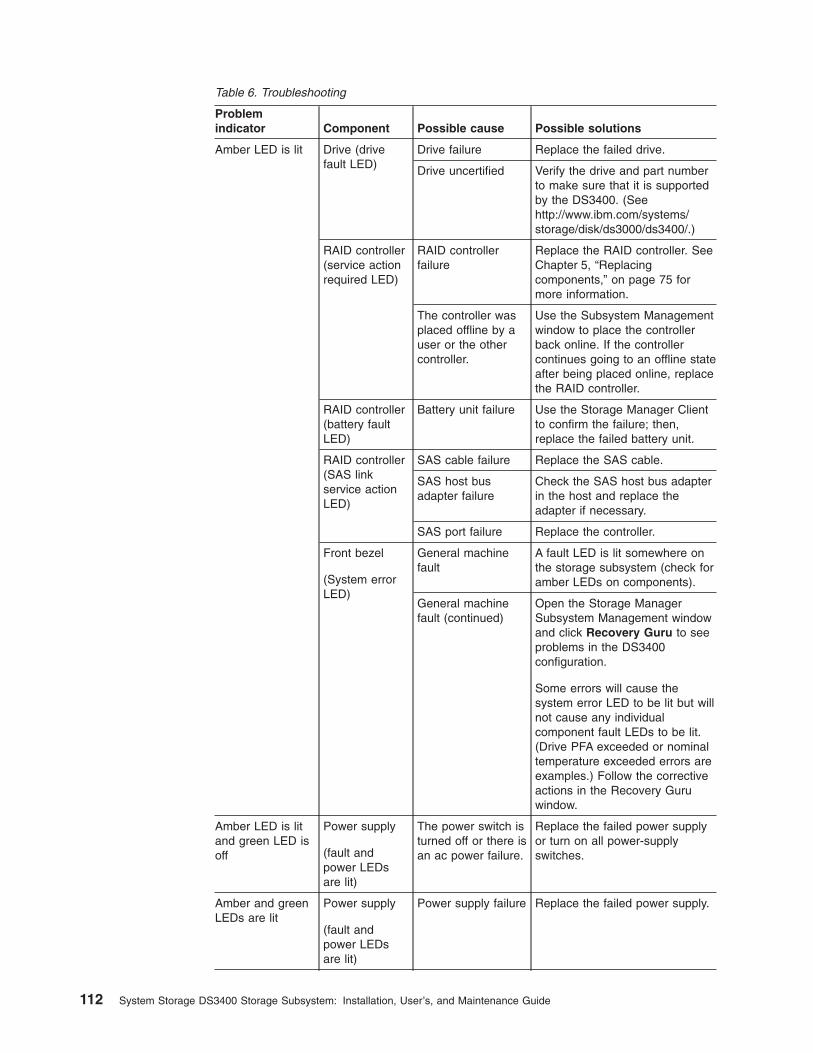
Table 6. Troubleshooting
Problemindicator Component Possible cause Possible solutions
Amber LED is lit Drive (drivefault LED)
Drive failure Replace the failed drive.
Drive uncertified Verify the drive and part numberto make sure that it is supportedby the DS3400. (Seehttp://www.ibm.com/systems/storage/disk/ds3000/ds3400/.)
RAID controller(service actionrequired LED)
RAID controllerfailure
Replace the RAID controller. SeeChapter 5, “Replacingcomponents,” on page 75 formore information.
The controller wasplaced offline by auser or the othercontroller.
Use the Subsystem Managementwindow to place the controllerback online. If the controllercontinues going to an offline stateafter being placed online, replacethe RAID controller.
RAID controller(battery faultLED)
Battery unit failure Use the Storage Manager Clientto confirm the failure; then,replace the failed battery unit.
RAID controller(SAS linkservice actionLED)
SAS cable failure Replace the SAS cable.
SAS host busadapter failure
Check the SAS host bus adapterin the host and replace theadapter if necessary.
SAS port failure Replace the controller.
Front bezel
(System errorLED)
General machinefault
A fault LED is lit somewhere onthe storage subsystem (check foramber LEDs on components).
General machinefault (continued)
Open the Storage ManagerSubsystem Management windowand click Recovery Guru to seeproblems in the DS3400configuration.
Some errors will cause thesystem error LED to be lit but willnot cause any individualcomponent fault LEDs to be lit.(Drive PFA exceeded or nominaltemperature exceeded errors areexamples.) Follow the correctiveactions in the Recovery Guruwindow.
Amber LED is litand green LED isoff
Power supply
(fault andpower LEDsare lit)
The power switch isturned off or there isan ac power failure.
Replace the failed power supplyor turn on all power-supplyswitches.
Amber and greenLEDs are lit
Power supply
(fault andpower LEDsare lit)
Power supply failure Replace the failed power supply.
112 System Storage DS3400 Storage Subsystem: Installation, User’s, and Maintenance Guide
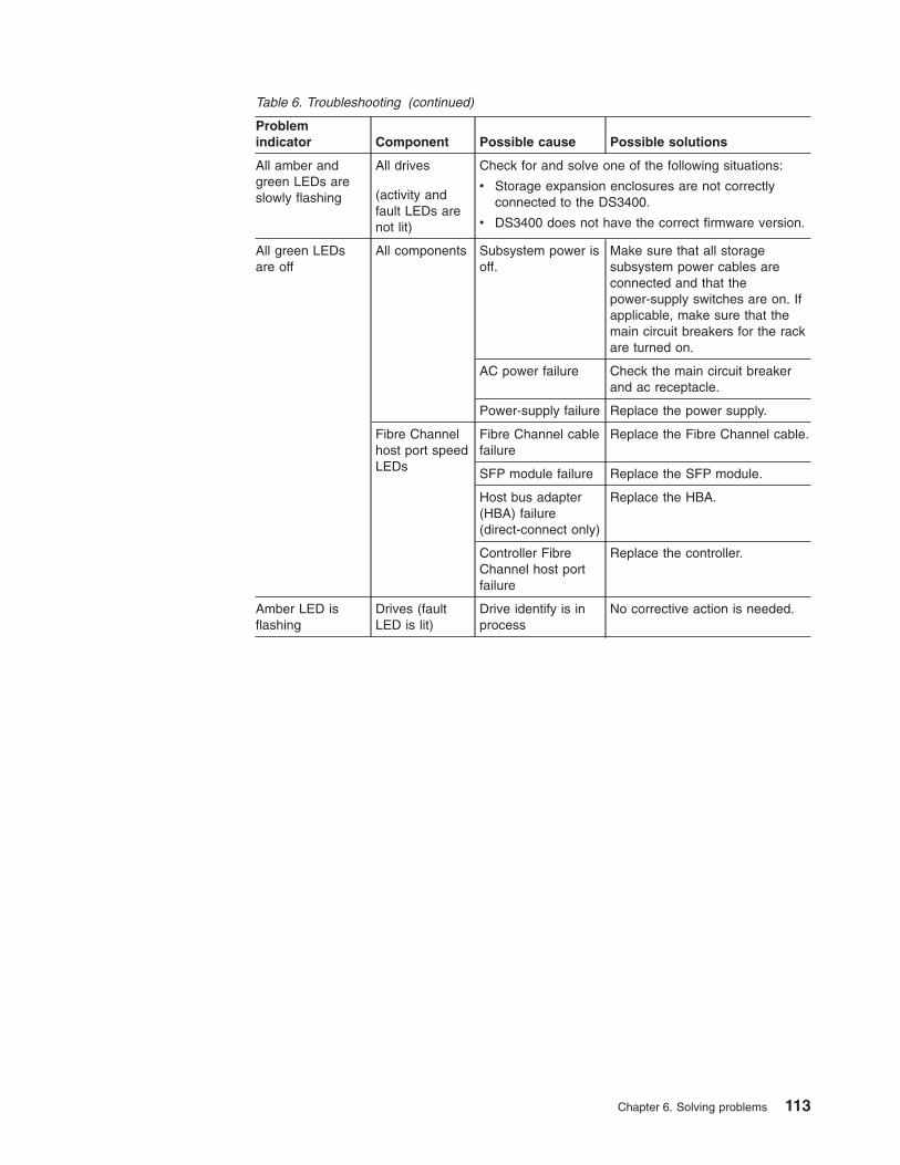
Table 6. Troubleshooting (continued)
Problemindicator Component Possible cause Possible solutions
All amber andgreen LEDs areslowly flashing
All drives
(activity andfault LEDs arenot lit)
Check for and solve one of the following situations:
v Storage expansion enclosures are not correctlyconnected to the DS3400.
v DS3400 does not have the correct firmware version.
All green LEDsare off
All components Subsystem power isoff.
Make sure that all storagesubsystem power cables areconnected and that thepower-supply switches are on. Ifapplicable, make sure that themain circuit breakers for the rackare turned on.
AC power failure Check the main circuit breakerand ac receptacle.
Power-supply failure Replace the power supply.
Fibre Channelhost port speedLEDs
Fibre Channel cablefailure
Replace the Fibre Channel cable.
SFP module failure Replace the SFP module.
Host bus adapter(HBA) failure(direct-connect only)
Replace the HBA.
Controller FibreChannel host portfailure
Replace the controller.
Amber LED isflashing
Drives (faultLED is lit)
Drive identify is inprocess
No corrective action is needed.
Chapter 6. Solving problems 113
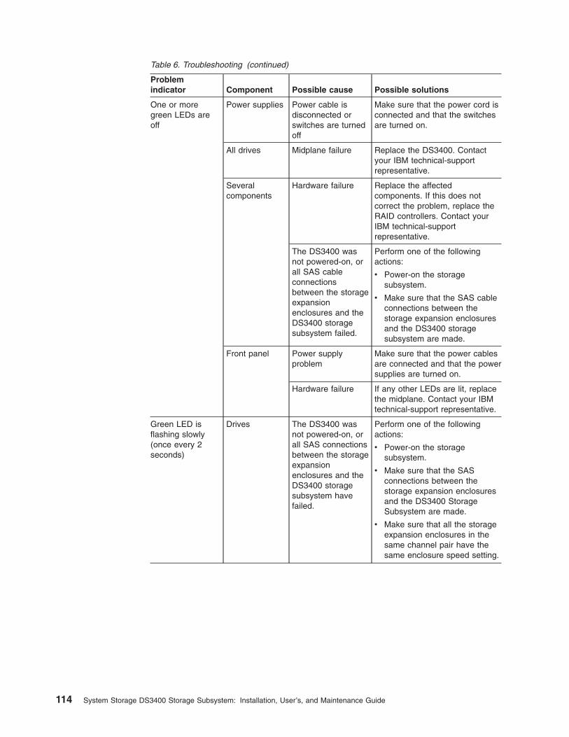
Table 6. Troubleshooting (continued)
Problemindicator Component Possible cause Possible solutions
One or moregreen LEDs areoff
Power supplies Power cable isdisconnected orswitches are turnedoff
Make sure that the power cord isconnected and that the switchesare turned on.
All drives Midplane failure Replace the DS3400. Contactyour IBM technical-supportrepresentative.
Severalcomponents
Hardware failure Replace the affectedcomponents. If this does notcorrect the problem, replace theRAID controllers. Contact yourIBM technical-supportrepresentative.
The DS3400 wasnot powered-on, orall SAS cableconnectionsbetween the storageexpansionenclosures and theDS3400 storagesubsystem failed.
Perform one of the followingactions:
v Power-on the storagesubsystem.
v Make sure that the SAS cableconnections between thestorage expansion enclosuresand the DS3400 storagesubsystem are made.
Front panel Power supplyproblem
Make sure that the power cablesare connected and that the powersupplies are turned on.
Hardware failure If any other LEDs are lit, replacethe midplane. Contact your IBMtechnical-support representative.
Green LED isflashing slowly(once every 2seconds)
Drives The DS3400 wasnot powered-on, orall SAS connectionsbetween the storageexpansionenclosures and theDS3400 storagesubsystem havefailed.
Perform one of the followingactions:
v Power-on the storagesubsystem.
v Make sure that the SASconnections between thestorage expansion enclosuresand the DS3400 StorageSubsystem are made.
v Make sure that all the storageexpansion enclosures in thesame channel pair have thesame enclosure speed setting.
114 System Storage DS3400 Storage Subsystem: Installation, User’s, and Maintenance Guide
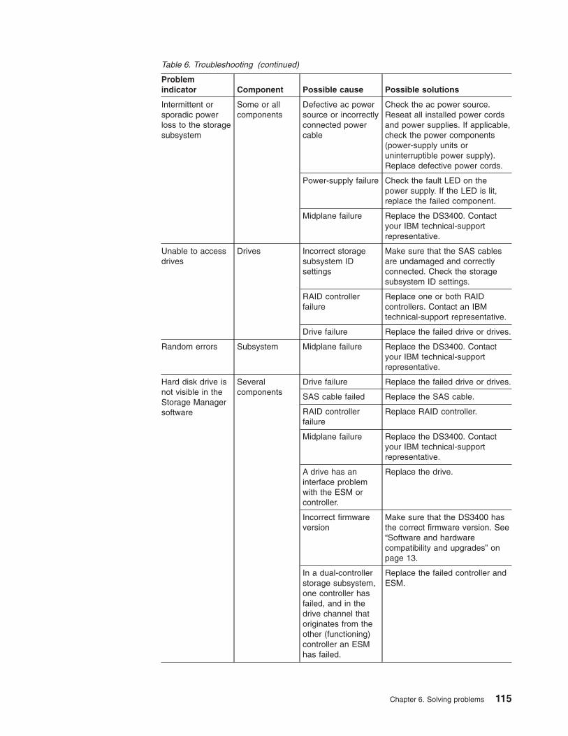
Table 6. Troubleshooting (continued)
Problemindicator Component Possible cause Possible solutions
Intermittent orsporadic powerloss to the storagesubsystem
Some or allcomponents
Defective ac powersource or incorrectlyconnected powercable
Check the ac power source.Reseat all installed power cordsand power supplies. If applicable,check the power components(power-supply units oruninterruptible power supply).Replace defective power cords.
Power-supply failure Check the fault LED on thepower supply. If the LED is lit,replace the failed component.
Midplane failure Replace the DS3400. Contactyour IBM technical-supportrepresentative.
Unable to accessdrives
Drives Incorrect storagesubsystem IDsettings
Make sure that the SAS cablesare undamaged and correctlyconnected. Check the storagesubsystem ID settings.
RAID controllerfailure
Replace one or both RAIDcontrollers. Contact an IBMtechnical-support representative.
Drive failure Replace the failed drive or drives.
Random errors Subsystem Midplane failure Replace the DS3400. Contactyour IBM technical-supportrepresentative.
Hard disk drive isnot visible in theStorage Managersoftware
Severalcomponents
Drive failure Replace the failed drive or drives.
SAS cable failed Replace the SAS cable.
RAID controllerfailure
Replace RAID controller.
Midplane failure Replace the DS3400. Contactyour IBM technical-supportrepresentative.
A drive has aninterface problemwith the ESM orcontroller.
Replace the drive.
Incorrect firmwareversion
Make sure that the DS3400 hasthe correct firmware version. See“Software and hardwarecompatibility and upgrades” onpage 13.
In a dual-controllerstorage subsystem,one controller hasfailed, and in thedrive channel thatoriginates from theother (functioning)controller an ESMhas failed.
Replace the failed controller andESM.
Chapter 6. Solving problems 115

116 System Storage DS3400 Storage Subsystem: Installation, User’s, and Maintenance Guide
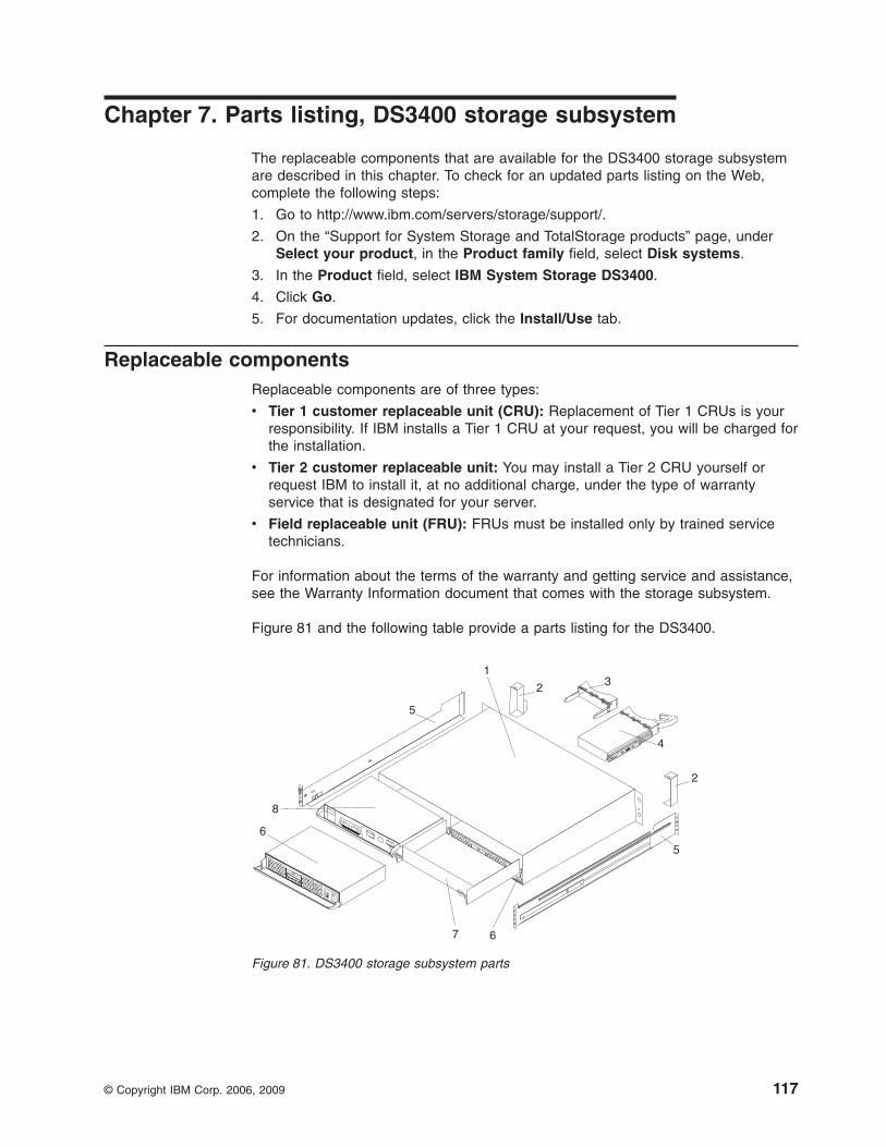
Chapter 7. Parts listing, DS3400 storage subsystem
The replaceable components that are available for the DS3400 storage subsystemare described in this chapter. To check for an updated parts listing on the Web,complete the following steps:
1. Go to http://www.ibm.com/servers/storage/support/.
2. On the “Support for System Storage and TotalStorage products” page, underSelect your product, in the Product family field, select Disk systems.
3. In the Product field, select IBM System Storage DS3400.
4. Click Go.
5. For documentation updates, click the Install/Use tab.
Replaceable componentsReplaceable components are of three types:
v Tier 1 customer replaceable unit (CRU): Replacement of Tier 1 CRUs is yourresponsibility. If IBM installs a Tier 1 CRU at your request, you will be charged forthe installation.
v Tier 2 customer replaceable unit: You may install a Tier 2 CRU yourself orrequest IBM to install it, at no additional charge, under the type of warrantyservice that is designated for your server.
v Field replaceable unit (FRU): FRUs must be installed only by trained servicetechnicians.
For information about the terms of the warranty and getting service and assistance,see the Warranty Information document that comes with the storage subsystem.
Figure 81 and the following table provide a parts listing for the DS3400.
1
2 3
4
5
5
67
2
8
6
Figure 81. DS3400 storage subsystem parts
© Copyright IBM Corp. 2006, 2009 117
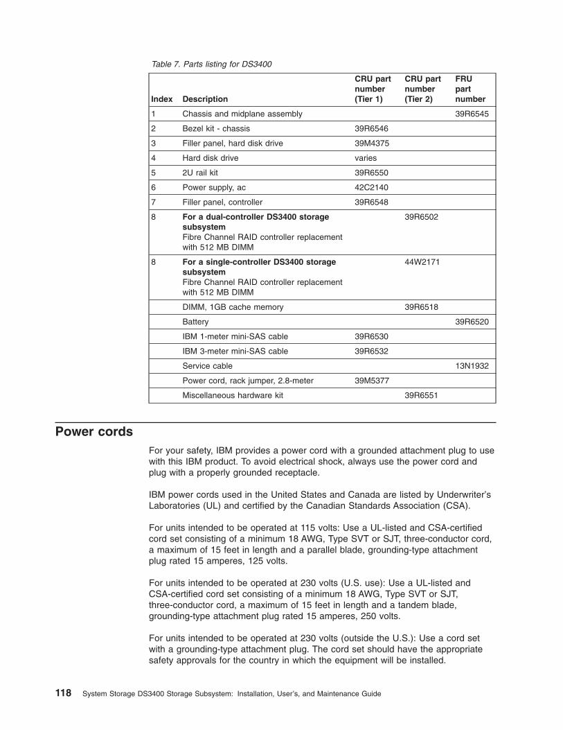
Table 7. Parts listing for DS3400
Index Description
CRU partnumber(Tier 1)
CRU partnumber(Tier 2)
FRUpartnumber
1 Chassis and midplane assembly 39R6545
2 Bezel kit - chassis 39R6546
3 Filler panel, hard disk drive 39M4375
4 Hard disk drive varies
5 2U rail kit 39R6550
6 Power supply, ac 42C2140
7 Filler panel, controller 39R6548
8 For a dual-controller DS3400 storagesubsystemFibre Channel RAID controller replacementwith 512 MB DIMM
39R6502
8 For a single-controller DS3400 storagesubsystemFibre Channel RAID controller replacementwith 512 MB DIMM
44W2171
DIMM, 1GB cache memory 39R6518
Battery 39R6520
IBM 1-meter mini-SAS cable 39R6530
IBM 3-meter mini-SAS cable 39R6532
Service cable 13N1932
Power cord, rack jumper, 2.8-meter 39M5377
Miscellaneous hardware kit 39R6551
Power cordsFor your safety, IBM provides a power cord with a grounded attachment plug to usewith this IBM product. To avoid electrical shock, always use the power cord andplug with a properly grounded receptacle.
IBM power cords used in the United States and Canada are listed by Underwriter’sLaboratories (UL) and certified by the Canadian Standards Association (CSA).
For units intended to be operated at 115 volts: Use a UL-listed and CSA-certifiedcord set consisting of a minimum 18 AWG, Type SVT or SJT, three-conductor cord,a maximum of 15 feet in length and a parallel blade, grounding-type attachmentplug rated 15 amperes, 125 volts.
For units intended to be operated at 230 volts (U.S. use): Use a UL-listed andCSA-certified cord set consisting of a minimum 18 AWG, Type SVT or SJT,three-conductor cord, a maximum of 15 feet in length and a tandem blade,grounding-type attachment plug rated 15 amperes, 250 volts.
For units intended to be operated at 230 volts (outside the U.S.): Use a cord setwith a grounding-type attachment plug. The cord set should have the appropriatesafety approvals for the country in which the equipment will be installed.
118 System Storage DS3400 Storage Subsystem: Installation, User’s, and Maintenance Guide
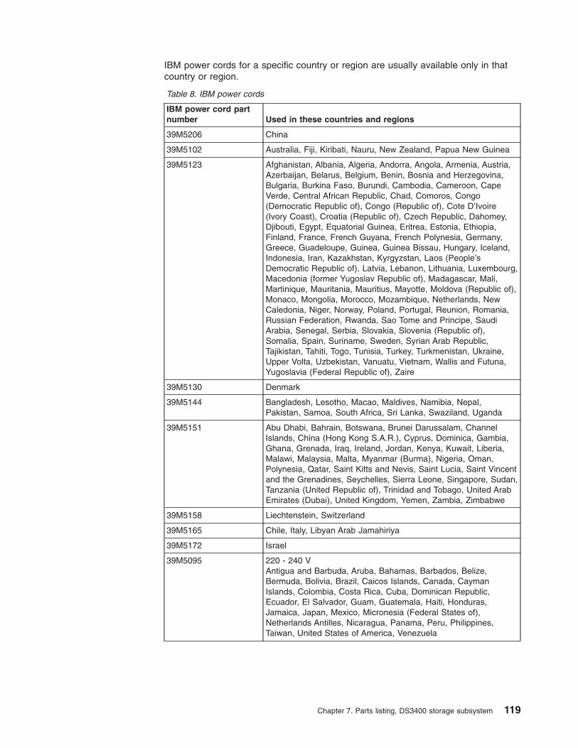
IBM power cords for a specific country or region are usually available only in thatcountry or region.
Table 8. IBM power cords
IBM power cord partnumber Used in these countries and regions
39M5206 China
39M5102 Australia, Fiji, Kiribati, Nauru, New Zealand, Papua New Guinea
39M5123 Afghanistan, Albania, Algeria, Andorra, Angola, Armenia, Austria,Azerbaijan, Belarus, Belgium, Benin, Bosnia and Herzegovina,Bulgaria, Burkina Faso, Burundi, Cambodia, Cameroon, CapeVerde, Central African Republic, Chad, Comoros, Congo(Democratic Republic of), Congo (Republic of), Cote D’Ivoire(Ivory Coast), Croatia (Republic of), Czech Republic, Dahomey,Djibouti, Egypt, Equatorial Guinea, Eritrea, Estonia, Ethiopia,Finland, France, French Guyana, French Polynesia, Germany,Greece, Guadeloupe, Guinea, Guinea Bissau, Hungary, Iceland,Indonesia, Iran, Kazakhstan, Kyrgyzstan, Laos (People’sDemocratic Republic of), Latvia, Lebanon, Lithuania, Luxembourg,Macedonia (former Yugoslav Republic of), Madagascar, Mali,Martinique, Mauritania, Mauritius, Mayotte, Moldova (Republic of),Monaco, Mongolia, Morocco, Mozambique, Netherlands, NewCaledonia, Niger, Norway, Poland, Portugal, Reunion, Romania,Russian Federation, Rwanda, Sao Tome and Principe, SaudiArabia, Senegal, Serbia, Slovakia, Slovenia (Republic of),Somalia, Spain, Suriname, Sweden, Syrian Arab Republic,Tajikistan, Tahiti, Togo, Tunisia, Turkey, Turkmenistan, Ukraine,Upper Volta, Uzbekistan, Vanuatu, Vietnam, Wallis and Futuna,Yugoslavia (Federal Republic of), Zaire
39M5130 Denmark
39M5144 Bangladesh, Lesotho, Macao, Maldives, Namibia, Nepal,Pakistan, Samoa, South Africa, Sri Lanka, Swaziland, Uganda
39M5151 Abu Dhabi, Bahrain, Botswana, Brunei Darussalam, ChannelIslands, China (Hong Kong S.A.R.), Cyprus, Dominica, Gambia,Ghana, Grenada, Iraq, Ireland, Jordan, Kenya, Kuwait, Liberia,Malawi, Malaysia, Malta, Myanmar (Burma), Nigeria, Oman,Polynesia, Qatar, Saint Kitts and Nevis, Saint Lucia, Saint Vincentand the Grenadines, Seychelles, Sierra Leone, Singapore, Sudan,Tanzania (United Republic of), Trinidad and Tobago, United ArabEmirates (Dubai), United Kingdom, Yemen, Zambia, Zimbabwe
39M5158 Liechtenstein, Switzerland
39M5165 Chile, Italy, Libyan Arab Jamahiriya
39M5172 Israel
39M5095 220 - 240 VAntigua and Barbuda, Aruba, Bahamas, Barbados, Belize,Bermuda, Bolivia, Brazil, Caicos Islands, Canada, CaymanIslands, Colombia, Costa Rica, Cuba, Dominican Republic,Ecuador, El Salvador, Guam, Guatemala, Haiti, Honduras,Jamaica, Japan, Mexico, Micronesia (Federal States of),Netherlands Antilles, Nicaragua, Panama, Peru, Philippines,Taiwan, United States of America, Venezuela
Chapter 7. Parts listing, DS3400 storage subsystem 119
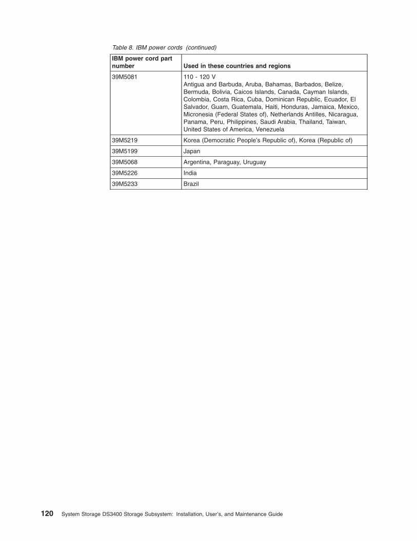
Table 8. IBM power cords (continued)
IBM power cord partnumber Used in these countries and regions
39M5081 110 - 120 VAntigua and Barbuda, Aruba, Bahamas, Barbados, Belize,Bermuda, Bolivia, Caicos Islands, Canada, Cayman Islands,Colombia, Costa Rica, Cuba, Dominican Republic, Ecuador, ElSalvador, Guam, Guatemala, Haiti, Honduras, Jamaica, Mexico,Micronesia (Federal States of), Netherlands Antilles, Nicaragua,Panama, Peru, Philippines, Saudi Arabia, Thailand, Taiwan,United States of America, Venezuela
39M5219 Korea (Democratic People’s Republic of), Korea (Republic of)
39M5199 Japan
39M5068 Argentina, Paraguay, Uruguay
39M5226 India
39M5233 Brazil
120 System Storage DS3400 Storage Subsystem: Installation, User’s, and Maintenance Guide
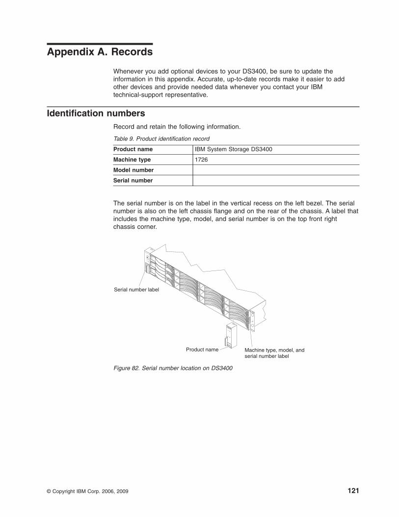
Appendix A. Records
Whenever you add optional devices to your DS3400, be sure to update theinformation in this appendix. Accurate, up-to-date records make it easier to addother devices and provide needed data whenever you contact your IBMtechnical-support representative.
Identification numbersRecord and retain the following information.
Table 9. Product identification record
Product name IBM System Storage DS3400
Machine type 1726
Model number
Serial number
The serial number is on the label in the vertical recess on the left bezel. The serialnumber is also on the left chassis flange and on the rear of the chassis. A label thatincludes the machine type, model, and serial number is on the top front rightchassis corner.
Serial number label
Product name Machine type, model, andserial number label
Figure 82. Serial number location on DS3400
© Copyright IBM Corp. 2006, 2009 121
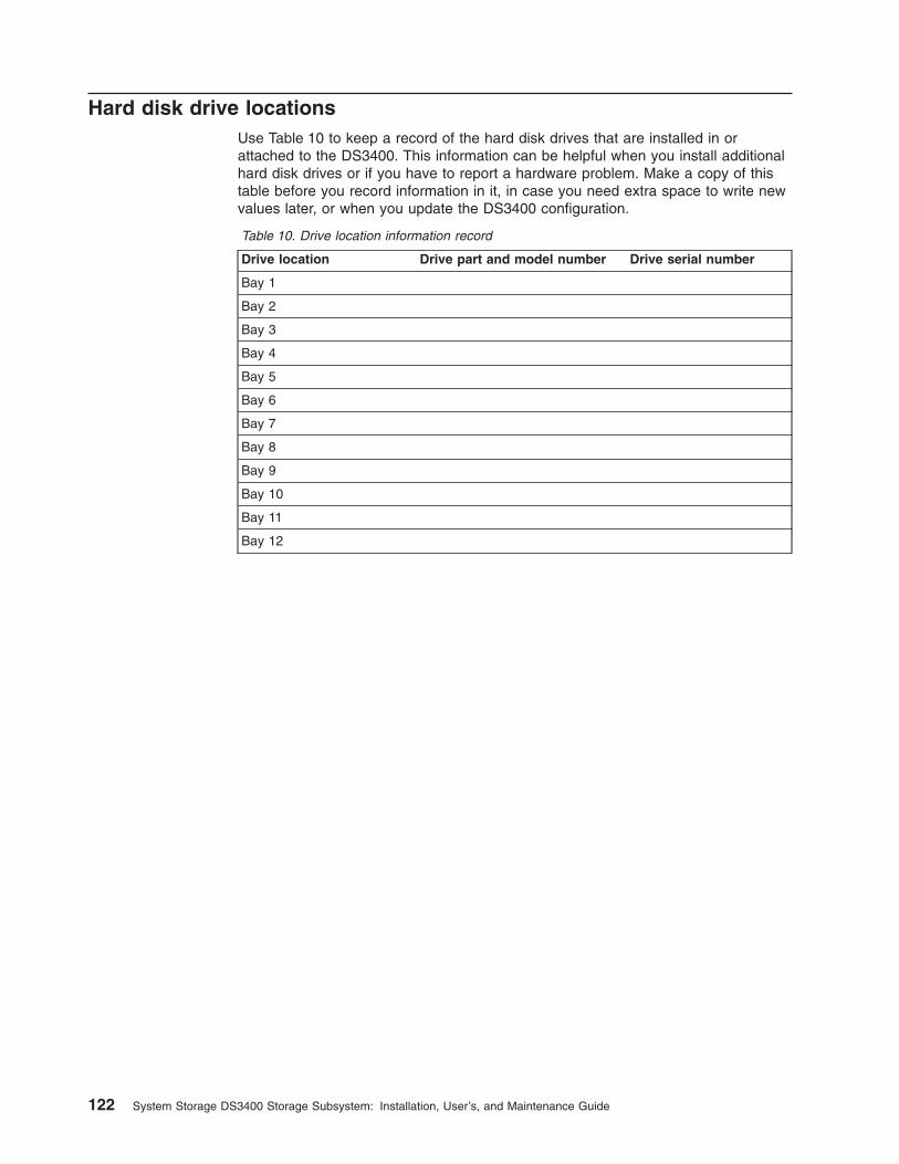
Hard disk drive locationsUse Table 10 to keep a record of the hard disk drives that are installed in orattached to the DS3400. This information can be helpful when you install additionalhard disk drives or if you have to report a hardware problem. Make a copy of thistable before you record information in it, in case you need extra space to write newvalues later, or when you update the DS3400 configuration.
Table 10. Drive location information record
Drive location Drive part and model number Drive serial number
Bay 1
Bay 2
Bay 3
Bay 4
Bay 5
Bay 6
Bay 7
Bay 8
Bay 9
Bay 10
Bay 11
Bay 12
122 System Storage DS3400 Storage Subsystem: Installation, User’s, and Maintenance Guide
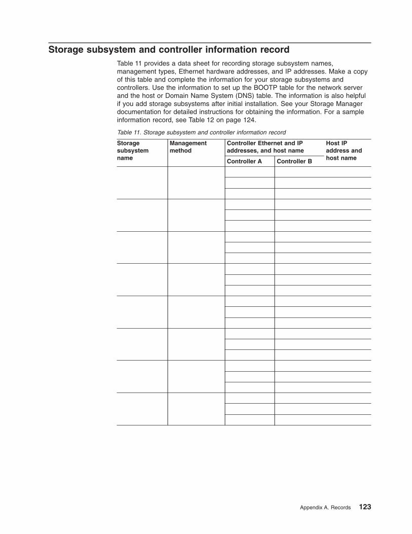
Storage subsystem and controller information recordTable 11 provides a data sheet for recording storage subsystem names,management types, Ethernet hardware addresses, and IP addresses. Make a copyof this table and complete the information for your storage subsystems andcontrollers. Use the information to set up the BOOTP table for the network serverand the host or Domain Name System (DNS) table. The information is also helpfulif you add storage subsystems after initial installation. See your Storage Managerdocumentation for detailed instructions for obtaining the information. For a sampleinformation record, see Table 12 on page 124.
Table 11. Storage subsystem and controller information record
Storagesubsystemname
Managementmethod
Controller Ethernet and IPaddresses, and host name
Host IPaddress andhost nameController A Controller B
Appendix A. Records 123
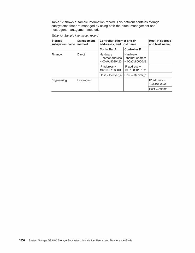
Table 12 shows a sample information record. This network contains storagesubsystems that are managed by using both the direct-management andhost-agent-management method.
Table 12. Sample information record
Storagesubsystem name
Managementmethod
Controller Ethernet and IPaddresses, and host name
Host IP addressand host name
Controller A Controller B
Finance Direct HardwareEthernet address= 00a0b8020420
HardwareEthernet address= 00a0b80000d8
IP address =192.168.128.101
IP address =192.168.128.102
Host = Denver_a Host = Denver_b
Engineering Host-agent IP address =192.168.2.22
Host = Atlanta
124 System Storage DS3400 Storage Subsystem: Installation, User’s, and Maintenance Guide
Appendix B. Getting help and technical assistance
If you need help, service, or technical assistance or just want more informationabout IBM products, you will find a wide variety of sources available from IBM toassist you. This section contains information about where to go for additionalinformation about IBM and IBM products, what to do if you experience a problemwith your system, and whom to call for service, if it is necessary.
Before you callBefore you call, make sure that you have taken these steps to try to solve theproblem yourself:
v Check all cables to make sure that they are connected.
v Check the power switches to make sure that the system and any optionaldevices are turned on.
v Use the troubleshooting information in your system documentation, and use thediagnostic tools that come with your system. Information about diagnostic tools isin the Problem Determination and Service Guide on the IBM Documentation CDthat comes with your system.
v Go to the IBM support Web site at http://www.ibm.com/systems/support/ to checkfor technical information, hints, tips, and new device drivers or to submit arequest for information.
You can solve many problems without outside assistance by following thetroubleshooting procedures that IBM provides in the online help or in thedocumentation that is provided with your IBM product. The documentation thatcomes with IBM systems also describes the diagnostic tests that you can perform.Most systems, operating systems, and programs come with documentation thatcontains troubleshooting procedures and explanations of error messages and errorcodes. If you suspect a software problem, see the documentation for the operatingsystem or program.
Using the documentationInformation about your IBM system and preinstalled software, if any, or optionaldevice is available in the documentation that comes with the product. Thatdocumentation can include printed documents, online documents, readme files, andhelp files. See the troubleshooting information in your system documentation forinstructions for using the diagnostic programs. The troubleshooting information orthe diagnostic programs might tell you that you need additional or updated devicedrivers or other software. IBM maintains pages on the World Wide Web where youcan get the latest technical information and download device drivers and updates.To access these pages, go to http://www.ibm.com/systems/support/ and follow theinstructions. Also, some documents are available through the IBM PublicationsCenter at http://www.ibm.com/shop/publications/order/.
Getting help and information from the World Wide WebOn the World Wide Web, the IBM Web site has up-to-date information about IBMsystems, optional devices, services, and support. The address for IBM System x®
and xSeries® information is http://www.ibm.com/systems/x/. The address for IBMBladeCenter® information is http://www.ibm.com/systems/bladecenter/. The addressfor IBM IntelliStation® information is http://www.ibm.com/intellistation/.
© Copyright IBM Corp. 2006, 2009 125
You can find service information for IBM systems and optional devices athttp://www.ibm.com/systems/support/.
Software service and supportThrough IBM Support Line, you can get telephone assistance, for a fee, with usage,configuration, and software problems with System x and xSeries servers,BladeCenter products, IntelliStation workstations, and appliances. For informationabout which products are supported by Support Line in your country or region, seehttp://www.ibm.com/services/sl/products/.
For more information about Support Line and other IBM services, seehttp://www.ibm.com/services/, or see http://www.ibm.com/planetwide/ for supporttelephone numbers. In the U.S. and Canada, call 1-800-IBM-SERV(1-800-426-7378).
Hardware service and supportYou can receive hardware service through your IBM reseller or IBM Services. Tolocate a reseller authorized by IBM to provide warranty service, go tohttp://www.ibm.com/partnerworld/ and click Find Business Partners on the rightside of the page. For IBM support telephone numbers, see http://www.ibm.com/planetwide/. In the U.S. and Canada, call 1-800-IBM-SERV (1-800-426-7378).
In the U.S. and Canada, hardware service and support is available 24 hours a day,7 days a week. In the U.K., these services are available Monday through Friday,from 9 a.m. to 6 p.m.
IBM Taiwan product service
IBM Taiwan product service contact information:IBM Taiwan Corporation3F, No 7, Song Ren Rd.Taipei, TaiwanTelephone: 0800-016-888
126 System Storage DS3400 Storage Subsystem: Installation, User’s, and Maintenance Guide
Appendix C. Notices
This information was developed for products and services offered in the U.S.A.
IBM may not offer the products, services, or features discussed in this document inother countries. Consult your local IBM representative for information on theproducts and services currently available in your area. Any reference to an IBMproduct, program, or service is not intended to state or imply that only that IBMproduct, program, or service may be used. Any functionally equivalent product,program, or service that does not infringe any IBM intellectual property right may beused instead. However, it is the user’s responsibility to evaluate and verify theoperation of any non-IBM product, program, or service.
IBM may have patents or pending patent applications covering subject matterdescribed in this document. The furnishing of this document does not give you anylicense to these patents. You can send license inquiries, in writing, to:
IBM Director of LicensingIBM CorporationNorth Castle DriveArmonk, NY 10504-1785U.S.A.
INTERNATIONAL BUSINESS MACHINES CORPORATION PROVIDES THISPUBLICATION “AS IS” WITHOUT WARRANTY OF ANY KIND, EITHER EXPRESSOR IMPLIED, INCLUDING, BUT NOT LIMITED TO, THE IMPLIED WARRANTIESOF NON-INFRINGEMENT, MERCHANTABILITY OR FITNESS FOR APARTICULAR PURPOSE. Some states do not allow disclaimer of express orimplied warranties in certain transactions, therefore, this statement may not apply toyou.
This information could include technical inaccuracies or typographical errors.Changes are periodically made to the information herein; these changes will beincorporated in new editions of the publication. IBM may make improvements and/orchanges in the product(s) and/or the program(s) described in this publication at anytime without notice.
Any references in this information to non-IBM Web sites are provided forconvenience only and do not in any manner serve as an endorsement of thoseWeb sites. The materials at those Web sites are not part of the materials for thisIBM product, and use of those Web sites is at your own risk.
IBM may use or distribute any of the information you supply in any way it believesappropriate without incurring any obligation to you.
TrademarksIBM, the IBM logo, and ibm.com are trademarks or registered trademarks ofInternational Business Machines Corporation in the United States, other countries,or both. If these and other IBM trademarked terms are marked on their firstoccurrence in this information with a trademark symbol (® or ™), these symbolsindicate U.S. registered or common law trademarks owned by IBM at the time thisinformation was published. Such trademarks may also be registered or common lawtrademarks in other countries. A current list of IBM trademarks is available on theWeb at “Copyright and trademark information” at http://www.ibm.com/legal/copytrade.shtml.
© Copyright IBM Corp. 2006, 2009 127
Adobe and PostScript are either registered trademarks or trademarks of AdobeSystems Incorporated in the United States and/or other countries.
Cell Broadband Engine is a trademark of Sony Computer Entertainment, Inc., in theUnited States, other countries, or both and is used under license therefrom.
Intel, Intel Xeon, Itanium, and Pentium are trademarks or registered trademarks ofIntel Corporation or its subsidiaries in the United States and other countries.
Java and all Java-based trademarks are trademarks of Sun Microsystems, Inc., inthe United States, other countries, or both.
Linux is a registered trademark of Linus Torvalds in the United States, othercountries, or both.
Microsoft, Windows, and Windows NT are trademarks of Microsoft Corporation inthe United States, other countries, or both.
UNIX is a registered trademark of The Open Group in the United States and othercountries.
Other company, product, or service names may be trademarks or service marks ofothers.
Important notesProcessor speed indicates the internal clock speed of the microprocessor; otherfactors also affect application performance.
CD or DVD drive speed is the variable read rate. Actual speeds vary and are oftenless than the possible maximum.
When referring to processor storage, real and virtual storage, or channel volume,KB stands for 1024 bytes, MB stands for 1 048 576 bytes, and GB stands for1 073 741 824 bytes.
When referring to hard disk drive capacity or communications volume, MB standsfor 1 000 000 bytes, and GB stands for 1 000 000 000 bytes. Total user-accessiblecapacity can vary depending on operating environments.
Maximum internal hard disk drive capacities assume the replacement of anystandard hard disk drives and population of all hard disk drive bays with the largestcurrently supported drives that are available from IBM.
Maximum memory might require replacement of the standard memory with anoptional memory module.
IBM makes no representation or warranties regarding non-IBM products andservices that are ServerProven®, including but not limited to the implied warrantiesof merchantability and fitness for a particular purpose. These products are offeredand warranted solely by third parties.
IBM makes no representations or warranties with respect to non-IBM products.Support (if any) for the non-IBM products is provided by the third party, not IBM.
128 System Storage DS3400 Storage Subsystem: Installation, User’s, and Maintenance Guide
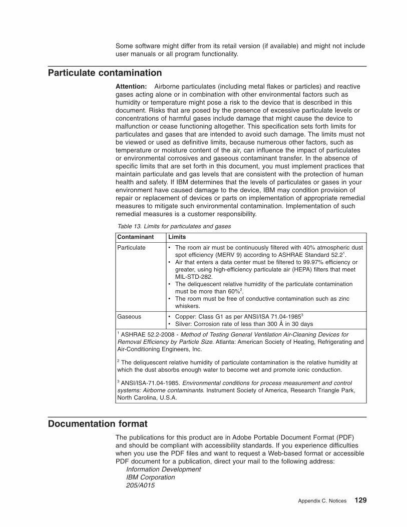
Some software might differ from its retail version (if available) and might not includeuser manuals or all program functionality.
Particulate contaminationAttention: Airborne particulates (including metal flakes or particles) and reactivegases acting alone or in combination with other environmental factors such ashumidity or temperature might pose a risk to the device that is described in thisdocument. Risks that are posed by the presence of excessive particulate levels orconcentrations of harmful gases include damage that might cause the device tomalfunction or cease functioning altogether. This specification sets forth limits forparticulates and gases that are intended to avoid such damage. The limits must notbe viewed or used as definitive limits, because numerous other factors, such astemperature or moisture content of the air, can influence the impact of particulatesor environmental corrosives and gaseous contaminant transfer. In the absence ofspecific limits that are set forth in this document, you must implement practices thatmaintain particulate and gas levels that are consistent with the protection of humanhealth and safety. If IBM determines that the levels of particulates or gases in yourenvironment have caused damage to the device, IBM may condition provision ofrepair or replacement of devices or parts on implementation of appropriate remedialmeasures to mitigate such environmental contamination. Implementation of suchremedial measures is a customer responsibility.
Table 13. Limits for particulates and gases
Contaminant Limits
Particulate v The room air must be continuously filtered with 40% atmospheric dustspot efficiency (MERV 9) according to ASHRAE Standard 52.21.
v Air that enters a data center must be filtered to 99.97% efficiency orgreater, using high-efficiency particulate air (HEPA) filters that meetMIL-STD-282.
v The deliquescent relative humidity of the particulate contaminationmust be more than 60%2.
v The room must be free of conductive contamination such as zincwhiskers.
Gaseous v Copper: Class G1 as per ANSI/ISA 71.04-19853
v Silver: Corrosion rate of less than 300 Å in 30 days1 ASHRAE 52.2-2008 - Method of Testing General Ventilation Air-Cleaning Devices forRemoval Efficiency by Particle Size. Atlanta: American Society of Heating, Refrigerating andAir-Conditioning Engineers, Inc.
2 The deliquescent relative humidity of particulate contamination is the relative humidity atwhich the dust absorbs enough water to become wet and promote ionic conduction.
3 ANSI/ISA-71.04-1985. Environmental conditions for process measurement and controlsystems: Airborne contaminants. Instrument Society of America, Research Triangle Park,North Carolina, U.S.A.
Documentation formatThe publications for this product are in Adobe Portable Document Format (PDF)and should be compliant with accessibility standards. If you experience difficultieswhen you use the PDF files and want to request a Web-based format or accessiblePDF document for a publication, direct your mail to the following address:
Information DevelopmentIBM Corporation205/A015
Appendix C. Notices 129

3039 E. Cornwallis RoadP.O. Box 12195Research Triangle Park, North Carolina 27709-2195U.S.A.
In the request, be sure to include the publication part number and title.
When you send information to IBM, you grant IBM a nonexclusive right to use ordistribute the information in any way it believes appropriate without incurring anyobligation to you.
Electronic emission notices
Federal Communications Commission (FCC) statementNote: This equipment has been tested and found to comply with the limits for aClass A digital device, pursuant to Part 15 of the FCC Rules. These limits aredesigned to provide reasonable protection against harmful interference when theequipment is operated in a commercial environment. This equipment generates,uses, and can radiate radio frequency energy and, if not installed and used inaccordance with the instruction manual, may cause harmful interference to radiocommunications. Operation of this equipment in a residential area is likely to causeharmful interference, in which case the user will be required to correct theinterference at his own expense.
Properly shielded and grounded cables and connectors must be used in order tomeet FCC emission limits. IBM is not responsible for any radio or televisioninterference caused by using other than recommended cables and connectors or byunauthorized changes or modifications to this equipment. Unauthorized changes ormodifications could void the user’s authority to operate the equipment.
This device complies with Part 15 of the FCC Rules. Operation is subject to thefollowing two conditions: (1) this device may not cause harmful interference, and (2)this device must accept any interference received, including interference that maycause undesired operation.
Industry Canada Class A emission compliance statementThis Class A digital apparatus complies with Canadian ICES-003.
Avis de conformité à la réglementation d’Industrie CanadaCet appareil numérique de la classe A est conforme à la norme NMB-003 duCanada.
Australia and New Zealand Class A statementAttention: This is a Class A product. In a domestic environment this product maycause radio interference in which case the user may be required to take adequatemeasures.
United Kingdom telecommunications safety requirementNotice to Customers
This apparatus is approved under approval number NS/G/1234/J/100003 for indirectconnection to public telecommunication systems in the United Kingdom.
130 System Storage DS3400 Storage Subsystem: Installation, User’s, and Maintenance Guide
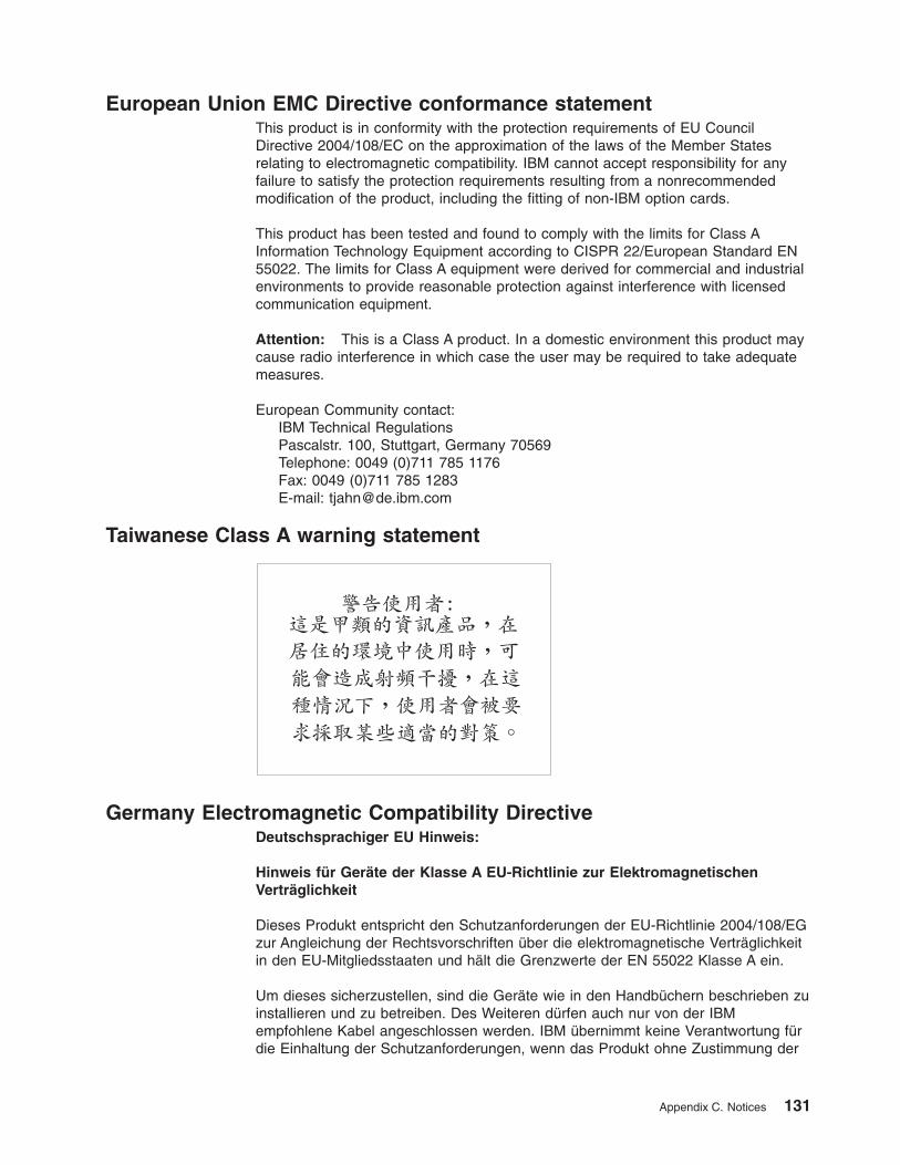
European Union EMC Directive conformance statementThis product is in conformity with the protection requirements of EU CouncilDirective 2004/108/EC on the approximation of the laws of the Member Statesrelating to electromagnetic compatibility. IBM cannot accept responsibility for anyfailure to satisfy the protection requirements resulting from a nonrecommendedmodification of the product, including the fitting of non-IBM option cards.
This product has been tested and found to comply with the limits for Class AInformation Technology Equipment according to CISPR 22/European Standard EN55022. The limits for Class A equipment were derived for commercial and industrialenvironments to provide reasonable protection against interference with licensedcommunication equipment.
Attention: This is a Class A product. In a domestic environment this product maycause radio interference in which case the user may be required to take adequatemeasures.
European Community contact:IBM Technical RegulationsPascalstr. 100, Stuttgart, Germany 70569Telephone: 0049 (0)711 785 1176Fax: 0049 (0)711 785 1283E-mail: [email protected]
Taiwanese Class A warning statement
Germany Electromagnetic Compatibility DirectiveDeutschsprachiger EU Hinweis:
Hinweis für Geräte der Klasse A EU-Richtlinie zur ElektromagnetischenVerträglichkeit
Dieses Produkt entspricht den Schutzanforderungen der EU-Richtlinie 2004/108/EGzur Angleichung der Rechtsvorschriften über die elektromagnetische Verträglichkeitin den EU-Mitgliedsstaaten und hält die Grenzwerte der EN 55022 Klasse A ein.
Um dieses sicherzustellen, sind die Geräte wie in den Handbüchern beschrieben zuinstallieren und zu betreiben. Des Weiteren dürfen auch nur von der IBMempfohlene Kabel angeschlossen werden. IBM übernimmt keine Verantwortung fürdie Einhaltung der Schutzanforderungen, wenn das Produkt ohne Zustimmung der
Appendix C. Notices 131
IBM verändert bzw. wenn Erweiterungskomponenten von Fremdherstellern ohneEmpfehlung der IBM gesteckt/eingebaut werden.
EN 55022 Klasse A Geräte müssen mit folgendem Warnhinweis versehen werden:“Warnung: Dieses ist eine Einrichtung der Klasse A. Diese Einrichtung kann imWohnbereich Funk-Störungen verursachen; in diesem Fall kann vom Betreiberverlangt werden, angemessene Maßnahmen zu ergreifen und dafür aufzukommen.”
Deutschland: Einhaltung des Gesetzes über dieelektromagnetische Verträglichkeit von GerätenDieses Produkt entspricht dem “Gesetz über die elektromagnetische Verträglichkeitvon Geräten (EMVG)”. Dies ist die Umsetzung der EU-Richtlinie 2004/108/EG inder Bundesrepublik Deutschland.
Zulassungsbescheinigung laut dem Deutschen Gesetz über dieelektromagnetische Verträglichkeit von Geräten (EMVG) (bzw. derEMC EG Richtlinie 2004/108/EG) für Geräte der Klasse ADieses Gerät ist berechtigt, in Übereinstimmung mit dem Deutschen EMVG dasEG-Konformitätszeichen - CE - zu führen. Verantwortlich für dieKonformitätserklärung des EMVG ist die IBM Deutschland GmbH, 70548 Stuttgart.
Generelle Informationen:
Das Gerät erfüllt die Schutzanforderungen nach EN 55024 und EN 55022Klasse A.
People's Republic of China Class A warning statement
Japanese Voluntary Control Council for Interference (VCCI) statement
Korean Class A warning statement
132 System Storage DS3400 Storage Subsystem: Installation, User’s, and Maintenance Guide
Index
Aac power LED 62ac power recovery 16ac power supply specifications 4accessible documentation 129activity LED, hard disk drive 63airflow 11, 17area requirements 15assistance, getting 125attention notices 3
Bbattery
LEDs 12, 72overview 12replacing 72, 99
bays 8best practices 6bezels
drive labels 9LEDs 9, 63replacing 106
Ccabling the power supply 54cabling the storage subsystem
connecting host to RAID controller 48connecting secondary interface cables 44connecting storage expansion enclosures 37topologies 39
cache batterySee battery 72
cache memorycache active LED 71size of 71
caution and danger notices xicaution statements 3checking the LEDs 62Class A electronic emission notice 130components
battery 12controllers 7hard disk drives 7power supplies 7weights 15
configuration, installing the storage subsystem 48contamination, particulate and gaseous 129controller
description 10information record 123LEDs 64location 10replacing 80sample information record 124
controllers, dualmust be identical 10requirements 10
cooling 17customer replaceable units (CRUs) 7, 117
removing a hard disk drive 85replacing the battery 99replacing the controllers 80
Ddanger statements 3data sheet 123data sheet, sample 124dc power LED 62devices, installing and replacing 75dimensions of DS3400 4direct management method 47documentation format 129documentation inventory 19drive compatibility key, replacing 108drive labels 85drive LEDs 85
activity LED 63, 85status LED 63, 85
drive, hard diskno hot-swapping when LEDs lit 10, 88replacing all at same time 89, 90replacing one at a time 89, 92working with 84
DS3000 Storage Managerinstalling 58using to monitor storage subsystem status 59
DS3400cache memory and cache battery 71configuring 46dimensions 15Health Check process 55installing the configuration 48parts listing 117
Eelectrical input specifications 4electrical requirements 16electronic emission Class A notice 130emergency shutdown 68enclosure ID 25environmental specifications 4Ethernet
cabling 21conectors 46connection to management station 44connectors 10
© Copyright IBM Corp. 2006, 2009 133
Ffault LED
battery 12, 64hard disk drive 85power supply 62
FCC Class A notice 130features and operating specifications 4fiber optic cable, handling 26Fibre Channel
connections 52host loop configurations 52LC-SC cable adapter, using 32overview 5
field replaceable units (FRUs) 117filler panelss 84firmware levels, determining 14firmware updates 60front controls and indicators
activity LED 63drive 8power-on LED 63status LED 63system-error LED 63
Ggaseous contamination 129getting help 125
Hhard disk drive
activity LED 63removal 85replacing all at same time 89, 90replacing one at a time 89, 92status LED 63
hardware fault LEDs 62hardware service and support 126Health Check process 55heat dissipation 17heat output 17heat output specifications 4help, getting 125host adapter, connecting to RAID controller 48host-agent management method 47hot-swap
controllers 75drive bays 8drive LEDs described 85hardware 85power supplies 75
hot-swap componentshard disk drive 8
hot-swap hard disk drives 84installing 86removing 85replacing 87working with 84
humidity specifications 4
IIBM Support Line 126identification numbers 121important notices 3in-band management method 47information record, storage subsystem and
controller 123installation
into a rack cabinet 19preparation 22
installing and replacing devicesbattery 99controller 75, 77, 80DIMM 101filler panels 84hard disk drive 85, 86, 87hot-swap hard disk drives 75memory cache DIMM 101power supply 94SFP module 104
inventory checklist 19
LLC-LC Fibre Channel cable 29
connecting to an SFP module 30latches and lever 34removing 32
LC-SC Fibre Channel cable adapterconnecting to a device 33connecting to an LC-LC Fibre Channel cable 34protective caps 34removing an LC-LC Fibre Channel cable 34using 32
LEDscache battery 72controller 64during power-on 62front bezel 63overtemperature 63power supply 62power-on 63system error 63system locator 63
loop configurationsoverview 52redundant 52
Mmemory, cache
cache active LED 71size of 71
multiple drivesn replacing 89
Nnoise emissions 4notes 3notes, important 128
134 System Storage DS3400 Storage Subsystem: Installation, User’s, and Maintenance Guide
notices 127electronic emission 130FCC, Class A 130safety and caution xi
notices and statements 3numbers, enclosure ID 10
Ooperating specifications 4out-of-band management method 47overheating, power supplies 69overview of the product 1
Ppart numbers, power cords 119particulate contamination 129parts listing 117planned shutdown, powering off 65power cord use by country 119power cords 118power cords and receptacles 17power outage, overheated power supplies 69power requirement specifications 4power supply
cabling 54connector 11described 11LEDs 62recovering from shutdown 69replacing 94specifications 4switch 11
power switch 11power-on LED 63power-supply controls, indicators, and connectors
ac power LED 62dc power LED 62fault LED 62OK to remove LED 62power connector 58power switch 58
power, restoring after an emergency 68powering off
for emergency shutdown 68for planned shutdown 65
powering onafter emergency shutdown 68after planned shutdown 57after power supply shutdown 69at initial startup 57
problem determination 111product overview 1
Rrack cabinet
installing the DS3400 23site preparation 22
RAID controllercache battery 72cache memory 71connecting Ethernet cable to 44connecting host to 48DIMM 71
recordshard disk drive locations 122identification numbers 121
redundant drive channel pair 38redundant host loops 52release tab, replacing 107replacement parts 117replacing components
battery 99bezels 106controller 80drive compatibility key 108hot-swap hard disk drives 87release tab 107Service Action Allowed Status LED 75
replacing failedpower supply 94SFP module 104
restoring powerafter an emergency 68after planned shutdown 57after power supply shutdown 69after unplanned shutdown 68
Ssafety information xiisafety, static-sensitive devices 21sample information record, storage subsystem and
controller 124SFP modules
described 12replacing 104required 12
shutdown, emergency 68site preparation 23size of DS3400 4small-form-factor pluggable (SFP) module
connecting an LC-LC Fibre Channel cable 30important information about 26protective cap 28removal 28removing an LC-LC cable 32replacing 104static-protective package 28
small-form-factor pluggable (SFP) modulesdescribed 12
software and firmware upgrades 13software service and support 126specifications 15specifications, DS3400 4startup sequence 57statements and notices 3static-sensitive devices, handling 21status LED on hard disk drive 63
Index 135
storage expansion enclosureconnecting to storage subsystem 37turning on before storage subsystem 91
storage manager software and hardwarecompatibility 13
storage subsystemairflow 11checking status 62enclosure ID numbers 10fans 11fault LEDs 62identification numbers 121information record 123performing an emergency shutdown 68power supply 11records 121restoring power after an emergency 68sample information record 124startup sequence 57troubleshooting 61turning off 65turning on 57
storage subsystem configuration, installing 48storage subsystem profile 7support, web site 125
Ttelephone numbers 126temperature and humidity 16temperature specifications 4temperature, maximum 69trademarks 127troubleshooting 111
no power 69overheating problem 69procedure 61
turning off powerfor emergency shutdown 68for planned shutdown 65
turning off the storage subsystem 65turning on power
after emergency shutdown 68after power supply shutdown 69at initial startup 57
UUnited States electronic emission Class A notice 130United States FCC Class A notice 130upgrades, support code 13user controls 10
Wweb site
publication ordering 125support 125support line, telephone numbers 126
weight of DS3400 4wiring and power 16
136 System Storage DS3400 Storage Subsystem: Installation, User’s, and Maintenance Guide

����
Part Number: 46M1394
Printed in USA
(1P) P/N: 46M1394