Embed Size (px)
Citation preview

IBM BladeCenterManagement Module
BladeCenter T Management Module
Advanced Management Module
BladeCenter T Advanced Management Module
User’s Guide
���


IBM BladeCenterManagement Module
BladeCenter T Management Module
Advanced Management Module
BladeCenter T Advanced Management Module
User’s Guide
���

Note: Before using this information and the product it supports, read the general information in Appendix A, “Getting help and
technical assistance,” on page 111 and Appendix B, “Notices,” on page 113.
Ninth Edition (December 2006)
This edition applies to version 1.25 of management-module firmware and to all subsequent releases and
modifications until otherwise indicated in new editions.
© Copyright International Business Machines Corporation 2006. All rights reserved.
US Government Users Restricted Rights – Use, duplication or disclosure restricted by GSA ADP Schedule Contract
with IBM Corp.
Contents
Chapter 1. The BladeCenter management module . . . . . . . . . . . 1
Related documentation . . . . . . . . . . . . . . . . . . . . . . 2
Notices and statements in this document . . . . . . . . . . . . . . . . 3
Chapter 2. Using the management-module Web interface . . . . . . . . 5
Connecting to the management module . . . . . . . . . . . . . . . . 5
Management-module connection overview . . . . . . . . . . . . . . 5
Hardware requirements . . . . . . . . . . . . . . . . . . . . 6
Software requirements . . . . . . . . . . . . . . . . . . . . 6
Cabling the management module . . . . . . . . . . . . . . . . . 7
Networked connection . . . . . . . . . . . . . . . . . . . . . 7
Direct connection . . . . . . . . . . . . . . . . . . . . . . 7
Connecting to the management module for the first time . . . . . . . . . 7
Starting the management-module Web interface . . . . . . . . . . . . . 8
Configuring the management module . . . . . . . . . . . . . . . . . 10
Configuring the management module for remote access . . . . . . . . . 11
Configuring the management-module Ethernet ports . . . . . . . . . . 11
Using the Configuration Wizard (advanced management module only) . . . 13
Communicating with the IBM Director software . . . . . . . . . . . . . 13
Configuring advanced features . . . . . . . . . . . . . . . . . . . 14
Network and security configuration . . . . . . . . . . . . . . . . 14
Configuring SNMP . . . . . . . . . . . . . . . . . . . . . 14
Configuring SMTP . . . . . . . . . . . . . . . . . . . . . . 17
Configuring LDAP . . . . . . . . . . . . . . . . . . . . . . 18
Secure Web server and secure LDAP . . . . . . . . . . . . . . 34
Configuring the secure shell server . . . . . . . . . . . . . . . 45
Configuring Wake on LAN . . . . . . . . . . . . . . . . . . . . 47
Verifying the Wake on LAN configuration . . . . . . . . . . . . . 48
Linux-specific configuration . . . . . . . . . . . . . . . . . . 48
Using the configuration file . . . . . . . . . . . . . . . . . . . 48
Backing up your management-module configuration . . . . . . . . . 49
Restoring and modifying your management-module configuration . . . . 50
Using the remote disk feature . . . . . . . . . . . . . . . . . . 52
Mounting a disk drive or disk image . . . . . . . . . . . . . . . 53
Unmounting a disk drive or disk image . . . . . . . . . . . . . . 53
Configuring an I/O module . . . . . . . . . . . . . . . . . . . . . 54
Chapter 3. Management-module Web interface overview . . . . . . . . 57
Web interface pages and user roles . . . . . . . . . . . . . . . . . 57
Management-module Web interface options . . . . . . . . . . . . . . 62
Monitors . . . . . . . . . . . . . . . . . . . . . . . . . . 62
System Status . . . . . . . . . . . . . . . . . . . . . . . 62
Event Log . . . . . . . . . . . . . . . . . . . . . . . . . 68
LEDs . . . . . . . . . . . . . . . . . . . . . . . . . . 69
Fuel Gauge . . . . . . . . . . . . . . . . . . . . . . . . 71
Hardware VPD . . . . . . . . . . . . . . . . . . . . . . . 74
Firmware VPD . . . . . . . . . . . . . . . . . . . . . . . 75
Blade Tasks . . . . . . . . . . . . . . . . . . . . . . . . . 76
Power/Restart . . . . . . . . . . . . . . . . . . . . . . . 76
On Demand . . . . . . . . . . . . . . . . . . . . . . . . 77
Remote Control . . . . . . . . . . . . . . . . . . . . . . . 78
Firmware Update . . . . . . . . . . . . . . . . . . . . . . 82
Configuration . . . . . . . . . . . . . . . . . . . . . . . 83
© Copyright IBM Corp. 2006 iii
Serial Over LAN . . . . . . . . . . . . . . . . . . . . . . 86
I/O Module Tasks . . . . . . . . . . . . . . . . . . . . . . . 87
Admin/Power/Restart . . . . . . . . . . . . . . . . . . . . . 87
Configuration . . . . . . . . . . . . . . . . . . . . . . . 88
Firmware Update . . . . . . . . . . . . . . . . . . . . . . 90
MM Control . . . . . . . . . . . . . . . . . . . . . . . . . 91
General Settings . . . . . . . . . . . . . . . . . . . . . . 91
Login Profiles . . . . . . . . . . . . . . . . . . . . . . . 92
Alerts . . . . . . . . . . . . . . . . . . . . . . . . . . 96
Serial Port (advanced management module only) . . . . . . . . . . 96
Port Assignments . . . . . . . . . . . . . . . . . . . . . . 97
Network Interfaces . . . . . . . . . . . . . . . . . . . . . 99
Network Protocols . . . . . . . . . . . . . . . . . . . . . 101
Security . . . . . . . . . . . . . . . . . . . . . . . . . 102
Configuration File (all management modules except advanced
management module) . . . . . . . . . . . . . . . . . . . 103
Configuration Mgmt (advanced management module only) . . . . . . 104
Firmware Update . . . . . . . . . . . . . . . . . . . . . 104
Restore Defaults (management modules other than the advanced
management module) . . . . . . . . . . . . . . . . . . . 105
Configuration Wizard (advanced management module only) . . . . . . 106
Restart MM . . . . . . . . . . . . . . . . . . . . . . . . 107
Service Tools (advanced management module only) . . . . . . . . . . 107
Settings . . . . . . . . . . . . . . . . . . . . . . . . . 107
Service Data . . . . . . . . . . . . . . . . . . . . . . . 108
AMM Status . . . . . . . . . . . . . . . . . . . . . . . 108
Appendix A. Getting help and technical assistance . . . . . . . . . . 111
Before you call . . . . . . . . . . . . . . . . . . . . . . . . 111
Using the documentation . . . . . . . . . . . . . . . . . . . . . 111
Getting help and information from the World Wide Web . . . . . . . . . 111
Software service and support . . . . . . . . . . . . . . . . . . . 112
Hardware service and support . . . . . . . . . . . . . . . . . . . 112
IBM Taiwan product service . . . . . . . . . . . . . . . . . . . . 112
Appendix B. Notices . . . . . . . . . . . . . . . . . . . . . . 113
Trademarks . . . . . . . . . . . . . . . . . . . . . . . . . . 114
Important notes . . . . . . . . . . . . . . . . . . . . . . . . 114
Index . . . . . . . . . . . . . . . . . . . . . . . . . . . . 117
iv IBM BladeCenter: Management Module User’s Guide
Chapter 1. The BladeCenter management module
This Management Module User’s Guide contains information about configuring the
management module and managing components that are installed in an IBM®
BladeCenter® unit. Although all types of management module have similar function,
their physical attributes might vary. See the Installation Guide for your management
module for information about management-module controls and indicators,
installation, cabling, and configuration.
All IBM BladeCenter unit types are referred to throughout this document as the
BladeCenter unit. All management-module types are referred to throughout this
document as the management module. Unless otherwise noted, all commands can
be run on all management-module and BladeCenter unit types.
The management module provides system-management functions and
keyboard/video/mouse (KVM) multiplexing for all of the blade servers in the
BladeCenter unit that support KVM. It controls the external keyboard, mouse, and
video connections, for use by a local console, and a 10/100 Mbps Ethernet remote
management connection.
Each BladeCenter unit comes with at least one management module. Some
BladeCenter units support installation of a second, standby management module.
Only one of the management modules in a BladeCenter unit can be active, and it
functions as the primary management module. If a standby management module is
installed, it remains inactive until it is switched to act as primary, either manually or
automatically, if the primary management module fails.
If two management modules are installed in a BladeCenter unit, they must be of the
same type: the advanced management module is not compatible for installation in
the same BladeCenter unit with other management module types. Both
management modules must always have the same level of firmware and the same
IP address, and the firmware must support redundant management-module
function, to enable changeover of control from the primary (active) management
module to the standby management module. The latest level of
management-module firmware is available at http://www.ibm.com/bladecenter/.
Note: After failover, you might not be able to establish a network connection to the
management module for 5 minutes.
The service processor in the management module communicates with the service
processor in each blade server to support features such as blade server power-on
requests, error and event reporting, KVM requests, and requests to use the
BladeCenter shared media tray (removable-media drives and USB ports).
You configure BladeCenter components by using the management module, setting
information such as IP addresses. The management module communicates with all
components in the BladeCenter unit, detecting their presence or absence, reporting
their status, and sending alerts for error conditions when required.
Note: The sample screens that appear in this document might differ slightly from
the screens that your system displays. Screen content varies according to
the type of BladeCenter unit that you are using and the firmware versions
and options that are installed.
© Copyright IBM Corp. 2006 1
Related documentation
In addition to this User’s Guide, the following documentation might be on the
Documentation CD that comes with your BladeCenter management module, in
Portable Document Format (PDF). Depending on your BladeCenter product,
additional documents might also be included on the Documentation CD. The most
recent versions of all BladeCenter documentation are at http://www.ibm.com/bladecenter/.
v Safety Information
This document contains translated caution and danger statements. Each caution
and danger statement that appears in the documentation has a number that you
can use to locate the corresponding statement in your language in the Safety
Information document.
v Management Module Installation Guide
Each management module has a customized Installation Guide that contains
instructions for installing the management module in a BladeCenter unit and
creating the initial configuration. This document also contains safety and warranty
information specific to the management module.
v BladeCenter Management Module Command-Line Interface Reference Guide
This document explains how to use the management-module command-line
interface to directly access BladeCenter management functions as an alternative
to using the Web-based user interface. The command-line interface also provides
access to the text-console command prompt on each blade server through a
Serial over LAN (SOL) connection.
v IBM SMASH Installation and User’s Guide
This document provides an overview of the SMASH command-line protocol
(CLP) standard, its history, features, and components and its relation to the IBM
SMASH product. It also provides a detailed overview of SMASH Proxy and
SMASH Embedded including configuration, functionality, accessibility, features,
and components.
v IBM BladeCenter Serial over LAN Setup Guide
This document explains how to update and configure BladeCenter components
for Serial over LAN (SOL) operation. The SOL connection provides access to the
text-console command prompt on each blade server and enables the blade
servers to be managed from a remote location.
In addition to the documentation in this library, be sure to review the IBM
BladeCenter Planning and Installation Guide for your BladeCenter unit for
information to help you prepare for system installation and configuration. This
document is available at http://www.ibm.com/bladecenter/.
2 IBM BladeCenter: Management Module User’s Guide
Notices and statements in this document
The caution and danger statements that appear in this document are also in the
multilingual Safety Information document, which is on the IBM BladeCenter
Documentation CD. Each statement is numbered for reference to the corresponding
statement in the Safety Information document.
The following notices and statements are used in this document:
v Note: These notices provide important tips, guidance, or advice.
v Important: These notices provide information or advice that might help you avoid
inconvenient or problem situations.
v Attention: These notices indicate possible damage to programs, devices, or
data. An attention notice is placed just before the instruction or situation in which
damage could occur.
v Caution: These statements indicate situations that can be potentially hazardous
to you. A caution statement is placed just before the description of a potentially
hazardous procedure step or situation.
v Danger: These statements indicate situations that can be potentially lethal or
extremely hazardous to you. A danger statement is placed just before the
description of a potentially lethal or extremely hazardous procedure step or
situation.
Chapter 1. The BladeCenter management module 3

4 IBM BladeCenter: Management Module User’s Guide
Chapter 2. Using the management-module Web interface
This section provides instructions for using the management-module Web interface.
It has the following information:
v “Connecting to the management module”
v “Starting the management-module Web interface” on page 8
v “Configuring the management module” on page 10
v “Communicating with the IBM Director software” on page 13
v “Configuring advanced features” on page 14
v “Configuring an I/O module” on page 54
See Chapter 3, “Management-module Web interface overview,” on page 57 for a
detailed description of the structure and content of the management-module Web
interface. Many Web interface functions can also be performed through the
management-module command-line interface (CLI). See the BladeCenter
Management Module Command-Line Interface Reference Guide for information and
instructions.
Connecting to the management module
A remote console connection to the management module is required to configure
and manage operation of the BladeCenter unit. All management-module types
support connection through the remote management and console (Ethernet)
connector. The advanced management module also supports CLI-only connection
through the serial management port.
You can manage the BladeCenter unit and blade servers that support KVM by using
the graphical user interface that is provided by the management-module Web
interface or by using the command-line interface that you access through Telnet, a
Secure Shell (SSH) server, or the serial port (advanced management module only).
All management connections to blade servers that do not support KVM are made
through the management-module command-line interface.
You can perform initial configuration of the management module after you connect it
to your network; however, because of some requirements that are imposed by the
default management-module settings, it might be easier to perform these setup
operations using a temporary connection. The following information is in this
section:
v “Management-module connection overview”
v “Cabling the management module” on page 7
v “Connecting to the management module for the first time” on page 7
After the initial cabling and configuration, connect to the management module as
described in “Starting the management-module Web interface” on page 8.
Management-module connection overview
You can access the management-module Web interface through a network or
through a computer that is connected directly to the management module. To
connect a remote console to the management-module Web interface, you need the
following equipment and information:
v A computer with Internet browser capability. To facilitate connections at multiple
locations, you can use a notebook computer.
© Copyright IBM Corp. 2006 5
v The management-module MAC address (listed on the label on the management
module).
v For a networked connection to the management module, the following
equipment:
– A standard Ethernet cable
– A local Ethernet network port (facility connection)
v For direct connection of a computer to the management module remote
management and console (Ethernet) connector, an Ethernet crossover cable. The
advanced management module can use either a standard Ethernet cable or an
Ethernet crossover cable to make this connection.
Connections through the advanced management-module serial port can access only
the management-module command-line interface (CLI). For information about
accessing the management-module CLI, see the BladeCenter Management Module
Command-Line Interface Reference Guide.
Hardware requirements
To use the Remote Control feature that provides KVM access to a blade server, the
client system must have, at minimum, the following performance level:
v Microprocessor - Intel® Pentium® III or later, operating at 700 MHz or faster (or
equivalent)
v Memory - 256 MB RAM
v Video - 16MB RADEON 7500 ATI Mobility video chipset or equivalent (AGP 4X
with 16 MB of video memory)
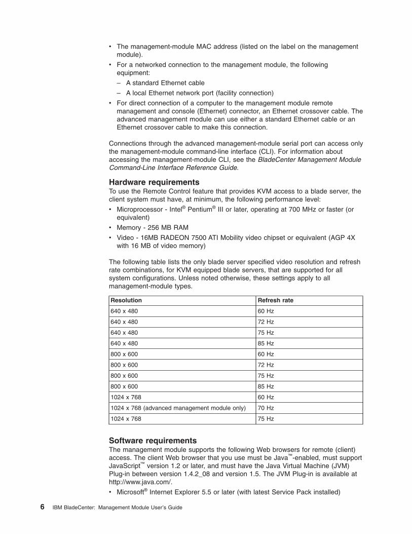
The following table lists the only blade server specified video resolution and refresh
rate combinations, for KVM equipped blade servers, that are supported for all
system configurations. Unless noted otherwise, these settings apply to all
management-module types.
Resolution Refresh rate
640 x 480 60 Hz
640 x 480 72 Hz
640 x 480 75 Hz
640 x 480 85 Hz
800 x 600 60 Hz
800 x 600 72 Hz
800 x 600 75 Hz
800 x 600 85 Hz
1024 x 768 60 Hz
1024 x 768 (advanced management module only) 70 Hz
1024 x 768 75 Hz
Software requirements
The management module supports the following Web browsers for remote (client)
access. The client Web browser that you use must be Java™-enabled, must support
JavaScript™ version 1.2 or later, and must have the Java Virtual Machine (JVM)
Plug-in between version 1.4.2_08 and version 1.5. The JVM Plug-in is available at
http://www.java.com/.
v Microsoft® Internet Explorer 5.5 or later (with latest Service Pack installed)
6 IBM BladeCenter: Management Module User’s Guide
v Mozilla Firefox version 1.07 or later
The following server operating systems have USB support, which is required for the
Remote Control feature:
v Microsoft Windows Server 2003
v Microsoft Windows 2000 with Service Pack 4 or later
v Red Hat Linux® version 7.3
v SUSE Linux version 8.0
v Novell NetWare 6.5
To use the Remote Control feature on an advanced management module, the client
system must also have the Sun JRE between version 1.4.2_08 and version 1.5.
The management-module Web interface does not support the double-byte character
set (DBCS) languages.
Cabling the management module
The following sections describe how to cable the management module to configure
the BladeCenter unit by using the management-module Web interface. See the
Installation Guide for your management module for specific cabling instructions. See
the BladeCenter Management Module Command-Line Interface Reference Guide
for information about connecting a remote console to the management module and
using the management-module CLI to configure the BladeCenter unit.
After you cable the management module for initial configuration, see “Connecting to
the management module for the first time.” See the Installation Guide for your
management module for specific cabling information.
Networked connection
Connect one end of a Category 5 or higher Ethernet cable to the remote
management and console (Ethernet) connector on the management module.
Connect the other end of the Ethernet cable to the facility network.
Direct connection
Connect one end of a Category 5 or higher Ethernet cable (advanced management
module only) or a Category 5 or higher Ethernet crossover cable (management
module and advanced management module) to the remote management and
console (Ethernet) connector on the management module. Connect the other end of
the cable to the Ethernet connector on the client computer.
Note: The advanced management module can perform an automatic media
dependent interface (MDI) crossover, eliminating the need for crossover
cables or cross-wired (MDIX) ports. You might need to use a crossover cable
to connect to the advanced management module if the network interface
card in the client computer is very old.
Connecting to the management module for the first time
The following sections describe how to connect a remote console to the
management module to perform initial configuration of the BladeCenter unit. The
management module has the following default network settings:
v IP address: 192.168.70.125
v Subnet: 255.255.255.0
v User ID: USERID (all capital letters)
Chapter 2. Using the management-module Web interface 7
v Password: PASSW0RD (note the number zero, not the letter O, in PASSW0RD)
By default, the management module is configured to respond to DHCP first before
using its static IP address.
The client computer that you connect to the management module must be
configured to operate on the same subnet as the BladeCenter management
module. The IP address of the management module must also be in the same local
domain as the client computer. To connect to the management module for the first
time, you must change the Internet protocol properties on the client computer.
After you connect the Ethernet cable from the management module to the client
computer, complete the following steps:
1. Make sure that the subnet of the client computer is set to the same value as the
default management module subnet (255.255.255.0).
2. Open a Web browser on the client computer, and direct it to the default
management-module IP address (192.168.70.125).
3. Enter the default user name, USERID, and the default password, PASSW0RD,
to start the remote session.
4. Follow the instructions on the screen. Be sure to set the timeout value that you
want for your Web session.
After you connect to the management module for the first time, perform the initial
configuration of the BladeCenter unit (see “Configuring the management module” on
page 10).
Starting the management-module Web interface
To start the management-module Web interface, complete the following steps:
1. Open a Web browser. In the address or URL field, type the IP address or host
name defined for the management-module remote connection (see the
Installation Guide for your management module for details).
The Enter Network Password page opens.
2. Type your user name and password. If you are logging in to the management
module for the first time, you can obtain your user name and password from
your system administrator. All login attempts are documented in the event log.
Note: The initial factory-defined user ID and password for the management
module are as follows:
v User ID: USERID (all capital letters)
v Password: PASSW0RD (note the zero, not O, in PASSW0RD)
3. Follow the instructions on the screen. Be sure to set the timeout value that you
want for your Web session.
The BladeCenter management-module Web-interface page opens. The content of
this and all other Web-interface pages varies according to the type of BladeCenter
unit that you are using and the firmware versions and options that are installed. See
Chapter 3, “Management-module Web interface overview,” on page 57 for detailed
information about the management-module Web interface.
8 IBM BladeCenter: Management Module User’s Guide
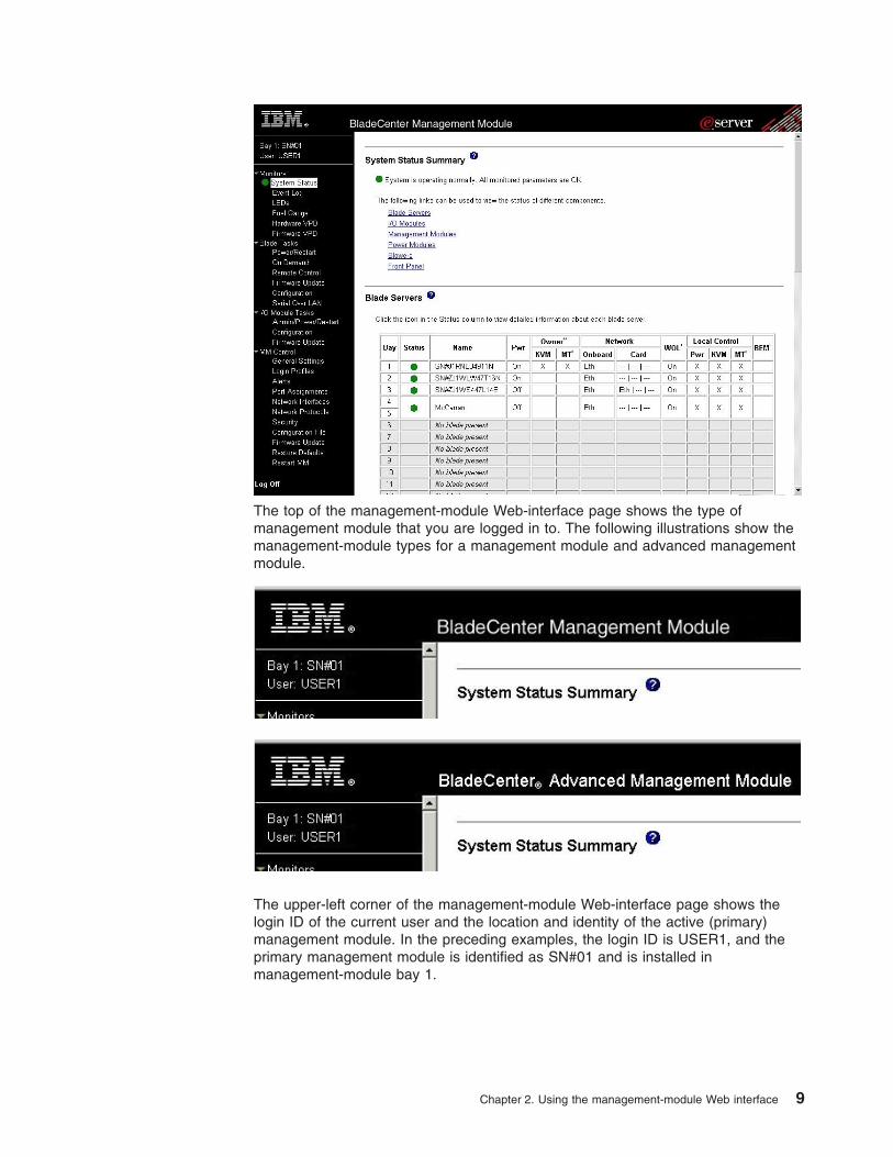
The top of the management-module Web-interface page shows the type of
management module that you are logged in to. The following illustrations show the
management-module types for a management module and advanced management
module.
The upper-left corner of the management-module Web-interface page shows the
login ID of the current user and the location and identity of the active (primary)
management module. In the preceding examples, the login ID is USER1, and the
primary management module is identified as SN#01 and is installed in
management-module bay 1.
Chapter 2. Using the management-module Web interface 9
Configuring the management module
You configure only the primary (active) management module. The standby
management module, if present, receives the configuration and status information
automatically from the primary management module when necessary. The
configuration information in this chapter applies to the primary management module,
which might be the only management module in the BladeCenter unit.
If the management module that you installed is a replacement for the only
management module in the BladeCenter unit and you saved the configuration file
before you replaced the management module, you can apply the saved
configuration file to the replacement management module by using the
management-module Web interface. See “Restoring and modifying your
management-module configuration” on page 50 for information about applying a
saved configuration file.
The BladeCenter unit automatically detects the modules and blade servers that are
installed and stores the vital product data (VPD). When the BladeCenter unit is
started, the management module automatically configures the remote management
port of the management module so that you can configure and manage
BladeCenter components. You configure and manage BladeCenter components
remotely by using the management-module Web interface or the
management-module command-line interface (CLI).
Note: There are two ways to configure the I/O modules: through the
management-module Web interface or through an external I/O-module port
that is enabled through the management module, using a Telnet interface or
a Web browser. See the documentation that comes with each I/O module for
information.
For the active management module to communicate with network resources and
with the I/O modules in the BladeCenter unit, you must configure the IP addresses
for the following internal and external ports:
v The external Ethernet (remote management) port (Ethernet 0) of the
management module (see the information that begins on page 99 for
information). The initial automatic management-module configuration enables the
network-management station to connect to the management module to configure
the port completely and to configure the rest of the BladeCenter unit.
v The internal Ethernet port (Ethernet 1) on the management module for
communication with the I/O modules (see the information that begins on page 99
for information). Internal Ethernet ports for the advanced management module
cannot be manually configured.
v The management port on each I/O module which provides for communication
with the management module. You configure this port by configuring the IP
address for the I/O module (see the information that begins on page 88 for
information).
Note: Some types of I/O modules, such as the pass-thru module, have no
management port.
See the documentation that comes with each I/O module to determine what else
you must configure in the I/O module.
To communicate with the blade servers for functions such as deploying an operating
system or application program over a network, you must also configure at least one
external (in-band) port on an Ethernet switch module in I/O-module bay 1 or 2.
10 IBM BladeCenter: Management Module User’s Guide
Note: If a pass-thru module (instead of an Ethernet I/O module) is installed in
I/O-module bay 1 or 2, you must configure the network switch that the
pass-thru module is connected to; see the documentation that comes with
the network switch for instructions.
Configuring the management module for remote access
After you connect the active management module to the network, the Ethernet port
connection is configured in one of the following ways:
v If you have an accessible, active, and configured dynamic host configuration
protocol (DHCP) server on the network, IP address, gateway address, subnet
mask, and DNS server IP address are set automatically. The host name is set to
the management-module MAC address by default, and the domain server cannot
change it.
v If the DHCP server does not respond within 3 minutes after the port is
connected, the management module uses the factory-defined static IP address
and default subnet address.
Important: You cannot connect to the management module using the
factory-defined static IP address and default subnet address until after
this 3-minute period passes.
Either of these actions enables the Ethernet connection on the active management
module.
Make sure that the client computer is on the same subnet as the management
module; then, use your Web browser to connect to the management module (see
“Starting the management-module Web interface” on page 8 for more information).
In the browser Address field, specify the IP address that the management module
is using:
v If the IP address was assigned through a DHCP server, get the IP address from
your network administrator.
v The factory-defined static IP address is 192.168.70.125, the default subnet
address is 255.255.255.0, and the default host name is MMxxxxxxxxxxxx, where
xxxxxxxxxxxx is the burned-in medium access control (MAC) address. The MAC
address is on a label on the management module, below the IP reset button.
Note: If the IP configuration is assigned by the DHCP server, the network
administrator can use the MAC address of the management-module network
interface to find out what IP address and host name are assigned.
Configuring the management-module Ethernet ports
To configure the management-module internal and external Ethernet ports,
complete the following steps:
1. Under MM Control in the navigation pane, click Network Interfaces.
2. Configure the two Ethernet interfaces: external (remote management and
console), and internal (communication with the I/O modules).
Note: For I/O-module communication with a remote management station, such
as a management server that is running IBM Director server, through the
management-module external Ethernet port, the I/O-module internal
network interface and the management-module internal and external
interfaces must be on the same subnet.
Chapter 2. Using the management-module Web interface 11
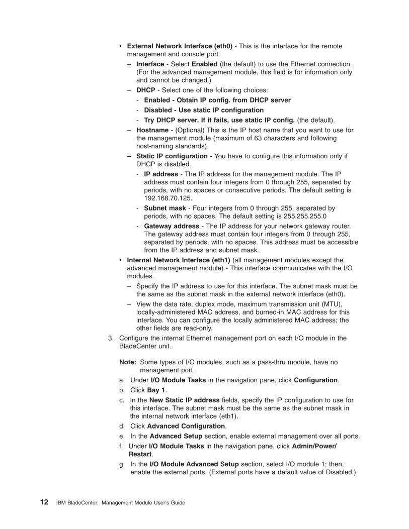
v External Network Interface (eth0) - This is the interface for the remote
management and console port.
– Interface - Select Enabled (the default) to use the Ethernet connection.
(For the advanced management module, this field is for information only
and cannot be changed.)
– DHCP - Select one of the following choices:
- Enabled - Obtain IP config. from DHCP server
- Disabled - Use static IP configuration
- Try DHCP server. If it fails, use static IP config. (the default).
– Hostname - (Optional) This is the IP host name that you want to use for
the management module (maximum of 63 characters and following
host-naming standards).
– Static IP configuration - You have to configure this information only if
DHCP is disabled.
- IP address - The IP address for the management module. The IP
address must contain four integers from 0 through 255, separated by
periods, with no spaces or consecutive periods. The default setting is
192.168.70.125.
- Subnet mask - Four integers from 0 through 255, separated by
periods, with no spaces. The default setting is 255.255.255.0
- Gateway address - The IP address for your network gateway router.
The gateway address must contain four integers from 0 through 255,
separated by periods, with no spaces. This address must be accessible
from the IP address and subnet mask.
v Internal Network Interface (eth1) (all management modules except the
advanced management module) - This interface communicates with the I/O
modules.
– Specify the IP address to use for this interface. The subnet mask must be
the same as the subnet mask in the external network interface (eth0).
– View the data rate, duplex mode, maximum transmission unit (MTU),
locally-administered MAC address, and burned-in MAC address for this
interface. You can configure the locally administered MAC address; the
other fields are read-only.
3. Configure the internal Ethernet management port on each I/O module in the
BladeCenter unit.
Note: Some types of I/O modules, such as a pass-thru module, have no
management port.
a. Under I/O Module Tasks in the navigation pane, click Configuration.
b. Click Bay 1.
c. In the New Static IP address fields, specify the IP configuration to use for
this interface. The subnet mask must be the same as the subnet mask in
the internal network interface (eth1).
d. Click Advanced Configuration.
e. In the Advanced Setup section, enable external management over all ports.
f. Under I/O Module Tasks in the navigation pane, click Admin/Power/Restart.
g. In the I/O Module Advanced Setup section, select I/O module 1; then,
enable the external ports. (External ports have a default value of Disabled.)
12 IBM BladeCenter: Management Module User’s Guide
Note: The initial user ID and password for the I/O module firmware are as
follows:
v User ID: USERID (all capital letters)
v Password: PASSW0RD (note the zero, not O, in PASSW0RD)
Repeat step 3 for each I/O module in the BladeCenter unit.
To communicate with the blade servers for functions such as deploying an operating
system or application program, you also must configure at least one external
(in-band) port on an Ethernet I/O module.
Using the Configuration Wizard (advanced management module only)
The configuration wizard starts automatically when you access the Web interface of
a new advanced management module for the first time. The configuration wizard
also starts automatically the first time that you access the Web interface of an
advanced management module that has been reset to its factory default settings.
To configure an advanced management module using the configuration wizard, click
Configuration Wizard under MM Control in the navigation pane. You must be
assigned the Supervisor role (command authority) to use the configuration wizard.
The first wizard pane lists all of the information that you need to know before using
the wizard to configure the management module. After gathering this information,
enter it into the wizard panes to complete a basic configuration of the management
module. If you are importing a saved management module configuration or restoring
one that is saved to the backplane of the BladeCenter unit, these options appear in
the Import Configuration pane of the configuration wizard. Imported or restored
configurations do not require any additional information entry.
You must restart the management module for the configuration changes to take
effect. Click Reboot Now in the Completion pane of the configuration wizard to
restart the management module; or, click Reboot Later to exit the wizard, saving
your configuration changes without putting them in effect.
Communicating with the IBM Director software
The IBM Director program is a systems-management product that comes with some
BladeCenter units. The IBM Director software communicates with the BladeCenter
unit through the Ethernet port on the active management module.
See http://www.ibm.com/servers/eserver/xseries/systems_management/
xseries_sm/dwnl.html for the version of IBM Director software that you can use to
manage redundant management modules.
For you to configure the remote alert recipients for IBM Director over LAN, the
remote alert recipient must be an IBM Director-enabled server.
To communicate with the BladeCenter unit, the IBM Director software needs a
managed object (in the Group Contents pane of the IBM Director Management
Console main window) that represents the BladeCenter unit. If the BladeCenter
management-module IP address is known, the network administrator can create an
IBM Director managed object for the unit. If the IP address is not known, the IBM
Director software can automatically discover the BladeCenter unit (out-of-band,
using the Ethernet port on the BladeCenter management module) and create a
managed object for the unit.
Chapter 2. Using the management-module Web interface 13
For the IBM Director software to discover the BladeCenter unit, your network must
initially provide connectivity from the IBM Director server to the BladeCenter
management-module Ethernet port. To establish connectivity, the management
module attempts to use DHCP to acquire its initial IP address for the Ethernet port.
If the DHCP request fails, the management module uses the static IP address that
is assigned to it. Therefore, the DHCP server (if it is used) must be on the
management LAN for your BladeCenter unit.
Notes:
1. All management modules are preconfigured with the same static IP address.
You can use the management-module Web interface to assign a new static IP
address for each BladeCenter unit. If DHCP is not used and you do not assign
a new static IP address for each BladeCenter unit before you attempt to
communicate with the IBM Director software, only one BladeCenter unit at a
time can be added onto the network for discovery. Adding multiple units to the
network without a unique IP address assignment for each BladeCenter unit
results in IP address conflicts.
2. For I/O-module communication with a remote management station, such as a
management server that is running the IBM Director server, through the
management-module external Ethernet port, the I/O-module internal network
interface and the management-module internal and external interfaces must be
on the same subnet.
Configuring advanced features
The following sections provide instructions for performing some of the functions that
the management-module Web interface supports. Detailed descriptions of the
management-module Web interface are in Chapter 3, “Management-module Web
interface overview,” on page 57.
v “Network and security configuration”
v “Configuring Wake on LAN” on page 47
v “Using the configuration file” on page 48
v “Using the remote disk feature” on page 52
Network and security configuration
The following sections describe how to configure management-module networking
and security parameters for the following protocols:
v SNMP and DNS (see “Configuring SNMP”)
v SMTP (see “Configuring SMTP” on page 17)
v SSL and LDAP (see “Configuring LDAP” on page 18)
v SSH (see “Configuring the secure shell server” on page 45)
Configuring SNMP
You can query the SNMP agent to collect the sysgroup information and to send
configured SNMP alerts to the configured host names or IP addresses.
Note: If you plan to configure Simple Network Management Protocol (SNMP) traps
on the management module, you must install and compile the management
information base (MIB) on your SNMP manager. The MIB supports SNMP
traps. The MIB is included in the management-module firmware update
package that you downloaded from http://www.ibm.com/bladecenter/.
14 IBM BladeCenter: Management Module User’s Guide
To configure SNMP, complete the following steps:
1. Log in to the management module on which you want to configure SNMP. For
more information, see “Starting the management-module Web interface” on
page 8
2. In the navigation pane, click MM Control → General Settings. In the
management-module information page that opens, specify the following
information:
v Name - The name that you want to use to identify the management module.
The name will be included with e-mail and SNMP alert notifications to
identify the source of the alert. If more than one management module is
installed in a BladeCenter unit, each management module can be given a
unique name.
v Contact - The name and phone number of the person to contact if there is
a problem with the BladeCenter unit.
v Location - Sufficient detail to quickly locate the BladeCenter unit for
maintenance or other purposes.
3. Scroll to the bottom of the page and click Save.
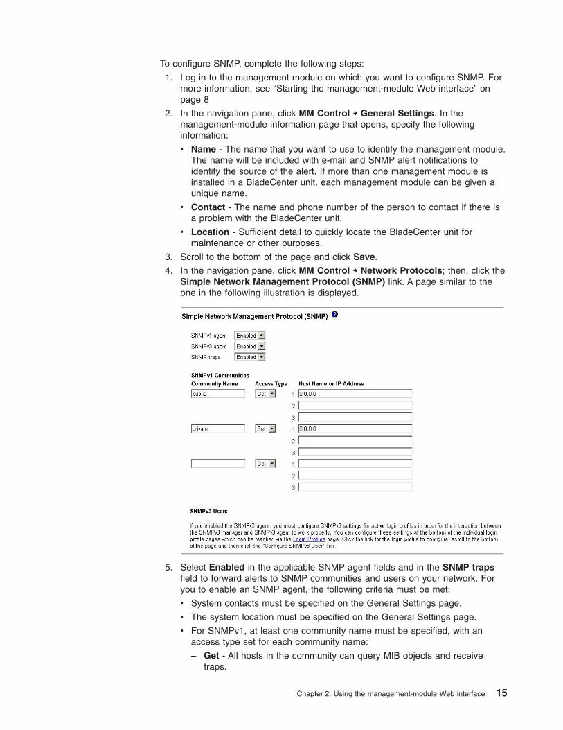
4. In the navigation pane, click MM Control → Network Protocols; then, click the
Simple Network Management Protocol (SNMP) link. A page similar to the
one in the following illustration is displayed.
5. Select Enabled in the applicable SNMP agent fields and in the SNMP traps
field to forward alerts to SNMP communities and users on your network. For
you to enable an SNMP agent, the following criteria must be met:
v System contacts must be specified on the General Settings page.
v The system location must be specified on the General Settings page.
v For SNMPv1, at least one community name must be specified, with an
access type set for each community name:
– Get - All hosts in the community can query MIB objects and receive
traps.
Chapter 2. Using the management-module Web interface 15

– Set - All hosts in the community can query and set MIB objects and
receive traps.
– Trap - All hosts in the community can receive traps.
v At least one valid IP address or host name (if DNS is enabled) must be
specified for each community.
v For SNMPv3, each SNMPv3 user must be configured.
Note: Alert recipients whose notification method is SNMP will not receive
alerts unless both the SNMP agent and the SNMP traps are enabled.
6. If you are enabling the SNMPv1 agent, complete the following steps to set up
a community that defines the administrative relationship between SNMP
agents and SNMP managers; otherwise, continue with step 7. You must define
at least one SNMPv1 community. Each community definition consists of the
following parameters:
v Community name
v Host name or IP address
If either of these parameters is not correct, SNMP management access is not
granted.
Note: If an error message window opens, make the necessary adjustments to
the fields that are listed in the error window. Then, scroll to the bottom
of the page and click Save to save the corrected information. You must
configure at least one community to enable this SNMP agent.
a. In the Community Name field, enter a name or authentication string to
specify the community.
b. Select the Access Type for the community.
c. In the corresponding Host Name or IP Address field, enter the host name
or IP address of each community manager.
7. Complete one of the following, based on DNS server availability:
v If a DNS server is not available on your network, scroll to the bottom of the
page and click Save.
v If a DNS server is available on your network, scroll to the Domain Name
System (DNS) section. A page similar to the one in the following illustration
is displayed.
8. If a DNS server (or servers) is available on your network, select Enabled in
the DNS field. The DNS field specifies whether you use a DNS server on your
network to translate host names into IP addresses.
9. (Optional) If you enabled DNS, in the DNS server IP address fields, specify
the IP addresses of up to three DNS servers on your network. Each IP
address must contain four integers from 0 through 255, separated by periods.
10. Scroll to the bottom of the page and click Save.
16 IBM BladeCenter: Management Module User’s Guide
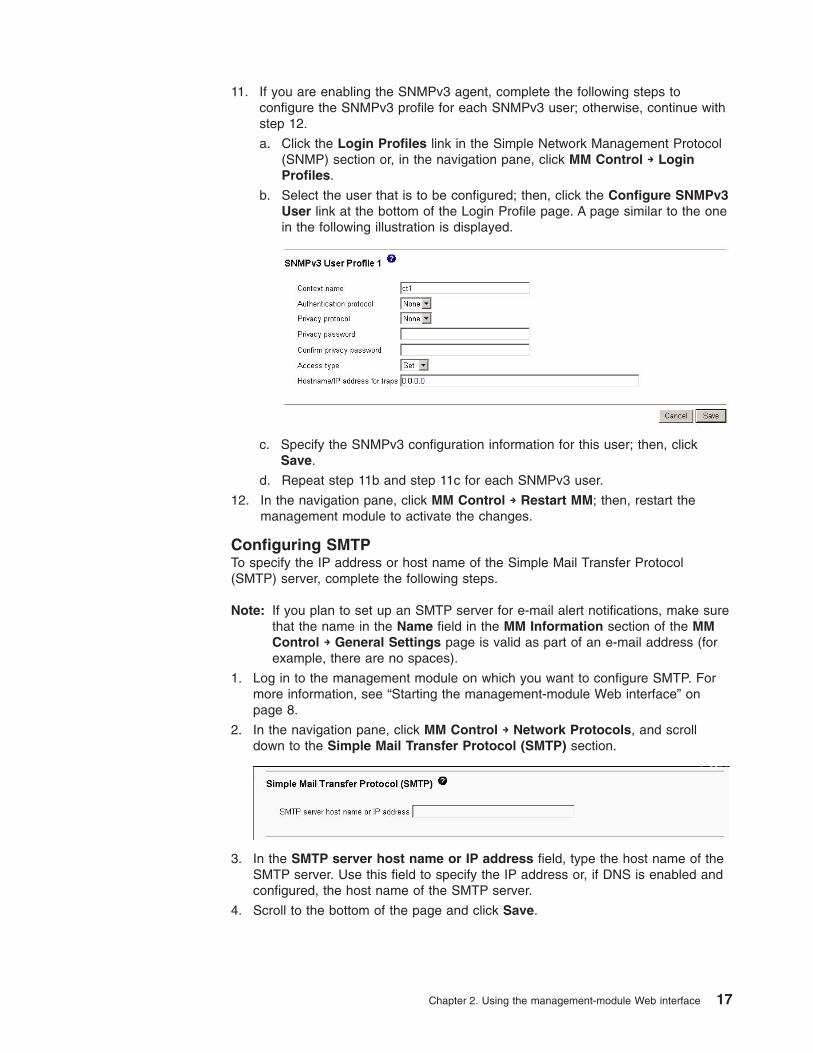
11. If you are enabling the SNMPv3 agent, complete the following steps to
configure the SNMPv3 profile for each SNMPv3 user; otherwise, continue with
step 12.
a. Click the Login Profiles link in the Simple Network Management Protocol
(SNMP) section or, in the navigation pane, click MM Control → Login
Profiles.
b. Select the user that is to be configured; then, click the Configure SNMPv3
User link at the bottom of the Login Profile page. A page similar to the one
in the following illustration is displayed.
c. Specify the SNMPv3 configuration information for this user; then, click
Save.
d. Repeat step 11b and step 11c for each SNMPv3 user.
12. In the navigation pane, click MM Control → Restart MM; then, restart the
management module to activate the changes.
Configuring SMTP
To specify the IP address or host name of the Simple Mail Transfer Protocol
(SMTP) server, complete the following steps.
Note: If you plan to set up an SMTP server for e-mail alert notifications, make sure
that the name in the Name field in the MM Information section of the MM
Control → General Settings page is valid as part of an e-mail address (for
example, there are no spaces).
1. Log in to the management module on which you want to configure SMTP. For
more information, see “Starting the management-module Web interface” on
page 8.
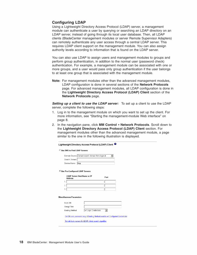
2. In the navigation pane, click MM Control → Network Protocols, and scroll
down to the Simple Mail Transfer Protocol (SMTP) section.
3. In the SMTP server host name or IP address field, type the host name of the
SMTP server. Use this field to specify the IP address or, if DNS is enabled and
configured, the host name of the SMTP server.
4. Scroll to the bottom of the page and click Save.
Chapter 2. Using the management-module Web interface 17
Configuring LDAP
Using a Lightweight Directory Access Protocol (LDAP) server, a management
module can authenticate a user by querying or searching an LDAP directory on an
LDAP server, instead of going through its local user database. Then, all LDAP
clients (BladeCenter management modules or server Remote Supervisor Adapters)
can remotely authenticate any user access through a central LDAP server. This
requires LDAP client support on the management module. You can also assign
authority levels according to information that is found on the LDAP server.
You can also use LDAP to assign users and management modules to groups and
perform group authentication, in addition to the normal user (password check)
authentication. For example, a management module can be associated with one or
more groups, and a user would pass only group authentication if the user belongs
to at least one group that is associated with the management module.
Note: For management modules other than the advanced management modules,
LDAP configuration is done in several sections of the Network Protocols
page. For advanced management modules, all LDAP configuration is done in
the Lightweight Directory Access Protocol (LDAP) Client section of the
Network Protocols page.
Setting up a client to use the LDAP server: To set up a client to use the LDAP
server, complete the following steps:
1. Log in to the management module on which you want to set up the client. For
more information, see “Starting the management-module Web interface” on
page 8.
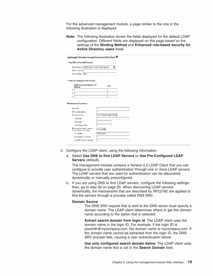
2. In the navigation pane, click MM Control → Network Protocols. Scroll down to
the Lightweight Directory Access Protocol (LDAP) Client section. For
management modules other than the advanced management module, a page
similar to the one in the following illustration is displayed.
18 IBM BladeCenter: Management Module User’s Guide
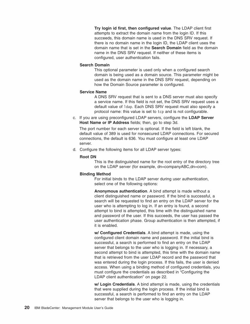
For the advanced management module, a page similar to the one in the
following illustration is displayed.
Note: The following illustration shows the fields displayed for the default LDAP
configuration. Different fields are displayed on this page based on the
settings of the Binding Method and Enhanced role-based security for
Active Directory users fields.
3. Configure the LDAP client, using the following information:
a. Select Use DNS to find LDAP Servers or Use Pre-Configured LDAP
Servers (default).
The management module contains a Version 2.0 LDAP Client that you can
configure to provide user authentication through one or more LDAP servers.
The LDAP servers that are used for authentication can be discovered
dynamically or manually preconfigured.
b. If you are using DNS to find LDAP servers, configure the following settings;
then, go to step 3d on page 20. When discovering LDAP servers
dynamically, the mechanisms that are described by RFC2782 are applied to
find the servers through a process called DNS SRV.
Domain Source
The DNS SRV request that is sent to the DNS server must specify a
domain name. The LDAP client determines where to get this domain
name according to the option that is selected:
Extract search domain from login id. The LDAP client uses the
domain name in the login ID. For example, if the login ID is
[email protected], the domain name is mycompany.com. If
the domain name cannot be extracted from the login ID, the DNS
SRV process fails, causing a user authentication failure.
Use only configured search domain below. The LDAP client uses
the domain name that is set in the Search Domain field.
Chapter 2. Using the management-module Web interface 19
Try login id first, then configured value. The LDAP client first
attempts to extract the domain name from the login ID. If this
succeeds, this domain name is used in the DNS SRV request. If
there is no domain name in the login ID, the LDAP client uses the
domain name that is set in the Search Domain field as the domain
name in the DNS SRV request. If neither of these items is
configured, user authentication fails.
Search Domain
This optional parameter is used only when a configured search
domain is being used as a domain source. This parameter might be
used as the domain name in the DNS SRV request, depending on
how the Domain Source parameter is configured.
Service Name
A DNS SRV request that is sent to a DNS server must also specify
a service name. If this field is not set, the DNS SRV request uses a
default value of ldap. Each DNS SRV request must also specify a
protocol name: this value is set to tcp and is not configurable.
c. If you are using preconfigured LDAP servers, configure the LDAP Server
Host Name or IP Address fields; then, go to step 3d.
The port number for each server is optional. If the field is left blank, the
default value of 389 is used for nonsecured LDAP connections. For secured
connections, the default is 636. You must configure at least one LDAP
server.
d. Configure the following items for all LDAP server types:
Root DN
This is the distinguished name for the root entry of the directory tree
on the LDAP server (for example, dn=companyABC,dn=com).
Binding Method
For initial binds to the LDAP server during user authentication,
select one of the following options:
Anonymous authentication. A bind attempt is made without a
client distinguished name or password. If the bind is successful, a
search will be requested to find an entry on the LDAP server for the
user who is attempting to log in. If an entry is found, a second
attempt to bind is attempted, this time with the distinguished name
and password of the user. If this succeeds, the user has passed the
user authentication phase. Group authentication is then attempted, if
it is enabled.
w/ Configured Credentials. A bind attempt is made, using the
configured client domain name and password. If the initial bind is
successful, a search is performed to find an entry on the LDAP
server that belongs to the user who is logging in. If necessary, a
second attempt to bind is attempted, this time with the domain name
that is retrieved from the user LDAP record and the password that
was entered during the login process. If this fails, the user is denied
access. When using a binding method of configured credentials, you
must configure the credentials as described in “Configuring the
LDAP client authentication” on page 22.
w/ Login Credentials. A bind attempt is made, using the credentials
that were supplied during the login process. If the initial bind is
successful, a search is performed to find an entry on the LDAP
server that belongs to the user who is logging in.
20 IBM BladeCenter: Management Module User’s Guide
Group Filter
(For management modules other than the advanced management
module) This parameter is used for group authentication. It specifies
the set of groups to which the management module belongs. If this
field is left blank, group authentication is disabled. Otherwise, group
authentication is performed against this filter. The specified filter can
be a specific group name (for example, IBMWest), a wildcard with a
prefix (for example, IBM*), or a wildcard (specified as *). If a specific
name is used, the management module belongs only to that group.
If a prefix filter is used (for example, IBM*), the management module
belongs to any group whose first three letters are IBM. If a wildcard
filter ( * ) is used, the management module belongs to all groups.
The default filter is IBM*.
Group authentication is performed after user authentication (where a
user ID and password are verified). Group authentication refers to
the process of verifying that a user is a member of at least one
group that is associated with the management module. For example,
if the group filter is set to IBM* and the user belongs to two groups
(for example, Engineering and IBMWest), group authentication
passes because the user belongs to a group (IBMWest) that
matches the filter IBM*. If the groups to which the user belongs do
not match the filter, group authentication fails, and the user is not
allowed to access the management module. Note that if the group
filter is *, group authentication will automatically succeed because
any group to which the user belongs will match this wildcard. You
must also configure additional authentication attributes as described
in “Configuring the LDAP search attributes” on page 23.
Enhanced role-based security for Active Directory users
(For advanced management modules only) The setting of the
Enhanced role-based security for Active Directory users field
determines how users are authenticated on Active Directory servers:
v Enabled: Activates version 2 of the advanced management
module role-based security (RBS) model. In version 2, a new
RBS model is used for Active Directory servers that requires the
use of a snap-in utility that runs on any Microsoft Windows
platform. The snap-in utility configures roles on an Active
Directory server and associates users, groups, and advanced
management modules to those roles. Each role identifies the
permissions given to users and groups associated with that role,
and identifies the targets, such as advanced management
modules, to which these roles are attached.
If enhanced role-based security is enabled, specify a target name
for the advanced management module needs to be specified in
the AMM Target Name field:
The free-formatted name configured in the AMM Target Name
field is the target name for an advanced management module.
A target name can be associated with one or more roles on
the Active Directory server through the Role Based Security
(RBS) Snap-In by creating targets with specific names and
associating them to roles. If a name is configured in this field,
you can define specific roles for users and advanced
management modules (targets) that are members of the same
role. When a user logs in to the advanced management
module, and is authenticated using Active Directory, the roles
Chapter 2. Using the management-module Web interface 21
for that user are retrieved from the directory. The permissions
assigned to the user are extracted from the roles specified for
the advanced management module target and from the
targets that match any advanced management module.
Multiple advanced management modules can share the same
target name. This method can be used to group multiple
advanced management modules together and assign them to
the same roles using a single managed target identified by a
single target name. The advanced management modules can
also be managed independently by giving them unique
names.
v Disabled: Activates version 1 of the advanced management
module RBS model. In version 1, bitstrings were used to
associate permissions to users and groups in an LDAP-enabled
server environment. Version 1 supported Active Directory, Novell
eDirectory, and OpenLDAP-based servers. When enhanced
role-based security for Active Directory users is disabled, you
must configure authentication attributes as described in
“Configuring the LDAP search attributes” on page 23.
If you are not using Active Directory, then you should not enable
version 2 of the advanced management module RBS model. Before
enabling version 2, you should already have roles configured on the
Active Directory server. The version 1 bitstring model cannot be
automatically converted to the version 2 model; this is why you must
configure users and groups before enabling version 2. Once
enabled, the change takes effect immediately.
Depending on the LDAP configuration that you have set, click the options to
set the domain names and passwords that are used for client authentication
and the LDAP client search attributes. Each of these options is described in
the following sections.
Configuring the LDAP client authentication: If the binding method is set to
configured credentials, configure LDAP client authentication by completing the
following steps:
1. In the navigation pane, click MM Control → Network Protocols.
2. Scroll down to the Lightweight Directory Access Protocol (LDAP) Client
section.
v For advanced management modules, the Client DN and Password are set in
the Miscellaneous Parameters area of the Lightweight Directory Access
Protocol (LDAP) Client section (see the illustration on page 19). The Client
DN and Password fields will display only when the binding method is set for
configured credentials.
v For management modules other than advanced management modules, click
Set DN and password only if Binding Method is Client Authentication. A
page similar to the one in the following illustration is displayed.
22 IBM BladeCenter: Management Module User’s Guide
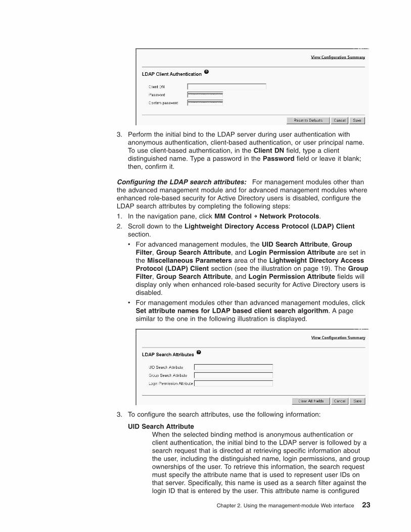
3. Perform the initial bind to the LDAP server during user authentication with
anonymous authentication, client-based authentication, or user principal name.
To use client-based authentication, in the Client DN field, type a client
distinguished name. Type a password in the Password field or leave it blank;
then, confirm it.
Configuring the LDAP search attributes: For management modules other than
the advanced management module and for advanced management modules where
enhanced role-based security for Active Directory users is disabled, configure the
LDAP search attributes by completing the following steps:
1. In the navigation pane, click MM Control → Network Protocols.
2. Scroll down to the Lightweight Directory Access Protocol (LDAP) Client
section.
v For advanced management modules, the UID Search Attribute, Group
Filter, Group Search Attribute, and Login Permission Attribute are set in
the Miscellaneous Parameters area of the Lightweight Directory Access
Protocol (LDAP) Client section (see the illustration on page 19). The Group
Filter, Group Search Attribute, and Login Permission Attribute fields will
display only when enhanced role-based security for Active Directory users is
disabled.
v For management modules other than advanced management modules, click
Set attribute names for LDAP based client search algorithm. A page
similar to the one in the following illustration is displayed.
3. To configure the search attributes, use the following information:
UID Search Attribute
When the selected binding method is anonymous authentication or
client authentication, the initial bind to the LDAP server is followed by a
search request that is directed at retrieving specific information about
the user, including the distinguished name, login permissions, and group
ownerships of the user. To retrieve this information, the search request
must specify the attribute name that is used to represent user IDs on
that server. Specifically, this name is used as a search filter against the
login ID that is entered by the user. This attribute name is configured
Chapter 2. Using the management-module Web interface 23
here. If this field is left blank, a default of UID is used during user
authentication. For example, on Active Directory servers, the attribute
name that is used for user IDs is often sAMAccoutName.
When the selected binding method is user principal name or strict user
principal name, the UID Search Attribute field defaults automatically to
userPrincipalName during user authentication, if the user ID that is
entered has the form userid@somedomain.
Group Filter
(For advanced management modules only) The Group Filter field is
used for group authentication. It specifies the groups that the advanced
management module belongs to. If the Group Filter field left blank,
group authentication is disabled. If enabled, group authentication is
performed after user authentication. Specifically, an attempt is made to
match at least one group in the list to a group that the user belongs to.
If there is no match, the user fails authentication and is denied access.
If there is at least one match, then group authentication passes. All
comparisons made during authentication are case sensitive.
The group filter is limited to 511 characters and can contain multiple
group names. The colon ":" character is used to delimit group names.
Leading spaces and trailing spaces are ignored; all other spaces are
treated as part of the group name. The asterisk "*" wildcard character is
not treated as a wildcard, the wildcard concept being removed for
security reasons. A group name can be specified as a full domain name
or using only the company name portion. For example, a group with a
domain name equal to cn=adminGroup,dc=mycompany,dc=com can be
specified using the actual domain name or by using adminGroup.
Group Search Attribute
When the group filter name is configured, the list of groups to which a
user belongs must be retrieved from the LDAP server. This is required
to perform group authentication. To retrieve this list, the search filter that
is sent to the server must specify the attribute name that is associated
with groups. This field specifies this attribute name.
If this field is left blank, the attribute name in the filter defaults to
memberOf.
Login Permission Attribute
When a user is successfully authenticated through an LDAP server, the
login permissions for the user must be retrieved. To retrieve these
permissions, the search filter that is sent to the server must specify the
attribute name that is associated with login permissions. This field
specifies this attribute name.
The login permission attributes are different for the advanced
management module and management modules other than the
advanced management module. Each set of attributes is described in
one of the following sections:
v Login permission attributes for advanced management modules on
page 25
v Login permission attributes for management modules other than
advanced management modules on page 29
24 IBM BladeCenter: Management Module User’s Guide
Login permission attributes for advanced management modules
This field must not be left blank, otherwise, it will be impossible
to retrieve the user permissions. Without verified permissions,
the login attempt will fail. This is a different from earlier
releases, where access was granted with default read-only
permissions assigned to the user whose permissions could not
be verified.
The attribute value returned by the LDAP server is searched for
the keyword string “IBMRBSPermissions=”. This keyword must
be immediately followed by a bit string entered as 64
consecutive 0’s or 1’s. Each bit represents a particular set of
functions. The bits are numbered according to their position.
The leftmost bit is bit position 0, and the rightmost bit is bit
position 11. A value of 1 at a particular position enables that
particular function. A value of 0 disables that function. The string
“IBMRBSPermissions=010000000000” is a valid example.
Note that the “IBMRBSPermissions=” keyword is used in order
to allow it to be placed anywhere in the attribute field. This
allows the LDAP administrator to reuse an existing attribute,
thus preventing an extension to the LDAP schema.
Furthermore, this allows the attribute to be used for its original
purpose. The keyword string can be added anywhere. The
attribute used should allow for a free-formatted string.
The permission bits are interpreted as follows:
v Deny Always (bit position 0): if this bit is set, a user will
always fail authentication. This function can be used to block
a particular user or users associated with a particular group.
v Supervisor Access (bit position 1): if this bit is set, a user is
given administrator privileges, which lets the user view any
page, allows changes to any field, and permits all actions
provided by the interface. When this bit is set, the other bits
that define specific function access do not have to be set
individually.
v Read Only Access (bit position 2): if this bit is set, a user has
read-only access, and cannot perform any maintenance
procedures (for example, restart, remote actions, and
firmware updates), and nothing can be modified (using the
save, clear, or restore functions). Note that read-only and all
other bits are mutually exclusive, with bit position 2 having
the lowest precedence. That is, if any other bit is set, this bit
will be ignored.
v Networking & Security (bit position 3): if this bit is set, a user
can modify the settings in the Security, Network Protocols,
and Network Interface panels for MM Control. If this bit is
set, the user can also modify the IP configuration parameters
for I/O modules under the I/O Module Tasks → Management
panel.
v User Account Management (bit position 4): if this bit is set, a
user can add, modify, and delete users and change the
Global Login Settings in the Login Profiles panel.
Chapter 2. Using the management-module Web interface 25
v Blade Server Remote Console Access (bit position 5): if this
bit is set, a user can access a remote blade server video
console with keyboard and mouse control.
v Blade Server Remote Console and Virtual Media Access (bit
position 6): if this bit is set, a user can access a remote blade
server video console with keyboard and mouse control, and
can also access the virtual media features for that remote
blade server.
v Blade Server and I/O Module Power/Restart Access (bit
position 7): if this bit is set, a user can access the power on
and restart functions for the blade servers and the I/O
modules. These functions are available in the Blade Tasks →
Power/Restart panel and the I/O Module Tasks →
Power/Restart panel.
v Basic Configuration (bit position 8): if this bit is set, a user
can modify basic configuration parameters for the
management module and blade servers. In particular, the
user can modify parameters in the General Settings and
Alerts panels of MM Control, and the Configuration panel
of the Blade Tasks.
v Ability to Clear Event Logs (bit position 9): if this bit is set, a
user can clear the event logs. All users can view the event
logs, but this permission is required to clear the event logs.
v Advanced Adapter Configuration (bit position 10): if this bit is
set, a user has no restrictions when configuring the
management module, blade servers, I/O modules, and VPD.
In addition, the user has administrative access, meaning that
this user can also perform the following advanced functions:
firmware upgrades on management module or blade servers,
restore management module factory defaults, modify and
restore the management module configuration from a
configuration file, and restart or reset the management
module.
v Version Number (bit positions 11 through 15): A version
number of 00000 indicates that the user permissions scheme
set using bit positions 0 through 10 will be used. A version
number of 00001 indicates that the role-based user
permissions scheme using bit positions 16 through 55 will be
used. Any other version number will use the user permissions
scheme set using bit positions 0 through 10.
v Deny Always Role (bit position 16): if this bit is set, a user will
always fail authentication. This function can be used to block
a particular user or users associated with a particular group.
v Supervisor Role (bit position 17): if this bit is set, a user has
no restrictions. User has read/write access to all panels and
fields for all devices. When this bit is set, there is no need to
set any other authority levels listed below.
v Operator Role (bit position 18): if this bit is set, the user has
read-only access. This user can not perform any
maintenance procedures (for example, restart, remote
actions, firmware updates) and is unable to modify any
settings (using the save, clear, or restore functions). Note that
26 IBM BladeCenter: Management Module User’s Guide

read-only and all other bits are mutually exclusive, with
read-only having the lowest precedence. That is, if any other
bit is set, this bit 18 is ignored.
v Chassis Operator Role (bit position 19): if this bit is set, the
user has the ability to browse status and properties of
chassis components (management module, blowers,
midplane, power modules, media tray) and the ability to
backup the management module configuration.
v Chassis User Account Management Role (bit position 20): if
this bit is set, the user can add, modify, and delete users in
the MM Control → Login Profiles panel. Changing the global
login settings requires the Chassis Configuration role.
v Chassis Log Account Management Role (bit position 21): if
this bit is set, the user can clear the event logs or change the
log policy settings. All users can view the event logs, but this
role is required to clear the logs or to change the log policy
settings (the field at the top of the event log page).
v Chassis Configuration Role (bit position 22): if this bit is set,
the user has the ability to modify and save any chassis
configuration parameter (except user profiles and event log
settings). For example, general management module
settings, management module port assignments,
management module network interfaces, management
module network protocols, management module security. This
user also has the ability to change the SOL configuration
under the SOL configuration web panel, the ability to change
the global login settings. In addition, this user can restore
management module factory defaults configuration, if they
also has Chassis Administration permissions.
v Chassis Administration Role (bit position 23): if this bit is set,
the user has the ability to perform management module
firmware updates, modify the state of the chassis LEDs, and
restart the management module. restore management
module factory defaults configuration if the user also has
Chassis Configuration permissions.
v Blade Operator Role (bit position 24): if this bit is set, the
user has the ability to read blade information but not to
modify it.
v Blade Remote Presence Role (bit position 25): if this bit is
set, the user has the ability to access the Remote Control
web panel and the functions provided on the panel: remote
console (KVM) and remote disk. In addition, this user can
issue the command-line interface (CLI) console command to
start an SOL session to a blade.
v Blade Configuration Role (bit position 26): if this bit is set, the
user has the ability to modify and save any blade server
configuration parameter (except parameters in the SOL
configuration web panel). For example, blade server names,
blade server policy settings, and the ability to disable or
enable SOL for individual blade servers under Serial Over
LAN status web panel.
v Blade Administration Role (bit position 27): if this bit is set,
the user has the ability to power on or off and restart blade
Chapter 2. Using the management-module Web interface 27

servers, activate standby blade servers, do firmware updates,
or modify the state of blade server LEDs.
v Switch Operator Role (bit position 28): if this bit is set, the
user has the ability to browse the status and properties of I/O
modules and the ability to ping I/O modules.
v Switch Configuration Role (bit position 29): if this bit is set,
the user has the ability to configure the I/O module IP
address, enable or disable external management over all
ports, and preserve new IP configuration on all resets. The
user also has the ability to restore factory defaults, and to
launch a Telnet or web session to an I/O module, if the user
also has Switch Administration permissions.
v Switch Administration Role (bit position 30): if this bit is set,
the user has the ability to power on or off and restart I/O
modules with various diagnostic levels, update passthru I/O
module firmware, enable or disable Fast POST, and enable
or disable external ports. The user also has the ability to
restore factory defaults, and to launch a Telnet or web
session to an I/O module, if the user also has Switch
Configuration permissions.
v Blade 1 Scope (bit position 31): if this bit is set, the user will
have access to the blade in slot 1.
v Blade 2 Scope (bit position 32): if this bit is set, the user will
have access to the blade in slot 2.
v Blade 3 Scope (bit position 33): if this bit is set, the user will
have access to the blade in slot 3.
v Blade 4 Scope (bit position 34): if this bit is set, the user will
have access to the blade in slot 4.
v Blade 5 Scope (bit position 35): if this bit is set, the user will
have access to the blade in slot 5.
v Blade 6 Scope (bit position 36): if this bit is set, the user will
have access to the blade in slot 6.
v Blade 7 Scope (bit position 37): if this bit is set, the user will
have access to the blade in slot 7.
v Blade 8 Scope (bit position 38): if this bit is set, the user will
have access to the blade in slot 8.
v Blade 9 Scope (bit position 39): if this bit is set, the user will
have access to the blade in slot 9.
v Blade 10 Scope (bit position 40): if this bit is set, the user will
have access to the blade in slot 10.
v Blade 11 Scope (bit position 41): if this bit is set, the user will
have access to the blade in slot 11.
v Blade 12 Scope (bit position 42): if this bit is set, the user will
have access to the blade in slot 12.
v Blade 13 Scope (bit position 43): if this bit is set, the user will
have access to the blade in slot 13.
v Blade 14 Scope (bit position 44): if this bit is set, the user will
have access to the blade in slot 14.
v Chassis Scope (bit position 45): if this bit is set, the user will
have access to the chassis and management module.
28 IBM BladeCenter: Management Module User’s Guide

v I/O Module 1 Scope (bit position 46): if this bit is set, the user
will have access to I/O module 1.
v I/O Module 2 Scope (bit position 47): if this bit is set, the user
will have access to I/O module 2.
v I/O Module 3 Scope (bit position 48): if this bit is set, the user
will have access to I/O module 3.
v I/O Module 4 Scope (bit position 49): if this bit is set, the user
will have access to I/O module 4.
v I/O Module 5 Scope (bit position 50): if this bit is set, the user
will have access to I/O module 5.
v I/O Module 6 Scope (bit position 51): if this bit is set, the user
will have access to I/O module 6.
v I/O Module 7 Scope (bit position 52): if this bit is set, the user
will have access to I/O module 7.
v I/O Module 8 Scope (bit position 53): if this bit is set, the user
will have access to I/O module 8.
v I/O Module 9 Scope (bit position 54): if this bit is set, the user
will have access to I/O module 9.
v I/O Module 10 Scope (bit position 55): if this bit is set, the
user will have access to I/O module 10.
v Reserved (bit position 56 through 63): reserved for future
use.
If none of the bits are set, the default is set to deny always
(read-only) for the user.
Note that priority is given to login permissions retrieved directly
from the user record. If the user does not have the login
permission attribute in their record, an attempt will be made to
retrieve the permissions from the groups that the user belongs
to; this is done as part of the group authentication phase. The
user will be assigned the inclusive OR of all the bits for all of
the groups. Again, the Deny Always bit will only be set if all the
other bits are zero. Also note that if the Deny Always bit is set
for any of the groups, the user will be refused access. The Deny
Always bit always has precedence over every other bit.
Important: If you give a user the ability to modify basic,
networking, or security related adapter configuration
parameters, you should consider giving this same
user the ability to restart the management module.
If the user is unable to reset the management
module, changes that they make which require a
restart will not take effect.
Login permission attributes for management modules other than
advanced management modules
If the Login Permission Attribute field is left blank, the user is
assigned a default of read-only permissions, assuming that user
and group authentication passes. When successfully retrieved,
the attribute value that is returned by the LDAP server is
interpreted according to the following information:
v The field supports user roles for both the command
authorities that are used in earlier versions of
Chapter 2. Using the management-module Web interface 29
management-module firmware and the role-based user
permissions for the latest version of management-module
firmware. Bit positions 11 through 16 determine which type of
role is used. See “Web interface pages and user roles” on
page 57 for information about the commands available for
each user role.
v The attribute value must be a bit string that is entered as
consecutive zeros or ones, with each bit representing a
particular set of functions (for example, 010000000000 or
0000110010000). The bits are numbered according to their
positions. The leftmost bit is bit position 0, and the rightmost
bit is bit position 50. A value of 1 at a particular position
enables the corresponding function. A value of 0 disables that
function. The LDAP attribute string is copied into a local
string that is 64 characters long. If fewer than 64 characters
are specified, the local string is padded with zeros. If the
string is longer than 64 characters, extra characters are not
copied.
v The following functions are associated with the 50 bit
positions:
– User authorities (for scripting on management modules
other than the advanced management module) (bit
positions 0 through 10):
- Deny Always (bit position 0): If this bit is set, a user will
always fail authentication. This function can be used to
block a particular user or users who are associated with
a particular group.
- Supervisor Access (bit position 1): If this bit is set, a
user is given administrator privileges. The user has
read and write access to every function. When this bit
is set, other bits that define specific function access do
not have to be set individually.
- Read Only Access (bit position 2): If this bit is set, a
user has read-only access and cannot perform any
maintenance procedures (for example, restart, remote
actions, and firmware updates), and nothing can be
modified (using the save, clear, or restore functions).
Note that read-only and all other bits are mutually
exclusive, with bit position 2 having the lowest
precedence. That is, if any other bit is set, this bit is
ignored.
- Networking and Security (bit position 3): If this bit is set,
a user can modify the settings in the Security, Network
Protocols, and Network Interface pages for MM Control.
If this bit is set, a user can also modify the settings in
the Management page for I/O Module Tasks.
- User Account Management (bit position 4): If this bit is
set, a user can add, modify, and delete users and
change the Global Login Settings in the Login Profiles
page.
- Blade server Remote Console Access (bit position 5): If
this bit is set, a user can access the remote server
console.
30 IBM BladeCenter: Management Module User’s Guide

- Blade server Remote Console and Virtual Media Access
(bit position 6): If this bit is set, a user can access the
remote server console and the virtual media functions
for the remote server.
- Blade and I/O Module Power/Restart Access (bit
position 7): If this bit is set, a user can access the
power-on and restart functions for the blade servers
and I/O modules.
- Basic Configuration (management module, I/O Modules,
Blades) (bit position 8): If this bit is set, a user can
modify the General Settings and Alerts pages for MM
Control and the Configuration page for Blade Tasks.
- Ability to Clear Event Logs (bit position 9): If this bit is
set, a user can clear the event logs. Everyone can look
at the event logs, but this permission is required to
clear the logs.
- Advanced Configuration (management module, I/O
Modules, Blades) (bit position 10): If this bit is set, a
user has no restrictions when configuring the
management module, blade servers, I/O modules, and
VPD. The user can also perform firmware upgrades on
the management module or blade servers, restore the
management module to its factory default settings,
modify and restore the management-module
configuration from a configuration file, and restart or
reset the management module.
– Permission version (bit positions 11 through 15): These
bits specify which type of user roles, user authorities, or
role-based user permissions is being used. If these bits
are set to 00001, the role-based user permissions, using
bits 16 through 30, are used. If these bits are set to 00000
or any other value, the user authorities, using bits 0
through 10, are used.
– Role-based user permissions (non-scripting use on all
management-module types) (bit positions 16 through 30):
- Deny Always (bit position 16): If this bit is set, a user
will always fail authentication. This function can be used
to block a particular user or users who are associated
with a particular group.
- Supervisor (bit position 17): If this bit is set, a user is
given administrator privileges. The user has read and
write access to every function. When this bit is set,
other bits that define specific function access do not
have to be set individually.
- Operator (bit position 18): If this bit is set, a user can
view all information. User access to information is
limited by the permission scope that is specified in bits
31 through 49.
- Chassis Operator (bit position 19): If this bit is set, a
user can view information about the common
BladeCenter unit components.
- Chassis User Account Management (bit position 20): If
this bit is set, a user can add, modify, and delete user
Chapter 2. Using the management-module Web interface 31

login profiles. Changing the Global Login Settings
requires Chassis Configuration permission.
- Chassis Log Management (bit position 21): If this bit is
set, a user can clear the event logs or change the log
policy settings. All users can look at the event logs, but
this permission is required to clear the logs or change
the log policy settings at the top of the event-log page.
- Chassis Configuration (bit position 22): If this bit is set,
a user can perform management and setup operations
for the common BladeCenter unit components and
features. User access to information is limited by the
permission scope that is specified in bit 45.
- Chassis Administration (bit position 23): If this bit is set,
a user can manage operation of the common
BladeCenter unit components and features. User
access to information is limited by the permission scope
that is specified in bit 45.
- Blade Operator (bit position 24): If this bit is set, a user
can view information about the blade servers. User
access to blade servers is limited by the permission
scope that is specified in bits 31 through 44.
- Blade Remote Presence (bit position 25): If this bit is
set, a user can access the remote server console and
the virtual media functions for the remote server. User
access to blade servers is limited by the permission
scope that is specified in bits 31 through 44.
- Blade Configuration (bit position 26): If this bit is set, a
user can perform management and setup operations for
the blade servers. User access to blade servers is
limited by the permission scope that is specified in bits
31 through 44.
- Blade Administration (bit position 27): If this bit is set, a
user can manage operation of the blade servers. User
access to blade servers is limited by the permission
scope that is specified in bits 31 through 44.
- Switch Operator (bit position 28): If this bit is set, a user
can view information about the I/O modules. User
access to I/O modules is limited by the permission
scope that is specified in bits 46 through 55.
- Switch Module Configuration (bit position 29): If this bit
is set, a user can perform management and setup
operations for the I/O modules. User access to I/O
modules is limited by the permission scope that is
specified in bits 46 through 55.
- Switch Module Administration (bit position 30): If this bit
is set, a user can manage operation of the I/O modules.
User access to I/O modules is limited by the permission
scope that is specified in bits 46 through 55.
– Permission scope (for role-based user permissions) (bit
positions 31 through 55):
- Blade 1 (bit position 31): If this bit is set, a user can
access information about the blade server that is
addressed in blade bay 1.
32 IBM BladeCenter: Management Module User’s Guide

- Blade 2 (bit position 32): If this bit is set, a user can
access information about the blade server that is
addressed in blade bay 2.
- Blade 3 (bit position 33): If this bit is set, a user can
access information about the blade server that is
addressed in blade bay 3.
- Blade 4 (bit position 34): If this bit is set, a user can
access information about the blade server that is
addressed in blade bay 4.
- Blade 5 (bit position 35): If this bit is set, a user can
access information about the blade server that is
addressed in blade bay 5.
- Blade 6 (bit position 36): If this bit is set, a user can
access information about the blade server that is
addressed in blade bay 6.
- Blade 7 (bit position 37): If this bit is set, a user can
access information about the blade server that is
addressed in blade bay 7.
- Blade 8 (bit position 38): If this bit is set, a user can
access information about the blade server that is
addressed in blade bay 8.
- Blade 9 (bit position 39): If this bit is set, a user can
access information about the blade server that is
addressed in blade bay 9.
- Blade 10 (bit position 40): If this bit is set, a user can
access information about the blade server that is
addressed in blade bay 10.
- Blade 11 (bit position 41): If this bit is set, a user can
access information about the blade server that is
addressed in blade bay 11.
- Blade 12 (bit position 42): If this bit is set, a user can
access information about the blade server that is
addressed in blade bay 12.
- Blade 13 (bit position 43): If this bit is set, a user can
access information about the blade server that is
addressed in blade bay 13.
- Blade 14 (bit position 44): If this bit is set, a user can
access information about the blade server that is
addressed in blade bay 14.
- Chassis (bit position 45): If this bit is set, a user can
access information about the common BladeCenter unit
components.
- I/O Module 1 (bit position 46): If this bit is set, a user
can access information about the I/O module in I/O
module bay 1.
- I/O Module 2 (bit position 47): If this bit is set, a user
can access information about the I/O module in I/O
module bay 2.
- I/O Module 3 (bit position 48): If this bit is set, a user
can access information about the I/O module in I/O
module bay 3.
Chapter 2. Using the management-module Web interface 33
- I/O Module 4 (bit position 49): If this bit is set, a user
can access information about the I/O module in I/O
module bay 4.
- I/O Module 5 (bit position 50): If this bit is set, a user
can access information about the I/O module in I/O
module bay 5.
- I/O Module 6 (bit position 51): If this bit is set, a user
can access information about the I/O module in I/O
module bay 6.
- I/O Module 7 (bit position 52): If this bit is set, a user
can access information about the I/O module in I/O
module bay 7.
- I/O Module 8 (bit position 53): If this bit is set, a user
can access information about the I/O module in I/O
module bay 8.
- I/O Module 9 (bit position 54): If this bit is set, a user
can access information about the I/O module in I/O
module bay 9.
- I/O Module 10 (bit position 55): If this bit is set, a user
can access information about the I/O module in I/O
module bay 10.
– Reserved (bit positions 56 through 63): These bits are
reserved for future use.
v If none of the bits are set, the default is read-only for the
user.
v Priority is given to login permissions that are retrieved directly
from the user record. If the user record does not have the
login permission attribute, an attempt will be made to retrieve
the permissions from the groups to which the user belongs.
This is done as part of the group authentication phase. The
user will be assigned the inclusive OR of all the bits for all of
the groups. The Browser Only bit is set only if all the other
bits are set to zero. If the Deny Always bit is set for any of
the groups, the user will be refused access. The Deny Always
bit always has precedence over every other bit.
Secure Web server and secure LDAP
Secure Sockets Layer (SSL) is a security protocol that provides communication
privacy. SSL enables applications to communicate in a way that is designed to
prevent eavesdropping, tampering, and message forgery.
You can configure the management module to use SSL support for two types of
connections: secure Web server (HTTPS) and secure LDAP connection (LDAPS).
The management module takes on the role of SSL client or SSL server, depending
on the type of connection. The following table shows that the management module
acts as an SSL server for secure Web server connections. The management
module acts as an SSL client for secure LDAP connections.
Table 1. Management-module SSL connection support
Connection type SSL client SSL server
Secure Web server
(HTTPS)
Web browser of the user
(for example, Microsoft Internet Explorer)
Management-module
Web server
34 IBM BladeCenter: Management Module User’s Guide
Table 1. Management-module SSL connection support (continued)
Connection type SSL client SSL server
Secure LDAP
connection
(LDAPS)
Management-module LDAP client An LDAP server
You can view or change the Secure Sockets Layer (SSL) settings from the MM
Control → Security page. You can enable or disable SSL and manage the
certificates that are required for SSL.
Configuring security: Use the general procedure in this section to configure
security for the management-module Web server and to configure security for the
connection between the management module and an LDAP server. If you are not
familiar with the use of SSL certificates, read the information in “SSL certificate
overview.”
The content of the Security Web page is context-sensitive. The selections that are
available on the page change when certificates or certificate-signing requests are
generated, when certificates are imported or removed, and when SSL is enabled or
disabled for the client or the server.
Perform the following general tasks to configure the security for the management
module:
1. Configure the SSL server certificates for the secure Web server:
a. Disable the SSL server. Use the SSL Server Configuration for Web
Server section on the MM Control → Security page.
b. Generate or import a certificate. Use the SSL Server Certificate
Management section on the MM Control → Security page. (See “SSL
server certificate management” on page 36.)
c. Enable the SSL server. Use the SSL Server Configuration for Web Server
section on the MM Control → Security page. (See “Enabling SSL for the
secure Web server” on page 43.)
2. Configure the SSL client certificates for secure LDAP connections:
a. Disable the SSL client. Use the SSL Client Configuration for LDAP Client
section on the MM Control → Security page.
b. Generate or import a certificate. Use the SSL Client Certificate
Management section on the MM Control → Security page. (See “SSL client
certificate management” on page 43.)
c. Import one or more trusted certificates. Use the SSL Client Trusted
Certificate Management section on the MM Control → Security page. (See
“SSL client trusted certificate management” on page 43.)
d. Enable the SSL client. Use the SSL Client Configuration for LDAP Client
section on the MM Control → Security page. (See “Enabling SSL for the
LDAP client” on page 45.)
3. Restart the management module for SSL server configuration changes to take
effect. For more information, see “Restart MM” on page 107.
Note: Changes to the SSL client configuration take effect immediately and do
not require a restart of the management module.
SSL certificate overview: You can use SSL with either a self-signed certificate or
with a certificate that is signed by a certificate authority. Using a self-signed
Chapter 2. Using the management-module Web interface 35
certificate is the simplest method for using SSL, but it does create a small security
risk. The risk arises because the SSL client has no way of validating the identity of
the SSL server for the first connection that is attempted between the client and
server. It is possible that a third party could impersonate the server and intercept
data that moves between the management module and the Web browser. If, at the
time of the initial connection between the browser and the management module, the
self-signed certificate is imported into the certificate store of the browser, all future
communications will be secure for that browser (assuming that the initial connection
was not compromised by an attack).
For more complete security, you can use a certificate that is signed by a certificate
authority. To obtain a signed certificate, use the SSL Certificate Management page
to generate a certificate-signing request. You must then send the certificate-signing
request to a certificate authority and make arrangements to procure a certificate.
When the certificate is received, it is then imported into the management module
through the Import a Signed Certificate link, and you can enable SSL.
The function of the certificate authority is to verify the identity of the management
module. A certificate contains digital signatures for the certificate authority and the
management module. If a well-known certificate authority issues the certificate or if
the certificate of the certificate authority has already been imported into the Web
browser, the browser is able to validate the certificate and positively identify the
management-module Web server.
The management module requires a certificate for the secure Web server and one
for the secure LDAP client. Also, the secure LDAP client requires one or more
trusted certificates. The trusted certificate is used by the secure LDAP client to
positively identify the LDAP server. The trusted certificate is the certificate of the
certificate authority that signed the certificate of the LDAP server. If the LDAP
server uses self-signed certificates, the trusted certificate can be the certificate of
the LDAP server itself. Additional trusted certificates can be imported if more than
one LDAP server is used in your configuration.
SSL server certificate management: The SSL server requires that a valid
certificate and corresponding private encryption key be installed before SSL is
enabled. Two methods are available for generating the private key and required
certificate: using a self-signed certificate and using a certificate that is signed by a
certificate authority. If you want to use a self-signed certificate for the SSL server,
see “Generating a self-signed certificate” on page 37. If you want to use a
certificate-authority-signed certificate for the SSL server, see “Generating a
certificate signing request” on page 38.
36 IBM BladeCenter: Management Module User’s Guide
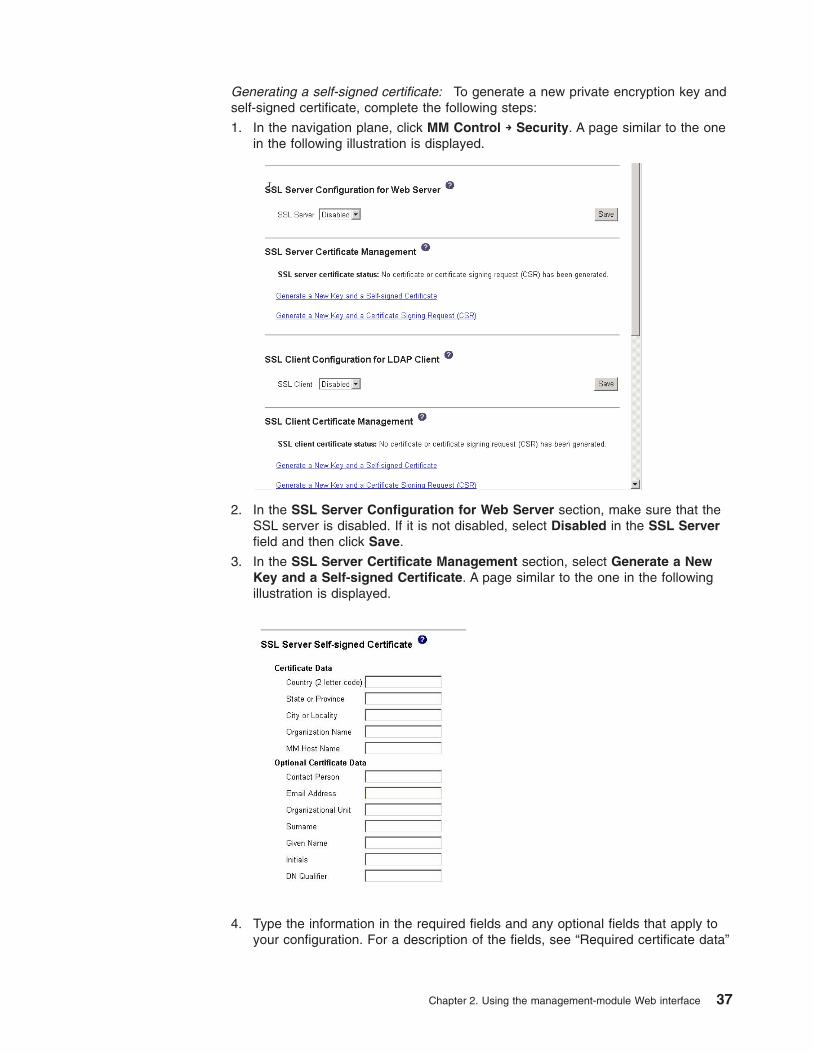
Generating a self-signed certificate: To generate a new private encryption key and
self-signed certificate, complete the following steps:
1. In the navigation plane, click MM Control → Security. A page similar to the one
in the following illustration is displayed.
2. In the SSL Server Configuration for Web Server section, make sure that the
SSL server is disabled. If it is not disabled, select Disabled in the SSL Server
field and then click Save.
3. In the SSL Server Certificate Management section, select Generate a New
Key and a Self-signed Certificate. A page similar to the one in the following
illustration is displayed.
4. Type the information in the required fields and any optional fields that apply to
your configuration. For a description of the fields, see “Required certificate data”
Chapter 2. Using the management-module Web interface 37
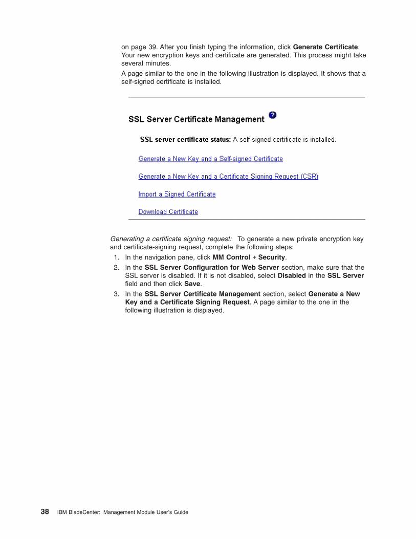
on page 39. After you finish typing the information, click Generate Certificate.
Your new encryption keys and certificate are generated. This process might take
several minutes.
A page similar to the one in the following illustration is displayed. It shows that a
self-signed certificate is installed.
Generating a certificate signing request: To generate a new private encryption key
and certificate-signing request, complete the following steps:
1. In the navigation pane, click MM Control → Security.
2. In the SSL Server Configuration for Web Server section, make sure that the
SSL server is disabled. If it is not disabled, select Disabled in the SSL Server
field and then click Save.
3. In the SSL Server Certificate Management section, select Generate a New
Key and a Certificate Signing Request. A page similar to the one in the
following illustration is displayed.
38 IBM BladeCenter: Management Module User’s Guide
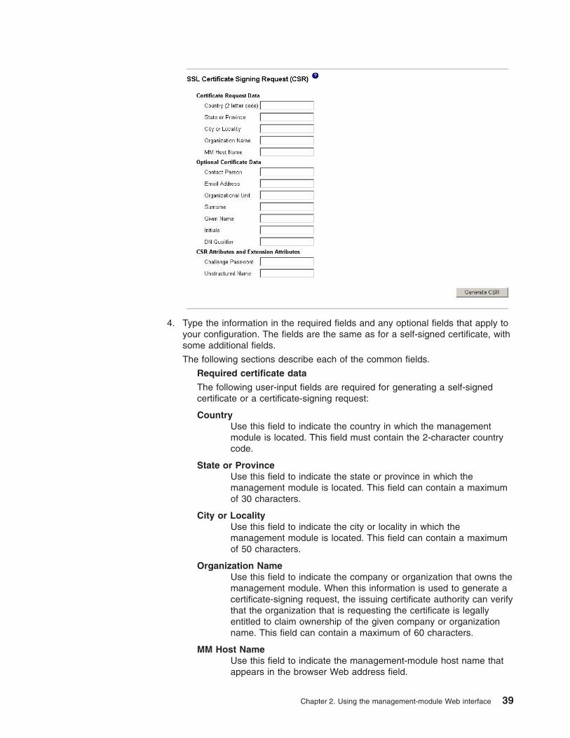
4. Type the information in the required fields and any optional fields that apply to
your configuration. The fields are the same as for a self-signed certificate, with
some additional fields.
The following sections describe each of the common fields.
Required certificate data
The following user-input fields are required for generating a self-signed
certificate or a certificate-signing request:
Country
Use this field to indicate the country in which the management
module is located. This field must contain the 2-character country
code.
State or Province
Use this field to indicate the state or province in which the
management module is located. This field can contain a maximum
of 30 characters.
City or Locality
Use this field to indicate the city or locality in which the
management module is located. This field can contain a maximum
of 50 characters.
Organization Name
Use this field to indicate the company or organization that owns the
management module. When this information is used to generate a
certificate-signing request, the issuing certificate authority can verify
that the organization that is requesting the certificate is legally
entitled to claim ownership of the given company or organization
name. This field can contain a maximum of 60 characters.
MM Host Name
Use this field to indicate the management-module host name that
appears in the browser Web address field.
Chapter 2. Using the management-module Web interface 39
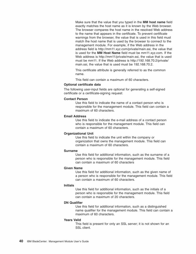
Make sure that the value that you typed in the MM host name field
exactly matches the host name as it is known by the Web browser.
The browser compares the host name in the resolved Web address
to the name that appears in the certificate. To prevent certificate
warnings from the browser, the value that is used in this field must
match the host name that is used by the browser to connect to the
management module. For example, if the Web address in the
address field is http://mm11.xyz.com/private/main.ssi, the value that
is used for the MM Host Name field must be mm11.xyz.com. If the
Web address is http://mm11/private/main.ssi, the value that is used
must be mm11. If the Web address is http://192.168.70.2/private/main.ssi, the value that is used must be 192.168.70.2.
This certificate attribute is generally referred to as the common
name.
This field can contain a maximum of 60 characters.
Optional certificate data
The following user-input fields are optional for generating a self-signed
certificate or a certificate-signing request:
Contact Person
Use this field to indicate the name of a contact person who is
responsible for the management module. This field can contain a
maximum of 60 characters.
Email Address
Use this field to indicate the e-mail address of a contact person
who is responsible for the management module. This field can
contain a maximum of 60 characters.
Organizational Unit
Use this field to indicate the unit within the company or
organization that owns the management module. This field can
contain a maximum of 60 characters.
Surname
Use this field for additional information, such as the surname of a
person who is responsible for the management module. This field
can contain a maximum of 60 characters
Given Name
Use this field for additional information, such as the given name of
a person who is responsible for the management module. This field
can contain a maximum of 60 characters.
Initials
Use this field for additional information, such as the initials of a
person who is responsible for the management module. This field
can contain a maximum of 20 characters.
DN Qualifier
Use this field for additional information, such as a distinguished
name qualifier for the management module. This field can contain a
maximum of 60 characters.
Years Valid
This field is present for only an SSL server; it is not shown for an
SSL client.
40 IBM BladeCenter: Management Module User’s Guide
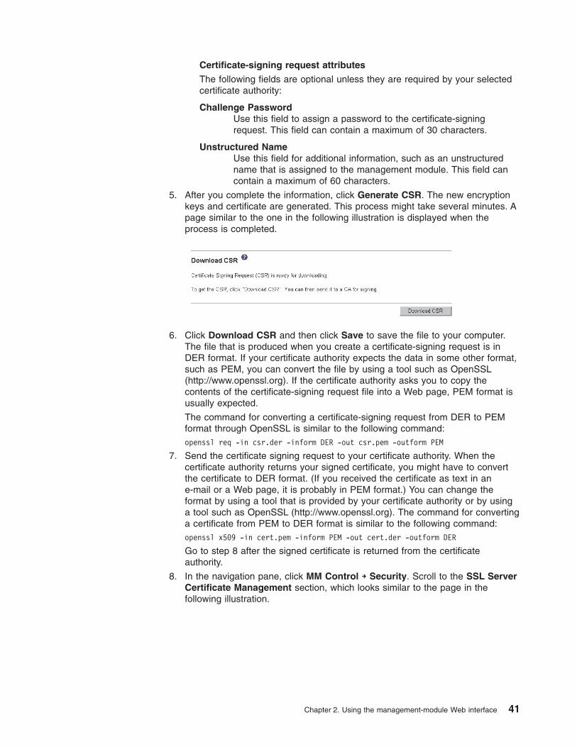
Certificate-signing request attributes
The following fields are optional unless they are required by your selected
certificate authority:
Challenge Password
Use this field to assign a password to the certificate-signing
request. This field can contain a maximum of 30 characters.
Unstructured Name
Use this field for additional information, such as an unstructured
name that is assigned to the management module. This field can
contain a maximum of 60 characters.
5. After you complete the information, click Generate CSR. The new encryption
keys and certificate are generated. This process might take several minutes. A
page similar to the one in the following illustration is displayed when the
process is completed.
6. Click Download CSR and then click Save to save the file to your computer.
The file that is produced when you create a certificate-signing request is in
DER format. If your certificate authority expects the data in some other format,
such as PEM, you can convert the file by using a tool such as OpenSSL
(http://www.openssl.org). If the certificate authority asks you to copy the
contents of the certificate-signing request file into a Web page, PEM format is
usually expected.
The command for converting a certificate-signing request from DER to PEM
format through OpenSSL is similar to the following command:
openssl req -in csr.der -inform DER -out csr.pem -outform PEM
7. Send the certificate signing request to your certificate authority. When the
certificate authority returns your signed certificate, you might have to convert
the certificate to DER format. (If you received the certificate as text in an
e-mail or a Web page, it is probably in PEM format.) You can change the
format by using a tool that is provided by your certificate authority or by using
a tool such as OpenSSL (http://www.openssl.org). The command for converting
a certificate from PEM to DER format is similar to the following command:
openssl x509 -in cert.pem -inform PEM -out cert.der -outform DER
Go to step 8 after the signed certificate is returned from the certificate
authority.
8. In the navigation pane, click MM Control → Security. Scroll to the SSL Server
Certificate Management section, which looks similar to the page in the
following illustration.
Chapter 2. Using the management-module Web interface 41
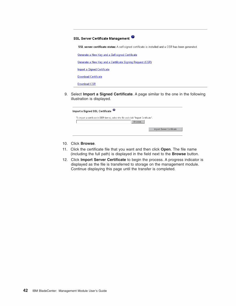
9. Select Import a Signed Certificate. A page similar to the one in the following
illustration is displayed.
10. Click Browse.
11. Click the certificate file that you want and then click Open. The file name
(including the full path) is displayed in the field next to the Browse button.
12. Click Import Server Certificate to begin the process. A progress indicator is
displayed as the file is transferred to storage on the management module.
Continue displaying this page until the transfer is completed.
42 IBM BladeCenter: Management Module User’s Guide
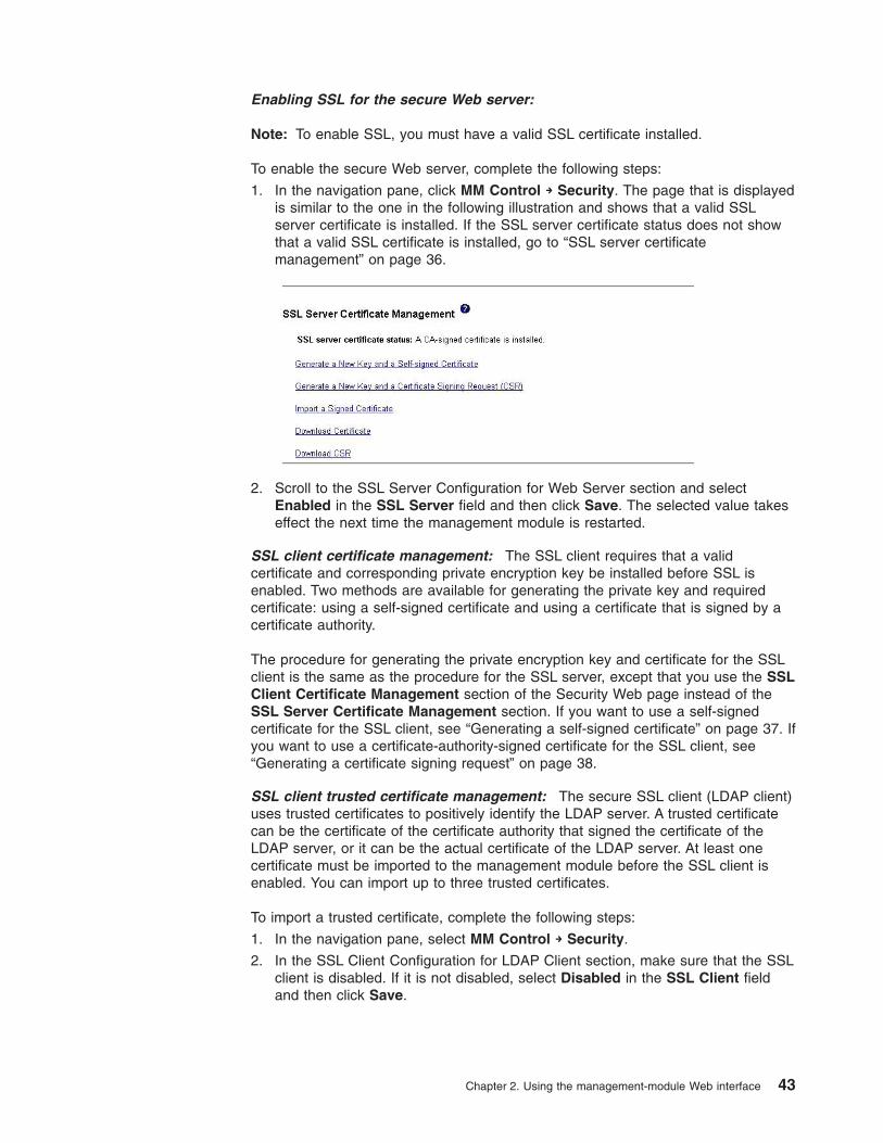
Enabling SSL for the secure Web server:
Note: To enable SSL, you must have a valid SSL certificate installed.
To enable the secure Web server, complete the following steps:
1. In the navigation pane, click MM Control → Security. The page that is displayed
is similar to the one in the following illustration and shows that a valid SSL
server certificate is installed. If the SSL server certificate status does not show
that a valid SSL certificate is installed, go to “SSL server certificate
management” on page 36.
2. Scroll to the SSL Server Configuration for Web Server section and select
Enabled in the SSL Server field and then click Save. The selected value takes
effect the next time the management module is restarted.
SSL client certificate management: The SSL client requires that a valid
certificate and corresponding private encryption key be installed before SSL is
enabled. Two methods are available for generating the private key and required
certificate: using a self-signed certificate and using a certificate that is signed by a
certificate authority.
The procedure for generating the private encryption key and certificate for the SSL
client is the same as the procedure for the SSL server, except that you use the SSL
Client Certificate Management section of the Security Web page instead of the
SSL Server Certificate Management section. If you want to use a self-signed
certificate for the SSL client, see “Generating a self-signed certificate” on page 37. If
you want to use a certificate-authority-signed certificate for the SSL client, see
“Generating a certificate signing request” on page 38.
SSL client trusted certificate management: The secure SSL client (LDAP client)
uses trusted certificates to positively identify the LDAP server. A trusted certificate
can be the certificate of the certificate authority that signed the certificate of the
LDAP server, or it can be the actual certificate of the LDAP server. At least one
certificate must be imported to the management module before the SSL client is
enabled. You can import up to three trusted certificates.
To import a trusted certificate, complete the following steps:
1. In the navigation pane, select MM Control → Security.
2. In the SSL Client Configuration for LDAP Client section, make sure that the SSL
client is disabled. If it is not disabled, select Disabled in the SSL Client field
and then click Save.
Chapter 2. Using the management-module Web interface 43
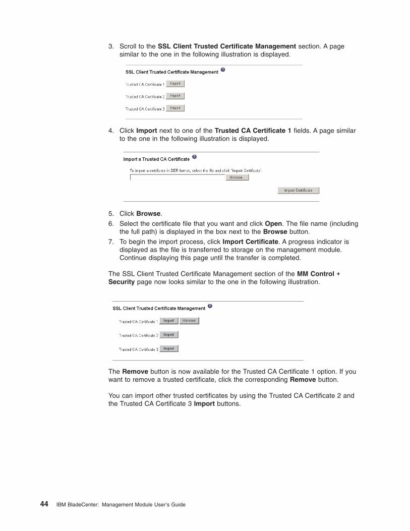
3. Scroll to the SSL Client Trusted Certificate Management section. A page
similar to the one in the following illustration is displayed.
4. Click Import next to one of the Trusted CA Certificate 1 fields. A page similar
to the one in the following illustration is displayed.
5. Click Browse.
6. Select the certificate file that you want and click Open. The file name (including
the full path) is displayed in the box next to the Browse button.
7. To begin the import process, click Import Certificate. A progress indicator is
displayed as the file is transferred to storage on the management module.
Continue displaying this page until the transfer is completed.
The SSL Client Trusted Certificate Management section of the MM Control →
Security page now looks similar to the one in the following illustration.
The Remove button is now available for the Trusted CA Certificate 1 option. If you
want to remove a trusted certificate, click the corresponding Remove button.
You can import other trusted certificates by using the Trusted CA Certificate 2 and
the Trusted CA Certificate 3 Import buttons.
44 IBM BladeCenter: Management Module User’s Guide
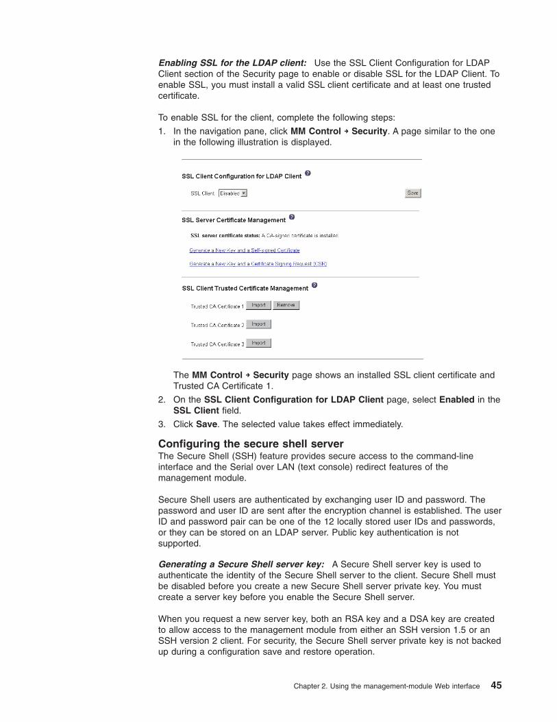
Enabling SSL for the LDAP client: Use the SSL Client Configuration for LDAP
Client section of the Security page to enable or disable SSL for the LDAP Client. To
enable SSL, you must install a valid SSL client certificate and at least one trusted
certificate.
To enable SSL for the client, complete the following steps:
1. In the navigation pane, click MM Control → Security. A page similar to the one
in the following illustration is displayed.
The MM Control → Security page shows an installed SSL client certificate and
Trusted CA Certificate 1.
2. On the SSL Client Configuration for LDAP Client page, select Enabled in the
SSL Client field.
3. Click Save. The selected value takes effect immediately.
Configuring the secure shell server
The Secure Shell (SSH) feature provides secure access to the command-line
interface and the Serial over LAN (text console) redirect features of the
management module.
Secure Shell users are authenticated by exchanging user ID and password. The
password and user ID are sent after the encryption channel is established. The user
ID and password pair can be one of the 12 locally stored user IDs and passwords,
or they can be stored on an LDAP server. Public key authentication is not
supported.
Generating a Secure Shell server key: A Secure Shell server key is used to
authenticate the identity of the Secure Shell server to the client. Secure Shell must
be disabled before you create a new Secure Shell server private key. You must
create a server key before you enable the Secure Shell server.
When you request a new server key, both an RSA key and a DSA key are created
to allow access to the management module from either an SSH version 1.5 or an
SSH version 2 client. For security, the Secure Shell server private key is not backed
up during a configuration save and restore operation.
Chapter 2. Using the management-module Web interface 45
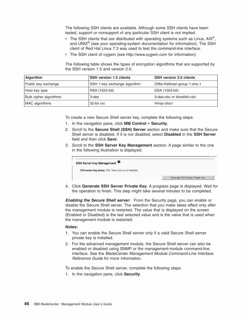
The following SSH clients are available. Although some SSH clients have been
tested, support or nonsupport of any particular SSH client is not implied.
v The SSH clients that are distributed with operating systems such as Linux, AIX®,
and UNIX® (see your operating-system documentation for information). The SSH
client of Red Hat Linux 7.3 was used to test the command-line interface.
v The SSH client of cygwin (see http://www.cygwin.com for information).
The following table shows the types of encryption algorithms that are supported by
the SSH version 1.5 and version 2.0.
Algorithm SSH version 1.5 clients SSH version 2.0 clients
Public key exchange SSH 1-key exchange algorithm Diffie-Hellman-group 1-sha-1
Host key type RSA (1024-bit) DSA (1024-bit)
Bulk cipher algorithms 3-des 3-des-cbc or blowfish-cbc
MAC algorithms 32-bit crc Hmac-sha1
To create a new Secure Shell server key, complete the following steps:
1. In the navigation pane, click MM Control → Security.
2. Scroll to the Secure Shell (SSH) Server section and make sure that the Secure
Shell server is disabled. If it is not disabled, select Disabled in the SSH Server
field and then click Save.
3. Scroll to the SSH Server Key Management section. A page similar to the one
in the following illustration is displayed.
4. Click Generate SSH Server Private Key. A progress page is displayed. Wait for
the operation to finish. This step might take several minutes to be completed.
Enabling the Secure Shell server: From the Security page, you can enable or
disable the Secure Shell server. The selection that you make takes effect only after
the management module is restarted. The value that is displayed on the screen
(Enabled or Disabled) is the last selected value and is the value that is used when
the management module is restarted.
Notes:
1. You can enable the Secure Shell server only if a valid Secure Shell server
private key is installed.
2. For the advanced management module, the Secure Shell server can also be
enabled or disabled using SNMP or the management-module command-line
interface. See the BladeCenter Management Module Command-Line Interface
Reference Guide for more information.
To enable the Secure Shell server, complete the following steps:
1. In the navigation pane, click Security.
46 IBM BladeCenter: Management Module User’s Guide
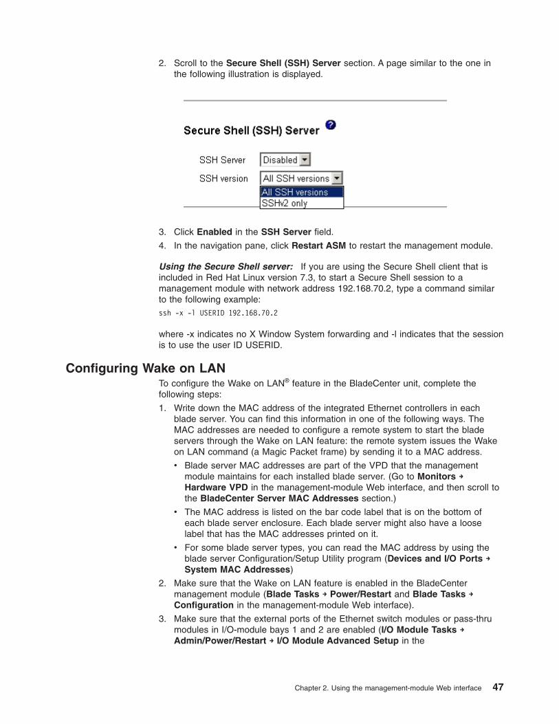
2. Scroll to the Secure Shell (SSH) Server section. A page similar to the one in
the following illustration is displayed.
3. Click Enabled in the SSH Server field.
4. In the navigation pane, click Restart ASM to restart the management module.
Using the Secure Shell server: If you are using the Secure Shell client that is
included in Red Hat Linux version 7.3, to start a Secure Shell session to a
management module with network address 192.168.70.2, type a command similar
to the following example:
ssh -x -l USERID 192.168.70.2
where -x indicates no X Window System forwarding and -l indicates that the session
is to use the user ID USERID.
Configuring Wake on LAN
To configure the Wake on LAN® feature in the BladeCenter unit, complete the
following steps:
1. Write down the MAC address of the integrated Ethernet controllers in each
blade server. You can find this information in one of the following ways. The
MAC addresses are needed to configure a remote system to start the blade
servers through the Wake on LAN feature: the remote system issues the Wake
on LAN command (a Magic Packet frame) by sending it to a MAC address.
v Blade server MAC addresses are part of the VPD that the management
module maintains for each installed blade server. (Go to Monitors →
Hardware VPD in the management-module Web interface, and then scroll to
the BladeCenter Server MAC Addresses section.)
v The MAC address is listed on the bar code label that is on the bottom of
each blade server enclosure. Each blade server might also have a loose
label that has the MAC addresses printed on it.
v For some blade server types, you can read the MAC address by using the
blade server Configuration/Setup Utility program (Devices and I/O Ports →
System MAC Addresses)
2. Make sure that the Wake on LAN feature is enabled in the BladeCenter
management module (Blade Tasks → Power/Restart and Blade Tasks →
Configuration in the management-module Web interface).
3. Make sure that the external ports of the Ethernet switch modules or pass-thru
modules in I/O-module bays 1 and 2 are enabled (I/O Module Tasks →
Admin/Power/Restart → I/O Module Advanced Setup in the
Chapter 2. Using the management-module Web interface 47
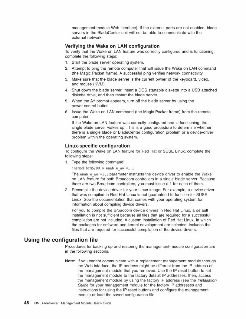
management-module Web interface). If the external ports are not enabled, blade
servers in the BladeCenter unit will not be able to communicate with the
external network.
Verifying the Wake on LAN configuration
To verify that the Wake on LAN feature was correctly configured and is functioning,
complete the following steps:
1. Start the blade server operating system.
2. Attempt to ping the remote computer that will issue the Wake on LAN command
(the Magic Packet frame). A successful ping verifies network connectivity.
3. Make sure that the blade server is the current owner of the keyboard, video,
and mouse (KVM).
4. Shut down the blade server, insert a DOS startable diskette into a USB attached
diskette drive, and then restart the blade server.
5. When the A:\ prompt appears, turn off the blade server by using the
power-control button.
6. Issue the Wake on LAN command (the Magic Packet frame) from the remote
computer.
If the Wake on LAN feature was correctly configured and is functioning, the
single blade server wakes up. This is a good procedure to determine whether
there is a single blade or BladeCenter configuration problem or a device-driver
problem within the operating system.
Linux-specific configuration
To configure the Wake on LAN feature for Red Hat or SUSE Linux, complete the
following steps:
1. Type the following command:
insmod bcm5700.o enable_wol=1,1
The enable_wol=1,1 parameter instructs the device driver to enable the Wake
on LAN feature for both Broadcom controllers in a single blade server. Because
there are two Broadcom controllers, you must issue a 1 for each of them.
2. Recompile the device driver for your Linux image. For example, a device driver
that was compiled in Red Hat Linux is not guaranteed to function for SUSE
Linux. See the documentation that comes with your operating system for
information about compiling device drivers.
For you to compile the Broadcom device drivers in Red Hat Linux, a default
installation is not sufficient because all files that are required for a successful
compilation are not included. A custom installation of Red Hat Linux, in which
the packages for software and kernel development are selected, includes the
files that are required for successful compilation of the device drivers.
Using the configuration file
Procedures for backing up and restoring the management-module configuration are
in the following sections.
Note: If you cannot communicate with a replacement management module through
the Web interface, the IP address might be different from the IP address of
the management module that you removed. Use the IP reset button to set
the management module to the factory default IP addresses; then, access
the management module by using the factory IP address (see the Installation
Guide for your management module for the factory IP addresses and
instructions for using the IP reset button) and configure the management
module or load the saved configuration file.
48 IBM BladeCenter: Management Module User’s Guide
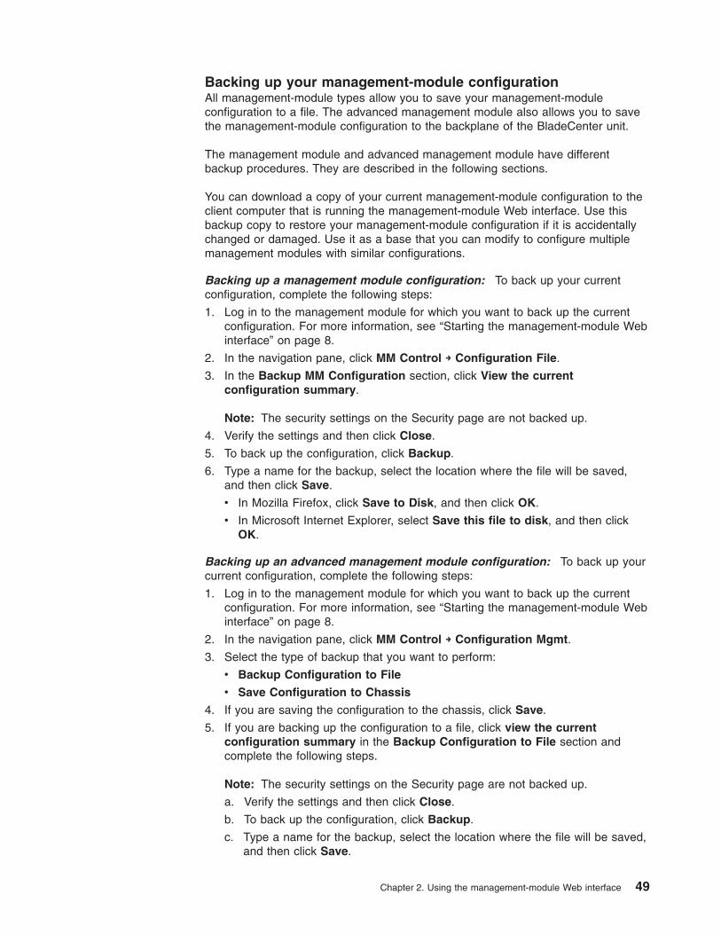
Backing up your management-module configuration
All management-module types allow you to save your management-module
configuration to a file. The advanced management module also allows you to save
the management-module configuration to the backplane of the BladeCenter unit.
The management module and advanced management module have different
backup procedures. They are described in the following sections.
You can download a copy of your current management-module configuration to the
client computer that is running the management-module Web interface. Use this
backup copy to restore your management-module configuration if it is accidentally
changed or damaged. Use it as a base that you can modify to configure multiple
management modules with similar configurations.
Backing up a management module configuration: To back up your current
configuration, complete the following steps:
1. Log in to the management module for which you want to back up the current
configuration. For more information, see “Starting the management-module Web
interface” on page 8.
2. In the navigation pane, click MM Control → Configuration File.
3. In the Backup MM Configuration section, click View the current
configuration summary.
Note: The security settings on the Security page are not backed up.
4. Verify the settings and then click Close.
5. To back up the configuration, click Backup.
6. Type a name for the backup, select the location where the file will be saved,
and then click Save.
v In Mozilla Firefox, click Save to Disk, and then click OK.
v In Microsoft Internet Explorer, select Save this file to disk, and then click
OK.
Backing up an advanced management module configuration: To back up your
current configuration, complete the following steps:
1. Log in to the management module for which you want to back up the current
configuration. For more information, see “Starting the management-module Web
interface” on page 8.
2. In the navigation pane, click MM Control → Configuration Mgmt.
3. Select the type of backup that you want to perform:
v Backup Configuration to File
v Save Configuration to Chassis
4. If you are saving the configuration to the chassis, click Save.
5. If you are backing up the configuration to a file, click view the current
configuration summary in the Backup Configuration to File section and
complete the following steps.
Note: The security settings on the Security page are not backed up.
a. Verify the settings and then click Close.
b. To back up the configuration, click Backup.
c. Type a name for the backup, select the location where the file will be saved,
and then click Save.
Chapter 2. Using the management-module Web interface 49
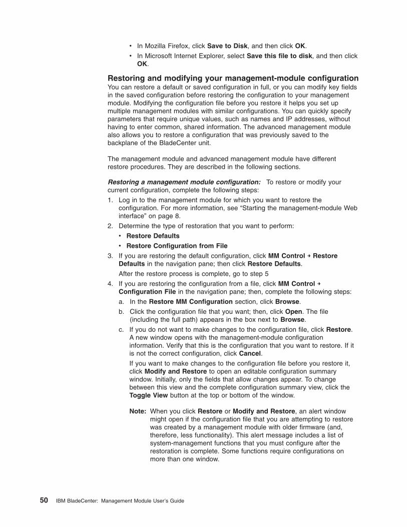
v In Mozilla Firefox, click Save to Disk, and then click OK.
v In Microsoft Internet Explorer, select Save this file to disk, and then click
OK.
Restoring and modifying your management-module configuration
You can restore a default or saved configuration in full, or you can modify key fields
in the saved configuration before restoring the configuration to your management
module. Modifying the configuration file before you restore it helps you set up
multiple management modules with similar configurations. You can quickly specify
parameters that require unique values, such as names and IP addresses, without
having to enter common, shared information. The advanced management module
also allows you to restore a configuration that was previously saved to the
backplane of the BladeCenter unit.
The management module and advanced management module have different
restore procedures. They are described in the following sections.
Restoring a management module configuration: To restore or modify your
current configuration, complete the following steps:
1. Log in to the management module for which you want to restore the
configuration. For more information, see “Starting the management-module Web
interface” on page 8.
2. Determine the type of restoration that you want to perform:
v Restore Defaults
v Restore Configuration from File
3. If you are restoring the default configuration, click MM Control → Restore
Defaults in the navigation pane; then click Restore Defaults.
After the restore process is complete, go to step 5
4. If you are restoring the configuration from a file, click MM Control →
Configuration File in the navigation pane; then, complete the following steps:
a. In the Restore MM Configuration section, click Browse.
b. Click the configuration file that you want; then, click Open. The file
(including the full path) appears in the box next to Browse.
c. If you do not want to make changes to the configuration file, click Restore.
A new window opens with the management-module configuration
information. Verify that this is the configuration that you want to restore. If it
is not the correct configuration, click Cancel.
If you want to make changes to the configuration file before you restore it,
click Modify and Restore to open an editable configuration summary
window. Initially, only the fields that allow changes appear. To change
between this view and the complete configuration summary view, click the
Toggle View button at the top or bottom of the window.
Note: When you click Restore or Modify and Restore, an alert window
might open if the configuration file that you are attempting to restore
was created by a management module with older firmware (and,
therefore, less functionality). This alert message includes a list of
system-management functions that you must configure after the
restoration is complete. Some functions require configurations on
more than one window.
50 IBM BladeCenter: Management Module User’s Guide
d. To proceed with restoring this file to the management module, click Restore
Configuration. A progress indicator appears as the firmware on the
management module is updated. A confirmation window opens to indicate
whether the update was successful.
Note: The security settings on the Security page are not restored with the
restore operation. To modify security settings, see “Secure Web
server and secure LDAP” on page 34.
5. After you receive a confirmation that the restore process is complete, in the
navigation pane, click MM Control → Restart MM; then, click Restart.
6. Click OK to confirm that you want to restart the management module.
7. Click OK to close the browser window.
8. To log in to the management module again, start the browser, and follow your
login process.
Restoring an advanced management module configuration: To restore or
modify your current configuration, complete the following steps. You can restore an
advanced management module configuration only if it was previously saved to the
chassis or external media, as described in “Backing up an advanced management
module configuration” on page 49.
1. Log in to the management module for which you want to restore the
configuration. For more information, see “Starting the management-module
Web interface” on page 8.
2. In the navigation pane, click MM Control → Configuration Mgmt.
3. Select the type of restoration that you want to perform:
v Restore Defaults
v Restore Configuration from File
v Restore Configuration from Chassis
4. If you are restoring the default configuration, click one of the following:
v Restore Defaults to restore the management module to factory settings
v Restore Defaults Preserve Logs to restore the management module to
factory settings while retaining the content of the management module
Event Log
A progress indicator appears as the firmware on the management module is
updated. A confirmation window opens to indicate whether the update was
successful. After the restore process is complete, go to step 7
5. If you are restoring the configuration from a file, click Browse in the Restore
Configuration from File section and complete the following steps:
a. Click the configuration file that you want; then, click Open. The file
(including the full path) appears in the box next to Browse.
b. If you do not want to make changes to the configuration file, click Restore.
A new window opens with the management-module configuration
information. Verify that this is the configuration that you want to restore. If it
is not the correct configuration, click Cancel.
If you want to make changes to the configuration file before you restore it,
click Modify and Restore to open an editable configuration summary
window. Initially, only the fields that allow changes appear. To change
between this view and the complete configuration summary view, click the
Toggle View button at the top or bottom of the window.
Note: When you click Restore or Modify and Restore, an alert window
might open if the configuration file that you are attempting to restore
Chapter 2. Using the management-module Web interface 51
was created by a management module with older firmware (and,
therefore, less functionality). This alert message includes a list of
system-management functions that you must configure after the
restoration is complete. Some functions require configurations on
more than one window.
c. To proceed with restoring this file to the management module, click
Restore Configuration. A progress indicator appears as the firmware on
the management module is updated. A confirmation window opens to
indicate whether the update was successful.
Note: The security settings on the Security page are not restored with the
restore operation. To modify security settings, see “Secure Web
server and secure LDAP” on page 34.
A progress indicator appears as the firmware on the management module is
updated. A confirmation window opens to indicate whether the update was
successful. After the restore process is complete, go to step 7
6. If you are restoring the configuration from the chassis, click Restore; then,
click OK.
A progress indicator appears as the firmware on the management module is
updated. A confirmation window opens to indicate whether the update was
successful.
7. After you receive a confirmation that the restore process is complete, in the
navigation pane, click MM Control → Restart MM; then, click Restart.
8. Click OK to confirm that you want to restart the management module.
9. Click OK to close the browser window.
10. To log in to the management module again, start the browser, and follow your
login process.
Using the remote disk feature
From the Remote Control window (see “Remote Control” on page 78), you can
assign, or mount, a optical drive or diskette drive that is on the remote client
computer to a blade server. By using this window, you can also specify a disk
image or CD (ISO) image on the remote client computer for the blade server to use.
You can use the remote disk for functions such as updating blade server firmware,
installing new software on the blade server, and installing or updating the operating
system on the blade server. After you assign the remote disk, use the remote
console function to access it. The remote disk appears as a USB drive on the blade
server.
Your operating system must have USB support for you to use the remote disk
feature. The following operating systems provide USB support:
v Microsoft Windows® Server 2003
v Microsoft Windows 2000 with Service Pack 4 or later
v Red Hat Linux version 7.3
v SUSE Linux version 8.0
v Novell NetWare 6.5
In addition, the client (remote) system must have Microsoft Windows 2000 or later
and must have the Java 1.4.1 or later Plug-in installed. The client system must also
have an Intel Pentium III or later microprocessor operating at 700 MHz or faster (or
an equivalent microprocessor).
52 IBM BladeCenter: Management Module User’s Guide
Mounting a disk drive or disk image
To mount a disk drive or disk image on a remote client computer to a blade server,
complete the following steps:
1. Start the management-module Web interface (see “Starting the
management-module Web interface” on page 8).
2. In the navigation pane, click Blade Tasks → Remote Control.
3. In the Start Remote Control section, click Start Remote Control.
4. For the advanced management module, select the blade server that will have
control of the media tray in the Remote Disk section.
5. In the Remote Disk section, select the hard disk drives or images to make
available for mounting from the left side of the remote disk drive selector; then,
click >> to finalize the selection and move them to the right side of the remote
disk drive selector. To deselect items, select them in the right side of the remote
disk drive selector and then click <<.
When you select a diskette drive or an image file and move it to the right side of
the drive selector, you are given the option to save the disk image in the
management-module random access memory (RAM). This enables the disk
image to remain mounted on the blade server so that you can access the disk
image later, even if the Web interface session is terminated. Mounted drives
that are not saved to the management module will be unmounted when the
remote-control window is closed.
A maximum of one diskette drive or drive image can be stored on the
management module. The size of the drive or image contents must be 1.44 MB
or less.
Important: For management modules other than the advanced management
module, the disk image is lost when the management module is
restarted or when the management-module firmware is updated. To
use the mounted disk, use the remote console function. The
mounted disk appears as a USB disk drive that is attached to the
server.
6. Click Write Protect to prevent data from being written to the mounted drives.
7. In the right side of the remote disk drive selector, select one or more drives or
images to mount; then, click Mount Drive.
The mounted drive or disk image functions as a USB device that is connected
to the blade server. To refresh the list of available drives on the remote client
computer, click Refresh List.
Unmounting a disk drive or disk image
When you have finished using a drive or disk image, complete the following steps
to close and unmount it:
1. Complete any procedures that are required by your operating system to close
and unmount a remote disk or image. See the documentation for your operating
system for information and instructions.
For the Microsoft Windows operating system, complete one of the following
procedures to close and unmount a drive or drive image:
v If there is an unplug or eject hardware icon in the Windows taskbar, complete
the following steps:
a. Double-click the unplug or eject hardware icon.
b. Select USB Mass Storage Device and click Stop.
c. Click Close.
Chapter 2. Using the management-module Web interface 53
v If there is no unplug or eject hardware icon in the Windows taskbar, complete
the following steps:
a. In the Microsoft Windows Control Panel, click Add/Remove Hardware;
then, click Next.
b. Select Uninstall/Unplug a device; then, click Next.
c. Click Unplug/Eject a device; then, click Next.
2. In the Remote Disk section of the Remote Control window of the
management-module Web interface, click Unmount Drive.
Configuring an I/O module
Note: The I/O-module configuration panes vary by I/O-module type. Each pane
displays only those settings that apply to the I/O module that is installed;
therefore, some steps in the following procedure might not apply to your I/O
module.
Most I/O-module configuration is performed using the management interface
provided by each I/O module. Before you can access this management environment
using a Web browser, some I/O modules must have their communications
parameters set up using either the management-module web Interface or the
management module command-line interface.
This section has general instructions for configuring I/O module communications
parameters using the management-module web Interface. See the Installation
Guide for your I/O module for specific configuration information. Instructions for
configuring the I/O module using the management module command-line interface
are in the BladeCenter Management Module Command-Line Interface Reference
Guide.
To configure the I/O module for external communication using the
management-module web Interface, complete the following steps:
1. Log on to the management module as described in “Connecting to the
management module” on page 5. The management-module window opens.
2. From the I/O Module Tasks menu, click Management.
3. In the I/O Module Management section, click the bay number that corresponds
to the location of the I/O module that you are configuring. The applicable bay
number appears at the bottom of the window, followed by other related
I/O-module information, including the IP address. The I/O-module information is
divided into two sections: Current IP Configuration and New Static IP
Configuration.
4. In the IP address field in the New Static IP Configuration section, type the
new IP address of the I/O module; then, click Save.
You can set up the IP address for the Gigabit Ethernet switch module in either
of two ways:
v Use the default IP address
v Obtain a valid, unique IP address from your system administrator
Note: The IP address for the I/O module must be on the same subnet as the
management module. The management module does not check for
invalid IP addresses.
54 IBM BladeCenter: Management Module User’s Guide

5. Click Advanced Management and make sure that the following switch-module
features are enabled:
v External ports
v External management over all ports
v Preserve new IP configuration on all resets
The default setting is Disabled for these features. If these features are not
already enabled, change the setting to Enabled; then, click Save.
Note: See the Installation and User’s Guide for your BladeCenter unit for
additional information about enabling external management over all ports.
6. For I/O modules that support Network Address Translation (NAT) table, click
Network Protocol Configuration.
The first column of the NAT table contains links that you can use to configure
the protocol values. The maximum number of protocols is ten. Five protocols
are predefined; for example, the first protocol will always be hypertext transfer
protocol (HTTP), and the second protocol will always be Telnet.
You can activate or modify the Network Protocol settings on this page of the
management-module interface by clicking one of the following buttons:
v To activate all of the values in the NAT table, click the Activate button.
v To immediately reset all of the values in the NAT table to their defaults, click
the Reset to defaults button.
You can now start a Web-interface session, a Telnet session, or a Secure Shell
(SSH) session to the I/O module to perform additional configuration. See the
documentation for your I/O module for information.
Chapter 2. Using the management-module Web interface 55

56 IBM BladeCenter: Management Module User’s Guide
Chapter 3. Management-module Web interface overview
This section describes the structure and content of the management-module Web
interface for all management-module types. It has the following information:
v Features of the management-module Web interface that can be accessed by
users, according to their assigned roles or authority levels (see “Web interface
pages and user roles”)
v Descriptions of the management-module Web interface pages (see
“Management-module Web interface options” on page 62)
See Chapter 2, “Using the management-module Web interface,” on page 5 for
information about using the management-module Web interface to perform selected
functions.
The Web-based user interface communicates with the management and
configuration program that is part of the firmware that comes with the management
module. You can use this program to perform the following tasks:
v Defining the login IDs and passwords.
v Selecting recipients for alert notification of specific events.
v Monitoring the status of the BladeCenter unit, blade servers, and other
BladeCenter components.
v Controlling the BladeCenter unit, blade servers, and other BladeCenter
components.
v Accessing the I/O modules to configure them.
v Changing the startup sequence in a blade server.
v Setting the date and time.
v Using a remote console for the blade servers.
v Changing ownership of the keyboard, video, and mouse.
v Changing ownership of the removable-media drives and USB ports. (The
removable-media drives in the BladeCenter unit are viewed as USB devices by
the blade server operating system.)
v Activating On Demand blade servers.
v Setting the active color of the critical (CRT) and major (MJR) alarm LEDs (for
BladeCenter T unit only)
You also can use the management-module Web interface, SNMP, SMASH, and the
management-module command-line interface to view some of the blade server
configuration settings. See the information in this chapter and the documentation for
the management method that you are using for more information.
Web interface pages and user roles
Some fields and selections in the management-module Web interface pages can be
changed or executed only by users who are assigned roles with the required level
of authority for those pages. Users with the Supervisor role (command authority) for
a page can change information and execute all tasks in the page. Viewing
information does not require any special command authority; however, users can be
assigned restricted read-only access to specific devices in the BladeCenter unit, as
follows:
v Users with the Operator role can view all information.
© Copyright IBM Corp. 2006 57
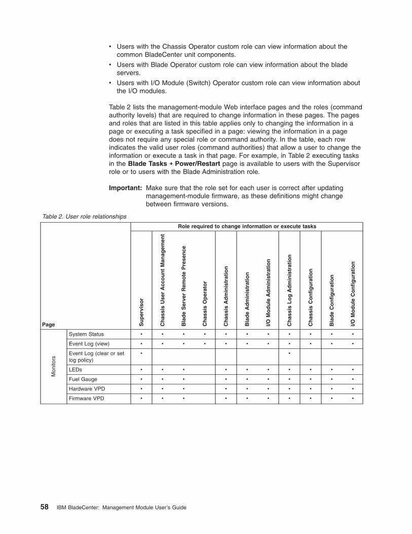
v Users with the Chassis Operator custom role can view information about the
common BladeCenter unit components.
v Users with Blade Operator custom role can view information about the blade
servers.
v Users with I/O Module (Switch) Operator custom role can view information about
the I/O modules.
Table 2 lists the management-module Web interface pages and the roles (command
authority levels) that are required to change information in these pages. The pages
and roles that are listed in this table applies only to changing the information in a
page or executing a task specified in a page: viewing the information in a page
does not require any special role or command authority. In the table, each row
indicates the valid user roles (command authorities) that allow a user to change the
information or execute a task in that page. For example, in Table 2 executing tasks
in the Blade Tasks → Power/Restart page is available to users with the Supervisor
role or to users with the Blade Administration role.
Important: Make sure that the role set for each user is correct after updating
management-module firmware, as these definitions might change
between firmware versions.
Table 2. User role relationships
Page
Role required to change information or execute tasks
Su
per
viso
r
Ch
assi
s U
ser
Acc
ou
nt
Man
agem
ent
Bla
de
Ser
ver
Rem
ote
P
rese
nce
Ch
assi
s O
per
ato
r
Ch
assi
s A
dm
inis
trat
ion
Bla
de
Ad
min
istr
atio
n
I/O M
od
ule
A
dm
inis
trat
ion
Ch
assi
s L
og
A
dm
inis
trat
ion
Ch
assi
s C
on
fig
ura
tio
n
Bla
de
Co
nfi
gu
rati
on
I/O M
od
ule
C
on
fig
ura
tio
n
Mon
itors
System Status v v v v v v v v v v v
Event Log (view) v v v v v v v v v v v
Event Log (clear or set
log policy)
v v
LEDs v v v v v v v v v v
Fuel Gauge v v v v v v v v v v
Hardware VPD v v v v v v v v v v
Firmware VPD v v v v v v v v v v
58 IBM BladeCenter: Management Module User’s Guide
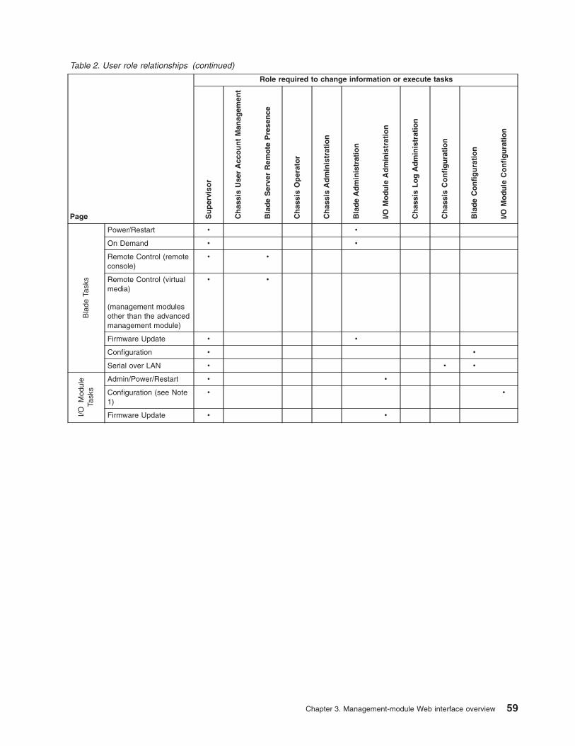
Table 2. User role relationships (continued)
Page
Role required to change information or execute tasks
Su
per
viso
r
Ch
assi
s U
ser
Acc
ou
nt
Man
agem
ent
Bla
de
Ser
ver
Rem
ote
P
rese
nce
Ch
assi
s O
per
ato
r
Ch
assi
s A
dm
inis
trat
ion
Bla
de
Ad
min
istr
atio
n
I/O M
od
ule
A
dm
inis
trat
ion
Ch
assi
s L
og
A
dm
inis
trat
ion
Ch
assi
s C
on
fig
ura
tio
n
Bla
de
Co
nfi
gu
rati
on
I/O M
od
ule
C
on
fig
ura
tio
n
Bla
de Ta
sks
Power/Restart v v
On Demand v v
Remote Control (remote
console)
v v
Remote Control (virtual
media)
(management modules
other than the advanced
management module)
v v
Firmware Update v v
Configuration v v
Serial over LAN v v v
I/O M
odul
e Ta
sks
Admin/Power/Restart v v
Configuration (see Note
1)
v v
Firmware Update v v
Chapter 3. Management-module Web interface overview 59
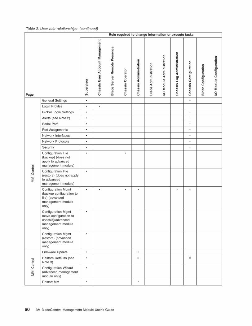
Table 2. User role relationships (continued)
Page
Role required to change information or execute tasks
Su
per
viso
r
Ch
assi
s U
ser
Acc
ou
nt
Man
agem
ent
Bla
de
Ser
ver
Rem
ote
P
rese
nce
Ch
assi
s O
per
ato
r
Ch
assi
s A
dm
inis
trat
ion
Bla
de
Ad
min
istr
atio
n
I/O M
od
ule
A
dm
inis
trat
ion
Ch
assi
s L
og
A
dm
inis
trat
ion
Ch
assi
s C
on
fig
ura
tio
n
Bla
de
Co
nfi
gu
rati
on
I/O M
od
ule
C
on
fig
ura
tio
n
MM
C
ontr
ol
General Settings v v
Login Profiles v v
Global Login Settings v v
Alerts (see Note 2) v v
Serial Port v v
Port Assignments v v
Network Interfaces v v
Network Protocols v v
Security v v
Configuration File
(backup) (does not
apply to advanced
management module)
v v
Configuration File
(restore) (does not apply
to advanced
management module)
v
Configuration Mgmt
(backup configuration to
file) (advanced
management module
only)
v v v v v v
Configuration Mgmt
(save configuration to
chassis)(advanced
management module
only)
v
Configuration Mgmt
(restore) (advanced
management module
only)
v
MM
C
ontr
ol
Firmware Update v v
Restore Defaults (see
Note 3)
v L L
Configuration Wizard
(advanced management
module only)
v
Restart MM v v
60 IBM BladeCenter: Management Module User’s Guide
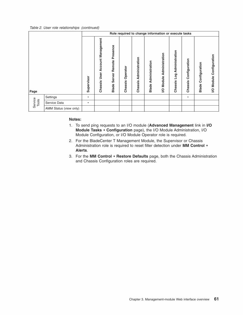
Table 2. User role relationships (continued)
Page
Role required to change information or execute tasks
Su
per
viso
r
Ch
assi
s U
ser
Acc
ou
nt
Man
agem
ent
Bla
de
Ser
ver
Rem
ote
P
rese
nce
Ch
assi
s O
per
ato
r
Ch
assi
s A
dm
inis
trat
ion
Bla
de
Ad
min
istr
atio
n
I/O M
od
ule
A
dm
inis
trat
ion
Ch
assi
s L
og
A
dm
inis
trat
ion
Ch
assi
s C
on
fig
ura
tio
n
Bla
de
Co
nfi
gu
rati
on
I/O M
od
ule
C
on
fig
ura
tio
n
Ser
vice
Tool
s
Settings v v
Service Data v
AMM Status (view only)
Notes:
1. To send ping requests to an I/O module (Advanced Management link in I/O
Module Tasks → Configuration page), the I/O Module Administration, I/O
Module Configuration, or I/O Module Operator role is required.
2. For the BladeCenter T Management Module, the Supervisor or Chassis
Administration role is required to reset filter detection under MM Control →
Alerts.
3. For the MM Control → Restore Defaults page, both the Chassis Administration
and Chassis Configuration roles are required.
Chapter 3. Management-module Web interface overview 61
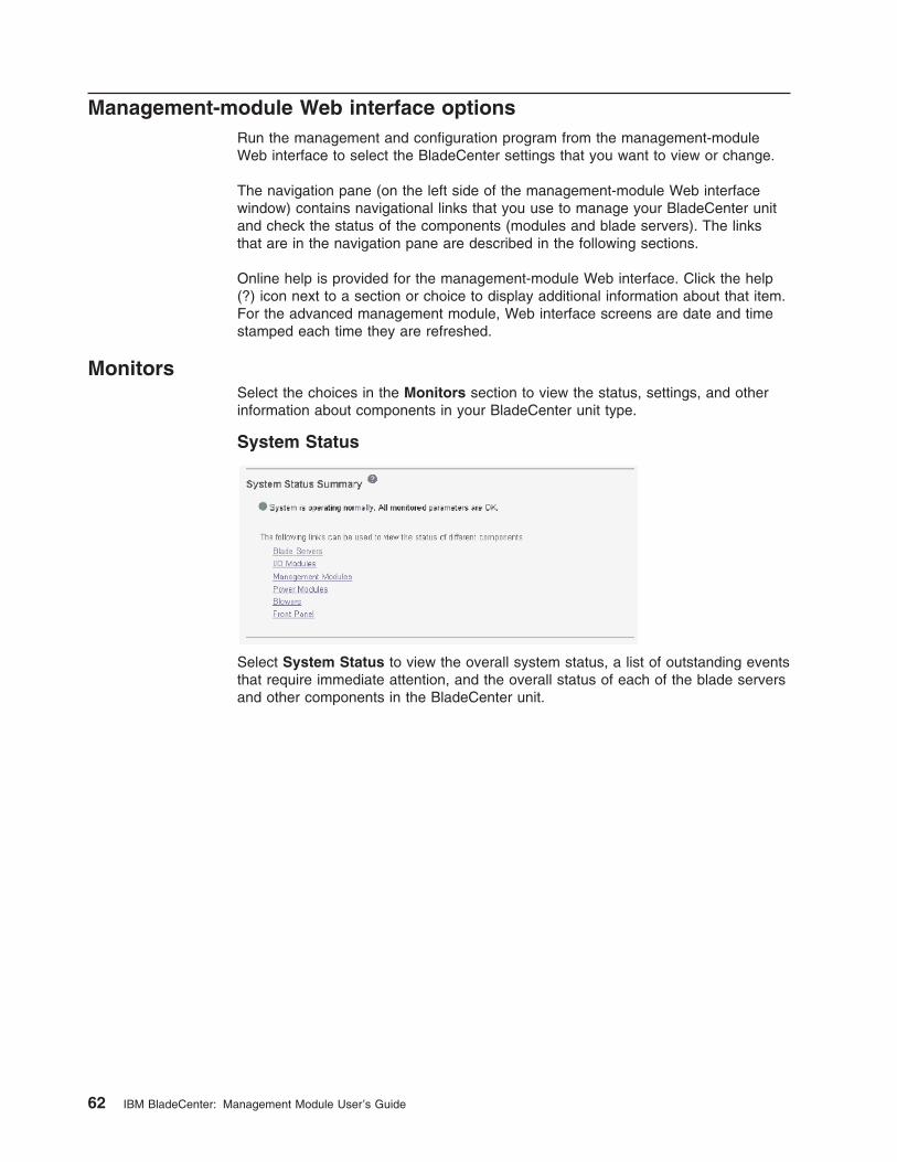
Management-module Web interface options
Run the management and configuration program from the management-module
Web interface to select the BladeCenter settings that you want to view or change.
The navigation pane (on the left side of the management-module Web interface
window) contains navigational links that you use to manage your BladeCenter unit
and check the status of the components (modules and blade servers). The links
that are in the navigation pane are described in the following sections.
Online help is provided for the management-module Web interface. Click the help
(?) icon next to a section or choice to display additional information about that item.
For the advanced management module, Web interface screens are date and time
stamped each time they are refreshed.
Monitors
Select the choices in the Monitors section to view the status, settings, and other
information about components in your BladeCenter unit type.
System Status
Select System Status to view the overall system status, a list of outstanding events
that require immediate attention, and the overall status of each of the blade servers
and other components in the BladeCenter unit.
62 IBM BladeCenter: Management Module User’s Guide
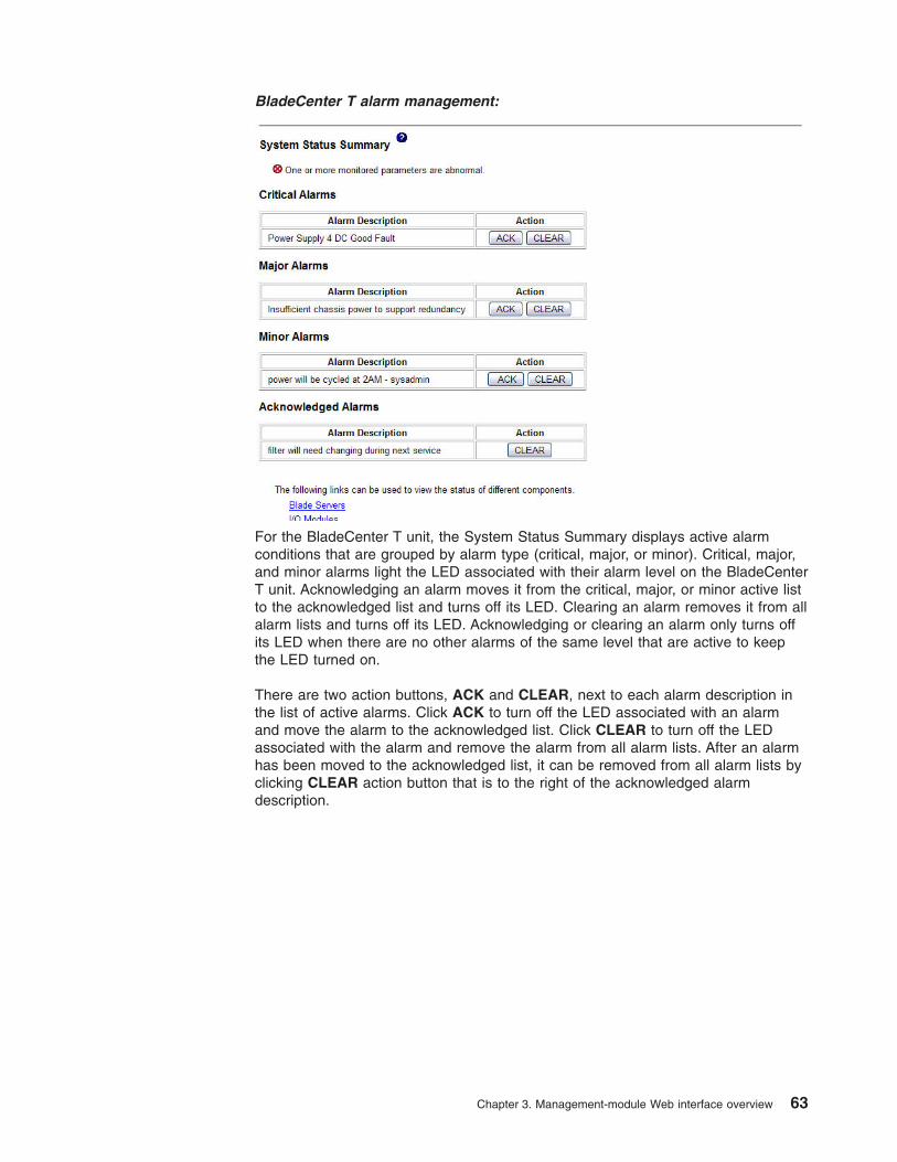
BladeCenter T alarm management:
For the BladeCenter T unit, the System Status Summary displays active alarm
conditions that are grouped by alarm type (critical, major, or minor). Critical, major,
and minor alarms light the LED associated with their alarm level on the BladeCenter
T unit. Acknowledging an alarm moves it from the critical, major, or minor active list
to the acknowledged list and turns off its LED. Clearing an alarm removes it from all
alarm lists and turns off its LED. Acknowledging or clearing an alarm only turns off
its LED when there are no other alarms of the same level that are active to keep
the LED turned on.
There are two action buttons, ACK and CLEAR, next to each alarm description in
the list of active alarms. Click ACK to turn off the LED associated with an alarm
and move the alarm to the acknowledged list. Click CLEAR to turn off the LED
associated with the alarm and remove the alarm from all alarm lists. After an alarm
has been moved to the acknowledged list, it can be removed from all alarm lists by
clicking CLEAR action button that is to the right of the acknowledged alarm
description.
Chapter 3. Management-module Web interface overview 63
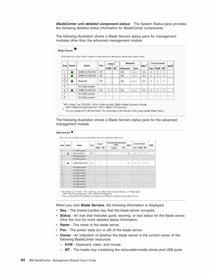
BladeCenter unit detailed component status: The System Status pane provides
the following detailed status information for BladeCenter components.
The following illustration shows a Blade Servers status pane for management
modules other than the advanced management module.
The following illustration shows a Blade Servers status pane for the advanced
management module.
When you click Blade Servers, the following information is displayed:
v Bay - The lowest-number bay that the blade server occupies.
v Status - An icon that indicates good, warning, or bad status for the blade server.
Click the icon for more detailed status information.
v Name - The name of the blade server.
v Pwr - The power state (on or off) of the blade server.
v Owner - An indication of whether the blade server is the current owner of the
following BladeCenter resources:
– KVM - Keyboard, video, and mouse
– MT - The media tray containing the removable-media drives and USB ports
64 IBM BladeCenter: Management Module User’s Guide
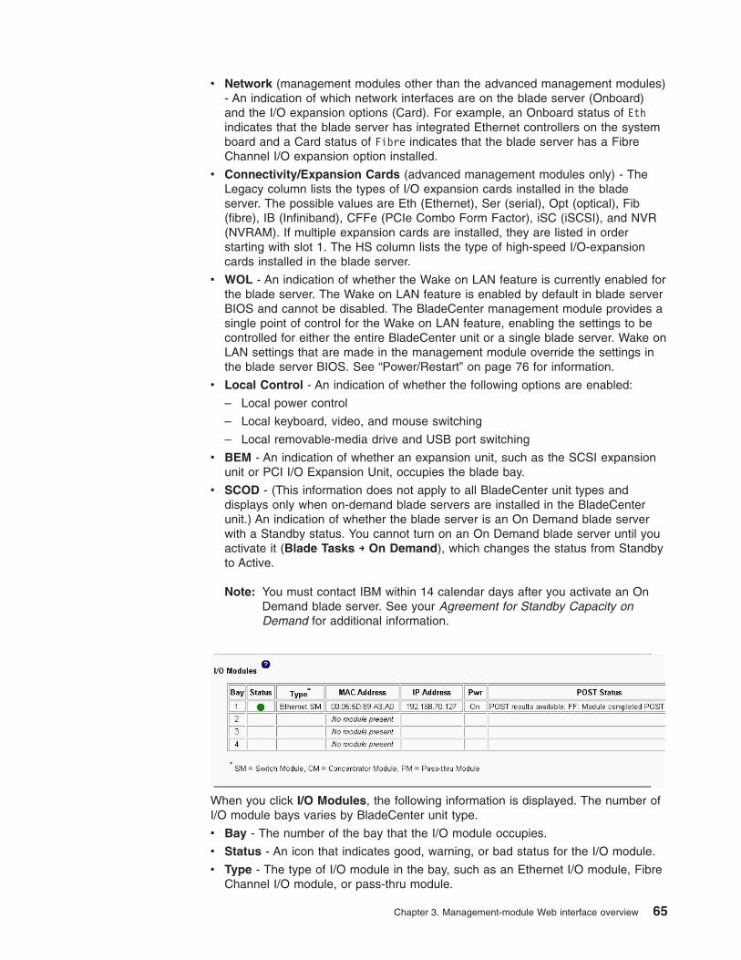
v Network (management modules other than the advanced management modules)
- An indication of which network interfaces are on the blade server (Onboard)
and the I/O expansion options (Card). For example, an Onboard status of Eth
indicates that the blade server has integrated Ethernet controllers on the system
board and a Card status of Fibre indicates that the blade server has a Fibre
Channel I/O expansion option installed.
v Connectivity/Expansion Cards (advanced management modules only) - The
Legacy column lists the types of I/O expansion cards installed in the blade
server. The possible values are Eth (Ethernet), Ser (serial), Opt (optical), Fib
(fibre), IB (Infiniband), CFFe (PCIe Combo Form Factor), iSC (iSCSI), and NVR
(NVRAM). If multiple expansion cards are installed, they are listed in order
starting with slot 1. The HS column lists the type of high-speed I/O-expansion
cards installed in the blade server.
v WOL - An indication of whether the Wake on LAN feature is currently enabled for
the blade server. The Wake on LAN feature is enabled by default in blade server
BIOS and cannot be disabled. The BladeCenter management module provides a
single point of control for the Wake on LAN feature, enabling the settings to be
controlled for either the entire BladeCenter unit or a single blade server. Wake on
LAN settings that are made in the management module override the settings in
the blade server BIOS. See “Power/Restart” on page 76 for information.
v Local Control - An indication of whether the following options are enabled:
– Local power control
– Local keyboard, video, and mouse switching
– Local removable-media drive and USB port switching
v BEM - An indication of whether an expansion unit, such as the SCSI expansion
unit or PCI I/O Expansion Unit, occupies the blade bay.
v SCOD - (This information does not apply to all BladeCenter unit types and
displays only when on-demand blade servers are installed in the BladeCenter
unit.) An indication of whether the blade server is an On Demand blade server
with a Standby status. You cannot turn on an On Demand blade server until you
activate it (Blade Tasks → On Demand), which changes the status from Standby
to Active.
Note: You must contact IBM within 14 calendar days after you activate an On
Demand blade server. See your Agreement for Standby Capacity on
Demand for additional information.
When you click I/O Modules, the following information is displayed. The number of
I/O module bays varies by BladeCenter unit type.
v Bay - The number of the bay that the I/O module occupies.
v Status - An icon that indicates good, warning, or bad status for the I/O module.
v Type - The type of I/O module in the bay, such as an Ethernet I/O module, Fibre
Channel I/O module, or pass-thru module.
Chapter 3. Management-module Web interface overview 65
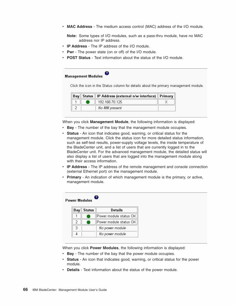
v MAC Address - The medium access control (MAC) address of the I/O module.
Note: Some types of I/O modules, such as a pass-thru module, have no MAC
address nor IP address.
v IP Address - The IP address of the I/O module.
v Pwr - The power state (on or off) of the I/O module.
v POST Status - Text information about the status of the I/O module.
When you click Management Module, the following information is displayed:
v Bay - The number of the bay that the management module occupies.
v Status - An icon that indicates good, warning, or critical status for the
management module. Click the status icon for more detailed status information,
such as self-test results, power-supply voltage levels, the inside temperature of
the BladeCenter unit, and a list of users that are currently logged in to the
BladeCenter unit. For the advanced management module, the detailed status will
also display a list of users that are logged into the management module along
with their access information.
v IP Address - The IP address of the remote management and console connection
(external Ethernet port) on the management module.
v Primary - An indication of which management module is the primary, or active,
management module.
When you click Power Modules, the following information is displayed:
v Bay - The number of the bay that the power module occupies.
v Status - An icon that indicates good, warning, or critical status for the power
module.
v Details - Text information about the status of the power module.
66 IBM BladeCenter: Management Module User’s Guide
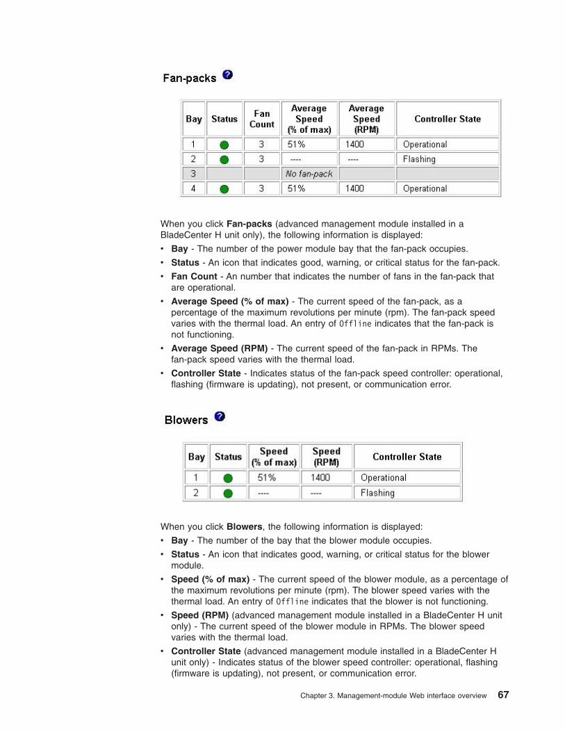
When you click Fan-packs (advanced management module installed in a
BladeCenter H unit only), the following information is displayed:
v Bay - The number of the power module bay that the fan-pack occupies.
v Status - An icon that indicates good, warning, or critical status for the fan-pack.
v Fan Count - An number that indicates the number of fans in the fan-pack that
are operational.
v Average Speed (% of max) - The current speed of the fan-pack, as a
percentage of the maximum revolutions per minute (rpm). The fan-pack speed
varies with the thermal load. An entry of Offline indicates that the fan-pack is
not functioning.
v Average Speed (RPM) - The current speed of the fan-pack in RPMs. The
fan-pack speed varies with the thermal load.
v Controller State - Indicates status of the fan-pack speed controller: operational,
flashing (firmware is updating), not present, or communication error.
When you click Blowers, the following information is displayed:
v Bay - The number of the bay that the blower module occupies.
v Status - An icon that indicates good, warning, or critical status for the blower
module.
v Speed (% of max) - The current speed of the blower module, as a percentage of
the maximum revolutions per minute (rpm). The blower speed varies with the
thermal load. An entry of Offline indicates that the blower is not functioning.
v Speed (RPM) (advanced management module installed in a BladeCenter H unit
only) - The current speed of the blower module in RPMs. The blower speed
varies with the thermal load.
v Controller State (advanced management module installed in a BladeCenter H
unit only) - Indicates status of the blower speed controller: operational, flashing
(firmware is updating), not present, or communication error.
Chapter 3. Management-module Web interface overview 67
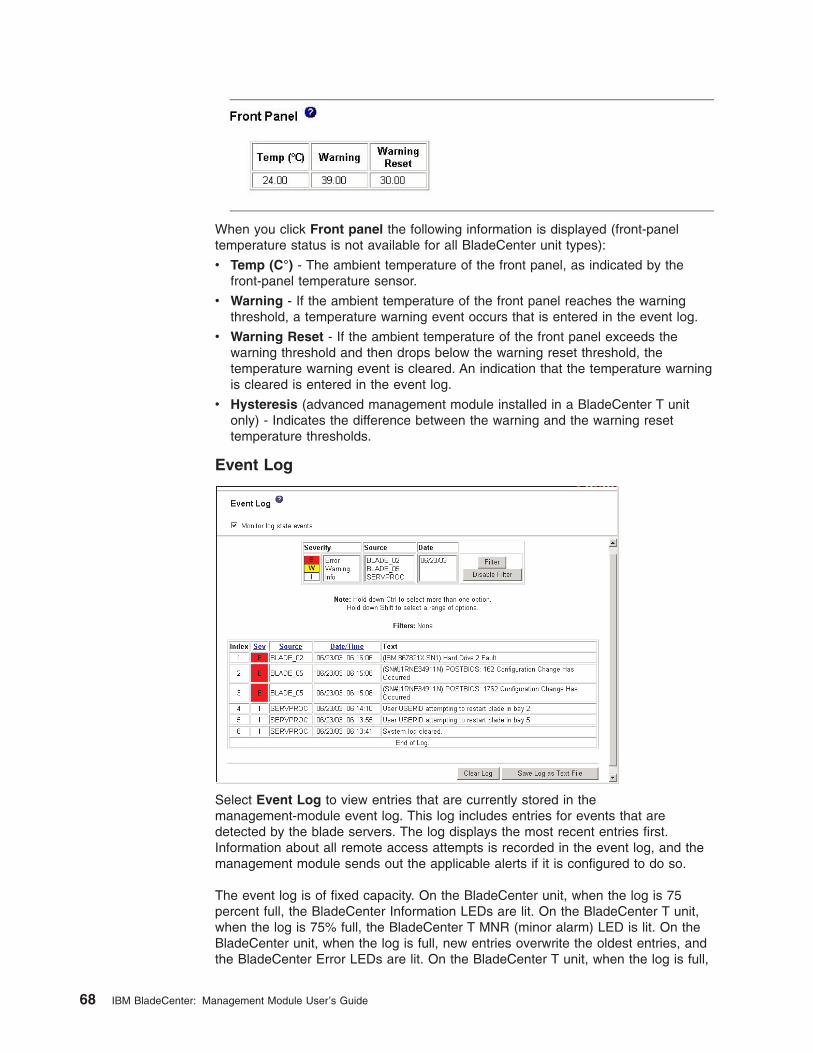
When you click Front panel the following information is displayed (front-panel
temperature status is not available for all BladeCenter unit types):
v Temp (C°) - The ambient temperature of the front panel, as indicated by the
front-panel temperature sensor.
v Warning - If the ambient temperature of the front panel reaches the warning
threshold, a temperature warning event occurs that is entered in the event log.
v Warning Reset - If the ambient temperature of the front panel exceeds the
warning threshold and then drops below the warning reset threshold, the
temperature warning event is cleared. An indication that the temperature warning
is cleared is entered in the event log.
v Hysteresis (advanced management module installed in a BladeCenter T unit
only) - Indicates the difference between the warning and the warning reset
temperature thresholds.
Event Log
Select Event Log to view entries that are currently stored in the
management-module event log. This log includes entries for events that are
detected by the blade servers. The log displays the most recent entries first.
Information about all remote access attempts is recorded in the event log, and the
management module sends out the applicable alerts if it is configured to do so.
The event log is of fixed capacity. On the BladeCenter unit, when the log is 75
percent full, the BladeCenter Information LEDs are lit. On the BladeCenter T unit,
when the log is 75% full, the BladeCenter T MNR (minor alarm) LED is lit. On the
BladeCenter unit, when the log is full, new entries overwrite the oldest entries, and
the BladeCenter Error LEDs are lit. On the BladeCenter T unit, when the log is full,
68 IBM BladeCenter: Management Module User’s Guide
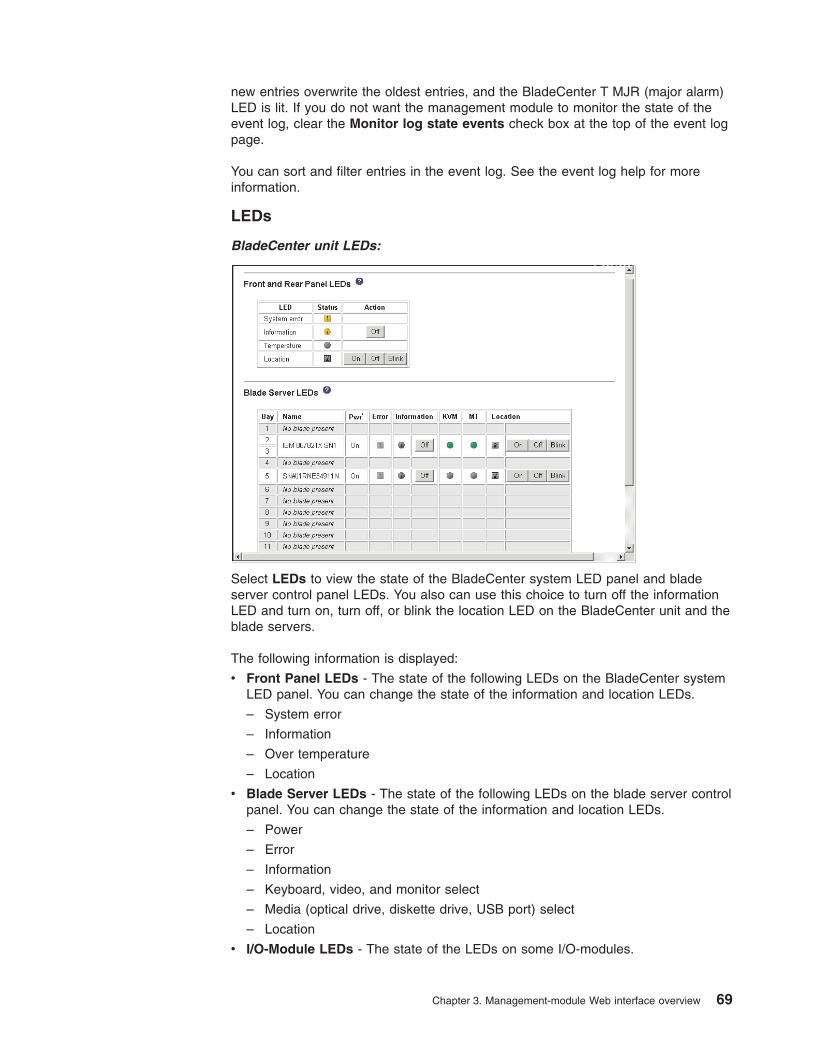
new entries overwrite the oldest entries, and the BladeCenter T MJR (major alarm)
LED is lit. If you do not want the management module to monitor the state of the
event log, clear the Monitor log state events check box at the top of the event log
page.
You can sort and filter entries in the event log. See the event log help for more
information.
LEDs
BladeCenter unit LEDs:
Select LEDs to view the state of the BladeCenter system LED panel and blade
server control panel LEDs. You also can use this choice to turn off the information
LED and turn on, turn off, or blink the location LED on the BladeCenter unit and the
blade servers.
The following information is displayed:
v Front Panel LEDs - The state of the following LEDs on the BladeCenter system
LED panel. You can change the state of the information and location LEDs.
– System error
– Information
– Over temperature
– Location
v Blade Server LEDs - The state of the following LEDs on the blade server control
panel. You can change the state of the information and location LEDs.
– Power
– Error
– Information
– Keyboard, video, and monitor select
– Media (optical drive, diskette drive, USB port) select
– Location
v I/O-Module LEDs - The state of the LEDs on some I/O-modules.
Chapter 3. Management-module Web interface overview 69
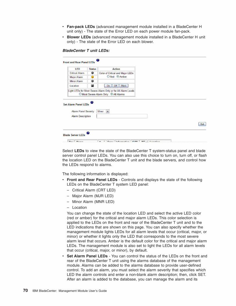
v Fan-pack LEDs (advanced management module installed in a BladeCenter H
unit only) - The state of the Error LED on each power module fan-pack.
v Blower LEDs (advanced management module installed in a BladeCenter H unit
only) - The state of the Error LED on each blower.
BladeCenter T unit LEDs:
Select LEDs to view the state of the BladeCenter T system-status panel and blade
server control panel LEDs. You can also use this choice to turn on, turn off, or flash
the location LED on the BladeCenter T unit and the blade servers, and control how
the LEDs respond to alarms.
The following information is displayed:
v Front and Rear Panel LEDs - Controls and displays the state of the following
LEDs on the BladeCenter T system LED panel:
– Critical Alarm (CRT LED)
– Major Alarm (MJR LED)
– Minor Alarm (MNR LED)
– Location
You can change the state of the location LED and select the active LED color
(red or amber) for the critical and major alarm LEDs. This color selection is
applied to the LEDs on the front and rear of the BladeCenter T unit and to the
LED indications that are shown on this page. You can also specify whether the
management module lights LEDs for all alarm levels that occur (critical, major, or
minor) or whether it lights only the LED that corresponds to the most severe
alarm level that occurs. Amber is the default color for the critical and major alarm
LEDs. The management module is also set to light the LEDs for all alarm levels
that occur (critical, major, or minor), by default.
v Set Alarm Panel LEDs - You can control the status of the LEDs on the front and
rear of the BladeCenter T unit using the alarms database of the management
module. Alarms can be added to the alarms database to provide user-defined
control. To add an alarm, you must select the alarm severity that specifies which
LED the alarm controls and enter a non-blank alarm description; then, click SET.
After an alarm is added to the database, you can manage the alarm and its
70 IBM BladeCenter: Management Module User’s Guide
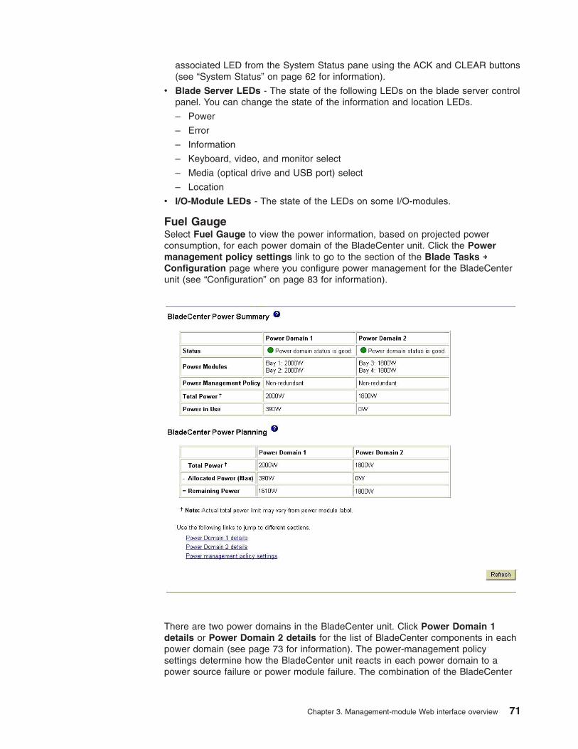
associated LED from the System Status pane using the ACK and CLEAR buttons
(see “System Status” on page 62 for information).
v Blade Server LEDs - The state of the following LEDs on the blade server control
panel. You can change the state of the information and location LEDs.
– Power
– Error
– Information
– Keyboard, video, and monitor select
– Media (optical drive and USB port) select
– Location
v I/O-Module LEDs - The state of the LEDs on some I/O-modules.
Fuel Gauge
Select Fuel Gauge to view the power information, based on projected power
consumption, for each power domain of the BladeCenter unit. Click the Power
management policy settings link to go to the section of the Blade Tasks →
Configuration page where you configure power management for the BladeCenter
unit (see “Configuration” on page 83 for information).
There are two power domains in the BladeCenter unit. Click Power Domain 1
details or Power Domain 2 details for the list of BladeCenter components in each
power domain (see page 73 for information). The power-management policy
settings determine how the BladeCenter unit reacts in each power domain to a
power source failure or power module failure. The combination of the BladeCenter
Chapter 3. Management-module Web interface overview 71

configuration, power-management policy settings, and available power might cause
blade servers to reduce their power level (throttle) or not turn on.
The following power status information is displayed in the BladeCenter Power
Summary and BladeCenter Power Planning sections:
v Status - This field contains a color-coded icon that indicates status of the
power-domains and a short status description that lists any outstanding issues
related to power consumption or redundancy in each power domain.
v Power Modules - This field lists the power modules installed in each power
domain and their rated capacity in Watts.
v Power-Management Policy - This field displays the power-management policy
set for each power domain, defining how the power domain will react to
conditions that could result in a loss of redundancy. This setting is configured on
the Blade Tasks → Configuration page (see “Configuration” on page 83 for
information)
v Power in Use - This field displays the current power being used in each power
domain, in Watts.
v Total Power - This field displays the amount of power available in each power
domain, in Watts. Total power is calculated by the management module based on
the rated capacities of the power modules installed in a power domain and the
power-management policy that has been set for this power domain.
v Allocated Power (Max) - This field displays the total amount of power, in Watts,
that is reserved for use by the components that are installed in a power domain.
This value might include power for components that are not currently installed in
the BladeCenter unit, such as the I/O Modules. Power is reserved for these
components because the management module pre-allocates power for some
components that are normally required for BladeCenter unit operation. The
reserved-power total might also include power for components that are installed
in BladeCenter unit, are in a standby state, and are not turned on. These
components are included in the total so that the amount of spare (unallocated)
power in the power domain can be accurately calculated.
v Remaining Power - This field displays the amount of unallocated (spare) power
in a power domain, in Watts. This value is used by the management module
when a deciding if a newly installed module should turn on. The remaining power
value is calculated based on the total power and the amount of reserved power
for each power domain.
72 IBM BladeCenter: Management Module User’s Guide
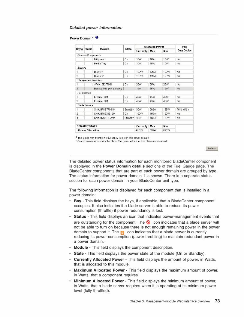
Detailed power information:
The detailed power status information for each monitored BladeCenter component
is displayed in the Power Domain details sections of the Fuel Gauge page. The
BladeCenter components that are part of each power domain are grouped by type.
The status information for power domain 1 is shown. There is a separate status
section for each power domain in your BladeCenter unit type.
The following information is displayed for each component that is installed in a
power domain:
v Bay - This field displays the bays, if applicable, that a BladeCenter component
occupies. It also indicates if a blade server is able to reduce its power
consumption (throttle) if power redundancy is lost.
v Status - This field displays an icon that indicates power-management events that
are outstanding for the component. The
icon indicates that a blade server will
not be able to turn on because there is not enough remaining power in the power
domain to support it. The
icon indicates that a blade server is currently
reducing its power consumption (power throttling) to maintain redundant power in
a power domain.
v Module - This field displays the component description.
v State - This field displays the power state of the module (On or Standby).
v Currently Allocated Power - This field displays the amount of power, in Watts,
that is allocated to this module.
v Maximum Allocated Power - This field displays the maximum amount of power,
in Watts, that a component requires.
v Minimum Allocated Power - This field displays the minimum amount of power,
in Watts, that a blade server requires when it is operating at its minimum power
level (fully throttled).
Chapter 3. Management-module Web interface overview 73
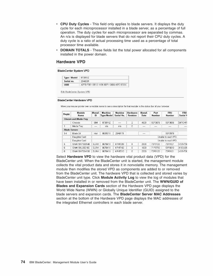
v CPU Duty Cycles - This field only applies to blade servers. It displays the duty
cycle for each microprocessor installed in a blade server, as a percentage of full
operation. The duty cycles for each microprocessor are separated by commas.
An n/a is displayed for blade servers that do not report their CPU duty cycles. A
duty cycle is a ratio of actual processing time used as a percentage of total
processor time available.
v DOMAIN TOTALS - These fields list the total power allocated for all components
installed in the power domain.
Hardware VPD
Select Hardware VPD to view the hardware vital product data (VPD) for the
BladeCenter unit. When the BladeCenter unit is started, the management module
collects the vital product data and stores it in nonvolatile memory. The management
module then modifies the stored VPD as components are added to or removed
from the BladeCenter unit. The hardware VPD that is collected and stored varies by
BladeCenter unit type. Click Module Activity Log to view the log of modules that
have been installed in or removed from the BladeCenter unit. The WWN/GUID of
Blades and Expansion Cards section of the Hardware VPD page displays the
World Wide Name (WWN) or Globally Unique Identifier (GUID) assigned to the
blade servers and expansion cards. The BladeCenter Server MAC Addresses
section at the bottom of the Hardware VPD page displays the MAC addresses of
the integrated Ethernet controllers in each blade server.
74 IBM BladeCenter: Management Module User’s Guide
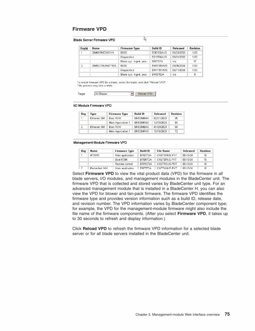
Firmware VPD
Select Firmware VPD to view the vital product data (VPD) for the firmware in all
blade servers, I/O modules, and management modules in the BladeCenter unit. The
firmware VPD that is collected and stored varies by BladeCenter unit type. For an
advanced management module that is installed in a BladeCenter H, you can also
view the VPD for blower and fan-pack firmware. The firmware VPD identifies the
firmware type and provides version information such as a build ID, release date,
and revision number. The VPD information varies by BladeCenter component type;
for example, the VPD for the management-module firmware might also include the
file name of the firmware components. (After you select Firmware VPD, it takes up
to 30 seconds to refresh and display information.)
Click Reload VPD to refresh the firmware VPD information for a selected blade
server or for all blade servers installed in the BladeCenter unit.
Chapter 3. Management-module Web interface overview 75
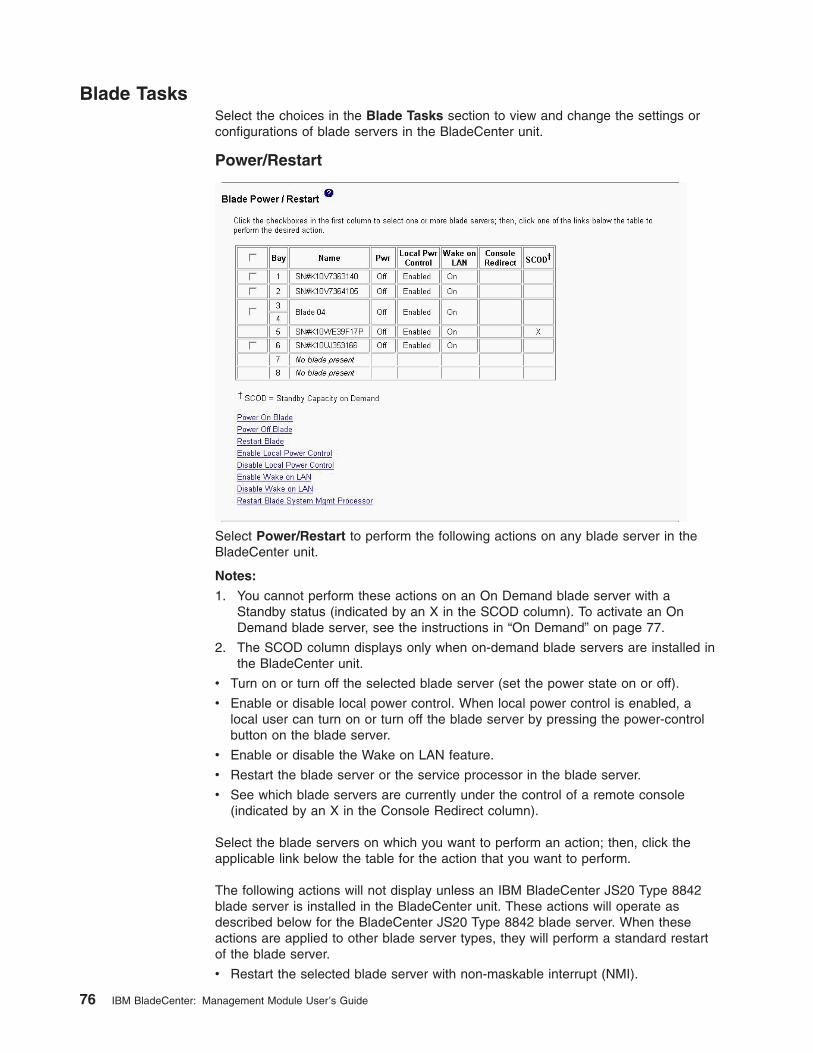
Blade Tasks
Select the choices in the Blade Tasks section to view and change the settings or
configurations of blade servers in the BladeCenter unit.
Power/Restart
Select Power/Restart to perform the following actions on any blade server in the
BladeCenter unit.
Notes:
1. You cannot perform these actions on an On Demand blade server with a
Standby status (indicated by an X in the SCOD column). To activate an On
Demand blade server, see the instructions in “On Demand” on page 77.
2. The SCOD column displays only when on-demand blade servers are installed in
the BladeCenter unit.
v Turn on or turn off the selected blade server (set the power state on or off).
v Enable or disable local power control. When local power control is enabled, a
local user can turn on or turn off the blade server by pressing the power-control
button on the blade server.
v Enable or disable the Wake on LAN feature.
v Restart the blade server or the service processor in the blade server.
v See which blade servers are currently under the control of a remote console
(indicated by an X in the Console Redirect column).
Select the blade servers on which you want to perform an action; then, click the
applicable link below the table for the action that you want to perform.
The following actions will not display unless an IBM BladeCenter JS20 Type 8842
blade server is installed in the BladeCenter unit. These actions will operate as
described below for the BladeCenter JS20 Type 8842 blade server. When these
actions are applied to other blade server types, they will perform a standard restart
of the blade server.
v Restart the selected blade server with non-maskable interrupt (NMI).
76 IBM BladeCenter: Management Module User’s Guide
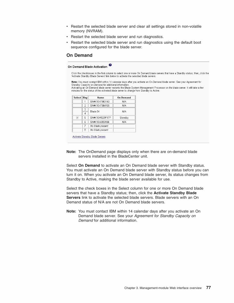
v Restart the selected blade server and clear all settings stored in non-volatile
memory (NVRAM).
v Restart the selected blade server and run diagnostics.
v Restart the selected blade server and run diagnostics using the default boot
sequence configured for the blade server.
On Demand
Note: The OnDemand page displays only when there are on-demand blade
servers installed in the BladeCenter unit.
Select On Demand to activate an On Demand blade server with Standby status.
You must activate an On Demand blade server with Standby status before you can
turn it on. When you activate an On Demand blade server, its status changes from
Standby to Active, making the blade server available for use.
Select the check boxes in the Select column for one or more On Demand blade
servers that have a Standby status; then, click the Activate Standby Blade
Servers link to activate the selected blade servers. Blade servers with an On
Demand status of N/A are not On Demand blade servers.
Note: You must contact IBM within 14 calendar days after you activate an On
Demand blade server. See your Agreement for Standby Capacity on
Demand for additional information.
Chapter 3. Management-module Web interface overview 77
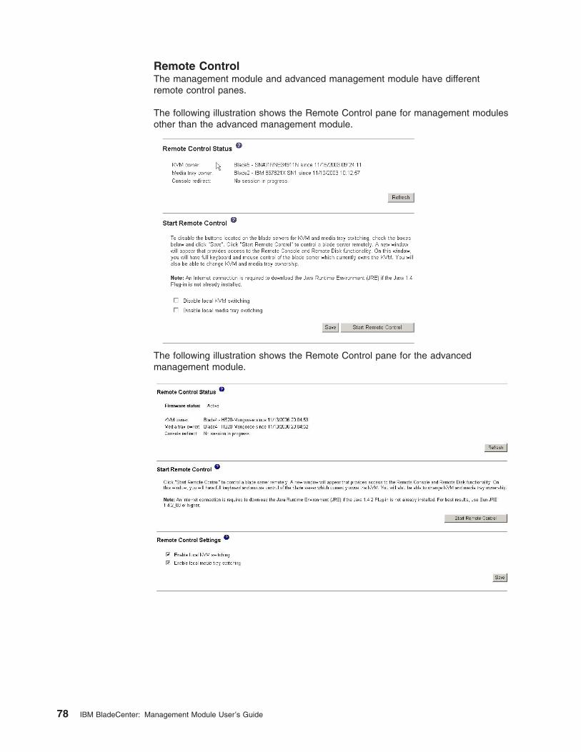
Remote Control
The management module and advanced management module have different
remote control panes.
The following illustration shows the Remote Control pane for management modules
other than the advanced management module.
The following illustration shows the Remote Control pane for the advanced
management module.
78 IBM BladeCenter: Management Module User’s Guide
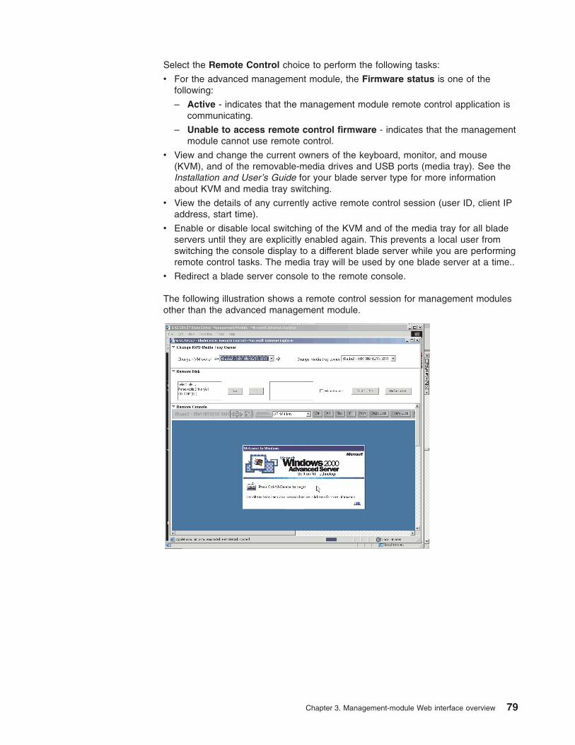
Select the Remote Control choice to perform the following tasks:
v For the advanced management module, the Firmware status is one of the
following:
– Active - indicates that the management module remote control application is
communicating.
– Unable to access remote control firmware - indicates that the management
module cannot use remote control.
v View and change the current owners of the keyboard, monitor, and mouse
(KVM), and of the removable-media drives and USB ports (media tray). See the
Installation and User’s Guide for your blade server type for more information
about KVM and media tray switching.
v View the details of any currently active remote control session (user ID, client IP
address, start time).
v Enable or disable local switching of the KVM and of the media tray for all blade
servers until they are explicitly enabled again. This prevents a local user from
switching the console display to a different blade server while you are performing
remote control tasks. The media tray will be used by one blade server at a time..
v Redirect a blade server console to the remote console.
The following illustration shows a remote control session for management modules
other than the advanced management module.
Chapter 3. Management-module Web interface overview 79
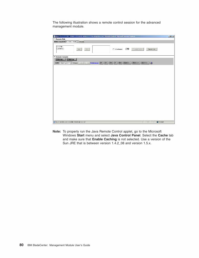
The following illustration shows a remote control session for the advanced
management module.
Note: To properly run the Java Remote Control applet, go to the Microsoft
Windows Start menu and select Java Control Panel. Select the Cache tab
and make sure that Enable Caching is not selected. Use a version of the
Sun JRE that is between version 1.4.2_08 and version 1.5.x.
80 IBM BladeCenter: Management Module User’s Guide
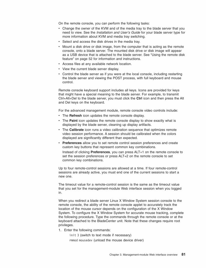
On the remote console, you can perform the following tasks:
v Change the owner of the KVM and of the media tray to the blade server that you
need to view. See the Installation and User’s Guide for your blade server type for
more information about KVM and media tray switching.
v Select and access the disk drives in the media tray.
v Mount a disk drive or disk image, from the computer that is acting as the remote
console, onto a blade server. The mounted disk drive or disk image will appear
as a USB device that is attached to the blade server. See “Using the remote disk
feature” on page 52 for information and instructions.
v Access files at any available network location.
v View the current blade server display.
v Control the blade server as if you were at the local console, including restarting
the blade server and viewing the POST process, with full keyboard and mouse
control.
Remote console keyboard support includes all keys. Icons are provided for keys
that might have a special meaning to the blade server. For example, to transmit
Ctrl+Alt+Del to the blade server, you must click the Ctrl icon and then press the Alt
and Del keys on the keyboard.
For the advanced management module, remote console video controls include:
v The Refresh icon updates the remote console display.
v The Paint icon updates the remote console display to show exactly what is
displayed by the blade server, cleaning up display artifacts.
v The Calibrate icon runs a video calibration sequence that optimizes remote
video session performance. A session should be calibrated when the colors
displayed are significantly different than expected.
v Preferences allow you to set remote control session preferences and create
custom key buttons that represent common key combinations.
Instead of clicking Preferences, you can press ALT+1 on the remote console to
set the session preferences or press ALT+2 on the remote console to set
common key combinations.
Up to four remote-control sessions are allowed at a time. If four remote-control
sessions are already active, you must end one of the current sessions to start a
new one.
The timeout value for a remote-control session is the same as the timeout value
that you set for the management-module Web interface session when you logged
in.
When you redirect a blade server Linux X Window System session console to the
remote console, the ability of the remote console applet to accurately track the
location of the mouse cursor depends on the configuration of the X Window
System. To configure the X Window System for accurate mouse tracking, complete
the following procedure. Type the commands through the remote console or at the
keyboard attached to the BladeCenter unit. Note that these changes require root
privileges.
1. Enter the following commands:
init 3 (switch to text mode if necessary)
rmmod mousedev (unload the mouse device driver)
Chapter 3. Management-module Web interface overview 81
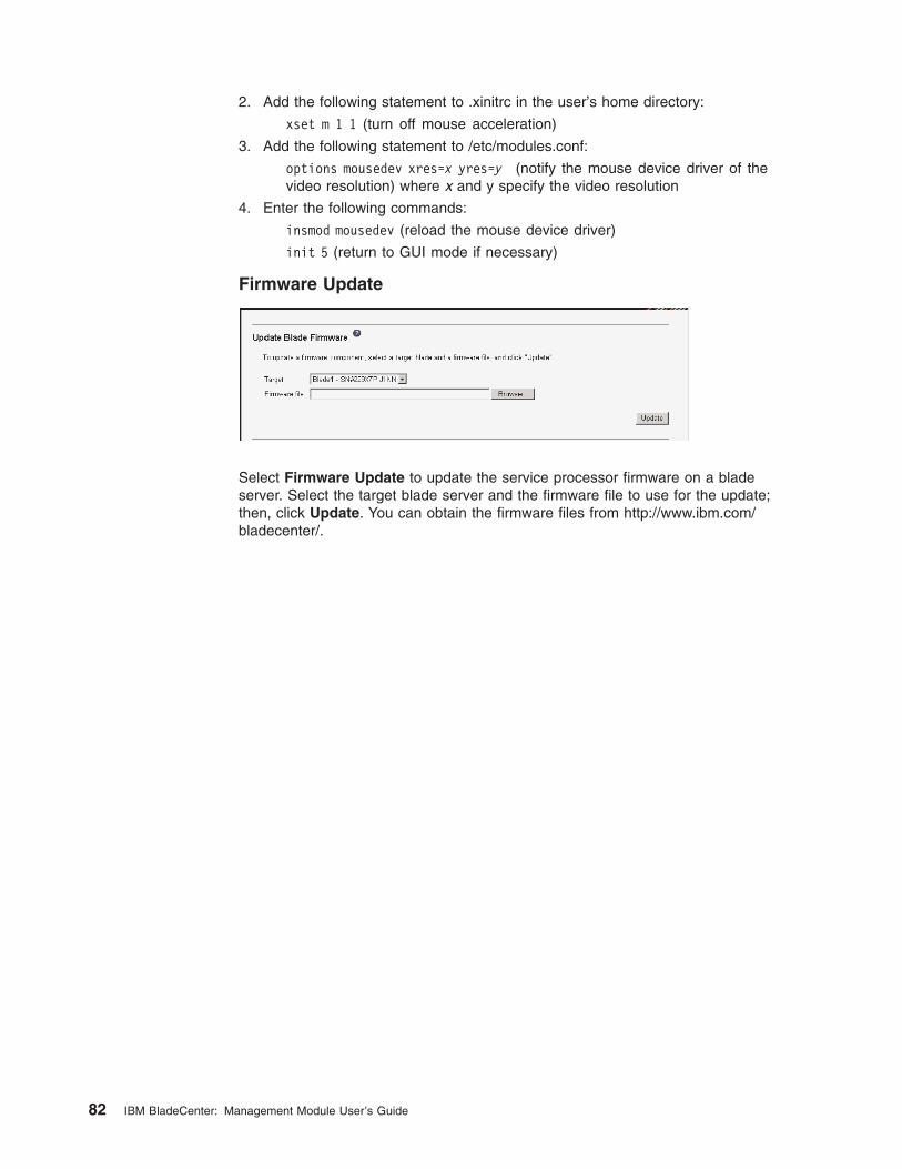
2. Add the following statement to .xinitrc in the user’s home directory:
xset m 1 1 (turn off mouse acceleration)
3. Add the following statement to /etc/modules.conf:
options mousedev xres=x yres=y (notify the mouse device driver of the
video resolution) where x and y specify the video resolution
4. Enter the following commands:
insmod mousedev (reload the mouse device driver)
init 5 (return to GUI mode if necessary)
Firmware Update
Select Firmware Update to update the service processor firmware on a blade
server. Select the target blade server and the firmware file to use for the update;
then, click Update. You can obtain the firmware files from http://www.ibm.com/bladecenter/.
82 IBM BladeCenter: Management Module User’s Guide
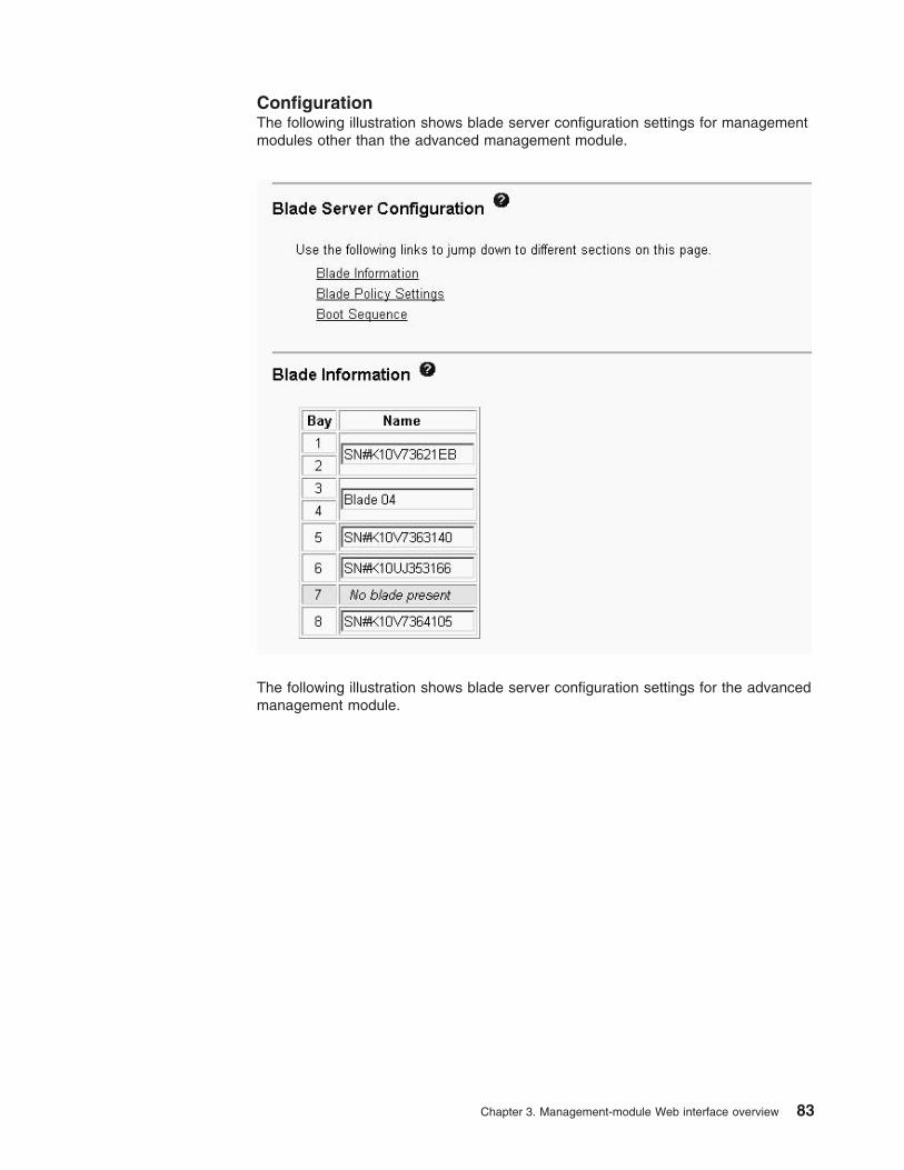
Configuration
The following illustration shows blade server configuration settings for management
modules other than the advanced management module.
The following illustration shows blade server configuration settings for the advanced
management module.
Chapter 3. Management-module Web interface overview 83
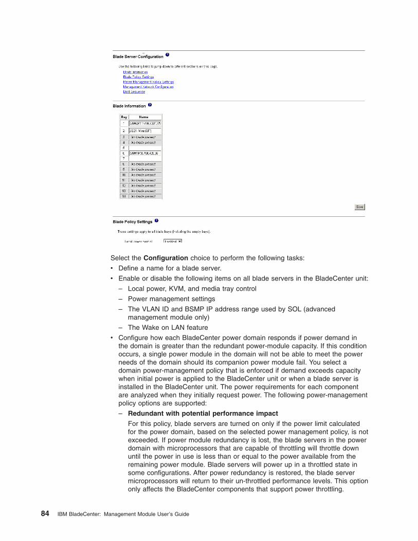
Select the Configuration choice to perform the following tasks:
v Define a name for a blade server.
v Enable or disable the following items on all blade servers in the BladeCenter unit:
– Local power, KVM, and media tray control
– Power management settings
– The VLAN ID and BSMP IP address range used by SOL (advanced
management module only)
– The Wake on LAN feature
v Configure how each BladeCenter power domain responds if power demand in
the domain is greater than the redundant power-module capacity. If this condition
occurs, a single power module in the domain will not be able to meet the power
needs of the domain should its companion power module fail. You select a
domain power-management policy that is enforced if demand exceeds capacity
when initial power is applied to the BladeCenter unit or when a blade server is
installed in the BladeCenter unit. The power requirements for each component
are analyzed when they initially request power. The following power-management
policy options are supported:
– Redundant with potential performance impact
For this policy, blade servers are turned on only if the power limit calculated
for the power domain, based on the selected power management policy, is not
exceeded. If power module redundancy is lost, the blade servers in the power
domain with microprocessors that are capable of throttling will throttle down
until the power in use is less than or equal to the power available from the
remaining power module. Blade servers will power up in a throttled state in
some configurations. After power redundancy is restored, the blade server
microprocessors will return to their un-throttled performance levels. This option
only affects the BladeCenter components that support power throttling.
84 IBM BladeCenter: Management Module User’s Guide
– Redundant without performance impact
For this policy, new components installed in the power domain are turned on
only if they can operate at their maximum power level if power redundancy in
the domain is lost.
– Non-redundant (default setting)
For this policy, blade servers are turned on, only if the power limit calculated
for the power domain, based on the selected power management policy, is not
exceeded. If power module redundancy is lost, then the blade servers in the
power domain with microprocessors that are capable of throttling will attempt
to throttle down until the power in use is less than or equal to the power
available from the remaining power module. After power redundancy is
restored, the blade server microprocessors will return to their un-throttled
performance levels. If blade servers are not able to reduce their power needs,
power in the domain might be lost.
v Determine how the management module responds if it detects a
over-temperature condition (thermal event) on a blade server. The following
acoustic mode (quiet mode) options are supported in response to thermal events:
– Disabled (default) - increases the blower speeds to provide additional cooling.
– Enabled - reduce blade server power consumption (throttle blade servers) to
stay within acoustic noise limits (quiet mode). This option only affects the
BladeCenter components that support power throttling.
v View or define the startup (boot) sequence for one or more blade servers. The
startup sequence prioritizes the following boot-record sources for a blade server.
Boot sequence choices for your BladeCenter unit type might include:
– Hard disk drives (0 through 3). The selection of hard disk drives depends on
the hard disk drives that are installed in your blade server.
– CD-ROM (optical drive).
– Diskette drive (some BladeCenter unit types)
– Network - PXE. Selecting Network - PXE attempts a PXE/DHCP network
startup the next time the blade server is turned on or restarted.
Note: To use the optical drive or diskette drive (some BladeCenter unit types) as
a boot-record source for a blade server, the blade server must have been
designated as the owner of the optical drive, diskette drive (if supported
for your BladeCenter unit type), and USB port. You set ownership either
by pressing the CD/diskette/USB select button on the blade server or
through the Remote Control choice described in “Remote Control” on
page 78.
Chapter 3. Management-module Web interface overview 85
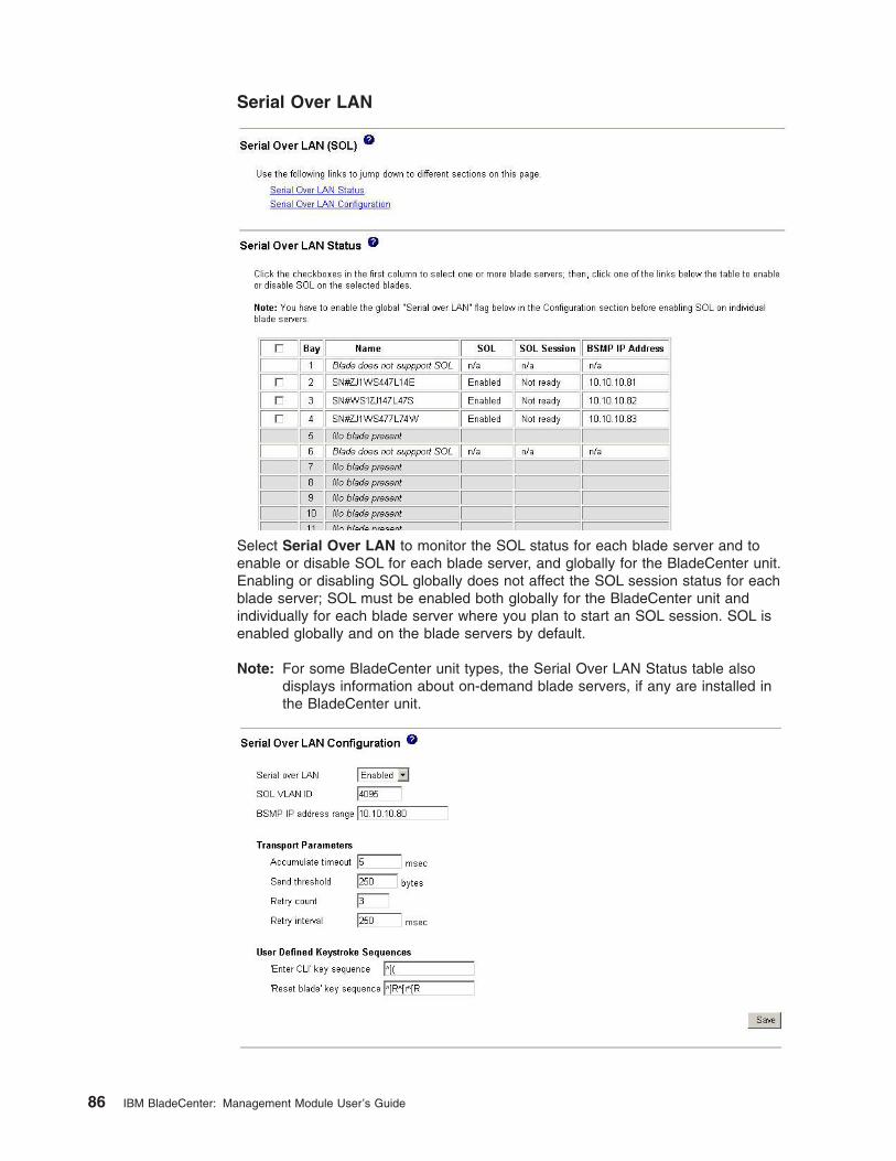
Serial Over LAN
Select Serial Over LAN to monitor the SOL status for each blade server and to
enable or disable SOL for each blade server, and globally for the BladeCenter unit.
Enabling or disabling SOL globally does not affect the SOL session status for each
blade server; SOL must be enabled both globally for the BladeCenter unit and
individually for each blade server where you plan to start an SOL session. SOL is
enabled globally and on the blade servers by default.
Note: For some BladeCenter unit types, the Serial Over LAN Status table also
displays information about on-demand blade servers, if any are installed in
the BladeCenter unit.
86 IBM BladeCenter: Management Module User’s Guide
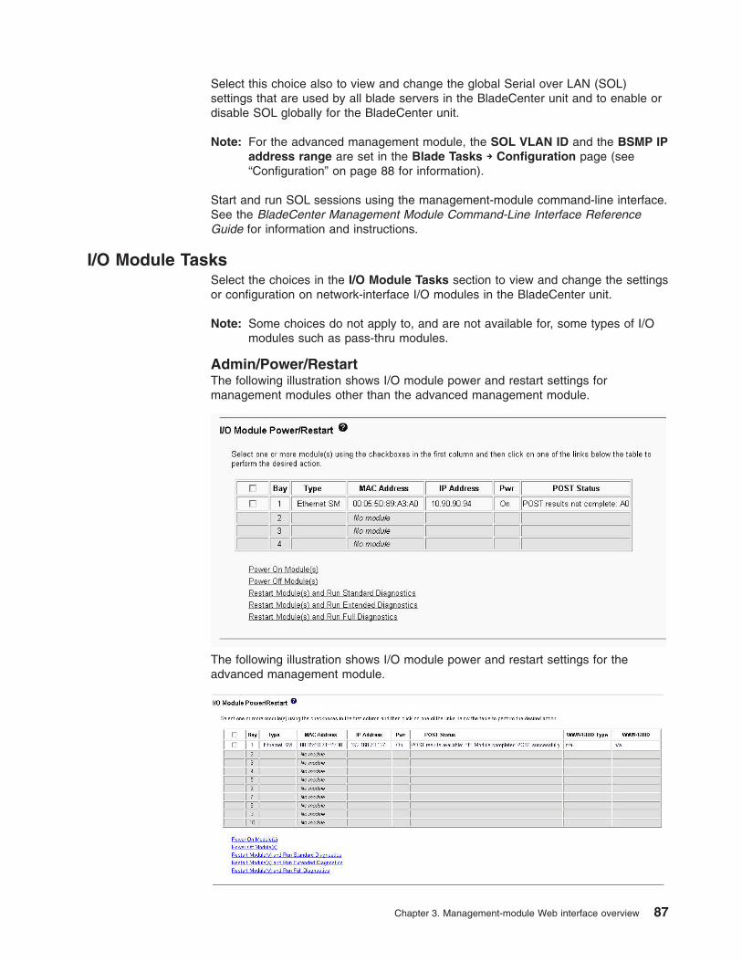
Select this choice also to view and change the global Serial over LAN (SOL)
settings that are used by all blade servers in the BladeCenter unit and to enable or
disable SOL globally for the BladeCenter unit.
Note: For the advanced management module, the SOL VLAN ID and the BSMP IP
address range are set in the Blade Tasks → Configuration page (see
“Configuration” on page 88 for information).
Start and run SOL sessions using the management-module command-line interface.
See the BladeCenter Management Module Command-Line Interface Reference
Guide for information and instructions.
I/O Module Tasks
Select the choices in the I/O Module Tasks section to view and change the settings
or configuration on network-interface I/O modules in the BladeCenter unit.
Note: Some choices do not apply to, and are not available for, some types of I/O
modules such as pass-thru modules.
Admin/Power/Restart
The following illustration shows I/O module power and restart settings for
management modules other than the advanced management module.
The following illustration shows I/O module power and restart settings for the
advanced management module.
Chapter 3. Management-module Web interface overview 87
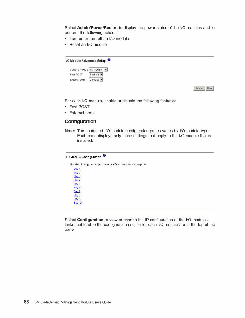
Select Admin/Power/Restart to display the power status of the I/O modules and to
perform the following actions:
v Turn on or turn off an I/O module
v Reset an I/O module
For each I/O module, enable or disable the following features:
v Fast POST
v External ports
Configuration
Note: The content of I/O-module configuration panes varies by I/O-module type.
Each pane displays only those settings that apply to the I/O module that is
installed.
Select Configuration to view or change the IP configuration of the I/O modules.
Links that lead to the configuration section for each I/O module are at the top of the
pane.
88 IBM BladeCenter: Management Module User’s Guide
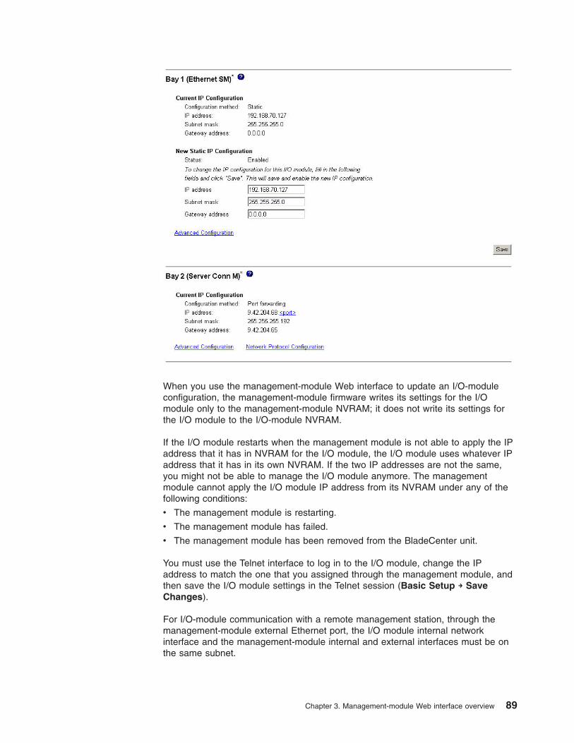
When you use the management-module Web interface to update an I/O-module
configuration, the management-module firmware writes its settings for the I/O
module only to the management-module NVRAM; it does not write its settings for
the I/O module to the I/O-module NVRAM.
If the I/O module restarts when the management module is not able to apply the IP
address that it has in NVRAM for the I/O module, the I/O module uses whatever IP
address that it has in its own NVRAM. If the two IP addresses are not the same,
you might not be able to manage the I/O module anymore. The management
module cannot apply the I/O module IP address from its NVRAM under any of the
following conditions:
v The management module is restarting.
v The management module has failed.
v The management module has been removed from the BladeCenter unit.
You must use the Telnet interface to log in to the I/O module, change the IP
address to match the one that you assigned through the management module, and
then save the I/O module settings in the Telnet session (Basic Setup → Save
Changes).
For I/O-module communication with a remote management station, through the
management-module external Ethernet port, the I/O module internal network
interface and the management-module internal and external interfaces must be on
the same subnet.
Chapter 3. Management-module Web interface overview 89
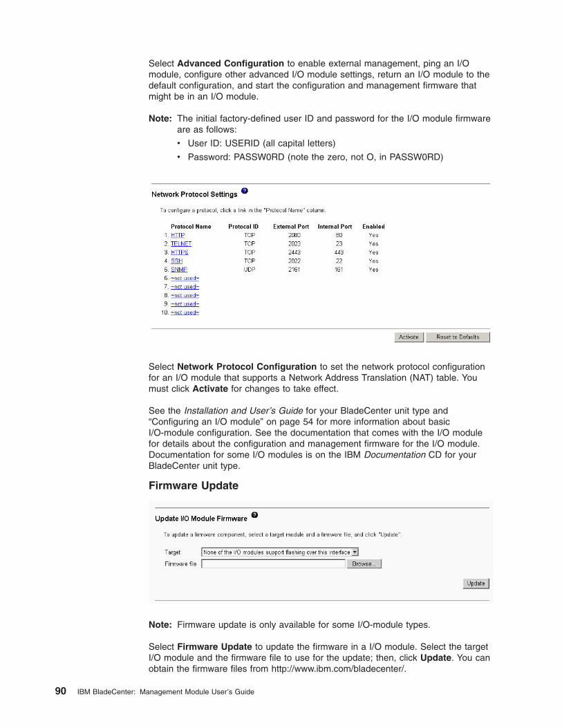
Select Advanced Configuration to enable external management, ping an I/O
module, configure other advanced I/O module settings, return an I/O module to the
default configuration, and start the configuration and management firmware that
might be in an I/O module.
Note: The initial factory-defined user ID and password for the I/O module firmware
are as follows:
v User ID: USERID (all capital letters)
v Password: PASSW0RD (note the zero, not O, in PASSW0RD)
Select Network Protocol Configuration to set the network protocol configuration
for an I/O module that supports a Network Address Translation (NAT) table. You
must click Activate for changes to take effect.
See the Installation and User’s Guide for your BladeCenter unit type and
“Configuring an I/O module” on page 54 for more information about basic
I/O-module configuration. See the documentation that comes with the I/O module
for details about the configuration and management firmware for the I/O module.
Documentation for some I/O modules is on the IBM Documentation CD for your
BladeCenter unit type.
Firmware Update
Note: Firmware update is only available for some I/O-module types.
Select Firmware Update to update the firmware in a I/O module. Select the target
I/O module and the firmware file to use for the update; then, click Update. You can
obtain the firmware files from http://www.ibm.com/bladecenter/.
90 IBM BladeCenter: Management Module User’s Guide
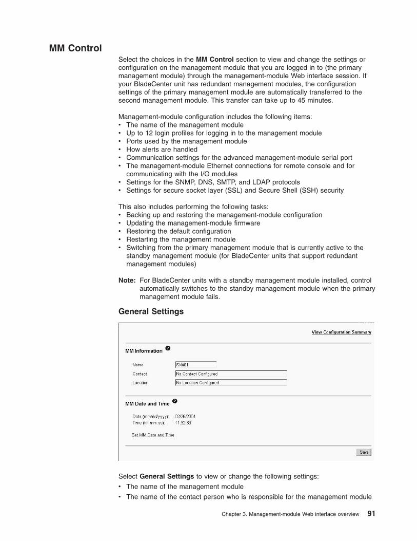
MM Control
Select the choices in the MM Control section to view and change the settings or
configuration on the management module that you are logged in to (the primary
management module) through the management-module Web interface session. If
your BladeCenter unit has redundant management modules, the configuration
settings of the primary management module are automatically transferred to the
second management module. This transfer can take up to 45 minutes.
Management-module configuration includes the following items:
v The name of the management module
v Up to 12 login profiles for logging in to the management module
v Ports used by the management module
v How alerts are handled
v Communication settings for the advanced management-module serial port
v The management-module Ethernet connections for remote console and for
communicating with the I/O modules
v Settings for the SNMP, DNS, SMTP, and LDAP protocols
v Settings for secure socket layer (SSL) and Secure Shell (SSH) security
This also includes performing the following tasks:
v Backing up and restoring the management-module configuration
v Updating the management-module firmware
v Restoring the default configuration
v Restarting the management module
v Switching from the primary management module that is currently active to the
standby management module (for BladeCenter units that support redundant
management modules)
Note: For BladeCenter units with a standby management module installed, control
automatically switches to the standby management module when the primary
management module fails.
General Settings
Select General Settings to view or change the following settings:
v The name of the management module
v The name of the contact person who is responsible for the management module
Chapter 3. Management-module Web interface overview 91
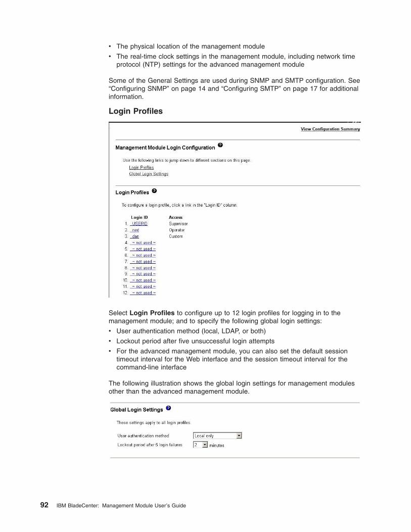
v The physical location of the management module
v The real-time clock settings in the management module, including network time
protocol (NTP) settings for the advanced management module
Some of the General Settings are used during SNMP and SMTP configuration. See
“Configuring SNMP” on page 14 and “Configuring SMTP” on page 17 for additional
information.
Login Profiles
Select Login Profiles to configure up to 12 login profiles for logging in to the
management module; and to specify the following global login settings:
v User authentication method (local, LDAP, or both)
v Lockout period after five unsuccessful login attempts
v For the advanced management module, you can also set the default session
timeout interval for the Web interface and the session timeout interval for the
command-line interface
The following illustration shows the global login settings for management modules
other than the advanced management module.
92 IBM BladeCenter: Management Module User’s Guide
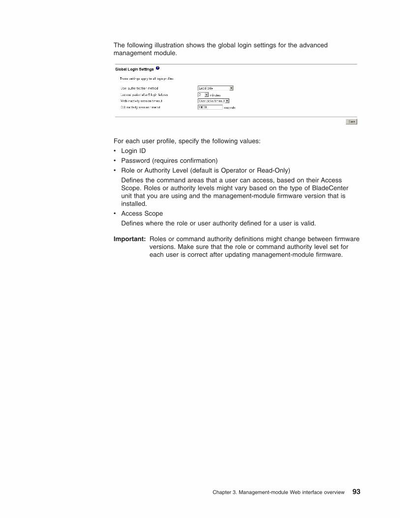
The following illustration shows the global login settings for the advanced
management module.
For each user profile, specify the following values:
v Login ID
v Password (requires confirmation)
v Role or Authority Level (default is Operator or Read-Only)
Defines the command areas that a user can access, based on their Access
Scope. Roles or authority levels might vary based on the type of BladeCenter
unit that you are using and the management-module firmware version that is
installed.
v Access Scope
Defines where the role or user authority defined for a user is valid.
Important: Roles or command authority definitions might change between firmware
versions. Make sure that the role or command authority level set for
each user is correct after updating management-module firmware.
Chapter 3. Management-module Web interface overview 93
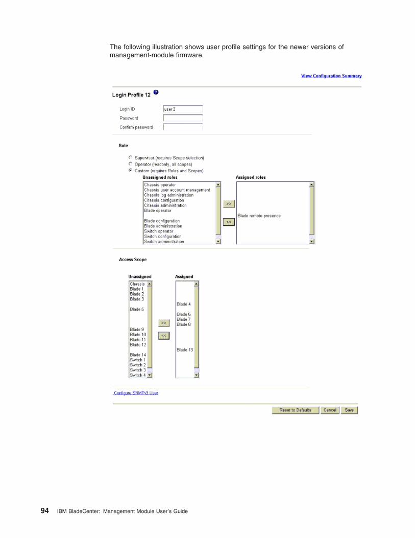
The following illustration shows user profile settings for the newer versions of
management-module firmware.
94 IBM BladeCenter: Management Module User’s Guide
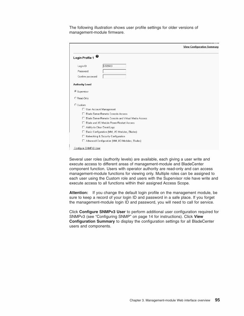
The following illustration shows user profile settings for older versions of
management-module firmware.
Several user roles (authority levels) are available, each giving a user write and
execute access to different areas of management-module and BladeCenter
component function. Users with operator authority are read-only and can access
management-module functions for viewing only. Multiple roles can be assigned to
each user using the Custom role and users with the Supervisor role have write and
execute access to all functions within their assigned Access Scope.
Attention: If you change the default login profile on the management module, be
sure to keep a record of your login ID and password in a safe place. If you forget
the management-module login ID and password, you will need to call for service.
Click Configure SNMPv3 User to perform additional user configuration required for
SNMPv3 (see “Configuring SNMP” on page 14 for instructions). Click View
Configuration Summary to display the configuration settings for all BladeCenter
users and components.
Chapter 3. Management-module Web interface overview 95
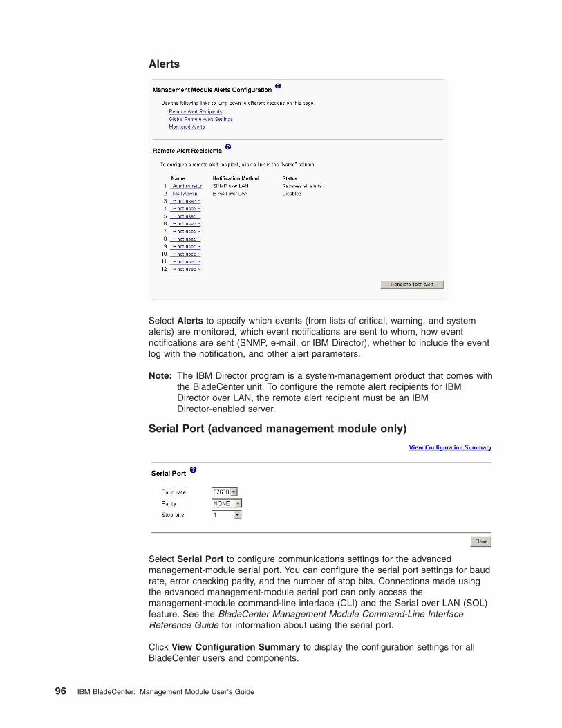
Alerts
Select Alerts to specify which events (from lists of critical, warning, and system
alerts) are monitored, which event notifications are sent to whom, how event
notifications are sent (SNMP, e-mail, or IBM Director), whether to include the event
log with the notification, and other alert parameters.
Note: The IBM Director program is a system-management product that comes with
the BladeCenter unit. To configure the remote alert recipients for IBM
Director over LAN, the remote alert recipient must be an IBM
Director-enabled server.
Serial Port (advanced management module only)
Select Serial Port to configure communications settings for the advanced
management-module serial port. You can configure the serial port settings for baud
rate, error checking parity, and the number of stop bits. Connections made using
the advanced management-module serial port can only access the
management-module command-line interface (CLI) and the Serial over LAN (SOL)
feature. See the BladeCenter Management Module Command-Line Interface
Reference Guide for information about using the serial port.
Click View Configuration Summary to display the configuration settings for all
BladeCenter users and components.
96 IBM BladeCenter: Management Module User’s Guide
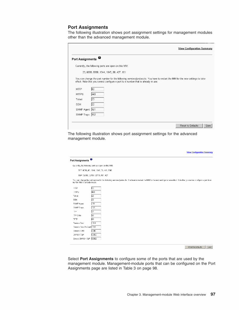
Port Assignments
The following illustration shows port assignment settings for management modules
other than the advanced management module.
The following illustration shows port assignment settings for the advanced
management module.
Select Port Assignments to configure some of the ports that are used by the
management module. Management-module ports that can be configured on the Port
Assignments page are listed in Table 3 on page 98.
Chapter 3. Management-module Web interface overview 97
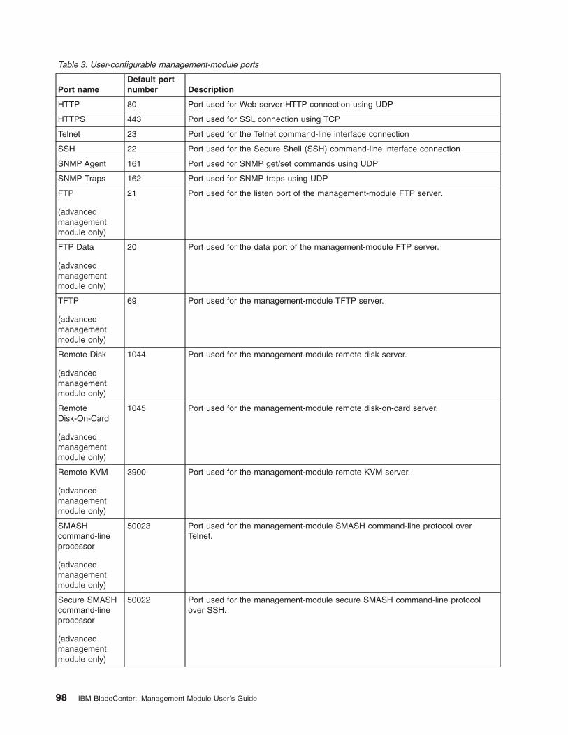
Table 3. User-configurable management-module ports
Port name
Default port
number Description
HTTP 80 Port used for Web server HTTP connection using UDP
HTTPS 443 Port used for SSL connection using TCP
Telnet 23 Port used for the Telnet command-line interface connection
SSH 22 Port used for the Secure Shell (SSH) command-line interface connection
SNMP Agent 161 Port used for SNMP get/set commands using UDP
SNMP Traps 162 Port used for SNMP traps using UDP
FTP
(advanced
management
module only)
21 Port used for the listen port of the management-module FTP server.
FTP Data
(advanced
management
module only)
20 Port used for the data port of the management-module FTP server.
TFTP
(advanced
management
module only)
69 Port used for the management-module TFTP server.
Remote Disk
(advanced
management
module only)
1044 Port used for the management-module remote disk server.
Remote
Disk-On-Card
(advanced
management
module only)
1045 Port used for the management-module remote disk-on-card server.
Remote KVM
(advanced
management
module only)
3900 Port used for the management-module remote KVM server.
SMASH
command-line
processor
(advanced
management
module only)
50023 Port used for the management-module SMASH command-line protocol over
Telnet.
Secure SMASH
command-line
processor
(advanced
management
module only)
50022 Port used for the management-module secure SMASH command-line protocol
over SSH.
98 IBM BladeCenter: Management Module User’s Guide
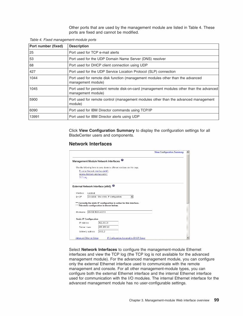
Other ports that are used by the management module are listed in Table 4. These
ports are fixed and cannot be modified.
Table 4. Fixed management-module ports
Port number (fixed) Description
25 Port used for TCP e-mail alerts
53 Port used for the UDP Domain Name Server (DNS) resolver
68 Port used for DHCP client connection using UDP
427 Port used for the UDP Service Location Protocol (SLP) connection
1044 Port used for remote disk function (management modules other than the advanced
management module)
1045 Port used for persistent remote disk-on-card (management modules other than the advanced
management module)
5900 Port used for remote control (management modules other than the advanced management
module)
6090 Port used for IBM Director commands using TCP/IP
13991 Port used for IBM Director alerts using UDP
Click View Configuration Summary to display the configuration settings for all
BladeCenter users and components.
Network Interfaces
Select Network Interfaces to configure the management-module Ethernet
interfaces and view the TCP log (the TCP log is not available for the advanced
management module). For the advanced management module, you can configure
only the external Ethernet interface used to communicate with the remote
management and console. For all other management-module types, you can
configure both the external Ethernet interface and the internal Ethernet interface
used for communication with the I/O modules. The internal Ethernet interface for the
advanced management module has no user-configurable settings.
Chapter 3. Management-module Web interface overview 99
For I/O-module communication with a remote management station, through the
management-module external Ethernet port, the I/O module internal network
interface and the management-module internal and external interfaces must be on
the same subnet.
v When you click External Network Interface (eth0), information about the
interface for the remote management and console port is displayed:
Note: If your BladeCenter unit supports redundant management modules and
you plan to use this feature with both management modules set to use the
same external IP address, disable DHCP and configure and use a static
IP address. (The IP configuration information will be transferred to the
standby management module automatically when needed.)
– Interface - The status (Enabled or Disabled) of the Ethernet connection. The
default is Enabled. (For the advanced management module, this field is for
information only and cannot be changed.)
– DHCP - Select one of the following choices:
- Enabled - Obtain IP config. from DHCP server
- Disabled - Use static IP configuration
- Try DHCP server. If it fails, use static IP config. (the default).
– Hostname - (Optional) This is the IP host name that you want to use for the
management module (maximum of 63 characters and following host-naming
standards).
– Static IP configuration - You must configure this information only if DHCP is
disabled.
- IP address - The IP address for the management module must contain four
integers from 0 through 255, separated by periods, with no spaces or
consecutive periods. The default setting is 192.168.70.125.
- Subnet mask - The subnet mask must contain four integers from 0 to 255,
separated by periods, with no spaces. The default setting is 255.255.255.0
- Gateway address - The IP address for your network gateway router must
contain four integers from 0 through 255, separated by periods, with no
spaces. This address must be accessible from the IP address and subnet
mask that were specified above.
– Click the Advanced Ethernet Setup link to view and configure the data rate,
duplex mode, maximum transmission unit (MTU), and locally-administered
MAC address for this interface. The burned-in MAC address field for the
external interface is read-only.
For management modules other than the advanced management module, you
can enable or disable the management-module physical uplink failover feature
using the Failover network uplink loss field. For the advanced management
module, you can enable or disable the management-module physical or
logical uplink failover features using the Failover on loss of physical
network link and Failover on loss of logical network link fields. If the
external network interface of the primary management module fails, the uplink
failover features force a failover to the standby management module, if one is
installed, after the specified network failover delay. For the advanced
management module, you can also specify the IP address that the
management module uses to check the status of its logical network link.
100 IBM BladeCenter: Management Module User’s Guide
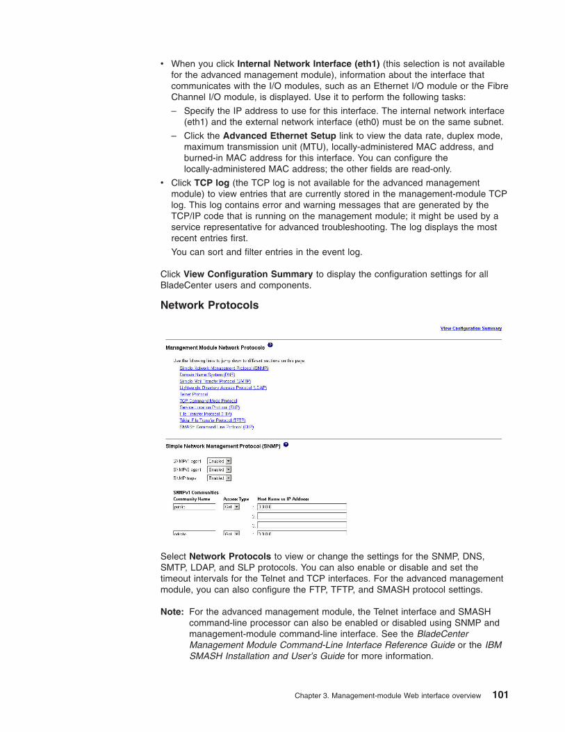
v When you click Internal Network Interface (eth1) (this selection is not available
for the advanced management module), information about the interface that
communicates with the I/O modules, such as an Ethernet I/O module or the Fibre
Channel I/O module, is displayed. Use it to perform the following tasks:
– Specify the IP address to use for this interface. The internal network interface
(eth1) and the external network interface (eth0) must be on the same subnet.
– Click the Advanced Ethernet Setup link to view the data rate, duplex mode,
maximum transmission unit (MTU), locally-administered MAC address, and
burned-in MAC address for this interface. You can configure the
locally-administered MAC address; the other fields are read-only.
v Click TCP log (the TCP log is not available for the advanced management
module) to view entries that are currently stored in the management-module TCP
log. This log contains error and warning messages that are generated by the
TCP/IP code that is running on the management module; it might be used by a
service representative for advanced troubleshooting. The log displays the most
recent entries first.
You can sort and filter entries in the event log.
Click View Configuration Summary to display the configuration settings for all
BladeCenter users and components.
Network Protocols
Select Network Protocols to view or change the settings for the SNMP, DNS,
SMTP, LDAP, and SLP protocols. You can also enable or disable and set the
timeout intervals for the Telnet and TCP interfaces. For the advanced management
module, you can also configure the FTP, TFTP, and SMASH protocol settings.
Note: For the advanced management module, the Telnet interface and SMASH
command-line processor can also be enabled or disabled using SNMP and
management-module command-line interface. See the BladeCenter
Management Module Command-Line Interface Reference Guide or the IBM
SMASH Installation and User’s Guide for more information.
Chapter 3. Management-module Web interface overview 101
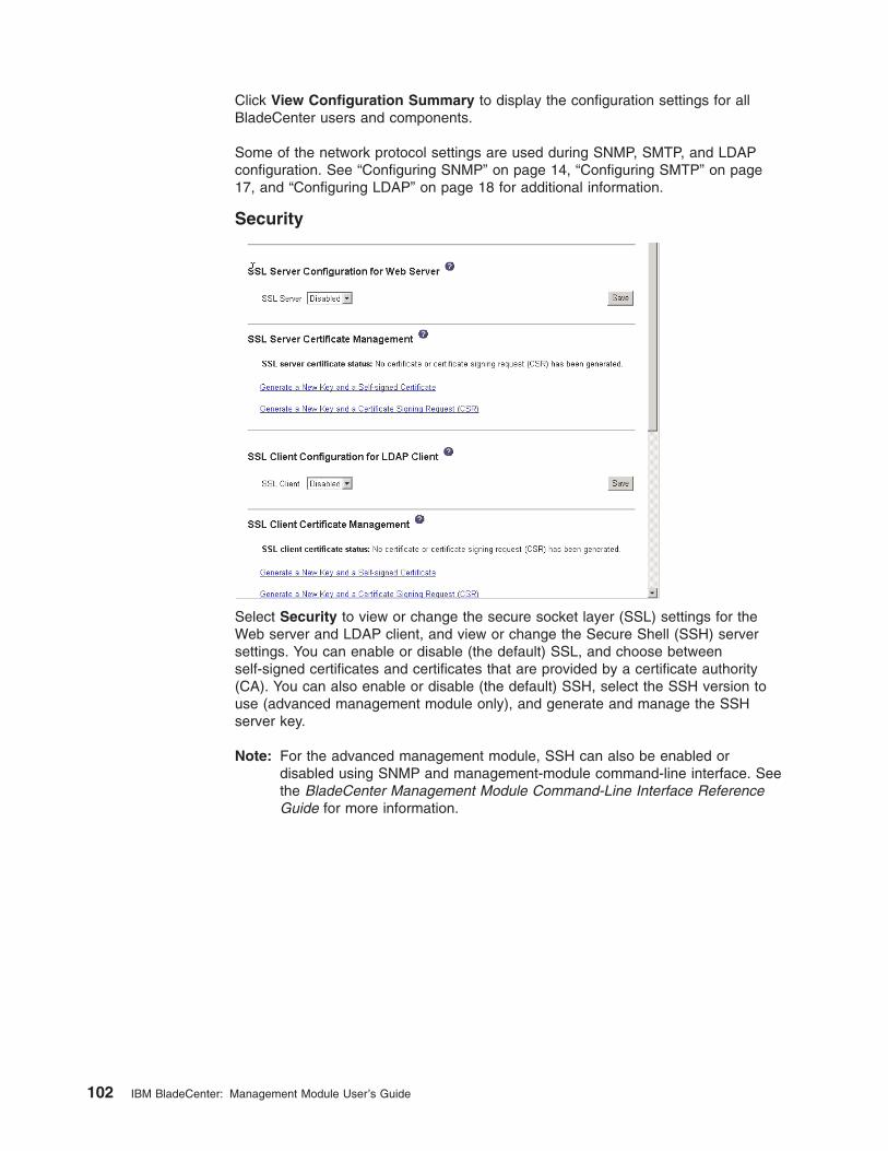
Click View Configuration Summary to display the configuration settings for all
BladeCenter users and components.
Some of the network protocol settings are used during SNMP, SMTP, and LDAP
configuration. See “Configuring SNMP” on page 14, “Configuring SMTP” on page
17, and “Configuring LDAP” on page 18 for additional information.
Security
Select Security to view or change the secure socket layer (SSL) settings for the
Web server and LDAP client, and view or change the Secure Shell (SSH) server
settings. You can enable or disable (the default) SSL, and choose between
self-signed certificates and certificates that are provided by a certificate authority
(CA). You can also enable or disable (the default) SSH, select the SSH version to
use (advanced management module only), and generate and manage the SSH
server key.
Note: For the advanced management module, SSH can also be enabled or
disabled using SNMP and management-module command-line interface. See
the BladeCenter Management Module Command-Line Interface Reference
Guide for more information.
102 IBM BladeCenter: Management Module User’s Guide
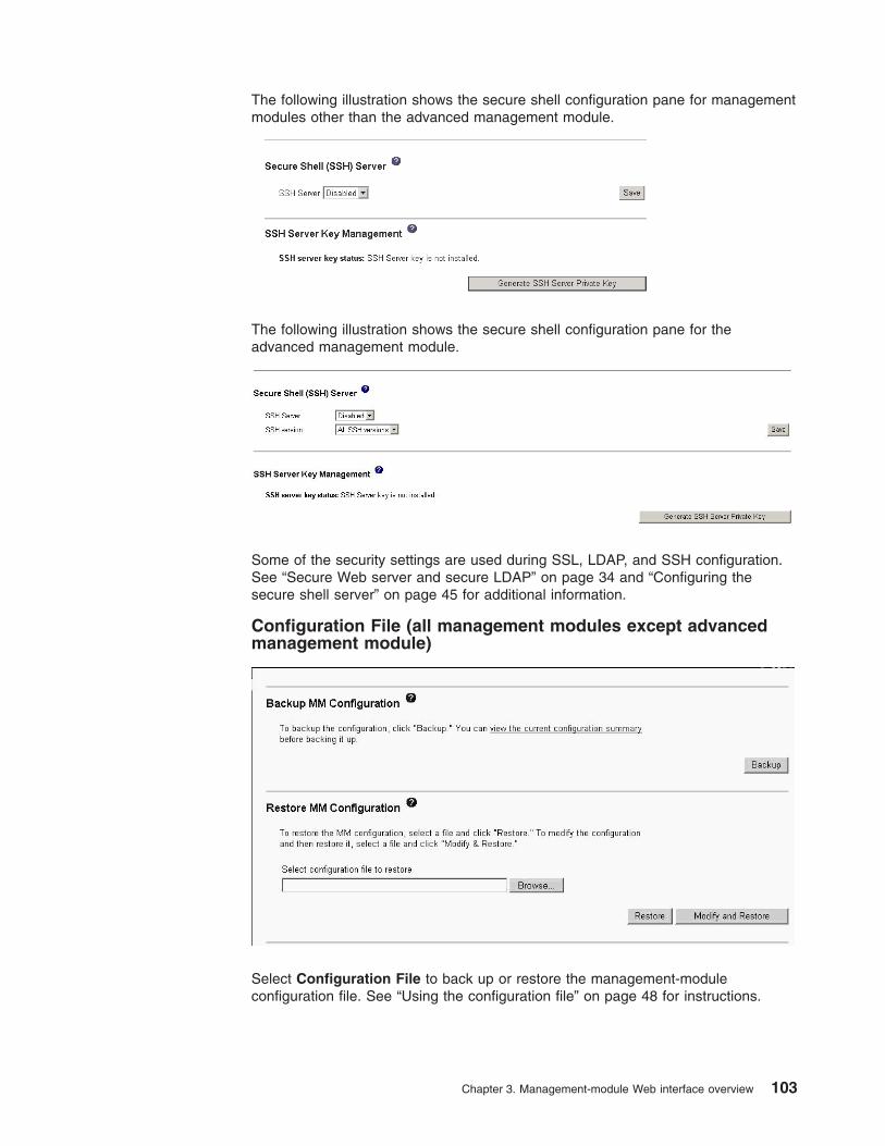
The following illustration shows the secure shell configuration pane for management
modules other than the advanced management module.
The following illustration shows the secure shell configuration pane for the
advanced management module.
Some of the security settings are used during SSL, LDAP, and SSH configuration.
See “Secure Web server and secure LDAP” on page 34 and “Configuring the
secure shell server” on page 45 for additional information.
Configuration File (all management modules except advanced
management module)
Select Configuration File to back up or restore the management-module
configuration file. See “Using the configuration file” on page 48 for instructions.
Chapter 3. Management-module Web interface overview 103
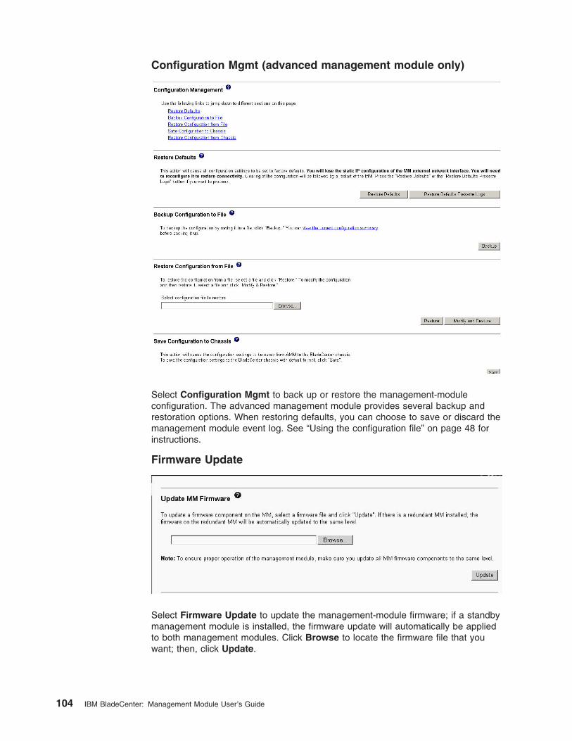
Configuration Mgmt (advanced management module only)
Select Configuration Mgmt to back up or restore the management-module
configuration. The advanced management module provides several backup and
restoration options. When restoring defaults, you can choose to save or discard the
management module event log. See “Using the configuration file” on page 48 for
instructions.
Firmware Update
Select Firmware Update to update the management-module firmware; if a standby
management module is installed, the firmware update will automatically be applied
to both management modules. Click Browse to locate the firmware file that you
want; then, click Update.
104 IBM BladeCenter: Management Module User’s Guide
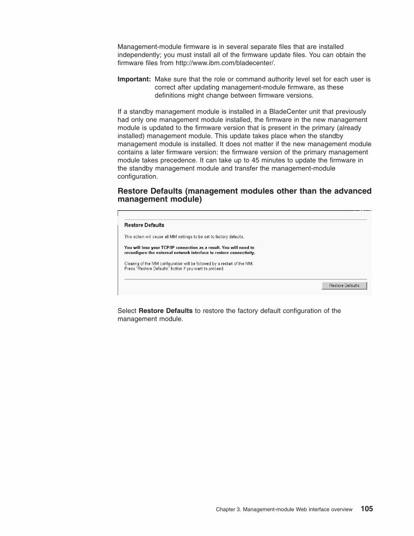
Management-module firmware is in several separate files that are installed
independently; you must install all of the firmware update files. You can obtain the
firmware files from http://www.ibm.com/bladecenter/.
Important: Make sure that the role or command authority level set for each user is
correct after updating management-module firmware, as these
definitions might change between firmware versions.
If a standby management module is installed in a BladeCenter unit that previously
had only one management module installed, the firmware in the new management
module is updated to the firmware version that is present in the primary (already
installed) management module. This update takes place when the standby
management module is installed. It does not matter if the new management module
contains a later firmware version: the firmware version of the primary management
module takes precedence. It can take up to 45 minutes to update the firmware in
the standby management module and transfer the management-module
configuration.
Restore Defaults (management modules other than the advanced
management module)
Select Restore Defaults to restore the factory default configuration of the
management module.
Chapter 3. Management-module Web interface overview 105
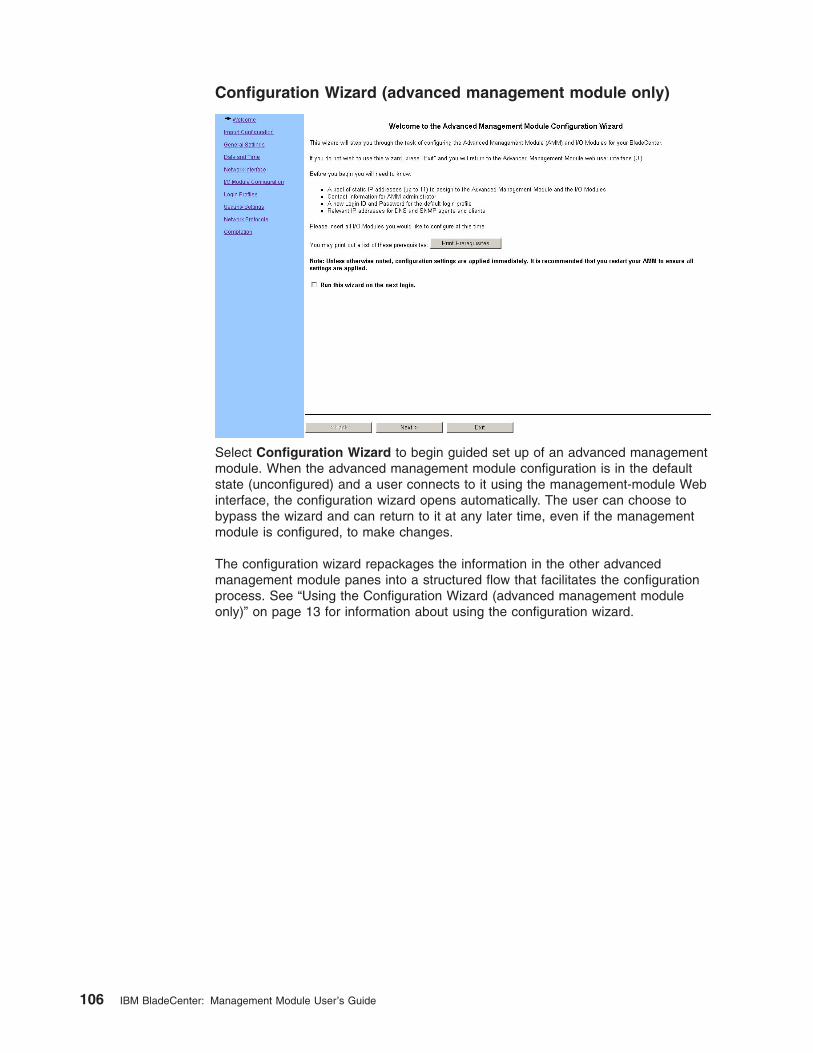
Configuration Wizard (advanced management module only)
Select Configuration Wizard to begin guided set up of an advanced management
module. When the advanced management module configuration is in the default
state (unconfigured) and a user connects to it using the management-module Web
interface, the configuration wizard opens automatically. The user can choose to
bypass the wizard and can return to it at any later time, even if the management
module is configured, to make changes.
The configuration wizard repackages the information in the other advanced
management module panes into a structured flow that facilitates the configuration
process. See “Using the Configuration Wizard (advanced management module
only)” on page 13 for information about using the configuration wizard.
106 IBM BladeCenter: Management Module User’s Guide
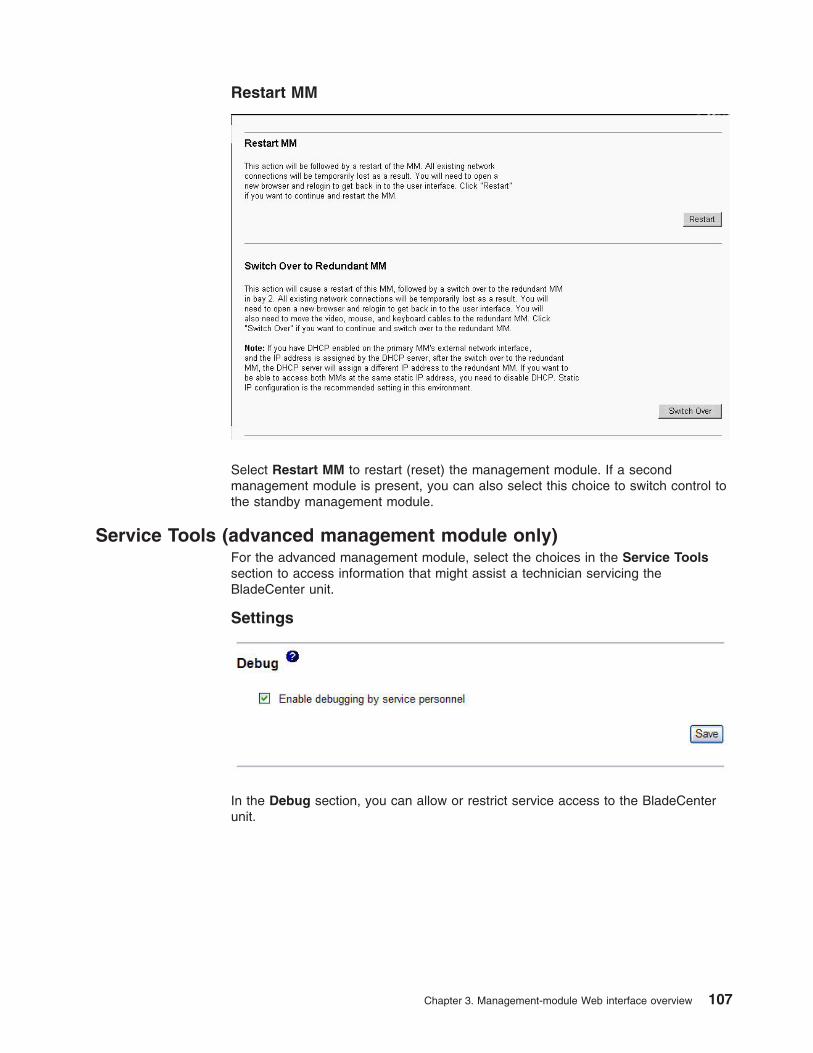
Restart MM
Select Restart MM to restart (reset) the management module. If a second
management module is present, you can also select this choice to switch control to
the standby management module.
Service Tools (advanced management module only)
For the advanced management module, select the choices in the Service Tools
section to access information that might assist a technician servicing the
BladeCenter unit.
Settings
In the Debug section, you can allow or restrict service access to the BladeCenter
unit.
Chapter 3. Management-module Web interface overview 107
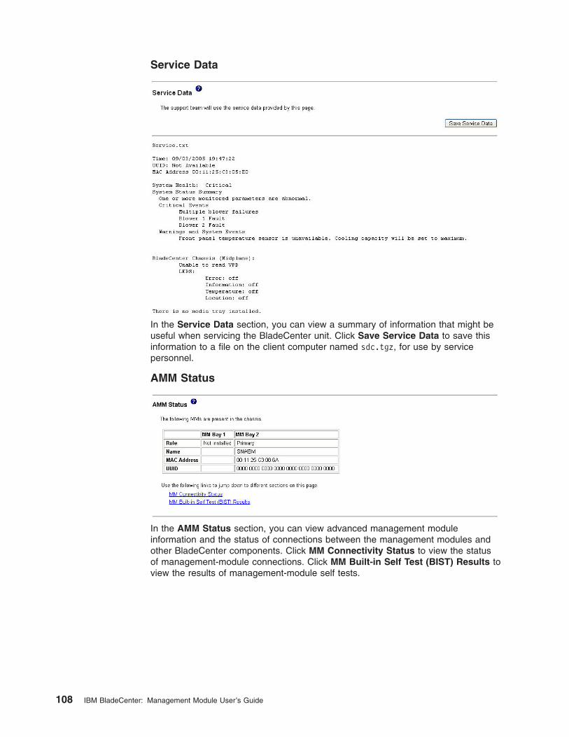
Service Data
In the Service Data section, you can view a summary of information that might be
useful when servicing the BladeCenter unit. Click Save Service Data to save this
information to a file on the client computer named sdc.tgz, for use by service
personnel.
AMM Status
In the AMM Status section, you can view advanced management module
information and the status of connections between the management modules and
other BladeCenter components. Click MM Connectivity Status to view the status
of management-module connections. Click MM Built-in Self Test (BIST) Results to
view the results of management-module self tests.
108 IBM BladeCenter: Management Module User’s Guide
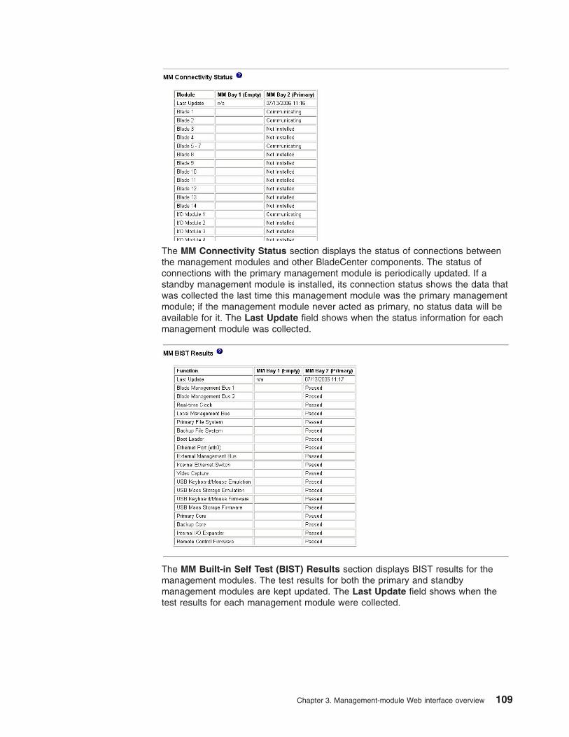
The MM Connectivity Status section displays the status of connections between
the management modules and other BladeCenter components. The status of
connections with the primary management module is periodically updated. If a
standby management module is installed, its connection status shows the data that
was collected the last time this management module was the primary management
module; if the management module never acted as primary, no status data will be
available for it. The Last Update field shows when the status information for each
management module was collected.
The MM Built-in Self Test (BIST) Results section displays BIST results for the
management modules. The test results for both the primary and standby
management modules are kept updated. The Last Update field shows when the
test results for each management module were collected.
Chapter 3. Management-module Web interface overview 109

110 IBM BladeCenter: Management Module User’s Guide
Appendix A. Getting help and technical assistance
If you need help, service, or technical assistance or just want more information
about IBM products, you will find a wide variety of sources available from IBM to
assist you. This appendix contains information about where to go for additional
information about IBM and IBM products, what to do if you experience a problem
with your BladeCenter® product or optional device, and whom to call for service, if it
is necessary.
Before you call
Before you call, make sure that you have taken these steps to try to solve the
problem yourself:
v Check all cables to make sure that they are connected.
v Check the power switches to make sure that the system and any optional
devices are turned on.
v Use the troubleshooting information in your system documentation, and use the
diagnostic tools that come with your system. Information about diagnostic tools is
in the Hardware Maintenance Manual and Troubleshooting Guide or Problem
Determination and Service Guide on the IBM Documentation CD that comes with
your system.
v Go to http://www.ibm.com/servers/eserver/support/bladecenter/ to check for
information to help you solve the problem.
You can solve many problems without outside assistance by following the
troubleshooting procedures that IBM provides in the online help or in the
documentation that is provided with your IBM product. The documentation that
comes with BladeCenter systems also describes the diagnostic tests that you can
perform. Most BladeCenter systems, operating systems, and programs come with
documentation that contains troubleshooting procedures and explanations of error
messages and error codes. If you suspect a software problem, see the
documentation for the software.
Using the documentation
Information about your IBM BladeCenter system and preinstalled software, if any, or
optional device is available in the documentation that comes with the product. That
documentation can include printed documents, online documents, readme files, and
help files. See the troubleshooting information in your system documentation for
instructions for using the diagnostic programs. The troubleshooting information or
the diagnostic programs might tell you that you need additional or updated device
drivers or other software. IBM maintains pages on the World Wide Web where you
can get the latest technical information and download device drivers and updates.
To access these pages, go to http://www.ibm.com/servers/eserver/support/bladecenter/ and follow the instructions. Also, some documents are available
through the IBM Publications Center at http://www.ibm.com/shop/publications/order/.
Getting help and information from the World Wide Web
On the World Wide Web, the IBM Web site has up-to-date information about IBM
BladeCenter systems, optional devices, services, and support at
http://www.ibm.com/servers/eserver/support/bladecenter/.
© Copyright IBM Corp. 2006 111
Software service and support
Through IBM Support Line, you can get telephone assistance, for a fee, with usage,
configuration, and software problems with BladeCenter products. For information
about which products are supported by Support Line in your country or region, see
http://www.ibm.com/services/sl/products/.
For more information about Support Line and other IBM services, see
http://www.ibm.com/services/, or see http://www.ibm.com/planetwide/ for support
telephone numbers. In the U.S. and Canada, call 1-800-IBM-SERV
(1-800-426-7378).
Hardware service and support
You can receive hardware service through IBM Services or through your IBM
reseller, if your reseller is authorized by IBM to provide warranty service. See
http://www.ibm.com/planetwide/ for support telephone numbers, or in the U.S. and
Canada, call 1-800-IBM-SERV (1-800-426-7378).
In the U.S. and Canada, hardware service and support is available 24 hours a day,
7 days a week. In the U.K., these services are available Monday through Friday,
from 9 a.m. to 6 p.m.
IBM Taiwan product service
IBM Taiwan product service contact information:
IBM Taiwan Corporation
3F, No 7, Song Ren Rd.
Taipei, Taiwan
Telephone: 0800-016-888
112 IBM BladeCenter: Management Module User’s Guide
Appendix B. Notices
This information was developed for products and services offered in the U.S.A.
IBM may not offer the products, services, or features discussed in this document in
other countries. Consult your local IBM representative for information on the
products and services currently available in your area. Any reference to an IBM
product, program, or service is not intended to state or imply that only that IBM
product, program, or service may be used. Any functionally equivalent product,
program, or service that does not infringe any IBM intellectual property right may be
used instead. However, it is the user’s responsibility to evaluate and verify the
operation of any non-IBM product, program, or service.
IBM may have patents or pending patent applications covering subject matter
described in this document. The furnishing of this document does not give you any
license to these patents. You can send license inquiries, in writing, to:
IBM Director of Licensing
IBM Corporation
North Castle Drive
Armonk, NY 10504-1785
U.S.A.
INTERNATIONAL BUSINESS MACHINES CORPORATION PROVIDES THIS
PUBLICATION “AS IS” WITHOUT WARRANTY OF ANY KIND, EITHER EXPRESS
OR IMPLIED, INCLUDING, BUT NOT LIMITED TO, THE IMPLIED WARRANTIES
OF NON-INFRINGEMENT, MERCHANTABILITY OR FITNESS FOR A
PARTICULAR PURPOSE. Some states do not allow disclaimer of express or
implied warranties in certain transactions, therefore, this statement may not apply to
you.
This information could include technical inaccuracies or typographical errors.
Changes are periodically made to the information herein; these changes will be
incorporated in new editions of the publication. IBM may make improvements and/or
changes in the product(s) and/or the program(s) described in this publication at any
time without notice.
Any references in this information to non-IBM Web sites are provided for
convenience only and do not in any manner serve as an endorsement of those
Web sites. The materials at those Web sites are not part of the materials for this
IBM product, and use of those Web sites is at your own risk.
IBM may use or distribute any of the information you supply in any way it believes
appropriate without incurring any obligation to you.
© Copyright IBM Corp. 2006 113
Trademarks
The following terms are trademarks of International Business Machines Corporation
in the United States, other countries, or both:
Active Memory IBM TechConnect
Active PCI IBM (logo) Tivoli
Active PCI-X IntelliStation Tivoli Enterprise
AIX NetBAY Update Connector
Alert on LAN Netfinity Wake on LAN
BladeCenter Predictive Failure Analysis XA-32
Chipkill ServeRAID XA-64
e-business logo ServerGuide X-Architecture
Eserver ServerProven XpandOnDemand
FlashCopy System x xSeries
i5/OS
Intel, Intel Xeon, Itanium, and Pentium are trademarks or registered trademarks of
Intel Corporation or its subsidiaries in the United States and other countries.
Microsoft, Windows, and Windows NT are trademarks of Microsoft Corporation in
the United States, other countries, or both.
UNIX is a registered trademark of The Open Group in the United States and other
countries.
Java and all Java-based trademarks and logos are trademarks of Sun
Microsystems, Inc. in the United States, other countries, or both.
Adaptec and HostRAID are trademarks of Adaptec, Inc., in the United States, other
countries, or both.
Linux is a trademark of Linus Torvalds in the United States, other countries, or both.
Red Hat, the Red Hat “Shadow Man” logo, and all Red Hat-based trademarks and
logos are trademarks or registered trademarks of Red Hat, Inc., in the United States
and other countries.
Other company, product, or service names may be trademarks or service marks of
others.
Important notes
Processor speeds indicate the internal clock speed of the microprocessor; other
factors also affect application performance.
CD drive speeds list the variable read rate. Actual speeds vary and are often less
than the maximum possible.
When referring to processor storage, real and virtual storage, or channel volume,
KB stands for approximately 1000 bytes, MB stands for approximately 1 000 000
bytes, and GB stands for approximately 1 000 000 000 bytes.
114 IBM BladeCenter: Management Module User’s Guide

When referring to hard disk drive capacity or communications volume, MB stands
for 1 000 000 bytes, and GB stands for 1 000 000 000 bytes. Total user-accessible
capacity may vary depending on operating environments.
Maximum internal hard disk drive capacities assume the replacement of any
standard hard disk drives and population of all hard disk drive bays with the largest
currently supported drives available from IBM.
Maximum memory may require replacement of the standard memory with an
optional memory module.
IBM makes no representation or warranties regarding non-IBM products and
services that are ServerProven®, including but not limited to the implied warranties
of merchantability and fitness for a particular purpose. These products are offered
and warranted solely by third parties.
IBM makes no representations or warranties with respect to non-IBM products.
Support (if any) for the non-IBM products is provided by the third party, not IBM.
Some software may differ from its retail version (if available), and may not include
user manuals or all program functionality.
Appendix B. Notices 115

116 IBM BladeCenter: Management Module User’s Guide

Index
Aacoustic mode 85
alarm management 63
algorithms, encryption 46
AMM status, view 108
assistance, getting 111
authentication, LDAP 92
authority, user 57
Bblade server
firmware update 82
blade server, Globally Unique Identifier 74
blade server, GUID 74
blade server, World Wide Name 74
blade server, WWN 74
BladeCenter unitconfiguring 10
Cconfiguration file
restoring 48
saving 48
configuration wizard 106
Configuration/Setup Utility program 5
configureI/O module 54
configuringDNS 16
LDAP 18
LDAP client authentication 22
LDAP search attributes 23
secure shell server 45
SMTP 17
SNMP 14
Wake on LAN 47
Wake on LAN (Linux) 48
current users 66
Ddate stamp 62
default IP address 7
difficulty communicating with replacement module 48
disable Telnet 101
DNS 101
DNS, configuring 16
Eenable service technician access 107, 108
encryption algorithms 46
error log.See event log
Ethernetconfiguring remote connection 11
Ethernet failover 100
event log 68
event log in alerts 96
event log, viewing 68
expansion card, Globally Unique Identifier 74
expansion card, GUID 74
expansion card, World Wide Name 74
expansion card, WWN 74
Ffailover, Ethernet 100
failover, uplink 100
firmware updateblade server 82
I/O module 90
management module 104
FTP 101
fuel gauge 71
Ggetting help 111
Globally Unique Identifier 74
GUID 74
Hhelp 62
help, getting 111
II/O module
firmware update 90
IP address, default 7
IP reset button 48
IP session, set for I/O module 54
LLDAP 101
configuring client authentication 22
configuring search attributes 23
overview 18
setting up client 18
LDAP authentication 92
LEDsset color 70
logged in users 66
MMAC address, blade server 74
© Copyright IBM Corp. 2006 117

management moduleconfiguration wizard 106
default IP address 7
firmware update 104
redundantmanual changeover 107
users logged in 66
management-module Web interfacestarting 8
managing alarms 63
managing power 71, 84
mounting remote drive or image 52
Nnetwork protocols
configuring DNS 16
configuring LDAP 18
configuring SMTP 17
configuring SNMP 14
configuring SSL 34
notes, important 114
notices 113
Pport assignments 97
ports 97
serial 96
power management 71, 84
protocolsDNS 16
SMTP 17
SNMP 14
SSL 34
Qquiet mode 85
Rredundant power loss 84
remote console 79
remote control 79
remote disk 52, 81
replacement module, difficulty communicating with 48
restoring configuration file 48
Ssaving configuration file 48
Secure Shell connection clients 46
secure shell serverenabling 46
generating private key 45
overview 45
secure Web server and secure LDAPconfiguring security 35
enabling SSL for LDAP client 45
secure Web server and secure LDAP (continued)enabling SSL for secure Web server 43
overview 34
SSL certificate overview 35
SSL client certificate management 43
SSL client trusted certificate management 43
SSL server certificate management 36
security 101, 102
security, configuring 35
serial over LAN 86
serial port 96
service technicianenable access 107, 108
setting up LDAP client 18
SMASH 101
SMTP 101
SMTP, configuring 17
SNMP 101
SNMP, configuring 14
SOL 86
SSH 102
SSH clients 46
SSL certificate overview 35
SSL client certificate management 43
SSL client trusted certificate management 43
SSL security protocol 34
SSL server certificate management 36
SSL, enablingfor LDAP client 45
for secure Web server 43
SSL,LDAP 102
TTCP 101
TCP log 101
TCP log, viewing 101
Telnet, disable 101
TFTP 101
thermal event response 85
time stamp 62
trademarks 114
Uuplink failover 100
use authority 57
users, logged in 66
utility, Configuration/Setup 5
Vview AMM status 108
WWake on LAN
configuration 47
Linux configuration 48
verify configuration 48
118 IBM BladeCenter: Management Module User’s Guide

Web browsers, supported 6
Web siteBladeCenter Planning and Installation Guide 2
World Wide Name 74
WWN 74
Index 119

120 IBM BladeCenter: Management Module User’s Guide


����
Part Number: 42C4886
Printed in USA
(1P) P/N: 42C4886