Embed Size (px)
Citation preview
ibm.com/redbooks
Implementing Citrix XenDesktop on IBM Flex System
Ilya KrutovAndreas Groth
Gica LivadaDiego Pereira
Jean-Baptiste ValetteBrad Wasson
Introduces IBM Flex System and Citrix XenDesktop offerings
Discusses design and deployment considerations
Provides step-by-step configuration guidance
Front cover

Implementing Citrix XenDesktop on IBM Flex System
January 2014
International Technical Support Organization
SG24-8163-00
© Copyright International Business Machines Corporation 2014. All rights reserved.Note to U.S. Government Users Restricted Rights -- Use, duplication or disclosure restricted by GSA ADPSchedule Contract with IBM Corp.
First Edition (January 2014)
This edition applies to IBM Flex System and Citrix XenDesktop 5.5 and 5.6.
Note: Before using this information and the product it supports, read the information in “Notices” on page vii.
Contents
Notices . . . . . . . . . . . . . . . . . . . . . . . . . . . . . . . . . . . . . . . . . . . . . . . . . . . . . . viiTrademarks . . . . . . . . . . . . . . . . . . . . . . . . . . . . . . . . . . . . . . . . . . . . . . . . . . . viii
Preface . . . . . . . . . . . . . . . . . . . . . . . . . . . . . . . . . . . . . . . . . . . . . . . . . . . . . . . ixAuthors . . . . . . . . . . . . . . . . . . . . . . . . . . . . . . . . . . . . . . . . . . . . . . . . . . . . . . . . ixNow you can become a published author, too! . . . . . . . . . . . . . . . . . . . . . . . . xiiComments welcome. . . . . . . . . . . . . . . . . . . . . . . . . . . . . . . . . . . . . . . . . . . . . xiiStay connected to IBM Redbooks . . . . . . . . . . . . . . . . . . . . . . . . . . . . . . . . . . xiii
Chapter 1. IBM SmartCloud Desktop Infrastructure overview . . . . . . . . . . 11.1 Virtual desktop infrastructure overview . . . . . . . . . . . . . . . . . . . . . . . . . . . . 21.2 IBM SmartCloud Desktop Infrastructure . . . . . . . . . . . . . . . . . . . . . . . . . . . 31.3 IBM Flex System . . . . . . . . . . . . . . . . . . . . . . . . . . . . . . . . . . . . . . . . . . . . . 71.4 Citrix XenDesktop . . . . . . . . . . . . . . . . . . . . . . . . . . . . . . . . . . . . . . . . . . . . 91.5 Integration with other IBM software products . . . . . . . . . . . . . . . . . . . . . . 12
Chapter 2. IBM Flex System components for the virtual desktop infrastructure. . . . . . . . . . . . . . . . . . . . . . . . . . . . . . . . . . . . . . . . 13
2.1 Introduction to IBM Flex System . . . . . . . . . . . . . . . . . . . . . . . . . . . . . . . . 142.2 Planning for Flex System components . . . . . . . . . . . . . . . . . . . . . . . . . . . 152.3 IBM Flex System compute nodes . . . . . . . . . . . . . . . . . . . . . . . . . . . . . . . 16
2.3.1 IBM Flex System x222 Compute Node . . . . . . . . . . . . . . . . . . . . . . . 172.3.2 IBM Flex System x240 Compute Node . . . . . . . . . . . . . . . . . . . . . . . 192.3.3 IBM Flex System x440 Compute Node . . . . . . . . . . . . . . . . . . . . . . . 202.3.4 IBM Flex System PCIe Expansion Node. . . . . . . . . . . . . . . . . . . . . . 212.3.5 IBM System x3650 M4 . . . . . . . . . . . . . . . . . . . . . . . . . . . . . . . . . . . 222.3.6 VMware ESXi 5.1 Embedded Hypervisor . . . . . . . . . . . . . . . . . . . . . 23
2.4 Storage considerations . . . . . . . . . . . . . . . . . . . . . . . . . . . . . . . . . . . . . . . 232.4.1 IBM Flex System V7000 . . . . . . . . . . . . . . . . . . . . . . . . . . . . . . . . . . 242.4.2 IBM Flex System Storage Expansion Node . . . . . . . . . . . . . . . . . . . 262.4.3 IBM FlashSystem 820 and IBM FlashSystem 720 . . . . . . . . . . . . . . 272.4.4 Solid-state drives (SSDs) compared to hard disk drives (HDDs) . . . 282.4.5 RAID considerations . . . . . . . . . . . . . . . . . . . . . . . . . . . . . . . . . . . . . 28
2.5 Network considerations . . . . . . . . . . . . . . . . . . . . . . . . . . . . . . . . . . . . . . . 292.5.1 Ethernet connectivity. . . . . . . . . . . . . . . . . . . . . . . . . . . . . . . . . . . . . 312.5.2 Fibre Channel connectivity . . . . . . . . . . . . . . . . . . . . . . . . . . . . . . . . 38
2.6 Management considerations . . . . . . . . . . . . . . . . . . . . . . . . . . . . . . . . . . . 402.6.1 Introduction to IBM Flex System Manager . . . . . . . . . . . . . . . . . . . . 402.6.2 Management Network . . . . . . . . . . . . . . . . . . . . . . . . . . . . . . . . . . . . 42
© Copyright IBM Corp. 2014. All rights reserved. iii
2.6.3 Chassis Management Module. . . . . . . . . . . . . . . . . . . . . . . . . . . . . . 432.6.4 Integrated Management Module II . . . . . . . . . . . . . . . . . . . . . . . . . . 442.6.5 Working with configuration patterns . . . . . . . . . . . . . . . . . . . . . . . . . 45
Chapter 3. VMware vSphere design considerations . . . . . . . . . . . . . . . . . 473.1 ESXi and vSphere features . . . . . . . . . . . . . . . . . . . . . . . . . . . . . . . . . . . . 48
3.1.1 Hypervisor ESXi . . . . . . . . . . . . . . . . . . . . . . . . . . . . . . . . . . . . . . . . 483.1.2 VMware vCenter Server . . . . . . . . . . . . . . . . . . . . . . . . . . . . . . . . . . 493.1.3 vMotion . . . . . . . . . . . . . . . . . . . . . . . . . . . . . . . . . . . . . . . . . . . . . . . 503.1.4 Distributed Resource Scheduler (DRS) . . . . . . . . . . . . . . . . . . . . . . 513.1.5 High Availability (HA) . . . . . . . . . . . . . . . . . . . . . . . . . . . . . . . . . . . . 533.1.6 vSphere licensing considerations . . . . . . . . . . . . . . . . . . . . . . . . . . . 543.1.7 IBM Flex System integration with VMware . . . . . . . . . . . . . . . . . . . . 55
3.2 Networking considerations . . . . . . . . . . . . . . . . . . . . . . . . . . . . . . . . . . . . 563.2.1 Virtual switch . . . . . . . . . . . . . . . . . . . . . . . . . . . . . . . . . . . . . . . . . . . 573.2.2 Ports and port groups . . . . . . . . . . . . . . . . . . . . . . . . . . . . . . . . . . . . 573.2.3 Uplink ports . . . . . . . . . . . . . . . . . . . . . . . . . . . . . . . . . . . . . . . . . . . . 58
3.3 Storage considerations . . . . . . . . . . . . . . . . . . . . . . . . . . . . . . . . . . . . . . . 583.3.1 Local or shared storage . . . . . . . . . . . . . . . . . . . . . . . . . . . . . . . . . . 583.3.2 Tiered storage . . . . . . . . . . . . . . . . . . . . . . . . . . . . . . . . . . . . . . . . . . 593.3.3 Redundancy and load balancing. . . . . . . . . . . . . . . . . . . . . . . . . . . . 59
Chapter 4. Citrix XenDesktop design basics . . . . . . . . . . . . . . . . . . . . . . . 614.1 Citrix XenDesktop components . . . . . . . . . . . . . . . . . . . . . . . . . . . . . . . . . 624.2 Desktop and application delivery. . . . . . . . . . . . . . . . . . . . . . . . . . . . . . . . 664.3 Citrix XenDesktop provisioning . . . . . . . . . . . . . . . . . . . . . . . . . . . . . . . . . 67
4.3.1 Provisioning Services (PVS) solution . . . . . . . . . . . . . . . . . . . . . . . . 684.3.2 Machine Creation Services . . . . . . . . . . . . . . . . . . . . . . . . . . . . . . . . 714.3.3 Personal vDisk . . . . . . . . . . . . . . . . . . . . . . . . . . . . . . . . . . . . . . . . . 724.3.4 Image assignment models . . . . . . . . . . . . . . . . . . . . . . . . . . . . . . . . 73
4.4 Storage configuration . . . . . . . . . . . . . . . . . . . . . . . . . . . . . . . . . . . . . . . . 744.5 Network configuration . . . . . . . . . . . . . . . . . . . . . . . . . . . . . . . . . . . . . . . . 764.6 Operational model and sizing guidelines. . . . . . . . . . . . . . . . . . . . . . . . . . 78
4.6.1 VDI compute node configuration. . . . . . . . . . . . . . . . . . . . . . . . . . . . 794.6.2 Management services . . . . . . . . . . . . . . . . . . . . . . . . . . . . . . . . . . . . 824.6.3 Shared storage . . . . . . . . . . . . . . . . . . . . . . . . . . . . . . . . . . . . . . . . . 84
Chapter 5. IBM Flex System and Citrix XenDesktop lab environment . . . 895.1 Lab environment . . . . . . . . . . . . . . . . . . . . . . . . . . . . . . . . . . . . . . . . . . . . 905.2 Use case for the lab environment . . . . . . . . . . . . . . . . . . . . . . . . . . . . . . . 915.3 Component model . . . . . . . . . . . . . . . . . . . . . . . . . . . . . . . . . . . . . . . . . . . 935.4 Operational model . . . . . . . . . . . . . . . . . . . . . . . . . . . . . . . . . . . . . . . . . . . 945.5 Logical design . . . . . . . . . . . . . . . . . . . . . . . . . . . . . . . . . . . . . . . . . . . . . . 96
5.5.1 Ethernet segment . . . . . . . . . . . . . . . . . . . . . . . . . . . . . . . . . . . . . . . 96
iv Implementing Citrix XenDesktop on IBM Flex System
5.5.2 Storage disk and host mapping. . . . . . . . . . . . . . . . . . . . . . . . . . . . . 98
Chapter 6. Deploying IBM Flex System . . . . . . . . . . . . . . . . . . . . . . . . . . . . 996.1 Initial configuration of the Chassis Management Module . . . . . . . . . . . . 100
6.1.1 Connecting to the Chassis Management Module . . . . . . . . . . . . . . 1006.1.2 Using the initial setup wizard. . . . . . . . . . . . . . . . . . . . . . . . . . . . . . 1026.1.3 Configuring IP addresses for the chassis components . . . . . . . . . . 117
6.2 The IBM Flex System Manager setup wizard . . . . . . . . . . . . . . . . . . . . . 1196.3 Selecting the chassis to manage. . . . . . . . . . . . . . . . . . . . . . . . . . . . . . . 1366.4 Discovery and inventory collection . . . . . . . . . . . . . . . . . . . . . . . . . . . . . 141
6.4.1 Discovery . . . . . . . . . . . . . . . . . . . . . . . . . . . . . . . . . . . . . . . . . . . . 1416.4.2 I/O modules. . . . . . . . . . . . . . . . . . . . . . . . . . . . . . . . . . . . . . . . . . . 153
6.5 IBM Flex System Fabric EN4093 10Gb Ethernet Switch configuration. . 1626.6 IBM Flex System x240 Compute Node configuration . . . . . . . . . . . . . . . 1686.7 IBM Flex Storwize V7000 configuration . . . . . . . . . . . . . . . . . . . . . . . . . 182
6.7.1 Flex System V7000 initial configuration . . . . . . . . . . . . . . . . . . . . . 1826.7.2 V7000 Storage Node setup wizard . . . . . . . . . . . . . . . . . . . . . . . . . 1886.7.3 MDisk configuration. . . . . . . . . . . . . . . . . . . . . . . . . . . . . . . . . . . . . 1966.7.4 Volumes configuration. . . . . . . . . . . . . . . . . . . . . . . . . . . . . . . . . . . 2036.7.5 Hosts configuration . . . . . . . . . . . . . . . . . . . . . . . . . . . . . . . . . . . . . 207
6.8 VMControl configuration and virtual server deployment . . . . . . . . . . . . . 2116.8.1 Configure VMControl. . . . . . . . . . . . . . . . . . . . . . . . . . . . . . . . . . . . 2116.8.2 Create virtual servers . . . . . . . . . . . . . . . . . . . . . . . . . . . . . . . . . . . 212
Chapter 7. Deploying Citrix XenDesktop. . . . . . . . . . . . . . . . . . . . . . . . . . 2157.1 Configuring utility services and vSphere . . . . . . . . . . . . . . . . . . . . . . . . . 2167.2 Provisioning VMs for Citrix XenDesktop components . . . . . . . . . . . . . . . 2177.3 Installing the Citrix License . . . . . . . . . . . . . . . . . . . . . . . . . . . . . . . . . . . 217
7.3.1 Configuring the licenses . . . . . . . . . . . . . . . . . . . . . . . . . . . . . . . . . 2247.4 Installing Citrix XenDesktop Controller . . . . . . . . . . . . . . . . . . . . . . . . . . 228
7.4.1 Installing the SSL certificate . . . . . . . . . . . . . . . . . . . . . . . . . . . . . . 2297.4.2 Installing the XenDesktop Controller . . . . . . . . . . . . . . . . . . . . . . . . 2307.4.3 Advanced settings. . . . . . . . . . . . . . . . . . . . . . . . . . . . . . . . . . . . . . 246
7.5 Installing Citrix XenApp . . . . . . . . . . . . . . . . . . . . . . . . . . . . . . . . . . . . . . 2487.5.1 Specify licensing . . . . . . . . . . . . . . . . . . . . . . . . . . . . . . . . . . . . . . . 2597.5.2 Initial configuration . . . . . . . . . . . . . . . . . . . . . . . . . . . . . . . . . . . . . 262
7.6 Installing Citrix Web Interface . . . . . . . . . . . . . . . . . . . . . . . . . . . . . . . . . 2717.6.1 Configure the website . . . . . . . . . . . . . . . . . . . . . . . . . . . . . . . . . . . 275
7.7 Installing Citrix Provisioning Services . . . . . . . . . . . . . . . . . . . . . . . . . . . 2807.7.1 Install the Citrix Provisioning Console. . . . . . . . . . . . . . . . . . . . . . . 300
Chapter 8. Operating Citrix XenDesktop . . . . . . . . . . . . . . . . . . . . . . . . . . 3038.1 Introduction . . . . . . . . . . . . . . . . . . . . . . . . . . . . . . . . . . . . . . . . . . . . . . . 3048.2 Configuring the gold image . . . . . . . . . . . . . . . . . . . . . . . . . . . . . . . . . . . 304
Contents v
8.2.1 Preparing the gold image for streaming services . . . . . . . . . . . . . . 3048.2.2 Preparing the gold image for persistent desktops. . . . . . . . . . . . . . 328
8.3 Configuring desktop distribution . . . . . . . . . . . . . . . . . . . . . . . . . . . . . . . 3368.3.1 Configuring streamed desktops . . . . . . . . . . . . . . . . . . . . . . . . . . . 3388.3.2 Configuring streaming desktops with personal vDisk . . . . . . . . . . . 3538.3.3 Configuring persistent desktops . . . . . . . . . . . . . . . . . . . . . . . . . . . 3678.3.4 Assigning a catalog to a group . . . . . . . . . . . . . . . . . . . . . . . . . . . . 372
8.4 Roaming profiles and folder redirection. . . . . . . . . . . . . . . . . . . . . . . . . . 3778.4.1 Configuring the roaming profile . . . . . . . . . . . . . . . . . . . . . . . . . . . . 3778.4.2 Configuring folder redirection . . . . . . . . . . . . . . . . . . . . . . . . . . . . . 3908.4.3 Configuring the Citrix Receiver . . . . . . . . . . . . . . . . . . . . . . . . . . . . 3948.4.4 Group Policy Object link . . . . . . . . . . . . . . . . . . . . . . . . . . . . . . . . . 3978.4.5 Configuring application distribution . . . . . . . . . . . . . . . . . . . . . . . . . 398
8.5 Monitoring health. . . . . . . . . . . . . . . . . . . . . . . . . . . . . . . . . . . . . . . . . . . 3988.5.1 Hardware monitoring. . . . . . . . . . . . . . . . . . . . . . . . . . . . . . . . . . . . 3998.5.2 Hypervisor monitoring . . . . . . . . . . . . . . . . . . . . . . . . . . . . . . . . . . . 4008.5.3 Monitoring performance with VMControl . . . . . . . . . . . . . . . . . . . . . 4018.5.4 Relocating the Virtual Server with VMControl . . . . . . . . . . . . . . . . . 4038.5.5 Host Maintenance Mode with VMControl . . . . . . . . . . . . . . . . . . . . 407
Abbreviations and acronyms . . . . . . . . . . . . . . . . . . . . . . . . . . . . . . . . . . . 409
Related publications . . . . . . . . . . . . . . . . . . . . . . . . . . . . . . . . . . . . . . . . . . 411IBM Redbooks . . . . . . . . . . . . . . . . . . . . . . . . . . . . . . . . . . . . . . . . . . . . . . . . 411Online resources . . . . . . . . . . . . . . . . . . . . . . . . . . . . . . . . . . . . . . . . . . . . . . 411Help from IBM . . . . . . . . . . . . . . . . . . . . . . . . . . . . . . . . . . . . . . . . . . . . . . . . 412
vi Implementing Citrix XenDesktop on IBM Flex System

Notices
This information was developed for products and services offered in the U.S.A.
IBM may not offer the products, services, or features discussed in this document in other countries. Consult your local IBM representative for information on the products and services currently available in your area. Any reference to an IBM product, program, or service is not intended to state or imply that only that IBM product, program, or service may be used. Any functionally equivalent product, program, or service that does not infringe any IBM intellectual property right may be used instead. However, it is the user's responsibility to evaluate and verify the operation of any non-IBM product, program, or service.
IBM may have patents or pending patent applications covering subject matter described in this document. The furnishing of this document does not grant you any license to these patents. You can send license inquiries, in writing, to: IBM Director of Licensing, IBM Corporation, North Castle Drive, Armonk, NY 10504-1785 U.S.A.
The following paragraph does not apply to the United Kingdom or any other country where such provisions are inconsistent with local law: INTERNATIONAL BUSINESS MACHINES CORPORATION PROVIDES THIS PUBLICATION "AS IS" WITHOUT WARRANTY OF ANY KIND, EITHER EXPRESS OR IMPLIED, INCLUDING, BUT NOT LIMITED TO, THE IMPLIED WARRANTIES OF NON-INFRINGEMENT, MERCHANTABILITY OR FITNESS FOR A PARTICULAR PURPOSE. Some states do not allow disclaimer of express or implied warranties in certain transactions, therefore, this statement may not apply to you.
This information could include technical inaccuracies or typographical errors. Changes are periodically made to the information herein; these changes will be incorporated in new editions of the publication. IBM may make improvements and/or changes in the product(s) and/or the program(s) described in this publication at any time without notice.
Any references in this information to non-IBM websites are provided for convenience only and do not in any manner serve as an endorsement of those websites. The materials at those websites are not part of the materials for this IBM product and use of those websites is at your own risk.
IBM may use or distribute any of the information you supply in any way it believes appropriate without incurring any obligation to you.
Any performance data contained herein was determined in a controlled environment. Therefore, the results obtained in other operating environments may vary significantly. Some measurements may have been made on development-level systems and there is no guarantee that these measurements will be the same on generally available systems. Furthermore, some measurements may have been estimated through extrapolation. Actual results may vary. Users of this document should verify the applicable data for their specific environment.
Information concerning non-IBM products was obtained from the suppliers of those products, their published announcements or other publicly available sources. IBM has not tested those products and cannot confirm the accuracy of performance, compatibility or any other claims related to non-IBM products. Questions on the capabilities of non-IBM products should be addressed to the suppliers of those products.
This information contains examples of data and reports used in daily business operations. To illustrate them as completely as possible, the examples include the names of individuals, companies, brands, and products. All of these names are fictitious and any similarity to the names and addresses used by an actual business enterprise is entirely coincidental.
COPYRIGHT LICENSE:This information contains sample application programs in source language, which illustrate programming techniques on various operating platforms. You may copy, modify, and distribute these sample programs in any form without payment to IBM, for the purposes of developing, using, marketing or distributing application programs conforming to the application programming interface for the operating platform for which the sample programs are written. These examples have not been thoroughly tested under all conditions. IBM, therefore, cannot guarantee or imply reliability, serviceability, or function of these programs. You may copy, modify, and distribute these sample programs in any form without payment to IBM for the purposes of developing, using, marketing, or distributing application programs conforming to IBM's application programming interfaces.
© Copyright IBM Corp. 2014. All rights reserved. vii
Trademarks
IBM, the IBM logo, and ibm.com are trademarks or registered trademarks of International Business Machines Corporation in the United States, other countries, or both. These and other IBM trademarked terms are marked on their first occurrence in this information with the appropriate symbol (® or ™), indicating US registered or common law trademarks owned by IBM at the time this information was published. Such trademarks may also be registered or common law trademarks in other countries. A current list of IBM trademarks is available on the Web at http://www.ibm.com/legal/copytrade.shtml
The following terms are trademarks of the International Business Machines Corporation in the United States, other countries, or both:
BladeCenter®DS8000®Easy Tier®FlashCopy®FlashSystem™IBM®IBM Flex System™
IBM Flex System Manager™IBM SmartCloud®Power Systems™PureFlex™PureSystems™Real-time Compression™Redbooks®
Redbooks (logo) ®Storwize®System Storage®System x®Tivoli®VMready®
The following terms are trademarks of other companies:
Intel, Intel Xeon, Intel logo, Intel Inside logo, and Intel Centrino logo are trademarks or registered trademarks of Intel Corporation or its subsidiaries in the United States and other countries.
ITIL is a registered trademark, and a registered community trademark of The Minister for the Cabinet Office, and is registered in the U.S. Patent and Trademark Office.
Microsoft, Windows, and the Windows logo are trademarks of Microsoft Corporation in the United States, other countries, or both.
Java, and all Java-based trademarks and logos are trademarks or registered trademarks of Oracle and/or its affiliates.
UNIX is a registered trademark of The Open Group in the United States and other countries.
Other company, product, or service names may be trademarks or service marks of others.
viii Implementing Citrix XenDesktop on IBM Flex System
Preface
The IBM® SmartCloud Desktop Infrastructure offers robust, cost-effective, and manageable virtual desktop solutions for a wide range of clients, user types, and industry segments. These solutions help to increase business flexibility and staff productivity, reduce IT complexity, and simplify security and compliance. Based on a reference architecture approach, this infrastructure supports various hardware, software, and hypervisor platforms.
The SmartCloud Desktop Infrastructure solution with Citrix XenDesktop running on IBM Flex System™ offers tailored solutions for every business, from the affordable all-in-one Citrix VDI-in-a-Box for simple IT organizations to the enterprise-wide Citrix XenDesktop. XenDesktop is a comprehensive desktop virtualization solution with multiple delivery models that is optimized for flexibility and cost-efficiency.
This IBM Redbooks® publication provides an overview of the SmartCloud Desktop Infrastructure solution, which is based on Citrix XenDesktop running on IBM Flex System. It highlights key components, architecture, and benefits of this solution. It also provides planning and deployment considerations, and step-by-step instructions about how to perform specific tasks.
This book is intended for IT professionals who are involved in the planning, design, deployment, and management of the IBM SmartCloud® Desktop Infrastructure built on IBM Flex System running Citrix XenDesktop.
Authors
This book was produced by a team of specialists from around the world working at the International Technical Support Organization, Raleigh Center.
© Copyright IBM Corp. 2014. All rights reserved. ix

Ilya Krutov is a Project Leader at the ITSO Center in Raleigh. Ilya has more than 15 years of experience in the IT industry, and he has been with IBM since 1998. Before he joined the ITSO, Ilya served in IBM as a Team Leader, Portfolio Manager, Brand Manager, IT Specialist, and Certified Instructor. Ilya has expertise in IBM System x®, BladeCenter®, and Flex System products; server operating systems; and networking solutions. He has authored over 130 books, papers, Product Guides, and Solution Guides. He has a Bachelor’s degree in Computer Engineering from the Moscow Engineering and Physics Institute.
Andreas Groth is the European Lead Architect for Virtualization and Cloud for the IBM System x Advanced Technical Skills (ATS) organization. Andy is a recognized advocate of x86 virtualization since early 2003 and leads technical consultancy engagements for European clients at the senior influence level. He is a Chartered Engineer of the IET (CEng IET), a Chartered IT professional of the British Computer Society (MBSC CITP), an MCSE, and a VMware VCP2, 3, and 4. Andy is a frequent speaker at international virtualization conferences and a major contributor to technical publications, including IBM Redbooks and various technology papers. He has two international patents to his name. Andy is an IBM WW virtualization and cloud community lead, practitioner, virtualization industry blogger, and the creator of http://www.VirtualizationMatrix.com.
x Implementing Citrix XenDesktop on IBM Flex System
Special thanks to Matt Darlington, VDI lead in the Advanced Technical Skills team, who made a significant contribution to the development of this book by extensively consulting and guiding the team on VDI topics.
Gica Livada is a Certified IT Specialist with more than 20 years experience in the IT field. He joined IBM in 2006 and has held several different positions: System Administrator, Customer Technical Leader, and Virtualization Specialist. He is currently a member of the VMware Centre of Excellence team and preparing to become an IT Architect. He is passionate about virtualization and cloud technologies, and he has multiple certifications from Citrix, Microsoft, and NetApp.
Diego Pereira is an Engagement Solution Architect at GTS in Brazil. He has 15 years of experience in the IT industry. His areas of expertise include developing technical architectures by using IBM, Citrix, Microsoft, and VMware products. He has a Bachelor’s degree in System Analysis from Pontifica Universidade Catolica do Rio Grande do Sul (PUCRS). He holds certifications from IBM, Microsoft, Citrix, and ITIL.
Jean-Baptiste Valette is an Associate Certified Architect in IBM Montpelier, in France. He has been in IBM since 2004. He supports client projects related to user devices and desktop management. He has expertise in IBM PureFlex™ System products, Microsoft operating systems, desktop management infrastructures, VMware, and Citrix virtualization solutions. He also holds an Engineering Diploma in Computer Science.
Brad Wasson is a Managing Technical Consultant with ITXen, LLC, an IBM Business Partner. He has over 15 years of IT experience in the manufacturing, financial, healthcare, energy, and education industries. Specializing in virtualization with a focus on virtual desktop infrastructure (VDI), Brad is a Citrix Certified and Microsoft Certified Engineer and Architect. Additionally, he holds certifications in the fields of information security and application development.
Preface xi
Thanks to the following people for their contributions to this project:
Kevin Barnes, Tamikia Barrow, Ella Buslovich, Mary Comianos, Shari Deiana, Cheryl Gera, David WattsInternational Technical Support Organization, Raleigh Center
Amy Freeman, Kenny Bain, Britni Coble, Michael PerksIBM
Michael CooperCitrix
Now you can become a published author, too!
Here’s an opportunity to spotlight your skills, grow your career, and become a published author—all at the same time! Join an ITSO residency project and help write a book in your area of expertise, while honing your experience using leading-edge technologies. Your efforts will help to increase product acceptance and customer satisfaction, as you expand your network of technical contacts and relationships. Residencies run from two to six weeks in length, and you can participate either in person or as a remote resident working from your home base.
Find out more about the residency program, browse the residency index, and apply online at:
ibm.com/redbooks/residencies.html
Comments welcome
Your comments are important to us!
We want our books to be as helpful as possible. Send us your comments about this book or other IBM Redbooks publications in one of the following ways:
� Use the online Contact us review Redbooks form found at:
ibm.com/redbooks
� Send your comments in an email to:
� Mail your comments to:
xii Implementing Citrix XenDesktop on IBM Flex System
IBM Corporation, International Technical Support OrganizationDept. HYTD Mail Station P0992455 South RoadPoughkeepsie, NY 12601-5400
Stay connected to IBM Redbooks
� Find us on Facebook:
http://www.facebook.com/IBMRedbooks
� Follow us on Twitter:
http://twitter.com/ibmredbooks
� Look for us on LinkedIn:
http://www.linkedin.com/groups?home=&gid=2130806
� Explore new Redbooks publications, residencies, and workshops with the IBM Redbooks weekly newsletter:
https://www.redbooks.ibm.com/Redbooks.nsf/subscribe?OpenForm
� Stay current on recent Redbooks publications with RSS Feeds:
http://www.redbooks.ibm.com/rss.html
Preface xiii

xiv Implementing Citrix XenDesktop on IBM Flex System
Chapter 1. IBM SmartCloud Desktop Infrastructure overview
This chapter introduces IBM SmartCloud Desktop Infrastructure and discusses one of its solutions, Citrix XenDesktop on IBM Flex System. The following topics are covered:
� 1.1, “Virtual desktop infrastructure overview” on page 2� 1.2, “IBM SmartCloud Desktop Infrastructure” on page 3� 1.3, “IBM Flex System” on page 7� 1.4, “Citrix XenDesktop” on page 9� 1.5, “Integration with other IBM software products” on page 12
1
© Copyright IBM Corp. 2014. All rights reserved. 1
1.1 Virtual desktop infrastructure overview
Today, businesses are looking for ways to securely bring in new ways for people to communicate at work without having to limit them to an office. Personal tablets, smartphones, and netbooks now dominate a landscape once owned by the personal computer. Delivering the same business applications securely to these new devices drives the adoption of the virtual desktop infrastructure (VDI).
VDI is based on a desktop-centric model to provide an environment to the remote networked-based user. The user accesses the desktop using a remote display protocol on their device in a secure manner. The resources are centralized and allow users to move between locations while accessing the applications and data. This allows administrators better control over the management of the desktop as well as tighter security.
The idea of having a centralized infrastructure has been around since the day of mainframe and terminal clients. In the early 1990s, there was a shift to a client/server model to meet the need for more flexibility by the user. This led to the idea of a centralized infrastructure for back-end processing and gave users the ability to save programs and files locally on their hard disk drives.
As the workforce changed from an office orientation to a more mobile and always “on” environment, the demand for flexibility grew. VDI has been the answer for many businesses. The market for VDI has changed how vendors are marketing their solutions. Traditional IT shops built out their infrastructure piece by piece along with the software or hypervisor. This tends to increase the amount of time needed to manage the storage, servers, and network environment.
A new market has emerged with the introduction of complete solutions of all aspects needed to implement, deploy, and maintain a virtual desktop solution. IBM has been at the top of this market with IBM PureSystems™ and leads the way with the only homogeneous vendor infrastructure. Other vendors have put pieces of the solution together but IBM is the only company to provide software, servers, storage, and networking in a single, easy-to-use management system.
One of the most important aspects of deploying a virtual desktop solution is to control costs while providing familiar user experience and functionality. The other important aspect is the ability to scale to the demanding needs of the user. Too many times, businesses are excited with a solution but soon outgrow the initial deployment and find it hard to add the next 100 users or 100 TB of storage. Therefore, careful planning and analysis must be done to ensure the successful implementation of VDI projects.
IBM VDI solutions are consolidated under the SmartCloud Desktop Infrastructure umbrella.
2 Implementing Citrix XenDesktop on IBM Flex System
1.2 IBM SmartCloud Desktop Infrastructure
IBM SmartCloud Desktop Infrastructure offers robust, cost-effective, and manageable virtual desktop solutions for a wide range of clients, user types, and industry segments. These solutions can help to increase business flexibility and staff productivity, reduce IT complexity, and simplify security and compliance. Based on a reference architecture approach, this infrastructure supports various hardware, software, and hypervisor platforms.
The SmartCloud Desktop Infrastructure solution with Citrix XenDesktop running on IBM Flex System offers tailored solutions for every business, from the affordable all-in-one Citrix VDI-in-a-Box to the enterprise-wide Citrix XenDesktop. XenDesktop is a comprehensive desktop virtualization solution with multiple delivery models that is optimized for flexibility and cost-efficiency.
The hosted virtual desktop (HVD) approach, combined with the streaming applications, is the most common form of implementing a virtualized user desktop environment. With HVDs, all applications and data that the user interacts with are stored centrally and securely in the data center. These applications never leave the data center boundaries. This setup makes management and administration much easier and gives users access to data and applications from anywhere and at anytime.
The following drivers are key for virtual desktops in today’s business climate:
� Data security and compliance concerns
� Complexity and costs of managing existing desktop environments
� An increasingly mobile workforce
� The changing ownership of endpoint devices with bring-your-own-device (BYOD) programs
� The need for rapid recovery from theft, failure, and disasters
IBM SmartCloud Desktop Infrastructure offers the following benefits:
� Lowers the total cost of ownership (TCO) over an extended period compared to traditional PCs
� Simplifies desktop administration, support, and management
� Enhances security and compliance management
� Improves availability and reliability
� Enables users to work anytime, anywhere quickly and easily regardless of location or device
� Supports growth initiatives for mobility and flexible work locations better
Chapter 1. IBM SmartCloud Desktop Infrastructure overview 3
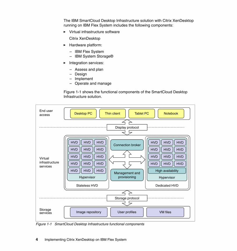
The IBM SmartCloud Desktop Infrastructure solution with Citrix XenDesktop running on IBM Flex System includes the following components:
� Virtual infrastructure software
Citrix XenDesktop
� Hardware platform:
– IBM Flex System– IBM System Storage®
� Integration services:
– Assess and plan– Design– Implement– Operate and manage
Figure 1-1 shows the functional components of the SmartCloud Desktop Infrastructure solution.
Figure 1-1 SmartCloud Desktop Infrastructure functional components
Storage services
Virtualinfrastructureservices
End useraccess
Management and provisioning
Image repository VM filesUser profiles
Connection broker
Hypervisor
Thin client NotebookTablet PCDesktop PC
HVD HVD HVD
HVD HVD HVD
Hypervisor
HVD HVD HVD
HVD HVD HVD
HVD HVD HVD
HVD HVD HVD
HVD HVD HVD
HVD HVD HVD
HVD HVD HVD
Display protocol
Storage protocol
Stateless HVD Dedicated HVD
High availability
4 Implementing Citrix XenDesktop on IBM Flex System
The SmartCloud Desktop Infrastructure solution consists of three functional layers:
� User access layer
The user access layer is a user entry point into the virtual infrastructure. Devices that are supported at this layer include traditional desktop PCs, thin clients, notebooks, and handheld mobile devices.
� Virtual infrastructure services layer
The virtual infrastructure services layer provides the secure, compliant, and highly available desktop environment to the user. The user access layer interacts with the virtual infrastructure layer through display protocols. The Remote Desktop Protocol (RDP), half-duplex (HDX), and Independent Channel Architecture (ICA) display protocols are available in Citrix XenDesktop.
� Storage services layer
The storage services layer stores user persona, profiles, gold master images, and actual virtual desktop images. The storage protocol is an interface between virtual infrastructure services and storage services. The storage protocols supported by Citrix XenDesktop include Network File System (NFS), Common Internet File System (CIFS), iSCSI, and Fibre Channel.
The virtual infrastructure services layer has the following key functional components:
� Hypervisor
The hypervisor provides a virtualized environment for running virtual machines (VMs) with the desktop operating systems in them. These VMs are called hosted virtual desktops.
� Hosted virtual desktops
An HVD is a VM that runs a user desktop operating system and applications.
� Connection broker
The connection broker is the point of contact for the client access devices that request the virtual desktops. The connection broker manages the authentication function and ensures that only valid users are allowed access to the infrastructure. When authenticated, it directs the clients to their assigned desktops. If the virtual desktop is unavailable, the connection broker works with the management and provisioning services to have the VM ready and available.
Chapter 1. IBM SmartCloud Desktop Infrastructure overview 5
� Management and provisioning services
The management and provisioning services allow the centralized management of the virtual infrastructure, providing a single console to manage multiple tasks. They provide image management, lifecycle management, and monitoring for hosted VMs.
� High availability services
High availability (HA) services ensure that the VM is up and running even if a critical software or hardware failure occurs. HA can be a part of connection broker function for stateless HVDs or a separate failover service for dedicated HVDs.
There are two types of the assignment models for the user HVDs: persistent and non-persistent.
A persistent (also known as stateful or dedicated) HVD is assigned permanently to the specific user (similar to a traditional desktop PC). Users log in to the same virtual desktop image every time they connect. All changes that they make and each application that they install are saved when the user logs off. The dedicated desktop model is best for users who need the ability to install more applications, store data locally, and retain the ability to work offline.
A non-persistent (also known as pooled or stateless) HVD is allocated temporarily to the user. After the user logs off, changes to the image are discarded (reset). Then, the desktop becomes available for the next user, or a new desktop is created for the next user session. A persistent user experience (the ability to personalize the desktop and save data) is achieved through user profile management, folder redirection, and similar approaches. Specific individual applications can be provided to nonpersistent desktops by using application virtualization technologies, if required.
Functional layers and components are supported by a hardware infrastructure platform that must provide the following features:
� Sufficient computing power to support demanding workloads
� Scalability to satisfy future growth requirements
� Reliability to support business continuity and 24x7 operations
� High-speed, low-latency networking for a better user experience
� Cost-efficient storage to handle large amounts of VM and user data
� Centralized management of combined physical and virtual infrastructure from a single user interface to simplify and automate deployment, maintenance, and support tasks
IBM Flex System is an integrated platform that satisfies these requirements.
6 Implementing Citrix XenDesktop on IBM Flex System
1.3 IBM Flex System
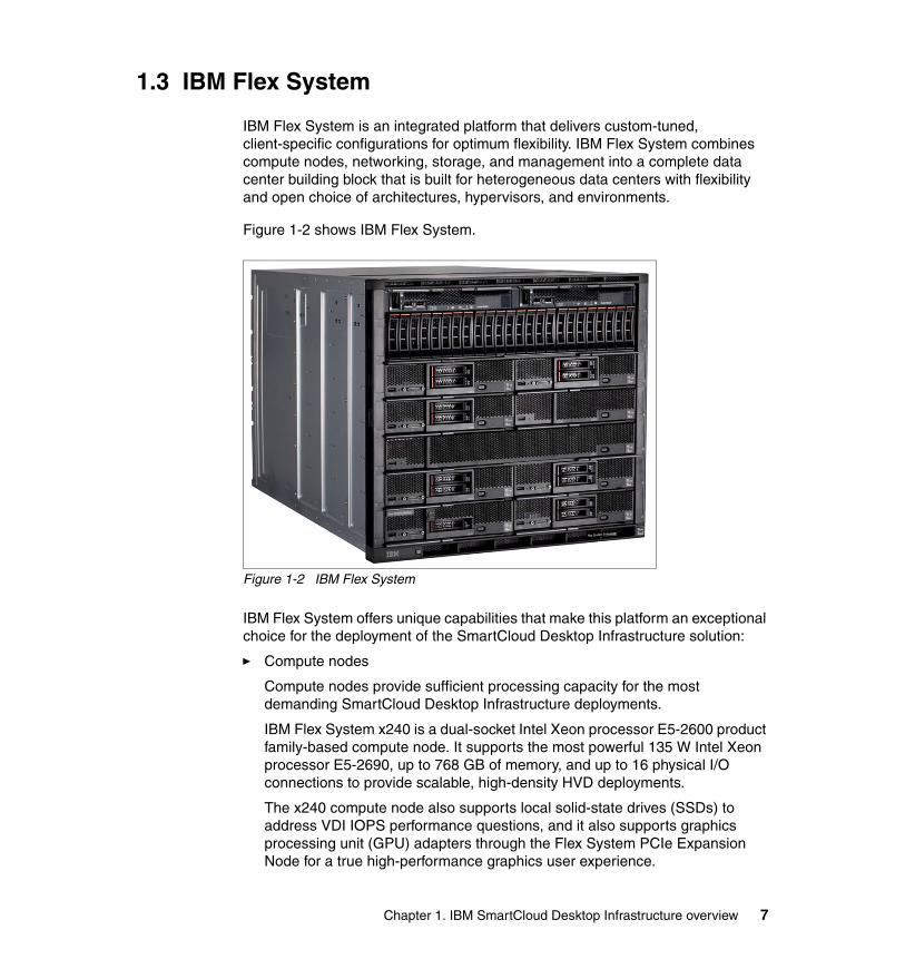
IBM Flex System is an integrated platform that delivers custom-tuned, client-specific configurations for optimum flexibility. IBM Flex System combines compute nodes, networking, storage, and management into a complete data center building block that is built for heterogeneous data centers with flexibility and open choice of architectures, hypervisors, and environments.
Figure 1-2 shows IBM Flex System.
Figure 1-2 IBM Flex System
IBM Flex System offers unique capabilities that make this platform an exceptional choice for the deployment of the SmartCloud Desktop Infrastructure solution:
� Compute nodes
Compute nodes provide sufficient processing capacity for the most demanding SmartCloud Desktop Infrastructure deployments.
IBM Flex System x240 is a dual-socket Intel Xeon processor E5-2600 product family-based compute node. It supports the most powerful 135 W Intel Xeon processor E5-2690, up to 768 GB of memory, and up to 16 physical I/O connections to provide scalable, high-density HVD deployments.
The x240 compute node also supports local solid-state drives (SSDs) to address VDI IOPS performance questions, and it also supports graphics processing unit (GPU) adapters through the Flex System PCIe Expansion Node for a true high-performance graphics user experience.
Chapter 1. IBM SmartCloud Desktop Infrastructure overview 7
IBM Flex System x222 Compute Node is a high-density dual-server offering that has two independent dual-socket servers in one mechanical package. Each server has two 10 GbE Virtual Fabric ports, and it supports up to 384 GB of memory. The
The x222 can be used as a dense VDI compute node for virtual desktops that do not require large amounts of memory.
� Networking
SmartCloud Desktop Infrastructure requires sufficient network bandwidth and efficient traffic management to host as many VMs as possible to ensure that all computing resources are not underutilized. IBM Flex System networking with IBM Virtual Fabric capabilities, when integrated into a chassis, can help to reduce communication latency and provide the required bandwidth with 10 Gb Ethernet LAN connectivity that has 40 Gb uplinks and 8 Gb or 16 Gb FC SAN connectivity.
Virtual Fabric Adapters offer virtual network interface card (NIC) capability to allow up to 32 logical ports on a single compute node, with controllable bandwidth allocation to manage traffic prioritization. vNIC capability helps to simplify deployment and bandwidth management for VDI hosts by providing flexible network configuration capabilities.
� Management
IBM Flex System Manager™ is a systems management appliance that drives efficiency and cost savings in the data center. Flex System Manager provides a pre-integrated and virtualized management environment across servers, storage, and networking that is easily managed from a single interface. A single focus point for seamless multichassis management provides an instant and resource-oriented view of chassis and chassis resources for IBM System x and IBM Power Systems™ compute nodes.
Flex System Manager allows centralized management of the ESXi hypervisors used in the IBM XenDesktop architecture, and it also supports configuration patterns to simplify deployment of VDI hosts.
� Storage
As virtualized storage systems, integrated IBM Flex System V7000 Storage Node or external IBM Storwize® V7000 complement virtual desktop environments. These systems offer robust enterprise-class storage capabilities, which include thin provisioning, automated tiering, internal and external virtualization, clustering, replication, multiprotocol support, and a next-generation graphical user interface (GUI). These features can be applied in virtual desktop environments to optimize storage capacity and performance and to simplify desktop user profile management and backup. These systems are flexible enough to support entry virtual desktop environments, but can also be scaled to support enterprise virtual desktop environments.
8 Implementing Citrix XenDesktop on IBM Flex System
In summary, IBM Flex System in a SmartCloud Desktop Infrastructure solution can help to achieve the following advantages:
� Better VM density due to support for top Intel Xeon processors and large memory and I/O capacity
� Better virtual desktop performance and better utilization of VDI server resources with flexible local SSD support
� Transparent support for high-performance remote graphics through PCIe Expansion Node with GPU adapters installed
� Lower communication latency due to integrated switching capabilities for a better user experience
� Simplified deployment and management of both physical and virtual infrastructures due to integrated design and IBM Flex System Manager capabilities
1.4 Citrix XenDesktop
IBM SmartCloud Desktop Infrastructure with Citrix XenDesktop can help to transform Microsoft Windows desktops, applications, and data into a cloud-type service that is accessible on virtually any device, anywhere. Citrix offers tailored solutions that range from the affordable, all-in-one Citrix VDI-in-a-Box for simple IT organizations to the enterprise-wide Citrix XenDesktop. XenDesktop is a comprehensive desktop virtualization solution for every user with multiple delivery models that are optimized for flexibility and cost efficiency. Both solution types deliver a rich, high-definition user experience across any network that uses Citrix HDX technologies.
By using the open architecture of Citrix XenDesktop, clients can adopt desktop virtualization quickly and easily with any hypervisor, storage, or management infrastructure.
The following XenDesktop features and benefits provide a familiar experience for the user:
� Multiple monitor support� 3D graphics business application support� Multimedia support� Printing from a virtual desktop� Accessing USB devices and other peripheral devices� Roaming user profiles
Chapter 1. IBM SmartCloud Desktop Infrastructure overview 9
XenDesktop offers several levels of security features, including the following features:
� Multifactor authentication� Traffic encryption� Built-in password management� Secure Sockets Layer (SSL) tunneling to ensure that all connections are
encrypted
The following Citrix XenDesktop features provide centralized administration and management:
� Microsoft Active Directory� Web-based administrative console� Automated desktop provisioning and storage optimization
XenDesktop includes the following scalability, integration, and optimization features:
� VMware vSphere, Microsoft Hyper-V, and XenServer hypervisor support
� Integration with VMware vCenter to achieve cost-effective densities, high levels of availability, and advanced resource allocation control for virtual desktops
� Automated provisioning of desktop images that share virtual disks with a master image
10 Implementing Citrix XenDesktop on IBM Flex System
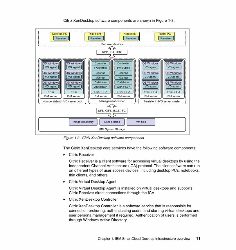
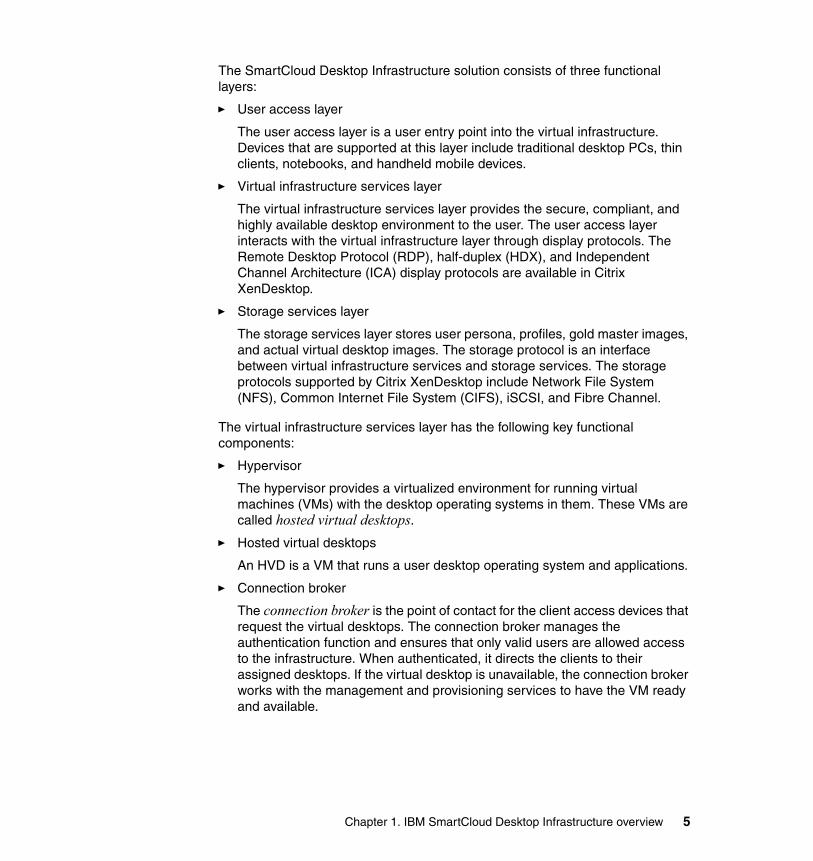
Citrix XenDesktop software components are shown in Figure 1-3.
Figure 1-3 Citrix XenDesktop software components
The Citrix XenDesktop core services have the following software components:
� Citrix Receiver
Citrix Receiver is a client software for accessing virtual desktops by using the Independent Channel Architecture (ICA) protocol. The client software can run on different types of user access devices, including desktop PCs, notebooks, thin clients, and others.
� Citrix Virtual Desktop Agent
Citrix Virtual Desktop Agent is installed on virtual desktops and supports Citrix Receiver direct connections through the ICA.
� Citrix XenDesktop Controller
Citrix XenDesktop Controller is a software service that is responsible for connection brokering, authenticating users, and starting virtual desktops and user persona management if required. Authentication of users is performed through Windows Active Directory.
IBM serverESXi + HA
Non-persistent HVD server pool
IBM serverESXi
OS WindowsVD agent
Management cluster
OS WindowsVD agent
OS WindowsVD agent
IBM serverESXi
OS WindowsVD agent
OS WindowsVD agent
OS WindowsVD agent
Persistent HVD server cluster
IBM serverESXi + HA
OS WindowsVD agent
OS WindowsVD agent
OS WindowsVD agent
IBM serverESXi + HA
OS WindowsVD agent
OS WindowsVD agent
OS WindowsVD agent
vCenter
IBM serverESXi + HA
DatabaseAD/DHCP
End user devices
IBM System Storage
Image repository VM filesUser profiles
License
Controller
PVS/MCS
vCenterDatabaseAD/DHCP
License
Controller
PVS/MCS
Desktop PCReceiver
Thin clientReceiver
NotebookReceiver
Tablet PCReceiver
RDP, ICA, HDX
NFS, CIFS, iSCSI, FC
Chapter 1. IBM SmartCloud Desktop Infrastructure overview 11
� Citrix Provisioning Services or Machine Creation Services
Citrix Provisioning Services and Machine Creation Services create and provision virtual desktops from desktop images. Provisioning Services support stateless HVD pools, and Machine Creation Services can support both stateless and dedicated HVD pools.
� Citrix License Server
Citrix License Server manages licenses for all XenDesktop components.
� Citrix Data Store
Citrix Data Store is a database that stores configuration information for the XenDesktop environment.
� VMware ESXi
VMware ESXi is a hypervisor that is used to host VMs.
� VMware vCenter
The VMware vCenter service acts as a central administrator for VMware ESX and ESXi servers that are connected on a network. vCenter Server provides a central point for configuring, provisioning, and managing VMs in the data center.
1.5 Integration with other IBM software products
IBM SmartCloud Desktop Infrastructure enables easy integration with optional security and endpoint management technologies, including the following technologies:
� IBM Security Access Manager for Enterprise Single Sign-On offers streamlined user access with automated sign-on and sign-off plus a single password for all applications. This technology can reduce help desk costs, improve productivity, and strengthen security for virtualized desktops.
� IBM Tivoli® Endpoint Manager combines endpoint and security management into a single solution. With this solution, your team can see and manage physical and virtual endpoints, such as servers, desktops, roaming notebooks, and specialized equipment, such as point-of-sale devices, automated teller machines (ATMs), and self-service kiosks.
12 Implementing Citrix XenDesktop on IBM Flex System
Chapter 2. IBM Flex System components for the virtual desktop infrastructure
This chapter introduces IBM Flex System building blocks and IBM System x servers to consider during the design of the virtual desktop infrastructure (VDI). It provides guidelines about how to use them to optimize the solution.
This chapter covers the following topics:
� 2.1, “Introduction to IBM Flex System” on page 14� 2.2, “Planning for Flex System components” on page 15� 2.3, “IBM Flex System compute nodes” on page 16� 2.4, “Storage considerations” on page 23� 2.5, “Network considerations” on page 29� 2.6, “Management considerations” on page 40
2
© Copyright IBM Corp. 2014. All rights reserved. 13
2.1 Introduction to IBM Flex System
The IBM PureFlex System is a fully integrated system with unified management of compute, storage, networking, and virtualization resources. These resources use built-in patterns of expertise based on decades of IBM experience and thousands of client deployments.
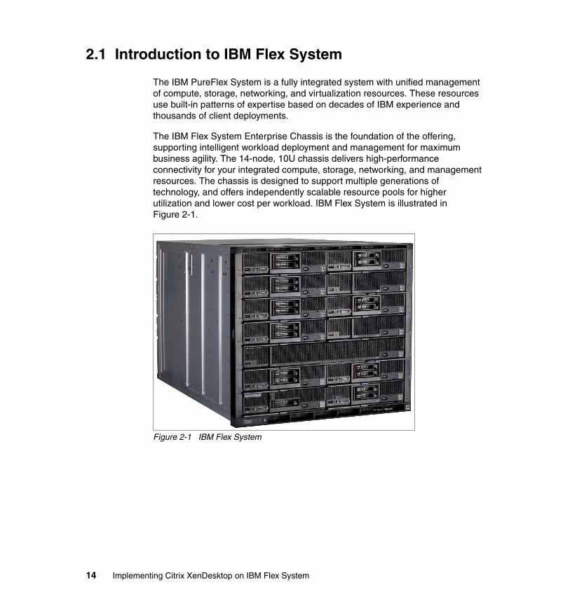
The IBM Flex System Enterprise Chassis is the foundation of the offering, supporting intelligent workload deployment and management for maximum business agility. The 14-node, 10U chassis delivers high-performance connectivity for your integrated compute, storage, networking, and management resources. The chassis is designed to support multiple generations of technology, and offers independently scalable resource pools for higher utilization and lower cost per workload. IBM Flex System is illustrated in Figure 2-1.
Figure 2-1 IBM Flex System
14 Implementing Citrix XenDesktop on IBM Flex System
2.2 Planning for Flex System components
To design your Flex System infrastructure, you need to determine the resources that are needed by your infrastructure servers, your persistent and non-persistent desktops.
Each category of user operates a specific software platform with a given workload, which involves different hardware resources. Consumption assessment on resource utilization must be performed for each category of user for the following resources:
� CPU
� Memory
� I/O characteristics: size, percentage of reads and writes, and type of access: random or sequential
� Size of user data and user profile
� Graphic utilization profile
Then, for each category of user or workload profile, you can translate the assessed requirements into compute node resources. CPU, memory, and graphic requirements have to be considered for compute node design. Requirements for I/O and storage for data determine the network and storage design.
Use the following considerations to size your compute nodes:
� Do not overcommit memory because disk swapping will deteriorate the performance.
� Do not overcommit processors as a best practice. If too many virtual machines (VMs) are used, the response time deteriorates quickly.
� Plan for failover. If one or more compute nodes fail, the user VMs hosted on the failed compute nodes need to be reallocated over the remaining compute nodes. As a best practice, allow for overhead of 20% in both memory and processor to support these additional VMs without reaching the compute node boundaries.
� The hypervisor uses 3 GB - 6 GB of compute node memory and 1 CPU core.
To define the storage solution, consider the subject in multiple parts:
� Storage for the infrastructure servers. A shared storage is the best solution.
� Storage for the persistent VMs. Privilege is also a shared storage.
� Storage for the non-persistent VMs. Consider using local storage or shared storage with high I/O performance.
Chapter 2. IBM Flex System components for the virtual desktop infrastructure 15
� Storage connectivity. Consider a separate Fibre Channel SAN to achieve potentially better performance, availability, scalability, and security with moderate to heavy storage workloads. Consider converged FCoE/iSCSI or unified NAS storage to achieve potentially better total cost of ownership (TCO) with light-to-medium storage workloads.
To achieve higher availability, consider redundancy for the I/O modules: Ethernet network switches and storage SAN switches.
2.3 IBM Flex System compute nodes
The choice for computer nodes is wide because it is designed for multiple generations of technology. The following available IBM Flex System compute nodes offer high performance for virtualization:
� Flex System x222� Flex System x240� Flex System x440
The choice of compute nodes depends on the computing requirements for the VMs hosted.
Flex System x222 is designed for virtualization, dense cloud deployments, and hosted clients. It is a good choice for the clients looking to virtualize their general-purpose user applications while maximizing the density of their computing resources.
Flex System x240 is a good choice for VDI workloads that require more memory and I/O bandwidth.
For resource demanding VMs, Flex System x440 brings massive compute power and memory resources. A high VM density on a compute node can be reached. The impact for the users in a compute node failure is proportional.
Table 2-1 on page 17 compares key features of the compute nodes.
16 Implementing Citrix XenDesktop on IBM Flex System
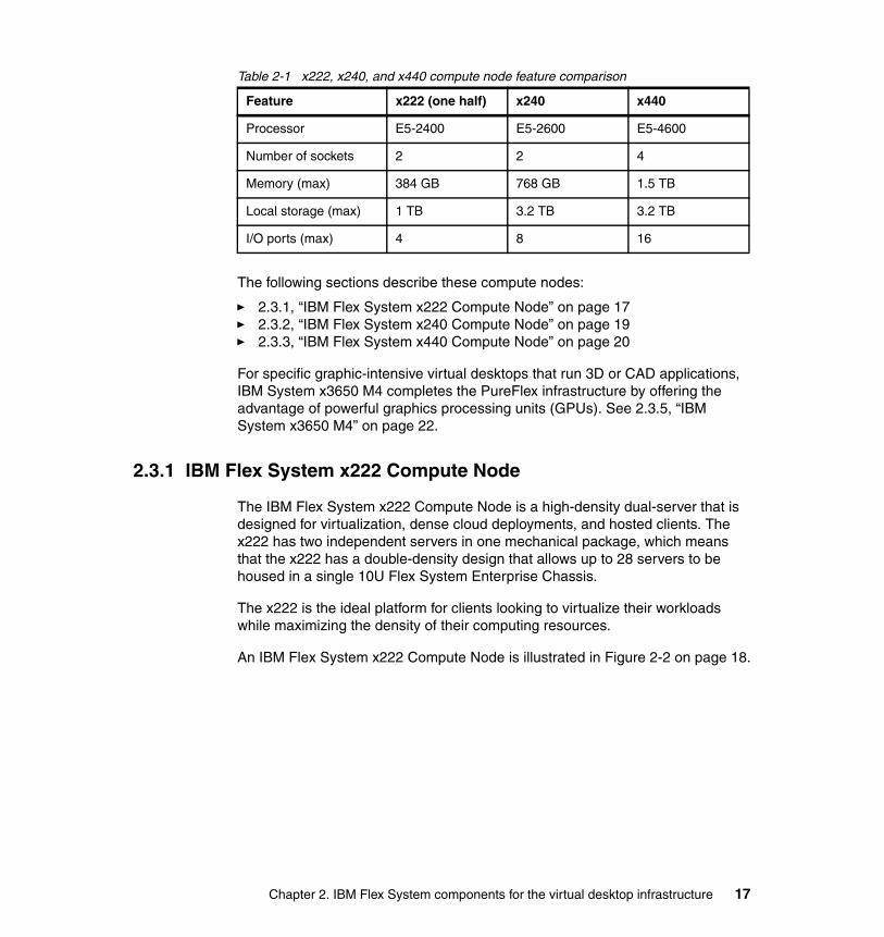
Table 2-1 x222, x240, and x440 compute node feature comparison
The following sections describe these compute nodes:
� 2.3.1, “IBM Flex System x222 Compute Node” on page 17� 2.3.2, “IBM Flex System x240 Compute Node” on page 19� 2.3.3, “IBM Flex System x440 Compute Node” on page 20
For specific graphic-intensive virtual desktops that run 3D or CAD applications, IBM System x3650 M4 completes the PureFlex infrastructure by offering the advantage of powerful graphics processing units (GPUs). See 2.3.5, “IBM System x3650 M4” on page 22.
2.3.1 IBM Flex System x222 Compute Node
The IBM Flex System x222 Compute Node is a high-density dual-server that is designed for virtualization, dense cloud deployments, and hosted clients. The x222 has two independent servers in one mechanical package, which means that the x222 has a double-density design that allows up to 28 servers to be housed in a single 10U Flex System Enterprise Chassis.
The x222 is the ideal platform for clients looking to virtualize their workloads while maximizing the density of their computing resources.
An IBM Flex System x222 Compute Node is illustrated in Figure 2-2 on page 18.
Feature x222 (one half) x240 x440
Processor E5-2400 E5-2600 E5-4600
Number of sockets 2 2 4
Memory (max) 384 GB 768 GB 1.5 TB
Local storage (max) 1 TB 3.2 TB 3.2 TB
I/O ports (max) 4 8 16
Chapter 2. IBM Flex System components for the virtual desktop infrastructure 17
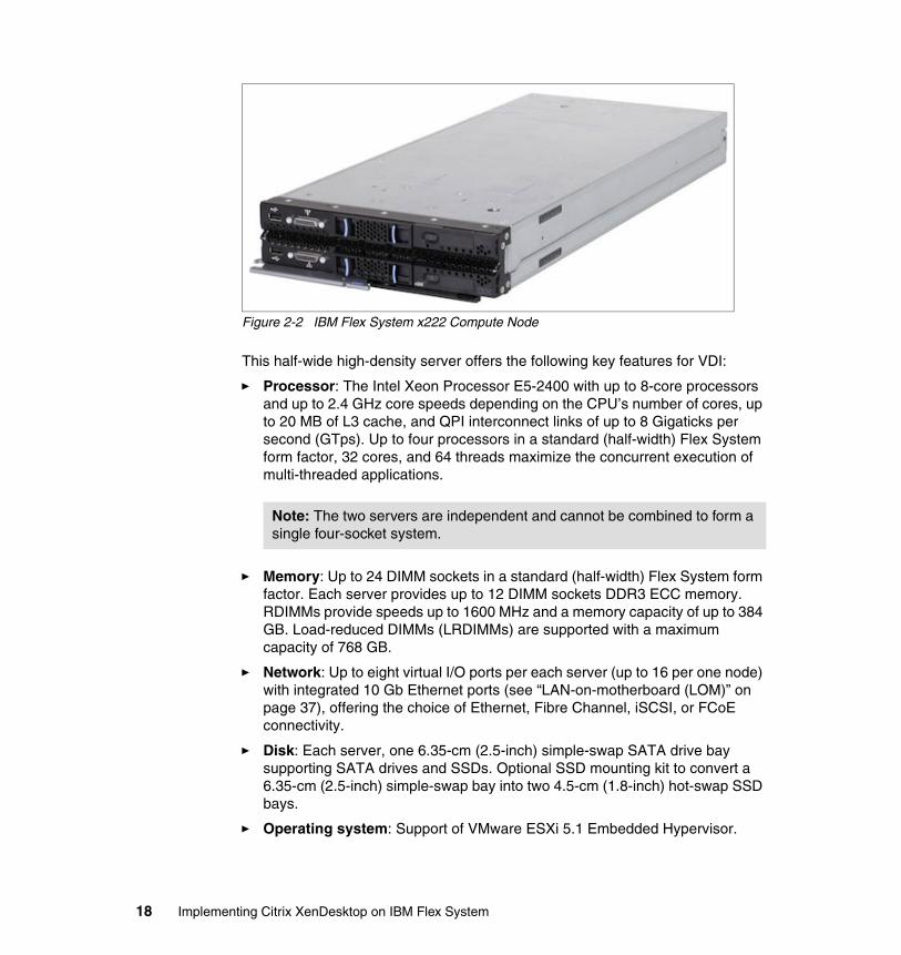
Figure 2-2 IBM Flex System x222 Compute Node
This half-wide high-density server offers the following key features for VDI:
� Processor: The Intel Xeon Processor E5-2400 with up to 8-core processors and up to 2.4 GHz core speeds depending on the CPU’s number of cores, up to 20 MB of L3 cache, and QPI interconnect links of up to 8 Gigaticks per second (GTps). Up to four processors in a standard (half-width) Flex System form factor, 32 cores, and 64 threads maximize the concurrent execution of multi-threaded applications.
� Memory: Up to 24 DIMM sockets in a standard (half-width) Flex System form factor. Each server provides up to 12 DIMM sockets DDR3 ECC memory. RDIMMs provide speeds up to 1600 MHz and a memory capacity of up to 384 GB. Load-reduced DIMMs (LRDIMMs) are supported with a maximum capacity of 768 GB.
� Network: Up to eight virtual I/O ports per each server (up to 16 per one node) with integrated 10 Gb Ethernet ports (see “LAN-on-motherboard (LOM)” on page 37), offering the choice of Ethernet, Fibre Channel, iSCSI, or FCoE connectivity.
� Disk: Each server, one 6.35-cm (2.5-inch) simple-swap SATA drive bay supporting SATA drives and SSDs. Optional SSD mounting kit to convert a 6.35-cm (2.5-inch) simple-swap bay into two 4.5-cm (1.8-inch) hot-swap SSD bays.
� Operating system: Support of VMware ESXi 5.1 Embedded Hypervisor.
Note: The two servers are independent and cannot be combined to form a single four-socket system.
18 Implementing Citrix XenDesktop on IBM Flex System
2.3.2 IBM Flex System x240 Compute Node
The IBM Flex System x240 Compute Node is a high-performance Intel Xeon processor-based server that offers outstanding performance for virtualization with new levels of processor performance and memory capacity, and high networking bandwidth.
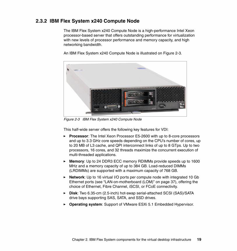
An IBM Flex System x240 Compute Node is illustrated on Figure 2-3.
Figure 2-3 IBM Flex System x240 Compute Node
This half-wide server offers the following key features for VDI:
� Processor: The Intel Xeon Processor E5-2600 with up to 8-core processors and up to 3.3 GHz core speeds depending on the CPU’s number of cores, up to 20 MB of L3 cache, and QPI interconnect links of up to 8 GTps. Up to two processors, 16 cores, and 32 threads maximize the concurrent execution of multi-threaded applications.
� Memory: Up to 24 DDR3 ECC memory RDIMMs provide speeds up to 1600 MHz and a memory capacity of up to 384 GB. Load-reduced DIMMs (LRDIMMs) are supported with a maximum capacity of 768 GB.
� Network: Up to 16 virtual I/O ports per compute node with integrated 10 Gb Ethernet ports (see “LAN-on-motherboard (LOM)” on page 37), offering the choice of Ethernet, Fibre Channel, iSCSI, or FCoE connectivity.
� Disk: Two 6.35-cm (2.5-inch) hot-swap serial-attached SCSI (SAS)/SATA drive bays supporting SAS, SATA, and SSD drives.
� Operating system: Support of VMware ESXi 5.1 Embedded Hypervisor.
Chapter 2. IBM Flex System components for the virtual desktop infrastructure 19
The x240 compute node can also be equipped with the Flex System PCIe Expansion Node, which is used to attach additional PCI Express cards, such as next-generation graphics processing units (GPU), to it. This capability is ideal for many desktop applications that require hardware acceleration using a PCI Express GPU card.
2.3.3 IBM Flex System x440 Compute Node
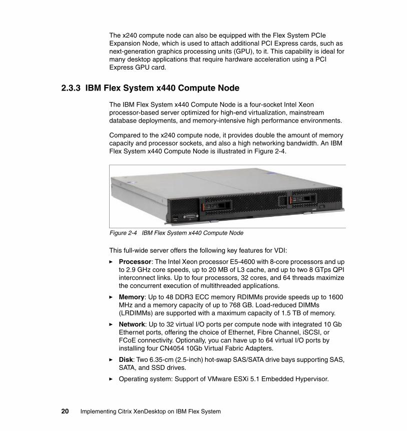
The IBM Flex System x440 Compute Node is a four-socket Intel Xeon processor-based server optimized for high-end virtualization, mainstream database deployments, and memory-intensive high performance environments.
Compared to the x240 compute node, it provides double the amount of memory capacity and processor sockets, and also a high networking bandwidth. An IBM Flex System x440 Compute Node is illustrated in Figure 2-4.
Figure 2-4 IBM Flex System x440 Compute Node
This full-wide server offers the following key features for VDI:
� Processor: The Intel Xeon processor E5-4600 with 8-core processors and up to 2.9 GHz core speeds, up to 20 MB of L3 cache, and up to two 8 GTps QPI interconnect links. Up to four processors, 32 cores, and 64 threads maximize the concurrent execution of multithreaded applications.
� Memory: Up to 48 DDR3 ECC memory RDIMMs provide speeds up to 1600 MHz and a memory capacity of up to 768 GB. Load-reduced DIMMs (LRDIMMs) are supported with a maximum capacity of 1.5 TB of memory.
� Network: Up to 32 virtual I/O ports per compute node with integrated 10 Gb Ethernet ports, offering the choice of Ethernet, Fibre Channel, iSCSI, or FCoE connectivity. Optionally, you can have up to 64 virtual I/O ports by installing four CN4054 10Gb Virtual Fabric Adapters.
� Disk: Two 6.35-cm (2.5-inch) hot-swap SAS/SATA drive bays supporting SAS, SATA, and SSD drives.
� Operating system: Support of VMware ESXi 5.1 Embedded Hypervisor.
20 Implementing Citrix XenDesktop on IBM Flex System
2.3.4 IBM Flex System PCIe Expansion Node
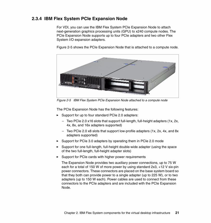
For VDI, you can use the IBM Flex System PCIe Expansion Node to attach next-generation graphics processing units (GPU) to x240 compute nodes. The PCIe Expansion Node supports up to four PCIe adapters and two other Flex System I/O expansion adapters.
Figure 2-5 shows the PCIe Expansion Node that is attached to a compute node.
Figure 2-5 IBM Flex System PCIe Expansion Node attached to a compute node
The PCIe Expansion Node has the following features:
� Support for up to four standard PCIe 2.0 adapters:
– Two PCIe 2.0 x16 slots that support full-length, full-height adapters (1x, 2x, 4x, 8x, and 16x adapters supported)
– Two PCIe 2.0 x8 slots that support low-profile adapters (1x, 2x, 4x, and 8x adapters supported)
� Support for PCIe 3.0 adapters by operating them in PCIe 2.0 mode
� Support for one full-length, full-height double-wide adapter (using the space of the two full-length, full-height adapter slots)
� Support for PCIe cards with higher power requirements
The Expansion Node provides two auxiliary power connections, up to 75 W each for a total of 150 W of more power by using standard 2x3, +12 V six-pin power connectors. These connectors are placed on the base system board so that they both can provide power to a single adapter (up to 225 W), or to two adapters (up to 150 W each). Power cables are used to connect from these connectors to the PCIe adapters and are included with the PCIe Expansion Node.
Chapter 2. IBM Flex System components for the virtual desktop infrastructure 21
� Two Flex System I/O expansion connectors
These I/O connectors expand the I/O capability of the attached compute node.
Table 2-2 lists the PCIe GPU adapters that can be used in the VDI solutions.
Table 2-2 Supported adapters
NVIDIA GRID K1 and K2 are designed for VDI. NVIDIA GRID cards can be shared between multiple users, with up to 100 concurrent users in GPU sharing the configuration for K1. K2 is intended to support heavy 3D applications, such as two power users in a GPU pass-through configuration.
2.3.5 IBM System x3650 M4
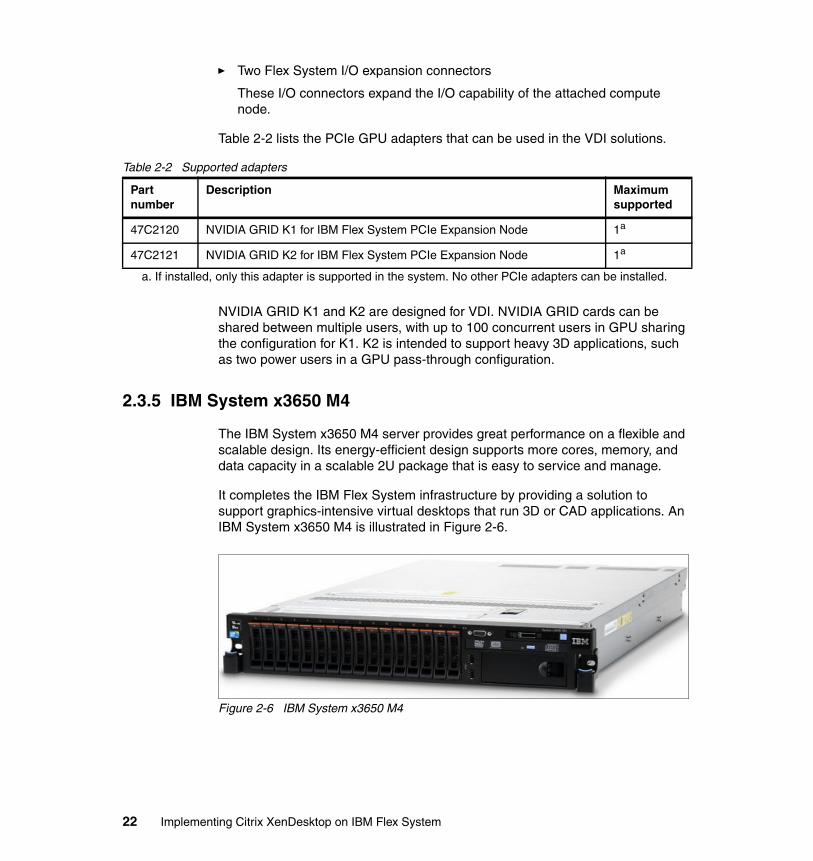
The IBM System x3650 M4 server provides great performance on a flexible and scalable design. Its energy-efficient design supports more cores, memory, and data capacity in a scalable 2U package that is easy to service and manage.
It completes the IBM Flex System infrastructure by providing a solution to support graphics-intensive virtual desktops that run 3D or CAD applications. An IBM System x3650 M4 is illustrated in Figure 2-6.
Figure 2-6 IBM System x3650 M4
Partnumber
Description Maximumsupported
47C2120 NVIDIA GRID K1 for IBM Flex System PCIe Expansion Node 1a
a. If installed, only this adapter is supported in the system. No other PCIe adapters can be installed.
47C2121 NVIDIA GRID K2 for IBM Flex System PCIe Expansion Node 1a
22 Implementing Citrix XenDesktop on IBM Flex System
The following components are key for VDI:
� Processor: Intel Xeon processor E5-2600 with 8-core processors and up to 2.9 GHz core speeds, up to 20 MB of L3 cache, and up to two 8 GTps QPI interconnect links. Up to two processors, 16 cores, and 32 threads maximize the concurrent execution of multi-threaded applications.
� Memory: Supports up to 24 Load Reduced DIMMs (LRDIMMs) of 1333 MHz DDR3 ECC memory that provide speed, high availability, and a memory capacity of up to 768 GB (running at 1066 MHz).
� Video: Support for up to two NVIDIA Quadro graphics processing units (GPUs) to maximize computing power (NVIDIA Quadro 6000, 4000, and 2000).
� Network: Four integrated Gigabit Ethernet 1000BASE-T ports (RJ-45); two embedded 10 Gb Ethernet ports (10GBASE-T RJ-45 or 10GBASE-SR SFP+-based) on an optional 10 Gb Ethernet mezzanine card.
� Disk: Support for 4.5-cm (1.8-inch) solid-state drives (SSDs), 6.35-cm (2.5-inch) SSDs and HDDs, and 8.8-cm (3.5-inch) HDDs.
� Operating system: Support of VMware ESXi 5.1 Embedded Hypervisor.
2.3.6 VMware ESXi 5.1 Embedded Hypervisor
IBM offers versions of VMware vSphere Hypervisor (ESXi) customized for select IBM hardware to provide online platform management, including updating and configuring firmware, platform diagnostics, and enhanced hardware alerts.
This option delivered on a USB flash drive is compatible with IBM Flex System compute nodes and IBM System x. At the time of writing this book, the last version provided by IBM is VMware vSphere Hypervisor (ESXi) 5.1.
Choose this option on the compute nodes that make up the VDI infrastructure:
� Reduce server deployment time. IBM Flex System Management integrates the management of the VMware vSphere Hypervisor (ESXi).
� Use a diskless compute node, reducing cost and security exposures.
� Use compute node local disks to host nonpersistent virtual desktops.
2.4 Storage considerations
Some of the storage options to consider for the VDI storage design are described.
Chapter 2. IBM Flex System components for the virtual desktop infrastructure 23
2.4.1 IBM Flex System V7000
IBM Flex System V7000 is integrated into IBM PureFlex Systems. It is designed to be a scalable internal storage system to support the compute nodes of the IBM Flex System environment.
The IBM Flex System V7000 is an innovative mid-range storage solution that combines simplicity and outstanding performance, with a compact and modular design.
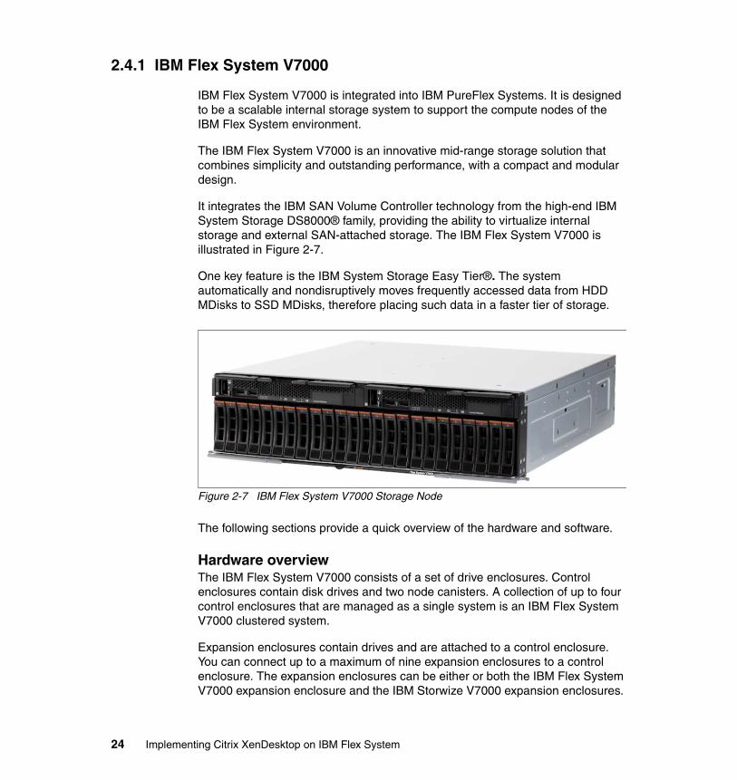
It integrates the IBM SAN Volume Controller technology from the high-end IBM System Storage DS8000® family, providing the ability to virtualize internal storage and external SAN-attached storage. The IBM Flex System V7000 is illustrated in Figure 2-7.
One key feature is the IBM System Storage Easy Tier®. The system automatically and nondisruptively moves frequently accessed data from HDD MDisks to SSD MDisks, therefore placing such data in a faster tier of storage.
Figure 2-7 IBM Flex System V7000 Storage Node
The following sections provide a quick overview of the hardware and software.
Hardware overviewThe IBM Flex System V7000 consists of a set of drive enclosures. Control enclosures contain disk drives and two node canisters. A collection of up to four control enclosures that are managed as a single system is an IBM Flex System V7000 clustered system.
Expansion enclosures contain drives and are attached to a control enclosure. You can connect up to a maximum of nine expansion enclosures to a control enclosure. The expansion enclosures can be either or both the IBM Flex System V7000 expansion enclosure and the IBM Storwize V7000 expansion enclosures.
24 Implementing Citrix XenDesktop on IBM Flex System
Up to two IBM Flex System V7000 expansion enclosures can be connected to a control enclosure. These expansion enclosures must be in the same IBM Flex System chassis as the control enclosure. Up to nine IBM Storwize V7000 expansion enclosures can be connected to the control enclosure. These IBM Storwize V7000 expansion enclosures must be mounted in the rack next to the IBM Flex System chassis where the control enclosure is installed.
Expansion canisters include the SAS interface hardware that enables the node canisters to use the drives of the expansion enclosures. An expansion enclosure cannot be connected to more than one control enclosure at the same time.
Software overviewThe IBM Flex System V7000 Storage Node provides thin provisioning, automated tiering for automated SSD optimization, internal and external virtualization, clustering, replication, multiprotocol support, and a next-generation graphical user interface (GUI).
Advantages of the IBM Flex System V7000 Storage Node include greater integration of server and storage management to automate and streamline provisioning.
The IBM Flex System V7000 software performs the following functions for the compute nodes that attach to IBM Flex System V7000:
� Creates a single pool of storage� Provides logical unit virtualization� Manages logical volumes� Manages physical resources, including drives
The IBM Flex System V7000 system also provides the following functions:
� Large scalable cache
� Copy Services:
– IBM FlashCopy® (point-in-time copy) function, including thin-provisioned FlashCopy to make multiple targets affordable
– Metro Mirror (synchronous copy)
– Global Mirror (asynchronous copy)
– Data migration
– Volume mirroring
� Space management:
– IBM System Storage Easy Tier to migrate the most frequently used data to higher performing storage
Chapter 2. IBM Flex System components for the virtual desktop infrastructure 25
– Metering of service quality when combined with IBM Tivoli Storage Productivity Center
– Thin-provisioned logical volumes
– Compressed volumes to consolidate storage
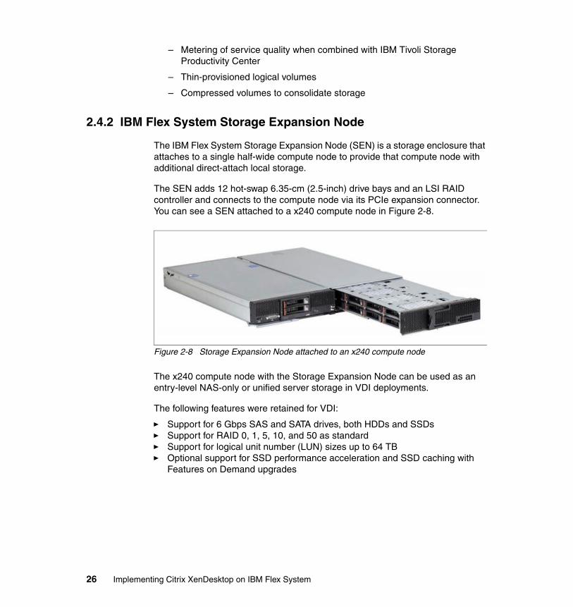
2.4.2 IBM Flex System Storage Expansion Node
The IBM Flex System Storage Expansion Node (SEN) is a storage enclosure that attaches to a single half-wide compute node to provide that compute node with additional direct-attach local storage.
The SEN adds 12 hot-swap 6.35-cm (2.5-inch) drive bays and an LSI RAID controller and connects to the compute node via its PCIe expansion connector. You can see a SEN attached to a x240 compute node in Figure 2-8.
Figure 2-8 Storage Expansion Node attached to an x240 compute node
The x240 compute node with the Storage Expansion Node can be used as an entry-level NAS-only or unified server storage in VDI deployments.
The following features were retained for VDI:
� Support for 6 Gbps SAS and SATA drives, both HDDs and SSDs� Support for RAID 0, 1, 5, 10, and 50 as standard � Support for logical unit number (LUN) sizes up to 64 TB� Optional support for SSD performance acceleration and SSD caching with
Features on Demand upgrades
26 Implementing Citrix XenDesktop on IBM Flex System
2.4.3 IBM FlashSystem 820 and IBM FlashSystem 720
IBM FlashSystem™ storage systems deliver advanced performance, scalability, reliability, security, and energy-efficiency features. FlashSystem 720 and FlashSystem 820 storage systems are the appropriate choice for mission-critical enterprise environments with the following characteristics: high storage performance requirements, such as low latency (microseconds as opposed to milliseconds), high bandwidth (gigabytes per second), or high IOPS (hundreds of thousands of I/O operations per second).
IBM FlashSystem storage systems deliver over 500,000 read IOPS and up to 5 GBps bandwidth with less than 100 microseconds latency. They provide up to 24 TB of total usable capacity or up to 20 TB of 2D Flash RAID protected data storage just in 1U of rack space. The IOPS specifications are shown in Table 2-3.
The FlashSystem 820, based on enterprise multi-level cell (eMLC) flash, is targeted to read-heavy workloads, where workload is distributed across multiple servers.
Based on single level cell (SLC) flash, the FlashSystem 720 is targeted to write-heavy enterprise workloads.
Table 2-3 IOPS specification
It completes the IBM Flex System infrastructure by providing the best performance solution for standard shared primary data storage devices, even compared to those that incorporate SSDs or flash technology.
These storage options can be integrated with IBM Flex System V7000, to be used as the top tier of storage with traditional arrays, provided by the IBM Easy Tier functionality.
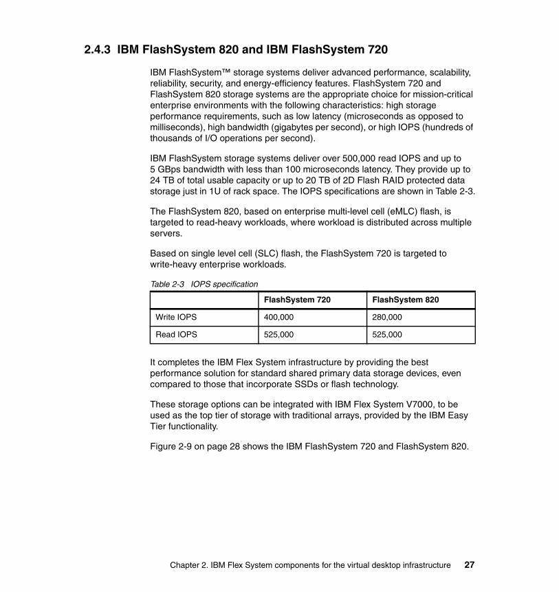
Figure 2-9 on page 28 shows the IBM FlashSystem 720 and FlashSystem 820.
FlashSystem 720 FlashSystem 820
Write IOPS 400,000 280,000
Read IOPS 525,000 525,000
Chapter 2. IBM Flex System components for the virtual desktop infrastructure 27
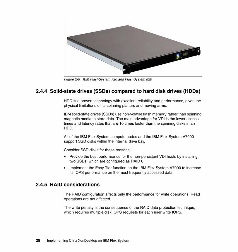
Figure 2-9 IBM FlashSystem 720 and FlashSystem 820
2.4.4 Solid-state drives (SSDs) compared to hard disk drives (HDDs)
HDD is a proven technology with excellent reliability and performance, given the physical limitations of its spinning platters and moving arms.
IBM solid-state drives (SSDs) use non-volatile flash memory rather than spinning magnetic media to store data. The main advantage for VDI is the lower access times and latency rates that are 10 times faster than the spinning disks in an HDD.
All of the IBM Flex System compute nodes and the IBM Flex System V7000 support SSD disks within the internal drive bay.
Consider SSD disks for these reasons:
� Provide the best performance for the non-persistent VDI hosts by installing two SSDs, which are configured as RAID 0
� Implement the Easy Tier function on the IBM Flex System V7000 to increase its IOPS performance on the most frequently accessed data
2.4.5 RAID considerations
The RAID configuration affects only the performance for write operations. Read operations are not affected.
The write penalty is the consequence of the RAID data protection technique, which requires multiple disk IOPS requests for each user write IOPS.
28 Implementing Citrix XenDesktop on IBM Flex System
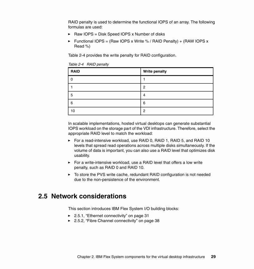
RAID penalty is used to determine the functional IOPS of an array. The following formulas are used:
� Raw IOPS = Disk Speed IOPS x Number of disks
� Functional IOPS = (Raw IOPS x Write % / RAID Penalty) + (RAW IOPS x Read %)
Table 2-4 provides the write penalty for RAID configuration.
Table 2-4 RAID penalty
In scalable implementations, hosted virtual desktops can generate substantial IOPS workload on the storage part of the VDI infrastructure. Therefore, select the appropriate RAID level to match the workload:
� For a read-intensive workload, use RAID 0, RAID 1, RAID 5, and RAID 10 levels that spread read operations across multiple disks simultaneously. If the volume of data is important, you can also use a RAID level that optimizes disk usability.
� For a write-intensive workload, use a RAID level that offers a low write penalty, such as RAID 0 and RAID 10.
� To store the PVS write cache, redundant RAID configuration is not needed due to the non-persistence of the environment.
2.5 Network considerations
This section introduces IBM Flex System I/O building blocks:
� 2.5.1, “Ethernet connectivity” on page 31� 2.5.2, “Fibre Channel connectivity” on page 38
RAID Write penalty
0 1
1 2
5 4
6 6
10 2
Chapter 2. IBM Flex System components for the virtual desktop infrastructure 29
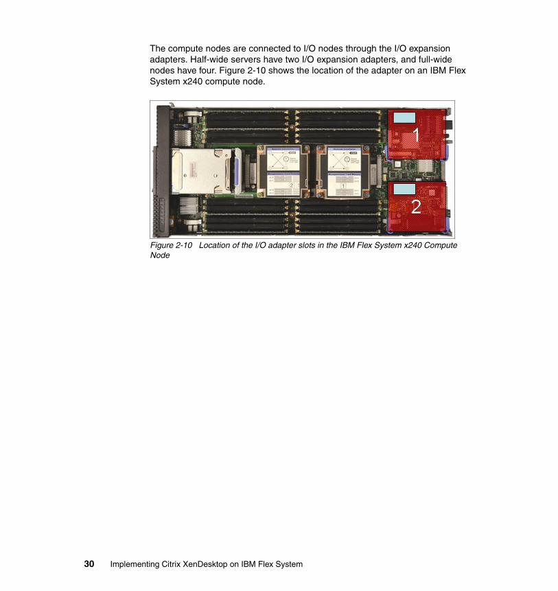
The compute nodes are connected to I/O nodes through the I/O expansion adapters. Half-wide servers have two I/O expansion adapters, and full-wide nodes have four. Figure 2-10 shows the location of the adapter on an IBM Flex System x240 compute node.
Figure 2-10 Location of the I/O adapter slots in the IBM Flex System x240 Compute Node
30 Implementing Citrix XenDesktop on IBM Flex System
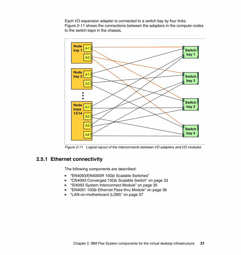
Each I/O expansion adapter is connected to a switch bay by four links. Figure 2-11 shows the connections between the adapters in the compute nodes to the switch bays in the chassis.
Figure 2-11 Logical layout of the interconnects between I/O adapters and I/O modules
2.5.1 Ethernet connectivity
The following components are described:
� “EN4093/EN4093R 10Gb Scalable Switches”� “CN4093 Converged 10Gb Scalable Switch” on page 33� “SI4093 System Interconnect Module” on page 35� “EN4091 10Gb Ethernet Pass-thru Module” on page 36� “LAN-on-motherboard (LOM)” on page 37
A1
A2
Node bay 1
A1
A2
Node bay 2
A1
A2
Node bays 13/14
A3
A4
Switchbay 1
Switchbay 3
Switchbay 2
Switchbay 4
Chapter 2. IBM Flex System components for the virtual desktop infrastructure 31
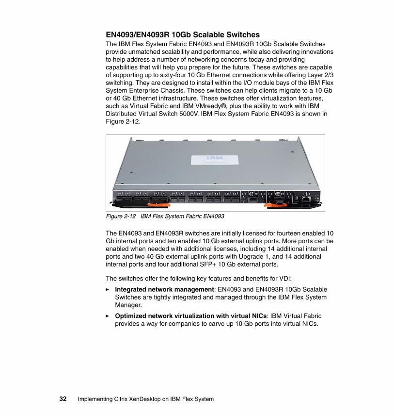
EN4093/EN4093R 10Gb Scalable SwitchesThe IBM Flex System Fabric EN4093 and EN4093R 10Gb Scalable Switches provide unmatched scalability and performance, while also delivering innovations to help address a number of networking concerns today and providing capabilities that will help you prepare for the future. These switches are capable of supporting up to sixty-four 10 Gb Ethernet connections while offering Layer 2/3 switching. They are designed to install within the I/O module bays of the IBM Flex System Enterprise Chassis. These switches can help clients migrate to a 10 Gb or 40 Gb Ethernet infrastructure. These switches offer virtualization features, such as Virtual Fabric and IBM VMready®, plus the ability to work with IBM Distributed Virtual Switch 5000V. IBM Flex System Fabric EN4093 is shown in Figure 2-12.
Figure 2-12 IBM Flex System Fabric EN4093
The EN4093 and EN4093R switches are initially licensed for fourteen enabled 10 Gb internal ports and ten enabled 10 Gb external uplink ports. More ports can be enabled when needed with additional licenses, including 14 additional internal ports and two 40 Gb external uplink ports with Upgrade 1, and 14 additional internal ports and four additional SFP+ 10 Gb external ports.
The switches offer the following key features and benefits for VDI:
� Integrated network management: EN4093 and EN4093R 10Gb Scalable Switches are tightly integrated and managed through the IBM Flex System Manager.
� Optimized network virtualization with virtual NICs: IBM Virtual Fabric provides a way for companies to carve up 10 Gb ports into virtual NICs.
32 Implementing Citrix XenDesktop on IBM Flex System
� Increased performance: The EN4093 and EN4093R are the embedded 10 GbE switches for a server chassis to support sub-microsecond latency and up to 1.28 Tbps, while also delivering full-line rate performance, making them ideal for managing dynamic workloads across the network. Furthermore, these switches provide a rich Layer 2 and Layer 3 feature set that is ideal for many of today’s data centers, and they offer industry-leading uplink bandwidth by being the first integrated switches to support 40 Gb uplinks.
� VM-aware networking: IBM System Networking’s Distributed Virtual Switch 5000V (sold separately) enables network administrators to simplify management by having a consistent virtual and physical networking environment. 5000V virtual and physical switches use the same configurations, policies, and management tools. Network policies migrate automatically along with VMs to ensure that security, performance, and access remain intact as VMs move from server to server.
CN4093 Converged 10Gb Scalable SwitchThe IBM Flex System Fabric CN4093 10Gb Converged Scalable Switch provides unmatched scalability, performance, convergence, and network virtualization. The switch offers full Layer 2/3 switching, as well as FCoE Full Fabric and Fibre Channel NPV Gateway operations to deliver a truly converged integrated solution, and it is designed to install within the I/O module bays of the IBM Flex System Enterprise Chassis. The switch can help clients migrate to a 10 Gb or 40 Gb converged Ethernet infrastructure and offers virtualization features, such as Virtual Fabric and VMready, plus the ability to work with IBM Distributed Virtual Switch 5000V.
IBM Flex System Fabric EN4093 is shown in Figure 2-13 on page 34.
Note: Internal layer 2 switches provide a more effective approach for communication between co-resident servers, by using a east/west approach. Communication between nodes uses an internal, active Layer 2 switch to pass traffic to one other. By containing network traffic within the Flex System chassis, latency is improved by 50% compared to a north/south approach. In the north/south approach, all the traffic is routed to the top-of-rack (TOR) switch, and the flow goes up to the TOR switch and down to the co-located server.
Chapter 2. IBM Flex System components for the virtual desktop infrastructure 33
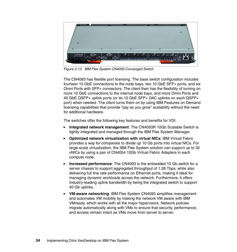
Figure 2-13 IBM Flex System CN4093 Converged Switch
The CN4093 has flexible port licensing. The base switch configuration includes fourteen 10 GbE connections to the node bays, two 10 GbE SFP+ ports, and six Omni Ports with SFP+ connectors. The client then has the flexibility of turning on more 10 GbE connections to the internal node bays, and more Omni Ports and 40 GbE QSFP+ uplink ports (or 4x 10 GbE SFP+ DAC uplinks on each QSFP+ port) when needed. The client turns them on by using IBM Features on Demand licensing capabilities that provide “pay as you grow” scalability without the need for additional hardware.
The switches offer the following key features and benefits for VDI:
� Integrated network management: The CN4093R 10Gb Scalable Switch is tightly integrated and managed through the IBM Flex System Manager.
� Optimized network virtualization with virtual NICs: IBM Virtual Fabric provides a way for companies to divide up 10 Gb ports into virtual NICs. For large-scale virtualization, the IBM Flex System solution can support up to 32 vNICs by using a pair of CN4054 10Gb Virtual Fabric Adapters in each compute node.
� Increased performance: The CN4093 is the embedded 10 Gb switch for a server chassis to support aggregated throughput of 1.28 Tbps, while also delivering full line rate performance on Ethernet ports, making it ideal for managing dynamic workloads across the network. Furthermore, it offers industry-leading uplink bandwidth by being the integrated switch to support 40 Gb uplinks.
� VM-aware networking: IBM Flex System CN4093 simplifies management and automates VM mobility by making the network VM aware with IBM VMready, which works with all the major hypervisors. Network policies migrate automatically along with VMs to ensure that security, performance, and access remain intact as VMs move from server to server.
34 Implementing Citrix XenDesktop on IBM Flex System
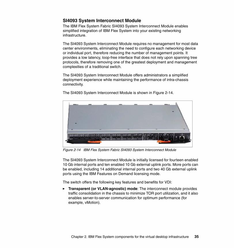
SI4093 System Interconnect ModuleThe IBM Flex System Fabric SI4093 System Interconnect Module enables simplified integration of IBM Flex System into your existing networking infrastructure.
The SI4093 System Interconnect Module requires no management for most data center environments, eliminating the need to configure each networking device or individual port, therefore reducing the number of management points. It provides a low latency, loop-free interface that does not rely upon spanning tree protocols, therefore removing one of the greatest deployment and management complexities of a traditional switch.
The SI4093 System Interconnect Module offers administrators a simplified deployment experience while maintaining the performance of intra-chassis connectivity.
The SI4093 System Interconnect Module is shown in Figure 2-14.
Figure 2-14 IBM Flex System Fabric SI4093 System Interconnect Module
The SI4093 System Interconnect Module is initially licensed for fourteen enabled 10 Gb internal ports and ten enabled 10 Gb external uplink ports. More ports can be enabled, including 14 additional internal ports and two 40 Gb external uplink ports using the IBM Features on Demand licensing mode.
The switch offers the following key features and benefits for VDI:
� Transparent (or VLAN-agnostic) mode: The interconnect module provides traffic consolidation in the chassis to minimize TOR port utilization, and it also enables server-to-server communication for optimum performance (for example, vMotion).
Chapter 2. IBM Flex System components for the virtual desktop infrastructure 35
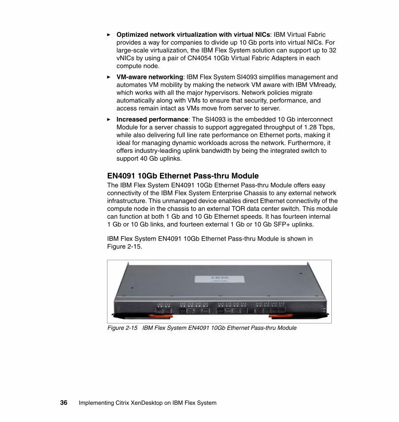
� Optimized network virtualization with virtual NICs: IBM Virtual Fabric provides a way for companies to divide up 10 Gb ports into virtual NICs. For large-scale virtualization, the IBM Flex System solution can support up to 32 vNICs by using a pair of CN4054 10Gb Virtual Fabric Adapters in each compute node.
� VM-aware networking: IBM Flex System SI4093 simplifies management and automates VM mobility by making the network VM aware with IBM VMready, which works with all the major hypervisors. Network policies migrate automatically along with VMs to ensure that security, performance, and access remain intact as VMs move from server to server.
� Increased performance: The SI4093 is the embedded 10 Gb interconnect Module for a server chassis to support aggregated throughput of 1.28 Tbps, while also delivering full line rate performance on Ethernet ports, making it ideal for managing dynamic workloads across the network. Furthermore, it offers industry-leading uplink bandwidth by being the integrated switch to support 40 Gb uplinks.
EN4091 10Gb Ethernet Pass-thru ModuleThe IBM Flex System EN4091 10Gb Ethernet Pass-thru Module offers easy connectivity of the IBM Flex System Enterprise Chassis to any external network infrastructure. This unmanaged device enables direct Ethernet connectivity of the compute node in the chassis to an external TOR data center switch. This module can function at both 1 Gb and 10 Gb Ethernet speeds. It has fourteen internal1 Gb or 10 Gb links, and fourteen external 1 Gb or 10 Gb SFP+ uplinks.
IBM Flex System EN4091 10Gb Ethernet Pass-thru Module is shown in Figure 2-15.
Figure 2-15 IBM Flex System EN4091 10Gb Ethernet Pass-thru Module
36 Implementing Citrix XenDesktop on IBM Flex System
The IBM Flex System EN4091 offers the following key features:
� It offers intelligent workload deployment and management for maximum business agility.
� The module delivers high-speed performance complete with integrated servers, storage, and networking.
� The flexible design meets the needs of varying workloads with independently scalable IT resource pools for higher utilization and lower cost per workload.
LAN-on-motherboard (LOM)The x222 and certain models of the x240 and x440 compute nodes have an Ethernet LAN-on-motherboard (LOM) controller integrated on the system board.
The LOM is installed on the I/O expansion adapter 1 (A1) of the compute node.
The I/O expansion adapter A1 routes to two switch bays for redundancy and performance. The first port is linked to the I/O module 1 within the chassis. The second port is connected to I/O module 2.
LOM offers two operational mode choices:
� One-port physical NIC mode (pNIC), multichannel disabled, which is the default. The adapter operates as a standard dual-port 10 Gbps Ethernet adapter, and it functions with any 10 GbE switch.
� Virtual NIC mode (vNIC), multichannel enabled. vNIC mode enables up to four virtual NIC interfaces per 10 Gb physical port (eight total for the LOM). Also, two options are available for vNIC linking: IBM Virtual Fabric Mode and Switch Independent Mode. Both modes offer the same capabilities in terms of the number of vNICs and the bandwidth for which each can be configured. The difference is in the direction of bandwidth control and switch support.
IBM Virtual Fabric Mode works with IBM Flex System EN4093 and EN4093R or CN4093 switches, and it allows bidirectional vNIC bandwidth metering and control for both server-to-switch and switch-to-server traffic. It uses Q-in-Q VLAN tagging to separate traffic flows from different vNICs, providing full transparency for the existing client VLANs.
Switch Independent Mode works with any switch, and the vNIC bandwidth metering and control are performed only on the adapter side, forming unidirectional virtual channel (server-to-switch). This mode extends the existing client’s VLANs to the virtual NIC interfaces.
Note: With LOM enabled, the Ethernet I/O module can only be installed on bays 1 and 2 on the chassis, because integrated NIC ports are routed to these bays with a specialized periscope connector.
Chapter 2. IBM Flex System components for the virtual desktop infrastructure 37
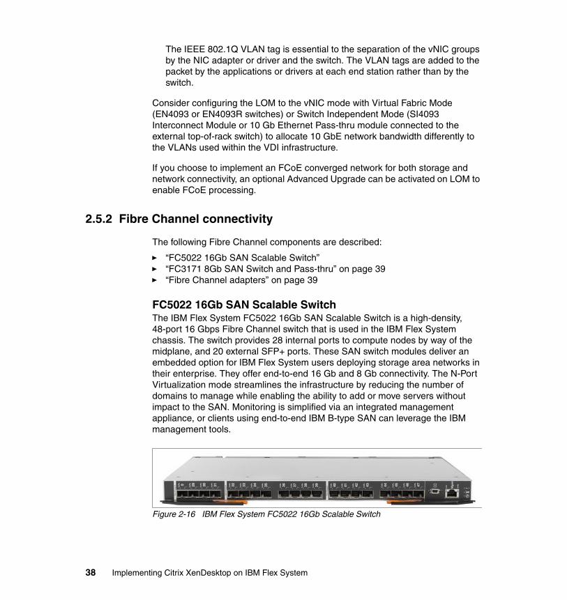
The IEEE 802.1Q VLAN tag is essential to the separation of the vNIC groups by the NIC adapter or driver and the switch. The VLAN tags are added to the packet by the applications or drivers at each end station rather than by the switch.
Consider configuring the LOM to the vNIC mode with Virtual Fabric Mode (EN4093 or EN4093R switches) or Switch Independent Mode (SI4093 Interconnect Module or 10 Gb Ethernet Pass-thru module connected to the external top-of-rack switch) to allocate 10 GbE network bandwidth differently to the VLANs used within the VDI infrastructure.
If you choose to implement an FCoE converged network for both storage and network connectivity, an optional Advanced Upgrade can be activated on LOM to enable FCoE processing.
2.5.2 Fibre Channel connectivity
The following Fibre Channel components are described:
� “FC5022 16Gb SAN Scalable Switch”� “FC3171 8Gb SAN Switch and Pass-thru” on page 39� “Fibre Channel adapters” on page 39
FC5022 16Gb SAN Scalable SwitchThe IBM Flex System FC5022 16Gb SAN Scalable Switch is a high-density, 48-port 16 Gbps Fibre Channel switch that is used in the IBM Flex System chassis. The switch provides 28 internal ports to compute nodes by way of the midplane, and 20 external SFP+ ports. These SAN switch modules deliver an embedded option for IBM Flex System users deploying storage area networks in their enterprise. They offer end-to-end 16 Gb and 8 Gb connectivity. The N-Port Virtualization mode streamlines the infrastructure by reducing the number of domains to manage while enabling the ability to add or move servers without impact to the SAN. Monitoring is simplified via an integrated management appliance, or clients using end-to-end IBM B-type SAN can leverage the IBM management tools.
Figure 2-16 IBM Flex System FC5022 16Gb Scalable Switch
38 Implementing Citrix XenDesktop on IBM Flex System
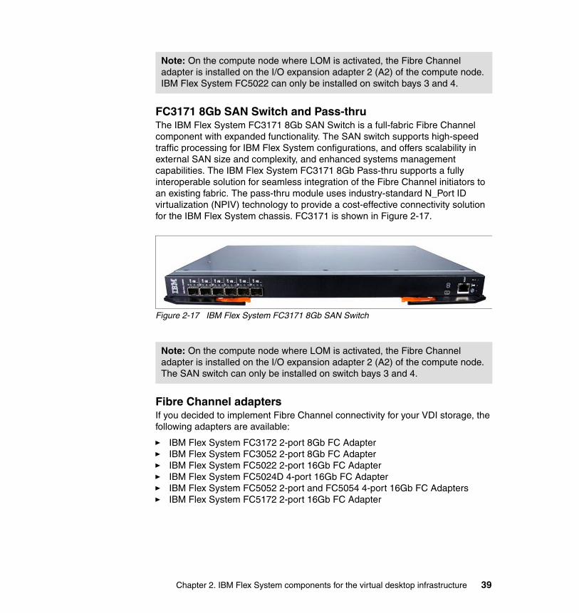
FC3171 8Gb SAN Switch and Pass-thruThe IBM Flex System FC3171 8Gb SAN Switch is a full-fabric Fibre Channel component with expanded functionality. The SAN switch supports high-speed traffic processing for IBM Flex System configurations, and offers scalability in external SAN size and complexity, and enhanced systems management capabilities. The IBM Flex System FC3171 8Gb Pass-thru supports a fully interoperable solution for seamless integration of the Fibre Channel initiators to an existing fabric. The pass-thru module uses industry-standard N_Port ID virtualization (NPIV) technology to provide a cost-effective connectivity solution for the IBM Flex System chassis. FC3171 is shown in Figure 2-17.
Figure 2-17 IBM Flex System FC3171 8Gb SAN Switch
Fibre Channel adaptersIf you decided to implement Fibre Channel connectivity for your VDI storage, the following adapters are available:
� IBM Flex System FC3172 2-port 8Gb FC Adapter� IBM Flex System FC3052 2-port 8Gb FC Adapter� IBM Flex System FC5022 2-port 16Gb FC Adapter� IBM Flex System FC5024D 4-port 16Gb FC Adapter� IBM Flex System FC5052 2-port and FC5054 4-port 16Gb FC Adapters� IBM Flex System FC5172 2-port 16Gb FC Adapter
Note: On the compute node where LOM is activated, the Fibre Channel adapter is installed on the I/O expansion adapter 2 (A2) of the compute node. IBM Flex System FC5022 can only be installed on switch bays 3 and 4.
Note: On the compute node where LOM is activated, the Fibre Channel adapter is installed on the I/O expansion adapter 2 (A2) of the compute node. The SAN switch can only be installed on switch bays 3 and 4.
Chapter 2. IBM Flex System components for the virtual desktop infrastructure 39
For more information, refer to the following IBM Flex System Product Guides for the I/O adapters:
http://www.redbooks.ibm.com/Redbooks.nsf/portals/puresystems?Open&page=pg&cat=adapters&count=999
2.6 Management considerations
This section introduces management components and features:
� 2.6.1, “Introduction to IBM Flex System Manager” on page 40� 2.6.2, “Management Network” on page 42� 2.6.3, “Chassis Management Module” on page 43� 2.6.4, “Integrated Management Module II” on page 44� 2.6.5, “Working with configuration patterns” on page 45
2.6.1 Introduction to IBM Flex System Manager
IBM Flex System Manager (FSM) is a systems management appliance that drives efficiency and cost savings in the data center. IBM Flex System Manager provides a pre-integrated and virtualized management environment across servers, storage, and networking that is easily managed from a single interface. A single focus point for seamless multichassis management provides an instant and resource-oriented view of the chassis and chassis resources for both IBM System x and IBM Power Systems compute nodes. Flex System Manager helps you realize these advantages:
� Reduce the number of interfaces, steps, and clicks that it takes to manage IT resources
� Manage and deploy workloads that are based on resource availability and predefined policies intelligently
� Manage events and alerts to increase system availability and reduce downtime
� Reduce operational costs
The IBM Flex System Manager management appliance is shown in Figure 2-18 on page 41.
40 Implementing Citrix XenDesktop on IBM Flex System
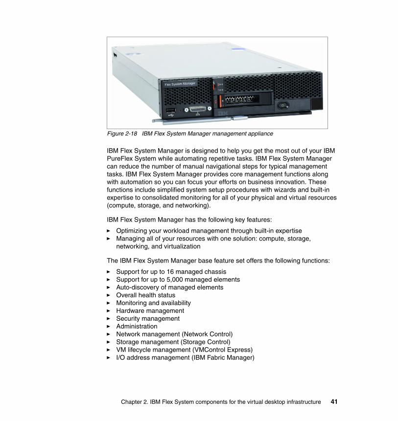
Figure 2-18 IBM Flex System Manager management appliance
IBM Flex System Manager is designed to help you get the most out of your IBM PureFlex System while automating repetitive tasks. IBM Flex System Manager can reduce the number of manual navigational steps for typical management tasks. IBM Flex System Manager provides core management functions along with automation so you can focus your efforts on business innovation. These functions include simplified system setup procedures with wizards and built-in expertise to consolidated monitoring for all of your physical and virtual resources (compute, storage, and networking).
IBM Flex System Manager has the following key features:
� Optimizing your workload management through built-in expertise� Managing all of your resources with one solution: compute, storage,
networking, and virtualization
The IBM Flex System Manager base feature set offers the following functions:
� Support for up to 16 managed chassis� Support for up to 5,000 managed elements� Auto-discovery of managed elements� Overall health status� Monitoring and availability� Hardware management� Security management� Administration� Network management (Network Control)� Storage management (Storage Control)� VM lifecycle management (VMControl Express)� I/O address management (IBM Fabric Manager)
Chapter 2. IBM Flex System components for the virtual desktop infrastructure 41

The IBM Flex System Manager Advanced feature set upgrade offers the following advanced features:
� Image management (VMControl Standard)� Pool management (VMControl Enterprise)
The Manager Node of the IBM Flex System Manager has the following fixed hardware specifications:
� One Intel Xeon processor E5-2650 8C 2.0 GHz 20 MB Cache 1600 MHz 95 W 32 GB of memory with eight 4 GB (1x4 GB, 1Rx4, 1.35 V) PC3L-10600 CL9 ECC DDR3 1333 MHz LP RDIMMs
� Integrated LSI SAS2004 RAID controller
� Two IBM 200 GB SATA 1.8” MLC SSDs configured in a RAID 1
� One IBM 1 TB 7.2 K 6 Gbps NL SATA 2.5” SFF HS HDD
� Dual-port 10 Gb Ethernet Emulex BladeEngine 3 (BE3) network controller for data network connections
� Dual-port Broadcom 5718-based network adapter with integrated Broadcom 5389 8-port basic L2 switch for internal chassis management network connections
� Integrated Management Module II (IMM2)
2.6.2 Management Network
The management network is a private and secure Gigabit Ethernet network. It is used to complete management-related functions throughout the chassis, including management tasks that are related to the compute nodes, switches, and the chassis itself.
The management network is shown in Figure 2-19 on page 43 as the blue line. It connects the Chassis Management Module (CMM) to the compute nodes, the switches in the I/O bays, and the Flex System Manager (FSM). The FSM connection to the management network is through a special Broadcom 5718-based management network adapter (Eth0). The management networks in multiple chassis can be connected through the external ports of the CMMs in each chassis by using a GbE top-of-rack switch.
The yellow line in Figure 2-19 on page 43 shows the production data network. The Flex System Manager also connects to the production network (Eth1) so that it can access the Internet for product updates and other related information.
42 Implementing Citrix XenDesktop on IBM Flex System
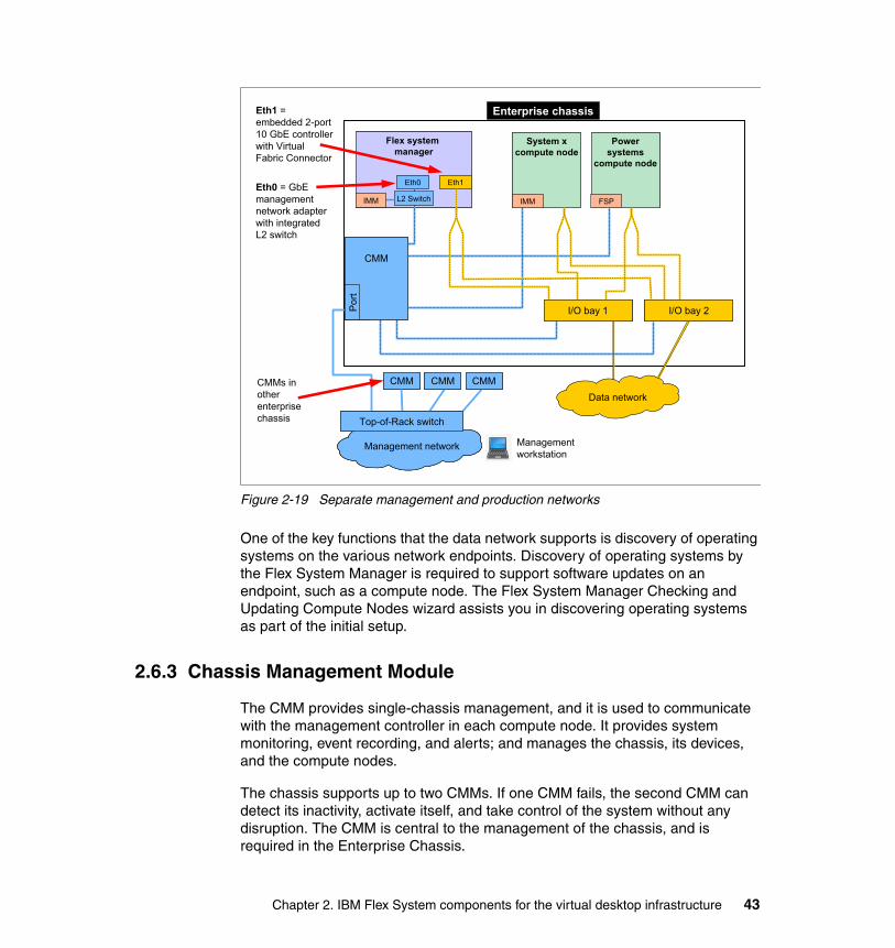
Figure 2-19 Separate management and production networks
One of the key functions that the data network supports is discovery of operating systems on the various network endpoints. Discovery of operating systems by the Flex System Manager is required to support software updates on an endpoint, such as a compute node. The Flex System Manager Checking and Updating Compute Nodes wizard assists you in discovering operating systems as part of the initial setup.
2.6.3 Chassis Management Module
The CMM provides single-chassis management, and it is used to communicate with the management controller in each compute node. It provides system monitoring, event recording, and alerts; and manages the chassis, its devices, and the compute nodes.
The chassis supports up to two CMMs. If one CMM fails, the second CMM can detect its inactivity, activate itself, and take control of the system without any disruption. The CMM is central to the management of the chassis, and is required in the Enterprise Chassis.
Enterprise chassis
Management network
CMM CMM CMM
Top-of-Rack switch
Flex system manager
Eth0 Eth1
System x compute node
Powersystems
compute node
CMM
Port
Management network
CMM CMM CMM
Top-of-Rack switch
Flex system manager
Eth0 Eth1
System x compute node
Powersystems
compute node
CMM
L2 Switch IMM FSP
Managementworkstation
CMMs in otherenterprisechassis
Eth0 = GbE managementnetwork adapter with integrated L2 switch
Eth1 =embedded 2-port 10 GbE controller with Virtual Fabric Connector
Por
t
IMM
I/O bay 1 I/O bay 2I/O bay 1 I/O bay 2
Data network
Chapter 2. IBM Flex System components for the virtual desktop infrastructure 43
Through an embedded firmware stack, the CMM implements functions to monitor, control, and provide external user interfaces to manage all chassis resources. The CMM allows you to perform these functions:
� Define login IDs and passwords
� Configure security settings, such as data encryption and user account security
� Select recipients for alert notification of specific events
� Monitor the status of the compute nodes and other components
� Find chassis component information
� Discover other chassis in the network and enable access to them
� Control the chassis, compute nodes, and other components
� Access the I/O modules to configure them
� Change the startup sequence in a compute node
� Set the date and time
� Use a remote console for the compute nodes
� Enable multichassis monitoring
� Set power policies and view power consumption history for chassis components
2.6.4 Integrated Management Module II
The Integrated Management Module II (IMM2) is the next generation of the integrated service processors for the IBM x86-based server family. The IMM2 enhancements include a more responsive user interface, faster power-on capability, and increased remote presence performance. The IMM2 incorporates a new web user interface that provides a common interface across all IBM System x software products.
The IMM2 provides the following major features as standard:
� Intelligent Peripheral Management Interface (IPMI) V2.0 compliance
� Remote configuration of IMM2 and Unified Extensible Firmware Interface (UEFI) settings without the need to power on the server
� Remote access to system fan, voltage, and temperature values
� Remote IMM and UEFI update
� UEFI update when the server is powered off
� Remote console by way of a serial over LAN
44 Implementing Citrix XenDesktop on IBM Flex System
� Remote access to the system event log
� Predictive failure analysis and integrated alerting features (for example, by using Simple Network Management Protocol (SNMP))
� Remote presence, including remote control of server by using a Java or Active x client
� Operating system failure window (blue screen) capture and display through the web interface
� Virtual media that allow the attachment of a diskette drive, CD/DVD drive, USB flash drive, or disk image to a server
� Syslog alerting mechanism that provides an alternative to email and SNMP traps
� Support for Features On Demand (FoD) enablement of server functions, option card features, and System x solutions and applications
2.6.5 Working with configuration patterns
Using configuration patterns, you can quickly provision or pre-provision multiple systems from a single pattern, and subsequent pattern changes will automatically be applied to all associated systems.
Server Configuration Patterns give us the ability to configure the storage, I/O adapter, boot order, and other Integrated Management Module (IMM) and Unified Extensible Firmware interface (UEFI) settings.
Configuration patterns also integrate support for IBM Fabric Manager so that you can virtualize server fabric connections, and failover or repurpose servers without disruption to the fabric. Also, you can initiate fabric change requests through your change management process before your hardware arrives by preconfiguring host interconnect addresses.
Chassis Configuration Patterns allow you to configure the CMM network management interface, users and security, power and acoustic settings, and basic I/O module and node IP address assignments.
Consider using this powerful method to configure your IBM Flex System infrastructure easily and quickly.
Chapter 2. IBM Flex System components for the virtual desktop infrastructure 45

46 Implementing Citrix XenDesktop on IBM Flex System
Chapter 3. VMware vSphere design considerations
VMware vSphere management infrastructure and ESXi hypervisor are the core virtualization components used in the XenDesktop on the IBM Flex System solution. One of the key features of ESXi hypervisor is its ability to be embedded into a server, providing “bare metal” virtualization capabilities without a need to perform additional installation and configuration tasks.
The technical and commercial features of VMware vSphere have steadily evolved from version to version. Throughout this progression, two main components have continued to define the fundamental virtualization platform: the ESXi hypervisor and the vCenter management layer.
In addition to these two significant components, it is important to note that a complete virtualization platform includes two additional components: storage and networking.
This chapter provides an overview of VMware vSphere 5.1 and design guidelines adapted for IBM Flex System hardware and Citrix XenDeskop.
This chapter includes the following topics:
� 3.1, “ESXi and vSphere features” on page 48� 3.2, “Networking considerations” on page 56� 3.3, “Storage considerations” on page 58
3
© Copyright IBM Corp. 2014. All rights reserved. 47
3.1 ESXi and vSphere features
This section describes the main features of VMware vSphere 5.1, including the ESXi Hypervisor, the VMware vCenter server, vMotion, the Distributed Resource Scheduler (DRS), and vSphere High Availability.
The VMware vCenter server is the core management component for virtual desktop infrastructure (VDI). It is widely used to manage the full VM lifecycle and to monitor the virtual environment. It also provides advanced functionality for virtual machines (VMs), such as high availability, live migration, and workload allocation.
In a VDI environment, advanced functions are used to provide required levels of availability for the server management components, as well as for persistent virtual desktops. For non-persistent desktops, these advanced functions are not required since the availability and workload management functions are performed by the XenDesktop Controller.
3.1.1 Hypervisor ESXi
In the vSphere infrastructure, the hypervisor is ESXi. ESXi provides a virtualization layer and creates an abstraction layer for processor, memory, storage, and networking resources of the hosted client.
Evolved from ESX, ESXi has a small disk footprint - just 144 MB in Version 5. This allows it to reside on internal flash memory, such as a USB key plugged into the motherboard of IBM PureFlex System compute nodes. The IBM Customized version provides additional drivers and Common Information Model (CIM) modules specific to IBM hardware.
Starting with vSphere Version 5.0, VMware offers only ESXi as the hypervisor.
In the VDI environment, ESXi supports management clusters and VDI compute clusters, as explained in Chapter 4, “Citrix XenDesktop design basics” on page 61.
Consider these design suggestions:
� Consult the VMware HCL when selecting the server model.
� Use the latest stable version of ESXi that is compatible with all other products used in the solution.
� Select hosts with a higher CPU core count per CPU socket to minimize VMware licensing costs.
48 Implementing Citrix XenDesktop on IBM Flex System
� Use fewer, larger hosts in big environments and more, smaller hosts in smaller environments. For Flex System, the IBM server models commonly used in the desktop virtualization are x222, x240, and x440 compute nodes (see 2.3, “IBM Flex System compute nodes” on page 16).
� Typically, memory overcommitment is not used, or it is used only for non-critical environments. If the ESXi host does not run into memory contention issues, ballooning or memory compression and swapping do not occur.
� ESXi hosts must have fully redundant hardware components, including redundant network cards, redundant host bus adapters (HBAs) for SAN access, and redundant power supplies. Flex compute nodes x240 match perfectly with these requirements.
3.1.2 VMware vCenter Server
VMware vCenter Server is a mandatory component to provide a centralized and extensible platform for managing virtual infrastructure. Many advanced features such as High Availability (HA), Distributed Resource Scheduler (DRS), vMotion, and dvSwitches are available only through vCenter Server.
VMware vCenter Server is also a critical component in a XenDesktop environment due to its central role of managing all communication between XenDesktop and vSphere. Each VMware cluster relies on vCenter to perform cluster management and other hosting infrastructure tasks. The delivery of desktops might be affected if vCenter becomes slow or unresponsive under high stress conditions, such as in a large XenDesktop environment with many morning logons or rapid shift changes.
The VMware recommendation is to use vCenter as a VM, which allows for protection of vCenter with high availability. Achieving high availability for the VMware vCenter Server is also recommended by Citrix for XenDesktop deployments.
Starting with Version 5.1, the vCenter architecture has changed by decoupling components, such as inventory services, or by introducing new components such as single sign-on, which can be installed on separate servers. This allows more flexibility in sizing and designing.
In addition to the classic vSphere client, VMware introduced a new Web client. All operations are possible now via the Web client and certain operations can be performed only via the Web client.
Chapter 3. VMware vSphere design considerations 49
An important consideration is the communication between vCenter Server and XenDesktop Desktop Delivery Controller (DDC): a third-party or self-signed certificate must be installed on the vCenter server and the DDCs in the environment. Although a self-signed certificate can be used in non-production environments, Citrix suggests the use of a certificate provided by a third-party certificate authority (CA) or an internal enterprise CA for production use.
3.1.3 vMotion
Live migration or vMotion technology allows you to move running VMs from one physical server to another with zero downtime. This enables companies to perform hardware maintenance without disrupting business operations.
vMotion relies on three mechanisms:
� Encapsulation of the VM state in files stored on shared storage � Transfer of the active memory of a VM over a network � Virtualized network being used by the VM to ensure that the network identity
and network connections are preserved
vMotion preserves the execution state, network identity, and active network connections with no disruption to users.
Storage vMotion enables moving VM disks from one physical storage location to another without an outage in the guest operating system and applications. Storage vMotion is used by system administrators to relocate VMs when changes need to be implemented in the physical infrastructure, or when the VM needs to grow its storage and there is not enough available space in the current physical container.
Before vSphere 5.1, vMotion required shared storage between hosts. Storage vMotion required a host to have access to the source and destination data stores.
vSphere 5.1 removes this requirement and allows combining vMotion and storage vMotion into one process. This combined migration copies both the VM memory and its disk over the network to the destination host. After all memory and disk data are sent, the destination VM will resume and the source VM will be powered off (see Figure 3-1 on page 51).
In the VDI environment, vMotion is used to provide live migration capabilities for management server VMs and persistent virtual desktops.
50 Implementing Citrix XenDesktop on IBM Flex System
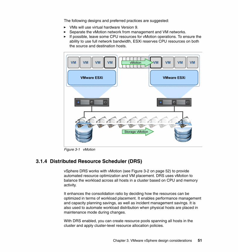
The following designs and preferred practices are suggested:
� VMs will use virtual hardware Version 9.� Separate the vMotion network from management and VM networks.� If possible, leave some CPU resources for vMotion operations. To ensure the
ability to use full network bandwidth, ESXi reserves CPU resources on both the source and destination hosts.
Figure 3-1 vMotion
3.1.4 Distributed Resource Scheduler (DRS)
vSphere DRS works with vMotion (see Figure 3-2 on page 52) to provide automated resource optimization and VM placement. DRS uses vMotion to balance the workload across all hosts in a cluster based on CPU and memory activity.
It enhances the consolidation ratio by deciding how the resources can be optimized in terms of workload placement. It enables performance management and capacity planning savings, as well as incident management savings. It is also used to automate workload distribution when physical hosts are placed in maintenance mode during changes.
With DRS enabled, you can create resource pools spanning all hosts in the cluster and apply cluster-level resource allocation policies.
VMware ESXi VMware ESXi
VM VM VM VM VM VM VM VMvMotion
Storage vMotion
Chapter 3. VMware vSphere design considerations 51
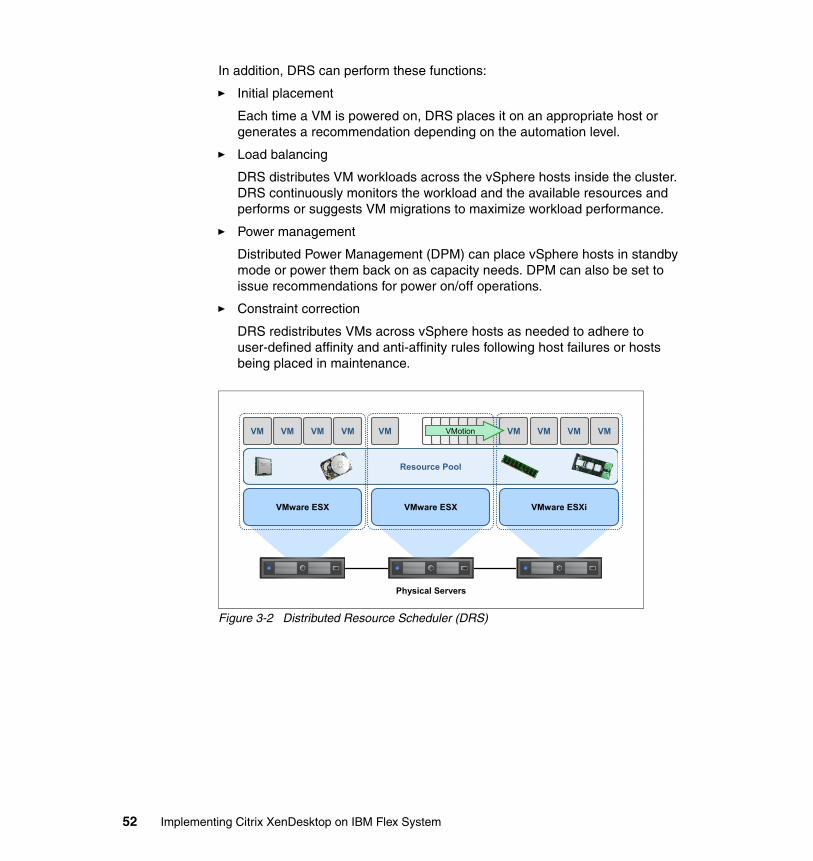
In addition, DRS can perform these functions:
� Initial placement
Each time a VM is powered on, DRS places it on an appropriate host or generates a recommendation depending on the automation level.
� Load balancing
DRS distributes VM workloads across the vSphere hosts inside the cluster. DRS continuously monitors the workload and the available resources and performs or suggests VM migrations to maximize workload performance.
� Power management
Distributed Power Management (DPM) can place vSphere hosts in standby mode or power them back on as capacity needs. DPM can also be set to issue recommendations for power on/off operations.
� Constraint correction
DRS redistributes VMs across vSphere hosts as needed to adhere to user-defined affinity and anti-affinity rules following host failures or hosts being placed in maintenance.
Figure 3-2 Distributed Resource Scheduler (DRS)
VMware ESX VMware ESX VMware ESXi
VM VM VM VM VM VM VM VM VM
Resource Pool
Physical Servers
VMotion
52 Implementing Citrix XenDesktop on IBM Flex System
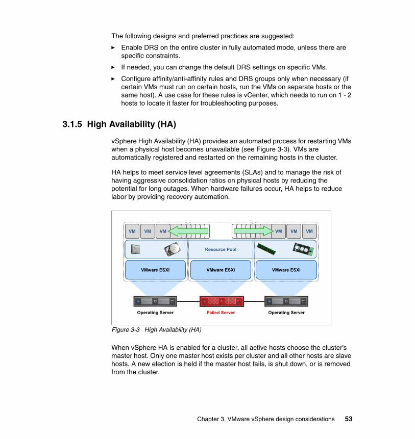
The following designs and preferred practices are suggested:
� Enable DRS on the entire cluster in fully automated mode, unless there are specific constraints.
� If needed, you can change the default DRS settings on specific VMs.
� Configure affinity/anti-affinity rules and DRS groups only when necessary (if certain VMs must run on certain hosts, run the VMs on separate hosts or the same host). A use case for these rules is vCenter, which needs to run on 1 - 2 hosts to locate it faster for troubleshooting purposes.
3.1.5 High Availability (HA)
vSphere High Availability (HA) provides an automated process for restarting VMs when a physical host becomes unavailable (see Figure 3-3). VMs are automatically registered and restarted on the remaining hosts in the cluster.
HA helps to meet service level agreements (SLAs) and to manage the risk of having aggressive consolidation ratios on physical hosts by reducing the potential for long outages. When hardware failures occur, HA helps to reduce labor by providing recovery automation.
Figure 3-3 High Availability (HA)
When vSphere HA is enabled for a cluster, all active hosts choose the cluster’s master host. Only one master host exists per cluster and all other hosts are slave hosts. A new election is held if the master host fails, is shut down, or is removed from the cluster.
VMware ESXi VMware ESXi VMware ESXi
Resource Pool
Failed Server
VM VM VMVMVMVM
Operating ServerOperating Server
Chapter 3. VMware vSphere design considerations 53
The master host in a cluster has a number of responsibilities:
� Monitoring the state of slave hosts. If a slave host fails or becomes unreachable, the master host identifies which VMs need to be restarted.
� If VM monitoring is enabled, the master host monitors the power state of all protected VMs. If one VM fails, the master host ensures that it is restarted.
� Managing the lists of cluster hosts and protected VMs.
� Acting as the vCenter Server management interface to the cluster and reporting the cluster health state.
The slave hosts primarily run VMs, monitoring their runtime states, and reporting state updates to the master host. A master host can also run and monitor VMs. Both slave hosts and master hosts implement the VM and Application Monitoring features.
In the VDI environment, VMware HA provides high availability for management services VMs and persistent virtual desktops, if required.
The following designs and preferred practices are suggested:
� HA will be enabled on all clusters with strict admission control, with one exception, the cluster for non-persistent desktops, which will have HA disabled.
� Clusters that have 12 or fewer hosts needs to allow for the loss of at least one physical host. Clusters with more than 12 hosts need to allow for the loss of at least two physical hosts.
� Configure the Percentage of Cluster Resources Reserved policy and reserve failover capacity for at least one host. Use the Host Failures Cluster Tolerates policy if VM reservations are not used and you do not need granular control of reserved failover capacity. Use the percentage policy if you have a cluster of only two hosts. There might be a requirement for desktop groups to offer varying levels of redundancy. For example, a desktop group might require N+100% redundancy while another one might only require N+10%.
� HA works even if vCenter is down; however, vCenter is needed to initially configure HA.
3.1.6 vSphere licensing considerations
vSphere 5.1 is licensed on a per-processor basis. Each physical processor (CPU) in a server needs to have at least one vSphere 5.1 processor license key assigned to be able to run vSphere. vRAM entitlement introduced in vSphere 5.0 was ended with vSphere 5.1.
54 Implementing Citrix XenDesktop on IBM Flex System
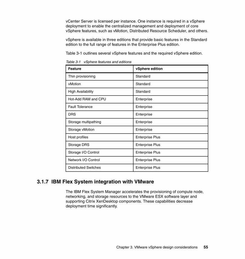
vCenter Server is licensed per instance. One instance is required in a vSphere deployment to enable the centralized management and deployment of core vSphere features, such as vMotion, Distributed Resource Scheduler, and others.
vSphere is available in three editions that provide basic features in the Standard edition to the full range of features in the Enterprise Plus edition.
Table 3-1 outlines several vSphere features and the required vSphere edition.
Table 3-1 vSphere features and editions
3.1.7 IBM Flex System integration with VMware
The IBM Flex System Manager accelerates the provisioning of compute node, networking, and storage resources to the VMware ESX software layer and supporting Citrix XenDesktop components. These capabilities decrease deployment time significantly.
Feature vSphere edition
Thin provisioning Standard
vMotion Standard
High Availability Standard
Hot-Add RAM and CPU Enterprise
Fault Tolerance Enterprise
DRS Enterprise
Storage multipathing Enterprise
Storage vMotion Enterprise
Host profiles Enterprise Plus
Storage DRS Enterprise Plus
Storage I/O Control Enterprise Plus
Network I/O Control Enterprise Plus
Distributed Switches Enterprise Plus
Chapter 3. VMware vSphere design considerations 55
VMware integration offers these features:
� Deploying hardware patterns from the Flex System Manager to new compute nodes, ensuring that standard hardware adapter interfaces are logically assigned to the compute resources, as suitable for a new vCloud Suite compute node.
� Installing IBM customized ESXi 5.1 images to the new compute nodes from inside the Flex System Manager interface.
� Providing VMware environment visibility and ESX resource inventory and topology views from within the Flex System Manager interface, including the ability to deploy new VM images.
� Providing extensibility from the native vCenter server to the IBM Flex System hardware, using the specialized IBM Systems Director Upward Integration Module (UIM). Capabilities of the UIM include monitoring power and thermals of the IBM Flex System components, viewing and updating firmware and software levels for various components in the chassis, and modifying settings for predictive failure alerts in the chassis.
3.2 Networking considerations
Networking can be seen as physical network infrastructure and VMware vSphere virtual network infrastructure.
From a physical network perspective, the host’s networking resources are shared by the virtual desktops that it supports. If there is no sufficient bandwidth, users experience a degraded level of performance. It is suggested to use fast network cards and IBM Flex System compute nodes to address this issue by using 10 Gb network cards.
Also, performance might be improved by separating different types of network traffic. For example, management, VM, storage, provisioning, and backup traffic can all be isolated from each other. For details about network design, see 4.5, “Network configuration” on page 76.
The VMware virtual network consists of various subcomponents, such as virtual switches (standard and distributed), ports, port groups, virtual Ethernet adapters, and uplink ports. These components build the communication channel between the VMs and the external or physical network.
56 Implementing Citrix XenDesktop on IBM Flex System
3.2.1 Virtual switch
Virtual switches (vSwitches) are a software-based switch that resides in the VMkernel and provides traffic management for VMs. There are two types of virtual switches in vSphere: standard switch (VSS) and distributed switch (VDS).
While standard virtual switches are defined at the host level, distributed virtual switches are defined at the data center level, which means that virtual switch configuration is then pushed consistently to all hosts within the same data center. A vSphere Distributed Switch is abbreviated as VDS and is also called a dvSwitch.
In addition, distributed virtual switches enable advanced features, such as Rx traffic shaping, improved monitoring through port mirroring (dvMirror), consistent network statistic monitoring or Link Layer Discovery Protocol (LLDP), which is a vendor-neutral standard equivalent of Cisco Discovery Protocol (CDP).
The VDS requires an Enterprise license. Use distributed switches to enable the benefits.
Note that when using dvSwitches, they can usually be controlled only from your vCenter server (unless you use a third-party distributed vSwitch, such as a Cisco 1000V or an IBM System Networking 5000V). If your vCenter Server becomes unavailable, networking continues to function, but you cannot make any modifications until the vCenter Server is back online.
3.2.2 Ports and port groups
A port or port group is a logical object on a vSwitch that provides specialized services for the VMkernel or VMs. A virtual switch can contain a VMkernel port or a VM port group. On a vSphere Distributed Switch, these are called dvPort groups.
A VMkernel port is a specialized virtual switch port type that is configured with an IP address to allow vMotion, iSCSI storage access, network-attached storage (NAS) or Network File System (NFS) access, or vSphere Fault Tolerance (FT) logging. Because vSphere 5.x only includes ESXi hosts, a VMkernel port also provides management connectivity for managing the host. A VMkernel port is also referred to as a vmknic.
A VM port group is a group of virtual switch ports that share a common configuration and allow VMs to access other VMs or the physical network.
Chapter 3. VMware vSphere design considerations 57
3.2.3 Uplink ports
Uplink ports are ports associated with physical adapters, providing a connection between a virtual network and a physical network.
Distributed Virtual Uplinks (dvUplinks) are a new concept introduced with VDS. dvUplinks provide a level of abstraction for the physical NICs (vmnics) on each host. NIC teaming, load balancing, and failover policies on the VDS and DV Port Groups are applied to the dvUplinks and not the vmnics on individual hosts. Each vmnic on each host is mapped to a dvUplink, permitting teaming and failover consistency regardless of vmnic assignments.
The following designs and preferred practices are suggested:
� Ensure redundancy by using a single dvSwitch with more uplinks on all of the hosts in the cluster.
� Create separate, highly available port groups for each management and vMotion traffic. The IBM PureFlex System platform positions Ethernet switch hardware inside the chassis, providing inherent network performance improvement for activities that use network bandwidth (such as VMware vMotion) from traditional top-of-rack (TOR) network switching.
� Improve the network performance by using the TCP offload engine (TOE) capabilities of integrated network adapters on the Flex System compute nodes, by enabling stateless offload of the following tunables:
– Checksum offload– TCP segmentation offload (TSO)– Jumbo frames (JF)– Large receive offload (LRO)
3.3 Storage considerations
Storage has a major impact on the performance, scalability, and availability of the XenDesktop implementation.
3.3.1 Local or shared storage
Virtual deployments typically use shared storage in preference to local storage. Shared storage is required to support vMotion, DRS, and High Availability. Although these features are less critical when hosting non-persistent virtual desktops, they are important for management server workloads and persistent desktops.
58 Implementing Citrix XenDesktop on IBM Flex System
3.3.2 Tiered storage
A one-size-fits-all storage solution is unlikely to meet the requirements of most virtual desktop implementations. The use of tiered storage, where storage technologies, such as solid-state drives (SSDs) and network-attached and Fibre Channel-attached storage systems, as well as drive access technologies, such as SAS and SATA, are grouped into storage tiers, provides an effective mechanism for offering a range of storage options differentiated by performance, scalability, redundancy, and cost. In this way, different virtual workloads with similar storage requirements can be grouped together and a similar cost model applied.
3.3.3 Redundancy and load balancing
vSphere Datastores must be designed to meet the redundancy requirements of the components that they support, such as RAID levels, storage adapters, and the back-end storage configuration. The preferred practice for shared storage is to configure two NICs or HBAs in a bonded or multipath setup.
VMware vSphere uses a default storage multipath policy of Fixed (VMware), which means that the same storage path is always used to access that specific logical unit number (LUN). If you have a configuration where you have multiple access paths to your storage LUNs, this is not the optimal multipath policy because it does not take advantage of your redundant hardware.
Selecting Round Robin (VMware) is usually a good choice. It means that at any time, the LUN is accessed over a single path, but that path will change the next time that it is accessed.
Chapter 3. VMware vSphere design considerations 59

60 Implementing Citrix XenDesktop on IBM Flex System
Chapter 4. Citrix XenDesktop design basics
This chapter describes the details of the Citrix XenDesktop design process based on IBM SmartCloud Desktop Infrastructure Reference Architecture (RA) for Citrix XenDesktop. The IBM RA for XenDesktop, an IBM validated reference design, uses a VMware ESXi back-end infrastructure based on VMware ESXi that is managed by VMware vCenter Server.
The IBM RA is updated on a regular basis to include new features and components. The most recent IBM RA for Citrix XenDesktop is at this website:
http://ibm.co/150EytE
This chapter includes the following topics:
� 4.1, “Citrix XenDesktop components” on page 62� 4.2, “Desktop and application delivery” on page 66� 4.3, “Citrix XenDesktop provisioning” on page 67� 4.4, “Storage configuration” on page 74� 4.5, “Network configuration” on page 76� 4.6, “Operational model and sizing guidelines” on page 78
4
© Copyright IBM Corp. 2014. All rights reserved. 61
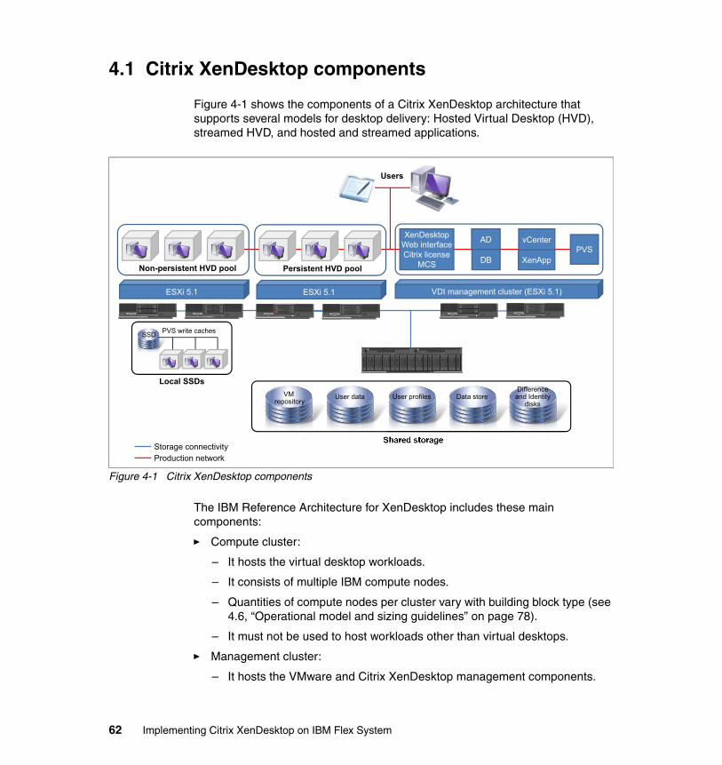
4.1 Citrix XenDesktop components
Figure 4-1 shows the components of a Citrix XenDesktop architecture that supports several models for desktop delivery: Hosted Virtual Desktop (HVD), streamed HVD, and hosted and streamed applications.
Figure 4-1 Citrix XenDesktop components
The IBM Reference Architecture for XenDesktop includes these main components:
� Compute cluster:
– It hosts the virtual desktop workloads.
– It consists of multiple IBM compute nodes.
– Quantities of compute nodes per cluster vary with building block type (see 4.6, “Operational model and sizing guidelines” on page 78).
– It must not be used to host workloads other than virtual desktops.
� Management cluster:
– It hosts the VMware and Citrix XenDesktop management components.
Storage connectivity
Users
Production network
Shared storage
User dataVMrepository
ESXi 5.1
Local SSDs
Non-persistent HVD pool
SSD PVS write caches
ESXi 5.1
Persistent HVD pool
VDI management cluster (ESXi 5.1)
XenDesktopWeb interfaceCitrix license
MCS
AD vCenter
DBPVS
User profiles Data storeDifference
and Identitydisks
XenApp
62 Implementing Citrix XenDesktop on IBM Flex System
– It can be hosted on an existing or new vSphere environment (or on other systems).
– This cluster contains VMware vCenter, XenDesktop, Machine Creation Services (MCS), Provisioning Services (PVS), License Server, Web Interface, database server, and other optional components.
– It can host additional infrastructure services (Active Directory (AD), Domain Name System (DNS), Dynamic Host Configuration Protocol (DHCP), and so on) if they do not already exist in the environment.
The components are described:
� Web Interface
The Web Interface provides the user interface to the XenDesktop environment. Web Interface brokers user authentication, enumerates the available desktops and, upon launch, delivers an .ica file to the Citrix Receiver on the user’s local device to initiate a connection. Because the Web Interface is a critical component, redundant servers must be available to provide fault tolerance.
� Domain Controller
The Domain Controller hosts Active Directory (AD), Dynamic Host Configuration Protocol (DHCP), and DNS services. Active Directory provides a common namespace and secure method of communication between all the servers and desktops in the environment. The Domain Name System (DNS) server provides IP host name resolution for the core XenDesktop infrastructure components. DHCP is used by the virtual desktops to request and obtain IP addresses. DHCP uses Option 66 and 67 to specify the bootstrap file location and file name to a virtual desktop. The DHCP service receives requests on UDP port 67 and sends data to UDP port 68 on a virtual desktop. Citrix Provisioning Services then streams the operating system over the network to the virtual desktops.
� Desktop delivery controller
The desktop delivery controllers (DDCs) are responsible for maintaining the proper level of idle desktops to allow for instantaneous connections, monitoring the state of online and connected desktops, and shutting down desktops, as needed.
Chapter 4. Citrix XenDesktop design basics 63
A XenDesktop farm is a larger grouping of virtual machine (VM) servers. The primary DDC is configured as the XenDesktop farm master server. The master focuses on farm management while an additional DDC acts as a dedicated XML server. The XML server is responsible for brokering user authentication, resource enumeration, and desktop launching. Because a failure in the XML service results in users being unable to start their desktops, it is suggested that you configure multiple controllers per farm.
� PVS or MCS
Provisioning Services (PVS) can be used to provision non-persistent VMs. Machine Creation Services (MCS) can be used to provision both persistent and non-persistent VMs (see 4.3, “Citrix XenDesktop provisioning” on page 67 for details).
� vCenter Server
vCenter Server is the managing server for VMware ESXi hypervisor. Using a single console, it provides centralized management of the VMs.
Redundancy for vCenter Server is achieved through VMware HA. The vCenter Server also contains a licensing server for VMware ESXi.
� vCenter SQL Server
vCenter requires a SQL database. The vCenter SQL server can be Microsoft Data Engine (MSDE), Oracle, or SQL Server. Because the vCenter SQL Server is a critical component, redundant servers must be available to provide fault tolerance. Existing client SQL databases (including respective redundancy) can be used.
� License Server
The Citrix License Server is responsible for managing the licenses for all XenDesktop components. XenDesktop has a 30-day grace period that allows the system to function normally for 30 days if the license server becomes unavailable. This grace period offsets the complexity of otherwise building redundancy into the license server.
� XenDesktop SQL Server
Each Citrix XenDesktop farm requires a SQL Server database called the data store that is used to centralize farm configuration information and transaction logs. The data store maintains all static information about the XenDesktop environment. Because the XenDesktop SQL server is a critical component, redundant servers must be available to provide fault tolerance.
64 Implementing Citrix XenDesktop on IBM Flex System
� Virtual Desktop Agent
Each VM needs a Citrix Virtual Desktop Agent (VDA) to capture VM data and send it to the Receiver in the client device. The VDA also emulates the keyboard and gestures sent from the Receiver. Note that the VDA is different for HDX 3D Pro because it has to capture data from a graphics processing unit (GPU) rendering a 3D scene. Independent Channel Architecture (ICA) is the Citrix display protocol for both 2D and 3D virtual desktop infrastructure (VDI).
� Client devices
XenDesktop supports a broad set of devices, including PCs, Mac OS devices, tablets, smartphones, and thin clients, along with all major device operating platforms, including Apple iOS, Google Android, and Google Chrome OS. XenDesktop enables a rich, native experience on each device, including support for gestures and multi-touch features, customizing the experience based on the type of device. Each client device has a Citrix Receiver, which acts as the agent to communicate with the virtual desktop using the ICA/HDX protocol.
� Hypervisor
XenDesktop has an open architecture that supports the use of XenServer, Microsoft Hyper-V, and VMware ESX or vSphere hypervisors. VMware vSphere 5.1 is the hypervisor that is used in the IBM Reference Architecture (RA) for Citrix XenDesktop.
� Citrix XenApp
Citrix XenApp allows most Windows applications to be instantly delivered as a service to users anywhere on any device. It can be used to deliver both virtualized applications and virtualized desktops. In the Hosted VDI model, XenApp is typically used for on-demand access to streamed and hosted applications.
� Shared storage
Shared storage is used to store user profiles and user data files. Depending on the provisioning model used, different data is stored for VM images. Shared storage also holds the redirected vSwap files.
Chapter 4. Citrix XenDesktop design basics 65
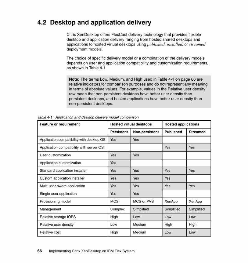
4.2 Desktop and application delivery
Citrix XenDesktop offers FlexCast delivery technology that provides flexible desktop and application delivery ranging from hosted shared desktops and applications to hosted virtual desktops using published, installed, or streamed deployment models.
The choice of specific delivery model or a combination of the delivery models depends on user and application compatibility and customization requirements, as shown in Table 4-1.
Table 4-1 Application and desktop delivery model comparison
Note: The terms Low, Medium, and High used in Table 4-1 on page 66 are relative indicators for comparison purposes and do not represent any meaning in terms of absolute values. For example, values in the Relative user density row mean that non-persistent desktops have better user density than persistent desktops, and hosted applications have better user density than non-persistent desktops.
Feature or requirement Hosted virtual desktops Hosted applications
Persistent Non-persistent Published Streamed
Application compatibility with desktop OS Yes Yes
Application compatibility with server OS Yes Yes
User customization Yes Yes
Application customization Yes
Standard application installer Yes Yes Yes Yes
Custom application installer Yes Yes Yes
Multi-user aware application Yes Yes Yes Yes
Single-user application Yes Yes
Provisioning model MCS MCS or PVS XenApp XenApp
Management Complex Simplified Simplified Simplified
Relative storage IOPS High Low Low Low
Relative user density Low Medium High High
Relative cost High Medium Low Low
66 Implementing Citrix XenDesktop on IBM Flex System
In general, if the application can work in a multi-user environment, requires no user customization, and is compatible with the server operating system, the most cost-efficient way to deploy VDI is to use hosted applications with a published or streamed delivery model.
For highly customized user application environments, hosted virtual desktops provide an efficient way to deploy a centralized desktop infrastructure, with a non-persistent model that is cost optimized and a persistent model that is application customization optimized.
4.3 Citrix XenDesktop provisioning
Citrix XenDesktop supports two primary provisioning models:
� Machine Creation Services (MCS)� Provisioning Services (PVS)
MCS is a part of the XenDesktop Studio management console, but is limited to hosted virtual desktops only, pooled or dedicated. Organizations looking to use a streamed VHD model need to use PVS. However, PVS requires a separate server and potentially multiple servers within the infrastructure. Both PVS and MCS support ESXi hypervisors.
An additional consideration is the requirement for dedicated private desktops. Private desktops allow users to completely control their virtual desktops. With private desktops, the initial delivery of the desktop is identical. After it is deployed, each desktop becomes unique as changes persist across reboots. Within the hosted VDI desktop FlexCast model, this level of personalization can be achieved with installed images, MCS images, and PVS images.
Using built-in technology to provide each desktop with a unique identity, MCS thin-provisions each desktop from a master image. Only changes made to the desktop consume additional disk space. PVS also uses built-in technology to provide each desktop with a unique identity, but it uses a complete copy of the base desktop image in read/write mode. Each copy consumes disk space that expands as the user adds additional items to the desktop image.
When dedicated desktops are required, most organizations use MCS images. Most organizations use PVS for pooled desktop configurations because PVS requires fewer IOPS and offers faster patching and image updates. A single XenDesktop environment can host any mix of PVS and MCS desktops that an organization needs to meet its design goals.
Chapter 4. Citrix XenDesktop design basics 67
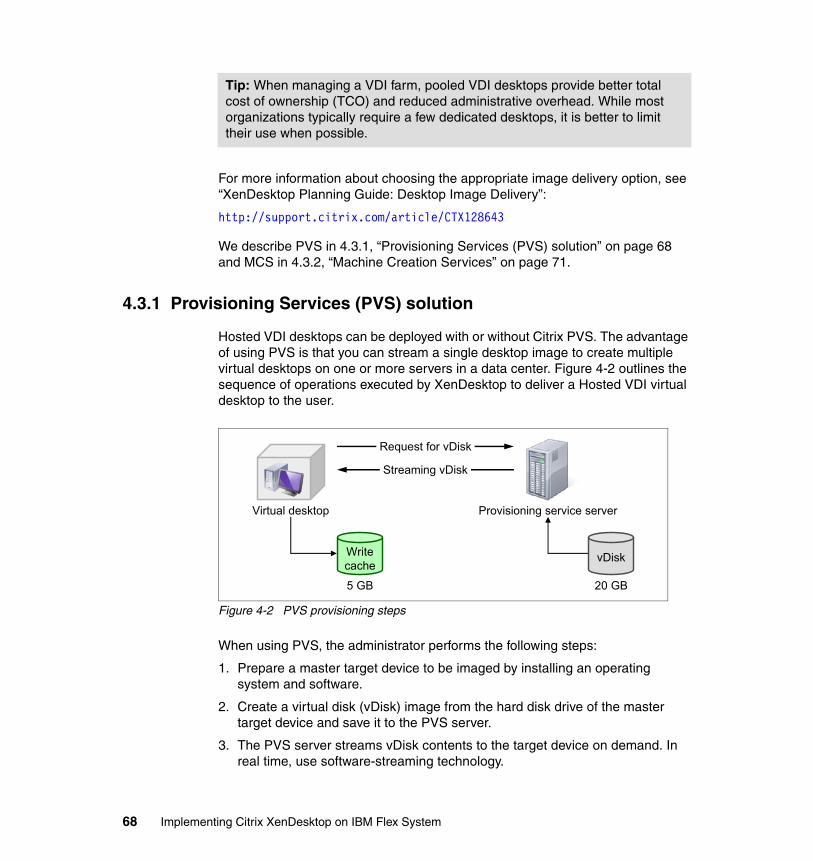
For more information about choosing the appropriate image delivery option, see “XenDesktop Planning Guide: Desktop Image Delivery”:
http://support.citrix.com/article/CTX128643
We describe PVS in 4.3.1, “Provisioning Services (PVS) solution” on page 68 and MCS in 4.3.2, “Machine Creation Services” on page 71.
4.3.1 Provisioning Services (PVS) solution
Hosted VDI desktops can be deployed with or without Citrix PVS. The advantage of using PVS is that you can stream a single desktop image to create multiple virtual desktops on one or more servers in a data center. Figure 4-2 outlines the sequence of operations executed by XenDesktop to deliver a Hosted VDI virtual desktop to the user.
Figure 4-2 PVS provisioning steps
When using PVS, the administrator performs the following steps:
1. Prepare a master target device to be imaged by installing an operating system and software.
2. Create a virtual disk (vDisk) image from the hard disk drive of the master target device and save it to the PVS server.
3. The PVS server streams vDisk contents to the target device on demand. In real time, use software-streaming technology.
Tip: When managing a VDI farm, pooled VDI desktops provide better total cost of ownership (TCO) and reduced administrative overhead. While most organizations typically require a few dedicated desktops, it is better to limit their use when possible.
Virtual desktop
Writecache
5 GB
vDisk
20 GB
Provisioning service server
Request for vDisk
Streaming vDisk
68 Implementing Citrix XenDesktop on IBM Flex System
After the vDisk image is available from the network, the VM on a target device no longer needs its local hard disk drive to operate; it boots directly from the network and behaves as if it is running from a local drive on the target device. This is why PVS is suggested for stateless virtual desktops. PVS is not generally used for dedicated virtual desktops because the write cache is not stored on shared storage.
PVS is also used with Microsoft Roaming Profiles (MSRPs) so that the user’s profile information can be separated out and reused. Profile data is available from shared storage.
PVS streaming configuration details are discussed in 8.3.1, “Configuring streamed desktops” on page 338.
Write cache optionsPVS supports several write cache destination options. The write cache destination for a vDisk is selected on the General tab on the vDisk File Properties dialog.
The following write cache destinations are valid:
� Cache on Device Hard Drive
The write cache can exist as a file in New Technology File System (NTFS) format located on the target device’s hard disk drive. This write cache option frees up the PVS server because it does not have to process write requests and does not have the finite limitation of RAM.
� Cache in Device RAM
In this case, the write cache exists as a temporary file in the target device’s RAM. This provides the fastest method of disk access because memory access is always faster than hard disk access.
� Cache on a Server
The write cache can exist as a temporary file on a PVS server, which can increase disk I/O and network traffic.
For additional security, the PVS server can be configured to encrypt write cache files. Because the write cache file exists on the hard disk drive between reboots, the data is encrypted in the event that a hard disk drive is stolen.
Note: The write cache file is temporary unless the vDisk mode is set to Difference Disk Image mode.
Chapter 4. Citrix XenDesktop design basics 69
� Cache on Server Persistent
This cache option allows for the saving of changes between reboots. Using this option, after rebooting, a target device is able to retrieve changes made from previous sessions that differ from the read-only vDisk image. If a vDisk is set to Cache on Server Persistent, each target device that accesses the vDisk automatically has a device-specific, writable disk file created. Any changes made to the vDisk image are written to that file, which is not automatically deleted upon shutdown.
The drawback of using this cache option is that the cache file is available only while the file remains valid. Any changes made to the vDisk force the cache file to be marked invalid. For example, if the vDisk is set to Private Image Mode, all associated cache files are marked invalid.
Write cache sizing The size of the cache file for each VM depends on several factors, including the types of applications, user workloads, and reboot frequency. A general estimate is 300 MB - 500 MB for the cache size of a provisioned workstation. If a workstation is not rebooted very often, or will use applications that are virtualized using Microsoft App-V or similar programs, cache size can grow much larger.
Because application workloads can vary for each environment, perform a detailed analysis to determine expected cache file sizes for your environment.
For more information about write cache sizing, see the “PVS Write Cache Sizing & Considerations” article:
http://blogs.citrix.com/2011/10/06/pvs-write-cache-sizing-considerations/
Communication PortsThe following User Datagram Protocol (UDP) ports are typically defined:
� PVS server to target device communication
Each PVS server must be configured to use the same UDP ports to communicate with target devices (using the StreamProcess). The port range is configured using the Console’s Network tab on the Server Properties dialog. Default ports are UDP ports 6910 - 6390.
� Login server communication
Each PVS server used as a login server must be configured on the Stream Servers Boot List dialog when the administrator runs the configuration wizard. The default port for login servers is UDP 6910.
70 Implementing Citrix XenDesktop on IBM Flex System
For the best practices for PVS sizing and configuration, see the “Provisioning Services 5.x and 6.x Best Practices” article:
http://support.citrix.com/article/ctx127549
4.3.2 Machine Creation Services
Unlike PVS, MCS does not require additional servers. Instead, it uses integrated functionality built into VMware vSphere and communicates through the respective APIs. Each desktop has one difference disk and one identity disk (Figure 4-3 on page 72).
The difference disk is used to capture any changes made to the master image. The identity disk is used to store information, such as machine name and password.
There are three types of image assignment models for MCS:
� Pooled-Random
Desktops are assigned randomly. When they log off, the desktop is free for another user. When rebooted, any changes made are destroyed.
� Pooled-Static
Desktops are permanently assigned to a single user. When a user logs off, only that user can use the desktop, regardless of whether the desktop is rebooted. During reboots, any changes that are made are destroyed.
� Dedicated
Desktops are permanently assigned to a single user. When a user logs off, only that user can use the desktop, regardless of whether the desktop is rebooted. During reboots, any changes that are made persist across subsequent restarts.
Chapter 4. Citrix XenDesktop design basics 71
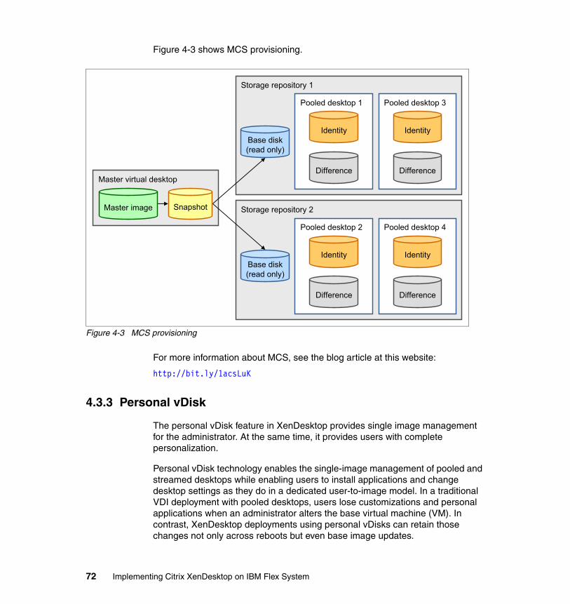
Figure 4-3 shows MCS provisioning.
Figure 4-3 MCS provisioning
For more information about MCS, see the blog article at this website:
http://bit.ly/1acsLuK
4.3.3 Personal vDisk
The personal vDisk feature in XenDesktop provides single image management for the administrator. At the same time, it provides users with complete personalization.
Personal vDisk technology enables the single-image management of pooled and streamed desktops while enabling users to install applications and change desktop settings as they do in a dedicated user-to-image model. In a traditional VDI deployment with pooled desktops, users lose customizations and personal applications when an administrator alters the base virtual machine (VM). In contrast, XenDesktop deployments using personal vDisks can retain those changes not only across reboots but even base image updates.
Master virtual desktop
Storage repository 2
Base disk(read only)
Pooled desktop 2
Difference
Identity
Pooled desktop 4
Difference
Identity
Storage repository 1
Base disk(read only)
Pooled desktop 1
Difference
Identity
Pooled desktop 3
Difference
Identity
Master image Snapshot
72 Implementing Citrix XenDesktop on IBM Flex System
This means administrators can easily and centrally manage base VMs while providing users with a customized and personalized desktop experience.
Personal vDisks provide this separation by redirecting all changes made on the user’s VM to a separate disk (the personal vDisk) attached to the user’s VM. The content of the personal vDisk is blended at run time with the content from the base VM to provide a unified experience. In this way, users can still access applications provisioned by their administrator in the base VM.
This user’s specific Virtual Hard Disk file (a .vhd or .vmdk file) contains all the user’s customizations, such as applications installed in C:\Program Files.
Physically, a personal vDisk does not need to be stored on the same storage with the base VM but can reside on other data stores.
Personal vDisk provides the best option: single image management with complete user personalization and customization. For details and help about whether personal vDisks are the correct approach for your environment, see the following documents:
� “Citrix Personal vDisk Technology Planning Guide”
http://support.citrix.com/article/CTX133227
� “Personal vDisk FAQs”
http://support.citrix.com/article/CTX131553
4.3.4 Image assignment models
We describe two primary user-to-image assignment models:
� Non-persistent (preferred)� Persistent (if needed)
Citrix has various image delivery options that allow you to achieve either of the two assignment models using PVS and MCS. In reality, they can be combined with various profile management options and also the Personal vDisk feature. The Personal vDisk feature allows you to simulate a persistent user experience (for example, installing personal applications) even when using non-persistent images, providing a “simulated” or “hybrid” model.
In our book, we describe two image assignment scenarios:
� Non-persistent: Streamed PVS image with Microsoft Roaming Profiles (MSRP)
� Persistent: Pooled image delivered through Machine Creation Services with MSRP
Chapter 4. Citrix XenDesktop design basics 73
4.4 Storage configuration
The architecture assumes that all VMware datastores are hosted on a supported shared storage that uses one of the storage protocols: FC, Fibre Channel over Ethernet (FCoE), Internet Small Computer System Interface (iSCSI), or Network File System (NFS).
The following sections describe the required storage-related components and configurations for each model.
Non-persistent model (PVS)The following local storage components make up the PVS model:
� Hypervisor
Each compute node is running the IBM ESXi custom image uploaded from an internal USB key.
� Local storage for each compute node
Two local SSD drives are configured in a RAID-0 configuration to store the PVS Write Cache (delta files).
Due to the stateless nature of the architecture, there is little added value in configuring reliable SSD drives in more redundant RAID configurations. Redundancy is not achieved on a host level but achieved inherently through the ability of a user to connect to virtual desktops hosted on any of the surviving nodes in the event of an individual node failure.
The following shared storage components are valid for the PVS model:
� Data stores
For PVS-delivered stateless virtual desktops, shared storage is only used to host the redirected vswap files for the hosts.
� User profiles (if using Roaming Profiles):
Common Internet File System (CIFS): A CIFS-based file share to host the user profile data (for Microsoft Roaming Profiles) is required.
� User data on network drives
CIFS: Specifically for the stateless user model, it is essential to redirect persistent user data (documents, other file repositories, and so on) to user-specific file shares (CIFS-based) or network drives. The detailed designs of these network shares (for example, aspects of redundancy and performance) is not within the scope of this book.
74 Implementing Citrix XenDesktop on IBM Flex System
Persistent model (MCS)The following local storage components make up the PVS model:
� Hypervisor
Each compute node is running the IBM ESXi Custom image uploaded from an internal USB key.
� Local storage for each compute node
For dedicated hosts, no local storage is configured.
The following shared storage components are valid for the PVS model:
� Shared storage data stores
vSphere Datastores are required to host all VM-associated data: MCS-provisioned desktops (including base disks, identity, and difference disks), the MCS Master Image, and the vswap files.
� User profiles (for example, if using Roaming Profiles)
CIFS: The user profiles are typically hosted on a CIFS-based file share. There are many ways to manage user profiles from native Microsoft profile management over Citrix’s profile management solution to third-party solutions. Our environment assumes the use of Microsoft Roaming Profiles.
� User data and network drives
CIFS-based file shares are primarily used for the stateless user model to redirect persistent user data (documents, other file repositories, and so on) to user-specific file shares or network drives. However, they can also be used to complement the dedicated model.
Figure 4-4 on page 76 illustrates the required storage tiers. It represents a XenDesktop hybrid environment that consists of a non-persistent PVS-delivered model and a dedicated MCS pool connected to the same storage system.
The vDisk used to stream the images to the individual targets resides on the PVS server on either local or shared storage. In our environment, we assume that the PVS server is in a VM hosted on the dedicated VDI management cluster (typically on shared storage for high availability purposes).
Chapter 4. Citrix XenDesktop design basics 75
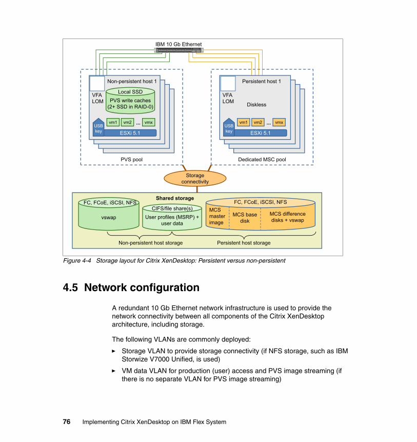
Figure 4-4 Storage layout for Citrix XenDesktop: Persistent versus non-persistent
4.5 Network configuration
A redundant 10 Gb Ethernet network infrastructure is used to provide the network connectivity between all components of the Citrix XenDesktop architecture, including storage.
The following VLANs are commonly deployed:
� Storage VLAN to provide storage connectivity (if NFS storage, such as IBM Storwize V7000 Unified, is used)
� VM data VLAN for production (user) access and PVS image streaming (if there is no separate VLAN for PVS image streaming)
����������� �� �
�����
�������������������
�� �������� ����� !"�#$� ��%���
����&��� ����� ��" ���'��� ��'�(
������ %��)
����%��� � �* %��)��#������
�������������������Shared storage
���+� ����� �������������( ! ����� �������������(
!,������ - %�*�� %���������
���+� ����� �� ������
,�./0� !,������ �*�*� �
�1#���-���� .�-+�"
/�*�����-
�'� �'2�'1 ...���) 3 �4� 56�
! ����� ���������
,�./0�
�'� �'2�'1 ...���) 3 �4� 56�
-��)� ��
�����( *��� *�����3
76 Implementing Citrix XenDesktop on IBM Flex System
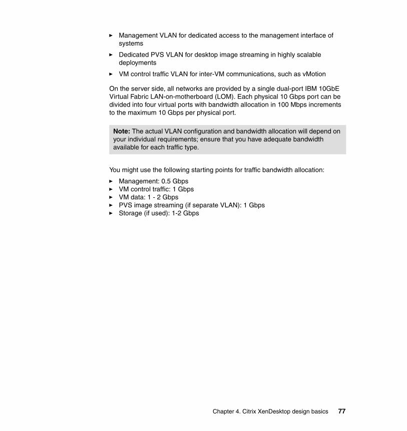
� Management VLAN for dedicated access to the management interface of systems
� Dedicated PVS VLAN for desktop image streaming in highly scalable deployments
� VM control traffic VLAN for inter-VM communications, such as vMotion
On the server side, all networks are provided by a single dual-port IBM 10GbE Virtual Fabric LAN-on-motherboard (LOM). Each physical 10 Gbps port can be divided into four virtual ports with bandwidth allocation in 100 Mbps increments to the maximum 10 Gbps per physical port.
You might use the following starting points for traffic bandwidth allocation:
� Management: 0.5 Gbps� VM control traffic: 1 Gbps� VM data: 1 - 2 Gbps� PVS image streaming (if separate VLAN): 1 Gbps� Storage (if used): 1-2 Gbps
Note: The actual VLAN configuration and bandwidth allocation will depend on your individual requirements; ensure that you have adequate bandwidth available for each traffic type.
Chapter 4. Citrix XenDesktop design basics 77
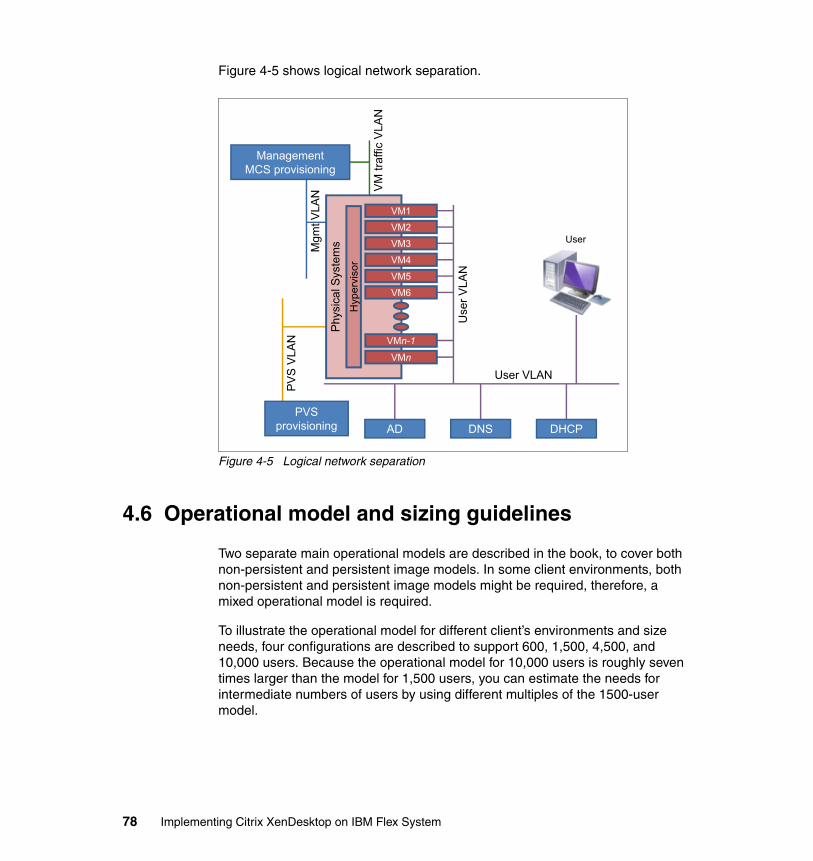
Figure 4-5 shows logical network separation.
Figure 4-5 Logical network separation
4.6 Operational model and sizing guidelines
Two separate main operational models are described in the book, to cover both non-persistent and persistent image models. In some client environments, both non-persistent and persistent image models might be required, therefore, a mixed operational model is required.
To illustrate the operational model for different client’s environments and size needs, four configurations are described to support 600, 1,500, 4,500, and 10,000 users. Because the operational model for 10,000 users is roughly seven times larger than the model for 1,500 users, you can estimate the needs for intermediate numbers of users by using different multiples of the 1500-user model.
PVS
VLAN
Phy
sica
l Sys
tem
sH
yper
viso
r
VM1
VM2
VM3
VM4
VM5
VM6
VMn-1
VMn
AD DNS DHCP
Use
r VLA
N
User VLAN
Mgm
t VLA
N
ManagementMCS provisioning
VM
traf
fic V
LAN
PVSprovisioning
User
78 Implementing Citrix XenDesktop on IBM Flex System
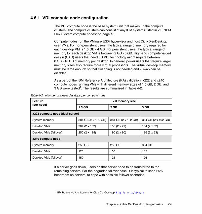
4.6.1 VDI compute node configuration
The VDI compute node is the base system unit that makes up the compute clusters. The compute clusters can consist of any IBM systems listed in 2.3, “IBM Flex System compute nodes” on page 16.
Compute nodes run the VMware ESXi hypervisor and host Citrix XenDesktop user VMs. For non-persistent users, the typical range of memory required for each desktop VM is 1.5 GB - 4 GB. For persistent users, the typical range of memory for each desktop VM is between 2 GB - 6 GB. High-end computer-aided design (CAD) users that need 3D VDI technology might require between 8 GB - 16 GB of memory per desktop. In general, power users that require larger memory sizes also require more virtual processors. The virtual desktop memory must be large enough so that swapping is not needed and vSwap can be disabled.
As a part of the IBM Reference Architecture (RA) validation, x222 and x240 compute nodes running VMs with different memory sizes of 1.5 GB, 2 GB, and 3 GB were tested1. The results are summarized in Table 4-2.
Table 4-2 Number of virtual desktops per compute node
If a server goes down, users on that server need to be transferred to the remaining servers. For the degraded failover case, it is typical to keep 25% headroom on servers, to cope with possible failover scenarios.
1 IBM Reference Architecture for Citrix XenDesktop: http://ibm.co/150EytE
Feature(per node)
VM memory size
1.5 GB 2 GB 3 GB
x222 compute node (dual-server)
System memory 384 GB (2 x 192 GB) 384 GB (2 x 192 GB) 384 GB (2 x 192 GB)
Desktop VMs 204 (2 x 10²) 158 (2 x 79) 104 (2 x 52)
Desktop VMs (failover) 250 (2 x 125) 190 (2 x 90) 126 (2 x 63)
x240 compute node
System memory 256 GB 256 GB 384 GB
Desktop VMs 125 105 105
Desktop VMs (failover) 150 126 126
Chapter 4. Citrix XenDesktop design basics 79
The following configurations of the compute nodes are suggested:
� Non-persistent host:
– Processor: Dual socket (8-core Intel Xeon processor E5-2680 or E5-2470)
– Memory: 256 GB (16 x 16 GB) or 384 GB (24 x 16 GB)
– Disks: IBM 2.5-inch MLC HS SSDs
– Disk controller: Standard integrated disk controller
– Hypervisor: IBM USB Memory Key for VMware ESXi 5.1 (ESXi IBM Custom Image)
– Network adapter: Integrated Dual Port 10 GbE Virtual Fabric LOM
� Persistent host:
– Processor: Dual socket (8-core Intel Xeon processor E5-2680 or E5-2470)
– Memory: 256 GB (16 x 16 GB) or 384 GB (24 x 16 GB)
– Disks: none
– Disk controller: None
– Hypervisor: IBM USB Memory Key for VMware ESXi 5.1 (ESXi IBM Custom Image)
– Network adapter: Integrated Dual Port 10 GbE Virtual Fabric LOM
If you intend to use the host in a dedicated user model (MCS in “dedicated” mode), you can remove the local SSD drives because all data other than the ESXi hypervisor will reside on shared external storage.
Table 4-3 on page 81, Table 4-4 on page 81, and Table 4-5 on page 81 show the number of compute nodes needed for each user size (based on desktop VM quantity per server from Table 4-2 on page 79 for different VM sizes).
80 Implementing Citrix XenDesktop on IBM Flex System
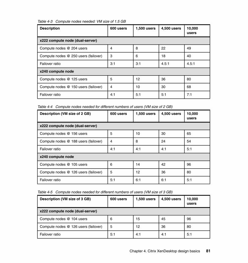
Table 4-3 Compute nodes needed: VM size of 1.5 GB
Table 4-4 Compute nodes needed for different numbers of users (VM size of 2 GB)
Table 4-5 Compute nodes needed for different numbers of users (VM size of 3 GB)
Description 600 users 1,500 users 4,500 users 10,000 users
x222 compute node (dual-server)
Compute nodes @ 204 users 4 8 22 49
Compute nodes @ 250 users (failover) 3 6 18 40
Failover ratio 3:1 3:1 4.5:1 4.5:1
x240 compute node
Compute nodes @ 125 users 5 12 36 80
Compute nodes @ 150 users (failover) 4 10 30 68
Failover ratio 4:1 5:1 5:1 7:1
Description (VM size of 2 GB) 600 users 1,500 users 4,500 users 10,000 users
x222 compute node (dual-server)
Compute nodes @ 156 users 5 10 30 65
Compute nodes @ 188 users (failover) 4 8 24 54
Failover ratio 4:1 4:1 4:1 5:1
x240 compute node
Compute nodes @ 105 users 6 14 42 96
Compute nodes @ 126 users (failover) 5 12 36 80
Failover ratio 5:1 6:1 6:1 5:1
Description (VM size of 3 GB) 600 users 1,500 users 4,500 users 10,000 users
x222 compute node (dual-server)
Compute nodes @ 104 users 6 15 45 96
Compute nodes @ 126 users (failover) 5 12 36 80
Failover ratio 5:1 4:1 4:1 5:1
Chapter 4. Citrix XenDesktop design basics 81
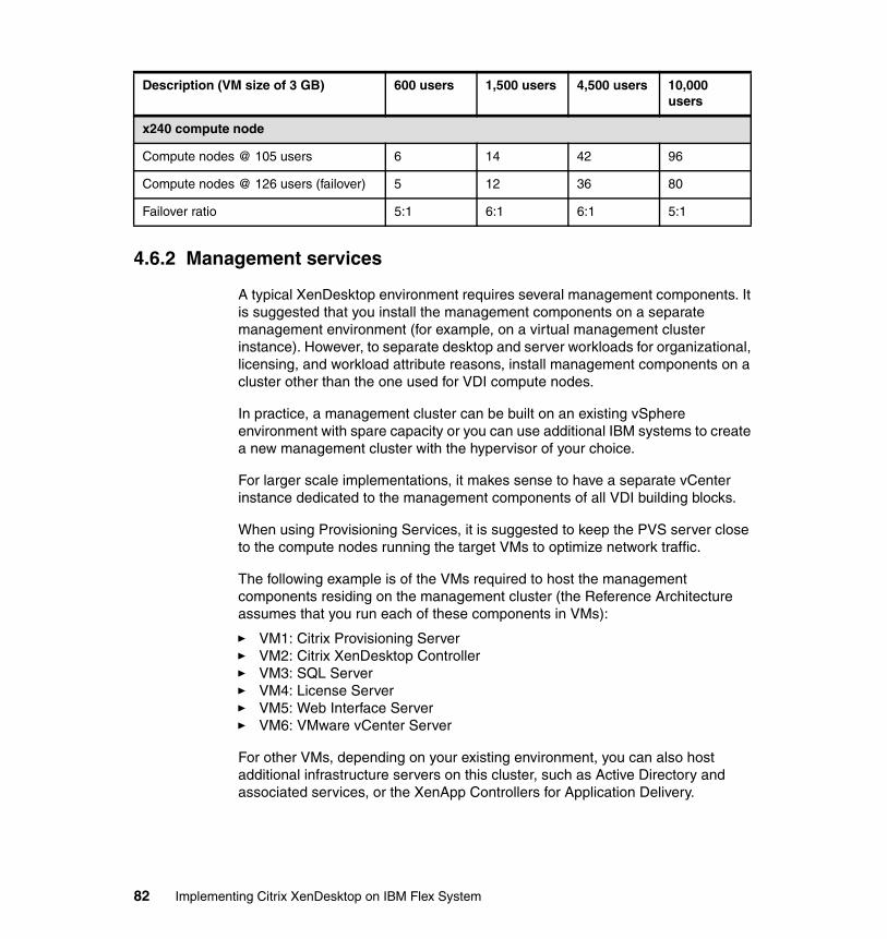
4.6.2 Management services
A typical XenDesktop environment requires several management components. It is suggested that you install the management components on a separate management environment (for example, on a virtual management cluster instance). However, to separate desktop and server workloads for organizational, licensing, and workload attribute reasons, install management components on a cluster other than the one used for VDI compute nodes.
In practice, a management cluster can be built on an existing vSphere environment with spare capacity or you can use additional IBM systems to create a new management cluster with the hypervisor of your choice.
For larger scale implementations, it makes sense to have a separate vCenter instance dedicated to the management components of all VDI building blocks.
When using Provisioning Services, it is suggested to keep the PVS server close to the compute nodes running the target VMs to optimize network traffic.
The following example is of the VMs required to host the management components residing on the management cluster (the Reference Architecture assumes that you run each of these components in VMs):
� VM1: Citrix Provisioning Server� VM2: Citrix XenDesktop Controller� VM3: SQL Server � VM4: License Server� VM5: Web Interface Server� VM6: VMware vCenter Server
For other VMs, depending on your existing environment, you can also host additional infrastructure servers on this cluster, such as Active Directory and associated services, or the XenApp Controllers for Application Delivery.
x240 compute node
Compute nodes @ 105 users 6 14 42 96
Compute nodes @ 126 users (failover) 5 12 36 80
Failover ratio 5:1 6:1 6:1 5:1
Description (VM size of 3 GB) 600 users 1,500 users 4,500 users 10,000 users
82 Implementing Citrix XenDesktop on IBM Flex System
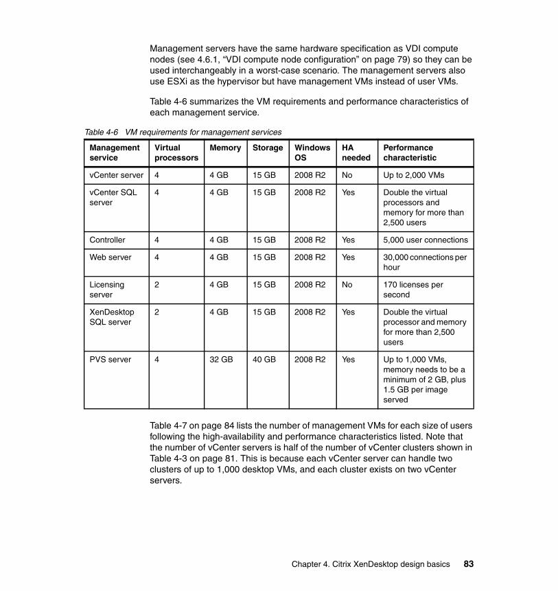
Management servers have the same hardware specification as VDI compute nodes (see 4.6.1, “VDI compute node configuration” on page 79) so they can be used interchangeably in a worst-case scenario. The management servers also use ESXi as the hypervisor but have management VMs instead of user VMs.
Table 4-6 summarizes the VM requirements and performance characteristics of each management service.
Table 4-6 VM requirements for management services
Table 4-7 on page 84 lists the number of management VMs for each size of users following the high-availability and performance characteristics listed. Note that the number of vCenter servers is half of the number of vCenter clusters shown in Table 4-3 on page 81. This is because each vCenter server can handle two clusters of up to 1,000 desktop VMs, and each cluster exists on two vCenter servers.
Management service
Virtual processors
Memory Storage Windows OS
HA needed
Performance characteristic
vCenter server 4 4 GB 15 GB 2008 R2 No Up to 2,000 VMs
vCenter SQL server
4 4 GB 15 GB 2008 R2 Yes Double the virtual processors and memory for more than 2,500 users
Controller 4 4 GB 15 GB 2008 R2 Yes 5,000 user connections
Web server 4 4 GB 15 GB 2008 R2 Yes 30,000 connections per hour
Licensing server
2 4 GB 15 GB 2008 R2 No 170 licenses per second
XenDesktop SQL server
2 4 GB 15 GB 2008 R2 Yes Double the virtual processor and memory for more than 2,500 users
PVS server 4 32 GB 40 GB 2008 R2 Yes Up to 1,000 VMs, memory needs to be a minimum of 2 GB, plus 1.5 GB per image served
Chapter 4. Citrix XenDesktop design basics 83
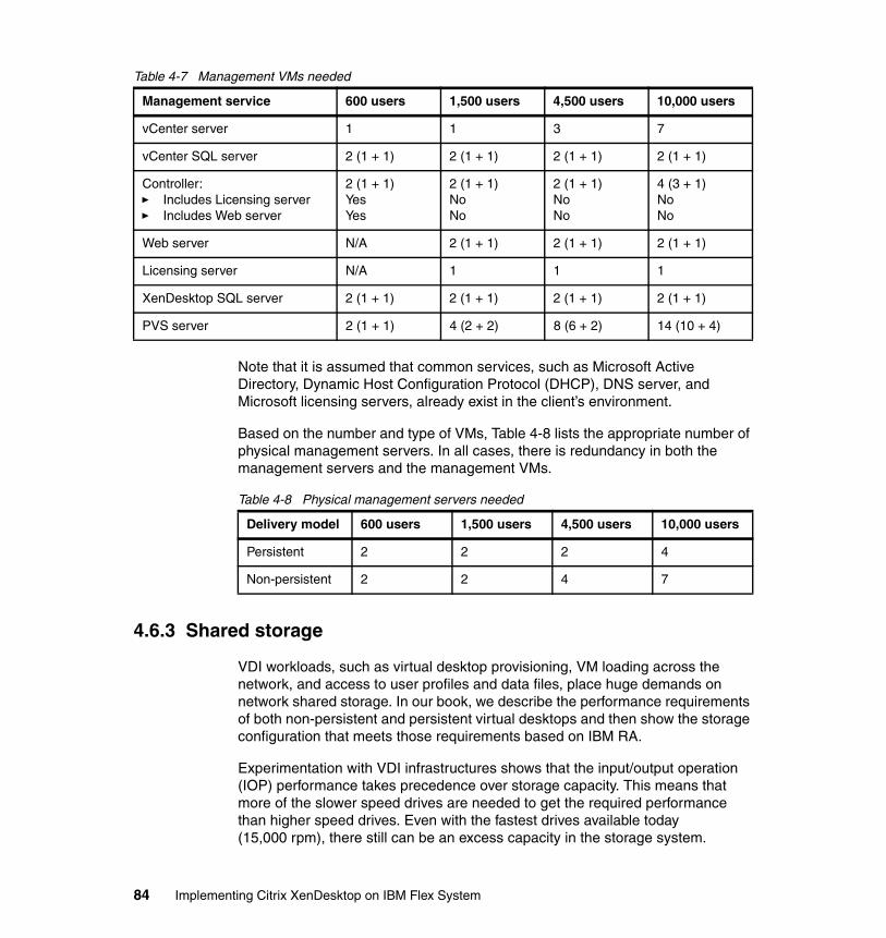
Table 4-7 Management VMs needed
Note that it is assumed that common services, such as Microsoft Active Directory, Dynamic Host Configuration Protocol (DHCP), DNS server, and Microsoft licensing servers, already exist in the client’s environment.
Based on the number and type of VMs, Table 4-8 lists the appropriate number of physical management servers. In all cases, there is redundancy in both the management servers and the management VMs.
Table 4-8 Physical management servers needed
4.6.3 Shared storage
VDI workloads, such as virtual desktop provisioning, VM loading across the network, and access to user profiles and data files, place huge demands on network shared storage. In our book, we describe the performance requirements of both non-persistent and persistent virtual desktops and then show the storage configuration that meets those requirements based on IBM RA.
Experimentation with VDI infrastructures shows that the input/output operation (IOP) performance takes precedence over storage capacity. This means that more of the slower speed drives are needed to get the required performance than higher speed drives. Even with the fastest drives available today (15,000 rpm), there still can be an excess capacity in the storage system.
Management service 600 users 1,500 users 4,500 users 10,000 users
vCenter server 1 1 3 7
vCenter SQL server 2 (1 + 1) 2 (1 + 1) 2 (1 + 1) 2 (1 + 1)
Controller:� Includes Licensing server� Includes Web server
2 (1 + 1)YesYes
2 (1 + 1)NoNo
2 (1 + 1)NoNo
4 (3 + 1)NoNo
Web server N/A 2 (1 + 1) 2 (1 + 1) 2 (1 + 1)
Licensing server N/A 1 1 1
XenDesktop SQL server 2 (1 + 1) 2 (1 + 1) 2 (1 + 1) 2 (1 + 1)
PVS server 2 (1 + 1) 4 (2 + 2) 8 (6 + 2) 14 (10 + 4)
Delivery model 600 users 1,500 users 4,500 users 10,000 users
Persistent 2 2 2 4
Non-persistent 2 2 4 7
84 Implementing Citrix XenDesktop on IBM Flex System
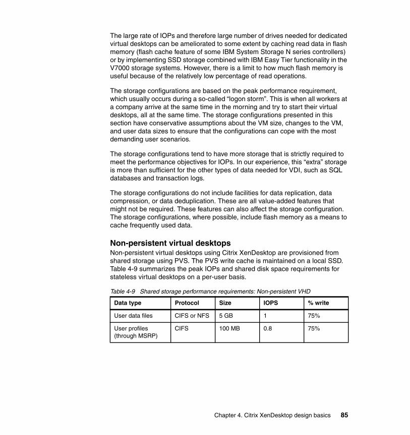
The large rate of IOPs and therefore large number of drives needed for dedicated virtual desktops can be ameliorated to some extent by caching read data in flash memory (flash cache feature of some IBM System Storage N series controllers) or by implementing SSD storage combined with IBM Easy Tier functionality in the V7000 storage systems. However, there is a limit to how much flash memory is useful because of the relatively low percentage of read operations.
The storage configurations are based on the peak performance requirement, which usually occurs during a so-called “logon storm”. This is when all workers at a company arrive at the same time in the morning and try to start their virtual desktops, all at the same time. The storage configurations presented in this section have conservative assumptions about the VM size, changes to the VM, and user data sizes to ensure that the configurations can cope with the most demanding user scenarios.
The storage configurations tend to have more storage that is strictly required to meet the performance objectives for IOPs. In our experience, this “extra” storage is more than sufficient for the other types of data needed for VDI, such as SQL databases and transaction logs.
The storage configurations do not include facilities for data replication, data compression, or data deduplication. These are all value-added features that might not be required. These features can also affect the storage configuration. The storage configurations, where possible, include flash memory as a means to cache frequently used data.
Non-persistent virtual desktopsNon-persistent virtual desktops using Citrix XenDesktop are provisioned from shared storage using PVS. The PVS write cache is maintained on a local SSD. Table 4-9 summarizes the peak IOPs and shared disk space requirements for stateless virtual desktops on a per-user basis.
Table 4-9 Shared storage performance requirements: Non-persistent VHD
Data type Protocol Size IOPS % write
User data files CIFS or NFS 5 GB 1 75%
User profiles (through MSRP)
CIFS 100 MB 0.8 75%
Chapter 4. Citrix XenDesktop design basics 85
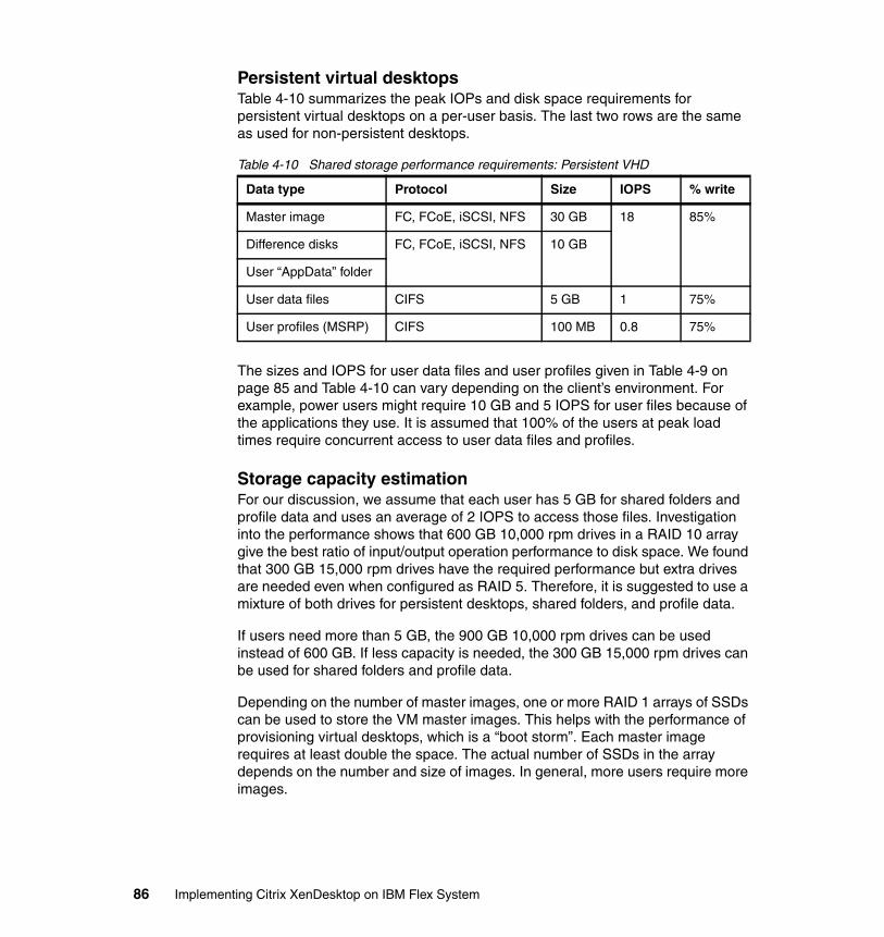
Persistent virtual desktopsTable 4-10 summarizes the peak IOPs and disk space requirements for persistent virtual desktops on a per-user basis. The last two rows are the same as used for non-persistent desktops.
Table 4-10 Shared storage performance requirements: Persistent VHD
The sizes and IOPS for user data files and user profiles given in Table 4-9 on page 85 and Table 4-10 can vary depending on the client’s environment. For example, power users might require 10 GB and 5 IOPS for user files because of the applications they use. It is assumed that 100% of the users at peak load times require concurrent access to user data files and profiles.
Storage capacity estimationFor our discussion, we assume that each user has 5 GB for shared folders and profile data and uses an average of 2 IOPS to access those files. Investigation into the performance shows that 600 GB 10,000 rpm drives in a RAID 10 array give the best ratio of input/output operation performance to disk space. We found that 300 GB 15,000 rpm drives have the required performance but extra drives are needed even when configured as RAID 5. Therefore, it is suggested to use a mixture of both drives for persistent desktops, shared folders, and profile data.
If users need more than 5 GB, the 900 GB 10,000 rpm drives can be used instead of 600 GB. If less capacity is needed, the 300 GB 15,000 rpm drives can be used for shared folders and profile data.
Depending on the number of master images, one or more RAID 1 arrays of SSDs can be used to store the VM master images. This helps with the performance of provisioning virtual desktops, which is a “boot storm”. Each master image requires at least double the space. The actual number of SSDs in the array depends on the number and size of images. In general, more users require more images.
Data type Protocol Size IOPS % write
Master image FC, FCoE, iSCSI, NFS 30 GB 18 85%
Difference disks FC, FCoE, iSCSI, NFS 10 GB
User “AppData” folder
User data files CIFS 5 GB 1 75%
User profiles (MSRP) CIFS 100 MB 0.8 75%
86 Implementing Citrix XenDesktop on IBM Flex System
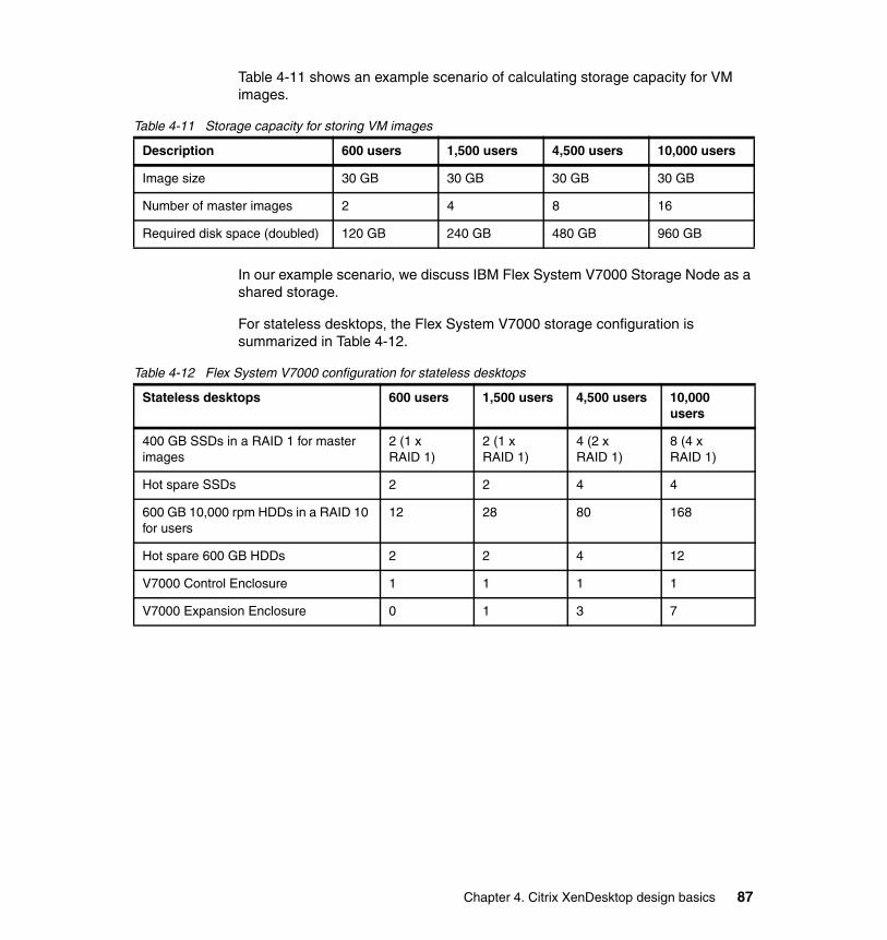
Table 4-11 shows an example scenario of calculating storage capacity for VM images.
Table 4-11 Storage capacity for storing VM images
In our example scenario, we discuss IBM Flex System V7000 Storage Node as a shared storage.
For stateless desktops, the Flex System V7000 storage configuration is summarized in Table 4-12.
Table 4-12 Flex System V7000 configuration for stateless desktops
Description 600 users 1,500 users 4,500 users 10,000 users
Image size 30 GB 30 GB 30 GB 30 GB
Number of master images 2 4 8 16
Required disk space (doubled) 120 GB 240 GB 480 GB 960 GB
Stateless desktops 600 users 1,500 users 4,500 users 10,000 users
400 GB SSDs in a RAID 1 for master images
2 (1 x RAID 1)
2 (1 x RAID 1)
4 (2 x RAID 1)
8 (4 x RAID 1)
Hot spare SSDs 2 2 4 4
600 GB 10,000 rpm HDDs in a RAID 10 for users
12 28 80 168
Hot spare 600 GB HDDs 2 2 4 12
V7000 Control Enclosure 1 1 1 1
V7000 Expansion Enclosure 0 1 3 7
Chapter 4. Citrix XenDesktop design basics 87
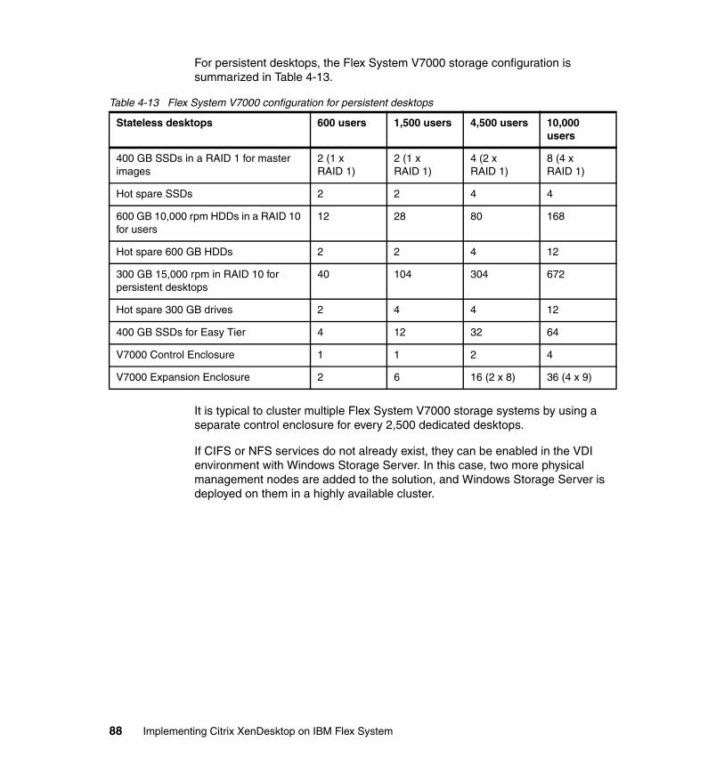
For persistent desktops, the Flex System V7000 storage configuration is summarized in Table 4-13.
Table 4-13 Flex System V7000 configuration for persistent desktops
It is typical to cluster multiple Flex System V7000 storage systems by using a separate control enclosure for every 2,500 dedicated desktops.
If CIFS or NFS services do not already exist, they can be enabled in the VDI environment with Windows Storage Server. In this case, two more physical management nodes are added to the solution, and Windows Storage Server is deployed on them in a highly available cluster.
Stateless desktops 600 users 1,500 users 4,500 users 10,000 users
400 GB SSDs in a RAID 1 for master images
2 (1 x RAID 1)
2 (1 x RAID 1)
4 (2 x RAID 1)
8 (4 x RAID 1)
Hot spare SSDs 2 2 4 4
600 GB 10,000 rpm HDDs in a RAID 10 for users
12 28 80 168
Hot spare 600 GB HDDs 2 2 4 12
300 GB 15,000 rpm in RAID 10 for persistent desktops
40 104 304 672
Hot spare 300 GB drives 2 4 4 12
400 GB SSDs for Easy Tier 4 12 32 64
V7000 Control Enclosure 1 1 2 4
V7000 Expansion Enclosure 2 6 16 (2 x 8) 36 (4 x 9)
88 Implementing Citrix XenDesktop on IBM Flex System
Chapter 5. IBM Flex System and Citrix XenDesktop lab environment
This chapter describes the structure of the environment and the implementation plan for Citrix XenDesktop in the International Technical Support Organization (ITSO) lab.
The lab setup described in this chapter illustrates the main infrastructure patterns applied to the production virtual desktop infrastructure (VDI) environments.
This chapter contains the following topics:
� 5.1, “Lab environment” on page 90� 5.2, “Use case for the lab environment” on page 91� 5.3, “Component model” on page 93� 5.4, “Operational model” on page 94� 5.5, “Logical design” on page 96
5
© Copyright IBM Corp. 2014. All rights reserved. 89
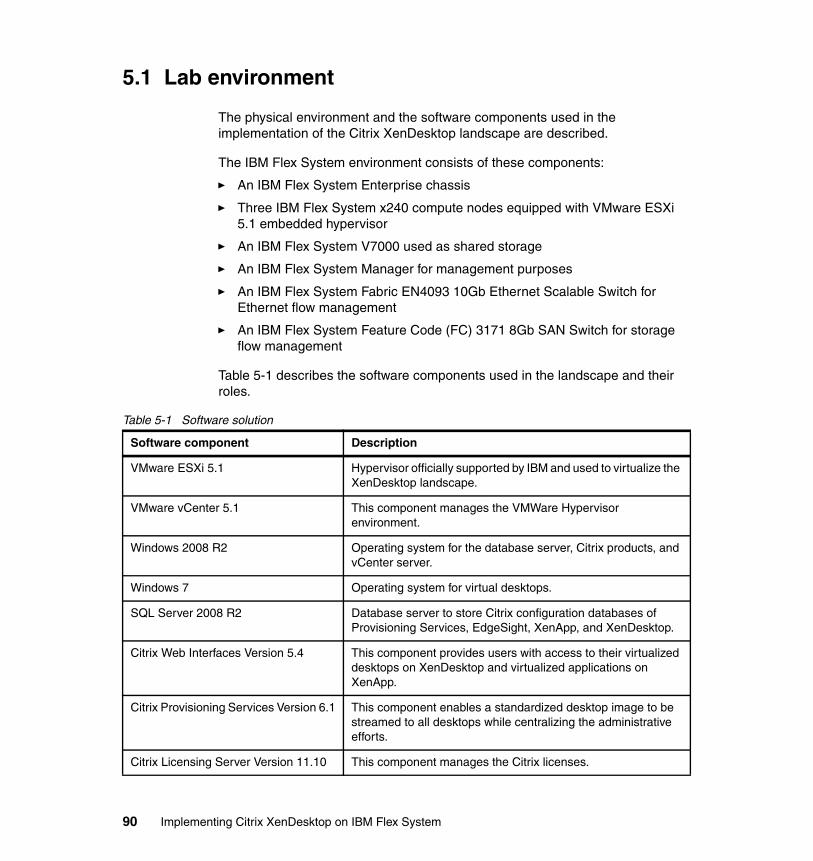
5.1 Lab environment
The physical environment and the software components used in the implementation of the Citrix XenDesktop landscape are described.
The IBM Flex System environment consists of these components:
� An IBM Flex System Enterprise chassis
� Three IBM Flex System x240 compute nodes equipped with VMware ESXi 5.1 embedded hypervisor
� An IBM Flex System V7000 used as shared storage
� An IBM Flex System Manager for management purposes
� An IBM Flex System Fabric EN4093 10Gb Ethernet Scalable Switch for Ethernet flow management
� An IBM Flex System Feature Code (FC) 3171 8Gb SAN Switch for storage flow management
Table 5-1 describes the software components used in the landscape and their roles.
Table 5-1 Software solution
Software component Description
VMware ESXi 5.1 Hypervisor officially supported by IBM and used to virtualize the XenDesktop landscape.
VMware vCenter 5.1 This component manages the VMWare Hypervisor environment.
Windows 2008 R2 Operating system for the database server, Citrix products, and vCenter server.
Windows 7 Operating system for virtual desktops.
SQL Server 2008 R2 Database server to store Citrix configuration databases of Provisioning Services, EdgeSight, XenApp, and XenDesktop.
Citrix Web Interfaces Version 5.4 This component provides users with access to their virtualized desktops on XenDesktop and virtualized applications on XenApp.
Citrix Provisioning Services Version 6.1 This component enables a standardized desktop image to be streamed to all desktops while centralizing the administrative efforts.
Citrix Licensing Server Version 11.10 This component manages the Citrix licenses.
90 Implementing Citrix XenDesktop on IBM Flex System
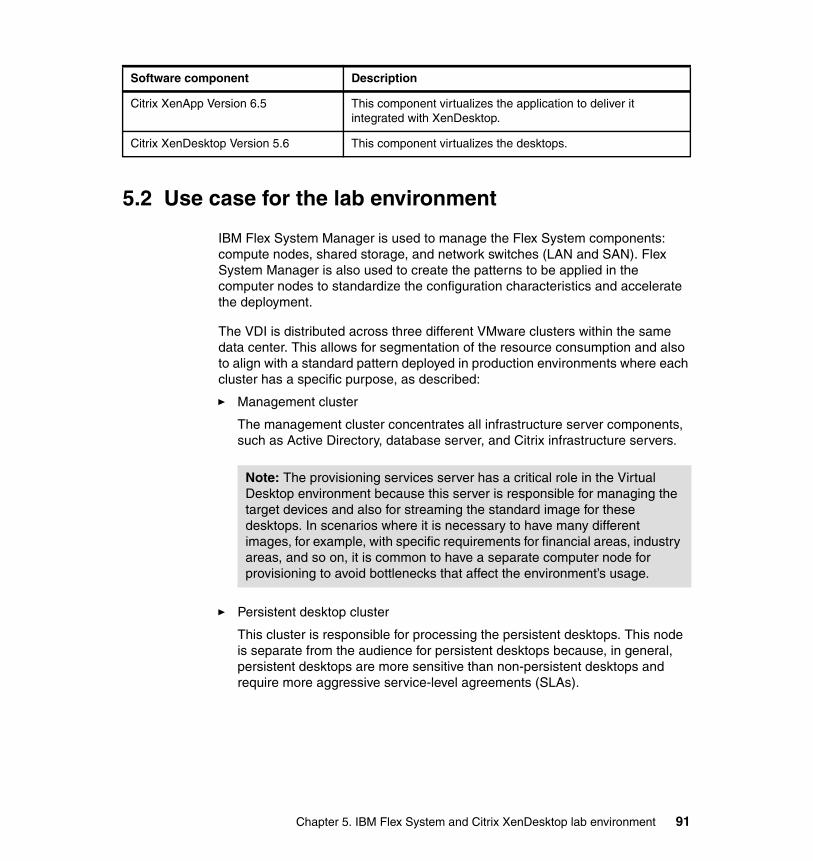
5.2 Use case for the lab environment
IBM Flex System Manager is used to manage the Flex System components: compute nodes, shared storage, and network switches (LAN and SAN). Flex System Manager is also used to create the patterns to be applied in the computer nodes to standardize the configuration characteristics and accelerate the deployment.
The VDI is distributed across three different VMware clusters within the same data center. This allows for segmentation of the resource consumption and also to align with a standard pattern deployed in production environments where each cluster has a specific purpose, as described:
� Management cluster
The management cluster concentrates all infrastructure server components, such as Active Directory, database server, and Citrix infrastructure servers.
� Persistent desktop cluster
This cluster is responsible for processing the persistent desktops. This node is separate from the audience for persistent desktops because, in general, persistent desktops are more sensitive than non-persistent desktops and require more aggressive service-level agreements (SLAs).
Citrix XenApp Version 6.5 This component virtualizes the application to deliver it integrated with XenDesktop.
Citrix XenDesktop Version 5.6 This component virtualizes the desktops.
Software component Description
Note: The provisioning services server has a critical role in the Virtual Desktop environment because this server is responsible for managing the target devices and also for streaming the standard image for these desktops. In scenarios where it is necessary to have many different images, for example, with specific requirements for financial areas, industry areas, and so on, it is common to have a separate computer node for provisioning to avoid bottlenecks that affect the environment’s usage.
Chapter 5. IBM Flex System and Citrix XenDesktop lab environment 91
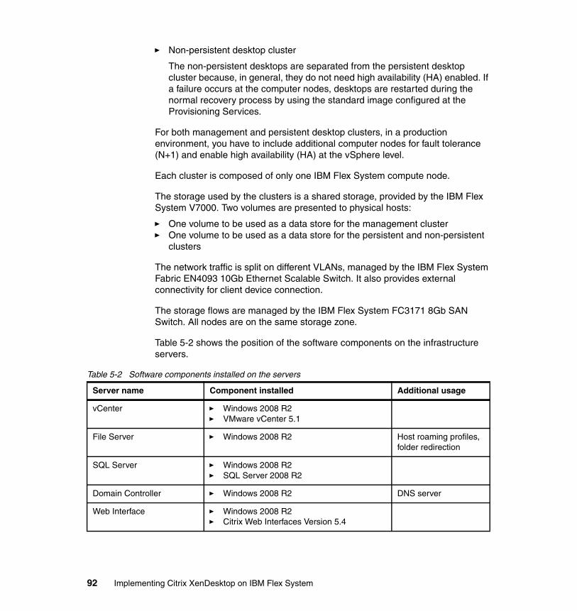
� Non-persistent desktop cluster
The non-persistent desktops are separated from the persistent desktop cluster because, in general, they do not need high availability (HA) enabled. If a failure occurs at the computer nodes, desktops are restarted during the normal recovery process by using the standard image configured at the Provisioning Services.
For both management and persistent desktop clusters, in a production environment, you have to include additional computer nodes for fault tolerance (N+1) and enable high availability (HA) at the vSphere level.
Each cluster is composed of only one IBM Flex System compute node.
The storage used by the clusters is a shared storage, provided by the IBM Flex System V7000. Two volumes are presented to physical hosts:
� One volume to be used as a data store for the management cluster� One volume to be used as a data store for the persistent and non-persistent
clusters
The network traffic is split on different VLANs, managed by the IBM Flex System Fabric EN4093 10Gb Ethernet Scalable Switch. It also provides external connectivity for client device connection.
The storage flows are managed by the IBM Flex System FC3171 8Gb SAN Switch. All nodes are on the same storage zone.
Table 5-2 shows the position of the software components on the infrastructure servers.
Table 5-2 Software components installed on the servers
Server name Component installed Additional usage
vCenter � Windows 2008 R2� VMware vCenter 5.1
File Server � Windows 2008 R2 Host roaming profiles, folder redirection
SQL Server � Windows 2008 R2� SQL Server 2008 R2
Domain Controller � Windows 2008 R2 DNS server
Web Interface � Windows 2008 R2� Citrix Web Interfaces Version 5.4
92 Implementing Citrix XenDesktop on IBM Flex System
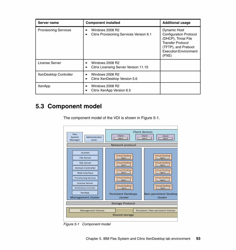
5.3 Component model
The component model of the VDI is shown in Figure 5-1.
Figure 5-1 Component model
Provisioning Services � Windows 2008 R2� Citrix Provisioning Services Version 6.1
Dynamic Host Configuration Protocol (DHCP), Trivial File Transfer Protocol (TFTP), and Preboot Execution Environment (PXE)
License Server � Windows 2008 R2� Citrix Licensing Server Version 11.10
XenDesktop Controller � Windows 2008 R2� Citrix XenDesktop Version 5.6
XenApp � Windows 2008 R2� Citrix XenApp Version 6.5
Server name Component installed Additional usage
Client devices
vCenter
File Server
SQL Server
Domain Controller
Web Interface
Provisioning Services
License Server
XenDesktop Controller
XenApp
Management clusterPersistent Desktops
clusterNon-persistent Desktop
cluster
AgentClient
AgentVirtual Desktop
AgentVirtual Desktop
AgentVirtual Desktop
AgentVirtual Desktop
AgentVirtual Desktop
AgentVirtual Desktop
AgentVirtual Desktop
AgentVirtual Desktop
AgentVirtual Desktop
AgentVirtual Desktop
AgentClient
AgentClient
Shared storage
Network protocol
Storage Protocol
Management Volume Persistent / Non-persistent Volume
Flex System
ManagerAdministrator
tools
Chapter 5. IBM Flex System and Citrix XenDesktop lab environment 93
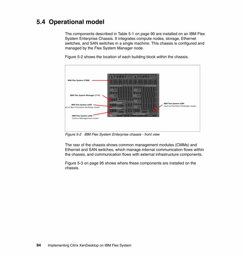
5.4 Operational model
The components described in Table 5-1 on page 90 are installed on an IBM Flex System Enterprise Chassis. It integrates compute nodes, storage, Ethernet switches, and SAN switches in a single machine. This chassis is configured and managed by the Flex System Manager node.
Figure 5-2 shows the location of each building block within the chassis.
Figure 5-2 IBM Flex System Enterprise chassis - front view
The rear of the chassis shows common management modules (CMMs) and Ethernet and SAN switches, which manage internal communication flows within the chassis, and communication flows with external infrastructure components.
Figure 5-3 on page 95 shows where these components are installed on the chassis.
IBM Flex System V7000
IBM Flex System Manager (FSM)
IBM Flex System x240sed as Non-Persistent Desktops cluster
IBM Flex System x240Used as Management cluster
IBM Flex System x240Used as Persistent Desktops cluster
94 Implementing Citrix XenDesktop on IBM Flex System
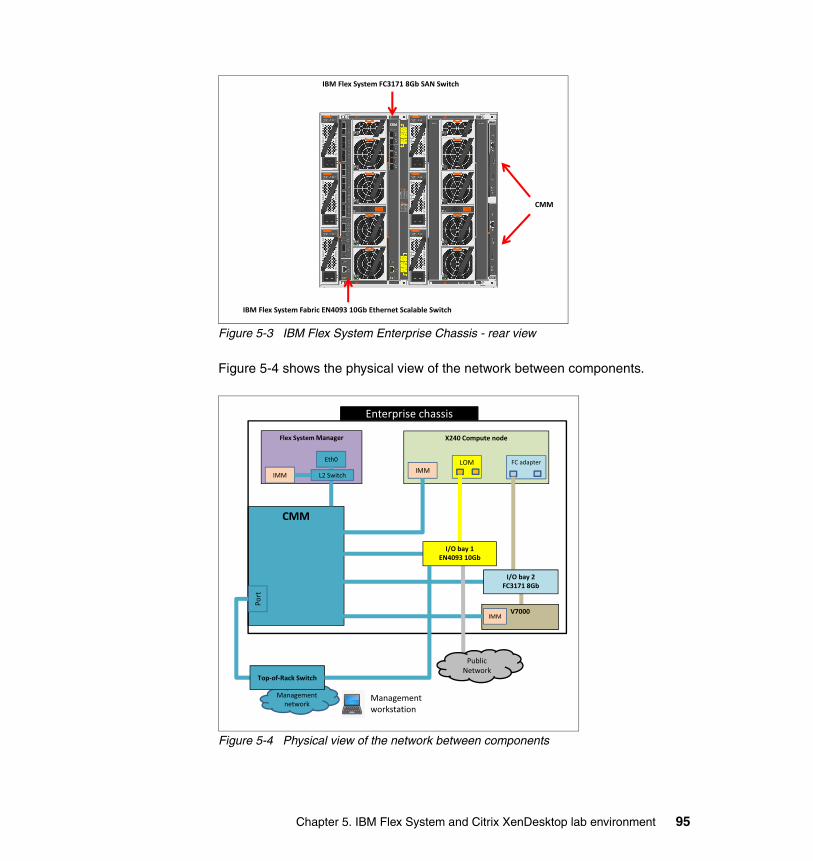
Figure 5-3 IBM Flex System Enterprise Chassis - rear view
Figure 5-4 shows the physical view of the network between components.
Figure 5-4 Physical view of the network between components
���������� ����������������������� ����� ����������� ��
���������� ������� ��!���"���� ��
���
������ �������#�� $%����&�'( ���&)�
������
���
��� ����� �����
* ���
�+,�����%���� ��!��
���������
��� ����� �������
����
��� � ���� �����
-&'.&/.0��1��� ��
��� � �������������
���
�+,�����������������
��� ���! �����
Chapter 5. IBM Flex System and Citrix XenDesktop lab environment 95
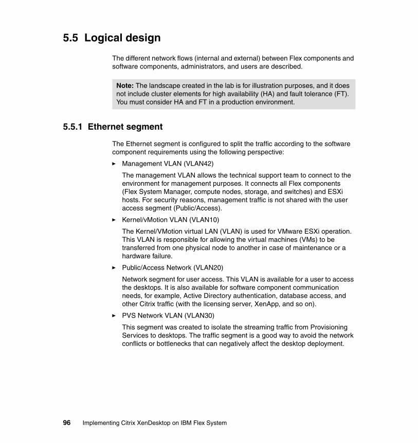
5.5 Logical design
The different network flows (internal and external) between Flex components and software components, administrators, and users are described.
5.5.1 Ethernet segment
The Ethernet segment is configured to split the traffic according to the software component requirements using the following perspective:
� Management VLAN (VLAN42)
The management VLAN allows the technical support team to connect to the environment for management purposes. It connects all Flex components (Flex System Manager, compute nodes, storage, and switches) and ESXi hosts. For security reasons, management traffic is not shared with the user access segment (Public/Access).
� Kernel/vMotion VLAN (VLAN10)
The Kernel/VMotion virtual LAN (VLAN) is used for VMware ESXi operation. This VLAN is responsible for allowing the virtual machines (VMs) to be transferred from one physical node to another in case of maintenance or a hardware failure.
� Public/Access Network (VLAN20)
Network segment for user access. This VLAN is available for a user to access the desktops. It is also available for software component communication needs, for example, Active Directory authentication, database access, and other Citrix traffic (with the licensing server, XenApp, and so on).
� PVS Network VLAN (VLAN30)
This segment was created to isolate the streaming traffic from Provisioning Services to desktops. The traffic segment is a good way to avoid the network conflicts or bottlenecks that can negatively affect the desktop deployment.
Note: The landscape created in the lab is for illustration purposes, and it does not include cluster elements for high availability (HA) and fault tolerance (FT). You must consider HA and FT in a production environment.
96 Implementing Citrix XenDesktop on IBM Flex System
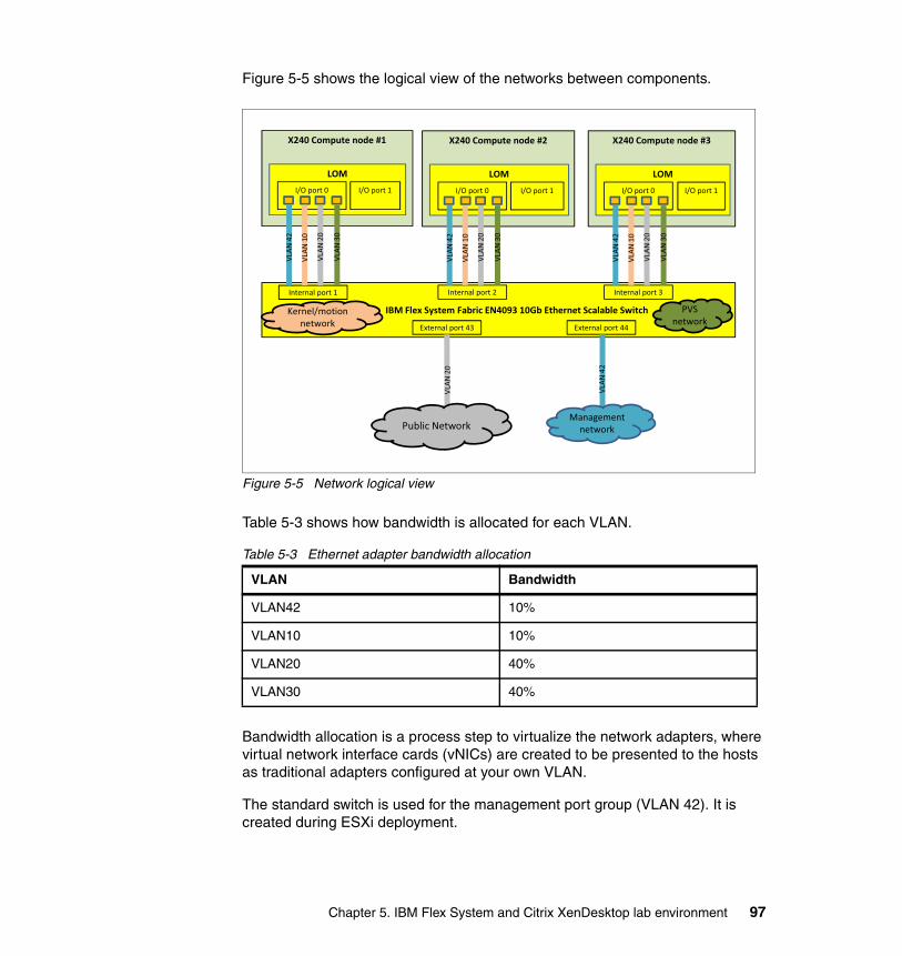
Figure 5-5 shows the logical view of the networks between components.
Figure 5-5 Network logical view
Table 5-3 shows how bandwidth is allocated for each VLAN.
Table 5-3 Ethernet adapter bandwidth allocation
Bandwidth allocation is a process step to virtualize the network adapters, where virtual network interface cards (vNICs) are created to be presented to the hosts as traditional adapters configured at your own VLAN.
The standard switch is used for the management port group (VLAN 42). It is created during ESXi deployment.
VLAN Bandwidth
VLAN42 10%
VLAN10 10%
VLAN20 40%
VLAN30 40%
$%����&�'( ���&)��2�
3,��"�������� �"�������#
$%����&�'( ���&)��2%
3,��"�������� �"�������#
���������� ����������������������� ����� ����������� ��
��� �� ������#
$�%!
�&�
$�%!
���
$�%!
�#�
$�%!
�'�
��� �� �������
$�%!
�&�
$�%!
���
$�%!
�#�
$�%!
�'�
$%����&�'( ���&)��2�
3,��"��������
��� �� ������&
$�%!
�&�
$�%!
���
$�%!
�#�
$�%!
�'�
�(� �� ������'& �(� �� ������''
$�%!
�'�
�"�������#
��� � ���� �������� ���! �����
$�%!
���
�$��� �����
) �� "�������� �����
Chapter 5. IBM Flex System and Citrix XenDesktop lab environment 97
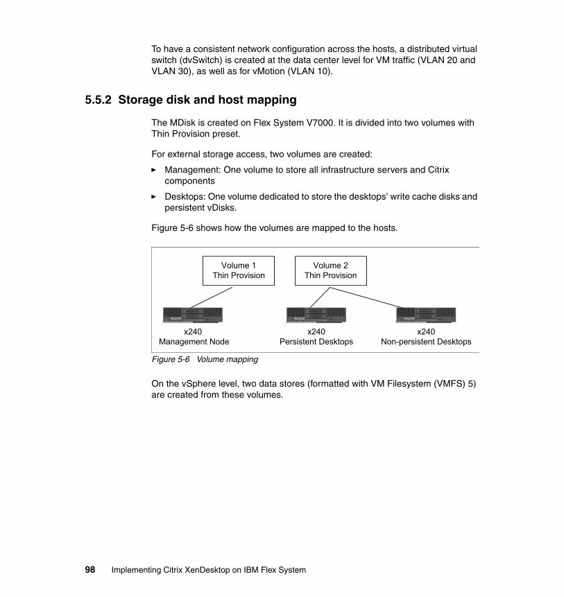
To have a consistent network configuration across the hosts, a distributed virtual switch (dvSwitch) is created at the data center level for VM traffic (VLAN 20 and VLAN 30), as well as for vMotion (VLAN 10).
5.5.2 Storage disk and host mapping
The MDisk is created on Flex System V7000. It is divided into two volumes with Thin Provision preset.
For external storage access, two volumes are created:
� Management: One volume to store all infrastructure servers and Citrix components
� Desktops: One volume dedicated to store the desktops’ write cache disks and persistent vDisks.
Figure 5-6 shows how the volumes are mapped to the hosts.
Figure 5-6 Volume mapping
On the vSphere level, two data stores (formatted with VM Filesystem (VMFS) 5) are created from these volumes.
Volume 1 Thin Provision
Volume 2 Thin Provision
x240Management Node
x240Persistent Desktops
x240Non-persistent Desktops
98 Implementing Citrix XenDesktop on IBM Flex System
Chapter 6. Deploying IBM Flex System
This chapter describes initial setup and configuration tasks that need to be performed on IBM Flex System for virtual desktop infrastructure (VDI) deployment.
This chapter contains the following topics:
� 6.1, “Initial configuration of the Chassis Management Module” on page 100
� 6.2, “The IBM Flex System Manager setup wizard” on page 119
� 6.3, “Selecting the chassis to manage” on page 136
� 6.4, “Discovery and inventory collection” on page 141
� 6.5, “IBM Flex System Fabric EN4093 10Gb Ethernet Switch configuration” on page 162
� 6.6, “IBM Flex System x240 Compute Node configuration” on page 168
� 6.7, “IBM Flex Storwize V7000 configuration” on page 182
� 6.8, “VMControl configuration and virtual server deployment” on page 211
6
© Copyright IBM Corp. 2014. All rights reserved. 99
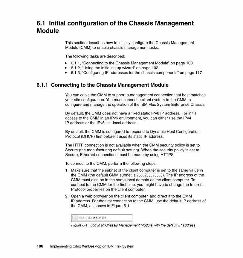
6.1 Initial configuration of the Chassis Management Module
This section describes how to initially configure the Chassis Management Module (CMM) to enable chassis management tasks.
The following tasks are described:
� 6.1.1, “Connecting to the Chassis Management Module” on page 100� 6.1.2, “Using the initial setup wizard” on page 102� 6.1.3, “Configuring IP addresses for the chassis components” on page 117
6.1.1 Connecting to the Chassis Management Module
You can cable the CMM to support a management connection that best matches your site configuration. You must connect a client system to the CMM to configure and manage the operation of the IBM Flex System Enterprise Chassis.
By default, the CMM does not have a fixed static IPv6 IP address. For initial access to the CMM in an IPv6 environment, you can either use the IPv4 IP address or the IPv6 link-local address.
By default, the CMM is configured to respond to Dynamic Host Configuration Protocol (DHCP) first before it uses its static IP address.
The HTTP connection is not available when the CMM security policy is set to Secure (the manufacturing default setting). When the security policy is set to Secure, Ethernet connections must be made by using HTTPS.
To connect to the CMM, perform the following steps.
1. Make sure that the subnet of the client computer is set to the same value in the CMM (the default CMM subnet is 255.255.255.0). The IP address of the CMM must also be in the same local domain as the client computer. To connect to the CMM for the first time, you might have to change the Internet Protocol properties on the client computer.
2. Open a web browser on the client computer, and direct it to the CMMIP address. For the first connection to the CMM, use the default IP address of the CMM, as shown in Figure 6-1.
Figure 6-1 Log in to Chassis Management Module with the default IP address
100 Implementing Citrix XenDesktop on IBM Flex System
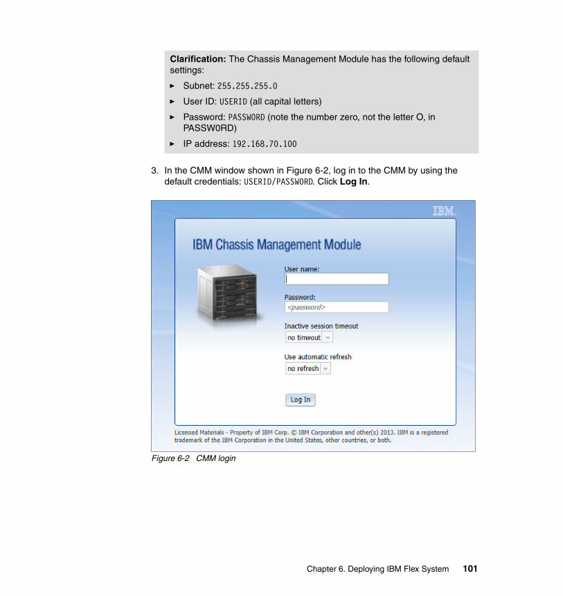
3. In the CMM window shown in Figure 6-2, log in to the CMM by using the default credentials: USERID/PASSW0RD. Click Log In.
Figure 6-2 CMM login
Clarification: The Chassis Management Module has the following default settings:
� Subnet: 255.255.255.0
� User ID: USERID (all capital letters)
� Password: PASSW0RD (note the number zero, not the letter O, in PASSW0RD)
� IP address: 192.168.70.100
Chapter 6. Deploying IBM Flex System 101
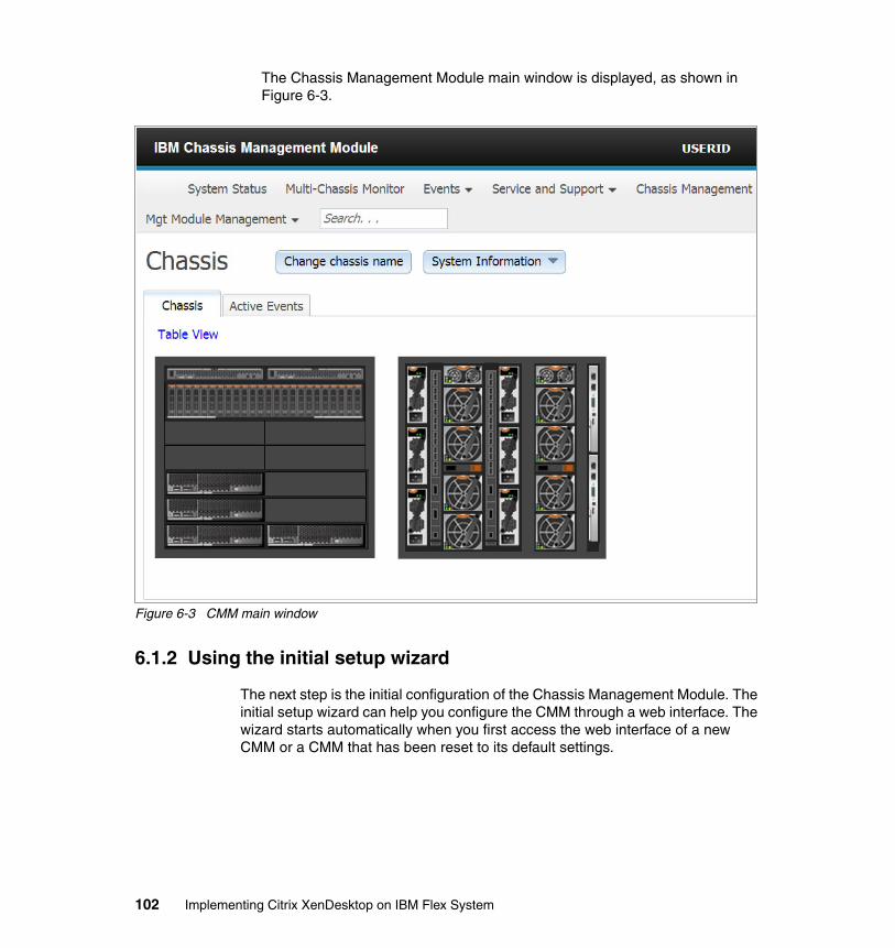
The Chassis Management Module main window is displayed, as shown in Figure 6-3.
Figure 6-3 CMM main window
6.1.2 Using the initial setup wizard
The next step is the initial configuration of the Chassis Management Module. The initial setup wizard can help you configure the CMM through a web interface. The wizard starts automatically when you first access the web interface of a new CMM or a CMM that has been reset to its default settings.
102 Implementing Citrix XenDesktop on IBM Flex System
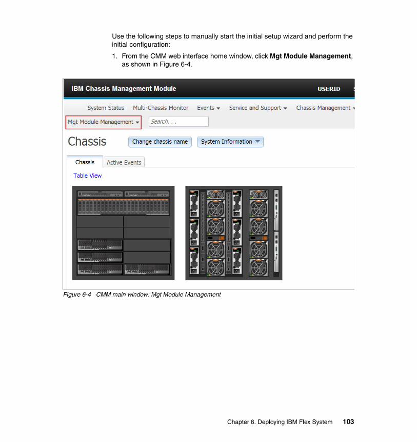
Use the following steps to manually start the initial setup wizard and perform the initial configuration:
1. From the CMM web interface home window, click Mgt Module Management, as shown in Figure 6-4.
Figure 6-4 CMM main window: Mgt Module Management
Chapter 6. Deploying IBM Flex System 103
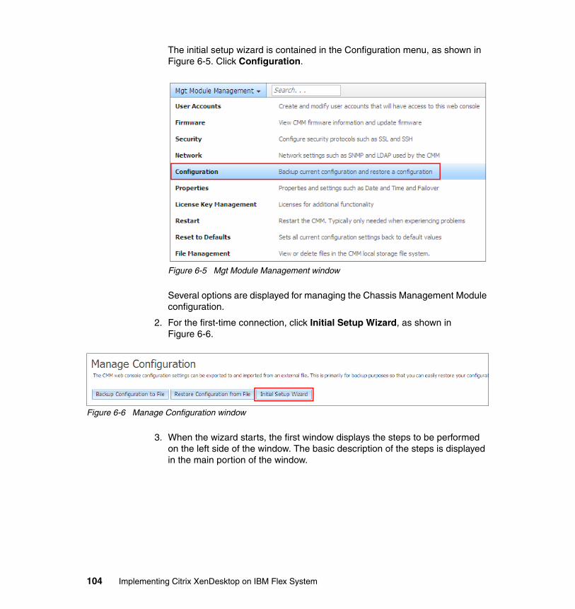
The initial setup wizard is contained in the Configuration menu, as shown in Figure 6-5. Click Configuration.
Figure 6-5 Mgt Module Management window
Several options are displayed for managing the Chassis Management Module configuration.
2. For the first-time connection, click Initial Setup Wizard, as shown in Figure 6-6.
Figure 6-6 Manage Configuration window
3. When the wizard starts, the first window displays the steps to be performed on the left side of the window. The basic description of the steps is displayed in the main portion of the window.
104 Implementing Citrix XenDesktop on IBM Flex System
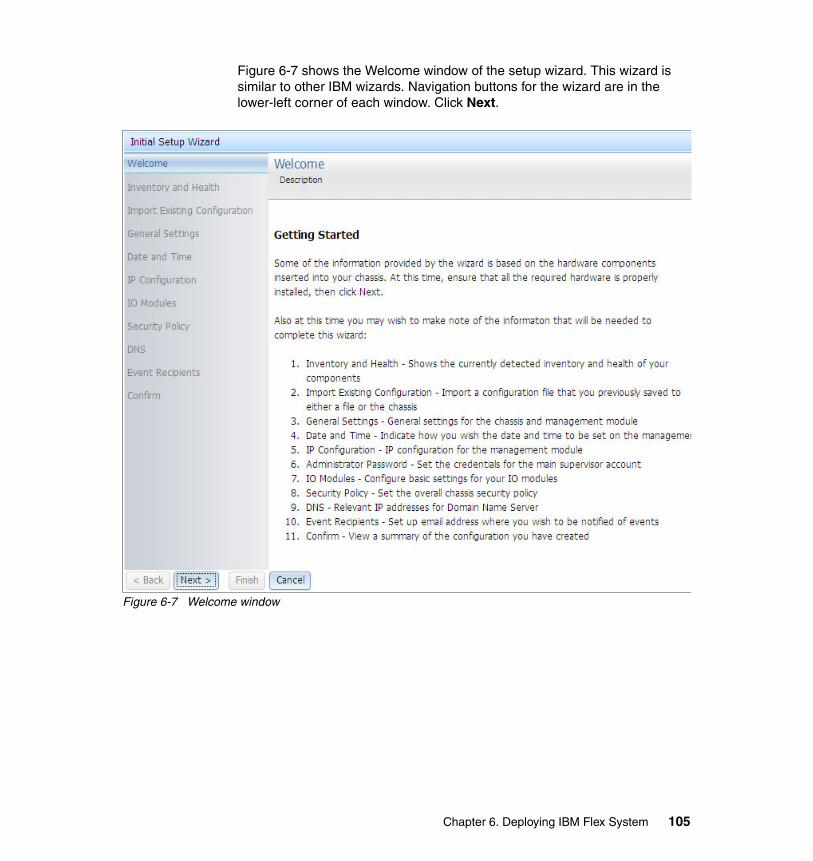
Figure 6-7 shows the Welcome window of the setup wizard. This wizard is similar to other IBM wizards. Navigation buttons for the wizard are in the lower-left corner of each window. Click Next.
Figure 6-7 Welcome window
Chapter 6. Deploying IBM Flex System 105
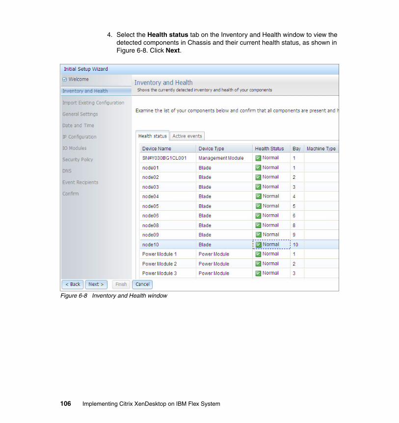
4. Select the Health status tab on the Inventory and Health window to view the detected components in Chassis and their current health status, as shown in Figure 6-8. Click Next.
Figure 6-8 Inventory and Health window
106 Implementing Citrix XenDesktop on IBM Flex System
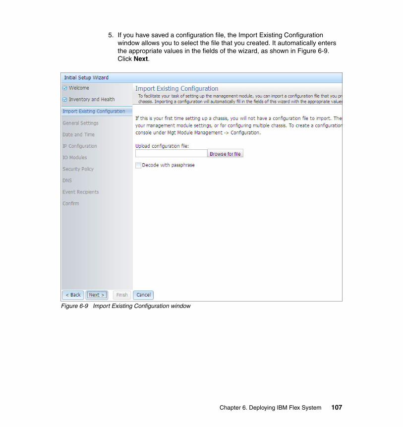
5. If you have saved a configuration file, the Import Existing Configuration window allows you to select the file that you created. It automatically enters the appropriate values in the fields of the wizard, as shown in Figure 6-9. Click Next.
Figure 6-9 Import Existing Configuration window
Chapter 6. Deploying IBM Flex System 107
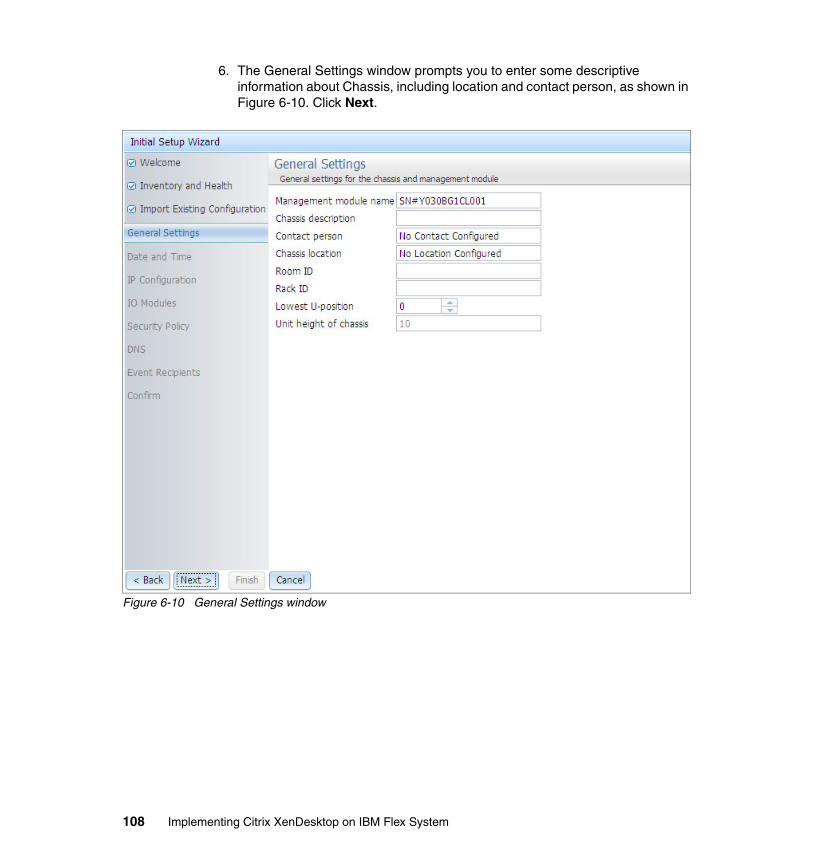
6. The General Settings window prompts you to enter some descriptive information about Chassis, including location and contact person, as shown in Figure 6-10. Click Next.
Figure 6-10 General Settings window
108 Implementing Citrix XenDesktop on IBM Flex System
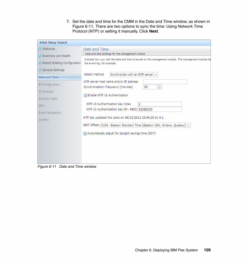
7. Set the date and time for the CMM in the Date and Time window, as shown in Figure 6-11. There are two options to sync the time: Using Network Time Protocol (NTP) or setting it manually. Click Next.
Figure 6-11 Date and Time window
Chapter 6. Deploying IBM Flex System 109
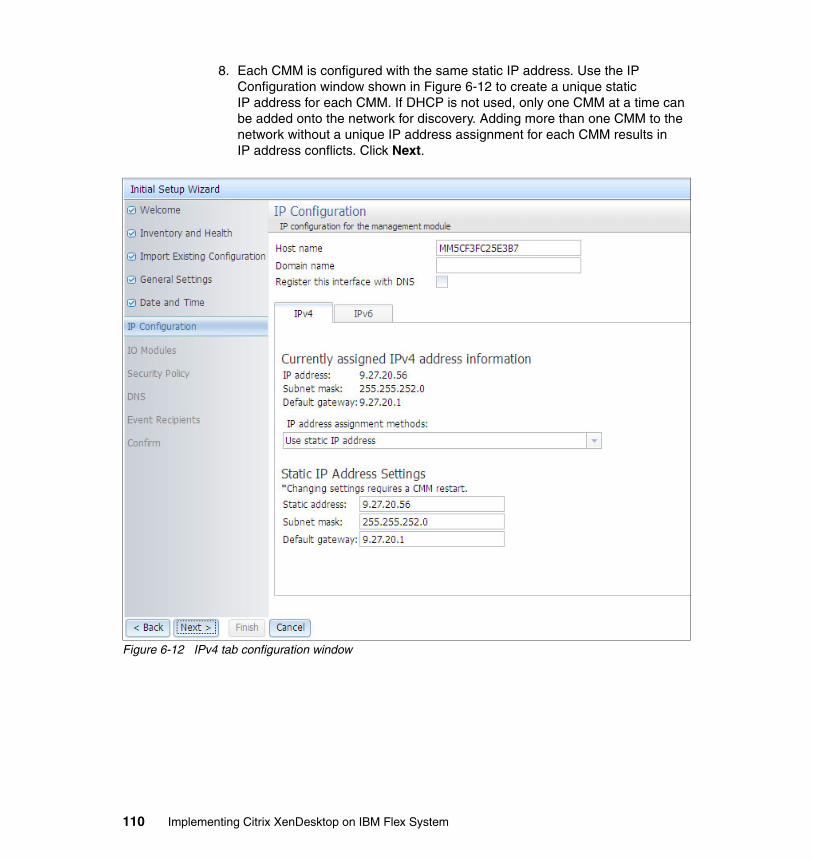
8. Each CMM is configured with the same static IP address. Use the IP Configuration window shown in Figure 6-12 to create a unique static IP address for each CMM. If DHCP is not used, only one CMM at a time can be added onto the network for discovery. Adding more than one CMM to the network without a unique IP address assignment for each CMM results in IP address conflicts. Click Next.
Figure 6-12 IPv4 tab configuration window
110 Implementing Citrix XenDesktop on IBM Flex System
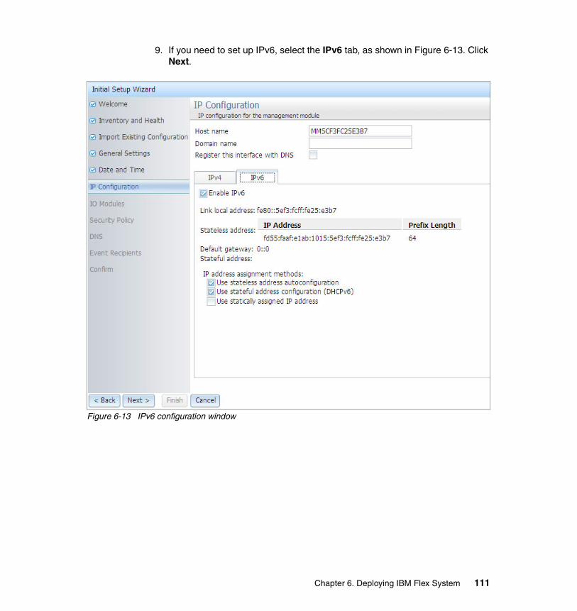
9. If you need to set up IPv6, select the IPv6 tab, as shown in Figure 6-13. Click Next.
Figure 6-13 IPv6 configuration window
Chapter 6. Deploying IBM Flex System 111
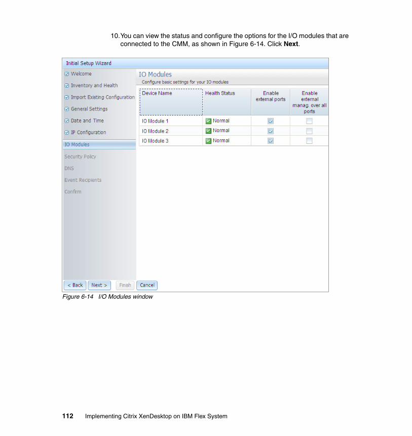
10.You can view the status and configure the options for the I/O modules that are connected to the CMM, as shown in Figure 6-14. Click Next.
Figure 6-14 I/O Modules window
112 Implementing Citrix XenDesktop on IBM Flex System
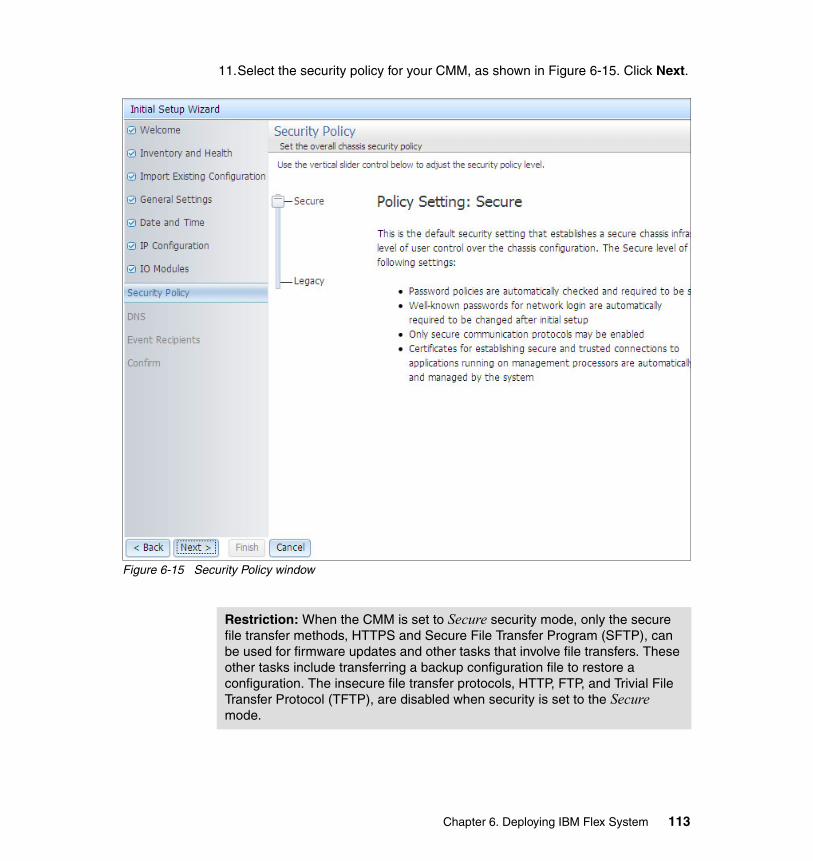
11.Select the security policy for your CMM, as shown in Figure 6-15. Click Next.
Figure 6-15 Security Policy window
Restriction: When the CMM is set to Secure security mode, only the secure file transfer methods, HTTPS and Secure File Transfer Program (SFTP), can be used for firmware updates and other tasks that involve file transfers. These other tasks include transferring a backup configuration file to restore a configuration. The insecure file transfer protocols, HTTP, FTP, and Trivial File Transfer Protocol (TFTP), are disabled when security is set to the Secure mode.
Chapter 6. Deploying IBM Flex System 113
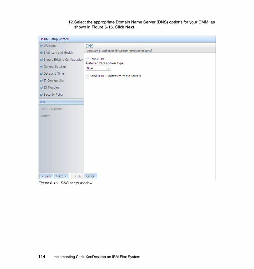
12.Select the appropriate Domain Name Server (DNS) options for your CMM, as shown in Figure 6-16. Click Next.
Figure 6-16 DNS setup window
114 Implementing Citrix XenDesktop on IBM Flex System
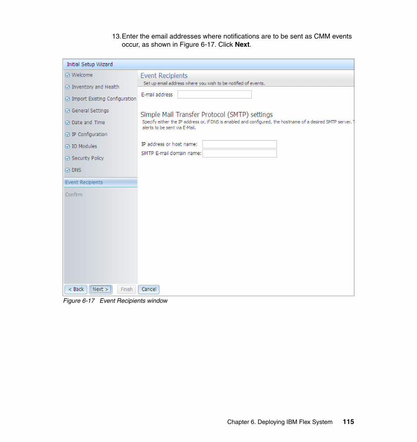
13.Enter the email addresses where notifications are to be sent as CMM events occur, as shown in Figure 6-17. Click Next.
Figure 6-17 Event Recipients window
Chapter 6. Deploying IBM Flex System 115
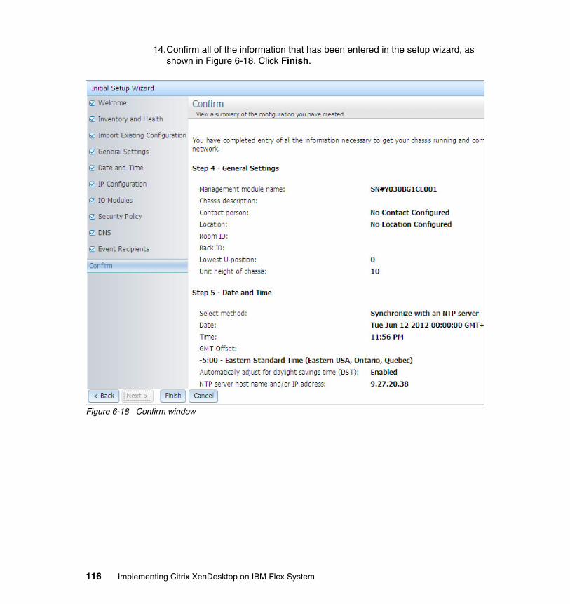
14.Confirm all of the information that has been entered in the setup wizard, as shown in Figure 6-18. Click Finish.
Figure 6-18 Confirm window
116 Implementing Citrix XenDesktop on IBM Flex System
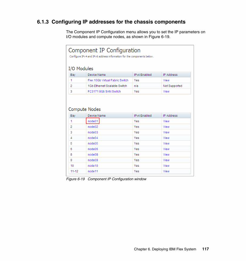
6.1.3 Configuring IP addresses for the chassis components
The Component IP Configuration menu allows you to set the IP parameters on I/O modules and compute nodes, as shown in Figure 6-19.
Figure 6-19 Component IP Configuration window
Chapter 6. Deploying IBM Flex System 117
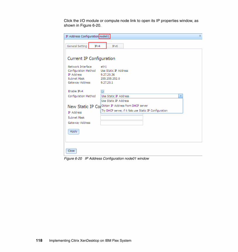
Click the I/O module or compute node link to open its IP properties window, as shown in Figure 6-20.
Figure 6-20 IP Address Configuration node01 window
118 Implementing Citrix XenDesktop on IBM Flex System
6.2 The IBM Flex System Manager setup wizard
The IBM Flex System Manager (FSM) is an appliance that comes with all required software preinstalled. When this software stack is started for the first time, a startup wizard is initiated. This wizard guides you through the required configuration process, such as licensing agreements and Transmission Control Protocol/Internet Protocol (TCP/IP) configuration for the appliance.
When the configuration is complete, the Flex System Manager is ready to manage the chassis on which it is installed and up to four additional chassis. After the chassis is managed, individual components, such as compute nodes and switches, can also be managed.
The Flex System Manager is based on an x86 compute node, and has the same options for obtaining an initial console. You can use the Integrated Management Module II (IMM2) remote console or use the supplied dongle and front port on the Flex System Manager node to connect directly to a keyboard, display, and mouse or to a console manager unit.
To monitor the Flex System Manager startup process, connect a console by using one of these methods before powering on the Flex System Manager node. The following steps use the IMM2 remote console method.
Chapter 6. Deploying IBM Flex System 119
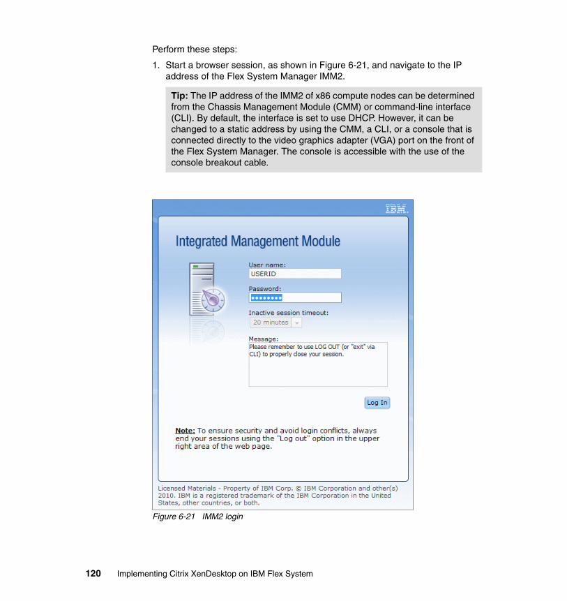
Perform these steps:
1. Start a browser session, as shown in Figure 6-21, and navigate to the IP address of the Flex System Manager IMM2.
Figure 6-21 IMM2 login
Tip: The IP address of the IMM2 of x86 compute nodes can be determined from the Chassis Management Module (CMM) or command-line interface (CLI). By default, the interface is set to use DHCP. However, it can be changed to a static address by using the CMM, a CLI, or a console that is connected directly to the video graphics adapter (VGA) port on the front of the Flex System Manager. The console is accessible with the use of the console breakout cable.
120 Implementing Citrix XenDesktop on IBM Flex System
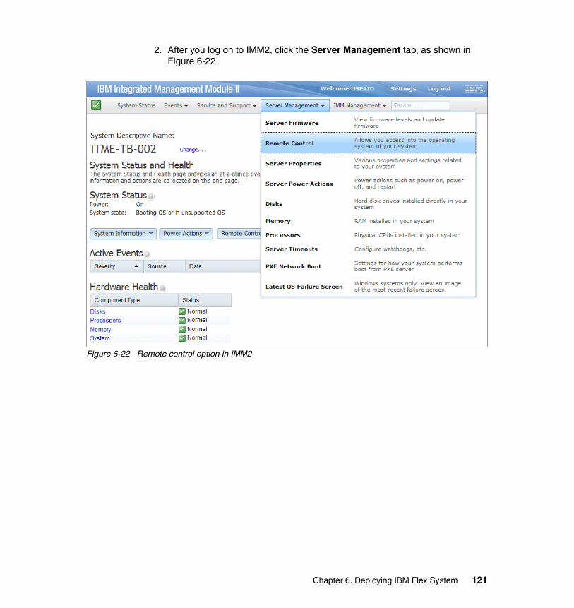
2. After you log on to IMM2, click the Server Management tab, as shown in Figure 6-22.
Figure 6-22 Remote control option in IMM2
Chapter 6. Deploying IBM Flex System 121
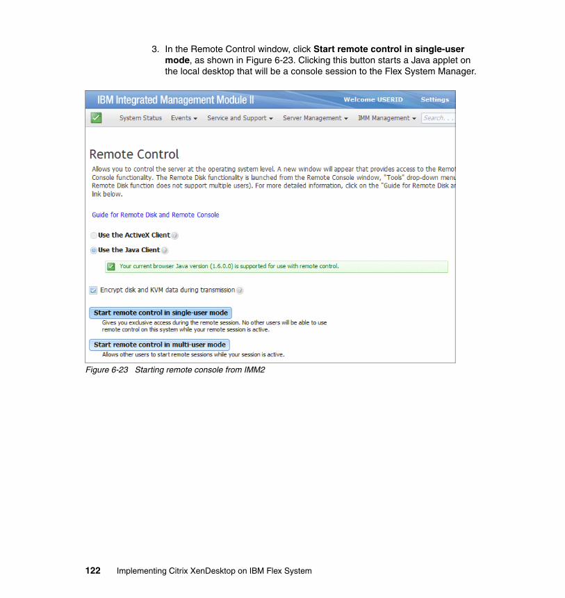
3. In the Remote Control window, click Start remote control in single-user mode, as shown in Figure 6-23. Clicking this button starts a Java applet on the local desktop that will be a console session to the Flex System Manager.
Figure 6-23 Starting remote console from IMM2
122 Implementing Citrix XenDesktop on IBM Flex System
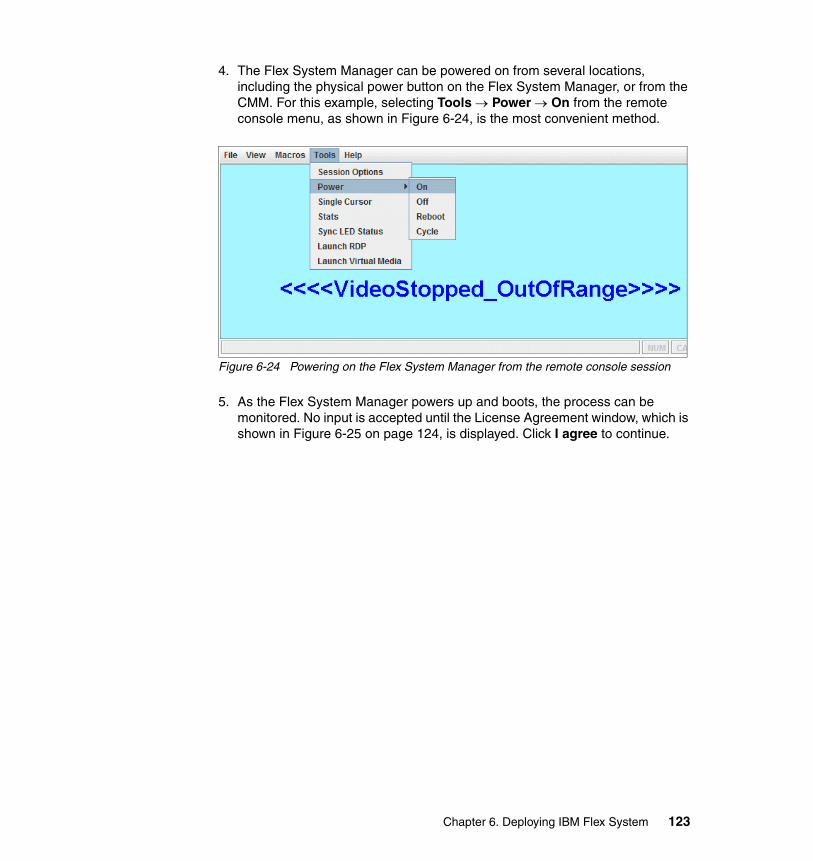
4. The Flex System Manager can be powered on from several locations, including the physical power button on the Flex System Manager, or from the CMM. For this example, selecting Tools Power On from the remote console menu, as shown in Figure 6-24, is the most convenient method.
Figure 6-24 Powering on the Flex System Manager from the remote console session
5. As the Flex System Manager powers up and boots, the process can be monitored. No input is accepted until the License Agreement window, which is shown in Figure 6-25 on page 124, is displayed. Click I agree to continue.
Chapter 6. Deploying IBM Flex System 123
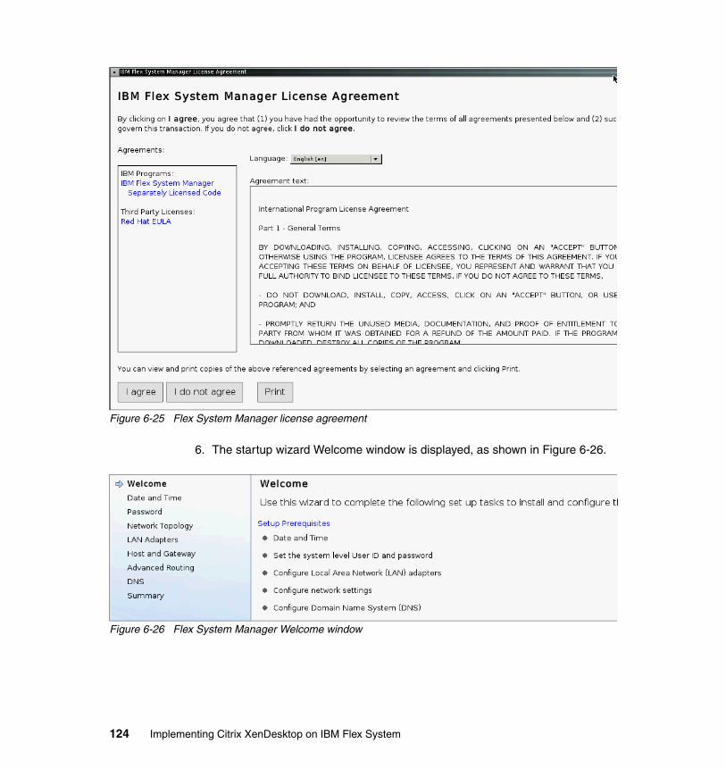
Figure 6-25 Flex System Manager license agreement
6. The startup wizard Welcome window is displayed, as shown in Figure 6-26.
Figure 6-26 Flex System Manager Welcome window
124 Implementing Citrix XenDesktop on IBM Flex System
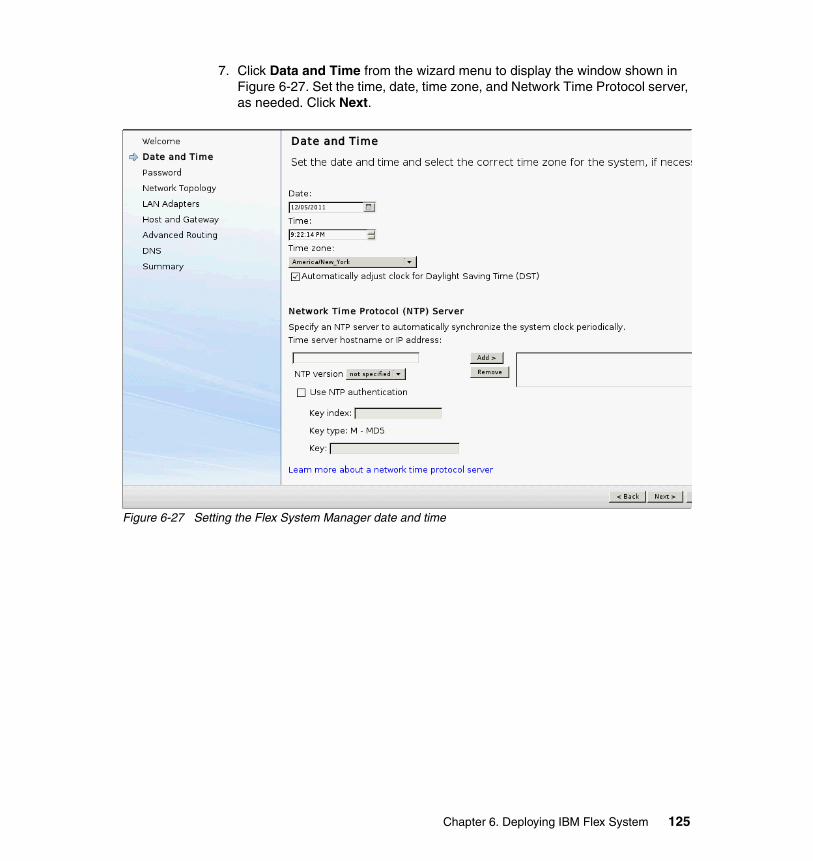
7. Click Data and Time from the wizard menu to display the window shown in Figure 6-27. Set the time, date, time zone, and Network Time Protocol server, as needed. Click Next.
Figure 6-27 Setting the Flex System Manager date and time
Chapter 6. Deploying IBM Flex System 125
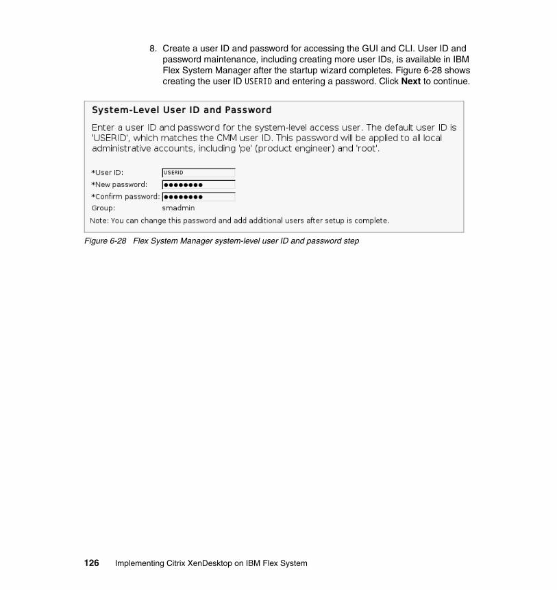
8. Create a user ID and password for accessing the GUI and CLI. User ID and password maintenance, including creating more user IDs, is available in IBM Flex System Manager after the startup wizard completes. Figure 6-28 shows creating the user ID USERID and entering a password. Click Next to continue.
Figure 6-28 Flex System Manager system-level user ID and password step
126 Implementing Citrix XenDesktop on IBM Flex System
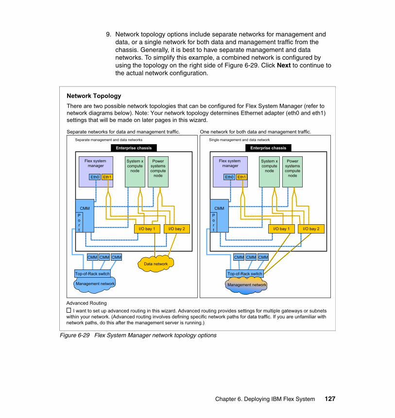
9. Network topology options include separate networks for management and data, or a single network for both data and management traffic from the chassis. Generally, it is best to have separate management and data networks. To simplify this example, a combined network is configured by using the topology on the right side of Figure 6-29. Click Next to continue to the actual network configuration.
Figure 6-29 Flex System Manager network topology options
� ����� �� ����)������%������%�'���( ' ���������*6�� ����� �'���( ' �����%�%����� ����)��
0� �� ����)���������%������%�'���( ' ���������*6����(� �'���( ' �����%�%����� ����)�
7� � ��� ����������� �� ����)�������(� �������*��� �*����($� %������� 2��3�� '�����( ���� � ������ ����)�%��(��'�� ���"6���� 8�9�$��� ����)�������(3�% � �'�� ���� �� ���%��� ��� ������%� ���"�� ����(������������ �'�% ������� ����( ������������:��%6
Network Topology
����������� ��$���%���* %���$���(�����������:��%6�.%���* %���$���(������% ��� ����(������'$����� �(�� ��3������$� ����������3�$��� ����)6��.%���* %���$���(������� ��% �����(��� *���*�� ����)�����������%����������*6����3�$��� �$���'������������ ����)��������%���������� ���� �'���( ' ���� �� ������$����(6"
.%���* %� �$���(
Enterprise chassis
����( ' ���� ����)
��� ��� ���
7��+��+ �*)�����*�
�� 2��3�� '�'���( �
��� ���
�3�� '�2�*�'�$� ���%
!�� ���3�� '��*�'�$� ���%
���
!������ �&0��3�� �&0��3�1
-����� ����)
Enterprise chassis
�� 2��3�� '�'���( �
�3�� '�2�*�'�$� ���%
!�� ���3�� '��*�'�$� ���%
���
!������
7��+��+ �*)�����*�
����( ' ���� ����)
�&0��3�� �&0��3�1
��� ��� ���
��� ���
Chapter 6. Deploying IBM Flex System 127
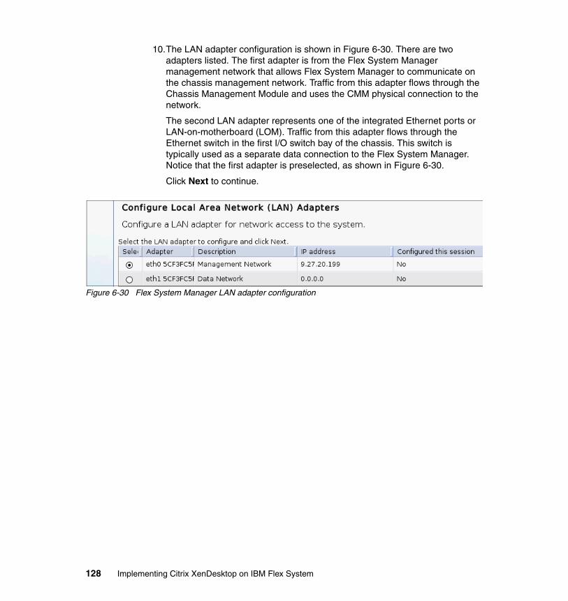
10.The LAN adapter configuration is shown in Figure 6-30. There are two adapters listed. The first adapter is from the Flex System Manager management network that allows Flex System Manager to communicate on the chassis management network. Traffic from this adapter flows through the Chassis Management Module and uses the CMM physical connection to the network.
The second LAN adapter represents one of the integrated Ethernet ports or LAN-on-motherboard (LOM). Traffic from this adapter flows through the Ethernet switch in the first I/O switch bay of the chassis. This switch is typically used as a separate data connection to the Flex System Manager. Notice that the first adapter is preselected, as shown in Figure 6-30.
Click Next to continue.
Figure 6-30 Flex System Manager LAN adapter configuration
128 Implementing Citrix XenDesktop on IBM Flex System
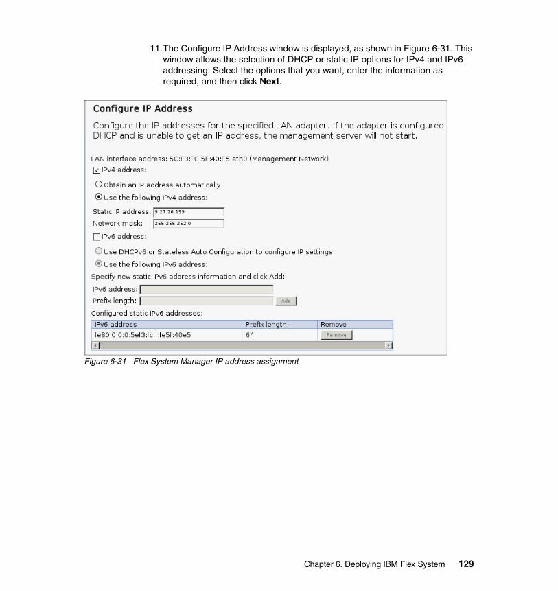
11.The Configure IP Address window is displayed, as shown in Figure 6-31. This window allows the selection of DHCP or static IP options for IPv4 and IPv6 addressing. Select the options that you want, enter the information as required, and then click Next.
Figure 6-31 Flex System Manager IP address assignment
Chapter 6. Deploying IBM Flex System 129
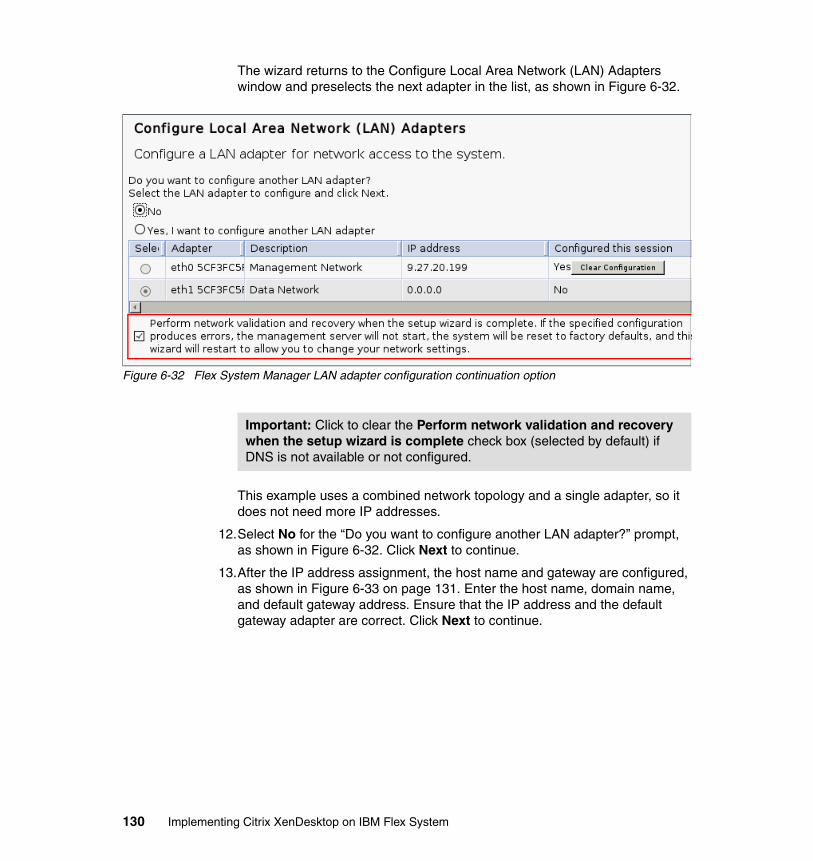
The wizard returns to the Configure Local Area Network (LAN) Adapters window and preselects the next adapter in the list, as shown in Figure 6-32.
Figure 6-32 Flex System Manager LAN adapter configuration continuation option
This example uses a combined network topology and a single adapter, so it does not need more IP addresses.
12.Select No for the “Do you want to configure another LAN adapter?” prompt, as shown in Figure 6-32. Click Next to continue.
13.After the IP address assignment, the host name and gateway are configured, as shown in Figure 6-33 on page 131. Enter the host name, domain name, and default gateway address. Ensure that the IP address and the default gateway adapter are correct. Click Next to continue.
Important: Click to clear the Perform network validation and recovery when the setup wizard is complete check box (selected by default) if DNS is not available or not configured.
130 Implementing Citrix XenDesktop on IBM Flex System
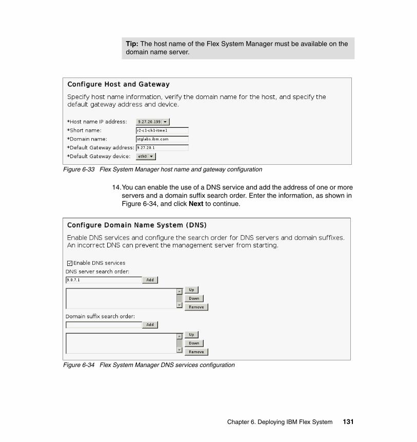
Figure 6-33 Flex System Manager host name and gateway configuration
14.You can enable the use of a DNS service and add the address of one or more servers and a domain suffix search order. Enter the information, as shown in Figure 6-34, and click Next to continue.
Figure 6-34 Flex System Manager DNS services configuration
Tip: The host name of the Flex System Manager must be available on the domain name server.
Chapter 6. Deploying IBM Flex System 131
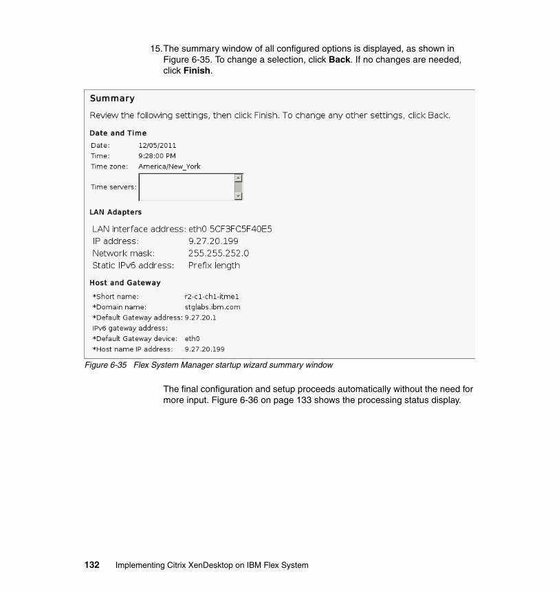
15.The summary window of all configured options is displayed, as shown in Figure 6-35. To change a selection, click Back. If no changes are needed, click Finish.
Figure 6-35 Flex System Manager startup wizard summary window
The final configuration and setup proceeds automatically without the need for more input. Figure 6-36 on page 133 shows the processing status display.
132 Implementing Citrix XenDesktop on IBM Flex System
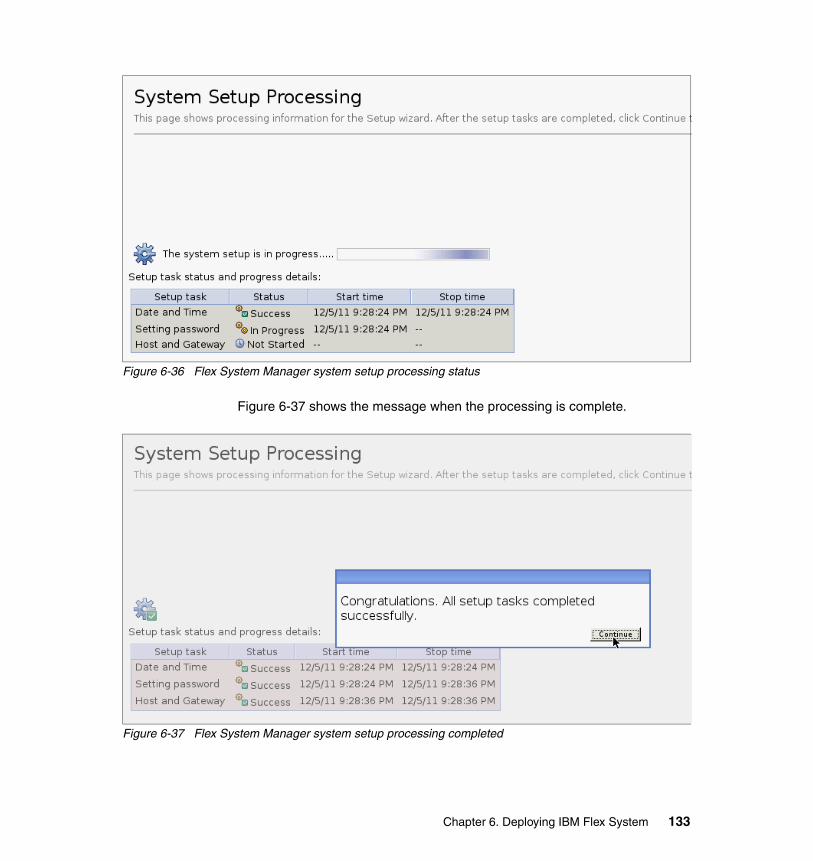
Figure 6-36 Flex System Manager system setup processing status
Figure 6-37 shows the message when the processing is complete.
Figure 6-37 Flex System Manager system setup processing completed
Chapter 6. Deploying IBM Flex System 133
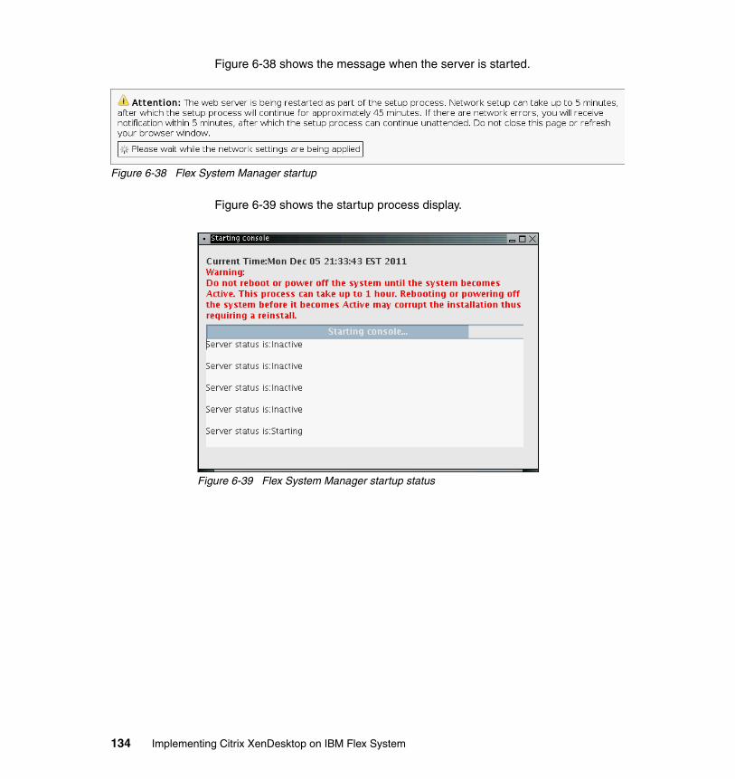
Figure 6-38 shows the message when the server is started.
Figure 6-38 Flex System Manager startup
Figure 6-39 shows the startup process display.
Figure 6-39 Flex System Manager startup status
134 Implementing Citrix XenDesktop on IBM Flex System
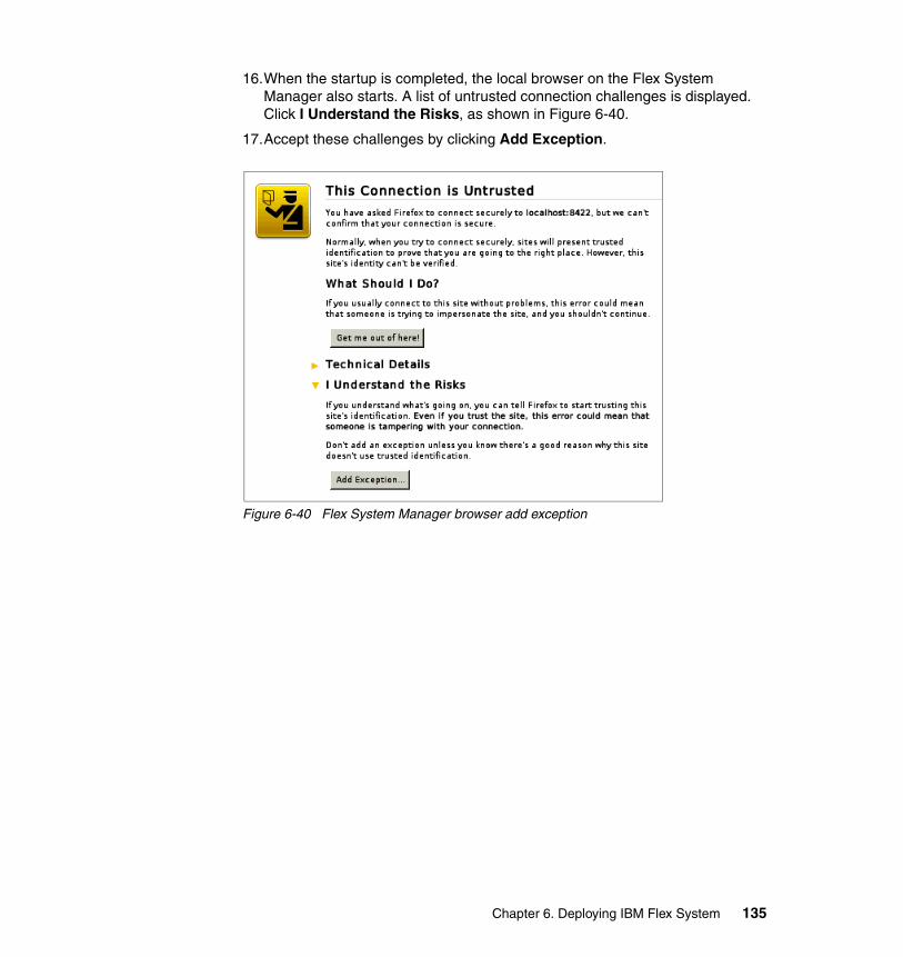
16.When the startup is completed, the local browser on the Flex System Manager also starts. A list of untrusted connection challenges is displayed. Click I Understand the Risks, as shown in Figure 6-40.
17.Accept these challenges by clicking Add Exception.
Figure 6-40 Flex System Manager browser add exception
Chapter 6. Deploying IBM Flex System 135
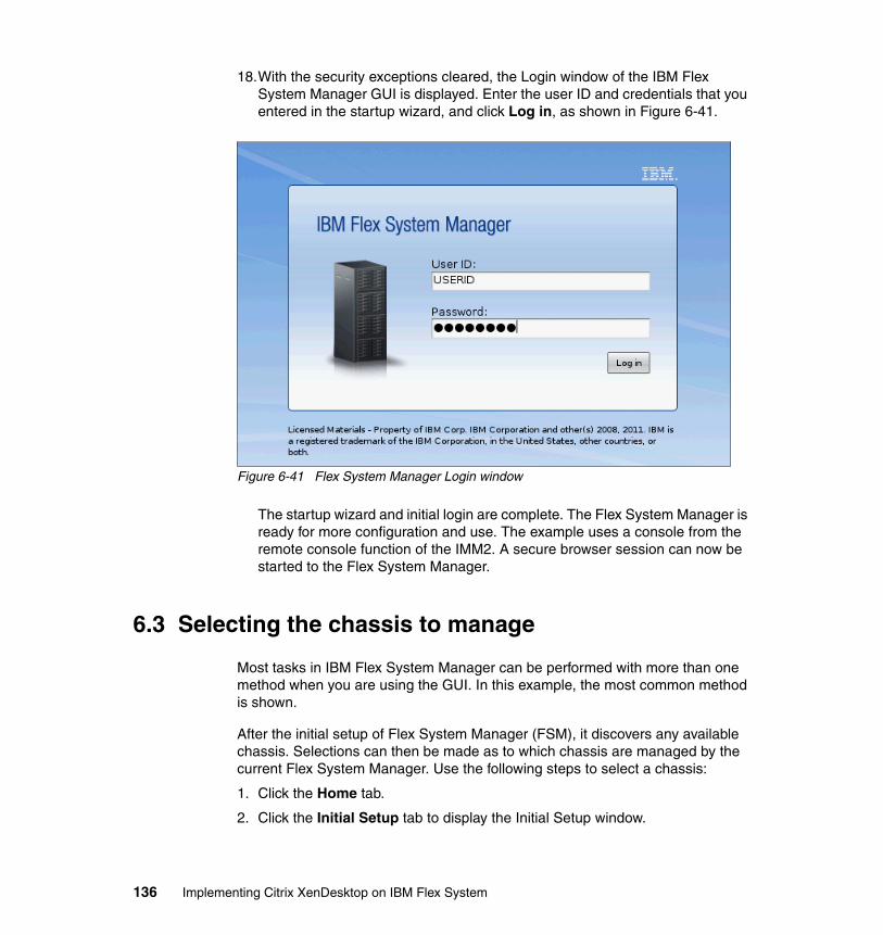
18.With the security exceptions cleared, the Login window of the IBM Flex System Manager GUI is displayed. Enter the user ID and credentials that you entered in the startup wizard, and click Log in, as shown in Figure 6-41.
Figure 6-41 Flex System Manager Login window
The startup wizard and initial login are complete. The Flex System Manager is ready for more configuration and use. The example uses a console from the remote console function of the IMM2. A secure browser session can now be started to the Flex System Manager.
6.3 Selecting the chassis to manage
Most tasks in IBM Flex System Manager can be performed with more than one method when you are using the GUI. In this example, the most common method is shown.
After the initial setup of Flex System Manager (FSM), it discovers any available chassis. Selections can then be made as to which chassis are managed by the current Flex System Manager. Use the following steps to select a chassis:
1. Click the Home tab.
2. Click the Initial Setup tab to display the Initial Setup window.
136 Implementing Citrix XenDesktop on IBM Flex System
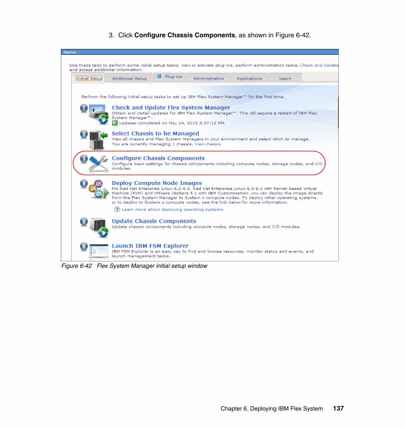
3. Click Configure Chassis Components, as shown in Figure 6-42.
Figure 6-42 Flex System Manager initial setup window
Chapter 6. Deploying IBM Flex System 137
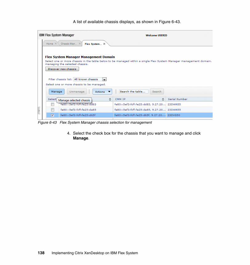
A list of available chassis displays, as shown in Figure 6-43.
Figure 6-43 Flex System Manager chassis selection for management
4. Select the check box for the chassis that you want to manage and click Manage.
138 Implementing Citrix XenDesktop on IBM Flex System
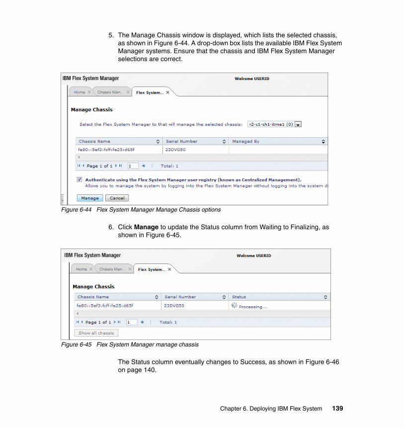
5. The Manage Chassis window is displayed, which lists the selected chassis, as shown in Figure 6-44. A drop-down box lists the available IBM Flex System Manager systems. Ensure that the chassis and IBM Flex System Manager selections are correct.
Figure 6-44 Flex System Manager Manage Chassis options
6. Click Manage to update the Status column from Waiting to Finalizing, as shown in Figure 6-45.
Figure 6-45 Flex System Manager manage chassis
The Status column eventually changes to Success, as shown in Figure 6-46 on page 140.
Chapter 6. Deploying IBM Flex System 139
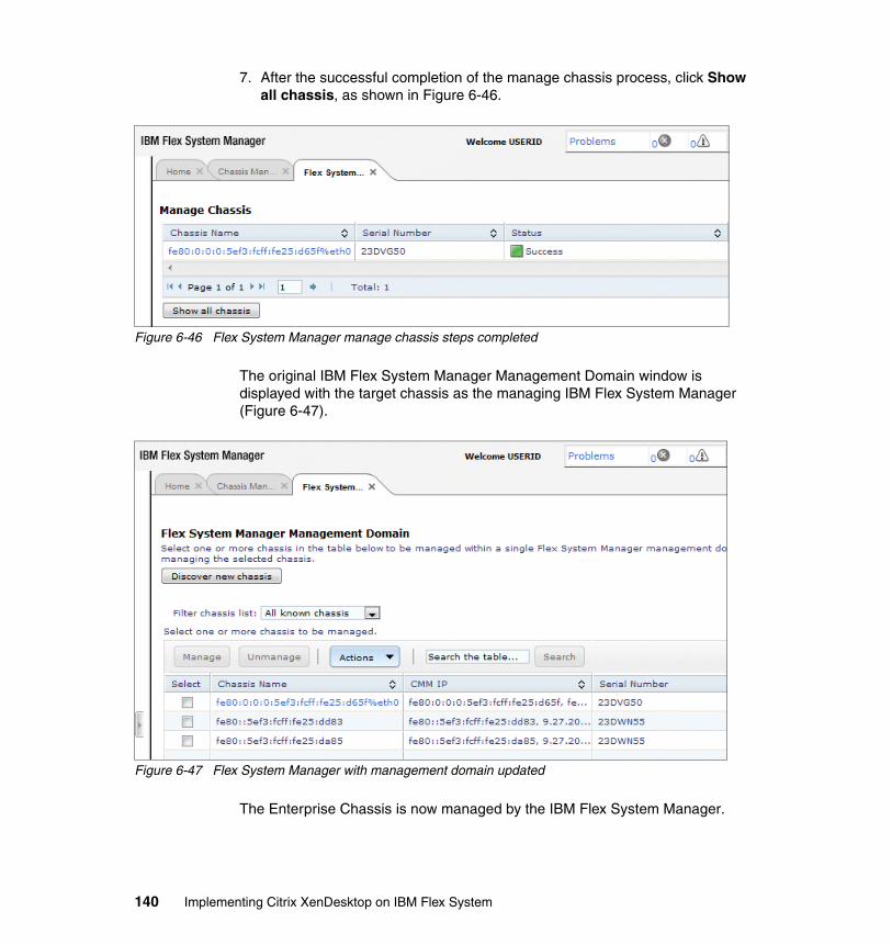
7. After the successful completion of the manage chassis process, click Show all chassis, as shown in Figure 6-46.
Figure 6-46 Flex System Manager manage chassis steps completed
The original IBM Flex System Manager Management Domain window is displayed with the target chassis as the managing IBM Flex System Manager (Figure 6-47).
Figure 6-47 Flex System Manager with management domain updated
The Enterprise Chassis is now managed by the IBM Flex System Manager.
140 Implementing Citrix XenDesktop on IBM Flex System
6.4 Discovery and inventory collection
To manage a resource within an environment or view inventory data about the resource, that resource must first be discovered. After access is granted, an inventory must be collected. The resource is recognized and added to the comprehensive list of native resources and native attributes for the system. Discovery and inventory collection are the two primary tasks that are used to connect to supported network resources and collect information about them.
6.4.1 Discovery
Discovery is the process by which IBM Flex System Manager identifies and establishes connections with network-level resources that IBM Flex System Manager can manage, for example:
� Compute nodes� Switches� Storage devices� Operating systems� Hypervisors� Virtual machines (VMs)
Use system discovery to identify resources within your environment, collect data about those resources, and establish connections with them.
Choosing which discovery method to useDiscovering your resources in the most efficient manner means deciding which method best suits your needs. Each method has advantages and disadvantages to consider.
Collecting the inventory of a chassis component requires three action steps:
1. Discovery2. Grant access3. Collect inventory
There are several paths to discover and collect the inventory on the IBM Flex System components. This section addresses the method that uses Discovery Manager. The subsequent sections present different paths to discover the three main components in an Enterprise Chassis (CMM, compute nodes, and I/O modules).
Chapter 6. Deploying IBM Flex System 141
Discovery protocolsA discovery protocol is any network communication protocol that IBM Flex System Manager uses during the discovery process to discover a resource. The default discovery profile uses a predetermined list of protocols. When you specify a single IP address, a single host name, or a single range of IP addresses, system discovery uses one or more protocols. These protocols are based on the selected target resource type. With a discovery profile, you can refine the target resource type and configure specific protocols that you want to use.
The communication protocols that IBM Flex System Manager uses during discovery depend on the protocols that are used by the target resource type. You need to decide about the different protocols only when you create or edit a discovery profile. The Discovery Profile wizard helps you select and configure the correct protocol for the type of resource that you want to discover.
When you are discovering many resources, network traffic that is associated with the discovery process might cause timeouts. These timeouts might result in some discoverable resources remaining undiscovered. To help prevent this problem, use one or more discovery profiles. With a discovery profile, you can target specific resources and limit the number of communication protocols that are used during discovery.
By default, IBM Flex System Manager supports the following discovery protocols:
� Agent manager discovery
Agent manager discovery specifically targets the discovery of Tivoli common agents. In the Tivoli paradigm, Service Location Protocol (SLP) is not supported. Management nodes must contact an agent manager that knows about the agents in their environment. You can select the agent managers that you want to use in discovery.
� Common Agent Services discovery
This discovery uses SLP discovery, with which clients can locate servers and other services in the network.
� Common Information Model (CIM) discovery
CIM discovery uses the Service Location Protocol (SLP) for discovery. With CIM discovery, clients can locate servers and other services in the network.
� Interprocess communication (IPC) discovery
IPC uses services that IBM Flex System Manager provides that components use to communicate with each other. By using these services, a server task can communicate with an agent task that is running on a target.
� Secure Shell (SSH) discovery
142 Implementing Citrix XenDesktop on IBM Flex System
Secure Shell is a command interface and protocol that is based on UNIX for securely accessing a remote computer. With SSH discovery, you can specify either a single IP address or a range of IP addresses upon which to run discovery.
� Simple Network Management Protocol (SNMP) discovery
SNMP is a network management standard that is widely used in Internet Protocol networks. SNMP runs management services by using a distributed architecture of management systems and agents. SNMP provides a method of managing network hosts, such as workstation and server computers, routers, bridges, and hubs, from a centrally located computer that runs the network-management software.
� Storage Management Initiative Specification (SMI-S) discovery
With SMI-S discovery, clients can locate servers and other services in the network. This design specification was developed by the Storage Networking Industry Association (SNIA). It specifies a secure and reliable interface with which storage management systems can identify, classify, monitor, and control physical and logical resources in a storage area network (SAN). The interface integrates the various devices to be managed in a SAN and the tools that are used to manage them.
� Windows distributed component object model (DCOM) discovery
Use Windows DCOM (an extension of the Microsoft Component Object Model (COM)) to support objects that are distributed across a network configuration. Use DCOM to specify either a single IP address or a range of IP addresses on which to run discovery.
Discovery ManagerWith Discovery Manager, you can discover and connect to the systems at your site. This window displays an overview of all discovered systems, the systems to which you have access, and the systems from which you collected inventory. It has options to explore all discovered resources, in order by category, as shown in Figure 6-48 on page 144.
To use Discover Manager, perform these steps:
1. Select System Discovery under Common tasks, as shown in Figure 6-48 on page 144.
Chapter 6. Deploying IBM Flex System 143
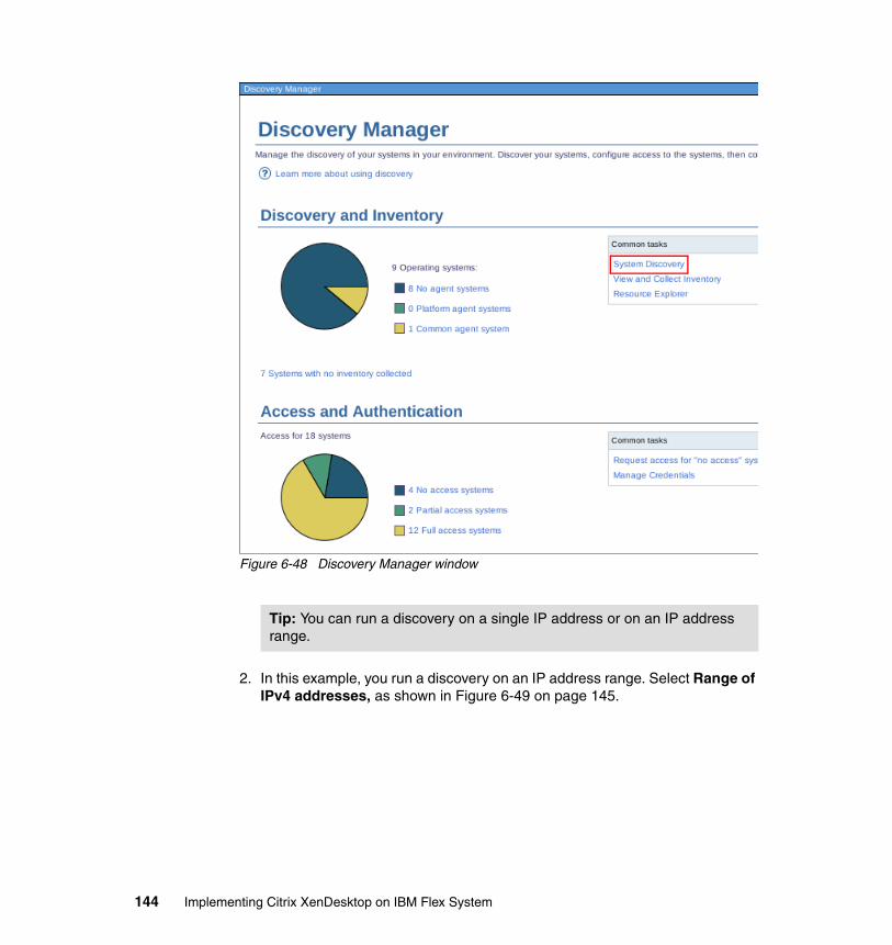
Figure 6-48 Discovery Manager window
2. In this example, you run a discovery on an IP address range. Select Range of IPv4 addresses, as shown in Figure 6-49 on page 145.
Tip: You can run a discovery on a single IP address or on an IP address range.
144 Implementing Citrix XenDesktop on IBM Flex System
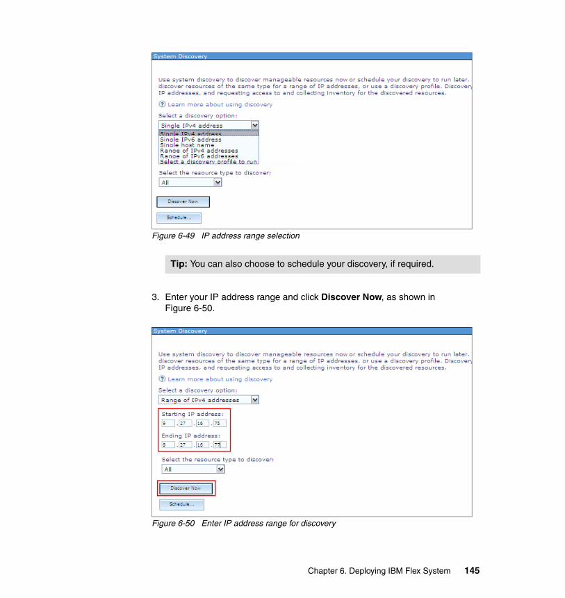
Figure 6-49 IP address range selection
3. Enter your IP address range and click Discover Now, as shown in Figure 6-50.
Figure 6-50 Enter IP address range for discovery
Tip: You can also choose to schedule your discovery, if required.
Chapter 6. Deploying IBM Flex System 145
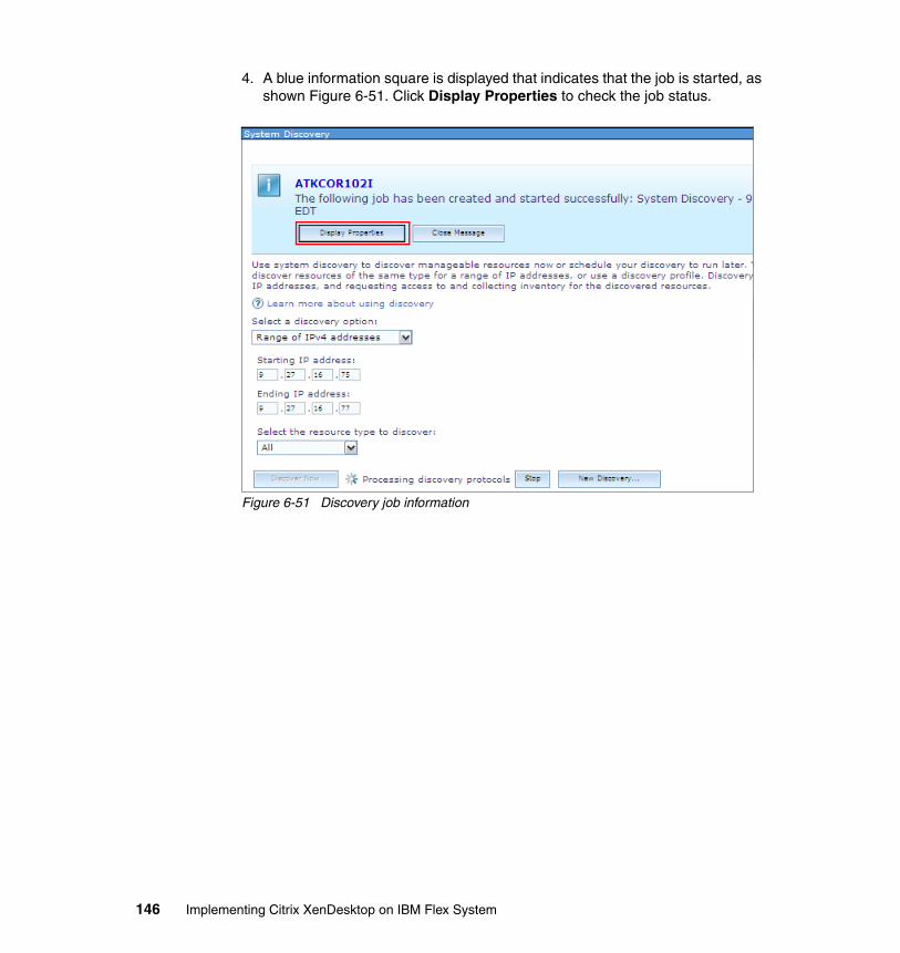
4. A blue information square is displayed that indicates that the job is started, as shown Figure 6-51. Click Display Properties to check the job status.
Figure 6-51 Discovery job information
146 Implementing Citrix XenDesktop on IBM Flex System
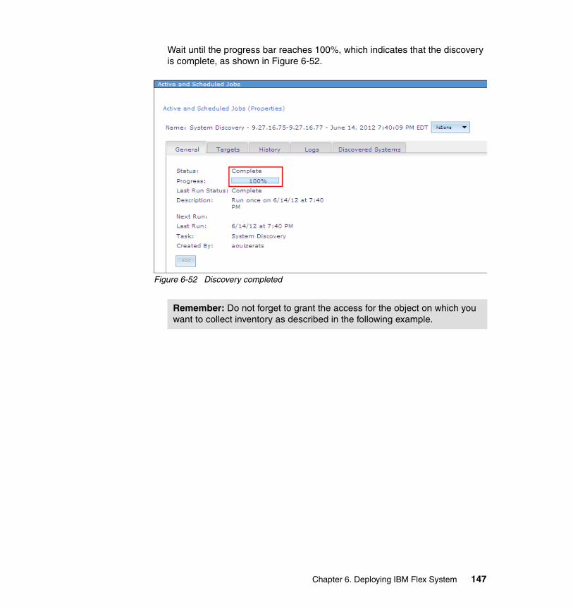
Wait until the progress bar reaches 100%, which indicates that the discovery is complete, as shown in Figure 6-52.
Figure 6-52 Discovery completed
Remember: Do not forget to grant the access for the object on which you want to collect inventory as described in the following example.
Chapter 6. Deploying IBM Flex System 147
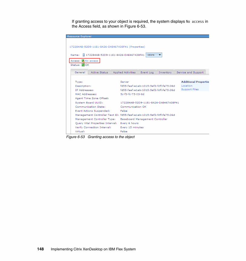
If granting access to your object is required, the system displays No access in the Access field, as shown in Figure 6-53.
Figure 6-53 Granting access to the object
148 Implementing Citrix XenDesktop on IBM Flex System
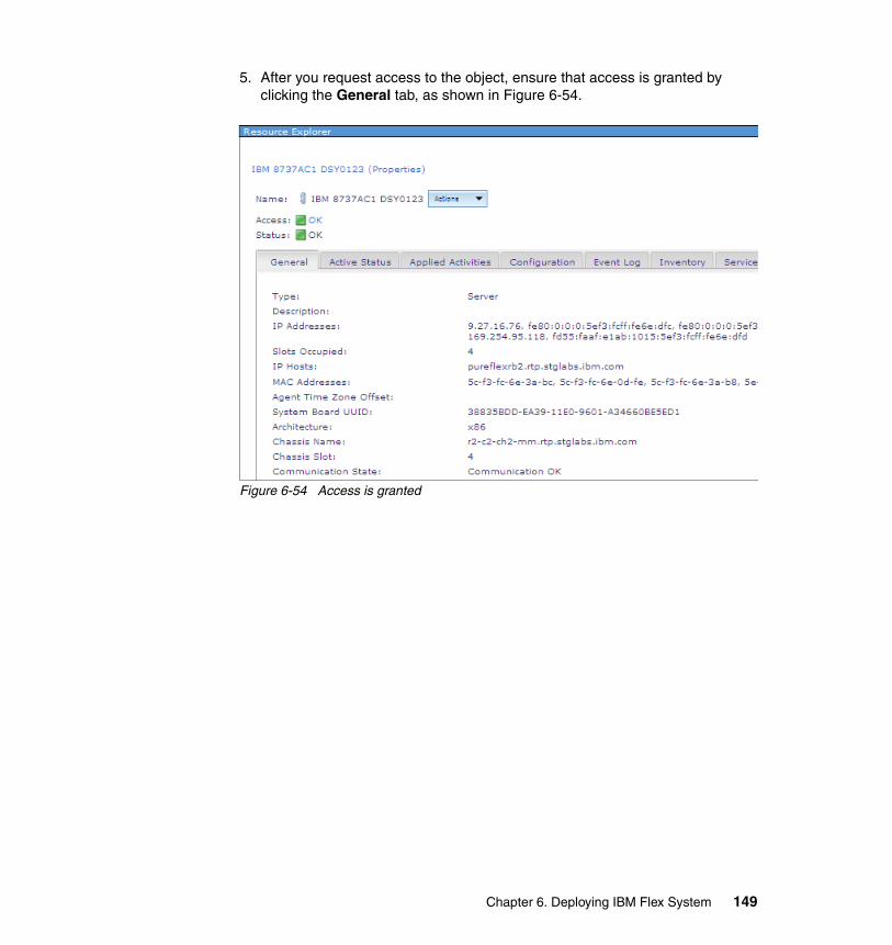
5. After you request access to the object, ensure that access is granted by clicking the General tab, as shown in Figure 6-54.
Figure 6-54 Access is granted
Chapter 6. Deploying IBM Flex System 149
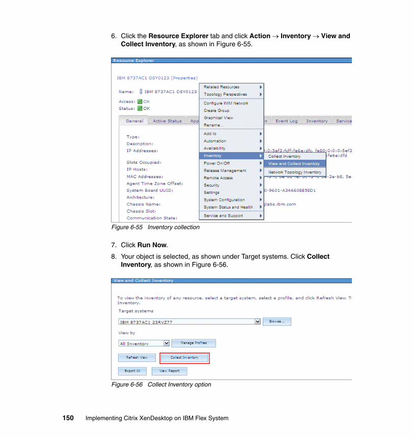
6. Click the Resource Explorer tab and click Action Inventory View and Collect Inventory, as shown in Figure 6-55.
Figure 6-55 Inventory collection
7. Click Run Now.
8. Your object is selected, as shown under Target systems. Click Collect Inventory, as shown in Figure 6-56.
Figure 6-56 Collect Inventory option
150 Implementing Citrix XenDesktop on IBM Flex System
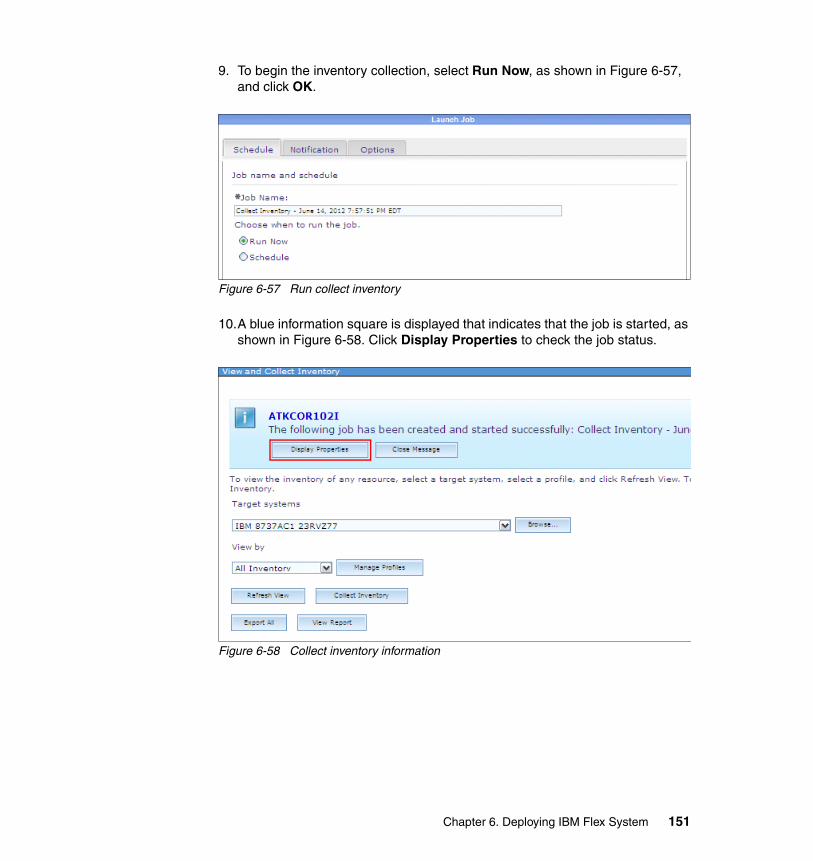
9. To begin the inventory collection, select Run Now, as shown in Figure 6-57, and click OK.
Figure 6-57 Run collect inventory
10.A blue information square is displayed that indicates that the job is started, as shown in Figure 6-58. Click Display Properties to check the job status.
Figure 6-58 Collect inventory information
Chapter 6. Deploying IBM Flex System 151
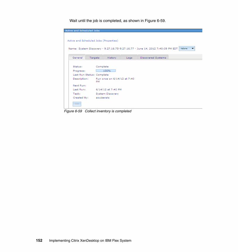
Wait until the job is completed, as shown in Figure 6-59.
Figure 6-59 Collect inventory is completed
152 Implementing Citrix XenDesktop on IBM Flex System
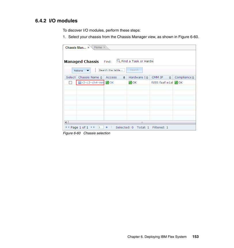
6.4.2 I/O modules
To discover I/O modules, perform these steps:
1. Select your chassis from the Chassis Manager view, as shown in Figure 6-60.
Figure 6-60 Chassis selection
Chapter 6. Deploying IBM Flex System 153
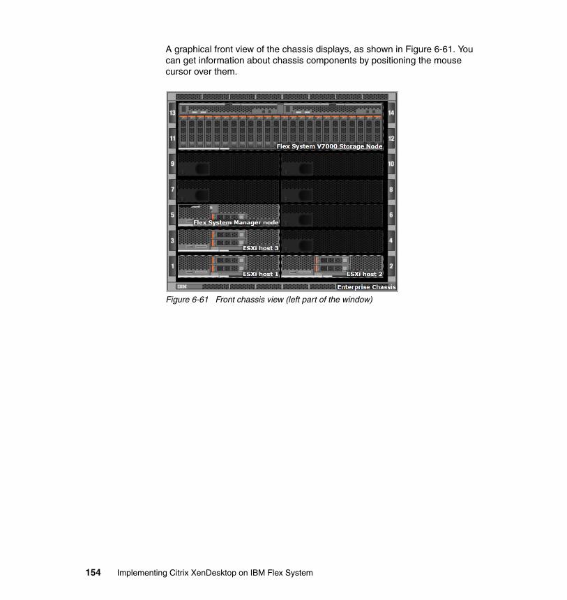
A graphical front view of the chassis displays, as shown in Figure 6-61. You can get information about chassis components by positioning the mouse cursor over them.
Figure 6-61 Front chassis view (left part of the window)
154 Implementing Citrix XenDesktop on IBM Flex System
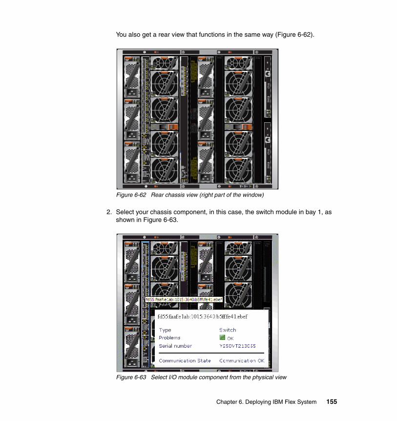
You also get a rear view that functions in the same way (Figure 6-62).
Figure 6-62 Rear chassis view (right part of the window)
2. Select your chassis component, in this case, the switch module in bay 1, as shown in Figure 6-63.
Figure 6-63 Select I/O module component from the physical view
Chapter 6. Deploying IBM Flex System 155
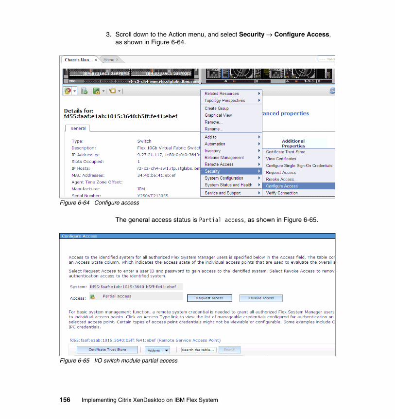
3. Scroll down to the Action menu, and select Security Configure Access, as shown in Figure 6-64.
Figure 6-64 Configure access
The general access status is Partial access, as shown in Figure 6-65.
Figure 6-65 I/O switch module partial access
156 Implementing Citrix XenDesktop on IBM Flex System
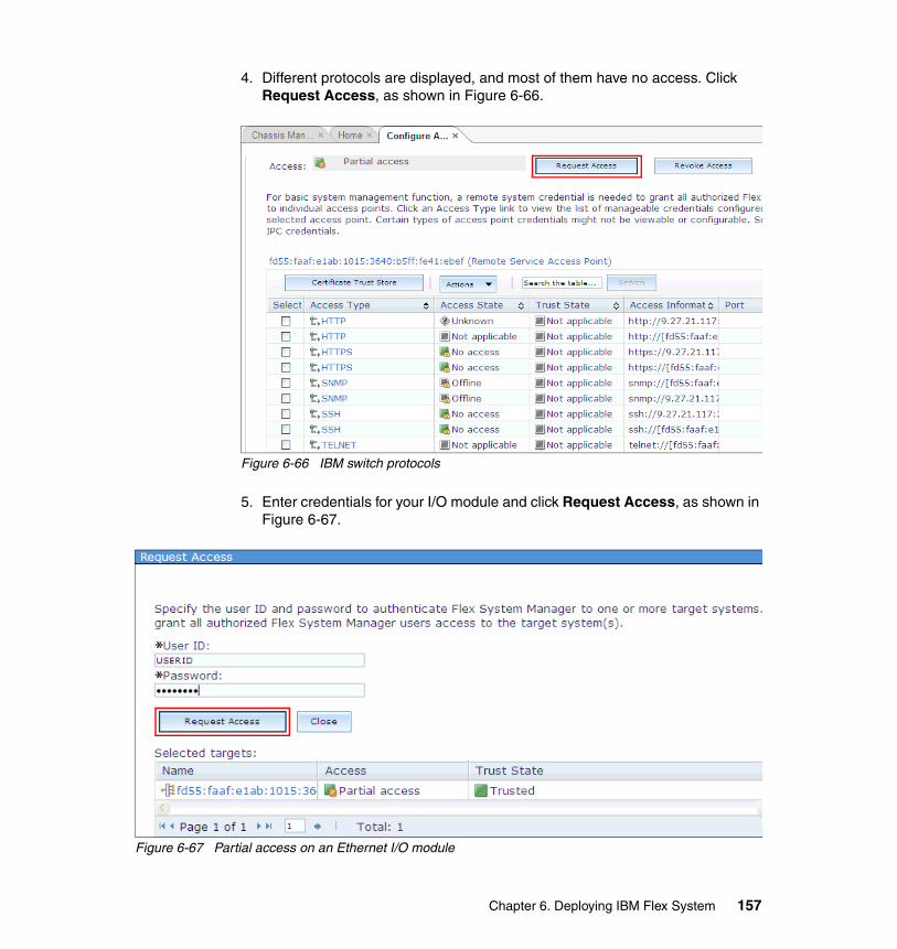
4. Different protocols are displayed, and most of them have no access. Click Request Access, as shown in Figure 6-66.
Figure 6-66 IBM switch protocols
5. Enter credentials for your I/O module and click Request Access, as shown in Figure 6-67.
Figure 6-67 Partial access on an Ethernet I/O module
Chapter 6. Deploying IBM Flex System 157
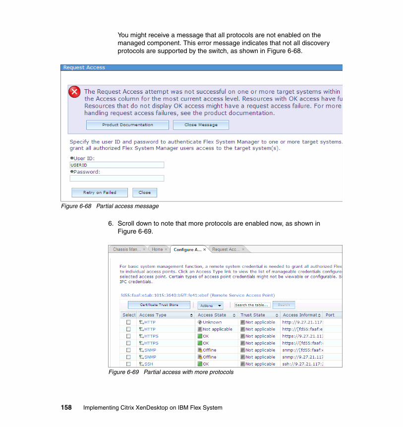
You might receive a message that all protocols are not enabled on the managed component. This error message indicates that not all discovery protocols are supported by the switch, as shown in Figure 6-68.
Figure 6-68 Partial access message
6. Scroll down to note that more protocols are enabled now, as shown in Figure 6-69.
Figure 6-69 Partial access with more protocols
158 Implementing Citrix XenDesktop on IBM Flex System
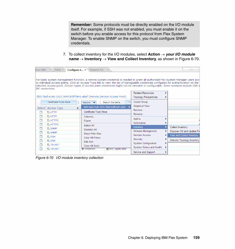
7. To collect inventory for the I/O modules, select Action your I/O module name Inventory View and Collect Inventory, as shown in Figure 6-70.
Figure 6-70 I/O module inventory collection
Remember: Some protocols must be directly enabled on the I/O module itself. For example, if SSH was not enabled, you must enable it on the switch before you enable access for this protocol from Flex System Manager. To enable SNMP on the switch, you must configure SNMP credentials.
Chapter 6. Deploying IBM Flex System 159
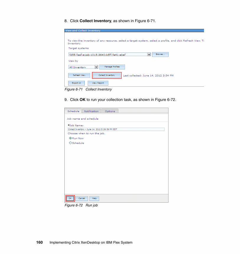
8. Click Collect Inventory, as shown in Figure 6-71.
Figure 6-71 Collect Inventory
9. Click OK to run your collection task, as shown in Figure 6-72.
Figure 6-72 Run job
160 Implementing Citrix XenDesktop on IBM Flex System
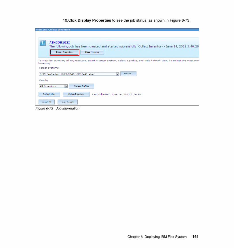
10.Click Display Properties to see the job status, as shown in Figure 6-73.
Figure 6-73 Job information
Chapter 6. Deploying IBM Flex System 161
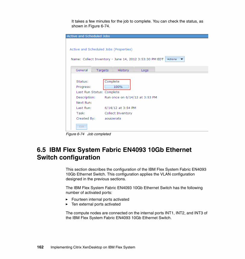
It takes a few minutes for the job to complete. You can check the status, as shown in Figure 6-74.
Figure 6-74 Job completed
6.5 IBM Flex System Fabric EN4093 10Gb Ethernet Switch configuration
This section describes the configuration of the IBM Flex System Fabric EN4093 10Gb Ethernet Switch. This configuration applies the VLAN configuration designed in the previous sections.
The IBM Flex System Fabric EN4093 10Gb Ethernet Switch has the following number of activated ports:
� Fourteen internal ports activated� Ten external ports activated
The compute nodes are connected on the internal ports INT1, INT2, and INT3 of the IBM Flex System Fabric EN4093 10Gb Ethernet Switch.
162 Implementing Citrix XenDesktop on IBM Flex System
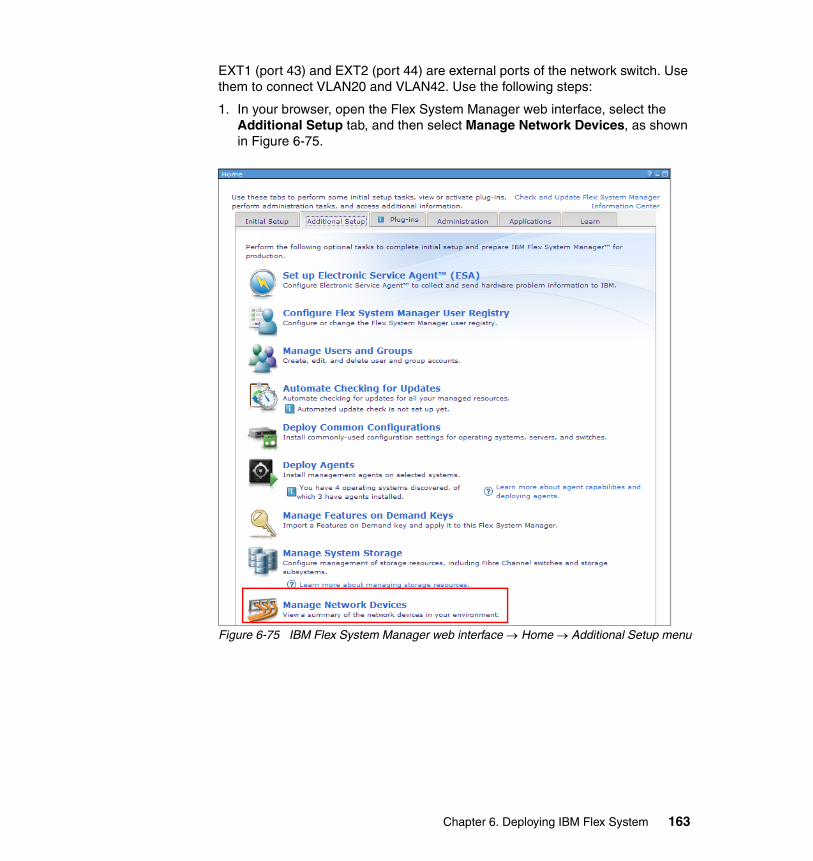
EXT1 (port 43) and EXT2 (port 44) are external ports of the network switch. Use them to connect VLAN20 and VLAN42. Use the following steps:
1. In your browser, open the Flex System Manager web interface, select the Additional Setup tab, and then select Manage Network Devices, as shown in Figure 6-75.
Figure 6-75 IBM Flex System Manager web interface Home Additional Setup menu
Chapter 6. Deploying IBM Flex System 163
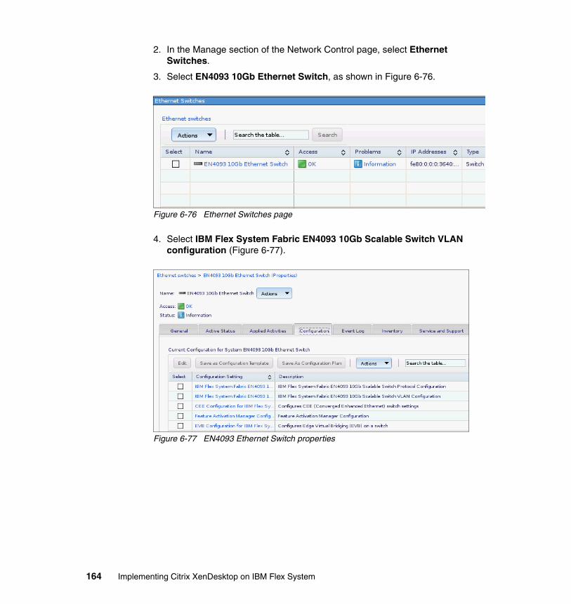
2. In the Manage section of the Network Control page, select Ethernet Switches.
3. Select EN4093 10Gb Ethernet Switch, as shown in Figure 6-76.
Figure 6-76 Ethernet Switches page
4. Select IBM Flex System Fabric EN4093 10Gb Scalable Switch VLAN configuration (Figure 6-77).
Figure 6-77 EN4093 Ethernet Switch properties
164 Implementing Citrix XenDesktop on IBM Flex System
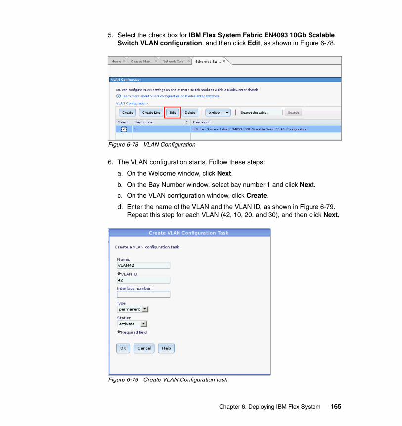
5. Select the check box for IBM Flex System Fabric EN4093 10Gb Scalable Switch VLAN configuration, and then click Edit, as shown in Figure 6-78.
Figure 6-78 VLAN Configuration
6. The VLAN configuration starts. Follow these steps:
a. On the Welcome window, click Next.
b. On the Bay Number window, select bay number 1 and click Next.
c. On the VLAN configuration window, click Create.
d. Enter the name of the VLAN and the VLAN ID, as shown in Figure 6-79. Repeat this step for each VLAN (42, 10, 20, and 30), and then click Next.
Figure 6-79 Create VLAN Configuration task
Chapter 6. Deploying IBM Flex System 165
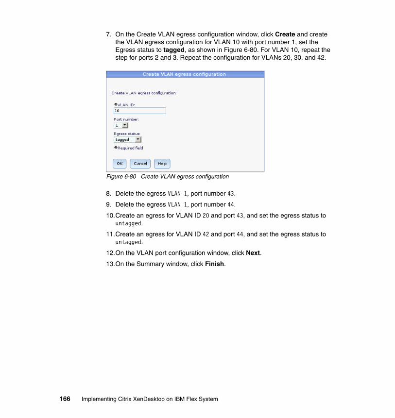
7. On the Create VLAN egress configuration window, click Create and create the VLAN egress configuration for VLAN 10 with port number 1, set the Egress status to tagged, as shown in Figure 6-80. For VLAN 10, repeat the step for ports 2 and 3. Repeat the configuration for VLANs 20, 30, and 42.
Figure 6-80 Create VLAN egress configuration
8. Delete the egress VLAN 1, port number 43.
9. Delete the egress VLAN 1, port number 44.
10.Create an egress for VLAN ID 20 and port 43, and set the egress status to untagged.
11.Create an egress for VLAN ID 42 and port 44, and set the egress status to untagged.
12.On the VLAN port configuration window, click Next.
13.On the Summary window, click Finish.
166 Implementing Citrix XenDesktop on IBM Flex System
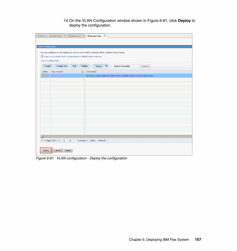
14.On the VLAN Configuration window shown in Figure 6-81, click Deploy to deploy the configuration.
Figure 6-81 VLAN configuration - Deploy the configuration
Chapter 6. Deploying IBM Flex System 167
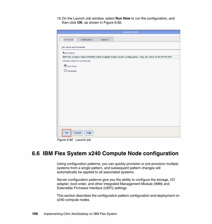
15.On the Launch Job window, select Run Now to run the configuration, and then click OK, as shown in Figure 6-82.
Figure 6-82 Launch job
6.6 IBM Flex System x240 Compute Node configuration
Using configuration patterns, you can quickly provision or pre-provision multiple systems from a single pattern, and subsequent pattern changes will automatically be applied to all associated systems.
Server configuration patterns give you the ability to configure the storage, I/O adapter, boot order, and other Integrated Management Module (IMM) and Extensible Firmware interface (UEFI) settings.
This section describes the configuration pattern configuration and deployment on x240 compute nodes.
168 Implementing Citrix XenDesktop on IBM Flex System
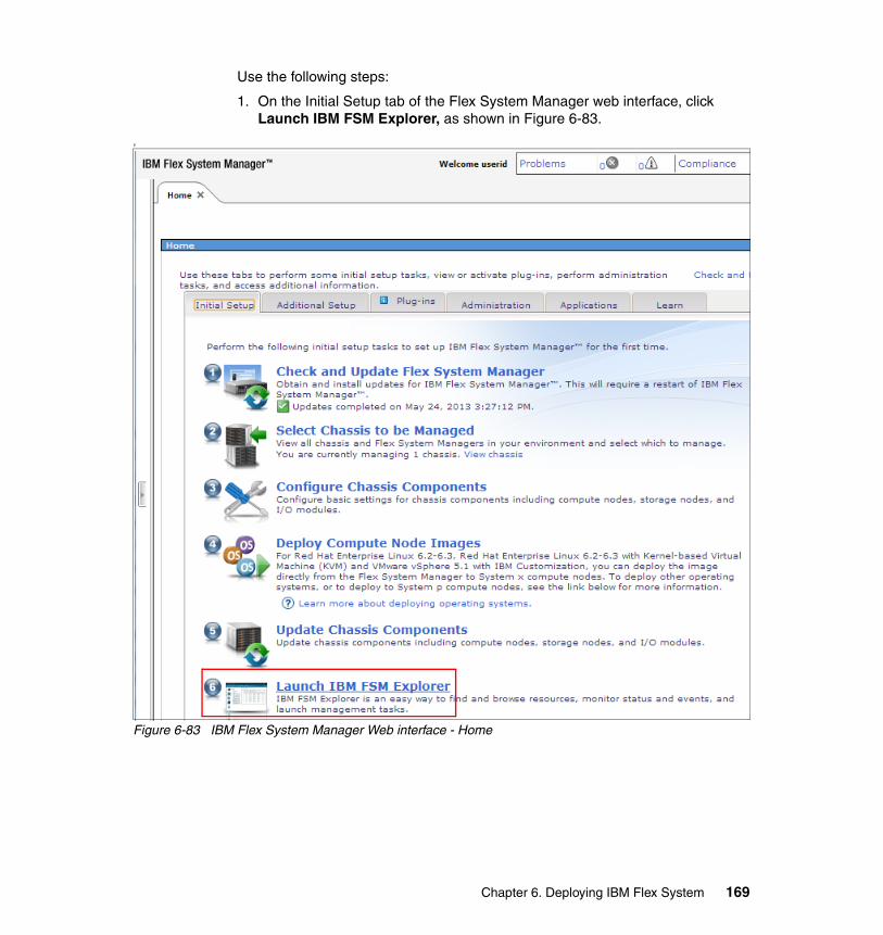
Use the following steps:
1. On the Initial Setup tab of the Flex System Manager web interface, click Launch IBM FSM Explorer, as shown in Figure 6-83.
,
Figure 6-83 IBM Flex System Manager Web interface - Home
Chapter 6. Deploying IBM Flex System 169
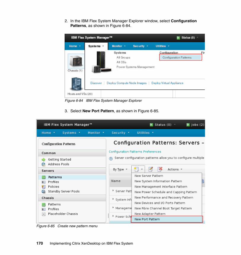
2. In the IBM Flex System Manager Explorer window, select Configuration Patterns, as shown in Figure 6-84.
Figure 6-84 IBM Flex System Manager Explorer
3. Select New Port Pattern, as shown in Figure 6-85.
Figure 6-85 Create new pattern menu
170 Implementing Citrix XenDesktop on IBM Flex System
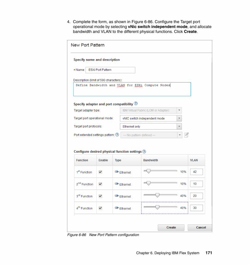
4. Complete the form, as shown in Figure 6-86. Configure the Target port operational mode by selecting vNic switch independent mode, and allocate bandwidth and VLAN to the different physical functions. Click Create.
Figure 6-86 New Port Pattern configuration
Chapter 6. Deploying IBM Flex System 171
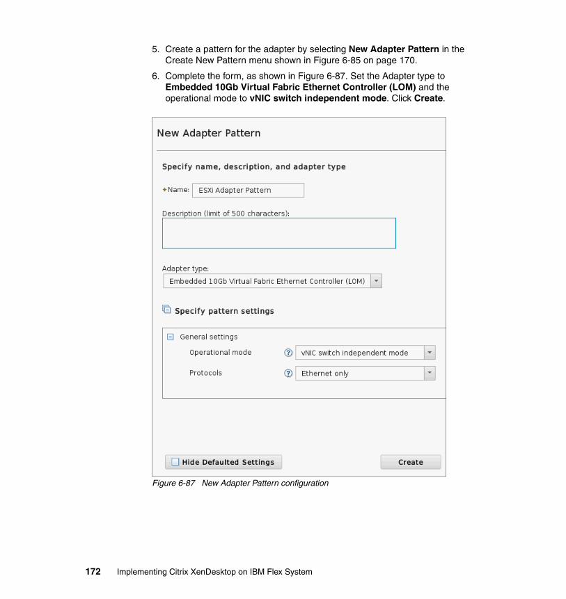
5. Create a pattern for the adapter by selecting New Adapter Pattern in the Create New Pattern menu shown in Figure 6-85 on page 170.
6. Complete the form, as shown in Figure 6-87. Set the Adapter type to Embedded 10Gb Virtual Fabric Ethernet Controller (LOM) and the operational mode to vNIC switch independent mode. Click Create.
Figure 6-87 New Adapter Pattern configuration
172 Implementing Citrix XenDesktop on IBM Flex System
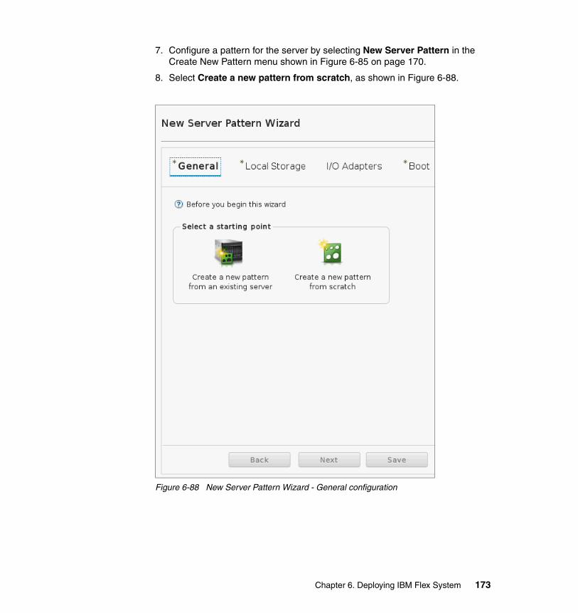
7. Configure a pattern for the server by selecting New Server Pattern in the Create New Pattern menu shown in Figure 6-85 on page 170.
8. Select Create a new pattern from scratch, as shown in Figure 6-88.
Figure 6-88 New Server Pattern Wizard - General configuration
Chapter 6. Deploying IBM Flex System 173
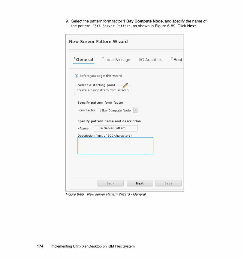
9. Select the pattern form factor 1 Bay Compute Node, and specify the name of the pattern, ESXi Server Pattern, as shown in Figure 6-89. Click Next.
Figure 6-89 New server Pattern Wizard - General
174 Implementing Citrix XenDesktop on IBM Flex System
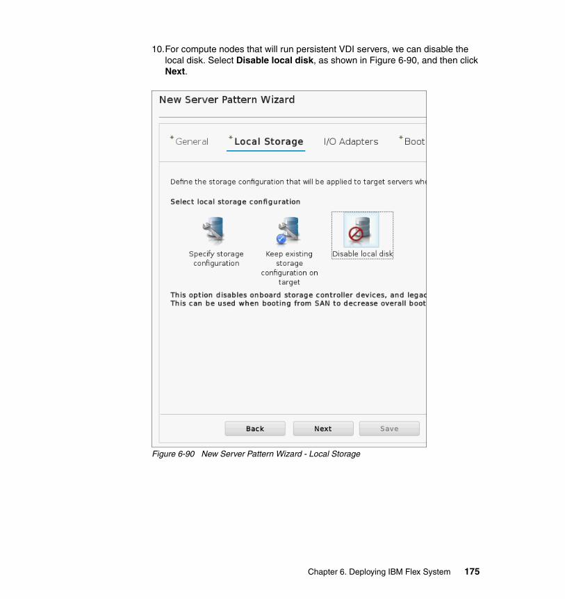
10.For compute nodes that will run persistent VDI servers, we can disable the local disk. Select Disable local disk, as shown in Figure 6-90, and then click Next.
Figure 6-90 New Server Pattern Wizard - Local Storage
Chapter 6. Deploying IBM Flex System 175
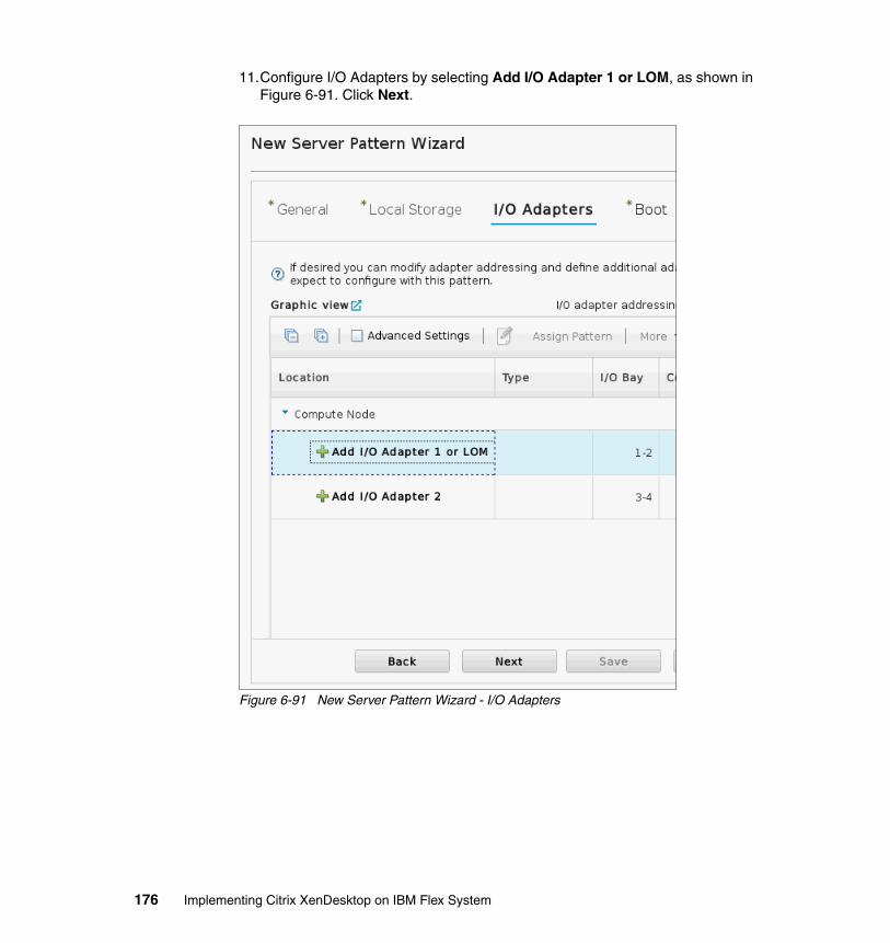
11.Configure I/O Adapters by selecting Add I/O Adapter 1 or LOM, as shown in Figure 6-91. Click Next.
Figure 6-91 New Server Pattern Wizard - I/O Adapters
176 Implementing Citrix XenDesktop on IBM Flex System
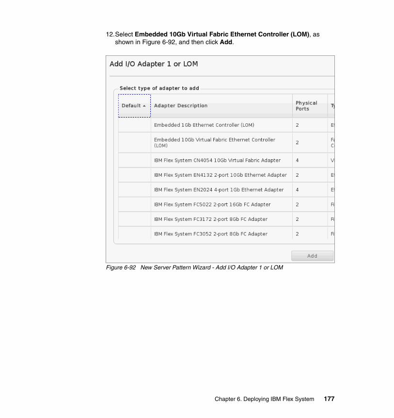
12.Select Embedded 10Gb Virtual Fabric Ethernet Controller (LOM), as shown in Figure 6-92, and then click Add.
Figure 6-92 New Server Pattern Wizard - Add I/O Adapter 1 or LOM
Chapter 6. Deploying IBM Flex System 177
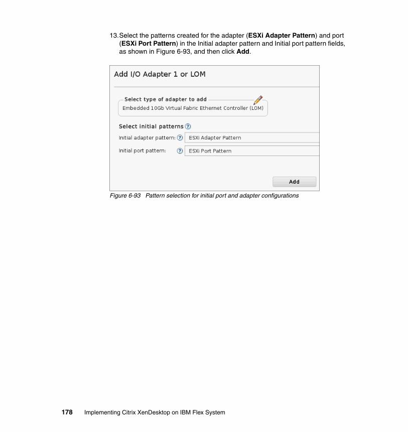
13.Select the patterns created for the adapter (ESXi Adapter Pattern) and port (ESXi Port Pattern) in the Initial adapter pattern and Initial port pattern fields, as shown in Figure 6-93, and then click Add.
Figure 6-93 Pattern selection for initial port and adapter configurations
178 Implementing Citrix XenDesktop on IBM Flex System
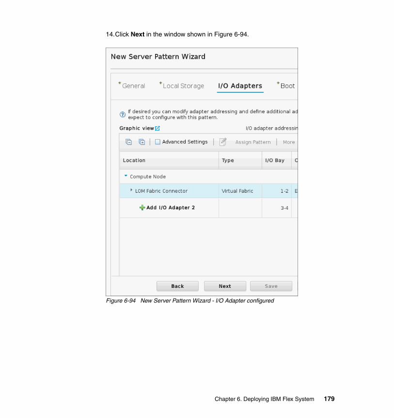
14.Click Next in the window shown in Figure 6-94.
Figure 6-94 New Server Pattern Wizard - I/O Adapter configured
Chapter 6. Deploying IBM Flex System 179
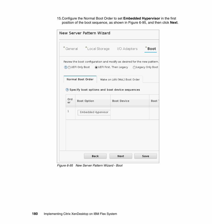
15.Configure the Normal Boot Order to set Embedded Hypervisor in the first position of the boot sequence, as shown in Figure 6-95, and then click Next.
Figure 6-95 New Server Pattern Wizard - Boot
180 Implementing Citrix XenDesktop on IBM Flex System
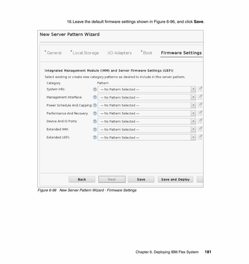
16.Leave the default firmware settings shown in Figure 6-96, and click Save.
Figure 6-96 New Server Pattern Wizard - Firmware Settings
Chapter 6. Deploying IBM Flex System 181
6.7 IBM Flex Storwize V7000 configuration
We configure the IBM Flex Storwize V7000. We configure one pool. In this pool, we implement the following volumes:
� A Thin-Provisioned volume that stands for the ESXi Management Datastore.� A Thin-Provisioned volume that is used as the ESXi Virtual Desktops
Datastore.
6.7.1 Flex System V7000 initial configuration
The following procedure guides you through the necessary steps when using the Flex System Manager web user interface:
1. Open a web browser and point it to the IP address of the Flex System Manager and log in. The menu panel shown in Figure 6-97 on page 183 opens, offering several selections.
Select Launch IBM FSM Explorer from the menu list.
182 Implementing Citrix XenDesktop on IBM Flex System
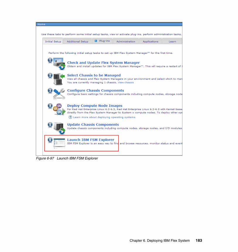
Figure 6-97 Launch IBM FSM Explorer
Chapter 6. Deploying IBM Flex System 183
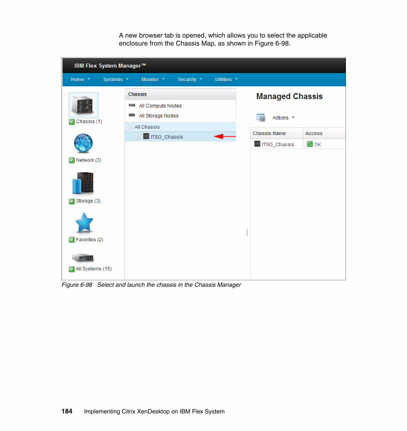
A new browser tab is opened, which allows you to select the applicable enclosure from the Chassis Map, as shown in Figure 6-98.
Figure 6-98 Select and launch the chassis in the Chassis Manager
184 Implementing Citrix XenDesktop on IBM Flex System
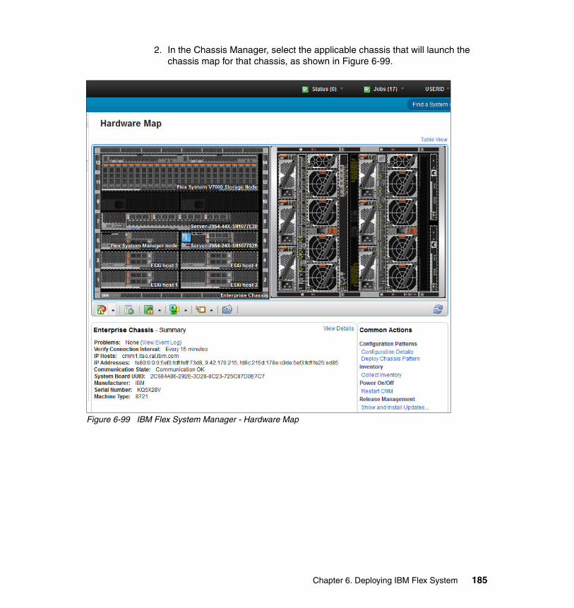
2. In the Chassis Manager, select the applicable chassis that will launch the chassis map for that chassis, as shown in Figure 6-99.
Figure 6-99 IBM Flex System Manager - Hardware Map
Chapter 6. Deploying IBM Flex System 185
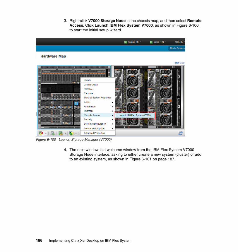
3. Right-click V7000 Storage Node in the chassis map, and then select Remote Access. Click Launch IBM Flex System V7000, as shown in Figure 6-100, to start the initial setup wizard.
Figure 6-100 Launch Storage Manager (V7000)
4. The next window is a welcome window from the IBM Flex System V7000 Storage Node interface, asking to either create a new system (cluster) or add to an existing system, as shown in Figure 6-101 on page 187.
186 Implementing Citrix XenDesktop on IBM Flex System
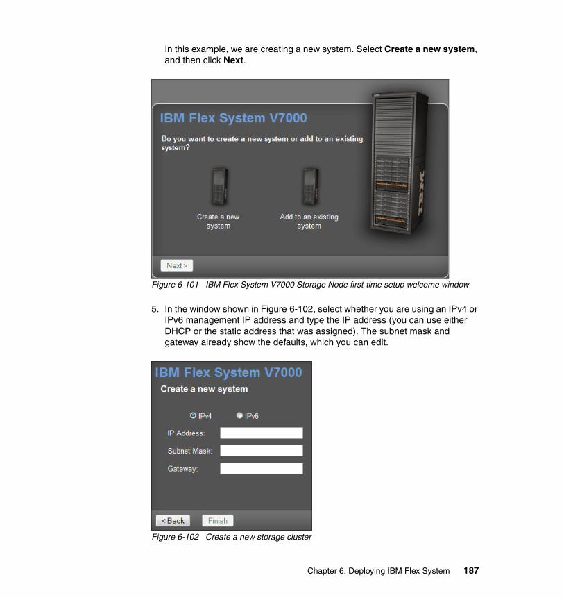
In this example, we are creating a new system. Select Create a new system, and then click Next.
Figure 6-101 IBM Flex System V7000 Storage Node first-time setup welcome window
5. In the window shown in Figure 6-102, select whether you are using an IPv4 or IPv6 management IP address and type the IP address (you can use either DHCP or the static address that was assigned). The subnet mask and gateway already show the defaults, which you can edit.
Figure 6-102 Create a new storage cluster
Chapter 6. Deploying IBM Flex System 187
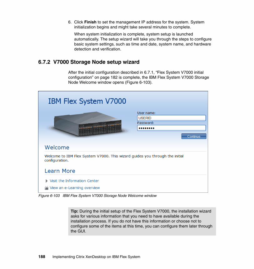
6. Click Finish to set the management IP address for the system. System initialization begins and might take several minutes to complete.
When system initialization is complete, system setup is launched automatically. The setup wizard will take you through the steps to configure basic system settings, such as time and date, system name, and hardware detection and verification.
6.7.2 V7000 Storage Node setup wizard
After the initial configuration described in 6.7.1, “Flex System V7000 initial configuration” on page 182 is complete, the IBM Flex System V7000 Storage Node Welcome window opens (Figure 6-103).
Figure 6-103 IBM Flex System V7000 Storage Node Welcome window
Tip: During the initial setup of the Flex System V7000, the installation wizard asks for various information that you need to have available during the installation process. If you do not have this information or choose not to configure some of the items at this time, you can configure them later through the GUI.
188 Implementing Citrix XenDesktop on IBM Flex System
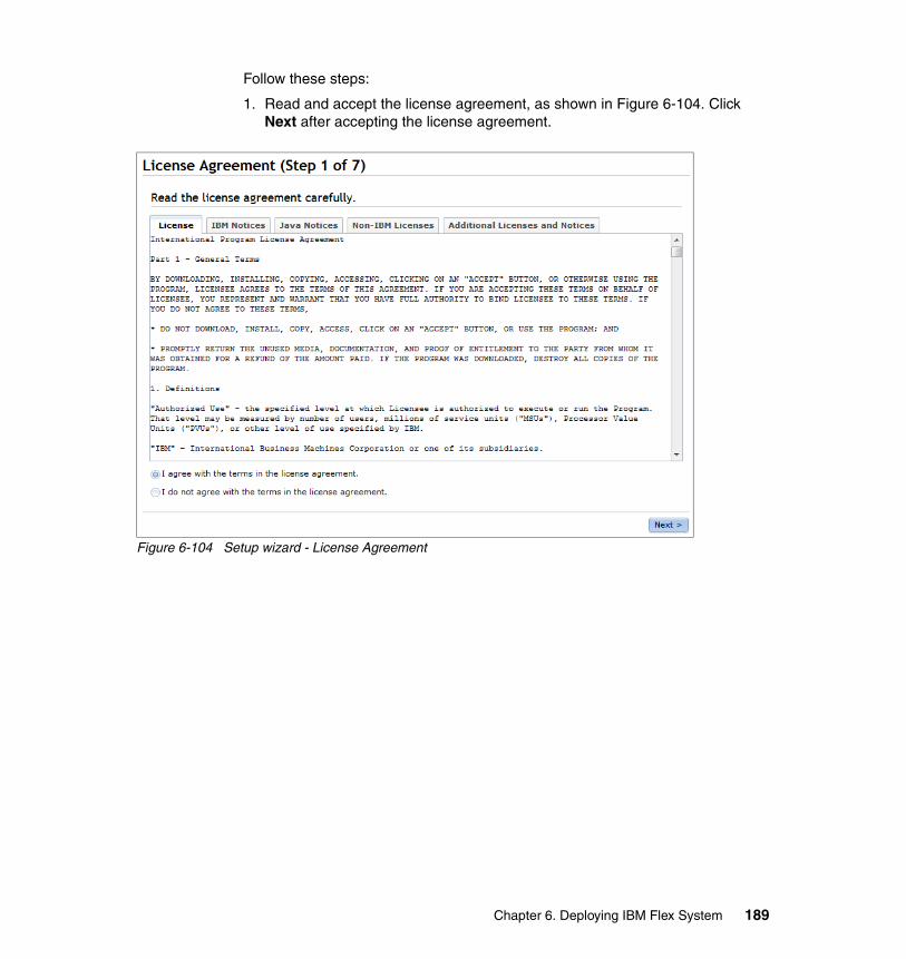
Follow these steps:
1. Read and accept the license agreement, as shown in Figure 6-104. Click Next after accepting the license agreement.
Figure 6-104 Setup wizard - License Agreement
Chapter 6. Deploying IBM Flex System 189
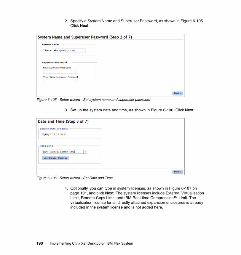
2. Specify a System Name and Superuser Password, as shown in Figure 6-105. Click Next.
Figure 6-105 Setup wizard - Set system name and superuser password
3. Set up the system date and time, as shown in Figure 6-106. Click Next.
Figure 6-106 Setup wizard - Set Date and Time
4. Optionally, you can type in system licenses, as shown in Figure 6-107 on page 191, and click Next. The system licenses include External Virtualization Limit, Remote-Copy Limit, and IBM Real-time Compression™ Limit. The virtualization license for all directly attached expansion enclosures is already included in the system license and is not added here.
190 Implementing Citrix XenDesktop on IBM Flex System
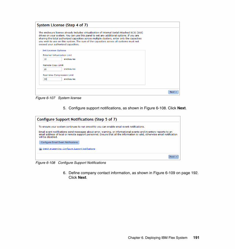
Figure 6-107 System license
5. Configure support notifications, as shown in Figure 6-108. Click Next.
Figure 6-108 Configure Support Notifications
6. Define company contact information, as shown in Figure 6-109 on page 192. Click Next.
Chapter 6. Deploying IBM Flex System 191
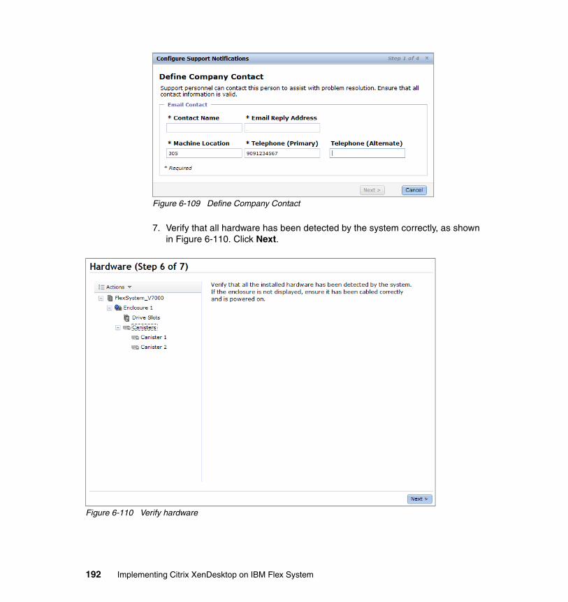
Figure 6-109 Define Company Contact
7. Verify that all hardware has been detected by the system correctly, as shown in Figure 6-110. Click Next.
Figure 6-110 Verify hardware
192 Implementing Citrix XenDesktop on IBM Flex System
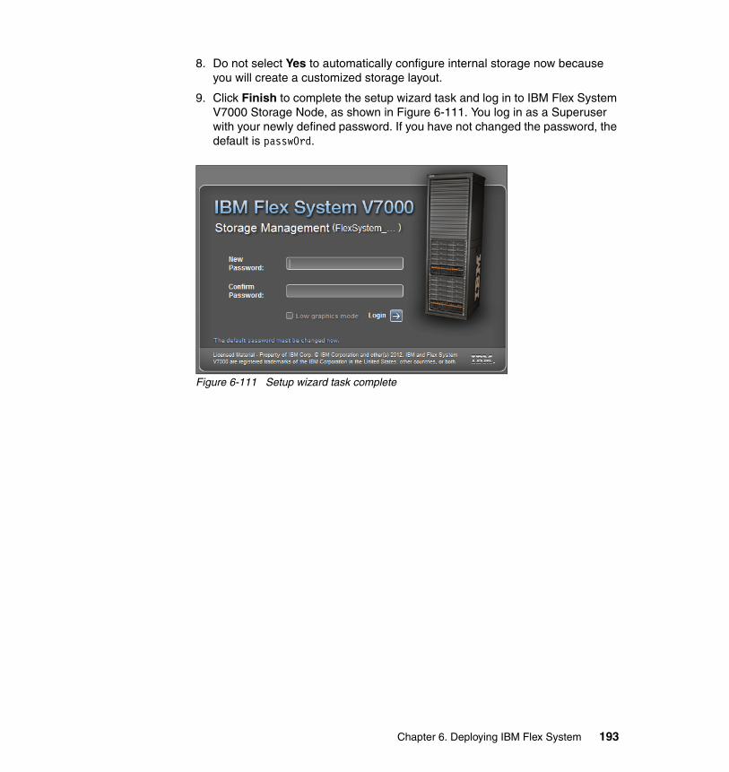
8. Do not select Yes to automatically configure internal storage now because you will create a customized storage layout.
9. Click Finish to complete the setup wizard task and log in to IBM Flex System V7000 Storage Node, as shown in Figure 6-111. You log in as a Superuser with your newly defined password. If you have not changed the password, the default is passw0rd.
Figure 6-111 Setup wizard task complete
Chapter 6. Deploying IBM Flex System 193
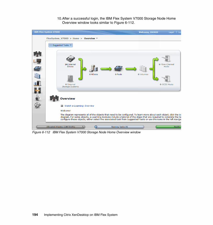
10.After a successful login, the IBM Flex System V7000 Storage Node Home Overview window looks similar to Figure 6-112.
Figure 6-112 IBM Flex System V7000 Storage Node Home Overview window
194 Implementing Citrix XenDesktop on IBM Flex System
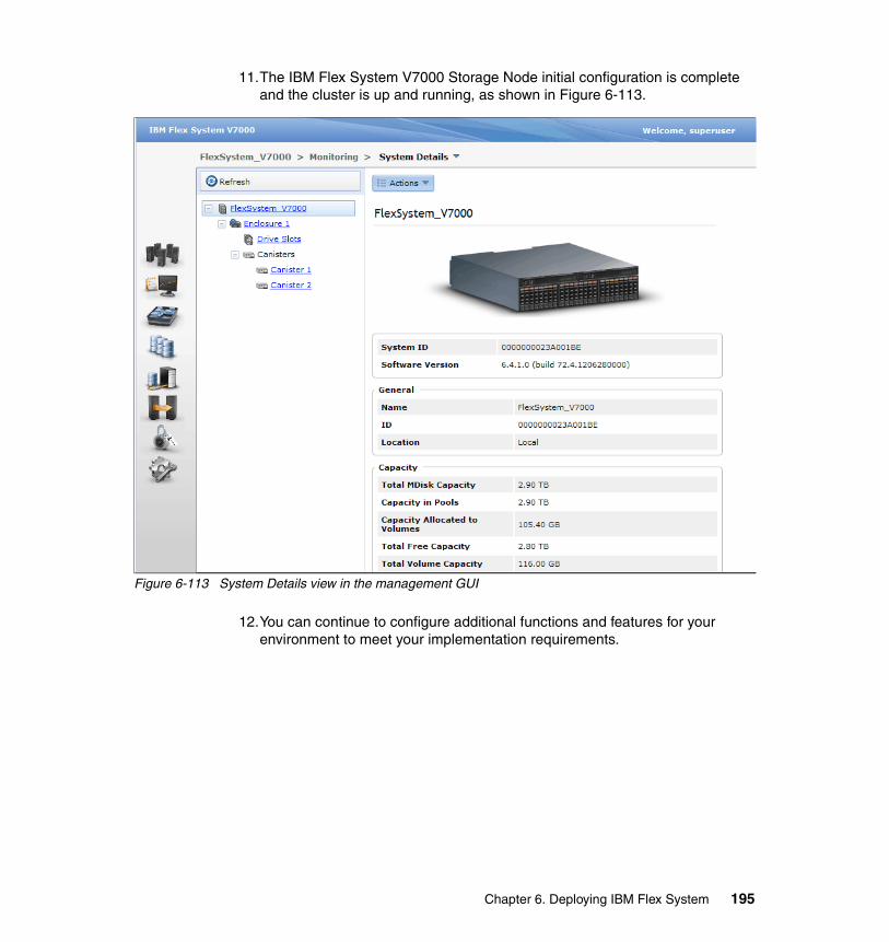
11.The IBM Flex System V7000 Storage Node initial configuration is complete and the cluster is up and running, as shown in Figure 6-113.
Figure 6-113 System Details view in the management GUI
12.You can continue to configure additional functions and features for your environment to meet your implementation requirements.
Chapter 6. Deploying IBM Flex System 195
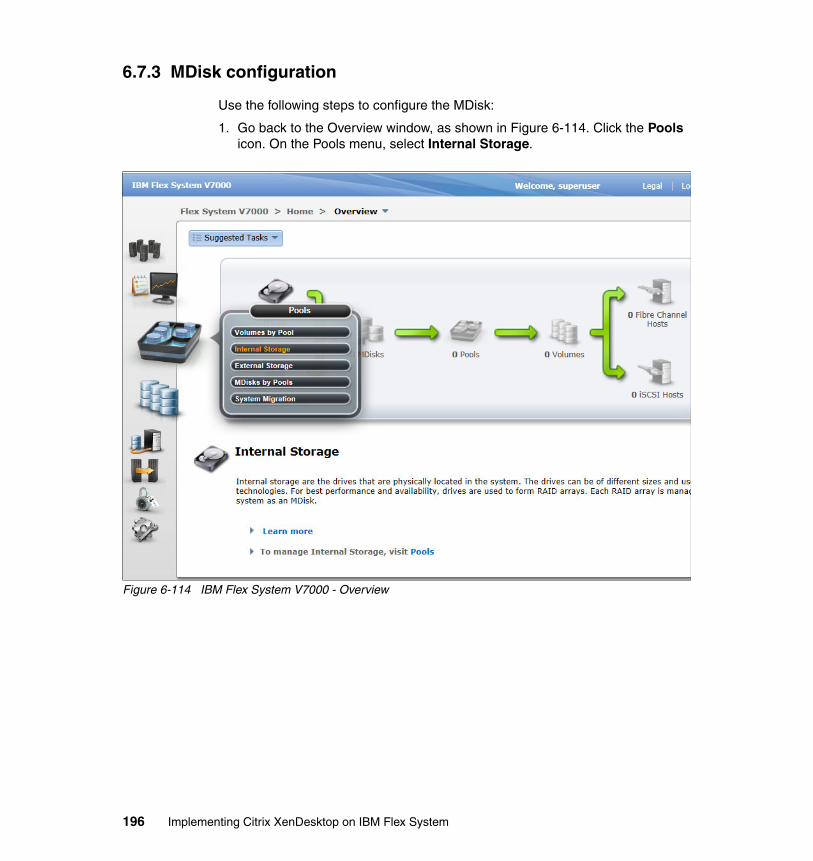
6.7.3 MDisk configuration
Use the following steps to configure the MDisk:
1. Go back to the Overview window, as shown in Figure 6-114. Click the Pools icon. On the Pools menu, select Internal Storage.
Figure 6-114 IBM Flex System V7000 - Overview
196 Implementing Citrix XenDesktop on IBM Flex System
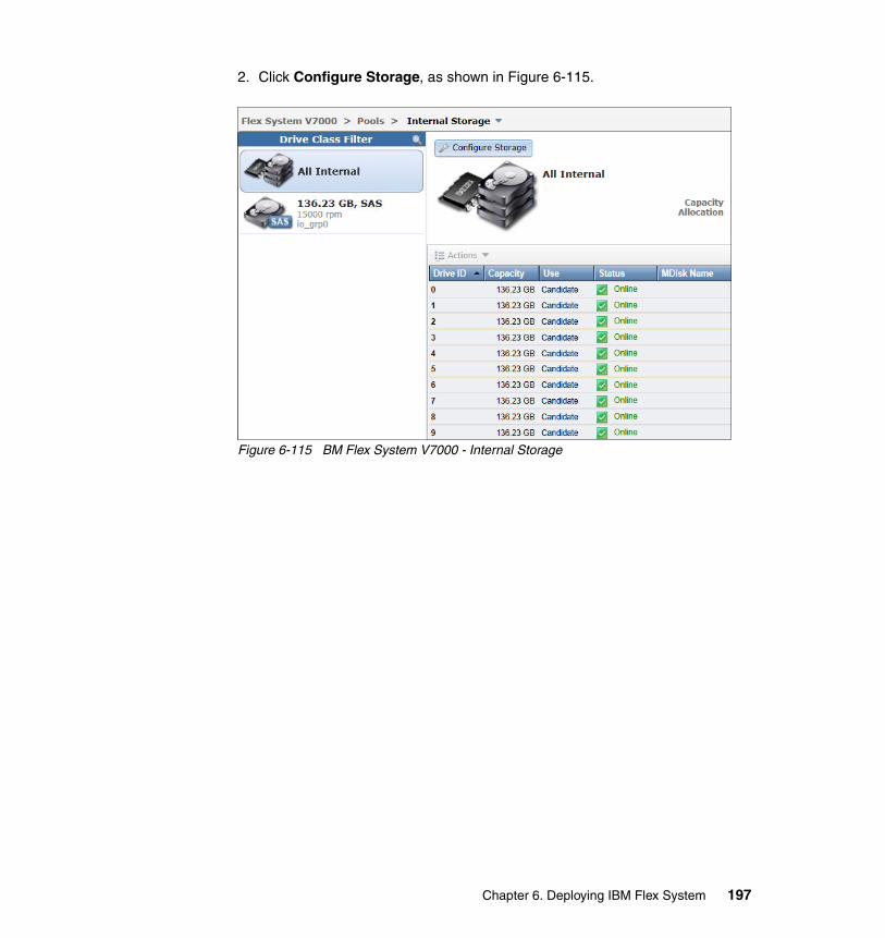
2. Click Configure Storage, as shown in Figure 6-115.
Figure 6-115 BM Flex System V7000 - Internal Storage
Chapter 6. Deploying IBM Flex System 197
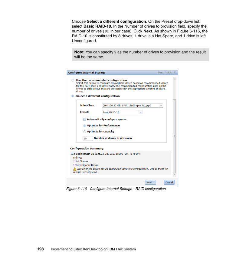
Choose Select a different configuration. On the Preset drop-down list, select Basic RAID-10. In the Number of drives to provision field, specify the number of drives (10, in our case). Click Next. As shown in Figure 6-116, the RAID-10 is constituted by 8 drives, 1 drive is a Hot Spare, and 1 drive is left Unconfigured.
Figure 6-116 Configure Internal Storage - RAID configuration
Note: You can specify 9 as the number of drives to provision and the result will be the same.
198 Implementing Citrix XenDesktop on IBM Flex System

3. Select Create one or more new pools and specify ESXiPool as the Pool Name or Prefix, as shown in Figure 6-117. Click Finish.
Figure 6-117 Configure Internal Storage - pool creation
4. When the task is completed, click Close, as shown in Figure 6-118.
Figure 6-118 Create RAID Arrays task
Chapter 6. Deploying IBM Flex System 199
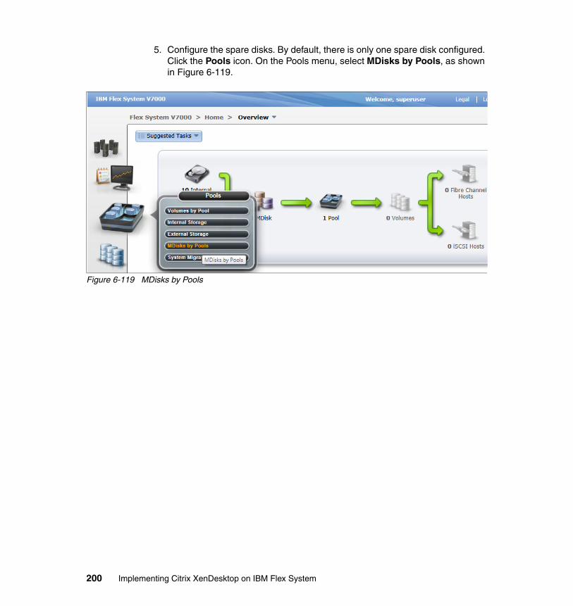
5. Configure the spare disks. By default, there is only one spare disk configured. Click the Pools icon. On the Pools menu, select MDisks by Pools, as shown in Figure 6-119.
Figure 6-119 MDisks by Pools
200 Implementing Citrix XenDesktop on IBM Flex System
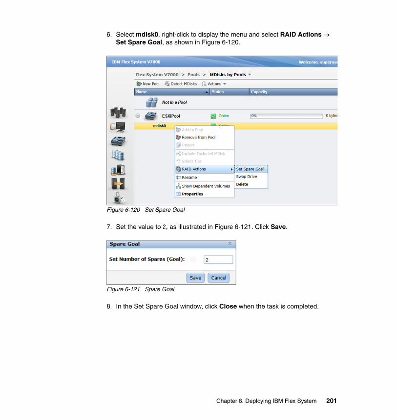
6. Select mdisk0, right-click to display the menu and select RAID Actions Set Spare Goal, as shown in Figure 6-120.
Figure 6-120 Set Spare Goal
7. Set the value to 2, as illustrated in Figure 6-121. Click Save.
Figure 6-121 Spare Goal
8. In the Set Spare Goal window, click Close when the task is completed.
Chapter 6. Deploying IBM Flex System 201
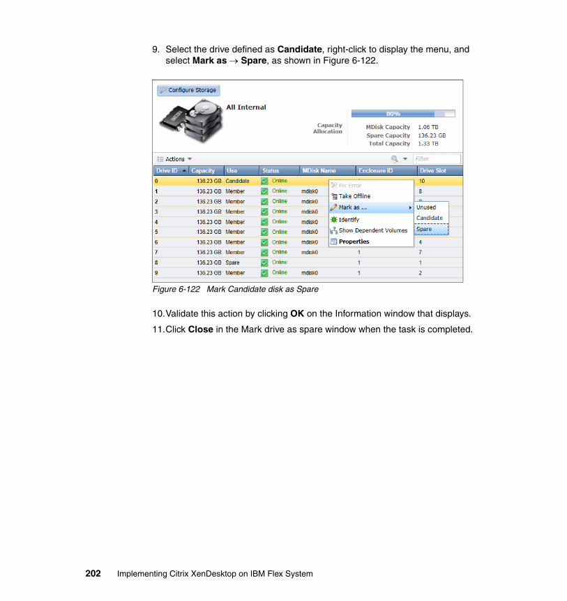
9. Select the drive defined as Candidate, right-click to display the menu, and select Mark as Spare, as shown in Figure 6-122.
Figure 6-122 Mark Candidate disk as Spare
10.Validate this action by clicking OK on the Information window that displays.
11.Click Close in the Mark drive as spare window when the task is completed.
202 Implementing Citrix XenDesktop on IBM Flex System
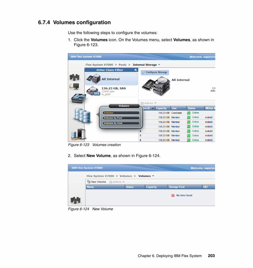
6.7.4 Volumes configuration
Use the following steps to configure the volumes:
1. Click the Volumes icon. On the Volumes menu, select Volumes, as shown in Figure 6-123.
Figure 6-123 Volumes creation
2. Select New Volume, as shown in Figure 6-124.
Figure 6-124 New Volume
Chapter 6. Deploying IBM Flex System 203
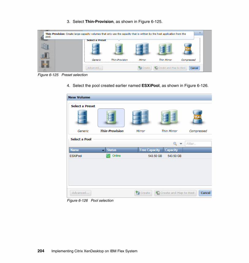
3. Select Thin-Provision, as shown in Figure 6-125.
Figure 6-125 Preset selection
4. Select the pool created earlier named ESXiPool, as shown in Figure 6-126.
Figure 6-126 Pool selection
204 Implementing Citrix XenDesktop on IBM Flex System
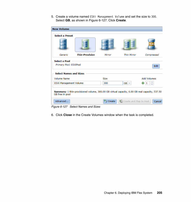
5. Create a volume named ESXi Management Volume and set the size to 300. Select GB, as shown in Figure 6-127. Click Create.
Figure 6-127 Select Names and Sizes
6. Click Close in the Create Volumes window when the task is completed.
Chapter 6. Deploying IBM Flex System 205
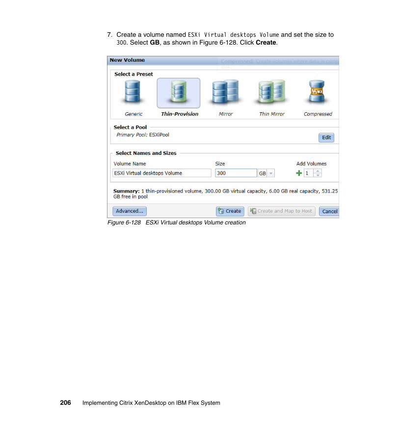
7. Create a volume named ESXi Virtual desktops Volume and set the size to 300. Select GB, as shown in Figure 6-128. Click Create.
Figure 6-128 ESXi Virtual desktops Volume creation
206 Implementing Citrix XenDesktop on IBM Flex System
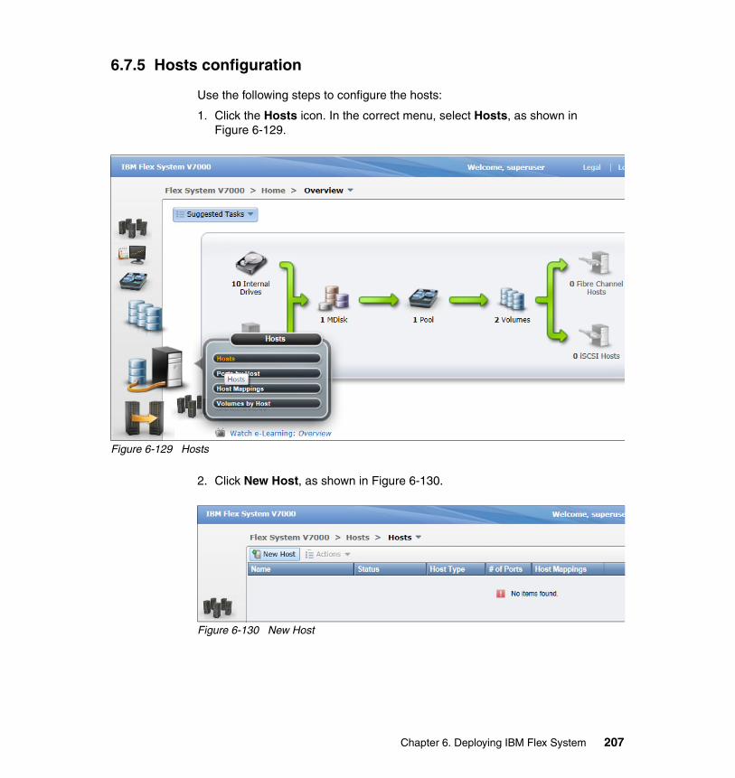
6.7.5 Hosts configuration
Use the following steps to configure the hosts:
1. Click the Hosts icon. In the correct menu, select Hosts, as shown in Figure 6-129.
Figure 6-129 Hosts
2. Click New Host, as shown in Figure 6-130.
Figure 6-130 New Host
Chapter 6. Deploying IBM Flex System 207
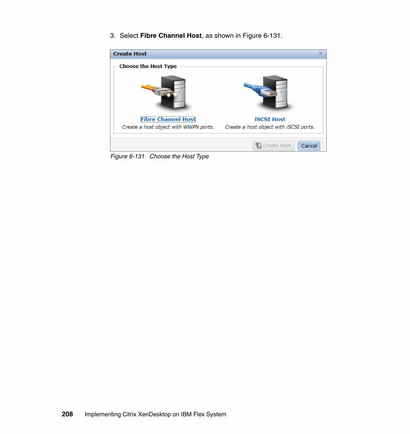
3. Select Fibre Channel Host, as shown in Figure 6-131.
Figure 6-131 Choose the Host Type
208 Implementing Citrix XenDesktop on IBM Flex System
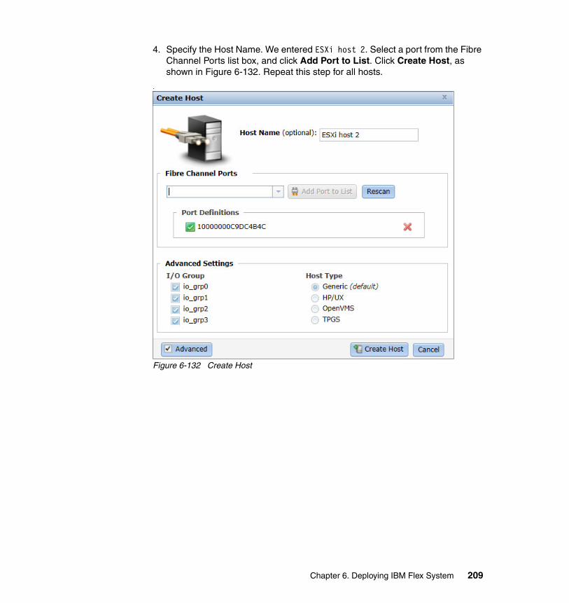
4. Specify the Host Name. We entered ESXi host 2. Select a port from the Fibre Channel Ports list box, and click Add Port to List. Click Create Host, as shown in Figure 6-132. Repeat this step for all hosts.
.
Figure 6-132 Create Host
Chapter 6. Deploying IBM Flex System 209
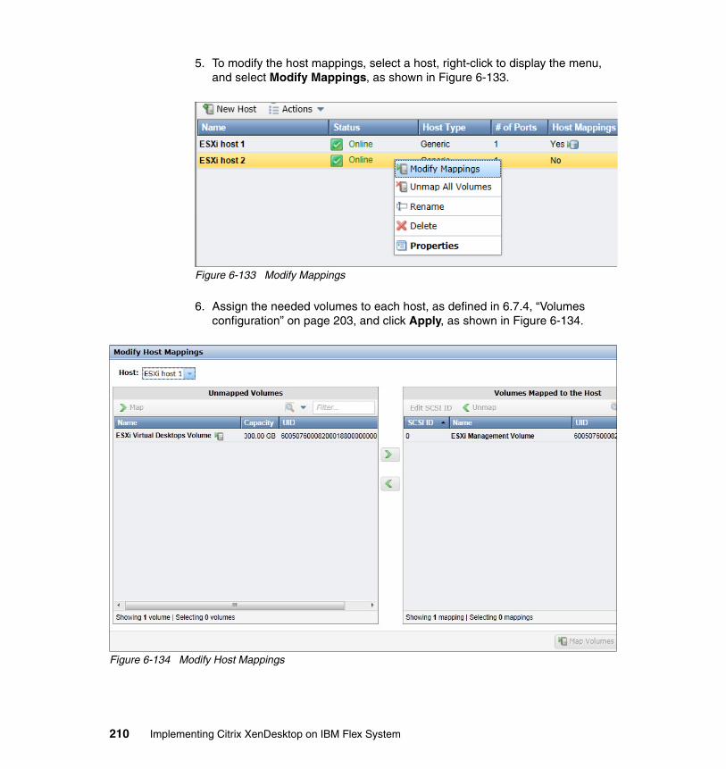
5. To modify the host mappings, select a host, right-click to display the menu, and select Modify Mappings, as shown in Figure 6-133.
Figure 6-133 Modify Mappings
6. Assign the needed volumes to each host, as defined in 6.7.4, “Volumes configuration” on page 203, and click Apply, as shown in Figure 6-134.
Figure 6-134 Modify Host Mappings
210 Implementing Citrix XenDesktop on IBM Flex System
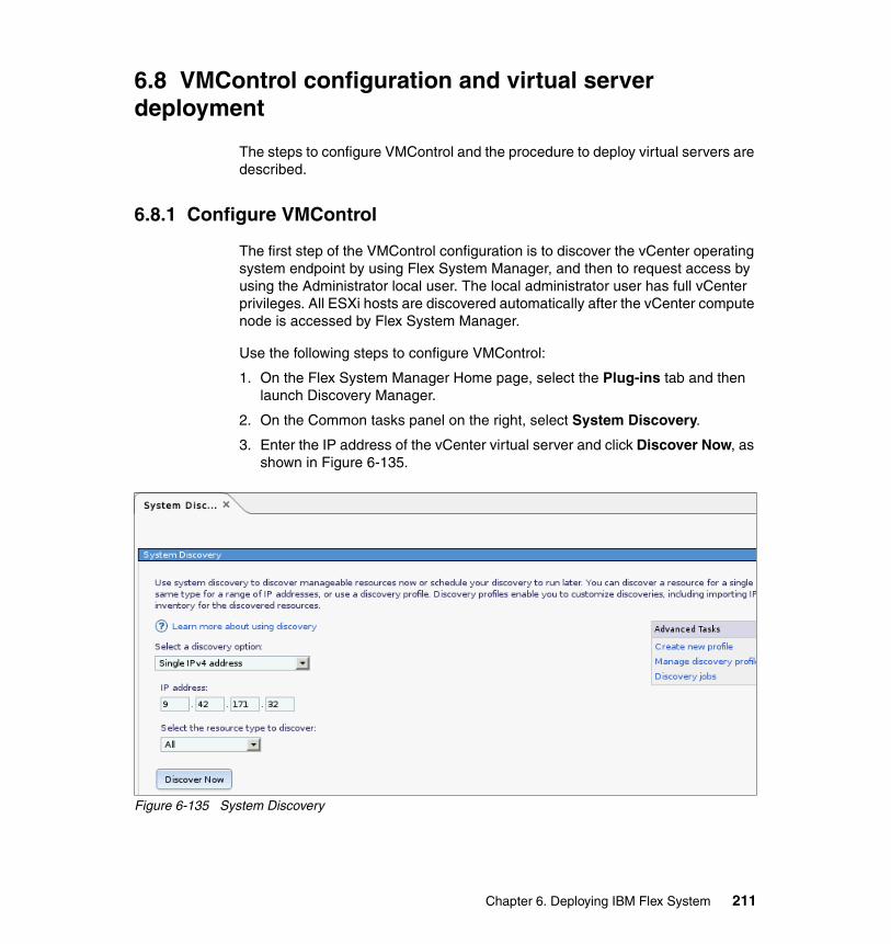
6.8 VMControl configuration and virtual server deployment
The steps to configure VMControl and the procedure to deploy virtual servers are described.
6.8.1 Configure VMControl
The first step of the VMControl configuration is to discover the vCenter operating system endpoint by using Flex System Manager, and then to request access by using the Administrator local user. The local administrator user has full vCenter privileges. All ESXi hosts are discovered automatically after the vCenter compute node is accessed by Flex System Manager.
Use the following steps to configure VMControl:
1. On the Flex System Manager Home page, select the Plug-ins tab and then launch Discovery Manager.
2. On the Common tasks panel on the right, select System Discovery.
3. Enter the IP address of the vCenter virtual server and click Discover Now, as shown in Figure 6-135.
Figure 6-135 System Discovery
Chapter 6. Deploying IBM Flex System 211
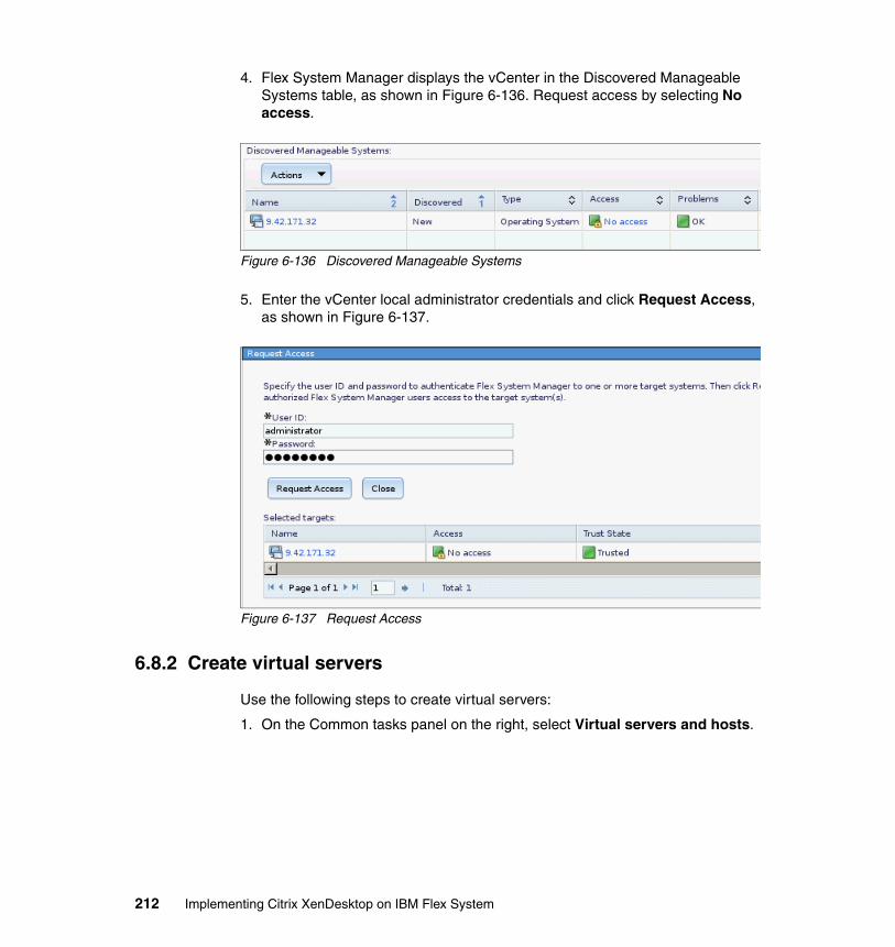
4. Flex System Manager displays the vCenter in the Discovered Manageable Systems table, as shown in Figure 6-136. Request access by selecting No access.
Figure 6-136 Discovered Manageable Systems
5. Enter the vCenter local administrator credentials and click Request Access, as shown in Figure 6-137.
Figure 6-137 Request Access
6.8.2 Create virtual servers
Use the following steps to create virtual servers:
1. On the Common tasks panel on the right, select Virtual servers and hosts.
212 Implementing Citrix XenDesktop on IBM Flex System
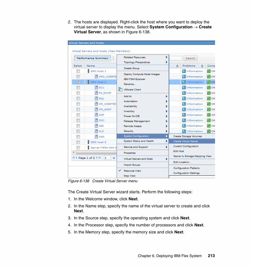
2. The hosts are displayed. Right-click the host where you want to deploy the virtual server to display the menu. Select System Configuration Create Virtual Server, as shown in Figure 6-138.
Figure 6-138 Create Virtual Server menu
The Create Virtual Server wizard starts. Perform the following steps:
1. In the Welcome window, click Next.
2. In the Name step, specify the name of the virtual server to create and click Next.
3. In the Source step, specify the operating system and click Next.
4. In the Processor step, specify the number of processors and click Next.
5. In the Memory step, specify the memory size and click Next.
Chapter 6. Deploying IBM Flex System 213
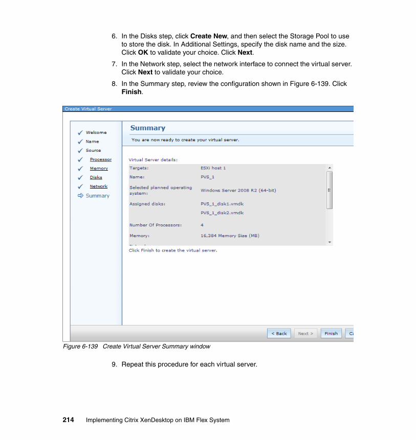
6. In the Disks step, click Create New, and then select the Storage Pool to use to store the disk. In Additional Settings, specify the disk name and the size. Click OK to validate your choice. Click Next.
7. In the Network step, select the network interface to connect the virtual server. Click Next to validate your choice.
8. In the Summary step, review the configuration shown in Figure 6-139. Click Finish.
Figure 6-139 Create Virtual Server Summary window
9. Repeat this procedure for each virtual server.
214 Implementing Citrix XenDesktop on IBM Flex System
Chapter 7. Deploying Citrix XenDesktop
How to provision virtual machines (VMs) for Citrix XenDesktop components and how to install the Citrix XenDesktop components are described.
This chapter contains the following topics:
� 7.1, “Configuring utility services and vSphere” on page 216� 7.2, “Provisioning VMs for Citrix XenDesktop components” on page 217� 7.3, “Installing the Citrix License” on page 217� 7.4, “Installing Citrix XenDesktop Controller” on page 228� 7.5, “Installing Citrix XenApp” on page 248� 7.6, “Installing Citrix Web Interface” on page 271� 7.7, “Installing Citrix Provisioning Services” on page 280
7
© Copyright IBM Corp. 2014. All rights reserved. 215
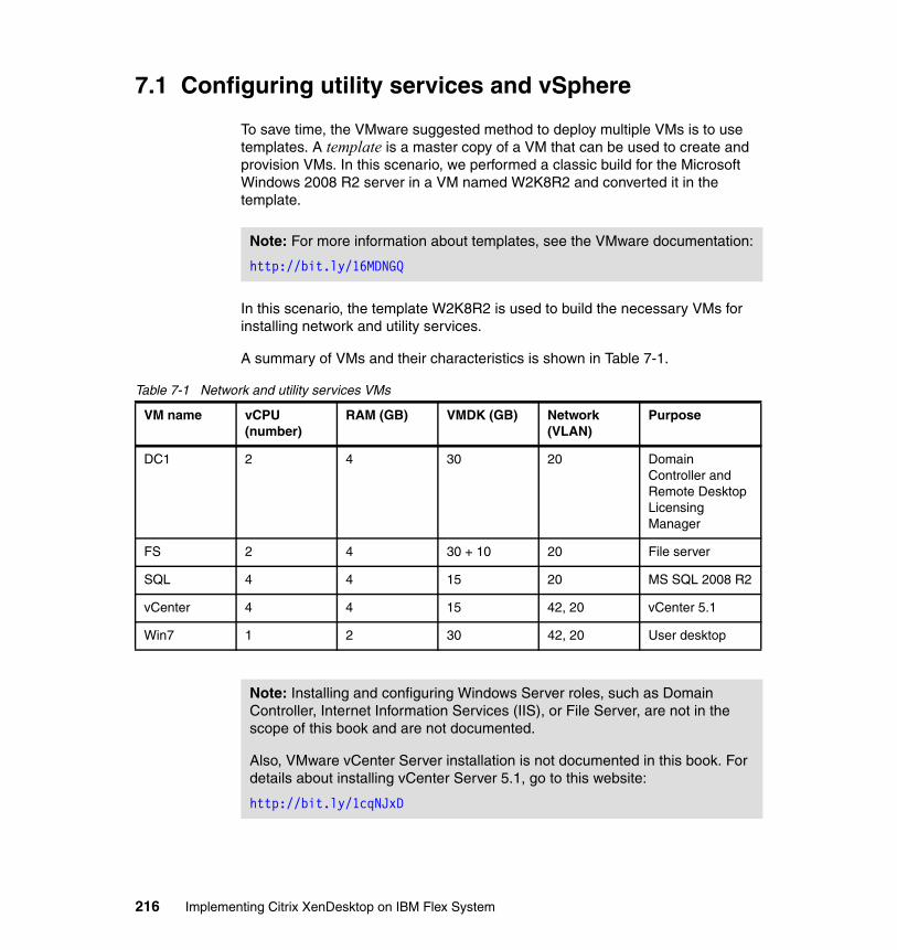
7.1 Configuring utility services and vSphere
To save time, the VMware suggested method to deploy multiple VMs is to use templates. A template is a master copy of a VM that can be used to create and provision VMs. In this scenario, we performed a classic build for the Microsoft Windows 2008 R2 server in a VM named W2K8R2 and converted it in the template.
In this scenario, the template W2K8R2 is used to build the necessary VMs for installing network and utility services.
A summary of VMs and their characteristics is shown in Table 7-1.
Table 7-1 Network and utility services VMs
Note: For more information about templates, see the VMware documentation:
http://bit.ly/16MDNGQ
VM name vCPU (number)
RAM (GB) VMDK (GB) Network (VLAN)
Purpose
DC1 2 4 30 20 Domain Controller and Remote Desktop Licensing Manager
FS 2 4 30 + 10 20 File server
SQL 4 4 15 20 MS SQL 2008 R2
vCenter 4 4 15 42, 20 vCenter 5.1
Win7 1 2 30 42, 20 User desktop
Note: Installing and configuring Windows Server roles, such as Domain Controller, Internet Information Services (IIS), or File Server, are not in the scope of this book and are not documented.
Also, VMware vCenter Server installation is not documented in this book. For details about installing vCenter Server 5.1, go to this website:
http://bit.ly/1cqNJxD
216 Implementing Citrix XenDesktop on IBM Flex System
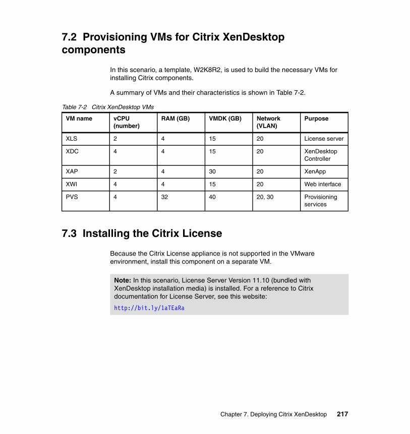
7.2 Provisioning VMs for Citrix XenDesktop components
In this scenario, a template, W2K8R2, is used to build the necessary VMs for installing Citrix components.
A summary of VMs and their characteristics is shown in Table 7-2.
Table 7-2 Citrix XenDesktop VMs
7.3 Installing the Citrix License
Because the Citrix License appliance is not supported in the VMware environment, install this component on a separate VM.
VM name vCPU (number)
RAM (GB) VMDK (GB) Network (VLAN)
Purpose
XLS 2 4 15 20 License server
XDC 4 4 15 20 XenDesktop Controller
XAP 2 4 30 20 XenApp
XWI 4 4 15 20 Web interface
PVS 4 32 40 20, 30 Provisioning services
Note: In this scenario, License Server Version 11.10 (bundled with XenDesktop installation media) is installed. For a reference to Citrix documentation for License Server, see this website:
http://bit.ly/1aTEaRa
Chapter 7. Deploying Citrix XenDesktop 217
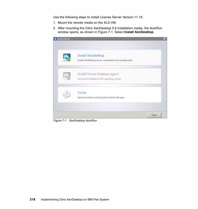
Use the following steps to install License Server Version 11.10:
1. Mount the remote media on the XLS VM.
2. After mounting the Citrix XenDesktop 5.6 installation media, the AutoRun window opens, as shown in Figure 7-1. Select Install XenDesktop.
Figure 7-1 XenDesktop AutoRun
218 Implementing Citrix XenDesktop on IBM Flex System
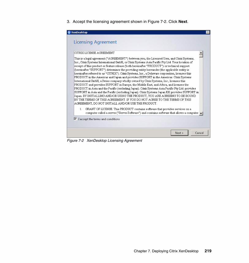
3. Accept the licensing agreement shown in Figure 7-2. Click Next.
Figure 7-2 XenDesktop Licensing Agreement
Chapter 7. Deploying Citrix XenDesktop 219
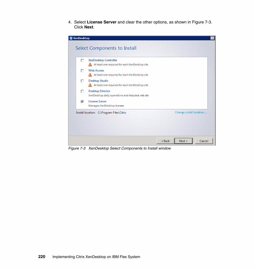
4. Select License Server and clear the other options, as shown in Figure 7-3. Click Next.
Figure 7-3 XenDesktop Select Components to Install window
220 Implementing Citrix XenDesktop on IBM Flex System
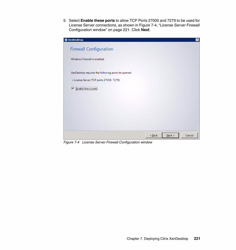
5. Select Enable these ports to allow TCP Ports 27000 and 7279 to be used for License Server connections, as shown in Figure 7-4, “License Server Firewall Configuration window” on page 221. Click Next.
Figure 7-4 License Server Firewall Configuration window
Chapter 7. Deploying Citrix XenDesktop 221
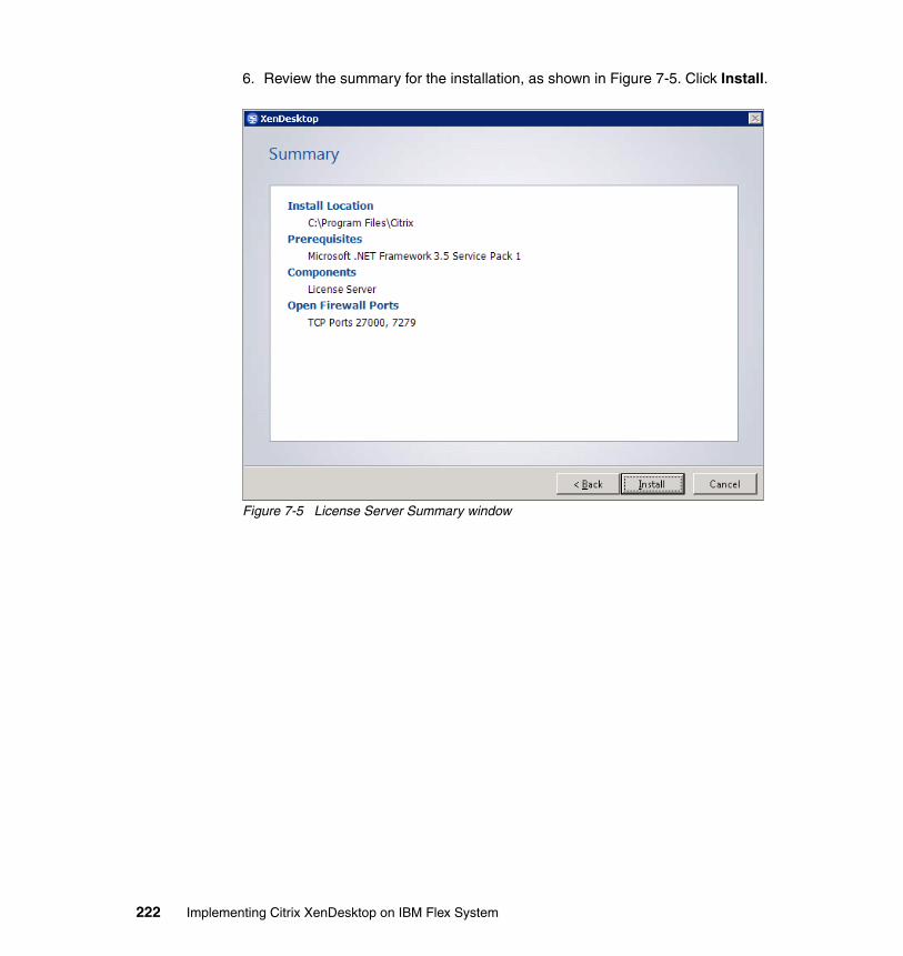
6. Review the summary for the installation, as shown in Figure 7-5. Click Install.
Figure 7-5 License Server Summary window
222 Implementing Citrix XenDesktop on IBM Flex System
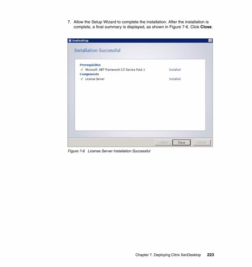
7. Allow the Setup Wizard to complete the installation. After the installation is complete, a final summary is displayed, as shown in Figure 7-6. Click Close.
Figure 7-6 License Server Installation Successful
Chapter 7. Deploying Citrix XenDesktop 223
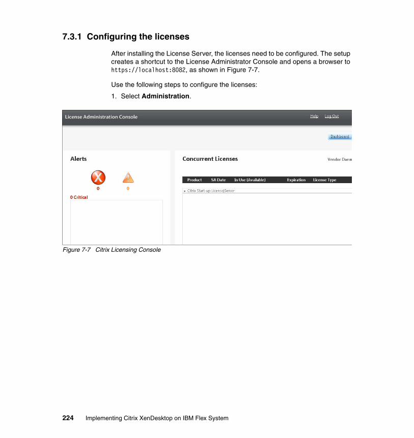
7.3.1 Configuring the licenses
After installing the License Server, the licenses need to be configured. The setup creates a shortcut to the License Administrator Console and opens a browser to https://localhost:8082, as shown in Figure 7-7.
Use the following steps to configure the licenses:
1. Select Administration.
Figure 7-7 Citrix Licensing Console
224 Implementing Citrix XenDesktop on IBM Flex System
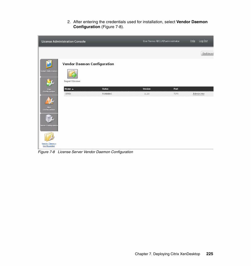
2. After entering the credentials used for installation, select Vendor Daemon Configuration (Figure 7-8).
Figure 7-8 License Server Vendor Daemon Configuration
Chapter 7. Deploying Citrix XenDesktop 225
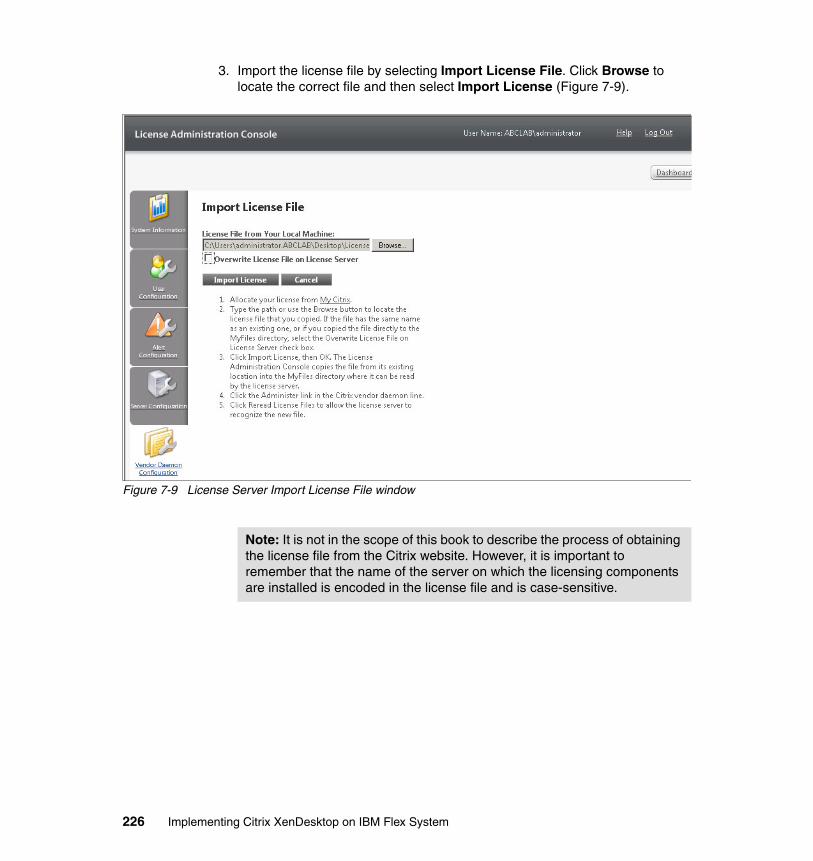
3. Import the license file by selecting Import License File. Click Browse to locate the correct file and then select Import License (Figure 7-9).
Figure 7-9 License Server Import License File window
Note: It is not in the scope of this book to describe the process of obtaining the license file from the Citrix website. However, it is important to remember that the name of the server on which the licensing components are installed is encoded in the license file and is case-sensitive.
226 Implementing Citrix XenDesktop on IBM Flex System
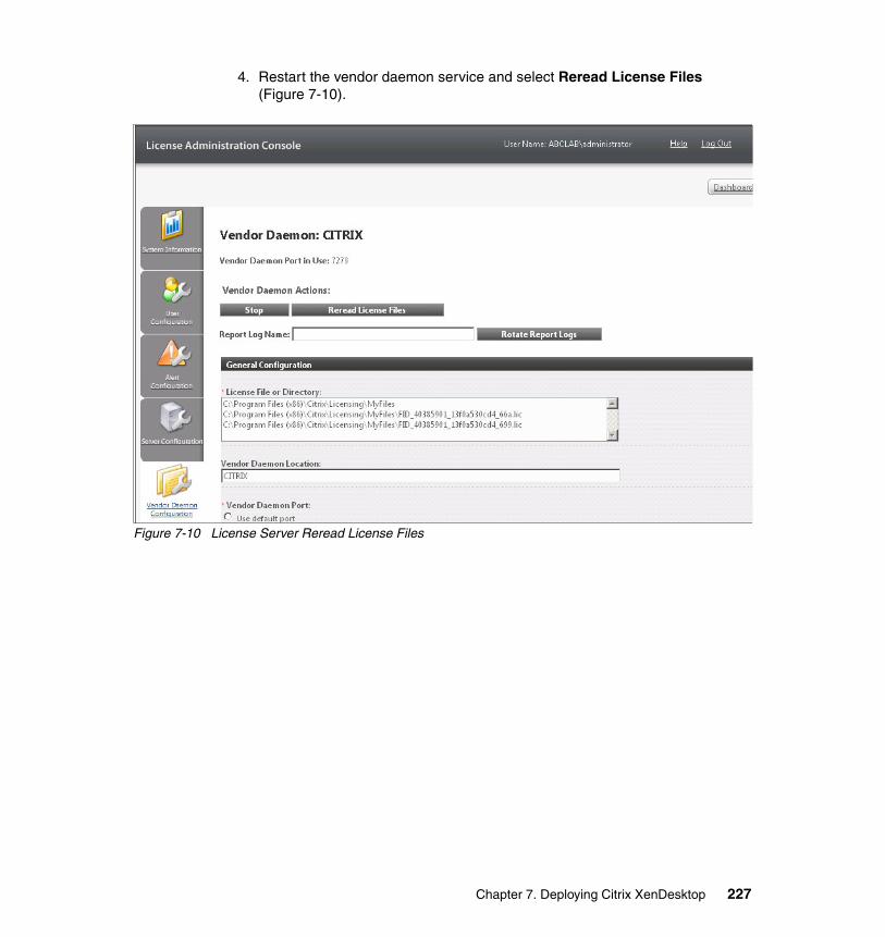
4. Restart the vendor daemon service and select Reread License Files (Figure 7-10).
Figure 7-10 License Server Reread License Files
Chapter 7. Deploying Citrix XenDesktop 227
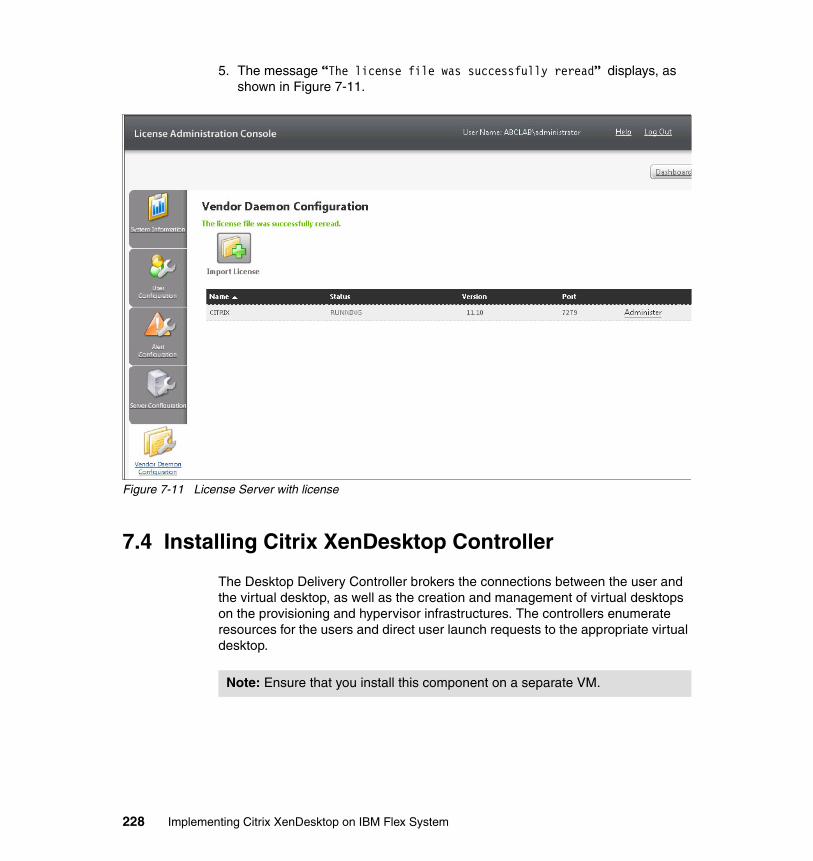
5. The message “The license file was successfully reread” displays, as shown in Figure 7-11.
Figure 7-11 License Server with license
7.4 Installing Citrix XenDesktop Controller
The Desktop Delivery Controller brokers the connections between the user and the virtual desktop, as well as the creation and management of virtual desktops on the provisioning and hypervisor infrastructures. The controllers enumerate resources for the users and direct user launch requests to the appropriate virtual desktop.
Note: Ensure that you install this component on a separate VM.
228 Implementing Citrix XenDesktop on IBM Flex System
Before proceeding with the installation, you need to add the Secure Sockets Layer (SSL) certificate of vCenter on the server where you plan to install XenDesktop Controller. Citrix suggests that you use a digital certificate that is issued from a certificate authority (CA). The VMware self-signed certificate can be also used if the organization’s security policy permits it.
If multiple XenDesktop Controllers are planned, apply the next procedure for all of them.
7.4.1 Installing the SSL certificate
Use the following steps to install the certificate:
1. Open Internet Explorer and enter the address of the computer running vCenter Server as https://vcenter.abclab.local.
2. Accept the security warnings.
3. Click Certificate Error in the Security Status bar, and select View certificates.
4. Click Install certificate, and then click Next.
5. Select Place all certificates in the following store, and then click Browse.
6. Select the Show physical stores check box.
7. Expand Trusted People and select Local Computer.
8. Click OK, and then click Finish.
Note: For additional information about installing this component, see this website:
http://support.citrix.com/proddocs/topic/xendesktop-bdx/cds-create-farm-bdx.html
Chapter 7. Deploying Citrix XenDesktop 229
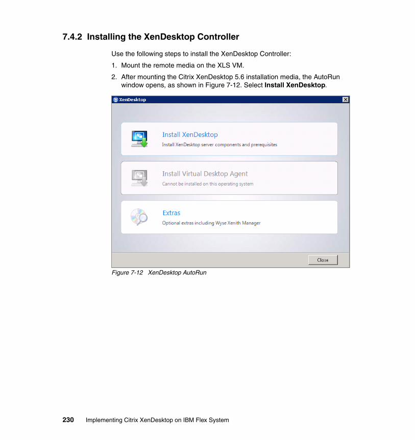
7.4.2 Installing the XenDesktop Controller
Use the following steps to install the XenDesktop Controller:
1. Mount the remote media on the XLS VM.
2. After mounting the Citrix XenDesktop 5.6 installation media, the AutoRun window opens, as shown in Figure 7-12. Select Install XenDesktop.
Figure 7-12 XenDesktop AutoRun
230 Implementing Citrix XenDesktop on IBM Flex System

3. Accept the license agreement, as shown in Figure 7-13. Click Next.
Figure 7-13 XenDesktop Licensing Agreement
Chapter 7. Deploying Citrix XenDesktop 231
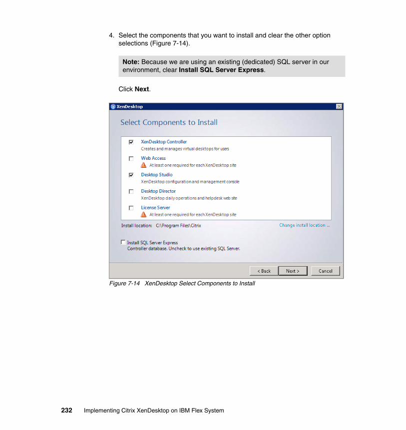
4. Select the components that you want to install and clear the other option selections (Figure 7-14).
Click Next.
Figure 7-14 XenDesktop Select Components to Install
Note: Because we are using an existing (dedicated) SQL server in our environment, clear Install SQL Server Express.
232 Implementing Citrix XenDesktop on IBM Flex System
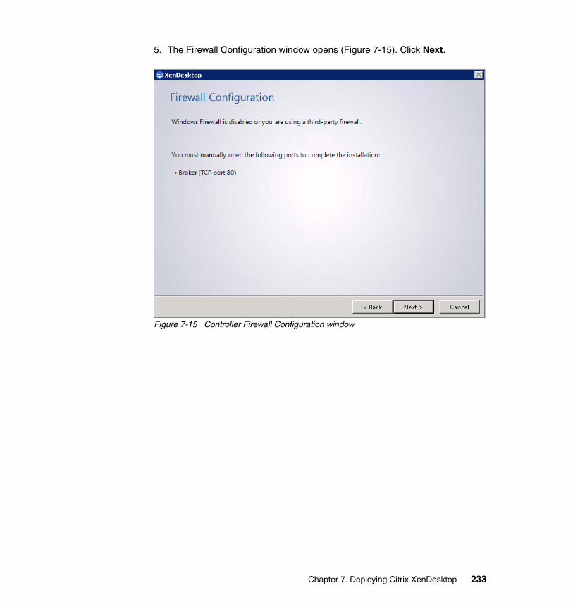
5. The Firewall Configuration window opens (Figure 7-15). Click Next.
Figure 7-15 Controller Firewall Configuration window
Chapter 7. Deploying Citrix XenDesktop 233
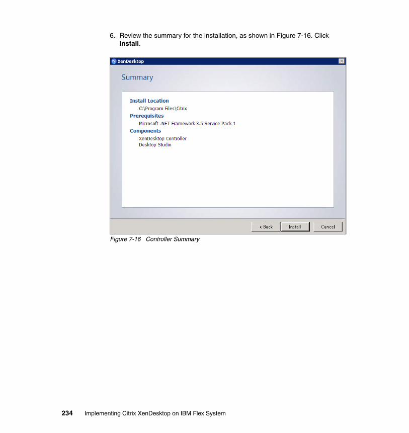
6. Review the summary for the installation, as shown in Figure 7-16. Click Install.
Figure 7-16 Controller Summary
234 Implementing Citrix XenDesktop on IBM Flex System
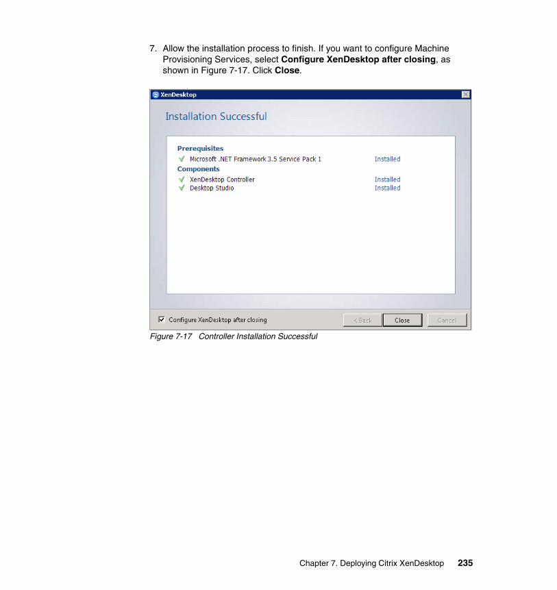
7. Allow the installation process to finish. If you want to configure Machine Provisioning Services, select Configure XenDesktop after closing, as shown in Figure 7-17. Click Close.
Figure 7-17 Controller Installation Successful
Chapter 7. Deploying Citrix XenDesktop 235
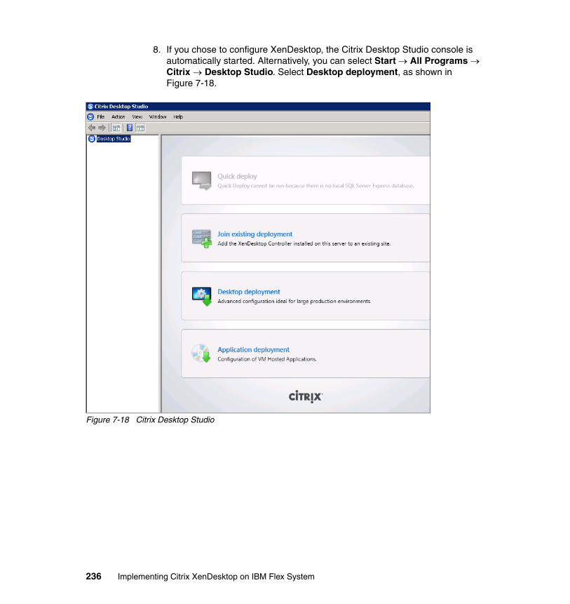
8. If you chose to configure XenDesktop, the Citrix Desktop Studio console is automatically started. Alternatively, you can select Start All Programs Citrix Desktop Studio. Select Desktop deployment, as shown in Figure 7-18.
Figure 7-18 Citrix Desktop Studio
236 Implementing Citrix XenDesktop on IBM Flex System
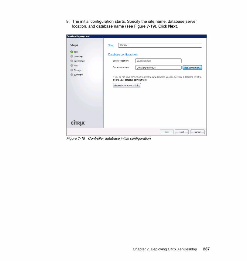
9. The initial configuration starts. Specify the site name, database server location, and database name (see Figure 7-19). Click Next.
Figure 7-19 Controller database initial configuration
Chapter 7. Deploying Citrix XenDesktop 237
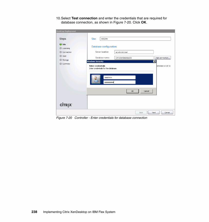
10.Select Test connection and enter the credentials that are required for database connection, as shown in Figure 7-20. Click OK.
Figure 7-20 Controller - Enter credentials for database connection
238 Implementing Citrix XenDesktop on IBM Flex System
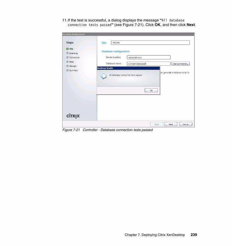
11.If the test is successful, a dialog displays the message “All database connection tests passed” (see Figure 7-21). Click OK, and then click Next.
Figure 7-21 Controller - Database connection tests passed
Chapter 7. Deploying Citrix XenDesktop 239
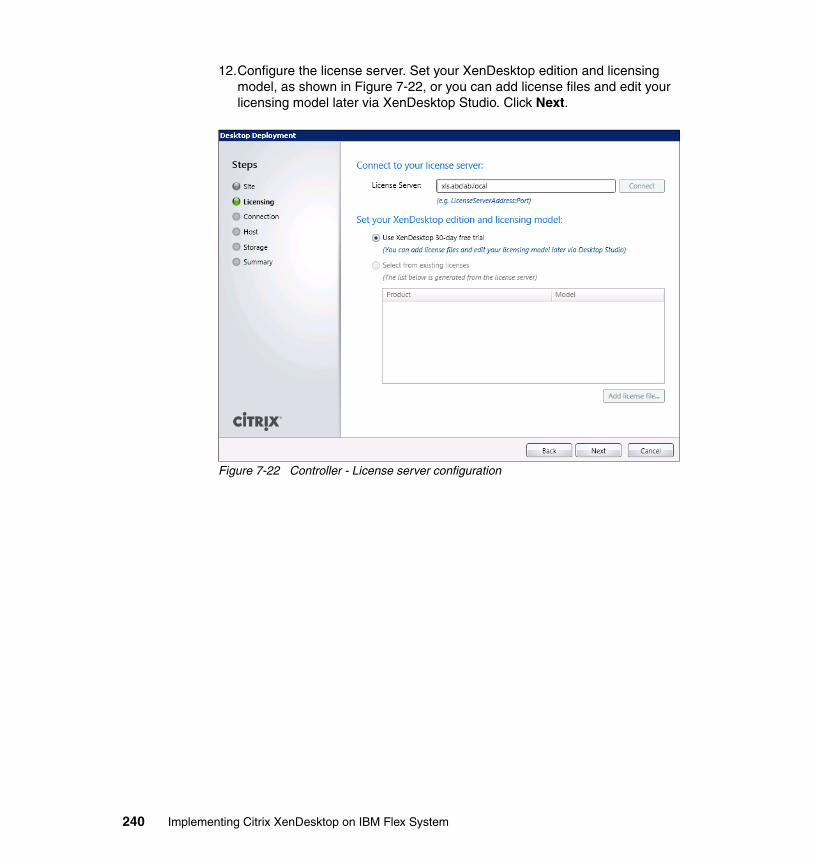
12.Configure the license server. Set your XenDesktop edition and licensing model, as shown in Figure 7-22, or you can add license files and edit your licensing model later via XenDesktop Studio. Click Next.
Figure 7-22 Controller - License server configuration
240 Implementing Citrix XenDesktop on IBM Flex System
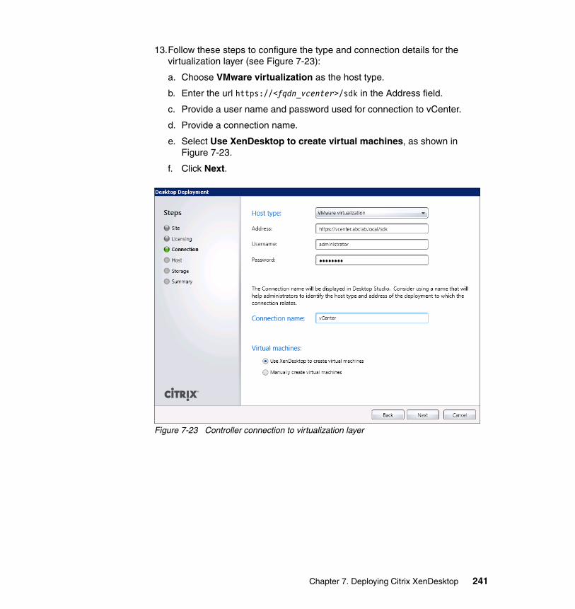
13.Follow these steps to configure the type and connection details for the virtualization layer (see Figure 7-23):
a. Choose VMware virtualization as the host type.
b. Enter the url https://<fqdn_vcenter>/sdk in the Address field.
c. Provide a user name and password used for connection to vCenter.
d. Provide a connection name.
e. Select Use XenDesktop to create virtual machines, as shown in Figure 7-23.
f. Click Next.
Figure 7-23 Controller connection to virtualization layer
Chapter 7. Deploying Citrix XenDesktop 241
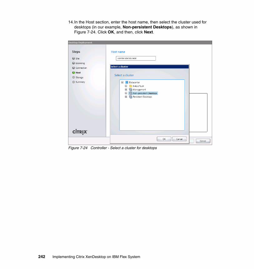
14.In the Host section, enter the host name, then select the cluster used for desktops (in our example, Non-persistent Desktops), as shown in Figure 7-24. Click OK, and then, click Next.
Figure 7-24 Controller - Select a cluster for desktops
242 Implementing Citrix XenDesktop on IBM Flex System
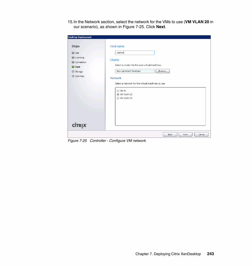
15.In the Network section, select the network for the VMs to use (VM VLAN 20 in our scenario), as shown in Figure 7-25. Click Next.
Figure 7-25 Controller - Configure VM network
Chapter 7. Deploying Citrix XenDesktop 243
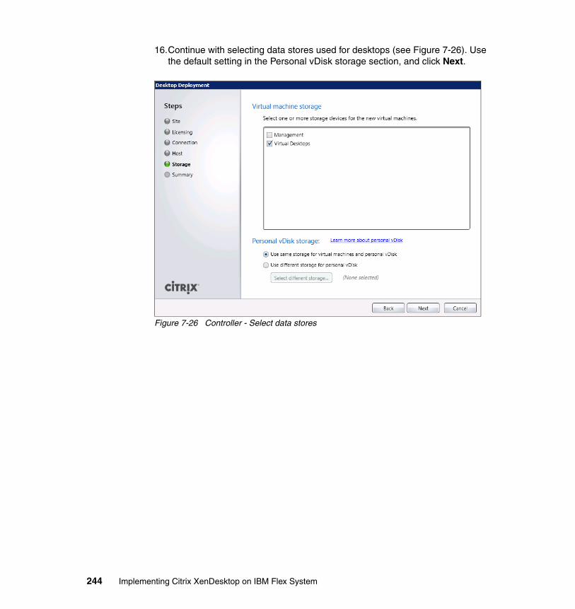
16.Continue with selecting data stores used for desktops (see Figure 7-26). Use the default setting in the Personal vDisk storage section, and click Next.
Figure 7-26 Controller - Select data stores
244 Implementing Citrix XenDesktop on IBM Flex System
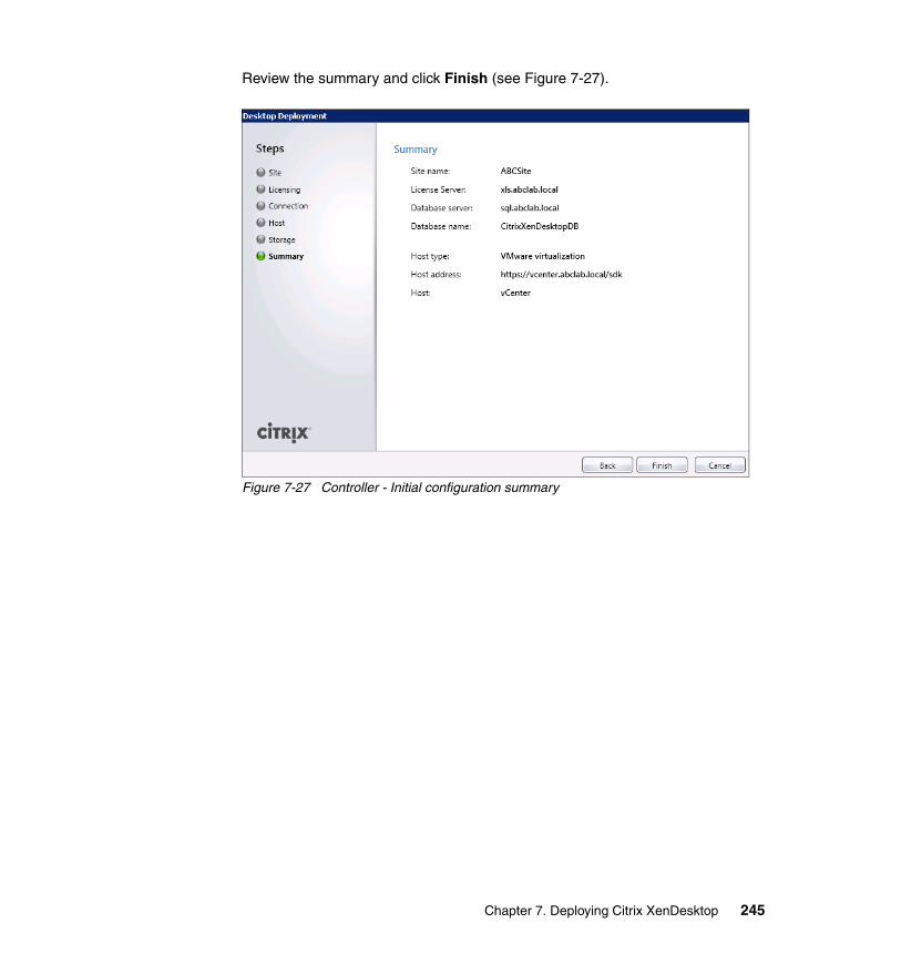
Review the summary and click Finish (see Figure 7-27).
Figure 7-27 Controller - Initial configuration summary
Chapter 7. Deploying Citrix XenDesktop 245
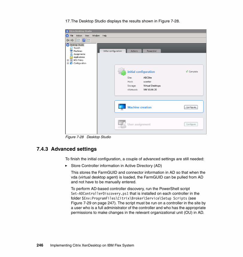
17.The Desktop Studio displays the results shown in Figure 7-28.
Figure 7-28 Desktop Studio
7.4.3 Advanced settings
To finish the initial configuration, a couple of advanced settings are still needed:
� Store Controller information in Active Directory (AD)
This stores the FarmGUID and connector information in AD so that when the vda (virtual desktop agent) is loaded, the FarmGUID can be pulled from AD and not have to be manually entered.
To perform AD-based controller discovery, run the PowerShell script Set-ADControllerDiscovery.ps1 that is installed on each controller in the folder $Env:ProgramFiles\Citrix\Broker\Service\Setup Scripts (see Figure 7-29 on page 247). The script must be run on a controller in the site by a user who is a full administrator of the controller and who has the appropriate permissions to make changes in the relevant organizational unit (OU) in AD.
246 Implementing Citrix XenDesktop on IBM Flex System
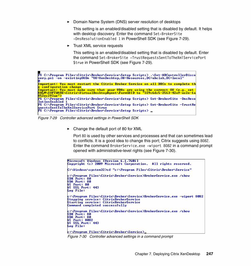
� Domain Name System (DNS) server resolution of desktops
This setting is an enabled/disabled setting that is disabled by default. It helps with desktop discovery. Enter the command Set-BrokerSite -DnsResolutionEnabled 1 in PowerShell SDK (see Figure 7-29).
� Trust XML service requests
This setting is an enabled/disabled setting that is disabled by default. Enter the command Set-BrokerSite -TrustRequestsSentToTheXmlServicePort $true in PowerShell SDK (see Figure 7-29).
Figure 7-29 Controller advanced settings in PowerShell SDK
� Change the default port of 80 for XML
Port 80 is used by other services and processes and that can sometimes lead to conflicts. It is a good idea to change this port; Citrix suggests using 8082. Enter the command BrokerService.exe -wiport 8082 in a command prompt opened with administrative-level rights (see Figure 7-30).
Figure 7-30 Controller advanced settings in a command prompt
Chapter 7. Deploying Citrix XenDesktop 247
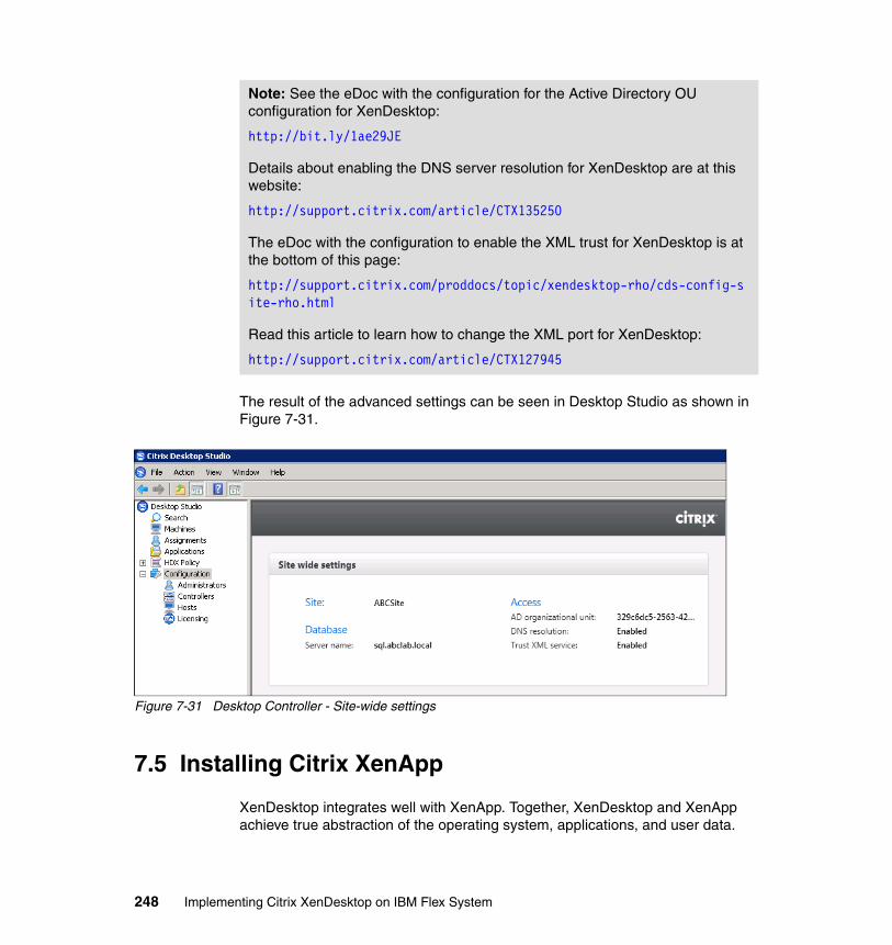
The result of the advanced settings can be seen in Desktop Studio as shown in Figure 7-31.
Figure 7-31 Desktop Controller - Site-wide settings
7.5 Installing Citrix XenApp
XenDesktop integrates well with XenApp. Together, XenDesktop and XenApp achieve true abstraction of the operating system, applications, and user data.
Note: See the eDoc with the configuration for the Active Directory OU configuration for XenDesktop:
http://bit.ly/1ae29JE
Details about enabling the DNS server resolution for XenDesktop are at this website:
http://support.citrix.com/article/CTX135250
The eDoc with the configuration to enable the XML trust for XenDesktop is at the bottom of this page:
http://support.citrix.com/proddocs/topic/xendesktop-rho/cds-config-site-rho.html
Read this article to learn how to change the XML port for XenDesktop:
http://support.citrix.com/article/CTX127945
248 Implementing Citrix XenDesktop on IBM Flex System
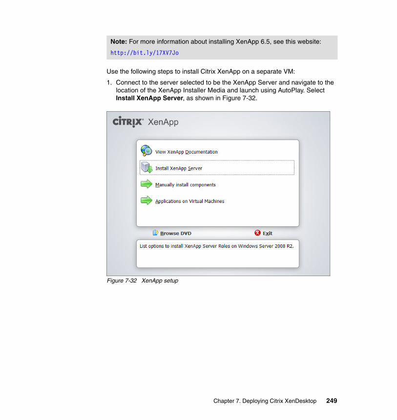
Use the following steps to install Citrix XenApp on a separate VM:
1. Connect to the server selected to be the XenApp Server and navigate to the location of the XenApp Installer Media and launch using AutoPlay. Select Install XenApp Server, as shown in Figure 7-32.
Figure 7-32 XenApp setup
Note: For more information about installing XenApp 6.5, see this website:
http://bit.ly/17XV7Jo
Chapter 7. Deploying Citrix XenDesktop 249
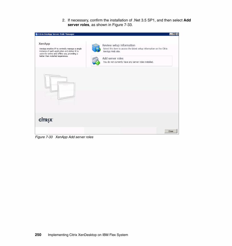
2. If necessary, confirm the installation of .Net 3.5 SP1, and then select Add server roles, as shown in Figure 7-33.
Figure 7-33 XenApp Add server roles
250 Implementing Citrix XenDesktop on IBM Flex System
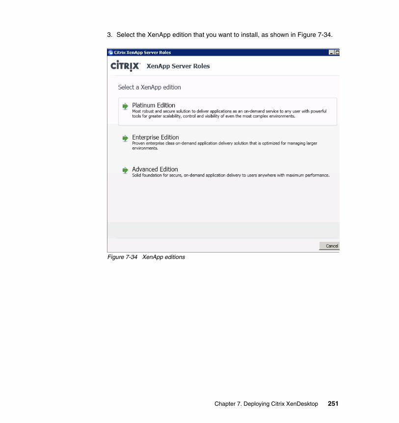
3. Select the XenApp edition that you want to install, as shown in Figure 7-34.
Figure 7-34 XenApp editions
Chapter 7. Deploying Citrix XenDesktop 251
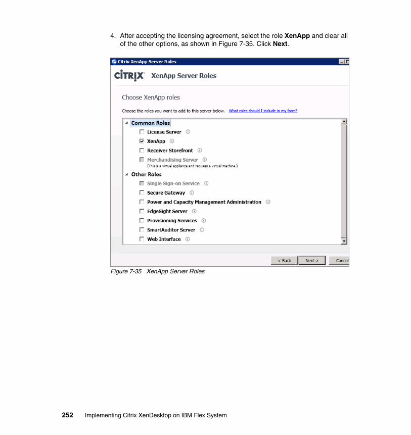
4. After accepting the licensing agreement, select the role XenApp and clear all of the other options, as shown in Figure 7-35. Click Next.
Figure 7-35 XenApp Server Roles
252 Implementing Citrix XenDesktop on IBM Flex System
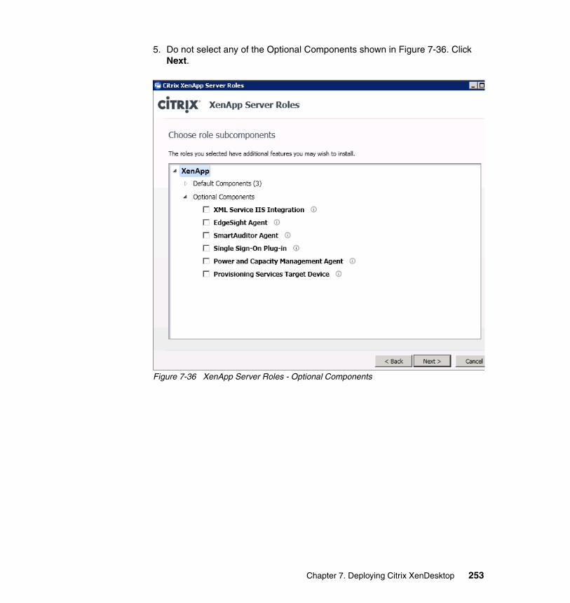
5. Do not select any of the Optional Components shown in Figure 7-36. Click Next.
Figure 7-36 XenApp Server Roles - Optional Components
Chapter 7. Deploying Citrix XenDesktop 253
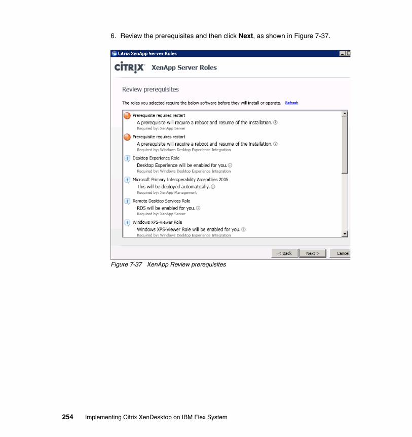
6. Review the prerequisites and then click Next, as shown in Figure 7-37.
Figure 7-37 XenApp Review prerequisites
254 Implementing Citrix XenDesktop on IBM Flex System
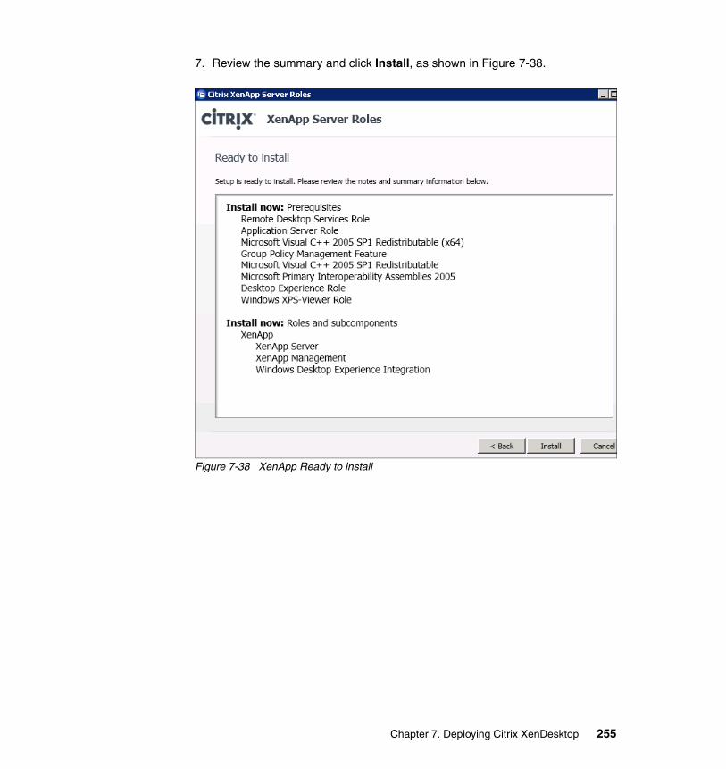
7. Review the summary and click Install, as shown in Figure 7-38.
Figure 7-38 XenApp Ready to install
Chapter 7. Deploying Citrix XenDesktop 255
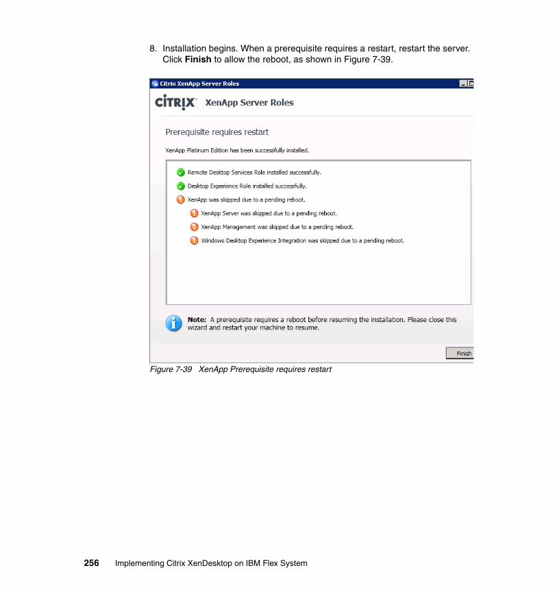
8. Installation begins. When a prerequisite requires a restart, restart the server. Click Finish to allow the reboot, as shown in Figure 7-39.
Figure 7-39 XenApp Prerequisite requires restart
256 Implementing Citrix XenDesktop on IBM Flex System
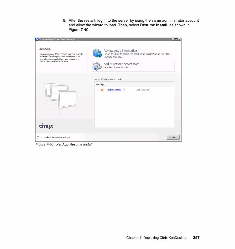
9. After the restart, log in to the server by using the same administrator account and allow the wizard to load. Then, select Resume Install, as shown in Figure 7-40.
Figure 7-40 XenApp Resume Install
Chapter 7. Deploying Citrix XenDesktop 257
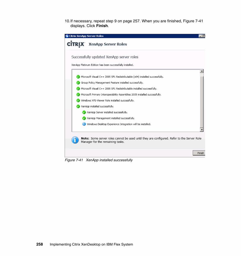
10.If necessary, repeat step 9 on page 257. When you are finished, Figure 7-41 displays. Click Finish.
Figure 7-41 XenApp installed successfully
258 Implementing Citrix XenDesktop on IBM Flex System
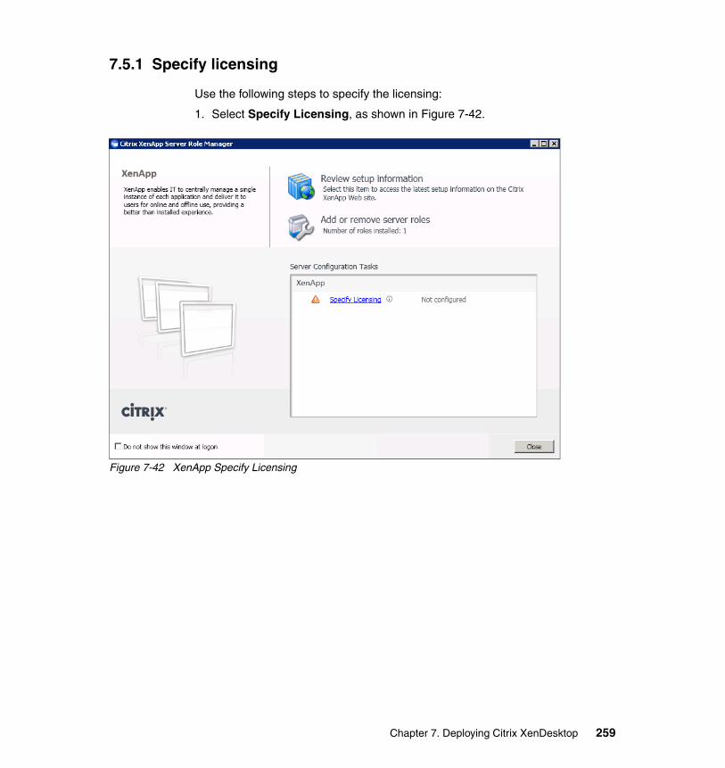
7.5.1 Specify licensing
Use the following steps to specify the licensing:
1. Select Specify Licensing, as shown in Figure 7-42.
Figure 7-42 XenApp Specify Licensing
Chapter 7. Deploying Citrix XenDesktop 259
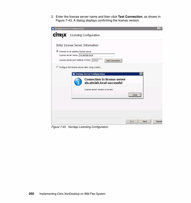
2. Enter the license server name and then click Test Connection, as shown in Figure 7-43. A dialog displays confirming the license version.
Figure 7-43 XenApp Licensing Configuration
260 Implementing Citrix XenDesktop on IBM Flex System
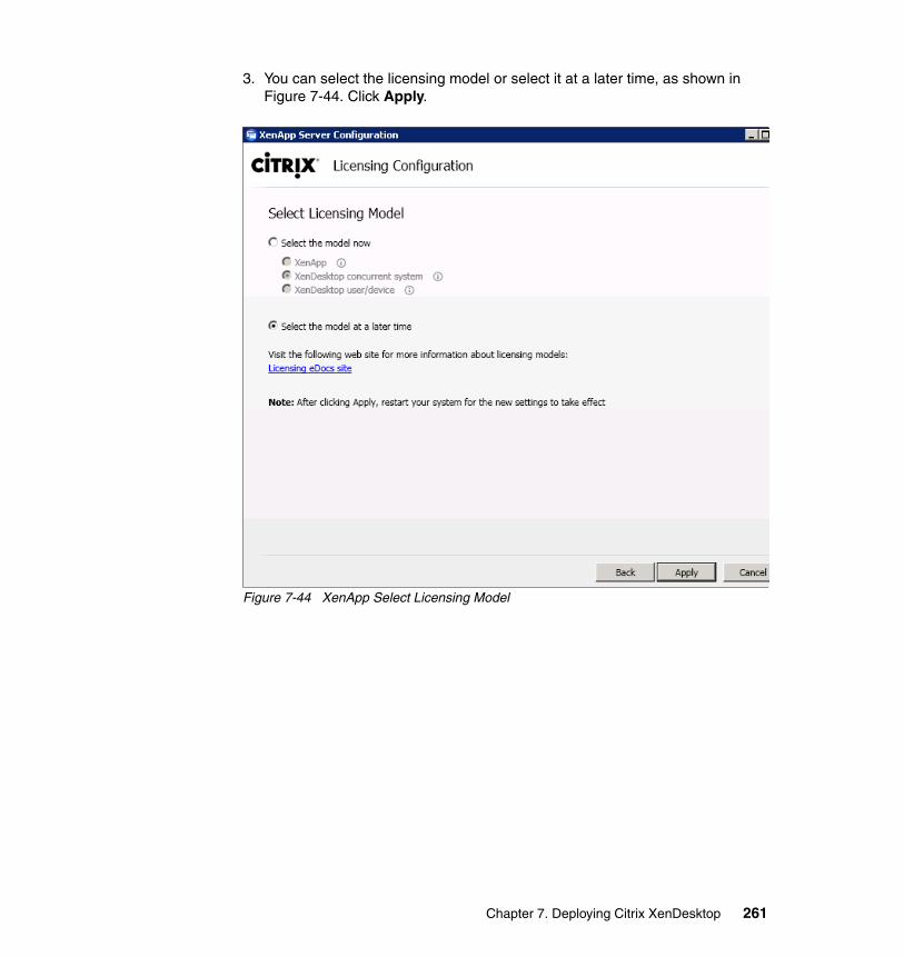
3. You can select the licensing model or select it at a later time, as shown in Figure 7-44. Click Apply.
Figure 7-44 XenApp Select Licensing Model
Chapter 7. Deploying Citrix XenDesktop 261
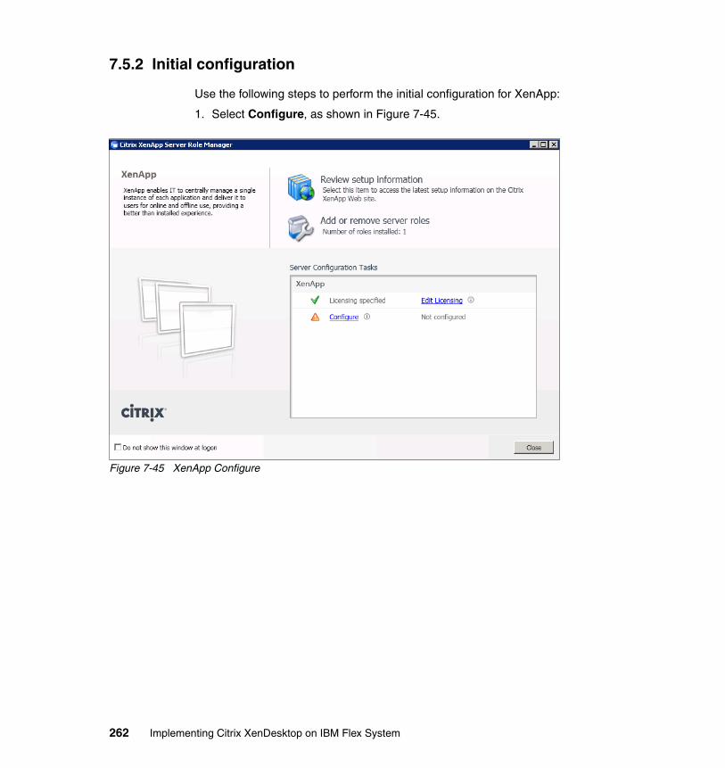
7.5.2 Initial configuration
Use the following steps to perform the initial configuration for XenApp:
1. Select Configure, as shown in Figure 7-45.
Figure 7-45 XenApp Configure
262 Implementing Citrix XenDesktop on IBM Flex System
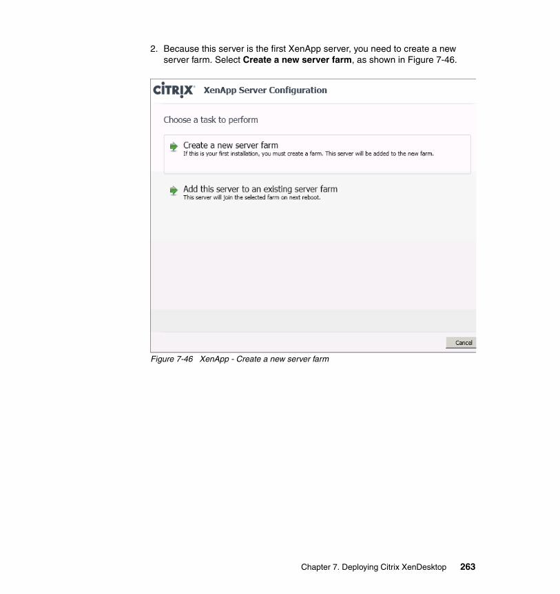
2. Because this server is the first XenApp server, you need to create a new server farm. Select Create a new server farm, as shown in Figure 7-46.
Figure 7-46 XenApp - Create a new server farm
Chapter 7. Deploying Citrix XenDesktop 263
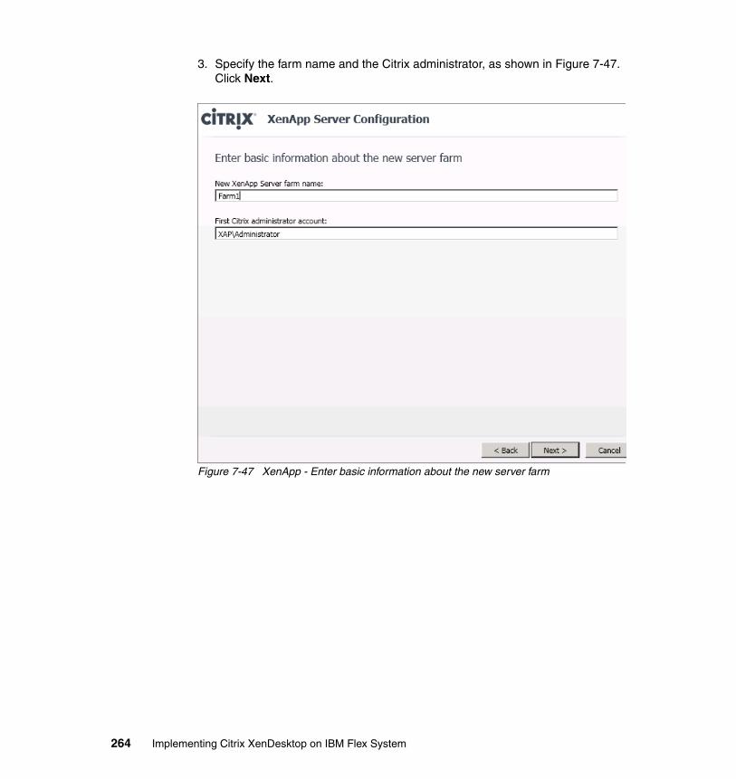
3. Specify the farm name and the Citrix administrator, as shown in Figure 7-47. Click Next.
Figure 7-47 XenApp - Enter basic information about the new server farm
264 Implementing Citrix XenDesktop on IBM Flex System
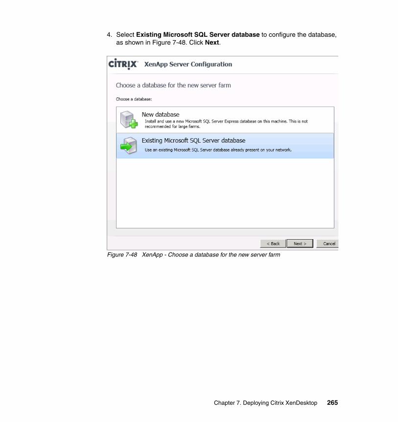
4. Select Existing Microsoft SQL Server database to configure the database, as shown in Figure 7-48. Click Next.
Figure 7-48 XenApp - Choose a database for the new server farm
Chapter 7. Deploying Citrix XenDesktop 265

5. Specify the server name, database name, and authentication model, as shown in Figure 7-49. Click Next.
Figure 7-49 XenApp - Database connection information
266 Implementing Citrix XenDesktop on IBM Flex System
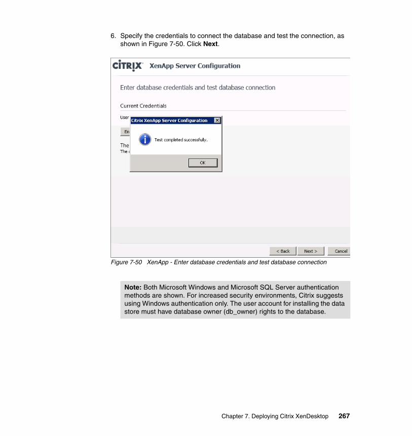
6. Specify the credentials to connect the database and test the connection, as shown in Figure 7-50. Click Next.
Figure 7-50 XenApp - Enter database credentials and test database connection
Note: Both Microsoft Windows and Microsoft SQL Server authentication methods are shown. For increased security environments, Citrix suggests using Windows authentication only. The user account for installing the data store must have database owner (db_owner) rights to the database.
Chapter 7. Deploying Citrix XenDesktop 267
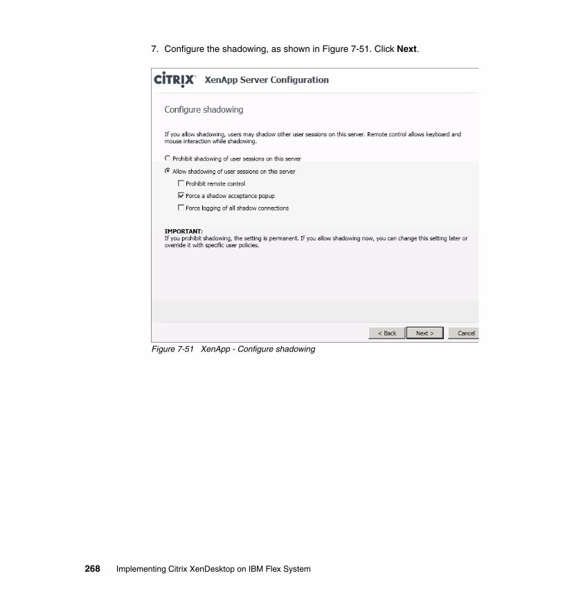
7. Configure the shadowing, as shown in Figure 7-51. Click Next.
Figure 7-51 XenApp - Configure shadowing
268 Implementing Citrix XenDesktop on IBM Flex System
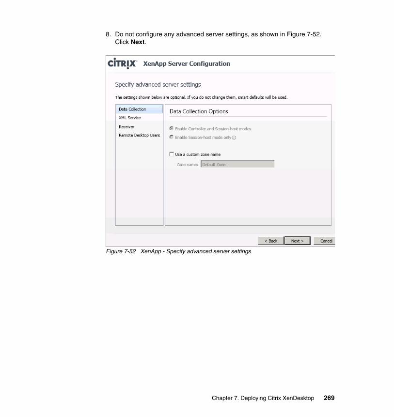
8. Do not configure any advanced server settings, as shown in Figure 7-52. Click Next.
Figure 7-52 XenApp - Specify advanced server settings
Chapter 7. Deploying Citrix XenDesktop 269
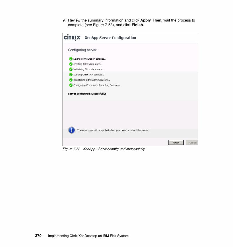
9. Review the summary information and click Apply. Then, wait the process to complete (see Figure 7-53), and click Finish.
Figure 7-53 XenApp - Server configured successfully
270 Implementing Citrix XenDesktop on IBM Flex System
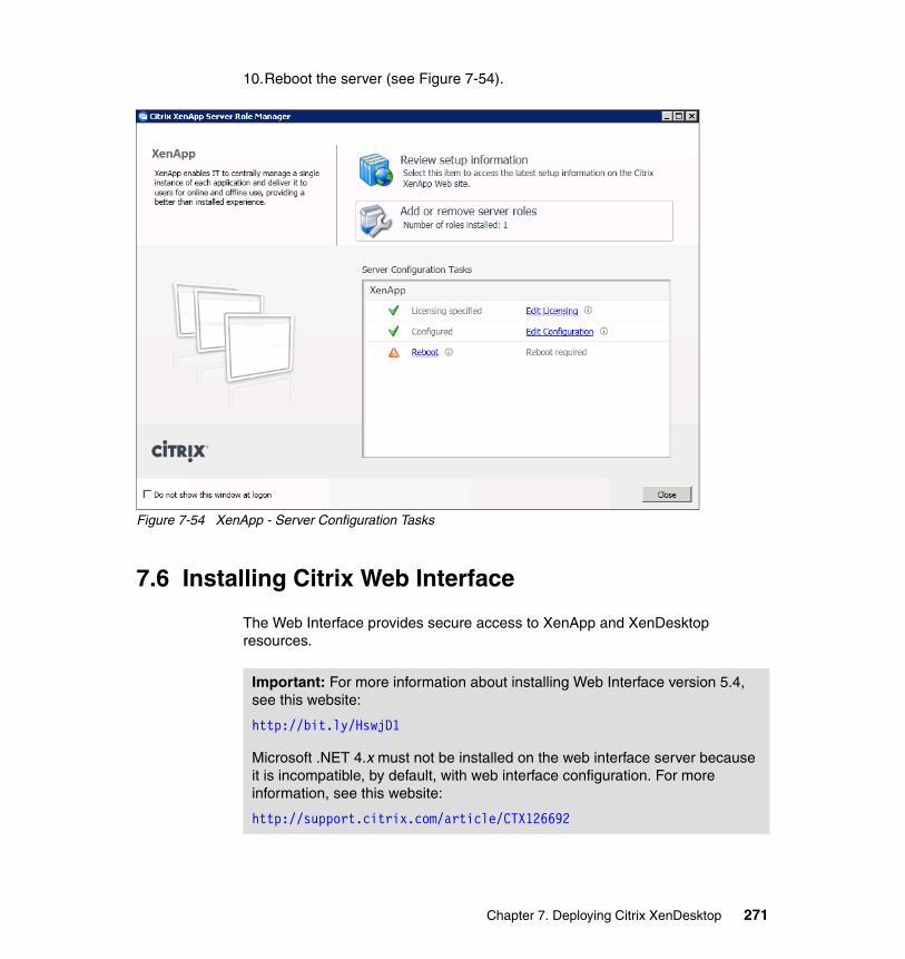
10.Reboot the server (see Figure 7-54).
Figure 7-54 XenApp - Server Configuration Tasks
7.6 Installing Citrix Web Interface
The Web Interface provides secure access to XenApp and XenDesktop resources.
Important: For more information about installing Web Interface version 5.4, see this website:
http://bit.ly/HswjD1
Microsoft .NET 4.x must not be installed on the web interface server because it is incompatible, by default, with web interface configuration. For more information, see this website:
http://support.citrix.com/article/CTX126692
Chapter 7. Deploying Citrix XenDesktop 271
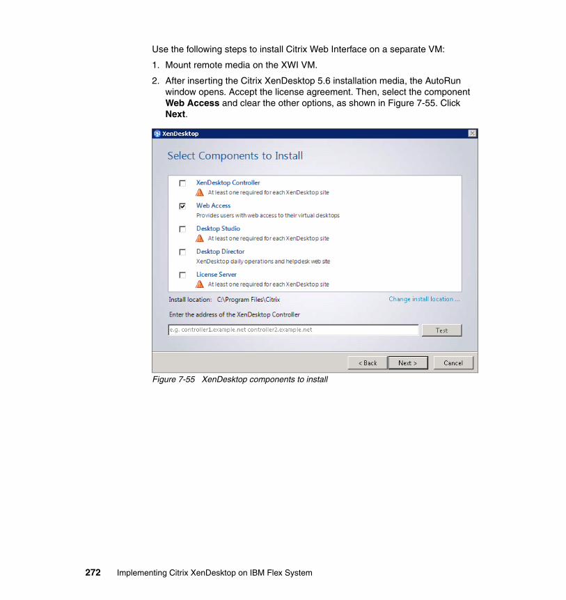
Use the following steps to install Citrix Web Interface on a separate VM:
1. Mount remote media on the XWI VM.
2. After inserting the Citrix XenDesktop 5.6 installation media, the AutoRun window opens. Accept the license agreement. Then, select the component Web Access and clear the other options, as shown in Figure 7-55. Click Next.
Figure 7-55 XenDesktop components to install
272 Implementing Citrix XenDesktop on IBM Flex System
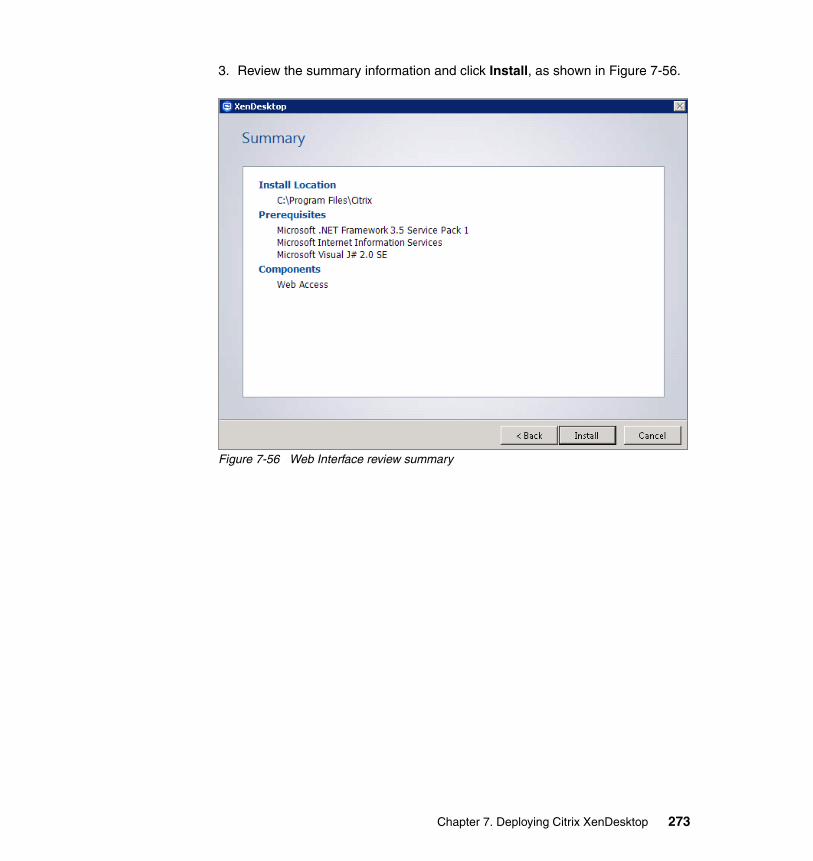
3. Review the summary information and click Install, as shown in Figure 7-56.
Figure 7-56 Web Interface review summary
Chapter 7. Deploying Citrix XenDesktop 273
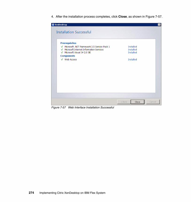
4. After the installation process completes, click Close, as shown in Figure 7-57.
Figure 7-57 Web Interface Installation Successful
274 Implementing Citrix XenDesktop on IBM Flex System
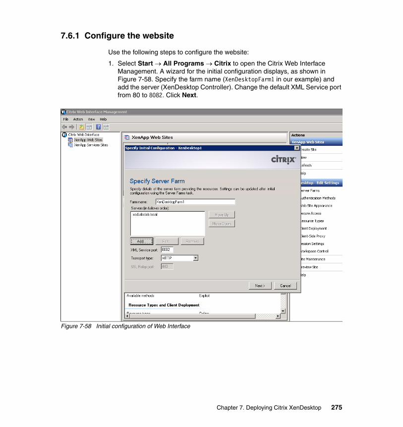
7.6.1 Configure the website
Use the following steps to configure the website:
1. Select Start All Programs Citrix to open the Citrix Web Interface Management. A wizard for the initial configuration displays, as shown in Figure 7-58. Specify the farm name (XenDesktopFarm1 in our example) and add the server (XenDesktop Controller). Change the default XML Service port from 80 to 8082. Click Next.
Figure 7-58 Initial configuration of Web Interface
Chapter 7. Deploying Citrix XenDesktop 275
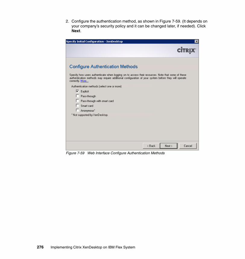
2. Configure the authentication method, as shown in Figure 7-59. (It depends on your company’s security policy and it can be changed later, if needed). Click Next.
Figure 7-59 Web Interface Configure Authentication Methods
276 Implementing Citrix XenDesktop on IBM Flex System
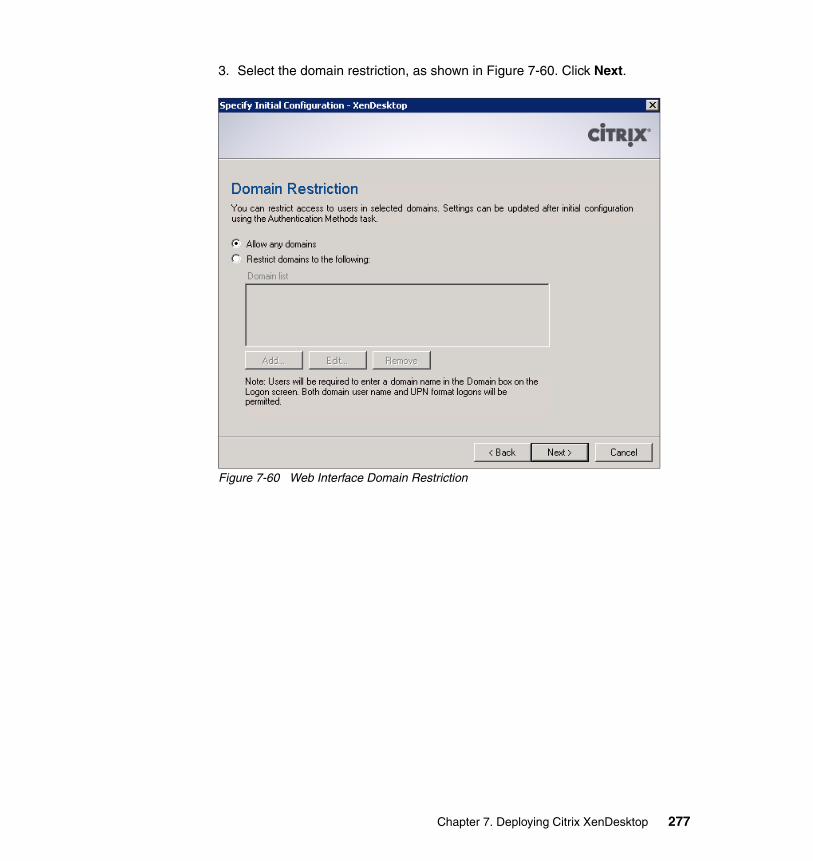
3. Select the domain restriction, as shown in Figure 7-60. Click Next.
Figure 7-60 Web Interface Domain Restriction
Chapter 7. Deploying Citrix XenDesktop 277
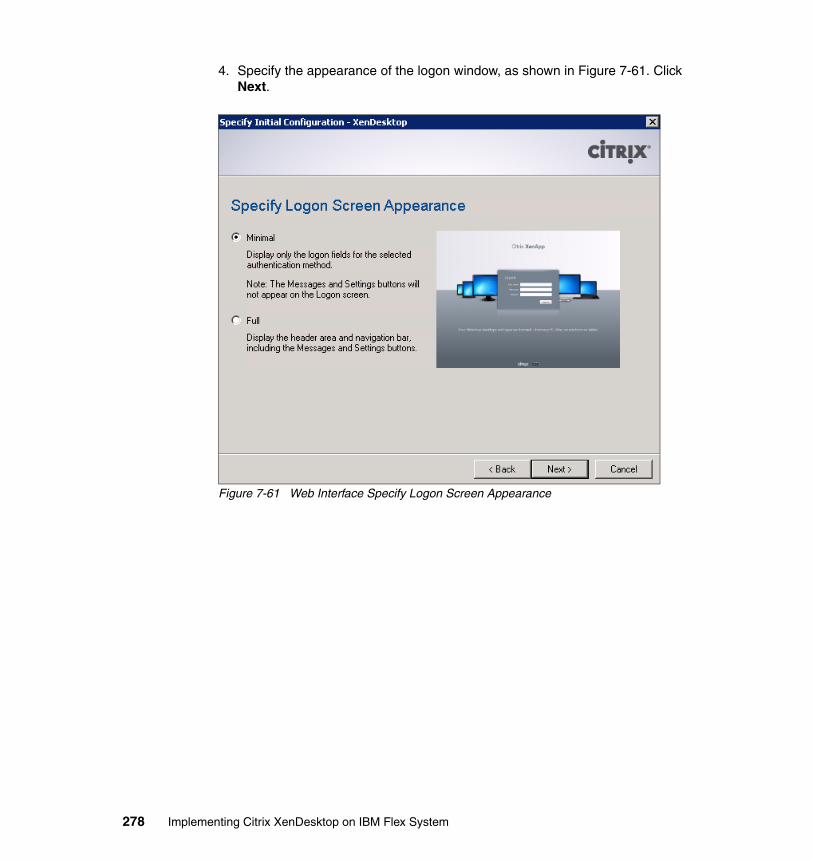
4. Specify the appearance of the logon window, as shown in Figure 7-61. Click Next.
Figure 7-61 Web Interface Specify Logon Screen Appearance
278 Implementing Citrix XenDesktop on IBM Flex System
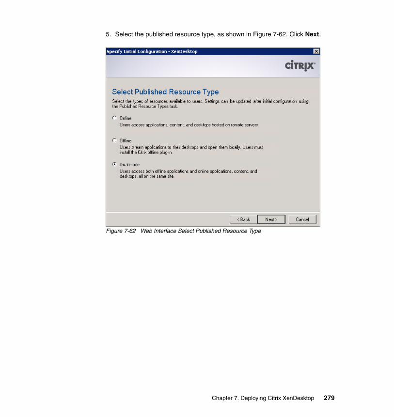
5. Select the published resource type, as shown in Figure 7-62. Click Next.
Figure 7-62 Web Interface Select Published Resource Type
Chapter 7. Deploying Citrix XenDesktop 279
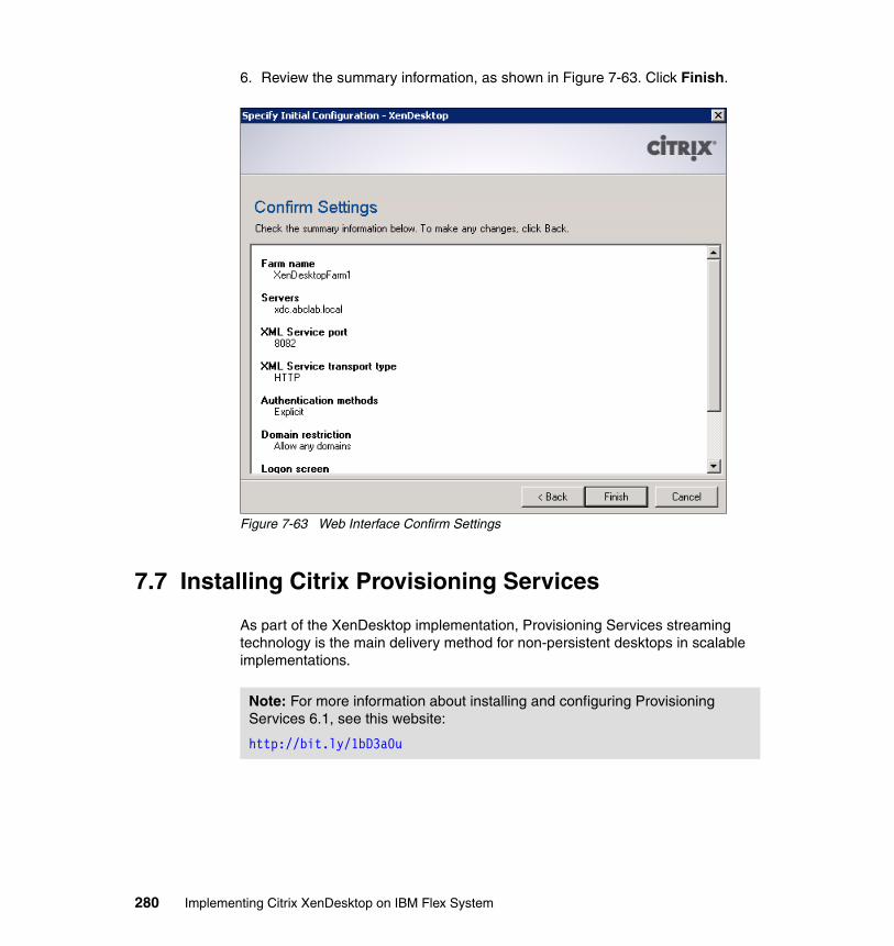
6. Review the summary information, as shown in Figure 7-63. Click Finish.
Figure 7-63 Web Interface Confirm Settings
7.7 Installing Citrix Provisioning Services
As part of the XenDesktop implementation, Provisioning Services streaming technology is the main delivery method for non-persistent desktops in scalable implementations.
Note: For more information about installing and configuring Provisioning Services 6.1, see this website:
http://bit.ly/1bD3a0u
280 Implementing Citrix XenDesktop on IBM Flex System
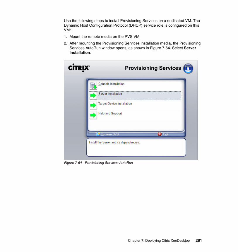
Use the following steps to install Provisioning Services on a dedicated VM. The Dynamic Host Configuration Protocol (DHCP) service role is configured on this VM:
1. Mount the remote media on the PVS VM.
2. After mounting the Provisioning Services installation media, the Provisioning Services AutoRun window opens, as shown in Figure 7-64. Select Server Installation.
Figure 7-64 Provisioning Services AutoRun
Chapter 7. Deploying Citrix XenDesktop 281
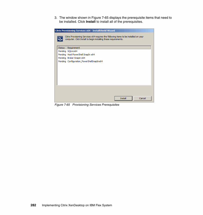
3. The window shown in Figure 7-65 displays the prerequisite items that need to be installed. Click Install to install all of the prerequisites.
Figure 7-65 Provisioning Services Prerequisites
282 Implementing Citrix XenDesktop on IBM Flex System
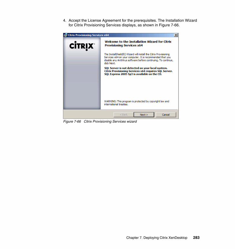
4. Accept the License Agreement for the prerequisites. The Installation Wizard for Citrix Provisioning Services displays, as shown in Figure 7-66.
Figure 7-66 Citrix Provisioning Services wizard
Chapter 7. Deploying Citrix XenDesktop 283
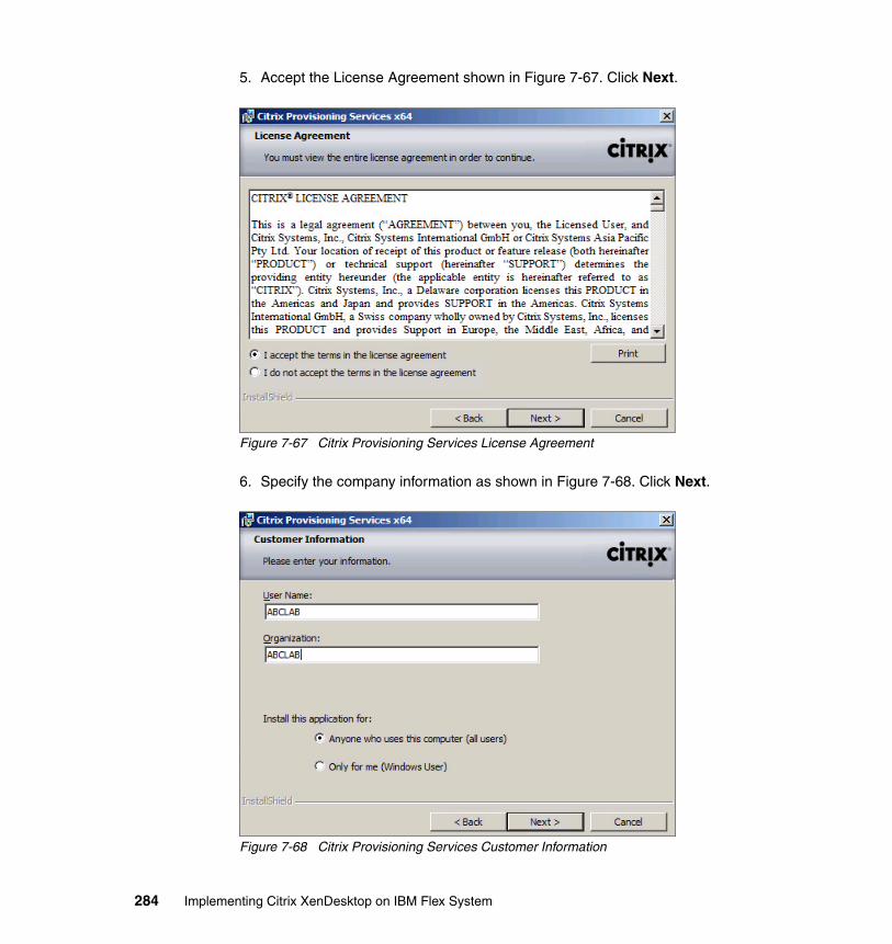
5. Accept the License Agreement shown in Figure 7-67. Click Next.
Figure 7-67 Citrix Provisioning Services License Agreement
6. Specify the company information as shown in Figure 7-68. Click Next.
Figure 7-68 Citrix Provisioning Services Customer Information
284 Implementing Citrix XenDesktop on IBM Flex System
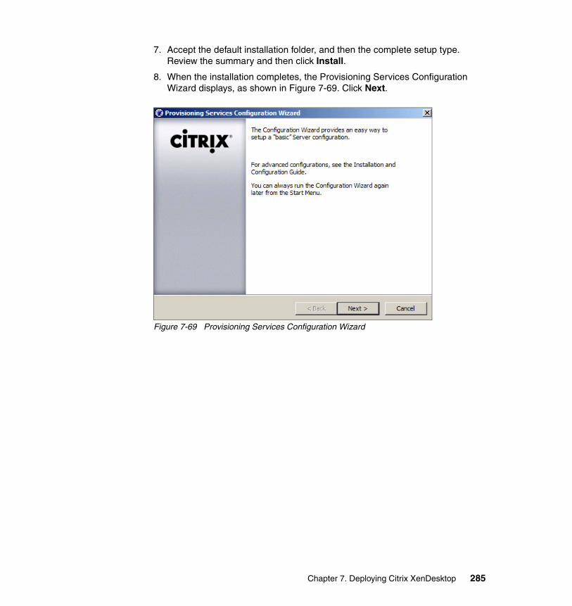
7. Accept the default installation folder, and then the complete setup type. Review the summary and then click Install.
8. When the installation completes, the Provisioning Services Configuration Wizard displays, as shown in Figure 7-69. Click Next.
Figure 7-69 Provisioning Services Configuration Wizard
Chapter 7. Deploying Citrix XenDesktop 285
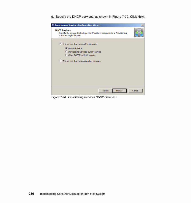
9. Specify the DHCP services, as shown in Figure 7-70. Click Next.
Figure 7-70 Provisioning Services DHCP Services
286 Implementing Citrix XenDesktop on IBM Flex System
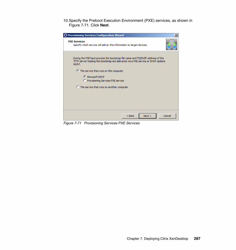
10.Specify the Preboot Execution Environment (PXE) services, as shown in Figure 7-71. Click Next.
Figure 7-71 Provisioning Services PXE Services
Chapter 7. Deploying Citrix XenDesktop 287
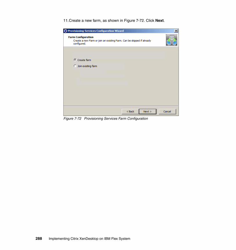
11.Create a new farm, as shown in Figure 7-72. Click Next.
Figure 7-72 Provisioning Services Farm Configuration
288 Implementing Citrix XenDesktop on IBM Flex System
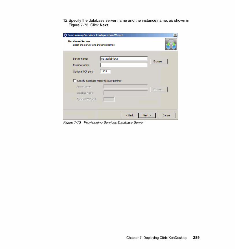
12.Specify the database server name and the instance name, as shown in Figure 7-73. Click Next.
Figure 7-73 Provisioning Services Database Server
Chapter 7. Deploying Citrix XenDesktop 289
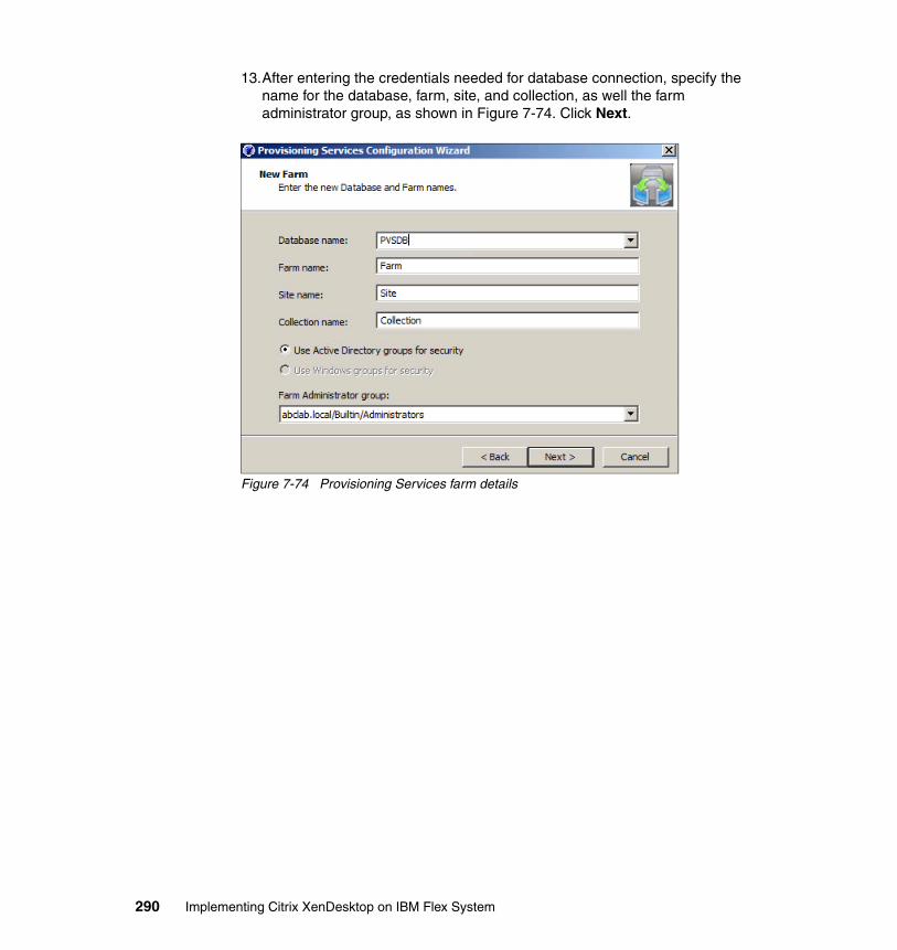
13.After entering the credentials needed for database connection, specify the name for the database, farm, site, and collection, as well the farm administrator group, as shown in Figure 7-74. Click Next.
Figure 7-74 Provisioning Services farm details
290 Implementing Citrix XenDesktop on IBM Flex System
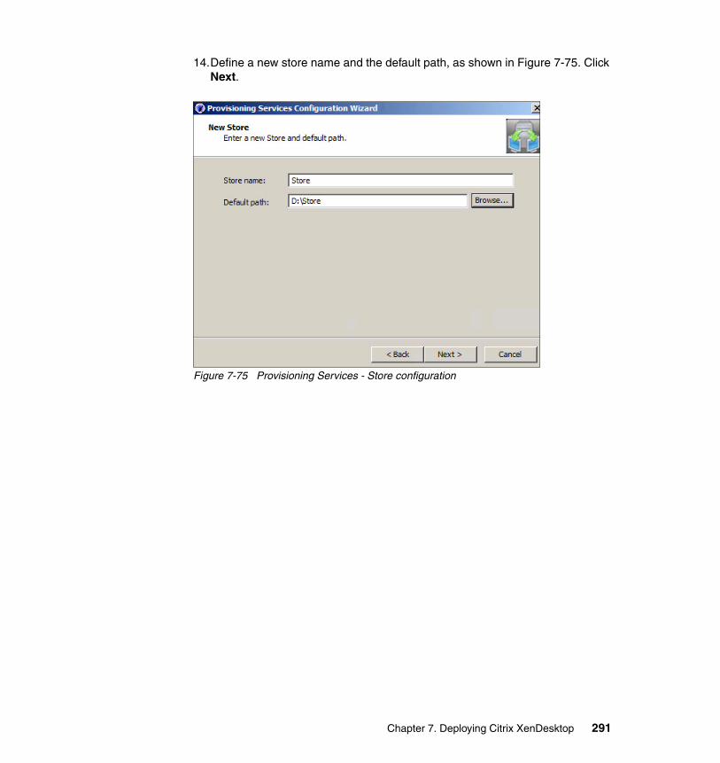
14.Define a new store name and the default path, as shown in Figure 7-75. Click Next.
Figure 7-75 Provisioning Services - Store configuration
Chapter 7. Deploying Citrix XenDesktop 291
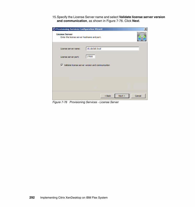
15.Specify the License Server name and select Validate license server version and communication, as shown in Figure 7-76. Click Next.
Figure 7-76 Provisioning Services - License Server
292 Implementing Citrix XenDesktop on IBM Flex System
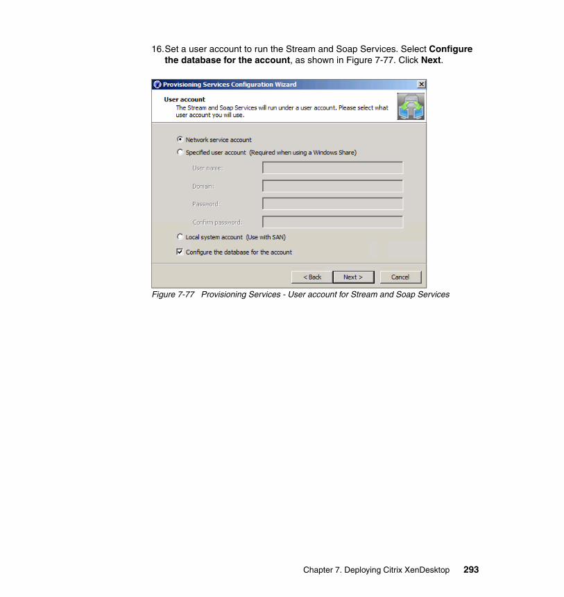
16.Set a user account to run the Stream and Soap Services. Select Configure the database for the account, as shown in Figure 7-77. Click Next.
Figure 7-77 Provisioning Services - User account for Stream and Soap Services
Chapter 7. Deploying Citrix XenDesktop 293
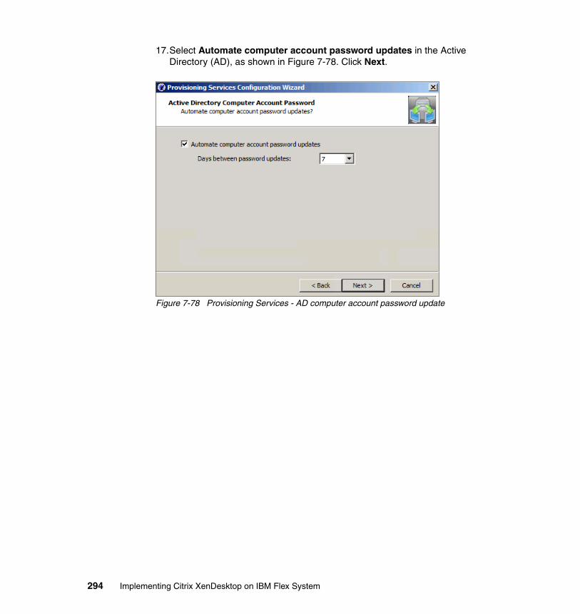
17.Select Automate computer account password updates in the Active Directory (AD), as shown in Figure 7-78. Click Next.
Figure 7-78 Provisioning Services - AD computer account password update
294 Implementing Citrix XenDesktop on IBM Flex System
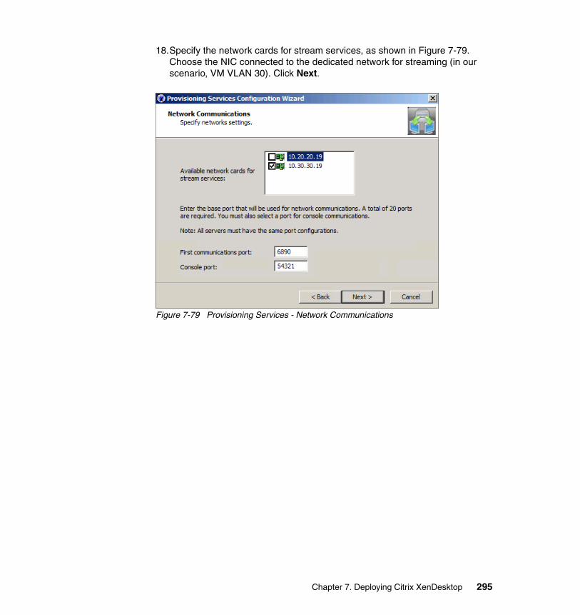
18.Specify the network cards for stream services, as shown in Figure 7-79. Choose the NIC connected to the dedicated network for streaming (in our scenario, VM VLAN 30). Click Next.
Figure 7-79 Provisioning Services - Network Communications
Chapter 7. Deploying Citrix XenDesktop 295
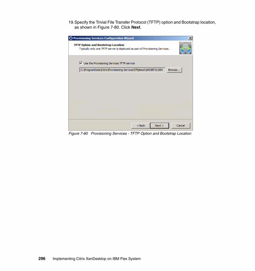
19.Specify the Trivial File Transfer Protocol (TFTP) option and Bootstrap location, as shown in Figure 7-80. Click Next.
Figure 7-80 Provisioning Services - TFTP Option and Bootstrap Location
296 Implementing Citrix XenDesktop on IBM Flex System
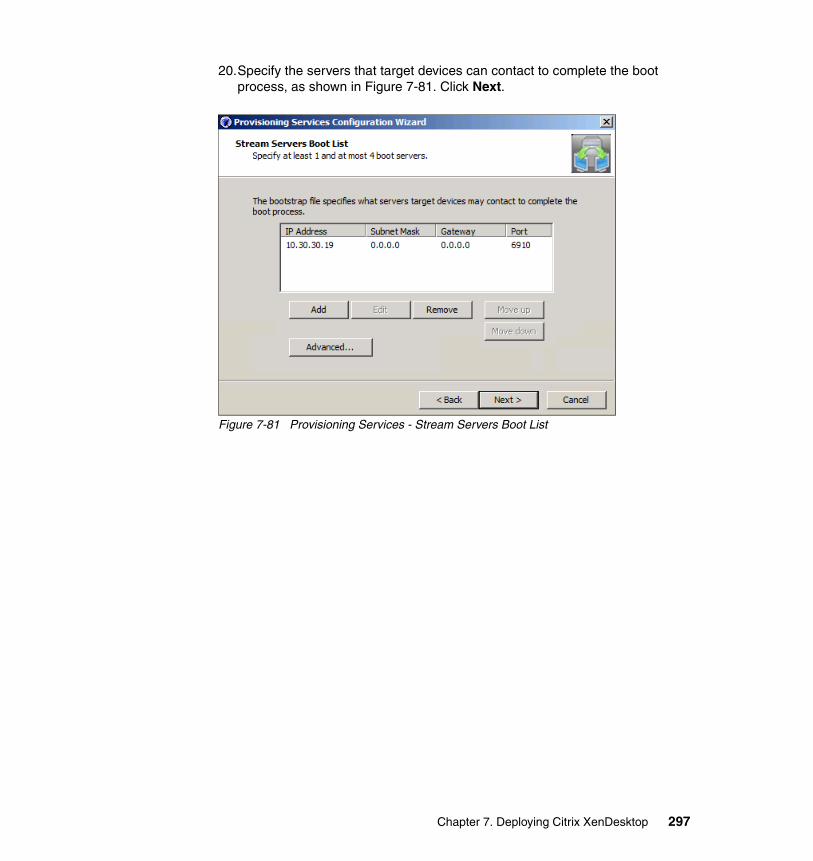
20.Specify the servers that target devices can contact to complete the boot process, as shown in Figure 7-81. Click Next.
Figure 7-81 Provisioning Services - Stream Servers Boot List
Chapter 7. Deploying Citrix XenDesktop 297
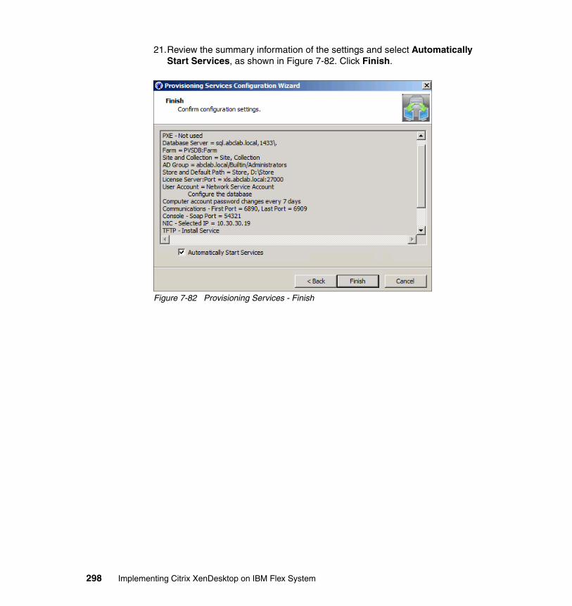
21.Review the summary information of the settings and select Automatically Start Services, as shown in Figure 7-82. Click Finish.
Figure 7-82 Provisioning Services - Finish
298 Implementing Citrix XenDesktop on IBM Flex System
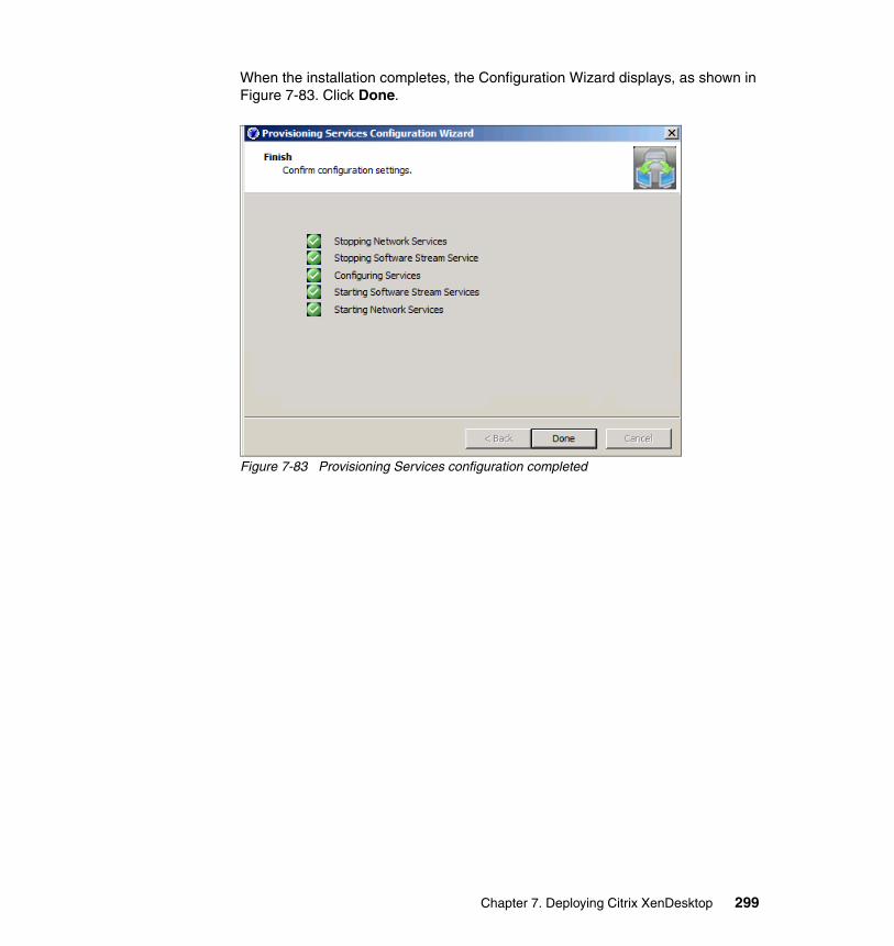
When the installation completes, the Configuration Wizard displays, as shown in Figure 7-83. Click Done.
Figure 7-83 Provisioning Services configuration completed
Chapter 7. Deploying Citrix XenDesktop 299
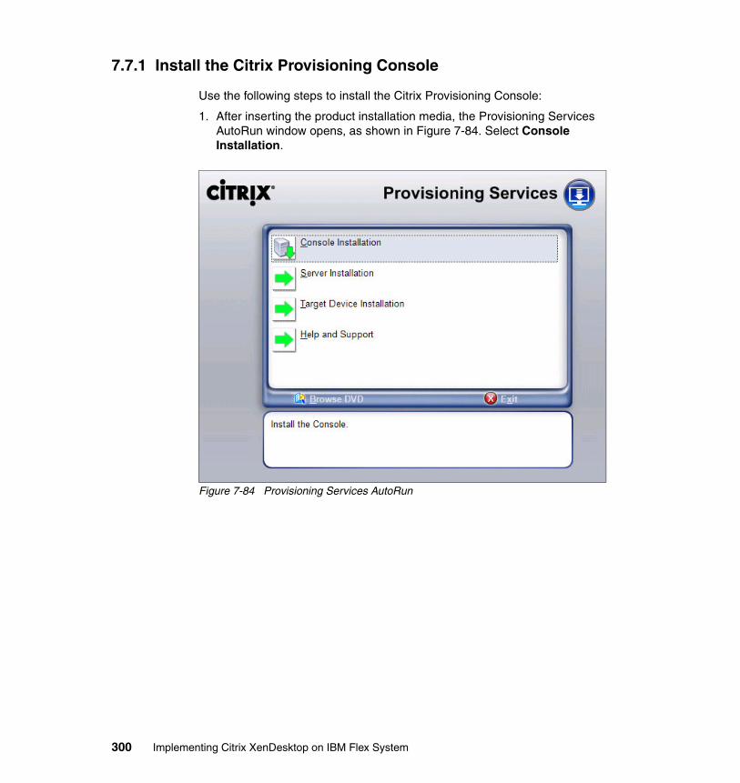
7.7.1 Install the Citrix Provisioning Console
Use the following steps to install the Citrix Provisioning Console:
1. After inserting the product installation media, the Provisioning Services AutoRun window opens, as shown in Figure 7-84. Select Console Installation.
Figure 7-84 Provisioning Services AutoRun
300 Implementing Citrix XenDesktop on IBM Flex System
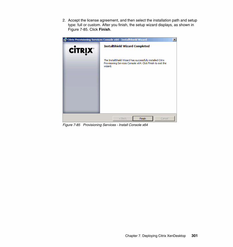
2. Accept the license agreement, and then select the installation path and setup type: full or custom. After you finish, the setup wizard displays, as shown in Figure 7-85. Click Finish.
Figure 7-85 Provisioning Services - Install Console x64
Chapter 7. Deploying Citrix XenDesktop 301
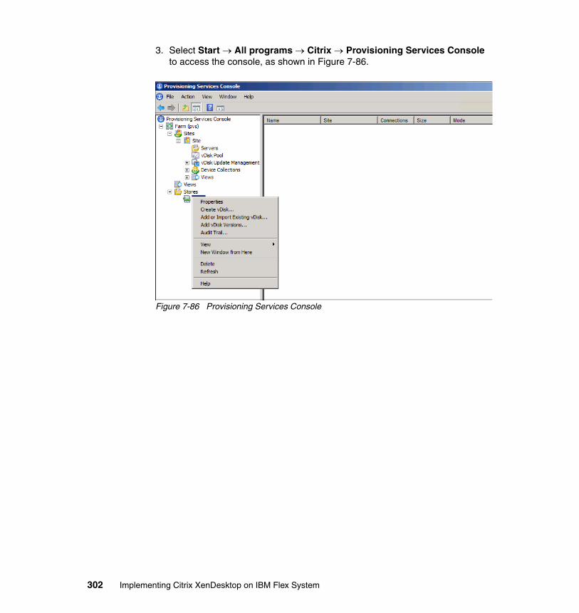
3. Select Start All programs Citrix Provisioning Services Console to access the console, as shown in Figure 7-86.
Figure 7-86 Provisioning Services Console
302 Implementing Citrix XenDesktop on IBM Flex System
Chapter 8. Operating Citrix XenDesktop
This chapter describes the steps to prepare your virtual desktop infrastructure (VDI) environment to deliver desktops to your users.
This chapter contains the following topics:
� 8.1, “Introduction” on page 304� 8.2, “Configuring the gold image” on page 304� 8.3, “Configuring desktop distribution” on page 336� 8.4, “Roaming profiles and folder redirection” on page 377� 8.5, “Monitoring health” on page 398
8
© Copyright IBM Corp. 2014. All rights reserved. 303

8.1 Introduction
The VDI operations consist of the initial desktop installation and configuration in accordance with your company’s business requirements and security policies.
This chapter describes how to prepare the desktop image (gold image) to be integrated with Provisioning Services and the XenDesktop Controller to be published to users.
This chapter also covers the user data that describes the profile and folder redirection and the integration with XenApp infrastructure to provide the business applications to desktops.
8.2 Configuring the gold image
The concept of the gold image means the initial installation of a virtual desktop that contains all of the customizations to meet your company’s directives and requirements.
One of the benefits of using a gold image installation is the reduction of administrative effort. As the VDI administrator, you perform the security and business applications’ update at the gold image and then you schedule when this new version will be available to your users.
The desktops that you will deliver by using the Citrix XenDesktop infrastructure will be a derivative of this gold image.
The following sections describe how to prepare the gold image and integrate it with your XenDesktop infrastructure.
8.2.1 Preparing the gold image for streaming services
The gold image preparation consists of installing your client operating system using a virtual machine (VM) and all of the other required components before integrating with the Citrix infrastructure.
Note: This procedure does not cover the installation of the operating system. It is assumed that you already have the operating system installed and the VM sizing (processor and memory) configured.
304 Implementing Citrix XenDesktop on IBM Flex System

Integrating the gold image with the Citrix Infrastructure consists of the following main steps:
1. Include an additional hard disk to your VM to store the write cache file (used for streaming desktops). Make the following configuration changes to this disk:
– Create a new partition and format the new disk by using the New Technology File System (NTFS).
– Assign the letter D: for this new disk.
– Move the pagefile location from C: to the new disk (D).
2. Install the Citrix Profile Manager
The Citrix Profile Manager is responsible for managing the user profile by loading the files when the user logs on to the desktop and saving the files when the user logs off from the desktop.
The product offers two methods to set the parameters:
– By using the .INI file that is stored on the installation folder
– Through Group Policies that are created at the Active Directory (AD) level
In this scenario, we use the Group Policy to create the configuration and to apply it to the desktops.
The version of Citrix Profile Manager that is used in the landscape is 4.1.2 and the parameters that we used to install were not changed from the default options suggested by the installer. For more information about the configuration, see 8.4, “Roaming profiles and folder redirection” on page 377.
3. Install the Virtual Desktop Agent
The Virtual Desktop Agent is responsible for registering the provisioned desktop in XenDesktop Controller after the startup. After this registration process, the XenDesktop Controller acts as a broker to deliver the desktops to the users. In this scenario, we chose to install the Virtual Desktop by running AutoRun.exe, which is located on the Citrix XenDesktop media.
Chapter 8. Operating Citrix XenDesktop 305
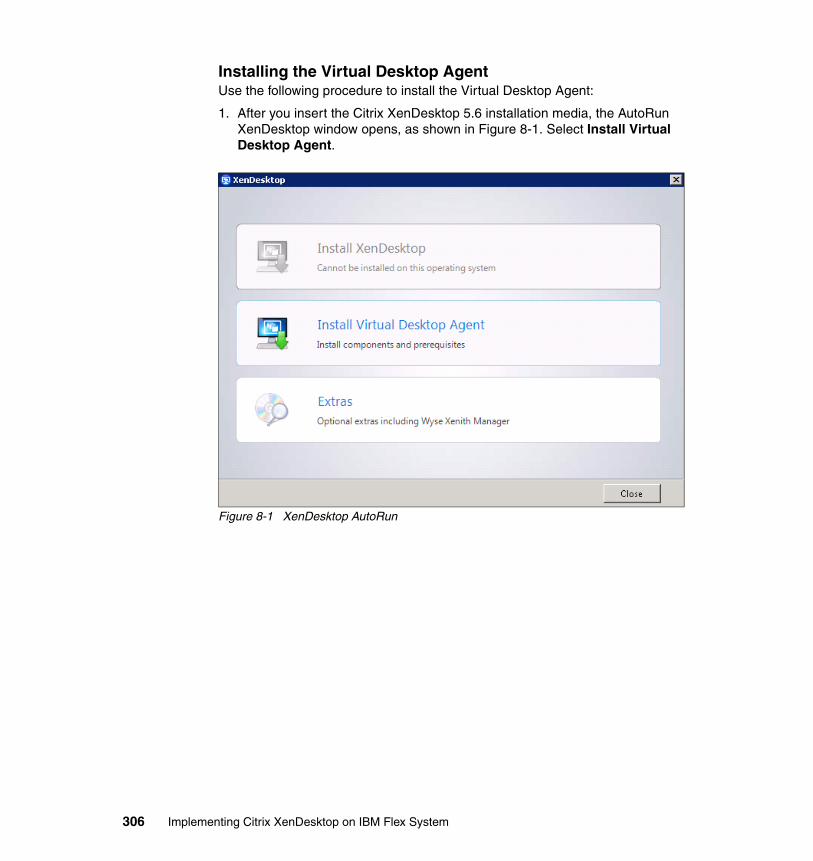
Installing the Virtual Desktop AgentUse the following procedure to install the Virtual Desktop Agent:
1. After you insert the Citrix XenDesktop 5.6 installation media, the AutoRun XenDesktop window opens, as shown in Figure 8-1. Select Install Virtual Desktop Agent.
Figure 8-1 XenDesktop AutoRun
306 Implementing Citrix XenDesktop on IBM Flex System
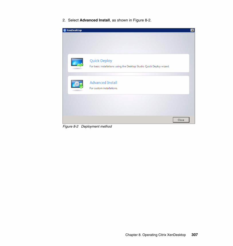
2. Select Advanced Install, as shown in Figure 8-2.
Figure 8-2 Deployment method
Chapter 8. Operating Citrix XenDesktop 307
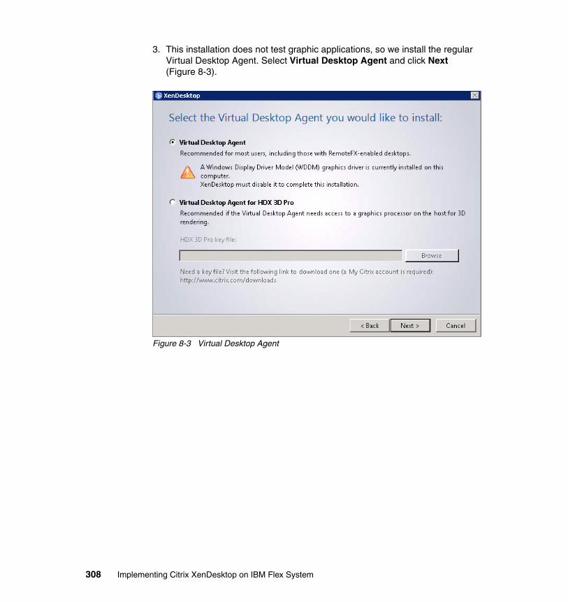
3. This installation does not test graphic applications, so we install the regular Virtual Desktop Agent. Select Virtual Desktop Agent and click Next (Figure 8-3).
Figure 8-3 Virtual Desktop Agent
308 Implementing Citrix XenDesktop on IBM Flex System
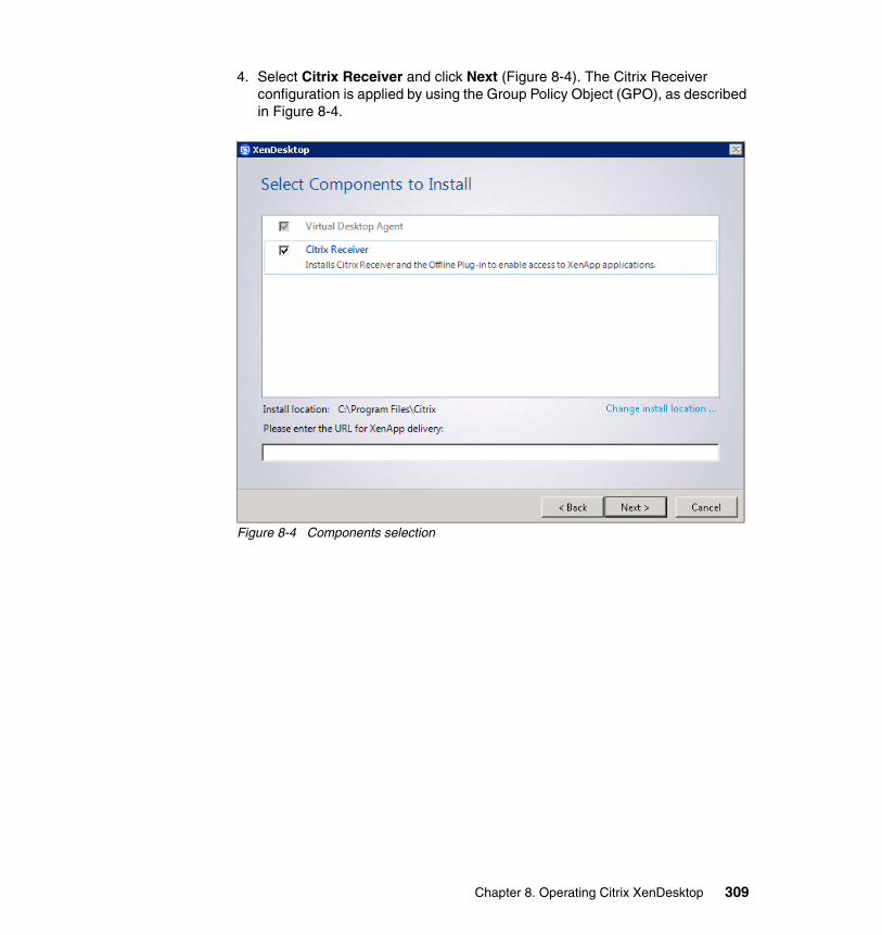
4. Select Citrix Receiver and click Next (Figure 8-4). The Citrix Receiver configuration is applied by using the Group Policy Object (GPO), as described in Figure 8-4.
Figure 8-4 Components selection
Chapter 8. Operating Citrix XenDesktop 309
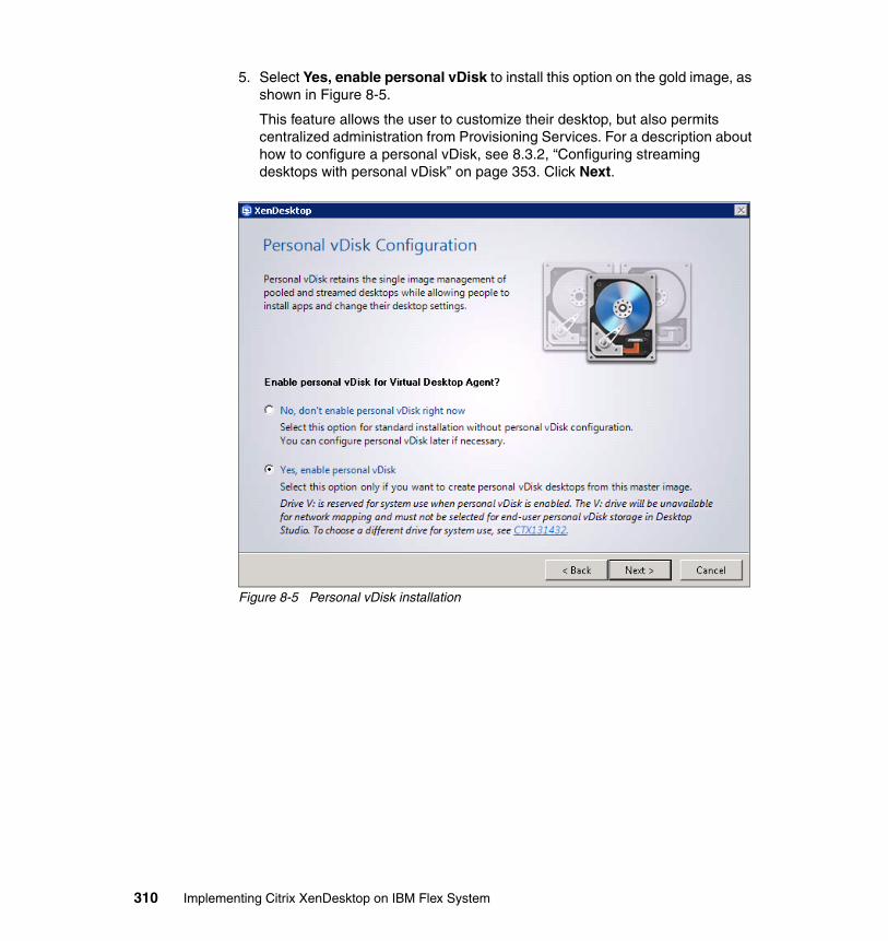
5. Select Yes, enable personal vDisk to install this option on the gold image, as shown in Figure 8-5.
This feature allows the user to customize their desktop, but also permits centralized administration from Provisioning Services. For a description about how to configure a personal vDisk, see 8.3.2, “Configuring streaming desktops with personal vDisk” on page 353. Click Next.
Figure 8-5 Personal vDisk installation
310 Implementing Citrix XenDesktop on IBM Flex System
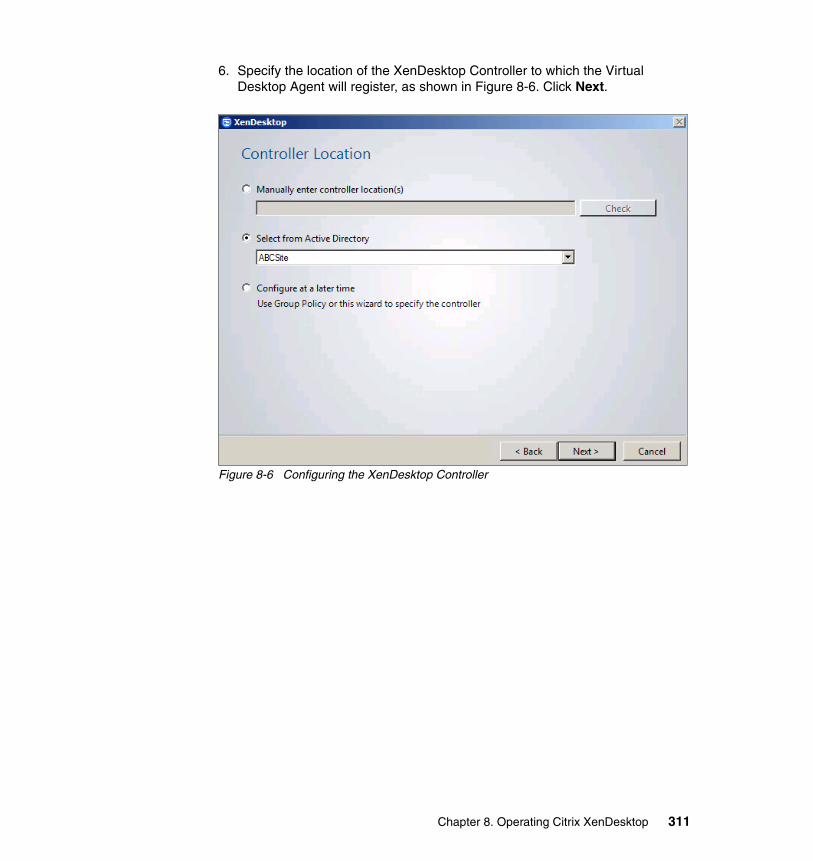
6. Specify the location of the XenDesktop Controller to which the Virtual Desktop Agent will register, as shown in Figure 8-6. Click Next.
Figure 8-6 Configuring the XenDesktop Controller
Chapter 8. Operating Citrix XenDesktop 311
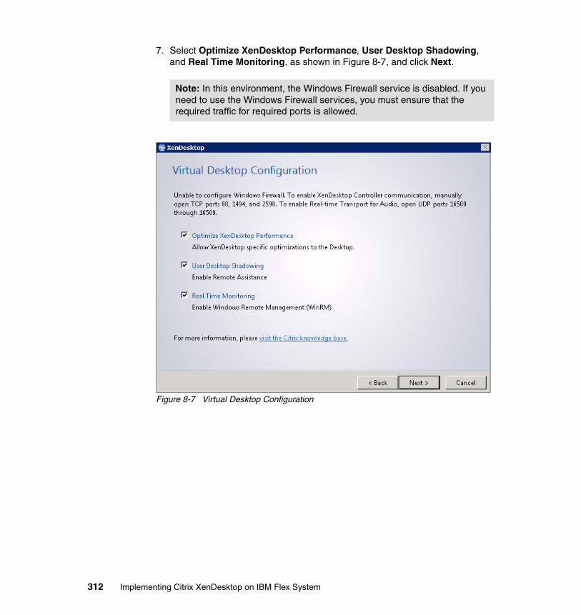
7. Select Optimize XenDesktop Performance, User Desktop Shadowing, and Real Time Monitoring, as shown in Figure 8-7, and click Next.
Figure 8-7 Virtual Desktop Configuration
Note: In this environment, the Windows Firewall service is disabled. If you need to use the Windows Firewall services, you must ensure that the required traffic for required ports is allowed.
312 Implementing Citrix XenDesktop on IBM Flex System
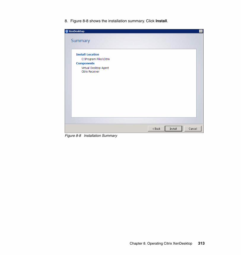
8. Figure 8-8 shows the installation summary. Click Install.
Figure 8-8 Installation Summary
Chapter 8. Operating Citrix XenDesktop 313
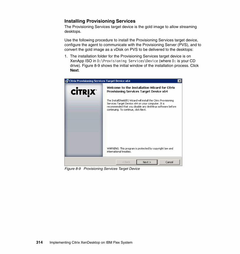
Installing Provisioning ServicesThe Provisioning Services target device is the gold image to allow streaming desktops.
Use the following procedure to install the Provisioning Services target device, configure the agent to communicate with the Provisioning Server (PVS), and to convert the gold image as a vDisk on PVS to be delivered to the desktops:
1. The installation folder for the Provisioning Services target device is on XenApp ISO in D:\Provisioning Services\Device (where D: is your CD drive). Figure 8-9 shows the initial window of the installation process. Click Next.
Figure 8-9 Provisioning Services Target Device
314 Implementing Citrix XenDesktop on IBM Flex System
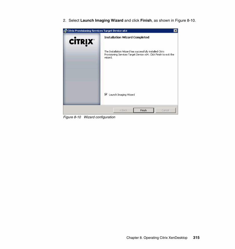
2. Select Launch Imaging Wizard and click Finish, as shown in Figure 8-10.
Figure 8-10 Wizard configuration
Chapter 8. Operating Citrix XenDesktop 315
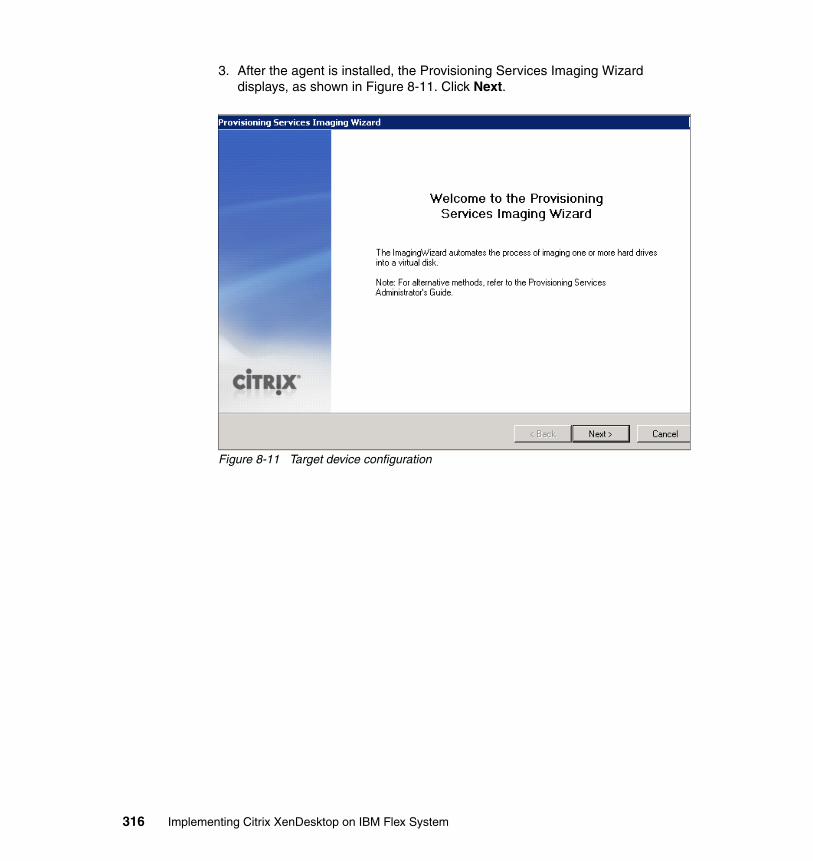
3. After the agent is installed, the Provisioning Services Imaging Wizard displays, as shown in Figure 8-11. Click Next.
Figure 8-11 Target device configuration
316 Implementing Citrix XenDesktop on IBM Flex System
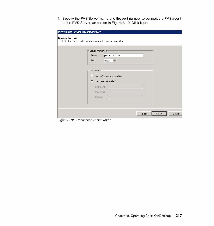
4. Specify the PVS Server name and the port number to connect the PVS agent to the PVS Server, as shown in Figure 8-12. Click Next.
Figure 8-12 Connection configuration
Chapter 8. Operating Citrix XenDesktop 317
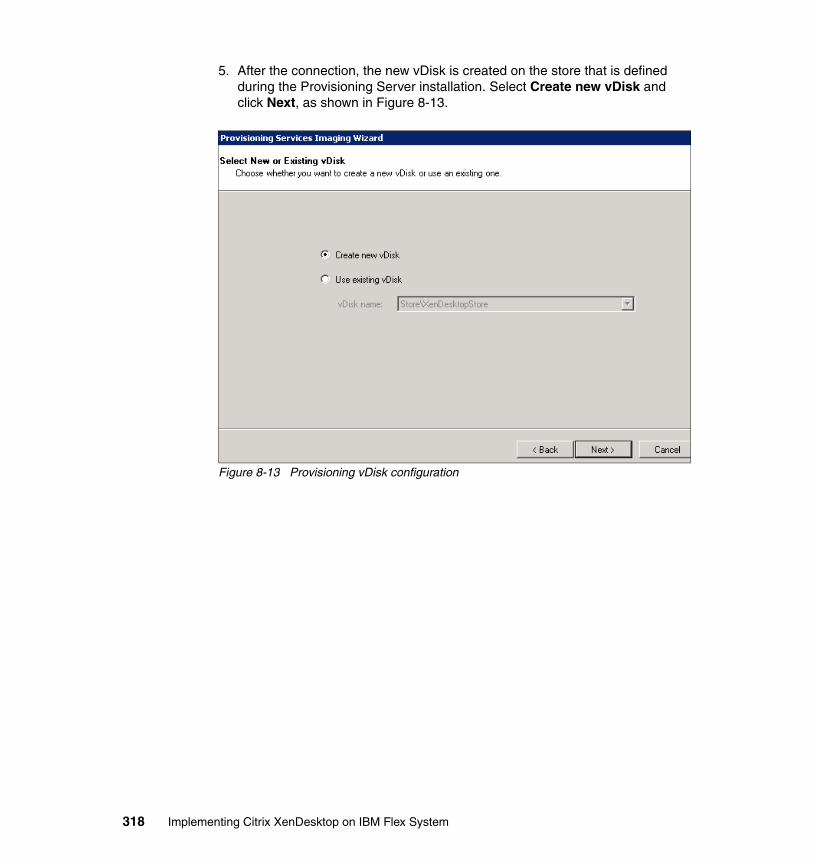
5. After the connection, the new vDisk is created on the store that is defined during the Provisioning Server installation. Select Create new vDisk and click Next, as shown in Figure 8-13.
Figure 8-13 Provisioning vDisk configuration
318 Implementing Citrix XenDesktop on IBM Flex System
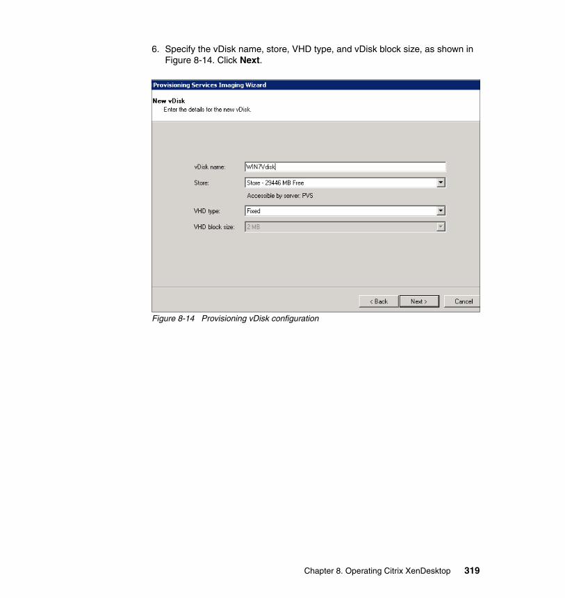
6. Specify the vDisk name, store, VHD type, and vDisk block size, as shown in Figure 8-14. Click Next.
Figure 8-14 Provisioning vDisk configuration
Chapter 8. Operating Citrix XenDesktop 319
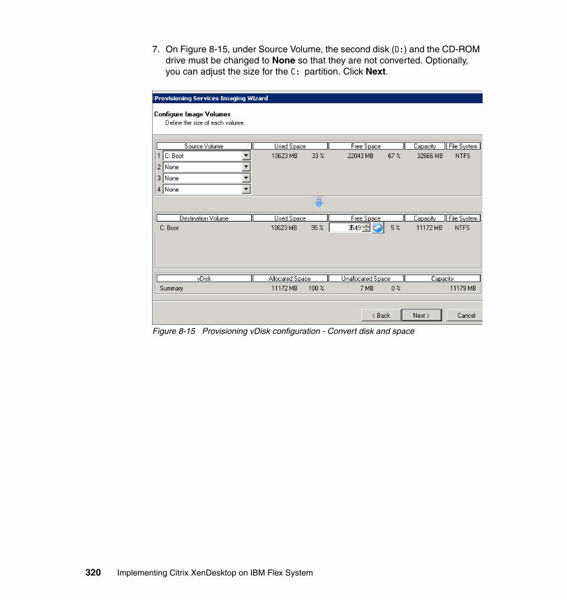
7. On Figure 8-15, under Source Volume, the second disk (D:) and the CD-ROM drive must be changed to None so that they are not converted. Optionally, you can adjust the size for the C: partition. Click Next.
Figure 8-15 Provisioning vDisk configuration - Convert disk and space
320 Implementing Citrix XenDesktop on IBM Flex System
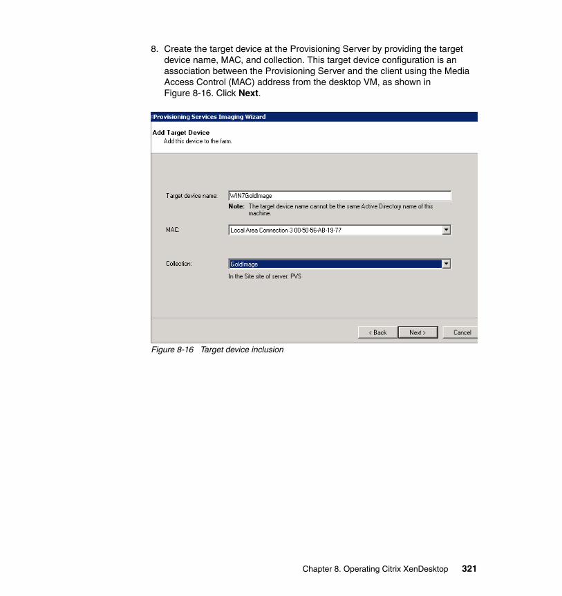
8. Create the target device at the Provisioning Server by providing the target device name, MAC, and collection. This target device configuration is an association between the Provisioning Server and the client using the Media Access Control (MAC) address from the desktop VM, as shown in Figure 8-16. Click Next.
Figure 8-16 Target device inclusion
Chapter 8. Operating Citrix XenDesktop 321
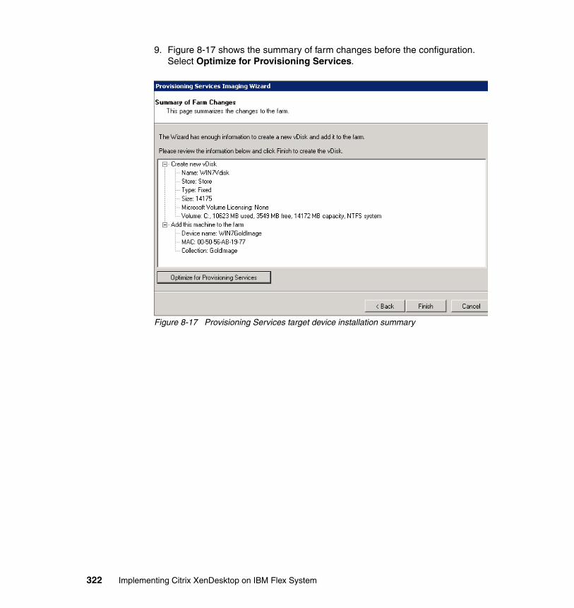
9. Figure 8-17 shows the summary of farm changes before the configuration. Select Optimize for Provisioning Services.
Figure 8-17 Provisioning Services target device installation summary
322 Implementing Citrix XenDesktop on IBM Flex System
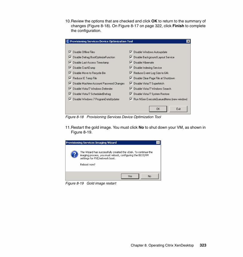
10.Review the options that are checked and click OK to return to the summary of changes (Figure 8-18). On Figure 8-17 on page 322, click Finish to complete the configuration.
Figure 8-18 Provisioning Services Device Optimization Tool
11.Restart the gold image. You must click No to shut down your VM, as shown in Figure 8-19.
Figure 8-19 Gold image restart
Chapter 8. Operating Citrix XenDesktop 323
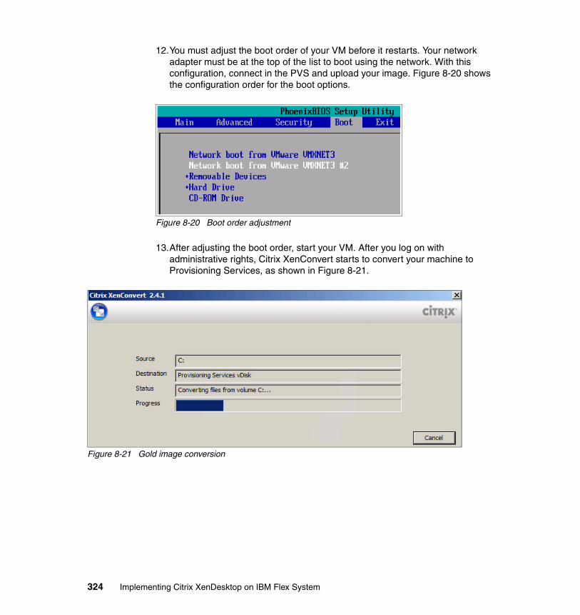
12.You must adjust the boot order of your VM before it restarts. Your network adapter must be at the top of the list to boot using the network. With this configuration, connect in the PVS and upload your image. Figure 8-20 shows the configuration order for the boot options.
Figure 8-20 Boot order adjustment
13.After adjusting the boot order, start your VM. After you log on with administrative rights, Citrix XenConvert starts to convert your machine to Provisioning Services, as shown in Figure 8-21.
Figure 8-21 Gold image conversion
324 Implementing Citrix XenDesktop on IBM Flex System
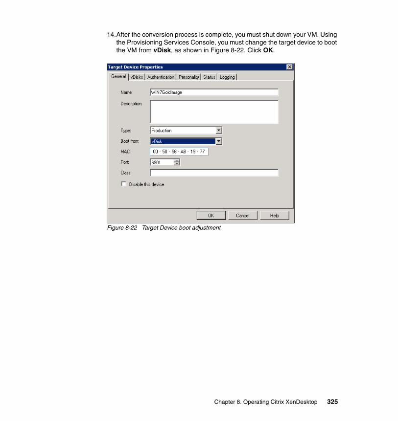
14.After the conversion process is complete, you must shut down your VM. Using the Provisioning Services Console, you must change the target device to boot the VM from vDisk, as shown in Figure 8-22. Click OK.
Figure 8-22 Target Device boot adjustment
Chapter 8. Operating Citrix XenDesktop 325
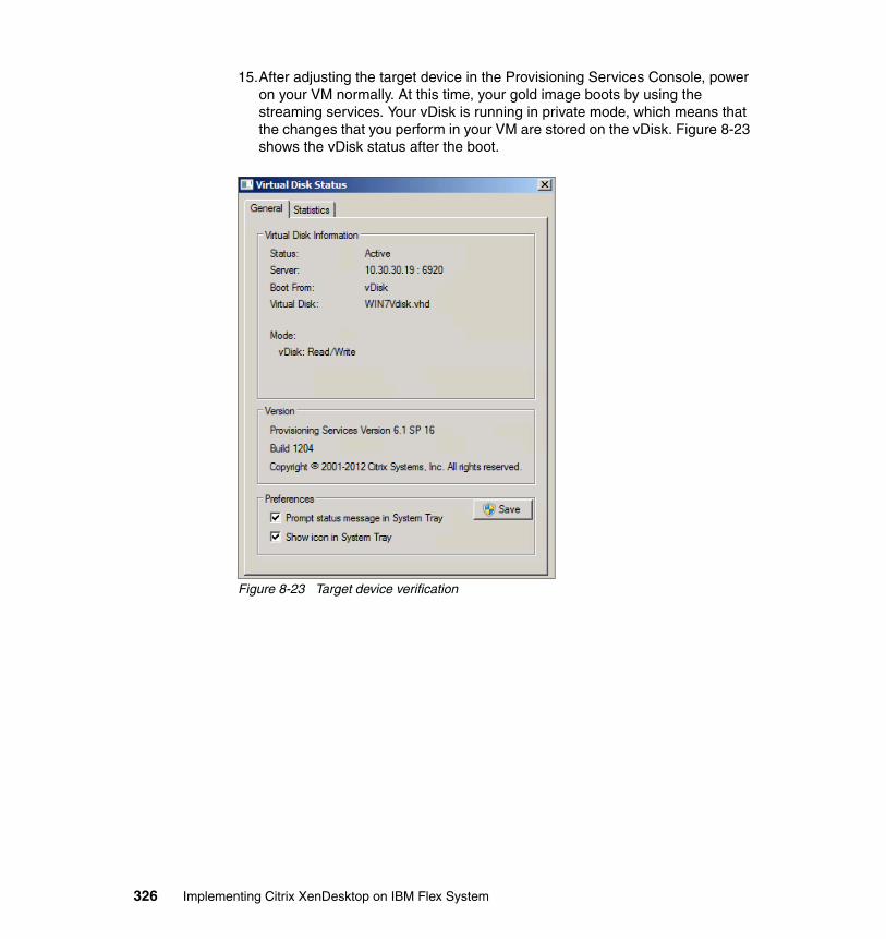
15.After adjusting the target device in the Provisioning Services Console, power on your VM normally. At this time, your gold image boots by using the streaming services. Your vDisk is running in private mode, which means that the changes that you perform in your VM are stored on the vDisk. Figure 8-23 shows the vDisk status after the boot.
Figure 8-23 Target device verification
326 Implementing Citrix XenDesktop on IBM Flex System
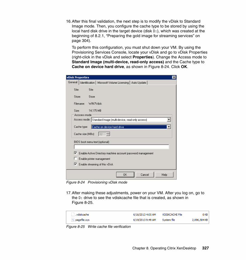
16.After this final validation, the next step is to modify the vDisk to Standard Image mode. Then, you configure the cache type to be stored by using the local hard disk drive in the target device (disk D:), which was created at the beginning of 8.2.1, “Preparing the gold image for streaming services” on page 304).
To perform this configuration, you must shut down your VM. By using the Provisioning Services Console, locate your vDisk and go to vDisk Properties (right-click in the vDisk and select Properties). Change the Access mode to Standard Image (multi-device, read-only access) and the Cache type to Cache on device hard drive, as shown in Figure 8-24. Click OK.
Figure 8-24 Provisioning vDisk mode
17.After making these adjustments, power on your VM. After you log on, go to the D: drive to see the vdiskcache file that is created, as shown in Figure 8-25.
Figure 8-25 Write cache file verification
Chapter 8. Operating Citrix XenDesktop 327
Before you create your new VMs to deliver to the users, you must clone your gold image in a VMware template. For the procedure to create a template, see this website:
http://bit.ly/1atCyR5
Now, you are ready to create your new desktops integrating the XenDesktop and Provisioning Services. The next section shows how to create the desktop catalogs and associate them for your domain users.
8.2.2 Preparing the gold image for persistent desktops
Dedicated desktops are provided directly by XenDesktop Controller integrated with a VMware environment.
The persistent desktop model uses Machine Creation Services instead of Provisioning Services to provision the desktop image. Therefore, you need to create a separate gold image for dedicated desktops.
Note: From this point, any modification that you perform is lost after the VM restarts.
328 Implementing Citrix XenDesktop on IBM Flex System
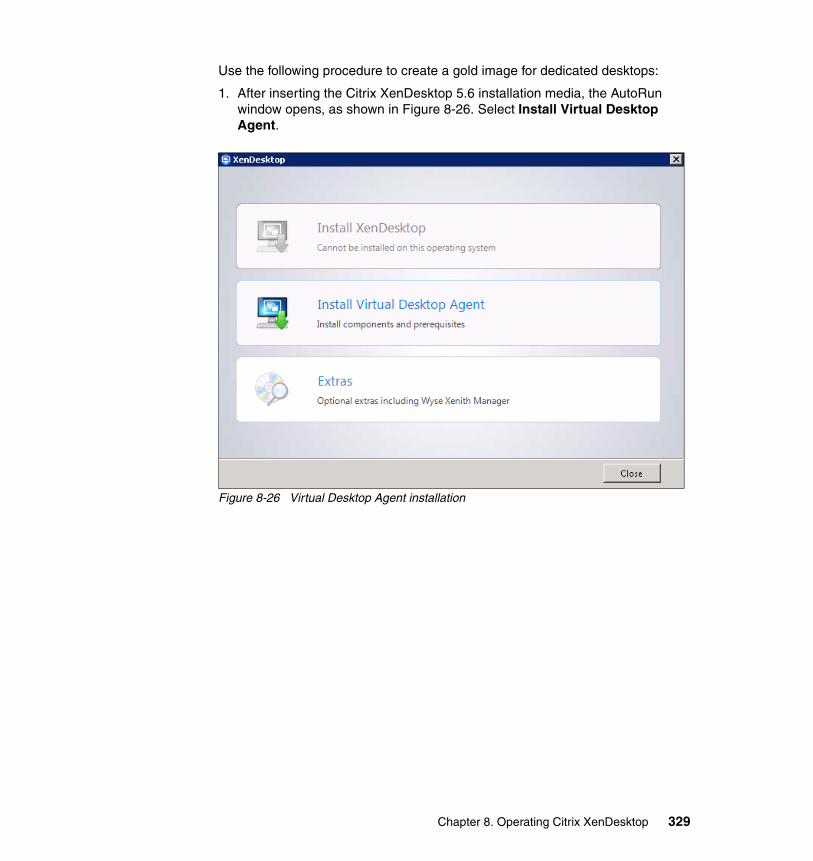
Use the following procedure to create a gold image for dedicated desktops:
1. After inserting the Citrix XenDesktop 5.6 installation media, the AutoRun window opens, as shown in Figure 8-26. Select Install Virtual Desktop Agent.
Figure 8-26 Virtual Desktop Agent installation
Chapter 8. Operating Citrix XenDesktop 329
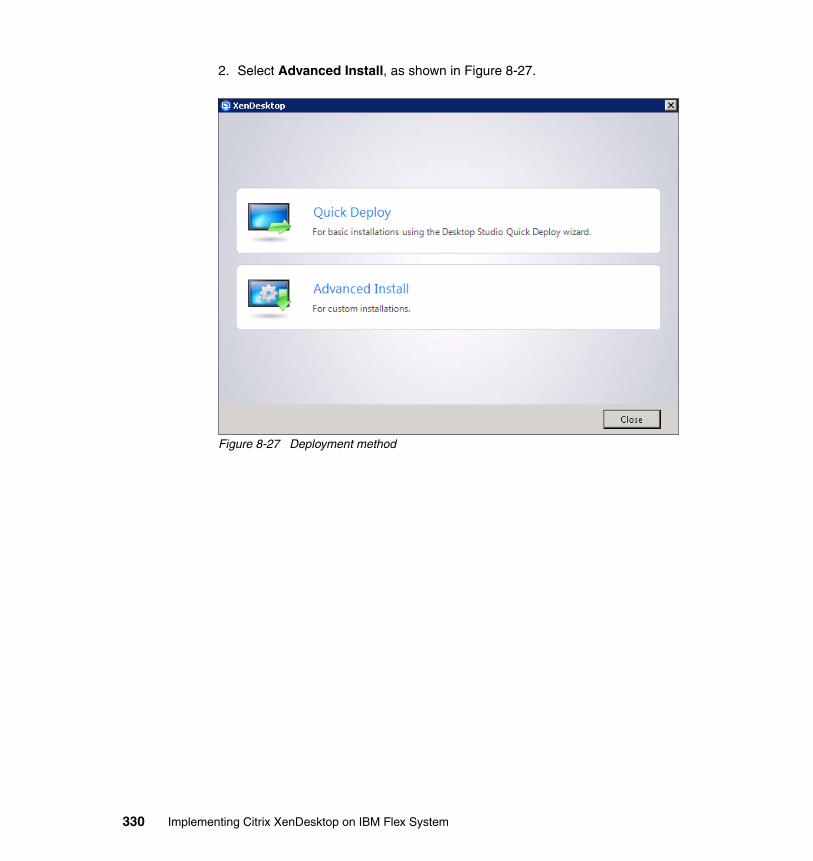
2. Select Advanced Install, as shown in Figure 8-27.
Figure 8-27 Deployment method
330 Implementing Citrix XenDesktop on IBM Flex System
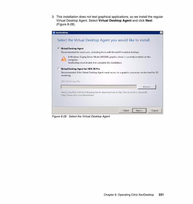
3. This installation does not test graphical applications, so we install the regular Virtual Desktop Agent. Select Virtual Desktop Agent and click Next (Figure 8-28).
Figure 8-28 Select the Virtual Desktop Agent
Chapter 8. Operating Citrix XenDesktop 331
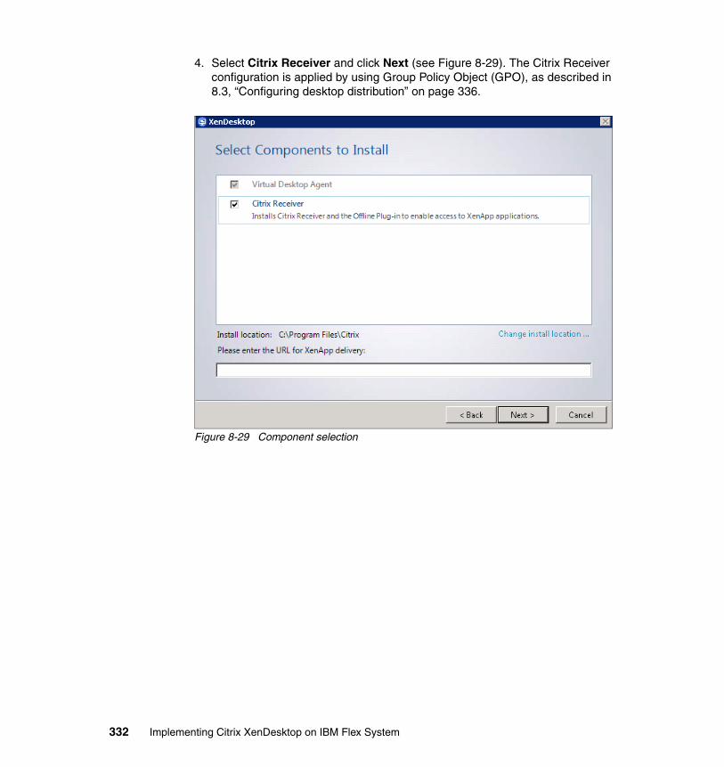
4. Select Citrix Receiver and click Next (see Figure 8-29). The Citrix Receiver configuration is applied by using Group Policy Object (GPO), as described in 8.3, “Configuring desktop distribution” on page 336.
Figure 8-29 Component selection
332 Implementing Citrix XenDesktop on IBM Flex System
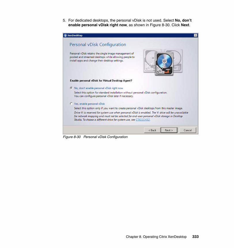
5. For dedicated desktops, the personal vDisk is not used. Select No, don’t enable personal vDisk right now, as shown in Figure 8-30. Click Next.
Figure 8-30 Personal vDisk Configuration
Chapter 8. Operating Citrix XenDesktop 333
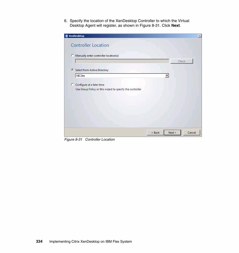
6. Specify the location of the XenDesktop Controller to which the Virtual Desktop Agent will register, as shown in Figure 8-31. Click Next.
Figure 8-31 Controller Location
334 Implementing Citrix XenDesktop on IBM Flex System
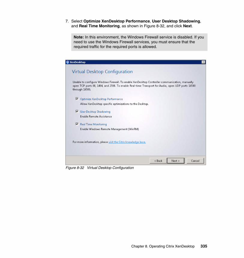
7. Select Optimize XenDesktop Performance, User Desktop Shadowing, and Real Time Monitoring, as shown in Figure 8-32, and click Next.
Figure 8-32 Virtual Desktop Configuration
Note: In this environment, the Windows Firewall service is disabled. If you need to use the Windows Firewall services, you must ensure that the required traffic for the required ports is allowed.
Chapter 8. Operating Citrix XenDesktop 335
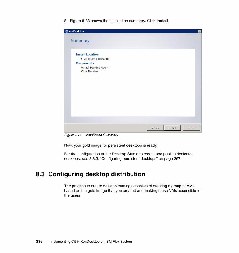
8. Figure 8-33 shows the installation summary. Click Install.
Figure 8-33 Installation Summary
Now, your gold image for persistent desktops is ready.
For the configuration at the Desktop Studio to create and publish dedicated desktops, see 8.3.3, “Configuring persistent desktops” on page 367.
8.3 Configuring desktop distribution
The process to create desktop catalogs consists of creating a group of VMs based on the gold image that you created and making these VMs accessible to the users.
336 Implementing Citrix XenDesktop on IBM Flex System
In this environment, we create three types of desktop catalogs:
� Non-persistent streamed desktops
The catalog is desktop streamed at Citrix Desktop Studio. You create a catalog with a predetermined number of desktops integrated with Provisioning Services and associated to a group of users.
These desktops are available for use, but they are not fixed for these users. When the users log off and log on again, they can log on to any available desktop in the catalog.
From a management perspective, if you modify your vDisk that is stored on Provisioning Services (PVS) and release it for production, the next time that your desktops restart, this new version is available for use.
� Non-persistent streamed with the personal vDisk desktops
The non-persistent streamed with personal vDisk (pvDisk) desktops are similar to the first catalog (they are integrated with Provisioning Services). However, in this catalog, a new disk is created and associated with each desktop. On this disk, all customizations made by the users are stored to be available after the machine is restarted.
Another difference is that the desktop is associated to the user that logs on for the first time and is always associated with this user.
� Persistent desktops
Persistent (or dedicated) desktops consist of virtual desktops created by Machine Creation Services based on a template that is stored on your hypervisor.
This procedure creates a predetermined number of desktops that are available to a specific group of users.
When the user logs on to the desktop for the first time, the user is associated with this desktop and always uses this desktop.
From an administrative perspective, these desktops are not integrated with PVS, and new update requirements for security patches or business applications must be performed with the additional tools. For more information, see Endpoint Security and Compliance Management Design Guide Using IBM Tivoli Endpoint Manager, SG24-7980.
Note: Because these desktops are non-persistent, any customizations made by the user will be lost after the machine is restarted.
Chapter 8. Operating Citrix XenDesktop 337
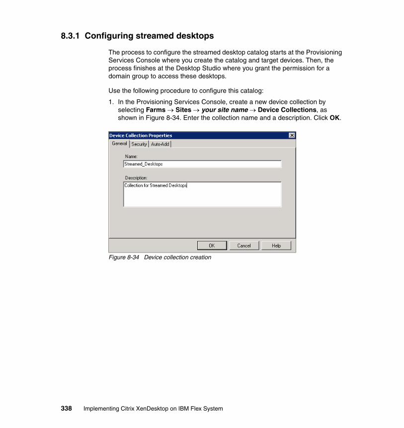
8.3.1 Configuring streamed desktops
The process to configure the streamed desktop catalog starts at the Provisioning Services Console where you create the catalog and target devices. Then, the process finishes at the Desktop Studio where you grant the permission for a domain group to access these desktops.
Use the following procedure to configure this catalog:
1. In the Provisioning Services Console, create a new device collection by selecting Farms Sites your site name Device Collections, as shown in Figure 8-34. Enter the collection name and a description. Click OK.
Figure 8-34 Device collection creation
338 Implementing Citrix XenDesktop on IBM Flex System
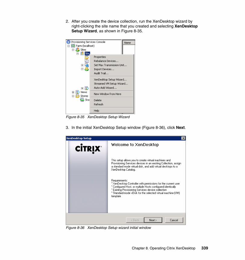
2. After you create the device collection, run the XenDesktop wizard by right-clicking the site name that you created and selecting XenDesktop Setup Wizard, as shown in Figure 8-35.
Figure 8-35 XenDesktop Setup Wizard
3. In the initial XenDesktop Setup window (Figure 8-36), click Next.
Figure 8-36 XenDesktop Setup wizard initial window
Chapter 8. Operating Citrix XenDesktop 339
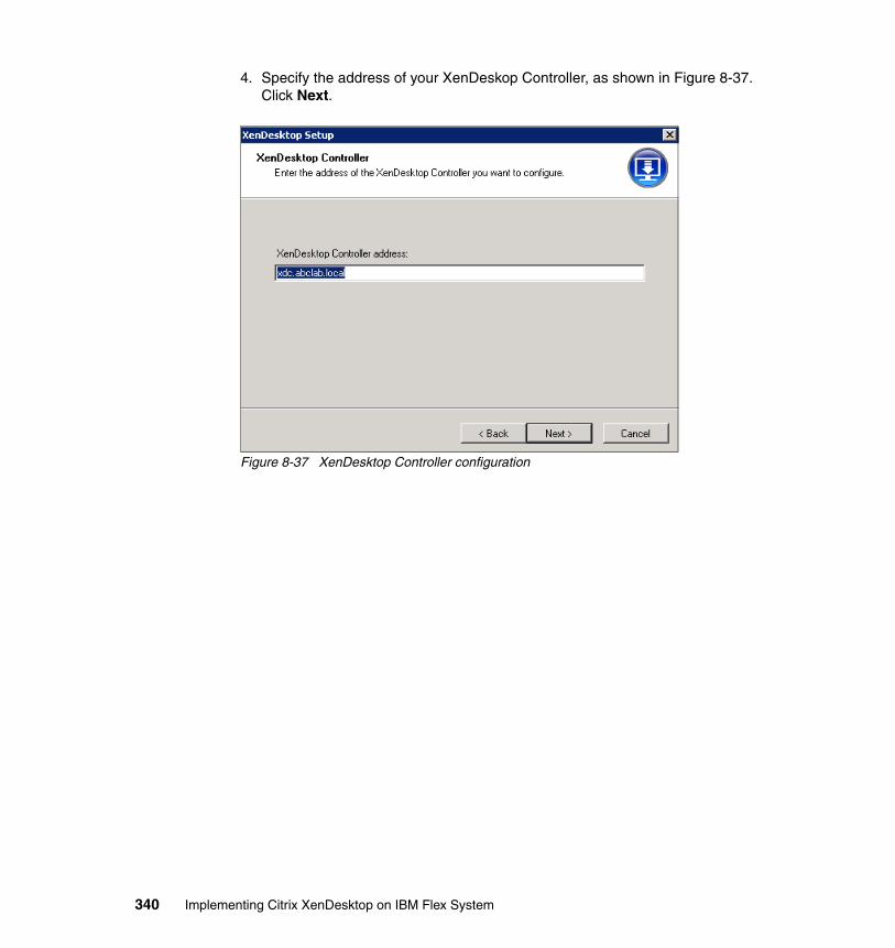
4. Specify the address of your XenDeskop Controller, as shown in Figure 8-37. Click Next.
Figure 8-37 XenDesktop Controller configuration
340 Implementing Citrix XenDesktop on IBM Flex System
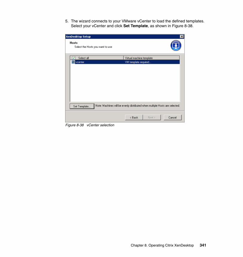
5. The wizard connects to your VMware vCenter to load the defined templates. Select your vCenter and click Set Template, as shown in Figure 8-38.
Figure 8-38 vCenter selection
Chapter 8. Operating Citrix XenDesktop 341
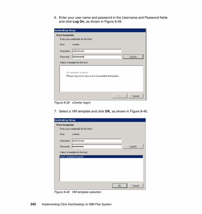
6. Enter your user name and password in the Username and Password fields and click Log On, as shown in Figure 8-39.
Figure 8-39 vCenter logon
7. Select a VM template and click OK, as shown in Figure 8-40.
Figure 8-40 VM template selection
342 Implementing Citrix XenDesktop on IBM Flex System
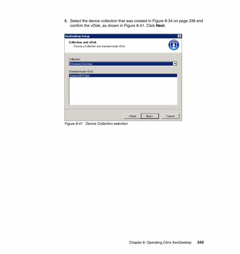
8. Select the device collection that was created in Figure 8-34 on page 338 and confirm the vDisk, as shown in Figure 8-41. Click Next.
Figure 8-41 Device Collection selection
Chapter 8. Operating Citrix XenDesktop 343
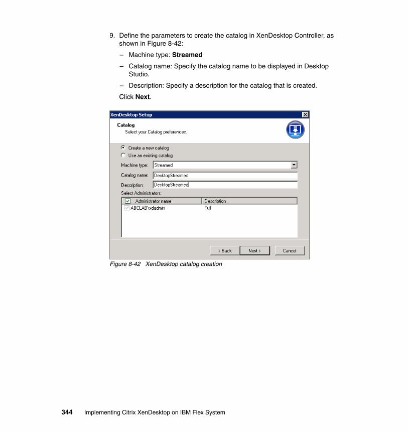
9. Define the parameters to create the catalog in XenDesktop Controller, as shown in Figure 8-42:
– Machine type: Streamed
– Catalog name: Specify the catalog name to be displayed in Desktop Studio.
– Description: Specify a description for the catalog that is created.
Click Next.
Figure 8-42 XenDesktop catalog creation
344 Implementing Citrix XenDesktop on IBM Flex System
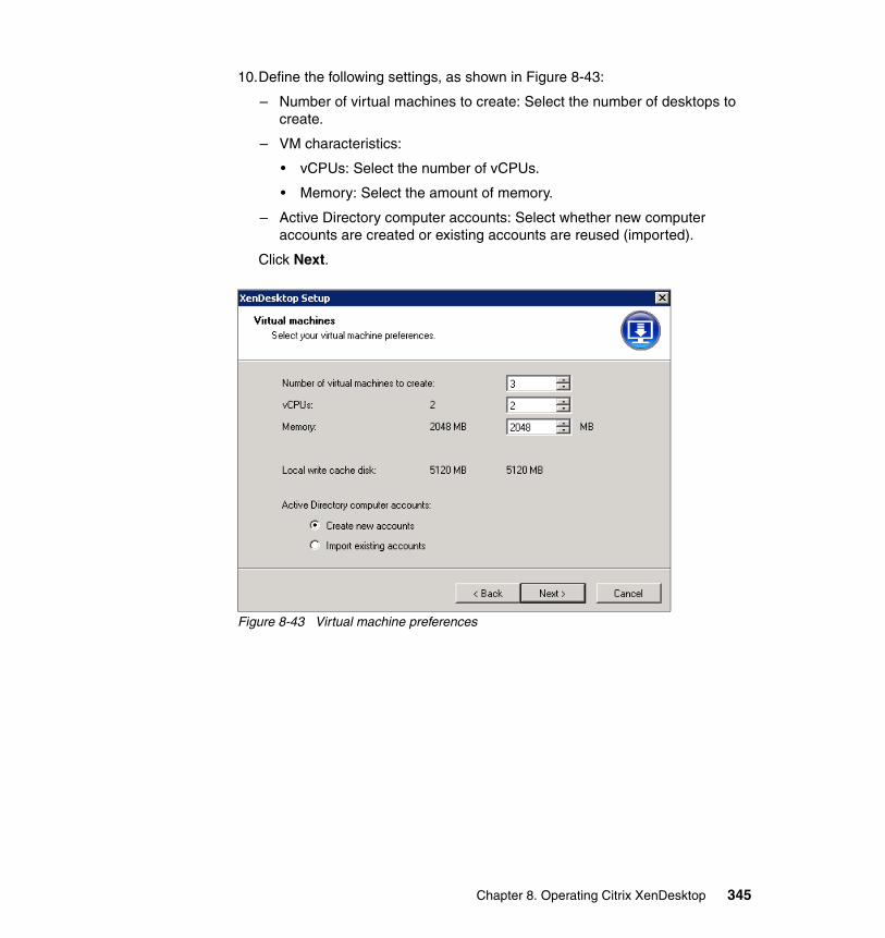
10.Define the following settings, as shown in Figure 8-43:
– Number of virtual machines to create: Select the number of desktops to create.
– VM characteristics:
• vCPUs: Select the number of vCPUs.
• Memory: Select the amount of memory.
– Active Directory computer accounts: Select whether new computer accounts are created or existing accounts are reused (imported).
Click Next.
Figure 8-43 Virtual machine preferences
Chapter 8. Operating Citrix XenDesktop 345
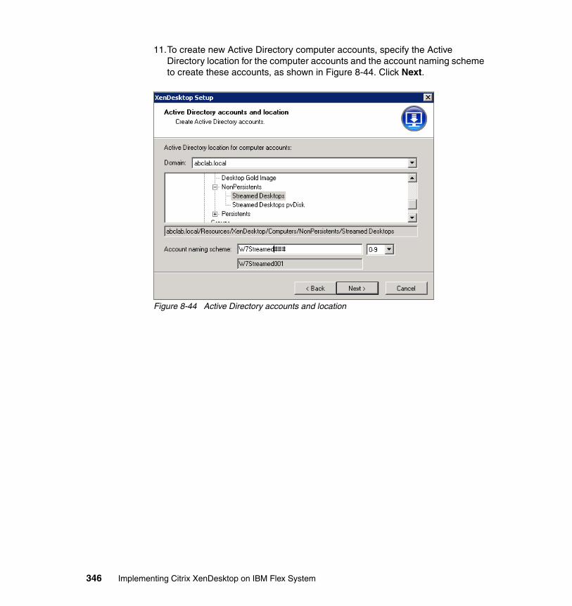
11.To create new Active Directory computer accounts, specify the Active Directory location for the computer accounts and the account naming scheme to create these accounts, as shown in Figure 8-44. Click Next.
Figure 8-44 Active Directory accounts and location
346 Implementing Citrix XenDesktop on IBM Flex System
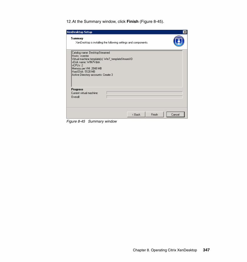
12.At the Summary window, click Finish (Figure 8-45).
Figure 8-45 Summary window
Chapter 8. Operating Citrix XenDesktop 347
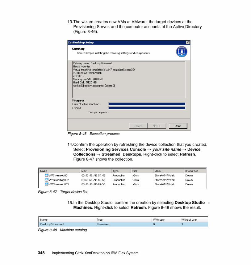
13.The wizard creates new VMs at VMware, the target devices at the Provisioning Server, and the computer accounts at the Active Directory (Figure 8-46).
Figure 8-46 Execution process
14.Confirm the operation by refreshing the device collection that you created. Select Provisioning Services Console your site name Device Collections Streamed_Desktops. Right-click to select Refresh. Figure 8-47 shows the collection.
Figure 8-47 Target device list
15.In the Desktop Studio, confirm the creation by selecting Desktop Studio Machines. Right-click to select Refresh. Figure 8-48 shows the result.
Figure 8-48 Machine catalog
348 Implementing Citrix XenDesktop on IBM Flex System
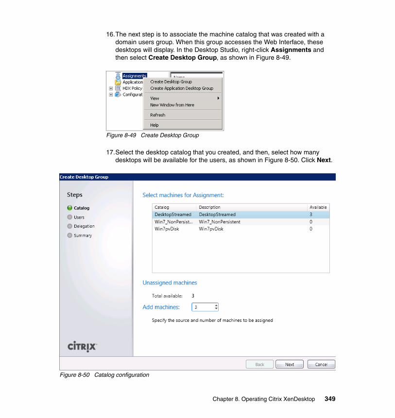
16.The next step is to associate the machine catalog that was created with a domain users group. When this group accesses the Web Interface, these desktops will display. In the Desktop Studio, right-click Assignments and then select Create Desktop Group, as shown in Figure 8-49.
Figure 8-49 Create Desktop Group
17.Select the desktop catalog that you created, and then, select how many desktops will be available for the users, as shown in Figure 8-50. Click Next.
Figure 8-50 Catalog configuration
Chapter 8. Operating Citrix XenDesktop 349
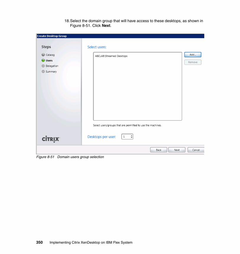
18.Select the domain group that will have access to these desktops, as shown in Figure 8-51. Click Next.
Figure 8-51 Domain users group selection
350 Implementing Citrix XenDesktop on IBM Flex System

19.Define a specific group to which to delegate the administrative privileges to manage the desktop groups, as shown in Figure 8-52. Click Next.
Figure 8-52 Delegation settings
Chapter 8. Operating Citrix XenDesktop 351
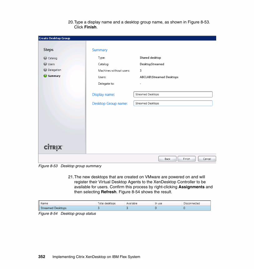
20.Type a display name and a desktop group name, as shown in Figure 8-53. Click Finish.
Figure 8-53 Desktop group summary
21.The new desktops that are created on VMware are powered on and will register their Virtual Desktop Agents to the XenDesktop Controller to be available for users. Confirm this process by right-clicking Assignments and then selecting Refresh. Figure 8-54 shows the result.
Figure 8-54 Desktop group status
352 Implementing Citrix XenDesktop on IBM Flex System
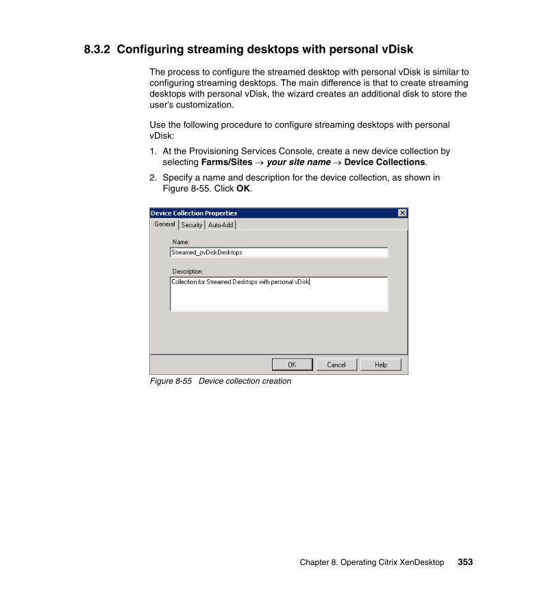
8.3.2 Configuring streaming desktops with personal vDisk
The process to configure the streamed desktop with personal vDisk is similar to configuring streaming desktops. The main difference is that to create streaming desktops with personal vDisk, the wizard creates an additional disk to store the user’s customization.
Use the following procedure to configure streaming desktops with personal vDisk:
1. At the Provisioning Services Console, create a new device collection by selecting Farms/Sites your site name Device Collections.
2. Specify a name and description for the device collection, as shown in Figure 8-55. Click OK.
Figure 8-55 Device collection creation
Chapter 8. Operating Citrix XenDesktop 353
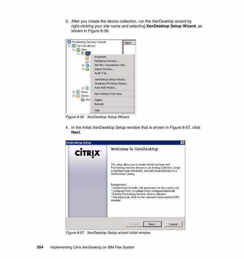
3. After you create the device collection, run the XenDesktop wizard by right-clicking your site name and selecting XenDesktop Setup Wizard, as shown in Figure 8-56.
Figure 8-56 XenDesktop Setup Wizard
4. In the initial XenDesktop Setup window that is shown in Figure 8-57, click Next.
Figure 8-57 XenDesktop Setup wizard initial window
354 Implementing Citrix XenDesktop on IBM Flex System
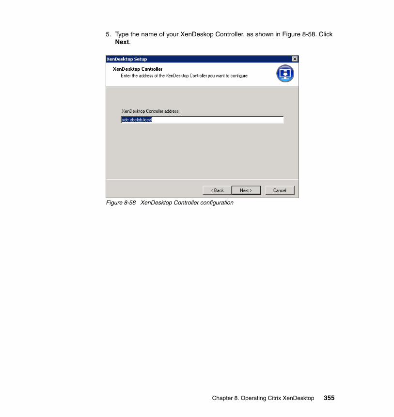
5. Type the name of your XenDeskop Controller, as shown in Figure 8-58. Click Next.
Figure 8-58 XenDesktop Controller configuration
Chapter 8. Operating Citrix XenDesktop 355
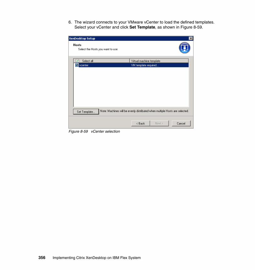
6. The wizard connects to your VMware vCenter to load the defined templates. Select your vCenter and click Set Template, as shown in Figure 8-59.
Figure 8-59 vCenter selection
356 Implementing Citrix XenDesktop on IBM Flex System
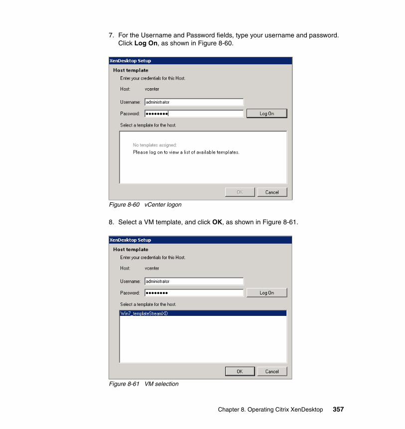
7. For the Username and Password fields, type your username and password. Click Log On, as shown in Figure 8-60.
Figure 8-60 vCenter logon
8. Select a VM template, and click OK, as shown in Figure 8-61.
Figure 8-61 VM selection
Chapter 8. Operating Citrix XenDesktop 357
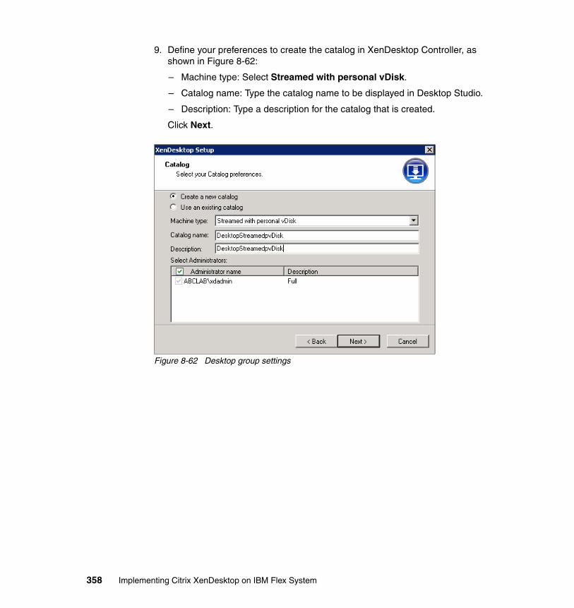
9. Define your preferences to create the catalog in XenDesktop Controller, as shown in Figure 8-62:
– Machine type: Select Streamed with personal vDisk.
– Catalog name: Type the catalog name to be displayed in Desktop Studio.
– Description: Type a description for the catalog that is created.
Click Next.
Figure 8-62 Desktop group settings
358 Implementing Citrix XenDesktop on IBM Flex System
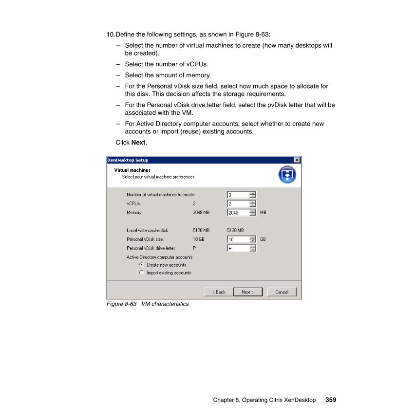
10.Define the following settings, as shown in Figure 8-63:
– Select the number of virtual machines to create (how many desktops will be created).
– Select the number of vCPUs.
– Select the amount of memory.
– For the Personal vDisk size field, select how much space to allocate for this disk. This decision affects the storage requirements.
– For the Personal vDisk drive letter field, select the pvDisk letter that will be associated with the VM.
– For Active Directory computer accounts, select whether to create new accounts or import (reuse) existing accounts.
Click Next.
Figure 8-63 VM characteristics
Chapter 8. Operating Citrix XenDesktop 359
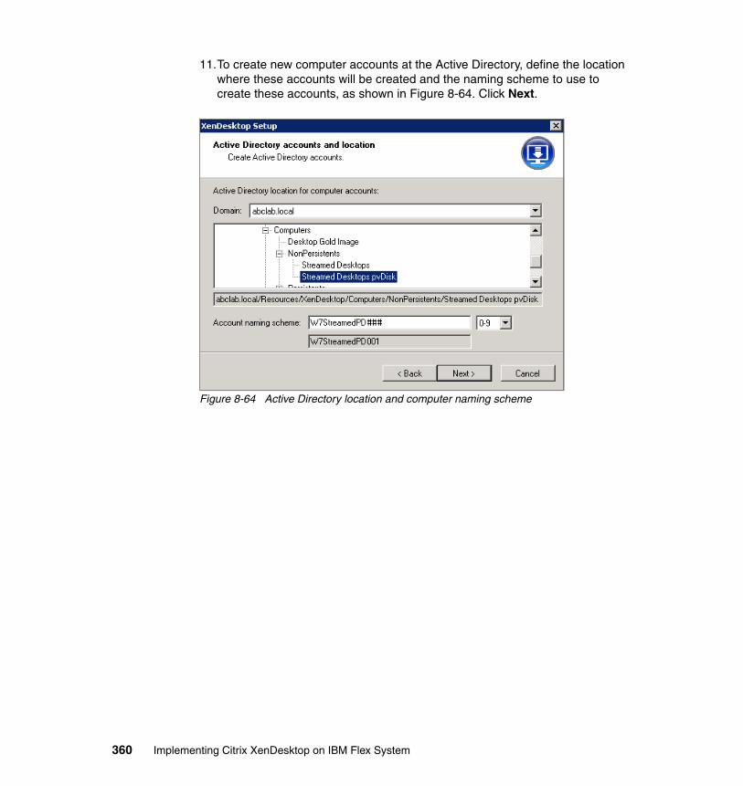
11.To create new computer accounts at the Active Directory, define the location where these accounts will be created and the naming scheme to use to create these accounts, as shown in Figure 8-64. Click Next.
Figure 8-64 Active Directory location and computer naming scheme
360 Implementing Citrix XenDesktop on IBM Flex System
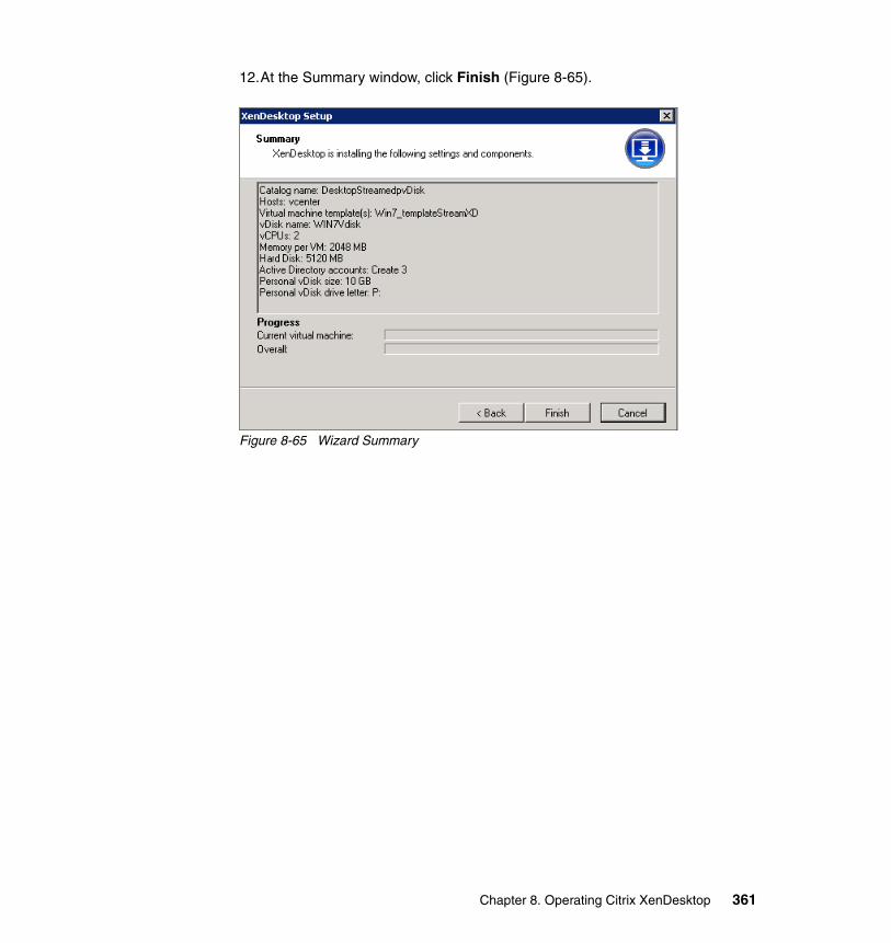
12.At the Summary window, click Finish (Figure 8-65).
Figure 8-65 Wizard Summary
Chapter 8. Operating Citrix XenDesktop 361
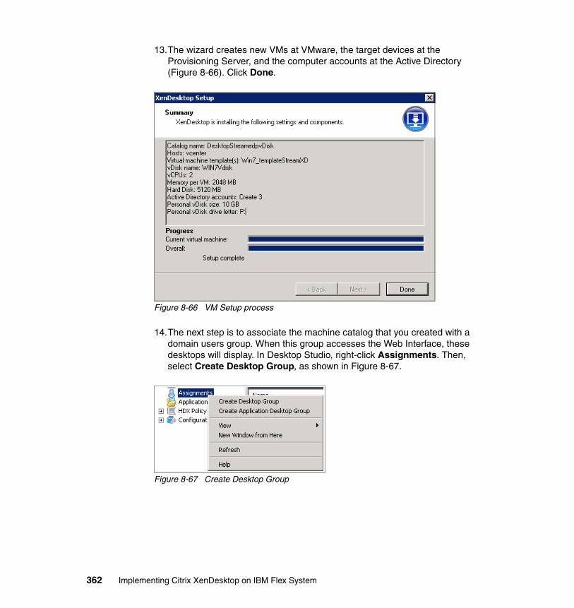
13.The wizard creates new VMs at VMware, the target devices at the Provisioning Server, and the computer accounts at the Active Directory (Figure 8-66). Click Done.
Figure 8-66 VM Setup process
14.The next step is to associate the machine catalog that you created with a domain users group. When this group accesses the Web Interface, these desktops will display. In Desktop Studio, right-click Assignments. Then, select Create Desktop Group, as shown in Figure 8-67.
Figure 8-67 Create Desktop Group
362 Implementing Citrix XenDesktop on IBM Flex System
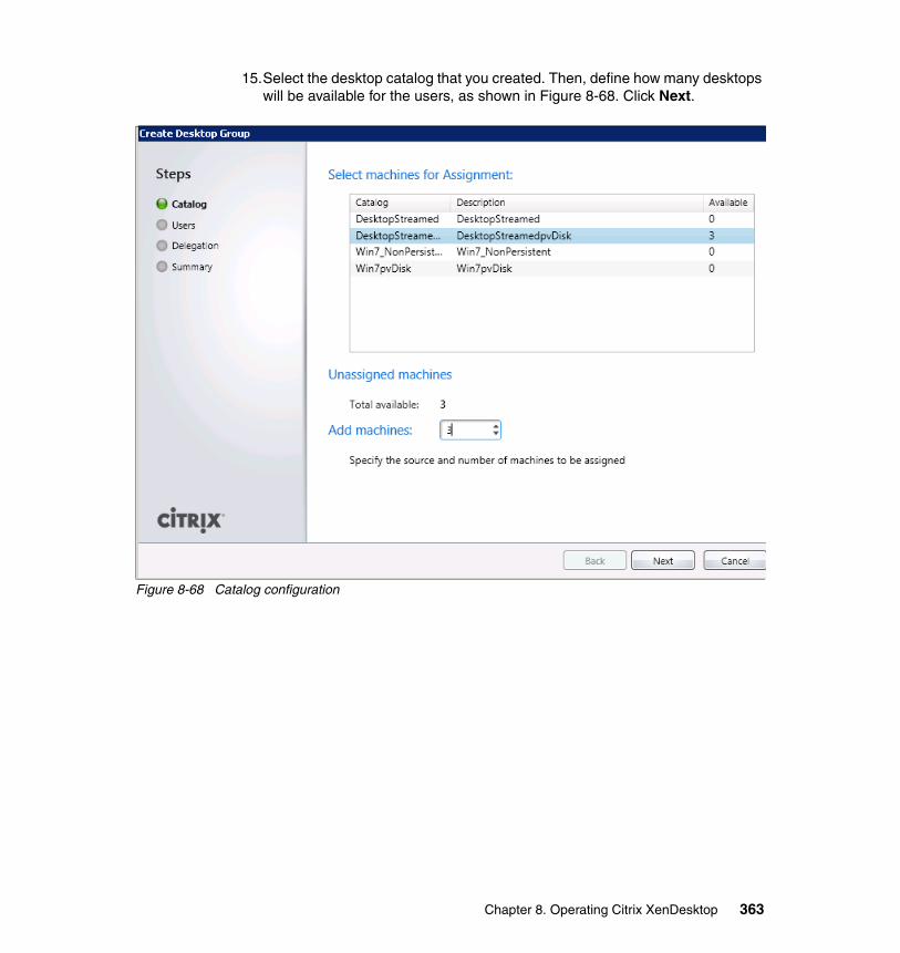
15.Select the desktop catalog that you created. Then, define how many desktops will be available for the users, as shown in Figure 8-68. Click Next.
Figure 8-68 Catalog configuration
Chapter 8. Operating Citrix XenDesktop 363
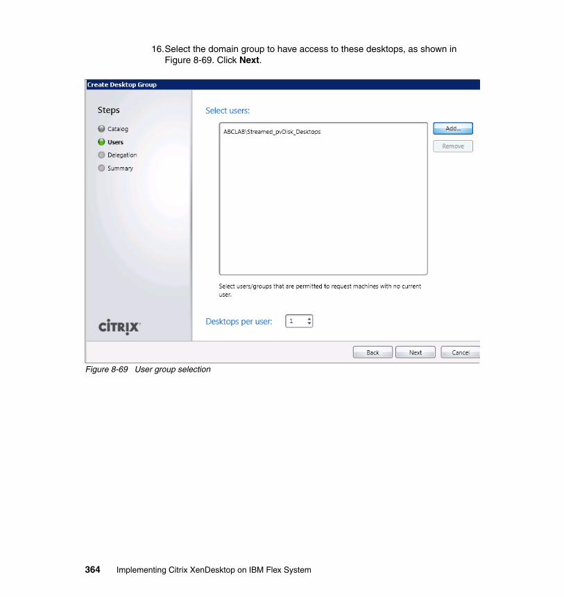
16.Select the domain group to have access to these desktops, as shown in Figure 8-69. Click Next.
Figure 8-69 User group selection
364 Implementing Citrix XenDesktop on IBM Flex System
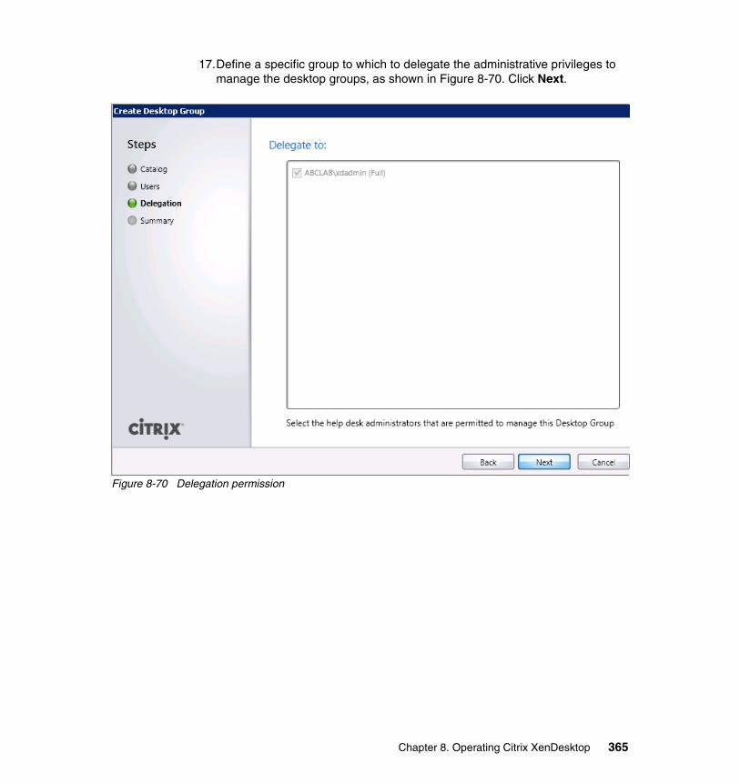
17.Define a specific group to which to delegate the administrative privileges to manage the desktop groups, as shown in Figure 8-70. Click Next.
Figure 8-70 Delegation permission
Chapter 8. Operating Citrix XenDesktop 365
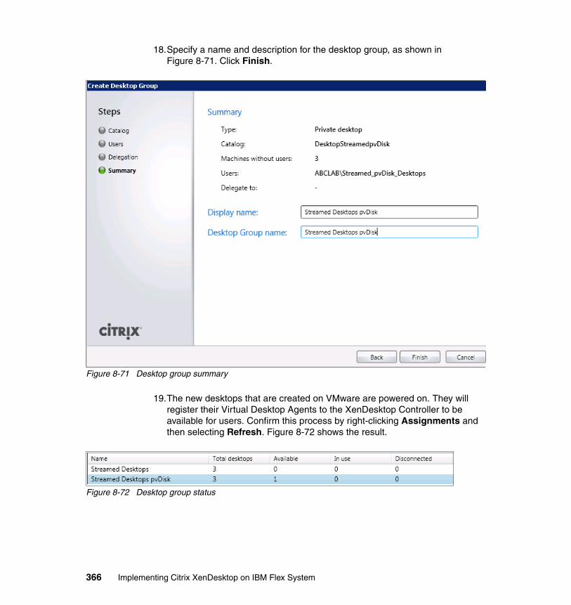
18.Specify a name and description for the desktop group, as shown in Figure 8-71. Click Finish.
Figure 8-71 Desktop group summary
19.The new desktops that are created on VMware are powered on. They will register their Virtual Desktop Agents to the XenDesktop Controller to be available for users. Confirm this process by right-clicking Assignments and then selecting Refresh. Figure 8-72 shows the result.
Figure 8-72 Desktop group status
366 Implementing Citrix XenDesktop on IBM Flex System
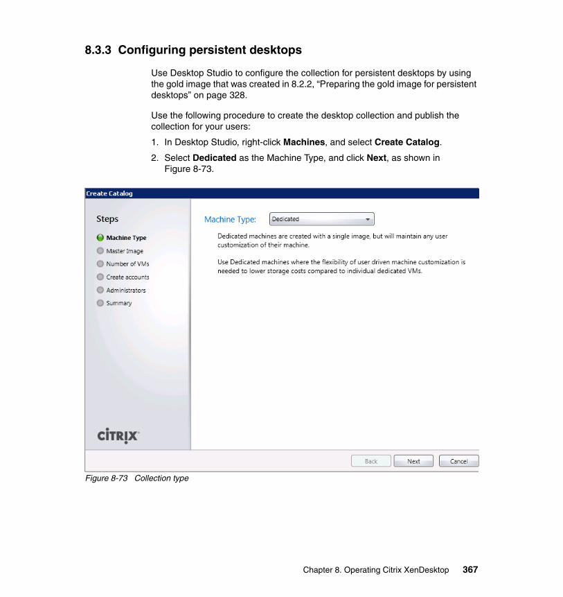
8.3.3 Configuring persistent desktops
Use Desktop Studio to configure the collection for persistent desktops by using the gold image that was created in 8.2.2, “Preparing the gold image for persistent desktops” on page 328.
Use the following procedure to create the desktop collection and publish the collection for your users:
1. In Desktop Studio, right-click Machines, and select Create Catalog.
2. Select Dedicated as the Machine Type, and click Next, as shown in Figure 8-73.
Figure 8-73 Collection type
Chapter 8. Operating Citrix XenDesktop 367
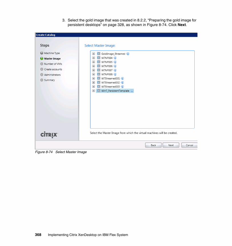
3. Select the gold image that was created in 8.2.2, “Preparing the gold image for persistent desktops” on page 328, as shown in Figure 8-74. Click Next.
Figure 8-74 Select Master Image
368 Implementing Citrix XenDesktop on IBM Flex System
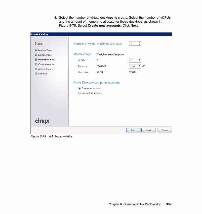
4. Select the number of virtual desktops to create. Select the number of vCPUs and the amount of memory to allocate for these desktops, as shown in Figure 8-75. Select Create new accounts. Click Next.
Figure 8-75 VM characteristics
Chapter 8. Operating Citrix XenDesktop 369
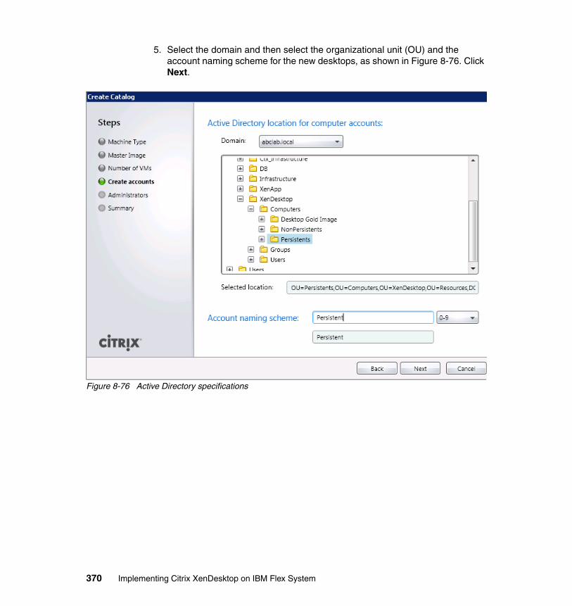
5. Select the domain and then select the organizational unit (OU) and the account naming scheme for the new desktops, as shown in Figure 8-76. Click Next.
Figure 8-76 Active Directory specifications
370 Implementing Citrix XenDesktop on IBM Flex System
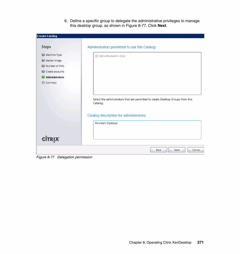
6. Define a specific group to delegate the administrative privileges to manage this desktop group, as shown in Figure 8-77. Click Next.
Figure 8-77 Delegation permission
Chapter 8. Operating Citrix XenDesktop 371
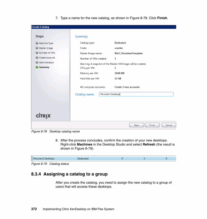
7. Type a name for the new catalog, as shown in Figure 8-78. Click Finish.
Figure 8-78 Desktop catalog name
8. After the process concludes, confirm the creation of your new desktops. Right-click Machines in the Desktop Studio and select Refresh (the result is shown in Figure 8-79).
Figure 8-79 Catalog status
8.3.4 Assigning a catalog to a group
After you create the catalog, you need to assign the new catalog to a group of users that will access these desktops.
372 Implementing Citrix XenDesktop on IBM Flex System
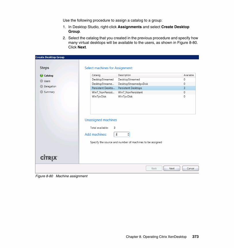
Use the following procedure to assign a catalog to a group:
1. In Desktop Studio, right-click Assignments and select Create Desktop Group.
2. Select the catalog that you created in the previous procedure and specify how many virtual desktops will be available to the users, as shown in Figure 8-80. Click Next.
Figure 8-80 Machine assignment
Chapter 8. Operating Citrix XenDesktop 373
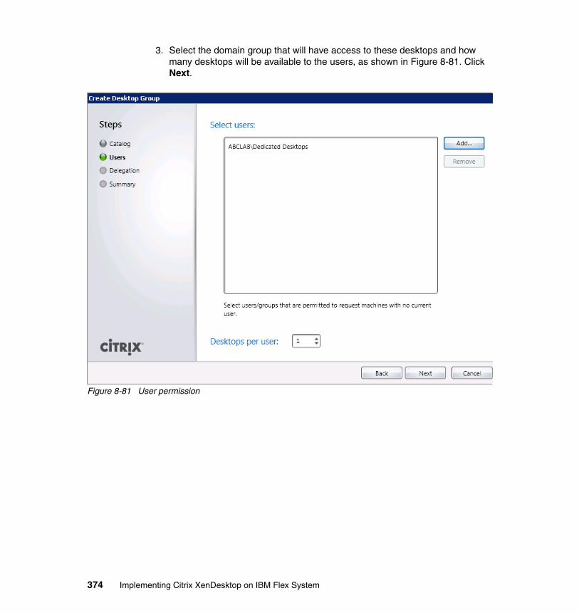
3. Select the domain group that will have access to these desktops and how many desktops will be available to the users, as shown in Figure 8-81. Click Next.
Figure 8-81 User permission
374 Implementing Citrix XenDesktop on IBM Flex System
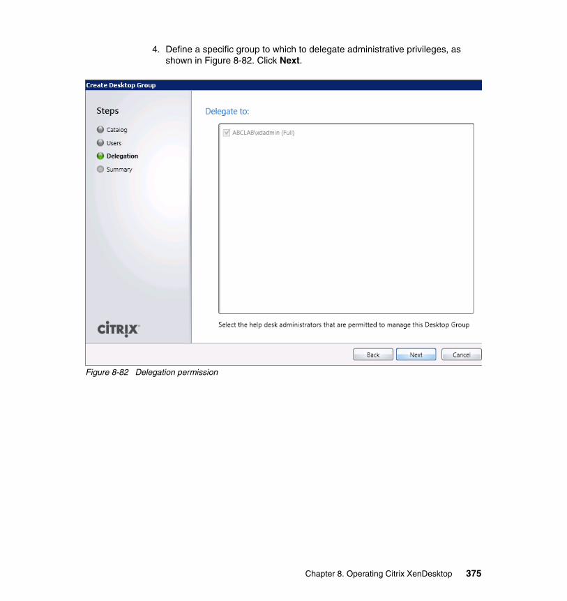
4. Define a specific group to which to delegate administrative privileges, as shown in Figure 8-82. Click Next.
Figure 8-82 Delegation permission
Chapter 8. Operating Citrix XenDesktop 375
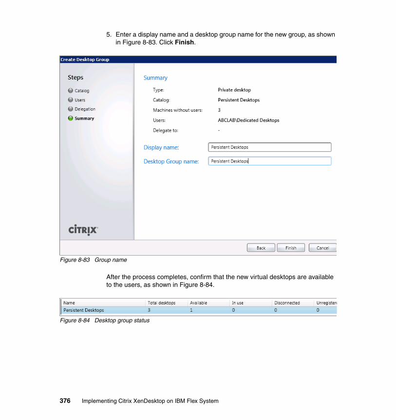
5. Enter a display name and a desktop group name for the new group, as shown in Figure 8-83. Click Finish.
Figure 8-83 Group name
After the process completes, confirm that the new virtual desktops are available to the users, as shown in Figure 8-84.
Figure 8-84 Desktop group status
376 Implementing Citrix XenDesktop on IBM Flex System
8.4 Roaming profiles and folder redirection
Defining roaming user profiles is an important part of the VDI configuration because it allows profiles to be stored in a centralized server. When a user logs on from a different desktop, that user’s profile is loaded.
The concept is similar for folder redirection. Redirection occurs to the same centralized server for accessing personal folders, such as My Documents, Favorites, and Desktop, is important for three main reasons:
� If the user logs on from a different desktop.
� If the administrator modifies the desktop image, the user’s files are not lost because the files are stored on a centralized server.
� For business applications, you can redirect the application settings folder to the same centralized server, and the configuration is loaded without reconfiguring.
To configure the roaming profile and folder redirection, we used the Group Policy on the Active Directory to centralize the configuration and to apply it at the organizational unit (OU) level to standardize the configuration for the environment.
The following sections describe the procedures for implementing roaming profiles and folder redirection.
8.4.1 Configuring the roaming profile
To initiate roaming profile functionality, we used the Citrix Profile Manager UPM installed on the desktop gold image and on the Citrix XenApp servers. Citrix provides an administrative template (ADM) that needs to be imported on the Group Policy Object to configure how the Profile Manager works.
Chapter 8. Operating Citrix XenDesktop 377
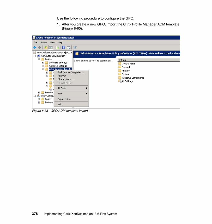
Use the following procedure to configure the GPO:
1. After you create a new GPO, import the Citrix Profile Manager ADM template (Figure 8-85).
Figure 8-85 GPO ADM template import
378 Implementing Citrix XenDesktop on IBM Flex System
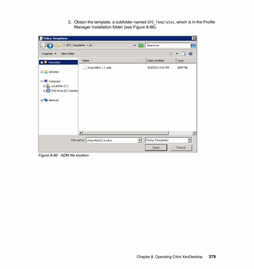
2. Obtain the template, a subfolder named GPO_Templates, which is in the Profile Manager installation folder (see Figure 8-86).
Figure 8-86 ADM file location
Chapter 8. Operating Citrix XenDesktop 379
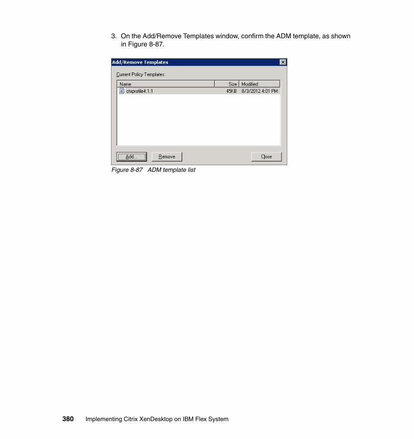
3. On the Add/Remove Templates window, confirm the ADM template, as shown in Figure 8-87.
Figure 8-87 ADM template list
380 Implementing Citrix XenDesktop on IBM Flex System
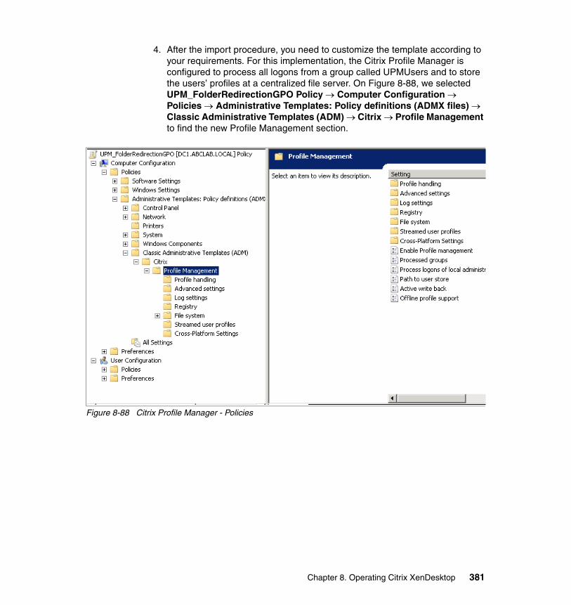
4. After the import procedure, you need to customize the template according to your requirements. For this implementation, the Citrix Profile Manager is configured to process all logons from a group called UPMUsers and to store the users’ profiles at a centralized file server. On Figure 8-88, we selected UPM_FolderRedirectionGPO Policy Computer Configuration Policies Administrative Templates: Policy definitions (ADMX files) Classic Administrative Templates (ADM) Citrix Profile Management to find the new Profile Management section.
Figure 8-88 Citrix Profile Manager - Policies
Chapter 8. Operating Citrix XenDesktop 381
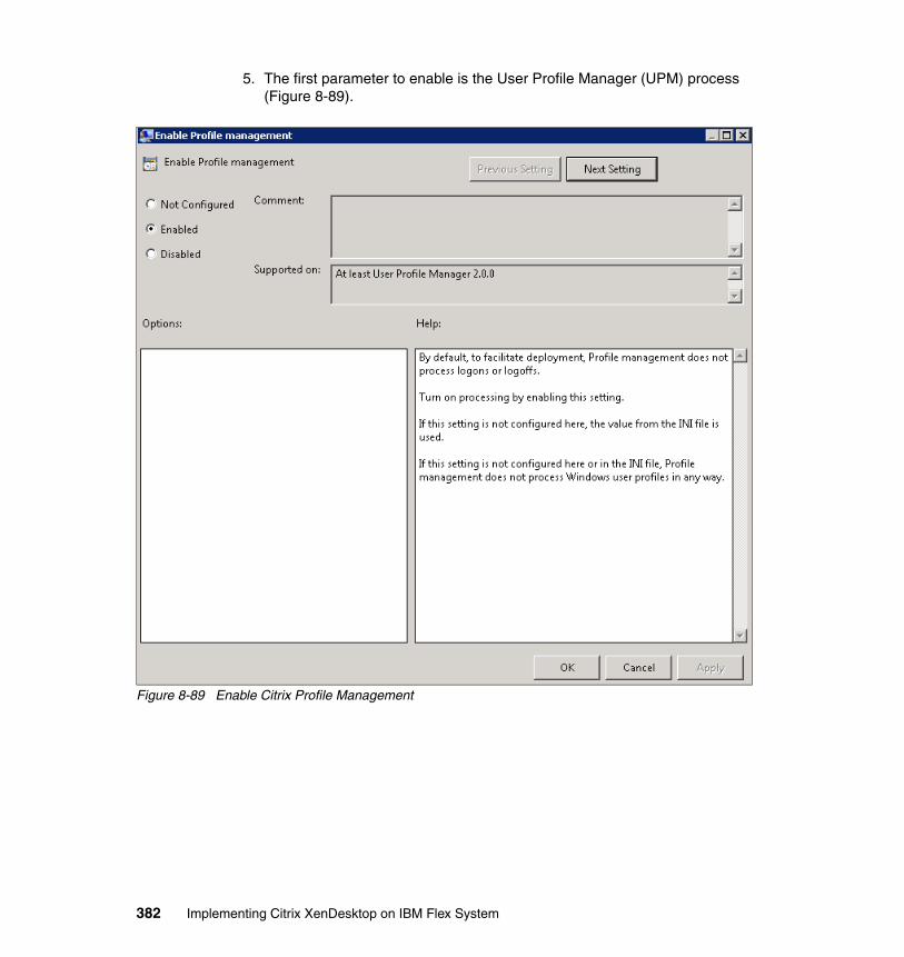
5. The first parameter to enable is the User Profile Manager (UPM) process (Figure 8-89).
Figure 8-89 Enable Citrix Profile Management
382 Implementing Citrix XenDesktop on IBM Flex System
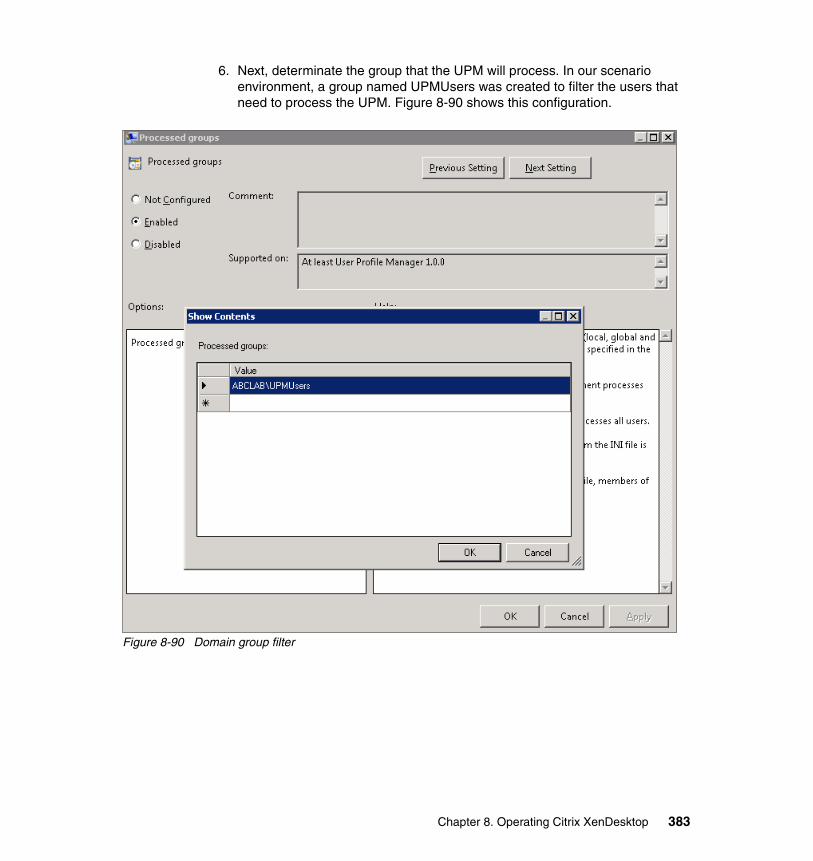
6. Next, determinate the group that the UPM will process. In our scenario environment, a group named UPMUsers was created to filter the users that need to process the UPM. Figure 8-90 shows this configuration.
Figure 8-90 Domain group filter
Chapter 8. Operating Citrix XenDesktop 383
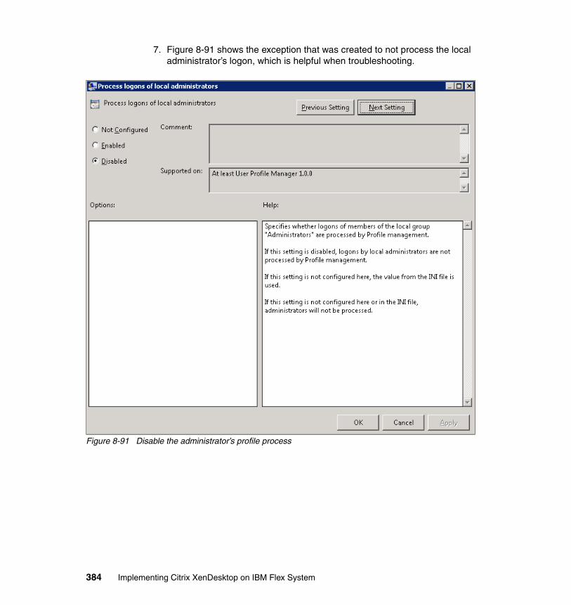
7. Figure 8-91 shows the exception that was created to not process the local administrator’s logon, which is helpful when troubleshooting.
Figure 8-91 Disable the administrator’s profile process
384 Implementing Citrix XenDesktop on IBM Flex System
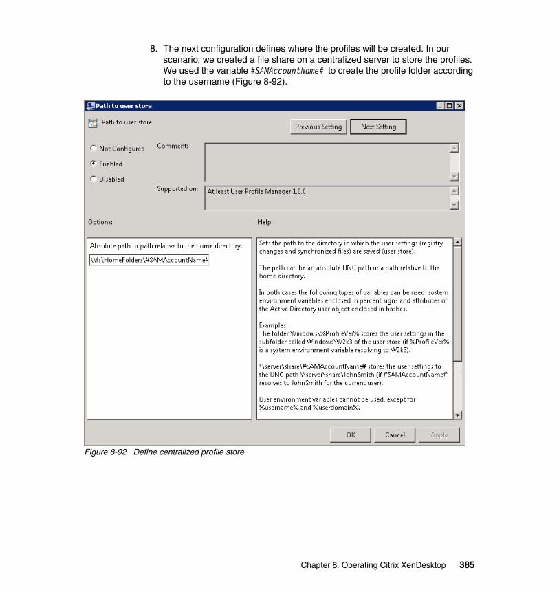
8. The next configuration defines where the profiles will be created. In our scenario, we created a file share on a centralized server to store the profiles. We used the variable #SAMAccountName# to create the profile folder according to the username (Figure 8-92).
Figure 8-92 Define centralized profile store
Chapter 8. Operating Citrix XenDesktop 385
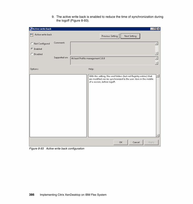
9. The active write back is enabled to reduce the time of synchronization during the logoff (Figure 8-93).
Figure 8-93 Active write back configuration
386 Implementing Citrix XenDesktop on IBM Flex System
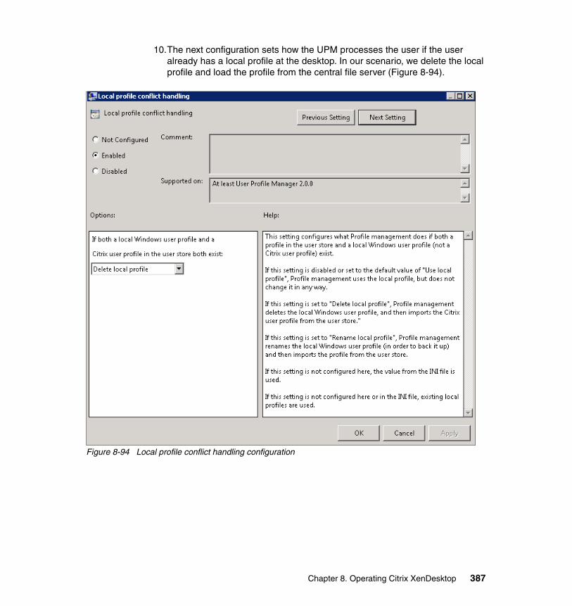
10.The next configuration sets how the UPM processes the user if the user already has a local profile at the desktop. In our scenario, we delete the local profile and load the profile from the central file server (Figure 8-94).
Figure 8-94 Local profile conflict handling configuration
Chapter 8. Operating Citrix XenDesktop 387
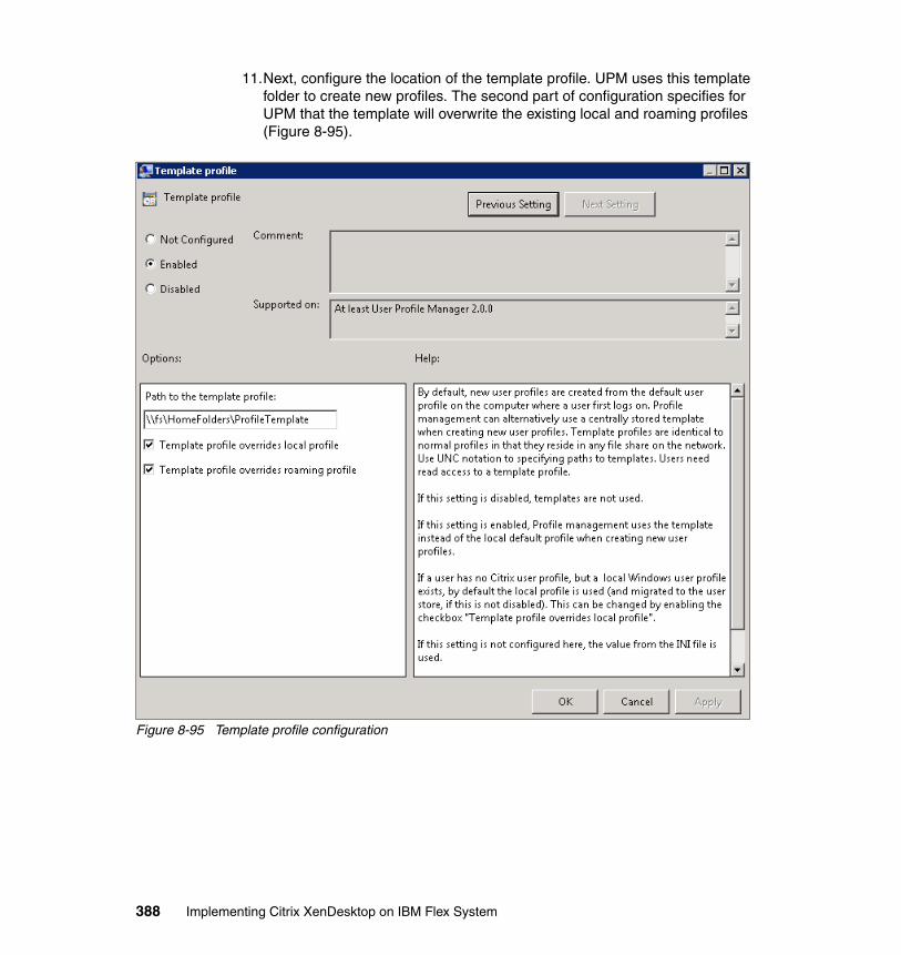
11.Next, configure the location of the template profile. UPM uses this template folder to create new profiles. The second part of configuration specifies for UPM that the template will overwrite the existing local and roaming profiles (Figure 8-95).
Figure 8-95 Template profile configuration
388 Implementing Citrix XenDesktop on IBM Flex System
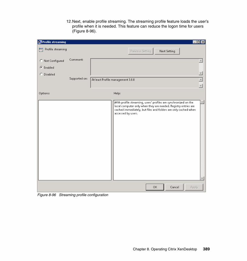
12.Next, enable profile streaming. The streaming profile feature loads the user’s profile when it is needed. This feature can reduce the logon time for users (Figure 8-96).
Figure 8-96 Streaming profile configuration
Chapter 8. Operating Citrix XenDesktop 389
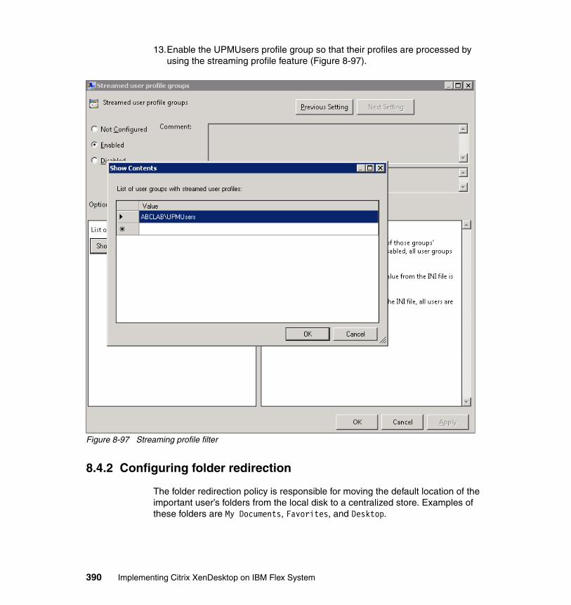
13.Enable the UPMUsers profile group so that their profiles are processed by using the streaming profile feature (Figure 8-97).
Figure 8-97 Streaming profile filter
8.4.2 Configuring folder redirection
The folder redirection policy is responsible for moving the default location of the important user’s folders from the local disk to a centralized store. Examples of these folders are My Documents, Favorites, and Desktop.
390 Implementing Citrix XenDesktop on IBM Flex System
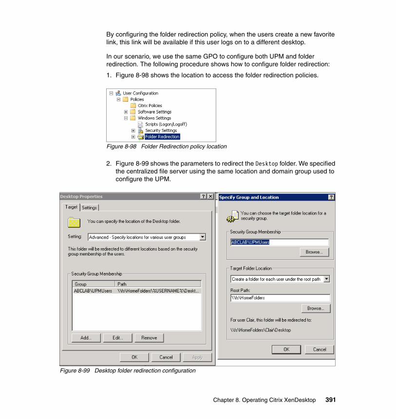
By configuring the folder redirection policy, when the users create a new favorite link, this link will be available if this user logs on to a different desktop.
In our scenario, we use the same GPO to configure both UPM and folder redirection. The following procedure shows how to configure folder redirection:
1. Figure 8-98 shows the location to access the folder redirection policies.
Figure 8-98 Folder Redirection policy location
2. Figure 8-99 shows the parameters to redirect the Desktop folder. We specified the centralized file server using the same location and domain group used to configure the UPM.
Figure 8-99 Desktop folder redirection configuration
Chapter 8. Operating Citrix XenDesktop 391
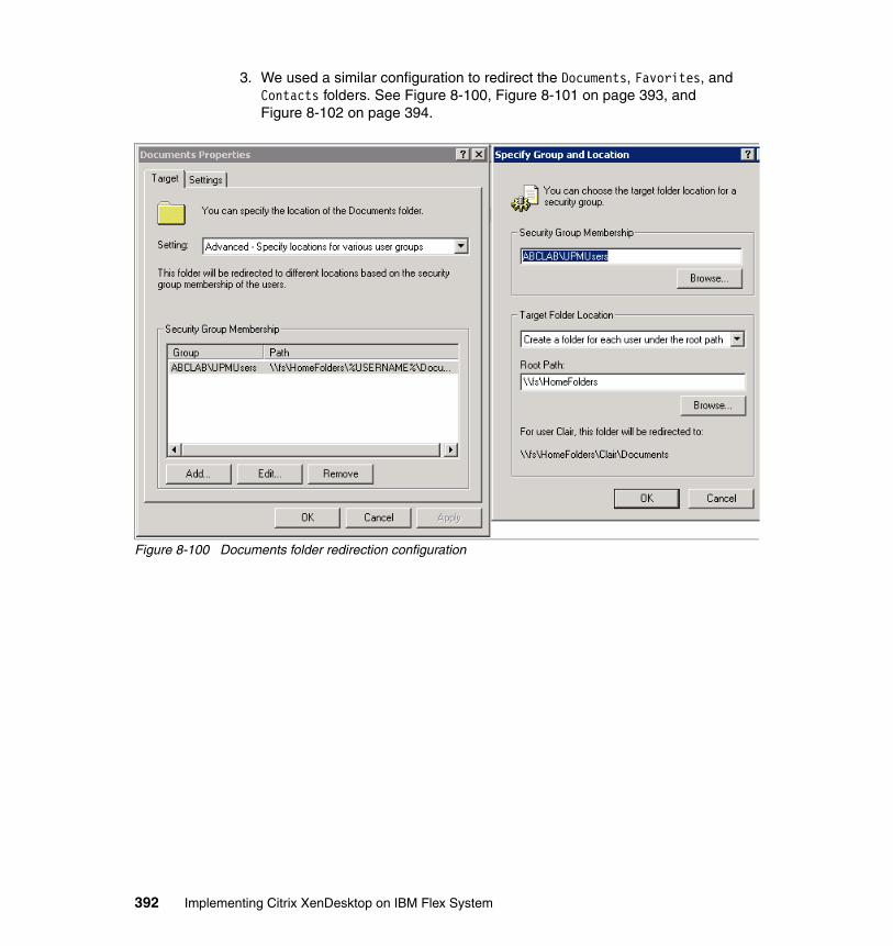
3. We used a similar configuration to redirect the Documents, Favorites, and Contacts folders. See Figure 8-100, Figure 8-101 on page 393, and Figure 8-102 on page 394.
Figure 8-100 Documents folder redirection configuration
392 Implementing Citrix XenDesktop on IBM Flex System
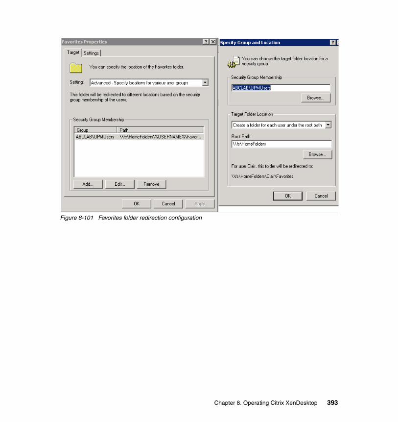
Figure 8-101 Favorites folder redirection configuration
Chapter 8. Operating Citrix XenDesktop 393
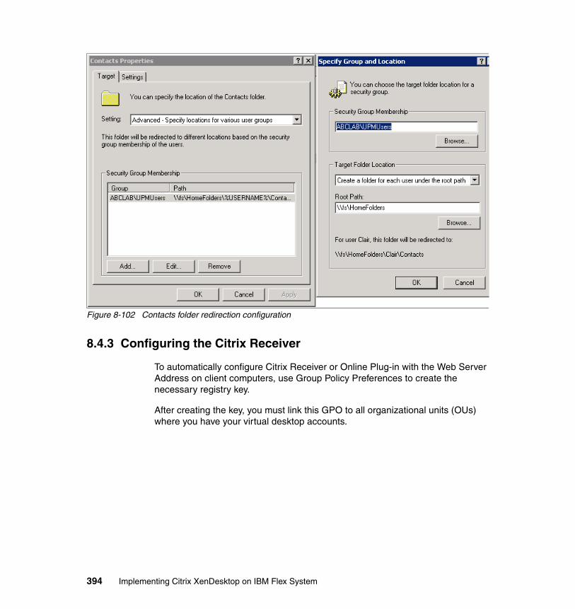
Figure 8-102 Contacts folder redirection configuration
8.4.3 Configuring the Citrix Receiver
To automatically configure Citrix Receiver or Online Plug-in with the Web Server Address on client computers, use Group Policy Preferences to create the necessary registry key.
After creating the key, you must link this GPO to all organizational units (OUs) where you have your virtual desktop accounts.
394 Implementing Citrix XenDesktop on IBM Flex System
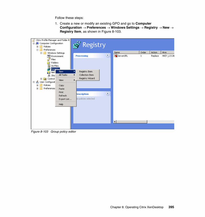
Follow these steps:
1. Create a new or modify an existing GPO and go to Computer Configuration Preferences Windows Settings Registry New Registry Item, as shown in Figure 8-103.
Figure 8-103 Group policy editor
Chapter 8. Operating Citrix XenDesktop 395
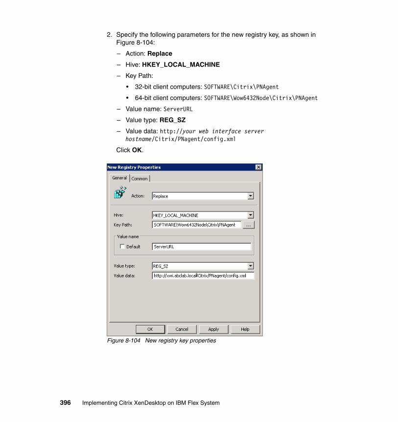
2. Specify the following parameters for the new registry key, as shown in Figure 8-104:
– Action: Replace
– Hive: HKEY_LOCAL_MACHINE
– Key Path:
• 32-bit client computers: SOFTWARE\Citrix\PNAgent
• 64-bit client computers: SOFTWARE\Wow6432Node\Citrix\PNAgent
– Value name: ServerURL
– Value type: REG_SZ
– Value data: http://your web interface server hostname/Citrix/PNagent/config.xml
Click OK.
Figure 8-104 New registry key properties
396 Implementing Citrix XenDesktop on IBM Flex System
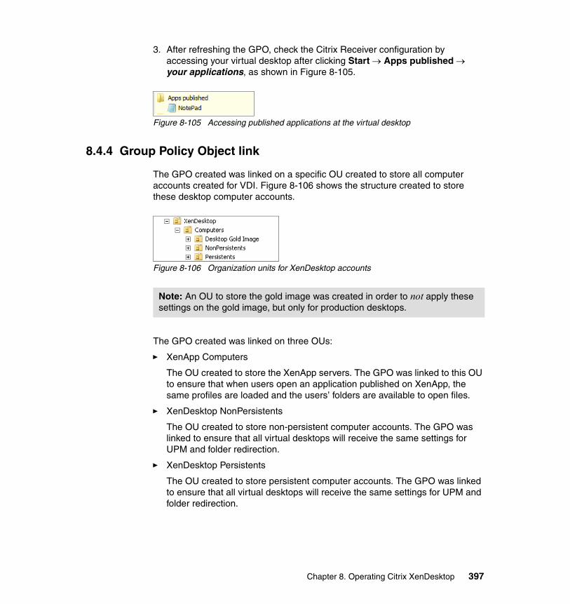
3. After refreshing the GPO, check the Citrix Receiver configuration by accessing your virtual desktop after clicking Start Apps published your applications, as shown in Figure 8-105.
Figure 8-105 Accessing published applications at the virtual desktop
8.4.4 Group Policy Object link
The GPO created was linked on a specific OU created to store all computer accounts created for VDI. Figure 8-106 shows the structure created to store these desktop computer accounts.
Figure 8-106 Organization units for XenDesktop accounts
The GPO created was linked on three OUs:
� XenApp Computers
The OU created to store the XenApp servers. The GPO was linked to this OU to ensure that when users open an application published on XenApp, the same profiles are loaded and the users’ folders are available to open files.
� XenDesktop NonPersistents
The OU created to store non-persistent computer accounts. The GPO was linked to ensure that all virtual desktops will receive the same settings for UPM and folder redirection.
� XenDesktop Persistents
The OU created to store persistent computer accounts. The GPO was linked to ensure that all virtual desktops will receive the same settings for UPM and folder redirection.
Note: An OU to store the gold image was created in order to not apply these settings on the gold image, but only for production desktops.
Chapter 8. Operating Citrix XenDesktop 397
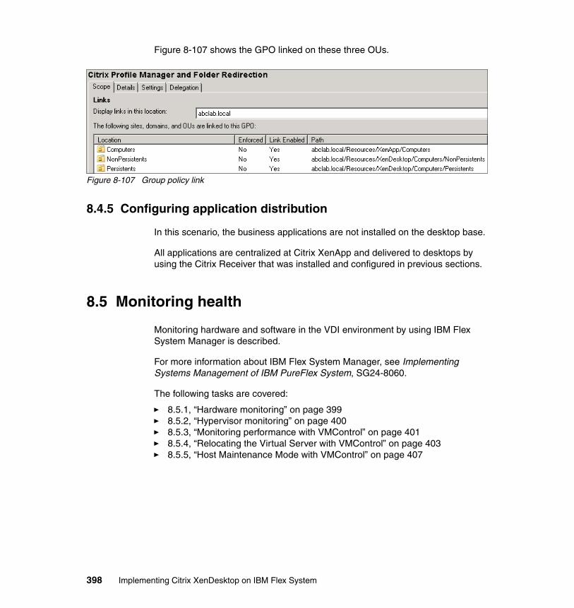
Figure 8-107 shows the GPO linked on these three OUs.
Figure 8-107 Group policy link
8.4.5 Configuring application distribution
In this scenario, the business applications are not installed on the desktop base.
All applications are centralized at Citrix XenApp and delivered to desktops by using the Citrix Receiver that was installed and configured in previous sections.
8.5 Monitoring health
Monitoring hardware and software in the VDI environment by using IBM Flex System Manager is described.
For more information about IBM Flex System Manager, see Implementing Systems Management of IBM PureFlex System, SG24-8060.
The following tasks are covered:
� 8.5.1, “Hardware monitoring” on page 399� 8.5.2, “Hypervisor monitoring” on page 400� 8.5.3, “Monitoring performance with VMControl” on page 401� 8.5.4, “Relocating the Virtual Server with VMControl” on page 403� 8.5.5, “Host Maintenance Mode with VMControl” on page 407
398 Implementing Citrix XenDesktop on IBM Flex System
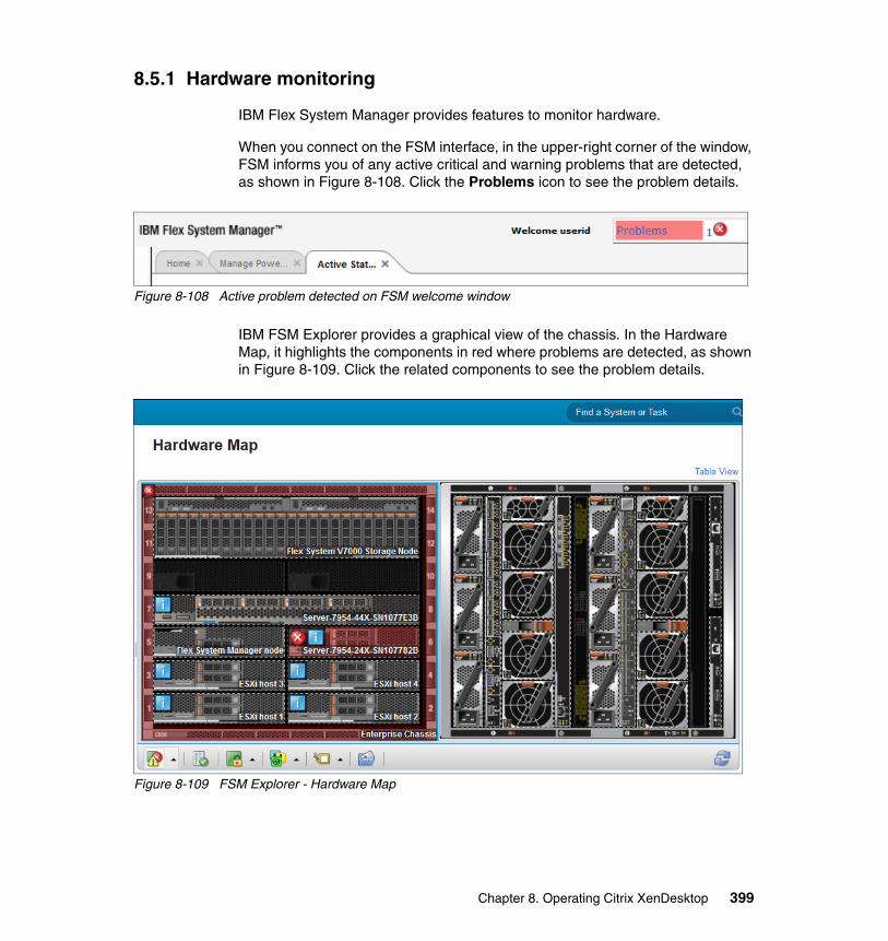
8.5.1 Hardware monitoring
IBM Flex System Manager provides features to monitor hardware.
When you connect on the FSM interface, in the upper-right corner of the window, FSM informs you of any active critical and warning problems that are detected, as shown in Figure 8-108. Click the Problems icon to see the problem details.
Figure 8-108 Active problem detected on FSM welcome window
IBM FSM Explorer provides a graphical view of the chassis. In the Hardware Map, it highlights the components in red where problems are detected, as shown in Figure 8-109. Click the related components to see the problem details.
Figure 8-109 FSM Explorer - Hardware Map
Chapter 8. Operating Citrix XenDesktop 399
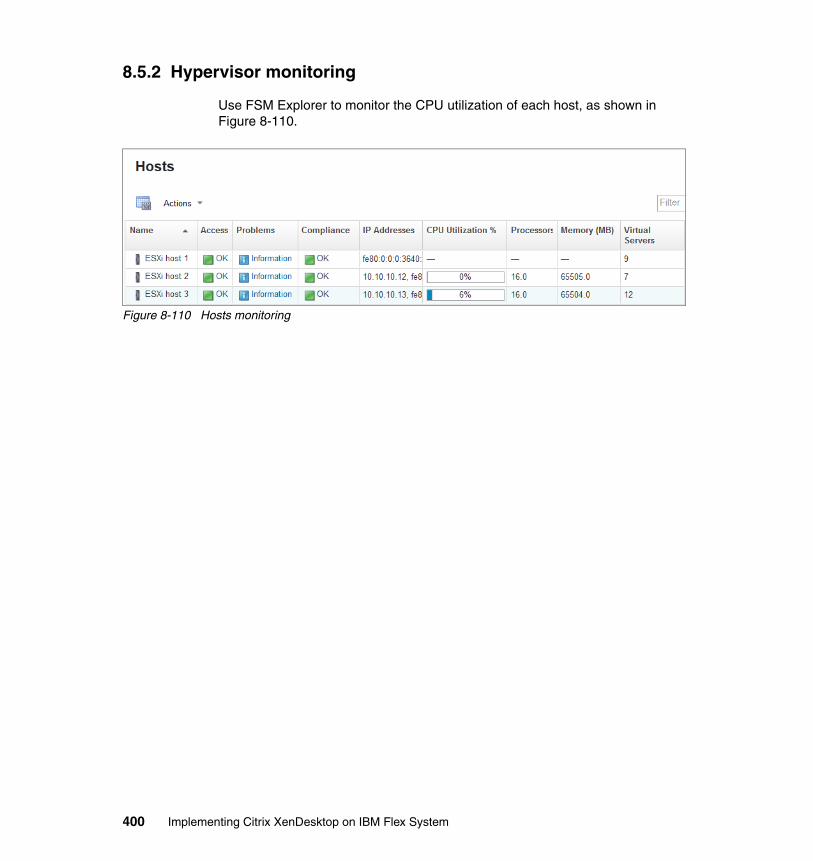
8.5.2 Hypervisor monitoring
Use FSM Explorer to monitor the CPU utilization of each host, as shown in Figure 8-110.
Figure 8-110 Hosts monitoring
400 Implementing Citrix XenDesktop on IBM Flex System
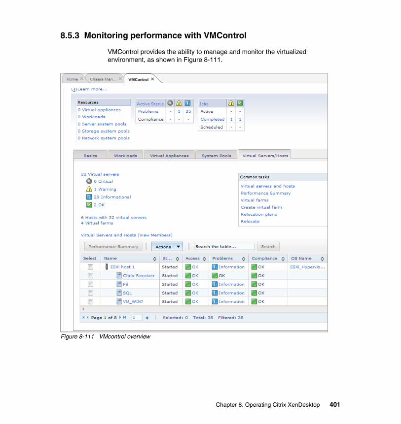
8.5.3 Monitoring performance with VMControl
VMControl provides the ability to manage and monitor the virtualized environment, as shown in Figure 8-111.
Figure 8-111 VMcontrol overview
Chapter 8. Operating Citrix XenDesktop 401
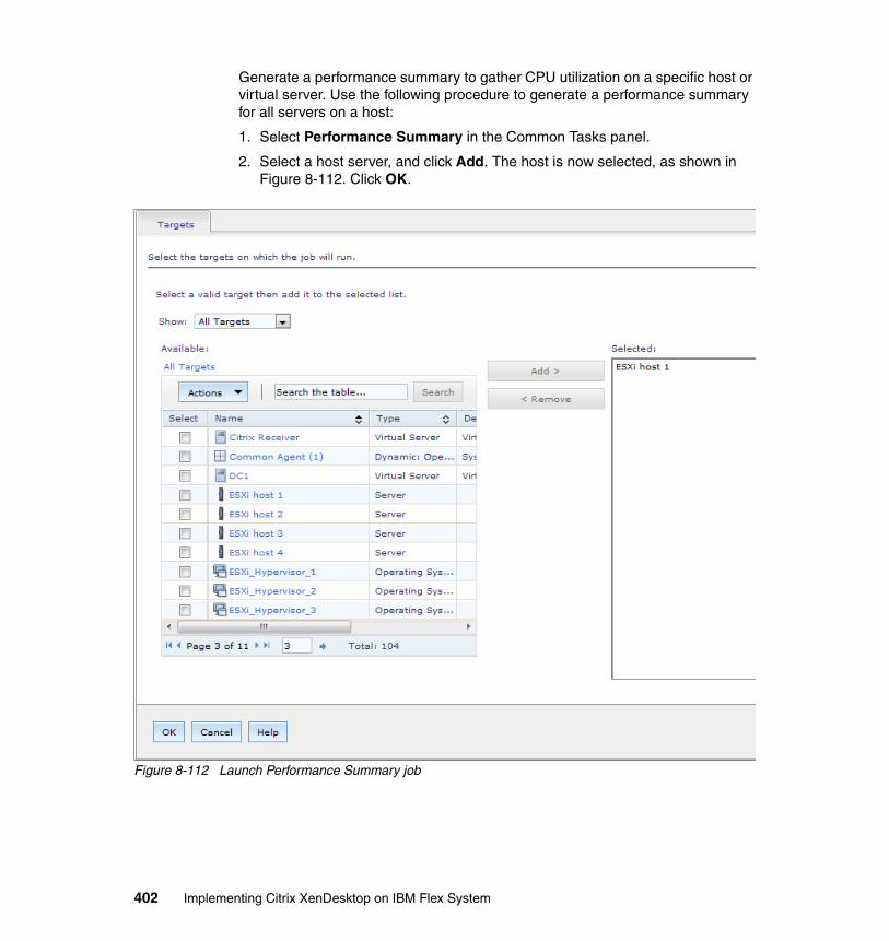
Generate a performance summary to gather CPU utilization on a specific host or virtual server. Use the following procedure to generate a performance summary for all servers on a host:
1. Select Performance Summary in the Common Tasks panel.
2. Select a host server, and click Add. The host is now selected, as shown in Figure 8-112. Click OK.
Figure 8-112 Launch Performance Summary job
402 Implementing Citrix XenDesktop on IBM Flex System
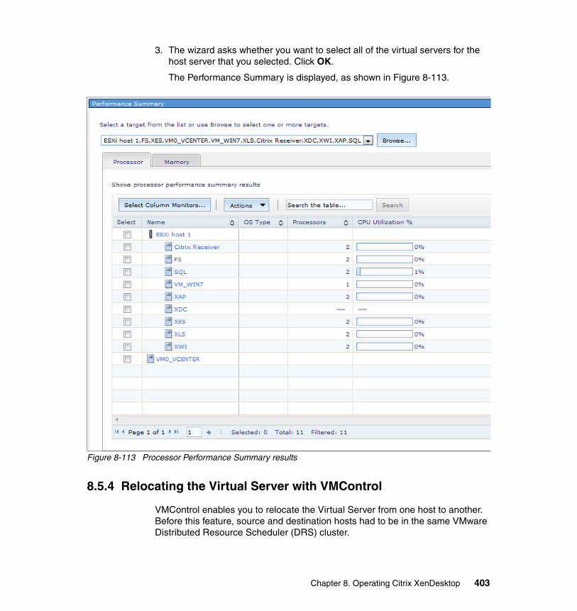
3. The wizard asks whether you want to select all of the virtual servers for the host server that you selected. Click OK.
The Performance Summary is displayed, as shown in Figure 8-113.
Figure 8-113 Processor Performance Summary results
8.5.4 Relocating the Virtual Server with VMControl
VMControl enables you to relocate the Virtual Server from one host to another. Before this feature, source and destination hosts had to be in the same VMware Distributed Resource Scheduler (DRS) cluster.
Chapter 8. Operating Citrix XenDesktop 403
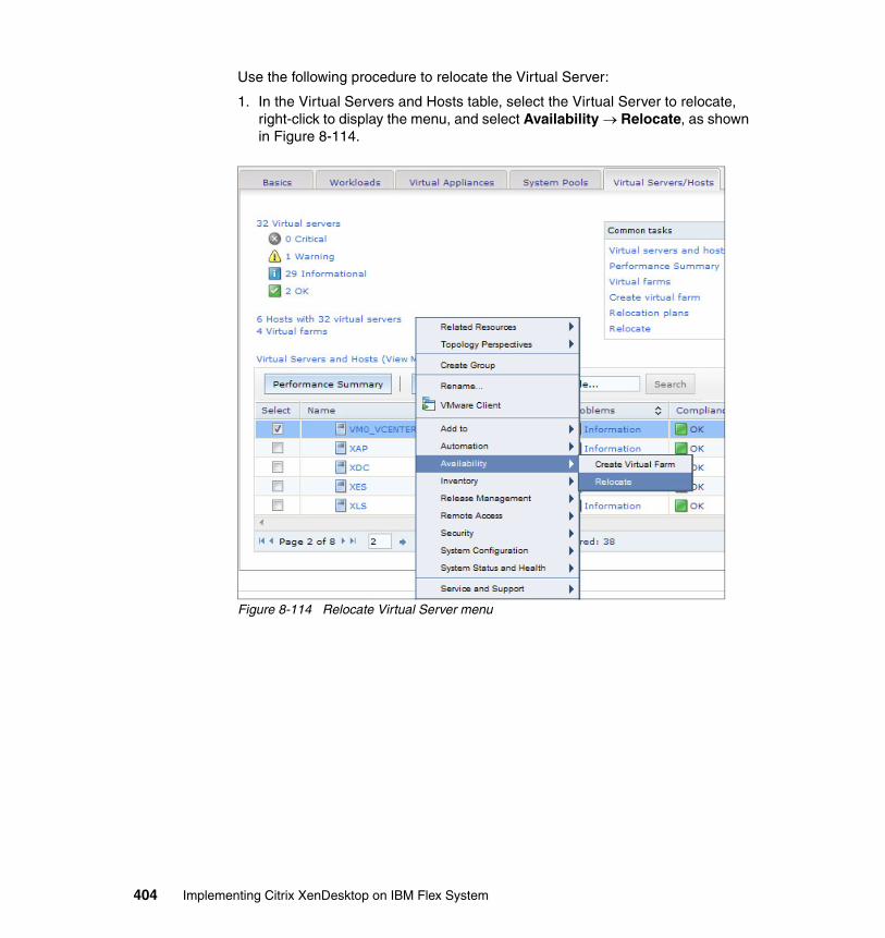
Use the following procedure to relocate the Virtual Server:
1. In the Virtual Servers and Hosts table, select the Virtual Server to relocate, right-click to display the menu, and select Availability Relocate, as shown in Figure 8-114.
Figure 8-114 Relocate Virtual Server menu
404 Implementing Citrix XenDesktop on IBM Flex System
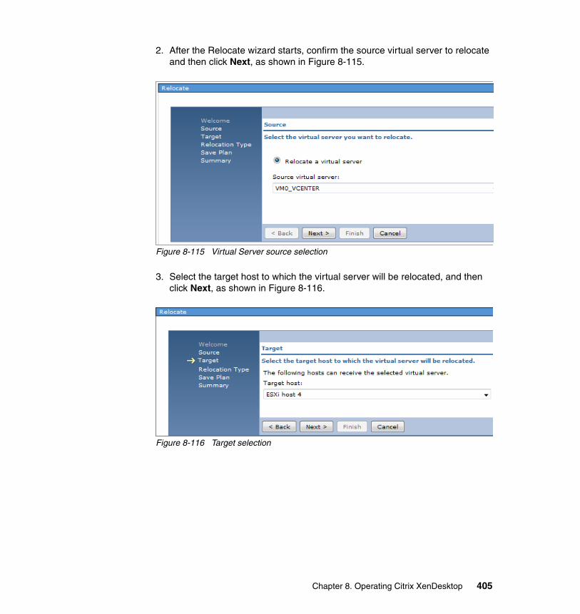
2. After the Relocate wizard starts, confirm the source virtual server to relocate and then click Next, as shown in Figure 8-115.
Figure 8-115 Virtual Server source selection
3. Select the target host to which the virtual server will be relocated, and then click Next, as shown in Figure 8-116.
Figure 8-116 Target selection
Chapter 8. Operating Citrix XenDesktop 405
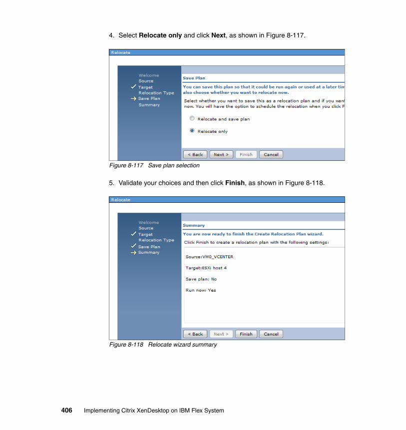
4. Select Relocate only and click Next, as shown in Figure 8-117.
Figure 8-117 Save plan selection
5. Validate your choices and then click Finish, as shown in Figure 8-118.
Figure 8-118 Relocate wizard summary
406 Implementing Citrix XenDesktop on IBM Flex System
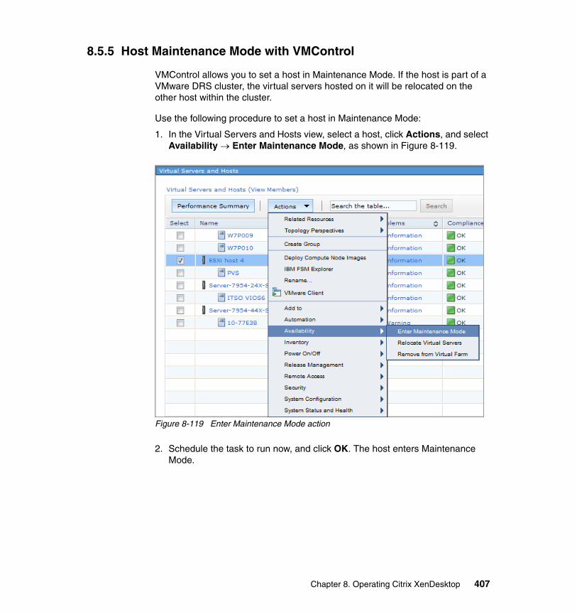
8.5.5 Host Maintenance Mode with VMControl
VMControl allows you to set a host in Maintenance Mode. If the host is part of a VMware DRS cluster, the virtual servers hosted on it will be relocated on the other host within the cluster.
Use the following procedure to set a host in Maintenance Mode:
1. In the Virtual Servers and Hosts view, select a host, click Actions, and select Availability Enter Maintenance Mode, as shown in Figure 8-119.
Figure 8-119 Enter Maintenance Mode action
2. Schedule the task to run now, and click OK. The host enters Maintenance Mode.
Chapter 8. Operating Citrix XenDesktop 407
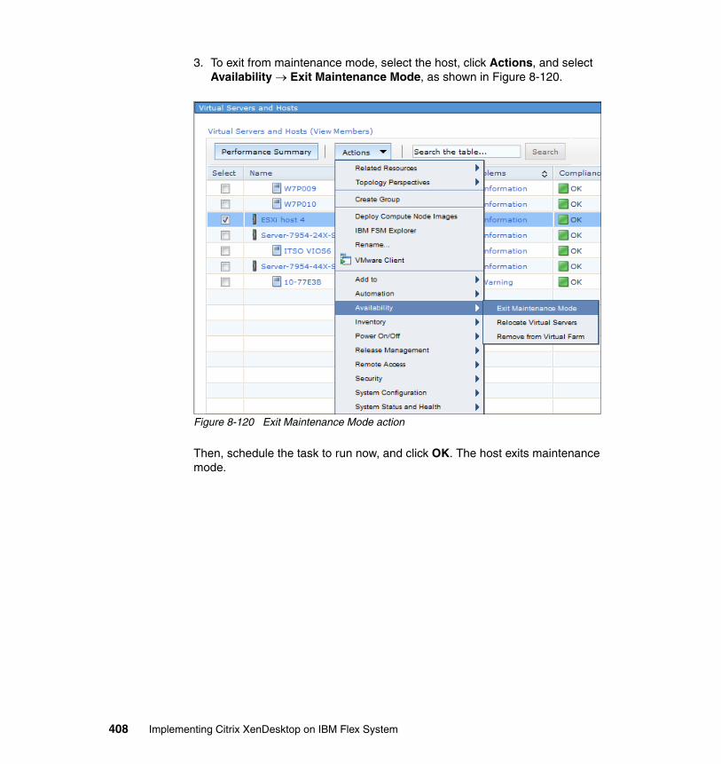
3. To exit from maintenance mode, select the host, click Actions, and select Availability Exit Maintenance Mode, as shown in Figure 8-120.
Figure 8-120 Exit Maintenance Mode action
Then, schedule the task to run now, and click OK. The host exits maintenance mode.
408 Implementing Citrix XenDesktop on IBM Flex System
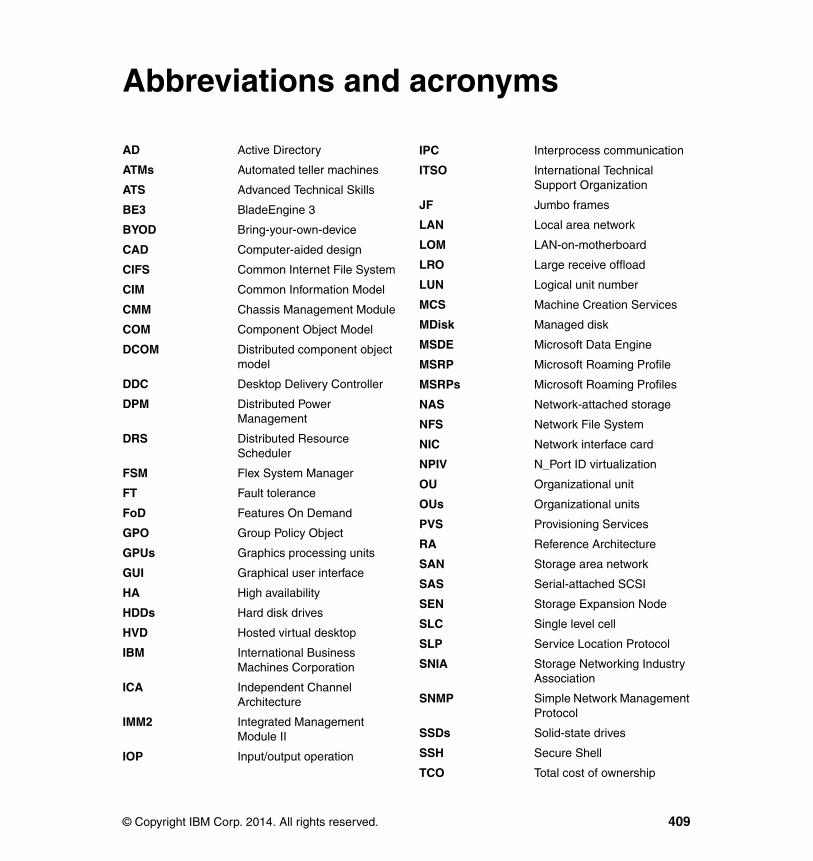
acronyms
AD Active Directory
ATMs Automated teller machines
ATS Advanced Technical Skills
BE3 BladeEngine 3
BYOD Bring-your-own-device
CAD Computer-aided design
CIFS Common Internet File System
CIM Common Information Model
CMM Chassis Management Module
COM Component Object Model
DCOM Distributed component object model
DDC Desktop Delivery Controller
DPM Distributed Power Management
DRS Distributed Resource Scheduler
FSM Flex System Manager
FT Fault tolerance
FoD Features On Demand
GPO Group Policy Object
GPUs Graphics processing units
GUI Graphical user interface
HA High availability
HDDs Hard disk drives
HVD Hosted virtual desktop
IBM International Business Machines Corporation
ICA Independent Channel Architecture
IMM2 Integrated Management Module II
IOP Input/output operation
Abbreviations and
© Copyright IBM Corp. 2014. All rights reserved.
IPC Interprocess communication
ITSO International Technical Support Organization
JF Jumbo frames
LAN Local area network
LOM LAN-on-motherboard
LRO Large receive offload
LUN Logical unit number
MCS Machine Creation Services
MDisk Managed disk
MSDE Microsoft Data Engine
MSRP Microsoft Roaming Profile
MSRPs Microsoft Roaming Profiles
NAS Network-attached storage
NFS Network File System
NIC Network interface card
NPIV N_Port ID virtualization
OU Organizational unit
OUs Organizational units
PVS Provisioning Services
RA Reference Architecture
SAN Storage area network
SAS Serial-attached SCSI
SEN Storage Expansion Node
SLC Single level cell
SLP Service Location Protocol
SNIA Storage Networking Industry Association
SNMP Simple Network Management Protocol
SSDs Solid-state drives
SSH Secure Shell
TCO Total cost of ownership
409
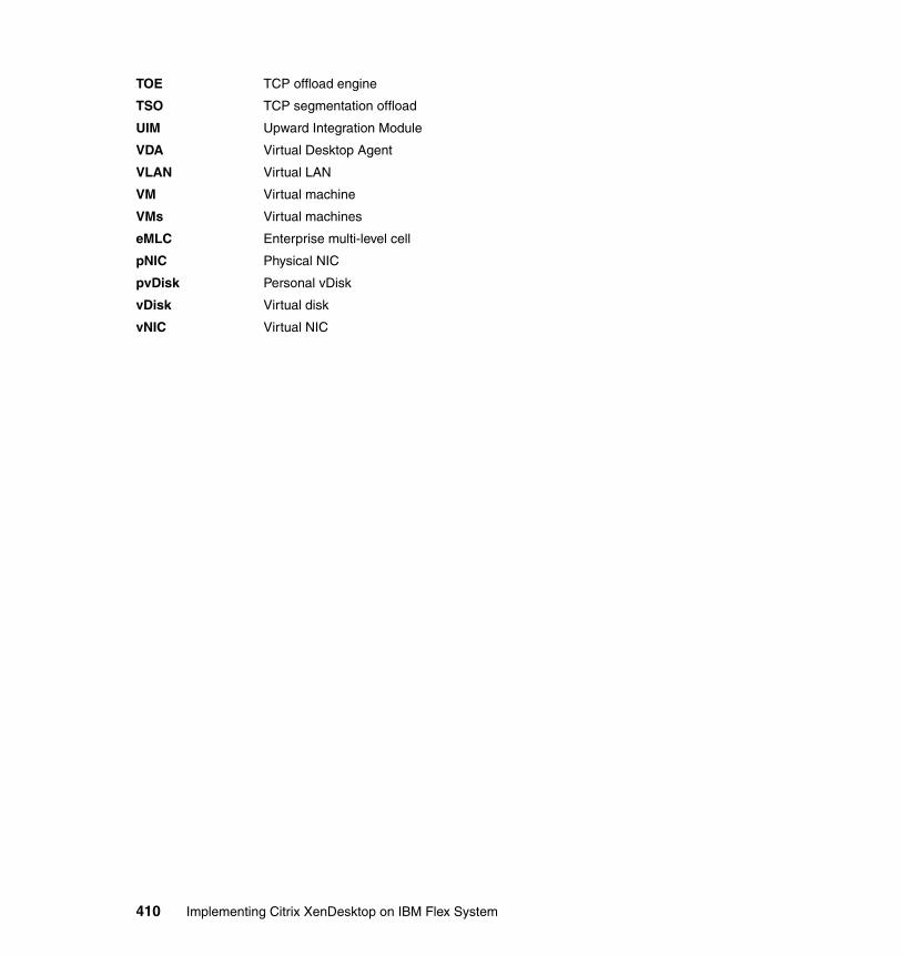
TOE TCP offload engine
TSO TCP segmentation offload
UIM Upward Integration Module
VDA Virtual Desktop Agent
VLAN Virtual LAN
VM Virtual machine
VMs Virtual machines
eMLC Enterprise multi-level cell
pNIC Physical NIC
pvDisk Personal vDisk
vDisk Virtual disk
vNIC Virtual NIC
410 Implementing Citrix XenDesktop on IBM Flex System
Related publications
The publications listed in this section are considered particularly suitable for a more detailed discussion of the topics covered in this book.
IBM Redbooks
The following IBM Redbooks publications provide additional information about the topic in this document. Note that some publications referenced in this list might be available in softcopy only.
� Implementing Systems Management of IBM PureFlex System, SG24-8060
� IBM PureFlex System and IBM Flex System Products and Technology, SG24-7984
� IBM Flex System Networking in an Enterprise Data Center, 2nd Edition, REDP-4834
� IBM SmartCloud Desktop Infrastructure: Citrix XenDesktop on IBM Flex System, TIPS0928
You can search for, view, download or order these documents and other Redbooks, Redpapers, Web Docs, draft and additional materials, at the following website:
ibm.com/redbooks
Online resources
These websites are also relevant as further information sources:
� IBM Reference Architecture for SmartCloud Desktop Infrastructure
http://ibm.co/186BJt7
� IBM Reference Architecture for Citrix XenDesktop
http://ibm.co/150EytE
© Copyright IBM Corp. 2014. All rights reserved. 411
Help from IBM
IBM Support and downloads
ibm.com/support
IBM Global Services
ibm.com/services
412 Implementing Citrix XenDesktop on IBM Flex System

(0.5” spine)0.475”<
->0.875”
250 <->
459 pages
Implem
enting Citrix XenDesktop on IBM Flex System


®
SG24-8163-00 ISBN 0738438952
INTERNATIONAL TECHNICALSUPPORTORGANIZATION
BUILDING TECHNICALINFORMATION BASED ONPRACTICAL EXPERIENCE
IBM Redbooks are developed by the IBM International Technical Support Organization. Experts from IBM, Customers and Partners from around the world create timely technical information based on realistic scenarios. Specific recommendations are provided to help you implement IT solutions more effectively in your environment.
For more information:ibm.com/redbooks
®
Implementing Citrix XenDesktop on IBM Flex System
Introduces IBM Flex System and Citrix XenDesktop offerings
Discusses design and deployment considerations
Provides step-by-step configuration guidance
The IBM SmartCloud Desktop Infrastructure offers robust, cost-effective, and manageable virtual desktop solutions for a wide range of clients, user types, and industry segments. These solutions help to increase business flexibility and staff productivity, reduce IT complexity, and simplify security and compliance. Based on a reference architecture approach, this infrastructure supports various hardware, software, and hypervisor platforms.
The SmartCloud Desktop Infrastructure solution with Citrix XenDesktop running on IBM Flex System offers tailored solutions for every business, from the affordable all-in-one Citrix VDI-in-a-Box for simple IT organizations to the enterprise-wide Citrix XenDesktop. XenDesktop is a comprehensive desktop virtualization solution with multiple delivery models that is optimized for flexibility and cost-efficiency.
This IBM Redbooks publication provides an overview of the SmartCloud Desktop Infrastructure solution, which is based on Citrix XenDesktop running on IBM Flex System. It highlights key components, architecture, and benefits of this solution. It also provides planning and deployment considerations, and step-by-step instructions about how to perform specific tasks.
This book is intended for IT professionals who are involved in the planning, design, deployment, and management of the IBM SmartCloud Desktop Infrastructure built on IBM Flex System running Citrix XenDesktop.
.
Back cover