Embed Size (px)
Citation preview
Systems
GA21-9152-2 File No. 3740-00,15
IBM 3740 Data Entry System System Summary and Installation Manual -Physical Planning
Prefa~e
This manual is intended for company executives, systems analysts, data processing managers and key entry supervisors, installation supervisors, programmers, and data station operators.
This manual provides general information about the system and installation information for centralized key entry. The manual contains descriptive information about the system and each unit, available functions and features, and the media. Programming information, suggestions for system designing, and operating procedures are included; and information necessary for planning the physical installation of the IBM 3740 Data Entry System.
In addition, a bibliography of teleprocessing publications is included.
Related Publications
IBM 3741 Data Station Reference Manual, GA21-9183.
IBM 3742 Dual Data Station Reference Manual, GA21-9184.
Third Edition (June 1974)
IBM 3747 Data Converter Reference Manual and Operator's Guide, GA21-9170
IBM 3741 and 3742 Operator's Guides, GA21-9131 and GA21-9136.
IBM 3740 System Print Chart, GX21-9187.
IBM 1443,2203 Forms Design Considerations, GA24-3488.
The IBM Diskette for Standard Data Interchange, GA21-9182
DOS/VS System Information for IBM 3540 Diskette Input/Output Unit, GC21-5072.
IBM System/370 Installation .Manual- Physical Planning, GC22-7004.
IBM 3741 Models 3 and 4 Programmable Work Station Programming Reference Manual, GA21-9194.
IBM 3741 Models 3 and 4 Programmable Work Station General Information, GA21-9196.
This is a major revision of, and obsoletes, GA21-9152-1. This edition describes new features and devices available with the IBM 3740 Data Entry System; it has been extensively rewritten and should be reviewed in its entirety.
Changes are continually made to the information herein; any such changes will be reported in subsequent revisions or Technical Newsletters.
A form for readers' comments is provided at the back of this publication. If the form has been removed, comments may be addressed to IBM Corporation, Publications, Department 245, Rochester, Minnesota 55901.
©Copyright International Business Machines Corporation, 1974
Contents
SYSTEM CONCEPT 1 SYSTEM DESIGN CONSIDERATIONS. 22
System Overview Job Scheduling and Work Flow 22
The IBM Diskette 2 Data Labeling on the Diskette . 24
IBM 3741 Models 1 and 2 Data Station 2 Single and Multiple Data Sets Per Diskette 24
IBM 3741 Models 3 and 4 Programmable Data Recovery 24
Work Station 2 IBM 3742 Dual Data Station 2 PREPARING FOR THE INSTALLATION 25
IBM 3747 Data Converter • 3 General Guidelines 25
IBM 3640 Diskette Input/Output Unit 3 Events 25
IBM 3713 Printer 4 Estimating Diskette Requirements 25
IBM 3715 Printer 4 Centralized Data Entry . 26
IBM 3717 Printer 5 Local Source Department 26
Why the System? 6 Remote Source Department 26 Example of Estimating Diskette Requirements 26
DATA STATIONS 9 Summary. 27
CRT Operator Display 9 Key Entry Programs 27
Entering Data 9 Diskette Control. 30
Operator Guidance 9 External Labels . 30
PlIOgram Control. 10 Diskette Library . 30
Program Chaining 10 Care and Storage of the Diskette 32
Updating Data 11 Documentation 32
Verifying Data 11 System Programming Considerations . 36
Adding Records to a Batch. 11 Card Replacement 36
Record Insert 11 Tape Replacement 37 Searching Data on Disk. 11 Teleprocessing Programming Support . 37
Search on Record Address 11 Telecommunications Facilities Considerations 3B Search on End of Data . 12 Unit Backup Considerations 3B Search on Content and Sequential Content 12 Education and Training 3B
Disk Copy 12 Second Disk . 12 PHYSICAL SITE PLANNING AND PREPARATION 40 128·Character Record 12 Spaca Requirements 40 Disk Initialization 12 Environmental Considerations. 40 Production Statistics 12 Temperature and Humidity 40 Field Totals 13 Tape and Diskette Storage . 40 Self Check 13 Dirt and Air Pollution 41 Proof Keyboard 13 Lighting 41 Data Recorder Attachment 13 Fire Protection Equipment. 41 Printers 14 Electrical Requirements 41
IBM 3713 Printer 14 Grounding 41 IBM 3715 Printer 14 Convenience Outlets 41 IBM 3717 Printer 15 Power Supply 41
Binary Synchronous Communications Adapter 16 Synchronous Clock . 16 UNIT SPECIFICATIONS! • 42 Terminal Identification. 16 129 Card Data Recorder 43 Keylock 16 3713 Printer . 44 Operator Identification Cerd Reader 16 3715 Printer. 45 Expanded Communications 16 3717 Printer. 46 !~. . . . Expanded Communications/Multipoint Data 3741 Data Station Models 1 and 2
Link Control 16 3741 Programmable Work Station Models 3 and 4 47 3741 and 3742 Function and Feature Summary 17 3742 Dual Data Station 48 Data Conversion via the 3747 19 3747 Data Converter 49 Input via the 3540 20 5496 Data Recorder 50
PROGRAMMABLE WORK STATIONS 21 3740SVSTEM CABLING INFORMATION. 51 Functions under ACL Program Control 21 Features Available with the Programmable Work INCH TO CENTIMETER CONVERSION CHART. 52 Station 21
ACL Translator . 21 GLOSSARY. 53
Storage. 4K Additional • 21 TELEPROCESSING BIBLIOGRAPHY 56
INDEX 51
iii
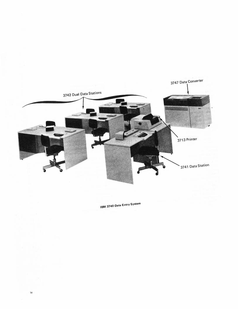
3742 Dual Data Stations
~~----~~--------
IBM 3740 Data Entry System
iv
3747 Data converter
3741 Data Station
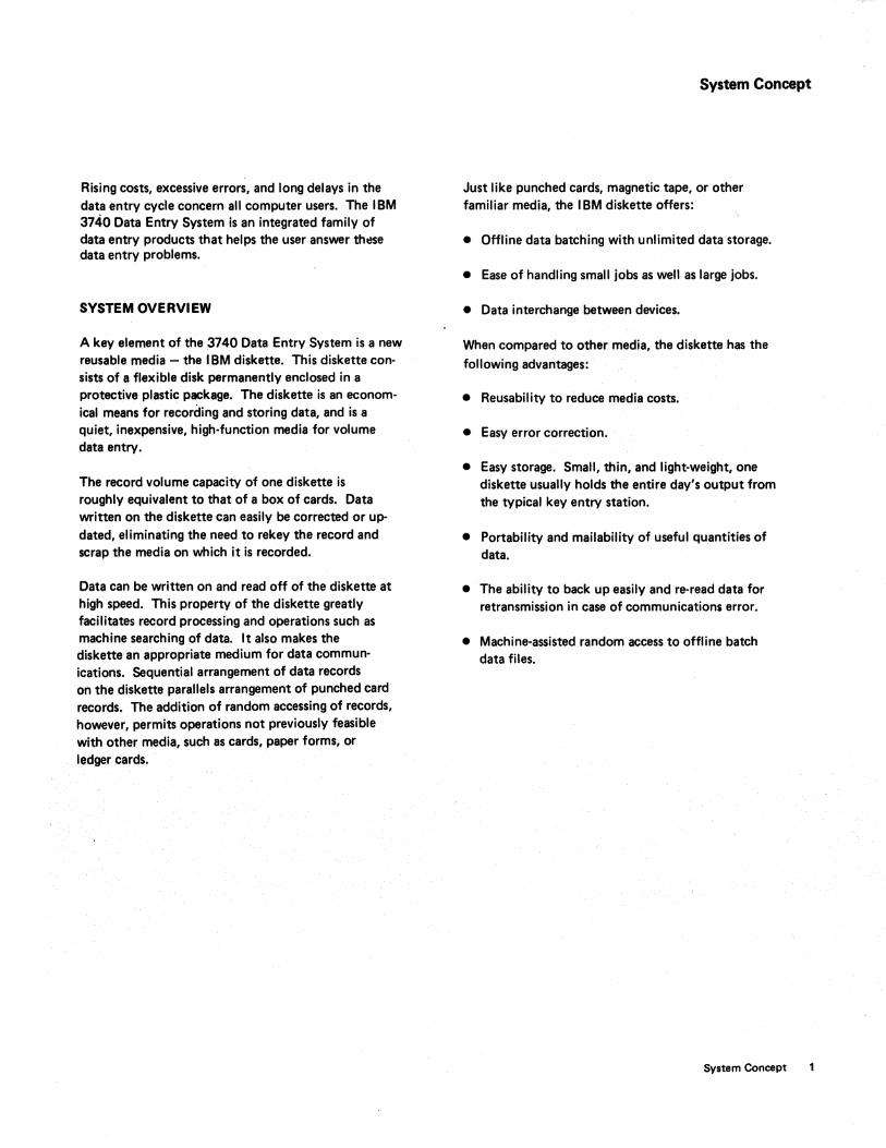
Rising costs, excessive errors, and long delays in the data entry cycle concern all computer users. The IBM 3740 Data Entry System is an integrated family of data entry products that helps the user answer th~se data entry problems.
SYSTEM OVERVIEW
A key element of the 3740 Data Entry System is a new reusable media - the I BM diskette. This diskette consists of a flexible disk permanently enclosed in a protective plastic package. The diskette is an economical means for recording and storing data, and is a quiet, inexpensive, high-function media for volume data entry.
The record volume capacity of one diskette is roughly equivalent to that of a box of cards. Data written on the diskette can easily be corrected or updated, eliminating the need to rekey the record and scrap the media on which it is recorded.
Data can be written on and read off of the diskette at high speed. This property of the diskette greatly facilitates record processing and operations such as machine searching of data. It also makes the diskette an appropriate medium for data communications. Sequential arrangement of data records on the diskette parallels arrangement of punched card records. The addition of random accessing of records, however, permits operations not previously feasible with other media, such as cards, paper forms, or ledger cards.
System Concept
Just like punched cards, magnetic tape, or other familiar media, the IBM diskette offers:
• Offline data batching with unlimited data storage.
• Ease of handling small jobs as well as large jobs.
• Data interchange between devices.
When compared to other media, the diskette has the following advantages:
• Reusability to reduce media costs.
• Easy error correction.
• Easy storage. Small, thin, and light-weight, one diskette usually holds the entire day's output from the typical key entry station.
• Portability and mailability of useful quantities of data.
• The ability to back up easily and re-read data for retransmission in case of communication$ error.
• Machine-assisted random access to offline batch data files.
System Concept
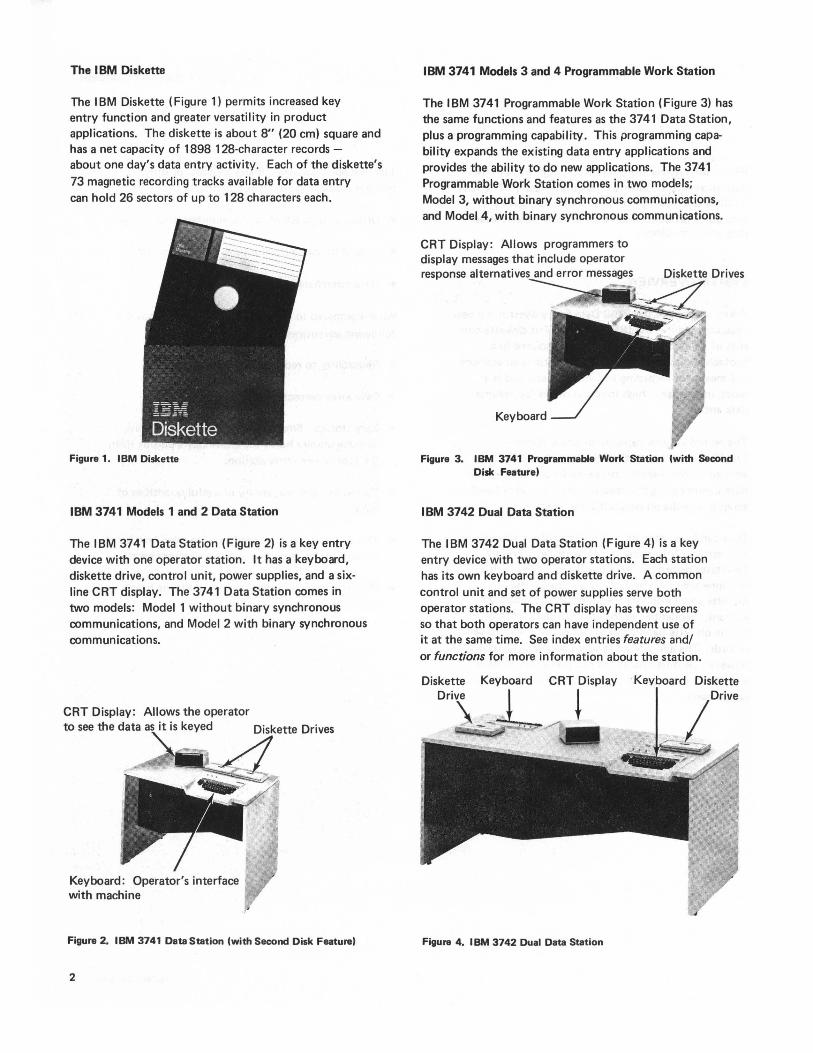
The I BM Diskette
The I BM Diskette (Figure 1) permits increased key entry function and greater versatility in product applications. The diskette is about 8" (20 cm) square and has a net capacity of 1898 128-character records -about one day's data entry activity. Each of the diskette's 73 magnetic recording tracks available for data entry can hold 26 sectors of up to 128 characters each.
Figure 1. IBM Diskette
IBM 3741 Models 1 and 2 Data Station
The IBM 3741 Data Station (Figure 2) is a key entry device with one operator station. It has a keyboard, diskette drive, control unit, power supplies, and a sixline CRT display. The 3741 Data Station comes in two models: Model 1 without binary synchronous communications, and Model 2 with binary synchronous commun ications.
Keyboard: Operator's interface with machine
Figure 2_ IBM 3741 Data Station (with Second Disk Feature)
2
IBM 3741 Models 3 and 4 Programmable Work Station
The IBM 3741 Programmable Work Station (Figure 3) has the same functions and features as the 3741 Data Station, plus a programming capability. This programming capability expands the existing data entry applications and provides the ability to do new applications. The 3741 Programmable Work Station comes in two models; Model 3, without binary synchronous communications, and Model 4, with binary synchronous communications_
CRT Display: Allows programmers to display messages that include operator response alternatives and error messages Diskette Drives
Figure 3_ IBM 3741 Programmable Work Station (with Second Disk Feature)
IBM 3742 Dual Data Station
The IBM 3742 Dual Data Station (Figure 4) is a key entry device with two operator stations. Each station has its own keyboard and diskette drive. A common control unit and set of power supplies serve both operator stations. The CRT display has two screens so that both operators can have independent use of it at the same time. See index entries features andl or functions for more information about the station.
Diskette Keyboard CRT Display . Kevboard Diskette
~
Figure 4_ IBM 3742 Dual Data Station
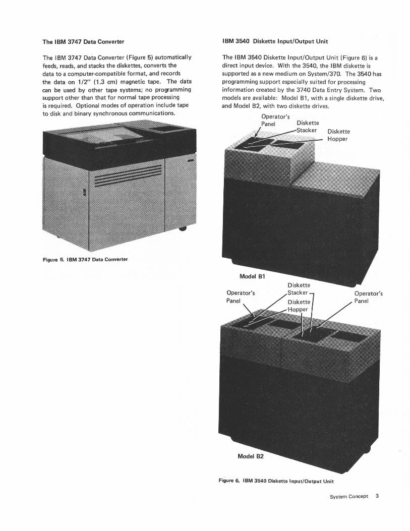
The IBM 3747 Data Converter
The IBM 3747 Data Converter (Figure 5) automatically feeds, reads, and stacks the diskettes, converts the data to a computer-compatible format, and records the data on 1/2" (1.3 em) magnetic tape. The data can be used by other tape systems; no programming support other than that for normal tape processing is required. Optional modes of operation include tape to disk and binary synchronous communications.
Figure 5. IBM 3747 Data Converter
IBM 3540 Diskette Input/Output Unit
The IBM 3540 Diskette Input/Output Unit (Figure 6) is a direct input device. With the 3540, the IBM diskette is supported as a new medium on System/370. The 3540 has programming support especially suited for processing information created by the 3740 Data Entry System. Two models are available : Model B1 , with a single diskette drive, and Model B2, with two diskette drives.
Operator's Panel
Diskette Diskette Hopper
Operator's Panel
Figure 6. IBM 3540 Diskette Input/Output Unit
System Concept 3
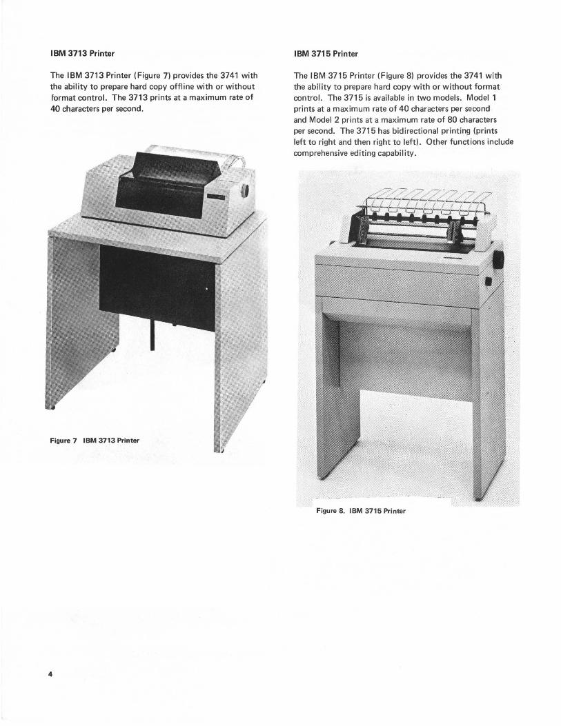
IBM 3713 Printer
The IBM 3713 Printer (Figure 7) provides the 3741 with the ability to prepare hard copy offline with or without format control. The 3713 prints at a maximum rate of 40 characters per second.
Figure 7 IBM 3713 Printer
4
IBM 3715 Printer
The IBM 3715 Printer (Figure 8) provides the 3741 with the ability to prepare hard copy with or without format control. The 3715 is available in two models. Model 1 prints at a maximum rate of 40 characters per second and Model 2 prints at a maximum rate of 80 characters per second. The 3715 has bidirectional printin.g (prints left to right and then right to left). Other functions include comprehensive editing capability.
Figure 8. IBM 3715 Printer
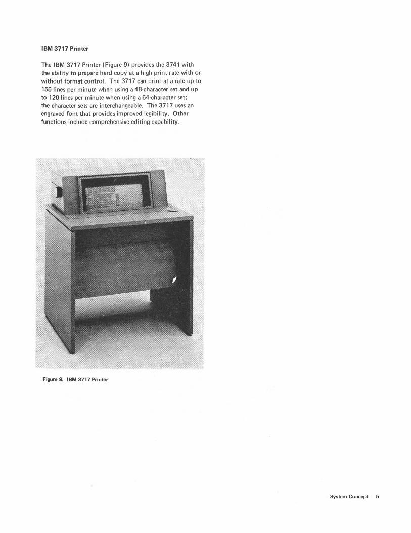
IBM 3717 Printer
The IBM 3717 Printer (Figure 9) provides the 3741 with the ability to prepare hard copy at a high print rate with or without format control. The 3717 can print at a rate up to 155 lines per minute when using a 48-character set and up to 120 lines per minute when using a 64-character set; the character sets are interchangeable. The 3717 uses an engraved font that provides improved legibility. Other functions include comprehensive editing capability.
Figure 9. IBM 3717 Printer
System Concept 5
WHY THE SYSTEM?
Key entry operator labor is one of the prominent factors in rising data entry costs. Therefore, improvement of operator productivity is extremely important in controlling these rising costs. The 3740 system features are aimed at:
• Making volume keying in the centralized keypunch room a high productivity operation.
• Changing data entry from pure transcription to an application oriented operation.
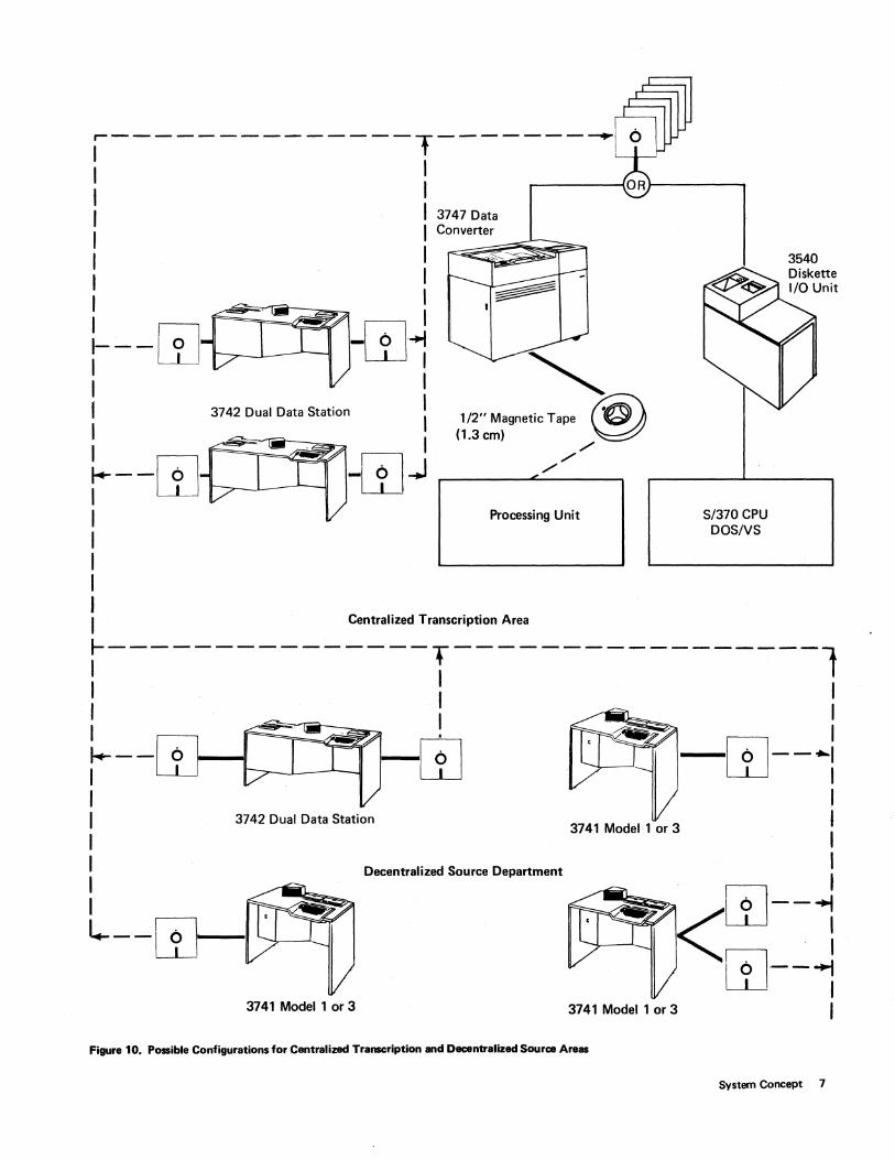
In a centralized transcription environment (see upper part of Figure 10), a typical installation includes a number of IBM 3742 Dual Data Stations for recording data on diskettes. An IBM 3747 Data Converter is included to convert the data to %" (1.3 cm) tape for processing by the host processing unit.
A decentralized or source department keying area (see lower part of Figure 10) is usually characterized by a relatively small number of key entry stations located in the data source area. Source departments may be either local, in the vicinity of the data processing systelTls and using messenger service or internal mail for delivery of data; or remote, relying on mail or telecommunications for delivery of data. The successful decentralization of the data entry function usually requires special features not normally found in key entry devices. The 3740 system provides such commonly required features as a printer, teleprocessing capability, operator guidance, and large data storage for reference and entry. In a decentralized
environment, several 3741s and 3742s are scattered through large installations in the source departments. For instance, one might be in the accounts payable department, where data is entered directly from vendor invoices. Other 3741 s might be in the payroll department to enter changes to salaried payroll. Diskettes are sent by interplant mail or messenger to some location having an IBM 3747 Data Converter.
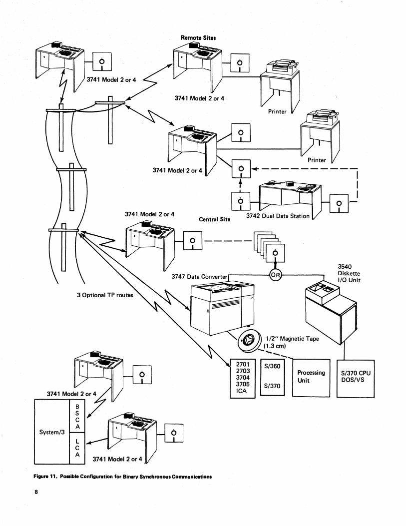
In a typical remote environment (see Figure 11), one or more 3741s are located at various offsite locations. In areas where the workload is heavy, these might be supplemented with some 3742s. For example, if parts are distributed from a warehouse to several divisions of a company, the inventory data is entered on diskettes as transactions occur. Periodically, the data is transmitted to the warehouse through 3741 Model 2 or 4 with binary synchronous communications. The receiving device at the warehouse can be an:
6
• IBM 3741 Model 2 or 4 with BSCA.
• IBM 3747 Data Converter with BSCA.
• IBM Systems/3 Model 6, Model 10 Disk System, or
Model 15 with BSCA.
• IBM System/370 via an: IBM 2701 Data Adapter Unit • IBM ;2703 Transmission Control Unit IBM 3704 Communications Controller IBM 3705 Communications Controller Integrated Communications Adapter(lCA).
The 3740 concept of an integrated family of devices used in both the centralized and source data entry environments provides the solution, not only to rising costs, but to excessive errors. By moving the data entry function from the keypunch room out to the data source, data control functions such as preparation of keypunch worksheets and coding can often be reduced or eliminated. Moreover, errors are reduced by eliminating hand transcription operations and having the data completely handled by those who are most familiar with it and have direct responsibility for its accuracy.
Data processing users who plan to decentralize their data entry operations must still control their costs in centralized data entry areas today. The 3740 system provides the features needed to increase productivity in today's keypunch room and at the same time, decentralize data entry applications without changing to a new and possibly incompatible data entry system.
Each station in the 3740 system operatesindep'endently with its own media. The 3740 Data Entry System provides the following advantages:
• Unlimited data storage at the station.
• Quiet data entry.
• Station independence and system reliability. (Each station can continue to operate regardless of the status of other stations or down time of other facilities.)
• Total configuration flexibility.
• Smooth growth by adding exactly as many stations as are needed.
~--------------T--------~ I I I I OR~------I I 3747 Data
I Converter
I I I I I I : I I---m -W~ I LLJ I I I I 3742 Dual Data Station I I I I . I j--W i1J~ I I I I I
'" 1 /2" Magnetic Tape @ (1.3cm) ~
,/ ,/
,/
Processing Unit S/370 CPU DOSIVS
3540
I j---------------T-----------------l I I I
Centralized Transcription Area
I I I
I ~--! I j--W ~ W -w--.. : I I I 3742 Dual Data Station I I 3741 Model 1 or 3 I
I Decentralized Source Department I I _. I I W--~ ~--W ~ :
W--1 3741 Model 1 or 3 3741 Model 1 or 3 I
Figure 10. Possible Configurations for Centralized Transcription and Decentralized Source Areas
System Concept 7
5ystem/3
L C A
3741 Model 2 or 4 \
Remote Sites
3741 Model 2 or 4
Central Site
Fif1U1'8 11. POIIibie Configuration for Binary Synchronous Communications
8
..-----------
1/2" Magnetic Tape (1.3 cm)
""'"--..,~.----5/360
5/370
"'"t------.
Processing Unit
I I I
,-
5/370 CPU D05N5
Both the 3741 and 3742 stations can be used in any installation to achieve the precise mix of stations and functions required. Operators find no difficulty in moving from one machine to the other because of the common interface presented to the operator; that is, the keyboard, function switches, and display. .
CRT OPERATOR DISPLAY
The CRT operator display significantly affects traditional key entry because it:
• Reduces operator training requirements.
• Provides quick communication of errors to an operator.
• Facilitates scanning and searching of stored records.
• Permits keying with operator guidance on the IBM 3741.
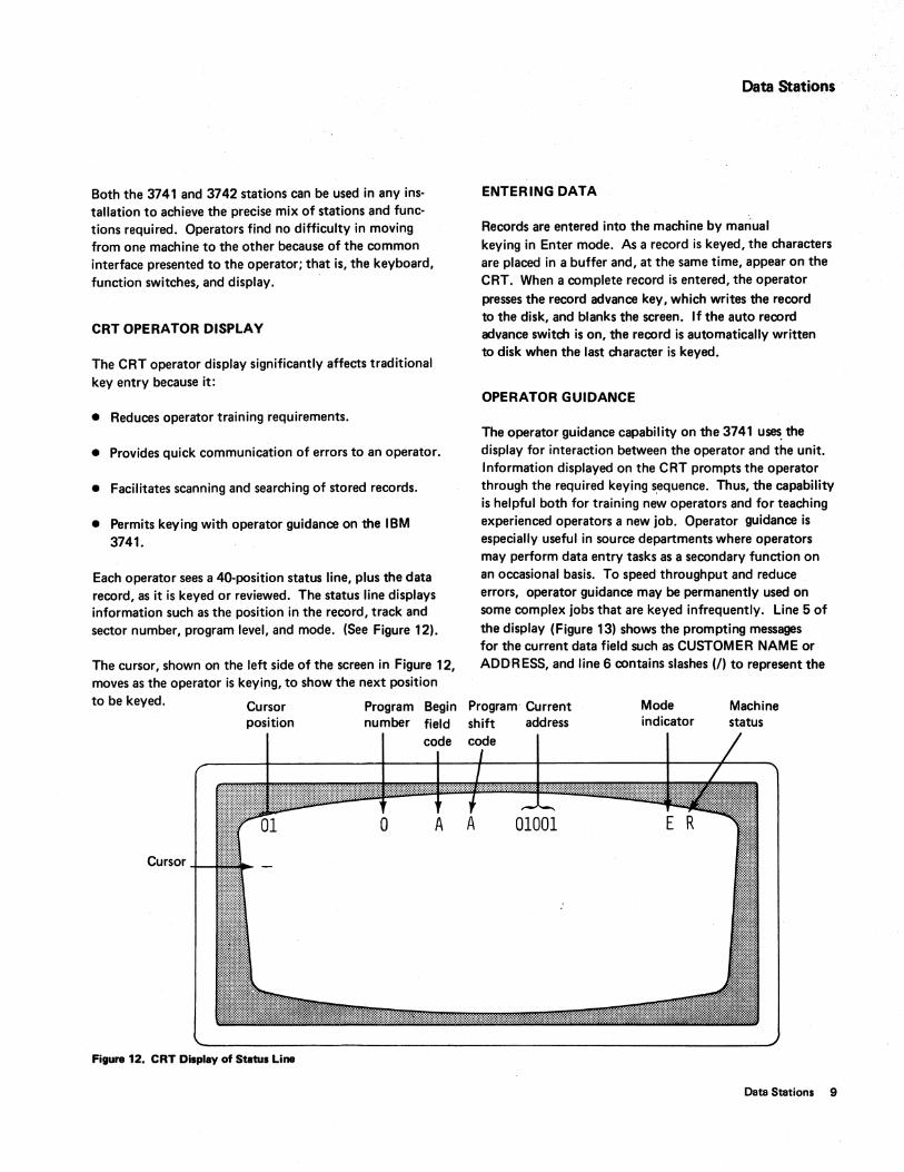
Each operator sees a 40-position status line, plus the data record, as it is keyed or reviewed. The status· line displays information such as the position in the record, track and sector number, program level, and mode. (See Figure 12).
The cursor, shown on the left side of the screen in Figure 12, moves as the operator is keying, to show the next position
Data Stations
ENTERING DATA
Records are entered into the machine by mariual keying in Enter mode. As a record is keyed, the characters are placed in a buffer and, at the same time, appear on the CRT. When a complete record is entered, the operator presses the record advance key, which writes the record to the disk, and blanks the screen. If the auto record advance switch is on, the record is automatically written to disk when the last character is keyed.
OPERATOR GUIDANCE
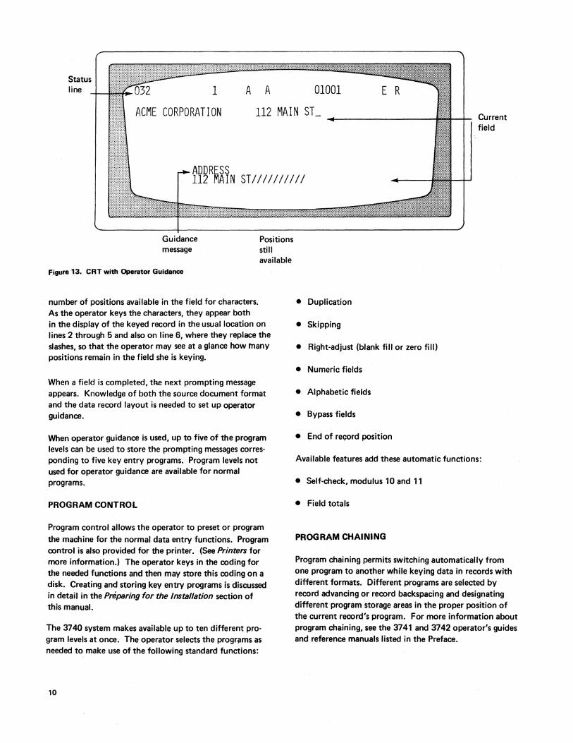
The operator guidance capability on the 3741 u~ the display for interaction between the operator and the unit. Information displayed on the CRT prompts the operator through the required keying s,equence. Thus, the capability is helpful both for training new operators and for teaching experienced operators a new job. Operator guidance is especially useful in source departments where operators may perform data entry tasks as a secondary function on an occasional basis. To speed throughput and reduce errors, operator guidance may be permanently used on some complex jobs that are keyed infrequently. Line 5 of the display (Figure 13) shows the prompting messages for the current data field such as CUSTOMER NAME or ADDRESS, and line 6 contains slashes (I) to represent the
to be keyed. Cursor position
Program Begin Program· Current number field shift address
Mode indicator
Machine status
code code
A A
Cursor
Figure 12. CRT Display of Statui Line
Data Stations 9
Status line A A
:::.:
GlOGl E 1
ACME CORPORATION 112 MAIN ST_ Current field
ADDRESS 112 MAIN STIIIIIIIIII
Guidance message
Figure 13. CRT with Operator Guidance
number of positions available in the field for characters. As the operator keys the characters, they appear both
Positions still available
in the display of the keyed record in the usual location on lines 2 through 5 and also on line 6, where they replace the slashes, so that the operator may see at a glance how many positions remain in the field she is keying.
When a field is completed, the next prompting message appears. Knowledge of both the source document format and the data record layout is needed to set up operator guidance.
When operator guidance is used, up to five of the program levels can be used to store the prompting messages corresponding to five key entry programs. Program levels not used for operator guidance are available for normal programs.
PROGRAM CONTROL
Program control allows the operator to preset or program the machine for the normal data entry functions. Program control is also provided for the printer. (See Printers for more information.) The operator keys in the coding for the needed functions and then may store this coding on a disk. Creating and storing key entry programs is discussed in detail in the Preparing for the Installation section of this manual.
The 3740 system makes available up to ten different program levels at once. The operator selects the progriJms as needed to make use of the following standard functions:
10
• Duplication
• Skipping
• Right-adjust (blank fill or zero fill)
• Numeric fields
• Alphabetic fields
• Bypass fields
• End of record position
Available features add these automatic functions:
• Self-check, modulus 10 and 11
• Field totals
PROGRAM CHAINING
Program chaining permits switching automatically from one program to another while keying data in records with different formats. Different programs are selected by record advancing or record backspacing and designating different program storage areas in the proper position of the current record's program. For more information about program chaining, see the 3741 and 3742 operator's guides and reference manuals listed in the Preface.
UPDATING DATA
Update mode can be selected to change a record that was keyed previously. After a partial or complete data set is entered, all the records in it can be reviewed as well as modified by either selecting Update mode or using the record backspace key. Update mode can be used to change any field in a record; it might be used to change the amounts in a price field or to make changes in a payroll file.
VERIFYING DATA
Verify mode checks the accuracy of prerecorded records and permits the operator to make corrections to the records as errors are discovered. Since any errors in the recorded data are corrected during the verify operation, output from this step is converter/computer ready.
All 3740 data entry units in an installation can be used for either entry or verification; thus, workloads can be balanced with fewer units.
Verification is performed much as it is on a card verifier or when visually checking information typed or entered on an accounting machine. In manual fields, keyed data must match the recorded data. The data is displayed on the screen; all characters up through the last character position verified are shown. The entire record is displayed at the beginning of the record, after any record backspace operation, or when an error occurs. If a verify error occurs, the keyboard locks; the display flashes, and an error code is displayed on the status line. The cursor indicates the position in the record in error. Pressing the reset key unlocks the keyboard and allows you to rekey a character. The rekeyed character is accepted as correct if (1) it matches the character originally entered or (2) it matches the verify stroke that caused the error condition. If another verify error occurs, the correction character is accepted only if one of the above conditions is met. (This procedure replaces the error notch and repunching required with cards.) The number of errors in a field may warrant the use of Field Correct. In this mode, an automatic field backspace occurs after the field is rekeyed, thus ensuring verification of the field.
Duplicate fields are compared, character by character, with corresponding data in the previous record. Skip fields are checked for all blank characters from the point of skip initialization to the end of the field. Duplicate and skip errors are handled just as errors are in a manual field.
Your program can Verify Bypass fields that do not require verification. Verify Bypass provides you with the capability to bypass a field without checking its content.
When the last record in the data set is verified, a verify mark is inserted in the data set label; this mark is reset if a record is added to the data set. The verify mark can be checked by the data converter to ensure that all data sets going into the system have passed through the verify operation.
ADDING RECORDS TO A BATCH
If an error is discovered during verification, batch totals, or a count of the number of records in a batch, one or more records may have to be added. The best way to do this is to add the records to the end of a batch after the rest of the batch is verified.
Some data sets may contain sequence-sensitive records; that is, one or more fields within the records may be arranged in ascending or descending order. The demand for such sequences is usually set up by the computer programs that will eventually proces~ the data. If missing records must be added sequentially, a machine equipped with disk copy can be used to perform this task by copying the data up to' the appropriate address, inserting the record, and then copying the rest of the data. This procedure is described in detail in the 3741 and 3742 operator's guides listed in the Preface.
RECORD INSERT
Another method of adding records to a data set is by using the record insert feature available on the 3741 and 3742. The record insert feature creates space (anywhere in a data set) for inserting records by moving existing data set records from the current disk address toward the end-of-extent (EOE) address of the data set. The number of spaces created can be up to 99. The feature fills the vacated space with deleted records. The deleted records are identified with a D in position 001 and a / (inverse slash) in position 002.
Once all of the spaces are filled with deleted records, the data station is placed in update mode and the disk address is displayed where the operator can begin to insert the additional records. For more information on the record insert feature, see the 3741 and 3742 reference manuals and opera:tor's guides listed in the Preface.
SEARCHING DATA ON THE DISK
Search mode replaces manual searching through records. The 3740 system offers the following capabilities:
Data Stations 11
Search on Record Address
Search on record address allows you to find a particular record by specifying its disk address, which is its track and sector number. The search stops at the specified address and the CRT displays the record found.
Search on End of Data
Search on end of data (EOD) finds the last record in a data set. This operation allows you to ad.d additional records to a data set without (1) knowing in advance where the end of the data set is or (2) manually searching for the end of the data set.
Search on Content and Sequential Content
Search on content and search on sequential content locate the record specified by a mask statement identifying the record's contents. Search sequential content is a faster search method for records in which the fields being searched are sequentially arranged. In either type of search, if the record is not found, an error is displayed.
DISK COpy
The disk copy function copies data from one disk to another. Records can be merged both from disk two and the keyboard onto disk one. All disk two functions are fully independent ot; and nonoverlapped with, disk one functions.
SECOND DISK
The second disk feature provides the second disk capability on the 3741. The second disk allows disk operations and expanded storage for use with communications.
128 CHARACTER RECORD
The 128-character record feature (3742 only) permits the use of variable length records up to 128 characters long. The feature also adds four more program levels per station.
Record length may be variable between data sets, but must be fixed within each data set. The record length is set in the label of the data set on the index track.
12
DISK INITIALIZATION
This function allows the operator to reinitialize a disk if irregularities develop in a track during disk usage.
Note: It is not necessary to reinitialize a disk every time the disk is to be reused.
When reinitialization is necessary, this feature rewrites the track and sector addresses of each track so that the previously identified irregular tracks are automatically skipped. Each disk contains two spare tracks to replace any irregular tracks. In addition, the initialization feature provides a means of altering the sequence of sector address on the diskette. Normally, the sequence of sectors is in numeric order (1, 2, 3, ... 25,26). By changing this sequence, the data conversion, ACL program translation, and search on content rates may be increased. Sector sequencing is transparent to the operator when keying and should not affect operation or throughput capabilities. (See the IBM 3741 and 3742 reference manuals and the standard data interchange manual for further information.)
PRODUCTION STATISTICS
The 3741 and 3742 count the number of records processed, the number of keystrokes used in entering data, and the number of keystrokes used in verify corrections; these three totals are stored in separate counters. Totals can be displayed on the CRT, and can be entered onto a disk. The .keystroke counter automatically resets to zero when the count reaches 999, 999. The record counter counts record advances in Enter, Verify, and Update modes. The verify correction keystroke counter counts verify correction keystrokes and all characters rekeyed in Field Correct mode.
FIELD TOTALS
The most important application of the field totals feature is for batch auditing. This feature provides the ability to balance a field to a predetermined total, to create a batch control total, or to crossfoot and enter totals into the same record or a following record under program control. Under program control, data is summed algebraically. A total from at least one field in every record or in specified records of the batch is kept in one of the three 19-digit decimal accumulators. The 3741 and 3742 can compute the totals in an offline pass after the batch is keyed. The 3741 can compute the totals online while in Enter, Update, and Verify modes.
The field totals accumulators may be read out by displaying them on the CRT or they may be automatically written into a record under program control. For example, these totals might be read into another record if the last record was the final total of a bill. These totals can also be visually compared to some predetermined total - a batch audit total of catalog numbers, for example, to determine that every record was entered. If a record was missed or incorrectly entered, the field totals capability helps the operator correct the error by keeping track of the net changes as the operator rekeys the records. For example, if the operator rekey's a 5 when she previously had a 6, the machine records -1. Thus, when the net difference in the accumulator matches the amount by which the batch was out of balance, the operator knows that the error is found and that no further corrections are necessary.
SELF-CHECK
Self-check checks the entry of numeric fields that have a last digit that was precomputed. When the field is keyed, the data station recomputes the self-check digit and compares it against the self-check digit that is entered. If the digits are not identical, an error is indicated. The machine goes into a wait state and waits for operator action to correct the error. Self-check fields can be entered manually or automatically under program control.
PROOF KEYBOARD
The proof keyboaOrd differs from a standard 3741 or 3742 keyboard only by a rearrangement of the numeric keys. The proof keyboard numeric key arrangement allows the operator who is more familiar with the adding machine key arrangement, to more effectively enter numeric data. For more information on the proof keyboard feature, see the 3741 and 3742 reference manual listed in the Preface.
DATA RECORDER ATTACHMENT
The data recorder attachment feature attaches the IBM 129 Data Recorder (Model 2) or the IBM 5496 Data Recorder (Model 1) to a 3741. This feature allows a 3741 to read, punch, punch/print via a 129 (80-column cards) or a 5496 (96-column cards) data recorder. The 129 Model 2 reads cards at a rate of up to 50 cards per minute and punches cards at a rate of 11 to 39 cards per minute. The 5496 Model 1 reads cards at a rate of 21 cards per minute and punches cards at a rate of 17 cards per minute. Tlie reading and punching of cards can be either formatted or unformatted.
The data recorders (online with a 3741) punch cards in four different modes. If the print switch on the data recorder is on, the cards are also printed. The four modes are:
1. Punch a record - The record in the 3741 current record buffer is punched.
2. Punch data set - The current data set is punched.
3. Punch under address control - The records found under search on record address are punched. This operation has the following characteristics:
4.
.. a. If initiated from the index track, all the records from the first record in the data set, up to and including the record at the record address specified, are punched.
b. If initiated from a record address in a data set, all the records from that address, up to and including the record at the record address specified, are punched.
Punch under search on content - The records found under search on content are punched. Once the operator initiates the search, each record in the data set that satisfies the search criteria is punched.
The data recorders (online with a 3741) read cards in two modes:
1. Read a card - A single card is read.
2. Continuous card read - Cards are read and written to disk until a card with ?* (indicates end-of-file) in columns 1 and 2 is read. The primary purpose of the continuous card read function is to perform cardto-disk operations in a batch environment. Single or multiple data sets can be created from a continuous card read operation.
Data Stations 13
This feature also allows the current record buffer to be formatted and written to disk.
Note: A data recorder does not have to be online for the 3741 to perform this function.
When not online with a 3741, the data recorders operate with their stand-alone functions.
PRINTERS
Either the 3713, 3715, or 3717 Printer can be attached to the 3741.
IBM 3713 Printer
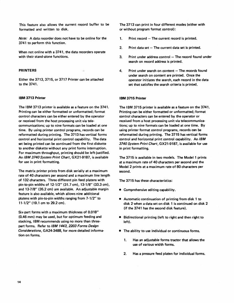
The IBM'3713 printer is available as a feature on the 3741. Printing can be either formatted or unformatted; format control characters can be either entered by the operator or received from the host processing unit via telecommunications; up to nine formats can be loaded at one time. By using printer control programs, records can be reformatted during printing. The 3713 has vertical forms control and horizontal print control capability. The data set being printed can be continued from the first diskette to another diskette without any print forms interruption. For maximum throughput, printing should be left-justified. An IBM 3740 System Print Chart, GX21-9187, is available for use in print formatting.
The matrix printer prints from disk serially at a maximum rate of 40 characters per second and a maximum line length of 132 characters. Three different pin feed platens with pin-to-pin widths of 12-1/2" (31.7 cm), 13-1/8" (33.3 cm), and 13-7/8" (35.2 cm) are available. An adjustable margin feature is also available, which allows nine additional platens with pin-to-pin widths ranging from 7-1/2" to 11-1/2" (19.1 cm to 29.2 cm).
Six-part forms with a maximum thickness of 0.018" (0.46 mm) may be used, but for optimum feeding and stacking, I BM recommends using no more than threepart forms. Refer to IBM 1443, 2203 Forms Design Considerations, GA24-3488, for more detailed information on forms.
14
The 3713 can print in four different modes (either with or without program format control) :
1. Print record - The current record is printed.
2. Print data set - The current data set is printed.
3.
4.
Print under address control - The record found under search on record address is printed.
Print under search on content - The records found under search on content are printed. Once the operator initiates the search, each record in the data set that satisfies the search criteria is printed.
IBM 3715 Printer
The IBM 3715 printer is available as a f!!ature on the 3741. Printing can be either formatted or unformatteq; format control characters can be entered by the operator or received from a host processing unit via telecommunications; up to nine formats can be loaded at one time. By using printer format control programs, records can be reformatted during printing. The 3715 has vertical forms control and horizontal print control capability. An IBM 3740 System Print Chart, GX21-9187, is available for use in print formatting.
The 3715 is available in two models. The Model 1 prints at a maximum rate of 40 characters per second and the Model 2 prints at a maximum rate of 80 characters per second.
The 3715 has these characteristics:
• Comprehensive editing capability.
• Automatic continuation of printing from disk 1 to disk 2 when a data set on disk 1 is continued on disk 2 (if the 3741 has the second disk feature).
• Bidirectional printing (left to right and then right to left).
• The ability to use individual or continuous forms.
1. Has an adjustable forms tractor that allows the use of various width forms.
2. Has a pressure feed platen for individual forms.
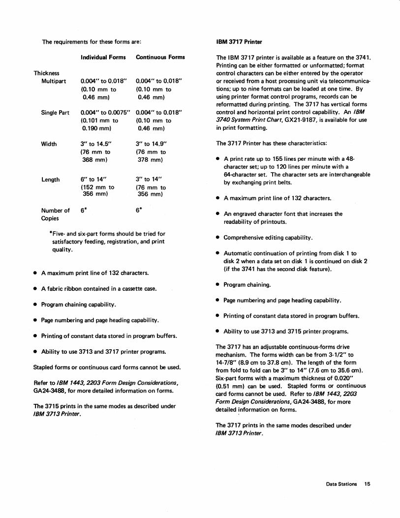
The requirements for these forms are:
Individual Forms Continuous Forms
Thickness Multipart
Single Part
Width
Length
Number of Copies
0.004" to 0.018" (0.10 mm to 0.46 mm)
0.004" to 0.0075" (0.101 mm to 0.190 mm)
3" to 14.5" (76 mm to 368 mm)
6" to 14" (152 mm to 356 mm)
6*
0.004" to 0.018" (0.10 mm to 0.46 mm)
0.004" to 0.018" (0.10 mm to 0.46 mm)
3" to 14.9" (76 mm to 378 mm)
3" to 14" (76 mm to 356 mm)
6*
*Five- and six-part forms should be tried for satisfactory feeding, registration, and print quality.
• A maximum print line of 132 characters.
• A fabric ribbon contained in a cassette case.
• Program chaining capability.
• Page numbering and page heading capability.
• Printing of constant data stored in program buffers.
• Ability to use 3713 and 3717 printer programs.
Stapled forms or continuous card forms cannot be used.
Refer to IBM 1443,2203 Form Design Considerations, GA24-3488, for more detailed information on forms.
The 3715 prints in the same modes as described under IBM 3713 Printer.
IBM 3717 Printer
The IBM 3717 printer is available as a feature on the 3741. Printing can be either formatted or unformatted; format control characters can be either entered by the operator or received from a host processing unit via telecommunications; up to nine formats can be loaded at one time. By using printer format control programs, records can be reformatted during printing. The 3717 has vertical forms control and horizontal print control capability. An IBM 3740 System Print Chart, GX21-9187, is available for use in print formatting.
The 3717 Printer has these characteristics:
• A print rate up to 155 lines per minute with a 48-character set; up to 120 lines per minute with a 64-character set. The character sets are interchangeable by exchanging print belts.
• A maximum print line of 132 characters.
• An engraved character font that increases the readability of printouts.
• Comprehensive editing capability.
• Automatic continuation of printing from disk 1 to disk 2 when a data set on disk 1 is continued on disk 2 (if the 3741 has the second disk feature).
• Program chaining.
• Page numbering and page heading capability.
• Printing of constant data stored in program buffers.
• Ability to use 3713 and 3715 printer. programs.
The 3717 has an adjustable continuous-forms drive mechanism. The forms width can be from 3-1/2" to 14-7/8" (8.9 cm to 37.8 em). The length of the form from fold to fold can be 3" to 14" (7.6 em to 35.6 em). Six-part forms with a maximum thickness of 0.020" (0.51 mm) can be used. Stapled forms or continuous card forms cannot be used. Refer to IBM 1443,2203 Form Design Considerations,·GA24-3488, for more detailed information on forms.
The 3717 prints in the same modes described under IBM 3713 Printer.
Data Stations 15
BINARY SYNCHRONOUS COMMUNICATIONS ADAPTER
The binary synchronous communications adapter (BSCA) provides the 3741 Model 2 or 4 with the ability to function as a point-to-point terminal on switched or nonswitched facilities_ Operation is half-duplex, synchronous, serial-bycharacter, serial-by-bit_ EBCDIC is used directly as the transmission code_ The Model 2 or 4 can communicate with either a 3747 with BSCA or another 3741 Model 2 or 4_ The 3747 can communicate with either the 3741 Model 2 or 4 or another 3747 with BSCA_ The 3747 and 3741 Model 2 or 4 can also communicate with a computer that has the appropriate-communications adapter attached to it_ (See index entry configuration _) Both the 3741 and the' 3747 have autoanswer capabilities.
Synchronous Clock
The synchronous clock feature provides internal clocking for the BSCA for use with modems that do not provide their own clocking. The bit rate for this feature is 1200 bits per second.
Terminal Identification
A terminal with the identification feature gives the 3741 with BSCA the ability to transmit a four-character terminal identification sequence and compare a received identification sequence with a keyed-in sequence. The first character of the terminal identification sequence is the same for all machines; the next three characters are a factory installed sequence assigned by IBM and chosen from a random master list.
Keylock
This feature prevents the 3741 from being placed in Communications mode until the keylock is unlocked. If the keylock is locked when the 3741 is already in Communications mode, it remains in that mode unless the operator takes the machine out of Communications mode. Once removed from Communications mode, it cannot be returned until the keylock is unlocked. The key can be removed from the locked position only.
Operator Identification Card Reader
With the operator identification card reader feature, only authorized personnel are able to operate the terminal in Communications mode. The operator I D sequence may be transmitted if desired.
16
Expanded Communications
The expanded communications feature provides the 3741 Model 2 or 4 with the following additional functions:
• Expanded buffer (512 bytes).
• Capability of transmitting selected fields.
• Capability of transmitting selected records.
• Capability of receiving data and inserting constants.
• Unattended printing after completion of communications, if the 3741 has a printer attached.
Note: The expanded communications feature provides the 3741 Model 4 with the capability to load (unattended) an ACL (application control language) program after the completion of communications.
Program buffers 8, 9, and A are used to store programs for transmitting selected records, transmitting selected fields, and receiving data and inserting constants. Each communications program that is loaded into a program buffer applies to only one data set. Therefore, during communications, only three data sets can have program control.
Note: The expanded communications feature allows a 3741 Model 2 or 4 to communicate with a 3747 having the blocking/reformatting feature (see Data Conversion via the 3747).
Expanded Communications/Multipoint Data Link Control
The expanded communications/multipoint data link control feature provides the 3741 Model 2 or 4 with the same functions as the expanded communications feature, plus multipoint communications allow the 3741 Model 2 or 4 and other terminal devices to communicate with a processing unit on a shared multi-drop network. The 3741 Model 2 or 4 monitors the line and responds to its own polling and selecting sequence as appropriate.
In addition, an inquiry capability allows the operator to key a single record inquiry message, transmit the inquiry to a remote processing unit, and receive a response to the inquiry. Both the inquiry message and response to the inquiry are recorded on the disk and can be displayed by the operator.
Note: The expanded communications/multipoint data link control feature cannot be used when communicating with a 3747.
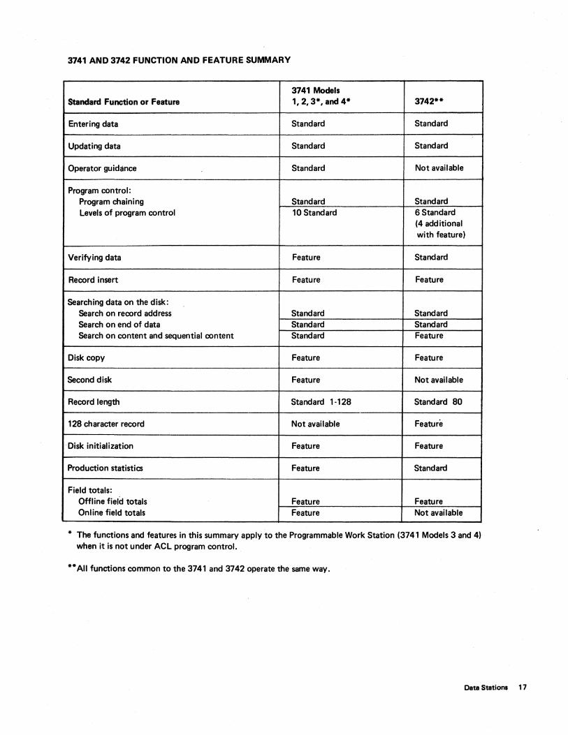
3741 AND 3742 FUNCTION AND FEATURE SUMMARY
3741 Models Standard Function or Feature 1,2,3*, and 4* 3742**
Entering data Standard Standard
Updating data Standard Standard
Operator guidance Standard Not available
Program control: Program chaining Standard Standard levels of program control 10 Standard 6 Standard
(4 additional with feature)
Verifying data Feature Standard
Record insert Feature Feature
Searching data on the disk: Search on record address Standard Standard Search on end of data Standard Standard Search on content and sequential content Standard Feature
Disk copy Feature Feature
Second disk Feature Not available
Record length Standard 1-128 Standard 80
128 character record Not available Feature
Disk initialization Feature Feature
Production statistics Feature Standard
Field totals: Offline field totals Feature Feature Online field totals Feature Not available
* The functions and features in this summary apply to the Programmable Work Station (3741 Models 3 and 4) when it is not under ACl program control.
** All functions common to the 3741 and 3742 operate the same way.
Data Stations 17
18
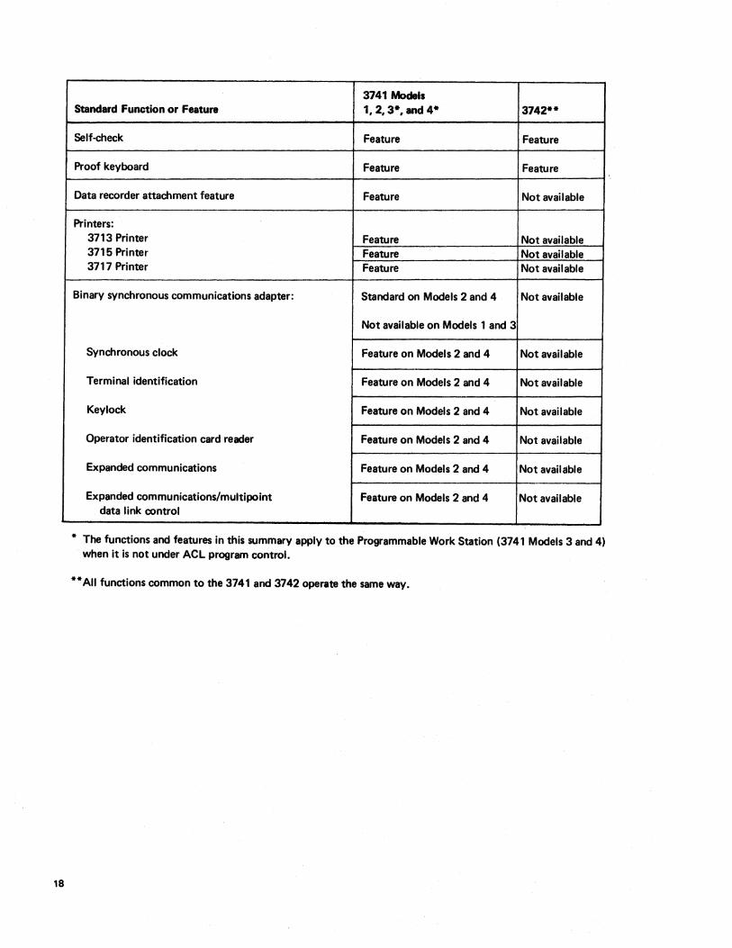
3741 Models Standard Function or Feature 1,2,3*, and 4* 3742**
Self-check Feature Feature
Proof keyboard Feature Feature
Data recorder attachment feature Feature Not available
Printers: 3713 Printer Feature Not available 3715 Printer Feature Not available 3717 Printer Feature Not available
Binary synchronous communications adapter: Standard on Models 2 and 4 Not available
Not available on Models 1 and 3
Synchronous clock Feature on Models 2 and 4 Not available
Terminal identification Feature on Models 2 and 4 Not available
Keylock Feature on Models 2 and 4 Not available
Operator identification card reader Feature on Models 2 and 4 Not available
Expanded communications Feature on Models 2 and 4 Not available
Expanded communications/multipoint Feature on Models 2 and 4 Not available data link control
* The functions and features in this summary apply to the Programmable Work Station (3741 Models 3 and 4) when it is not under ACL program control.
** All functions common to the 3741 and 3742 operate the same way.
DATA CONVERSION VIA THE 3747
All diskettes to be converted to tape are delivered to the IBM 3747 Data Converter, which might be located in the data entry room or the computer room, depending on the installation. The operator loads a batch of diskettes and mounts a tape. The converter automatically feeds, reads, and stacks the diskettes, converting the data to computer compatible format and writing it on nine-track or seventrack 1/2" (1.3 em) tape. These tapes are compatible with System/360, System/370 and other IBM tape systems, for which only normal tape protessing program support is required. The 3747 can process multiple diskettes pet data set and can handle multiple data sets per diskette. With the former, operator intervention is necessary only when starting and ending a job or during error recovery.
If error conditions arise, the 3747 activates an automatic error recovery routine. If the automatic routine fails to correct the error, a message is displayed on the operator's panel and the operator must initiate action. Information displayed on the operator's panel includes the number of diskettes read, the number of data sets on tape, the number of records input, the number of records skipped, the num-ber of records output, and the address of the last disk record read. This information serves as a checkpoint for run procedures by showing whether the correct number of records were converted, the correct number of diskettes were read, etc. Thus, when an error occurs, this information helps isolate the error.
A control recOrd is required for any job that uses the special features of the converter. These features include:
• Tape label processing - Checking and building standard IBM header and trailer records.
• Erasing tape to the end-of-tape marker following the last data set.
• Tape to disk conversion - Writing data from tape onto disk. By using the batching capability, a fixed number of records can be copied to anyone disk.
• Verify check option - Checking for verification of disk data sets before conversion to tape. The verify byte in the data set label is checked before the disk data set is converted.
• Communications - You may select from the following options:
1. Autoanswer or manual answer.
2. Nontransparent or transparent text.
3. Identification verification through the terminal or far end device ID codes. These ID codes are specified as part of the control records and are checked automatically by the converter on a switched line.
• Expanded functions - Increases operational control by:
1. Adding records to an existing file on tape.
2. Adding a file or replacing a file on tape.
3. Checking label name on diskette.
4. Writing conversion mark and checking on diskette.
The expanded functions feature improves communications operation by:
1. Unattended automatic answering.
2.
3.
4.
Multiple calls out using only one tape.
Restarting without retransmitting data correctly sent.
Restarting without duplicating data correctly received.
• Storage - Provides 2K, 4K, or 8K of storage to support the blocking/reformatting featur.e.
• Blocking/reformatting - Provides the capability of:
1.
2.
3.
Blocking of records from disk to tape to increase the processing unit efficiency and communications throughput.
Deblocking of records from tape to disk.
Reformatting of data before recording on tape or sending over BSC entry into the processing unit. It includes deletion of records or fields, rearranging fields; inserting constants, and record splitting or joining.
Data Stations 19
Details on operation of the converter are found in the 3747 combination operator's guide and reference manual listed in the Preface.
INPUT VIA THE 3540
Diskettes to be used as input to the System/370 are loaded into the IBM 3540 Diskette Input/Output Unit. This unit attaches directly to System/370. The 3540 feeds, reads, and stacks diskettes just like the 3747, but inputs the data directly to the system at high speed. The 3540 also takes data from the system and writes the data on the diskette. There are two models of the 3540, B1 and B2. Model B1 has a single diskette drive and the B2 has two diskette drives. Each drive is addressed independently, and all operations are fully overlapped: read/read, read/write, write/read, and write/write. Double buffering optimizes performance by allowing the 3540 to process data previously stored in a buffer. More than one 3540 can be attached to the System/370: the total number depends on the number of system control unit positions available. Each 3540 operates independently of the others, regardless of the number of units.
If an error condition occurs, the 3540 activates an automatic error recovery routine. If this automatic routine fails to correct the error, a message is displayed on the operator's panel and the operator must initiate action.
20
The programming support for the 3540 is especially suited for processing information created by the 3740 system. This support includes:
• DOSIVS supports the 3540 using the sequential access method (SAM) for logical input/output control system (LiOCS) and the system logical units: system reader, system input, system punch, and system list. The 3540 may also be a spooled input device under POWE R.
• OSIVS1 supports the 3540 as a system input/system output device. This support includes the capability to submit data separately from the job (JCl). After the data is submitted, it is associated with the job, spooled, and scheduled for execution.
For more information about the 3540, refer to DOS/VS System Information for IBM 3540 Diskette Input/Output Unit, GC21-5072, Planning Guide for OS/VS1 Support of the IBM 3540, GC24-51 06; IBM 3540 Diskette Input/ Output Unit Operator's Guide and Programmer's Reference, GA21-9197. For installation planning information, refer to IBM System/370 Installation Manual and Physical Planning, GC22-7004.
The 3741 Programmable Work Station can be used in many installations to expand the key entry function. The work station has all the functions of the data station, plus it allows you to control all input and output functions, arithmetic and logical operations, and to guide the operator through the application. These additional functions are possible through a programming facility called Application Control Language (ACL).
An application programmer, familiar with data entry devices and operations, will find ACL an excellent tool for implementing work station applications. ACL program source statements consist of control statements and instructions. Control statements give the output object code a program name, define data sets and access methods, specify data formats, provide printer control information, and designate the end of the program. Instructions initiate input/output operations, internal data movement, branching, arithmetic operations, and table searching.
The work station, when not under ACL program control, functions like the data station. The Model 3 has the same functions as the Model 1 and the Model 4 has the same functions as the Model 2.
FUNCTIONS UNDER ACL PROGRAM CONTROL
In addition to its functions as a data station, the 3741 Programmable Work Station has the following functions under ACL program control.
• Expande '1arithmetic including add, subtract, multiply, and divide operations that make possible additional field totals, zero balancing, and crossfooting operations.
• Data checking including range checking, unit checking, table search, and diskette file search.
• Data manipulation which allows data to be reformatted before it is written on a diskette, displayed, or printed.
• Additional keyboard and display including displaying prompting messages for data entry, option selection, or error conditions.
Programmable Work Stations
• Additional disk access methods which allow processing of multiple data sets, reading and writing on two disk drives, and creating and maintaining data set indexes that provide fast access to online data.
• Overlapped printing which allows the operator to key data while printing.
• • Ability to check or generate self-check numbers wh ich
allows the programmer to specify any modulus from 1 to 127, and the characteristics of the algorithm to be used.
FEATURES AVAILABLE WITH THE PROGRAMMABLE WORK STATION
The 3741 Programmable Work Station has the following features available, in addition to the features available for the 3741 Data Station.
ACL Translator
The ACL translator feature translates ACL source programs into object programs for the programmable work station. The ACL translator feature is only required on programmable work stations used to generate object programs. The object programs can then be executed on any programmable work station. The printer and second disk features are required for the ACL translator feature. I BM recommends that the programmable work stations with the ACL translator feature have the record insert feature to allow easy source program maintenance.
Storage, 4K Additional
The storage, 4K additional feature provides the programmable work station with 32 additional general purpose, 128-byte buffers.
Programmable Work Stations 21
System Design Considerations
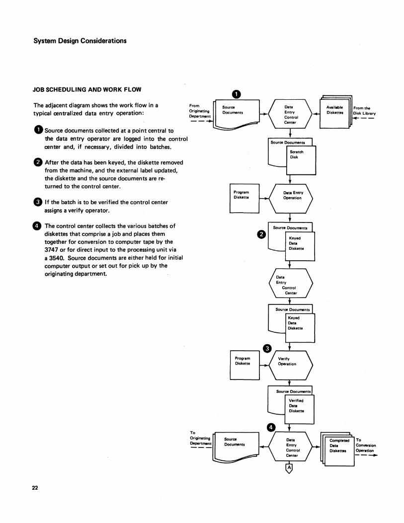
JOB SCHEDULING AND WORK FLOW
The adjacent diagram shows the work flow in a typical centralized data entry operation:
o Source documents collected at a point central to the data entry operator are logged into the control center and, if necessary, divided into batches.
.. After the data has been keyed, the diskette removed from the machine, and the external label updated, the diskette and the source documents are returned to the control center.
• If the batch is to be verified the control center assigns a verify operator.
o The control center collects the various batches of diskettes that comprise a job and places them together for conversion to computer tape by the 3747 or for direct input to the processing unit via
22
a 3540. Source documents are either held for initial computer output or set out for pick up by the originating department.
From Originating Department
To Originating Department
o Source Documents
Program Diskette
Program Diskette
Source
Scratch Dilk
Keyed Data Diskette
Keyed Date Diskette
Verified Data Diskette
Available Diskette.
From the Disk Library
Completed To Data COn ..... ion Di.kettes Oparation ---
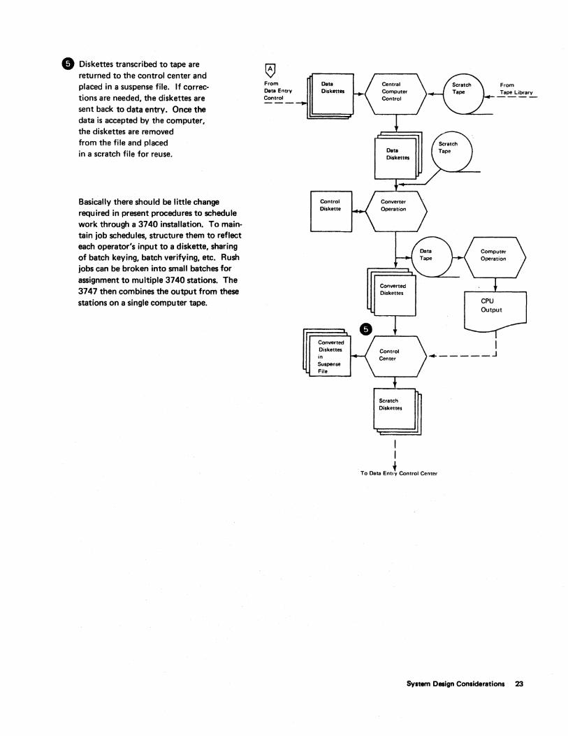
• Diskettes transcribed to tape are returned to the control center and placed in a suspense file. If corrections are needed, the diskettes are sent back to data entry. Once the data is accepted by the computer, the diskettes are removed from the file and placed in a scratch file for reuse.
Basically there should be little change required in present procedures to schedule work through a 3740 installation. To maintain job schedules, structure them to reflect each operator's input to a diskette, sharing of batch keying, batch verifying, etc. Rush jobs can be broken into small batches for assignment to multiple 3740 stations. The 3747 then combines the output from these stations on a single computer tape.
From OIIta Entry Control
OIIta Diskettes
Control Diskelle
Converted Diskelles in Suspense File
Scratch Diskettes
From
~~~rL
CPU Output
_-----.J
~ To Data Ent.v Control Center
System O.ign Considerations 23
DATA LABELING ON THE DISKETTE
During initialization, the data set label for a data set is magnetically recorded on the index track (track 00) of the diskette. The primary purpose of this label is to show the location of the data set on the diskette. The label can also be used to identify the data set by name. The degree to which the name field in the label is used is optional. An installation plan that calls for one or any of the following could require use of the diskette label for proper processing of data:
1.
2.
3.
Attachment of a 3540 Diskette Input/Output Unit to the system (the 3540 Diskette Input/Output Unit recognizes discrete data set label names when reading the diskettes).
The addition of the tape label feature to the 3747 Data Converter (when creating tape labels on the 3747, the label name is taken from the diskette label).
The use of multiple data sets on a single diskette.
The 3747 operator's guide and reference manual, the 3741 and 3742 reference manuals, and the standard data interchange manual (all listed in the Preface) contain detailed information as to what data must be in the labels.
SINGLE AND MULTIPLE DATA SETS PER DISKETTE
One of the earliest systems design decisions to make is whether to use single data set diskettes only or to allow multiple data set diskettes as well. A single diskette may hold multiple data sets, but for easy management of the work flow, keying only one data set on each diskette is recommended.
There. are many advantages to keying single data sets on diskettes. (Programs for a specific job can be stored on the diskette that contains the job data set.) One significant advantage of keying single data sets is that work scheduling and distribution is kept simple. No coordination of retention and conversion cycles, of key entry operations, or of data set grouping is necessary for regular jobs. Since jobs are scheduled independently, there are no delays; each job proceeds through the shop according to its usual schedule. Therefore, there are no unknowns in job completion, or efforts spent in creating new schedules. Once keyed, data sets are simply converted to tape, ready for processing.
24
If a diskette containing multiple data sets is to be, processed, some specially designed procedures apply, which provide for proper handling of individual data sets. For example, if data on a diskette is to be converted (or transmitted), and that diskette also contains another data set that needs to be converted (or transmitted), these procedures ensure that the system will differentiate the data sets. (See the 3747 operator's guide and reference manual listed in the Preface for a discussion of these procedures.)
DATA RECOVERY
Operators will make errors on 3740 stations just as they do with traditional equipment. If an operator should mistakenly write over data that has not yet been converted, the data must be recreated from source or backup materials. To recover a partially destroyed dl!ta set, it is important to re-establish the EOD (end of data) address. Operating procedures for recovery of EOD address for overwritten records are found in the 3741 and 3742 reference manuals and operator's guides listed in the Preface.
Although diskettes rarely develop irregularities through wear, irregularities may occur if some foreign material has been present on the diskette. Each installation should have a standard procedure to be followed in case a data record cannot be read or written onto a diskette. If the station has the copy function, the best data recovery procedure is to copy the data onto a new diskette and manually key in the affected records. Alternate methods depend on the mode of operation the station is in at the time the disk error is encountered. (See the 3741 and 3742 operator's guides for information about alternate procedures.)
The operator should make note of diskette irregularities on the external label of the diskette. After data on an irregular track has been recovered, the diskette should be re-initialized, excluding the irregular track(s) and substituting one or both of the alternate tracks provided. If both of the alternate tracks are used up, consider the following before replacing the diskette:
1. I s the new error on one of the fi rst few tracks? (This is apt to be the case since these tracks will be used on most or all jobs.) If so, you can easily modify the data index track to skip the bad track and all tracks that precede it, and simply start recording further into the diskette.
2. Is a full 1898 record capacity necessary? Many installations key work batches that are 300-500 records in size. These would not require a full diskette capacity.
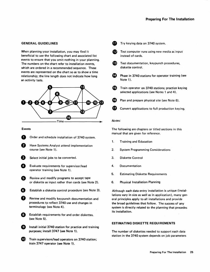
GENERAL GUIDELINES
When planning you.r installation, you may find it beneficial to use the following chart and associated list events to ensure that you omit nothing in your planning. The numbers on the chart refer to installation events, which are ordered in a recommended sequence. These events are represented on the chart so as to show a time relationship; the line length does not indicate how long an activity lasts.
-------------------Time------------------~.~
Events
o Order and schedule installation of 3740 system.
e Have Systems Analyst attend implementation course (see Note 1).
• Select initial jobs to be converted.
• Evaluate requirements for supervisor/lead operator training (see Note 1).
• RElview and modify programs to accept tape or diskette as input rather than cards (see Note 2).
G Establish a diskette control procedure (see Note 3).
• Review and modify keypunch documentation and procedures t.o reflect 3740 use and changes in terminology (see Note 4).
e Establish requirements for and order diskettes. (see Note 5).
'. Install initial 3740 station for practice and training purposes; install 3747 (see Note 1).
G Train supervisors/lead operators on 3740 station; train 3747 operator (see Note 1).
Preparing For The Installation
• Try keying data on 3740 system.
• Test computer runs using new media as' input instead of cards.
e Test documentation, keypunch procedures, diskette control.
41 Phase in 3740 stations for operator training (see Note 1).
~ Train operator on 3740 stations; practice keying selected applications (see Notes 1 and 4).
CD Plan and prepare physical site (see Note 6).
• Convert applications to full production keying.
Notes:
The following are chapters or titled sections in this manual that are given for reference.
1. Training and Education
2. System Programming Considerations
3. Diskette Control
4. Documentation
5. Estimating Diskette Requirements
6. Physical Installation Planning
Although each data entry installation is unique (installations vary in size as well as in application), many general principles apply to all installations and provide the broad guidelines that follow. The success of any system is directly related to the planning that precedes its installation.
ESTIMATING DISKETTE REQUIREMENTS
The number of diskettes needed to support each data station in the 3740 system depends on job parameters
Preparing For The Installation 25
and installation policies. The following checklist can serve as a guide to estimating average requirements and will cover factors tending to increase or decrease require· ments from the average.
Centralized Data Entry
Batch Size: One diskette should normally be estimated for each separate batch which an operator keys in a day.
In some applications prompt customer service dictates that keying be broken into many small batches; this leads to increased diskette requirements.
Machines Used to Verify: Machines that are steadily used for verifying do not require additional diskettes and should be excluded from the estimates. However, each 3740 station can also be used for keying. If you anticipate that, due to the nature and scheduling of jobs, all or most stations may be used for keying on some days of the month, then diskettes should be provided to support those machines when they are used for keying rather than verifying.
Retention Cycle: Normally you will retain the diskette after keying for at least one day prior to reuse, just as cards are retained until processing is assured. Diskettes are then used only every other day, which increases diskette life. Twice the daily diskette quantities will be needed to satisfy data retention requirements.
Data Storage for Weekly Runs: In some cases, input for weekly computer runs arrives and is keyed daily but is retained in key entry until the weekly computer run. Therefore, batches will be accumulated on disk and stor· ed at the 3740 stations. Such storage periods 'must be accounted for in your estimate.
Peak Load: If monthly, quarterly~ or annual peaks result in overtime and an increase in data keyed, diskette requirements will be affected.
Local Source Department
When machines are placed in local source departments such as payroll or accounts payable, requirements can be estimated the way they are in centralized data entry. Reduction in diskette requirements because of larger batches is partially offset by longer retention cycles caused by diskette 'float' in the interdepartment mail system.
26
Remote Source Department
Units in remote locations usually create larger batches on a diskette to facilitate data communications. Diskettes should be retained at least one day to assure that good data has been received by the home office computer. Additional spare diskettes should be maintained at remote sites if it is difficult to obtain additional diskettes quickly.
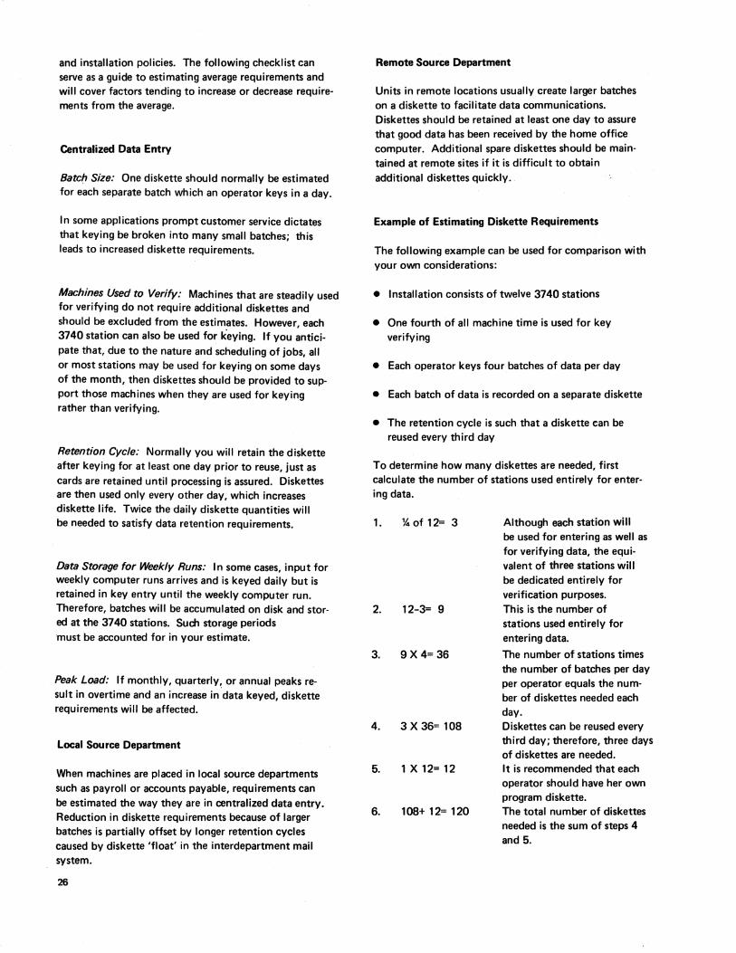
Example of Estimating Diskette Requirements
The following example can be used for comparison with your own considerations:
• Installation consists of twelve 3740 stations
• One fourth of all machine time is used for key verifying
• Each operator keys four batches of data per day
• Each batch of data is recorded on a separate diskette
• The retention cycle is such that a diskette can be reused every third day
To determine how many diskettes are needed, first calculate the number of stations used entirely for entering data.
1. %of 12= 3
2. 12-3= 9
3. 9 X 4= 36
4. 3 X 36= 108
5. 1X12=12
6. 108+ 12= 120
Although each station will be used for entering as well as for verifying data, the equivalent of three stations will be dedicated entirely for verification purposes. This is the number of stations used entirely for entering data.
The number of stations times the number of batches per day per operator equals the number of diskettes needed each day. Diskettes can be reused every third day; therefore, three days of diskettes are needed. It is recommended that each operator should have her own program diskette. The total number of diskettes needed is the sum of steps 4 and 5.
Summary
• At least one diskette per machine should be allocated for storage of programs.
• An additional diskette may be desired for recording of daily production statistics.
.. Contingencies should be provided for if off-the-shelf delivery of purchased diskettes is not available locally.
• Additional diskettes for control records may be need· ed if 3747 features are used.
KEY ENTRY PROGRAMS
Job descriptions used for current card punch and verify
Verify Code Bypass
Begin field codes N V
A W
J Y
R X
I Z
B
D
U
S
K
Continue field codes -
End program code E
Feature begin field codes H
C
F
G
L
M
jobs can still be used as the basis for creating key entry programs for the 3741 and the 3742.
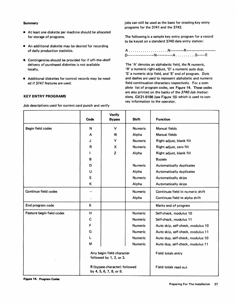
The following is a sample key entry program for a record to be keyed on a standard 3740 data entry station:
A ...•................ N-----R----------D----------N------A ......•..• S---E
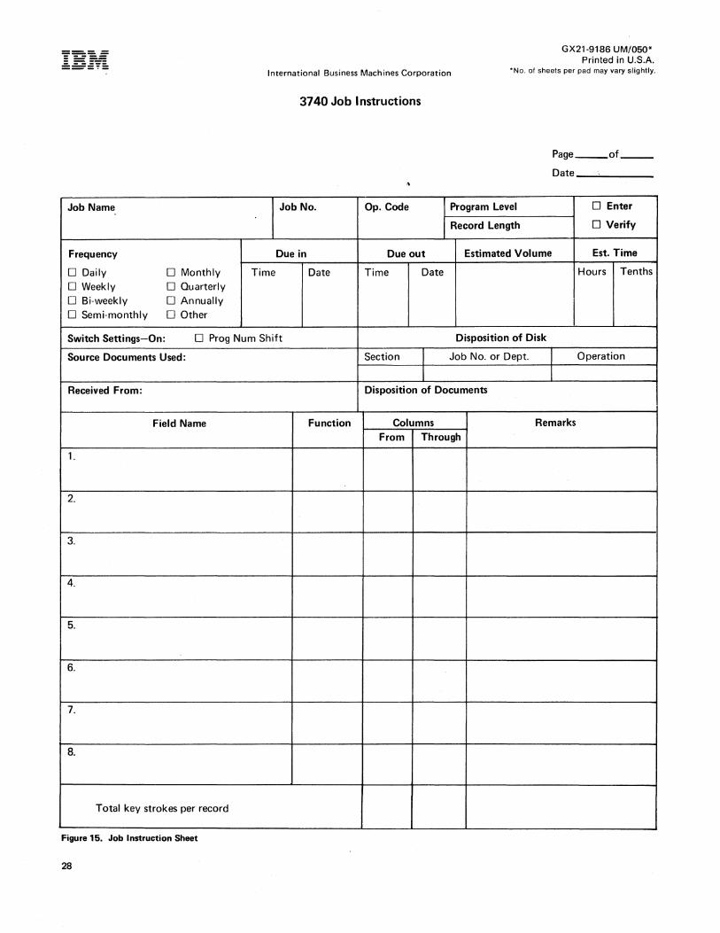
The 'A' denotes an alphabetic field, the N numeric, 'R' a numeric right-adjust, 'D' a numeric auto dup, 'S' a numeric skip field, and 'E' end of program. Dots and dashes are used to represent alphabetic and numeric field continuation characters respectively. For a complete list of program codes, see Figure 14. These codes are also printed on the backs of the 3740 Job Instructions, GX21-9186 (see Figure 15) which is used to convey information to the operator.
Shift Function
Numeric Manual fields
Alpha Manual fields
Numeric Right adjust, blank fill
Numeric Right adjust, zero fill
Alpha Right adjust, blank fill
Bypass
Numeric Automatically duplicates
Alpha Automatically duplicates
Numeric Automatically skips
Alpha Automatically skips
Numeric Continues field in numeric shift
Alpha Continues field in alpha shift
Marks end of program
Numeric Self-check, modulus 10
Numeric Self-check, modulus 11
Numeric Auto skip, self-check, modulus 10
Numeric Auto skip., self-check, modulus 11
Numeric Auto dup, self-check, modulus 10
Numeric Auto dup, self-check, modulus 11
Any begin field character Field totals entry followed by 1, 2, or 3.
B (bypass character) followed Field totals read out by 4, 5, 6, 7, 8, or 9.
Figura 14. Program Codas
Preparing For The Installation 27
--- ------ - -------- ----- - - -----------'-
Job Name
Frequency
o Daily o Monthly o Weekly o Quarterly OBi-weekly o Annually o Semi·monthly o Other
GX21-9186 UM/050* Printed in U.S.A.
International Business Machines Corporation "No. of sheets per pad may vary slightly.
3740 Job Instructions
Page __ of __
Date_......;. ___ _
Job No. Op. Code Program Level DEnter
Record Length o Verify
Due in Due out Estimated Volume Est. Time
Time Date Time Date Hours Tenths
Switch Settings-On: o Prog Num Shift Disposition of Disk
Source Documents Used: Section Job No. or Dept. I Operation
I Received From: Disposition of Documents
Field Name Function Columns Remarks From Through
1.
2.
3.
4.
5.
6.
7.
8.
Total key strokes per record
Figure 15. Job Instruction Sheet
28
Note: IBM recommends that all programs be made the same length for each data set, regardless of actual record length, and that the longest actual record length be the length given to each program.
There are two basic approaches to creating programs: The first approach is used in many of today's card punch installations, where each operator is responsible for making and maintaining her own program cards. However, for initial efficiency when installing 3740s, the second approach - creation of a master program diskette - is suggested. This approach involves having a supervisor, lead operator, or system engineer create all of the programs for every operator in the installation. One diskette can hold as many as 1898 programs. A copy of the master program diskette is made for each operator, who then has her own program diskette, as in the first approach; the only difference is that it was prepared centrally. Centrally prepared program diskettes can be maintained by changing existing programs or adding new ones to the master program diskette and making copies for each operator. The effective date of the program diskette can then be noted on the external label to indicate whether the program diskette is the latest
Job Address
Number Track
24 01 0
24 01 0
24 01 0
25 02 0
25 02 0
25 02 0
25 02 0
26 03 0
26 03 0
26 03 0
version. The master program diskette approach provides the advantage that the operator does not have to concern herself with making programs during her initial training period.
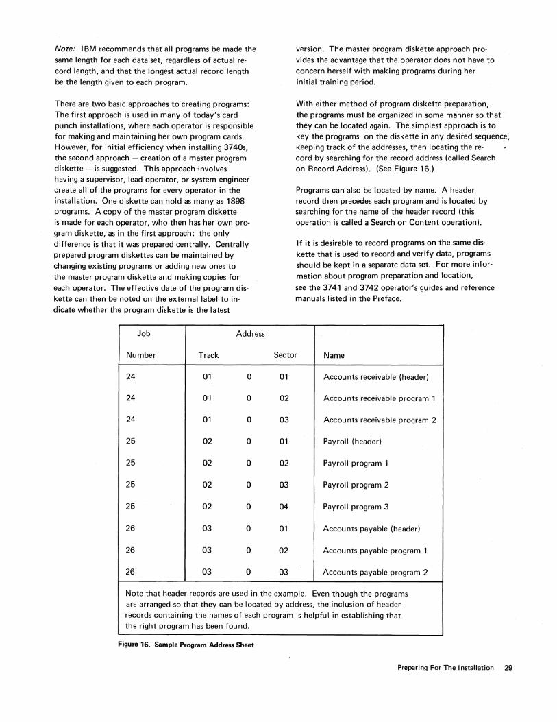
With either method of program diskette preparation, the programs must be organized in some manner so that they can be located again. The simplest approach is to key the programs on the diskette in any desired sequence, keeping track of the addresses, then locating the re-cord by searching for the record address (called Search on Record Address). (See Figure 16.)
Programs can also be located by name. A header record then precedes each program and is located by searching for the name of the header record (this operation is called a Search on Content operation).
If it is desirable to record programs on the same diskette that is used to record and verify data, programs should be kept in a separate data set. For more information about program preparation and location,
see the 3741 and 3742 operator's guides and reference manuals listed in the Preface.
Sector Name
01 Accounts receivable (header)
02 Accounts receivable program 1
03 Accounts receivable program 2
01 Payroll (header)
02 Payroll program 1
03 Payroll program 2
04 Payroll program 3
01 Accounts payable (header)
02 Accounts payable program 1
03 Accounts payable program 2
Note that header records are used in the example. Even though the programs are arranged so that they can be located by address, the inclusion of header records containing the names of each program is helpful in establishing that the right program has been found.
Figure 16. Sample Program Address Sheet
Preparing For The Installation 29
DISKETTE CONTROL
The three primary factors in diskette control are diskette labeling, diskette library maintenance, and physical handling of the diskette.
External labels
There are two kinds of diskette labels: external and internal (data set) labels. See Data Labeling on the Diskette, in this manual, for information about internal labels.
External labels are visible labels that are physically attached to the diskette. Two kinds are useful. The first type is the permanent diskette label, which contains information such as diskette serial number and the date the diskette was received from the manufacturer. These permanent labels are affixed to the upper left corner of each diskette. It is recommended that a ballpoint pen be used to write information on these labels.
The second type of external label is usually a paper label with adhesive backing. This label is for information such as what data is recorded on the diskette - (job name and number), who keyed the data, whether the data is verified, whether it has been converted for processing, and the date the job is being processed. I BM recommends that this label be no larger than 2.0" by 5.5" (5.1 cm by 14.0 cm) and that it be affixed to the diskette just to the right of the permanent I BM label. This label can be designed to fit your procedures.
Information should be written on the label while the diskette is in the envelope to prevent damage and contamination of the recording surface. The diskette envelope is designed with a slot which exposes this label for access. When a new job is begun, the old label information should be crossed out - not erased. Eraser particles could get inside the diskette permanent envelope and interfere with its being read.
In addition to keeping the diskette clean, this process provides an audit trail. When the entire label is full, it should first be removed, then be replaced by a new label. (If new labels are simply pasted on top of the old labels, the label buildup can affect machine performance.) Don't affix labels to the reverse side of the diskette and don't cover any of the holes in the diskette. labels
30
should be replaced every six months; otherwise the adhesive may harden and make label removal difficult.
Colored labels is a good way to convey information at a glance. Each installation can work out a system to increase the security of certain classes of diskettes and reduce handling time and other requirements. Color coding for a hypothetical insurance installation could be:
• Red labels - Reserved for program storage; not to be used for data.
• Green labels - For general data use; available for data keying if the label shows that the previous job was dumped.
• Blue labels - Reserved for keying claims, which are 65 percent of the installation workload. Keying program is repeated on each disk (information in the index track tells the converter to bypass the program when dumping disk to tape).
• Yellow Labels - Local or personal files not to be used for general data (operator or job statistics, lists of job charge numbers, ACl source and object programs, etc).
To avoid mismatching the diskette and envelope, no information should be written on the protective cardboard envelope.
Diskette library
The second major factor in diskette control is the diskette library. Setting up and maintaining an effective diskette library is more than a matter of providing storage space; it is establishing procedures that are reliable and integrated with the operations of the total data process-ing system. Diskette control should involve procedures that are simple and constant for all applications. Several possible library systems would satisfy these conditions. One possible system, based on the use of four storage areas for diskettes passing through the data processing cycle, is as follows.
After a diskette is received from the manufacturer, it is given a serial number and an entry is made on a master diskette log sheet. (see Figure 17.)

MASTER DISKETTE LOG SHEET
Serial Date Number Comments Received
V
'" ~ -.;;,;;: - ~ Figure 17. Sample Master Diskette Log Sheet
Job and History Card
The diskette is then placed in the sctatch file containing all diskettes that are available for immediate use. The key entry operator goes to the scratch file to select a diskette for use. A blank job card (see Figure 18) is inserted in the envelope of each scratch diskette. This card is used to show the status of the job as it progresses through the installation. Once the source data has been keyed, the job card is updated, showing such infomation as job number, job name, date, diskette serial number, opera· tor's initials, and the number of records keyed. (If pro· duction statistics are not used, the conversion table found in the 3741 and 3742 reference manuals can be used to obtain an accurate record count.)
Next the diskette, job card, and source documents are placed in a "to be verified" storage area. The verify operator verifies the data, updates her portion of the job card, and places the diskette, etc, in a hold-for-conversion storage area, where it remains until any other diskettes for the job are completed and are also placed in the hold area. After the diskettes have been converted to tape and the job card is updated, they are placed in a suspense file_ They remain there until the computer application using that data has been processed. The diskettes are then removed from the suspense file and placed in the scratch file to begin another cycle. The job card becomes a history card for that particular diskette and is filed by serial number.
Job #
Job Name
Date
Serial
KP #
KV #
Tape Number
Release OK
Release Date
Miscellaneous
Figure 18. Sample Job Card
Volume
Errors
Preparing For The Installation 31
Care and Storage of the Diskette
The third factor in effective diskette control is the proper physical handling of the diskette. It is important to establish policies to ensure proper handling. The following points should be considered:
• Keep the diskette in the protective cardboard envelope provided when the diskette is not being used. The diskette should be placed in the envelope before writing on the adhesive label so that the label is visible through the cut-away front of the envelope.
• Do not write on labels with an erasable writing instrument. Use a ballpoint pen.
• Handle the diskette by the label area to avoid touching the recording surface. Fingerprints on the surface may cause permanent diskette errors.
• Carry the diskette in a file folder or carrier envelope.
• Keep office utility magnets away from the diskette.
If a diskette is physically damaged or if the recording surface becomes contaminated with foreign material, it should be replaced. Diskettes should be stored in the protective envelope in an upright position. They may be used in most environments that are neither wet nor dusty - environments that are relatively unaffected by climatic variables. If diskettes are mailed, they should be placed in a box or heavy cardboard mailer. Refer to the standard data interchange manual (see the Preface) for comprehensive information regarding diskette handling.
32
DOCUMENTATION
An essential part of installation planning is reviewing and updating records containing a vast amount of detail on the various aspects of running an installation. Although many procedures may require no modification at all, some procedures may be modified to take advantage of a new capability or feature available through the 3740 system; also, any missing documentation must be created.·
To allow operators to focus their full attention on building speed and productivity on the new units rather than on filling in gaps in the documentation, documents containing special keying instructions should be revised to reflect 3740 terminology. For example, job steps for correcting errors during verification should be rewritten to include correction while verification is in process; references to terms such as verify punches, overpunching, header cards, etc., should be removed.
Documentation for the 3741 Programmable Work Station depends on the programming for each application. It is the programmer's responsibility to provide documentation and training for the operator for each job.
To aid the operator in running the job, a job run sheet and step·by-step instructions should be provided. The job run sheet should include:
• Job name and number.
• Name, location, and telephone number of the programmer.
• Printer setup instructions.
• Diskette data set label specifications.
• Instructions for starting the program.
• Instructions for ending the job.
• Instructions for aborting or continuing the job if a system error is encountered.
• A summary of special keys and functions.
A sample job run sheet is shown in Figure 19.
Step-by-step instructions should be provided to supplement prompting messages to the operator.
Documentation will be needed for the 3747 data converter operations. Procedures must be written to include such functions as:
Job Setup
• What function is to be performed in this run (that is, diskette-to-tape, tape-to-diskette, etc)?
• Will a control diskette be required to perform this job?
• Will a labeled or unlabeled tape be required?
Error Recovery
• What action should the operator take if an operational error occurs (job setup instructions specify a labeled tape but an unlabeled tape has been mounted; expiration date on tape is greater than date keyed in at job setup time, etc)?
• What action should the operator take if an unreadable/unwritable record is found (should the record be skipped, the job terminated, etc)?
End of Job
• Should job statistics be taken?
• What disposition of the diskettes and tape is required after the job is completed?
The IBM 3747 Data Converter Run Sheet, GX21-9185, (see Figure 20) can be used to document the necessary procedures.
Preparing For The Installation 33
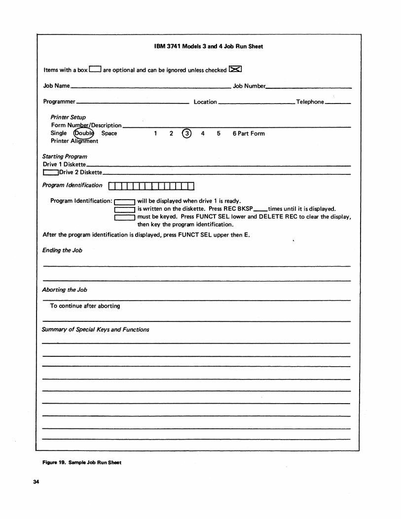
34
IBM 3741 Models 3 and 4 Job Run Sheet
Items with a box 0 are optional and can be ignored unless checked ~
Job Name ___________________________________________ Job Number ______________________ _
Programmer ___________________________ __ Location ________________ Telephone----
Printer Setup
Form N~escriPtion Single oubl Space Printer Alignment
2 ® 4 5 6 Part Form
Starting Program Drive 1 Diskette _____________________________________________________ _ r::::JDrive 2 Diskette _________________________________________________ _
Program Identification I I I I I I I I I I I I I I I
Program Identification: I 1 will be displayed when drive 1 is ready. :=1 =~I is written on the diskette. Press REC BKSP __ times until it is displayed. L-_..JI must be keyed. Press FUNCT SELlower and DELETE REC to clear the display,
then key the program identification.
After the program identification is displayed, press FUNCT SEL upper then E.
Ending the Job
Aborting the Job
To continue after aborting
Summary of Special Keys and Functions
Figure 19. Sample Job Run Sheet
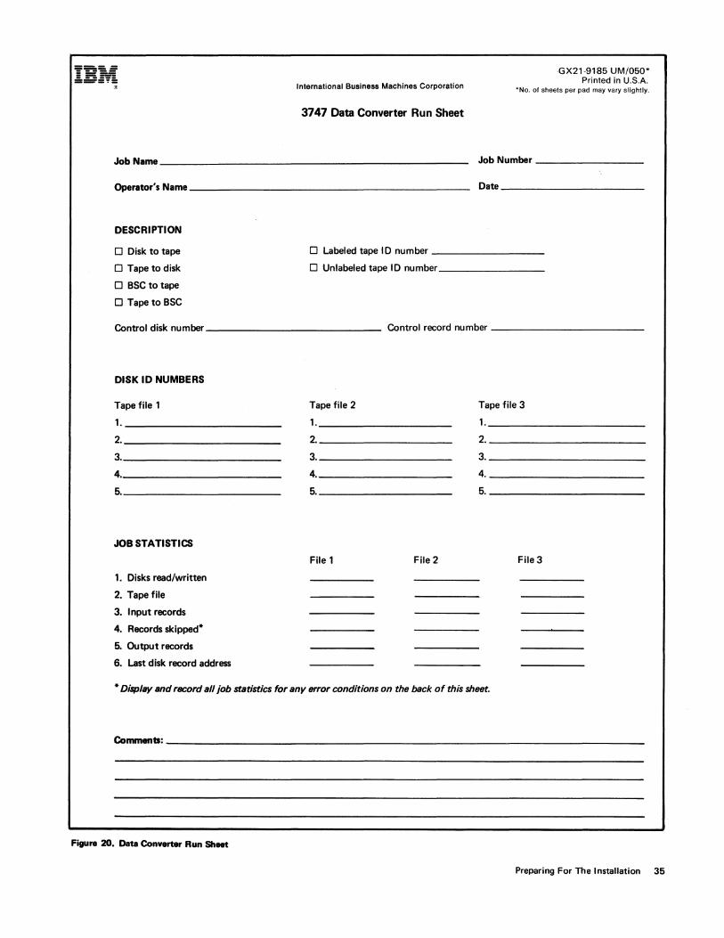
I:::~~ '" International Business Machines Corporation
3747 Data Converter Run Sheet
,GX21·9185 UM/050* Printed in U.S.A.
-No. of sheets per pad may vary slightly.
Job Name ______________________________________________ _ Job Number ________________ _
Operator's Name __________________________________________ _ Dne _____________________ _
DESCRIPTION
o Disk to tape o Labeled tape 10 number _______________ _
o Tape to disk o Unlabeled tape 10 number _______________ _
o BSC to tape
o TapetoBSC
Control disk number ____________________________ Control record number _____________________ _
DISK ID NUMBERS
Tape file 1 Tape file 2 Tape file 3
1. 1. 1.
2. 2. 2.
3. 3. 3.
4. 4. 4.
5. 5. 5.
JOB STATISTICS
File 1 File 2 File 3
1. Disks read/written
2. Tape file
3. Input records
4. Records skipped-
5. Output records
6. Last disk record address
- DisplllY and record all job statistics for any error conditions on the back of this sheet.
COmmenb: __________________________________________________________________________ ___
Figure ZO. Data Converter Run Sheet
Preparing For The Installation 35
SYSTEM PROGRAMMING CONSIDERATIONS
A review of all computer programs may be required, de· pending on the change of input medium. If tape is reo placing card decks, some software modifications will be necessary. In general, the best approach to program modification is to begin with the largest volume jobs. Data from the 3740 to be used as input to a programming system can be in the form of 1/2" (1.3 cm) magnetic tape from the 3747, or it can be in the form of the diskette to be used as input via the 3540. No special tape program· ming support is required to process the tape from the 3747. The input from this tape will be unblocked and either labeled or unlabeled, depending on the option chosen. The 3540 has programming support especially suited for processing information created by the 3740 system.
Replacing an existing data entry installation with tape input to the processing unit can involve the following:
• JCL changes only
• Application program changes
• No changes when replacing certain tape input
The considerations discussed in this chapter refer to both OS and DOS unless otherwise noted.
Card Replacement
There are normally two modes of entering card data to a programming system: directly to a processing program or in stages through the SYSIN facility. The former mode may be simply a preprocessing program that provides a labeled tape for direct input to the main processing program. When a card·to·tape utility pools data and creates a tape file for input to the system, the 3747 can do the same job and thus save system time. The 3747 can create an unlabeled or labeled tape for direct input to the application program. If a SYSIN file is used, the 3747 can create the SYSIN file on tape either by pooling JCL disks and data disks or by creat-ing tape from disks on which JCL records have been keyed in with the data. The operator assigns the system reader to the tape instead of to a card reader. The SYSIN procedures assume that all records are 80 characters long.
If the job is being run in OS using a cataloged procedure, each new collection of data on the SYSI N tape must in· clude a record of the form:
//procstepname.ddname DO DATA
36
Only JCL changes are required if the tape is input directly to a job (private volume concept) or if labels are added to the input file. These will be the most common changbs in an installation.
When only a change in medium is involved (that is, tape instead of card). the device assignment is all that needs to be changed. The DOS change is:
From: //ASSGN SYSIPT,X'OOC' or
ASSGN SYSIN,X'OOC'
To: //ASSGN SYSIPT,X'181' or
ASSGN SYSIN,X'181'
This change assumes that the input is part of the SYSIN (SYSRDR/SYSIPT) file.
In OS the change is:
From: //DATA DO DATA
To: //DATA DO UNIT=TAPE,DS NAME=DATA, LABEL=(.NL)
These changes assume that the application program does not have device dependent code (such as stacker select) and is not using a card DTF or DCB control block.
When the 3747 supplies a labeled input tape, the JCL changes include:
• For DOS, add the statement: //TLBL. ..
• For OS, change the existing statement to: //DATA DO ... ,LABEL=(,SL), ...
If the application that is switching from card to tape in· put uses device dependencies or takes advantage of some converter feature to eliminate effort on a system, pro· gramming changes must be considered. Any device de· pendent control blocks or instructions dealing exclu· sively with cards must be changed to accept the tape medium; for example, the DOS control block DTFCD must be recoded to a DTFMT or DTFDI. The same is true of OS where the device type of the DCB must be changed from card to tape. Any instruction such as stacker select must be handled differently or eliminated.
In DOS, if the input is currently assigned to a programmer unit (for example, SYS001 - SYSnnn), a device dependent control block is generally used and additional programming changes are required. When an application is modified in any way (for instance, if record types are combined to use the 128 character records), pro-gram changes are required. The changes range from simple control block and buffer size changes to partial or total rewrite of the application. In OS, if these changes are size cbanges only, they may be made through the DCB parameters in the JCL statements.
The converter capabilities can save time by eliminating pre-edit runs used to produce labeled tape. Since the converter can provide the labeled tape input, any simple pre-edit functions can be combined with the main edit program and thus eliminate the need for the pre-edit run.
A card deck of source statements to be processed by a compiler is really a file to be updated. If this type of application is installed using a 3740, the source statements should be maintained on normal DASD source statement libraries. When a programmer submits changes to the source statements using a 3740, these changes will be sent to the source statement library, and the file may be updated by a utility program like IEBUPDTE. The updated source statements are then processed by the compiler as a subsequent step in the job. In other applications where the card input represents a type of master file, a similar procedural change is required to permit the system to do the updating.
Tape Replacement
When the 3740 supplies data that is to be entered into a system via a tape there are normally no changes to the JCL or programs required. The 3747 can build the input tape in the same format as before the 3740 installation.
JCL changes may be required however, if, for example you are switching from seven-track to nine-track tape or from 800 bpi to 1600 bpi. In DOS, this change would be:
From: IIASSGN SYS001,X'187,X78' (seven-track tape drive)
To: !!AASGN SYSOO1,X'181,X'CO" (nine-track tape drive)
In OS, this change would be:
From: !!DATA DD ... , UNIT=2400-1, ... (seven-track tape drive)
To: !!DATA DD ... , UNIT=2400, ... (ninetrack tape drive)
For changes needed to input a labeled tape instead of an unlabeled tape, see the example under Card Replacement in this section.
. Teleprocessing Programming Support
Teleprocessing programming support will be provided for the 3741 Model 2 and 4, and the 3747 with BSCA by the following access methods and operating systems:
System!370
DOSNSBTAM DOSNSVTAM
OSNS1 BTAM OSNS1 TCAM OSNS1 VTAM
OSNS2BTAM OSNS2TCAM OSNS2VTAM
System!3 Model 6, Model 10 Disk System, or Model 15
RPG II (3741 Model 2 and 4 only)
RPG II can be used with both LCA and BSCA. In System!3 RPG II, the terminal designation is BSCA on the file description specification and blank in the remote device field of the telecommunications specifications. In BTAM and TCAM, the terminal designation is BSC1 or BSC2 depending on whether nonswitched or switched tacility is being used. In VTAM, the designation is 3740.
The 3741 Model 2 and 4, and the 3747 with BSCA are transparent to the teleprocessing support that exists in 'System!360-370 DOS BT AM and System!360-370 OS BTAM and TCAM. The 3740 units with BSCA are transparent through the device classes of BSC1 and BSC2 in the above access methods.
Because of this capability, the following support is provided:
System!360 - 370
DOSBTAM OSBTAM OS TCAM
Preparing For The Installation 37
Communications with System/360 - 370 can be via an:
• IBM 2701 Data Adapter Unit
• IBM 2703 Transmission Control Unit
• IBM 3704 Communic'!tions Controller
• IBM 3705 Communications Controller
In addition, communication with System/370 can take place via the Integrated Communications Adapter (lCA).
More detailed information appropriate to the system and language support being used is found in the corresponding SRLs as defined in the Teleprocessing Bibliography at the end of this manual.
TELECOMMUNICATIONS FA.CILITIES CONSIDERATIONS
The communications facilities can be common carrier switched telephone networks, common carrier nonswitched line services (channels), or equivalent nonswitched facilities. Communications services must be arranged by the user. (Refer to the IBM Teleprocessing Systems Summary, GA24-3090, for further information.)
The communications facilities used by 3740 BSCA must have appropriate modulation/demodulation capability. To provide this capability, an external modem or integrated 1200 bps modem is used to attach to the telephone lines. The BSC adapter is compatible with the IBM 3872 modem and integrated 1200 bps modems. The BSC adapter is compatible with the IBM 3976-3 modem for World Trade only. Bit rates available are 1200, 2000, and 2400 bits per second (bps). A selectable 600 bps transmission rate is available except in Canada, the United States, and Japan. For additional information about communications facilities, see the Teleprocessing Bibliography at the end of the manual.
Note: It is the user's responsibility to have the cable to the communication facility connected or disconnected from the CBS coupler (or equivalent) when the 1200 bps Integrated Modem, Switched with Autoanswer Feature (#5501) is implemented.
38
UNIT BACKUP CONSIDERATIONS
A station outage affects at most only two stations. Converter outage does not affect the stations as long as additional diskettes are available to continue accumu-lation and storage of data until the converter is return-ed to service. Converter outage impact on computer runs can be minimized by scheduling, but converter backup arrangements with other users having com-patible configurations should also be considered.
EDUCATION AND TRAINING
An education program is required after the decision to install a 3740 system is made. Classes offered are outlined in schedules published by IBM. They consist of detailed training for persons who will perform the systems implementation as well as for those who will operate the stations or program in ACL. Arrangements for attending IBM courses may be made with the locar IBM sales representatives.
In addition to classroom instruction, 3740 self-study courses and other training materials are available for operator training. These are also useful to systems analysts and key entry supervisors as a structured approach to learning 3740 data entry operations.
The following analysis of educational and training needs is not intended to be all-inclusive but to serve as a guide for specific planning according to specific needs.
System Analyst: Attendance at an installation planning course is recommended. The role of the 3740 system analyst entails responsibility for the total systems effort, from the planning stages through the first sets of application conversion and paralleling activities. The installation planning course is intended to convey the characteristics of the IBM diskette recording medium, the functions of each individual machine, and how these machines interact as a system. Other topics cover the essential steps in any 3740 implementation, the key decisions in 3740 systems design, and the sources of information and assistance available to support installation activities.
ACL Programmers: A 5-day training program in ACL is available at the IBM Data Center. The program is intended to teach programmers ACL and familtarize them with the application capabilities of the 3741 Programmable Work Station. It is assumed that the programmer has experience in at least one programming language, before attending the training program.
Key Entry Supervisors and Operators: The 3740 Data Entry System Feature Instruction Program is available for training key entry supervisors and experienced operators. Customer Engineering personnel have been trained to provide this instruction. The intent of the program is to enable operators of current key entry products to begin equivalent production operations immediately on the 3740 stations. Instruction is in basic 3740 functions only, such as data keying, verifying, program formats, CRT usage, etc. Operators requiring training on advanced machine functions or features such as offline field totals, BSCA operation, and 3713 printer or diskette copy functions should complete the Advanced Topics self-study course.
Machine training schedules should be established as early as possible. It is suggested that supervisors and lead operators be trained first. These people need a thorougn understanding of machine operations in order to revise key entry procedures as necessary, to set up initial jobs to be converted, to answer operating questions, and to supervise operator training.
Installation conversion plans determine when each operator should begin training. If plans are such that one application at a time is to be converted to 3740 operation, the operators that normally key the re-lated data should be trained first. Once they have developed speed and accuracy with on-the-job prac-tice, the next application can be converted, additional operators trained, and the process repeated until all jobs have been converted and all operators trained. In the event that all jobs are to be converted simultaneously, it is recommended that the more experienced operators be trained first, as training time normally varies with
• operator skill (that is, the more skilled the operator the less time needed for training).
SeIf-5tudy Materials - 3740 station operator training is available also through two separate self-study courses: a basic machine course and an advanced topics course.
• Inexperienced operators - It is recommended that the basic machine self-study course should be used when 3740 stations are planned for use in other than the central keypunch room and the situation·.dictates-that clerk typists be trained. Course duration will vary with each student but will normally require 20 - 25 hours.
• Experienced or inexperienced operators who require additional machine training - It is recommended that operators take the Advanced Topics self-study course. Course topics include 3740 station operations such as teleprocessing, using the printer diskette copy, and field totals. Course duration will vary, since students will complete only the sections they require, to operate within their own 3740 system design.
Data Converter Operators: As part of the instruction program mentioned previously under Key Entry Supervisors and Operators, instruction will be given to familiarize the data converter operator with basic machine operations, tape handling, and error recovery procedures. If one or more 3740 station operators will be required to operate a 3747, involvement of experienced computer room personnel in developing applicationoriented training is recommended_ Operation of this device must be closely tied to established tape handling and tape library conventions and job setup instructions as prepared by systems people in a specific installation.
Preparing For The Installation 39
Physical Site Planning and Preparation
Customers planning an IBM 3740 Data Entry System installation should use this chapter as a guide to determine how they can best prepar.e their physical site for the arrival and installation of the system. Careful advance planning and scheduling makes it possible for a customer to install his equipment with little or no interruption of the daily office routine.
SPACE REQUIREMENTS
Since the data entry areas may differ in room size, column spacing, location of electrical outlets, othe~ equipment, and work areas, it may be advisable to prepare a floor plan of the area showing the location of all the equipment to be included.
To help prepare the floor plan, IBM provides a plastic template (GX21-9155) of each of the 3740 system units. The templates are scaled so that 1/4 inch = 1 foot (1 mm = 48 mm) and 'show the floor space and working clearance for each unit. When room size permits, additional operator space is recommended. In some cases, clearances shown on the template may be overlapped as long as the larger clearance is maintained.
The following items should be considered:
• Work space
• Storage space
• Aisle space
• Service clearance
• Heat dissipation
• Electrical outlets and communication facilities
• Doorway sizes and loading facilities used in getting machines to their locations.
40
ENVIRONMENTAL CONSIDERATIONS
Temperature and Humidity
The temperature and humidity of a data entry area are influenced by many factors. These include heat produced by mechanical and electrical equipment, amount of fresh air entering the area, personnel body heat, and heat introduced or dissipated through walls, ceilings, and floors. As these factors change, varying amounts of heat and humidity may need to be introduced or dissipated to maintain an acceptable operating environment.
Extremes in relative humidity, if maintained for long periods of time, may have an adverse affect on the overall operating efficiency of the installation and should be avoided whenever possible. High relative humidity may cause improper feeding and stacking of paper, as well as operator discomfort. Low relative humidity aggravates problems associated with static electricity. Static charges, which are usually dissipated without any adverse effects, tend to build into significant charges when the humidity is low. High voltage static discharges from moving people, carts, furniture, paper, etc., can be objectionable to operating personnel and, in extreme cases, can interfere with the correct operation of electronic equipment.
Tape and Diskette Storage
Tapes and diskettes should be stored in dust proof containers in a vertical position. They should never come in contact with magnetic material since field strengths greater than 50 oersteds can cause noise or a loss of information.
Storage facilities should be within the following limits:
Tape Diskette
Dry Bulb Temperature 40° to 90°F 50° to 125°F (4° to 32°C) (10° to 51°C)
Wet Bulb Temperature 80°F (26°C) 85°F (29°C) (maximum) Relative Humidity 20 to 80% 8 to 80%
If stored outside the stated limits, tape and diskettes should be conditioned in the operating environment, to ensure proper performance. Conditioning time for diskettes is at least five minutes; for tape, the
conditioning time is the same as the length of time it was stored outside operating limits (maximum of 24 hours).
Dirt and Air Pollution
The amount of contamination usually found in the air within a normal business environment will not interfere with the operation of IBM equipment. However, take normal precautions to keep dust, dirt, and other foreign matter away from the machines. If the system must be installed in an area having a high dust" content or where there is an exposure to abrasive materials or corrosive gases, contact your I BM representative for advice and recommendations.
LIGHTING
Adequate illumination of a data entry area for operator and service personnel is important. The recommended light level is 50·55 foot-candles (538-592 lumens/m2 ) at a height of 30 inches (76 centimeters) above the floor.
Direct sunlight on either the 3741 or 3742 is not recommended since it would impair the readability of the CRT as well as the comfort of an operator facing the light.
FIRE PROTECTION EQUIPMENT
The machine room should be equipped with portable, carbon dioxide fire extinguishers of suitable size for quick, efficient use. These, of course, are subject to local building code and fire insurance requirements. A nonwetting extinguishing agent for electrical equipment (Class C hazard) is recommended.
ELECTRICAL REQUIREMENTS
All reasonable efforts have been made in the machine design to ensure satisfactory operation with the normal power supplied by most power companies.
Power should not be supplied from the same electrical circuit that supplies power to machines that may create electrical noise. Some machines having start-stop motor action can cause transient electrical noise signals. If there is a question of electrical noise affecting machine operation, consult your IBM representative.
Branch circuits should be protected by circuit breakers suitable for motor load application and should contain wiring that will handle the same load.
Grounding
Power cords supplied with each IBM unit have a green (or green with yellow trace) wire grounding conductor for equipment ground. The receptacles recommended provide for connection of this equipment ground. Each customersupplied branch circuit must have an insulated wire conductor, equal to the size of the phase conductors, for grounding the equipment. All branch circuit grounding wires must be tied to a common ground point at the distribution panel. A single grounding wire should run from the distribution panel to service ground or suitable building ground. This is a noncurrent carrying ground, not a neutral. Conduit must not be used as the only grounding means.
Convenience Outlets
A suitable number of convenience outlets should be available in the area for use by building maintenance personnel, etc. The same general rules for electric power apply for the wiring of the convenience outlets.
Power Supply
Power is provided through a separate power cord, 8 feet (2.5 meters) long, connected to each machine (unless
otherwise noted on the unit specification page). Plug types (or equivalent) shown on the unit specification page are supplied with the machine. Customer provides matching receptacle.
On 50 Hertz machines, power cords are provided without plugs to accommodate installing a local standard plug. See Figure 21 for power cord specifications.
The following electrical specifications apply (unless otherwise noted on the unit specification page):
50 Hertz 60 Hertz
Voltage (single phase) 110,123.5 115,208,230 200,220,235
Voltage Tolerance: ±10% ±10% Frequency Tolerance: ±1/2 Hertz ±1/2 Hertz
In Japan, the following specifications should be added to those listed above:
100 (50 Hertz) 100, 200 (60 Hertz)
Physical Site Planning And Preparation 41
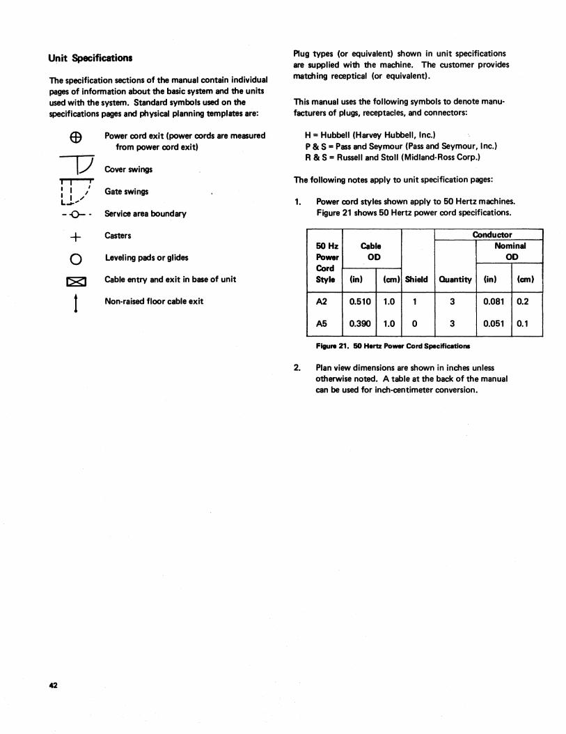
Unit Specifications
The specification sections of the manual contain individual pages of information about the basic system and the units used with the system. Standard symbols used on the specifications pages and physical planning templates are:
42
I I i I I / I I ./ L..-"
- -0-- -
Power cord exit (power cords are measured from power cord exit)
Cover swings
Gate swings
Service area boundary
+ Casters
o Leveling pads or glides
~ Cable entry and exit in base of unit
1 Non-raised floor cable exit
Plug types (or equivalent) shown in unit specifications are supplied with the machine. The customer provides matching receptical (or equivalent).
This manual uses the following symbols to denote manufacturers of plugs, receptacles, and connectors:
H = Hubbell (Harvey Hubbell, Inc.) P & S = Pass and Seymour (Pass and Seymour, Inc.) R & S = Russell and Stoll (Midland-Ross Corp.)
The following notes apply to unit specification pages:
1. Power cord styles shown apply to 50 Hertz machines. Figure 21 shows 5.0 Hertz power cord specifications.
Conductor 50Hz Cable Nominal Power 00 00 Cord Style (in) (em) Shield Quantity (in)
A2 0.510 1.0 1 3 0.081
A5 0.390 1.0 0 3 0.051
Figure 21. 50 Hertz Power Cord Specifications
2. Plan view dimensions are shown in inches unless otherwise noted. A table at the back of the manual can be used for inch-centimeter conversion.
(em)
0.2
0.1
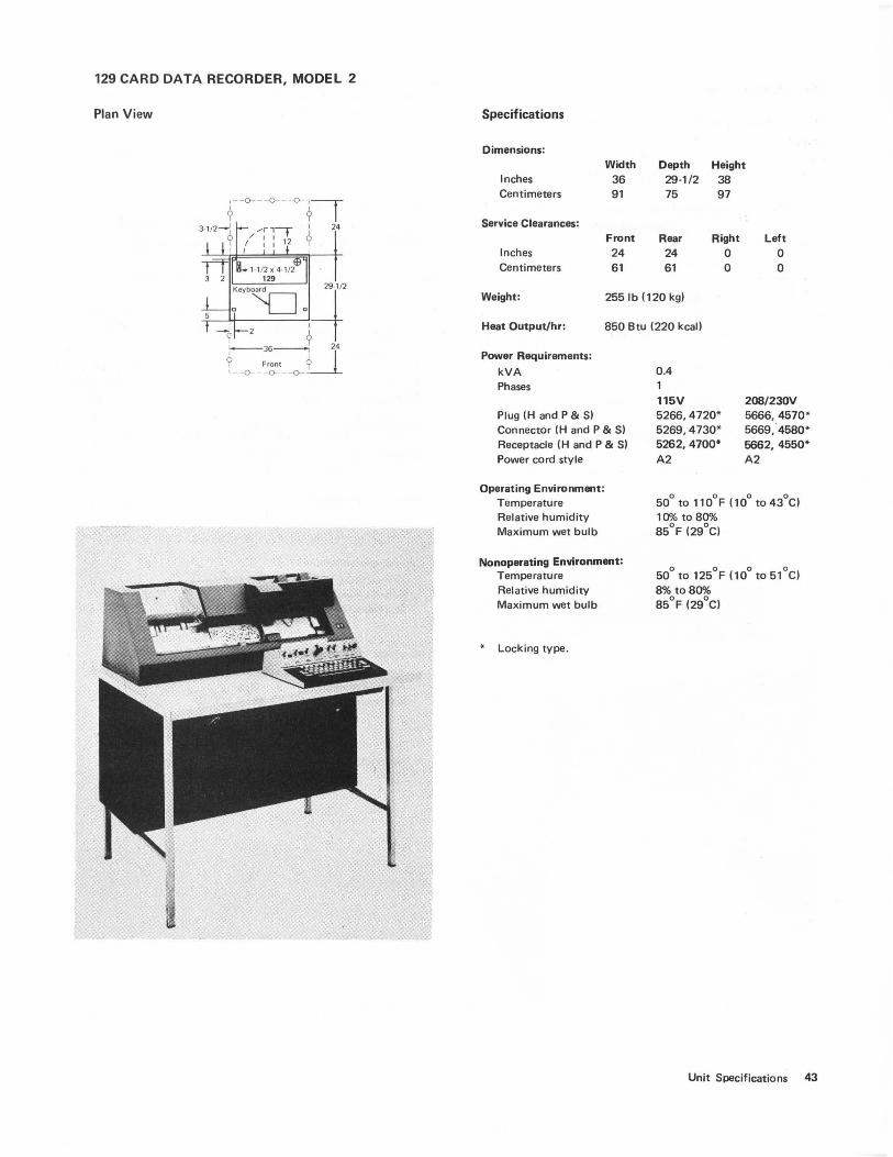
129 CARD DATA RECORDER, MODEL 2
Plan View Specifications
Dimensions:
Inches Centimeters
Service Clearances:
Inches Centimeters
Width 36 91
Front 24 61
Depth Height 29-1/2 38 75 97
Rear Right Left 24 0 0 61 0 0
Weight: 2551b (120 kg)
Heat Output/lu: 850 Btu (220 kcall
Power Requirements:
kVA Phases
Plug (H and P & S) Connector (H and P & S) Receptacle (H and P & S) Power cord style
Operating Environment: Temperature Relative humidity Maximum wet bulb
Nonoperating Environment: Temperature Relative humidity Maximum wet bulb
• Locking type_
0.4
115V 5266,4720· 5269,4730· 5262,4700· A2
208/230V 5666,4570· 5669,4580· 5662, 4550· A2
50° to 110°F (10° to 43°C) 10"10 to 80% 85°F (29°C)
50° to 125°F (10° to 51°C) 8% to 80"10 85°F (29°C)
Unit Specifications 43
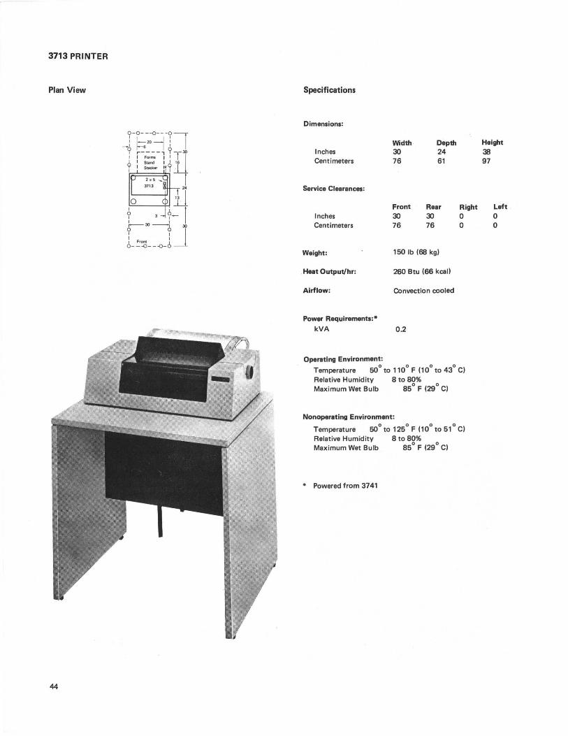
3713 PRINTER
Plan View
:-t-~~-:1 _I ~6 I I I 9 ,..----, 9--30 II , .. "" I' ~ 9 I Stand I I t6
I I Stadr.er '9 · 2 x 5 ......
o 3713 l2j 6 3 <L 1 I I I I ~ 30 ------0 30
L!:~ __ ~jJ
44
Specifications
Dimensions:
Inches Centimeters
Service Clearances:
Inches Centimeters
Weight:
Heat Output/hr:
Airflow:
Power Requirements:
kVA
Operating Environment:
Width 30 76
Front 30 76
Depth 24 61
Rear 30 76
150 Ib (68 kg)
260 Btu (66 kcall
Convection cooled
0.2
Right o o
Temperature 50° to 110° F (10° to 43° C) Relative Humidity 8 to 80% Maximum Wet Bulb 85° F (29° C)
Nonoperating Environment:
Temperature SOO to 125° F (10° to 51° C) Relative Humidity 8 to 80% Maximum Wet Bulb 85° F (29
0 C)
• Powered from 3741
Height 38 97
Left o o
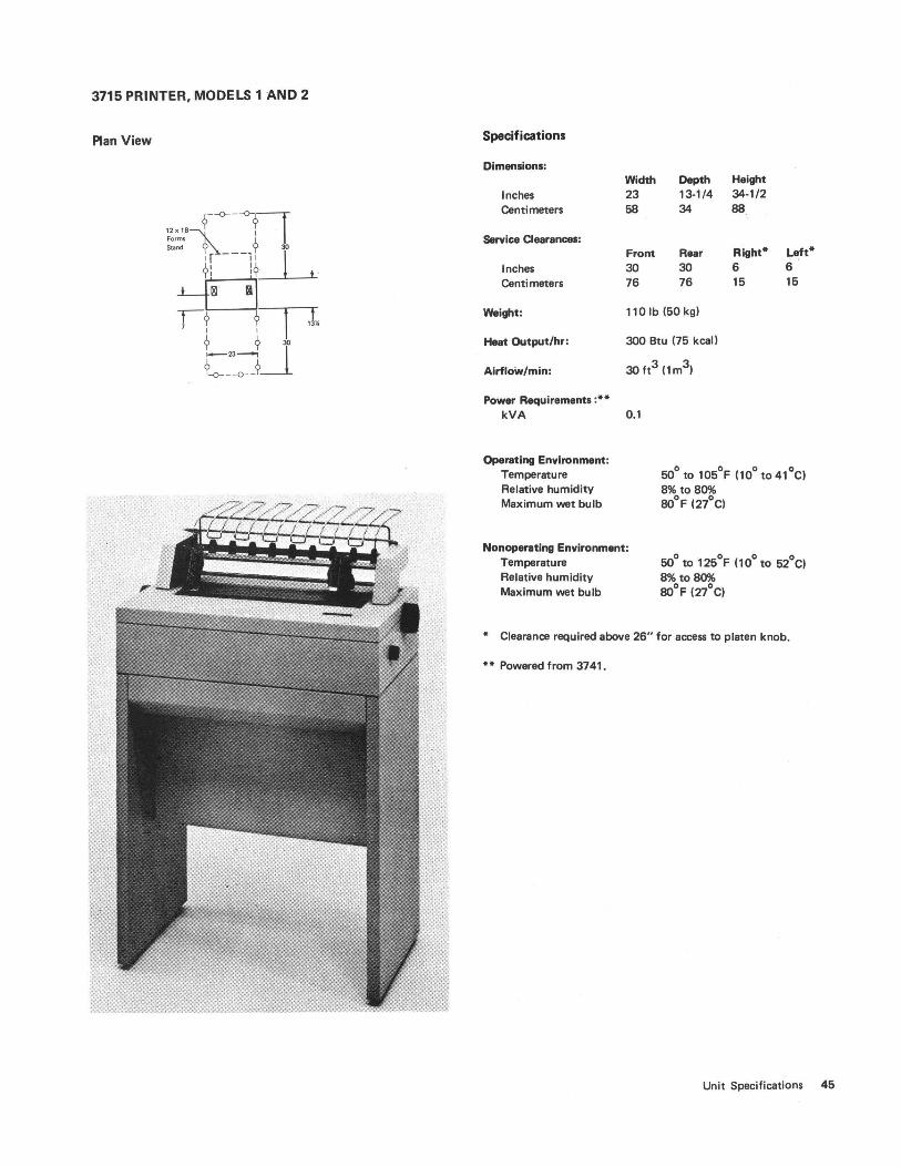
3715 PRINTER, MODELS 1 AND 2
Plan View Specifications
Dimensions:
Inches Centimeters
Service Clearances:
Inches Centimeters
Weight:
Heat Output/hr:
Airflow/min:
Power Requirements :-. kVA
Operating Environment: Temperature Relative humidity Maximum wet bulb
Width Depth Height 23 13-1/4 34·1/2 58 34 88
Front Rear Right- Left-30 JO 6 6 76 76 15 15
110 Ib (50 kg)
JOO Btu (75 kcall
JO ft3 (1m3)
0.1
50° to 105°F (10° to 41°C) 8% to 80% 80°F (27°C)
Nonoperating Environment: Temperature Relative humidity Maximum wet bulb
50° to 125°F (10° to 52°C) 8% to 80% 80°F (27°C)
• Clearance required above 26" for access to platen knob.
-- Powered from 3741.
Unit Specifications 45
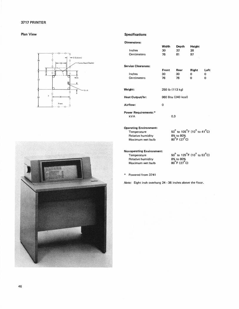
3717 PRINTER
Plan View
46
Specifications
Dimensions:
Inches Centimeters
Service Clearances:
Inches Centimeters
Weight:
Heat Output/hr:
Airflow:
Power Requirements:· kVA
Operating Environment: Temperature Relative humidity Maximum wet bulb
Width .
30 76
Front 30 76
Depth 32 81
Rear 30 76
250 Ib (11 3 kg)
960 Btu (240 kcal)
o
0.3
Height 38 97
Right o o
Left o o
Soo to 10SoF (10° to 41°C) 8% to 80% 80°F (27°C)
Nonoperating Environment: Temperature Relative humidity Maximum wet bulb
• Powered from 3741
Soo to 12SoF (10° to S2°C) 8% to 80% 80°F (27°C)
Note: Eight inch overhang 24 - 36 inches above the floor.

3741 DATA STATION MODELS 1 AND 2 3741 PROGRAMMABLE WORK STATION MODELS 3 AND 4
Plan View
9- --o---o---o---o---n I I
6 17-1 "1 (,24 I I
<> I
16 I /
Lit 0
I I I I I
I I I I
0 2614
I I o
t.. 3 : : 30
10::Li,' 3 3741
9 [al Front 0 L-~91 I
I 42 ----i
~---o---o---o---o---~~
Specifications
Dimensions:
Inches Centimeters
Service Clearances:
Inches Centimeters
Weight (Maximuml:
Heat Output/hr:
Airflow/min:
Power Requirements: kVA Phases
Width
42 107
Depth
26-1/4 67
Front Rear 30 24 76 61
240 Ib (109 kgl
700 Btu (1 BO kcall
150 ft3 (4m3)
0.4
Height
34 87
Right o o
Left 18 46
Plug (H and P & SI Connector (H and P & SI Receptacle (H and P & SI Power cord style
115V 5266,4720· 5269,4730· 5262,4700· A5
208/23U11 5666,4570· 5669,4580· 5662,4550· A5
Operating Environment: Temperature Relative humidity Maximum wet bulb
Nonoperating Environment: Temperature Relative humidity Maximum wet bulb
• Locking type
60° to 90°F (16° to 32°C) 8% to 80% 73°F (26°C)
50° to 110°F (10° to 43°C) 8% to 80% BOoF (27°C)
Unit Specifications 47
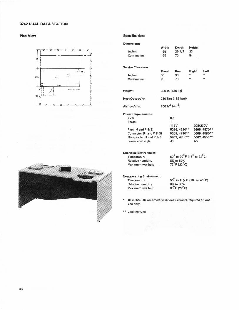
3742 DUAL DATA STATION
Plan View
48
Specifications
Dimensions:
Inches Centimeters
Service Clearances:
Inches Centimeters
Width 65
165
Front 30 76
Depth 29-1/2 75
Rear 30 76
Height 33 84
Right * *
Left * *
Weight: 300 Ib (136 kg)
Heat Output/hr:
Airflow/min:
730 Btu (185 kcal)
150 tt3 (4m3)
Power Requirements: kVA Phases
Plug (H and P & S) Connector (H and P & S)
Receptacle (H and P & S)
Power cord style
Operating Environment: Temperature Relative humidity Maximum wet bulb
Nonoperating Environment: Temperature Relative humidity Maximum wet bulb
0.4
115V 5266,4720** 5269,4730** 5262,4700** A5
20B/23OV 5666,4570** 5669,4580** 5662,4550** A5
60° to 90°F (16° to 32°C) 8% to 80% 73°F (23°C)
50° to 110°F (10° to 43°C) 8% to 80% 80°F (27°C)
* 18 inches (46 centimeters) service clearance required on one side only.
** Locking type
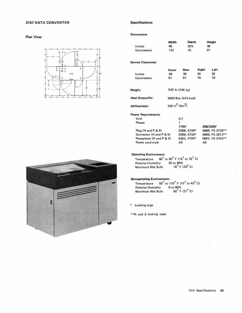
3747 DATA CONVERTER
Plan View
Specifications
Dimensions:
Inches Centimeters
Service Clearances:
Inches Centimeters
Width 48 122
Front 36 91
Depth 29% 75
Rear 36 91
Weight: 540 Ib (245 kg)
Heat Output/hr:
Airflow/min:
2050 Btu (515 kcall
230 ft3 (6m3)
Power Requirements: kVA Phases
Plug (H and P & S) Connector (H and P & S) Receptacle (H and P & S) Power cord style
Operating Environment:
0.7
115V 5266,4720* 5269,4730* 5262, 4700* A5
Height 38 97
Right 30
Left 30 76 76
208/23OV 5666, FS 3720** 5669, FS 3913** 5662, FS 3743** A5
Temperature 60° to 90° F (16° to 32° C) Relative Humidity 20 to SO% Maximum Wet Bulb 7So F (26° C)
Nonoperating Environment: Temperature 50° to 110° F (10° to 43° C) Relative Humidity S to SO% Maximum Wet Bulb SOO F (27° C)
* Locking type
**R and S locking type.
Unit Specifications 49
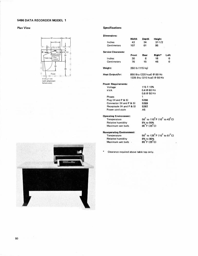
5496 DATA RECORDER MODEL 1
Plan View
50
r- 42q 18l ,0--~t_:L-oL -o I 4 ,--- - -"1 6 I
I 12j1/2 ? 24 I
1 '" -1 : ~ I 30 ~ ~-o _-o-"~O~ _--o-_lj
4-114 x 1-1/4 (with attachment feature only)
Specifications
Dimensions: Width Depth Height
Inches 42 24 37-1/2 Centimeters 107 61 95
Service Clearances: Front Rear Right* Left
Inches 30 6 18 0 Centimeters 76 15 46 0
Weight: 250 Ib (115 kg)
Heat Output/hr: 850 Btu (220 kcall @ 60 Hz 1225 Btu (310 kcall @ 50 Hz
Power Requirements: Voltage kVA
Phases Plug (H and P & S) Connector (H and P & S)
Receptacle (H and P & S)
Power cord style
Operating Environment: Temperature Relative humidity Maximum wet bulb
Nonoperating Environment: Temperature Relative humidity Maximum wet bulb
115±10% 0.4 @60Hz 0.6@50Hz 1 5266 5269 5262 A5
50° to 110°F (10° to 43°C) 8% to 80% 85°F (29°C)
50° to 125°F (10° to 51°C) 8% to 80% 85°F (29°C)
Clearance required above table top only.
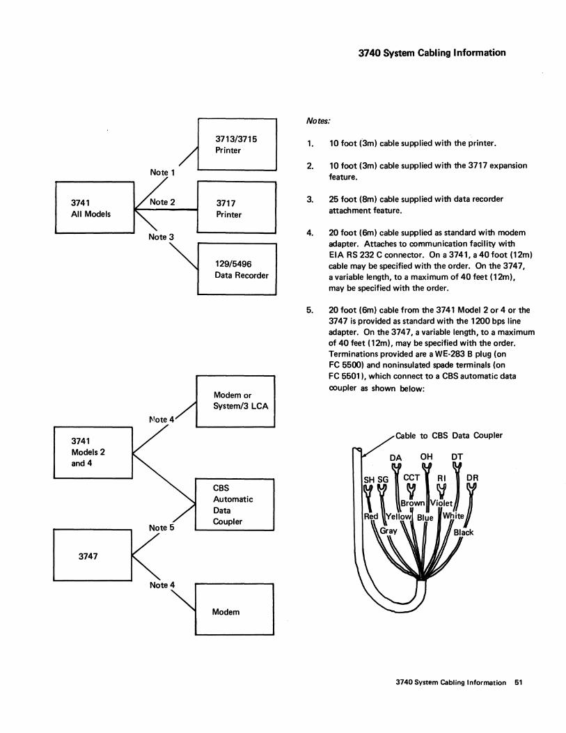
3713/3715
/ Printer
Note 1
3741 3717 All Models Printer
Note 3
129/5496 Data Recorder
Modem or System/3 LCA
Note 4
3741 Models 2 and 4
CBS Automatic Data
K~6 Coupler
3747
Note 4
Modem
3740 System Cabling Information
Notes:
1.
2.
3.
4.
5.
10 foot (3m) cable supplied with the printer.
10 foot (3m) cable supplied with the 3717 expansion feature.
25 foot (8m) cable supplied with data recorder attachment feature.
20 foot (6m) cable supplied as standard with modem adapter. Attaches to communication facility with EI A RS 232 C connector. On a 3741, a 40 foot (12m) cable may be specified with the order. On the 3747, a variable length, to a maximum of 40 feet (12m), may be specified with the order.
20 foot (6m) cable from the 3741 Model 2 or 4 or the 3747 is provided as standard with the 1200 bps line adapter. On the 3747, a variable length, to a maximum of 40 feet (12m), may be specified with the order. Terminations provided are a WE-283 B plug (on FC 5500) and non insulated spade terminals (on FC 5501), which connect to a CBS automatic data
coupler as shown below:
Cable to CBS Data Coupler
3740 System Cabling Information 51
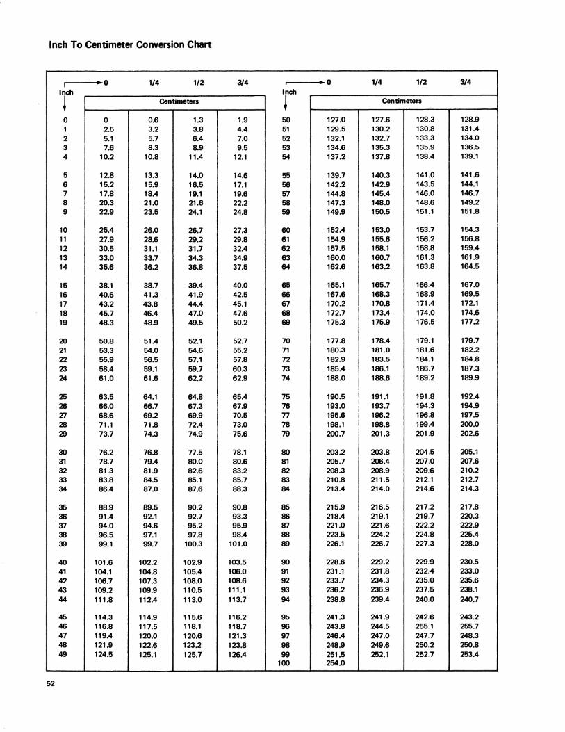
Inch To Centimeter Conversion Chart
I -0 1/4 1/2 3/4 i • 0 1/4 1/2 3/4 Inch Inch
~ Centimeters ~ Centimeters
0 0 0.6 1.3 1.9 50 127.0 127.6 128.3 128.9 1 2.5 3.2 3.8 4.4 51 129.5 130.2 130.8 131.4 2 5.1 5.7 6.4 7.0 52 132.1 132.7 133.3 134.0 3 7.6 8.3 8.9 9.5 53 134.6 135.3 135.9 136.5 4 10.2 10.8 11.4 12.1 54 137.2 137.8 138.4 139.1
5 12.8 13.3 14.0 14.6 55 139.7 140.3 141.0 141.6 6 15.2 15.9 16.5 17.1 56 142.2 142.9 143.5 144.1 7 17.8 18.4 19.1 19.6 57 144.8 145.4 146.0 146.7 8 20.3 21.0 21.6 22.2 58 147.3 148.0 148.6 149.2 9 22.9 23.5 24.1 24.8 59 149.9 150.5 151.1 151.8
10 25.4 26.0 26.7 27.3 60 152.4 153.0 153.7 154.3 11 27.9 28.6 29.2 29.8 61 154.9 155.6 156.2 156.8 12 30.5 31.1 31.7 32.4 62 157.5 158.1 158.8 159.4 13 33.0 33.7 34.3 34.9 63 160.0 160.7 161.3 161.9 14 35.6 36.2 36.8 37.5 64 162.6 163.2 163.8 164.5
15 38.1 38.7 39.4 40.0 65 165.1 165.7 166.4 167.0 16 40.6 41.3 41.9 42.5 66 167.6 168.3 168.9 169.5 17 43.2 43.8 44.4 45.1 67 170.2 170.8 171.4 172.1 18 45.7 46.4 47.0 47.6 68 172.7 173.4 174.0 174.6 19 48.3 48.9 49.5 50.2 69 175.3 175.9 176.5 177.2
20 50.8 51.4 52.1 52.7 70 177.8 178.4 179.1 179.7 21 53.3 54.0 54.6 55.2 71 180.3 181.0 181.6 182.2 22 55.9 56.5 57.1 57.8 72 182.9 183.5 184.1 184.8 23 58.4 59.1 59.7 60.3 73 185.4 186.1 186.7 187.3 24 61.0 61.6 62.2 62.9 74 188.0 188.6 189.2 189.9
25 63.5 64.1 64.8 65.4 75 190.5 191.1 191.8 192.4 26 66.0 66.7 67.3 67.9 76 193.0 193.7 194.3 194.9 27 68.6 69.2 69.9 70.5 77 195.6 196.2 196.8 197.5 28 71.1 71.8 72.4 73.0 78 198.1 198.8 199.4 200.0 29 73.7 74.3 74.9 75.6 79 200.7 201.3 201.9 202.6
30 76.2 76.8 77.5 78.1 80 203.2 203.8 204.5 205.1 31 78.7 79.4 80.0 80.6 81 205.7 206.4 207.0 207.6 32 81.3 81.9 82.6 83.2 82 208.3 208.9 209.6 210.2 33 83.8 84.5 85.1 85.7 83 210.8 211.5 212.1 212.7 34 86.4 87.0 87.6 88.3 84 213.4 214.0 214.6 214.3
35 88.9 89.5 90.2 90.8 85 215.9 216.5 217.2 217.8 36 91.4 92.1 92.7 93.3 86 218.4 219.1 219.7 220.3 37 94.0 94.6 95.2 95.9 87 221.0 221.6 222.2 222.9 38 96.5 97.1 97.8 98.4 88 223.5 224.2 224.8 225.4 39 99.1 99.7 100.3 101.0 89 226.1 226.7 227.3 228.0
40 101.6 102.2 102.9 103.5 90 228.6 229.2 229.9 230.5 41 104.1 104.8 105.4 106.0 91 231.1 231.8 232.4 233.0 42 106.7 107.3 108.0 108.6 92 233.7 234.3 235.0 235.6 43 109.2 109.9 110.5 111.1 93 236.2 236.9 237.5 238.1 44 111.8 112.4 113.0 113.7 94 238.8 239.4 240.0 240.7
45 114.3 114.9 115.6 116.2 95 241.3 241.9 242.6 243.2 46 116.8 117.5 118.1 118.7 96 243.8 244.5 255.1 255.7 47 119.4 120.0 120.6 121.3 97 246.4 247.0 247.7 248.3 48 121.9 122.6 123.2 123.8 98 248.9 249.6 250.2 250.8 49 124.5 125.1 125.7 126.4 99 251.5 252.1 252.7 253.4
100 254.0
52
address: Location on the diskette consisting of a track and sector number; types include: record, program, end of data.
access method: Method of moving data between main storage and input/output devices.
ACL (application control language): Programming.
alphanumerics: Machine processible characters, including both letters and digits.
application: A specific type of job.
auto answer mode: Machine feature that allows a transmission control unit or a station to automatically respond to a call that it receives over a switched line.
backup: Substitute to be used in case of emergency.
batching: See data batching.
begin field code: The first letter in a program field; defines type of field.
bit: The smallest unit of information in a binary system. Eight bits make a byte (see byte).
BSCA (binary synchronous communications adapter): Provides the ability to transmit data from one location to another.
buffer: Machine data storage area.
byte: A series of eight adjacent bits that are used to store alphanumeric information.
channel-attached: Defines relationship to CPU.
centralized/decentralized: See source, remote.
communications: Telecommunications.
configuration: Specific number and types of units related in a specific way to each other and to the CPU.
Glossary
control disk: Disk containing job specifications for converter operation.
CPU: Central processing unit; computer.
CRT: Cathode ray tube; operator display screen on key entry stations.
cursor: Character position underscore (-) on display screen.
data batching: Splitting source data for a job into segments to expedite the job.
data conversion: Process whereby 3747 writes data from a disk onto tape or vice versa.
data recovery: Reconstruction of recorded data that cannot be read.
data set: A complete and related group of records (payroll, accounts receivable, etc.).
data set label: Data on index track of diskette that identifies a data set recorded on that disk by name and location, and shows whether or not the data set has been verified.
direct input: Method of providing data to a CPU.
disk drive: The device that moves the disk past a read/ write mechanism.
duplex!half-duplex: Duplex = data transmission in both directions at once.
error recovery: Automatic or operator-initiated action to correct an error condition.
field, data: Specific category of information in a record (name, social security number, etc.).
field, program: Code specifying format for a given data field.
Glossary 53
half-duplex: Data transmission in both directions but not at the same time.
hard copy: Printed copy of machine output in visually readable form.
header record: Record containing identifying information for a group of records that follows.
ICA: Integrated communications adapte~; provides for direct connection of a device with the CPU.
index track: The first track on the diskette (track 00); used for data set labels.
initialization: Process resulting in the diskette's original physical format.
LCA: Local communications adapter; permits direct attachment of the 3741 Model 2 to System/3 when it is installed.
library, diskette: Procedural system for controlling diskette use; typically involves the implementation of a filing system and control cards or forms.
machine status: The state the machine is in if it is 1) ready to be operated, 2) not ready, or 3) in a wait state.
manual fields: Any field involving operator action characterby-character.
mask statement: Information keyed when doing a search that the 3740 system uses to compare to information stored on the diskette.
mode: Type of machine operation in which certain functions can be selected and certain simple operations performed (Enter mode, Update mode, etc.).
modem: A device that changes machine readable data into a form suitable for transmission over communications facilities.
nonswitched: A connection between a remote terminal and a computer that does not have to be established by dialing.
54
nontransparent text mode: See transparent text mode.
offline: Type of operation in which data recording and machine handling of recorded data are separated by some form of operator intervention.
online: Type of operation in which recorded da,ta is operated on by the machine without intervening operator action.
operating system: Software controlling the execution of computer programs (OS, OSIVS, DOS, etc.).
outage: Not in service.
print format: Print line and column specifications.
program disk: Disk containing key entry programs.
program, key entry: A set of information stored in the machine to relieve the operator of certain actions. Programs can be used, for example, to place the machine in alpha or numeric shift, to automatically skip or duplicate fields, etc.
program level: Program storage area in the machine.
program shift code: Symbol representing a data field containing either alphabetic (dots) or numeric (dashes) characters.
record: One or more data fields that form a unit of information meaningful to your operation; for example, payroll, accounts receivable, accounts payable records. A record can be no more than 128 characters.
reinitialization: The process of altering the diskette's current track and sector format.
remote location:. Offsite.
retention cycle: Length of time a job recorded on the diskette is retained before the diskette can be used to record other information.
right-adjust field: Field in which characters are recorded at the right end of the field so that the position of the last rather than first character is fixed, regardless of the number of characters in the field; positions not occupied by characters may contain blanks or zeros. Examples of such fields are amount fields, count fields, etc.
scratch diskette: A diskette that can be used to record data; a diskette that is no longer in a retention cycle.
scratch file: Collection of scratch diskettes.
sector: A section in a track on the disk for a record.
source document: Material containing the data being keyed.
source location: Area generating a source document.
suspense file: Collection of diskettes that have been converted to tape and are being held for release by the CPU. operator.
switched: A communication line in which the connection between the computer and a remote station is established by dialing.
synchronous: Occurring with a regular or predictable time relationship.
tape labels: Records at the beginning or end of a tape that identify the information on that tape.
telecommunications: Data transmission between a computing system and remotely located devices via a unit that performs the necessary format conversion and controls the rate of transmission.
teleprocessing: Processing of data that is received from or sent to remote locations by way of telecommunication lines.
terminal: A device capable of sending and receiving information over a communication channel.
throughput: Rate of production.
track: The portion of a moving storage medium, such as a tape or diskette, that is accessible to a given reading head position.
trailer record: A record that follows one or more records and contains data related to those records.
transparent text mode: Type of operation permitting unrestricted coding of data.
unit specifications: Information pertaining to physical machine characteristics such as size, power requirements, etc.
Gloaary 66
Teleprocessing Bibliography
General Information
IBM Teleprocessing SRL Bibliography, GA24-3089 IBM TeleproceSSing System Summary, GA24-3090
Bse Information
General Information Binary Synchronous Communications, GA27-3004
IBM 3740 Data Entry System Programmer's Guide, GC21-5071
56
Programming Information
System/370 System Summary, GA22-7001 System/360 Programming Systems Summary (BPS, BOS,
TOS, DOS), GC24-3420 OSNS1 Planning and Users Guide, GC24-509P OSNS1 Release Guide, GC24-5092 OSNS2 Planning Guide, GC28-0600 OSNS2 Release Guide, GC28-0oo1 DOS/360 BTAM Reference Manual, GC30-5001 IBM Systems - DOSNS Version 4 Basic Telecommunica-
tions Access Method (BTAM), GC27-6978 OS BTAM Reference Manual, GC30-2004 IBM Systems - OSNS BTAM, GC27-6980 IBM Systems - OSIMFT and OS!MVT TCAM Programmer's Guide, GC30-2024.
IBM Systems - OSNS TCAM Programmer's Guide, GC30-2034
Introduction to VTAM, GC27-6987
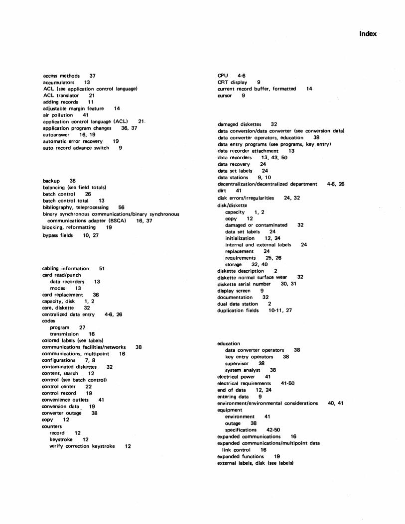
access methods 37 accumulators 13 ACL (see application control language) ACL translator 21 adding records 11 adjustable margin feature 14 air pollution 41 application control language (ACL) 21. application program changes 36, 37 autoanswer 16, 19 automatic error recovery 19 auto record advance switch 9
backup 38 balancing (see field totals) batch control 26 batch control total 13 bibliography, teleprocessing 56 binary synchronous communications/binary synchronous
communications adapter (BSCA) 16, 37 blocking, reformatting 19
bypass fields 10, 27
cabling information 51 card read/punch
data recorders 13 modes 13
card replacement 36 capacity, disk 1, 2 care, diskette 32 centralized data entry codes
program 27 transmission 16
4-6, 26
colored labels (see labels) communications facilities/networks communications, multipoint 16 configurations 7, 8 contaminated diskettes 32 content, search 12 control (see batch controll control center 22 control record 19 convenience outlets 41 conversion data 19 converter outage 38 copy 12 counters
record 12 keystroke 12 verify correction keystroke 12
38
CPU 4-6 CRT display 9 current record buffer, formatted 14 cursor 9
damaged diskettes 32 data conversion/data converter (see conversion data) data converter operators, education 38 data entry programs (see programs, key entry) data recorder attachment 13 data recorders 13, 43, 50 data recovery 24 data set labels 24 data stations 9, 10 decentralization/decentralized department 4-6, 26 dirt 41 disk errors/irregularities disk/diskette
capacity 1, 2 copy 12
24,32
damaged or contaminated 32 data set labels 24 initialization 12, 24 internal and external labels 24 replacement 24 requirements 25, 26 storage 32, 40
diskette description 2 diskatte normal surface wear 32 diskette serial number 30, 31 display screen 9 documentation 32 dual data station 2 duplication fields 10-11, 27
education data converter operators 38 key entry operators 38 supervisor 38 system analyst 38
electrical power 41 electrical requirements 41-50 end of data 12, 24 entering data 9 environment/environmental considerations equipment
environment 41 outage 38 specifications 42-50
expanded communications 16 expanded communications/multipoint data
link control 16 expanded functions 19 external labels, disk (see labels)
40,41
Index
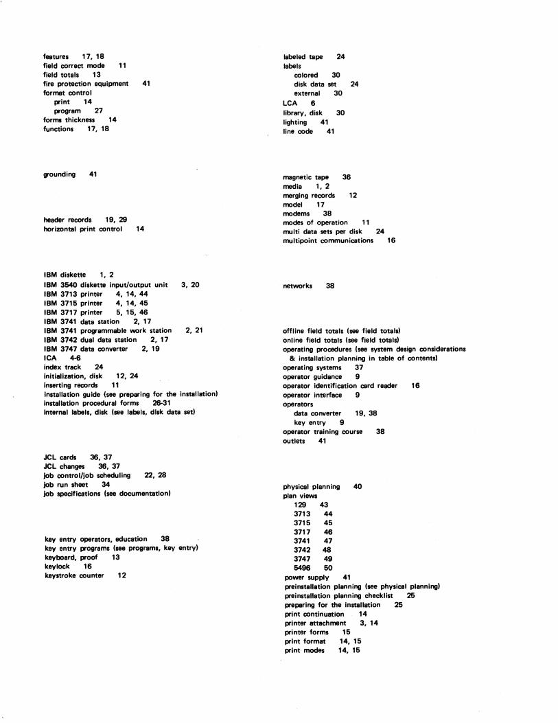
features 17, 18 field correct mode 11 field totals 13 fire protection equipment format control
print 14 program 27
forms thickness 14 functions 17, 18
grounding 41
header records 19,29 horizontal print control
IBM diskette 1, 2
41
14
IBM 3640 diskette input/output unit 3, 20 IBM 3713 printer 4, 14, 44 IBM 3715 printer 4, 14, 45 IBM 3717 printer 5, 15, 46 IBM 3741 data station 2, 17 IBM 3741 programmable work station 2, 21 IBM 3742 dual data station 2, 17 IBM 3747 data converter 2, 19 ICA 4-6 index track 24 initialization, disk 12, 24 inserting records 11 installation guide (see preparing for the installation) installation procedural forms 26-31 internal labels, disk (see labals, disk deta sat)
JCL cards 36, 37 JCL changes 36, 37 job control/job scheduling 22, 28 job run sheet 34 job specifications (see documentation)
key entry operators, education 38 key entry programs (see programs, key entry) keyboard, proof 13 key lock 16 keystroke counter 12
labeled tepe 24 labels
colored 30 disk data set 24 external 30
LCA 6 library, disk 30 lighting 41 line code 41
magnetic tape 36 media 1, 2 marging records 12 model 17 modems 38 modes of operation 11 multi deta sets per disk multipoint communications
networks 38
24 16
offline field totals (see field totals) online field totals (see field totals) operating procedures (see system design considerations
& installation planning in table of contents) operating systems 37 operator guidance 9 operator identification card reader 16 operator interface 9 operators
data converter 19, 38 key entry 9
operator training course 38 outlats 41
physical planning 40 plan views
129 43 3713 44 3715 45 3717 46 3741 47 3742 48 3747 49 5496 50
power supply 41 preinstallation planning (see physical planning) preinstallation planning checklist 26 prepering for the installation 25 print continuation 14 printer attachment 3, 14 printer forms 15 print format 14, 15 print modes 14, 15
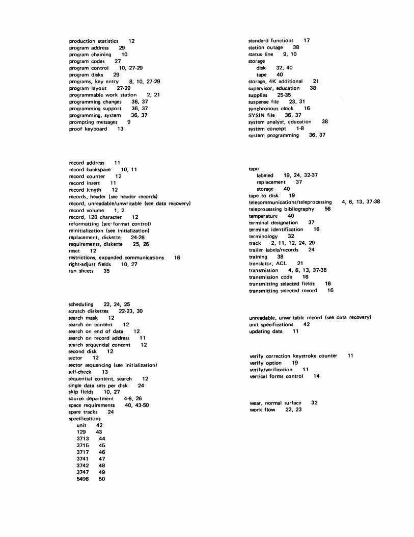
production statistics 12 program address 29 program chaining 10 program codes 27 program control 10, 27·29 program disks 29 programs, key entry 8, 10, 27·29 program layout 27·29 programmable work station 2, 21 programming changes 36, 37 programming support 36, 37 programming, system 36, 37 prompting messages 9 proof keyboard 13
record address 11 record backspace record counter record insert record length
10, 11 12
11 12
records, header (see header records) record, unreadable/unwritable (see data recovery) record volume 1, 2 record, 128 character 12 reformatting (see" format controll reinitialization (see initialization) replacement, diskette 24·26 requirements, diskette 25, 26 reset 12 restrictions, expanded communications 16 right·adjust fields 10, 27 run sheets 35
scheduling 22, 24, 25 scratch diskettes 22·23, 30 search mask 12 search on content 12 search on end of data 12 search on record address 11 search sequential content 12 second disk 12 sector 12 sector sequencing (see initialization) self·check 13 sequential content, search 12 single data sets per disk 24 skip fields 10, 27 source department space requirements spare tracks 24 specifications
unit 42 129 43 3713 44 3715 45 3717 46 3741 47 3742 48 3747 49 5496 50
4-6, 26 40, 43·50
standard functions 17 station outage 38 status line 9, 10 storage
disk 32,40 tape 40
storage, 4K additional 21 supervisor, education 38 supplies 25·35 suspense file 23, 31 synchronous clock 16 SYSIN file 36, 37 system analyst, education 38 system concept 1·8 system programming 36,37
tape labeled 19, 24, 32·37 replacement 37 storage 40
tape to disk 19 telecommunications/teleprocessing 4, 6, 13, 37·38 teleprocessing bibliography 56 temperature 40 terminal designation 37 ~erminal identification 16 terminology 32 track 2, 11, 12, 24, 29 trailer labels/records 24 training 38 translator, ACL 21 transmission 4, 6, 13, 37·38 transmission code 16 transmitting selected fields 16 transmitting selected record 16
unreadable, unwritable record (see data recovery) unit specifications 42 updati ng data 11
verify correction keystroke counter verify option 19 verify/verification 11 vertical forms control 14
wear, normal surface work flow 22, 23
32
11

READER'S COMMENT FORM
IBM 3740 Data Entry System System Summary and Installation Manual - Physical Planning
YOUR COMMENTS, PLEASE •••
GA21-9152-2 File No. 3740-00,15
Your comments assist us in improving the usefulness of our publications; they are an important part of the input used in preparing updates to the publications. All comments and suggestions become the property of IBM.
Please do not use this form for technical questions about the system or for requests for additional publications; this only delays the response. Instead. direct your inquiries or requests to your IBM representative or to the IBM branch office serving your locality.
Corrections or clarifications needed:
Page Comment
Please include your name and address in the space below if you wish a reply.
• Thank you for your cooperation. No postage necessary if mailed in the U.S.A.
Fold
BUSINESS REPLY MAil NO POSTAGE STAMP NECESSARY IF. MAILED IN THE UNITED STATES
POSTAGE WILL BE PAID BY •.•
IBM Corporation General Systems Division Development Laboratory Publications, Dept. 245 Rochester, Minnesota 55901
Attention: Publications, Dept. 245
Fold
--- ------ --------:i:::..: :s~i:
®
International Business Machines Corporation General Systems Division 815 Johnson Ferry Road N. E. Atlanta, Ga. 30342 (USA Only)
IBM World Trade Corporation 821 United Nations Plaza, New York, New York 10017 (International)
Fold
FIRST CLASS
PERMIT NO. 387
ROCHESTER, MINN.
Fold
GA21-9152-2
--- -----:i:: :;l"i: '"
International Business Machines Corporation General Systems Division 875Johnson Ferry Road N. E. Atlanta. Ga. 30342 (USA Only)
IBM World Trade Corporation 821 United Nations Plaza. New York. New York 10017 U ntarnational)