Embed Size (px)
Citation preview
IAG Performance | 1203 Baltimore Blvd. Westminster, MD 21157 | Ph: 410-840-3555 | www.iagperformance.com 1
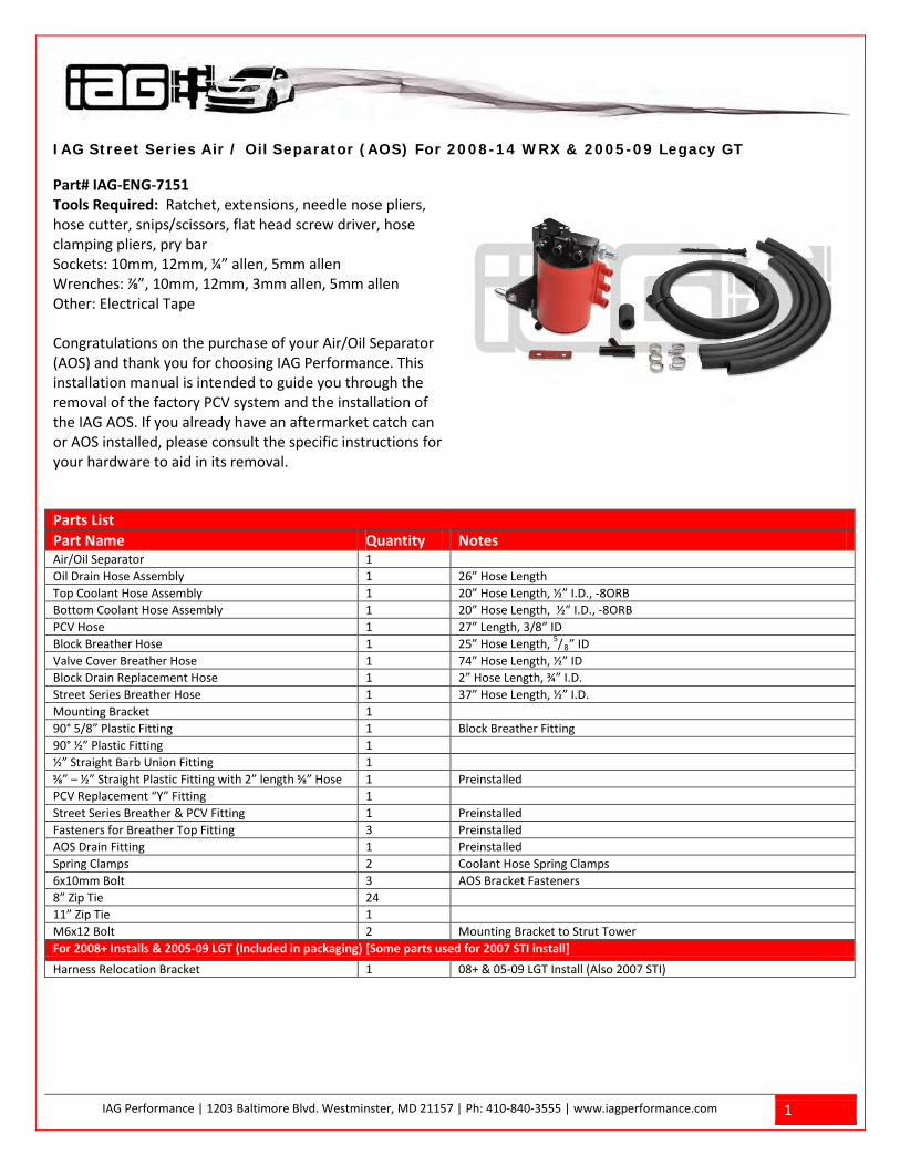
IAG Street Series Air / Oil Separator (AOS) For 2008-14 WRX & 2005-09 Legacy GT
Part# IAG-ENG-7151 Tools Required: Ratchet, extensions, needle nose pliers, hose cutter, snips/scissors, flat head screw driver, hose clamping pliers, pry bar Sockets: 10mm, 12mm, ¼” allen, 5mm allen Wrenches: ⅞”, 10mm, 12mm, 3mm allen, 5mm allen Other: Electrical Tape Congratulations on the purchase of your Air/Oil Separator (AOS) and thank you for choosing IAG Performance. This installation manual is intended to guide you through the removal of the factory PCV system and the installation of the IAG AOS. If you already have an aftermarket catch can or AOS installed, please consult the specific instructions for your hardware to aid in its removal.
Parts List Part Name Quantity Notes Air/Oil Separator 1 Oil Drain Hose Assembly 1 26” Hose Length Top Coolant Hose Assembly 1 20” Hose Length, ½” I.D., -8ORB Bottom Coolant Hose Assembly 1 20” Hose Length, ½” I.D., -8ORB PCV Hose 1 27” Length, 3/8” ID Block Breather Hose 1 25” Hose Length, P
5P/R8R” ID
Valve Cover Breather Hose 1 74” Hose Length, ½” ID Block Drain Replacement Hose 1 2” Hose Length, ¾” I.D. Street Series Breather Hose 1 37” Hose Length, ½” I.D. Mounting Bracket 1 90° 5/8” Plastic Fitting 1 Block Breather Fitting 90° ½” Plastic Fitting 1 ½” Straight Barb Union Fitting 1 ⅝” – ½” Straight Plastic Fitting with 2” length ⅝” Hose 1 Preinstalled PCV Replacement “Y” Fitting 1 Street Series Breather & PCV Fitting 1 Preinstalled Fasteners for Breather Top Fitting 3 Preinstalled AOS Drain Fitting 1 Preinstalled Spring Clamps 2 Coolant Hose Spring Clamps 6x10mm Bolt 3 AOS Bracket Fasteners 8” Zip Tie 24 11” Zip Tie 1 M6x12 Bolt 2 Mounting Bracket to Strut Tower For 2008+ Installs & 2005-09 LGT (Included in packaging) [Some parts used for 2007 STI install] Harness Relocation Bracket 1 08+ & 05-09 LGT Install (Also 2007 STI)
IAG Performance | 1203 Baltimore Blvd. Westminster, MD 21157 | Ph: 410-840-3555 | www.iagperformance.com 2
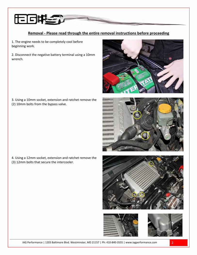
URemoval - Please read through the entire removal instructions before proceeding 1. The engine needs to be completely cool before beginning work. 2. Disconnect the negative battery terminal using a 10mm wrench.
3. Using a 10mm socket, extension and ratchet remove the (2) 10mm bolts from the bypass valve.
4. Using a 12mm socket, extension and ratchet remove the (3) 12mm bolts that secure the intercooler.
IAG Performance | 1203 Baltimore Blvd. Westminster, MD 21157 | Ph: 410-840-3555 | www.iagperformance.com 3
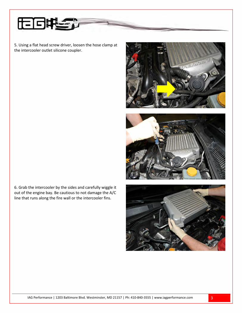
5. Using a flat head screw driver, loosen the hose clamp at the intercooler outlet silicone coupler.
6. Grab the intercooler by the sides and carefully wiggle it out of the engine bay. Be cautious to not damage the A/C line that runs along the fire wall or the intercooler fins.
IAG Performance | 1203 Baltimore Blvd. Westminster, MD 21157 | Ph: 410-840-3555 | www.iagperformance.com 4
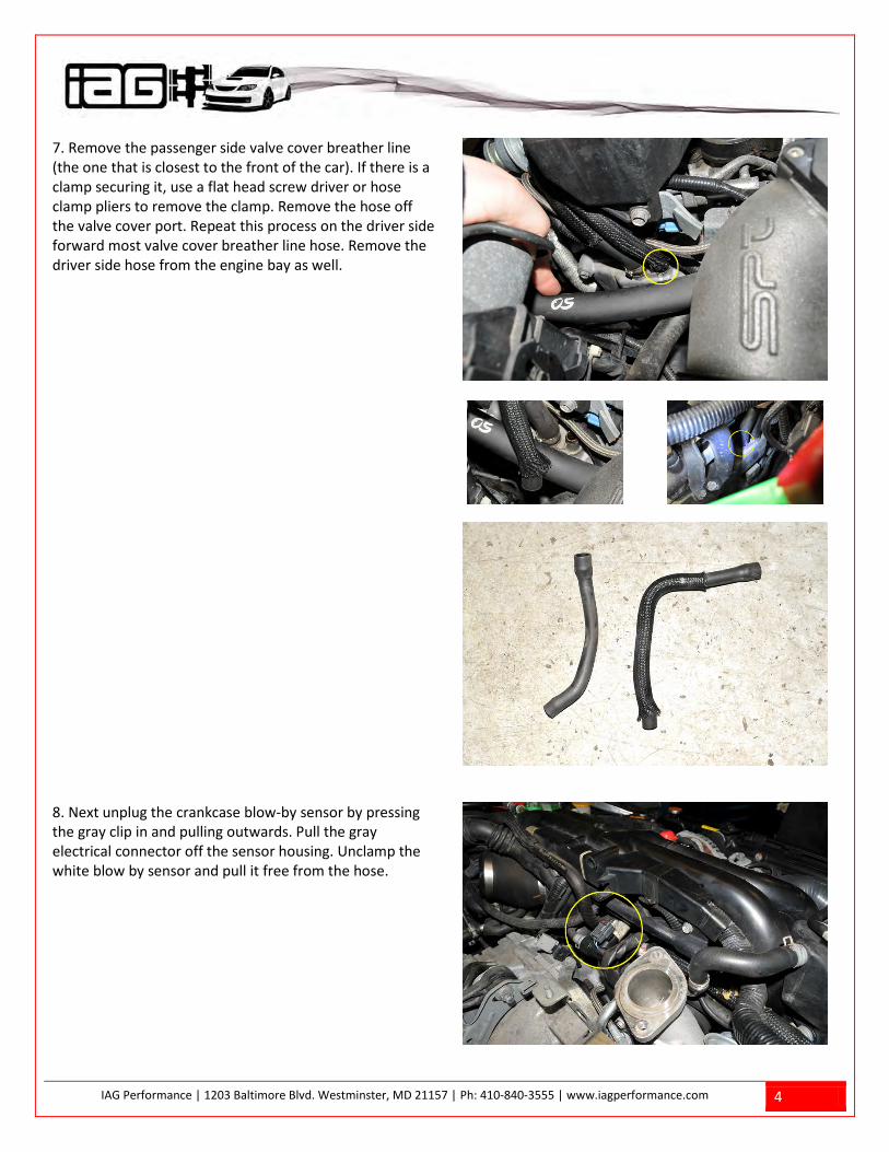
7. Remove the passenger side valve cover breather line (the one that is closest to the front of the car). If there is a clamp securing it, use a flat head screw driver or hose clamp pliers to remove the clamp. Remove the hose off the valve cover port. Repeat this process on the driver side forward most valve cover breather line hose. Remove the driver side hose from the engine bay as well.
8. Next unplug the crankcase blow-by sensor by pressing the gray clip in and pulling outwards. Pull the gray electrical connector off the sensor housing. Unclamp the white blow by sensor and pull it free from the hose.
IAG Performance | 1203 Baltimore Blvd. Westminster, MD 21157 | Ph: 410-840-3555 | www.iagperformance.com 5
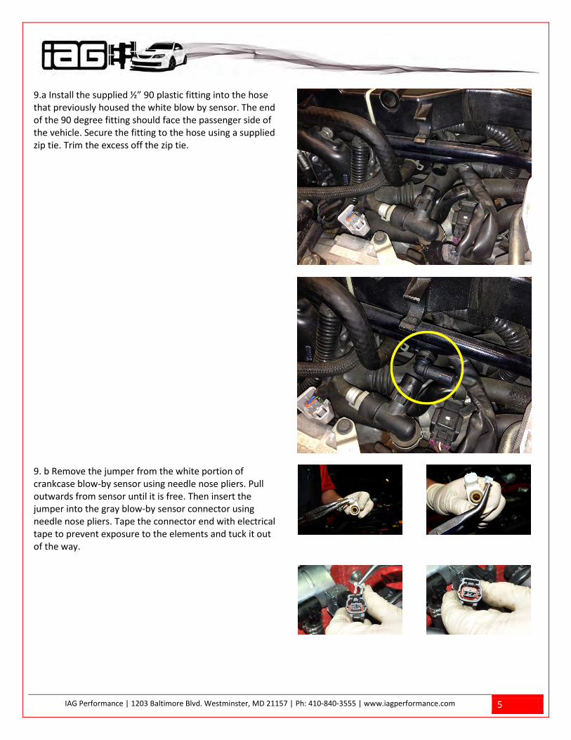
9.a Install the supplied ½” 90 plastic fitting into the hose that previously housed the white blow by sensor. The end of the 90 degree fitting should face the passenger side of the vehicle. Secure the fitting to the hose using a supplied zip tie. Trim the excess off the zip tie.
9. b Remove the jumper from the white portion of crankcase blow-by sensor using needle nose pliers. Pull outwards from sensor until it is free. Then insert the jumper into the gray blow-by sensor connector using needle nose pliers. Tape the connector end with electrical tape to prevent exposure to the elements and tuck it out of the way.
IAG Performance | 1203 Baltimore Blvd. Westminster, MD 21157 | Ph: 410-840-3555 | www.iagperformance.com 6
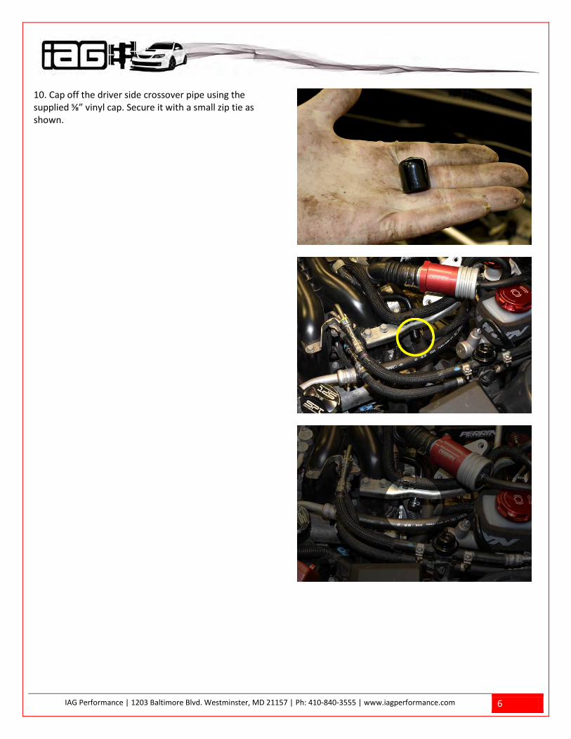
10. Cap off the driver side crossover pipe using the supplied ⅝” vinyl cap. Secure it with a small zip tie as shown.
IAG Performance | 1203 Baltimore Blvd. Westminster, MD 21157 | Ph: 410-840-3555 | www.iagperformance.com 7
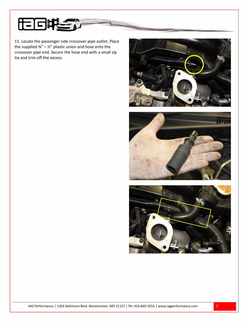
11. Locate the passenger side crossover pipe outlet. Place the supplied ⅝” – ½” plastic union and hose onto the crossover pipe end. Secure the hose end with a small zip tie and trim off the excess.
IAG Performance | 1203 Baltimore Blvd. Westminster, MD 21157 | Ph: 410-840-3555 | www.iagperformance.com 8
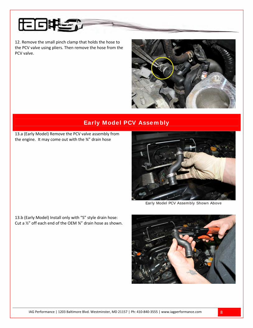
12. Remove the small pinch clamp that holds the hose to the PCV valve using pliers. Then remove the hose from the PCV valve.
Early Model PCV Assembly
13.a (Early Model) Remove the PCV valve assembly from the engine. It may come out with the ¾” drain hose
Early Model PCV Assembly Shown Above
13.b (Early Model) Install only with “S” style drain hose: Cut a ½” off each end of the OEM ¾” drain hose as shown.
IAG Performance | 1203 Baltimore Blvd. Westminster, MD 21157 | Ph: 410-840-3555 | www.iagperformance.com 9
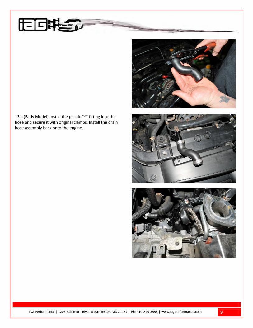
13.c (Early Model) Install the plastic “Y” fitting into the hose and secure it with original clamps. Install the drain hose assembly back onto the engine.
IAG Performance | 1203 Baltimore Blvd. Westminster, MD 21157 | Ph: 410-840-3555 | www.iagperformance.com 10
Late Model PCV Assembly
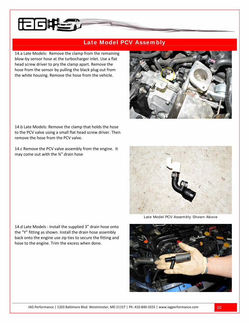
14.a Late Models: Remove the clamp from the remaining blow-by sensor hose at the turbocharger inlet. Use a flat head screw driver to pry the clamp apart. Remove the hose from the sensor by pulling the black plug out from the white housing. Remove the hose from the vehicle.
14.b Late Models: Remove the clamp that holds the hose to the PCV valve using a small flat head screw driver. Then remove the hose from the PCV valve.
14.c Remove the PCV valve assembly from the engine. It may come out with the ¾” drain hose
Late Model PCV Assembly Shown Above
14.d Late Models : Install the supplied 3” drain hose onto the “Y” fitting as shown. Install the drain hose assembly back onto the engine use zip ties to secure the fitting and hose to the engine. Trim the excess when done.
IAG Performance | 1203 Baltimore Blvd. Westminster, MD 21157 | Ph: 410-840-3555 | www.iagperformance.com 11
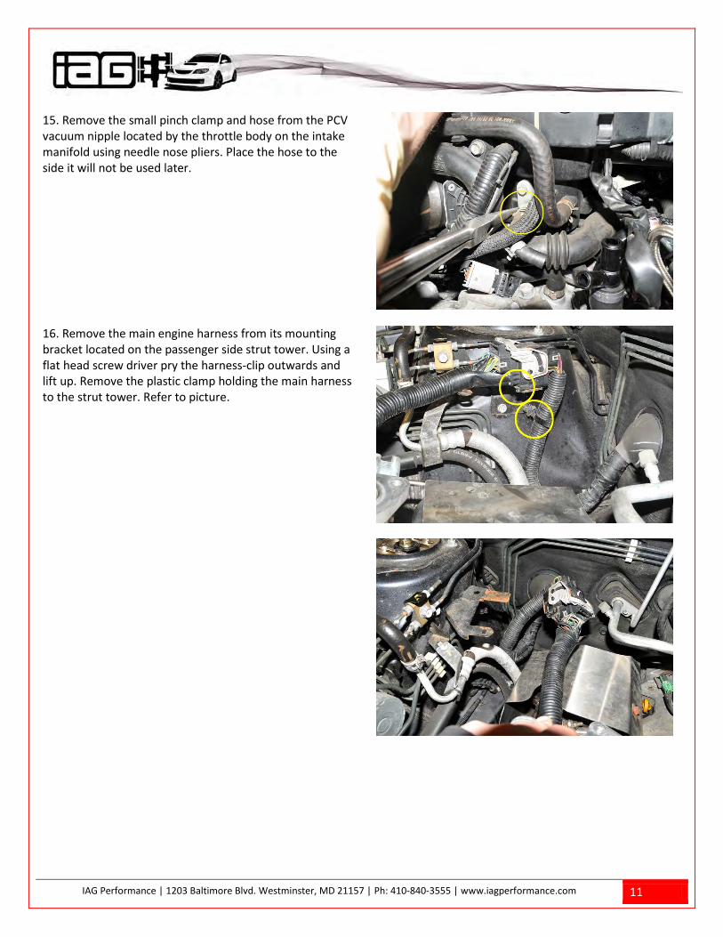
15. Remove the small pinch clamp and hose from the PCV vacuum nipple located by the throttle body on the intake manifold using needle nose pliers. Place the hose to the side it will not be used later.
16. Remove the main engine harness from its mounting bracket located on the passenger side strut tower. Using a flat head screw driver pry the harness-clip outwards and lift up. Remove the plastic clamp holding the main harness to the strut tower. Refer to picture.
IAG Performance | 1203 Baltimore Blvd. Westminster, MD 21157 | Ph: 410-840-3555 | www.iagperformance.com 12
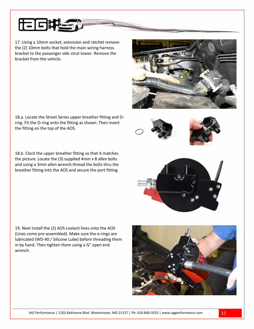
17. Using a 10mm socket, extension and ratchet remove the (2) 10mm bolts that hold the main wiring harness bracket to the passenger side strut tower. Remove the bracket from the vehicle.
18.a. Locate the Street Series upper breather fitting and O-ring. Fit the O-ring onto the fitting as shown. Then insert the fitting on the top of the AOS.
18.b. Clock the upper breather fitting so that it matches the picture. Locate the (3) supplied 4mm x 8 allen bolts and using a 3mm allen wrench thread the bolts thru the breather fitting into the AOS and secure the port fitting.
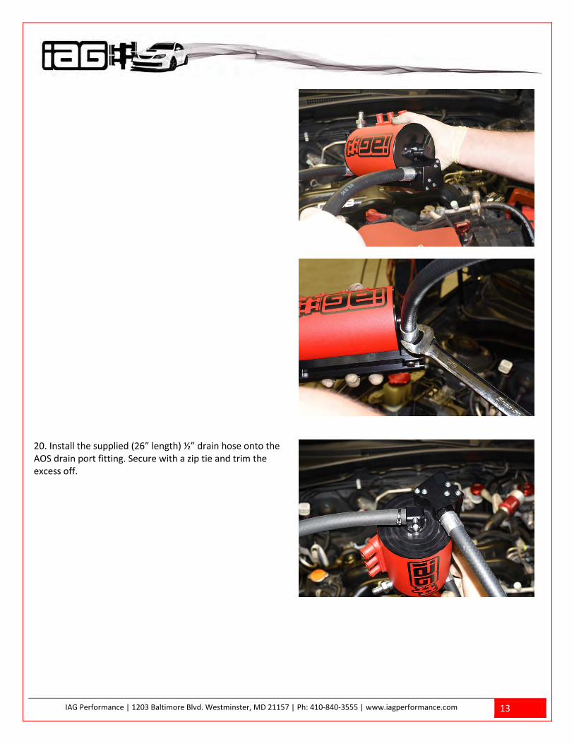
19. Next install the (2) AOS coolant lines onto the AOS (Lines come pre-assembled). Make sure the o-rings are lubricated (WD-40 / Silicone Lube) before threading them in by hand. Then tighten them using a ⅞” open end wrench.
IAG Performance | 1203 Baltimore Blvd. Westminster, MD 21157 | Ph: 410-840-3555 | www.iagperformance.com 13
20. Install the supplied (26” length) ½” drain hose onto the AOS drain port fitting. Secure with a zip tie and trim the excess off.
IAG Performance | 1203 Baltimore Blvd. Westminster, MD 21157 | Ph: 410-840-3555 | www.iagperformance.com 14
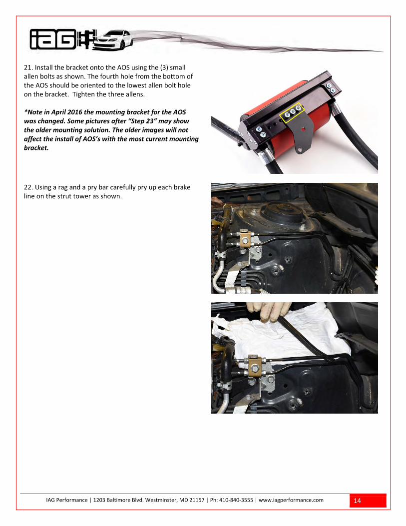
21. Install the bracket onto the AOS using the (3) small allen bolts as shown. The fourth hole from the bottom of the AOS should be oriented to the lowest allen bolt hole on the bracket. Tighten the three allens. *Note in April 2016 the mounting bracket for the AOS was changed. Some pictures after “Step 23” may show the older mounting solution. The older images will not affect the install of AOS’s with the most current mounting bracket.
22. Using a rag and a pry bar carefully pry up each brake line on the strut tower as shown.
IAG Performance | 1203 Baltimore Blvd. Westminster, MD 21157 | Ph: 410-840-3555 | www.iagperformance.com 15
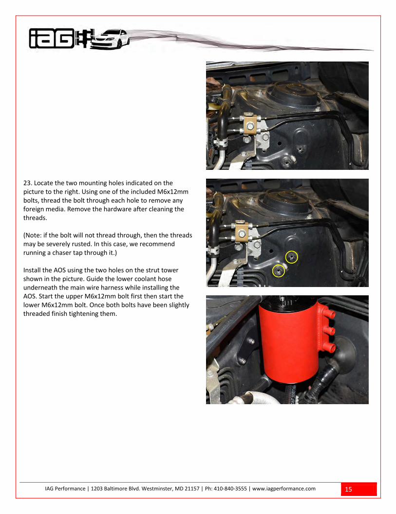
23. Locate the two mounting holes indicated on the picture to the right. Using one of the included M6x12mm bolts, thread the bolt through each hole to remove any foreign media. Remove the hardware after cleaning the threads. (Note: if the bolt will not thread through, then the threads may be severely rusted. In this case, we recommend running a chaser tap through it.) Install the AOS using the two holes on the strut tower shown in the picture. Guide the lower coolant hose underneath the main wire harness while installing the AOS. Start the upper M6x12mm bolt first then start the lower M6x12mm bolt. Once both bolts have been slightly threaded finish tightening them.
IAG Performance | 1203 Baltimore Blvd. Westminster, MD 21157 | Ph: 410-840-3555 | www.iagperformance.com 16
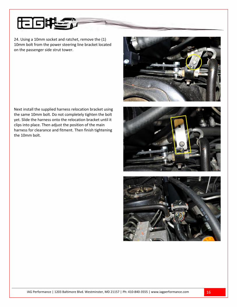
24. Using a 10mm socket and ratchet, remove the (1) 10mm bolt from the power steering line bracket located on the passenger side strut tower.
Next install the supplied harness relocation bracket using the same 10mm bolt. Do not completely tighten the bolt yet. Slide the harness onto the relocation bracket until it clips into place. Then adjust the position of the main harness for clearance and fitment. Then finish tightening the 10mm bolt.
IAG Performance | 1203 Baltimore Blvd. Westminster, MD 21157 | Ph: 410-840-3555 | www.iagperformance.com 17
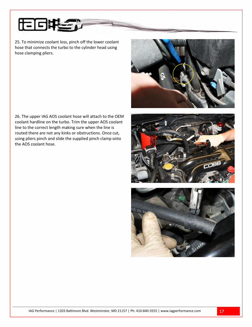
25. To minimize coolant loss, pinch off the lower coolant hose that connects the turbo to the cylinder head using hose clamping pliers.
26. The upper IAG AOS coolant hose will attach to the OEM coolant hardline on the turbo. Trim the upper AOS coolant line to the correct length making sure when the line is routed there are not any kinks or obstructions. Once cut, using pliers pinch and slide the supplied pinch clamp onto the AOS coolant hose.
IAG Performance | 1203 Baltimore Blvd. Westminster, MD 21157 | Ph: 410-840-3555 | www.iagperformance.com 18
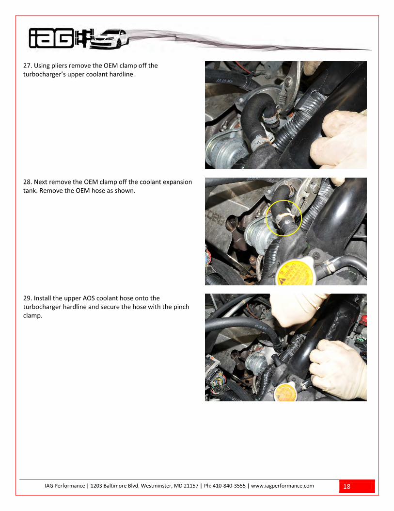
27. Using pliers remove the OEM clamp off the turbocharger’s upper coolant hardline.
28. Next remove the OEM clamp off the coolant expansion tank. Remove the OEM hose as shown.
29. Install the upper AOS coolant hose onto the turbocharger hardline and secure the hose with the pinch clamp.
IAG Performance | 1203 Baltimore Blvd. Westminster, MD 21157 | Ph: 410-840-3555 | www.iagperformance.com 19
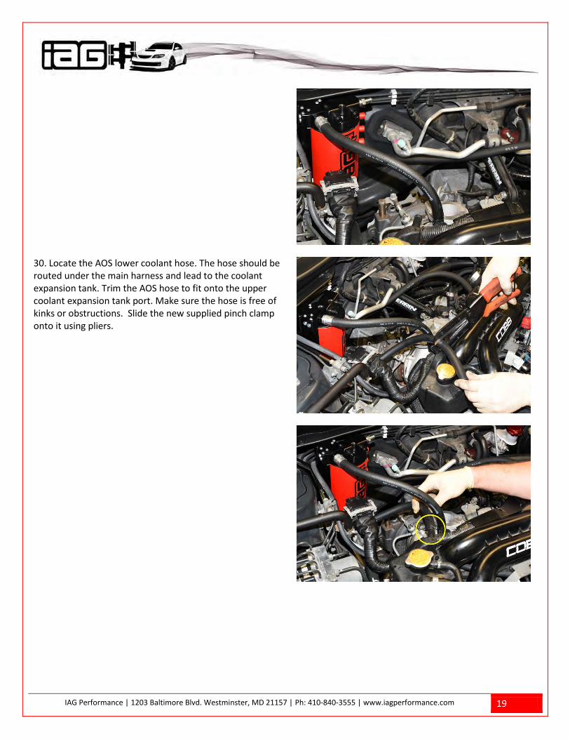
30. Locate the AOS lower coolant hose. The hose should be routed under the main harness and lead to the coolant expansion tank. Trim the AOS hose to fit onto the upper coolant expansion tank port. Make sure the hose is free of kinks or obstructions. Slide the new supplied pinch clamp onto it using pliers.
IAG Performance | 1203 Baltimore Blvd. Westminster, MD 21157 | Ph: 410-840-3555 | www.iagperformance.com 20
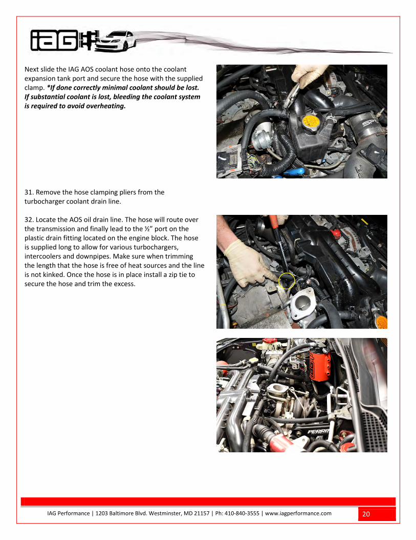
Next slide the IAG AOS coolant hose onto the coolant expansion tank port and secure the hose with the supplied clamp. *If done correctly minimal coolant should be lost. If substantial coolant is lost, bleeding the coolant system is required to avoid overheating.
31. Remove the hose clamping pliers from the turbocharger coolant drain line.
32. Locate the AOS oil drain line. The hose will route over the transmission and finally lead to the ½” port on the plastic drain fitting located on the engine block. The hose is supplied long to allow for various turbochargers, intercoolers and downpipes. Make sure when trimming the length that the hose is free of heat sources and the line is not kinked. Once the hose is in place install a zip tie to secure the hose and trim the excess.
IAG Performance | 1203 Baltimore Blvd. Westminster, MD 21157 | Ph: 410-840-3555 | www.iagperformance.com 21
OEM TMIC INSTALL (Steps 33.a-33.b) / LARGE TMIC INSTALL (Steps 34.a - 34.b)
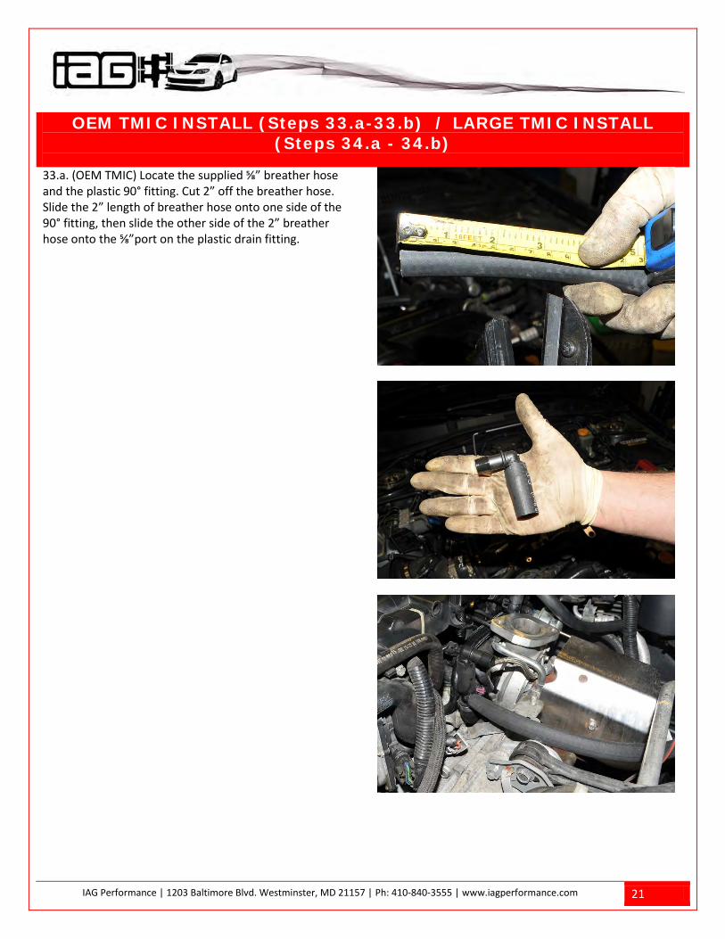
33.a. (OEM TMIC) Locate the supplied ⅝” breather hose and the plastic 90° fitting. Cut 2” off the breather hose. Slide the 2” length of breather hose onto one side of the 90° fitting, then slide the other side of the 2” breather hose onto the ⅝”port on the plastic drain fitting.
IAG Performance | 1203 Baltimore Blvd. Westminster, MD 21157 | Ph: 410-840-3555 | www.iagperformance.com 22
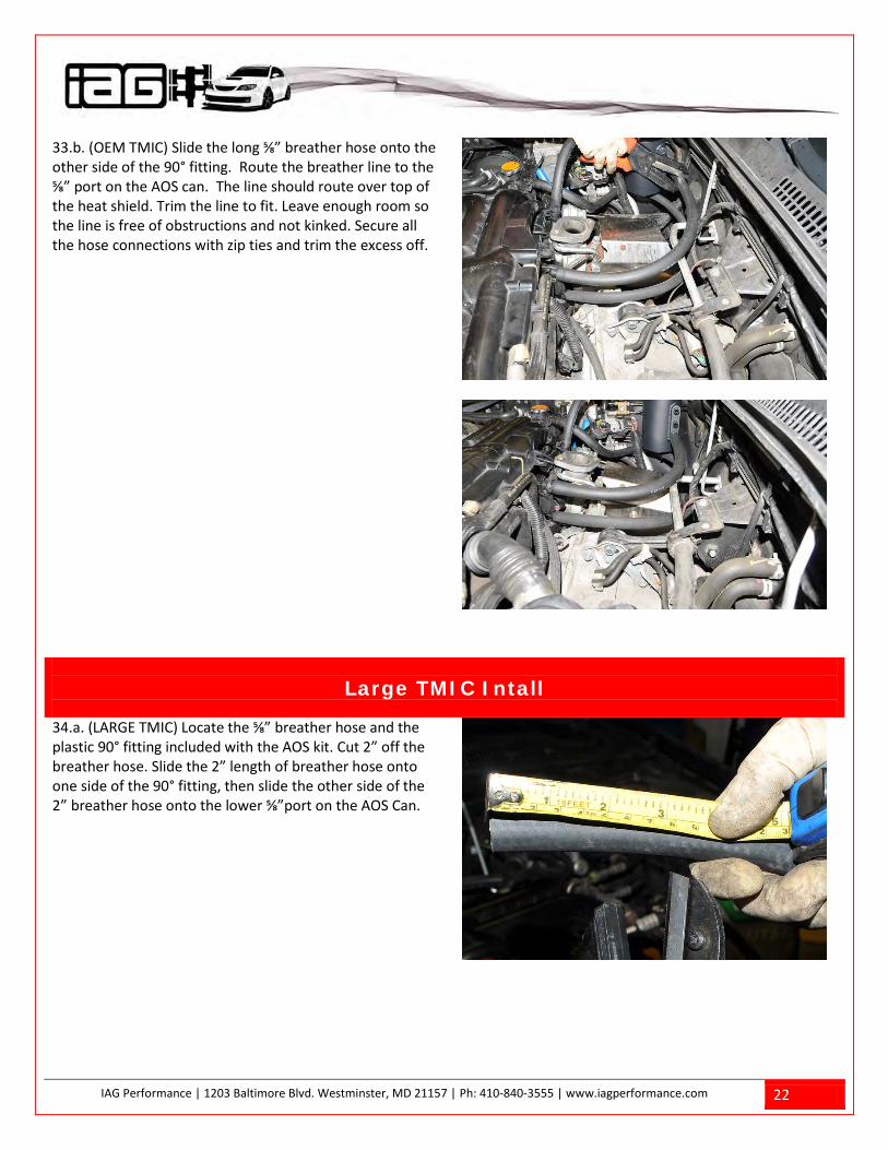
33.b. (OEM TMIC) Slide the long ⅝” breather hose onto the other side of the 90° fitting. Route the breather line to the ⅝” port on the AOS can. The line should route over top of the heat shield. Trim the line to fit. Leave enough room so the line is free of obstructions and not kinked. Secure all the hose connections with zip ties and trim the excess off.
Large TMIC Intall
34.a. (LARGE TMIC) Locate the ⅝” breather hose and the plastic 90° fitting included with the AOS kit. Cut 2” off the breather hose. Slide the 2” length of breather hose onto one side of the 90° fitting, then slide the other side of the 2” breather hose onto the lower ⅝”port on the AOS Can.
IAG Performance | 1203 Baltimore Blvd. Westminster, MD 21157 | Ph: 410-840-3555 | www.iagperformance.com 23
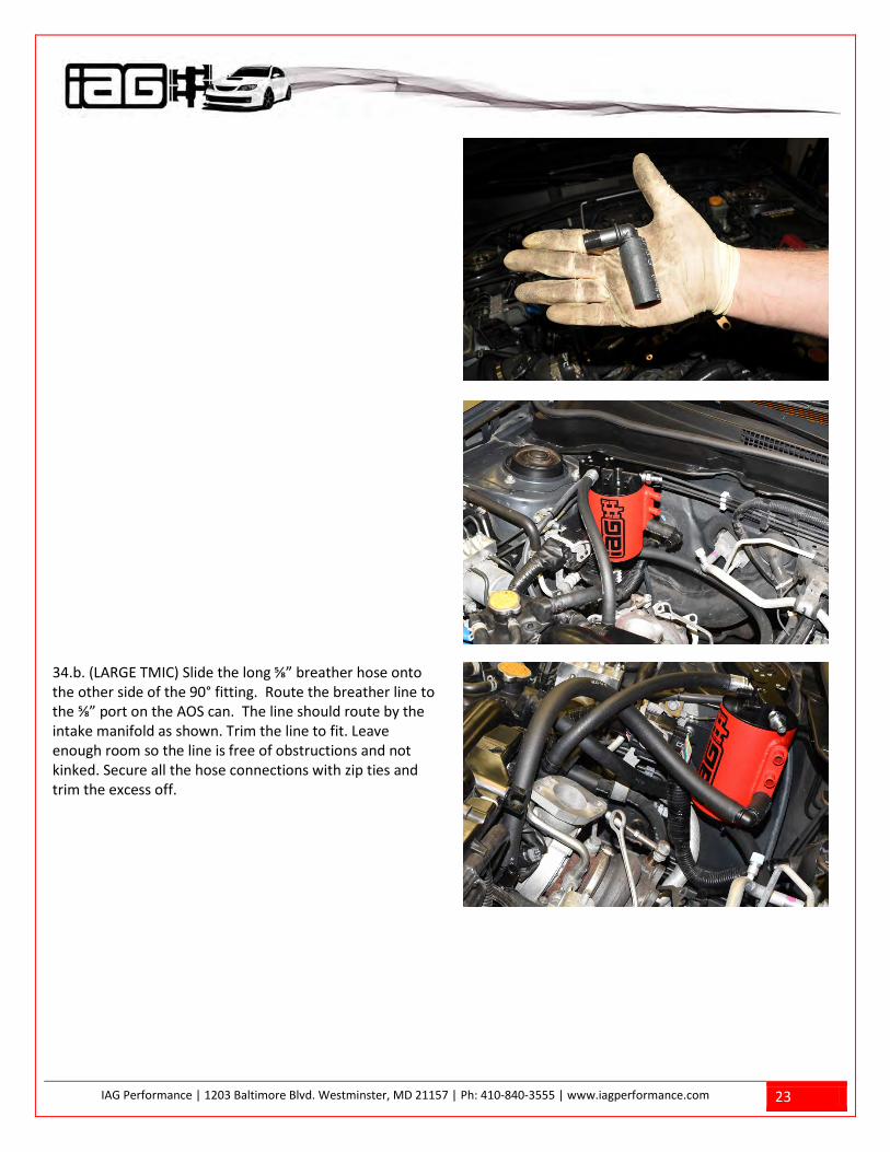
34.b. (LARGE TMIC) Slide the long ⅝” breather hose onto the other side of the 90° fitting. Route the breather line to the ⅝” port on the AOS can. The line should route by the intake manifold as shown. Trim the line to fit. Leave enough room so the line is free of obstructions and not kinked. Secure all the hose connections with zip ties and trim the excess off.
IAG Performance | 1203 Baltimore Blvd. Westminster, MD 21157 | Ph: 410-840-3555 | www.iagperformance.com 24
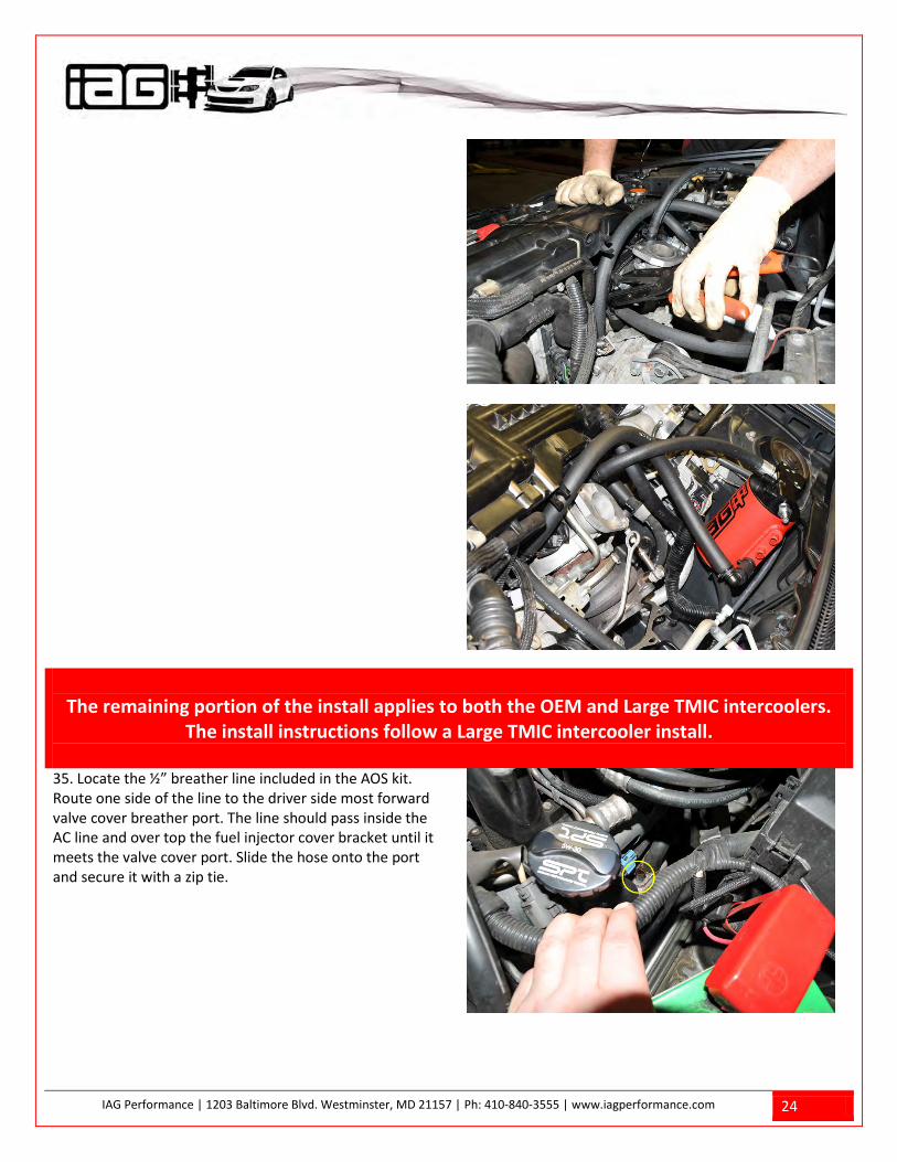
The remaining portion of the install applies to both the OEM and Large TMIC intercoolers.
The install instructions follow a Large TMIC intercooler install.
35. Locate the ½” breather line included in the AOS kit. Route one side of the line to the driver side most forward valve cover breather port. The line should pass inside the AC line and over top the fuel injector cover bracket until it meets the valve cover port. Slide the hose onto the port and secure it with a zip tie.
IAG Performance | 1203 Baltimore Blvd. Westminster, MD 21157 | Ph: 410-840-3555 | www.iagperformance.com 25
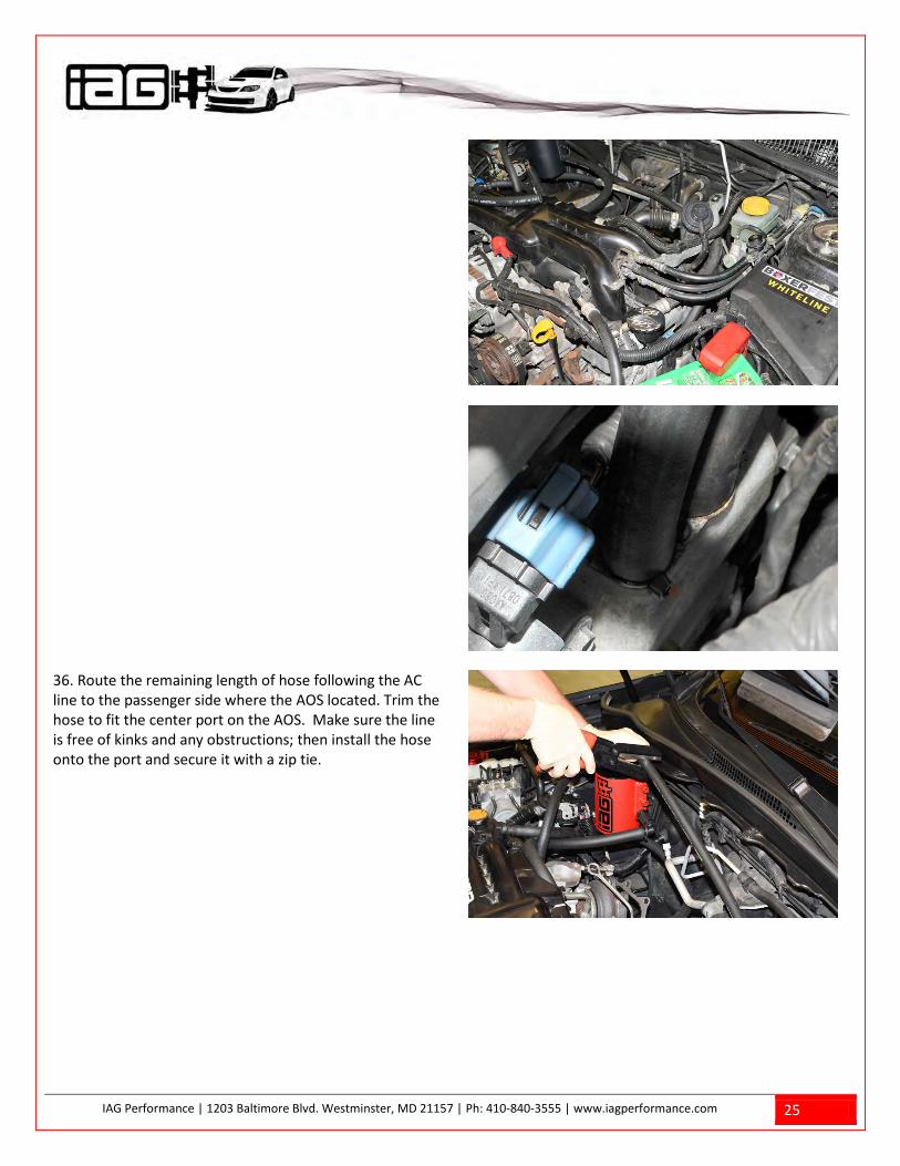
36. Route the remaining length of hose following the AC line to the passenger side where the AOS located. Trim the hose to fit the center port on the AOS. Make sure the line is free of kinks and any obstructions; then install the hose onto the port and secure it with a zip tie.
IAG Performance | 1203 Baltimore Blvd. Westminster, MD 21157 | Ph: 410-840-3555 | www.iagperformance.com 26
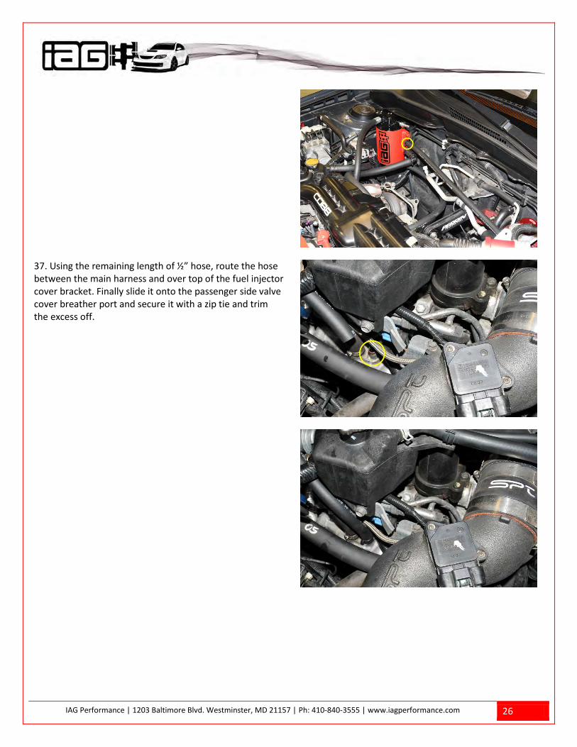
37. Using the remaining length of ½” hose, route the hose between the main harness and over top of the fuel injector cover bracket. Finally slide it onto the passenger side valve cover breather port and secure it with a zip tie and trim the excess off.
IAG Performance | 1203 Baltimore Blvd. Westminster, MD 21157 | Ph: 410-840-3555 | www.iagperformance.com 27
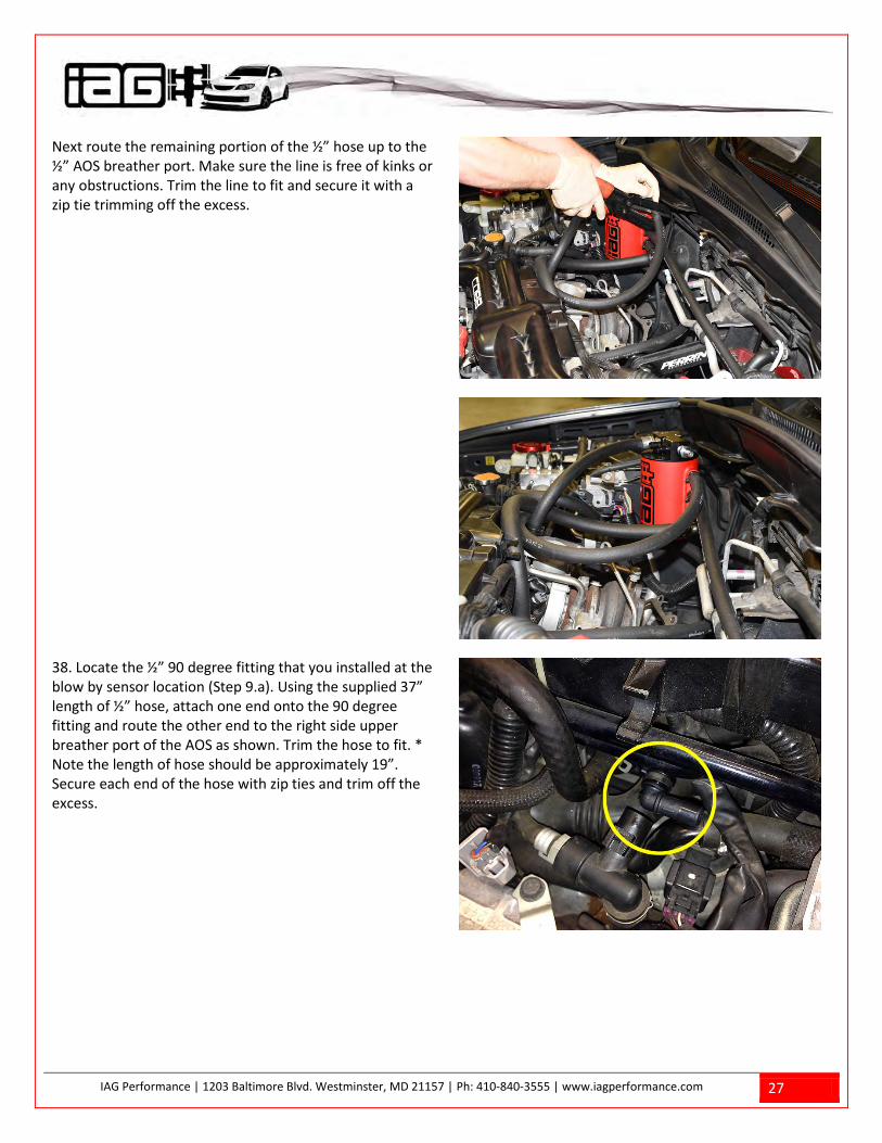
Next route the remaining portion of the ½” hose up to the ½” AOS breather port. Make sure the line is free of kinks or any obstructions. Trim the line to fit and secure it with a zip tie trimming off the excess.
38. Locate the ½” 90 degree fitting that you installed at the blow by sensor location (Step 9.a). Using the supplied 37” length of ½” hose, attach one end onto the 90 degree fitting and route the other end to the right side upper breather port of the AOS as shown. Trim the hose to fit. * Note the length of hose should be approximately 19”. Secure each end of the hose with zip ties and trim off the excess.
IAG Performance | 1203 Baltimore Blvd. Westminster, MD 21157 | Ph: 410-840-3555 | www.iagperformance.com 28
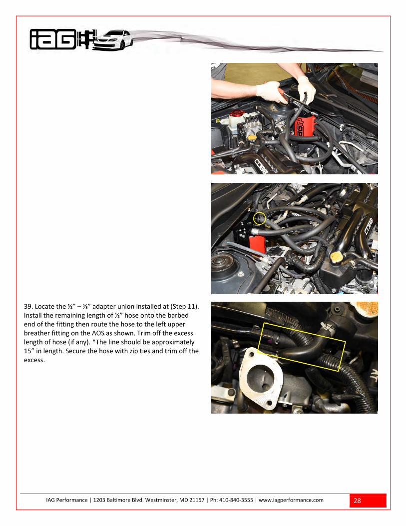
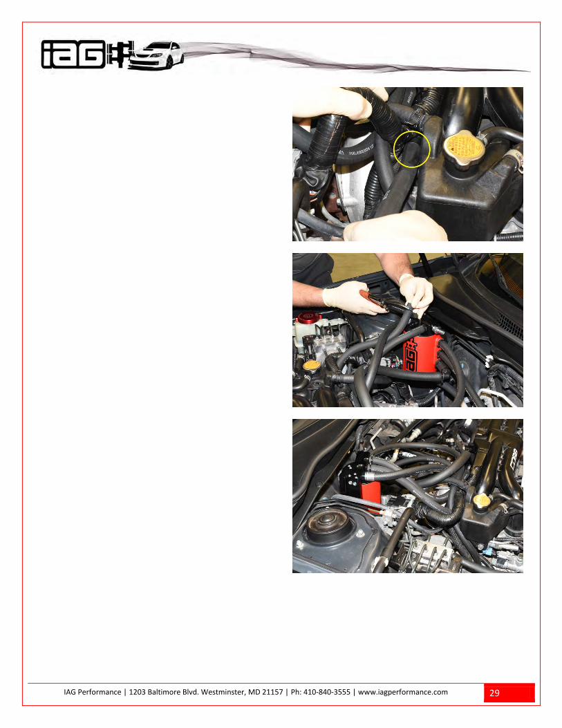
39. Locate the ½” – ⅝” adapter union installed at (Step 11). Install the remaining length of ½” hose onto the barbed end of the fitting then route the hose to the left upper breather fitting on the AOS as shown. Trim off the excess length of hose (if any). *The line should be approximately 15” in length. Secure the hose with zip ties and trim off the excess.
IAG Performance | 1203 Baltimore Blvd. Westminster, MD 21157 | Ph: 410-840-3555 | www.iagperformance.com 29
IAG Performance | 1203 Baltimore Blvd. Westminster, MD 21157 | Ph: 410-840-3555 | www.iagperformance.com 30
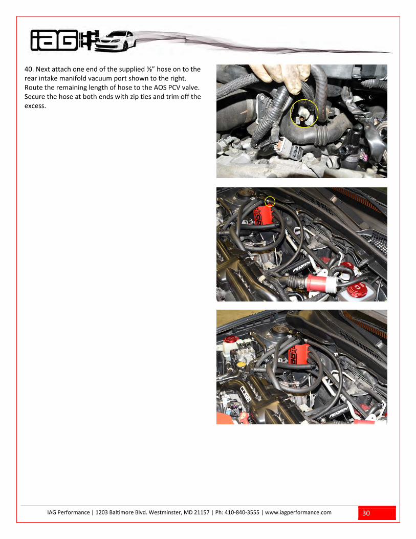
40. Next attach one end of the supplied ⅜” hose on to the rear intake manifold vacuum port shown to the right. Route the remaining length of hose to the AOS PCV valve. Secure the hose at both ends with zip ties and trim off the excess.
IAG Performance | 1203 Baltimore Blvd. Westminster, MD 21157 | Ph: 410-840-3555 | www.iagperformance.com 31
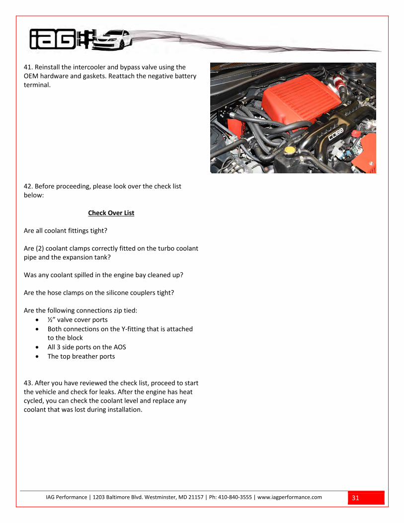
41. Reinstall the intercooler and bypass valve using the OEM hardware and gaskets. Reattach the negative battery terminal.
42. Before proceeding, please look over the check list below:
UCheck Over List
Are all coolant fittings tight? Are (2) coolant clamps correctly fitted on the turbo coolant pipe and the expansion tank? Was any coolant spilled in the engine bay cleaned up? Are the hose clamps on the silicone couplers tight? Are the following connections zip tied:
• ½” valve cover ports • Both connections on the Y-fitting that is attached
to the block • All 3 side ports on the AOS • The top breather ports
43. After you have reviewed the check list, proceed to start the vehicle and check for leaks. After the engine has heat cycled, you can check the coolant level and replace any coolant that was lost during installation.